wp 6.4 joint acceptance criteria - refresco - towards a ... · figure 6 tensile test for specimen...
TRANSCRIPT
Deliverable 6.4 – Joint acceptance criteria
Towards a REgulatory FRamework for the usE of Structural new materials in
railway passenger and freight Bodyshells
Grant Agreement no.: 605632
WP 6.4
Joint acceptance criteria
Deliverable: D6.4
Due date of deliverable: M27
Submission date: 26 02 2016
Version: Final
Project co-funded by the European Commission within the 7th Framework
Programme

Deliverable 6.4 –Joint acceptance criteria
REFRESCO Deliverable D6.4 was produced by BT and received contributions
from the following members of the consortium:
- CAF
- DLR
- UNEW
This document should be referenced as:
“REFRESCO- Joint behaviour, Deliverable 6.3, version 01”
QUALITY CONTROL INFORMATION
Issue Date Description Revising Authorship
Draft 1 06.11.2015 Draft version of REFRESCO
D6.4 for TMT COMMENT
Jan PROCKAT
(BOMBARDIER)
Final 26.11.2015 Submission of REFRESCO D6.4
final version to the EC
Hendrik SEIDLER
(BOMBARDIER)
DOCUMENT HISTORY
Issue Date Pages Comment
1 19.06.2015 All Initial issue (Draft 1)
2 06.11.2015 All Draft 1
3 26.11.2015 All Final
4 15.12.2015 13/15/16/19/29 Rev_1
DISSEMINATION LEVEL
PU Public [X]
PP Restricted to other programme participants (including the
Commission Services)
RE Restricted to a group specified by the consortium (including the
Commission Services)
CO Confidential, only for members of the consortium (including the
Commission Services)
Deliverable 6.4 –Joint acceptance criteria
EXECUTIVE SUMMARY
The Work Package 6.4 deals with acceptance criteria for joints used for new
materials.
Destructive and Non- destructive test measures have been investigated
to become able to have acceptance criteria in manufacturing
This measures have been clustered to the three most relevant joining
principles
Gaps in the Regulatory framework have been highlighted
A recommendation for the use of the different norms in relation to the
material has been given
A recommendation for the structure of a future framework for joining
principles has been made
Deliverable 6.4 – Joint acceptance criteria
Table of Contents
1 INTRODUCTION INTO OJECTIVE OF WP 6.4 .................................................... 6
2 TESTING PROCESSES ........................................................................................ 7
2.1 GENERAL .......................................................................................................... 7
2.2 DESTRUCTIVE TESTING ................................................................................. 8
2.3 NON DESTRUCTIVE TESTING ...................................................................... 16
2.4 RECOMMENDATION FOR THE RAIL INDUSTRY ......................................... 24
3 REGULATIVE FRAMEWORK PROPOSAL/ APPROACH ................................ 25
4 SUMMARY .......................................................................................................... 31
5 APPENDIX .......................................................................................................... 32
5.1 APPENDIX A ....................................................................................................... 32
6 REFERENCES .................................................................................................... 34

Deliverable 6.4 –Joint acceptance criteria
List of tables
TABLE 1 SHORTLIST OF MATERIALS CONSIDERED FOR PROCESS DETERMINATION ............................ 8
TABLE 2 ALLOWABLE TOLERANCES FOR WELDING ....................................................................... 17
TABLE 3 COMPARISON OF WALL THICKNESS VS. VOLTAGE ............................................................ 18
TABLE 4 RECOMMENDED FRAMEWORKS ..................................................................................... 30
List of figures
FIGURE 1 BENDING TEST PRINCIPLE ............................................................................................. 9
FIGURE 2 TENSILE TEST SPECIMEN ............................................................................................. 10
FIGURE 3 CREEP TENSILE TEST – EXPERIMENTAL SET UP ............................................................ 10
FIGURE 4 PEEL TEST – SET UP EXAMPLE ................................................................................... 11
FIGURE 5 TENSILE TEST FOR LOW TEMPERATURES - SPECIMEN ................................................... 11
FIGURE 6 TENSILE TEST FOR SPECIMEN WITH ROUNDED NOTCH - SPECIMEN ................................ 12
FIGURE 7 SCHEMATIC FOR TENSILE TEST ................................................................................... 13
FIGURE 8 SCHEMATIC FOR COMPRESSION SHEAR TEST .............................................................. 13
FIGURE 9 SCHEMATIC FOR TENSILE SHEAR TEST ....................................................................... 14
FIGURE 10 SCHEMATIC FOR TORSION SHEAR TEST .................................................................... 14
FIGURE 11 SCHEMATIC FOR PEEL TEST ..................................................................................... 14
FIGURE 12 PRINCIPLE OF ULTRA SONIC TESTING FOR WELDS ..................................................... 18
FIGURE 13 PRINCIPLE OF ULTRA SONIC TESTING ....................................................................... 20
FIGURE 14 PRINCIPLE OF ELECTRICAL METHOD ......................................................................... 21
FIGURE 15 PRINCIPLE OF THERMAL METHOD .............................................................................. 21
FIGURE 16 PRINCIPLE OF X-RAY TESTING ................................................................................... 22
FIGURE 17 PRINCIPLE OF ACTOR-SENSOR SYSTEM ..................................................................... 23
FIGURE 18 FREQUENCY SHIFT IN A LOCK BOLT JOINT BETWEEN 1 AND 10KN ................................ 23
FIGURE 19 SCREENSHOT FROM EN15085 REGARDING STRESS CATEGORIES ............................... 28

Deliverable 6.4 – Joint acceptance criteria
1 INTRODUCTION INTO OJECTIVE OF WP 6.4
The WP 6.4 - Joint acceptance criteria is part of the REFRESCO WP 6 - Joint
and Manufacturing. Work package WP 6 is structured into the following sub packages:
WP 6.1 – Materials manufacturing and processes,
WP 6.2 – Manufacturing acceptance criteria
WP 6.3 – Joint behaviour
WP 6.4 – Joint acceptance criteria
WP 6.1 and WP 6.2 are dealing with the material and related manufacturing. WP
6.3 combines materials with joints and gives an overview about influencing process
parameters.
WP 6.4 aims to give an overview about the different testing possibilities to be
able to check if the expected and needed property of a joint connection inside of or
between components/ assemblies has been reached.
It is clustered into destructive and non-destructive testing related to the fact that
different testing processes will be used to validate different kinds of requirements.
WP 6.3 has shown in its chapter 4 that there is no rail specific regulation
framework existing for the different joining processes. To satisfy the needs of
REFRESCO the WP 6.4 will try to outline which topics such a framework should cover.
Therefore it will partly refer on existing norms which are already in use or preparation
and which can be used in one or the other way to contribute to this framework.

Deliverable 6.4 –Joint acceptance criteria
2 TESTING PROCESSES
2.1 GENERAL
This chapter will summarise which testing processes are available to prove that
the properties of a joint is as expected and needed to fulfil the given/ expected
specification/ requirements.
The focus is to show opportunities for testing after/ during serial production as
well for the incoming and outgoing good control.
Consequently this will be non- destructive measures with the objective to
compare their test results with the acceptance criteria to show/ document the stability
of a serial manufacturing and to support the QA process.
The acceptance criteria need to be defined in advance for each specific
connection by a combination of non-destructive and destructive methods.
To gain very specific information about the properties of joints also destructive
measures are needed. To be complete the basic tests will be mentioned too.
Therefore it will be differentiated between the three joining principles worked out
in WP 6.3.
Welding
Bonding
Mechanical fastened (Bolted/ Riveted)

Deliverable 6.4 –Joint acceptance criteria
The principles can be applied in connection with the following basic materials as
agreed for the project and its combinations.
„TOP“ Monolithic Sandwich
1
CFRP CFRP – Toplayer
Resin: Epoxy Resin: Epoxy
UD top-layers: UD or quasi-isotropic
Foam: Airex T90
Honeycomb: Aramid (alternative: Aluminium*)
2
GFRP GFRP – Toplayer
Resin: Epoxy Resin: Epoxy
quasi-isotropic top-layers: quasi-isotropic
Foam: Airex T90
Honeycomb: Aluminium (alternative: Aramid)
*) No direct combinaton of carbon fibres and Aluminium due to
galvanic corrosion issues. But it is possible by using at least one layer
of GFRP (100g/m² dry fabric) between Aluminium HC core and CFRP.
Therefore this option is still possible as "Hybrid".
Table 1 Shortlist of materials considered for process determination
In addition a recommendation for a structure of a future regulatory framework in
connection with the use of new materials will be proposed.
2.2 DESTRUCTIVE TESTING
In the following destructive static tests for the different joining principles are
shown.
To get information about the fatigue behaviour of a joint it is recommended to
test the specific geometries under relevant loads and cycles for the specific situation.
WELDING
Deliverable 6.4 –Joint acceptance criteria
According to the findings in the report for WP6.3, this chapter limits on
composites with thermoplastic resins.
For destructive testing the following two international/ national standards have
been found:
EN 12814 - Testing of welded connections at thermoplastic material
DVS 2203 - Testing of welded connections at thermoplastic material
EN 12814 consists of the following parts:
EN 12814 – 1 Bending Test
EN 12814 – 2 Tensile Test
EN 12814 – 3 Creep Tensile Test
EN 12814 – 4 Peel Test
EN 12814 – 5 Macroscopic investigation
EN 12814 – 6 Tensile Test for low temperatures
EN 12814 – 7 Tensile Test for specimen with rounded notch
EN 12814 – 8 General requirements
In the following the different geometries of test specimen or the layouts for the
related tests are shown.
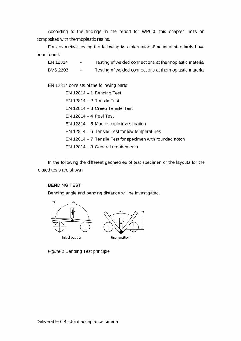
BENDING TEST
Bending angle and bending distance will be investigated.
Figure 1 Bending Test principle
Deliverable 6.4 –Joint acceptance criteria
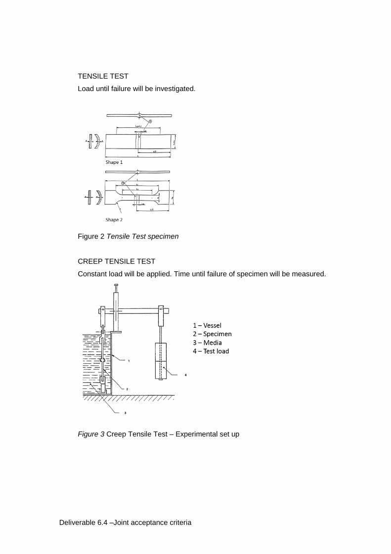
TENSILE TEST
Load until failure will be investigated.
Figure 2 Tensile Test specimen
CREEP TENSILE TEST
Constant load will be applied. Time until failure of specimen will be measured.
Figure 3 Creep Tensile Test – Experimental set up

Deliverable 6.4 –Joint acceptance criteria
PEEL TEST
The specimen will be tested with constant feed rate until failure.
Figure 4 Peel Test – Set up example
TENSILE TEST FOR LOW TEMPERATURES
Same as normal tensile test but under low temperature conditions.
Figure 5 Tensile Test for low temperatures - specimen
Deliverable 6.4 –Joint acceptance criteria
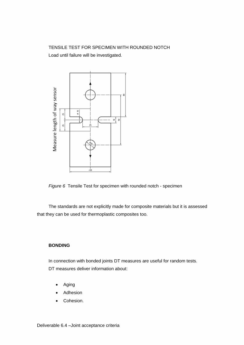
TENSILE TEST FOR SPECIMEN WITH ROUNDED NOTCH
Load until failure will be investigated.
Figure 6 Tensile Test for specimen with rounded notch - specimen
The standards are not explicitly made for composite materials but it is assessed
that they can be used for thermoplastic composites too.
BONDING
In connection with bonded joints DT measures are useful for random tests.
DT measures deliver information about:
Aging
Adhesion
Cohesion.
Deliverable 6.4 –Joint acceptance criteria
They are used to determine characteristic values for bonded joints under static,
dynamic and chemical load.
They are relatively good regulated in different ISO, ASTM or DIN standards.
To judge a serial production these measures are typically used in connection
with specific test pieces in parallel to the real product.
Typical destructive tests for bonded connections are mentioned in the following.
All tests need to be adjusted to the real demands of a joint.
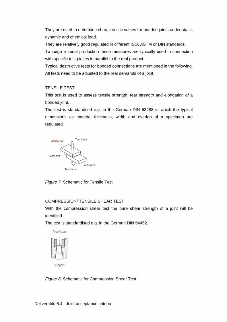
TENSILE TEST
This test is used to assess tensile strength, tear strength and elongation of a
bonded joint.
The test is standardised e.g. in the German DIN 53288 in which the typical
dimensions as material thickness, width and overlap of a specimen are
regulated.
Figure 7 Schematic for Tensile Test
COMPRESSION/ TENSILE SHEAR TEST
With the compression shear test the pure shear strength of a joint will be
identified.
The test is standardised e.g. in the German DIN 54452.
Figure 8 Schematic for Compression Shear Test
Deliverable 6.4 –Joint acceptance criteria
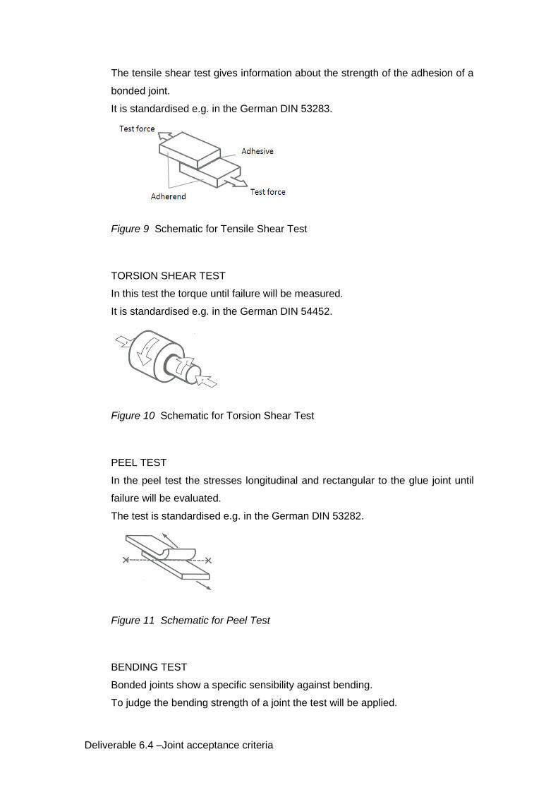
The tensile shear test gives information about the strength of the adhesion of a
bonded joint.
It is standardised e.g. in the German DIN 53283.
Figure 9 Schematic for Tensile Shear Test
TORSION SHEAR TEST
In this test the torque until failure will be measured.
It is standardised e.g. in the German DIN 54452.
Figure 10 Schematic for Torsion Shear Test
PEEL TEST
In the peel test the stresses longitudinal and rectangular to the glue joint until
failure will be evaluated.
The test is standardised e.g. in the German DIN 53282.
Figure 11 Schematic for Peel Test
BENDING TEST
Bonded joints show a specific sensibility against bending.
To judge the bending strength of a joint the test will be applied.
Deliverable 6.4 –Joint acceptance criteria
It is standardised e.g. in the US standard ASTM 1184-55.
Beside static tests also dynamic test as:
Creep rupture test and
Fatigue tests are in use.
Test/ Standards like
Pre-treatment of specimen for bonded joints DIN 53281
Fabrication of specimen for bonded joints DIN 53281
Conditions for temperature tests DIN 53286
Durability of adhesives DIN 53287
Tensile strength of overlap joints EN 1465
Shear testing for thick material EN 14869
Tensile testing for double shear joints ASTM D 3528
Fatigue properties for tensile loads EN ISO 9664
Ageing with thermal and humidity cycle EN ISO 9142
Shear impact test for adhesive joints EN ISO 9653
are available too.
MECHANICAL FASTENED
In general testing procedures for mechanical joints are summarised in ISO
13469.
The following DT measures are mentioned in this standard:
- Macro section
- Tensile shear test
- Cross tension test
- Mechanized peel test
- Fatigue and endurance tests
The Macro-section test is shown in the ISO 13469.
Deliverable 6.4 –Joint acceptance criteria
It describes where the section has to be taken from and clarifies some terms.
The tensile shear test is further specified in ISO 12996.
The Cross tension test is specified in ISO 16237.
The Mechanised peel test has to be carried out according to ISO 14270.
Fatigue and endurance tests have to follow ISO 18592 and ISO 14324.
The following additional norms are available for mechanical joints:
Test of properties of a combination of bonding and mech. joining
DVS/ EFB 3480
Lock bolt systems – mech. properties DVS/ EFB 3435
Mech. testing of blind rivets EN ISO 14589
Torque/ preload test EN ISO 16047
2.3 NON DESTRUCTIVE TESTING
Facing the growing quality requirements for structural joints compared with non-
structural, there is a need for informative and reproducible test measures.
Since destructive test measures are valid to get e.g. mechanical strength
properties under specific conditions only but without the chance to further use the
tested specimen for a product, non- destructive measures are required.
In the following NDT measures are proposed for the specific types of joints.
In connection with welding and bonding the measures need to be validated by
tests in regard to the influence of the fibre on the quality of the evaluation.
WELDING
As for the destructive testing and according to the findings in the report for
WP6.3, this chapter limits on composites with thermoplastic resins.
Therefore the two most relevant testing processes are:
- Ultrasonic Testing and
- High Voltage Testing

Deliverable 6.4 –Joint acceptance criteria
Also X- ray testing can be used to investigate irregularities but in connection with
this “optical” method the influence of the fibres need to be considered.
The German DVS 2206 gives a good bundle of information and shows
references to other international and national norms.
The three most relevant parts of the DVS 2206 are:
DVS 2206-1 – Check of dimensions and visual testing
DVS 2206-3 – Ultrasonic Testing
DVS 2206-4 – High Voltage Testing
DVS 2206 part 1
This part gives an overview of allowable tolerances in relation to length and heat
introduction coming from the related welding process.
See following table:
Table 2 Allowable tolerances for welding
There is a reference also to EN ISO 13920.
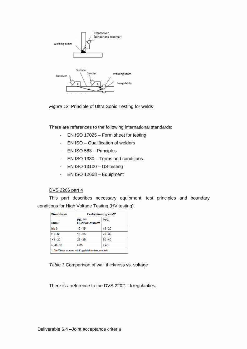
DVS 2206 part 3
This part describes necessary equipment, test principles and boundary
conditions for Ultrasonic Testing (US testing).
See two examples for testing principles:
Deliverable 6.4 –Joint acceptance criteria
Figure 12 Principle of Ultra Sonic Testing for welds
There are references to the following international standards:
- EN ISO 17025 – Form sheet for testing
- EN ISO – Qualification of welders
- EN ISO 583 – Principles
- EN ISO 1330 – Terms and conditions
- EN ISO 13100 – US testing
- EN ISO 12668 – Equipment
DVS 2206 part 4
This part describes necessary equipment, test principles and boundary
conditions for High Voltage Testing (HV testing).
Table 3 Comparison of wall thickness vs. voltage
There is a reference to the DVS 2202 – Irregularities.

Deliverable 6.4 –Joint acceptance criteria
BONDING
NDT for bonded joints primarily delivers information about/ recognises the
following defects in the adhesive layer and its boundary layers:
Porosities
Cavities
Insufficient wetting
Delamination (kissing bonds) etc.
NDT measures can’t deliver a related factor for a remaining mechanical strength
facing a specific defect.
They give only a YES or NO statement if there is a failure or not. The result of
this measures need to be assessed by QA and Engineering.
That’s why a combination of trained staff, save and repeatable processes, stable
environmental conditions in manufacturing, destructive and non-destructive testing
measures always in relation to the safety needs is needed for quality assurance in
companies dealing with structural bonding.
To document the results of such a process often specific test pieces will be
manufactures in parallel to the serial production under exactly the same conditions/
parameters as the serial product.
This test pieces can destructively be tested parallel to the running production to
recognise problems.
The following topics cannot be detected with NDT for bonding:
Aging effects
Long term statements
Overall qualification of a bonded connection
Differences in adhesion coming from failures in manufacturing
According to the NMAB of the American Society for Non-destructive Testing
these measures can be structured into the following categories (Classification of NDT-
Methods 2002):
Mechanical Vibration
Electro- Mechanical
Deliverable 6.4 –Joint acceptance criteria
Thermal
Penetrative Radiation
Visual
Chemical- Electro- Chemical
This measures need to be applied at the end of the manufacturing process.
The visual measure is meaningful only for the control of the application of the
adhesive.
Chemical- Electro- Chemical measures are not applicable for bonded joints.
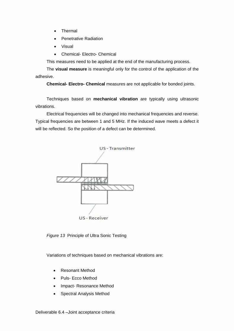
Techniques based on mechanical vibration are typically using ultrasonic
vibrations.
Electrical frequencies will be changed into mechanical frequencies and reverse.
Typical frequencies are between 1 and 5 MHz. If the induced wave meets a defect it
will be reflected. So the position of a defect can be determined.
Figure 13 Principle of Ultra Sonic Testing
Variations of techniques based on mechanical vibrations are:
Resonant Method
Puls- Ecco Method
Impact- Resonance Method
Spectral Analysis Method

Deliverable 6.4 –Joint acceptance criteria
Electrical Methods are not reasonable for industrial bonding processes and
non- conductive material like composite.
They are based on a measurement of the electrical capacity of a bonded joint of
two metals and an adhesive which are forming a kind of a condenser.
Figure 14 Principle of Electrical Method
The thermal method is using the different heat conduction through a
homogenous joints and a joint with defects. For the evaluation infrared cameras are
used.
Figure 15 Principle of thermal method
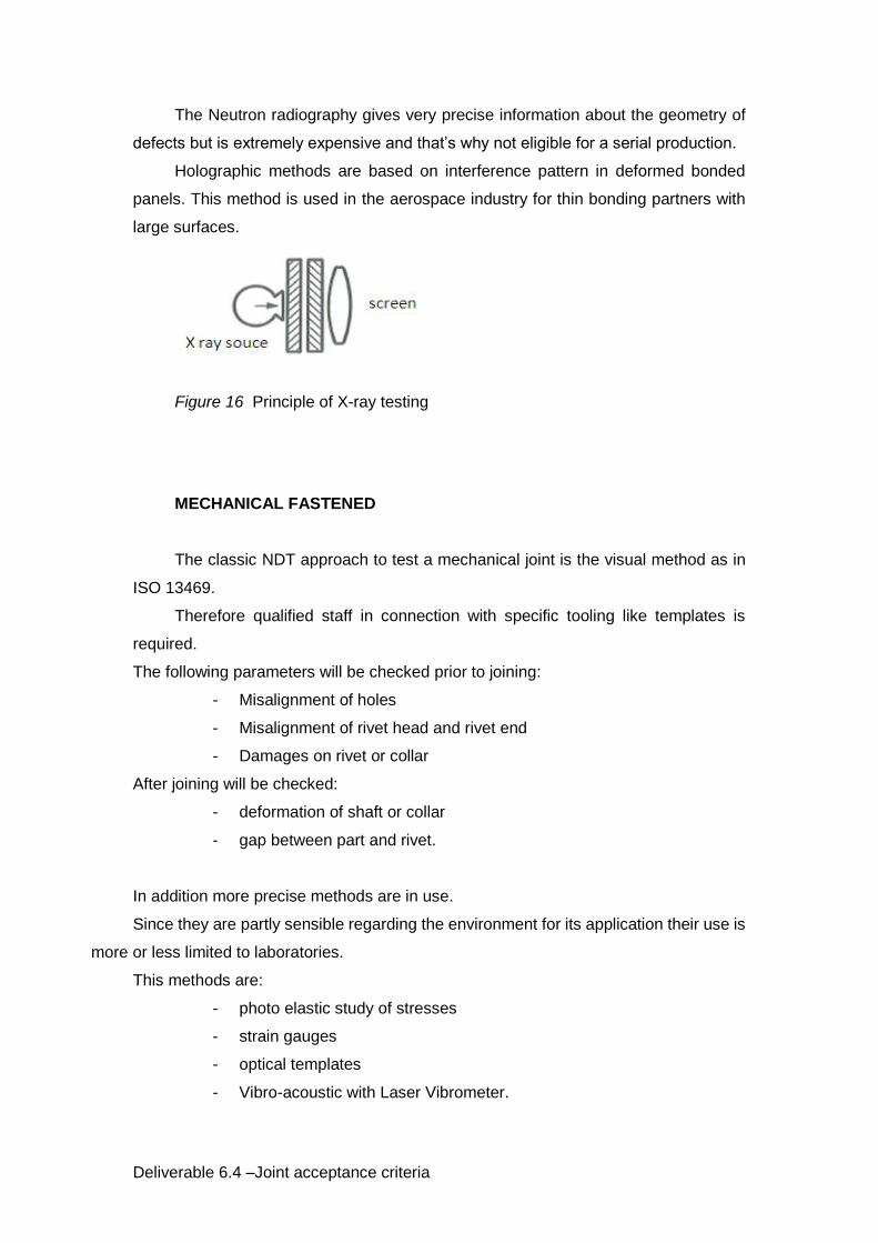
The penetrative radiation methods are clustered in the following methods:
X Ray Testing
Neutron Radiography
Holographic Method
X ray testing can be used to visualise inner structures like honeycomb structures
in sandwich panels. The thin adhesive layer cannot be checked with this method.
Deliverable 6.4 –Joint acceptance criteria
The Neutron radiography gives very precise information about the geometry of
defects but is extremely expensive and that’s why not eligible for a serial production.
Holographic methods are based on interference pattern in deformed bonded
panels. This method is used in the aerospace industry for thin bonding partners with
large surfaces.
Figure 16 Principle of X-ray testing
MECHANICAL FASTENED
The classic NDT approach to test a mechanical joint is the visual method as in
ISO 13469.
Therefore qualified staff in connection with specific tooling like templates is
required.
The following parameters will be checked prior to joining:
- Misalignment of holes
- Misalignment of rivet head and rivet end
- Damages on rivet or collar
After joining will be checked:
- deformation of shaft or collar
- gap between part and rivet.
In addition more precise methods are in use.
Since they are partly sensible regarding the environment for its application their use is
more or less limited to laboratories.
This methods are:
- photo elastic study of stresses
- strain gauges
- optical templates
- Vibro-acoustic with Laser Vibrometer.
Deliverable 6.4 –Joint acceptance criteria
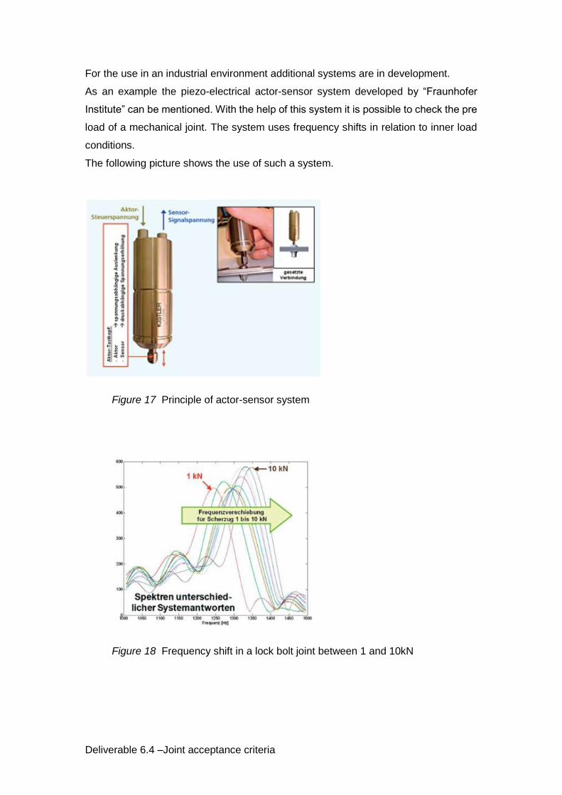
For the use in an industrial environment additional systems are in development.
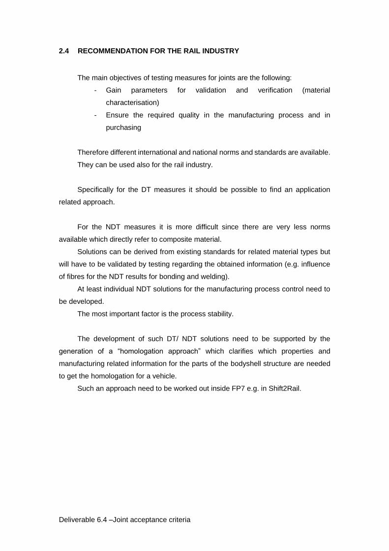
As an example the piezo-electrical actor-sensor system developed by “Fraunhofer
Institute” can be mentioned. With the help of this system it is possible to check the pre
load of a mechanical joint. The system uses frequency shifts in relation to inner load
conditions.
The following picture shows the use of such a system.
Figure 17 Principle of actor-sensor system
Figure 18 Frequency shift in a lock bolt joint between 1 and 10kN
Deliverable 6.4 –Joint acceptance criteria
2.4 RECOMMENDATION FOR THE RAIL INDUSTRY
The main objectives of testing measures for joints are the following:
- Gain parameters for validation and verification (material
characterisation)
- Ensure the required quality in the manufacturing process and in
purchasing
Therefore different international and national norms and standards are available.
They can be used also for the rail industry.
Specifically for the DT measures it should be possible to find an application
related approach.
For the NDT measures it is more difficult since there are very less norms
available which directly refer to composite material.
Solutions can be derived from existing standards for related material types but
will have to be validated by testing regarding the obtained information (e.g. influence
of fibres for the NDT results for bonding and welding).
At least individual NDT solutions for the manufacturing process control need to
be developed.
The most important factor is the process stability.
The development of such DT/ NDT solutions need to be supported by the
generation of a “homologation approach” which clarifies which properties and
manufacturing related information for the parts of the bodyshell structure are needed
to get the homologation for a vehicle.
Such an approach need to be worked out inside FP7 e.g. in Shift2Rail.
Deliverable 6.4 –Joint acceptance criteria
3 REGULATIVE FRAMEWORK PROPOSAL/ APPROACH
To reach a common regulatory framework for the European rail industry it is
necessary to have a system of norms and standards which covers a whole range of
building blocks (BB).
BUILDING BLOCKS
Can be nominated as follows:
BB 1 - Concept and design
BB 2 - Safety needs for:
Supplier selection
Requirements to the manufacturing facility
Requirements to the workers in manufacturing
BB 3 - Generic QA requirements
BB 4 - Static and fatigue evaluation
BB 1) The concept and design chapter should contain:
- General accepted GO/ NO GO principles for the design of a specific
joint connection
- Definition of terms
BB 2) The safety need chapter should contain:
- Safety categories to cluster the safety need
- Related performance and inspection classes
BB 3) The generic QA requirements chapter should contain:
- Define rules for planning (min. needed documents in manufacturing, to
be documented)
- Defines rules for documentation of product
- Defines rules for documentation of repairs
BB 4) The static and fatigue evaluation chapter should contain:
- Generic rules for meshing and evaluation
- Safety factors
- Number and range of needed test to validate the FE analysis

Deliverable 6.4 –Joint acceptance criteria
COMPETITIVE CONTENT
Information like
- Real numbers for allowable stresses of specific material combinations
- Processes for FAI’s
- Detailed QA measures during manufacturing
- Incoming/ outgoing goods control processes
are to be seen as competitive processes which not need to be part of a
European framework.
SPECIFIC REQUIREMENTS
Norms which are defining specific requirements for rail vehicles like the EN
45545 for Fire and Smoke or the EN 12663 for Structural requirements are
not recommended to be part of the framework.
They represent requirements which have to be fulfilled for each rail vehicle,
independent from the material of the Bodyshell but it need to be discussed if
they need to be adopted to fit for composites.
EXPECTED FRAMEWORKS
Facing the principally different requirements for the different joint systems we
recommend creating a number of three of such frameworks.
- for welded connections with new materials
- for bolted/ riveted hybrid and single material solutions with involved new
materials
- for bonded hybrid and single material solutions with involved new
materials

Deliverable 6.4 –Joint acceptance criteria
EXISTING NORMS/ FRAMEWORKS
EN 15085
In front of the above mentioned background the existing EN 15085
gives an excellent example for a regulatory framework for welded
connections in metallic structures. The idea of the framework is to cover all
requirements for design, layout, assessment and quality assurance approach
based on the same philosophy.
This gives a clear guideline which enables supplier and customer to reach a
stable quality. It makes results and requirements transparent and secures the
comparability of welding manufacturers. It leads to the possibility of objective
cost evaluations and clear responsibilities.
The EN 15085 consists of different parts which are dealing with different
topics.
They are:
Part 1 – General
Defines Terms and gives general comments
Part 2 – Quality requirements and certification of welding manufacturers
Defines certification levels for the product and relates them to
Qualification needs to the manufacturers
Part 3 – Design requirements
Creates a relation of safety categories (LOW/ MEDIUM/ HIGH)
and stress category (Fatigue utilisation). This is related to
performance classes (CP A to CP D) for the welding seam
which are related to inspection classes (T 1 to 4).
The inspection class defines the necessary effort for testing.
Gives advises for the design engineer regarding the
arrangement of welding seams.

Deliverable 6.4 –Joint acceptance criteria
Figure 19 Screenshot from EN15085 regarding stress categories
Part 4 – Production requirements
Defines steps for the manufacturing of a welded connection.
Mentions documents for planning and exceptions for testing.
Defines rules for repairs.
Part 5 – Inspection, testing and documentation
It defines rules for planning and documentation of QA
measures in the manufacturing.
The EN 15085 explicitly excludes methodologies, boundaries and values for
static and fatigue analysis.
DIN 6701
The DIN 6701 represents a national framework for bonded structures in the
rail industry.
It follows the same approach as the EN 15085.
This Regulation consists of the following parts:
Deliverable 6.4 –Joint acceptance criteria
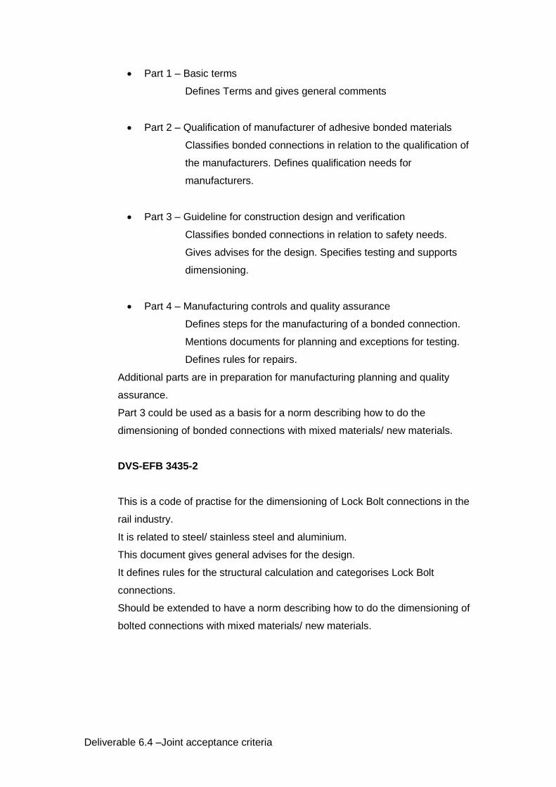
Part 1 – Basic terms
Defines Terms and gives general comments
Part 2 – Qualification of manufacturer of adhesive bonded materials
Classifies bonded connections in relation to the qualification of
the manufacturers. Defines qualification needs for
manufacturers.
Part 3 – Guideline for construction design and verification
Classifies bonded connections in relation to safety needs.
Gives advises for the design. Specifies testing and supports
dimensioning.
Part 4 – Manufacturing controls and quality assurance
Defines steps for the manufacturing of a bonded connection.
Mentions documents for planning and exceptions for testing.
Defines rules for repairs.
Additional parts are in preparation for manufacturing planning and quality
assurance.
Part 3 could be used as a basis for a norm describing how to do the
dimensioning of bonded connections with mixed materials/ new materials.
DVS-EFB 3435-2
This is a code of practise for the dimensioning of Lock Bolt connections in the
rail industry.
It is related to steel/ stainless steel and aluminium.
This document gives general advises for the design.
It defines rules for the structural calculation and categorises Lock Bolt
connections.
Should be extended to have a norm describing how to do the dimensioning of
bolted connections with mixed materials/ new materials.

Deliverable 6.4 –Joint acceptance criteria
CONCLUSION
The following table show the regulatory frameworks which are proposed to be
developed for new materials in structural approaches to get homologation in the rail
industry.
FRAMEWORK 1 FRAMEWORK 2 FRAMEWORK 3
HEADLINE
welded connections with
new materials
bolted/ riveted hybrid and single material solutions with involved new
materials
bonded hybrid and single material solutions with involved new
materials
EXAMPLE FOR RECOMMENDED FRAMEWORK ARCHITECTURE BB 1 to BB 3
EN 15085 EN 15085 DIN 6701 Part 1 to 4
EXAMPLE FOR NORM BB 4
DVS-EFB 3435-2 (adopt and make
international)
DIN 6701 part 3 (adopt and make
international)
Table 4 Recommended frameworks
At least there are approaches available which are already in use in single
countries or for metallic structures or specific processes.
It will be the task of future regulation boards to use this approaches also for new
materials.
Therefore it is recommended to use the structure of the above mentioned regulations,
to adopt them as mentioned and to give them the status of a European Norm.

Deliverable 6.4 –Joint acceptance criteria
4 SUMMARY
In this subtask an overview about the destructive and non- destructive testing
processes is given, based on existing norms and standards.
Some of the standards are made for similar or different base materials but the
principles should be able to be used for new materials/ composites too.
In any case it is recommended to validate this specifically for the NDT measures
by tests.
According to the agreements from the beginning of this projects tests have not
been performed.
The different testing measures have been clustered to the three essential joining
principles:
- Welding
- Bonding
- Mechanically fastened.
Test Principles and standardised geometries of specimen have been shown
exemplary.
In the last chapter a recommendation for the structure of a regulatory framework
is given.
It refers to existing regulations.
For further activities in regard to such a framework, the introduction of the related
regulation boards is strongly recommended.
Deliverable 6.4 –Joint acceptance criteria
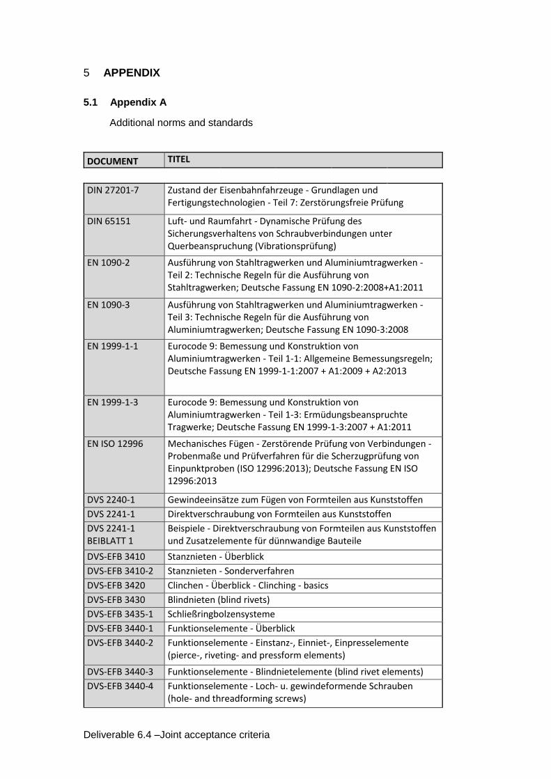
5 APPENDIX
5.1 Appendix A
Additional norms and standards
DOCUMENT TITEL
DIN 27201-7 Zustand der Eisenbahnfahrzeuge - Grundlagen und Fertigungstechnologien - Teil 7: Zerstörungsfreie Prüfung
DIN 65151 Luft- und Raumfahrt - Dynamische Prüfung des Sicherungsverhaltens von Schraubverbindungen unter Querbeanspruchung (Vibrationsprüfung)
EN 1090-2 Ausführung von Stahltragwerken und Aluminiumtragwerken - Teil 2: Technische Regeln für die Ausführung von Stahltragwerken; Deutsche Fassung EN 1090-2:2008+A1:2011
EN 1090-3 Ausführung von Stahltragwerken und Aluminiumtragwerken - Teil 3: Technische Regeln für die Ausführung von Aluminiumtragwerken; Deutsche Fassung EN 1090-3:2008
EN 1999-1-1 Eurocode 9: Bemessung und Konstruktion von Aluminiumtragwerken - Teil 1-1: Allgemeine Bemessungsregeln; Deutsche Fassung EN 1999-1-1:2007 + A1:2009 + A2:2013
EN 1999-1-3 Eurocode 9: Bemessung und Konstruktion von Aluminiumtragwerken - Teil 1-3: Ermüdungsbeanspruchte Tragwerke; Deutsche Fassung EN 1999-1-3:2007 + A1:2011
EN ISO 12996 Mechanisches Fügen - Zerstörende Prüfung von Verbindungen - Probenmaße und Prüfverfahren für die Scherzugprüfung von Einpunktproben (ISO 12996:2013); Deutsche Fassung EN ISO 12996:2013
DVS 2240-1 Gewindeeinsätze zum Fügen von Formteilen aus Kunststoffen
DVS 2241-1 Direktverschraubung von Formteilen aus Kunststoffen
DVS 2241-1 BEIBLATT 1
Beispiele - Direktverschraubung von Formteilen aus Kunststoffen und Zusatzelemente für dünnwandige Bauteile
DVS-EFB 3410 Stanznieten - Überblick
DVS-EFB 3410-2 Stanznieten - Sonderverfahren
DVS-EFB 3420 Clinchen - Überblick - Clinching - basics
DVS-EFB 3430 Blindnieten (blind rivets)
DVS-EFB 3435-1 Schließringbolzensysteme
DVS-EFB 3440-1 Funktionselemente - Überblick
DVS-EFB 3440-2 Funktionselemente - Einstanz-, Einniet-, Einpresselemente (pierce-, riveting- and pressform elements)
DVS-EFB 3440-3 Funktionselemente - Blindnietelemente (blind rivet elements)
DVS-EFB 3440-4 Funktionselemente - Loch- u. gewindeformende Schrauben (hole- and threadforming screws)

Deliverable 6.4 –Joint acceptance criteria
DVS-EFB 3450-1 Hybridfügen - Clinch Kleben - Stanznietkleben - Überblick
DVS-EFB 3460 Nacharbeit und Reparatur von unlösbar mechanisch gefügten Verbindungen
DVS-EFB 3470 Mechanisches Fügen - Konstruktion und Auslegung - Grundlagen/Überblick
DVS-EFB 3480-1 Prüfung von Verbindungseigenschaften - Prüfung der Eigenschaften mechanisch und kombiniert mittels Kleben gefertigter Verbindungen
DVS-EFB 3480-1 BEIBLATT 1
Prüfung von Verbindungseigenschaften - Prüfung der Eigenschaften mechanisch und kombiniert mittels Kleben gefertigter Verbindungen - Steifigkeitsermittlung elementar mechanisch gefügter Verbindungen
DVS-EFB 3490 Anlagen zum Stanznieten
ISO 13469 Mechanisches Fügen - Formschlüssiges Blindniete und Schließringbolzen - Festlegungen und Bewertung von Prüfverfahren
VDI 2014 BLATT 3 Entwicklung von Bauteilen aus Faser-Kunststoff-Verbund - Berechnungen
ISO 11003-1 Klebstoffe - Bestimmung des Scherverhaltens von Strukturklebstoffen - Teil 1: Torsionsprüfverfahren unter Verwendung stumpfgeklebter Hohlzylinder
ISO 11003-2 Klebstoffe - Bestimmung des Scherverhaltens von Strukturklebstoffen - Teil 2: Scherprüfverfahren für dicke Fügeteile
Deliverable 6.4 –Joint acceptance criteria
6 REFERENCES
[1] DAkkS – Deutsche Akkreditierungsstelle
[2] Fraunhofer Institute – Anwendungszentrum Rostock
[3] Normmaster
[4] DVS – Deutscher Verband für Schweißen und verwandte Verfahren
[5] Handbook DVS – Merkblätter „Kunststoffe, Schweißen und Kleben“
[6] M. Rasch; Handbuch Klebetechnik
[7] G. Habenicht; Grundlagen Kleben