wp4c dew point potentiameterlabcell.com/media/140280/wp4c instruction manual.pdfloss of anticipated...
TRANSCRIPT

WP4CDew Point PotentiaMeter
Operator’s Manual
METER Group, Inc.
Version: June 2, 2017 — 08:22:53

WP4C
METER Group, Inc.2365 NE Hopkins Court
Pullman WA 99163
Phone: 509-332-5600Fax: 509-332-5158
Website: www.metergroup.comEmail: [email protected] or
Trademarksc©2017 METER Group, Inc.
All Rights Reserved
ii
WP4C CONTENTS
Contents
1 Introduction 11.1 Customer Support . . . . . . . . . . . . . . . . . . . . 11.2 About This Manual . . . . . . . . . . . . . . . . . . . 21.3 Warranty . . . . . . . . . . . . . . . . . . . . . . . . . 21.4 Seller’s Liability . . . . . . . . . . . . . . . . . . . . . . 2
2 About the WP4C 42.1 Specifications . . . . . . . . . . . . . . . . . . . . . . . 42.2 WP4C and Water Potential . . . . . . . . . . . . . . . 52.3 How the WP4C works . . . . . . . . . . . . . . . . . . 52.4 WP4C and Temperature . . . . . . . . . . . . . . . . . 6
3 Getting Started 73.1 Components of your WP4C . . . . . . . . . . . . . . . 73.2 Choosing a Location . . . . . . . . . . . . . . . . . . . 73.3 Features . . . . . . . . . . . . . . . . . . . . . . . . . . 83.4 Preparing the WP4C for Operation . . . . . . . . . . . 83.5 Portability . . . . . . . . . . . . . . . . . . . . . . . . . 9
4 The Menus 114.1 The Main Menu . . . . . . . . . . . . . . . . . . . . . . 11
4.1.1 Changing Languages . . . . . . . . . . . . . . . 114.1.2 Reading Modes . . . . . . . . . . . . . . . . . . 12
4.2 System Configuration . . . . . . . . . . . . . . . . . . 144.3 Sample Equilibration Screen . . . . . . . . . . . . . . . 17
5 Calibration and Verification 195.1 Verification . . . . . . . . . . . . . . . . . . . . . . . . 195.2 Verification Standards . . . . . . . . . . . . . . . . . . 195.3 When to Verify Calibration . . . . . . . . . . . . . . . 195.4 How to Verify and Calibrate the WP4C . . . . . . . . 20
6 Sample Preparation 226.1 Choosing a Sample Cup . . . . . . . . . . . . . . . . . 226.2 Preparing the Sample . . . . . . . . . . . . . . . . . . 226.3 Dry Samples . . . . . . . . . . . . . . . . . . . . . . . 236.4 Samples and Temperature . . . . . . . . . . . . . . . . 246.5 Measuring Plant Samples . . . . . . . . . . . . . . . . 25
iii
CONTENTS WP4C
6.6 Taking a Reading . . . . . . . . . . . . . . . . . . . . . 256.7 How WP4C takes Readings . . . . . . . . . . . . . . . 25
7 Computer Interface 277.1 AquaLink 4 Software . . . . . . . . . . . . . . . . . . . 277.2 Using a Communication Program . . . . . . . . . . . . 28
8 Theory: Water Potential 308.1 Water Potential . . . . . . . . . . . . . . . . . . . . . . 308.2 Measuring Water Potential . . . . . . . . . . . . . . . 308.3 Effect of Temperature on Water Potential . . . . . . . 318.4 Estimating Osmotic Potential . . . . . . . . . . . . . . 32
9 Cleaning and Maintenance 339.1 Accessing the Block . . . . . . . . . . . . . . . . . . . 339.2 Cleaning Procedure . . . . . . . . . . . . . . . . . . . . 349.3 Checking Calibration . . . . . . . . . . . . . . . . . . . 37
10 Repair Instructions 3810.1 Shipping Directions . . . . . . . . . . . . . . . . . . . . 3810.2 Repair Costs . . . . . . . . . . . . . . . . . . . . . . . 3910.3 Loaner Service . . . . . . . . . . . . . . . . . . . . . . 39
11 Troubleshooting 4011.1 Problems and Solutions . . . . . . . . . . . . . . . . . 4011.2 Sensor Performance Screen . . . . . . . . . . . . . . . 44
12 Further Reading 4612.1 Application Notes . . . . . . . . . . . . . . . . . . . . 46
13 Appendix A 4813.1 Preparing Salt Solutions . . . . . . . . . . . . . . . . . 48
14 Appendix B 49
15 Declaration of Conformity 50
16 Certificate of Traceability 51
iv
WP4C 1 INTRODUCTION
1 Introduction
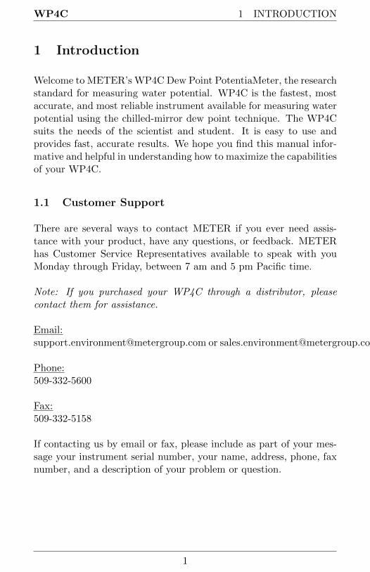
Welcome to METER’s WP4C Dew Point PotentiaMeter, the researchstandard for measuring water potential. WP4C is the fastest, mostaccurate, and most reliable instrument available for measuring waterpotential using the chilled-mirror dew point technique. The WP4Csuits the needs of the scientist and student. It is easy to use andprovides fast, accurate results. We hope you find this manual infor-mative and helpful in understanding how to maximize the capabilitiesof your WP4C.
1.1 Customer Support
There are several ways to contact METER if you ever need assis-tance with your product, have any questions, or feedback. METERhas Customer Service Representatives available to speak with youMonday through Friday, between 7 am and 5 pm Pacific time.
Note: If you purchased your WP4C through a distributor, pleasecontact them for assistance.
Email:[email protected] or [email protected]
Phone:509-332-5600
Fax:509-332-5158
If contacting us by email or fax, please include as part of your mes-sage your instrument serial number, your name, address, phone, faxnumber, and a description of your problem or question.
1

1 INTRODUCTION WP4C
1.2 About This Manual
Please read these instructions before operating your Potentia Meterto ensure that it performs at full potential. This manual includesinstructions for setting up, calibrating, and maintaining the WP4C.Please read these instructions before operating WP4C to ensure thatthe instrument performs to its full potential. This manual will aidend users in understanding the basic concepts of water potential andenable them to use our instrument with confidence. Every effort hasbeen made to ensure that the content of this manual is correct andscientifically sound.
1.3 Warranty
This device has a 30-day satisfaction guarantee and a one-year war-ranty on parts and labor. Your warranty is automatically validatedupon receipt of the instrument.
1.4 Seller’s Liability
Seller warrants new equipment of its own manufacture against de-fective workmanship and materials for a period of one year from thedate of receipt of equipment.
Note: We do not consider the results of ordinary wear and tear,neglect, misuse, or accident as defects.
The Seller’s liability for defective parts shall in no event exceed thefurnishing of replacement parts “freight on board” the factory whereoriginally manufactured. Material and equipment covered herebywhich is not manufactured by Seller shall be covered only by thewarranty of its manufacturer. Seller shall not be liable to Buyer forloss, damage or injuries to persons (including death), or to propertyor things of whatsoever kind (including, but not without limitation,loss of anticipated profits), occasioned by or arising out of the instal-lation, operation, use, misuse, nonuse, repair, or replacement of saidmaterial and equipment, or out of the use of any method or process
2
WP4C 1 INTRODUCTION
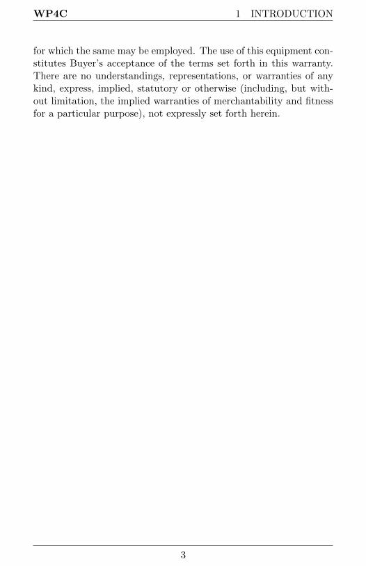
for which the same may be employed. The use of this equipment con-stitutes Buyer’s acceptance of the terms set forth in this warranty.There are no understandings, representations, or warranties of anykind, express, implied, statutory or otherwise (including, but with-out limitation, the implied warranties of merchantability and fitnessfor a particular purpose), not expressly set forth herein.
3

2 ABOUT THE WP4C WP4C
2 About the WP4C
2.1 Specifications
Range: 0 to −300 MPa1
Accuracy: ± 0.05 MPa1 from 0 to −5 MPa1% from −5 to −300 MPa
Measurement Time:∼10 to 15 minutes for most soil samples in precise mode∼20 min. for plant tissue samples< 5 minutes in fast mode (reduced accuracy)
Temperature Control: 15 to 40 ◦C (± 0.2 ◦C)
Operating Environment: 5 to 40 ◦C (41 to 104 ◦F)
Sensor Type: A chilled-mirror dew point sensor and an Infraredtemperature sensor
Sample Cup Capacity: 7 mL recommended (15 mL full)
Dimensions: 24.1 x 22.9 x 8.9 cm (9.5 x 9.0 x 3.5 in)
Weight: 3.2 Kg (7.1 lbs)
Case Material: Powder Painted Aluminum
Display: 20 x 2 alphanumeric LCD with backlighting
Data Communication: RS232A compatible, 8-data bit ASCII code,9600 baud, no parity, 1 stop bit
Power: 110 VAC to 220 VAC, 50/60 Hz
Interface Cable: Standard RS232 to USB cable (included)
Compatible Standards: ASTM D6836-07
Warranty: One year parts and labor
1The WP4C (and all vapor pressure instruments) are limited by accuracy inthe wet end of the water potential range. The range of 0 to −5 MPa has anaccuracy of 0.05 MPa. For example, a measurement at −0.1MPa has an accuracyof ±50% of the reading and −1 MPa has an accuracy of ±5% of the reading. TheWP4C will not measure water potential accurately near field capacity.
4

WP4C 2 ABOUT THE WP4C
2.2 WP4C and Water Potential
Water potential is a measurement of the energy status of the waterin a system. It indicates how tightly water is bound, structurally orchemically, within a substance. Water potential can be computedfrom the vapor pressure of air in equilibrium with a sample in asealed measurement chamber. For a more detailed description ofwater potential, please refer to Chapter 9, titled “Theory: WaterPotential” of this manual.
2.3 How the WP4C works
The WP4C uses the chilled mirror dew point technique to measurethe water potential of a sample. In this type of instrument, thesample is equilibrated with the headspace of a sealed chamber thatcontains a mirror and a means of detecting condensation on the mir-ror. At equilibrium, the water potential of the air in the chamber isthe same as the water potential of the sample. In the WP4C, the mir-ror temperature is precisely controlled by a thermoelectric (Peltier)cooler. A photoelectric cell detects the exact point at which conden-sation first appears on the mirror. The WP4C directs a beam of lightonto the mirror, which reflects into a photodetector. The photode-tector senses the change in reflectance when condensation occurs onthe mirror. A thermocouple attached to the mirror then records thetemperature at which condensation occurs. Values begin to be dis-played indicating that initial measurements are being taken. WP4Cthen signals you by flashing a green LED and/or beeping when itreaches the final values. The instrument will display the final waterpotential and temperature of the sample.
In addition to the technique described above, WP4C uses an inter-nal fan that circulates the air within the sample chamber to reducetime to equilibrium. Measuring both dew point and sample surfacetemperatures are simultaneously measured, this eliminates the needfor complete thermal equilibrium. The WP4C controls the sampletemperature by means of an internal thermo-electrical module thatmonitors and stabilizes the sample block temperature according tohow it is set.
5
2 ABOUT THE WP4C WP4C
2.4 WP4C and Temperature
Large temperature differences, between sample and block, will causelonger reading times, since a complete and accurate reading will notbe made until the difference between the sample temperature andthe block temperature is less than 1.0 degree. To help you monitorthe temperature difference between your sample and the block, youcan access a Sample Equilibration screen at the Main menu.
6

WP4C 3 GETTING STARTED
3 Getting Started
3.1 Components of your WP4C
Your WP4C should have shipped with the following items.
• WP4C Main Unit• Quickstart Guide• Certificate of Calibration• Power Cord• RS-232 to USB Cable• 25 Plastic Sample Cups and Lids• 10 Stainless Steel Sample Cups• Operator’s Manual• 12 Vials of 0.50 mol/kg KCl• Cleaning Kit
3.2 Choosing a Location
To ensure that your WP4C operates correctly and consistently, placeit on a level surface. This reduces the chance that sample materialwill spill and contaminate the inside of the instrument. To protectthe internal electrical components, and to avoid inaccurate readings,place your WP4C in a location where the temperature remains fairlystable. This location should be well away from air conditioner andheater vents, open windows, outside doors, refrigerator exhausts, orother items that may cause rapid temperature fluctuation.
7

3 GETTING STARTED WP4C
3.3 Features
Figure 1: Front View of WP4C
Figure 2: Back View of WP4C
3.4 Preparing the WP4C for Operation
After finding a good location for your WP4C, plug the power cordinto the back of the unit. Before turning it on, pull open the sampledrawer (turn the knob to the OPEN/LOAD position). You usuallyplace an empty disposable sample cup upside-down in the drawer to
8

WP4C 3 GETTING STARTED
protect it during shipment. Remove this sample cup and turn theinstrument on. The ON/OFF switch is located on the lower rightcorner of the WP4C back panel. The model and then the main menuwill appear on the LCD.
Then:
This is the Main menu, displaying the water potential in both Mega-Pascals (MPa) and pF, and the sample temperature in ◦C. In order toprovide the most accurate readings, WP4C should ideally be alloweda warm-up period of 15 to 30 minutes after turning it on. When youinsert a sample into the chamber drawer and turn the drawer knobto the READ position, the instrument will begin the read cycle tomeasure the water potential of your sample.
3.5 Portability
On occasion you may want to take water potential measurements inthe field where it is not feasible to take samples and return to thelab. The following is a procedure for powering your WP4C usingyour vehicle as a power source at sites where AC power is not readilyavailable.
1. Purchase a portable power inverter that plugs into the 12 Voutput (cigarette lighter) of your vehicle. The inverter shouldhave a continuous output of at least 140 Watts.
9

3 GETTING STARTED WP4C
2. Place the WP4C on a level surface. Care should be taken tominimize temperature gradients that may affect the instrumentwhile in the field. A Styrofoam box, for example, will helpminimize temperature effects.
3. Plug the 12-volt inverter to the 12-volt output of the vehicle,or directly to the battery itself.
4. Plug the WP4C to the inverter, and turn it on. When theinstrument is on, it draws up to 1 amp. Check the rating ofyour battery if you want to know how long it will power theinstrument (for example, if your battery is rated for 60 amphours, it will work for 60 hours when the vehicle is not running.
5. Allow the instrument to warm up for 15 to 30 minutes as youwould in the lab. Check the calibration of the instrument beforeproceeding with reading.
10
WP4C 4 THE MENUS
4 The Menus
4.1 The Main Menu
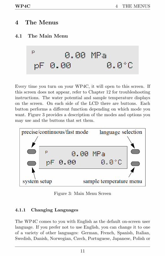
Every time you turn on your WP4C, it will open to this screen. Ifthis screen does not appear, refer to Chapter 12 for troubleshootinginstructions. The water potential and sample temperature displayson the screen. On each side of the LCD there are buttons. Eachbutton performs a different function depending on which mode youwant. Figure 3 provides a description of the modes and options youmay use and the buttons that set them.
Figure 3: Main Menu Screen
4.1.1 Changing Languages
The WP4C comes to you with English as the default on-screen userlanguage. If you prefer not to use English, you can change it to oneof a variety of other languages: German, French, Spanish, Italian,Swedish, Danish, Norwegian, Czech, Portuguese, Japanese, Polish or
11

4 THE MENUS WP4C
Finnish. Change languages by pressing the upper right button ofthe instrument while it is not reading a sample. You will see theLanguage screen with default English.
Press the upper right key again, and the next language option (Ger-man) will appear.
Each time you press the right button, the display will scroll to thenext language option. Select the language you prefer and press thelower left button to exit.
4.1.2 Reading Modes
Precise Mode
When you first turn on the WP4C, it will be in precise mode. TheWP4C repeats sample measurements until successive readings agreewithin a preset tolerance (0.03 MPa for Ψ > −40 MPa; otherwise0.3 MPa). The WP4C always starts in precise mode. To togglebetween the precise, continuous and fast modes, press the top leftbutton. The display will show a small p, c or f to the left of thewater potential readings.(Figure 4)
12

WP4C 4 THE MENUS
Figure 4: Main Menu with Continuous Mode Enabled
Precise mode ensures a precise water potential value by repeatingmeasurements on a sample. Typical read times are within 10 to 15minutes. The green LED blinks until you turn the drawer know tothe OPEN/LOAD position.
Continuous Mode
Continuous mode measures the water potential of your sample con-tinuously until you turn the drawer knob to the OPEN/LOAD po-sition. This can be useful in doing long term monitoring of samplesthat take an especially long time to come to vapor equilibrium, suchas plant samples and moist soil samples with water potential > −0.5MPa. In this mode the WP4C will measure the sample, stop to dis-play the water potential and sample temperature, then begin anotherread cycle. Between samples, it will signal you with the green LEDflash, accompanied by the beeper, if enabled. Some find it helpfulto connect their WP4C to a computer while in continuous mode inorder to log and store data over time. For instructions on how to dothis, see Chapter 8.
Fast Mode
In fast mode, the sample is measured only once. Read time is typ-ically 3 to 5 minutes. Readings are less precise, particularly in thewet range. However, fast mode is recommended for dry soil sampleswith water potential < −40 MPa.
13
4 THE MENUS WP4C
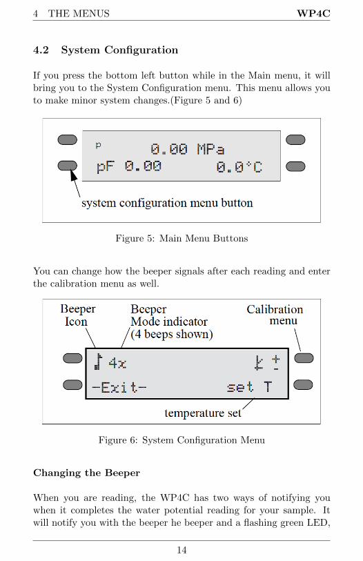
4.2 System Configuration
If you press the bottom left button while in the Main menu, it willbring you to the System Configuration menu. This menu allows youto make minor system changes.(Figure 5 and 6)
Figure 5: Main Menu Buttons
You can change how the beeper signals after each reading and enterthe calibration menu as well.
Figure 6: System Configuration Menu
Changing the Beeper
When you are reading, the WP4C has two ways of notifying youwhen it completes the water potential reading for your sample. Itwill notify you with the beeper he beeper and a flashing green LED,
14
WP4C 4 THE MENUS
located on the left front corner of the WP4C case. In fast and pre-cise reading modes, the LED will flash once when a sample is started.When it is finished the LED will flash continuously until the knob ismoved to the OPEN/LOAD position (if not operating in continuousmode). You cannot turn off or change the LED flashing functions.
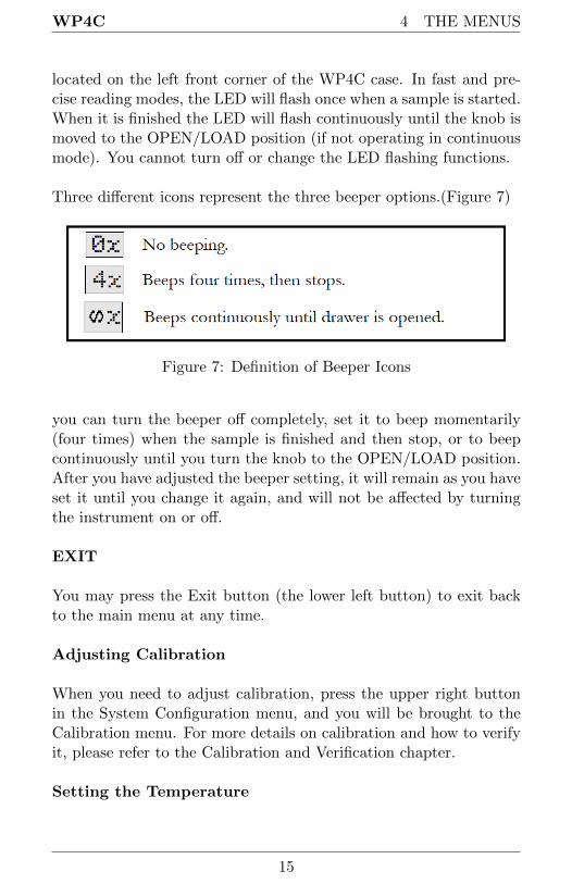
Three different icons represent the three beeper options.(Figure 7)
Figure 7: Definition of Beeper Icons
you can turn the beeper off completely, set it to beep momentarily(four times) when the sample is finished and then stop, or to beepcontinuously until you turn the knob to the OPEN/LOAD position.After you have adjusted the beeper setting, it will remain as you haveset it until you change it again, and will not be affected by turningthe instrument on or off.
EXIT
You may press the Exit button (the lower left button) to exit backto the main menu at any time.
Adjusting Calibration
When you need to adjust calibration, press the upper right buttonin the System Configuration menu, and you will be brought to theCalibration menu. For more details on calibration and how to verifyit, please refer to the Calibration and Verification chapter.
Setting the Temperature
15
4 THE MENUS WP4C
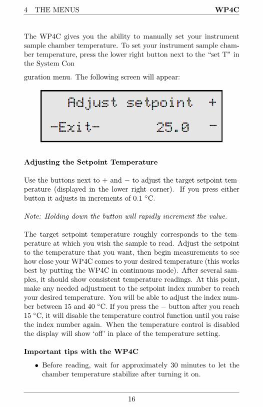
The WP4C gives you the ability to manually set your instrumentsample chamber temperature. To set your instrument sample cham-ber temperature, press the lower right button next to the “set T” inthe System Con
guration menu. The following screen will appear:
Adjusting the Setpoint Temperature
Use the buttons next to + and − to adjust the target setpoint tem-perature (displayed in the lower right corner). If you press eitherbutton it adjusts in increments of 0.1 ◦C.
Note: Holding down the button will rapidly increment the value.
The target setpoint temperature roughly corresponds to the tem-perature at which you wish the sample to read. Adjust the setpointto the temperature that you want, then begin measurements to seehow close your WP4C comes to your desired temperature (this worksbest by putting the WP4C in continuous mode). After several sam-ples, it should show consistent temperature readings. At this point,make any needed adjustment to the setpoint index number to reachyour desired temperature. You will be able to adjust the index num-ber between 15 and 40 ◦C. If you press the − button after you reach15 ◦C, it will disable the temperature control function until you raisethe index number again. When the temperature control is disabledthe display will show ‘off’ in place of the temperature setting.
Important tips with the WP4C
• Before reading, wait for approximately 30 minutes to let thechamber temperature stabilize after turning it on.
16
WP4C 4 THE MENUS
• Cool samples to a temperature slightly below chamber temper-ature before starting a reading.
• For slow equilibration samples, such as plant and moist soilsamples (> −0.5 MPa), precise reading mode may yield smallerrors. For these types of samples, We recommend you usecontinuous mode and log data over time (See Chapter 8) todetermine when equilibrium conditions are reached.
• For samples with very little water holding capacity (i.e. drysand samples), small leaks in the sample chamber can causewater potential to drift down over time. Fast mode is recom-mended for these samples.
• For best results, run most soil samples in precise mode for bestresults.
• Never place a hot or warm sample in a cooled chamber, becausecondensation will form inside the chamber, causing errors inreading.
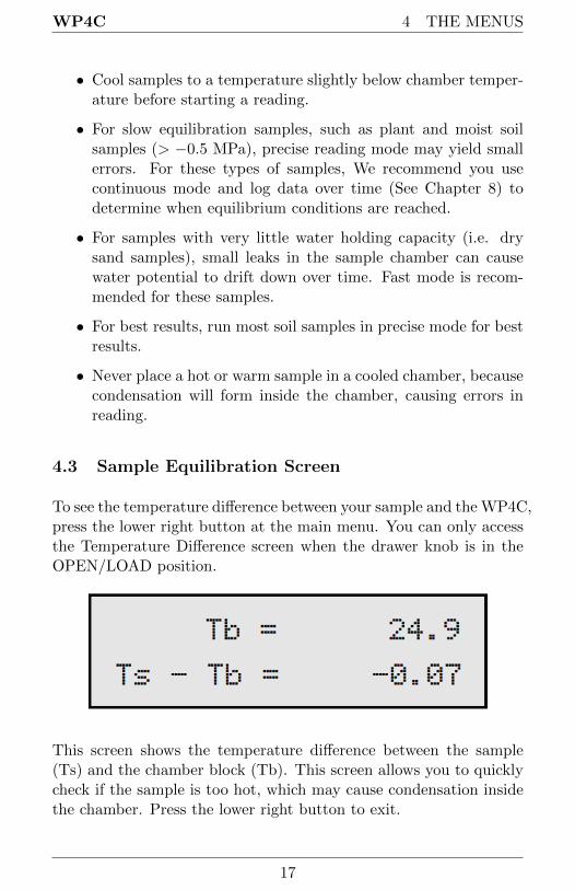
4.3 Sample Equilibration Screen
To see the temperature difference between your sample and the WP4C,press the lower right button at the main menu. You can only accessthe Temperature Difference screen when the drawer knob is in theOPEN/LOAD position.
This screen shows the temperature difference between the sample(Ts) and the chamber block (Tb). This screen allows you to quicklycheck if the sample is too hot, which may cause condensation insidethe chamber. Press the lower right button to exit.
17

4 THE MENUS WP4C
Note:) It is important that Ts−Tb is negative in order to preventcondensation inside the sample chamber.
18

WP4C 5 CALIBRATION AND VERIFICATION
5 Calibration and Verification
5.1 Verification
The WP4C uses the chilled mirror dew point technique for mea-suring water potential. This is the primary measurement method,though instrument cleanliness can affect the calibration. We fix thecalibration slope during factory calibration. The user can adjust thezero offset and calibrate successfully with any solution of known wa-ter potential. We recommend using the 0.5 mol/kg KCl verificationstandard available from METER.
5.2 Verification Standards
Verification standards are specially prepared salt solutions that havea specific molality and water potential. The potassium chloride (KCl)verification standards are accurate, easy to use, and readily availablefrom METER. Most importantly, they greatly reduce preparationerrors.
The standards are produced under a strict quality assurance regimeand are shelf stable for one year. If for some reason you cannot obtainMETER’s verification standards and need to make a salt solution forverification, refer to Appendix A.
Note: To avoid inaccurate water activity readings, verification stan-dards should be used once immediately after opening and not storedin sample cups for repeated use.
5.3 When to Verify Calibration
The calibration of your WP4C should be checked with the KCl stan-dard before each use. It can also be checked by measuring distilledwater, but this is often not a good choice for checking calibration.When using distilled water, the humidity of the chamber approaches100% which can cause condensation to occur if the sample is warmerthan the chamber. For batch processing, you should regularly check
19
5 CALIBRATION AND VERIFICATION WP4C
the instrument against the KCl standard. This will alert you to thepossibility of contamination of the unit or shifts in the calibrationfrom other causes.
5.4 How to Verify and Calibrate the WP4C
Since errors in the calibration value result in errors in all values sub-sequently measured, care should be taken to do it right.
Checking and Adjusting Calibration
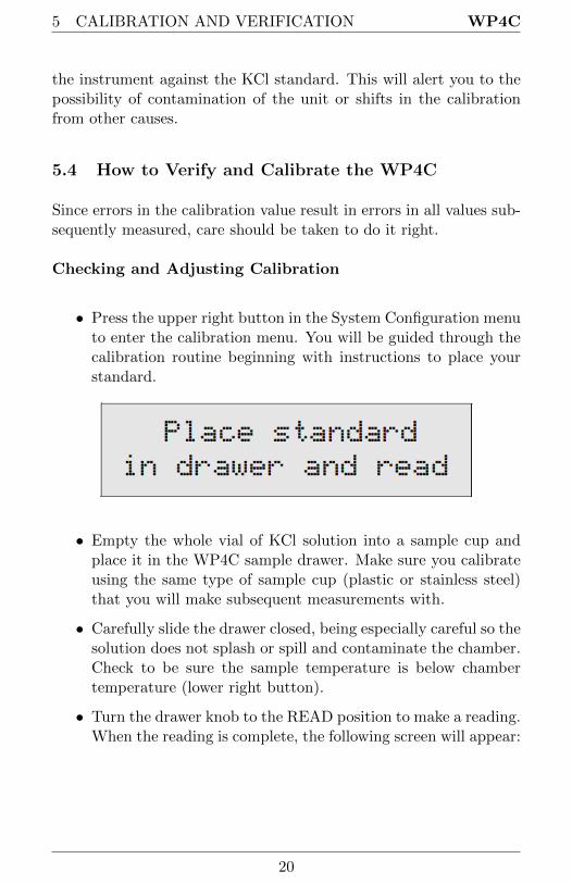
• Press the upper right button in the System Configuration menuto enter the calibration menu. You will be guided through thecalibration routine beginning with instructions to place yourstandard.
• Empty the whole vial of KCl solution into a sample cup andplace it in the WP4C sample drawer. Make sure you calibrateusing the same type of sample cup (plastic or stainless steel)that you will make subsequent measurements with.
• Carefully slide the drawer closed, being especially careful so thesolution does not splash or spill and contaminate the chamber.Check to be sure the sample temperature is below chambertemperature (lower right button).
• Turn the drawer knob to the READ position to make a reading.When the reading is complete, the following screen will appear:
20
WP4C 5 CALIBRATION AND VERIFICATION
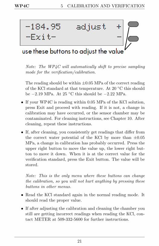
Note: The WP4C will automatically shift to precise samplingmode for the verification/calibration.
The reading should be within ±0.05 MPa of the correct readingof the KCl standard at that temperature. At 20 ◦C this shouldbe −2.19 MPa. At 25 ◦C this should be −2.22 MPa.
• If your WP4C is reading within 0.05 MPa of the KCl solution,press Exit and proceed with reading. If it is not, a change incalibration may have occurred, or the sensor chamber may becontaminated. For cleaning instructions, see Chapter 10. Aftercleaning, repeat these instructions.
• If, after cleaning, you consistently get readings that differ fromthe correct water potential of the KCl by more than ±0.05MPa, a change in calibration has probably occurred. Press theupper right button to move the value up, the lower right but-ton to move it down. When it is at the correct value for theverification standard, press the Exit button. The value will bestored.
Note: This is the only menu where these buttons can changethe calibration, so you will not hurt anything by pressing thesebuttons in other menus.
• Read the KCl standard again in the normal reading mode. Itshould read the proper value.
• If after adjusting the calibration and cleaning the chamber youstill are getting incorrect readings when reading the KCl, con-tact METER at 509-332-5600 for further instructions.
21

6 SAMPLE PREPARATION WP4C
6 Sample Preparation
Your WP4C will continually provide accurate water potential mea-surements as long as its internal sensors are not contaminated. Care-ful preparation and loading of samples will lengthen time betweencleanings and will help you avoid downtime and repairs.
6.1 Choosing a Sample Cup
The WP4C comes with two types of samples cups: disposable plas-tic cups and stainless steel cups. The disposable plastic cups areadequate for most samples, but are not good for samples in the wetend. If you are measuring samples with water potential wetter than−1 MPa, you should use the stainless steel sample cups. You canalso oven dry soil samples directly in the stainless steel cups to de-termine water content gravimetrically, which is convenient if you aregenerating soil moisture characteristic curves. It is important tonote that you must thoroughly clean the stainless steel cups usingdeionized water between uses to prevent solutes from contaminatingsubsequent samples and causing artificially negative osmotic poten-tial. Finally, if you calibrate the WP4C (see chapter 5), be sure tocalibrate using the same type of sample cup that you intend to usefor subsequent measurements.
6.2 Preparing the Sample
First, place the sample in a disposable sample cup, completely cov-ering the bottom of the cup, if possible.WP4C may not be able toaccurately measure a sample that does not (or cannot) cover thebottom of the cup. A larger sample surface area speeds up the read-ing by shortening the time needed to reach vapor equilibrium. Italso increases instrument accuracy by providing more stable infraredsample temperature measurements.
Do not fill the sample cup more than half full. Overfilled cups maycontaminate the sensors in the chamber, remember more is not nec-essarily better.
22
WP4C 6 SAMPLE PREPARATION
Make sure that the rim and outside of the sample cup are clean.Wipe any excess sample material from the rim of the cup with a cleantissue. Material left on the rim or the outside of the cup will con-taminate the sensor chamber and will be transferred to subsequentsamples. The rim of the cup forms a vapor seal with the sensor blockwhen the drawer knob is turned to the READ position. Therefore,any sample material left on the cup rim will be transferred to theblock, preventing this seal and contaminating future samples.
If a sample will be read at some future time, put the sample cupdisposable lid on the cup to restrict water transfer. For short-termstorage (< 3 hours) the cup lid is acceptable. If it will be a long timebefore the measurement is made, seal the lid with tape or Parafilm R©
completely around the cup and lid junction.
6.3 Dry Samples
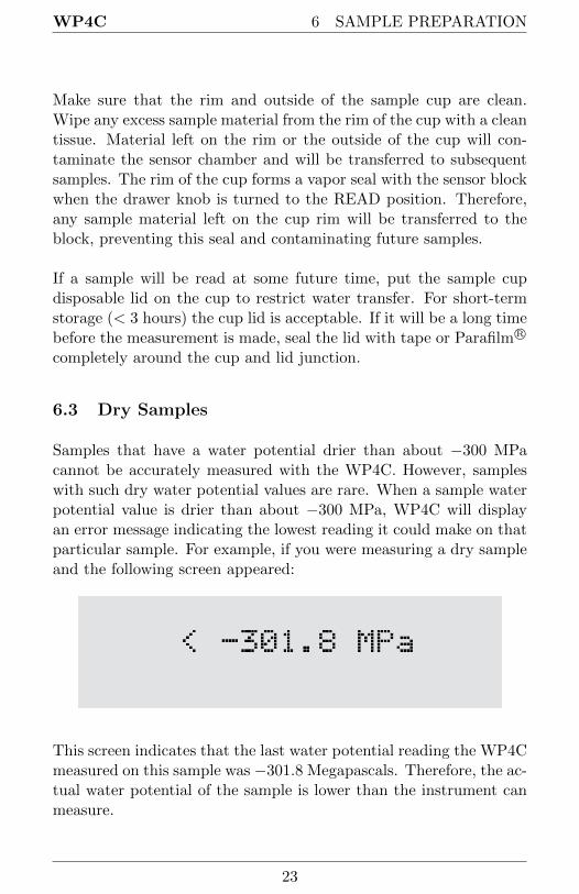
Samples that have a water potential drier than about −300 MPacannot be accurately measured with the WP4C. However, sampleswith such dry water potential values are rare. When a sample waterpotential value is drier than about −300 MPa, WP4C will displayan error message indicating the lowest reading it could make on thatparticular sample. For example, if you were measuring a dry sampleand the following screen appeared:
This screen indicates that the last water potential reading the WP4Cmeasured on this sample was −301.8 Megapascals. Therefore, the ac-tual water potential of the sample is lower than the instrument canmeasure.
23

6 SAMPLE PREPARATION WP4C
6.4 Samples and Temperature
If samples are warmer than the chamber when they are placed in it(Ts-Tb is a positive number), condensation may occur and moisturemay condense inside the block. In order to prevent this, follow steps1 and 2.
1. Place your sample in the chamber, slide the drawer closed andpress the lower right button to access the sample temperaturescreen and look at the temperature difference. If the sampletemperature is shown to be a positive number, take the sampleout immediately and let it cool on a cold surface with the cuplid on it to preserve the moisture. Do not cool the sample toomuch, or the equilibrium time will be lengthened (ideally theTs-Tb will be between −0.5 and 0).
2. After cooling it for a minute or so, place the sample back inand note the temperature difference. If it is close enough tothe block temperature, turn the knob to the READ position tobegin reading.
There is a linear relationship between the sample dew point temper-ature and its water potential. The dew point decreases −0.12 ◦Cper MPa. For example, a very dry sample at −40 MPa can be 4.8◦C (−.12 ∗ −40) above the chamber temperature without condens-ing. A sample at −1 MPa (fairly dry for most soils) can be 0.12 ◦Cabove the chamber temperature without condensing. Therefore, ifyou know the general range of your sample water potential, you cangauge at which temperature it will condense moisture. For samplesthat are more than 1 ◦C below chamber temperature, the WP4Cwaits until their temperature increases to 1 ◦C below chamber tem-perature to start a reading. Readings are therefore sped up if sampletemperature is just a little below chamber temperature.
24
WP4C 6 SAMPLE PREPARATION
6.5 Measuring Plant Samples
The WP4C can be used to measure the water potential of leavesand plant material. Please refer to the application note: Measure-ment of Leaf Water Potential Using the WP4, which can be foundat www.metergroup.com.
6.6 Taking a Reading
Once you have prepared your sample, you are ready to take readings.Follow steps 1 through 5 to take readings.
1. Turn the sample drawer knob to the OPEN/LOAD positionand pull the drawer open.
2. Place your prepared sample in the drawer. Check the top lipof the cup to make sure it is free from sample residue (remem-ber, an over-filled sample cup will contaminate the chambersensors).
3. Carefully slide the drawer closed, being especially careful if youhave a liquid sample that may splash or spill and contaminatethe chamber.
4. Access the sample temperature menu (press lower right button)to watch the temperature difference between the sample andthe instrument.
5. Turn the sample drawer knob to the READ position to seal thesample cup with the chamber. The instrument will beep once,and the green light will flash once to indicate that the readingcycle has started. In about 40 seconds, the first measurementwill be displayed.
6.7 How WP4C takes Readings
The WP4C cooled mirror is controlled at the chamber dew pointand its temperature is measured.. When the instrument has finishedits read cycle, the water potential is displayed, accompanied by theLED flash and beeper (if you have the beeper enabled).
25

6 SAMPLE PREPARATION WP4C
Cautions
• Never leave a sample in your WP4C after a reading hasfinished. The sample may spill and contaminate theinstrument chamber if the instrument is accidentallymoved or jolted.
• Never try to move your instrument after loading a sam-ple. Movement may cause the sample material to spilland contaminate the sample chamber.
• Take special care not to move the sample drawer tooquickly when loading or unloading liquid samples, inorder to avoid spilling.
• If a sample has a temperature that is higher than theWP4C chamber (Ts-Tb is a positive number), take thesample out immediately, put a cap on it, and cool it.Warm samples can cause condensation in the chamberand adversely affect subsequent readings.
• The physical temperature of the instrument should bebetween 5 ◦C and 40 ◦C. The WP4C will measure sam-ples between this range quickly and accurately.
• If you are reading and a triangular warning symbolappears in the top right corner of the display, this in-dicates that the mirror has become too dirty to giveaccurate measurements. You will need to clean themirror and chamber before continuing to sample. Formore details about this symbol, please refer to Chapter12. For cleaning instructions, refer to Chapter 10.
26
WP4C 7 COMPUTER INTERFACE
7 Computer Interface
Your WP4C comes with a RS-232 to USB Serial cable. Using thiscable, you can connect to your WP4C and send water activity datato a computer for further analysis and storage. The interface is runthrough the AquaLink 4 Software or a terminal communication pro-gram.
Note: If you computer does not have a USB port, you can use aUSB to RS-232 adapter.
7.1 AquaLink 4 Software
An optional software program, AquaLink 4, is available for use withyour WP4C. AquaLink 4 is a Windows based program designed fordata collection and customized report generation. AquaLink 4 logswater activity, temperature, time of measurement, and date stampsalong with other information. AquaLink 4 also has sample identi-fication and comment fields that you can use to help annotate thedata your WP4C is gathering.
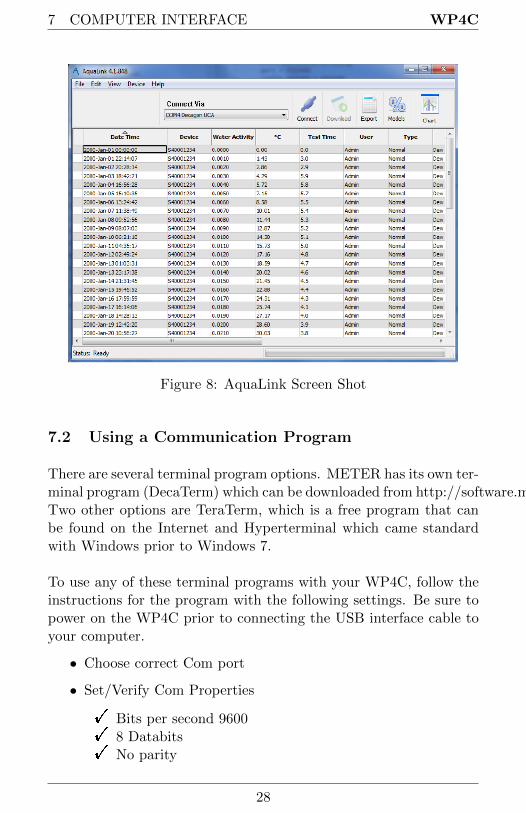
A 30 day trial USB of this program is attached to the front cover ofthis manual. If you are interested in purchasing a license of AquaLink4, contact METER or your local distributor. On the next page is asample picture of the AquaLink 4 program:
27
7 COMPUTER INTERFACE WP4C
Figure 8: AquaLink Screen Shot
7.2 Using a Communication Program
There are several terminal program options. METER has its own ter-minal program (DecaTerm) which can be downloaded from http://software.metergroup.com/DecaTerm.zip.Two other options are TeraTerm, which is a free program that canbe found on the Internet and Hyperterminal which came standardwith Windows prior to Windows 7.
To use any of these terminal programs with your WP4C, follow theinstructions for the program with the following settings. Be sure topower on the WP4C prior to connecting the USB interface cable toyour computer.
• Choose correct Com port
• Set/Verify Com Properties
! Bits per second 9600! 8 Databits! No parity
28
WP4C 7 COMPUTER INTERFACE
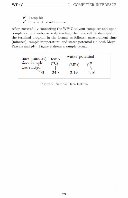
! 1 stop bit! Flow control set to none
After successfully connecting the WP4C to your computer and uponcompletion of a water activity reading, the data will be displayed inthe terminal program in the format as follows: measurement time(minutes), sample temperature, and water potential (in both Mega-Pascals and pF). Figure 9 shows a sample return.
Figure 9: Sample Data Return
29

8 THEORY: WATER POTENTIAL WP4C
8 Theory: Water Potential
8.1 Water Potential
Water potential is defined as the potential energy per unit volume ofwater in a sample. The total water potential of a sample is the sum offour component potentials: gravitational, matric, osmotic, and pres-sure. Gravitational potential depends on the position of the waterin a gravitational field. Matric potential depends on the adsorptiveforces binding water to a matrix. Osmotic potential depends on theconcentration of dissolved substance in the water. Pressure potentialdepends on the hydrostatic or pneumatic pressure on the water.
The WP4C measures the sum of the osmotic and matric potentials ina sample. Often one or the other of these potentials will be the domi-nant factor in determining the total potential. For example, solutionslike the KCl calibration standard have only an osmotic component.Soils bind water mainly through matric forces, and therefore havemainly a matric component (though salt-affected soils can have asignificant osmotic component).
8.2 Measuring Water Potential
The water potential of a solid or liquid sample can be found byrelating the sample water potential reading to the vapor pressure ofair in equilibrium with the sample. The relation ship between thesample water potential (Ψ) and the vapor pressure of the air is:
Ψ =RT
M∗ ln
p
po(1)
where p is the vapor pressure of the air, po is the saturation vaporpressure at sample temperature, R is the gas constant (8.31 J/molK), T is the Kelvin temperature of the sample, and M is the molec-ular mass of water. The vapor pressure of the air can be measuredusing a chilled mirror, and po is computed from sample temperature.
The WP4C measures water potential by equilibrating the liquidphase water of the sample with the vapor phase water in the headspace
30
WP4C 8 THEORY: WATER POTENTIAL
of a closed chamber, then measuring the vapor pressure of thatheadspace. In the WP4C, a sample is placed in a sample cup, whichis sealed against a sensor block. Inside the sensor block is a fan, adew point sensor, a temperature sensor, and an infrared thermome-ter. The dew point sensor measures the dew point temperature ofthe air, and the infrared thermometer measures the sample temper-ature. The purpose of the fan is to speed equilibrium and to controlthe boundary layer conductance of the dew point sensor.
From these measurements, the WP4C computes the vapor pressureof the air in the headspace as the saturation vapor pressure at dewpoint temperature. When the water potential of the sample and theheadspace air are in equilibrium, the measurement of the headspacevapor pressure and sample temperature (from which saturation va-por pressure is calculated) gives the water potential of the sample.
In addition to equilibrium between the liquid phase water in thesample and the vapor phase, the internal equilibrium of the sampleitself is important. If the sample is not at internal equilibrium, onemight measure a steady vapor pressure (over the period of measure-ment) which is not the true water potential of the sample.
8.3 Effect of Temperature on Water Potential
Temperature plays a critical role in water potential determinations.Most critical is the measurement of the difference between sampleand dew point temperature. If this temperature difference were inerror by 1 ◦C, an error of 8 MPa would result. In order for waterpotential measurements to be accurate to 0.05 MPa, temperaturedifference measurements need to be accurate to 0.006 ◦C.
The WP4C infrared thermometer measures the difference in tem-perature between the sample and the block. It is carefully calibratedto minimize temperature errors, but achieving 0.006 ◦C accuracy isdifficult when temperature differences are large. Best accuracy istherefore obtained when the sample is near chamber temperature.
Another effect of temperature on water potential occurs with samples
31

8 THEORY: WATER POTENTIAL WP4C
that are near saturation (like many soil samples). A sample that isclose to 0.00 MPa and is only slightly warmer than the sensor blockwill condense water within the block. This will cause errors in themeasurement, and in subsequent measurements until the condensa-tion disappears. The Ts-Tb function helps the user ensure that thesample will not condense on the sensor block.
8.4 Estimating Osmotic Potential
The WP4C measures the sum of osmotic and matric potential. Anapproximate value for the osmotic potential can be found by mea-suring the electrical conductivity (EC) of the saturation extract ofthe soil. The osmotic potential of the saturation extract is computedfrom:
Ψos(MPa) = −0.036EC(dS/m) (2)
The osmotic component of the water potential is then computedfrom:
Ψ = Ψos(θsθ
) (3)
where θ is the volumetric water content of the sample and θs is thevolumetric water content at saturation. The matric potential is thetotal potential minus the osmotic.
32
WP4C 9 CLEANING AND MAINTENANCE
9 Cleaning and Maintenance
The accuracy of your WP4C is vitally dependent on keeping yourinstrument clean. Dust and sample debris can contaminate the sam-pling chamber and must therefore be regularly cleaned out. To cleanyour instrument, carefully follow these instructions. Your instru-ment ships with a cleaning kit that should last one year with regularcleanings. METER has additional cleaning kits available for pur-chase with supplies to clean your WP4C.
Note: Kimwipe R© are included in the WP4C Cleaning Kit. They areideal for cleaning because they do not leave much of a lint residuelike most tissues. They also do not have any other compounds in thetissue that may contaminate the sensors in the WP4C block. Neveruse cotton swabs to clean the block sensors. Most cotton swabs con-tain adhesives and other compounds that are released and transferredto the mirror and other surfaces, contaminating them.
9.1 Accessing the Block
1. Unplug your WP4C
2. Remove the case lid screw located on the back panel. Carefullyremove the lid by pulling the back of the lid upward and thensliding the lid back (away from the front of the case) and off.
3. Unscrew the two thumbscrews that secure the sensor block.
4. Unplug the cable with the 20-pin socket that attaches the blockto the main circuit board by releasing the two locking leversthat are on either side of the socket.
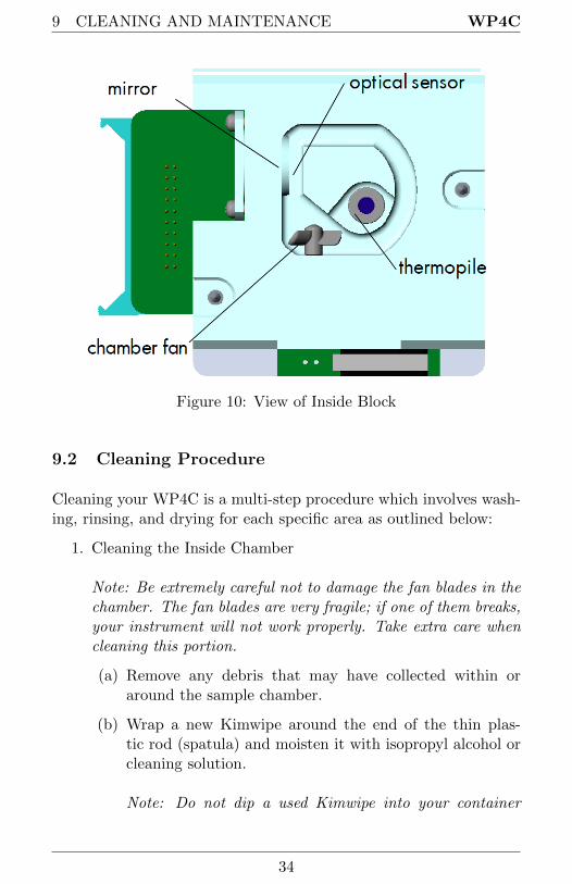
5. Carefully lift the block straight up from its mount. Turn theblock over to expose the chamber cavity as shown in the illus-tration:
33
9 CLEANING AND MAINTENANCE WP4C
Figure 10: View of Inside Block
9.2 Cleaning Procedure
Cleaning your WP4C is a multi-step procedure which involves wash-ing, rinsing, and drying for each specific area as outlined below:
1. Cleaning the Inside Chamber
Note: Be extremely careful not to damage the fan blades in thechamber. The fan blades are very fragile; if one of them breaks,your instrument will not work properly. Take extra care whencleaning this portion.
(a) Remove any debris that may have collected within oraround the sample chamber.
(b) Wrap a new Kimwipe around the end of the thin plas-tic rod (spatula) and moisten it with isopropyl alcohol orcleaning solution.
Note: Do not dip a used Kimwipe into your container
34
WP4C 9 CLEANING AND MAINTENANCE
of IPA or cleaning solution (the IPA or cleaning solutionwill become contaminated).
(c) WASH–Clean all surface edges of the samples chamber in-cluding the edge where the sample cup seals to the cham-ber block. You may need to replace the Kimwipe if itbecomes too dirty during this process.
(d) RINSE–Repeat steps b and c using new Kimwipes withdeionized water.
(e) DRY–Repeat steps b and c using new, dry Kimwipes tohelp remove any moisture remaining from the cleaning.
(f) Visually inspect the sample chamber for cleanliness. Cleanagain if necessary.
Note: Do not reuse Kimwipes.
2. Cleaning the Mirror
Note: Wash hands with soap and water (to prevent oils fromcontaminating the Kimwipe tissue and being transferred to themirror).
(a) Wrap a NEW Kimwipe around the end of the thin plas-tic rod (spatula) and moisten it with isopropyl alcohol orcleaning solution.
(b) WASH–Carefully clean the mirror with the moist Kimwipe.
(c) RINSE–Repeat steps b and c using new Kimwipes withdeionized water.
(d) DRY–Repeat steps b and c using new, dry Kimwipes tohelp remove any moisture remaining from the cleaning.
(e) Visually inspect the mirror for cleanliness. Re-clean ifnecessary. Note: Do not reuse Kimwipes.
3. Cleaning the Optical Sensor
You will probably clean the optical sensor while you are clean-ing the mirror, since they face each other in a very small gap.
35
9 CLEANING AND MAINTENANCE WP4C
Clean it in the same manner as described above for the mirror.
4. Cleaning the Thermopile
(a) Wrap a new Kimwipe around the end of the thin plas-tic rod (spatula) and moisten it with isopropyl alcohol orcleaning solution.
(b) WASH–Swipe the moistened Kimwipe across thermopile.(A single swipe is usually sufficient to remove contami-nants.)
(c) RINSE–Repeat steps a-b using new Kimwipes moistenedwith deionized water instead of cleaning solution.
(d) DRY–Repeat steps a-b but use a new, dry Kimwipe tohelp remove any moisture remaining from the cleaning.
(e) Visually inspect the thermopile for cleanliness. This sen-sor must be free of all dirt and lint. Re-clean if necessary.
5. Inside Case
(a) Clean the sample drawer and drawer base as describedabove for the thermopile. Remove any debris that mayhave collected inside the case.
(b) Check once more to make sure there is no contaminationof the sample chamber cavity.
(c) Replace the block, and insert the ribbon cable socket intoto the 20-pin plug on the block. Lock it in place with thelocking levers.
(d) Screw the thumb-screws on the block back in until theyare hand-tight.
(e) Replace the case lid and secure the lid screw.
6. Connect the WP4C power cord.
36
WP4C 9 CLEANING AND MAINTENANCE
9.3 Checking Calibration
After you have cleaned the chamber and other parts of your WP4C, itis important to check the instrument performance in order to correctfor any calibration change that may have occurred during cleaningprocedures.
Check the calibration of your instrument by measuring the waterpotential of the KCl standard. If a change has occurred, refer tochapter 5 for directions on how to recalibrate. If, after adjustingcalibration your instrument is still not reading samples correctly,contact METER for technical support.
37

10 REPAIR INSTRUCTIONS WP4C
10 Repair Instructions
If your WP4C ever needs to be sent in for service or repair, call ME-TER at 509-332-5600 or fax us at 509-332-5158. We will ask you foryour address, phone number, and serial number. For non-warrantyrepairs, we will also ask for a payment method (such as a purchaseorder or credit card number), a repair budget, and billing address.
Note: If you purchased your WP4C from one of our internationaldistributors, please contact them before contacting METER. Theymay be able to provide you with local service and help you remedythe problem.
10.1 Shipping Directions
When you ship your instrument back to us, please include with it adocument with the complete shipping address, name and departmentof the person responsible for the instrument, and (most importantly)a description of the problem. This information will better help ourtechnicians and our shipping department to expedite repair on yourinstrument and ship it back to you in good time.
All WP4Cs returning to METER for servicing must be accompa-nied with a Return Material Authorization (RMA) form. Prior toshipping the instrument, please contact a METER customer supportrepresentative to obtain an RMA.
Follow steps 1 through 6 to successfully and safely ship your in-strument back to us.
1. If possible, ship your WP4C back in its original cardboard boxwith foam inserts. If this is not possible, use a box that hasat least four inches of space between your instrument and eachwall of the box. If you are not using the foam inserts, packthe box moderately tight with packing material, like styrofoampeanuts
2. Put your instrument in a plastic bag to avoid disfiguring marksfrom the packaging.
38
WP4C 10 REPAIR INSTRUCTIONS
3. Do not ship your WP4C to us with the power cord; we haveplenty here to use with your instrument, and it may damagethe instrument in shipment.
4. Please review the RMA form and verify the ship to and bill toinformation, contact name, and problem description. If any-thing is incorrect, please contact a METER representative.
5. Tape the box in both directions so it will not break open inshipment.
6. Include the RMA number in the attention line on the shippinglabel.
Ship to:METER Group, Inc.ATTN: RMA (insert your RMA #)2365 NE Hopkins CourtPullman, WA 99163
10.2 Repair Costs
Manufacturers defects and instruments within the one-year warrantywill be repaired at no cost. For non-warranty repairs (includingcleanings for instruments in their warranty period), costs for parts,labor, and shipping will be billed to you. We have a minimum repaircharge, and an extra fee will be charged for rush work. METER willprovide an estimated repair cost, if requested.
10.3 Loaner Service
METER has loaner instruments to keep you measuring water activitywhile your instrument is being serviced. If your WP4C is still undercalibration warranty or you have a service plan with your instrument,there is no charge for the loaner service.
39
11 TROUBLESHOOTING WP4C
11 Troubleshooting
WP4C is a high performance instrument, designed to have low main-tenance and few problems if used with care. Unfortunately, some-times even the best operators using the best instruments encountertechnical difficulties. Here is a list of some problems that may oc-cur. If you have encountered a problem that is not addressed here,or if these remedies still do not resolve your problem, contact ME-TER at 509-332-5600 (for those outside the US). If purchased froma distributor, please contact the distributor for assistance first.
11.1 Problems and Solutions
The following table is a brief guide to help you quickly define so-lutions to your problems. For more detailed descriptions of theseproblems and their solutions, see the explanations below the table.
Table 1: Troubleshooting Quick Guide
If this problem occurs: Refer to:
WP4C does not turn on Problem #1Long Read Time Problem #2Readings on KCl standards are too high/low toadjust
Problem #3
Reading < −301.8 MPa Problem #4Triangle appears in upper right corner Problem #5“Block Failure” appears on screen after turning onWP4C
Problem #6
“Set T” option no longer appears on System Con-figuration menu
Problem #7
1. PROBLEMWP4C does not turn on.
SOLUTIONS:
40
WP4C 11 TROUBLESHOOTING
• Check to make sure your power cord is securely attached to theback of the instrument and the power outlet.
• A power sure may have caused a fuse to blow. Follow steps 1through 5 to change the fuses.
1. Unplug the power cord from the wall and the instrument.
2. Locate the panel where the power cord plugs in. The fusebox is on the right side of that panel. Press in on therelease tab and pull the fuse-holder out.
3. Pull the broken fuse(s) out and replace with a 2.0 Amp250 V fuse. Caution: Do not use any other kind of fuseor you will risk damage to your instrument and void yourwarranty.
4. Replace the fuse-holder and push it into the fuse-well untilthe release tab snaps into place.
5. Reconnect the power cord and turn your instrument on.If the fuse blows again, a failed component may be caus-ing the problem. Contact METER to make arrangementsfor repairs if your problem persists.
2. PROBLEM:Readings are slow or inconsistent.
SOLUTION:
• The sample chamber may be dirty. Refer to Chapter 10 of themanual for directions on cleaning the sample chamber.
• Some samples absorb or desorb moisture very slowly, causingmeasurements to take longer than usual, and nothing can bedone to speed up the process. Refer to Chapter 6 for furtherexplanation.
• The fan blade inside the block chamber may be broken. If eventhe KCl standard takes a long time to read, and the samplechamber is clean, you may have a broken or bent chamber
41
11 TROUBLESHOOTING WP4C
fan blade. This is especially likely if you have just cleanedthe chamber. If you suspect this may have happened, contactMETER for details on replacement.
3. PROBLEM:Water potential readings on KCl standards are too high or low anda calibration adjustment cannot be made any higher or lower.
SOLUTIONS:
• The thermopile in your chamber, which measures sample tem-perature, may have become contaminated. Refer to Chapter10 for directions on cleaning.
• If you are not using METER’s KCl verification standards, highreadings may indicate that the salt solution you are using isnot in equilibrium.
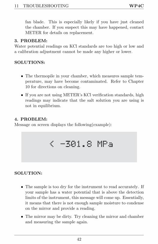
4. PROBLEM:Message on screen displays the following(example):
SOLUTION:
• The sample is too dry for the instrument to read accurately. Ifyour sample has a water potential that is above the detectionlimits of the instrument, this message will come up. Essentially,it means that there is not enough sample moisture to condenseon the mirror and provide a reading.
• The mirror may be dirty. Try cleaning the mirror and chamberand measuring the sample again.
42

WP4C 11 TROUBLESHOOTING
5. PROBLEM:A small triangle appears in the upper right corner after reading:
SOLUTION:
The mirror needs to be cleaned, along with the rest of the samplechamber, until it disappears. This triangle is a mirror performanceindicator. When the WP4C senses that the mirror performance hasdropped to unacceptable levels, it will display the triangular warningsign after measuring the sample. When this appears, you should stopsampling and clean the chamber. If the triangle is still on the screenafter cleaning, the mirror is most likely still dirty and you will needto clean it until the triangle disappears.
6. PROBLEM:“Block failure” message appears on screen.
SOLUTION:
• The block is not plugged in to the motherboard. Open thecase and check to make sure that the small ribbon cable thatconnects the block to the motherboard is snapped and lockedin place.
• One or more components has failed on the block circuit board.
43
11 TROUBLESHOOTING WP4C
If the block is properly plugged in to the motherboard and thismessage appears, it is likely that one or more of the compo-nents have failed on the block circuit board.
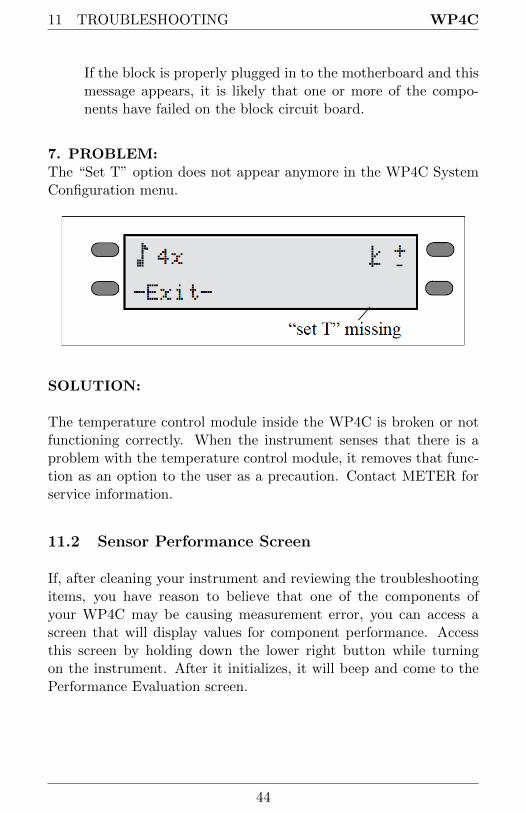
7. PROBLEM:The “Set T” option does not appear anymore in the WP4C SystemConfiguration menu.
SOLUTION:
The temperature control module inside the WP4C is broken or notfunctioning correctly. When the instrument senses that there is aproblem with the temperature control module, it removes that func-tion as an option to the user as a precaution. Contact METER forservice information.
11.2 Sensor Performance Screen
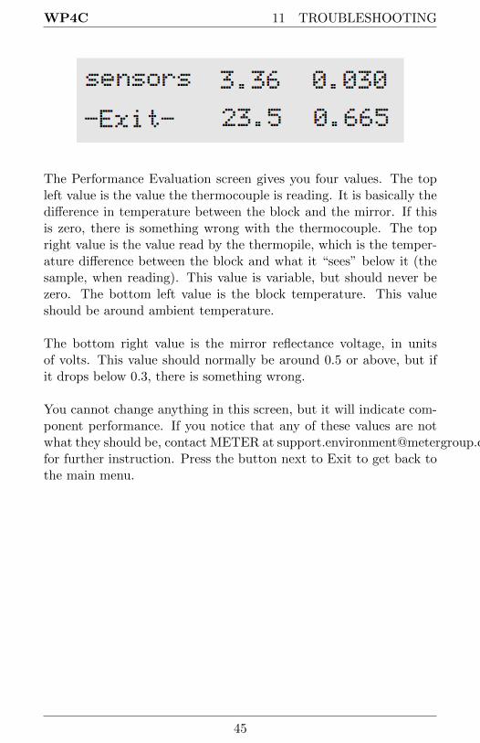
If, after cleaning your instrument and reviewing the troubleshootingitems, you have reason to believe that one of the components ofyour WP4C may be causing measurement error, you can access ascreen that will display values for component performance. Accessthis screen by holding down the lower right button while turningon the instrument. After it initializes, it will beep and come to thePerformance Evaluation screen.
44
WP4C 11 TROUBLESHOOTING
The Performance Evaluation screen gives you four values. The topleft value is the value the thermocouple is reading. It is basically thedifference in temperature between the block and the mirror. If thisis zero, there is something wrong with the thermocouple. The topright value is the value read by the thermopile, which is the temper-ature difference between the block and what it “sees” below it (thesample, when reading). This value is variable, but should never bezero. The bottom left value is the block temperature. This valueshould be around ambient temperature.
The bottom right value is the mirror reflectance voltage, in unitsof volts. This value should normally be around 0.5 or above, but ifit drops below 0.3, there is something wrong.
You cannot change anything in this screen, but it will indicate com-ponent performance. If you notice that any of these values are notwhat they should be, contact METER at [email protected] further instruction. Press the button next to Exit to get back tothe main menu.
45

12 FURTHER READING WP4C
12 Further Reading
References:
Brye, K.R., (2003). Long-term effects of cultivation on particle sizeand water-retention characteristics determined using wetting curves.Soil Science Society of America 168:7 459-468.
Campbell, E.C., G.S. Campbell, and W.K. Barlow., (1973). A dewpoint hygrometer for water potential measurement. Agric. Meteor.12:113-121.
G.W. Gee, M.D. Campbell, G.S. Campbell, and J.H. Campbell.,(1992). Rapid measurement of low soil water potentials using a wa-ter activity meter. Soil Science Society of America 56:4 1068-1070.
Papendick, R.I. and G.S. Campbell., (1980). Theory and measure-ment of water potential. in Water Potential Relations in Soil Micro-biology. Soil Science Society of America. Madison, Wisconsin. pp.1-22.
12.1 Application Notes
The following WP4C application notes are available from METERby request and from our website under the education tab, chooseWP4C.
• Generating a Soil Moisture Characteristic with the WP4C.
• Measuring Leaf Water Potential using the WP4C.
• Field Portability Instructions for the WP4C.
• Water Potential: The Key to Successful Seed Priming.
• Seed Longevity in Storage is Enhanced by Controlling WaterActivity.
46

WP4C 12 FURTHER READING
• Classification of Expansive Soils using the WP4C Dew pointPotentiaMeter
47
13 APPENDIX A WP4C
13 Appendix A
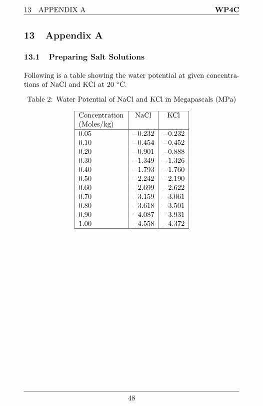
13.1 Preparing Salt Solutions
Following is a table showing the water potential at given concentra-tions of NaCl and KCl at 20 ◦C.
Table 2: Water Potential of NaCl and KCl in Megapascals (MPa)
Concentration(Moles/kg)
NaCl KCl
0.05 −0.232 −0.2320.10 −0.454 −0.4520.20 −0.901 −0.8880.30 −1.349 −1.3260.40 −1.793 −1.7600.50 −2.242 −2.1900.60 −2.699 −2.6220.70 −3.159 −3.0610.80 −3.618 −3.5010.90 −4.087 −3.9311.00 −4.558 −4.372
48
WP4C 14 APPENDIX B
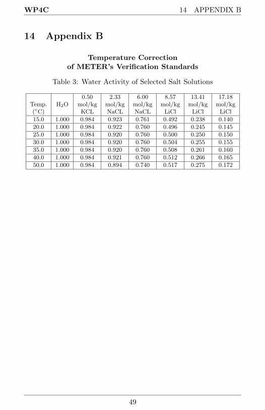
14 Appendix B
Temperature Correctionof METER’s Verification Standards
Table 3: Water Activity of Selected Salt Solutions
Temp. H2O0.50 2.33 6.00 8.57 13.41 17.18
(◦C)mol/kg mol/kg mol/kg mol/kg mol/kg mol/kgKCL NaCL NaCL LiCl LiCl LiCl
15.0 1.000 0.984 0.923 0.761 0.492 0.238 0.140
20.0 1.000 0.984 0.922 0.760 0.496 0.245 0.145
25.0 1.000 0.984 0.920 0.760 0.500 0.250 0.150
30.0 1.000 0.984 0.920 0.760 0.504 0.255 0.155
35.0 1.000 0.984 0.920 0.760 0.508 0.261 0.160
40.0 1.000 0.984 0.921 0.760 0.512 0.266 0.165
50.0 1.000 0.984 0.894 0.740 0.517 0.275 0.172
49

15 DECLARATION OF CONFORMITY WP4C
15 Declaration of Conformity
Application of Council Directive: 2004/108/EC and 2011/65/EU
Standards to which conformity isdeclared:
EN 61326-1:2013 and
EN 50581:2012
Manufacturer’s Name: METER Group, Inc 2365 NEHopkins Ct. Pullman, WA 99163USA
Type of Equipment: Dew Point PotentiaMeter
Model Number: WP4C
Year of First Manufacture: 2010
This is to certify that the Dew Point PotentiaMeter, manufactured byMETER Group, Inc., a corporation based in Pullman, Washington,USA meets or exceeds the standards for CE compliance as per theCouncil Directives noted above. All instruments are built at thefactory at METER and pertinent testing documentation is freelyavailable for verification.
50

WP4C 16 CERTIFICATE OF TRACEABILITY
16 Certificate of Traceability
METER Group, Inc.2365 NE Hopkins CourtPullman WA 99163 USA
Tel: 509-332-5600Fax: [email protected]
This NIST seal certifies that METER Group, Inc. manufactures allWP4C Dew Point PotentiaMeters according to temperature stan-dards with calibration traceable to the National Institute of Stan-dards and Technology (NIST).
51
Index
Accessories, 7Application Notes, 46AquaLink 4 Software, 27
Beeper, 14, 44Block Failure, 40, 43Block Sensors, 33Buttons
Menu Selection, 11
C for Continuous Mode, 13Calibration
Changes In, 19Checking, 37Drift, 19Menu, 15Steps, 20When to Check, 19
Cautions, 26CE Compliance, 50Certificate of Traceability, 51Chilled Mirror Technique, 5Cleaning, 33
Inside Case, 36Inside Chamber, 34Optical Sensor, 35Sensor Block, 33Thermopile, 36
Components, 7Computer Interface, 27Contact Information, 1Cotton Swabs
Not for Cleaning, 33Customer Support, 1
DecaTerm Program, 28
Declaration of Conformity, 50Dirty Mirror Indicator, 26Distilled Water, 19Dry Samples, 23, 42Dry Water Potential, 23
Email, 1, 51Error Messages, 40Exit, 15
FanInside Sample Chamber, 31
Fax Number, iiFeatures, 8Field Measurements, 9Further Reading, 46Fuse
Changing, 41
Gravitational Potential, 30
Hyperterminal, 28
KCl Standards, 19
LanguagesChanging, 11Czech, 11Danish, 11Finnish, 12French, 11German, 11Italian, 11Japanese, 11Norwegian, 11Polish, 11Portuguese, 11
52

WP4C INDEX
Spanish, 11Swedish, 11
LeafMeasuring Water Potential in
Continuous Mode, 13LED, 14, 44Linear Offset
Adjusting for, 20Loaner Service, 39Location
for Reading, 7
Main Menu, 8, 11Maintenance, 33Matric Potential, 30Menu
Main Menu, 11System Configuration, 14
MolalityVerification Standards, 19
Osmotic Potential, 30, 32
Peltier Cooler, 5Phone Number, iiPlant Samples, 25Portability, 9Preparing Salt Solutions, 48Pressure Potential, 30
Read TimeAffected by Sample Temper-
ature, 24Long, 40, 41
Reading Modes, 12Continuous, 13Fast, 13Precise, 12
ReadingsCautions, 26
How WP4C Takes, 25Taking Readings, 25
References, 46Repair
Costs, 39Instructions, 38Shipping, 38
SampleDry Water Potential, 23Not at Room Temperature,
24Preparation, 22Slow Water Emitting, 41Spilling, 26Too Dry, 42Too Hot, 26
Sample CupsCleaning, 22Filling, 22Sealing, 22
Sample Equilibration Screen, 17Saturated Salts, 48Seller’s Liability, 2Sensor Performance Screen, 44Specifications, 4
Technical Support, 1Temperature
Effect on Water Potential, 31Hot Samples, 26Impact on Readings, 6Instrument, 26Samples not at Room Tem-
perature, 24Setting, 15
Triangle, 40, 43Troubleshooting, 40
USB
53

INDEX WP4C
Driver, 28Interface Cable, 27
Vapor Pressure, 30, 31Verification Standards, 19
Long Read Times for, 42Water Potential too High/Low,
42
Warm-Up, 10Warranty, 2Water Content, 30
vs Water Potential, 30Water Potential, 30
Definition, 5Displayed, 8Equation, 30Measurement, 30Theory, 30
WP4Cand Temperature, 6Chilled Mirror Dew Point Tech-
nique, 5Important Tips, 16Measuring Water Potential, 30Preparing for Operation, 8Theory, 30
WP4C ReadingsCautions, 26
54