wr250 service manual
DESCRIPTION
Service manual for Yamaha WR250X WR250RTRANSCRIPT

SERVICE MANUAL
WR250RX(C)
2008
32C-28197-10
WR250XX(C)
LIT-11616-21-66


EAS20050
WR250RX(C)/WR250XX(C)SERVICE MANUAL
©2008 by Yamaha Motor Corporation, U.S.A.First edition, December 2007
All rights reserved.Any reproduction or unauthorized use
without the written permission of Yamaha Motor Corporation, U.S.A.
is expressly prohibited.Printed in U.S.A.
P/N LIT-11616-21-66

NOTICE
1-1
EAS20070
NOTICE
This manual was produced by the Yamaha Motor Company, Ltd. primarily for use by Yamaha dealersand their qualified mechanics. It is not possible to include all the knowledge of a mechanic in one man-ual. Therefore, anyone who uses this book to perform maintenance and repairs on Yamaha vehiclesshould have a basic understanding of mechanics and the techniques to repair these types of vehicles.Repair and maintenance work attempted by anyone without this knowledge is likely to render the vehi-cle unsafe and unfit for use.This model has been designed and manufactured to perform within certain specifications in regard toperformance and emissions. Proper service with the correct tools is necessary to ensure that the vehi-cle will operate as designed. If there is any question about a service procedure, it is imperative that youcontact a Yamaha dealer for any service information changes that apply to this model. This policy isintended to provide the customer with the most satisfaction from his vehicle and to conform to federalenvironmental quality objectives.Yamaha Motor Company, Ltd. is continually striving to improve all of its models. Modifications and sig-nificant changes in specifications or procedures will be forwarded to all authorized Yamaha dealers andwill appear in future editions of this manual where applicable.NOTE:
This Service Manual contains information regarding periodic maintenance to the emission controlsystem. Please read this material carefully.
Designs and specifications are subject to change without notice.
EAS20080
IMPORTANT MANUAL INFORMATION
Particularly important information is distinguished in this manual by the following.
The Safety Alert Symbol means ATTENTION! BECOME ALERT! YOUR SAFETY IS INVOLVED!
Failure to follow WARNING instructions could result in severe injury or death to the vehicle operator, a bystander or a person checking or repairing the vehicle.
A CAUTION indicates special precautions that must be taken to avoid damage to the vehicle.
A NOTE provides key information to make procedures easier or clearer.
WARNING
CAUTION:
NOTE:

HOW TO USE THIS MANUAL
1-2
EAS20090
HOW TO USE THIS MANUAL
This manual is intended as a handy, easy-to-read reference book for the mechanic. Comprehensiveexplanations of all installation, removal, disassembly, assembly, repair and check procedures are laidout with the individual steps in sequential order.
The manual is divided into chapters and each chapter is divided into sections. The current section titleis shown at the top of each page “1”.
Sub-section titles appear in smaller print than the section title “2”.
To help identify parts and clarify procedure steps, there are exploded diagrams at the start of eachremoval and disassembly section “3”.
Numbers are given in the order of the jobs in the exploded diagram. A number indicates a disassem-bly step “4”.
Symbols indicate parts to be lubricated or replaced “5”.Refer to “SYMBOLS”.
A job instruction chart accompanies the exploded diagram, providing the order of jobs, names ofparts, notes in jobs, etc “6”.
Jobs requiring more information (such as special tools and technical data) are described sequentially“7”.
3
4
5
6
7
1
2
SYMBOLS
1-3
EAS20100
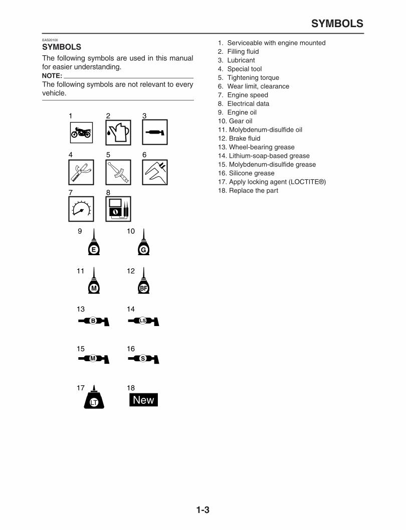
SYMBOLS
The following symbols are used in this manualfor easier understanding.NOTE:
The following symbols are not relevant to every
vehicle.
G
M
E
B LS
M
9 10
11 12
13 14
15 16
17 18
LT New
BF
S
T R..
1 2 3
4 5 6
7 8
1. Serviceable with engine mounted2. Filling fluid3. Lubricant4. Special tool5. Tightening torque6. Wear limit, clearance7. Engine speed8. Electrical data9. Engine oil10. Gear oil11. Molybdenum-disulfide oil12. Brake fluid13. Wheel-bearing grease14. Lithium-soap-based grease15. Molybdenum-disulfide grease16. Silicone grease17. Apply locking agent (LOCTITE®)18. Replace the part
GENERAL INFORMATION
1
SPECIFICATIONS
2
PERIODIC CHECKS ANDADJUSTMENTS
3
CHASSIS
4
ENGINE
5
COOLING SYSTEM
6
FUEL SYSTEM
7
ELECTRICAL SYSTEM
8
TROUBLESHOOTING
9
EAS20110
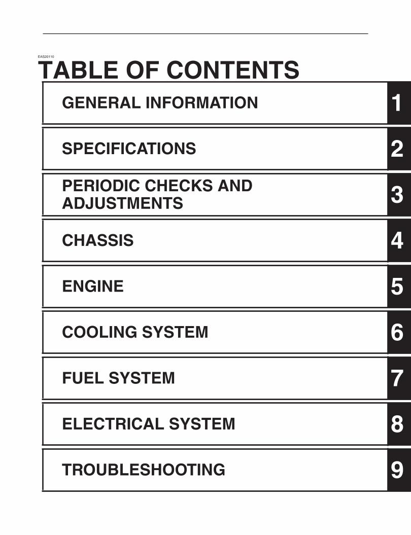
TABLE OF CONTENTS

1
2
3
4
5
6
7
8
9
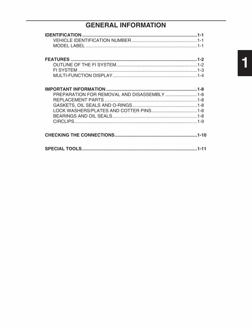
GENERAL INFORMATION
IDENTIFICATION ...........................................................................................1-1
VEHICLE IDENTIFICATION NUMBER....................................................1-1MODEL LABEL ........................................................................................1-1
FEATURES ....................................................................................................1-2
OUTLINE OF THE FI SYSTEM................................................................1-2FI SYSTEM ..............................................................................................1-3MULTI-FUNCTION DISPLAY...................................................................1-4
IMPORTANT INFORMATION ........................................................................1-8
PREPARATION FOR REMOVAL AND DISASSEMBLY .........................1-8REPLACEMENT PARTS .........................................................................1-8GASKETS, OIL SEALS AND O-RINGS...................................................1-8LOCK WASHERS/PLATES AND COTTER PINS....................................1-8BEARINGS AND OIL SEALS...................................................................1-8CIRCLIPS.................................................................................................1-9
CHECKING THE CONNECTIONS.................................................................1-10
SPECIAL TOOLS...........................................................................................1-11

IDENTIFICATION
1-1
EAS20130
IDENTIFICATION
EAS20140
VEHICLE IDENTIFICATION NUMBER
The vehicle identification number “1” is stampedinto the right side of the steering head pipe.
EAS20150
MODEL LABEL
The model label “1” is affixed to the frame. Thisinformation will be needed to order spare parts.
1
1

FEATURES
1-2
EAS20170
FEATURES
EAS32D1017
OUTLINE OF THE FI SYSTEM
The main function of a fuel supply system is to provide fuel to the combustion chamber at the optimumair-fuel ratio in accordance with the engine operating conditions and the atmospheric temperature. Inthe conventional carburetor system, the air-fuel ratio of the mixture that is supplied to the combustionchamber is created by the volume of the intake air and the fuel that is metered by the jet used in therespective carburetor.Despite the same volume of intake air, the fuel volume requirement varies by the engine operating con-ditions, such as acceleration, deceleration, or operating under a heavy load. Carburetors that meter thefuel through the use of jets have been provided with various auxiliary devices, so that an optimumair-fuel ratio can be achieved to accommodate the constant changes in the operating conditions of theengine.As the requirements for the engine to deliver more performance and cleaner exhaust gases increase,it becomes necessary to control the air-fuel ratio in a more precise and finely tuned manner. To accom-modate this need, this model has adopted an electronically controlled fuel injection (FI) system, in placeof the conventional carburetor system. This system can achieve an optimum air-fuel ratio required bythe engine at all times by using a microprocessor that regulates the fuel injection volume according tothe engine operating conditions detected by various sensors.The adoption of the FI system has resulted in a highly precise fuel supply, improved engine response,better fuel economy, and reduced exhaust emissions.
9
1 2 3 4 5 6 7 8
10
11121314
1. Engine trouble warning light2. Fuel pump3. Ignition coil4. Fuel injector5. Throttle position sensor6. Intake air pressure sensor 17. Battery8. Lean angle sensor9. ECU
10. Intake air temperature sensor11. EXUP servomotor12. Speed sensor13. Coolant temperature sensor14. Crankshaft position sensor

FEATURES
1-3
EAS32D1018
FI SYSTEM
The fuel pump delivers fuel to the fuel injector via the fuel filter. The pressure regulator is installed inthe fuel rail, and maintains the fuel pressure that is applied to the fuel injector at 245
–
255 kPa(34.8
–
36.3 psi) (2.45
–
2.55 kg/cm
2
). The fuel injector is operated due to signals from the ECU, and in-jects fuel into the intake manifold. Since fuel is supplied only for the duration of injection, good fueleconomy is obtained. The injection duration and the injection timing are controlled by the ECU. Signalsthat are input from the throttle position sensor, crankshaft position sensor, intake air pressure sensor,intake temperature sensor and coolant temperature sensor enable the ECU to determine the injectionduration. The injection timing is determined through the signals from the crankshaft position sensor. Asa result, the volume of fuel that is required by the engine can be supplied at all times in accordance withthe driving conditions.
1
10
9
B
8
7
6
5
A
2
3
C
4
11
1. Fuel pump2. Injector3. ECU4. Throttle position sensor5. Coolant temperature sensor6. Crankshaft position sensor7. Intake air pressure sensor8. Throttle bodies9. Intake air temperature sensor10. Air filter case11. Pulsation damper
A. Fuel systemB. Intake systemC. Control system

FEATURES
1-4
EAS32D1004
MULTI-FUNCTION DISPLAY
WARNING
EWA32D1008
Be sure to stop the vehicle before makingany setting changes to the multi-function
display.
NOTE:
The multi-function display can be set to the ba-sic mode or the measurement mode.
Tripmeter A will automatically reset to zerowhen changing from the basic mode to the
measurement mode or vice versa.
Basic mode:
a speedometer (which shows the riding speed)
an odometer (which shows the total distancetraveled)
two tripmeters (which show the distance trav-eled since they were last set to zero)
a fuel reserve tripmeter (which shows the dis-tance traveled since the fuel level warning lightcame on)
a clock
a self-diagnosis device
Measurement mode:
a speedometer (which shows the riding speed)
a distance-compensation tripmeter (whichshows the accumulated distance traveledsince set to zero and which can be calibratedto provide a more accurate tripmeter reading)
a stopwatch (which shows the time that hasbeen accumulated since the start of stopwatchmeasurement)
a self-diagnosis deviceNOTE:
Be sure to turn the key to “ON” before using the“SELECT 1”, “SELECT 2” and “RESET” but-tons.
When the key is turned to “ON”, all of the dis-play segments of the multi-function display willappear and then disappear, in order to test theelectrical circuit.
To switch the speedometer and odometer/tripmeter displays between kilometers andmiles, press the “SELECT 2” button until thedisplay changes after the main switch is turned
to “ON”.
Basic mode
Odometer and tripmeter modesPush the “SELECT 2” button to switch the dis-play between the odometer mode and thetripmeter modes A and B in the following order:odometer
→
tripmeter A
→
tripmeter B
→
odom-eter
1. “RESET” button2. “SELECT 1” button3. “SELECT 2” button4. Clock/stopwatch5. Speedometer6. Odometer/tripmeter/fuel reserve tripmeter
1. Stopwatch indicator “ ”2. Tripmeter A indicator “ ”/Distance-com-
pensation tripmeter “ ”3. Tripmeter B indicator “ ”
1 2 3 4
56
1
3
2
1. Tripmeter A indicator “ ”
1. Tripmeter B indicator “ ”
1
1

FEATURES
1-5
NOTE:
Indicator “ ” comes on when tripmeter A is se-lected, and indicator “ ” comes on when
tripmeter B is selected.
If the fuel level warning light comes on, the dis-play will automatically change to the fuel reservetripmeter mode “F” and start counting the dis-tance traveled from that point. In this case, pushthe “SELECT 2” button to switch the display be-tween the various tripmeter and odometermodes in the following order:fuel reserve tripmeter “F”
→
odometer
→
tripmeter A
→
tripmeter B
→
fuel reservetripmeter “F”NOTE:
The fuel level warning light may not function ac-curately while riding off road as the fuel levelreading changes due to the movement and incli-
nation of the vehicle.
If the fuel level warning light comes on whileriding in the measurement mode, change to thebasic mode and push the “SELECT 2” button todisplay the fuel reserve tripmeter.NOTE:
To change from the measurement mode to thebasic mode, the stopwatch and the dis-
tance-compensation tripmeter must be stopped.
To reset a tripmeter, select it by pushing the“SELECT 2” button, and then push the “RESET”button for at least one second. If you do not resetthe fuel reserve tripmeter manually, it will resetitself automatically and the display will return tothe prior mode after refueling and traveling 5 km(3 mi).ClockTurn the key to “ON”.NOTE:
When setting the clock, push the “SELECT 1”button to increase the digits or “SELECT 2” but-ton to decrease the digits. Pushing and holdingeither button will increase or decrease the digits
continuously until the button is released.
To set the clock1. Push the “SELECT 1” button for at least two
seconds.2. When the hour digits start flashing, push ei-
ther select button to set the hours.3. Push the “RESET” button, and the minute
digits will start flashing.4. Push either select button to set the minutes.5. Push the “RESET” button, and the second
digits will start flashing.6. Push either select button to set the second
digits to zero.7. Push the “RESET” button for at least two sec-
onds, and then release it to start the clock.NOTE:
If the “RESET” button is not pushed within 30seconds, the clock will not be set and will return
to the prior time.
Changing from the basic mode to the mea-surement mode
With the odometer selected, push the “SELECT1” button and “SELECT 2” button together for atleast two seconds to change to the measure-ment mode.
Changing from the measurement mode tothe basic modeNOTE:
The stopwatch must be stopped before chang-
ing to the basic mode.
1. Check that the stopwatch is not in operation.If the stopwatch is in operation, stop it bypushing the “SELECT 1” button and “SE-LECT 2” button together.
2. Push the “SELECT 1” button and “SELECT2” button together for at least two seconds tochange to the basic mode.
Measurement mode (for the stopwatch)
When the measurement mode is selected, thestopwatch is displayed and it can be startedmanually or automatically.Manual startThe manual start is the default setting for thestopwatch. The stopwatch indicator “ ” and thedistance-compensation tripmeter indicator “ ”will start flashing.
1. Fuel reserve tripmeter “F”
1
FEATURES
1-6
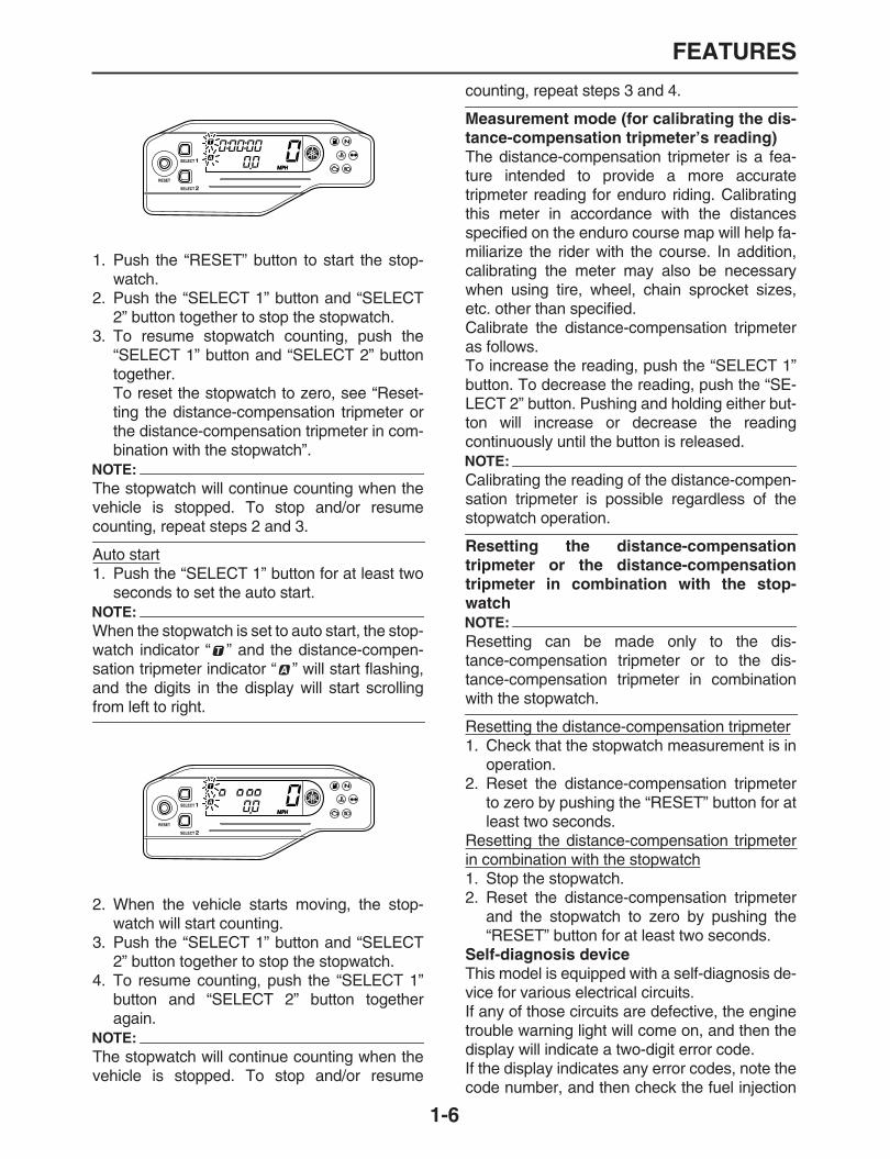
1. Push the “RESET” button to start the stop-watch.
2. Push the “SELECT 1” button and “SELECT2” button together to stop the stopwatch.
3. To resume stopwatch counting, push the“SELECT 1” button and “SELECT 2” buttontogether.To reset the stopwatch to zero, see “Reset-ting the distance-compensation tripmeter orthe distance-compensation tripmeter in com-bination with the stopwatch”.
NOTE:
The stopwatch will continue counting when thevehicle is stopped. To stop and/or resume
counting, repeat steps 2 and 3.
Auto start1. Push the “SELECT 1” button for at least two
seconds to set the auto start.NOTE:
When the stopwatch is set to auto start, the stop-watch indicator “ ” and the distance-compen-sation tripmeter indicator “ ” will start flashing,and the digits in the display will start scrolling
from left to right.
2. When the vehicle starts moving, the stop-watch will start counting.
3. Push the “SELECT 1” button and “SELECT2” button together to stop the stopwatch.
4. To resume counting, push the “SELECT 1”button and “SELECT 2” button togetheragain.
NOTE:
The stopwatch will continue counting when thevehicle is stopped. To stop and/or resume
counting, repeat steps 3 and 4.
Measurement mode (for calibrating the dis-tance-compensation tripmeter’s reading)
The distance-compensation tripmeter is a fea-ture intended to provide a more accuratetripmeter reading for enduro riding. Calibratingthis meter in accordance with the distancesspecified on the enduro course map will help fa-miliarize the rider with the course. In addition,calibrating the meter may also be necessarywhen using tire, wheel, chain sprocket sizes,etc. other than specified.Calibrate the distance-compensation tripmeteras follows.To increase the reading, push the “SELECT 1”button. To decrease the reading, push the “SE-LECT 2” button. Pushing and holding either but-ton will increase or decrease the readingcontinuously until the button is released.NOTE:
Calibrating the reading of the distance-compen-sation tripmeter is possible regardless of the
stopwatch operation.
Resetting the distance-compensationtripmeter or the distance-compensationtripmeter in combination with the stop-watchNOTE:
Resetting can be made only to the dis-tance-compensation tripmeter or to the dis-tance-compensation tripmeter in combination
with the stopwatch.
Resetting the distance-compensation tripmeter1. Check that the stopwatch measurement is in
operation.2. Reset the distance-compensation tripmeter
to zero by pushing the “RESET” button for atleast two seconds.
Resetting the distance-compensation tripmeterin combination with the stopwatch1. Stop the stopwatch.2. Reset the distance-compensation tripmeter
and the stopwatch to zero by pushing the“RESET” button for at least two seconds.
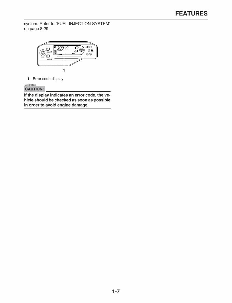
Self-diagnosis device
This model is equipped with a self-diagnosis de-vice for various electrical circuits.If any of those circuits are defective, the enginetrouble warning light will come on, and then thedisplay will indicate a two-digit error code.If the display indicates any error codes, note thecode number, and then check the fuel injection
FEATURES
1-7
system. Refer to “FUEL INJECTION SYSTEM”on page 8-29.
CAUTION:
ECA32D1007
If the display indicates an error code, the ve-hicle should be checked as soon as possible
in order to avoid engine damage.
1. Error code display
1
IMPORTANT INFORMATION
1-8
EAS20180
IMPORTANT INFORMATION
EAS20190
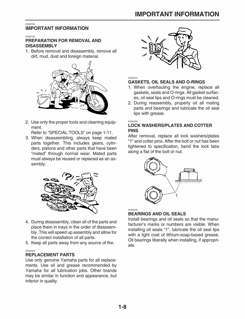
PREPARATION FOR REMOVAL AND DISASSEMBLY
1. Before removal and disassembly, remove alldirt, mud, dust and foreign material.
2. Use only the proper tools and cleaning equip-ment.Refer to “SPECIAL TOOLS” on page 1-11.
3. When disassembling, always keep matedparts together. This includes gears, cylin-ders, pistons and other parts that have been“mated” through normal wear. Mated partsmust always be reused or replaced as an as-sembly.
4. During disassembly, clean all of the parts andplace them in trays in the order of disassem-bly. This will speed up assembly and allow forthe correct installation of all parts.
5. Keep all parts away from any source of fire.
EAS20200
REPLACEMENT PARTS
Use only genuine Yamaha parts for all replace-ments. Use oil and grease recommended byYamaha for all lubrication jobs. Other brandsmay be similar in function and appearance, butinferior in quality.
EAS20210
GASKETS, OIL SEALS AND O-RINGS
1. When overhauling the engine, replace allgaskets, seals and O-rings. All gasket surfac-es, oil seal lips and O-rings must be cleaned.
2. During reassembly, properly oil all matingparts and bearings and lubricate the oil seallips with grease.
EAS20220
LOCK WASHERS/PLATES AND COTTER PINS
After removal, replace all lock washers/plates“1” and cotter pins. After the bolt or nut has beentightened to specification, bend the lock tabsalong a flat of the bolt or nut.
EAS20230
BEARINGS AND OIL SEALS
Install bearings and oil seals so that the manu-facturer’s marks or numbers are visible. Wheninstalling oil seals “1”, lubricate the oil seal lipswith a light coat of lithium-soap-based grease.Oil bearings liberally when installing, if appropri-ate.

IMPORTANT INFORMATION
1-9
CAUTION:
ECA13300
Do not spin the bearing with compressed airbecause this will damage the bearing surfac-
es.
EAS20240
CIRCLIPS
Before reassembly, check all circlips carefullyand replace damaged or distorted circlips. Al-ways replace piston pin clips after one use.When installing a circlip “1”, make sure thesharp-edged corner “2” is positioned oppositethe thrust “3” that the circlip receives.

CHECKING THE CONNECTIONS
1-10
EAS20250
CHECKING THE CONNECTIONS
Check the leads, couplers, and connectors forstains, rust, moisture, etc.1. Disconnect:
Lead
Coupler
Connector2. Check:
Lead
Coupler
ConnectorMoisture
→
Dry with an air blower.Rust/stains
→
Connect and disconnect sev-eral times.
3. Check:
All connectionsLoose connection
→
Connect properly.NOTE:
If the pin “1” on the terminal is flattened, bend it
up.
4. Connect:
Lead
Coupler
ConnectorNOTE:
Make sure all connections are tight.
5. Check:
Continuity(with the pocket tester)
NOTE:
If there is no continuity, clean the terminals.
When checking the wire harness, performsteps (1) to (3).
As a quick remedy, use a contact revitalizer
available at most part stores.
Pocket tester90890-03112
Analog pocket testerYU-03112-C

SPECIAL TOOLS
1-11
EAS20260
SPECIAL TOOLS
The following special tools are necessary for complete and accurate tune-up and assembly. Use onlythe appropriate special tools as this will help prevent damage caused by the use of inappropriate toolsor improvised techniques. Special tools, part numbers or both may differ depending on the country.When placing an order, refer to the list provided below to avoid any mistakes.NOTE:
For U.S.A. and Canada, use part number starting with “YM-”, “YU-”, or “ACC-”.
For others, use part number starting with “90890-”.
Tool name/Tool No. Illustration Referencepages
Crankcase separating tool90890-01135Crankcase separatorYU-01135-B
5-62
Ring nut wrench90890-01268Spanner wrenchYU-01268
4-51
Crankshaft installer pot90890-01274Installing potYU-90058
5-63
Crankshaft installer bolt90890-01275BoltYU-90060
5-63
Adapter (M12)90890-01278Adapter #3YU-90063
5-63
YU-90058/YU-90059
SPECIAL TOOLS
1-12
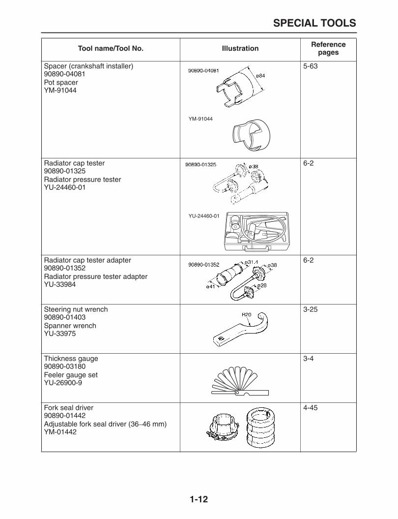
Spacer (crankshaft installer)90890-04081Pot spacerYM-91044
5-63
Radiator cap tester90890-01325Radiator pressure testerYU-24460-01
6-2
Radiator cap tester adapter90890-01352Radiator pressure tester adapterYU-33984
6-2
Steering nut wrench90890-01403Spanner wrenchYU-33975
3-25
Thickness gauge90890-03180Feeler gauge setYU-26900-9
3-4
Fork seal driver90890-01442Adjustable fork seal driver (36
–
46 mm)YM-01442
4-45
Tool name/Tool No. Illustration Referencepages
YM-91044
YU-24460-01

SPECIAL TOOLS
1-13
Damper rod holder90890-01454
4-42, 4-44
Spoke nipple wrench (8
–
9)90890-01522YM-01522
3-31
Sheave holder90890-01701Primary clutch holderYS-01880-A
5-53, 5-54
Compression gauge90890-03081Engine compression testerYU-33223
3-9
Pocket tester90890-03112Analog pocket testerYU-03112-C
1-10, 5-32, 8-65, 8-66, 8-67, 8-71, 8-72, 8-73, 8-74, 8-75, 8-76, 8-77, 8-78, 8-79, 8-81
Timing light90890-03141Inductive clamp timing lightYU-03141
3-9
Pressure gauge90890-03153YU-03153
7-6
Vacuum/pressure pump gauge set90890-06756Mityvac brake bleeding toolYS-42423
7-6
Tool name/Tool No. Illustration Referencepages

SPECIAL TOOLS
1-14
Digital circuit tester90890-03174Model 88 Multimeter with tachometerYU-A1927
7-7, 8-80, 8-81
Fuel pressure adapter90890-03176YM-03176
7-6
Middle driven shaft bearing driver90890-04058Bearing driver 40 mmYM-04058
6-7
Mechanical seal installer90890-04145
6-7
Universal clutch holder90890-04086YM-91042
5-38, 5-40
Valve lapper90890-04101Valve lapping toolYM-A8998
3-5
Valve spring compressor90890-04019YM-04019
5-18, 5-23
Tool name/Tool No. Illustration Referencepages
SPECIAL TOOLS
1-15
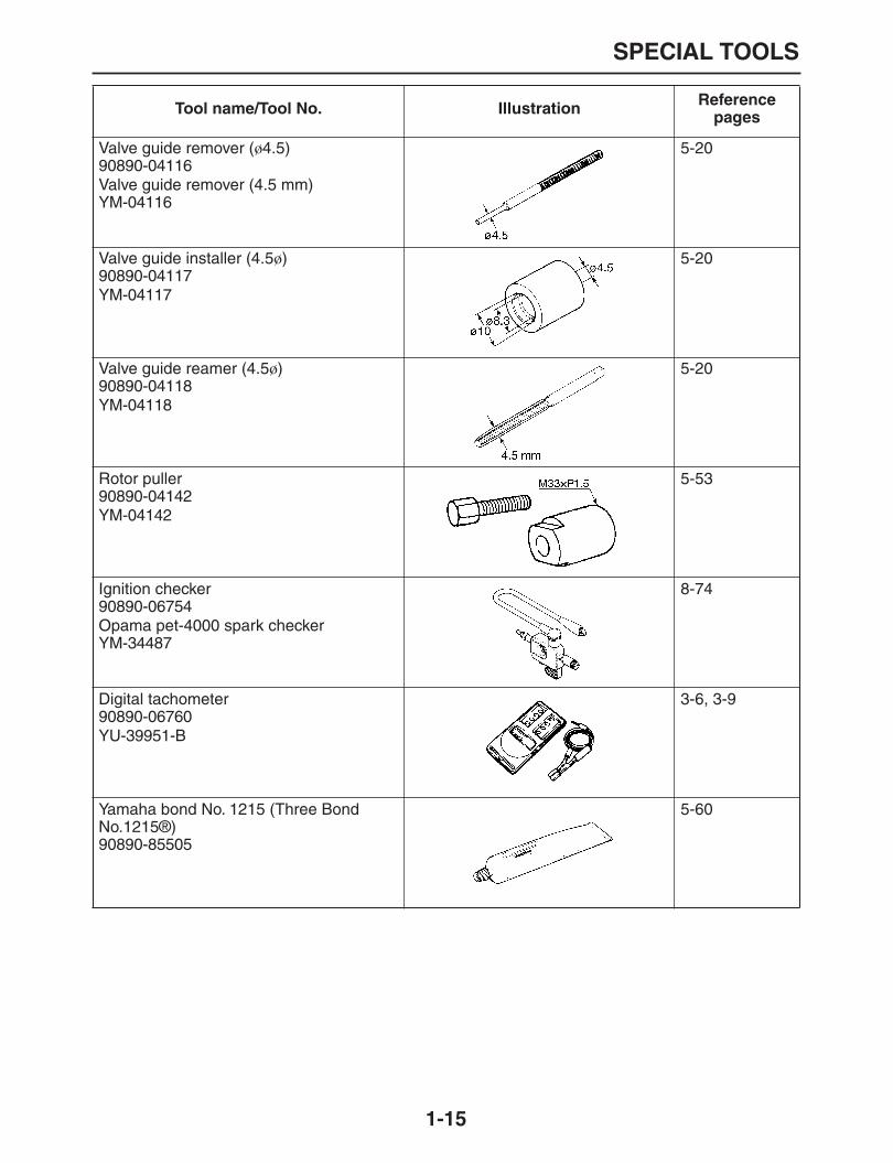
Valve guide remover (
ø
4.5)90890-04116Valve guide remover (4.5 mm)YM-04116
5-20
Valve guide installer (4.5
ø
)90890-04117YM-04117
5-20
Valve guide reamer (4.5
ø
)90890-04118YM-04118
5-20
Rotor puller90890-04142YM-04142
5-53
Ignition checker90890-06754Opama pet-4000 spark checkerYM-34487
8-74
Digital tachometer90890-06760YU-39951-B
3-6, 3-9
Yamaha bond No. 1215 (Three Bond No.1215®)90890-85505
5-60
Tool name/Tool No. Illustration Referencepages

1
2
3
4
5
6
7
8
9
SPECIFICATIONS
GENERAL SPECIFICATIONS .......................................................................2-1
ENGINE SPECIFICATIONS...........................................................................2-2
CHASSIS SPECIFICATIONS.........................................................................2-9
ELECTRICAL SPECIFICATIONS..................................................................2-12
TIGHTENING TORQUES...............................................................................2-15
GENERAL TIGHTENING TORQUE SPECIFICATIONS..........................2-15ENGINE TIGHTENING TORQUES..........................................................2-15CHASSIS TIGHTENING TORQUES........................................................2-17
LUBRICATION POINTS AND LUBRICANT TYPES .....................................2-21
ENGINE....................................................................................................2-21CHASSIS..................................................................................................2-22
LUBRICATION SYSTEM CHART AND DIAGRAMS ....................................2-25
LUBRICATION DIAGRAMS.....................................................................2-25
COOLING SYSTEM DIAGRAMS...................................................................2-29
CABLE ROUTING..........................................................................................2-31
Front rear brake hose...................................................................................2-39
Throttle body.................................................................................................2-41
Canister (for California)................................................................................2-43

GENERAL SPECIFICATIONS
2-1
EAS20280
GENERAL SPECIFICATIONS
Model
Model WR250R 32C1 (U49)WR250R 32C3 (CAL)WR250X 32C2 (U49)WR250X 32C4 (CAL)
Dimensions
Overall length WR250R 2175 mm (85.6 in)WR250X 2110 mm (83.1 in)
Overall width 810 mm (31.9 in)Overall height WR250R 1230 mm (48.4 in)
WR250X 1190 mm (46.9 in)Seat height WR250R 930 mm (36.6 in)
WR250X 895 mm (35.2 in)Wheelbase WR250R 1420 mm (55.9 in)
WR250X 1425 mm (56.1 in)Ground clearance WR250R 295 mm (11.61 in) (CAL)
WR250R 300 mm (11.81 in) (U49)WR250X 260 mm (10.24 in) (CAL)WR250X 265 mm (10.43 in) (U49)
Minimum turning radius 2300 mm (90.6 in)
Weight
With oil and fuel WR250R 134.0 kg (295 lb) (U49)WR250R 135.0 kg (298 lb) (CAL)WR250X 136.0 kg (300 lb) (U49)WR250X 137.0 kg (302 lb) (CAL)
Maximum load 185 kg (408 lb)

ENGINE SPECIFICATIONS
2-2
EAS20290
ENGINE SPECIFICATIONS
Engine
Engine type Liquid cooled 4-stroke, DOHCDisplacement 250.0 cm
3
Cylinder arrangement Forward-inclined single cylinderBore
×
stroke 77.0
×
53.6 mm (3.03
×
2.11 in)Compression ratio 11.80 :1Starting system Electric starter
Fuel
Recommended fuel Premium unleaded gasoline onlyFuel tank capacity WR250R 7.2 L (1.90 US gal) (1.58 Imp.gal)
(CAL) WR250R 7.6 L (2.01 US gal) (1.67 Imp.gal) (U49) WR250X 7.2 L (1.90 US gal) (1.58 Imp.gal) (CAL) WR250X 7.6 L (2.01 US gal) (1.67 Imp.gal) (U49)
Fuel reserve amount 2.1 L (0.55 US gal) (0.46 Imp.gal)
Engine oil
Lubrication system Wet sumpType YAMALUBE 4, SAE 10W-30 or SAE 20W-40Recommended engine oil grade API service SG type or higher, JASO standard
MAEngine oil quantityTotal amount 1.50 L (1.59 US qt) (1.32 Imp.qt)Without oil filter element replacement 1.30 L (1.37 US qt) (1.14 Imp.qt)With oil filter element replacement 1.40 L (1.48 US qt) (1.23 Imp.qt)Oil filter type Paper
Oil pump
Oil pump type TrochoidInner-rotor-to-outer-rotor-tip clearance Less than 0.120 mm (0.0047 in)Limit 0.20 mm (0.0079 in)Outer-rotor-to-oil-pump-housing clearance 0.090
–
0.160 mm (0.0035
–
0.0063 in)Limit 0.230 mm (0.0091 in)
Oil-pump-housing-to-inner-and-outer-rotor clearance
0.030-0.100 mm (0.0012-0.0039 in)Limit 0.17 mm (0.0067 in)Bypass valve opening pressure 500.0
–
600.0 kPa (72.5
–
87.0 psi) (5.00
–
6.00 kgf/cm
2
)
Cooling system
Radiator capacity (including all routes) 0.90 L (0.95 US qt) (0.79 Imp.qt)Radiator capacity 0.32 L (0.34 US qt) (0.28 Imp.qt)
Coolant reservoir capacity (up to the maximum level mark)
0.25 L (0.26 US qt) (0.22 Imp.qt)Radiator cap opening pressure 108.0
–
137.4 kPa (15.7
–
19.9 psi) (1.08
–
1.37 kgf/cm
2
)Radiator coreWidth 121.4 mm (4.78 in)Height 246.0 mm (9.69 in)Depth 28.0 mm (1.10 in)

ENGINE SPECIFICATIONS
2-3
Spark plug (s)
Manufacturer/model NGK/CR9EKSpark plug gap 0.6
–
0.7 mm (0.024
–
0.028 in)
Cylinder head
Volume 15.36 cm
3
(0.94 cu.in)Warpage limit 0.05 mm (0.0020 in)
Camshaft
Drive system Chain drive (left)Camshaft cap inside diameter 22.000
–
22.021 mm (0.8661
–
0.8670 in)Camshaft journal diameter 21.959
–
21.972 mm (0.8645
–
0.8650 in)Camshaft-journal-to-camshaft-cap clearance 0.028
–
0.062 mm (0.0011
–
0.0024 in)Limit 0.08 mm (0.0031 in)Camshaft lobe dimensionsIntake A 34.550
–
34.650 mm (1.3602
–
1.3642 in)Limit 35.450 mm (1.3957 in)Intake B 25.953
–
26.053 mm (1.0218
–
1.0257 in)Limit 25.853 mm (1.0178 in)Exhaust A 34.850
–
34.950 mm (1.3720
–
1.3760 in)Limit 34.750 mm (1.3681 in)Exhaust B 25.986
–
26.086 mm (1.0231
–
1.0270 in)Limit 25.886 mm (1.0191 in)
Camshaft runout limit 0.015 mm (0.0006 in)
Timing chain
Model/number of links 98XRH2010-118MTensioning system Automatic
Valve, valve seat, valve guide
Valve clearance (cold)Intake 0.13
–
0.20 mm (0.0051
–
0.0079 in)Exhaust 0.23
–
0.30 mm (0.0091
–
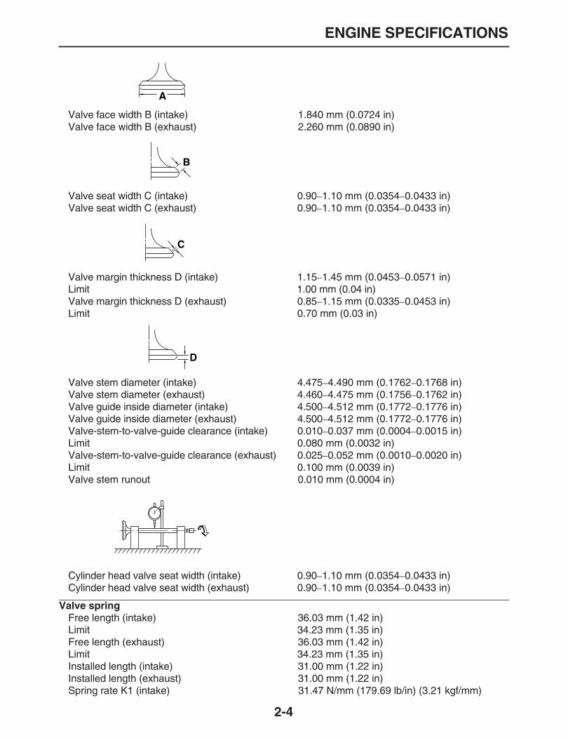
0.0118 in)Valve dimensionsValve head diameter A (intake) 29.90
–
30.10 mm (1.1772
–
1.1850 in)Valve head diameter A (exhaust) 24.40
–
24.60 mm (0.9606
–
0.9685 in)
A
B
ENGINE SPECIFICATIONS
2-4
Valve face width B (intake) 1.840 mm (0.0724 in)Valve face width B (exhaust) 2.260 mm (0.0890 in)
Valve seat width C (intake) 0.90
–
1.10 mm (0.0354
–
0.0433 in)Valve seat width C (exhaust) 0.90
–
1.10 mm (0.0354
–
0.0433 in)
Valve margin thickness D (intake) 1.15
–
1.45 mm (0.0453
–
0.0571 in)Limit 1.00 mm (0.04 in)Valve margin thickness D (exhaust) 0.85
–
1.15 mm (0.0335
–
0.0453 in)Limit 0.70 mm (0.03 in)
Valve stem diameter (intake) 4.475
–
4.490 mm (0.1762
–
0.1768 in)Valve stem diameter (exhaust) 4.460
–
4.475 mm (0.1756
–
0.1762 in)Valve guide inside diameter (intake) 4.500
–
4.512 mm (0.1772
–
0.1776 in)Valve guide inside diameter (exhaust) 4.500
–
4.512 mm (0.1772
–
0.1776 in)Valve-stem-to-valve-guide clearance (intake) 0.010
–
0.037 mm (0.0004
–
0.0015 in)Limit 0.080 mm (0.0032 in)Valve-stem-to-valve-guide clearance (exhaust) 0.025
–
0.052 mm (0.0010
–
0.0020 in)Limit 0.100 mm (0.0039 in)Valve stem runout 0.010 mm (0.0004 in)
Cylinder head valve seat width (intake) 0.90
–
1.10 mm (0.0354
–
0.0433 in)Cylinder head valve seat width (exhaust) 0.90
–
1.10 mm (0.0354
–
0.0433 in)
Valve spring
Free length (intake) 36.03 mm (1.42 in)Limit 34.23 mm (1.35 in)Free length (exhaust) 36.03 mm (1.42 in)Limit 34.23 mm (1.35 in)Installed length (intake) 31.00 mm (1.22 in)Installed length (exhaust) 31.00 mm (1.22 in)Spring rate K1 (intake) 31.47 N/mm (179.69 lb/in) (3.21 kgf/mm)
A
B
C
D

ENGINE SPECIFICATIONS
2-5
Spring rate K2 (intake) 40.90 N/mm (233.54 lb/in) (4.17 kgf/mm)Spring rate K1 (exhaust) 31.47 N/mm (179.69 lb/in) (3.21 kgf/mm)Spring rate K2 (exhaust) 40.90 N/mm (233.54 lb/in) (4.17 kgf/mm)Installed compression spring force (intake) 147.00
–
169.00 N (33.05
–
37.99 lbf) (14.99
–
17.23 kgf)Installed compression spring force (exhaust) 147.00
–
169.00 N (33.05
–
37.99 lbf) (14.99
–
17.23 kgf)Spring tilt (intake) 2.5
°/
1.6 mmSpring tilt (exhaust) 2.5
°/
1.6 mm
Winding direction (intake) ClockwiseWinding direction (exhaust) Clockwise
Cylinder
Bore 77.000
–
77.010 mm (3.0315
–
3.0319 in)Wear limit 77.100 mm (3.0354 in)Taper limit 0.050 mm (0.0020 in)Out of round limit 0.050 mm (0.0020 in)
Piston
Piston-to-cylinder clearance 0.010
–
0.035 mm (0.0004
–
0.0014 in)Limit 0.10 mm (0.0039 in)Diameter D 76.975
–
76.990 mm (3.0305
–
3.0311 in)Height H 12.0 mm (0.47 in)
Offset 0.50 mm (0.0197 in)Offset direction Intake sidePiston pin bore inside diameter 17.002
–
17.013 mm (0.6694
–
0.6698 in)Limit 17.043 mm (0.6710 in)Piston pin outside diameter 16.991
–
17.000 mm (0.6689
–
0.6693 in)Limit 16.971 mm (0.6681 in)Piston-pin-to-piston- pin-bore clearance 0.002
–
0.022 mm (0.0001
–
0.0009 in)
HD
ENGINE SPECIFICATIONS
2-6
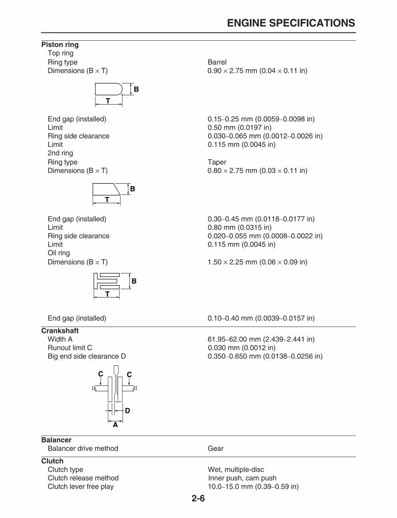
Piston ring
Top ringRing type BarrelDimensions (B
×
T) 0.90
×
2.75 mm (0.04
×
0.11 in)
End gap (installed) 0.15
–
0.25 mm (0.0059
–
0.0098 in)Limit 0.50 mm (0.0197 in)Ring side clearance 0.030
–
0.065 mm (0.0012
–
0.0026 in)Limit 0.115 mm (0.0045 in)2nd ringRing type TaperDimensions (B
×
T) 0.80
×
2.75 mm (0.03
×
0.11 in)
End gap (installed) 0.30
–
0.45 mm (0.0118
–
0.0177 in)Limit 0.80 mm (0.0315 in)Ring side clearance 0.020
–
0.055 mm (0.0008
–
0.0022 in)Limit 0.115 mm (0.0045 in)Oil ringDimensions (B
×
T) 1.50
×
2.25 mm (0.06
×
0.09 in)
End gap (installed) 0.10
–
0.40 mm (0.0039
–
0.0157 in)
Crankshaft
Width A 61.95
–
62.00 mm (2.439
–
2.441 in)Runout limit C 0.030 mm (0.0012 in)Big end side clearance D 0.350
–
0.650 mm (0.0138
–
0.0256 in)
Balancer
Balancer drive method Gear
Clutch
Clutch type Wet, multiple-discClutch release method Inner push, cam pushClutch lever free play 10.0
–
15.0 mm (0.39
–
0.59 in)
T
B
B
T
B
T
CC
D
A

ENGINE SPECIFICATIONS
2-7
Friction plate thickness 2.90
–
3.10 mm (0.114
–
0.122 in)Wear limit 2.80 mm (0.1102 in)Plate quantity 7 pcsClutch plate thickness 1.50
–
1.70 mm (0.059
–
0.067 in)Plate quantity 6 pcsWarpage limit 0.10 mm (0.0039 in)Clutch spring free length 41.20 mm (1.62 in)Minimum length 39.14 mm (1.54 in)Spring quantity 5 pcsPush rod bending limit 0.100 mm (0.0039 in)
Transmission
Transmission type Constant mesh 6-speedPrimary reduction system Spur gearPrimary reduction ratio 78/25 (3.120)Secondary reduction system Chain driveSecondary reduction ratio WR250R 43/13 (3.307)
WR250X 42/13 (3.231)Operation Left foot operationGear ratio1st 37/14 (2.642)2nd 29/16 (1.813)3rd 29/22 (1.318)4th 26/25 (1.040)5th 24/27 (0.888)6th 22/28 (0.786)
Shifting mechanism
Shift mechanism type Shift drum and guide barShift fork guide bar bending limit 0.050 mm (0.0020 in)Shift fork thickness 4.85 mm (0.1909 in)
Decompression device
Device type Auto decomp
Air filter
Air filter element Wet elementAir filter oil grade Foam air-filter oil or engine oil
Throttle body
Type/quantity 38EIS/1Manufacturer MIKUNIID mark WR250R 32C3 00 (CAL)
WR250R 3D71 10 (U49)WR250X 32C3 00 (CAL)WR250X 3D71 10 (U49)
Fuel injection sensor
Crankshaft position sensor 248
–
278
Ω
Intake air pressure sensor output voltage 3.75
–
4.25 VCoolant temperature sensor resistance 2320
–
2590
Ω
@20
°
C (68
°
F)310
–
326
Ω
@80
°
C (176
°
F)
Idling condition
Engine idling speed 1450
–
1650 r/minIntake vacuum 28.3 kPa (8.4 inHg) (212 mmHg)Water temperature 80
°
C (176
°
F)

ENGINE SPECIFICATIONS
2-8
Oil temperature 60.0
°
C (140.00
°
F)Throttle cable free play 3.0
–
5.0 mm (0.12
–
0.20 in)
CHASSIS SPECIFICATIONS
2-9
EAS20300
CHASSIS SPECIFICATIONS
Chassis
Frame type Semi double cradleCaster angle WR250R 26.67
°
WR250X 25.33
°
Trail WR250R 111.0 mm (4.37 in)WR250X 76.0 mm (2.99 in)
Front wheel
Wheel type Spoke wheelRim size WR250R 21x1.60
WR250X 17M/C x MT3.00Rim material AluminumWheel travel 270.0 mm (10.63 in)Radial wheel runout limit 2.0 mm (0.08 in)Lateral wheel runout limit 2.0 mm (0.08 in)Wheel axle bending limit 0.50 mm (0.02 in)
Rear wheel
Wheel type Spoke wheelRim size WR250R 18x2.15
WR250X 17M/C x MT4.00Rim material AluminumWheel travel WR250R 270.0 mm (10.63 in)
WR250X 265.0 mm (10.43 in)Radial wheel runout limit 2.0 mm (0.08 in)Lateral wheel runout limit 2.0 mm (0.08 in)Wheel axle bending limit 0.50 mm (0.02 in)
Front tire
Type With tubeSize WR250R 80/100-21M/C 51P
WR250X 110/70R17M/C 54HManufacturer/model WR250R BRIDGESTONE/TW-301 F
WR250X BRIDGESTONE/BT090F RADIAL G
Rear tire
Type With tubeSize WR250R 120/80-18M/C 62P
WR250X 140/70R17M/C 66HManufacturer/model WR250R BRIDGESTONE/TW-302 F
WR250X BRIDGESTONE/BT090R RADIAL G
Tire air pressure (measured on cold tires)
Loading condition 0–90 kg (0–198 lb)Front WR250R 125 kPa (18 psi) (1.25 kgf/cm
2
)WR250X 200 kPa (29 psi) (2.00 kgf/cm
2
)Rear WR250R 175 kPa (25 psi) (1.75 kgf/cm
2
)WR250X 200 kPa (29 psi) (2.00 kgf/cm
2
)Loading condition 90
–
185 kg (198
–
408 lb)Front WR250R 150 kPa (22 psi) (1.50 kgf/cm
2
)WR250X 200 kPa (29 psi) (2.00 kgf/cm
2
)Rear WR250R 200 kPa (29 psi) (2.00 kgf/cm
2
)WR250X 225 kPa (33 psi) (2.25 kgf/cm
2
)
CHASSIS SPECIFICATIONS
2-10
Front brake
Type Single disc brakeOperation Right hand operationFront brake lever free play 5.0
–
8.0 mm (0.20
–
0.31 in)Front disc brakeDisc outside diameter
×
thickness WR250R 250.0
×
3.5 mm (9.84
×
0.14 in)WR250X 298.0
×
4.0 mm (11.73
×
0.16 in)Brake disc thickness limit WR250R 3.0 mm (0.12 in)
WR250X 3.5 mm (0.14 in)Brake disc deflection limit 0.15 mm (0.0059 in)Brake pad lining thickness (inner) WR250R 4.8 mm (0.19 in)
WR250X 4.0 mm (0.16 in)Limit 1.0 mm (0.04 in)Brake pad lining thickness (outer) WR250R 4.8 mm (0.19 in)
WR250X 4.0 mm (0.16 in)Limit 1.0 mm (0.04 in)Master cylinder inside diameter WR250R 11.00 mm (0.43 in)
WR250X 12.70 mm (0.50 in)Caliper cylinder inside diameter 27.00 mm
×
2 (1.06 in
×
2)Recommended fluid DOT 4
Rear brake
Type Single disc brakeOperation Right foot operationBrake pedal position 11.5 mm (0.45 in)Rear disc brakeDisc outside diameter
×
thickness 230.0
×
4.5 mm (9.06
×
0.18 in)Brake disc thickness limit 4.0 mm (0.16 in)Brake disc deflection limit 0.15 mm (0.0059 in)Brake pad lining thickness (inner) 6.4 mm (0.25 in)Limit 1.0 mm (0.04 in)Brake pad lining thickness (outer) 6.4 mm (0.25 in)Limit 1.0 mm (0.04 in)Master cylinder inside diameter 11.0 mm (0.43 in)Caliper cylinder inside diameter 25.40 mm
×
1 (1.00 in
×
1)Recommended fluid DOT 4
Steering
Steering bearing type Taper roller bearingCenter to lock angle (left) 44.0
°
Center to lock angle (right) 44.0
°
Front suspension
Type Telescopic forkSpring/shock absorber type Coil spring/oil damperFront fork travel 270.0 mm (10.63 in)Fork spring free length 450.0 mm (17.72 in)Limit 441.0 mm (17.36 in)Installed length 439.2 mm (17.29 in)Spring rate K1 4.60 N/mm (26.27 lb/in) (0.47 kgf/mm)Spring stroke K1 0.0
–
270.0 mm (0.00
–
10.63 in)Inner tube outer diameter 46.0 mm (1.81 in)Inner tube bending limit 0.2 mm (0.01 in)Optional spring available No

CHASSIS SPECIFICATIONS
2-11
Recommended oil Suspension oil 01Quantity 613.0 cm
3
(20.73 US oz) (21.62 Imp.oz)Level 105.0 mm (4.13 in)Rebound damping adjusting positionsMinimum 12Standard 10Maximum 1Compression damping adjusting positionsMinimum 19Standard 10Maximum 1
Rear suspension
Type Swingarm (link suspension)Spring/shock absorber type Coil spring/gas-oil damperRear shock absorber assembly travel 95.0 mm (3.74 in)Spring free length 220.0 mm (8.66 in)Installed length 211.5 mm (8.33 in)Spring rate K1 80.00 N/mm (456.80 lb/in) (8.16 kgf/mm)Spring stroke K1 0.0
–
95.0 mm (0.00
–
3.74 in)Optional spring available NoEnclosed gas/air pressure (STD) 1200 kPa (170.7 psi) (12.0 kgf/cm
2
)Spring preload adjusting positionsMinimum 216.0 mm (8.50 in)Standard 211.5 mm (8.33 in)Maximum 206.0 mm (8.11 in)Rebound damping adjusting positionsMinimum 25Standard WR250R 12
WR250X 13Maximum 3Compression damping adjusting positionsMinimum 12Standard WR250R 10
WR250X 7Maximum 1
Swingarm
Swingarm end free play limit (radial) 1.0 mm (0.04 in)Swingarm end free play limit (axial) 1.0 mm (0.04 in)
Drive chain
Type/manufacturer 520V/DAIDOLink quantity 108Drive chain slack WR250R 38.0
–
48.0 mm (1.50
–
1.89 in)WR250X 40.0
–
50.0 mm (1.57
–
1.97 in)15-link length limit 239.3 mm (9.42 in)

ELECTRICAL SPECIFICATIONS
2-12
EAS20310
ELECTRICAL SPECIFICATIONS
Voltage
System voltage 12 V
Ignition system
Ignition system TCI (digital)Advancer type DigitalIgnition timing (B.T.D.C.) 10.0
°
Engine control unit
Model/manufacturer TBDF88/DENSO
Ignition coil
Model/manufacturer F6T558/MITSUBISHIPrimary coil resistance 1.19
–
1.61
Ω
Secondary coil resistance 8.50
–
11.50 k
Ω
AC magneto
Model/manufacturer F3D7/YAMAHAStandard output 14.0 V, 350 W@5000 r/minStator coil resistance 0.168
–
0.252
Ω
(W-W)Rectifier/regulatorRegulator type Semi conductor-short circuitModel/manufacturer SH678-11/SHINDENGENNo load regulated voltage 14.1
–
14.9 VRectifier capacity (DC) 35.0 AWithstand voltage 200.0 V
Battery
Model YTZ7SVoltage, capacity 12 V, 6.0 AhSpecific gravity 1.310Manufacturer GS YUASATen hour rate amperage 0.60 A
Headlight
Bulb type Halogen bulb
Bulb voltage, wattage
×
quantity
Headlight 12 V, 60 W/55.0 WTail/brake light LEDFront turn signal/position light 12 V, 21.0 W/5.0 W
×
2Rear turn signal light 12 V, 21.0 W
×
2License plate light 12 V, 5.0 W
Indicator light
Neutral indicator light LEDTurn signal indicator light LEDHigh beam indicator light LEDFuel level warning light LEDCoolant temperature warning light LEDEngine trouble warning light LED
Electric starting system
System type Constant mesh

ELECTRICAL SPECIFICATIONS
2-13
Starter motor
Model/manufacturer SM-14/MITSUBAPower output 0.50 kWArmature coil resistance 0.0040
–
0.0050
Ω
Brush overall length 10.0 mm (0.39 in)Limit 3.50 mm (0.14 in)Brush spring force 7.16
–
9.52 N (25.77
–
34.27 oz) (730
–
971 gf)Commutator diameter 28.0 mm (1.10 in)Limit 27.0 mm (1.06 in)Mica undercut (depth) 0.70 mm (0.03 in)
Starter relay
Model/manufacturer A3943-072/JIDECOAmperage 180.0 ACoil resistance 4.18
–
4.62
Ω
Horn
Horn type PlaneQuantity 1 pcsModel/manufacturer HF-12/NIKKOMaximum amperage 3.0 ACoil resistance 1.01
–
1.11
Ω
Performance 108
–
116 dB/2m
Turn signal relay
Relay type Full transistorModel/manufacturer FE246BH/DENSOBuilt-in, self-canceling device NoTurn signal blinking frequency 75
–
95 cycles/min
Starting circuit cut-off relay
Model/manufacturer G8R-30Y-V4/OMRONCoil resistance 162.0
–
198.0
Ω
Headlight relay
Model/manufacturer ACM33211 M04/MATSUSHITACoil resistance 86.40
–
105.60
Ω
Sidestand relay
Model/manufacturer G8R-30Y-V4/OMRON
Fuel pump relay
Model/manufacturer G8R-30Y-V4/OMRONCoil resistance 162
–
198
Ω
Fan motor relay
Model/manufacturer ACM33211 M04/MATSUSHITA
Fuses
Main fuse 30.0 AHeadlight fuse 15.0 ASignaling system fuse 10.0 AIgnition fuse 7.5 ARadiator fan fuse 7.5 AFuel injection system fuse 7.5 ABackup fuse 7.5 ASpare fuse 30.0 A

ELECTRICAL SPECIFICATIONS
2-14
Spare fuse 15.0 ASpare fuse 10.0 ASpare fuse 7.5 A

TIGHTENING TORQUES
2-15
EAS20320
TIGHTENING TORQUES
EAS20330
GENERAL TIGHTENING TORQUE SPECIFICATIONS
This chart specifies tightening torques for stan-dard fasteners with a standard ISO thread pitch.Tightening torque specifications for special com-ponents or assemblies are provided for eachchapter of this manual. To avoid warpage, tight-en multi-fastener assemblies in a crisscross pat-tern and progressive stages until the specifiedtightening torque is reached. Unless otherwisespecified, tightening torque specifications re-quire clean, dry threads. Components should beat room temperature.
EAS20340
ENGINE TIGHTENING TORQUES
A. Distance between flatsB. Outside thread diameter
A (nut) B (bolt)General tightening torques
Nm m•kg ft•lb
10 mm 6 mm 6 0.6 4.3
12 mm 8 mm 15 1.5 11
14 mm 10 mm 30 3.0 22
17 mm 12 mm 55 5.5 40
19 mm 14 mm 85 8.5 61
22 mm 16 mm 130 13.0 94
Item Thread size Q’ty Tightening torque Remarks
Camshaft cap bolt M6 8 10 Nm (1.0 m•kg, 7.2 ft•lb)
Cylinder head straight screw plug M12 1 28 Nm (2.8 m•kg, 20 ft•lb)
Cylinder head stud bolt (exhaust pipe bolt) M8 2 15 Nm (1.5 m•kg, 11 ft•lb)
Spark plug M10 1 13 Nm (1.3 m•kg, 9.4 ft•lb)
Cylinder head bolt M10 4 40 Nm (4.0 m•kg, 29 ft•lb)
Cylinder head cover bolt M6 2 12 Nm (1.2 m•kg, 8.7 ft•lb)
Cylinder head bolt M6 2 10 Nm (1.0 m•kg, 7.2 ft•lb)
Oil check bolt M8 1 10 Nm (1.0 m•kg, 7.2 ft•lb)
Cylinder head cover bolt (small head) M6 5 10 Nm (1.0 m•kg, 7.2 ft•lb)
Balancer weight screw M6 3 10 Nm (1.0 m•kg, 7.2 ft•lb)
Balancer gear nut M14 1 50 Nm (5.0 m•kg, 36 ft•lb)lock
washer use
Rotor nut M12 1 65 Nm (6.5 m•kg, 47 ft•lb)
Cam sprocket bolt M7 4 24 Nm (2.4 m•kg, 17 ft•lb)
Timming chain tensioner bolt M6 2 10 Nm (1.0 m•kg, 7.2 ft•lb)
LT
LT
LT
TIGHTENING TORQUES
2-16
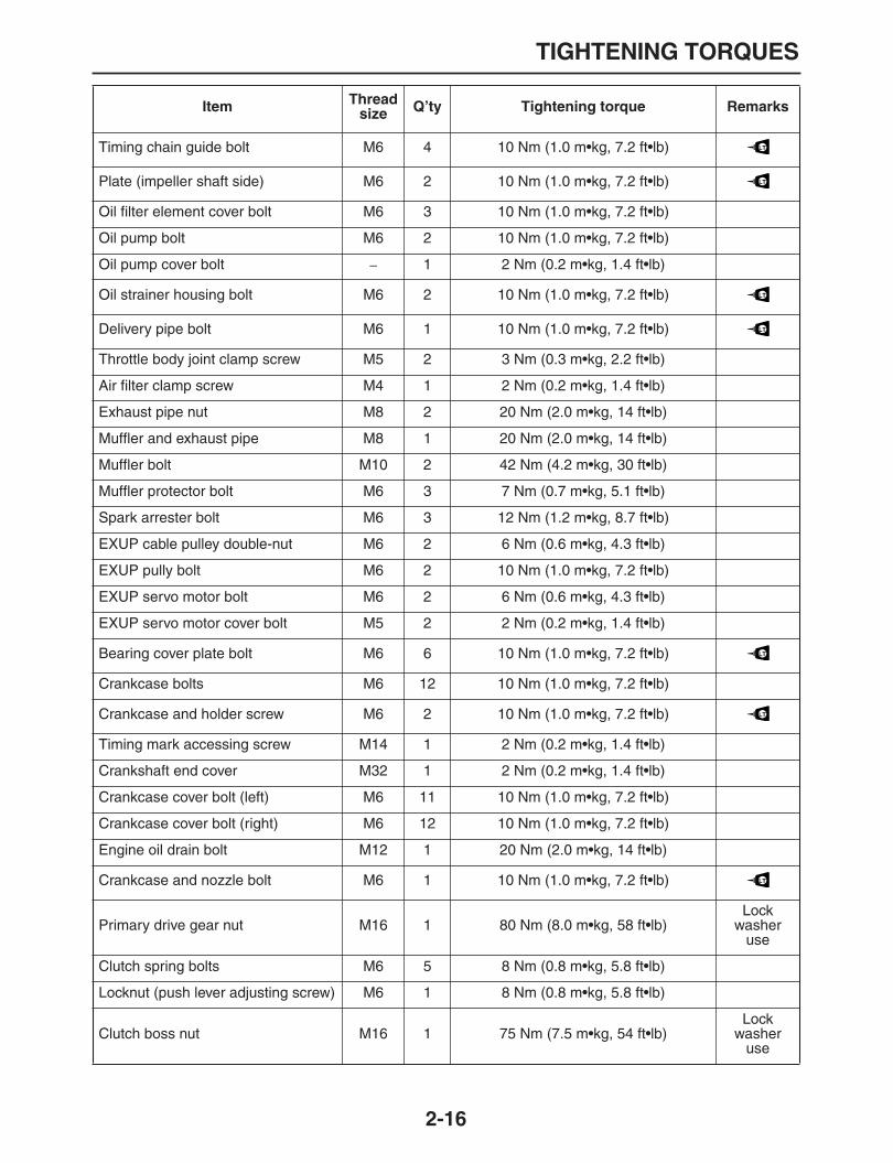
Timing chain guide bolt M6 4 10 Nm (1.0 m•kg, 7.2 ft•lb)
Plate (impeller shaft side) M6 2 10 Nm (1.0 m•kg, 7.2 ft•lb)
Oil filter element cover bolt M6 3 10 Nm (1.0 m•kg, 7.2 ft•lb)
Oil pump bolt M6 2 10 Nm (1.0 m•kg, 7.2 ft•lb)
Oil pump cover bolt
–
1 2 Nm (0.2 m•kg, 1.4 ft•lb)
Oil strainer housing bolt M6 2 10 Nm (1.0 m•kg, 7.2 ft•lb)
Delivery pipe bolt M6 1 10 Nm (1.0 m•kg, 7.2 ft•lb)
Throttle body joint clamp screw M5 2 3 Nm (0.3 m•kg, 2.2 ft•lb)
Air filter clamp screw M4 1 2 Nm (0.2 m•kg, 1.4 ft•lb)
Exhaust pipe nut M8 2 20 Nm (2.0 m•kg, 14 ft•lb)
Muffler and exhaust pipe M8 1 20 Nm (2.0 m•kg, 14 ft•lb)
Muffler bolt M10 2 42 Nm (4.2 m•kg, 30 ft•lb)
Muffler protector bolt M6 3 7 Nm (0.7 m•kg, 5.1 ft•lb)
Spark arrester bolt M6 3 12 Nm (1.2 m•kg, 8.7 ft•lb)
EXUP cable pulley double-nut M6 2 6 Nm (0.6 m•kg, 4.3 ft•lb)
EXUP pully bolt M6 2 10 Nm (1.0 m•kg, 7.2 ft•lb)
EXUP servo motor bolt M6 2 6 Nm (0.6 m•kg, 4.3 ft•lb)
EXUP servo motor cover bolt M5 2 2 Nm (0.2 m•kg, 1.4 ft•lb)
Bearing cover plate bolt M6 6 10 Nm (1.0 m•kg, 7.2 ft•lb)
Crankcase bolts M6 12 10 Nm (1.0 m•kg, 7.2 ft•lb)
Crankcase and holder screw M6 2 10 Nm (1.0 m•kg, 7.2 ft•lb)
Timing mark accessing screw M14 1 2 Nm (0.2 m•kg, 1.4 ft•lb)
Crankshaft end cover M32 1 2 Nm (0.2 m•kg, 1.4 ft•lb)
Crankcase cover bolt (left) M6 11 10 Nm (1.0 m•kg, 7.2 ft•lb)
Crankcase cover bolt (right) M6 12 10 Nm (1.0 m•kg, 7.2 ft•lb)
Engine oil drain bolt M12 1 20 Nm (2.0 m•kg, 14 ft•lb)
Crankcase and nozzle bolt M6 1 10 Nm (1.0 m•kg, 7.2 ft•lb)
Primary drive gear nut M16 1 80 Nm (8.0 m•kg, 58 ft•lb)Lock
washer use
Clutch spring bolts M6 5 8 Nm (0.8 m•kg, 5.8 ft•lb)
Locknut (push lever adjusting screw) M6 1 8 Nm (0.8 m•kg, 5.8 ft•lb)
Clutch boss nut M16 1 75 Nm (7.5 m•kg, 54 ft•lb)Lock
washer use
Item Thread size Q’ty Tightening torque Remarks
LT
LT
LT
LT
LT
LT
LT

TIGHTENING TORQUES
2-17
EAS20350
CHASSIS TIGHTENING TORQUES
Drive sprocket nut M18 1 95 Nm (9.5 m•kg, 69 ft•lb) Stake the nut
Stopper screw (stopper lever) M8 1 22 Nm (2.2 m•kg, 16 ft•lb)
Shift pedal bolt M8 1 18 Nm (1.8 m•kg, 13 ft•lb)
Stator assembly bolt M6 3 10 Nm (1.0 m•kg, 7.2 ft•lb)
Crankshaft position sensor bolt M6 2 10 Nm (1.0 m•kg, 7.2 ft•lb)
Neutral switch M5 2 4 Nm (0.4 m•kg, 2.9 ft•lb)
Thermosensor bolt M12 1 18 Nm (1.8 m•kg, 13 ft•lb)
Drive sprocket cover bolt M6 3 10 Nm (1.0 m•kg, 7.2 ft•lb)
Right side cover bolt M6 1 10 Nm (1.0 m•kg, 7.2 ft•lb)
Side cover stay bolt M6 2 10 Nm (1.0 m•kg, 7.2 ft•lb)
Cylinder bolt M6 2 10 Nm (1.0 m•kg, 7.2 ft•lb)
Water pump housing cover bolt M6 3 10 Nm (1.0 m•kg, 7.2 ft•lb)
Coolant drain bolt M6 1 10 Nm (1.0 m•kg, 7.2 ft•lb)
Clutch cable holder bolt M6 2 10 Nm (1.0 m•kg, 7.2 ft•lb)
Speed sensor bolt M6 1 10 Nm (1.0 m•kg, 7.2 ft•lb)
Radiator hose clamp screw — 6 2 Nm (0.2 m•kg, 1.4 ft•lb)
Radiator fan bolt M6 3 8 Nm (0.8 m•kg, 5.8 ft•lb)
Radiator M6 1/1 10 Nm (1.0 m•kg, 7.2 ft•lb)
Radiator cover bolt M6 2 10 Nm (1.0 m•kg, 7.2 ft•lb)
Thermostat cover bolt M6 2 10 Nm (1.0 m•kg, 7.2 ft•lb)
Seat guide screw M6 2 7 Nm (0.7 m•kg, 5.1 ft•lb)
Throttle position sensor screw M5 2 3.5 Nm (0.35 m•kg, 2.5 ft•lb)
Air induction system pipe bolt M6 2 10 Nm (1.0 m•kg, 7.2 ft•lb)
Wire harness holder bolt M6 1 10 Nm (1.0 m•kg, 7.2 ft•lb)
Item Thread size Q’ty Tightening torque Remarks
LT
LT
LT
LT
Item Thread size Q’ty Tightening torque Remarks
Engine mounting nut (front upper) M10 1 67 Nm (6.7 m•kg, 48 ft•lb)
Engine mounting nut (front, front lower) M10 1/1 56 Nm (5.6 m•kg, 41 ft•lb)
Down tube nut M12 3 113 Nm (11.3 m•kg, 82 ft•lb)
Main frame and rear frame M10 4 56 Nm (5.6 m•kg, 41 ft•lb)
Engine protector bolt M6 2 10 Nm (1.0 m•kg, 7.2 ft•lb)
Drive chain tensioner bolt M8 2 23 Nm (2.3 m•kg, 17 ft•lb)

TIGHTENING TORQUES
2-18
Taillight cover bolt M6 4 10 Nm (1.0 m•kg, 7.2 ft•lb)
Helmet hanger screw M6 1 10 Nm (1.0 m•kg, 7.2 ft•lb)
Front fender bolt M6 4 7 Nm (0.7 m•kg, 5.1 ft•lb)
Sidecover screw M6 2 10 Nm (1.0 m•kg, 7.2 ft•lb)
Sidecover stay bolt M6 1 10 Nm (1.0 m•kg, 7.2 ft•lb)
Horn bolt M6 1 10 Nm (1.0 m•kg, 7.2 ft•lb)
Air scoop stay bolt M8 2 16 Nm (1.6 m•kg, 12 ft•lb)
Air scoop bolt M6 4 7 Nm (0.7 m•kg, 5.1 ft•lb)
Air scoop and right air panel M6 2 4 Nm (0.4 m•kg, 2.9 ft•lb)
Rectifier/regulator bolt M6 2 7 Nm (0.7 m•kg, 5.1 ft•lb)
Recovery tank screw M6 2 7 Nm (0.7 m•kg, 5.1 ft•lb)
Starter motor leads nut M6 2 5 Nm (0.5 m•kg, 3.6 ft•lb)
Starter motor bolt M6 1 10 Nm (1.0 m•kg, 7.2 ft•lb)
Pivot shaft nut M16 1 85 Nm (8.5 m•kg, 62 ft•lb)
Rear shock absorber locknut — 1 42 Nm (4.2 m•kg, 30 ft•lb)
Rear shock absorber nut (upper) M10 1 40 Nm (4.0 m•kg, 29 ft•lb)
Rear shock absorber nut (lower) M10 1 53 Nm (5.3 m•kg, 38 ft•lb)
Frame and connecting rod nut M14 1 80 Nm (8.0 m•kg, 58 ft•lb)
Connecting rod and relay arm nut M14 1 80 Nm (8.0 m•kg, 58 ft•lb)
Relay arm and swing arm nut M14 1 70 Nm (7.0 m•kg, 51 ft•lb)
Chain case bolt M6 2 7 Nm (0.7 m•kg, 5.1 ft•lb)
Chain cover bolt M6 3 7 Nm (0.7 m•kg, 5.1 ft•lb)
Sidestand nut M10 1 64 Nm (6.4 m•kg, 46 ft•lb)
Sidestand switch screw M5 2 4 Nm (0.4 m•kg, 2.9 ft•lb)
Steering stem nut M24 1 120 Nm (12.0 m•kg, 87 ft•lb)
Lower ring nut M28 1
–
See NOTE
Upper bracket pinch bolt M8 4 23 Nm (2.3 m•kg, 17 ft•lb)
Lower bracket pinch bolt M8 4 20 Nm (2.0 m•kg, 14 ft•lb)
Fuel tank bolt M6 4 7 Nm (0.7 m•kg, 5.1 ft•lb)
Fuel tank bracket bolt M6 3 10 Nm (1.0 m•kg, 7.2 ft•lb)
Fuel pump bolt M5 6 4 Nm (0.4 m•kg, 2.9 ft•lb)
Meter nut M5 3 4 Nm (0.4 m•kg, 2.9 ft•lb)
Meter bracket nut M6 1 7 Nm (0.7 m•kg, 5.1 ft•lb)
Handlebar upper holder bolt M8 4 28 Nm (2.8 m•kg, 20 ft•lb)
Handlebar lower holder nut M12 2 40 Nm (4.0 m•kg, 29 ft•lb)
Front fork cap bolt M48 2 30 Nm (30. m•kg, 22 ft•lb)
Item Thread size Q’ty Tightening torque Remarks

TIGHTENING TORQUES
2-19
Front fork base valve M22 2 55 Nm (5.5 m•kg, 40 ft•lb)
Front fork axle nut M16 1 63 Nm (6.3 m•kg, 46 ft•lb)
Front wheel axle pinch bolt M8 4 23 Nm (2.3 m•kg, 17 ft•lb)
Front brake disc bolt (WR250R) M6 6 12 Nm (1.2 m•kg, 8.7 ft•lb)
Front brake disc bolt (WR250X) M8 6 23 Nm (2.3 m•kg, 17 ft•lb)
Spoke (front, rear) BC4 72 3 Nm (0.3 m•kg, 2.2 ft•lb)
Rear wheel axle nut M20 1 125 Nm (12.5 m•kg, 90 ft•lb)
Rear brake disc bolt M6 6 12 Nm (1.2 m•kg, 8.7 ft•lb)
Rear wheel sprocket nut M8 6 35 Nm (3.5 m•kg, 25 ft•lb)
Front brake caliper bolt M8 2 23 Nm (2.3 m•kg, 17 ft•lb)
Union bolt M10 4 30 Nm (30. m•kg, 22 ft•lb)
Bleed screw M7 2 6 Nm (0.6 m•kg, 4.3 ft•lb)
Front caliper support bolt M8 2 17 Nm (1.7 m•kg, 12 ft•lb)
Front caliper pin plug M8 1 2.5 Nm (0.25 m•kg, 1.8 ft•lb) WR250X only
Front master cylinder holder bolt M6 2 7 Nm (0.7 m•kg, 5.1 ft•lb)
Front brake lever nut M6 1 7 Nm (0.7 m•kg, 5.1 ft•lb)
Rear master cylinder bolt M6 2 10 Nm (1.0 m•kg, 7.2 ft•lb)
Rear caliper protector bolt M6 2 7 Nm (0.7 m•kg, 5.1 ft•lb)
Rear brake caliper support bolt M8 2 17 Nm (1.7 m•kg, 12 ft•lb)
Rear master cylinder bracket bolt M8 2 10 Nm (1.0 m•kg, 7.2 ft•lb)
Passenger footrest bolt (left) M8 1 23 Nm (2.3 m•kg, 17 ft•lb)
Passenger footrest bolt (right) M8 1 30 Nm (30. m•kg, 22 ft•lb)
Drive chain tensioner bolt (upper, lower) M8 2 23 Nm (2.3 m•kg, 17 ft•lb)
Drive chain adjuster locknut M8 1 16 Nm (1.6 m•kg, 12 ft•lb)
Front fork protector bolt M6 6 7 Nm (0.7 m•kg, 5.1 ft•lb)
Seat bolt M6 2 7 Nm (0.7 m•kg, 5.1 ft•lb)
Front brake lever adjusting locknut M6 1 4 Nm (0.4 m•kg, 2.9 ft•lb)
Front brake master cylinder cap M4 2 4 Nm (0.4 m•kg, 2.9 ft•lb)
Front brake hose holder bolt M6 1 10 Nm (1.0 m•kg, 7.2 ft•lb)
Rear brake caliper pin plug M10 1 2.5 Nm (0.25 m•kg, 1.8 ft•lb)
Rear brake master cylinder lock nut M6 1 12 Nm (1.2 m•kg, 8.7 ft•lb)
Clutch lever holder bolt M5 2 7 Nm (0.7 m•kg, 5.1 ft•lb)
Brake hose holder nut M6 2 7 Nm (0.7 m•kg, 5.1 ft•lb)
Damper rod nut M10 2 15 Nm (1.5 m•kg, 11 ft•lb)
Item Thread size Q’ty Tightening torque Remarks
LT
LT
LT
LT

TIGHTENING TORQUES
2-20
NOTE:
Tighten the lower ring nut with the 38 Nm (3.8 m•kg, 27 ft•lb) torque.
Turn the front fork to the left and right. The rotation motion must be smooth.
Fully loosen the lower ring nut, and retighten it with the 7 Nm (0.7 m•kg, 5.1 ft•lb) torque.
Headlight unit bolt M6 2 7 Nm (0.7 m•kg, 5.1 ft•lb)
Rear brake hose holder screw M5 5 2 Nm (0.2 m•kg, 1.4 ft•lb)
Front drive chain guide bolt M6 1 7 Nm (0.7 m•kg, 5.1 ft•lb)
Delivery pipe screw M6 2 5 Nm (0.5 m•kg, 3.6 ft•lb)
Canister cover bolt M6 4 7 Nm (0.7 m•kg, 5.1 ft•lb)
Item Thread size Q’ty Tightening torque Remarks

LUBRICATION POINTS AND LUBRICANT TYPES
2-21
EAS20360
LUBRICATION POINTS AND LUBRICANT TYPES
EAS20370
ENGINE
Lubrication points Lubrication types
Oil seal lips
O-rings
Bearings
Camshaft cap bolt head
Cylinder head bolt threads
Camshaft profile, journal
Decompression system moving parts
Valve stem, stem end
Valve lifter surface
Crank assembly (crankshaft pin surface)
Both sliding surfaces of connecting rod big end
Piston pin surface
Piston surface
Cylinder body inner surface
Impeller shaft
Oil pump assembly shaft
Oil pump assembly drain port
Idle gear inner diameter and end, idle gear shaft and end
Throttle body joint
Rotor boss end surface
Thrust gear surface
Starter clutch assembly
Rotor assembly
Shaft surface (crankcase bearings)
Idle gear-2 inner surface, thrust surfaces
Damper assembly shaft, thrust surfaces
LS
LS
E
E
M
M
E
M
E
E
E
E
E
E
LS
E
LS
E
E
E
E
E
E
E
E
E

LUBRICATION POINTS AND LUBRICANT TYPES
2-22
EAS20380
CHASSIS
Push rod 1 surface, end
Ball (push rod)
Primary driven gear assembly, inner surface
Push lever assembly end
Transmission gears (wheel and pinion)
Main axle and drive axle
Shift drum
Shift fork and shift fork guide bars
Shift shaft
Shift shaft washer, spacer inner surface
Cylinder head cover gasketYamaha bond No. 1215
(Three Bond No. 1215®)
Cylinder head semicircular surfaceYamaha bond No. 1215
(Three Bond No. 1215®)
Crankcase mating surfaceYamaha bond No. 1215
(Three Bond No. 1215®)
Stator assembly lead grommetYamaha bond No. 1215
(Three Bond No. 1215®)
Lubrication points Lubrication types
E
E
E
E
M
M
E
E
E
E
Lubrication points Lubrication types
Upper bearings and oil seal lip (steering head)
Lower bearings and oil seal lip (steering head)
Handle lower holder threads
Front wheel oil seal (left/right)
Rear wheel oil seal (left/right)
Brake pedal bolt, boss
Throttle cable end and throttle grip
Throttle cable housing inner surface
Throttle cable
LS
LS
LS
LS
LS
LS
LS
LS
LS

LUBRICATION POINTS AND LUBRICANT TYPES
2-23
Brake lever bolt
Brake lever and front brake master cylinder
Adjusting screw (brake lever)
Rear brake master cylinder push rod (boot mount groove)
Brake caliper piston seal
Brake caliper dust seal
Brake caliper support bolt
Brake pad support bolt
Clutch lever cable
Clutch lever bolt
Clutch lever
Pivot shaft
Swing arm bearing, collar, spacer, and oil seal
Relay arm bearing, collar, and oil seal
Connecting rod bearing, collar and oil seal
Connecting rod bolt
Rear shock absorber assembly lower bolt
Rear wheel axle
Sidestand switch
Sidestand bracket and sidestand
Sidestand spring and link
Sidestand bolt collar
Drive chain tensioner roller collar (upper)
Lubrication points Lubrication types
S
S
S
S
BF
S
S
S
LS
LS
LS
LS
LS
LS
LS
LS
LS
LS
LS
LS
LS
LS
LS

LUBRICATION POINTS AND LUBRICANT TYPES
2-24

LUBRICATION SYSTEM CHART AND DIAGRAMS
2-25
EAS20390
LUBRICATION SYSTEM CHART AND DIAGRAMS
EAS20410
LUBRICATION DIAGRAMS

LUBRICATION SYSTEM CHART AND DIAGRAMS
2-26
1. Camshaft2. Timing chain tensioner3. Piston cooler4. Oil filter5. Main axle6. Delivery pipe7. Drive axle8. Oil pump9. Relief valve10. Oil strainer11. Oil pan

LUBRICATION SYSTEM CHART AND DIAGRAMS
2-27

LUBRICATION SYSTEM CHART AND DIAGRAMS
2-28
1. Oil pump assembly2. Relief valve3. Main axle4. Delivery pipe5. Drive axle6. Crankshaft7. Oil filter8. Oil strainer

COOLING SYSTEM DIAGRAMS
2-29
EAS20420
COOLING SYSTEM DIAGRAMS
8
5
1
2
3
4
67
9

COOLING SYSTEM DIAGRAMS
2-30
1. Radiator cap2. Radiator3. Radiator inlet hose4. Radiator outlet hose5. Recovery tank hose6. Cap7. Side cover stay8. Water pump housing cover9. Impeller shaft
CABLE ROUTING
2-31
EAS20430
CABLE ROUTING

CABLE ROUTING
2-32
1. Starter motor lead2. Coolant temperature sensor lead3. Speed sensor lead4. Negative battery lead5. Starter relay6. Starter relay probe7. Starter relay lead8. Intake solenoid lead9. ECU lead10. Headlight relay11. Turn signal relay12. Radiator fan motor relay13. Relay unit14. Positive battery lead15. EXUP servo motor lead16. Sidestand switch lead17. AC magneto lead18. Neutral switch lead19. Recovery tank hose20. Rectifier/regulator21. Fuse box22. Air cut-off valve lead23. Air induction system pipe24. Horn lead25. Neutral switch lead26. Recovery tank hose27. Cover28. Clutch cable29. Wire harness
A. Dimensions of wire harness fastening.B. Fasten the wire harness, clutch cable, clutch
switch lead, and left handlebar switch lead using a cable tie. Place the clutch cable at the top position. The others can be in any position.
C. Route the wire harness under the clutch cable, above the throttle cable, and along the right side of vehicle.
D. Pass the ignition lead under the clutch cable, above the throttle cable, and through the hole inside of frame tank rail.
E. Wire harness branch (at left side of vehicle) connected to the fuse box, AC magneto and others.
F. Securely insert the wire harness clamp into the T-stud of cable holder.
G. Fasten the wire harness, starter motor lead, negative battery lead, coolant temperature sen-sor lead, and speed sensor lead to the frame with a cable tie.
H. Fasten the starter motor lead, negative battery lead, coolant temperature sensor lead, and speed sensor lead to the frame with a cable tie. Fasten them to the outside of RCU mounting boss (left).
I. To engine.J. Fasten the wire harness, starter motor lead,
negative battery lead, coolant temperature sen-sor lead, and speed sensor lead using a cable tie.
K. Securely insert the wire harness clamp into the T-stud of the rear frame.
L. Pass the ECU lead between the intake solenoid hose and connector.
M. Wrap the connectors with a cover for protection.N. Fasten the starter motor lead, negative battery
lead, coolant temperature sensor lead, and speed sensor lead using a cable tie. Fasten them between the battery band and battery ter-minals, and face their cable lock inward.
O. Route the sidestand switch lead to the inside of battery band.
P. Fasten the rear frame and sidestand switch lead using a cable tie.
Q. Fasten the rear frame, sidestand switch lead using a cable tie. They must be fixed to the T-stud of the rear frame. Any locking position can be used.
R. Position the recovery tank hose end between the engine bracket and down tube.
S. Pass the clutch cable through the inside of FID hose.
T. Fasten the neutral switch lead, and recovery tank hose to the down tube with a cable tie. An excess must face inward.
U. Fasten the AC magneto lead, neutral switch lead, and recovery tank hose to the down tube with a cable tie. They must be fixed to the T-stud of down tube. Any locking position can be used.
V. Fasten the recovery tank hose to the down tube with clamps. They must be fixed to the T-stud of down tube. Any locking position can be used.
W. After cable connection, place the connectors in the cover, and mount them in a hole of the frame.
X. Clamp the wire harness, clultch cable and clutch switch lead (6-pin natural color) at the top of sidecover stay mount boss.
Y. Fix the fuse box lead to the side cover stay.Z. Pass the AC magneto lead and neutral switch
lead through the behind of rectifier regulator.AA. Pass the horn lead through the behind of recti-
fier regulator.AB. Fasten the magneto lead, horn lead, and the
top of cover (for AC magneto lead and neutral switch lead) using a cable tie. An excess must face inward. (The bare conductors of lead can be clamped.)
AC. Fasten the sidecover stay, AC magneto lead, neutral switch lead, and horn lead using a cable tie. An excess must face forward.
AD. The AC magneto lead and neutral switch lead must not contact with the horn.
AE. After connecting the AC magneto lead and neutral switch lead, place their connectors in the cover.
AF. Fasten the sidecover stay, AC magneto lead, and neutral switch lead using a cable tie.
AG. Rotate the AC magneto lead to the cover.AH. Fasten the rear frame cover using a cable tie.
The clamp lock must face downwards.AI. Fasten the sidestand switch lead to the rear
frame with a cable tie. Pass the lead through the hole of rear frame bracket, and direct the clamp lock to the inside of the frame.
AJ. Install the cover between of the wire harness (inside) and clutch cable (outside).
AK. Do not route the AC magneto lead, neutral switch lead, horn lead and air induction lead above the air cut-off valve assembly.

CABLE ROUTING
2-33

CABLE ROUTING
2-34
1. Clamp2. Throttle position sensor lead3. Fan motor lead
A. Fasten the breather hose using a clamp.B. Fasten the throttle position sensor connector
cover and the rear brake switch lead using a cable tie.
C. Insert the fan motor lead into the concave sec-tion of guide air, and pass them backward through the hole.
D. After connecting the main switch lead, front brake switch lead, and handlebar right lead, and place their connectors in the cover.
E. Fasten the main switch lead, front brake switch lead, and handlebar switch right lead using a clamp. They must be placed between the front edge of the cable guide and below the “H”, within the range of the handlebar turns from straight ahead to the fully left.
F. Slightly pull out the end of rear brake switch lead backward.
G. Fasten the rear brake switch lead to the frame with a clamp. The clamp must be securely inserted into the frame hole. Any locking posi-tion can be used.
H. The position is a between the halfway from the cable guide and the upperend of the frame number.
I. Front edge of the cable guide

CABLE ROUTING
2-35

CABLE ROUTING
2-36
1. Ignition coil lead2. Fuel pump lead3. Injector lead4. Throttle position sensor lead5. Rear brake switch lead6. Right rear turn signal light lead7. License plate light lead8. Taillight lead9. Left rear turn signal light lead10. Lean angle sensor lead11. Intake air pressure sensor lead12. Clutch cable13. Throttle cable
A. Fasten the radiator fan motor lead and breather hose using a clamp. The rightmost end of breather hose must be secured (to the front as much as possible).
B. Pass the radiator fan motor lead under the breather hose, and pull them out.
C. Pass the injector lead between the fuel pipe.D. Fasten the ECU lead using a clamp.E. Fasten the right and rear left turn signal light
lead, license plate light lead, and taillight lead to the rear frame with a clamp.
F. Fasten the right and left rear turn signal light lead, license plate light lead, and taillight lead to the rear frame with a cable tie.
G. After connection of lead, place the connector in the cover so that bare conductors are not exposed.
H. Fasten the frame cover, wire harness, and clutch cables to the frame with a cable tie.
I. A silicone hydrate can be applied when passing the clutch cable or throttle cable through the internal hole of frame tank rails.

CABLE ROUTING
2-37
CABLE ROUTING
2-38
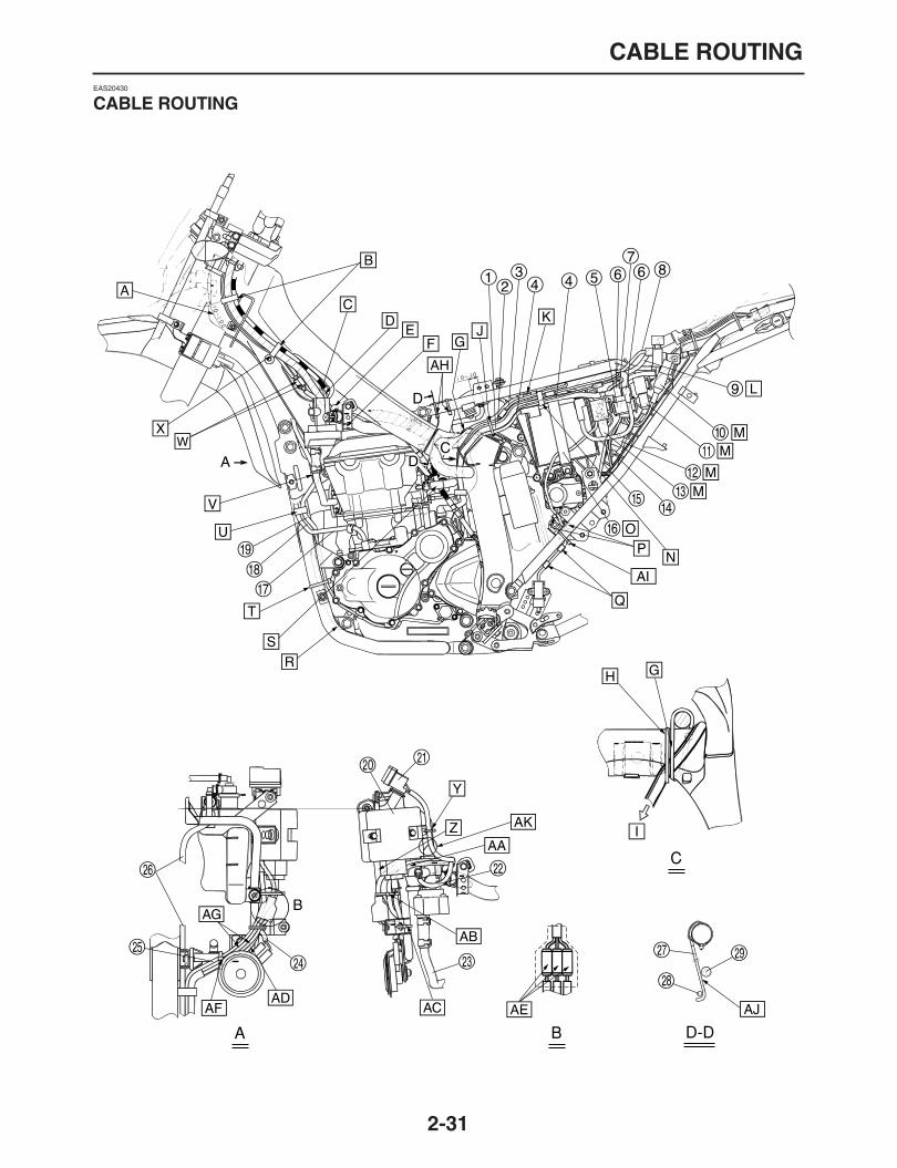
1. Throttle cable (accelerator)2. Throttle cable (decelerator)3. Right handlebar switch lead4. Clutch switch lead5. Left handlebar switch lead6. Clutch cable7. Front brake switch lead8. Left front turn signal light lead9. Wire harness (brown connector)10. Wire harness (green connector)11. Left front turn signal light lead12. Meter lead (3-pin black coupler)13. Meter lead (4-pin natural color coupler)14. Meter lead (3-pin natural color coupler)15. Left handlebar switch lead (headlight lead)16. Cable guide17. Main switch lead18. Clamp19. Auxiliary light lead20. Wire harness (2-pin natural color coupler)21. Stopper (headlight stay)22. Wire harness (3-pin natural color coupler)23. Wire harness (4-pin natural color coupler)
A. Clamp near the end of bent handlebar section using a clamp.
B. Route the handlebar switch right lead and front brake switch lead through the side of main switch, and extend to the side of head pipe.
C. Place the clutch cable in the right position. The others can be in any position.
D. Pass the throttle cable between the cable guides of right turn signal light stay and meter stay.
E. Place the lead in the hose so that bare conduc-tors are not exposed.
F. Pass the left handlebar switch lead above the meter lead (3-pin natural color coupler) as shown, and connect them to the headlight assembly.
G. Pass the wire harness, clutch cable, clutch switch lead and handlebar switch left lead through the wire guide. Route the clutch cable in the top position. The others can be in any position.
H. Pass the throttle cable, front brake switch lead, right handlebar switch lead, and main switch lead through the wire guide. Place the throttle cable in the top position. The others can be in any position.
I. Route the main switch lead upward to the side of head pipe. Do not route the main switch lead to the outside of meter stay cable guide.
J. Pass the right front turn signal light lead through headlight cowling stay as shown, and then through the inside of meter stay cable guide from behind the throttle cable, and connect them inside of the meter.
K. Fasten the right and left front turn signal light lead and wire harnesses using a cable tie. Insert the cable tie into the meter stay, and face the lock downward. Cut and remove an excess if any.
L. Insert the meter lead (3-pin natural color cou-pler) under the meter stay, and connect them.
M. Route the left front turn signal light lead above the meter lead from behind the handlebar switch left lead, and connect them at the meter position.
N. Insert the wire harness clamps by inserting the two harness clamps into the hole of the meter stay.
O. Install the left handlebar switch lead by inserting them into the space at the side of meter stay.
P. Pass the front left turn signal light lead through headlight cowling stay as shown, and then through the abobe of meter lead (3-pin black) from behind the handlebar switch lead (3-pin black), and connect them inside of the meter.

Front rear brake hose
2-39
Front rear brake hose
Front rear brake hose
2-40
1. Front brake hose2. Hose guide3. Union bolt4. Copper washer5. Front brake caliper assembly6. Rear brake disc7. Rear brake caliper assembly8. Copper washer9. Union bolt10. Rear brake hose11. Rear brake master cylinder12. Rear brake switch13. Brake pedal

Throttle body
2-41
Throttle body

Throttle body
2-42
1. Breather hose2. Air filter case assembly3. Pipe4. Throttle body assembly5. Radiator inlet hose6. Radiator7. Throttle body joint8. FID hose9. Vacuum hose10. Pressure sensor11. Bend hose12. ITS boost hose13. Air induction system hose14. Surge tank
A. Face the white paint upward of the vehicle.B. Face the white paint mark to the right side of vehi-
cle.C. Face the clip holder to the right front of vehicle.D. Face the clip holder upward of the vehicle.E. Face the white paint mark backward of the vehi-
cle.F. Face the clip holder to the front side of vehicle.G. Align the throttle body joint with the hose clamp.H. Face the white paint mark to the left side of vehi-
cle.I. Insert the IST boost hose into position until it is
stopped.J. Install the vacuum hose to the air-filter case until it
is stopped.K. Face the yellow paint mark to the left of vehicle.L. Connect the tank surge hose until it is stopped.

Canister (for California)
2-43
Canister (for California)
5mm
(0.
20 in
)
45˚

Canister (for California)
2-44
1. Fuel tank2. Hose (Fuel tank
–
roll over valve)3. Canister cover4. Canister5. A.C. magneto lead6. Neutral switch lead7. Recovery tank hose8. Roll over valve9. Holder10. Hose11. Clip
A. Face the clip end forward of the vehicle.B. Face the clip end backward of the vehicle.C. Pass the hose (roll over valve
–
canister) between the engine head and air cut-off valve assembly.
D. Route the hose (canister
–
throttle body) to the up side of the FID hose, and then route it to the inside the clutch wire.
E. Hold the hose (canister
–
throttle body) through the 2 clamps securely.
F. Fasten the A.C. magneto lead, neutral switch lead, recovery tank hose, and the hose (roll over valve
–
canister) using the clamp. Install the clamp to T stud of the down tube securely.
G. Fasten the recovery tank hose and the hose (roll over
–
canister). Install the clamp to T stud of the down tube. Face the lock part forward of the vehi-cle.
H. Align the paint mark with the projection of the bot-tom of the roll over valve.
I. Face the paint leftward of the vehicle.J. Face the clip end downward of the vehicle.K. From the roll over valve.L. To the throttle body.M. Face the paint upward of the vehicle.N. Align the slot of the damper with the pipe of the
throttle body side.O. Insert the projection of the canister damper to the
hole of canister cover.P. Face the clip end upward of the vehicle.Q. When the canister cover install, you may spread
the soapy water to the damper as shown. How-ever, do not spread the soapy water to the projec-tion of the damper and the hole of the canister cover.

Canister (for California)
2-45
1
2
3
4
5
6
7
8
9
PERIODIC CHECKS AND ADJUSTMENTS
PERIODIC MAINTENANCE...........................................................................3-1
INTRODUCTION......................................................................................3-1Periodic maintenance chart for the emission control system ...................3-1
ENGINE ..........................................................................................................3-4
ADJUSTING THE VALVE CLEARANCE .................................................3-4ADJUSTING THE ENGINE IDLING SPEED............................................3-6ADJUSTING THE THROTTLE CABLE FREE PLAY ...............................3-6CHECKING THE SPARK PLUG ..............................................................3-8CHECKING THE IGNITION TIMING........................................................3-8MEASURING THE COMPRESSION PRESSURE...................................3-9CHECKING THE ENGINE OIL LEVEL ....................................................3-10CHANGING THE ENGINE OIL ................................................................3-11ADJUSTING THE CLUTCH CABLE FREE PLAY....................................3-12CLEANING THE AIR FILTER ELEMENT ................................................3-13CHECKING THE THROTTLE BODY JOINT............................................3-14CHECKING THE FUEL LINE...................................................................3-14CHECKING THE CYLINDER HEAD BREATHER HOSE ........................3-15CHECKING THE EXHAUST SYSTEM ....................................................3-15ADJUSTING THE EXUP CABLES...........................................................3-15CLEANING THE SPARK ARRESTER.....................................................3-16CHECKING THE CANISTER (FOR CALIFORNIA ONLY).......................3-17CHECKING THE COOLANT LEVEL........................................................3-17CHECKING THE COOLING SYSTEM.....................................................3-17CHANGING THE COOLANT ...................................................................3-18
CHASSIS........................................................................................................3-20
ADJUSTING THE FRONT DISC BRAKE.................................................3-20ADJUSTING THE REAR DISC BRAKE...................................................3-20CHECKING THE BRAKE FLUID LEVEL .................................................3-21CHECKING THE FRONT BRAKE PADS.................................................3-21CHECKING THE REAR BRAKE PADS ...................................................3-22CHECKING THE FRONT BRAKE HOSE ................................................3-22CHECKING THE REAR BRAKE HOSE...................................................3-22ADJUSTING THE REAR BRAKE LIGHT SWITCH..................................3-22BLEEDING THE HYDRAULIC BRAKE SYSTEM ....................................3-23ADJUSTING THE DRIVE CHAIN SLACK................................................3-24LUBRICATING THE DRIVE CHAIN.........................................................3-24CHECKING AND ADJUSTING THE STEERING HEAD..........................3-25CHECKING THE FRONT FORK..............................................................3-26ADJUSTING THE FRONT FORK LEGS..................................................3-26AIR BLEEDING FROM FRONT FORK ....................................................3-27ADJUSTING THE REAR SHOCK ABSORBER ASSEMBLY...................3-27CHECKING THE TIRES...........................................................................3-29CHECKING THE WHEELS......................................................................3-31CHECKING AND TIGHTENING THE SPOKES.......................................3-31CHECKING AND LUBRICATING THE CABLES .....................................3-31LUBRICATING THE LEVERS..................................................................3-31LUBRICATING THE PEDAL ....................................................................3-32LUBRICATING THE SIDESTAND ...........................................................3-32

ELECTRICAL SYSTEM .................................................................................3-33
CHECKING AND CHARGING THE BATTERY........................................3-33CHECKING THE FUSES .........................................................................3-33REPLACING THE HEADLIGHT BULB ....................................................3-33ADJUSTING THE HEADLIGHT BEAM....................................................3-33

PERIODIC MAINTENANCE
3-1
EAS20450
PERIODIC MAINTENANCE
EAS20460
INTRODUCTION
This chapter includes all information necessary to perform recommended checks and adjustments. Iffollowed, these preventive maintenance procedures will ensure more reliable vehicle operation, a long-er service life and reduce the need for costly overhaul work. This information applies to vehicles alreadyin service as well as to new vehicles that are being prepared for sale. All service technicians should befamiliar with this entire chapter.
EAS17580
Periodic maintenance chart for the emission control system
* Since these items require special tools, data and technical skills, have a Yamaha dealer perform the service.
No. ITEM ROUTINE
INITIAL ODOMETER READINGS
600 mi (1000 km)
or 1 month
4000 mi (6000 km)
or 6 months
7000 mi (11000 km)
or 12 months
10000 mi (16000 km)
or 18 months
13000 mi (21000 km)
or 24 months
16000 mi (26000 km)
or 30 months
1 *
Fuel line
Check fuel hoses for cracks or damage.
Replace if necessary.
√ √ √ √ √
2
Spark plug
Check condition.
Adjust gap and clean.
Replace at 7000 mi (11000 km) or 12 months and there-after every 6000 mi (10000 km) or 12 months.
√
Replace.
√
Replace.
√
3
Spark arrester
Clean.
√ √ √ √ √
4 *
Valve clearance
Check and adjust valve clearance when engine is cold.
Every 26600 mi (42000 km)
5 *
Crankcase breather system
Check breather hose for cracks or damage.
Replace if necessary.
√ √ √ √ √
6 *
Exhaust system
Check for leakage.
Tighten if necessary.
Replace gasket(s) if neces-sary.
√ √ √ √ √
7 *
Evaporative emis-sion control system (For California only)
Check control system for damage.
Replace if necessary.
√ √
8 *
Air induction sys-tem
Check the air cut-off valve, reed valve, and hose for damage.
Replace any damaged parts.
√ √

General maintenance and lubrication chart
3-2
EAS32164
General maintenance and lubrication chart
No. ITEM ROUTINE
INITIAL ODOMETER READINGS
600 mi (1000 km)
or 1 month
4000 mi (6000 km)
or 6 months
7000 mi (11000 km)
or 12 months
10000 mi (16000 km)
or 18 months
13000 mi (21000 km)
or 24 months
16000 mi (26000 km)
or 30 months
1 *
Air filter element
Clean with solvent.
Replace if necessary.
√ √ √ √ √
2 *
Clutch
Check operation.
Adjust or replace cable.
√ √ √ √ √ √
3 *
Front brake
Check operation, fluid level, and for fluid leakage.
Adjust brake lever free play and replace brake pads if necessary.
√ √ √ √ √ √
4 *
Rear brake
Check operation, fluid level, and for fluid leakage.
Replace brake pads if nec-essary.
√ √ √ √ √ √
5 *
Brake hose
Check for cracks or damage.
√ √ √ √ √
Replace. Every 4 years
6 *
Wheels
Check runout, spoke tight-ness and for damage.
Tighten spokes if necessary.
√ √ √ √ √
7 *
Tires
Check tread depth and for damage.
Replace if necessary.
Check air pressure.
Correct if necessary.
√ √ √ √ √
8 *
Wheel bearings
Check bearings for smooth operation.
Replace if necessary.
√ √ √ √ √
9 *
Swingarm pivot bearings
Check bearing assemblies for looseness.
√ √ √ √ √
10
Drive chain
Check chain slack, align-ment and condition.
Adjust and lubricate chain with a special O-ring chain lubricant thoroughly.
Every 300 mi (500 km) and after washing the motorcycle or riding in the rain
11 *
Steering bearings
Check bearing assemblies for looseness.
Moderately repack with lith-ium-soap-based grease.
√ √ √ √
Repack.
√
12 *
Chassis fasteners
Check all chassis fitting and fasteners.
Correct if necessary.
√ √ √ √ √
13
Brake lever pivot shaft
Apply silicone grease lightly.
√ √ √ √ √
14
Brake pedal pivot shaft
Apply lithium-soap-based grease lightly.
√ √ √ √ √
15
Clutch lever pivot shaft
Apply lithium-soap-based grease lightly.
√ √ √ √ √

3-3
* Since these items require special tools, data and technical skills, have a Yamaha dealer perform the service.NOTE:
From 19000 mi (31000 km) or 36 months, repeat the maintenance intervals starting from 7000 mi
(11000 km) or 12 months.
NOTE:
The air filter needs more frequent service if you are riding in unusually wet or dusty areas.
Hydraulic brake service
After disassembling the brake master cylinders and calipers, always change the fluid. Regularlycheck the brake fluid levels and fill the reservoirs as required.
Every two years replace the internal components of the brake master cylinders and calipers, andchange the brake fluid.
Replace the brake hoses every four years and if cracked or damaged.
16
Sidestand pivot
Check operation.
Apply lithium-soap-based grease lightly.
√ √ √ √ √
17 *
Sidestand switch
Check operation and replace if necessary.
√ √ √ √ √ √
18 *
Front fork
Check operation and for oil leakage.
Replace if necessary.
√ √ √ √ √
19 *
Shock absorber assembly
Check operation and for oil leakage.
Replace if necessary.
√ √ √ √ √
20 *
Rear suspension link pivots
Check operation.
Correct if necessary.
√ √
21
Engine oil
Change (warm engine before draining).
√ √ √ √ √ √
22
Engine oil filter ele-ment
Replace.
√ √ √
23 *
Cooling system
Check hoses for cracks or damage.
Replace if necessary.
√ √ √ √ √
Change with ethylene glycol anti-freeze coolant every 24 months.
Change.
24 *
Front and rear brake switches
Check operation.
√ √ √ √ √ √
25 *
Control cables
Apply Yamaha chain and cable lube or engine oil SAE 10W-30 thoroughly.
√ √ √ √ √ √
26 *
Throttle grip hous-ing and cable
Check operation and free play.
Adjust the throttle cable free play if necessary.
Lubricate the throttle grip housing and cable.
√ √ √ √ √
27 *
Lights, signals and switches
Check operation.
Adjust headlight beam.
√ √ √ √ √ √
No. ITEM ROUTINE
INITIAL ODOMETER READINGS
600 mi (1000 km)
or 1 month
4000 mi (6000 km)
or 6 months
7000 mi (11000 km)
or 12 months
10000 mi (16000 km)
or 18 months
13000 mi (21000 km)
or 24 months
16000 mi (26000 km)
or 30 months

ENGINE
3-4
EAS20471
ENGINE
EAS20520
ADJUSTING THE VALVE CLEARANCE
The following procedure applies to all of thevalves.NOTE:
Valve clearance adjustment should be madeon a cold engine, at room temperature.
When the valve clearance is to be measured oradjusted, the piston must be at top dead center
(TDC) on the compression stroke.
1. Remove:
Seat
Side cover (left/right)
Air scoop (left/right)Refer to “GENERAL CHASSIS” on page 4-1.
Fuel tankRefer to “FUEL TANK” on page 7-1.
2. Drain:
CoolantRefer to “CHANGING THE COOLANT” onpage 3-20.
3. Remove:
Throttle cable
Clutch cableRefer to “CAMSHAFT” on page 5-6.
4. Remove:
Ignition coil assembly
Spark plugRefer to “CAMSHAFT” on page 5-6.
5. Remove:
Throttle bodiesRefer to “THROTTLE BODIES” on page 7-4.
Air vent hose (Air induction)
Cylinder head coverRefer to “CAMSHAFT” on page 5-6.
6. Remove:
Timing mark accessing screw “1”
Crankshaft end cover “2”
7. Measure:
Valve clearance
Out of specification
→
Adjust.
a. Turn the crankshaft counterclockwise.b. Align TDC mark “a” of the generator rotor with
mark “b” of the generator rotor cover.
c. Measure the valve clearance with a thicknessgauge “1”.Out of specification
→
Adjust.
8. Adjust:
Valve clearance
a. Remove:
Cam chain tensioner
Camshaft cap
Intake camshaft
Exhaust camshaftNOTE:
Refer to “CAMSHAFT” on page 5-6.
1
2
Valve clearance (cold)Intake
0.13
–
0.20 mm (0.0051
–
0.0079 in)Exhaust
0.23
–
0.30 mm (0.0091
–
0.0118 in)
Special thickness gauge90890-03180
Feeler gauge setYU-26900-9
a
b
1
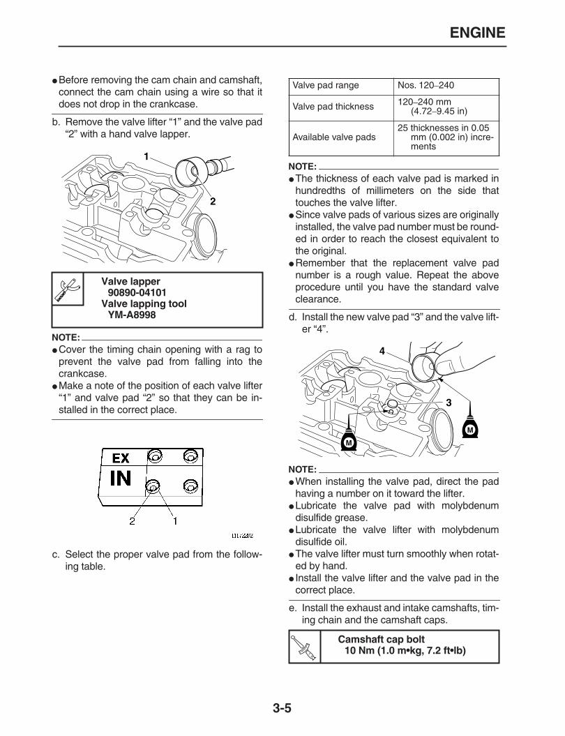
ENGINE
3-5
Before removing the cam chain and camshaft,connect the cam chain using a wire so that it
does not drop in the crankcase.
b. Remove the valve lifter “1” and the valve pad“2” with a hand valve lapper.
NOTE:
Cover the timing chain opening with a rag toprevent the valve pad from falling into thecrankcase.
Make a note of the position of each valve lifter“1” and valve pad “2” so that they can be in-
stalled in the correct place.
c. Select the proper valve pad from the follow-ing table.
NOTE:
The thickness of each valve pad is marked inhundredths of millimeters on the side thattouches the valve lifter.
Since valve pads of various sizes are originallyinstalled, the valve pad number must be round-ed in order to reach the closest equivalent tothe original.
Remember that the replacement valve padnumber is a rough value. Repeat the aboveprocedure until you have the standard valve
clearance.
d. Install the new valve pad “3” and the valve lift-er “4”.
NOTE:
When installing the valve pad, direct the padhaving a number on it toward the lifter.
Lubricate the valve pad with molybdenumdisulfide grease.
Lubricate the valve lifter with molybdenumdisulfide oil.
The valve lifter must turn smoothly when rotat-ed by hand.
Install the valve lifter and the valve pad in the
correct place.
e. Install the exhaust and intake camshafts, tim-ing chain and the camshaft caps.
Valve lapper90890-04101
Valve lapping toolYM-A8998
1
2
Valve pad range Nos. 120
–
240
Valve pad thickness 120
–
240 mm (4.72
–
9.45 in)
Available valve pads25 thicknesses in 0.05
mm (0.002 in) incre-ments
Camshaft cap bolt10 Nm (1.0 m•kg, 7.2 ft•lb)
4
3
M
M
TR..

ENGINE
3-6
NOTE:
Refer to “CAMSHAFT” on page 5-6.
Lubricate the camshaft bearings, camshaftlobes and camshaft journals.
First, install the exhaust camshaft.
Align the camshaft sprocket marks with theedge of the cylinder head.
Turn the crankshaft counterclockwise several
full turns to seat the parts.
f. Measure the valve clearance again.g. If the valve clearance is still out of specifica-
tion, repeat all of the valve clearance adjust-ment steps until the specified clearance isobtained.
9. Install:
All removed partsNOTE:
For installation, reverse the removal procedure.
Note the following points.
10.Fill the coolant as specification, and thencheck the coolant level.
EAS20590
ADJUSTING THE ENGINE IDLING SPEEDNOTE:
Prior to adjusting the idling speed, the air filter el-ement should be clean, and the engine should
have adequate compression.
1. Start the engine and let it warm up until itreaches the specified temperature.
2. Use a temperature probe tester “1” and con-tact it to the drain bolt thread.
3. Install:
Digital tachometer(Red/black ignition coil leads)
4. Measure:
Engine idling speedOut of specification
→
Adjust.
5. Adjust:
Engine idling speed
a. Adjust the engine idling speed by turning theadjust screw “1” in direction “a” or “b”.
6. Adjust:
Throttle cable free playRefer to “ADJUSTING THE THROTTLE CA-BLE FREE PLAY” on page 3-8.
Throttle cable free play (Cable free play atsurface of throttle grip flange)3
–
5 mm
EAS20640
ADJUSTING THE THROTTLE CABLE FREE PLAYNOTE:
Prior to adjusting the throttle cable free play, the
engine idling speed should be adjusted properly.
1. Check:
Throttle cable free play “a”Out of specification
→
Adjust.
Oil temperature60.0
°
C (140.00
°
F)
1
Digital tachometer90890-06760YU-39951-B
Engine idling speed1450
–
1650 r/min
Direction “a” Engine idling speed
→
Decrease
Direction “b” Engine idling speed
→
Increase
Throttle cable free play3.0
–
5.0 mm
1
a
b

ENGINE
3-7
2. Remove:
Seat
Side cover (left/right)
Air scoop (left/right)Refer to “GENERAL CHASSIS” on page 4-1.
Fuel tankRefer to “FUEL TANK” on page 7-1.
3. Adjust:
Throttle cable free playNOTE:
When the throttle is opened, the accelerator ca-
ble is pulled.
Throttle body side
a. Loosen the locknut “1” on the decelerator ca-ble.
b. Turn the adjusting nut “2” in direction “a” or“b” to take up any slack on the decelerator ca-ble.
c. Loosen the locknut “3” on the accelerator ca-ble.
d. Turn the adjusting nut “4” in direction “a” or“b” until the specified throttle cable free playis obtained.
e. Tighten the locknuts “1”, “3”.
NOTE:
If the specified throttle cable free play cannot beobtained on the throttle body side of the cable,
use the adjusting nut on the handlebar side.
Handlebar side
a. Loosen the locknut “1”.b. Turn the adjusting nut “2” in direction “a” or
“b” until the specified throttle cable free playis obtained.
c. Tighten the locknut.
WARNING
EWA12920
After adjusting the throttle cable free play,start the engine and turn the handlebars tothe right and to the left to ensure that thisdoes not cause the engine idling speed to
change.
4. Install:
Fuel tankRefer to “GENERAL CHASSIS” on page 4-1.
Air scoop (left/right)
Side cover (left/right)
Throttle cable free play3.0
–
5.0 mm (0.12
–
0.20 in)
Direction “a”Throttle cable free play is increased.Direction “b”Throttle cable free play is decreased.
a
Direction “a”Throttle cable free play is increased.Direction “b”Throttle cable free play is decreased.
a
a
2
3
1
4b
b
12
a
b
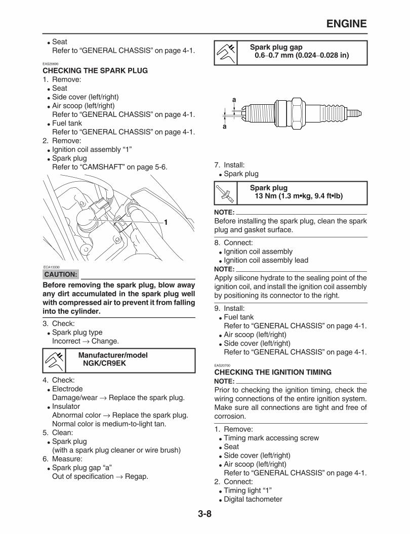
ENGINE
3-8
SeatRefer to “GENERAL CHASSIS” on page 4-1.
EAS20690
CHECKING THE SPARK PLUG
1. Remove:
Seat
Side cover (left/right)
Air scoop (left/right)Refer to “GENERAL CHASSIS” on page 4-1.
Fuel tankRefer to “GENERAL CHASSIS” on page 4-1.
2. Remove:
Ignition coil assembly “1”
Spark plugRefer to “CAMSHAFT” on page 5-6.
CAUTION:
ECA13330
Before removing the spark plug, blow awayany dirt accumulated in the spark plug wellwith compressed air to prevent it from falling
into the cylinder.
3. Check:
Spark plug typeIncorrect
→
Change.
4. Check:
ElectrodeDamage/wear
→
Replace the spark plug.
InsulatorAbnormal color
→
Replace the spark plug.Normal color is medium-to-light tan.
5. Clean:
Spark plug(with a spark plug cleaner or wire brush)
6. Measure:
Spark plug gap “a”Out of specification
→
Regap.
7. Install:
Spark plug
NOTE:
Before installing the spark plug, clean the spark
plug and gasket surface.
8. Connect:
Ignition coil assembly
Ignition coil assembly leadNOTE:
Apply silicone hydrate to the sealing point of theignition coil, and install the ignition coil assembly
by positioning its connector to the right.
9. Install:
Fuel tankRefer to “GENERAL CHASSIS” on page 4-1.
Air scoop (left/right)
Side cover (left/right)Refer to “GENERAL CHASSIS” on page 4-1.
EAS20700
CHECKING THE IGNITION TIMINGNOTE:
Prior to checking the ignition timing, check thewiring connections of the entire ignition system.Make sure all connections are tight and free of
corrosion.
1. Remove:
Timing mark accessing screw
Seat
Side cover (left/right)
Air scoop (left/right)Refer to “GENERAL CHASSIS” on page 4-1.
2. Connect:
Timing light “1”
Digital tachometer
Manufacturer/modelNGK/CR9EK
1
Spark plug gap0.6
–
0.7 mm (0.024
–
0.028 in)
Spark plug13 Nm (1.3 m•kg, 9.4 ft•lb)
a
a
TR..

ENGINE
3-9
(Red/black ignition coil leads)
3. Check:
Ignition timing
a. Start the engine, warm it up for several min-utes, and then let it run at the specified en-gine idling speed.
b. Check the firing range as shown.Incorrect firing range
→
Check the ignitionsystem.
NOTE:
The ignition timing is not adjustable.
4. Remove:
Timing light
Digital tachometer5. Install:
Air scoop (left/right)
Side cover (left/right)
SeatRefer to “GENERAL CHASSIS” on page 4-1.
Timing mark accessing screw
EAS20710
MEASURING THE COMPRESSION PRESSURE
The following procedure applies to all of the cyl-inders.NOTE:
Insufficient compression pressure will result in a
loss of performance.
1. Measure:
Valve clearanceOut of specification
→
Adjust.Refer to “ADJUSTING THE VALVE CLEAR-ANCE” on page 3-5.
2. Start the engine, warm it up for several min-utes, and then turn it off.
3. Remove:
Seat
Side cover (left/right)
Air scoop (left/right)Refer to “GENERAL CHASSIS” on page 4-1.
Fuel tankRefer to “FUEL TANK” on page 7-1.
4. Disconnect:
Ignition coil assembly coupler5. Remove:
Ignition coil assembly
Spark plug
CAUTION:
ECA13340
Before removing the spark plugs, use com-pressed air to blow away any dirt accumulat-ed in the spark plug wells to prevent it from
falling into the cylinders.
6. Install:
Compression gauge “1”
Timing light90890-03141
Inductive clamp timing lightYU-03141
Digital tachometer90890-06760YU-39951-B
Oil temperature 55
–
65
°
C
Engine idling speed1450
–
1650 r/min
1
Compression gauge90890-03081
Engine compression testerYU-33223

ENGINE
3-10
7. Measure:
Compression pressureOut of specification
→
Refer to steps (c) and(d).
a. Set the main switch to “ON”.b. With the throttle wide open, crank the engine
until the reading on the compression gaugestabilizes.
NOTE:
Make use the battery is fully charged when tak-ing measurements.
Make sure there is no compression leakagefrom the connecting section of the compres-
sion gauge.
c. If the compression pressure is above themaximum specification, check the cylinderhead, valve surfaces and piston crown forcarbon deposits.Carbon deposits
→
Eliminate.d. If the compression pressure is below the min-
imum specification, pour a teaspoonful of en-gine oil into the spark plug bore and measureagain.Refer to the following table.
8. Install:
Spark plug
9. Install:
Ignition coil assembly10.Connect:
Ignition coil assembly lead coupler11.Install:
Fuel tankRefer to “FUEL TANK” on page 7-1.
Air scoop (left/right)
Side cover (left/right)
SeatRefer to “GENERAL CHASSIS” on page 4-1.
EAS20730
CHECKING THE ENGINE OIL LEVEL
1. Stand the vehicle on a level surface.NOTE:
Place the vehicle on a suitable stand.
Make sure the vehicle is upright.
2. Start the engine, warm it up for several min-utes, and then turn it off.
3. Check:
Engine oil levelThe engine oil level should be between theminimum level mark “a” and maximum levelmark “b”.Below the minimum level mark
→
Add therecommended engine oil to the proper level.
Compression pressure (Stan-dard)
850 kPa (121 psi) (8.5 kg/cm
2
)Compression pressure (Mini-mum)
740 kPa (105 psi) (7.4 kg/cm
2
)Compression pressure (Maxi-mum)
950 kPa (135 psi) (9.5 kg/cm
2
)
Compression pressure (with oil applied into the cylinder)
Reading Diagnosis
Higher than without oil Piston ring (s) wear or damage
→
Repair.
1
Same as without oil
Piston, valves, cylinder head gasket or pis-ton possibly defec-tive
→
Repair.
Spark plug13 Nm (1.3 m•kg, 9.4 ft•lb)T
R..
ba

ENGINE
3-11
CAUTION:
ECA13360
Engine oil also lubricates the clutch andthe wrong oil types or additives couldcause clutch slippage. Therefore, do notadd any chemical additives or use engineoils with a grade of CD or higher and do notuse oils labeled “ENERGY CONSERVINGII”.
Do not allow foreign materials to enter the
crankcase.
NOTE:
Before checking the engine oil level, wait a few
minutes until the oil has settled.
4. Start the engine, warm it up for several min-utes, and then turn it off.
5. Check the engine oil level again.NOTE:
Before checking the engine oil level, wait a few
minutes until the oil has settled.
EAS20810
CHANGING THE ENGINE OIL
1. Start the engine, warm it up for several min-utes, and then turn it off.
2. Place a container under the engine oil drainbolt.
3. Remove:
Engine oil filler cap “1”
Engine oil drain bolt “2”(along with the gasket)
4. Drain:
Engine oil(completely from the crankcase)
5. If the oil filter element is also to be replaced,perform the following procedure.
a. Remove the oil filter element cover “1” and oilfilter element “2”.
b. Replace the O-rings “3”.
c. Install the new oil filter element and the oil fil-
TypeYAMALUBE 4, SAE 10W-30 orSAE 20W-40
Recommended engine oil gradeAPI service SG type or higher,JASO standard MA
10 30 50 70 90 1100 130 ˚F
YAMALUBE 4 (10W-30)or SAE 10W-30
YAMALUBE 4 (20W-40)or SAE 20W-40
–10 0 10 20 30 40–20 50 ˚C
1
2
1
3
2
1

ENGINE
3-12
ter element cover.
6. Check:
Engine oil drain bolt gasket
Oil filter element drain bolt gasketDamage
→
Replace.7. Install:
Engine oil drain bolt(along with the gasket)
8. Fill:
Crankcase(with the specified amount of the recom-mended engine oil)
9. Install:
Engine oil filler cap10.Start the engine, warm it up for several min-
utes, and then turn it off.11.Check:
Engine(for engine oil leaks)
12.Check:
Engine oil levelRefer to “CHECKING THE ENGINE OILLEVEL” on page 3-12.
13.Check:
Engine oil pressure
a. Slightly loosen the oil check bolt “1”.
b. Start the engine and keep it idling until engineoil starts to seep from the oil check bolt. If noengine oil comes out after one minute, turnthe engine off so that it will not seize.
c. Check the engine oil passages, the oil filtercartridge and the oil pump for damage orleakage. Refer to “OIL PUMP AND BALANC-ER GEAR” on page 5-45.
d. Start the engine after solving the problem (s)and check the engine oil pressure again.
e. Tighten the oil check bolt to specification.
EAS20870
ADJUSTING THE CLUTCH CABLE FREE PLAY
1. Check:
Clutch cable free play “a”Out of specification
→
Adjust.
2. Adjust:
Clutch cable free play
Handlebar side
a. Loosen the locknut “1”.b. Turn the adjusting bolt “2” in direction “a” or
“b” until the specified clutch cable free play is
Oil filter element cover bolt (M10)10 Nm (1.0 m•kg, 7.2 ft•lb)
Engine oil drain bolt20 Nm (2.0 m•kg, 14 ft•lb)
Engine oil quantityTotal amount
1.50 L (1.59 US qt) (1.32 Imp.qt)Without oil filter element replace-ment
1.30 L (1.37 US qt) (1.14 Imp.qt)With oil filter element replace-ment
1.40 L (1.48 US qt) (1.23 Imp.qt)
TR..
TR..
Oil check bolt10 Nm (1.0 m•kg, 7.2 ft•lb)
Clutch lever free play10.0
–
15.0 mm (0.39
–
0.59 in)
1
TR..
a
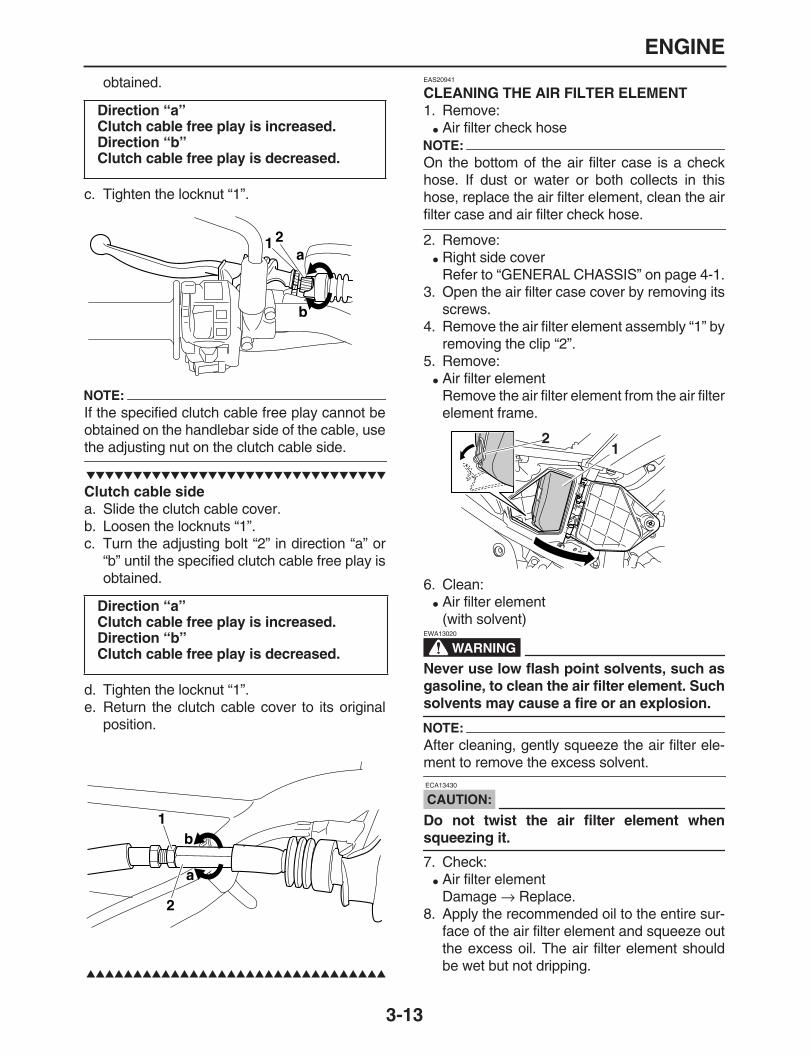
ENGINE
3-13
obtained.
c. Tighten the locknut “1”.
NOTE:
If the specified clutch cable free play cannot beobtained on the handlebar side of the cable, use
the adjusting nut on the clutch cable side.
Clutch cable side
a. Slide the clutch cable cover.b. Loosen the locknuts “1”.c. Turn the adjusting bolt “2” in direction “a” or
“b” until the specified clutch cable free play isobtained.
d. Tighten the locknut “1”.e. Return the clutch cable cover to its original
position.
EAS20941
CLEANING THE AIR FILTER ELEMENT
1. Remove:
Air filter check hoseNOTE:
On the bottom of the air filter case is a checkhose. If dust or water or both collects in thishose, replace the air filter element, clean the air
filter case and air filter check hose.
2. Remove:
Right side coverRefer to “GENERAL CHASSIS” on page 4-1.
3. Open the air filter case cover by removing itsscrews.
4. Remove the air filter element assembly “1” byremoving the clip “2”.
5. Remove:
Air filter elementRemove the air filter element from the air filterelement frame.
6. Clean:
Air filter element(with solvent)
WARNING
EWA13020
Never use low flash point solvents, such asgasoline, to clean the air filter element. Such
solvents may cause a fire or an explosion.
NOTE:
After cleaning, gently squeeze the air filter ele-
ment to remove the excess solvent.
CAUTION:
ECA13430
Do not twist the air filter element when
squeezing it.
7. Check:
Air filter elementDamage
→
Replace.8. Apply the recommended oil to the entire sur-
face of the air filter element and squeeze outthe excess oil. The air filter element shouldbe wet but not dripping.
Direction “a”Clutch cable free play is increased.Direction “b”Clutch cable free play is decreased.
Direction “a”Clutch cable free play is increased.Direction “b”Clutch cable free play is decreased.
21a
b
1
a
b
2
21

ENGINE
3-14
9. Install:
Air filter element frame
CAUTION:
ECA14401
Never operate the engine without the air filterelement installed. Unfiltered air will causerapid wear of engine parts and may damagethe engine. Operating the engine without theair filter element will also affect carburetorsynchronization, leading to poor engine per-
formance and possible overheating.
10.Install:
Air filter element assembly11.Install:
Air filter cover12.Install:
Side cover (right)Refer to “GENERAL CHASSIS” on page 4-1.
EAS21020
CHECKING THE THROTTLE BODY JOINT
1. Remove:
Seat
Side cover (left/right)
Air scoop (left/right)Refer to “GENERAL CHASSIS” on page 4-1.
Fuel tankRefer to “FUEL TANK” on page 7-1.
2. Check:
Throttle body joint “1”Cracks/damage
→
Replace.
Insulator manifold “2”Cracks/damage
→
Replace.
3. Install:
Fuel tankRefer to “FUEL TANK” on page 7-1.
Air scoop (left/right)
Side cover (left/right)
SeatRefer to “GENERAL CHASSIS” on page 4-1.
EAS21030
CHECKING THE FUEL LINE
The following procedure applies to all of the fuel,vacuum and breather hoses.1. Remove:
Seat
Side cover (left/right)
Air scoop (left/right)Refer to “GENERAL CHASSIS” on page 4-1.
Fuel tankRefer to “FUEL TANK” on page 7-1.
2. Check:
Fuel hose “1”Cracks/damage
→
Replace.Loose connection
→
Connect properly.
3. Fuel tank
Fuel tankRefer to “GENERAL CHASSIS” on page 4-1.
Air scoop (left/right)
Side cover (left/right)
SeatRefer to “GENERAL CHASSIS” on page 4-1.
Recommended oil Foam air filter oil or engine oil
1
2
1

ENGINE
3-15
EAS21050
CHECKING THE CYLINDER HEAD BREATHER HOSE
1. Remove:
Seat
Side cover (left/right)
Air scoop (left/right)Refer to “GENERAL CHASSIS” on page 4-1.
Fuel tankRefer to “FUEL TANK” on page 7-1.
2. Check:
Cylinder head breather hose “1”Cracks/damage
→
Replace.Loose connection
→
Connect properly.
CAUTION:
ECA14920
Make sure the cylinder head breather hose is
routed correctly.
3. Install:
Fuel tankRefer to “FUEL TANK” on page 7-1.
Air scoop (left/right)
Side cover (left/right)
SeatRefer to “GENERAL CHASSIS” on page 4-1.
EAS21080
CHECKING THE EXHAUST SYSTEM
The following procedure applies to all of the ex-haust pipes and gaskets.1. Remove:
Muffler protector2. Check:
Exhaust pipe
MufflerCracks/damage
→
Replace.
GasketExhaust gas leaks
→
Replace.3. Check:
Tightening torque
4. Install:
Muffler protector
EAS21100
ADJUSTING THE EXUP CABLES
1. Remove:
Side cover (left/right)Refer to “GENERAL CHASSIS” on page 4-1.
2. Remove:
EXUP valve pulley cover “1”
1
Exhaust pipe nut “1”20 Nm (2.0 m•kg, 14 ft•lb)
Exhaust pipe and muffler bolt “2”20 Nm (2.0 m•kg, 14 ft•lb)
Muffler and muffler bracket bolt“3”
42 Nm (4.2 m•kg, 30 ft•lb)
Muffler protector bolt7 Nm (0.7 m•kg, 5.1 ft•lb)
TR..
1
2
3
TR..
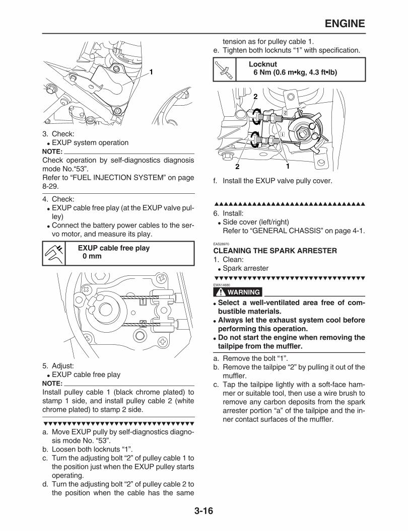
ENGINE
3-16
3. Check:
EXUP system operationNOTE:
Check operation by self-diagnostics diagnosismode No.“53”.Refer to “FUEL INJECTION SYSTEM” on page
8-29.
4. Check:
EXUP cable free play (at the EXUP valve pul-ley)
Connect the battery power cables to the ser-vo motor, and measure its play.
5. Adjust:
EXUP cable free playNOTE:
Install pulley cable 1 (black chrome plated) tostamp 1 side, and install pulley cable 2 (white
chrome plated) to stamp 2 side.
a. Move EXUP pully by self-diagnostics diagno-sis mode No. “53”.
b. Loosen both locknuts “1”.c. Turn the adjusting bolt “2” of pulley cable 1 to
the position just when the EXUP pulley startsoperating.
d. Turn the adjusting bolt “2” of pulley cable 2 tothe position when the cable has the same
tension as for pulley cable 1.e. Tighten both locknuts “1” with specification.
f. Install the EXUP valve pully cover.
6. Install:
Side cover (left/right)Refer to “GENERAL CHASSIS” on page 4-1.
EAS28970
CLEANING THE SPARK ARRESTER
1. Clean:
Spark arrester
WARNING
EWA14680
Select a well-ventilated area free of com-bustible materials.
Always let the exhaust system cool beforeperforming this operation.
Do not start the engine when removing the
tailpipe from the muffler.
a. Remove the bolt “1”.b. Remove the tailpipe “2” by pulling it out of the
muffler.c. Tap the tailpipe lightly with a soft-face ham-
mer or suitable tool, then use a wire brush toremove any carbon deposits from the sparkarrester portion “a” of the tailpipe and the in-ner contact surfaces of the muffler.
EXUP cable free play0 mm
1
Locknut6 Nm (0.6 m•kg, 4.3 ft•lb)T
R..
2 1
2
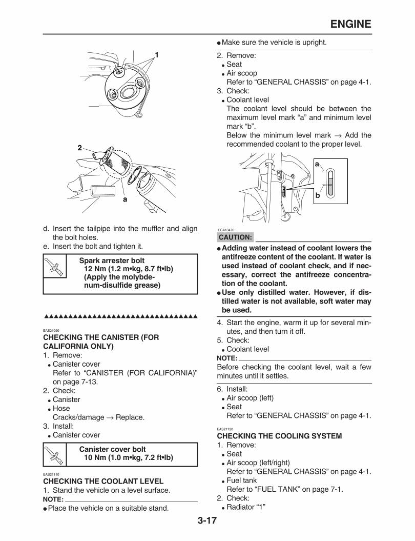
ENGINE
3-17
d. Insert the tailpipe into the muffler and alignthe bolt holes.
e. Insert the bolt and tighten it.
EAS21090
CHECKING THE CANISTER (FOR CALIFORNIA ONLY)
1. Remove:
Canister coverRefer to “CANISTER (FOR CALIFORNIA)”on page 7-13.
2. Check:
Canister
HoseCracks/damage
→
Replace.3. Install:
Canister cover
EAS21110
CHECKING THE COOLANT LEVEL
1. Stand the vehicle on a level surface.NOTE:
Place the vehicle on a suitable stand.
Make sure the vehicle is upright.
2. Remove:
Seat
Air scoopRefer to “GENERAL CHASSIS” on page 4-1.
3. Check:
Coolant levelThe coolant level should be between themaximum level mark “a” and minimum levelmark “b”.Below the minimum level mark
→
Add therecommended coolant to the proper level.
CAUTION:
ECA13470
Adding water instead of coolant lowers theantifreeze content of the coolant. If water isused instead of coolant check, and if nec-essary, correct the antifreeze concentra-tion of the coolant.
Use only distilled water. However, if dis-tilled water is not available, soft water may
be used.
4. Start the engine, warm it up for several min-utes, and then turn it off.
5. Check:
Coolant levelNOTE:
Before checking the coolant level, wait a few
minutes until it settles.
6. Install:
Air scoop (left)
SeatRefer to “GENERAL CHASSIS” on page 4-1.
EAS21120
CHECKING THE COOLING SYSTEM
1. Remove:
Seat
Air scoop (left/right)Refer to “GENERAL CHASSIS” on page 4-1.
Fuel tankRefer to “FUEL TANK” on page 7-1.
2. Check:
Radiator “1”
Spark arrester bolt12 Nm (1.2 m•kg, 8.7 ft•lb)(Apply the molybde-num-disulfide grease)
Canister cover bolt10 Nm (1.0 m•kg, 7.2 ft•lb)
1
2
a
TR..
TR..
a
b

ENGINE
3-18
Radiator inlet hose “2”
Radiator outlet hose “3”Cracks/damage
→
Replace.Refer to “RADIATOR” on page 6-1, “THER-MOSTAT” on page 6-4 and “WATER PUMP”on page 6-6.
3. Install:
Fuel tankRefer to “FUEL TANK” on page 7-1.
Fuel tank (left/right)
SeatRefer to “GENERAL CHASSIS” on page 4-1.
EAS21130
CHANGING THE COOLANT
1. Remove:
Seat
Air scoop (left/right)Refer to “GENERAL CHASSIS” on page 4-1.
2. Remove:
Coolant reservoir hose “1”
Recovery tank “2”
3. Drain:
Coolant(from the recovery)
4. Remove:
Radiator cap “1”Remove the radiator cap by removing lockscrew “2”.
WARNING
EWA13030
A hot radiator is under pressure. Therefore,do not remove the radiator cap when the en-gine is hot. Scalding hot fluid and steam maybe blown out, which could cause serious in-jury. When the engine has cooled, open theradiator cap as follows:Place a thick rag or a towel over the radiatorcap and slowly turn the radiator cap counter-clockwise toward the detent to allow any re-sidual pressure to escape. When the hissingsound has stopped, press down on the radi-ator cap and turn it counterclockwise to re-
move.
5. Remove:
Coolant drain bolt (water pump) “1”(along with the copper washer)
6. Drain:
Coolant(from the engine and radiator)
7. Install:
Copper washer
Coolant drain bolt (water pump)
8. Install:
Reservoir tank9. Connect:
Coolant reservoir hose
2
3
1
1
2
Coolant drain bolt (engine)10 Nm (1.0 m•kg, 7.2 ft•lb)
2
1
1
New
TR..

ENGINE
3-19
10.Fill:
Cooling system(with the specified amount of the recom-mended coolant)
Handling notes for coolantCoolant is potentially harmful and should behandled with special care.
WARNING
EWA13040
If coolant splashes in your eyes, thorough-ly wash them with water and consult a doc-tor.
If coolant splashes on your clothes, quicklywash it away with water and then with soapand water.
If coolant is swallowed, induce vomiting
and get immediate medical attention.
CAUTION:
ECA13480
Adding water instead of coolant lowers theantifreeze content of the coolant. If water isused instead of coolant check, and if nec-essary, correct the antifreeze concentra-tion of the coolant.
Use only distilled water. However, if dis-tilled water is not available, soft water maybe used.
If coolant comes into contact with paintedsurfaces, immediately wash them with wa-
ter.
Do not mix different types of antifreeze.
11.Install:
Radiator cap12.Fill:
Coolant reservoir(with the recommended coolant to the maxi-mum level mark “a”)
13.Install:
Coolant reservoir cap14.Start the engine, warm it up for several min-
utes, and then stop it.15.Check:
Coolant levelRefer to “CHECKING THE COOLANT LEV-EL” on page 3-19.
NOTE:
Before checking the coolant level, wait a few
minutes until the coolant has settled.
16.Install:
Air scoop (left/right)
SeatRefer to “GENERAL CHASSIS” on page 4-1.
Recommended antifreezeHigh-quality ethylene glycol anti-freeze containing corrosion inhib-itors for aluminum enginesMixing ratio
1:1 (antifreeze:water)Radiator capacity (including allroutes)
0.90 L (0.95 US qt) (0.79 Imp.qt)Coolant reservoir capacity (up tothe maximum level mark)
0.25 L (0.26 US qt) (0.22 Imp.qt)
a

CHASSIS
3-20
EAS21140
CHASSIS
EAS21170
ADJUSTING THE FRONT DISC BRAKE
1. Check:
Brake lever free play “a”Out of specification
→
Adjust.
2. Adjust:
Brake lever free play
a. Loosen the locknut “1”.b. Turn the adjusting bolt “2” in direction “a” or
“b” until the specified brake lever free play isobtained.
c. Tighten the locknut “1”.
WARNING
EWA13050
A soft or spongy feeling in the brake levercan indicate the presence of air in the brakesystem. Before the vehicle is operated, theair must be removed by bleeding the brakesystem. Air in the brake system will consid-
erably reduce braking performance.
CAUTION:
ECA13490
After adjusting the brake lever position,
make sure there is no brake drag.
EAS21200
ADJUSTING THE REAR DISC BRAKE
1. Check:
Brake pedal position “a”(distance “a” from the top of the rider footrestto the top of the brake pedal)Out of specification
→
Adjust.
2. Adjust:
Brake pedal position
a. Loosen the locknut “1”.b. Turn the adjusting bolt “2” in direction “a” or
“b” until the specified brake pedal position isobtained.
c. Tighten the locknut “1” to specification.
Front brake lever free play5.0
–
8.0 mm (0.20
–
0.31 in)
Direction “a”Brake lever free play is increased.Direction “b”Brake lever free play is decreased.
a
aa
bb
12
Brake pedal position11.5 mm (0.45 in)
Direction “a”Brake pedal is raised.Direction “b”Brake pedal is lowered.
a
1
2
ab
CHASSIS
3-21
WARNING
EWA13050
A soft or spongy feeling in the brake levercan indicate the presence of air in the brakesystem. Before the vehicle is operated, theair must be removed by bleeding the brakesystem. Air in the brake system will consid-
erably reduce braking performance.
CAUTION:
ECA13510
After adjusting the brake pedal position,
make sure there is no brake drag.
3. Adjust:
Rear brake light switchRefer to “ADJUSTING THE REAR BRAKELIGHT SWITCH” on page 3-24.
EAS21240
CHECKING THE BRAKE FLUID LEVEL
1. Stand the vehicle on a level surface.NOTE:
Place the vehicle on a suitable stand.
Make sure the vehicle is upright.
In order to ensure a correct reading of thebrake fluid level, make sure the top of the
brake fluid reservoir is horizontal.
2. Check:
Brake fluid levelBelow the minimum level mark “a”
→
Add therecommended brake fluid to the proper level.
WARNING
EWA13090
Use only the designated brake fluid. Otherbrake fluids may cause the rubber seals todeteriorate, causing leakage and poorbrake performance.
Refill with the same type of brake fluid thatis already in the system. Mixing brake flu-ids may result in a harmful chemical reac-tion, leading to poor brake performance.
When refilling, be careful that water doesnot enter the brake fluid reservoir. Waterwill significantly lower the boiling point of
the brake fluid and could cause vapor lock.
CAUTION:
ECA13540
Brake fluid may damage painted surfacesand plastic parts. Therefore, always clean up
any spilt brake fluid immediately.
EAS21250
CHECKING THE FRONT BRAKE PADS
The following procedure applies to all of thebrake pads.1. Operate the brake.2. Check:
Front brake padWear indicator groove “1” almost disappeard
→
Replace the brake pads as a set.Refer to “FRONT BRAKE” on page 4-11.
Locknut12 Nm (1.2 m•kg, 8.7 ft•lb)
Recommended fluidDOT 4
TR..
A
a
A. Front brakeB. Rear brake
a
B
1
1

CHASSIS
3-22
EAS21260
CHECKING THE REAR BRAKE PADS
The following procedure applies to all of thebrake pads.1. Operate the brake.2. Check:
Rear brake padWear indicators “1” almost touch the brakedisc
→
Replace the brake pads as a set.Refer to “REAR BRAKE” on page 4-23.
EAS21270
CHECKING THE FRONT BRAKE HOSE
1. Check:
Brake hose “1”Cracks/damage/wear
→
Replace.
2. Check:
Brake hose clampLoose Connection
→
Tighten the clamp bolt.3. Hold the vehicle upright and apply the front
brake several times.4. Check:
Brake hose “1”Brake fluid leakage
→
Replace the damagedhose.Refer to “FRONT BRAKE” on page 4-11.
EAS21290
CHECKING THE REAR BRAKE HOSE
1. Check:
Brake hose “1”Cracks/damage/wear
→
Replace.
2. Check:
Brake hose clampLoose Connection
→
Tighten the clamp bolt.3. Hold the vehicle upright and apply the rear
brake several times.4. Check:
Brake hoseBrake fluid leakage
→
Replace the damagedhose.Refer to “REAR BRAKE” on page 4-23.
EAS21330
ADJUSTING THE REAR BRAKE LIGHT SWITCHNOTE:
The rear brake light switch is operated by move-ment of the brake pedal. The rear brake lightswitch is properly adjusted when the brake light
comes on just before the braking effect starts.
1. Check:
Rear brake light operation timingIncorrect
→
Adjust.2. Adjust:
Rear brake light operation timing
a. Hold the main body “1” of the rear brake lightswitch so that it does not turn the adjustingnut “2” in direction “a” or “b” until the rearbrake light comes on at the proper time.
1
1
Direction “a”Brake light comes on sooner.Direction “b”Brake light comes on later.
1

CHASSIS
3-23
EAS21350
BLEEDING THE HYDRAULIC BRAKE SYSTEM
WARNING
EWA13100
Bleed the hydraulic brake system whenever:
the system is disassembled.
a brake hose is loosened, disconnected orreplaced.
the brake fluid level is very low.
brake operation is faulty.
1. Remove:
Brake master cylinder reservoir capNOTE:
Be careful not to spill any brake fluid or allowthe brake master cylinder reservoir or brakefluid reservoir to overflow.
When bleeding the hydraulic brake system,make sure there is always enough brake fluidbefore applying the brake. Ignoring this pre-caution could allow air to enter the hydraulicbrake system, considerably lengthening thebleeding procedure.
If bleeding is difficult, it may be necessary to letthe brake fluid settle for a few hours. Repeatthe bleeding procedure when the tiny bubbles
in the hose have disappeared.
2. Bleed:
Hydraulic brake system
a. Fill the brake fluid reservoir to the proper levelwith the recommended brake fluid.
b. Install the diaphragm (brake master cylinderreservoir or brake fluid reservoir).
c. Connect a clear plastic hose “1” tightly to thebleed screw “2”, and place an oil pan underthe vinyl hose end on one side.
d. Place the other end of the hose into a con-tainer.
e. Slowly apply the brake several times.f. Fully pull the brake lever or fully press down
the brake pedal and hold it in position.g. Loosen the bleed screw.NOTE:
Loosening the bleed screw will release the pres-sure and cause the brake lever to contact the
throttle grip or the brake pedal to fully extend.
h. Tighten the bleed screw and then release thebrake lever or brake pedal.
i. Repeat steps (e) to (h) until all of the air bub-bles have disappeared from the brake fluid inthe plastic hose.
j. Tighten the bleed screw to specification.
k. Fill the brake fluid reservoir to the proper levelwith the recommended brake fluid.Refer to “CHECKING THE BRAKE FLUIDLEVEL” on page 3-23.
WARNING
EWA13110
After bleeding the hydraulic brake system,
check the brake operation.
A. FrontB. Rear
Bleed screw6 Nm (0.6 m•kg, 4.3 ft•lb)
1
2A
2
1
B
TR..

CHASSIS
3-24
EAS21420
ADJUSTING THE DRIVE CHAIN SLACKNOTE:
The drive chain slack must be checked at the
tightest point on the chain.
CAUTION:
ECA13550
A drive chain that is too tight will overloadthe engine and other vital parts, and one thatis too loose can skip and damage the swing-arm or cause an accident. Therefore, keepthe drive chain slack within the specified lim-
its.
1. Stand the vehicle on a level surface.
WARNING
EWA13120
Securely support the vehicle so that there is
no danger of it falling over.
NOTE:
Place the vehicle on a suitable stand so that the
rear wheel is elevated.
2. Spin the rear wheel several times and find thetightest position of drive chain.
3. Check:
Drive chain slack “a”Out of specification
→
Adjust.NOTE:
Measure the drive chain slack in an intermediateposition between the chain tensioner and the
chain support bolt.
4. Adjust:
Drive chain slack
a. Loosen the wheel axle nut “1”.b. Loosen both locknuts “2”.c. Turn the drive chain puller “3” in direction “a”
or “b” until the specified drive chain slack isobtained.
NOTE:
To maintain the proper wheel alignment, adjustboth sides evenly.
Push the rear wheel forward to make surethere is no clearance between the swingarm
end plates and the ends of the swingarm.
d. Tighten the locknut.
e. Tighten the wheel axle nut.
EAS21440
LUBRICATING THE DRIVE CHAIN
The drive chain consists of many interactingparts. If the drive chain is not maintained proper-ly, it will wear out quickly. Therefore, the drivechain should be serviced, especially when the
Drive chain slackWR250R38.0
–
48.0 mmWR250X40.0
–
50.0 mm
a
Direction “a”Drive chain is tightened.Direction “b”Drive chain is loosened.
Locknut16 Nm (1.6 m•kg, 12 ft•lb)
Wheel axle nut125 Nm (12.5 m•kg, 90 ft•lb)
1 3 2
ab
TR..
TR..
CHASSIS
3-25
vehicle is used in dusty areas.This vehicle has a drive chain with small rubberO-rings between each side plate. Steam clean-ing, high-pressure washing, certain solvents,and the use of a coarse brush can damagethese O-rings. Therefore, use only kerosene toclean the drive chain. Wipe the drive chain dryand thoroughly lubricate it with engine oil orchain lubricant that is suitable for O-ring chains.Do not use any other lubricants on the drivechain since they may contain solvents that coulddamage the O-rings.
EAS21510
CHECKING AND ADJUSTING THE STEERING HEAD
1. Stand the vehicle on a level surface.
WARNING
EWA13120
Securely support the vehicle so that there is
no danger of it falling over.
NOTE:
Place the vehicle on a suitable stand so that the
front wheel is elevated.
2. Check:
Steering headGrasp the bottom of the front fork legs andgently rock the front fork.Blinding/looseness
→
Adjust the steeringhead.
3. Remove:
HandlebarRefer to “HANDLEBAR” on page 4-34.
Upper bracketRefer to “STEERING HEAD” on page 4-49.
4. Adjust:
Steering head
a. Remove the lock washer “1”, the upper ringnut “2”, and the rubber washer “3”.
b. Tighten the lower ring nut “4” with a steeringnut wrench “5”.
c. Turn the front fork to the right and left a fewtimes, and make sure that the steering ro-tates smoothly. If it does not turn smoothly,remove the lower bracket and inspect the up-per and lower bearings.Refer to “STEERING HEAD” on page 4-49.
d. Loosen the lower ring nut “4” fully turn andthen tighten it to specification with a steeringnut wrench.
WARNING
EWA13140
Do not overtighten the lower ring nut.
e. Install the rubber washer.f. Install the upper ring nut.g. Finger tighten the upper ring nut “2”, then
align the slots of both ring nuts. If necessary,
Recommended lubricantEngine oil or chain lubricantsuitable for O-ring chains
Steering nut wrench90890-01403
Spanner wrenchYU-33975
Lower ring nut (initial tighteningtorque)
38 Nm (3.8 m•kg, 27 ft•lb)
Lower ring nut (final tighteningtorque)
7 Nm (0.7 m•kg, 5.1 ft•lb)
5
4
TR..
TR..

CHASSIS
3-26
hold the lower ring nut and tighten the upperring nut until their slots are aligned.
NOTE:
Make sure the special washer tabs “a” sit cor-
rectly in the ring nut slots “b”.
5. Install:
Upper bracketRefer to “STEERING HEAD” on page 4-49.
HandlebarRefer to “HANDLEBAR” on page 4-34.
EAS21530
CHECKING THE FRONT FORK
1. Stand the vehicle on a level surface.
WARNING
EWA13120
Securely support the vehicle so that there is
no danger of it falling over.
2. Check:
Inner tubeDamage/scratches
→
Replace.
Oil sealOil leakage
→
Replace.3. Hold the vehicle upright and apply the front
brake.4. Check:
Front fork operationPush down hard on the handlebar severaltimes and check if the front fork reboundssmoothly.Rough movement
→
Repair.Refer to “FRONT FORK” on page 4-39.
EAS21580
ADJUSTING THE FRONT FORK LEGS
The following procedure applies to both of thefront fork legs.
WARNING
EWA32D1006
Always adjust the left and right front forksevenly. If this is not done, the vehicle willhave poor stability.
Securely support the vehicle so that there
is no danger of it falling over.
Rebound damping
CAUTION:
ECA13590
Never go beyond the maximum or minimum
adjustment positions.
1. Adjust:
Rebound damping
a. Turn the adjusting screw “1” in direction “a” or“b”.
Direction “a”Rebound damping is increased (suspen-sion is harder).Direction “b”Rebound damping is decreased (suspen-sion is softer).
Rebound dampingMaximum (hard)
1click(s) out*Standard
10 click(s) out*Minimum (soft)
12 click(s) out*
* With the adjusting screw fully turned in

CHASSIS
3-27
Compression damping
CAUTION:
ECA13590
Never go beyond the maximum or minimum
adjustment positions.
1. Adjust:
Compression damping
a. Turn the adjusting screw “1” in direction “a” or“b”.
EAS32D1020
AIR BLEEDING FROM FRONT FORK
When the temperature increases in the front fork
during touring, the air pressure increases in thefork and the suspension will become less flexi-ble.Bleed following procedure.1. Stand the vehicle on a level surface.
WARNING
EWA13120
Securely support the vehicle so that there is
no danger of it falling over.
NOTE:
Stand the vehicle vertically using an appropriate
stand, and bleed the air from the front fork.
2. Bleed the air from the front fork.Bleed the air from the front fork by removingbleed screw “1”.
CAUTION:
ECA32D1001
Always bleed the left and right front forkevenly.
If this is not done, the vehicle will have poor
stability.
3. Install:
Bleed screw
EAS21610
ADJUSTING THE REAR SHOCK ABSORBER ASSEMBLY
WARNING
EWA13120
Securely support the vehicle so that there is
no danger of it falling over.
Spring preload
CAUTION:
ECA13590
Never go beyond the maximum or minimum
adjustment positions.
1. Adjust:
Spring preloadNOTE:
Remove the rear shock absorber from the vehi-
Direction “a”Compression damping is increased (sus-pension is harder).Direction “b”Compression damping is decreased (sus-pension is softer).
Compression dampingMaximum (hard)
1 click(s) out*Standard
10 click(s) out*Minimum (soft)
19 click(s) out*
* With the adjusting screw fully turned in
1
b
a
1
ab
Bleed screw1.5 Nm (0.15 m•kg, 1.1 ft•lb)
1
TR..

CHASSIS
3-28
cle before this adjustment.Refer to “REAR SHOCK ABSORBER ASSEM-
BLY” on page 4-53.
a. Adjust the spring preload with a ring nutwrench.
b. Loosen the locknut “1”.c. Turn the adjusting nut “2” in direction “a” or
“b”.
d. Tighten the locknut.
Rebound damping
CAUTION:
ECA13590
Never go beyond the maximum or minimum
adjustment positions.
1. Adjust:
Rebound damping
a. Turn the adjusting knob “1” in direction “a” or“b”.
Compression damping
CAUTION:
ECA13590
Never go beyond the maximum or minimum
adjustment positions.
1. Adjust:
Compression damping
Ring nut wrench90890-01268
Spanner wrenchYU-01268
Direction “a”Spring preload is increased (suspensionis harder).Direction “b”Spring preload is decreased (suspensionis softer).
Spring length “c”Standard
211.5 mm (8.33 in)Minimum (hard)
206 mm (8.11 in)Maximum (soft)
216 mm (8.50 in)
1
a b
2
c
Locknut42 Nm (4.2 m•kg, 30 ft•lb)
Direction “a”Rebound damping is increased (suspen-sion is harder).Direction “b”Rebound damping is decreased (suspen-sion is softer).
Rebound dampingMaximum (hard)
3 click(s) out*Standard
12 click(s) out* (WR250R)13 click(s) out* (WR250X)
Minimum (soft)25 click(s) out*
* With the adjusting knob fully turned in
TR..
ab
1

CHASSIS
3-29
a. Turn the adjusting screw “1” in direction “a” or“b”.
EAS21650
CHECKING THE TIRES
The following procedure applies to both of thetires.1. Check:
Tire pressureOut of specification
→
Regulate.
WARNING
EWA13180
The tire pressure should only be checkedand regulated when the tire temperature
equals the ambient air temperature.
The tire pressure and the suspension mustbe adjusted according to the total weight(including cargo, rider, passenger and ac-cessories) and the anticipated ridingspeed.
Operation of an overloaded vehicle couldcause tire damage, an accident or an injury.
NEVER OVERLOAD THE VEHICLE.
WARNING
EWA13190
It is dangerous to ride with a worn-out tire.When the tire tread reaches the wear limit,
replace the tire immediately.
2. Check:
Tire surfacesDamage/wear
→
Replace the tire.
Direction “a”Compression damping is increased (sus-pension is harder).Direction “b”Compression damping is decreased (sus-pension is softer).
Compression dampingMaximum (hard)
1 click(s) out*Standard
10 click(s) out* (WR250R)7 click(s) out* (WR250X)
Minimum (soft)12 click(s) out*
* With the adjusting screw fully turned in
1
ab
Loading condition0
–
90 (0
–
198 lb)Tire air pressure (measured oncold tires)
Loading condition0
–
90 kg (0
–
198 lb)Front
WR250R 125 kPa (18 psi) (1.25kgf/cm
2
)WR250X 200 kPa (29 psi) (2.00kgf/cm
2
)Rear
WR250R 175 kPa (25 psi) (1.75kgf/cm
2
)WR250X 200 kPa (29 psi) (2.00kgf/cm
2
)Loading condition
90
–
185 kg (198
–
408 lb)Front
WR250R 150 kPa (22 psi) (1.50kgf/cm
2
)WR250X 200 kPa (29 psi) (2.00kgf/cm
2
)Rear
WR250R 200 kPa (29 psi) (2.00kgf/cm
2
)WR250X 225 kPa (33 psi) (2.25kgf/cm
2
)
Maximum load185 kg (408 lb)
* Total weight of rider, passenger, cargoand accessories

CHASSIS
3-30
WARNING
EWA14080
Do not use a tubeless tire on a wheel de-signed only for tube tires to avoid tire fail-ure and personal injury from suddendeflation.
When using a tube tire, be sure to install thecorrect tube.
Always replace a new tube tire and a newtube as a set.
To avoid pinching the tube, make sure thewheel rim band and tube are centered in thewheel groove.
Patching a punctured tube is not recom-mended. If it is absolutely necessary to doso, use great care and replace the tube assoon as possible with a good quality re-
placement.
WARNING
EWA14090
After extensive tests, the tires listed belowhave been approved by Yamaha Motor Co.,Ltd. for this model. The front and rear tiresshould always be by the same manufacturerand of the same design. No guarantee con-cerning handling characteristics can be giv-en if a tire combination other than one
approved by Yamaha is used on this vehicle.
WARNING
EWA13210
New tires have a relatively low grip on theroad surface until they have been slightlyworn. Therefore, approximately 100 kmshould be traveled at normal speed before
any high-speed riding is done.
NOTE:
For tires with a direction of rotation mark “1”: In-stall the tire with the mark pointing in the direc-tion of wheel rotation.
Align the mark “2” with the valve installation
point.
1. Tire tread depth2. Side wall3. Wear indicator
Wear limit (front)0.8 mm (0.03 in)
Wear limit (rear)0.8 mm (0.03 in)
A. Tube wheelB. Tubeless wheel
1
2 3
A B
Tube wheel Tube tire only
Tubeless wheel Tube or tubeless tire
Front tireSize
WR250R 80/100-21M/C 51PWR250X 110/70R17M/C 54H
Manufacturer/modelWR250R BRIDGESTONE/TW-301 FWR250X BRIDGESTONE/BT090F RADIAL G
Rear tireSize
WR250R 120/80-18M/C 62PWR250X 140/70R17M/C 66H
Manufacturer/modelWR250R BRIDGESTONE/TW-302 FWR250X BRIDGESTONE/BT090R RADIAL G

CHASSIS
3-31
EAS21670
CHECKING THE WHEELS
The following procedure applies to both of thewheels.1. Check:
WheelDamage/out-of-round
→
Replace.
WARNING
EWA13260
Never attempt to make any repairs to the
wheel.
NOTE:
After a tire or wheel has been changed or re-
placed, always balance the wheel.
EAS21680
CHECKING AND TIGHTENING THE SPOKES
The following procedure applies to all of thespokes.1. Check:
SpokeBends/damage
→
Replace.Loose
→
Tighten.Tap the spokes with a screwdriver.
NOTE:
A tight spoke will emit a clear, ringing tone; a
loose spoke will sound flat.
2. Tighten: (front/rear)
Spoke(with a spoke nipple wrench “1”)
NOTE:
Be sure to tighten the spokes before and after
break-in.
EAS21690
CHECKING AND LUBRICATING THE CABLES
The following procedure applies to all of the in-ner and outer cables.
WARNING
EWA13270
Damaged outer cable may cause the cable tocorrode and interfere with its movement. Re-place damaged outer cable and inner cables
as soon as possible.
1. Check:
Outer cableDamage
→
Replace.2. Check:
Cable operationRough movement
→
Lubricate.
NOTE:
Hold the cable end upright and pour a few dropsof lubricant into the cable sheath or use a suit-
able lubricating device.
EAS21700
LUBRICATING THE LEVERS
Lubricate the pivoting point and metal-to-metalmoving parts of the levers.
2
1
Spoke nipple wrench (8
–
9)90890-01522YM-01522
Spoke (front/rear)3 Nm (0.3 m•kg, 2.2 ft•lb)
Recommended lubricantEngine oil or a suitable cable lu-bricant
1
TR..

CHASSIS
3-32
EAS21710
LUBRICATING THE PEDAL
Lubricate the pivoting point and metal-to-metalmoving parts of the pedal.
EAS21720
LUBRICATING THE SIDESTAND
Lubricate the pivoting point and metal-to-metalmoving parts of the sidestand.
Brake leverSilicone grease
Clutch leverLithium-soap-based grease
Recommended lubricantLithium-soap-based grease
Recommented lubricantLithium-soap-based grease

ELECTRICAL SYSTEM
3-33
EAS21750
ELECTRICAL SYSTEM
EAS21760
CHECKING AND CHARGING THE BATTERY
Refer to “ELECTRICAL COMPONENTS” onpage 8-59.
EAS21770
CHECKING THE FUSES
Refer to “ELECTRICAL COMPONENTS” onpage 8-59.
EAS21780
REPLACING THE HEADLIGHT BULB
WARNING
EWA13320
Since the headlight bulb gets extremely hot,keep flammable products and your hands
away from the bulb until it has cooled down.
1. Remove:
Headlight unit bolt “1”NOTE:
After you have removed the headlight unit bolts,lift and remove the headlight unit from front fend-
er grommet “2”.
2. Remove:
Headlight coupler “1”
Bulb cover “2”
3. Remove:
Headlight bulb holder “1”
Headlight bulb “2”
4. Install:
Headlight bulb Fasten the new headlight bulb with the head-light bulb holder.
CAUTION:
ECA13690
Avoid touching the glass part of the head-light bulb to keep it free from oil, otherwisethe transparency of the glass, the life of thebulb and the luminous flux will be adverselyaffected. If the headlight bulb gets soiled,thoroughly clean it with a cloth moistened
with alcohol or lacquer thinner.
5. Install:
Headlight bulb holder
Bulb cover
Headlight coupler6. Install:
Headlight unit
EAS21800
ADJUSTING THE HEADLIGHT BEAM
1. Adjust:
Headlight beam (vertically)
a. Turn the adjusting screw “1” in direction “a” or“b”.
1
2
1
2
1
2
Headlight unit bolt7 Nm (0.7 m•kg, 5.1 ft•lb)
Direction “a”Headlight beam is raised.Direction “b”Headlight beam is lowered.
1
2
New
TR..

ELECTRICAL SYSTEM
3-34
ab ab

ELECTRICAL SYSTEM
3-35

ELECTRICAL SYSTEM
3-36

1
2
3
4
5
6
7
8
9
CHASSIS
GENERAL CHASSIS .....................................................................................4-1
FRONT WHEEL .............................................................................................4-2
REMOVING THE FRONT WHEEL ..........................................................4-4CHECKING THE FRONT WHEEL...........................................................4-4DISASSEMBLING THE FRONT WHEEL.................................................4-5ASSEMBLING THE FRONT WHEEL.......................................................4-5INSTALLING THE FRONT WHEEL (DISC) .............................................4-5
REAR WHEEL................................................................................................4-7
REMOVING THE REAR WHEEL.............................................................4-9DISASSEMBLING THE REAR WHEEL...................................................4-9CHECKING THE REAR WHEEL .............................................................4-9CHECKING AND REPLACING THE REAR WHEEL SPROCKET ..........4-9ASSEMBLING THE REAR WHEEL.........................................................4-10INSTALLING THE REAR WHEEL (DISC) ...............................................4-10
FRONT BRAKE..............................................................................................4-11
INTRODUCTION......................................................................................4-16CHECKING THE FRONT BRAKE DISC..................................................4-16REPLACING THE FRONT BRAKE PADS...............................................4-17REMOVING THE FRONT BRAKE CALIPER...........................................4-18DISASSEMBLING THE FRONT BRAKE CALIPER.................................4-18CHECKING THE FRONT BRAKE CALIPER ...........................................4-18ASSEMBLING THE FRONT BRAKE CALIPER.......................................4-19INSTALLING THE FRONT BRAKE CALIPER .........................................4-19REMOVING THE FRONT BRAKE MASTER CYLINDER........................4-20CHECKING THE FRONT BRAKE MASTER CYLINDER ........................4-20ASSEMBLING THE FRONT BRAKE MASTER CYLINDER....................4-21INSTALLING THE FRONT BRAKE MASTER CYLINDER ......................4-21
REAR BRAKE................................................................................................4-23
INTRODUCTION......................................................................................4-28CHECKING THE REAR BRAKE DISC ....................................................4-28REPLACING THE REAR BRAKE PADS .................................................4-28REMOVING THE REAR BRAKE CALIPER.............................................4-29DISASSEMBLING THE REAR BRAKE CALIPER ...................................4-29CHECKING THE REAR BRAKE CALIPER..............................................4-30ASSEMBLING THE REAR BRAKE CALIPER .........................................4-30INSTALLING THE REAR BRAKE CALIPER............................................4-30REMOVING THE REAR BRAKE MASTER CYLINDER ..........................4-31CHECKING THE REAR BRAKE MASTER CYLINDER...........................4-31ASSEMBLING THE REAR BRAKE MASTER CYLINDER ......................4-32INSTALLING THE REAR BRAKE MASTER CYLINDER.........................4-32
HANDLEBAR .................................................................................................4-34
REMOVING THE HANDLEBARS ............................................................4-36CHECKING THE HANDLEBAR ...............................................................4-36INSTALLING THE HANDLEBAR .............................................................4-36
FRONT FORK ................................................................................................4-39
REMOVING THE FRONT FORK LEGS...................................................4-42DISASSEMBLING THE FRONT FORK LEGS.........................................4-42CHECKING THE FRONT FORK LEGS ...................................................4-43ASSEMBLING THE FRONT FORK LEGS...............................................4-43INSTALLING THE FRONT FORK LEGS .................................................4-47
STEERING HEAD ..........................................................................................4-49
REMOVING THE LOWER BRACKET .....................................................4-51CHECKING THE STEERING HEAD........................................................4-51INSTALLING THE STEERING HEAD......................................................4-51
REAR SHOCK ABSORBER ASSEMBLY .....................................................4-53
HANDLING THE REAR SHOCK ABSORBER.........................................4-54DISPOSING OF A REAR SHOCK ABSORBER ......................................4-54REMOVING THE REAR SHOCK ABSORBER ASSEMBLY ...................4-54CHECKING THE REAR SHOCK ABSORBER ASSEMBLY....................4-54CHECKING THE CONNECTING ARM AND RELAY ARM......................4-54INSTALLING THE RELAY ARM ..............................................................4-55INSTALLING THE REAR SHOCK ABSORBER ASSEMBLY..................4-55
SWINGARM ...................................................................................................4-56
REMOVING THE SWINGARM ................................................................4-57CHECKING THE SWINGARM.................................................................4-57INSTALLING THE SWINGARM...............................................................4-57
CHAIN DRIVE ................................................................................................4-59
REMOVING THE DRIVE CHAIN .............................................................4-60CHECKING THE DRIVE CHAIN..............................................................4-60CHECKING THE DRIVE SPROCKET .....................................................4-61CHECKING THE REAR WHEEL SPROCKET.........................................4-61INSTALLING THE DRIVE CHAIN............................................................4-61
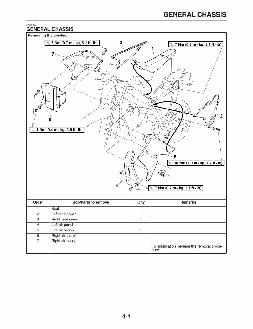
GENERAL CHASSIS
4-1
EAS21830
GENERAL CHASSIS
Removing the cowling
Order Job/Parts to remove Q’ty Remarks
1 Seat 12 Left side cover 13 Right side cover 14 Left air panel 15 Left air scoop 16 Right air panel 17 Right air scoop 1
For installation, reverse the removal proce-dure.
1
2
3
4
5
6
7
T R..
7 Nm (0.7 m • kg, 5.1 ft • Ib)
T R..
4 Nm (0.4 m • kg, 2.9 ft • Ib)
T R..
7 Nm (0.7 m • kg, 5.1 ft • Ib)
T R..
7 Nm (0.7 m • kg, 5.1 ft • Ib)
T R..
10 Nm (1.0 m • kg, 7.2 ft • Ib)

FRONT WHEEL
4-2
EAS21870
FRONT WHEEL
Removing the front wheel and brake discs
Order Job/Parts to remove Q’ty Remarks
Use a suitable stand to raise the front wheel off the ground.
1 Front wheel axle pinch bolt 4 Loosen.2 Front wheel axle nut 13 Front wheel axle 14 Cap 1 For Europe5 Front wheel assembly 16 Collar 17 Collar 18 Front brake disc 19 Wheel ring 1 Only WR250R
For installation, reverse the removal proce-dure.
LT
(WR250X)
(WR250R)
24
3
(4)1
5
6
8
(6)
(6)
9
T R..
23 Nm (2.3 m • kg, 17 ft • Ib)
T R..
12 Nm (1.2 m • kg, 8.7 ft • Ib)
T R..
23 Nm (2.3 m • kg, 17 ft • Ib)
T R..
63 Nm (6.3 m • kg, 46 ft • Ib)
T R..
23 Nm (2.3 m • kg, 17 ft • Ib)
7

FRONT WHEEL
4-3
Disassembling the front wheel
Order Job/Parts to remove Q’ty Remarks
1 Oil seal 22 Bearing 23 Spacer 1
For assembly, reverse the disassembly pro-cedure.
12
23
1

FRONT WHEEL
4-4
EAS21890
REMOVING THE FRONT WHEEL
1. Stand the vehicle on a level surface.
WARNING
EWA13120
Securely support the vehicle so that there is
no danger of it falling over.
NOTE:
Place the vehicle on a suitable stand so that the
front wheel is elevated.
2. Remove:
Front wheelNOTE:
Place the vehicle on a suitable stand so that the
front wheel is elevated.
EAS21930
CHECKING THE FRONT WHEEL
1. Check:
Wheel axleRoll the wheel axle on a flat surface.Bends
→
Replace.
WARNING
EWA13460
Do not attempt to straighten a bent wheel ax-
le.
2. Check:
Tire
Front wheelDamage/wear
→
Replace.Refer to “CHECKING THE TIRES” on page1-31 and “CHECKING THE WHEELS” onpage 1-33.
3. Check:
SpokesBends/damage
→
Replace.Loose
→
Tighten.Tap the spokes with a screwdriver.
NOTE:
A tight spoke will emit a clear, ringing tone, a
loose spoke will sound flat.
4. Tighten:
SpokesRefer to “CHECKING AND TIGHTENINGTHE SPOKES” on page 1-33.
NOTE:
After tightening the spokes, measure the front
wheel runout.
5. Measure:
Front wheel radial runout “a”
Front wheel lateral runout “b”Over the specified limits
→
Replace.
6. Check:
CollarsDamage/wear
→
Replace.7. Check:
Wheel bearingsFront wheel turns roughly or is loose
→
Re-place the wheel bearings.
Oil sealsDamage/wear
→
Replace.
Spoke3 Nm (0.3 m•kg, 2.2 ft•lb)
Radial wheel runout limit2.0 mm (0.08 in)
Lateral wheel runout limit2.0 mm (0.08 in)
TR..
ab
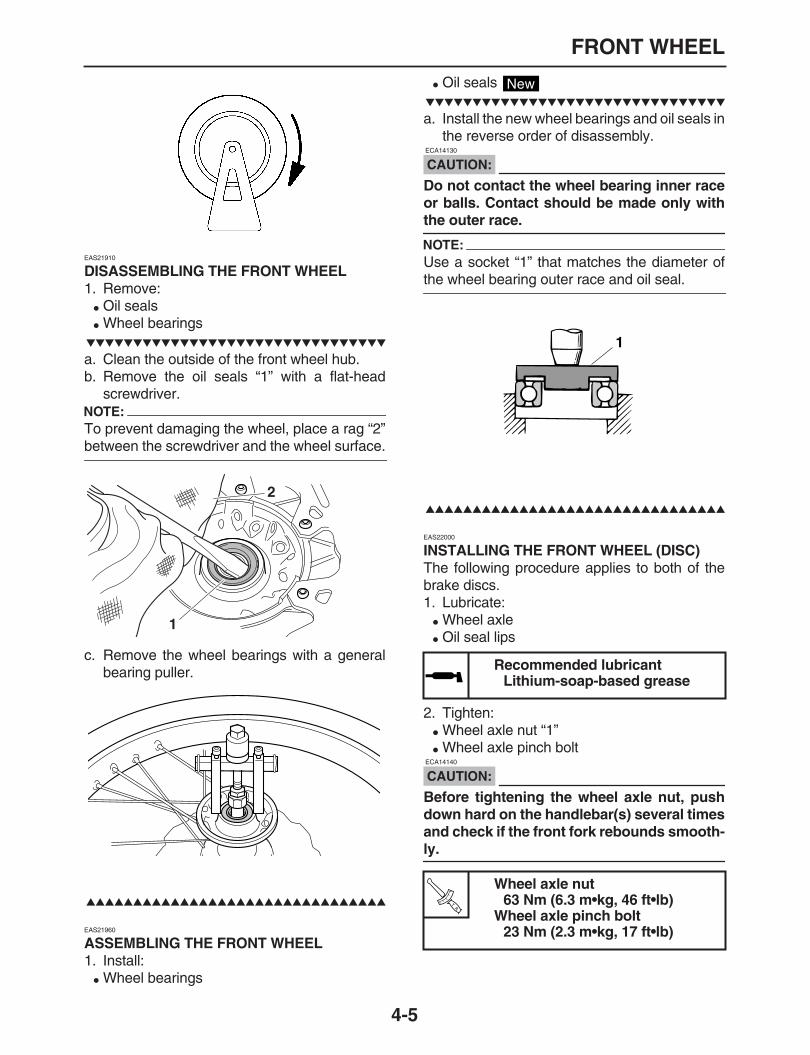
FRONT WHEEL
4-5
EAS21910
DISASSEMBLING THE FRONT WHEEL
1. Remove:
Oil seals
Wheel bearings
a. Clean the outside of the front wheel hub.b. Remove the oil seals “1” with a flat-head
screwdriver.NOTE:
To prevent damaging the wheel, place a rag “2”
between the screwdriver and the wheel surface.
c. Remove the wheel bearings with a generalbearing puller.
EAS21960
ASSEMBLING THE FRONT WHEEL
1. Install:
Wheel bearings
Oil seals
a. Install the new wheel bearings and oil seals inthe reverse order of disassembly.
CAUTION:
ECA14130
Do not contact the wheel bearing inner raceor balls. Contact should be made only with
the outer race.
NOTE:
Use a socket “1” that matches the diameter of
the wheel bearing outer race and oil seal.
EAS22000
INSTALLING THE FRONT WHEEL (DISC)
The following procedure applies to both of thebrake discs.1. Lubricate:
Wheel axle
Oil seal lips
2. Tighten:
Wheel axle nut “1”
Wheel axle pinch bolt
CAUTION:
ECA14140
Before tightening the wheel axle nut, pushdown hard on the handlebar(s) several timesand check if the front fork rebounds smooth-
ly.
1
2
Recommended lubricantLithium-soap-based grease
Wheel axle nut63 Nm (6.3 m•kg, 46 ft•lb)
Wheel axle pinch bolt23 Nm (2.3 m•kg, 17 ft•lb)
New
1T
R..

FRONT WHEEL
4-6
1
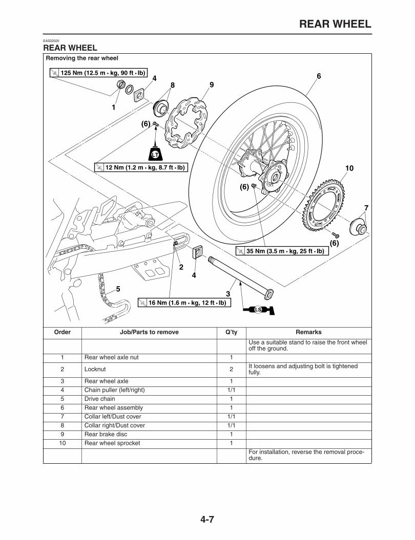
REAR WHEEL
4-7
EAS22020
REAR WHEEL
Removing the rear wheel
Order Job/Parts to remove Q’ty Remarks
Use a suitable stand to raise the front wheel off the ground.
1 Rear wheel axle nut 1
2 Locknut 2 It loosens and adjusting bolt is tightened fully.
3 Rear wheel axle 14 Chain puller (left/right) 1/15 Drive chain 16 Rear wheel assembly 17 Collar left/Dust cover 1/18 Collar right/Dust cover 1/19 Rear brake disc 110 Rear wheel sprocket 1
For installation, reverse the removal proce-dure.
1
2
3
4
4
5
(6)
(6)
(6)
6
7
8 9
10
LT
T R..
125 Nm (12.5 m • kg, 90 ft • Ib)
T R..
12 Nm (1.2 m • kg, 8.7 ft • Ib)
T R..
16 Nm (1.6 m • kg, 12 ft • Ib)
T R..
35 Nm (3.5 m • kg, 25 ft • Ib)
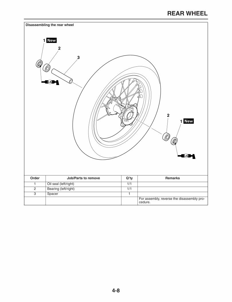
REAR WHEEL
4-8
Disassembling the rear wheel
Order Job/Parts to remove Q’ty Remarks
1 Oil seal (left/right) 1/12 Bearing (left/right) 1/13 Spacer 1
For assembly, reverse the disassembly pro-cedure.
1
2
12
3

REAR WHEEL
4-9
EAS22040
REMOVING THE REAR WHEEL
1. Stand the vehicle on a level surface.
WARNING
EWA13120
Securely support the vehicle so that there is
no danger of it falling over.
NOTE:
Place the vehicle on a suitable stand so that the
rear wheel is elevated.
2. Elevate:
Rear wheel3. Remove:
Rear wheel axle nut “1”4. Loosen:
Locknut5. Tighten:
Adjusting boltNOTE:
Place the motorcycle on a suitable stand so that
the rear wheel is elevated.
6. Remove:
Wheel axle “2”
Rear wheel “3”
NOTE:
Push the rear wheel forward and remove the
drive chain from the rear wheel sprocket.
EAS22080
DISASSEMBLING THE REAR WHEEL
1. Remove:
Oil seals
Wheel bearingsRefer to “DISASSEMBLING THE FRONTWHEEL” on page 4-5.
EAS22100
CHECKING THE REAR WHEEL
1. Check:
Wheel axle
Rear wheel
Wheel bearings
Oil sealsRefer to “CHECKING THE FRONT WHEEL”on page 4-4.
2. Check:
Tire
Rear wheelDamage/wear
→
Replace.Refer to “CHECKING THE TIRES” on page1-31 and “CHECKING THE WHEELS” onpage 1-33.
3. Check:
SpokesRefer to “CHECKING THE FRONT WHEEL”on page 4-4.
4. Measure:
Radial wheel runout
Lateral wheel runoutRefer to “CHECKING THE FRONT WHEEL”on page 4-4.
EAS22120
CHECKING AND REPLACING THE REAR WHEEL SPROCKET
1. Check:
Rear wheel sprocketMore than 1/4 tooth wear
→
Replace the rearwheel sprocket.Bent teeth
→
Replace the rear wheel sprock-et.
2. Replace:
Rear wheel sprocket
a. Remove the self-locking nuts and the rearwheel sprocket.
3
1
2
Radial wheel runout limit2.0 mm
Lateral wheel runout limit2.0 mm
a. Tooth faceb. Normal
1. Drive chain roller2. Rear wheel sprocket
1
2
a
b

REAR WHEEL
4-10
b. Clean the rear wheel drive hub with a cleancloth, especially the surfaces that contact thesprocket.
c. Install the new rear wheel sprocket.
NOTE:
Tighten the self-locking nuts in stages and in a
crisscross pattern.
EAS22140
ASSEMBLING THE REAR WHEEL
1. Install:
Wheel bearings
Oil seals Refer to “ASSEMBLING THE FRONTWHEEL” on page 4-5.
EAS22160
INSTALLING THE REAR WHEEL (DISC)
1. Install:
Brake discRefer to “CHECKING THE REAR BRAKEDISC” on page 4-28
2. Lubricate:
Wheel axle
Oil seal lips
3. Adjust:
Drive chain slackRefer to “ADJUSTING THE DRIVE CHAINSLACK” on page 1-26.
4. Tighten:
Wheel axle nut
Rear wheel sprocket self-lockingnut
35 Nm (3.5 m•kg, 25 ft•lb)
Recommended lubricantLithium-soap-based grease
TR..
New
Drive chain slackWR250R 38.0
–
48.0 mm (1.50
–
1.89 in)WR250X 40.0
–
50.0 mm (1.57
–
1.97 in)
Wheel axle nut125 Nm (12.5 m•kg, 90 ft•lb)T
R..

FRONT BRAKE
4-11
EAS22210
FRONT BRAKE
Removing the front brake pads
Order Job/Parts to remove Q’ty Remarks
1 Pin plug 1 WR250X only2 Front brake caliper support bolt 13 Front brake caliper assembly 14 Brake pad 25 Brake pad spring 2
For installation, reverse the removal proce-dure.
1
2
2
3
4
5
S
S
WR250X
T R..
23 Nm (2.3 m • kg, 17 ft • Ib)
T R..
17 Nm (1.7 m • kg, 12 ft • Ib)
T R..
17 Nm (1.7 m • kg, 12 ft • Ib)
T R..
2.5 Nm (0.25 m • kg, 1.8 ft • Ib)

FRONT BRAKE
4-12
Removing the front brake master cylinder
Order Job/Parts to remove Q’ty Remarks
Brake fluidDrain.Refer to“BLEEDING THE HYDRAULIC BRAKE SYSTEM” on page 1-25.
1 Rear view mirror (right) 12 Brake lever 13 Front brake switch 14 Union bolt 15 Copper washer 26 Front brake hose 17 Brake master cylinder reservoir cap 1
8 Brake master cylinder reservoir diaphragm holder 1
9 Brake master cylinder reservoir diaphragm 110 Front brake master cylinder holder 111 Front brake master cylinder 1
For installation, reverse the removal proce-dure.
S
1
2
3
4
5
6
7
8
9
10
11S
S
T R..
7 Nm (0.7 m • kg, 5.1 ft • Ib)
T R..
4 Nm (0.4 m • kg, 2.9 ft • Ib)
T R..
7 Nm (0.7 m • kg, 5.1 ft • Ib)
T R..
30 Nm (3.0 m • kg, 22 ft • Ib)
T R..
4 Nm (0.4 m • kg, 2.9 ft • Ib)
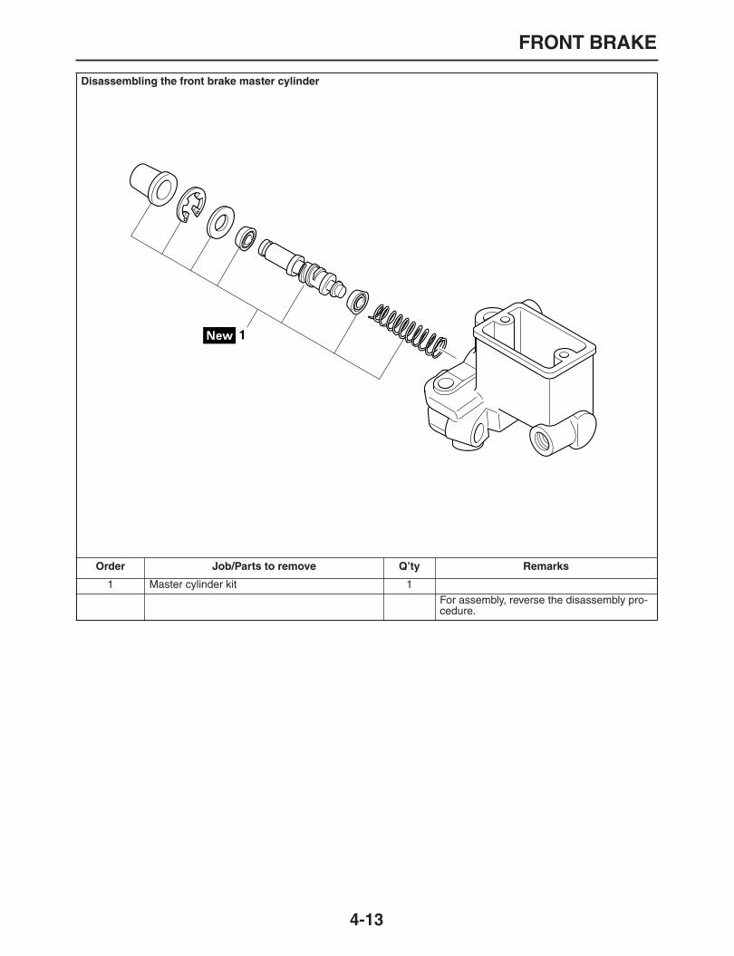
FRONT BRAKE
4-13
Disassembling the front brake master cylinder
Order Job/Parts to remove Q’ty Remarks
1 Master cylinder kit 1For assembly, reverse the disassembly pro-cedure.
1
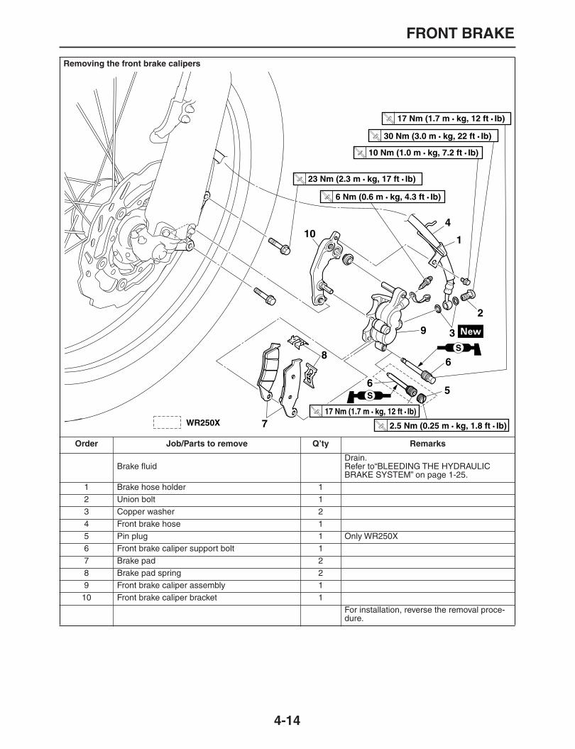
FRONT BRAKE
4-14
Removing the front brake calipers
Order Job/Parts to remove Q’ty Remarks
Brake fluidDrain.Refer to“BLEEDING THE HYDRAULIC BRAKE SYSTEM” on page 1-25.
1 Brake hose holder 12 Union bolt 13 Copper washer 24 Front brake hose 15 Pin plug 1 Only WR250X6 Front brake caliper support bolt 17 Brake pad 28 Brake pad spring 29 Front brake caliper assembly 110 Front brake caliper bracket 1
For installation, reverse the removal proce-dure.
S
5
6
6
9
7
8
10 1
4
S
2
3
T R..
2.5 Nm (0.25 m • kg, 1.8 ft • Ib)
T R..
17 Nm (1.7 m • kg, 12 ft • Ib)
T R..
6 Nm (0.6 m • kg, 4.3 ft • Ib)
T R..
23 Nm (2.3 m • kg, 17 ft • Ib)
T R..
10 Nm (1.0 m • kg, 7.2 ft • Ib)
T R..
30 Nm (3.0 m • kg, 22 ft • Ib)
T R..
17 Nm (1.7 m • kg, 12 ft • Ib)
WR250X

FRONT BRAKE
4-15
Disassembling the front brake calipers
Order Job/Parts to remove Q’ty Remarks
1 Brake caliper piston 22 Brake caliper dust seal 23 Brake caliper piston seal 24 Bleed screw 1
For assembly, reverse the disassembly pro-cedure.
1 2
3
4
S
S
BF
BF
T R..
6 Nm (0.6 m • kg, 4.3 ft • Ib)
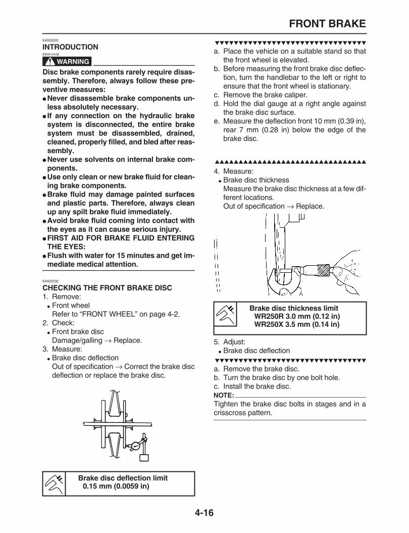
FRONT BRAKE
4-16
EAS22220
INTRODUCTION
WARNING
EWA14100
Disc brake components rarely require disas-sembly. Therefore, always follow these pre-ventive measures:
Never disassemble brake components un-less absolutely necessary.
If any connection on the hydraulic brakesystem is disconnected, the entire brakesystem must be disassembled, drained,cleaned, properly filled, and bled after reas-sembly.
Never use solvents on internal brake com-ponents.
Use only clean or new brake fluid for clean-ing brake components.
Brake fluid may damage painted surfacesand plastic parts. Therefore, always cleanup any spilt brake fluid immediately.
Avoid brake fluid coming into contact withthe eyes as it can cause serious injury.
FIRST AID FOR BRAKE FLUID ENTERINGTHE EYES:
Flush with water for 15 minutes and get im-
mediate medical attention.
EAS22230
CHECKING THE FRONT BRAKE DISC
1. Remove:
Front wheelRefer to “FRONT WHEEL” on page 4-2.
2. Check:
Front brake discDamage/galling
→
Replace.3. Measure:
Brake disc deflectionOut of specification
→
Correct the brake discdeflection or replace the brake disc.
a. Place the vehicle on a suitable stand so thatthe front wheel is elevated.
b. Before measuring the front brake disc deflec-tion, turn the handlebar to the left or right toensure that the front wheel is stationary.
c. Remove the brake caliper.d. Hold the dial gauge at a right angle against
the brake disc surface.e. Measure the deflection front 10 mm (0.39 in),
rear 7 mm (0.28 in) below the edge of thebrake disc.
4. Measure:
Brake disc thicknessMeasure the brake disc thickness at a few dif-ferent locations.Out of specification
→
Replace.
5. Adjust:
Brake disc deflection
a. Remove the brake disc.b. Turn the brake disc by one bolt hole.c. Install the brake disc.NOTE:
Tighten the brake disc bolts in stages and in a
crisscross pattern.
Brake disc deflection limit0.15 mm (0.0059 in)
Brake disc thickness limitWR250R 3.0 mm (0.12 in)WR250X 3.5 mm (0.14 in)

FRONT BRAKE
4-17
d. Measure the brake disc deflection.e. If out of specification, repeat the adjustment
steps until the brake disc deflection is withinspecification.
f. If the brake disc deflection cannot be broughtwithin specification, replace the brake disc.
6. Install:
Front wheelRefer to “FRONT WHEEL” on page 4-2.
EAS22280
REPLACING THE FRONT BRAKE PADSNOTE:
When replacing the brake pads, it is not neces-sary to disconnect the brake hose or disassem-
ble the brake caliper.
1. Measure:
Brake pad wear limit “a”Out of specification
→
Replace the brakepads as a set.
2. Install:
Brake pads
Brake pad springNOTE:
Always install new brake pads, and a brake pad
spring as a set.
a. Connect a clear plastic hose “1” tightly to thebleed screw “2”. Put the other end of the hoseinto an open container.
b. Loosen the bleed screw and push the brakecaliper pistons into the brake caliper with yourfinger.
c. Tighten the bleed screw.
d. Install new brake pads and a new brake padspring.
3. Install:
Brake pad pins
Brake pad clips
Brake pad cover
Brake caliper
Brake disc boltWR250R:12 Nm (1.2 m•kg, 8.7ft•lb)LOCTITE®WR250X:23 Nm (2.3 m•kg, 17ft•lb)LOCTITE®
Brake pad lining thickness (inner)WR250R 4.8 mm (0.19 in)WR250X 4.0 mm (0.16 in)
Limit1.0 mm (0.04 in)
Brake pad lining thickness (outer)WR250R 4.8 mm (0.19 in)WR250X 4.0 mm (0.16 in)
Limit1.0 mm (0.04 in)
LT
TR..
Bleed screw6 Nm (0.6 m•kg, 4.3 ft•lb)
Brake caliper bolt23 Nm (2.3 m•kg, 17 ft•lb)
a
1
2
TR..
TR..

FRONT BRAKE
4-18
4. Check:
Brake fluid levelBelow the minimum level mark “a”
→
Add therecommended brake fluid to the proper level.Refer to “CHECKING THE BRAKE FLUIDLEVEL” on page 1-23.
5. Check:
Brake lever free playRefer to “ADJUSTING THE FRONT DISCBRAKE” on page 1-22.
Brake pedal operationSoft or spongy feeling
→
Bleed the brakesystem.Refer to “BLEEDING THE HYDRAULICBRAKE SYSTEM” on page 1-25.
EAS22290
REMOVING THE FRONT BRAKE CALIPERNOTE:
Before disassembling the brake caliper, drain
the brake fluid from the entire brake system.
1. Remove:
Union bolt
Copper washers
Brake hoseNOTE:
Put the end of the brake hose into a container
and pump out the brake fluid carefully.
EAS22320
DISASSEMBLING THE FRONT BRAKE CALIPER
1. Remove:
Brake caliper pistons “1”
Brake caliper dust seals “2”
Brake caliper piston seals “3”
a. Blow compressed air into the brake hose jointopening to force out the pistons from thebrake caliper.
WARNING
EWA13550
Cover the brake caliper piston with a rag.Be careful not to get injured when the pis-ton is expelled from the brake caliper.
Never try to pry out the brake caliper pis-
ton.
b. Remove the dust seals and brake caliper pis-ton seals.
EAS22380
CHECKING THE FRONT BRAKE CALIPER
1. Check:
Brake caliper pistons “1”Rust/scratches/wear
→
Replace the brakecaliper pistons.
a
Recommended brake component replacement schedule
Brake pads If necessary
Piston seals Every two years
Brake hoses Every four years
Brake fluidEvery two years and whenever the brake is dis-assembled
3
2
1

FRONT BRAKE
4-19
Brake caliper cylinders “2”Scratches/wear
→
Replace the brake caliperassembly.
Brake caliper body “3”Cracks/damage
→
Replace the brake caliperassembly.
Brake fluid delivery passages(brake caliper body)Obstruction
→
Blow out with compressed air.
WARNING
EWA13600
Whenever a brake caliper is disassembled,
replace the piston seals.
2. Check:
Brake caliper bracketCracks/damage
→
Replace.
EAS22400
ASSEMBLING THE FRONT BRAKE CALIPER
WARNING
EWA13620
Before installation, all internal brake com-ponents should be cleaned and lubricatedwith clean or new brake fluid.
Never use solvents on internal brake com-ponents as they will cause the piston sealsto swell and distort.
Whenever a brake caliper is disassembled,
replace the brake caliper piston seals.
EAS22420
INSTALLING THE FRONT BRAKE CALIPER
1. Install:
Front brake caliper bracket
Front brake caliper(temporarily)
Copper washers
Brake hose
Union bolt
WARNING
EWA13530
Proper brake hose routing is essential to in-sure safe vehicle operation. Refer to “CA-
BLE ROUTING” on page 2-30.
CAUTION:
ECA14170
When installing the brake hose onto thebrake caliper “1”, make sure the brake pipe“a” touches the projection “b” on the brake
caliper.
2. Install:
Front brake caliper
Brake pad springs
Front brake caliper support bolt
Brake hose holder
Refer to “REPLACING THE FRONT BRAKEPADS” on page 4-17.
3. Fill:
Brake master cylinder reservoir(with the specified amount of the recom-mended brake fluid)
WARNING
EWA13090
Use only the designated brake fluid. Otherbrake fluids may cause the rubber seals todeteriorate, causing leakage and poor
Recommended fluidDOT 4
2
1 1
3
New
Front brake caliper bracket23 Nm (2.3 m•kg, 17 ft•lb)
Brake hose union bolt30 Nm (30. m•kg, 22 ft•lb)
Front brake caliper support bolt17 Nm (1.7 m•kg, 12 ft•lb)
Brake hose holder10 Nm (1.0 m•kg, 7.2 ft•lb)
Recommended fluidDOT 4
TR..
1
b
a
TR..

FRONT BRAKE
4-20
brake performance.
Refill with the same type of brake fluid thatis already in the system. Mixing brake flu-ids may result in a harmful chemical reac-tion, leading to poor brake performance.
When refilling, be careful that water doesnot enter the brake fluid reservoir. Waterwill significantly lower the boiling point of
the brake fluid and could cause vapor lock.
CAUTION:
ECA13540
Brake fluid may damage painted surfacesand plastic parts. Therefore, always clean up
any spilt brake fluid immediately.
4. Bleed:
Brake systemRefer to “BLEEDING THE HYDRAULICBRAKE SYSTEM” on page 1-25.
5. Check:
Brake fluid levelBelow the minimum level mark
→
Add therecommended brake fluid to the proper level.Refer to “CHECKING THE BRAKE FLUIDLEVEL” on page 1-23.
6. Check:
Brake lever free playRefer to “ADJUSTING THE FRONT DISCBRAKE” on page 1-22.
Brake lever operationSoft or spongy feeling
→
Bleed the brakesystem.Refer to “BLEEDING THE HYDRAULICBRAKE SYSTEM” on page 1-25.
EAS22490
REMOVING THE FRONT BRAKE MASTER CYLINDERNOTE:
Before removing the front brake master cylinder,drain the brake fluid from the entire brake sys-
tem.
1. Disconnect:
Brake switch coupler “1”(from the brake master cylinder)
2. Remove:
Union bolt
Copper washers
Brake hosesNOTE:
To collect any remaining brake fluid, place acontainer under the master cylinder and the end
of the brake hose.
EAS22500
CHECKING THE FRONT BRAKE MASTER CYLINDER
1. Check:
Brake master cylinder “1”Damage/scratches/wear
→
Replace.
Brake fluid delivery passages “2”(brake master cylinder body)Obstruction
→
Blow out with compressed air.
2. Check:
Brake master cylinder kitDamage/scratches/wear
→
Replace.3. Check:
Brake master cylinder reservoir cap4. Check:
Brake master cylinder reservoir diaphragmholder
Brake master cylinder reservoir diaphragmholderCracks/damage
→
Replace.5. Check:
Brake hosesCracks/damage/wear
→
Replace.
1
2

FRONT BRAKE
4-21
EAS22520
ASSEMBLING THE FRONT BRAKE MASTER CYLINDER
WARNING
EWA13520
Before installation, all internal brake com-ponents should be cleaned and lubricatedwith clean or new brake fluid.
Never use solvents on internal brake com-
ponents.
1. Install:
Master cylinder cup
Master cylinder piston2. Install:
Circlip “1”
Dust boot “2”
EAS22530
INSTALLING THE FRONT BRAKE MASTER CYLINDER
1. Install:
Brake master cylinder “1”
NOTE:
Install the brake master cylinder holder with the“UP” mark facing up.
Align the end of the brake master cylinder hold-er with the punch mark “a” on the handlebar.
First, tighten the upper bolt, then the lower bolt.
2. Install:
Copper washers “1”
Brake hose “2”
Union bolt “3”
WARNING
EWA13530
Proper brake hose routing is essential to in-sure safe vehicle operation. Refer to “CA-
BLE ROUTING” on page 2-30.
NOTE:
While holding the brake hose, tighten the unionbolt as shown.
Turn the handlebar to the left and right to makesure the brake hose does not touch other parts(e.g., wire harness, cables, leads). Correct if
necessary.
3. Fill:
Brake master cylinder reservoir(with the specified amount of the recom-mended brake fluid)
WARNING
EWA13540
Use only the designated brake fluid. Otherbrake fluids may cause the rubber seals todeteriorate, causing leakage and poor
Recommended fluidDOT 4
Brake master cylinder holder bolt7 Nm (0.7 m•kg, 5.1 ft•lb)
NewNew
TR..
Brake hose union bolt30 Nm (30. m•kg, 22 ft•lb)
Recommended fluidDOT 4
a
1
New
TR..
1
2
3
New
FRONT BRAKE
4-22
brake performance.
Refill with the same type of brake fluid thatis already in the system. Mixing brake flu-ids may result in a harmful chemical reac-tion, leading to poor brake performance.
When refilling, be careful that water doesnot enter the brake master cylinder reser-voir. Water will significantly lower the boil-ing point of the brake fluid and could cause
vapor lock.
CAUTION:
ECA13540
Brake fluid may damage painted surfacesand plastic parts. Therefore, always clean up
any spilt brake fluid immediately.
4. Bleed:
Brake systemRefer to “BLEEDING THE HYDRAULICBRAKE SYSTEM” on page 1-25.
5. Check:
Brake fluid levelBelow the minimum level mark
→
Add therecommended brake fluid to the proper level.Refer to “CHECKING THE BRAKE FLUIDLEVEL” on page 1-23.
6. Check:
Brake lever free playRefer to “ADJUSTING THE FRONT DISCBRAKE” on page 1-22.
Brake lever operationSoft or spongy feeling
→
Bleed the brakesystem.Refer to “BLEEDING THE HYDRAULICBRAKE SYSTEM” on page 1-25.
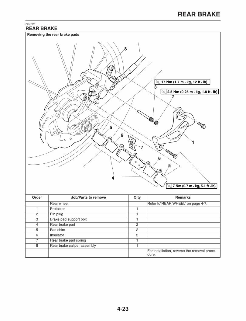
REAR BRAKE
4-23
EAS22550
REAR BRAKE
Removing the rear brake pads
Order Job/Parts to remove Q’ty Remarks
Rear wheel Refer to“REAR WHEEL” on page 4-7.1 Protector 12 Pin plug 13 Brake pad support bolt 14 Rear brake pad 25 Pad shim 26 Insulator 27 Rear brake pad spring 18 Rear brake caliper assembly 1
For installation, reverse the removal proce-dure.
1
2
3
4
5
5
6
6
7
8
T R..
7 Nm (0.7 m • kg, 5.1 ft • Ib)
T R..
17 Nm (1.7 m • kg, 12 ft • Ib) T R.
.
2.5 Nm (0.25 m • kg, 1.8 ft • Ib)

REAR BRAKE
4-24
Removing the rear brake master cylinder
Order Job/Parts to remove Q’ty Remarks
Brake fluidDrain.Refer to “BLEEDING THE HYDRAULIC BRAKE SYSTEM” on page 1-25.
1 Union bolt 12 Copper washer 23 Brake hose 14 Split pin 15 Plain washer 16 Pin 17 Brake master cylinder reservoir cap 18 Brake master cylinder reservoir diaphragm plate 19 Brake master cylinder reservoir diaphragm 110 Rear brake master cylinder 1
For installation, reverse the removal proce-dure.
1
2
3
4
7
5
8
6
9
10
T R..
10 Nm (1.0 m • kg, 7.2 ft • Ib)
T R..
30 Nm (3.0 m • kg, 22 ft • Ib)

REAR BRAKE
4-25
Disassembling the rear brake master cylinder
Order Job/Parts to remove Q’ty Remarks
1 Master cylinder kit 1For assembly, reverse the disassembly pro-cedure.
S1
T R..
12 Nm (1.2 m • kg, 8.7 ft • Ib)

REAR BRAKE
4-26
Removing the rear brake calipers
Order Job/Parts to remove Q’ty Remarks
Brake fluidDrain.Refer to“BLEEDING THE HYDRAULIC BRAKE SYSTEM” on page 1-25.
Protector Refer to“REAR BRAKE” on page 4-23.1 Union bolt 12 Copper washer 23 Rear brake hose 14 Pin plug 15 Brake caliper support bolt 16 Rear brake pad assemblyl 27 Rear brake caliper bracket 18 Brake pad spring 29 Rear brake caliper assembly 1
For installation, reverse the removal proce-dure.
1
2
3
4
5
6
7
8
8
9
S
T R..
30 Nm (3.0 m • kg, 22 ft • Ib)
T R..
17 Nm (1.7 m • kg, 12 ft • Ib)
T R..
2.5 Nm (0.25 m • kg, 1.8 ft • Ib)

REAR BRAKE
4-27
Disassembling the rear brake calipers
Order Job/Parts to remove Q’ty Remarks
1 Brake caliper piston 12 Brake caliper dust seal 13 Brake caliper piston seal 14 Bleed screw 1
For assembly, reverse the disassembly pro-cedure.
1
2
3
4
S
BF
T R..
6 Nm (0.6 m • kg, 4.3 ft • Ib)

REAR BRAKE
4-28
EAS22560
INTRODUCTION
WARNING
EWA14100
Disc brake components rarely require disas-sembly. Therefore, always follow these pre-ventive measures:
Never disassemble brake components un-less absolutely necessary.
If any connection on the hydraulic brakesystem is disconnected, the entire brakesystem must be disassembled, drained,cleaned, properly filled, and bled after reas-sembly.
Never use solvents on internal brake com-ponents.
Use only clean or new brake fluid for clean-ing brake components.
Brake fluid may damage painted surfacesand plastic parts. Therefore, always cleanup any spilt brake fluid immediately.
Avoid brake fluid coming into contact withthe eyes as it can cause serious injury.
FIRST AID FOR BRAKE FLUID ENTERINGTHE EYES:
Flush with water for 15 minutes and get im-
mediate medical attention.
EAS22570
CHECKING THE REAR BRAKE DISC
1. Remove:
Rear wheelRefer to “REAR WHEEL” on page 4-7.
2. Check:
Brake discDamage/galling
→
Replace.3. Measure:
Brake disc deflectionOut of specification
→
Correct the brake discdeflection or replace the brake disc.Refer to “CHECKING THE FRONT BRAKEDISC” on page 4-16.
4. Measure:
Brake disc thicknessMeasure the brake disc thickness at a few dif-ferent locations.Out of specification
→
Replace.Refer to “CHECKING THE FRONT BRAKEDISC” on page 4-16.
5. Adjust:
Brake disc deflectionRefer to “CHECKING THE FRONT BRAKEDISC” on page 4-16.
6. Install:
Rear wheelRefer to “REAR WHEEL” on page 4-7.
EAS22580
REPLACING THE REAR BRAKE PADSNOTE:
When replacing the brake pads, it is not neces-sary to disconnect the brake hose or disassem-
ble the brake caliper.
1. Measure:
Brake pad wear limit “a”Out of specification
→
Replace the brakepads as a set.
2. Install:
Brake pad shims(onto the brake pads)
Brake pads
Brake pad springNOTE:
Always install new brake pads, brake pad shims,
Brake disc deflection limit0.15 mm (0.0059 in)
Brake disc thickness limit4.0 mm (0.16 in)
Brake disc bolt12 Nm (1.2 m•kg, 8.7 ft•lb)LOCTITE®
Brake pad lining thickness (inner)6.4 mm (0.25 in)
Limit1.0 mm (0.04 in)
Brake pad lining thickness (outer)6.4 mm (0.25 in)
Limit1.0 mm (0.04 in)
TR..
a

REAR BRAKE
4-29
and a brake pad spring as a set.
a. Connect a clear plastic hose “1” tightly to thebleed screw “2”. Put the other end of the hoseinto an open container.
b. Loosen the bleed screw and push the brakecaliper pistons into the brake caliper with yourfinger.
c. Tighten the bleed screw.
d. Install a new brake pad shim onto each newbrake pad.
e. Install new brake pads and a new brake padspring.
NOTE:
The longer tangs “b” of the brake pad spring
must point in the direction of disc rotation.
3. Install:
Brake caliper support bolt
Pin plug
Rear brake caliper protector
4. Check:
Brake fluid levelBelow the minimum level mark “a”
→
Add therecommended brake fluid to the proper level.Refer to “CHECKING THE BRAKE FLUIDLEVEL” on page 1-23.
5. Check:
Brake pedal operationSoft or spongy feeling
→
Bleed the brakesystem.Refer to “BLEEDING THE HYDRAULICBRAKE SYSTEM” on page 1-25.
EAS22590
REMOVING THE REAR BRAKE CALIPERNOTE:
Before disassembling the brake caliper, drain
the brake fluid from the entire brake system.
1. Remove:
Union bolt
Copper washers
Brake hoseNOTE:
Put the end of the brake hose into a container
and pump out the brake fluid carefully.
EAS22600
DISASSEMBLING THE REAR BRAKE CALIPER
1. Remove:
Brake caliper piston “1”
Brake caliper dust seals “2”
Brake caliper piston seals “3”
a. Blow compressed air into the brake hose jointopening to force out the piston from the brakecaliper.
Bleed screw6 Nm (0.6 m•kg, 4.3 ft•lb)
Brake caliper support bolt17 Nm (1.7 m•kg, 12 ft•lb)
Pin plug2.5 Nm (0.25 m•kg, 1.8 ft•lb)
Rear brake caliper protector7 Nm (0.7 m•kg, 5.1 ft•lb)
2
1
TR..
TR..
a
2 3
1
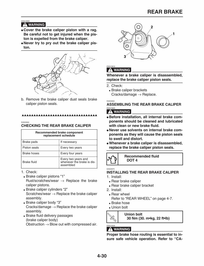
REAR BRAKE
4-30
WARNING
EWA13550
Cover the brake caliper piston with a rag.Be careful not to get injured when the pis-ton is expelled from the brake caliper.
Never try to pry out the brake caliper pis-
ton.
b. Remove the brake caliper dust seals brakecaliper piston seals.
EAS22640
CHECKING THE REAR BRAKE CALIPER
1. Check:
Brake caliper pistons “1”Rust/scratches/wear
→
Replace the brakecaliper pistons.
Brake caliper cylinders “2”Scratches/wear
→
Replace the brake caliperassembly.
Brake caliper body “3”Cracks/damage
→
Replace the brake caliperassembly.
Brake fluid delivery passages(brake caliper body)Obstruction
→
Blow out with compressed air.
WARNING
EWA13610
Whenever a brake caliper is disassembled,
replace the brake caliper piston seals.
2. Check:
Brake caliper bracketsCracks/damage
→
Replace.
EAS22650
ASSEMBLING THE REAR BRAKE CALIPER
WARNING
EWA13620
Before installation, all internal brake com-ponents should be cleaned and lubricatedwith clean or new brake fluid.
Never use solvents on internal brake com-ponents as they will cause the piston sealsto swell and distort.
Whenever a brake caliper is disassembled,
replace the brake caliper piston seals.
EAS22670
INSTALLING THE REAR BRAKE CALIPER
1. Install:
Rear brake caliper
Rear brake caliper bracket2. Install:
Rear wheelRefer to “REAR WHEEL” on page 4-7.
Brake hose
Union bolt
WARNING
EWA13530
Proper brake hose routing is essential to in-sure safe vehicle operation. Refer to “CA-
Recommended brake componentreplacement schedule
Brake pads If necessary
Piston seals Every two years
Brake hoses Every four years
Brake fluidEvery two years and whenever the brake is dis-assembled
Recommended fluidDOT 4
Union bolt30 Nm (30. m•kg, 22 ft•lb)
1
2
3
TR..
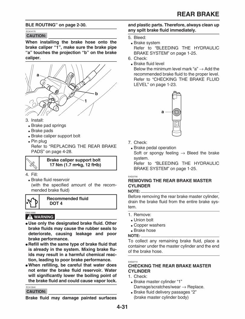
REAR BRAKE
4-31
BLE ROUTING” on page 2-30.
CAUTION:
ECA14170
When installing the brake hose onto thebrake caliper “1”, make sure the brake pipe“a” touches the projection “b” on the brake
caliper.
3. Install:
Brake pad springs
Brake pads
Brake caliper support bolt
Pin plugRefer to “REPLACING THE REAR BRAKEPADS” on page 4-28.
4. Fill:
Brake fluid reservoir(with the specified amount of the recom-mended brake fluid)
WARNING
EWA13090
Use only the designated brake fluid. Otherbrake fluids may cause the rubber seals todeteriorate, causing leakage and poorbrake performance.
Refill with the same type of brake fluid thatis already in the system. Mixing brake flu-ids may result in a harmful chemical reac-tion, leading to poor brake performance.
When refilling, be careful that water doesnot enter the brake fluid reservoir. Waterwill significantly lower the boiling point of
the brake fluid and could cause vapor lock.
CAUTION:
ECA13540
Brake fluid may damage painted surfaces
and plastic parts. Therefore, always clean up
any spilt brake fluid immediately.
5. Bleed:
Brake systemRefer to “BLEEDING THE HYDRAULICBRAKE SYSTEM” on page 1-25.
6. Check:
Brake fluid levelBelow the minimum level mark “a”
→
Add therecommended brake fluid to the proper level.Refer to “CHECKING THE BRAKE FLUIDLEVEL” on page 1-23.
7. Check:
Brake pedal operationSoft or spongy feeling
→
Bleed the brakesystem.Refer to “BLEEDING THE HYDRAULICBRAKE SYSTEM” on page 1-25.
EAS22700
REMOVING THE REAR BRAKE MASTER CYLINDERNOTE:
Before removing the rear brake master cylinder,drain the brake fluid from the entire brake sys-
tem.
1. Remove:
Union bolt
Copper washers
Brake hoseNOTE:
To collect any remaining brake fluid, place acontainer under the master cylinder and the end
of the brake hose.
EAS22710
CHECKING THE REAR BRAKE MASTER CYLINDER
1. Check:
Brake master cylinder “1”Damage/scratches/wear
→
Replace.
Brake fluid delivery passages “2”(brake master cylinder body)
Brake caliper support bolt17 Nm (1.7 m•kg, 12 ft•lb)
Recommended fluidDOT 4
1
a
TR..
a

REAR BRAKE
4-32
Obstruction
→
Blow out with compressed air.
2. Check:
Brake master cylinder kitDamage/wear
→
Replace.3. Check:
Master cylinder reservoir capCracks/damage
→
Replace.
Brake master cylinder reservoir diaphragmholder
Brake master cylinder reservoir diaphragmCracks/damage
→
Replace.4. Check:
Brake hosesCracks/damage/wear
→
Replace.
EAS22730
ASSEMBLING THE REAR BRAKE MASTER CYLINDER
WARNING
EWA13520
Before installation, all internal brake com-ponents should be cleaned and lubricatedwith clean or new brake fluid.
Never use solvents on internal brake com-
ponents.
1. Install:
Cylinder cup
Master cylinder piston2. Install:
Spring “1”
Master cylinder piston “2”
Adjusting rod “3”
Circlip “4”
Dust boot “5”
EAS22750
INSTALLING THE REAR BRAKE MASTER CYLINDER
1. Install:
Copper washers
Brake hoses
Union bolt
WARNING
EWA13530
Proper brake hose routing is essential to in-sure safe vehicle operation. Refer to “CA-
BLE ROUTING” on page 2-30.
CAUTION:
ECA32D1002
When installing the brake hose onto thebrake master cylinder, make sure the brake
pipe touch the projection “a” as shown.
2. Fill:
Brake fluid reservoir
WARNING
EWA13090
Use only the designated brake fluid. Otherbrake fluids may cause the rubber seals todeteriorate, causing leakage and poor
Recommended fluidDOT 4
1 2
New
NewNew
NewNew
New
Brake hose union bolt30 Nm (30. m•kg, 22 ft•lb)
Recommended fluidDOT 4
New
TR..
a

REAR BRAKE
4-33
brake performance.
Refill with the same type of brake fluid thatis already in the system. Mixing brake flu-ids may result in a harmful chemical reac-tion, leading to poor brake performance.
When refilling, be careful that water doesnot enter the brake fluid reservoir. Waterwill significantly lower the boiling point of
the brake fluid and could cause vapor lock.
CAUTION:
ECA13540
Brake fluid may damage painted surfacesand plastic parts. Therefore, always clean up
any spilt brake fluid immediately.
3. Bleed:
Brake systemRefer to “BLEEDING THE HYDRAULICBRAKE SYSTEM” on page 1-25.
4. Check:
Brake fluid levelBelow the minimum level mark “a”
→
Add therecommended brake fluid to the proper level.Refer to “CHECKING THE BRAKE FLUIDLEVEL” on page 1-23.
5. Check:
Brake pedal operationSoft or spongy feeling
→
Bleed the brakesystem.Refer to “BLEEDING THE HYDRAULICBRAKE SYSTEM” on page 1-25.
a

HANDLEBAR
4-34
EAS22840
HANDLEBAR
Removing the handlebar
Order Job/Parts to remove Q’ty Remarks
1 Rear view mirror (left/right) 1/12 Front brake light switch 13 Front brake master cylinder holder 14 Front brake master cylinder assembly 15 Right handlebar switch 16 Throttle cable housing 17 Throttle cable 28 Throttle grip 19 Clutch cable 110 Clutch switch 111 Clutch lever holder 112 Clutch lever 113 Left handlebar switch 114 Handlebar grip 115 Special washer 116 Handlebar upper holder 217 Handlebar 118 Handlebar lower holder 2
1
1
2
3
4
5
6
7
8
9
10
11
12
13 1415
17
18
16
T R..
30 Nm (3.0 m • kg, 22 ft • Ib)
T R..
40 Nm (4.0 m • kg, 29 ft • Ib)
T R..
7 Nm (0.7 m • kg, 5.1 ft • Ib)
T R..
28 Nm (2.8 m • kg, 20 ft • Ib)
T R..
7 Nm (0.7 m • kg, 5.1 ft • Ib)

HANDLEBAR
4-35
For installation, reverse the removal proce-dure.
Removing the handlebar
Order Job/Parts to remove Q’ty Remarks
1
1
2
3
4
5
6
7
8
9
10
11
12
13 1415
17
18
16
T R..
30 Nm (3.0 m • kg, 22 ft • Ib)
T R..
40 Nm (4.0 m • kg, 29 ft • Ib)
T R..
7 Nm (0.7 m • kg, 5.1 ft • Ib)
T R..
28 Nm (2.8 m • kg, 20 ft • Ib)
T R..
7 Nm (0.7 m • kg, 5.1 ft • Ib)
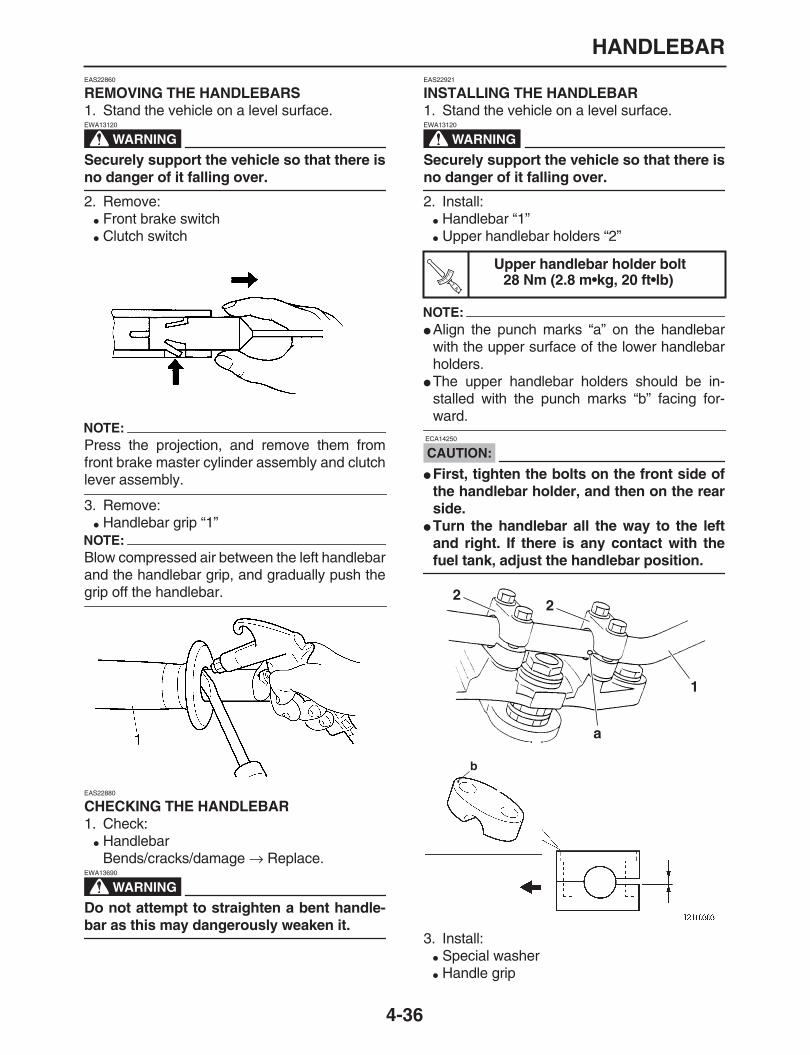
HANDLEBAR
4-36
EAS22860
REMOVING THE HANDLEBARS
1. Stand the vehicle on a level surface.
WARNING
EWA13120
Securely support the vehicle so that there is
no danger of it falling over.
2. Remove:
Front brake switch
Clutch switch
NOTE:
Press the projection, and remove them fromfront brake master cylinder assembly and clutch
lever assembly.
3. Remove:
Handlebar grip “1”NOTE:
Blow compressed air between the left handlebarand the handlebar grip, and gradually push the
grip off the handlebar.
EAS22880
CHECKING THE HANDLEBAR
1. Check:
HandlebarBends/cracks/damage
→
Replace.
WARNING
EWA13690
Do not attempt to straighten a bent handle-
bar as this may dangerously weaken it.
EAS22921
INSTALLING THE HANDLEBAR
1. Stand the vehicle on a level surface.
WARNING
EWA13120
Securely support the vehicle so that there is
no danger of it falling over.
2. Install:
Handlebar “1”
Upper handlebar holders “2”
NOTE:
Align the punch marks “a” on the handlebarwith the upper surface of the lower handlebarholders.
The upper handlebar holders should be in-stalled with the punch marks “b” facing for-
ward.
CAUTION:
ECA14250
First, tighten the bolts on the front side ofthe handlebar holder, and then on the rearside.
Turn the handlebar all the way to the leftand right. If there is any contact with the
fuel tank, adjust the handlebar position.
3. Install:
Special washer
Handle grip
Upper handlebar holder bolt28 Nm (2.8 m•kg, 20 ft•lb)T
R..
22
1
a
b

HANDLEBAR
4-37
a. Slightly coat the handlebar left end with a rub-ber adhesive.
Install the handlebar grip on the handlebar bypressing the grip from the left side.
Wipe off any excess rubber adhesive with aclean rag.
WARNING
EWA32D1005
Do not touch and move the handlebar grip
until its adhesive dries completely.
4. Install:
Left handlebar switch “1”NOTE:
Align tab “a” of special washer with slot “b” ofleft handlebar switch.
Align the mating surfaces of the left handlebarswitch with the punch mark “c” on the handle-
bar.
5. Install:
Clutch lever holder “1”
Clutch lever “2”NOTE:
Align the mating surfaces of the brake lever
holder with the punch mark “a” on the handlebar.
6. Install:
Throttle grip “1”
Throttle cable housing “2”
Throttle cables “3”
NOTE:
Align projection “a” of slot cable housing withhole “b” of the handlebar.
Slightly coat the end of slot cable and inside ofthrottle grip with lithium-soap-based grease.Then, mount the throttle grip onto the handle-
bar.
7. Install:
Right handlebar switch “1”NOTE:
Align projection “a” of the right handlebar switch
with hole “b” of the handlebar.
8. Install:
Front master cylinder assembly “1”
Front brake master cylinder holder “2”
NOTE:
Install the front brake master cylinder on thefront brake master cylinder assembly by facingthe cylinder " “UP” mark upward.
Align the matching surface of front brake mas-ter cylinder holder with mark “a” of handlebar.
Tighten the upper bolt first, and then tighten
the lower bolt.
1
a
b
c
1 a
2
Front brake master cylinder hold-er bolt
7 Nm (0.7 m•kg, 5.1 ft•lb)
b
3
a 12
b a
1
TR..

HANDLEBAR
4-38
9. Adjust:
Clutch cable free playRefer to “ADJUSTING THE CLUTCH CA-BLE FREE PLAY” on page 1-14.
10.Adjust:
Throttle cable free playRefer to “ADJUSTING THE THROTTLE CA-BLE FREE PLAY” on page 1-8.
Clutch lever free play10.0
–
15.0 mm (0.39
–
0.59 in)
Throttle cable free play3.0
–
5.0 mm (0.12
–
0.20 in)
a 21

FRONT FORK
4-39
EAS22950
FRONT FORK
Removing the front fork legs
Order Job/Parts to remove Q’ty Remarks
Front wheel Refer to“FRONT WHEEL” on page 4-2.1 Front fork protector 12 Brake hose holder 23 Front brake caliper 14 Upper bracket pinch bolt 2 Loosen.5 Front fork cap bolt 1 Loosen.6 Lower bracket pinch bolt 2 Loosen.7 Front fork 1
For installation, reverse the removal proce-dure.
1
2
3
4
5
6
7
T R..
7 Nm (0.7 m • kg, 5.1 ft • Ib)
T R..7 Nm (0.7 m • kg, 5.1 ft • Ib)
T R..
23 Nm (2.3 m • kg, 17 ft • Ib)
T R..
20 Nm (2.0 m • kg, 14 ft • Ib) T R.
.
23 Nm (2.3 m • kg, 17 ft • Ib)
T R..
30 Nm (3.0 m • kg, 22 ft • Ib)

FRONT FORK
4-40
Disassembling the front fork legs
Order Job/Parts to remove Q’ty Remarks
1 Front fork cap bolt 12 O-ring 13 Rod 14 Spring seat 15 Fork spring 16 Nut 17 Spring guide 18 Dust seal 19 Stopper ring 110 Base valve 111 Copper washer 112 O-ring 213 Damper rod 114 Outer tube 115 Oil seal 116 Oil sealWasher 117 Slide metal 118 Piston metal 119 Inner tube 120 Rubber cap 1
1
2
3
45
6
7
8
9
10
1112
13
14
15
16
17
18
19
LT
20
T R..
30 Nm (3.0 m • kg, 22 ft • Ib)
T R..
15 Nm (1.5 m • kg, 11 ft • Ib)
T R..
55 Nm (5.5 m • kg, 40 ft • Ib)

FRONT FORK
4-41
For assembly, reverse the disassembly pro-cedure.
Disassembling the front fork legs
Order Job/Parts to remove Q’ty Remarks
1
2
3
45
6
7
8
9
10
1112
13
14
15
16
17
18
19
LT
20
T R..
30 Nm (3.0 m • kg, 22 ft • Ib)
T R..
15 Nm (1.5 m • kg, 11 ft • Ib)
T R..
55 Nm (5.5 m • kg, 40 ft • Ib)
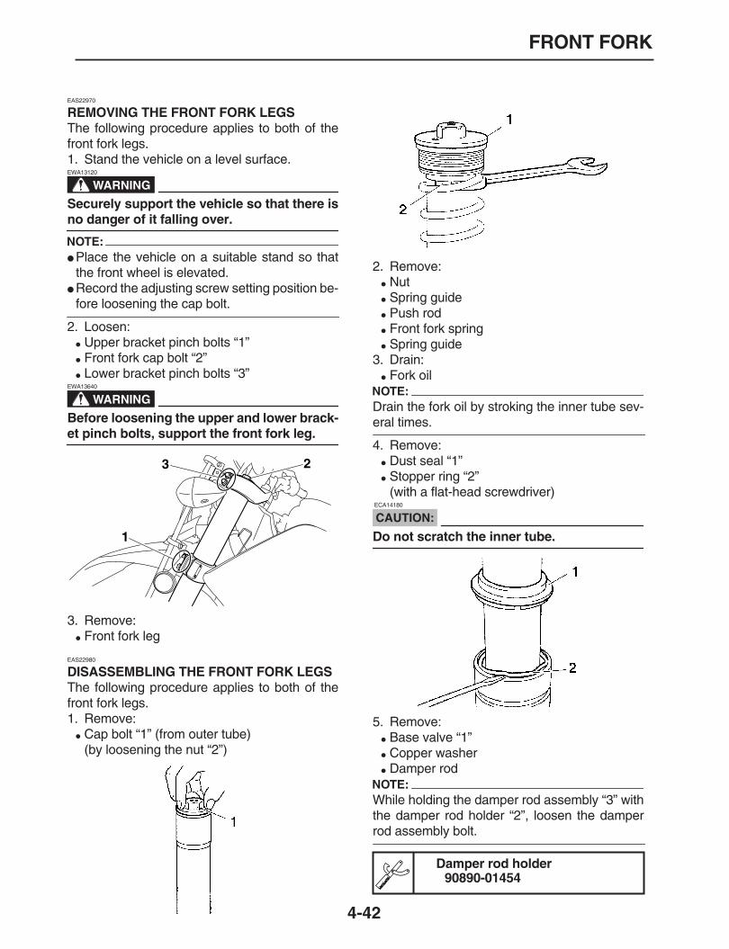
FRONT FORK
4-42
EAS22970
REMOVING THE FRONT FORK LEGS
The following procedure applies to both of thefront fork legs.1. Stand the vehicle on a level surface.
WARNING
EWA13120
Securely support the vehicle so that there is
no danger of it falling over.
NOTE:
Place the vehicle on a suitable stand so thatthe front wheel is elevated.
Record the adjusting screw setting position be-
fore loosening the cap bolt.
2. Loosen:
Upper bracket pinch bolts “1”
Front fork cap bolt “2”
Lower bracket pinch bolts “3”
WARNING
EWA13640
Before loosening the upper and lower brack-
et pinch bolts, support the front fork leg.
3. Remove:
Front fork leg
EAS22980
DISASSEMBLING THE FRONT FORK LEGS
The following procedure applies to both of thefront fork legs.1. Remove:
Cap bolt “1” (from outer tube)(by loosening the nut “2”)
2. Remove:
Nut
Spring guide
Push rod
Front fork spring
Spring guide3. Drain:
Fork oilNOTE:
Drain the fork oil by stroking the inner tube sev-
eral times.
4. Remove:
Dust seal “1”
Stopper ring “2”(with a flat-head screwdriver)
CAUTION:
ECA14180
Do not scratch the inner tube.
5. Remove:
Base valve “1”
Copper washer
Damper rodNOTE:
While holding the damper rod assembly “3” withthe damper rod holder “2”, loosen the damper
rod assembly bolt.
1
23
Damper rod holder90890-01454

FRONT FORK
4-43
6. Remove:
Inner tube “1”
a. Hold the front fork leg horizontally.b. Securely clamp the brake caliper bracket in a
vise with soft jaws.c. Separate the inner tube from the outer tube
by pulling the inner tube forcefully but careful-ly.
EAS23010
CHECKING THE FRONT FORK LEGS
The following procedure applies to both of thefront fork legs.1. Check:
Inner tube
Outer tubeBends/damage/scratches
→
Replace.
WARNING
EWA13650
Do not attempt to straighten a bent inner
tube as this may dangerously weaken it.
2. Measure:
Spring free length “a”Out of specification
→
Replace.
3. Check:
Damper rod “1”Damage/wear
→
Replace.Obstruction
→
Blow out all of the oil passag-es with compressed air.
4. Check:
Base valveDamage/wear
→
Replace.Obstruction
→
Blow out all of the oil passag-es with compressed air.
5. Check:
Push rodBends/damage/wear
→
Replace.6. Check:
Cap boltDamage/wear
→
Replace.
EAS23020
ASSEMBLING THE FRONT FORK LEGS
The following procedure applies to both of thefront fork legs.
Fork spring free length450.0 mm (17.72 in)
Limit441.0 mm (17.36 in)

FRONT FORK
4-44
WARNING
EWA13660
Make sure the oil levels in both front forklegs are equal.
Uneven oil levels can result in poor han-
dling and a loss of stability.
NOTE:
When assembling the front fork leg, be sure toreplace the following parts:
Piston metal
Slide metal
Oil seal
Dust seal
Before assembling the front fork leg, make
sure all of the components are clean.
1. Install:
Damper rod “1”
Inner tube “2”
CAUTION:
ECA14210
Allow the damper rod assembly to slideslowly down the inner tube until it protrudesfrom the bottom of the inner tube. Be careful
not to damage the inner tube.
2. Lubricate:
Inner tube’s outer surface
3. Install:
O-ring “1”
Copper washer
Base valve “2”
4. Tighten:
Base valve “1”
NOTE:
While holding the damper rod assembly “3” withthe damper rod holder “2”, tighten the base
valve.
5. Install:
Dust seal “1”
Stopper ring “2”
Oil seal “3”
Oil seal washer “4”
Slide metal “5”(on to the inner tube “6”)
Recommended oilSuspension oil 01
NewNew
Base valve55 Nm (5.5 m•kg, 40 ft•lb)LOCTITE®
Damper rod holder90890-01454
1
2
TR..
New
New
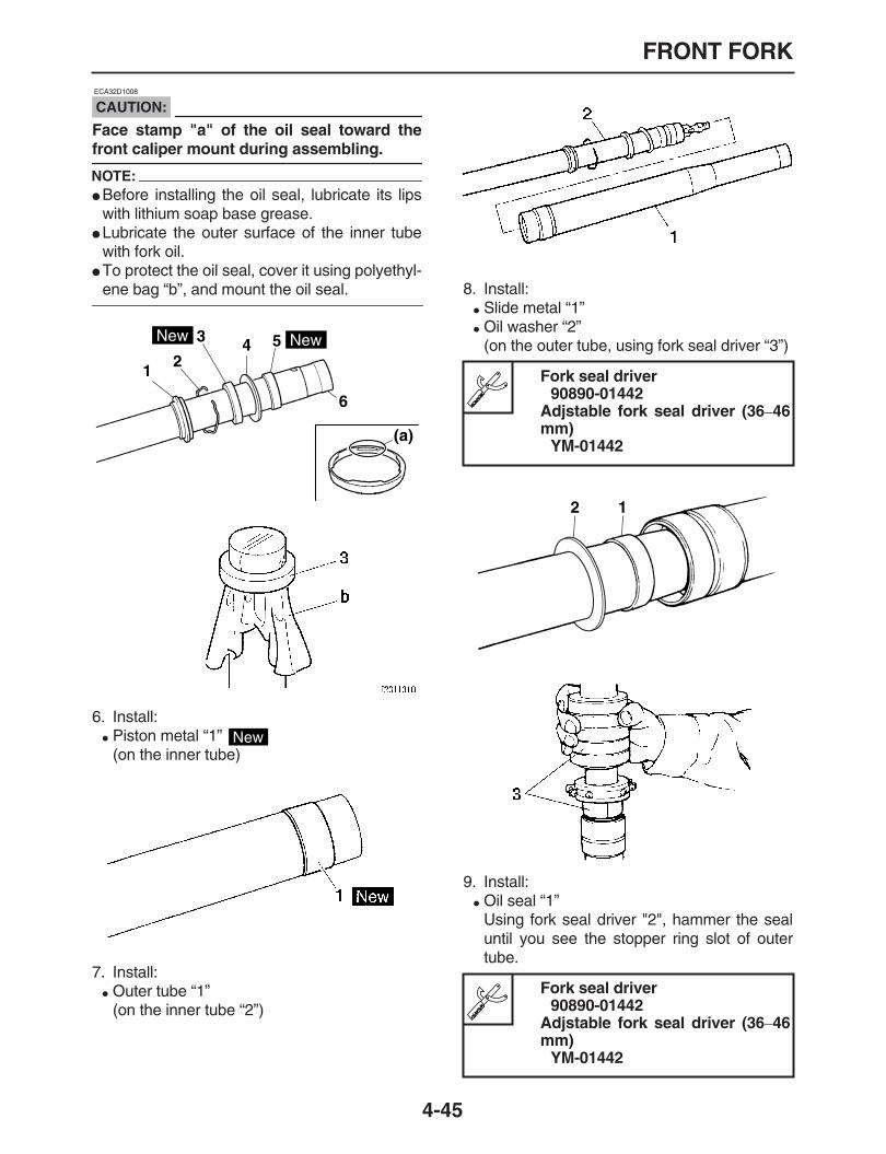
FRONT FORK
4-45
CAUTION:
ECA32D1008
Face stamp "a" of the oil seal toward the
front caliper mount during assembling.
NOTE:
Before installing the oil seal, lubricate its lipswith lithium soap base grease.
Lubricate the outer surface of the inner tubewith fork oil.
To protect the oil seal, cover it using polyethyl-
ene bag “b”, and mount the oil seal.
6. Install:
Piston metal “1” (on the inner tube)
7. Install:
Outer tube “1”(on the inner tube “2”)
8. Install:
Slide metal “1”
Oil washer “2”(on the outer tube, using fork seal driver “3”)
9. Install:
Oil seal “1”Using fork seal driver "2", hammer the sealuntil you see the stopper ring slot of outertube.
12
3 4 5
6
(a)
New New
New
Fork seal driver90890-01442
Adjstable fork seal driver (36
–
46mm)
YM-01442
Fork seal driver90890-01442
Adjstable fork seal driver (36
–
46mm)
YM-01442
12

FRONT FORK
4-46
10.Install:
Stopper ring “1”(in the slot of outer tube)
11.Install:
Dust seal “1”(Slightly apply grease to the inner tube.)
12.Check:
Inner tube for slidingUnsmooth sliding
→
Disassemble andcheck.
13.Lubricate:
Front fork
CAUTION:
ECA14230
Be sure to use the recommended fork oil.Other oils may have an adverse effect onfront fork performance.
When disassembling and assembling thefront fork leg, do not allow any foreign ma-
terial to enter the front fork.
14.When the front fork is filled with oil, slowlymove dumper rod “1” up and down (at least10 times) for lubrication of fork.
NOTE:
Move dumper rod slowly not to leak the fork oil.
15.Slowly move the inner tube up and down forlubrication again. (1 stroke = Approx. 250mm)
NOTE:
Do not move more than 250 mm as it causes an
air insertion.
16.Wait for 10 minutes to sediment and deaer-
Recommended oilSuspension oil 01
Quantity613.0 cm
3
(20.73 US oz) (21.62Imp.oz)
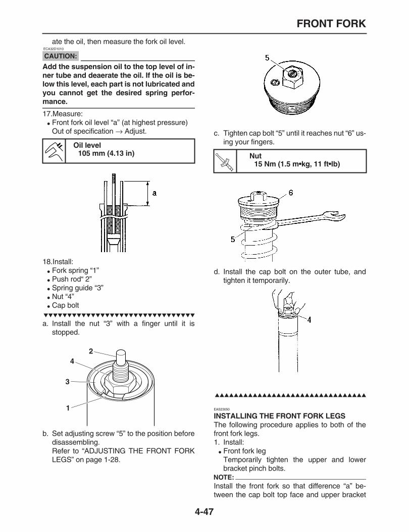
FRONT FORK
4-47
ate the oil, then measure the fork oil level.
CAUTION:
ECA32D1010
Add the suspension oil to the top level of in-ner tube and deaerate the oil. If the oil is be-low this level, each part is not lubricated andyou cannot get the desired spring perfor-
mance.
17.Measure:
Front fork oil level “a” (at highest pressure)Out of specification
→
Adjust.
18.Install:
Fork spring “1”
Push rod“ 2”
Spring guide “3”
Nut “4”
Cap bolt
a. Install the nut “3” with a finger until it isstopped.
b. Set adjusting screw “5” to the position beforedisassembling.Refer to “ADJUSTING THE FRONT FORKLEGS” on page 1-28.
c. Tighten cap bolt “5” until it reaches nut “6” us-ing your fingers.
d. Install the cap bolt on the outer tube, andtighten it temporarily.
EAS23050
INSTALLING THE FRONT FORK LEGS
The following procedure applies to both of thefront fork legs.1. Install:
Front fork legTemporarily tighten the upper and lowerbracket pinch bolts.
NOTE:
Install the front fork so that difference “a” be-tween the cap bolt top face and upper bracket
Oil level105 mm (4.13 in)
1
2
3
4
Nut15 Nm (1.5 m•kg, 11 ft•lb)T
R..
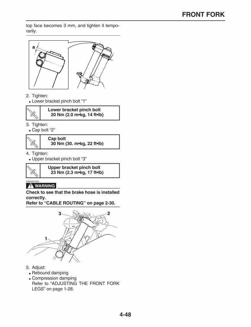
FRONT FORK
4-48
top face becomes 3 mm, and tighten it tempo-
rarily.
2. Tighten:
Lower bracket pinch bolt “1”
3. Tighten:
Cap bolt “2”
4. Tighten:
Upper bracket pinch bolt “3”
WARNING
EWA32D1003
Check to see that the brake hose is installedcorrectly.
Refer to “CABLE ROUTING” on page 2-30.
5. Adjust:
Rebound damping
Compression dampingRefer to “ADJUSTING THE FRONT FORKLEGS” on page 1-28.
Lower bracket pinch bolt20 Nm (2.0 m•kg, 14 ft•lb)
Cap bolt30 Nm (30. m•kg, 22 ft•lb)
Upper bracket pinch bolt23 Nm (2.3 m•kg, 17 ft•lb)
a
TR..
TR..
TR..
1
23
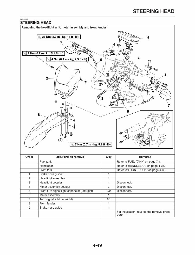
STEERING HEAD
4-49
EAS23090
STEERING HEAD
Removing the headlight unit, meter assembly and front fender
Order Job/Parts to remove Q’ty Remarks
Fuel tank Refer to“FUEL TANK” on page 7-1.Handlebar Refer to“HANDLEBAR” on page 4-34.Front fork Refer to“FRONT FORK” on page 4-39.
1 Brake hose guide 12 Headlight assembly 13 Headlight coupler 1 Disconnect.4 Meter assembly coupler 3 Disconnect.5 Front turn signal light connector (left/right) 2/2 Disconnect.6 Meter assembly 17 Turn signal light (left/right) 1/18 Front fender 19 Brake hose guide 1
For installation, reverse the removal proce-dure.
12
3
(4)
5
5
6
4
7
7
89
4
T R..
7 Nm (0.7 m • kg, 5.1 ft • Ib) T R.
.
4 Nm (0.4 m • kg, 2.9 ft • Ib)
T R..
23 Nm (2.3 m • kg, 17 ft • Ib)
T R..
7 Nm (0.7 m • kg, 5.1 ft • Ib)
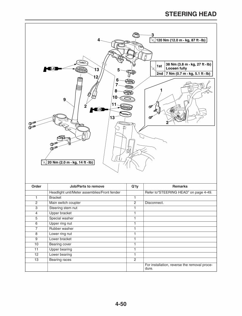
STEERING HEAD
4-50
Order Job/Parts to remove Q’ty Remarks
Headlight unit/Meter assemblies/Front fender Refer to“STEERING HEAD” on page 4-49.1 Bracket 12 Main switch coupler 2 Disconnect.3 Steering stem nut 14 Upper bracket 15 Special washer 16 Upper ring nut 17 Rubber washer 18 Lower ring nut 19 Lower bracket 110 Bearing cover 111 Upper bearing 112 Lower bearing 113 Bearing races 2
For installation, reverse the removal proce-dure.
2
34
5
678
9 10
11
12
13
13
1
2
T R..
120 Nm (12.0 m • kg, 87 ft • Ib)
38 Nm (3.8 m • kg, 27 ft • Ib)
7 Nm (0.7 m • kg, 5.1 ft • Ib) Loosen fully T R.
1st
2nd
T R..
20 Nm (2.0 m • kg, 14 ft • Ib)

STEERING HEAD
4-51
EAS23110
REMOVING THE LOWER BRACKET
1. Stand the vehicle on a level surface.
WARNING
EWA13120
Securely support the vehicle so that there is
no danger of it falling over.
2. Remove:
Upper ring nut
Lower ring nut “1”NOTE:
Hold the lower ring nut with the exhaust andsteering nut wrench, and then remove the upper
ring nut with the ring nut wrench.
WARNING
EWA13730
Securely support the lower bracket so that
there is no danger of it falling.
EAS23120
CHECKING THE STEERING HEAD
1. Wash:
Bearings
Bearing races
2. Check:
Bearings
Bearing racesDamage/pitting
→
Replace.3. Replace:
Bearings
Bearing races
a. Remove the bearing races from the steeringhead pipe with a long rod “1” and hammer.
b. Remove the bearing race from the lower
bracket with a floor chisel “2” and hammer.c. Install a new bearing races.
CAUTION:
ECA14270
If the bearing race is not installed properly,
the steering head pipe could be damaged.
NOTE:
Always replace the bearings and bearing races
as a set.
4. Check:
Upper bracket
Lower bracket(along with the steering stem)Bends/cracks/damage
→
Replace.
EAS23140
INSTALLING THE STEERING HEAD
1. Lubricate:
Upper bearing
Lower bearing
Bearing races
2. Install:
Lower bracket
Lower ring nut “1”
Rubber washer “2”
Upper ring nut “3”
Special washer “4”
Ring nut wrench90890-01268
Spanner wrenchYU-01268
Recommended cleaning solventKerosene
1
Recommended lubricantLithium-soap-based grease

STEERING HEAD
4-52
Refer to “CHECKING AND ADJUSTINGTHE STEERING HEAD” on page 1-27.
3. Install:
Upper bracket
Steering stem nutNOTE:
Temporarily tighten the steering stem nut.
4. Install:
Front fork legsRefer to “FRONT FORK” on page 4-39.
NOTE:
Temporarily tighten the upper and lower bracket
pinch bolts.
5. Tighten:
Steering stem nut
Steering stem nut120 Nm (12.0 m•kg, 87 ft•lb)
321
4
TR..

REAR SHOCK ABSORBER ASSEMBLY
4-53
EAS23160
REAR SHOCK ABSORBER ASSEMBLY
Removing the rear shock absorber assembly
Order Job/Parts to remove Q’ty Remarks
Left slide cover/Right slide cover Refer to“GENERAL CHASSIS” on page 4-1.Drive chain tensioner top Refer to“CHAIN DRIVE” on page 4-59.
1 Rear shock absorber assembly 12 Connection rod 13 Relay arm 14 Collar (short) 15 Collar (long) 16 Oil seal 47 Bearing 28 Collar 19 Oil seal 210 Bearing 211 Collar 112 Bearing 113 Oil seal 2
For installation, reverse the removal proce-dure.
2
3
1
4
5 6
6
67
78
9
910
10
11
12
13
13
LS
LS
LS
LS
LS
LS
LS
LS
T R..
53 Nm (5.3 m • kg, 38 ft • Ib)
T R..
80 Nm (8.0 m • kg, 58 ft • Ib)
T R..
80 Nm (8.0 m • kg, 58 ft • Ib)
T R..
70 Nm (7.0 m • kg, 51 ft • Ib)
T R..
40 Nm (4.0 m • kg, 29 ft • Ib)

REAR SHOCK ABSORBER ASSEMBLY
4-54
EAS23180
HANDLING THE REAR SHOCK ABSORBER
WARNING
EWA13740
This rear shock absorber contains highlycompressed nitrogen gas. Before handlingthe rear shock absorber, read and make sureyou understand the following information.The manufacturer cannot be held responsi-ble for property damage or personal injurythat may result from improper handling ofthe rear shock absorber.
Do not tamper or attempt to open the rearshock absorber.
Do not subject the rear shock absorber toan open flame or any other source of highheat. High heat can cause an explosion dueto excessive gas pressure.
Do not deform or damage the rear shockabsorber in any way. Rear shock absorberdamage will result in poor damping perfor-
mance.
EAS23190
DISPOSING OF A REAR SHOCK ABSORBER
1. Gas pressure must be released before dis-posing of a rear shock absorber. To releasethe gas pressure, drill a 2
–
3-mm hole throughthe rear shock absorber at a point 30
–
35 mmfrom its end as shown.
WARNING
EWA13760
Wear eye protection to prevent eye damage
from released gas or metal chips.
EAS23230
REMOVING THE REAR SHOCK ABSORBER ASSEMBLY
1. Stand the vehicle on a level surface.
WARNING
EWA13120
Securely support the vehicle so that there is
no danger of it falling over.
NOTE:
Place the vehicle on a suitable stand so that the
rear wheel is elevated.
2. Remove:
Connecting arm bolt “1”
Rear shock absorber assembly lower bolt “2”NOTE:
While removing the rear shock absorber assem-bly lower bolt, hold the swingarm so that it does
not drop down.
3. Remove:
Rear shock absorber assembly upper bolt
Rear shock absorber assemblyNOTE:
Raise the swingarm and then remove the rearshock absorber assembly from between the
swingarm and relay arm.
EAS23240
CHECKING THE REAR SHOCK ABSORBER ASSEMBLY
1. Check:
Rear shock absorber rodBends/damage
→
Replace the rear shockabsorber assembly.
Rear shock absorberGas leaks/oil leaks
→
Replace the rear shockabsorber assembly.
SpringDamage/wear
→
Replace the rear shock ab-sorber assembly.
BushingsDamage/wear
→
Replace.
BoltsBends/damage/wear
→
Replace.
EAS23260
CHECKING THE CONNECTING ARM AND RELAY ARM
1. Check:
Connecting rod
Relay arm
2 1

REAR SHOCK ABSORBER ASSEMBLY
4-55
Damage/wear
→
Replace.2. Check:
Bearings
Oil sealsDamage/pitting
→
Replace.3. Check:
CollarDamage/scratches
→
Replace.
EAS23270
INSTALLING THE RELAY ARM
1. Lubricate:
Oil seal
Bearings
Collar
2. Install:
Bearing “1”(To connecting rod “2”)
Bearing “3”(To relay arm “4”)
Bearing “5”(To rear cushion lower position “6”)
Oil seal “7”(To the connecting rod, relay arm, and rearcushion lower position)
EAS23310
INSTALLING THE REAR SHOCK ABSORBER ASSEMBLY
1. Install:
Rear shock absorber assemblyNOTE:
When installing the rear shock absorber as-sembly, lift up the swingarm.
Install all bolts from the left side.
2. Tighten:
Rear shock absorber assembly upper nut
Nut (Frame and connecting rod)
Nut (Relay arm and connecting rod)
Nut (Relay arm and swingarm)
Nut (Rear shock absorber assembly lowerand Relay arm)
Recommended lubricantLithium-soap-based grease
Installed depth (connecting rodbearing) “a”
5.0
–
5.5 mm (0.20
–
0.22 in)Installed depth (rear cushion low-er bearing) “b”
4.0 mm (0.16 in)Installed depth (relay arm bear-ing) “c”
6 mm (0.24 in)Installed depth (connecting rodoil seal, relaly arm oil seal) “d”
0-0.5 mm (0
–
0.02 in)Installed depth (rear cushion low-er oil seal) “e”
0.5-1.0 mm (0.02
–
0.04 in)
a d c d
a d c d
2
1
7
7
7
Rear shock absorber assemblyupper nut
40 Nm (4.0 m•kg, 29 ft•lb)
Nut (Frame and connecting rod)80 Nm (8.0 m•kg, 58 ft•lb)
Nut (Relay arm and connectingrod)
80 Nm (8.0 m•kg, 58 ft•lb)
Nut (Relay arm and Swingarm)70 Nm (7.0 m•kg, 51 ft•lb)
Nut (Rear shock absorber assem-bly lower and Relay arm)
53 Nm (5.3 m•kg, 38 ft•lb)
b
b
c d
c d
47
6
3
57
ee
TR..
TR..
TR..
TR..
TR..

SWINGARM
4-56
EAS23330
SWINGARM
Removing the swingarm
Order Job/Parts to remove Q’ty Remarks
Rear wheel Refer to“REAR WHEEL” on page 4-7.1 Bolt (Swingarm and relay arm) 12 Brake hose holder 33 Chain case 14 Chain cover 15 Chain support 16 Pivot shaft nut 17 Pivot shaft 18 Swingarm 19 Dust cover 210 Front drive chain guide 111 Collar 212 Oil seal 213 Bearing 4
For installation, reverse the removal proce-dure.
22
3
4
5
6
7
89
9
10
11
11
12
12
13
13
13
13
1T R.
.
7 Nm (0.7 m • kg, 5.1 ft • Ib)
T R..
7 Nm (0.7 m • kg, 5.1 ft • Ib)
T R..
2 Nm (0.2 m • kg, 1.4 ft • Ib)
T R..
85 Nm (8.5 m • kg, 62 ft • Ib)
T R..
70 Nm (7.0 m • kg, 51 ft • Ib)

SWINGARM
4-57
EAS23350
REMOVING THE SWINGARM
1. Stand the vehicle on a level surface.
WARNING
EWA13120
Securely support the vehicle so that there is
no danger of it falling over.
NOTE:
Place the vehicle on a suitable stand so that the
rear wheel is elevated.
2. Measure:
Swingarm side play
Swingarm vertical movement
a. Measure the tightening torque of the pivotshaft nut.
b. Measure the swingarm side play “a” by mov-ing the swingarm from side to side.
c. If the swingarm side play is out of specifica-tion, check the spacers, bearings, washers,and dust covers.
d. Check the swingarm vertical movement “b”by moving the swingarm up and down.If swingarm vertical movement is not smoothor if there is binding, check the spacers, bear-ings, washers, and dust covers.
EAS23360
CHECKING THE SWINGARM
1. Check:
SwingarmBends/cracks/damage
→
Replace.
2. Check:
Pivot shaftRoll the pivot shaft on a flat surface.Bends
→
Replace.
WARNING
EWA13770
Do not attempt to straighten a bent pivot
shaft.
3. Wash:
Pivot shaft
Dust covers
Collar
Washers
Bearings
4. Check:
Dust covers
Collar
Washers
Oil sealsDamage/wear
→
Replace.
BearingsDamage/pitting
→
Replace.
EAS23380
INSTALLING THE SWINGARM
1. Lubricate:
Bearings
Collar
Dust covers
Pivot shaft
2. Install:
Bearing “1”
Oil seal “2”
Collar(Swingarm)
Pivot shaft nut85 Nm (8.5 m•kg, 62 ft•lb)
Swingarm side play (at the end ofthe swingarm)
0 mm (0 in)
TR..
Recommended cleaning solventKerosene
Recommended lubricantLithium-soap-based grease

SWINGARM
4-58
3. Install:
Rear shock absorber assemblyRefer to “REAR SHOCK ABSORBER AS-SEMBLY” on page 4-53.
4. Install:
Swing arm assembly
5. Install:
Rear wheelRefer to “REAR WHEEL” on page 4-7.
6. Adjust:
Drive chain slackRefer to “ADJUSTING THE DRIVE CHAINSLACK” on page 1-26.
Installed depth “a”15 mm (0.59 in)
Installed depth “b”8.5
–
9.0 mm (0.33
–
0.35 in)Installed depth “c”
0
–
0.5 mm (0
–
0.02 in)
Pivot shaft nut85 Nm (8.5 m•kg, 62 ft•lb)
Drive chain slackWR250R 38.0
–
48.0 mm (1.50
–
1.89 in)WR250X 40.0
–
50.0 mm (1.57
–
1.97 in)
a bc
bc
acb
a
cb a
1 12
TR..
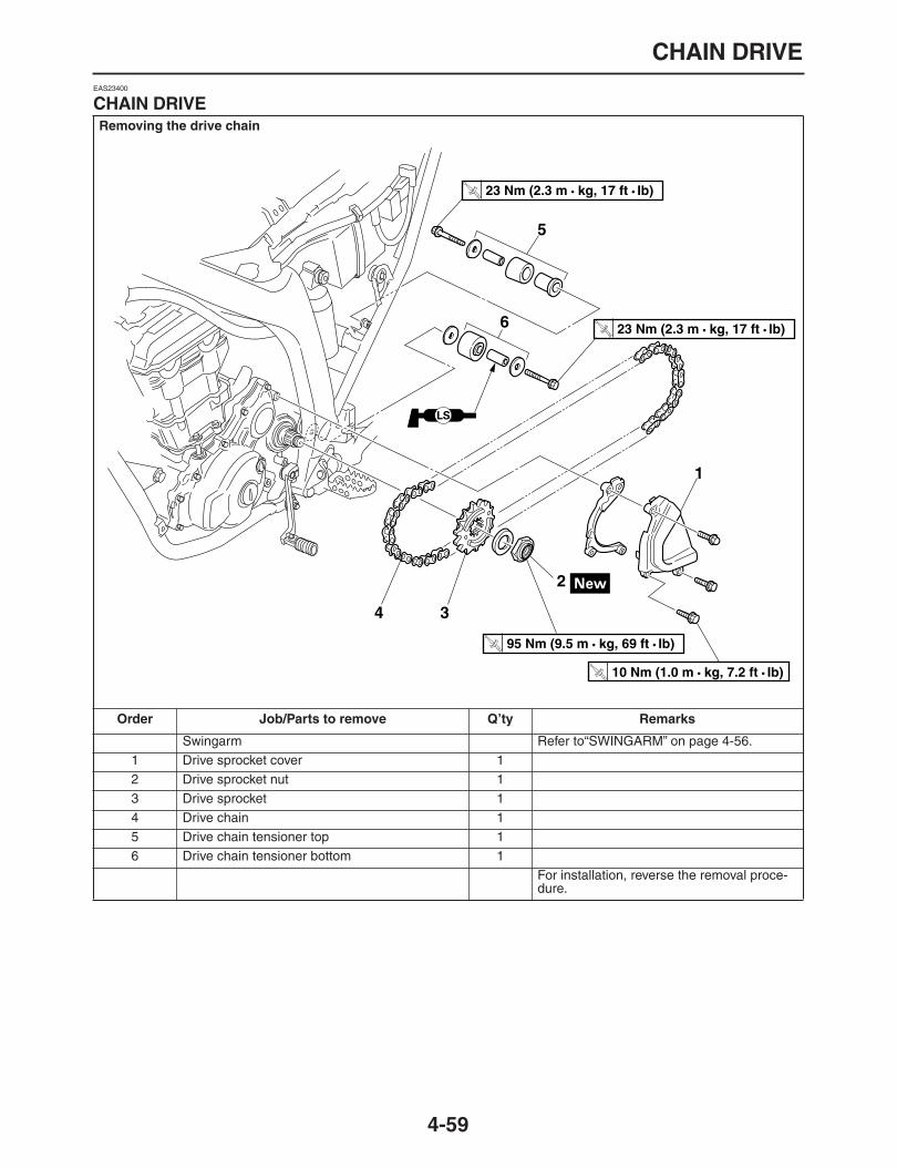
CHAIN DRIVE
4-59
EAS23400
CHAIN DRIVE
Removing the drive chain
Order Job/Parts to remove Q’ty Remarks
Swingarm Refer to“SWINGARM” on page 4-56.1 Drive sprocket cover 12 Drive sprocket nut 13 Drive sprocket 14 Drive chain 15 Drive chain tensioner top 16 Drive chain tensioner bottom 1
For installation, reverse the removal proce-dure.
1
2
34
5
6
T R..
23 Nm (2.3 m • kg, 17 ft • Ib)
T R..
23 Nm (2.3 m • kg, 17 ft • Ib)
T R..
10 Nm (1.0 m • kg, 7.2 ft • Ib)
T R..
95 Nm (9.5 m • kg, 69 ft • Ib)

CHAIN DRIVE
4-60
EAS23420
REMOVING THE DRIVE CHAIN
1. Stand the vehicle on a level surface.
WARNING
EWA13120
Securely support the vehicle so that there is
no danger of it falling over.
NOTE:
Place the vehicle on a suitable stand so that the
rear wheel is elevated.
2. Remove:
Drive sprocket nut “1”NOTE:
Return the bent tab of the locknut.
Operate the rear brake, and loosen the drivesprocket.
After loosening the drive sprocket, remove the
rear wheel and swingarm.
3. Remove:
Rear wheelRefer to “REAR WHEEL” on page 4-7.
Rear shock absorberRefer to “REAR SHOCK ABSORBER AS-SEMBLY” on page 4-53.
SwingarmRefer to “SWINGARM” on page 4-56.
4. Remove:
Drive chain
EAS23441
CHECKING THE DRIVE CHAIN
1. Measure:
15-link section “a” of the drive chainOut of specification
→
Replace the drivechain.
a. Measure the length “a” between the innersides of the pins and the length “b” betweenthe outer sides of the pins on a 15-link section
of the drive chain as shown in the illustration.
b. Calculate the length “c” of the 15-link sectionof the drive chain using the following formula.Drive chain 15-link section length “c” =(length “a” between pin inner sides + length“b” between pin outer sides)/2
NOTE:
When measuring a 15-link section of the drivechain, make sure that the drive chain is taut.
Perform this procedure 2
–
3 times, at a different
location each time.
2. Check:
Drive chainStiffness
→
Clean, lubricate, or replace.
3. Clean:
Drive chain
a. Wipe the drive chain with a clean cloth.b. Put the drive chain in kerosene and remove
any remaining dirt.
15-link length limit239.3 mm (9.42 in)
1

CHAIN DRIVE
4-61
c. Remove the drive chain from the keroseneand completely dry it.
CAUTION:
ECA14290
This motorcycle has a drive chain withsmall rubber O-rings “1” between the drivechain side plates. Never use high-pressurewater or air, steam, gasoline, certain sol-vents (e.g., benzine), or a coarse brush toclean the drive chain. High-pressure meth-ods could force dirt or water into the drivechain’s internals, and solvents will deterio-rate the O-rings. A coarse brush can alsodamage the O-rings. Therefore, use onlykerosene to clean the drive chain.
Do not soak the drive chain in kerosene formore than ten minutes, otherwise the
O-rings can be damaged.
4. Check:
O-rings “1”Damage
→
Replace the drive chain.
Drive chain rollers “2”Damage/wear
→
Replace the drive chain.
Drive chain side plates “3”Damage/wear
→
Replace the drive chain.
5. Lubricate:
Drive chain
EAS23460
CHECKING THE DRIVE SPROCKET
1. Check:
Drive sprocketRefer to “CHECKING AND REPLACINGTHE REAR WHEEL SPROCKET” on page4-9.
EAS23470
CHECKING THE REAR WHEEL SPROCKET
Refer to “CHECKING AND REPLACING THEREAR WHEEL SPROCKET” on page 4-9.
EAS23490
INSTALLING THE DRIVE CHAIN
1. Lubricate:
Drive chain
2. Install:
Drive chain
Drive sprocket
Drive sprocket nut(temporarily)
3. Install:
SwingarmRefer to “SWINGARM” on page 4-56.
Rear wheelRefer to “REAR WHEEL” on page 4-7.
4. Tighten:
Drive sprocket nut “1”
Recommended lubricantEngine oil or chain lubricantsuitable for O-ring chains
Recommended lubricantEngine oil or chain lubricantsuitable for O-ring chains
Drive sprocket nut95 Nm (9.5 m•kg, 69 ft•lb)T
R..

CHAIN DRIVE
4-62
NOTE:
While applying the rear brake, tighten the drivesprocket nut.
Stake the nut “1”.
5. Adjust:
Drive chain slackRefer to “ADJUSTING THE DRIVE CHAINSLACK” on page 1-26.
CAUTION:
ECA13550
A drive chain that is too tight will overloadthe engine and other vital parts, and one thatis too loose can skip and damage the swing-arm or cause an accident. Therefore, keepthe drive chain slack within the specified lim-
its.
Drive chain slackWR250R 38.0
–
48.0 mm (1.50
–
1.89 in)WR250X 40.0
–
50.0 mm (1.57
–
1.97 in)
1

1
2
3
4
5
6
7
8
9
ENGINE
ENGINE REMOVAL .......................................................................................5-1
INSTALLING THE ENGINE .....................................................................5-5INSTALLING THE SHIFT PEDAL............................................................5-5
CAMSHAFT....................................................................................................5-6
REMOVING THE CAMSHAFT.................................................................5-8CHECKING THE CAMSHAFT .................................................................5-8CHECKING THE TIMING CHAIN AND CAMSHAFT SPROCKET ..........5-10CHECKING THE TIMING CHAIN TENSIONERS....................................5-10CHECKING THE DECOMPRESSION SYSTEM .....................................5-11INSTALLING THE CAMSHAFTS.............................................................5-11
CYLINDER HEAD ..........................................................................................5-14
REMOVING THE CYLINDER HEAD .......................................................5-15CHECKING THE CYLINDER HEAD........................................................5-15INSTALLING THE CYLINDER HEAD......................................................5-15
VALVES AND VALVE SPRINGS ..................................................................5-17
REMOVING THE VALVES.......................................................................5-18CHECKING THE VALVES AND VALVE GUIDES ...................................5-19CHECKING THE VALVE SEATS.............................................................5-20CHECKING THE VALVE SPRINGS ........................................................5-22CHECKING THE VALVE LIFTERS..........................................................5-23INSTALLING THE VALVES .....................................................................5-23
CYLINDER AND PISTON ..............................................................................5-25
REMOVING THE PISTON .......................................................................5-26CHECKING THE CYLINDER AND PISTON............................................5-26CHECKING THE PISTON RINGS ...........................................................5-27CHECKING THE PISTON PIN.................................................................5-27INSTALLING THE PISTON AND CYLINDER..........................................5-28
STARTER MOTOR ........................................................................................5-30
CHECKING THE STARTER MOTOR......................................................5-32ASSEMBLING THE STARTER MOTOR..................................................5-33
CLUTCH .........................................................................................................5-34
REMOVING THE CLUTCH......................................................................5-38CHECKING THE FRICTION PLATES .....................................................5-38CHECKING THE CLUTCH PLATES........................................................5-38CHECKING THE CLUTCH SPRINGS .....................................................5-39CHECKING THE CLUTCH HOUSING.....................................................5-39CHECKING THE CLUTCH BOSS............................................................5-39CHECKING THE PRESSURE PLATE.....................................................5-39CHECKING THE CLUTCH PUSH RODS ................................................5-39CHECKING THE PRIMARY DRIVE GEAR..............................................5-40CHECKING THE PRIMARY DRIVEN GEAR...........................................5-40INSTALLING THE CLUTCH.....................................................................5-40
SHIFT SHAFT ................................................................................................5-43
CHECKING THE SHIFT SHAFT..............................................................5-44CHECKING THE STOPPER LEVER .......................................................5-44INSTALLING THE SHIFT SHAFT............................................................5-44
OIL PUMP AND BALANCER GEAR .............................................................5-45
REMOVING THE OIL PUMP ...................................................................5-47CHECKING THE OIL PUMP....................................................................5-47ASSEMBLING THE OIL PUMP................................................................5-47INSTALLING THE OIL PUMP AND BALANCER GEAR..........................5-48
GENERATOR AND STARTER CLUTCH ......................................................5-50
REMOVING THE GENERATOR..............................................................5-53CHECKING THE STARTER CLUTCH.....................................................5-53INSTALLING THE STARTER CLUTCH...................................................5-54INSTALLING THE GENERATOR ............................................................5-54
CRANKCASE.................................................................................................5-56
DISASSEMBLING THE CRANKCASE ....................................................5-59CHECKING THE TIMING CHAIN, TIMING CHAIN GUIDE, OIL STRAINER, NOZZLE, DELIVERY PIPE ........................................5-59CHECKING THE CRANKCASE...............................................................5-59ASSEMBLING THE CRANKCASE ..........................................................5-59
CRANKSHAFT ASSEMBLY AND BALANCER SHAFT...............................5-61
REMOVING THE CRANKSHAFT ASSEMBLY........................................5-62CHECKING THE CRANKSHAFT ASSEMBLY ........................................5-62INSTALLING THE CRANKSHAFT ASSEMBLY ......................................5-62
TRANSMISSION ............................................................................................5-64
CHECKING THE SHIFT FORKS .............................................................5-67CHECKING THE SHIFT DRUM ASSEMBLY...........................................5-67CHECKING THE TRANSMISSION..........................................................5-67INSTALLING THE SHIFT FORKS AND SHIFT DRUM ASSEMBLY .......5-68INSTALLING THE TRANSMISSION........................................................5-69
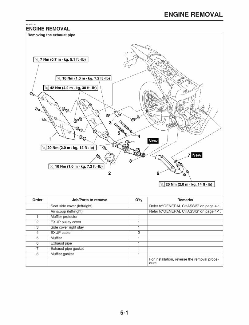
ENGINE REMOVAL
5-1
EAS23710
ENGINE REMOVAL
Removing the exhaust pipe
Order Job/Parts to remove Q’ty Remarks
Seat side cover (left/right) Refer to“GENERAL CHASSIS” on page 4-1.Air scoop (left/right) Refer to“GENERAL CHASSIS” on page 4-1.
1 Muffler protector 12 EXUP pulley cover 13 Side cover right stay 14 EXUP cable 25 Muffler 16 Exhaust pipe 17 Exhaust pipe gasket 18 Muffler gasket 1
For installation, reverse the removal proce-dure.
2
3
45
6
78
1
T R..
7 Nm (0.7 m • kg, 5.1 ft • Ib)
T R..
10 Nm (1.0 m • kg, 7.2 ft • Ib)
T R..
42 Nm (4.2 m • kg, 30 ft • Ib)
T R..
10 Nm (1.0 m • kg, 7.2 ft • Ib)
T R..
20 Nm (2.0 m • kg, 14 ft • Ib)
T R..
20 Nm (2.0 m • kg, 14 ft • Ib)

ENGINE REMOVAL
5-2
Removing the shift pedal, leads and hoses
Order Job/Parts to remove Q’ty Remarks
CoolantDrain.Refer to“CHANGING THE COOLANT” on page 3-18.
Radiator Refer to“RADIATOR” on page 6-1.Starter motor Refer to“STARTER MOTOR” on page 5-30.
1 Shift pedal 12 Drive sprocket cover 13 Gasket 14 Drive sprocket nut 15 Drive sprocket 16 Speed sensor coupler 1 Disconnect.7 Coolant temperature sensor coupler 1 Disconnect.8 Generator coupler 2 Disconnect.9 Crankshaft position sensor coupler 1 Disconnect.10 Horn lead coupler 1 Disconnect.11 Fuse box 112 Side cover stay 113 Ground lead 114 Neutral switch lead 1 Disconnect.15 Ignition coil lead coupler 1 Disconnect.
95 Nm (9.5 m • kg, 69 ft • Ib)
1
23
45
6
7
8
9
10
11
12
15
13
14
T R..
10 Nm (1.0 m • kg, 7.2 ft • Ib)
T R..
18 Nm (1.8 m • kg, 13 ft • Ib)
T R..
T R..
10 Nm (1.0 m • kg, 7.2 ft • Ib)
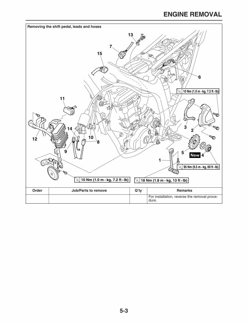
ENGINE REMOVAL
5-3
For installation, reverse the removal proce-dure.
Removing the shift pedal, leads and hoses
Order Job/Parts to remove Q’ty Remarks
95 Nm (9.5 m • kg, 69 ft • Ib)
1
23
45
6
7
8
9
10
11
12
15
13
14
T R..
10 Nm (1.0 m • kg, 7.2 ft • Ib)
T R..
18 Nm (1.8 m • kg, 13 ft • Ib)
T R..
T R..
10 Nm (1.0 m • kg, 7.2 ft • Ib)

ENGINE REMOVAL
5-4
Order Job/Parts to remove Q’ty Remarks
NOTE:
Use a suitable stand to supported the
engine side.
Engine oilDrain.Refer to“CHANGING THE ENGINE OIL” on page 3-11.
1 Engine mounting bolt (front upper) 12 Engine mounting bolt (front) 13 Engine mounting bolt (front lower) 14 Down tube bolts (front upper) 25 Down tube bolts (rear lower) 26 Down tube 17 Pivot shaft 18 Engine assembly 1
For installation, reverse the removal proce-dure.
1
2
3
4
5
6
7
8
T R..
85 Nm (8.5 m • kg, 62 ft • Ib)
T R..
67 Nm (6.7 m • kg, 48 ft • Ib)
T R..
56 Nm (5.6 m • kg, 41 ft • Ib)
T R..
113 Nm (11.3 m • kg, 82 ft • Ib)
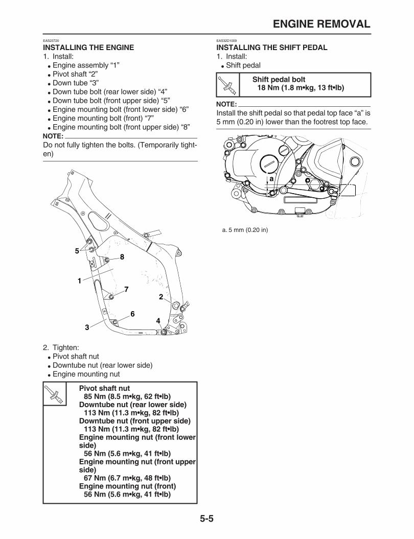
ENGINE REMOVAL
5-5
EAS23720
INSTALLING THE ENGINE
1. Install:
Engine assembly “1”
Pivot shaft “2”
Down tube “3”
Down tube bolt (rear lower side) “4”
Down tube bolt (front upper side) “5”
Engine mounting bolt (front lower side) “6”
Engine mounting bolt (front) “7”
Engine mounting bolt (front upper side) “8”NOTE:
Do not fully tighten the bolts. (Temporarily tight-
en)
2. Tighten:
Pivot shaft nut
Downtube nut (rear lower side)
Engine mounting nut
EAS32D1009
INSTALLING THE SHIFT PEDAL
1. Install:
Shift pedal
NOTE:
Install the shift pedal so that pedal top face “a” is
5 mm (0.20 in) lower than the footrest top face.
Pivot shaft nut85 Nm (8.5 m•kg, 62 ft•lb)
Downtube nut (rear lower side)113 Nm (11.3 m•kg, 82 ft•lb)
Downtube nut (front upper side)113 Nm (11.3 m•kg, 82 ft•lb)
Engine mounting nut (front lowerside)
56 Nm (5.6 m•kg, 41 ft•lb)Engine mounting nut (front upperside)
67 Nm (6.7 m•kg, 48 ft•lb)Engine mounting nut (front)
56 Nm (5.6 m•kg, 41 ft•lb)
7
8
64
1
3
2
5
TR..
Shift pedal bolt18 Nm (1.8 m•kg, 13 ft•lb)
a. 5 mm (0.20 in)
TR..
a

CAMSHAFT
5-6
EAS23730
CAMSHAFT
Removing the cylinder head cover
Order Job/Parts to remove Q’ty Remarks
Side cover (left/right) Refer to “GENERAL CHASSIS” on page 4-1.
Fuel tank Refer to “FUEL TANK” on page 7-1.
CoolantDrain.Refer to “CHANGING THE COOLANT” on page 3-18.
Engine oilDrain.Refer to “CHANGING THE ENGINE OIL” on page 3-11.
1 Throttle cable 22 Throttle body 13 Clutch cable 1 Disconnect.4 Ignition coil coupler 1 Disconnect.5 Cylinder head cover breather hose 16 Ignition coil assembly 17 Spark plug 18 Cylinder head cover 19 Cylinder head cover gasket 1
For installation, reverse the removal proce-dure.
1
2
9
4 5
6
73
8
T R..
13 Nm (1.3 m • kg, 9.4 ft • Ib)
T R..
12 Nm (1.2 m • kg, 8.7 ft • Ib)

CAMSHAFT
5-7
REMOVING THE CAMSHAFT
Order Job/Parts to remove Q’ty Remarks
1 Timing mark accessing screw 12 Crankshaft end cover 13 Timing chain tensioner assembly 14 Camshaft cap 15 Dowel pin 26 Camshaft (IN) 17 Camshaft (EX) 18 Camshaft sprocket (IN) 19 Camshaft sprocket (EX) 1
For installation, reverse the removal proce-dure.
1
2
3
4
5
6
78
9
M
M
T R..
10 Nm (1.0 m • kg, 7.2 ft • Ib)
T R..
10 Nm (1.0 m • kg, 7.2 ft • Ib)
T R..
24 Nm (2.4 m • kg, 17 ft • Ib)
E
E

CAMSHAFT
5-8
EAS23800
REMOVING THE CAMSHAFT
1. Remove:
Crankshaft end cover
Timing mark accessing screw2. Align:
TDC on the generator rotor(mark on the crankcase cover)
a. Turn the crankshaft counterclockwise.b. When piston is at TDC on the compression
stroke, align the mark “a” on the generator ro-tor with the mark “b” on the crankcase cover.
NOTE:
TDC on the compression stroke can be foundwhen the camshaft lobes are turned away from
each other.
3. Remove:
Cylinder head cover4. Loosen:
Camshaft sprocket bolt5. Remove:
Timing chain tensioner assembly
Gasket6. Remove:
Camshaft cap bolts
Camshaft cap
CAUTION:
ECA32D1006
To prevent damage to the cylinder head,camshafts or camshaft caps, loosen thecamshaft cap bolts in satages and in order
from 1 to 8.
7. Remove:
Intake camshaft “1”
Exhaust camshaft “2” NOTE:
To prevent the timing chain from falling into the
crankcase, fasten it with a wire to it.
EAS23840
CHECKING THE CAMSHAFT
1. Check:
Camshaft lobesBlue discoloration/pitting/scratches
→
Re-place the camshaft.
2. Measure:
Camshaft lobe dimensions “a” and “b”Out of specification
→
Replace the camshaft.
a
b
2 4 68
135 7
1
2

CAMSHAFT
5-9
3. Measure:
Camshaft runoutOut of specification
→
Replace.
4. Measure:
Camshaft-journal-to-camshaft-cap clearanceOut of specification
→
Measure the camshaftjournal diameter.
a. Install the camshaft into the cylinder head(without the dowel pins and camshaft caps).
b. Position a strip of Plastigauge® “1” onto thecamshaft journal as shown.
c. Install the dowel pins and camshaft caps.NOTE:
Tighten the camshaft cap bolts in the order ofthe embossed numbers on the camshaft cap.
Do not turn the camshaft when measuring the
camshaft journal-to-camshaft cap clearance.
d. Remove the camshaft caps and then mea-sure the width of the Plastigauge® “1”.
Camshaft lobe dimension limitIntake A
34.550
–
34.650 mm (1.3602
–
1.3642 in)Limit
35.450 mm (1.3957 in)Intake B
25.953
–
26.053 mm (1.0218
–
1.0257 in)Limit
25.853 mm (1.0178 in)Exhaust A
34.850
–
34.950 mm (1.3720
–
1.3760 in)Limit
34.750 mm (1.3681 in)Exhaust B
25.986
–
26.086 mm (1.0231
–
1.0270 in)Limit
25.886 mm (1.0191 in)
Camshaft runout limit0.015 mm (0.00059 in) or less
Camshaft-journal-to-cam-shaft-cap clearance
0.028
–
0.062 mm (0.0011
–
0.0024in)
Limit0.08 mm (0.0031 in)
Camshaft cap bolts10 Nm (1.0 m•kg, 7.2 ft•lb)
1
TR..

CAMSHAFT
5-10
5. Measure:
Camshaft journal diameter “a” Out of specification
→
Replace the camshaft.Within specification
→
Replace the cylinderhead and the camshaft caps as a set.
EAS23870
CHECKING THE TIMING CHAIN AND CAMSHAFT SPROCKET
1. Check:
Timing chain “1”Damage/stiffness
→
Replace the timingchain and camshaft and camshaft sprocketas a set.
2. Check:
Camshaft sprocketMore than 1/4 tooth wear “a”
→
Replace thecamshaft sprocket and the timing chain as aset.
EAS23960
CHECKING THE TIMING CHAIN TENSIONERS
The following procedure applies to both of thetiming chain tensioners.1. Check:
Timing chain tensionerCracks/damage
→
Replace.
a. Using a finger, push and insert timing chaintensioner rod “1” into the timing chaintensioner housing.
NOTE:
Push the timing chain tensioner rod in direction“a”, and turn the timing chain tensioner body “2”
in direction “b” until it stops.
b. Keep pressing the timing chain tensioner rod,mount clip “3” into groove “4”, and lock thetiming chain tensioner rod.
c. Push the timing chain tensioner rod in direc-tion “c”.
d. Make sure that the timing chain tensioner rodcan smoothly move out from the timing chaintensioner housing in direction “d”. If notsmooth, replace the timing chain tensionerassembly.
Camshaft journal diameter21.959
–
21.972 mm (0.864
–
0.865in)
1
a. 1/4 toothb. Correct
1. Timing chain roller2. Camshaft sprocket
a
b
1
2
b
a
2
1

CAMSHAFT
5-11
EAS32D1001
CHECKING THE DECOMPRESSION SYSTEM
1. Check:
Decompression system
a. Check that the decompressor lever pin “1”projects from the camshaft.
b. Check that the decompressor cam “2” movessmoothly.
EAS24000
INSTALLING THE CAMSHAFTS
1. Install:
Exhaust camshaft “1”
Intake camshaft “2”
NOTE:
Stamp line “a” of the camshaft sprocket mustlocate in the position as shown.
Temporarily tighten the camshaft sprocket
bolts.
2. Install:
Intake camshaft sprocket
Exhaust camshaft sprocket
a. Turn the crankshaft counterclockwise.b. When piston is at TDC on the compression
stroke, align the mark “a” on the generator ro-tor with the mark “b” on the crankcase cover.
c. Install the timing chain onto both camshaftsprockets and then install the exhaust cam-shaft onto the cylinder head first.
NOTE:
Locate mark “c” of exhaust system camshaftchain sprocket “1” and mark “d” of intake systemcamshaft chain sprocket “2” in the same positionat the end of cylinder head as shown. This is the
Top Dead Center (TDC).
CAUTION:
ECA13740
Do not turn the crankshaft when installingthe camshaft(s) to avoid damage or improp-
er valve timing.Camshaft sprocket bolt24 Nm (2.4 m•kg, 17 ft•lb)
43 cd
1
2
TR..
1 2
a a
b
a

CAMSHAFT
5-12
3. Install:
Dowel pin
Camshaft cap
Camshaft cap boltsNOTE:
Lubricate the camshaft cap bolt threads withengine oil.
Finger tighten the camshaft cap bolts.
4. Tighten:
Camshaft cap bolts
NOTE:
Tighten the camshaft cap bolts in the order of
the embossed numbers on the camshaft cap.
CAUTION:
ECA13730
The camshaft cap bolts must be tightenedevenly or damage to the cylinder head, cam-
shaft caps, and camshafts will result.
5. Install:
Timing chain tensioner
a. Using a finger, push and insert timing chaintensioner rod “1” into the timing chaintensioner housing.
NOTE:
Push the timing chain tensioner rod in direction“a”, and turn the timing chain tensioner body “2”
in direction “b” until it stops.
b. Keep pressing the timing chain tensioner rod,mount clip “3” into groove “4”, and lock thetiming chain tensioner rod.
c. In the status of step “b”, install the rod assem-bly in the cylinder block.
NOTE:
Always use a new gasket.
Camshaft cap bolt10 Nm (1.0 m•kg, 7.2 ft•lb)
1
2
c d
TR..
Timing chain tensioner bolt10 Nm (1.0 m•kg, 7.2 ft•lb)
2 4 68
135 7
b
a
2
1
43 cd
TR..

CAMSHAFT
5-13
d. Unlock the camshaft chain tensioner by turn-ing the crankshaft counterclockwise, and ten-sion the timing chain.
6. Turn:
Crankshaft(several turns counterclockwise)
7. Check:
The TDC mark of rotor, and the mark ofcrankshaft case cover
a. Turn the crankshaft counterclockwise.b. When the piston is in the compression pro-
cess, align TDC mark “a” of the rotor withmark “b” of crankshaft case cover.
NOTE:
You can check the TDC in compression process
when the camshaft robes face outward.
Punch mark on the camshaftCheck the matching of stamp line “c” of thecamshaft punch mark timing chain sprocketand the cylinder head end.Out of alignment
→
Reinstall.Refer to the installation steps above.
8. Measure:
Valve clearanceOut of specification
→
Adjust.
Refer to “ADJUSTING THE VALVE CLEAR-ANCE” on page 3-4.
a
b
c c
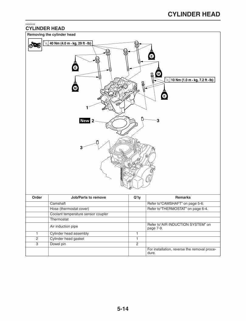
CYLINDER HEAD
5-14
EAS24100
CYLINDER HEAD
Removing the cylinder head
Order Job/Parts to remove Q’ty Remarks
Camshaft Refer to“CAMSHAFT” on page 5-6.Hose (thermostat cover) Refer to“THERMOSTAT” on page 6-4.Coolant temperature sensor couplerThermostat
Air induction pipe Refer to“AIR INDUCTION SYSTEM” on page 7-9.
1 Cylinder head assembly 12 Cylinder head gasket 13 Dowel pin 2
For installation, reverse the removal proce-dure.
1
2
3
3
E
E
M
M
T R..
40 Nm (4.0 m • kg, 29 ft • Ib)
T R..
10 Nm (1.0 m • kg, 7.2 ft • Ib)
E

CYLINDER HEAD
5-15
EAS24130
REMOVING THE CYLINDER HEAD
1. Remove:
Cylinder head bolts “1” (M6
×
60)
Cylinder head bolts “2” (M10
×
154)
Cylinder head bolts “3” (M10
×
140)NOTE:
Gradually loosen bolts “a” to “f” in this sequence
in several times.
EAS24160
CHECKING THE CYLINDER HEAD
1. Eliminate:
Combustion chamber carbon deposits(with a rounded scraper)
NOTE:
Do not use a sharp instrument to avoid damag-ing or scratching:
Spark plug bore threads
Valve seats
2. Check:
Cylinder headDamage/scratches
→
Replace.
Cylinder head water jacketMineral deposits/rust
→
Eliminate.3. Measure:
Cylinder head warpageOut of specification
→
Resurface the cylinderhead.
a. Place a straightedge “1” and a thicknessgauge “2” across the cylinder head.
b. Measure the warpage.c. If the limit is exceeded, resurface the cylinder
head as follows.d. Place a 400
–
600 grit wet sandpaper on thesurface plate and resurface the cylinder headusing a figure-eight sanding pattern.
NOTE:
To ensure an even surface, turn the cylinder
head several times.
e. After resurfacing, out of specification
→
Re-place the cylinder head.
EAS24230
INSTALLING THE CYLINDER HEAD
1. Install:
Cylinder head gasket “1”
Dowel pins “2”
Cylinder head warpage0.05 mm (0.002 in)
c f
de
b a
3
3
12
21
New
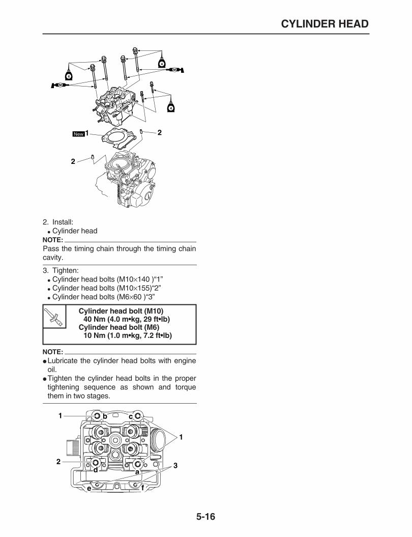
CYLINDER HEAD
5-16
2. Install:
Cylinder headNOTE:
Pass the timing chain through the timing chain
cavity.
3. Tighten:
Cylinder head bolts (M10
×
140 )“1”
Cylinder head bolts (M10
×
155)“2”
Cylinder head bolts (M6
×
60 )“3”
NOTE:
Lubricate the cylinder head bolts with engineoil.
Tighten the cylinder head bolts in the propertightening sequence as shown and torque
them in two stages.
Cylinder head bolt (M10)40 Nm (4.0 m•kg, 29 ft•lb)
Cylinder head bolt (M6)10 Nm (1.0 m•kg, 7.2 ft•lb)
M
M
New
4
4
4
1 2
2
TR..
d a
cb
e f
1
3
1
2

VALVES AND VALVE SPRINGS
5-17
EAS24270
VALVES AND VALVE SPRINGS
Removing the valves and valve springs
Order Job/Parts to remove Q’ty Remarks
Cylinder head Refer to“CYLINDER HEAD” on page 5-14.1 Valve lifter 42 Valve pad 43 Valve cotter 84 Valve spring retainer 45 Valve spring 46 Exhaust valve 27 Intake valve 28 Valve stem seal 49 Valve spring seat 4
For installation, reverse the removal proce-dure.
1
1
2
2
33
44
55
6 7
88
99
M
M
M

VALVES AND VALVE SPRINGS
5-18
EAS24280
REMOVING THE VALVES
The following procedure applies to all of thevalves and related components.NOTE:
Before removing the internal parts of the cylin-der head (e.g., valves, valve springs, valve
seats), make sure the valves properly seal.
1. Remove:
Valve lifter “1”
Valve pad “2”NOTE:
Make a note of the position of each valve lifterand valve pad so that they can be reinstalled in
their original place.
2. Check:
Valve sealingLeakage at the valve seat
→
Check the valveface, valve seat, and valve seat width.Refer to “CHECKING THE VALVE SEATS”on page 5-20.
a. Pour a clean solvent “a” into the intake andexhaust ports.
b. Check that the valves properly seal.NOTE:
There should be no leakage at the valve seat
“1”.
3. Remove:
Valve cotters “1”NOTE:
Remove the valve cotters by compressing thevalve spring with the valve spring compressor
“2”.
4. Remove:
Valve spring retainer “1”
Valve spring “2”
Valve “3”
Valve stem seal “4”
Valve spring seat “5”NOTE:
Identify the position of each part very carefully
so that it can be reinstalled in its original place.
1
2
Valve spring compressor90890-04019YM-04019
1a
1
2

VALVES AND VALVE SPRINGS
5-19
EAS24290
CHECKING THE VALVES AND VALVE GUIDES
The following procedure applies to all of thevalves and valve guides.1. Measure:
Valve-stem-to-valve-guide clearanceOut of specification
→
Replace the valveguide.
2. Replace:
Valve guideNOTE:
To ease valve guide removal and installation,and to maintain the correct fit, heat the cylinder
head to 100
°
C (212
°
F) in an oven.
a. Remove the valve guide with the valve guideremover “1”.
b. Install the new valve guide with the valveguide installer “2” and valve guide remover“1”.
c. After installing the valve guide, bore the valveguide with the valve guide reamer “3” to ob-tain the proper valve-stem-to-valve-guideclearance.
Valve-stem-to-valve-guide clearance =Valve guide inside diameter
“
a
”
-Valve stem diameter
“
b
”
Valve-stem-to-valve-guide clear-ance
Valve-stem-to-valve-guide clear-ance (intake)
0.010
–
0.037 mm (0.0004
–
0.0015in)
Limit0.080 mm (0.0032 in)
Limit0.08 mm (0.0032 in)
Valve-stem-to-valve-guide clear-ance (exhaust)
0.025
–
0.052 mm (0.0010
–
0.0020in)
Limit0.100 mm (0.0039 in)
Limit0.10 mm (0.004 in)
12
4
5
3
1
2

VALVES AND VALVE SPRINGS
5-20
NOTE:
After replacing the valve guide, reface the valve
seat.
3. Eliminate:
Carbon deposits(from the valve face and valve seat)
4. Check:
Valve facePitting/wear
→
Grind the valve face.
Valve stem endMushroom shape or diameter larger than thebody of the valve stem
→
Replace the valve.5. Measure:
Valve margin thickness “a”Out of specification
→
Replace the valve.
6. Measure:
Valve stem runoutOut of specification
→
Replace the valve.NOTE:
When installing a new valve, always replacethe valve guide.
If the valve is removed or replaced, always re-
place the oil seal.
EAS24300
CHECKING THE VALVE SEATS
The following procedure applies to all of thevalves and valve seats.1. Eliminate:
Carbon deposits(from the valve face and valve seat)
2. Check:
Valve seatPitting/wear
→
Replace the cylinder head.3. Measure:
Valve seat width “a”Out of specification
→
Replace the cylinderhead.
Valve guide remover (
ø
4.5)90890-04116YM-04116
Valve guide installer (
ø
4.5)90890-04117YM-04117
Valve guide reamer (
ø
4.5)90890-04118YM-04118
Valve margin thicknessValve margin thickness D (intake)
1.15
–
1.45 mm (0.0453
–
0.0571 in)Limit
1.00 mm (0.0394 in)Valve margin thickness D (ex-haust)
0.85
–
1.15 mm (0.0335
–
0.0453 in)Limit
0.70 mm (0.0276 in)
Valve stem runout0.010 mm (0.0004 in)
Valve seat widthValve seat width C (intake)
0.90
–
1.10 mm (0.0354
–
0.0433 in)Valve seat width C (exhaust)
0.90
–
1.10 mm (0.0354
–
0.0433 in)

VALVES AND VALVE SPRINGS
5-21
a. Apply Mechanic’s blueing dye (Dykem) “b”onto the valve face.
b. Install the valve into the cylinder head.c. Press the valve through the valve guide and
onto the valve seat to make a clear impres-sion.
d. Measure the valve seat width “a”.NOTE:
Where the valve seat and valve face contactedone another, the blueing will have been re-
moved.
4. Lap:
Valve face
Valve seatNOTE:
After replacing the cylinder head or replacing thevalve and valve guide, the valve seat and valve
face should be lapped.
CAUTION:
ECA32D1012
This model uses titanium intake valves.Titaium valves that have been used to lap thevalve seats must not be used. Always re-
place lapped valves with new valves.
NOTE:
When replacing the cylinder head, replace thevalves without lapping the valve seats andvalve faces.
When replacing the valves or valves guides,use new valves to lap the valve seats, and then
replace them with new valves.
a. Apply a coarse lapping compound “a” to thevalve face.
CAUTION:
ECA13790
Do not let the lapping compound enter thegap between the valve stem and the valve
guide.
b. Apply molybdenum disulfide oil onto thevalve stem.
c. Install the valve into the cylinder head.d. Turn the valve until the valve face and valve
seat are evenly polished, then clean off all ofthe lapping compound.
NOTE:
For the best lapping results, lightly tap the valveseat while turning the valve back and forth be-
tween your hands.
e. Apply a fine lapping compound to the valveface and repeat the above steps.
f. After every lapping procedure, be sure toclean off all of the lapping compound from thevalve face and valve seat.
g. Apply Mechanic’s blueing dye (Dykem) “b”onto the valve face.
a

VALVES AND VALVE SPRINGS
5-22
h. Install the valve into the cylinder head.i. Press the valve through the valve guide and
onto the valve seat to make a clear impres-sion.
j. Measure the valve seat width “c” again. If thevalve seat width is out of specification, refaceand lap the valve seat.
EAS24310
CHECKING THE VALVE SPRINGS
The following procedure applies to all of thevalve springs.1. Measure:
Valve spring free length “a”Out of specification
→
Replace the valvespring.
2. Measure:
Compressed valve spring force “a”Out of specification
→
Replace the valvespring.
3. Measure:
Valve spring tilt “a”Out of specification
→
Replace the valvespring.
Valve spring free lengthFree length (intake)
36.03 mm (1.42 in)Limit
34.23 mm (1.35 in)Free length (exhaust)
36.03 mm (1.42 in)Limit
34.23 mm (1.35 in)
a. Compressed valve spring forceb. Installed length
Installed compression springforce (intake)
147.00
–
169.00 N (33.05
–
37.99lbf) (14.99
–
17.23 kgf)Installed compression springforce (exhaust)
147.00
–
169.00 N (33.05
–
37.99lbf) (14.99
–
17.23 kgf)Installed length
31.00 mm (1.22 in)
Spring tilt limitSpring tilt (intake)
2.5
°
/1.6 mmSpring tilt (exhaust)
2.5
°
/1.6 mm
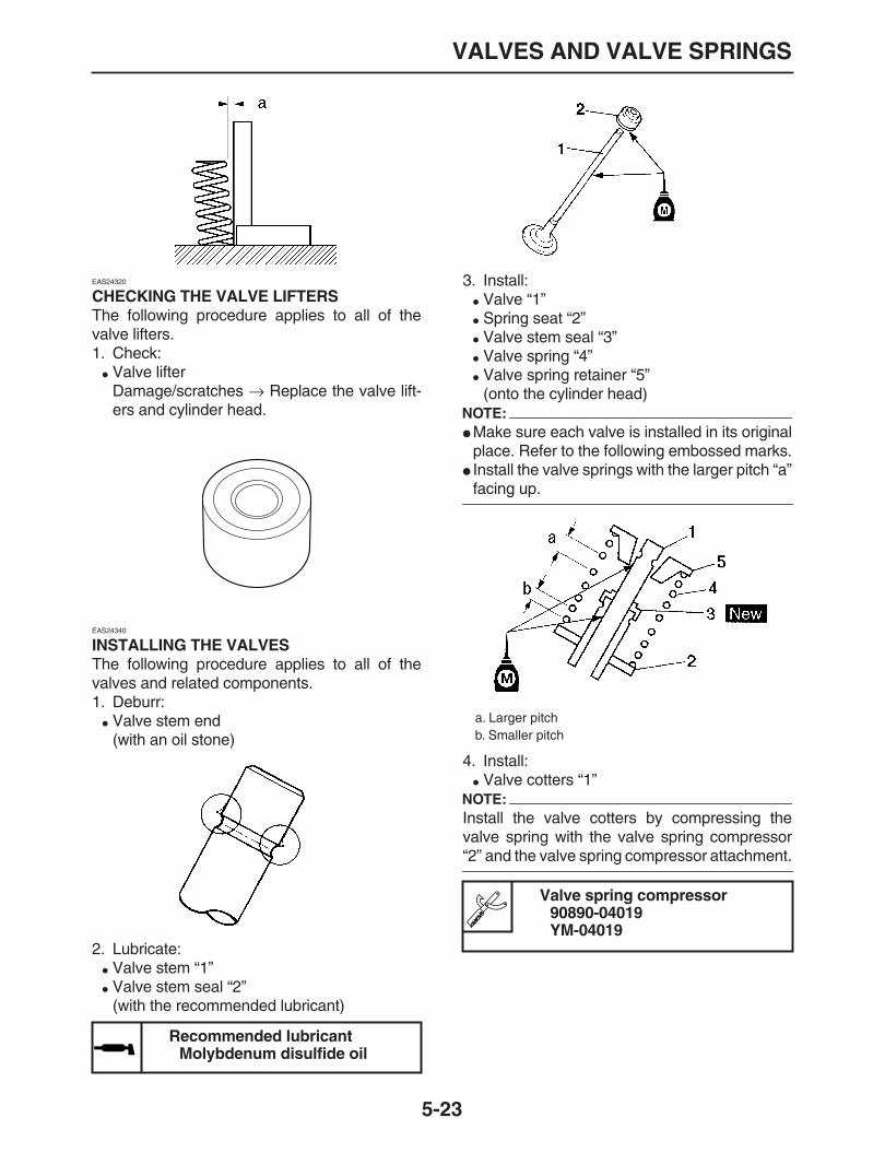
VALVES AND VALVE SPRINGS
5-23
EAS24320
CHECKING THE VALVE LIFTERS
The following procedure applies to all of thevalve lifters.1. Check:
Valve lifterDamage/scratches
→
Replace the valve lift-ers and cylinder head.
EAS24340
INSTALLING THE VALVES
The following procedure applies to all of thevalves and related components.1. Deburr:
Valve stem end(with an oil stone)
2. Lubricate:
Valve stem “1”
Valve stem seal “2”(with the recommended lubricant)
3. Install:
Valve “1”
Spring seat “2”
Valve stem seal “3”
Valve spring “4”
Valve spring retainer “5”(onto the cylinder head)
NOTE:
Make sure each valve is installed in its originalplace. Refer to the following embossed marks.
Install the valve springs with the larger pitch “a”
facing up.
4. Install:
Valve cotters “1”NOTE:
Install the valve cotters by compressing thevalve spring with the valve spring compressor
“2” and the valve spring compressor attachment.
Recommended lubricantMolybdenum disulfide oil
a. Larger pitchb. Smaller pitch
Valve spring compressor90890-04019YM-04019

VALVES AND VALVE SPRINGS
5-24
5. To fasten the valve cotters “1” onto the valvestem, lightly tap the valve tip with a soft-facehammer.
CAUTION:
ECA13800
Hitting the valve tip with excessive force
could damage the valve.
6. Lubricate:
Valve pad “1”
Valve lifter “2”
7. Install:
Valve pad
Valve lifterNOTE:
The valve lifter must move smoothly when ro-tated with a finger.
Each valve lifter and valve pad must be rein-
stalled in its original position.
Recommended lubricantMolybdenum disulfide oil
1
2
M
1
2

CYLINDER AND PISTON
5-25
EAS24350
CYLINDER AND PISTON
Removing the cylinder and piston
Order Job/Parts to remove Q’ty Remarks
Cylinder head Refer to“CYLINDER HEAD” on page 5-14.1 Cylinder 12 Dowel pin 23 Water pipe 14 O-ring 15 Cylinder gasket 16 Piston pin clip 27 Piston pin 18 Piston 19 Piston ring set 1
For installation, reverse the removal proce-dure.
1
2
2
3
4
5
6
6
7
8
9E
E
E
T R..
10 Nm (1.0 m • kg, 7.2 ft • Ib)
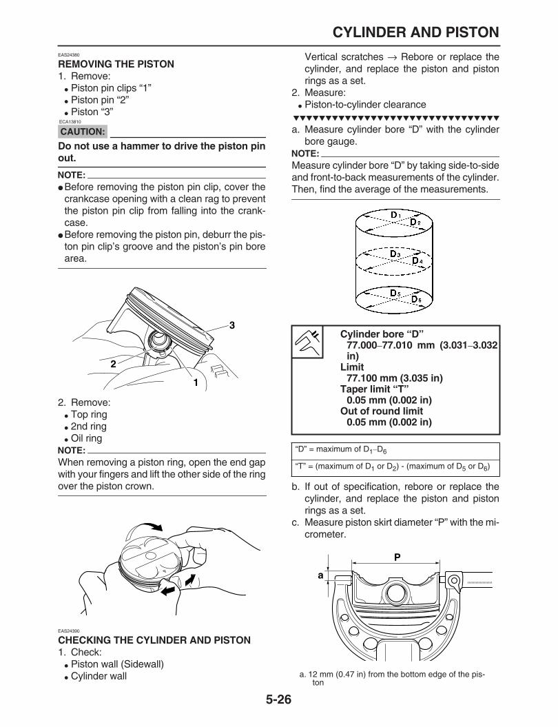
CYLINDER AND PISTON
5-26
EAS24380
REMOVING THE PISTON
1. Remove:
Piston pin clips “1”
Piston pin “2”
Piston “3”
CAUTION:
ECA13810
Do not use a hammer to drive the piston pin
out.
NOTE:
Before removing the piston pin clip, cover thecrankcase opening with a clean rag to preventthe piston pin clip from falling into the crank-case.
Before removing the piston pin, deburr the pis-ton pin clip’s groove and the piston’s pin bore
area.
2. Remove:
Top ring
2nd ring
Oil ringNOTE:
When removing a piston ring, open the end gapwith your fingers and lift the other side of the ring
over the piston crown.
EAS24390
CHECKING THE CYLINDER AND PISTON
1. Check:
Piston wall (Sidewall)
Cylinder wall
Vertical scratches
→
Rebore or replace thecylinder, and replace the piston and pistonrings as a set.
2. Measure:
Piston-to-cylinder clearance
a. Measure cylinder bore “D” with the cylinderbore gauge.
NOTE:
Measure cylinder bore “D” by taking side-to-sideand front-to-back measurements of the cylinder.
Then, find the average of the measurements.
b. If out of specification, rebore or replace thecylinder, and replace the piston and pistonrings as a set.
c. Measure piston skirt diameter “P” with the mi-crometer.
1
2
3
Cylinder bore “D”77.000
–
77.010 mm (3.031
–
3.032in)
Limit77.100 mm (3.035 in)
Taper limit “T”0.05 mm (0.002 in)
Out of round limit0.05 mm (0.002 in)
“D” = maximum of D
1
–
D
6
“T” = (maximum of D
1
or D
2
) - (maximum of D
5
or D
6
)
a. 12 mm (0.47 in) from the bottom edge of the pis-ton
a
P
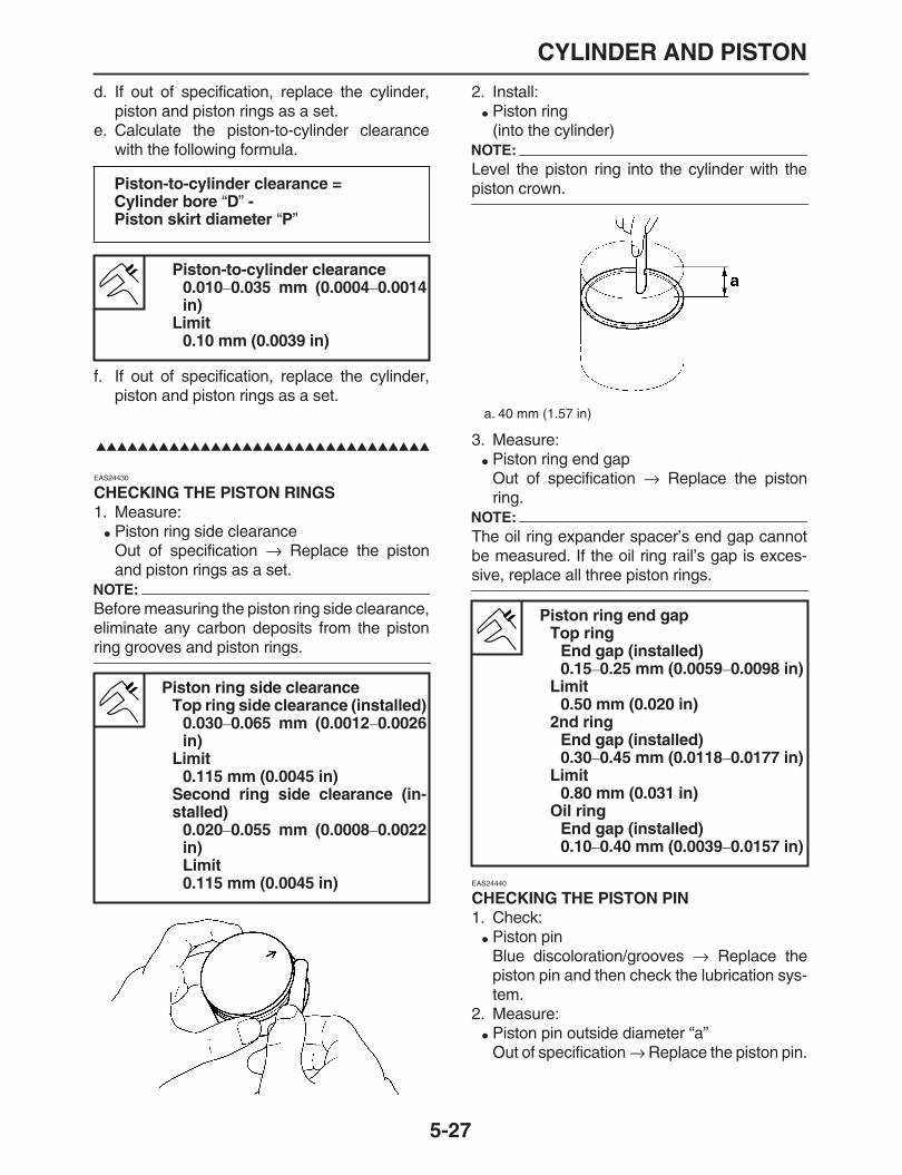
CYLINDER AND PISTON
5-27
d. If out of specification, replace the cylinder,piston and piston rings as a set.
e. Calculate the piston-to-cylinder clearancewith the following formula.
f. If out of specification, replace the cylinder,piston and piston rings as a set.
EAS24430
CHECKING THE PISTON RINGS
1. Measure:
Piston ring side clearanceOut of specification
→
Replace the pistonand piston rings as a set.
NOTE:
Before measuring the piston ring side clearance,eliminate any carbon deposits from the piston
ring grooves and piston rings.
2. Install:
Piston ring(into the cylinder)
NOTE:
Level the piston ring into the cylinder with the
piston crown.
3. Measure:
Piston ring end gapOut of specification
→
Replace the pistonring.
NOTE:
The oil ring expander spacer’s end gap cannotbe measured. If the oil ring rail’s gap is exces-
sive, replace all three piston rings.
EAS24440
CHECKING THE PISTON PIN
1. Check:
Piston pinBlue discoloration/grooves
→
Replace thepiston pin and then check the lubrication sys-tem.
2. Measure:
Piston pin outside diameter “a”Out of specification
→
Replace the piston pin.
Piston-to-cylinder clearance =Cylinder bore
“
D
”
-Piston skirt diameter
“
P
”
Piston-to-cylinder clearance0.010
–
0.035 mm (0.0004
–
0.0014in)
Limit0.10 mm (0.0039 in)
Piston ring side clearanceTop ring side clearance (installed)
0.030
–
0.065 mm (0.0012
–
0.0026in)
Limit0.115 mm (0.0045 in)
Second ring side clearance (in-stalled)
0.020
–
0.055 mm (0.0008
–
0.0022in)Limit0.115 mm (0.0045 in)
a. 40 mm (1.57 in)
Piston ring end gapTop ring
End gap (installed)0.15
–
0.25 mm (0.0059
–
0.0098 in)Limit
0.50 mm (0.020 in)2nd ring
End gap (installed)0.30
–
0.45 mm (0.0118
–
0.0177 in)Limit
0.80 mm (0.031 in)Oil ring
End gap (installed)0.10
–
0.40 mm (0.0039
–
0.0157 in)

CYLINDER AND PISTON
5-28
3. Measure:
Piston pin bore diameter “b”Out of specification
→
Replace the piston.
4. Calculate:
Piston-pin-to-piston-pin-bore clearanceOut of specification
→
Replace the piston pinand piston as a set.
EAS24450
INSTALLING THE PISTON AND CYLINDER
1. Install:
Top ring “1”
2nd ring “2”
Lower oil ring rail “3”
Upper oil ring rail “4”
Oil ring expander “5”NOTE:
Be sure to install the piston rings so that the
manufacturer’s marks or numbers face up.
2. Install:
Cylinder gasket
Water pipe “1”
Dowel pins “2”
O-ring “3”
3. Install:
Piston “1”
Piston pin “2”
Piston pin clips “3” NOTE:
Apply engine oil the piston pin.
Make sure the mark “a” on the piston points to-wards the exhaust side of the cylinder.
Before installing the piston pin clip, cover thecrankcase opening with a clean rag to prevent
the clip from falling into the crankcase.
Piston pin outside diameter16.991
–
17.000 mm (0.6689
–
0.6693 in)Limit
16.971 mm (0.668 in)
Piston pin bore inside diameter17.002
–
17.013 mm (0.6694
–
0.6698 in)Limit
17.043 mm (0.670 in)
Piston-pin-to-piston-pin-bore clearance=Piston pin bore diameter
“
b
”
-Piston pin outside diameter
“
a
”
Piston pin/piston pin hole clear-ance
0.002
–
0.022 mm (0.00008
–
0.00087 in)
b
New
New
New
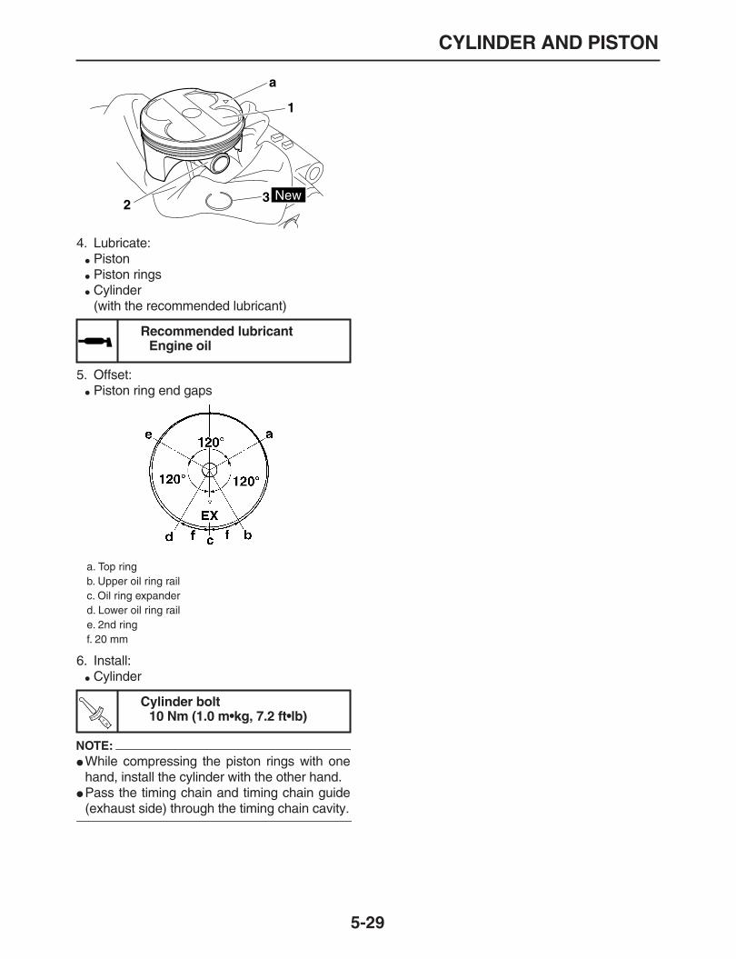
CYLINDER AND PISTON
5-29
4. Lubricate:
Piston
Piston rings
Cylinder(with the recommended lubricant)
5. Offset:
Piston ring end gaps
6. Install:
Cylinder
NOTE:
While compressing the piston rings with onehand, install the cylinder with the other hand.
Pass the timing chain and timing chain guide
(exhaust side) through the timing chain cavity.
Recommended lubricantEngine oil
a. Top ringb. Upper oil ring railc. Oil ring expanderd. Lower oil ring raile. 2nd ringf. 20 mm
Cylinder bolt10 Nm (1.0 m•kg, 7.2 ft•lb)
1
2 3 New
a
TR..

STARTER MOTOR
5-30
EAS24780
STARTER MOTOR
Removing the starter motor
Order Job/Parts to remove Q’ty Remarks
Seat/Air scoop (left/ritht) Refer to “GENERAL CHASSIS” on page 4-1.
EXUP cable/Exhaust pipe/Muffler Refer to “ENGINE REMOVAL” on page 5-1.1 Starter motor lead 1 Disconnect.2 Starter motor 1
For assembly, reverse the disassembly pro-cedure.
1
2
T R..
5 Nm (0.5 m • kg, 3.6 ft • Ib) T R..
10 Nm (1.0 m • kg, 7.2 ft • Ib)

STARTER MOTOR
5-31
Disassembling the starter motor
Order Job/Parts to remove Q’ty Remarks
1 Starter motor front cover 12 Lock washer 13 Armature assembly 14 Starter motor yoke 15 Starter motor rear cover 16 Brush holder set 1
For assembly, reverse the disassembly pro-cedure.
1
2
3
4
5
6

STARTER MOTOR
5-32
EAS24790
CHECKING THE STARTER MOTOR
1. Check:
CommutatorDirt
→
Clean with 600 grit sandpaper.2. Measure:
Commutator diameter “1”Out of specification
→
Replace the startermotor.
3. Measure:
Mica undercut “a”Out of specification
→
Scrape the mica to theproper measurement with a hacksaw bladethat has been grounded to fit the commuta-tor.
NOTE:
The mica of the commutator must be undercut to
ensure proper operation of the commutator.
4. Measure:
Armature assembly resistances (commutatorand insulation)Out of specification
→
Replace the startermotor.
a. Measure the armature assembly resistanceswith the pocket tester.
b. If any resistance is out of specification, re-place the starter motor.
5. Measure:
Brush length “a”Out of specification
→
Replace the brushesas a set.
6. Measure:
Brush spring forceOut of specification
→
Replace the brushsprings as a set.
Limit27.0 mm (1.06 in)
Mica undercut (depth)0.70 mm (0.03 in)
Pocket tester90890-03112
Analog pocket testerYU-03112-C
Armature coilCommutator resistance “1”
0.004
–
0.005
Ω
at 20
°
C (68
°
F)Insulation resistance “2”
Above 1 M
Ω
at 20
°
C (68
°
F)
Limit3.50 mm (0.14 in)
Brush spring force7.16
–
9.52 N (25.77
–
34.27 oz)(730
–
971 gf)
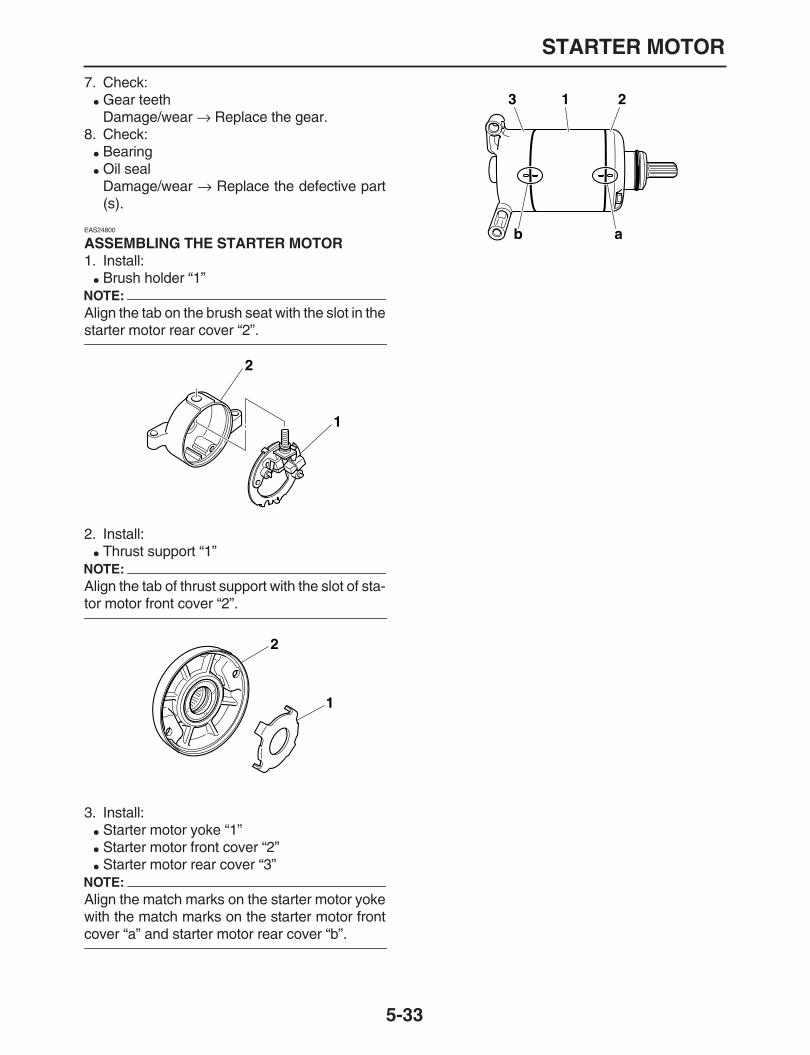
STARTER MOTOR
5-33
7. Check:
Gear teethDamage/wear
→
Replace the gear.8. Check:
Bearing
Oil sealDamage/wear
→
Replace the defective part(s).
EAS24800
ASSEMBLING THE STARTER MOTOR
1. Install:
Brush holder “1”NOTE:
Align the tab on the brush seat with the slot in the
starter motor rear cover “2”.
2. Install:
Thrust support “1”NOTE:
Align the tab of thrust support with the slot of sta-
tor motor front cover “2”.
3. Install:
Starter motor yoke “1”
Starter motor front cover “2”
Starter motor rear cover “3”NOTE:
Align the match marks on the starter motor yokewith the match marks on the starter motor front
cover “a” and starter motor rear cover “b”.
1
2
1
2
13 2
ab

CLUTCH
5-34
EAS25061
CLUTCH
Removing the clutch cover
Order Job/Parts to remove Q’ty Remarks
Drain the engine oil Refer to “CHANGING THE ENGINE OIL” on page 3-11.
Drain the coolant Refer to “CHANGING THE COOLANT” on page 3-18.
1 Brake pedal spring 1 Remove it from the frame mounting hook.2 Water pump housing cover 13 Gasket 14 Oil cleaner element cover 15 Oil cleaner element 16 Cover 1
7 Clutch cover 1 Remove the clutch cover only if you do not remove the primary drive gear.
8 Clutch cover gasket 19 Dowel pin 210 Crankcase cover (right) 111 Crankcase cover right gascket 112 Water pipe 113 O-ring 114 Dowel pin 2
1
2
3
4
5
6
78
9
10
11
1213
14
14
T R..
10 Nm (1.0 m • kg, 7.2 ft • Ib)
T R..
10 Nm (1.0 m • kg, 7.2 ft • Ib)
T R..
10 Nm (1.0 m • kg, 7.2 ft • Ib) T R.
.
10 Nm (1.0 m • kg, 7.2 ft • Ib)

CLUTCH
5-35
For installation, reverse the removal proce-dure.
Removing the clutch cover
Order Job/Parts to remove Q’ty Remarks
1
2
3
4
5
6
78
9
10
11
1213
14
14T R.
.
10 Nm (1.0 m • kg, 7.2 ft • Ib)
T R..
10 Nm (1.0 m • kg, 7.2 ft • Ib)
T R..
10 Nm (1.0 m • kg, 7.2 ft • Ib) T R.
.
10 Nm (1.0 m • kg, 7.2 ft • Ib)

CLUTCH
5-36
Removing the clutch
Order Job/Parts to remove Q’ty Remarks
1 Clutch spring 52 Pressure plate 13 Push rod 14 Locknut 15 Friction plate 76 Clutch plate 67 Primary drive gear nut 18 Lock washer 19 Clutch boss nut 110 Lock washer 111 Clutch boss 112 Thrust washer 113 Clutch housing 114 Ball 115 Clutch push rod 116 Primary drive gear 1
For installation, reverse the removal proce-dure.
2
34
5
(5)
1(5)
6
7
8
910
1112
13
1415
16
E
E
T R..
8 Nm (0.8 m • kg, 5.8 ft • Ib)
T R..
8 Nm (0.8 m • kg, 5.8 ft • Ib)
T R..
80 Nm (8.0 m • kg, 58 ft • Ib)
T R..
75 Nm (7.5 m • kg, 54 ft • Ib)
E
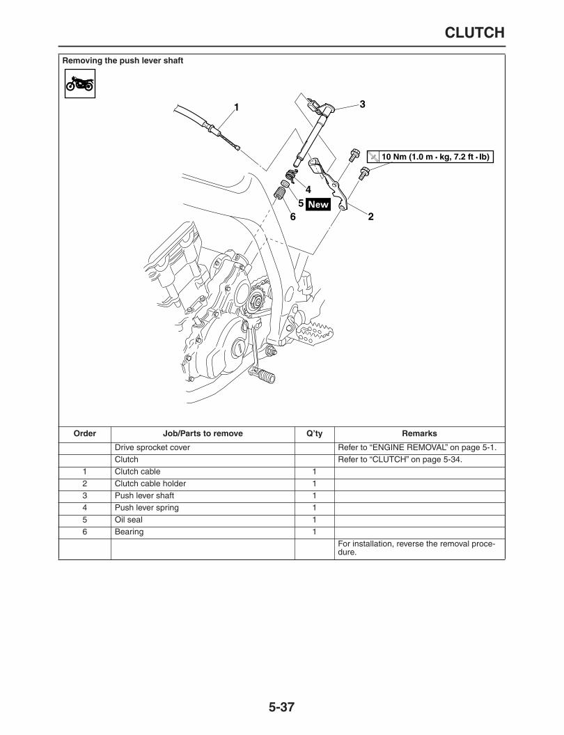
CLUTCH
5-37
Removing the push lever shaft
Order Job/Parts to remove Q’ty Remarks
Drive sprocket cover Refer to “ENGINE REMOVAL” on page 5-1.Clutch Refer to “CLUTCH” on page 5-34.
1 Clutch cable 12 Clutch cable holder 13 Push lever shaft 14 Push lever spring 15 Oil seal 16 Bearing 1
For installation, reverse the removal proce-dure.
1
2
3
45
6
T R..
10 Nm (1.0 m • kg, 7.2 ft • Ib)

CLUTCH
5-38
EAS25070
REMOVING THE CLUTCH
You need not drain the coolant and engine oil ifyou do not service the primary drive gear.You can reach the clutch housing removal stepby simply removing the cover and clutch cover.1. Straighten the lock washer tab.2. Loosen:
Clutch boss nut “1”NOTE:
While holding the clutch boss “3” with the univer-
sal clutch holder “2”, loosen the clutch boss nut.
3. Straighten the lock washer tab.4. Remove:
Primary drive gear nut “1”
Lock washerNOTE:
Insert aluminum plate “a” between primary drivegear “2” and clutch housing “3”, and removethese parts by loosening the primary drive gear
nut.
EAS25100
CHECKING THE FRICTION PLATES
The following procedure applies to all of the fric-tion plates.1. Check:
Friction plate
Damage/wear
→
Replace the friction platesas a set.
2. Measure:
Friction plate thicknessOut of specification
→
Replace the frictionplates as a set.
NOTE:
Measure the friction plate at four places.
EAS25110
CHECKING THE CLUTCH PLATES
The following procedure applies to all of theclutch plates.1. Check:
Clutch plateDamage
→
Replace the clutch plates as aset.
2. Measure:
Clutch plate warpage(with a surface plate and thickness gauge “1”)Out of specification
→
Replace the clutchplates as a set.
Universal clutch holder90890-04086YM-91042
1
2
3
1
23
a
Friction plate thickness2.90
–
3.10 mm (0.114
–
0.122 in)Limit
2.80 mm (0.110 in)
Warpage limit0.10 mm (0.0039 in)

CLUTCH
5-39
EAS25140
CHECKING THE CLUTCH SPRINGS
The following procedure applies to all of theclutch springs.1. Check:
Clutch springDamage
→
Replace the clutch springs as aset.
2. Measure:
Clutch spring free lengthOut of specification
→
Replace the clutchsprings as a set.
EAS25150
CHECKING THE CLUTCH HOUSING
1. Check:
Clutch housing dogs “a”Damage/pitting/wear
→
Deburr the clutchhousing dogs or replace the clutch housing.
NOTE:
Pitting on the clutch housing dogs will cause er-
ratic clutch operation.
EAS25160
CHECKING THE CLUTCH BOSS
1. Check:
Clutch boss splinesDamage/pitting/wear
→
Replace the clutchboss.
NOTE:
Pitting on the clutch boss splines will cause er-
ratic clutch operation.
2. Check:
Primary driven gearDamage/wear
→
Replace the primary driveand clutch housing as a set.Excessive noise during operation
→
Replacethe primary drive and clutch housing as a set.
EAS25170
CHECKING THE PRESSURE PLATE
1. Check:
Pressure plate “1”Cracks/damage
→
Replace.
EAS25190
CHECKING THE CLUTCH PUSH RODS
1. Check:
Push rod “1”
Push rod “2”
Ball “3”Cracks/damage/wear
→
Replace.
2. Measure:
Push rod bending limitOut of specification
→
Replace the defectivepart (s).
Clutch spring free length41.20 mm (1.62 in)
Limit39.14 mm (1.54 in)
a
Push rod bending limit0.100 mm (0.004 in)
23
1

CLUTCH
5-40
EAS25200
CHECKING THE PRIMARY DRIVE GEAR
1. Check:
Primary drive gearDamage/wear
→
Replace the primary driveand primary driven gears as a set.Excessive noise during operation
→
Replacethe primary drive and primary driven gears asa set.
EAS25210
CHECKING THE PRIMARY DRIVEN GEAR
1. Check:
Primary driven gearDamage/wear
→
Replace the primary driveand primary driven gears as a set.Excessive noise during operation
→
Replacethe primary drive and primary driven gears asa set.
EAS25260
INSTALLING THE CLUTCH
1. Install:
Primary drive gear “1”
Clutch housing “2”
Thrust washer
Clutch boss “3”
Lock washer “4”
Lock washer “5”
Clutch boss nut “6”
Primary drive gear nut “7”NOTE:
Align the lock washer projection with the clutchboss slit during assembling.
Install the primary drive gear by facing its flat
face toward the crankcase.
2. Tighten:
Clutch boss nut “1”NOTE:
While holding the clutch boss “3” with the univer-
sal clutch holder “2”, tighten the clutch boss nut.
3. Bend the lock washer tab along a flat side ofthe nut.
4. Tighten:
Primary drive gear nut “1”NOTE:
Insert aluminum plate “a” between primary drivegear “2” and clutch housing “3”, and tighten the
primary drive gear nut.
5. Bend the lock washer tab along a flat side ofthe nut.
6. Lubricate:
Friction plates
Clutch plates(with the recommended lubricant)
Push rod
Push rod1
Ball
NewNew
7
12
3
4
6
5
Universal clutch holder90890-04086YM-91042
Clutch boss nut75 Nm (7.5 m•kg, 54 ft•lb)
Primary drive gear nut80 Nm (8.0 m•kg, 58 ft•lb)
Recommended lubricantEngine oil
TR..
1
2
3T
R..
1
23
a

CLUTCH
5-41
7. Install:
Friction plates
Clutch platesNOTE:
First, install a friction plate and then alternate be-
tween a clutch plate and a friction plate.
8. Install:
Push plate
Push rod (onto the clutch pressure plate.)
9. Install:
Push rod
Ball
Pressure plate
Clutch spring10.Tighten:
Push rod
Clutch springNOTE:
Tighten the clutch spring bolts in two stages and
in a crisscross pattern.
11.Check:
Push lever positionPush lever mark “a” and crankcase mark “b”not aligned
→
Correct.NOTE:
Move the push lever in the arrow direction, andmake sure that its movement becomes hard in
the position where the marks match.
12.Adjust:
Push lever position
a. Loosen locknut “2” of push rod “1”.b. Return or tighten push rod “1” until the mark
of push lever matches the mark of clutch ca-ble holder.
c. Hold the push rod (not to move it), and tightenthe push rod locknut.
13.Install:
Water pipe “1”
O-ring “2”
Dowel pin “3”
Crankcase cover right gascket “4”
Crankcase cover (right) “5”
NOTE:
Tighten bolts in a crisscross pattern.
Turn the impeller shaft and check the engagingof impeller shaft gear and primary drive gear,
and assemble the right crankcase cover.
Locknut8 Nm (0.8 m•kg, 5.8 ft•lb)
Clutch spring bolt8 Nm (0.8 m•kg, 5.8 ft•lb)
TR..
Lock nut8 Nm (0.8 m•kg, 5.8 ft•lb)
Crankcase cover (right) bolt10 Nm (1.0 m•kg, 7.2 ft•lb)
a
b
TR..
2
1
New
New
TR..

CLUTCH
5-42
14.Install:
Oil cleaner elementRefer to “CHANGING THE ENGINE OIL” onpage 3-11.
15.Install:
Water pump housing coverRefer to “WATER PUMP” on page 6-6.
16.Fill:
Crankcase(with the specified amount of the engine oil)Refer to “CHANGING THE ENGINE OIL” onpage 3-11.
17.Fill:
Cooling system(with the specified amount of the the coolant)Refer to “CHANGING THE COOLANT” onpage 3-18.
18.Install:
Brake spring
5
34
1 23
New
New

SHIFT SHAFT
5-43
EAS25410
SHIFT SHAFT
Removing the shift shaft and stopper lever
Order Job/Parts to remove Q’ty Remarks
Shift pedal Refer to “ENGINE REMOVAL” on page 5-1.Clutch housing Refer to “CLUTCH” on page 5-34.
1 Shift shaft 12 Plate washer 13 Stopper lever spring 14 Circlip 15 Plate washer 16 Stopper lever 17 Spacer 18 Shift shaft spring 19 Stopper screw 1
For installation, reverse the removal proce-dure.
1
234
56
7
8
E
E
E
9
LT
T R..
22 Nm (2.2 m • kg, 16 ft • Ib)

SHIFT SHAFT
5-44
EAS25420
CHECKING THE SHIFT SHAFT
1. Check:
Shift shaft
Shift leverBends/damage/wear
→
Replace.
Shift lever springDamage/wear
→
Replace.
EAS25430
CHECKING THE STOPPER LEVER
1. Check:
Stopper leverBends/damage
→
Replace.Roller turns roughly
→
Replace the stopperlever.
EAS25450
INSTALLING THE SHIFT SHAFT
1. Install:
Shift shaft “1”
Shift shaft spring “2”
Stopper lever “3”
Stopper lever springNOTE:
Hook the ends “4” of the stopper lever springonto the stopper lever and the crankcase boss.
Mesh the stopper lever with the shift drum seg-
ment assembly.
12
3
4

OIL PUMP AND BALANCER GEAR
5-45
EAS24911
OIL PUMP AND BALANCER GEAR
Removing the oil pump
Order Job/Parts to remove Q’ty Remarks
Clutch/Primary drive gear Refer to“CLUTCH” on page 5-34.Shift shaft Refer to“SHIFT SHAFT” on page 5-43.
1 Balancer weight gear nut 12 Lock washer 13 Balancer weight gear 14 Straight key 15 Absorber plate 16 Balancer drive gear 17 Straight key 18 Circlip 19 Plain washer 210 Idle gear 111 Gasket 112 Oil pump assembly 113 Dowel pin 2
For installation, reverse the removal proce-dure.
1
23
4
56
7
89
10
11
1213
T R..
10 Nm (1.0 m • kg, 7.2 ft • Ib)
T R..
50 Nm (5.0 m • kg, 36 ft • Ib)

OIL PUMP AND BALANCER GEAR
5-46
Disassembling the oil pump
Order Job/Parts to remove Q’ty Remarks
1 Pump cover 12 Outer rotor 13 Inner rotor 14 Dowel pin 15 Plain washer 16 Driven gear 17 Circlip 18 Relief valve assembly 19 Oil pump housing 1
For installation, reverse the removal proce-dure.
1
23
45
6
7
8
9
E
T R..
2 Nm (0.2 m • kg, 1.4 ft • Ib)

OIL PUMP AND BALANCER GEAR
5-47
EAS24940
REMOVING THE OIL PUMP
1. Drain:
Engine oil(completely from the crankcase)Refer to “CHANGING THE ENGINE OIL” onpage 3-11.
2. Remove:
Idle gear “1”
Oil pump assembly“2”
3. Remove:
Balancer weight gear “1”
Balancer drive gear assembly “2”
EAS24960
CHECKING THE OIL PUMP
1. Check:
Oil pump drive gear
Oil pump driven gear
Oil pump housing
Oil pump housing coverCracks/damage/wear
→
Replace the defec-tive part (s).
2. Measure:
Inner-rotor-to-outer-rotor-tip clearance “a”
Outer-rotor-to-oil-pump-housing clearance“b”
Oil-pump-housing-to-inner-rotor-and-out-er-rotor clearance “c”Out of specification
→
Replace the oil pump.
3. Check:
Oil pump operationRough movement
→
Repeat steps (1) and(2) or replace the defective part (s).
EAS25000
ASSEMBLING THE OIL PUMP
1. Lubricate:
Inner rotor
Outer rotor
Oil pump shaft(with the recommended lubricant)
2
1
21
Inner-rotor-to-outer-rotor-tipclearance
Less than0.120 mm (0.0047 in)
Outer-rotor-to-oil-pump-housingclearance
0.090
–
0.160 mm (0.0004
–
0.0013in)
Limit0.230 mm (0.0091 in)
Oil-pump-housing-to-inner-ro-tor-and-outer-rotor clearance
0.030
–
0.100 mm (0.0012
–
0.0039in)
Limit0.170 mm (0.0067 in)
1. Inner rotor2. Outer rotor3. Oil pump housing

OIL PUMP AND BALANCER GEAR
5-48
2. Install:
Oil pump housing “1”
Relief valve assembly
Driven gear “2”
Dowel pin “3”
Outer rotor “4”
Inner rotor “5”
Oil pump cover
3. Check:
Oil pump operationRefer to “CHECKING THE OIL PUMP” onpage 5-47.
EAS32D1008
INSTALLING THE OIL PUMP AND BALANCER GEAR
1. Install:
Oil pump assembly
CAUTION:
ECA13890
After tightening the bolts, make sure the oil
pump turns smoothly.
2. Install:
Drive gear “1”
Buffer boss “2”
Dowel pin “3”
Spring “4”(to driven gear)
NOTE:
Align mark “a” of the drive gear with slot “b” ofthe buffer boss.
Install the dowel pin on the spring as shown.
3. Install:
Drive gear “1”
Balancer weight gear “2”
Lock washer “3”
Balancer weight gear nut “4”NOTE:
Align mark “a” of the drive gear with mark “b” ofthe balancer shaft weight gear during assem-
bling.
4. Tighten:
Primary drive gear nutRefer to “CLUTCH” on page 5-34.
5. Tighten:
Balancer weight gear nut “1”
NOTE:
Insert aluminum plate “a” between drive gear “2”and balancer weight gear “3”, and tighten the pri-
mary drive gear nut.
Recommended lubricantEngine oil
Oil pump cover screw2 Nm (0.2 m•kg, 1.4 ft•lb)
Oil pump bolt10 Nm (1.0 m•kg, 7.2 ft•lb)
TR..
1
2
3
45
TR..
Blancer weight gear nut50 Nm (5.0 m•kg, 36 ft•lb)
1
2
3
4 4
4
4
3a
b
3
3
New
2ba1
3
4
TR..

OIL PUMP AND BALANCER GEAR
5-49
6. Install:Be sure to bend the lock washer tab along tothe nut side face.
1
23
a

GENERATOR AND STARTER CLUTCH
5-50
EAS24480
GENERATOR AND STARTER CLUTCH
Removing the generator
Order Job/Parts to remove Q
’
ty Remarks
Drain the engine oil Refer to
“CHANGING THE ENGINE OIL” on page 3-11
.
Seat Refer to
“GENERAL CHASSIS” on page 4-1
.
Air scoop (left) Refer to
“GENERAL CHASSIS” on page 4-1
.
1 Crankshaft position sensor coupler/Stator assembly coupler 1/1
2 Timing mark accessing screw 13 Crankshaft end cover 14 Crankcase cover (left) 15 Crankcase cover gascket (left) 16 Dowel pin 17 Stator assembly 18 Damper assembly 19 Starter idle gear shaft 110 Starter idle gear 111 Generator rotor 112 Woodruff key 113 Starter clutch gear 1
1
2
345
6
7
8
9
10
11
12
13
14
15
16
LT
LT
E
E
T R..
10 Nm (1.0 m • kg, 7.2 ft • Ib)
T R..
10 Nm (1.0 m • kg, 7.2 ft • Ib) T R..
65 Nm (6.5 m • kg, 47 ft • Ib)

GENERATOR AND STARTER CLUTCH
5-51
14 Bearing 115 Starter clutch side plate 116 Starter clutch assembly 1
For installation, reverse the removal proce-dure.
Removing the generator
Order Job/Parts to remove Q
’
ty Remarks
1
2
345
6
7
8
9
10
11
12
13
14
15
16
LT
LT
E
E
T R..
10 Nm (1.0 m • kg, 7.2 ft • Ib)
T R..
10 Nm (1.0 m • kg, 7.2 ft • Ib) T R..
65 Nm (6.5 m • kg, 47 ft • Ib)

GENERATOR AND STARTER CLUTCH
5-52
Disassembling the damper assembly
Order Job/Parts to remove Q
’
ty Remarks
1 Circlip 12 Limiter disc 13 Starter reduction gear 14 Limiter disc 15 Outer torque limiter 16 Circlip 1
For installation, reverse the removal proce-dure.
1
2
3
4
5
6
M
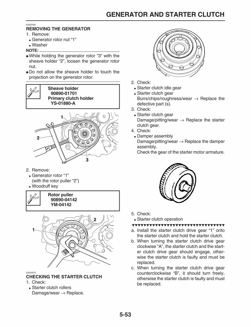
GENERATOR AND STARTER CLUTCH
5-53
EAS24490
REMOVING THE GENERATOR
1. Remove:
Generator rotor nut “1”
WasherNOTE:
While holding the generator rotor “3” with thesheave holder “2”, loosen the generator rotornut.
Do not allow the sheave holder to touch the
projection on the generator rotor.
2. Remove:
Generator rotor “1”(with the rotor puller “2”)
Woodruff key
EAS24570
CHECKING THE STARTER CLUTCH
1. Check:
Starter clutch rollersDamage/wear
→
Replace.
2. Check:
Starter clutch idle gear
Starter clutch gearBurrs/chips/roughness/wear
→
Replace thedefective part (s).
3. Check:
Starter clutch gearDamage/pitting/wear
→
Replace the starterclutch gear.
4. Check:
Damper assemblyDamage/pitting/wear
→
Replace the damperassembly.Check the gear of the starter motor armature.
5. Check:
Starter clutch operation
a. Install the starter clutch drive gear “1” ontothe starter clutch and hold the starter clutch.
b. When turning the starter clutch drive gearclockwise “A”, the starter clutch and the start-er clutch drive gear should engage, other-wise the starter clutch is faulty and must bereplaced.
c. When turning the starter clutch drive gearcounterclockwise “B”, it should turn freely,otherwise the starter clutch is faulty and mustbe replaced.
Sheave holder90890-01701
Primary clutch holderYS-01880-A
Rotor puller90890-04142YM-04142
1
2
3
2
1

GENERATOR AND STARTER CLUTCH
5-54
EAS24600
INSTALLING THE STARTER CLUTCH
1. Install:
Starter clutch assembly “1”Push the starter clutch assembly strongly un-til bumping. (Turn the projection part “a” tothe interior side.)
2. Install:
Starter clutch side plate “1”Set the 4 tabs “a” of the starter clutch sideplate to the groove “b” of the generator rotor“2” securely.
EAS24500
INSTALLING THE GENERATOR
1. Install:
Woodruff key
Generator rotor
Washer
Generator rotor bolt
NOTE:
Clean the tapered portion of the crankshaftand the generator rotor hub.
When installing the generator rotor, make surethe woodruff key is properly sealed in the key-
way of the crankshaft.
2. Tighten:
Generator rotor nut “1”
NOTE:
While holding the generator rotor “3” with thesheave holder “2”, tighten the generator rotorbolt.
Do not allow the sheave holder to touch the
projection on the generator rotor.
3. Install:
Starter idler gears4. Install:
Left crankcase cover “1”
NOTE:
Tighten bolts in a crisscross pattern.
Use copper washer for part “2” only.
1AB
1
a
1
b
a
2
Generator rotor nut65 Nm (6.5 m•kg, 47 ft•lb)
Sheave holder90890-01701
Primary clutch holderYS-01880-A
Crankcase cover bolt10 Nm (1.0 m•kg, 7.2 ft•lb)
TR..
1
2
3
TR..
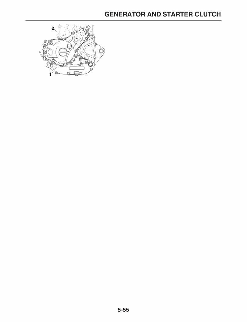
GENERATOR AND STARTER CLUTCH
5-55
1
2

CRANKCASE
5-56
EAS25540
CRANKCASE
Separating the crankcase
Order Job/Parts to remove Q’ty Remarks
Engine Refer to“ENGINE REMOVAL” on page 5-1.Cylinder head Refer to“CYLINDER HEAD” on page 5-14.
Cylinder Refer to“CYLINDER AND PISTON” on page 5-25.
Starter motor Refer to“STARTER MOTOR” on page 5-30.Clutch Refer to“CLUTCH” on page 5-34.
Balancer drive gear Refer to“OIL PUMP AND BALANCER GEAR” on page 5-45.
Shift shaft Refer to“SHIFT SHAFT” on page 5-43.
Oil pump,Balancer gear Refer to“OIL PUMP AND BALANCER GEAR” on page 5-45.
Generator rotor Refer to“GENERATOR AND STARTER CLUTCH” on page 5-50.
1 Timing chain guide (intake side) 12 Stopper guide plate 13 Timing chain guide (exhaust side) 14 Timing chain 15 Speed sensor 16 Neutral switch 17 Delivery pipe 1
1
23
4
5
6
7
8
9
9
10
11
12
LT
LT
LT
LTT R.
.
10 Nm (1.0 m • kg, 7.2 ft • Ib)
T R..
10 Nm (1.0 m • kg, 7.2 ft • Ib)
T R..
10 Nm (1.0 m • kg, 7.2 ft • Ib)
T R..
10 Nm (1.0 m • kg, 7.2 ft • Ib)
T R..
10 Nm (1.0 m • kg, 7.2 ft • Ib)
T R..
4 Nm (0.4 m • kg, 2.9 ft • Ib)
LT

CRANKCASE
5-57
8 Crankcase Right 19 Dowel pin 210 Oil strainer 111 Nozzle 112 Left crankcase 1
For installation, reverse the removal proce-dure.
Separating the crankcase
Order Job/Parts to remove Q’ty Remarks
1
23
4
5
6
7
8
9
9
10
11
12
LT
LT
LT
LT
T R..
10 Nm (1.0 m • kg, 7.2 ft • Ib)
T R..
10 Nm (1.0 m • kg, 7.2 ft • Ib)
T R..
10 Nm (1.0 m • kg, 7.2 ft • Ib)
T R..
10 Nm (1.0 m • kg, 7.2 ft • Ib)
T R..
10 Nm (1.0 m • kg, 7.2 ft • Ib)
T R..
4 Nm (0.4 m • kg, 2.9 ft • Ib)
LT

CRANKCASE
5-58
Removing the bearing and oil seal
Order Job/Parts to remove Q’ty Remarks
Crankshaft assembly Refer to“CRANKSHAFT ASSEMBLY AND BALANCER SHAFT” on page 5-61.
Transmission assembly Refer to“TRANSMISSION” on page 5-64.1 Bearing cover plate 12 Bearing cover plate 23 Stopper plate 24 Oil seal 25 Bearing 76 Needle bearing 2
For installation, reverse the removal proce-dure.
1
2
3
4
5 5
5
5
6
6LT
LT
LT
EE
E
E
E
E
T R..
10 Nm (1.0 m • kg, 7.2 ft • Ib)
T R..
10 Nm (1.0 m • kg, 7.2 ft • Ib)

CRANKCASE
5-59
EAS25570
DISASSEMBLING THE CRANKCASE
1. Remove:
Crankcase boltsNOTE:
Loosen each bolt 1/4 of a turn at a time, in stag-es and in a crisscross pattern. After all of the
bolts are fully loosened, remove them.
2. Turn:
Shift drum segmentNOTE:
Turn the shift drum segment to the positionshown in the illustration. In this position, the shiftdrum segment’s teeth will not contact the crank-
case during crankcase separation.
3. Remove:
Right crankcase
CAUTION:
ECA13910
First check that the shift drum segment’steeth and the drive axle circlip are properlypositioned, then remove the right crank-case.
Do not damage the crankcase mating sur-
faces.
EAS32D1015
CHECKING THE TIMING CHAIN, TIMING CHAIN GUIDE, OIL STRAINER, NOZZLE, DELIVERY PIPE
1. Check:
Timing chainStiffness
→
Replace the camshaft sprocket,timing chain and crankshaft sprocket as aset.
2. Check:
Timing chain guideDamage/wear
→
Replace.3. Check:
Oil strainerObstruction
→
Blow out with compressed air.Cracks/damage
→
Replace.
4. Check:
Nozzle
Delivery pipeObstruction
→
Blow out with compressed air.Bends/cracks/damage
→
Replace.
EAS25580
CHECKING THE CRANKCASE
1. Thoroughly wash the crankcase halves in amild solvent.
2. Thoroughly clean all the gasket surfaces andcrankcase mating surfaces.
3. Check:
CrankcaseCracks/damage
→
Replace.
Oil delivery passagesObstruction
→
Blow out with compressed air.
EAS25700
ASSEMBLING THE CRANKCASE
1. Install:
Nozzle “1”
Oil strainer “2”
Bearing cover plate “3”
Oil delivery pipe “4”
Nozzle bolt10 Nm (1.0 m•kg, 7.2 ft•lb)LOCTITE®
Oil delivery bolt10 Nm (1.0 m•kg, 7.2 ft•lb)LOCTITE®
Oil strainer bolt10 Nm (1.0 m•kg, 7.2 ft•lb)LOCTITE®
Bearing cover plate10 Nm (1.0 m•kg, 7.2 ft•lb)LOCTITE®
TR..

CRANKCASE
5-60
2. Thoroughly clean all the gasket mating sur-faces and crankcase mating surfaces.
3. Apply:
Sealant(onto the crankcase mating surfaces)
4. Install:
Crankcase (to the left crankcase)
NOTE:
Turn the shift drum segment as shown so thatthe shift drum segment teeth do not contact thecrankcase during its assembling.
Tighten the bolts in a crisscross pattern in two
(2) stages, with 1/4 turn each.
Yamaha bond No. 1215 (ThreeBond No.1215®)
90890-85505
Crankcase bolt10 Nm (1.0 m•kg, 7.2 ft•lb)
431
2
TR..
1. M6
×
90 mm2. M6
×
65 mm3. M6
×
45 mm
2
13
23232
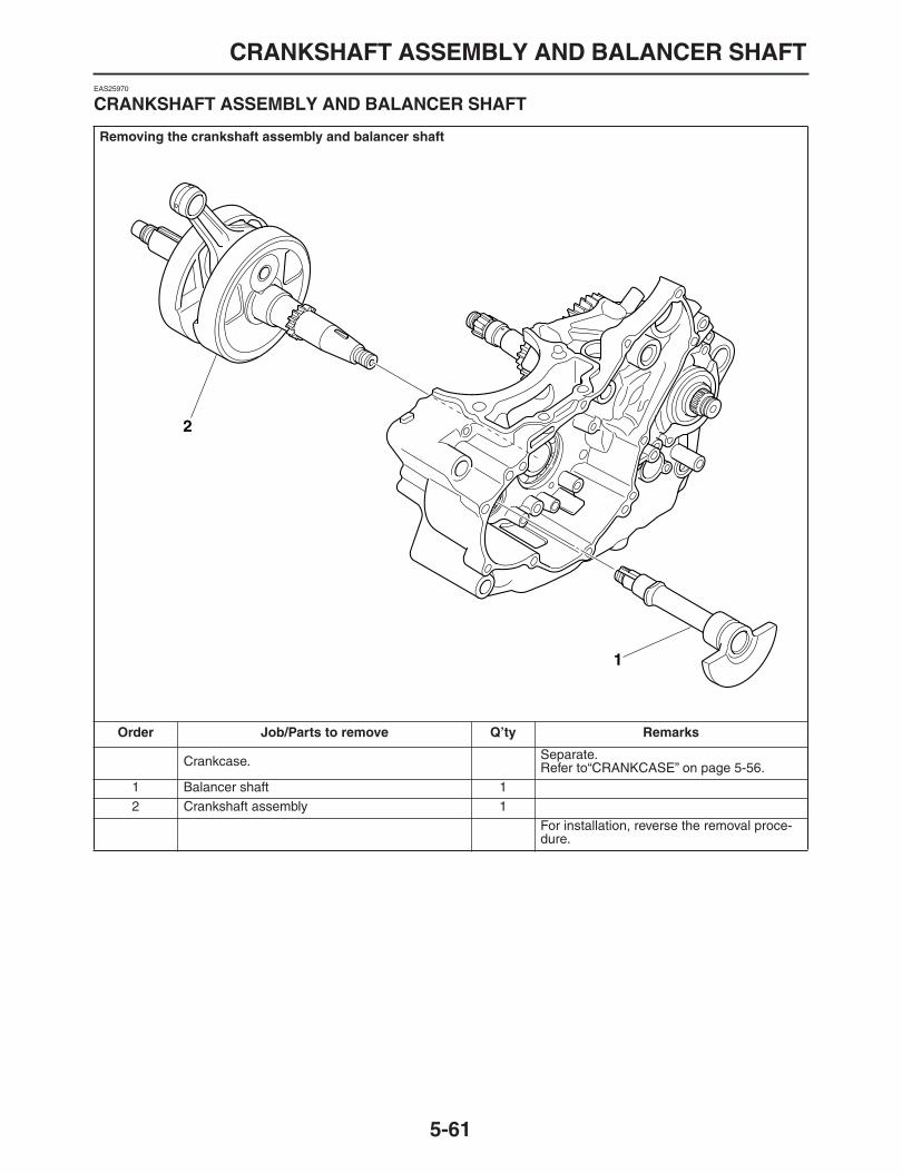
CRANKSHAFT ASSEMBLY AND BALANCER SHAFT
5-61
EAS25970
CRANKSHAFT ASSEMBLY AND BALANCER SHAFT
Removing the crankshaft assembly and balancer shaft
Order Job/Parts to remove Q’ty Remarks
Crankcase. Separate.Refer to“CRANKCASE” on page 5-56.
1 Balancer shaft 12 Crankshaft assembly 1
For installation, reverse the removal proce-dure.
1
2

CRANKSHAFT ASSEMBLY AND BALANCER SHAFT
5-62
EAS26000
REMOVING THE CRANKSHAFT ASSEMBLY
1. Remove:
Crankshaft assembly “1”NOTE:
Remove the crankshaft assembly by using the
crankcase separating tool “2”.
EAS26060
CHECKING THE CRANKSHAFT ASSEMBLY
1. Measure:
Crankshaft runoutOut of specification
→
Replace the crank-shaft, bearing or both.
NOTE:
Turn the crankshaft slowly.
2. Measure:
Big end side clearanceOut of specification
→
Replace the big endbearing, crankshaft pin, or connecting rod.
3. Measure:
Crankshaft widthOut of specification
→
Replace the crank-shaft.
4. Check:
Crankshaft sprocket “1”Damage
→
Replace the crankshaft.
5. Check:
Crankshaft journal oil passageObstruction
→
Blow out with compressed air.
EAS26210
INSTALLING THE CRANKSHAFT ASSEMBLY
1. Install:
Crankshaft assemblyNOTE:
Install the crankshaft assembly with the crank-shaft installer pot “1”, crankshaft installer bolt
Crankcase separating tool90890-01135
Crankcase separatorYU-01135-B
Runout limit C0.030 mm (0.0012 in)
Big end side clearance D0.350
–
0.650 mm (0.0138
–
0.0256in)
Width A61.95
–
62.00 mm (2.439
–
2.441 in)
1

CRANKSHAFT ASSEMBLY AND BALANCER SHAFT
5-63
“2”, adapter (M12) “3” and spacer “4”.
CAUTION:
ECA13970
To avoid scratching the crankshaft and toease the installation procedure, lubricate theoil seal lips with lithium-soap-based grease
and each bearing with engine oil.
NOTE:
Hold the connecting rod at top dead center(TDC) with one hand while turning the nut of thecrankshaft installer bolt with the other. Turn thecrankshaft installer bolt until the crankshaft as-
sembly bottoms against the bearing.
Crankshaft installer pot “1”90890-01274
Installing potYU-90058
Crankshaft installer bolt “2”90890-01275
BoltYU-90060
Adapter (M12) “3”90890-01278
Adapter #3YU-90063
Spacer (crankshaft installer) “4”90890-04081
Pot spacerYM-91044
4
3
2
1

TRANSMISSION
5-64
EAS26241
TRANSMISSION
Removing the transmission, shift drum assembly, and shift forks
Order Job/Parts to remove Q’ty Remarks
Crankcase Separate.Refer to“CRANKCASE” on page 5-56.
1 Shift fork guide bar 12 Shift drum 13 Shift fork-R 14 Shift fork-C 15 Shift fork-L 16 Main axle assembly 17 Drive axle assembly 18 O-ring 19 Collar 1
For installation, reverse the removal proce-dure.
1
2
3
4
5
6
7
8
9
E
E
E

TRANSMISSION
5-65
Disassembling the transmission
Order Job/Parts to remove Q’ty Remarks
1 2nd pinion gear 12 6th pinion gear 13 3rd pinion gear 14 Circlip 15 Washer 16 5th pinion gear 17 Main axle 18 Circlip 19 Plain washer 110 1st wheel gear 111 Washer 112 Collar 113 5th wheel gear 114 Circlip 115 Washer 116 4th wheel gear 117 3rd wheel gear 118 6th wheel gear 119 Circlip 120 Washer 121 2nd wheel gear 1
1
2
3
45
6
7
89
10
1112
1314
1516
17
1819
20
21
22
M
M
M
M
M
M

TRANSMISSION
5-66
22 Drive axle 1For installation, reverse the removal proce-dure.
Disassembling the transmission
Order Job/Parts to remove Q’ty Remarks
1
2
3
45
6
7
89
10
1112
1314
1516
17
1819
20
21
22
M
M
M
M
M
M

TRANSMISSION
5-67
EAS26260
CHECKING THE SHIFT FORKS
The following procedure applies to all of the shiftforks.1. Check:
Shift fork pawl “2”Bends/damage/scoring/wear
→
Replace theshift fork.
Shift fork cam follower “1”
2. Check:
Shift fork guide barRoll the shift fork guide bar on a flat surface.Bends
→
Replace.
WARNING
EWA12840
Do not attempt to straighten a bent shift fork
guide bar.
3. Check:
Shift fork movement(along the shift fork guide bar)Rough movement
→
Replace the shift forksand shift fork guide bar as a set.
EAS26270
CHECKING THE SHIFT DRUM ASSEMBLY
1. Check:
Shift drum grooveDamage/scratches/wear
→
Replace the shiftdrum assembly.
Shift drum segment “1”Damage/wear
→
Replace the shift drum as-sembly.
Shift drum bearingDamage/pitting
→
Replace the shift drum as-sembly.
EAS26290
CHECKING THE TRANSMISSION
1. Measure:
Main axle runout(with a centering device and dial gauge “1”)Out of specification
→
Replace the main axle.
Main axle runout limit0.08 mm (0.0032 in)
1

TRANSMISSION
5-68
2. Measure:
Drive axle runout(with a centering device and dial gauge “1”)Out of specification
→
Replace the drive axle.
3. Check:
Transmission gearsBlue discoloration/pitting/wear
→
Replacethe defective gear (s).
Transmission gear dogsCracks/damage/rounded edges
→
Replacethe defective gear (s).
4. Check:
Transmission gear engagement(each pinion gear to its respective wheelgear)Incorrect
→
Reassemble the transmissionaxle assemblies.
NOTE:
When reassembling the main axle, press the
2nd pinion gear “1” onto it “2” as shown.
5. Check:
Transmission gear movementRough movement
→
Replace the defectivepart (s).
EAS26320
INSTALLING THE SHIFT FORKS AND SHIFT DRUM ASSEMBLY
1. Install:
Shift fork guide bar “1”
Shift fork-R “2”
Shift fork-C “3”
Shift fork-L “4”NOTE:
The embossed marks on the shift forks shouldface towards the clutch side of the engine and
be in the following sequence: “R”, “C”, “L”.
Drive axle runout limit0.08 mm (0.0032 in)
a. 107.4
–
107.6 mm (4.228
–
4.236 in)
a
21
1
2
3
4

TRANSMISSION
5-69
EAS26340
INSTALLING THE TRANSMISSION
1. Install:
Transmission2. Check:
TransmissionRough movement
→
Repair.NOTE:
Oil each gear, shaft, and bearing thoroughly.

TRANSMISSION
5-70

1
2
3
4
5
6
7
8
9
COOLING SYSTEM
RADIATOR.....................................................................................................6-1
CHECKING THE RADIATOR...................................................................6-2INSTALLING THE RADIATOR.................................................................6-2
THERMOSTAT...............................................................................................6-4
CHECKING THE THERMOSTAT ............................................................6-5INSTALLING THE THERMOSTAT ASSEMBLY......................................6-5
WATER PUMP ...............................................................................................6-6
CHECKING THE WATER PUMP.............................................................6-7ASSEMBLING THE WATER PUMP ........................................................6-7

RADIATOR
6-1
EAS26380
RADIATOR
Removing the radiator
Order Job/Parts to remove Q’ty Remarks
Seat/Air scoop (left/right) Refer to“GENERAL CHASSIS” on page 4-1.Fuel tank Refer to“FUEL TANK” on page 7-1.
CoolantDrain.Refer to“CHANGING THE COOLANT” on page 3-18.
1 Radiator fan motor coupler 1 Disconnect.2 Radiator inlet hose 1 Disconnect.3 Coolant reservoir hose 1 Disconnect.4 Radiator outlet hose 1 Disconnect.5 FID Hose (radiator side) 16 Radiator cover 17 Breather hose 1 Disconnect.8 Recovery tank 19 Radiator 110 Radiator fan 1
For installation, reverse the removal proce-dure.
1
2
3
45
67
8
9
10
T R..
7 Nm (0.7 m • kg, 5.1 ft • Ib)
T R..
10 Nm (1.0 m • kg, 7.2 ft • Ib)
T R..
10 Nm (1.0 m • kg, 7.2 ft • Ib)
T R..
8 Nm (0.8 m • kg, 5.8 ft • Ib)
T R..
2 Nm (0.2 m • kg, 1.4 ft • Ib)

RADIATOR
6-2
EAS26390
CHECKING THE RADIATOR
1. Check:
Radiator fins “1”Obstruction
→
Clean.Apply compressed air to the rear of the radi-ator.Damage
→
Repair or replace.NOTE:
Straighten any flattened fins with a thin,
flat-head screwdriver.
2. Check:
Radiator hoses (IN/OUT)
Radiator pipesCracks/damage
→
Replace.3. Measure:
Radiator cap opening pressureBelow the specified pressure
→
Replace theradiator cap.
a. Install the radiator cap tester “1” and radiatorcap tester adapter “2” to the radiator cap “3”.
b. Apply the specified pressure for ten secondsand make sure there is no drop in pressure.
4. Check:
Radiator fanDamage
→
Replace.Malfunction
→
Check and repair.Refer to “COOLING SYSTEM” on page 8-25.
EAS26400
INSTALLING THE RADIATOR
1. Fill:
Cooling system(with the specified amount of the recom-mended coolant)Refer to “CHANGING THE COOLANT” onpage 3-18.
2. Check:
Cooling systemLeakage
→
Collect or replace.
a. Attach the radiator cap tester “1” to the radia-tor.
Radiator cap opening pressure108.0
–
137.4 kPa (15.7
–
19.9 psi)(1.08
–
1.37 kgf/cm
2
)
Radiator cap tester90890-01325
Radiator pressure testerYU-24460-01
Radiator cap tester adapter90890-01352
Radiator pressure tester adapterYU-33984
Radiator cap tester90890-01325
Radiator pressure testerYU-24460-01
Radiator cap tester adapter90890-01352
Radiator pressure tester adapterYU-33984
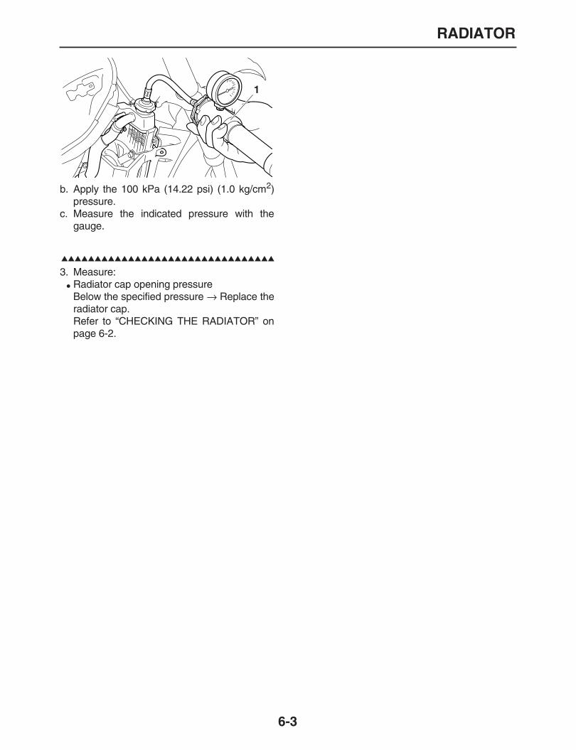
RADIATOR
6-3
b. Apply the 100 kPa (14.22 psi) (1.0 kg/cm
2
)pressure.
c. Measure the indicated pressure with thegauge.
3. Measure:
Radiator cap opening pressureBelow the specified pressure
→
Replace theradiator cap.Refer to “CHECKING THE RADIATOR” onpage 6-2.
1
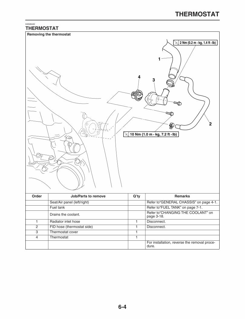
THERMOSTAT
6-4
EAS26440
THERMOSTAT
Removing the thermostat
Order Job/Parts to remove Q’ty Remarks
Seat/Air panel (left/right) Refer to“GENERAL CHASSIS” on page 4-1.Fuel tank Refer to“FUEL TANK” on page 7-1.
Drains the coolant. Refer to“CHANGING THE COOLANT” on page 3-18.
1 Radiator inlet hose 1 Disconnect.2 FID hose (thermostat side) 1 Disconnect.3 Thermostat cover 14 Thermostat 1
For installation, reverse the removal proce-dure.
1
2
34
T R..
10 Nm (1.0 m • kg, 7.2 ft • Ib)
T R..
2 Nm (0.2 m • kg, 1.4 ft • Ib)

THERMOSTAT
6-5
EAS26450
CHECKING THE THERMOSTAT
1. Check:
Thermostat “1”Does not open at 70.5
–
73.5
°
C(158.9
–
164.3
°
F)
→
Replace.
a. Suspend the thermostat “1” in a container “2”filled with water.
b. Slowly heat the water.c. Place a thermometer “3” in the water “4”.d. While stirring the water, observe the thermo-
stat and thermometer’s indicated tempera-ture.
NOTE:
If the accuracy of the thermostat is in doubt, re-place it. A faulty thermostat could cause serious
overheating or overcooling.
2. Check:
Thermostat housing coverCracks/damage
→
Replace.
EAS26480
INSTALLING THE THERMOSTAT ASSEMBLY
1. Install:
Thermostat “1”
Thermostat cover “2”NOTE:
Install the thermostat by facing breather hole up-
ward.
2. Fill:
Cooling system(with the specified amount of the recom-mended coolant)Refer to “CHANGING THE COOLANT” onpage 3-18.
3. Check:
Cooling systemLeaks
→
Repair or replace any faulty part.4. Measure:
Radiator cap opening pressureBelow the specified pressure
→
Replace theradiator cap.Refer to “CHECKING THE RADIATOR” onpage 6-2.
A. Fully closed
Thermostat cover bolt10 Nm (1.0 m•kg, 7.2 ft•lb)T
R..
1 2

WATER PUMP
6-6
EAS26500
WATER PUMP
Removing the water pump
Order Job/Parts to remove Q’ty Remarks
Drains the coolant. Refer to“CHANGING THE COOLANT” on page 3-18.
Drains the engine oil Refer to“CHANGING THE ENGINE OIL” on page 3-11.
Water pump housing cover Refer to“CLUTCH” on page 5-34.Crank case cover light Refer to“CLUTCH” on page 5-34.
1 Circlips 12 Impeller shaft gear 13 Dowelpin 14 Plate 15 Impeller shaft 16 Mechanical seal 17 Bearing 1
For installation, reverse the removal proce-dure.
LT
1
23
4
5
6
7
LT
E
T R..
10 Nm (1.0 m • kg, 7.2 ft • Ib)

WATER PUMP
6-7
EAS26530
CHECKING THE WATER PUMP
1. Check:
Water pump housing cover
Impeller shaft
PlateCracks/damage/wear
→
Replace.2. Check:
Impeller shaft gearCracks/damage/chips
→
Replace.
EAS26560
ASSEMBLING THE WATER PUMP
1. Install:
Bearing
Mechanical “1”(to the right crankcase cover)
NOTE:
Install the mechanical seal by facing stampworld “WATER SIDE” to the impeller housingcover.
Install the mechanical seal by using mechani-cal seal installer “2” and middle driven shaft
bearing driver “3”.
2. Lubricate:
Mechanical seal lip
Impeller shaft3. Install:
Impeller shaft “1”
Plate “2”NOTE:
Tighten the plate bolt with appling the
LOCTITE®.
4. Lubricate:
Engine oil(to the bearing)
5. Install:
Plate washer
Dowel pin
Impeller shaft gear “1”
Plate washer “2”
Circlip “3”
6. Install:
Crankcase cover right gascket
Crankcase cover (right)Refer to “CLUTCH” on page 5-34.
7. Install:
Water pump housing cover gascket
Water pump housing cover “1”(Bolt “2” with new copper washer)
8. Fill:
Mechanical seal installer90890-04145
Middle driven shaft bearing driver90890-04058
Plate bolt10 Nm (1.0 m•kg, 7.2 ft•lb)
NewNew
3
2
1
TR..
Water pump housing cover bolt10 Nm (1.0 m•kg, 7.2 ft•lb)
1
2
New
23
1
New
New
TR..
2
1
WATER PUMP
6-8
CrankcaseRefer to “CHANGING THE ENGINE OIL” onpage 3-11.
9. Fill:
Cooling systemRefer to “CHANGING THE COOLANT” onpage 3-18.
WATER PUMP
6-9

1
2
3
4
5
6
7
8
9
FUEL SYSTEM
FUEL TANK ...................................................................................................7-1
REMOVING THE FUEL TANK.................................................................7-2REMOVING THE FUEL PUMP................................................................7-2INSTALLING THE FUEL PUMP...............................................................7-2INSTALLING THE FUEL TANK ...............................................................7-2
THROTTLE BODIES......................................................................................7-4
CHECKING THE INJECTORS.................................................................7-6CHECKING THE THROTTLE BODIES....................................................7-6CHECKING THE PRESSURE REGULATOR..........................................7-6CHECKING THE PRESSURE REGULATOR OPERATION....................7-6ADJUSTING THE THROTTLE POSITION SENSOR ..............................7-7
AIR INDUCTION SYSTEM.............................................................................7-9
CHECKING THE AIR INDUCTION SYSTEM ..........................................7-12CANISTER (FOR CALIFORNIA)..............................................................7-13
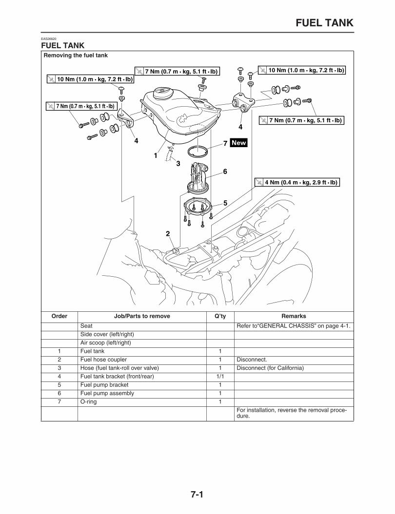
FUEL TANK
7-1
EAS26620
FUEL TANK
Removing the fuel tank
Order Job/Parts to remove Q’ty Remarks
Seat Refer to“GENERAL CHASSIS” on page 4-1.Side cover (left/right)Air scoop (left/right)
1 Fuel tank 12 Fuel hose coupler 1 Disconnect.3 Hose (fuel tank-roll over valve) 1 Disconnect (for California)4 Fuel tank bracket (front/rear) 1/15 Fuel pump bracket 16 Fuel pump assembly 17 O-ring 1
For installation, reverse the removal proce-dure.
1
2
4
4
5
6
7
T R..
10 Nm (1.0 m • kg, 7.2 ft • Ib)
T R..
4 Nm (0.4 m • kg, 2.9 ft • Ib)
T R..
10 Nm (1.0 m • kg, 7.2 ft • Ib)
T R..
7 Nm (0.7 m • kg, 5.1 ft • Ib)
T R..
7 Nm (0.7 m • kg, 5.1 ft • Ib)
T R..
7 Nm (0.7 m • kg, 5.1 ft • Ib)
3

FUEL TANK
7-2
EAS26630
REMOVING THE FUEL TANK
1. Extract the fuel in the fuel tank through thefuel tank cap with a pump.
2. Remove:
Fuel hose coupler
CAUTION:
ECA14700
Although the fuel has been removed fromthe fuel tank be careful when removing thefuel hoses, since there may be fuel remain-
ing in it.
NOTE:
Slide the fuel hose connector cover “1” in thedirection of the arrow mark, and press the but-tons “2” on both sides of the connector to re-move the fuel hose.
Disconnecting the hose is done by hand.There is no need to use tools.
Before removing the fuel hose, place a fewrags in the area under where it will be re-
moved.
3. Remove:
Fuel tankNOTE:
Do not set the fuel tank down so that the instal-lation surface of the fuel pump is directly underthe tank. Be sure to lean the fuel tank in an up-
right position.
EAS26640
REMOVING THE FUEL PUMP
1. Remove:
Fuel pump
CAUTION:
ECA14720
Do not drop the fuel pump or give it astrong shock.
Do not touch the base section of the fuel
sender.
EAS26700
INSTALLING THE FUEL PUMP
1. Install:
Fuel pump
NOTE:
Do not damage the installation surfaces of thefuel tank when installing the fuel pump.
Always use a new fuel pump gasket.
Install the fuel pump as shown in the illustra-tion.
Align the projection “a” on the fuel pump withthe slot in the fuel pump bracket.
Align the slot “b” on the fuel tank damper withthe projection “a” on the fuel pump.
Tighten the fuel pump bolts in stages in a criss-
cross pattern.
EAS32D1016
INSTALLING THE FUEL TANK
1. Install:
Fuel hose
Fuel return hose
CAUTION:
ECA14740
When installing the fuel hose, make sure thatit is securely connected, and that the fuelhose holders are in the correct position, oth-erwise the fuel hose will not be properly in-
stalled.
NOTE:
Insert the fuel hose on the fuel pipe until youhear a definite “click”.
Slide the fuel hose connector cover “1” at the
fuel hose end in the direction of the arrow.
12
Fuel pump bolts4 Nm (0.4 m•kg, 2.9 ft•lb)T
R..
a
b

FUEL TANK
7-3
1

THROTTLE BODIES
7-4
EAS26970
THROTTLE BODIES
Removing the throttle bodies
Order Job/Parts to remove Q’ty Remarks
Seat Refer to “GENERAL CHASSIS” on page 4-1.
Side cover (left/right)Air scoop (left/right)Fuel tank Refer to “FUEL TANK” on page 7-1.Throttle cable Refer to “CAMSHAFT” on page 5-6.Clutch cable
CoolantDrain.Refer to “CHANGING THE COOLANT” on page 3-18.
Ignition coil lead Refer to “CAMSHAFT” on page 5-6.1 Injector coupler 1 Disconnect.2 Vacuum hose 13 ITS boost hose 14 FID hose (Thermostat side/radiator side) 25 Hose (canister-throttle body) 1 (for California)6 Throttle bodies assembly 1
For installation, reverse the removal proce-dure.
6
1
2
5
3
4
4

THROTTLE BODIES
7-5
Disassembling the throttle body
Order Job/Parts to remove Q’ty Remarks
1 Delivery pipe 12 Injector 13 Gasket 14 Throttle position sensor 1
For installation, reverse the removal proce-dure.
1
2 3
4
T R..
5 Nm (0.5 m • kg, 3.6 ft • Ib)
T R..
3.5 Nm (0.4 m • kg, 2.5 ft • Ib)

THROTTLE BODIES
7-6
EAS26980
CHECKING THE INJECTORS
WARNING
EWA32D1009
Replace the fuel injector with a new one if
you have dropped or impacted it.
1. Check:
InjectorsDamage
→
Replace.
EAS26990
CHECKING THE THROTTLE BODIES
1. Check:
Throttle bodiesCracks/damage
→
Replace the throttle bod-ies as a set.
2. Check:
Fuel passagesObstructions
→
Clean.
a. Wash the throttle bodies in a petroleum-based solvent.Do not use any caustic carburetor cleaningsolution.
b. Blow out all of the passages with com-pressed air.
EAS27000
CHECKING THE PRESSURE REGULATOR
WARNING
EWA32D1010
Replace the pressure regulator with a new
one if you have dropped or impacted it.
1. Check:
Pressure regulatorDamage
→
Replace.
EAS27010
CHECKING THE PRESSURE REGULATOR OPERATION
1. Check:
Pressure regulator operation
a. Remove the fuel tank.Refer to “FUEL TANK” on page 7-1.
b. Connect the pressure gauge “1” and adapter“2” to the fuel injection pipe.
c. Install the fuel tank.Refer to “FUEL TANK” on page 7-1.
d. Start the engine.e. Measure the fuel pressure.
f. Use the vacuum/pressure pump gauge set toadjust the fuel pressure in relation to the vac-uum pressure as described below.
NOTE:
The vacuum pressure should not exceed 100
kPa (14.2 psi) (1.00 kg/cm
2
).
Faulty
→
Replace the pressure regulator.
Vacuum/pressure pump gaugeset
90890-06756Mityvac brake bleeding tool
YS-42423Pressure gauge
90890-03153YU-03153
Fuel pressure adapter90890-03176YM-03176
Fuel pressure250 kPa (35.6 psi) (2.50 kg/cm
2
)
Increase the vacuum pressure
→
Fuel pressure is decreasedDecrease the vacuum pressure
→
Fuel pressure is increased
1
2

THROTTLE BODIES
7-7
EAS27030
ADJUSTING THE THROTTLE POSITION SENSOR
WARNING
EWA32D1011
Replace the throttle position sensor with a
new one if you have dropped or impacted it.
NOTE:
Before adjusting the throttle position sensor, the
engine idling speed should be properly adjusted.
1. Check:
Throttle position sensorRefer to “CHECKING THE THROTTLE PO-SITION SENSOR” on page 8-79.
2. Adjust:
Throttle position sensor angle
a. Connect the throttle position sensor couplerto the wire harness.
b. Connect the digital circuit tester to the throttleposition sensor.
c. Measure the throttle position sensor voltage.d. Adjust the throttle position sensor angle so
that the voltage is within the specified range.
e. After adjusting the throttle position sensor an-
gle, tighten the throttle position sensorscrews.
Positive tester probeBlue
“
1
”
Negative tester probeBlack/Blue
“
2
”
Digital circuit tester90890-03174
Model 88 Multimeter with tachom-eter
YU-A1927
Throttle position sensorOutput voltage (when the engineis idling)
0.63
–
0.73 V
L Y B/L
1 2

THROTTLE BODIES
7-8

AIR INDUCTION SYSTEM
7-9
EAS27040
AIR INDUCTION SYSTEM
2
1
3
4
AIR INDUCTION SYSTEM
7-10
1. Air filter case2. Air induction system hose3. Air cut-off valve4. Air induction system pipe
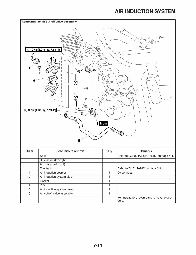
AIR INDUCTION SYSTEM
7-11
Removing the air cut-off valve assembly
Order Job/Parts to remove Q’ty Remarks
Seat Refer to“GENERAL CHASSIS” on page 4-1.Side cover (left/right)Air scoop (left/right)Fuel tank Refer to“FUEL TANK” on page 7-1.
1 Air induction coupler 1 Disconnect.2 Air induction system pipe 13 Gasket 14 Pipe3 15 Air induction system hose 16 Air cut-off valve assembly 1
For installation, reverse the removal proce-dure.
1
2
3
4
5
6
T R..
10 Nm (1.0 m • kg, 7.2 ft • Ib)
T R..
10 Nm (1.0 m • kg, 7.2 ft • Ib)

AIR INDUCTION SYSTEM
7-12
EAS27060
CHECKING THE AIR INDUCTION SYSTEMAir induction
The air induction system burns unburned ex-haust gases by injecting fresh air (secondary air)into the exhaust port, reducing the emission ofhydrocarbons. When there is negative pressureat the exhaust port, the reed valve opens, allow-ing secondary air to flow into the exhaust port.The required temperature for burning the un-burned exhaust gases is approximately 600 to700
°
C.
Air cut-off valve
The air cut-off valve is controlled by the signalsfrom the ECU in accordance with the combus-tion conditions. Ordinarily, the air cut-off valveopens to allow the air to flow during idle andcloses to cut-off the flow when the vehicle is be-ing driven.
1. Check:
HosesLoose connections
→
Connect properly.Cracks/damage
→
Replace.
PipesCracks/damage
→
Replace.2. Check:
Reed valve
Reed valve stopper
Reed valve seatCracks/damage
→
Replace the reed valve.
3. Check:
Air cut-off valveCracks/damage
→
Replace.
A. From the air filterB. To the cylinder head
A
B

AIR INDUCTION SYSTEM
7-13
EAS32D12011
CANISTER (FOR CALIFORNIA)
Removing the canister
Order Job/Parts to remove Q’ty Remarks
1 Canister cover 12 Canister 13 Hose (fuel tank
–
roll over valve) 14 Roll over valve 15 Hose (roll over valve
–
canister) 16 Hose (canister
–
throttle body) 1For installation, reverse the removal proce-dure.
T R..
10 Nm (1.0 m • kg, 7.2 ft • Ib)
1
T R..
10 Nm (1.0 m • kg, 7.2 ft • Ib)
2
56
3
4

1
2
3
4
5
6
7
8
9
ELECTRICAL SYSTEM
IGNITION SYSTEM ........................................................................................8-1
CIRCUIT DIAGRAM.................................................................................8-1TROUBLESHOOTING .............................................................................8-3
ELECTRIC STARTING SYSTEM...................................................................8-5
CIRCUIT DIAGRAM.................................................................................8-5STARTING CIRCUIT CUT-OFF SYSTEM OPERATION.........................8-7TROUBLESHOOTING .............................................................................8-9
CHARGING SYSTEM ....................................................................................8-11
CIRCUIT DIAGRAM.................................................................................8-11TROUBLESHOOTING .............................................................................8-13
LIGHTING SYSTEM.......................................................................................8-15
CIRCUIT DIAGRAM.................................................................................8-15TROUBLESHOOTING .............................................................................8-17
SIGNALING SYSTEM ....................................................................................8-19
CIRCUIT DIAGRAM.................................................................................8-19TROUBLESHOOTING .............................................................................8-21
COOLING SYSTEM .......................................................................................8-25
CIRCUIT DIAGRAM.................................................................................8-25TROUBLESHOOTING .............................................................................8-27
FUEL INJECTION SYSTEM ..........................................................................8-29
CIRCUIT DIAGRAM.................................................................................8-29ECU SELF-DIAGNOSTIC FUNCTION.....................................................8-31FAIL-SAFE ACTIONS (SUBSTITUTE CHARACTERISTICS OPERATION CONTROL) ......................................................................8-32TROUBLESHOOTING METHOD.............................................................8-34DIAGNOSTIC MODE ...............................................................................8-34TROUBLESHOOTING DETAILS .............................................................8-41
FUEL PUMP SYSTEM ...................................................................................8-55
CIRCUIT DIAGRAM.................................................................................8-55TROUBLE SHOOTING ............................................................................8-57
ELECTRICAL COMPONENTS ......................................................................8-59
CHECKING THE SWITCHES ..................................................................8-63CHECKING THE BULBS AND BULB SOCKETS ....................................8-66CHECKING THE FUSES .........................................................................8-67CHECKING AND CHARGING THE BATTERY........................................8-68CHECKING THE RELAYS.......................................................................8-71CHECKING THE DIODE..........................................................................8-73CHECKING THE IGNITION SPARK GAP ...............................................8-74CHECKING THE IGNITION COIL............................................................8-74

CHECKING THE CRANKSHAFT POSITION SENSOR ..........................8-75CHECKING THE LEAN ANGLE SENSOR ..............................................8-75CHECKING THE STATOR COIL .............................................................8-76CHECKING THE RECTIFIER/REGULATOR...........................................8-76CHECKING THE HORN...........................................................................8-77CHECKING THE SPEED SENSOR.........................................................8-77CHECKING THE FUEL SENDER (FUEL PUMP) ....................................8-78CHECKING THE COOLANT TEMPERATURE SENSOR .......................8-78CHECKING THE RADIATOR FAN MOTOR............................................8-79CHECKING THE THROTTLE POSITION SENSOR................................8-79CHECKING THE EXUP SERVO MOTOR ...............................................8-80CHECKING THE INTAKE AIR PRESSURE SENSOR ............................8-80CHECKING THE INTAKE AIR TEMPERATURE SENSOR.....................8-80CHECKING THE INTAKE SOLENOID.....................................................8-81


IGNITION SYSTEM
8-1
EAS27090
IGNITION SYSTEM
EAS27100
CIRCUIT DIAGRAM

IGNITION SYSTEM
8-2
1. AC magneto3. Main switch4. Battery5. Main fuse8. Right handlebar switch9. Engine stop switch11. Relay unit12. Sidestand switch13. Neutral switch14. Clutch switch16. ECU17. Ignition coil18. Spark plug27. Lean angle sensor56. Ignition fuse

IGNITION SYSTEM
8-3
EAS27130
TROUBLESHOOTING
The ignition system fails to operate (no spark or intermittent spark).NOTE:
Before troubleshooting, remove the following part (s):1. Seat2. Side cover (left)3. Air scoop (left/right)
4. Fuel tank
1. Check the fuses.(Main and ignition)Refer to
“CHECKING THE FUSES” on page 8-67
.
NG
→
Replace the fuse (s).
OK
↓
2. Check the battery.Refer to
“CHECKING AND CHARG-ING THE BATTERY” on page 8-68
.NG
→
Clean the battery terminals.
Recharge or replace the battery.
OK
↓
3. Check the spark plug.Refer to
“CHECKING THE SPARK PLUG” on page 3-8
.NG
→
Re-gap or replace the spark plug.
OK
↓
4. Check the ignition spark gap.Refer to
“CHECKING THE IGNITION SPARK GAP” on page 8-74
.OK
→
The ignition system is normal.
NG
↓
5. Check the ignition coil.Refer to
“CHECKING THE IGNITION COIL” on page 8-74
.NG
→
Replace the ignition coil.
OK
↓
6. Check the crankshaft position sen-sor.Refer to
“CHECKING THE CRANK-SHAFT POSITION SENSOR” on page 8-75
.
NG
→
Replace the stater assembly.
OK
↓
7. Check the main switch.Refer to
“CHECKING THE SWITCHES” on page 8-63
.NG
→
Replace the main switch.
OK
↓
8. Check the engine stop switch.Refer to
“CHECKING THE SWITCHES” on page 8-63
.NG
→
Replace the right handlebar switch.
OK
↓
9. Check the neutral switch.Refer to
“CHECKING THE SWITCHES” on page 8-63
.NG
→
Replace the neutral switch.
OK
↓
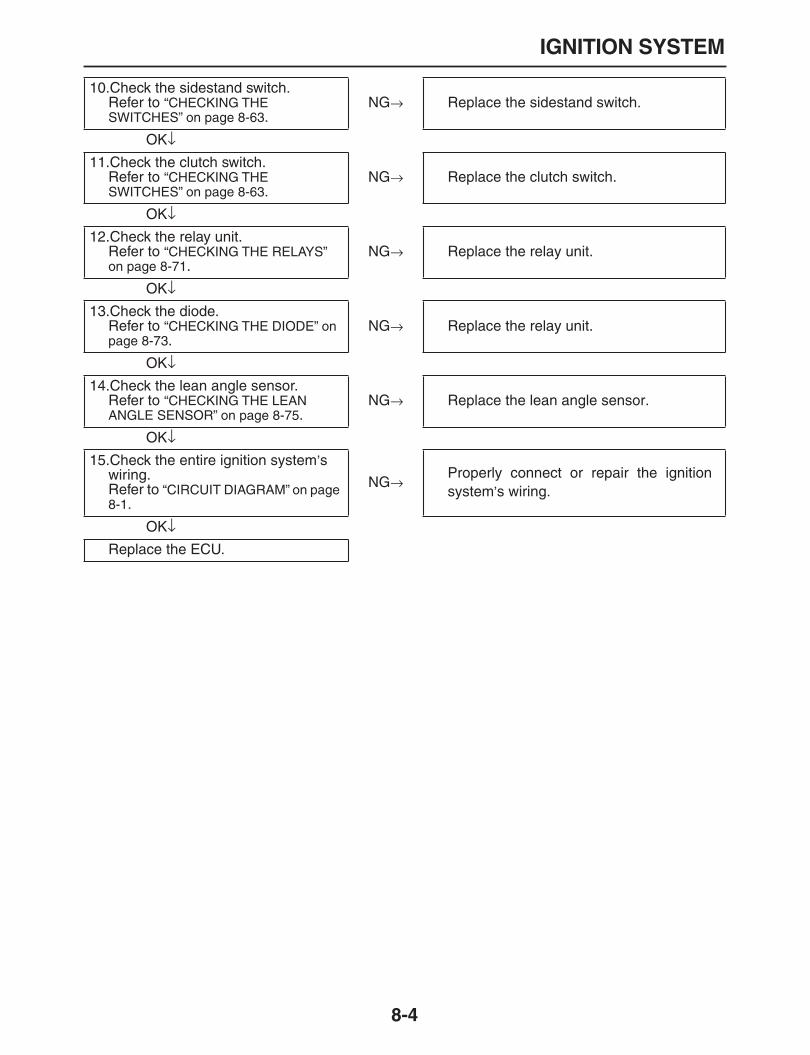
IGNITION SYSTEM
8-4
10.Check the sidestand switch.Refer to
“CHECKING THE SWITCHES” on page 8-63
.NG
→
Replace the sidestand switch.
OK
↓
11.Check the clutch switch.Refer to
“CHECKING THE SWITCHES” on page 8-63
.NG
→
Replace the clutch switch.
OK
↓
12.Check the relay unit.Refer to
“CHECKING THE RELAYS” on page 8-71
.NG
→
Replace the relay unit.
OK
↓
13.Check the diode.Refer to
“CHECKING THE DIODE” on page 8-73
.NG
→
Replace the relay unit.
OK
↓
14.Check the lean angle sensor.Refer to
“CHECKING THE LEAN ANGLE SENSOR” on page 8-75
.NG
→
Replace the lean angle sensor.
OK
↓
15.Check the entire ignition system
’
s wiring.Refer to
“CIRCUIT DIAGRAM” on page 8-1
.
NG
→
Properly connect or repair the ignitionsystem
’
s wiring.
OK
↓
Replace the ECU.

ELECTRIC STARTING SYSTEM
8-5
EAS27160
ELECTRIC STARTING SYSTEM
EAS27170
CIRCUIT DIAGRAM

ELECTRIC STARTING SYSTEM
8-6
3. Main switch4. Battery5. Main fuse6. Starter relay7. Starter motor8. Right handlebar switch9. Engine stop switch10. Start switch11. Relay unit12. Sidestand switch13. Neutral switch14. Clutch switch55. Signaling system fuse56. Ignition fuse

ELECTRIC STARTING SYSTEM
8-7
EAS27180
STARTING CIRCUIT CUT-OFF SYSTEM OPERATION
If the engine stop switch is set to “ ” and the main switch is set to “ON” (both switches are closed), thestarter motor can only operate if at least one of the following conditions is met:
The transmission is in neutral (the neutral switch is closed).
The clutch lever is pulled to the handlebar (the clutch switch is closed) and the sidestand is up (thesidestand switch is closed).
The starting circuit cut-off relay prevents the starter motor from operating when neither of these condi-tions has been met. In this instance, the starting circuit cut-off relay is open so current cannot reach thestarter motor. When at least one of the above conditions has been met the starting circuit cut-off relayis closed and the engine can be started by pressing the starter switch.
15
1
14
2
3
4
5
6 13
9
10
11 12
a
b
7
9
9
8

ELECTRIC STARTING SYSTEM
8-8
a. WHEN THE TRANSMISSION IS IN NEU-TRAL
b. WHEN THE SIDESTAND IS UP AND THE CLUTCH LEVER IS PULLED TO THE HANDLEBAR
1. Battery2. Main fuse3. Main switch4. Ignition fuse5. Engine stop switch6. Starting circuit cut-off relay7. Signal fuse8. Diode9. Diode10. Clutch switch11. Sidestand switch12. Neutral switch13. Start switch14. Starter relay15. Starter motor

ELECTRIC STARTING SYSTEM
8-9
EAS27190
TROUBLESHOOTING
The starter motor fails to turn.NOTE:
Before troubleshooting, remove the following part (s):1. Seat2. Side cover (left)3. Air scoop (left/right)
4. Fuel tank
1. Check the fuses.(Main, ignition and signal fuse)Refer to
“CHECKING THE FUSES” on page 8-67
.
NG
→
Replace the fuse (s).
OK
↓
2. Check the battery.Refer to
“CHECKING AND CHARG-ING THE BATTERY” on page 8-68
.NG
→
Clean the battery terminals.
Recharge or replace the battery.
OK
↓
3. Replace the starter motor.Refer to
“CHECKING THE STARTER MOTOR” on page 5-32
.NG
→
Repair or replace the starter motor.
OK
↓
4. Check the relay unit.Refer to
“CHECKING THE RELAYS” on page 8-71
.NG
→
Replace the relay unit.
OK
↓
5. Check the diode.Refer to
“CHECKING THE DIODE” on page 8-73
.NG
→
Replace the relay unit.
OK
↓
6. Check the starter relay.Refer to
“CHECKING THE RELAYS” on page 8-71
.NG
→
Replace the starter relay.
OK
↓
7. Check the main switch.Refer to
“CHECKING THE SWITCHES” on page 8-63
.NG
→
Replace the main switch.
OK
↓
8. Check the engine stop switch.Refer to
“CHECKING THE SWITCHES” on page 8-63
.NG
→
Replace the right handlebar switch.
OK
↓
9. Check the neutral switch.Refer to
“CHECKING THE SWITCHES” on page 8-63
.NG
→
Replace the neutral switch.
OK
↓
10.Check the sidestand switch.Refer to
“CHECKING THE SWITCHES” on page 8-63
.NG
→
Replace the sidestand switch.

ELECTRIC STARTING SYSTEM
8-10
OK
↓
11.Check the clutch switch.Refer to
“CHECKING THE SWITCHES” on page 8-63
.NG
→
Replace the clutch switch.
OK
↓
12.Check the start switch.Refer to
“CHECKING THE SWITCHES” on page 8-63
.NG
→
Replace the right handlebar switch.
OK
↓
13.Check the entire starting system
’
s wiring.Refer to
“CIRCUIT DIAGRAM” on page 8-5
.
NG
→
Properly connect or repair the startingsystem’s wiring.
OK
↓
The starting system circuit is OK.
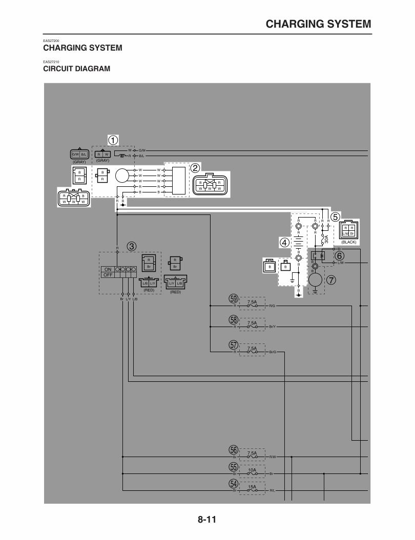
CHARGING SYSTEM
8-11
EAS27200
CHARGING SYSTEM
EAS27210
CIRCUIT DIAGRAM

CHARGING SYSTEM
8-12
1. AC magneto2. Rectifier/regulator4. Battery5. Main fuse

CHARGING SYSTEM
8-13
EAS27220
TROUBLESHOOTING
The battery is not being charged.NOTE:
Before troubleshooting, remove the following part (s):1. Seat2. Side cover (left)
3. Air scoop (left)
1. Check the fuse.(Main)Refer to
“CHECKING THE FUSES” on page 8-67
.
NG
→
Replace the fuse.
OK
↓
2. Check the battery.Refer to
“CHECKING AND CHARG-ING THE BATTERY” on page 8-68
.NG
→
Clean the battery terminals.
Recharge or replace the battery.
OK
↓
3. Check the stator coil.Refer to
“CHECKING THE STATOR COIL” on page 8-76
.NG
→
Replace the stator assembly.
OK
↓
4. Check the rectifier/regulator.Refer to
“CHECKING THE RECTI-FIER/REGULATOR” on page 8-76
.NG
→
Replace the rectifier/regulator.
OK
↓
5. Check the entire charging system
’
s wiring.Refer to
“CIRCUIT DIAGRAM” on page 8-11
.
NG
→
Properly connect or repair the chargingsystem’s wiring.
OK
↓
This circuit is OK.

CHARGING SYSTEM
8-14

LIGHTING SYSTEM
8-15
EAS27240
LIGHTING SYSTEM
EAS27250
CIRCUIT DIAGRAM

LIGHTING SYSTEM
8-16
3. Main switch4. Battery5. Main fuse16. ECU34. High beam indicator39. Front right turn signal/position light40. Front left turn signal/position light42. Headlight relay43. Dimmer switch44. Headlight50. Tail/brake light51. License light54. Headlight fuse55. Signaling system fuse
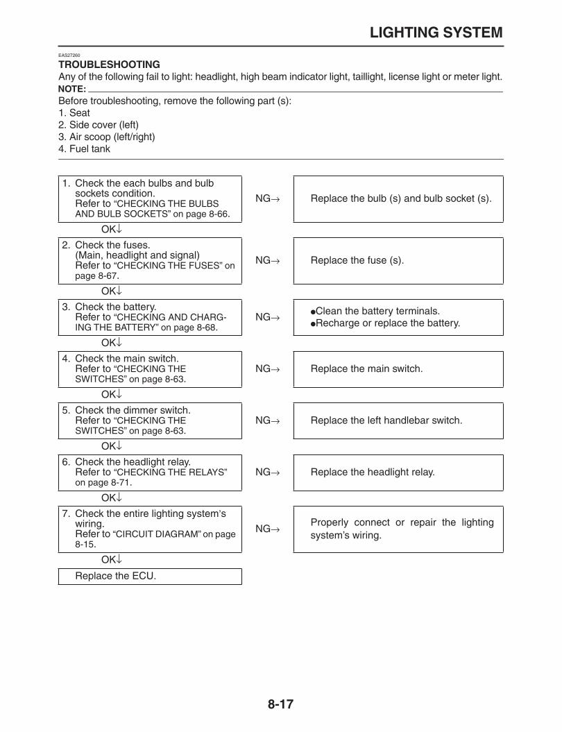
LIGHTING SYSTEM
8-17
EAS27260
TROUBLESHOOTING
Any of the following fail to light: headlight, high beam indicator light, taillight, license light or meter light.NOTE:
Before troubleshooting, remove the following part (s):1. Seat2. Side cover (left)3. Air scoop (left/right)
4. Fuel tank
1. Check the each bulbs and bulb sockets condition.Refer to
“CHECKING THE BULBS AND BULB SOCKETS” on page 8-66
.
NG
→
Replace the bulb (s) and bulb socket (s).
OK
↓
2. Check the fuses.(Main, headlight and signal)Refer to
“CHECKING THE FUSES” on page 8-67
.
NG
→
Replace the fuse (s).
OK
↓
3. Check the battery.Refer to
“CHECKING AND CHARG-ING THE BATTERY” on page 8-68
.NG
→
Clean the battery terminals.
Recharge or replace the battery.
OK
↓
4. Check the main switch.Refer to
“CHECKING THE SWITCHES” on page 8-63
.NG
→
Replace the main switch.
OK
↓
5. Check the dimmer switch.Refer to
“CHECKING THE SWITCHES” on page 8-63
.NG
→
Replace the left handlebar switch.
OK
↓
6. Check the headlight relay.Refer to
“CHECKING THE RELAYS” on page 8-71
.NG
→
Replace the headlight relay.
OK
↓
7. Check the entire lighting system
’
s wiring.Refer to
“CIRCUIT DIAGRAM” on page 8-15
.
NG
→
Properly connect or repair the lightingsystem’s wiring.
OK
↓
Replace the ECU.

LIGHTING SYSTEM
8-18
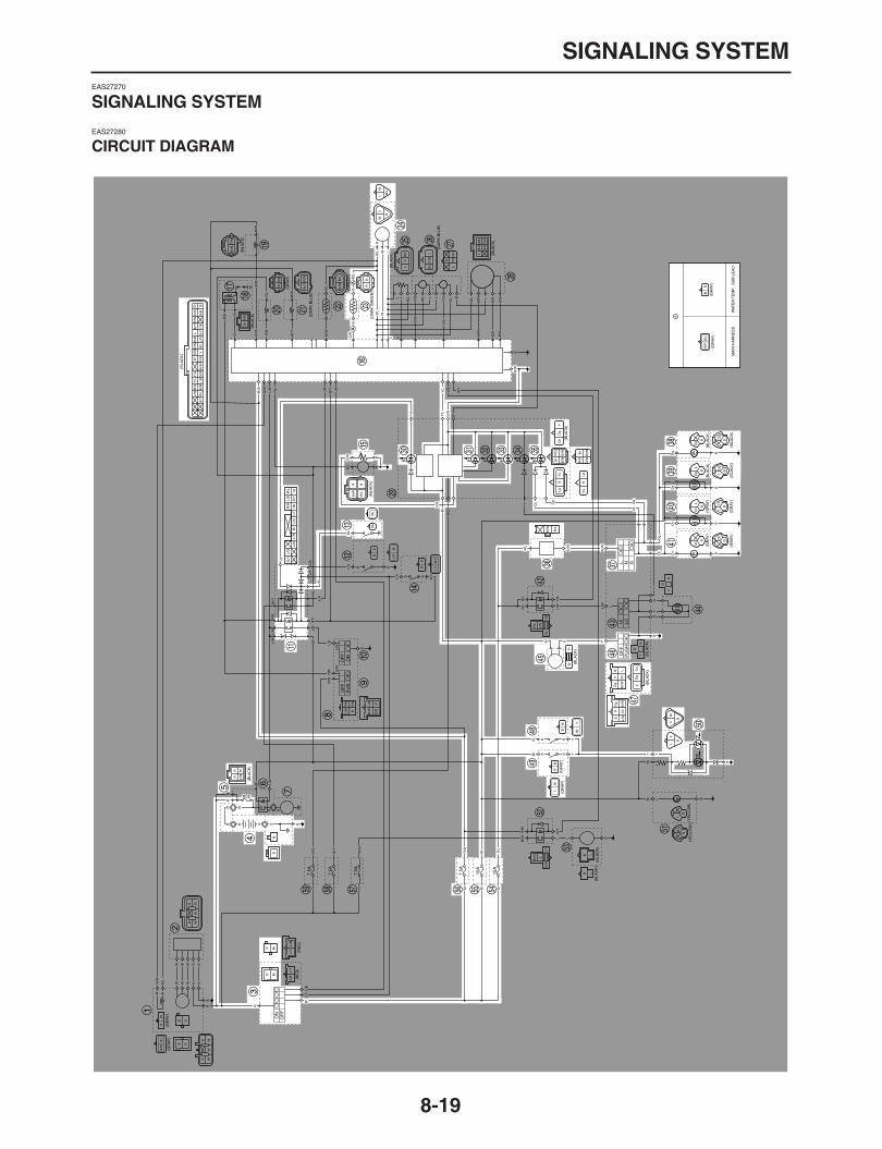
SIGNALING SYSTEM
8-19
EAS27270
SIGNALING SYSTEM
EAS27280
CIRCUIT DIAGRAM

SIGNALING SYSTEM
8-20
3. Main switch4. Battery5. Main fuse11. Relay unit13. Neutral switch15. Fuel pump16. ECU23. Coolant temperature sensor24. Speed sensor30. Neutral indicator light31. Coolant temperature warning light33. Fuel level warning light35. Turn signal indicator light36. Turn signal relay37. Turn signal switch38. Rear right turn signal light39. Front right turn signal/position light40. Front left turn signal/position light41. Rear left turn signal light45. Horn46. Horn switch47. Left handlebar switch48. Rear brake switch49. Front brake switch50. Tail/brake light54. Headlight fuse55. Signaling system fuse56. Ignition fuse

SIGNALING SYSTEM
8-21
EAS27290
TROUBLESHOOTING
Any of the following fail to light: turn signal light, brake light, turn signal indicator light and fuel levelwarning light.
The horn fails to sound.
The speedometer does not operate normally.
The fuel indicator light does not come on.
The coolant temperature warning light does not operate normally.NOTE:
Before troubleshooting, remove the following part (s):1. Seat2. Side cover (left)3. Air scoop (left/right)
4. Fuel tank
.
Check the signaling system
The horn fails to sound.
1. Check the fuses.(Main, ignition, signaling and head-light)Refer to
“CHECKING THE FUSES” on page 8-67
.
NG
→
Replace the fuse (s).
OK
↓
2. Check the battery.Refer to
“CHECKING AND CHARG-ING THE BATTERY” on page 8-68
.NG
→
Clean the battery terminals.
Recharge or replace the battery.
OK
↓
3. Check the main switch.Refer to
“CHECKING THE SWITCHES” on page 8-63
.NG
→
Replace the main switch.
OK
↓
4. Check the entire signaling system
’
s wiring.Refer to
“CIRCUIT DIAGRAM” on page 8-19
.
NG
→
Properly connect or repair the signalingsystem’s wiring.
OK
↓
This circuit is OK.
1. Check the horn switch.Refer to
“CHECKING THE SWITCHES” on page 8-63
.NG
→
Replace the left handlebar switch.
OK
↓
2. Check the horn.Refer to
“CHECKING THE HORN” on page 8-77
.NG
→
Replace the horn.
OK
↓
3. Check the entire signaling system
’
s wiring.Refer to
“CIRCUIT DIAGRAM” on page 8-19
.
NG
→
Properly connect or repair the signalingsystem
’
s wiring.
OK
↓
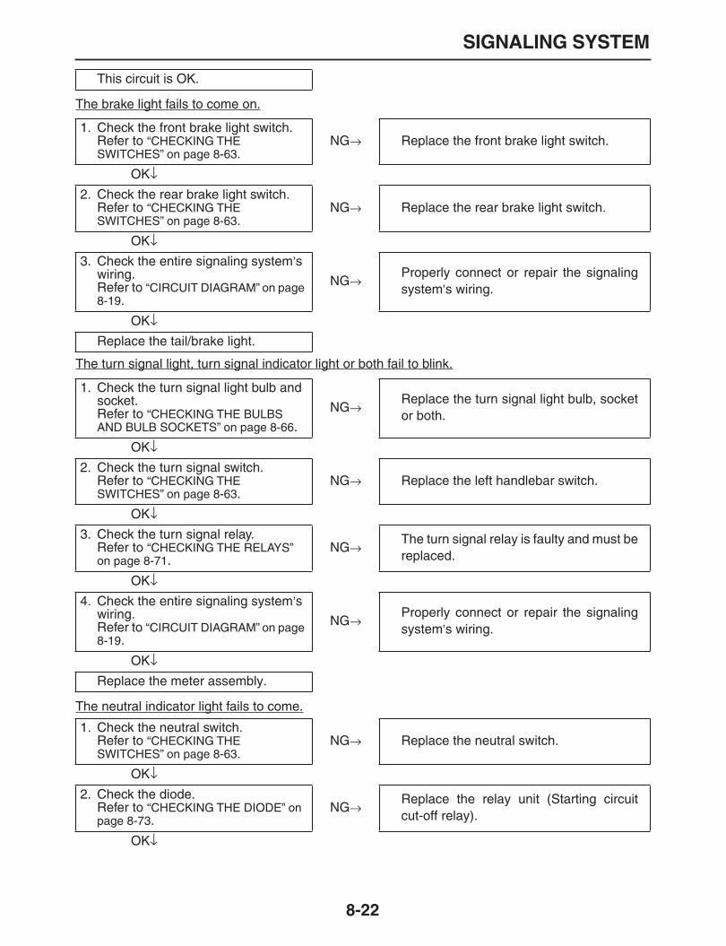
SIGNALING SYSTEM
8-22
The brake light fails to come on.
The turn signal light, turn signal indicator light or both fail to blink.
The neutral indicator light fails to come.
This circuit is OK.
1. Check the front brake light switch.Refer to
“CHECKING THE SWITCHES” on page 8-63
.NG
→
Replace the front brake light switch.
OK
↓
2. Check the rear brake light switch.Refer to
“CHECKING THE SWITCHES” on page 8-63
.NG
→
Replace the rear brake light switch.
OK
↓
3. Check the entire signaling system
’
s wiring.Refer to
“CIRCUIT DIAGRAM” on page 8-19
.
NG
→
Properly connect or repair the signalingsystem
’
s wiring.
OK
↓
Replace the tail/brake light.
1. Check the turn signal light bulb and socket.Refer to
“CHECKING THE BULBS AND BULB SOCKETS” on page 8-66
.
NG
→
Replace the turn signal light bulb, socketor both.
OK
↓
2. Check the turn signal switch.Refer to
“CHECKING THE SWITCHES” on page 8-63
.NG
→
Replace the left handlebar switch.
OK
↓
3. Check the turn signal relay.Refer to
“CHECKING THE RELAYS” on page 8-71
.NG
→
The turn signal relay is faulty and must bereplaced.
OK
↓
4. Check the entire signaling system
’
s wiring.Refer to
“CIRCUIT DIAGRAM” on page 8-19
.
NG
→
Properly connect or repair the signalingsystem
’
s wiring.
OK
↓
Replace the meter assembly.
1. Check the neutral switch.Refer to
“CHECKING THE SWITCHES” on page 8-63
.NG
→
Replace the neutral switch.
OK
↓
2. Check the diode.Refer to
“CHECKING THE DIODE” on page 8-73
.NG
→
Replace the relay unit (Starting circuitcut-off relay).
OK
↓

SIGNALING SYSTEM
8-23
The speedometer fails to operate.
The fuel level warning light fails to come.
The coolant temperature warning light fails to operate.
3. Check the entire signaling system
’
s wiring.Refer to
“CIRCUIT DIAGRAM” on page 8-19
.
NG
→
Properly connect or repair the signalingsystem
’
s wiring.
OK
↓
Replace the meter assembly.
1.
Check the speed sensor.Refer to
“CHECKING THE SPEED SENSOR” on page 8-77
.NG
→
Replace the speed sensor.
OK
↓
2. Check the entire signaling system
’
s wiring.Refer to
“CIRCUIT DIAGRAM” on page 8-19
.
NG
→
Properly connect or repair the signalingsystem
’
s wiring.
OK
↓
Replace the meter assembly.
1. Check the fuel sender.Refer to
“CHECKING THE FUEL SENDER (FUEL PUMP)” on page 8-78
.NG
→
Replace the fuel pump assembly.
OK
↓
2. Check the entire signaling system
’
s wiring.Refer to
“CIRCUIT DIAGRAM” on page 8-19
.
NG
→
Properly connect or repair the signalingsystem
’
s wiring.
OK
↓
Replace the meter assembly.
1.
Check the coolant temperature sen-sor.Refer to
“CHECKING THE COOLANT TEMPERATURE SENSOR” on page 8-78
.
NG
→
Replace the coolant temperature sensor.
OK
↓
2. Check the entire signaling system
’
s wiring.Refer to
“CIRCUIT DIAGRAM” on page 8-19
.
NG
→
Properly connect or repair the signalingsystem
’
s wiring.
OK
↓
Replace the meter, ECU or both.

SIGNALING SYSTEM
8-24

COOLING SYSTEM
8-25
EAS27300
COOLING SYSTEM
EAS27310
CIRCUIT DIAGRAM

COOLING SYSTEM
8-26
3. Main switch4. Battery5. Main fuse16. ECU23. Coolant temperature sensor52. Radiator fan motor relay53. Radiator fan motor56. Ignition fuse57. Radiator fan fuse

COOLING SYSTEM
8-27
EAS27320
TROUBLESHOOTING
The radiator fan fails to operate.NOTE:
Before troubleshooting, remove the following part (s):1. Seat2. Side cover (left)3. Air scoop (left/right)4. Fuel tank5. Radiator cover
6. Drain the coolant.
1. Check the fuses.(Main, ignition and radiator fan fuse)Refer to
“CHECKING THE FUSES” on page 8-67
.
NG
→
Replace the fuse (s).
OK
↓
2. Check the battery.Refer to
“CHECKING AND CHARG-ING THE BATTERY” on page 8-68
.NG
→
Clean the battery terminals.
Recharge or replace the battery.
OK
↓
3. Check the main switch.Refer to
“CHECKING THE SWITCHES” on page 8-63
.NG
→
Replace the main switch.
OK
↓
4. Check the radiator fan motor relay.Refer to
“CHECKING THE RELAYS” on page 8-71
.NG
→
Replace the radiator fan motor relay.
OK
↓
5. Check the radiator fan motor.Refer to
“CHECKING THE RADIATOR FAN MOTOR” on page 8-79
.NG
→
The radiator fan motor is faulty and mustbe replaced.
OK
↓
6. Check the coolant temperature.Refer to
“CHECKING THE COOLANT TEMPERATURE SENSOR” on page 8-78
.
NG
→
Replace the coolant temperature sensor.
OK
↓
7. Check the entire cooling system
’
s wiring.Refer to
“CIRCUIT DIAGRAM” on page 8-25
.
NG
→
Properly connect or repair the coolingsystem
’
s wiring.
OK
↓
Replace the ECU.

COOLING SYSTEM
8-28

FUEL INJECTION SYSTEM
8-29
EAS27330
FUEL INJECTION SYSTEM
EAS27340
CIRCUIT DIAGRAM

FUEL INJECTION SYSTEM
8-30
1. AC magneto3. Main switch4. Battery5. Main fuse6. Starter relay8. Right handlebar switch9. Engine stop switch10. Start switch11. Relay unit12. Sidestand switch13. Neutral switch14. Clutch switch15. Fuel pump16. ECU17. Ignition coil18. Spark plug19. ITS solenoid20. Fuel injector21. AI solenoid22. Intake air temperature sensor23. Coolant temperature sensor24. Speed sensor25. Throttle position sensor26. Intake air pressure sensor27. Lean angle sensor28. EXUP servo motor32. Engine trouble warning light42. Headlight relay52. Radiator fan motor relay54. Headlight fuse55. Signaling system fuse56. Ignition fuse58. EFI fuse59. Backup fuse

FUEL INJECTION SYSTEM
8-31
EAS27350
ECU SELF-DIAGNOSTIC FUNCTION
The ECU is equipped with a self-diagnostic function in order to ensure that the fuel injection system isoperating normally. If this function detects a malfunction in the system, it immediately operates the en-gine under substitute characteristics and illuminates the engine trouble warning light to alert the riderthat a malfunction has occurred in the system. Once a malfunction has been detected, a fault code isstored in the memory of the ECU.
To inform the rider that the fuel injection system is not functioning, the engine trouble warning lightflashes when the start switch is being pushed to start the engine.
If a malfunction is detected in the system by the self-diagnostic function, the ECU provides an appro-priate substitute characteristic operation, and alerts the rider of the detected malfunction by illuminat-ing the engine trouble warning light.
After the engine has been stopped, the lowest fault code number appears on the clock LCD. Once afault code has been displayed, it remains stored in the memory of the ECU until it is deleted.
Engine trouble warning light indication and FI system operation
* The warning light flashes when any one of the conditions listed below is present and the start switch is pushed:
Checking for a defective engine trouble warning light bulb
The engine trouble warning light comes on for 1.4 seconds after the main switch has been turned to“ON” and when the start switch is being pushed. If the warning light does not come on under these con-ditions, the warning light bulb may be defective.
Warning light indication ECU operation FI operation Vehicle operation
Flashing* Warning provided when unable to start engine Operation stopped Cannot be operated
Remains on Malfunction detected
Operated with substitute characteristics in accor-dance with the descrip-tion of the malfunction
Can or cannot be oper-ated depending on the fault code
12: Crankshaft position sensor 41: Lean angle sensor(open or short-circuit)
19: Sidestand switch(open circuit in the wire to the ECU) 50: ECU internal malfunction
(faulty ECU memory)
30: Lean angle sensor(Latch up detected)
33:Ignition coil(Malfunction detected in the primary wire of
the ignition coil)
a b
cc d
a. Main switch OFFb. Main switch ONc. Light OFFd. Light ON for 1.4 seconds
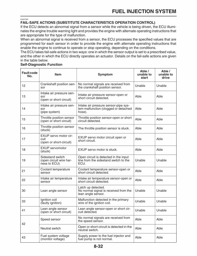
FUEL INJECTION SYSTEM
8-32
EAS27393
FAIL-SAFE ACTIONS (SUBSTITUTE CHARACTERISTICS OPERATION CONTROL)
If the ECU detects an abnormal signal from a sensor while the vehicle is being driven, the ECU illumi-nates the engine trouble warning light and provides the engine with alternate operating instructions thatare appropriate for the type of malfunction.When an abnormal signal is received from a sensor, the ECU processes the specified values that areprogrammed for each sensor in order to provide the engine with alternate operating instructions thatenable the engine to continue to operate or stop operating, depending on the conditions.The ECU takes fail-safe actions in two ways: one in which the sensor output is set to a prescribed value,and the other in which the ECU directly operates an actuator. Details on the fail-safe actions are givenin the table below.
Self-Diagnostic Function
Fault code No. Item Symptom
Able / unable to
start
Able / unable to
drive
12 Crankshaft position sen-sor
No normal signals are received from the crankshaft position sensor. Unable Unable
13Intake air pressure sen-sor(open or short circuit)
Intake air pressure sensor-open or short circuit detected. Able Able
14Intake air pressure sen-sor(pipe system)
Intake air pressure sensor-pipe sys-tem malfunction (clogged or detached hose).
Able Able
15 Throttle position sensor(open or short circuit)
Throttle position sensor-open or short circuit detected. Able Able
16 Throttle position sensor(stuck) The throttle position sensor is stuck. Able Able
17EXUP servo motor cir-cuit(open or short-circuit)
EXUP servo motor circuit open or short circuit. Able Able
18 EXUP servomotor(stuck) EXUP servo motor is stuck. Able Able
19Sidestand switch(open circuit wire har-ness to ECU)
Open circuit is detected in the input line from the sidestand switch to the ECU.
Unable Unable
21 Coolant temperature sensor
Coolant temperature sensor-open or short circuit detected. Able Able
22 Intake air temperature sensor
Intake air temperature sensor-open or short circuit detected. Able Able
30 Lean angle sensorLatch up detected.No normal signal is received from the lean angle sensor.
Unable Unable
33 Ignition coil(faulty ignition)
Malfunction detected in the primary wire of the ignition coil. Unable Unable
41 Lean angle sensor(open or short circuit)
Lean angle sensor-open or short cir-cuit detected. Unable Unable
42Speed sensor No normal signals are received from
the speed sensor. Able Able
Neutral switch Open or short circuit is detected in the neutral switch. Able Able
43 Fuel system voltage(monitor voltage)
Supply power to the fuel injector and fuel pump is not normal. Able Able

FUEL INJECTION SYSTEM
8-33
Communication error with the multifunction meter
* If multiple malfunctions have been detected for the ECU, you may not be able to start or drive the vehicle.
44Error in writing the amount of CO adjust-ment on EEPROM
Error is detected while reading or writ-ing on EEPROM (code re-registering key code and throttle valve fully closed notification value).
Able Able
46Vehicle system power supply(Monitor voltage)
Power supply to the ECU system relay is not normal. Able Able
50ECU internal malfunc-tion(memory check error)
Faulty ECU memory. (When this mal-function is detected in the ECU, the fault code number might not appear on the meter.)
Unable Unable
70 Left idle control After 20 minutes left idling, the ECU automatically stops the engine. Able Able
— Start unable warning
Engine trouble warning light flashes when the start switch is turned ON.Relay is not turned ON even if the crank signal is input while the start switch is turned ON.When the start switch is turned ON while an error is detected with the fault code of No.12, 19, 30, 41 or 50.
Unable Unable
Fault code No. Item Symptom
Able / unable to
start
Able / unable to
drive
Er-1ECU internal malfunc-tion(output signal error)
No signals are received from the ECU. Able* Able*
Er-2ECU internal malfunc-tion(output signal error)
No signals are received from the ECU within the specified duration. Able* Able*
Er-3ECU internal malfunc-tion(output signal error)
Data from the ECU cannot be received correctly. Able* Able*
Er-4ECU internal malfunc-tion(input signal error)
Non-registered data has been received from the meter. Able* Able*
Fault code No. Item Symptom
Able / unable to
start
Able / unable to
drive
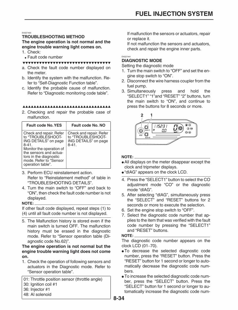
FUEL INJECTION SYSTEM
8-34
EAS27400
TROUBLESHOOTING METHODThe engine operation is not normal and theengine trouble warning light comes on.
1. Check:
Fault code number
a. Check the fault code number displayed onthe meter.
b. Identify the system with the malfunction. Re-fer to “Self-Diagnostic Function table”.
c. Identify the probable cause of malfunction.Refer to “Diagnostic monitoring code table”.
2. Checking and repair the probable case ofmalfunction.
3. Perform ECU reinstatement action.Refer to “Reinstatement method” of table in“TROUBLESHOOTING DETAILS”.
4. Turn the main switch to “OFF” and back to“ON”, then check the fault code number is notdisplayed.
NOTE:
If other fault code displayed, repeat steps (1) to
(4) until all fault code number is not displayed.
5. The Malfunction history is stored even if themain switch is turned OFF. The malfunctionhistory must be erased in the diagnosticmode. Refer to “Sensor operation table (Di-agnostic code No.62)”.
The engine operation is not normal but theengine trouble warning light does not comeon.
1. Check the operation of following sensors andactuators in the Diagnostic mode. Refer to“Sensor operation table”.
If malfunction the sensors or actuators, repairor replace it.If not malfunction the sensors and actuators,check and repair the engine inner parts.
EAS27441
DIAGNOSTIC MODE
Setting the diagnostic mode1. Turn the main switch to “OFF” and set the en-
gine stop switch to “ON”.2. Disconnect the wire harness coupler from the
fuel pump.3. Simultaneously press and hold the
“SELECT1” “1”and “RESET” “2” buttons, turnthe main switch to “ON”, and continue topress the buttons for 8 seconds or more.
NOTE:
All displays on the meter disappear except theclock and tripmeter displays.
“dIAG” appears on the clock LCD.
4. Press the “SELECT1” button to select the COadjustment mode “CO” or the diagnosticmode “dIAG”.
5. After selecting “dIAG”, simultaneously pressthe “SELECT” and “RESET” buttons for 2seconds or more to execute the selection.
6. Set the engine stop switch to “OFF”.7. Select the diagnostic code number that ap-
plies to the item that was verified with the faultcode number by pressing the “SELECT1”and “RESET” buttons.
NOTE:
The diagnostic code number appears on theclock LCD (01
–
70).
To decrease the selected diagnostic codenumber, press the “RESET” button. Press the“RESET” button for 1 second or longer to auto-matically decrease the diagnostic code num-bers.
To increase the selected diagnostic code num-ber, press the “SELECT” button. Press the“SELECT” button for 1 second or longer to au-tomatically increase the diagnostic code num-
Fault code No. YES Fault code No. NO
Check and repair. Refer to “TROUBLESHOOT-ING DETAILS” on page 8-41.Monitor the operation of the sensors and actua-tors in the diagnostic mode. Refer to “Sensor operation table”.
Check and repair. Refer to “TROUBLESHOOT-ING DETAILS” on page 8-41.
01: Throttle position sensor (throttle angle)30: Ignition coil #136: Injector #148: AI solenoid
2 1

FUEL INJECTION SYSTEM
8-35
bers.
8. Verify the operation of the sensor or actuator.
Sensor operationThe data representing the operating condi-tions of the sensor appears on the trip LCD.
Actuator operationSet the engine stop switch to “ON” to operatethe actuator.
NOTE:
If the engine stop switch is set to “ON”, set it to
“OFF”, and then set it to “ON” again.
9. Turn the main switch to “OFF” to cancel thediagnostic mode.

FUEL INJECTION SYSTEM
8-36
Diagnostic code table
Fault code No.
Symptom Probable cause of malfunction Diagnostic code No.
12No normal signals are received from the crankshaft position sensor.
Open or short circuit in wire harness.
Defective crankshaft position sensor.
Malfunction in pickup rotor.
Malfunction in ECU.
Improperly installed sensor.
—
13Intake air pressure sen-sor-open or short circuit detected.
Open or short circuit in wire harness.
Defective intake air pressure sensor.
Malfunction in ECU.
03
14Intake air pressure sen-sor-pipe system malfunction (clogged hose).
Intake air pressure sensor hose is clogged.
Malfunction in ECU.
03
15 Throttle position sensor-open or short circuit detected.
Open or short circuit in wire harness.
Defective throttle position sensor.
Malfunction in ECU.
01
16 Stuck throttle position sensor detected.
Stuck throttle position sensor.
Malfunction in ECU.
01
17 EXUP servo motor circuit open or short circuit.
Open circuit in wire harness.
Defective EXUP servo motor.
ECU is defective.
53
18 EXUP servo motor is stuck.
Open circuit in wire harness.
EXUP servo motor lockup (valve or motor)
53
19Open circuit is detected in the input line from the sidestand switch to the ECU.
Open or short circuit in wire harness.
Malfunction in ECU.
20
21Coolant temperature sen-sor-open or short circuit detected.
Open or short circuit in wire harness.
Defective coolant temperature sensor.
Malfunction in ECU.
06
22Intake air temperature sen-sor-open or short circuit detected.
Open or short circuit in wire harness.
Defective intake temperature sensor.
Malfunction in ECU.
Improperly installed intake air temperature sensor.
05
30Latch up detected.No normal signal is received from the lean angle sensor.
The vehicle has overturned.
Defective lean angle sensor.
Malfunction in ECU.
Improperly installed lean angle sensor.
08
33Malfunction detected in the primary wire of the ignition coil.
Open or short circuit in wire harness.
Malfunction in ignition coil.
Malfunction in ECU.
Malfunction in a component of ignition cut-off circuit system.
30
41 Lean angle sensor-open or short circuit detected.
Open or short circuit in wire harness.
Defective lean angle sensor.
Malfunction in ECU.
08

FUEL INJECTION SYSTEM
8-37
Sensor operation table
42
No normal signals are received from the speed sen-sor.
Open or short circuit in wiring harness.
Defective speed sensor.
Malfunction in vehicle speed sensor detected unit.
Malfunction in ECU.
07
Open or short circuit in neutral switch.
Open circuit in wire harness.
Defective neutral switch.
ECU is defective.
21
43Supply power to the fuel injec-tor and fuel pump is not nor-mal.
Open circuit in wire harness.
Malfunction in ECU.
Defective relay unit (fuel pump).
09
44 Error is detected while read-ing or writing on EEPROM.
Malfunction in ECU. (CO concentration adjustment valve cannot be correctly writ-ten to or read from internal memory)
60
46 Power supply to the FI system relay is not normal.
Malfunction in charging system.
—
50
Faulty ECU memory. (When this malfunction is detected in the ECU, the fault code num-ber might not appear on the meter.)
Malfunction in ECU. (The program and data are not properly written on or read from the internal memory.)
—
70 Left idle control
After 20 minutes left idling, the ECU auto-matically stops the engine.
—
Er-1 No signals are received from the ECU.
Open or short circuit in communication line.
Malfunction in meter unit.
Malfunction in ECU.
—
Er-2No signals are received from the ECU within the specified duration.
Open or short circuit in communication line.
Malfunction in meter unit.
Malfunction in ECU.
—
Er-3 Data from the ECU cannot be received correctly.
Open or short circuit in communication line.
Malfunction in meter unit.
Malfunction in ECU.
—
Er-4 Non-registered data has been received from the meter.
Open or short circuit in communication line.
Malfunction in meter unit.
Malfunction in ECU.
—
Fault code No.
Symptom Probable cause of malfunction Diagnostic code No.
Diagnostic
monitoring code
No.
Item Meter display Checking method
01 Throttle angle
Fully closed position 15
–
19 Check with throttle fully closed.
Fully opened position 95
–
100 Check with throttle fully open.
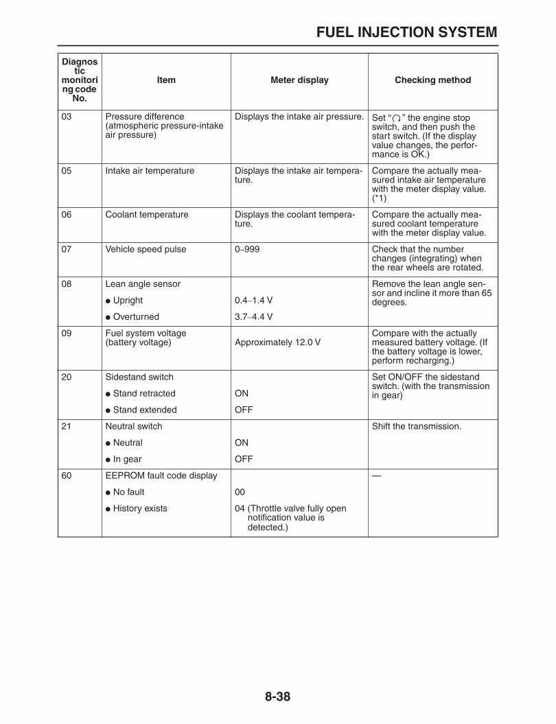
FUEL INJECTION SYSTEM
8-38
03 Pressure difference(atmospheric pressure-intake air pressure)
Displays the intake air pressure. Set “ ” the engine stop switch, and then push the start switch. (If the display value changes, the perfor-mance is OK.)
05 Intake air temperature Displays the intake air tempera-ture.
Compare the actually mea-sured intake air temperature with the meter display value. (*1)
06 Coolant temperature Displays the coolant tempera-ture.
Compare the actually mea-sured coolant temperature with the meter display value.
07 Vehicle speed pulse 0
–
999 Check that the number changes (integrating) when the rear wheels are rotated.
08 Lean angle sensor Remove the lean angle sen-sor and incline it more than 65 degrees.
Upright 0.4
–
1.4 V
Overturned 3.7
–
4.4 V
09 Fuel system voltage(battery voltage) Approximately 12.0 V
Compare with the actually measured battery voltage. (If the battery voltage is lower, perform recharging.)
20 Sidestand switch Set ON/OFF the sidestand switch. (with the transmission in gear)
Stand retracted ON
Stand extended OFF
21 Neutral switch Shift the transmission.
Neutral ON
In gear OFF
60 EEPROM fault code display —
No fault 00
History exists 04 (Throttle valve fully open notification value is detected.)
Diagnostic
monitoring code
No.
Item Meter display Checking method
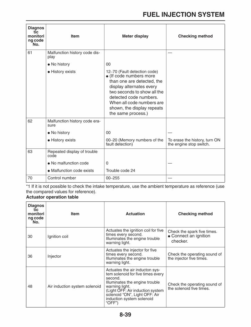
FUEL INJECTION SYSTEM
8-39
*1 If it is not possible to check the intake temperature, use the ambient temperature as reference (usethe compared values for reference).
Actuator operation table
61 Malfunction history code dis-play
—
No history 00
History exists 12
–
70 (Fault detection code)
(If code numbers more than one are detected, the display alternates every two seconds to show all the detected code numbers. When all code numbers are shown, the display repeats the same process.)
62 Malfunction history code era-sure
No history 00 —
History exists 00
–
20 (Memory numbers of the fault detection)
To erase the history, turn ON the engine stop switch.
63 Repeated display of trouble code
No malfunction code 0 —
Malfunction code exists Trouble code 24
70 Control number 00
–
255 —
Diagnostic
monitoring code
No.
Item Meter display Checking method
Diagnostic
monitoring code
No.
Item Actuation Checking method
30 Ignition coil
Actuates the ignition coil for five times every second.Illuminates the engine trouble warning light.
Check the spark five times.
Connect an ignition checker.
36 Injector
Actuates the injector for five times every second.Illuminates the engine trouble warning light.
Check the operating sound of the injector five times.
48 Air induction system solenoid
Actuates the air inducton sys-tem solenoid for five times every second.Illuminates the engine trouble warning light.(Light OFF: Air induction system solenoid “ON”, Light OFF: Air induction system solenoid “OFF”)
Check the operating sound of the solenoid five times.

FUEL INJECTION SYSTEM
8-40
49 Intake solenoid
Actuates the intake solenoid for five times every second.Illuminates the engine trouble warning light.
Check the operating sound of the solenoid five times.
50 Fuel injection system relay
Actuates the fuel injection sys-tem relay for five times every second.Illuminates the engine trouble warning light.(The engine trouble warning light is OFF when the relay is ON, and the engine trouble warning light is ON when the relay is OFF).
Check the operating sound of the relay five times.
51 Radiator fan motor relay
Actuates the radiator fan motor relay for five times every sec-ond. (ON two seconds, OFF three seconds)Illuminates the engine trouble warning light.
Check the operating sound of the relay five times.
52 Headlight relay
Actuates the headlight relay for five times every five-second. (ON two seconds, OFF three seconds)Illuminates the engine trouble warning light five times.
Check the operating sound of the headlight relay five times.
53 EXUP servo motor
Turn the servo motor once in the open direction and then in the close direction.Illuminates the engine trouble warning light.
Check the operating sound of the EXUP motor.
Diagnostic
monitoring code
No.
Item Actuation Checking method

FUEL INJECTION SYSTEM
8-41
EAS27480
TROUBLESHOOTING DETAILS
This section describes the measures per fault code number displayed on the meter. Carry out checkand maintenance on items or components that could be a cause of malfunction in accordance with theorder.When the check and maintenance of malfunctioned part is completed, restore the meter display ac-cording to the “Reinstatement method”.Fault code No.:Fault code number displayed on the meter when the engine failed to work normally. Refer to “DIAG-NOSTIC MODE” on page 8-34.Diagnostic monitoring code No.:Code number to be used when the diagnostic monitoring mode is operated. Refer to “DIAGNOSTICMODE” on page 8-34.
Fault code No. 12 Symptom No normal signals are received from the crankshaft position sensor.
Diagnostic monitoring code No. — —
Order Item/components and probable cause Check or maintenance job Reinstatement method
1 Installed condition of crankshaft position sensor
Check the installed area for loose-ness or pinching.
Cranking the engine.
2 Connected state of connector
Crankshaft position sensor coupler
Main wire harness ECU coupler
Check the coupler for any pins that may have pulled out.
Check the locking condition of the coupler.
If there is a malfunction, repair it and connect it securely.
3 Open or short circuit in wire harness.
Repair or replace if there is an open or short circuit.
Between the crankshaft position sensor coupler and ECU coupler.
(Green/White
–
Green/White)(Black/Blue
–
Black/Blue)
4 Defective crankshaft position sensor.
Replace if defective.
Refer to “CHECKING THECRANKSHAFT POSITION SEN-SOR” on page 8-75.
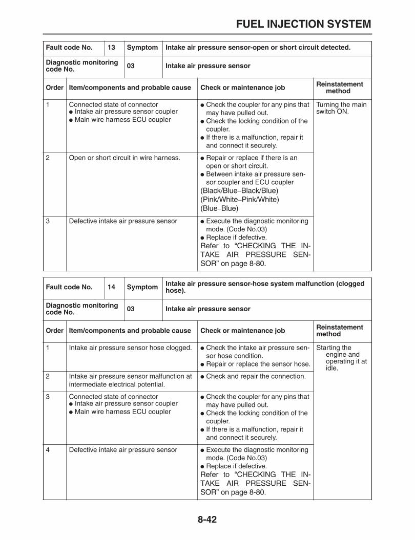
FUEL INJECTION SYSTEM
8-42
Fault code No. 13 Symptom Intake air pressure sensor-open or short circuit detected.
Diagnostic monitoring code No. 03 Intake air pressure sensor
Order Item/components and probable cause Check or maintenance job Reinstatement method
1 Connected state of connector
Intake air pressure sensor coupler
Main wire harness ECU coupler
Check the coupler for any pins that may have pulled out.
Check the locking condition of the coupler.
If there is a malfunction, repair it and connect it securely.
Turning the main switch ON.
2 Open or short circuit in wire harness.
Repair or replace if there is an open or short circuit.
Between intake air pressure sen-sor coupler and ECU coupler
(Black/Blue
–
Black/Blue)(Pink/White
–
Pink/White)(Blue
–
Blue)
3 Defective intake air pressure sensor
Execute the diagnostic monitoring mode. (Code No.03)
Replace if defective.
Refer to “CHECKING THE IN-TAKE AIR PRESSURE SEN-SOR” on page 8-80.
Fault code No. 14 Symptom Intake air pressure sensor-hose system malfunction (clogged hose).
Diagnostic monitoring code No. 03 Intake air pressure sensor
Order Item/components and probable cause Check or maintenance job Reinstatement method
1 Intake air pressure sensor hose clogged.
Check the intake air pressure sen-sor hose condition.
Repair or replace the sensor hose.
Starting the engine and operating it at idle.
2 Intake air pressure sensor malfunction at intermediate electrical potential.
Check and repair the connection.
3 Connected state of connector
Intake air pressure sensor coupler
Main wire harness ECU coupler
Check the coupler for any pins that may have pulled out.
Check the locking condition of the coupler.
If there is a malfunction, repair it and connect it securely.
4 Defective intake air pressure sensor
Execute the diagnostic monitoring mode. (Code No.03)
Replace if defective.
Refer to “CHECKING THE IN-TAKE AIR PRESSURE SEN-SOR” on page 8-80.
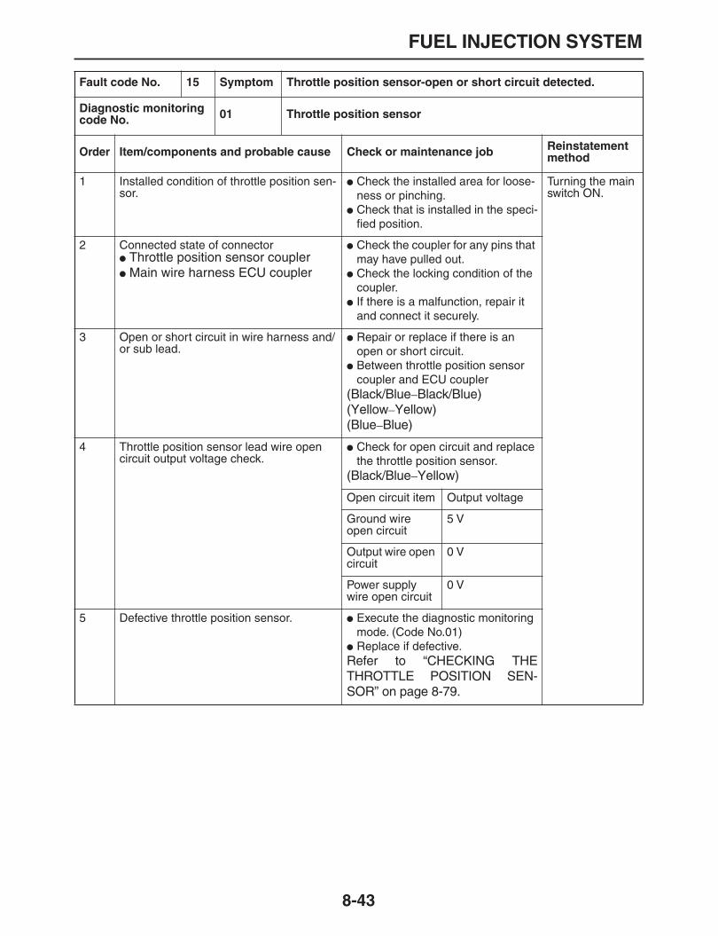
FUEL INJECTION SYSTEM
8-43
Fault code No. 15 Symptom Throttle position sensor-open or short circuit detected.
Diagnostic monitoring code No. 01 Throttle position sensor
Order Item/components and probable cause Check or maintenance job Reinstatement method
1 Installed condition of throttle position sen-sor.
Check the installed area for loose-ness or pinching.
Check that is installed in the speci-fied position.
Turning the main switch ON.
2 Connected state of connector
Throttle position sensor coupler
Main wire harness ECU coupler
Check the coupler for any pins that may have pulled out.
Check the locking condition of the coupler.
If there is a malfunction, repair it and connect it securely.
3 Open or short circuit in wire harness and/or sub lead.
Repair or replace if there is an open or short circuit.
Between throttle position sensor coupler and ECU coupler
(Black/Blue
–
Black/Blue)(Yellow
–
Yellow)(Blue
–
Blue)
4 Throttle position sensor lead wire open circuit output voltage check.
Check for open circuit and replace the throttle position sensor.
(Black/Blue
–
Yellow)
Open circuit item Output voltage
Ground wire open circuit
5 V
Output wire open circuit
0 V
Power supply wire open circuit
0 V
5 Defective throttle position sensor.
Execute the diagnostic monitoring mode. (Code No.01)
Replace if defective.
Refer to “CHECKING THETHROTTLE POSITION SEN-SOR” on page 8-79.

FUEL INJECTION SYSTEM
8-44
Fault code No. 16 Symptom Stuck throttle position sensor detected.
Diagnostic monitoring code No. 01 Throttle position sensor
Order Item/components and probable cause Check or maintenance job Reinstatement method
1 Installed condition of throttle position sen-sor.
Check the installed area for loose-ness or pinching.
Check that is installed in the speci-fied position.
Reinstated by starting the engine, operating it at idle.And then racing it.2 Defective throttle position sensor.
Execute the diagnostic monitoring mode. (Code No.01)
Replace if defective.
Refer to “CHECKING THETHROTTLE POSITION SEN-SOR” on page 8-79.
Fault code No. 17 Symptom EXUP servo motor circuit open or short circuit
Diagnostic monitoring code No. 53 EXUP servo motor
Order Item/components and probable cause Check or maintenance job Reinstatement method
1 Connected state of connector.
EXUP servo motor coupler
Wire harness ECU coupler
Check the coupler for any pins that may have pulled out.
Check the locking condition of the coupler.
If there is a malfunction, repair it and connect it securely.
Turn the main switch to “ON”.
2 Open or short circuit in wire harness.
Repair or replace if there is an open or short circuit.
Between EXUP servo motor cou-pler and ECU coupler
(Black/Blue
–
Black/Blue)(White/Red
–
White/Red)(Blue
–
Blue)
3 Defective EXUP servo motor
Execute the diagnostic monitoring mode. (Code No.53)
Replace if defective.

FUEL INJECTION SYSTEM
8-45
Fault code No. 18 Symptom EXUP servo motor is stuck.
Diagnostic monitoring code No. 53 EXUP servo motor
Order Item/components and probable cause Check or maintenance job Reinstatement method
1 Connected state of connector.
EXUP servo motor coupler
Wire harness ECU coupler
Check the coupler for any pins that may have pulled out.
Check the locking condition of the coupler.
If there is a malfunction, repair it and connect it securely.
Turn the main switch to “ON”.
2 Open or short circuit in wire harness.
Repair or replace if there is an open or short circuit.
Between EXUP servo motor cou-pler and ECU coupler
(Black/Red
–
Black/Red)(Black/Green
–
Black/Green)
3 Defective EXUP servo motor
Execute the diagnostic monitoring mode. (Code No.53)
Replace if defective.
4 Defective EXUP valve, pully and cable.
Replace if defective.
Fault code No. 19 Symptom Open circuit is detected in the input line from the sidestand switch to the ECU.
Diagnostic monitoring code No. 20 Sidestand switch
Order Item/components and probable cause Check or maintenance job Reinstatement method
1 Connected state of connector
Main wire harness ECU coupler
Execute the diagnostic monitoring mode. (Code No.20)
Check the coupler for any pins that may have pulled out.
Check the locking condition of the coupler.
If there is a malfunction, repair it and connect it securely.
If the transmis-sion is in gear, retracting the sidestand.If the transmis-sion is in neutral, reconnecting the wiring.
2 Open or short circuit in wire harness.
Repair or replace if there is an open or short circuit.
Between relay unit and main switch coupler.
(Blue/Yellow
–
Blue/Yellow)
Between ECU and main switch coupler.
(Blue/Black
–
Blue/Black)
3 Defective sidestand switch.
Replace if defective.
Refer to “CHECKING THESWITCHES” on page 8-63.

FUEL INJECTION SYSTEM
8-46
Fault code No. 21 Symptom Coolant temperature sensor-open or short circuit detected.
Diagnostic monitoring code No. 06 Coolant temperature sensor
Order Item/components and probable cause Check or maintenance job Reinstatement method
1 Installed condition of coolant temperature sensor.
Check the installed area for loose-ness or pinching.
Turning the main switch ON.
2 Connected state of connector
Coolant temperature sensor coupler
Main wire harness ECU coupler
Sub-wire harness coupler
Check the coupler for any pins that may have pulled out.
Check the locking condition of the coupler.
If there is a malfunction, repair it and connect it securely.
3 Open or short circuit in wire harness and/or sub lead.
Repair or replace if there is an open or short circuit.
Between coolant temperature sen-sor coupler and ECU coupler.
(Black
–
Black/Blue)(Black
–
Green/Red)
4 Defective coolant temperature sensor.
Execute the diagnostic monitoring mode. (Code No.06)
Replace if defective.
Refer to “CHECKING THE COOL-ANT TEMPERATURE SENSOR”on page 8-78.

FUEL INJECTION SYSTEM
8-47
Fault code No. 22 Symptom Intake air temperature sensor-open or short circuit detected.
Diagnostic monitoring code No. 05 Intake air temperature sensor
Order Item/components and probable cause Check or maintenance job Reinstatement method
1 Installed condition of intake air tempera-ture sensor.
Check the installed area for loose-ness or pinching.
Turning the main switch ON.
2 Connected state of connector
Intake air temperature sensor coupler
Main wire harness ECU coupler
Check the coupler for any pins that may have pulled out.
Check the locking condition of the coupler.
If there is a malfunction, repair it and connect it securely.
3 Open or short circuit in wire harness and/or sub lead.
Repair or replace if there is an open or short circuit.
Between intake air temperature sensor coupler and ECU coupler.
(Black/Blue
–
Black/Blue)(Brown/White
–
Brown/White)
4 Defective intake air temperature sensor.
Execute the diagnostic monitoring mode. (Code No.05)
Replace if defective.
Refer to “CHECKING THE IN-TAKE AIR TEMPERATURE SEN-SOR” on page 8-80.
Fault code No. 30 Symptom Latch up detected.No normal signal is received from the lean angle sensor.
Diagnostic monitoring code No. 08 Lean angle sensor
Order Item/components and probable cause Check or maintenance job Reinstatement method
1 The vehicle has overturned.
Raise the vehicle upright. Turning the main switch ON (how-ever, the engine cannot be restarted unless the main switch is first turned OFF).
2 Installed condition of the lean angle sen-sor
Check the installed area for loose-ness or pinching.
3 Connected state of connector
Lean angle sensor coupler
Main wire harness ECU coupler
Check the coupler for any pins that may have pulled out.
Check the locking condition of the coupler.
If there is a malfunction, repair it and connect it securely.
4 Defective lean angle sensor.
Execute the diagnostic monitoring mode. (Code No.08)
Replace if defective.

FUEL INJECTION SYSTEM
8-48
Fault code No. 33 Symptom Malfunction detected in the primary wire of the ignition coil.
Diagnostic monitoring code No. 30 Ignition coil
Order Item/components and probable cause Check or maintenance job Reinstatement method
1 Connected state of connector
Ignition coil primary side coupler (Orange)
Main wire harness ECU coupler
Check the coupler for any pins that may have pulled out.
Check the locking condition of the coupler.
If there is a malfunction, repair it and connect it securely.
Starting the engine and oper-ating it at idle.
2 Open or short circuit in wire harness or sub lead.
Repair or replace if there is an open or short circuit.
Between ignition coil coupler and ECU coupler/main wire harness.
(Orange
–
Orange)
3 Defective ignition coil
Execute the diagnostic monitoring mode. (Code No.30)
Test the primary and secondary coils for continuity.
Replace if defective.
Refer to “CHECKING THE IGNI-TION COIL” on page 8-74.
Fault code No. 41 Symptom Lean angle sensor-open or short circuit detected.
Diagnostic monitoring code No. 08 Lean angle sensor
Order Item/components and probable cause Check or maintenance job Reinstatement method
1 Connected state of connector
Lean angle sensor coupler
Main wire harness ECU coupler
Check the coupler for any pins that may have pulled out.
Check the locking condition of the coupler.
If there is a malfunction, repair it and connect it securely.
Turning the main switch ON.
2 Open or short circuit in wire harness.
Repair or replace if there is an open or short circuit.
Between switch coupler and ECU coupler.
(Black/Blue
–
Black/Blue)(Yellow/Green
–
Yellow/Green)(Blue
–
Blue)
3 Defective lean angle sensor
Execute the diagnostic monitoring mode. (Code No.08)
Replace if defective.
Refer to “CHECKING THE LEANANGLE SENSOR” on page 8-75.

FUEL INJECTION SYSTEM
8-49
Fault code No. 42 Symptom A. No normal signals are received from the speed sensor.B. Open or short circuit is detected in the neutral switch.
Diagnostic monitoring code No.
A 07 Speed sensor
B 21 Neutral switch
Order Item/components and probable cause Check or maintenance job Reinstatement method
A-1 Installed condition of speed sensor
Check the installed area for loose-ness or pinching.
Starting the engine, and inputting the vehicle speed signals by oper-ating the motor-cycle at a low speed of 20
–
30 km/h.
A-2 Connected state of connector.
Speed sensor coupler
Wire harness ECU coupler
Check the coupler for any pins that may have pulled out.
Check the locking condition of the coupler.
If there is a malfunction, repair it and connect it securely.
A-3 Open or short circuit in speed sensor lead.
Repair or replace if there is an open or short circuit.
Between sensor coupler and ECU coupler.
(Blue
–
Blue)(White
–
White)(Black/Blue
–
Black/Blue)
A-4 Defective speed sensor.
Execute the diagnostic monitoring mode. (Code No.07)
Replace if defective.
Refer to “CHECKING THESPEED SENSOR” on page 8-77.

FUEL INJECTION SYSTEM
8-50
Fault code No. 42 Symptom A. No normal signals are received from the speed sensor.B. Open or short circuit is detected in the neutral switch.
Diagnostic monitoring code No.
A 07 Speed sensor
B 21 Neutral switch
Order Item/components and probable cause Check or maintenance job Reinstatement method
B-1 Installed condition of neutral switch
Check the installed area for loose-ness or pinching.
Turn the main switch to “ON”.
B-2 Connected state of connector.
Neutral switch coupler
Wire harness ECU coupler
Check the coupler for any pins that may have pulled out.
Check the locking condition of the coupler.
If there is a malfunction, repair it and connect it securely.
B-3 Open or short circuit in speed sensor lead.
Repair or replace if there is an open or short circuit.
Between relay unit coupler and ECU coupler
(Black/Yellow
–
Black/Yellow)
Between neutral switch and relay unit coupler
(Sky blue
–
Sky blue)
B-4 Defective neutral switch
Execute the diagnostic monitoring mode. (Code No.21)
Replace if defective.
Refer to “CHECKING THESWITCHES” on page 8-63.
B-5 Defective shift drum (neutral detection location)
Replace if defective.
Refer to “TRANSMISSION” onpage 5-64.

FUEL INJECTION SYSTEM
8-51
Fault code No. 43 Symptom Supply power to the fuel injector and fuel pump is not normal.
Diagnostic monitoring code No. 09 Fuel system voltage
Order Item/components and probable cause Check or maintenance job Reinstatement method
1 Connected state of connector
Relay unit coupler
Fuel pump coupler
Fuel injector coupler
ECU coupler
Check the coupler for any pins that may have pulled out.
Check the locking condition of the coupler.
If there is a malfunction, repair it and connect it securely.
Starting the engine and oper-ating it at idle.
2 Open or short circuit in the wire harness.
Repair or replace if there is an open or short circuit.
Between relay unit and ECU cou-pler
(Red/Blue
–
Red/Blue)
Between relay unit and fuse (EFI)
(Brown/Yellow
–
Brown/Yellow)
Between fuse (EFI) and battery
(Brown/Yellow
–
Brown/Yellow)
3 Faulty battery voltage
Execute the diagnostic monitoring mode. (Code No. 09)
Charge or replace if defective.
Fault code No. 44 Symptom Error is detected while reading or writing on EEPROM (CO adjustment valve).
Diagnostic monitoring code No. 60 EEPROM improper cylinder indication
Order Item/components and probable cause Check or maintenance job Reinstatement method
1 Malfunction in ECU 1. Execute the diagnostic monitoring mode. (Code No. 60)
2. Adjust the CO exhaust gas level, and set the abnormal exhaust gas level.
Set until “0” is shown on the display.
When defect cannot be repaired, replace the ECU.
Turn the main switch to “ON”.(When displayed again, readjust the exhaust gas.)
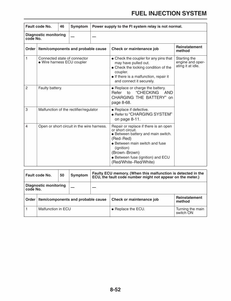
FUEL INJECTION SYSTEM
8-52
Fault code No. 46 Symptom Power supply to the FI system relay is not normal.
Diagnostic monitoring code No. — —
Order Item/components and probable cause Check or maintenance job Reinstatement method
1 Connected state of connector
Wire harness ECU coupler
Check the coupler for any pins that may have pulled out.
Check the locking condition of the coupler.
If there is a malfunction, repair it and connect it securely.
Starting the engine and oper-ating it at idle.
2 Faulty battery.
Replace or charge the battery.
Refer to “CHECKING ANDCHARGING THE BATTERY” onpage 8-68.
3 Malfunction of the rectifier/regulator
Replace if defective.
Refer to
“CHARGING SYSTEM” on page 8-11
.
4 Open or short circuit in the wire harness. Repair or replace if there is an open or short circuit.
Between battery and main switch.
(Red
–
Red)
Between main switch and fuse (ignition)
(Brown
–
Brown)
Between fuse (ignition) and ECU
(Red/White
–
Red/White)
Fault code No. 50 Symptom Faulty ECU memory. (When this malfunction is detected in the ECU, the fault code number might not appear on the meter.)
Diagnostic monitoring code No. — —
Order Item/components and probable cause Check or maintenance job Reinstatement method
1 Malfunction in ECU
Replace the ECU. Turning the main switch ON
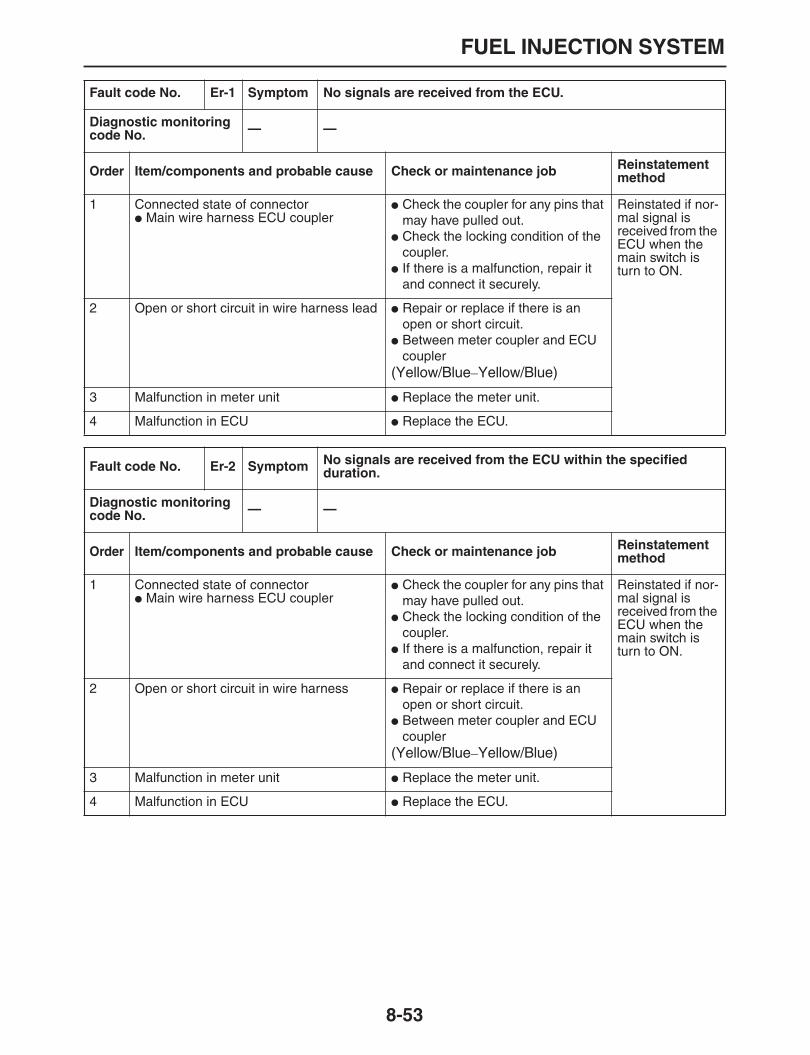
FUEL INJECTION SYSTEM
8-53
Fault code No. Er-1 Symptom No signals are received from the ECU.
Diagnostic monitoring code No. — —
Order Item/components and probable cause Check or maintenance job Reinstatement method
1 Connected state of connector
Main wire harness ECU coupler
Check the coupler for any pins that may have pulled out.
Check the locking condition of the coupler.
If there is a malfunction, repair it and connect it securely.
Reinstated if nor-mal signal is received from the ECU when the main switch is turn to ON.
2 Open or short circuit in wire harness lead
Repair or replace if there is an open or short circuit.
Between meter coupler and ECU coupler
(Yellow/Blue
–
Yellow/Blue)
3 Malfunction in meter unit
Replace the meter unit.
4 Malfunction in ECU
Replace the ECU.
Fault code No. Er-2 Symptom No signals are received from the ECU within the specified duration.
Diagnostic monitoring code No. — —
Order Item/components and probable cause Check or maintenance job Reinstatement method
1 Connected state of connector
Main wire harness ECU coupler
Check the coupler for any pins that may have pulled out.
Check the locking condition of the coupler.
If there is a malfunction, repair it and connect it securely.
Reinstated if nor-mal signal is received from the ECU when the main switch is turn to ON.
2 Open or short circuit in wire harness
Repair or replace if there is an open or short circuit.
Between meter coupler and ECU coupler
(Yellow/Blue
–
Yellow/Blue)
3 Malfunction in meter unit
Replace the meter unit.
4 Malfunction in ECU
Replace the ECU.

FUEL INJECTION SYSTEM
8-54
Fault code No. Er-3 Symptom Data from the ECU cannot be received correctly.
Diagnostic monitoring code No. — —
Order Item/components and probable cause Check or maintenance job Reinstatement method
1 Connected state of connector
Main wire harness ECU coupler
Check the coupler for any pins that may have pulled out.
Check the locking condition of the coupler.
If there is a malfunction, repair it and connect it securely.
Reinstated if nor-mal signal is received from the ECU when the main switch is turn to ON.
2 Open or short circuit in wire harness lead.
Repair or replace if there is an open or short circuit.
Between meter coupler and ECU coupler
(Yellow/Blue
–
Yellow/Blue)
3 Malfunction in meter unit
Replace the meter unit.
4 Malfunction in ECU
Replace the ECU.
Fault code No. Er-4 Symptom Non-registered data has been received from the meter.
Diagnostic monitoring code No. — —
Order Item/components and probable cause Check or maintenance job Reinstatement method
1 Connected state of connector
Main wire harness ECU coupler
Check the coupler for any pins that may have pulled out.
Check the locking condition of the coupler.
If there is a malfunction, repair it and connect it securely.
Reinstated if nor-mal signal is received from the ECU when the main switch is turn to ON.
2 Open or short circuit in wire harness lead.
Repair or replace if there is an open or short circuit.
Between sensor coupler and ECU coupler
(Yellow/Blue
–
Yellow/Blue)
3 Malfunction in meter unit
Replace the meter unit.
4 Malfunction in ECU
Replace the ECU.

FUEL PUMP SYSTEM
8-55
EAS27580
FUEL PUMP SYSTEM
EAS27590
CIRCUIT DIAGRAM

FUEL PUMP SYSTEM
8-56
3. Main switch4. Battery5. Main fuse8. Right handlebar switch9. Engine stop switch11. Relay unit15. Fuel pump16. ECU56. Ignition fuse58. EFI fuse
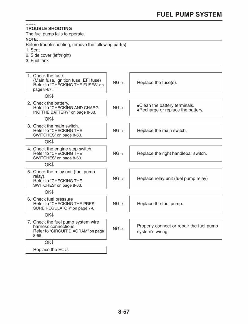
FUEL PUMP SYSTEM
8-57
EAS27600
TROUBLE SHOOTING
The fuel pump fails to operate.NOTE:
Before troubleshooting, remove the following part(s):1. Seat2. Side cover (left/right)
3. Fuel tank
1. Check the fuse(Main fuse, ignition fuse, EFI fuse)Refer to
“CHECKING THE FUSES” on page 8-67
.
NG
→
Replace the fuse(s).
OK
↓
2. Check the battery.Refer to
“CHECKING AND CHARG-ING THE BATTERY” on page 8-68
.NG
→
Clean the battery terminals.
Recharge or replace the battery.
OK
↓
3. Check the main switch.Refer to
“CHECKING THE SWITCHES” on page 8-63
.NG
→
Replace the main switch.
OK
↓
4. Check the engine stop switch.Refer to
“CHECKING THE SWITCHES” on page 8-63
.NG
→
Replace the right handlebar switch.
OK
↓
5. Check the relay unit (fuel pump relay).Refer to
“CHECKING THE SWITCHES” on page 8-63
.
NG
→
Replace relay unit (fuel pump relay)
OK
↓
6. Check fuel pressureRefer to
“CHECKING THE PRES-SURE REGULATOR” on page 7-6
.NG
→
Replace the fuel pump.
OK
↓
7. Check the fuel pump system wire harness connections.Refer to
“CIRCUIT DIAGRAM” on page 8-55
.
NG
→
Properly connect or repair the fuel pumpsystem
’
s wiring.
OK
↓
Replace the ECU.

FUEL PUMP SYSTEM
8-58

ELECTRICAL COMPONENTS
8-59
EAS27971
ELECTRICAL COMPONENTS
EAS32D1011
2
3
4
7
5
8
10
12
1
11
6
9
13
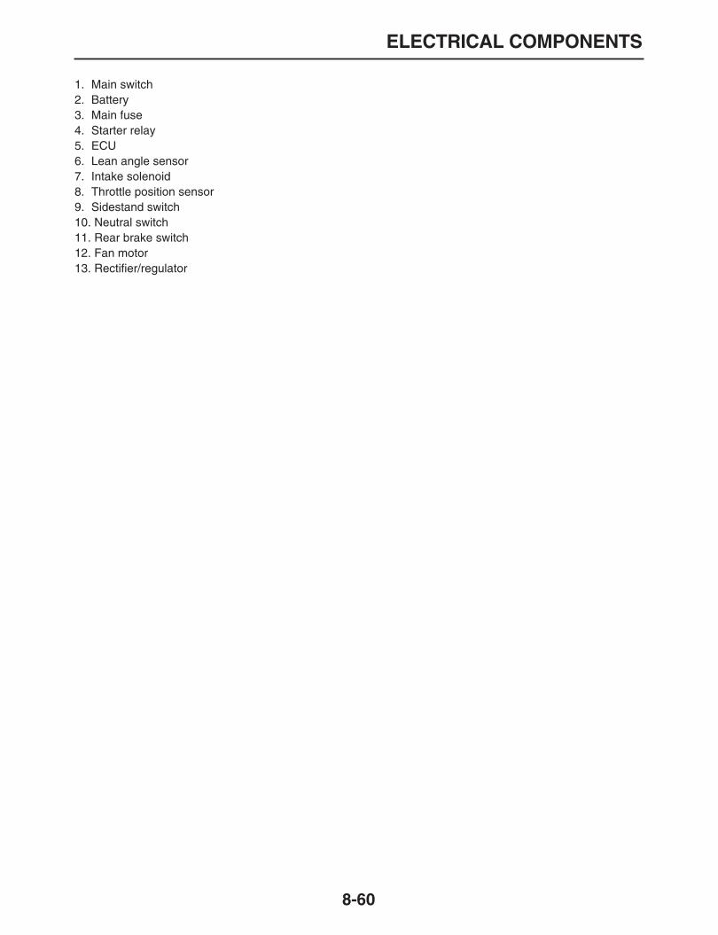
ELECTRICAL COMPONENTS
8-60
1. Main switch2. Battery3. Main fuse4. Starter relay5. ECU6. Lean angle sensor7. Intake solenoid8. Throttle position sensor9. Sidestand switch10. Neutral switch11. Rear brake switch12. Fan motor13. Rectifier/regulator

ELECTRICAL COMPONENTS
8-61
23
4
9
5
10
14
13
16
7
11
12
158

ELECTRICAL COMPONENTS
8-62
1. Horn2. Fuse box3. Starter motor4. Radiator fan motor relay5. Turn signal relay6. Relay assembly7. Headlight relay8. Intake air temperature sensor9. Coolant temperature sensor10. Speed sensor11. EXUP servo motor12. Injector13. Ignition coil14. Fuel pump15. Air cut-off valve
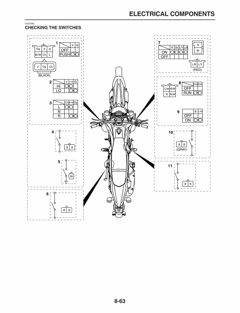
ELECTRICAL COMPONENTS
8-63
EAS27980
CHECKING THE SWITCHES
7
9
8
11
104
2
3
5
6
1
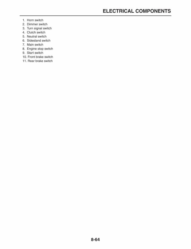
ELECTRICAL COMPONENTS
8-64
1. Horn switch2. Dimmer switch3. Turn signal switch4. Clutch switch5. Neutral switch6. Sidestand switch7. Main switch8. Engine stop switch9. Start switch10. Front brake switch11. Rear brake switch

ELECTRICAL COMPONENTS
8-65
Check each switch for continuity with the pocket tester. If the continuity reading is incorrect, check thewiring connections and if necessary, replace the switch.
CAUTION:
ECA14370
Never insert the tester probes into the coupler terminal slots “1”. Always insert the probes from
the opposite end of the coupler, taking care not to loosen or damage the leads.
NOTE:
Before checking for continuity, set the pocket tester to “0” and to the “
Ω
×
1” range.
When checking for continuity, switch back and forth between the switch positions a few times.
The terminal connections for switches (e.g., main switch, engine stop switch) are shown in an illustra-tion similar to the one on below.The switch positions “a” are shown in the far left column and the switch lead colors “b” are shown in thetop row in the switch illustration.NOTE:
“ ” indicates a continuity of electricity between switch terminals (i.e., a closed circuit at the re-
spective switch position).
The example illustration below shows that:
There is continuity between red and brown blue/yellow and blue/black when the switch is set to “ON”.
Pocket tester90890-03112
Analog pocket testerYU-03112-C
a
b

ELECTRICAL COMPONENTS
8-66
EAS27990
CHECKING THE BULBS AND BULB SOCKETS
Check each bulb and bulb socket for damage orwear, proper connections, and also for continu-ity between the terminals.Damage/wear
→
Repair or replace the bulb,bulb socket or both.Improperly connected
→
Properly connect.No continuity
→
Repair or replace the bulb, bulbsocket or both.
Types of bulbs
The bulbs used on this vehicle are shown in theillustration on the left.
Bulbs “a” and “b” are used for the headlightsand usually use a bulb holder that must be de-tached before removing the bulb. The majorityof these types of bulbs can be removed fromtheir respective socket by turning them coun-terclockwise.
Bulbs “c” is used for turn signal and can be re-moved from the socket by pushing and turningthe bulb counterclockwise.
Checking the condition of the bulbs
The following procedure applies to all of thebulbs.1. Remove:
Bulb
WARNING
EWA13320
Since the headlight bulb gets extremely hot,keep flammable products and your hands
away from the bulb until it has cooled down.
CAUTION:
ECA14380
Be sure to hold the socket firmly when re-moving the bulb. Never pull the lead, other-wise it may be pulled out of the terminal inthe coupler.
Avoid touching the glass part of the head-light bulb to keep it free from oil, otherwisethe transparency of the glass, the life of thebulb, and the luminous flux will be adverse-ly affected. If the headlight bulb gets soiled,thoroughly it with a cloth moistened with
alcohol or lacquer thinner.
2. Check:
Bulb (for continuity)(with the pocket tester)No continuity
→
Replace.
NOTE:
Before checking for continuity, set the pocket
tester to “0” and to the “
Ω
×
1” range.
a. Connect the positive tester probe to terminal“1” and the negative tester probe to terminal“2”, and check the continuity.
b. Connect the positive tester probe to terminal“1” and the negative tester probe to terminal“3”, and check the continuity.
c. If either of the readings indicate no continuity,replace the bulb.
Pocket tester90890-03112
Analog pocket testerYU-03112-C

ELECTRICAL COMPONENTS
8-67
Checking the condition of the bulb sockets
The following procedure applies to all of the bulbsockets.1. Check:
Bulb socket (for continuity)(with the pocket tester)No continuity
→
Replace.
NOTE:
Check each bulb socket for continuity in thesame manner as described in the bulb section;
however, note the following.
a. Install a good bulb into the bulb socket.b. Connect the pocket tester probes to the re-
spective leads of the bulb socket.c. Check the bulb socket for continuity. If any of
the readings indicate no continuity, replacethe bulb socket.
EAS28000
CHECKING THE FUSES
The following procedure applies to all of the fus-es.
CAUTION:
ECA13680
To avoid a short circuit, always set the mainswitch to “OFF” when checking or replacing
a fuse.
1. Remove:
Side cover (left)
Air scoop (left)Refer to “GENERAL CHASSIS” on page 4-1.
2. Check:
Main fuse “1”
Fuse box “2”
a. Connect the pocket tester to the fuse andcheck the continuity.
NOTE:
Set the pocket tester selector to “
Ω
×
1”.
b. If the pocket tester indicates “
∞
”, replace thefuse.
3. Replace:
Blown fuse
a. Set the main switch to “OFF”.b. Install a new fuse of the correct amperage
rating.c. Set on the switches to verify if the electrical
circuit is operational.d. If the fuse immediately blows again, check
the electrical circuit.
Pocket tester90890-03112
Analog pocket testerYU-03112-C
1
Pocket tester90890-03112
Analog pocket testerYU-03112-C
2

ELECTRICAL COMPONENTS
8-68
WARNING
EWA13310
Never use a fuse with an amperage ratingother than that specified. Improvising or us-ing a fuse with the wrong amperage ratingmay cause extensive damage to the electri-cal system, cause the lighting and ignitionsystems to malfunction and could possibly
cause a fire.
4. Install:
Air scoop (left)
Side cover (left)Refer to “GENERAL CHASSIS” on page 4-1.
EAS28030
CHECKING AND CHARGING THE BATTERY
WARNING
EWA13290
Batteries generate explosive hydrogen gasand contain electrolyte which is made of poi-sonous and highly caustic sulfuric acid.Therefore, always follow these preventivemeasures:
Wear protective eye gear when handling orworking near batteries.
Charge batteries in a well-ventilated area.
Keep batteries away from fire, sparks oropen flames (e.g., welding equipment,lighted cigarettes).
DO NOT SMOKE when charging or han-dling batteries.
KEEP BATTERIES AND ELECTROLYTE
OUT OF REACH OF CHILDREN.
Avoid bodily contact with electrolyte as itcan cause severe burns or permanent eyeinjury.
FIRST AID IN CASE OF BODILY CONTACT:EXTERNAL
Skin — Wash with water.
Eyes — Flush with water for 15 minutes andget immediate medical attention.
INTERNAL
Drink large quantities of water or milk fol-lowed with milk of magnesia, beaten egg orvegetable oil. Get immediate medical atten-
tion.
CAUTION:
ECA13660
This is a sealed battery. Never remove thesealing caps because the balance betweencells will not be maintained and battery per-formance will deteriorate.
Charging time, charging amperage andcharging voltage for an MF battery are dif-ferent from those of conventional batteries.The MF battery should be charged as ex-plained in the charging method illustra-tions. If the battery is overcharged, theelectrolyte level will drop considerably.Therefore, take special care when charging
the battery.
NOTE:
Since MF batteries are sealed, it is not possibleto check the charge state of the battery by mea-suring the specific gravity of the electrolyte.Therefore, the charge of the battery has to bechecked by measuring the voltage at the battery
terminals.
1. Remove:
Side cover (left)Refer to “GENERAL CHASSIS” on page 4-1.
2. Disconnect:
Battery band
Battery leads(from the battery terminals)
CAUTION:
ECA13640
First, disconnect the negative battery lead
“1”, and then positive battery lead “2”.
Fuses Amperage rating Q’ty
Main 30A 1
Headlight 15A 1
Signaling system 10A 1
Ignition 7.5A 1
EFI 7.5A 1
Radiator fan motor 7.5A 1
Backup 7.5A 1
Reserve 30A 1
Reserve 15A 1
Reserve 10A 1
Reserve 7.5A 1

ELECTRICAL COMPONENTS
8-69
3. Remove:
Battery4. Check:
Battery charge
a. Connect a pocket tester to the battery termi-nals.
NOTE:
The charge state of an MF battery can bechecked by measuring its open-circuit voltage(i.e., the voltage when the positive battery ter-minal is disconnected).
No charging is necessary when the open-cir-
cuit voltage equals or exceeds 12.8 V.
b. Check the charge of the battery, as shown inthe charts and the following example.
5. Charge:
Battery
WARNING
EWA13300
Do not quick charge a battery.
CAUTION:
ECA13670
Never remove the MF battery sealing caps.
Do not use a high-rate battery chargersince it forces a high-amperage currentinto the battery quickly and can cause bat-tery overheating and battery plate damage.
If it is impossible to regulate the chargingcurrent on the battery charger, be carefulnot to overcharge the battery.
When charging a battery, be sure to re-move it from the vehicle. (If charging has tobe done with the battery mounted on thevehicle, disconnect the negative batterylead from the battery terminal.)
To reduce the chance of sparks, do notplug in the battery charger until the batterycharger leads are connected to the battery.
Before removing the battery charger leadclips from the battery terminals, be sure toturn off the battery charger.
Make sure the battery charger lead clips arein full contact with the battery terminal andthat they are not shorted. A corroded bat-tery charger lead clip may generate heat inthe contact area and a weak clip spring maycause sparks.
If the battery becomes hot to the touch atany time during the charging process, dis-connect the battery charger and let the bat-
Positive tester probe
→
positive battery terminalNegative tester probe
→
negative battery terminal
ExampleOpen-circuit voltage = 12.0 VCharging time = 6.5 hoursCharge of the battery = 20
–
30%
A. Open-circuit voltageB. Charging time
2
1
(V)
(h)
B
A
A. Open-circuit voltageB. Charge of the batteryC. Temperature 20
°
C
A
B
C

ELECTRICAL COMPONENTS
8-70
tery cool before reconnecting it. Hotbatteries can explode!
As shown in the following illustration, theopen-circuit voltage of an MF battery stabi-lizes about 30 minutes after charging hasbeen completed. Therefore, wait 30 min-utes after charging is completed before
measuring the open-circuit voltage.
Charging method using a variable-current(voltage) charger
a. Measure the open-circuit voltage prior tocharging.
NOTE:
Voltage should be measured 30 minutes after
the machine is stopped.
b. Connect a charged and AMP meter to thebattery and start charging.
NOTE:
Set the charging voltage at 16
–
17 V.If the settingis lower, charging will be insufficient. If too high,
the battery will be over-charged.
c. Make sure that the current is higher than thestandard charging current written on the bat-tery.
NOTE:
If the current is lower than the standard chargingcurrent written on the battery, set the chargingvoltage adjust dial at 20
–
24 V and monitor the
amperage for 3
–
5 minutes to check the battery.
d. Adjust the voltage so that the current is at thestandard charging level.
e. Set the time according to the charging timesuitable for the open-circuit voltage.Refer to “Battery condition checking steps”.
f. If charging requires more than 5 hours, it isadvisable to check the charging current aftera lapse of 5 hours. If there is any change inthe amperage, readjust the voltage to obtainthe standard charging current.
g. Measure the battery open-circuit voltage af-ter leaving the battery unused for more than30 minutes.
Charging method using a constant voltagecharger
a. Measure the open-circuit voltage prior tocharging.
NOTE:
Voltage should be measured 30 minutes after
the machine is stopped.
b. Connect a charger and AMP meter to the bat-tery and start charging.
c. Make sure that the current is higher than thestandard charging current written on the bat-tery.
NOTE:
If the current is lower than the standard chargingcurrent written on the battery, This type of bat-tery charger cannot charge the MF battery. A
variable voltage charger is recommended.
d. Charge the battery until the battery’s charg-ing voltage is 15 V.
NOTE:
Set the charging time at 20 hours (maximum).
e. Measure the battery open-circuit voltage af-ter leaving the battery unused for more than30 minutes.
A. Open-circuit voltageB. Charging the open-circuit voltageC. Temperature 20
°
C
Reach the standard charging currentBattery is good.Does not reach the standard chargingcurrentReplace the battery.
A
B
C
12.8 V or more --- Charging is complete.12.7 V or less --- Recharging is required.Under 12.0 V --- Replace the battery.
12.8 V or more --- Charging is complete.12.7 V or less --- Recharging is required.Under 12.0 V --- Replace the battery.

ELECTRICAL COMPONENTS
8-71
6. Check:
Battery terminalsDirt
→
Clean with a wire brush.Loose connection
→
Connect properly.7. Install:
Battery8. Connect:
Battery leads(to the battery terminals)
9. Lubricate:
Battery terminals
10.Install:
Battery band11.Install:
Side cover (left)Refer to “GENERAL CHASSIS” on page 4-1.
EAS28040
CHECKING THE RELAYS
Check each switch for continuity with the pockettester. If the continuity reading is incorrect, re-place the relay.
1. Disconnect the relay from the wire harness.2. Connect the pocket tester (
Ω
×
1) and battery(12 V) to the relay terminal as shown.Check the relay operation.Out of specification
→
Replace.
Starter relay
Relay unit (starting circuit cut-off relay)
Relay unit (fuel pump)
Recommended lubricantDielectric grease
Pocket tester90890-03112
Analog pocket testerYU-03112-C
1. Positive battery terminal2. Negative battery terminal3. Positive tester probe4. Negative tester probe
2 1
3
4
ResultContinuity(between “3” to “4”)
1. Positive battery terminal2. Negative battery terminal3. Positive tester probe4. Negative tester probe
ResultContinuity(between “3” to “4”)
1. Positive battery terminal2. Negative battery terminal3. Positive tester probe4. Negative tester probe
ResultContinuity(between “3” to “4”)
514367 2
1
2
3 4

ELECTRICAL COMPONENTS
8-72
Headlight relay
Checking the turn signal relay
a. Check:
Turn signal relay input voltageOff specification
→
Repair wire harness con-nection failure from main switch to turn signalrelay coupler
a. Connect the pocket tester (DC 20 V) to theturn signal relay terminal.
b. Turn the main switch to “ON”.c. Measure turn signal relay applied voltage.
d. Check:
Turn signal relay output voltageOut of specification
→
Replace the defectivepart (s).
a. Connect the pocket tester (DC 20 V) to theturn signal relay terminal.
b. Turn the main switch to “ON”.c. Measure turn signal relay applied voltage.
1. Positive battery terminal2. Negative battery terminal3. Positive tester probe4. Negative tester probe
ResultContinuity(between “3” to “4”)
Turn signal relay input voltageDC 12V
Pocket tester90890-03112
Analog pocket testerYU-03112-C
Tester positive probeRed/Blue
“
1
”
Negative tester probeGround
12
3
4
Turn signal relay output voltageDC 12V
Pocket tester90890-03112
Analog pocket testerYU-03112-C
Tester positive probeBrown/White termnals
“
1
”
Negative tester probeGround
1
1

ELECTRICAL COMPONENTS
8-73
Radiator fan motor relay
EAS28050
CHECKING THE DIODE
1. Check:
DiodeOut of specification
→
Replace.
NOTE:
The pocket tester and the analog pocket tester
readings are shown in the following table.
a. Disconnect the starting circuit cut-off relayfrom the wire harness.
b. Connect the pocket tester (
Ω
×
1) to the start-ing circuit cut-off relay coupler as shown.
1. Positive battery terminal2. Negative battery terminal3. Positive tester probe4. Negative tester probe
ResultContinuity(between “3” to “4”)
Pocket tester90890-03112
Analog pocket testerYU-03112-C
12
3
4
ContinuityTester positive lead
→
Sky blue“1”Tester negative lead
→
Lightgreen “2”
No continuityTester positive lead
→
Lightgreen “2”Tester negative lead
→
Sky blue“1”
ContinuityTester positive lead
→
Blue/Green “3”Tester negative lead
→
Blue/Yel-low “4”
No continuityTester positive lead
→
Blue/Yel-low “4”Tester negative lead
→
Blue/Green “3”
ContinuityTester positive lead
→
Sky blue“1”Tester negative lead
→
Blue/Yel-low “4”
No continuityTester positive lead
→
Blue/Yel-low “4”Tester negative lead
→
Sky blue“1”
ContinuityTester positive lead
→
Sky blue“1”Tester negative lead
→
Black/Yellow “5”
No continuityTester positive lead
→
Black/Yellow “5”Tester negative lead
→
Sky blue“1”
ContinuityTester positive lead
→
Brown“6”Tester negative lead
→
Blue/White “7”
No continuityTester positive lead
→
Blue/White “7”Tester negative lead
→
Brown“6”

ELECTRICAL COMPONENTS
8-74
c. Check the diode for continuity.d. Check the diode for no continuity.
EAS28930
CHECKING THE IGNITION SPARK GAP
1. Check:
Ignition spark gapOut of specification
→
Perform the ignitionsystem troubleshooting, starting with step *.Refer to “TROUBLESHOOTING” on page8-3.
NOTE:
If the ignition spark gap is within specification,
the ignition system circuit is operating normally.
a. Disconnect the spark plug cap from the sparkplug.
b. Connect the ignition checker “1” as shown.
c. Turn the main switch to “ON” and engine stopswitch to “ ”.
d. Measure the ignition spark gap “a”.e. Crank the engine by pushing the start switch
“ ” and gradually increase the spark gap un-til a misfire occurs.
EAS28090
CHECKING THE IGNITION COIL
1. Check:
Primary coil resistanceOut of specification
→
Replace.
a. Disconnect the ignition coil lead coupler fromwire harness.
b. Connect the pocket tester (
Ω
×
1) to the igni-tion coil as shown.
c. Measure the primary coil resistance.
2. Check:
Secondary coil resistanceOut of specification
→
Replace.
Minimum ignition spark gap6.0 mm (0.24 in)
Ignition checker90890-06754
Opama pet-4000 spark checkerYM-34487
1. Ignition checker2. Spark plug cap
514367 2
Primary coil resistance1.19
–
1.61
Ω
Pocket tester90890-03112
Analog pocket testerYU-03112-C
Tester positive probeRed/Black termainal
“
1
”
Negative tester probeOrange terminal
“
2
”
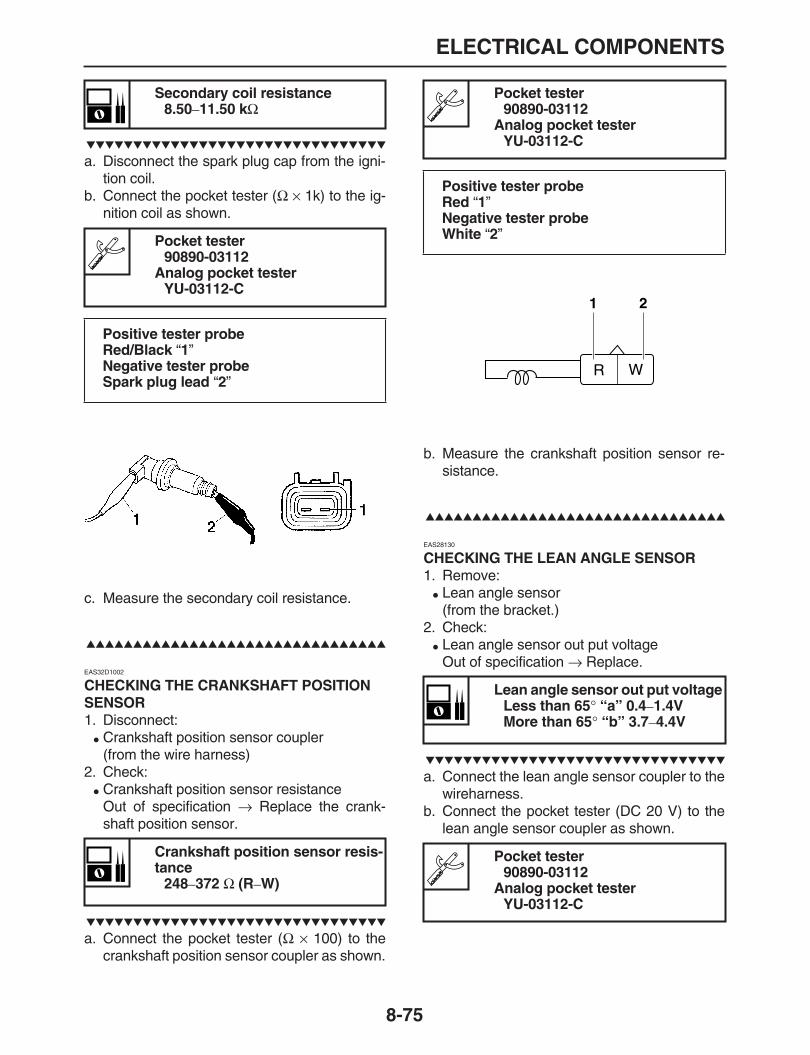
ELECTRICAL COMPONENTS
8-75
a. Disconnect the spark plug cap from the igni-tion coil.
b. Connect the pocket tester (
Ω
×
1k) to the ig-nition coil as shown.
c. Measure the secondary coil resistance.
EAS32D1002
CHECKING THE CRANKSHAFT POSITION SENSOR
1. Disconnect:
Crankshaft position sensor coupler(from the wire harness)
2. Check:
Crankshaft position sensor resistanceOut of specification
→
Replace the crank-shaft position sensor.
a. Connect the pocket tester (
Ω
×
100) to thecrankshaft position sensor coupler as shown.
b. Measure the crankshaft position sensor re-sistance.
EAS28130
CHECKING THE LEAN ANGLE SENSOR
1. Remove:
Lean angle sensor(from the bracket.)
2. Check:
Lean angle sensor out put voltageOut of specification
→
Replace.
a. Connect the lean angle sensor coupler to thewireharness.
b. Connect the pocket tester (DC 20 V) to thelean angle sensor coupler as shown.
Secondary coil resistance8.50
–
11.50 k
Ω
Pocket tester90890-03112
Analog pocket testerYU-03112-C
Positive tester probeRed/Black
“
1
”
Negative tester probeSpark plug lead
“
2
”
Crankshaft position sensor resis-tance
248
–
372
Ω
(R
–
W)
Pocket tester90890-03112
Analog pocket testerYU-03112-C
Positive tester probeRed
“
1
”
Negative tester probeWhite
“
2
”
Lean angle sensor out put voltageLess than 65
°
“a” 0.4
–
1.4VMore than 65
°
“b” 3.7
–
4.4V
Pocket tester90890-03112
Analog pocket testerYU-03112-C
1 2

ELECTRICAL COMPONENTS
8-76
c. Incline the lean angle sensor.d. Measure the lean angle sensor out put volt-
age.
EAS28150
CHECKING THE STATOR COIL
1. Disconnect:
Stator coil coupler(from the wire harness)
2. Check:
Stator coil resistanceOut of specification
→
Replace the stator coil.
a. Connect the pocket tester (
Ω
×
1) to the statorcoil coupler as shown.
b. Measure the stator coil resistance.
EAS28170
CHECKING THE RECTIFIER/REGULATOR
1. Check:
Charging voltageOut of specification
→
Replace the rectifier/regulator.
a. Set the digital tachometer to the ignition coilof cylinder #1.
b. Connect the pocket tester (DC 20 V) to therectifier/regulator coupler as shown.
Tester positive probeBlue
“
1
”
Negative tester probeYellow/Green
“
2
”
Stator coil resistance0.168
–
0.252
Ω
(W-W)
Pocket tester90890-03112
Analog pocket testerYU-03112-C
Positive tester probeWhite
“
1
”
Negative tester probeWhite
“
2
”
Positive tester probeWhite
“
1
”
Negative tester probeWhite
“
3
”
1
2
a a
b
ONON
Positive tester probeWhite
“
2
”
Negative tester probeWhite
“
3
”
Charging voltage14 V at 5000 r/min
Pocket tester90890-03112
Analog pocket testerYU-03112-C
Positive tester probePositive battery terminal
“
1
”
Negative tester probeNegative battery terminal
“
2
”
1 32
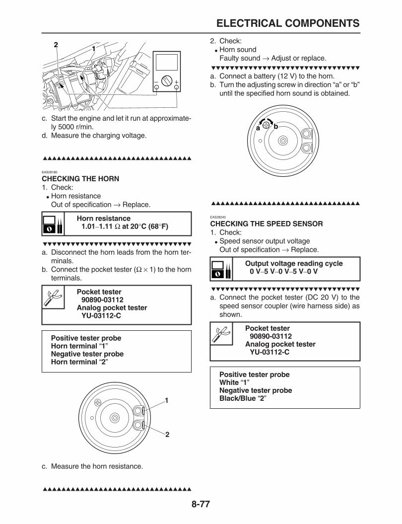
ELECTRICAL COMPONENTS
8-77
c. Start the engine and let it run at approximate-ly 5000 r/min.
d. Measure the charging voltage.
EAS28180
CHECKING THE HORN
1. Check:
Horn resistanceOut of specification
→
Replace.
a. Disconnect the horn leads from the horn ter-minals.
b. Connect the pocket tester (
Ω
×
1) to the hornterminals.
c. Measure the horn resistance.
2. Check:
Horn soundFaulty sound
→
Adjust or replace.
a. Connect a battery (12 V) to the horn.b. Turn the adjusting screw in direction “a” or “b”
until the specified horn sound is obtained.
EAS28240
CHECKING THE SPEED SENSOR
1. Check:
Speed sensor output voltageOut of specification
→
Replace.
a. Connect the pocket tester (DC 20 V) to thespeed sensor coupler (wire harness side) asshown.
Horn resistance1.01
–
1.11
Ω
at 20
°
C (68
°
F)
Pocket tester90890-03112
Analog pocket testerYU-03112-C
Positive tester probeHorn terminal
“
1
”
Negative tester probeHorn terminal
“
2
”
12
1
2
Output voltage reading cycle0 V
–
5 V
–
0 V
–
5 V
–
0 V
Pocket tester90890-03112
Analog pocket testerYU-03112-C
Positive tester probeWhite
“
1
”
Negative tester probeBlack/Blue
“
2
”
a b

ELECTRICAL COMPONENTS
8-78
b. Set the main switch to “ON”.c. Elevate the rear wheel and slowly turn it.d. Measure the voltage (DC 5 V) of white and
black/blue. With the front wheel slowly rotat-ing, voltage alternates between 0 V and 5 V.
EAS32D1012
CHECKING THE FUEL SENDER (FUEL PUMP)
Drain the gasoline.1. Disconnect:
Fuel pump coupler(from the fuel pump)
2. Remove:
Fuel pump(from the fuel pump tank)
3. Check:
Fuel sender resistanceOut of specification
→
Replace the fuelpump.
a. Connect the pocket tester (k
Ω
×
1) to the fuelsender as shown.
b. Measure the resistance of the fuel sender.
EAS28260
CHECKING THE COOLANT TEMPERATURE SENSOR
1. Remove:
Coolant temperature sensorRefer to “THERMOSTAT” on page 6-4.
WARNING
EWA14130
Handle the coolant temperature sensorwith special care.
Never subject the coolant temperature sen-sor to strong shocks. If the coolant temper-
ature sensor is dropped, replace it.
2. Check:
Coolant temperature sensor resistanceOut of specification
→
Replace.
a. Connect the pocket tester (
Ω
×
100) to thecoolant temperature sensor as shown.
Fuel sender resistance0.94
–
1.88 k
Ω
Pocket tester90890-03112
Analog pocket testerYU-03112-C
Positive tester probeGreen/White
“
1
”
Negative tester probeBlack
“
2
”
2
1
Resistance 20
°
C (68
°
F)2.32
–
2.59 k
Ω
Resistance 80
°
C (176
°
F)310
–
326
Ω
Pocket tester90890-03112
Analog pocket testerYU-03112-C
Positive tester probeBlack “1”Negative tester probeBlack “2”
12

ELECTRICAL COMPONENTS
8-79
b. Immerse the coolant temperature sensor in acontainer filled with coolant.
NOTE:
Make sure the coolant temperature sensor ter-
minals do not get wet.
c. Place a thermometer in the coolant.d. Slowly heat the coolant, and then let it cool to
the specified temperature indicated in the ta-ble.
e. Check the coolant temperature sensor forcontinuity at the temperatures indicated inthe table.
EAS28250
CHECKING THE RADIATOR FAN MOTOR
1. Check:
Radiator fan motorFaulty/rough movement
→
Replace.
a. Disconnect the radiator fan motor coupler
from the wire harness.b. Connect the battery (DC 12 V) as shown.
c. Measure the radiator fan motor movement.
EAS28300
CHECKING THE THROTTLE POSITION SENSOR
1. Check:
Throttle position sensor
a. Connect the pocket tester (DC 20 V) to thethrottle position sensor as shown.
b. While slowly turning the throttle position sen-
1 2
Positive tester probeBlue
“
1
”
Negative tester probeBlack
“
2
”
Pocket tester90890-03112
Analog pocket testerYU-03112-C
Tester positive lead
→
Yellow
“
1
”
Tester negative lead
→
Black/Blue
“
2
”
1
2
1 2
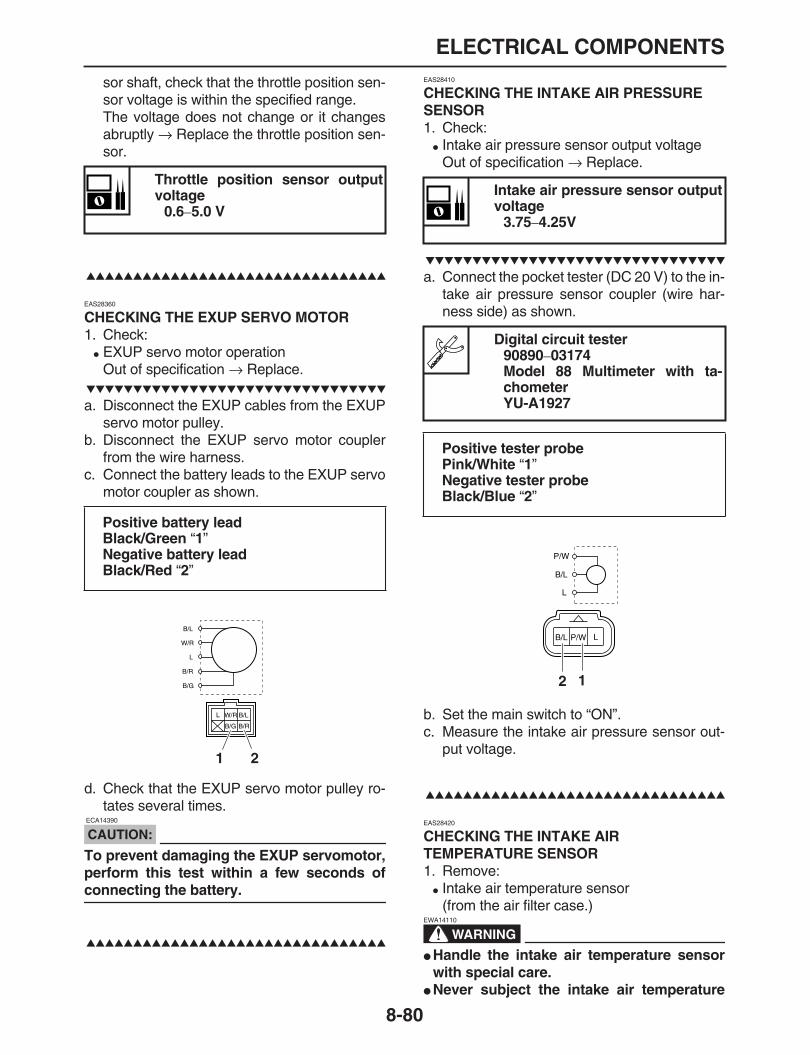
ELECTRICAL COMPONENTS
8-80
sor shaft, check that the throttle position sen-sor voltage is within the specified range.The voltage does not change or it changesabruptly
→
Replace the throttle position sen-sor.
EAS28360
CHECKING THE EXUP SERVO MOTOR
1. Check:
EXUP servo motor operationOut of specification
→
Replace.
a. Disconnect the EXUP cables from the EXUPservo motor pulley.
b. Disconnect the EXUP servo motor couplerfrom the wire harness.
c. Connect the battery leads to the EXUP servomotor coupler as shown.
d. Check that the EXUP servo motor pulley ro-tates several times.
CAUTION:
ECA14390
To prevent damaging the EXUP servomotor,perform this test within a few seconds of
connecting the battery.
EAS28410
CHECKING THE INTAKE AIR PRESSURE SENSOR
1. Check:
Intake air pressure sensor output voltageOut of specification
→
Replace.
a. Connect the pocket tester (DC 20 V) to the in-take air pressure sensor coupler (wire har-ness side) as shown.
b. Set the main switch to “ON”.c. Measure the intake air pressure sensor out-
put voltage.
EAS28420
CHECKING THE INTAKE AIR TEMPERATURE SENSOR
1. Remove:
Intake air temperature sensor(from the air filter case.)
WARNING
EWA14110
Handle the intake air temperature sensorwith special care.
Never subject the intake air temperature
Throttle position sensor outputvoltage
0.6
–
5.0 V
Positive battery leadBlack/Green
“
1
”
Negative battery leadBlack/Red
“
2
”
1 2
Intake air pressure sensor outputvoltage
3.75
–
4.25V
Digital circuit tester90890
–
03174Model 88 Multimeter with ta-chometerYU-A1927
Positive tester probePink/White
“
1
”
Negative tester probeBlack/Blue
“
2
”
12

ELECTRICAL COMPONENTS
8-81
sensor to strong shocks. If the intake air
temperature sensor is dropped, replace it.
2. Check:
Intake air temperature sensor resistanceOut of specification
→
Replace.
a. Connect the pocket tester (
Ω
×
1k) to the in-take air temperature sensor terminal asshown.
EAS32D1013
CHECKING THE INTAKE SOLENOID
1. Check:
Intake solenoid resistanceOut of specification
→
Replace.
a. Disconnect the intake solenoid coupler fromthe wire harness.
b. Connect the pocket tester (
Ω
×
10) to the in-take solenoid terminal as shown.
c. Measure the intake solenoid resistance.
Intake air temperature sensor re-sistance
2.21
–
2.69 k
Ω
20
°
C
Digital circuit tester90890
–
03174Model 88 Multimeter with ta-chometerYU-A1927
Positive tester probeBrown/White
“
1
”
Negative tester probeBlack/Blue
“
2
”
Intake solenoid resistance42
–
48
Ω
20
°
C
1 2
Pocket tester90890-03112
Analog pocket testerYU-03112-C
Tester positive leadRed/White
“
1
”
Tester negative leadBrown/Black
“
2
”
12

1
2
3
4
5
6
7
8
9
TROUBLESHOOTING
TROUBLESHOOTING ...................................................................................9-1
GENERAL INFORMATION......................................................................9-1STARTING FAILURES.............................................................................9-1INCORRECT ENGINE IDLING SPEED...................................................9-1POOR MEDIUM-AND-HIGH-SPEED PERFORMANCE..........................9-2FAULTY GEAR SHIFTING.......................................................................9-2SHIFT PEDAL DOES NOT MOVE...........................................................9-2JUMPS OUT OF GEAR ...........................................................................9-2FAULTY CLUTCH....................................................................................9-2OVERHEATING .......................................................................................9-2OVERCOOLING.......................................................................................9-3POOR BRAKING PERFORMANCE.........................................................9-3FAULTY FRONT FORK LEGS.................................................................9-3UNSTABLE HANDLING...........................................................................9-3FAULTY LIGHTING OR SIGNALING SYSTEM.......................................9-3

TROUBLESHOOTING
9-1
EAS28450
TROUBLESHOOTING
EAS28460
GENERAL INFORMATIONNOTE:
The following guide for troubleshooting does notcover all the possible causes of trouble. It shouldbe helpful, however, as a guide to basic trouble-shooting. Refer to the relative procedure in thismanual for checks, adjustments, and replace-
ment of parts.
EAS28470
STARTING FAILURESEngine
1. Cylinder (s) and cylinder head (s)
Loose spark plug
Loose cylinder head or cylinder
Damaged cylinder head gasket
Damaged cylinder gasket
Worn or damaged cylinder
Incorrect valve clearance
Improperly sealed valve
Incorrect valve-to-valve-seat contact
Incorrect valve timing
Faulty valve spring
Seized valve2. Piston (s) and piston ring (s)
Damaged, worn or fatigued piston ring
Seized piston ring
Seized or damaged piston3. Air filter
Improperly installed air filter
Clogged air filter element4. Crankcase and crankshaft
Improperly assembled crankcase
Seized crankshaft
Fuel system
1. Fuel tank
Empty fuel tank
Deteriorated or contaminated fuel2. Fuel pump
Faulty fuel pump3. Fuel cock
Clogged or damaged fuel hose4. Throttle body
Clogged pilot air passage
Electrical system
1. Battery
Discharged battery
Faulty battery2. Fuse (s)
Blown, damaged or incorrect fuse
Improperly installed fuse3. Spark plug (s)
Incorrect spark plug gap
Incorrect spark plug heat range
Fouled spark plug
Worn or damaged electrode
Worn or damaged insulator4. Ignition coil (s)
Cracked or broken ignition coil body
Broken or shorted primary or secondary coils5. Ignition system
ECU failure.
Faulty crankshaft position sensor
Broken generator rotor woodruff key6. Switches and wiring
Defective lean angle sensor
Faulty main switch
Faulty engine stop switch
Broken or shorted wiring
Faulty neutral switch
Faulty start switch
Faulty sidestand switch
Faulty clutch switch
Improperly grounded circuit
Loose connections7. Starting system
Faulty starter motor
Faulty starter relay
Faulty starting circuit cut-off relay
Faulty starter clutch
EAS28490
INCORRECT ENGINE IDLING SPEEDEngine
1. Cylinder (s) and cylinder head (s)
Incorrect valve clearance
Damaged valve train components2. Air filter
Clogged air filter element
Fuel system
1. Throttle body
Air intake in throttle body joint
Improper throttle cable free play
Faulty air induction system
Electrical system
1. Battery
Discharged battery
Faulty battery2. Spark plug (s)
Incorrect spark plug gap
Incorrect spark plug heat range
Fouled spark plug
Worn or damaged electrode
Worn or damaged insulator

TROUBLESHOOTING
9-2
Faulty spark plug cap3. Ignition coil (s)
Faulty ignition coil
Cracked or broken ignition coil4. Ignition system
ECU failure.
Faulty crankshaft position sensor
EAS28520
POOR MEDIUM-AND-HIGH-SPEED PERFORMANCE
Refer to “STARTING FAILURES” on page 9-1.
Engine
1. Air filter
Clogged air filter element
Fuel system
1. Fuel pump
Faulty fuel pump2. Throttle body
Defective throttle body3. ECU
ECU failure.
EAS28530
FAULTY GEAR SHIFTINGShifting is difficult
Refer to “Clutch drags”.
EAS28540
SHIFT PEDAL DOES NOT MOVEShift shaft
Bent shift shaft
Shift drum and shift forks
Foreign object in a shift drum groove
Seized shift fork
Bent shift fork guide bar
Transmission
Seized transmission gear
Foreign object between transmission gears
Improperly assembled transmission
EAS28550
JUMPS OUT OF GEARShift shaft
Incorrect shift pedal position
Improperly returned stopper lever
Shift forks
Worn shift fork
Shift drum
Incorrect axial play
Worn shift drum groove
Transmission
Worn gear dog
EAS28560
FAULTY CLUTCHClutch slips
1. Clutch
Improperly assembled clutch
Loose or fatigued clutch spring
Worn friction plate
Worn clutch plate2. Engine oil
Incorrect oil level
Incorrect oil viscosity (low)
Deteriorated oil
Clutch drags
1. Clutch
Unevenly tensioned clutch springs
Warped pressure plate
Bent clutch plate
Swollen friction plate
Bent clutch push rod
Broken clutch boss
Burnt primary driven gear bushing2. Engine oil
Incorrect oil level
Incorrect oil viscosity (high)
Deteriorated oil
EAS28590
OVERHEATINGEngine
1. Cylinder head (s) and piston (s)
Heavy carbon buildup2. Engine oil
Incorrect oil level
Incorrect oil viscosity
Inferior oil quality
Cooling system
1. Coolant
Low coolant level2. Radiator
Damaged or leaking radiator
Faulty radiator cap
Bent or damaged radiator fin3. Water pump
Damaged or faulty water pump
Faulty thermostat
Damaged fan motor or disconnected coupler
Damaged hose
Improperly connected hose
Damaged pipe
Improperly connected pipe
Fuel system
1. Throttle body
Air intake in throttle body joint2. Air filter

TROUBLESHOOTING
9-3
Clogged air filter element
Chassis
1. Brake (s)
Dragging brake
Electrical system
1. Spark plug (s)
Incorrect spark plug gap
Incorrect spark plug heat range2. Ignition system
ECU failure
Faulty radiator fan motor relay
Faulty coolant temperature sensor
EAS28610
OVERCOOLINGCooling system
1. Thermostat
Thermostat stays open
EAS28620
POOR BRAKING PERFORMANCE
Worn brake pad
Worn brake disc
Air in hydraulic brake system
Leaking brake fluid
Defective master cylinder kit
Faulty brake caliper kit
Faulty brake caliper seal
Loose union bolt
Damaged brake hose
Oil or grease on the brake disc
Oil or grease on the brake pad
Incorrect brake fluid level
EAS28660
FAULTY FRONT FORK LEGSLeaking oil
Bent, damaged or rusty inner tube
Cracked or damaged outer tube
Improperly installed oil seal
Damaged oil seal lip
Incorrect oil level (high)
Loose damper rod assembly bolt
Damaged damper rod assembly bolt copperwasher
Cracked or damaged cap bolt O-ring
Malfunction
Bent or damaged inner tube
Bent or damaged outer tube
Damaged fork spring
Bent or damaged damper rod
Incorrect oil viscosity
Incorrect oil level
EAS28690
UNSTABLE HANDLING
1. Handlebar
Bent or improperly installed handlebar2. Steering head components
Improperly installed upper bracket
Improperly installed lower bracket(improperly tightened ring nut)
Bent steering stem
Damaged ball bearing or bearing race3. Front fork leg (s)
Uneven oil levels (both front fork legs)
Unevenly tensioned fork spring (both frontfork legs)
Broken fork spring
Bent or damaged inner tube
Bent or damaged outer tube4. Swingarm
Worn bearing or bushing
Bent or damaged swingarm5. Rear shock absorber assembly (-ies)
Faulty rear shock absorber spring
Leaking oil or gas6. Tire (s)
Uneven tire pressures (front and rear)
Incorrect tire pressure
Uneven tire wear7. Wheel (s)
Incorrect wheel balance
Broken or loose spoke
Damaged wheel bearing
Bent or loose wheel axle
Excessive wheel runout8. Frame
Bent frame
Damaged steering head pipe
Improperly installed bearing race
EAS28710
FAULTY LIGHTING OR SIGNALING SYSTEMHeadlight does not come on
Fuse open circuit
Wrong headlight bulb
Too many electrical accessories
Hard charging
Incorrect connection
Improperly grounded circuit
Poor contacts (main or light switch)
Burnt-out headlight bulb
Headlight bulb burnt out
Wrong headlight bulb
Faulty battery
Faulty rectifier/regulator
Improperly grounded circuit

TROUBLESHOOTING
9-4
Faulty main switch
Headlight bulb life expired
Tail/brake light does not come on
Too many electrical accessories
Incorrect connection
Turn signal does not come on
Fuse open circuit
Faulty turn signal switch
Faulty turn signal relay
Burnt-out turn signal bulb
Incorrect connection
Damaged or faulty wire harness
Improperly grounded circuit
Faulty battery
Blown, damaged or incorrect fuse
Turn signal blinks slowly
Faulty turn signal relay
Faulty main switch
Faulty turn signal switch
Incorrect turn signal bulb
Turn signal remains lit
Faulty turn signal relay
Burnt-out turn signal bulb
Turn signal blinks quickly
Incorrect turn signal bulb
Faulty turn signal relay
Burnt-out turn signal bulb
Horn does not sound
Improperly adjusted horn
Damaged or faulty horn (Coil open circuit ordamaged terminal)
Faulty main switch
Faulty horn switch
Faulty battery
Blown, damaged or incorrect fuse
Faulty wire harness

TROUBLESHOOTING
9-5

EAS28740
WIRING DIAGRAMWR250R(X)/WR250X(X) 2008 WIRING DIAGRAM
1.AC magneto2.Rectifier/regulator3.Main switch4.Battery5.Main fuse6.Starter relay7.Starter motor8.Right handlebar switch9.Engine stop switch10.Start switch11.Relay unit12.Sidestand switch13.Neutral switch14.Clutch switch15.Fuel pump16.ECU (electronic control unit)17.Ignition coil18.Spark plug19.Intake solenoid20.Fuel injector21.Air induction solenoid22.Intake air temperature sensor23.Coolant temperature sensor24.Speed sensor25.Throttle position sensor26.Intake air pressure sensor27.Lean angle sensor28.EXUP servo motor29.Meter assembly30.Neutral indicator light31.Coolant temperature warning
light32.Engine trouble warning light33.Fuel level warning light34.High beam indicator light35.Turn signal indicator light36.Turn signal relay37.Turn signal switch38.Rear right turn signal light39.Front right turn signal/posi-
tion light40.Front left turn signal/position
light41.Rear left turn signal light42.Headlight relay43.Dimmer switch44.Headlight45.Horn46.Horn switch
47.Left handlebar switch48.Rear brake switch49.Front brake light switch50.Tail/brake light51.License plate light52.Radiator fan motor relay53.Radiator fan motor54.Headlight fuse55.Signal fuse56.Ignition fuse57.Radiator fan fuse58.Fuel injection system fuse59.Backup fuse
EAS28750
COLOR CODE
B BlackBr BrownCh ChocolateDg Dark greenG GreenGy GrayL BlueO OrangeP PinkR RedSb Sky blueW WhiteY YellowB/G Black/GreenB/L Black/BlueB/R Black/RedB/W Black/WhiteB/Y Black/YellowBr/G Brown/GreenBr/L Brown/BlueBr/R Brown/RedBr/W Brown/WhiteG/B Green/BlackG/R Green/RedG/W Green/WhiteG/Y Green/YellowGy/G Gray/GreenGy/R Gray/RedGy/Y Gray/YellowL/B Blue/YellowL/R Blue/RedL/W Blue/WhiteL/Y Blue/YellowO/B Orange/BlackP/W Pink/WhiteR/B Red/BlackR/G Red/GreenR/L Red/BlueR/W Red/WhiteR/Y Red/YellowSb/W Sky blue/WhiteW/B White/BlackW/R White/RedW/Y White/YellowY/B Yellow/BlackY/G Yellow/GreenY/L Yellow/BlueY/R Yellow/Red


YAMAHA MOTOR CO., LTD.2500 SHINGAI IWATA SHIZUOKA JAPAN

WR250RX/WR250XX 2008WIRING DIAGRAM
WR250RX/WR250XX 2008SCHÉMA DE CÂBLAGE
WR250RX/WR250XX 2008 SCHALTPLAN
SCHEMA ELETTRICOWR250RX/WR250XX 2008
DIAGRAMA ELÉCTRICO DE LAWR250RX/WR250XX 2008
32D-7-E0 W.D 30/10/07 2:09 PM Page 1

WR250RX/WR250XX 2008WIRING DIAGRAM
WR250RX/WR250XX 2008SCHÉMA DE CÂBLAGE
WR250RX/WR250XX 2008 SCHALTPLAN
SCHEMA ELETTRICOWR250RX/WR250XX 2008
DIAGRAMA ELÉCTRICO DE LAWR250RX/WR250XX 2008
32D-7-E0 W.D 30/10/07 2:09 PM Page 2