write-behind logging - vldb this paper, we present a new protocol, called write-behind logging...
TRANSCRIPT

Write-Behind Logging
Joy Arulraj Matthew Perron Andrew PavloCarnegie Mellon University Carnegie Mellon University Carnegie Mellon [email protected] [email protected] [email protected]
ABSTRACTThe design of the logging and recovery components of databasemanagement systems (DBMSs) has always been influenced by thedifference in the performance characteristics of volatile (DRAM)and non-volatile storage devices (HDD/SSDs). The key assumptionhas been that non-volatile storage is much slower than DRAM andonly supports block-oriented read/writes. But the arrival of new non-volatile memory (NVM) storage that is almost as fast as DRAM withfine-grained read/writes invalidates these previous design choices.
This paper explores the changes that are required in a DBMS toleverage the unique properties of NVM in systems that still includevolatile DRAM. We make the case for a new logging and recoveryprotocol, called write-behind logging, that enables a DBMS torecover nearly instantaneously from system failures. The key idea isthat the DBMS logs what parts of the database have changed ratherthan how it was changed. Using this method, the DBMS flushesthe changes to the database before recording them in the log. Ourevaluation shows that this protocol improves a DBMS’s transactionalthroughput by 1.3×, reduces the recovery time by more than twoorders of magnitude, and shrinks the storage footprint of the DBMSon NVM by 1.5×. We also demonstrate that our logging protocol iscompatible with standard replication schemes.
1. INTRODUCTIONA DBMS ensures that the database state is not corrupted due to an
application, operating system, or device failure [19]. It ensures thedurability of all updates made by a transaction by writing changesout to durable storage, such as an HDD, before returning an acknowl-edgement back to the application. Such storage devices, however,are much slower than DRAM (especially for random writes) andonly support bulk data transfers as blocks. In contrast, a DBMS canquickly read and write a single byte from a volatile DRAM device,but all data is lost after the system restarts or there is a power failure.
These differences between the two types of storage are a majorfactor in the design of DBMS architectures. For example, disk-oriented DBMSs employ different data layouts optimized for non-volatile and volatile storage. This is because of the performance gapbetween sequential and random accesses in HDD/SSDs. Further,DBMSs try to minimize random writes to the disk due to its high
This work is licensed under the Creative Commons Attribution-NonCommercial-NoDerivatives 4.0 International License. To view a copyof this license, visit http://creativecommons.org/licenses/by-nc-nd/4.0/. Forany use beyond those covered by this license, obtain permission by [email protected] of the VLDB Endowment, Vol. 10, No. 4Copyright 2016 VLDB Endowment 2150-8097/16/12.
random write latency. During transaction processing, if the DBMSwere to overwrite the contents of the database before committingthe transaction, then it must perform random writes to the databaseat multiple locations on disk. It works around this constraint byflushing the transaction’s changes to a separate log on disk with onlysequential writes on the critical path of the transaction. This methodis referred to as write-ahead logging (WAL).
But emerging non-volatile memory (NVM) technologies are poisedto upend these assumptions. NVM storage devices support low la-tency reads and writes similar to DRAM, but with persistent writesand large storage capacity like a SSD [9]. The CPU can also ac-cess NVM at cache line-granularity. This means that the canonicalapproaches for DBMS logging and recovery that assume slowerstorage are incompatible with this new hardware landscape [14].
In this paper, we present a new protocol, called write-behindlogging (WBL), that is designed for a hybrid storage hierarchy withNVM and DRAM. We demonstrate that tailoring these algorithmsfor NVM not only improves the runtime performance of the DBMS,but it also enables it to recovery nearly instantaneously from failures.The way that WBL achieves this is by tracking what parts of thedatabase have changed rather than how it was changed. Using thislogging method, the DBMS can flush the changes to the databasebefore recording them in the log. By ordering writes to NVMcorrectly, the DBMS can guarantee that all transactions are durableand atomic. This allows the DBMS to write less data per transaction,thereby improving an NVM device’s lifetime [6].
To evaluate our approach, we implemented it in the Peloton [2]in-memory DBMS and compared it against WAL using three storagetechnologies: NVM, SSD, and HDD. These experiments show thatWBL with NVM improves the DBMS’s throughput by 1.3× whilealso reducing the database recovery time and the overall system’sstorage footprint. Our results also show that WBL only achieves thiswhen the DBMS uses NVM; the DBMS actually performs worsethan WAL when WBL is deployed on the slower, block-orientedstorage devices (i.e., SSD, HDD). This is expected since our protocolis explicitly designed for fast, byte-addressable NVM. We alsodeployed Peloton in a multi-node configuration and demonstratehow to adapt WBL to work with standard replication methods.
The remainder of this paper is organized as follows. We begin inSection 2 with an overview of the recovery principles of a DBMSand how NVM affects them. We then discuss logging and recoveryimplementations in modern DBMSs. We start with the ubiquitousWAL protocol in Section 3, followed by our new WBL method inSection 4. In Section 5, we discuss how this logging protocol canbe used in replicated environments. We then provide an overviewof the NVM hardware emulator that we use in our experiments inSection 6. We present our experimental evaluation in Section 7. Weconclude with a discussion of related work in Section 8.
337

2. BACKGROUNDWe begin with an overview of DBMS recovery principles and
discuss how emerging NVM technologies affect them. We thenmake the case for adapting the logging protocol for NVM.
2.1 Recovery PrinciplesA DBMS guarantees the integrity of a database by ensuring (1)
that all of the changes made by committed transactions are durableand (2) that none of the changes made by aborted transactions ortransactions that were running at the point of a failure are visibleafter recovering from the failure. These two constraints are referredto as durability of updates and failure atomicity, respectively [5, 19].
There are three types of failures that a DBMS must protect against:(1) transaction failure, (2) system failure, and (3) media failure. Thefirst happens when a transaction is aborted either by the DBMSdue to a conflict with another transaction or because the applicationchose to do so. System failures occur due to bugs in the DBMS/OSor hardware failures. Finally, in the case of a data loss or corruptionon the non-volatile storage, the DBMS must recover the databasefrom an archival version. It must also remove the updates of incom-plete transactions to satisfy the failure atomicity constraint.
Almost every DBMS adopts the steal and no-force policies formanaging the data stored in the volatile buffer pool and the databaseon durable storage [19]. The former policy allows a DBMS to flushthe changes of uncommitted transactions at any time. With the latter,the DBMS is not required to ensure that the changes made by atransaction are propagated to the database when it commits. Instead,the DBMS records a transaction’s changes to a log on durable stor-age before sending an acknowledgement to the application. Further,it flushes the modifications made by uncommitted transactions tothe log before propagating them to the database.
During recovery, the DBMS uses the log to ensure the atomic-ity and durability properties. The recovery algorithm reverses theupdates made by failed transactions using their undo informationrecorded in the log. In case of a system failure, the DBMS firstensures the durability of updates made by committed transactionsby reapplying their redo information in the log on the database. Af-terwards, the DBMS uses the log’s undo information to remove theeffects of transactions that were aborted or active at the time of thefailure. DBMSs can handle media failures by storing the database,the log, and the archival versions of the database (i.e., checkpoints)on multiple durable storage devices.
2.2 Non-Volatile Memory Database SystemsModern HDDs are based on the same high-level design principles
from the 1960s: a magnetic platter spins and an arm reads data offof it with a block-granularity (typically 4 KB). Since moving theplatter and the arm is a mechanical process, these drives are theslowest of all the durable storage devices. Sequential reads andwrites to the device are faster than random accesses as they do notrequire the arm to be re-positioned. HDDs have a high data densityand thus offer a lower storage price per capacity.
SSDs are faster than HDDs because they use non-volatile NANDstorage cells; their read and write latencies are up to three orders ofmagnitude lower than an average HDD. But there are three problemsthat make SSDs less than ideal for DBMSs. Foremost is that theyonly support block-oriented access to data. Each storage cell in aSSD can only be written to a fixed number of times before it canno longer reliably store the data. Lastly, SSDs are currently 3–10×more expensive per GB than an HDD.
The performance of DBMSs that use HDDs/SSDs for durablestorage is constrained by the speed with which they persist changesto the log stored on these devices. This is because there is a large
Devices : NVM SSD HDD
1 4 16 64Block size (KB)
0.01
0.1
1
10
100
1000
IOP
S(K
)
(a) Sequential Writes
1 4 16 64Block size (KB)
0.01
0.1
1
10
100
1000
IOP
S(K
)
(b) Random Writes
Figure 1: I/O Performance – Synchronous file write throughput obtainedon different storage devices including emulated NVM, SSD, and HDD.
NVM-WBL NVM-WAL
NVM-WBL NVM-WALLogging Protocol
0
45000
90000
Thro
ughp
ut(t
xn/s
)
(a) Throughput
NVM-WBL NVM-WALLogging Protocol
0.1
1
10
100
1000
Rec
over
yLa
tenc
y(s
)
(b) Recovery Time
NVM-WBL NVM-WALLogging Protocol
0.00
1.75
3.50
Sto
rage
(GB
)
(c) Storage Footprint
Figure 2: WBL vs. WAL – The throughput, recovery time, and storagefootprint of the DBMS for the YCSB benchmark with the write-aheadlogging and write-behind logging protocols.
gap in the read/write latencies of DRAM and HDDs/SSDs, as wellas a mismatch in their data access granularities (i.e., coarse-grainedblock writes vs. fine-grained byte-level writes).
NVM technologies, such as phase change memory, STT-MRAM,and memristors, provide low-latency, byte-addressable loads andstores [6]. In contrast to the other durable storage devices that usethe PCIe or SATA interfaces, NVM can be plugged into DIMM slotsto deliver higher bandwidths and lower latencies to CPUs. Con-sequently, it can help reduce the performance overhead associatedwith persisting the changes on durable storage.
To better understand the performance characteristics of thesedevices, we benchmark them using fio [8] with different accesspatterns. In this experiment, we measure the write throughput of asingle thread performing synchronous writes to a large file (64 GB)stored on a HDD, SSD, and emulated NVM [17]. The results in Fig-ure 1 show that NVM delivers more than two orders of magnitudehigher write throughput compared to the SSD and HDD. More im-portantly, the gap between sequential and random write throughputof NVM is much smaller.
Although the performance advantages of NVM are obvious, itis still not clear how to make full use of it in a DBMS running ona hybrid storage hierarchy with both DRAM and NVM. Previouswork has shown that optimizing the storage methods for NVM im-proves both the DBMS performance and the lifetime of the storagedevice [6]. These techniques, however, cannot be employed in ahybrid storage hierarchy, as they target an NVM-only system. An-other line of research focuses on using NVM only for storing thelog and managing the database still on disk [22]. This is a morecost-effective solution, as the cost of NVM devices are expectedto be higher than that of disk. But this approach only leveragesthe low-latency sequential writes of NVM, and does not exploit itsability to efficiently support random writes and fine-grained dataaccess. Given this, we contend that it is better to employ loggingand recovery algorithms that are designed for NVM.
We designed such an approach that we call write-behind logging(WBL). Before we present WBL in Section 4, we first show itsbenefits for a DBMS running with NVM. We compared it againstthe canonical write-ahead logging (WAL) protocol that is used inmost DBMSs today [19]. For this microbenchmark, we executed awrite-heavy variation of the YCSB workload on Peloton. We deferthe description of our experiment environment until Section 7. Theresults in Figure 2 show that WBL improves the DBMS’s throughput
338

YX
X’∞1001
—
305 1002
1001
∞—
101—
— 1002102101
103
Tuple ID Prev VEnd CTSBegin CTSTxn ID Data
Figure 3: Tuple Version Meta-data – The additional data that the DBMSstores to track tuple versions in an MVCC protocol.
by 1.3× over WAL, while also reducing the recovery time by over100× and storage footprint on NVM by 1.5×.
To appreciate why WBL is better than WAL when using NVM,we now discuss how WAL is implemented in both disk-oriented andin-memory DBMSs.
3. WRITE-AHEAD LOGGINGThe most well-known recovery method based on WAL is the
ARIES protocol developed by IBM in the 1990s [28]. ARIESis a physiological logging protocol where the DBMS combines aphysical redo process with a logical undo process [19]. Duringnormal operations, the DBMS records transactions’ modificationsin a durable log that it uses to restore the database after a crash.
In this section, we provide an overview of ARIES-style WAL.We begin with discussing the original protocol for a disk-orientedDBMS and then describe optimizations for in-memory DBMSs.Our discussion is focused on DBMSs that use the multi-version con-currency control (MVCC) protocol for scheduling transactions [7,29]. MVCC is the most widely used concurrency control schemein DBMSs developed in the last decade, including Hekaton [16],MemSQL, and HyPer. The DBMS records the versioning meta-data alongside the tuple data, and uses it determine whether a tupleversion is visible to a transaction. When a transaction starts, theDBMS assigns it a unique transaction identifier from a monotoni-cally increasing global counter. When a transaction commits, theDBMS assigns it a unique commit timestamp by incrementing thetimestamp of the last committed transaction. Each tuple containsthe following meta-data:• TxnId: A placeholder for the identifier of the transaction that
currently holds a latch on the tuple.• BeginCTS & EndCTS: The commit timestamps from which
the tuple becomes visible and after which the tuple ceases tobe visible, respectively.
• PreV: Reference to the previous version (if any) of the tuple.Figure 3 shows an example of this versioning meta-data. A tuple
is visible to a transaction if and only if its last visible committimestamp falls within the BeginCTS and EndCTS fields of the tuple.The DBMS uses the previous version field to traverse the versionchain and access the earlier versions, if any, of that tuple. In Figure 3,the first two tuples are inserted by the transaction with committimestamp 1001. The transaction with commit timestamp 1002updates the tuple with ID 101 and marks it as deleted. The newerversion is stored with ID 103. Note that the PreV field of the thirdtuple refers to the older version of tuple. At this point in time, thetransaction with identifier 305 holds a latch on the tuple with ID 103.See [7, 26] for a more detailed description of in-memory MVCC.
We now begin with an overview of the runtime operation ofthe DBMS during transaction processing and its commit protocol.Table 1 lists the steps in a WAL-based DBMS to execute database op-erations, process transaction commits, and take checkpoints. Later,in Section 4, we present our WBL protocol for NVM systems.
3.1 Runtime OperationFor each modification that a transaction makes to the database,
the DBMS creates a log record that corresponds to that change. As
AfterImage
DeleteLocation
InsertLocation
TableId
TransactionCommit Timestamp
Log RecordType
LSNChecksum
Figure 4: Structure of WAL Record – Structure of the log record con-structed by the DBMS while using the WAL protocol.
CheckpointCheckpointCheckpoint
Table Heap
LogCheckpoint
Volatile Storage1
2 3Durable Storage
Figure 5: WAL Commit Protocol – The ordering of writes from the DBMSto durable storage while employing the WAL protocol.
Oldest ActiveTransaction
Earliest RedoLog Record Checkpoint End of Log
Log (Time)
Analysis
Redo
Undo
1
2
3
Figure 6: WAL Recovery Protocol – The phases of the recovery protocol.
shown in Figure 4, a log record contains a unique log sequencenumber (LSN), the operation associated with the log record (i.e.,INSERT, UPDATE, or DELETE), the transaction identifier, and the tablemodified. For INSERT and UPDATE operations, the log record con-tains the location of the inserted tuple or the newer version. Eachrecord also contains the after-images (i.e., new values) of the tuplesmodified, as shown in Table 1. In case of UPDATE and DELETE op-erations, it contains the location of the older version or the deletedtuple, respectively. This is known as the before-images (i.e., oldvalues) of the modified tuples and is used to ensure failure atomicity.
A disk-oriented DBMS maintains two meta-data tables at runtimethat it uses for recovery. The first is the dirty page table (DPT) thatcontains the modified pages that are in DRAM but have not beenpropagated to durable storage. Each of these pages has an entry inthe DPT that marks the log record’s LSN of the oldest transactionthat modified it. This allows the DBMS to identify the log recordsto replay during recovery to restore the page. The second table is theactive transaction table (ATT) that tracks the status of the runningtransactions. This table records the LSN of the latest log record ofall active transactions. The DBMS uses this information to undotheir changes during recovery.
To bound the amount of work to recover a database after a restart,the DBMS periodically takes checkpoints at runtime. ARIES usesfuzzy checkpointing where the checkpoint can contain the effects ofboth committed and uncommitted transactions [28]. Consequently,the DBMS must write out the DPT and ATT as a part of the check-point so that it can restore committed transactions and undo un-committed transactions during recovery. After all the log recordsassociated with a transaction are safely persisted in a checkpoint,the DBMS can remove those records from the log.
With an in-memory DBMS, transactions access tuples throughpointers without indirection through a buffer pool [7]. The ARIESprotocol can, therefore, be simplified and optimized for this archi-tecture. Foremost is that a MVCC DBMS does not need to performfuzzy checkpointing [34]. Instead, it constructs transactionally-consistent checkpoints that only contain the changes of committedtransactions by skipping the modifications made by transactionsthat began after the checkpoint operation started. Hence, a MVCCDBMS neither stores the before-images of tuples in the log nor
339

tracks dirty data (i.e., DPT) at runtime. Its recovery component,however, maintains an ATT that tracks the LSN of the latest logrecord written by each active transaction.
3.2 Commit ProtocolWe now describe how a WAL-based DBMS processes and com-
mits transactions. When a transaction begins, the DBMS creates anentry in the ATT and sets it status as active. For each modificationthat the transaction makes to the database, the DBMS constructs thecorresponding log record and appends it to the log buffer. It thenupdates the LSN associated with the transaction in the ATT.
The DBMS flushes all the log records associated with a transac-tion to durable storage (using the fsync command) before commit-ting the transaction. This is known as synchronous logging. Finally,the DBMS marks the status of the transaction in the ATT as com-mitted. The ordering of writes from the DBMS to durable storagewhile employing WAL is presented in Figure 5. The changes arefirst applied to the table heap and the indexes residing in volatilestorage. At the time of commit, WAL requires that the DBMS flushall the modifications to the durable log. Then, at some later pointthe DBMS writes the changes to the database in its next checkpoint.
As transactions tend to generate multiple log records that are eachsmall in size, most DBMSs use group commit to minimize the I/Ooverhead [15]. It batches the log records for a group of transactionsin a buffer and then flushes them together with a single write todurable storage. This improves the transactional throughput andamortizes the synchronization overhead across multiple transactions.
3.3 Recovery ProtocolThe traditional WAL recovery algorithm (see Figure 6) comprises
of three phases: (1) analysis, (2) redo, and (3) undo. In the anal-ysis phase, the DBMS processes the log starting from the latestcheckpoint to identify the transactions that were active at the timeof failure and the modifications associated with those transactions.In the subsequent redo phase, the DBMS processes the log forwardfrom the earliest log record that needs to be redone. Some of theselog records could be from transactions that were active at the timeof failure as identified by the analysis phase. During the final undophase, the DBMS rolls back uncommitted transactions (i.e., transac-tions that were active at the time of failure) using the informationrecorded in the log. This recovery algorithm is simplified for theMVCC DBMS. During the redo phase, the DBMS skips replayingthe log records associated with uncommitted transactions. Thisobviates the need for an undo phase.
Figure 7 shows the contents of the log after a system failure.The records contain the after-images of the tuples modified by thetransactions. At the time of system failure, only transactions 80and 81 are uncommitted. During recovery, the DBMS first loadsthe latest checkpoint that contains an empty ATT. It then analyzesthe log to identify which transactions must be redone and whichare uncommitted. During the redo phase, it reapplies the changesmade by transactions committed since the latest checkpoint. It skipsthe records associated with the uncommitted transactions 80 and 81.After recovery, the DBMS can start executing new transactions.
Correctness: For active transactions, the DBMS maintains thebefore-images of the tuples they modified. This is sufficient toreverse the changes of any transaction that aborts. The DBMSensures that the log records associated with a transaction are forcedto durable storage before it is committed. To handle system failuresduring recovery, the DBMS allows for repeated undo operations.This is feasible because it maintains the undo information as before-images and not in the form of compensation log records [5, 19].
…
TXN 2: UPDATE TUPLE 100 (NEW: X’) TXN 1, 3,…, 20: COMMIT 23
86
4
TXN 20: DELETE TUPLE 20
85
TXN 21: UPDATE TUPLE 21 (NEW: Z’)
…
84
3
TXN 2, 21,…, 79: COMMIT
…
22
…
END CHECKPOINT (EMPTY ATT)21
25
TXN 1: INSERT TUPLE 100 (NEW: X)
SYSTEM FAILURE
TXN 2: UPDATE TUPLE 2 (NEW: Y’)
TXN 80: DELETE TUPLE 80
BEGIN CHECKPOINT
24
TXN 81: UPDATE TUPLE 100 (NEW: X’’)
WRITE AHEAD LOGLSN
Figure 7: WAL Example – Contents of the WAL during recovery.
Although WAL supports efficient transaction processing whenmemory is volatile and durable storage cannot support fast randomwrites, it is inefficient for NVM storage [6]. Consider a transactionthat inserts a tuple into a table. The DBMS first records the tuple’scontents in the log, and it later propagates the change to the database.With NVM, the logging algorithm can avoid this unnecessary dataduplication. We now describe the design of such an algorithm gearedtowards a DBMS running on a hybrid storage hierarchy comprisingof DRAM and NVM.
4. WRITE-BEHIND LOGGINGWrite-behind logging (WBL) leverages fast, byte-addressable
NVM to reduce the amount of data that the DBMS records in thelog when a transaction modifies the database. The reason whyNVM enables a better logging protocol than WAL is three-fold.Foremost, the write throughput of NVM is more than an order ofmagnitude higher than that of an SSD or HDD. Second, the gapbetween sequential and random write throughput of NVM is smallerthan that of older storage technologies. Finally, individual bytes inNVM can be accessed by the processor, and hence there is no needto organize tuples into pages or go through the I/O subsystem.
WBL reduces data duplication by flushing changes to the databasein NVM during regular transaction processing. For example, when atransaction inserts a tuple into a table, the DBMS records the tuple’scontents in the database before it writes any associated meta-datain the log. Thus, the log is always (slightly) behind the contents ofthe database, but the DBMS can still restore it to the correct andconsistent state after a restart.
We begin this section with an overview of the runtime operationsperformed by a WBL-based DBMS. We then present its commitprotocol and recovery algorithm. Table 1 provides a summary of thesteps during runtime, recovery, and checkpointing. Although ourdescription of WBL is for MVCC DBMSs, we also discuss how toadapt the protocol for a single-version system.
4.1 Runtime OperationWBL differs from WAL in many ways. Foremost is that the
DBMS does not construct log records that contain tuple modifica-tions at runtime. This is because the changes made by transactionsare guaranteed to be already present on durable storage before theycommit. As transactions update the database, the DBMS inserts en-tries into a dirty tuple table (DTT) to track their changes. Each entryin the DTT contains the transaction’s identifier, the table modified,and additional meta-data based on the operation associated with thechange. For INSERT and DELETE, the entry only contains the loca-tion of the inserted or deleted tuple, respectively. Since UPDATEs areexecuted as a DELETE followed by an INSERT in MVCC, the entrycontains the location of the new and old version of the tuple. DTT
340

Table 1: An overview of the steps performed by the DBMS during its runtime operation, commit processing, and checkpointing.
Runtime Operation Commit Processing Checkpointing
WAL • Execute the operation.• Write changes to table heap on DRAM.• Construct a log record based on operation(contains after-image of tuple).• Append log record to log entry buffer.
• Collect log entries from log entry buffers.• Sync the collected entries on durable storage.• Mark all the transactions as committed.• Inform workers about group commit.
• Construct checkpoint containing after-imagesof visible tuples.• Write out transactionally consistent check-point to durable storage.• Truncate unnecessary log records.
WBL • Execute the operation.• Write changes to table heap on DRAM.• Add an entry to the DTT for that modification(does not contain after-image of tuple).
• Determine dirty tuples using the DTT.• Compute cp and cd for this group commit.• Sync dirty blocks to durable storage.• Sync a log entry containing cp and cd.• Inform workers about group commit.
• Construct a checkpoint containing only the ac-tive commit identifier gaps (no after-images).• Write out transactionally consistent check-point to durable storage.• Truncate unnecessary log records.
DirtyCommit Timestamp(Cd)
Log RecordType
PersistedCommit Timestamp(Cp)Checksum LSN
Figure 8: Structure of WBL Record – Structure of the log record con-structed by the DBMS while using the WBL protocol.
Table Heap
Log
1
3Table Heap
2
Volatile Storage
Durable Storage
Figure 9: WBL Commit Protocol – The ordering of writes from the DBMSto durable storage while employing the WBL protocol.
entries never contain the after-images of tuples and are removedwhen their corresponding transaction commits. As in the case ofWAL, the DBMS uses this information to ensure failure atomicity.But unlike in disk-oriented WAL, the DTT is never written to NVM.The DBMS only maintains the DTT in memory while using WBL.
4.2 Commit ProtocolRelaxing the ordering of writes to durable storage complicates
WBL’s commit and recovery protocols. When the DBMS restartsafter a failure, it needs to locate the modifications made by trans-actions that were active at the time of failure so that it can undothem. But these changes can reach durable storage even before theDBMS records the associated meta-data in the log. This is becausethe DBMS is unable to prevent the CPU from evicting data from itsvolatile caches to NVM. Consequently, the recovery algorithm mustscan the entire database to identify the dirty modifications, which isprohibitively expensive and increases the recovery time.
The DBMS avoids this problem by recording meta-data about theclean and dirty modifications that have been made to the databaseby tracking two commit timestamps in the log. First, it records thetimestamp of the latest committed transaction all of whose changesand updates of prior transactions are safely persisted on durablestorage (cp). Second, it records the commit timestamp (cd, wherecp < cd) that the DBMS promises to not assign to any transactionbefore the subsequent group commit finishes. This ensures that anydirty modifications that were flushed to durable storage will haveonly been made by transactions whose commit timestamp is earlierthan cd. When the DBMS restarts after a failure, it considers all thetransactions with commit timestamps earlier than cp as committed,and ignores the changes of the transactions whose commit timestampis later than cp and earlier than cd. In other words, if a tuple’sbegin timestamp falls within the (cp, cd) pair, then the DBMS’stransaction manager ensures that it is not visible to any transactionthat is executed after recovery.
When committing a group of transactions, as shown in Table 1,the DBMS examines the DTT entries to determine the dirty modifi-
Checkpoint End of Log
Log (Time)
Analysis 1
Figure 10: WBL Recovery Protocol – The phases of the recovery protocol.
cations. For each change recorded in the DTT, the DBMS persiststhe change to the table heap using the device’s sync primitive (seeSection 6.2). It then constructs a log entry containing cp and cd torecord that any transaction with commit timestamps earlier than cphas committed, and to indicate that it will not issue a commit times-tamp later than cd for any of the subsequent transactions before thenext group commit. It appends this commit record (see Figure 8) tothe log. The DBMS flushes the modifications of all the transactionswith commit timestamps less than cp before recording cp in the log.Otherwise, it cannot guarantee that those transactions have beencommitted upon restart.
For long running transactions that span a group commit window,the DBMS also records their commit timestamps in the log. Withoutthis information, the DBMS cannot increment cp before the transac-tion commits. During recovery, it uses this information to identifythe changes made by uncommitted transactions. With WBL, theDBMS writes out the changes to locations spread across the durablestorage device. For example, if a transaction updates tuples stored intwo tables, then the DBMS must flush the updates to two locationsin the durable storage device. This design works well for NVM as itsupports fast random writes. But it is not a good choice for slowerdevices that incur expensive seeks to handle random writes.
To abort a transaction, the DBMS uses the information recordedin the DTT to determine the changes made by the transaction. Itthen discards those changes and reclaims their table heap storage.
The diagram in Figure 9 shows WBL’s ordering of writes fromthe DBMS to durable storage. The DBMS first applies the changeson the table heap residing in volatile storage. But unlike WAL, whena transaction commits, the DBMS flushes all of its modificationsto the durable table heap and indexes. Subsequently, the DBMSappends a record containing cp and cd to the log.
4.3 Recovery ProtocolBefore describing WBL’s recovery algorithm, we first introduce
the notion of a commit timestamp gap. A commit timestamp gaprefers to the range of timestamps defined by the pair (cp, cd). TheDBMS must ignore the effects of transactions that fall within sucha gap while determining the tuple visibility. This is equivalent toundoing the effects of any transaction that was active at the time offailure. The set of commit timestamp gaps that the DBMS needs totrack increases on every system failure. To limit the amount of workperformed while determining the visibility of tuples, the DBMS’sgarbage collector thread periodically scans the database to undo thedirty modifications associated with the currently present gaps. Onceall the modifications in a gap have been removed by the garbage
341

1
Time
2 3 4 5
Gaps { } { (101, 199) } { (101, 199) } { (101, 199), (301, 399) }
{ }
Group Commit
Garbage Collection
Figure 11: WBL Commit Timestamp Gaps – An illustration of successivesystem failures resulting in multiple commit timestamp gaps. The effects oftransactions in those gaps are eventually undone by the garbage collector.
collector, the DBMS stops checking for the gap in tuple visibilitychecks and no longer records it in the log.
The example in Figure 11 depicts a scenario where successivefailures result in multiple commit timestamp gaps. At the end ofthe first group commit operation, there are no such gaps and thecurrent commit timestamp is 101. The DBMS promises to not issuea commit timestamp higher than 199 in the time interval before thesecond commit. When the DBMS restarts after a system failure,it adds (101, 199) to its set of gaps. The garbage collector thenstarts cleaning up the effects of transactions that fall within this gap.Before it completes the scan, there is another system failure. Thesystem then also adds (301, 399) to its gap set. Finally, when thegarbage collector finishes cleaning up the effects of transactions thatfall within these two gaps, it empties the set of gaps that the DBMSmust check while determining the visibility of tuples.
With WBL, the DBMS does not need to periodically constructWAL-style physical checkpoints to speed up recovery. This is be-cause each WBL log record contains all the information needed forrecovery: the list of commit timestamp gaps and the commit times-tamps of long running transactions that span across a group commitoperation. The DBMS only needs to retrieve this information duringthe analysis phase of the recovery process. It can safely removeall the log records located before the most recent log record. Thisensures that the log’s size is always bounded.
As shown in Figure 10, the WBL recovery protocol only containsan analysis phase. During this phase, the DBMS scans the logbackward until the most recent log record to determine the currentlypresent commit timestamp gaps and timestamps of long runningtransactions. There is no need for a redo phase because all themodifications of committed transactions are already present in thedatabase. WBL also does not require an WAL-style undo phase.Instead, the DBMS uses the information in the log to ignore theeffects of uncommitted transactions.
Figure 12 shows the contents of the log after a system failure.This example is based on the same the workload used in Figure 7.We note that transactions 2 and 80 span across a group commitoperation. At the time of system failure, only transactions 80 and81 are uncommitted. During recovery, the DBMS loads the latestlog record to determine the currently present commit timestampgaps and timestamps of long running transactions. After this briefanalysis phase, it can immediately start handling transactions again.
Correctness: When a transaction modifies the database, theDBMS only writes those changes to DRAM. Then when that trans-action commits, the DBMS persists its changes to the table heap ondurable storage. This prevents the system from losing the effects ofany committed transaction, thereby ensuring the durability property.It ensures atomicity by tracking the uncommitted transactions usingcommit timestamp gaps. WBL allows repeated undo operations as itmaintains logical undo information about uncommitted transactions.
SYSTEM FAILURE
BEGIN CHECKPOINT2
{ 80, (81, 180) }
END CHECKPOINT (EMPTY CTG)
54 { 2, (21, 120) }
{ (1, 100) }3
1WRITE BEHIND LOGLSN
Figure 12: WBL Example – Contents of the WBL during recovery.
Single-Versioned System: In a single-versioned DBMS withWBL, the system makes a copy of a tuple’s before-image prior toupdating it and propagating the new version to the database. This isnecessary to support transaction rollbacks and to avoid torn writes.The DBMS stores the before-images in the table heap on durablestorage. The DBMS’s recovery process then only consists of an anal-ysis phase; a redo phase is not needed because the modifications forall committed transactions are already present in the database. TheDBMS, however, must roll back the changes made by uncommittedtransactions using the before-images. As this undo process is doneon demand, the DBMS starts handling transactions immediatelyafter the analysis phase. Similar to the multi-versioned case, theDBMS uses the commit timestamps to determine the visibility oftuples and identify the effects of uncommitted transactions.
5. REPLICATIONWith both the WAL and WBL protocols described above, the
DBMS can recover from system and transaction failures. Theseprotocols, however, are not able to handle media failures or cor-rupted data. This is because they rely on the integrity of durabledata structures (e.g., the log) during recovery. These failures areinstead overcome through replication, wherein the DBMS propa-gates changes made by transactions to multiple servers. When theprimary server incurs a media failure, replication ensures that thereis no data loss since the secondary servers can be configured tomaintain a transactionally consistent copy of the database.
But replicating a database using WBL DBMS is different than ina WAL DBMS. With WAL, the DBMS sends the same log recordsthat it stores on its durable storage device over the network. The sec-ondary server then applies them to their local copy of the database.But since WBL’s log records only contain timestamps and not theactual data (e.g., after-images), the DBMS has to perform extra stepsto make WBL compatible with a replication protocol.
We now describe the different replication schemes for a primary-secondary configuration. We later present how a DBMS transformsWBL log records to work with these schemes.
5.1 Replication SchemesThere are two schemes for replicating a database in a primary-
secondary configuration that each provide different consistencyguarantees: (1) synchronous, and (2) asynchronous. Figure 13presents the steps executed by the DBMS during replication. Withsynchronous replication, the primary server sends log records andwaits for acknowledgments from the secondary servers that theyhave flushed the changes to durable storage (steps Ê,Ë,Ì,Í areon the transaction’s critical path). In asynchronous replication, theprimary server does not wait for acknowledgments from any of thesecondary servers (steps Ê,Ë).
5.2 Record FormatThe primary server in a WBL-based system cannot simply send
its log records to the secondary servers because they do not containthe after-images of the modified tuples. Thus, to support replication,the DBMS must construct additional WAL records that containthe physical modifications to the database and send them to the
342

Primary Server Secondary Server
Log4
Table Heap
Log
Volatile Storage
Durable Storage
Table HeapVolatile Storage
Durable Storage
1
2
3
Figure 13: Replication – The steps taken by the DBMS during replication.
secondary servers. As we show in Section 7.3, this additional stepadds minimal computational overhead since replication is bound bynetwork communication costs.
We now describe the failover procedure in the secondary serverwhen the primary server goes down. By design, the DBMS onlytransfers the changes associated with the committed transactions tothe secondary servers. Consequently, there is no need for an undoprocess on the secondary servers on a failover. After a failover,the secondary server can immediately start handling transactionson a transactionally consistent database. But if the DBMS usesasynchronous replication, then the effects of recently committedtransactions might not be present in the secondary server.
6. NVM EVALUATION PLATFORMWe next describe the hardware emulator that we use in our exper-
iments. We then present the design of our NVM-aware allocator.
6.1 NVM EmulatorExisting NVM devices cannot store large databases due to their
limited capacities and prohibitive costs. We instead use Intel Labs’persistent memory evaluation platform (PMEP) [17, 37]. PMEPmodels the latency and bandwidth characteristics of Intel’s upcom-ing NVM technologies. It also emulates the newly proposed per-sistence primitives [4]. PMEP emulates NVM’s higher read/writelatencies for the NVM partition by using custom CPU microcode.This microcode estimates the number of cycles that the CPU wouldhave to wait if DRAM is replaced by slower NVM and then stalls theCPU for that amount of time. The emulator provides two interfacesto access NVM storage:
Allocator Interface: The emulator contains a NVM-aware mem-ory allocator (see Section 6.2) that exports the POSIX malloc inter-face. Internally, this allocator uses libnuma to allocate memory onlyfrom the emulated NVM partition [1].
Filesystem Interface: The emulator also supports a special per-sistent memory filesystem (PMFS) interface to read/write data tofiles stored on a NVM-backed volume [17, 6].
6.2 NVM-aware AllocatorA NVM-aware allocator needs to provide a naming mechanism
so that pointers to locations in memory remain valid even whenthe system restarts. That is, it ensures that any pointer to a virtualmemory address assigned to a memory-mapped region is always thesame after the DBMS restarts. We refer to these pointers as non-volatile pointers [32, 6]. These allow us to construct non-volatiledata structures that are guaranteed to always be consistent.
The allocator also provides a durability mechanism that theDBMS uses to ensure that database modifications are persistedon NVM. This is required because stores to NVM share the samevolatile micro-architectural buffers in the processor and can there-fore be lost on a power failure. The CPU must provide instructionsthat the allocator uses to expose a special NVM sync primitive.
Internally, the allocator implements the sync primitive by writ-ing back the modifications to NVM using the cache-line write back(CLWB) instruction [4]. This instruction writes back the modified datain the cache-lines to NVM. Unlike the cache-line flush (CLFLUSH)instruction that is generally used for flushing operations, CLWB doesnot invalidate the line from the cache and instead only transitions itto a non-modified state. This reduces the possibility of a compul-sory cache miss when the same data is accessed momentarily afterthe line has been flushed. As we later present in Section 7.7, anefficient cache flushing primitive is critical for a high-performanceDBMS. We developed the memory allocator using the open-sourceNVM programming library [3]. After a system failure, the allocatorreclaims memory that has not been persisted and restores its internalmeta-data to a consistent state.
6.3 Three-Tier Storage HierarchyIn our analysis, we focus on a two-tier storage hierarchy compris-
ing of volatile DRAM and a durable storage device that is eitherNVM, SSD, or HDD. WBL can also be used in a three-tier storagehierarchy with DRAM, NVM, and SSD. In this case, the DBMSuses SSD to store the less frequently accessed tuples in the database.It stores the log and the more frequently accessed tuples on NVM.As bulk of the data is stored on SSD, the DBMS only requires a lessexpensive NVM device with smaller storage capacity.
The latency of a transaction that accesses a cold tuple will behigher in a three-tier storage hierarchy. This is because NVM sup-ports faster reads than SSD. During update operations, however, theDBMS quickly writes to the log and database on NVM. Eventually,it moves the cold data to SSD. We plan to explore the impact of thedata placement on a three-tier storage hierarchy in future work.
7. EXPERIMENTAL EVALUATIONWe now present our analysis of the logging protocols. We im-
plemented both WAL and WBL in Peloton, an in-memory HTAPDBMS that supports NVM [2]. We compare the DBMS’s runtimeperformance, recovery times, and storage footprint for two OLTPworkloads. We then analyze the effect of using WBL in a replicatedsystem. Next, we compare WBL against an instant recovery pro-tocol based on WAL [20, 21]. Finally, we examine the impact ofstorage latency, group commit latency, and new CPU instructionsfor NVM on the system’s performance.
We performed these experiments using Intel Lab’s PMEP hard-ware emulator that we described in Section 6. It contains two IntelXeon E5-4620 CPUs (2.6 GHz), each with eight cores and a 20 MBL3 cache. The PMEP contains 256 GB of DRAM. It dedicates128 GB of DRAM for the emulated NVM. We configured the NVMlatency to be 4× that of DRAM and validated these settings usingIntel’s memory latency checker [6]. The PMEP also includes twoadditional storage devices:• HDD: Seagate Barracuda (3 TB, 7200 RPM, SATA 3.0)• SSD: Intel DC S3700 (400 GB, SATA 2.6)We modified Peloton to use the PMEP’s allocator and filesystem
interfaces to store its logs, checkpoints, and table heap on NVM(see Section 6.1). When employing WAL, the DBMS maintains thelog and the checkpoints on the filesystem, and uses fsync to ensuredurability. When it adopts WBL, the DBMS uses the allocator formanaging the durable table heap and indexes. Internally, it storesindexes in persistent B+trees [11, 10]. It relies on the allocator’s syncprimitive to ensure database durability. All the transactions executewith the same snapshot isolation level and durability guarantees. Toevaluate replication, we use a second PMEP with the same hardwarethat is connected via 1 Gb Ethernet with 150 µs latency.
343

NVM-WBL SSD-WBL HDD-WBL NVM-WAL SSD-WAL HDD-WAL
1 2 4 8Number of Worker Threads
0
125000
250000
Thro
ughp
ut
(a) Read-Heavy Workload
1 2 4 8Number of Worker Threads
0
70000
140000
Thro
ughp
ut
(b) Balanced Workload
1 2 4 8Number of Worker Threads
0
45000
90000
Thro
ughp
ut
(c) Write-Heavy Workload
Figure 14: YCSB Throughput – The throughput of the DBMS for the YCSB benchmark with different logging protocols and durable storage devices.
NVM-WBL SSD-WBL HDD-WBL NVM-WAL SSD-WAL HDD-WAL
1 2 4 8Number of Worker Threads
0.010.1
110
100
Late
ncy
(ms)
(a) Read-Heavy Workload
1 2 4 8Number of Worker Threads
0.010.1
110
100
Late
ncy
(ms)
(b) Balanced Workload
1 2 4 8Number of Worker Threads
0.010.1
110
100
Late
ncy
(ms)
(c) Write-Heavy Workload
Figure 15: YCSB Latency – The latency of the DBMS for the YCSB benchmark with different logging protocols and durable storage devices.
7.1 BenchmarksWe next describe the benchmarks that we use in our evaluation.
YCSB: This is a widely-used key-value store workload fromYahoo! [13]. It is representative of the transactions handled by web-based companies. The workload consists of two transaction types:(1) a read transaction that retrieves a single tuple using its primarykey, and (2) an update transaction that modifies a single tuple basedon its primary key. The distribution of the transactions’ accesspatterns is based on a Zipfian skew. We use three workload mixturesto vary the amount of I/O operations that the DBMS executes:• Read-Heavy: 90% reads, 10% updates
• Balanced: 50% reads, 50% updates
• Write-Heavy: 10% reads, 90% updates
The YCSB database contains a single table comprised of tupleswith a primary key and 10 columns of random string data, each 100bytes in size. Each tuple’s size is approximately 1 KB. We use adatabase with 2 million tuples (∼2 GB).
TPC-C: This benchmark simulates an order-entry application ofa wholesale supplier [35]. The TPC-C workload consists of fivetransaction types, of which 88% of them modify the database. Weconfigured the benchmark to use eight warehouses and 100,000items. The initial storage footprint of the database is ∼1 GB.
7.2 Runtime PerformanceWe begin with an analysis of the recovery protocols’ impact on the
DBMS’s runtime performance. To obtain insights that are applicablefor different storage technologies, we run the YCSB and TPC-Cbenchmarks in Peloton while using either the WAL or WBL. Foreach configuration, we scale up the number of worker threads thatthe DBMS uses to process transactions. The clients issue requests ina closed loop. We execute all the workloads three times under eachsetting and report the average throughput and latency. To providea fair comparison, we disable checkpointing in the WAL-basedconfigurations, since it is up to the administrator to configure thecheckpointing frequency. We note that throughput drops by 12–16%in WAL when the system takes a checkpoint.
YCSB: We first consider the read-heavy workload results shownin Figure 14a. These results provide an approximate upper boundon the DBMS’s performance because the 90% of the transactionsdo not modify the database and therefore the system does not have
to construct many log records. The most notable observation fromthis experiment is that while the DBMS’s throughput with the SSD-WAL configuration is 4.5× higher than that with the SSD-WBLconfiguration, its performance with the NVM-WBL configurationis comparable to that obtained with the NVM-WAL configuration.This is because NVM supports fast random writes unlike HDD.
The NVM-based configurations deliver 1.8–2.3× higher through-put over the SSD-based configurations. This is because of the abilityof NVM to support faster reads than SSD. The gap between theperformance of the NVM-WBL and the NVM-WAL configurationsis not prominent on this workload as most transactions only per-form reads. The throughput of all the configurations increases withthe number of worker threads as the increased concurrency helpsamortize the logging overhead. While the WAL-based DBMS runswell for all the storage devices on a read-intensive workload, theWBL-based DBMS delivers lower performance while running onthe HDD and SSD due to their slower random writes.
The benefits of WBL are more prominent for the balanced andwrite-heavy workloads presented in Figures 14b and 14c. We ob-serve that the NVM-WBL configuration delivers 1.2–1.3× higherthroughput than the NVM-WAL configuration because of its lowerlogging overhead. That is, under WBL the DBMS does not con-struct as many log records as it does with WAL and therefore itwrites less data to durable storage. The performance gap betweenthe NVM-based and SSD-based configurations also increases onwrite-intensive workloads. With the read-heavy workload, the NVM-WBL configuration delivers only 4.7× higher throughput than theSSD-WBL configuration. But on the balanced and write-heavyworkloads, NVM-WBL provides 10.4–12.1× higher throughput.
The transactions’ average response time is presented in Figure 15.As expected, the HDD-based configurations incur the highest la-tency across all workloads, especially for WBL. For example, on thewrite-heavy workload, the average latency of the HDD-WBL con-figuration is 3.9× higher than the HDD-WAL configuration. Thisis because the random seek time of HDDs constrains the DBMSperformance. The SSD-based configurations have up to two ordersof magnitude lower transaction latency compared to HDD configura-tions because of their better write performance. On the write-heavyworkload shown in Figure 14c, the transaction latency of the NVM-WBL configuration is 21% and 65% lower than that observed withNVM-WAL and SSD-WAL respectively. We attribute this to WAL’shigher overhead and higher write latency of SSD.
344

NVM-WBL SSD-WBL HDD-WBL NVM-WAL SSD-WAL HDD-WAL
1 2 4 8Number of Worker Threads
0
15000
30000
Thro
ughp
ut
Figure 16: TPC-C Throughput – The measured throughput for the TPC-Cbenchmark with different logging protocols and durable storage devices.
NVM-WBL SSD-WBL HDD-WBL NVM-WAL SSD-WAL HDD-WAL
1 2 4 8Number of Worker Threads
0.11
10100
1000
Late
ncy
(ms)
Figure 17: TPC-C Latency – The latency of the DBMS for the TPC-Cbenchmark with different logging protocols and durable storage devices.
NVM-WBL SSD-WBL HDD-WBL NVM-WAL SSD-WAL HDD-WAL
1000 10000Number of Transactions (K)
0.1
1
10
100
1000
Rec
over
yTi
me
(s)
(a) YCSB
100 1000Number of Transactions (K)
0.1
1
10
100
1000
Rec
over
yTi
me
(s)
(b) TPC-C
Figure 18: Recovery Time – The time taken by the DBMS to restore thedatabase to a consistent state after a restart with different logging protocols.
TPC-C: Figures 16 and 17 show the throughput and latency ofthe DBMS while executing TPC-C with varying number of workerthreads. Like with YCSB, the DBMS achieves the highest through-put and the lowest latency using the NVM-WBL configuration. TheNVM-WAL and SSD-WAL configurations provide 1.3× and 1.8×lower throughput compared to NVM-WBL. We attribute this to thelarge number of writes performed per transaction in TPC-C. Weobserve that the performance obtained across all configurations onthe TPC-C benchmark is lower than that on the YCSB benchmark.This is because the transactions in TPC-C contain more complexprogram logic and execute more queries per transaction.
7.3 Recovery TimeWe evaluate the recovery time of the DBMS using the different
logging protocols and storage devices. For each benchmark, we firstexecute a fixed number of transactions and then force a hard shut-down of the DBMS (SIGKILL). We then measure the amount of timefor the system to restore the database to a consistent state. That is, astate where the effects of all committed transactions are durable andthe effects of uncommitted transactions are removed. Recall fromSection 3 that the number of transactions that the DBMS processesafter restart in WAL depends on the frequency of checkpointing.With WBL, the DBMS performs garbage collection to clean up thedirty effects of uncommitted transactions at the time of failure. Thisgarbage collection step is done asynchronously and does not have asignificant impact on the throughput of the DBMS.
YCSB: The results in Figure 18a present the recovery measure-ments for the YCSB benchmark. The recovery times of the WAL-based configurations grow linearly in proportion to the number oftransactions that the DBMS recovers. This is because the DBMS
TABLE HEAP INDEX LOG CHECKPOINT
DRAM NVM DRAM NVM0
1
2
3
Sto
rage
(GB
)
NVM-WBL NVM-WAL
(a) YCSB Storage Footprint
DRAM NVM DRAM NVM0.0
1.5
3.0
4.5
Sto
rage
(GB
)
NVM-WBL NVM-WAL
(b) TPC-C Storage Footprint
Figure 20: Storage Footprint – The storage space occupied by the internalcomponents of the DBMS while using different recovery protocols.
needs to replay the log to restore the effects of committed transac-tions. In contrast, with WBL, we observe that the recovery time isindependent of the number of transactions executed. The systemonly reverses the effects of transactions that were active at the timeof failure as the changes made by all the transactions committedafter the last checkpoint are already persisted. The WBL-basedconfigurations, therefore, have a short recovery.
TPC-C: The results for the TPC-C benchmark in Figure 18bshow that the recovery time of the WAL-based configurations ishigher than that in the YCSB benchmark. This is because the TPC-C transactions perform more operations, and consequently require alonger redo phase. The recovery time of the WBL-based configu-rations, however, is still independent of the number of transactionsexecuted unlike their WAL counterparts because they ensure thatthe effects of committed transactions are persisted immediately ondurable storage.
7.4 Storage FootprintWe compare the storage utilization of the DBMS using either
the WAL and WBL protocols while running on NVM. This metricis important because we expect that the first NVM products willinitially be more expensive than current technologies [24], and thususing less storage means a lower procurement cost.
We measure Peloton’s storage footprint as the amount of spacethat it uses in either DRAM or NVM to store tables, logs, indexes,and checkpoints. We periodically collect statistics from the DBMS’sstorage manager and the filesystem meta-data during the workloadexecution. We perform these measurements after loading the initialdatabase and report the peak storage footprint of the DBMS foreach trial. For all of the configurations, we allow the DBMS’sbackground processes (e.g., group commit, checkpointing, garbagecollection) to execute while we collect these measurements.
YCSB: We use the balanced workload mixture for this experi-ment with an initial database size of 2 GB. The results in Figure 20ashow that the WAL-based configuration has a larger storage foot-print than WBL. This is because WAL constructs log records thatcontain the physical changes associated with the modified tuples.In contrast, as described in Section 4.1, WBL’s log records donot contain this information. Another important difference is thatwhile the WAL-based DBMS periodically constructs transactionally-consistent checkpoints of the database, WBL only requires theDBMS to write log records that contain the list of currently presentcommit identifier gaps. As such, its logical checkpoints have asmaller storage footprint than WAL’s physical checkpoints. UnlikeWAL, WBL persists the indexes on durable storage to avoid rebuild-ing it during recovery. The WBL-based DBMS consume 26% lessstorage space on NVM than its WAL counterpart.
TPC-C: The graph in Figure 20b shows the storage footprintof the engines while executing TPC-C. For this benchmark, theinitial size of the database is 1 GB and it grows to 2.4 GB. Transac-tions inserting new orders increase the size of the table heap, log,
345

NVM-WBL NVM-WAL
DISABLED ASYNC SYNCReplication Mode
0
125000
250000
Thro
ughp
ut
(a) Read-Heavy Workload
DISABLED ASYNC SYNCReplication Mode
0
70000
140000
Thro
ughp
ut
(b) Balanced Workload
DISABLED ASYNC SYNCReplication Mode
0
45000
90000
Thro
ughp
ut
(c) Write-Heavy Workload
Figure 19: Replication – The throughput of the DBMS for the YCSB benchmark with different replication schemes and logging protocols.
and checkpoints in the WAL-based configuration. By reducing un-necessary data duplication using NVM’s persistence property, theNVM-WBL configuration has a 31% smaller storage footprint onNVM. The space savings are more significant in this benchmarkbecause the workload is write-intensive with longer running trans-actions. Thus, the log in the WAL-based configuration grows morequickly compared to the smaller undo log in WBL.
7.5 ReplicationWe now examine the impact of replication on the runtime per-
formance of the DBMS while running the YCSB benchmark andusing the NVM-based configurations. The results shown in Fig-ure 19 indicate that the synchronous replication scheme reduces thethroughput. On the read-heavy workload, the throughput drops by3.6× with both NVM-WAL and NVM-WBL configurations. Thisshows that the overhead of constructing WAL-style log records whenusing WBL is lower than the overhead of sending the log recordsover the network. Under the asynchronous replication scheme, theDBMS’s throughput drops by less than 1.1× across all the work-loads. The DBMS should, therefore, be configured to use thisreplication scheme when the user can afford to lose the effects ofsome recently committed transactions on a media failure.
The impact of replication is more prominent in the write-heavyworkload shown in Figure 19c. We observe that throughput of theDBMS drops by 10.1× when it performs synchronous replication.This is because the round trip latency between the primary and sec-ondary server (150 µs) is higher than the durable write latency (0.6µs) of NVM. The networking cost is, thus, the major performancebottleneck in replication. We conclude that a faster replicationstandard, such as the NVMe over Fabrics [30], is required for effi-cient transaction processing in a replicated environment containingNVM [37]. With this technology, the additional latency betweena local and remote NVM device is expected to be less than a fewmicroseconds. As every write to NVM must be replicated in mostdatacenter usage models, we expect WBL to outperform WAL inthis replicated environment because it executes fewer NVM writes.We plan to investigate this in future work.
7.6 Impact of NVM LatencyIn this experiment, we analyze how the latency of the NVM
affects the runtime performance of the WBL and WAL protocolsin the DBMS. We ran YCSB under three latency configurations forthe emulator: (1) default DRAM latency (160 ns), (2) a low latencythat is 2× slower than DRAM (320 ns), and (3) a high latency thatis 4× slower than DRAM (640 ns). Prior work has shown thatthe sustained bandwidth of NVM is likely to be lower than that ofDRAM [17]. We therefore use the PMEP’s throttling mechanism toreduce the NVM bandwidth to be 8× lower (9.5 GB/s) than DRAM.
The key observation from the results in Figure 21 is that the NVM-WAL configuration is more sensitive to NVM latency compared toNVM-WBL. On the write-heavy workload shown in Figure 21c,with a 4× increase in NVM latency, the throughput of NVM-WALdrops by 1.3×, whereas NVM-WBL only drops by 1.1×. This isbecause the DBMS performs fewer stores to NVM with WBL. We
NVM-WBL NVM-WAL
1X 2X 4XNVM Latency
220000
235000
250000
Thro
ughp
ut
(a) Read-Heavy Workload
1X 2X 4XNVM Latency
95000
117500
140000
Thro
ughp
ut
(b) Balanced Workload
1X 2X 4XNVM Latency
70000
80000
90000
Thro
ughp
ut
(c) Write-Heavy Workload
Figure 21: Impact of NVM Latency – The throughput for the YCSBbenchmark with different logging protocols and NVM latency settings.
NVM-WBL NVM-WAL
CLFLUSH CLWBNVM Flush Instruction
0
125000
250000
Thro
ughp
ut
(a) Read-Heavy Workload
CLFLUSH CLWBNVM Flush Instruction
0
70000
140000
Thro
ughp
ut
(b) Balanced Workload
CLFLUSH CLWBNVM Flush Instruction
0
50000
100000
Thro
ughp
ut
(c) Write-Heavy Workload
Figure 22: NVM Instruction Set Extensions (CLFLUSH vs. CLWB) – Thethroughput of the DBMS for the YCSB benchmark under the NVM-basedconfigurations with different flush instructions.
observe that NVM latency has a higher impact on the performancefor write-intensive workloads. On the read-heavy workload shownin Figure 21a, the throughput of the DBMS only drops by 1.1–1.3×with a 4× increase in latency. We attribute this to the effects ofcaching and memory-level parallelism.
7.7 NVM Instruction Set ExtensionsWe next measure the impact of proposed NVM-related instruction
set extensions on the DBMS’s performance with the NVM-WBLconfiguration1 [4]. We examine the impact of using the CLWB instruc-tion for flushing the cache-lines instead of the CLFLUSH instruction.Recall from Section 6.1 that the CLWB instruction reduces the possi-bility of compulsory cache misses during subsequent data accesses.
Figure 22 presents the throughput of the DBMS with the NVM-WBL configuration while using either the CLWB or CLFLUSH instruc-tions in its sync primitive. The throughput obtained with the NVM-WAL configuration, that does not use the sync primitive, is providedfor comparison. We observe that the throughput under the NVM-WBL configuration exceeds that obtained with NVM-WAL whenthe DBMS uses the CLWB instruction. We attribute this to the effectsof caching. The impact of the CLWB instruction is more prominenton the write-intensive workloads, where the WBL-based DBMSdelivers 1.7× higher throughput when using the CLWB instructioninstead of the CLFLUSH instruction. Thus, an efficient cache flushingprimitive is critical for a high-performance NVM-aware DBMS.
7.8 Instant Recovery ProtocolWe now compare WBL against an instant recovery protocol based
on WAL [20, 21]. This protocol uses on-demand single-tuple redo
1Intel added these extensions in 2014 and they are expected to be commer-cially available in processors shipping in 2017.
346
NVM-INSTANT SSD-INSTANT HDD-INSTANT
0.001 0.01 0.1Redo Fraction
0
125000
250000
Thro
ughp
ut
(a) Chain length ∈ (0, 10)
0.001 0.01 0.1Redo Fraction
0
125000
250000
Thro
ughp
ut
(b) Chain length ∈ (0, 100)
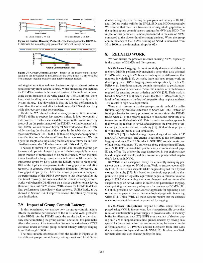
Figure 23: Instant Recovery Protocol – The throughput of the DBMS forYCSB with the instant logging protocol on different storage devices.
NVM-WBL SSD-WBL HDD-WBL NVM-WAL SSD-WAL HDD-WAL
10 100 1000 10000Group Commit Interval (us)
0
45000
90000
Thro
ughp
ut
Figure 24: Group Commit Latency – Impact of the group commit latencysetting on the throughput of the DBMS for the write-heavy YCSB workloadwith different logging protocols and durable storage devices.
and single-transaction undo mechanisms to support almost instanta-neous recovery from system failures. While processing transactions,the DBMS reconstructs the desired version of the tuple on demandusing the information in the write-ahead log. The DBMS can, there-fore, start handling new transactions almost immediately after asystem failure. The downside is that the DBMS performance islower than that observed after the traditional ARIES-style recoverywhile the recovery is not yet complete.
Unlike the WAL-based instant recovery protocol, WBL relies onNVM’s ability to support fast random writes. It does not contain aredo process. To better understand the impact of the instant-recoveryprotocol on the performance of the DBMS, we implemented it inour DBMS. We run the read-heavy YCSB workload on the DBMS,while varying the fraction of the tuples in the table that must bereconstructed from 0.001 to 0.1. With more frequent checkpointing,a smaller fraction of tuples would need be to reconstructed. We con-figure the length of a tuple’s log record chain to follow an uniformdistribution over the following ranges: (0, 100) and (0, 10).
The results shown in Figures 23a and 23b indicate that the per-formance drops with longer log record chains, especially when alarger fraction of tuples need to be reconstructed. When the max-imum length of a long record chain is limited to 10 records, thethroughput drops by 1.5× when the DBMS needs to reconstruct10% of the tuples in comparison to the throughput observed afterrecovery. In contrast, when the length is limited to 100 records, thethroughput drops by 8×. After the recovery process is complete,the performance of the DBMS converges to that observed after thetraditional recovery. We conclude that the instant recovery protocolworks well when the DBMS runs on a slower durable storage device.However, on a fast NVM device, WBL allows the DBMS to deliverhigh performance immediately after recovery. Unlike WAL, as weshowed in Section 7.4, it improves device utilization by reducingdata duplication.
7.9 Impact of Group Commit LatencyIn this experiment, we analyze how the group commit latency
affects the runtime performance of the WBL and WAL protocolsin the DBMS. As the DBMS sends the results back to the clientonly after completing the group commit operation, this parameteraffects the latency of the transaction. We run the write-heavy YCSBworkload under different group commit latency settings rangingfrom 10 through 10000 µs.
The most notable observation from the results in Figure 24 isthat different group commit latency settings work well for different
durable storage devices. Setting the group commit latency to 10, 100,and 1000 µs works well for the NVM, SSD, and HDD respectively.We observe that there is a two orders of magnitude gap betweenthe optimal group commit latency settings for NVM and HDD. Theimpact of this parameter is more pronounced in the case of NVMcompared to the slower durable storage devices. When the groupcommit latency of the DBMS running on NVM is increased from10 to 1000 µs, the throughput drops by 62×.
8. RELATED WORKWe now discuss the previous research on using NVM, especially
in the context of DBMSs and file-systems.
NVM-Aware Logging: A previous study demonstrated that in-memory DBMSs perform only marginally better than disk-orientedDBMSs when using NVM because both systems still assume thatmemory is volatile [14]. As such, there has been recent work ondeveloping new DBMS logging protocols specifically for NVM.Pelley et al. introduced a group commit mechanism to persist trans-actions’ updates in batches to reduce the number of write barriersrequired for ensuring correct ordering on NVM [33]. Their work isbased on Shore-MT [23], which means that the DBMS records page-level before-images in the log before performing in-place updates.This results in high data duplication.
Wang et al. present a passive group commit method for a dis-tributed logging protocol extension to Shore-MT [36]. Instead ofissuing a barrier for every processor at commit time, the DBMStracks when all of the records required to ensure the durability of atransaction are flushed to NVM. This is similar to another approachthat writes log records to NVM, and addresses the problems of de-tecting partial writes and recoverability [18]. Both of these projectsrely on software-based NVM simulation.
SOFORT [32] is a hybrid storage engine designed for both OLTPand OLAP workloads. The engine is designed to not perform anylogging and uses MVCC. Similar to SOFORT, we also make useof non-volatile pointers [3], but we use these pointers in a differentway. SOFORT’s non-volatile pointers are a combination of pageID and offset. We eschew the page abstraction in our engines sinceNVM is byte-addressable, and thus we use raw pointers that map todata’s location in NVM.
REWIND is an userspace library for efficiently managing per-sistent data structures on NVM using WAL to ensure recoverabil-ity [10]. FOEDUS is a scalable OLTP engine designed for a hybridstorage hierarchy [25]. It is based on the dual page primitive thatpoints to a pair of logically equivalent pages, a mutable volatilepage in DRAM containing the latest changes, and an immutablesnapshot page on NVM. SiloR is an efficient parallelized logging,checkpointing, and recovery subsystem for in-memory DBMSs [38].Oh et al. present a per-page logging approach for replacing a setof successive page writes to the same logical page with fewer logwrites [31]. Unlike WBL, all these systems require that the changesmade to persistent data must be preceded by logging.
NVM-Aware File-systems: Beyond DBMSs, others have ex-plored using NVM in file-systems. Rio is a persistent file cache thatrelies on uninterruptible power supply to provide a safe, in-memorybuffer for filesystem data [27]. BPFS uses a variant of shadow pag-ing on NVM to support atomic fine-grained updates by relying on aspecial hardware instruction that ensures ordering between writes indifferent epochs [12]. PMFS is another filesystem from Intel Labsthat is designed for byte-addressable NVM [17]. It relies on a WALfor meta-data and uses shadow paging for data.
347

Instant Recovery Protocol: This protocol comprises of on-demand single-tuple redo and single-transaction undo mechanismsto support almost instantaneous recovery from system failures [20,21]. While processing transactions, the DBMS reconstructs thedesired version of the tuple on demand using the information in thewrite-ahead log. The DBMS can, therefore, start handling new trans-actions almost immediately after a system failure. The downside isthat the DBMS performance is lower than that observed after thetraditional ARIES-style recovery while the recovery is not yet com-plete. This protocol works well when the DBMS runs on a slowerdurable storage device. But with NVM, WBL enables the DBMSto deliver high performance than instant recovery immediately afterrecovery as it does not require an on-demand redo process.
9. ACKNOWLEDGEMENTSThis work was supported (in part) by the Intel Science and Tech-
nology Center for Big Data, the U.S. National Science Foundation(CCF-1438955), and the Samsung Fellowship Program. We aregrateful to Jinwoong Kim, Jiajun Wang, Haibin Lin, and AbhishekJoshi for their assistance in implementing WBL in Peloton. Wewould like to thank Garth Gibson and Mike Stonebraker for theirfeedback on this work.
10. CONCLUSIONThis paper presented the write-behind logging protocol for emerg-
ing non-volatile storage technologies. We examined the impact ofthis redesign on the transactional throughput, latency, availability,and storage footprint of the DBMS. Our evaluation of recovery al-gorithm in Peloton showed that across different OLTP workloads itreduces the system’s recovery time by 100× and shrinks the storagefootprint by 1.5×.
11. REFERENCES[1] NUMA policy library. http://linux.die.net/man/3/numa.[2] Peloton Database Management System. http://pelotondb.org.[3] Persistent memory programming library. http://pmem.io/.[4] Intel Architecture Instruction Set Extensions Programming Reference.
https://software.intel.com/sites/default/files/managed/b4/3a/319433-024.pdf, 2016.
[5] R. Agrawal and H. V. Jagadish. Recovery algorithms for databasemachines with nonvolatile main memory. IWDM’89, pages 269–285.
[6] J. Arulraj, A. Pavlo, and S. Dulloor. Let’s talk about storage &recovery methods for non-volatile memory database systems. InSIGMOD’15.
[7] J. Arulraj, A. Pavlo, and P. Menon. Bridging the archipelago betweenrow-stores and column-stores for hybrid workloads. In SIGMOD’16.
[8] J. Axboe. Flexible io tester. http://freecode.com/projects/fio.[9] G. W. Burr, B. N. Kurdi, J. C. Scott, C. H. Lam, K. Gopalakrishnan,
and R. S. Shenoy. Overview of candidate device technologies forstorage-class memory. IBM J. Res. Dev., 52(4):449–464, July 2008.
[10] A. Chatzistergiou, M. Cintra, and S. D. Viglas. REWIND: Recoverywrite-ahead system for in-memory non-volatile data-structures.PVLDB, 2015.
[11] S. Chen and Q. Jin. Persistent b+-trees in non-volatile main memory.Proc. VLDB Endow., 2015.
[12] J. Condit, E. B. Nightingale, C. Frost, E. Ipek, B. Lee, D. Burger, andD. Coetzee. Better I/O through byte-addressable, persistent memory.In SOSP, pages 133–146, 2009.
[13] B. F. Cooper, A. Silberstein, E. Tam, R. Ramakrishnan, and R. Sears.Benchmarking cloud serving systems with YCSB. In SoCC, 2010.
[14] J. DeBrabant, J. Arulraj, A. Pavlo, M. Stonebraker, S. Zdonik, andS. Dulloor. A prolegomenon on OLTP database systems fornon-volatile memory. In ADMS@VLDB, 2014.
[15] D. J. DeWitt, R. H. Katz, F. Olken, L. D. Shapiro, M. R. Stonebraker,and D. Wood. Implementation techniques for main memory databasesystems. SIGMOD Rec., 14(2):1–8, 1984.
[16] C. Diaconu, C. Freedman, E. Ismert, P.-A. Larson, P. Mittal,R. Stonecipher, N. Verma, and M. Zwilling. Hekaton: SQL Server’sMemory-optimized OLTP Engine. In SIGMOD, 2013.
[17] S. R. Dulloor, S. K. Kumar, A. Keshavamurthy, P. Lantz,D. Subbareddy, R. Sankaran, and J. Jackson. System software forpersistent memory. In EuroSys, 2014.
[18] R. Fang, H.-I. Hsiao, B. He, C. Mohan, and Y. Wang. Highperformance database logging using storage class memory. ICDE,pages 1221–1231, 2011.
[19] M. Franklin. Concurrency Control and Recovery. The ComputerScience and Engineering Handbook, pages 1058–1077, 1997.
[20] G. Graefe, W. Guy, and C. Sauer. Instant recovery with write-aheadlogging: Page repair, system restart, and media restore. SynthesisLectures on Data Management, 2015.
[21] T. Härder, C. Sauer, G. Graefe, and W. Guy. Instant recovery withwrite-ahead logging. Datenbank-Spektrum, pages 235–239, 2015.
[22] J. Huang, K. Schwan, and M. K. Qureshi. Nvram-aware logging intransaction systems. Proc. VLDB Endow., pages 389–400, Dec. 2014.
[23] R. Johnson, I. Pandis, N. Hardavellas, A. Ailamaki, and B. Falsafi.Shore-MT: a scalable storage manager for the multicore era. In EDBT,pages 24–35, 2009.
[24] H. Kim, S. Seshadri, C. L. Dickey, and L. Chiu. Evaluating phasechange memory for enterprise storage systems: A study of cachingand tiering approaches. In FAST, 2014.
[25] H. Kimura. FOEDUS: OLTP engine for a thousand cores andNVRAM. In SIGMOD, 2015.
[26] P.-A. Larson, S. Blanas, C. Diaconu, C. Freedman, J. M. Patel, andM. Zwilling. High-performance concurrency control mechanisms formain-memory databases. Proc. VLDB Endow., 5(4):298–309, Dec.2011.
[27] D. E. Lowell and P. M. Chen. Free transactions with rio vista. In SOSP,1997.
[28] C. Mohan, D. Haderle, B. Lindsay, H. Pirahesh, and P. Schwarz.ARIES: a transaction recovery method supporting fine-granularitylocking and partial rollbacks using write-ahead logging. ACM Trans.Database Syst., 17(1):94–162, 1992.
[29] T. Neumann, T. Mühlbauer, and A. Kemper. Fast SerializableMulti-Version Concurrency Control for Main-Memory DatabaseSystems. In SIGMOD, 2015.
[30] NVM Express Inc. NVM Express over Fabrics specification.http://www.nvmexpress.org/specifications, 2016.
[31] G. Oh, S. Kim, S.-W. Lee, and B. Moon. Sqlite optimization withphase change memory for mobile applications. Proc. VLDB Endow.,8(12):1454–1465, Aug. 2015.
[32] I. Oukid, D. Booss, W. Lehner, P. Bumbulis, and T. Willhalm.SOFORT: A hybrid SCM-DRAM storage engine for fast data recovery.DaMoN, 2014.
[33] S. Pelley, T. F. Wenisch, B. T. Gold, and B. Bridge. Storagemanagement in the NVRAM era. PVLDB, 7(2):121–132, 2013.
[34] S. Pilarski and T. Kameda. Checkpointing for distributed databases:Starting from the basics. IEEE Trans. Parallel Distrib. Syst., 1992.
[35] The Transaction Processing Council. TPC-C Benchmark (Revision5.9.0). http://www.tpc.org/tpcc/, June 2007.
[36] T. Wang and R. Johnson. Scalable logging through emergingnon-volatile memory. PVLDB, 7(10):865–876, 2014.
[37] Y. Zhang, J. Yang, A. Memaripour, and S. Swanson. Mojim: A reliableand highly-available non-volatile memory system. In ASPLOS, 2015.
[38] W. Zheng, S. Tu, E. Kohler, and B. Liskov. Fast databases with fastdurability and recovery through multicore parallelism. In OSDI, 2014.
348