wrought steels for mechanical and allied engineering...
TRANSCRIPT

BRITISH STANDARD BS 970-2:1988Incorporating Amendment Nos. 1 and 2
Specification for
Wrought steels for mechanical and allied engineering purposes —
Part 2: Requirements for steels for the manufacture of hot formed springs
UDC 669.14-131:[669-122.4:669-15:669.018.27]:001.2
Lice
nsed
Cop
y: In
stitu
te O
f Tec
hnol
ogy
Tal
lagh
t, In
stitu
te o
f Tec
hnol
ogy,
Fri
Jul 2
0 10
:07:
34 G
MT
+00
:00
2007
, Unc
ontr
olle
d C
opy,
(c)
BS
I

BS 970-2:1988
This British Standard, having been prepared under the direction of the Iron and Steel Standards Committee, was published under the authority of the Board of BSI and comes into effect on31 October 1988
© BSI 12-1998
First published July 1941 First revision October 1942 Second revision March 1947 Third revision January 1955 Fourth revision, as Part 5, June 1972Fifth revision, as Part 2, October 1988
The following BSI references relate to the work on this standard:Committee reference ISM/31 Draft for comment 87/36929 DC
ISBN 0 580 16869 7
Committees responsible for this British Standard
The preparation of this British Standard was entrusted by the Iron and Steel Standards Committee (ISM/-) to Technical Committee ISM/31, upon which the following bodies were represented:
British Chain Manufacturers’ AssociationBritish CoalBritish Forging Industry AssociationBritish Industrial Fasteners FederationBritish RailBritish Steel IndustryCold Rolled Sections AssociationDepartment of Trade and Industry (National Physical Laboratory)Engineering Industries’ AssociationFederation of British Engineers’ Tool ManufacturersInstitution of Production EngineersLloyds Register of ShippingMinistry of DefenceNational Association of Steel StockholdersRoad Vehicle Spring SocietySociety of British Aerospace Companies LimitedSociety of Motor Manufacturers and Traders LimitedStainless Steel Fabricators’ Association of Great Britain
The following bodies were also represented in the drafting of the standard, through sub-committees and panels:
Spring Research and Manufacturers’ Association
Amendments issued since publication
Amd. No. Date of issue Comments
6190 August, 1989
6942 February, 1992 Indicated by a sideline in the margin
Lice
nsed
Cop
y: In
stitu
te O
f Tec
hnol
ogy
Tal
lagh
t, In
stitu
te o
f Tec
hnol
ogy,
Fri
Jul 2
0 10
:07:
34 G
MT
+00
:00
2007
, Unc
ontr
olle
d C
opy,
(c)
BS
I
BS 970-2:1988
© BSI 12-1998 i
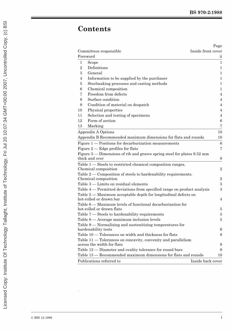
Contents
PageCommittees responsible Inside front coverForeword ii
1 Scope 12 Definitions 13 General 14 Information to be supplied by the purchaser 15 Steelmaking processes and casting methods 16 Chemical composition 17 Freedom from defects 48 Surface condition 49 Condition of material on despatch 4
10 Physical properties 411 Selection and testing of specimens 412 Form of section 613 Marking 7
Appendix A Options 10Appendix B Recommended maximum dimensions for flats and rounds 10
Figure 1 — Positions for decarburization measurements 6Figure 2 — Edge profiles for flats 7Figure 3 — Dimensions of rib and groove spring steel for plates 9.52 mm thick and over 8
Table 1 — Steels to restricted chemical composition ranges.Chemical composition 2Table 2 — Composition of steels to hardenability requirements.Chemical composition 2Table 3 — Limits on residual elements 3Table 4 — Permitted deviations from specified range on product analysis 3Table 5 — Maximum acceptable depth for longitudinal defects onhot-rolled or drawn bar 4Table 6 — Maximum levels of functional decarburization forhot-rolled or drawn flats 5Table 7 — Steels to hardenability requirements 5Table 8 — Average maximum inclusion levels 5Table 9 — Normalizing and austenitizing temperatures forhardenability tests 6Table 10 — Tolerances on width and thickness for flats 8Table 11 — Tolerances on concavity, convexity and parallelism across the width for flats 8Table 12 — Diameter and ovality tolerance for round bars 9Table 13 — Recommended maximum dimensions for flats and rounds 10
Publications referred to Inside back cover
Lice
nsed
Cop
y: In
stitu
te O
f Tec
hnol
ogy
Tal
lagh
t, In
stitu
te o
f Tec
hnol
ogy,
Fri
Jul 2
0 10
:07:
34 G
MT
+00
:00
2007
, Unc
ontr
olle
d C
opy,
(c)
BS
I

BS 970-2:1988
ii © BSI 12-1998
Foreword
This Part of BS 970 has been prepared under the direction of the Iron and Steel Standards Committee.It forms Part 2 of a restructured BS 970 and is a revision of BS 970-5:1972, incorporating the requirements of BS 24-3A:1959. Both these standards are withdrawn.The restructured BS 970 consists of three Parts. Part 1 specifies general inspection and testing procedures and specific requirements for carbon, carbon manganese, alloy and stainless steels and was published in 1983. BS 970-4 was published in 1970 and specifies requirements for valve steels.New steels have been introduced in this Part of BS 970 to reflect changes in spring manufacture, the need for fine-grained steels and, for certain applications, closely controlled hardenability. Requirements have also been introduced for average maximum levels of non-metallic inclusions for all types of bar and for depths of decarburization and surface defects on hot rolled or drawn bar.The dimensional and decarburization tolerances in this Part of BS 970 apply only to material supplied directly to the spring maker and not to intermediate products.The carbon steels for general applications have been removed in this revision as they are already covered in Table 2 of BS 970-1:1983 (grades 080A67 and 060A78).A number of ordering options is listed in appendix A. These should be called up by the purchaser as required.Assessed capability. Users of this British Standard are advised to consider the desirability of assessment and registration of a supplier’s quality systems against the appropriate Part of BS 5750 by a third party certification body.A British Standard does not purport to include all the necessary provisions of a contract. Users of British Standards are responsible for their correct application.
Compliance with a British Standard does not of itself confer immunity from legal obligations.
Summary of pagesThis document comprises a front cover, an inside front cover, pages i and ii, pages 1 to 10, an inside back cover and a back cover.This standard has been updated (see copyright date) and may have had amendments incorporated. This will be indicated in the amendment table on the inside front cover.
Lice
nsed
Cop
y: In
stitu
te O
f Tec
hnol
ogy
Tal
lagh
t, In
stitu
te o
f Tec
hnol
ogy,
Fri
Jul 2
0 10
:07:
34 G
MT
+00
:00
2007
, Unc
ontr
olle
d C
opy,
(c)
BS
I

BS 970-2:1988
© BSI 12-1998 1
1 ScopeThis Part of BS 970 specifies requirements for steelmaking, chemical composition, physical properties, dimensional tolerances and testing procedures for hot-rolled flats and rounds and drawn or turned (or peeled) or ground rounds for the production of hot formed and heat treated springs.The requirements apply to eleven grades of steel supplied to restricted chemical analysis ranges and twelve grades of steel supplied to hardenability limits.Special ordering options, to be called up, as required, by the purchaser, are included in appendix A.NOTE The titles of the publications referred to in this standard are listed on the inside back cover.
2 DefinitionsFor the purposes of this Part of BS 970 the following definitions apply.
2.1 drawn bar
bar of circular cross section obtained, usually after annealing and descaling by drawing of hot-rolled rod on a draw bench (cold deformation without removing material) followed by straightening and cutting. This operation gives the product special features with respect to shape, dimensional accuracy and surface finish but has only a small reducing effect on decarburization and defect depth
2.2 turned (or peeled) bar
bar of circular cross section having the special features of drawn products, concerning shape, dimensional accuracy and bright surface finish produced by turning on a lathe (or peeling), together with the additional benefit of metal removal on decarburization and defect depth
2.3 ground bar
bar of circular cross section having the special features of drawn products, concerning shape, dimensional accuracy and bright surface finish, produced by grinding or grinding and polishing, together with the additional benefit of metal removal on decarburization and defect depth
3 GeneralThe steel products shall comply with the general requirements of this standard and with the specific requirements applicable to the grade concerned. Where any of the options given in appendix A are called up at the time of the enquiry and order, the steel products shall, in addition, comply with the requirements of any such options.
4 Information to be supplied by the purchaser4.1 General
The following information shall be supplied at the time of enquiry and order.
a) Details of the form of section, size and quantity (see clause 12).b) The grade of steel (see Table 1, Table 2 and Table 7).
4.2 Options
A number of ordering options are given in appendix A. If the purchaser does not specify any of these options at the time of enquiry and order, the manufacturer shall supply in accordance with the basic specification. See option A.11.
5 Steelmaking processes and casting methods5.1 Steelmaking
Steelmaking shall be by any process except the air or mixed air and oxygen bottom blown basic converter process.
5.2 Casting methods
The steel shall be cast into ingots or continuously cast. See also option A.1.
6 Chemical composition6.1 Composition ranges
The chemical composition of the steel, based on cast analysis, shall comply with the requirements of the appropriate material specification in Table 1 or Table 2. See also option A.2.NOTE 1 Table 2 gives the composition ranges for the steels in Table 7.NOTE 2 The recommended maximum section thickness for each of the steel grades is given in appendix B.
6.2 Residual elements
Elements not quoted in the relevant material specification shall not be added to the steel other than for the purpose of finishing the heat.Percentages of elements up to the limits given in Table 3 shall be considered as residual.
Lice
nsed
Cop
y: In
stitu
te O
f Tec
hnol
ogy
Tal
lagh
t, In
stitu
te o
f Tec
hnol
ogy,
Fri
Jul 2
0 10
:07:
34 G
MT
+00
:00
2007
, Unc
ontr
olle
d C
opy,
(c)
BS
I

BS
970-2:1988
2©
BS
I 12-1998
Table 1 — Steels to restricted chemical composition ranges. Chemical composition
Table 2 — Composition of steels to hardenability requirements. Chemical composition
Grade Carbon Silicon Manganese Phosphorus Sulphur Chromium Molybdenum Vanadium
C Si Mn P S Cr Mo V
% m/m % m/m % m/m % m/m (max.)
% m/m (max.)
% m/m % m/m %m/m
Silico-manganese steels
251A58 0.55 to 0.60 1.80 to 2.10 0.80 to 1.00 0.035 0.035 0.15 to 0.30 0.10 max. —
251A60 0.57 to 0.62 1.80 to 2.10 0.80 to 1.00 0.035 0.035 0.25 to 0.40 0.12 max. —
Alloy steels 525A58 0.55 to 0.60 0.20 to 0.35 0.80 to 0.95 0.035 0.035 0.70 to 0.85 0.10 max. —
525A60 0.57 to 0.62 0.20 to 0.35 0.85 to 1.0 0.035 0.035 0.80 to 0.95 0.06 min. —
525A61 0.57 to 0.63 0.20 to 0.35 0.85 to 1.0 0.035 0.035 0.85 to 1.00 0.08 to 0.15 —
685A57 0.55 to 0.60 1.20 to 1.60 0.70 to 0.90 0.035 0.035 0.60 to 0.85 — —
704A60 0.57 to 0.62 0.20 to 0.35 0.85 to 1.0 0.035 0.035 0.80 to 0.95 0.15 to 0.25 —
705A60 0.57 to 0.62 0.20 to 0.35 0.85 to 1.0 0.035 0.035 0.85 to 1.00 0.25 to 0.35 —
735A51 0.48 to 0.54 0.20 to 0.35 0.70 to 1.0 0.035 0.035 0.90 to 1.20 — 0.10 to 0.20
735A54 0.52 to 0.57 0.20 to 0.35 0.90 to 1.15 0.035 0.035 1.05 to 1.20 — 0.12 to 0.20
925A60 0.55 to 0.65 1.70 to 2.10 0.70 to 1.00 0.035 0.035 0.20 to 0.40 0.20 to 0.30 —
Grade Carbon Silicon Manganese Phosphorus Sulphur Chromium Molybdenum Nickel Vanadium
C Si Mn P S Cr Mo Ni V
% m/m % m/m % m/m % m/m % m/m % m/m % m/m % m/m % m/m
(max.)
Silico-manganese steel
251H60 0.56 to 0.64 1.60 to 2.20 0.70 to 1.00 0.035 0.035 0.40 max. 0.12 max. — —
Alloy steels 525H60 0.55 to 0.64 0.15 to 0.40 0.65 to 1.00 0.035 0.035 0.60 to 1.00 0.15 max. — —
685H57 0.54 to 0.62 1.20 to 1.60 0.50 to 0.80 0.035 0.035 0.50 to 0.80 — — —
704H60 0.55 to 0.64 0.15 to 0.40 0.65 to 1.10 0.035 0.035 0.60 to 1.00 0.15 to 0.25 — —
705H60 0.55 to 0.64 0.15 to 0.40 0.65 to 1.10 0.035 0.035 0.60 to 1.00 0.25 to 0.35 — —
735H51 0.47 to 0.55 0.15 to 0.40 0.70 to 1.10 0.035 0.035 0.90 to 1.20 — — 0.10 to 0.25
805H60 0.55 to 0.64 0.15 to 0.40 0.65 to 1.05 0.035 0.035 0.35 to 0.65 0.15 to 0.25 0.35 to 0.75 —
Lice
nsed
Cop
y: In
stitu
te O
f Tec
hnol
ogy
Tal
lagh
t, In
stitu
te o
f Tec
hnol
ogy,
Fri
Jul 2
0 10
:07:
34 G
MT
+00
:00
2007
, Unc
ontr
olle
d C
opy,
(c)
BS
I
BS 970-2:1988
© BSI 12-1998 3
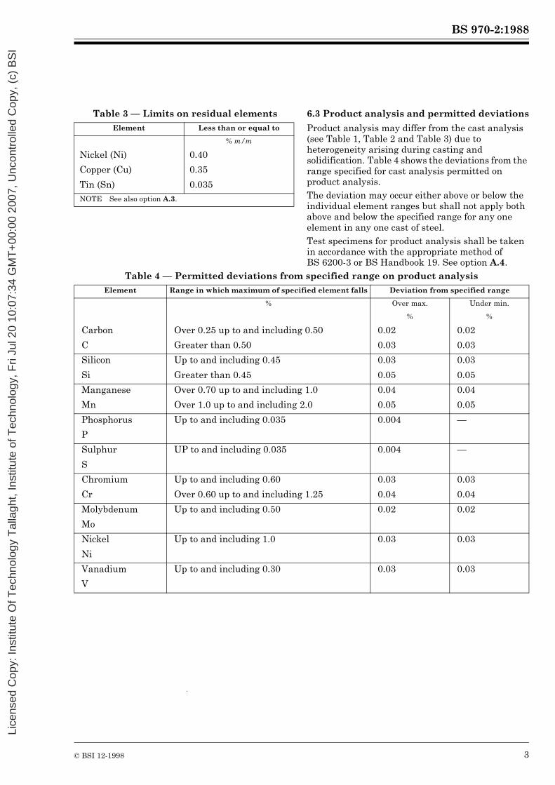
Table 3 — Limits on residual elements 6.3 Product analysis and permitted deviations
Product analysis may differ from the cast analysis (see Table 1, Table 2 and Table 3) due to heterogeneity arising during casting and solidification. Table 4 shows the deviations from the range specified for cast analysis permitted on product analysis.The deviation may occur either above or below the individual element ranges but shall not apply both above and below the specified range for any one element in any one cast of steel.Test specimens for product analysis shall be taken in accordance with the appropriate method of BS 6200-3 or BS Handbook 19. See option A.4.
Table 4 — Permitted deviations from specified range on product analysis
Element Less than or equal to
% m/m
Nickel (Ni) 0.40
Copper (Cu) 0.35
Tin (Sn) 0.035NOTE See also option A.3.
Element Range in which maximum of specified element falls Deviation from specified range
% Over max. Under min.
% %
Carbon Over 0.25 up to and including 0.50 0.02 0.02
C Greater than 0.50 0.03 0.03
Silicon Up to and including 0.45 0.03 0.03
Si Greater than 0.45 0.05 0.05
Manganese Over 0.70 up to and including 1.0 0.04 0.04
Mn Over 1.0 up to and including 2.0 0.05 0.05
Phosphorus Up to and including 0.035 0.004 —
P
Sulphur UP to and including 0.035 0.004 —
S
Chromium Up to and including 0.60 0.03 0.03
Cr Over 0.60 up to and including 1.25 0.04 0.04
Molybdenum Up to and including 0.50 0.02 0.02
Mo
Nickel Up to and including 1.0 0.03 0.03
Ni
Vanadium Up to and including 0.30 0.03 0.03
V
Lice
nsed
Cop
y: In
stitu
te O
f Tec
hnol
ogy
Tal
lagh
t, In
stitu
te o
f Tec
hnol
ogy,
Fri
Jul 2
0 10
:07:
34 G
MT
+00
:00
2007
, Unc
ontr
olle
d C
opy,
(c)
BS
I

BS 970-2:1988
4 © BSI 12-1998
7 Freedom from defectsThe procedures for casting, working, reheating and cooling and the amount of working shall ensure that the product is free from piping, central unsoundness and harmful segregation.
8 Surface condition8.1 Surface defects
Hot-rolled or drawn bar shall be free from transverse defects and from longitudinal defects deeper than those given in Table 5. Turned (or peeled) or ground bar shall not exhibit surface defects.Currently established in-process methods for the inspection of hot-rolled bar may not detect all defects resulting in some bars in a consignment containing defects in excess of the maximum acceptable depth. Bars exhibiting such defects on later processing shall be deemed not to comply with this standard.
8.2 Surface texture of turned (or peeled) or ground bars
When assessed in accordance with BS 1134-1, bars shall exhibit a maximum Ra of 3.2 µm. See also option A.6.
Table 5 — Maximum acceptable depth for longitudinal defects on hot-rolled
or drawn bar
8.3 Decarburization
Complete decarburization shall not be present.The maximum depth of functional decarburization on hot-rolled or drawn bars shall be as follows, when measured in accordance with BS 6617-1 or BS 6617-2.
a) For flats, the requirements of Table 6 shall be met when measured in the areas defined inFigure 1.b) For rounds, the maximum depth of decarburization shall be 1.5 % of the actual bar diameter for silico-manganese steels and 1.25 % of the actual bar diameter for alloy steels.
Turned (or peeled) or ground bars shall not exhibit decarburization.
9 Condition of material on despatchBar ends shall be free from splits.NOTE For the avoidance of shearing and machining problems, a maximum hardness of 321 Brinell Hardness Number (BHN) is recommended. Subcritical annealing may be required to ensure freedom from shearing and machining problems and may also be necessary in the case of rod material requiring decoiling and cutting for the production of rounds in straight lengths. When subcritical annealing is employed, the maximum recommended hardness is 277 BHN.
See also option A.5.
10 Physical properties10.1 Hardenability
Steels to hardenability requirements shall comply with the hardness values at the positions specified in Table 7.See also option A.7.
10.2 Grain size
Steels in both Table 1 and Table 7 shall exhibit a grain size of 5 to 8 (see BS 4490).See also option A.8.NOTE This applies to the grain size assessment on a laboratory test (see 11.3) and to the developed grain size in the heat-treated spring. For the latter, the austenitizing temperature used for the dual hot-forming/hardening operation should not exceed 1 000 °C.
10.3 Inclusion content
Steels shall comply with the requirements inTable 8 for the level of freedom from non-metallic inclusions.See also options A.9 and A.10.
11 Selection and testing of specimens11.1 General
Where options A.7, A.8 or A.9 are invoked, testing shall be carried out in accordance with the relevant subclause.
11.2 Hardenability
One test sample selected to represent each cast shall be reduced by forging or rolling to a size not greater than 38 mm in diameter, which shall represent the full cross section of the material. This test sample shall also be of sufficient size to ensure the removal of decarburization in machining to the standard test specimen of 25 mm diameter. Normalizing and austenitizing temperatures for the hardenability test shall be as given in Table 9. Tests shall be carried out in accordance with method 1 of BS 4437.
Thickness/diameter Maximum acceptable depth
mm
Up to and including 25 0.25 mm
Over 25 up to and including 50 1 % of thickness
Over 50 up to and including 63.5 0.50 mm
Over 63.5 up to and including 80 0.60 mm
Lice
nsed
Cop
y: In
stitu
te O
f Tec
hnol
ogy
Tal
lagh
t, In
stitu
te o
f Tec
hnol
ogy,
Fri
Jul 2
0 10
:07:
34 G
MT
+00
:00
2007
, Unc
ontr
olle
d C
opy,
(c)
BS
I

BS 970-2:1988
© BSI 12-1998 5
Table 6 — Maximum levels of functional decarburization for hot-rolled or drawn flats
Table 7 — Steels to hardenability requirements
Table 8 — Average maximum inclusion levels
Thickness Maximum functional decarburization
Silico-manganese steels Alloy steels Flat surface Edge
mm mm mm mm
Up to and including 7 Up to and including 15 0.25 0.35
Over 7 up to and including 10 Over 15 up to and including 25 0.30 0.40
Over 10 up to and including 14 Over 25 up to and including 35 0.35 0.45
Over 14 Over 35 up to and including 45 0.40 0.50
— Over 45 0.45 0.55
Grade Distance from quenched end (mm)
1.5 3 5 7 9 11 13 15 20 25 30 35 40 45 50Rockwell Hardness Number (scale C) (HRC)
Silico-manganese steels
251 H60-M max. 66 66 66 65 65 64 63 61 55 47 45 43 42 41 40min. 60 59 58 56 52 46 42 38 34 31 29 28 27 26 25
251 H60-H max. 66 66 66 65 65 64 63 61 55 47 45 43 42 41 40min. 60 59 58 57 56 52 45 42 36 33 31 30 29 28 27
Alloy steels 525H60 max. 66 66 66 65 65 65 65 64 64 63 63 62 62 61 60min. 60 60 60 59 57 55 51 45 40 36 35 34 33 32 31
525H60-M max. 66 66 66 65 65 65 65 64 64 63 63 62 62 61 60min. 60 60 60 59 59 58 57 55 48 43 38 37 36 33 32
525H60-H max. 66 66 66 65 65 65 65 64 64 63 63 62 62 61 60min. 60 60 60 59 59 59 58 57 55 50 45 42 40 38 36
685H57 max. 66 65 64min. 60 58 53
704H60 max. 66 66 66 66 66 65 65 65 65 64 64 63 63 63 63min. 60 60 60 60 60 59 59 59 59 57 55 51 49 46 44
705H60 max. 66 66 66 66 66 65 65 65 65 64 64 64 64 64 64min. 60 60 60 60 60 59 59 59 59 58 58 57 57 56 55
735H51 max. 65 65 64 64 63 62 62 61 60 58 57 55 54 53 52min. 57 56 55 54 53 52 50 48 44 41 37 35 34 33 32
805H60 max. 66 66 66 66 66 66 66 66 66 66 65 64 63 62 61min. 60 60 60 60 59 58 55 52 47 43 39 37 36 35 35
805H60-M max. 66 66 66 66 66 66 66 66 66 66 65 64 63 62 60min. 60 60 60 60 60 59 58 56 51 47 43 40 38 37 36
805H60-H max. 66 66 66 66 66 66 66 66 66 66 65 64 63 62 61min. 60 60 60 60 60 60 60 59 58 55 49 46 42 41 40
Type B Type C Type D
Fine series Thick series Fine series Thick series Fine series Thick series
Silico-manganese steels 3 11/2 21/2 11/2 2 11/2
Alloy steels 3 11/2 11/2 1 2 11/2
NOTE Requirements are based on the description of inclusions given in ISO 4967.
Lice
nsed
Cop
y: In
stitu
te O
f Tec
hnol
ogy
Tal
lagh
t, In
stitu
te o
f Tec
hnol
ogy,
Fri
Jul 2
0 10
:07:
34 G
MT
+00
:00
2007
, Unc
ontr
olle
d C
opy,
(c)
BS
I

BS 970-2:1988
6 © BSI 12-1998
Table 9 — Normalizing and austenitizing temperatures for hardenability tests
11.3 Grain size
One specimen shall be selected to represent each cast. Tests shall be carried out in accordance with the McQuaid Ehn method given in BS 4490.
11.4 Inclusion assessment
A minimum of six specimens per cast shall be selected. Specimens shall be prepared and examined in accordance with ISO 4967 and the average maximum levels shall comply with the requirements of Table 8.
12 Form of section12.1 Flats
12.1.1 General. The section shall be rectangular and free from rhomboidal effects. The edge profile shall meet one of the following criteria which are illustrated in Figure 2.NOTE Unless otherwise ordered by the purchaser, the normal section profiles will be supplied.
12.1.2 Normal sections
a) For thicknesses below 14 mm, the edge radius shall be approximately equal to the thickness of the material.b) For thicknesses of 14 mm and above, the edge radius shall be approximately equal to the thickness of the material. The corners shall have localized radii equal to a quarter of the thickness.
12.1.3 Special sections
a) For certain large applications and sizes generally above 40 mm thick, a profile shall have a square edge and radiused corners. The corner radius shall be within the range 6 mm to 12 mm with a tolerance of mm.b) The edge radius shall be equal to half the material thickness.
Figure 1 — Positions for decarburization measurements
Grade Normalizing temperature
Austenitizing temperature
°C °C
251H60 900 870
525H60 870 845
685H57 900 870
704H60 870 845
705H60 870 845
805H60 870 845
2+ 0–
Lice
nsed
Cop
y: In
stitu
te O
f Tec
hnol
ogy
Tal
lagh
t, In
stitu
te o
f Tec
hnol
ogy,
Fri
Jul 2
0 10
:07:
34 G
MT
+00
:00
2007
, Unc
ontr
olle
d C
opy,
(c)
BS
I
BS 970-2:1988
© BSI 12-1998 7
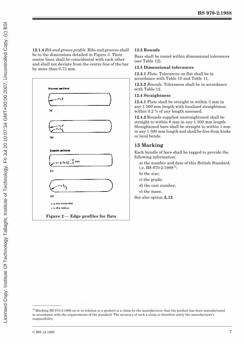
12.1.4 Rib and groove profile. Ribs and grooves shall be to the dimensions detailed in Figure 3. Their centre lines shall be coincidental with each other and shall not deviate from the centre line of the bar by more than 0.73 mm.
12.2 Rounds
Bars shall be round within dimensional tolerances (see Table 12).
12.3 Dimensional tolerances
12.3.1 Flats. Tolerances on flat shall be in accordance with Table 10 and Table 11.12.3.2 Rounds. Tolerances shall be in accordance with Table 12.
12.4 Straightness
12.4.1 Flats shall be straight to within 3 mm in any 1 500 mm length with localized straightness within 0.2 % of any length assessed.12.4.2 Rounds supplied unstraightened shall be straight to within 6 mm in any 1 500 mm length. Straightened bars shall be straight to within 1 mm in any 1 500 mm length and shall be free from kinks or local bends.
13 MarkingEach bundle of bars shall be tagged to provide the following information:
a) the number and date of this British Standard, i.e. BS 970-2:19881);b) the size;c) the grade;d) the cast number;e) the mass.
See also option A.12.
Figure 2 — Edge profiles for flats
1) Marking BS 970-2:1988 on or in relation to a product is a claim by the manufacturer that the product has been manufactured in accordance with the requirements of the standard. The accuracy of such a claim is therefore solely the manufacturer’s responsibility.
Lice
nsed
Cop
y: In
stitu
te O
f Tec
hnol
ogy
Tal
lagh
t, In
stitu
te o
f Tec
hnol
ogy,
Fri
Jul 2
0 10
:07:
34 G
MT
+00
:00
2007
, Unc
ontr
olle
d C
opy,
(c)
BS
I

BS 970-2:1988
8 © BSI 12-1998
Table 10 — Tolerances on width and thickness for flats
Table 11 — Tolerances on concavity, convexity and parallelism across the width for flats
Nominal width Width tolerance
Thickness tolerance
Up to 13 mm thick
Over 13 mm up to 20 mm thick
Over 20 mm up to 30 mm thick
Over 30 mm up to 40 mm thick
Over 40 mm up to 60 mm thick
mm mm mm mm mm mm
Up to 50 mm ± 0.40 ± 0.13 ± 0.18 ± 0.20 ± 0.30 ± 0.40Above 50 mm Up to 75 mm
± 0.50 ± 0.15 ± 0.20 ± 0.20 ± 0.30 ± 0.40
Above 75 mm Up to 100 mm
± 0.50 ± 0.15 ± 0.20 ± 0.30 ± 0.40 ±0.50
Above 100 mm Up to 160 mm
± 0.70 ± 0.20 ± 0.25 ± 0.30 ± 0.40 ± 0.50
Figure 3 — Dimensions of rib and groove spring steel for plates 9.52 mm thick and over
Nominal width Total concavity maximum
Total convexity maximum
Thickness difference between the two edges,
maximum
mm mm mm
Up to and including 50 mm 0.10 0 0.05
Over 50 mm up to and including 75 mm 0.10 0 0.08
Over 75 mm up to and including 100 mm 0.15 0 0.10
Over 100 mm up to and including 160 mm 0.20 0 0.13
Lice
nsed
Cop
y: In
stitu
te O
f Tec
hnol
ogy
Tal
lagh
t, In
stitu
te o
f Tec
hnol
ogy,
Fri
Jul 2
0 10
:07:
34 G
MT
+00
:00
2007
, Unc
ontr
olle
d C
opy,
(c)
BS
I

BS 970-2:1988
© BSI 12-1998 9
Table 12 — Diameter and ovality tolerance for round barsHot-rolled rounds Drawn or turned (or peeled) or ground rounds
Size (diameter) The greater of mm or , up to a
maximum of 0.50 mm
Up to 15 mm dia: ± 0.03 mm
Above 15 mm
Up to 25 mm dia: ± 0.05 mm
Above 25 mm dia: ± 0.07 mm
Ovality Maximum of 75 % of the size tolerance band Maximum of 40 % of the size tolerance band
0.25+ 0–
1.5+ 0–
%
Lice
nsed
Cop
y: In
stitu
te O
f Tec
hnol
ogy
Tal
lagh
t, In
stitu
te o
f Tec
hnol
ogy,
Fri
Jul 2
0 10
:07:
34 G
MT
+00
:00
2007
, Unc
ontr
olle
d C
opy,
(c)
BS
I
BS 970-2:1988
10 © BSI 12-1998
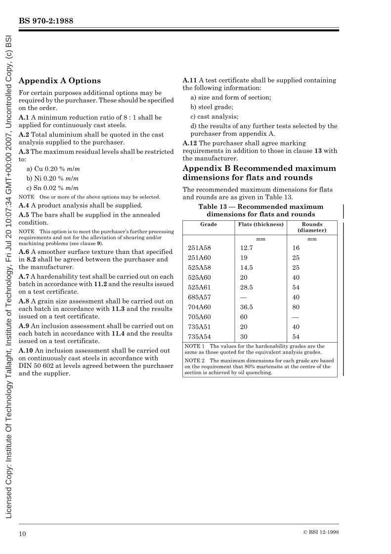
Appendix A Options
For certain purposes additional options may be required by the purchaser. These should be specified on the order.A.1 A minimum reduction ratio of 8 : 1 shall be applied for continuously cast steels.A.2 Total aluminium shall be quoted in the cast analysis supplied to the purchaser.A.3 The maximum residual levels shall be restricted to:
a) Cu 0.20 % m/mb) Ni 0.20 % m/mc) Sn 0.02 % m/m
NOTE One or more of the above options may be selected.
A.4 A product analysis shall be supplied.A.5 The bars shall be supplied in the annealed condition.NOTE This option is to meet the purchaser’s further processing requirements and not for the alleviation of shearing and/or machining problems (see clause 9).
A.6 A smoother surface texture than that specified in 8.2 shall be agreed between the purchaser and the manufacturer.A.7 A hardenability test shall be carried out on each batch in accordance with 11.2 and the results issued on a test certificate.A.8 A grain size assessment shall be carried out on each batch in accordance with 11.3 and the results issued on a test certificate.A.9 An inclusion assessment shall be carried out on each batch in accordance with 11.4 and the results issued on a test certificate.A.10 An inclusion assessment shall be carried out on continuously cast steels in accordance with DIN 50 602 at levels agreed between the purchaser and the supplier.
A.11 A test certificate shall be supplied containing the following information:
a) size and form of section;b) steel grade;c) cast analysis;d) the results of any further tests selected by the purchaser from appendix A.
A.12 The purchaser shall agree marking requirements in addition to those in clause 13 with the manufacturer.
Appendix B Recommended maximum dimensions for flats and rounds
The recommended maximum dimensions for flats and rounds are as given in Table 13.
Table 13 — Recommended maximum dimensions for flats and rounds
Grade Flats (thickness) Rounds (diameter)
mm mm
251A58 12.7 16251A60 19 25525A58 14.5 25525A60 20 40525A61 28.5 54685A57 — 40704A60 36.5 80705A60 60 —735A51 20 40735A54 30 54
NOTE 1 The values for the hardenability grades are the same as those quoted for the equivalent analysis grades.
NOTE 2 The maximum dimensions for each grade are based on the requirement that 80% martensite at the centre of the section is achieved by oil quenching.
Lice
nsed
Cop
y: In
stitu
te O
f Tec
hnol
ogy
Tal
lagh
t, In
stitu
te o
f Tec
hnol
ogy,
Fri
Jul 2
0 10
:07:
34 G
MT
+00
:00
2007
, Unc
ontr
olle
d C
opy,
(c)
BS
I

BS 970-2:1988
© BSI 12-1998
Publications referred to
BS 970, Specification for wrought steels for mechanical and allied engineering purposes2).BS 970-1, General inspection and testing procedures and specific requirements for carbon,carbon-manganese, alloy and stainless steels.BS 970-4, Valve steels.BS 1134, Method for the assessment of surface texture Part 1 Method and instrumentation.BS 4437, Method for determining hardenability of steel by end quenching (Jominy test).BS 4490, Methods for the determination of the austenitic grain size of steel.BS 5750, Quality systems2).BS 6200, Sampling and analysis of iron, steel and other ferrous metals.BS 6200-3, Methods of analysis.BS 6617, Determination of decarburization in steel.BS 6617-1, Methods for determining decarburization by microscopic and micro-hardness techniques.BS 6617-2, Methods for determining decarburization by chemical and spectrographic analysis techniques.Handbook 19, Methods for sampling and analysis of iron, steel and other ferrous metals.ISO 4967, Steel — Determination of content of non-metallic inclusions — Micrographic method using standard diagrams.DIN 50 602, Microscopic examination of special steels using standard diagrams to assess the content ofnon-metallic inclusions.
2) Referred to in the foreword only.Lice
nsed
Cop
y: In
stitu
te O
f Tec
hnol
ogy
Tal
lagh
t, In
stitu
te o
f Tec
hnol
ogy,
Fri
Jul 2
0 10
:07:
34 G
MT
+00
:00
2007
, Unc
ontr
olle
d C
opy,
(c)
BS
I

BSI389 Chiswick High RoadLondonW4 4AL
|||||||||||||||||||||||||||||||||||||||||||||||||||||||||||||||||||||||||||||||||||||||||||||||||||||||||||||||||||||||||||||||
BSI Ð British Standards Institution
BSI is the independent national body responsible for preparing British Standards. Itpresents the UK view on standards in Europe and at the international level. It isincorporated by Royal Charter.
Revisions
British Standards are updated by amendment or revision. Users of British Standardsshould make sure that they possess the latest amendments or editions.
It is the constant aim of BSI to improve the quality of our products and services. Wewould be grateful if anyone finding an inaccuracy or ambiguity while using thisBritish Standard would inform the Secretary of the technical committee responsible,the identity of which can be found on the inside front cover. Tel: 020 8996 9000.Fax: 020 8996 7400.
BSI offers members an individual updating service called PLUS which ensures thatsubscribers automatically receive the latest editions of standards.
Buying standards
Orders for all BSI, international and foreign standards publications should beaddressed to Customer Services. Tel: 020 8996 9001. Fax: 020 8996 7001.
In response to orders for international standards, it is BSI policy to supply the BSIimplementation of those that have been published as British Standards, unlessotherwise requested.
Information on standards
BSI provides a wide range of information on national, European and internationalstandards through its Library and its Technical Help to Exporters Service. VariousBSI electronic information services are also available which give details on all itsproducts and services. Contact the Information Centre. Tel: 020 8996 7111.Fax: 020 8996 7048.
Subscribing members of BSI are kept up to date with standards developments andreceive substantial discounts on the purchase price of standards. For details ofthese and other benefits contact Membership Administration. Tel: 020 8996 7002.Fax: 020 8996 7001.
Copyright
Copyright subsists in all BSI publications. BSI also holds the copyright, in the UK, ofthe publications of the international standardization bodies. Except as permittedunder the Copyright, Designs and Patents Act 1988 no extract may be reproduced,stored in a retrieval system or transmitted in any form or by any means ± electronic,photocopying, recording or otherwise ± without prior written permission from BSI.
This does not preclude the free use, in the course of implementing the standard, ofnecessary details such as symbols, and size, type or grade designations. If thesedetails are to be used for any other purpose than implementation then the priorwritten permission of BSI must be obtained.
If permission is granted, the terms may include royalty payments or a licensingagreement. Details and advice can be obtained from the Copyright Manager.Tel: 020 8996 7070.
Lice
nsed
Cop
y: In
stitu
te O
f Tec
hnol
ogy
Tal
lagh
t, In
stitu
te o
f Tec
hnol
ogy,
Fri
Jul 2
0 10
:07:
34 G
MT
+00
:00
2007
, Unc
ontr
olle
d C
opy,
(c)
BS
I