ws10-1 contact analysis using 3d bolts workshop 10
TRANSCRIPT

WS10-1
CONTACT ANALYSIS USING 3D BOLTS
Workshop 10

WS10-2

WS10-3
● Workshop Objectives● To create contact bodies and tables● To create 3D bolts. ● To run an implicit nonlinear (Solution 600) analysis.
● Problem Description● Import a parasolid file containing five 3D unmeshed parts: two
plates to be tightened by three bolts● Define all parts as 3D deformable bodies.● Create a contact table to indicate a contact body pair between
each bolt and each plate and between the two plates.● Define 3D bolts● Perform an implicit nonlinear analysis● Evaluate the results
● Software Version● MSC SimXpert R2.1

WS10-4
a
Open MSC SimXpert Structures.a. Click on Structures.
Step 1. Enter the SimXpert Structures Workspace

WS10-5
Set units to mm, kg, sa. Tools / Optionsb. Select Units Manager.c. Click on Standard Units.d. Scroll down and select the
line with units mm, kg, s.e. Click OK.
a
Step 2. Set Import Options
d
e
c
b

WS10-6
Step 2. Set Import Options
a
b
c
Set Parasolid import options.a. Select CAD Import under the
Geometry branch.b. Check Create a part for
each body when importing a subassembly
c. Click OK.

WS10-7
Step 3. Import a Parasolid
a
b
c
Import a Parasolid.a. Select File / Import /
Parasolidb. Navigate to and select
bolt_geom_v2.xmt_txt.c. Click Open.

WS10-8
Step 4. Create a Material
b
c
d
e
Create a Material.a. On the Materials and
Properties tab, select Isotropic from the Material group.
b. Enter Material Name steel.c. Enter value for Young’s
Modulus 2e8.d. Enter value for Poisson’s
Ratio 0.3.e. Click OK.
a

WS10-9
Step 5. Create a Solid Property
bcd
Create a Property for Solid Elements
a. On the Materials and Properties tab, select Solid from the 3D Properties group.
b. Select Solid as the Solid type.
c. Click in the Pick entities textbox and select all 5 parts from the Model browser or the model window.
d. Click in the Material textbox and select steel from the Model Browser.
e. Click OK.
a
e
d
c

WS10-10
Step 6. Rename Parts
a
b
c
d
Apply Properties and rename parts.
a. Double Click on Part bolt geom v2 P1 in Model Browser under ASSY2.
b. Change the Title (part name) to plate_bottom
c. Click OK.d. Repeat steps a thru c for the
remaining parts: P2, P3, P4, P5 renaming them plate_top, bolt_1, bolt_3 and bolt_2, respectively.

WS10-11
Step 7. Create a Mesh For the Plates
b
d
e
a
c
Create a Solid Mesh for the plates.a. On the Meshing tab, select
Solid from the Automesh group.
b. Click in the Solid to Mesh text box and select bottom plate by picking it in the window or Model Browser.
c. Enter 100 for element size.d. Select Quadratic.e. Click Apply.f. Repeat step a~d select the
top plate
bf
WS10-12
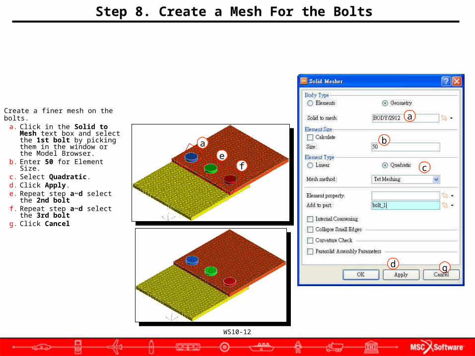
Step 8. Create a Mesh For the Bolts
d
b
c
a
a
Create a finer mesh on the bolts.a. Click in the Solid to Mesh
text box and select the 1st bolt by picking them in the window or the Model Browser.
b. Enter 50 for Element Size.c. Select Quadratic.d. Click Apply.e. Repeat step a~d select the
2nd boltf. Repeat step a~d select the
3rd boltg. Click Cancel
g
ef

WS10-13
Step 9. Create Contact Bodies
a
b
c
de
Create 3D Deformable Bodies. If the Contact toolbox is not displayed, right click next to the toolboxes and make sure Contact is checked.
a. On the LBC’s tab, select Deformable/ Deformable Solid from the Contact group.
b. Enter Contact Body Name Bottom_Plate.
c. Click in the Group textbox and select plate_bottom from the Model Browser.
d. Click Apply.e. Repeat steps a thru e for:
Top_Plate Bolt_1 Bolt_3 Bolt_2
c

WS10-14
Step 10. Create Contact Table
a
Define 7 Possible Contact Body Pairs.
a. On the LBC’s tab, select Contact Table/ BCTABLE from the Contact group.
b. Enter Bolt_Contact_Table for the Name
c. Select Deact. Diagonal to eliminate self-contact.
d. Since the bolts will not come into contact with each other, in row 1 (bolt_1) clear columns 2 and 3 by repeatedly clicking in each box until it is blank. In row 2 (bolt_2) clear column 3 by clicking in the box until it is blank.
e. Click OK.
b c
d
e

WS10-15
Step 11. Apply Constraints
a
b
c
e
d
Apply Constraints.a. On the LBC’s tab, select Pin
from the Constraint group.b. Click in the Pick entities text
boxc. Change the pick filter to
Surfaces on the Picking Filter toolbar.
d. Select the outer faces of both the top and bottom plates.
e. Click OK.

WS10-16
Step 11. Apply Constraints (Cont.)
b
c
a
f
Constrain rigid body motion of thebolts
a. On the LBC’s tab, select General Constraint from the Constraint group.
b. For Name, enter X_and_Y.c. Deselect Tz, Rx, Ry, and Rz.d. Click in the Pick Entities
textbox.e. Select surface as the picking
filter as on the previous slide.
f. Click on the top surface of each bolt.
g. Click OK.
g
d

WS10-17
Step 12. Create 3D bolts.
f
h
d
g
Create 3D Bolts with a 5 unit preload.
a. On the Meshing tab, select 3D Bolt from the Features
b. Enter 5 for displacement.c. Select Part textbox.d. Select bolt_1 from the Model
Browser tree under ASSY2. e. Click Apply. f. Repeat steps d and e for
bolt_2 and bolt_3. g. As the bolts are created, a
local coordinate system is displayed on the part.
h. Click Cancel.
e
a
c

WS10-18
Step 13. Setup Analysis
c
d
e
a
Specify analysis parameters.a. Right click the FileSet and
select Create new Nastran Job.
b. Enter 3D_Bolt as the Job Name.
c. Select Implicit Nonlinear Analysis (SOL600).
d. Click the ellipses on Solver Input File.
e. Select the file path to where the Nastran job will be saved.
f. Enter 3D_Bolt in the Filename textbox.
g. Click Save.h. Click OK.
b
f
h
g

WS10-19
Step 13. Setup Analysis (Cont.)
i
j
k
Specify analysis parameters(continued).
i. Double Click on Solver Control.
j. Select ContactControlParameters
k. Check Activate Quadratic Contact
l. Click Applym. Click Close.
l
m

WS10-20
Step 13. Setup Analysis (Cont.)
o
n
p
Specify analysis parameters(continued).
n. Right click on Loads/Boundaries and Select Lbc Set.
o. Select DefaultLbcSet from the Model Browser.
p. Click OK.

WS10-21
Step 13. Setup Analysis (Cont.)
Specify analysis parameters(continued).
q. Right click on Loads/Boundaries and Select BCTABLE.
r. Select Bolt_Contact_Table from the Model Browser.
s. Click OK.
q
r
s
WS10-22
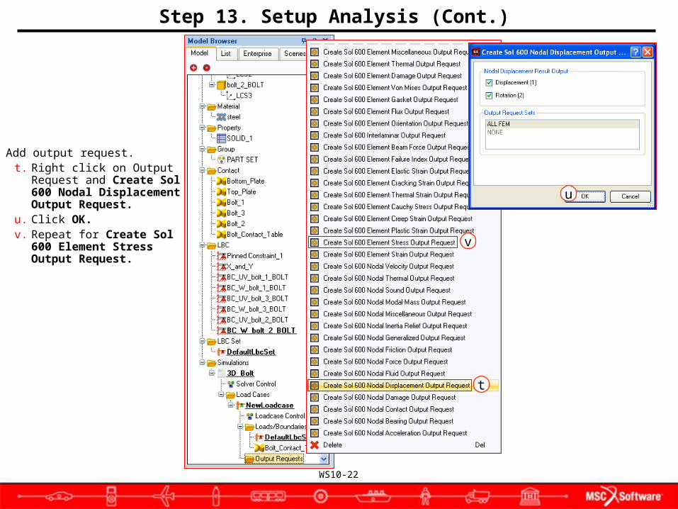
Step 13. Setup Analysis (Cont.)
Add output request.t. Right click on Output Request
and Create Sol 600 Nodal Displacement Output Request.
u. Click OK.v. Repeat for Create Sol 600
Element Stress Output Request.
t
v
u
WS10-23
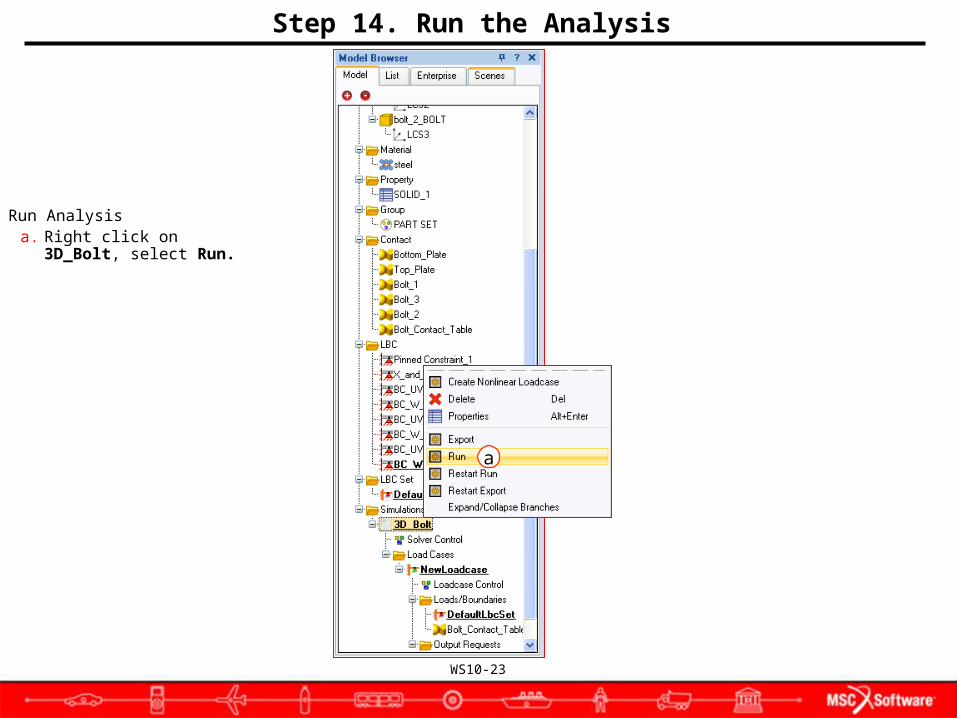
Step 14. Run the Analysis
Run Analysisa. Right click on 3D_Bolt, select
Run.
a

WS10-24
Step 15. Attach the Results
Attach the .xdb file to access the analysis results.
a. Select File/Attach Results.b. Click the browse button for
File Path.c. Navigate to and select the
file 3d_bolt.xdbd. Click Open.e. Select Results as the Attach
Option.f. Click OK.
a
c
d
b
e
WS10-25
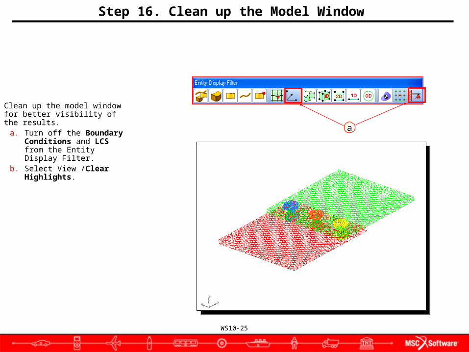
Step 16. Clean up the Model Window
Clean up the model window for better visibility of the results.
a. Turn off the Boundary Conditions and LCS from the Entity Display Filter.
b. Select View /Clear Highlights.
a

WS10-26
Step 17. Results Plot-Deformation Fringe Plot
Deformation Fringe Plot.a. On the Results tab, select
Fringe.b. Select Results Case Time
= 1.c. Select Results Type
Displacements, Translational.
d. Select Derivation Magnitude.
e. Click Update to generate a Fringe Plot showing deformation concentrated in the bolts.
f. In order to be able to see the fringe plot clearly turn off all Geometry and Boundary Conditions
g. Click Clear when finished.
b
c
a
ef
dh
gi

WS10-27
Step 18. Results Plot-Stress Fringe Plot
Generate a Stress Fringe Plota. Change Result type to
Stress Tensor.b. Derivation: von Misesc. Click Update.
b ca

WS10-28
Step 19. Clip the Model
Clip the model to show the stresses inside the bolt.
a. Select View / Model Clipping.
b. Select XYZ on the Pick Panel as the method to enter 3 points to define a clipping plane.
c. Enter 0 0 0.d. Click OK.e. Now enter:
0 0 1 click OK0 1 1 click OK
f. Enter Incremental Distance: 100 for the amount to translate the plane
g. Click OK.h. Click Add.i. Click Sub.
b
c
a
f
d
h
g
i
e

WS10-29
Step 19. Clip the Model (Cont.)
Rotate the Model to view the fringe results inside the bolts.

WS10-30