wsg1640 英文说明书(160715 更换td400界面)
TRANSCRIPT

WSG1640AHD SURFACE GRINDING MACHINE
OPERATING MANUAL

Operating manual
QUALIFIED CERTIFICATE
Ex-factory record:
The machine is performing GB4022-83
《Horizontal Shaft &Rectangular Table Surface Grinder Precision》
standard
Model of machine: WSG1640AHD
Width of worktable: 16 in
Length of worktable: 40 in
The machine has been inspected being up to the standard and
approved for delivery.
Serial No.:
Inspector:
Date :

Operating manual
Precision Inspection Register
Geometrical precision
No. Items Diagram Permissible deviation
Actual deviation
1 Flatness of the table surface
Full length: 0.01
Local: 0.005/300
2
a. Parallelism of the table surface to its longitudinal movement b. Parallelism of the table surface to its transverse movement
a. Full length:
0.015 Local:
0.008/300 b.
Full length: 0.01
3 Parallelism of the median slot to the longitudinal movement of table
Full length: 0.015
Local: 0.008/300
4 Verticality of the table transverse movement to the longitudinal movement
0.03/300
5 Verticality and straightness of the wheel head up and down to the table surface
0.03/300

Operating manual
6 Radial run out of the wheel spindle nose
0.004
7 Axial run out of the wheel spindle 0.004
8 Parallelism of the spindle center line to the table surface
0.025/300
9 Verticality of the spindle center line to the medina slot
0.015/300
Machining precision
No. Inspection items Permissible deviation Actual deviation Remark
P1 Grinding five columned test blocks
Tolerance in thickness: 0.005/300
Test pieces are 45#steel φ50
P2 Grinding completed test block
Tolerance in thickness: 0.005/300
The material test piece is iron HT200, the length is half of table, width is three times of wheel width ,the thickness is 60mm

Operating manual
DISTRIBUTOR
Do not transport the machine and start operation before reading
the safety directions and the instruction manual.
The below mentioned persons herewith confirm that they have read
and comprehended the operation instructions before transport and
appropriate use of the machine for their security and of third persons
and the safety of the machine. For achieving best grinding results it is
in the user’s own interest to follow the technical directions for
grinding.
1.
2.
3.
4.
5.
6.
7.
8.
9.
10.
(Name) (Signature)

Operating manual
SAFETY DIRECTIONS
To guarantee an optimal, trouble-free operation at lowest possible endangering this machine should only be operated, maintained and repaired by persons familiar with it and list operation.
For these reasons the instruction directions must be read and be followed exactly before transport and start of operation.
Especially important safety directions are marked with symbols in front of them.
Comments on indicative symbols
= Safety directions must be followed exactly.
Not noting them causes danger for the operator
= Caution advices must be remembered exactly
Not noting them may entail operation trouble or
damage of the machine
= Important directions should be noted in order to
reach good working results.

Operating manual
INDEX
Description page
Chapter 1. Safety instruction
1.1 general safety instruction 1 1.2 safety regulation of the machine 2
Chapter 2. Summary of the machine
2.1 concise statement on the machine 4 2.2 field of application 4 2.3 construction identification 5 2.4 main specification 6
Chapter 3. Machine installation instruction
3.1 Diagram of machine floor space 7 3.2 demand of foundation 9 3.3 foundation construction and machine setting 9 3.4 Carriage and lifting machine 11 3.5 Remove the setting plates 11 3.6 Clean the machine 12 3.7 Placement of Hydraulic system and coolant tank 12 3.8 power supply 15
Chapter 4. Trial running
4.1 preparation before trial running 18 4.2 safety inspection before operation 20
Chapter 5. Operation instruction
5.1 control panel instruction 22 5.2 operating caution 37 5.3 correct operation of wheel 38

Operating manual
INDEX
Description page
5.4 select perfect method of variously grinding 43 5.5 inspection of the grinding wheel 44 5.6 wheel dressing & correct use of wheel dresser 47 5.7 Balancing wheel 49
Chapter 6. Daily maintenance
6.1 daily inspection (oil & water) 51 6.2 daily inspection (test list before operating) 52 6.3 daily inspection (test list after work) 53
Chapter 7. Setting, Adjusting and trouble shooting
7.1 There are ripples on the work piece 54 7.2 Accuracy of the work-piece ground is not so good 54 7.3 The spindle don’t run 55
Appendix
Electrical parts list 56 Circuit diagram 58 Hydraulic system principle diagram (1page) 66 Main function structure drawing ( 10 pages) 67
PACKING LIST

Operating Manual
1
Chapter 1 Safety instruction
1.1. general safety instruction
(1) The operator must be trained and passed the operating and
maintaining test.
(2) The user should educate the operator according to local law of
industrial safety and hygiene.
(3) The user should warn operator about unsafe operating.
(4) Read the manual before using the machine, and note danger mark and
content stuck on the machine.
(5) The operator whose hair is too long must wear hat before operating
and maintain machine.
(6) When operating, the operator must wear glasses protecting eyes, wear
mask and safe industrial shoes.
(7) Keep machine and around surroundings clean and, avoid the floor
being wet and slippery, and clean unnecessary goods.
(8) In order to prevent compression, please retain 600mm space out of
machine’s limit position, mark the working range with yellow line and
forbid any other person to enter in when operating.
(9) Always shut all guard shied and the door of electrical box unless
maintain the unit.
(10) Shut off the power before maintain the machine.
Forbidden Items:
(1) Don’t operate or maintain the machine with long sleeve clothing, tie,

Operating Manual
2
and glove.
(2) Don’t lean against the machine in working range
(3) Don’t adjust the grinding wheel cover, right or left travel limit control
block, nozzle with hand or tools when the machine is running.
(4) Don’t blow out scrap or dust with compressed air to protect operator’s
eyes.
1.2. safety regulation of the machine
(1) Be sure that the allowable maximum fringe speed of wheel is 35m/s or
higher.
(2) Pay attention to correlative warning instructions before inspecting and
maintaining.
(3) When inspecting electrical parts, must wear nonconducting protector
such as insulating gloves, rubber shoes and so on..
(4) All the electrical parts needing earth should be properly earthed
according to circuit diagram.
(5) Be sure that circuit is turned off with appropriate instrument before
inspecting circuit
(6) Only certified operator can open the electrical box and inspect circuit
when there is fault.
(7) If the hardness of work-piece is more than HRC65 and grinding is
difficult, Please connect with wheel manufactory and choice a proper
kind of wheel.
(8) The grinding wheel should be installed after balanced, the wheel
should be balanced by trained worker. Before fixing the wheel on the
spindle, cleaning contact surface between flange and front end of
spindle.
(9) Should confirm the position and performance of emergency switch

Operating Manual
3
before driving the machine.
(10) Must inspect if the spindle rotating direction is correct before driving the
spindle motor. Begin to grind work-piece after not less than 5 minutes
since driving the machine.
(11) Please clean the magnetic chuck surface before using, if there is
scuffing or scar on the surface, please grind it again.
(12) When grinding antimagnetic material such as aluminum alloy, graphite
and so on, please use suitable chuck block to fix the work piece and
make sure it could not touches the wheel.
(13) By hands before wheel turning, the operator should confirm if magnetic
chuck holding work-piece fast and hard.
(14) The work table must be motionless when operator adjusts right or left
travel limit control block.
(15) When wet grinding, should shut off cooling device before braking the
spindle motor.
Forbidden Items:
(1) The machine is forbidden to install near the powder, magazine and
explosive.
(2) Don’t use inflammable liquid as cutting fluid.
(3) The wheel of spindle is forbidden to cut material as rotary sander.
(4) It’s forbidden to alter use & capacity design of the machine and to use
the wheel out of stipulation, also not processing overweight or
overlarge work-piece.
(5) Don’t change circuit before authorized by manufactory avoid damage.
(6) Don’t change interlocked circuit into by pass circuit.
(7) Don’t touch the parts at random where stuck heat lightning mark.
(8) Should avoid touching electrical box and circuit when body and hands
are wet.

Operating Manual
4
(9) Must not wearing metal garnish to avoid electric shock when inspecting
electrical parts, and hang up warning mark to avoid someone operating
the machine.
(10) Forbid to fixed short & over-thin work-piece or complicated shape,
precarious CG work-piece directly on the magnetic chuck.
(11) When grinding, any other goods are permitted to place on the table but
the fixed work piece.
(12) Don’t adjust nozzle after the spindle has been driven, when wet
grinding.
(13) Don’t stop the wheel with hands or other things, after the motor is shut
off.
(14) Don’t move or exchange work-piece when the work table is moving or
the wheel is turning.
(15) Don’t take a risk clean the scraps on the work piece while grinding or
the wheel is turning.
(16) Specific accessory should be used to takedown the wheel. Forbid to
pound the wheel and pounding maybe make the wheel broken.

Operating Manual
5
Chapter 2 Summary of the machine
2.1 concise statement on the machine
“十” saddle is adopted in the design, all these three guide way is lined with TF
wearable material and lubricated by intermittent forced oil pump, the column
have double walls. The table right and left moving is driven by variable
displacement vane pump and adopted closed type hydraulic system. All above
make the machine with high rigidity and precision, small thermal distortion,
moving smoothly, low noise and temperature increase, is easy to maintain. The
table is driven by manual or by hydraulic in right or left direction, the speed is
variable changed by adjusting lever located on the saddle, driven by manual or
by motor through driven the ball leading screw. The grinding head could be
driven by lifting motor( AHR model) or servo motor( AHD model), also it be
driven by manual.
2.2 field of application
The machine is used for mid-type & mini-type material processing workshop and
the other maintain & tools workshop in.
The machine is mainly used to grinding the surface with the wheel circle face,
the surface been ground have high precision and low roughness. Also it can
grind the vertical surface with the end face of the wheel. the work pieces can be
placed on the magnetic chuck or fixed directly on the table or with other fixtures
suit to various work pieces.
The machine can be used for grinding steel, cast iron and nonferrous metals.

Operating Manual
6
2.3 construction identification
No Name No. Name
1 Bed 7 Grind wheel
2 Electro lubricate pump 8 Saddle cross moving hand wheel
3 Table longitudinal moving hand wheel 9 Saddle
4 Table 10 Wheel head lifting hand wheel
5 Column 11 Cabinet
6 Wheel guard 12 Elevating motor (only for R/A model)

Operating Manual
7
2.4 main specification
Main specification of WSG1640 Series
Model Item Unit AHR AHD
Table size (W×L) In 16×40
Table longitudinal move speed in/min 275.5~906 Max. Distance from table surface to spindle centerline In 23
Max. Loading capacity ( include chuck) kg 500
Table transverse movement
Auto intermittent feed In 0.004~0.3
Rapid speed in/min 39
Feed of Hand-wheel in/div. 0.0008
Vertical movement
Auto feed In - 0.0002/0.0004/0.0008/0.0016/0.002
Rapid Speed in/min 18
Feed of hand-wheel
in/div. 0.0002
in/rev. 0.08
Grinding wheel
Size (OD×W×ID) In 14×1.5×5
Speed rpm 1450 (50HZ) 1750 (60HZ)
Motor
Spindle motor kw 5.5
Oil pump motor kw 2.2
Cooling pump motor kw 0.09
Vertical driven motor kw 0.25 0.5
Transverse driven motor kw 0.04
Gross Weight kg 3800
Floor space (L ×W×H) In 116×89.5×86
1. AH mean: auto feed on transverse, hydraulic transmission on longitudinal, manual
on vertical. 2. AHR mean: auto feed on transverse, hydraulic transmission on longitudinal, rapid
movement on vertical. 3. AHD mean: auto feed on transverse, hydraulic transmission on longitudinal, auto
feed on vertical.

Operating Manual
8
Chapter 3 Preparation before machine installation
3.1 diagram of machine floor space
size
model A B C
WSG1020 89” 68” 85”
WSG1224 110” 82” 87”
WSG1240 173” 128” 87”
WSG1632 142” 104” 94”
WSG1640 173” 128” 94”
Limit position drawing

Operating Manual
9
3.2 demand of foundation
1) Installation of the machine will effect deeply efficiency and precision,
don’t place the grinder between the milling machine and planer, etc,
because there is shock when these machine are running, the shock will
be transferred to the grinder and make wave mark on the grinding
surface.
2) The table of the machine must be prevented from insolate for this will
make the table thermal distortion. Don’t install the machine in the field full
of magnet, inflammable dirt, metal dirt and outburst gas.
3) Don’t install the grinding machine on the insubstantiality foundation avoid
distortion.
3.3 foundation instruction and machine setting
1) The machine should be installed on a solid concrete foundation, the
foundation is to be cast in one piece, the concrete should not be lower
than #500, the depth noted on the “Foundation Layout” is the min. value
suitable only for the ordinary solid soil, else it should be accordingly
increased. If the shop is near the sandy river bank or the ground is newly
filled, the foundation should be reinforced with the additional blocks. After
the foundation is finished a curing period of 28days is necessary. During
the first week the foundation should be watered often so that it can be
kept damp. In winter the curing period has to be properly lengthened and
anti-freezing measure should taken into consideration, Installing is not
allowed within the curing period.
2) Don’t use simple “knocking in” type wedges, when the machine is
installed and adjust leveling with wedges. The machine is to be installed
with foundation bolts, the cavities should be grouted with 1:3 cement
mortar around the bolts and then left to dry 3-7 days after the machine
has been pre-leveled up. Following this proceed with fine leveling and
tighten the nuts.
3) Check insulating resistance for electric system, then connection of power
mains to the machine electric cabinet should be made only after it has
been well grounded. Only when the installation has been entirely

Operating Manual
10
completely and the function of electric circuits proved to be securely safe
and reliable, can the wheel of the machine be tested for geometrical
complete, started and operated.
UNIT: inch
sizemodel A B C
WSG1640 45 30 16
WSG1632 34 30 16
WSG1240 45 22 16
WSG1224 30 22 16
WSG1020 25 21 17
Machine ground diagram

Operating Manual
11
3.4 Carriage and lifting machine
Use equipment to lift the machine as following.
Lifting: first fasten the sling bolts on the machine base, then set the wire cables
on the sling bolts and the hook.
3.5 Remove the setting plates
In order to avoid damage during transporting, the movable parts have been
locked. When the machine is positioned and no needing to change location
again, uncrating the lock blocks (refer to pictures)
1. Get off the tighten bolt which used to fix the saddle and work table

Operating Manual
12
3.6 Clean the machine
All the machines are provided with anti-rust treatment. The moving parts are
lubricated with grease and fixture point and dye black portions are applied with
anti-rust oil. Before first running the machine, clean all the slide ways, cylinder, spindle and surface which have been applied with anti-rust oil.
3.7 Placement of Hydraulic system and coolant tank
3.7.1. Placement of Hydraulic system
2. Move up the wheel head then get off the wooden block
3. Remove the antirust paper
covered around the hydraulic
piston rod. Clean the saddle slide
way.

Operating Manual
13
Connect the hydraulic pipe to oil tank. Right side is the oil Out the tank with high
pressure, left one the oil back to the oil tank.
Each one pipe connecting to the each point is Ok!
Fill in suitable oil (32# Hydraulic oil) through
the top of the tank.(capability of tank is about
110L)
Hydraulic Oil recommended: (32# hydraulic oil )
Brand China Petro MOBIL BP CASTROL ESSO GULF SHELL TOTAL
Model N32G DTE13 NO.2
Energo 1
SHF 32Hyspin AWH 32
UnivisN 32
Hydrasil Multi
Tellus T 32
EquivisZS 32
Note:
1. the hydraulic oil is filled in via the filling top at the oil tank, the pump for
the hydraulic oil will also be lubricated by it and should not run dry
otherwise it will be destroyed.

Operating Manual
14
2. Fill in oil until marking at oil gauge is reached.
3. Oil types are recommended according to the above list.
4. The oil filter should be changed for the first two month after starting
operation of the machine at the latest. After that changing the filter in the oil
changing cycle of two times a year in case of one shift operation is
sufficient.
5. The pressure of hydraulic system has been adjusted in factory before
delivery. Do not adjust it in normal condition.
6. The wasted oil should be disposed by special treatment procedures to
prevent pollution.
3.7.2. Installation of coolant system
1. Assemble the coolant collect slot box ( fixed by two screws)
2. Assemble the coolant collect pipe and tighten it

Operating Manual
15
3.8 power supply
Power: 3.7kw (WSG1020 Series)
9.0kw (WSG1224~1640 Series).
For the power supply wire, the 6.00 mm2×4 cable is advised.
3. Assemble the pipe to the
coolant pump and tighten it. You
can put the pipe into hot water for
a few minutes, make it easy to
install
Power wire connect to
the electrical box
Filter box. The coolant should
flow back into the box at first

Operating Manual
16
The electric connections must be carried through by an approved
electrical engineer only.
Before connecting the supply line, it has to be checked if the stated
operation voltage of the machine corresponds to the available power
supply voltage.
Machine must be connected to the ground in order to compensate the
internal power.
Connect to the suitable power according to the rated voltage
Connect the coolant pump and
oil pump power wire to the
electrical box.
For coolant pump
For oil pump

Operating Manual
17
In a short starting testing, the grinding wheel spindle must rotate
clockwise.

Operating Manual
18
Chapter 4 Trial running
4.1 preparation before trial running
4.1.1 Lubrication
A. Lubrication set
1) In order to maintain mechanical performance and life, choice correct
lubrication oil for lubrication system is necessary.
2) When the machine is on work, the lubrication pump auto intermittently
feed oil to all the lubrication points.
3) 32# guide way oil is advised.
4) Pay attention to if the pump motor is running, refill the oil in time.
B. Refill lubricant oil.
1) Open the cover, fill the cleaning oil in the tank through the filtering net
until to the FULL line.
2) Keep the oil clean.
3) If there are some sundries in the oil tank and the oil could be support,
please clean the filtering net right now.
4) If the oil is lower than the lower limit, refill the oil right now, if not, the
machine will stop.
5) Before working, please push the STARTUP button, after the machine
running about 20 minutes and the oil have been supply to all the guide
way, then start to working.
6) Look at the safety inspection items before running the machine.

Operating Manual
19
No Lubricate point Lubricating
mode Lubricant Times
1 V slide way of saddle Auto lubricating 32# slide way oil Adjustable
2 Cross feed screw Auto lubricating 32# slide way oil Adjustable
3 Lifting feed screw/nut Auto lubricating 32# slide way oil Adjustable
4 Front slide way of
column Auto lubricating 32# slide way oil Adjustable
5 V slide way of saddle Auto lubricating 32# slide way oil Adjustable
6 Back slide way of
column Auto lubricating 32# slide way oil Adjustable
7 Flat slide way of table Auto lubricating 32# slide way oil Adjustable
8 V slide way of table Auto lubricating 32# slide way oil Adjustable
C. Program of lubricating and oil feed adjusting.
Turn on the power, the lubrication pump is running, and the green DIS lamp
(running timing ) is shinning, this means the pump is running. The “running
timing” is over and the “ stop timing” is on work, and DIS lamp is dark and
the yellow INT lamp is shinning. The “stop timing” program is stopped, then
go to next cycle. If the oil is empty, the red EMG lamp will shine, this time
you should refill oil. The oil-feed adjustment by adjusting the running timing
knob DIS. TIME( the range from 2s to 90s) or the stop timing knob INT.

Operating Manual
20
TIME(the range from 2min to 30min). the shortest stop time should not less
than 2min. after setting, push the RESET button for confirm. THE TIME HAS
BEEN ADJUSTTED WELL BEFORE DELIVERY.
Lubricant recommended (32# slide way oil)
4.1.2 Hydraulic system
1) 32# hydraulic oil is advised for the hydraulic system. The hydraulic oil
tank should be cleaned in the first two month and change the oil, then
change the oil two times a year, when change the oil, cleaning the
filter at the same time.
2) the max. pressure is 3Mpa, the pressure have been adjusted well
before delivery, the operator need not adjusting the pressure.
Hydraulic Oil recommended: (32# hydraulic oil )
Brand China Petro MOBIL BP CASTROL ESSO GULF SHELL TOTAL
Model N32G DTE13 NO.2
Energo 1
SHF 32Hyspin AWH 32
UnivisN 32
Hydrasil Multi
Tellus T 32
EquivisZS 32
4.2 Safety inspection before operation
Be sure inspecting as following items before running the machine.
1) Clean the antirust oil from the machine.
2) Level the machine.
3) Fill in the lubrication oil regarding as the direction.
Brand China petro MOBIL BP CASTROL ESSO GULF SHELL TOTAL
Model 32# Vactra
Oil No.2
Maccruat Magna BD68
Febis K68
Slideway 68
Tonna TX68
Drosera68

Operating Manual
21
4) Check the spindle rotating and make sure the direction is clockwise.
Before check the spindle rotating direction, please remove the wheel,
because the spindle turning unticlockwisly is very dangerous.
5) Conform the oil tank is full enough.
6) Make sure the speed control valve is taken off.
7) Adjusting suitable travel by adjusting the position of these two “travel
adjusting block”
8) Check if all the fixed blocks have been took out.
9) When working the wheel cover should be never opened.
10) Check the pipes connected to the oil tank.
11) All above items have been checked , then look around and to find if there
is any other person in the working area, let him go to prevent from
danger.
12) The machine operating will be explained in next chapter.
13) Remember the position of the EMERGENCY SWITCH

Operating Manual
22
Chapter 5 Operation instruction
5.1. Control panel instruction
5.1.1 Control panel
1) AHD Series control panel(WSG818AHD ~ WSG1640AHD)

Operating Manual
23
5.1.2 control panel instruction:
1) AHD Series
SB0:Emergency switch
SB1:Power on push button / indicator lamp
SB6:Wheel head rapid down push button
SB7:Wheel head rapid up push button
SB8:Table cross rapid moving backward push button
SB9:Table cross rapid moving forward push button
SA2:Table cross movement mode (Manual/ Auto.) selecting knob
SA4:Wheel head down feed mode (rapid elevating/ jog feed /Auto. down
feed) selecting knob
SA5:Electro magnetic chuck ON/OFF knob
SA6:Value of wheel head auto. down feed selecting knob
SA7:Coolant pump/dust collector ON/OFF knob
VR :Table cross intermittent feed adjusting knob
HL1:Grinding spindle motor working condition indicator (lamp)
HL2:Hydraulic pump motor working condition indicator (lamp)
HL3:Electric magnetic chuck working condition indicator (lamp)
HL4:Alarm light
HL5:Plunge grinding mode indicator (lamp)
HMI:Human machine interface
5.1.3 Switch function instruction:
1. Power on / off
push SB1, power on, lamp is shining. Push SB0, power off. If want to
power on again, first step turning the SB0 and make it up, then push
SB1, power on.
When push SB1, but the spindle could not start, may be cause by:
a. the lubricant is short
b. the circuit breaker is off

Operating Manual
24
c. creep age
d. transformer is bad.
2. Table longitudinal movement
a) Start the oil pump: turn the SA5 to “ magnetized “ position, the
electric magnetic chuck engaged, waiting for a moment then push Key
F6 on HMI, the oil pump start, Push F2, the oil pump stop.
when push the F6, the oil pump not start, may be cause by:
a. there is error of undercurrent rely in the circuit control chuck
(magnetizable or unmagnetizable) ; b. the oil pump motor circuit is
short
b) Table moving speed is control by an
Adjusting lever located on the top surface of
saddle. Turn the lever clockwise, speed
changing from low to high.
c) Table longitudinal movement reverse
the stroke is adjusted by moving these two
Reversing dog, while direction control arm touch the reversing block, the
table movement would reverse.

Operating Manual
25
If the table reversing dog D1/D2 bump against table direction control
arm C due to operator’s error operating or an long times using, control
arm will lost the correct position then cause the table unable to travel
automatically. In such case adjusting the control arm position as follows:
1) Turn L (speed controller) to close position to stop table movement.
2) Take away D1/D2 (reversing dog) or move it apart from C (reversing
control arm).
3) Take off the C from the S (shaft), turn S (shaft) making the
induction block against the proxi. Switch until the red lamp shining (on
switch), this means the shaft is on correct position. After that, reset C
(arm) on S make it on right position.
4) Turn L by left hand make the table moving on low speed, turn C right

Operating Manual
26
and left by right hand (about 15-20 degrees), if this can’t make the table
move right and left, reset C at other position and try again, by this way,
you can find the right position for C.
ATTENTION: be care for not clamping fingers by dogs and control
arm.
5) Then fix C well on S and tighten it.
NOTE: IF THE TABLE MOVEMENT IS NOT SMOOTHLY, MAY BE
THE OIL PIPE HAVE AIR, MAKE THE TABLE MOVE ON HIGH
SPEED FOR A MOMENT, THE AIR WILL GET OUT THE PIPE.
3. Table cross movement
a) Rapid movement
Table cross rapid movement: Rotate the pushbutton SA2 to” ”
“MANUAL” position, depress the pushbutton SB9, the table will move
rapidly to front, depress the pushbutton SB8, the table will move rapidly
to behind.
b) Table cross auto feed
Rotate the pushbutton SA2 to” “AUTO” position, depress SB8 or
SB9, the table will move automatically intermittent to frond or to behind,
Rotate clockwise VR, intermittent feed for saddle transverse can be shift
variably. Cross intermittent feed start and stop point can be set by
distance setting block located on the right side of saddle.

Operating Manual
27
The cross intermittent feed is control by AC motor controller in the
cabinet. On the Ac motor controller Panel, the “ set” key is for set the
feed rate. There are 4 shift !~4, feed rate: shift 1: 0.08~6mm; shift 2:
0.3~12mm; shift 3: 1.3-18mm; shift 4:2.7-24mm. if more than two or
three shift is on “ON” position, the low shift is working and others is no
work.
The AC motor controller has been adjusting well and is suitable for
the confirmed machine, please don’t reset it without the engineer’s
advising.
NOTE: for AHD model, only the grinding mode is set to “SURFACE
GRINDING” mode, the table can make cross rapid or intermittent

Operating Manual
28
feed. if the grinding mode is set to “PLUNGE GRINDING” mode the
table couldn’t make cross rapid or intermittent feed.
4. Wheel head vertical up / down movement
a) AH model: the wheel head can only up/down by manual and handwheel.
b) AHR model:
push the SB6 “ ” , the wheel head make step down feed
NOTE: when the spindle rotating, the function is no use.
Push the SB7 “ , the wheel head make step up feed.(on the up
limit position, there is an protect switch)
c) AHD model: rapid up/down feed, step-feed and auto down feed control.
1. Rapid feed:
turn the SA4 (Wheel head vertical movement mode selecting knob
(Jog-feed, rapid-feed, Auto feed) to “ rapid feed ” keep push on
the SB6 “ ” , the wheel head make rapid down moving
Push the SB7 “, the wheel head make rapid up moving.(on the up
limit position, there is an protect switch).
2. Jog-feed:
turn the SA4 to “Jog-feed ”, one push SB6 “ ” , the wheel head
make one step down feed, the feed value could be set by SA6
(Wheel head down feed value adjusting knob) from
0.0002/0.0004/0.0008/0.0016/0.002 in. push down SB7, the wheel head

Operating Manual
29
make rapid up moving.
Note: the when the machine is set on “ Jog-feed “ function, the
elevating Servo motor will be “ power on”, IT IS FORBIDED MOVING
THE WHEEL HEAD BY MANUAL (HAND WHEEL) !
3. Auto feed
Turn the SA4 to “ auto feed “ position, the wheel head will make
auto down feed, this function have two mode: “Surface grinding” or
“Plunge grinding” mode ( select by F3 and F7)
Note: the when the machine is set on “ auto feed “ function, the
lifting Servo motor will be “ power on”, IT IS FORBIDED MOVING THE
WHEEL HEAD BY MANUAL (HAND WHEEL) !
”SURFACE GRINDING” mode operating instruction
push F11 and select Surface grinding mode , turn SA4 to rapid feed
position → set feed rate and feed times by HMI F8F7F5 F6
F4F3F2F1
F16F15F14F13
F12F11F10F9ESC
ENTERSHIFT
TD400CSIEMENS
→ set
spark out feed by HMI F8F7F5 F6
F4F3F2F1
F16F15F14F13
F12F11F10F9ESC
ENTERSHIFT
TD400CSIEMENS
→ start the oil pump →turn the table
speed control lever make the table longitudinal moving→ start the
wheel head spindle → move the saddle and spindle head to the start
working position → turn the SA4 to Auto feed → push SB6
then the auto feed is start, the wheel head will make first down feed as
soon as the saddle inversing, until finish all steps down feed, then the

Operating Manual
30
wheel head make Spark out grinding, when all the feed is finished, the
wheel head would lift up (the travel can be set) auto and the spindle
motor and hydraulic pump motor are power off.
During the auto feed working, push “emergency switch” end the program,
the new auto down feed working should be reset again.
During the auto feed working, change to the manual mode to lift or down
the grinding head, then can go on the program.
”PLUNGE GRINDING” mode operating instruction(while Plunge
grinding mode is select, the lamp HL5 will light for warning)
press the Key F15 to Plunge grinding mode (the HL5 alarm lamp
will light), turn SA4 to rapid feed position → set feed rate and feed times
by HMI F8F7F5 F6
F4F3F2F1
F16F15F14F13
F12F11F10F9ESC
ENTERSHIFT
TD400CSIEMENS
→ set spark out feed by HMI F8F7F5 F6
F4F3F2F1
F16F15F14F13
F12F11F10F9ESC
ENTERSHIFT
TD400CSIEMENS
→ start the oil
pump →turn the table speed control lever make the table longitudinal
moving→ start the wheel head spindle → move the saddle to the start
working position ( for safety, the SB8 and SB9 is no used, you could
only move the saddle by manual) → move the wheel head to the
start working position → turn the SA4 to Auto feed → push SB6
then the auto feed is start, the wheel head will make first down
feed as soon as the table inversing, until finish all steps down feed, then
the wheel head make Spark out grinding, when all the feed is finished,
the wheel head would lift up auto and the machine is power off.
during the auto feed working, push “emergency switch” end the program,
the new auto down feed working should be reset again.

Operating Manual
31
4. Auto down feed stop and reset
while the autodown feed program is going, stop the working table by
speed control lever , the table and wheel head move stop, restart the
workig table longitudinal moving, the program resatart too.
While the autodown feed program is going, turn the knob SA4 to “jog
feed” position, the program is stop, and then the operator can
make grinding head down feed by SB6 , and if turn SA4 to “auto down
feed” mode again, push the button SB6 , the program will going on
again.
While the auto down feed program is going, push soft KEY F8, the
program will be cancel, and the grind head will lift up auto.
NOTE: WHEN USE THE PLUNGE GRINDING, MUST NOT MOVE THE
SADDLE AVOID WHEEL BROKEN AND THE CHIP ON HIGH SPEED
WILL DAMAGE THE PEOPLE!
Must not press the KEY F11 OR F15 by mistake while the auto.
down feed working in process
5. how to use the HMI
F8F7F5 F6
F4F3F2F1
F16F15F14F13
F12F11F10F9ESC
ENTERSHIFT
TD400CSIEMENS

Operating Manual
32
On the HMI panel there are 16 soft keys, F1~F8 can take effect by pressing
directly, F9~F16 take effect by pressing “SHIFT” key at first and then
pressing one key of them.
“SHIFT”: shift key, used to make F9~F16 take effect
1) Functions of soft keys:
F1—spindle motor stop F5--- spindle motor start
F2—hydraulic pump motor stop F6—hydraulic pump motor start
F11—surface grinding mode F15—plunge grinding mode
F4—set key used to set times of grinding feed and spark out grinding feed
F8—Reset key( fault resetting) F16—data setting confirm
2) Operating process
HMI start
When the machine is power on, the display of HMI will shining
F13 F14 F15 F16
F12F11
F8
F4F3
F7F6
F10F2
F9F1
SHIFT
ESC
ENTERF5
SIEMENS TD 400C
The system start-upplease for a moment.

Operating Manual
33
F13 F14 F15 F16
F12F11
F8
F4F3
F7F6
F10F2
F9F1
SHIFT
ESC
ENTERF5
SIEMENS TD 400C
F R C N Csurface grinder.
(default menu)
Set feed times for different feed rate

Operating Manual
34
Press F4, HMI will show above menu, press arrow↑、↓to turn page,
press “ENTER”, the fist data will shining, the feed times can be set by
press arrow↑、↓ to increase or decrease times. Pressing “ENTER” to
confirm the data and then the second data shining, repeat the same
operating step to set the grinding times. And press “ ENTER” to confirm
until all the data was set. Then press F16 to make the data setting
effective.
Press “ENTER” directly without data reset, the cursor will move to
next data
Press “ESC” key, the date will be reset, and then press “ ENTER”, the
cursor will move to first data.
Program stop and cancel
while the autodown feed program is going, stop the working table by
speed control lever , the table and wheel head move stop, restart the
workig table longitudinal moving, the program resatart too.
While the autodown feed program is going, turn the knob SA4 to “jog
feed” position, the program is stop, and then the operator can
make grinding head down feed by SB6 , and if turn SA4 to “auto down

Operating Manual
35
feed” mode again, push the button SB6 , the program will going on
again.
While the auto down feed program is going, push soft KEY F8, the
program will be cancel, and the grind head will lift up auto.
3) Other operating
Under the default menu, press “ ESC” two times, the system will go into
“operator menu” and “diagnostic menu)
In the “diagnostic menu”, there are many important data, the operator
must not modify these data, for if the data be modified, the contact
between the PLC to HMI will be interrupt
Factory parameter of TD400 is list as follow
TD400 add. : 1
PLC add. 2
Parameter add. 200
Baud rate 187K( the real value is 187.5K)
HAS 31
GUF 10
Contrast ratio 40
In case of the data be modified by mistake, the engineer can reset the
data according to about parameter
NOTE: while HMI show Servo alarm, make HMI power off and then restart.
6. Wheel head spindle motor start
Turn the SA5 to “ magnetized” position , push F6 (HMI), start the oil
pump, then depress the F5, the spindle motor start (the HL2 alarm lamp will
light); depress F1, the spindle motor stop.

Operating Manual
36
after up steps, if the spindle motor would not start, please check the
undercurrent rely and oil pump control circuit and spindle motor control
circuit.
NOTE: There is a micro switch fixed on the inside of Wheel guard, if
the door have not been closed, the spindle motor could not start.
7. Start coolant pump
Turn the SA7 to position, the coolant pump start, open the valve
located on the right side of the wheel guard, the coolant will flow out. Turn
the SA7 to “stop position, the coolant pump would power off. (the dust
collector is optional equipment, if the machine is special equipped with dust
collector, turn SA7 to position, the dust collector is start)
8. Electro magnetic chuck operating
Turn SA5 to “ magnetized” position , the chuck on working(the HL3
alarm lamp will light); turn the SA5 to “ demagnetized ” position, the
chuck demagnetized; turn SA5 to “ stop” position, the chuck would
work.
NOTE: if the chuck suction force is low, may be caused by: VC is
broken which located in the Rectifier circuit.
If the chuck have no force, may be caused by:
1) the Undercurrent rely is broken
2) electric circuit is take off
3) the chuck is burned.

Operating Manual
37
5.2. Operating caution:
1) Before install of remove the wheel, shut off the power in advanced.
2) Don’t operate the grinding machine which have no wheel cover, it is
forbidden that opening the wheel cover while working.
3) Not move the work piece or put hand on the table before the wheel stop
4) Make sure that work piece is fixed on the table substantially.
5) Must not try to fix the work piece by hands.
6) The length and weight of the work piece must be lower than the rating.
7) Using the suitable wheel, dress the wheel often and keep the wheel
sharp.
8) Make hand and clothes far away from the table and wheel while
working.
9) And not try to connect any wire if you do not know well about the circuit
and electrical parts to prevent from damage.
10) Make the wheel free running about 5 minutes before working, don’t be in
the danger range.
11) The operator should dress the respirator and prevent glass while dry
grinding.
12) Not using the wheel which the speed is higher than rating.
13) Closing the wheel cover fixed before running the grinding head motor.
14) Be sure the feed is suitable, large feed will heat the work piece and

Operating Manual
38
reduce the motor speed.
15) Confirm the direction of wheel turning is same as indicated on the wheel
cover.
16) Confirm all the switch and button are on the shut off position before start
the machine.
17) Stop the table while adjusting the longitudinal travel.
18) Shut off the grinding head motor before cleaning the table after working.
5.3. correct operation of wheel
5.3.1 How to selecting suitable wheel
The wheel have tiny grain which is sharp and rotating at high speed, and
cutting variable kinds of material.
The mainly basic factor is as following
(1) Abrasive —— the cutter
(2) Bond —— make these grains one piece and could turn safely at a
high speed.
(3) Air hole —— the space between these grains, which could expel the
chip and have good processing surface.
All above factor form a whole wheel, it have these chapter as following:
(1) As the cutter, the grain is harden than the work piece, it can process
the tool steel and hard alloy steel, too.
(2) The passivated grains will fall off then the new grains appear.
(3) The grain is tiny and hard, using it can obtain good surface and
accuracy.
5.3.2 Notation of grinding wheel

Operating Manual
39
NOTE:
(1) Max Peripheral cutting velocity of the wheel must be higher than
limit speed of the wheel.
(2) The Peripheral cutting velocity of the grinding wheel (m/s)
=3.14×D(dia. Of wheel, mm)×N(spindle speed, r/min)÷60000
5.3.3 ABRASIVE
All the abrasives have themselves physics character, their hardness and
tenacity is deferent, choice proper wheel according to work-piece material.

Operating Manual
40
Sort of abrasive and using range
Name Code Color Using Range
Brown emery A (GZ) Brown
Grinding carbon steel, general alloy steel, malleable cast iron, hard bronze etc. especially suit grinding steel without quenched & quenched and tempered steel, suit rough grinding too.
White emery WA(GB) White Grinding quenched steel high-speed steel high carbon steel etc., which don’t suit grind roughly as the wheel waste more.
Mono-crystalline emery SA(GD)
White or canary yellow
Grinding stainless steel and high-speed steel & high intension and high tenacity material.
Micro-crystalline emery MA(GW) Brown Grinding stainless steel bearing steel and
special ductile iron
Chrome emery PA(GG) Rosy orMauve
Grinding alloy steel, high-speed steel, manganese steel etc. high intension material and suit the working procedure for high smooth
Black silicon carbide C(TH) Black Grinding iron, brass soft-bronze etc. soft
material.
green silicon carbide GC(TL) Green Grinding carbide, glass fibre reinforced
plastic etc. high hard material.
diamond RVD, MBDMP—SD Grinding carbide, glass fibre reinforced
plastic and pottery & porcelain material.
Cube boron nitride CBN Nigger-
brown
Grinding the high-speed steel, which is complex of quite a few chrome, tungsten, cobalt and series wearproof material .
5.3.4 GRIT SIZE
Express grain as grit size, express grit size as the number of sieve pore on
per inch length of sieve screen.
A general grit size of the wheel, which is used grinding surface, is 36-60, in

Operating Manual
41
general way, the grit size is smaller, the surface ground is better.
APPLICATION RANGE OF SERIES WHEEL GRIT SIZE
Grit size of gain Application range
14-24 Grinding steel ingot, iron burr, cutting off billet
36-60 Grinding general surface
60-100 Fine grinding and grinding edge
120-W20 Fine grinding, hone, screw grinding
below W20 Fine grinding, abrade, mirror grinding
5.3.5 GRADE
The grade of wheel is cohere degree of abrasive adhere to a wheel. The
soft wheel is express that abrasives break off easily from wheel, on the other
hand, the bond among the abrasive not only have cohere function, and fixing
abrasive function. The beat state is that the wheel has been blunted and sharp &
blunt has been balanced by itself, so as to choice grade of wheel is the most
important basic to gain better grinding effect.
THE GRADE OF WHEEL
Grade Over soft
Soft 1
Soft 2
Soft 3
MSoft
1
M Soft
2
M1
M 2
MHard
1
MHard
2
M Hard
3
Hard 1
Hard2
Over hard
Code 0 G H J K L M N P Q R S T Y

Operating Manual
42
GRINDING CONDITION AND CHOICE OF HARDNESS
Soft grad hard
Hard and brittle work-piece material soft and ductile
width interface narrowness
fast linear speed slow
Slow work-piece moving speed fast
Better mechanical precision badness
Experience operator inexperience
5.3.6 STRUCTURE
Express volume proportion among grain, bond, pore, separate three kinds
of structuredense structure, middle structure, open structure, 15 degree. Wheel
structure loosing affects directly grinding efficiency and surface grinding quality.
The pore not only obtain grinding crumb in the grinding process, and bring
cooling water and air into grinding area to cool, and reduce work-piece heating,
deformation, burning. If the pore is too big, grain per area would be less, the
outline of the wheel isn’t better circinal, which would affect surface roughness.
Middle structure is normal chosen.
5.3.7 BOND
The function of bond is to have kept intension cohere grain to the wheel for
long. Ensure the wheel is safe at grinding.
Operating Manual
43
Divide bond into:
(1) Vitrified bond, its purpose is abroad, combine degree and structure is
easy to adjust, chemical performance is better.
(2) Resinoid bond, is propitious to high speed rotate, has a bit stretch.
(3) Rubber bond, has stretch, is propitious to thin wheel
(4) Metal bond, is mainly propitious to make the wheel whose abrasive is
over-hard.
5.4. select perfect method of variously grinding
1) At first must choice proper wheel when grinding, method as follow:
a. high grinding efficiency
b. low wear of grinding wheel
c. gain perfect precision and machining quality
2) The basic considered choice grinding wheel
Definite basic:
a. the ground work-piece material
b. request precision and roughness
c. area of grinding interface
d. character of operating grinding
Variable basic:
a. speed of grinding wheel
b. feed
c. state of the machine

Operating Manual
44
d. operator’s skill
★ If ground material is steel or alloy, the abrasive usually be oxide, if it is
iron, non-ferrous metal or nonmetal, abrasive would be carbide. Fine grit
size abrasive is propitious to soft, high ductility material. Hard grinding
wheel grinds soft material, soft grinding wheel grinds hard material. The
grinding wheel of Dense structure grinds hard and brittle material, the
grinding wheel of open structure grinds soft and ductile material.
★ About precision and roughness, advise adopt high speed grinding to
gain a bit high precision and a bit low roughness, if use coarse wheel.
Adopt fine grain wheel to gain high precision and low roughness.
★ About interface, dense structure wheel is propitious to small interface,
whose grain is request fine and hard. Open structure wheel is propitious
to big interface.
★ Feed is faster, grinding press is heavier, the grinding wheel is request
harder, the opposite feed would automatically increase with table moving
speed increase at equal absolute feed speed, so as to the grinding
wheel wears fast, the wear would improve using hard grade wheel.
Note: Bigger for feed, more probability for the grinding wheel
breaks.
5.5. INSPECTION OF THE GRINDING WHELL
Must stand to the following safe regulation, the regulation is to assure
operator safe.
1) Should inspect the grinding wheel before fixed. In general way, it is well
to test the voice of the wheel. Use an mandrel passes the center bore of

Operating Manual
45
the wheel and supports the wheel, then lightly knock the wheel with
wooden bar, the wheel would have voices, if the wheel has broken, it
would have different voice, even we don’t see with our eyes. The perfect
wheel’s voice is very clear. The bad wheel must be forbid using.
2) Two absorbing-ink paper on the both side of grinding wheel can be as
spring cushion between the wheel and flange, don’t rip off when fixing.
Slightly slip the wheel to flange with hands, don’t force. The flange must
be cleaned, special orienting surface and fixing surface etc.
3) The grinding wheel is availably balanced, inside stress of the grinding
wheel can be eliminated, grinding precision and life of the wheel, spindle,
bearing are all in contact with whether fine to balance the grinding wheel.
For the purpose, general speaking, static balance is enough.
4) Take the grinding wheel, wheel flange and balance shaft on the balance
stand after have fixed, way of balance the wheel as follow:
a) The grinding wheel balance stand is leveled in one unit of a gradienter.
b) Let the grinding wheel roll freely until stop, then mark the heaviest
place with chalk.
c) Fix the first balancing weight at the place opposite to the mark place,
note it never to be moved again.

Operating Manual
46
d) Then fix two other balancing weights at symmetrically place, which is
at the same periphery and isogonal of the first one position, then rotate
the wheel 90° one times, test the wheel whether balance, if not,
remove the two balancing weight until the wheel comes to an entire
standstill at any place.
e) The wheel which has been balanced at the first time, should be fixed
to the spindle and dressed by a wheel dresser, then take down the
wheel and carefully balance again refer to above way, fix to the spindle,
dress the wheel until accurately. Even the balance better wheel would
be unbalance as wear, so should often test. If it is need the wheel
should be balanced again. The wheel should be trial run for 5 minutes
with normal grinding speed.
f) Don’t open cooling water when the wheel standstills, as the wheel can
absorb cooling water, otherwise the wheel should lose its balance. If
the wheel has been standstill for long, that would lose its balance as
water concentrate at the bottom of the wheel, so the wheel hasn’t turn
for some time after have ground, it would lose its balance too, at the
moment, drive it turn without feed, separate water from the wheel by
centrifugal effect, and come back its balance.
g) Should clean the taper of the spindle and wheel flange before the
wheel has be fixed to the spindle, then fix and lock down.
h) Replace different wheel with grinding different material, to exchange

Operating Manual
47
the wheel by take-down flange is uneconomical. We advise contact
with manufacturer of wheel flange, special order wheel flanges
according your condition.
5.6. WHEEL DRESSING & CORRECT USE OF WHEEL
DRESSER
1) The dresser can be fixed on the magnetic chuck or the table, inclination
between axis of diamond tool and vertical axis of the wheel is 5°, because
the wore part of diamond must be toward rotate direction of the wheel, so as
to the diamond keep sharp.
2) To change dressing speed of the wheel, can exchange grit size of the
wheel. If grinding 0.1-0.2mm thickness, rough grinding is well, that crosswise
moving speed of the wheel head increase, the diamond tool passes by the
wheel fast, so as the wheel can be chipped bigger, if fine grinding, crosswise
moving speed of the wheel head would be slower, dress 2-3 times, feeding
0.01mm per times.
3) The diamond is easy to break, even to be hit lightly, because it is brittle
and hard.
4) When dressing, the diamond tool should dress from middle of the wheel,
because the both side of the wheel wear more, if dressing from both side of
wheel, there would be heavy press to result the wheel break accident.
5) When the diamond has wore, should be rollback, the diamond would
keep sharp, and could be continuously used.
6) If the wheel is not dressed, even the wheel get the great quality which
can not do the high precision on the workpiece. So for the higher grinding
performance, the wheel dressing is very necessary. The operators must

Operating Manual
48
handle the well wheel-dressing technic, and make sure the wheel get the
high performance at any time.
7) The wheel dressing is the process of making the wheel sharp. In this
process, we need to remove the agglutinant and the grains,so that the
grains will come out from the agglutinant and form the sharp tool. The wheel
dressing is also need to remove the macro materials in the holes, so that to
avoid the grinding force increment of the wheel to make the damage on the
workpiece surface.
8) In the wheel dressing, we need the diamond pen, the machine get the
diamond pen base as a standard accessories. The diamond pen is the
optional accessory.
9) The wheel dresser need to be treated very carefully, because it consists
by the diamond which is very sensitive about the shake or crash.
10) The wheel dressing can be done by the diamond pen base or the
parallel dresser (the parallel dresser is the optional accessory)
11) When the wheel dressing is going by
the diamond pen base, we can hold it by
the electro magnetic chuck or clamped on
the worktable. There is 5°-15°angle
between the center of diamond pen and
the wheel, so that can make the diamond
pen very sharp. If the diamond pen is not
sharp, the operator can turn the diamond
pen at 180°and use it. The touch point between diamond pen and wheel is
less than the wheel axial line 0.5-2mm to avoid the diamond pen prick into
the wheel.
Operating Manual
49
12) In the wheel dressing, please let the diamond pen do the movement in
constant speed. If the roughness of the wheel require more low, the speed
will be more slow. The total quantity of the wheel dressing is 0.1mm in single
section, and repeat several times. The rough dressing is about 0.01-0.13mm
every time, and the accurate dressing is less than 0.01mm. Please start the
dressing from the wheel center, because the two edges consumption of the
wheel is more. If the dressing is starting from the two edges, it will cause the
diamond pen break.
13) In the wheel dressing the operators need to add the coolant which can
make the dressing fast and more efficiency. The suitable coolant can remove
much heat from the dresser, and increase the diamond pen working life.
Please make the coolant clean so that the coolant can be used for many
times. Before the off daily work, please turn off the coolant and let the wheel
run few circles so that to avoid the wheel break.
14) In the wheel dressing, please reduce the shake to avoid to make the
scratches on the workpiece surface. That is very important. It is necessary to
make the wheel balance very well. At the same time, please avoid the shake
from the machine so that to make sure the most min. pendency and the
dresser fixed on the base tightly, then the dresser gets the enough stiffness.
If the diamond pen is not fastened very tightly, which will cause the shake
and noisy, then the workpiece will get the some scratches or waves and also
the dresser will get the damages.
5.7. BALANCING WHEEL
The grinding wheel must be dressed before balancing.
The balancing method is according to the operation of the bubble balancing

Operating Manual
50
racket. As shown:
1. Let the wheel rolling on the stand freely to
find out it is gravity center “S” and mark it with
chalk.
2. Insert a balancing weight on the opposite “G” of “S”, rotate
the wheel 90°to find out “S” or “G” side is heavier.
3. Insert another two balancing weights at lighter side points”
K” which are of the same circle surface as “G” point.
4. Rotate the wheel 90° to check the balance of the wheel. If
it is still out of balance, readjust two weights “K” position until
grinding wheel is really balanced. When grinding work pieces
with different materials, change the wheel together with its
flange to save the time required for balancing the wheel.

Operating Manual
51
Chapter 6: Daily maintenance
6.1. daily inspection (oil & coolant)
警告
工作台运动中,禁
止操作人员探头进入工
作区观看工件,以免造
成挤压的危险。
position Oiling model
inspection time Oil advised remark
Lubricate unit oil for guide-way daily 32# oil for guide-way
Hydraulic unit Hydraulic oil monthly 32#hydraulic oil
Spindle Heat-resistant grease Never Need not change
Cooling unit Cutting fluid Every three month
Total composed cutting fluid
Note:
1) The new machines have used for three months, should exchange
hydraulic oil of hydraulic unit, then clean oil tank and exchange
hydraulic oil per year,.

Operating Manual
52
2) Clean oil filter of the oil tank half year. (exchange if need)
3) Clean and exchange cooling water of the coolant tank according your
condition (exchange every three months at least)
6.2. daily inspection (test list before operating)
Item Test content Machine state Test
modelTest
period Test standard Before starting
After starting
1 Lubrication unit √ visual daily Lubricating oil is over lower limit line
2 Table speed control handle √ visual daily Minimal state
3 Grinding wheel √ visual daily 50mm far away to work-piece
4 Hydraulic unit √ visual daily Shut off
5 Cooling unit √ Visual daily Shut off
6 Spindle motor √ Visual daily Shut off
7 Wheel protecting cover √ Visual daily Closed and locked
8 Electric control box √ Visual daily Closed and lock
9 Running Direction √ Visual daily Clockwise
10 Warm-up √ Visual daily About 30minuts
Operating Manual
53
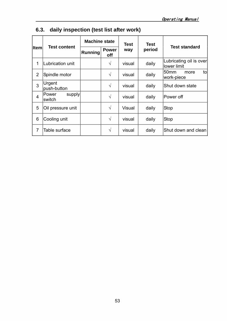
6.3. daily inspection (test list after work)
Item Test content Machine state Test
way Test
period Test standard Running Power
off
1 Lubrication unit √ visual daily Lubricating oil is over lower limit
2 Spindle motor √ visual daily 50mm more to work-piece
3 Urgent push-button √ visual daily Shut down state
4 Power supply switch √ visual daily Power off
5 Oil pressure unit √ Visual daily Stop
6 Cooling unit √ visual daily Stop
7 Table surface √ visual daily Shut down and clean

Operating Manual
54
Chapter 7: Setting, Adjusting and trouble shooting
7.1. there are ripples on the work piece
Cause :
1) The wheel is not well balanced — balance again.
2) The abrasive is not suitable to the work piece material — select
suitable wheel again.
3) Space between the grinding head pressboard and the column guide way
— adjusting the slide wedge again.
4) The hook bolt is loosing — tighten again.
5) The table backward or forward feed is not suitable.
6) Oil shortage on guide way.
7) The spindle running out of the way
8) The wheel is too blunt — dressing the wheel again.
7.2. Accuracy of the work piece ground is not so good
Cause:
1) The grind wheel is not suitable to the work piece
2) The machine was not leveled very well
3) The speed of cross and longitudinal moving is not suitable.
4) Space between the grinding head pressboard and the column guide way
5) The guide way need lubricating
6) The surface of the magnetic chuck is not so good.

Operating Manual
55
7.3. The spindle don’t run.
Cause:
1) The electro magnet doesn’t work
2) The fault of the power switch
3) The wheel guard is not closed well.
4) The control wire is loosened.
5) The coupling of the spindle is broken
6) The fault of spindle motor
7) The lubricating pump is short of oil.
8) The hydraulic pump is shut off.

Operating Manual
56
Parts list of Electrical circuit
No Code Name Spec. Qty Remark
1 QM1 Breaker 3UV1340‐1MN00(14‐20A) 1 Siemens
2 QM2 Breaker 3UV1340‐1NL00(8‐13A) 1 Siemens
3 QM3 Breaker 3UV1340‐1MF00(0.6‐1A) 1 Siemens
4 QM4 Breaker 3UV1340‐1MJ00(2.4‐4A) 1 Siemens
5 QM5 Breaker DZ47‐63/2P D6 1 Siemens
6 QM6‐7 Breaker DZ47‐63/1P D6 2 Siemens
7 QM8 Breaker DZ47‐63/1P C1 1 Siemens
8 KM1 Contactor 3TB4322‐OXB0 1 Siemens
9 KM0‐8 Contactor 3TB4022‐OXB0 9 Siemens
10 KA0 KA4 Middle rely MY2NJ‐AC24V 2 OMRON
11 KA1‐8 Middle rely MY2NJ‐DC24V 5 OMRON
12 AC motor controller SQ‐02A 1 Zhuozhuo
13 EL1 Working lamp Jl50B 1 Sanying
14 PLC 6ES7214‐1AD23‐0XB8 1 SIEMENS
15 TD400 HMI 6AV6 6640‐OAA00‐OAX0 1 SIEMENS
16 Power switch S‐100‐24 1 Mingwei
17 SQ1‐2 Travel switch TZ‐6004 2 Tend
18 SQ3‐4 Travel switch JLXK1‐411 2 Delixi
19 SQ5 Travel switch YBLX‐19/001 1 Delixi
20 SQ7 Travel switch TZ‐3101 1 Tend
21 SB0 Emergency switch LA38‐11MXS/203 1 Changjiang
22 SB1/6/7 Button with lamp LA38‐11D/203 绿 3 Changjiang

Operating Manual
57
23 SB7‐8 Button LA38‐11/203绿 2 Changjiang
24 SA2 Knob LA38‐31X2/203 2 Changjiang
25 SA4 Knob LA38‐21X3/203 1 Changjiang
26 SA5 Knob(auto reset) LA38‐20XL3/203 1 Changjiang
27 SA6 Waveband switch DPN01N‐30° 1 Dongce
28 HL1‐3 Indicator lamp AD11‐16/21‐6GZ(绿) 4 Changjiang
29 HL4 Indicator lamp AD11‐16/21‐6GZ(红) 1 Changjian
30 SQ6 Approach switch Bi2‐M12‐AZ31X
(AC20‐250V3‐100MA. DC10‐300V63‐100MA)
1 Tuerke
31 Servo diver ASD‐A0421‐AB 1 Taida
32 Servo motor ECMA‐E31305ES 1 Taida
33 QS Switch JFD11‐32/300030 1 Yaming
34 VR Potentiometer WTH118‐47KΩ 2W 1
35 KI Undercurrent rely JL18S‐2.5A 1 Tenglong
36 VC Rectifier QL20A‐500V 1
37 R1 R2 Resistance ZG11‐50‐T1000Ω 2
38 TC1 Transformer JBK5‐630VA/220V380V/127V(400VA) 、
110V(50VA)、24V(180VA) 1 Jiuchan
39 TM2 Transformer JSG‐1KVA/220V,380V/220V 1 Jiuchuan

Operating Manual
58
Circuit diagram

Operating Manual
59

Operating Manual
60

Operating Manual
61

Operating Manual
62

Operating Manual
63

Operating Manual
64

Operating Manual
65

Operating Manual
66

Operating Manual
67
Table assembly structure
NO. Parts name Machine model Parts Code name Qt.
1 Table extend guard
WSG1225 FSG3063R-30-304
2 WSG1632 FSG4080R-30-308 WSG1240 FSG30100R-30-311 WSG1640 FSG40100R-30-301
2 Splashing guard
WSG1020 FSG2550R-30-303
1 WSG1225 FSG3063R-30-303 WSG1632 FSG4080R-30-301 WSG1240 FSG30100R-30-303 WSG1640 FSG40100R-30-300
3 Table
WSG1020 FSG2550R-30-100
1 WSG1225 FSG3063R-30-100A WSG1632 FSG4080R-30-100 WSG1240 FSG30100R-30-100A WSG1640 FSG40100R-30-100
4 Right transverse adjusting dog All SG Aseries grinders FSG2050M-30-102 1 5 Left transverse adjusting dog All SGAseries grinders FSG2050M-30-103 1
6 Table manual feed rack
WSG1020 FSG2550R-30-300
1 WSG1225 FSG3063R-30-300 WSG1632 FSG4080R-30-300 WSG1240 FSG30100R-30-300 WSG1640 FSG30100R-30-300

Operating Manual
68
Column structure
No Code Name Qt.
1 FSG4080R-12-300 Fixed Guard 1
2 FSG4080R-12-304 Movable guard 2
3 FSG4080R-12-301 Dust-proof plate 1
4 FSG4080R-12-500 Bellow Plastic guard 3
5 FSG4080R-12-303 Dust-proof clamping strip 2
6 FSG2550R-12-100 FSG4080R-12-101 FSG30100R-12-100
Grinding spindle housing 1
7 FSG4080R-12-305 Upper cover-plate 1
8 FSG4080R-12-100 column 1
9 Column rear guard 1

Operating Manual
69
Table longitudinal manual feed structure
No. Code Name Qt.
1 FSG-30100R-23-302 FSG-4080R-23-305 Gear shaft 1
2
FSG-3063R -30-300 FSG-2550R -30-300 FSG-4080R -30-300 FSG-30100R -30-300A
Rack 1
3 61204-2Z(17×30×7)GB/T276-94 Deep-furrow ball bearing (61204)
2
4 FSG-30100R -23-101 FSG-4080R -23-103
Manual shaft bracket on longitudinal 1
5 FSG-30100R -23-304 FSG-4080R -23-311 Driven shaft sleeve 1
6 FSG-2050M-23-306 Spring 1
7 FSG-2050M-23-202 copper sleeve 1
8 FSG-2050M-10-503 Hand wheel 2
9 M12/J13-2B Acorn nut 1

Operating Manual
70
Cross feed structure
No Code Name Qt.
1 FSG-4080R-23-313 Washer 1 2 FSG-2050M-23-503 Hand wheel 1 3 FSG-2050M-23-302 Bearing cover 1 4 FSG-4080R-23-316 Feed dial 1 5 M818-10-312 Knurling set screw 1 6 FSG-4080R-23-307 Spacer 1 7 FSG-2050M-23-304 Sleeve 1 8 FSG-4080R-23-104 Vernier dial plate 1 9 M20×1.5/J14-4B Round nut 1
10 3204A (47×20×20.6)/GB/T292-94 Bearing 1 11 FSG-2050M-23-106 Small timing pulley 1 12 FSG-2050M-23-105 Big time pulley 1 13 187L075/GB11616-89 Timing belt 1 14 FSG-2550R-23-300
FSG-4080R-23-300 FSG-30100R-23-300
Cross lead screw 1
15 KT516 Cross feed motor 1 16 FSG-4080R-23-101 Feed nut bracket 1 17 FSG-30100R-23-301
FSG-4080R-23-310 Cross lead screw safe shield 1

Operating Manual
71
Elevating structure

Operating Manual
72
Parts list of elevating structure
No Code Name qt. 1 FSG-4080R-23-313 Washer 1 2 17*250/HY8313.7 Hand wheel 1 3 FSG-3063R-10-310 Vertical feed dial 1 4 FSG-3063R-10-315 Vernier dial 1 5 FSG-4080R-10-311 Dial sleeve 1 6 FSG-4080R-10-315 Spacer 1 7 50/GB893.1 Retaining washer 1
9 6204-2Z(20×47×14)GB/T281-94 Deep-furrow ball bearing (6204) 2
10 FSG-4080R-10-314A Bearing base 1 11 Cover plate 1 12 FSG-4080R-10-103 transmission box 1 13 FSG-3063R-10-102 Vertical belt pulley(big) 1 14 203L075/GB11616-89 Timing belt 1 15 FSG-3063R-10-307 Small pulley 1 16 FSG-3063R-10-102 Fixed plate for lifting motor 1 17 YS71M2-6-B5 Motor 1 18 FSG-3063R-10-101 Extension shaft bracket 1 19 M25×1.5/J14-4B Round nut 1 20 FSG-3063R-10-304 Bearing cover 1
21 1205(25×52×15)GB/T301-95 Double-row self-aligning bearing (1205) 1
22 FSG-3063R-10-303 Washer 1
23
FSG3063R-10-302 FSG4080R-10-302A FSG30100R-10-300A FSG40100R-10-300
Vertical shaft 1
24 6204-2Z(20×47×14)GB/T281-94 Deep-furrow ball bearing (6204) 2
25 FSG-2050M-10-305 Bevel pinion 1 26 FSG-4080R-10-303 Vertical screw 1
27 FSG-2050M-10-306 Bevel gear 1
28 6204-Z(55×90×18)GB/T286-94 Deep-furrow ball bearing (6204) 1
29 FSG-4080R-10-105 Drive base 1 30 M40×1.5/J14-4B Round nut 1 31 FSG-2050M-10-200 Vertical nut 1 32 51108(40×60×13)GB/T301-95 Thrust bearing(51108) 1 33 FSG-4080R-10-104 Connecting plate 1 34 FSG-4080R-10-106 Top guard 1

Operating Manual
73
HYDRAULIC CYLINDER

Operating Manual
74
HYDRAULIC CYLINDER No Code Name Qt. 1 M16×1.5/J11-1B Hexagonal nut 4 2 SG-4080AHR-53-300 Washer 4 3 SG-4080AHR-53-500 Cushion 2 4 SG-4080AHR-53-301 Driven base 2 5 M12×40/J21-9B Socket head cap screw 8 6 12/J54-1B Spring washer 8
7
SG2550AHR-53-301 SG3063AHR-53A-301 SG-4080AHR-53A-302 SG30100AHR-53-301
Piston rod 2
8 M6×20/J21-9B Socket head cap screw 6 9 6/J54-1B Spring washer 6
10 SG-4080AHR-53A-301 End cap 2 11 AD48-20×28×5.3 Dust-proof ring 2 12 MA30-20×28×6.3 Y-shaped ring 4 13 SG-4080AHR-53A-100 Hydraulic cylinder bracket 2 14 12/J54-1B Spring washer 4 15 8×35/41-2B taper pin 2 16 M12×40/J21-9B Socket head cap screw 4 17 40/G52-2 O-shaped ring 2 18 SG-4080AHR-53A-304 Guard cover 2 19 M6×20/J21-9B Hexagonal socket screw 8 20 6/J54-1B Spring washer 8 21 SG-4080AHR-53A-303 Ring 2
22
SG2550AHR-53-300 SG3063AHR-53A-300 SG-4080AHR-53A-306 SG30100AHR-53-300
Hydraulic cylinder 1
23 6×30/41-2B Taper pin 2 24 SG-4080AHR-53A-305 piston 1 25 K30-40A Hermetic ring 1 26 FUR02-8.1×2.5-40-D24 Guide ring 2

Operating Manual
75
Spindle unit
Parts list spindle unit
No Name qt. 1 Grinding wheel shield 1 2 Lock screw 3 3 Balancing block 3 4 Grinding wheel 1 5 Spindle 1 6 Plug 2 7 Spindle housing 1 8 Coupling connect to motor shaft 1 9 Gjb
10 Clamping plate 1 11 Motor assembling flange 1 12 AC motor 1 13 Gib 1 14 Plastic insert 1 15 Coupling connect to the spindle 1 16 Gib 1 17 Plug 1 18 Wheel flange base 1 19 Wheel flange clamping cover 1 20 Lock nut 1

Packing List
PACKING LIST 1.
No Name G.W. 1 WSG1640AHD 3800KG
2.
No Name Qt. 1 Oil tank 1pc 2 Coolant tank 1pc
3. Accessories
No. Name Code Qt. Remark
1 Balance arbor FSG2550R-86-301/302 1pc In the tool box
2 Wheel dresser base 1pc In the tool box
3 Wheel Flange Suit for 350*40*120 1 set In the carton
4 Leveling wedge 1set In the tool box
5 Tool box 1pc
6 Wrench body Handle Wheel extractor
FSG2550R-86-303 1pc In the tool box
7 M7130-8016 1pc In the tool box
8 Screw drive 150 1pc In the tool box
9
Wrench for hexagonsocket
head screw
4/S91-7 1pc In the tool box
10 5/S91-7 1pc In the tool box
11 6/S91-7 1pc In the tool box
12 8/S91-7 1pc In the tool box
13 10/S91-7 1pc In the tool box
14 Adjustable wrench 200 1pc In the tool box
15 Wheel P350×40×127 WA46L5V35 1pc In the carton
16 Electro magnetic chuck 400*1000mm 1pc On the
worktable 17 Dust brusher 1pc In the tool box

Packing List
4. Optional accessories No. Name Code Qt 1 Balance stand
2 Parallel wheel dresser
3 Digital readout
4 Magnetic separator
5 Paper filter
6 Diamond pen
5. Documents
No Name Qt 1 Operating manual 1 copy 2 Packing list 1 copy
Inspector:
Y M D