wsjt-x user guide - broken arrow amateur radio...
TRANSCRIPT

WSJT-X User GuideJoseph H Taylor, Jr, K1JT
Version 1.8.0
https://physics.princeton.edu/pulsar/k1jt/wsjtx-doc/wsjtx-main-1.8.0.html 5/6/18, 10@21 AMPage 1 of 94

Table of Contents1. Introduction
1.1. New in Version 1.81.2. Documentation Conventions1.3. How You Can Contribute
2. System Requirements3. Installation
3.1. Windows3.2. Linux3.3. OS X and macOS
4. Settings4.1. General4.2. Radio4.3. Audio4.4. Tx Macros4.5. Reporting4.6. Frequencies4.7. Colors4.8. Advanced
5. Transceiver Setup6. Basic Operating Tutorial
6.1. Main Window Settings6.2. Download Samples6.3. Wide Graph Settings6.4. JT96.5. JT9+JT656.6. FT8
7. Making QSOs7.1. Standard Exchange7.2. Free-Text Messages7.3. Auto-Sequencing7.4. VHF Contest Mode7.5. Compound Callsigns7.6. Pre-QSO Checklist
8. VHF+ Features8.1. VHF Setup8.2. JT48.3. JT658.4. QRA648.5. ISCAT
https://physics.princeton.edu/pulsar/k1jt/wsjtx-doc/wsjtx-main-1.8.0.html 5/6/18, 10@21 AMPage 2 of 94

8.6. MSK1448.7. Echo Mode8.8. VHF+ Sample Files
9. WSPR Mode9.1. Band Hopping
10. On-Screen Controls10.1. Menus10.2. Button Row10.3. Left10.4. Center10.5. Tx Messages10.6. Status Bar10.7. Wide Graph10.8. Fast Graph10.9. Echo Graph10.10. Miscellaneous
11. Logging12. Decoder Notes
12.1. AP Decoding12.2. Decoded Lines
13. Measurement Tools13.1. Frequency Calibration13.2. Reference Spectrum13.3. Phase Equalization
14. Cooperating Programs15. Platform Dependencies16. Frequently Asked Questions17. Protocol Specifications
17.1. Overview17.2. Slow Modes17.3. Fast Modes
18. Astronomical Data19. Utility Programs20. Support
20.1. Help with Setup20.2. Bug Reports20.3. Feature Requests
21. Acknowledgements22. License
https://physics.princeton.edu/pulsar/k1jt/wsjtx-doc/wsjtx-main-1.8.0.html 5/6/18, 10@21 AMPage 3 of 94
1. IntroductionWSJT-X is a computer program designed to facilitate basic amateur radio communication using very weak signals. Thefirst four letters in the program name stand for “Weak Signal communication by K1JT,” while the suffix “-X” indicates thatWSJT-X started as an extended and experimental branch of the program WSJT.
WSJT-X Version 1.8 offers nine different protocols or modes: FT8, JT4, JT9, JT65, QRA64, ISCAT, MSK144, WSPR,and Echo. The first five are designed for making reliable QSOs under extreme weak-signal conditions. They use nearlyidentical message structure and source encoding. JT65 and QRA64 were designed for EME (“moonbounce”) on theVHF/UHF bands and have also proven very effective for worldwide QRP communication on the HF bands. QRA64 has anumber of advantages over JT65, including better performance on the very weakest signals. We imagine that over timeit may replace JT65 for EME use. JT9 was originally designed for the LF, MF, and lower HF bands. Its submode JT9A is2 dB more sensitive than JT65 while using less than 10% of the bandwidth. JT4 offers a wide variety of tone spacingsand has proven highly effective for EME on microwave bands up to 24 GHz. These four “slow” modes use one-minutetimed sequences of alternating transmission and reception, so a minimal QSO takes four to six minutes — two or threetransmissions by each station, one sending in odd UTC minutes and the other even. FT8 is operationally similar but fourtimes faster (15-second T/R sequences) and less sensitive by a few dB. On the HF bands, world-wide QSOs arepossible with any of these modes using power levels of a few watts (or even milliwatts) and compromise antennas. OnVHF bands and higher, QSOs are possible (by EME and other propagation types) at signal levels 10 to 15 dB belowthose required for CW.
ISCAT, MSK144, and optionally submodes JT9E-H are “fast” protocols designed to take advantage of brief signalenhancements from ionized meteor trails, aircraft scatter, and other types of scatter propagation. These modes usetimed sequences of 5, 10, 15, or 30 s duration. User messages are transmitted repeatedly at high rate (up to 250characters per second, for MSK144) to make good use of the shortest meteor-trail reflections or “pings”. ISCAT usesfree-form messages up to 28 characters long, while MSK144 uses the same structured messages as the slow modesand optionally an abbreviated format with hashed callsigns.
WSPR (pronounced “whisper”) stands for Weak Signal Propagation Reporter. The WSPR protocol was designed forprobing potential propagation paths using low-power transmissions. WSPR messages normally carry the transmittingstation’s callsign, grid locator, and transmitter power in dBm, and they can be decoded at signal-to-noise ratios as low as-28 dB in a 2500 Hz bandwidth. WSPR users with internet access can automatically upload reception reports to a centraldatabase called WSPRnet (http://wsprnet.org/drupal/) that provides a mapping facility, archival storage, and many otherfeatures.
Echo mode allows you to detect and measure your own station’s echoes from the moon, even if they are far below theaudible threshold.
WSJT-X provides spectral displays for receiver passbands as wide as 5 kHz, flexible rig control for nearly all modernradios used by amateurs, and a wide variety of special aids such as automatic Doppler tracking for EME QSOs andEcho testing. The program runs equally well on Windows, Macintosh, and Linux systems, and installation packages areavailable for all three platforms.
https://physics.princeton.edu/pulsar/k1jt/wsjtx-doc/wsjtx-main-1.8.0.html 5/6/18, 10@21 AMPage 4 of 94

1.1. New in Version 1.8For quick reference, here’s a short list of features and capabilities added to WSJT-X since Version 1.7.0:
New mode FT8 designed for fast QSOs
New tool FreqCal for accurate frequency calibration of your radio
Improved decoding performance for JT65, QRA64, and MSK144
SWL option for third-party decoding short-format MSK144 messages
Experimental phase equalization for MSK144
Options to minimize screen space used by Main and Wide Graph windows
New set of suggested default frequencies specific to the three IARU regions
Enhanced scheme for managing table of suggested default operating frequencies
Improved CAT control for many radios, including those controlled through Commander or OmniRig
Bug fixes and minor tweaks to user interface
1.2. Documentation ConventionsIn this manual the following icons call attention to particular types of information:
! Notes containing information that may be of interest to particuar classes of users.
" Tips on program features or capabilities that might otherwise be overlooked.
# Warnings about usage that could lead to undesired consequences.
1.3. How You Can ContributeWSJT-X is part of an open-source project released under the GNU General Public License(http://www.gnu.org/licenses/gpl-3.0.txt) (GPL). If you have programming or documentation skills or would like to contribute tothe project in other ways, please make your interests known to the development team. The project’s source-coderepository can be found at SourceForge (http://sourceforge.net/p/wsjt/wsjt/HEAD/tree/), and most communication among thedevelopers takes place on the email reflector [email protected]. Bug reports and suggestions for newfeatures, improvements to the WSJT-X User Guide, etc., may also be sent to the WSJT Group(https://groups.yahoo.com/neo/groups/wsjtgroup/info) email reflector. You must join the relevant group before posting to eitheremail list.
https://physics.princeton.edu/pulsar/k1jt/wsjtx-doc/wsjtx-main-1.8.0.html 5/6/18, 10@21 AMPage 5 of 94

2. System RequirementsSSB transceiver and antenna
Computer running Windows (XP or later), Linux, or OS X
1.5 GHz or faster CPU and 200 MB of available memory; faster machines are better
Monitor with at least 1024 x 780 resolution
Computer-to-radio interface using a serial port or equivalent USB device for T/R switching, or CAT control, or VOX,as required for your radio-to-computer connections
Audio input and output devices supported by the operating system and configured for sample rate 48000 Hz, 16 bits
Audio or equivalent USB connections between transceiver and computer
A means for synchronizing the computer clock to UTC within ±1 second
https://physics.princeton.edu/pulsar/k1jt/wsjtx-doc/wsjtx-main-1.8.0.html 5/6/18, 10@21 AMPage 6 of 94

3. InstallationInstallation packages for released versions on Windows, Linux, and OS X are found on the WSJT Home Page(http://physics.princeton.edu/pulsar/K1JT/). Click on the WSJT-X link at the left margin and select the appropriate package foryour operating system.
3.1. WindowsDownload and execute the package file wsjtx-1.8.0-win32.exe (http://physics.princeton.edu/pulsar/K1JT/wsjtx-1.8.0-win32.exe),following these instructions:
Install WSJT-X into its own directory, for example C:\WSJTX or C:\WSJT\WSJTX , rather than the conventionallocation C:\Program Files\WSJTX .
All program files relating to WSJT-X will be stored in the chosen installation directory and its subdirectories.
Logs and other writeable files will normally be found in the directoryC:\Users\<username>\AppData\Local\WSJT-X .
"Your computer may be configured so that this directory is “invisible”. It’s there, however, andaccessible. An alternative (shortcut) directory name is %LOCALAPPDATA%\WSJT-X\ .
The built-in Windows facility for time synchronization is usually not adequate. We recommend the program MeinbergNTP (see Network Time Protocol Setup (http://www.satsignal.eu/ntp/setup.html) for downloading and installationinstructions) or Dimension 4 from Thinking Man Software (http://www.thinkman.com/dimension4/).
WSJT-X expects your sound card to do its raw sampling at 48000 Hz. To ensure that this will be so when runningunder recent versions of Windows, open the system’s Sound control panel and select in turn the Recording andPlayback tabs. Click on Properties, then Advanced, and select 16 bit, 48000 Hz (DVD Quality).
You can uninstall WSJT-X by clicking its Uninstall link in the Windows Start menu, or by using Uninstall a Programon the Windows Control Panel.
3.2. LinuxDebian, Ubuntu, and other Debian-based systems including Raspbian:
32-bit: wsjtx_1.8.0_i386.deb (http://physics.princeton.edu/pulsar/K1JT/wsjtx_1.8.0_i386.deb)
To install:
sudo dpkg -i wsjtx_1.8.0_i386.deb
Uninstall:
https://physics.princeton.edu/pulsar/k1jt/wsjtx-doc/wsjtx-main-1.8.0.html 5/6/18, 10@21 AMPage 7 of 94

sudo dpkg -P wsjtx
64-bit: wsjtx_1.8.0_amd64.deb (http://physics.princeton.edu/pulsar/K1JT/wsjtx_1.8.0_amd64.deb)
To install:
sudo dpkg -i wsjtx_1.8.0_amd64.deb
64-bit: wsjtx_1.8.0_armhf.deb (http://physics.princeton.edu/pulsar/K1JT/wsjtx_1.8.0_armhf.deb)
To install:
sudo dpkg -i wsjtx_1.8.0_armhf.deb
Uninstall:
sudo dpkg -P wsjtx
You may also need to execute the following command in a terminal:
sudo apt install libqt5multimedia5-plugins libqt5serialport5 libfftw3-single3
Fedora, Red Hat, and other rpm-based systems:
32-bit: wsjtx-1.8.0-i686.rpm (http://physics.princeton.edu/pulsar/K1JT/wsjtx-1.8.0-i686.rpm)
To install:
sudo rpm -i wsjtx-1.8.0-i686.rpm
Uninstall:
sudo rpm -e wsjtx
64-bit: wsjtx-1.8.0-x86_64.rpm (http://physics.princeton.edu/pulsar/K1JT/wsjtx-1.8.0-x86_64.rpm)
To install:
https://physics.princeton.edu/pulsar/k1jt/wsjtx-doc/wsjtx-main-1.8.0.html 5/6/18, 10@21 AMPage 8 of 94

sudo rpm -i wsjtx-1.8.0-x86_64.rpm
Uninstall:
sudo rpm -e wsjtx
You may also need to execute the following command in a terminal:
sudo dnf install fftw-libs-single qt5-qtmultimedia qt5-qtserialport
3.3. OS X and macOSOS X 10.9 and later: Download the file wsjtx-1.8.0-Darwin.dmg (http://physics.princeton.edu/pulsar/K1JT/wsjtx-1.8.0-Darwin.dmg)
to your desktop, double-click on it and consult its ReadMe file for important installation notes.
If you have already installed a previous version, you can retain it by changing its name in the Applications folder (say,from WSJT-X to WSJT-X_1.7). You can then proceed to the installation phase.
Take note also of the following:
Use the Mac’s Audio MIDI Setup utility to configure your sound card for 48000 Hz, two-channel, 16-bit format.
Use System Preferences to select an external time source to keep your system clock synchronized to UTC.
To uninstall simply drag the WSJT-X application from Applications to the Trash Can.
https://physics.princeton.edu/pulsar/k1jt/wsjtx-doc/wsjtx-main-1.8.0.html 5/6/18, 10@21 AMPage 9 of 94

4. SettingsSelect Settings from the File menu or by typing F2. (On Macintosh select Preferences from the WSJT-X menu, or usethe keyboard shortcut Cmd+,). The following sections describe setup options available on each of eight tabs selectablenear the top of the window.
4.1. General
Select the General tab on the Settings window. Under Station Details enter your callsign, grid locator (preferably the 6-character locator) and IARU Region number. Region 1 is Europe, Africa, the Middle East, and Northern Asia; Region 2the Americas; and Region 3 Southern Asia and the Pacific. This information will be sufficient for initial tests.
Meanings of remaining options on the General tab should be self-explanatory after you have made some QSOs usingWSJT-X. You may return to set these options to your preferences later.
https://physics.princeton.edu/pulsar/k1jt/wsjtx-doc/wsjtx-main-1.8.0.html 5/6/18, 10@21 AMPage 10 of 94
! If you are using a callsign with an add-on prefix or suffix, or wish to work a station using such a call,be sure to read the section Compound Callsigns.
!Enabling VHF/UHF/Microwave features necessarily disables the wideband multi-decode capability ofJT65. In most circumstances you should turn this feature off when operating at HF.
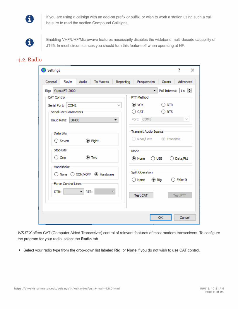
4.2. Radio
WSJT-X offers CAT (Computer Aided Transceiver) control of relevant features of most modern transceivers. To configurethe program for your radio, select the Radio tab.
Select your radio type from the drop-down list labeled Rig, or None if you do not wish to use CAT control.
https://physics.princeton.edu/pulsar/k1jt/wsjtx-doc/wsjtx-main-1.8.0.html 5/6/18, 10@21 AMPage 11 of 94
Alternatively, if you have configured your station for control by DX Lab Suite Commander, Ham Radio Deluxe,Hamlib NET rigctl, or OmniRig, you may select one of those program names from the Rig list. In these cases theentry field immediately under CAT Control will be relabeled as Network Server. Leave this field blank to access thedefault instance of your control program, running on the same computer. If the control program runs on a differentcomputer and/or port, specify it here. Hover the mouse pointer over the entry field to see the required formattingdetails.
Select OmniRig Rig 1 or OmniRig Rig 2 to connect to an OmniRig server running on the same computer. Note thatOmniRig is available only under Windows.
Set Poll Interval to the desired interval for WSJT-X to query your radio. For most radios a small number (say, 1 – 3s) is suitable.
CAT Control: To have WSJT-X control the radio directly rather than though another program, make the followingsettings:
Select the Serial Port used to communicate with your radio.
Serial Port Parameters: Set values for Baud Rate, Data Bits, Stop Bits, and Handshake method. Consult yourradio’s user guide for the proper parameter values.
Force Control Lines: A few station setups require the CAT serial port’s RTS and/or DTR control lines to be forcedhigh or low. Check these boxes only if you are sure they are needed (for example, to power the radio serialinterface).
PTT Method: select VOX, CAT, DTR, or RTS as the desired method for T/R switching. If your choice is DTR or RTS,select the desired serial port (which may be the same one as used for CAT control).
Transmit Audio Source: some radios permit you to choose the connector that will accept Tx audio. If this choice isenabled, select Rear/Data or Front/Mic.
Mode: WSJT-X uses upper sideband mode for both transmitting and receiving. Select USB, or choose Data/Pkt ifyour radio offers such an option and uses it to enable the rear-panel audio line input. Some radios also offer widerand/or flatter passbands when set to Data/Pkt mode. Select None if you do not want WSJT-X to change the radio’sMode setting.
Split Operation: Significant advantages result from using Split mode (separate VFOs for Rx and Tx) if your radiosupports it. If it does not, WSJT-X can emulate such behavior. Either method will result in a cleaner transmittedsignal, by keeping the Tx audio always in the range 1500 to 2000 Hz so that audio harmonics cannot pass throughthe Tx sideband filter. Select Rig to use the radio’s Split mode, or Fake It to have WSJT-X adjust the VFO frequencyas needed, when T/R switching occurs. Choose None if you do not wish to use split operation.
When all required settings have been made, click Test CAT to test communication between WSJT-X and your radio. Thebutton should turn green to indicate that proper communication has been established. Failure of the CAT-control testturns the button red and displays an error message. After a successful CAT test, toggle the Test PTT button to confirmthat your selected method of T/R control is working properly. (If you selected VOX for PTT Method, you can test T/Rswitching later by using the Tune button on the main window.)
4.3. Audio
https://physics.princeton.edu/pulsar/k1jt/wsjtx-doc/wsjtx-main-1.8.0.html 5/6/18, 10@21 AMPage 12 of 94
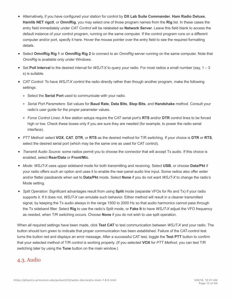
Select the Audio tab to configure your sound system.
Soundcard: Select the audio devices to be used for Input and Output. Usually the Mono settings will suffice, but inspecial cases you can choose Left, Right, or Both stereo channels.
Be sure that your audio device is configured to sample at 48000 Hz, 16 bits.
#If you select the audio output device that is also your computer’s default audio device, be sure to turnoff all system sounds to prevent inadvertently transmitting them over the air.
!Windows Vista and later may configure audio devices using the Texas Instruments PCM2900 seriesCODEC for microphone input rather line input. (This chip is used in many radios with built-in USBCODECs, as well as various other audio interfaces.) If you are using such a device, be sure to setthe mic level in the Recording Device Properties to 0 dB.
Save Directory: WSJT-X can save its received audio sequences as .wav files. A default directory for these files isprovided; you can select another location if desired.
AzEl Directory: A file named azel.dat will appear in the specified directory. The file contains information usable byanother program for automatic tracking of the Sun or Moon, as well as calculated Doppler shift for the specified EMEpath. The file is updated once per second whenever the Astronomical Data window is displayed.
https://physics.princeton.edu/pulsar/k1jt/wsjtx-doc/wsjtx-main-1.8.0.html 5/6/18, 10@21 AMPage 13 of 94

Remember power settings by band: Checking either of these will cause WSJT-X to remember the Pwr slider settingfor that operation on a band-by-band basis. For example, when Tune is checked here and you click the Tune buttonon the main window, the power slider will change to the most recent setting used for Tune on the band in use.
4.4. Tx Macros
Tx Macros are an aid for sending brief, frequently used free-text messages such as the examples shown above.
To add a new message to the list, enter the desired text (up to 13 characters) in the entry field at top, then click Add.
To remove an unwanted message, click on the message and then on Delete.
You can reorder your macro messages by using drag-and-drop. The new order will be preserved when WSJT-X isrestarted.
Messages can also be added from the main window’s Tx5 field on Tab 1 or the Free msg field on Tab 2. Simply hit[Enter] after the message has been entered.
4.5. Reporting
https://physics.princeton.edu/pulsar/k1jt/wsjtx-doc/wsjtx-main-1.8.0.html 5/6/18, 10@21 AMPage 14 of 94

Logging: Choose any desired options from this group.
Network Services: Check Enable PSK Reporter Spotting to send reception reports to the PSK Reporter(http://pskreporter.info/pskmap.html) mapping facility.
UDP Server: This group of options controls the network name or address and port number used by a program thatwill receive status updates from WSJT-X. Cooperating applications like JTAlert use this feature to obtain informationabout a running WSJT-X instance. If you are using JTAlert, be sure to check the three boxes at lower right.
4.6. Frequencies
https://physics.princeton.edu/pulsar/k1jt/wsjtx-doc/wsjtx-main-1.8.0.html 5/6/18, 10@21 AMPage 15 of 94

Working Frequencies: By default the Working Frequencies table contains a list of frequencies conventionally used formodes JT4, JT9, JT65, MSK144, WSPR, and Echo. Conventions may change with time or by user preference; you canmodify the frequency table as desired.
To change an existing entry, double-click to edit it, type a desired frequency in MHz or select from the drop down listof options, then hit Enter on the keyboard. The program will format your changed entry appropriately.
To add a new entry, right-click anywhere on the frequency table and select Insert. Enter a frequency in MHz in thepop-up box and select the desired mode (or leave the Mode selection as All). Then click OK. The table may includemore than one frequency for a given band.
To delete an entry, right-click it and select Delete, multiple entries can be deleted in a single operation by selectingthem before right-clicking.
Right-click any entry and click Reset button to return the table to its default configuration.
Other more advanced maintenance operations are available on the right-click context menu that should be self-explanatory.
https://physics.princeton.edu/pulsar/k1jt/wsjtx-doc/wsjtx-main-1.8.0.html 5/6/18, 10@21 AMPage 16 of 94

Frequency Calibration: If you have calibrated your radio using WWV or other reliable frequency references, or perhapswith the technique described in Accurate Frequency Measurements with your WSPR Setup(http://www.physics.princeton.edu/pulsar/K1JT/FMT_User.pdf), enter the measured values for Intercept A and Slope B in theequation
Dial error = A + B*f
where “Dial error” and A are in Hz, f is frequency in MHz, and B is in parts per million (ppm). Frequency values sent tothe radio and received from it will then be adjusted so that frequencies displayed by WSJT-X are accurate.
Station Information: You can save Band, Offset and Antenna Description information for your station. The antennainformation will be included in reception reports sent to PSK Reporter (http://pskreporter.info/pskmap.html). By default thefrequency offset for each band is zero. Nonzero offsets may be added if (for example) a transverter is in use.
To simplify things you might want to delete any unwanted bands — for example, bands where you have noequipment. Then click on a Frequency entry and type Ctrl+A to “select all,” and drag-and-drop the entries onto theStation Information table. You can then add any transverter offsets and antenna details.
To avoid typing the same information many times, you can drag-and-drop entries between the lines of the StationInformation table.
When all settings have been configured to your liking, click OK to dismiss the Settings window.
4.7. Colors
WSJT-X uses colors to highlight decoded messages containing information of particular interest. Click on one of thebuttons to select your preferred colors for any message category.
https://physics.princeton.edu/pulsar/k1jt/wsjtx-doc/wsjtx-main-1.8.0.html 5/6/18, 10@21 AMPage 17 of 94

4.8. Advanced
JT65 decoding parameters
Random erasure patterns logarithmically scales the number of pseudo-random trials used by the Franke-TaylorJT65 decoder. Larger numbers give slightly better sensitivity but take longer. For most purposes a good setting is 6 or7.
Aggressive decoding level sets the threshold for acceptable decodes using Deep Search. Higher numbers willdisplay results with lower confidence levels.
Check Two-pass decoding to enable a second decoding pass after signals producing first-pass decodes have beensubtracted from the received data stream.
Miscellaneous
Set a positive number in Degrade S/N of .wav file to add known amounts of pseudo-random noise to data read froma .wav file. To ensure that the resulting S/N degradation is close to the requested number of dB, set Receiverbandwidth to your best estimate of the receiver’s effective noise bandwidth.
Set Tx delay to a number larger than the default 0.2 s to create a larger delay between execution of a command toenable PTT and onset of Tx audio.
#For the health of your T/R relays and external preamplifier, we strongly recommend using ahardware sequencer and testing to make sure that sequencing is correct.
Check FT8 and MSK144: NA VHF Contest Mode to enable generation and auto-sequencing of messages usingfour-character grid locators in place of signal reports, as required for most North American VHF contests.
Check x 2 Tone spacing to generate Tx audio with twice the normal tone spacing. This feature is intended for usewith specialized LF/MF transmitters that divide the audio waveform by 2 before further processing.
https://physics.princeton.edu/pulsar/k1jt/wsjtx-doc/wsjtx-main-1.8.0.html 5/6/18, 10@21 AMPage 18 of 94

5. Transceiver SetupReceiver Noise Level
If it is not already highlighted in green, click the Monitor button to start normal receive operation.
Be sure your transceiver is set to USB (or USB Data) mode.
Use the receiver gain controls and/or the computer’s audio mixer controls to set the background noise level (scale atlower left of main window) to around 30 dB when no signals are present. It is usually best to turn AGC off or reducethe RF gain control to minimize AGC action.
Bandwidth and Frequency SettingIf your transceiver offers more than one bandwidth setting in USB mode, it may be advantageous to choose thewidest one possible, up to about 5 kHz. This choice has the desirable effect of allowing the Wide Graph (waterfalland 2D spectrum) to display the conventional JT65 and JT9 sub-bands simultaneously on most HF bands. Furtherdetails are provided in the Basic Operating Tutorial. A wider displayed bandwidth may also be helpful at VHF andabove, where FT8, JT4, JT65, and QRA64 signals may be found over much wider ranges of frequencies.
If you have only a standard SSB filter you won’t be able to display more than about 2.7 kHz bandwidth. Dependingon the exact dial frequency setting, on HF bands you can display the full sub-band generally used for one mode.
Of course, you might prefer to concentrate on one mode at a time, setting your dial frequency to (say) 14.074 forFT8, 14.076 for JT65, or 14.078 for JT9. Present conventions have the nominal JT9 dial frequency 2 kHz higher thanthe JT65 dial frequency on most bands, and the FT8 frequency 2 kHz lower.
Transmitter Audio LevelClick the Tune button on the main screen to switch the radio into transmit mode and generate a steady audio tone.
Listen to the generated audio tone using your radio’s Monitor facility. The transmitted tone should be perfectlysmooth, with no clicks or glitches. Make sure that this is true even when you simultaneously use the computer to doother tasks such as email, web browsing, etc.
Adjust the Pwr slider (at right edge of main window) downward from its maximum until the RF output from yourtransmitter falls slightly. This is generally a good level for audio drive.
Toggle the Tune button once more or click Halt Tx to stop your test transmission.
https://physics.princeton.edu/pulsar/k1jt/wsjtx-doc/wsjtx-main-1.8.0.html 5/6/18, 10@21 AMPage 19 of 94
6. Basic Operating TutorialThis section introduces the basic user controls and program behavior of WSJT-X, with particular emphasis on the JT9,JT65, and FT8 modes. We suggest that new users should go through the full HF-oriented tutorial, preferably while atyour radio. Subsequent sections cover additional details on Making QSOs, WSPR mode and VHF+ Features.
6.1. Main Window SettingsClick the Stop button on the main window to halt any data acquisition.
Select JT9 from the Mode menu and Deep from the Decode menu.
Set the audio frequencies to Tx 1224 Hz and Rx 1224 Hz.
"Sliders and spinner controls respond to Arrow key presses and Page Up/Down key presses, withthe Page keys moving the controls in larger steps. You can also type numbers directly into thespinner controls or use the mouse wheel.
Select Tab 2 (below the Decode button) to choose the alternative set of controls for generating and selecting Txmessages.
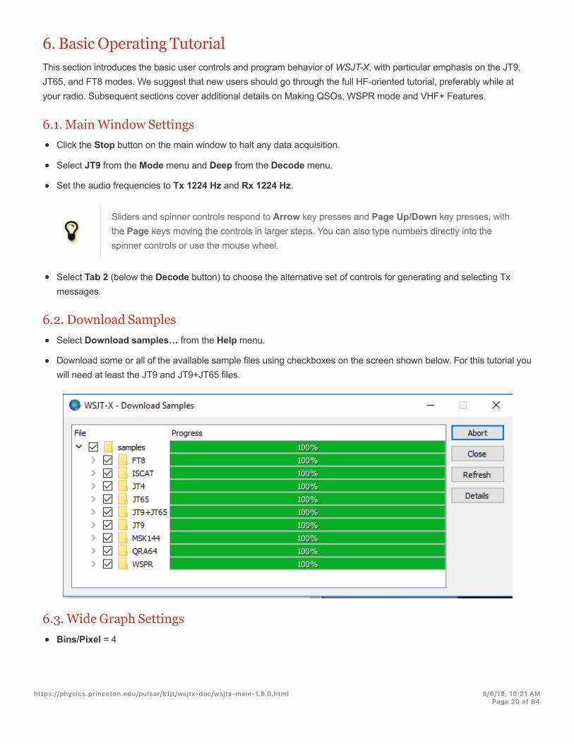
6.2. Download SamplesSelect Download samples… from the Help menu.
Download some or all of the available sample files using checkboxes on the screen shown below. For this tutorial youwill need at least the JT9 and JT9+JT65 files.
6.3. Wide Graph SettingsBins/Pixel = 4
https://physics.princeton.edu/pulsar/k1jt/wsjtx-doc/wsjtx-main-1.8.0.html 5/6/18, 10@21 AMPage 20 of 94

Start = 200 Hz
N Avg = 5
Palette = Digipan
Flatten = checked
Select Cumulative for data display
Gain and Zero sliders for waterfall and spectrum set near midscale
Spec = 25%
Use the mouse to grab the left or right edge of the Wide Graph, and adjust its width so that the upper frequency limitis about 2400 Hz.
6.4. JT9For this step and the next, you may want to pretend you are K1JT by entering that callsign temporarily as My Call on theSettings | General tab. Your results should then be identical to those shown in the screen shot below.
Open a Wave File:Select File | Open and select the file ...\save\samples\JT9\130418_1742.wav. When the file opens you should seesomething similar to the following screen shot:
https://physics.princeton.edu/pulsar/k1jt/wsjtx-doc/wsjtx-main-1.8.0.html 5/6/18, 10@21 AMPage 21 of 94

Decoding OverviewDecoding takes place at the end of a receive sequence and proceeds in two steps. The first decode is done at theselected Rx frequency, indicated by the U-shaped green marker on the waterfall frequency scale. Results appear in boththe left (Band Activity) and right (Rx Frequency) text windows on the main screen. The program then finds anddecodes all signals in the selected mode over the displayed frequency range. The red marker on the waterfall scaleindicates your Tx frequency.
https://physics.princeton.edu/pulsar/k1jt/wsjtx-doc/wsjtx-main-1.8.0.html 5/6/18, 10@21 AMPage 22 of 94

Seven JT9 signals are present in the example file, all decodable. When this file was recorded KF4RWA was finishing aQSO with K1JT. Since the green marker was placed at his audio frequency, 1224 Hz, his message K1JT KF4RWA 73 isdecoded first and appears in the Rx Frequency window. The Band Activity window shows this message plus alldecodes at other frequencies. By default lines containing CQ are highlighted in green, and lines with My Call (in thiscase K1JT) in red.
Decoding ControlsTo gain some feeling for controls frequently used when making QSOs, try clicking with the mouse on the decoded textlines and on the waterfall spectral display. You should be able to confirm the following behavior:
Double-click on either of the decoded lines highlighted in green. This action produces the following results:
Callsign and locator of a station calling CQ are copied to the DX Call and DX Grid entry fields.
Messages are generated for a standard minimal QSO.
The Tx even box is checked or cleared appropriately, so that you will transmit in the proper (odd or even) minutes.
The Rx frequency marker is moved to the frequency of the CQing station.
The Gen Msg (“generated message”) radio button at bottom right of the main window is selected.
If you had checked Double-click on call sets Tx Enable on the Setup menu, Enable Tx would be activated anda transmission would start automatically at the proper time.
You can modify the double-click behavior by holding down the Shift key to move only the Tx frequency or the Ctrlkey to move both Rx and Tx frequencies.
Double-click on the decoded message K1JT N5KDV EM41 , highlighted in red. Results will be similar to those in theprevious step. The Tx frequency (red marker) is not moved unless Shift or Ctrl is held down. Messages highlightedin red are usually in response to your own CQ or from a tail-ender, and you probably want your Tx frequency to staywhere it was.
!Double-clicking on decoded messages can be defaulted to simplex operation by checking Doubleclick on call sets Tx and Rx freqs on the Settings → General tab.
! You can prevent your Tx frequency from being changed by checking the box Lock Tx Freq.
Click somewhere on the waterfall to set Rx frequency (green marker on waterfall scale).
Shift-click on the waterfall to set Tx frequency (red marker).
Ctrl-click on the waterfall to set both Rx and Tx frequencies.
Double-click on a signal in the waterfall to set Rx frequency and start a narrow-band decode there. Decoded text willappear in the right window only.
Ctrl-double-click on a signal to set both Rx and Tx frequencies and decode at the new frequency.
https://physics.princeton.edu/pulsar/k1jt/wsjtx-doc/wsjtx-main-1.8.0.html 5/6/18, 10@21 AMPage 23 of 94

Click Erase to clear the right window.
Double-click Erase to clear both text windows.
6.5. JT9+JT65Main Window:
Select JT9+JT65 on the Mode menu.
Toggle the Tx mode button to read Tx JT65 #, and set the Tx and Rx frequencies to 1718 Hz.
Double-click on Erase to clear both text windows.
Wide Graph Settings:Bins/Pixel = 7
JT65 …. JT9 = 2500
Adjust the width of the Wide Graph window so that the upper frequency limit is approximately 4000 Hz.
Open a Wave File:Select File | Open and navigate to ...\save\samples\JT9+JT65\130610_2343.wav. The waterfall should looksomething like this:
The position of the blue marker on the waterfall scale is set by the spinner control JT65 nnnn JT9, where nnnn is anaudio frequency in Hz. In JT9+JT65 mode the program will automatically decode JT9 signals only above this frequency.JT65 signals will be decoded over the full displayed frequency range.
JT9 signals appear in the Cumulative spectrum as nearly rectangular shapes about 16 Hz wide. They have no clearlyvisible sync tone like the one at the low-frequency edge of all JT65 signals. By convention the nominal frequency of bothJT9 and JT65 signals is taken to be that of the lowest tone, at the left edge of its spectrum.
This sample file contains 17 decodable signals — nine in JT65 mode (flagged with the character # in the decoded textwindows), and eight in JT9 mode (flagged with @). On multi-core computers the decoders for JT9 and JT65 modes runsimultaneously, so their results will be interspersed. The Band Activity window contains all decodes (you might need to
https://physics.princeton.edu/pulsar/k1jt/wsjtx-doc/wsjtx-main-1.8.0.html 5/6/18, 10@21 AMPage 24 of 94

scroll back in the window to see some of them). A signal at the frequency specified by the green marker is givendecoding priority, and its message is displayed also in the Rx Frequency window.
Confirm that mouse-click behavior is similar to that described earlier, in Example 1. WSJT-X automatically determinesthe mode of each JT9 or JT65 message.
"When you double-click on a signal in the waterfall it will be properly decoded even if on the “wrong”side of the JT65 nnnn JT9 marker. The Tx mode automatically switches to that of the decodedsignal and the Rx and Tx frequency markers on the waterfall scale resize themselves accordingly.When selecting a JT65 signal, click on the sync tone at its left edge.
Double-click on the waterfall near 815 Hz: a JT65 message originating from W7VP will be decoded and appear in theRx Frequency window. Between the UTC and Freq columns on the decoded text line you will find dB, the measuredsignal-to-noise ratio, and DT, the signal’s time offset in seconds relative to your computer clock.
UTC dB DT Freq Mode Message
2343 -7 0.3 815 # KK4DSD W7VP -16
Double-click on the waterfall at 3196 Hz. The program will decode a JT9 message from IZ0MIT:
UTC dB DT Freq Mode Message
2343 -8 0.3 3196 @ WB8QPG IZ0MIT -11
https://physics.princeton.edu/pulsar/k1jt/wsjtx-doc/wsjtx-main-1.8.0.html 5/6/18, 10@21 AMPage 25 of 94

Scroll back in the Band Activity window and double-click on the message CQ DL7ACA JO40 . The program will setTx mode to JT65 and the Rx frequency to that of DL7ACA, 975 Hz. If you hold down the Ctrl key, both Rx and Txfrequencies will be moved. If you had checked Double-click on call sets Tx Enable on the Setup menu, theprogram would configure itself to begin a transmission and start a QSO with DL7ACA.
Hold Ctrl down and double-click on the decoded JT65 message CQ TA4A KM37 . The program will set Tx mode toJT9 and the Rx and Tx frequencies to 3567 Hz. The program is now configured properly for a JT9 QSO with TA4A.
Reopen the First Sample File:Select File | Open and navigate to … \save\samples\130418_1742.wav .
Taking full advantage of the wide-band, dual-mode capability of WSJT-X requires a receiver bandwidth of at least 4 kHz.These data were recorded with a much narrower Rx bandwidth, roughly 200 to 2400 Hz. If you have no Rx filter widerthan about 2.7 kHz, you will be using data like this. For best viewing, adjust Bins/Pixel and the width of the Wide Graphso that only the active part of the spectrum shows, say 200 to 2400 Hz. Re-open the example file after any change ofBins/Pixel or Wide Graph width, to refresh the waterfall.
The signals in this file are all JT9 signals. To decode them automatically in JT9+JT65 mode you’ll need to move theJT65 nnnn JT9 delimiter down to 1000 Hz or less.
Waterfall ControlsNow is a good time to experiment with the Start control and the sliders controlling gain and zero-point of the waterfalland spectrum plots. Start determines the frequency displayed at the left side of the waterfall scale. Sliders set thebaseline level and gain for the waterfall and the several types of spectra. Good starting values should be close to mid-scale. You might want to uncheck Flatten when adjusting the sliders. Re-open the wave file after each change, to seethe new results.
6.6. FT8Main Window:
Select FT8 on the Mode menu.
Set Tx and Rx frequencies to 1200 Hz.
Double-click on Erase to clear both text windows.
Wide Graph Settings:Bins/Pixel = 4, Start = 200 Hz, N Avg = 2
Adjust the width of the Wide Graph window so that the upper frequency limit is approximately 2600 Hz.
Open a Wave File:Select File | Open and navigate to ...\save\samples\FT8\170709_135615.wav. The waterfall and decoded textwindow should look something like the following screen shots:
https://physics.princeton.edu/pulsar/k1jt/wsjtx-doc/wsjtx-main-1.8.0.html 5/6/18, 10@21 AMPage 26 of 94

Click with the mouse anywhere on the waterfall display. The green Rx frequency marker will jump to your selectedfrequency, and the Rx frequency control on the main window will be updated accordingly.
Do the same thing with the Shift key held down. Now the red Tx frequency marker and its associated control on themain window will follow your frequency selections.
Do the same thing with the Ctrl key held down. Now the both colored markers and both spinner controls will followyour selections.
Double-clicking at any frequency on the waterfall does all the things just described and also invokes the decoder in asmall range around the Rx frequency. To decode a particular signal, double-click near the left edge of its waterfalltrace.
Now double-click on any of the the lines of decoded text in the main window. All three lines will show the samebehavior, setting Rx frequency to that of the selected message and leaving Tx frequency unchanged. To change bothRx and Tx frequencies, hold Ctrl down when double-clicking.
!To avoid QRM from competing callers, it is frequently desirable to answer a CQ on a differentfrequency from that of the CQing station. Choose a Tx frequency that appears to be not in use. Thesame is true when you tail-end another QSO.
!The FT8 decoder can often copy several overlapping signals at nearly the same frequency.Keyboard shortcuts Shift+F11 and Shift+F12 provide an easy way to move your Tx frequency downor up in 60 Hz steps.
https://physics.princeton.edu/pulsar/k1jt/wsjtx-doc/wsjtx-main-1.8.0.html 5/6/18, 10@21 AMPage 27 of 94

! Further helpful tips on FT8 operating procedures are available here(http://www.physics.princeton.edu/pulsar/K1JT/FT8_Operating_Tips.pdf). Thanks to ZL2IFB!
#When finished with this Tutorial, don’t forget to re-enter your own callsign as My Call on theSettings | General tab.
https://physics.princeton.edu/pulsar/k1jt/wsjtx-doc/wsjtx-main-1.8.0.html 5/6/18, 10@21 AMPage 28 of 94

7. Making QSOs
7.1. Standard ExchangeBy longstanding tradition, a minimally valid QSO requires the exchange of callsigns, a signal report or some otherinformation, and acknowledgments. WSJT-X is designed to facilitate making such minimal QSOs using short, structuredmessages. The process works best if you use these formats and follow standard operating practices. The recommendedbasic QSO goes something like this:
CQ K1ABC FN42 #K1ABC calls CQ K1ABC G0XYZ IO91 #G0XYZ answersG0XYZ K1ABC –19 #K1ABC sends report K1ABC G0XYZ R-22 #G0XYZ sends R+reportG0XYZ K1ABC RRR #K1ABC sends RRR K1ABC G0XYZ 73 #G0XYZ sends 73
Standard messages consist of two callsigns (or CQ, QRZ, or DE and one callsign) followed by the transmitting station’sgrid locator, a signal report, R plus a signal report, or the final acknowledgements RRR or 73. These messages arecompressed and encoded in a highly efficient and reliable way. In uncompressed form (as displayed on-screen) theymay contain as many as 22 characters.
Signal reports are specified as signal-to-noise ratio (S/N) in dB, using a standard reference noise bandwidth of 2500Hz. Thus, in the example message above, K1ABC is telling G0XYZ that his signal is 19 dB below the noise power inbandwidth 2500 Hz. In the message at 0004, G0XYZ acknowledges receipt of that report and responds with a –22 dBsignal report. JT65 reports are constrained to lie in the range –30 to –1 dB, and values are significantly compressedabove about -10 dB. JT9 supports the extended range –50 to +49 dB and assigns more reliable numbers to relativelystrong signals.
!Signals become visible on the waterfall around S/N = –26 dB and audible (to someone with verygood hearing) around –15 dB. Thresholds for decodability are around -20 dB for FT8, -23 dB for JT4,–25 dB for JT65, –27 dB for JT9.
!
Several options are available for circumstances where fast QSOs are desirable. Double-click the Tx1control under Now or Next to toggle use of the Tx2 message rather than Tx1 to start a QSO.Similarly, double-click the Tx4 control to toggle between sending RRR and RR73 in that message.The RR73 message should be used only if you are reasonably confident that no repititions will berequired.
7.2. Free-Text MessagesUsers often add some friendly chit-chat at the end of a QSO. Free-format messages such as “TNX ROBERT 73” or “5WVERT 73 GL” are supported, up to a maximum of 13 characters, including spaces. In general you should avoid thecharacter / in free-text messages, as the program may then try to interpret your construction as part of a compound
https://physics.princeton.edu/pulsar/k1jt/wsjtx-doc/wsjtx-main-1.8.0.html 5/6/18, 10@21 AMPage 29 of 94

callsign. It should be obvious that the JT4, JT9, and JT65 protocols are not designed or well suited for extensiveconversations or rag-chewing.
7.3. Auto-SequencingThe slow modes JT4, JT9, JT65, and QRA64 allow nearly 10 seconds at the end of each one-minute receivingsequence — enough time for you to inspect decoded messages and decide how to reply. The 15-second T/R cycles ofFT8 allow only about two seconds for this task, which is often not enough. For this reason a basic auto-sequencingfeature is offered. Check Auto Seq on the main window to enable this feature:
When calling CQ you may also choose to check the box Call 1st. WSJT-X will then respond automatically to the firstdecoded responder to your CQ.
!When Auto-Seq is enabled the program de-activates Enable Tx at the end of each QSO. It is notintended that WSJT-X should make fully automated QSOs.
7.4. VHF Contest ModeA special NA VHF Contest mode can be activated for FT8 and MSK144 modes by checking a box on the main window.This mode is configured especially for contests in which four-character grid locators are the required exchange. WhenNA VHF Contest mode is active, the standard QSO sequence looks like this:
CQ K1ABC FN42 K1ABC W9XYZ EN37W9XYZ K1ABC R FN42 K1ABC W9XYZ RRRW9XYZ K1ABC 73
In contest circumstances K1ABC might choose to call CQ again rather than sending 73 for his third transmission.
#Do not use VHF Contest Mode on an HF band or in conditions where worldwide propagation isavailable. See Protocol Specifications for further details.
https://physics.princeton.edu/pulsar/k1jt/wsjtx-doc/wsjtx-main-1.8.0.html 5/6/18, 10@21 AMPage 30 of 94
7.5. Compound CallsignsCompound callsigns such as xx/K1ABC or K1ABC/x are handled in one of two possible ways:
Messages containing Type 1 compound callsignsA list of about 350 of the most common prefixes and suffixes can be displayed from the Help menu. A single compoundcallsign involving one item from this list can be used in place of the standard third word of a message (normally a locator,signal report, RRR, or 73). The following examples are all acceptable messages containing Type 1 compound callsigns:
CQ ZA/K1ABCCQ K1ABC/4ZA/K1ABC G0XYZG0XYZ K1ABC/4
The following messages are not valid, because a third word is not permitted in any message containing a Type 1compound callsign:
ZA/K1ABC G0XYZ -22 #These messages are invalid; each wouldG0XYZ K1ABC/4 73 # be sent without its third "word"
A QSO between two stations using Type 1 compound-callsign messages might look like this:
CQ ZA/K1ABC ZA/K1ABC G0XYZG0XYZ K1ABC –19 K1ABC G0XYZ R–22G0XYZ K1ABC RRR K1ABC G0XYZ 73
Notice that the full compound callsign is sent and received in the first two transmissions. After that, the operators omitthe add-on prefix or suffix and use the standard structured messages.
Type 2 Compound-Callsign MessagesPrefixes and suffixes not found in the displayable short list are handled by using Type 2 compound callsigns. In this casethe compound callsign must be the second word in a two- or three-word message, and the first word must be CQ, DE, orQRZ. Prefixes can be 1 to 4 characters, suffixes 1 to 3 characters. A third word conveying a locator, report, RRR, or 73 ispermitted. The following are valid messages containing Type 2 compound callsigns:
https://physics.princeton.edu/pulsar/k1jt/wsjtx-doc/wsjtx-main-1.8.0.html 5/6/18, 10@21 AMPage 31 of 94
CQ W4/G0XYZ FM07QRZ K1ABC/VE6 DO33DE W4/G0XYZ FM18DE W4/G0XYZ -22DE W4/G0XYZ R-22DE W4/G0XYZ RRRDE W4/G0XYZ 73
In each case, the compound callsign is treated as Type 2 because the add-on prefix or suffix is not one of those in thefixed list. Note that a second callsign is never permissible in these messages.
!During a transmission your outgoing message is displayed in the first label on the Status Bar andshown exactly as another station will receive it. You can check to see that you are actuallytransmitting the message you wish to send.
QSOs involving Type 2 compound callsigns might look like either of the following sequences:
CQ K1ABC/VE1 FN75 K1ABC G0XYZ IO91G0XYZ K1ABC –19 K1ABC G0XYZ R–22G0XYZ K1ABC RRR K1ABC/VE1 73
CQ K1ABC FN42 DE G0XYZ/W4 FM18G0XYZ K1ABC –19 K1ABC G0XYZ R–22G0XYZ K1ABC RRR DE G0XYZ/W4 73
Operators with a compound callsign use its full form when calling CQ and possibly also in a 73 transmission, as may berequired by licensing authorities. Other transmissions during a QSO may use the standard structured messages withoutcallsign prefix or suffix.
"If you are using a compound callsign, you may want to experiment with the option Messagegeneration for type 2 compound callsign holders on the Settings | General tab, so thatmessages will be generated that best suit your needs.
7.6. Pre-QSO ChecklistBefore attempting your first QSO with one of the WSJT modes, be sure to go through the Basic Operating Tutorial aboveas well as the following checklist:
https://physics.princeton.edu/pulsar/k1jt/wsjtx-doc/wsjtx-main-1.8.0.html 5/6/18, 10@21 AMPage 32 of 94

Your callsign and grid locator set to correct values
PTT and CAT control (if used) properly configured and tested
Computer clock properly synchronized to UTC within ±1 s
Audio input and output devices configured for sample rate 48000 Hz, 16 bits
Radio set to USB (upper sideband) mode
Radio filters centered and set to widest available passband (up to 5 kHz).
"Remember that in many circumstances FT8, JT4, JT9, JT65, and WSPR do not require high power.Under most HF propagation conditions, QRP is the norm.
https://physics.princeton.edu/pulsar/k1jt/wsjtx-doc/wsjtx-main-1.8.0.html 5/6/18, 10@21 AMPage 33 of 94

8. VHF+ FeaturesWSJT-X v1.8 suppports a number of features designed for use on the VHF and higher bands. These features include:
FT8, a mode designed for making fast QSOs with weak, fading signals
JT4, a mode particularly useful for EME on the microwave bands
JT9 fast modes, useful for scatter propagation on VHF bands
QRA64, a mode for EME using a “Q-ary Repeat Accumulate” code, a low-density parity-check (LDPC) code using a64-character symbol alphabet
MSK144, a mode for meteor scatter using a binary LDPC code and Offset Quadrature Phase-Shift Keying (OQPSK).The resulting waveform is sometimes called Minimum Shift Keying (MSK).
ISCAT, intended for aircraft scatter and other types of scatter propagation
Echo mode, for detecting and measuring your own lunar echoes
Doppler tracking, which becomes increasingly important for EME on bands above 1.2 GHz.
8.1. VHF SetupTo activate the VHF-and-up features:
On the Settings | General tab check Enable VHF/UHF/Microwave features and Single decode.
For EME, check Decode at t = 52 s to allow for extra path delay on received signals.
If you will use automatic Doppler tracking and your radio accepts frequency-setting commands while transmitting,check Allow Tx frequency changes while transmitting. Transceivers known to permit such changes include theIC-735, IC-756 Pro II, IC-910-H, FT-847, TS-590S, TS-590SG, TS-2000 (with Rev 9 or later firmware upgrade), Flex1500 and 5000, HPSDR, Anan-10, Anan-100, and KX3. To gain full benefit of Doppler tracking your radio shouldallow frequency changes under CAT control in 1 Hz steps.
!If your radio does not accept commands to change frequency while transmitting, Doppler trackingwill be approximated with a single Tx frequency adjustment before a transmission starts, using avalue computed for the middle of the Tx period.
On the Radio tab select Split Operation (use either Rig or Fake It; you may need to experiment with both options tofind one that works best with your radio).
On the right side of the main window select Tab 1 to present the traditional format for entering and choosing Txmessages.
The main window will reconfigure itself as necessary to display controls supporting the features of each mode.
https://physics.princeton.edu/pulsar/k1jt/wsjtx-doc/wsjtx-main-1.8.0.html 5/6/18, 10@21 AMPage 34 of 94

If you are using transverters, set appropriate frequency offsets on the Settings | Frequencies tab. Offset is definedas (transceiver dial reading) minus (on-the-air frequency). For example, when using a 144 MHz radio at 10368 MHz,Offset (MHz) = (144 - 10368) = -10224.000. If the band is already in the table, you can edit the offset by doubleclicking on the offset field itself. Otherwise a new band can be added by right clicking in the table and selectingInsert.
On the View menu, select Astronomical data to display a window with important information for tracking the Moonand performing automatic Doppler control. The right-hand portion of the window becomes visible when you checkDoppler tracking.
https://physics.princeton.edu/pulsar/k1jt/wsjtx-doc/wsjtx-main-1.8.0.html 5/6/18, 10@21 AMPage 35 of 94
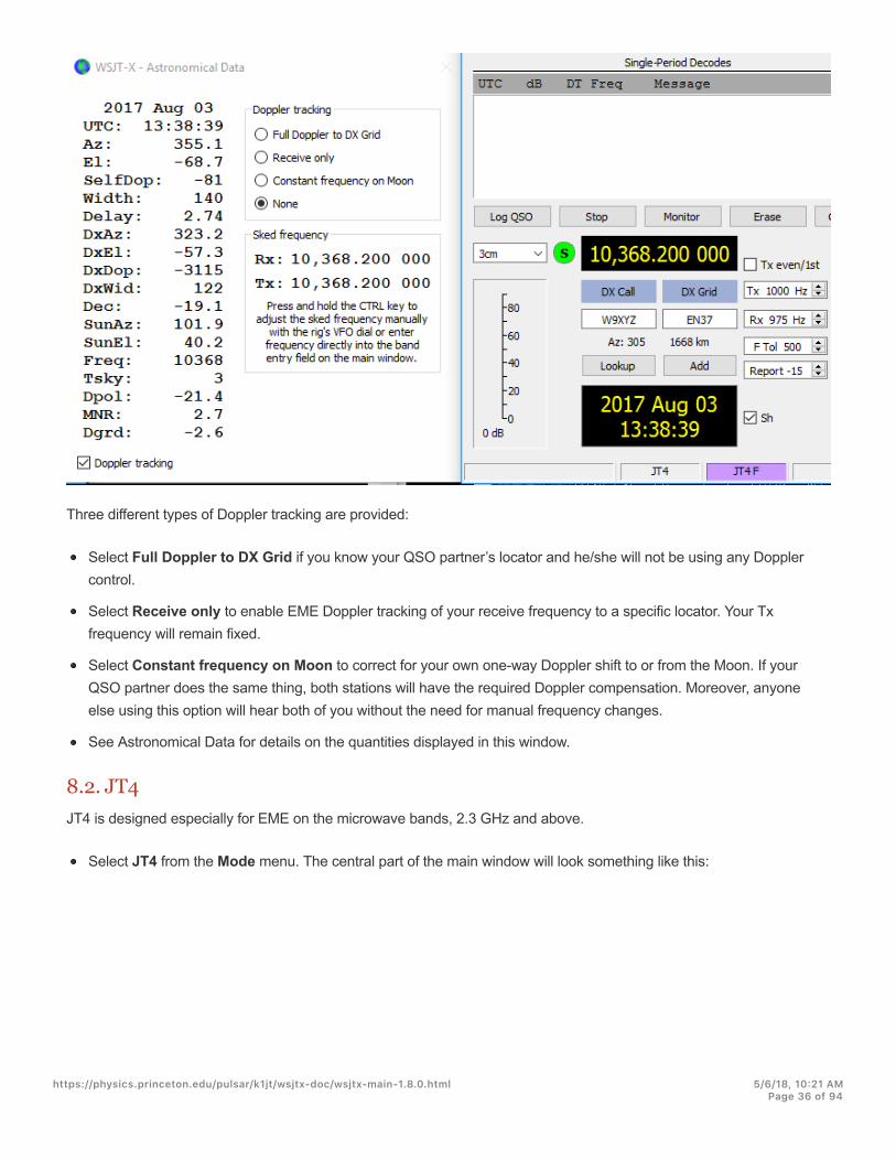
Three different types of Doppler tracking are provided:
Select Full Doppler to DX Grid if you know your QSO partner’s locator and he/she will not be using any Dopplercontrol.
Select Receive only to enable EME Doppler tracking of your receive frequency to a specific locator. Your Txfrequency will remain fixed.
Select Constant frequency on Moon to correct for your own one-way Doppler shift to or from the Moon. If yourQSO partner does the same thing, both stations will have the required Doppler compensation. Moreover, anyoneelse using this option will hear both of you without the need for manual frequency changes.
See Astronomical Data for details on the quantities displayed in this window.
8.2. JT4JT4 is designed especially for EME on the microwave bands, 2.3 GHz and above.
Select JT4 from the Mode menu. The central part of the main window will look something like this:
https://physics.princeton.edu/pulsar/k1jt/wsjtx-doc/wsjtx-main-1.8.0.html 5/6/18, 10@21 AMPage 36 of 94
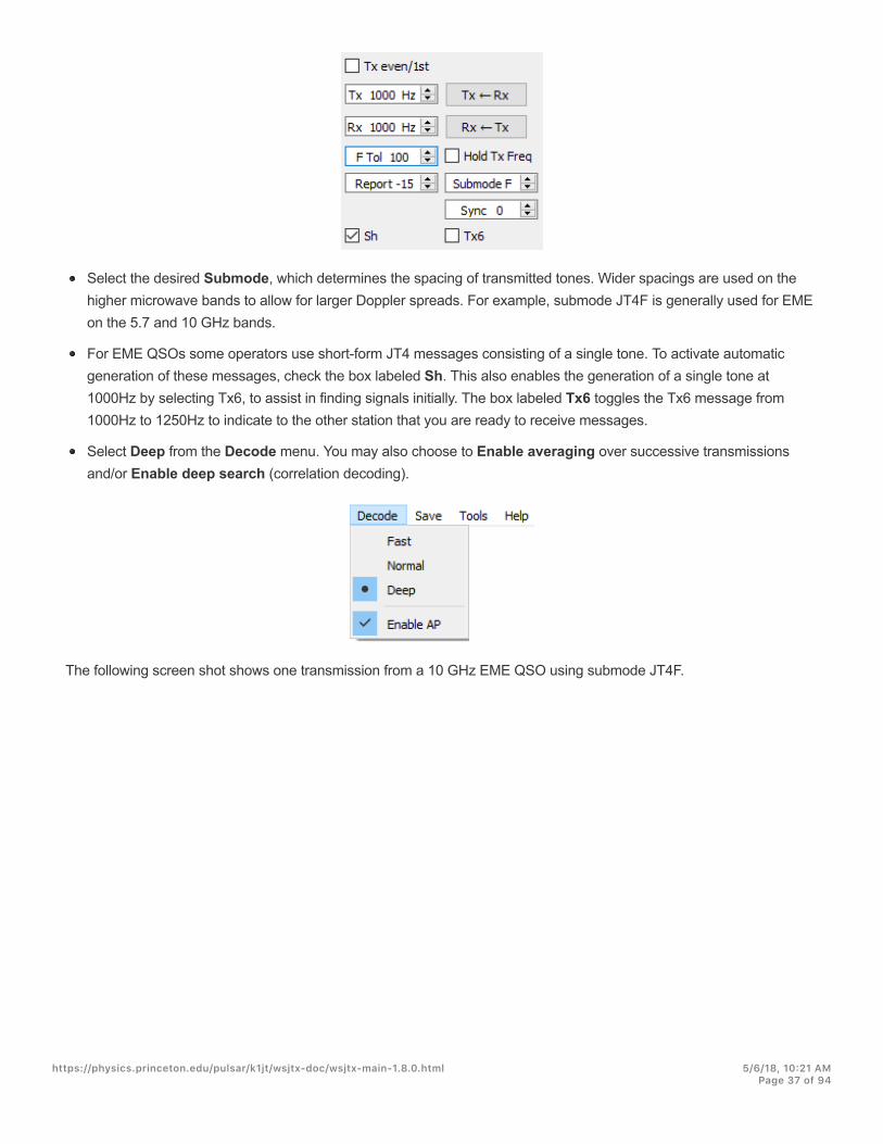
Select the desired Submode, which determines the spacing of transmitted tones. Wider spacings are used on thehigher microwave bands to allow for larger Doppler spreads. For example, submode JT4F is generally used for EMEon the 5.7 and 10 GHz bands.
For EME QSOs some operators use short-form JT4 messages consisting of a single tone. To activate automaticgeneration of these messages, check the box labeled Sh. This also enables the generation of a single tone at1000Hz by selecting Tx6, to assist in finding signals initially. The box labeled Tx6 toggles the Tx6 message from1000Hz to 1250Hz to indicate to the other station that you are ready to receive messages.
Select Deep from the Decode menu. You may also choose to Enable averaging over successive transmissionsand/or Enable deep search (correlation decoding).
The following screen shot shows one transmission from a 10 GHz EME QSO using submode JT4F.
https://physics.princeton.edu/pulsar/k1jt/wsjtx-doc/wsjtx-main-1.8.0.html 5/6/18, 10@21 AMPage 37 of 94
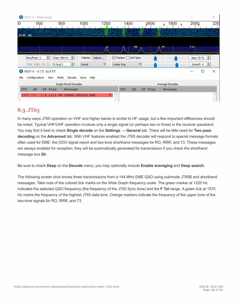
8.3. JT65In many ways JT65 operation on VHF and higher bands is similar to HF usage, but a few important differences shouldbe noted. Typical VHF/UHF operation involves only a single signal (or perhaps two or three) in the receiver passband.You may find it best to check Single decode on the Settings → General tab. There will be little need for Two passdecoding on the Advanced tab. With VHF features enabled the JT65 decoder will respond to special message formatsoften used for EME: the OOO signal report and two-tone shorthand messages for RO, RRR, and 73. These messagesare always enabled for reception; they will be automatically generated for transmission if you check the shorthandmessage box Sh.
Be sure to check Deep on the Decode menu; you may optionally include Enable averaging and Deep search.
The following screen shot shows three transmissions from a 144 MHz EME QSO using submode JT65B and shorthandmessages. Take note of the colored tick marks on the Wide Graph frequency scale. The green marker at 1220 Hzindicates the selected QSO frequency (the frequency of the JT65 Sync tone) and the F Tol range. A green tick at 1575Hz marks the frequency of the highest JT65 data tone. Orange markers indicate the frequency of the upper tone of thetwo-tone signals for RO, RRR, and 73.
https://physics.princeton.edu/pulsar/k1jt/wsjtx-doc/wsjtx-main-1.8.0.html 5/6/18, 10@21 AMPage 38 of 94
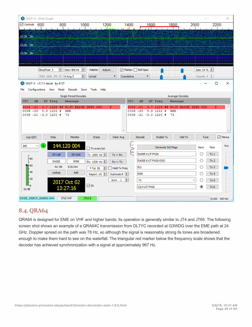
8.4. QRA64QRA64 is designed for EME on VHF and higher bands; its operation is generally similar to JT4 and JT65. The followingscreen shot shows an example of a QRA64C transmission from DL7YC recorded at G3WDG over the EME path at 24GHz. Doppler spread on the path was 78 Hz, so although the signal is reasonably strong its tones are broadenedenough to make them hard to see on the waterfall. The triangular red marker below the frequency scale shows that thedecoder has achieved synchronization with a signal at approximately 967 Hz.
https://physics.princeton.edu/pulsar/k1jt/wsjtx-doc/wsjtx-main-1.8.0.html 5/6/18, 10@21 AMPage 39 of 94

The QRA64 decoder makes no use of a callsign database. Instead, it takes advantage of a priori (AP) information suchas one’s own callsign and the encoded form of message word CQ . In normal usage, as a QSO progresses the availableAP information increases to include the callsign of the station being worked and perhaps also his/her 4-digit grid locator.The decoder always begins by attempting to decode the full message using no AP information. If this attempt fails,additional attempts are made using available AP information to provide initial hypotheses about the message content. Atthe end of each iteration the decoder computes the extrinsic probability of the most likely value for each of themessage’s 12 six-bit information symbols. A decode is declared only when the total probability for all 12 symbols hasconverged to an unambiguous value very close to 1.
https://physics.princeton.edu/pulsar/k1jt/wsjtx-doc/wsjtx-main-1.8.0.html 5/6/18, 10@21 AMPage 40 of 94

For EME QSOs some operators use short-form QRA64 messages consisting of a single tone. To activate automaticgeneration of these messages, check the box labeled Sh. This also enables the generation of a single tone at 1000Hzby selecting Tx6, to assist in finding signals initially, as the QRA64 tones are often not visible on the waterfall. The boxlabeled Tx6 switches the Tx6 message from 1000Hz to 1250Hz to indicate to the other station that you are ready toreceive messages.
"QRA64 is different from JT65 in that the decoder attempts to find and decode only a single signal inthe receiver passband. If many signals are present you may be able to decode them by double-clicking on the lowest tone of each one in the waterfall.
"G3WDG has prepared a more detailed tutorial on using QRA64 for microwave EME(http://physics.princeton.edu/pulsar/K1JT/QRA64_EME.pdf).
8.5. ISCATISCAT is a useful mode for signals that are weak but more or less steady in amplitude over several seconds or longer.Aircraft scatter at 10 GHz is a good example. ISCAT messages are free-format and may have any length from 1 to 28characters. This protocol includes no error-correction facility.
8.6. MSK144Meteor-scatter QSOs can be made any time on the VHF bands at distances up to about 2100 km (1300 miles).Completing a QSO takes longer in the evening than in the morning, longer at higher frequencies, and longer at distancesclose to the upper limit. But with patience, 100 Watts or more, and a single yagi it can usually be done. The followingscreen shot shows two 15-second MSK144 transmissions from W5ADD during a 50 MHz QSO with K1JT, at a distanceof about 1800 km (1100 mi). The decoded segments have been marked on the Fast Graph spectral display.
https://physics.princeton.edu/pulsar/k1jt/wsjtx-doc/wsjtx-main-1.8.0.html 5/6/18, 10@21 AMPage 41 of 94

Unlike other WSJT-X modes, the MSK144 decoder operates in real time during the reception sequence. Decodedmessages will appear on your screen almost as soon as you hear them.
To configure WSJT-X for MSK144 operation:
Select MSK144 from the Mode menu.
https://physics.princeton.edu/pulsar/k1jt/wsjtx-doc/wsjtx-main-1.8.0.html 5/6/18, 10@21 AMPage 42 of 94
Select Fast from the Decode menu.
Set the audio receiving frequency to Rx 1500 Hz.
Set frequency tolerance to F Tol 100.
Set the T/R sequence duration to 15 s.
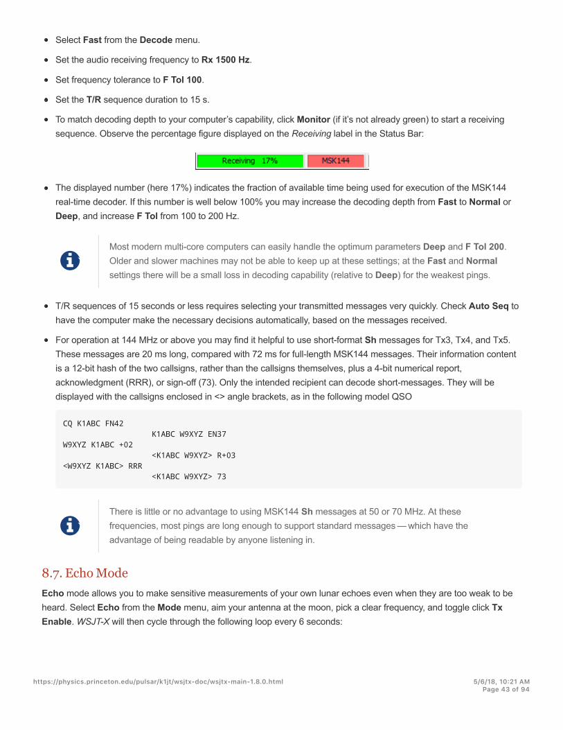
To match decoding depth to your computer’s capability, click Monitor (if it’s not already green) to start a receivingsequence. Observe the percentage figure displayed on the Receiving label in the Status Bar:
The displayed number (here 17%) indicates the fraction of available time being used for execution of the MSK144real-time decoder. If this number is well below 100% you may increase the decoding depth from Fast to Normal orDeep, and increase F Tol from 100 to 200 Hz.
!Most modern multi-core computers can easily handle the optimum parameters Deep and F Tol 200.Older and slower machines may not be able to keep up at these settings; at the Fast and Normalsettings there will be a small loss in decoding capability (relative to Deep) for the weakest pings.
T/R sequences of 15 seconds or less requires selecting your transmitted messages very quickly. Check Auto Seq tohave the computer make the necessary decisions automatically, based on the messages received.
For operation at 144 MHz or above you may find it helpful to use short-format Sh messages for Tx3, Tx4, and Tx5.These messages are 20 ms long, compared with 72 ms for full-length MSK144 messages. Their information contentis a 12-bit hash of the two callsigns, rather than the callsigns themselves, plus a 4-bit numerical report,acknowledgment (RRR), or sign-off (73). Only the intended recipient can decode short-messages. They will bedisplayed with the callsigns enclosed in <> angle brackets, as in the following model QSO
CQ K1ABC FN42 K1ABC W9XYZ EN37W9XYZ K1ABC +02 <K1ABC W9XYZ> R+03<W9XYZ K1ABC> RRR <K1ABC W9XYZ> 73
!There is little or no advantage to using MSK144 Sh messages at 50 or 70 MHz. At thesefrequencies, most pings are long enough to support standard messages — which have theadvantage of being readable by anyone listening in.
8.7. Echo ModeEcho mode allows you to make sensitive measurements of your own lunar echoes even when they are too weak to beheard. Select Echo from the Mode menu, aim your antenna at the moon, pick a clear frequency, and toggle click TxEnable. WSJT-X will then cycle through the following loop every 6 seconds:
https://physics.princeton.edu/pulsar/k1jt/wsjtx-doc/wsjtx-main-1.8.0.html 5/6/18, 10@21 AMPage 43 of 94

1. Transmit a 1500 Hz fixed tone for 2.3 s
2. Wait about 0.2 s for start of the return echo
3. Record the received signal for 2.3 s
4. Analyze, average, and display the results
5. Repeat from step 1
To make a sequence of echo tests:
Select Echo from the Mode menu.
Check Doppler tracking and Constant frequency on the Moon on the Astronomical Data window.
Be sure that your rig control has been set up for Split Operation, using either Rig or Fake It on the Settings | Radiotab.
Click Enable Tx on the main window to start a sequence of 6-second cycles.
WSJT-X calculates and compensates for Doppler shift automatically. As shown in the screen shot below, whenproper Doppler corrections have been applied your return echo should always appear at the center of the plot areaon the Echo Graph window.
https://physics.princeton.edu/pulsar/k1jt/wsjtx-doc/wsjtx-main-1.8.0.html 5/6/18, 10@21 AMPage 44 of 94

8.8. VHF+ Sample Files
https://physics.princeton.edu/pulsar/k1jt/wsjtx-doc/wsjtx-main-1.8.0.html 5/6/18, 10@21 AMPage 45 of 94

Sample recordings typical of QSOs using the VHF/UHF/Microwave modes and features of WSJT-X are available fordownload. New users of the VHF-and-up features are strongly encouraged to practice decoding the signals in thesefiles.
https://physics.princeton.edu/pulsar/k1jt/wsjtx-doc/wsjtx-main-1.8.0.html 5/6/18, 10@21 AMPage 46 of 94

9. WSPR ModeSelect WSPR from the Mode menu. The main window will reconfigure itself to the WSPR interface, removing somecontrols not used in WSPR mode.
Set the Wide Graph controls as suggested below.
Use the mouse to drag the width and height of the main window to the desired size.
Select an active WSPR frequency (for example, 10.1387 or 14.0956 MHz).
#If you will transmit in the 60 m band, be sure to choose a frequency that conforms with your localregulations.
Click Monitor to start a 2-minute WSPR receiving period.
If you will be transmitting as well as receiving, select a suitable value for Tx Pct (average percentage of 2-minutesequences devoted to transmitting) and activate the Enable Tx button. Transmitting periods are also 2 minutesduration, and will occur randomly in time to reduce the chance of clashing with other stations you may be monitoring.
Select your Tx power (in dBm) from the drop-down list.
9.1. Band HoppingWSPR mode allows those with CAT-controlled radios to investigate propagation on many bands without userintervention. Coordinated hopping enables a sizable group of stations around the world to move together from band toband, thereby maximizing the chances of identifying open propagation paths.
To enable automatic band hopping, check the Band Hopping box on the main window.
Click Schedule to open the WSPR Band Hopping window, and select the bands you wish to use at each time ofday.
https://physics.princeton.edu/pulsar/k1jt/wsjtx-doc/wsjtx-main-1.8.0.html 5/6/18, 10@21 AMPage 47 of 94

Band-switching occurs after each 2-minute interval. Preferred bands are identified with time slots in a repeating 20-minute cycle, according to the following table:
Band: 160 80 60 40 30 20 17 15 12 10
UTC minute: 00 02 04 06 08 10 12 14 16 18
20 22 24 26 28 30 32 34 36 38
40 42 44 46 48 50 52 54 56 58
If the preferred band is not active according to your band-hopping schedule, a band will be selected at random fromamong the active bands.
If the box labeled Tune is checked for a particular band, WSJT-X transmits an unmodulated carrier for severalseconds just after switching to that band and before the normal Rx or Tx period starts. This feature can be used toactivate an automatic antenna tuner (ATU) to tune a multi-band antenna to the newly selected band.
Depending on your station and antenna setup, band changes might require other switching besides retuning yourradio. To make this possible in an automated way, whenever WSJT-X executes a successful band-change commandto a CAT-controlled radio, it looks for a file named user_hardware.bat , user_hardware.cmd ,user_hardware.exe , or user_hardware in the working directory. If one of these is found, WSJT-X tries toexecute the command
user_hardware nnn
In the above command nnn is the band-designation wavelength in meters. You must write your own program, script,or batch file to do the necessary switching at your station.
The following screen shot is an example of WSPR operation with band hopping enabled:
https://physics.princeton.edu/pulsar/k1jt/wsjtx-doc/wsjtx-main-1.8.0.html 5/6/18, 10@21 AMPage 48 of 94

https://physics.princeton.edu/pulsar/k1jt/wsjtx-doc/wsjtx-main-1.8.0.html 5/6/18, 10@21 AMPage 49 of 94

A careful look at the screen shot above illustrates some of the impressive capabilities of the WSPR decoder. Forexample, look at the decodes at UTC 0152, 0154, and 0156 along with the corresponding minutes from the waterfalldisplay below. Yellow ovals have been added to highlight two isolated signals decoded at -28 and -29 dB in the first andthird two-minute interval. At 0154 UTC signals from VE3FAL, AB4QS, and K5CZD fall within a 5 Hz interval near audiofrequency 1492 Hz; similarly, K3FEF, DL2XL/P, and LZ1UBO fall within a 6 Hz interval near 1543 Hz. Each of theoverlapping signals is decoded flawlessly.
https://physics.princeton.edu/pulsar/k1jt/wsjtx-doc/wsjtx-main-1.8.0.html 5/6/18, 10@21 AMPage 50 of 94
10. On-Screen Controls
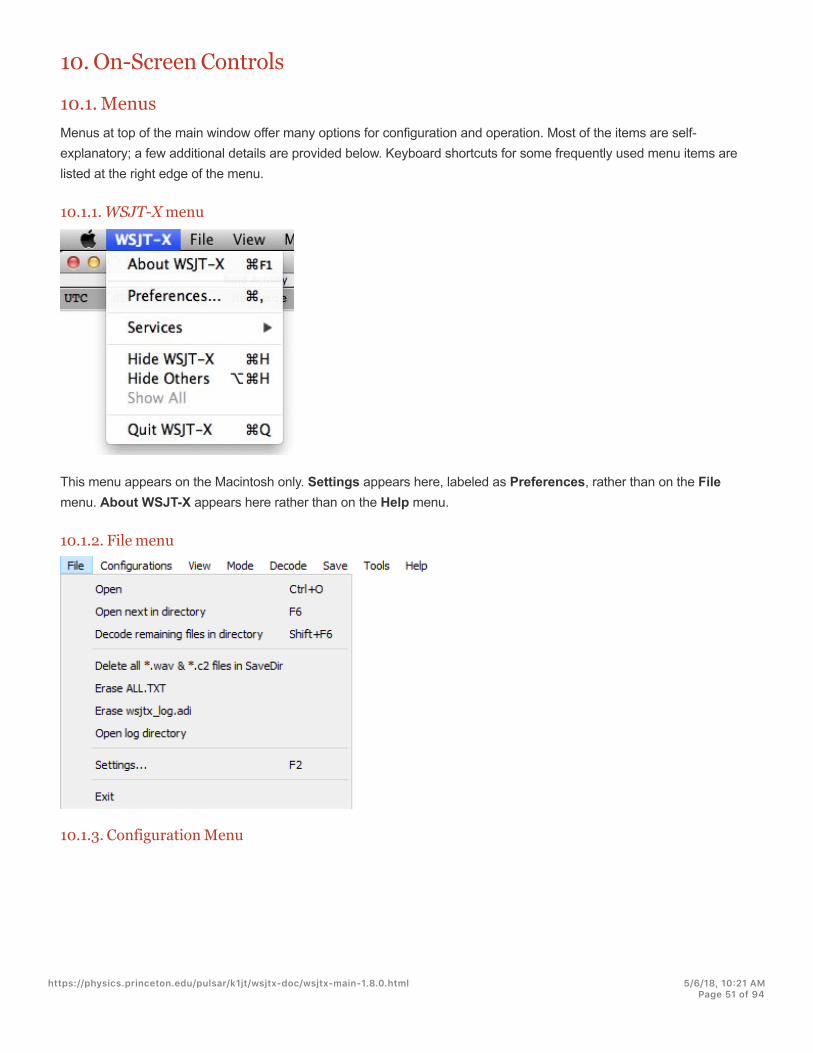
10.1. MenusMenus at top of the main window offer many options for configuration and operation. Most of the items are self-explanatory; a few additional details are provided below. Keyboard shortcuts for some frequently used menu items arelisted at the right edge of the menu.
10.1.1. WSJT-X menu
This menu appears on the Macintosh only. Settings appears here, labeled as Preferences, rather than on the Filemenu. About WSJT-X appears here rather than on the Help menu.
10.1.2. File menu
10.1.3. Configuration Menu
https://physics.princeton.edu/pulsar/k1jt/wsjtx-doc/wsjtx-main-1.8.0.html 5/6/18, 10@21 AMPage 51 of 94
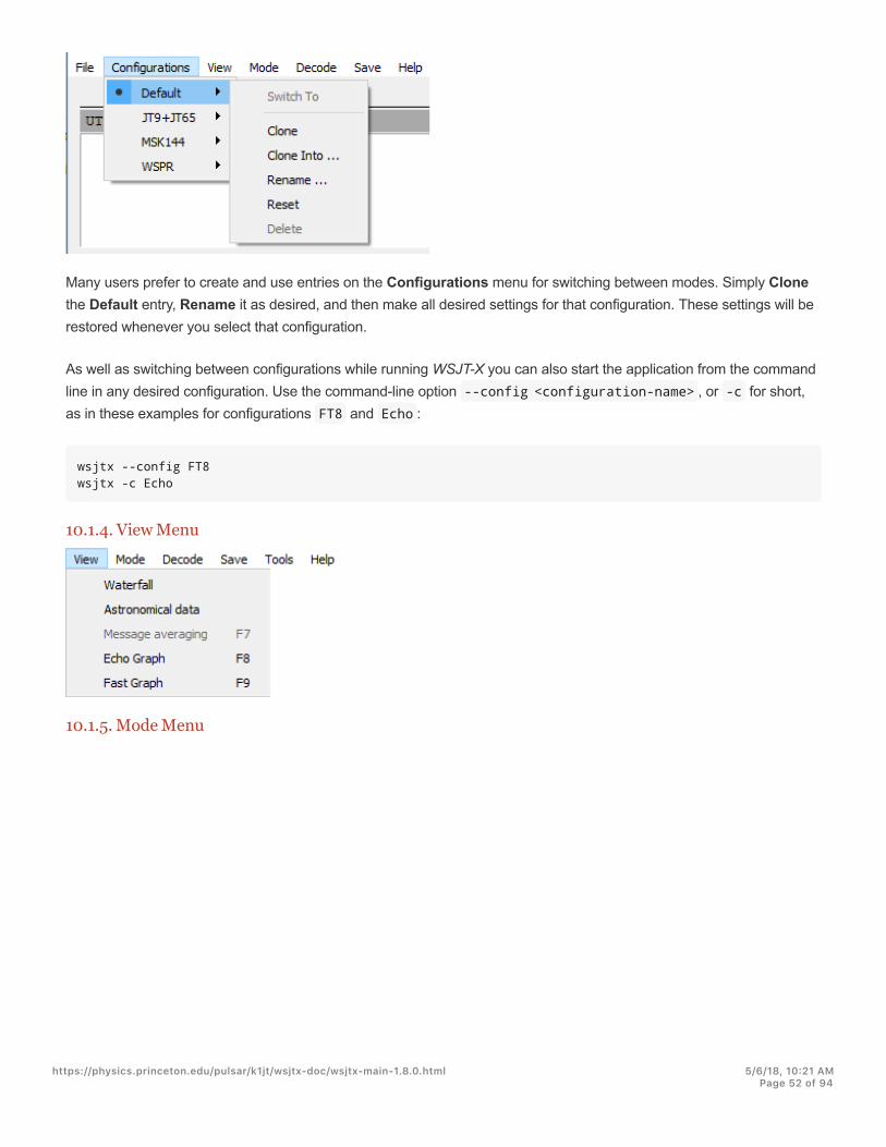
Many users prefer to create and use entries on the Configurations menu for switching between modes. Simply Clonethe Default entry, Rename it as desired, and then make all desired settings for that configuration. These settings will berestored whenever you select that configuration.
As well as switching between configurations while running WSJT-X you can also start the application from the commandline in any desired configuration. Use the command-line option --config <configuration-name> , or -c for short,as in these examples for configurations FT8 and Echo :
wsjtx --config FT8wsjtx -c Echo
10.1.4. View Menu
10.1.5. Mode Menu
https://physics.princeton.edu/pulsar/k1jt/wsjtx-doc/wsjtx-main-1.8.0.html 5/6/18, 10@21 AMPage 52 of 94
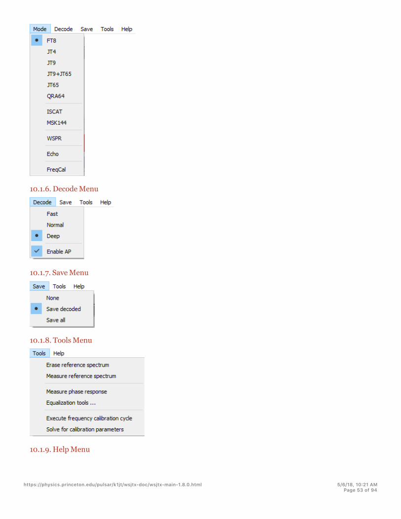
10.1.6. Decode Menu
10.1.7. Save Menu
10.1.8. Tools Menu
10.1.9. Help Menu
https://physics.princeton.edu/pulsar/k1jt/wsjtx-doc/wsjtx-main-1.8.0.html 5/6/18, 10@21 AMPage 53 of 94

Keyboard Shortcuts (F3)
https://physics.princeton.edu/pulsar/k1jt/wsjtx-doc/wsjtx-main-1.8.0.html 5/6/18, 10@21 AMPage 54 of 94

Special Mouse Commands (F5)
https://physics.princeton.edu/pulsar/k1jt/wsjtx-doc/wsjtx-main-1.8.0.html 5/6/18, 10@21 AMPage 55 of 94
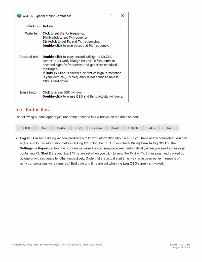
10.2. Button RowThe following buttons appear just under the decoded text windows on the main screen:
Log QSO raises a dialog window pre-filled with known information about a QSO you have nearly completed. You canedit or add to this information before clicking OK to log the QSO. If you check Prompt me to log QSO on theSettings → Reporting tab, the program will raise the confirmation screen automatically when you send a messagecontaining 73. Start Date and Start Time are set when you click to send the Tx 2 or Tx 3 message, and backed upby one or two sequence lengths, respectively. (Note that the actual start time may have been earlier if repeats ofearly transmissions were required.) End date and time are set when the Log QSO screen is invoked.
https://physics.princeton.edu/pulsar/k1jt/wsjtx-doc/wsjtx-main-1.8.0.html 5/6/18, 10@21 AMPage 56 of 94

Stop will terminate normal data acquisition in case you want to freeze the waterfall or open and explore a previouslyrecorded audio file.
Monitor toggles normal receive operation on or off. This button is highlighted in green when the WSJT-X is receiving.If you are using CAT control, toggling Monitor OFF relinquishes control of the rig; if Monitor returns to last usedfrequency is selected on the Settings | General tab, toggling Monitor back ON will return to the original frequency.
Erase clears the right-hand decoded text window. Double-clicking Erase clears both text windows.
"Right-clicking on either text window brings up a context menu with several options (including Erase)which operate on that window alone.
Clear Avg is present only in modes that support message averaging. It provides a way to erase the accumulatinginformation, thus preparing to start a new average.
Decode tells the program to repeat the decoding procedure at the Rx frequency (green marker on waterfall scale),using the most recently completed sequence of received data.
Enable Tx toggles automatic T/R sequencing mode on or off and highlights the button in red when ON. Atransmission will start at the beginning of the selected (odd or even) sequence, or immediately if appropriate.Toggling the button to OFF during a transmission allows the current transmission to finish.
Halt Tx terminates a transmission immediately and disables automatic T/R sequencing.
Tune toggles the program into Tx mode and generates an unmodulated carrier at the specified Tx frequency (redmarker on waterfall scale). This process is useful for adjusting an antenna tuner or tuning an amplifier. The button ishighlighted in red while Tune is active. Toggle the button a second time or click Halt Tx to terminate the Tuneprocess. Note that activating Tune interrupts a receive sequence and will prevent decoding during that sequence.
https://physics.princeton.edu/pulsar/k1jt/wsjtx-doc/wsjtx-main-1.8.0.html 5/6/18, 10@21 AMPage 57 of 94
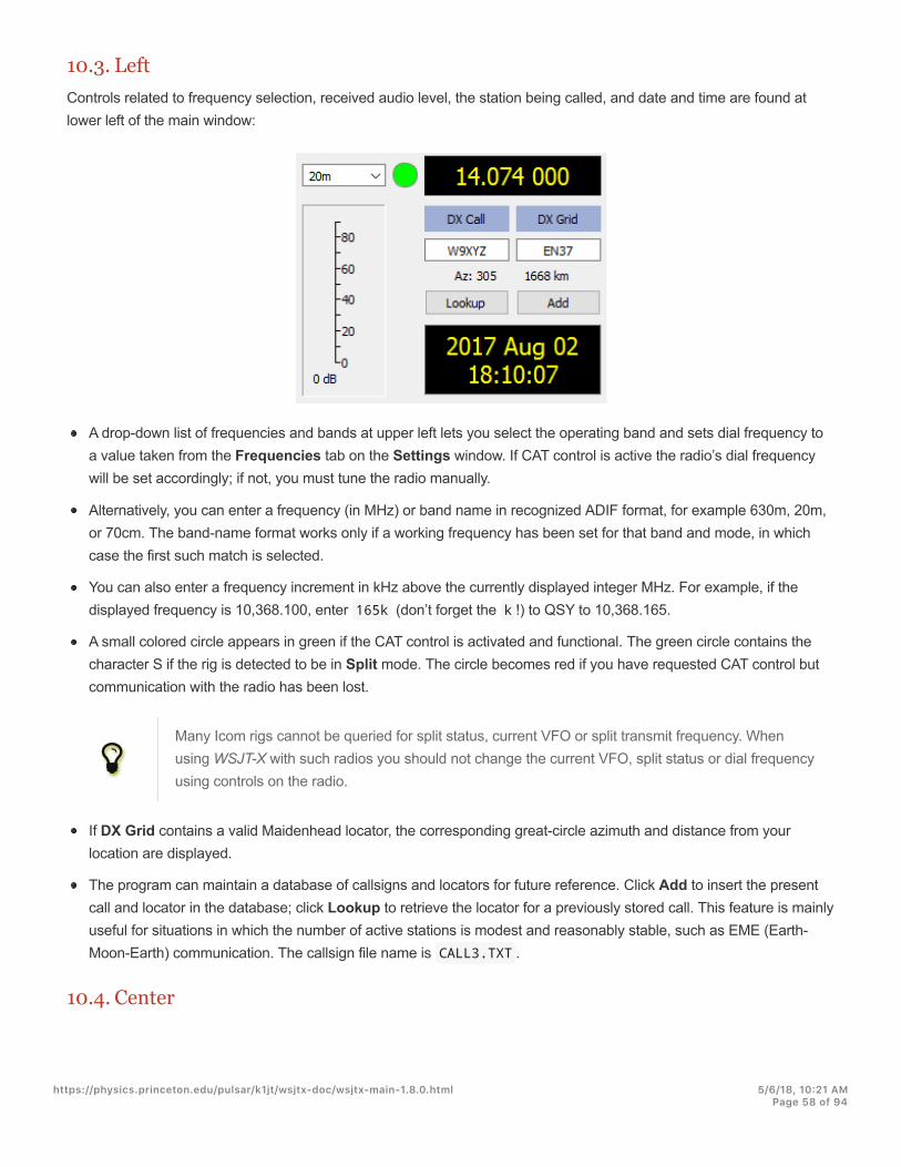
10.3. LeftControls related to frequency selection, received audio level, the station being called, and date and time are found atlower left of the main window:
A drop-down list of frequencies and bands at upper left lets you select the operating band and sets dial frequency toa value taken from the Frequencies tab on the Settings window. If CAT control is active the radio’s dial frequencywill be set accordingly; if not, you must tune the radio manually.
Alternatively, you can enter a frequency (in MHz) or band name in recognized ADIF format, for example 630m, 20m,or 70cm. The band-name format works only if a working frequency has been set for that band and mode, in whichcase the first such match is selected.
You can also enter a frequency increment in kHz above the currently displayed integer MHz. For example, if thedisplayed frequency is 10,368.100, enter 165k (don’t forget the k !) to QSY to 10,368.165.
A small colored circle appears in green if the CAT control is activated and functional. The green circle contains thecharacter S if the rig is detected to be in Split mode. The circle becomes red if you have requested CAT control butcommunication with the radio has been lost.
"Many Icom rigs cannot be queried for split status, current VFO or split transmit frequency. Whenusing WSJT-X with such radios you should not change the current VFO, split status or dial frequencyusing controls on the radio.
If DX Grid contains a valid Maidenhead locator, the corresponding great-circle azimuth and distance from yourlocation are displayed.
The program can maintain a database of callsigns and locators for future reference. Click Add to insert the presentcall and locator in the database; click Lookup to retrieve the locator for a previously stored call. This feature is mainlyuseful for situations in which the number of active stations is modest and reasonably stable, such as EME (Earth-Moon-Earth) communication. The callsign file name is CALL3.TXT .
10.4. Center
https://physics.princeton.edu/pulsar/k1jt/wsjtx-doc/wsjtx-main-1.8.0.html 5/6/18, 10@21 AMPage 58 of 94

At the center of the main window are a number of controls used when making QSOs. Controls not relevant to a particularmode or submode may be "grayed out" (disabled) or removed from the display.
Check Tx even to transmit in even-numbered UTC minutes or sequences, starting at 0. Uncheck this box to transmitin the odd sequences. The correct selection is made automatically when you double-click on a decoded text line, asdescribed in the Basic Operating Tutorial.
The Tx and Rx audio frequencies can be set automatically by double-clicking on decoded text or a signal in thewaterfall. They can also be adjusted using the spinner controls.
You can force Tx frequency to the current Rx frequency by clicking the Tx←Rx button, and vice-versa for Rx←Tx.The on-the-air frequency of your lowest JT9 or JT65 tone is the sum of dial frequency and audio Tx frequency.
Check the box Lock Tx=Rx to make the frequencies always track one another.
#In general we do not recommend using Lock Tx=Rx since it encourages poor radio etiquette whenrunning a frequency. With this box checked, your own Tx frequency will move around following yourcallers.
For modes lacking a multi-decode feature, or when Enable VHF/UHF/Microwave features has been checked onthe Settings → General tab, the F Tol control sets a frequency toilerance range over which decoding will beattempted, centered on the Rx frequency.
The Report control lets you change a signal report that has been inserted automatically. Typical reports for thevarious modes fall in the range –30 to +20 dB. Remember that JT65 reports saturate at an upper limit of -1 dB.
"Consider reducing power if your QSO partner reports your signal above -5 dB in one of the WSJT-Xslow modes. These are supposed to be weak signal modes!
https://physics.princeton.edu/pulsar/k1jt/wsjtx-doc/wsjtx-main-1.8.0.html 5/6/18, 10@21 AMPage 59 of 94

In some circumstances, especially on VHF and higher bands, you can select a supported submode of the activemode by using the Submode control. The Sync control sets a minimum threshold for establishing time andfrequency synchronization with a received signal.
Spinner control T/R xx s sets sequence lengths for transmission and reception in ISCAT, MSK144, and the fast JT9modes.
With Split operation activated on the Settings → Radio tab, in MSK144 and the fast JT9 submodes you canactivate the spinner control Tx CQ nnn by checking the box to its right. The program will then generate somethinglike CQ nnn K1ABC FN42 for your CQ message, where nnn is the kHz portion of your current operating frequency.Your CQ message Tx6 will then be transmitted at the calling frequency selected in the Tx CQ nnn spinner control. Allother messages will be transmitted at your current operating frequency. On reception, when you double-click on amessage like CQ nnn K1ABC FN42 your rig will QSY to the specified frequency so you can call the station at hisspecified response frequency.
Checkboxes at bottom center of the main window control special features for particular operating modes:
Sh enables shorthand messages in JT4, JT65, and MSK144 modes
Fast enables fast JT9 submodes
Auto Seq enables auto-sequencing of Tx messages
Call 1st enables automatic response to the first decoded responder to your CQ
Tx6 toggles between two types of shorthand messages in JT4 mode
10.5. Tx MessagesTwo arrangements of controls are provided for generating and selecting Tx messages. Controls familiar to users ofprogram WSJT appear on Tab 1, providing six fields for message entry. Pre-formatted messages for the standardminimal QSO are generated when you click Generate Std Msgs or double-click on an appropriate line in one of thedecoded text windows.
Select the next message to be transmitted (at the start of your next Tx sequence) by clicking on the circle underNext.
https://physics.princeton.edu/pulsar/k1jt/wsjtx-doc/wsjtx-main-1.8.0.html 5/6/18, 10@21 AMPage 60 of 94
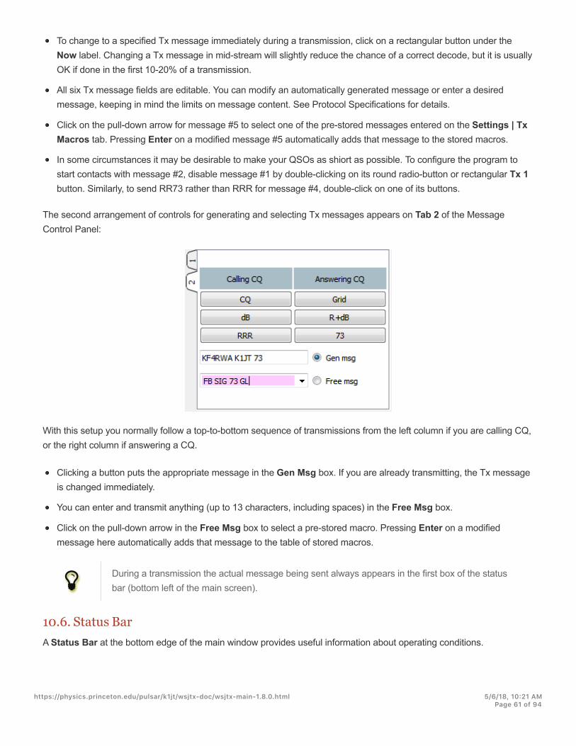
To change to a specified Tx message immediately during a transmission, click on a rectangular button under theNow label. Changing a Tx message in mid-stream will slightly reduce the chance of a correct decode, but it is usuallyOK if done in the first 10-20% of a transmission.
All six Tx message fields are editable. You can modify an automatically generated message or enter a desiredmessage, keeping in mind the limits on message content. See Protocol Specifications for details.
Click on the pull-down arrow for message #5 to select one of the pre-stored messages entered on the Settings | TxMacros tab. Pressing Enter on a modified message #5 automatically adds that message to the stored macros.
In some circumstances it may be desirable to make your QSOs as shiort as possible. To configure the program tostart contacts with message #2, disable message #1 by double-clicking on its round radio-button or rectangular Tx 1button. Similarly, to send RR73 rather than RRR for message #4, double-click on one of its buttons.
The second arrangement of controls for generating and selecting Tx messages appears on Tab 2 of the MessageControl Panel:
With this setup you normally follow a top-to-bottom sequence of transmissions from the left column if you are calling CQ,or the right column if answering a CQ.
Clicking a button puts the appropriate message in the Gen Msg box. If you are already transmitting, the Tx messageis changed immediately.
You can enter and transmit anything (up to 13 characters, including spaces) in the Free Msg box.
Click on the pull-down arrow in the Free Msg box to select a pre-stored macro. Pressing Enter on a modifiedmessage here automatically adds that message to the table of stored macros.
"During a transmission the actual message being sent always appears in the first box of the statusbar (bottom left of the main screen).
10.6. Status BarA Status Bar at the bottom edge of the main window provides useful information about operating conditions.
https://physics.princeton.edu/pulsar/k1jt/wsjtx-doc/wsjtx-main-1.8.0.html 5/6/18, 10@21 AMPage 61 of 94

Labels on the Status Bar display such information as the program’s current operating state, configuration name,operating mode, and the content of your most recent transmitted message. The first label (operating state) can beReceiving, Tx (for Transmitting), Tune, or the name of file opened from the File menu; this label is highlighted in greenfor Receiving, yellow for Tx, red for Tune, and light blue for a file name. When transmitting, the Tx message is displayedexactly as it will be decoded by receiving stations. The second label (as shown above) will be absent if you are using theDefault setting on the Configurations menu. A progress bar shows the elapsed fraction of a Tx or Rx sequence.Finally, if the Watchdog (WD) timer was enabled on the settings | General tab, a label in the lower right-hand cornerdisplays the number of minutes remaining before timeout.
10.7. Wide GraphThe following controls appear at the bottom of the Wide Graph window. Decoding occurs only in the displayed frequencyrange; otherwise, with the exceptions of Start NNN Hz and of JT65 nnnn JT9 when operating in JT9+JT65 mode,controls on the Wide Graph window have no effect on the decoding process.
Bins/Pixel controls the displayed frequency resolution. Set this value to 1 for the highest possible resolution, or tohigher numbers to compress the spectral display. Normal operation with a convenient window size works well at 2 to8 bins per pixel.
JT65 nnnn JT9 sets the dividing point (blue marker) for wide-band decoding of JT65 and JT9 signals in JT9+JT65mode. The decoder looks for JT65 signals everywhere, but JT9 signals only above this frequency. This setting isstored separately for each band.
Start nnn Hz sets the low-frequency starting point of the waterfall frequency scale.
N Avg is the number of successive spectra to be averaged before updating the display. Values around 5 are suitablefor normal JT9 and JT65 operation. Adjust N Avg to make the waterfall move faster or slower, as desired.
A dropdown list below the Palette label lets you select from a wide range of waterfall color palettes.
Click Adjust to activate a window that allows you to create a user-defined palette.
Check Flatten if you want WSJT-X to compensate for a sloping or uneven response across the received passband.For this feature to work properly, you should restrict the range of displayed frequencies so that only the active part ofthe spectrum is shown.
Select Current or Cumulative for the spectrum displayed in the bottom one-third of the Wide Graph window.Current is the average spectrum over the most recent N Avg FFT calculations. Cumulative is the average spectrumsince the start of the present UTC minute. Linear Avg is useful in JT4 mode, especially when short-form messagesare used.
https://physics.princeton.edu/pulsar/k1jt/wsjtx-doc/wsjtx-main-1.8.0.html 5/6/18, 10@21 AMPage 62 of 94

Four sliders control reference levels and scaling for waterfall colors and the spectrum plot. Values around midscaleare usually about right, depending on the input signal level, the chosen palette, and your own preferences. Hover themouse over a control to display a tip reminding you of its function.
Smoothing is active only when Linear Average has been selected. Smoothing the displayed spectrum over morethan one bin can enhance your ability to detect weak EME signals with Doppler spread more than a few Hz.
10.8. Fast GraphThe waterfall palette used for the Fast Graph is the same as the one selected on the Wide Graph. Three sliders at thebottom of the Fast Graph window can be used to optimize gain and zero-offset for the displayed information. Hover themouse over a control to display a tip reminding you of its function. Clicking the Auto Level button will producereasonable settings as a starting point.
10.9. Echo GraphThe following controls appear at the bottom of the Echo Graph:
Bins/Pixel controls the displayed frequency resolution. Set this value to 1 for the highest possible resolution, or tohigher numbers to compress the spectral display.
Gain and Zero sliders control scaling and offset of plotted spectra.
Smooth values greater than 0 apply running averages to the plotted spectra, thereby smoothing the curves overmultiple bins.
Label N shows the number of echo pulses averaged.
Click the Colors button to cycle through 6 possible choices of color and line width for the plots.
10.10. MiscellaneousMost windows can be resized as desired. If you are short of screen space you can make the Main Window and WideGraph smaller by hiding some controls and labels. To enable this feature type Ctrl+M with focus on the appropriatewindow. (For the Main Window you can select Hide menus and labels on the View menu.) Type Ctrl+M again to makethe controls visible once more.
https://physics.princeton.edu/pulsar/k1jt/wsjtx-doc/wsjtx-main-1.8.0.html 5/6/18, 10@21 AMPage 63 of 94

11. LoggingA basic logging facility in WSJT-X saves QSO information to files named wsjtx.log (in comma-separated text format)and wsjtx_log.adi (in standard ADIF format). These files can be imported directly into other programs, for examplespreadsheets and popular logging programs. As described in the Installation and Platform Dependencies sections,different operating systems may place your local log files in different locations. You can always navigate to them directlyby selecting Open log directory from the File menu.
More elaborate logging capabilities are supported by third party applications like JT-Alert (http://hamapps.com/), which canlog QSOs automatically to other applications including Ham Radio Deluxe (http://www.hrdsoftwarellc.com/), DX Lab Suite(http://www.dxlabsuite.com/), and Log4OM (http://www.log4om.com).
The program option Show DXCC entity and worked before status (selectable on the Settings | General tab) isintended mostly for use on non-Windows platforms, where JT-Alert (http://hamapps.com/) is not available. When this optionis checked WSJT-X appends some additional information to all CQ messages displayed in the Band Activity window.The name of the DXCC entity is shown, abbreviated if necessary. Your “worked before” status for this callsign (accordingto log file wsjtx_log.adi ) is flagged with a single character and a change of background color, as follows:
! Default color bright purple: New DXCC entity
~ Light pink: You have already worked this DXCC entity but not this station
Green: You have previously worked the calling station
In this respect the program does not distinguish between modes, but it does differentiate between bands.
WSJT-X includes a built-in cty.dat file containing DXCC prefix information. Updated files can be downloaded from theAmateur Radio Country Files (http://www.country-files.com/cty/) web site when required. If an updated cty.dat is present inthe logs folder and readable, it will be used in preference to the built-in one.
The log file wsjtx_log.adi is updated whenever you log a QSO from WSJT-X. (Keep in mind that if you erase this fileyou will lose all “worked before” information.) You can append or overwrite the wsjtx_log.adi file by exporting yourQSO history as an ADIF file from another logging program. Turning Show DXCC entity and worked before status offand then on again will cause WSJT-X to re-read the log file. Very large log files may cause WSJT-X to slow down whensearching for calls.
https://physics.princeton.edu/pulsar/k1jt/wsjtx-doc/wsjtx-main-1.8.0.html 5/6/18, 10@21 AMPage 64 of 94

12. Decoder Notes
12.1. AP DecodingThe WSJT-X decoders for QRA64 and FT8 include optional procedures that use naturally accumulating informationduring a minimal QSO. This a priori (AP) information increases sensitivity of the decoder by up to 4 dB, at the cost of aslightly higher rate of false decodes.
For example: when you decide to answer a CQ, you already know your own callsign and that of your potential QSOpartner. The software therefore “knows” what to expect for 57 of the 72 message bits (28 bits for each of two callsigns, 1bit for message type) in the next received message. The decoder’s task can thus be reduced to determining theremaining 15 bits of the message and ensuring that the resulting solution is reliable.
AP decoding starts by setting AP bits to the hypothesized values, as if they had been received correctly. We thendetermine whether the remaining message and parity bits are consistent with the hypothesized AP bits, with a specifiedlevel of confidence. Successful AP decodes are labeled with an end-of-line indicator of the form aP , where P is one ofthe single-digit AP decoding types listed in Table 1. For example, a2 indicates that the successful decode used MyCallas hypothetically known information.
Table 1. AP information types
P Message components
1 CQ ? ?
2 MyCall ? ?
3 MyCall DxCall ?
4 MyCall DxCall RRR
5 MyCall DxCall 73
6 MyCall DxCall RR73
If a codeword is found that is judged to have high (but not overwhelmingly high) probability of being correct, a ?character is appended when the decoded message is displayed. To avoid misleading spots of occasional false decodes,messages so marked are not forwarded to PSK Reporter (http://pskreporter.info/pskmap.html).
Table 2 lists the six possible QSO states that are tracked by the WSJT-X auto-sequencer, along with the type of APdecoding that would be attempted in each state.
Table 2. AP decoding types for each QSO state
State AP type
https://physics.princeton.edu/pulsar/k1jt/wsjtx-doc/wsjtx-main-1.8.0.html 5/6/18, 10@21 AMPage 65 of 94
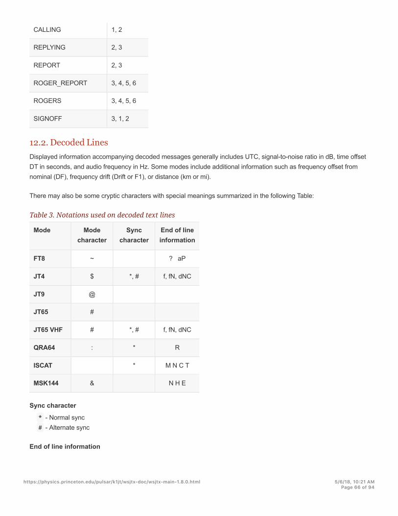
CALLING 1, 2
REPLYING 2, 3
REPORT 2, 3
ROGER_REPORT 3, 4, 5, 6
ROGERS 3, 4, 5, 6
SIGNOFF 3, 1, 2
12.2. Decoded LinesDisplayed information accompanying decoded messages generally includes UTC, signal-to-noise ratio in dB, time offsetDT in seconds, and audio frequency in Hz. Some modes include additional information such as frequency offset fromnominal (DF), frequency drift (Drift or F1), or distance (km or mi).
There may also be some cryptic characters with special meanings summarized in the following Table:
Table 3. Notations used on decoded text lines
Mode Modecharacter
Synccharacter
End of lineinformation
FT8 ~ ? aP
JT4 $ *, # f, fN, dNC
JT9 @
JT65 #
JT65 VHF # *, # f, fN, dNC
QRA64 : * R
ISCAT * M N C T
MSK144 & N H E
Sync character
* - Normal sync# - Alternate sync
End of line information
https://physics.princeton.edu/pulsar/k1jt/wsjtx-doc/wsjtx-main-1.8.0.html 5/6/18, 10@21 AMPage 66 of 94

? - Decoded with lower confidencea - Decoded with aid of some a priori (AP) informationC - Confidence indicator [ISCAT and Deep Search; (0-9,*)]d - Deep Search algorithmE - Size of MSK eye diagram opening - if negative, the eye is closedf - Franke-Taylor or Fano algorithmH - Number of bit errors correctedM - Message length (characters)N - Number of Rx intervals or frames averagedP - Number indicating type of AP information (Table 1, above)R - Return code from QRA64 decoderT - Length of analyzed region (s)
https://physics.princeton.edu/pulsar/k1jt/wsjtx-doc/wsjtx-main-1.8.0.html 5/6/18, 10@21 AMPage 67 of 94
13. Measurement Tools
13.1. Frequency CalibrationMany WSJT-X capabilities depend on signal-detection bandwidths no more than a few Hz. Frequency accuracy andstability are therefore unusually important. We provide tools to enable accurate frequency calibration of your radio, aswell as precise frequency measurement of on-the-air signals. The calibration procedure works by automatically cyclingyour CAT-controlled radio through a series of preset frequencies of carrier-based signals at reliably known frequencies,measuring the error in dial frequency for each signal.
You will probably find it convenient to define and use a special Configuration dedicated to frequency calibration. Thencomplete the following steps, as appropriate for your system.
Switch to FreqCal mode
In the Working Frequencies box on the Settings → Frequencies tab, delete any default frequencies for FreqCalmode that are not relevant for your location. You may want to replace some of them with reliably known frequenciesreceivable at your location.
"We find major-city AM broadcast stations generally serve well as frequency calibrators at the lowfrequency end of the spectrum. In North America we also use the standard time-and-frequencybroadcasts of WWV at 2.500, 5.000, 10.000, 15.000, and 20.000 MHz, and CHU at 3.330, 7.850,and 14.670 MHz. Similar shortwave signals are available in other parts of the world.
In most cases you will want to start by deleting any existing file fmt.all in the directory where your log files arekept.
To cycle automatically through your chosen list of calibration frequencies, check Execute frequency calibrationcycle on the Tools menu. WSJT-X will spend 30 seconds at each frequency. Initially no measurement data is savedto the fmt.all file although it is displayed on screen, this allows you to check you current calibration parameters.
During the calibration procedure, the radio’s USB dial frequency is offset 1500 Hz below each FreqCal entry in thedefault frequencies list. As shown in the screen shot below, detected signal carriers therefore appear at about 1500Hz in the WSJT-X waterfall.
To start a measurement session check the Measure option and let the calibration cycle run for at least one completesequence. Note that, while measuring, any existing calibration parameters are automatically disabled so you mayhave to increase the FTol range if your rig is off freqeuncy by more than a few Hertz in order to capture validmeasurements.
https://physics.princeton.edu/pulsar/k1jt/wsjtx-doc/wsjtx-main-1.8.0.html 5/6/18, 10@21 AMPage 68 of 94

With modern synthesized radios, small measured offsets from 1500 Hz will exhibit a straight-line dependence onfrequency. You can approximate the calibration of your radio by simply dividing the measured frequency offset (in Hz) atthe highest reliable frequency by the nominal frequency itself (in MHz). For example, the 20 MHz measurement for WWVshown above produced a measured tone offset of 24.6 Hz, displayed in the WSJT-X decoded text window. The resultingcalibration constant is 24.6/20=1.23 parts per million. This number may be entered as Slope on the settings →Frequencies tab.
A more precise calibration can be effected by fitting the intercept and slope of a straight line to the whole sequence ofcalibration measurements, as shown for these measurements in the graph plotted below. Software tools for completingthis task are included with the WSJT-X installation, and detailed instructions for their use are available athttps://physics.princeton.edu/pulsar/k1jt/FMT_User.pdf.
Using these tools and no specialized hardware beyond your CAT-interfaced radio, you can calibrate the radio to betterthan 1 Hz and compete very effectively in the ARRL’s periodic Frequency Measuring Tests.
https://physics.princeton.edu/pulsar/k1jt/wsjtx-doc/wsjtx-main-1.8.0.html 5/6/18, 10@21 AMPage 69 of 94
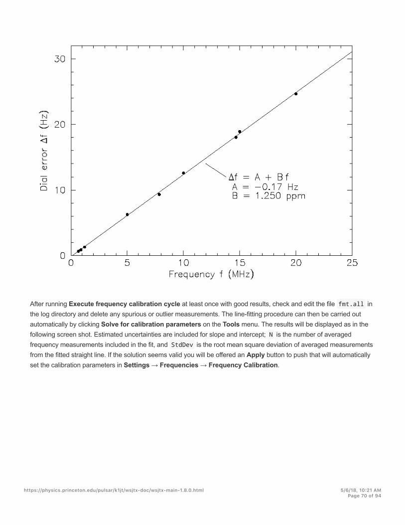
After running Execute frequency calibration cycle at least once with good results, check and edit the file fmt.all inthe log directory and delete any spurious or outlier measurements. The line-fitting procedure can then be carried outautomatically by clicking Solve for calibration parameters on the Tools menu. The results will be displayed as in thefollowing screen shot. Estimated uncertainties are included for slope and intercept; N is the number of averagedfrequency measurements included in the fit, and StdDev is the root mean square deviation of averaged measurementsfrom the fitted straight line. If the solution seems valid you will be offered an Apply button to push that will automaticallyset the calibration parameters in Settings → Frequencies → Frequency Calibration.
https://physics.princeton.edu/pulsar/k1jt/wsjtx-doc/wsjtx-main-1.8.0.html 5/6/18, 10@21 AMPage 70 of 94
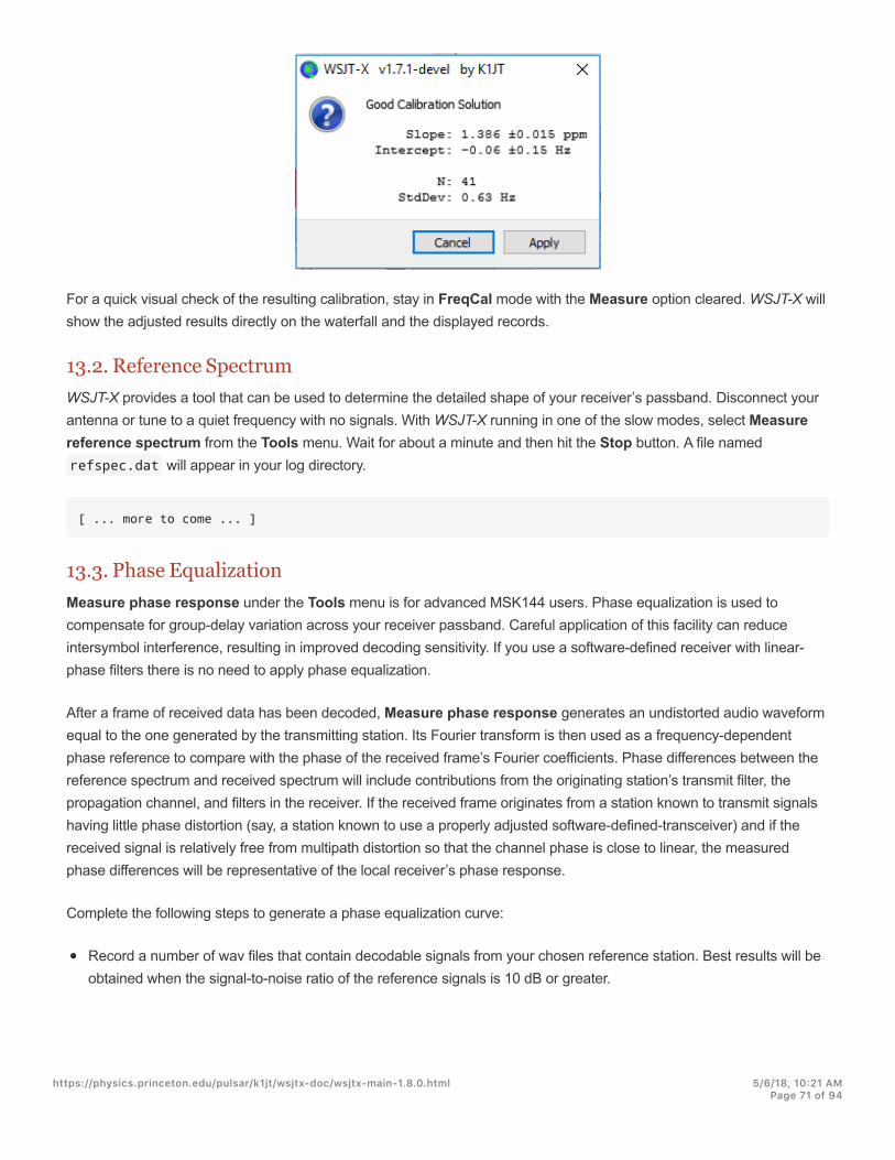
For a quick visual check of the resulting calibration, stay in FreqCal mode with the Measure option cleared. WSJT-X willshow the adjusted results directly on the waterfall and the displayed records.
13.2. Reference SpectrumWSJT-X provides a tool that can be used to determine the detailed shape of your receiver’s passband. Disconnect yourantenna or tune to a quiet frequency with no signals. With WSJT-X running in one of the slow modes, select Measurereference spectrum from the Tools menu. Wait for about a minute and then hit the Stop button. A file namedrefspec.dat will appear in your log directory.
[ ... more to come ... ]
13.3. Phase EqualizationMeasure phase response under the Tools menu is for advanced MSK144 users. Phase equalization is used tocompensate for group-delay variation across your receiver passband. Careful application of this facility can reduceintersymbol interference, resulting in improved decoding sensitivity. If you use a software-defined receiver with linear-phase filters there is no need to apply phase equalization.
After a frame of received data has been decoded, Measure phase response generates an undistorted audio waveformequal to the one generated by the transmitting station. Its Fourier transform is then used as a frequency-dependentphase reference to compare with the phase of the received frame’s Fourier coefficients. Phase differences between thereference spectrum and received spectrum will include contributions from the originating station’s transmit filter, thepropagation channel, and filters in the receiver. If the received frame originates from a station known to transmit signalshaving little phase distortion (say, a station known to use a properly adjusted software-defined-transceiver) and if thereceived signal is relatively free from multipath distortion so that the channel phase is close to linear, the measuredphase differences will be representative of the local receiver’s phase response.
Complete the following steps to generate a phase equalization curve:
Record a number of wav files that contain decodable signals from your chosen reference station. Best results will beobtained when the signal-to-noise ratio of the reference signals is 10 dB or greater.
https://physics.princeton.edu/pulsar/k1jt/wsjtx-doc/wsjtx-main-1.8.0.html 5/6/18, 10@21 AMPage 71 of 94
Enter the callsign of the reference station in the DX Call box.
Select Measure phase response from the Tools menu, and open each of the wav files in turn. The mode characteron decoded text lines will change from & to ^ while WSJT-X is measuring the phase response, and it will changeback to & after the measurement is completed. The program needs to average a number of high-SNR frames toaccurately estimate the phase, so it may be necessary to process several wav files. The measurement can beaborted at any time by selecting Measure phase response again to toggle the phase measurement off.
When the measurement is complete WSJT-X will save the measured phase response in the Log directory, in a filewith suffix ".pcoeff". The filename will contain the callsign of the reference station and a timestamp, for exampleK0TPP_170923_112027.pcoeff .
Select Equalization tools … under the Tools menu and click the Phase … button to view the contents of the Logdirectory. Select the desired pcoeff file. The measured phase values will be plotted as filled circles along with a fittedred curve labeled "Proposed". This is the proposed phase equalization curve. It’s a good idea to repeat the phasemeasurement several times, using different wav files for each measurement, to ensure that your measurements arerepeatable.
Once you are satisfied with a fitted curve, push the Apply button to save the proposed response. The red curve willbe replaced with a light green curve labeled "Current" to indicate that the phase equalization curve is now beingapplied to the received data. Another curve labeled "Group Delay" will appear. The "Group Delay" curve shows thegroup delay variation across the passband, in ms. Click the Discard button to remove the captured data, leaving onlythe applied phase equalization curve and corresponding group delay curve.
To revert to no phase equalization, push the Restore Defaults button followed by the Apply button.
The three numbers printed at the end of each MSK144 decode line can be used to assess the improvement provided byequalization. These numbers are: N = Number of frames averaged, H = Number of hard bit errors corrected, E = Sizeof MSK eye diagram opening.
Here is a decode of K0TPP obtained while Measure phase response was measuring the phase response:
103900 17 6.5 1493 ^ WA8CLT K0TPP +07 1 0 1.2
The "^" symbol indicates that a phase measurement is being accumulated but is not yet finished. The three numbers atthe end of the line indicate that one frame was used to obtain the decode, there were no hard bit errors, and the eye-opening was 1.2 on a -2 to +2 scale. Here’s how the same decode looks after phase equalization:
103900 17 6.5 1493 & WA8CLT K0TPP +07 1 0 1.6
In this case, equalization has increased the eye opening from 1.2 to 1.6. Larger positive eye openings are associatedwith reduced likelihood of bit errors and higher likelihood that a frame will be successfully decoded. In this case, thelarger eye-opening tells us that phase equalization was successful, but it is important to note that this test does not byitself tell us whether the applied phase equalization curve is going to improve decoding of signals other than those fromthe reference station, K0TPP.
https://physics.princeton.edu/pulsar/k1jt/wsjtx-doc/wsjtx-main-1.8.0.html 5/6/18, 10@21 AMPage 72 of 94

It’s a good idea to carry out before and after comparisons using a large number of saved wav files with signals frommany different stations, to help decide whether your equalization curve improves decoding for most signals. When doingsuch comparisons, keep in mind that equalization may cause WSJT-X to successfully decode a frame that was notdecoded before equalization was applied. For this reason, be sure that the time "T" of the two decodes are the samebefore comparing their end-of-line quality numbers.
When comparing before and after decodes having the same "T", keep in mind that a smaller first number means thatdecoding has improved, even if the second and third numbers appear to be "worse". For example, suppose that the end-of-line quality numbers before equalization are 2 0 0.2 and after equalization 1 5 -0.5 . These numbers showimproved decoding because the decode was obtained using only a single frame after equalization whereas a 2-frameaverage was needed before equalization. This implies that shorter and/or weaker pings could be decodable.
!Further details on phase equalization and examples of fitted phase curves and eye diagrams can befound in the article on MSK144 by K9AN and K1JT published in QEX(http://physics.princeton.edu/pulsar/k1jt/MSK144_Protocol_QEX.pdf).
https://physics.princeton.edu/pulsar/k1jt/wsjtx-doc/wsjtx-main-1.8.0.html 5/6/18, 10@21 AMPage 73 of 94
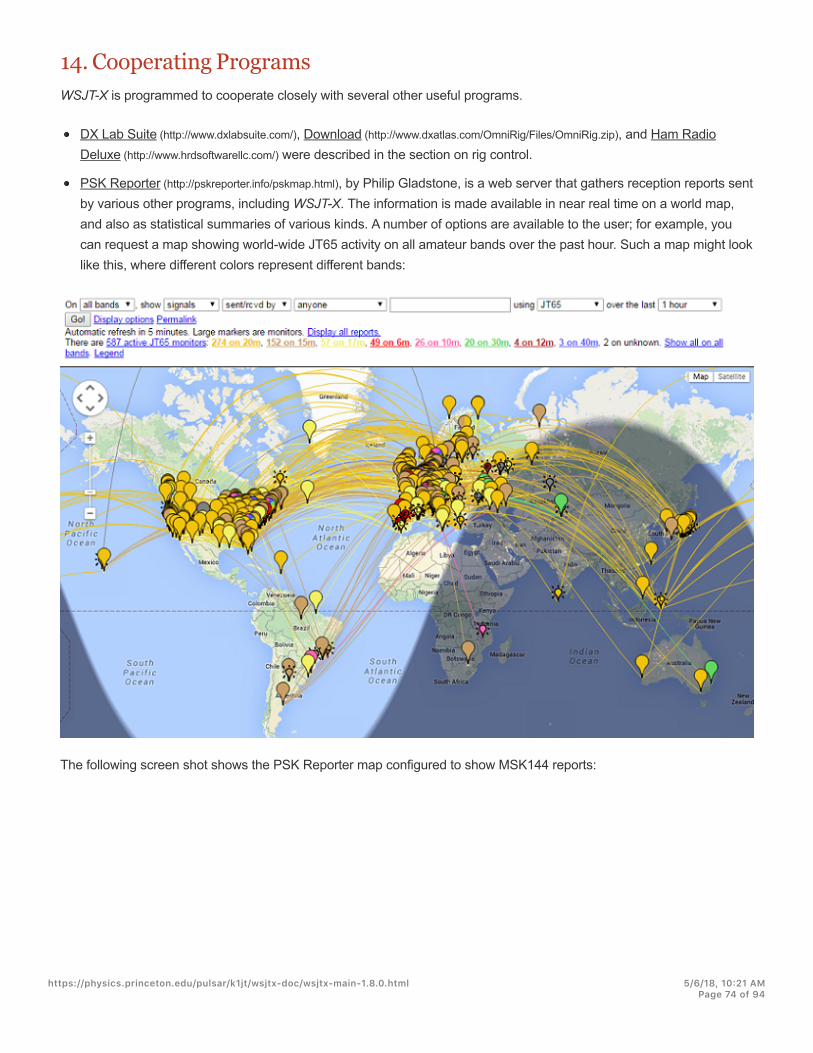
14. Cooperating ProgramsWSJT-X is programmed to cooperate closely with several other useful programs.
DX Lab Suite (http://www.dxlabsuite.com/), Download (http://www.dxatlas.com/OmniRig/Files/OmniRig.zip), and Ham RadioDeluxe (http://www.hrdsoftwarellc.com/) were described in the section on rig control.
PSK Reporter (http://pskreporter.info/pskmap.html), by Philip Gladstone, is a web server that gathers reception reports sentby various other programs, including WSJT-X. The information is made available in near real time on a world map,and also as statistical summaries of various kinds. A number of options are available to the user; for example, youcan request a map showing world-wide JT65 activity on all amateur bands over the past hour. Such a map might looklike this, where different colors represent different bands:
The following screen shot shows the PSK Reporter map configured to show MSK144 reports:
https://physics.princeton.edu/pulsar/k1jt/wsjtx-doc/wsjtx-main-1.8.0.html 5/6/18, 10@21 AMPage 74 of 94
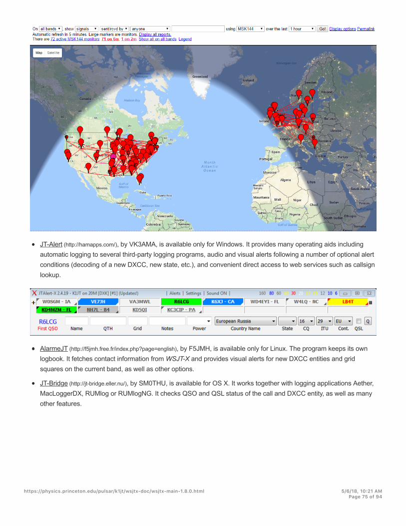
JT-Alert (http://hamapps.com/), by VK3AMA, is available only for Windows. It provides many operating aids includingautomatic logging to several third-party logging programs, audio and visual alerts following a number of optional alertconditions (decoding of a new DXCC, new state, etc.), and convenient direct access to web services such as callsignlookup.
AlarmeJT (http://f5jmh.free.fr/index.php?page=english), by F5JMH, is available only for Linux. The program keeps its ownlogbook. It fetches contact information from WSJT-X and provides visual alerts for new DXCC entities and gridsquares on the current band, as well as other options.
JT-Bridge (http://jt-bridge.eller.nu/), by SM0THU, is available for OS X. It works together with logging applications Aether,MacLoggerDX, RUMlog or RUMlogNG. It checks QSO and QSL status of the call and DXCC entity, as well as manyother features.
https://physics.princeton.edu/pulsar/k1jt/wsjtx-doc/wsjtx-main-1.8.0.html 5/6/18, 10@21 AMPage 75 of 94

15. Platform DependenciesA few WSJT-X features behave differently in Windows, Linux, or OS X, or may not be relevant to all operating platforms.
File locationsWindows
Settings: %LOCALAPPDATA%\WSJT-X\WSJT-X.ini
Log directory: %LOCALAPPDATA%\WSJT-X\
Default save directory: %LOCALAPPDATA%\WSJT-X\save\
Windows, when using "--rig-name=xxx"
Settings: %LOCALAPPDATA%\WSJT-X - xxx\WSJT-X - xxx.ini
Log directory: %LOCALAPPDATA%\WSJT-X - xxx\
Default save directory: %LOCALAPPDATA%\WSJT-X - xxx\save\
Linux
Settings: ~/.config/WSJT-X.ini
Log directory: ~/.local/share/WSJT-X/
Default save directory: ~/.local/share/WSJT-X/save/
Linux, when using "--rig-name=xxx"
Settings: ~/.config/WSJT-X - xxx.ini
Log directory: ~/.local/share/WSJT-X - xxx/
Default save directory: ~/.local/share/WSJT-X - xxx/save/
Macintosh
Settings: ~/Library/Preferences/WSJT-X.ini
Log directory: ~/Library/Application Support/WSJT-X/
Default save directory: ~/Library/Application Support/WSJT-X/save/
Macintosh, when using "--rig-name=xxx"
Settings: ~/Library/Preferences/WSJT-X - xxx.ini
Log directory: ~/Library/Application Support/WSJT-X - xxx/
Default save directory: ~/Library/Application Support/WSJT-X - xxx/save/
https://physics.princeton.edu/pulsar/k1jt/wsjtx-doc/wsjtx-main-1.8.0.html 5/6/18, 10@21 AMPage 76 of 94

16. Frequently Asked Questions1. My displayed spectrum is flatter when I do not check the Flatten box. What’s wrong?
WSJT-X does not expect a steep filter edge within the displayed passband. Use a wider IF filter or reduce thedisplayed passband by decreasing Bins/Pixel, increasing Start, or reducing the width of the Wide Graph. Youmight also choose to re-center the filter passband, if such control is available.
2. How should I configure WSJT-X to run multiple instances?
Start WSJT-X from a command-prompt window, assigning each instance a unique identifier as in the following two-instance example. This procedure will isolate the Settings file and the writable file location for each instance ofWSJT-X.
wsjtx --rig-name=TS2000wsjtx --rig-name=FT847
3. When setting up rig control through OmniRig, something goes wrong when I click Test CAT. What can I do about it?
OmniRig apparently has a bug that appears when you click Test CAT. Forget using Test CAT and just click OK.OmniRig then behaves normally.
4. I am using WSJT-X with Ham Radio Deluxe. All seems well until I start HRD Logbook or DM780 running in parallel;then CAT control becomes unreliable.
You may see delays up to 20 seconds or so in frequency changes or other radio commands, due to a bug in HRD.HRD folks are aware of the problem, and are working to resolve it.
5. I am running WSJT-X under Ubuntu. The program starts, but menu bar is missing from the top of the main windowand the hot-keys don’t work.
Ubuntu’s new “Unity” desktop puts the menu for the currently active window at the top of the primary display screen.You can restore menu bars to their traditional locations by typing the following in a command-prompt window:
sudo apt remove appmenu-qt5
Alternatively, you can disable the common menu bar for just WSJT-X by starting the application with the environmentvariable QT_QPA_PLATFORMTHEME set to empty (the space after the '=' character is necessary):
QT_QPA_PLATFORMTHEME= wsjtx
https://physics.princeton.edu/pulsar/k1jt/wsjtx-doc/wsjtx-main-1.8.0.html 5/6/18, 10@21 AMPage 77 of 94

17. Protocol Specifications
17.1. OverviewAll QSO modes except ISCAT use structured messages that compress user-readable information into fixed-lengthpackets of 72 bits. Each message consists of two 28-bit fields normally used for callsigns and a 15-bit field for a gridlocator, report, acknowledgment, or 73. An additional bit flags a message containing arbitrary alphanumeric text, up to 13characters. Special cases allow other information such as add-on callsign prefixes (e.g., ZA/K1ABC) or suffixes (e.g.,K1ABC/P) to be encoded. The basic aim is to compress the most common messages used for minimally valid QSOs intoa fixed 72-bit length. Information payloads in FT8 include 3 additional bits (75 bits total), with definitions yet to be defined.
A standard amateur callsign consists of a one- or two-character prefix, at least one of which must be a letter, followed bya digit and a suffix of one to three letters. Within these rules, the number of possible callsigns is equal to37×36×10×27×27×27, or somewhat over 262 million. (The numbers 27 and 37 arise because in the first and last threepositions a character may be absent, or a letter, or perhaps a digit.) Since 2 is more than 268 million, 28 bits areenough to encode any standard callsign uniquely. Similarly, the number of 4-digit Maidenhead grid locators on earth is180×180 = 32,400, which is less than 2 = 32,768; so a grid locator requires 15 bits.
Some 6 million of the possible 28-bit values are not needed for callsigns. A few of these slots have been assigned tospecial message components such as CQ , DE , and QRZ . CQ may be followed by three digits to indicate a desiredcallback frequency. (If K1ABC transmits on a standard calling frequency, say 50.280, and sends CQ 290 K1ABC FN42 , itmeans that s/he will listen on 50.290 and respond there to any replies.) A numerical signal report of the form –nn or R–nn can be sent in place of a grid locator. (As originally defined, numerical signal reports nn were required to fallbetween -01 and -30 dB. Recent program versions accommodate reports between -50 and +49 dB.) A country prefix orportable suffix may be attached to one of the callsigns. When this feature is used the additional information is sent inplace of the grid locator or by encoding additional information into some of the 6 million available slots mentioned above.
As a convenience for sending directed CQ messages, the compression algorithm supports messages starting with CQAA through CQ ZZ . These message fragments are encoded internally as if they were the callsigns E9AA throughE9ZZ . Upon reception they are converted back to the form CQ AA through CQ ZZ , for display to the user.
The FT8 and MSK144 modes support a special feature allowing convenient transmission and acknowledgment of four-character grid locators, the required exchanges in most North American VHF contests. With this Contest Mode enabled,WSJT-X supports messages of the form W9XYZ K1ABC R FN42 by converting the grid locator to that of its diametricallyopposite point on Earth. The receiving program recognizes a locator implying a distance greater than 10,000 km, doesthe reverse transformation, and inserts the implied “R”. Obviously, this mode should not be used on the HF bands orunder other circumstances where world-wide propagation is possible.
To be useful on channels with low signal-to-noise ratio, this kind of lossless message compression requires use of astrong forward error correcting (FEC) code. Different codes are used for each mode. Accurate synchronization of timeand frequency is required between transmitting and receiving stations. As an aid to the decoders, each protocol includesa “sync vector” of known symbols interspersed with the information-carrying symbols. Generated waveforms for all of theWSJT-X modes have continuous phase and constant envelope.
28
15
https://physics.princeton.edu/pulsar/k1jt/wsjtx-doc/wsjtx-main-1.8.0.html 5/6/18, 10@21 AMPage 78 of 94

17.2. Slow Modes
17.2.1. FT8Forward error correction (FEC) in FT8 uses a low-density parity check (LDPC) code with 75 information bits, a 12-bitcyclic redundancy check (CRC), and 87 parity bits making a 174-bit codeword. It is thus called an LDPC (174,87) code.Synchronization uses 7×7 Costas arrays at the beginning, middle, and end of each transmission. Modulation is 8-tonefrequency-shift keying (8-FSK) at 12000/1920 = 6.25 baud. Each transmitted symbol carries three bits, so the totalnumber of channel symbols is 174/3 + 21 = 79. The total occupied bandwidth is 8 × 6.25 = 50 Hz.
17.2.2. JT4FEC in JT4 uses a strong convolutional code with constraint length K=32, rate r=1/2, and a zero tail. This choice leads toan encoded message length of (72+31) x 2 = 206 information-carrying bits. Modulation is 4-tone frequency-shift keying(4-FSK) at 11025 / 2520 = 4.375 baud. Each symbol carries one information bit (the most significant bit) and onesynchronizing bit. The two 32-bit polynomials used for convolutional encoding have hexadecimal values 0xf2d05351 and0xe4613c47, and the ordering of encoded bits is scrambled by an interleaver. The pseudo-random sync vector is thefollowing sequence (60 bits per line):
00001100011011001010000000110000000000001011011010111110100010010011111000101000111101100100011010101010111110101011010101110010110111100001101100011101110111001000110110010001111110011000011000101101111010
17.2.3. JT9FEC in JT9 uses the same strong convolutional code as JT4: constraint length K=32, rate r=1/2, and a zero tail, leadingto an encoded message length of (72+31) × 2 = 206 information-carrying bits. Modulation is nine-tone frequency-shiftkeying, 9-FSK at 12000.0/6912 = 1.736 baud. Eight tones are used for data, one for synchronization. Eight data tonesmeans that three data bits are conveyed by each transmitted information symbol. Sixteen symbol intervals are devotedto synchronization, so a transmission requires a total of 206 / 3 + 16 = 85 (rounded up) channel symbols. The syncsymbols are those numbered 1, 2, 5, 10, 16, 23, 33, 35, 51, 52, 55, 60, 66, 73, 83, and 85 in the transmitted sequence.Tone spacing of the 9-FSK modulation for JT9A is equal to the keying rate, 1.736 Hz. The total occupied bandwidth is 9× 1.736 = 15.6 Hz.
17.2.4. JT65A detailed description of the JT65 protocol was published in QEX (http://physics.princeton.edu/pulsar/K1JT/JT65.pdf) forSeptember-October, 2005. A Reed Solomon (63,12) error-control code converts 72-bit user messages into sequences of63 six-bit information-carrying symbols. These are interleaved with another 63 symbols of synchronizing informationaccording to the following pseudo-random sequence:
100110001111110101000101100100011100111101101111000110101011001101010100100000011000000011010010110101010011001001000011111111
https://physics.princeton.edu/pulsar/k1jt/wsjtx-doc/wsjtx-main-1.8.0.html 5/6/18, 10@21 AMPage 79 of 94

The synchronizing tone is normally sent in each interval having a “1” in the sequence. Modulation is 65-FSK at11025/4096 = 2.692 baud. Frequency spacing between tones is equal to the keying rate for JT65A, and 2 and 4 timeslarger for JT65B and JT65C. For EME QSOs the signal report OOO is sometimes used instead of numerical signalreports. It is conveyed by reversing sync and data positions in the transmitted sequence. Shorthand messages for RO,RRR, and 73 dispense with the sync vector entirely and use time intervals of 16384/11025 = 1.486 s for pairs ofalternating tones. The lower frequency is the same as that of the sync tone used in long messages, and the frequencyseparation is 110250/4096 = 26.92 Hz multiplied by n for JT65A, with n = 2, 3, 4 used to convey the messages RO,RRR, and 73.
17.2.5. QRA64QRA64 is intended for EME and other extreme weak-signal applications. Its internal code was designed by IV3NWV.The protocol uses a (63,12) Q-ary Repeat Accumulate code that is inherently better than the Reed Solomon (63,12)code used in JT65, yielding a 1.3 dB advantage. A new synchronizing scheme is based on three 7 x 7 Costas arrays.This change yields another 1.9 dB advantage.
In most respects the current implementation of QRA64 is operationally similar to JT65. QRA64 does not use two-toneshorthand messages, and it makes no use of a callsign database. Rather, additional sensitivity is gained by making useof already known information as a QSO progresses — for example, when reports are being exchanged and you havealready decoded both callsigns in a previous transmission. QRA64 presently offers no message averaging capability,though that feature may be added. In early tests, many EME QSOs were made using submodes QRA64A-E on bandsfrom 144 MHz to 24 GHz.
17.2.6. SummaryTable 2 provides a brief summary parameters for the slow modes in WSJT-X. Parameters K and r specify the constraintlength and rate of the convolutional codes; n and k specify the sizes of the (equivalent) block codes; Q is the alphabetsize for the information-carrying channel symbols; Sync Energy is the fraction of transmitted energy devoted tosynchronizing symbols; and S/N Threshold is the signal-to-noise ratio (in a 2500 Hz reference bandwidth) above whichthe probability of decoding is 50% or higher.
Table 4. Parameters of Slow Modes
Mode FEC Type (n,k) Q Modulationtype
Keyingrate
(Baud)
Bandwidth(Hz)
SyncEnergy
TxDuration
(s)
S/NThreshold
(dB)
FT8 LDPC,r=1/2
(174,87) 8 8-FSK 6.25 50.0 0.27 12.6 -21
JT4A K=32, r=1/2 (206,72) 2 4-FSK 4.375 17.5 0.50 47.1 -23
JT9A K=32, r=1/2 (206,72) 8 9-FSK 1.736 15.6 0.19 49.0 -27
JT65A ReedSolomon
(63,12) 64 65-FSK 2.692 177.6 0.50 46.8 -25
https://physics.princeton.edu/pulsar/k1jt/wsjtx-doc/wsjtx-main-1.8.0.html 5/6/18, 10@21 AMPage 80 of 94

QRA64A Q-aryRepeat
Accumulate
(63,12) 64 64-FSK 1.736 111.1 0.25 48.4 -26
WSPR K=32, r=1/2 (162,50) 2 4-FSK 1.465 5.9 0.50 110.6 -28
Submodes of JT4, JT9, JT65, and QRA64 offer wider tone spacings for circumstances that may require them, suchsignificant Doppler spread. Table 3 summarizes the tone spacings, bandwidths, and approximate threshold sensitivitiesof the various submodes when spreading is comparable to tone spacing.
Table 5. Parameters of Slow Submodes
Mode ToneSpacing
BW (Hz) S/N (dB)
FT8 6.25 50.0 -21
JT4A 4.375 17.5 -23
JT4B 8.75 30.6 -22
JT4C 17.5 56.9 -21
JT4D 39.375 122.5 -20
JT4E 78.75 240.6 -19
JT4F 157.5 476.9 -18
JT4G 315.0 949.4 -17
JT9A 1.736 15.6 -27
JT9B 3.472 29.5 -26
JT9C 6.944 57.3 -25
JT9D 13.889 112.8 -24
JT9E 27.778 224.0 -23
JT9F 55.556 446.2 -22
JT9G 111.111 890.6 -21
JT9H 222.222 1779.5 -20
https://physics.princeton.edu/pulsar/k1jt/wsjtx-doc/wsjtx-main-1.8.0.html 5/6/18, 10@21 AMPage 81 of 94

JT65A 2.692 177.6 -25
JT65B 5.383 352.6 -25
JT65C 10.767 702.5 -25
QRA64A 1.736 111.1 -26
QRA64B 3.472 220.5 -25
QRA64C 6.944 439.2 -24
QRA64D 13.889 876.7 -23
QRA64E 27.778 1751.7 -22
17.3. Fast Modes
17.3.1. ISCATISCAT messages are free-form, up to 28 characters in length. Modulation is 42-tone frequency-shift keying at 11025 /512 = 21.533 baud (ISCAT-A), or 11025 / 256 = 43.066 baud (ISCAT-B). Tone frequencies are spaced by an amount inHz equal to the baud rate. The available character set is:
Transmissions consist of sequences of 24 symbols: a synchronizing pattern of four symbols at tone numbers 0, 1, 3, and2, followed by two symbols with tone number corresponding to (message length) and (message length + 5), and finally18 symbols conveying the user’s message, sent repeatedly character by character. The message always starts with @ ,the beginning-of-message symbol, which is not displayed to the user. The sync pattern and message-length indicatorhave a fixed repetition period, recurring every 24 symbols. Message information occurs periodically within the 18 symbolpositions set aside for its use, repeating at its own natural length.
For example, consider the user message CQ WA9XYZ . Including the beginning-of-message symbol @ , the message is10 characters long. Using the character sequence displayed above to indicate tone numbers, the transmitted messagewill therefore start out as shown in the first line below:
Note that the first six symbols (four for sync, two for message length) repeat every 24 symbols. Within the 18information-carrying symbols in each 24, the user message @CQ WA9XYZ repeats at its own natural length, 10characters. The resulting sequence is extended as many times as will fit into a Tx sequence.
0123456789ABCDEFGHIJKLMNOPQRSTUVWXYZ /.?@-
0132AF@CQ WA9XYZ@CQ WA9X0132AFYZ@CQ WA9XYZ@CQ W0132AFA9X ... sync## sync## sync##
https://physics.princeton.edu/pulsar/k1jt/wsjtx-doc/wsjtx-main-1.8.0.html 5/6/18, 10@21 AMPage 82 of 94
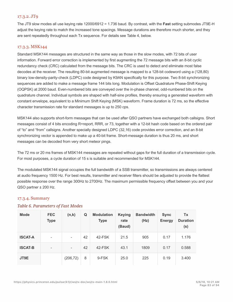
17.3.2. JT9The JT9 slow modes all use keying rate 12000/6912 = 1.736 baud. By contrast, with the Fast setting submodes JT9E-Hadjust the keying rate to match the increased tone spacings. Message durations are therefore much shorter, and theyare sent repeatedly throughout each Tx sequence. For details see Table 4, below.
17.3.3. MSK144Standard MSK144 messages are structured in the same way as those in the slow modes, with 72 bits of userinformation. Forward error correction is implemented by first augmenting the 72 message bits with an 8-bit cyclicredundancy check (CRC) calculated from the message bits. The CRC is used to detect and eliminate most falsedecodes at the receiver. The resulting 80-bit augmented message is mapped to a 128-bit codeword using a (128,80)binary low-density-parity-check (LDPC) code designed by K9AN specifically for this purpose. Two 8-bit synchronizingsequences are added to make a message frame 144 bits long. Modulation is Offset Quadrature Phase-Shift Keying(OQPSK) at 2000 baud. Even-numbered bits are conveyed over the in-phase channel, odd-numbered bits on thequadrature channel. Individual symbols are shaped with half-sine profiles, thereby ensuring a generated waveform withconstant envelope, equivalent to a Minimum Shift Keying (MSK) waveform. Frame duration is 72 ms, so the effectivecharacter transmission rate for standard messages is up to 250 cps.
MSK144 also supports short-form messages that can be used after QSO partners have exchanged both callsigns. Shortmessages consist of 4 bits encoding R+report, RRR, or 73, together with a 12-bit hash code based on the ordered pairof “to” and “from” callsigns. Another specially designed LDPC (32,16) code provides error correction, and an 8-bitsynchronizing vector is appended to make up a 40-bit frame. Short-message duration is thus 20 ms, and shortmessages can be decoded from very short meteor pings.
The 72 ms or 20 ms frames of MSK144 messages are repeated without gaps for the full duration of a transmission cycle.For most purposes, a cycle duration of 15 s is suitable and recommended for MSK144.
The modulated MSK144 signal occupies the full bandwidth of a SSB transmitter, so transmissions are always centeredat audio frequency 1500 Hz. For best results, transmitter and receiver filters should be adjusted to provide the flattestpossible response over the range 300Hz to 2700Hz. The maximum permissible frequency offset between you and yourQSO partner ± 200 Hz.
17.3.4. Summary
Table 6. Parameters of Fast Modes
Mode FECType
(n,k) Q ModulationType
Keyingrate
(Baud)
Bandwidth(Hz)
SyncEnergy
TxDuration
(s)
ISCAT-A - - 42 42-FSK 21.5 905 0.17 1.176
ISCAT-B - - 42 42-FSK 43.1 1809 0.17 0.588
JT9E (206,72) 8 9-FSK 25.0 225 0.19 3.400
https://physics.princeton.edu/pulsar/k1jt/wsjtx-doc/wsjtx-main-1.8.0.html 5/6/18, 10@21 AMPage 83 of 94

K=32,r=1/2
JT9F K=32,r=1/2
(206,72) 8 9-FSK 50.0 450 0.19 1.700
JT9G K=32,r=1/2
(206,72) 8 9-FSK 100.0 900 0.19 0.850
JT9H K=32,r=1/2
(206,72) 8 9-FSK 200.0 1800 0.19 0.425
MSK144 LDPC (128,80) 2 OQPSK 2000 2400 0.11 0.072
MSK144Sh
LDPC (32,16) 2 OQPSK 2000 2400 0.20 0.020
https://physics.princeton.edu/pulsar/k1jt/wsjtx-doc/wsjtx-main-1.8.0.html 5/6/18, 10@21 AMPage 84 of 94
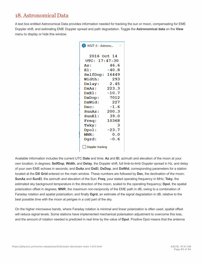
18. Astronomical DataA text box entitled Astronomical Data provides information needed for tracking the sun or moon, compensating for EMEDoppler shift, and estimating EME Doppler spread and path degradation. Toggle the Astronomical data on the Viewmenu to display or hide this window.
Available information includes the current UTC Date and time; Az and El, azimuth and elevation of the moon at yourown location, in degrees; SelfDop, Width, and Delay, the Doppler shift, full limb-to-limb Doppler spread in Hz, and delayof your own EME echoes in seconds; and DxAz and DxEl, DxDop, and DxWid, corresponding parameters for a stationlocated at the DX Grid entered on the main window. These numbers are followed by Dec, the declination of the moon;SunAz and SunEl, the azimuth and elevation of the Sun; Freq, your stated operating frequency in MHz; Tsky, theestimated sky background temperature in the direction of the moon, scaled to the operating frequency; Dpol, the spatialpolarization offset in degrees; MNR, the maximum non-reciprocity of the EME path in dB, owing to a combination ofFaraday rotation and spatial polarization; and finally Dgrd, an estimate of the signal degradation in dB, relative to thebest possible time with the moon at perigee in a cold part of the sky.
On the higher microwave bands, where Faraday rotation is minimal and linear polarization is often used, spatial offsetwill reduce signal levels. Some stations have implemented mechanical polarisation adjustment to overcome this loss,and the amount of rotation needed is predicted in real time by the value of Dpol. Positive Dpol means that the antenna
https://physics.princeton.edu/pulsar/k1jt/wsjtx-doc/wsjtx-main-1.8.0.html 5/6/18, 10@21 AMPage 85 of 94

should be rotated in a clockwise direction looking from behind the antenna towards the moon. For a dish antenna, thefeed should similarly be rotated clockwise looking into the mouth of the feed. A negative value for Dpol meansanticlockwise rotation.
The state of the art for establishing three-dimensional locations of the sun, moon, and planets at a specified time isembodied in a numerical model of the solar system maintained at the Jet Propulsion Laboratory. The model has beennumerically integrated to produce tabular data that can be interpolated with very high accuracy. For example, thecelestial coordinates of the moon or a planet can be determined at a specified time to within about 0.0000003 degrees.The JPL ephemeris tables and interpolation routines have been incorporated into WSJT-X. Further details on accuracy,especially concerning calculated EME Doppler shifts, are described in QEX(http://physics.princeton.edu/pulsar/K1JT/LunarEchoes_QEX.pdf) for November-December, 2016.
The sky background temperatures reported by WSJT-X are derived from the all-sky 408 MHz map of Haslam et al.(Astronomy and Astrophysics Supplement Series, 47, 1, 1982), scaled by frequency to the -2.6 power. This map hasangular resolution of about 1 degree, and of course most amateur EME antennas have much broader beamwidths thanthis. Your antenna will therefore smooth out the hot spots considerably, and the observed extremes of sky temperaturewill be less. Unless you understand your sidelobes and ground reflections extremely well, it is unlikely that more accuratesky temperatures would be of much practical use.
https://physics.princeton.edu/pulsar/k1jt/wsjtx-doc/wsjtx-main-1.8.0.html 5/6/18, 10@21 AMPage 86 of 94
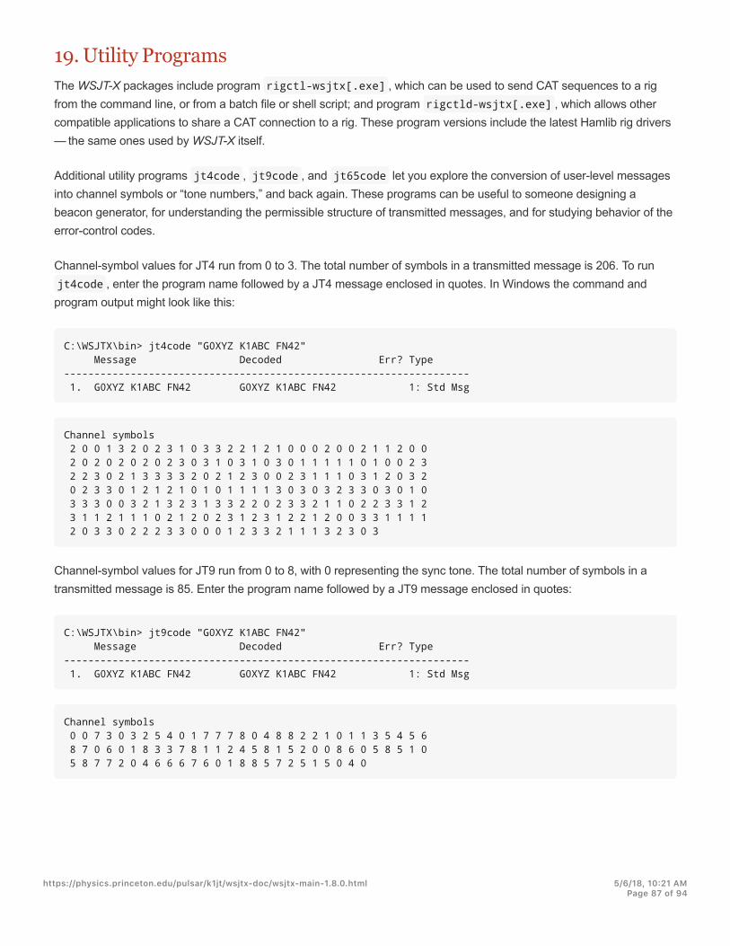
19. Utility ProgramsThe WSJT-X packages include program rigctl-wsjtx[.exe] , which can be used to send CAT sequences to a rigfrom the command line, or from a batch file or shell script; and program rigctld-wsjtx[.exe] , which allows othercompatible applications to share a CAT connection to a rig. These program versions include the latest Hamlib rig drivers — the same ones used by WSJT-X itself.
Additional utility programs jt4code , jt9code , and jt65code let you explore the conversion of user-level messagesinto channel symbols or “tone numbers,” and back again. These programs can be useful to someone designing abeacon generator, for understanding the permissible structure of transmitted messages, and for studying behavior of theerror-control codes.
Channel-symbol values for JT4 run from 0 to 3. The total number of symbols in a transmitted message is 206. To runjt4code , enter the program name followed by a JT4 message enclosed in quotes. In Windows the command andprogram output might look like this:
C:\WSJTX\bin> jt4code "G0XYZ K1ABC FN42" Message Decoded Err? Type------------------------------------------------------------------- 1. G0XYZ K1ABC FN42 G0XYZ K1ABC FN42 1: Std Msg
Channel symbols 2 0 0 1 3 2 0 2 3 1 0 3 3 2 2 1 2 1 0 0 0 2 0 0 2 1 1 2 0 0 2 0 2 0 2 0 2 0 2 3 0 3 1 0 3 1 0 3 0 1 1 1 1 1 0 1 0 0 2 3 2 2 3 0 2 1 3 3 3 3 2 0 2 1 2 3 0 0 2 3 1 1 1 0 3 1 2 0 3 2 0 2 3 3 0 1 2 1 2 1 0 1 0 1 1 1 1 3 0 3 0 3 2 3 3 0 3 0 1 0 3 3 3 0 0 3 2 1 3 2 3 1 3 3 2 2 0 2 3 3 2 1 1 0 2 2 3 3 1 2 3 1 1 2 1 1 1 0 2 1 2 0 2 3 1 2 3 1 2 2 1 2 0 0 3 3 1 1 1 1 2 0 3 3 0 2 2 2 3 3 0 0 0 1 2 3 3 2 1 1 1 3 2 3 0 3
Channel-symbol values for JT9 run from 0 to 8, with 0 representing the sync tone. The total number of symbols in atransmitted message is 85. Enter the program name followed by a JT9 message enclosed in quotes:
C:\WSJTX\bin> jt9code "G0XYZ K1ABC FN42" Message Decoded Err? Type------------------------------------------------------------------- 1. G0XYZ K1ABC FN42 G0XYZ K1ABC FN42 1: Std Msg
Channel symbols 0 0 7 3 0 3 2 5 4 0 1 7 7 7 8 0 4 8 8 2 2 1 0 1 1 3 5 4 5 6 8 7 0 6 0 1 8 3 3 7 8 1 1 2 4 5 8 1 5 2 0 0 8 6 0 5 8 5 1 0 5 8 7 7 2 0 4 6 6 6 7 6 0 1 8 8 5 7 2 5 1 5 0 4 0
https://physics.princeton.edu/pulsar/k1jt/wsjtx-doc/wsjtx-main-1.8.0.html 5/6/18, 10@21 AMPage 87 of 94
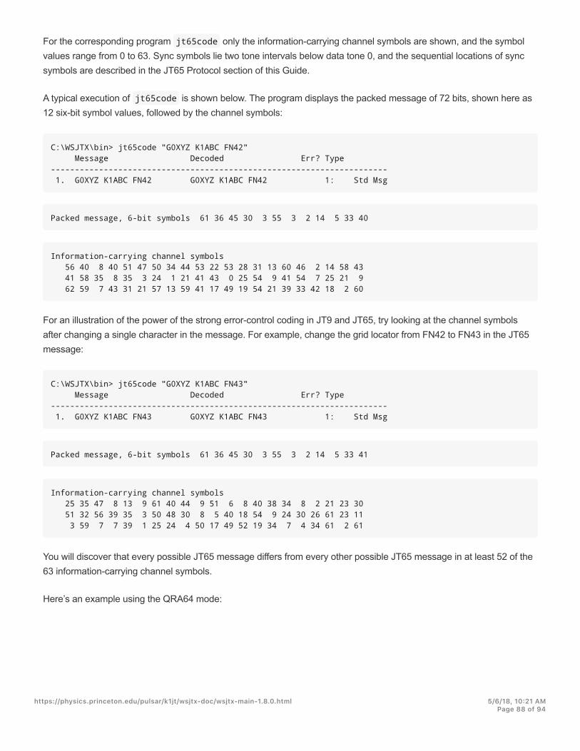
For the corresponding program jt65code only the information-carrying channel symbols are shown, and the symbolvalues range from 0 to 63. Sync symbols lie two tone intervals below data tone 0, and the sequential locations of syncsymbols are described in the JT65 Protocol section of this Guide.
A typical execution of jt65code is shown below. The program displays the packed message of 72 bits, shown here as12 six-bit symbol values, followed by the channel symbols:
C:\WSJTX\bin> jt65code "G0XYZ K1ABC FN42" Message Decoded Err? Type---------------------------------------------------------------------- 1. G0XYZ K1ABC FN42 G0XYZ K1ABC FN42 1: Std Msg
Packed message, 6-bit symbols 61 36 45 30 3 55 3 2 14 5 33 40
Information-carrying channel symbols 56 40 8 40 51 47 50 34 44 53 22 53 28 31 13 60 46 2 14 58 43 41 58 35 8 35 3 24 1 21 41 43 0 25 54 9 41 54 7 25 21 9 62 59 7 43 31 21 57 13 59 41 17 49 19 54 21 39 33 42 18 2 60
For an illustration of the power of the strong error-control coding in JT9 and JT65, try looking at the channel symbolsafter changing a single character in the message. For example, change the grid locator from FN42 to FN43 in the JT65message:
C:\WSJTX\bin> jt65code "G0XYZ K1ABC FN43" Message Decoded Err? Type---------------------------------------------------------------------- 1. G0XYZ K1ABC FN43 G0XYZ K1ABC FN43 1: Std Msg
Packed message, 6-bit symbols 61 36 45 30 3 55 3 2 14 5 33 41
Information-carrying channel symbols 25 35 47 8 13 9 61 40 44 9 51 6 8 40 38 34 8 2 21 23 30 51 32 56 39 35 3 50 48 30 8 5 40 18 54 9 24 30 26 61 23 11 3 59 7 7 39 1 25 24 4 50 17 49 52 19 34 7 4 34 61 2 61
You will discover that every possible JT65 message differs from every other possible JT65 message in at least 52 of the63 information-carrying channel symbols.
Here’s an example using the QRA64 mode:
https://physics.princeton.edu/pulsar/k1jt/wsjtx-doc/wsjtx-main-1.8.0.html 5/6/18, 10@21 AMPage 88 of 94

C:\WSJTX\bin qra64code "KA1ABC WB9XYZ EN37" Message Decoded Err? Type-------------------------------------------------------------------------- 1 KA1ABC WB9XYZ EN37 KA1ABC WB9XYZ EN37 1: Std Msg
Packed message, 6-bit symbols 34 16 49 32 51 26 31 40 41 22 0 41
Information-carrying channel symbols 34 16 49 32 51 26 31 40 41 22 0 41 16 46 14 24 58 45 22 45 38 54 7 23 2 49 32 50 20 33 55 51 7 31 31 46 41 25 55 14 62 33 29 24 2 49 4 38 15 21 1 41 56 56 16 44 17 30 46 36 23 23 41
Channel symbols including sync 20 50 60 0 40 10 30 34 16 49 32 51 26 31 40 41 22 0 41 16 46 14 24 58 45 22 45 38 54 7 23 2 49 32 50 20 33 55 51 20 50 60 0 40 10 30 7 31 31 46 41 25 55 14 62 33 29 24 2 49 4 38 15 21 1 41 56 56 16 44 17 30 46 36 23 23 41 20 50 60 0 40 10 30
Execution of any of these utility programs with "-t" as the only command-line argument produces examples of allsupported message types. For example, using jt65code -t :
C:\WSJTX\bin> jt65code -t
https://physics.princeton.edu/pulsar/k1jt/wsjtx-doc/wsjtx-main-1.8.0.html 5/6/18, 10@21 AMPage 89 of 94

Message Decoded Err? Type-------------------------------------------------------------------------- 1. CQ WB9XYZ EN34 CQ WB9XYZ EN34 1: Std Msg 2. CQ DX WB9XYZ EN34 CQ DX WB9XYZ EN34 1: Std Msg 3. QRZ WB9XYZ EN34 QRZ WB9XYZ EN34 1: Std Msg 4. KA1ABC WB9XYZ EN34 KA1ABC WB9XYZ EN34 1: Std Msg 5. KA1ABC WB9XYZ RO KA1ABC WB9XYZ RO 1: Std Msg 6. KA1ABC WB9XYZ -21 KA1ABC WB9XYZ -21 1: Std Msg 7. KA1ABC WB9XYZ R-19 KA1ABC WB9XYZ R-19 1: Std Msg 8. KA1ABC WB9XYZ RRR KA1ABC WB9XYZ RRR 1: Std Msg 9. KA1ABC WB9XYZ 73 KA1ABC WB9XYZ 73 1: Std Msg10. KA1ABC WB9XYZ KA1ABC WB9XYZ 1: Std Msg11. CQ 000 WB9XYZ EN34 CQ 000 WB9XYZ EN34 1: Std Msg12. CQ 999 WB9XYZ EN34 CQ 999 WB9XYZ EN34 1: Std Msg13. CQ EU WB9XYZ EN34 CQ EU WB9XYZ EN34 1: Std Msg14. CQ WY WB9XYZ EN34 CQ WY WB9XYZ EN34 1: Std Msg15. ZL/KA1ABC WB9XYZ ZL/KA1ABC WB9XYZ 2: Type 1 pfx16. KA1ABC ZL/WB9XYZ KA1ABC ZL/WB9XYZ 2: Type 1 pfx17. KA1ABC/4 WB9XYZ KA1ABC/4 WB9XYZ 3: Type 1 sfx18. KA1ABC WB9XYZ/4 KA1ABC WB9XYZ/4 3: Type 1 sfx19. CQ ZL4/KA1ABC CQ ZL4/KA1ABC 4: Type 2 pfx20. DE ZL4/KA1ABC DE ZL4/KA1ABC 4: Type 2 pfx21. QRZ ZL4/KA1ABC QRZ ZL4/KA1ABC 4: Type 2 pfx22. CQ WB9XYZ/VE4 CQ WB9XYZ/VE4 5: Type 2 sfx23. HELLO WORLD HELLO WORLD 6: Free text24. ZL4/KA1ABC 73 ZL4/KA1ABC 73 6: Free text25. KA1ABC XL/WB9XYZ KA1ABC XL/WB9 * 6: Free text26. KA1ABC WB9XYZ/W4 KA1ABC WB9XYZ * 6: Free text27. 123456789ABCDEFGH 123456789ABCD * 6: Free text28. KA1ABC WB9XYZ EN34 OOO KA1ABC WB9XYZ EN34 OOO 1: Std Msg29. KA1ABC WB9XYZ OOO KA1ABC WB9XYZ OOO 1: Std Msg30. RO RO -1: Shorthand31. RRR RRR -1: Shorthand32. 73 73 -1: Shorthand
MSK144 uses a binary channel code, so transmitted symbols have the value 0 or 1. Even numbered symbols (indexstarting at 0) are transmitted on the I (in-phase) channel, odd numbered symbols on the Q (quadrature) channel. Atypical execution of msk144code is shown below.
C:\WSJTX\bin> msk144code "K1ABC W9XYZ EN37"
Message Decoded Err? Type-------------------------------------------------------------------------- 1. K1ABC W9XYZ EN37 K1ABC W9XYZ EN37 1: Std Msg
Channel symbols110000100011001101010101001000111111001001001100110010011100001001000000010110001011101111001010111011001100110101011000111101100010111100100011
https://physics.princeton.edu/pulsar/k1jt/wsjtx-doc/wsjtx-main-1.8.0.html 5/6/18, 10@21 AMPage 90 of 94

C:\WSJTX\bin> msk144code "<KA1ABC WB9XYZ> R-03" Message Decoded Err? Type-------------------------------------------------------------------------- 1. <KA1ABC WB9XYZ> R-03 <KA1ABC WB9XYZ> R-03 7: Hashed calls
Channel symbols1000011100001000111011111010011011111010
https://physics.princeton.edu/pulsar/k1jt/wsjtx-doc/wsjtx-main-1.8.0.html 5/6/18, 10@21 AMPage 91 of 94

20. Support
20.1. Help with SetupThe best source of help in setting up your station or configuring WSJT-X is the WSJT Group(https://groups.yahoo.com/neo/groups/wsjtgroup/info) at email address [email protected]. The chances are goodthat someone with similar interests and equipment has already solved your problem and will be happy to help. To postmessages here you will need to join the group.
20.2. Bug ReportsOne of your responsibilities as a WSJT-X user is to help the volunteer programmers to make the program better. Bugsmay be reported to WSJT Group (https://groups.yahoo.com/neo/groups/wsjtgroup/info) (email [email protected]) or the WSJT Developers list ([email protected]). Again, you will need tojoin the group or subscribe to the list. You can register for the list here (https://lists.sourceforge.net/lists/listinfo/wsjt-devel).
To be useful, bug reports should include at least the following information:
Program version
Operating system
Concise description of the problem
Exact sequence of steps required to reproduce the problem
20.3. Feature RequestsSuggestions from users often result in new program features. Good ideas are always welcome: if there’s a feature youwould like to see in WSJT-X, spell it out in as much detail as seems useful and send it to us at one of the emailaddresses given a few lines above. Be sure to explain why you think the feature is desirable, and what sort of otherusers might find it so.
https://physics.princeton.edu/pulsar/k1jt/wsjtx-doc/wsjtx-main-1.8.0.html 5/6/18, 10@21 AMPage 92 of 94

21. AcknowledgementsThe WSJT project was started in 2001. Since 2005 it has been an Open Source project, and it now includes programsWSJT, MAP65, WSPR, WSJT-X, and WSPR-X. All code is licensed under the GNU Public License (GPL). Many usersof these programs, too numerous to mention here individually, have contributed suggestions and advice that havegreatly aided the development of WSJT and its sister programs.
For WSJT-X in particular, we acknowledge contributions from AC6SL, AE4JY, DJ0OT, G3WDG, G4KLA, G4WJS,IV3NWV, IW3RAB, K3WYC, K9AN, KA6MAL, KA9Q, KB1ZMX, KD6EKQ, KI7MT, KK1D, ND0B, PY2SDR, VE1SKY,VK3ACF, VK4BDJ, VK7MO, W4TI, W4TV, and W9MDB. Each of these amateurs has helped to bring the program’sdesign, code, testing, and/or documentation to its present state.
Most of the color palettes for the WSJT-X waterfall were copied from the excellent, well documented, open-sourceprogram fldigi, by W1HKJ and friends.
We use development tools and libraries from many sources. We particularly wish to acknowledge importance of theGNU Compiler Collection from the Free Software Foundation, the "clang" compiler from LLVM at the University of Illinois,and the Qt Project from Digia PLC. Other important resources include the FFTW library by Matteo Frigo and Steven G.Johnson; SLALIB, the Positional Astronomy Library by P. T. Wallace; and a high-precision planetary ephemeris andassociated software from NASA’s Jet Propulsion Laboratory.
https://physics.princeton.edu/pulsar/k1jt/wsjtx-doc/wsjtx-main-1.8.0.html 5/6/18, 10@21 AMPage 93 of 94

22. LicenseWSJT-X is free software: you may redistribute and/or modify it under the terms of the GNU General Public License aspublished by the Free Software Foundation, either version 3 of the License, or (at your option) any later version.
WSJT-X is distributed in the hope that it will be useful, but WITHOUT ANY WARRANTY; without even the impliedwarranty of MERCHANTABILITY or FITNESS FOR A PARTICULAR PURPOSE. See the GNU General Public Licensefor more details.
You should have received a copy of the GNU General Public License along with this documentation. If not, see GNUGeneral Public License (http://www.gnu.org/licenses/gpl-3.0.txt).
Except where otherwise noted, all algorithms, protocol designs, source code, and supporting files contained in theWSJT-X package are the intellectual property of the program’s authors. The authors assert Copyright ownership of thismaterial, whether or not such copyright notice appears in each individual file. Others who make fair use of our workunder terms of the GNU General Public License must display the following copyright notice prominently:
The algorithms, source code, look-and-feel of WSJT-X and related programs, and protocol specifications forthe modes FSK441, FT8, JT4, JT6M, JT9, JT65, JTMS, QRA64, ISCAT, and MSK144 are Copyright © 2001-2017by one or more of the following authors: Joseph Taylor, K1JT; Bill Somerville, G4WJS; Steven Franke, K9AN;Nico Palermo, IV3NWV; Greg Beam, KI7MT; Michael Black, W9MDB; Edson Pereira, PY2SDR; Philip Karn,KA9Q; and other members of the WSJT Development Group.
Version 1.8.0Last updated 2017-10-14 10:00:51 GMT Summer Time
https://physics.princeton.edu/pulsar/k1jt/wsjtx-doc/wsjtx-main-1.8.0.html 5/6/18, 10@21 AMPage 94 of 94