wt8000 wireless device - abb ltd · the menu options if either of the run, dinfo, or fctry menus...
TRANSCRIPT

1
WT8000 Wireless DeviceCommunication Between A Gateway And Up To 55 Nodes
WT8000-0200-1 Rev nc (1-2011) DRR0339 For the latest version of this manual, visit www.ktekcorp.com.
WT8000 Wireless DeviceCommunication Between A Gateway And Up To 55 Nodes
For the latest version of this manual, visit ktekcorp.com or kteksolidslevel.com.
Installation & Operation Manual

WT8000 Wireless DeviceCommunication Between A Gateway And Up To 55 Nodes
WT8000-0200-1 Rev nc (1-2011) DRR0339 For the latest version of this manual, visit www.ktekcorp.com. 2
Introduction. . . . . . . . . . . . . . . . . . . . . . . . . . . . . . . . . . . . . . . . . . . . . . . . . . . . . . . . . . . . . . . . . . . . . . . . . . . . . . . . . . . . . . . . . . . . . 3WT8000 Gateway and Node . . . . . . . . . . . . . . . . . . . . . . . . . . . . . . . . . . . . . . . . . . . . . . . . . . . . . . . . . . . . . . . . . . . . . . . . . . . . . . . . . . . . . . . 4WT8000 Gateway and Node Wiring Chamber. . . . . . . . . . . . . . . . . . . . . . . . . . . . . . . . . . . . . . . . . . . . . . . . . . . . . . . . . . . . . . . . . . . . . . . . . . 5Pinouts . . . . . . . . . . . . . . . . . . . . . . . . . . . . . . . . . . . . . . . . . . . . . . . . . . . . . . . . . . . . . . . . . . . . . . . . . . . . . . . . . . . . . . . . . . . . . . . . . . . . . . . . 6Dimensions. . . . . . . . . . . . . . . . . . . . . . . . . . . . . . . . . . . . . . . . . . . . . . . . . . . . . . . . . . . . . . . . . . . . . . . . . . . . . . . . . . . . . . . . . . . . . . . . . . . . . 7
Menu Structure. . . . . . . . . . . . . . . . . . . . . . . . . . . . . . . . . . . . . . . . . . . . . . . . . . . . . . . . . . . . . . . . . . . . . . . . . . . . . . . . . . . . . . . . . . 8WT8000 Gateway Setup Menu . . . . . . . . . . . . . . . . . . . . . . . . . . . . . . . . . . . . . . . . . . . . . . . . . . . . . . . . . . . . . . . . . . . . . . . . . . . . . . . . . . . . . 8WT8000 Node Setup Menu . . . . . . . . . . . . . . . . . . . . . . . . . . . . . . . . . . . . . . . . . . . . . . . . . . . . . . . . . . . . . . . . . . . . . . . . . . . . . . . . . . . . . . 9-10
Setting Up Your Wireless Network . . . . . . . . . . . . . . . . . . . . . . . . . . . . . . . . . . . . . . . . . . . . . . . . . . . . . . . . . . . . . . . . . . . . . . . . . . . . . . . . . . . . .11Step 1: Apply Power. . . . . . . . . . . . . . . . . . . . . . . . . . . . . . . . . . . . . . . . . . . . . . . . . . . . . . . . . . . . . . . . . . . . . . . . . . . . . . . . . . . . . . . . . . . . . .11Step 2: Forming Networks and Assigning Node Addresses . . . . . . . . . . . . . . . . . . . . . . . . . . . . . . . . . . . . . . . . . . . . . . . . . . . . . . . . . . . . 11-12Step 3: Verify Communications . . . . . . . . . . . . . . . . . . . . . . . . . . . . . . . . . . . . . . . . . . . . . . . . . . . . . . . . . . . . . . . . . . . . . . . . . . . . . . . . . . . . 12
Installation . . . . . . . . . . . . . . . . . . . . . . . . . . . . . . . . . . . . . . . . . . . . . . . . . . . . . . . . . . . . . . . . . . . . . . . . . . . . . . . . . . . . . . . . . . . . . . . . . . . . . . 13Ideal Mounting Conditions . . . . . . . . . . . . . . . . . . . . . . . . . . . . . . . . . . . . . . . . . . . . . . . . . . . . . . . . . . . . . . . . . . . . . . . . . . . . . . . . . . . . . . . . 13Weather-Proofi ng Glands and Plugs . . . . . . . . . . . . . . . . . . . . . . . . . . . . . . . . . . . . . . . . . . . . . . . . . . . . . . . . . . . . . . . . . . . . . . . . . . . . . . . . 14Quick Tips. . . . . . . . . . . . . . . . . . . . . . . . . . . . . . . . . . . . . . . . . . . . . . . . . . . . . . . . . . . . . . . . . . . . . . . . . . . . . . . . . . . . . . . . . . . . . . . . . . . . . 15
Advanced Setup . . . . . . . . . . . . . . . . . . . . . . . . . . . . . . . . . . . . . . . . . . . . . . . . . . . . . . . . . . . . . . . . . . . . . . . . . . . . . . . . . . . . . . . . . . . . . . . . . . 16Manual Binding. . . . . . . . . . . . . . . . . . . . . . . . . . . . . . . . . . . . . . . . . . . . . . . . . . . . . . . . . . . . . . . . . . . . . . . . . . . . . . . . . . . . . . . . . . . . . . . 16-17Automatic Binding (Menu Navigation) . . . . . . . . . . . . . . . . . . . . . . . . . . . . . . . . . . . . . . . . . . . . . . . . . . . . . . . . . . . . . . . . . . . . . . . . . . . . . . . 18Collocated Networks - Setting the Network ID. . . . . . . . . . . . . . . . . . . . . . . . . . . . . . . . . . . . . . . . . . . . . . . . . . . . . . . . . . . . . . . . . . . . . . . . . 19Setting the Maximum Node Count . . . . . . . . . . . . . . . . . . . . . . . . . . . . . . . . . . . . . . . . . . . . . . . . . . . . . . . . . . . . . . . . . . . . . . . . . . . . . . . . . . 19
System Layouts . . . . . . . . . . . . . . . . . . . . . . . . . . . . . . . . . . . . . . . . . . . . . . . . . . . . . . . . . . . . . . . . . . . . . . . . . . . . . . . . . . . . . . . . . . . . . . . . . . 20Stand-Alone Systems. . . . . . . . . . . . . . . . . . . . . . . . . . . . . . . . . . . . . . . . . . . . . . . . . . . . . . . . . . . . . . . . . . . . . . . . . . . . . . . . . . . . . . . . . . . . 21Modbus RTU . . . . . . . . . . . . . . . . . . . . . . . . . . . . . . . . . . . . . . . . . . . . . . . . . . . . . . . . . . . . . . . . . . . . . . . . . . . . . . . . . . . . . . . . . . . . . . . . 22-23
Sensor Connections . . . . . . . . . . . . . . . . . . . . . . . . . . . . . . . . . . . . . . . . . . . . . . . . . . . . . . . . . . . . . . . . . . . . . . . . . . . . . . . . . . . . . . . . . . . . . . . 24Digital Sensors, Sourcing (PNP) Inputs . . . . . . . . . . . . . . . . . . . . . . . . . . . . . . . . . . . . . . . . . . . . . . . . . . . . . . . . . . . . . . . . . . . . . . . . . . . . . . 24Digital Sensors, Sinking (NPN) Inputs . . . . . . . . . . . . . . . . . . . . . . . . . . . . . . . . . . . . . . . . . . . . . . . . . . . . . . . . . . . . . . . . . . . . . . . . . . . . . . . 25Digital Sensors, Sourcing (PNP) Outputs . . . . . . . . . . . . . . . . . . . . . . . . . . . . . . . . . . . . . . . . . . . . . . . . . . . . . . . . . . . . . . . . . . . . . . . . . . . . 26Digital Sensors, Sinking (NPN) Outputs. . . . . . . . . . . . . . . . . . . . . . . . . . . . . . . . . . . . . . . . . . . . . . . . . . . . . . . . . . . . . . . . . . . . . . . . . . . . . . 27Analog Inputs . . . . . . . . . . . . . . . . . . . . . . . . . . . . . . . . . . . . . . . . . . . . . . . . . . . . . . . . . . . . . . . . . . . . . . . . . . . . . . . . . . . . . . . . . . . . . . . . . . 28Analog Outputs. . . . . . . . . . . . . . . . . . . . . . . . . . . . . . . . . . . . . . . . . . . . . . . . . . . . . . . . . . . . . . . . . . . . . . . . . . . . . . . . . . . . . . . . . . . . . . . . . 29
Agency Certifi cations . . . . . . . . . . . . . . . . . . . . . . . . . . . . . . . . . . . . . . . . . . . . . . . . . . . . . . . . . . . . . . . . . . . . . . . . . . . . . . . . . . . . . . . . . . . . . . 30FCC Certifi cation 900 MHz . . . . . . . . . . . . . . . . . . . . . . . . . . . . . . . . . . . . . . . . . . . . . . . . . . . . . . . . . . . . . . . . . . . . . . . . . . . . . . . . . . . . . . . 30FCC Certifi cation, 2.4 GHz. . . . . . . . . . . . . . . . . . . . . . . . . . . . . . . . . . . . . . . . . . . . . . . . . . . . . . . . . . . . . . . . . . . . . . . . . . . . . . . . . . . . . . . . 31Certifi ed Countries List . . . . . . . . . . . . . . . . . . . . . . . . . . . . . . . . . . . . . . . . . . . . . . . . . . . . . . . . . . . . . . . . . . . . . . . . . . . . . . . . . . . . . . . . . 32-33
Table of Contents

3
WT8000 Wireless DeviceCommunication Between A Gateway And Up To 55 Nodes
WT8000-0200-1 Rev nc (1-2011) DRR0339 For the latest version of this manual, visit www.ktekcorp.com.
IntroductionThe SureCross™ WT8000 wireless I/O network provides reliable monitoring without the burden of wiring or conduit installation and can operate independently or in conjunction with a PLC and/or PC software.
The SureCross NetworkThe SureCross WT8000 network is a deterministic system—the network identifi es when the radio signal is lost and drives relevant outputs to user-defi ned conditions. Once the radio signal is reacquired, the network returns to normal operation.Each wireless network system consists of one Gateway and one or more Nodes that ship with factory defi ned inputs and outputs. Devices may be all discrete I/O, all analog I/O, mixed discrete and analog I/O, and FlexPower™.
Gateways and NodesA Gateway device acts as the master device within each radio network and initiates communication and reporting with the Nodes. A radio network contains only one Gateway, but can contain many Nodes. Each Node device can be connected to sensors or output devices and reports I/O status to the Gateway. Devices may be all discrete I/O, mixed discrete and analog I/O, or FlexPower™.
Host SystemsHost-connected systems can contain up to 15 Nodes (Rotary Switch addressing) or 56 Nodes (extended addressing mode) within a single network and may be all discrete, all analog, or a mix of discrete and analog I/O. Host-connected systems allow for logic and calculations to be applied to the I/O. Inputs from Nodes within the network are transmitted to the Gateway, which communicates the information to a host device for processing. While the Gateway is the master device within the radio network, the Gateway may be a slave to the Modbus network.

WT8000 Wireless DeviceCommunication Between A Gateway And Up To 55 Nodes
WT8000-0200-1 Rev nc (1-2011) DRR0339 For the latest version of this manual, visit www.ktekcorp.com. 4
WT8000 Gateway and Node
1
2
3
456
7
1. Port, NPT Gland, or Plug If unused, install the provided plug into the 1/2 NPT threaded port. Refer to the Installation section if an IP67 seal is required.
2. Rotary Switch 1 (left) Sets the Network ID (NID) to a hexidecimal value from 0 to F, for a total of 16 Network IDs. A Gateway and its corresponding Nodes must be assigned the same Network ID.
Rotary Switch 2 (right) Gateway: Sets the Gateway’s LCD viewing device address. The Gateway is predefi ned as Device Address 0. Node: Sets the Node’s Device Address (hexidecimal 1 to F). Each Node within a network must have a unique Node Device Address.
3. Push Button 1 Single-click to advance across all top-level WT8000 menus.Single-click to move down interactive menus, once a top-level menu is chosen.
4. Push Button 2 Double-click to select a menu and to enter manual scrolling mode.Double-click to move up one level at a time.
5. LED 1 and 2 Provide real-time feedback to the user regarding RF link status, serial communications activity, and the error state.
6. LCD Display Six-character display provides run mode user information and shows enabled I/O point status. This display allows the user to conduct a Site Survey (RSSI) and modify other WT8000 confi guration parameters without the use of a PC or other external software interfaces. On the Node, after 15 minutes of inactivity, the LCD goes blank. Press any button to refresh the display.
7. 5-Pin M12 Euro-style quick-disconnect serial port

5
WT8000 Wireless DeviceCommunication Between A Gateway And Up To 55 Nodes
WT8000-0200-1 Rev nc (1-2011) DRR0339 For the latest version of this manual, visit www.ktekcorp.com.
1
2
3
4
5
WT8000 Gateway and Node Wiring Chamber
1. Housing The rugged, industrial WT8000 housing meets IEC IP67 standards.
2. Mounting Hole, #10/M5 Clearance Mounting Holes accept metric M5 or UNC/UNF #10 hardware -- DIN rail mount adapter bracket available.
3. Wiring Terminal Strip The 16 spring-clip type wiring terminals accept wire sizes: AWG 12-28 or 2.5 mm2
4. Port, PG-7 Gland or Blank The PG-7 threaded ports can accept provided cable glands or blanks.

WT8000 Wireless DeviceCommunication Between A Gateway And Up To 55 Nodes
WT8000-0200-1 Rev nc (1-2011) DRR0339 For the latest version of this manual, visit www.ktekcorp.com. 6
Pinouts
5-pin Euro-style Hookup (RS-485)
Wire Color Gateway, GatewayPro, DX85*
FlexPower Gateway and Data Radio**
10–30V dc Node FlexPower Node**
1 Brown +10 to 30V dc Input +10 to 30V dc Input +10 to 30V dc Input2 White RS485 / D1 / B / + RS485 / D1 / B / +3 Blue dc common (GND) dc common (GND) dc common (GND) dc common (GND)4 Black RS485 / D0 / A / − RS485 / D0 / A / −5 Gray Comms grnd 3.6 to 5.5V dc 3.6 to 5.5V dc
* Connecting dc power to the communication pins will cause permanent damage.
5-pin Euro-style Hookup (RS-232 Serial)
Wire Color GatewayPro, Ethernet Bridge*
Data Radio**
1 Brown +10 to 30V dc Input +10 to 30V dc Input2 White RS232 Tx RS232 Tx3 Blue dc common (GND) dc common (GND)4 Black RS232 Rx RS232 Rx5 Gray Comms grnd 3.6 to 5.5V dc
* Connecting dc power to the communication pins will cause permanent damage. ** For FlexPower devices, do not apply more than 5.5V dc to the gray wire.

7
WT8000 Wireless DeviceCommunication Between A Gateway And Up To 55 Nodes
WT8000-0200-1 Rev nc (1-2011) DRR0339 For the latest version of this manual, visit www.ktekcorp.com.
Dimensions
65.0[2.56”]
65.0[2.56”]
80.3[3.16”]
80.8[3.18”]
60[2.36”]
120[4.72”]
127[5”]
19[0.75”]
30.65[1.21”]
22.2[0.875”]
7.9[0.31”]
7.65[0.30”]
14.67[0.578”]

WT8000 Wireless DeviceCommunication Between A Gateway And Up To 55 Nodes
WT8000-0200-1 Rev nc (1-2011) DRR0339 For the latest version of this manual, visit www.ktekcorp.com. 8
Menu Structure
WT8000 Gateway Setup Menu When power is applied, the WT8000 begins running. The display screen auto loops through the RUN menu and communication begins between the Gateway and Node(s). Auto looping through the RUN menu is the normal operating mode for all devices on the wireless network.From the RUN Menu (or any menu), single-click button 1 to advance through the top-level menus. The device auto display loops through the menu options if either of the RUN, DINFO, or FCTRY menus are selected. If the device is paused on the SITE, DVCFG, or DERR menu options, the display does not auto loop. To enter manual scrolling mode, double-click button 2 at the top level menu. Use the instructions shown in the chart below to navigate the menu system. To return to the top level menus and auto display loop mode, double-click button 2 twice.
NOD XX
M XX
R XX
Y XX
G XX
*DINFO *FCTRY *SITE *DVCFG *DERR*RUN
AUTODISPLAY
LOOP
AUTODISPLAY
LOOP
AUTODISPLAY
LOOP
(DEV)
GATEWY
(NID)
XX
(SLID)
XX
(BAUD)
XX
(PRTY)
XX
(DEV)
GATEWY
(RADIO
MICRO)
V 00.0 A
(LCD
MICRO)
V 00.0 A
(DX80
S/N)
(0000)
(DX80
MODEL)
(0000-00)
(PROD
DATE)
(00-00)
Single-clickButton 2
Single-clickButton 2
Single-clickButton 2
Double-clickButton 2
adjust right rotaryswitch to survey the
selected Node
Single-clickButton 2
Dou
ble-
clic
kB
utto
n 2
Dou
ble-
clic
k B
utto
n 2
NOD XX
EC XX CLEAR
ERR
ERASED
ERR
DISABL
*ERROR
DISABL IGNORE
NextDevice
Single-click Button 1 to advance through menu
AUTODISPLAY
LOOP
Single-clickButton 2
Single-clickButton 2
Single-clickButton 2
Single-clickButton 2
Single-clickButton 2
Single-clickButton 2
New ErrorDetected
adjust the rotaryswitches to surveythe selected Node
(DEV)
I/O XX
GATEWY
NID XX
ON/OFF
(DEV)
I/O XX
GATEWY
NID XX
ON/OFF
Even
None
Odd
Single-clickButton 2
Single-clickButton 2
SAVESDISPLAYED
VALUE
Sing
le-c
lick
B1
19200
9600
38400
Single-clickButton 2
Single-clickButton 2
SAVESDISPLAYED
VALUE
NEW XX
Single-clickButton 2
Single-clickButton 2
adjust rotary switchesto set the network ID
SAVES NEWVALUES
CUR XX
Single-clickButton 2
Single-clickButton 2
adjust rotary switchesto set slave ID, usingbutton 1 to select the
digits
SAVES NEWVALUES
(NID) (SLID) (BAUD) (PRTY)Network ID Slave ID Baud Rate Parity
Sing
le-c
lick
B1
NEW XX
Single-clickButton 1
Single-clickButton 1
Single-clickButton 1
Single-clickButton 1
Single-click Button 1 to advance through menu
(NAME)
XXXXXX
XXXXXX
Single-click Button 1 to advance through menu
CUR XX
Dou
ble-
clic
k B
utto
n 2
Dou
ble-
clic
kB
utto
n 2
* Set to 000000 to use the serial number.
Device Info Factory Info Site Survey Device Config Device Error
16
8
32
Single-clickButton 2
Single-clickButton 2
SAVESDISPLAYED
VALUE
Sing
le-c
lick
B1
(MAXN)Timing
56
MANUAL
AUTOAUTO
SET
Single-clickButton 2
Single-clickButton 2
Sing
le-c
lick
B1
(XADR)Extended Addressing
XADR
ADJUST ROTARYSWITCH TOSET XADR
Single-clickButton 2
XXXXXX
Sing
le-c
lick
B1
Single-clickButton 2
CONFRM
XADR
XXXXX
NETWRK
Single-click
Button 2
BINDNG
Single-clickButton 1 or 2
Reboot
SAVED
*
XXXXXX
The Network ID (NID) can be set at any time using the rotary switches. Once changed, allow fi ve seconds for the devices to update to the new NID.
Navigating the menu:* indicates a top level menu option( ) indicates a sub-menu itemNo characters indicate the value of the previous item
The MAXN and XADR menus are only available in extended addressing mode. To access extended addressing mode, move DIP switch 1 to the ON position. To manually select the serial number, use button 1 to move across the digits and use the right rotary switch to select the value used as the device serial number.

9
WT8000 Wireless DeviceCommunication Between A Gateway And Up To 55 Nodes
WT8000-0200-1 Rev nc (1-2011) DRR0339 For the latest version of this manual, visit www.ktekcorp.com.
WT8000 Node Setup Menu When power is applied, the WT8000 begins running. The display screen auto loops through the RUN menu and communication begins between the Gateway and Node(s). Auto looping through the RUN menu is the normal operating mode for all devices on the wireless network.From the RUN Menu (or any menu), single-click button 1 to advance through the top-level menus. The device auto display loops through the menu options if either of the RUN, DINFO, or FCTRY menus are selected. If the device is paused on the DVCFG or DERR menu options, the display does not auto display loop.To enter manual scrolling mode, double-click button 2 at the top level menu. Use the instructions shown in the chart below to navigate the menu system. To return to the top level menus and auto display loop mode, double-click button 2 twice.
*DINFO*RUN *FCTRY *DVCFG *DERR
AUTODISPLAY
LOOP
AUTODISPLAY
LOOP
AUTODISPLAY
LOOP
(DEV)
NOD XX
(NAME)
NODE XX
KIT
XXXXX
(NID)
XX
(DEV)
NOD XX
(RADIO
MICRO)
V 00.0 A
(DX80
S/N)
0x0000(2)
(LCD
MICRO)
0x0000(2)
(PROD
DATE)
(00-00)
Single-clickButton 2
NEW XX
Single-clickButton 2
Single-clickButton 2
SAVES NEWVALUES
(NID)Network ID
Single-clickButton 2
Dou
ble-
clic
k B
tn 2
NEW XX
Single-clickButton 2
Single-clickButton 2
SAVES NEWVALUES
(NADR)Node Address
NOD XX
**EC XX IGNORE
*ERROR
Single-click Button 1
** LCD will display ‘NO ERR’ if no error is detected.
Single-clickButton 2
Single-clickButton 2
New ErrorDetected
Sing
le-c
lick
But
ton
2
OFF Press and hold Button 1 from any top level menu to power down the Node.Press and hold Button 1 from power down mode to enter RUN mode.
ADJUST LEFTROTARY SWITCH
TO SETNETWORK ID
ADJUST RIGHTROTARY SWITCH
TO SETNODE ADDRESS
(DEV)
I/O XX
NOD XX
NID XX
ON/OFF
Single-clickButton 1
Single-clickButton 1
Single-clickButton 1
(DX80
MODEL)
0x0000(2)
0.00
Single-click Button 1 to advance through menu
MANUAL
AUTO
SET
Single-clickButton 2
Sing
le-c
lick
B1
(XADR)Extended Addressing
XADR
Adjust rotary switchto set XADR
Single-clickButton 2
XXXXXXSing
le-c
lick
B1
CONFRM
XADR
XXXXX
NETWRK
Single-click
Button 2
BINDNG
Single-clickButton 1 or 2
RebootD
oubl
e-cl
ick
But
ton
2
BOUND
Device Info Factory #s Device Config. Device Error
Single-clickButton 2
PRIOR
NADR
XX
NEW
NADR
XX
CONFRM
NADR
XX
Single-click Button 1 to advance through menu
Navigating the menu:* indicates a top level menu option( ) indicates a sub-menu itemNo characters indicate the value of the previous itemNode LCD Timeout: After 15 minutes of inactivity, the LCD screen stops displaying information. Press any button to refresh the display if the Node has entered this energy-saving mode.
The Network ID (NID) and Node Address (NADR) can be set at any time from the rotary switches. The left rotary switch sets the Network ID and the right rotary switch sets the Node Address.
The MAXN and XADR menus are only available in extended addressing mode. To access extended addressing mode, move DIP switch 1 to the ON position. To manually select the serial number, use button 1 to move across the digits and use the right rotary switch to select the value used as the device serial number.

WT8000 Wireless DeviceCommunication Between A Gateway And Up To 55 Nodes
WT8000-0200-1 Rev nc (1-2011) DRR0339 For the latest version of this manual, visit www.ktekcorp.com. 10
RUNThe RUN menu displays the Network ID, device name, and the I/O values of the device. On a Gateway, the I/O displayed may be the I/O of the Gateway or of a selected Node, which is determined by the position of the rotary switches.
DINFO (Device Information)The Device Info menu displays the device-specifi c information, such as the device name, the Network ID, Slave ID, baud rate, and parity. When in extended address mode, the DINFO menu also displays the maximum Node setting and the extended addressing binding code used to form the network.
FCTRY (Factory)The FCTRY menu displays the version numbers of various components within the device, including the radio micro number, the LCD number, the device’s serial number, the device’s model number, and the production date.
SITE (Site Survey)Access the SITE menu to see the results of a Site Survey conducted with this Gateway. The SITE menu displays the device number of the Node the Site Survey was conducted with as well as the missed, green, yellow, and red received packet count. For more information on determining what these values represent, refer to the Site Survey chapter of this manual.The SITE menu is only available on the Gateways.
DVCFG (Device Confi guration)On Gateways, the DVCFG menu allows users to set various device-specifi c parameters, including the Network ID, Slave ID, baud rate, and parity. When in extended address mode, use this menu to set the maximum number of Nodes within the network and the extended address binding code.On Nodes, use the DVCFG to set the network ID, Node address (also referred to as a device address), and extended address binding code.
DERR (Device Error)On the GatewayUse the DERR menu to clear, disable, or ignore error messages generated by devices within the network. The Node number that generated the error and the error code (EC) display onscreen. Single-click button 1 to advance through the menu of CLEAR (clear this particular instance of the error from the system), DISABL (disable this particular error from appearing from this specifi c Node), and IGNORE (ignore this error but do not remove it from the system).After the error messages for a Node are cleared, disabled, or ignored, errors for any additional Nodes display on the Gateway’s LCD.
On the NodeUse the DERR menu to view and ignore error messages for that Node.
11
WT8000 Wireless DeviceCommunication Between A Gateway And Up To 55 Nodes
WT8000-0200-1 Rev nc (1-2011) DRR0339 For the latest version of this manual, visit www.ktekcorp.com.
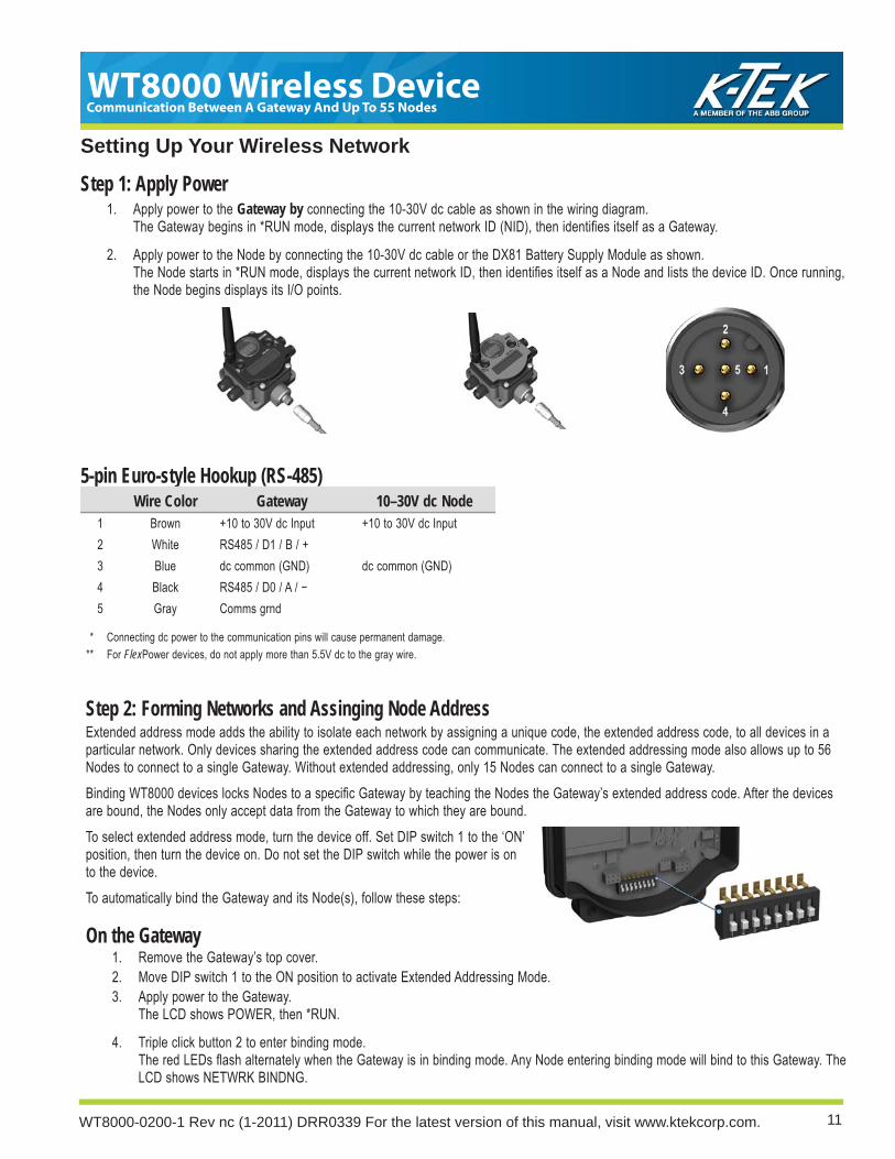
Setting Up Your Wireless Network
1. Apply power to the Gateway by connecting the 10-30V dc cable as shown in the wiring diagram.The Gateway begins in *RUN mode, displays the current network ID (NID), then identifi es itself as a Gateway.
2. Apply power to the Node by connecting the 10-30V dc cable or the DX81 Battery Supply Module as shown.The Node starts in *RUN mode, displays the current network ID, then identifi es itself as a Node and lists the device ID. Once running, the Node begins displays its I/O points.
5-pin Euro-style Hookup (RS-485)Wire Color Gateway 10–30V dc Node
1 Brown +10 to 30V dc Input +10 to 30V dc Input2 White RS485 / D1 / B / +3 Blue dc common (GND) dc common (GND)4 Black RS485 / D0 / A / −5 Gray Comms grnd
* Connecting dc power to the communication pins will cause permanent damage. ** For FlexPower devices, do not apply more than 5.5V dc to the gray wire.
Step 1: Apply Power
Step 2: Forming Networks and Assinging Node AddressExtended address mode adds the ability to isolate each network by assigning a unique code, the extended address code, to all devices in a particular network. Only devices sharing the extended address code can communicate. The extended addressing mode also allows up to 56 Nodes to connect to a single Gateway. Without extended addressing, only 15 Nodes can connect to a single Gateway.Binding WT8000 devices locks Nodes to a specifi c Gateway by teaching the Nodes the Gateway’s extended address code. After the devices are bound, the Nodes only accept data from the Gateway to which they are bound. To select extended address mode, turn the device off. Set DIP switch 1 to the ‘ON’ position, then turn the device on. Do not set the DIP switch while the power is on to the device. To automatically bind the Gateway and its Node(s), follow these steps:
On the Gateway1. Remove the Gateway’s top cover.2. Move DIP switch 1 to the ON position to activate Extended Addressing Mode.3. Apply power to the Gateway.
The LCD shows POWER, then *RUN.
4. Triple click button 2 to enter binding mode.The red LEDs fl ash alternately when the Gateway is in binding mode. Any Node entering binding mode will bind to this Gateway. The LCD shows NETWRK BINDNG.

WT8000 Wireless DeviceCommunication Between A Gateway And Up To 55 Nodes
WT8000-0200-1 Rev nc (1-2011) DRR0339 For the latest version of this manual, visit www.ktekcorp.com. 12
Setting Up Your Wireless NetworkOn the Node
1. Remove the Node’s top cover.2. Mode DIP switch 1 to the ON position to activate Extended Addressing Mode.3. Apply power to the NODE.
The LCD shows POWER, then *RUN.
4. Use both of the Node’s rotary dials to assign a decimal Node address (device ID) between 01 and 56.*The left rotary dial represents the tens digit (0-5) and the right dial represents the ones digit (0-9) of the Node address (device ID).
5. Triple click button 2 to enter binding mode.The Node enters binding mode and locates the Gateway that is also in binding mode. While the Node in binding, the LCD shows NETWRK BINDNG. When the Node is bound, the LEDs are both solid red for a few seconds. The Node cycles its power, then entering RUN mode. The LCD shows BOUND, then *RUN.
6. Repeat steps 5 through 9 for each additional Node that needs to communicate to that Gateway.
On the Gateway7. Single click either button 1 or button 2 on the Gateway to exiting binding mode and reboot the Gateway.
The Gateway exists binding mode and reboots. The LCD reads POWER, then *RUN.
* IMPORTANT: For special kits, indicated by device model numbers beginning in WT8000K, do not change the position of the right rotary dial. Set the left rotary dial to zero.
On the GatewayVerify LED 1 is on and green.
Gateway Status LED 1 LED 2Power ON Green ON —
Modbus Communication Active — Yellow Flash
Modbus Communication Error — Red Flash
System Error Red Flash Red Flash
On the NodeVerify LED 1 is fl ashing green and LED 2 is off. Until communication is established with the Gateway, the Node’s LED 2 fl ashes red. When communication is established, the Node’s LED 1 fl ashes green.A Node will not sample its inputs until it is in sync with a Gateway.
Node Status LED 1 LED 2RF Link Ok Green Flash (1 per sec) —
RF Link Error — Red Flash (1 every 3 sec)
System Error Red Flash Red Flash (1 per sec)
When testing the Gateway and Node before installation, verify the Gateway and Node are at
Next Steps: Conducting a Site Survey and Installing your devices.
Step 3: Verify Communications

13
WT8000 Wireless DeviceCommunication Between A Gateway And Up To 55 Nodes
WT8000-0200-1 Rev nc (1-2011) DRR0339 For the latest version of this manual, visit www.ktekcorp.com.
Avoid Direct Sunlight
Installation
Ideal Mounting ConditionsAvoid Direct SunlightTo minimize the damaging effects of ultra-violet radiation, avoid mounting any SureCross™ device facing intense direct sunlight.
• Mount within a protective enclosure,• Mount under an overhang or other source of shade,• Install indoors, or• Face the devices north when installing outside.
For harsh outdoor applications, consider installing your SureCross radio inside a secondary enclosure. For a list of available enclosures, refer to the Accessories chapter.
Avoid Collecting RainWhen possible, mount the devices where rain or snow will drain away from the device.
• Mount vertically so that precipitation, dust, and dirt do not accumulate on permeable surfaces.
• Avoid mounting the devices on fl at or concave surfaces, especially if the display will be pointing up.
Reduce Chemical ExposureBefore installing any SureCross™ devices in a chemically harsh environment, contact Banner for more information regarding the life-expectancy. Solvents, oxidizing agents, and other chemicals will damage the devices.
Minimize Mechanical StressWhile the SureCross devices are very durable, they are sophisticated electronic devices that are sensitive to shock and excessive loading.
• Avoid mounting the devices to an object that may be shifting or vibrating excessively. High levels of static force or acceleration may damage the housing or electronic components.
• Do not subject the devices to external loads. Do not step on them or use them as handgrips.• Do not allow long lengths of cable to hang from the WT8000 glands on the Gateway or Node. Cabling heavier than 100 grams should be
supported instead of allowed to hang from the WT8000 housing.It is the user’s responsibility to install the WT8000 devices so they will not be subject to overvoltage transients. Always ground the devices in accordance with local, state, or national regulations.

WT8000 Wireless DeviceCommunication Between A Gateway And Up To 55 Nodes
WT8000-0200-1 Rev nc (1-2011) DRR0339 For the latest version of this manual, visit www.ktekcorp.com. 14
Watertight Glands and Plugs
If the Gateway or Node is mounted outdoors or will be exposed to moisture, dirt, or dust, follow these steps to weatherproof the units.
Watertight GlandsTo make the glands watertight:
1. Wrap four to eight passes of polytetrafl uoroethylene (PTFE) tape around the threads as close as possible to the hexagonal body of the gland.
2. Manually thread the gland into the housing hole. Never apply more than 5 in-lbf of torque to the gland or its cable clamp nut.*
Note, these instructions apply both to the PG-7 glands and the 1/2” NPT gland.
Rotary Switch Access Cover Check the rotary switch access cover o-ring every time the access cover is removed. Replace the o-ring when it is damaged, discolored, or showing signs of wear. The o-ring should be:
• Seated fi rmly against the threads without stretching to fi t or without bulging loosely, and
• Pushed against the fl anged cover.When removing or closing the rotary switch access cover, manually twist the cover into position. Do not allow cross-threading between the cover and the WT8000 face. Once the cover is in place and manually tightened, use a small screwdriver (no longer than fi ve inches total length) as a lever to apply enough torque to bring the rotary switch access cover even with the WT8000 cover surface.
Watertight 1/2” NPT PlugSeal the 1/2” NPT port if it is not used. To install a watertight NPT plug:
1. Wrap 12 to 16 passes of PTFE tape evenly across the length of the threads.
2. Manually thread the plug into the housing port until reaching some resistance.
3. Using a 9/16” crescent wrench, turn the plug until all the plug’s threads are engaged by the housing port or until the resistance doubles. Do not overtighten as this will damage the SureCross unit. These threads are tapered and will create a waterproof seal without overtightening.
Watertight PG-7 PlugSeal any unused PG-7 access holes with one of the supplied black plastic plugs. To install a watertight PG-7 plug:
1. Wrap four to eight passes of PTFE tape around the plug’s threads, as close as possible to the fl anged surface.
2. Carefully thread the plastic plug into the vacant hole in the WT8000 housing and tighten using a slotting screwdriver. Never apply more than 10 in-lbf torque to the plastic plug.
* This is not a lot of torque and is equivalent to the torque generated without using tools. If a wrench is used, apply only very light pressure. Torquing these fi ttings excessively damages the device.
Weather-Proofi ng Glands and Plugs

15
WT8000 Wireless DeviceCommunication Between A Gateway And Up To 55 Nodes
WT8000-0200-1 Rev nc (1-2011) DRR0339 For the latest version of this manual, visit www.ktekcorp.com.
Clear Communication Paths
Increase the Height of the WT8000 UnitsPosition the external antenna vertically for optimal RF communication. If necessary, consider changing the height of the SureCross radio, or its antenna, to improve reception. For outdoor applications, mounting the antenna on top of a building or pole may help achieve a line-of-sight radio link with the other radios in the network.
Increase the height of the WT8000 units or antenna
A clear path increases separation range and performance
Collocation Issues When the radio network’s master device is located too close to another radio device, communications between all devices is interrupted. For this reason, do not install a SureCross Gateway device within two meters of another SureCross WT8000 Gateway or Node.
Be Aware of Seasonal ChangesWhen conducting the initial Site Survey, the fewest possible missed packets for a given link is better. However, seasonal changes may affect the signal strength and the total signal quality. Radios installed outside with 50% missed packets in the winter months may have 80% or more missed packets in the summer
Create a Clear Communication Path Wireless communication is hindered by radio interference and obstructions in the path between the transmitter and receiver. To achieve the best radio performance, carefully consider the installation locations for the Gateways and Nodes and select locations without obstructions in the path. For more information about antennas, please refer to DOCUMENT NAME.
No line of sight
Line of sight
Node
Gateway
During spring and summer, leaves may block more of the radio signal.
A good signal strength in winter doesn’t always mean you’ll get the same signal strength the rest of the year.
NodeGateway
Node
Gateway
Quick Tips
A clear on

WT8000 Wireless DeviceCommunication Between A Gateway And Up To 55 Nodes
WT8000-0200-1 Rev nc (1-2011) DRR0339 For the latest version of this manual, visit www.ktekcorp.com. 16
Advanced SetupManual BindingManually choosing the extended address code is particularly useful when replacing components of an existing wireless network. To determine the existing extended address code, access the DINFO (Device Information) menu of either the existing Gateway or another Node in the network. Follow the submenu structure to the XADR display for that device.
To Manually Bind a Gateway1. Remove the Gateway’s top cover.2. Move DIP switch 1 to the ON position to activate Extended Addressing Mode.3. Apply power to the Gateway.
The Gateway’s LCD shows POWER, then RUN.
4. On the Gateway, single click button 1 to advance across the menus, stopping at the DVCFG menu.The Gateway’s LCD shows (DVCFG).
5. Single click button 2 to select DVCFG. Single click button 1 to select from the available menu options, stopping at XADR.6. Single click button 2 to enter the XADR menu.
AUTO is automatic binding mode and uses the Gateway’s serial number as the extended address code.
7. Single click button 1 to select manual mode.8. Single click button 2 to enter manual mode.
MANUAL allows the user to manually enter an extended address code.
9. Single click button 2 to advance to the extended address code entry step.Once in manual mode, use the right rotary dial to select the digits of the extended address code. The LCD shows SET XADR 000000.
10. Use the right rotary switch to begin setting the extended address code. Digit selection begins with the left most digit. After selecting the fi rst digit, single click button 1 to advance right to the next digit. All six digits must be fi lled, even if it is with leading zeros. For example, to use 2245 as the code, enter 002245 into the device.To use the Gateway’s serial number, enter 000000 as the extended addressing code.
11. Continue entering the code using a single click of button 1 to advance from left to right.Upon reaching the sixth digit, the curser returns to the fi rst digit.
12. Single click button 2 when code entry is complete. The Gateway LCD displays the entered value for confi rmation by showing CONFRM XADR, then repeating back your value.
13. Single click button 2 to save the code and exit the XADR menu.When entering the extended address code, the digits auto fi ll with whatever position the rotary switch is currently in. For example, after entering the 00 part of the extended address code 002245, the third digit auto fi lls with a 0 until the rotary dial is rotated to 2.After manually changing the extended address code on a Gateway in an existing network, change the extended address code for all Nodes in that network by either manually setting the code on all Node(s) or by beginning the automatic binding sequence on the Gateway and auto-binding all the Node(s).

17
WT8000 Wireless DeviceCommunication Between A Gateway And Up To 55 Nodes
WT8000-0200-1 Rev nc (1-2011) DRR0339 For the latest version of this manual, visit www.ktekcorp.com.
To Manually Bind a Node1. Remove the Node’s top cover.2. Move DIP switch 1 to the ON position to activate extended address mode.3. Apply power to the Node.*
The LCD displays POWER, then RUN.
4. On the Node, single click button 1 to advance across the menus, stopping at the DVCFG menu.5. Single click button 2 to select DVCFG. Single click button one to select from the available menu options, stopping at XADR.6. Single click button 2 to enter the XADR menu.
AUTO is automatic binding mode and uses the Gateway’s serial number as the extended address code.
7. Single click button 1, stopping at manual mode.MANUAL allows the user to manually enter an extended address code.
8. Single click button 2 to enter manual mode.9. Single click button 2 to enter the extended address code entry step.
The LCD shows SET XADR 000000.
10. Use the right rotary switch to begin setting the extended address code. Digit selection begins with the left most digit. After selecting the fi rst digit, single click button 1 to advance right to the next digit. All six digits must be fi lled, even if it is with leading zeros. For example, to use 2245 as the code, enter 002245 into the device.
11. Continue entering the code using a single click of button 1 to advance from left to right.Upon reaching the sixth digit, the curser returns to the fi rst digit.
12. Single click button 2 when code entry is complete. The Node LCD displays the entered value for confi rmation.The LCD shows CONFRM XADR XXXXXX.
13. If the rotary dial hasn’t been returned to the previous Node address (device address or ID), the LCD displays the prior setting as a reminder. Return the rotary dial to its previous Node address.
14. The new Node address setting displays (NEW NADR XX).15. The Node confi rms the new Node address by displaying CONFRM NADR XX.16. Double click button 2 to exit the XADR menu and to return to RUN mode.
When entering the extended address code, the digits auto fi ll with whatever position the rotary switch is currently in. For example, after entering the 00 part of the extended address code 002245, the third digit auto fi lls with a 0 until the rotary dial is rotated to 2.* For devices with batteries integrated into the housing, remove the battery for one minute to cycle power to the device.

WT8000 Wireless DeviceCommunication Between A Gateway And Up To 55 Nodes
WT8000-0200-1 Rev nc (1-2011) DRR0339 For the latest version of this manual, visit www.ktekcorp.com. 18
Automatic Binding (Menu Navigation)The easiest way to bind the Gateway to its Nodes is by triple clicking button 2 to enter automatic binding mode. For these instructions, refer to the installation and setup instructions in the Installation chapter.If you would prefer to begin automatic binding mode using the menu structure instead of the buttons, follow these steps:
On the Gateway1. Remove the Gateway’s top cover.2. Move DIP switch 1 to the ON position to activate extended addressing mode.3. Apply power to the Gateway.
The LCD should show POWER, then *RUN.
4. On the Gateway, single click button 1 to advance across the menus, stopping at the DVCFG menu.5. Single click button 2 to select DVCFG. Single click button 1 to select from the available menu options, stopping at XADR. 6. Single click button 2 to enter XADR mode. When the display reads (AUTO), single click button 2 again to begin the automatic binding
mode.The LCD shows NETWRK BINDNG and the LEDs fl ash alternately when the Gateway is in binding mode. Any Node entering binding mode will bind to this Gateway.
On the Node7. Remove the Node’s top cover.8. Move DIP switch 1 to the ON position to activate extended addressing mode.9. Apply power to the Node.*
The LCD should show POWER, then *RUN.
10. On the Node, single click button 1 to advance across the menus, stopping at the DVCFG menu.11. Single click button 2 to enter the DVCFG menu.12. Single click button 1 to select from the available submenu options, stopping at XADR.13. Single click button 2 to enter the XADR submenu.14. When the display reads (AUTO), single click button 2 to begin the automatic binding mode.
The LCD shows NETWRK BINDNG to indicate the Node has entered binding mode.When the Node is bound, the LEDs are both solid red for a few seconds and the LCD shows BOUND. The Node cycles its power, then enters RUN mode.
15. Use both of the Node’s rotary dials to assign a decimal Device Address between 01 and 56.The left rotary dial represents the tens digit (0–5) and the right dial represents the ones digit (0–9) of the Device Address.
16. Repeat steps 7 through 16 for each additional Node that needs to communicate to that Gateway.
On the Gateway17. Single click button 1 or button 2.
When button 1 or 2 is pressed, the Gateway exits binding mode and reboots. When the LCD shows POWER, then *RUN, the Gateway has entered RUN mode.
* For devices with batteries integrated into the housing, remove the battery for one minute to cycle power to the device. After making any changes to DIP switch settings, you must cycle power to the device or the DIP switch changes will not be recognized.

19
WT8000 Wireless DeviceCommunication Between A Gateway And Up To 55 Nodes
WT8000-0200-1 Rev nc (1-2011) DRR0339 For the latest version of this manual, visit www.ktekcorp.com.
Collacated Networks - Setting the Network IDRemember, the extended addressing code is independent from the system network ID (NID). Consequently, multiple networks can share a NID and will not exchange data; the networks are completely isolated from one another. Users of the WT8000 product do not need to be aware of other nearby networks to ensure their network does not unintentionally exchange data with other networks. Assigning different NIDs to different networks improves collocation performance in dense installations; this is true whether the network is in standard addressing mode or extended addressing mode.To set the network ID follow these steps on the Gateway device:
1. From the top level menus, single click button 1 to advance through the menus, stopping at DVCFG (Device Confi guration).2. Single click button 2 to enter the DVCFG menu options and stop at (NID).3. Single click button 2 to enter the (NID) menu option.4. Using both rotary dials on the front of the Gateway, select a Network ID number. The left rotary dial acts as the left digit and the right
rotary dial acts as the right digit of the Network ID. In extended addressing mode, the Network ID can only be set from the rotary dials while in the (NID) menu.Any Nodes bound to this Gateway ‘follow’ the Gateway to the new Network ID automatically. The current Network ID and the new Network ID display on the LCD panel.
5. Single click button 2 to save the new values.6. Double click button 2 to exit this submenu.7. Double click button 2 to exit to the main menu system and return to RUN mode.
Setting the Maximum Node CountUse the MAXN submenu, located under the *DVCFG (Device Confi guration) menu to set the maximum number of Nodes for this system. For example, if you are running four Nodes in this network, set the system’s maximum Node count to 8. This allows up to 8 Nodes in the wireless network. Selecting 8 also results in the highest throughput, 62.5 milliseconds, for each Node. The choices are 8, 16, 32, and 56 Nodes.

WT8000 Wireless DeviceCommunication Between A Gateway And Up To 55 Nodes
WT8000-0200-1 Rev nc (1-2011) DRR0339 For the latest version of this manual, visit www.ktekcorp.com. 20
System LayoutsGatewaysA SureCross Gateway is the wireless network master device used to control network timing for the entire network. The Gateway also holds the confi guration for the network. Every wireless network must have one Gateway that schedules communication traffi c and controls the I/O confi guration for the network. Similar to how a gateway device on a wired network acts as a “portal” between networks, the SureCross Gateway acts as the portal between the wireless network and the central control process.
NodesGenerally, a node is any point within a network. A SureCross Node is a wireless network slave device used to provide sensing capability in a remote area or factory. The Node collects sensor data from sensors and communicates the data back to the SureCross Gateway.SureCross Nodes are available in a wide variety of power or input/output options. Each wireless network includes one Gateway and up to 56 Nodes.
21
WT8000 Wireless DeviceCommunication Between A Gateway And Up To 55 Nodes
WT8000-0200-1 Rev nc (1-2011) DRR0339 For the latest version of this manual, visit www.ktekcorp.com.
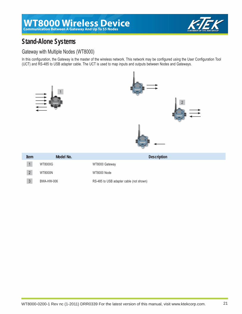
Stand-Alone SystemsGateway with Multiple Nodes (WT8000)In this confi guration, the Gateway is the master of the wireless network. This network may be confi gured using the User Confi guration Tool (UCT) and RS-485 to USB adapter cable. The UCT is used to map inputs and outputs between Nodes and Gateways.
Item Model No. Description1 WT8000G WT8000 Gateway
2 WT8000N WT8000 Node
3 BWA-HW-006 RS-485 to USB adapter cable (not shown)
1
2

WT8000 Wireless DeviceCommunication Between A Gateway And Up To 55 Nodes
WT8000-0200-1 Rev nc (1-2011) DRR0339 For the latest version of this manual, visit www.ktekcorp.com. 22
Modbus RTUHost System(e.g. Modbus Master)
MODBUS RTUModbus RTU Host Controlled OperationA simple host-connected system uses an RS485 serial cable to connect the WT8000 Gateway device to a host system. The host system may be a PC or a PLC unit. Because the serial cable is used to connect to a host system, the communications protocol used is Modbus RTU. The wireless network is a Modbus slave.
Item Model No. Description1 WT8000G Gateway
2 CSRB-M1250M125.47M125.73 Cable, RS-485, quick disconnect, 5-pin Euro, male trunk, female branches, black*
MQDC1-5*** Cable, quick disconnect, 5-pin Euro, female, straight, lengths vary
1
2
Purpose: The wireless network collects I/O data and sends it back to a Modbus host system.
Modbus Slave

23
WT8000 Wireless DeviceCommunication Between A Gateway And Up To 55 Nodes
WT8000-0200-1 Rev nc (1-2011) DRR0339 For the latest version of this manual, visit www.ktekcorp.com.
Modbus/TCP and RTU Register Map Modbus/TCP and Modbus RTU provide device control and monitoring using holding registers in the 40000 register block. Each wireless device in the system is allocated 16 holding registers. The Gateway uses the fi rst 16 registers followed by each Node in the network, based on the Node address. For Node 5, the starting Modbus registers are 1 + (Node# × 16) = 1 + (5 × 16) = 81, the ending register is 97.
Registers Device and Input Connections1 Gateway I/O 12 Gateway I/O 23 Gateway I/O 34 Gateway I/O 45 Gateway I/O 56 Gateway I/O 67 Gateway I/O 78 Gateway I/O 89 Gateway I/O 9
10 Gateway I/O 1011 Gateway I/O 1112 Gateway I/O 1213 Gateway I/O 1314 Gateway I/O 1415 Gateway I/O 1516 Gateway I/O 1617 Node #1 I/O 118 Node #1 I/O 219 Node #1 I/O 320 Node #1 I/O 421 Node #1 I/O 522 Node #1 I/O 623 Node #1 I/O 724 Node #1 I/O 825 Node #1 I/O 926 Node #1 I/O 1027 Node #1 I/O 11• •• •• •
905 Node #56 I/O 9906 Node #56 I/O 10907 Node #56 I/O 11908 Node #56 I/O 12909 Node #56 I/O 13910 Node #56 I/O 14911 Node #56 I/O 15912 Node #56 I/O 16
I/O Point Gateway Modbus Holding Register
Node Modbus Register
1 1 1 + (Node# × 16)2 2 2 + (Node# × 16)3 3 3 + (Node# × 16)4 4 4 + (Node# × 16)5 5 5 + (Node# × 16)6 6 6 + (Node# × 16)7 7 7 + (Node# × 16)8 8 8 + (Node# × 16)9 9 9 + (Node# × 16)
10 10 10 + (Node# × 16)11 11 11 + (Node# × 16)12 12 12 + (Node# × 16)13 13 13 + (Node# × 16)14 14 14 + (Node# × 16)15 15 15 + (Node# × 16)16 16 16 + (Node# × 16)

WT8000 Wireless DeviceCommunication Between A Gateway And Up To 55 Nodes
WT8000-0200-1 Rev nc (1-2011) DRR0339 For the latest version of this manual, visit www.ktekcorp.com. 24
Sensor ConnectionsDigital Sensors, Sourcing (PNP) InputsNeither the inputs nor the outputs on the WT8000 devices are isolated. Under certain operating conditions, externally powered sensors may need to have ground in common with the WT8000 device to which they are connected. The power sources do not have to be the same.
DIx
PWR or SPx
DIx +10 to 30V dc
Wiring diagram for a sourcing (PNP), two-wire sensor powered using the WT8000 device terminal block.
Wiring diagram for a sourcing (PNP) two-wire sensor powered externally. Under certain conditions, the dc commons between the sensor and the WT8000 might need to be connected.
sensor
outputDIx
PWR
GND
Wiring diagram for a sourcing (PNP), three-wire sensor powered using the WT8000 device terminal block.
dc common
DIx +10 to 30V dc
Wiring diagram for a sourcing (PNP) three-wire sensor powered externally. Under certain conditions, the dc commons between the sensor and the WT8000 might need to be connected.
Powered by WT8000
Powered Externally
Two-Wire Three-Wire

25
WT8000 Wireless DeviceCommunication Between A Gateway And Up To 55 Nodes
WT8000-0200-1 Rev nc (1-2011) DRR0339 For the latest version of this manual, visit www.ktekcorp.com.
DIx
GND
Digital Sensors, Sinking (NPN) InputsNeither the inputs nor the outputs on the WT8000 devices are isolated. Under certain operating conditions, externally powered sensors may need to have ground in common with the WT8000 device to which they are connected. The power sources do not have to be the same.
dc commonDIx
Wiring diagram for a sinking (NPN) two-wire sensor powered using the WT8000 device terminal block.
Wiring diagram for a sinking (NPN) two-wire sensor grounded outside the WT8000 device. Under certain conditions, the dc commons between the sensor and the WT8000 might need to be connected.
Powered by WT8000
Powered Externally
Two-Wire Three-WireDIx
GND
PWR
Wiring diagram for a sinking (NPN) three-wire sensor powered using the WT8000 device terminal block.
dc commonDIx
+10 to 30V dc
Wiring diagram for a sinking (NPN) three-wire sensor grounded outside the WT8000 device. Under certain conditions, the dc commons between the sensor and the WT8000 might need to be connected.

WT8000 Wireless DeviceCommunication Between A Gateway And Up To 55 Nodes
WT8000-0200-1 Rev nc (1-2011) DRR0339 For the latest version of this manual, visit www.ktekcorp.com. 26
DOx
GND
Wiring diagram for a sourcing (PNP) two-wire output load powered using the WT8000 device terminal block.
Digital Sensors, Sourcing (PNP) OutputsNeither the inputs nor the outputs on the WT8000 devices are isolated. Under certain operating conditions, externally powered sensors may need to have ground in common with the WT8000 device to which they are connected. The power sources do not have to be the same.
Powered by WT8000
Powered Externally
Two-Wire Three-Wire
DOx
GND
PWR
Wiring diagram for a sourcing (PNP) three-wire output load powered using the WT8000 device terminal block.
dc commonDOx
+10 to 30V dc
Wiring diagram for a sourcing (PNP) three-wire output load powered from outside the WT8000 device. Under certain conditions, the dc commons between the sensor and the WT8000 might need to be connected.
DIx +10 to 30V dc
Wiring diagram for a sourcing (PNP) two-wire output load powered from outside the WT8000 device. Under certain conditions, the dc commons between the sensor and the WT8000 might need to be connected.

27
WT8000 Wireless DeviceCommunication Between A Gateway And Up To 55 Nodes
WT8000-0200-1 Rev nc (1-2011) DRR0339 For the latest version of this manual, visit www.ktekcorp.com.
DOx
PWR or SPx
Wiring diagram for a sinking (NPN) two-wire output.
Powered by WT8000
Powered Externally
Two-Wire Three-Wire
Digital Sensors, Sinking (NPN) OutputsNeither the inputs nor the outputs on the WT8000 devices are isolated. Under certain operating conditions, externally powered sensors may need to have ground in common with the WT8000 device to which they are connected. The power sources do not have to be the same.
DOx
PWR
GND
Wiring diagram for a sinking (NPN) three-wire output.
DOx +10 to 30V dc
Wiring diagram for a sinking (NPN) two-wire output. Under certain conditions, the dc commons between the sensor and the WT8000 might need to be connected.
dc common
DOx+10 to 30V dc
Wiring diagram for a sinking (NPN) three-wire output. Under certain conditions, the dc commons between the sensor and the WT8000 might need to be connected.

WT8000 Wireless DeviceCommunication Between A Gateway And Up To 55 Nodes
WT8000-0200-1 Rev nc (1-2011) DRR0339 For the latest version of this manual, visit www.ktekcorp.com. 28
PWR or SPx
AIx
Analog InputsFor analog sensors, the ground/dc common of the sensor should be connected to the ground of the WT8000 device. For best results, Banner recommends that the power source for the sensor and WT8000 device is the same.
AIx or Ax+
SPx
dc common
+10 to 30V dcAIx or Ax+
GND
Three-wire analog sensor using a FlexPower Node but the sensor is powered externally (not from the WT8000 device).
Two-wire analog sensor using a FlexPower™ Node and powered using the Node’s switch power.
Two-wire analog sensor powered from a 10 to 30V dc power WT8000 device using the PWR terminal.
Powered by WT8000
Switch Powered
Two-Wire Three-Wire
PWR
AIx
GND
Powered Externally
A1+
SP1
GND
Three-wire analog sensor powered from 10 to 30V dc power WT8000 device using the PWR terminal.
Three-wire analog sensor using a FlexPower™ Node and powered using the Node’s switch power.

29
WT8000 Wireless DeviceCommunication Between A Gateway And Up To 55 Nodes
WT8000-0200-1 Rev nc (1-2011) DRR0339 For the latest version of this manual, visit www.ktekcorp.com.
AOx
GND
+10 to 30V dc
Analog OutputsFor analog sensors, the ground/dc common of the sensor should be connected to the ground of the WT8000 device. For best results, Banner recommends that the power source for the sensor and WT8000 device is the same.
Three-wire analog output device powered externally (not from the WT8000 device).
AOx
GND
PWR
Three-wire analog output device powered off the WT8000 device.
Drive/MotorController
AOx
GND
AI+
AI−
When the AI- can be referenced to ground, use this wiring diagram for drive/motor controllers.
Drive/motorcontrollers
AOx
GND
AI+
AI−
When the AI- cannot be referenced to ground, use this wiring diagram for drive/motor controllers.

WT8000 Wireless DeviceCommunication Between A Gateway And Up To 55 Nodes
WT8000-0200-1 Rev nc (1-2011) DRR0339 For the latest version of this manual, visit www.ktekcorp.com. 30
The WT8000 Module complies with Part 15 of the FCC rules and regulations.FCC ID: TGUWT8000 This device complies with Part 15 of the FCC Rules. Operation is subject to the following two conditions: (1) this device may not cause harmful interference, and (2) this device must accept any interference received, including interference that may cause undesired operation.
FCC NoticesIMPORTANT: The WT8000 Modules have been certifi ed by the FCC for use with other products without any further certifi cation (as per FCC section 2.1091). Changes or modifi cations not expressly approved by the manufacturer could void the user’s authority to operate the equipment.IMPORTANT: The WT8000 Modules have been certifi ed for fi xed base station and mobile applications. If modules will be used for portable applications, the device must undergo SAR testing.IMPORTANT: If integrated into another product, the FCC ID label must be visible through a window on the fi nal device or it must be visible when an access panel, door, or cover is easily removed. If not, a second label must be placed on the outside of the fi nal device that contains the following text: Contains FCC ID: TGUWT8000.
NoteThis equipment has been tested and found to comply with the limits for a Class B digital device, pursuant to Part 15 of the FCC Rules. These limits are designed to provide reasonable protection against harmful interference in a residential installation. This equipment generates, uses, and can radiate radio frequency energy and, if not installed and used in accordance with the instructions, may cause harmful interference to radio communications. However, there is no guarantee that interference will not occur in a particular installation. If this equipment does cause harmful interference to radio or television reception, which can be determined by turning the equipment off and on, the user is encouraged to try to correct the interference by one or more of the following measures:
• Reorient or relocate the receiving antenna,• Increase the separation between the equipment and receiving
module,• Connect the equipment into an outlet on a circuit different from
that to which the receiving module is connected, and/or• Consult the dealer or an experienced radio/TV technician for
help.
Antenna Warning WARNING: This device has been tested with Reverse Polarity SMA connectors with the antennas listed in Table 1 Appendix A. When integrated into OEM products, fi xed antennas require installation preventing end-users from replacing them with non-approved antennas. Antennas not listed in the tables must be tested to comply with FCC Section 15.203 (unique antenna connectors) and Section 15.247 (emissions).
FCC-Approved AntennasWARNING: This equipment is approved only for mobile and base station transmitting devices. Antenna(s) used for this transmitter must be installed to provide a separation distance of at least 20 cm from all persons and must not be collocated or operating in conjunction with any other antenna or transmitter.WT8000 Module may be used only with Approved Antennas that have been tested with this module.
Part Number Antenna Type Maximum Gain
— Integral antenna Unity gainBWA-9O1-x Omni, 1/4 wave dipole ≤2 dBiBWA-9O2-C Omni, 1/2 wave dipole, Swivel ≤2 dBiBWA-9O6-A Omni Wideband, Fiberglass Radome ≤8.2 dBiBWA-9O5-B Omni Base Whip ≤7.2 dBiBWA-9Y10-A Yagi ≤10 dBi
Table 1. Type certifi ed Antenna
Agency Certifi cationsFCC Certifi cation 900 MHz

31
WT8000 Wireless DeviceCommunication Between A Gateway And Up To 55 Nodes
WT8000-0200-1 Rev nc (1-2011) DRR0339 For the latest version of this manual, visit www.ktekcorp.com.
The WT8000 Module complies with Part 15 of the FCC rules and regulations.FCC ID: UE300WT8000-2400 This device complies with Part 15 of the FCC Rules. Operation is subject to the following two conditions: (1) this device may not cause harmful interference, and (2) this device must accept any interference received, including interference that may cause undesired operation.
FCC NoticesIMPORTANT: The WT8000 Modules have been certifi ed by the FCC for use with other products without any further certifi cation (as per FCC section 2.1091). Changes or modifi cations not expressly approved by the manufacturer could void the user’s authority to operate the equipment.IMPORTANT: The WT8000 Modules have been certifi ed for fi xed base station and mobile applications. If modules will be used for portable applications, the device must undergo SAR testing.IMPORTANT: If integrated into another product, the FCC ID label must be visible through a window on the fi nal device or it must be visible when an access panel, door, or cover is easily removed. If not, a second label must be placed on the outside of the fi nal device that contains the following text: Contains FCC ID: UE300WT8000-2400.
NoteThis equipment has been tested and found to comply with the limits for a Class B digital device, pursuant to Part 15 of the FCC Rules. These limits are designed to provide reasonable protection against harmful interference in a residential installation. This equipment generates, uses, and can radiate radio frequency energy and, if not installed and used in accordance with the instructions, may cause harmful interference to radio communications. However, there is no guarantee that interference will not occur in a particular installation. If this equipment does cause harmful interference to radio or television reception, which can be determined by turning the equipment off and on, the user is encouraged to try to correct the interference by one or more of the following measures:
• Reorient or relocate the receiving antenna,• Increase the separation between the equipment and receiving
module,• Connect the equipment into an outlet on a circuit different from
that to which the receiving module is connected, and/or• Consult the dealer or an experienced radio/TV technician for
help.
Antenna Warning WARNING: This device has been tested with Reverse Polarity SMA connectors with the antennas listed in Table 1 Appendix A. When integrated into OEM products, fi xed antennas require installation preventing end-users from replacing them with non-approved antennas. Antennas not listed in the tables must be tested to comply with FCC Section 15.203 (unique antenna connectors) and Section 15.247 (emissions).
FCC-Approved AntennasWARNING: This equipment is approved only for mobile and base station transmitting devices. Antenna(s) used for this transmitter must be installed to provide a separation distance of at least 20 cm from all persons and must not be collocated or operating in conjunction with any other antenna or transmitter.WT8000 Module may be used only with Approved Antennas that have been tested with this module.
Part Number Antenna Type Maximum Gain
— Integral antenna Unity gainBWA-2O2-C Omni, 1/2 wave dipole, Swivel ≤2 dBiBWA-2O5-C Omni, Collinear, Swivel ≤5 dBiBWA-2O7-C Omni, Coaxial Sleeve, Swivel ≤7 dBi
Table 1. Type certifi ed Antenna
FCC Certifi cation, 2.4 GHz

WT8000 Wireless DeviceCommunication Between A Gateway And Up To 55 Nodes
WT8000-0200-1 Rev nc (1-2011) DRR0339 For the latest version of this manual, visit www.ktekcorp.com. 32
Certifi ed Counties List
Country FrequencyModelsWT8000
Australia 2.4 GHz xAustria 2.4 GHz xBahamas, The 900 MHz xBahamas, The 2.4 GHz xBahrain (Kingdom of) 2.4 GHz xBelgium 2.4 GHz xBrazil 2.4 GHz xBulgaria 2.4 GHz xCanada 900 MHz xCanada 2.4 GHz xChina (People’s Republic of) 2.4 GHz xColombia 900 MHz xColombia 2.4 GHz xCyprus 2.4 GHz xCzech Republic 2.4 GHz xDenmark 2.4 GHz xEstonia 2.4 GHz xFinland 2.4 GHz xFrance 2.4 GHz xGermany 2.4 GHz xGreece 2.4 GHz xHungary 2.4 GHz xIceland 2.4 GHz xIndia 2.4 GHz xIreland 2.4 GHz xIsrael 2.4 GHz x*Italy 2.4 GHz xLatvia 2.4 GHz xLiechtenstein 2.4 GHz xLithuania 2.4 GHz xLuxembourg 2.4 GHz xMalta 2.4 GHz xMexico 900 MHz xMexico 2.4 GHzNetherlands 2.4 GHz xNew Zealand 2.4 GHz xNorway 2.4 GHz xPanama 900 MHz xPanama 2.4 GHz xPoland 2.4 GHz x
33
WT8000 Wireless DeviceCommunication Between A Gateway And Up To 55 Nodes
WT8000-0200-1 Rev nc (1-2011) DRR0339 For the latest version of this manual, visit www.ktekcorp.com.
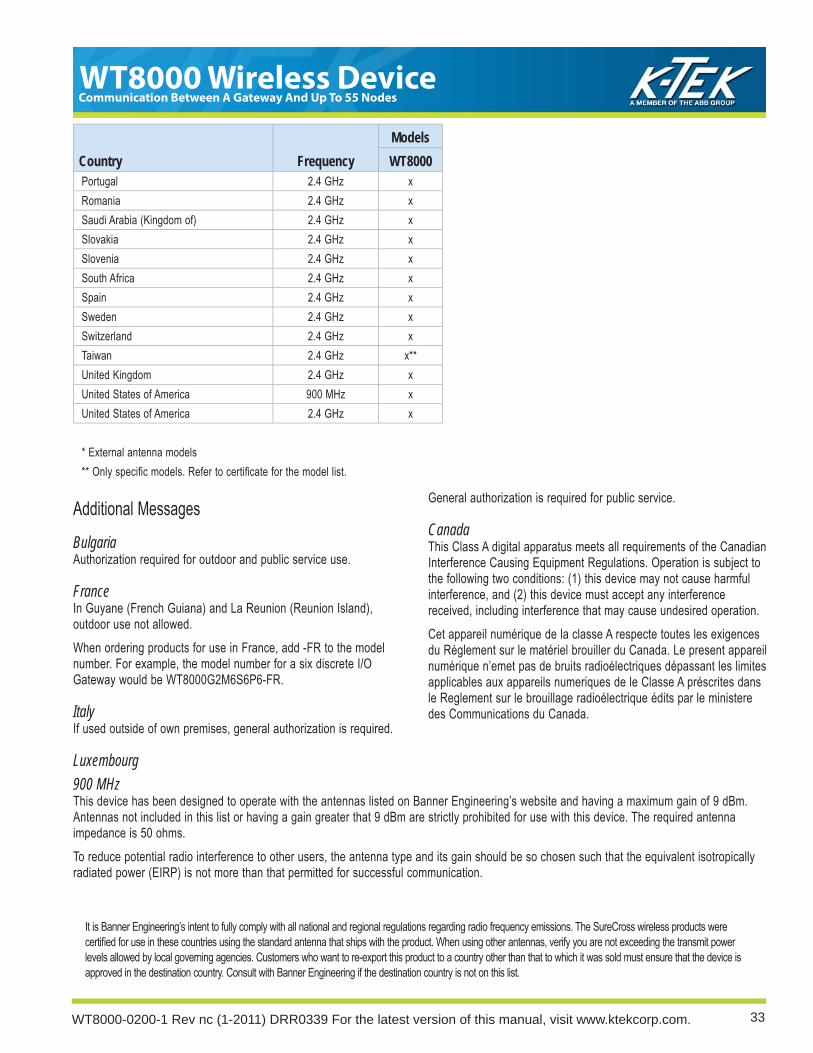
Additional MessagesBulgariaAuthorization required for outdoor and public service use.
FranceIn Guyane (French Guiana) and La Reunion (Reunion Island), outdoor use not allowed.When ordering products for use in France, add -FR to the model number. For example, the model number for a six discrete I/O Gateway would be WT8000G2M6S6P6-FR.
ItalyIf used outside of own premises, general authorization is required.
Luxembourg
General authorization is required for public service.
CanadaThis Class A digital apparatus meets all requirements of the Canadian Interference Causing Equipment Regulations. Operation is subject to the following two conditions: (1) this device may not cause harmful interference, and (2) this device must accept any interference received, including interference that may cause undesired operation.Cet appareil numérique de la classe A respecte toutes les exigences du Règlement sur le matériel brouiller du Canada. Le present appareil numérique n’emet pas de bruits radioélectriques dépassant les limites applicables aux appareils numeriques de le Classe A préscrites dans le Reglement sur le brouillage radioélectrique édits par le ministere des Communications du Canada.
900 MHzThis device has been designed to operate with the antennas listed on Banner Engineering’s website and having a maximum gain of 9 dBm. Antennas not included in this list or having a gain greater that 9 dBm are strictly prohibited for use with this device. The required antenna impedance is 50 ohms.To reduce potential radio interference to other users, the antenna type and its gain should be so chosen such that the equivalent isotropically radiated power (EIRP) is not more than that permitted for successful communication.
It is Banner Engineering’s intent to fully comply with all national and regional regulations regarding radio frequency emissions. The SureCross wireless products were certifi ed for use in these countries using the standard antenna that ships with the product. When using other antennas, verify you are not exceeding the transmit power levels allowed by local governing agencies. Customers who want to re-export this product to a country other than that to which it was sold must ensure that the device is approved in the destination country. Consult with Banner Engineering if the destination country is not on this list.
Country FrequencyModelsWT8000
Portugal 2.4 GHz xRomania 2.4 GHz xSaudi Arabia (Kingdom of) 2.4 GHz xSlovakia 2.4 GHz xSlovenia 2.4 GHz xSouth Africa 2.4 GHz xSpain 2.4 GHz xSweden 2.4 GHz xSwitzerland 2.4 GHz xTaiwan 2.4 GHz x**United Kingdom 2.4 GHz xUnited States of America 900 MHz xUnited States of America 2.4 GHz x
* External antenna models** Only specifi c models. Refer to certifi cate for the model list.

WT8000 Wireless DeviceCommunication Between A Gateway And Up To 55 Nodes
WT8000-0200-1 Rev nc (1-2011) DRR0339 For the latest version of this manual, visit www.ktekcorp.com. 34
This page was intentionally left blank.

35
WT8000 Wireless DeviceCommunication Between A Gateway And Up To 55 Nodes
WT8000-0200-1 Rev nc (1-2011) DRR0339 For the latest version of this manual, visit www.ktekcorp.com.
This page was intentionally left blank.

WT8000 Wireless DeviceCommunication Between A Gateway And Up To 55 Nodes
WT8000-0200-1 Rev nc (1-2011) DRR0339 For the latest version of this manual, visit www.ktekcorp.com. 36
CoCommmmununiccatatioion n Between A Gateway And Up To 55 Nododeses
WTWT80800000-0-020200-0-11 ReRev v ncnc ((1-1-20201111) ) DRDRR0R033339 9 FoFor r ththee lalatetestst vverersisionon oof f ththisis mmananuaual,l, vvisisitit wwwwww.k.ktetekckcororp.p.cocom.m. 3636
For the latest version of this manual, visit ktekcorp.com.
K-TEK Solids Level 6100 West by Northwest #140
Houston, TX 77040 USATel: (1) 713.462.7665
Fax: (1) 713.462.7684Email: [email protected]
Website: kteksolidslevel.com
K-TEK 18321 Swamp Road Prairieville, LA 70769 USATel: (1) 225.673.6100 Fax: (1) 225.673.2525Email: [email protected] Website: ktekcorp.com