wtpa component guide - narrat1ve.comnarrat1ve.com/wtpa_v100_bare_pcb_assembly_helper_rev2.pdf ·...
TRANSCRIPT

WTPA Component GuideHardwareRev 1.01Rev. 1.0Forward Intothe Past!Sealion,February 14,2010
TMB
WTPA Version 1.0
Our story so far… Once upon a time in a galaxy far far away from New York,Chicago actually, our hero Todd recalls at time of great struggle to save the 8-bit planet from the evil Imperial troopers of the Lord Audophile DAC.
He recounts in his own words:

This is the secret Suge Knight revision PCB, offering a certified 100% Biggie FreeEnvironment. But srsly y'all. Those of you who follow my "blog" know that I messed up andthe first revision of the PCB I ordered for WTPA had a bug in the overdub summing amplifier.The bad news is I lost a lot of scratch, because I wanted everything to be perfect and revved andre-ordered all the boards. The good news is, a few days later I started doing the overdubbing inthe digital domain and stopped using the overdub summing amp audio path altogetherANYWAY. Which rendered these boards un-broken again. They are a little less pretty, thereare a couple more components, and the signal routing is just a hair noisier, but they will doEXACTLY THE SAME THING as a v1.01 WTPA if you make one. I'm not selling the barev1.01 WTPA boards because it will screw up my math and parts counts, so if you are lookingfor a real deal, get this PCB, source the parts yourself, and get crackin. The parts list is 99%similar to the r1.01 boards which are in a doc on the main page. Sometime soon when I get myact together more I'll make a pdf that details the differences but it hasn't happened yet.
Alas, this did not happen, so faithful servant sealion searched the dark caves of thePlanet 4’Uhm-WPTA and found these miraculous fragments:
Kaz “decided I'll build the version 1.0 kit. Order the same items listed for the 1.1 andadd the following additional parts.3x 10K Resistor1x 1M Resistor3x 0.1 uf 50V ceramic or film (2.5mm lead spacing)I recommend using MKP film caps for anything that audio passes through over ceramic,so order extra and use them in those places.Couple key issues I noticed was the 240R resistor is not clearly marked that feeds theFine/Course pots so look for the component number R52.Also start with not stuffing R50 and R51, it looks like they were there to reduce the potsdown to a more adjustable range, which is not probably necessary because of the changevalues in the kit. kazper
To which Todd replied:
Hey Kaz-- Right on for the most part. R36, R37, R17, and R19 are all overdubbingrelated and unnecessary. The extra ceramic caps got replaced with bigger valueelectrolytics in the newer board to quiet down the midrail references.R13 (1M) is not necessary and can be replaced with a jumper.R18 (on the output) can be 10k, but was moved up to 59k in the later revision.R52 limits the highest frequency on the relaxation oscillator and is 220 ohms in bothrevisions. And yes, R50 and R51 are there to make the pots more adjustable, however, abetter way to do this is to change the pot values to 10k (audio taper) for the coarse and1k (audio taper) for the fine. And yes, leave R50 and R51 unpopulated.Hope this helps! TB”
And it did.

Elsewhere was found this:
bsom: I noticed that the areas marked 10uf on the board for electrolytics have, in fact,been supplied as 22uf caps in my kit. I'm sure this substitution is on purpose, but I justwanted to be sure.... glitched: Same here. The pictures show the 22uf part, but thesilkscreen says 10uf. I just put the 22uf in there. ToddBailey: Hey Gents. Sorry, Ishould've been more clear. Those three caps are either filters or DC blocking capsdepending on their location. When I was sourcing parts I found some 22uF caps thatwere as cheap as the 10uF I originally specified, so I used them instead -- they give aslightly better bass response in the DC blocking application (the output cap) and just ahair more filtering on the voltage references. Using them slows startup by a fraction of asecond as well (the analog references settle more slowly). In general it doesn't mattertoo much, but I got a got a little more "bang for the buck" with the 22uF. Sorry if thiswas unclear! Best, TB
And it was better.
So, with these mystical clues in mind what follows will help you go back in time, beforethere was a WTPA? 1.01, which there isn’t now anyway. We now return you to themanual from the future for use in the past, today. Sealion. [delirious, well okay, justquarantined, with mild flu 11/26/2009].
In summary:
R52 is 220 ohms but not well labelled. R18 try 10k, R13 change it to a jumper. (see C18 below). Forget about R17, R19, R36, R37, R50, R51. Leave empty. No need to cut traces. Coarse pot: 10K audio taper, Fine pot: 1k audio taper. Capacitor option some people try which may improve the original specs a bit is C14
(10uf), C17 (47uf), C15 (10uf). Comment from Todd: Just note that C17 couplesthe audio output. It should be big -- at least 10uF as in the schematic, any amountbigger is OK (like 22uF, not 0.22uF).
C14, C15, and C18 quiet the midrail references. Those are marked as 0.1uF but canbe increased in size too, maybe to as much as 10uF providing you keep the polarityfrom getting mixed up. ** Note, there is no cap in the same position as C18 on thenewer boards. And when R13 is changed to a jumper then C18 doesn't really haveto be there at all, although it can only help.
Power supply regulator cap was 1000uf, but you can go down to 470uf. If you want to reduce the noise floor (Why? Noise is our friend!) you can cut the
trace to the right of pin 7 on the quad-op amp and run a shielded connection directlyto pin 34 of the AVR. Only connect one end of the shield to ground to avoid aground loop.


This is basically a big set of descriptions and pictures of WHAT and HOW MANYof those bits that go into a single WTPA kit.
This doc isn't really about theory or about how to use WTPA, it's just what goesinto it and a very little about the components involved. So without furtheradieu here's what goes in WTPA, divided up by type of component.The component type and value explain what the thing is, and the referencedesignator is the part's name in the schematic and on the printed circuit board.Quantity per board ought to be pretty self explanatory.
Note: if you're a printing-stuff type of person it might help to have this list in handwhile you're building the kit. Sometimes I like that.
Note: THE MOST IMPORTANT THING YOU SHOULD TAKE AWAY FROMTHIS DOC if you aren't already familiar with electronics: some componentsare POLAR. Namely, the diodes and some of the electrolytic capacitors.POLAR components need to maintain a certain orientation with respect tovoltages. What this means for the kit builder is that although the polarcomponents CAN fit into the board one of two ways, one way is backwards, andbad things will happen either immediately or down the road if you put them inthe wrong way.
The board has markings on the caps and diodes to help you remember this.
(Note: you can always find the most recent WTPA notes onwww.narrat1ve.com if this doc gets outdated, or just if you're curious).

What Is It? Value Qty Per Ref Designator:
5v Reg 7805 1 IC6
MCU ATMEGA164-20P 1 IC1
MIDI Opto 6N138 1 OK1
Dual Opamp TLV2472 1 IC9
Quad Opamp TLV2474 1 IC7
Parallel Latch 74LS373N 4 IC2, IC3, IC4, IC8
SRAM Memory CY7C1049D_8 1 IC5
Resistor 59k 9R10, R18, R21, R23, R25, R27, R29, R31,R33
Resistor 118k 13R15, R16, R20, R22, R24, R26, R28, R30,R32, R34, R35, R38, R49
Resistor 220 6 R1, R3, R4, R5, R6, R52 (R52 lower rght IC9)
Resistor 470 10R8, R11, R39, R40, R41, R42, R43, R44,R45, R46
Resistor 10k 13R2, R7, R9, R14, R36, R37, R47, R48, R53,R54, R55, R56, R57
Resistor 1M 1 R12
Resistor ? 2 R50, R51 leave empty, R13 replace withjumper
Bypass Cap 0.1uF 13 C3, C5, C6, C7, C8, C9, C10, C11, C13, C16,C21, C25, C30
Coupling Cap 1.0uF 2 C19, C22
Coupling Cap 22uF 10uF 3 C14, C15, C17 (10 uf or larger to say 22uf)
PSU Cap 470uF 2 C4, C12
Xtal Cap 20pF 2 C1, C2
Potentiometer 1kB 3 VR2, VR4, VR5
Potentiometer 500kA 2 VR1, VR3
Potentiometer Coarse** 1 VR6 (10K audio taper)
Potentiometer Fine** 1 VR7 (1k audio taper)
40 Pin Socket -- 1
20 Pin Socket -- 4
14 Pin Socket -- 1
8 Pin Socket -- 2
Tact Switch -- 6 S0, S1, S2, S3, S4, S5
20Mhz Xtal -- 1 X1
5mm LED -- 9LED0, LED1, LED2, LED3, LED4, LED5,LED6, LED7, POWER
Diode 1N4004 5D1, D2, D3, D4, D5

PCB -- 1Version 1.0
Silkscreened on PCB 1.0, But With Special Changes.
Resistors 6R17, R19, R36, R37, R50, R51 – leave empty.
Resistor 1Meg 1Replace with Jumper wire.
Resistor 10k 1R18 was originally 10k but is now 59k, Todd
finds it a better value.
Couplingcapacitors
.10uF 3
The silk screen for C14, 1C15, C17 says .10uF.C14, C15, and C18 quiet the midrail references. They
can be increased up as high as 10uF BUT keep thepolarity unchanged!
C17 couples audio, again you can go up in size, start bigat 10uf , 22uf okay, but never smaller values, example
NOT .22uf.
Optional:
Lowering the noisefloor.
You may not want to do this. It depends onhow you feel about lo-fi grit and 8-bit grungin’,
me, I say bring on the noise!
But, if you want clean:Cut the trace to the right of pin 7 on the quad-opamp and run a shielded connection directly to pin34 of the AVR. The shielding in your cable shouldonly be connected to ground at one end to avoid
ground loop hums.
*If you decide to do this after your build and youused sockets: make sure you are grounded for
protection from static charges, carefully lever upand remove the chips, solder, and reinsert with
proper orientation of the chips.
Now, here's what all these different parts look like in schematic representation. I used to bereally good about drawing pretty pictures, but now I just jack things from the internet likeeverybody else:
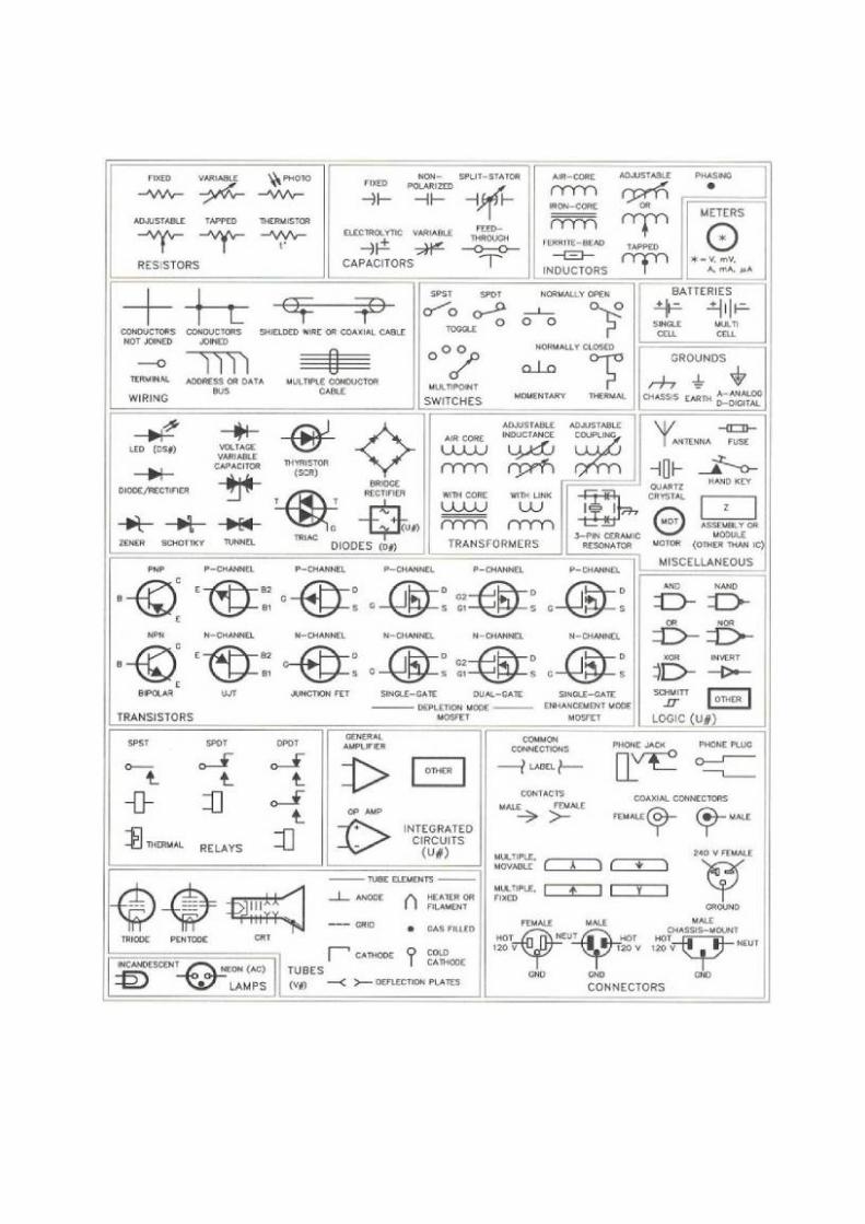
Don't take that chart too seriously, though. An op-amp hasn't had that weird curve in theback since Widlar was giving sheep to bartenders. If you want to try and figure out what'sgoing on in the schematics, you'll need to know these symbols. Since debugging a messedup kit often involves that, I've included that chart. If you don't know, now you know.
PHYSICAL REPRESENTATIONS:
So now I know what I've got for WTPA and what it looks like on paper, so what is it in reallife? It all starts with:
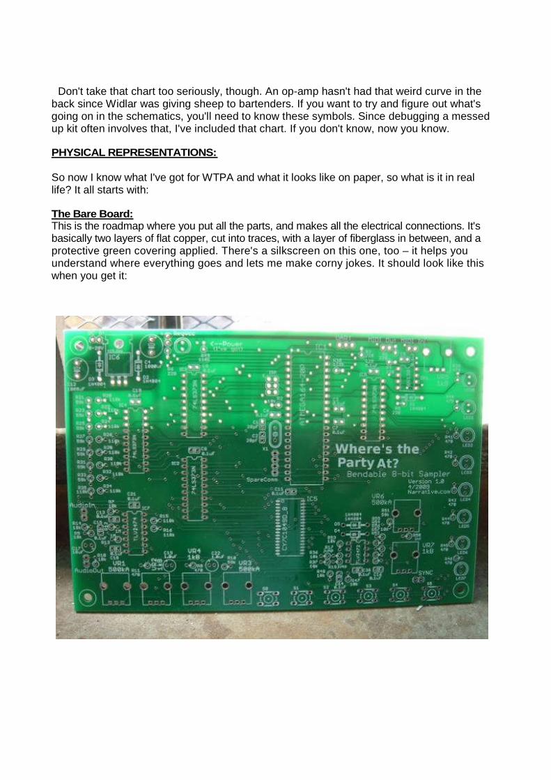
The Bare Board:This is the roadmap where you put all the parts, and makes all the electrical connections. It'sbasically two layers of flat copper, cut into traces, with a layer of fiberglass in between, and aprotective green covering applied. There's a silkscreen on this one, too – it helps youunderstand where everything goes and lets me make corny jokes. It should look like thiswhen you get it:
CAPACITORS :
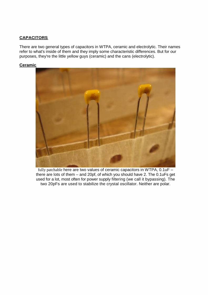
There are two general types of capacitors in WTPA, ceramic and electrolytic. Their namesrefer to what's inside of them and they imply some characteristic differences. But for ourpurposes, they're the little yellow guys (ceramic) and the cans (electrolytic).
Ceramic:
fully patchable here are two values of ceramic capacitors in WTPA, 0.1uF –there are lots of them – and 20pf, of which you should have 2. The 0.1uFs getused for a lot, most often for power supply filtering (we call it bypassing). The
two 20pFs are used to stabilize the crystal oscillator. Neither are polar.

Electrolytic:
There are three kinds of electrolytic caps: the 470uFs (the big guys), the 22uFs (the blackones) and the 1.0uF (light blue in this photo). The colors aren't important, the numbers are.They'll all be labeled. The big guys are the main power supply filters, the 22uFs are filters foranalog references and also the audio output AC coupling, and the 1.0uF caps are inter-stageaudio coupling caps.
The 470uF and 22uF caps are polar! The 1.0uF is not.The PCBs are marked with a + where the positive lead of the cap should go, and the capsthemselves have a stripe with a – running down the side above the negative lead.Note: If you want to sound smart and impress the Swedish Bipolar Bikini Team you'll call the“positive lead” the anode and the “negative lead” the cathode.
Sockets and ICsAre like peas in a pod. You don't NEED to use the sockets at all, but if you haven't donemuch with electronics before I recommend that you do. Sometimes they are helpful, andsometimes detrimental, but the job of sockets is to allow you to change chips. They alsomake it impossible to damage an IC when soldering it, because you don't solder it. In WTPAyou might change chips to try new experiments, you might change chips to upgrade firmware,or you might change chips because you broke one when bending.The ICs themselves do all the heavy lifting in the chip. The 40-pin guy is the microcontroller(the brain), and the 20-pin guys are parallel latches which allow the microcontroller toeffectively have more output pins. The 14-pin guy is a quad op-amp and is responsible for allthe audio amplification and level shifting. One 8-pin IC is a dual op-amp that is configured asan oscillator and used as the analog clock source, and the other 8-pin chip is an optocoupler,which lets WTPA receive MIDI messages.
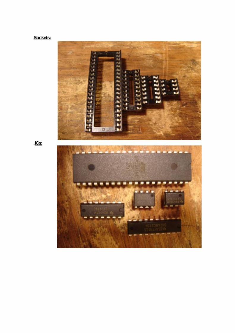
Sockets:
ICs:

Next is the dreaded...SRAM:
The SRAM is technically an IC, but I'm treating it specially because it is in a fundamentallydifferent kind of package – a surface mount package. That means its legs don't poke throughthe board, they sit on top of it. They typically require a little bit more skill to solder, but are doablewith a little patience. Electrically, the differences between DIP / through hole (the dead bug styleICs) and SMT ICs are small. The big difference is size – which can be good or bad dependingon your outlook.
Functionally, the SRAM (that's Static Random Access Memory) holds all the audio we'vesampled.
Diodes, the Crystal, the Regulator, Switches:

These components are sort of a miscellany. The regulator is really an IC (again) but (again) Itook a picture of it because it looks different. The crystal (the silver guy) is what lets themicrocontroller generate an accurate clock for it's CPU. The switches are for user input. Thediodes (WHICH ARE POLAR ) are used to protect WTPA from hooking up power and inputsincorrectly. The bar on one side (the cathode or “negative side”) goes in the direction of thearrow on the PCB.
LEDs:
LED stands for Light Emitting Diode. Like our other diodes, it goes in one way (it's POLAR)
Unlike our other diodes, it lights up!
The LONG LEAD on the LED is the anode (positive). It is oriented towards the top of thePCB everywhere in WTPA. There is also a flat on the other side of the LED (the cathode)which matches the diagram on the PCB.NOTE: Don't test the polarity of LEDs by hooking them up to a battery (or the power supply)to see if they glow. Backwards they won't glow, forwards and they'll burn out immediately.
Potentiometers:
Often called pots. These are variable resistors which internally wipe copper leaf over acarbon strip. They let us adjust electrical parameters and are the most interesting of theresistive family. THERE ARE 4 KINDS OF POTS IN WTPA but physically they look exactlythe same! You've got to read the text to tell them apart.
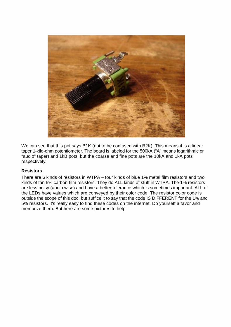
We can see that this pot says B1K (not to be confused with B2K). This means it is a lineartaper 1-kilo-ohm potentiometer. The board is labeled for the 500kA (“A” means logarithmic or“audio” taper) and 1kB pots, but the coarse and fine pots are the 10kA and 1kA potsrespectively.
Resistors:
There are 6 kinds of resistors in WTPA – four kinds of blue 1% metal film resistors and twokinds of tan 5% carbon-film resistors. They do ALL kinds of stuff in WTPA. The 1% resistorsare less noisy (audio wise) and have a better tolerance which is sometimes important. ALL ofthe LEDs have values which are conveyed by their color code. The resistor color code isoutside the scope of this doc, but suffice it to say that the code IS DIFFERENT for the 1% and5% resistors. It's really easy to find these codes on the internet. Do yourself a favor andmemorize them. But here are some pictures to help:
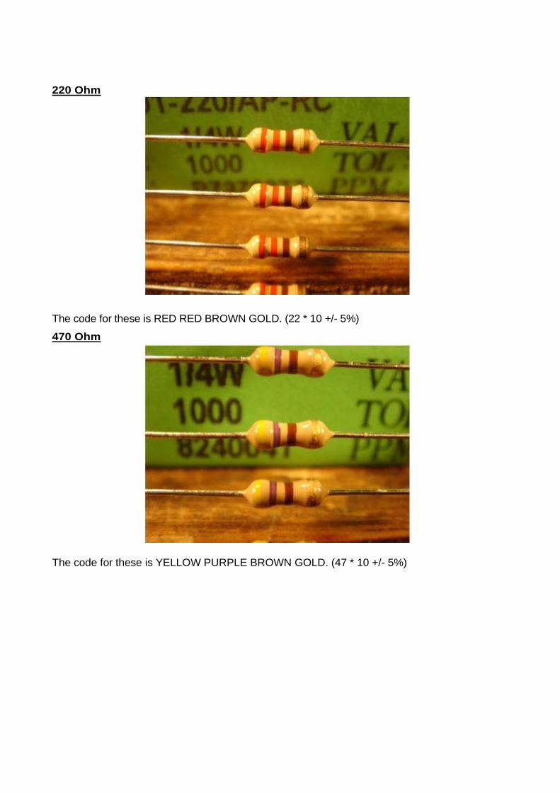
220 Ohm
The code for these is RED RED BROWN GOLD. (22 * 10 +/- 5%)
470 Ohm
The code for these is YELLOW PURPLE BROWN GOLD. (47 * 10 +/- 5%)

10kOhm
The color code for these are BROWN BLACK BLACK RED BROWN (100 * 100 +/- 1%)
118kOhm
The color code for these are BROWN BROWN PURPLE ORANGE BROWN(118 * 1000 +/- 1%)
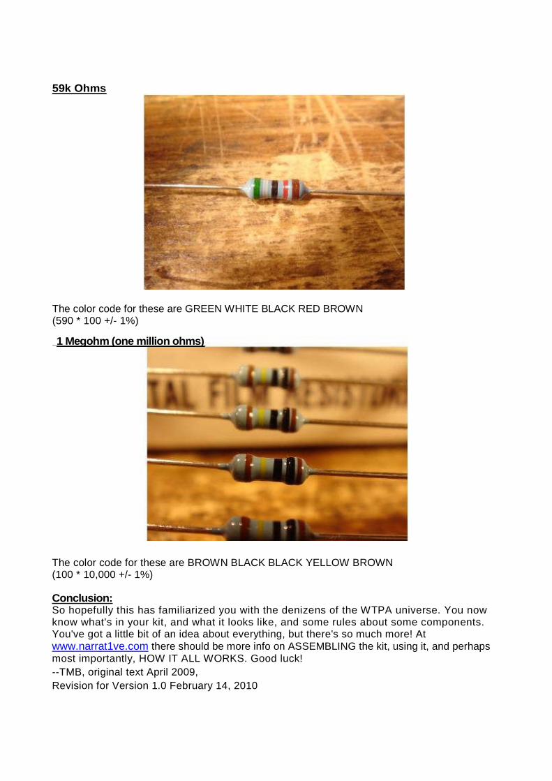
59k Ohms
The color code for these are GREEN WHITE BLACK RED BROWN(590 * 100 +/- 1%)
The color code for these are BROWN BLACK BLACK YELLOW BROWN(100 * 10,000 +/- 1%)
Conclusion:So hopefully this has familiarized you with the denizens of the WTPA universe. You nowknow what's in your kit, and what it looks like, and some rules about some components.You've got a little bit of an idea about everything, but there's so much more! Atwww.narrat1ve.com there should be more info on ASSEMBLING the kit, using it, and perhapsmost importantly, HOW IT ALL WORKS. Good luck!
--TMB, original text April 2009,
Revision for Version 1.0 February 14, 2010
1 Megohm (one million ohms)