ww-900 series - bermad · ww-900 series hydrometers - integrated water meter and valve engineering...
TRANSCRIPT
WW-900 SeriesHydrometers - Integrated Water Meter and Valve
Engineering Data
BERMAD Waterworks900 Series
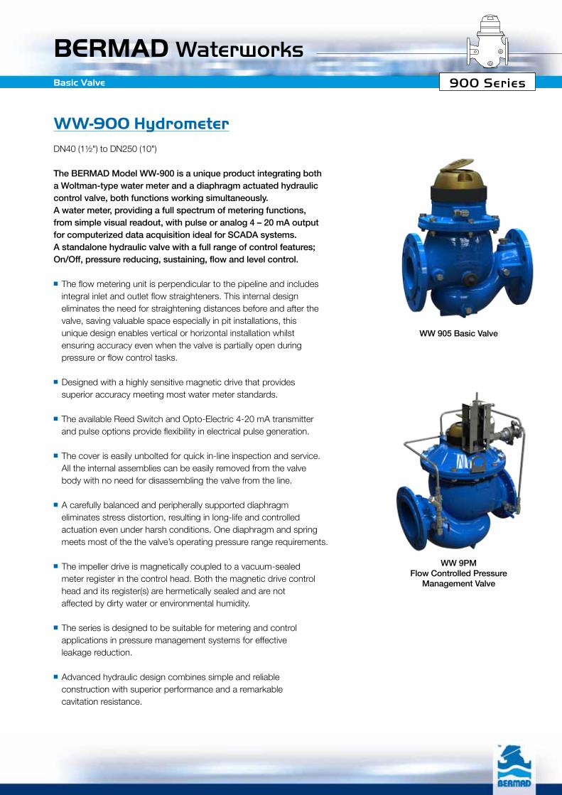
WW-900 HydrometerDN40 (1½") to DN250 (10")
The BERMAD Model WW-900 is a unique product integrating both a Woltman-type water meter and a diaphragm actuated hydraulic control valve, both functions working simultaneously. A water meter, providing a full spectrum of metering functions, from simple visual readout, with pulse or analog 4 – 20 mA output for computerized data acquisition ideal for SCADA systems. A standalone hydraulic valve with a full range of control features; On/Off, pressure reducing, sustaining, flow and level control.
■ The flow metering unit is perpendicular to the pipeline and includes integral inlet and outlet flow straighteners. This internal design eliminates the need for straightening distances before and after the valve, saving valuable space especially in pit installations, this unique design enables vertical or horizontal installation whilst ensuring accuracy even when the valve is partially open during pressure or flow control tasks.
■ Designed with a highly sensitive magnetic drive that provides superior accuracy meeting most water meter standards.
■ The available Reed Switch and Opto-Electric 4-20 mA transmitter and pulse options provide flexibility in electrical pulse generation.
■ The cover is easily unbolted for quick in-line inspection and service. All the internal assemblies can be easily removed from the valve body with no need for disassembling the valve from the line.
■ A carefully balanced and peripherally supported diaphragm eliminates stress distortion, resulting in long-life and controlled actuation even under harsh conditions. One diaphragm and spring meets most of the the valve’s operating pressure range requirements.
■ The impeller drive is magnetically coupled to a vacuum-sealed meter register in the control head. Both the magnetic drive control head and its register(s) are hermetically sealed and are not affected by dirty water or environmental humidity.
■ The series is designed to be suitable for metering and control applications in pressure management systems for effective leakage reduction.
■ Advanced hydraulic design combines simple and reliable construction with superior performance and a remarkable
cavitation resistance.
Basic Valve
WW 905 Basic Valve
WW 9PMFlow Controlled Pressure
Management Valve
BERMAD Waterworks900 Series
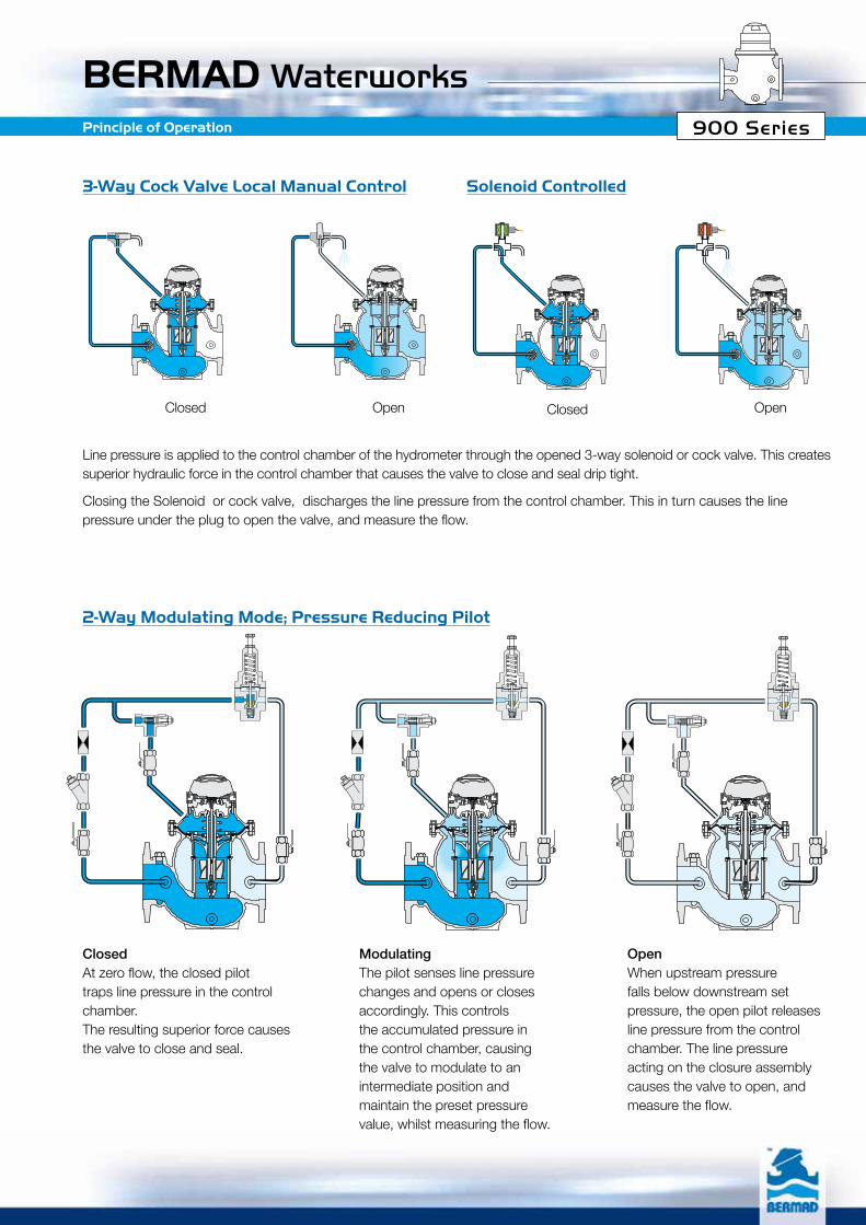
3-Way Cock Valve Local Manual Control
2-Way Modulating Mode; Pressure Reducing Pilot
Solenoid Controlled
Line pressure is applied to the control chamber of the hydrometer through the opened 3-way solenoid or cock valve. This creates superior hydraulic force in the control chamber that causes the valve to close and seal drip tight.
Closing the Solenoid or cock valve, discharges the line pressure from the control chamber. This in turn causes the line pressure under the plug to open the valve, and measure the flow.
Closed At zero flow, the closed pilot traps line pressure in the control chamber. The resulting superior force causes the valve to close and seal.
ModulatingThe pilot senses line pressure changes and opens or closes accordingly. This controls the accumulated pressure in the control chamber, causing the valve to modulate to an intermediate position and maintain the preset pressure value, whilst measuring the flow.
OpenWhen upstream pressure falls below downstream set pressure, the open pilot releases line pressure from the control chamber. The line pressure acting on the closure assembly causes the valve to open, and measure the flow.
Principle of Operation
Closed ClosedOpen Open
BERMAD Waterworks900 Series
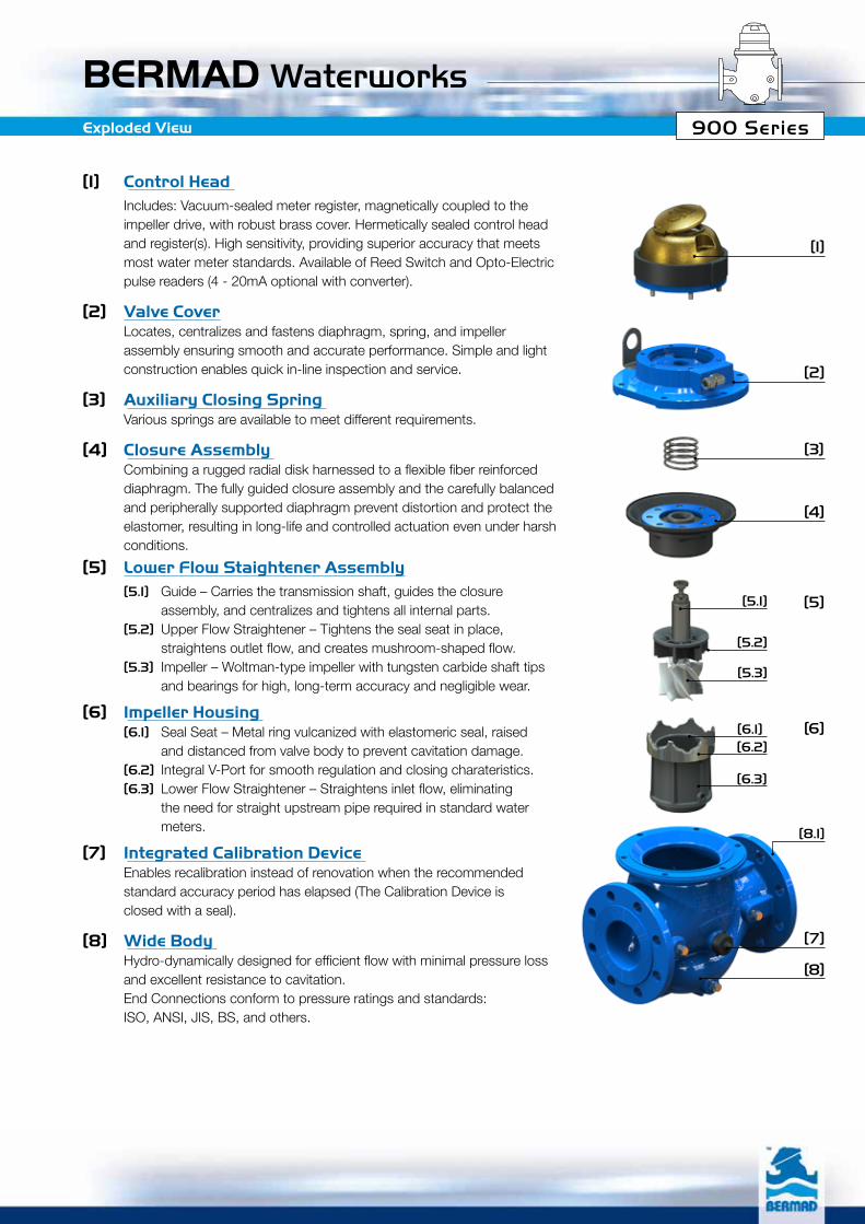
[1] Control Head Includes: Vacuum-sealed meter register, magnetically coupled to the
impeller drive, with robust brass cover. Hermetically sealed control head and register(s). High sensitivity, providing superior accuracy that meets most water meter standards. Available of Reed Switch and Opto-Electric pulse readers (4 - 20mA optional with converter).
[2] Valve Cover Locates, centralizes and fastens diaphragm, spring, and impeller
assembly ensuring smooth and accurate performance. Simple and light construction enables quick in-line inspection and service.
[3] Auxiliary Closing Spring Various springs are available to meet different requirements.
[4] Closure Assembly Combiningaruggedradialdiskharnessedtoaflexiblefiberreinforced
diaphragm. The fully guided closure assembly and the carefully balanced and peripherally supported diaphragm prevent distortion and protect the elastomer, resulting in long-life and controlled actuation even under harsh conditions.
[5] Lower Flow Staightener Assembly [5.1] Guide – Carries the transmission shaft, guides the closure
assembly, and centralizes and tightens all internal parts. [5.2] Upper Flow Straightener – Tightens the seal seat in place,
straightensoutletflow,andcreatesmushroom-shapedflow. [5.3] Impeller – Woltman-type impeller with tungsten carbide shaft tips
and bearings for high, long-term accuracy and negligible wear.
[6] Impeller Housing [6.1] Seal Seat – Metal ring vulcanized with elastomeric seal, raised
and distanced from valve body to prevent cavitation damage. [6.2] Integral V-Port for smooth regulation and closing charateristics. [6.3] LowerFlowStraightener–Straightensinletflow,eliminating
the need for straight upstream pipe required in standard water meters.
[7] Integrated Calibration Device Enables recalibration instead of renovation when the recommended
standard accuracy period has elapsed (The Calibration Device is closed with a seal).
[8] Wide Body Hydro-dynamicallydesignedforefficientflowwithminimalpressureloss
and excellent resistance to cavitation. End Connections conform to pressure ratings and standards: ISO, ANSI, JIS, BS, and others.
[1]
[2]
[3]
[7]
[8]
[4]
[5]
[6]
[5.1]
[5.2]
[5.3]
[6.3]
[8.1]
[6.2][6.1]
Exploded View
BERMAD Waterworks900 Series
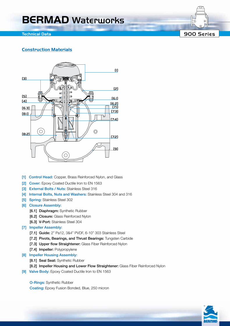
Construction Materials
[3]
[1]
[2]
[6.1]
[6.2][7.1]
[7.3]
[7.4]
[7.2]
[9]
[5]
[4]
[8.1]
[6.3]
[8.2]
[1] Control Head: Copper, Brass Reinforced Nylon, and Glass
[2] Cover: Epoxy Coated Ductile Iron to EN 1563
[3] External Bolts / Nuts: Stainless Steel 316
[4] Internal Bolts, Nuts and Washers: Stainless Steel 304 and 316
[5] Spring: Stainless Steel 302
[6] Closure Assembly:
[6.1] Diaphragm: Synthetic Rubber
[6.2] Closure: Glass Reinforced Nylon
[6.3] V-Port: Stainless Steel 304
[7] Impeller Assembly:
[7.1] Guide: 2” Pa12, 3&4” PVDF, 6-10” 303 Stainless Steel
[7.2] Pivots, Bearings, and Thrust Bearings: Tungsten Carbide
[7.3] Upper flow Straightener: Glass Fiber Reinforced Nylon
[7.4] Impeller: Polypropylene
[8] Impeller Housing Assembly:
[8.1] Seal Seat: Synthetic Rubber
[8.2] Impeller Housing and Lower Flow Straightener: Glass Fiber Reinforced Nylon
[9] Valve Body: Epoxy Coated Ductile Iron to EN 1563
O-Rings: Synthetic Rubber
Coating: Epoxy Fusion Bonded, Blue, 250 micron
Technical Data
BERMAD Waterworks900 SeriesTechnical Data
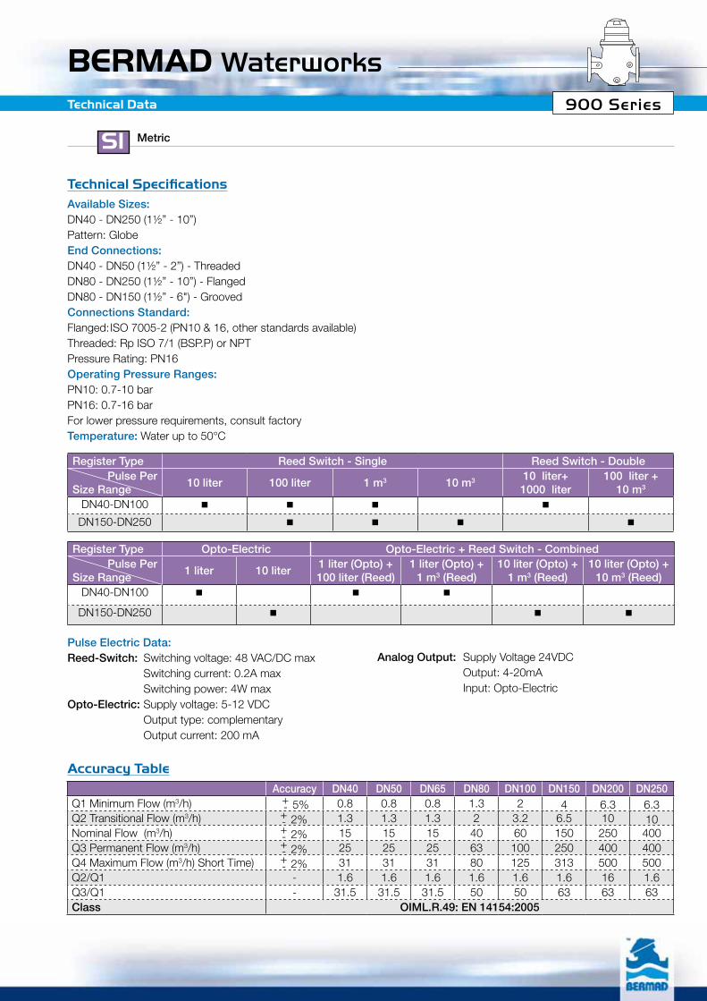
Available Sizes: DN40 - DN250 (1½” - 10”)Pattern: GlobeEnd Connections: DN40 - DN50 (1½” - 2”) - ThreadedDN80 - DN250 (1½” - 10”) - FlangedDN80 - DN150 (1½” - 6") - GroovedConnections Standard:Flanged: ISO 7005-2 (PN10 & 16, other standards available)Threaded: Rp ISO 7/1 (BSP.P) or NPTPressure Rating: PN16Operating Pressure Ranges:PN10: 0.7-10 barPN16: 0.7-16 barFor lower pressure requirements, consult factoryTemperature: Water up to 50°C
Pulse Options: Register Type Reed Switch - Single Reed Switch - DoublePulse Per
Size Range10 liter 100 liter 1 m3 10 m3 10 liter+
1000 liter100 liter +
10 m3
DN40-DN100 ■ ■ ■ ■
DN150-DN250 ■ ■ ■ ■
Register Type Opto-Electric Opto-Electric + Reed Switch - CombinedPulse Per
Size Range1 liter 10 liter
1 liter (Opto) +100 liter (Reed)
1 liter (Opto) +1 m3 (Reed)
10 liter (Opto) +1 m3 (Reed)
10 liter (Opto) +10 m3 (Reed)
DN40-DN100 ■ ■ ■
DN150-DN250 ■ ■ ■
Accuracy DN40 DN50 DN65 DN80 DN100 DN150 DN200 DN250Q1 Minimum Flow (m3/h) -
+ 5% 0.8 0.8 0.8 1.3 2 4 6.3 6.3Q2 Transitional Flow (m3/h) -
+ 2% 1.3 1.3 1.3 2 3.2 6.5 10 10Nominal Flow (m3/h) -
+ 2% 15 15 15 40 60 150 250 400Q3 Permanent Flow (m3/h) -
+ 2% 25 25 25 63 100 250 400 400Q4 Maximum Flow (m3/h) Short Time) -
+ 2% 31 31 31 80 125 313 500 500Q2/Q1 - 1.6 1.6 1.6 1.6 1.6 1.6 16 1.6Q3/Q1 - 31.5 31.5 31.5 50 50 63 63 63Class OIML.R.49: EN 14154:2005
Accuracy Table
Technical Specifications
Pulse Electric Data:Reed-Switch: Switching voltage: 48 VAC/DC max Switching current: 0.2A max Switching power: 4W maxOpto-Electric: Supply voltage: 5-12 VDC Output type: complementary Output current: 200 mA
Analog Output: Supply Voltage 24VDC Output: 4-20mA Input: Opto-Electric
BERMAD Waterworks900 SeriesTechnical Data
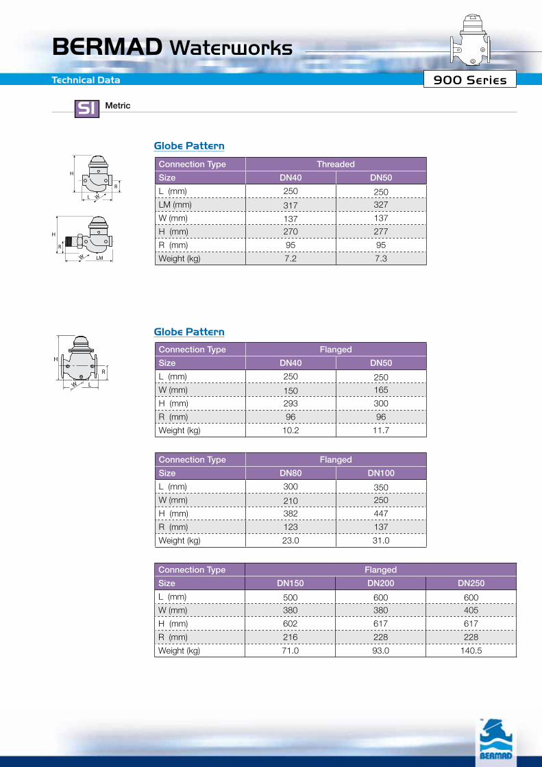
Connection Type Threaded
Size DN40 DN50
L (mm) 250 250LM (mm) 317 327
W (mm) 137 137
H (mm) 270 277
R (mm) 95 95
Weight (kg) 7.2 7.3
Connection Type Flanged
Size DN40 DN50
L (mm) 250 250W (mm) 150 165
H (mm) 293 300
R (mm) 96 96
Weight (kg) 10.2 11.7
Connection Type Flanged
Size DN80 DN100
L (mm) 300 350W (mm) 210 250
H (mm) 382 447
R (mm) 123 137
Weight (kg) 23.0 31.0
Connection Type Flanged
Size DN150 DN200 DN250
L (mm) 500 600 600W (mm) 380 380 405
H (mm) 602 617 617
R (mm) 216 228 228
Weight (kg) 71.0 93.0 140.5
Globe Pattern
Globe Pattern
R
L
H
W
R
LM
H
W
R
L
H
W
R
LM
H
W
R
L
H
W
BERMAD Waterworks900 Series
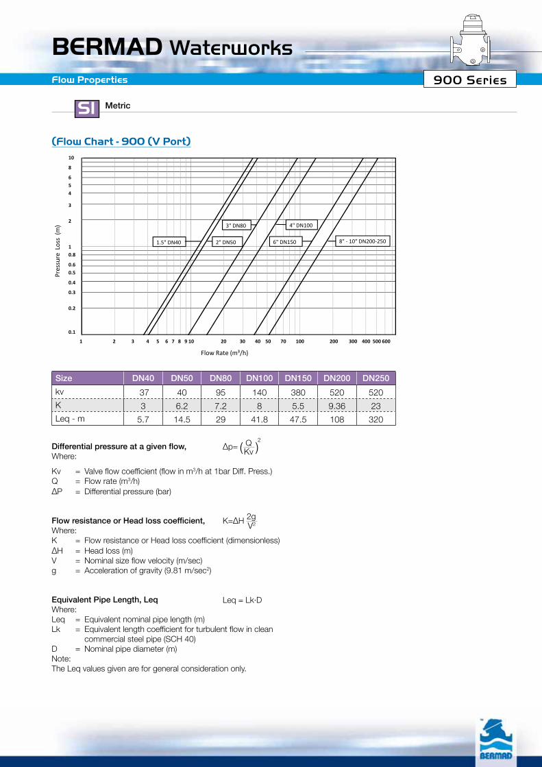
Differential pressure at a given flow, Where:
Kv = Valve flow coefficient (flow in m3/h at 1bar Diff. Press.)Q = Flow rate (m3/h)∆P = Differential pressure (bar)
Flow Properties
Size DN40 DN50 DN80 DN100 DN150 DN200 DN250
kv 37 40 95 140 380 520 520K 3 6.2 7.2 8 5.5 9.36 23Leq - m 5.7 14.5 29 41.8 47.5 108 320
)Flow Chart - 900 )V Port(
1.0
10.0
Flow Chart 900 V port
Pres
sure
Loss
(m
)
10
8
654
3
2
10.8
1.5" DN40
3" DN80
2" DN50 6" DN150
4" DN100
8" - 10" DN200-250
0.11 10 100
Flow Rate (m³/h)
Pres
sure 0.8
0.60.5
0.4
0.3
0.2
0.1
1 2 3 4 5 6 7 8 9 10 20 30 40 50 70 100 200 300 400 500 600
Flow resistance or Head loss coefficient, Where:K = Flow resistance or Head loss coefficient (dimensionless)∆H = Head loss (m)V = Nominal size flow velocity (m/sec)g = Acceleration of gravity (9.81 m/sec2)
Equivalent Pipe Length, Leq Where:Leq = Equivalent nominal pipe length (m)Lk = Equivalent length coefficient for turbulent flow in clean commercial steel pipe (SCH 40)D = Nominal pipe diameter (m)Note:The Leq values given are for general consideration only.
K=∆H 2gV2
Leq = Lk·D
∆p=2Q
Kv( )
BERMAD Waterworks900 SeriesTechnical Data
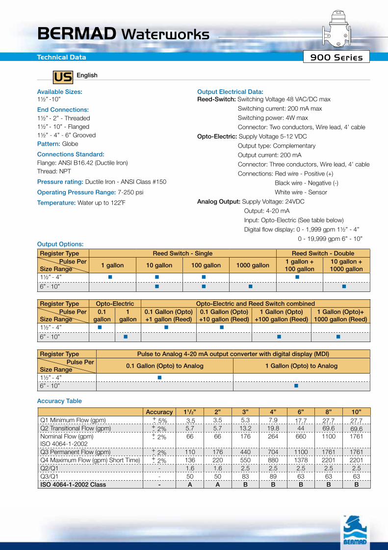
Available Sizes: 1½” -10”
End Connections: 1½” - 2” - Threaded1½” - 10” - Flanged1½” - 4” - 6” GroovedPattern: Globe
Connections Standard: Flange: ANSI B16.42 (Ductile Iron)Thread: NPT
Pressure rating: Ductile Iron - ANSI Class #150
Operating Pressure Range: 7-250 psi
Temperature: Water up to 122˚F
Register Type Reed Switch - Single Reed Switch - DoublePulse Per
Size Range1 gallon 10 gallon 100 gallon 1000 gallon
1 gallon +100 gallon
10 gallon +1000 gallon
1½” - 4” � � � �
6” - 10” � � � �
Register Type Opto-Electric Opto-Electric and Reed Switch combinedPulse Per
Size Range0.1
gallon1
gallon0.1 Gallon (Opto) +1 gallon (Reed)
0.1 Gallon (Opto) +10 gallon (Reed)
1 Gallon (Opto) +100 gallon (Reed)
1 Gallon (Opto)+1000 gallon (Reed)
1½” - 4” � � �
6” - 10” � � �
Register Type Pulse to Analog 4-20 mA output converter with digital display (MDI)Pulse Per
Size Range0.1 Gallon (Opto) to Analog 1 Gallon (Opto) to Analog
1½” - 4” � 6” - 10” �
Accuracy 11/2” 2” 3” 4” 6” 8” 10”Q1 Minimum Flow (gpm) -
+ 5% 3.5 3.5 5.3 7.9 17.7 27.7 27.7Q2 Transitional Flow (gpm) -
+ 2% 5.7 5.7 13.2 19.8 44 69.6 69.6Nominal Flow (gpm) ISO 4064-1-2002
-+ 2% 66 66 176 264 660 1100 1761
Q3 Permanent Flow (gpm) -+ 2% 110 176 440 704 1100 1761 1761
Q4 Maximum Flow (gpm) Short Time) -+ 2% 136 220 550 880 1378 2201 2201
Q2/Q1 - 1.6 1.6 2.5 2.5 2.5 2.5 2.5Q3/Q1 - 50 50 83 89 63 63 63ISO 4064-1-2002 Class - A A B B B B B
Output Electrical Data: Reed-Switch: Switching Voltage 48 VAC/DC max
Switching current: 200 mA max
Switching power: 4W max
Connector: Two conductors, Wire lead, 4’ cable
Opto-Electric: Supply Voltage 5-12 VDC
Output type: Complementary
Output current: 200 mA
Connector: Three conductors, Wire lead, 4’ cable
Connections: Red wire - Positive (+)
Black wire - Negative (-)
White wire - Sensor
Analog Output: Supply Voltage: 24VDC
Output: 4-20 mA
Input: Opto-Electric (See table below)
Digital flow display: 0 - 1,999 gpm 1½” - 4”
0 - 19,999 gpm 6” - 10”Output Options:
Accuracy Table
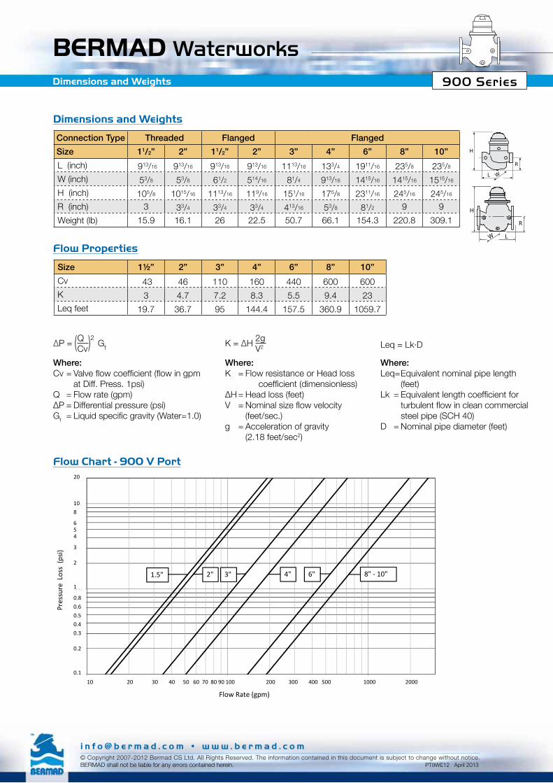
BERMAD Waterworks900 SeriesDimensions and Weights
Connection Type Threaded Flanged Flanged
Size 11/2” 2” 11/2” 2” 3” 4” 6” 8” 10”
L (inch) 913/16 913/16 913/16 913/16 1113/16 133/4 1911/16 235/8 235/8
W (inch) 53/8 53/8 61/2 514/16 81/4 913/16 1415/16 1415/16 1515/16
H (inch) 105/8 1015/16 1113/16 119/16 151/16 175/8 2311/16 245/16 245/16
R (inch) 3 33/4 33/4 33/4 413/16 53/8 81/2 9 9
Weight (lb) 15.9 16.1 26 22.5 50.7 66.1 154.3 220.8 309.1
Size 1½” 2” 3” 4” 6” 8” 10”
Cv 43 46 110 160 440 600 600K 3 4.7 7.2 8.3 5.5 9.4 23Leq feet 19.7 36.7 95 144.4 157.5 360.9 1059.7
Dimensions and Weights
Flow Properties
Flow Chart - 900 V Port
Where:Leq= Equivalent nominal pipe length (feet)Lk =Equivalentlengthcoefficientfor turbulentflowincleancommercial steel pipe (SCH 40)D = Nominal pipe diameter (feet)
Leq = Lk·D
Where:Cv=Valveflowcoefficient(flowingpm at Diff. Press. 1psi) Q = Flow rate (gpm)∆P=Differentialpressure(psi)Gf =Liquidspecificgravity(Water=1.0)
∆P = 2Q
Cv)( Gf
Where:K = Flow resistance or Head loss coefficient(dimensionless)∆H=Headloss(feet)V =Nominalsizeflowvelocity (feet/sec.)g = Acceleration of gravity (2.18 feet/sec2)
K = ∆H 2gV2
R
L
H
W
R
LM
H
W
R
L
H
W
1.0
10.0
Flow Chart 900 V port
Pres
sure
Loss
(ps
i)
20
108
654
3
2
1
1.5" 3"2" 6"4" 8" - 10"
0.1
1.0
10 100 1000
Flow Rate (gpm)
Pres
sure 1
0.80.60.50.40.3
0.2
0.110 20 30 40 50 60 70 80 90 100 200 300 400 500 1000 2000
i n f o @ b e r m a d . c o m • w w w . b e r m a d . c o m© Copyright 2007-2012 Bermad CS Ltd. All Rights Reserved. The information contained in this document is subject to change without notice. BERMAD shall not be liable for any errors contained herein. PT9WE12 April 2013