wwiilldd ssttaalllliioonn ddiissttoorrttiioonn ppeeddaall
TRANSCRIPT
WWiilldd SSttaalllliioonn DDiissttoorrttiioonn PPeeddaall
A SENIOR PROJECT
PRESENTED TO
THE FACULTY OF THE ELECTRICAL ENGINEERING DEPARTMENT
CALIFORNIA POLYTECHNIC STATE UNIVERSITY, SAN LUIS OBISPO
IN PARTIAL FULLFILMENT OF THE REQUIREMENTS FOR THE DEGREE
BACHELOR OF SCIENCE IN ELECTRICAL ENGINEERING
AAAUUUTTTHHHOOORRREEEDDD BBBYYY::: LLLEEEVVVIII SSSUUULLLLLLEEENNNGGGEEERRR
DECEMBER, 2016
© 2016 LEVI SULLENGER
Wild Stallion Distortion
i
Table of Contents
Section Page
List of Tables and Figures ……………………………………………………………………..
Acknowledgements…………………………………………………………………………….
Abstract…………………………………………………………………………………………
ii
iii
iv
I. Introduction…………………………………………………………...……..............
II. Product Design - Engineering Requirements ……….……………………………....
III. System Design - Functional Decomposition ………………………………………..
IV. Design Approach Alternatives ……………………………..…..………………........
V. Project Design ……………………………………………………………………….
VI. Physical Construction and Integration………………………………………….........
VII. Integrated System Tests and Results …………………………………………….......
VIII. Conclusions ………………………………………………………………………….
1
2
5
7
9
19
26
32
References……………………………………………………………………………………… 33
Appendix
A. ABET Senior Project Analysis……………………………………………………….
B. Parts List and Costs…………………………………………………………………...
C. Project Schedule………………………………….……….……….…………………
D. Printed Circuit Board Layout…………………………………………….…………...
35
38
41
43
Wild Stallion Distortion
ii
List of Tables and Figures
Table Page
2.1 Requirements and Specifications……………….……….......................................
2.2 Level 0 Functionality ……………………………………...……………………..
3.1 Level 1 Functionality……………………………………………..........................
7.1 Product Specifications……………………………………………........................
7.2 Testability Matrix……………………………………………...............................
B.1 Total Time Estimates………………………………………………......................
B.2 Total Cost Estimates……………………………………………….......................
B.3 Bill of Materials………………………………………………..............................
3
4
6
31
31
38
39
40
Figure
2.1 Level 0 Block Diagram………..…….………..…………......................................
3.1 Level 1 Block Diagram.…………….…………………………………………….
4.1 Post-Amplification Diode Clipping ……………...………………………………
4.2 Soft Diode Clipping ………………….……………...…………….......................
4.3 Output Waveform of Soft Diode Clipping ………………….……………………
5.1 Final Simulation Distortion Circuit Schematic. …….…........................................
5.2 Input Stage.…………….………………………………………………………….
5.3 Frequency Response of the Input Stage ……………...….……………………….
5.4 Clipping Stage ………………….……………...……………................................
5.5 Non-Inverting Op Amp Configuration ………………………………...................
5.6 Gain Sweep of the Distortion Stage Output ………………………...…….………
5.7 Revised Value Gain Sweep.…………….…………………………………………
5.8 Transient Response of the Distortion Stage ……………...….……………………
5.9 Revised Clipping Stage………………….……………...……………...................
5.10 Transient Response of Revised Distortion Stage …………….…………………..
5.11 Tone Stage …………….………………………………………………………….
5.12 Extremes of the Tone Stage’s 20 kΩ Potentiometer …………….……………….
5.13 Parametric Sweep of the Tone Stage (Volts)…………….………………………..
5.14 Parametric Sweep of the Tone Stage (dB) …………….………………………….
5.15 Volume Stage …………….……………………………………………………….
5.16 Parametric Sweep of the Volume Stage (Volts)…………….…………………….
5.17 Parametric Sweep of the Volume Stage (dB)…………….……………………….
5.18 Transient Response of Volume Stage …………….………………………………
5.19 Output Stage …………….…………………………………………………..........
6.1 Preliminary Breadboard Design …………….……………………………………
6.2 Intermediate Breadboard Design …………….……………………………...........
6.3 Schematic of the Power Supply Network …………….……………………..........
6.4 3PDT Switch, Input, and Jack Schematic …………….…………………………..
6.5 Functional Breadboard Design …………….………………………………..........
6.6 Application Testing Setup …………….………………………………………….
6.7 Design Layout in Eagle Schematic …………….…………………………………
6.8 PCB Layout in Eagle Schematic …………….……………………………………
6.9 Printed Circuit Board From Advanced Circuits …………….…………………….
6.10 Verifying PCB Conductivity …………….……………………………………….
6.11 Soldering Diagram…………….……………………………………………..........
6.12 PCB with Soldered Components …………….……………………………………
6.13 Drilled Enclosure …………….……………………………………………………
6.14 Components Mounted in Enclosure …………….…………………………………
4
5
7
7
8
9
9
10
11
11
12
12
13
13
14
14
15
15
16
16
17
17
17
18
19
19
20
20
20
21
21
22
22
23
23
23
24
24

Wild Stallion Distortion
iii
6.15 Painted Enclosure …………….……………………………………………………
6.16 The Complete Wild Stallion Distortion Pedal …………….……………………….
7.1 Clipping Stage Output Drive Pot Max…………….……………………………….
7.2 Clipping Stage Output Drive Pot Min …………….……………………………….
7.3 Clipping Stage Output Drive Pot Max (Guitar Input)…………….………………..
7.4 Clipping Stage Output Drive Pot Min (Guitar Input)…………….………………..
7.5 Tone Stage Frequency Response Tone Pot Max …………….…………………….
7.6 Tone Stage Frequency Response Tone Pot Min …………….…………………….
7.7 Volume Stage Output Volume Pot Min …………….……………………………..
7.8 Volume Stage Output Volume Pot Max …………….…………………………….
7.9 Overall Circuit Output with Guitar Input …………….……………………………
C.1 Gantt Chart Through EE 460 …………….…………………………………...........
C.2 Gantt Chart Through EE 461 …………….…………………………………………
C.3 Gantt Chart Through EE 462 …………….…………………………………...........
D.1 Printed Circuit Board Layout ………………………………………………………
25
25
26
26
27
27
28
28
29
29
30
41
41
42
43

Wild Stallion Distortion
iv
Acknowledgements
To my loving mother - Thank you so much for the unbounded love, support, and guidance you have given
me throughout the years. Without your incredible example I wouldn’t be half the man I am today.
To my wonderful and dearly missed father - Thank you for the wisdom and lessons you taught me while
still on this earth. I miss you and wish you could be here for this. I am still trying to make you proud.
To all my instructors and to my advisor Dr. Pilkington -Thank you for the patience, flexibility, guidance,
and enthusiasm in teaching me. Because of you, I have received a world-class education and am able to
open the door for incredible future opportunity.
To Chris - Thank you helping with the decal work and being such an awesome friend.
To Robby - Thank you being attentive and putting up with all my interview questions.
To all the friends I have made while here at Cal Poly - Thank you for the great times and shoulders to lean
on. You made this journey a blast.
To my God and Savior Jesus Christ – Thanks for watching out for me, believing in me, and giving me
everything I needed to get through this crazy journey- Joshua 1:9.

Wild Stallion Distortion
v
Abstract
The Wild Stallion Distortion Pedal project encompasses the research, design, implementation, PCB
layout, and packaging of a distortion effect pedal for the electric guitar. This project aims to use analog
circuitry in order to replicate the effect of vintage tube amplifiers to create a distortion effect. The
procedure includes research, design, simulations, and prototype testing in order to produce a quality
distortion effect built as a stomp pedal for the electric guitar.
Wild Stallion Distortion
1
Chapter I: Introduction
Having studied and performed on the piano and guitar for over 17 years, it has been a dream of mine to
understand and explore the sonic characteristics and designs of my favorite musical devices. Throughout
the entirety of my electrical engineering studies at Cal Poly, I have sought to understand and perceive
certain concepts taught, from a musical stand point. With my senior project, it is my desire to incorporate
the education I have received to facilitate the creation of an effect pedal for the electric guitar.
This project aims to create a quality distortion pedal that models a vintage tube-like distortion sound
similar to the widely used Ibanez Tube Screamer. By using analog circuitry, qualities can be induced in
the signal that model sounds as though interacting with a vacuum tube amplifier. Tube amplifiers work in
such a way that as the amplitude of the input signal from a guitar increases to overload the tube
amplifier’s preamp, the signal becomes distorted in such a way that sustain, edge, and harmonic qualities
affect the signal, while leaving the tonal characteristics of the guitar and the player dynamics intact [2].
For this project, the design goal aims at distorting the signal asymmetrically like a vacuum tube amplifier
would, to create a stylish and quality sounding distortion effect. With this basic design goal in mind,
modification possibilities will be explored to produce a more custom and unique final product tailored to
my own aesthetic tastes as well as customer needs.
Wild Stallion Distortion
2
Chapter II: Product Design - Engineering Requirements
Customer Needs Assessment
Engineering requirements necessary for design of the Wild Stallion Distortion Pedal are partially derived
from customer need assessments. The primary customer base mainly includes electric guitar players.
However, keyboard players, singers, hobbyists or anyone who has a ¼” TRS audio cable and wants Wild
Stallion distortion in their signal chain can use it. Assessments of customer needs, determined by
conducting interviews and doing market research, yielded the most useful information. While
demographic characterization of potential customers includes players of all skill levels, ages, and
ethnicities, brief interview questions posed to musicians having more significant experience with guitar
effect pedals yielded the best results. Questions during interviews included:
1. What features and qualities do you like concerning distortion pedals?
2. What are some of your favorite distortion pedals and why?
3. What concerns do you have when considering purchasing a distortion pedal?
4. What might be a nice or novel additional feature to a distortion pedal?
These interviews yielded a strong bias towards a more “vintage” distortion quality with a couple mentions
of JFET technology and the Ibanez Tube Screamer circa the mid eighties design. Overall, of the
customers interviewed, four prominent product needs emerged: quality sound, ease of use, product
durability, and product affordability.
Requirements and Specifications
The Wild Stallion’s requirements and specifications derive primarily from the previous customer needs
assessment. The expected design follows several customers’ aesthetic preference as well as my own in
that the design attempts to model the ever popular “vintage” tube amplifier sound by performing
asymmetrical soft clipping. The expected durability for performing guitarists requires devices that can
withstand possible high external pressures applied during a live stage performance as indicated by the
common name “stomp pedal” for such devices. Customer needs also indicate a desire for simple and easy
to use controllability. As the use of the Wild Stallion Distortion pedal includes live performances as well
as at-home practice sessions, the device must accommodate a portability feature via an optional
autonomous battery supply. Finally, the product’s retail price must cap at a per-unit cost of $175 to retain
affordability. The previously mentioned needs promote requirements for device sound quality, device
durability, device portability, and affordability. A complete list of the Wild Stallion’s marketing
requirements and engineering specifications appears in Table 2.1.
Wild Stallion Distortion
3
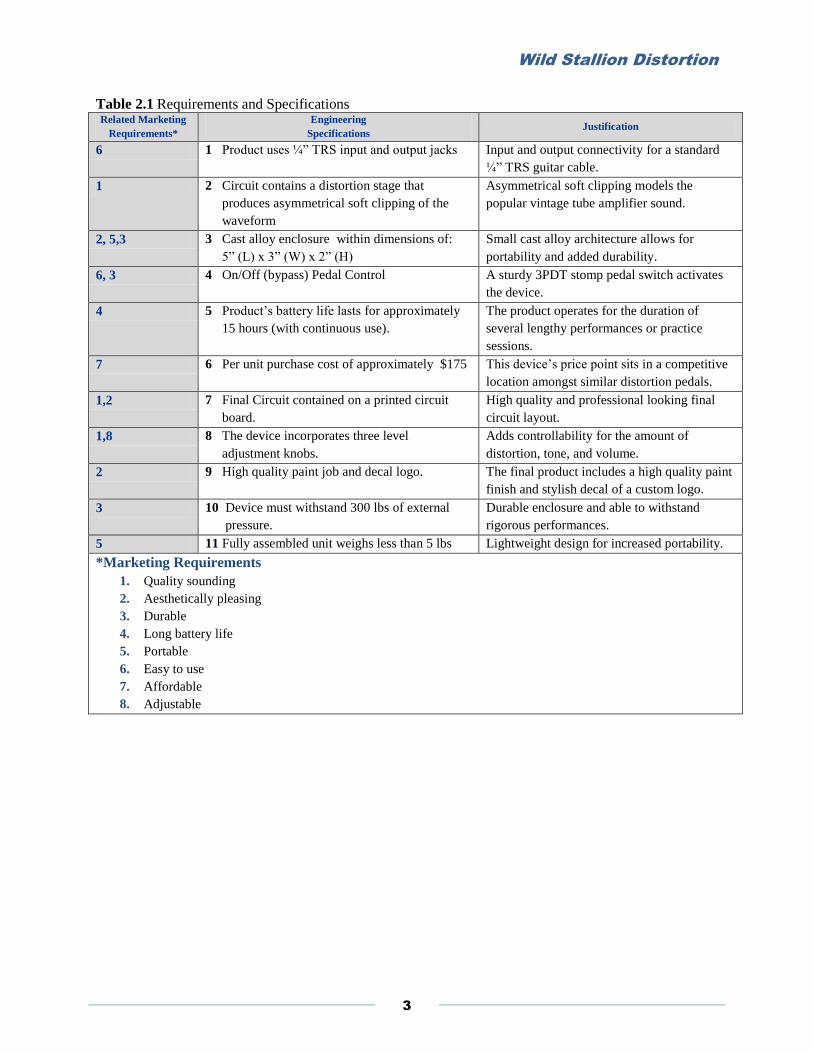
Table 2.1 Requirements and Specifications Related Marketing
Requirements*
Engineering
Specifications Justification
6 1 Product uses ¼” TRS input and output jacks Input and output connectivity for a standard
¼” TRS guitar cable.
1 2 Circuit contains a distortion stage that
produces asymmetrical soft clipping of the
waveform
Asymmetrical soft clipping models the
popular vintage tube amplifier sound.
2, 5,3 3 Cast alloy enclosure within dimensions of:
5” (L) x 3” (W) x 2” (H)
Small cast alloy architecture allows for
portability and added durability.
6, 3 4 On/Off (bypass) Pedal Control A sturdy 3PDT stomp pedal switch activates
the device.
4 5 Product’s battery life lasts for approximately
15 hours (with continuous use).
The product operates for the duration of
several lengthy performances or practice
sessions.
7 6 Per unit purchase cost of approximately $175 This device’s price point sits in a competitive
location amongst similar distortion pedals.
1,2 7 Final Circuit contained on a printed circuit
board.
High quality and professional looking final
circuit layout.
1,8 8 The device incorporates three level
adjustment knobs.
Adds controllability for the amount of
distortion, tone, and volume.
2 9 High quality paint job and decal logo. The final product includes a high quality paint
finish and stylish decal of a custom logo.
3 10 Device must withstand 300 lbs of external
pressure.
Durable enclosure and able to withstand
rigorous performances.
5 11 Fully assembled unit weighs less than 5 lbs Lightweight design for increased portability.
*Marketing Requirements
1. Quality sounding
2. Aesthetically pleasing
3. Durable
4. Long battery life
5. Portable
6. Easy to use
7. Affordable
8. Adjustable

Wild Stallion Distortion
4
Level 0 Decomposition
On the most abstracted level, the Wild Stallion Distortion Pedal accepts an audio signal and introduces
distortion (or clipping) to the signal then passes the signal out. Figure 2.1 presents the device’s level 0
black box diagram. The inputs and outputs shown represent abstract information transmission rather than
electrical signal transmission. Table 2.2 further explains the inputs and outputs of the diagram. It also
describes the functionality of the box itself.
Figure 2.1: Wild Stallion Distortion Pedal Level 0 Black Box Diagram
Table 2.2 Level 0 Functionality
Module Signal Description
Inputs Audio Signal - ¼“ male stereo TRS cable socket (from guitar) On/Off Switch - Physical 3PDT push button stomp switch
Power Supply - 9 V dc supply for circuit (battery alternative)
Distortion - Distortion amount adjustment knob
Tone – Adjustment knob controlling cutoff frequency
Volume - Adjustment knob controlling gain
Outputs Audio Signal - ¼“ male stereo TRS Cable socket (to amplifier)
Functionality The distortion pedal utilizes analog circuitry to introduce clipping to an audio input signal,
effectively producing a desirable distortion quality on the output waveform. The pedal is equipped
with a foot switch that when pressed, activates the circuit that otherwise remains bypassed. The
pedal has three user control knobs; one controls the level of distortion on the output signal, one
controls an RC network to adjust the tone, and the third controls the overall gain in the signal.
9 V dc Power Supply
Audio Input From guitar Audio Output
To Amplifier
User Controls
On/Bypass Switch
Distortion Adjustment
Volume Adjustment
WWWIIILLLDDD
SSSTTTAAALLLLLLIIIOOONNN
DDDIIISSSTTTOOORRRTTTIIIOOONNN
PPPEEEDDDAAALLL
Tone Adjustment
Wild Stallion Distortion
5
Chapter III: System Design - Functional Decomposition
Level 1 Decomposition
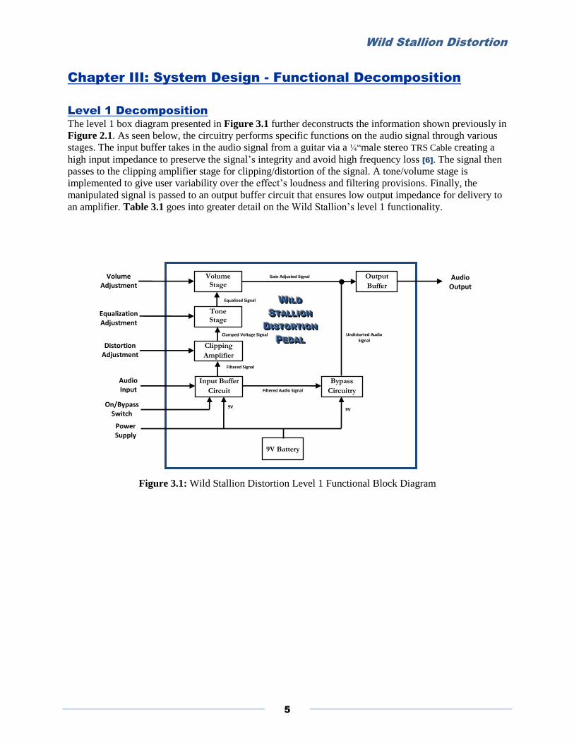
The level 1 box diagram presented in Figure 3.1 further deconstructs the information shown previously in
Figure 2.1. As seen below, the circuitry performs specific functions on the audio signal through various
stages. The input buffer takes in the audio signal from a guitar via a ¼“male stereo TRS Cable creating a
high input impedance to preserve the signal’s integrity and avoid high frequency loss [6]. The signal then
passes to the clipping amplifier stage for clipping/distortion of the signal. A tone/volume stage is
implemented to give user variability over the effect’s loudness and filtering provisions. Finally, the
manipulated signal is passed to an output buffer circuit that ensures low output impedance for delivery to
an amplifier. Table 3.1 goes into greater detail on the Wild Stallion’s level 1 functionality.
Figure 3.1: Wild Stallion Distortion Level 1 Functional Block Diagram
Input Buffer
Circuit
Volume Stage
Tone Stage
Output
Buffer
Audio Input
Power Supply
Bypass
Circuitry
Circ
Equalization Adjustment
On/Bypass Switch
Volume Adjustment
9V Battery
Audio Output
WWW IIILLLDDD
SSSTTTAAALLLLLLIIIOOONNN
DDD IIISSSTTTOOORRRTTTIIIOOONNN
PPPEEEDDDAAALLL
Clamped Voltage Signal
Filtered Signal
9V
Gain Adjusted Signal
Filtered Audio Signal
Undistorted Audio Signal
9V
Clipping
Amplifier
Equalized Signal
Distortion Adjustment
Wild Stallion Distortion
6
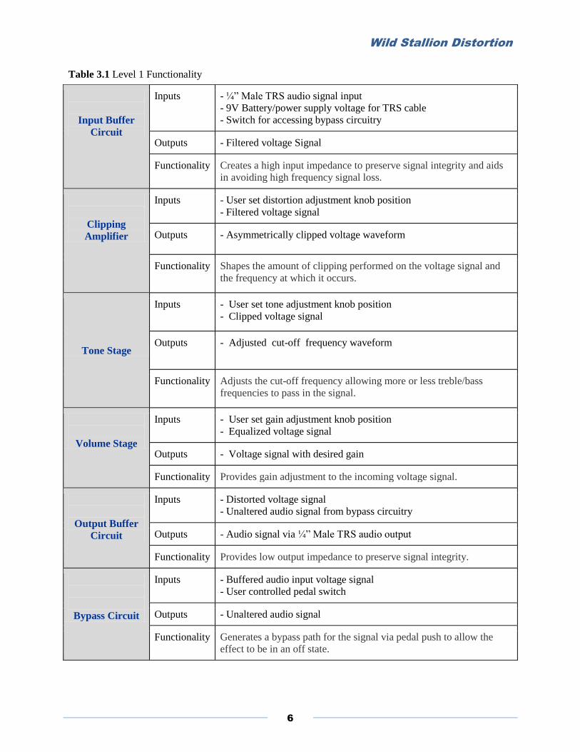
Table 3.1 Level 1 Functionality
Input Buffer
Circuit
Inputs - ¼” Male TRS audio signal input
- 9V Battery/power supply voltage for TRS cable
- Switch for accessing bypass circuitry
Outputs - Filtered voltage Signal
Functionality Creates a high input impedance to preserve signal integrity and aids
in avoiding high frequency signal loss.
Clipping
Amplifier
Inputs - User set distortion adjustment knob position
- Filtered voltage signal
Outputs - Asymmetrically clipped voltage waveform
Functionality Shapes the amount of clipping performed on the voltage signal and
the frequency at which it occurs.
Tone Stage
Inputs - User set tone adjustment knob position
- Clipped voltage signal
Outputs - Adjusted cut-off frequency waveform
Functionality Adjusts the cut-off frequency allowing more or less treble/bass
frequencies to pass in the signal.
Volume Stage
Inputs - User set gain adjustment knob position
- Equalized voltage signal
Outputs - Voltage signal with desired gain
Functionality Provides gain adjustment to the incoming voltage signal.
Output Buffer
Circuit
Inputs - Distorted voltage signal
- Unaltered audio signal from bypass circuitry
Outputs - Audio signal via ¼” Male TRS audio output
Functionality Provides low output impedance to preserve signal integrity.
Bypass Circuit
Inputs - Buffered audio input voltage signal
- User controlled pedal switch
Outputs - Unaltered audio signal
Functionality Generates a bypass path for the signal via pedal push to allow the
effect to be in an off state.
Wild Stallion Distortion
7
Chapter IV: Design Approach Alternatives
The primary choice in designing this distortion pedal lies in how the clipping of the incoming signal is
performed in order to achieve the desired distortion sound. Many design approaches exist in introducing
distortion to a guitar signal. One way is to overdrive one of the amplifiers to its supply rails somewhere in
the signal chain in order to clip the audio signal. Similarly by cascading gain stages, the input signal can
be driven to the supply rails of the op-amps in order to clip the waveform yielding a harsher sounding
clipping quality [3].
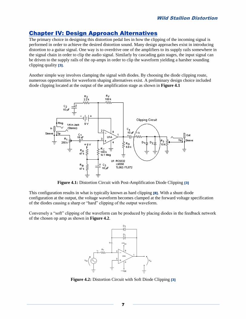
Another simple way involves clamping the signal with diodes. By choosing the diode clipping route,
numerous opportunities for waveform shaping alternatives exist. A preliminary design choice included
diode clipping located at the output of the amplification stage as shown in Figure 4.1
Figure 4.1: Distortion Circuit with Post-Amplification Diode Clipping [3]
This configuration results in what is typically known as hard clipping [8]. With a shunt diode
configuration at the output, the voltage waveform becomes clamped at the forward voltage specification
of the diodes causing a sharp or “hard” clipping of the output waveform.
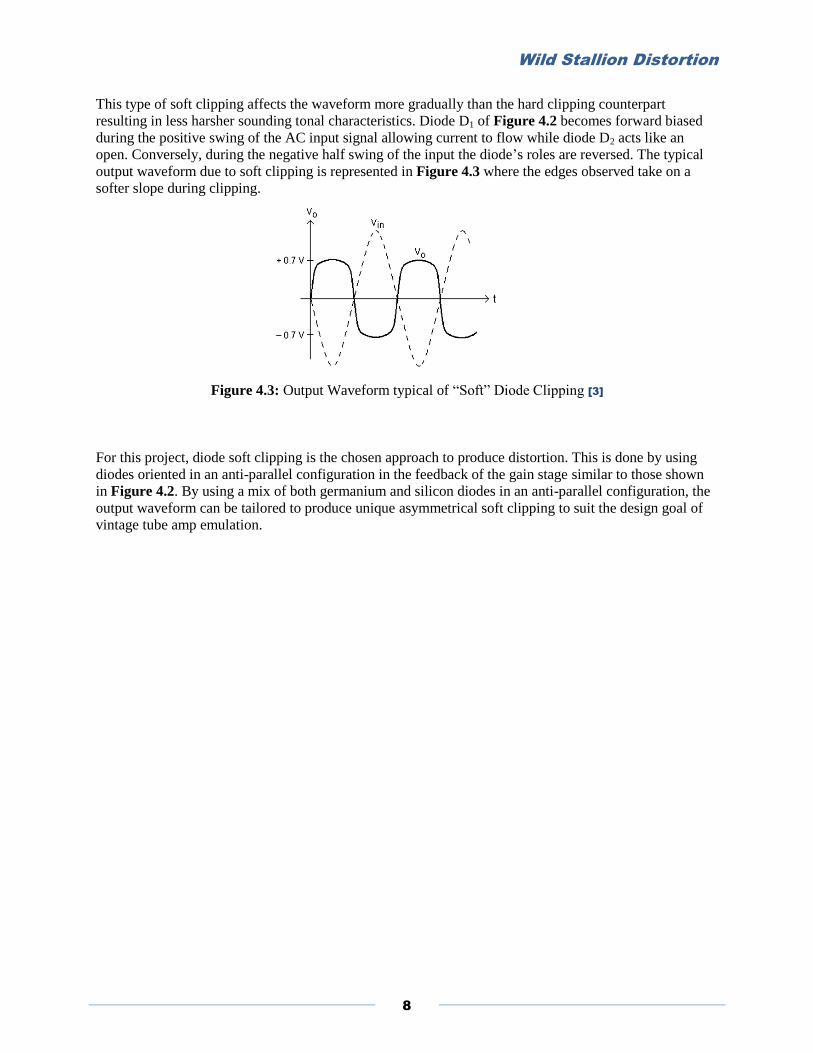
Conversely a “soft” clipping of the waveform can be produced by placing diodes in the feedback network
of the chosen op amp as shown in Figure 4.2.
Figure 4.2: Distortion Circuit with Soft Diode Clipping [3]
Wild Stallion Distortion
8
This type of soft clipping affects the waveform more gradually than the hard clipping counterpart
resulting in less harsher sounding tonal characteristics. Diode D1 of Figure 4.2 becomes forward biased
during the positive swing of the AC input signal allowing current to flow while diode D2 acts like an
open. Conversely, during the negative half swing of the input the diode’s roles are reversed. The typical
output waveform due to soft clipping is represented in Figure 4.3 where the edges observed take on a
softer slope during clipping.
Figure 4.3: Output Waveform typical of “Soft” Diode Clipping [3]
For this project, diode soft clipping is the chosen approach to produce distortion. This is done by using
diodes oriented in an anti-parallel configuration in the feedback of the gain stage similar to those shown
in Figure 4.2. By using a mix of both germanium and silicon diodes in an anti-parallel configuration, the
output waveform can be tailored to produce unique asymmetrical soft clipping to suit the design goal of
vintage tube amp emulation.

Wild Stallion Distortion
9
Chapter V: Project Design
Circuit simulation software LTSpice was used to simulate the preliminary design layouts. A circuit was
built modeling a basic dual op-amp distortion circuit similar to the Boss DS-1 or Ibanez Tube Screamer
topology. The circuit consists of an input buffer, clipping stage, a tone and volume stage, and finally an
output buffer. Values were swept, adjusted, and evaluated to produce reasonable results. Resistor
networks were used to simulate the three potentiometers used in actual physical design. Figure 5.1
displays the finalized overall schematic of the topology used for simulating the distortion circuit.
Figure 5.1: Final Schematic of the Distortion Circuit Used for Simulation
The overall circuit comprises several stages, each performing various modifications to the input signal
sent from the guitar. These stages will be discussed in detail starting with the first stage of the overall
circuit consisting of an input buffer.
The Input Stage
Before the guitar’s small output signal (in the mV range) is sent to the clipping stage, the signal is sent
through an emitter-follower (common collector) amplifier which serves as a voltage buffer to the guitar’s
signal [3]. By using a capacitor to inhibit the guitars lower frequencies and presenting a high input-
impedance at the transistor base, noise (low frequency hum or popping) from the guitar signal is buffered.
The schematic shown in Figure 5.2 displays the circuit diagram of the unity gain input buffer used for the
input of the design.
Figure 5.2: Distortion Circuit Input Stage
Wild Stallion Distortion
10
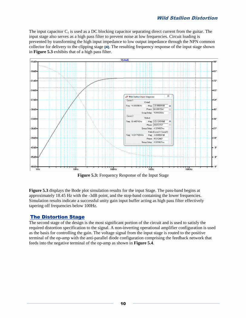
The input capacitor C1 is used as a DC blocking capacitor separating direct current from the guitar. The
input stage also serves as a high pass filter to prevent noise at low frequencies. Circuit loading is
prevented by transforming the high input impedance to low output impedance through the NPN common
collector for delivery to the clipping stage [4]. The resulting frequency response of the input stage shown
in Figure 5.3 exhibits that of a high pass filter.
Figure 5.3: Frequency Response of the Input Stage
Figure 5.3 displays the Bode plot simulation results for the input Stage. The pass-band begins at
approximately 18.45 Hz with the -3dB point, and the stop-band containing the lower frequencies.
Simulation results indicate a successful unity gain input buffer acting as high pass filter effectively
tapering off frequencies below 100Hz.
The Distortion Stage
The second stage of the design is the most significant portion of the circuit and is used to satisfy the
required distortion specification to the signal. A non-inverting operational amplifier configuration is used
as the basis for controlling the gain. The voltage signal from the input stage is routed to the positive
terminal of the op-amp with the anti-parallel diode configuration comprising the feedback network that
feeds into the negative terminal of the op-amp as shown in Figure 5.4.
Wild Stallion Distortion
11
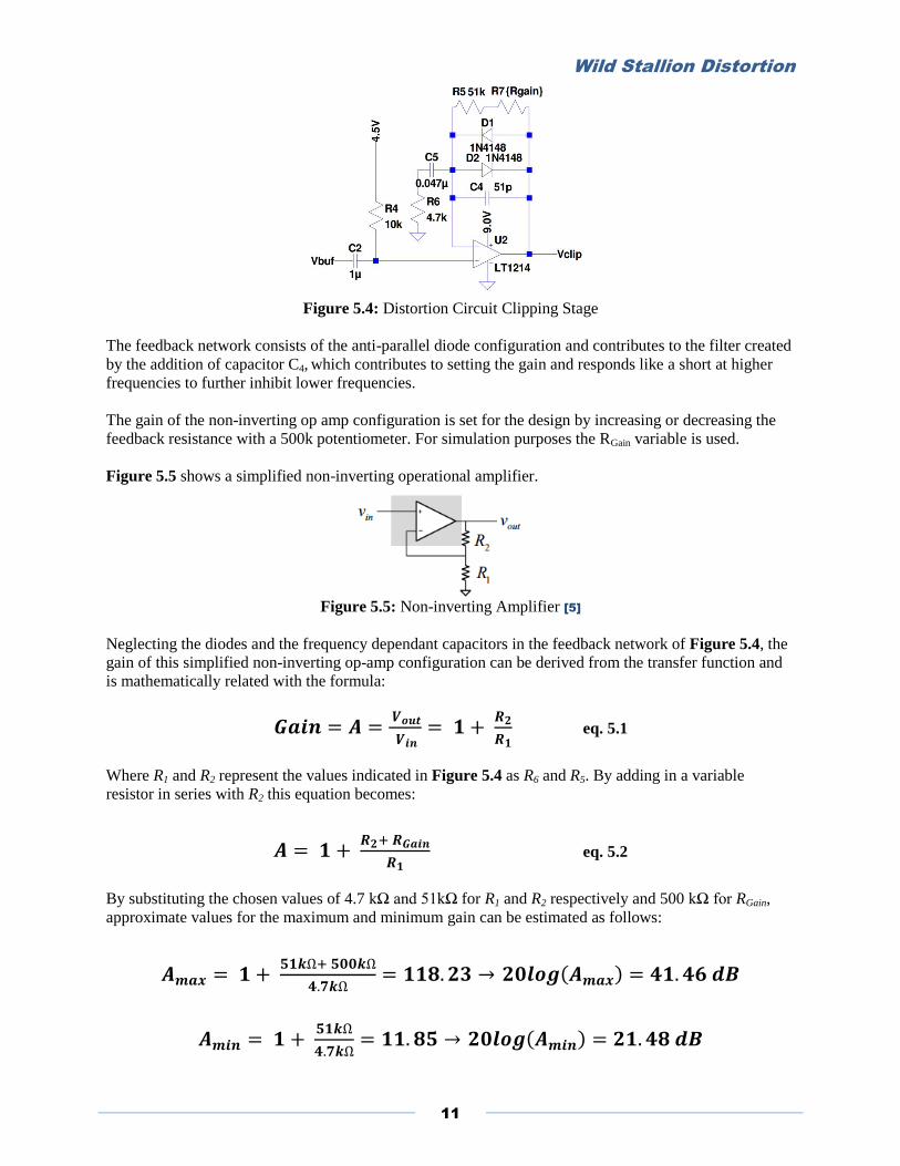
Figure 5.4: Distortion Circuit Clipping Stage
The feedback network consists of the anti-parallel diode configuration and contributes to the filter created
by the addition of capacitor C4, which contributes to setting the gain and responds like a short at higher
frequencies to further inhibit lower frequencies.
The gain of the non-inverting op amp configuration is set for the design by increasing or decreasing the
feedback resistance with a 500k potentiometer. For simulation purposes the RGain variable is used.
Figure 5.5 shows a simplified non-inverting operational amplifier.
Figure 5.5: Non-inverting Amplifier [5]
Neglecting the diodes and the frequency dependant capacitors in the feedback network of Figure 5.4, the
gain of this simplified non-inverting op-amp configuration can be derived from the transfer function and
is mathematically related with the formula:
eq. 5.1
Where R1 and R2 represent the values indicated in Figure 5.4 as R6 and R5. By adding in a variable
resistor in series with R2 this equation becomes:
eq. 5.2
By substituting the chosen values of 4.7 kΩ and 51kΩ for R1 and R2 respectively and 500 kΩ for RGain,
approximate values for the maximum and minimum gain can be estimated as follows:

Wild Stallion Distortion
12
Figure 5.6 shows a Bode plot for the simulated results, generated by sweeping the RGain variable. The
resulting Amax and Amin are respectively close to 41 dB and 21 dB as shown.
Figure 5.6: Gain Sweep of the Distortion Stage Output
Further increasing the value of the 500kΩ potentiometer to 1MΩ and decreasing the value of R6 and R5 to
1kΩ and 10kΩ yields:
Figure 5.7 shows the frequency response of sweeping the RGain variable with the revised values. The new
values yield an increased maximum gain approaching 60 dB and a broader dB range.
Figure 5.7: Gain Sweep of the Distortion Stage Output with revised values
Figure 5.8 shows the transient response for sweeping the RGain variable of the circuit with a .50 mV
sinusoidal input at 200 Hz.

Wild Stallion Distortion
13
Figure 5.8: Transient Response of the Distortion Stage Output
The waveform in Figure 5.8 depicts a soft clipped waveform that is symmetrical about the x and y axes.
By placing another diode in series in one of the parallel feedback pathways as shown in Figure 5.9, the
waveform becomes asymmetrical and better produces a unique tube amplifier sound to satisfy
requirements set forth in the engineering specifications.
Figure 5.9: Distortion Circuit Clipping Stage with Added Diode and Revised Values
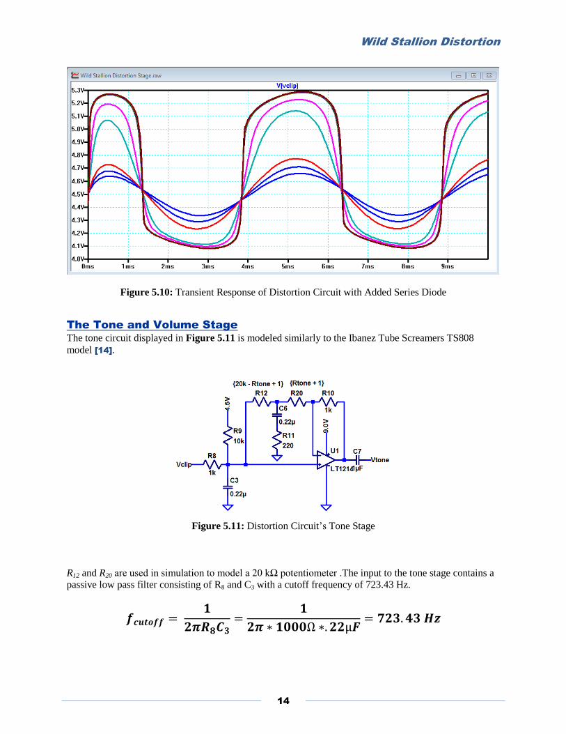
As shown in Figure 5.10, the added diode yields an asymmetrical waveform where the positive half
swing of the AC output varies significantly from the lower portion. The result during the bread-boarding
and audible testing phase is a tone with a fuller sound, more warmth and a seemingly increased bass
response.
Wild Stallion Distortion
14
Figure 5.10: Transient Response of Distortion Circuit with Added Series Diode
The Tone and Volume Stage
The tone circuit displayed in Figure 5.11 is modeled similarly to the Ibanez Tube Screamers TS808
model [14].
Figure 5.11: Distortion Circuit’s Tone Stage
R12 and R20 are used in simulation to model a 20 kΩ potentiometer .The input to the tone stage contains a
passive low pass filter consisting of R8 and C3 with a cutoff frequency of 723.43 Hz.

Wild Stallion Distortion
15
The R11 and C6 network create another low pass filter or a high pass filter to limit frequencies depending
on the 20 kΩ potentiometer’s position. With the potentiometer rotated to both extremes, the circuit‘s
outputs yields that of Figure 5.12.
Figure 5.12: Extremes of the 20 kΩ Potentiometer for the Tone Stage
With the potentiometer rotated fully counter clockwise (brown trace of Figure 5.13), the R11 and C6
network act as a low pass filter inhibiting higher frequencies .With the potentiometer rotated fully
clockwise (red trace of Figure 5.13), the network results in a band pass type filter as shown in Figure
5.12 and Figure 5.13. The full parametric sweep for the potentiometer from 1k to 20 kΩ is shown in
Figure 5.13. A dB scale is shown for reference in Figure 5.14.
Figure 5.13: Full Parametric Sweep of the 20 kΩ Potentiometer for the Tone Stage

Wild Stallion Distortion
16
Figure 5.14: Full Parametric Sweep of the 20 kΩ Potentiometer in dB scale
The Volume stage shown in Figure 5.15 is controlled by a 100 kΩ linear potentiometer that inhibits a
portion of the input signal depending on the potentiometer’s position.
Figure 5.15: Distortion Circuit’s Volume Stage
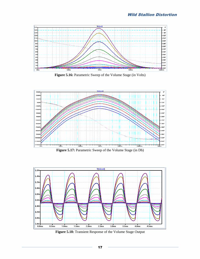
Figure 5.16, Figure 5.17, and Figure 5.18 display output results of the volume stage. R15 and R16 are
used in simulation to model the 100 kΩ potentiometer in a fashion similar to the tone stage. By sweeping
the values for R15 and R16, the 100 kΩ potentiometer is modeled and results are produced as shown.
Wild Stallion Distortion
17
Figure 5.16: Parametric Sweep of the Volume Stage (in Volts)
Figure 5.17: Parametric Sweep of the Volume Stage (in Db)
Figure 5.18: Transient Response of the Volume Stage Output
Wild Stallion Distortion
18
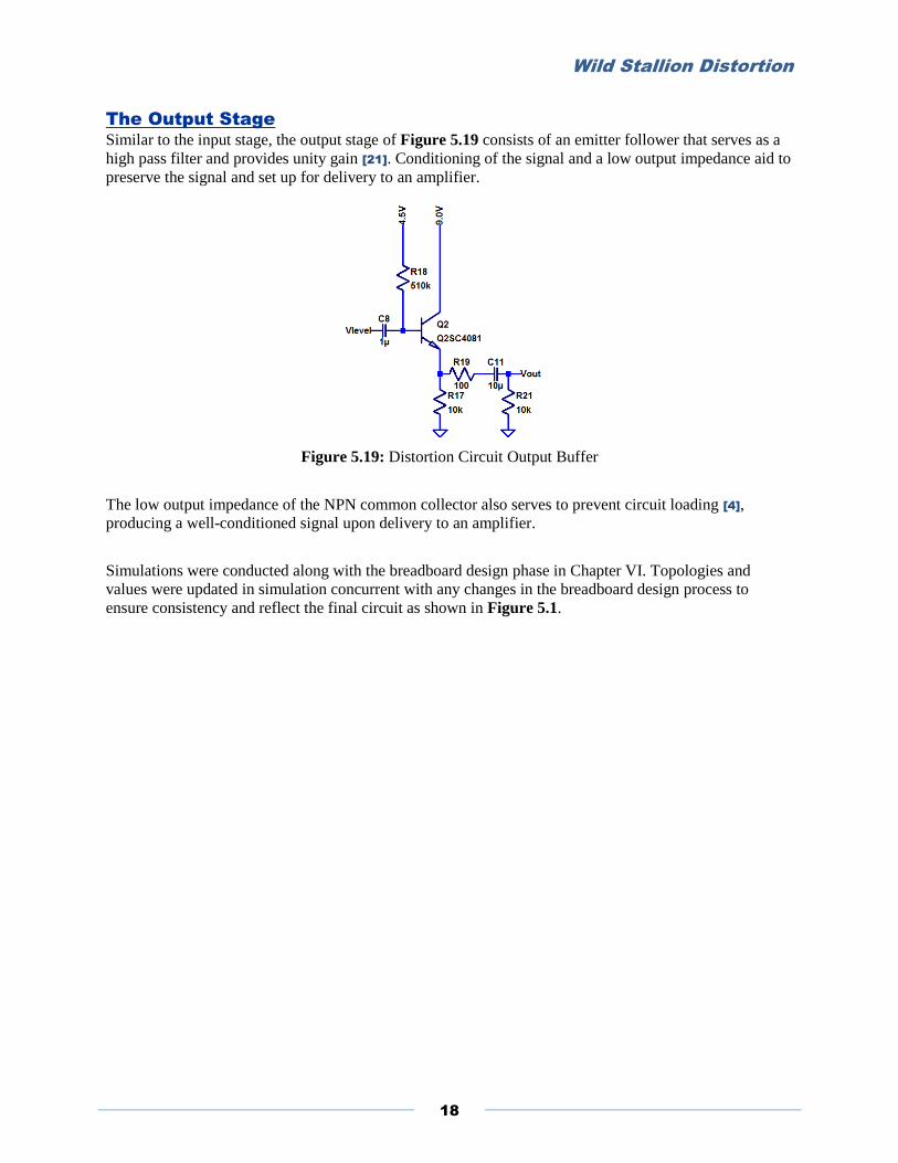
The Output Stage
Similar to the input stage, the output stage of Figure 5.19 consists of an emitter follower that serves as a
high pass filter and provides unity gain [21]. Conditioning of the signal and a low output impedance aid to
preserve the signal and set up for delivery to an amplifier.
Figure 5.19: Distortion Circuit Output Buffer
The low output impedance of the NPN common collector also serves to prevent circuit loading [4],
producing a well-conditioned signal upon delivery to an amplifier.
Simulations were conducted along with the breadboard design phase in Chapter VI. Topologies and
values were updated in simulation concurrent with any changes in the breadboard design process to
ensure consistency and reflect the final circuit as shown in Figure 5.1.

Wild Stallion Distortion
19
Chapter VI: Physical Construction and Integration
To facilitate development of the Wild Stallion Distortion Pedal, preliminary designs were physically
constructed onto a breadboard to enable audible testing of the circuit and allow for ease-of-use in
changing component values. Figure 6.1 and Figure 6.2 show the early developmental stages of the
pedal’s design.
Figure 6.1: Preliminary Breadboard Design
Figure 6.2: Intermediate Breadboard Design
For physical construction, potentiometers were used in place of the resistor networks utilized in
simulation and a 9V battery was used as the 9V DC source with a resistor divider network (10kΩ and
10kΩ) used to obtain the reference voltage of approximately 4.5V to bias the circuit. By-pass capacitors [19] were used to remove unnecessary AC ripple present on the DC supply signal. Figure 6.3 represents
the power supply network used in physical implementation.
Wild Stallion Distortion
20
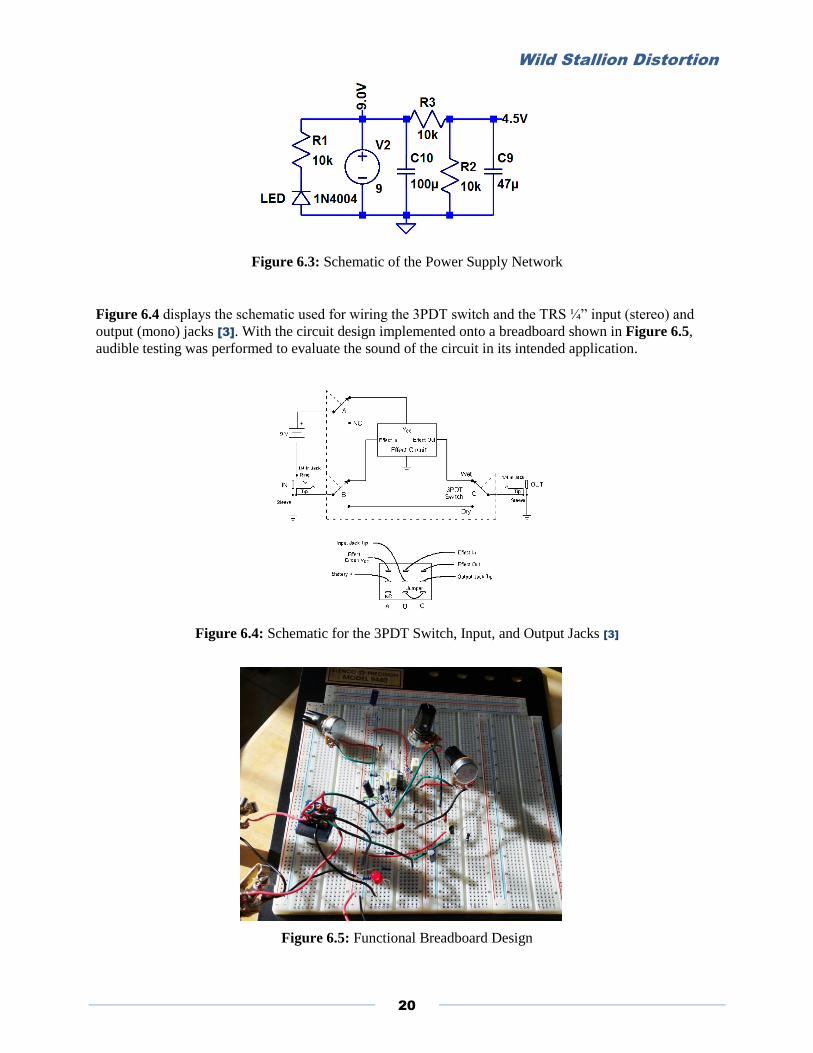
Figure 6.3: Schematic of the Power Supply Network
Figure 6.4 displays the schematic used for wiring the 3PDT switch and the TRS ¼” input (stereo) and
output (mono) jacks [3]. With the circuit design implemented onto a breadboard shown in Figure 6.5,
audible testing was performed to evaluate the sound of the circuit in its intended application.
Figure 6.4: Schematic for the 3PDT Switch, Input, and Output Jacks [3]
Figure 6.5: Functional Breadboard Design

Wild Stallion Distortion
21
Audible testing was conducted using a Fender Stratocaster electric guitar and a small Crate KX-15
amplifier shown in Figure 6.6.
Figure 6.6: Application Testing Using a Fender Stratocaster and Crate KX-15 Amplifier
Audible results with the initial design yielded acceptable sound quality. However, design revisions were
made during this stage of the design process to produce a warmer and fuller sound quality. Changes
included adding a series diode to one of the diode feedback branches (discussed in Chapter V) and
swapping values of C5, R5 and R6 to achieve a more unique sound. Changing the values of R5 and R6 from
51 kΩ and 4.7 kΩ to 10 kΩ and 1 kΩ and lowering the capacitance of C5 to .22 µF from .047 µF
suppressed the brittle sounding and higher tonal qualities and produced more bass and mid-range
sounding tonal characteristics as a result. The addition of the series diode gave the design a far more
unique sound quality.
The next phase of the design process required the Wild Stallion Distortion pedal’s final circuit layout to
consist on a printed circuit board (PCB). Eagle PCB design software was used to facilitate transfer of the
design to a PCB. Figure 6.7 displays the design made in the Eagle’s Schematic software.
Figure 6.7: Design Layout in Eagle Schematic

Wild Stallion Distortion
22
With the design laid out, carefully inspected, and tested using the software’s analysis, the schematic was
transferred to a board layout. Elements were arranged to allow proper spacing of the traces and to exist
within the confines of the chosen board dimensions. The board’s dimensions of 1.4” x 2.5” ensure the
PCB to fit inside a chosen enclosure. Figure 6.8 shows the PCB layout in the Eagle CAD software.
Figure 6.8: PCB Layout in Eagle Schematic
Gerber files were then generated and sent to printed circuit board manufacturer Advanced Circuits at
www.4pcb.com for the PCB’s assembly [22]. Three boards were ordered in case of manufacturing defect
or the event of soldering error. Figure 6.9 shows the printed circuit board upon arrival.
Figure 6.9: Printed Circuit Board From Advanced Circuits
Once the PCB’s arrived, the routes were verified using a multi-meter to check the conductivity of the
traces Figure 6.10.

Wild Stallion Distortion
23
Figure 6.10: Verifying Conductivity of Printed Circuit Board Assembly
Components are then soldered into respective places and cross referenced using Figure 6.11.
Figure 6.12 shows the PCB with elements soldered in place during the assembly and build phase.
Figure 6.11: Diagram Used for Soldering and Wiring Components
Figure 6.12: PCB with Soldered Components
Wild Stallion Distortion
24
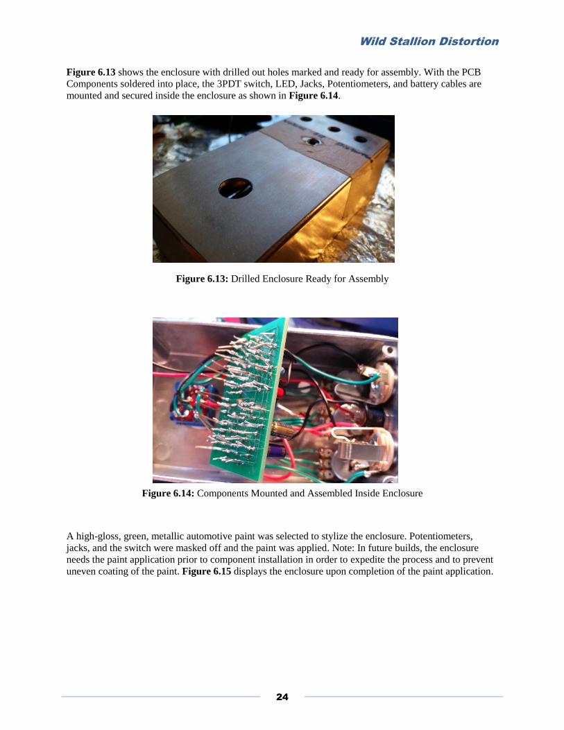
Figure 6.13 shows the enclosure with drilled out holes marked and ready for assembly. With the PCB
Components soldered into place, the 3PDT switch, LED, Jacks, Potentiometers, and battery cables are
mounted and secured inside the enclosure as shown in Figure 6.14.
Figure 6.13: Drilled Enclosure Ready for Assembly
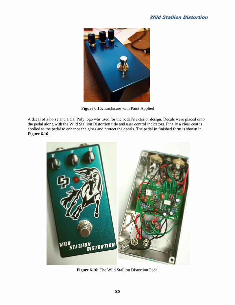
Figure 6.14: Components Mounted and Assembled Inside Enclosure
A high-gloss, green, metallic automotive paint was selected to stylize the enclosure. Potentiometers,
jacks, and the switch were masked off and the paint was applied. Note: In future builds, the enclosure
needs the paint application prior to component installation in order to expedite the process and to prevent
uneven coating of the paint. Figure 6.15 displays the enclosure upon completion of the paint application.
Wild Stallion Distortion
25
Figure 6.15: Enclosure with Paint Applied
A decal of a horse and a Cal Poly logo was used for the pedal’s exterior design. Decals were placed onto
the pedal along with the Wild Stallion Distortion title and user control indicators. Finally a clear coat is
applied to the pedal to enhance the gloss and protect the decals. The pedal in finished form is shown in
Figure 6.16.
Figure 6.16: The Wild Stallion Distortion Pedal
Wild Stallion Distortion
26
Chapter VII: Integrated System Tests and Results
To ensure proper functionality for each stage, the circuit outputs are tested at necessary stages. Circuit
measurements are made using the Analog Discovery2 oscilloscope and instrumentation system. Transient
and frequency response characteristics are examined to confirm proper behavior of the circuit.
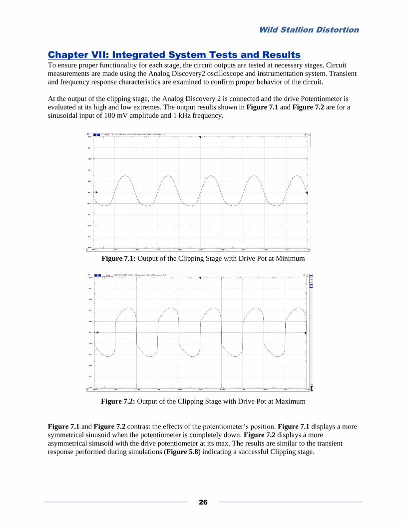
At the output of the clipping stage, the Analog Discovery 2 is connected and the drive Potentiometer is
evaluated at its high and low extremes. The output results shown in Figure 7.1 and Figure 7.2 are for a
sinusoidal input of 100 mV amplitude and 1 kHz frequency.
Figure 7.1: Output of the Clipping Stage with Drive Pot at Minimum
Figure 7.2: Output of the Clipping Stage with Drive Pot at Maximum
Figure 7.1 and Figure 7.2 contrast the effects of the potentiometer’s position. Figure 7.1 displays a more
symmetrical sinusoid when the potentiometer is completely down. Figure 7.2 displays a more
asymmetrical sinusoid with the drive potentiometer at its max. The results are similar to the transient
response performed during simulations (Figure 5.8) indicating a successful Clipping stage.
Wild Stallion Distortion
27
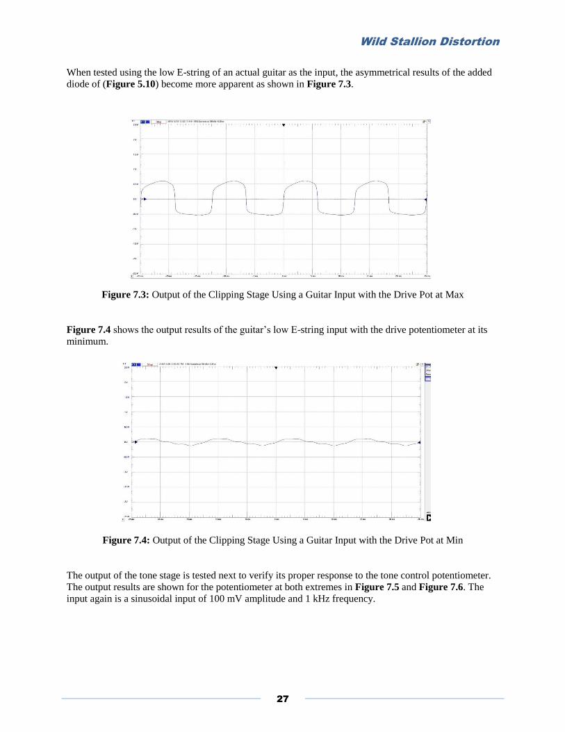
When tested using the low E-string of an actual guitar as the input, the asymmetrical results of the added
diode of (Figure 5.10) become more apparent as shown in Figure 7.3.
Figure 7.3: Output of the Clipping Stage Using a Guitar Input with the Drive Pot at Max
Figure 7.4 shows the output results of the guitar’s low E-string input with the drive potentiometer at its
minimum.
Figure 7.4: Output of the Clipping Stage Using a Guitar Input with the Drive Pot at Min
The output of the tone stage is tested next to verify its proper response to the tone control potentiometer.
The output results are shown for the potentiometer at both extremes in Figure 7.5 and Figure 7.6. The
input again is a sinusoidal input of 100 mV amplitude and 1 kHz frequency.
Wild Stallion Distortion
28
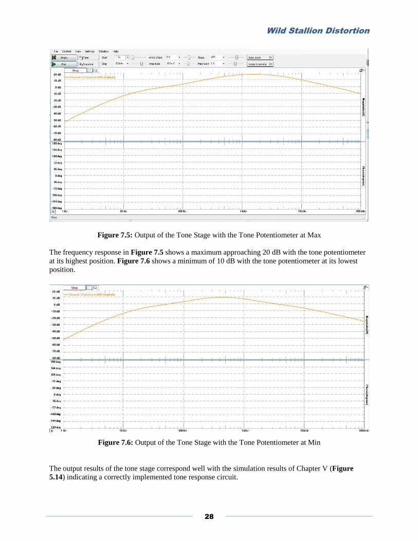
Figure 7.5: Output of the Tone Stage with the Tone Potentiometer at Max
The frequency response in Figure 7.5 shows a maximum approaching 20 dB with the tone potentiometer
at its highest position. Figure 7.6 shows a minimum of 10 dB with the tone potentiometer at its lowest
position.
Figure 7.6: Output of the Tone Stage with the Tone Potentiometer at Min
The output results of the tone stage correspond well with the simulation results of Chapter V (Figure
5.14) indicating a correctly implemented tone response circuit.

Wild Stallion Distortion
29
The transient response for the output of the volume stage is shown in Figure 7.7 and Figure 7.8. The
same sinusoidal input of 100 mV amplitude and 1 kHz frequency is used again.
Figure 7.7: Output of the Volume Stage with the Volume Potentiometer Approaching Minimum
Figure 7.8: Output of the Volume Stage with the Volume Potentiometer at Maximum

Wild Stallion Distortion
30
Figure 7.9 displays the output of the entire circuit for the low E-string of the guitar with all the
potentiometers at their maximum positions.
Figure 7.9: Circuit Output with All Potentiometers at Maximum Positions
The input (shown in red) in Figure 7.9, is the guitar signal read directly from the guitar cable. The output
(shown in blue) is the output of the overall circuit. The waveform produced is asymmetrical about the x
and y axes satisfying design criteria and producing a desirable sound reminiscent of a tube amplifier.
Current Draw and Battery Life
By connecting a multi-meter in series with the battery negative terminal the current draw is measured for
the pedal for both its active mode and bypassed mode of operation in order to determine the total runtime
of the effect pedal. The values found were: 8.48mA for the active mode’s current draw and 4.75 mA for
the bypass mode’s current draw. The rated battery capacity at 580 mAh is found from the battery’s
datasheet [18]. The total runtime (TR) for the pedal in bypassed mode is then determined as follows:
Similarly for the active mode:
While the results fully satisfy the engineering specifications presented in Chapter II, the parasitic current
draw of 4.75 mA in bypassed mode is something to be addressed in future designs to allow the circuit to
be more efficient during bypass mode and conserve power.

Wild Stallion Distortion
31
Product Specifications
Table 7.1 displays the Wild Stallion Distortion Pedal’s product specifications.
Table 7.1 Product Specifications Power Supply 1 x 9V Battery or external AC adapter
Battery Type 9V
Battery Life 68.40 hrs (active) 122.11 hrs (bypass)
Active Mode Current Draw 8.48 mA
Bypass Mode Current Draw 4.75 mA
Enclosure Dimensions 4.75 in x 2.5 in x 1.5 in
Max Gain + 26 dB
Weight 2.6 lbs
Test Plan
The following test plan is used to determine that the final product satisfies the major design goals and
requirements set forth in Table 2.1.
TC1 - Verify conductivity of PCB traces.
TC2 - Power the circuit using a 9V battery and external AC adapter to ensure unit is powered correctly.
TC3 - Test and evaluate controllability of all potentiometers.
TC4 - Conduct audible testing to ensure a desired sound.
TC5 - Evaluate current draw in active and bypass modes of operation.
TC6 – Perform visual inspection to satisfy aesthetic features and to ensure secure connections.
TC7 – Weigh the pedal on a scale to ensure a weight of less than 5 lbs.
TC8 – Stand on the pedal for approximate durability to withstand external pressure.
TC9 – Evaluate production cost to ensure per unit price of less than $175.00
The testability matrix of Table 7.2 displays the results of testing the product to ensure all requirements
are met in the incorporated design.
Table 7.2 Testability Matrix Requirements R1 R2 R3 R4 R5 R6 R7 R8
Test
Cases
Total 2 2 4 2 3 2 1 2
TC1 2 X X
TC2 2 X X
TC3 2 X X
TC4 6 X X X X X X
TC5 1 X
TC6 2 X X
TC7 1 X
TC8 1 X
TC9 1 X
The testability matrix of Table 7.2 displays the results of testing the product to ensure all requirements
are met in the incorporated design.

Wild Stallion Distortion
32
Chapter VIII: Conclusions
The Wild Stallion Distortion Pedal in its current state is a working and successful design. However, the
process involved in creating the pedal revealed several areas of improvement for future design endeavors.
While the device succeeds in meeting the basic functionality in the requirements section of this report, the
current draw of 4.75 mA for the device in its bypass mode of operation is something to be improved
upon. To access the battery and change it every several days is inconvenient from a user stand point as it
involves unscrewing the enclosure. Along these lines, future improvements would be to reduce this
parasitic current draw to conserve power and also make the battery more accessible for replacement.
An important lesson learned from minor oversight is that the painting of the enclosure should be done
prior to assembly. Masking off the various potentiometers and jacks to apply the paint added a significant
amount of time and effort to the project and the resulting paint application was imperfect to say the least.
Also, multiple coats of paint require ample time to dry in between coats and need the right non-humid
environment to produce a quality paint job.
Care should also be taken with assembly of components and the right tools should be used. Stripped out
threads on a potentiometer, an oversized drilled hole, and multiple diode replacements were the result of
rushing and improper preparation. These missteps will consequently be avoided in future endeavors.
In future design builds, the 1 MΩ logarithmic potentiometer used for the distortion control, could be
changed to a linear potentiometer for future revisions. This would potentially produce a smoother gain
adjustment and aid in avoiding leaps in the gain as shown in Figure 5.7.
As far as the cost of the unit goes, the total project cost was more than the anticipated selling point of
$175.00. The projects total cost, approaching $250.00 with shipping and handling, tax, and miscellaneous
trips to RadioShack for part replacement, doesn’t account for the costs of tools required, such as a
soldering iron or testing equipment such as an oscilloscope. The PCB assembly was the most expensive
portion of the overall cost adding a significant amount to the overall project. With Bulk production of the
unit, manufacturing costs could be reduced significantly.
Overall, the project was a success and I am happy to have been a part of it. The Wild Stallion Distortion
Pedal will be a part of my musical arsenal for years to come and the knowledge I have acquired
throughout the process is even more valuable.
Wild Stallion Distortion
33
References
[1] D. Hartl, "A Short History of effects pedals", 2016. [Online]. Available:
http://makesenseofguitarpedals.pbworks.com/w/page/25527088/ History of effect pedals. [Accessed: 20-
Feb- 2016].
[2] L. Tucker, "Green Giant: History of the Tube Screamer", 2011. [Online]. Available:
http://www.premierguitar.com/articles/Green_Giant_History_of_the_Tube_Screamer. [Accessed: 20-
Feb- 2016].
[3] D. Dailey, Electronics for Guitarists. New York: Springer, 2011.
[4] T. Smilkstein, Topic: “Single Transistor Amplifiers,” Lecture Notes for Analog Electronics and
Integrated Circuits, Department of Electrical Engineering, California Polytechnic State University, San
Luis Obispo, California, Spring 2015.
[5] V. Prodanov, Topic: “Large Gain-BW Amplifier Design (using “dual op-amp” IC),” Lecture Notes
for Electronic Design, Department of Electrical Engineering, California Polytechnic State University, San
Luis Obispo, California, Fall 2015.
[6] Electrosmash.com, "Tube Screamer Analysis", 2016. [Online]. Available:
http://www.electrosmash.com/tube-screamer-analysis. [Accessed: 31- Jan- 2016].
[7] B. Topaktas "Tube Screamer's Secret", 2016. [Online]. Available:
http://www.bteaudio.com/articles/TSS/TSS.html. [Accessed: 31- Jan- 2016].
[8] R. Salminen, “How To Make Your Own Distortion Pedal”, Sessionville, 2016. [Online]. Available:
http://sessionville.com/articles/how-to-make-your-own-distortion-pedal. [Accessed: 21- Jan- 2016].
[9] Panasonic Semiconductor. (2000, Aug.). “MA150 Switching Diode” [Online]. Available:
http://www.datasheets360.com/pdf/-3336900561333395880 [Accessed: 31-Jan-2016]
[10] Artschip “JRC4558 Monolithic Dual Operational Amplifier” [Online]. Available:
https://www.rcscomponents.kiev.ua/datasheets/jrc45584i743ncft874nfdt34ufguygf43.pdf [Accessed: 31-
Jan-2016]
[11] Toshiba Semiconductor. (1997, Apr.). “2SC1815 Audio Frequency General Purpose Amplifier”
[Online]. pdf1.alldatasheet.com/datasheet-pdf/view/30083/TOSHIBA/2SC1815.html [Accessed: 31-Jan-
2016]
[12] R.M. Ford and C.S. Coulston, Design for Electrical and Computer Engineers, McGraw-Hill, 2007.
[13] A. Ertas, J. C. Jones, The Engineering Design Process. New York: John Wiley & Sons, Inc., 1993
[14] R. Keen, "The Technology of the Tube Screamer", 1998. [Online]. Available:
http://www.geofex.com/article_folders/tstech/tsxtech.htm. [Accessed: 11- July- 2016].

Wild Stallion Distortion
34
[15] D. Yeh, J. Abel, and J. Smith "Automated Physical Modeling of Nonlinear Audio Circuits for Real-
Time Audio Effects—Part I: Theoretical Development", IEEE Transactions on Audio, Speech, and
Language Processing, vol. 18, no. 4, pp. 728-737, 2016.
[16] P. Dahl, “Musical Distortion circuits” U.S. Patent 7 787 634, Issue date: 2010, Aug. 31
[17] Texas Instruments. “RC4558 Dual General-Purpose Operational Amplifier”(1976, Mar.) [Online].
Available: http://www.ti.com.cn/cn/lit/ds/symlink/rc4558.pdf [Accessed: 31-Jan-2016]
[18] Duracell. (2013, Aug.). “Duracell Coppertop Alkaline-Manganese Dioxide Battery MN1604”
[Online]. Available: http://www.batterystore.com/content/Spec_Sheets/Duracell_MN1604_6LR61
_US_CT.pdf [Accessed: 31-Jan-2016]
[19] V. Prodanov, Topic: “Coupling and By-pass Capacitors,” Lecture Notes for Electronic Design,
Department of Electrical Engineering, California Polytechnic State University, San Luis Obispo,
California, Fall 2015.
[20] ”How to Install and Setup Eagle” 2016. [Online]. https://learn.sparkfun.com/tutorials/how-to-install-
and-setup-eagle/using-the-sparkfun-libraries [Accessed: July 16,2016]
[21] R. C. Jaeger and T. N. Blalock, Microelectronic circuit design, 4th ed. Boston: McGraw Hill Higher
Education, 2007.
[22] Advanced Circuits: Printed circuit board manufacturer & PCB assembly, [Online]. Available:
http://www.4pcb.com. Accessed: Aug. 18, 2016

Wild Stallion Distortion
35
Appendix A: Senior Project Analysis
1. Summary of Functional Requirements
The Wild Stallion Distortion functions as a guitar effect pedal. By taking a ¼“ TRS cable output of a
guitar as its input, a distorted waveform results on the output due to diode clipping implemented through
analog circuitry. The signal then routes to a ¼“ TRS connected output. The pedal comes equipped with a
foot switch that when pressed, activates the distortion circuit that otherwise remains bypassed. The three
control knobs give user control over the level of distortion on the output signal, the tone of the signal, and
the amount of gain or overall volume of the signal.
2. Primary Constraints
The constraints surrounding The Wild Stallion Distortion unit and its development primarily include
economic and social constraints. Limited funding exists for the project. In order to remain competitive in
market, the developmental costs per unit excluding labor should not exceed $250. This limits the
possibility of numerous design revisions during development thereby making quality design practices
imperative. Possible legal constraints could potentially exist since the product’s initial design piggybacks
on previous known and successful designs which would require a thorough patent search and legal
consult before the product to become commercialized.
3. Economic
Upon comparison with large scale projects, the Wild Stallion Distortion pedal requires minimal capital.
The required human capital, encompass the electrical engineering student, academic advisor, and those
involved with testing procedures.
Financial capital accrues upon successful design and marketing efforts. The expected financial capital
required to build one unit is projected at $6209.72. This value accounts for anticipated component and
labor costs the project requires and incorporates the possibility of multiple design revisions, build, and
test cycles. The labor costs for research and development account for the majority of the cost estimated at
$4.515.00, representing a fixed cost [12]. The manufacturing, labor, and component costs represent
variable cost estimated at $1,694.72. This cost would likely decrease with the use of bulk reproduction
and streamlined manufacturing processes. Principal funding for the project, provided primarily by the Cal
Poly electrical engineering department’s Senior Project Fund and the project developer, finances the
build. Large scale production of the unit would require investment for manufacturing facilities, labor
force, and marketing.
Testing equipment and testing facilities are required for the project’s successful completion including:
guitars, guitar amplifiers, power supplies, oscilloscopes, function generators, and simulation software.
These represent real capital and are used to aid in the characterization of various stages of the product.
Environmental costs accumulate through various forms including: the silicon used in the production of
the components as well as any toxic materials possibly contained in the components. The requirement of
electricity for the product’s use has environmental implications as well. Environment costs remain
minimal with development of one unit. However, the costs would increase at a linear rate with increase in
production.
4. Manufacturing on a Commercial Basis
The estimated number of Wild Stallion Distortion pedals sold per year depends largely on final design
quality and successful marketing tactics. A baseline estimate provided simplistic marketing efforts, might
include 200 units conservatively. The per-unit cost of the final device, not including labor, is tentatively

Wild Stallion Distortion
36
projected at $150.00. With a sale price of $175 to the consumer, a projected profit of about $5000 per
year minus labor cost appears. The production scale may rise if presented with quick market success. In
this case, projected profits rise in relation to decreasing per unit development costs. When considering an
estimated production labor cost of $2,500.00 associated with the project as fixed costs, a break-even point
appears at 249 units according to the following equation:
eq. 3
5. Environmental
The Wild Stallion Distortion pedal contributes to the depletion of natural resources including metals such
as gold and silver, and materials such as silicon. Due to anticipated low power consumption and limited
number of components, the environmental impact becomes modest.
6. Manufacturability
Manufacturing challenges arise when considering making production autonomous. The more larger scale
the production, the more labor involved; printed circuit board production as well as metal fabrication of
the product’s enclosure, involve monetary and safety concerns when dealing with manufacturing thereby
increasing with increased production. In current stages, the Wild Stallion pedal aims at hand construction
involving the use of solder. This places limitations on mass production. In order to increase both the
speed and size of manufacturing, investments in manufacturing equipment and facilities would have to
occur for circuit board fabrication, assembly, testing, and soldering.
7. Sustainability
Maintainability of the product becomes a small concern provided that the product is used as intended.
Factors such as degradation of materials due to corrosion wouldn’t concern the consumer for many years
into the product’s lifespan.
This project impacts the sustainable use of resources in its limited use of electrical components. A slight
negative impact presents itself as the components and materials used appear in nature on a finite basis;
however, the expected limited production of the device makes this impact nearly negligible.
8. Ethical
Adherence to ethical standards according to the frameworks of the IEEE code of ethics and ethical
principlism are strived for throughout the course of this project. Safety and responsibility become key
concerns in the design and implementation of this project; for all who use it as well as the environment as
a whole. Non-toxic materials are used whenever possible to lessen environmental impacts. The
development of the device features no conflict of interests since few third parties have direct financial
stake in the device.
Any claims about the product’s functionality, asserts support from empirical data. The IEEE code leads in
that developers accept no forms of bribes for the project. Through analysis of the social and ethical
effects, the developers aim at improving the understanding of the device’s technology and its
consequences. The developer of the device claims qualifications to create such a device from electrical
engineering education and experiences obtained at Cal Poly San Luis Obispo. The product development
of the Wild Stallion Distortion pedal seeks to accept honest criticism and critique through faculty
advisement and customer feedback.
The project supports the ethical principlism function of autonomy by allowing users the freedom of
implementation through a wide variety of means. The device aims at benevolence and non-maleficence
by subjecting to safety tests, avoiding toxic materials, and striving to give due credit throughout the
entirety of production when considering existing design concepts.

Wild Stallion Distortion
37
9. Health and Safety
Health and safety concerns may arise with the use of the product. Being an electrical device, a power
supply is needed for operation and may pose a risk if not used as intended or proper precautions are not
taken when electrical connection occurs. Any sharp edges on the enclosure are beveled and sanded off too
protect handling of the device. Non-toxic materials are used during construction whenever and wherever
there’s reasonable opportunity to do so. During the device’s design and manufacturing processes, the
health and safety of those building the device requires consideration. The potential for accidents can arise
when working with electrical and manufacturing equipment used for product development.
10. Social and Political
The developer stands as the primary beneficiary and stakeholder concerning the Wild Stallion Distortion
project. With successful completion of the project, not only is a good grade received for Cal Poly courses
EE 460, EE 461, and EE 462, but financial gain becomes possible with the result of a successfully
packaged and commercially available product. A failed project however potentially affects academic
success and possibly the outlook future employers may have when making hiring decisions. Cal Poly
faculty and students appear as stakeholders in this project. Wild Stallion Distortion’s future success
possibly relates to the school’s reputation as well.
Social and political organizations associated with music and guitar players could potentially consider
themselves stakeholders in this project. Though, little potential harm exists for these organizations as a
failed project would not release publicly.
11. Development
Project planning and design analysis tools including Gantt chart development and Monte Carlo analysis
techniques are a useful resource and continue as an aid through product finalization. The ability to
analyze the economic, social, and political considerations associated with product development was
achieved. This included finding the projected fixed and variable costs of the project and developing a
timeline to meet successful completion. The project’s development required research into past and present
analog distortion designs as well as strategies involved in the design process itself. A literature search was
conducted as a result thereby yielding quality information to provide a starting point for this project.
Finally, the project furthered understanding of processes used and considerations to make when
manufacturing an electrical product. Overall, electrical engineering abilities improved as this serves as a
solid starting point for future endeavors.

Wild Stallion Distortion
38
Appendix B: Parts List and Costs
The Wild Stallion Distortion unit requires many hours for design and manufacturing. These hours account
for design, build, and test phases of the device’s hardware and layout, as well as documentation of the
work involved with the device. Table B.1 lays out estimated hours associated with each task, resulting in
a total time exhausted of 208.75 hours. The time shown for task completion within the Gantt chart
appears longer than the hours represented in Table B.1 allowing for a division of labor time into multiple
days. Each time estimate derived for the table relies upon the PERT method of estimation [12]. The
following equation (eq. b.1) shows the method’s implementation procedure:
eq. b.1
Table B.1 Total Wild Stallion Distortion Time Estimate Category Task Time (hr.)
Research & Development Hardware Design 30
Hardware Prototyping and Revisions 40
Project Planning Documentation 55
Final Project Documentation 25.50
Total 150.50
Manufacturing and Testing Hardware Building 15
Hardware Testing 25
Product Packaging and Layout 18.25
Total 78.25
Total 208.75
The Wild Stallion project’s costs include a combination of labor and component costs. Table B.2 presents
a breakdown of these costs. Research and Development represent the largest portion of the total project
cost, with subsequent costs falling close to $200.00 and likely to be less. Similar to the time estimates,
cost estimates in Table B.2 are derived from the PERT estimation method [12] where applicable. Similar
to before, eq. b.2 appears as follows:
eq. b.2
Wild Stallion Distortion
39
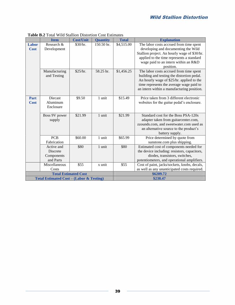
Table B.2 Total Wild Stallion Distortion Cost Estimates Item Cost/Unit Quantity Total Explanation
Labor
Cost
Research &
Development
$30/hr. 150.50 hr. $4,515.00 The labor costs accrued from time spent
developing and documenting the Wild
Stallion project. An hourly wage of $30/hr.
applied to the time represents a standard
wage paid to an intern within an R&D
position.
Manufacturing
and Testing
$25/hr. 58.25 hr. $1,456.25 The labor costs accrued from time spent
building and testing the distortion pedal.
An hourly wage of $25/hr. applied to the
time represents the average wage paid to
an intern within a manufacturing position.
Part
Cost
Diecast
Aluminum
Enclosure
$9.50 1 unit $15.49 Price taken from 3 different electronic
websites for the guitar pedal’s enclosure.
Boss 9V power
supply
$21.99 1 unit $21.99 Standard cost for the Boss PSA-120s
adapter taken from guitarcenter.com,
zzounds.com, and sweetwater.com used as
an alternative source to the product’s
battery supply.
PCB
Fabrication
$60.00 1 unit $65.99 Price determined by quote from
sunstone.com plus shipping.
Active and
Discrete
Components
and Parts
$80 1 unit $80 Estimated cost of components needed for
the device including: resistors, capacitors,
diodes, transistors, switches,
potentiometers, and operational amplifiers.
Miscellaneous
Costs
$55 x unit $55 Cost of paint, jacks/sockets, knobs, decals,
as well as any unanticipated costs required.
Total Estimated Cost $6209.72
Total Estimated Cost – (Labor & Testing) $238.47

Wild Stallion Distortion
40
Bill of Materials
Table B.3 Wild Stallion Distortion Bill of Materials
Part Description Manufacturer Distributor Quantity Unit Price Total Price
Yobett Resistors Pack Yobett Amazon 1 14.99 14.99
E-Projects 36 Value
Capacitor Kit
E-Projects Amazon 1 19.99 19.99
Alpha 500k & 1M Audio
(Log) Taper
Alpha Electronics Amazon 2 1.40 2.80
Alpha B20k Potentiometer Alpha Electronics Amazon 1 3.99 3.99
Alpha 100k Linear
Potentiometer
Alpha Electronics Amazon 1 1.40 1.40
JRC 4558D DIP Dual Op
Amp
Mammoth Electronics Mammoth
Electronics
2 0.40 0.80
RC 4558P DIP Dual Op
Amp
Texas Instruments Mouser 1 0.37 0.37
LF353P DIP Dual Op Amp Texas Instruments Mouser 1 0.57 0.57
1N914 Zener Diode 20Pack NTE Electronics Amazon 1 7.17 7.17
5mm Red LED RadioShack RadioShack 2 1.99 3.98
Stereo ¼” TRS Jack Switchcraft Amazon 1 6.39 6.39
Mono ¼” TRS Jack Switchcraft Amazon 1 1.55 1.55
2N4401 NPN BJT Central Semiconductor
Corp.
Mouser 2 0.39 0.78
JK-101DC Round DC
Power Jack
Mammoth Electronics Mammoth
Electronics
1 0.80 0.80
9-Pin Latching 3PDT
Footswitch
Uxcell Amazon 1 7.78 7.78
3 x Spool Solid Core
20AWG Hookup Wire
RadioShack RadioShack 1 8.99 8.99
9V DC 1A Power Supply
Cable
Mr. Power Amazon 1 10.99 10.99
3 Pack Duracell Quantum
9V Battery
Duracell Walgreens 1 12.99 12.99
JK-9VSNP Battery Snap
Connector
Mammoth Electronics Mammoth
Electronics
1 0.45 0.45
4S1590B Enclosure Mammoth Electronics Mammoth
Electronics
1 5.75 5.75
PCB Assembly Advanced Circuits Advanced Circuits
www.4pcb.com
3 33.00 99.00
1900 H Series Knob Mammoth Electronics Mammoth
Electronics
3 0.80 2.40
Total Cost $213.93

Wild Stallion Distortion
41
Appendix C: Project Schedule
The project plan formed at the beginning of the Wild Stallion Distortion project assists to provide
organization and accountability. When planning a project, two main resources require accounting. These
resources appear as time and money. Figure C.1, Figure C.2, and Figure C.3 show Gantt charts
representing the expected timeline of the project. The chart exists, split into three figures for the reader’s
convenience.
Figure C.1: Gantt chart through EE460

Wild Stallion Distortion
42
Figure C.2: Gantt chart through EE461
Figure C.3: Gantt chart through EE462

Wild Stallion Distortion
43
Appendix D: Printed Circuit Board Layout
Figure D.1: PCB Layout