wylliams barbosa santos...catalogação na fonte bibliotecária jane souto maior, crb4-571 santos,...
TRANSCRIPT

“TIRT: A Traceability Information Retrieval Tool for
Software Product Lines Projects”
By
Wylliams Barbosa Santos
M.Sc. Dissertation
RECIFE, SEPTEMBER/2011

Federal University of Pernambuco
Center for InformaticsGraduate in Computer Science
Wylliams Barbosa Santos
“TIRT: A Traceability Information Retrieval Tool forSoftware Product Lines Projects”
A M.Sc. Dissertation presented to the Center for Informatics
of Federal University of Pernambuco in partial fulfillment
of the requirements for the degree of Master of Science in
Computer Science.
Advisor: Silvio Romero de Lemos Meira
Co-Advisor: Eduardo Santana de Almeida
RECIFE, SEPTEMBER/2011

Catalogação na fonte Bibliotecária Jane Souto Maior, CRB4-571 Santos, Wylliams Barbosa
TIRT: A traceability information retrieval tool for software product lines projects / Wylliams Barbosa Santos - Recife: O Autor, 2011. xvi, 115 folhas : il., fig., tab. Orientador: Silvio Romero de Lemos Meira. Dissertação (mestrado) - Universidade Federal de Pernambuco. CIn, Ciência da Computação, 2011. Inclui bibliografia e apêndice. 1. Ciência da Computação. 2. Engenharia de software. I. Meira, Silvio Romero de Lemos (orientador). II. Título. 004 CDD (22. ed.) MEI2011 – 150


I specially dedicate this dissertation with love and affection
to my father Rosenildo (In Memoriam). The best man and
friend I ever met.

Acknowledgements
Firstly to God for every blessing, protection, love and strength throughout my life.To my father Rosenildo (in memoriam), that has always guided me, supported and
encouraged me every step of my life. I would like to thank him for his reference oflove, happiness, father and teacher, as well as their advices, words of encouragement andsupport during the master degree. Finally, I would like to dedicate this work to my great,eternal and beloved father Rosenildo, because this is the realization of our dream!
To my mother for all support, love and friendship. I am profoundly grateful for herwisdom in understanding the distance that separates us, especially in the most delicateand difficult moments we faced. Mother, know that even with the distance will always betogether and great friends. I also dedicate this work with all the love and affection to mymother and friend Graça.
My friend and bride Deborah, for all love, affection, support and friendship duringthis the master degree, as well as by welcome and friendly words in the most adversemoments.
My brother Wylker, for friendship during our lives and especially during these yearswe lived in Recife.
To my uncles Marcos, Kêda and their entire family, my eternal gratitude for allcomfort and affection during the most delicate moment of my life. All these feelingswere channeled in a positive way, giving me strength and support for achieving this work.
To my friends from Maceió for all support: Elinaldo da Mota, Fabiano Wandeley,Telma Melo, Marcelo Feijó, Giordany Corado, Thiago Alves and Bruno Correia.
All RiSE members which contributed with valuable suggestions, comments andreviews in this work, especially, to friends: Leandro Souza, Jonatas Bastos, Iuri Santos,Thiago Fernandes, Ivonei Freitas, Raphael Pereira, Ivan Machado and Paulo Silveira.
Last but not least, my sincere thanks to my co-advisor Eduardo Almeida, for allguidance, support and teachings. I am also very grateful to my advisor Silvio Meira whoaccepted me as his student.
iv
Agradecimentos
Primeiramente a Deus, por toda benção, proteção, amor e força durante toda minha vida.Ao meu pai Rosenildo (in memoriam), que sempre me guiou, apoiou e incentivou-me
em todas as etapas de minha vida. Gostaria de agradecê-lo pelo seu referencial de amor,alegria, pai e mestre, assim como seus conselhos, palavras de incentivo e apoio durante ajornada do mestrado. Por fim, gostaria de dedicar este trabalho ao meu grande, eterno eamado pai Rosenildo, pois este é a concretização do nosso sonho!
À minha mãe por todo suporte, amor e amizade. Sou imensamente grato por suasabedoria em compreender a distância que nos separa, principalmente nos momentosmais delicados e difíceis que enfrentamos. Mãe, saiba que independente da distânciasempre estaremos juntos e seremos grandes amigos. Também dedico este trabalho comtodo amor e carinho à minha mãe e amiga Graça.
À minha amiga, companheira e noiva Deborah, por todo amor, carinho, suporte eamizade durante essa jornada, assim como pelas palavras amigas e acolhimento nosmomentos mais adversos.
Ao meu irmão Wylker, pelo companheirismo e amizade durante nossas vidas eprincipalmente ao longo desses anos que moramos em Recife.
Aos meus tios Marcos, Kêda e toda sua família, minha gratidão eterna, por todo con-forto e carinho durante o momento mais delicado de minha vida. Todos esses sentimentosforam canalizados de forma muito positiva, dando-me forças e suporte para concretizaçãodeste trabalho.
Aos meus amigos de Maceió por todo apoio: Fabiano Wandeley, Elinaldo da Mota,Telma Melo, Marcelo Feijó, Bruno Correia, Giordany Corado e Thiago Alves.
A todos os membros do RiSE que contribuíram com valiosas sugestões, comentáriose revisões neste trabalho. Em especial, aos amigos: Leandro Souza, Jonatas Bastos, IuriSantos, Thiago Fernandes, Ivonei Freitas, Raphael Pereira, Ivan Machado e Paulo Neto.
Por fim, mas não menos importante, meus sinceros agradecimentos ao meu co-orientador Eduardo Almeida, por todo direcionamento, apoio e ensinamentos. Tambémsou muito grato ao meu orientador Silvio Meira que me acolheu como seu aluno demestrado.
v

De tudo ficaram três coisas:
a certeza de que estava sempre começando,
a certeza de que era preciso continuar
e a certeza de que seria interrompido antes de terminar.
Fazer da interrupção um caminho novo,
fazer da queda, um passo de dança,
do medo, uma escada,
do sonho, uma ponte,
da procura, um encontro.
—FERNANDO SABINO (1923-2004)

Resumo
Linha de Produto de Software - SPL tem provado ser a metodologia para o desenvolvi-mento de uma diversidade de produtos de software e sistemas com custos mais baixos,em menor tempo, e com maior qualidade. Numerosos relatos documentam significativasexperiências adquiridas através da implantação de linhas de produtos na indústria desoftware.
Neste cenário, a rastreabilidade se refere à capacidade de conectar e preservar orastro de transformação de diferentes artefatos de softwares, portanto, é considerada umacondição necessária para preservar a consistência dos artefatos durante a implementação,reduzindo o tempo e o custo de desenvolvimento da SPL. No entanto, a adoção emanutenção da rastreabilidade no contexto das linhas de produtos são consideradastarefas difíceis, devido ao grande número e heterogeneidade dos artefatos desenvolvidos.Além disso, a criação manual e manutenção das relações de rastreabilidade são difíceis,propensa a erros, lenta e complexa.
Neste sentido, esta dissertação propõe diferentes cenários de recomendação de rastre-abilidade, onde os artefatos podem estar relacionados. Além disso, os requisitos, projetoe desenvolvimento de uma ferramenta também são propostos. Esta ferramenta foca nasatividades de manutenibilidade, relacionadas à rastreabilidade entre diferentes artefatosde uma SPL através do seu sistema de recomendação. Assim, o tempo gasto nessasatividades pode ser reduzido e menos propenso a erros. Finalmente, este trabalho tambémapresenta um estudo experimental inicial, a fim de identificar a viabilidade da ferramentae cenários de rastreabilidade propostos.
Palavras-chave: Rastreabilidade, Linha de Produto de Software, Ferramenta, Recuper-ação de Informação, Rastreabilidade em Linha de Produto de Software
vii

Abstract
Software Product Line - SPL has proven to be the methodology for developing a diversityof software products and software-intensive systems at lower costs, in shorter time,and with higher quality. Numerous reports document the significant achievements andexperience gained by introducing software product lines in the software industry.
In this scenario, traceability refers to the ability to link and preserve the trace oftransformation among different software artefacts, thus it is considered a necessaryprecondition for preserving the consistency of the complete family model during de-velopment, reducing the development time and cost in the SPL. However, the adoptionand maintenance of traceability in the context of product lines is considered a difficulttask, due to the large number and heterogeneity of assets developed during product lineengineering. Futhermore, the manual creation and management of traceability relationsis difficult, error-prone, time consuming and complex.
In this sense, this dissertation proposes different scenarios of traceability recom-mendation, which the core assets can be related. In addition, the requirements, designand implementation of a tool is also proposed. It focus on the maintenance activitiesregarding to the traceability relationship among the different core assets in a SPL throughits recommendation system. Thus, the time spent in these activities can be reduced andless error prone. Finally, this work also presents an initial experimental study in order toidentify the viability of the proposed tool and traceability scenarios.
Keywords: Traceability, Software Product Lines, Tool, Information Retrieval, Trace-ability in Software Product Lines
viii

Table of Contents
List of Figures xiii
List of Tables xiv
List of Acronyms xv
1 Introduction 11.1 Motivation . . . . . . . . . . . . . . . . . . . . . . . . . . . . . . . . . 21.2 Problem Statement . . . . . . . . . . . . . . . . . . . . . . . . . . . . 31.3 Overview of the Proposed Solution . . . . . . . . . . . . . . . . . . . . 3
1.3.1 Context . . . . . . . . . . . . . . . . . . . . . . . . . . . . . . 31.3.2 Outline of the Proposal . . . . . . . . . . . . . . . . . . . . . . 6
1.4 Out of Scope . . . . . . . . . . . . . . . . . . . . . . . . . . . . . . . 61.5 Statement of the Contributions . . . . . . . . . . . . . . . . . . . . . . 71.6 Dissertation Structure . . . . . . . . . . . . . . . . . . . . . . . . . . . 8
2 Software Product Lines: An Overview 92.1 Software Reuse . . . . . . . . . . . . . . . . . . . . . . . . . . . . . . 92.2 Software Product Lines . . . . . . . . . . . . . . . . . . . . . . . . . . 10
2.2.1 SPL Motivations and Benefits . . . . . . . . . . . . . . . . . . 12Reduction of Development Costs . . . . . . . . . . . . . . . . 12Enhancement of Quality . . . . . . . . . . . . . . . . . . . . . 13Reduction of Time to Market . . . . . . . . . . . . . . . . . . . 14Reduction of Maintenance Effort . . . . . . . . . . . . . . . . . 14Coping with Evolution and Improving Cost Estimation . . . . . 15Benefits for the Customer . . . . . . . . . . . . . . . . . . . . 15
2.2.2 SPL Essential Activities . . . . . . . . . . . . . . . . . . . . . 16Core Asset Development . . . . . . . . . . . . . . . . . . . . . 17Product Development . . . . . . . . . . . . . . . . . . . . . . . 18Management . . . . . . . . . . . . . . . . . . . . . . . . . . . 20
2.2.3 SPL Strategies . . . . . . . . . . . . . . . . . . . . . . . . . . 202.3 Chapter Summary . . . . . . . . . . . . . . . . . . . . . . . . . . . . . 21
ix

3 An Overview on Traceability and Impact Analysis 223.1 Traceability . . . . . . . . . . . . . . . . . . . . . . . . . . . . . . . . 23
3.1.1 Purpose of Stakeholders . . . . . . . . . . . . . . . . . . . . . 253.1.2 Types of Traceability Relations . . . . . . . . . . . . . . . . . 273.1.3 Generation of Traceability . . . . . . . . . . . . . . . . . . . . 30
Manual Generation . . . . . . . . . . . . . . . . . . . . . . . . 31Semi-automatic Generation . . . . . . . . . . . . . . . . . . . 31Automatic Generation of Traceability Relations . . . . . . . . . 32
3.2 Traceability for SPL . . . . . . . . . . . . . . . . . . . . . . . . . . . . 333.2.1 Research Strategy - SPL Traceability Literature . . . . . . . . . 34
Research Questions . . . . . . . . . . . . . . . . . . . . . . . . 34Search Strategy . . . . . . . . . . . . . . . . . . . . . . . . . . 35Data Sources . . . . . . . . . . . . . . . . . . . . . . . . . . . 36Studies Selection . . . . . . . . . . . . . . . . . . . . . . . . . 38Data Analysis . . . . . . . . . . . . . . . . . . . . . . . . . . . 39
3.2.2 Research Results . . . . . . . . . . . . . . . . . . . . . . . . . 393.2.3 Risks and Challenges . . . . . . . . . . . . . . . . . . . . . . . 43
3.3 Impact Analysis . . . . . . . . . . . . . . . . . . . . . . . . . . . . . . 443.3.1 Impact Analysis for SPL . . . . . . . . . . . . . . . . . . . . . 46
Challenges . . . . . . . . . . . . . . . . . . . . . . . . . . . . 463.4 Chapter Summary . . . . . . . . . . . . . . . . . . . . . . . . . . . . . 47
4 TIRT: Traceability Information Retrieval Tool 484.1 The Set of Requirements . . . . . . . . . . . . . . . . . . . . . . . . . 49
4.1.1 Functional Requirements . . . . . . . . . . . . . . . . . . . . . 494.1.2 Non-Functional Requirements . . . . . . . . . . . . . . . . . . 50
4.2 Traceability Recommendation Proposal . . . . . . . . . . . . . . . . . 524.2.1 The Metamodel . . . . . . . . . . . . . . . . . . . . . . . . . . 524.2.2 Metamodel Instantiation . . . . . . . . . . . . . . . . . . . . . 564.2.3 Scenarios Recommendation . . . . . . . . . . . . . . . . . . . 564.2.4 Vocabulary Standardization . . . . . . . . . . . . . . . . . . . 624.2.5 Impact Analysis . . . . . . . . . . . . . . . . . . . . . . . . . 64
4.3 TIRT Architecture and Technologies . . . . . . . . . . . . . . . . . . . 664.3.1 TIRT’s Architecture Overview . . . . . . . . . . . . . . . . . . 664.3.2 Demoiselle Framework Architecture . . . . . . . . . . . . . . . 694.3.3 Demoiselle Framework Architecture Instatiation for TIRT . . . 71
x

Visualization . . . . . . . . . . . . . . . . . . . . . . . . . . . 71Text Processor . . . . . . . . . . . . . . . . . . . . . . . . . . 73Query Parser . . . . . . . . . . . . . . . . . . . . . . . . . . . 74Indexer . . . . . . . . . . . . . . . . . . . . . . . . . . . . . . 74
4.4 TIRT in Action . . . . . . . . . . . . . . . . . . . . . . . . . . . . . . 744.5 Chapter Summary . . . . . . . . . . . . . . . . . . . . . . . . . . . . . 77
5 TIRT Evaluation 785.1 Introduction . . . . . . . . . . . . . . . . . . . . . . . . . . . . . . . . 785.2 The Definition . . . . . . . . . . . . . . . . . . . . . . . . . . . . . . . 80
5.2.1 Goal . . . . . . . . . . . . . . . . . . . . . . . . . . . . . . . . 805.2.2 Questions . . . . . . . . . . . . . . . . . . . . . . . . . . . . . 815.2.3 Metrics . . . . . . . . . . . . . . . . . . . . . . . . . . . . . . 81
5.3 The Planning . . . . . . . . . . . . . . . . . . . . . . . . . . . . . . . 835.3.1 Context Selection . . . . . . . . . . . . . . . . . . . . . . . . . 835.3.2 Hypothesis Formulation . . . . . . . . . . . . . . . . . . . . . 845.3.3 Variable Selection . . . . . . . . . . . . . . . . . . . . . . . . 855.3.4 Selection of Subjects . . . . . . . . . . . . . . . . . . . . . . . 855.3.5 Experimental Design . . . . . . . . . . . . . . . . . . . . . . . 865.3.6 Instrumentation . . . . . . . . . . . . . . . . . . . . . . . . . . 875.3.7 Pilot Project . . . . . . . . . . . . . . . . . . . . . . . . . . . . 885.3.8 Validity Evaluation . . . . . . . . . . . . . . . . . . . . . . . . 88
5.4 The Operation . . . . . . . . . . . . . . . . . . . . . . . . . . . . . . . 895.4.1 Preparation . . . . . . . . . . . . . . . . . . . . . . . . . . . . 905.4.2 Execution . . . . . . . . . . . . . . . . . . . . . . . . . . . . . 905.4.3 Data Validation . . . . . . . . . . . . . . . . . . . . . . . . . . 91
5.5 Analysis and Interpretation . . . . . . . . . . . . . . . . . . . . . . . . 915.5.1 Quantitative Analysis . . . . . . . . . . . . . . . . . . . . . . . 91
Hypothesis Testing . . . . . . . . . . . . . . . . . . . . . . . . 935.5.2 Qualitative Analysis . . . . . . . . . . . . . . . . . . . . . . . 93
5.6 Conclusion . . . . . . . . . . . . . . . . . . . . . . . . . . . . . . . . 945.7 Chapter Summary . . . . . . . . . . . . . . . . . . . . . . . . . . . . . 94
6 Conclusion 966.1 Research Contribution . . . . . . . . . . . . . . . . . . . . . . . . . . 976.2 Future Work . . . . . . . . . . . . . . . . . . . . . . . . . . . . . . . . 98
xi

Bibliography 100
Appendices 111
A Experiment Instruments 112A.1 Time sheet of Core Assets Management with TIRT . . . . . . . . . . . 112A.2 Time sheet of Core Assets Management with SPLMT . . . . . . . . . . 113A.3 Questionnaire for Subjects Profile . . . . . . . . . . . . . . . . . . . . 114A.4 Form for Qualitative Analysis . . . . . . . . . . . . . . . . . . . . . . 115
xii

List of Figures
1.1 RiSE Labs Influences . . . . . . . . . . . . . . . . . . . . . . . . . . . 41.2 RiSE Labs Projects . . . . . . . . . . . . . . . . . . . . . . . . . . . . 5
2.1 SPL Development Cost . . . . . . . . . . . . . . . . . . . . . . . . . . 132.2 SPL Time to Market . . . . . . . . . . . . . . . . . . . . . . . . . . . 142.3 SPL Essential Activities . . . . . . . . . . . . . . . . . . . . . . . . . . 162.4 Core Asset Development . . . . . . . . . . . . . . . . . . . . . . . . . 172.5 Product Development . . . . . . . . . . . . . . . . . . . . . . . . . . . 19
4.1 Software Product Line Metamodel . . . . . . . . . . . . . . . . . . . . 534.2 Subset of the Software Product Line Metamodel . . . . . . . . . . . . . 574.3 Core Assets: Feature, Requirement and Use Case . . . . . . . . . . . . 584.4 Scenario 1 - Feature and Parent-Features . . . . . . . . . . . . . . . . . 594.5 Scenario 2 - Feature and Required-Features . . . . . . . . . . . . . . . 594.6 Scenario 3 - Feature and Excluded-Features . . . . . . . . . . . . . . . 604.7 Scenario 4 - Feature and Requirements . . . . . . . . . . . . . . . . . . 604.8 Scenario 5 - Requirement and Features . . . . . . . . . . . . . . . . . . 614.9 Scenario 6 - Requirement and Use Cases . . . . . . . . . . . . . . . . . 624.10 Scenario 7 - Use Case and Requirements . . . . . . . . . . . . . . . . . 624.11 Tree View of Analysis Impact . . . . . . . . . . . . . . . . . . . . . . 654.12 System Architecture for Generic Text Mining System . . . . . . . . . . 674.13 Instantiation of Text Mining Architecture for TIRT . . . . . . . . . . . 684.14 Demoiselle Framework Architecture . . . . . . . . . . . . . . . . . . . 704.15 Demoiselle Layers . . . . . . . . . . . . . . . . . . . . . . . . . . . . 714.16 Demoiselle Instantiation Layers for TIRT . . . . . . . . . . . . . . . . 724.17 Tree View of Analysis Impact . . . . . . . . . . . . . . . . . . . . . . 764.18 Requirements Recommendation Screen . . . . . . . . . . . . . . . . . 764.19 Help of Scenarios Recommendation . . . . . . . . . . . . . . . . . . . 77
5.1 Overview of the Experimental Process . . . . . . . . . . . . . . . . . . 795.2 MedicWare Projects . . . . . . . . . . . . . . . . . . . . . . . . . . . . 845.3 Experiment Design: One factor with two treatment design . . . . . . . 87
xiii

List of Tables
5.1 Subject Profile . . . . . . . . . . . . . . . . . . . . . . . . . . . . . . . 915.2 Collected data during the experiment . . . . . . . . . . . . . . . . . . . 925.3 Descriptive Statistics . . . . . . . . . . . . . . . . . . . . . . . . . . . 925.4 Hypothesis Analysis . . . . . . . . . . . . . . . . . . . . . . . . . . . 93
A.1 Time sheet used with the TIRT tool. . . . . . . . . . . . . . . . . . . . 112A.2 Time sheet used with the SPLMT tool. . . . . . . . . . . . . . . . . . 113A.3 Questionnaire for Subjects Profile. . . . . . . . . . . . . . . . . . . . . 114A.4 Questionnaire for Qualitative Analysis. . . . . . . . . . . . . . . . . . . 115
xiv

List of Acronyms
AJAX Asynchronous Javascript and XML
AOSD Aspect-Oriented Software Development
C.E.S.A.R. Recife Center For Advanced Studies and Systems
CBD Component-Based Development
DE Domain Engineering
FR Functional Requirements
GQM Goal Question Metric
IR Information Retrieval
J2EE Java 2 Enterprise Edition
JSF Java Server Faces
LSI Latent Semantic Indexing
MVC Model-View-Controller
NFR Non-Functional Requirements
ORM Object-Relational Mapping
PLE Product Line Engineering
RiPLE Rise Product Line Engineering Process
RiSE Reuse in Software Engineering Labs
RM Risk Management
SE Software Engineering
SPL Software Product Lines
SPLMT Software Product Lines Management Tool
SQL Structured Query Language
xv

ToolDAy Tool for Domain Analysis
TIRT Traceability Information Retrieval Tool
UFPE Federal University of Pernambuco
VSM Vector Space Model
xvi

1Introduction
Life Success comes from Leaving Your Comfort Zones.
—JONATHAN FARRINGTO
Since the time that software development started to be discussed within the industry,researchers and practitioners have been searching for methods, techniques and tools thatwould allow for improvements in costs, time-to-market and quality. Thus, an envisionedscenario was that managers, analysts, architects, developers and testers would avoidperforming the same activities over and over. In this way, performing some kinds of reuse,costs would be decreased, because the time that would have been necessary to repeat anactivity could be invested in others relevant tasks (Almeida et al., 2007).
However, these benefits are not assured by the application of ad-hoc reuse, whichaddress a not systematic, and generally restricted to source code. Systematic softwarereuse is a technique that is employed to address the need for the improvement of softwaredevelopment quality and efficiency, without relying on individual iniciative (Almeidaet al., 2007).
In this context, Software Product Lines Engineering has proven to be the method-ology for developing a diversity of software products and software-intensive systemsat lower costs, in short time and with higher quality. Numerous reports document thesignificant achievements and experience gained by introducing Software Product Linesin the software industry (Pohl et al., 2005). However in the context of Software ProductLines (SPL), one asset can be used for many applications in the product development, forthis reason, the traceability becomes more important in a Product Line environment.
Thus, the focus of this dissertation is to investigate the state-of-art of traceability inthe context of Software Product Lines and facilitate the maintenance activities of a SPL
1
1.1. MOTIVATION
based of a set recommendations senarios.This Chapter contextualizes the focus of this dissertation and starts by presenting
its motivation in Section 1.1 and a clear definition of the problem in Section 1.2. Anoverview of the proposed solution is outlined in Section 1.3, while Section 1.4 describessome related aspects that are not directly addressed by this work. Section 1.5 presents themain contributions of this work and, finally, Section 1.6 outlines the remainder structureof this dissertation.
1.1 Motivation
Software Product Lines (SPL) allow companies to achieve significant improvements intime-to-market, cost, productivity, and system quality (Clements and Northrop, 2001).For this reason, Product Line systems have been recognized as an important paradigm forsoftware systems engineering. In the last years, a large number of methodologies andapproaches have been proposed to support the development of software systems basedon Product Line development, such as: FODA (Kang et al., 1990a), RSEB (Griss et al.,1998), FORM (Kang et al., 1990b), FAST (Gupta et al., 1997), PLUS(Eriksson et al.,2005), and RiPLE (Neiva, 2008; Oliveira, 2009; Balbino, 2010; Machado, 2010).
On the other hand, traceability has been recognized as an highly important activity insoftware development (Ramesh and Jarke, 2001). In general, traceability relations canimprove the quality of the product being developed, and reduce the development timeand cost. In particular, traceability relations can support evolution of software systems,reuse of parts of the system by comparing components of the new and existing systems,validation that a system meets its requirements, understanding of the rationale for certaindesign and implementation decisions in the system, and analysis of the implications ofchanges in the system (Jirapanthong and Zisman, 2005).
However, the support for traceability in contemporary software engineering environ-mens is not always satisfactory due the lack of tool support, and a general perception thatthe effort to maintain traceability was excessive in respect to its benefits (Cleland-Huang,2006). Other difficulties linked to traceability in SPL are: (a) there is a large number andheterogeneity of documents (features, requirements, use cases, among others), even morethan in traditional software development; (b) one needs to have a basic understandingof the variability consequences during the different development phases; (c) one needsto establish relationships between product members and the product line architecture,or relationships between the product members themselves; and (d) there is still poorgeneral support for managing requirements and handling complex relations (Anquetil
2

1.2. PROBLEM STATEMENT
et al., 2008). In addition, the lack of automation support for traceability, maintaininglinks between artefacts is a tedious and time consuming job (Abid, 2004). According toSpanoudakis and Zisman (2004), despite its importance and results from several years ofresearch, empirical studies of traceability needs, and practices in industrial organizationshave indicated that traceability support is not always satisfactory. As a result, traceabilityis rarely established in existing industrial settings.
Thus, in this work we try to mitigate the dificulties in the maintenance activities inSPL environments, based on a set of recommendations scenarios proposed in Chapter 4.Both Software Product Lines and Traceability are futher discussed in Chapters 2 and 3repectively.
1.2 Problem Statement
Motivated by the scenario presented in the previous Section, the goal of this dissertationcan be stated as:
This work investigates the state-of-art of Traceability in the context of Software
Product Lines, provides a tool to support and reduce the effort spent in the traceability
maintenance. This tool emcompasses some features, such as: a set of recommendations
scenarios of traceability and the standarlized vocabulary for recording the artefacts.
Moreover, the Traceability Information Retrieval Tool (TIRT) also emcompasses some
features to aid in impact analysis.
1.3 Overview of the Proposed Solution
In order to accomplish the goal of this dissertation, the TIRT is proposed. The proposedtool supports the recommendation of core assets traceability in order to assist engineersin the maintenance activity. This Section presents the context where it is regarded andoutlines the proposed solution.
1.3.1 Context
This dissertation is part of the Reuse in Software Engineering Labs (RiSE) 1 (Almeidaet al., 2004), formerly called RiSE Project, whose goal is to develop a robust frameworkfor software reuse in order to enable the adoption of a reuse program. However, it is
1http://www.rise.com.br
3

1.3. OVERVIEW OF THE PROPOSED SOLUTION
influenced by a series of areas, such as software measurement, architecture, quality,environments and tools, and so on, in order to achieve its goal. The influence areas aredepicted in Figure 1.1.
Figure 1.1 RiSE Labs Influences
Based on these areas, the RiSE Labs is divided in several projects, as shown in Figure1.2. This framework encompasses many different projects related to software reuse andsoftware engineering.
• RiSE Framework: Involves reuse processes (Almeida et al., 2004; Nascimento,2008), component certification (Alvaro, 2009) and reuse adoption process (Garcia,2010).
• RiSE Tools: Research focused on software reuse tools, such as the Admire Envi-ronment (Mascena, 2006), the Basic Asset Retrieval Tool (B.A.R.T) (Santos et al.,2006), which was enhanced with folksonomy mechanisms (Vanderlei et al., 2007),semantic layer (Durao, 2008), facets (Mendes, 2008) and data mining (Martinset al., 2008), and the Legacy InFormation retrieval Tool (LIFT) (Brito, 2007), andthe Tool for Domain Analysis (ToolDAy) (Lisboa, 2008).
• RiPLE: Development of a methodology for Software Product Lines (Filho et al.,2008), composed of scoping (Balbino, 2010), requirements engineering (Neiva,
4

1.3. OVERVIEW OF THE PROPOSED SOLUTION
2008), design (Cavalcanti, 2010), implementation, test (Neto, 2010; Machado,2010), and evolution management (Oliveira, 2009).
• SOPLE: Development of a methodology for Software Product Lines based onservices (Ribeiro, 2010; Medeiros, 2010), with some ideas of RiPLE;
• MATRIX: Investigates the area of measurement in reuse and its impact on qualityand productivity;
• BTT: Research focused on tools for detection of duplicated change requests (Cav-alcanti, 2009; Cunha, 2009), based on text mining and software vizualizationtechnique.
• Exploratory Research: Investigates new research directions in software engineer-ing and its impact on reuse;
• CX-Ray: Focused on understanding the Recife Center For Advanced Studies andSystems (C.E.S.A.R.), and its processes and practices in software development.C.E.S.A.R. 2 is a CMMi level 3 company with around 700 employees.
Figure 1.2 RiSE Labs Projects
This dissertation is part of the RiSE Tools and RiPLE process. Its goal is to providea tool for search and maintainability of traceability between different core asset with theobjective of avoiding the lose of tracebility information. In additional, this dissertationdefines an approach to traceability recommendation of core assets identified in the RiPLE
2http://www.cesar.org.br
5

1.4. OUT OF SCOPE
process, such as: features, requirements and use cases. This work was conducted inthe context of a Software Product Lines environment, where the large number andheterogeneity of core assets generated during the development of product line systemsmay cause difficulties to identify common and variable aspects among applications,and reuse of core assets available under the product line architecture (Jirapanthong andZisman, 2005). In this context, is possible to see that the recommendation of traceabilitylinks between these artefacts facilitate the matainance activity, and thus a systematic andconsistent reuse (Pohl et al., 2005).
1.3.2 Outline of the Proposal
Thus, the goal of this dissertation is to develop a solution that consists in a Web basedapplication that enables engineers involved in the core assets maintenance to performsuch task more effectively. This is possible with the set of traceability recommendations
scenarios, the standardized vocabulary for recording the core assets, and the feature to
aid in impact analysis, encompassed in the TIRT tool.Traceability has been recognized as an important activity in SPL, thus the essence of
this work is to make the maintenance activity of traceability in the context of SoftwareProduct Line less expensive and error-prone.
1.4 Out of Scope
As the traceability process in the context of Software Product Lines is part of a broadercontext, a set of related aspects are left out of its scope. Thus, the following issues arenot directly addressed by this work:
• Product Development: The creation of individual products by reusing the artefactsis an important issue in a SPL. However, this aspect can be as complex as coreassets development, thus, it is out of the scope of this work. In this context, thecore assets focused in this work are: features, requirements and use cases.
• Analyzes of Efficiency: The TIRT tool uses a Vector Space Model (VSM) (Saltonet al., 1975) to represent core assets and perform searches that better meets ournecessity. However, the activity of analyzing how efficient is the model is outof scope of this work. The work proposed by Salton et al. (1975), discusses forexample, the efficiency of this model.
6

1.5. STATEMENT OF THE CONTRIBUTIONS
• Evolution Management: The SPL evolution control is ensured by appropriatepractices of changes management. Inside the evolution management, it is possibleto identify some important research topics, such as: change management, buildmanagement and release management. In this context, a recent work developedin the RiSE Labs (Oliveira, 2009) presented the RiPLE-EM process that focuson a systematic way to guide and manage the evolution of every managementand release management activities. For this reason, evolution management is outof scope of this work. However, this work proposes an approach to mitigate thechange impacts in the context of TIRT tool.
1.5 Statement of the Contributions
As a result of the work presented in this dissertation, a list of main contributions can beidentified:
• An analysis of the state-of-art of the traceability area in the context of SoftwareProduct Lines Engineering. This study was conducted using some good practicesof the Mapping Study proposed by Petersen et al. (2007), allowing an overview ofthe work in the literature and gray literature.
• The TIRT tool to support the maintenance of traceability links. It specifies, designsand implements a solution based on Text Mining (Feldman and Sanger, 2007)and Keywords search techniques, with the objective of recommending possibletraceability links between different core assets.
• Scenarios for traceability recommendation, based on the metamodel developedin the RiSE Labs (Cavalcanti et al., 2011).
• Standardized vocabulary for recording the artefacts, contributing to the effi-ciency of traceability recommendations.
• Description of some scenarios to support the process of Impact Analysis in thecontext of traceability maintenance, implemented in the TIRT tool.
• The definition, planning, analysis of an experimental study in order to evaluatethe proposed tool and approaches.
7

1.6. DISSERTATION STRUCTURE
1.6 Dissertation Structure
The remainder of this dissertation is organized as follows:
• Chapter 2: discusses the concepts of Software Reuse and outlines the main topicsof SPL, such as: the SPL motivations, the SPL strategies and the essential activities.
• Chapter 3: introduces the concepts of Software Traceability and the main topicsin the context of Software Product Lines. The concept of Impact Analysis also arediscussed in this Chapter.
• Chapter 4: presents the functional and non-functional requirements proposedfor the TIRT tool as well as architecture, the set of frameworks, technologiesused during the TIRT implementation. Additionally, the proposals for traceability
recommendation and the standardized vocabulary for recording the artefacts arealso explored.
• Chapter 5: presents the definition, planning, operation, analysis and interpretationof the experimental study which evaluates the TIRT’s tool and proposed approaches.
• Chapter 6: concludes this dissertation, summarizing the findings and proposingfuture enhancements to the solution, and discussing possible future work.
• Appendix A: describes the questionnaires and time sheets applied in the experi-mental study.
8

2Software Product Lines: An Overview
Life has no limitations, except the ones you make.
—LES BROWN (Musician)
Software product lines engineering has proven to be the methodology for developinga diversity of software products and software-intensive systems at lower costs, in shortertime, and with higher quality. Several reports document the significant achievements andexperience gained by introducing software product lines in the software industry (Pohlet al., 2005).
This Chapter introduces the concepts of Software Reuse in Section 2.1 and SoftwareProduct Lines in Section 2.2. The SPL Motivations and Benefits are discussed in Section2.2.1. The SPL Essential Activities in Section 2.2.2 and the SPL Strategies in Section2.2.3. The Chapter Summary is described in Section 2.3.
2.1 Software Reuse
Software reuse is the process of creating software systems from existing software ratherthan building software systems from scratch. This simple yet powerful vision wasintroduced in 1968 by McIlroy (1968). The concept of software reuse has been introducedto overcome the software crisis, i.e., the problem of building large and reliable softwaresystem in a cost effective and controlled way.
Many definitions for software reuse can be found in the literature. Krueger (1992)defines software reuse as ”the process whereby an organization define a set of systematicoperating procedures to specify, produce, classify, retrieve, and adapt software artefactsfor the purpose of using them in its development activities”. Basili and Rombach(1991) defines software reuse as the use of everything associated with a software project,
9

2.2. SOFTWARE PRODUCT LINES
including knowledge. According to Frakes and Isoda (1994), software reuse is definedas the use of engineering knowledge or artefacts from existing systems to build newones. In a practic way, Jamwal (2010) defines software reuse as a ”solution that avoidsa repeated labor in the software development and can make use of the knowledge andexperience getting from the past software development and concentrates the especial partof application.”
A good software reuse process facilitates the increase of productivity, quality, andreliability, and the decrease of costs and implementation time. An initial investment isrequired to start a software reuse process, however, this investment pays for itself in afew reuses (Tracz, 1988).
Besides the issues related to non-technical aspects, a software reuse process mustalso describe two essential activities: the development for reuse and the developmentwith reuse. In the literature, several research work that study efficient ways to developreusable software can be found. These work focus on two directions: domain engineering
and, currently, product lines, as can be seen in the next Sections. According to Pohlet al. (2005), the aim of the domain engineering process is to define and realise thecommonality and the variability of the software product line.
Thus, with the use of techniques such as domain engineering or software productlines, a set of assets (requirements, architectures, source code, test cases, etc.) can bereused in an effective way. In this context, the reminder of this Chapter describes thebasic concepts and ideas of Software Product Lines.
2.2 Software Product Lines
The way that goods are produced has changed significantly in the course of time. Formerlygoods were handcrafted for individual customers. Along the time, the number of peoplewho could afford to buy various kinds of products increased. In the domain of automobilesFord has led the invention of the production line, which enabled the production for amass market much more cheaply than individual product creation on a handcrafted basis.However, the production line reduced the possibilities for diversification. Thus, industrywas confronted with a rising demand for individualised products. This was the beginningof mass customisation, which meant taking into account the customers’ requirements andgiving them what they wanted (Pohl et al., 2005).
Mass customisation is the large-scale production of goods tailored to individualcustomers’ needs (Davis, 1987). For the customer, mass customisation means the ability
10

2.2. SOFTWARE PRODUCT LINES
to have an individualised product. For the company, mass customisation means highertechnological investments which leads to higher prices for the individualised productsand/or to lower profit margins for the company. Both effects are undesirable. Thus manycompanies, especially in the car industry, started to introduce common platforms for theirdifferent types of cars by planning beforehand which parts will be used in different cartypes. The parts comprising the platform were usually the most expensive subsystem interms of design and manufacturing preparation costs. The use of the platform for differentcar types typically led to a reduction in the production cost for a particular car type. Theplatform approach enabled car manufactures to offer a large variety of products and toreduce costs at the same time (Pohl et al., 2005).
R. Cooper and Kleinschmidt (2001) consider a platform when we can derive multipleproducts. According to TechTarget (2004), a platform is any base of technologies onwhich other technologies or processes are built, however, a common definition of platformdoes no exist. This definition encompasses all kinds of reusable artefacts as well as allkinds of technological capabilities.
The combination of mass customisation and a common platform allows us to reusea common base of technology and, at the same time, to bring out products in closeaccordance with customers’ wishes. The systematic combination of mass customisationand the use of a common platform for the development of software-intensive systems andsoftware products is the key focus of software product line engineering.
The strategy commonly adopted is, first, to focus on what is common to all products,and next, to focus on what is different, designing the commonality first and differenceslater. In the first step, artefacts are provided that can be reused for all products. Theseartefacts may be built from scratch or derived from another platform or earlier systems(Pohl et al., 2005).
This flexibility is a precondition for mass customisation; it also means that we canpredefine what possible realisations shall be developed. The flexibility described here iscalled variability in the software product lines context. This variability is the basis formass customization. For Frank J. van der Linder and Schmid (2007), a key distinction ofsoftware product line engineering from other reuse approaches is that the various assetsthemselves contain explicit variability.
Variability management is a concern in any software product lines engineering ap-proach, covering the whole life-cycle, since the early steps of scoping, covering theimplementation, testing and finally the evolution. Thus, variability is relevant to allassets throughout software development (Frank J. van der Linder and Schmid, 2007).
11

2.2. SOFTWARE PRODUCT LINES
Consequently, it became necessary to manage carefully the trace information from aplatform to the products derived from it. Without such trace information, it is barelypossible to find out which parts of the platform have been used in which product.
Next, are described the different reasons and benefits that motivate the companies toadopt a software product lines engineering approach.
2.2.1 SPL Motivations and Benefits
Many different reasons lead companies to adopt a software product lines approach. Theserange for more process-oriented aspects such as cost and time over product qualities (e.g.reliability to end-user aspects such as user interface consistency) (Frank J. van der Linderand Schmid, 2007).
According to Clements and Northrop (2001), the companies adopt software productlines in order to achieve not only benefits that they desired, but also benefits that theyabsolutely needed to ensure their organizational health and in some cases their veryexistence.
The following are some reasons for developing software based on the product lineengineering approach.
Reduction of Development Costs
An essential reason for introducing product line engineering is the reduction of costs.When artefacts from the platform are reused in several different kinds of systems, thisimplies a cost reduction for each system. Before the artefacts can be reused, investmentsare necessary for creating them. In addition, the way in which they shall be reused hasto be planned beforehand to provide managed reuse. This means that the company hasto make an up-front investment to create the platform before it can reduce the costs perproduct by reusing platform artefacts (Pohl et al., 2005).
Figure 2.1 shows the accumulated costs needed to develop n different systems. Thesolid line sketches the costs of developing the systems independently, while the dashedline shows the costs for product line engineering. In the case of a few systems, the costsfor product line engineering are relatively high, whereas they are significantly lowerfor larger quantities. The location at which both curves intersect marks the break-evenpoint. At this point, the costs are the same for developing the systems separately as fordeveloping them by product line engineering. The precise location of the break-even pointdepends on various characteristics of the organisation and the market it has envisaged,
12

2.2. SOFTWARE PRODUCT LINES
such as the customer base, the expertise, and the range and kinds of products (Pohl et al.,2005).
According to McGregor et al. (2002), the strategy that is used to iniciate a productline also influences the break-even point significantly. The strategies behind the productline engineering paradigm are outlined in Section 2.2.3.
Figure 2.1 SPL Development Cost (Pohl et al., 2005)
Moreover, a complete study achieved by Poulin (1997) shows that the developmentcosts are recovered after two or three reuses.
Enhancement of Quality
Software product lines engineering also has a strong impact on the quality of the resultingsoftware. A new application consists, to a large extent, of matured and proven components.This implies that the defect density of such products can be expected to be drasticallylower than products that are developed all anew (Frank J. van der Linder and Schmid,2007).
Thus, the artefacts in the platform are reviewed and tested in many products. Theyhave to prove their proper functioning in more than one kind of product. The extensivequality assurance implies a significantly higher chance of detecting faults and correctingthem, thereby increasing the quality of all products (Pohl et al., 2005).
13

2.2. SOFTWARE PRODUCT LINES
Reduction of Time to Market
According to Pohl et al. (2005), a very critical success factor for a product is the time tomarket. For single-product development, it is assumed that is roughly constant, mostlycomprising the time to develop the product. Figure 2.2 shows that for product lineengineering, the time to market indeed is initially higher, as the common artefacts haveto be built first. Yet, after having passed this hurdle, the time to market is considerablyshortened as many artefacts can be reused for each new product.
Figure 2.2 SPL Time to Market (Pohl et al., 2005)
The improvements of costs and time to market are strongly correlated in softwareproduct line engineering: the approach supports large-scale reuse during software de-velopment (Frank J. van der Linder and Schmid, 2007). As opposed to traditional reuseapproaches (Poulin, 1997), this can be as much as 90% of the overall software. Reuse ismore cost-effetive than development by orders of magnitude. Thus, both developmentcosts and time do market can be dramatically reduced by product line engineering.
Reduction of Maintenance Effort
Whenever an artefact from the platform is changed, e.g., for the purpose of error correction,the changes can be propagated to all products in which the artefact is being used. Thismay be exploited to reduce maintenance effort. At best, maintenance staff does not needto know all specific products and their parts, thus also reducing learning effort. However,given the fact that platform artefacts are changed, testing the products is still unavoidable.Yet, the reuse of test procedures is within the focus of product line engineering as well
14

2.2. SOFTWARE PRODUCT LINES
and helps reduce maintenance effort (Pohl et al., 2005).Usually, along with the reduction of development costs, a reduction of maintenance
costs is also achieved. According by Frank J. van der Linder and Schmid (2007), severalaspects contribute to this reduction; the most notably is the fact that the overall amount ofcode and documentation that must be maintained is dramatically reduced. As the overallsize of the application development projects is strongly reduced, the accompanyingproject risk is reduced as well.
Coping with Evolution and Improving Cost Estimation
According to Pohl et al. (2005), the introduction of a new artefact into the platformor the change of an existing one gives the opportunity for the evolution of all kinds ofproducts derived from the platform. Thus, the company has gains with the evolution andpropagations of new or modified artefacts.
The activity of software estimation becomes straightforward and does not includemuch risk, once the core assets base used in SPL is already built. Consequently, theplatform provides a sound basis for cost estimation.
Benefits for the Customer
Customers have the guarantee of getting products adapted to their real needs and wishes.Besides the advantages of customized products, users do not have to adapt their own wayof working to the software anymore. In the past, it often happened that customers had toget used to a different user interface and a different installation procedure with each newproduct. This annoyed them, in particular as it even happened when replacing one versionof a product by the next version. So, customers began to ask for improved softwareergonomics. Accordingly, software packages were developed to support common userinterfaces and common installation procedures. The use of such packages contributedto the proliferation of the idea of platforms. Moreover, customers can purchase theseproducts at a reasonable price as product line engineering helps to reduce the productioncosts (Pohl et al., 2005).
The benefits, on the oher hand, accrue with each new product release. Once theapproach is established, the organization’s productivity accelerates rapidly and the benefitsfar outweigh the cost. However, an organization that attempts to institute a product linewithout being aware of the cost is likely to abandon the product line concept before seeingit through. It takes a certainn degree of maturity in the developing organization to field a
15

2.2. SOFTWARE PRODUCT LINES
product line sucessfully. Technology change is not the only barrier to sucessful productline adoption. For instance, according to Clements and Northrop (2001), traditionalorganizational structures that simply have one business unit per product are generally notappropriate for product lines.
The following section presents the essential Software Product Lines Activities.
2.2.2 SPL Essential Activities
Each organization differs in a variety of terms, such as, the nature of this products, theirbussiness goals, culture and policies and even their software process discipline. However,this diversity between all companies do not represents an impediment to the successfullof a software product lines adoption.
Nevertheless, Clements and Northrop (2001) distilled universal and essental softwareproduct line activities and practises that apply in every situation. At the highest level ofgenerality are three essential activities illustrated in Figure 2.3.
Figure 2.3 SPL Essential Activities (Clements and Northrop, 2001)
According to Clements and Northrop (2001), core asset development and productdevelopment from the core assets can occur in either order: new products are built fromcore assets, or core assets are extracted from existing products.
Each rotating circle described in Figure 2.3 represents one of the essential activities.All three are linked together and in perpetual motion, showing that they are all essential,
16

2.2. SOFTWARE PRODUCT LINES
linked, and highly iterative, and can occur in any order. Moreover, the rotating arrowsindicates that revisions of existing core assets or even new core assets might, and mostoften do, evolve out of product development. Thus, it is given a neutral idea in regard towhich part of the effort is launched first (Clements and Northrop, 2001).
These three essential activities are outlined in more detail next.
Core Asset Development
Core Asset Development has also been called domain engineering (Pohl et al., 2005).The goal of the core asset development activity is to establish a production capability forproducts. Figure 2.4 illustrates the core asset development activity along with its outputsand influential contextual factors (Clements and Northrop, 2001).
Figure 2.4 Core Asset Development (Clements and Northrop, 2001)
The necessary inputs required by a production capability to develop products are theoutputs of the core asset development activity. They are Product Line Scope, Core AssetBase and Production Plan.
Product Line Scope is a description of the products that will constitute the productline or that the product line is capable of including. At its simplest, scope may consist ofan enumerated list of product names. For a product line to be successful, its scope must
17

2.2. SOFTWARE PRODUCT LINES
be defined carefully. The scope of product line envolves as market conditions change, asthe organization’s plans change, as new opportunities arise, or as the organization quitesimply becomes more adept at software product lines. Envolving the scope is the startingpoint for evolution the product line to keep it current (Clements and Northrop, 2001).Thus, the integration of technical and marketing-oriented product line planning is key tosuccessful product line adoption (Frank J. van der Linder and Schmid, 2007).
According to Helferich et al. (2006), the advantages an organization can reap fromproduct line engineering strongly depend on how well the product line infrastructure andthe actual products that the organisation os going to develop are aligned.
Besides the traditional forms of define product line scope, Balbino (2010) realized anew and challenger study that presents an agile scoping process for product lines joiningthe benefits of the two approaches.
Another output of the core asset development activity are the Core Assets that almostcertainly include an architecture that the products in the product line will share, as wellas software components that are developed for systematic reuse across the product line.
A product line architecture is shared across many different products. Thus, it mustcapture the commonality of these products and deal with their diferences in an effectivemanner (Frank J. van der Linder and Schmid, 2007).
Finally, the last output of core asset development activity is the Production Plan,that describes how the products are produced from the core assets. The Product Plandescribes the overall scheme for how these individual process can be fitted together tobuild a product. It is, in fact, the reuser’s guide to product development within the productline (Clements and Northrop, 2001).
Therefore, these three outputs (the product line scope, core asset base, and productionplan) are necessary ingredients for feeding the product development activity, which turnsout products that serve a particular customer or market niche (Clements and Northrop,2001).
Product Development
Product Development is also known as Application Engineering. The goal of the productdevelopment is to derive specific applications by exploting the variability of the softwreproduct line (Pohl et al., 2005).
In general way, mature product line organizations priorize the health of the overallproduct line over that of individual products, but in the end, the activity of turning out the
18

2.2. SOFTWARE PRODUCT LINES
products is the ultimate product line goal (Clements and Northrop, 2001).The product development activity depends on the three outputs outlined in the Core
Asset Development Section: the product line scope, the core assets, and the productionplan. Besides these outputs, the product development activity also uses the requirementsfor individual products as input. Figure 2.5 shows these relationships.
Figure 2.5 Product Development (Clements and Northrop, 2001)
As well in the Core Asset Development section, the rotating arrows indicate interationand intricate relationships. An appropriate example for this representation, building aproduct that has previously unrecognized commonality with another product already inthe product line will create pressure to update the core assets and provide a basis forexploiting that commonality for future products (Clements and Northrop, 2001).
In a wider way, the main goal of the application engineering is to achieve an as high aspossible reuse of the domain assets. Some specific goals are: to exploit the commonalityand the variability of the software product lines during the development of a productline application; to document the application artefacts, i.e. application requirements,architecture, components, tests, and relate them to the domain artefacts. Last but not least,the activity of estimate the impacts of the differences between application and domainrequirements on architecture, components, and tests (Pohl et al., 2005).
19

2.2. SOFTWARE PRODUCT LINES
Management
Management in the context of Core Assets and Product Development has a critial role ofmaintain the sucessful fielding of a product line (Pohl et al., 2005). Thus, both technicaland organizational levels must be strongly committed to the software product lines effort.That commitment manifests itself in a number of ways that feed the product line effortand keep it healthy and vital (Clements and Northrop, 2001).
Commonly the practice of management identifies production constraints and ulti-mately determines the production strategy. This activity should ensure that these op-erations and the communication paths of the product line effort are documented in anoperational concept.
According Clements and Northrop (2001), some individual or group should be desig-nated to either fill the product line management role and act as a product line championor find and empower one. That champion must be a strong, visionary leader who cankeep the organization squarely pointed toward the product line goals, especially when thegoing gets rough in the early stages.
2.2.3 SPL Strategies
The Software Product Lines strategy describes how the product line practices should beemployed so that the product line organization will achieve its production goals. Thus, theproduction strategy for a software product lines is the high-level description of how theproduction system performs both the core assets and products. The production strategy isderived from the organization business strategy and is intended to coordinate the actionsof the core asset and product developers (Chastek et al., 2009).
There are some strategies for developing SPLs (Pohl et al., 2005): proactive, reactive,and extractive.
With the proactive approach, the organization analyzes, designs and implementsa fresh Software Product Lines to support the full scope of products needed on theforeseeable horizon. Consequently, from the analysis and design, a complete set ofcommon and varying source code, feature declarations, product definitions, and automataare implemented.
In contrast, in the reactive approach, the organization incrementally grows an existingSoftware Product Lines when the demand arises for new products or new requirementson existing products. With this strategy, the common and varying source code, along withthe feature declarations, product definitions, and automata, are incrementally extended in
20

2.3. CHAPTER SUMMARY
reaction to new requirements (Krueger, 2002).Finally, in the the extractive approach, the organization extracts existing products into
a Software product Lines. Thus, this high level of software reuse enables an organizationto very quickly adopt software mass customization (Krueger, 2002).
Although these approaches have different strategies to work during the process ofSPL adoption, they aren not mutually exclusive. For example, a common approach is tobootstrap a software mass customization effort using the extractive approach and thenmove on to a reactive approach to incrementally evolve the production line over time(Krueger, 2002).
2.3 Chapter Summary
Software Product Lines is a very successful approach to achieve software reuse. A goodsoftware reuse adoption facilitates the increase of productivity, quality, and reliability,and the decrease of costs and implementation time. In this context, this chapter sum-marized the basic concepts about software product lines and their aspects, such as: SPLMotivations, the related benefits to use and adoption of SPL and the commonly strategiesused in the SPL adoption.
Next Chapter presents an overview about Traceability in order to identify the conceptsand associated techniques. Moreover, it outlines the specific aspects about the Traceabilityin the context of Software Product Lines and the issues of Impact Analysis area.
21

3An Overview on Traceability and Impact
Analysis
E não diga que a vitória está perdida
Se é de batalhas que se vive a vida
Tente outra vez!
Don’t say that the victory is lost
Because life is a succession of battles
Try one more time!
—RAUL SEIXAS (Musician)
Traceability refers to the ability to link different software artefacts, therefore, trace-ability of software artefacts has been recognized as an important approach for supportingvarious activities in the software system development process. In general, the objective oftraceability is to improve the quality of software systems. More specifically, the traceablesoftware artefacts can be used to support the analysis of implications and integration ofchanges that occur in the software systems (Bennett and Rajlich, 2000); the maintenanceand evolution of software systems; the reuse of software system components by identi-fying and comparing requirements of new and existing systems; the testing of softwaresystem components; and system inspection, by indicating alternatives and compromisesmade during development (von Knethen and Paech, 2002). More succinctly, Kotonyaand Sommerville (1998) emphasize that traceability is mainly concerned to maintaininglinks between different core assets.
According to the various interrelationships of artefacts within a project, software
22

3.1. TRACEABILITY
traceability has been recognized by both researchers and practitioners as a key factor forimproving software development. Potential benefits of traceability include better impactanalysis, lower maintenance costs, and better assessment of product quality (Asuncion,2008). Besides these benefits, traceability also enables system acceptance by allowingusers to better understand the system and contributes to a clear and consistent systemdocumentation.
In the context of Software Product Lines Engineering, the traceability of softwareartefacts is an important factor when it comes to effective development and maintenanceof software system. Traceability management facilitates the SPL artefacts to remain insynchronous state and ensure the consistency of derived products (Abid, 2004).
Thus, the remainder of this Chapter is organized as follows. In Section 3.1, areintroduced the concepts of Software Traceability. Next, the main topics of the Traceabilityarea in the context of Software Product Lines are discussed in Section 3.2. The conceptsof Impact Analysis are depicted in Section 3.3 and finally, the Chapter Summary isdescribed in Section 3.4.
3.1 Traceability
During the software development lifecycle, a lot of software artefacts are generated ateach phases and there are huge amounts of complex traceability links among them (Zhouet al., 2008). According to Lindvall and Sandahl (1996), the establishment of traceabilityrelations has makes the documentation of a system clear and consistent, and makes theprocess of maintaining the system less dependent on individual experts.
von Knethen and Paech (2002) describe traceability as the ability to determine whichdocumentation entities of a software system are related to which other ones, accordingto specific relationships. Another accepted definition given by IEEE (1990) is that”Traceability is the degree to which a relationship can be established between two or moreproducts of the development process, especially products having a predecessor-successoror master-subordinate relationship to one another; for example, the degree to which therequirements and design of a given software component match.”
According to Spanoudakis and Zisman (2004), software traceability is the ability torelate artefacts created during the development of a software system to describe the systemfrom different perspectives and levels of abstraction with each other, the stakeholders thathave contributed to the creation of the artefacts, and the rationale that explains the formof the artefacts - has been recognized as a significant factor for any phase of a softwaresystem development and maintenance process, thus contributing to the quality of the final
23

3.1. TRACEABILITY
product. Its importance has been widely recognized in software process standards and ingovernment regulations (IEEE, 1998) (Ramesh and Jarke, 2001).
Consistently, von Knethen and Paech (2002) describe that besides the tracing approachcaptures and manages relationships between documentation entities, a trace should alsocapture the human cooperation in the design process, that is, how stakeholders contributeto the development (e.g., maintainer, project manager, or tester) in performing their tasks(e.g., changing, controlling, or testing). In this way, tracing approach is used to establishtraceability.
Over the last few years, many work addressing various aspects of traceability proposedby system engineering communities have been done to enhance traceability betweendeveloped artefacts throughout the development lifecycle, such as following.
In the context of vizualization area, Cleland-Huang and Habrat (2007) proposed anapproach to display the candidate links to the user in a relatively bland textual format.This work described several visualization techniques for helping analysts to evaluate setsof candidate links.
There are also other work in the same direction conducted by Cleland-Huang andHabrat (2007), that proposed a special visualization technique - ENVISION, whichis intended to facilitate major software traceability understanding tasks with viewing,navigating, focusing, searching and filtering. In Addition, ENVISION provides otheruseful functions like dual visualization mode, historical navigation path, round tripvisualization. ENVISION is implemented in Eclipse for a traceability visualizing (Zhouet al., 2008).
In the context of automated traceability approaches, Alexander (2002) describedthe experience with a toolkit that helped to reduce the burden of installing traces andallowed readers to view traces with familiar tools. Three traceability tools were used:an analyser that can automatically link Use Case references to Use Cases; a dictionarybuilder that links and if need be creates definitions from marked-up terms; and an exporterthat translates a database of Use Cases into a fully-navigable and fully-indexed hypertext.
In the Information Retrieval (IR) area, Hayes et al. (2003) presented an approachfor improving requirements tracing based on framing it as an IR problem. Specifically,they focus on improving recall and precision in order to reduce the number of missedtraceability links as well as to reduce the number of irrelevant potential links that ananalyst has to examine when performing requirements tracing.
Overall, research into software traceability has been mainly concerned with the study
24

3.1. TRACEABILITY
and definition of different types of traceability relations; support for the generation oftraceability relations, which is the focus of this work in the context of SPL; developmentof architectures, tools, stakeholders’ purpose and environments for the representation andmaintenance of traceability relations; and empirical investigations into organizationalpractices regarding the establishment and deployment of traceability relations in thesoftware development life cycle (Spanoudakis and Zisman, 2004).
3.1.1 Purpose of Stakeholders
Although traceability has been studied in practice for over two decades, there has yetto be a consensus on what information should be captured and used as a part of atraceability scheme. There are many different definitions of traceability, each changingwith a stakeholder’s view of the system (Ramesh et al., 1995). Different stakeholders areinterested in different types of relations. For Kotonya and Sommerville (1998), systemstakeholders are people or organisations who will be affected by the system and who havea direct or indirect influence on the system requirements. For example, end users may beinterested in relations between requirements and design objects as a way of identifyingdesign components generated by or satisfying requirements; designers may be interestedin the same type of relations but as a way of identifying the constraints represented asrequirements associated with a certain design object (Spanoudakis and Zisman, 2004). Inthe context of single software, stakeholders could be the customer, the project manager,the system analyst, the system designer, the test engineer, system maintenance personnel,or the end user of the system.
Traceability provides stakeholders with a means of showing compliance with require-ments, maintaining system design rationale, showing when the system is complete, andestablishing change control and maintenance mechanisms.
In a general way, the purpose of a tracing approach depends on the stakeholder whois interested in the traceability information and the task of the stakeholder that shouldbe supported by the traceability. In this context, purpose characterizes different tracingapproached according to the stakeholders’ view of traceability (von Knethen and Paech,2002). These purposes are discussed following (von Knethen and Paech, 2002).
• Project Manager: Project managers use the traceability information to provide acontrol project progress. The traceability matrix provides the manager a meansof tracking staff progress on the project. Consequently, some project managersbelieve that proper use on traceability provides a means of showing full control of
25

3.1. TRACEABILITY
the project. The project manager uses traceability to track project status similarto the way upper management does, only in more detail. For instance, a GANTTchart generated from the traceability information is used by the project manager indeveloping weekly project status reports (Ramesh et al., 1995). Also, traceabilityhelps the project manager in detecting project delays. Finally, the project managerplans to use traceability to verify and prove to the customer that the system meetsthe stated requirements and the job is complete. By using traceability to acceptancetest plans for every validated requirement, including derived requirements, theproject manager can prove to the customer that the system ”completely” meetstheir needs.
• Customer: Traceability ensures the customer’s satisfaction by proving that all ofthe stated requirements are met and that the job is completed. In addition, the effectof a required change can be demonstrated. These activities are executed by theProject manager.
• Project planner: Project planners are responsible for planning, organizing, secur-ing and managing activities. Thus, a project planner uses a tracing approach toperform impact analysis. Requirements can be tracked to determine the impact of arequired change.
• Tester: The system testers plan on using traceability in writing the acceptancetest plan. Being a tester is about improving the quality of the product beforeit is complete. Thus, making use of the traceability tool, the testers will verifythat the Acceptance Test Plan tests all of the system requirements, thus ensuringcompleteness and that it operates as it is designed to, while meeting all of thecustomer’s requirements.
• System Engineering: Although the project is not at the stage of maintenance,the system designer foresees using requirements traceability extensively in trac-ing changes to code modules and documentation due to the complexity of theengineering projects and management over the life of the project.
• System Designer: Designers use the traceability information to understand de-pendencies between the requirements and to check whether all requirements areconsidered by the design. The system designer also plans on using traceability todetermine which test plans and documentation are effected by a change so that they
26

3.1. TRACEABILITY
could be updated and rewritten. The software designer use traceability as a ”fit andfunction” verification tool.
• Requirements engineer: Requirements engineers is responsible for manage changesto the system requirements (Kotonya and Sommerville, 1998), thus the traceabilityinformation is used to check correctness and consistency of the requirements.
• Validator: Validators use traceability relationships between requirements andtest plans to prove that the system ”completely” meets the needs of the customer.In addition, test procedures can be identified that should be rerun to validate animplemented change. This saves test resources and allows the schedule to bestreamlined.
• Maintainer: Maintainers use the traceability information to decide how a requiredand accepted change will affect a system. Maintainers could identify which modulesare directly affected and which other modules will experience residual effects.Documenting an engineer’s design rationale helps the maintainer to understand thesystem. If a required change is implemented, understanding the existing solutionstructure helps to prevent the system from degrading.
In a case study conducted by Ramesh et al. (1995), are identified that from theupper level management to the system maintenance personnel, every person believesthat traceability needed for the successful completion of a project and that without it,their organization’s success would be in jeopardy. However, there is no agreement in theliterature as to which conceptual trace models are necessary to support which stakeholderand task.
In general way, stakeholders with different perspectives, goals and interests who areinvolved in software development may contribute to the capture and use of traceabilityinformation. Depending on their perceptions and needs, they may influence the selectionof different types of traceability relations which are used in software development projects,and can establish project specific conventions for interpreting the meaning of suchrelations (Spanoudakis and Zisman, 2004). An overview of the main types of traceabilityrelations that have been proposed in the literature is outlined in the following session.
3.1.2 Types of Traceability Relations
Existing approaches and tools for traceability support the representation of different typesof relations between system artefacts but the interpretation of the semantics associated
27

3.1. TRACEABILITY
with a traceability relation depends on the stakeholders, as described in the previewSection 3.1.1.
The semantic associated with the traceability relations leads to a series of relatedstudies. Dick (2002) shows that in industrial settings, the traceability relations are veryshallow and it is necessary to represent deeper and richer semantic traceability relations.He proposes the use of textual rationale and propositional logic in the construction oftraceability arguments. According to Pinheiro and Goguen (1996), traceability relationsshould have precise semantic definition to avoid the problem of culture-based interpreta-tions. On the other hand, Bayer and Widen (2002) suggested that in order to increase theuse of traceability and, therefore, compensate for its cost, traceability relations shouldhave a rich semantic meaning instead of being bi-directional referential relations.
In order to overcome the lack of standard semantic interpretation of traceability rela-tions and establish meaningful forms of semantics for traceability relations, Spanoudakisand Zisman (2004) organized various types of traceability relations proposed in the litera-ture into eight main groups namely: dependency, generalisation, evolution, satisfaction,overlap, conflicting, rationalisation, and contribution relations.
In a general way, traceability relations denote overlap, satisfiability, dependency,evolution, generalization, conflict, contribution and rationalisation associations betweenvarious software artefacts and the stakeholders that have contributed to their construction.These groups are described next in details (Spanoudakis and Zisman, 2004) . In thisexplanation about these types of traceability, is used the term element in a general way torepresent the different parts, entities, and objects in software artefacts that are traceable,such as: stakeholders, requirements statements, classes and code statements. Thus, twoelements e1 and e2, in different or in the same software artefact can be related by morethan one type of relations.
• Dependency relations: This type of relations, an element e1 depends on an ele-ment e2, if the existence of e1 relies on the existence of e2, or if changes in e2 haveto be reflected in e1. For instance, Ramesh and Jarke (2001) propose the use ofdependency relations between different requirements, and between requirementsand design elements.
• Generalisation relations This type of relationship is used to identify how complexelements of a system can be broken down into components, how elements of asystem can be combined to form other elements, focusing on specific conceptsand how an element can be refined by another element (Spanoudakis and Zisman,2004).
28
3.1. TRACEABILITY
• Evolution relations: Relations of this type means the evolution of elements ofsoftware artefacts. In this case, an element e1 ”evolves to” an element e2, if e1
has been replaced by e2 during the development, maintenance, or evolution of thesystem.
• Satisfiability relations: In this type of relations, an element e1 satisfies an elemente2, if e1 meets the expectation, needs, and desires of e2; or if e1 complies with acondition represented by e2. This type of relations is classified within the conditionlink group, which associates restrictions to requirements and contains constraintsand pre-condition links (Pohl, 1996b).
• Overlap relations: In this type of relations, an element e1 overlaps with anelement e2, if e1 and e2 refer to common features of a system or its domain.In (Jirapanthong and Zisman, 2009), an example of this relation exists betweenoperations in the sequence diagram and the descriptions in the use case, sincethis description contains the name of the operation and the name of the class ofthe object of this operations is the sequence diagram. While in (Spanoudakis andZisman, 2004), overlap relations are used between requirement statements, usecases, and analysis object model.
• Contribution relations: This type of relations are used to represent associationsbetween requirement artefacts and stakeholders that have contributed to the gen-eration of the requirements. Gotel and Finkelstein (1995) present an approach,based on modelling the dynamic contribution structures underlying requirementsartefacts, which addresses this issue. More specifically, this approach supportsrequirements pre-traceability, that is the ability to relate a requirement with thestakeholders that expressed it and contributed to its specification.
• Conflict relations: This type of relations means conflicts between two elements e1
and e2. In (Ramesh and Jarke, 2001), conflict relations are used to identify conflictswhen two requirements conflit with each other. This type of conflict relations alsoare used to components, and design elements, to define issues related to theseelements, and to provide information that can help in resolving the conflicts andissues.
• Rationalisation relations: Relations of this type are used to represent and maintainthe rationale behind the creation and evolution of elements, and decisions about
29
3.1. TRACEABILITY
the system at different levels of detail. Ramesh and Jarke (2001) capture therationalisation relations based on the history of actions of how elements are created.
According to Ramesh and Jarke (2001), most of the existing approaches in theliterature have proposed different types of traceability relations that relate requirementsspecifications, and requirements with design specifications and requirements and designartefacts. Ramesh and Jarke (2001) attributed this to the fact that traceability was initiallyproposed to describe and follow the life of a requirement, such as requirement traceability.In additional, Ramesh and Jarke (2001) describe in details the establishment of traceabilityrelations involving code specifications and other software artefacts is not an easy task.
Another classification identified in the literature is related with the dependencyof condition whether traceability relations associate elements of the same artefacts orelements of different artefacts, they can be distinguished into vertical and horizontalrelations, respectively.
As described in this Section, much reference models have also been proposed tosupport semantic interpretation of traceability relations in the literature, but they are notan easy task, besides being error prone on the maintanence activities. In the Chapter4, we describe in details an metamodel that proposes a representation of traceabilityinformation including the different traceable elements and possible traceability scenariosof recommendation.
In the following Section is outlined the different options of traceability generationdescribed in the literature.
3.1.3 Generation of Traceability
As described in the beginning of this Chapter, potential benefits to traceability includebetter impact analysis, lower maintenance costs, and better assessment of product quality(Asuncion, 2008). However, despite these advantages, traceability is difficult to achievein practice, because users still face many problems when employing traceability toolsand techniques.
The majority of contemporary requirements engineering and traceability tools offeronly limited support for traceability as they require users to create traceability relationsmanually. Accordingly to Asuncion et al. (2007), these approaches are generally infea-sible, because most of the manual approaches require high overhead and are viewed bysoftware engineers as imposed work.
In order to mitigate the problem, some approaches which support automatic or
30

3.1. TRACEABILITY
semi-automatic generation of traceability relations have been proposed. Soon thereafter,are described the different approaches for traceability generation based on the level ofautomation that they often which ranges from manual, to semi-automatic, and fullyautomatic generation.
Manual Generation
Manual generation of traceability is normally supported by visualisation and display toolcomponents, in which the documents to be traced are displayed and the users can identifythe elements in the documents to be related in an easier way (Spanoudakis and Zisman,2004).
An example of this approaches was presented in (Pohl, 1996a) that presents a re-quirements engineering environment, called PRO-ART, which enables requirementspre-traceability. PRO-ART is based on some main contributions: a three-dimensionalframework for requirements engineering which defines the kind of information to berecorded; a trace-repository for structuring the trace information and enabling selectivetrace retrieval.
Despite the numerous advantages, the manual creation of traceability relations isdifficult, error prone, time consuming and complex. Thus, an effective traceability israrely established manually in industry.
Semi-automatic Generation
Spanoudakis and Zisman (2004) classify the semi-automatic traceability generation ap-proaches into two groups: pre-defined link group, that is concerned with the approachesin which traceability relations are generated based on some previous user-defined links,and process-driven group, that is concerned with the approaches in which traceabilityrelations are generated as a result of the software development process.
The semi-automated approach appeared in order order to overcome the issues associ-ated with the manual generation of traceability relations. Some approaches have beenproposed in which traceability relations are generated in a semi-automatic way as follows.
In the context of a pre-defined group approach, Egyed (2003) presented an semi-automated approach to generating and validate trace dependencies. This work addressedthe severe problem that the lack of trace information or the uncertainty of its correctnesslimits the usefulness of software models during software development. It also automateswhat is normally a time consuming and costly activity due to the quadratic explosion ofpotential trace dependencies between development artefacts.
31

3.1. TRACEABILITY
Although the above approaches may be considered an improvement when comparedwith the manual approaches, the identification of the initial user-defined links required bysome of the approaches may still cause traceability to be error prone, time consuming,and expensive (Spanoudakis and Zisman, 2004).
Automatic Generation of Traceability Relations
In order to overcome the issues associated with the manual and semi-automated gener-ation of traceability relations, some recently approaches have been proposed in whichtraceability relations are generated in a automatic way. Spanoudakis and Zisman (2004)identify three proposals of approaches to support automatic generation of traceabilityrelations. Some of these approaches use Information Retrieval - IR techniques, others usetraceability rules, special integrators and inference axioms.
In the context of Information Retrieval IR, Antoniol et al. (2002) proposed a methodbased on IR to recover traceability links between source code and free text documents.A premise of this is that programmers use meaningful names for program items, suchas functions, variables, types, classes, and methods. They believes that the application-domain knowledge that programmers process when writing the code is often capturedby the mnemonics for identifiers; therefore, the analysis of these mnemonics can help toassociate high-level concepts with program concepts and vice-versa. This work has beenreported to produce traceability relations at low levels of precision and reasonable levelsof recall. It should be noted, however, that the relations produced by this approach couldonly represent overlap relations between elements in different system artefacts that referto common features of a system. With the same technique, Hayes et al. (2003) presentan approach for improving requirements tracing based on framing it as an informationretrieval IR problem. Specifically, this work focus on improving recall and precision inorder to reduce the number of missed traceability links as well as to reduce the number ofirrelevant potential links that an analyst has to examine when performing requirementstracing.
In the context of rule-based technique, Zisman et al. (2003) presents an approach forautomatic generation and maintenance of bi-directional traceability relations betweencommercial and functional requirements expressed in natural language, and requirementobject models. The generation of traceability relations is based on two types of traceabilityrules: requirements-to-object-model rules and inter-requirements rules.
Sherba et al. (2003) describe a framework for automating the management of trace-ability relationships chaining, called TraceM. According to Sherba et al. (2003), a key
32

3.2. TRACEABILITY FOR SPL
contribution of TraceM is its ability to transform implicit relationships into explicit rela-tionships by processing chains of traceability relationships. This approach uses specialintegrators, which can discover and create traceability relations between software artefactsand other previously defined relations.
In a tool called TOOR (Traceability of Object-Oriented Requirements), traceabilityis defined and derived in terms of axioms. Based on these axioms, the tool allowsautomatic identification of traceability relations between requirements, design, and codespecifications (Pinheiro and Goguen, 1996).
Although none of the above approaches can fully automate the generation of trace-ability relations, they have taken significant steps toward this direction.
According to Ramesh et al. (1995), the costs associated with implementing a compre-hensive traceability scheme can be justified in terms of better quality of the product andthe systems development and maintenance process with potentially lower life cycle costs.
Some of the points described in this Section are strongly present in software productlines. The Mapping Study in the Traceabilify for SPL, and the relation between softwareproduct lines and traceability are outlined in the following Section.
3.2 Traceability for SPL
The Software Product Lines methods and techniques aim at producing software systemfamilies with high level of quality and productivity (Pohl et al., 2005). As discussed inthe preview Chapter, the development of a SPL is typically organized in domain andapplication engineering. The focus of domain engineering is the production of a set ofcore assets to scoping, specification and modeling of the common and variable features ofa Software Product Lines; the definition of a flexible architecture that comprise the SPLcommon and variable features; and the implementation of the SPL architecture. In anapplication engineering process, a feature model configuration can be used to composeand integrate the core assets produced during the domain engineering stage in order togenerate and instance of the SPL architecture.
Several authors believe that traceability is a fundamental condition for the SPLs sucess.According to Streitferdt (2001), traceability throughout model elements is a necessaryprecondition for preserving the consistency of the complete family model during develop-ment. Likewise, Sousa et al. (2009) show that traceability is fundamental to guaranteeand validade the quality of SPL development and to allow a better management of SPL
33

3.2. TRACEABILITY FOR SPL
variabilities. For Jirapanthong and Zisman (2005), traceability relations can improve thequality of the product being developed, and reduce the development time and cost inthe SPL. Researchers have widely acknowledged the potential of traceability relationsin identifying reusable artefacts in the software development life-cycle. According toSpanoudakis and Zisman (2004), these artefacts may be at different levels of abstraction(e.g. source code, design or requirement artefacts) and can be identified and reusedthrough different scenarios, which require the existence of different types of traceabilityrelations.
Next, is outlined the Research Strategy conducted to provide an overview of Trace-ability in the context of the Software product Lines area.
3.2.1 Research Strategy - SPL Traceability Literature
Compared to single systems development, the traceability for Software Product Linesbecomes more complex and challenging, since it involves more artefacts and moredifferent stakeholders. In order to address part of these challenges, some approaches havebeen proposed by industry and academy. Many of these approaches are reported on thescientific literature, thus it is necessary a strategy to map the studies that report thoseapproaches.
The research strategy adopted to relate the main available approaches of the Traceabil-ity area in the context of Software Product Lines was carried out based on some practicesof the Systematic Mapping Study (Petersen et al., 2007). The Systematic mapping isa methodology that is frequently used in medical research, but that have largely beenneglected in Software Engineering (SE). The main practices of the systematic mappingdefined by Petersen et al. (2007) are: definition of the research questions, conductingthe search for relevant papers, screening of papers, keywording of abstracts and dataextraction and mapping.
The remain of this Section presents the good practices of Systematic Mapping Studyadopted in our Research Strategy, but without using all the activities proposed by Petersenet al. (2007).
Research Questions
The research questions guide the design of the research strategy to provide an overviewof a research area, and identify the main and relevant related work. Thus, this study isintended to answer the following research questions:
34

3.2. TRACEABILITY FOR SPL
Q1.Which techniques and areas are addressed by the Traceability in the contextof SPL? This question aims identifing the Traceability approaches in the SPL context,such as: rule based, information retrieval, metamodel.
Q2. Which type of traceability approaches are adopted in the context of SPL?This question aims identifing the the types of existing traceability approaches in thecontext of SPL, such as: manual generation, semi-automatic generation and automaticgeneration.
Following are described how the research was conducted. If involves the steps adaptedfrom (Petersen et al., 2007), such as: Search Strategy and Data sources.
Search Strategy
The first strategy to conduct our research was to create the search string because theprimary studies are identified by using search strings on scientific databases or browsingmanually through relevant conference proceedings or journal publications (Petersenet al., 2007). According to Kitchenham and Charters (2007), a good way to create thesearch string is to structure them in terms of population, intervention, comparison, andoutcome. The structure should be driven by the research questions and are constructedusing boolean ANDs and ORs to combine keywords.
We used various combinations of search items to achieve a more adequate set of key-words, they are: software product lines, software product family, product line, applicationfamily, production line, product population, product family, domain analysis, domain en-gineering, requirements engineering, domain, requirement, variability, variation, domainrequirement, domain requirements software reuse and reuse, as well as their syntacticvariations (e.g. plural form). Thus, this research strategy defines the two following searchstrings:
• Search With Software Product Line criterias: (”Software Product Line” OR
”product line” OR ”product lines” OR ”software family” OR ”software families” OR
”spl” OR ”ple”) AND (”traceability” OR ”tracing” OR ”trace”) AND (”automate”
OR ”automated” OR ”automatic” OR ”semi-automatic” OR ”semi-automated”
OR ”rule-based” OR ”visualization” OR ”information retrieval” OR ”ontology”
OR ”ontological” OR ”semantic index” OR ”latent semantic indexing” OR ”se-
mantic indexing” OR ”generation”)
35

3.2. TRACEABILITY FOR SPL
• Search without Software Product Line criterias: (”Software”) AND (”automate”
OR ”automated” OR ”automatic” OR ”semi-automatic” OR ”semi-automated”
OR ”rule-based” OR ”visualization” OR ”information retrieval” OR ”ontology”
OR ”ontological” OR ”semantic index” OR ”latent semantic indexing” OR ”se-
mantic indexing” OR ”generation”)
Data Sources
The choice of databases was performed in search engines and digital libraries of the mostpopular publishers and organizations in software engineering. Beside the analysis ofthe journals, conferences, proceedings, books and technical reports, we also analyzedthe references of the gray literature. The research was done through last ten years ofconferences and journals. The used strategy is explained in three steps:
1. Since usually the most important work are published on journals (from IEEE, ACMand Springer), they were the first place search.
2. After that, the papers were searched in important conferences in the SoftwareEngineering. The searched conferences were:
• International Conference of Software Engineering (ICSE);
• International Conference on Software Reuse (ICSR);
• International Conference on Software Maintenance (ICSM);
• International Requirements Engineering Conference (IREC);
• International Conference on Object-Oriented Programming, Systems, Lan-guages, and Applications (OOPSLA);
• Software Product Line Conference (SPLC);
• International Conference on Enterprise Information Systems (ICEIS);
• International Conference on Software Process (ICSP);
• International Conference/Workshop on Program Comprehension (ICPC);
• International Conference on Information Reuse and Integration (IRI);
• European Conference for Object-Oriented Programming (ECOOP);
• Empirical Software Engineering and Measurement (ESEM);
36

3.2. TRACEABILITY FOR SPL
• European Software Engineering Conference (ESEC);
• European Conference on Software Architecture (ECSA);
• International Conference and Workshop on the Engineering of Computer-Based Systems (ECBS);
• Asia Pacific Software Engineering Conference (APSEC);
• International Conference on Automated Software Engineering (ASE);
• International Computer Software and Applications Conference (COMPSAC);
• International Conference on Advanced Information Systems Engineering(CAiSE);
• European Conference on Software Maintenance and Reengineering (CSMR);
• Technology of Object-Oriented Languages and Systems Conference (TOOLS);
• Working IEEE/IFIP Conference on Software Architecture (WICSA);
• Working Conference on Reverse Engineering (WCRE);
• Fundamental Approaches to Software Engineering (FASE);
• International Conference on Quality Software (QSIC);
• Euromicro Conference on Software Engineering and Advanced Applica-tions(SEAA);
• International Conference on Generative Programming and Component Engi-neering (GPCE);
• International Conference on Software Engineering and Knowledge Engineer-ing (SEKE);
• International Conference on Composition-Based Software Systems (ICCBSS);
• International Conference on the Quality of Software Architectures (QoSA);
• International Symposium on Component-based Software Engineering (CBSE);
• International Conference on Model Driven Engineering Languages and Sys-tems (MODELS).
3. As next step, the search string defined just above was used to filter potential workthat are not found in the second step. The main databases used to find these paperswere: Scopus, IEEEXPlore, ACM and SpringLink.
4. Finally, papers referenced by the authors of the found papers were also analyzed.
37

3.2. TRACEABILITY FOR SPL
Studies Selection
As soon as the potentially relevant primary studies have obtained, according to the matchof the search items and research questions, the studies found needed to be assessed fortheir actual relevance. In order to obtain these results, are shown shortly after the inclusionand exclusion of the objects. According to Petersen et al. (2007), inclusion/exclusioncriteria are used to exclude studies that are not relevant to answer the research questions,thus it useful to exclude papers which only mentioned our main focus, traceability andSoftware Product Lines in the abstract. This was important since traceability and Software
Product Lines are the central concepts in the area, thus is frequently used in abstractswithout papers really addressing it any further. The criteria are next detailed:
Inclusion Criteria: Studies that present at least one of the following topics:
• Traceability for Software Product Lines.
• SPL Meta-models. It is directly related with traceability for SPL.
• Software Product Lines Variability. Variability is a key concept for SPL modelingand the traceability aspects are important points that must be analyzed.
The inclusion criteria establish the reasons for each study found in the previous step.The abstract explicitly mentions these following topics, because from the abstract, theresearcher is able to deduce that focus of the paper contributes to traceability in thecontext of software product lines engineering.
Exclusion Criteria: the criteria that describes the reasons to discart studies found inthe previous step are:
• The paper lies outside the software engineering domain.
• A work where traceability and software product lines are not part of the contribu-tions of the paper or with insufficient information in traceability.
• A work that is not an approach. It involves only concepts or issues related withtraceability for software product lines.
• A work that the term are only mentioned in the general introductory sentences ofthe abstract.
• Finally, the duplicate studies are ignored when has been published in more thanone publication, the most complete version will be used.
38

3.2. TRACEABILITY FOR SPL
In general, for each selected study was applied the reading of the following elements:titles, abstract, keywords, conclusion and references. These studies were analyzed withfocus on the inclusion and exclusion criteria. The results of this research strategy isvizualized in the Section 3.2.2 (related works), which are described the main availableand relevant works in the area.
Data Analysis
The first stage resulted in a set of 66 studies raised from the web search, through the useof search strategy described previously. However, titles are not always clear indicators ofwhat a study is about. The possibility of finding not so relevant studies was considerated,therefore in a next stage inclusion and exclusion criteria described previously wereapplied to them, which resulted in the reduction of studies. It basically comprised a briefanalysis of abstract and conclusion. This strategy is claimed to be useful for giving theresearcher more detailed information on the subject (Kitchenham and Charters, 2007). Inthe next stage, the whole text was visited in order to have a critical viewpoint on the topicaddressed by the study. Finally, in the end of this stage, many studies that lies out of theinclusion criteria was excluded.
Finally, these good practices addressed the research strategy to the process of identi-fication the main related and available work in the gray literature. A description aboutsome selected approaches in the area are outlined in detail in the next Section.
3.2.2 Research Results
According to the research approach based on some good practices of Systemactic MappingStudies proposed by Petersen et al. (2007) and 28 studies were selected.. The followingworks bring differents traceability approaches in the context of Software Product Lines.
In order to apply SPL practically and to automate SPL process, elements of artefactsand their relationships should be precisely specified. In this context, Streitferdt (2001)proposed a requirements metamodel for system family development. As mentionedin the beginning of the Chapter, Streitferdt (2001) puts traceability throughout modelelement as a necessary precondition for preserving the consistency of the complete familymodel during development. According to Streitferdt (2001), current methods such asFODA (Kang et al., 1990a) and FeatuRSEB (Griss et al., 1998) address the requirements
39

3.2. TRACEABILITY FOR SPL
engineering phase by high level constructs such as use-cases. This is insufficient, sincenot all systems are workflow oriented being needed a lower level approach. Thus, theproposed solution consists of a metamodel upon which a low level model of requirementscan be built for developing system families. In addition, this work identifid the necessityof a tool to perform consistency checking and analyses. The prototype was used inacademic projects and a cooperation project with industry partners, to evaluate, refineand validate the proposed metamodel in practice.
Likewise, Kim et al. (2005) proposed a generic Product Line Engineering (PLE)process based on a survey to identify the representative PLE approaches. Then, this workdefined a meta-model of PLE artefacts, to show how each artefact can be represented atconceptual and physical levels. Finally, were specified an overall traceability map, tracelinks and mapping relationships. For Kim et al. (2005), through the foundation of PLEtraceability, the PLE artefacts such as core assets and instantiated products can be moreefficiently and correctly developed. According to this proposal, family development basedon the metamodel guarantees traceability by the inclusion of all development artefacts ina single and consistent model.
Another work suggested a metamodeling approach to support the tracing of variabilityin requirements and architecture in a product line (Moon et al., 2007). Two metamodelsrepresenting the domain requirements and domain architecture with variability wereproposed. In a general way, the variations in artefact constituents are determined basedon several trace matrices. It must be demonstrated that decisions as to whether propertiesof the requirements are common or optional are rational, because these decisions affectthe properties of subsequent core assets.
The work proposed by Moon et al. (2007) realized a study and verified that manyfeatures modeling approaches are used to represent variability in the problem space, i.e.,at the requirements level, or in the solution space, i.e., at the architecture or source codelevel. However, Moon et al. (2007) emphasized that while these approaches appropriatelyaddress variability issues at each level of abstractions in a product line development, theydo not address issues with regard to tracing between the requirements and the architecture.In other words, they only describe the means of mapping features to the architecture ordesign elements and they do not describe traceability with respect to variation points in therequirements and architecture, which are considered crucial for consistent and efficientdevelopment of product line based applications. Although Berg et al. (2005) describethe importance of tracing variability in a product line and proposes a conceptual modelfor traceability, it does not provide a detailed description of traceability dependencies
40

3.2. TRACEABILITY FOR SPL
between requirement and architecture, such as requirement and architecture models andspecific dependencies with respect to the variability between these.
In summary, this work presents a metamodel, the basis for tracing the variabilitieswith a clear description between two phases in a product line.
Another work conducted by Sousa et al. (2009) proposed a traceability frameworkfor implementing forward and backward trace links among different artefacts from SPLdevelopment, using model-driven engineering techniques. This framework requires thedefinition of a variability model to allow the tracing of SPL common and variable featuresalong the domain and application engineering stages. The variability model is used in thisapproach as the main reference to trace the SPL artefacts. In addition, it is implementedas a flexible framework in order to allow its customization to different SPL traceabilityscenarios.
This work also delineates a survey of existing traceability tools development. Thissurvey was conducted in the context of the AMPLE project (AMPLE, 2011). Accordingto Sousa et al. (2009), the objectives of this survey were to investigate the currentfeatures provided by existing tools in order to assess their strengths and weaknesses andtheir suitability to address SPL development. The tools were evaluated in terms of thefollowing criteria: management of traceability links; traceability queries; traceabilityviews; extensibility; and support for Software Product Lines, Model Driven Engineeringand Aspect-Oriented Software Development (AOSD).
In this context, Sousa et al. (2009) concluded that none of the investigated tools hadbuilt-in support for SPL development, and a vast majority of them are closed, so theycannot be adapted to deal with the issues raised by SPL. In additional, this work alsoidentifies that many tools are still in an experimental state and does not cover traceabilityup to a degree that is desirable. Another relevat aspect detected in this survey is that manytools do not support advanced and specific support to deal with change impact analysis orrequirement/feature covering in the context of SPL development. This is a specific gapthat will be covered in our approach in Chapter 4.
Finally, the conclusions draws from this survey were that existing traceability toolsdo not provide a sucient support to address the traceability problem in SPL development.
In the context of automatic generation of traceability relations, Jirapanthong andZisman (2009) define a traceability reference model with nine different types of traceabil-ity relations for eight types of documents. The traceability rules used in this work areclassified into two groups namely: direct rules, which support the creation of traceability
41

3.2. TRACEABILITY FOR SPL
relations that do not depend on the existence of other relations, and indirect rules, whichrequire the existence of previously generated relations. This rule-based approach allowsautomatic generation of traceability relations between elements of documents createdduring the development of product line systems.
In general, rules assist and automate decision making, allow for standard ways ofrepresenting knowledge that can be used to infer data, facilitate the construction oftraceability generators for large data sets, and support representation of dependenciesbetween elements in the documents. In addition, the use of rules in this approach allowsfor the generation of new relations based on the existence of other relations, supportsthe heterogeneity of documents being compared, and supports data inference in similarapplications (Jirapanthong and Zisman, 2009).
This work is an extension of the work of (Jirapanthong and Zisman, 2005). Itpresented some initial ideas about the approach, an initial version of the traceabilityreference model, and few examples of traceability rules.
A prototype tool called XTraQue was implemented. This tool allows the generation oftraceability relations by interpreting traceability rules. It also offers support for creatingnew traceability rules and translating documents into XML format.
In order to illustrate and evaluate this work, the researchers used a case study from amobile phone product line system. According to Jirapanthong and Zisman (2009), theresults of these experiments are encouraging and comparable with other approaches thatsupport automatic generation of traceability relations. The results of these experimentshave shown an average precision of 85.3% and an average recall of 83.5%. These resultsare comparable to other approaches that support automatic generation of traceabilityrelations between requirements specifications and source code, requirements, use cases,and object models, and requirements and design models (Jirapanthong and Zisman, 2009).
In the context of Information Retrieval - IR approaches, Lucia et al. (2007) haveimproved an artefact management system with a traceability recovery tool based onLatent Semantic Indexing (LSI), an information retrieval technique. Although severalresearch and commercial tools are available to support traceability between artefacts,the main drawback of these tools is the lack of automatic or semi-automatic traceabilitylink generation and maintenance (Alexander, 2002). According to Lucia et al. (2007),several researches have recently applied Information Retrieval techniques to the problemof recovering traceability links between artefacts of different types. IR-based methodsrecover traceability links on the basis of the similarity between the text contained inthe software artefacts. The rationale behind them is the fact that most of the software
42

3.2. TRACEABILITY FOR SPL
documentation is text based or contains textual descriptions and that programmers usemeaninful domain terms to define source code identifier.
This work has assessed LSI in relation to strengths and limitations of using informationretrieval techniques for traceability recovery and devised the need for an incrementalapproach. LSI is an advanced IR method that is able to achieve the same performanceswithout as the classical probabilistic or VSM without requiring preliminary morphologicalanalysis of the document words.
Another contribution of this work are the definition and implementation of a tool thathelps the software engineer to discover emerging traceability links during the softwareevolution, as well as to monitor previously traced links.
Finally, Lucia et al. (2007) concluded that although tools based on informationretrieval provide a useful support for the identification of traceability links during softwaredevelopment, they are still far to support a complete semi-automatic recovery of all links.The results they experience have also shown that such tools can help to identify qualityproblems in the textual description of traced artefacts.
Following are outlined the main risks and challenges of the traceability adoption inthe context of Software Product Lines Engineering.
3.2.3 Risks and Challenges
The large number and heterogeneity of documents generated is considerated as thebiggest challenge to the adoption and maintenance of traceability in the development ofproduct lines. Systems may cause difficulties to identify common and variable aspectsamong applications, and to reuse core assets that are available under the product line(Jirapanthong and Zisman, 2009). Moreover, according to Kim et al. (2005), a precisemapping and relationship among the artefacts are yet to define. In order to apply PLEpractically and to automate PLE process, elements of artefacts and their relationshipsshould be precisely specified.
In general, most of authors agree that despite the advantages and benefits of currenttraceability methods and techniques, most of them do not provide automatic mechanismsor tools to address the traceability between the produced artefacts in both domain andapplication engineering process. Sousa et al. (2009) argue that this is fundamental toguarantee and validate the quality of SPLs development and to allow a better managementof SPL variabilities. On the other hand, current traceability tools do not provide supportto address the new artefacts, such as variability model or processes of SPL development.
43

3.3. IMPACT ANALYSIS
As a result, they do not allow the explicit modeling and management of SPL features.For Lucia et al. (2007), the support for traceability in contemporary software engineeringenvironments and tools is not satisfatory. Lucia et al. (2007) also complete that thisinadequate traceability is one of the main factor that contributes to project overruns andfailures. According to (Alexander, 2002), the main drawback of these tools is the lack ofautomatic or semi-automatic traceability links generation and maintenance.
Beside all these topics discussed previously, the traceability area in the context ofSPL has some limitation, because the majority of the approaches concerning traceabilityfor product line systems focus on traceability metamodel and do not provide ways ofgenerating traceability relations automatically. This is one of the main concerns of thiswork.
Finally, Moon et al. (2007) show that traceability issues are even more important inthe context of product line because the impact of changes in a product line can involveall the product line-based applications, thus the impact analysis is considered as anotherchallenge in this area. The main topics of Impact Analysis are outlined in next session.
3.3 Impact Analysis
Since the process proposed by Royce (1987), popularly known as waterfall process,the maintenance was considered a post-production activity. According to the waterfallprocess, maintenance is the last phase of the software life-cycle, after the delivery anddeployment of the software. This classical view on maintenance has governed theindustrial practice in software development and is still in use today by several companies(Mens and Demeyer, 2008).
As analyzed by Oliveira (2009), it took a while before the software engineers haverealized the limitations of this waterfall model, given the fact that the separation inphases were too strict and inflexible. Commonly, it is unrealistic to assume that allrequirements are know before starting the design phase of the software. One example isthat in many cases, the software requirements continues to change until the end of thesoftware life-cycle.
Software process more evolutionary have been proposed, such as the change mini-cycle, which introduced new important activities such as change impact analysis andchange propagation (Yau et al., 1993).
According to Abma (2009), when a system is designed with evolvability in mind,a good change process can improve the implementation of changes. Such process is
44

3.3. IMPACT ANALYSIS
called change management and provides a common communication channel betweenmaintenance staff, users, project managers and operations staff, and it provides a directoryof changes to the system, for status reporting, project management, auditing and qualitycontrol.
According to Moreton (1996), change management needs at least the following steps:impact analysis, system release planning, change design, implementation, testing andsystem release and integration. One of the interests of this work are in the first stage:impact analysis. In general, impact analysis is the activity of identifing what to modifyto accomplish a change, or of identifying the potential consequences of a change. ForArnold and Bohner (1996), software change impact analysis is the process of identifyingthe potential consequences of a proposed change. It can be used to estimate what has to bemodified in an implementation to accomplish a change. Another definition is providen byPfleeger (2001), as the evaluation of the many risks associated with the change, includingestimates of effects on resources, effort, and schedule.
Arnold and Bohner (1996) summarize that an important aspect that all definitionshave in common is that impact analysis normally does not change anything but for theirunderstanding of the system and the effect of the proposed change. Arnold and Bohner(1996) still identified two types of impact analysis being supported in tools. The first typeworks based on analyzing the source code using techniques like program slicing, cross-referencing and control flow analyzing. The second type is more life-cycle-documentoriented and is based on creating relations between artefacts from the beginning of theproject, instead of the end.
According to Lientz and Swanson (1980), software evolution can be categorized bythe type of changes that are being peformed into four different ”dimensions”:
• Adaptive: related to maintenance performed in response to changes in data andprocessing environments;
• Perfective: maintenance performed to eliminate processing inefficiencies, enhanceperformance, improve maintainability, or which is response to new user require-ments;
• Corrective: maintenance performed in response to failures; and
• Preventive: where the objective is to prevent problems in the future.
The adaptive, perfective and corrective activities are reactive evolution managementactivities, since it concerns with managing the arrived changes and controlling them in
45

3.3. IMPACT ANALYSIS
order to maintain the stability and integrity of the systems. On the other hand, preventiveactivities can be seen as a proactive evolution management activity, since the efforts areon improving the evolvability, and preventing future problems.
3.3.1 Impact Analysis for SPL
In the context of Software Product Lines, the evolution mechanisms still appling in general.However, acoording to Galvão et al. (2008), Software Product Lines pose additionalchallenges regarding their evolution. The evolution in product line is complicated bythe fact that an asset is shared among products, and any change in this asset may affecton several products (McGregor, 2003). Thus, this makes evolution management morechallenging than in traditional single software development (Pussinen, 2002).
A recent work developed in the RiSE Labs by Oliveira (2009) presented the RiPLE-EM process to evolution management. This process is a systematic way to guide andmanage the evolution of every asset and product in a product line context, handlingchange management, build management and release management activities.
Following are described the main Impact Analysis Challenges in the context ofSoftware Product Lines.
Challenges
The main challenges identified by Galvão et al. (2008) are described in order to preservethe benefits of the Software Product Lines approach:
• Declining quality: As with single systems development, the product line is subjectto decline quality unless measures are taken to preserve the quality of the productline. Therefor changes to software artefacts need to be kept track of avoid the devi-ation of core assets from the general architecture, or even disconnection betweenassets and products.
• Corrective maintenance: Differently than single systems development, correctivemaintenance on SPL may impact several application products. We can discernbetween maintenance to core assets and custom assets, where the maintenance oncore assets potentially impacts a higher number of products, while maintenance tocustom assets only affects a smaller number. In any case, corrective changes needto be evaluated carefully in order to ascertain the applicability of the performedchanges to all involved products (Galvão et al., 2008).
46

3.4. CHAPTER SUMMARY
3.4 Chapter Summary
This Chapter presented the main concepts about the Traceability area, including traceabil-ity in the context of Software Product Lines and Impact Analysis.
Traceability refers to the ability to link different information, therefore, traceability ofsoftware artefacts has been recognized as an important approach for supporting variousactivities in the software system development process.
Existing approaches and tools for traceability support the representation of differenttypes of relations (dependency, generalization, evolution, satisfiability, overlap, contri-bution, conflit and rationalisation) between system artefacts but the interpretation of thesemantics associated with a traceability relation depends on the stakeholders, as describedin the Section 3.1.1. Traceability provides stakeholders with a means of showing compli-ance with requirements, maintaining system design rationale, showing when the systemis complete, and establishing change control and maintenance mechanisms. The differentoptions of traceability generation (manual, semi-automatic and automatic) described inthe literature also were described in Section 3.1.3.
In the context of Software Product Lines Engineering, software artefact traceabily isan important factor when it comes to effective development and maintenance of softwaresystem. Traceability management facilitates the SPL artefacts to remain in synchronousstate and ensure the consistency of derived products (Abid, 2004).
A preliminary Mapping Study (Petersen et al., 2007) on Traceability for SPL wasperformed and several related and important works were selected.
Finally, software change impact analysis was discussed in the context of SoftwareProduct Lines. Impact Analysis is the process of identifying the potential consequencesof a proposed change (Arnold and Bohner, 1996). Impact analysis in the context of SPLis complicated by the fact that an asset is shared among products, and any change in thisasset may affect on several products.
Next Chapter presents in details the proposed approach to traceability recommendationin the context of Software Product Lines. Still in the following Chapter are outlined theset of requirements, functionalities and architecture of the TIRT.
47
4TIRT: Traceability Information Retrieval
Tool
Whether you think you can or can’t, you’re right.
—HENRY FORD (Engineer)
Traceability of software artefacts has been recognized as an important approach forsupporting various activities in the software development process. Potential benefits oftraceability include better impact analysis, lower maintenance costs, and better assessmentof product quality (Bennett and Rajlich, 2000). Besides these benefits, traceabilityalso enables system acceptance by allowing users to better understand the system andcontributes to a clear and consistent system documentation. In this way, traceabilityimproves the quality of software system (Asuncion, 2008).
However, as discussed in the previous Chapter, the adoption and maintenance oftraceability in the context of product lines is considered a difficult task, due to thelarge number and heterogeneity of assets developed during product lines engineering.Futhermore, the manual creation and management of traceability relations is difficult,error-prone, time consuming and complex.
In this Chapter, a metamodel is described, which was developed by the RiSE Labswhich proposes a representation of traceability information, including the differenttraceable elements (Features, Requirements, Use Case and Test). This metamodel is thebasis for the traceability recommendation proposal and the tool called TIRT (TraceabilityInformation Retrieval Tool).
TIRT goal is to facilitate the creation and mainly the maintenance activities regardingto the traceability relationship among the different core assets in a Software Product Line
48

4.1. THE SET OF REQUIREMENTS
through its recommendation system. In addition, the tool was also built in order to helpin the process of impact analysis. Thus, the time spent in these activities can be reducedand less error prone.
This Chapter is organized as follows: Section 4.1 presents set of Functional andNon-Functional requirements proposed for the tool and Section 4.2 presents the theproposal for traceability recommendation. Section 4.3 describes the architecture, the setof frameworks and technologies used during the TIRT implementation, while Section 4.4shows the operation of the tool and, finally, Section 4.5 summarizes this Chapter.
4.1 The Set of Requirements
According to Kotonya and Sommerville (1998), the requirements define the services thatthe system should provide and the set out constraints on the system’s operation.
4.1.1 Functional Requirements
Functional Requirements (FR) define the functions of a system, which can be, for example,manipulation of data, implementation of data, implementation of algorithms, and thetechnical details on the system implementation (Kotonya and Sommerville, 1998). In theTIRT specification, the following Functional Requirements were defined:
• FR1. Keyword-based Search in Core Assets base: The tool must provide fea-tures for core assets search in the database, as in web search engines. This wasused since that people are familiar with web search engines.
• FR2. Core Asset Traceability Recomendation: After the inclusion or updateof some core asset, the system has to provide possible recommendation of thecore assets traceability, showing the link between them. The recommendationsare accomplished based on the recommendation scenarios defined in Section 4.2.3.This semi-automatic approach aims to mitigate the inconsistencies of traceabilityand maintainability problems, since every update realized to a core asset, somepossible suggestions of traceability are proposed.
• FR3. Extract useful information from the traceability’s recommendations:After making a search in the tool of possible core assets recommendations, thesubmitters can view each possible core assets from the recommendation list. Thus,when a core asset is being view, the tool must extract relevant information from
49

4.1. THE SET OF REQUIREMENTS
it, such as descriptions, related core assets, restrictions, and so on; Such supple-mentary information may be useful in the analysis made by the domain analyst toascertain whether the relationship among these artefacts is consistent.
• FR4. Impact Analysis: When a core asset is updated, its traceability matrix isshown with the purpose of identifying the impact analysis (forward and backward)of the evolution or correction, in the relation to the SPL assets. With this feature,the domain analyst can analyze the impacts that could occur, before the update beperformed.
• FR5. Metamodel Implementation: The TIRT tool should implement the enti-ties and relationships defined in the metamodel described in Section 4.2.1. Themetamodel is in accordance with the proposal of this work, since this metamodelcan easily understand the relationships among the SPL assets, communicate to thestakeholders, facilitate the evolution and maintenance of the SPL.
• FR6. Core Asset Addition: The tool should allow the user to add new core assets(e.g. features, requirements, and use cases), according to metamodel.
• FR7. Rank search results based on core assets similarity rate: The searchresult must be ranked according to the similarity of textual description of coreassets according to recommendations scenarios on Section 4.2.3.
• FR8. Core Assets Status Report: Project managers have interest in reports suchas: relatioship between core assets, list of features, requirements, or results basedon core assets similarity rate.
• FR8. Core Assets Status Report: Project managers have interest in reportssuch as: relationship between core assets, list of features, use cases. All theseinformation can be helpfull to the management of the SPL, since the manager canuse this information to inspect their product line.
4.1.2 Non-Functional Requirements
For Kotonya and Sommerville (1998), Non-Functional Requirements (NFR) are require-ments which are not specifically concerned with the functionality of a system. Theyplace restrictions on the product being developed and the development process, and theyspecify constraints that the product must meet. Non-functional requirements include
50

4.1. THE SET OF REQUIREMENTS
safety, security, usability, reliability, and peformance requirements, among others. In theTIRT specification, the following Non-Functional Requirements were defined:
• NFR1. Web-based interface: Engineers and Domain Analysts can be locatedremotely, thus the tool must run on a web-server which enables them to access thesystem independently of their location.
• NFR2. Usability: The traceability maintenance can be an exausting activity. Thus,the tool must optimize the usability experience, providing a aesthetic and minimalistdesign, according to the usability heuristic proposed by Nielsen (2011).
• NFR3. Access Control: Since the tool is web-based, it is necessary to keep theaccess control in the application in order to guarantee the core assets integrity.
• NFR4. Log users actions: In order to perform the evolution the tool, someindicators should be collected regarding to the tool usage. Thus, the tool must logall engineers actions. With the log it is possible to analyze these indicators in orderto provide some customizations or corrections in the tool.
• NFR5. Maintainability and Reusability: The tool must be developed under theproperties of maintainability and reusability. As mentioned in Chapter 1, TIRTproject is part of the RiSE Labs. Thus, software reuse researchers (Krueger, 1992)advocate that the systems should be developed in form of buildable components, inorder to provide good maintainability and reusability. The demoiselle frameworkoutlined in Section 4.3.2 allows this kind of development.
• NFR7. Help for Vocabulary and Scenario Recommendation: The tool shouldprovide a detailed explanation about the vocabulary characterization. Its vocabulary
proposes some suggestions to the fields registration. Its aims the improvementof traceability recommendation among the core asset artefacts. This vocabulary
characterization is outlined in Section 4.2.4. In additional, the system shouldalso provide details regarding to the recommendation scenarios that is outlined inSection 4.2.3.
Next Section outlines the Proposal for Traceability Recommendation. These ideaspresented in the following Section formed the basis for implementation and aplicabilityof the Functional and Non-Functional requirements described previously.
51

4.2. TRACEABILITY RECOMMENDATION PROPOSAL
4.2 Traceability Recommendation Proposal
In order to apply PLE systematically and to automate its process, artefacts and theirrelationships need to be precisely specified (Kim et al., 2005).
In this context, the RiSE Labs have been focused on the development of the RiseProduct Line Engineering Process (RiPLE), an effort to build a framework for SPLdevelopment, that encompasses a set of disciplines that comprise SPL life-cycle, such asrisk management, scoping, requirements, design, testing, evolution and product derivation.In addition, they have working in a metamodel that is the basis for maintaining thetraceability among different assets.
4.2.1 The Metamodel
The Product Line success depends on some factors that should be considered, such as:mature software engineering, planning and reuse, adequate practices of management anddevelopment, as well as the ability to deal with organizational issues and architecturalcomplexity. Thus, the development must be supported by auxiliary methods and toolswhich helps the development process (Birk and Heller, 2007).
In this context, a recent work (Cavalcanti et al., 2011) presented a metamodel whichaims to coordinate SPL activities, by managing different SPL phases and to maintain thetraceability and variability among different artefacts. The metamodel was built for a SPLproject in a private company working on the medical information management domain,which includes four products.
In this work, the metamodel is used as basis for the traceability recommendationsdescribed in Section 4.2.3 and development of the TIRT tool, outlined in Section 4.4.This metamodel serves as basis to understand the relationship among the SPL assets,communicate them to the stakeholders, and facilitate the evolution and maintenance ofthe SPL. Thus, the basis of constructing a SPL metamodel is a strong linkage among allelements/assets involved in a SPL development (Cavalcanti et al., 2011).
The metamodel is composed of five sub-models: scoping, requirements, testing,project and risk management, each of them, representing a SPL phase (Cavalcanti et al.,2011). It was described using UML notation (Booch et al., 2005), according to Figure 4.1described next. Figure 4.1 shows the complete view of the metamodel, where the dashedboxes specify the phase of the metamodel.
• Scoping Module: In the scoping module, the Feature objects are grouped into
52

4.2. TRACEABILITY RECOMMENDATION PROPOSAL
Figure 4.1 Software Product Line Metamodel (Cavalcanti et al., 2011)
53

4.2. TRACEABILITY RECOMMENDATION PROPOSAL
Module objects, which are then grouped into Product objects. The Module objectscan be viewed also as the sub-domains of the Product objects, since it betterrepresents the SPL project. During scoping phase, the feature model is assembledbased on the method to identify those features assets (Kang et al., 1990a). Thetree is built containing all the features types, such as mandatory, alternative andoptional features. In the scoping model, a Feature object also has BindingTime andVariabilityType associated with it. Kang et al. (1990a) describe examples of bidingtime, such as before compilation, compile time, link time, load time, run-time; andexamples of variability as Mandatory, Alternative, Optional, and Or.
In addition, the feature model proposed in the scoping model also enables otherrelationship between features, such as: required and excluded features (Cavalcantiet al., 2011). In this sence, the composite design pattern (Gamma et al., 1995) is agood representation using UML diagrams for the feature model proposed by Kanget al. (1990a), hence it was used to dependencies to be represented in a form of tree,where features can represent the feature model. This pattern enables the featuresand their subfeatures recursively.
• Requirements Module: The two main assets from this SPL phase are the re-
quirements and use cases. This phase also involves the requirement engineeringtraceability and interactions issues, considering the variability and commonalityin the SPL products. The Requirement object is composed by name, description,priority. During its elicitation, it should envisage the variations over the foresee-able SPL life-cycle, considering the products requirements and the SPL variations(Cavalcanti et al., 2011).
Some scoping outputs serve as source of information in this phase. For instance,during the requirements elicitation, the feature model is one of the primary artefacts.The relationship between feature and requirements is many-to-many in both ways,which means that one feature can encompass many requirements and differentrequirements can conglomerate many features (Neiva, 2008).
Cavalcanti et al. (2011) highlight three scenarios where a requirement may bedescribed: (i) the requirement is a variation point; (ii) the requirement is a variantof a variation point; and (iii) the requirement has variation points. The samescenarios are used when eliciting use cases, it also can be composed of variationpoints and variants, described in the model by flow and sub-flow, respectively. Inaddition, the same many-to-many association is used between requirements and
54

4.2. TRACEABILITY RECOMMENDATION PROPOSAL
use cases, in which one requirement could encompass many use cases, and an use
case could be related by many requirements. The Use Case model is composedof name, description, preCondition and posCondition. The alternative flows arerepresented by the flows and sub-flows.
• Testing Module: The metamodel developed also encompasses testing issues interms of how system test cases interact with other artefacts. The Test Cases arederived from Use Cases, as can be seen in Figure 4.1. This model expands on theabstract use case definition, in which variability is represented in the use cases.According to Cavalcanti et al. (2011), a use case is herein composed of the entityAbstractFlow, that comprises the subentity Flow, which actually represent the usecase steps. Every step can be associated with a subflow, which can represent avariation point. Considering that a use case can generate several test cases, thestrategy to represent each step in a use case and enable it to be linked to a variationpoint, supporting the building of test cases which also consider the variation points.This way, several test cases can be instantiated from a use case, which describes thevariation points. Variability is preserved in the core asset test artefacts to facilitatereuse.
It allows that every change in the use case and/or variation points and their variantsare properly propagated to the test cases and their steps (variable or not), due thestrong traceability represented in the metamodel (Cavalcanti et al., 2011).
• Project Management Module: The main objective of this module is to coordinatethe SPL activities. It supports the SPL management by keeping track of SPL phasesand the staff responsible for that. Thus, through this model it is possible to defineinformation about the SPL project, as well as details, such as: the SPL phases,which are the tasks supported, the members responsible for these tasks and the rolesof each one. In addition, the decisions about the SPL project can be documentedusing the Decision entity, by describing the decisions, alternatives, justification
and notes, also registering their occurence and the involved staff (Cavalcanti et al.,2011).
• Risk Management Module: According to Sommerville (2007), Risk Management(RM) is particularly important for software projects since of the uncertainties thatmost projects face. In this context, this RM involves activities that encompass allSPL phases. These activities performed by this metamodel are: risk identification,documentation, analysis, planning and risk monitoring. These activities are based
55

4.2. TRACEABILITY RECOMMENDATION PROPOSAL
on the definition proposed by Sommerville (2007), however it was adapted to thiscontext, based on the needs with feedback in risk identification stage. (Cavalcantiet al., 2011).
The risks detected according to these activities are identified and then their maincharacteristics are documented. The characteristics are: the risk description, type,status, mitigation strategy, and contingency plans. In addition, as the RM processis a continuous activity, it is necessary to keep track of the history about themanagement of these risks. Thus, the risks likelihood and impact are documentedaccording to their occurrence, which happens in different moments throughout theproject development (Cavalcanti et al., 2011).
4.2.2 Metamodel Instantiation
The TIRT tool implements the traceability scenarios of recommendation proposed in thenext Section. These scenarios are based on part of the metamodel outlined in the previousSection. Figure 4.2 describes the subset of the Software Product Lines Metamodelhighlighting the Project Management, Scoping and Requirements modules, focus of thiswork.
As mentioned in Chapter 1, the creation of individual products by reusing the artefactsis an important issue in a SPL. However, this aspect can be as complex as core assetsdevelopment, thus, this work is restricted to features, requirements, use cases and theexisting traceability among them.
4.2.3 Scenarios Recommendation
Recommendation Scenarios are likely occurrences of updates, which map their impactsand correlations. The recommendation scenarios of traceability are described in orderto facilitate the maintenance activities of SPL. This recommendation approach aids thedecision making, supporting representation of dependencies between different core assets.
The engineer or domain analyst interact with the collection of core assets in order toexamine existing similarity relationship after the updating of these artefacts. In order toverify whether a core asset is related, the engineer should perform searches in the systemand interact with this artefact in order to verify the consistency of this relationship.
In this way, the main motivation of traceability recommendations of core assets isto support the involved stakeholder during the maintenance activities. The maintenanceprocess are influenced by the different change dimensions (Lientz and Swanson, 1980)
56
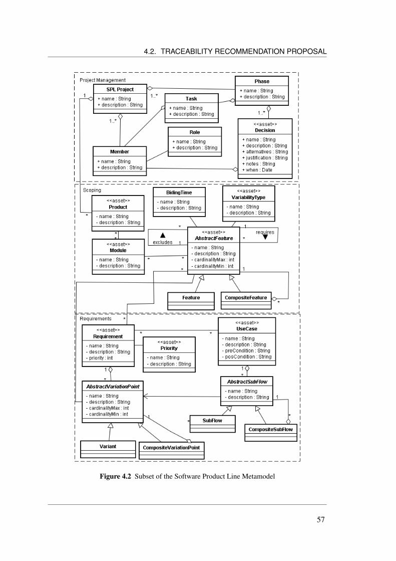
4.2. TRACEABILITY RECOMMENDATION PROPOSAL
Figure 4.2 Subset of the Software Product Line Metamodel
57
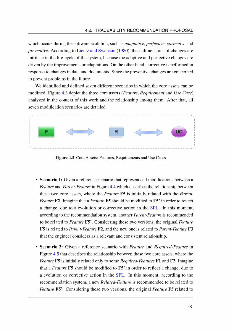
4.2. TRACEABILITY RECOMMENDATION PROPOSAL
which occurs during the software evolution, such as adaptative, perfective, corrective andpreventive. According to Lientz and Swanson (1980), these dimensions of changes areintrinsic in the life-cycle of the system, because the adaptive and perfective changes aredriven by the improvements or adaptations. On the other hand, corrective is peformed inresponse to changes in data and documents. Since the preventive changes are concernedto prevent problems in the future.
We identified and defined seven different scenarios in which the core assets can bemodified. Figure 4.3 depict the three core assets (Feature, Requirement and Use Case)analyzed in the context of this work and the relationship among them. After that, allseven modification scenarios are detailed.
Figure 4.3 Core Assets: Features, Requirements and Use Cases
• Scenario 1: Given a reference scenario that represents all modifications between aFeature and Parent-Feature in Figure 4.4 which describes the relationship betweenthese two core assets, where the Feature F5 is initially related with the Parent-
Feature F2. Imagine that a Feature F5 should be modified to F5’ in order to reflecta change, due to a evolution or corrective action in the SPL. In this moment,according to the recommendation system, another Parent-Feature is recommendedto be related to Feature F5’. Considering these two versions, the original Feature
F5 is related to Parent-Feature F2, and the new one is related to Parent-Feature F3that the engineer considers as a relevant and consistent relationship.
• Scenario 2: Given a reference scenario with Feature and Required-Feature inFigure 4.5 that describes the relationship between these two core assets, where theFeature F5 is initially related only to some Required-Features F1 and F2. Imaginethat a Feature F5 should be modified to F5’ in order to reflect a change, due toa evolution or corrective action in the SPL. In this moment, according to therecommendation system, a new Related-Feature is recommended to be related toFeature F5’. Considering these two versions, the original Feature F5 related to
58

4.2. TRACEABILITY RECOMMENDATION PROPOSAL
Figure 4.4 Scenario 1 - Feature and Parent-Feature
Related-Features F1 and F2, and the new one is related to Related-Features F1, F2and F3 that the engineer considers as a relevant and consistent relationship.
Figure 4.5 Scenario 2 - Feature and Required-Features
• Scenario 3: Given a reference scenario with Feature and Excluded-Feature inFigure 4.5 that describes the relationship between these two core assets, where theFeature F5 is initially related only to some Excluded-Features F1 and F2. Suposethat a Feature F5 should be modified to F5’ in order to reflect a change, due toa evolution or corrective action in the SPL. In this moment, according to therecommendation system, a new Excluded-Feature is recommended to be relatedto Feature F5’. Considering these two versions, the original Feature F5 related toExcluded-Features F1 and F2, and the new one is related to Excluded-Features F1,F2 and F3 that the engineer considers as a relevant and consistent relationship.
59

4.2. TRACEABILITY RECOMMENDATION PROPOSAL
Figure 4.6 Scenario 3 - Feature and Excluded-Features
• Scenario 4: Given a reference scenario with Feature and Requirement in Figure 4.7that describes the relationship between these two core assets, where the Feature F1is initially related only to some Requirements R1 and R2. Imagine that a Feature
F1 should be modified to F1’ in order to reflect a change, due to a evolution orcorrective action in the SPL. In this moment, according to the recommendationsystem, a new Requirement is recommended to be related to Feature F1’. Consid-ering these two versions, the original Feature F1 related to Requirements R1 andR2, and the new one is related to Requirements R1, R2 and R3 that the engineerconsiders as a relevant and consistent relationship.
Figure 4.7 Scenario 4 - Feature and Requirements
• Scenario 5: Given a reference scenario with Requirement and Feature in Fig-ure 4.8 that describes the relationship between these two core assets, where the
60

4.2. TRACEABILITY RECOMMENDATION PROPOSAL
Requirement R1 is initially related only to some Features F1 and F2. Imaginethat a Requirement R1 should be modified to R1’ in order to reflect a change,due to a evolution or corrective action in the SPL. In this moment, accordingto the recommendation system, a new Feature is recommended to be related toRequirement R1’. Considering these two versions, the original Requirement R1related to Features F1 and F2, and the new one is related to Features F1, F2 andF3 that the engineer considers as a relevant and consistent relationship.
Figure 4.8 Scenario 5 - Requirement and Features
• Scenario 6: Given a reference scenario with Requirement and Use Case inFigure 4.9 that describes the relationship between these two core assets, where theRequirement R1 is initially related only to some Use Cases UC1 and UC2. Imaginethat a Requirement R1 should be modified to R1’ in order to reflect a change, dueto a evolution or corrective action in the SPL. In this moment, according tothe recommendation system, a new Use Case is recommended to be related toRequirement R1’. Considering these two versions, the original Requirement R1related to Use Cases UC1 and UC2, and the new one is related to Use Cases UC1,UC2 and UC3 that the engineer considers as a relevant and consistent relationship.
• Scenario 7: Given a reference scenario with Use Case and Requirement in Figure4.10 that describes the relationship between these two core assets, where the Use
Case UC1 is initially related only to some Requirements R1 and R2. Imagine thata Use Case UC1 should be modified to UC1’ in order to reflect a change, dueto a evolution or corrective action in the SPL. In this moment, according to therecommendation system, a new Requirement is recommended to be related to Use
61
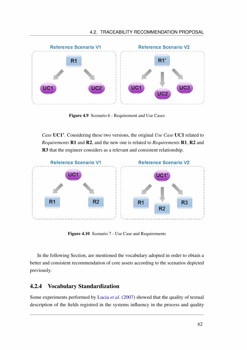
4.2. TRACEABILITY RECOMMENDATION PROPOSAL
Figure 4.9 Scenario 6 - Requirement and Use Cases
Case UC1’. Considering these two versions, the original Use Case UC1 related toRequirements R1 and R2, and the new one is related to Requirements R1, R2 andR3 that the engineer considers as a relevant and consistent relationship.
Figure 4.10 Scenario 7 - Use Case and Requirements
In the following Section, are mentioned the vocabulary adopted in order to obtain abetter and consistent recommendation of core assets according to the scenarios depictedpreviously.
4.2.4 Vocabulary Standardization
Some experiments performed by Lucia et al. (2007) showed that the quality of textualdescription of the fields registred in the systems influency in the process and quality
62

4.2. TRACEABILITY RECOMMENDATION PROPOSAL
of information extraction. According to Lancaster (1986), a common and well definedvocabulary for registration the fields could help to finding the related core assets in therecommendation process.
In this context, we propose some suggestions to the fields registration. It aims theimprovement of traceability recommendation between the core asset artefacts. The TIRTtool helps the software engineer to discover potential core assets relations, accordingto the descriptions expressed in natural language. However, these core assets mightapply some suggestions of registration described following, aiming to minimize qualityproblem, in terms of poor textual description.
A recent work developed in the RiSE Labs by Neiva (2008) defined a requirementengineering process by providing activities for correct requirements development andmanagement for Software Product Lines. Basically, this process called RiPLE-REconsists of a guideline to implement three activities: Model Scope, Define Requirements
and Define Use Case. Although the process details some guidelines for requirementsengineering, some specific aspects of the registration form are left out.
In face the problem of the different forms of core assets specification, we wereencouraged to propose some suggestions of core assets registration, because the reallanguage are not perfectly punctuated, and this problem influence negatively in therecommendation process. There are many difficult problems to consider in the context ofcore assets vocabulary, such as: abbreviations, multi-component words, token-boundaries,contractions and sence-initial. According to Kaplan (2005), many applications that workwith text-processing ignore the treatment of these kind of limitations and difficulties. Thetext-processing is one of the main functionalities of the TIRT tool, as will be discussed inSection 4.3.
Most core assets express the text in natural language, based on textual description,written in narrative manner as the name and description properties. Based on someperformed analyses in the tokenization context (Kaplan, 2005), we detailed and proposedsome suggestions for registration these core assets. There is not a grammatical formalismthat are closed under composition with regular relation, but instead, we propose somedesirable properties, such as:
• Abreviation: The english string chap. can be taken as either an abbreviation forthe word Chapter or as the word chap appearing at the end of the sentence, and Jan.can be regarded neither as an abbreviation for January or as a sentence final propername. Thus, we recommend avoiding the registration of abbreviations.
• Multi-Component Words: One of the token boundaries used in the TIRT tool is
63

4.2. TRACEABILITY RECOMMENDATION PROPOSAL
the white-space, but there are some multi-component words in english that includewhite spaces as internal characters, e.g., General Motors, a priori. Thus, we donot recommend the hyphenation between these words as an alternative to representthese multi-component words.
• Token-boundaries: Another difficult in the context of text-processing is related tothe token-boundaries, such as: quotes and commas. Thus, we do not recommendthe use of quotes or commas in the core assets registrations.
Finally, the name of an use case have a particular formalization. We recommend thatthis name start with a verb. According to Larman (2004), a common exception to one usecase per goal is to collapse CRUD (create, retrieval, update, delete) separate goals intoone CRUD use case, idiomatically called Manage <X>. For example, the goals edit user,delete user, and so forth are all satisfied by the Manage Users use case.
In general, the punctuation is one of the main problem in the context of text-processing,but with these patterns described previously, we can mitigate these problems.
4.2.5 Impact Analysis
The TIRT tool supports the impact analysis approach, providing a traceability matrixto trace the impact analysis of some changes in the context of SPL. Moreover, the toolproposes a way of alerting and presenting to user the impact that could occur in the coreasset if its was updated.
Arnold and Bohner (1996) summarize that an important aspect that all definitionshave in common is that impact analysis normally does not change anything but for theirunderstanding of the system and the effect of the proposed change. Arnold and Bohner(1996) still identified two types of impact analysis being supported in tools. The firsttype works based on analyzing the source code using techniques like program slicing,cross-referencing and control flow analyzing. The second type, that is the focus of thiswork is more life-cycle-document oriented and is based on, creating relations betweenartefacts from the beginning of the project, instead of the end.
The graphical representations details the traces and their direction between two coreasserts. Therefore, with this representation it is possible to find the forward and backwardtraces between them. When an artefact in the SPL has been changed, this matrix viewalso shows which target artefacts can be affected by this change. In this context, the TIRTtool provides a way to perform an impact analysis to determine the affected artefacts. Thematrix view is represented as a tree view component, or formally called in the literature
64

4.2. TRACEABILITY RECOMMENDATION PROPOSAL
(Diehl, 2007) as the indented component, organized as a horizontal tree, that is presentedbefore the update of some core asset, ensuring the engineer’s analysis of the correlatedcore assets and the analysis of the change impact that could accur with these changes.In the horizontal tree, vertical lines show the extent of clocks, and vertically stretchedoval lines show that of loops. This kind of structure between artefacts has to create astructure among artefacts to make clear which artefacts are predecessors or successors ofan artefact.
Accordingly to Abma (2009), normally a change affects artefacts in more the twophases. Therefore, the system, to detect mappings that have to be changed or preservedbetween two phases, has to be extended so it taked in account the mappings in andbetween multiple phases.
The details view for a particular artefact can be used to see which other artefacts aredirectly linked to this one. By doing this again for all these linked artefacts and their linksit is possible to analyze the impact (Abma, 2009). Figure 4.11 presents an sample of theindented component that represent the traceability matrix. In this picture, the use caseartefact willbe updated, thus its relationships forward and backward are detailed in orderto enable the analyze of the software engineer.
Figure 4.11 Tree View of Analysis Impact
65

4.3. TIRT ARCHITECTURE AND TECHNOLOGIES
4.3 TIRT Architecture and Technologies
As mentioned in the beginning of this Chapter, TIRT goal is to provide a system forcore asset registrations and recommendation of possible traceability relationship amongthem in the Software Product Lines context, thus, the time spent in these activities can bereduced, less error prone and less exhausted. To achieve this goal, the tool meets all therequirements previously defined.
Next section presents the architecture, the set of frameworks and technologies used inTIRT project.
4.3.1 TIRT’s Architecture Overview
The recommendation search for core assets is one of the main and most important servicesthat the TIRT tool provides for the software engineer. It is possible through the extractionand mining of core assets candidates. Thus, this type of activities follows the way ageneric application of Text Mining.
Feldman and Sanger (2007) define Text Mining as a knowledge-intensive processin which a user interacts with a document collection over time by using a suite ofanalysis tools. In a manner analogous to data mining, text mining seeks to extract usefulinformation from data sources through the identification and exploration of interestingpatterns. In the case of text mining, however, the data sources are document collections,and interesting patterns are found not among formalized database records but in theunstructured textual data in the documents in these collections.
In the context of the TIRT tool, the data sources are the core assets and the user is thedomain analyst, software engineer or another stakeholder responsible for maintenance ofthe core asset traceability. The software interacts with the collection of these core assetsin the maintenance process, where one artefact should be modified in order to reflect achange, due to a evolution or corrective action in the SPL. Thus, in the moment of theupdate, a core asset relation is indicated according the traceability scenarios defined inSection 4.2.3.
Accordingly to Figure 4.12, some classic data mining applications are roughly di-visible into four main areas: (a) preprocessing tasks, (b) core mining operations, (c)
presentation layer components and browsing functionality, and (d) refinement techniques
(Feldman and Sanger, 2007). However, the TIRT does not implement all areas of ageneric architecture of text mining. Some modifications were performed in order tosupport the TIRT domain. As can be observed in schematic Figure 4.13, we removed
66

4.3. TIRT ARCHITECTURE AND TECHNOLOGIES
from the original architecture described in Figure 4.12 the module Text Mining Discovery
Algorithms. We also removed the Document Fetching/Crawling module, since the toolpeforms the searchs from a single base. The core assets are our unique source, so wereduced the scope of the type of documents. In summary, this architecture was refined tocover only the issues to search based on by keywords, indexing, information extractionand visualization of possible recommended core assets.
Figure 4.12 System Architecture for Generic Text Mining System (Feldman and Sanger, 2007)
67

4.3. TIRT ARCHITECTURE AND TECHNOLOGIES
Figure 4.13 Instantiation of Text Mining Architecture for TIRT
68
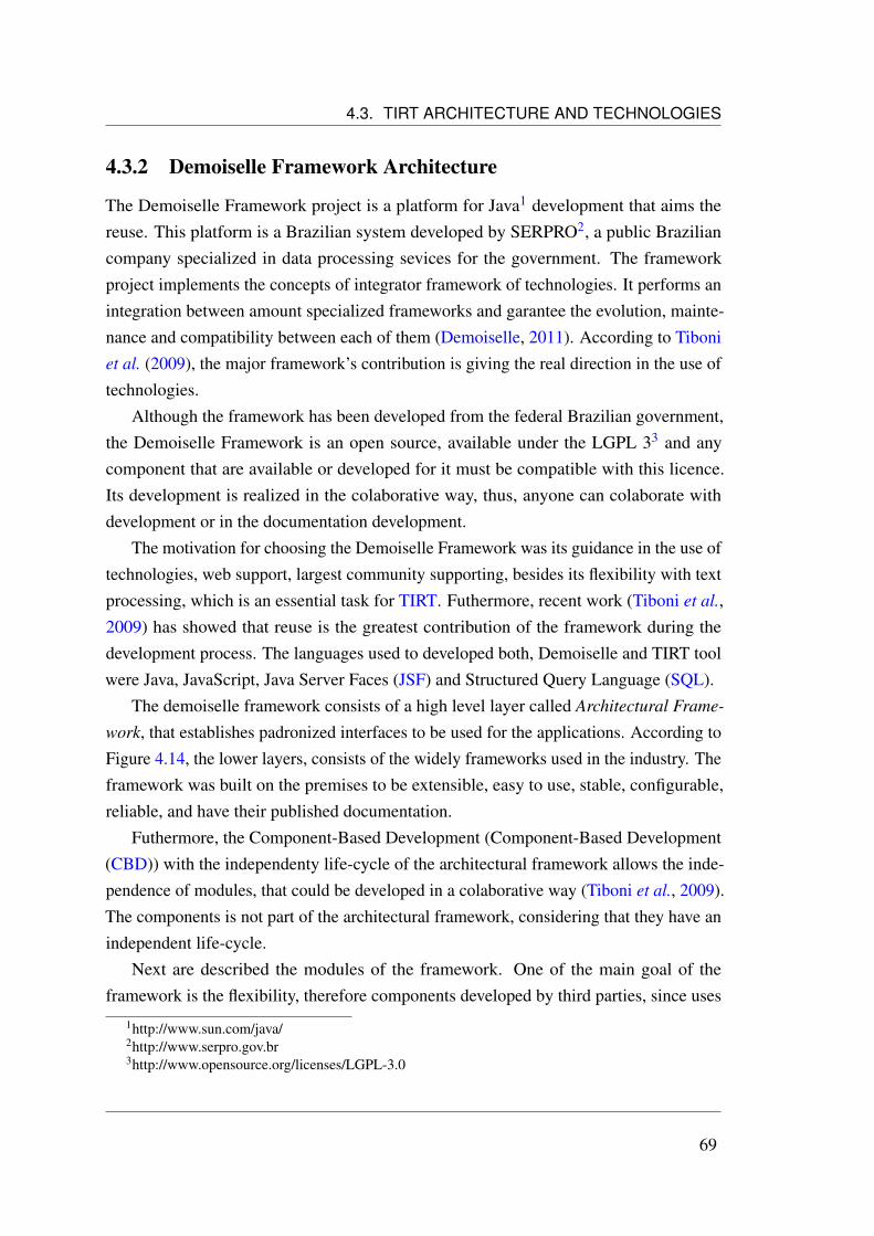
4.3. TIRT ARCHITECTURE AND TECHNOLOGIES
4.3.2 Demoiselle Framework Architecture
The Demoiselle Framework project is a platform for Java1 development that aims thereuse. This platform is a Brazilian system developed by SERPRO2, a public Braziliancompany specialized in data processing sevices for the government. The frameworkproject implements the concepts of integrator framework of technologies. It performs anintegration between amount specialized frameworks and garantee the evolution, mainte-nance and compatibility between each of them (Demoiselle, 2011). According to Tiboniet al. (2009), the major framework’s contribution is giving the real direction in the use oftechnologies.
Although the framework has been developed from the federal Brazilian government,the Demoiselle Framework is an open source, available under the LGPL 33 and anycomponent that are available or developed for it must be compatible with this licence.Its development is realized in the colaborative way, thus, anyone can colaborate withdevelopment or in the documentation development.
The motivation for choosing the Demoiselle Framework was its guidance in the use oftechnologies, web support, largest community supporting, besides its flexibility with textprocessing, which is an essential task for TIRT. Futhermore, recent work (Tiboni et al.,2009) has showed that reuse is the greatest contribution of the framework during thedevelopment process. The languages used to developed both, Demoiselle and TIRT toolwere Java, JavaScript, Java Server Faces (JSF) and Structured Query Language (SQL).
The demoiselle framework consists of a high level layer called Architectural Frame-
work, that establishes padronized interfaces to be used for the applications. According toFigure 4.14, the lower layers, consists of the widely frameworks used in the industry. Theframework was built on the premises to be extensible, easy to use, stable, configurable,reliable, and have their published documentation.
Futhermore, the Component-Based Development (Component-Based Development(CBD)) with the independenty life-cycle of the architectural framework allows the inde-pendence of modules, that could be developed in a colaborative way (Tiboni et al., 2009).The components is not part of the architectural framework, considering that they have anindependent life-cycle.
Next are described the modules of the framework. One of the main goal of theframework is the flexibility, therefore components developed by third parties, since uses
1http://www.sun.com/java/2http://www.serpro.gov.br3http://www.opensource.org/licenses/LGPL-3.0
69
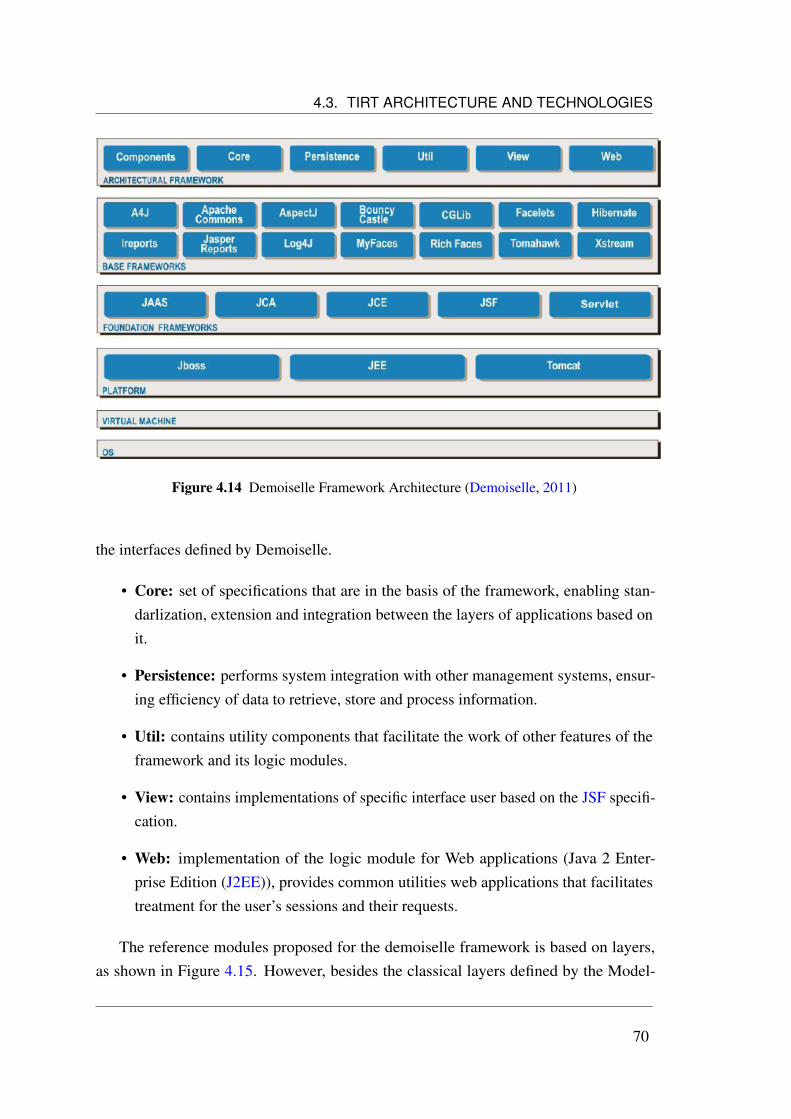
4.3. TIRT ARCHITECTURE AND TECHNOLOGIES
Figure 4.14 Demoiselle Framework Architecture (Demoiselle, 2011)
the interfaces defined by Demoiselle.
• Core: set of specifications that are in the basis of the framework, enabling stan-darlization, extension and integration between the layers of applications based onit.
• Persistence: performs system integration with other management systems, ensur-ing efficiency of data to retrieve, store and process information.
• Util: contains utility components that facilitate the work of other features of theframework and its logic modules.
• View: contains implementations of specific interface user based on the JSF specifi-cation.
• Web: implementation of the logic module for Web applications (Java 2 Enter-prise Edition (J2EE)), provides common utilities web applications that facilitatestreatment for the user’s sessions and their requests.
The reference modules proposed for the demoiselle framework is based on layers,as shown in Figure 4.15. However, besides the classical layers defined by the Model-
70

4.3. TIRT ARCHITECTURE AND TECHNOLOGIES
View-Controller (MVC) pattern, its is distinguished as the persistence layer, transaction,security, injection dependency and message.
Figure 4.15 Demoiselle Layers (Tiboni et al., 2009)
4.3.3 Demoiselle Framework Architecture Instatiation for TIRT
In order to support the TIRT purpose, the demoiselle framework architecture was instanti-ated. The main goal of this instantiation was made to accomplish the activities and a wayto support the components specified in the Figure 4.13. As can be observed in Figure4.16, we added the new functionalities in the the layers of the MVC model. In the Per-sistence layer, were added the Query Parser and Indexer, since the Text Processor wasincorporated in the Business layer, and finally, the View layer received the Visualization.All these components are following outlined.
Visualization
For Diehl (2007), software visualization is defined as the visualization of artefacts relatedto software and its development process. Thus, this TIRT module provides a visualization
71

4.3. TIRT ARCHITECTURE AND TECHNOLOGIES
Figure 4.16 Demoiselle Instantiation Layers for TIRT
72

4.3. TIRT ARCHITECTURE AND TECHNOLOGIES
of the traceability matrix. This matrix is represented with the indented component,organized as a horizontal tree that is presented before the update of some core asset,enabling the analysis of the correlated core assets and the analysis of the change impactthat can happen with these changes. This analysis can be peformed by the domain analyst,software engineer or another stakeholder responsible for maintenance of the core assettraceability in the SPL.
Text Processor
This module is responsible to process the text from core assets database. Some of thefeatures of this module are: text tokenization, stop-words removal, and stemming. Thesemodules are detailed below:
• Text Tokenization: The approach involves breaking the text into sentences andwords (Feldman and Sanger, 2007). The stream of characters in a natural languagetext must be broken up into distinct meaningful tokens before any language process-ing beyond the character level can be performed. Accordingly to Kaplan (2005),this would be a trivial thing to do, however the language have to be perfectly pontu-ated, which rarely happens. For this reason, the vocabulary proposed in Section4.2.4 is essential.
• Stop-word removal: This module removes the function words and in general thecommon words of the language that do not contribute to the semantics of the coreassets descriptions and have no real added value. According to Feldman and Sanger(2007), most of these words are irrelevant and can be dropped with no harm to theperformance and may even result in improvement owing to noise reduction.
• Stemming: Removing suffixes from words by automatic means is an operationwhich is especially useful in the field of information extraction (Porter, 1980).According to Strzalkowski (1994), word stemming has been an effective way ofimproving document recall since it reduce words to their common morphologicalroot, thus allowing more successful matches. On the other hand, Strzalkowski(1994) analyzes that stemming tends to decrease retrieval precision, if care is nottaken to prevent situations where otherwise unrelated words are reduced to thesame stem. In this context, we applied the Poter algorithm (Porter, 1980) forreducing words with a common stem to its radical. For example, the words connect,connected, connecting and connection are reduced to connect.
73

4.4. TIRT IN ACTION
Query Parser
This module provides the ability to create queries, where the software engineer interactswith the system in order to identify possible core assets recommendations. These coreassets are stored in the PostgreSQL4, on open source object-relational database system.It has more than 15 years of active development and a proven architecture that hasearned it a strong reputation for reliability, data integrity, and correctness. This databasesystem was also selected because of its advanced indexing features. In additional, theHibernate5 was used in order to facilitate the storage and retrieval of Java domain objectsvia Object-Relational Mapping (ORM).
Indexer
This module is responsible for processing the contents of each core asset in the database.The index structure is created and maintained by the PostgreSQL engine. As mentionedpreviously, the PostgreSQL database provides the full text searching or just text searchcapability to identify natural-language documents that satisfy a query, and optionally tosort them by relevance to the query. In the TIRT context, this type of search is applied inorder to identify relevants core assets to recommendation.
4.4 TIRT in Action
This Section presents the TIRT from the user’s point view, exposing its main operationsand its main screens, showed in Figures 4.17, 4.18 and 4.19.
Beyond the support for recommendation of core assets traceability and supportfor change analysis, TIRT also focus on usability, following many of the usabilityheuristics proposed by (Nielsen, 2011), resulting in an clean and intuitive user interface.In additional, Asynchronous Javascript and XML (AJAX) technology were also used inorder to improve the user experience with an interative application. The main activitiesof TIRT are following described:
1. Menu Bar: The engineer or domain analyst interact with this area of the tool inorder to access all modules of the system. As depicted in Figure 4.17, the menu barare initially composed by the Project Configurations menu, that offers access tothe Project, Product, Module and Actors management. Therefore, the Core Assets
4http://www.postgresql.org/5http://www.hibernate.org/
74

4.4. TIRT IN ACTION
menu provides access to the Feature, Requirement and Use Case management.Finally, the Help menu provides instructions and some tips about the Vocabulary
and Scenario Recommendation.
2. Core Asset Management: In this part, are provided the basic functionality of thetool, which performs the registration of core assets (e.g. features, requirements anduse cases), according to metamodel defined in Section 4.2.1. This activity is alsoshowed in Figure 4.17.
3. Traceability Matrix: This area of the tool is responsible for making possible theimpact analysis by the engineer or domain analyst. This information is displayedwhen a core asset is updated, and the traceability matrix is shown with the purposeof identify the impact analysis (forward and backward) that may accur in the SPLcontexting. The matrix view is represented as a indented component, organizedas a horizontal tree. In this picture, the use case artefact will be updated, thus itsrelationships (forward and backward) are detailed in order to enable the analyze bythe software engineer.
4. Traceability Recommendation: This part of the tool presents the search recom-mendation for core assets, which is one of the main and most important function-alities that TIRT tool provides for the software engineer. It is possible throughthe extraction and mining of core assets candidates. The software interact withthe collection of these core assets in the maintenance process, where one artefactshould be modified in order to reflect a change, due to a evolution or correctiveaction in the SPL. Thus, in the moment of update, a core asset relation is indicatedaccording to the traceability scenarios defined in Section 4.2.3. In addition, when acore asset is being view, the tool must extract relevant information from it, such asdescriptions, related core assets, restrictions, and so on;
5. Help: TIRT provides a detailed explanation about the characterization of thevocabulary, as was outlined in Section 4.2.4. Moreover, the system also mustprovide details about the scenarios of recommendation that are outlined in Section4.2.3.
75

4.4. TIRT IN ACTION
Figure 4.17 Tree View of Analysis Impact
Figure 4.18 Requirements Recommendation Screen
76

4.5. CHAPTER SUMMARY
Figure 4.19 Help of Scenarios Recommendation
4.5 Chapter Summary
This Chapter presented the main aspects of TIRT tool, including the set of functional andnon-functional requirements, architecture, frameworks and technologies adopted duringits construction.
Futhermore, it presented the proposal for traceability recommendation, that outlinesthe recommendation scenarios of traceability, described in order to facilitate the main-tenance activities of SPL. This recommendation approach aids the decision making,supporting representation of dependencies between different core assets. Finally, thisChapter presented the TIRT from the user’s point view, exposing its main operations.
Next Chapter presents the evaluations peformed with a group of subjects to verify thetool helpfulness to the maintenance traceability activity.
77

5TIRT Evaluation
If you can dream it, you can do it.
—WALT DISNEY (Cartoonist)
New methods, techniques, languages and tools should not just be suggested, publishedand marked. It is crusial to evaluate these new inventions and proposals. Experimentationprovides this opportunity and should be used. In other words, we should use the methodsand strategies available when conducting research in software engineering (Wohlin et al.,2000). In this way, this Chapter presents the experimental study in order to to evaluatethe proposed tool and the approaches outlined in the previous Chapter.
The remainder of this Chapter is organized as follows. Section 5.1 introduces somedefinitions to clarify the steps and concepts of the experimental study. Section 5.2 presentsthe definition of the experiment. Section 5.3 presents the planning of the experiment. Thedetails about the operation of the experiment are presented in Section 5.4. Section 5.5presents the analysis and interpretation of the results. Section 5.6 presents the conclusionand finally, the Chapter summary is described in Section 5.7.
5.1 Introduction
This dissertation presented TIRT - Traceability Information Retrieval Tool, that focus onthe maintenance activities regarding to the traceability relationship among the differentcore assets in a Software Product Lines through its recommendation system. In additional,the tool was also built in order to aid in the process of impact analysis. Thus, we believethat the time spent in these activities can be reduced and less error prone. In order toevaluate the tool, a controlled experiment was performed with 10 subjects.
so that mode, conclusive results can be obtained.
78

5.1. INTRODUCTION
This experimental study is based on the process proposed in (Wohlin et al., 2000), seeFigure 5.1. It is divided into the following main activities: the definition is the first step,where the experiment is defined in terms of problem, objective and goals. The planningcomes next, where the design of the experiment is determined, the instrumentation is con-sidered and the threats to the experiment are evaluated. The operation of the experimentfollows from the design. In the operational phase, measurements are collected, analysedand evaluated in the analysis and interpretation. Finally, the results are presented andpackaged in the conclusion.
Figure 5.1 Overview of the Experimental Process (Wohlin et al., 2000)
The process detailed in Figure 5.1 is not supposed to be a ”true” waterfall model,because it is an iterative and it may be necessary to go back and refine a previous activitybefore continuing with the experiment.
The main objetive of an experiment is mostly to evaluate a hypothesis. Hypothesistesting normally refers to the former and the latter is foremost a matter of building arelational model based on the data collected. In additional, two kinds of variable arestudied in an experiment, independent and dependent. These variables are studied inorder to analyse their outcomes when are varied some of the input variable to a process.The variables that are objects of the study which see the effect of the changes in the
79

5.2. THE DEFINITION
independent variables are called dependent variables. All variables in a process that aremanipulated and controlled are called independent variables (Wohlin et al., 2000).
According to Wohlin et al. (2000), an experiment studies the effect of changing oneor more independent variables. Those variables are called factors. The other independentvariables are controlled at a fixed level during the experiment, or else it would not bepossible to determine if the factor or another variable causes the effect. A treatment isone particular value of a factor.
The treatments are being applied to the combination of objects and subjects. An objectcan, for example, be a traceability matrix that will be updated using different systems.The people that apply the treatment are called subjects. In general, an experiment consistsof a set of tests where each test is a combination of treatment, subject and object (Wohlinet al., 2000).
5.2 The Definition
The first activity is definition. In this phase, the foundations of the experiment aredetermined, presenting why the experiment will be conducted. In addition, the hypothesishas to be stated clearly. Futhermore, the objective and goals of the experiment must bedefined.
In order to define the experiment, the Goal Question Metric (GQM) paradigm (Basiliet al., 1994) was used. The GQM is based upon the assumption that for an organization tomeasure in a purposeful way it must first specify the goals for itself and its projects, thenit must trace those goals to the data that are intended to define those goals operationally,and finally provide a framework for interpreting the data with respect to the statedgoals. According to (Basili et al., 1994), the result of the application of the GQM isthe specification of a measurement system targeting a particular set of issues and a setof rules for the interpretation of the measurement data. The resulting measurementmodel is composed of: Goal, Question and Metric. The metrics also are defined later asindependent variables.
5.2.1 Goal
According to the paradigm, the main objective of this experiment is:G1: To analyse the tool for the purpose of evaluating it with respect to the recall and
precision of recommendation of core assets traceability and effort (time saving), in theview point of software engineers.
80

5.2. THE DEFINITION
Object of Study (What is studied?): The objective of study is the tool used to analyseand perform the recommendation of core assets traceability and their ability in term ofeffort reduction (save time).
Purpose (What is the intention?): The purpose is to evaluate the recommendation
activities of core assets. We would like to understand if the tool can bring benefits tomaintenance of core asset traceability, according to the scenario recommendation andvocabulary proposed.
Quality Focus (Which effect is studied?): The benefits gains obtained by the use ofthe tool is the recommendation of core assets traceability. Moreover, we also analyseeffort reduction (time saving) in the core asset maintenance.
Perspective (Whose view?): The perspective is from the software engineer’s point ofview.
5.2.2 Questions
In order to achieve this goal, we defined quantitative and qualitative questions. Thefirst ones are related to the data collected during the period that the experiment will beexecuted, and the last one concerned with the subjects’ feedback about the new approachadoption. The questions are described as follow:
• Q1: Is there increase of the effectiveness of core assets management with the recom-
mendation approach performed in the new tool adoption? In order to understand ifthe recommendation of core assets traceability provides effective recommendations,the recall and precision are analysed.
• Q2: Is there reduction of the effort (time) that software engineers spend to performthe core assets management? This quantitative issue is observed in order to analyseif TIRT tool provides saving time.
• Q3: Did the software engineers have difficult to use the tool? In order to understandthe difficult that the submitters will face during the experimentation, they will beasked to describe the difficulties encountered during the experiment.
5.2.3 Metrics
The metrics are a set of data that is associated with every question in order to answer it ina quantitative way.
81

5.2. THE DEFINITION
Two fundamental metrics are used to assess the efficiency of any information retrievalmechanism: recall and precision (Kowalski and Maybury, 2002). Both recall andprecision take on values between 0 and 1.
M1: Precision of core assets relationship that were recommended; The capacity ofavoiding irrelevant results is measured by the precision metric. The following equation isused to calculate this metric.
P =TP
TP + FP
� �5.1
TP: True-Positive. FP: False-Positive.
M2: Recall of core assets relationship that were recommended; The capacity of amechanism of retrieving relevant results is measured by the recall metric. The followingequation is used to calculate this metric.
R =TP
TP + FN
� �5.2
TP: True-Positive. FN: False-Negative.
M3: Effort Variation (EV) of core asset management (Basili et al., 1996); Thefollowing equation is used to calculate effort metric.
EV =ETIRT
ESPLMT
� �5.3
ETIRT: Average Effort to subjects execute the core asset management using theTraceability Information Retrieval Tool (TIRT), a different tool.
ESPLMT: Average Effort to subjects execute the core asset management usingSoftware Product Lines Management Tool (SPLMT), the tool used to initially mod-eling the MedicWare’s core assets.
The Effort Variation metric has range [0, N], where EV 0 indicates the maximuneffort Time Spent reduction when using the TIRT tool, and EV >= 1 indicates that theeffort to execute the core asset management using TIRT tool is equals, or even higherthan using SPLMT tool.
82

5.3. THE PLANNING
5.3 The Planning
After the definition of the experiment, the planning activity takes place. The definition
determines the foundation for the experiment - why the experiment is conducted - whilethe planning prepares for how the experiment is conducted. The Planning phase of anexperiment can be divided in some steps. Based on the experiment definition, the contextof the experiment is determined in details, as well as the hypothesis and an alternativehypothesis. The next step in the planning activity is to determine the independent anddependent variables. The subjects of the study are also identified. Futhermore, thequestions of validity of results also are consider. Validity can be divided into three majorclasses: internal, external, and conclusion validity (Wohlin et al., 2000).
5.3.1 Context Selection
The experiment will be performed as an off-line experiment. It will run using softwareengineers of Pitang Software Factory1. In addition, the experiment will be performeddistributed, which means that the subjects are free to choose their work environment,such as their home or company laboratories.
Regarding the data used in the experiment, the subjects will use core assets froma private company working in the medical information management domain, calledMedicWare Informatics System LTDA2 which has negociated a cooperation project withRiSE Labs.
MedicWare works with software development for the medical domain since 1994 andis located at Salvador, Bahia, Brazil. The company was created in 1994 offering strategicand operational solutions integrated for hospitals, clinics, labs and private doctor’s office.
The company has four products presented in the decreasing order according to theirsize. The first one (SmartHealth) is a product of 35 modules or sub-domains, and managesthe whole area of a hospital, from financial to patient aspects. The second one (SmartClin),composed of 28 modules, performs the clinical management supporting activities relatedto medical exams, diagnostics and so on. The third one (SmartLab) has 28 modules andintegrates a set of features to manage labs of clinical pathology. Finally, the last one((SmartDoctor) is the only web product and composed of 11 modules to manage the tasksand routines of a doctor’s office. Figure 5.2 shows the correlation among the products.
1http://www.pitang.com/ - Pitang is the Software Factory of C.E.S.A.R., offering system development,consulting, software factory, testing factory, legacy migration and outsourcing services.
2http://www.medicware.com.br/
83

5.3. THE PLANNING
As it can be seen in the figure, SmartHealth is the biggest product and some of its featurescompose the other ones.
Figure 5.2 MedicWare Projects
This experiment is concerned with the adoption of a tool developed to aid the main-tenance of core assets links, focusing on analysis of recommendation of core assetstraceability. The Traceability Information Retrieval Tool (TIRT) will be compared withthe Software Product Lines Management Tool (SPLMT), that was used to modeling theMedicWare core assets. In addition, it is important to highlight that SPLMT tool doesnot have the recommendation approach, proposed and developed in TIRT. Thus, thesubjects will use both tools and it will be analysed the effort reduction (time saved) andrecommendation of core assets traceability performed by the tool. Initially, the subjectswill be trained in several aspects of SPL and in usage of the tool.
5.3.2 Hypothesis Formulation
The basis for the statistical analysis of an experiment is the hypothesis testing. If thehypothesis can be rejected then conclusions can be drawn, based on the hypothesistesting under given risks. According to Wohlin et al. (2000), in the planning phase, theexperiment definition is formalized into two hypotheses: Null Hypothesis and Alternative
Hypothesis.Null Hypothesis: The null hypothesis determines that there is no benefits of using
TIRT to perform the recommendation of core assets traceability, besides not have time
saved. The null hypothesis are:
H0: µ effort(time saved) with TIRT > 1
84

5.3. THE PLANNING
H0: µ precision TIRT < 50%H0: µ recall TIRT < 50%
Alternative Hypothesis: The alternative hypothesis determines that TIRT can save
more time and that there is benefits of using TIRT to perform the recommendation of core
assets traceability.
H1: µ effort(time saved) with TIRT <= 1H1: µ precision TIRT >= 50%H1: µ recall TIRT >= 50%
We perform the effort (time saved) measurements between the TIRT and SPLMTtools, but we also perform an analysis of the hypotheses in terms of precision and recall
(Kowalski and Maybury, 2002) measurements, considering the percentage greater than orabove of 50% as encouraging results in the context of TIRT tool recommendation.
5.3.3 Variable Selection
Before any design can start, we have to choose the dependent and independent variables.The independent variables are those variables that we control and changes in the ex-periment. On the other hand, the effect of the treatments is measured in the dependentvariable or variables (Wohlin et al., 2000).
In this experiment we have only one independent variable, which is the tool used toperform the recommendation of core assets traceability. The dependent variables for thisexperiment are (a) precision, (b) recall of core assets recommendation and (b) the effort
(time spent) with maintenance of core assets.
5.3.4 Selection of Subjects
The subjects of this experiment will be selected by the technique of convenience sampling,which the nearest and most convenient persons are selected as subjects (Wohlin et al.,2000). The subjects of this study are software engineers of Pitang Software Factory. Forthis evaluation will be selected ten (10) subjects. The questionnaire in Appendix A.3were used to gather data about subjects education and background.
85

5.3. THE PLANNING
5.3.5 Experimental Design
An experiment consists of a serie of tests of the treatments. A design of an experimentdescribes how the tests are organized and run. When designing an experiment, manyaspects must be considered, however, the general design principles are randomization,blocking and balancing.
• Randomization: The randomization applies on the allocation of the objects, sub-jects and in which order the tests are performed. Randomization is also used toselect subjects that is representative of the population of interest (Wohlin et al.,2000). Since all subjects will participate in both treatments, no randomization isrequired.
• Blocking: is used to systematically eliminate the indesired effect in the comparisonamong the treatments (Wohlin et al., 2000). We believe the division of subjects arenot necessary, since all work in the same company with similar knowledge degree.The questionnaire in Appendix A.3 were used to gather data about education andbackground, which determined that blocking design were needed.
• Balancing: Whe have a balanced design, which means that there is the samenumber of persons in each group.
The experimental design used to perform the experiment is one factor with two
treatments design. With this design, we would like to compare the two treatments againsteach other (Wohlin et al., 2000). In such case, the factor is TIRT. Thus, there is atreatment with such tool and another with the SPLMT tool. It is important to note thatthe data used in the experiment was the result of cooperation between the RiSE andMedicWare, in order to identify the core assets of the company. The two treatments aredescribed as follows and depicted in Figure 5.3:
• Treatment 1: In the first treatment, the subjects will use the SPLMT tool in orderto perform the core assets update, according to the firt list and traceability matrix.In addition, the subjects have to register the time spent in this activity timesheet inAppendix A.2.
• Treatment 2: In the second treatment, the subjects will receive the second list
and its corresponding traceability matrix. The subjects also have to register thetime spent in this activity in a timesheet. After the update, the TIRT tool will
86

5.3. THE PLANNING
Figure 5.3 Experiment Design: One factor with two treatment design
recommend possible core asset traceabilities. Thus, the subjects also have toquantify the recommendations results, such as: correct results, incorrect results andunlisted recommendations. It is important to highlight that we had to translate theoriginal data to the English language, because the stop-word removal and stemming
algorithms detailed in Chapter 4 and implemented in TIRT tool only considers theEnglish language. It is a limitation to be solved in the future.
In both of treatments, the experiment was applied in the context of one traceabilityscenario (Use Case and Requirement). The remainder of traceability scenarios proposedalso could be analysed. It did not happen, because the time constraint to conduct theexperiment, however, in in order to obtain more conclusive results, other experiments canbe performed, as detailed in the following Chapter.
5.3.6 Instrumentation
In order to guide the subjects in the experiment, we provided the experiment descrip-tion and guidelines with all support material, the list of core asset modifications, andquestionnaires.
The results of the experiments, such as recall, precision and effort (time saved) willbe collected. In order to guarantee more precision for the data collected, the participants
87

5.3. THE PLANNING
will be oriented to use timesheet to register the time, while performing the core assets
management. In addition, questionnaires will be elaborated to gather qualitative datafrom subjects. The instruments are presented in Appendix A.
5.3.7 Pilot Project
Before performing the study, a pilot project was conducted with the same structure ofthe Definition and Planning. The pilot project was performed by two subjects, who weretrained in SPL and tool usage. During training, we highlight some aspects related to thecore assets and manipulation of tool. The training was performed for approximately 2hours. These subjects are not part of the subject identified in the Selection of Participants.In this way, the pilot project provided a feedback about the questions, metrics and design
adopted in this experiment.
5.3.8 Validity Evaluation
A fundamental question concerning results from an experiment is how valid the resultsare. In this study, we have the following types of threats to validity the experiment.
Conclusion Validation: This validation is concerned with the relationship betweenthe treatment and the outcome (Wohlin et al., 2000). In order to evaluate and interpret theresults of the experiment, the descriptive statistics and statistical hypothesis testing willbe collected during the experiment.
Internal Validity: Threats to internal validity are influences that can affect the inde-pendent variable with respect to causality, without the researcher’s knowledge (Wohlinet al., 2000). This study is evaluated with 10 (ten) subjects with similar background oncore assets management, providing a good internal validity.
External Validity: Threats to external validity are conditions that limit out ability togeneralize the results of our experiment to industrial practice (Wohlin et al., 2000). Thus,the following external validity were identified:
• Generalization of subjects: The study will be conducted with Software engineerswho have similar background. Thus, the subjects will not be selected from ageneral population. In this case, if these professionals succeed using the tool andapproach, we cannot conclude that tool would use it succesfuly with another groups
88

5.4. THE OPERATION
too. On the other hand, negative conclusions have external validity, because if theprofessionals fail in using the tool, then this is strong evidence that another practicewould fail too;
• Time constraint: We identified that due to the time constraints, the scope ofexperiment was recuced, which could affect the experiment results. Thus, it can beconsidered as a external validity.
Validity Threats: There is a conflit between some of the types of validity threats(Wohlin et al., 2000). Thus, the following validity treatments were identified:
• Internet connection contraints: The tool will run in the web, thus the time tomanage the core assets might be comprised by the quality of Internet connectionfrom the subject environment. In this way, the results can be imprecise.
• Environment: The subjects will be free to do the task for the experiment in a placethat suits them best. Thus, the different environments can have positive or negativeinfluences for the correct execution of the experiment.
• Boredom: The subjects may be disappointed or even upset during the experiment,since the experiment will be conducted for a long period of time, but in order toreduce the boredom of the experiment, we recommended short interval during theexperiment execution.
5.4 The Operation
When an experiment has been designed and planned it must be carried out in order tocollect the data that should be analysed. This is what we mean with the operation ofan experiment. In the operational phase of an experiment, the treatments, depicted inSection 5.3.5 are applied to the subjects. Thus, this means that this part of an experimentis the part where the experimenter meets the subjects (Wohlin et al., 2000).
The operational phase of this experiment consists of three steps: preparation wheresubjects are chosen and informed and the material is prepared, execution where thesubjects perform their tasks according to the treatment and the data is collected, and datavalidation where the collected data is validated (Wohlin et al., 2000).
89

5.4. THE OPERATION
5.4.1 Preparation
The subjects of this experiment were selected by probability technique of convenience
sampling, which the nearest and most convenient persons are selected as subjects (Wohlinet al., 2000). The subjects of this study are software engineers of Pitang Software Factory.For this evaluation were selected 10 (ten) subjects.
Before the experiment can be executed, all experiment instruments defined in Section5.3.6 must be prepared. After that, a list of core assets with its traceability matrix is givento each subject. This traceability matrix contains the relationship between two core assetsof MedicWare project. In this sence, the subjects have to update each core asset in orderto relate with its correct core asset relationship. Nevertheless in the TIRT situation, thetool will recommend possible core asset traceabilities. Thus, the subjects also have toquantify the recommendations results in order to understand and analyse its results, suchas: correct results, incorrect results and unlisted recommendations.
As mentioned in the Planning Section 5.3, we had to translate the original data to theEnglish language, because the stop-word removal and stemming algorithms detailed inChapter 4 and implemented in TIRT tool only considers the English language.
5.4.2 Execution
The experimental study was conducted in July of 2011 with the subjects describedpreviously. The participants were free to do the experimentation in a place that suitsthem best. In addition, information about the experiment execution were detailed, viaemail and skype, to the subjects. The questionnaires and timesheet used in this study arepresented in Appendix A.
The experiment focus on analysis of recommendation of core assets traceability.The Traceability Information Retrieval Tool (TIRT) will be compared with the Software
Product Lines Management Tool (SPLMT), because the SPLMT does not have therecommendation approach, developed in the TIRT tool.
The treatmens and design detailed in Section 5.3.5 were aplied in this phase. Initiallya SPL training was performed, because most subjects have no expertise in the reusearea, since all work in the same company with similar knowledge degree. As mentionedbefore, the questionnaire in Appendix A.3 was used to gather data about education andbackground.
Table 5.1 details the profile of each subject. The Subject IDs are represented in thefirst column, the Graduation column represents the quantifier of years since graduation,
90

5.5. ANALYSIS AND INTERPRETATION
the amount of projects that subjects participated are described in the third column, theProject Roles are represented in the fourth column, and finally, Software Reuse and SPL
columns represent the expertise in these areas respectively.
ID Graduation Pro jects Roles So f tware Reuse SPL1 0.5 5 Developer Low None2 0.5 8 Developer Medium None3 1.5 6 Developer Medium None4 3 8 Developer Medium Low5 1 4 Tester None None6 3.5 7 Developer/Tester Low None7 3.5 7 Developer/Architect High Low8 3 8 Tester/Developer Low None9 0.5 3 Tester/Developer None None
10 1 4 Developer Low None
Table 5.1 Subject Profile
5.4.3 Data Validation
Data was collected from ten (10) subject, however, two of them (Subjects ID 2 and 7) didnot participate of treatments and qualitative questionnaire, affecting the data validation.In this way, we had eight (8) subjects for statistical and quality analysis.
5.5 Analysis and Interpretation
After collecting experimental data in the operation phase, we would like to be able todraw conclusions based on it. Nevertheless, to be able to draw valid conclusions, we mustinterpret the experiment data (Wohlin et al., 2000). In this phase, the quantitative andqualitative data were analysed.
5.5.1 Quantitative Analysis
Table 5.2 details the collected data during the experiment. The column IDs representsthe subjects identifications. It is important to highlight that the subjects #2 and #7 wereexcluded of this analysis, because they did not participate of treatments and qualitativequestionnaire, affecting the data validation. The next columns represent the time spentin minutes on analysis of both tools SPLMT and TIRT respectively. Finally, the tabledepicts the Precision and Recall metrics obtained with the TIRT tool.
91

5.5. ANALYSIS AND INTERPRETATION
ID SPLMT (min) T IRT (min) T IRT Precision (%) T IRT Recall (%)1 14.41 23 64.5 40.53 40 44.30 64.5 40.54 32 42.10 64.5 40.55 34.30 35 58.2 30.36 22.30 35 55.2 28.78 35 37.3 64.5 40.59 20 36.40 64.5 40.5
10 23 33 64.5 40.5
Table 5.2 Collected data during the experiment
From Table 5.2 we can indicate that subjects using SPLMT to analysis the core assetstraceability spent less time than using TIRT. However, it is important to highlight thatduring the analysis of recommendations in TIRT, participants also had to quantify thequality of the recommendations, enumerating the total, correct, incorrect and unlisted
recommendations. Thus, these activities can be impacted and justify the excess time ofTIRT.
Table 5.3 details descriptive statistics about the experiment results. According toWohlin et al. (2000), descriptive statistics can be used to describe and presenting interest-ing aspects of the data set. Regarding the time spent on analysis, SPLMT had mean valueof 27.43 minutes, minimum of 14.41 and maximum of 40 minutes, while TIRT had mean
value of 35.51 minutes, minimum of 23 and maximum of 44.30 minutes. In addition,Table 5.3 also brings descriptive statitics about the precision and recall metrics of TIRTtool. Regarding the precision metric, the mean value is 62.55 percent, the minimum 55.2and maximum value 64.5, while the recall metric has mean value of 37.75, minimum of28.7 and maximum value of 40.5.
SPLMT (min) T IRT (min) T IRT Precision (%) T IRT Recall (%)Mean 27.43 35.51 62.55 37.75
Minimum 14.41 23 55.2 28.7Maximum 40 44.30 64.5 40.5
Table 5.3 Descriptive Statistics
From Table 5.3, it indicates that although TIRT spent more time in the analysis ofcore assets traceability, its bring the recommendation feature with acceptable data ofprecision.
92

5.5. ANALYSIS AND INTERPRETATION
Hypothesis Testing
The objective of hypothesis testing is to verify if it is possible to reject a certain nullhypothesis (H0) (Wohlin et al., 2000), defined in the Subsection 5.3.2.
The results detailed in Table 5.4 shows that it spent more time using TIRT in thecore assets analysis. Thus, it does not reject the null hypothesis (H01): µ effort(time
saved) with TIRT > 1. The metric used to evaluate the precision of the traceabilityrecommendation presents the value of 62.55%. Thus, it rejects the null hypothesis (H02):µ precision TIRT < 50%. Finally, the metric used to evaluate the recall of the traceabilityrecommendation presents the value of 37.75%. Thus, it does not reject the null hypothesis(H03): µ recall TIRT < 50%.
Null Hypothesis Results Re jectedH01 µ effort(time saved) with T IRT > 1 1.29 NoH02 µ precision T IRT < 50% 62.55% YesH03 µ recall T IRT < 50% 37.75% No
Table 5.4 Hypothesis Analysis
As mentioned previously, it is important to highlight that during the analysis of recom-mendations in TIRT, participants also had to quantify the quality of the recommendations,enumerating the total, correct, incorrect and unlisted recommendations. Thus, theseactivities can be impacted and justify the excess time of TIRT.
5.5.2 Qualitative Analysis
The questionnaire presented in Appendix A.4 were elaborated to gather qualitativeinformation about the TIRT usability and functionality. These qualitative information aresummarized as follows:
The eight (8) subject were unanimous in declaring that TIRT traceability recommen-
dation feature is useful for the core asset management activity. Six (6) subjects reportedthat the tree view component is really useful in order to verify the impact analysis, onthe other hand, two participants reported that using this type of component, a seriousperformance problem can arise as the database grows, because it loads all the related datafield, forward and backward.
The subjects also reported that the the details of traceability recommendations pre-sented were helpful to perform the analysis, however, two (2) subjects of them alsojustified that adding more fields, the reading of these data cold be impaired. Moreover,these participants also informed that the user interface is clear and intuitive.
93

5.6. CONCLUSION
5.6 Conclusion
The analysis performed in this experimet showed that TIRT had a lower performance(spent time) compared to SPLMT. The results also indicated that the evaluation aboutthe recall metric did not provide good results. However the precision metric presents asignificant result, helping the subjects in the traceability management. In this way, thedescriptive analysis do not provide a concrete conclusion. Moreover, the experiment wasapplied in the context of one traceability scenario (Use Case and Requirement). Theremainder of traceability scenarios proposed also could be analysed. It did not happenbecause the time constraint to conduct the experiment, however, in in order to obtainmore conclusive results, other experiments can be performed.
As analysed in the 5.5.1, only one of three null hypothesis was rejected. However,the qualitative analysis showed that TIRT has many favorable aspects to be taken intoconsideration when selecting which tool should be used. The subjects reported the mainfollowing contributions and improvements: (a) the TIRT can contribute to impact analysiswith the tree view component; (b) the TIRT recommendation of core asset traceabilitycan contribute to the maintenance of core assets in a SPL project.
5.7 Chapter Summary
This Chapter presented the experimental studies conducted in order to evaluate the TIRTtool. This experimental study was based on the proposed process in (Wohlin et al.,2000), divided into the following main activities: the definition, planning, operationand Analysis and Interpretation.
The experiment was conducted with 10 subjects, however, two of them (Subjects
ID #2 and #7) did not participated of treatments and qualitative questionnaire, affectingthe data validation. In this way, we had 8 subjects for statistical and quality analysis.The results of the experiment pointed out that the null hypothesis of effort has not beenrejected, as well as the recall metric. On the other hand, the precision metric presentedfavorable results.
Although the quantitative analysis showed that only one hypothesis of three wasrejected, the subjects reported in the qualitative analysis that traceability recommendation
feature is useful for the core asset management activity. In addition, subjects reportedthat the tree view component is really useful in order to verify the impact analysis.
Next Chapter will present the conclusions of this work, its main contributions and
94

5.7. CHAPTER SUMMARY
directions for future work.
95
6Conclusion
Sonho que se sonha só
É só um sonho que se sonha só
Mas sonho que se sonha junto é realidade.
Dream you dream alone
It is just a dream you dream alone
But dream you dream together is reality.
—RAUL SEIXAS (Musician)
Software reuse is an important aspect to minimize costs and time-to-market, andmaximize quality and productivity (Clements and Northrop, 2001). In this sence, SoftwareProduct Lines Engineering has proven to be the methodology for developing a diversityof software products and software-intensive systems at lower costs, in shorter time, andwith higher quality. Many reports document the significant achievements and experiencegained by introducing software product lines in the software industry (Pohl et al., 2005).Chapter 2 summarized the basic concepts about software product lines and their aspects,such as: SPL motivations, the related benefits from its use and some strategies used inthe SPL adoption.
Regarding to Traceability, there are difficults to be addressed by the SPL approaches.Chapter 3 presented the main concepts about the Traceability area, Traceability in Soft-ware Product Lines and Impact Analysis. In the context of Software Product LinesEngineering, software artefact traceabily is an important factor when it comes to effectivedevelopment and maintenance of software system. Traceability management facilitatesthe SPL artefacts to remain in synchronous state and ensure the consistency of derived
96

6.1. RESEARCH CONTRIBUTION
products (Abid, 2004).From this scenario, Chapter 4 described the tool and the proposal for traceability
recommendation, that outline the recommendation scenarios of traceability, describedin order to facilitate the maintenance activities of SPL. This recommendation approachassist support the decision making, supporting representation of dependencies betweendifferent core assets.
6.1 Research Contribution
The main contributions of this work can be summarized according to the followingaspects: (a) state of the art of Traceability in Software Product Lines, emphasizing thetraceability approaches and key challenges; (b) a tool, called TIRT, was proposed inorder to mitigate the maintenance traceability problem; (c) the standardization of thevocabulary; (d) finally, it was performed an experimental study with 10 subject to evaluatethe proposed tool.
• State of the art and Prelimiray Mappy Study on Traceability for SPL: I pre-sented an study and identification of the main work about Traceability in the contextof Software Product Lines, emphasizing the key challenges. This study was con-ducted based on some good practices of Systematic Mapping Studies proposed byPetersen et al. (2007), several related and important work were selected.
• TIRT: A prototype tool to support the traceability scenarios was proposed. It mustbe involved, including other techniques, features, and core assets. TIRT’s goal isto facilitate the creation and mainly the maintenance activities regarding to thetraceability relationship among the different core assets in a Software Product Linesprojects. The prototype tool supports the traceability recommendation proposalin the context of Software Product Lines. Recommendation scenarios are likelyoccurrences of updates, which were mapped their impacts and correlations. Therecommendation scenarios of traceability are described in order to facilitate themaintenance activities of SPL. This recommendation approach can aid the decisionmaking, supporting representation of dependencies between different core assets.
• Vocabulary: The proposal of some suggestions to the fields registration. It aimsthe improvement of traceability recommendation between the core asset artefacts.
• Experimental Study: An experiment conducted in order to evaluate the TIRTtool was based on the proposed process defined in (Wohlin et al., 2000), which is
97

6.2. FUTURE WORK
composed of the following main activities: the definition, planning, operation andconclusion. However, the quantitative analysis showed that only one hypothesis ofthree was rejected, users reported satisfactory results using the tool.
6.2 Future Work
Due to the time constraints imposed on the master degree, this work can be seen as aninitial climbing towards the efficient, usable and effective traceability management in thecontext of Software Product Lines. Thus, there are interesting topics to improve what wasstarted, and new paths to explore. In this way, the following issues should be investigatedas future work:
• Systematic Mapping Study: A complete Systematic Mapping Studies aboutTraceability in Software Product Lines in order to identify more relevant work andbuild a classification scheme and structure this area.
• Improvements of the prototype: In order to optimize the TIRT, enhancementsand new features must be implemented, as well as some problems must be fixed.These improvements and some defects reported by users are detailed as follows:(a) the recommendation system of tool must support the Portuguese language,because in the current version, the stop-word removal and streamming algorithmsimplemented in TIRT only considers the English language. (b) the tool shouldenabling the option of enable or not the impact analysis component, because someusers related that performance problems can arise as the database grows, because itloads all the related data field, foward and backward. (c) the users also reported theimplementation of new differents visualization components, in order to facilitatethe software traceability and impact analysis. In addition to the improvementsreported by users, it is also important to note that the tool will need to be adapted,according to the evolution and adaptation of the metamodel.
• Automation of Traceability: Another area is the automation and optimizationof the generation of traceability relations in Software Product Lines, becausewe believe that this automation can bring considerable gains related to time andmaintainability.
• Analysis of vocabulary: A tool to analyze the consistency of adoption of recom-mended vocabulary.
98

6.2. FUTURE WORK
• Extension of the Experiment: Since the experiment performed in this dissertationwas applied in the context of one traceability scenario (Use Case and Requirement),thus it is necessary to perform a more elaborated experimental study, applyingthe other proposed scenarios. It did not happen in this current version, since thelimitation of time, but we believe that the extension of the experiment could providemore conclusive results. In this way, the experiment should involve more subjects.
99

Bibliography
Abid, S. B. (2004). Resolving Traceability Issues In Product Derivation For SoftwareProduct Lines. 4th International Conference for Software and Data Technologies,pages 99–104.
Abma, B. (2009). Evaluation of requirements management tools with support for
traceability-based change impact analysis. Master’s thesis, University of Twente,Enschede, The Netherlands.
Alexander, I. (2002). Towards Automatic Traceability in Industrial Practice. In In Proc.
of the 1st Int. Workshop on Traceability, pages 26–31.
Almeida, E. S., Alvaro, A., Lucrédio, D., Garcia, V. C., and Meira, S. R. L. (2004). RiseProject: Towards a Robust Framework for Software Reuse. In IEEE International
Conference on Information Reuse and Integration (IRI), pages 48–53, Las Vegas, NV,USA.
Almeida, E. S., Alvaro, A., Garcia, V. C., Jorge, Burégio, V. A., Nascimento, L. M., Lu-crédio, D., and Silvio (2007). C.R.U.I.S.E: Component Reuse in Software Engineering.C.E.S.A.R e-book, Recife, 1st edition.
Alvaro, A. (2009). A Software Component Quality Framework. Ph.d. thesis, CIn -Informatics Center, UFPE - Federal University of Pernambuco, Recife-PE, Brazil.
AMPLE (2011). Project AMPLE: Aspect-Oriented, Model-Driven Product Line Engi-neering. http://ample.holos.pt/.
Anquetil, N., Grammel, B., Galvao Lourenco da Silva, I., Noppen, J. A. R., Shakil Khan,S., Arboleda, H., Rashid, A., and Garcia, A. (2008). Traceability for Model Driven,Software Product Line Engineering. In ECMDA Traceability Workshop Proceedings,
Berlin, Germany, pages 77–86, Norway. SINTEF.
Antoniol, G., Canfora, G., Casazza, G., De Lucia, A., and Merlo, E. (2002). RecoveringTraceability Links between Code and Documentation. IEEE Transactions on Software
Engineering, 28, 970–983.
Arnold, R. S. and Bohner, S. (1996). Software Change Impact Analysis. IEEE ComputerSociety Press, Los Alamitos, CA, USA.
100

BIBLIOGRAPHY
Asuncion, H. U. (2008). Towards Practical Software Traceability. In Companion of the
30th international conference on Software engineering, ICSE Companion ’08, pages1023–1026, New York, NY, USA. ACM.
Asuncion, H. U., François, F., and Taylor, R. N. (2007). An end-to-end industrial softwaretraceability tool. In Proceedings of the the 6th joint meeting of the European software
engineering conference and the ACM SIGSOFT symposium on The foundations of
software engineering, ESEC-FSE ’07, pages 115–124, New York, NY, USA. ACM.
Balbino, M. (2010). RiPLE-SC: An Agile Scoping Process for Software Product Lines.Master’s thesis, Federal University of Pernambuco, Recife, Pernambuco, Brazil.
Basili, V., Caldiera, G., and Rombach, D. H. (1994). The Goal Question Metric Approach.In J. Marciniak, editor, Encyclopedia of Software Engineering. Wiley.
Basili, V. R. and Rombach, H. D. (1991). Support for Comprehensive Reuse. Software
Engineering Journal, Special issue on software process and its support, 6(5), 303–316.
Basili, V. R., Briand, L. C., and Melo, W. L. (1996). How Reuse Influences Productivityin Object-Oriented Systems. Communications of the ACM, 39(10), 104–116.
Bayer, J. and Widen, T. (2002). Introducing Traceability to Product Lines. In Revised
Papers from the 4th International Workshop on Software Product-Family Engineering,PFE ’01, pages 409–416, London, UK. Springer-Verlag.
Bennett, K. H. and Rajlich, V. T. (2000). Software maintenance and evolution: a Roadmap.In Proceedings of the Conference on The Future of Software Engineering (ICSE’00),pages 73–87, New York, NY, USA. ACM Press.
Berg, K., Bishop, J., and Muthig, D. (2005). Tracing Software Product Line Variability:from Problem to SSpace. In Proceedings of the 2005 annual research conference of
the South African institute of computer scientists and information technologists on IT
research in developing countries, SAICSIT ’05, pages 182–191, Republic of SouthAfrica. South African Institute for Computer Scientists and Information Technologists.
Birk, A. and Heller, G. (2007). Challenges for requirements engineering and managementin software product line development. In Proceedings of the 13th international working
conference on Requirements engineering: foundation for software quality, REFSQ’07,pages 300–305, Berlin, Heidelberg. Springer-Verlag.
101

BIBLIOGRAPHY
Booch, G., Rumbaugh, J., and Jacobson, I. (2005). The Unified Modeling Language.Addison-Wesley, 2nd edition.
Brito, K. (2007). LIFT: A Legacy InFormation retrieval Tool. Master’s thesis, CIn -Informatics Center, UFPE - Federal University of Pernambuco, Recife, Pernambuco,Brazil.
Cavalcanti, R. (2010). Extending the RiPLE-Design Process with Quality Attribute
Variability Realization. M.sc. dissertation, CIn - Informatics Center, UFPE - FederalUniversity of Pernambuco, Recife-PE, Brazil.
Cavalcanti, Y. a. C., do Carmo Machado, I., da Mota, P. A., Neto, S., Lobato, L. L.,de Almeida, E. S., and de Lemos Meira, S. R. (2011). Towards metamodel supportfor variability and traceability in software product lines. In Proceedings of the 5th
Workshop on Variability Modeling of Software-Intensive Systems, VaMoS ’11, pages49–57, New York, NY, USA. ACM.
Cavalcanti, Y. C. (2009). A Bug Report Analysis and Search Tool. M.sc. dissertation, CIn- Informatics Center, UFPE - Federal University of Pernambuco, Recife-PE, Brazil.
Chastek, G. J., Donohoe, P., and McGregor, J. D. (2009). Formulation of a ProductionStrategy for a Software Product Line. Technical report, Software Engineering Institute.
Cleland-Huang, J. (2006). Just Enough Requirements Traceability. In Proceedings of the
30th Annual International Computer Software and Applications Conference - Volume
01, pages 41–42, Washington, DC, USA. IEEE Computer Society.
Cleland-Huang, J. and Habrat, R. (2007). Visual Support In Automated Tracing. InProceedings of the Second International Workshop on Requirements Engineering
Visualization, REV 2007, pages 4–9, Washington, DC, USA. IEEE Computer Society.
Clements, P. and Northrop, L. (2001). Software Product Lines: Practices and Patterns,volume 0201703327. Addison-Wesley Longman Publishing Co., Inc., Boston, MA,USA.
Cunha, C. (2009). A Visual Bug Report Analysis and Search Tool. M.sc. dissertation, CIn- Informatics Center, UFPE - Federal University of Pernambuco, Recife-PE, Brazil.
Davis, S. M. (1987). Future Perfect. Addison-Wesley, Boston, Massachusetts.
Demoiselle (2011). Demoiselle Framework. http://www.frameworkdemoiselle.gov.br/.
102

BIBLIOGRAPHY
Dick, J. (2002). Rich Traceability. In Proceedings of the 1st International Workshop on
Traceability for Emerging forms of Software Engineering, page 2005, Edinburgh, UK.
Diehl, S. (2007). Software Visualization: Visualizing the Structure, Behaviour, and
Evolution of Software. Springer, Berlin.
Durao, F. (2008). Semantic Layer Applied to a Source Code Search Engine. Master’sthesis, Federal University of Pernambuco, Recife, Pernambuco, Brazil.
Egyed, A. (2003). A Scenario-Driven Approach to Trace Dependency Analysis. IEEE
Transactions on Software Engineering, 29, 116–132.
Eriksson, M., Börstler, J., and Borg, K. (2005). The PLUSS Approach Domain Modelingwith Features, Use Cases and Use Case Realizations. In In Proceedings of the 9th
International Software Product Line Conference, pages 33–44.
Feldman, R. and Sanger, J. (2007). The Text Mining Handbook: advanced approaches in
analyzing unstructured data. Cambridge University Press.
Filho, E. D. S., Cavalcanti, R. O., Neiva, D. F. S., Oliveira, T. H. B., Lisboa, L. B.,Almeida, E. S., and Meira, S. R. L. (2008). Evaluating Domain Design ApproachesUsing Systematic Review. In R. Morrison, D. Balasubramaniam, and K. E. Falkner,editors, 2nd European Conference on Software Architecture (ECSA’08), volume 5292of Lecture Notes in Computer Science, pages 50–65. Springer.
Frakes, W. B. and Isoda, S. (1994). Success Factors of Systematic Software Reuse. IEEE
Software, 11(01), 14–19.
Frank J. van der Linder, E. R. and Schmid, K. (2007). Software Product Lines in Action.Springer, New York, USA.
Galvão, I., Shakil, S., Nopper, J., Rummler, A., and Sánchez, P. (2008). Definition of a
traceability framework (including the metamodel and the modelling of processes and
artefacts to allow traceability in the presence of uncertainty) for SPLs. Master’s thesis.
Gamma, E., Helm, R., Johnson, R., and Vlissides, J. M. (1995). Design Patterns:
Elements of Reusable Object-Oriented Software. Addison-Wesley, Boston, MA, USA.
Garcia, V. C. (2010). RiSE Reference Model for Software Reuse Adoption in Brazilian
Companies. Ph.d. thesis, CIn - Informatics Center, UFPE - Federal University ofPernambuco, Recife-PE, Brazil.
103

BIBLIOGRAPHY
Gotel, O. and Finkelstein, A. (1995). Contribution Structures. In Proceedings of 2nd
International Symposium on Requirements Engineering, (RE ’95, pages 100–107.Society Press.
Griss, M. L., Favaro, J., and Alessandro, M. d. (1998). Integrating Feature Modelingwith the RSEB. In Proceedings of the 5th International Conference on Software Reuse,ICSR ’98, pages 76–, Washington, DC, USA. IEEE Computer Society.
Gupta, N. K., Gupta, N. K., Jagadeesan, L. J., Jagadeesan, L. J., Koutsofios, E. E.,Koutsofios, E. E., Weiss, D. M., and Weiss, D. M. (1997). Auditdraw: GeneratingAudits the FAST Way. In In Proceedings of the 3rd IEEE International Symposium on
Requirements Engineering, pages 188–197, Washington, DC, USA.
Hayes, J. H., Dekhtyar, A., and Osborne, J. (2003). Improving requirements tracing viainformation retrieval. Information Retrieval, pages 138–150.
Helferich, A., Schmid, K., and Herzwurm, G. (2006). Reconciling Marketed and Engi-neered Software Product Lines. Software Product Line Conference, International, 0,23.
IEEE (1990). IEEE Std.610.12-1990. Standard Glossary of Software Engineering Termi-nology. http://standards.ieee.org/findstds/standard/610.12-1990.html.
IEEE (1998). IEEE Std 830-1998 - IEEE Recommended Practice for Software Require-ments Specifications. http://standards.ieee.org/findstds/standard/830-1998.html.
Jamwal, D. (2010). Software Reuse: A Systematic Review. In Proceedings of the 4th
National Conference.
Jirapanthong, W. and Zisman, A. (2005). Supporting Product Line Development throughTraceability. 12th Asia-Pacific Software Engineering Conference (APSEC’05), pages506–514.
Jirapanthong, W. and Zisman, A. (2009). XTraQue: Traceability for Product LineSystems. Software and Systems Modeling, 8, 117–144. 10.1007/s10270-007-0066-8.
Kang, K., Cohen, S., Hess, J., Nowak, W., and Peterson, S. (1990a). Feature-OrientedDomain Analysis (FODA) Feasibility Study. Technical Report CMU/SEI-90-TR-21.
104

BIBLIOGRAPHY
Kang, K. C., Cohen, S. G., Hess, J. A., Novak, W. E., and Peterson, A. S. (1990b). Feature-Oriented Domain Analysis (FODA) Feasibility Study. Technical report, Carnegie-Mellon University Software Engineering Institute.
Kaplan, R. M. (2005). Inquiries into Words, Constraints and Contexts. Stanford Universit,Stanford, CA.
Kim, S. D., Chang, S. H., and La, H. J. (2005). Traceability Map: Foundations toAutomate for Product Line Engineering. Software Engineering Research, Management
and Applications, ACIS International Conference on, 0, 340–347.
Kitchenham, B. and Charters, S. (2007). Guidelines for performing Systematic LiteratureReviews in Software Engineering. Technical report, Keele University and DurhamUniversity Joint Report.
Kotonya, G. and Sommerville, I. (1998). Requirements Engineering - Processes and
Techniques. John Wiley & Sons Ltd.
Kowalski, G. and Maybury, M., editors (2002). Information Storage and Retrieval
Systems. Kluwer Academic Publishers.
Krueger, C. W. (1992). Software Reuse. ACM Comput. Surv., 24, 131–183.
Krueger, C. W. (2002). Easing the Transition to Software Mass Customization. In Revised
Papers from the 4th International Workshop on Software Product-Family Engineering,PFE ’01, pages 282–293, London, UK. Springer-Verlag.
Lancaster, F. W. (1986). Vocabulary Control for Information Retrieval. InformationResources Press, 2 edition.
Larman, C. (2004). Applying UML and Patterns: An Introduction to Object-Oriented
Analysis and Design and Iterative Development (3rd Edition). Prentice Hall PTR,Upper Saddle River, NJ, USA.
Lientz, B. P. and Swanson, E. B. (1980). Software Maintenance Management. Addison-Wesley, Boston, MA, USA.
Lindvall, M. and Sandahl, K. (1996). Practical implications of traceability. Software
Practice and Experience, 26, 1161–1180.
105

BIBLIOGRAPHY
Lisboa, L. (2008). ToolDAy - A Tool for Domain Analysis. Master’s thesis, CIn -Informatics Center, UFPE - Federal University of Pernambuco, Recife, Pernambuco,Brazil.
Lucia, A. D., Fasano, F., Oliveto, R., and Tortora, G. (2007). Recovering traceabilitylinks in software artifact management systems using information retrieval methods.ACM Transactions on Software Engineering and Methodology, 16.
Machado, I. (2010). RiPLE-TE : A Software Product Lines Testing Process. Master’sthesis, CIn - Informatics Center, UFPE - Federal University of Pernambuco, Recife,Pernambuco, Brazil.
Martins, A. C., Garcia, V. C., Almeida, E. S., and Meira, S. R. L. (2008). Enhancingcomponents search in a reuse environment using discovered knowledge techniques.In 2nd Brazilian Symposium on Software Components, Architectures, and Reuse
(SBCARS’08), Porto Alegre, Brazil.
Mascena, J. C. C. P. (2006). ADMIRE: Asset Development Metric-based Integrated Reuse
Environment. Master’s thesis, CIn - Informatics Center, UFPE - Federal University ofPernambuco, Recife, Pernambuco, Brazil.
McGregor, J. D. (2003). The Evolution of Product Line Assets. Technical report, SoftwareEngineering Institute.
McGregor, J. D., Northrop, L. M., Jarrad, S., and Pohl, K. (2002). Initiating SoftwareProduct Lines. IEEE Software, 19(4), 24–27.
McIlroy, D. (1968). Mass-Produced Software Components. In Proceedings of the 1st
International Conference on Software Engineering, Garmisch Pattenkirchen, Germany,pages 88–98.
Medeiros, F. M. (2010). SOPLE-DE: An Approach to Design Service-Oriented Product
Line Architecture. M.sc. dissertation, CIn - Informatics Center, UFPE - FederalUniversity of Pernambuco, Recife-PE, Brazil.
Mendes, R. C. (2008). Search and Retrieval of Reusable Source Code using Faceted
Classification Approach. Master’s thesis, CIn - Informatics Center, UFPE - FederalUniversity of Pernambuco, Recife, Pernambuco, Brazil.
Mens, T. and Demeyer, S. (2008). Software Evolution. Springer, Springer.
106

BIBLIOGRAPHY
Moon, M., Chae, H. S., Nam, T., and Yeom, K. (2007). A Metamodeling Approach toTracing Variability between Requirements and Architecture in Software Product Lines.Computer and Information Technology, International Conference on, 0, 927–933.
Moreton, R. (1996). A Process Model for Software Maintenance Software. ChangeImpacty Analysis. IEEE Computer Society.
Nascimento, L. (2008). Core Assets Development in SPL - Towards a Practical Approach
for the Mobile Game Domain. Master’s thesis, Federal University of Pernambuco,Recife, Pernambuco, Brazil.
Neiva, D. (2008). RiPLE-RE : A Requirements Engineering Process for Software Prod-
uct Lines. Master’s thesis, CIn - Informatics Center, UFPE - Federal University ofPernambuco, Recife, Pernambuco, Brazil.
Neto, P. (2010). A Regression Testing Approach for Software Product Lines Architectures.M.sc. dissertation, CIn - Informatics Center, UFPE - Federal University of Pernambuco,Recife-PE, Brazil.
Nielsen, J. (2011). Ten Usability Heuristics.http://www.useit.com/papers/heuristic/heuristic_list.html/.
Oliveira, T. B. (2009). RiPLE-EM : A Process to Manage Evolution in Software Product
Lines. Master’s thesis, Federal University of Pernambuco, Recife, Pernambuco, Brazil.
Petersen, K., Feldt, R., Mujtaba, S., and Mattsson, M. (2007). Systematic MappingStudies in Software Engineering. 12th International Conference on Evaluation and
Assessment in Software Engineering, 17(1), 1–10.
Pfleeger, S. L. (2001). Software Engineering: Theory and Practice. Prentice Hall PTR,Upper Saddle River, NJ, USA, 2nd edition.
Pinheiro, F. A. C. and Goguen, J. A. (1996). An Object-Oriented Tool for TracingRequirements. IEEE Software, 13, 52–64.
Pohl, K. (1996a). PRO-ART: Enabling Requirements Pre-Traceability. IEEE Interna-
tional Conference on Requirements Engineering, 0, 76.
Pohl, K. (1996b). Process-Centered Requirements Engineering. John Wiley & Sons, Inc.,New York, NY, USA.
107

BIBLIOGRAPHY
Pohl, K., Böckle, G., and van der Linden, F. (2005). Software Product Line Engineering:
Foundations, Principles, and Techniques. Springer.
Porter, M. F. (1980). An algorithm for suffix stripping. Program, 3(14), 130–137.
Poulin, J. S. (1997). Measuring Software Reuse - Principles, Practices, and Economic
Models. Assison-Wesley, Boston, MA, USA.
Pussinen, M. (2002). A survey on software product-line evolution. Technical report,Institute of Software Systems.
R. Cooper, S. E. and Kleinschmidt, E. (2001). Portfolio Management for new Products.Perseus Publishing, Philadelphia, USA.
Ramesh, B. and Jarke, M. (2001). Toward Reference Models for Requirements Traceabil-ity. IEEE Transactions on Software Engineering, 27, 58–93.
Ramesh, B., Powers, T., Stubbs, C., and Edwards, M. (1995). Implementing requirementstraceability: a case study. In Proceedings of the Second IEEE International Symposium
on Requirements Engineering, RE ’95, pages 89–95, Washington, DC, USA. IEEEComputer Society.
Ribeiro, H. B. (2010). An Approach to Implement Core Assets in Service-Oriented
Product Lines. M.sc. dissertation, CIn - Informatics Center, UFPE - Federal Universityof Pernambuco, Recife-PE, Brazil.
Royce, W. W. (1987). Managing the development of large software systems: conceptsand techniques. In Proceedings of the 9th international conference on Software
Engineering, ICSE ’87, pages 328–338, Los Alamitos, CA, USA. IEEE ComputerSociety Press.
Salton, G., Wong, A., and Yang, C. S. (1975). A Vector Space Model for AutomaticIndexing. Commun. ACM, 18(11), 613–620.
Santos, E. C. R., ao, F. A. D., Martins, A. C., Mendes, R., Melo, C., Garcia, V. C.,Almeida, E. S., and Meira, S. R. L. (2006). Towards an effective context-awareproactive asset search and retrieval tool. In 6th Workshop on Component-Based
Development (WDBC’06), pages 105–112, Recife, Pernambuco, Brazil.
Sherba, S. A., Anderson, K. M., and Faisal, M. (2003). A Framework for MappingTraceability Relationships. In 2 nd International Workshop on Traceability in Emerging
108

BIBLIOGRAPHY
Forms of Software Engineering at 18th IEEE International Conference on Automated
Software Engineering, pages 32–39.
Sommerville, I. (2007). Software Engineering. Addison Wesley, 8 edition.
Sousa, A., Kulesza, U., Rummler, A., Anquetil, N., Fct, C. D. I., Lisboa, U. N. D., andDarmstadt, T. U. (2009). A Model-Driven Traceability Framework to Software ProductLine Development. Software Systems Modeling, 9, 427–451–451.
Spanoudakis, G. and Zisman, A. (2004). Software Traceability: A Roadmap. In Handbook
of Software Engineering and Knowledge Engineering, pages 395–428. World ScientificPublishing.
Streitferdt, D. (2001). Traceability for System Families. In Proceedings of the 23rd Inter-
national Conference on Software Engineering, ICSE ’01, pages 803–804, Washington,DC, USA. IEEE Computer Society.
Strzalkowski, T. (1994). Robust text processing in automated information retrieval. InProceedings of the fourth conference on Applied natural language processing, ANLC’94, pages 168–173, Stroudsburg, PA, USA. Association for Computational Linguistics.
TechTarget (2004). SearchCIO.com Definitions, whatis.techtarget.com.http://www.whatis.techtarget.com. Last acess on May/2011.
Tiboni, A. C., da Silva Lisboa, F. G., and Mota, L. C. (2009). Uma plataforma livrepara padronização do desenvolvimento de sistemas no Governo Federal. COLIBRI -
Colóquio de informática - Brasil - INRIA.
Tracz, W. (1988). Software reuse: emerging technology. IEEE Software, pages 62–67.
Vanderlei, T. A., ao, F. A. D., Martins, A. C., Garcia, V. C., Almeida, E. S., and Meira, S.R. L. (2007). A cooperative classification mechanism for search and retrieval softwarecomponents. In Proceedings of the 2007 ACM symposium on Applied computing
(SAC’07), pages 866–871, New York, NY, USA. ACM.
von Knethen, A. and Paech, B. (2002). A Survey on Tracing Approaches in Practice andResearch. Fraunhofer IESE, (095), 1–49.
Wohlin, C., Runeson, P., Martin Höst, M. C. O., Regnell, B., and Wesslén, A. (2000).Experimentation in Software Engineering: An Introduction. The Kluwer Internation
109

BIBLIOGRAPHY
Series in Software Engineering. Kluwer Academic Publishers, Norwell, Massachusets,USA.
Yau, S. S., Collofello, J. S., and MacGregor, T. M. (1993). Software engineering metricsi. In M. Shepperd, editor, Software engineering metrics I, pages 71–82, New York, NY,USA. McGraw-Hill, Inc.
Zhou, X., Huo, Z., Huang, Y., and Xu, J. (2008). Facilitating Software TraceabilityUnderstanding with ENVISION. Computer Software and Applications Conference,
Annual International, 0, 295–302.
Zisman, A., Spanoudakis, G., mi nana, E. P., and Krause, P. (2003). Tracing SoftwareRequirements Artefacts. In In: The 2003 International Conference on Software
Engineering Research and Practice (SERP’03). 2003. Las Vegas, pages 448–455.
110

Appendices
111

AExperiment Instruments
A.1 Time sheet of Core Assets Management with TIRT
ID Start time End time Total∗ Correct∗ Incorrect∗ Unlisted∗1 : :2 : :3 : :4 : :5 : :6 : :7 : :8 : :9 : :10 : :
Table A.1 Time sheet used with the TIRT tool.
*Indicators about the core assets recommendation.
112

A.2. TIME SHEET OF CORE ASSETS MANAGEMENT WITH SPLMT
A.2 Time sheet of Core Assets Management with SPLMT
ID Start time End time1 : :2 : :3 : :4 : :5 : :6 : :7 : :8 : :9 : :
10 : :
Table A.2 Time sheet used with the SPLMT tool.
113

A.3. QUESTIONNAIRE FOR SUBJECTS PROFILE
A.3 Questionnaire for Subjects Profile
Questionnaire for Subjects ProfileHow many years since graduation?
[ ] years.
How many projects do you have participated according to the following categories?
[ ] Low complexity.[ ] Medium complexity.[ ] High complexity.
In case you have already participated in projects cited before, what was your role?Cite the number of times you played each role.
How do you define your experience in Software Reuse?
[ ] None.[ ] Low.[ ] Medium.[ ] High.
How do you define your experience in Software Product Lines?
[ ] None.[ ] Low.[ ] Medium.[ ] High.
Have you used any CASE tool to core assets management?
[ ] Yes. [ ] No.
Table A.3 Questionnaire for Subjects Profile.
114

A.4. FORM FOR QUALITATIVE ANALYSIS
A.4 Form for Qualitative Analysis
Questionnaire for Qualitative AnalysisWas the traceability recommendation useful for the core asset management activ-ity?[ ] Yes. [ ] No.
Was the tree view component useful in order to verify the impact analysis?[ ] Yes. [ ] No.
Did you have any problem with the traceability recommendation?[ ] Yes. [ ] No. Cite them:
Do you believe the details of traceability recommendations presented were helpfulto perform the analysis?[ ] Yes. [ ] No.
Do you think there is any other important information that must be present in thelist of traceability recommendation?[ ] Yes. [ ] No. Cite them:
Did you use the help provided by TIRT?[ ] Yes. [ ] No.
In your opinion, TIRT provides a clean and useful interface?
Did you found any other problems that were not mentioned before? Cite them.
In your opinion, what are the strengths of the TIRT tool?
Please, write down any suggestion you think might would be useful for TIRT.
Table A.4 Questionnaire for Qualitative Analysis.
115