wyoming small public water system design and …deq.wyoming.gov/media/attachments/water...
TRANSCRIPT
Wyoming Small Public Water System Design and Operation
Seminar
Storage Tank Design
Thomas Brauer, CEPI
Presentation Overview
Definition of Tanks Water Storage Tank Sizing Storage Tank Siting and Elevation Tank Design and Standards Tank Amenities
Types of Water Storage Tanks Tank Materials
Welded Steel Bolted Steel Reinforced Concrete
Tank Types Reservoirs (diameter > height) Standpipes (diameter < height) Elevated
Multiple Column Spherical Pedestal (Hydrosphere) Modified Single Pedestal
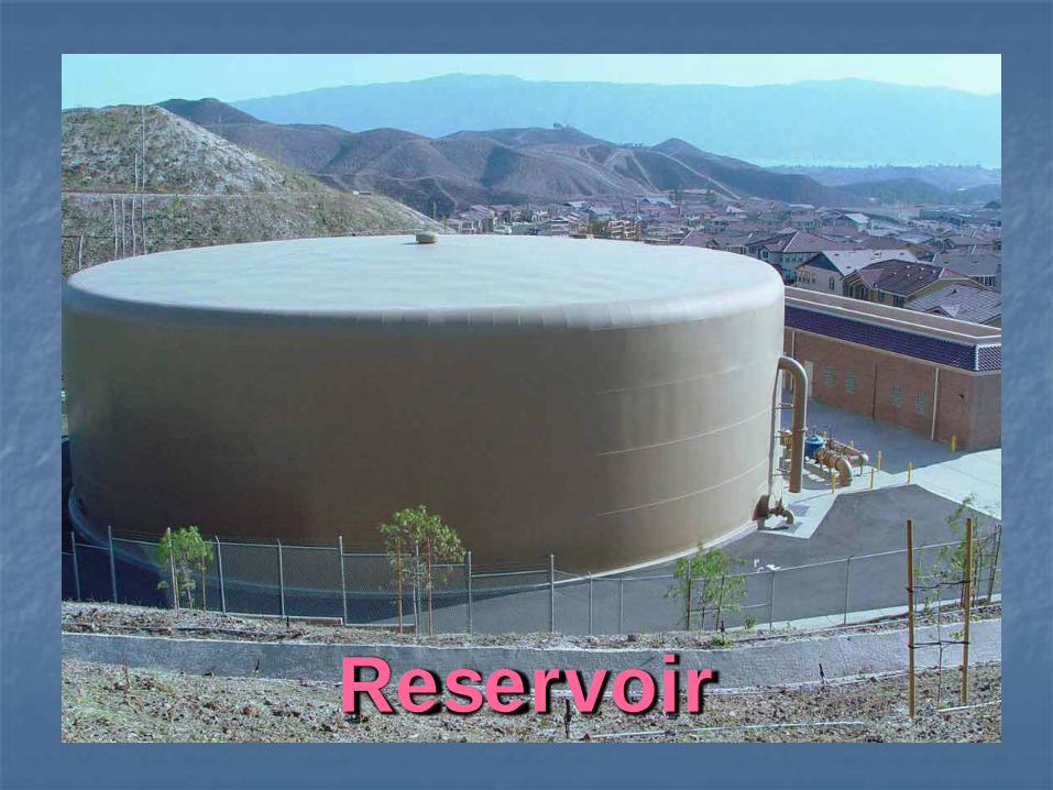
Reservoir
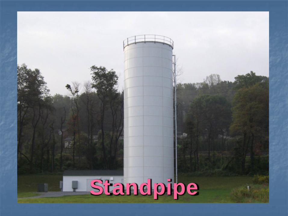
Standpipe
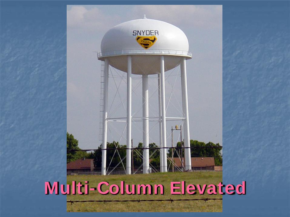
Multi-Column Elevated
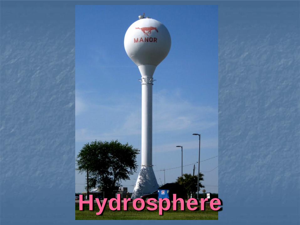
Hydrosphere
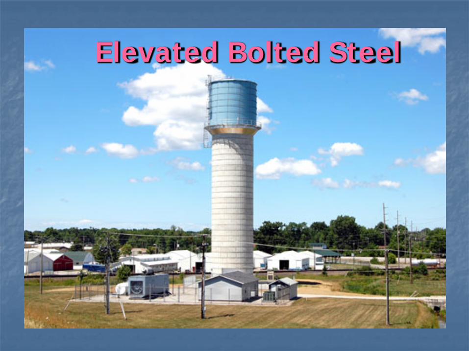
Elevated Bolted Steel
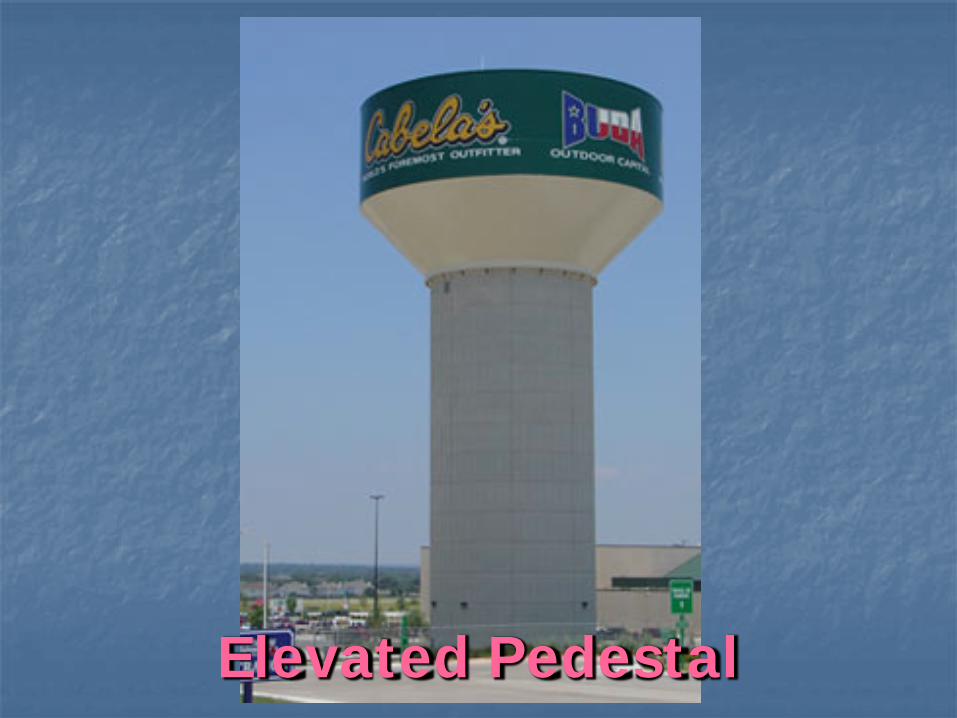
Elevated Pedestal
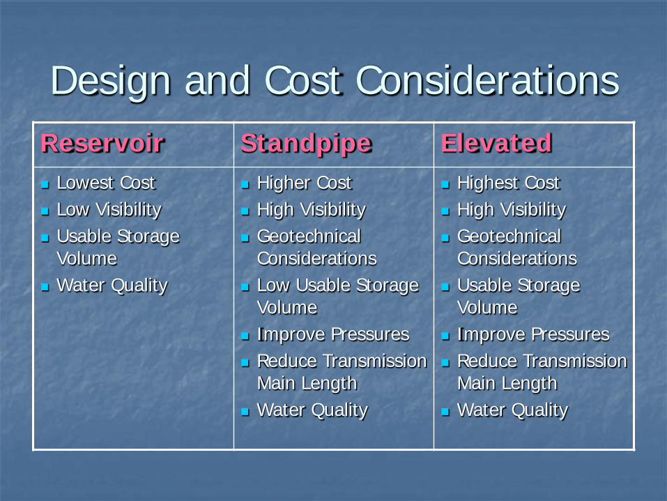
Design and Cost Considerations Reservoir Standpipe Elevated Lowest Cost Low Visibility Usable Storage
Volume Water Quality
Higher Cost High Visibility Geotechnical
Considerations Low Usable Storage
Volume Improve Pressures Reduce Transmission
Main Length Water Quality
Highest Cost High Visibility Geotechnical
Considerations Usable Storage
Volume Improve Pressures Reduce Transmission
Main Length Water Quality
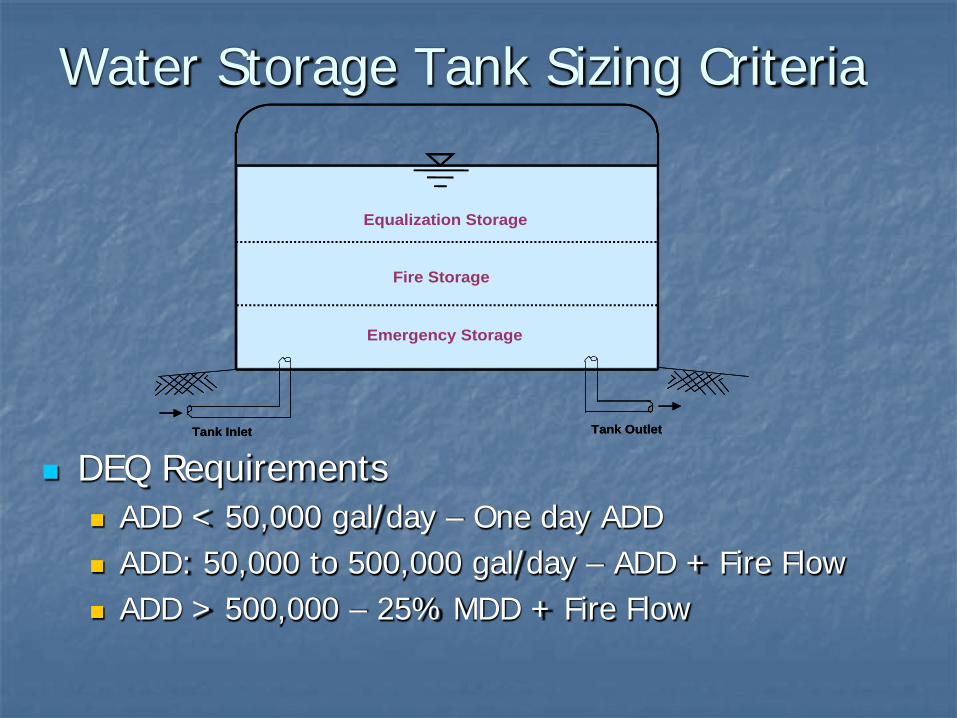
Water Storage Tank Sizing Criteria
Tank Inlet Tank Outlet
Emergency Storage
Equalization Storage
Fire Storage
Tank Inlet Tank Outlet
Emergency Storage
Equalization Storage
Fire Storage
DEQ Requirements ADD < 50,000 gal/day – One day ADD ADD: 50,000 to 500,000 gal/day – ADD + Fire Flow ADD > 500,000 – 25% MDD + Fire Flow
5700
5200
5500
5400
5000
5300
4900
5100
5600
LDC Field Tank
LDC 1El = 5400
LDC 2El = 5440
Indian Hills Tank Sunup Ridge Tank
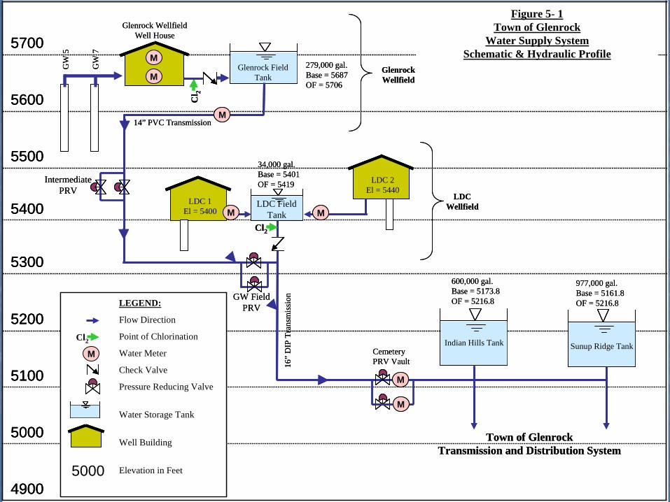
Figure 5- 1Town of Glenrock
Water Supply System Schematic & Hydraulic Profile
Glenrock Field Tank
GW
5
34,000 gal.Base = 5401OF = 5419
GW
7
Cl 2
M
Glenrock WellfieldWell House
M279,000 gal.Base = 5687OF = 5706
M
Cl2
M
LEGEND:
Flow Direction
Point of Chlorination
Water Meter
Check Valve
Pressure Reducing Valve
Water Storage Tank
Well Building
Elevation in Feet
M
M
Cl2
MM
600,000 gal.Base = 5173.8OF = 5216.8
977,000 gal.Base = 5161.8OF = 5216.8
Cemetery PRV Vault
Town of GlenrockTransmission and Distribution System
5000
Glenrock Wellfield
14” PVC Transmission
16”
DIP
Tra
nsm
issi
on
Intermediate PRV
GW Field PRV
LDCWellfield
5700
5200
5500
5400
5000
5300
4900
5100
5600
5700
5200
5500
5400
5000
5300
4900
5100
5600
LDC Field Tank
LDC 1El = 5400
LDC 1El = 5400
LDC 2El = 5440
LDC 2El = 5440
Indian Hills Tank Sunup Ridge Tank
Figure 5- 1Town of Glenrock
Water Supply System Schematic & Hydraulic Profile
Glenrock Field Tank
GW
5
34,000 gal.Base = 5401OF = 5419
GW
7
Cl 2
M
Glenrock WellfieldWell House
M279,000 gal.Base = 5687OF = 5706
M
Cl2
M
LEGEND:
Flow Direction
Point of Chlorination
Water Meter
Check Valve
Pressure Reducing Valve
Water Storage Tank
Well Building
Elevation in Feet
M
M
Cl2
MM
600,000 gal.Base = 5173.8OF = 5216.8
977,000 gal.Base = 5161.8OF = 5216.8
Cemetery PRV Vault
Town of GlenrockTransmission and Distribution System
5000
Glenrock Wellfield
14” PVC Transmission
16”
DIP
Tra
nsm
issi
on
Intermediate PRV
GW Field PRV
LDCWellfield
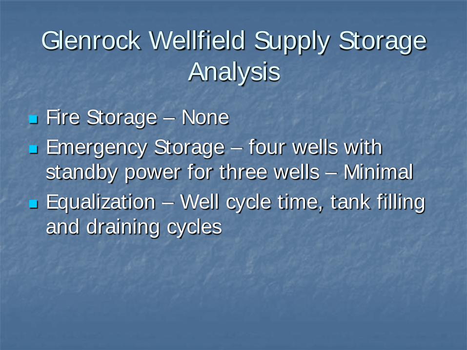
Glenrock Wellfield Supply Storage Analysis
Fire Storage – None Emergency Storage – four wells with
standby power for three wells – Minimal Equalization – Well cycle time, tank filling
and draining cycles
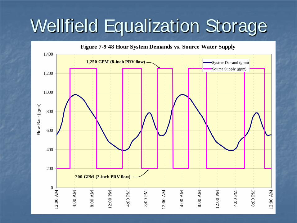
Wellfield Equalization Storage Figure 7-9 48 Hour System Demands vs. Source Water Supply
0
200
400
600
800
1,000
1,200
1,40012
:00
AM
4:00
AM
8:00
AM
12:0
0 PM
4:00
PM
8:00
PM
12:0
0 A
M
4:00
AM
8:00
AM
12:0
0 PM
4:00
PM
8:00
PM
12:0
0 A
M
Flow
Rat
e (g
pm)
System Demand (gpm)Source Supply (gpm)
200 GPM (2-inch PRV flow)
1,250 GPM (8-inch PRV flow)
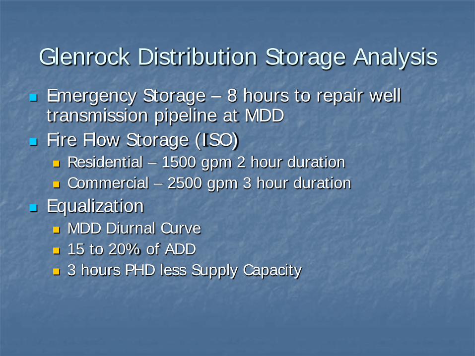
Glenrock Distribution Storage Analysis Emergency Storage – 8 hours to repair well
transmission pipeline at MDD Fire Flow Storage (ISO)
Residential – 1500 gpm 2 hour duration Commercial – 2500 gpm 3 hour duration
Equalization MDD Diurnal Curve 15 to 20% of ADD 3 hours PHD less Supply Capacity
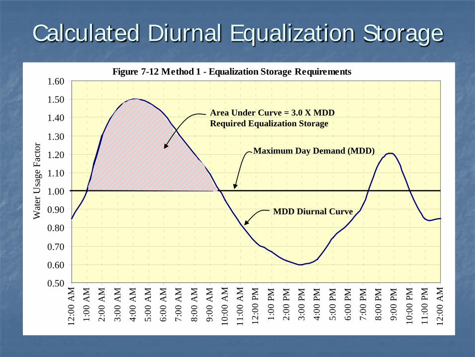
Calculated Diurnal Equalization Storage Figure 7-12 Method 1 - Equalization Storage Requirements
0.50
0.60
0.70
0.80
0.90
1.00
1.10
1.20
1.30
1.40
1.50
1.6012
:00
AM
1:00
AM
2:00
AM
3:00
AM
4:00
AM
5:00
AM
6:00
AM
7:00
AM
8:00
AM
9:00
AM
10:0
0 A
M
11:0
0 A
M
12:0
0 PM
1:00
PM
2:00
PM
3:00
PM
4:00
PM
5:00
PM
6:00
PM
7:00
PM
8:00
PM
9:00
PM
10:0
0 PM
11:0
0 PM
12:0
0 A
M
Wat
er U
sage
Fac
tor
Area Under Curve = 3.0 X MDDRequired Equalization Storage
Maximum Day Demand (MDD)
MDD Diurnal Curve
Figure 7-12 Method 1 - Equalization Storage Requirements
0.50
0.60
0.70
0.80
0.90
1.00
1.10
1.20
1.30
1.40
1.50
1.6012
:00
AM
1:00
AM
2:00
AM
3:00
AM
4:00
AM
5:00
AM
6:00
AM
7:00
AM
8:00
AM
9:00
AM
10:0
0 A
M
11:0
0 A
M
12:0
0 PM
1:00
PM
2:00
PM
3:00
PM
4:00
PM
5:00
PM
6:00
PM
7:00
PM
8:00
PM
9:00
PM
10:0
0 PM
11:0
0 PM
12:0
0 A
M
Wat
er U
sage
Fac
tor
Area Under Curve = 3.0 X MDDRequired Equalization Storage
Maximum Day Demand (MDD)
MDD Diurnal Curve
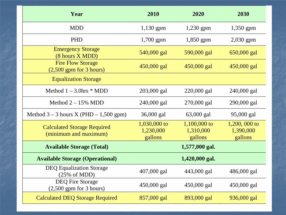
Year 2010 2020 2030
MDD 1,130 gpm 1,230 gpm 1,350 gpm
PHD 1,700 gpm 1,850 gpm 2,030 gpm Emergency Storage (8 hours X MDD) 540,000 gal 590,000 gal 650,000 gal
Fire Flow Storage (2,500 gpm for 3 hours) 450,000 gal 450,000 gal 450,000 gal
Equalization Storage
Method 1 – 3.0hrs * MDD 203,000 gal 220,000 gal 240,000 gal
Method 2 – 15% MDD 240,000 gal 270,000 gal 290,000 gal
Method 3 – 3 hours X (PHD – 1,500 gpm) 36,000 gal 63,000 gal 95,000 gal
Calculated Storage Required (minimum and maximum)
1,030,000 to 1,230,000
gallons
1,100,000 to 1,310,000
gallons
1,200, 000 to 1,390,000
gallons Available Storage (Total) 1,577,000 gal.
Available Storage (Operational) 1,420,000 gal. DEQ Equalization Storage
(25% of MDD) 407,000 gal 443,000 gal 486,000 gal
DEQ Fire Storage (2,500 gpm for 3 hours) 450,000 gal 450,000 gal 450,000 gal
Calculated DEQ Storage Required 857,000 gal 893,000 gal 936,000 gal
Usable Storage vs. Available Storage
Available Storage = Total Volume of Tanks Usable Storage = Volume Available to
Maintain 35 psi @ PHD and 20 psi @ MDD w/ Fire Flow
Reservoir Usable Storage Standpipe Usable Storage Elevated Tank Usable Storage Develop System and Demand Curves
Tank Sizing Design Considerations Don’t be too Conservative!
Realistic Assumptions Water Quality
Sizing Considerations Assume: Supply and Transmission Capacity = MDD No standby power Three components additive Adjust your analysis accordingly
Tank Cycling Water Quality System Operational Pressures System Curves
Tank Siting and Elevation System Operational Pressures
35 psi normal; 20 psi MDD with Fire Flow System Curves Tank Cycling (ice and water quality) Higher is better!
Geotechnical Considerations Collapsible Soils Swell and Consolidation Analysis Tank Drain and Overflow Piping Slope Failure
Transmission Supply Proximity to Distribution Transmission Storage Water Quality
Tank Design Standards DEQ Chapter 12 AWWA D-100 (D-100-11 forthcoming) API Standards Reference Standards and Specify Tank Performance Specification vs. Structurally
Designed Solution Provide Technical Specifications and Tank
Elevations and Detail Drawings
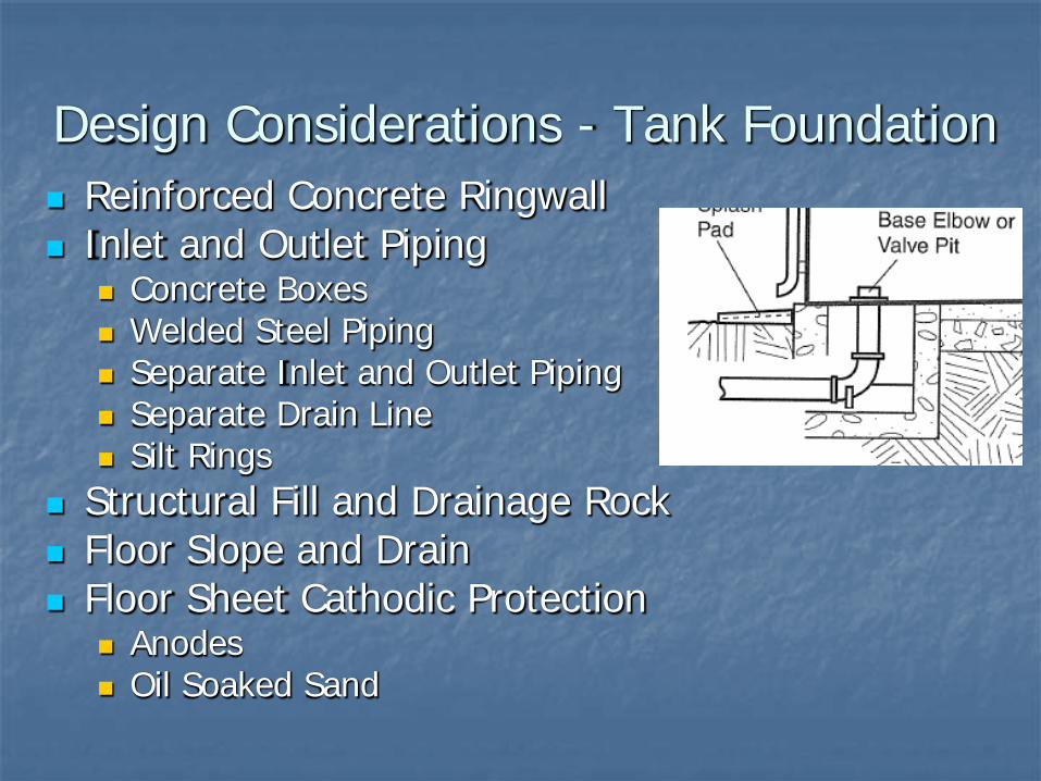
Design Considerations - Tank Foundation Reinforced Concrete Ringwall Inlet and Outlet Piping
Concrete Boxes Welded Steel Piping Separate Inlet and Outlet Piping Separate Drain Line Silt Rings
Structural Fill and Drainage Rock Floor Slope and Drain Floor Sheet Cathodic Protection
Anodes Oil Soaked Sand
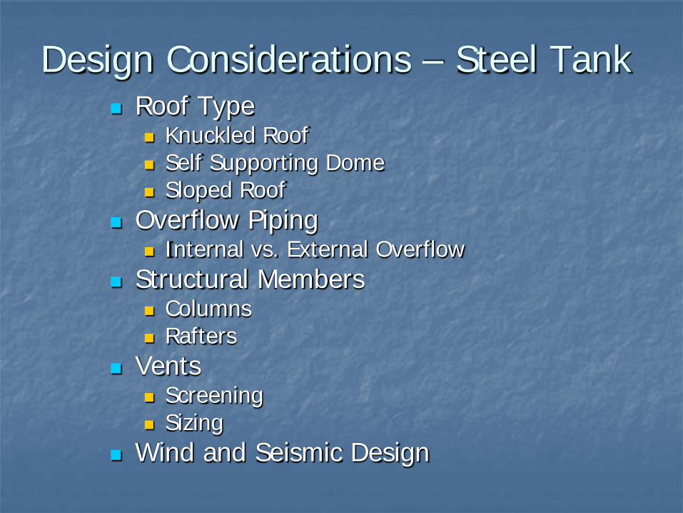
Design Considerations – Steel Tank Roof Type
Knuckled Roof Self Supporting Dome Sloped Roof
Overflow Piping Internal vs. External Overflow
Structural Members Columns Rafters
Vents Screening Sizing
Wind and Seismic Design
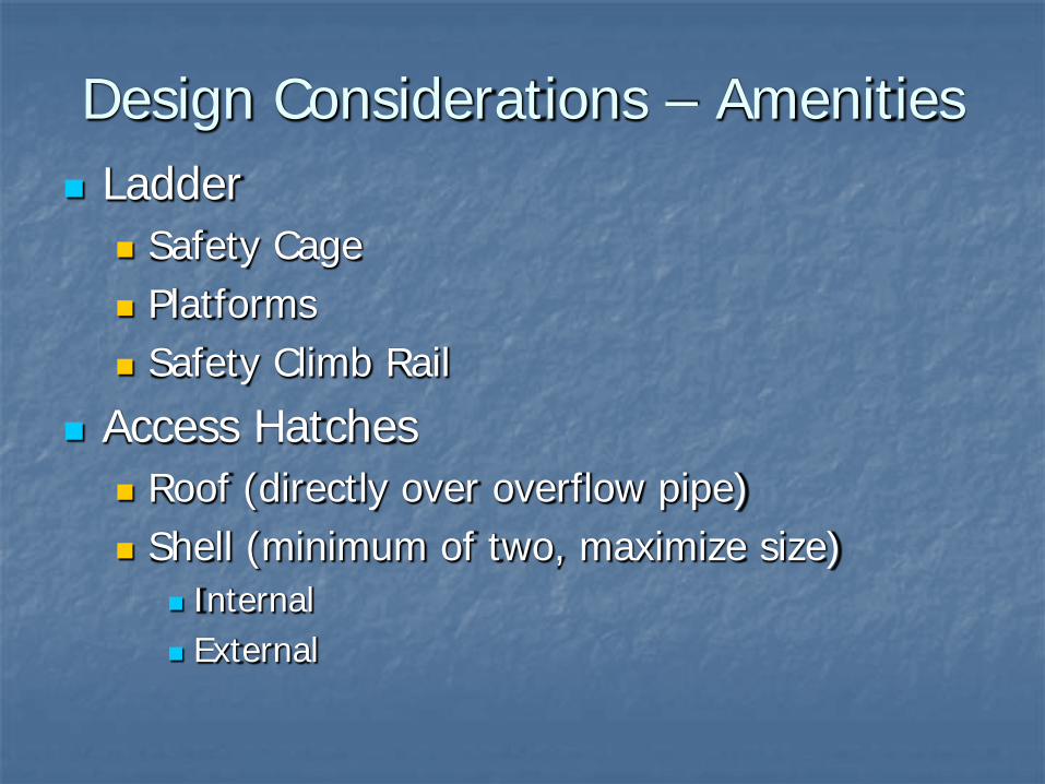
Design Considerations – Amenities Ladder
Safety Cage Platforms Safety Climb Rail
Access Hatches Roof (directly over overflow pipe) Shell (minimum of two, maximize size)
Internal External
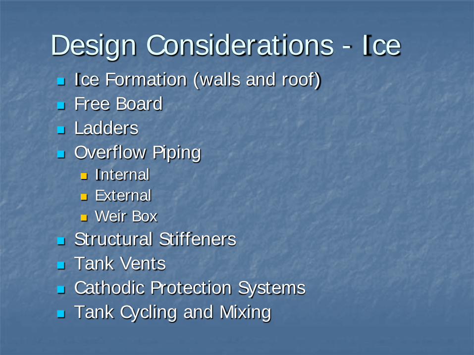
Design Considerations - Ice Ice Formation (walls and roof) Free Board Ladders Overflow Piping
Internal External Weir Box
Structural Stiffeners Tank Vents Cathodic Protection Systems Tank Cycling and Mixing
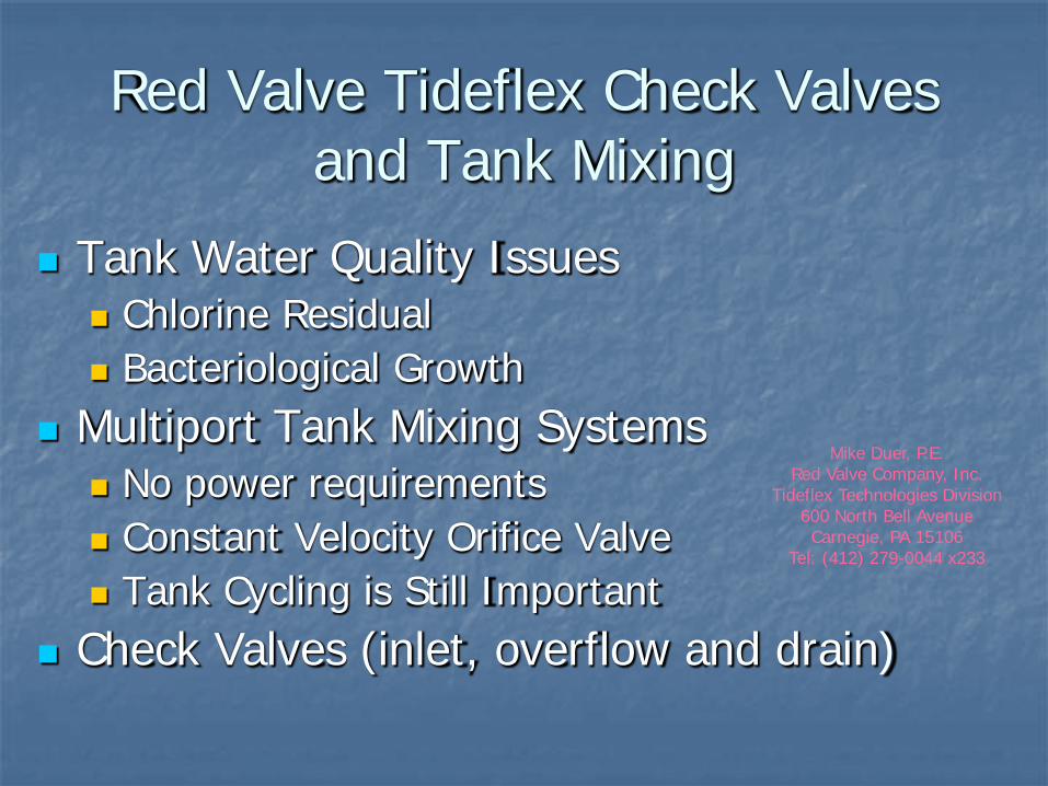
Red Valve Tideflex Check Valves and Tank Mixing
Tank Water Quality Issues Chlorine Residual Bacteriological Growth
Multiport Tank Mixing Systems No power requirements Constant Velocity Orifice Valve Tank Cycling is Still Important
Check Valves (inlet, overflow and drain)
Mike Duer, P.E. Red Valve Company, Inc.
Tideflex Technologies Division 600 North Bell Avenue Carnegie, PA 15106
Tel: (412) 279-0044 x233
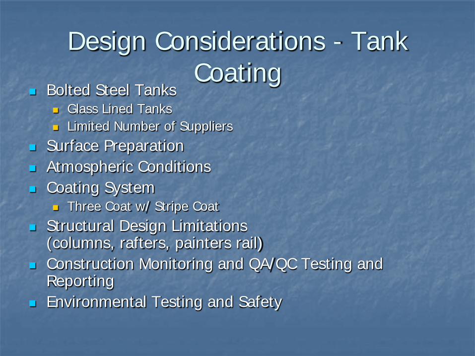
Design Considerations - Tank Coating
Bolted Steel Tanks Glass Lined Tanks Limited Number of Suppliers
Surface Preparation Atmospheric Conditions Coating System
Three Coat w/ Stripe Coat Structural Design Limitations
(columns, rafters, painters rail) Construction Monitoring and QA/QC Testing and
Reporting Environmental Testing and Safety
Reference Material AWWA M42 Steel Water Storage Tanks AWWA M32 Distributions Network Analysis for Water
Utilities DEQ Chapter 12 AWWA D100 Welded Steel Tanks AWWA D102 Coating Steel Water Storage Tanks AWWA C652 Disinfection of Water Storage Facilities AWWA D103 Factory Coated Bolted Steel Tanks AWWA D104 Automatically Controlled Impressed-Current
Cathodic Protection Systems API Standards