x-line 101 · 2019-08-14 · •anti-short cycle time delay ... •over/under voltage protection....
TRANSCRIPT

X-Line 101
X-Line 101June 2019

X-Line 101
X-Line Unit OverviewWhat makes X-Line unique

X-Line 101X-Line 101
Technology Changes, The Function Stays The Same
3
The new truck looks different, has extra features, and is more efficient, but it is still a truck.
Old Technology New Technology
• Internal Combustion Engine• Steering Wheel / Foot Pedals• Bed
• Internal Combustion Engine• Steering Wheel / Foot Pedals• Bed
• Carburetor• Distributor• Manual Steering• Drum Brakes
• Fuel Injection• Electronic Ignition• Power Steering• Disk Brakes
• On-Board Diagnostics• Seatbelts / Airbags• Crash Avoidance• Heated Seats / A/C

X-Line 101X-Line 101
Technology Changes, The Function Stays The Same
4
The new unit looks different, has extra features, and is more efficient, but it is still a unit.
Old Technology New Technology
• Scroll Compressor• Condenser• Outdoor Enclosure
• Scroll Compressor• Condenser• Outdoor Enclosure
• Mechanical Controls
• “Box” Design• “Air Beater” Fan
• Electronic Controls• Slim Design• High Efficient Fan
• On-Board Diagnostics• Communication• System Protection• Heated Seats / A/C

X-Line 101
X-Line BenefitsUptime - improve maintenance accuracy and reduce callbacks
– Diagnostics, protection, and connectivity standardFlexibility – install in more location options
– Lightweight, slim profile– Corrosion resistant– Quiet– Multi-refrigerant
Efficiency – lower usage costs– High efficient scroll compressor and optimized condenser sizing– Floating head pressure control and low condensing ready

X-Line 101
X-Line Nomenclature / FeaturesX F A M - 0 2 0 Z - T F C - 0 8 1
X =
Out
door
F =
Mul
ti-R
efrig
eran
tJ
= R
-404
A/
R-4
07A/
C
A =
Air C
oole
d
L =
Low
Tem
pM
= M
ediu
m T
emp.
P =
Mul
ti-Ap
plic
atio
n
Nom
inal
HP:
008
= ¾
HP
015
= 1.
5 H
P06
0 =
6 H
P
Z =
Scro
ll C
ompr
esso
r
CFV
= 2
08/2
30v
1Ph.
60 H
z.TF
C =
208
/230
v 3P
h.60
Hz.
Bill
Of M
ater
ial
Base Model Electrical BOMBOM Features UL
Gen
erat
ion
0.1
–1.
1
Gen
erat
ion
2.0
Rec
eive
r W/ V
alve
Rec
ieve
r Hea
ter /
In
sula
tion
Suct
ion
Valv
e
Liqu
id V
alve
Accu
mul
ator
Oil
Sepe
rato
r(L
ow T
emp
Onl
y)
Pres
sure
Con
trols
(A
djus
tabl
e lo
w, F
ixed
H
igh)
Def
rost
Con
trol
Filte
r Drie
r
Moi
stur
e In
dica
tor /
Sig
ht
Gla
ss
Cra
nkca
se H
eate
r
Varia
ble
Spee
d C
onde
nser
Fan
Dem
and
Coo
ling
Low
Tem
p -E
nhan
ced
Vapo
r Inj
ectio
n (E
VI)
Med
/Ext
Med
Tem
p -
Suct
ion
Line
Liq
uid
Inje
cton
One
-Way
Com
mun
icat
ion
Two-
Way
Com
mun
icat
ion
Cor
eSen
se D
iagn
ostic
s /
Prot
ectio
n
List
ed
Rec
ogni
zed
002 X X X Low Temp Only X X X X X X X X X X012 X X X Low Temp Only X X X X X X X X X X X022 X X X X Low Temp Only X X X X X X X X X X X
081 X X X X XFAL, XFAP Only X X X X X X X X X X X

X-Line 101
CoreSense TM Diagnostics And Protection
Integrated Technology Delivers Highest Efficiency And Diagnostic Protection
Variable Speed PSC Fan Motors• High Efficiency • Ultra Quiet • Optimizes Air-Flow
For MaximumHeat Transfer
• Meets CEC andNational Standards
Copeland Scroll Compressor Technology• High Efficiency• Ultra Quiet• High Reliability
Unit Sound Levels at Minimum and Maximum Load
•Over Current protection •Flooded Start Protection (“Bump-Start” Logic)
•Incorrect Phase Detection •Discharge Temp. Protection
•High Pressure Lockout •Anti-Short Cycle Time Delay
•Flood-Back Prediction •Digital Fault Code Display / Remote Alarming
•Demand Cooling™ •Over/Under Voltage Protection

X-Line 101X-Line 101
Wide Ambient Operating Range
System Location, Refrigerant, And Application May Affect Min/Max Operating Capability.
Heated And Insulated ReceiverMaintains Liquid Pressure For Starting In Low AmbientT-Stat Controlled Heater
Check Valve At Inlet Of ReceiverMaintains Pressure Build Up Inside Receiver
Low Ambient Approved Electronics And Sensors
Built In Low Pressure BypassAutomatic Bypass For Low Ambient Startup With Adjustable Time Delay.
Pressure Relief ValvePre-Installed For Zoning Code Compliance
Demand CoolingXFAM/P – Liquid InjectionXFAL – Vapor InjectionKeeps Compressor Cool During High Compression
Variable Speed FanContinually Adjusts Speed Between Approximately 300 to 1000 RPM For Current Conditions
Large Condenser CoilOptimized For High Ambient Conditions

X-Line 101
Setup / Diagnostics / Protection

X-Line 101
Top Diagnosis of Returned Compressors
28
No Fault Found
• Compressors are misdiagnosed and returned with no faults.
Electrical Problem
• Hi/Low voltage or current• Phase loss• Reverse rotation
Mechanical Problem
• Overheating• Flooded start• Liquid Floodback

X-Line 101
63%
17%
100%92%
0%
20%
40%
60%
80%
100%
Entry Level ExperiencedNo Diagnostics Comfort Alert
How Diagnostics Improve Troubleshooting Accuracy And Warranty
43%
18%22%
92%0%
15%
30%
45%
2002 2003 2004
No Diagnostics Comfort Alert
Service Technician Study Actual Warranty Results
Improved ServiceTechnician Accuracy
Lower “No Defect Found”Warranty Failures
%NDFTechnicianAccuracy
“My main concern is getting the equipment repaired the first time on the first visit. . . “ – Refrigeration Contractor
29
CoreSense CoreSense

X-Line 101X-Line 101
X-Line InstallationController Setup
Simplified Commissioning Allows For Setup in about 1 Minute.
•All installation instructions, diagrams, and guidelines are included in the application bulletin (AE5-1412)
•A quick start guide is supplied with each unit (attached to door), showing how to set the control (also in manual)
•Setup is similar to the EUC

X-Line 101X-Line 101
2.0 Diagnostic Codes
Lockouts Occur After An Adjustable Number Of Errors Within A Set Timeframe. Lockouts Can Be Disabled To Always Allow Auto Restarts
Code Description01 AI1 error (Suction Transducer)02 AI2 error (Condenser Temp Probe)03 AI3 error (Discharge Line Temp Probe)
04 AI4 error (Vapor Inlet Temp Probe)05 AI5 error (Vapor Outlet Temp Probe)06 AI6 error (Ambient Temp Probe)07 AI7 error (Liquid Line Temp Probe)08 Battery error09 Current sensor 1 error10 Current sensor 2 error11 Voltage sensor 1 error12 Voltage sensor 2 error13 Voltage sensor 3 error20 Lost phase error21 Phase sequence error22 Phase Imbalance23 Over current 124 Over current 225 Open run circuit error26 Open start circuit error
Code Description27 Under voltage alarm28 Over voltage alarm29 Compressor Build-in protector trip40 High pressure switch41 Low pressure switch42 High pressure alarm43 Low pressure alarm44 Discharge line temperature alarm46 High condenser temperature alarm47 EXV full open in EVI48 EVI high superheating alarm 49 EVI low superheating alarm50 High side flood back alarm80 RTC warning, date not correct81 RTF warning, communication with clock82 Probe configuration error83 DI configuration error84 Compressor configuration error85 Injection probe configuration error86 EEPROM R/W error (manual)
E=ErrorL=Lockout
Code

X-Line 101
System Protection
Proactive Reactive
• Floodback Prediction• Flooded Start Protection (Bump Start)• Short Cycle Protection• Demand Cooling™• Phase Imbalance Protection• High Condensing Temperature
Protection
• Over Current*• Lost Phase• High Pressure*• High Discharge Temperature*• Incorrect Phase Detection• Open Start Or Open Run Circuit• Over/Under Voltage
Identify or protect against conditions that may lead to compressor damage. System may adapt and continue running.
Shut down and prevent compressor damage from system or power supply issues that are occurring.*Can be set to Lockout or auto restart

X-Line 101X-Line 101
Compressor Lockouts
Code Condition Controlling Parameter
Default Setting
Value Range
L20 Lost Phase pEn 5 0 – 15; 0=Always Auto RestartL21 Reversed Phase - - On power upL23 Over Current oCn 5 0 – 15; 0=Always Auto RestartL24 Open Run Circuit oCn 5 0 – 15; 0=Always Auto RestartL25 Open Start Circuit oCn 5 0 – 15; 0=Always Auto RestartL26 Under Voltage pEn 5 0 – 15; 0=Always Auto RestartL27 Over Voltage pEn 5 0 – 15; 0=Always Auto RestartL40 High Pressure HPn 5 0 – 15; 0=Always Auto RestartL44 Discharge Line Temp dLn 4 0 – 15; 0=Always Auto RestartL86 EEPROM (Memory) - - -
Repeated Trips Are Often Indicative Of A Larger System Problem. If A Compressor Is Locked Out, The System Should Be Closely Examined To Determine The Cause Of The Issue.

X-Line 101
Lost Phase Protection
• Monitored by voltage sensing terminals on control module
• Triggered if any phase is not detected• Unit will restart after 3 minutes if phase returns• Unit will lockout if phase is lost more than 5
times in an hour
Error Code: E20 or L20

X-Line 101
Incorrect Phase Protection
• Monitored by voltage sensing terminals on control module
• Triggered if any phase does not lead the next by 120°
• Unit will not start until phase is corrected
Error Code: L21

X-Line 101
Phase Imbalance Protection
• Monitored by voltage sensing terminals on control module
• Triggered if voltage on any phase drops below 10% of the average
• Unit will not start until phase is corrected
Error Code: E22

X-Line 101
Over Current Protection
Comp. Status
With ProtectionWithout ProtectionMotorTemp.
OnOff
OnOff
On
•Over current protection is provided before the compressor overheats and trips on internal thermal protection. This shortens restart times from as long as 45 minutes down to 3 minutes.
•Unit will restart after 3 minutes and lockout if more than 5 trips occur within an hour
Error Code: E23 or L23

X-Line 101
High Pressure LockoutHigh pressure cut-out will stop compressor and restart after 3 minutes.• Fixed cut-out at 440psig, cut-in at 348psig• Lockout after 5 trips within one hour
Error Code: L42

X-Line 101
Discharge Line Temperature ProtectionError Code: E44 or L44
• Monitored by temperature sensor on discharge line located 6” from compressor discharge fitting.
• Compressor shuts down if temperature exceeds 250°f (low temp) or 255°f (medium temp)
• Unit will restart after 3 minutes if temperature drops below 170°F.
• System will lockout if compressor trips more than 4 times in an hour

X-Line 101
Flood Back Prediction• Error will display if high-side superheat (discharge –
condenser temp) is less than 18°F for more than 30 minutes of the last 45 minutes
• Unit will continue to run
Error Code: E50

X-Line 101
Flooded Start Protection (Bump Start)Bump start is a startup process that protects against bearing wear caused by flooded starts (refrigerant absorbed into the oil). The compressor and fans will run for 2 seconds then turn off for 15 seconds repeating this sequence 3 times. Once this sequence is completed, the unit resumes normal operation.The bump start sequence will initiate on first startup, and anytime power is lost and restored. Bump start will also initiate anytime the compressor does not run for more than 4 hours, and the ambient temperature is below 95°F.

X-Line 101
Anti-Short Cycle Protection• Compressor will remain off for 3 minutes after any
compressor shutdown.• Use Parameter 2oF to adjust timing.• Compressor indicator on display will flash during
time delay

X-Line 101
Error Code: L26 or L27• Monitored by voltage sensing terminals on
control module• Compressor stopped if voltage exceeds 10% of
min/max rated voltage for more than 1 second• Unit will restart after 3 minutes if voltage returns• Will lockout if compressor is stopped more than
5 times in an hour
Under/Over Voltage Protection
Power Supply
+10%
-10%

X-Line 101
Smart Crankcase Heater
Crankcase heater operates when:• Ambient temperature < 50°F• Compressor off

X-Line 101
Low Ambient Operation
Receiver heater operates when:• Ambient temperature < 50°F• Compressor off •Receiver temperature thermostat is closed (cut-in: 30°F, cut out: 70°F)
Low pressure control bypass:• Ambient temperature < -20°F
•Controlled by parameter LAS• 6 second duration
•Adjustable with parameter LMO

X-Line 101X-Line 101
Demand Cooling™
Injection Attempts To Maintain Discharge Line Temps Below 225°F (LT) Or 235°F (MT)Electronic Injection Valves (EIV) Control Refrigerant Flow For Optimum Injection
Provides Protection For Out Of Envelope OperationEVI Increases Capacity And Efficiency
Enhanced Vapor Injection (2-6 HP LT) Suction Line Liquid Injection (MT/EMT)
EXVHX
EVI Scroll
TXV
Condenser
Evaporator
EIV
TXV
Condenser
Evaporator
Low Temp Medium Temp

X-Line 101X-Line 101
Demand Cooling™ Continued
Direct Liquid Injection (3/4 – 1 1/4 HP LT)
Low Temp units with ZF*KAE compressors use direct liquid injection instead of EVI.
TXV
Condenser
Evaporator
LI Scroll
ZF*KAE

X-Line 101X-Line 101
On-Board Alarm History
Alarm History Retains The Last 50 Alarms With Date/Time Stamp
+ EXITAlarm 01 Error 40
Alarm 02 Error 40

X-Line 101
Digital Temperature And Pressure Display (Fast Access Menu)
49
Probe 1 - Pressure
Probe 2 - Temperature

X-Line 101X-Line 101
X-Line Communications
Availability Timing Varies. Product Information And Training Will Be Provided When Available.
Site SupervisorXWEB Internet Gateway
Available to end users thru retail solutions
CoreSense PCSoftware
Remote Display
Local “On-Site” Visibility And Control Remote “Off-Site” Visibility And Control
Kit # 943-0224-00Kit # 943-0058-00
E2 Site Control
Existing installationsV4.08
RS485 Modbus

X-Line 101
PC Interface Software (PCIF)
51
Version 3.00F01
Browse “Software Downloads” from OPI homepage
Requires RS485 to USB adapterhttp://a.co/3fG9T4U

X-Line 101X-Line 101
X-Line InstallationMounting And Connections
Physical Installation Is Simple And Standardized Across All Models
Mount almost anywhere with optional wall mount brackets or snow legs. Will accept brackets and legs from most mini-split manufacturers.
Easy access hinged door panel allows access to centralized color-coded terminal block for main power, defrost, and accessory connections. Door hinges separate for easy door removal.
External valves with standard 7/8” suction and ½” liquid connections

X-Line 101
Integration With Advanced Evaporators

X-Line 101X-Line 101
Using An X-Line Unit With An Interconnected Evap/CDU System
A false load needs applied to the evaporator control. Contact the evap manufacturer for the proper procedure
When a connected CDU is removed, the evaporator may require modification to avoid false alarms.
Example: Beacon II System
Other systems are similar. Contact the evaporator manufacturer for model specific instructions.

X-Line 101
Evaporators with built-in time delay function
If the evaporator has a built-in time delay, it may conflict with the time delay function in the X-Line unit. One of the time delays must be disabled or adjusted.
Options• Disable the evaporator time delay function.• If the evaporator time delay cannot be disabled, the
time delay on the X-Line can be adjusted. – Field installs have shown setting parameter 2oF to 20 seconds
has avoided conflicts with evaporator time delay settings.
55

X-Line 101
Built-In Defrost Controls
Many new evaporators come with defrost controls built into the evaporator. If the evaporator defrost control is used, the defrost control on the X-Line unit must be disabled.
To disable the defrost on the X-Line unit:• Set parameter EDF to nU
56

X-Line 101
Low Condensing / Envelope Mapping
Low
C
onde
nsin
gN
orm
al
Con
dens
ing
Envelope Map Override
• Default setting allows 70° minimum condensing (80° for XFAL)• 15-20% energy savings for each 10° lower condensing• System EXV needed to handle fluctuation• Adjust parameter MCS to allow low condensing• Control will override to remain within envelope

X-Line 101
Energy Savings

X-Line 101X-Line 101
X-Line Outdoor AWEF Scores
59
Outdoor AWEF (With Factory Settings)
Outdoor AWEF (With 50°F Minimum Condensing Temperature Settings)
Basic Model 22 134a 404A 407A 407C 448A 449A 22 134a 404A 407A 407C 448A 449A
XFAM/P-015Z 9.57 8.87 9.79 9.82 9.7 9.17 9.2 10.11 8.87 10.18 10.28 10.03 9.51 9.54
XFAM/P-017Z 9.97 9.29 10.22 9.98 10.01 9.62 9.62 10.45 9.29 10.58 10.44 10.36 10.06 10.08
XFAM/P-022Z 10.08 9.87 10.39 10.27 10.22 9.79 9.79 10.51 9.87 10.74 10.72 10.53 10.23 10.23
XFAM/P-030Z 10.81 10.93 10.41 10.5 10.96 10.4 10.41 11.22 10.93 10.73 10.82 11.3 10.75 10.76
XFAM/P-045Z 10.51 10.46 10.37 9.93 10.57 10.38 10.38 10.9 10.46 10.65 10.21 10.9 10.66 10.66
XFAM/P-050Z 9.22 9.59 9.17 9.25 9.26 9.31 9.28 9.22 9.59 9.17 9.51 9.47 9.25 9.25
XFAM/P-060Z 9.45 9.9 9.36 9.43 9.42 9.48 9.48 9.45 9.9 9.33 9.74 9.62 9.56 9.54
DOE Minimum AWEF For Outdoor MT Equipment: 7.6

X-Line 101
Capacity, Refrigerants, and AWEF (New Small Scroll Units)Medium Temp Capacity @ 95°F Ambient / 25°F Evap
Unit Comp. R-134a R-404A / 507A R-407A R-407C R-448A / 449ACap. AWEF Cap. AWEF Cap. AWEF Cap. AWEF Cap. AWEF
XFAM-008Z ZB06KAE 4,980 9.00 7,965 8.76 7,225 8.22 6,775 8.08 7,390 8.45
XFAM-010Z ZB07KAE 6,030 9.00 9,620 9.22 8,785 8.76 8,085 8.63 8,785 8.75
XFAM-012Z ZB08KAE 7,080 10.00 10,950 9.77 10,200 8.94 9,370 9.20 10,260 9.01
60
Low Temp Information not yet available.
X-Line 101
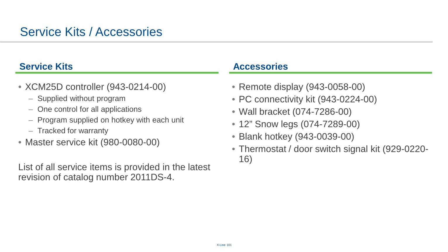
Service Kits / Accessories
Service Kits Accessories
• XCM25D controller (943-0214-00)– Supplied without program– One control for all applications– Program supplied on hotkey with each unit– Tracked for warranty
• Master service kit (980-0080-00)
List of all service items is provided in the latest revision of catalog number 2011DS-4.
• Remote display (943-0058-00)• PC connectivity kit (943-0224-00)• Wall bracket (074-7286-00)• 12” Snow legs (074-7289-00)• Blank hotkey (943-0039-00)• Thermostat / door switch signal kit (929-0220-
16)

X-Line 101
Annual Energy Savings Compared To Traditional UnitsXF Outdoor Scroll Vs Standard Units Typical Annual Energy Savings1
Ambient Temperature Zones
Medium Temperature Low Temperature
HP Unit CompressorXFAM kWh
Savings $0.08/kWh $0.12/kWh $0.16/kWh $0.20/kWh HP Unit CompressorXFAL kWh Savings $0.08/kWh $0.12/kWh $0.16/kWh $0.20/kWh
1.5Hermetic 4,521 $362 $543 $723 $904
2Hermetic 3,775 $302 $453 $604 $755
Scroll 2,561 $205 $307 $410 $512 Scroll 2,892 $231 $347 $463 $578 Semi-Hermetic 5,588 $447 $671 $894 $1,118
2Hermetic 3,713 $297 $446 $594 $743
3Scroll 5,247 $420 $630 $840 $1,049 Scroll 2,288 $183 $275 $366 $458 Semi-Hermetic 5,546 $444 $666 $887 $1,109 Semi-Hermetic 4,100 $328 $492 $656 $820
3Hermetic 5,417 $433 $650 $867 $1,083
4Scroll 5,484 $439 $658 $877 $1,097 Scroll 4,504 $360 $540 $721 $901 Semi-Hermetic 6,994 $560 $839 $1,119 $1,399 Semi-Hermetic 5,739 $459 $689 $918 $1,148
4Hermetic 6,967 $557 $836 $1,115 $1,393
5Scroll 6,900 $552 $828 $1,104 $1,380 Scroll 2,892 $231 $347 $463 $578 Semi-Hermetic 2,050 $164 $246 $328 $410
5Hermetic 9,854 $788 $1,182 $1,577 $1,971
6Scroll 8,889 $711 $1,067 $1,422 $1,778 Scroll 5,369 $430 $644 $859 $1,074 Semi-Hermetic 3,440 $275 $413 $550 $688 Semi-Hermetic 1,209 $97 $145 $193 $242
6 Scroll 13,237 $1,059 $1,588 $2,118 $2,647 Semi-Hermetic 8,046 $644 $966 $1,287 $1,609
1 Estimated kWh savings shown based on simulated unit operation based on average seasonal ambient temperatures in Climate Zone 2. Reciprocating, Scroll, and Semi-Hermetic refer to typical standard condensing units using these compressor technologies, with capacity generally matched to ± 10% of the Copeland Outdoor Scroll unit. Every effort has been made to assure the accuracy of the estimated annual operating cost and savings analysis. Actual energy results may vary by: type of application; load calculation assumptions; proper equipment sizing and matching selections; operational variables; and specific location. Emerson Climate Technologies, Inc. assumes no responsibility for actual energy performance deviations from these estimates, or for damages incurred through the use of the information presented. Detailed Annual Energy Efficiency Ratio (AEER) calculation assumptions, comparative unit and compressor model details, and additional Climate Zone savings estimates are available at: www.EmersonClimate.com/copelandoutdoorunit
Premium To Upgrade Typically < 1 Year PaybackExclusive Technology Only Available From Emerson
http://energycalculator.emersonclimate.com/xline
X-Line 101
Performance / Specs

X-Line 101
Spacing Requirements
64

X-Line 101
Medium Temp Capacity and AWEF
65
Medium Temp Capacity @ 95°F Ambient / 25°F Evap
Unit Comp.R-134a R-22 R-404A / 507A R-407A R-407C R-448A / 449A
Capacity AWEF Capacity AWEF Capacity AWEF Capacity AWEF Capacity AWEF Capacity AWEF
XFAM-008Z ZB06KAE 4,745 9.00 N/A N/A 7,965 10.59 7,225 10.01 6,775 9.94 7,390 10.00
XFAM-010Z ZB07KAE 5,750 10.00 N/A N/A 9,620 10.84 8,785 10.39 8,085 10.34 8,785 10.00
XFAM-012Z ZB08KAE 6,715 10.00 N/A N/A 10,950 11.32 10,200 10.37 9,370 11.00 10,260 10.00
XFAM-015Z ZS09KAE 7,810 8.87 12,100 9.79 12,400 9.78 11,400 9.82 10,900 9.66 10,700 9.07
XFAM-017Z ZS11KAE 9,270 9.29 14,100 9.97 14,600 10.08 13,500 9.98 12,900 10.01 12,900 9.51
XFAM-020Z ZS13KAE 10,500 9.36 16,050 10.07 16,950 10.42 15,300 9.89 14,600 9.94 14,450 9.38
XFAM-022Z ZS15KAE 12,600 10.08 26,800 9.87 20,300 10.43 18,200 10.19 17,450 10.22 17,300 9.66XFAM-025Z ZS19KAE 14,100 9.99 21,000 10.07 21,800 10.61 20,400 10.27 19,550 10.22 19,150 9.69XFAM-030Z ZS21KAE 18,700 10.93 27,600 10.81 28,200 10.43 26,300 10.50 25,800 10.96 26,500 10.24
XFAM-033Z ZS26KAE 20,550 11.06 30,300 10.87 31,850 10.49 29,300 10.55 28,350 10.95 28,000 10.05
XFAM-037Z ZS29KAE 22,850 11.06 33,450 10.79 35,500 10.36 31,850 10.33 31,400 10.86 32,500 10.41
XFAM-045Z ZS33KAE 25,600 10.46 37,900 10.51 39,100 10.26 36,800 9.93 35,400 10.57 36,800 10.21
XFAM-050Z ZS38K4E 29,900 9.59 47,100 9.22 44,800 8.71 42,600 8.93 42,600 9.07 44,600 9.31XFAM-060Z ZS45K4E 35,000 9.90 51,500 9.45 53,000 9.36 51,500 9.43 51,000 9.42 52,500 9.48
This refrigeration system is designed and certified for use in walk-in cooler applications. See Emerson.com/OPI for complete specifications.

X-Line 101
Low Temp Capacities
66
Low Temp Capacity @ 95°F Ambient / -10°F Evap
Unit CompressorR-404A / 507A R-407A R-407C R-448A / 449A
Capacity Capacity Capacity CapacityXFAL-008Z ZF03KAE 4,005 3,500 3,390 3,650XFAL-009Z ZF04KAE 5,480 4,780 4,600 4,975XFAP-015Z ZS09KAE 5,700 N/A N/A N/AXFAL-010Z ZF05KAE 6,625 5,660 5,470 5,895XFAP-017Z ZS11KAE 6,845 N/A N/A N/AXFAP-022Z ZS15KAE 9,290 N/A N/A N/AXFAL-012Z ZF07KAE 10,170 8,830 8,320 8,870XFAL-020Z ZXI06KCE 12,910 9,234 9,111 11,448XFAP-030Z ZS21KAE 13,700 N/A N/A N/A
XFAL-030Z-TFC ZXI09KCE 16,795 13,455 11,949 13,931XFAL-035Z-CFV ZXI11KCE 18,900 16,201 14,555 17,196
XFAP-045Z ZS33KAE 19,000 N/A N/A N/AXFAP-050Z ZS38K4E 22,800 N/A N/A N/AXFAL-040Z ZXI14KCE 24,210 21,078 19,760 22,872
XFAL-050Z-TFC ZXI15KCE 26,615 22,165 20,530 25,664XFAL-051Z-CFV ZXI16KCE 26,615 22,982 23,440 24,438
XFAP-060Z ZS45K4E 27,200 N/A N/A N/AXFAL-060Z ZXI18KCE 33,720 29,271 25,377 27,677

X-Line 101
Resources

X-Line 101
New Websitehttp://www.emerson.com/CopelandOutdoorUnit
Brochures, Manuals, and QBR’s

X-Line 101
Videos
• https://www.youtube.com/playlist?list=PL0EzIbQoBtncDGAubL6lBPrOVvjyLNcSB
69

X-Line 101
Mobile Apps
• https://climate.emerson.com/en-us/tools-resources/mobile-apps
70

X-Line 101
Questions?

X-Line 101
Backup Slides

X-Line 101
Condenser CoatingSalt Corrosion Test

X-Line 101
Test Parts Ys/T95.2-2001 Aluminum foil
Hydrophilic Coated
Aluminum
Uncoated Aluminum
Condenser Section
W/Coated Aluminum

X-Line 101
900 Hours Salt Spray (Maximum Environment)
Slight Corrosion At Edges
Standard Aluminum
Material Dark Grey / Slight Corrosion
Hydrophilic Aluminum Foil
Material No change

X-Line 101
Coastal Environment Field Test
Unit Installed 12/8/08 Tommy Bahamas Tampa Bay FloridaApproximately 100 Yards From The Gulf Of Mexico.
Unit Inspected 3/24/14 (5 ½ Yrs.) No Issues With Aluminum Fins, Slight Rust On the Cabinet.
Updates Since Inspection:• Screws changed to stainless steel.• Cabinet changed to galvannealed
steel with powder coating• Plastic parts resin changed to more
UV stable material