x-mind dc - profi dentalx-mind® dc 3 before beginning to use the “x-mind dc” x-ray system,...
TRANSCRIPT

X-Mind® DCInstallation manual / Manuel d’installation
Installationshandbuch / Installatiehandleiing

X-MindDC
Intraoral X-ray system at constant potential
INSTALLATION & MAINTENANCE MANUAL
This manual should always be kept in proximity to the device

22 XX--MMiinndd®® DDCC
INTRODUCTION page 2 SUMMARY page 3 PRELIMINARY INFORMATION page 4 INSTALLER INFORMATION page 5 1. “X-Mind DC” X-RAY SYSTEM page 6 2. IDENTIFICATION TAGS page 7 3. OVERALL DIMENSIONS page 8 4. INSTALLATION SPECIFICATIONS page 12 5. INSTALLATION page 15 5.1 UNPACKING page 15 5.2 ASSEMBLING THE WALL PLATE page 16 5.3 ASSEMBLING THE BRACKET page 18 5.4 ASSEMBLING THE PANTOGRAPH-TYPE ARM page 20 5.5 CONNECTION TO THE FEEDING TERMINAL BOARD page 21 5.6 ASSEMBLING THE TUBEHEAD page 24 5.7 BALANCING THE PANTOGRAPH-TYPE ARM page 27 5.8 ASSEMBLING THE “X-Mind DC” TIMER page 30 5.9 TIMER ELECTRIC CONNECTION page 32 6. CONTROL PANEL page 34 7. SYSTEM CONFIGURATION page 36 8. CHANGING THE CONFIGURATION page 38 9. START-UP page 40 10. CHECKING THE INSTALLATION page 41 11. CHECKING THE EXPOSURE FACTORS page 43 12. DIAGNOSTICS page 44 13. CALIBRATION page 45 13. ERROR MESSAGES page 46 14. FUSE REPLACEMENT page 48 15. MAINTENANCE page 49 16. CLEANING OUTER SURFACES page 50 17. SHOULD A REPAIR BECOME NECESSARY page 51 18. DISPOSAL page 51 19. ATTACHMENTS page 52
SUMMARY

XX--MMiinndd®® DDCC 33
Before beginning to use the “X-Mind DC” X-ray system, instructions contained herein should be carefully read and followed so as to obtain the best possible performance. Always pay close attention to the CAUTION, WARNING, and PLEASE NOTE messages when operating the system. LEGEND
CAUTION The word CAUTION refers to events which might compromise the operator's personal safety or cause injuries to people.
WARNING The word WARNING refers to events which might compromise the radiographic system’s performance.
PLEASE NOTE The words PLEASE NOTE refer to special indications to facilitate maintenance or make important information clearer.
PRELIMINARY INFORMATION

44 XX--MMiinndd®® DDCC
CAUTION The installer is responsible for the installation, with regards to the system safety and operation.
For safe and reliable installation of the “X-Mind DC” X-ray system it is advisable to: Check that the voltage mentioned in the rating plate matches the line voltage
Install the “X-Mind DC” X-ray system according to the procedures described in this manual
Provide the user with any information regarding the use of the “X-Mind DC” X-ray system pursuant to the manual
Certify the work done by a Statement of Compliance
Return the duly filled in warranty certificate to “Satelec S.A.S”: if this is not done, the warranty is not valid
INSTALLER INFORMATION

XX--MMiinndd®® DDCC 55
The “X-Mind DC” X-ray system (Fig. 1) consists of:
TUBEHEAD
SPACER CONE
PANTOGRAPH-TYPE ARM
TIMER
WALL PLATE
BRACKET
OPTIONAL
− long 12” (31 cm) cone
− short 8” (20 cm) cone
− long cone 12” (31 cm) with a rectangular section sized 44x35mm
− second “CONTROL BUTTON” with extension cable
− RX signaling lamp for external use: X-Mind LIGHT
− remote control button: X-Mind ECB
Fig. 1
1. “X-Mind DC” X-RAY SYSTEM

66 XX--MMiinndd®® DDCC
The identification tags on the tubehead, on the timer and on the cone indicate the model name, the serial number, the manufacturing date and the symbols of the main technical characteristics.
ID TAG OF THE “X-Mind DC”
TUBEHEAD
ID TAG OF THE “X-Mind DC”
TIMER
ID TAG OF THE LONG 12” CONE
ID TAG OF THE SHORT 8” CONE
ID TAG OF THE RECTANGULAR CONE
GRADUATED SCALE TAG ON TUBEHEAD
Pictograms used
This symbol guarantees that the X-ray system complies with the regulations contained in the European Directive EEC 93/42 regarding Medical Devices
The degree of protection against direct and indirect electric contacts is B type
Refer to Manual's instructions
N “NEUTRAL" power supply wire
L “PHASE" power supply wire
T Ground cable
2. IDENTIFICATION TAGS

XX--MMiinndd®® DDCC 77
Fig. 1A, 1B, 1C give the overall dimensions of the possible supply conditions:
SHORT BRACKET (optional) length 41 cm - 16.2”
STANDARD BRACKET length 82,5 cm - 32.5”
LONG BRACKET (optional) length 110 cm - 43.5”
SHORT BRACKET 41 cm Fig. 1A
STANDARD BRACKET 82.5 cm Fig. 1B
LONG BRACKET 110 cm Fig. 1C
3. OVERALL DIMENSIONS

88 XX--MMiinndd®® DDCC
Fig. 2, 3A, 3B, 3C e 4 show the typical dimensions of the X-ray system:
STANDARD BRACKET 82.5 cm Fig. 2

XX--MMiinndd®® DDCC 99
STANDARD BRACKET 82.5 cm Fig. 3A
Fig. 3B Fig. 3C SHORT BRACKET 41 cm LONG BRACKET 110 cm

1100 XX--MMiinndd®® DDCC
Fig. 4
XX--MMiinndd®® DDCC 1111
WARNING Prior to installing the X-ray system the Office Owner must ascertain that: the environment, the electrical system and the power supply comply with the requirements specified, otherwise he must provide the required adjustment works.
1. ENVIRONMENT REQUIREMENTS a. The installation environment must be of appropriate width.
Using the sizes and overall dimensions provided (refer to §3 “OVERALL DIMENSIONS”), ensure that no obstacles are present while positioning the X-ray system
b. The environment must not be subject to explosion risks and must not be pressurized c. While operating, the ambient temperature must range within +5°C and +40°C d. The storage temperature must range within -15°C and +50°C e. The relative humidity must range within 25 % and 75 %
2. SUPPORTING WALL REQUIREMENTS a. The X-ray system supporting wall must be able to stand 200 kg tear at every point
PLEASE NOTE The nature and consistency of the wall must be checked and if required, seek the support of a brickwork expert. Walls of uncertain consistency must be reinforced with a buried counter plate or with a sandwich type system.
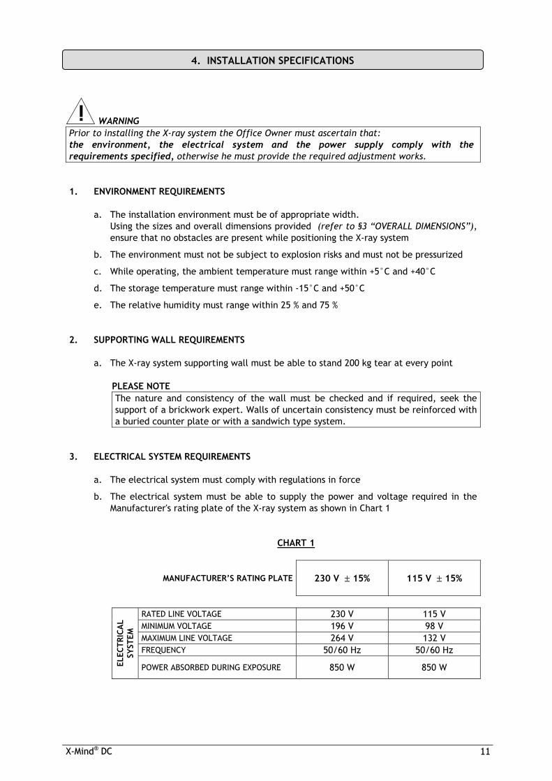
3. ELECTRICAL SYSTEM REQUIREMENTS a. The electrical system must comply with regulations in force b. The electrical system must be able to supply the power and voltage required in the
Manufacturer's rating plate of the X-ray system as shown in Chart 1
CHART 1
MANUFACTURER’S RATING PLATE 230 V ± 15%
115 V ± 15%
RATED LINE VOLTAGE 230 V 115 V MINIMUM VOLTAGE 196 V 98 V MAXIMUM LINE VOLTAGE 264 V 132 V FREQUENCY 50/60 Hz 50/60 Hz
ELEC
TRIC
AL
SYST
EM
POWER ABSORBED DURING EXPOSURE 850 W 850 W
4. INSTALLATION SPECIFICATIONS

1122 XX--MMiinndd®® DDCC
4. ELECTRICAL LINE REQUIREMENTS a. The electrical line must be "single-phase" type b. It is essential that a 16A – 250V, magnetothermal differential switch be fitted
upstream of the X-ray system, with differential protection In<= 30mA (refer to §20 “ATTACHMENTS”)
c. The power cords of the timer and the tubehead connection conductors with must be two-pole + ground, and in proportion to the length of the power cord, as shown in Chart 2
CHART 2
POWER SUPPLY VOLTAGE MINIMUM
CONDUCTOR SECTION
MAXIMUM
LINE LENGTH
1.5 mm2 10 meters
196V to 264V 2.5 mm2 20 meters 1.5 mm2 10 meters
98V to 132V 2.5 mm2 20 meters
PLEASE NOTE For longer lines, the cord section must be increased in proportion.
d. The communication cables (C11, C12 – C21, C22) between the timer and X-Ray must
be two-pole, twisted and shielded with >0.25 mm2 section (example: Belden 9501 type)
e. The cables (S11, S12 – S21, S22) connecting the timer and the signal lamps located outside the surgery must be two-pole > 0.5 mm2
f. The electrical line characteristics must comply with Chart 3
CHART 3
LINE VOLTAGE 230 V ± 15%
115 V ± 15%
MAXIMUM LINE VOLTAGE DROP 3% 3%
ELEC
TRIC
AL
LIN
E
MAXIMUM LINE APPARENT RESISTANCE 0.5 ohm 0.5 ohm

XX--MMiinndd®® DDCC 1133
5. ELECTRICAL CONNECTIONS
WARNING Prior to installing the X-ray system, it is advisable that all the electrical connections be in place.
Timer electric connections
CAUTION According to the relevant standard, the timer must be installed in a position allowing the operator to always control the X-ray exposure.
On the timer installation wall, suitable conduits for the following electric cables must be provided, pursuant to the electrical installation diagram (refer to §20 “ATTACHMENTS”):
a. Timer electrical cables
(refer to §5.9 “TIMER ELECTRIC CONNECTIONS”) b. Cables connecting the timer and the tubehead
(refer to §5.9 “ TIMER ELECTRIC CONNECTIONS ”) c. Cables connecting the timer and the RX signal lamp/s for external use:
X-Mind LIGHT (OPTIONAL) d. Cables connecting the timer and the remote control button:
X-Mind ECB (IF PROVIDED) Tubehead electrical connections
On the wall plate installation wall, a suitable conduit for the cable connecting the timer
and tubehead must be provided (refer to §5.5 “CONNECTION TO THE POWER SUPPLY TERMINAL BOARD”)

1144 XX--MMiinndd®® DDCC
CAUTION The “ X-MindDC X-ray system must be installed by professionally trained technicians, who must be able to certify their work with a Statement of Compliance.
WARNING Prior to installing the X-ray system, it is advisable to ensure that all needed requirements have been met (refer to §4 “INSTALLATION SPECIFICATIONS”)
The components of the “ X-MindDC ” radiographic system are duly packed within a carton box, as shown in the following sketch (Fig. 5):
D DOCUMENTS: INSTRUCTION MANUAL, INSTALLATION & MAINTENANCE MANUAL, AND WARRANTY CARD
X-MindDC TUBEHEAD PACKAGING
X-MindDC TIMER + RX SIGNALING LAMP FOR EXTERNAL USE X-Mind LIGHT (OPTIONAL) + REMOTE CONTROL BUTTON X-Mind ECB (OPTIONAL) PACKAGING
PANTOGRAPH-TYPE ARM PACKAGING
WALL PLATE + BRACKET PACKAGING
PLEASE NOTE Prior to installation, duly check all components.
PLEASE NOTE The carton and the polystyrene foam can be completely recycled and can be disposed of by authorized recycling companies.
PLEASE NOTE The original packaging should be stored in the event the equipment is returned for repairs.
5. INSTALLATION
5.1 UNPACKING

XX--MMiinndd®® DDCC 1155
WARNING To fix the wall plate, DO NOT use plastic or rubber anchor screws. For cement or solid/hollow brick walls, use metal anchor screws Ø12 (NOT included).
ASSEMBLY INSTRUCTIONS (Fig. 6)
1. Take the wall plate out of the packaging (refer to Fig. 5) and take the drilling template
2. Position the drilling template on the X-ray system installation wall, at the required height (130 cm from the base is the suggested height)
3. Secure the template with adhesive tape 4. Check the holes for vertical and horizontal alignment, using a plumb line 5. Mark the wall plate anchor holes 6. Mark the holes for the electric cables connecting the timer to the tubehead
PLEASE NOTE To prevent any flaking in the white coat and to control the center distances between the holes, it is advisable to start drilling with a Ø7 bit, increasing this size gradually.
7. Drill the wall plate anchor holes 8. If required, drill the holes for the electric cables connecting the timer to the tubehead 9. Remove the template and insert the suitable anchor screws, according to the wall’s characteristics
10. Unscrew the screw and remove the plug from the wall plate 11. Withdraw the sliding cover 12. Apply the wall plate to the wall and insert the screws with the appropriate washers, then tighten them alternately
13. Ensure that the wall plate is solidly attached to the wall
PLEASE NOTE If the wall is not perfectly plumbed, insert a suitable shim between the wall and the wall plate, in order to prevent warping.
5.2 ASSEMBLING THE WALL PLATE

1166 XX--MMiinndd®® DDCC
Fig. 6

XX--MMiinndd®® DDCC 1177
PLEASE NOTE The brackets come in the following lengths: 41 cm - 82,5 cm - 110 cm The 82.5 cm and 110 cm brackets are provided with a stop key (Fig. 7A and 7B) to prevent the electrical cable from twisting.
PLEASE NOTE Generally, the stop key is installed so that the equipment position at rest is on the right side, viewed from the front of the wall plate (Fig. 7A). Should the position at rest be on the left side, the stop key must be rotated by 180° (Fig. 7B).
5.3 ASSEMBLING THE BRACKET
Fig. 7A Fig. 7B
WALL

1188 XX--MMiinndd®® DDCC
After fixing the plate to the wall, assemble the bracket, using the following procedure (Fig. 8):
1. Take the bracket out of the packaging (refer to Fig. 5) 2. Insert the bracket pin into the wall plate (upwards) 3. Insert the supporting rest
Fig. 8 PLEASE NOTE Prevent all foreign matter (ground, dust, cement, etc. ) from settling on the pin seat. The pin must slide freely in its seat. If required, thoroughly clean and lubricate with “molikote D" lubricant.
PLEASE NOTE Carefully check that the bracket is parallel to the floor, using a water level.

XX--MMiinndd®® DDCC 1199
ASSEMBLY INSTRUCTIONS (Fig. 9)
1. Take out the pantograph-type arm from the packaging (refer to Fig. 5)
2. Remove the bracket plug by unscrewing the set screw
3. Insert the bracket guard wafer
4. Insert the pantograph group cable into the washer and then the pantograph pin
Fig. 9
5. If required, clean the pin and the washer and lubricate with “molikote D" lubricant 6. Insert the electric cable into the bracket housing 7. Assemble the guard wafer 8. Insert the cable into the bracket and push it until it reaches the pin outlet near the supply
terminal board
5.4 ASSEMBLING THE PANTOGRAPH-TYPE ARM

2200 XX--MMiinndd®® DDCC
CAUTION For electrical safety, it is essential that the ground conductors be correctly connected.
WARNING The length of the electrical cable and of the communication cable is suitable for 82.5 cm brackets. DOT NOT tamper with the terminals arrangement when 41 cm long brackets are used. The excess cable must be stored in the housing provided.
WARNING In case of electric power supply type PHASE – PHASE the higher value must be taken using a tester and entered in L.
5.5 CONNECTION TO THE FEEDING TERMINAL BOARD
XX--MMiinndd®® DDCC 2211
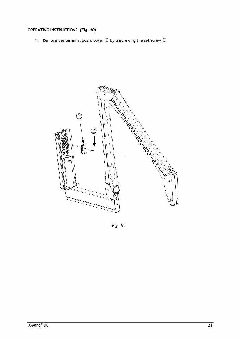
OPERATING INSTRUCTIONS (Fig. 10)
1. Remove the terminal board cover by unscrewing the set screw
Fig. 10

2222 XX--MMiinndd®® DDCC
2. Proceed with the electrical connection as shown in Fig. 11
Fig. 11
TERMINAL BOARD CONNECTION DIAGRAM
BROWN L (line)
YELLOW GREEN T (ground)
BLUE N (neutral)
BLACK COMMUNICATIONS
RED COMMUNICATIONS
YELLOW GREEN T (ground)
YELLOW GREEN T (ground)
THE COMMUNICATIONS CABLES ARE NOT POLARIZED
3. Connect the pantograph cable shield to the grounding potential 4. Connect the wall plate to the grounding potential 5. Clamp the cables with the cable clamps provided 6. Reassemble the terminal board cover (refer to Fig. 10)
IMPORTANT !

XX--MMiinndd®® DDCC 2233
ASSEMBLY INSTRUCTIONS
1. Remove the tubehead from the packaging (refer to Fig. 5) 2. Check that all the rating data match the power supply voltage 3. Remove both guards from the pantograph-type arm by loosening the appropriate screws
(Fig. 12)
Fig. 12
4. Using a bit, detach the front coupling device (Fig. 13A)
5. Remove both guards (Fig. 13B)
Fig. 13A Fig. 13B
5.6 ASSEMBLING THE TUBEHEAD

2244 XX--MMiinndd®® DDCC
6. Insert the tubehead pin into the pantograph head (Fig. 14A) and insert the
support (Fig. 14B)
Fig. 14A Fig. 14B
7. Check that during insertion, the pin of the rotation prevention device is correctly inserted into the seat located on the pantograph head (Fig. 15)
Fig. 15

XX--MMiinndd®® DDCC 2255
8. Couple the pantograph and tubehead connectors and insert them into their seats (Fig. 16)
Fig. 16

2266 XX--MMiinndd®® DDCC
CAUTION The pantograph-type arm must be adjusted only when the tubehead is assembled .
WARNING To prevent damage to the internal mechanism while making adjustments and executing the balancing tests, the adjustment key must not be left in place.
WARNING The key provided must be carefully stored. PLEASE NOTE To reach the “X” adjustment screw “ARM A” must be put in vertical position. To reach the “Y” adjustment screw “ARM B” must be put in horizontal position. The adjustment key provided can be inserted only under the above conditions (Fig. 17)
5.7 BALANCING THE PANTOGRAPH-TYPE ARM
ARM B
Y
ARM A
Fig. 17
X

XX--MMiinndd®® DDCC 2277
Procedure to be followed to correctly balance the pantograph-type arm (refer to Fig. 17): 1. “ARM A” BALANCING
PLEASE NOTE The pantograph-type arm is supplied with “ARM A” already preloaded. “ARM B” is supplied unloaded for safety reasons.
2. “ARM B” BALANCING For correct balancing, proceed as follows: 1. “ARM A” VERTICAL
2. “ARM B” HORIZONTAL 3. INSERT THE ADJUSTMENT KEY IN “Y” 4. LOAD THE SPRING WITH 22 TURNS 5. WITHDRAW THE KEY
3. CHECKING THE BALANCING To check the balancing, proceed as follows:
BRING “ARM B” TO THE VARIOUS POSITIONS if it does not maintain the correct position:
1. BRING “ARM B” BACK TO THE HORIZONTAL POSITION
2. INSERT THE ADJUSTMENT KEY IN “Y” 3. ROTATE THE ADJUSTMENT KEY BY HALF TURN:
- - CLOCKWISE IF IT TENDS TO COME DOWN - COUNTERCLOCKWISE IF IT TENDS TO GO UP
4. WITHDRAW THE KEY
PLEASE NOTE Repeat the test and adjustment until “ARM B” is steady and stable in all positions, even when “ARM A” is completely extended.
4. READJUSTMENT OF “ARM A” If it does not maintain the required position: 1. BRING “ARM A” TO THE VERTICAL POSITION AGAIN 2. INSERT ADJUSTMENT KEY IN “X” 3. ROTATE ADJUSTMENT KEY BY HALF TURN: - CLOCKWISE IF IT TENDS TO COME DOWN - COUNTERCLOCKWISE IF IT TENDS TO GO UP 4. WITHDRAW THE KEY
PLEASE NOTE Repeat the test and adjustment until “ARM A” is steady and stable in all positions, even when “ARM B” is completely extended.

2288 XX--MMiinndd®® DDCC
Upon completion of balancing:
1. Insert the movable finish (A) between the pantograph-type arm guard and the metal frame (Fig. 18)
Fig. 18
2. Insert the pins of the guards into their slots; then position them and ensure that the movable finish is coupled to the guards (Fig. 19)
Fig. 19
A

XX--MMiinndd®® DDCC 2299
CAUTION Check that the cable conduits are present in the timer installation wall; check the compliance of the power supply with the installation specifications (refer to §.4 “INSTALLATION SPECIFICATIONS”).
CAUTION Check that the rating data match the power supply voltage.
ASSEMBLY INSTRUCTIONS (Fig. 20)
1. Take the timer out of the packaging (refer to Fig. 5) 2. Take out the drilling template 3. Mark the anchor holes on the wall using the drilling template 4. Drill using a Ø3mm bit, then drill again with a Ø6 mm bit to prevent any flaking of the
white coat 5. Insert the three screw anchors provided into the holes 6. Open the timer by unscrewing the three screws
5.8 ASSEMBLING THE “X-Mind®DC” TIMER
Fig. 20
3300 XX--MMiinndd®® DDCC
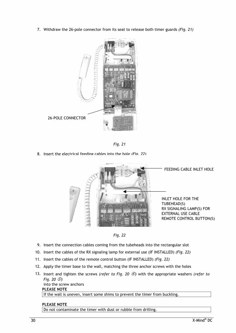
7. Withdraw the 26-pole connector from its seat to release both timer guards (Fig. 21)
Fig. 21
8. Insert the electrical feeding cables into the hole (Fig. 22)
Fig. 22
9. Insert the connection cables coming from the tubeheads into the rectangular slot
10. Insert the cables of the RX signaling lamp for external use (IF INSTALLED) (Fig. 22) 11. Insert the cables of the remote control button (IF INSTALLED) (Fig. 22) 12. Apply the timer base to the wall, matching the three anchor screws with the holes 13. Insert and tighten the screws (refer to Fig. 20 ) with the appropriate washers (refer to
Fig. 20 ) into the screw anchors
PLEASE NOTE If the wall is uneven, insert some shims to prevent the timer from buckling.
PLEASE NOTE Do not contaminate the timer with dust or rubble from drilling.
26-POLE CONNECTOR
FEEDING CABLE INLET HOLE
INLET HOLE FOR THE TUBEHEAD(S) RX SIGNALING LAMP(S) FOR EXTERNAL USE CABLE REMOTE CONTROL BUTTON(S)
XX--MMiinndd®® DDCC 3311
CAUTION Before proceeding with connections, the power supply must be cut off.
CAUTION If the equipment is mounted on metal walls, these must be connected to the grounding circuit.
WARNING While performing the connection, always comply with the PHASE – NEUTRAL polarity.
WARNING While stripping the cables, be careful that small copper wires do not fall on the printed circuit and cause short circuits or malfunctioning.
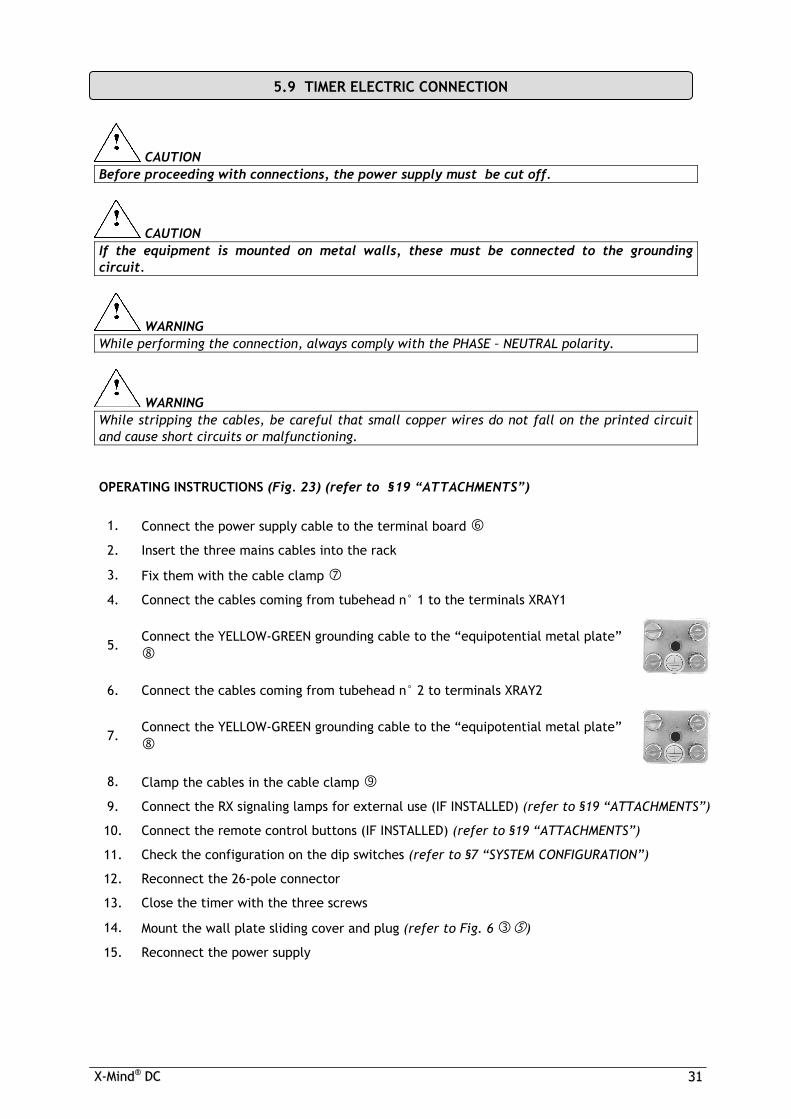
OPERATING INSTRUCTIONS (Fig. 23) (refer to §19 “ATTACHMENTS”)
1. Connect the power supply cable to the terminal board 2. Insert the three mains cables into the rack
3. Fix them with the cable clamp 4. Connect the cables coming from tubehead n° 1 to the terminals XRAY1
5. Connect the YELLOW-GREEN grounding cable to the “equipotential metal plate”
6. Connect the cables coming from tubehead n° 2 to terminals XRAY2
7. Connect the YELLOW-GREEN grounding cable to the “equipotential metal plate”
8. Clamp the cables in the cable clamp 9. Connect the RX signaling lamps for external use (IF INSTALLED) (refer to §19 “ATTACHMENTS”) 10. Connect the remote control buttons (IF INSTALLED) (refer to §19 “ATTACHMENTS”) 11. Check the configuration on the dip switches (refer to §7 “SYSTEM CONFIGURATION”) 12. Reconnect the 26-pole connector 13. Close the timer with the three screws
14. Mount the wall plate sliding cover and plug (refer to Fig. 6 ) 15. Reconnect the power supply
5.9 TIMER ELECTRIC CONNECTION

3322 XX--MMiinndd®® DDCC
Fig. 23
1 1 TUBEHEAD N° 1 CONTROL BUTTON and/or REMOTE CONTROL BUTTON
2 2 TUBEHEAD N° 2 CONTROL BUTTON and/or REMOTE CONTROL BUTTON
3A 3A TUBEHEAD N° 1 RX SIGNALING LAMP FOR EXTERNAL USE
3B 3B TUBEHEAD N° 2 RX SIGNALING LAMP FOR EXTERNAL USE
The electronic card terminal boards control the following functions:
4A 4A RS232 COMMUNICATION FOR XRAY1
4B 4B RS232 COMMUNICATION FOR XRAY2
5 5 TUBEHEAD N° 1 POWER SUPPLY
6 6 TUBEHEAD N° 2 POWER SUPPLY
7 7 TIMER POWER SUPPLY
1 2 3A-3B 4A-4B 5 6 7

XX--MMiinnddDDCC 3333
The control panel is the user's interface, from which the operator can: use the keys to select the operating parameters
to change the exposure times displayed
to store the new customized exposure times
use the “green LED” light indicators to check the timer operating conditions
6. CONTROL PANEL

3344 XX--MMiinnddDDCC
MAIN SWITCH
CONTROL BUTTON
X-RAY KEY
DISPLAY
KEY TO DECREASE
EXPOSURE TIME
KEY TO INCREASE
EXPOSURE TIME
TUBEHEAD
TYPE INDICATOR
X-RAY DISTANCE INDICATOR
TUBEHEAD SELECTION
X-RAY VOLTAGE INDICATOR
MEMORY
SELECTION OF PATIENT’S PHYSIQUE
TYPE
UPPER MAXILLARY TEETH
LOWER MANDIBLE
TEETH
X-RAY CURRENT INDICATOR
X-RAY
OUTPUT SIGNAL OCCLUSAL EXAM
BITEWING EXAM
PAUSE INDICATOR
MALFUNCTION INDICATOR
DIGITAL X-RAY TECHNIQUE
CONVENTIONAL
X-RAY TECHNIQUE
KEY SWITCH

XX--MMiinndd®® DDCC 3355
The “ X-Mind®DC ” X-ray system is factory configured for “standard mode” operation which determines:
No. 2 “ X-Mind®DC ” tube heads pressing the RX button on the control panel causes the LED 1 button to light up, pressing the button again causes the LED 2 to light up
** IF THE LONG 12” (31 cm) CONE IS USED ** An X-ray distance SSD = 31cm with the long 12” cone
on the control panel LED 12” is lit
** IF THE SHORT 8” (20 cm) CONE IS USED ** An X-ray distance SSD = 20cm with the short 8” cone
on the control panel 8” LED is lit
with film type “D” on the control panel “D” LED is lit
no. 1 CONTROL BUTTON to make the exposure The timer includes a key with an extension
cable
The installed tube head has the following features:
work with direct current at constant potential
the “DC” LED on the control panel must be lit
work with an X-ray voltage equal to 70kVp
the “70 kVp” LED on the control panel must be lit
work with an X-ray current equal to 8mA
the “8 mA” LED on the control panel must be lit
The above configuration depends on the position of 8 mini-switches (dip-switch ) on the timer electronic card:
DIP SWICH PARAMETER ON OFF
1 TUBEHEAD No. 1 INSTALLED NOT INSTALLED
2 TYPE OF TUBEHEAD No. 1 dc
DIRECT CURRENT AT CONSTANT POTENTIAL
ac ALTERNATING CURRENT
SINGLE-PHASE 3 TUBEHEAD No. 2 INSTALLED NOT INSTALLED
4 TYPE OF TUBEHEAD No. 2 dc
DIRECT CURRENT AT CONSTANT POTENTIAL
ac ALTERNATING CURRENT
SINGLE-PHASE 5 CONTROL BUTTON No. 2 INSTALLED NOT INSTALLED 6 CONE LONG (12”) SHORT (8”) 7 NOT AVAILABLE NOT AVAILABLE 8 NOT AVAILABLE NOT AVAILABLE
7. SYSTEM CONFIGURATION

3366 XX--MMiinnddDDCC
** IF THE LONG 12” (31 cm) CONE IS USED **
ON OFF 1 ■ tubehead no. 1 2 ■ “dc” type tubehead 3 ■ tube head .no. 2 4 ■ “dc” type tubehead 5 ■ control button no. 2 6 ■ 12” cone (31cm) 7 ■ not available 8 ■ not available
** IF THE SHORT 8” (20 cm) CONE IS USED **
ON OFF 1 ■ no. 1tubehead 2 ■ “dc type” tubehead 3 ■ no. 2tubehead 4 ■ “dc” type tubehead 5 ■ no. 2 control button 6 ■ 8” cone (20 cm) 7 ■ not available 8 ■ not available
The configuration may be changed if:
POSSIBLE MODIFICATION HOW TO CARRY OUT THE MODIFICATIONS
− type “E” and “F” films are used − a digital system is used − use of a voltage equal to 60 kV − use of a current equal to 4 mA
refer to USER’S MANUAL § 6 “OPERATING INSTRUCTIONS”
− the short 8” (20 cm) cone is used − the long 12” (31 cm) cone is used − a single tubehead is used − use of a tubehead with “ac” technology − no. 2 CONTROL BUTTON is used
by changing the dip switch position THIS ,MAY ONLY BE DONE BY THE INSTALLER

XX--MMiinndd®® DDCC 3377
CAUTION This must be done by the installer.
WARNING To make the changes operative, turn off the timer and then turn it on again.
To change the configuration, the timer’s dip switch positions ( )must be changed: DIP
SWICH PARAMETER ON OFF
1 TUBEHEAD No. 1 INSTALLED NOT INSTALLED
2 TYPE OF TUBEHEAD No. 1 dc
DIRECT CURRENT AT CONSTANT POTENTIAL
ac ALTERNATING CURRENT
SINGLE-PHASE 3 TUBEHEAD No. 2 INSTALLED NOT INSTALLED
4 TYPE OF TUBEHEAD No. 2 dc
DIRECT CURRENT AT CONSTANT POTENTIAL
ac ALTERNATING CURRENT
SINGLE-PHASE 5 No. 2 CONTROL BUTTON INSTALLED NOT INSTALLED 6 CONE LONG (12”) SHORT (8”) 7 NOT AVAILABLE NOT AVAILABLE 8 NOT AVAILABLE NOT AVAILABLE
8. CHANGING THE CONFIGURATION
3388 XX--MMiinnddDDCC
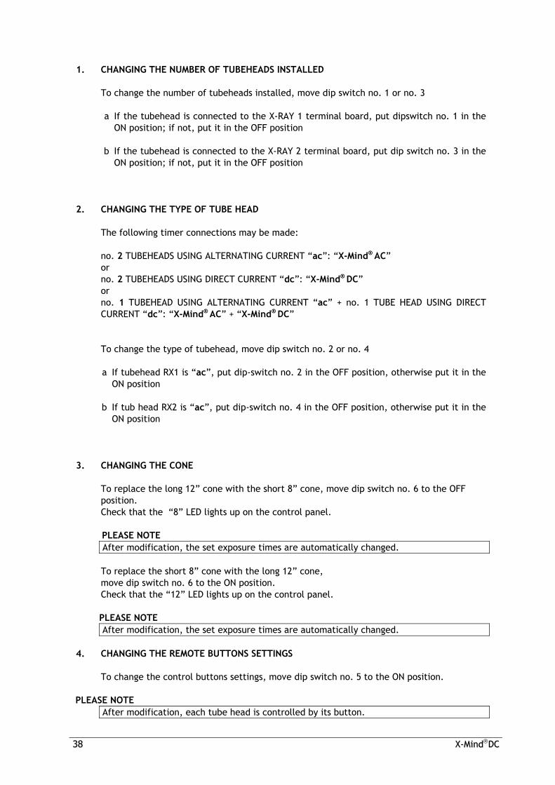
1. CHANGING THE NUMBER OF TUBEHEADS INSTALLED To change the number of tubeheads installed, move dip switch no. 1 or no. 3 a. If the tubehead is connected to the X-RAY 1 terminal board, put dipswitch no. 1 in the
ON position; if not, put it in the OFF position b. If the tubehead is connected to the X-RAY 2 terminal board, put dip switch no. 3 in the
ON position; if not, put it in the OFF position
2. CHANGING THE TYPE OF TUBE HEAD The following timer connections may be made: no. 2 TUBEHEADS USING ALTERNATING CURRENT “ac”: “X-Mind® AC” or no. 2 TUBEHEADS USING DIRECT CURRENT “dc”: “X-Mind® DC” or no. 1 TUBEHEAD USING ALTERNATING CURRENT “ac” + no. 1 TUBE HEAD USING DIRECT
CURRENT “dc”: “X-Mind® AC” + “X-Mind® DC” To change the type of tubehead, move dip switch no. 2 or no. 4 a. If tubehead RX1 is “ac”, put dip-switch no. 2 in the OFF position, otherwise put it in the
ON position b. If tub head RX2 is “ac”, put dip-switch no. 4 in the OFF position, otherwise put it in the
ON position
3. CHANGING THE CONE To replace the long 12” cone with the short 8” cone, move dip switch no. 6 to the OFF
position. Check that the “8” LED lights up on the control panel.
PLEASE NOTE After modification, the set exposure times are automatically changed.
To replace the short 8” cone with the long 12” cone,
move dip switch no. 6 to the ON position. Check that the “12” LED lights up on the control panel.
PLEASE NOTE After modification, the set exposure times are automatically changed.
4. CHANGING THE REMOTE BUTTONS SETTINGS To change the control buttons settings, move dip switch no. 5 to the ON position.
PLEASE NOTE
After modification, each tube head is controlled by its button.

XX--MMiinndd®® DDCC 3399
CAUTION When all connections are completed, the installer must check the system’s electrical and operating safety. For further information, see the USER'S MANUAL.
TURN ON THE TIMER to power up the X-ray system
a.
Bring the "MAIN SWITCH" located on the upper part of the timer to the “I” position (ON)
b. Bring the “’KEY SWITCH” to the “I” position (ON)
the green light turns on indicating that the system is powered up the LEDs of the set parameters automatically light up the exposure time is shown on the display c. THE X-RAY SYSTEM IS NOW READY FOR USE
WARNING If an error is detected when the system is turned on, the anomaly is indicated as follows: • an intermittent beep sounds
• the MALFUNCTION INDICATOR LED blinks intermittently
The error code (E ….) appears on the display
(refer to § 13 “ERROR MESSAGES”)
• All control panel functions are disabled In this event, turn off the timer and then turn it back on. If the error should recur, call the “Support Department”.
PLEASE NOTE The exposure time and parameters displayed are the last which to be set before the timer was turned off.
PLEASE NOTE If installed, the RX signal lamp for external use, corresponding to the selected tube head, turns on.
PLEASE NOTE If the timer remains inactive for a few minutes, it switches to the stand-by mode. Press any control panel key to restore it to operating mode.
9. START UP

4400 XX--MMiinnddDDCC
OPERATING INSTRUCTIONS 1. CHECKING THE CONFIGURATION On the control panel, check that all LEDs corresponding to the required configuration are
lit; if not, change them. (refer to § 7 “SYSTEM CONFIGURATION” and § 8 “CHANGING THE CONFIGURATION” )
2. CHECKING THE TIMER OPERATION a. Check the correct operation of the control panel by selecting different exposure
times b. Check the time on the display c. Check that, when changing the selected tube head, the corresponding RX signal
lamp for external use (IF INSTALLED) turns on 3. CHECKING THE EXPOSURE a. Set an exposure time of 1 sec b. Take the timer’s "CONTROL BUTTON" c. Using the extension cable of the “CONTROL BUTTON”, maintain a safe distance of
at least 2 meters from the tube head, so as to be able to constantly check the X-ray exposure
d. Press the “X-RAY” key and keep it depressed until the acoustic signal (beep)
stops, and the yellow X-RAY OUTPUT SIGNAL LED turns off e.
At the end of the exposure, the green PAUSE INDICATOR LED blinks intermittently
f. On the display, check the actual exposure time (refer to § 11 4.“EXPOSURE TIME (sec)” )
4. CHECKING THE TUBEHEAD OPERATION Take several exposures on the tubehead installed and check that: a. There are no errors b. The LED of the selected tube head is lit c. The "CONTROL BUTTON" LED is lit for the entire duration of the acoustic signal
10. CHECKING THE INSTALLATION

XX--MMiinndd®® DDCC 4411
5. CHECKING THE POWER ABSORBED BY THE X-RAY SYSTEM To check the power absorbed by the radiographic system a tester must be used, in the
mode ampmeter in “AC” a. Connect the instrument to the power supply line
(refer to § 5.9 “TIMER ELECTRIC CONNECTION”) b. Set an exposure time of approx. 3 sec on the timer c. Take an exposure and read the current value on the display
PLEASE NOTE The X-ray system complies with the requirements when the absorbed current is ≤ 8A with 230V line voltage (±15%)
the absorbed current is ≤ 12.5A with 115V line voltage (±15%) Otherwise, check the electrical system or call the “Support Department”.
6. CHECKING THE ELECTRIC SYSTEM To check the electric system, a tester must be used, in the mode voltmeter in “AC” a. Connect the instrument to the L and N terminals on the timer b. Measure the line voltage (V0) c. Connect the instrument to the L and N terminals of the wall plate terminal board
(refer to § 5.5 “CONNECTION TO THE FEEDING TERMINAL BOARD”) d. Set an exposure time of approx. 3 sec on the timer e. Proceed with the exposure f. Measure the line voltage during exposure (V1)
PLEASE NOTE The electrical system complies with the requirements when the result of the formula
(V0 – V1 ) / V0 is ≤ 0.03 (3%)
Otherwise, the electric system must be adjusted. (refer to § 4 “INSTALLATION SPECIFICATIONS”

4422 XX--MMiinnddDDCC
OPERATING INSTRUCTIONS 1. RADIOGRAPHIC VOLTAGE (kVp) The radiographic high voltage is measured using a calibrated "non-invasive" instrument
with an initial delay of 50 m. sec. Line Voltage = nominal V ±15% Max Voltage Drop = 3 % kVp = 60 - 70 mA = 4 - 8
SET TECHNICAL VALUES
Set Exposure Time = 3.2 sec The radiographic VOLTAGE is 60 kVp - 70 kVp ±10 % 2. RADIOGRAPHIC CURRENT (mA) The radiographic current is measured by connecting a milliampmeter inside the tube head Line Voltage = Nominal V ±15% Max Voltage Drop = 3 % kVp = 60 - 70 mA = 4 - 8
SET TECHNICAL VALUES
Set Exposure Time = 3.2 sec The radiographic CURRENT is 4mA - 8mA ±10 % 3. DOSE (mGy) The dose in the air is measured with a "non-invasive" instrument, by positioning the
detector at an SSD (source-skin distance) of 31 cm (12”) or 20 cm (8”) Line Voltage = Nominal V ±15 % Max Voltage Drop = 3 % kVp = 60 - 70 mA = 4 - 8
SET TECHNICAL VALUES
Set Exposure Time = 1 sec DOSE in the air = SSD = SOURCE-SKIN DISTANCE = 31 CM (12”) SSD = SOURCE-SKIN DISTANCE = 20 CM (8”) 70 kVp – 8 mA = 5.5 mGy/s ±30 % 70 kVp – 8 mA = 12 mGy/s ±30 % 60 kVp – 8 mA = 4.5 mGy/s ±30 % 60 kVp – 8 mA = 9 mGy/s ±30 % 70 kVp – 4 mA = 3 mGy/s ±30 % 70 kVp – 4 mA = 6 mGy/s ±30 % 60 kVp – 4 mA = 2.2 mGy/s ±30 % 60 kVp – 4 mA = 4.5 mGy/s ±30 % 4. EXPOSURE TIME (sec) The exposure time is measured with a “non-invasive” instrument.
Line Voltage = Nominal V ±15 % Max Voltage Drop = 3 % kVp = 60 - 70 mA = 4 - 8
SET TECHNICAL VALUES
Set Exposure Time = 3.2 sec The EXPOSURE TIME measured is 3.2 sec ±10 %
11. CHECKING THE EXPOSURE FACTORS

XX--MMiinndd®® DDCC 4433
The “X-Mind DC” X-ray system allows the installer to set or display some of the timer’s functional parameters: 1. To set the parameters, the installer must: a. Turn off the timer
b. Simultaneously press and keep the following keys depressed: (45) LOWER MANDIBLE PREMOLAR + (43) LOWER MANDIBLE CANINE
c. Turn on the timer d. When the message "inst” is displayed, the installer can set the
minimum exposure time:
1. select the tube head 2. turn off the timer
3. turn on the timer, by keeping the key depressed
4. the message “SEC” is displayed for approx 1 sec 5. the current value of the lower set limit is displayed
6. to change the value, press the keys and
7. to confirm, press the key
e. To exit this mode, turn the timer off and then on again 2. To display the parameters, the installer must:
a. Simultaneously press and keep depressed the (17) UPPER MAXILLARY MOLAR + (47) LOWER MAXILLARY MOLAR keys
b. Press the key associated with the desired parameter
KEY DISPLAYED PARAMETER Example U.M.
BITEWING ANT
X-RAY SYSTEM NOMINAL VOLTAGE
230 Volt
BITEWING POST LINE VOLTAGE 227 Volt
UPPER INCISOR
MAXIMUM LINE VOLTAGE VALUE DETECTED
238 Volt
LOWER INCISOR
MINIMUM LINE VOLTAGE VALUE DETECTED
215 Volt
OCCLUSAL SOFTWARE VERSION 2.3
12. DIAGNOSTIC

4444 XX--MMiinnddDDCC
CAUTION During this operation there is X-ray output. All the safety measures relevant to radioprotection must be observed.
If necessary, “ X-Mind DC ” can be calibrated. The relevant procedure is as follows: a. Switch off the timer
b. Switch on the timer and keep the mA button depressed
c. The display shows the “tube” message
d. Select X-RAY with the button to calibrate
e. Take the exposure:
Press and keep the “RX” button depressed until the beeping stops
stops the yellow “X-RAY OUTPUT SIGNAL” LED goes off
f. Once the exposure has been taken, if the display does not show “ERRORS”, the calibration has been successfully completed, otherwise (refer to §14 “ERROR MESSAGES”)
13. CALIBRATION

XX--MMiinndd®® DDCC 4455
The following chart contains a list of error messages that may appear while the “X-Mind® DC” X-ray system is operating. The chart also includes the causes of the error messages and what to do to resolve them.
Error Message Cause Solution
RX1 TUBE HEAD
IS NOT CONNECTED OR IS OUT OF ORDER CALL THE “SUPPORT DEPARTMENT”
RX2 TUBE HEAD IS NOT CONNECTED OR IS OUT OF ORDER
CALL THE “SUPPORT DEPARTMENT”
CORRUPTED EEPROM DATA CALL THE “SUPPORT DEPARTMENT”
EEPROM DATA NOT PROPERLY SAVED CALL THE “SUPPORT DEPARTMENT”
LINE VOLTAGE VALUE NOT WITHIN THE SET LIMITS
CALL THE “SUPPORT DEPARTMENT”
LINE VOLTAGE VALUE NOT INCLUDED WITHIN THE ±15 % NOMINAL VALUE
CALL THE “SUPPORT DEPARTMENT”
THE “X-RAY” KEY ALWAYS SEEMS TO BE DEPRESSED
ENSURE THAT IT IS NOT JAMMED
ANOMALY ON THE CONTROL PANEL CALL THE “SUPPORT DEPARTMENT”
THE EXPOSURE HAS BEEN PREMATURELY INTERRUPTED
KEEP THE “X-RAY KEY” DEPRESSED TILL THE END OF THE EXPOSURE
ANOMALY IN THE TRIAC/RELAY CALL THE “SUPPORT DEPARTMENT”
ANOMALY IN THE ELECTRONIC CIRCUIT CALL THE “SUPPORT DEPARTMENT”
ANOMALY IN THE CONTROL CIRCUIT CALL THE “SUPPORT DEPARTMENT”
INCORRECT DIP SWITCH CONFIGURATION CALL THE “SUPPORT DEPARTMENT”
THE “CONTROL BUTTON” DOES NOT CORRESPOND TO THE SELECTED TUBE HEAD
USE THE “CONTROL BUTTON” THAT CORRESPONDS TO THE SELECTED TUBE HEAD
THE TUBEHEAD DOES NOT WORK PROPERLY
CALL THE “SUPPORT DEPARTMENT”
THE TUBEHEAD IS NOT IN THE CORRECT MODE
CALL THE “SUPPORT DEPARTMENT”
14. ERROR MESSAGES

4466 XX--MMiinnddDDCC
THE TUB HEAD HAS NOT COMPLETED THE EXPOSURE
REPEAT THE EXPOSURE OR CALL THE “SUPPORT DEPARTMENT”
FREQUENCY OR REGULATION PROBLEM
CALL THE “SUPPORT DEPARTMENT”
THE TUBEHEAD IS NOT CALIBRATED
CALIBRATE OR CALL THE “SUPPORT DEPARTMENT”
EEPROM DATA NOT PROPERLY SAVED CALL THE “SUPPORT DEPARTMENT”
CORRUPTED EEPROM DATA CALL THE “SUPPORT DEPARTMENT”
OVERVOLTAGE ERROR CALL THE “SUPPORT DEPARTMENT”
ANODE VOLTAGE OUT OF TOLERANCE CALL THE “SUPPORT DEPARTMENT”
ANODE CURRENT OUT OF TOLERANCE CALL THE “SUPPORT DEPARTMENT”
CONTROL CONNECTOR CALL THE “SUPPORT DEPARTMENT”
REFERENCE VOLTAGE PROBLEM CALL THE “SUPPORT DEPARTMENT”
MAJOR ERROR ALL X-RAY SYSTEM FUNCTIONS ARE DISABLED
CALL THE “SUPPORT DEPARTMENT”

XX--MMiinndd®® DDCC 4477
The timer’s electronic equipment is protected by 4 fuses located on the electronic card. To replace them, proceed as follows (Fig. 25): 1. Cut off the power supply 2. Temporarily remove the timer’s guard by removing the adjusting
3. Determine the fuse to be replaced (Fig. 26) 4. Remove the plastic protector (Fig. 27) 5. Remove the fuse 6. Replace it with a fuse of same type
POWER VOLTAGE OF THE X-RAY SYSTEM 230 V ± 15 % 115 V ± 15 % Internal protection fuses (5x20) quick 8AF – 250V 12.5AF – 250V
7. Insert the protection
Fig. 26 Fig. 27 8. Close the timer’s guard 9. Restore the power
15. FUSE REPLACEMENT

4488 XX--MMiinnddDDCC
To guarantee the X-ray system’s safety, the following checks must be carried out:
CAUTION The owner is responsible for arranging and respecting the maintenance schedule. The X-ray system must undergo maintenance to check for correct operation every 12 months. 1. Cut the power 2. Release the spring of the “ARM B” of the pantograph type arm using the key provided
(refer to § 5.7 “BALANCING THE PANTOGRAPH-TYPE ARM”) 3. Remove the tube head
(refer to § 5.6 “ASSEMBLING THE TUBE HEAD”) 4. Remove the wall plate guard
(refer to § 5.2 “ASSEMBLING THE WALL PLATE”) 5. Remove the terminal board cover and disconnect the pantograph-type arm cable 6. Remove the bracket plug and remove the guard slab
(refer to § 5.4 “ASSEMBLING THE PANTOGRAPH-TYPE ARM") 7. Remove the pantograph-type arm and its cable from the bracket 8. Remove the bracket from the wall plate
(refer to § 5.3 “ASSEMBLING THE BRACKET”) 9. Check the wall plate’s vertical alignment – adjust if required 10. Check the six wall plate’s adjusting screws – tighten if required 11. Clean the old lubricating grease from the bracket shaft 12. Should the bracket shaft be damaged, install a new bracket 13. Clean the old lubricating grease from the bracket bush 14. If the bracket bush is damaged, install a new bracket 15. Grease the bracket shaft (use “molikote D” lubricant) 16. Lubricate the bracket bush with lubrication grease (use “molikote D” lubricant) 17. Install the bracket in the wall plate
(refer to § 5.3 “ASSEMBLING THE BRACKET") 18. Check the pantograph-type arm cable
If it is be damaged, send the pantograph-type arm to the manufacturer for repairs 19. Check the pantograph-type arm guards 20. Replace the damaged guards 21. Remove all old grease of the shaft
(refer to §. 5.4 “ASSEMBLING THE PANTOGRAPH-TYPE ARM”) 22. If the shaft is damaged, send the pantograph-type arm to the manufacturer for repairs 23. Lubricate the pantograph-type arm shaft with lubricant (use “molikote D” lubricant) and
reposition it in the bracket 24. Replace the pantograph-type arm cable in the bracket and the wall plate, connect it to the
terminal board and replace the terminal board cover (refer to § 5.5 “CONNECTION TO THE TERMINAL BOARD”)
25. Position the guard slab in the bracket 26. Position the bracket plug 27. Position the plate guard 28. Check the tubehead’s electrical contact 29. If damaged, send the tube head to the manufacturer for repairs 30. Clean the old grease from the tube head assembly shaft 31. Lubricate the tubehead’s assembly shaft with a thin layer of lubricant(use “molikote D”
lubricant) 32. Reposition the tubehead 33. Load the spring of the pantograph-type arm “ARM B” using the key provided
(refer to § 5.7 “BALANCING THE PANTOGRAPH-TYPE ARM”) 34. Power up and check that the X-ray system is operating correctly
16. MAINTENANCE

XX--MMiinndd®® DDCC 4499
Use a soft cloth with water and soap to clean the outer surfaces. The spacer cone may be cleaned with cotton wool soaked in surgical alcohol. In case of a malfunction, send the defective part to (USING THE ORIGINAL PACKAGING): Satelec S.A.S. Z.I. du Phare B.P. 216 33708 MERIGNAC cedex - France Tel. +33 (0) 556 34 06 07 Fax +33 (0) 556 34 92 92 E-mail: [email protected] In the event of disposal, the components and packaging must be disposed of in an environmentally correct manner. In particular, the dielectric oil as well as the shielding lead must be disposed by means of authorized companies specialized in the disposal of waste material.
17. CLEANING THE OUTER SURFACES
18. IF A REPAIR BECOMES NECESSARY
19. DISPOSAL

5500 XX--MMiinnddDDCC
The manufacturer undertakes to supply, upon request, drawings, circuit diagrams, component parts lists, instructions or other information needed by qualified technical personnel to perform repairs on those parts of the “ X-Mind® DC ” radiographic system which may be repaired.
20. ACCESSORIES

XX--MMiinndd®® DDCC 5511
X-Mind® DC
Installation electrical scheme
All rights reserved
5522 XX--MMiinnddDDCC
A B C
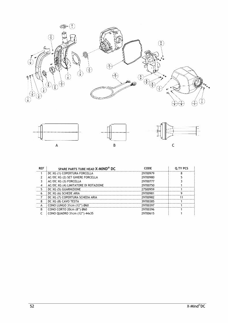
REF SPARE PARTS TUBE HEAD X-MIND® DC CODE Q.TY PCS
1 DC XG (1) COPERTURA FORCELLA 29700979 8 2 AC/DC XG (2) SET GHIERE FORCELLA 29700980 5 3 AC/DC XG (3) FORCELLA 29700777 3 4 AC/DC XG (4) LIMITATORE DI ROTAZIONE 29700750 1 5 DC XG (5) GUARNIZIONE 27500959 1 6 DC XG (6) SCHEDE ARIA 29700981 9 7 DC XG (7) COPERTURA SCHEDA ARIA 29700982 11 8 DC XG (8) CAVO TESTA 39700385 1 A CONO LUNGO 31cm (12”) Ø60 29700397 1 B CONO CORTO 20cm (8”) Ø60 29700396 1 C CONO QUADRO 31cm (12”) 44x35 29700615 1

XX--MMiinndd®® DDCC 5533
REF SPARE PARTS X-MIND® LIGHT CODE Q.TY PCS
1 XG LIGHT (1) GUSCIO INF & SUP 29700977 4 2 XG LIGHT (2) PORTALAMPADA 33400372 1 3 XG LIGHT (3) LAMPADINA 230V 15W 33300352 1 3 XG LIGHT (3) LAMPADINA 115V 15W 33300390 1 4 XG LIGHT (4) SCHEDA 230V 39200354 3 4 XG LIGHT (4) SCHEDA 115V 39200353 3

5544 XX--MMiinnddDDCC
REF SPARE PARTS X-MIND® ECB CODE Q.TY PCS
1 XG ECB (1) GUSCIO INF & SUP 29700978 4 2 SCHEDA COMANDO CON PULSANTE E LED 39700303 1 3 XG ECB (3) INTERRUTTORE A CHIAVE 35100298 1
XX--MMiinndd®® DDCC 5555
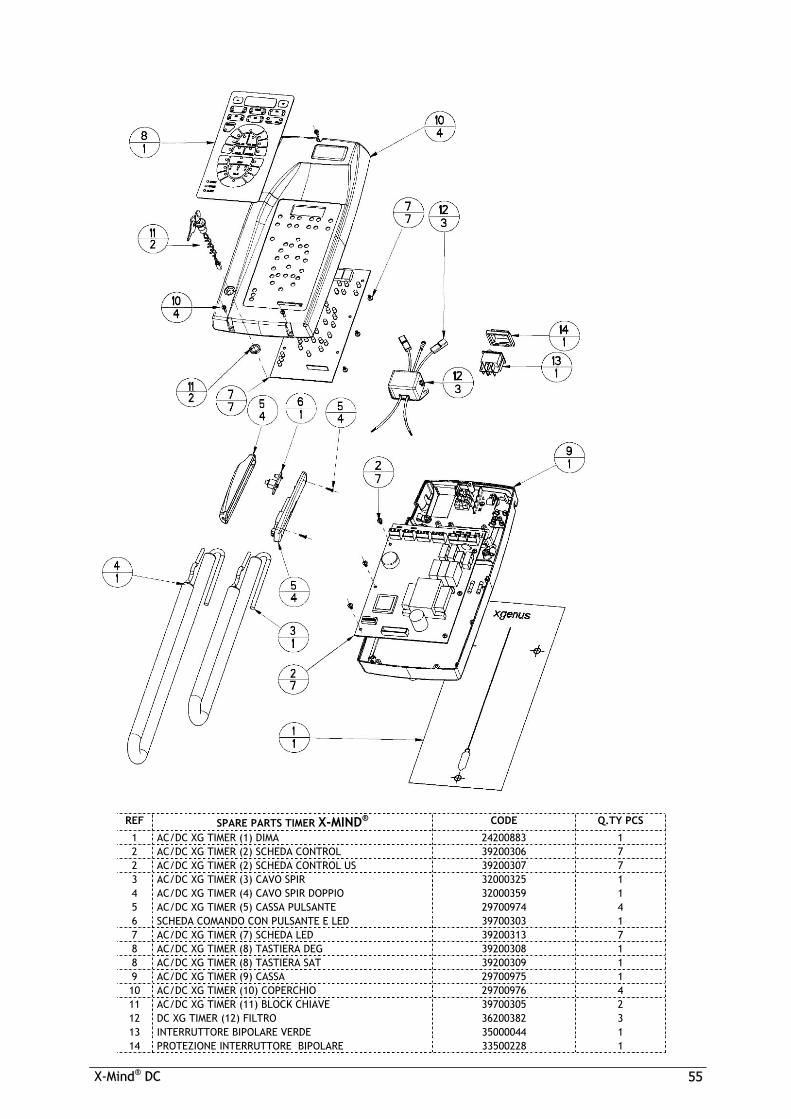
REF SPARE PARTS TIMER X-MIND® CODE Q.TY PCS
1 AC/DC XG TIMER (1) DIMA 24200883 1 2 AC/DC XG TIMER (2) SCHEDA CONTROL 39200306 7 2 AC/DC XG TIMER (2) SCHEDA CONTROL US 39200307 7 3 AC/DC XG TIMER (3) CAVO SPIR 32000325 1 4 AC/DC XG TIMER (4) CAVO SPIR DOPPIO 32000359 1 5 AC/DC XG TIMER (5) CASSA PULSANTE 29700974 4 6 SCHEDA COMANDO CON PULSANTE E LED 39700303 1 7 AC/DC XG TIMER (7) SCHEDA LED 39200313 7 8 AC/DC XG TIMER (8) TASTIERA DEG 39200308 1 8 AC/DC XG TIMER (8) TASTIERA SAT 39200309 1 9 AC/DC XG TIMER (9) CASSA 29700975 1 10 AC/DC XG TIMER (10) COPERCHIO 29700976 4 11 AC/DC XG TIMER (11) BLOCK CHIAVE 39700305 2 12 DC XG TIMER (12) FILTRO 36200382 3 13 INTERRUTTORE BIPOLARE VERDE 35000044 1 14 PROTEZIONE INTERRUTTORE BIPOLARE 33500228 1

5566 XX--MMiinnddDDCC
REF SPARE PARTS PANTOGRAPH TYPE ARM X-MIND® CODE Q.TY PCS
1 AC XG B (1) CAVO + CONNETTORE 3 POLI 39700384 1 2 DC XG B (2) CAVO + CONNETTORE 5 POLI 39700381 1 3 AC/DC XG B (3) GUSCI LATO TESTA 29700990 9 4 BRACCIO PANTOGRAFO TIRANTE ANTERIORE 29700460 4 5 BRACCIO PANTOGRAFO PORTATIRANTE 29700458 6 6 AC/DC XG B (6) TAPPI (set) 29700991 7 7 AC/DC XG B (7) COPERTURA EST 27500757 1 8 AC/DC XG B (8) COPERTURA INT 27500758 1 9 AC/DC XG B (9) GUSCI CENTRALI 29700993 8 10 BRACCIO PANTOGRAFO CHIAVE CARICAMENTO 22000543 1 11 AC/DC XG B (11) COPERTURA INT 27500758 1 12 AC/DC B (12) COPERTURA EST 27500757 1 13 AC/DC XG B (13) TIRANTE POST 29700992 7 14 BRACCIO PANTOGRAFO LUNETTA 22000177 1 15 AC/DC B (15) GUSCI LATO MENSOLA 29700994 8

XX--MMiinndd®® DDCC 5577
REF SPARE PARTS WALL PLATE 350 CODE Q.TY PCS 1 PIASTRA (1) COPERTURA 29700985 5 1 AC/DC XG PIASTRA (1) COPERTURA SAT 29700986 5 2 PIASTRA LUNETTA 22000176 1 3 PIASTRA (3) DIMA 24200984 1 PIASTRA MURO 350 DEG 29700383 COMPLETO AC/DC XG PIASTRA MURO 350 SAT 29700987 COMPLETO

5588 XX--MMiinnddDDCC
REF SPARE PARTS WALL PLATE 350 TOP CODE Q.TY PCS 1 PIASTRA (1) COPERTURA 29700985 5 1 AC/DC XG PIASTRA (1) COPERTURA SAT 29700986 5 2 PIASTRA LUNETTA 22000176 1 3 PIASTRA (3) DIMA TOP 24201002 1 PIASTRA MURO 350 TOP DEG 29700988 COMPLETO AC/DC XG PIASTRA MURO 350 TOP SAT 29700989 COMPLETO

XX--MMiinndd®® DDCC 5599
REF SPARE PARTS BRACKET CODE Q.TY PCS
MENSOLA 400 29700380 COMPLETO MENSOLA 800 29700378 COMPLETO MENSOLA 1100 29700379 COMPLETO
REF SPARE PARTS CEILING BRACKET CODE Q.TY PCS
MENSOLA PLAFONE 29700382 COMPLETO
REF SPARE PARTS UNIT BRACKET CODE Q.TY PCS
MENSOLA RIUNITO 29700381 COMPLETO
REF SPARE PARTS TOP MOUNT BRACKET CODE Q.TY PCS
MENSOLA 400 TOP MOUNT 29700620 COMPLETO MENSOLA 800 TOP MOUNT 29700621 COMPLETO MENSOLA 1100 TOP MOUNT 29700622 COMPLETO

5566 XX--MMIINNDD®® DDCC
REF WISSELSTUKKEN RICHTARM X-MIND® CODE AANTAL
1 AC XG B (1) CAVO + CONNETTORE 3 POLI 39700384 1 2 DC XG B (2) CAVO + CONNETTORE 5 POLI 39700381 1 3 AC/DC XG B (3) GUSCI LATO TESTA 29700990 9 4 BRACCIO PANTOGRAFO TIRANTE ANTERIORE 29700460 4 5 BRACCIO PANTOGRAFO PORTATIRANTE 29700458 6 6 AC/DC XG B (6) TAPPI (set) 29700991 7 7 AC/DC XG B (7) COPERTURA EST 27500757 1 8 AC/DC XG B (8) COPERTURA INT 27500758 1 9 AC/DC XG B (9) GUSCI CENTRALI 29700993 8 10 BRACCIO PANTOGRAFO CHIAVE CARICAMENTO 22000543 1 11 AC/DC XG B (11) COPERTURA INT 27500758 1 12 AC/DC B (12) COPERTURA EST 27500757 1 13 AC/DC XG B (13) TIRANTE POST 29700992 7 14 BRACCIO PANTOGRAFO LUNETTA 22000177 1 15 AC/DC B (15) GUSCI LATO MENSOLA 29700994 8

XX--MMIINNDD®® DDCC 5577
REF WISSELSTUKKEN MUURPLAAT 350 CODE AANTAL 1 PIASTRA (1) COPERTURA 29700985 5 1 AC/DC XG PIASTRA (1) COPERTURA SAT 29700986 5 2 PIASTRA LUNETTA 22000176 1 3 PIASTRA (3) DIMA 24200984 1 PIASTRA MURO 350 DEG 29700383 COMPLETO AC/DC XG PIASTRA MURO 350 SAT 29700987 COMPLETO

5588 XX--MMIINNDD®® DDCC
REF WISSELSTUKKEN MUURPLAAT 350 TOP CODE AANTAL 1 PIASTRA (1) COPERTURA 29700985 5 1 AC/DC XG PIASTRA (1) COPERTURA SAT 29700986 5 2 PIASTRA LUNETTA 22000176 1 3 PIASTRA (3) DIMA TOP 24201002 1 PIASTRA MURO 350 TOP DEG 29700988 COMPLETO AC/DC XG PIASTRA MURO 350 TOP SAT 29700989 COMPLETO

XX--MMIINNDD®® DDCC 5599
REF WISSELSTUKKEN BEUGEL CODE AANTAL
MENSOLA 400 29700380 COMPLETO MENSOLA 800 29700378 COMPLETO MENSOLA 1100 29700379 COMPLETO
REF WISSELSTUKKEN PLAFONDBEUGEL CODE AANTAL
MENSOLA PLAFONE 29700382 COMPLETO
REF WISSELSTUKKEN EENHEIDBEUGEL CODE AANTAL
MENSOLA RIUNITO 29700381 COMPLETO
REF WISSELSTUKKEN BOVENBEUGEL CODE AANTAL
MENSOLA 400 TOP MOUNT 29700620 COMPLETO MENSOLA 800 TOP MOUNT 29700621 COMPLETO MENSOLA 1100 TOP MOUNT 29700622 COMPLETO

I 031
06 •
P2
- Ver
sion
2
17 av Gustave Eiffel • BP 216 • 33708 MERIGNAC cedex • France • Tel. +33 (0) 556 34 06 07 • Fax. +33 (0) 556 34 92 92 E.mail : [email protected] • Web : acteongroup.com
FranceSATELEC ACTEON GROUP17 av. Gustave Eiffel - B.P. 216 - F-33708 MERIGNAC cedex Tel. +33 (0) 556 34 06 07 Fax. +33 (0) 556 34 92 92 e-mail : [email protected]
U.S.A.ACTEON NORTH AMERICA130 Gaither Drive, Suite 100, MOUNT LAUREL NJ 08034 - U.S.A.Tel. +1 856 222 9988Fax. +1 856 222 4726e-mail : [email protected]
GERMANYACTEON GERMANYIndustriestrasse 9 - D-40822 METTMANNTel. +49 21 04 95 65 10Fax. +49 21 04 95 65 11e-mail : [email protected]
SPAINACTEON IBERICAAvda Principal n°11 H - Poligono Industrial Can ClapersE-08181 SENTMENAT (BARCELONA)Tel. +34 93 715 33 66Fax. +34 93 715 32 29 e-mail : [email protected]
U.K.SATELEC (UK) LIMITEDUnit 1B - Steel Close - Eaton Cocon, St NeotsGB-CAMBS PE19 8TTTel. +44 1480 477 307Fax. +44 1480 477 381 e-mail : [email protected]
MIDDLE EASTACTEON MIDDLE EASTNuman Center - 1st Floor N°111 - Gardens Street PO Box 468 - AMMAN 11953 - JORDANTel. +962 6 553 4401Fax. +962 6 553 7833 e-mail : [email protected]
CHINAACTEON CHINAOffice 401 - 12 Xinyuanxili Zhong Street - Chaoyang District - BEIJING100027 - CHINATel. +86 10 646 570 11/2/3Fax. +86 10 646 580 15 e-mail : [email protected]
PHILIPPINESACTEON PHILIPPINES3F King's Court II Bldg. - Corner Pasong Tamo & de la Rosa Street - Makati City - 1200 METRO MANILA - PHILIPPINESTel. +632 811 2487Fax. +632 811 2488e-mail : [email protected]
THAILANDACTEON (THAILAND) LTD23/81 Sorachai Bldg 20th floor - Sukumvit 63 Road - Klongtan NuaWattana - 10110 BANGKOK - THAILANDTel. +66 2 714 3295Fax. +66 2 714 3296e-mail : [email protected]
KOREAACTEON KOREA8F Hanil B/D - 132-4 1Ga Bongrae-dong - JOONG-GU - SEOUL - KOREATel. +82 2 753 41 91Fax. +82 2 753 41 93 e-mail : [email protected]
INDIAACTEON INDIAE-91, G.I.D.C. Electronic Estate - Sector 26 - GANDHINAGAR 382044(Gujarat)Tel. ++91 79 2323 8000Fax. ++91 79 2646 2041e-mail : [email protected]
SATELEC