x-ray optics and imaging - cvut.cz
TRANSCRIPT

X-ray Optics and Imaging
Czech Technical University, Prague, Czech Republic
Ladislav Pína
EXTATIC Prague, September 2017 1

X-ray photonics group
Cooperation • Academy of Sciences of the Czech Rep. • Rigaku Innovative Technologies Europe s.r.o. – hi-tech Ltd., x-ray optics, detectors, sources • Institute of Opto-Electronics Warsaw, Poland • Others (ESA, NASA, industry, academic institutions …)
• X-ray systems R&D • Laboratory and space optics • Plasma sources • Detection techniques
• X-ray applications
• Capillary discharge EUV source equipped with focusing optics • X-ray lithography • X-ray tomography (50 - 420 kV) • X-ray all sky monitor simulations • Future x-ray telescopes
EXTATIC Prague, September 2017 2

Spectrum of X-ray Radiation
• EUV (50 eV)
• XUV (100 eV)
• SXR (100 eV – 1 keV)
• XR (1 keV – 10 keV)
• HXR (100 keV)
• Gamma Rays (100 keV – 100 TeV)
EXTATIC Prague, September 2017 3

D. T. Attwood Soft X-rays and Extreme Ultraviolet Radiation: Principles and Applications (Cambridge
University Press, Cambridge, 1999)
Electromagnetic radiation spectrum
Czech Technical University in Prague
13.5 nm – 92 eV
2.34 – 4.39 nm – 283 - 531 eV
6.2 nm – 200 eV
EUV Lithography
BEUV Lithography
Water Window Microscopy
EXTATIC Prague, September 2017 4

Applications of X-ray Radiation
• Medicine – radiography, tomography, therapy
• Industry – NDT, material research
• X-ray diffraction - crystalography, genetics, pharmaceutical industry
• EUV lithography – nanopatterning, semiconductor industry
• Diagnostics of hot plasmas – spectroscopy, imaging, basic research
• Astrophysics – stars, black holes, gamma bursts
EXTATIC Prague, September 2017 5
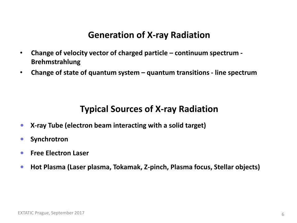
Generation of X-ray Radiation
• Change of velocity vector of charged particle – continuum spectrum - Brehmstrahlung
• Change of state of quantum system – quantum transitions - line spectrum
Typical Sources of X-ray Radiation
• X-ray Tube (electron beam interacting with a solid target)
• Synchrotron
• Free Electron Laser
• Hot Plasma (Laser plasma, Tokamak, Z-pinch, Plasma focus, Stellar objects)
EXTATIC Prague, September 2017 6

Characteristics of X-ray Tube - Relatively low brightness - 2p sterad diverging beam - Wide energy spectrum: Characteristic and Bremsstrahlung (2 keV to 430 keV) - Not polarised. - Continual - Microfocus - Stable solid anode, rotating anode, liquid metal jet anode - Coupling to XR optics possible
X-ray Tube
7 EXTATIC Prague, September 2017

Characteristics of Synchrotron Radiation - High brightness: synchrotron radiation is extremely intense (hundreds of thousands of times higher than conventional X-ray tubes) and highly collimated. - Wide energy spectrum: synchrotron radiation is emitted with a wide range of energies, allowing a beam of any energy to be produced. - Synchrotron radiation is highly polarised. - It is emitted in very short pulses, typically less that a nano-second.
Synchrotron radiation<<<…FEL
8 EXTATIC Prague, September 2017
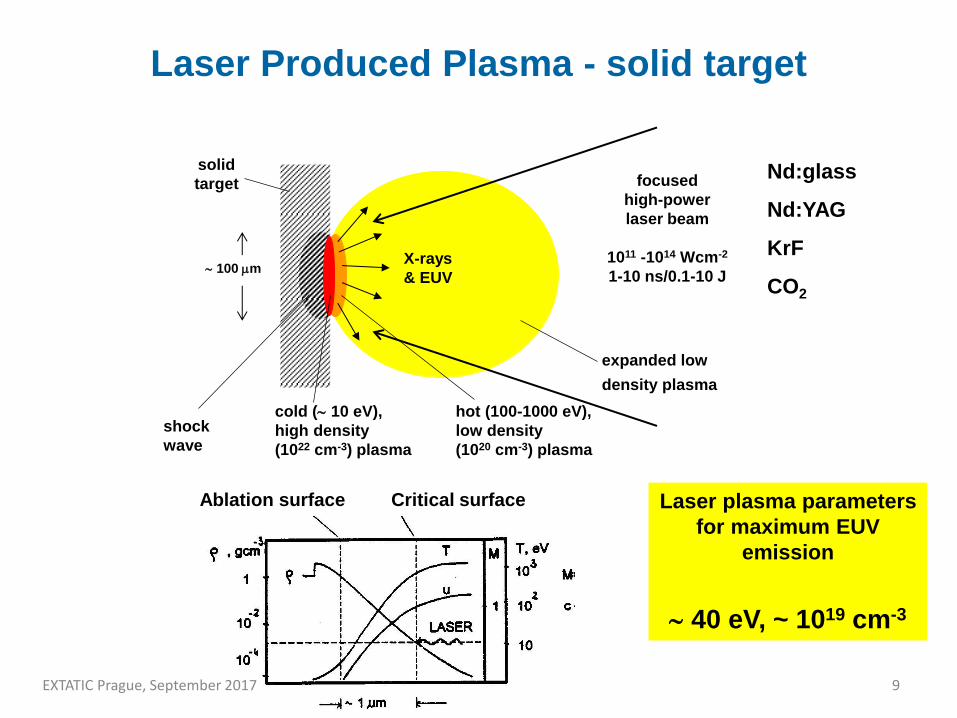
100 m
solid
target focused
high-power
laser beam
1011 -1014 Wcm-2
1-10 ns/0.1-10 J
shock
wave
cold ( 10 eV),
high density
(1022 cm-3) plasma
hot (100-1000 eV),
low density
(1020 cm-3) plasma
expanded low
density plasma
X-rays
& EUV
Nd:glass
Nd:YAG
KrF
CO2
Ablation surface Critical surface Laser plasma parameters
for maximum EUV
emission
40 eV, ~ 1019 cm-3
Laser Produced Plasma - solid target
9 EXTATIC Prague, September 2017

outer nozzle
inner nozzle
high-Z gas (xenon, krypton,
argon)
low-Z gas (helium,
hydrogen)
laser
beam
electromagnetic valve system X-ray backlighting images
H. Fiedorowicz et al. Appl.Phys. B 70 (2000) 305; Patent No.: US 6,469,310 B1
Laser Produced Plasma – gas puff target
10 EXTATIC Prague, September 2017

11
Capillary Discharge Plasma
Main discharge unit
• Ceramic Capacitors (1.25 ÷ 31 nF).
• Al2O3 capillary, 3.2mm dia., 20cm long.
• Low inductance -> high dI/dt.
• Pulse-charged: 1x Marx + coil.
• Rogowski coil.
CTU Prague, Fac. of Nucl. Sci
EXTATIC Prague, September 2017

12
Capillary Discharge Plasma
Nitrogen spectra 1 ÷ 25 nm
(water window radiation source 200 eV – 500 eV)
CTU Prague, Fac. Of Nucl. Sci
EXTATIC Prague, September 2017

13
Interaction of X-ray Radiation with Matter

The scattered amplitude:
The factors f1 and f2:
The atomic photoionization cross section:
)E(if)E(f)(A)E,(A 21T
rel22
2
2e0
1 dWWE
)W(W
he
cm4Z)E(f
0
)E(Eh
cm2)E(f e0
2
0N
A)E(
EXTATIC Prague, September 2017 14

The macroscopic factors n and :
The average atomic scattering factors:
where Nj is the number of atoms of type j per unit volume.
12e0
22
fEm2
en1
22e0
22
fEm2
e
j
j1j1 fNf
j
j2j2 fNf
EXTATIC Prague, September 2017 15

And consequently, using the relation :
where N is the total number of electrons of type j per unit volume.
Variation of the absorption coefficient away from an absorption edge:
hcE
2e0
2
22
2
e0
22
2e0
22
cm8
Ne
hcm2
2
hNe
Em2
Ne
p
p
323
2 ZE
hcZ
EXTATIC Prague, September 2017 16

Reflectivity in X-ray region
• Complex index of refraction
• Fresnel equations
• Microroughness
EXTATIC Prague, September 2017 17

Complex refractive index
Refraction and Reflection of X-rays
Total external reflection
i1n~
EXTATIC Prague, September 2017 18

Fresnel formulas:
i222
i2
i222
i2
||
||
cos)1()1()1(sin)1(
cos)1()1()1(sin)1(
A
R
1212
1212
i222
i2
i
||
||
cos)1()1()1(sin)1(
sin)1)(1(2
A
T
1212
21
i222
i
i
cos)1()1(sin)1(
sin)1(2
A
T
121
1
i222
i
i222
i
cos)1()1(sin)1(
cos)1()1(sin)1(
A
R
121
121
EXTATIC Prague, September 2017 19

Reflectivity Rp and Rs:
Surface microrouphness is important:
R = R
FR
R = exp(-4p/)
||
||
||
||p
A
R
A
RR
A
R
A
RRs
EXTATIC Prague, September 2017 20

X-Ray Optics
Reflective optics
Capillaries, polycapillaries, parabolic, elliptic and foil mirrors, paraboloidal and ellipsoidal mirrors. K-B system, Wolter system
No monochromatisation, but hard energy cut-off
Refractive optics Multiple Lenses
Microfabricated Kinoform structures
Difractive optics Crystals
Multilayered structures
Fresnel lenses EXTATIC Prague, September 2017
21

EXTATIC Prague, September 2017
X-RAY OPTICS BASED
ON REFRACTION
22

X-RAY LENS
REFRACTIVE INDEX n=1i (1)
=0.5 (Ep/E)2~10-410-7, =1/4p ~10-310-5
Ep plasmon energy, E photon energy, wavelength, absorption
c o e f f i c i e n t .
d
R
FX-rays
Fig.1
R curvature radius, d lens thickness.
Lens focal length
F= R / 2 (2)
EXTATIC Prague, September 2017 23

COMPOUND X-RAY LENS
Compound lens focal length : F= R / 2N (1),
N number of individual lenses
A.Snigirev, V.Kohn, I.Snigireva, B.Lengeler, “A Compound Refractive lens for
focusing high-energy X-rays”, Nature (London) 384, 49 (1996).
15 keV X-rays Aluminum plate
15 keV X-raysd=25 m F= 2 m
2 R f = 8 m
R
Fig. 1
R=0.3 mm, N=30, intensity gain G=3
EXTATIC Prague, September 2017
24

SPHERICAL ABERRATIONS AND SPOT SIZE OF THE MICROCAPILLARY OR BUBBLE LENS
0 20 40 60 80 100 120 140 160 180 200
-200
-175
-150
-125
-100
-75
-50
-25
0
25
50
75
100
125
150
175
200
Focal plane
Distance to axis, microns
Distance from the lens, microns
MS-plane
Fig 1. Paths of 8 keV X- rays forming a focal spot of the X- ray lens. Individual lens radius is 100 microns. The number of microlenses is N = 103.
EXTATIC Prague, September 2017 25

Photographs of epoxy microcapillary compound refractive
lens
Capillary
diameter
= 0.8 mm
Capillary diameter = 0.2
mm
EXTATIC Prague, September 2017 26

EXTATIC Prague, September 2017
GRAZING INCIDENCE
X-RAY MIRRORS
27

Grazing Incidence Optics
• Total external reflection
– Capillaries, polycapillaries
– Parabolic, elliptic and foil mirrors, paraboloidal and ellipsoidal mirrors
– Kirkpatrick-Baez optic
– Wolter optic
– No monochromatisation, but hard energy cut-off
EXTATIC Prague, September 2017 28

Flat X-ray Mirror
EXTATIC Prague, September 2017 29

Grazing Incidence Reflectivity
Refractive index n < 1, total external reflection. Critical angle rises with atomic number as Z½. Beyond critical angle intensity falls as -4 or faster
10-6
10-4
10-2
100
0 1 2 3
SiNiAu
Incidence angle (degrees)
Ref
lect
ivity
1.54Å wavelength Zero roughness
EXTATIC Prague, September 2017 30

Absorption reduces reflectivity near the critical angle
Grazing-incidence reflectivity for Au, Ni and Si
0
0.2
0.4
0.6
0.8
1.0
0 0.2 0.4 0.6 0.8 1.0
AuNiSi
Incidence angle (degrees)
Ref
lect
ivity
1.54Å wavelength
EXTATIC Prague, September 2017 31

Variation of reflectivity with X-ray wavelength (Au)
0
0.2
0.4
0.6
0.8
1.0
0 0.5 1.0 1.5 2.0
0.5Å1Å1.5Å2Å2.5Å3Å
Incidence angle (degrees)
Refle
ctivi
ty
EXTATIC Prague, September 2017 32

Tapping AFM images of the surface of the double - sided flats developed for
Schmidt lobster-eye telescopes. The resulting microroughness RMS is 0.3 nm.
Test facility at the Astronomical Observatory in Brera, Italy.
EXTATIC Prague, September 2017 33

EXTATIC Prague, September 2017
Effect of Grazing Angle
34

Effect of Surface Microroughness
0
0.2
0.4
0.6
0.8
1.0
0 0.2 0.4 0.6 0.8 1.0
0Å r.m.s5Å r.m.s.10Å r.m.s.15Å r.m.s.20Å r.m.s.
1.54Å wavelength
Incidence angle (degrees)
Ref
lect
ivity
Gold reflectivity as function of roughness
0.44
0.46
0.48
0.50
0.52
0 5 10 15 20
1.54Å wavelength
r.m.s. roughness (Å)
Inte
grat
ed r
efle
ctiv
ity (
degr
ees)
Gold integrated reflectivity
Unlike the reflectivity beyond the critical angle, the effect of roughness is relatively small. Loss of only 5% for roughness of 1nm (10Å)
35

EXTATIC Prague, September 2017 36

Monocapillary (SC) geometry and description
EXTATIC Prague, September 2017 37

EXTATIC Prague, September 2017 38

EXTATIC Prague, September 2017 39

Paraboloidal Mirror
Phi1
Phi2
PhiInP1
Highly parallel beam (< 1 mr) Large area - circa 1 mm diameter Hole in the middle Beam profile
Source
Optimum efficiency in coupling to monochromator Precise alignment necessary
EXTATIC Prague, September 2017 40

Multilayer Mirrors
n = 2d.sin
X-ray Optics
EXTATIC Prague, September 2017 41

EXTATIC Prague, September 2017 42

Replicated Wolter 1 X-ray mirrors of the KORONAS satellite (aperture 80 mm)
Replicated X-ray Optics –
EXTATIC Prague, September 2017 43

MANDREL
EXTATIC Prague, September 2017 44

36 years of development - from astronomy to laboratory
CF mirror
Thin Ni Wolter shell
CF+epoxy
Thin CF mirror
Double sided sandwich flats
X-ray micromirror
Grazing Incidence X-Ray Optics
Samples of replicated grazing incidence X-ray optics
EXTATIC Prague, September 2017
45

Ellipsoidal X-ray Mirror
• Apertures as small as 0.4 mm dia
• Mirrors optimised for 8 keV
• Grazing angle 9.5 mrad at the mirror input
(Au coated reflecting surface)
• Au or Ni surface
• Convergence / Divergence lower than 1.5 mrad (ellipsoidal mirrors)
• Convergence / Divergence lower than 0.1 mrad (parabolic mirrors)
Ellipsoidal Micromirror
EXTATIC Prague, September 2017 46

Vacuum Test Bench for X-ray Cameras and Optics
EXTATIC Prague, September 2017 47

EXTATIC Prague, September 2017 48

EXTATIC Prague, September 2017 49

Ellipsoidal X-ray Mirror as a Spectral Filter
EXTATIC Prague, September 2017 50

Wolter Optic
EXTATIC Prague, September 2017 51

Computer simulations
(virtual CCD images)
EXTATIC Prague, September 2017 52

Graphs a to c show the effect of point-like X-ray source off-axis displacement on the detector intensity distribution for ellipsoidal mirror. a – 0 m source displacement, b – 200 m displacement, c – 400 m displacement.
Focal spots for off-axis source position
EXTATIC Prague, September 2017 53
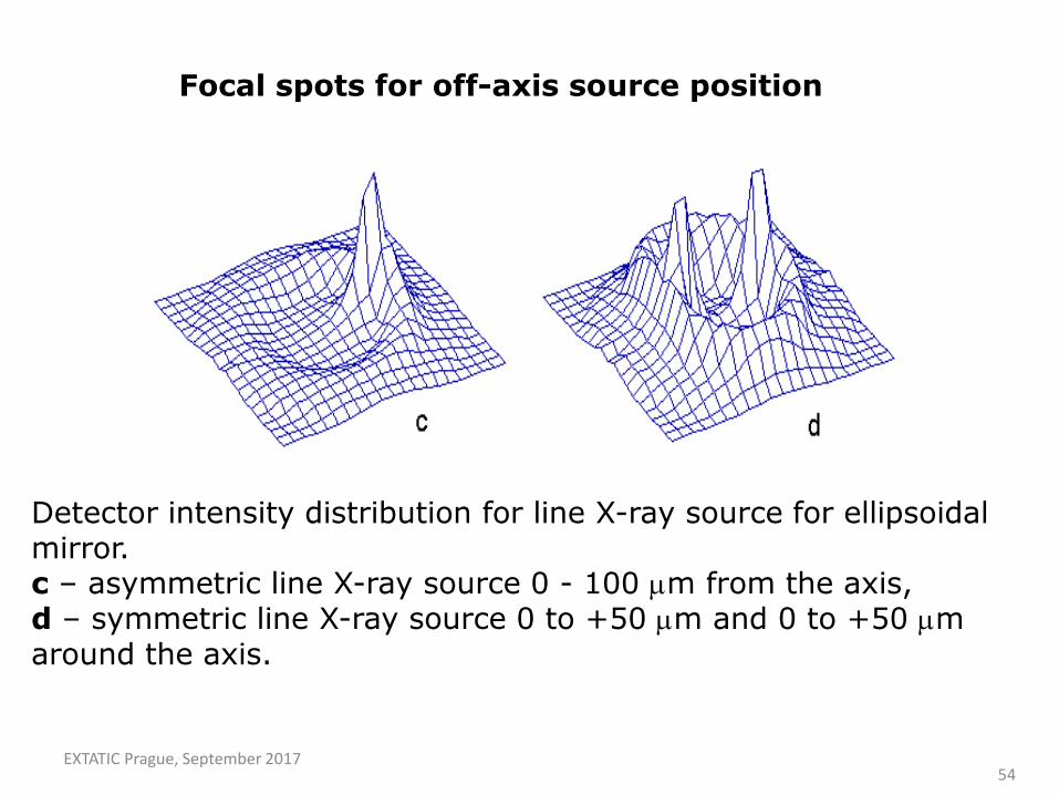
Detector intensity distribution for line X-ray source for ellipsoidal mirror. c – asymmetric line X-ray source 0 - 100 m from the axis, d – symmetric line X-ray source 0 to +50 m and 0 to +50 m around the axis.
Focal spots for off-axis source position
EXTATIC Prague, September 2017 54

Micromirror ML mirror Polycapillary
Steering & focusing coils
Electron Gun X-ray beam Target
• The focus may be changed from spot to line electronically
• Stability of focal spot assured
• Modular design allows ease of access for tube changes
• Patents
• Focal spot size, shape and position are controlled automatically
MicroSOURCE® X-ray source – X-ray mirror combination
EXTATIC Prague, September 2017 55

Two examples of micromirror gain as a function of X-ray source diameter (Computer ray-tracing calculations).
Source – X-ray Optic combination (The importance of source size)
EXTATIC Prague, September 2017 56

NoniusKappaCCD2000
Excellent performance in terms of brightness, low background noise, small beam size. and ease of use.
Courtesy of Nonius B.V.
Unit cell aligned to the direction of the X-ray beam using 180 secs per 2° rotation
Lysozyme single crystal
EXTATIC Prague, September 2017 57

Powder Diffraction
50
100
150
200
250
300
350
400
450
500
550
3 4 5 6 7 8 9 10
Inte
nsity (
cp
s (
det d (deg)
Silver Behenate
Microsource 25W
2 mrad Micromirror
Sealed tube 2kW
Divergence 0.05 - 0.2°
good resolution
High intensity in small spot
suitable for small samples
forensic, combinatorial
chemistry
Portable
24 W
EXTATIC Prague, September 2017 58

• X-ray optics based on multiple thin X-ray foils
• Various foil materials
• glass
• Si
• metal …
• Various arrangements and geometries
• Lobster Eye
• KB system
• Wolter
• Double conical approximation to Wolter…
Multi Foil X-ray Optics (MFO)
EXTATIC Prague, September 2017 59

Motivation – wide field imaging • Astronomical sources
Imaging Image reconstruction Scanning observations
•Laboratory sources Imaging Image reconstruction
• Other optic types
EXTATIC Prague, September 2017 60

Lobster Eye
Channels – optical elements Wide field optic EXTATIC Prague, September 2017
61

Lobster Eye (MFO) Geometry
• Reflection from two orthogonal stacks of planar mirrors (Schmidt) • Wide field imaging • LE modification - planar mirrors replaced by elliptical mirrors (MF KB, MFO) • Focusing (no wide field feature)
Source 1 Source 2
EXTATIC Prague, September 2017 62

Lobster Eye (MFO) Optic Concept
EXTATIC Prague, September 2017 63

Multi-Foil X-ray Optics
• foil thicknesses from 30
µm to 1 mm
• foils 3 x 3 mm to 300 x
300 mm
• planar & ellipsoidal
Various examples of Lobster Eye and MFOs
EXTATIC Prague, September 2017 64

Single Point Imaging – Typical PSF
x [px] y [px]
Intensity (AU)
EXTATIC Prague, September 2017 65

X - ray focal image of the 80 x 100 mm Schmidt prototype at 1.5 nm (X-ray
test facility, University of Leicester, UK). The measured gain is 185 EXTATIC Prague, September 2017
66

Multi-Foil X-ray Optic
thin foils additional coatings shape variations
MFO in Schmidt Lobster Eye arrangement
20 x 20 mm front area 100 m thickness, 300 m spacing
EXTATIC Prague, September 2017 67

X-ray test arrangement for testing the ímaging quality of the LE prototypes
Experimental setup
EXTATIC Prague, September 2017 68

The X-ray shadowgram of the LES module showing the 100 micron thick gold plated flats and approx. 300 micron spaces separating them (and also confirming the high optical quality of used flats). Right: The X-ray focal spot image (LES module).
Multi-Foil X-ray Optics
EXTATIC Prague, September 2017 69

LE X-ray experiment vs theory • Point-to-point focusing system • Source: 20 m size, 8 keV photons • Source-detector distance: 1.2 m, 8 keV photons • Detector: 512x512 pixels, 24x24 m pixel size • Gain: ~570 (experiment) vs. ~584 (comp. simulation)
Experiment
Simulation
Multi-Foil X-ray Optics
EXTATIC Prague, September 2017 70

Schmidt X - ray telescope prototype, 80 x 100 mm plates EXTATIC Prague, September 2017 71

Kirkpatrick-Baez Multi Foil X-ray Optic
Kirkpatrick-Baez mirror consisting of orthogonal stacks of reflectors. Each reflector a parabola in one dimension.
EXTATIC Prague, September 2017 72

XEUS test mirror
assembly
2D module,
30 x 30 cm glass foils
0.75 mm thickness of foils
gold-coated by sputtering,
plates spaced at 12 mm.
Tests of LE modules, XEUS modules, large K-B modules.
Light-weight (glass)
Kirkpatrick-Baez Multi Foil X-ray Optic
EXTATIC Prague, September 2017 73

The Cassiopea constellation as seen by the Angel type Lobster - eye
telescope (computer ray - tracing)
EXTATIC Prague, September 2017 74

Typical X-Ray Telescope
EXTATIC Prague, September 2017 75

EXTATIC Prague, September 2017 76

EXTATIC Prague, September 2017 77

EXTATIC Prague, September 2017 78

MFO EUV condensor
Optic profile – a quarter of the optic system is displayed, all dimensions
in millimeters. Ellipsoidal mirrors, length 40mm, width 80mm.
EXTATIC Prague, September 2017 79

MFO EUV condensor
EXTATIC Prague, September 2017 80

Experimental setup of MFO condensor
Two orthogonal sets of elliptical mirrors
EXTATIC Prague, September 2017 81

Ray-tracing for point source
Focal spot for point source, 1m pixel size, 256x256 pixels each.
Linear intensity scale on the left, sqr intensity scale on the right
EXTATIC Prague, September 2017 82

EXTATIC Prague, September 2017
TEFLON layer exposed by EUV radiation
83

EXTATIC Prague, September 2017 84

EXTATIC Prague, September 2017
X-RAY OPTICS BASED
ON Si WAFERS
85

EXTATIC Prague, September 2017
Slightly parabolized D = 150 mm Si wafer
(ON Semiconductor Czech Reublic)
86

EXTATIC Prague, September 2017
Flatness measurements of Si wafer produced by ON Semiconductor Czech Republic
Flatness and thickness uniformity of a Si wafer (diameter 150 mm)
1.81 m TIR Total Indicated Reading
1.68 m TTV Total Thickness Variation
686.92 m cen. thickness
687.18 m ave. thickness
687.75 m max. thickness 686.07 m min. thickness
87

EXTATIC Prague, September 2017
Si WAFERS SHAPING test cylindrical samples
gold-coated, d=100 mm, thickness 0.8 mm, R=1.3 m
88
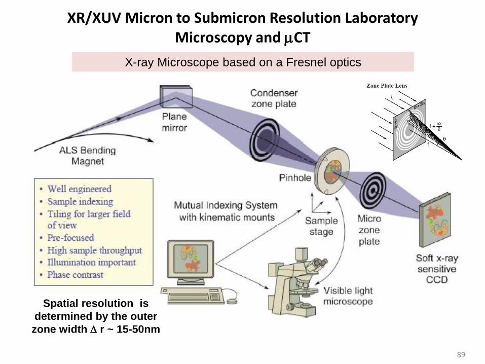
XR/XUV Micron to Submicron Resolution Laboratory Microscopy and CT
X-ray Microscope based on a Fresnel optics
Spatial resolution is
determined by the outer
zone width r ~ 15-50nm
89

Xsight™ Micron X-ray CCD Camera Applications:,
•X-ray microscopy
•X-ray microtomography
•X-ray optics adjustment
& metrology
•Phase contrast X-ray
imaging
Field of view: 0,90 mm x 0,67 mm Resolution: ≤ 1 µm (@ 8 keV) Spectral range: 50 eV to 35 keV Exposure time range: 20 µs to 500 s Dynamic range: 70 dB Dimensions: 60 x 70 x 250 Weight: 2.5 kg
90

Projection X–ray Microscopy RITE and CTU, microfocus X-ray tube 8 keV (Prague, Czech Republic)
91

92
X-ray image of Ixodes Ricinus (Taken by XSight Micron at RITE laboratory using
80 W microfocus X-ray tube with Cu target
Projection X–ray Microscopy
92

X-ray image of Ixodes Ricinus (Taken by XSight Micron at RITE laboratory using 80 W microfocus X-ray tube with Cu target)
Projection X–ray Microscopy
93

Projection X–ray Microscopy Advanced Photon Source synchrotron facility (USA)
„Image of non-focused X-ray beam reflected by a bimorph mirror at beamline 21ID of the Advanced Photon Source. Separate peaks correspond to reflections by the mirror segments“, by courtesy of Dr. Elena Kondrashkina, Synchrotron Research/LS-CAT, Northwestern University. RITE Xsight Micron camera, pixel size 0.65 μm
94

Ultra High Resolution 3D X-ray Tomography
POWER : Ultra High flux, up to 1200 W
ENERGY: Cr, Cu , Mo
DETECTOR: 3300 x 3300 x 2500 Matrix
OPTICS: No projection magnification
EASY: Minimal Alignment or optimisation
95

Rigaku nano3DX
RES FOV: ENERGY:
CFRP 0.27um voxel 3200 x 3200 x 2500 (0.9mm) Cu Anode 8keV
6 μm Carbon Fibres
High Contrast X-ray Imaging and Tomography of Material Samples
97

THANK YOU FOR ATTENTION
Prague
Czech Technical University in Prague
EXTATIC Prague, September 2017
98

EXTATIC Prague, September 2017 99
