x10 & hx10
TRANSCRIPT
LOOKING FOR PARTS?
Check out our onlineParts Catalog!
Read this manual before using product. Failure tofollow instructions and safety precautions canresult in serious injury, death, or propertydamage. Keep manual for future reference.
Part Number: 30909 R6Revised: November 2021
Original Instructions
X10 & HX10Swing-Away Grain AugerAssembly Manual
This manual applies to:Westfield X10, AGI X10, Hutchinson HX10, Mayrath HX10:63’, 73’, 83’
New in this Manual
The following changes have been made in this revision of the manual:
Description Section
Modified boot. Section 4.3.3 – Install the Boot on the Auger Tube onpage 33
Added note to align the transport stand and theupper scissor support.
Section 4.8 – Connecting the Short Cross Memberand Upper Scissors arms on page 47
Modified manual winch. Section 4.15 – Install Hopper Lift Arm and Winch onpage 57
X10 & HX10 – SWING-AWAY GRAIN AUGER
30909 R6 3
CONTENTS1. Introduction ............................................................................................................................................ 5
2. Safety....................................................................................................................................................... 62.1 Safety Alert Symbol and Signal Words...................................................................................... 62.2 General Safety Information....................................................................................................... 62.3 Rotating Flighting Safety ........................................................................................................... 72.4 Overhead Power Lines .............................................................................................................. 72.5 Upending ................................................................................................................................... 72.6 Rotating Parts Safety................................................................................................................. 72.7 Hand Winch Safety .................................................................................................................... 82.8 Hydraulic Winch Safety ............................................................................................................. 82.9 Work Area Safety ...................................................................................................................... 82.10 Guards Safety .......................................................................................................................... 92.11 Raising and Lowering the Auger ........................................................................................... 102.12 Positioning the Auger............................................................................................................ 102.13 Towing the Auger .................................................................................................................. 102.14 Drives and Lockout Safety..................................................................................................... 11
2.14.1 PTO Driveline Safety............................................................................................... 112.14.2 Hydraulic Power Safety .......................................................................................... 12
2.15 Tire Safety.............................................................................................................................. 132.16 Personal Protective Equipment............................................................................................. 132.17 Safety Equipment .................................................................................................................. 142.18 Safety Decals ......................................................................................................................... 14
2.18.1 Decal Installation/Replacement............................................................................. 142.18.2 Safety Decal Locations and Details ........................................................................ 15
3. Features................................................................................................................................................. 26
4. Assembly ............................................................................................................................................... 294.1 Assembly Safety ...................................................................................................................... 294.2 General Assembly.................................................................................................................... 294.3 Assemble the Auger Tube ....................................................................................................... 30
4.3.1 Arrange Tubes and Apply Model Decals.................................................................. 304.3.2 Connect Auger Tube Sections Together .................................................................. 324.3.3 Install the Boot on the Auger Tube.......................................................................... 334.3.4 Install the Discharge Spout ...................................................................................... 374.3.5 Set the Thrust Adjuster ............................................................................................ 38
4.4 Install Truss Towers................................................................................................................. 394.5 Install Truss Cables .................................................................................................................. 414.6 Assemble the Lower Frame..................................................................................................... 454.7 Connect the Lower Frame Arms ............................................................................................. 464.8 Connecting the Short Cross Member and Upper Scissors arms............................................. 474.9 Install Hydraulic Lift Cylinder .................................................................................................. 494.10 Connect the Auger Tube to the Frame ................................................................................. 494.11 Connect Hydraulic Hose and Ball Valve ............................................................................... 514.12 Connect the PTO Driveline .................................................................................................... 524.13 Install Low Profile Intake Hopper.......................................................................................... 544.14 Install the Hopper Lift Extension........................................................................................... 574.15 Install Hopper Lift Arm and Winch........................................................................................ 574.16 Install the Hitch Jack.............................................................................................................. 60

X10 & HX10 – SWING-AWAY GRAIN AUGER
4 30909 R6
4.17 Install the Plastic Manual Container ..................................................................................... 61
5. Specifications ........................................................................................................................................ 62
6. Appendix ............................................................................................................................................... 636.1 Bolt Torque.............................................................................................................................. 63
7. AGI Limited Warranty........................................................................................................................... 64
30909 R6 5
1. IntroductionBefore assembling, please read this manual. Familiarize yourself with the process and the necessaryprecautions for efficient and safe assembly of this AGI Swing-Away Grain Auger.
Everyone present at the assembly site is required to be familiar with all safety precautions.
Keep this manual available for frequent reference and review it with new personnel. Call your localdistributor or dealer if you need assistance or additional information.
X10 & HX10 – SWING-AWAY GRAIN AUGER 1. INTRODUCTION
6 30909 R6
2. Safety2.1. Safety Alert Symbol and Signal Words
This safety alert symbol indicates important safety messages in this manual. When you seethis symbol, be alert to the possibility of injury or death, carefully read the message thatfollows, and inform others.
Signal Words: Note the use of the signal words DANGER,WARNING, CAUTION, and NOTICE with the safetymessages. The appropriate signal word for each message has been selected using the definitions below as aguideline.
Indicates an imminently hazardous situation that, if not avoided, will result in serious injury ordeath.Indicates a hazardous situation that, if not avoided, could result in serious injury or death.
Indicates a hazardous situation that, if not avoided, may result in minor or moderate injury.
Indicates a potentially hazardous situation that, if not avoided, may result in property damage.
2.2. General Safety InformationRead and understand all safety instructions, safety decals, and manuals and follow them when operating ormaintaining the equipment.
• Owners must give instructions and review the information initially and annually withall personnel before allowing them in the work area. Untrained users/operatorsexpose themselves and bystanders to possible serious injury or death.
• Use for intended purposes only.
• Do not modify the auger in any way without written permission from the manufacturer and is not coveredby the warranty.
• Follow a health and safety program for your worksite. Contact your local occupational health and safetyorganization for information.
• Follow applicable local codes and regulations.
2. SAFETY X10 & HX10 – SWING-AWAY GRAIN AUGER

30909 R6 7
2.3. Rotating Flighting Safety
• KEEP AWAY from rotating flighting.
• DO NOT remove or modify flighting guards, doors, or covers.Keep in good working order. Have replaced if damaged.
• DO NOT operate the auger without all guards, doors, andcovers in place.
• NEVER touch the flighting. Use a stick or other tool toremove an obstruction or clean out.
• Shut off and lock out power to adjust, service, or clean.
2.4. Overhead Power Lines
• When operating or moving, keep auger away from overheadpower lines and devices.
• The auger is not insulated.
• Electrocution can occur without direct contact.
2.5. Upending
• Anchor intake end and/or support discharge end to preventupending.
• Intake end must always have downward weight. Do notrelease until attached to tow bar or resting on ground.
• Do not raise intake end above tow bar height.
• Empty the auger and fully lower before moving.
2.6. Rotating Parts Safety
• Keep body, hair, and clothing away from rotating pulleys,belts, chains, and sprockets.
• Do not operate with any guard removed or modified. Keepguards in good working order.
• Shut off and lock out power source before inspecting orservicing machine.
X10 & HX10 – SWING-AWAY GRAIN AUGER 2. SAFETY
8 30909 R6
2.7. Hand Winch Safety
When Equipped:
• Inspect lift cable before using. Replace if frayed or damaged. Make sure lift cable is seatedproperly in cable sheaves and cable clamps are secure.
• Tighten brake lock by turning winch handle clockwise at least two clicks after lowering theauger.
• Raise the swing hopper fully before towing.
• Do not lubricate winch brake discs.
2.8. Hydraulic Winch Safety
When Equipped:
• Keep away from rotating cable drum and winch cable. Do not touch or grab cable whilewinch is being operated or use hands to guide the cable.
• Inspect cable and cable clamps before using hydraulic winch. Replace cable if frayed ordamaged. Tighten cable clamps if necessary.
• Check the cable anchor on the winch drum is tight.
• Confirm hydraulic hoses are in good condition.
• Do not continue to supply power to hydraulic winch after the swing hopper is fully lifted.
• Do not disconnect hydraulic quick couplers when lines are pressurized.
• Make sure lift cable is seated in cable pulley.
• Always keep a minimum of 3 cable wraps on the cable drum.
2.9. Work Area Safety• Have another trained person nearby who can shut down the auger in case of accident.
• Do not allow any unauthorized persons in the work area.
• Keep the work area clean and free of debris.
2. SAFETY X10 & HX10 – SWING-AWAY GRAIN AUGER
30909 R6 9
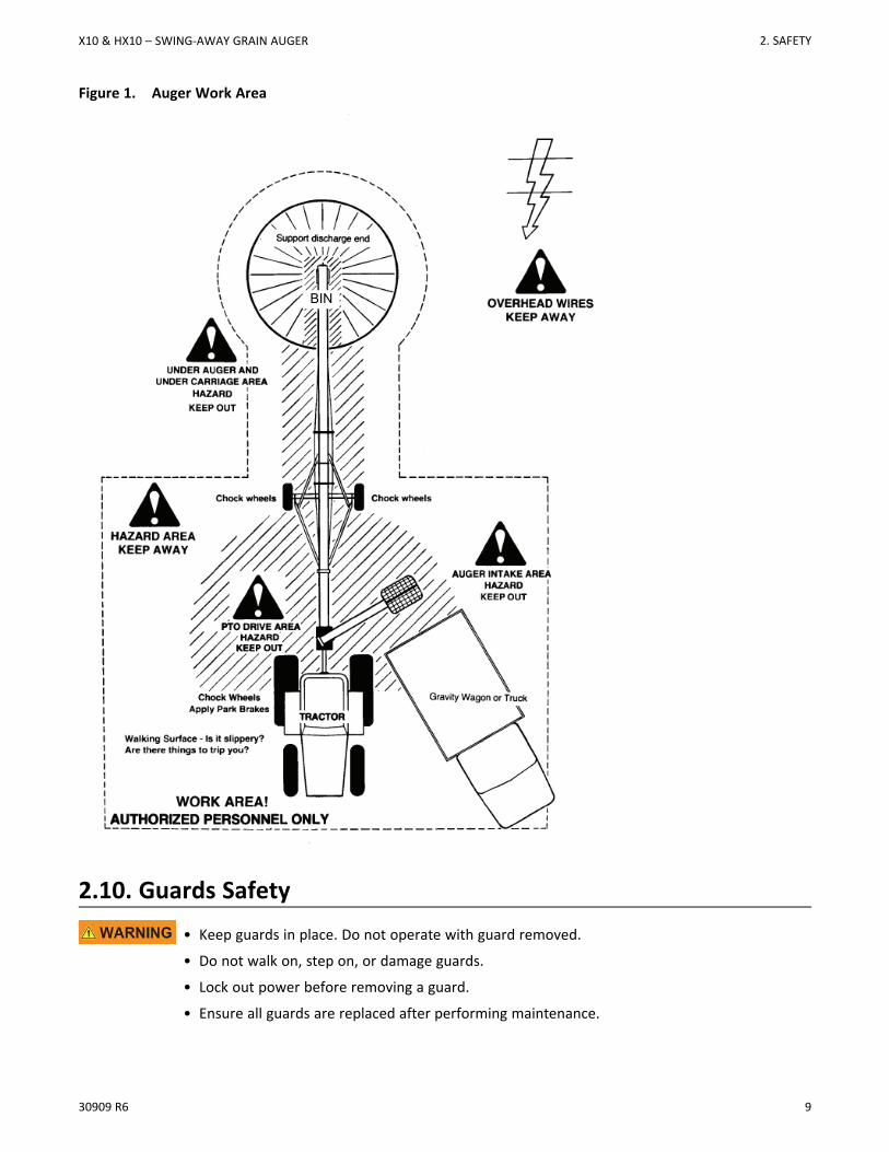
Figure 1. Auger Work Area
BIN
2.10. Guards Safety
• Keep guards in place. Do not operate with guard removed.
• Do not walk on, step on, or damage guards.
• Lock out power before removing a guard.
• Ensure all guards are replaced after performing maintenance.
X10 & HX10 – SWING-AWAY GRAIN AUGER 2. SAFETY
10 30909 R6
2.11. Raising and Lowering the Auger
• Before raising/lowering/moving/adjusting the auger, make sure the area around the auger isclear of obstructions and/or untrained personnel. Never allow anyone to stand on orbeneath the auger when it is being placed.
• Lower the auger to its lowest position when not in use.
• Empty the auger before raising or lowering.
• Do not get on or beneath the auger when raising or lowering.
• Raise and lower auger on reasonably level ground only.
• Never attempt to increase height of the auger by positioning wheels on lumber, blocks, or byany other means. To do so will result in damage to auger and/or serious injury.
• Do not raise the auger in high winds.
2.12. Positioning the Auger
• Transport and place equipment on reasonably level ground when raising, lowering,positioning, or operating.
• Move the auger into position slowly. Do not unhitch and attempt to move by hand.
• Chock wheels and anchor intake end after placement.
2.13. Towing the AugerThe auger is not intended for transport on public roads. If it requires transport on a public roadway, thefollowing steps should be taken:
• Check with local authorities regarding transport on public roads. Obey all applicable lawsand regulations.
• Always travel at a safe speed, never exceeding 20 mph (32 km/h).
• Reduce speed on rough surfaces.
• Do not transport on slopes greater than 20°.
• Use caution when turning corners or meeting traffic.
• Make sure the SMV (slow moving vehicle) emblem and all the lights and reflectors that arerequired by local authorities are in place, are clean, and can be seen by all over-taking andoncoming traffic.
• Always use hazard-warning flashers on tractor/towing vehicle when transporting unlessprohibited by law.
• Do not allow riders on the auger or towing vehicle during transport.
• Attach to towing vehicle with an appropriate pin and retainer. Always attach safety chains.
• Place the auger in the transport position before moving on roads.
2. SAFETY X10 & HX10 – SWING-AWAY GRAIN AUGER
30909 R6 11
2.14. Drives and Lockout SafetyInspect the power source(s) before using and know how to shut down in an emergency.Whenever you service or adjust your equipment, make sure you shut down the powersource and follow lockout and tagout procedures to prevent inadvertent start-up andhazardous energy release. Know the procedure(s) that applies to your equipment from thefollowing power source(s). Ensure that only 1 key exists for each assigned lock, and thatyou are the only one that holds that key. Ensure that all personnel are clear before turningon power to equipment.
WARNING
2.14.1 PTO Driveline SafetyDrive
• Keep body, hair, and clothing away from rotating PTOdriveline.
• Make certain the driveline shields telescope and rotate freelyon driveline before attaching.
• Make certain the driveline is securely attached at both ends.
• Do not operate auger unless all driveline, tractor, andequipment shields are in place and in good working order.
• Do not exceed the specified operating speed.
• Keep universal joint angles small and equal. Do not exceedmaximum recommended length for PTO driveline.
• Engage tractor park brake and/or chock wheels.
Lockout
• Position all controls in neutral, shut off tractor’s engine, and remove key from tractor.
• If removing key is impossible, remove PTO driveline from tractor.
X10 & HX10 – SWING-AWAY GRAIN AUGER 2. SAFETY

12 30909 R6
2.14.2 Hydraulic Power SafetyPower Source
• Refer to the rules and regulations applicable to the powersource operating your hydraulic drive.
• Do not connect or disconnect hydraulic lines while system isunder pressure.
• Keep all hydraulic lines away from moving parts and pinchpoints.
• Escaping hydraulic fluid under pressure will cause seriousinjury if it penetrates the skin surface (serious infection ortoxic reaction can develop). See a doctor immediately ifinjured.
• Use metal or wood as a backstop when searching forhydraulic leaks and wear proper hand and eye protection.
• Check all hydraulic components are tight and in goodcondition. Replace any worn, cut, abraded, flattened, orcrimped hoses.
• Clean the connections before connecting to equipment.
• Do not attempt any makeshift repairs to the hydraulic fittingsor hoses with tape, clamps, or adhesive. The hydraulicsystem operates under extremely high pressure; such repairswill fail suddenly and create a hazardous and unsafecondition.
Lockout
• Always place all hydraulic controls in neutral and relievesystem pressure before disconnecting or working onhydraulic system.
2. SAFETY X10 & HX10 – SWING-AWAY GRAIN AUGER
30909 R6 13
2.15. Tire SafetyFailure to follow proper procedures when mounting a tire on awheel or rim can produce an explosion that may result inserious injury or death.
• DO NOT attempt to mount a tire unless you have the properequipment and experience to do the job.
• Have a qualified tire dealer or repair service performrequired tire maintenance.
• When replacing worn tires, make sure they meet the originaltire specifications. Never undersize the replacement tire.
• DO NOT weld to the tire rim with the tire mounted on therim. This action may cause an explosion which could result inserious injury or death.
• Inflate tires to the manufacturer’s recommended pressure.
• Tires should not be operated at speeds higher than theirrated speed.
• Keep wheel lug nuts tightened to manufacturer’srecommendations.
• Never reinflate a tire that has been run flat or seriouslyunder-inflated without removing the tire from the wheel.Have the tire and wheel closely inspected for damage beforeremounting.
2.16. Personal Protective EquipmentThe following Personal Protective Equipment (PPE) should be worn when operating or maintaining theequipment.
Safety Glasses• Wear safety glasses at all times to protect eyes from debris.
Coveralls• Wear coveralls to protect skin.
Hard Hat• Wear a hard hat to help protect your head.
X10 & HX10 – SWING-AWAY GRAIN AUGER 2. SAFETY
14 30909 R6
Steel-Toe Boots• Wear steel-toe boots to protect feet from falling debris.
Work Gloves• Wear work gloves to protect your hands from sharp and rough edges.
Dust Mask• Wear a dust mask to prevent breathing potentially harmful dust.
Hearing Protection• Wear ear protection to prevent hearing damage.
2.17. Safety EquipmentThe following safety equipment should be kept on site.
Fire Extinguisher• Provide a fire extinguisher for use in case of an accident. Store in a highly visible and
accessible place.
First-Aid Kit• Have a properly-stocked first-aid kit available for use should the need arise, and
know how to use it.
2.18. Safety Decals• Keep safety decals clean and legible at all times.
• Replace safety decals that are missing or have become illegible. See decal location figures that follow.
• Replaced parts must display the same decal(s) as the original part.
• Replacement safety decals are available free of charge from your distributor, dealer, or factory as applicable.
2.18.1 Decal Installation/Replacement1. Decal area must be clean and dry, with a temperature above 50°F (10°C).
2. SAFETY X10 & HX10 – SWING-AWAY GRAIN AUGER
30909 R6 15
2. Decide on the exact position before you remove the backing paper.
3. Align the decal over the specified area and carefully press the small portion with the exposed sticky backingin place.
4. Slowly peel back the remaining paper and carefully smooth the remaining portion of the decal in place.
5. Small air pockets can be pierced with a pin and smoothed out using the decal backing paper.
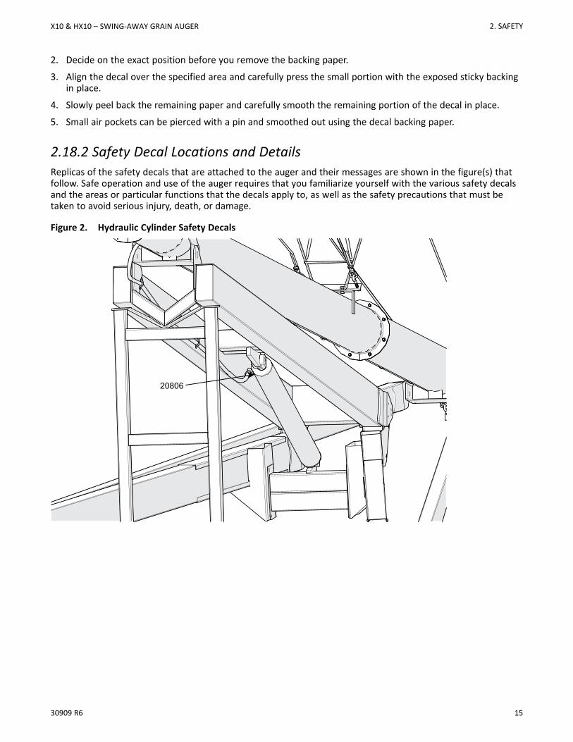
2.18.2 Safety Decal Locations and DetailsReplicas of the safety decals that are attached to the auger and their messages are shown in the figure(s) thatfollow. Safe operation and use of the auger requires that you familiarize yourself with the various safety decalsand the areas or particular functions that the decals apply to, as well as the safety precautions that must betaken to avoid serious injury, death, or damage.
Figure 2. Hydraulic Cylinder Safety Decals
20806
X10 & HX10 – SWING-AWAY GRAIN AUGER 2. SAFETY
16 30909 R6
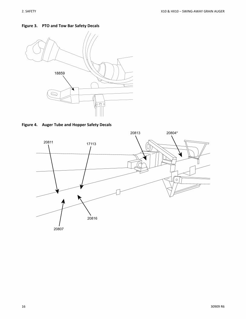
Figure 3. PTO and Tow Bar Safety Decals
18859
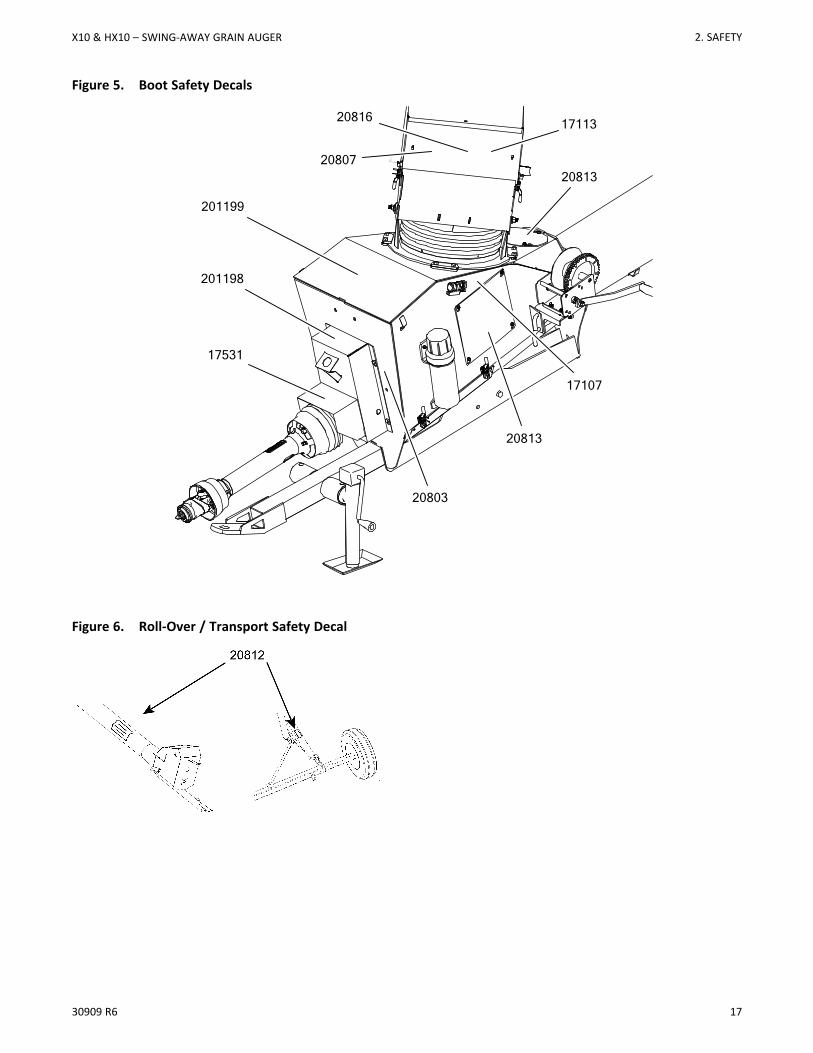
Figure 4. Auger Tube and Hopper Safety Decals
20807
20816
17113
20804*20813
20811
2. SAFETY X10 & HX10 – SWING-AWAY GRAIN AUGER
30909 R6 17
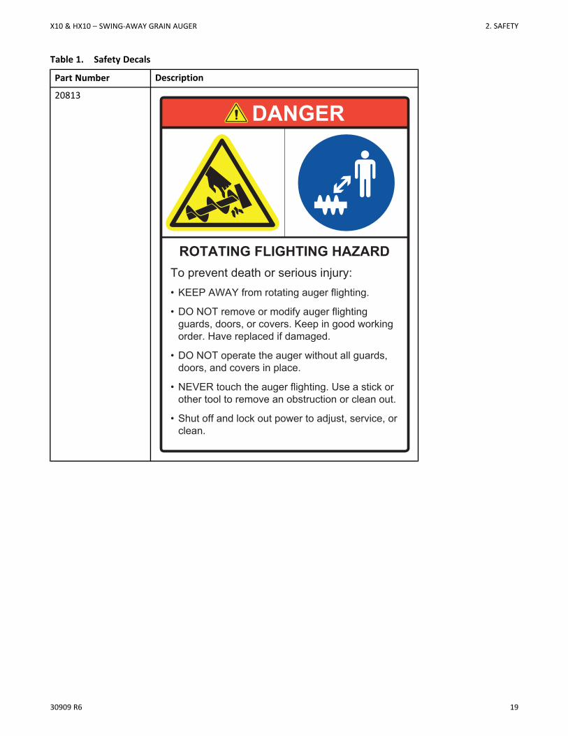
Figure 5. Boot Safety Decals
Figure 6. Roll-Over / Transport Safety Decal
20813
20803
17107
20813
17531
201199
201198
20807
20816 17113
X10 & HX10 – SWING-AWAY GRAIN AUGER 2. SAFETY

18 30909 R6
Figure 7. Optional Safety Decals (Hydraulic Landing Gear Power Swing)
20806
2. SAFETY X10 & HX10 – SWING-AWAY GRAIN AUGER
30909 R6 19
Table 1. Safety Decals
Part Number Description
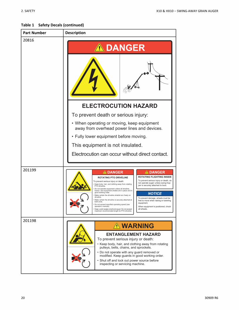
20813
To prevent death or serious injury:• KEEP AWAY from rotating auger flighting.
• DO NOT remove or modify auger flighting guards, doors, or covers. Keep in good working order. Have replaced if damaged.
• DO NOT operate the auger without all guards, doors, and covers in place.
• NEVER touch the auger flighting. Use a stick or other tool to remove an obstruction or clean out.
• Shut off and lock out power to adjust, service, or clean.
ROTATING FLIGHTING HAZARD
DANGER
X10 & HX10 – SWING-AWAY GRAIN AUGER 2. SAFETY
20 30909 R6
Table 1 Safety Decals (continued)
Part Number Description
20816
DANGER
ELECTROCUTION HAZARDTo prevent death or serious injury:• When operating or moving, keep equipment
away from overhead power lines and devices.
• Fully lower equipment before moving.
This equipment is not insulated.
Electrocution can occur without direct contact.
201199 DANGER
To prevent serious injury or death:• Keep body, hair, and clothing away from rotating
PTO driveline.• Do not operate equipment unless all driveline,
tractor, and equipment shields are in place and in good working order.
• Make certain the driveline shields turn freely on driveline.
• Make certain the driveline is securely attached at both ends.
• Do not exceed specified operating speed (see operator’s manual).
• Keep u-joint angles small and equal. Do not exceed maximum recommended length for PTO driveline.
ROTATING PTO DRIVELINETo prevent serious injury or death, do not operate auger unless swing-hop-per is securely attached to boot.
ROTATING FLIGHTING INSIDE
DANGER
To prevent damage, wheels must be free to move when raising or lowering equipment.
When equipment is positioned, chock all wheels.
NOTICE
201198
To prevent serious injury or death:• Keep body, hair, and clothing away from rotating
pulleys, belts, chains, and sprockets.• Do not operate with any guard removed or
modified. Keep guards in good working order. • Shut off and lock out power source before
inspecting or servicing machine.
ENTANGLEMENT HAZARD
WARNING
2. SAFETY X10 & HX10 – SWING-AWAY GRAIN AUGER
30909 R6 21
Table 1 Safety Decals (continued)
Part Number Description
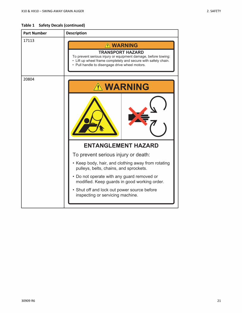
17113
To prevent serious injury or equipment damage, before towing:• Lift up wheel frame completely and secure with safety chain.• Pull handle to disengage drive wheel motors.
TRANSPORT HAZARDWARNING
20804
To prevent serious injury or death:• Keep body, hair, and clothing away from rotating
pulleys, belts, chains, and sprockets.
• Do not operate with any guard removed or modified. Keep guards in good working order.
• Shut off and lock out power source before inspecting or servicing machine.
ENTANGLEMENT HAZARD
WARNING
X10 & HX10 – SWING-AWAY GRAIN AUGER 2. SAFETY
22 30909 R6
Table 1 Safety Decals (continued)
Part Number Description
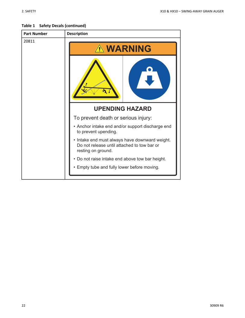
20811
WARNING
UPENDING HAZARDTo prevent death or serious injury:• Anchor intake end and/or support discharge end
to prevent upending.
• Intake end must always have downward weight. Do not release until attached to tow bar or resting on ground.
• Do not raise intake end above tow bar height.
• Empty tube and fully lower before moving.
2. SAFETY X10 & HX10 – SWING-AWAY GRAIN AUGER
30909 R6 23
Table 1 Safety Decals (continued)
Part Number Description
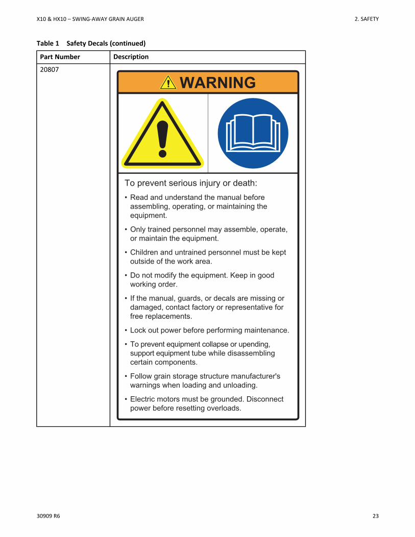
20807
To prevent serious injury or death:• Read and understand the manual before
assembling, operating, or maintaining the equipment.
• Only trained personnel may assemble, operate, or maintain the equipment.
• Children and untrained personnel must be kept outside of the work area.
• Do not modify the equipment. Keep in good working order.
• If the manual, guards, or decals are missing or damaged, contact factory or representative for free replacements.
• Lock out power before performing maintenance.
• To prevent equipment collapse or upending, support equipment tube while disassembling certain components.
• Follow grain storage structure manufacturer's warnings when loading and unloading.
• Electric motors must be grounded. Disconnect power before resetting overloads.
WARNING
X10 & HX10 – SWING-AWAY GRAIN AUGER 2. SAFETY
24 30909 R6
Table 1 Safety Decals (continued)
Part Number Description
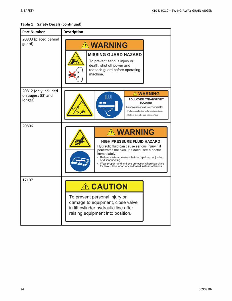
20803 (placed behindguard)
To prevent serious injury or death, shut off power and reattach guard before operating machine.
MISSING GUARD HAZARD
WARNING
20812 (only includedon augers 83' andlonger)
To prevent serious injury or death:• Fully extend axles before raising tube.
• Retract axles before transporting.
ROLLOVER / TRANSPORT HAZARD
WARNING
20806
HIGH PRESSURE FLUID HAZARDHydraulic fluid can cause serious injury if it penetrates the skin. If it does, see a doctor immediately.• Relieve system pressure before repairing, adjusting
or disconnecting.• Wear proper hand and eye protection when searching
for leaks. Use wood or cardboard instead of hands.
WARNING
17107
To prevent personal injury or damage to equipment, close valve in lift cylinder hydraulic line after raising equipment into position.
CAUTION
2. SAFETY X10 & HX10 – SWING-AWAY GRAIN AUGER
30909 R6 25
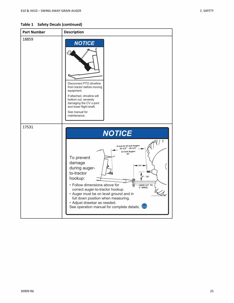
Table 1 Safety Decals (continued)
Part Number Description
18859
Disconnect PTO driveline from tractor before moving equipment.
If attached, driveline will bottom out, severely damaging the CV u-joint and lower flight shaft.
See manual for maintenance.
NOTICE
17531
To prevent damage during auger-to-tractorhookup:
NOTICE
• Follow dimensions above for correct auger-to-tractor hookup.
• Auger must be on level ground and in full down position when measuring.
• Adjust drawbar as needed.See operation manual for complete details.
X10 & HX10 – SWING-AWAY GRAIN AUGER 2. SAFETY
26 30909 R6
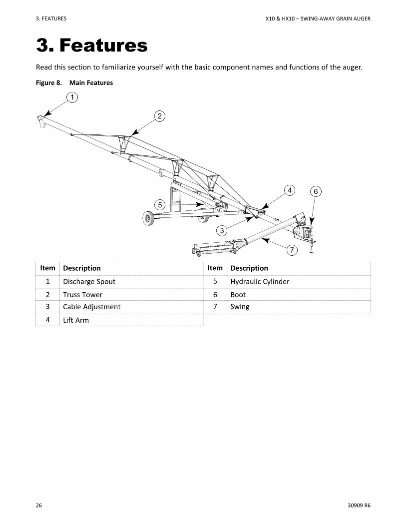
3. FeaturesRead this section to familiarize yourself with the basic component names and functions of the auger.
Figure 8. Main Features
61
62
6664
67
63
65
Item Description Item Description
1 Discharge Spout 5 Hydraulic Cylinder
2 Truss Tower 6 Boot3 Cable Adjustment 7 Swing
4 Lift Arm
3. FEATURES X10 & HX10 – SWING-AWAY GRAIN AUGER
30909 R6 27
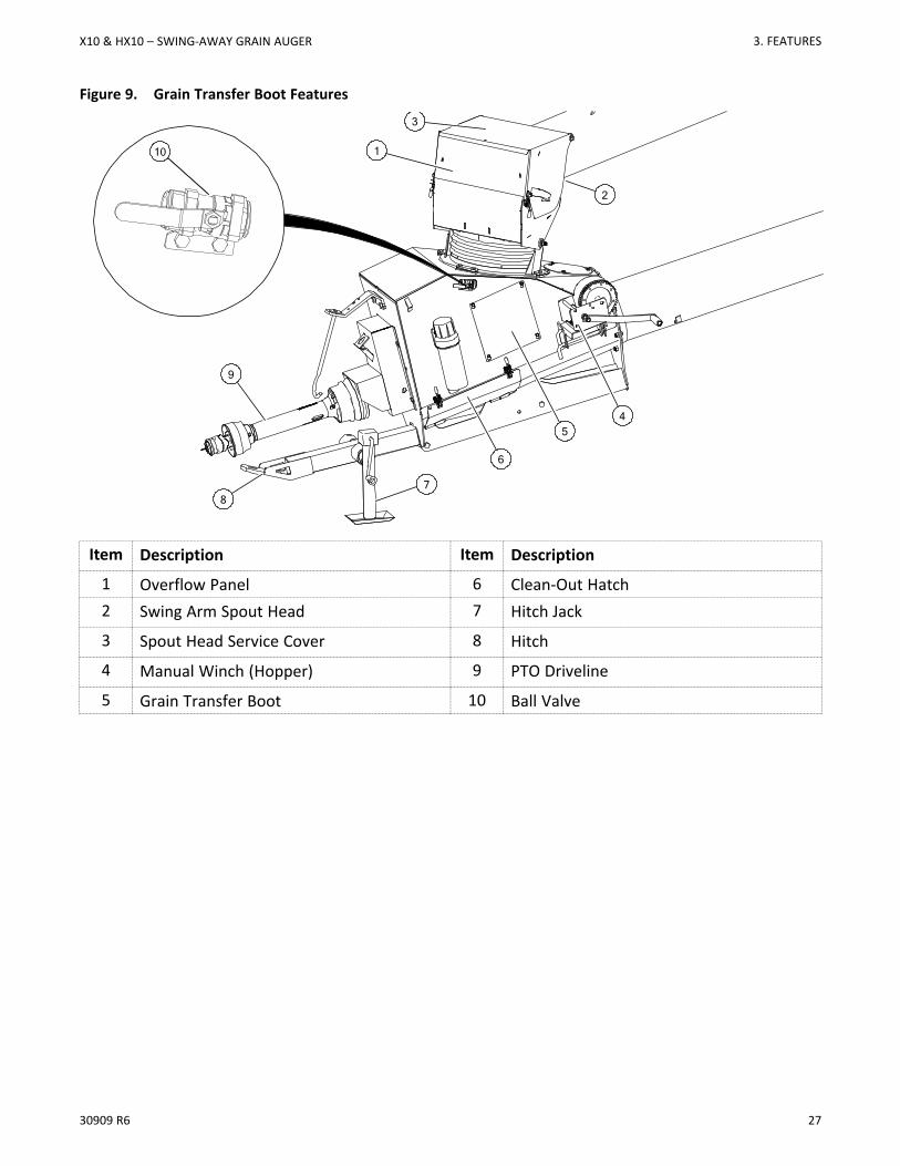
Figure 9. Grain Transfer Boot Features
Item Description Item Description
1 Overflow Panel 6 Clean-Out Hatch2 Swing Arm Spout Head 7 Hitch Jack
3 Spout Head Service Cover 8 Hitch
4 Manual Winch (Hopper) 9 PTO Driveline
5 Grain Transfer Boot 10 Ball Valve
87
6
45
9
3
1
2
10
X10 & HX10 – SWING-AWAY GRAIN AUGER 3. FEATURES
28 30909 R6
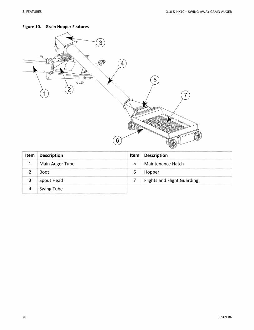
Figure 10. Grain Hopper Features
12
3
5
6
7
4
12
3
5
6
7
4
Item Description Item Description
1 Main Auger Tube 5 Maintenance Hatch
2 Boot 6 Hopper
3 Spout Head 7 Flights and Flight Guarding
4 Swing Tube
3. FEATURES X10 & HX10 – SWING-AWAY GRAIN AUGER
30909 R6 29
4. AssemblyBefore continuing, ensure you have completely read and understood this manual’sSafety section, in addition to the safety information in the section(s) below.
4.1. Assembly Safety
• Do not take chances with safety. The components can be large, heavy, and hard to handle.Always use the proper tools, rated lifting equipment, and lifting points for the job.
• Carry out assembly in a large open area with a level surface.
• Always have two or more people assembling the auger.
• Make sure you have sufficient lighting for the work area.
• Tighten all fasteners according to their specifications. Do not replace or substitute bolts,nuts, or other hardware that is of lesser quality than the hardware supplied by themanufacturer.
4.2. General Assembly1. Select an assembly area that is level, has a firm or hard surface and is free of debris. Be sure it is large
enough to allow access from all sides when the components are being assembled.
2. If assembling inside a building, be sure the ceiling is at least 14’ (4.27 m) high to provide clearance wheninstalling the undercarriage
3. Bring all the tools, blocks, stands, jacks, and hoists to the assembly area before starting.
4. The following tools and equipment are required to assemble the machine:
• 11-14 Support stands (tube section supports, three per tube)
• Four Saw horses (1200 lb / 544.3 kg bearing capacity)
• One Standard socket set and wrench set
• One Torque wrench
• One Standard 25’ (7.62 m) tape measure
• One 2’ level
• One 8” level magnetic
• Two C-clamps or vise grips
• One Picker with minimum reach of 12’ (3.66 m) 4000-6000 lb (1814 - 2722 kg) lifting capacity
• One 100’ (30 m) measuring tape
• One Tire gauge
• One Tire chuck
• 6-10 Wood blocks (2x4's or smaller)
• Grease
• Impact wrench and sockets
X10 & HX10 – SWING-AWAY GRAIN AUGER 4. ASSEMBLY
30 30909 R6
• 2+ Steel Punches (for aligning bolt holes)
4.3. Assemble the Auger Tube
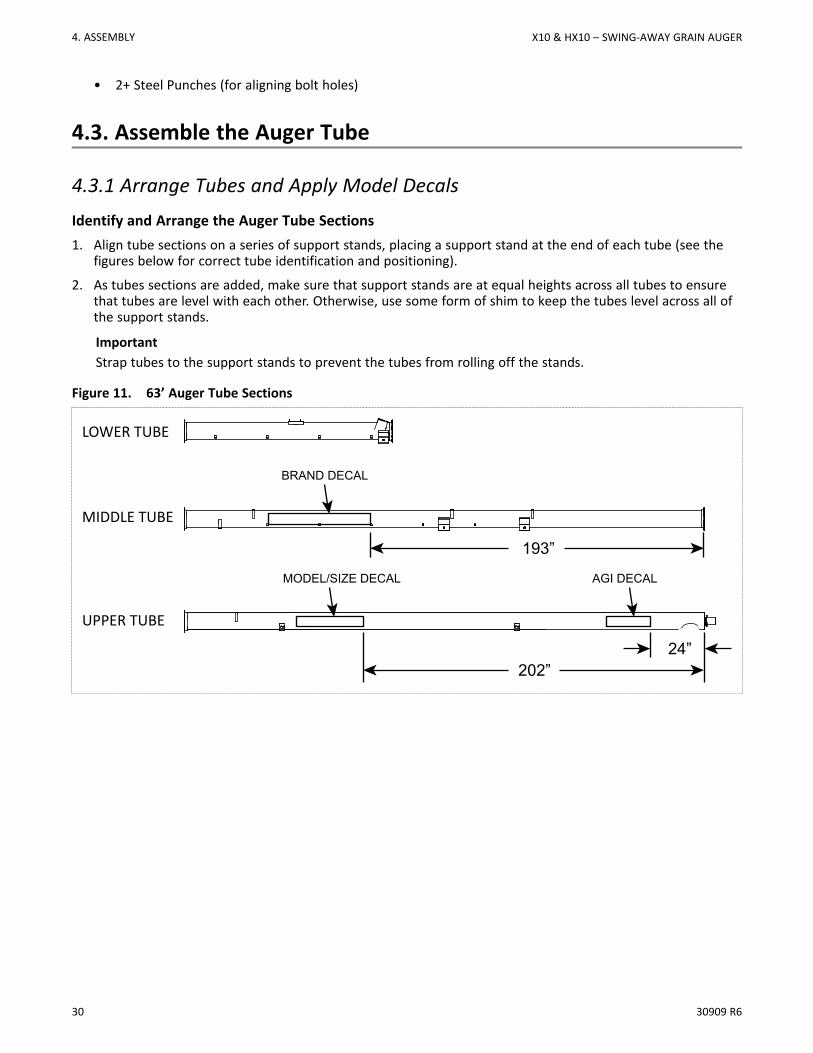
4.3.1 Arrange Tubes and Apply Model DecalsIdentify and Arrange the Auger Tube Sections1. Align tube sections on a series of support stands, placing a support stand at the end of each tube (see the
figures below for correct tube identification and positioning).
2. As tubes sections are added, make sure that support stands are at equal heights across all tubes to ensurethat tubes are level with each other. Otherwise, use some form of shim to keep the tubes level across all ofthe support stands.
ImportantStrap tubes to the support stands to prevent the tubes from rolling off the stands.
Figure 11. 63’ Auger Tube Sections
LOWER TUBE
MIDDLE TUBE
UPPER TUBE
193”
202”
AGI DECALMODEL/SIZE DECAL
BRAND DECAL
24”
4. ASSEMBLY X10 & HX10 – SWING-AWAY GRAIN AUGER
30909 R6 31
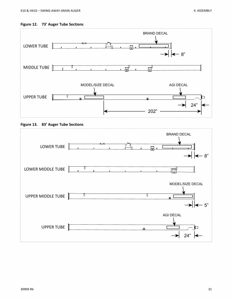
Figure 12. 73’ Auger Tube Sections
LOWER TUBE
MIDDLE TUBE
UPPER TUBE
202”
AGI DECALMODEL/SIZE DECAL
BRAND DECAL
24”
8”
Figure 13. 83’ Auger Tube Sections
LOWER TUBE
LOWER MIDDLE TUBE
UPPER MIDDLE TUBE
UPPER TUBE
AGI DECAL
MODEL/SIZE DECAL
BRAND DECAL
24”
8”
5”
X10 & HX10 – SWING-AWAY GRAIN AUGER 4. ASSEMBLY
32 30909 R6
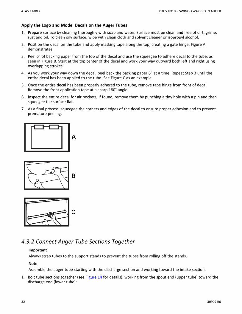
Apply the Logo and Model Decals on the Auger Tubes1. Prepare surface by cleaning thoroughly with soap and water. Surface must be clean and free of dirt, grime,
rust and oil. To clean oily surface, wipe with clean cloth and solvent cleaner or isopropyl alcohol.
2. Position the decal on the tube and apply masking tape along the top, creating a gate hinge. Figure Ademonstrates.
3. Peel 6" of backing paper from the top of the decal and use the squeegee to adhere decal to the tube, asseen in Figure B. Start at the top center of the decal and work your way outward both left and right usingoverlapping strokes.
4. As you work your way down the decal, peel back the backing paper 6" at a time. Repeat Step 3 until theentire decal has been applied to the tube. See Figure C as an example.
5. Once the entire decal has been properly adhered to the tube, remove tape hinge from front of decal.Remove the front application tape at a sharp 180° angle.
6. Inspect the entire decal for air pockets; if found, remove them by punching a tiny hole with a pin and thensqueegee the surface flat.
7. As a final process, squeegee the corners and edges of the decal to ensure proper adhesion and to preventpremature peeling.
4.3.2 Connect Auger Tube Sections TogetherImportantAlways strap tubes to the support stands to prevent the tubes from rolling off the stands.
NoteAssemble the auger tube starting with the discharge section and working toward the intake section.
1. Bolt tube sections together (see Figure 14 for details), working from the spout end (upper tube) toward thedischarge end (lower tube):
4. ASSEMBLY X10 & HX10 – SWING-AWAY GRAIN AUGER
30909 R6 33
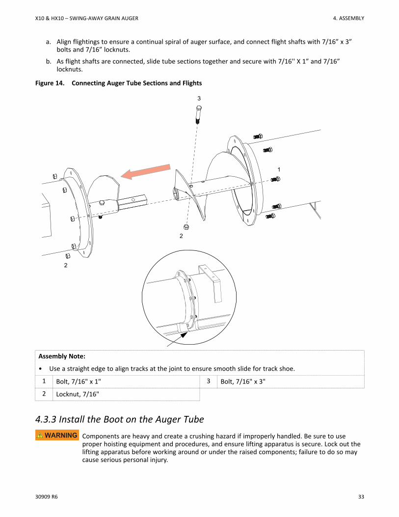
a. Align flightings to ensure a continual spiral of auger surface, and connect flight shafts with 7/16” x 3”bolts and 7/16” locknuts.
b. As flight shafts are connected, slide tube sections together and secure with 7/16'' X 1” and 7/16”locknuts.
Figure 14. Connecting Auger Tube Sections and Flights
2
3
1
2
Assembly Note:
• Use a straight edge to align tracks at the joint to ensure smooth slide for track shoe.
1 Bolt, 7/16" x 1" 3 Bolt, 7/16" x 3"
2 Locknut, 7/16"
4.3.3 Install the Boot on the Auger TubeComponents are heavy and create a crushing hazard if improperly handled. Be sure to useproper hoisting equipment and procedures, and ensure lifting apparatus is secure. Lock out thelifting apparatus before working around or under the raised components; failure to do so maycause serious personal injury.
X10 & HX10 – SWING-AWAY GRAIN AUGER 4. ASSEMBLY

34 30909 R6
ImportantThe gearbox is sent from the factory filled half way with EP90 gear oil. Before further assembly, checkoil level to make certain the gearbox is half full. Add oil if necessary. Do not use grease.
1. The boot flighting comes pre-installed on the end of the lower tube flighting shaft. (See Figure 15.) Ensurethat the flighting is fastened with a 1/2" X 4" GR8 bolt and lock nut.
Figure 15. Check Boot Flight Bolt and Nut
1
2
1 Bolt, 1/2" x 4" 2 Lock Nut, 1/2"
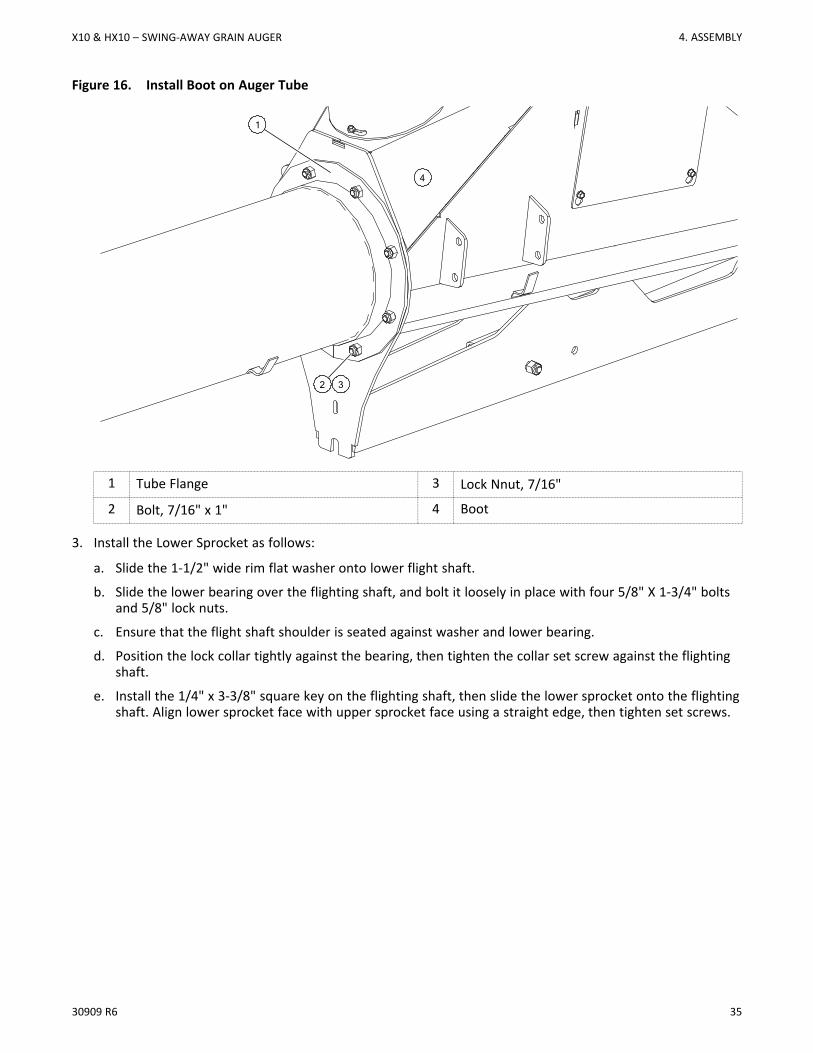
2. Slip the boot assembly over the lower flighting shaft and attach it to the flange on the lower tube with eight7/16" x 1" bolts and locknuts. (See Figure 16.)
4. ASSEMBLY X10 & HX10 – SWING-AWAY GRAIN AUGER
30909 R6 35
Figure 16. Install Boot on Auger Tube
1 Tube Flange 3 Lock Nnut, 7/16"
2 Bolt, 7/16" x 1" 4 Boot
3. Install the Lower Sprocket as follows:
a. Slide the 1-1/2" wide rim flat washer onto lower flight shaft.
b. Slide the lower bearing over the flighting shaft, and bolt it loosely in place with four 5/8" X 1-3/4" boltsand 5/8" lock nuts.
c. Ensure that the flight shaft shoulder is seated against washer and lower bearing.
d. Position the lock collar tightly against the bearing, then tighten the collar set screw against the flightingshaft.
e. Install the 1/4" x 3-3/8" square key on the flighting shaft, then slide the lower sprocket onto the flightingshaft. Align lower sprocket face with upper sprocket face using a straight edge, then tighten set screws.
2 3
1
4
X10 & HX10 – SWING-AWAY GRAIN AUGER 4. ASSEMBLY
36 30909 R6
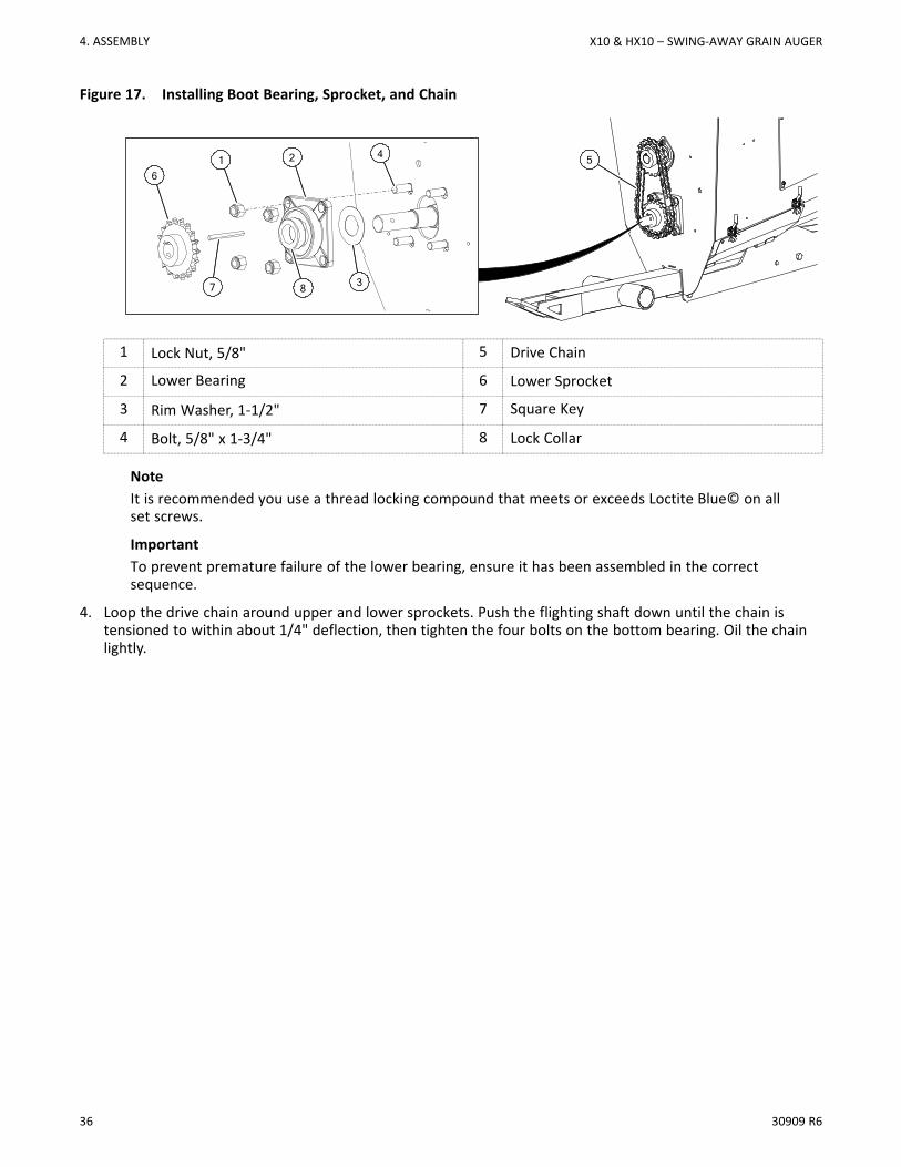
Figure 17. Installing Boot Bearing, Sprocket, and Chain
1 Lock Nut, 5/8" 5 Drive Chain
2 Lower Bearing 6 Lower Sprocket
3 Rim Washer, 1-1/2" 7 Square Key
4 Bolt, 5/8" x 1-3/4" 8 Lock Collar
NoteIt is recommended you use a thread locking compound that meets or exceeds Loctite Blue© on allset screws.
ImportantTo prevent premature failure of the lower bearing, ensure it has been assembled in the correctsequence.
4. Loop the drive chain around upper and lower sprockets. Push the flighting shaft down until the chain istensioned to within about 1/4" deflection, then tighten the four bolts on the bottom bearing. Oil the chainlightly.
4
3
516
7
2
8
4. ASSEMBLY X10 & HX10 – SWING-AWAY GRAIN AUGER
30909 R6 37
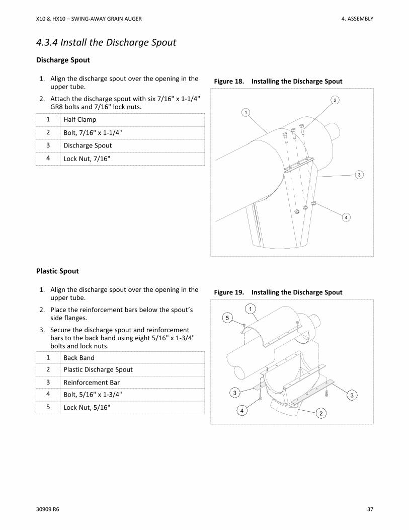
4.3.4 Install the Discharge SpoutDischarge Spout
1. Align the discharge spout over the opening in theupper tube.
2. Attach the discharge spout with six 7/16" x 1-1/4"GR8 bolts and 7/16" lock nuts.
Figure 18. Installing the Discharge Spout
1
3
2
4
1 Half Clamp
2 Bolt, 7/16" x 1-1/4"
3 Discharge Spout
4 Lock Nut, 7/16"
Plastic Spout
1. Align the discharge spout over the opening in theupper tube.
2. Place the reinforcement bars below the spout’sside flanges.
3. Secure the discharge spout and reinforcementbars to the back band using eight 5/16" x 1-3/4"bolts and lock nuts.
Figure 19. Installing the Discharge Spout
3
2
15
3
4
1 Back Band2 Plastic Discharge Spout
3 Reinforcement Bar4 Bolt, 5/16" x 1-3/4"
5 Lock Nut, 5/16"
X10 & HX10 – SWING-AWAY GRAIN AUGER 4. ASSEMBLY
38 30909 R6
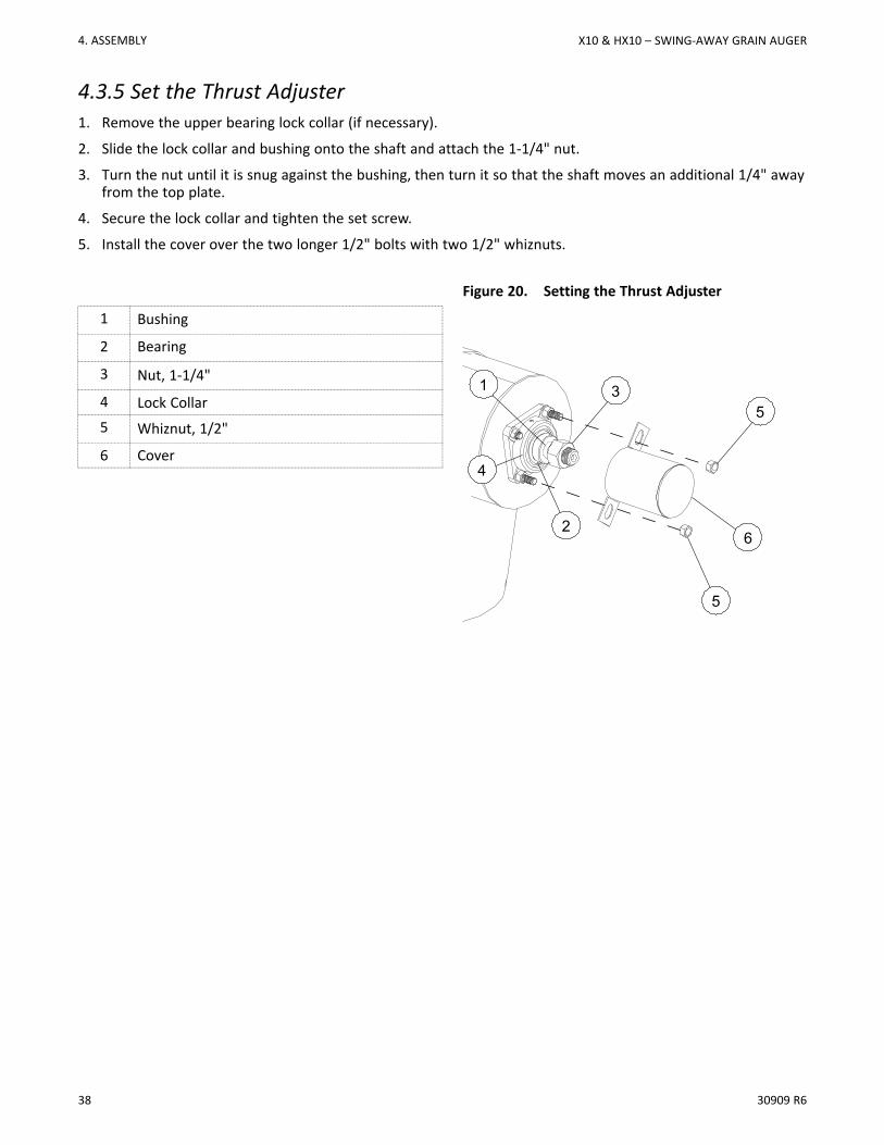
4.3.5 Set the Thrust Adjuster1. Remove the upper bearing lock collar (if necessary).
2. Slide the lock collar and bushing onto the shaft and attach the 1-1/4" nut.
3. Turn the nut until it is snug against the bushing, then turn it so that the shaft moves an additional 1/4" awayfrom the top plate.
4. Secure the lock collar and tighten the set screw.
5. Install the cover over the two longer 1/2" bolts with two 1/2" whiznuts.
Figure 20. Setting the Thrust Adjuster
1 Bushing
62
5
1 35
4
2 Bearing
3 Nut, 1-1/4"
4 Lock Collar5 Whiznut, 1/2"
6 Cover
4. ASSEMBLY X10 & HX10 – SWING-AWAY GRAIN AUGER
30909 R6 39
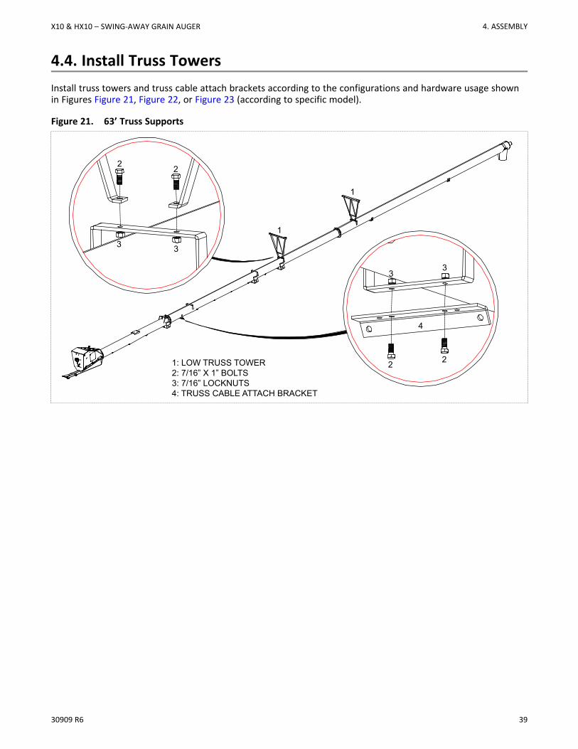
4.4. Install Truss TowersInstall truss towers and truss cable attach brackets according to the configurations and hardware usage shownin Figures Figure 21, Figure 22, or Figure 23 (according to specific model).
Figure 21. 63’ Truss Supports
2 2
3 3
2 2
33
4
1: LOW TRUSS TOWER2: 7/16” X 1” BOLTS3: 7/16” LOCKNUTS4: TRUSS CABLE ATTACH BRACKET
1
1
X10 & HX10 – SWING-AWAY GRAIN AUGER 4. ASSEMBLY
40 30909 R6
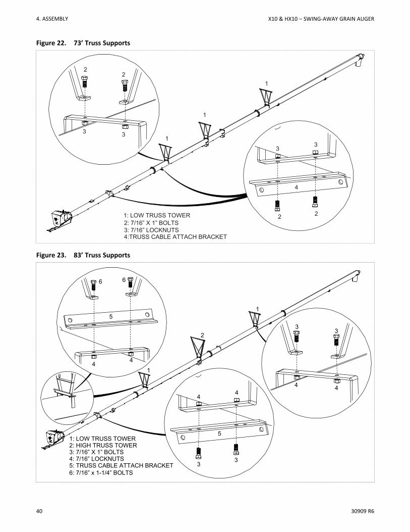
Figure 22. 73’ Truss Supports
1: LOW TRUSS TOWER2: 7/16” X 1” BOLTS3: 7/16” LOCKNUTS
1
1
1
22
3 3
2 2
33
4:TRUSS CABLE ATTACH BRACKET
4
Figure 23. 83’ Truss Supports
1: LOW TRUSS TOWER2: HIGH TRUSS TOWER3: 7/16” X 1” BOLTS4: 7/16” LOCKNUTS
1
1
2
6 6
33
44
4 4
5: TRUSS CABLE ATTACH BRACKET
5
53
3
4 4
6: 7/16” x 1-1/4” BOLTS
4. ASSEMBLY X10 & HX10 – SWING-AWAY GRAIN AUGER
30909 R6 41
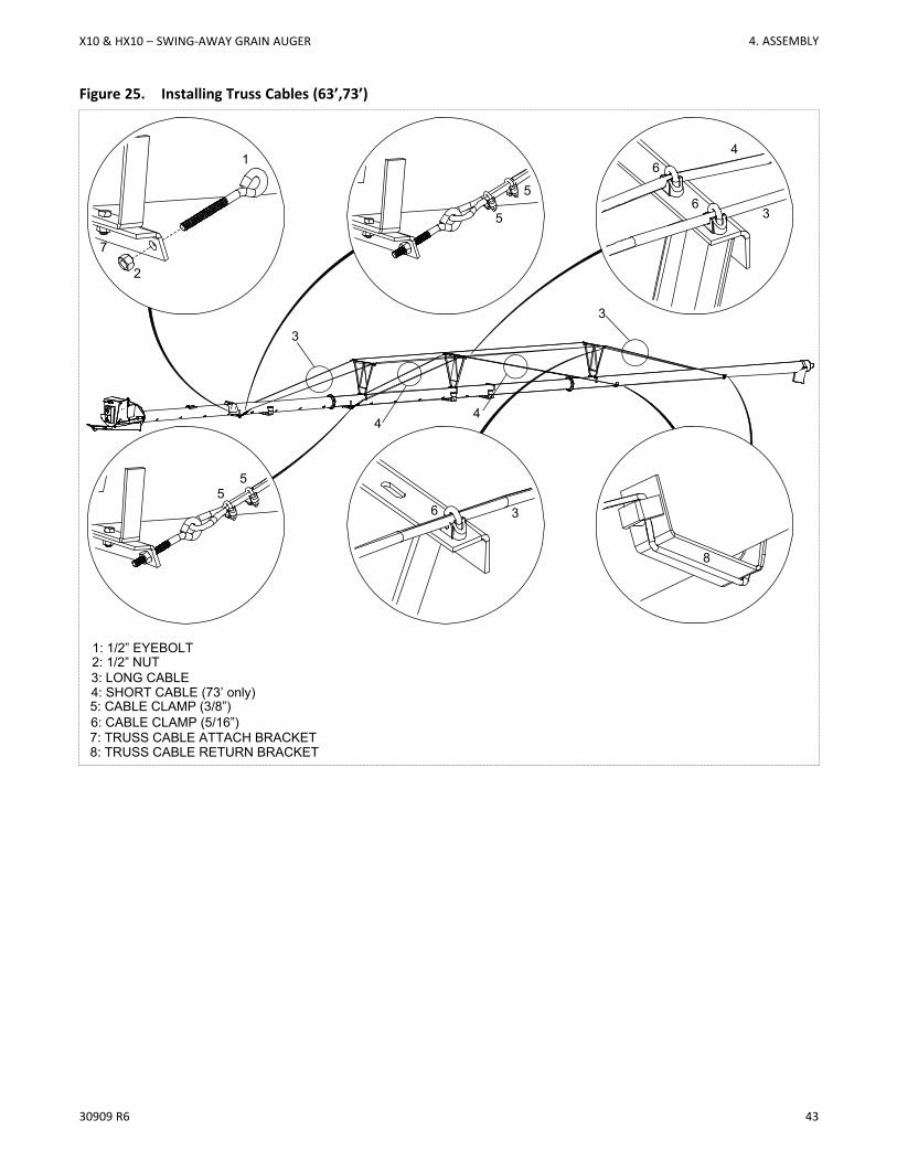
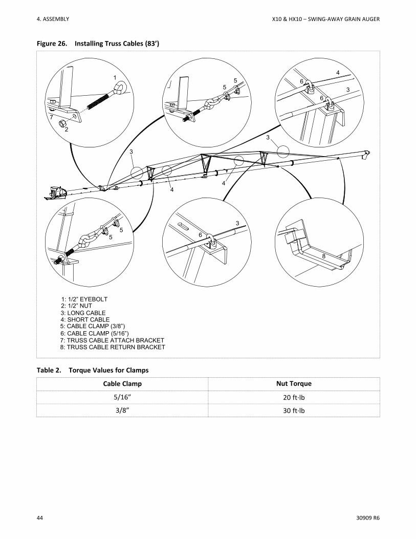
4.5. Install Truss CablesRefer to Figure 25 and Figure 26, according to the specific model.
1. Remove the support stands but those ones at the ends of the tube sections to let the tube deflect under itsown weight.
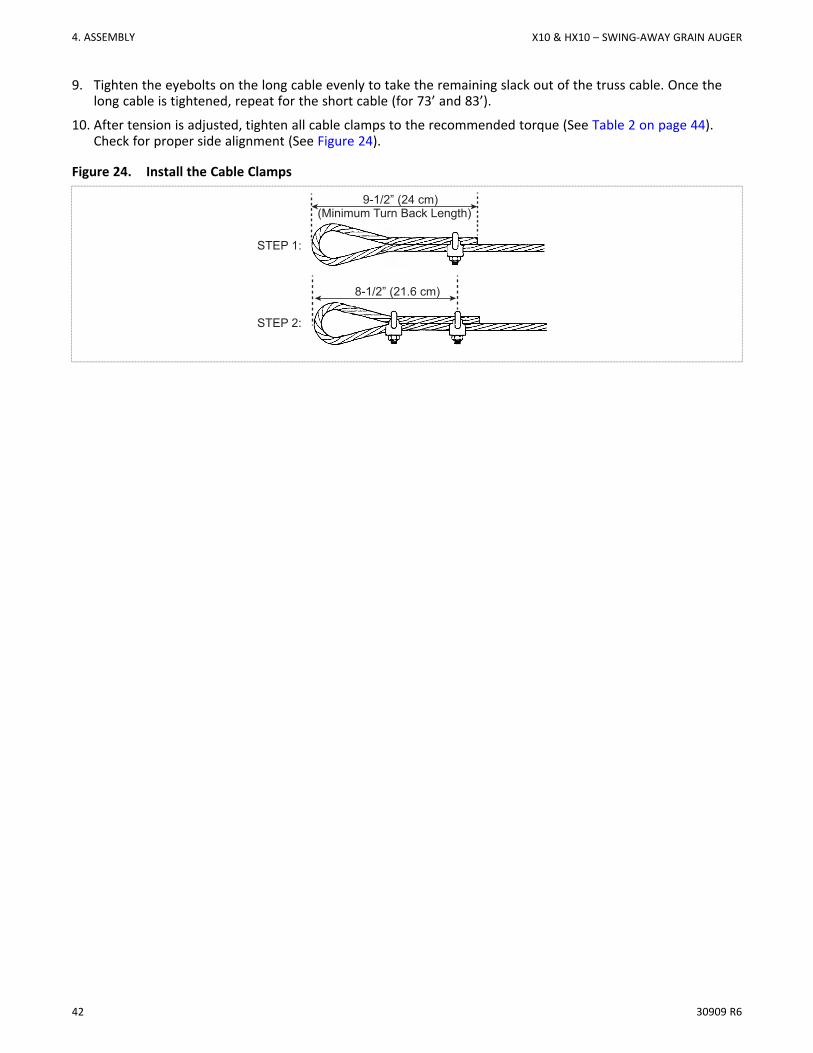
2. Thread truss cable through eyebolt and ensure a minimum turn back length of 9-1/2" (24 cm) of cable (seeFigure 24 on page 42). Secure the cable in place by installing and tightening two 3/8" cable clamps.
a. Apply the first clamp 8-1/2” from the cable loop with the u-bolt over the dead end. The live end rests inclip saddle. Tighten nuts firmly but do not fully tighten.
b. Apply the second clamp as close to the loop as possible in the same orientation as the first clamp. Thelive end rests in clip saddle. Apply tension and tighten nuts firmly but do not fully tighten.
3. Insert eyebolt into truss cable attach bracket and thread on a 1/2" locknut a short way (~1.0”).
4. Pull the long truss cable:
• over the cable bridges
• around the cable return bracket
• back over the cable bridges
• back to the cable anchor bracket
5. 73’/83’ only: Pull the short truss cable:
• over the middle cable bridge
• around the cable return bracket
• back over the middle cable bridge
• back to the cable anchor bracket
ImportantThe long truss cable must be installed on the outside of the middle bridge.
6. Use loosely attached 5/16” cable clamps to hold the cable in place — 2 cable clamps per cable bridge andtwo clamps on the cable return bracket at the eyebolt.
NoteDo not tighten the cable clamps at this time.
7. Insert eyebolts in the opposite sides of the both cable attach brackets and thread on a 1/2” locknut a shortway (~1.0”).
8. Thread truss cable through the eyebolt and pull out all slack. Ensure a minimum turn back length of 9-1/2"(24 cm) of cable. Secure the cable in place by installing and tightening two 3/8" cable clamps. (See Figure24)
a. Apply the first clamp 8-1/2” (21.6 cm) from the cable loop with the u-bolt over the dead end. The liveend rests in clip saddle. Tighten nuts firmly but do not fully tighten.
b. Apply the second clamp as close to the loop as possible in the same orientation as the first clamp. Thelive end rests in clip saddle. Apply tension and tighten nuts firmly but do not fully tighten.
NoteIf there isn’t enough cable, loosen the clamps on the opposite eyebolt and adjust the cable.Retighten clamps.
X10 & HX10 – SWING-AWAY GRAIN AUGER 4. ASSEMBLY
42 30909 R6
9. Tighten the eyebolts on the long cable evenly to take the remaining slack out of the truss cable. Once thelong cable is tightened, repeat for the short cable (for 73’ and 83’).
10. After tension is adjusted, tighten all cable clamps to the recommended torque (See Table 2 on page 44).Check for proper side alignment (See Figure 24).
Figure 24. Install the Cable Clamps
STEP 1:
STEP 2:
(Minimum Turn Back Length)
8-1/2” (21.6 cm)
9-1/2” (24 cm)
4. ASSEMBLY X10 & HX10 – SWING-AWAY GRAIN AUGER
30909 R6 43
Figure 25. Installing Truss Cables (63’,73’)
1
2
5
5
4
36
6
7: TRUSS CABLE ATTACH BRACKET
5: CABLE CLAMP (3/8”)
1: 1/2” EYEBOLT
3: LONG CABLE4: SHORT CABLE (73’ only)
2: 1/2” NUT
6: CABLE CLAMP (5/16”)
8: TRUSS CABLE RETURN BRACKET
36
7
8
3
4
3
4
55
X10 & HX10 – SWING-AWAY GRAIN AUGER 4. ASSEMBLY
44 30909 R6
Figure 26. Installing Truss Cables (83’)
7: TRUSS CABLE ATTACH BRACKET
5: CABLE CLAMP (3/8”)
1: 1/2” EYEBOLT
3: LONG CABLE4: SHORT CABLE
2: 1/2” NUT
6: CABLE CLAMP (5/16”)
8: TRUSS CABLE RETURN BRACKET
15
5
6
64
3
8
3
6
2
7
3
4
3
4
55
Table 2. Torque Values for Clamps
Cable Clamp Nut Torque
5/16” 20 ft·lb
3/8” 30 ft·lb
4. ASSEMBLY X10 & HX10 – SWING-AWAY GRAIN AUGER
30909 R6 45
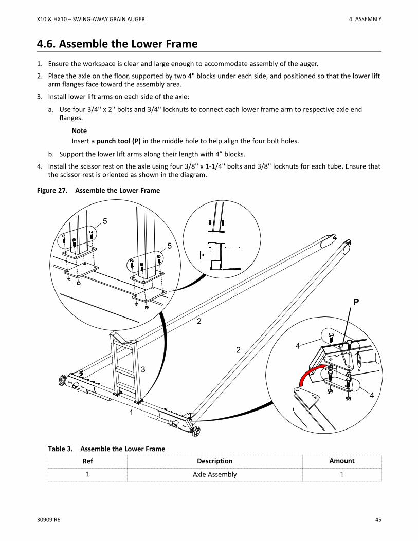
4.6. Assemble the Lower Frame1. Ensure the workspace is clear and large enough to accommodate assembly of the auger.
2. Place the axle on the floor, supported by two 4" blocks under each side, and positioned so that the lower liftarm flanges face toward the assembly area.
3. Install lower lift arms on each side of the axle:
a. Use four 3/4'' x 2'' bolts and 3/4'' locknuts to connect each lower frame arm to respective axle endflanges.
NoteInsert a punch tool (P) in the middle hole to help align the four bolt holes.
b. Support the lower lift arms along their length with 4” blocks.
4. Install the scissor rest on the axle using four 3/8'' x 1-1/4'' bolts and 3/8'' locknuts for each tube. Ensure thatthe scissor rest is oriented as shown in the diagram.
Figure 27. Assemble the Lower Frame
1
2
2 4
4
3
5
5
P
Table 3. Assemble the Lower Frame
Ref Description Amount
1 Axle Assembly 1
X10 & HX10 – SWING-AWAY GRAIN AUGER 4. ASSEMBLY

46 30909 R6
Table 3 Assemble the Lower Frame (continued)
2 Lower Reach Arm 2
3 Transport Stand 1
4 3/4" x 2" Bolt 8
3/4" Locknut 8
5 3/8" x 1-1/4" Bolt 8
3/8" Locknut 8
4.7. Connect the Lower Frame ArmsImportantThe position of the lower frame arm connections on the axle depends on the model. For the 83’ modelthe frame arms connect using the outermost bracket positions. For the 73’ model the frame armsconnect using the middle bracket positions. For the 63’ model the frame arms connect using theinnermost bracket positions.
1. Elevate the reach arms on a support stand, and place another support stand so it can be used to support thelower scissor arms as they are installed.
2. Lift, position, and connect the lower scissors one at a time. Use lower scissor attach pins to attach thenarrow ends of the arms to the flanges on the axle, and secure each pin with two 1” SAE washers and two1/4” x 1-3/4” cotter pins.
4. ASSEMBLY X10 & HX10 – SWING-AWAY GRAIN AUGER
30909 R6 47
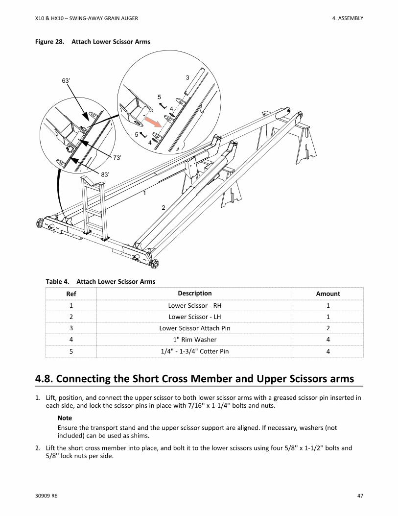
Figure 28. Attach Lower Scissor Arms
1
2
5
4
54
3
73’
83’
63’
Table 4. Attach Lower Scissor Arms
Ref Description Amount
1 Lower Scissor - RH 12 Lower Scissor - LH 13 Lower Scissor Attach Pin 2
4 1" Rim Washer 4
5 1/4" - 1-3/4" Cotter Pin 4
4.8. Connecting the Short Cross Member and Upper Scissors arms1. Lift, position, and connect the upper scissor to both lower scissor arms with a greased scissor pin inserted in
each side, and lock the scissor pins in place with 7/16'' x 1-1/4'' bolts and nuts.
NoteEnsure the transport stand and the upper scissor support are aligned. If necessary, washers (notincluded) can be used as shims.
2. Lift the short cross member into place, and bolt it to the lower scissors using four 5/8'' x 1-1/2'' bolts and5/8'' lock nuts per side.
X10 & HX10 – SWING-AWAY GRAIN AUGER 4. ASSEMBLY
48 30909 R6
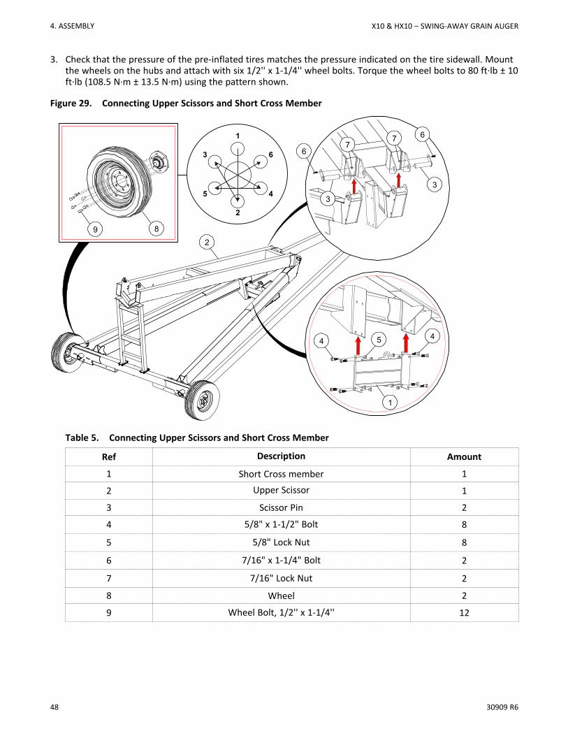
3. Check that the pressure of the pre-inflated tires matches the pressure indicated on the tire sidewall. Mountthe wheels on the hubs and attach with six 1/2'' x 1-1/4'' wheel bolts. Torque the wheel bolts to 80 ft·lb ± 10ft·lb (108.5 N·m ± 13.5 N·m) using the pattern shown.
Figure 29. Connecting Upper Scissors and Short Cross Member
1
2
3 6
45
9 8
1
3
3
2
4
67
76
5 4
Table 5. Connecting Upper Scissors and Short Cross Member
Ref Description Amount
1 Short Cross member 1
2 Upper Scissor 1
3 Scissor Pin 2
4 5/8" x 1-1/2" Bolt 8
5 5/8" Lock Nut 8
6 7/16" x 1-1/4" Bolt 2
7 7/16" Lock Nut 2
8 Wheel 2
9 Wheel Bolt, 1/2'' x 1-1/4'' 12
4. ASSEMBLY X10 & HX10 – SWING-AWAY GRAIN AUGER
30909 R6 49
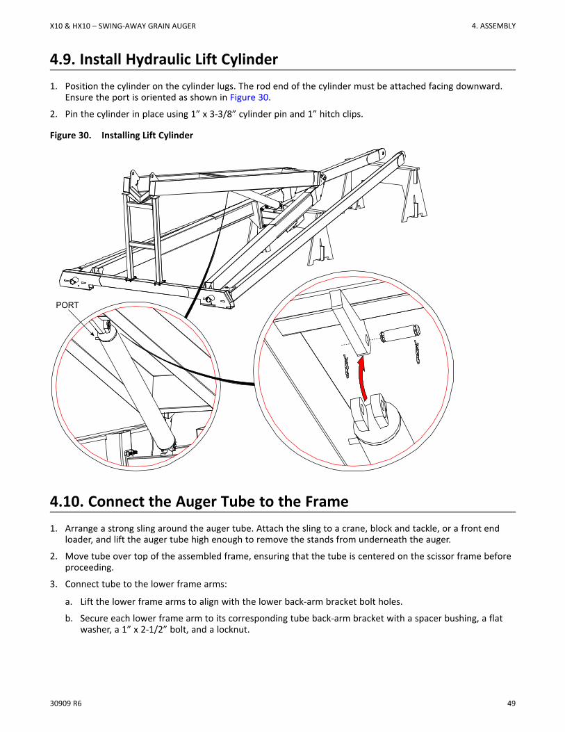
4.9. Install Hydraulic Lift Cylinder1. Position the cylinder on the cylinder lugs. The rod end of the cylinder must be attached facing downward.
Ensure the port is oriented as shown in Figure 30.
2. Pin the cylinder in place using 1” x 3-3/8” cylinder pin and 1” hitch clips.
Figure 30. Installing Lift Cylinder
PORT
4.10. Connect the Auger Tube to the Frame1. Arrange a strong sling around the auger tube. Attach the sling to a crane, block and tackle, or a front end
loader, and lift the auger tube high enough to remove the stands from underneath the auger.
2. Move tube over top of the assembled frame, ensuring that the tube is centered on the scissor frame beforeproceeding.
3. Connect tube to the lower frame arms:
a. Lift the lower frame arms to align with the lower back-arm bracket bolt holes.
b. Secure each lower frame arm to its corresponding tube back-arm bracket with a spacer bushing, a flatwasher, a 1” x 2-1/2” bolt, and a locknut.
X10 & HX10 – SWING-AWAY GRAIN AUGER 4. ASSEMBLY
50 30909 R6
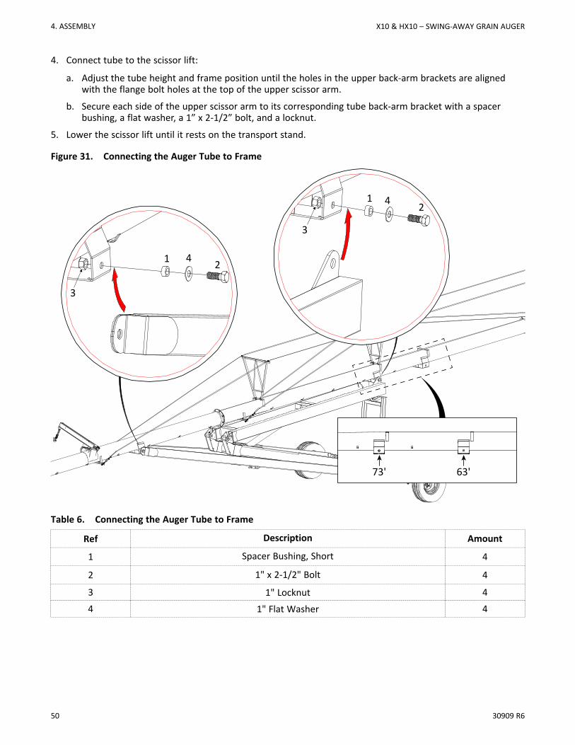
4. Connect tube to the scissor lift:
a. Adjust the tube height and frame position until the holes in the upper back-arm brackets are alignedwith the flange bolt holes at the top of the upper scissor arm.
b. Secure each side of the upper scissor arm to its corresponding tube back-arm bracket with a spacerbushing, a flat washer, a 1” x 2-1/2” bolt, and a locknut.
5. Lower the scissor lift until it rests on the transport stand.
Figure 31. Connecting the Auger Tube to Frame
3
1 4 2
3
1 4 2
73' 63'
Table 6. Connecting the Auger Tube to Frame
Ref Description Amount
1 Spacer Bushing, Short 4
2 1" x 2-1/2" Bolt 4
3 1" Locknut 4
4 1" Flat Washer 4
4. ASSEMBLY X10 & HX10 – SWING-AWAY GRAIN AUGER
30909 R6 51
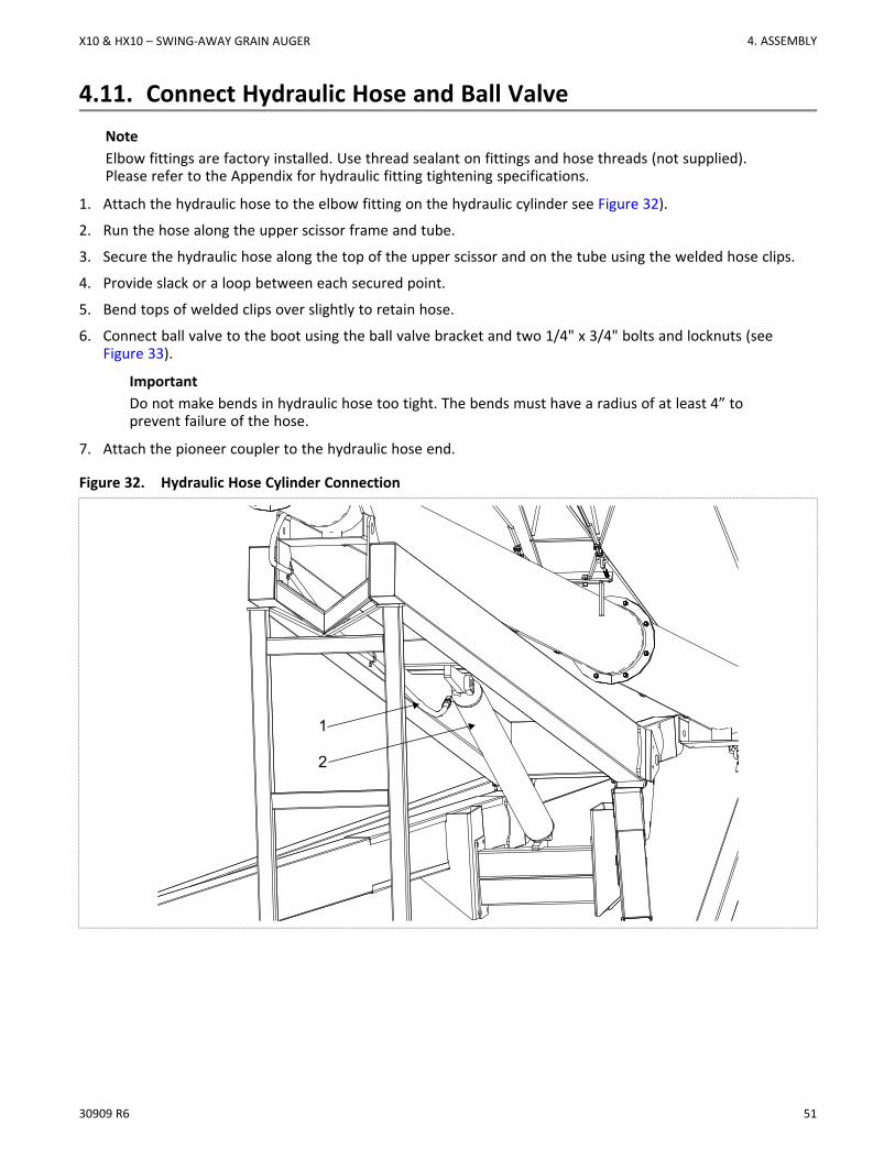
4.11. Connect Hydraulic Hose and Ball ValveNoteElbow fittings are factory installed. Use thread sealant on fittings and hose threads (not supplied).Please refer to the Appendix for hydraulic fitting tightening specifications.
1. Attach the hydraulic hose to the elbow fitting on the hydraulic cylinder see Figure 32).
2. Run the hose along the upper scissor frame and tube.
3. Secure the hydraulic hose along the top of the upper scissor and on the tube using the welded hose clips.
4. Provide slack or a loop between each secured point.
5. Bend tops of welded clips over slightly to retain hose.
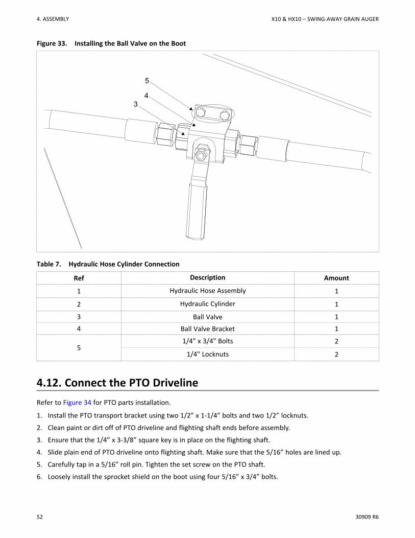
6. Connect ball valve to the boot using the ball valve bracket and two 1/4" x 3/4" bolts and locknuts (seeFigure 33).
ImportantDo not make bends in hydraulic hose too tight. The bends must have a radius of at least 4” toprevent failure of the hose.
7. Attach the pioneer coupler to the hydraulic hose end.
Figure 32. Hydraulic Hose Cylinder Connection
1
2
X10 & HX10 – SWING-AWAY GRAIN AUGER 4. ASSEMBLY
52 30909 R6
Figure 33. Installing the Ball Valve on the Boot
5
43
Table 7. Hydraulic Hose Cylinder Connection
Ref Description Amount
1 Hydraulic Hose Assembly 1
2 Hydraulic Cylinder 1
3 Ball Valve 1
4 Ball Valve Bracket 1
51/4" x 3/4" Bolts 2
1/4" Locknuts 2
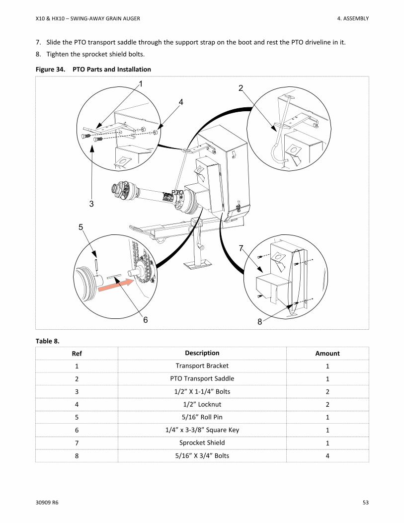
4.12. Connect the PTO DrivelineRefer to Figure 34 for PTO parts installation.
1. Install the PTO transport bracket using two 1/2” x 1-1/4” bolts and two 1/2” locknuts.
2. Clean paint or dirt off of PTO driveline and flighting shaft ends before assembly.
3. Ensure that the 1/4” x 3-3/8” square key is in place on the flighting shaft.
4. Slide plain end of PTO driveline onto flighting shaft. Make sure that the 5/16” holes are lined up.
5. Carefully tap in a 5/16” roll pin. Tighten the set screw on the PTO shaft.
6. Loosely install the sprocket shield on the boot using four 5/16” x 3/4” bolts.
4. ASSEMBLY X10 & HX10 – SWING-AWAY GRAIN AUGER
30909 R6 53
7. Slide the PTO transport saddle through the support strap on the boot and rest the PTO driveline in it.
8. Tighten the sprocket shield bolts.
Figure 34. PTO Parts and Installation
1
3
4
2
5
PTO
7
6 8
Table 8.
Ref Description Amount
1 Transport Bracket 1
2 PTO Transport Saddle 1
3 1/2” X 1-1/4” Bolts 2
4 1/2” Locknut 2
5 5/16” Roll Pin 1
6 1/4” x 3-3/8” Square Key 1
7 Sprocket Shield 1
8 5/16” X 3/4” Bolts 4
X10 & HX10 – SWING-AWAY GRAIN AUGER 4. ASSEMBLY
54 30909 R6
4.13. Install Low Profile Intake Hopper1. Clean dirt and paint from inside the u-joint and flighting shaft end, grease the shaft end, then insert a
Woodruff key (Figure 35).
2. Raise and support the hopper tube spout head on a stand about 50” high.
3. Open the service door on the Transition, then bring the transition and hopper together guiding the flightshaft into the u-joint (Figure 35).
4. Attach the Transition to the intake hopper with two 5/8” x 1-1/2” bolts and 5/8” locknuts. DO NOT over-tighten; tighten to a slightly loose fit only as these bolts act as pivot points (Figure 35).
5. Tighten set screws on u-joints, then close and secure the service door.
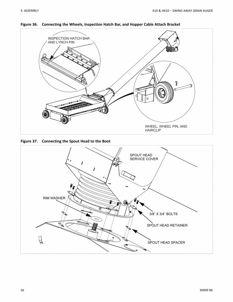
6. Attach the 4 solid wheels to the 4 hopper corners with the axle pins and hairpins. There are 3 height settings(Figure 36) that can be used according to preference.
7. To connect the intake hopper to the auger boot, the swing head spout door must first be opened. To do so,open the spring clasps and rotate the spout door open, so that it lies down on the top of the swing tube.
8. Check that the u-joint spline and splined shaft on the lower gear box are clean, then apply a light film ofgrease on the splined shaft.
9. Install a rim washer on the top shaft of the lower gearbox.
10. Shift the position of the hopper so that the spout head is supported above the hopper, centred on the shaftof the gear box.
11. Lower the spout head onto the boot while guiding the splined universal joint onto the splined gearbox shaft.Once positioned, the swivel ring should be resting flat on the boot surface.
12. Install spout head spacers, followed by spout-head retainers, using eight 3/8” x 3/4” bolts (Figure 37).
13. Lubricate the universal joint and then close and secure the spout head service cover.
ImportantAlways keep the spout head service cover closed and secured during operation.
4. ASSEMBLY X10 & HX10 – SWING-AWAY GRAIN AUGER
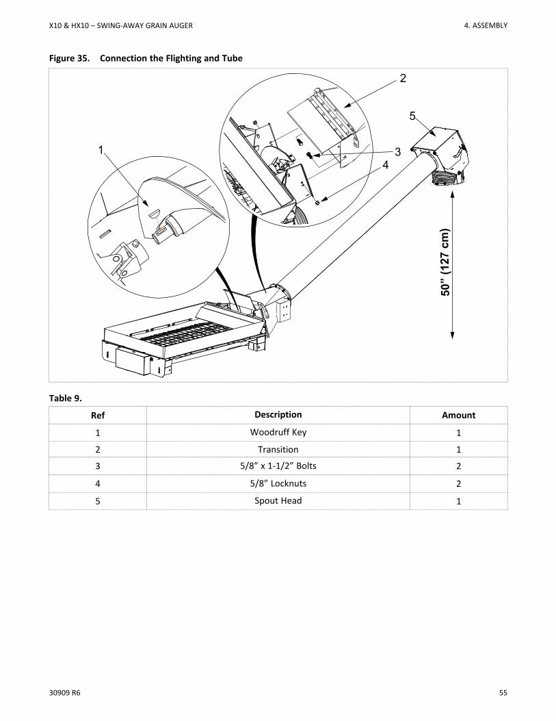
30909 R6 55
Figure 35. Connection the Flighting and Tube
1
5
2
43
50”
(127
cm
)
Table 9.
Ref Description Amount
1 Woodruff Key 1
2 Transition 1
3 5/8” x 1-1/2” Bolts 2
4 5/8” Locknuts 2
5 Spout Head 1
X10 & HX10 – SWING-AWAY GRAIN AUGER 4. ASSEMBLY
56 30909 R6
Figure 36. Connecting the Wheels, Inspection Hatch Bar, and Hopper Cable Attach Bracket
WHEEL, WHEEL PIN, ANDHAIRCLIP
INSPECTION HATCH BAR AND LYNCH PIN
Figure 37. Connecting the Spout Head to the Boot
SPOUT HEAD SPACER
SPOUT HEAD RETAINER
3/8” X 3/4” BOLTS
SPOUT HEADSERVICE COVER
RIM WASHER
4. ASSEMBLY X10 & HX10 – SWING-AWAY GRAIN AUGER
30909 R6 57
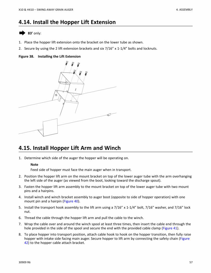
4.14. Install the Hopper Lift Extension
Æ 83’ only:
1. Place the hopper lift extension onto the bracket on the lower tube as shown.
2. Secure by using the 2 lift extension brackets and six 7/16” x 1-1/4” bolts and locknuts.
Figure 38. Installing the Lift Extension
4.15. Install Hopper Lift Arm and Winch1. Determine which side of the auger the hopper will be operating on.
NoteFeed side of hopper must face the main auger when in transport.
2. Position the hopper lift arm on the mount bracket on top of the lower auger tube with the arm overhangingthe left side of the auger (as viewed from the boot, looking toward the discharge spout).
3. Fasten the hopper lift arm assembly to the mount bracket on top of the lower auger tube with two mountpins and a hairpins.
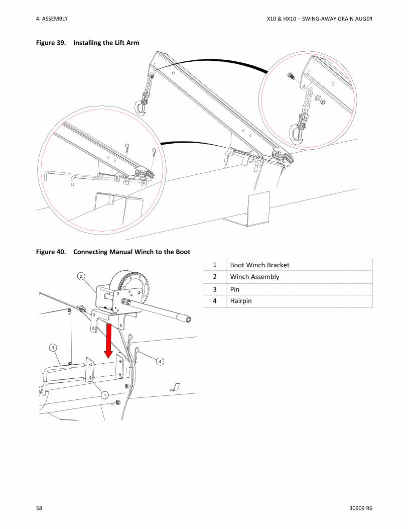
4. Install winch and winch bracket assembly to auger boot (opposite to side of hopper operation) with onemount pin and a hairpin (Figure 40).
5. Install the transport hook assembly to the lift arm using a 7/16” x 1-1/4” bolt, 7/16” washer, and 7/16” locknut.
6. Thread the cable through the hopper lift arm and pull the cable to the winch.
7. Wrap the cable over and around the winch spool at least three times, then insert the cable end through thehole provided in the side of the spool and secure the end with the provided cable clamp (Figure 41).
8. To place hopper into transport position, attach cable hook to hook on the hopper transition, then fully raisehopper with intake side facing main auger. Secure hopper to lift arm by connecting the safety chain (Figure42) to the hopper cable attach bracket.
X10 & HX10 – SWING-AWAY GRAIN AUGER 4. ASSEMBLY
58 30909 R6
Figure 39. Installing the Lift Arm
Figure 40. Connecting Manual Winch to the Boot
1 Boot Winch Bracket2 Winch Assembly
3 Pin4 Hairpin
1
2
4
3
4. ASSEMBLY X10 & HX10 – SWING-AWAY GRAIN AUGER
30909 R6 59
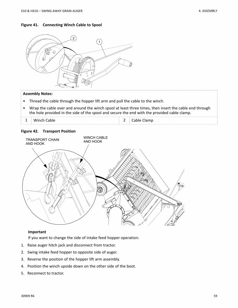
Figure 41. Connecting Winch Cable to Spool
12
Assembly Notes:
• Thread the cable through the hopper lift arm and pull the cable to the winch.
• Wrap the cable over and around the winch spool at least three times, then insert the cable end throughthe hole provided in the side of the spool and secure the end with the provided cable clamp.
1 Winch Cable 2 Cable Clamp
Figure 42. Transport Position
TRANSPORT CHAINAND HOOK
WINCH CABLEAND HOOK
ImportantIf you want to change the side of intake feed hopper operation:
1. Raise auger hitch jack and disconnect from tractor.
2. Swing intake feed hopper to opposite side of auger.
3. Reverse the position of the hopper lift arm assembly.
4. Position the winch upside down on the other side of the boot.
5. Reconnect to tractor.
X10 & HX10 – SWING-AWAY GRAIN AUGER 4. ASSEMBLY
60 30909 R6
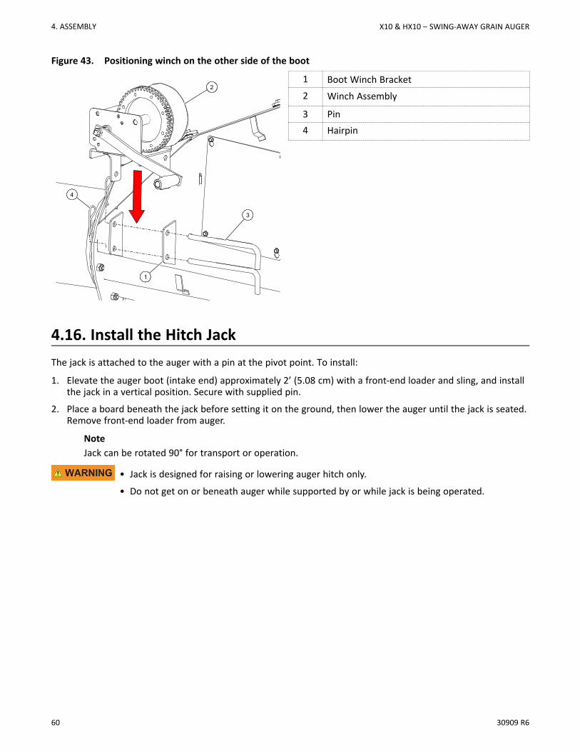
Figure 43. Positioning winch on the other side of the boot
1 Boot Winch Bracket2 Winch Assembly
3 Pin4 Hairpin
4.16. Install the Hitch JackThe jack is attached to the auger with a pin at the pivot point. To install:
1. Elevate the auger boot (intake end) approximately 2’ (5.08 cm) with a front-end loader and sling, and installthe jack in a vertical position. Secure with supplied pin.
2. Place a board beneath the jack before setting it on the ground, then lower the auger until the jack is seated.Remove front-end loader from auger.
NoteJack can be rotated 90° for transport or operation.
• Jack is designed for raising or lowering auger hitch only.
• Do not get on or beneath auger while supported by or while jack is being operated.
4
1
2
3
4. ASSEMBLY X10 & HX10 – SWING-AWAY GRAIN AUGER
30909 R6 61
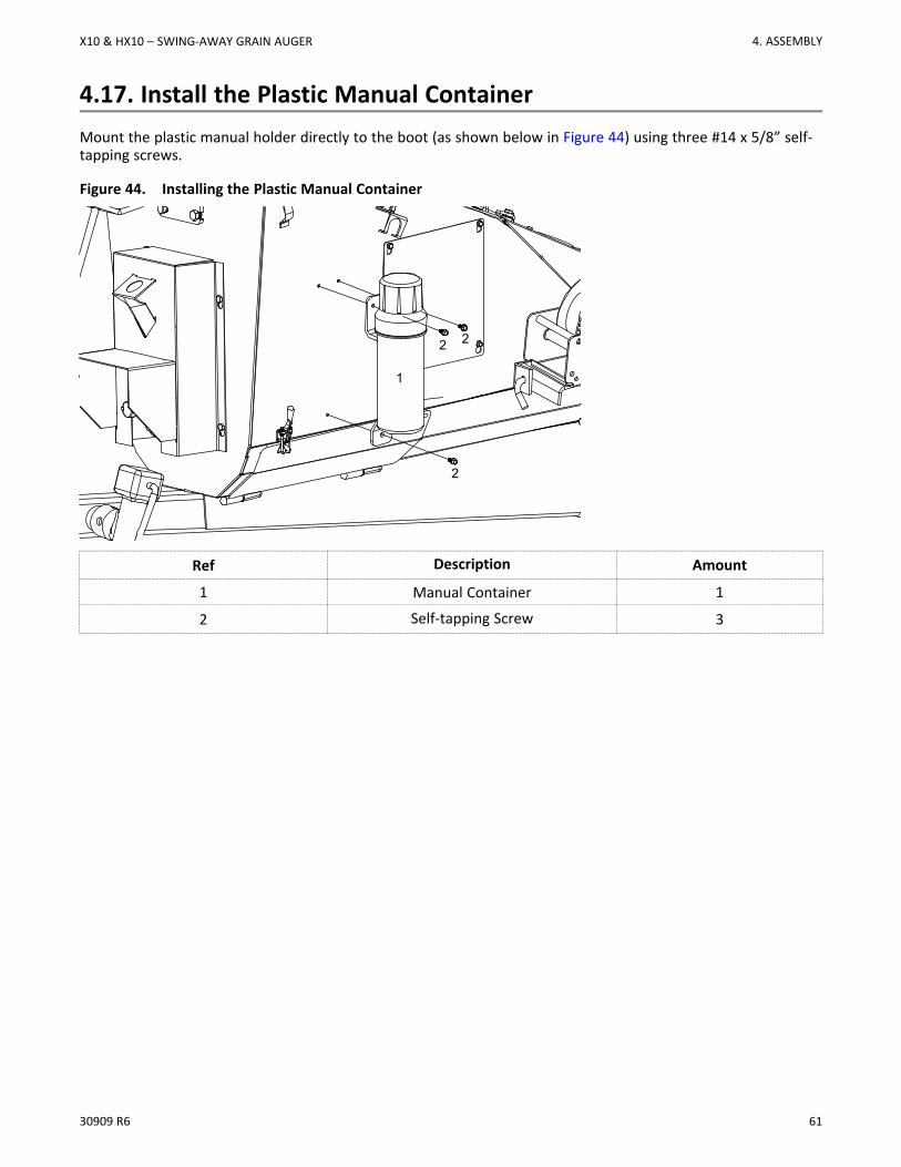
4.17. Install the Plastic Manual ContainerMount the plastic manual holder directly to the boot (as shown below in Figure 44) using three #14 x 5/8” self-tapping screws.
Figure 44. Installing the Plastic Manual Container
1
2 2
2
Ref Description Amount
1 Manual Container 1
2 Self-tapping Screw 3
X10 & HX10 – SWING-AWAY GRAIN AUGER 4. ASSEMBLY
62 30909 R6
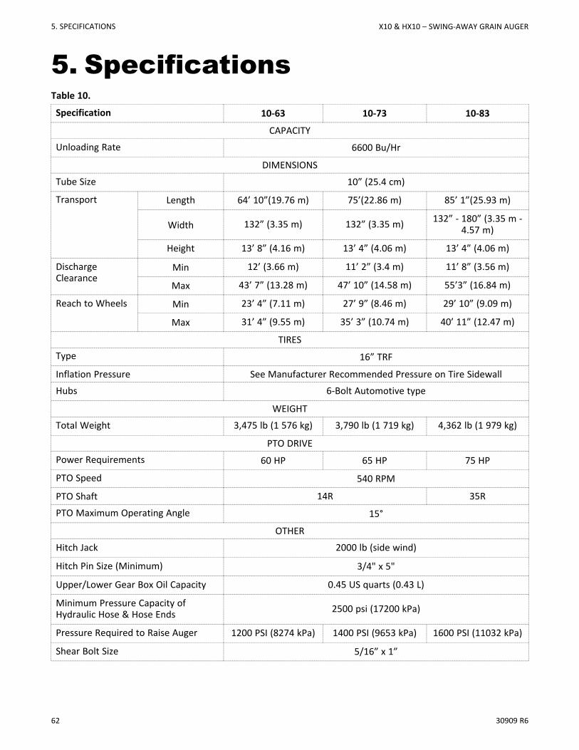
5. SpecificationsTable 10.
Specification 10-63 10-73 10-83
CAPACITY
Unloading Rate 6600 Bu/Hr
DIMENSIONS
Tube Size 10” (25.4 cm)
Transport Length 64’ 10”(19.76 m) 75’(22.86 m) 85’ 1”(25.93 m)
Width 132” (3.35 m) 132” (3.35 m) 132” - 180” (3.35 m -4.57 m)
Height 13’ 8” (4.16 m) 13’ 4” (4.06 m) 13’ 4” (4.06 m)
DischargeClearance
Min 12’ (3.66 m) 11’ 2” (3.4 m) 11’ 8” (3.56 m)
Max 43’ 7” (13.28 m) 47’ 10” (14.58 m) 55’3” (16.84 m)
Reach to Wheels Min 23’ 4” (7.11 m) 27’ 9” (8.46 m) 29’ 10” (9.09 m)
Max 31’ 4” (9.55 m) 35’ 3” (10.74 m) 40’ 11” (12.47 m)
TIRESType 16” TRF
Inflation Pressure See Manufacturer Recommended Pressure on Tire Sidewall
Hubs 6-Bolt Automotive type
WEIGHT
Total Weight 3,475 lb (1 576 kg) 3,790 lb (1 719 kg) 4,362 lb (1 979 kg)
PTO DRIVEPower Requirements 60 HP 65 HP 75 HP
PTO Speed 540 RPM
PTO Shaft 14R 35R
PTO Maximum Operating Angle 15°
OTHER
Hitch Jack 2000 lb (side wind)
Hitch Pin Size (Minimum) 3/4" x 5"
Upper/Lower Gear Box Oil Capacity 0.45 US quarts (0.43 L)
Minimum Pressure Capacity ofHydraulic Hose & Hose Ends 2500 psi (17200 kPa)
Pressure Required to Raise Auger 1200 PSI (8274 kPa) 1400 PSI (9653 kPa) 1600 PSI (11032 kPa)
Shear Bolt Size 5/16” x 1”
5. SPECIFICATIONS X10 & HX10 – SWING-AWAY GRAIN AUGER
30909 R6 63
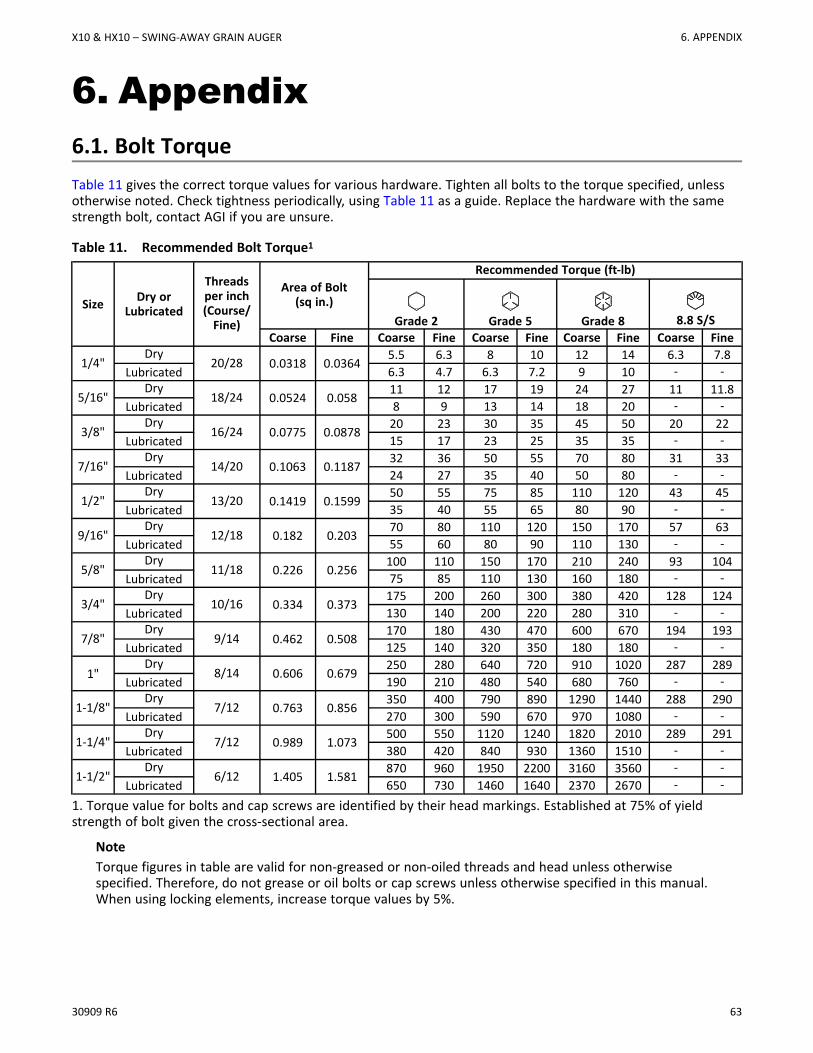
6. Appendix6.1. Bolt TorqueTable 11 gives the correct torque values for various hardware. Tighten all bolts to the torque specified, unlessotherwise noted. Check tightness periodically, using Table 11 as a guide. Replace the hardware with the samestrength bolt, contact AGI if you are unsure.
Table 11. Recommended Bolt Torque1
Size Dry orLubricated
Threadsper inch(Course/Fine)
Area of Bolt(sq in.)
Recommended Torque (ft-lb)
Grade 2 Grade 5 Grade 8 8.8 S/SCoarse Fine Coarse Fine Coarse Fine Coarse Fine Coarse Fine
1/4"Dry
20/28 0.0318 0.03645.5 6.3 8 10 12 14 6.3 7.8
Lubricated 6.3 4.7 6.3 7.2 9 10 - -
5/16"Dry
18/24 0.0524 0.05811 12 17 19 24 27 11 11.8
Lubricated 8 9 13 14 18 20 - -
3/8"Dry
16/24 0.0775 0.087820 23 30 35 45 50 20 22
Lubricated 15 17 23 25 35 35 - -
7/16"Dry
14/20 0.1063 0.118732 36 50 55 70 80 31 33
Lubricated 24 27 35 40 50 80 - -
1/2"Dry
13/20 0.1419 0.159950 55 75 85 110 120 43 45
Lubricated 35 40 55 65 80 90 - -
9/16"Dry
12/18 0.182 0.20370 80 110 120 150 170 57 63
Lubricated 55 60 80 90 110 130 - -
5/8"Dry
11/18 0.226 0.256100 110 150 170 210 240 93 104
Lubricated 75 85 110 130 160 180 - -
3/4"Dry
10/16 0.334 0.373175 200 260 300 380 420 128 124
Lubricated 130 140 200 220 280 310 - -
7/8"Dry
9/14 0.462 0.508170 180 430 470 600 670 194 193
Lubricated 125 140 320 350 180 180 - -
1"Dry
8/14 0.606 0.679250 280 640 720 910 1020 287 289
Lubricated 190 210 480 540 680 760 - -
1-1/8"Dry
7/12 0.763 0.856350 400 790 890 1290 1440 288 290
Lubricated 270 300 590 670 970 1080 - -
1-1/4"Dry
7/12 0.989 1.073500 550 1120 1240 1820 2010 289 291
Lubricated 380 420 840 930 1360 1510 - -
1-1/2"Dry
6/12 1.405 1.581870 960 1950 2200 3160 3560 - -
Lubricated 650 730 1460 1640 2370 2670 - -
1. Torque value for bolts and cap screws are identified by their head markings. Established at 75% of yieldstrength of bolt given the cross-sectional area.
NoteTorque figures in table are valid for non-greased or non-oiled threads and head unless otherwisespecified. Therefore, do not grease or oil bolts or cap screws unless otherwise specified in this manual.When using locking elements, increase torque values by 5%.
X10 & HX10 – SWING-AWAY GRAIN AUGER 6. APPENDIX
64 30909 R6
7. AGI Limited WarrantyThis warranty relates to AGI Augers (the “Product”) sold by AGI, (referred to herein as the “Seller”) and applies only tothe first user of the Product (meaning a purchaser directly from the Seller or from an authorized dealer or distributor ofthe Product, referred to herein as the “Buyer”).
This warranty shall only be effective if properly registered with the Seller in accordance with information provided to theBuyer at the time of sale.
1. The Seller warrants to the Buyer that the Product is free from defects in material and workmanship under normal andreasonable use.
2. This warranty applies only to defects in materials and workmanship and not to damage incurred in shipping orhandling, through normal wear and tear, or damage due to causes beyond the control of the Seller such as lightning,fire, flood, wind, earthquake, excessive voltage, mechanical shock, water damage, or damage arising out of abuse,alteration, improper assembly, improper installation, improper maintenance or improper repair of the Product.
3. The warranty period for the Product shall be two years from delivery of the Product to the Buyer where the Productis used in a normal farm operation. First year of warranty coverage of parts and labour, second year warrantycoverage of parts only. Warranty period for the Product shall be 90 days from delivery of the Product to the Buyerwhere the Product is used in a commercial operation.In the event that any part incorporated into the Product ismanufactured and sold to the Seller by a third party vendor, such part is only warranted to the extent of the warrantygiven by that third party.
4. The obligations set forth in this warranty are conditional upon the Buyer promptly notifying the Seller of any defect andcompleting reasonably required documentation and, if required, promptly making the Product available for correction.The Seller shall be given reasonable opportunity to investigate all claims and no Product shall be returned to the Selleror part disposed of until after inspection and approval by the Seller and receipt by the Buyer of written shippinginstructions, with transportation charges prepaid.
5. Upon return of the Product, or such part of the Product that requires correction, the Seller shall, at the Seller’s option,either repair or replace the Product or such part. The Seller shall replace or attempt to repair and return the Product orsuch part within a reasonable period of time from receipt of an approved warranty claim from the Buyer. If the Seller isunable to repair or replace the Product, the Buyer shall be entitled to a credit note in the amount of the purchase pricefor the Product.
6. The total liability of the Seller on any claim, whether in contract, tort or otherwise, arising out of, connected with, orresulting from the manufacture, sale, delivery, repair, replacement or use of the Product or any part thereof shall notexceed the price paid for the Product and the Seller shall not be liable for any special indirect, incidental orconsequential damages caused by reason of the installation, modification, use, repair, maintenance or mechanicalfailure of the Product. Consequential or special damages as used herein include, but are not limited to, lost ordamaged products or goods, costs of transportation, lost sales, lost orders, lost income, increased overhead, laborand incidental costs and operational inefficiencies.
7. Notwithstanding anything contained herein to the contrary, the foregoing is the Buyer’s sole and exclusive remedyfor breach of warranty by the Seller in respect of the Product. The Seller, for itself, its agents, contractors, employeesand for any parent or subsidiary of the Seller, expressly disclaims all warranties, either express or implied, written ororal, including implied warranties of merchantability or fitness for a particular purpose and undertakes no obligationwith respect to the conformity of the Product except as set out in the purchase agreement, if any, or marketingmaterials.
8. The foregoing warranty is the entire warranty of the Seller to the Buyer and the Buyer shall not be entitled to rely uponany representation or warranty contained in any marketing material of the Seller in respect of the Product. The Sellerneither assumes, nor authorizes any other person purporting to act on its behalf to modify or to change this warranty,nor to assume for it any other warranty or liability concerning the Product.
WARRANTY VOID IF NOT REGISTERED
7. AGI LIMITED WARRANTY X10 & HX10 – SWING-AWAY GRAIN AUGER

30909 R6 65
X10 & HX10 – SWING-AWAY GRAIN AUGER 7. AGI LIMITED WARRANTY

If you have any comments or questions on this manual, or find an error, email us at [email protected] include the part number listed on the cover page in your message.
AGI is a leading provider of equipment solutions for agriculture bulk commodities including seed, fertilizer, grain, and feed systems with a growingplatform in providing equipment and solutions for food processing facilities. AGI has manufacturing facilities in Canada, the United States, theUnited Kingdom, Brazil, South Africa, India and Italy and distributes its products globally.
P.O. Box 39, Rosenort, Manitoba, R0G 1W0 CanadaP 866.467.7207 (Canada & USA) or 204.746.2396 │ F 866.768.4852 │ E [email protected]
AGGROWTH.COM aggrowthintl
©Ag Growth International Inc. 2021 │ Printed in Canada