x2rail2, wp6, d6.3final draft
TRANSCRIPT

X2Rail-2
Project Title: Enhancing railway signalling systems based on train
satellite positioning, on-board safe train integrity,
formal methods approach and standard interfaces,
enhancing traffic management system functions
Starting date: 01/09/2017
Duration in months: 36
Call (part) identifier: H2020-S2RJU-CFM-IP2-01-2017
Grant agreement no: 777465
Deliverable D6.3
Description of Use-Cases for new TMS Principles
Due date of deliverable Month 30
Actual submission date 29-02-2020
Organization name of lead contractor for this deliverable HC
Dissemination level PU
Revision Final
Deliverable template version: 05 (13/02/18)
Ref. Ares(2020)1256669 - 28/02/2020
X2Rail-2 Deliverable D6.3 Description of Use-Cases for new TMS Principles
Authors
Author(s) HaCon (HC) Mahnam Saeednia Rolf Goossmann Sandra Kempf
Overall writer and editor Use case development
Contributor(s) Deutsche Bahn (DB) Andreas Söhlke Jens Wieczorek Sebastian Bachmann Simon Heller
Objective and aim Use case development Review
Siemens (SIE) Stefan Wegele
Use case development Review
CAF SIGNALLING S.L. (CAF) Carlos Sicre Vara de Rey Laura González Suárez Carlos Montón Gómez
Use case development Review
Thales (THA) Cem Ormesher Hussein Allan Young
Use case development Review
INDRA José Antonio Sánchez Pérez Javier Monje Rubio Soledad Hurtado Rodrigo Carlos Monton Gomez Ana Alves Pires
Use case development Review
Bombardier Transportation (BT) Roland Kuhn Zbigniew Dyksy
Use case development Review
Hitachi Rail STS (STS) Fabio Grassi Gian Luigi Zanella
Use case development Review
AŽD Praha (AZD) Michal Žemlička Martin Bojda
Use case development Review

X2Rail-2 Deliverable D6.3 Description of Use-Cases for new TMS Principles
GA 777465 Page 3 of 102
SNCF Réseau (SNCF-R) Nicolas Dennielou
Use case development
Review
SYSTRA (SYS) Hugues De Goësbriand Jean-Marc Galimont
Use case development
Review
Network Rail (NR) Mark Newton Imtithal Aziz Angie Adams
Use case development
Review

X2Rail-2 Deliverable D6.3 Description of Use-Cases for new TMS Principles
GA 777465 Page 4 of 102
1 Executive Summary
Deliverable D6.3 entitled Description of Use Cases for new TMS Principles, reports the results of the activities carried out within Task 4, WP 6 (T6.4), of X2Rail2 European project- Enhancing railway signaling systems based on train satellite positioning, on-board safe train integrity, formal methods approach and standard interfaces, enhancing traffic management system functions. This task is led by HaCon and other participating partners are TRV, VTI, IND, NR, BT, SIE, STS, SYS, SNCF-R, DB and TTS, CAF, and AZD.
The focus of T6.4 is on the research and development for specifying new and advanced principles for managing railway traffic. This goal has been pursued by specifying the key functionalities of a future TMS from a wide range of functionalities identified by the partners. The functionalities, or processes required In TMS, have been built upon the core functionalities of a TMS defined in In2Rail, D7.2 [Ref 1, Ref 8]. These functionalities were then structured using the Digitale Schiene Deutschland, DSD model [Ref 2], and grouped into three levels (based on the level of detail of the processes that the use case describes), with the highest level functionalities being covered by level 1 use cases, and level 3 use cases describing more narrow functionalities of a TMS. Detailed use cases are described for elaboration of each functionality in order to identify the processes that should be supported by a future TMS.
It is recommended that the principles and functionalities defined in this deliverable shall be revised, deepened and possibly modified in the framework of the upcoming projects since they reflect the achieved consensus among the participating partners of T6.4 and the scope and time-frame of the X2Rail-2 project and T6.4. Such continuation in the research and development of an advanced TMS ensures a comprehensive inclusion of all enhanced and new required functionalities.
X2Rail-2 Deliverable D6.3 Description of Use-Cases for new TMS Principles
GA 777465 Page 5 of 102
2 Table of Contents
1 EXECUTIVE SUMMARY .............................................................................................................................. 4
2 TABLE OF CONTENTS ................................................................................................................................. 5
3 ABBREVIATIONS AND ACRONYMS ............................................................................................................. 7
4 BACKGROUND .......................................................................................................................................... 9
5 OBJECTIVE / AIM .................................................................................................................................... 10
6 USE CASES OF ADVANCED TRAFFIC MANAGEMENT SYSTEMS ................................................................... 11
6.1 Process of use case selection and structuring ........................................................................................ 11
6.2 Scope and benefits of DSD ...................................................................................................................... 11
6.3 Functional scope for the advanced TMS ................................................................................................. 12
6.4 Use cases for Advanced Traffic Management ........................................................................................ 13
6.5 Summary of the selected use cases ........................................................................................................ 13
6.6 Use case actors ....................................................................................................................................... 16
Railway Undertaking .............................................................................................................................. 16 6.6.1
Passenger Information System ............................................................................................................... 17 6.6.2
Traffic Management System .................................................................................................................. 17 6.6.3
Automatic Route Setting ........................................................................................................................ 18 6.6.4
Infrastructure Manager .......................................................................................................................... 18 6.6.5
IM Possession Manager ......................................................................................................................... 18 6.6.6
6.7 Train Localization System ....................................................................................................................... 18
Incident/Emergency Management ......................................................................................................... 18 6.7.1
Automated Train Operation (including Train Operation On-Board and Train Operation Trackside) ..... 19 6.7.2
Vehicle Management ............................................................................................................................. 19 6.7.3
Vehicle Maintenance Worker ................................................................................................................. 19 6.7.4
Integration Layer .................................................................................................................................... 19 6.7.5
Trackside (Interlocking/RBC) .................................................................................................................. 19 6.7.6
On-board ETCS ........................................................................................................................................ 20 6.7.7
Train Driver ............................................................................................................................................. 20 6.7.8
IM Train Dispatcher ................................................................................................................................ 20 6.7.9
Train Unit ........................................................................................................................................... 20 6.7.10
Maintenance personnel ..................................................................................................................... 20 6.7.11
Passenger ........................................................................................................................................... 21 6.7.12
Rail Traffic Control ............................................................................................................................. 21 6.7.13
Signalling Control ............................................................................................................................... 21 6.7.14
Automatic Train Protection ................................................................................................................ 21 6.7.15
6.8 Detailed description of the use cases for advanced TMS ....................................................................... 21
Plan/Modify/Cancel Train Path .............................................................................................................. 21 6.8.1
Assign/Modify Consist to Train Unit ....................................................................................................... 32 6.8.2
Possession Request Management: reserve/modify/cancel reservation of an Infrastructure Element for 6.8.3
maintenance ........................................................................................................................................................ 35
X2Rail-2 Deliverable D6.3 Description of Use-Cases for new TMS Principles
GA 777465 Page 6 of 102
Modify features of infrastructure element ............................................................................................. 40 6.8.4
Modify features of vehicle ...................................................................................................................... 43 6.8.5
Manage possible conflicts ...................................................................................................................... 46 6.8.6
Solve train unit assignment conflicts ...................................................................................................... 49 6.8.7
Solve Train Path conflicts ....................................................................................................................... 53 6.8.8
Re-planning train services in response to a predicted asset failure ....................................................... 57 6.8.9
Send Mission Profile ........................................................................................................................... 59 6.8.10
Start of Mission .................................................................................................................................. 61 6.8.11
Request route setting ......................................................................................................................... 64 6.8.12
Drive Train Unit .................................................................................................................................. 67 6.8.13
Detect Location change with/without release of route ..................................................................... 70 6.8.14
Event triggering an emergency stop .................................................................................................. 73 6.8.15
Perform physical coupling .................................................................................................................. 76 6.8.16
Perform physical decoupling .............................................................................................................. 81 6.8.17
TSR management/execution (Setting/releasing a TSR) .................................................................... 87 6.8.18
Possession management/execution (Check-in / Check-out Infrastructure Element) ......................... 91 6.8.19
Retrieve operational information ...................................................................................................... 95 6.8.20
7 CONCLUSIONS ........................................................................................................................................ 99
8 REFERENCES ......................................................................................................................................... 100
APPENDIX A: OWNERSHIP OF RESULTS ...................................................................................................... 101
APPENDIX B: VERSION MANAGEMENT ...................................................................................................... 102

X2Rail-2 Deliverable D6.3 Description of Use-Cases for new TMS Principles
GA 777465 Page 7 of 102
3 Abbreviations and acronyms
Abbreviation / Acronyms Description ARS Automatic Route Setting ATO Automatic Train Operation ATP Automatic Train Protection CCS Command, Control & Signalling CCTV Closed-Circuit Television CDR Conflict Detection and Resolution DMI Driver Machine Interface DSD Digitale Schiene Deutschland EB Emergency Brake EOM End of Movement ERTMS European Rail Traffic Management System ESH Emergency Stop Handle ESR Emergency Speed Restriction ETCS European Train Control System EVC European Vital Computer GNSS Global Navigation Satellite System GoA Grade of Automation GPS Global Positioning System GSM-R Global System for Mobile Communications – Railway GUI Graphical User Interface IAMS Intelligent Asset Management System ID Identifier IL Integration Layer IM Infrastructure Manager In2Rail Innovative Intelligent Rail IP Internet Protocol IPM Incident Management IXL Interlocking KPI Key Performance Indicator LZ Localization MA Movement Authority PICOP Person in Charge of Possession PIS Passenger Information System PSR Permanent Speed Restriction RA Right Away RBC Radio Block Centre RCA Reference CCS architecture RU Railway Undertaking RUOM Railway Undertaking Operation Management RUS Railway Undertaking Supervisor S2R Shift2Rail TC Traffic Control TIS Traffic Information System

X2Rail-2 Deliverable D6.3 Description of Use-Cases for new TMS Principles
GA 777465 Page 8 of 102
TMS Traffic Management System TOC Train Operating Company TOPS Total Operations Processing System TRN Train Running Number TRTS Train Ready to Start TRUST Train running system TSR Temporary Speed Restriction TT Timetable TU Train Unit VM Vehicle Management VMW Vehicle Maintenance Worker WP Work Package

X2Rail-2 Deliverable D6.3 Description of Use-Cases for new TMS Principles
GA 777465 Page 9 of 102
4 Background
The present document constitutes the Deliverable D6.3 “Detailed Description of Use Cases for new TMS Principles” in the framework of the project titled “Enhancing railway signalling systems based on train satellite positioning, on-board safe train integrity, formal methods approach and standard interfaces, enhancing traffic management system functions” (Project Acronym: X2Rail-2; Grant Agreement No. 777465). The research and identification of principles of an advanced traffic management system is the focus of T6.4 activities as part of WP6 of this project. This document, D6.3, has been prepared to report the outcome of these activities by providing detailed use cases related to the core functionalities of a traffic management system. In the In2Rail project, D7.2 [Ref 1, Ref 8], a bi-level approach was taken to define the main TMS operational processes. In a first process-breakdown of the TMS, first level use cases were identified which determine the different areas which should be supported by TMS. These high-level use cases cover all operations performed during traffic management using TMS, including managing maintenance information, short-term requests, real-time traffic plan, train traffic and infrastructure, information distribution, temporary traffic restrictions, etc. In X2Rail-2, T6.4, these areas were used as a basis, and taken further, to specify the core functionalities of an advanced TMS. These functionalities, which have been derived from partners’ experiences, are grouped and structured following the concept of the Digitale Schiene Deutschland, the DSD model [Ref 2]. The core processes involved in the functionalities of TMS are then detailed through the development of comprehensive use cases, detailing the exchange of information through the integration layer to carry out each process. The identified functionalities of the traffic management will contribute to a resilient, cost-efficient, high capacity, and automated future traffic management system.
As mentioned before, it is recommended that principles and functionalities defined in this deliverable shall be used as the basis to modify, and possibly extend the requirements of a future TMS in the framework of the upcoming projects since they reflect the scope and time-frame of the X2Rail-2 project and T6.4. Such continuation in the research and development of an advanced TMS ensures a comprehensive inclusion of all enhanced and new required functionalities as well as technologies.
X2Rail-2 Deliverable D6.3 Description of Use-Cases for new TMS Principles
GA 777465 Page 10 of 102
5 Objective / Aim
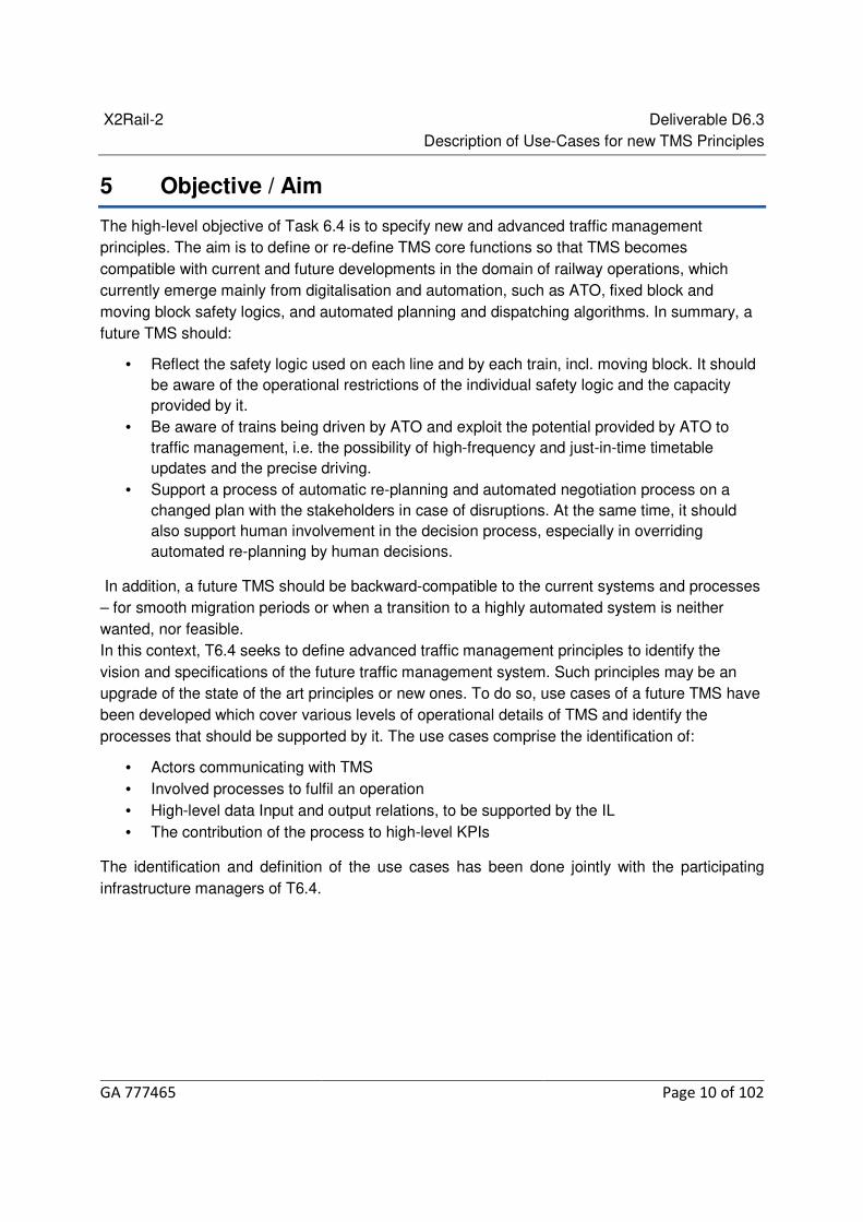
The high-level objective of Task 6.4 is to specify new and advanced traffic management principles. The aim is to define or re-define TMS core functions so that TMS becomes compatible with current and future developments in the domain of railway operations, which currently emerge mainly from digitalisation and automation, such as ATO, fixed block and moving block safety logics, and automated planning and dispatching algorithms. In summary, a future TMS should:
• Reflect the safety logic used on each line and by each train, incl. moving block. It should be aware of the operational restrictions of the individual safety logic and the capacity provided by it.
• Be aware of trains being driven by ATO and exploit the potential provided by ATO to traffic management, i.e. the possibility of high-frequency and just-in-time timetable updates and the precise driving.
• Support a process of automatic re-planning and automated negotiation process on a changed plan with the stakeholders in case of disruptions. At the same time, it should also support human involvement in the decision process, especially in overriding automated re-planning by human decisions.
In addition, a future TMS should be backward-compatible to the current systems and processes – for smooth migration periods or when a transition to a highly automated system is neither wanted, nor feasible. In this context, T6.4 seeks to define advanced traffic management principles to identify the vision and specifications of the future traffic management system. Such principles may be an upgrade of the state of the art principles or new ones. To do so, use cases of a future TMS have been developed which cover various levels of operational details of TMS and identify the processes that should be supported by it. The use cases comprise the identification of:
• Actors communicating with TMS • Involved processes to fulfil an operation • High-level data Input and output relations, to be supported by the IL • The contribution of the process to high-level KPIs
The identification and definition of the use cases has been done jointly with the participating infrastructure managers of T6.4.

X2Rail-2 Deliverable D6.3 Description of Use-Cases for new TMS Principles
GA 777465 Page 11 of 102
6 Use cases of advanced traffic management systems
6.1 Process of use case selection and structuring
In order to select the main processes that should be supported by an advanced TMS, initially, a broad range of functionalities were identified by the partners, based on the high level process break-down of a TMS in the In2Rail project [Ref 8]. These functionalities were then structured using the DSD model [Ref 2] (as explained in the following sections), and grouped into three levels (based on the level of detail of the processes that the use case describes), with the highest level functionalities being covered by level 1 use cases, and level 3 use cases describing more narrow functionalities of a TMS.
The use cases described in this section cover the main functionalities of a future Traffic Management System. After evaluation by the partners, it was decided to use the model from DB’s “Digitale Schiene Deutschland” (DSD) system architecture as a starting point for structuring the use cases. From the complete list of use cases of DSD – which has a wider scope than only TMS – a subset of relevant use cases for X2Rail-2 WP6 was identified and then the functionalities were elaborated according to the WP6 pre-conditions (DSD itself works on a long-term vision where other pre-conditions apply). It should be noted that the selection of the functionalities and use cases in this deliverable correspond to the time-scope framework of T6.4, X2Rail-2 and this process will continue in X2Rail-4.
6.2 Scope and benefits of DSD
Digital Rail for Germany (Digitale Schiene Deutschland, DSD) is the German railway sector initiative to define a fundamentally new system to plan and execute railway operations, by using consistent digitisation and creating one coherent solution with TMS, ATO and a moving-block-based train control. Hence, it optimally supports the objectives of the future TMS, as is pursued in T6.4 of X2Rail-2. And in effect, it enables the railway to become more reliable and offer more trains on the same infrastructure. As a result, the railway system can benefit from:
• Improved reliability o Less delays from inconsistent track work or ad-hoc timetable planning by a system that
integrates long-term and short-term, track work timetable planning as well as ad-hoc changes to track or vehicle properties into one consistent and comprehensive system and business process;
o Reduced human involvement in the provision of timetable documents, incl. ad-hoc timetable, by maximizing level of digitization of the process;
o Reduced human involvement in train disposition and control by AI-based traffic management and digitised route setting allowing faster reactions and more reliable solutions in case of service disruptions;
o Allowance to adapt the dynamic adaptation of the timetable to the latest known state operations using ATO, as ATO is tolerant to frequent changes of the timetable;
o Reduced instream of micro-delays into operations using ATO, as ATO drives with higher precision than human drivers.

X2Rail-2 Deliverable D6.3 Description of Use-Cases for new TMS Principles
GA 777465 Page 12 of 102
• Higher capacity – Several measures reduce the track occupation of a moving train o A newly designed geometric interlocking allows to use moving block and to drastically
reduce route stopping times; o ATO further reduces occupation time because it does not need the spotting time required
for optical signals; o GNSS based localisation.
The intention of DSD systems architecture is to be compatible with European initiatives like S2R’s train-based localisation and train integrity findings, S2R’s ATO GoA 3/4 findings and RCA.
6.3 Functional scope for the advanced TMS
The main foreseen features of the future TMS include the following:
TMS schedules all consumers of infrastructure, by integrating the scheduling of train path and possessions/TSRs. It handles the planned TSRs by scheduling them within the timing constraints stated by the infrastructure manager;
• TMS integrates traditional planning phases (long-term, short-term, disruption management), by scheduling train paths and possessions/TSRs (or in general, limitations to the availability of track) independent from how far in the future they happen;
• TMS enables applying individual business rules (to also fulfil national and international regulations) to different planning phases, e.g. to determine the priority of a train path request over other train paths; o The future TMS shall not necessarily be used for all planning phases but its
interface design shall be ready to allow for it. • TMS shall support moving block and ATO operations (up to GoA4)
Moreover, a key contributor to an advanced TMS will be the Integration Layer (IL) defined in In2Rail [Ref 8] and further developed in the current Shift2Rail projects. The IL provides a standard format for data exchange among different railway systems, applications, and interface plug-ins communicating to external systems [Ref 3]. This is enabled by the Integration Layer by providing a standardized high-performance communication platform for data management and distribution through:
• Canonical Data Model – a formal specification of the data structures representing (TMS) data.
• API providing access to the data via publish-subscribe mechanism [Ref 4, Ref 5].
Opportunities provided by the IL will foster innovative and multi-vendor solutions for TMS as well as intelligent, automated and flexible rail traffic operations, and an integrated approach to the optimisation of railway architecture and operational systems at network, route and individual train levels.

X2Rail-2 Deliverable D6.3 Description of Use-Cases for new TMS Principles
GA 777465 Page 13 of 102
6.4 Use cases for Advanced Traffic Management
The use cases for advanced traffic management system were derived in a top-down approach. The starting point is a set of actors that use the system and a core function (or function of interest) for the system. The function is broken down into various use cases (or system capabilities) that the system provides to the actors.
A TMS relevant subset of use cases– adapted for X2Rail-2, WP6 is shown in the diagram below.
Figure 6.1 – Subset of use cases and their relation
6.5 Summary of the selected use cases
Below, a brief description of the use cases for advanced traffic management is mentioned.
Use case title Use case description level
1. Plan/Modify/Cancel Train Path These use cases describe the request to TMS by the Railway Undertaking Operation Management to plan, modify or cancel a Train Path by providing Train Path planning data including Degrees of Freedom. A Train Unit for the Train Path needs to be specified.
1

X2Rail-2 Deliverable D6.3 Description of Use-Cases for new TMS Principles
GA 777465 Page 14 of 102
2. Assign/Modify Consist to Train Unit
This use case describes the modification of consist assignment to the Train Unit of a Train Path by the Vehicle Management or Railway Undertaking Operation Management.
2
3. Possession planning: Reserve/modify reservation Infrastructure Element for maintenance
This use case describes the creation or modification of an Infrastructure Element reservation by the Infrastructure Management for planned or unplanned maintenance operations, construction works or repairs. The time period can be provided for any time horizon from immediately to longer horizons.
1
4. Modify features of infrastructure element
This use case describes the modification of TMS register by the Infrastructure Manager to remove an Infrastructure Element, or to permanently or temporarily modify features of the Infrastructure Element.
1
5. Modify features of vehicles
This use case outlines the structure of a ‘Modify features of vehicles’ function related to the features that are subject to planned changes over the life-cycle of the vehicle and must be considered within an advanced TMS or may change due to instant hardware and/or software failures.
1
6. Manage possible conflicts
This use case describes the solution by TMS for managing possible Train Paths and Consists assignment conflicts.
1
7. Solve train unit assignment conflicts
This use case describes the solution of conflicts in Consist assignments by TMS by informing Vehicle Management about the conflicts and requesting conflict-free modifications.
1
8. Solve train path conflicts This use case describes the solution of Train Path conflicts by the TMS by offering
1

X2Rail-2 Deliverable D6.3 Description of Use-Cases for new TMS Principles
GA 777465 Page 15 of 102
the most optimal Train Path possible after available Train Unit assignments have been checked. In addition, it describes how to confirm and establish the best common solution for Railway Undertaking Operations Management and Vehicle Management.
9. Re-planning train services in response to a predicted asset failure
This use case involves TMS re-planning services based on an actual failure or a predicted failure of a railway asset, in particular a set of points affecting the capacity of a station.
4
10. Send Mission Profile This use case describes the process of sending mission profiles for complete missions (origin to destination) or the complete part of the mission that runs in the area of competence of the TMS instance, by TMS.
1
11. Start Train Mission
This use case describes the start of a Train Unit Run by TMS to set up the Train Unit to status ready.
3
12. Request route setting
This use case describes the process of requesting route setting and order from signalling/safety system.
1
13. Drive Train Unit
This use case describes the driving of a Train Mission by TMS along the Train Path between two Stopping Locations. Journey profiles are generated based on the Train Path scheduling and the Train Unit status and sent to the Train Unit, which continuously reports its status. TMS would also supervise the drive mode.
1
14. Detect Location change with/without release of route
This Use Case describes the detection and processing of Location changes of Train Units.
1

X2Rail-2 Deliverable D6.3 Description of Use-Cases for new TMS Principles
GA 777465 Page 16 of 102
15. Event triggering an emergency stop
This use case describes the triggering of an emergency stop, e.g. by a Passenger or the Operations Manager to request the affected Train Units to immediately stop at the next Safe Stopping Area.
3
16. Perform physical coupling
This use case describes the physical (automatic or manual) coupling of Consists of one Train Unit to consists of another Train Unit. Coupling leads to a new Train Unit with a new Consist formation.
2
17. Perform physical decoupling
This use case describes the physical decoupling of Consists within a Train Unit. Decoupling Consists of a Train Unit leads to multiple new Train Units with a new Consist formation for each.
2
18. TSR management/execution (setting/releasing a TSR)
This use case focuses mainly on the communication of possession execution information triggering an action/workflow on the TMS’s side.
1
19. Possession Management/Execution
This use case describes the check-out/check-in of an infrastructure element from/to the control of the TMS by the IM maintenance worker.
1
20. Retrieve operational information
This use case describes the request of operational information by actors to retrieve operational data.
3
Table 6.2 – Use case selection
6.6 Use case actors
Below is the list of actors (entities, persons, or systems) involved in the use cases of advanced Traffic Management System. Note that this list is not all-inclusive as some use cases involving additional actors may not have been considered by partners.
Railway Undertaking 6.6.1
The actor Railway Undertaking (RU) provides transport services for goods and/or passengers. This actor is in charge of operation and management of the rolling stock and train crew.

X2Rail-2 Deliverable D6.3 Description of Use-Cases for new TMS Principles
GA 777465 Page 17 of 102
6.6.1.1 The Railway Undertaking Supervisor
The actor Railway Undertaking Supervisor (RUS) represents a person from Railway Undertaking requesting the System to perform Train Unit Runs in order to fulfil transport demand.
Passenger Information System 6.6.2
The actor Passenger Information System (PIS) is responsible for informing the passengers of the long term plan, the current status of the running trains and the compliance with the planning (delays, disruptions, etc.) through information systems available across different platforms such as information displays at stations, mobile devices and internet.
Traffic Management System 6.6.3
The actor Traffic Management System (TMS) is the global system for monitoring, controlling and commanding the traffic and the signalling systems from the Control Centres. It covers a broad range of functionalities and, therefore, it is expressed in some cases such as multi-actor systems, which includes several actors.
6.6.3.1 Capacity Management
This TMS module in charge of receiving short term path requests from the Railway Undertakings, checking the availability of the line according to the scheduled services in the approved Operating Plans and interfacing with the Railway Undertaking for accepting or rejecting the request. It is responsible for the overall management of the infrastructure to create or modify paths.
6.6.3.2 Timetable Management
This TMS module is in charge of maintaining the updated schedule information. It receives the scheduled plan and all real-time changes to perform the global schedule management.
6.6.3.3 Running Time Calculator
This TMS module has the information and algorithms to calculate the speed and times that trains require to move between the controls points in the infrastructure.
It simulates the running behaviour of a train taking into account the physical and dynamic data of the rolling stock and the physical model of the infrastructure.
6.6.3.4 Timetable Forecasting
This TMS module calculates the traffic evolution of the trains according to the planned services, the current schedules, the real situation of the traffic and the infrastructure and the restrictions and constraints in the line.
X2Rail-2 Deliverable D6.3 Description of Use-Cases for new TMS Principles
GA 777465 Page 18 of 102
6.6.3.5 Conflicts Detection
This TMS module detects conflicts between services and between services and the infrastructure. It requires simulation of the train route and the planned schedules for working properly. This actor in addition to detecting the conflict informs the other system of the conflict detected.
Automatic Route Setting 6.6.4
The actor Automatic Route Setting (ARS) is a subsystem of the railway traffic management systems that establishes the appropriate path for each train to the planned destination at the correct time to fulfil the real time traffic plan. ARS automatically sets routes in the line in accordance with the scheduled service timetables, the train features and the current situation of the traffic and the infrastructure. This system considers train operations, track layouts and equipped facilities.
Infrastructure Manager 6.6.5
The actor Infrastructure Manager (IM) is the entity responsible for establishing, maintaining and managing the railway infrastructure.
IM Possession Manager 6.6.6
The actor IM Possession Manager (PM) is responsible for planning maintenance activities, managing dynamic requests for adapting the possessions according to ongoing events and planning new possessions according to requests and to recover the optimal infrastructure capacity. In addition, the IM possession management is responsible for updating the actual work status and running possessions, including forecasting the validity period (e.g. end times).
6.7 Train Localization System
The Localization System (LZ) is responsible for generating and processing position information of movable objects and integrity information of Train Units needed for automated railway operation by all subsystems.
It provides
• safe navigation data, e.g. using ETCS 3 position reports • precise navigation data, e.g. via GNSS and/or identification and mapping of Landmarks
in the environment
Incident/Emergency Management 6.7.1
The actor Emergency Management (EM) represents an entity that carries out non-automated emergency functions which require human actions. It is part of the Infrastructure Management.

X2Rail-2 Deliverable D6.3 Description of Use-Cases for new TMS Principles
GA 777465 Page 19 of 102
Automated Train Operation (including Train Operation On-Board and Train 6.7.2Operation Trackside)
The actor Automatic Train Operation (ATO) is in charge of commanding the driving (traction and braking) and additional services (doors control, coupling control, fire detection, inner lighting, etc.) of the train according to the traffic control and regulation decisions and commands.
It is composed of two separated subsystems, with an interface between them:
• Train Operation On-Board: It is deployed on-board the train units with communication with the Train Operation Trackside equipment. It is able to command the Train Unit running without driver intervention.
• Train Operation Trackside: It is deployed trackside with communication with the Train Operation On-Board equipment of the trains. It updates the train journeys according to the traffic control commands and the regulation actions.
Vehicle Management 6.7.3
The actor Vehicle Management (VM) represents an entity responsible for a number of railway Vehicles and Consists able to operate and maintain in accordance with legal regulations. VM provides these Vehicles and Consists to TMS to perform train operation.
Vehicle Maintenance Worker 6.7.4
The actor Vehicle Maintenance Worker (VMW) represents a person who is responsible for executing maintenance tasks on Vehicles.
Integration Layer 6.7.5
The actor Integration Layer (IL) is a Communication platform for the exchange of information linking Traffic, Asset and Energy Management Systems, as well as field infrastructure and vehicles. It also provides a gateway for communication with external clients to receive updates of different services, e.g. traffic status, and to receive requests impacting the planning of different services.
Trackside (Interlocking/RBC) 6.7.6
The actorTrackside systems includes Interlocking and RBC.
Interlocking – a centralised safety unit that handles routes requested by the TMS. The interlocking controls and supervises the trackside equipment, such as points, signals (if used) and level crossings, and informs the RBC about route status.
RBC (Radio Block Centre) – a centralized safety unit that receives train position information via radio and sends movement authorities via radio to trains based on information from the interlocking.

X2Rail-2 Deliverable D6.3 Description of Use-Cases for new TMS Principles
GA 777465 Page 20 of 102
On-board ETCS 6.7.7
The actor Onboard ETCS is the on-board part of the European Train Control System, promoted by the European Commission and specified for compliance with the Conventional and High Speed Rail Interoperability Directives, supervises the movement of the train based on information exchanged with the RBC.
Train Driver 6.7.8
The actor Train Driver represents a person capable and authorized to drive trains, including locomotives shunting locomotives, work trains, maintenance railway vehicles or trains for the carriage of goods or passengers by rail in an autonomous responsible and safe manner. This entity includes the Local Driver when the train is equipped with a driving desk and the Remote Driver when the train is remote controlled by the control centre.
IM Train Dispatcher 6.7.9
The actor IM Train Dispatcher is responsible for the real time traffic regulation within the scope of the TMS. The IM train dispatcher can also be responsible for making operational decisions to respond to perturbations, minor or major, to meet the daily timetable.
Train Unit 6.7.10
The actor Train Unit (TU) is a logical entity bound to a mission, comprising one or more mechanically joined Consist s. The life cycle corresponds to the life cycle of the mission to which it is assigned.
The attributes of the Train Unit correspond to the combination of the attributes of the Consist s forming it.
Maintenance personnel 6.7.11
The actor IM Maintenance Personnel are responsible for the following activities:
• Import a plan for daily maintenance activities planned on the infrastructure that may affect train paths;
• Adapt the maintenance plan and possessions, according to ongoing events; • Propose maintenance plans and possessions to recover optimal infrastructure
capacity to face operational contingency; • Update the actual status of works that are being implemented, including forecasted
finish times.
IM maintenance personnel can work either directly for the Infrastructure Manager or for an undertaking which is accredited by the Infrastructure Manager to perform maintenance activities on the infrastructure of the railway network.

X2Rail-2 Deliverable D6.3 Description of Use-Cases for new TMS Principles
GA 777465 Page 21 of 102
Passenger 6.7.12
The actor Passengers are users of the rail transport system. They are informed of the long term plan, the real-time status of the running trains and the compliance with the planning (delays, disruptions, etc.) through information systems available across different platforms, information at stations, mobile devices and the internet. The Passenger represents the persons travelling on board passenger trains and embarking/disembarking at stations.
Rail Traffic Control 6.7.13
The actor Rail Traffic Control (RTC) is responsible for safe and efficient operation of the Railway within a designated operating area. RTC is responsible for ensuring that train delays are minimized in their operating area by effectively controlling the train operations by taking appropriate train routing and/or timing decisions.
Signalling Control 6.7.14
The actor Signaling Control (SC) performs the management of trains in terms of positioning, protection and integrity. It establishes communication with the protection and the positioning System and receives Train Dispatcher requests within the TMS environment. It is the interface with the signalling systems from the Control Centre.
Automatic Train Protection 6.7.15
The actor Automatic Train Protection (ATP) Automatic supervisor system responsible for automatically authorising movement of Train Units and setting of Track Elements to protect train movements against train collision, danger points and over speeding.
6.8 Detailed description of the use cases for advanced TMS
The detailed description of use cases of advanced TMS is included in this section. The description provides information on the required processes, the high level data exchange (which may be carried out via the IL), and the contribution of each use case to the relevant high-level KPIs.
Plan/Modify/Cancel Train Path 6.8.1
Title Plan Train Path
Use Case level 1
Related Use Case NA
Use Case Actors Railway Undertaking
Passenger Information System
Traffic Management System:

X2Rail-2 Deliverable D6.3 Description of Use-Cases for new TMS Principles
GA 777465 Page 22 of 102
Train Dispatcher (operator)
Capacity Management
Timetable Management
Running Time Calculator
Timetable Forecasting
Conflicts Detection
Automatic Route Setting
Compiled by INDRA – CAF
Base-line Description
General Description
The Railway Undertaking requests a new itinerary for a train to the Train Dispatcher in the short term (the day o days before the operation, but out of the scheduling process) or during the operation. In the request the Railway Undertaking can include the detailed formation information or not. If the specific formation is not included, the TMS will assign a default formation for its internal procedures and calculations.
To perform the analysis of the itinerary, it is required to calculate the Running Simulation and the Forecasted Timetable:
• The Running Time Calculator details the timetable of the requested train along the specified itinerary according to the simulated dynamic behavior of the rolling stock on the tracks. This simulation takes into account the features of the train and the installations, without taking into account the movements of the rest of scheduled trains.
• The Forecasted Timetable details the expected behavior of all the scheduled trains on the line according to the current status and the target timetable of the previous trains and the new requested train.
When this information is calculated, the Conflicts Manager module searches for possible conflicts between the timetables, but also conflicts because of rolling stock dependencies between trains and conflicts of the new train with the infrastructure.
If there is a conflict, through the Train Dispatcher, the Railway Undertaking is informed of the eventuality, and therefore the rejection of the requested Itinerary and its reasons.
If there is no conflict, through Train Dispatcher, the Railway Undertaking is informed of the acceptance of the new Itinerary and its detailed timetable. That is so to say, the Train Path associated to the requested itinerary.
In the same way, the Train Dispatcher updates the Target Timetable of the line, including the new train and provides this information to the Passenger Information System. The conflict

X2Rail-2 Deliverable D6.3 Description of Use-Cases for new TMS Principles
GA 777465 Page 23 of 102
detection system resumes with the new Target Timetable.
Steps
The complete process is composed of the following actions:
1. The Railway Undertaking requests a new train path through the TMS Capacity Management module. It specifies the Start and End locations and the stopping locations, and optionally the expected real formation.
2. The Capacity Management receives the request and it requires to Running Simulation and the Forecasted Timetable to study the viability of the Itinerary. The following processes will be launched in sequence:
a. If the formation is specified it is taken into account for the calculations, but it is not specified, a default formation is used according to the Railway Undertaking and the type of train and service required.
b. The Capacity Management requests to the Running Time Calculation module for Running Simulation of the requested itinerary.
c. The Capacity Management, with the Running Simulation, requires to Timetable Forecasting module for Forecasted Timetable.
3. The Timetable Forecasting, with the Running Simulation and the Forecasted Timetable, requests to the Conflict Detection module to analyse possible conflicts with the new itinerary. There are two possibilities:
a. Conflicts are detected: The requested itinerary is rejected. The Capacity Management informs the Railway Undertaking of the reasons of the rejection.
b. Conflicts are not detected: The requested itinerary is accepted, and therefore the Train Path is formed. The Capacity Management informs the Railway Undertaking.
4. If there are no conflicts detected, the Capacity Management sends the New Itinerary to the Timetable Management.
a. Timetable Management sends the new Target Timetable to the Passengers Information System.
b. Timetable Management sends the new Target Timetable to Automatic Route Setting.
Timetable Management requests to Timetable Forecasting System the new Forecast Timetable, Timetable Forecasting then sends the new forecast timetable to Conflict Detection to resume with the new Data. The following figure displays a sequence diagram including the interaction between the involved actors performing the actions described above.
ddFIGURE
Preconditions
The Railway Undertaking requires a new itinerary in the short-term or during the operation, including the following data:
• Start Location. • End Location. • Stopping Locations.

X2Rail-2 Deliverable D6.3 Description of Use-Cases for new TMS Principles
GA 777465 Page 24 of 102
• Dates/Times for locations. • Optional: Formation.
Outcome
• The itinerary request from the Railway Undertaking is accepted or rejected by the Train Dispatcher.
• The Target Timetable and the Forecasted Timetable of the line are updated and the new Train Path is included.
• The Target Timetable does not include any conflict.
Data Register
The Data Register includes the interactions between the main involved actors, but it does not include the details of the exchanges between the different subsystems of the Traffic Management System.
Railway Undertaking -> TMS
• Itinerary Request
TMS -> Railway Undertaking
• Reject Planned Train Path • Confirm Panned Train Path
TMS -> Passenger Information System. Automatic Route Setting and the rest of interested systems
• Updated Target Timetable including the new Train Path • Updated Forecasted Timetable including the new Train Path
Related KPIs
• Offered line capacity (increase), • Line utilisation (increase), • Free conflict target timetables (increase), • Robustness of timetable.
Title Modify Train Path
Use Case level 1
Related Use Case NA
Use Case Actors Railway Undertaking
Passenger Information System
Traffic Management System:
Train Dispatcher (operator)
X2Rail-2 Deliverable D6.3 Description of Use-Cases for new TMS Principles
GA 777465 Page 25 of 102
Capacity Management
Timetable Management
Running Time Calculator
Timetable Forecasting
Conflicts Detection
Automatic Route Setting
Compiled by INDRA - CAF
Base-line Description
General Description
The Railway Undertaking requests a modification of a train path to the Train Dispatcher in the short term or the same period in the operation.
The train dispatcher receives the information about the modification and before accepting it, performs the following analysis:
• First of all, the data of the modification is introduced in the Running Time Calculator to calculate the new timetable that the modification would cause.
• Then, that new timetable is used in the timetable forecasting subsystem and an overall forecast including the modification is calculated.
• This new forecast is used by the Conflict Detection subsystem to check that the modification of the itinerary does not generate any operational conflicts. Once the dispatcher checks that no conflicts would arise, he confirms the modification and the itinerary is changed in the timetable.
The new timetable is then distributed to be consumed by other subsystems in order to update the corresponding information (conflict detection, Passenger information system, etc.).
Steps
The complete process is composed of the following actions:
1. The Railway Undertaking requests to modify a train path. 2. The Train Dispatcher receives the information of the request and starts an off-line
analysis to check that no conflicts will arise after the modification: a. First of all, the requested modified path is simulated to calculate its associated
timetable. b. Then, the Timetable Forecasting performs a calculation of the overall forecast
after the modification. c. With the forecast, the Conflict Detection System performs a calculation to
check if the modification would cause any operation conflicts. 3. In case the Conflict Detection System detects any operation conflicts because of the
train path modification, the modification is rejected and the RU is notified with the

X2Rail-2 Deliverable D6.3 Description of Use-Cases for new TMS Principles
GA 777465 Page 26 of 102
reasons of the rejection. 4. When the results of the previous calculation with no conflicts detected are shown to
the Train Dispatcher, he accepts the modification, triggering the following actions: a. The information of the accepted modification is shown to the Railway
Undertaking Operator. b. The Timetable Management System updates the timetable taking into account
the modification service. 5. This timetable modification is used by other systems to perform their common tasks:
a. The Timetable Forecasting System performs its timetable forecasts. b. The Passenger Information System informs the passengers.
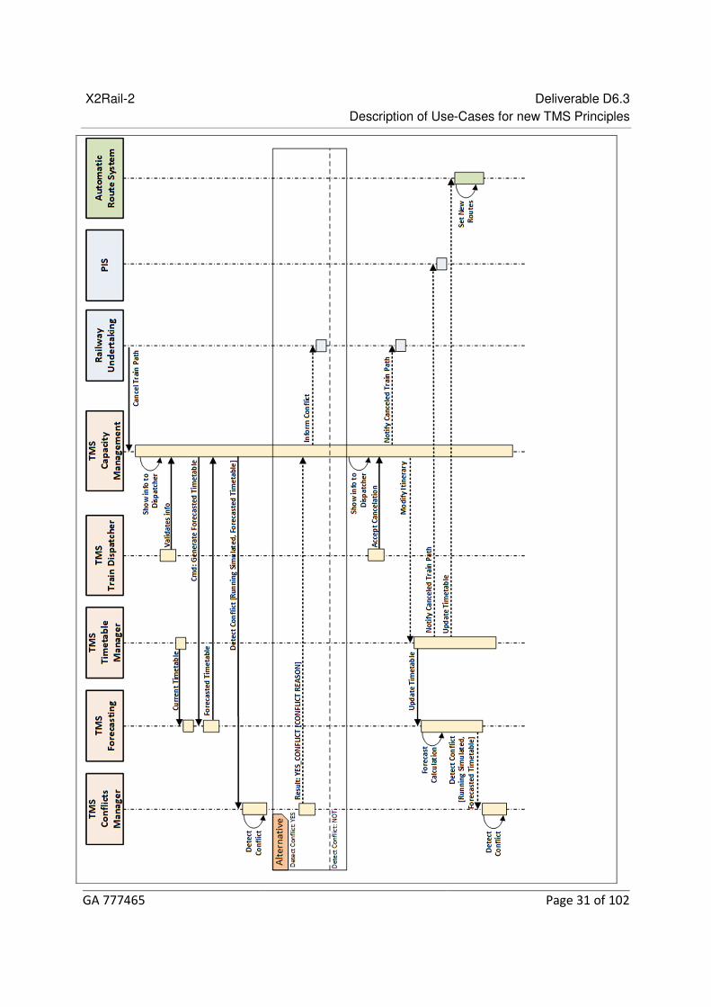
The Automatic Route Setting System triggers the routes in the right moment.
The following figure displays a sequence diagram including the interaction between the involved actors performing the actions described above:

X2Rail-2 Deliverable D6.3 Description of Use-Cases for new TMS Principles
GA 777465 Page 27 of 102

X2Rail-2 Deliverable D6.3 Description of Use-Cases for new TMS Principles
GA 777465 Page 28 of 102
Preconditions
• The itinerary to be modified must be previously planned in the timetable.
Outcome
• The itinerary modified does not belong anymore to the timetable.
Data Register
The Data Register includes the interactions between the main involved actors, but it does not include the details of the exchanges between the different subsystems of the Traffic Management System.
Railway Undertaking -> TMS
• Modify Itinerary Request.
TMS -> Railway Undertaking
• Reject Modify Train Path. • Confirm Modify Train Path.
TMS -> Passenger Information System. Automatic Route Setting and the rest of interested systems
• Updated Target Timetable including the new Train Path. • Updated Forecasted Timetable including the new Train Path.
Related KPIs
• Offered line capacity (increase), • Line utilisation (increase), • Free conflict target timetables (increase).
Title Cancel Train Path
Use Case level 1
Related Use Case NA
Use Case Actors Railway Undertaking
Passenger Information System
Traffic Management System:
Train Dispatcher (operator)
Capacity Management
Timetable Management

X2Rail-2 Deliverable D6.3 Description of Use-Cases for new TMS Principles
GA 777465 Page 29 of 102
Running Time Calculator
Timetable Forecasting
Conflicts Detection
Automatic Route Setting
Compiled by INDRA – CAF
Base-line Description
General Description
The Railway Undertaking requests a cancelation of an itinerary (for partial cancellation) or list of itineraries (for global cancellation) to the Train Dispatcher in the short term or during the operation.
The train dispatcher receives the information and before accepting it, performs a capacity analysis to check that the cancelation of the itinerary does not generate any operational conflicts (.rolling stock links, crewmember links and passenger transfers) Once the dispatcher checks that no conflicts would arise, he confirms the cancellation and the itinerary is removed from the timetable.
The new timetable is then distributed to be consumed by other subsystems in order to update the corresponding information (conflict detection, Passenger information system, etc.)
Steps
The complete process is composed of the following actions:
1. The Railway Undertaking requests to cancel an itinerary. 2. The Train Dispatcher receives the information of the request and starts an off-line
analysis to check that no conflicts will arise after the cancelation: a. First of all, the Timetable Forecasting performs a calculation of the overall
forecast after the cancelation for taking into account the additional track availability after the cancelation.
b. With the forecast, the Conflict Detection System performs a calculation to check if the cancelation would cause any operation conflicts.
3. When the results of the previous calculation with no conflicts detected are shown to the Train Dispatcher, he accepts the cancelation, triggering the following actions:
a. The information of the accepted cancelation is shown to the Railway Undertaking Operator.
b. The Timetable Management System updates the timetable taking into account the cancelled service.
4. This timetable modification is used by other systems to perform their common tasks: a. The Passenger Information System informs the passengers. b. The Timetable Forecasting System performs its timetable forecasts.
X2Rail-2 Deliverable D6.3 Description of Use-Cases for new TMS Principles
GA 777465 Page 30 of 102
c. The Automatic Route Setting System triggers the routes in the right moment.
The following figure displays a sequence diagram including the interaction between the involved actors performing the actions described above:
X2Rail-2 Deliverable D6.3 Description of Use-Cases for new TMS Principles
GA 777465 Page 31 of 102

X2Rail-2 Deliverable D6.3 Description of Use-Cases for new TMS Principles
GA 777465 Page 32 of 102
Preconditions
The itinerary to be cancelled must be previously planned in the timetable.
Outcome
The itinerary cancelled does not belong anymore to the timetable.
Data Register
The Data Register includes the interactions between the main involved actors, but it does not include the details of the exchanges between the different subsystems of the Traffic Management System.
Railway Undertaking -> TMS
• Cancel Itinerary Request.
TMS -> Railway Undertaking
• Notify Cancel Train Path.
TMS -> Passenger Information System. Automatic Route Setting and the rest of interested systems
• Updated Target Timetable removing the cancelled Train Path. • Updated Forecasted Timetable taking into account the cancelled Train Path.
Related KPIs
• Offered line capacity (increase), • Line utilisation (increase), • Free conflict target timetables (increase).
Assign/Modify Consist to Train Unit 6.8.2
Title Assign/Modify Consist to Mission/Itinerary
Use Case level 1
Related Use Case Modify features of vehicles; Plan/Modify/Cancel Train Path
Use Case Actors Railway Undertaking (RU)
Vehicle Management (VM)
Traffic Information System (TIS)
Infrastructure Management (IM)
Compiled by DB
Base-line Description
X2Rail-2 Deliverable D6.3 Description of Use-Cases for new TMS Principles
GA 777465 Page 33 of 102
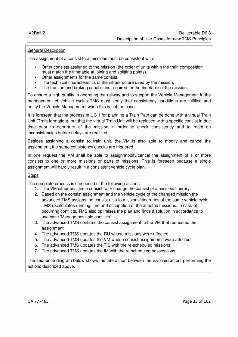
General Description
The assignment of a consist to a missions must be consistent with:
• Other consists assigned to the mission (the order of units within the train composition must match the timetable at joining and splitting points),
• Other assignments for the same consist, • The technical characteristics of the infrastructure used by the mission, • The traction and braking capabilities required for the timetable of the mission.
To ensure a high quality in operating the railway and to support the Vehicle Management in the management of vehicle cycles TMS must verify that consistency conditions are fulfilled and notify the Vehicle Management when this is not the case.
It is foreseen that the process in UC 1 for planning a Train Path can be done with a virtual Train Unit (Train formation), but that the virtual Train Unit will be replaced with a specific consist in due time prior to departure of the mission in order to check consistency and to react on inconsistencies before delays are realized.
Besides assigning a consist to train unit, the VM is also able to modify and cancel the assignment; the same consistency checks are triggered.
In one request the VM shall be able to assign/modify/cancel the assignment of 1 or more consists to one or more missions or parts of missions. This is foreseen because a single assignment will hardly result in a consistent vehicle cycle plan.
Steps
The complete process is composed of the following actions: 1. The VM either assigns a consist to or change the consist of a mission/itinerary. 2. Based on the consist assignment and the vehicle cycle of the changed mission the
advanced TMS assigns the consist also to missions/itineraries of the same vehicle cycle. TMS recalculates running time and occupation of the affected missions. In case of occurring conflicts, TMS also optimises the plan and finds a solution in accordance to use case 'Manage possible conflicts'.
3. The advanced TMS confirms the consist assignment to the VM that requested the assignment.
4. The advanced TMS updates the RU whose missions were affected. 5. The advanced TMS updates the VM whose consist assignments were affected. 6. The advanced TMS updates the TIS with the re-scheduled missions. 7. The advanced TMS updates the IM with the re-scheduled possessions.
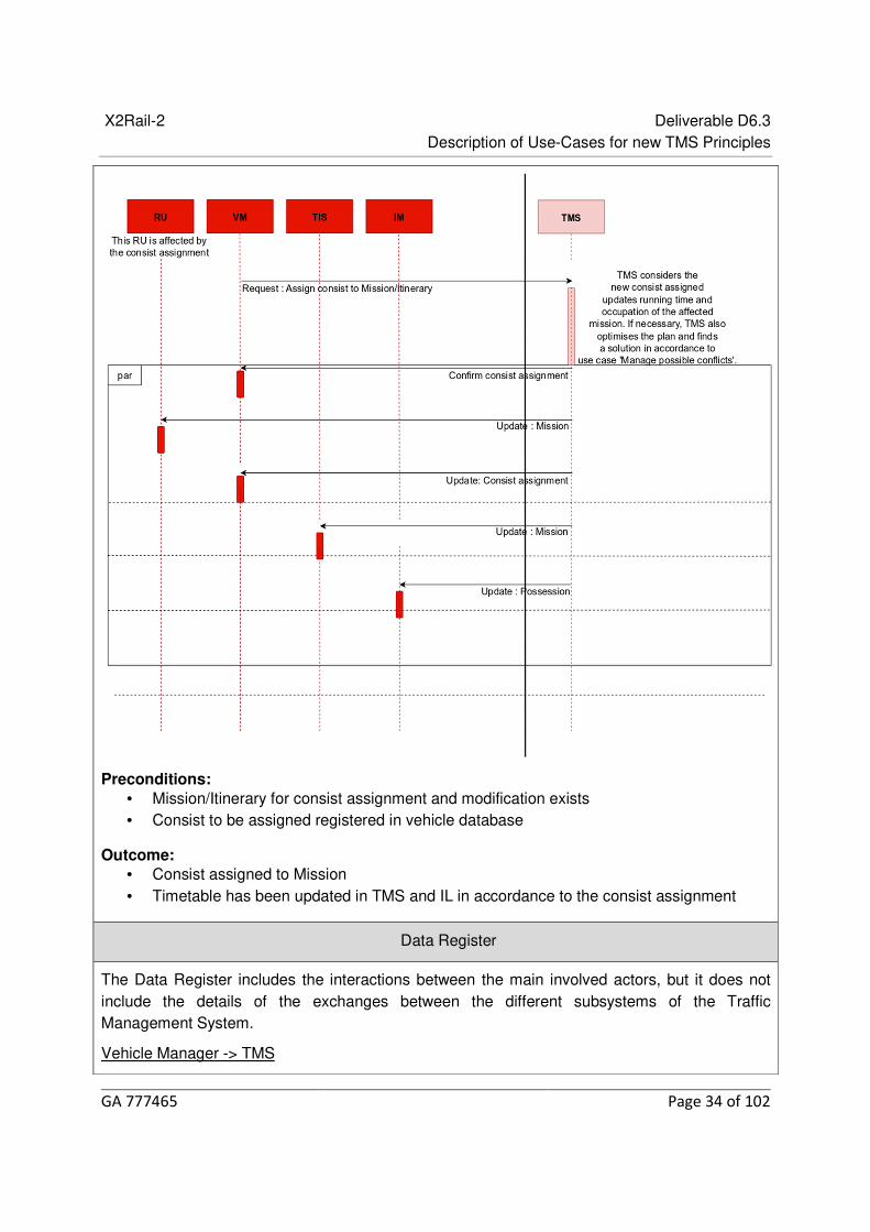
The sequence diagram below shows the interaction between the involved actors performing the actions described above.
X2Rail-2 Deliverable D6.3 Description of Use-Cases for new TMS Principles
GA 777465 Page 34 of 102
Preconditions: • Mission/Itinerary for consist assignment and modification exists • Consist to be assigned registered in vehicle database
Outcome: • Consist assigned to Mission • Timetable has been updated in TMS and IL in accordance to the consist assignment
Data Register
The Data Register includes the interactions between the main involved actors, but it does not include the details of the exchanges between the different subsystems of the Traffic Management System.
Vehicle Manager -> TMS

X2Rail-2 Deliverable D6.3 Description of Use-Cases for new TMS Principles
GA 777465 Page 35 of 102
• Assign consist to Mission/Itinerary • Modify consist assignment • Cancel consist assignment
TMS -> Vehicle Manager
• Feedback on assignment request • Information about broken vehicle cycle links
Related KPIs
• Itineraries / missions without assigned consists, • Number of delays caused by inconsistent vehicle cycles, train-track incompatibilities
or insufficient traction/braking capabilities known at start of mission.
Possession Request Management: reserve/modify/cancel reservation of an 6.8.3Infrastructure Element for maintenance
Title Possession Request Management: reserve/modify/cancel reservation of an Infrastructure Element for maintenance
Use Case level 1
Related Use Case Manage possible conflicts
Use Case Actors IM Possession Management, TMS, RU, IM
Compiled by HC
Base-line Description
This use case focuses mainly on the communication of possession requests and demands triggering an action/workflow on the TMS’s side, mainly applying to the following scenarios:
• A new request for a possession is placed by the IM possession management. • An already reserved possession should be modified at the request of IM possession
management. • An already reserved possession should be cancelled at the request of IM possession
management.
Efficient communication of possession related information is a key feature in the efficient management of possession related operations, requiring an action on the TMS’s side, such as cancellation or modification of a possession.
Technologies such as PICOP mobile applications enable real time collaboration and communication via smart phones and tablets. Using such technologies, field staff can connect to the traffic management system to exchange information in real-time. They exchange possession related information, such as GPS real time location, working times, time buffers, etc., with the TMS using their applications. In addition, possession requests such as setting up speed restrictions, changes to a planned possession, etc., can be communicated using these

X2Rail-2 Deliverable D6.3 Description of Use-Cases for new TMS Principles
GA 777465 Page 36 of 102
technologies.
Having received this information, TMS follows the related possession management workflow on TMS’s side such as the release of a possession. In addition, TMS uses the maintenance information as an input into forecasting the operational daily TT to reduce the effect of the planned and unplanned maintenance activities.
The communication flow can be effectively carried out using web-interfaces which allow connection of mobile and portal applications to the TMS via IP based mobile and web-interfaces. Defining the requirements of such interfaces was the focus of task 6.7, X2Rail-2 and the requirements were reported as part of D6.6 of this task. The TMS may then communicate the outcome to the interested parties, e.g. changes to the time table, etc., using the same communication channel. This paves the way towards a more digitalized railway system, with higher efficiency (time saving, quality gain, and reduced risk of mistakes). This will result in an increase in safety and facilitates the communication of possession information and demands.
Today this process is carried out manually and verbally (radio/phone) and in most cases is highly paper driven. Relying on the information technology and integration layer, this use case focuses on the opportunities provided by these tools to offer a more digitalized and efficient possession management system (with respect to process and cost, as it opens the market).
The following scenarios are defined under the umbrella of this use case:
Possession request (ad-hoc requests for possessions)
This scenario describes the management of the request for a new/modified possession (e.g. adding a TSR to the short term traffic plan), made by the IM possession management.
Steps
In summary, the following steps may be taken to fulfill this scenario:
1. The IM receives a request for a TSR or possession via the interface (e.g. the IM possession management staff applies for such possessions via an external application using the web-interface).
2. The related access rights are verified for this request. 3. The IM plans the possession and communicates it to the TMS. The IM creates the slot
with an extended geography (in terms of space and time) due to signaling and train control constraints.
4. The TMS carries out the conflict detection and solves the arising conflicts. 5. The outcome is communicated to the IM. 6. The relevant decision is communicated (or fetched by the interface) and presented (e.g.
via the GUI) to the IM possession management, the IM, and RU depending on the available time-horizon to the possession start.
Preconditions
The agreement on the possession plan is subject to agreement among all parties, e.g. IM, IM
X2Rail-2 Deliverable D6.3 Description of Use-Cases for new TMS Principles
GA 777465 Page 37 of 102
possession management, and RU. This precondition may not hold in specific critical cases which are usually addressed by the national regulations.
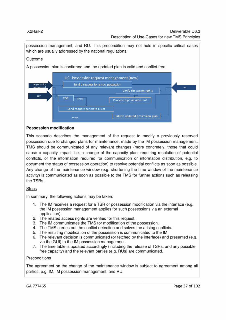
Outcome
A possession plan is confirmed and the updated plan is valid and conflict-free.
Possession modification
This scenario describes the management of the request to modify a previously reserved possession due to changed plans for maintenance, made by the IM possession management. TMS should be communicated of any relevant changes (more concretely, those that could cause a capacity impact, i.e. a change of the capacity plan, requiring resolution of potential conflicts, or the information required for communication or information distribution, e.g. to document the status of possession operation) to resolve potential conflicts as soon as possible. Any change of the maintenance window (e.g. shortening the time window of the maintenance activity) is communicated as soon as possible to the TMS for further actions such as releasing the TSRs.
Steps
In summary, the following actions may be taken:
1. The IM receives a request for a TSR or possession modification via the interface (e.g. the IM possession management applies for such possessions via an external application).
2. The related access rights are verified for this request. 3. The IM communicates the TMS for modification of the possession. 4. The TMS carries out the conflict detection and solves the arising conflicts. 5. The resulting modification of the possession is communicated to the IM. 6. The relevant decision is communicated (or fetched by the interface) and presented (e.g.
via the GUI) to the IM possession management. 7. The time table is updated accordingly (including the release of TSRs, and any possible
free capacity) and the relevant parties (e.g. RUs) are communicated.
Preconditions
The agreement on the change of the maintenance window is subject to agreement among all parties, e.g. IM, IM possession management, and RU.

X2Rail-2 Deliverable D6.3 Description of Use-Cases for new TMS Principles
GA 777465 Page 38 of 102
A prior reservation should be modified according the IM’s request.
Outcome
An infrastructure element is successfully modified and the updated plan is conflict-free.
Possession cancellation
This scenario applies to the request for cancellation of a planned possession either requested by the IM possession e.g. due to changes in plans, or upon the request by the contracted company operating the possession
Steps
In summary, the following actions may be taken:
1. The IM receives a request for the cancellation of a possession via the interface 2. The related access rights are verified for this request. 3. The IM communicates the cancellation of the possession to the TMS. 4. The TMS checks for optional changes of RU operations e.g., reverting back to train
paths as originally requested or potential earlier running due to the release of capacity 5. TMS sends the cancellation notification to the IM and the related RU (including
suggestion of operational changes or/and of the available extra capacity). 6. The relevant decision is communicated (or fetched by the interface) and presented (e.g.
via the GUI) to the IM possession management.
Preconditions
A prior reservation should be canceled according the IM’s request
Outcome
The infrastructure reservation is canceled and the affected RUs are informed of the available capacity.

X2Rail-2 Deliverable D6.3 Description of Use-Cases for new TMS Principles
GA 777465 Page 39 of 102
In all scenarios, the communication may be carried out using the Integration layer.
* The term ‘IM’, in the description of this use case, is used in a more narrow sense for the capacity management function of the IM.
Data Register
IM -> TMS
Daily TT
Maintenance plan (detailed information below)
Real time maintenance information including start-end times
Updated operational plan due to updated maintenance activities including TSRs
TMS-> IM
Confirmation of a possession cancellation
CDR regarding a modified possession
IM->RU
Free available capacity due to cancellation of a possession
Modified possession time windows
Updated daily TT due to updated maintenance activities including TSRs
IM possession management -> IM
Request for a new or modified possession (including cancelation of a possession
Maintenance location
Modified geographical area
Track information
Maintenance duration (working time, time buffers)

X2Rail-2 Deliverable D6.3 Description of Use-Cases for new TMS Principles
GA 777465 Page 40 of 102
Type of activity
Protection requirements
TSR specifications
Possession ID/TSR ID
IM-> IM Possession Management
Possession release
Changes to the planned possession (working time)
An indication of criticality and certainty of the maintenance taking place may also be included e.g. longer term scheduled event may be less certain than event planned for the next 4 hours. This will be feasible to model with typical maintenance description data structure.
Related KPIs
• Increase of capacity,
• Increase of punctuality,
• Decrease of costs (IM).
Modify features of infrastructure element 6.8.4
Title Change in Infrastructure - Conditions
Category Operations Management
Sub-Category Operational Change
Use Case level 1
Related Use Case Start of Mission
Actors IM Planning, Tech Terminal, Workstation, TOC planning
Compiled by Network Rail
Base-line Description
Technological advancements and development are permitting further semi/automatic engagement in a train’s route/journey/mission.
Change in Infrastructure – Assumption as to the application of a TSR, Blanket restriction, route limitation A ‘Change in Infrastructure’ can affect the preferred route, due to delayed mission time or having to re-route.
Therefore, and as stated from the above scenarios this ‘Use Case model’ outlines the structure for a ‘change in infrastructure’ functions (assumed permitted operational conditions).
This change is typically the manual or automatic application of a TSR/ ESR which may affect the preferred/chosen route characteristics.
These can be generated automatically from ‘Trackside Sensory Networks’
This task has various construction forms which are dependent on the level of ERTMS/TMS

X2Rail-2 Deliverable D6.3 Description of Use-Cases for new TMS Principles
GA 777465 Page 41 of 102
interface.
Assumptions Infrastructure conditions are known PSR’s are known, as part of the timetable. Route capability and capacity for trains is known Manual applications are assumed to have to be manually cancelled (for critical systems) Trip – refers to the ‘journey’, not ‘failure’. The Planning Department of the Infrastructure Manager (IM) is responsible for creation of
itineraries (trips) assuming requested consists for the runtime calculations. This will include published restrictions/changes.
Application of restrictions at this point is assumed to be via ETCS. A level crossing maybe interfaced into ETCS – therefore MA will depend on crossing
conditions and therefore permitted speed to traverse. As above – local control procedures will be required dependant on crossing conditions.
For each mission (trip), degrees of flexibility will be specified • Train planning and Route confirmation • Connection to ETCS • Connection to (on board) EVC • Degraded Working – Reduced functionality – manual or automated infrastructure input to
route planning. • Permitted Routes • Decision point for alternative route/s. • Minimum criteria for successful ‘start’ of mission. • Independent degrees of failure will be managed by TMS – Application to assess conflict
impact. • In most cases even for the improved operational situation some itineraries will still violate
the degrees of freedom.
Planning • IM Planning – Elements of infrastructure data including degraded conditions and
TSR/ESR’s. • TOC Planning – Crew rostering, locations and duties. • On Board – Train Control and Registration • DMI – EVC – ATO • Train Control • ETCS – Signalers Workstation • Infrastructure Change • Workstation – Techs Terminal – Auto Application • Output - Revised programme
Change in Infrastructure • IM train planning create timetables – IM planners
Standard pattern timetable as designed by IM planners for seasonal/periodic/regular pattern use/short term planning/ad-hoc/changes devised by TMS
• Manual route restriction – Signalers/technicians A manually applied route/speed restriction by signaler or technician to mitigate a
change in infrastructure or running conditions • Auto route restriction – Sensory network

X2Rail-2 Deliverable D6.3 Description of Use-Cases for new TMS Principles
GA 777465 Page 42 of 102
An auto applied route/speed restriction by infrastructure sensory network to mitigate a change in infrastructure or running conditions (landslip prediction)
• Application of Infrastructure change – ETCS/Interlocking Route restriction applied through interlocking control.
• TMS route calculation – TMS or Signaler Applicable route and times are extracted by TMS or signaler
• Route trip calculation output – TMS or Signaler On Board EVC – route information TOC planning – change in crew requirements
Change in Infrastructure
Actors: IM Planning – Planners, advance data
Tech Terminal – Technical Staff
Workstation – Signalers, dispatchers, supervisors
TOC planning – Planners
Application • Planning route/train crew information • Infrastructure integral – ETCS operating mode - Route availability – Infrastructure
X2Rail-2 Deliverable D6.3 Description of Use-Cases for new TMS Principles
GA 777465 Page 43 of 102
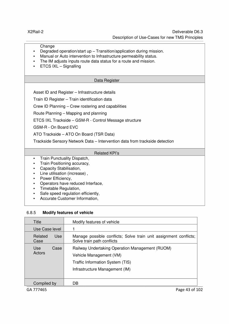
Change • Degraded operation/start up – Transition/application during mission. • Manual or Auto intervention to Infrastructure permeability status. • The IM adjusts inputs route data status for a route and mission. • ETCS IXL – Signalling
Data Register
Asset ID and Register – Infrastructure details
Train ID Register – Train identification data
Crew ID Planning – Crew rostering and capabilities
Route Planning – Mapping and planning
ETCS IXL Trackside – GSM-R - Control Message structure
GSM-R - On Board EVC
ATO Trackside – ATO On Board (TSR Data)
Trackside Sensory Network Data – Intervention data from trackside detection
Related KPI’s • Train Punctuality Dispatch, • Train Positioning accuracy, • Capacity Stabilisation, • Line utilisation (increase) , • Power Efficiency, • Operators have reduced Interface, • Timetable Regulation, • Safe speed regulation efficiently, • Accurate Customer Information,
Modify features of vehicle 6.8.5
Title Modify features of vehicle
Use Case level 1
Related Use Case
Manage possible conflicts; Solve train unit assignment conflicts; Solve train path conflicts
Use Case Actors
Railway Undertaking Operation Management (RUOM)
Vehicle Management (VM)
Traffic Information System (TIS)
Infrastructure Management (IM)
Compiled by DB

X2Rail-2 Deliverable D6.3 Description of Use-Cases for new TMS Principles
GA 777465 Page 44 of 102
Base-line Description
General description
Features of a vehicle are on the one hand often subject to planned changes over the life-cycle of the vehicle and must be considered within an advanced TMS. On the other hand vehicle features can change due to instant hardware and/or software failures. Especially, these vehicle features that will affect the routing and the running time calculation of the vehicle as well as features that change the behavior of the vehicle within the safety logic must be transmitted to the advanced TMS by the responsible actor (e.g. RUOM) instantly to enable TMS to solve possible conflicts that were caused by these changes.
Therefore, this use case outlines the structure for a ‘Modify features of vehicle’ function.
Steps
The complete process is composed by the following actions: 1. The VM transmits either a planned or un-planned modification of vehicle features to
the advanced TMS. 2. The advanced TMS considers the modified vehicle features. TMS recalculates
running time and occupation of the affected missions. In case of occurring conflicts, TMS also optimises the plan and finds a solution in accordance to use case 'Manage possible conflicts'.
3. The advanced TMS confirms the modification of vehicle features to the VM that requested the change.
4. The advanced TMS updates the RUOMs whose missions were affected. 5. The advanced TMS updates the VM whose consist assignments were affected. 6. The advanced TMS updates the TIS with the re-scheduled missions. 7. The advanced TMS updates the IM with the re-scheduled possessions.
The sequence diagram below shows the interaction between the involved actors performing the actions described above.
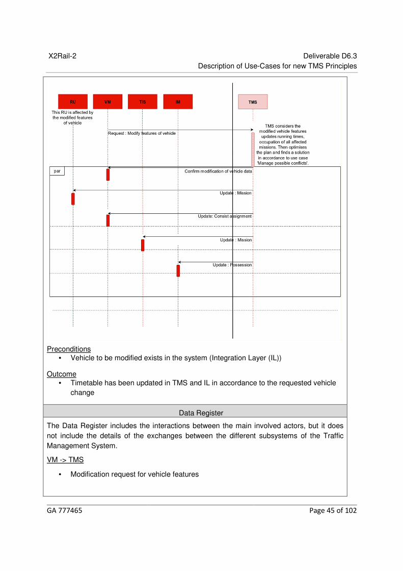
X2Rail-2 Deliverable D6.3 Description of Use-Cases for new TMS Principles
GA 777465 Page 45 of 102
Preconditions • Vehicle to be modified exists in the system (Integration Layer (IL))
Outcome • Timetable has been updated in TMS and IL in accordance to the requested vehicle
change
Data Register
The Data Register includes the interactions between the main involved actors, but it does not include the details of the exchanges between the different subsystems of the Traffic Management System.
VM -> TMS
• Modification request for vehicle features

X2Rail-2 Deliverable D6.3 Description of Use-Cases for new TMS Principles
GA 777465 Page 46 of 102
TMS -> VM
• Confirmation of modification request for vehicle features • Update of consist assignments
TMS -> RU
• Update of missions that were affected
TMS -> TIS
• Update of target timetable including updated missions that were affected • Update of forecasted timetable including updated missions that were affected
TMS -> IM
• Update of possessions that were affected
Related KPIs • Number of delays caused by inconsistent vehicle cycles, train-track
incompatibilities or insufficient traction/braking capabilities known at start of mission.
Manage possible conflicts 6.8.6
Title Manage Possible Conflicts
Use Case level 1
Related Use Case NA
Use Case Actors Infrastructure Manager, Railway Undertaking
Complied by TTS- AŽD
Base-line Description
Whenever data related to the running of the railway deters from the agreed plan, the impact of the change should be analysed to identify if conflicts in the plan are created. These conflicts then need to be managed to arrive at a resolution.
If the calculated solution requires any modifications to the current plan, which are beyond pre-determined degrees of freedom, these need to be accepted by the relevant stakeholders and then updated in the appropriate systems.
Although the methods to solve these conflicts may be unique to the supplier, the process before and after identifying the solution will be captured in this use case.
For the new plan to be executed the required resources must be available, namely:
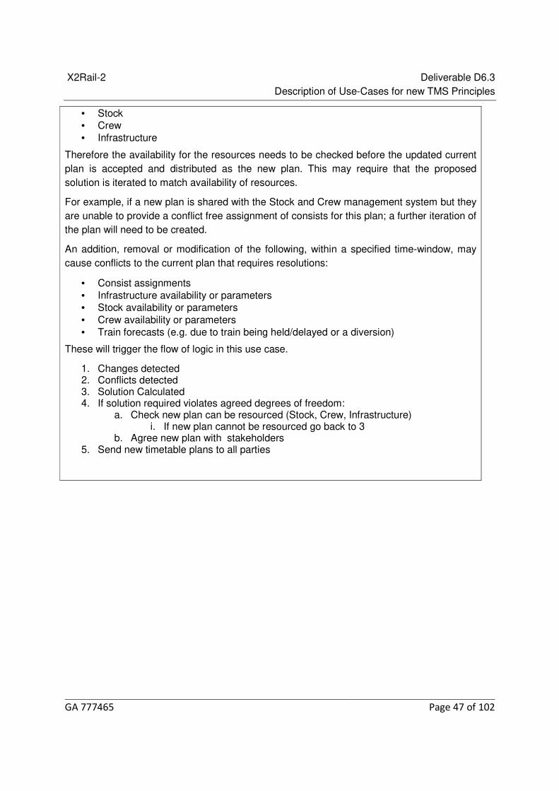
X2Rail-2 Deliverable D6.3 Description of Use-Cases for new TMS Principles
GA 777465 Page 47 of 102
• Stock • Crew • Infrastructure
Therefore the availability for the resources needs to be checked before the updated current plan is accepted and distributed as the new plan. This may require that the proposed solution is iterated to match availability of resources.
For example, if a new plan is shared with the Stock and Crew management system but they are unable to provide a conflict free assignment of consists for this plan; a further iteration of the plan will need to be created.
An addition, removal or modification of the following, within a specified time-window, may cause conflicts to the current plan that requires resolutions:
• Consist assignments • Infrastructure availability or parameters • Stock availability or parameters • Crew availability or parameters • Train forecasts (e.g. due to train being held/delayed or a diversion)
These will trigger the flow of logic in this use case.
1. Changes detected 2. Conflicts detected 3. Solution Calculated 4. If solution required violates agreed degrees of freedom:
a. Check new plan can be resourced (Stock, Crew, Infrastructure) i. If new plan cannot be resourced go back to 3
b. Agree new plan with stakeholders 5. Send new timetable plans to all parties

X2Rail-2 Deliverable D6.3 Description of Use-Cases for new TMS Principles
GA 777465 Page 48 of 102

X2Rail-2 Deliverable D6.3 Description of Use-Cases for new TMS Principles
GA 777465 Page 49 of 102
Data Register
TMS->RU
Itineraries – planned, forecasts, re-planned
Conflicts detected
RU->TMS
Consist assignments
Crew Assignments
IM->TMS
Infrastructure Possession/restrictions
Infrastructure status
Related KPIs
• Energy consumption, • Delay reduction, • Quality of Service, • Number of secondary delay minutes caused by an incident.
Solve train unit assignment conflicts 6.8.7
Title Solve train unit assignment conflicts
Use-Case-Level 2
Related Use-Case Manage possible conflicts
Use Case Actors TMS, Vehicle Management.
Compiled by SIE
Base-line Description

X2Rail-2 Deliverable D6.3 Description of Use-Cases for new TMS Principles
GA 777465 Page 50 of 102
Before the TMS operates the trains, several planning phases are implemented. The planning is done by several organisations for the aspects they are responsible for.
The Planning Department of the Infrastructure Manager (IM) is responsible for creation of itineraries (trips) assuming requested consists for the runtime calculations. The Train Operating Company (TOC) is responsible for their Vehicles and assigns vehicles to itineraries. The IM adjusts the itineraries during the operation to the current state e.g. by re-routing the train due to unavailable infrastructure. During this process conflicts can occur, e.g.:
• The planned itinerary goes over not electrified tracks, so it cannot be implemented by the assigned consist.
• Consist violates the cross section of the tunnels it should use. • Consists does not support Automatic Train Protection system (ATP) installed along the
itinerary path.
As the TOC is responsible for the consist assignment, the conflicts must be resolved by this actor. The process of the conflict resolution is shown below.
The consist assignment conflicts can be identified by different actors inside of TMS:
• The forecast calculation could identify insufficient power to accelerate over planned track with high gradient.

X2Rail-2 Deliverable D6.3 Description of Use-Cases for new TMS Principles
GA 777465 Page 51 of 102
• Dedicated modules could identify conflicts with cross sections, ATP etc.
In future TMS such functionality can be developed around the Integration Layer.
To allow identification of the conflict resolution state, the TMS conflicts should contain versioning information about objects involved into the conflict (s. X2Rail-2 D6.1).
The consist assignments are conflict free, TMS conflicts topic is empty.

X2Rail-2 Deliverable D6.3 Description of Use-Cases for new TMS Principles
GA 777465 Page 52 of 102
Data register
Itineraries (Trips) containing times and route for each train
Consist assignments – mapping of train consists to itineraries
Infrastructure – track graph, planned and active restrictions, gradients, speed profiles etc.
Consist-conflicts in TMS-Conflicts topic
Related KPIs
• Number of delays caused by inconsistent vehicle cycles, train-track incompatibilities or insufficient traction/braking capabilities known at start of mission.
X2Rail-2 Deliverable D6.3 Description of Use-Cases for new TMS Principles
GA 777465 Page 53 of 102
Solve Train Path conflicts 6.8.8
Title Solve Train Path (itinerary) conflicts
Use Case Level 2
Related Use Case Manage possible conflicts
Use Case Actors TMS, Railway Undertaking Operation Management (RUOM)
Compiled by SIE
Base-line Description
For each itinerary (trip) a set of degrees of freedom are specified, e.g.
- Minimum waiting time at specific location - Latest arrival time at specific location - Connection to other itineraries (one train waits for a delayed one) - Allowed tracks to be used, e.g. due to limitations of axle load - Minimum platform length.
In case of violation one of these degrees of freedom the TMS starts the conflict resolution process by modifying the itineraries. In most cases even for the improved operational situation some itineraries will still violate the degrees of freedom. These violations must be accepted by the Railway Undertaking companies (in their Operation Management department) RUOM.
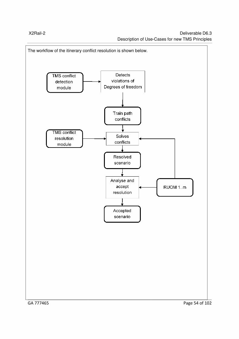
X2Rail-2 Deliverable D6.3 Description of Use-Cases for new TMS Principles
GA 777465 Page 54 of 102
The workflow of the itinerary conflict resolution is shown below.

X2Rail-2 Deliverable D6.3 Description of Use-Cases for new TMS Principles
GA 777465 Page 55 of 102
In a future TMS the modules are provided with data using Integration Layer. In this Use-Case several modules are involved. The connection to IL is shown below.

X2Rail-2 Deliverable D6.3 Description of Use-Cases for new TMS Principles
GA 777465 Page 56 of 102
Railway Undertakings involved into the conflict resolution scenario provide their Acceptances/Modification Requests into Integration Layer influencing the conflict resolution process. At the end of these cycles the current conflict resolution scenario is accepted by all Railway Undertakings and is stored into the Itineraries-Topic.
Final state: the modified itineraries are accepted by RUOM, so all degrees of freedom are respected.

X2Rail-2 Deliverable D6.3 Description of Use-Cases for new TMS Principles
GA 777465 Page 57 of 102
Data register
Itineraries (Trips) containing times and route for each train
Infrastructure – track graph, planned and active restrictions, gradients, speed profiles etc.
Resolution scenario as a set of modifications to the current state of the itineraries.
Conflicts between trains, delays, lost connections.
Related KPIs
• Number of delays caused by train-track conflicts, • Number of accumulated weighted secondary delays, • Amount of energy saved due to resolved conflicts.
Re-planning train services in response to a predicted asset failure 6.8.9
Title Re-planning train services in response to a predicted asset failure
Use Case level 2
Related Use Case Manage Possible Conflicts
Use Case Actors IM/RU
Compiled by TTS
Base-line Description
This use case involves TMS re-planning services based on an actual failure or a predicted failure of a railway asset, in particular a set of points affecting the capacity of a station.
When an infrastructure asset fails, there is likely to be an impact to the running of the railway. The change in availability of this resource will cause conflicts with the current plan, as trains that are planned to use the failed infrastructure no longer can. In this case, the plan needs to be updated to resolve these conflicts. This in turn may lead to further conflicts which need to be resolved such as ensuring the new plan can be resourced by Stock and Crew.
The earlier this asset failure is detected, the more time the operators have to identify resolutions to the conflicts that appear and put actions into place to minimize the impact of the new plan. A link to intelligent asset management may allow a failure to be detected earlier than through the signaling system, or even be predicted in advance; giving operators more time to identify the best resolution to the problem.
The actual failure or prediction of the failure of a set of points in the near future (8 hours) is made by a Signaling System or Interlocking System or an Intelligent Asset Management System. The failure details are available to the TMS over a Publish-Subscribe interface of the Shift2Rail Integration Layer.
Examples of this failure information are: • The interlocking attempts to swing a set of points, but it fails to move.

X2Rail-2 Deliverable D6.3 Description of Use-Cases for new TMS Principles
GA 777465 Page 58 of 102
• A set of points perform a swing and, although it completes successfully, IAMS can detect the points have failed during the swing and are unlikely to complete another swing successfully.
• IAMS detects a set of points is likely to fail in the next few hours.
Once TMS has this data it assesses the impact of the failure and informs the operator of the conflict this will cause at the actual or predicted time of failure. It then proposes various solutions to these conflicts. The operator simulates each of these proposals in turn to assess their impact.
As the proposals are assessed. The Plans are communicated with Rolling Stock and Crew systems to ensure they can be resourced.
The user can assess the different re-plan options and activate the plan which has the least disruptive effect.
1. Infrastructure asset failure detected 2. Conflicts detected 3. Solutions calculated 4. If solution violates agreed degrees of freedom:
a. Check new plan can be resourced (Stock, Crew, Infrastructure) b. If new plan cannot be resourced:
i. Return to step 3. a. Agree new plan with stakeholders
5. Send new timetable plans to all parties
Data Register
IM TMS
Asset ID
Predicted failure time
Predicted failure type
Actual failure time
Actual failure type
Signaling System TMS
Actual failure time
Actual failure type
Asset ID
TMS Stock and Crew Management
Train ID
Train Status
Train Forecast
Train Modification
Stock and Crew Management TMS
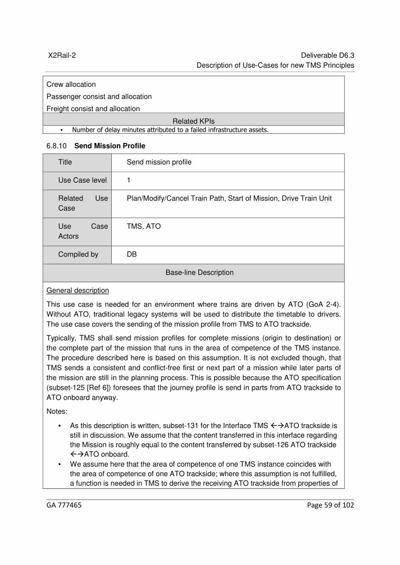
X2Rail-2 Deliverable D6.3 Description of Use-Cases for new TMS Principles
GA 777465 Page 59 of 102
Crew allocation
Passenger consist and allocation
Freight consist and allocation
Related KPIs • Number of delay minutes attributed to a failed infrastructure assets.
Send Mission Profile 6.8.10
Title Send mission profile
Use Case level 1
Related Use Case
Plan/Modify/Cancel Train Path, Start of Mission, Drive Train Unit
Use Case Actors
TMS, ATO
Compiled by DB
Base-line Description
General description
This use case is needed for an environment where trains are driven by ATO (GoA 2-4). Without ATO, traditional legacy systems will be used to distribute the timetable to drivers. The use case covers the sending of the mission profile from TMS to ATO trackside.
Typically, TMS shall send mission profiles for complete missions (origin to destination) or the complete part of the mission that runs in the area of competence of the TMS instance. The procedure described here is based on this assumption. It is not excluded though, that TMS sends a consistent and conflict-free first or next part of a mission while later parts of the mission are still in the planning process. This is possible because the ATO specification (subset-125 [Ref 6]) foresees that the journey profile is send in parts from ATO trackside to ATO onboard anyway.
Notes:
• As this description is written, subset-131 for the Interface TMS ATO trackside is still in discussion. We assume that the content transferred in this interface regarding the Mission is roughly equal to the content transferred by subset-126 ATO trackside ATO onboard.
• We assume here that the area of competence of one TMS instance coincides with the area of competence of one ATO trackside; where this assumption is not fulfilled, a function is needed in TMS to derive the receiving ATO trackside from properties of

X2Rail-2 Deliverable D6.3 Description of Use-Cases for new TMS Principles
GA 777465 Page 60 of 102
the mission (like timing points)
The Mission profile includes
• The content required to create the “Journey Profile Package” as defined in subset-126 [Ref 7]
• In addition to the current journey profile definition – optional for GoA2, mandatory for GoA 3/4 – the mission profile must include:
o the information that at a stopping point the train is foreseen to join another – waiting – train
o the information that at a stopping point the train is foreseen to be joined by another – later arriving – train and at which end (front or rear end upon arrival at stopping point)
o the information that at a stopping point the train is foreseen to be split and between which consists
• optionally, in case TMS is not requested to send the Mission Profile but triggers the sending on its own (see below), the identification of the train unit to send to mission profile to, based on the known consist allocation for the mission
Sending the mission profile has two separate triggers:
• TMS detects that the point in time has been reached where it must send the mission profile to ATO so that ATO itself can trigger the preparation of the train for the mission early enough to complete train preparation before planned departure
• ATO requests the Mission profile
Preconditions
• The mission is known in TMS • The mission in TMS is planned completely and up-to-date • A train unit is assigned to the first leg of the mission
Steps
• ATO sends request for mission profile identifying the mission or TMS triggers sending of the mission profile
• TMS generates the mission profile for the mission and sends it to ATO trackside • ATO acknowledges the mission profile
Post conditions
• ATO trackside has received and acknowledged the mission profile

X2Rail-2 Deliverable D6.3 Description of Use-Cases for new TMS Principles
GA 777465 Page 61 of 102
Data Register
TMS -> ATO
• Mission Profile
ATO -> TMS
• Acknowledge Mission Profile
Related KPIs
• Automation level of railway operations (increase), • Free conflict target timetables (increase).
Start of Mission 6.8.11
Title Start of Mission
Category Operations management
Sub - Category Train Dispatching
Use Case level 1
Related Use Case Resolution of consist assignment conflicts
Actors Railway Undertaking (RU)
Traffic Information System (TIS)
Tech Terminal – Technical Staff
TOC planning
Infrastructure Management (IM)
Work station – dispatchers, signalers, controllers, ARS

X2Rail-2 Deliverable D6.3 Description of Use-Cases for new TMS Principles
GA 777465 Page 62 of 102
On Board – Train crew registration,
IM Planning – Planning Resource,
IXL – ETCS
Compiled by NR
Base-line Description
Technological advancements and development are permitting further semi/automatic engagement in a train’s route/journey/mission.
Therefore, and as stated from the above scenarios this ‘Use Case model’ outlines the structure for a ‘start of mission’ function.
Start of mission – Is when the engagement and registration of a mission (route A to B) is enabled and commenced.
This task has various construction forms which are dependent on the level of ERTMS/TMS interface.
Start of Mission: • IM train planning creates timetables. Applicable route and times are extracted by TMS. • Driver/train crew following roster and work orders will enter train cab at the designated
time and position and enter the registration key. • EVC/ETCS via GSM-R acknowledges train registration (ATO possible) • Dispatcher/Signaler/TMS sets route.
For each mission (trip), degrees of flexibility will be specified
e.g. • Min/Max train start registration to TMS (driver registration- timed) • Train planning and Route confirmation • Connection to ETCS • Connection to (on board) EVC
Minimum criteria for successful ‘start’ of mission.
Independent degrees of tolerance will be managed by TMS.
In most cases even for the improved operational situation some itineraries will still violate the degrees of freedom.
These violations must be accepted by the Railway Undertaking companies
Assumptions
Train timetable already assigned entry
Crew rostering is allocated
Train No/ID per mission
Train position stationing

X2Rail-2 Deliverable D6.3 Description of Use-Cases for new TMS Principles
GA 777465 Page 63 of 102
Initial MA for programme has been accepted
Correlation of position for Train Set
Train crew includes all on board train control staff
IM planning - stakeholder and regulatory requirements are met
TRUST – Train running system – European equivalent - TOPS
EOM – train in service – running criteria – train priority hierarchy
Start of Mission ETCS - SIL 4
Structure
The Planning Department of the Infrastructure Manager (IM) is responsible for creation of itineraries (trips) assuming requested consists for the runtime calculations.
• Planning route/driver information • Infrastructure integral – ETCS operating mode - route availability • Degraded operation/start up – Transition during mission etc. • The Train Operating Companies (TOC’s) are responsible for their Vehicles and assign
appropriately. • TOC Driver registers in Cab DMI – Connects to GSM-R – Failure to connect can result in
‘start of mission’ in degraded mode and operational rules amendments will apply. Mode of operation is resolved by IM.
• The IM adjusts inputs route data status for a route and mission. • ETCS – signalling principles and functional control to route data.

X2Rail-2 Deliverable D6.3 Description of Use-Cases for new TMS Principles
GA 777465 Page 64 of 102
• IM Workstation route appropriately.
Planning
IM Planning – Elements of infrastructure data including degraded conditions and TSR’s.
TOC Planning – Crew rostering, locations and duties.
On Board – Train Control and Registration
DMI – EVC – ATO- Network and Driver registration.
Train Control
ETCS – Signalers Workstation
Output
Commencement of Mission
DATA REGISTER
Asset ID
Train ID Register
Crew ID Planning
Route Planning
ETCS IXL Trackside – GSM-R
GSM-R - On Board EVC
ATO Trackside – ATO On Board
Related KPI’s • Train Punctuality Dispatch, • Train Positioning accuracy, • Capacity Stabilisation, • Line utilisation (increase), • Power Efficiency, • Operators have reduced Interface, • Timetable Regulation.
Request route setting 6.8.12
Title Request Route Setting
Use Case level 1
Related Use Case NA
Use Case Actors Automatic Route Setting (ARS), TMS, Integration Layer (IL), Trackside (Interlocking / RBC), ETCS Onboard - Train, Train Driver, Dispatcher

X2Rail-2 Deliverable D6.3 Description of Use-Cases for new TMS Principles
GA 777465 Page 65 of 102
Compiled by BT
Base-line Description
Request route setting is triggered either by a Dispatcher giving a command to the TMS for a route to be set or by an Automatic Route Setting (ARS) module in the TMS. The reason behind this is normally a train sending a Movement Authority (MA) request but the Dispatcher may also request routes for other reasons, e.g. in degraded situations.
MA requests can come from trains at standstill when ready to depart (which is initiated by the Driver selecting START on the DMI) or while running when getting close to the end of the current MA, but there are also other reasons for sending MA requests. The MA request from a train is sent to the Trackside (RBC) and published on the Integration Layer (IL) as part of the Train Status for that train.
The TMS is notified by the IL of changes to train statuses and may initiate that a route is prepared by the ARS module for a specific Train Running Number (TRN). For the ARS to prepare a route for a train it needs information about the Timetable based on the TRN (alternatively the identity of the ETCS On-board), the current position of the train and the status of the route scheduled in the Timetable. This information should come with the request or be available in advance on the IL. The ARS decides on the route to be set for the train and publish this on the IL. The ARS may also be able to optimise the traffic in case of delays and/or disruptions, i.e. less need for manual support by a dispatcher.
The Interlocking is notified by the IL of the requested route and tries to lock the route. If successful, the route is locked and the RBC authorises the train for that route by sending an MA; if not, the IL is updated with this information.
The sequence diagram showing the interaction between mentioned systems is presented below.

X2Rail-2 Deliverable D6.3 Description of Use-Cases for new TMS Principles
GA 777465 Page 66 of 102
Preconditions • The source information to prepare the route by the ARS is available on IL (Timetable,
route status from A to B) published by other systems and being updated to remain valid.
Outcome • Movement Authority for a route from A to B is sent to the train.
Data Register
Train Trackside
Movement Authority (MA) request
Trackside IL
Publish train status with TRN
IL TMS
sd Request Route Settings use case
Train driverDispatcher
Automatic Route
Setting (ARS)
(TMS service)
Integration
Layer (IL)
Trackside
( Interlocking /
RBC )
ETCS onboard
(Train)
TMS
opt
alt
DMI = Driver Machine Interface
MA = Movement Authority
TRN = Train Running Number
:Route status AB
Activate(TRN)
SetRoute(RouteAB)
Get Route Status(A, B)
:TimeTable TRN
SetRoute(TRN, RouteAB)
Get TimeTable(TRN)
Set route(TRN, RouteAB)
MovementAuthority(RouteAB)
Train Status(TRN)
LockRoute(A, B)
MA Request()
TrainStatus(TRN)
DMI(START)
SetRoute(TRN, RouteAB)
PrepareRoute(TRN, TimeTableTRN,
RouteStatusAB): RouteAB

X2Rail-2 Deliverable D6.3 Description of Use-Cases for new TMS Principles
GA 777465 Page 67 of 102
Subscription of train status with TRN
TMS ARS
ARS activation with TRN
ARS IL
Get timetable for TRN
ARS IL
Get route from A to B status
ARS
ARS IL
Prepared route based on TRN, Timetable and route status
Alternative (In case dispatcher gives direct command to TMS which route to set):
Dispatcher TMS
The set route from A to B for TRN
TMS IL
Publish the set route
IL Trackside
Route notification
Trackside Train
Authorization (MA) for a route from A to B to the train
Alternative (In case Trackside cannot set/lock the route and the same send MA to the train):
Trackside IL
Requested route cannot be set/locked
Related KPIs • Required manual procedures (reduction), • Automation level of railway operations (increase),
• Offered line capacity (increase),
• Line utilisation (increase),
• Free conflict target timetables (increase).
Drive Train Unit 6.8.13
Title Drive Train Unit
Use Case level 1
Related Use Case NA
Use Case Actors Traffic Management System (Train Dispatching component), Train Operation (Train Operation Trackside, and Train Operation On-Board), Train Unit
Compiled by CAF – STS

X2Rail-2 Deliverable D6.3 Description of Use-Cases for new TMS Principles
GA 777465 Page 68 of 102
Base-line Description
General Description
This scenario covers the most common behavior during the operation and running of trains, where the train moves between two planned stopping points without exceeding the authorities of movement assigned.
It is assumed that the operation is performed based on Automatic Train Operation systems available on the train and the trackside facilities.
The Automatic Train Operation system analyses the itinerary and the scheduled timetable for train form the stopping point and provides to the On-Board equipment the Journey Profile information after its request.
The Train Operation On-Board requests the driving instructions for moving the train according to the received profile complying with all the specified speed limits. During the running the Train Operation system provides to the external systems positioning information of the train based on the Status Report information provided by the On-Board equipment.
Steps
The complete process is composed by the following actions: 1. The Train Operation On-Board requests to establish communication with Train
Operation Trackside in case it is not previously established. 2. The Train Operation On-Board requests to the Train Operation Trackside the Journey
Profile for the movement of the train. The Train Operation Trackside provides this information.
3. The Train Operation On-Board request to the Train Operation Trackside the Segment Profiles referred in the Journey Profile in case it has not them previously available. The Train Operation Trackside provides this information.
4. The Train Operation Trackside access to the assigned itinerary and timetable of the train through the timetable information provided by the Traffic Management System.
5. The Train Operation Trackside provides to the Train Operation On-Board the Journey Profile for the running of the train from the stopping point the train is placed. The Journey Profile covers at least the running up to the next Timing point, and within 100km (as per ATO group recommendations at time of writing
6. The Train Operations On-Board requests to the Train Unit driving commands for starting the running and reaching the next stop.
7. The Train Operations On-Board provides to the Train Operations Trackside the Status Report information periodically.
8. The Train Trackside provides to the Traffic Management and other interested systems the positioning of the train and the estimated time of arrival at Timing Point.
The following figure displays a sequence diagram including the interaction between the involved actors performing the actions described above.

X2Rail-2 Deliverable D6.3 Description of Use-Cases for new TMS Principles
GA 777465 Page 69 of 102
Preconditions • The line and the trains include Automatic Train Operation systems. • The train has an itinerary assigned with defined timetable. • The train is stopped at stopping point of the itinerary.
Outcome • The train stops at the next stopping point of the itinerary. • The train is able to continue running from the stopping point.
Data Register
The Data Register includes the interactions between the main involved actors. The interactions should be performed through the Integration Layer for those systems involved in

X2Rail-2 Deliverable D6.3 Description of Use-Cases for new TMS Principles
GA 777465 Page 70 of 102
this integration, but for the interactions between the on-board systems the interaction should be direct between the actors.
Train Operation On-Board -> Train Operation Trackside • Handshake Request. • Journey Profile Request. • Segment Profile Request. • Status Report.
Train Operation Trackside -> TMS • Positioning.
TMS -> Train Operation Trackside • Target Timetable.
Train Operation Trackside -> Train Operation On-board
• Handshake Acknowledgement. • Journey Profile. • Segment Profile.
Train Operation On-board -> Train Unit • Driving commands.
Related KPIs • Offered line capacity (increase), • Line utilisation (increase), • Power consumption (decrease), • Passenger Comfort (increase), • Maintenance Cost (decrease), • Timetable Regularity (increase).
Detect Location change with/without release of route 6.8.14
Title Detect Location change with/without release of route
Use Case level 1
Related Use Case Manage Possible Conflicts
Use Case Actors TMS, ATP, LZ (Train Localization System), ATO
Compiled by DB
Base-line Description
General description
This use case describes the update of TMS with the change of the location of a train unit.
The train unit moves on one track element. Localization systems (LZ) detects a location change

X2Rail-2 Deliverable D6.3 Description of Use-Cases for new TMS Principles
GA 777465 Page 71 of 102
of the train unit.
The last detected location of the train unit was A_Rear for rear end and A_Front for front end on the track element. It is now detected that the location of both train unit ends have changed correspondingly to B_Rear and B_Front. The detected location changes are consistent.
As a consequence of the detected consistent location change, the system releases the section of track element between locations A_Rear and B_Rear.
Preconditions
Mission is in execution.
The section of track element between locations A_Rear and B_Rear is allocated.
Sequence
1. LZ receives localization information. 2. LZ detects that the location has changed: rear end of train unit is in location B_Rear and
front end of train unit is in location B_Front. 3. LZ updates ATP with new safe navigation date 4. ATP validates that the Location change is consistent and sets the Section of Track
Element between Locations A and B to NOT_ALLOCATED. 5. ATP updates TMS with new safe navigation date 6. ATP updates TMS with section status: Allocation_State = NOT_ALLOCATED 7. LZ commands ATO with new precise navigation data 8. ATO updates TMS with new precise navigation data within status report.
Postconditions
Navigation data for Train Unit has been updated.
The section of Track Element between Locations A and B is NOT_ALLOCATED.
Sequence Diagram
The sequence diagram below shows the interaction between the involved actors performing the actions described above. Actions that can be performed in parallel are marked with PAR.

X2Rail-2 Deliverable D6.3 Description of Use-Cases for new TMS Principles
GA 777465 Page 72 of 102
Data Register
ATP->TMS:
• save position data
ATO->TMS:
• precise position data

X2Rail-2 Deliverable D6.3 Description of Use-Cases for new TMS Principles
GA 777465 Page 73 of 102
Related KPIs
Delay reduction
Quality of Service
Event triggering an emergency stop 6.8.15
Title Event triggering an emergency stop
Use Case level 3
Related Use Case N/A
Use Case Actors IM Train Dispatcher (shown as TMS Train dispatcher in the figure), Train Operation System, Train Driver, Train Unit, Passenger Information System, Passenger
Complied by Hitachi Rail STS-CAF
Base-line Description
General Description
Stations are the safest areas from which to handle all emergency cases. Therefore, a train shall never stop away from a station as long as it can move safely.
The train automatically shall stop in the next safe area after an Emergency Stop Handle (ESH) activation if the train is anywhere on the mainline.
The safe area will be the next station except when the train is just departing from a station. If the train is still within the platform area of the station, the train will Emergency Brake (EB) immediately.
The ESH only triggers an EB when the train is stopped or leaving a station (e.g. if the train can stop with at least one door facing the platform then the EB triggers), between stations the train doesn’t stop but the driver communicates with passengers through the public address system.
Any stopped train cannot be moved until the ESH on board the train has been reset by the driver (or by steward).
Steps
Case a – Train between stations or approaching a station.
1. The train is running in GoA2 mode and passenger pulls an ESH on the train. 2. The train informs TMS on the activation of an ESH, TMS alerts the train dispatcher. 3. The Train Operation System forces a stopping point for the next station.

X2Rail-2 Deliverable D6.3 Description of Use-Cases for new TMS Principles
GA 777465 Page 74 of 102
4. The TMS modifies Journey Profile holding the train in the next station. 5. On board CCTV (if available), automatically shows to the driver the images where the
ESH has been operated. 6. On board public address system (if available), automatically switch on for a duplex voice
communication with the ESH area and the driver. 7. The train continues running to next station and it stops on platform and opens the doors. 8. Automatic announcement on board is generated informing passengers upon an ESH
activation 9. The train driver (or a steward) goes to check the situation and reset the ESH pulled. 10. The driver informs Train Dispatcher about the status of emergency situation. 11. If the emergency has been resolved, the Train Dispatcher resets the hold and the train
can restart. 12. The driver closes the doors and the train starts.
Case b – Train is departing from a station but it is still in the station area.
1. The train is running in GoA2 mode and passenger pulls an ESH on the train. 2. The train informs TMS on the activation of an ESH, TMS alerts the train dispatcher. 3. The train applies an Emergency break. 4. Automatic announcement on board is generated informing passenger upon an ESH
activation. 5. The train comes to a complete stop on platform area and remains in hold status. 6. On board CCTV (if available), automatically shows to the driver the images where the
ESH has been operated. 7. The on board public address system (if available), automatically switches on for a duplex
voice communication with the ESH area and the driver. 8. The driver (or a steward) goes to check the situation and reset the ESH pulled. 9. The driver informs Train Dispatcher about the status of emergency situation. 10. The driver closes the doors and train starts.
The following figure displays a sequence diagram including the interaction between the involved actors performing the actions described above.

X2Rail-2 Deliverable D6.3 Description of Use-Cases for new TMS Principles
GA 777465 Page 75 of 102
Preconditions
• The train has itinerary assigned in execution. • The train is running between two stations or it is leaving a station but it is still in the
station area.
Outcome
• The train stops in a safe area and restarts running after the reset of the Emergency Stop Handle.
Data Register
The Data Register includes the interactions between the main involved actors. The interactions should be performed through the Integration Layer for those systems involved in this integration, but in some cases, for instance between the on-board systems, the interaction should be direct between the actors.

X2Rail-2 Deliverable D6.3 Description of Use-Cases for new TMS Principles
GA 777465 Page 76 of 102
Train Operation -> TMS
• Emergency Stop Handle activation.
TMS -> Train Operation
• Modified Target Timetable (included stop in the next station): Modified Journey Profile.
TMS -> Passenger Information System
• Emergency Stop Announcement.
Train Driver -> TMS (Train Dispatcher)
• Status of the emergency situation.
Train Operation -> Train Unit
• Driving commands.
Related KPIs
• Operation safety (increase), • Passenger safety (increase).
Perform physical coupling 6.8.16
Title Perform physical coupling
Use Case level 2
Related Use Case NA
Use Case Actors Train Operation
Traffic Management System
Train Dispatcher
Signalling Control
Train Localization System
Automatic Train Protection
Compiled by INDRA

X2Rail-2 Deliverable D6.3 Description of Use-Cases for new TMS Principles
GA 777465 Page 77 of 102
Base-line Description
General Description
The coupling of a train unit is the process of joining two stopped on the track train units into one resulting train unit formed by the vehicles of the two initial train units.
The process is performed while the trains are located in a point available for performing this kind of operations and while the transfer of passengers is not allowed.
The coupling is performed through the junction of the first vehicle of on train unit from its rear end with the front end of the first vehicle of the second initial train unit. The coupling is performed at a point where the initial train units end their itineraries and the resulting train starts its assigned itinerary.
The involved trains are noted as:
1. Stationary initial train unit: Initial train unit which does not moves for completing the coupling process.
2. Moving initial train unit: Initial train unit which moves towards the stationary initial train unit for completing the coupling process.
3. Resulting train unit resulting of the coupling process. There are two possibilities: o Resulting train is new (different from Stationary and Moving train). o Resulting train is Stationary or Moving train, modified after the junction.
This item allows the couple operation in intermediate stop.
The operation differs in the cases the train units are equipped with or without automatic train couplers, because of that some specific steps are defined for each of these cases.
Steps
The complete process is composed by the following actions:
1. The Train Dispatcher detects the scheduled coupling action and performs the internal logical coupling for managing and controlling the resulting train.
2. The Train Dispatcher commands the Signalling Control for starting the coupling procedure.
3. The following processes of preparation can be launched in parallel: a. Preparation of the coupling of the stationary initial train unit:
i. The Signalling Control commands the Automatic Train Protection system to prepare the coupling of the stationary initial train unit.
ii. The Automatic Train Protection system confirms the availability of the infrastructure for the coupling action on the stationary initial train unit.
iii. The Signalling Control requests the Train Operation of the stationary initial train unit to prepare for the coupling.
iv. The Train Operation of the stationary initial train unit confirms the availability for coupling.
b. Preparation of the coupling of the moving initial train unit: i. The Signalling Control commands the Automatic Train Protection

X2Rail-2 Deliverable D6.3 Description of Use-Cases for new TMS Principles
GA 777465 Page 78 of 102
system to prepare the coupling of the moving initial train unit. ii. The Automatic Train Protection system confirms the availability of the
infrastructure for the coupling action on the moving initial train unit. iii. The Signalling Control requests the Train Operation of the moving
initial train unit to prepare for the coupling. iv. The Train Operation of the moving initial train unit confirms the
availability for coupling. 4. Moving train moves until reaches coupling contact with the stationary train, including
the following steps in parallel while the operation is performed: a. Reporting of positioning of the moving initial train unit:
i. Positioning of the moving initial train unit monitors the distance between the moving initial train unit and the stationary initial train unit.
ii. Positioning of the moving initial train unit provides the distance between the moving initial train unit and the stationary initial train unit to the Signalling Control.
b. Controlling of the movement of the moving initial train unit: i. Signalling Control commands Train Operation of the moving initial train
unit to moving for reaching the coupling distance. ii. The Train Operation of the moving initial train unit notifies the status of
the train unit to the Signalling Control. 5. LZ notifies that the train units reach the coupling contact point. 6. The physical coupling can be launched in parallel:
a. Coupling actions on the moving initial train unit: i. In case the trains are equipped with automatic couplers:
1. The Signalling Control commands the Train Operation of the moving initial train unit to couple trains.
2. The Train Operation of the moving initial train unit confirms to the Signalling Control the coupling action.
ii. In case the trains are not equipped with automatic train couplers: 1. The Signalling Control request the manual operation for
coupling the trains. 2. The operators confirms the physical coupling.
b. Coupling actions on the stationary initial train unit: i. In case the trains are equipped with automatic couplers:
1. The Signalling Control commands the Train Operation of the stationary initial train unit to couple trains.
2. The Train Operation of the stationary initial train unit confirms to the Signalling Control the coupling action.
ii. In case the trains are not equipped with automatic train couplers: 1. The Signalling Control request the manual operation for
coupling the trains. 2. The operators confirms the physical coupling.
7. Depending of type Resulting Train: a. New Train

X2Rail-2 Deliverable D6.3 Description of Use-Cases for new TMS Principles
GA 777465 Page 79 of 102
b. Moving Train modified c. Stationary Train modified
8. The Train Operation of the resulting train unit informs to the Signalling Control of the data of the train unit.
9. The Signalling Control commands the Train Operation of the initial train units to set master and slave modes for each of them.
10. The Train Operations of the each initial train units confirm the mode master and slave for each of them.
11. The Signalling Control commands to use the data of the resulting train unit to the TMS modules.
12. The Signalling Control confirms to the Train Dispatcher that the coupling process is finalised. The resulting train unit is set to close to Run.
The following figure displays a sequence diagram including the interaction between the involved actors performing the actions described above.

X2Rail-2 Deliverable D6.3 Description of Use-Cases for new TMS Principles
GA 777465 Page 80 of 102
Preconditions
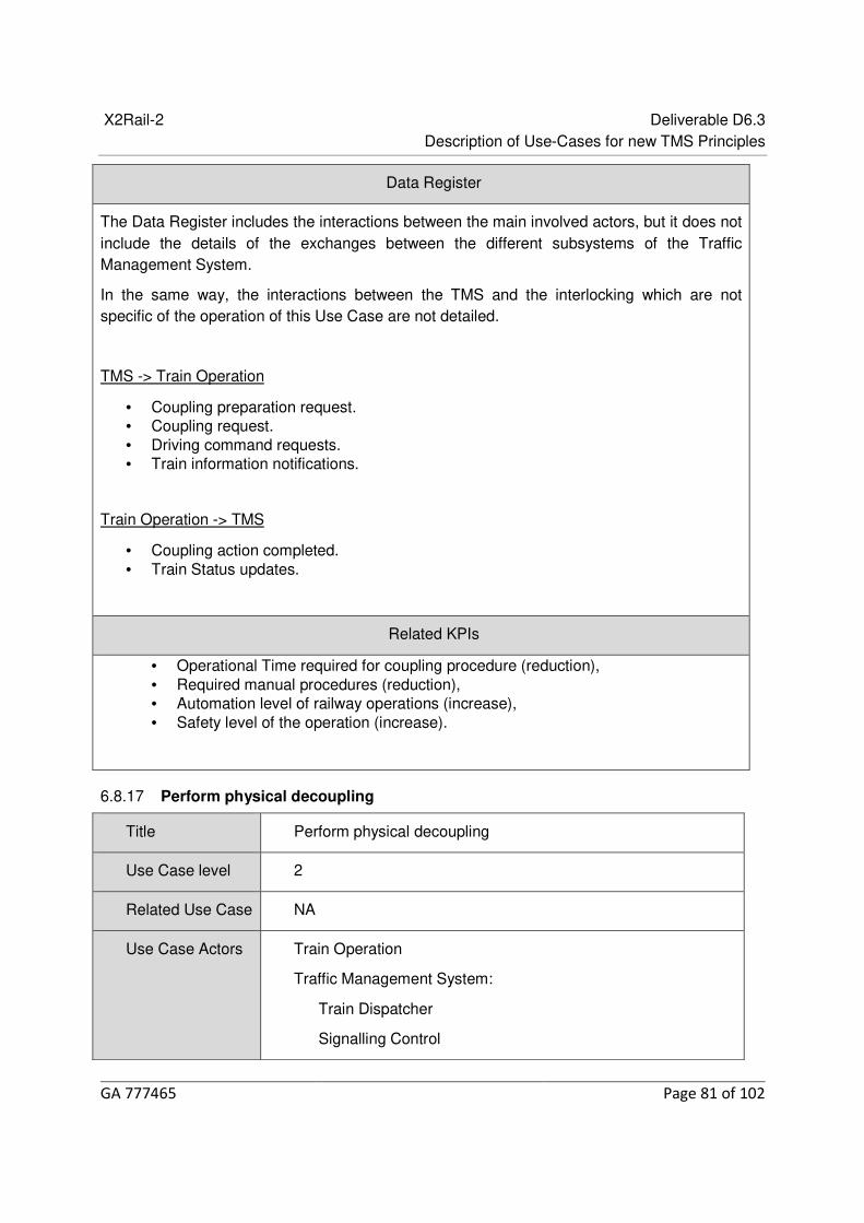
X2Rail-2 Deliverable D6.3 Description of Use-Cases for new TMS Principles
GA 777465 Page 81 of 102
Data Register
The Data Register includes the interactions between the main involved actors, but it does not include the details of the exchanges between the different subsystems of the Traffic Management System.
In the same way, the interactions between the TMS and the interlocking which are not specific of the operation of this Use Case are not detailed.
TMS -> Train Operation
• Coupling preparation request. • Coupling request. • Driving command requests. • Train information notifications.
Train Operation -> TMS
• Coupling action completed. • Train Status updates.
Related KPIs
• Operational Time required for coupling procedure (reduction), • Required manual procedures (reduction), • Automation level of railway operations (increase), • Safety level of the operation (increase).
Perform physical decoupling 6.8.17
Title Perform physical decoupling
Use Case level 2
Related Use Case NA
Use Case Actors Train Operation
Traffic Management System:
Train Dispatcher
Signalling Control

X2Rail-2 Deliverable D6.3 Description of Use-Cases for new TMS Principles
GA 777465 Page 82 of 102
Train Localization System
Automatic Train Protection
Compiled by INDRA
Base-line Description
General Description
The decoupling of a train unit is the process of splitting a stopped on the track train into two train units whose consists are formed by vehicles of the initial train unit.
The process is performed while the train is parked in a point available for performing this kind of operations and while the transfer of passengers is not allowed.
The decoupling is performed through the separation of a vehicle from its front end regarding the rear end of the previous vehicle in the consist of the initial train unit.
There are two possibilities for decoupling:
- At this point, the initial train unit ends its itinerary and the two resulting trains start its assigned itineraries.
- At this point, the initial train is modified, it continues the itinerary with other characteristics, and one resulting train start its assigned itinerary.
The involved trains are noted as:
1. Initial train unit: It includes initially all the vehicles which will conform the resulting train units after the decoupling process.
2. First resulting train unit. 3. Second resulting train unit. (If the option is to end the initial train).
The operation differs in the cases the train unit is equipped with or without automatic train couplers, because of that some specific steps are defined for each of these cases.
Steps
The complete process is composed by the following actions:
1. The Train Dispatcher detects the scheduled decoupling action and performs the internal logical decoupling for managing and controlling each resulting train independently.
2. The Train Dispatcher commands the Signalling Control for starting the decoupling procedure.
3. The following processes of preparation can be launched in parallel: a. Preparation of the decoupling of the initial train unit:
i. The Signalling Control commands the Automatic Train Protection system to prepare the decoupling of the initial train unit.
ii. The Automatic Train Protection system confirms the availability of the infrastructure for the decoupling action on the initial train unit.

X2Rail-2 Deliverable D6.3 Description of Use-Cases for new TMS Principles
GA 777465 Page 83 of 102
iii. The Signalling Control requests the Train Operation of the initial train unit to prepare for the decoupling.
iv. The Train Operation of the initial train unit confirms the availability for decoupling.
b. If the initial train ends after decoupling, Signal Control starts the preparation of the decoupling of the resulting second train unit, if the initial train continue after decoupling prepare the origin train:
(*) Hereinafter the operations referred to the "second" train is applicable to the "Initial" train if it is maintained after decoupling.
i. The Signalling Control commands the Automatic Train Protection system to prepare the decoupling of the second resulting train unit.
ii. The Automatic Train Protection system confirms the availability of the infrastructure for the decoupling action on the second resulting train unit.
c. Preparation of the decoupling of the resulting first train unit: i. The Signalling Control commands the Automatic Train Protection
system to prepare the decoupling of the first resulting train unit. ii. The Automatic Train Protection system confirms the availability of the
infrastructure for the decoupling action on the first resulting train unit. 4. The following processes of physical decoupling can be launched in parallel:
a. Decoupling actions on the second resulting train unit: i. In case the trains are equipped with automatic couplers:
1. The Signalling Control commands the Train Operation of the second resulting train unit to decouple.
2. The Train Operation of the second resulting train unit confirms to the Signalling Control the decoupling action.
3. The Signalling Control informs the Automatic Train Protection that the second resulting train unit is set to coupler open.
ii. In case the trains are not equipped with automatic train couplers: 1. The Signalling Control request the manual operation for
decoupling the trains. 2. The operators confirms the physical decoupling.
iii. The Automatic Train Protection deactivates the train Integrity supervision of the second resulting train unit.
b. Decoupling actions on the first resulting train unit: i. In case the trains are equipped with automatic couplers:
1. The Signalling Control commands the Train Operation of the first resulting train unit to decouple.
2. The Train Operation of the first resulting train unit confirms to the Signalling Control the decoupling action.
3. The Signalling Control informs the Automatic Train Protection that the first resulting train unit is set to coupler open.
ii. In case the trains are not equipped with automatic train couplers: 1. The Signalling Control request the manual operation for
decoupling the trains. 2. The operators confirms the physical decoupling.
iii. The Automatic Train Protection deactivates the train Integrity supervision of the first resulting train unit.
5. If the initial train unit ends, this train unit is set to finished status. 6. The following processes of setting in operation mode of the resulting train units can

X2Rail-2 Deliverable D6.3 Description of Use-Cases for new TMS Principles
GA 777465 Page 84 of 102
be performed in parallel: a. Setting in operation of the first resulting train unit:
i. The Train Operation of the first resulting train unit informs to the Signalling Control of the data of the first resulting train unit.
ii. The Signalling Control commands the Automatic Train Protection to use the data of the first resulting train unit.
iii. The Automatic Train Protection confirms to the Signalling Control that the provided data will be used.
iv. The Signalling Control commands the Train Operation of the first resulting train unit to finalise the decoupling process and to set the train in operation.
b. Setting in operation of the second resulting train unit: i. The Train Operation of the second resulting train unit informs to the
Signalling Control of the data of the second resulting train unit. ii. The Signalling Control commands the Automatic Train Protection to
use the data of the second resulting train unit. iii. The Automatic Train Protection confirms to the Signalling Control that
the provided data will be used. iv. The Signalling Control commands the Train Operation of the first
resulting train unit to finalise the decoupling process and to set the train in operation.
7. At least one of the resulting train units moves to be enough separated from the other one to finalise the decoupling process.
8. The Automatic Train Protection system detects the movement and the position of the resulting trains and notifies to the other TMS modules.
9. In case the trains are equipped with automatic couplers, then the Train Operation system of the trains closes the bow doors.
10. The Signalling Control confirms to the Train Dispatcher that the decoupling process is finalised. The first and the second resulting train units are set to Close to Run.
The following figure displays a sequence diagram including the interaction between the involved actors performing the actions described above.
If the initial train ends after decoupling:
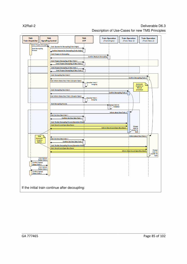
X2Rail-2 Deliverable D6.3 Description of Use-Cases for new TMS Principles
GA 777465 Page 85 of 102
If the initial train continue after decoupling:

X2Rail-2 Deliverable D6.3 Description of Use-Cases for new TMS Principles
GA 777465 Page 86 of 102
Preconditions
• The initial train unit is parked and the transfer of passengers is not allowed for this train.
• The detailed consist of the initial train is completely defined. • The detailed consists of the resulting train units are completely defined. • The itinerary of the initial train unit ends at the decoupling point if the decoupling
operation not maintain the initial train

X2Rail-2 Deliverable D6.3 Description of Use-Cases for new TMS Principles
GA 777465 Page 87 of 102
• The itinerary of each of the resulting train units starts at the decoupling point.
Outcome
• The initial train is finished at the decoupling point. • The first and the second resulting trains are physically composed and able to start
their itineraries at the decoupling point.
Data Register
The Data Register includes the interactions between the main involved actors, but it does not include the details of the exchanges between the different subsystems of the Traffic Management System.
In the same way, the interactions between the TMS and the interlocking which are not specific of the operation of this Use Case are not detailed.
TMS -> Train Operation
• Decoupling preparation request. • Decoupling request. • Train information notifications.
Train Operation -> TMS
• Decoupling action completed. • Train Status updates.
Related KPIs
• Operational Time required for decoupling procedure (reduction), • Required manual procedures (reduction), • Automation level of railway operations (increase), • Safety level of the operation (increase).
TSR management/execution (Setting/releasing a TSR) 6.8.18
Title Possession management TSR Implementation (setting and releasing a TSR)
Use Case level 1
Related Use Case
NA
Use Case IM possession management, TMS, IM, TC

X2Rail-2 Deliverable D6.3 Description of Use-Cases for new TMS Principles
GA 777465 Page 88 of 102
Actors
Compiled by HC
Base-line Description
This use case focuses mainly on the communication of possession execution information triggering an action/workflow on the TMS’s side, mainly applying to the following scenarios:
• The speed of a track section should be restricted temporarily by train control
• A track section’s speed limits should be released to the defined permanent speed.
These scenarios apply to the safety related procedures, i.e. when the speed should be restricted for e.g. protection of possession management staff or infrastructure in place.
The times for setting and releasing a TSR may be planned as part of the possession planning process. Therefore, the setting and releasing process described below applies to an already planned possession and related traffic regulation, in order to execute the TSR plan. Please note that the effective setting and releasing process could cause delays in case of non-coherence with the planned possession, thus creating potential conflicts or delays with/in traffic. The same holds for early TSR setting situations. The setting and releasing need to be confirmed by the traffic controllers and is communicated to the TMS. The situation where the possession is finalized ahead of the planned schedule should be communicated to the TMS in-time for releasing the speed restriction.
Efficient communication of TSR related information is a key feature in the efficient management of possessions requiring an action on the TMS’s side, both operation-wise, such as cancellation or modification of a possession (the possession planning use case), or may result in a status transition such as check in/checkout of an infrastructure element or setting/releasing of a TSR.
Having received this information, TMS follows the related possession management workflow on TMS’s side, for instance, status transition workflows such as check in/check out of an infrastructure element, or setting/releasing of a single TSR.
Technologies such as PICOP mobile applications enable real time collaboration and communication via smart phones and tablets. Using such technologies, field staff can connect to the traffic management system to exchange information in real-time. They can exchange possession related information, such as GPS real time location, working times, time buffers, etc., with the TMS using their applications. In addition, they may communicate their possession requests such as setting up speed restrictions, changes to a planned possession, check in/out of an infrastructure element, etc.

X2Rail-2 Deliverable D6.3 Description of Use-Cases for new TMS Principles
GA 777465 Page 89 of 102
The communication flow can be effectively carried out using web-interfaces which allow connection of mobile and portal applications to the TMS via IP based mobile and web-interfaces. Defining the requirements of such interfaces were the focus of task 6.7, X2Rail-2 and the requirements were defined as part of D6.6 of this task. The TMS may then communicate the outcome to the interested parties, e.g. the confirmation of the check in/out process, using the same communication channel. This paves the way towards a more digitalized railway system, with higher efficiency (time saving, quality gain, and reduced risk of mistakes). This will result in an increase in safety and facilitates the communication of possession information and demands.
Today this process is carried out manually and verbally (radio/phone) and in most cases is highly paper driven. Relying on the information technology and integration layer this use case focuses on
The opportunities provided by these tools to offer a more digitalized and efficient (process and cost, as it opens the market) possession management system. The classical communication channels pose potential delays in the start/finalization of a planned possession activity, interfering with traffic management operations.
Using the IL, would offer the possibility of reduction of system costs, as it opens the market and enables more efficient operations.
The following scenarios are defined in more detail under the umbrella of this use case:
Setting a TSR
This scenario describes the setting of a TSR according to the TSR plan or in case of an ad-hoc TSR request.
Steps for the setting of a TSR:
1. The IM possession management staff requests the setting of a TSR from traffic control.
2. The traffic control initializes the setting of a TSR, notifying TMS. 3. The traffic control confirms the setting of a TSR to the IM possession management
staff, to TMS, and to IM.
Outcome: a new TSR set in place.

X2Rail-2 Deliverable D6.3 Description of Use-Cases for new TMS Principles
GA 777465 Page 90 of 102
Release of a TSR
This scenario describes the release of a TSR in order to revert back to the defined maximum line speed.
Steps for the release of a TSR:
1. The IM possession management staff requests the release of a TSR from traffic control.
2. The traffic control initializes the release of a TSR, notifying TMS. 3. The traffic control confirms the release of a TSR to the IM possession management staff, to
TMS, and to IM.
In all scenarios, the communication may be carried out using the Integration layer.
* The term ‘IM’, in the description of this use case, is used in a more narrow sense for the capacity management function of the IM.
Data Register
IM possession management -> TC
Request for the set/release a TSR
TSR location
Track information
TSR duration (working time, time buffers)
TSR speed
Possession ID
TC->TMS
Notification of the initialization of the set/release of a TSR
TC-> IM possession management

X2Rail-2 Deliverable D6.3 Description of Use-Cases for new TMS Principles
GA 777465 Page 91 of 102
Notification of the successful set/release of a TSR
TC-> TMS
Notification of the successful set/release of a TSR
IM->RU
Notification of the successful set/release of a TSR
Related KPIs
• Reduce delays,
• Potential operational cost reduction,
• Potential capacity increase,
• Potential safety increase,
• Staff comfort.
Possession management/execution (Check-in / Check-out Infrastructure Element) 6.8.19
Title Possession management/execution (Check-in / Check-out Infrastructure Element)
Use Case level 1
Related Use Case
NA
Use Case Actors
IM Possession Management, TMS, IM, TC
Compiled by HC
Base-line Description
This use case focuses mainly on the communication of possession execution information triggering an action/workflow on the TMS’s side, mainly applying to the following scenarios:
• An infrastructure element should be checked out of train control/signaling
This scenario describes the request to check an infrastructure element out of the control of TMS by the possession management staff.
• An infrastructure element should be checked in

X2Rail-2 Deliverable D6.3 Description of Use-Cases for new TMS Principles
GA 777465 Page 92 of 102
This scenario describes the check of an infrastructure element back in to the control of TMS by the possession management staff.
Checking in/out of an infrastructure element coordinates the control of an infrastructure element by train control/signaling. These scenarios apply to the safety related procedures, i.e. when the possession management staff is present in the field in order to obtain and release the track access authority for their track works.
The times for the check in and out of an infrastructure element are planned as part of the possession planning process. Therefore, the check in and out processes described below apply to an already planned possession and the related traffic regulation, i.e. for executing the ‘’check in and check out plan’’. Please note that the check in and check out processes could cause delays in case of non-coherence with the planned possession, thus creating potential conflicts with traffic. The same holds for early check out situations. The check in and check out need to be confirmed by the traffic controllers and are communicated to the TMS. The situation where the possession is finalized ahead of the planned schedule should be communicated to the TMS in-time for releasing the capacity.
Efficient communication of possession related information is a key feature in the efficient management of possessions which may require an action on the TMS’s side, such as cancellation or modification of a possession (the possession planning use case), or may result in a status transition such as check in/checkout of an infrastructure element.
Having received this information, TMS follows the related possession management workflow on the TMS side, for instance, status transition workflows such as check in/check out of an infrastructure element, or the release of a possession (see use case…).
Technologies such as PICOP mobile applications enable real time collaboration and communication via smart phones and tablets. Using such technologies, field staff can connect to the traffic management system to exchange information in real-time. They can exchange possession related information, such as GPS real time location, working times, time buffers, etc., with the TMS using their applications. In addition, they may communicate their possession requests such as setting up speed restrictions, changes to a planned possession, check in/out of an infrastructure element, etc.
The communication flow can be effectively carried out using web-interfaces which allow connection of mobile and portal applications to the TMS via IP based mobile and web-interfaces. Defining the requirements of such interfaces were the focus of task 6.7, X2Rail-2 and the requirements were defined as part of D6.6 of this task. The TMS may then communicate the outcome to the interested parties, e.g. the confirmation of the check in/out process, using the same communication channel. This paves the way towards a more digitalized railway system, with higher efficiency (time saving, quality gain, and reduced risk of mistakes). This will result in an increase in safety and facilitates the communication of possession information and demands.
Today this process is carried out manually and verbally (radio/phone) and in most cases is

X2Rail-2 Deliverable D6.3 Description of Use-Cases for new TMS Principles
GA 777465 Page 93 of 102
highly paper driven. Relying on the information technology and integration layer this use case focuses on
The opportunities provided by these tools to offer a more digitalized and efficient (process and cost, as it opens the market) possession management system. The classical communication channels pose potential delays in the start/finalization of a planned possession activity, interfering with traffic management operations.
Using the IL, we can have the reduction of system costs, as it opens the market.
The following scenarios are defined in more detail under the umbrella of this use case:
Check out of an infrastructure element
This scenario describes the check of an infrastructure element back in to the control of TMS by the possession management staff.
Steps for the check out of an infrastructure element:
4. The IM possession management staff requests the check out of an infrastructure element from traffic control.
5. The traffic control initializes the checkout process, notifying TMS. 6. The traffic control confirms the checkout of the infrastructure element to the IM possession
management staff, to TMS, and to IM.
Outcome: Management of the check-in and check-out request of a track element in and out of the control of TC.
Check in of an infrastructure element
This scenario describes the check in of an infrastructure element back in to the control of TMS by the possession management staff.
Steps for the check in of an infrastructure element:
1. The IM possession management staff requests the check in of an infrastructure element from traffic control.
2. The traffic control initializes the check in process, notifying TMS. 3. The traffic control confirms the check in of the infrastructure element to the IM possession
management staff, to TMS, and to IM.

X2Rail-2 Deliverable D6.3 Description of Use-Cases for new TMS Principles
GA 777465 Page 94 of 102
In all scenarios, the communication may be carried out using the Integration layer.
* The term ‘IM’, in the description of this use case, is used in a more narrow sense for the capacity management function of the IM.
Data Register
IM possession management -> TC
Request for the check in/out of an infrastructure element
Maintenance location
Modified geographical area
Track information
Maintenance duration (working time, time buffers)
Type of activity
Possession ID
TC->TMS
Notification of the initialization of the check in/out process of an infrastructure element
TC-> IM possession management
Notification of the successful check in/out of an infrastructure element
TC-> TMS
Notification of the successful check in/out of an infrastructure element
IM->RU
Notification of the successful check in/out of an infrastructure element
Related KPIs
• Reduce delays,
• Potential operational cost reduction,
• Potential capacity increase,
• Potential safety increase,
• Staff comfort.

X2Rail-2 Deliverable D6.3 Description of Use-Cases for new TMS Principles
GA 777465 Page 95 of 102
Retrieve operational information 6.8.20
Title Retrieve Operational Information
Use Case level 3
Related Use Case
Plan/Modify/Cancel train path
Assign/Modify Consist to Train Unit
Possession planning: Reserve/modify reservation Infrastructure Element for maintenance
TSR management/execution (setting/releasing a TSR)
Possession Management/Execution
Modify features of infrastructure element
Re-planning train services in response to a predicted asset failure
Detect Location change with/without release of route
Use Case Actors
TMS, Passenger Information System (PIS)
Compiled by SNCF-R/SYSTRA
Base-line Description
General Description :
This use case describes the request of operational information by the Traffic Information System (or Passenger Information System - PIS) to retrieve operational data.
The PIS is responsible for informing the passengers of the long term plan, the current status of the running trains and the compliance with the planning (delays, disruptions, etc.).

X2Rail-2 Deliverable D6.3 Description of Use-Cases for new TMS Principles
GA 777465 Page 96 of 102
Steps :
Preconditions :
PIS requests information from TMS. The frequency of these requests can be set automatically according to the type of request and the status of the previous informations.
The request includes:
• The area concerned (whole or part of the network) • The train list concerned (list of train IDs, or aggregated parameters : Railway
Undertaking, Line…) • The time range • The type of the data needed
TMS controls if the request is compliant with the PIS access rights (e.g. confidentiality filters).
Outcome :
According to the request, the TMS provides several types of information. For each type, we describe the interest :
• Train position/delay: used to provide passengers with basic information on the status of the situation. Relevant data include :

X2Rail-2 Deliverable D6.3 Description of Use-Cases for new TMS Principles
GA 777465 Page 97 of 102
o Train ID o Position and direction on the track o Time of observation o Movement status (moving/stopped) o Accuracy of Time/Position measure (depending on the source) o Delay (difference between planned timetable and real time measure) o Delay cause
• Train modification/addition/cancellation: used to inform passenger of train service changes. Relevant data include : o Train ID o Planned/Updated Timetable o Planned/Updated Itineraries o Cancellation Status
• Forecast: used to inform passengers of forecast time at stations and running time. Relevant data include : o Train ID o Forecast Timetable o Forecast Itineraries o Forecast Cause o Time of Forecast generation
• Train unit assignment modification: used to inform passengers of a possible modification of the characteristics of the train (position of access doors, seats, comfort, etc.). Relevant data include: o Train ID o List and order of units assigned to the train with joining and splitting points o Units types and features (nominal or degraded)
• Connection: used to inform passengers of the time and location of the connections. Relevant data include : o Train ID of waited train, time and track of arrival o Train ID of waiting train, time and track of departure
• Possession/TSR/Incident: used to provide passengers the cause of the possible delay. Relevant data include : o Area (position, tracks and length of disruption) o Time range o Consequence (impossible passage, limited speed with rate, imposed stop with
stopping time, impossible stop, low adherence…) for each train category (passenger, freight…)
o Cause o Current status (planned, confirmed, finished…)

X2Rail-2 Deliverable D6.3 Description of Use-Cases for new TMS Principles
GA 777465 Page 98 of 102
o Train IDs of impacted trains
Data Register
PIS -> TMS
• Request
TMS -> PIS
• Train position/delay • Train modification/addition/cancellation • Forecast • Train unit assignment modification • Connection • Possession/TSR/Incident
Related KPIs
• Number of requests processed.

X2Rail-2 Deliverable D6.3 Description of Use-Cases for new TMS Principles
GA 777465 Page 99 of 102
7 Conclusions
The main goal of T6.4 is to define or re-define TMS core functions of a traffic management system that is both compatible with current and future developments in the domain of railway operations, such as ATO, fixed and moving block safety logics, etc. and with current systems and processes.
The core functionalities of an advance TMS were selected from a wide range of functionalities identified by the partners. The identified functionalities were then grouped and structured using the structure of DSD model. The core functionalities were then detailed through development of use cases by all participating partners. The identified functionalities of the traffic management will contribute to a resilient, cost-efficient, high capacity, and automated future traffic management system.
Connection to the Integration Layer, designed in In2Rail [Ref 8] and extended in the follow-up Shift2Rail projects, lies at the heart of an advanced traffic management system. The data exchange between TMS and different systems via the IL has been identified as part of the description of use cases.
It is recommended that functionalities and use cases as defined in this deliverable continue to be modified since they reflect the achieved consensus among the participating partners. Such continuation in product development and product deployment ensures a comprehensive inclusion of all enhanced and new required functionalities.

X2Rail-2 Deliverable D6.3 Description of Use-Cases for new TMS Principles
GA 777465 Page 100 of 102
8 References
[Ref 1] In2Rail, D7.2, Consolidated Functional and Non-functional requirements, 2016.
[Ref 2] Digital Rail for Germany (Digitale Schiene Deutschland, DSD), https://dsd-sysmodel.extranet.deutschebahn.com/dbbmodel, Access will be granted on request.
[Ref 3] In2Rail, D8.1, Requirements for the Integration Layer, 2016.
[Ref 4] In2Rail, D8.3, Description of Integration Layer and Constituents, 2015.
[Ref 5] X2Rail-2, D6.2, System requirements specification (SRS) for Application Framework, 2019.
[Ref 6] ATO over ETCS, System Requirements Specification, subset-125, Issue 0.1.0, 04-05-2018
[Ref 7] ATO over ETCS, ATO-OB / ATO-TS FFFIS Application Layer, subset-126, Issue 0.0.16, 07-05-2018
[Ref 8] Innovative Intelligent Rail, Grant Agreement H2020-MG-2014-635900 (In2Rail.eu).
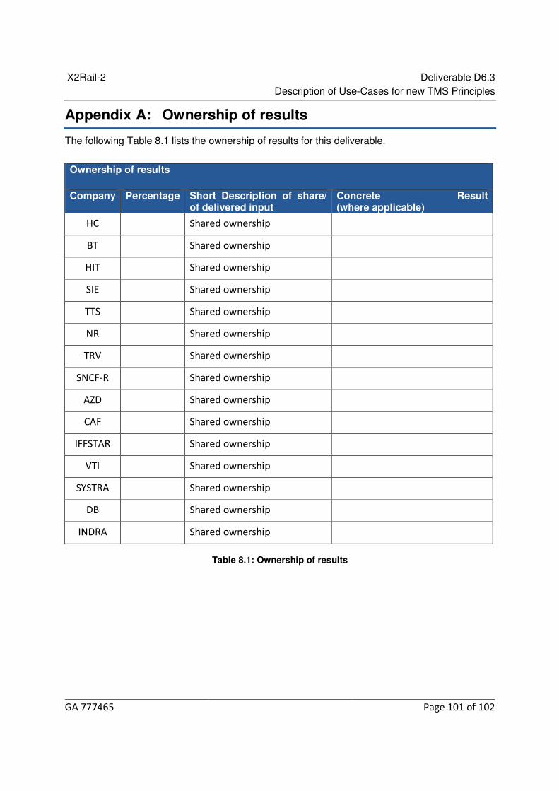
X2Rail-2 Deliverable D6.3 Description of Use-Cases for new TMS Principles
GA 777465 Page 101 of 102
Appendix A: Ownership of results
The following Table 8.1 lists the ownership of results for this deliverable.
Table 8.1: Ownership of results
Ownership of results
Company Percentage Short Description of share/ of delivered input
Concrete Result (where applicable)
HC Shared ownership
BT Shared ownership
HIT Shared ownership
SIE Shared ownership
TTS Shared ownership
NR Shared ownership
TRV Shared ownership
SNCF-R Shared ownership
AZD Shared ownership
CAF Shared ownership
IFFSTAR Shared ownership
VTI Shared ownership
SYSTRA Shared ownership
DB Shared ownership
INDRA Shared ownership

X2Rail-2 Deliverable D6.3 Description of Use-Cases for new TMS Principles
GA 777465 Page 102 of 102
Appendix B: Version Management
Table 8.2: Version management
Version Number
Date Description
1 28.03.2019 First sketch of the deliverable
2 26.06.2019 First distributed draft for review
3 26.08.2019 First draft including partners‘comments
4 5.09.2019 Second distributed draft for review
5 19.11.2019 Second draft including partners‘comments
6 9.12.2019 Second distributed draft for review
7 17.12.2019 Final submitted deliverable
8 28.02.2020 Final submitted deliverable, including TMT reviews