x86 32-bit assembly for ath
TRANSCRIPT

News Pastebin Documents Code Dump x86 Instruction Set Reference Administration
x86 32-bit Assembly for Atheists
Contents
Introduction
What is Assembly?
What is the Purpose of Learning Assembly?
Getting to know the x86 Architecture
Bits, Bytes and Numbers
Bit Operations
Signed Integers
The First Steps
Writing Windows Applications Using x86 32-bit Assembly
MASM
FASM
NASM
Writing Linux/BSD Applications Using x86 32-bit Assembly
as
Partial Registers
Control Structures
Multiplication and Division of Integers
Floating Point Operations
Introduction
This document is an introduction to creating programs for microprocessors of the x86 architecture family - in particular
32-bit code. The reader is expected to be familiar with programming in C/C++ (or similar languages such as Java at
least) and the essential API of the operating system they are using. Some mathematical knowledge up to
highschool/university level is essential for understanding a lot of things aswell. I will try not to be too OS specific but the
environments I am going to focus on in this document are Windows, Linux and BSD. Pure knowledge of assembly in
itself is useless if you do nott know how to combine it with the API of the operating system you are going to run it on so
I want to make sure that this will be demonstrated to a certain extent. It is not that different from the way you would do
it in a high level programming language such as C++ so it is not difficult to understand.
You might wonder why the name of this document contains the "for Atheists" part. I added it primarily to distinguish it
from other documents by name but also because I am an outspoken atheist, as every scientist should be. It was more
of a joke really, though.
What is Assembly?
Assembly (short ASM) is the lowest level programming possible - if you are a programmer and you want to get as close
to the hardware as you can get then this is the place you want to be. In assembly code you get to control every single
instruction that your CPU (central processing unit) is going to execute. There are different assembly languages for
different microprocessor architectures and all of them are different from each other. Usually they are totally
incompatible so you will have to write assembly code that is specific to the particular architecture you want your
program to run on. In assembly you write instructions using the ASCII character set which directly represent machine
code instructions that are executed by your processor. The names of these instructions are usually extremely short and
are often abbreviations of full names. These assembly instruction names are called mnemonics.
Before your microprocessor can actually run the program you have written in assembly you will have to run it through a
program which translates all the mnemonics and arguments to numerical machine code. This program is called an
assembler. Assemblers often also support more features than just the pure instructions to make the jobs easier for the
x86 32-bit Assembly for Atheists http://siyobik.info/index.php?document=x86_32bit_asm
1 of 37 10/5/2010 10:15 PM

programmers but you will see how they do that later on.
What is the Purpose of Learning Assembly?
This is a very important question and subject to a lot of discussion. My answer to this question is a list of reasons,
really. Better understanding of what goes on at the lowest level can make you a better programmer at a higher level. It
allows you to see what goes on behind the scenes and it often gives you a totally new perspective on things. It has its
uses in writing high performance parts of high level language programming where you need to use features of your
processor that are not easily accessible in that high level language. Knowing assembly is obviously also necessary to be
able to write compilers for a particular microprocessor architecture which convert high level language code to machine
instructions.
The truth is that most people learn x86 ASM nowadays to crack commercial software, to reverse engineer closed
source programs and to write cheats for computer games. Cracking is the one that made me learn it but I have to admit
that I never got particularly good at it and I got totally distracted from my original goal in the process of understanding
how it works. It is my experience that it is essential to learn how to write x86 ASM yourself first in order to be
successful at cracking and reverse engineering. Knowing how to manually translate a C++ program to assembly is a
valuable skill to have for this purpose.
Getting to know the x86 Architecture
So, what are we dealing with here? The x86 microprocessor is basically register machine which uses a CISC (complex
instruction set computer) instruction set. At first I am going to explain what a register machine is. After that I will move
on to the CISC part. A register machine is a computing device which stores results of arithmetic operations and such
primarily in so called registers. These are small but highly efficient storage units inside the processor. When you write
assembly you deal a lot with them. They are simple hardware implementations of integers. They are incapable of
holding a lot of data at once but they are essential as temporary placeholders used in most instructions executed by the
processor. In the terms of the memory hierarchy of contemporary computers they are at the very top. The hierarchy
looks like this:
CPU registers1.
CPU cache2.
RAM (random access memory)3.
HDD (hard disk drive storage)4.
External storage, DVDs and such5.
Registers hold minimal amounts of data and are extremely fast. The cache holds far larger amounts of data but it is still
pretty fast. The RAM holds even larger amounts of data and it is far slower than any memory operation inside your
CPU. Hard disks have an even larger capacity than your RAM and they are very slow in comparison to the objects at
the top of the hierarchy.
At this point I should probably briefly explain what the CPU cache actually is. It is a small high performance storage unit
inside your CPU to which chunks of memory from the RAM are copied whenever you perform a RAM memory access.
This way the CPU does not have to access the RAM over and over again when it is processing the same piece of data.
This speeds up the execution of code a lot - RAM access is vey slow in comparison to cache access after all. In reality
this cache is actually not a single unit but it is divided into multiple cache levels. The Level 1 Cache is the smallest but
fastest one. The next level is bigger but slower and so on. Caching is not of much interest to somebody who is new to
assembly, though. I might cover this topic later in sections with deal with optimising code for speed.
Back to the CISC part I mentioned earlier. There are two major microprocessor architecture philosophies known as
RISC (reduced instruction set computer) and CISC (complex instruction set computer). In RISC architectures
instructions are really fundamental and atomic. These instructions are incapable of performing multiple actions at once
but they are very fast. The instruction format for such architectures is usually quite uniform with instructions that all take
up the same amount of bytes which makes them very easy to decode for the processor. in CISC architectures it is
common practice to have complex instructions which perform multiple tasks sequentially, like loading a value from
memory, peforming an arithmetic operation on it and then writing back the result of the operation to the memory. In a
RISC architecture this would be divided into multiple steps. CISC instructions are usually of variable length and they are
very complicated to decode for the CPU. The CISC philosophy actually predates RISC, even though it was not called
CISC at that time. Back in the early days of microprocessors (around 1971) most code had to be written in architecture
specific assembly. High level languages as we know them today were pretty much impossible in those days so it was
desirable to make the job for the programmers easier by providing them with comfortable to use instructions which
would perform commonly grouped actions at once. When they finally realised that this was not very efficient (around
1975) it was already too late. The microprocessor industry based around CISC architectures would flourish and
dominate to eventually totally conquer the desktop market. I would like to emphasise that this did not happen because
of superior technology but because of superior resources and marketing strategies. We are basically using an inherently
inferior instruction architecture for most desktop computers nowadays. The pure design philosophies do not exist as
such in practice anymore and you will find elements of both of them in architectures nowadays.
Bits, Bytes and Numbers
x86 32-bit Assembly for Atheists http://siyobik.info/index.php?document=x86_32bit_asm
2 of 37 10/5/2010 10:15 PM

A bit is simply the smallest digital piece of information possible. To us it is a rather abstract unit which can have two
values, zero or one. A byte is composed of a certain number of bits. On all mainstream architectures a byte is
composed of exactly 8 bits. In this document we focus on the x86 32-bit architecture. The 32-bit part means that the
word size of this processor is 32 bits. The word size of a microprocessor tells you what size most registers and
operands are. So in this case all general purpose registers are 32 bits = 4 bytes in size. General purpose means that
we, the programmers, can pretty much use these registers as we want without breaking anything. They are meant to be
used for all major calculations. There are special registers such as the stack pointer, which may not be used in such a
way. In fact, that would usually result in a crash at some point, but we will get back to that later. Our registers consist
of 32 single bits which can each assume two different values. This means that each register can assume one of
(that is: 2 to the power of 32) different values at a time.
There are different systems of representing numbers using digits (which can actually be arbitrary symbols) such as our
decimal system. At this point it is important to introduce the concept of the positional notation. Positional notation is a
method which takes a base and a set of digits with values , . I hope I did
not scare anybody away with those equations - I should probably clarify. is a natural number - a positive integer like 1,
2, 3, etc. is the union of the digits which are associated with the numerical values 0 to . In a positional system
the number which is composed of the digits actually represents the natural number
.
The decimal system is actually a positional system with . So we have the digits with the
corresponding values. So according to the equation the decimal number 913 represents the natural number
.
Now that was fairly obvious but let us move on to other systems such as the hexadecimal one, which is quite frequently
used in the world of programming, especially in assembly languages. In the hexadecimal system we deal with the base
and the digits . So A stands for 10, B for 11, and so on. So the
hexadecimal number F4D7 actually represents the natural number
.
Then there is of course the binary system which has the digits . The binary number 1101001 represents
the natural number
. This is pretty
much exactly the way unsigned numbers are stored at the hardware level in the registers of your x86 microprocessor.
The single binary digits represent the bits in the register. But the binary number 1101001 has 7 bits and our 32-bit
registers have 32 bits. What happens to the other 25 bits? The upper bits are simply set to 0, so the register would
actually be set to 00000000000000000000000001101001.
Bit Operations
In the introduction I stated that this document is intended for people who already know a high level programming
language which also implies knowledge about the six essential binary operations but I would still like to introduce them
at this point. I will use the C operators & for AND, | for OR, ~ for NOT, ^ for XOR, << for SHIFT LEFT and >> for
SHIFT RIGHT in this document. Let's start with AND. It takes two bits as input and outputs a single bit. If you do not
fully grasp these operations yet I suggest taking a few moments to totally digest and appreciate their output. So what is
the AND operation usually used for? We use it to set particular bits of an integer to 0, to "mask off" particular ranges of
bits we do not care about.
a b a & ba & ba & ba & b
0 0 0
0 1 0
1 0 0
1 1 1
Now for the OR operator. Like AND it takes two bits as input and has a single bit as output. We use it to set particular
bits of an integer to 1:
a b a | ba | ba | ba | b
0 0 0
0 1 1
1 0 1
x86 32-bit Assembly for Atheists http://siyobik.info/index.php?document=x86_32bit_asm
3 of 37 10/5/2010 10:15 PM

1 1 1
The NOT operator inverts bits so it takes one argument instead of two like the previous operators:
a ~a~a~a~a
0 1
1 0
The XOR operator is used to "flip" bits. It is not an essential function, meaning that it can be expressed with the help of
AND, OR and NOT. Its primary purpose curiously is setting registers to zero but we will get to that later. It is also very
useful for pseudo random number and encryption algorithms.
a b a ^ ba ^ ba ^ ba ^ b
0 0 0
0 1 1
1 0 1
1 1 0
The bit shift operations SHIFT LEFT and SHIFT RIGHT cannot be described in compact tables like the other ones.
They shift the bits inside the register to the left or to the right, discarding information as bits "are pushed out" and
shifting new 0-bits in. The first operand for a shift operation is the number that will get shifted. The second operator
describes the number of bits that are shifted in and out. Here are a few examples on 32-bit numbers to clarify what
these operations mean:
a b a << ba << ba << ba << b
11010001010010100001101010001010 1 10100010100101000011010100010100
00000000100000001100000001011111 3 10001010010100001101010001010000
11100000010100110001010010111010 2 01000101001010000110101000101000
00001001101110000000001110000000 29 00000000000000000000000000000000
a b a > ba > ba > ba > b
11010001010010100001101010001010 1 01101000101001010000110101000101
00000000100000001100000001011111 3 00000000000100000001100000001011
11100000010100110001010010111010 2 00010001010010100001101010001010
00001001101110000000001110000000 27 00000000000000000000000000000001
Signed Integers
We have seen how unsigned integers are encoded in the 32-bit registers of the microprocessor but surely the x86
architecture has to deal with signed integers aswell. There are different systems of representing signed integers using
binary encodings. The most intuitive approach is to sacrifice one bit (the "left-most" one) to represent the sign of the
integer. This system is called sign and magnitude and the bit we sacrificed is called the sign bit. A sign bit of 0 stands
for the lack of the minus and the sign bit of 1 means that the number is signed. The absolute value is expressed in all the
other bits. In an 8-bit register the binary number 10011100 represents the integer . One
irritating property of this system is that there are two representations for the number 0: 00000000, 10000000 - a
"positive" zero and a "negative" zero - which is obviously a waste. The actual major problem with this system is that it is
very annoying to perform addition and subtraction in it because there are three different cases to be dealt with (positive
+ positve, positive + negative, negative + negative).
Another possibility is to represent the negative version of the natural number , , by inverting all its bits (see
NOT operation). Hence this system is called One's Complement. This way also one bit is sacrificed to represent the
sign and there are two representations of the number zero again. So the negative version of 00001111 (which is 15) is
11110000 (which is -15) in our hypothetical 8 bit register. The advantage of this system is that it makes
addition/subtraction easier. Consider the operation -7 + 3: 11111000 + 00000011 = 11111011, which is the One's
Complement representation of -4. As you can see we can reduce the complexity of arithmetic operations this way as
x86 32-bit Assembly for Atheists http://siyobik.info/index.php?document=x86_32bit_asm
4 of 37 10/5/2010 10:15 PM

long as we don't cross the zero barrier. Consider the case -1 + 2: 11111110 + 00000010 = 00000000. This is obviously
the wrong result, - 1 + 2 is not zero, it's 1! Every time you cross the "zero barrier" in One's Complement you have to fix
the result by offsets of 1.
So to solve this problem smart computer scientists came up with Two's Complement. It is similar to One's
Complement but all negative numbers have an additional offset of 1. This way there is no redundant zero and you can
flawlessly perform arithmetic operations without having to worry about the sign really. Two's Complement is the system
used by all important mainstream CPUs in desktop computers including the x86 architecture - so be sure to understand
this. There is no inherent difference between storing an unsigned integer and a signed integer in a 32-bit
register - it is all about how you treat it. The 32-bit value 11111111111111111111111111111111 can either stand
for (which is the greatest unsigned integer that can be represented with 32 bits) or, if
interpreted as negative number, for -1. To calculate the Two's Complement representation of with you need
to:
Subtract 11.
Invert bits2.
All of these operations are injective so you can simply reverse the order of the two steps in order to convert a negative
number to its positive representation. Let's have a look at the Two's Complement representations of a few integers:
Signed decimal number Two's Complement Representation
23 00000000000000000000000000010111
-1 11111111111111111111111111111111
-2 11111111111111111111111111111110
-3 11111111111111111111111111111101
-2147483648 10000000000000000000000000000000
2147483647 01111111111111111111111111111111
As you can see the greatest signed number that can be represented with Two's Complement is 2147483647 and the
lowest one is -2147483648.
The First Steps
Now that we have covered most of the basics we can finally get started with some x86 ASM. I am going to use Intel
syntax for now which is far more popular and more intuitive than AT&T syntax. Let's have a look at the following code:
mov eax, 1mov ebx, 10xor ecx, ecx
our_loop:add ecx, eaxinc eaxcmp eax, ebxjle our_loop
Most of these lines represent an instruction that gets executed by the processor. The pattern is instruction
[argument 1], [argument 2], .... Let's go through it line by line. mov eax, 1 calls the instruction mov with
the arguments eax and 1. The mov destination, source operator is kind of like the assignment operator in C++.
It copies the value of source to destination. In this case it writes the constant 1 to the 32-bit general purpose
register eax. That is one of the registers we can use for all kinds of calculations without breaking anything. Here is a list
of all the 32-bit general purpose registers of the x86 architecture:
eax1.
ebx2.
ecx3.
edx4.
edi5.
esi6.
ebp7.
As you can see they have different naming patterns and historically some of them are used by special instructions which
hardly appear in modern code, though. They are mostly still supported for legacy reasons but they are inefficient and
are not produced by modern compilers. After that instruction has been processed the instruction pointer gets
increased. The instruction pointers contains of the current address that is being executed. The instruction pointer of the
x86 32-bit Assembly for Atheists http://siyobik.info/index.php?document=x86_32bit_asm
5 of 37 10/5/2010 10:15 PM

x86 architecture is stored in the 32-bit register eip. So eip gets increased by the length of the mov eax, 1
instruction after it has been executed and eip points towards the next instruction which is mov ebx, 10. As you might
have guessed, mov ebx, 10 writes the value 10 to the register ebx. But now it gets interesting. xor ecx, ecx is
basically the x86 ASM equivalent of the C++ code ecx ^= ecx;. You might ask: What is the fucking point? The
educated mind sees immediately that a ^ a is equal to zero for all values of a. So what this basically is does is setting
ecx to zero. So you might wonder why you do not use mov ecx, 0 instead. Well, you could, but xor ecx, ecx is
actually shorter because it does not involve any constant. By always using xor reg, reg instead we reduce the
overall file size of our binaries and this can save time and space. But this instruction does more than just modify the ecx
register. The x86 microprocessor has a set of so called flags. These are 1 bit values which are used for conditional
jumps and other operations. We do not think about them most of the time and it is not too relevant for writing
conventional code but it is absolutely essential to know how they exist, what they are good for and how they are set. All
arithmetic-logical operations set some of these flags. The mov instruction does not modify the flags but the xor
instruction sets several of them. The Intel x86 Instruction Set Reference says: "The OF and CF flags are cleared; the
SF, ZF, and PF flags are set according to the result. The state of the AF flag is undefined." You can look such data up
in the original PDF document released by Intel or by using the HTML version provided on this site: x86 Instruction Set
Reference. Here is a list of the most important x86 flags and what they stand for:
Abbreviation Full name
CF Carry Flag
PF Parity Flag
ZF Zero Flag
SF Sign Flag
OF Overflow Flag
When you perform the addition of two large unsigned 32-bit numbers the result can obviously be too large to be stored
in a 32-bit register so what you get is a so called wraparound or an overflow. Consider the addition of the following
numbers:
Summand 1 11111111111111111111111111111111
Summand 2 + 00000000000000000000000000000001
Sum 100000000000000000000000000000000
The result requires at least 33 bits to be displayed properly using Two's Complement. So the bit that has been marked
red is basically discarded and not stored in the target register - instead it gets stored in the Carry Flag. The Carry Flag
is basically always the "33rd" bit. Actually This is not a 1 bit value but it is a single bit at offset 0 in a 32 bit register
known as the FLAGS register. This is where all the flags are stored - so obviously there are far more flags than just
the ones listed above but most of them are not of any relevance for writing user land applications. The Parity Flag is
set to 1 if the number of 1-bits in the right most 8 bits of the result contains an even number of 1-bits. It is set to 0
otherwise. It is basically the result of XORing those 8 bits with each other and eventually inverting the result. The Zero
Flag is set when the the result is equal to zero - very useful. The Sign Flag is the left most bit of he 32-bit result - it
represents its sign. The Overflow Flag is set when an overflow occured.
But let us get back to the actual code we were discussing. So none of the flags that are set by most arithmetic logical
operations actually get used and are simply overwritten immediately. The next line in the code is our_loop: is not an
actual instruction that gets executed but an instruction for your assembler which allows you to define labels. These are
markings in the code which are essential to control the flow of execution by providing named locations to which you can
jump to. add ecx, eax is the x86 ASM equivalent of ecx += eax; and it sets the flags again but they are unused -
again. inc eax increments the value of eax by 1 - it is the equivalent of eax++;. We could have used add eax, 1
instead and it is pretty much the same but the inc instruction is smaller so it is preferable. It does not affect the carry
flag but it does not make any difference in this case. cmp eax, ebx is short for "compare" and it performs the
subtraction eax - ebx but the result is not stored anywhere. Instead it simply sets the flags we just talked about
according to the result. This is an essential way to check whether two registers have equal values, for example. In case
they are equal the result of the subtraction is zero so the Zero Flag gets set and we can act accordingly. A cmp is the
first part of the x86 ASM equivalent of a C++ if construct, so to say. The next part is one of the conditional jumps - in
this case it is jle our_loop. jle is short for "jump if less or equal". So, what is a jump? It is a method of controlling
the flow of execution of your program by basically telling your microprocessor where to resume the execution after the
jump. In the case of the x86 32-bit architecture it means modifying the value of eip. When jumps actually get encoded
they just contain numeric offsets which are either relative to the position of the jump ("jump 25 backward") or even
absolute ("go to the instruction at offset 0x12345678"). There are unconditional jumps which are executed no matter
what and conditional jumps which only perform jumps under certain conditions. If a conditional jump is not taken the
execution simply continues with the next instruction after the jump as usual. our_loop refers to the label we previously
defined so if the jump gets executed the next instruction will be add ecx, eax. So in this case we are dealing with a
jump which is executed if the flags indicate that the result is "less or equal". What is this supposed to mean?! Less than
x86 32-bit Assembly for Atheists http://siyobik.info/index.php?document=x86_32bit_asm
6 of 37 10/5/2010 10:15 PM

or equal to what? The cmp operation is usually always used in combination with a conditional jump. Together they are
the x86 ASM equivalent of the C++ if construct. So what the "less or equal" part relates to is the cmp executed prior to
the conditional jump. Read cmp eax, ebx in combination with jle our_loop as if(eax <= ebx) goto
our_loop; - resume execution at label our_loop if eax is less than or equal to ebx. There are actually 32 different
mnemonics for such jumps:
Mnemonic Meaning
ja Jump if above (CF=0 and ZF=0).
jae Jump if above or equal (CF=0).
jb Jump if below (CF=1).
jbe Jump if below or equal (CF=1 or ZF=1).
jc Jump if carry (CF=1).
je Jump if equal (ZF=1).
jz Jump if 0 (ZF=1).
jg Jump if greater (ZF=0 and SF=OF).
jge Jump if greater or equal (SF=OF).
jl Jump if less (SF!=OF).
jle Jump if less or equal (ZF=1 or SF!=OF).
jne Jump if not above (CF=1 or ZF=1).
jna Jump if not above (CF=1 or ZF=1).
jnae Jump if not above or equal (CF=1).
jnb Jump if not below (CF=0).
jnbe Jump if not below or equal (CF=0 and ZF=0).
jnc Jump if not carry (CF=0).
jne Jump if not equal (ZF=0).
jng Jump if not greater (ZF=1 or SF!=OF).
jnge Jump if not greater or equal (SF!=OF).
jnl Jump if not less (SF=OF).
jnle Jump if not less or equal (ZF=0 and SF=OF).
jno Jump if not overflow (OF=0).
jnp Jump if not parity (PF=0).
jns Jump if not sign (SF=0).
jnz Jump if not zero (ZF=0).
jo Jump if overflow (OF=1).
jp Jump if parity (PF=1).
jpe Jump if parity even (PF=1).
jpo Jump if parity odd (PF=0).
js Jump if sign (SF=1).
jz Jump if 0 (ZF=1).
As you can see several of these mnemonics basically do the same thing and they are actually encoded the same way in
the actual executable files - they just exist to make the jobs for the programmers easier. So let's translate this assembly
code to C++ so we can see what it does:
int eax, ebx, ecx;
//...
//mov eax, 1eax = 1;
//mov ebx, 10ebx = 10;
//xor ecx, ecxecx = 0;
our_loop:
x86 32-bit Assembly for Atheists http://siyobik.info/index.php?document=x86_32bit_asm
7 of 37 10/5/2010 10:15 PM

//add ecx, eaxecx += eax;
//inc eaxeax++;
//cmp eax, ebx//jle our_loop
if(eax <= ebx)goto our_loop;
As you can see there is some kind of iteration going on. eax is the iterator which is involved in the decision when to
leave the loop, ebx contains the limit for the iterator and ecx += eax is the actual body of the loop. So we can further
simplify the program to:
int sum = 0;for(int i = 1; i <= 10; i++)
sum += i;
Nice, now that is actually really short and easy to comprehend C/C++ code. So it actually calculates the sum 1 + 2 + ...
+ 9 + 10 = 55. Currently the upper limit is 10 - what do we do if want to set this limit to an arbitrary number? In a high
level language we would write a new function for this purpose which takes the limit for the loop as its sole argument and
which returns an integer, something along the lines of:
int calculate_sum(int limit){
int sum = 0;for(int i = 1; i <= limit; i++)
sum += i;return sum;
}
So, how do we translate this back to x86 ASM? There is a direct equivalent for functions, too. Let us check out what it
looks like when we translate this function to assembly language and call the function with a larger limit 20:
calculate_sum:mov eax, 1mov ebx, [esp + 4]xor ecx, ecx
sum_loop:add ecx, eaxinc eaxcmp eax, ebxjle sum_loopmov eax, ecxret 4
start:push 20call calculate_sum
The first change you can see is the calculate_sum label that has been added. It is necessary so we have marker in
x86 32-bit Assembly for Atheists http://siyobik.info/index.php?document=x86_32bit_asm
8 of 37 10/5/2010 10:15 PM

the code which we can use to call the function. The next change is the mov ebx, [esp + 4] part. The brackets
mean that we perform a memory access (RAM). It is the x86 ASM equivalent of the C/C++ * operator to dereference
pointers. So in this case the pointer is esp + 4. The x86 architecture supports statements of the form register +
constant_offset for this purpose. So in this case the address esp + 4 is calculated and dereferenced. But how
many bytes are read and stored in ebx? The register is 32-bits in size so 4 bytes are read, beginning at the address
esp + 4, so the bytes esp + 4, esp + 5, esp + 6, esp + 7 are stored in ebx - but in what order? Which byte
goes where? The x86 architecture uses the so called Little Endian byte order in memory. In this order the least
significant byte is stored first in memory:
10010011000100001100000001110010
In this case the red bit is the most significant bit and the green bit is the least significant bit. Significance means how
much of a difference the bit can make to the value of the integer. The most significant bit has a value of whereas
the least significant bit only makes a difference of . We do not have to worry about as long as we stick to writing
values of size to memory and reading bytes later. When we read bytes from memory with an instruction like
mov ebx, [esi] the x86 microprocessor reads 4 bytes in Little Endian order, of course. The only time we have to
worry about it is we have an integer of bytes in memory and we want to access particular bytes of it with
. In that case we have to know what Endianess the underlying system uses so we read the
right bytes. The opposite of Little Endian byte order is Big Endian. In Big Endian byte order the most significant byte
is stored first - just like we do in normal hexadecimal and decimal notation. We write down the number 931 to express
. If we applied the Little Endian philosophy to this we would write 139 instead of 931, so to
say. Let us have a look at a few examples of how bytes are stored in memory with different "Endianesses":
Hexadecimal
notation
Consecutive bytes in memory with
Little Endian byte order
Consecutive bytes in memory with
Big Endian byte order
0xFF 0xFF 0xFF
0x1234 0x34, 0x12 0x12, 0x34
0x09451143 0x43, 0x11, 0x45, 0x09 0x09, 0x45, 0x11, 0x43
So for single bytes it does not make any difference but as soon as you deal with integers which require two or more
bytes the Endianess becomes an issue. Big Endian byte order is much more intuitive as you can see, since it matches
the way we usually write numbers so it is easier for humans to read when looking at hex dumps and stuff like that. With
Little Endian byte order you would have to reverse it first in order to parse it in the way you usually do. Unluckily the x86
architecture uses the Little Endian byte order so there is not much we can do about it. Even the internet is based on the
Big Endian byte order - all the official protocols such as IP, TCP and UDP use it. This is why it is also called Network
Byte Order. When you send multi byte integer values in the headers of the official protocols using a Little Endian byte
order all the bytes must be reversed in order first in order to satisfy the specifications - what a bummer! Now that we
have cleared this up we should get back to the statement we were originally discussing, mov ebx, [esp + 4]. So
there is a new register in that statement: esp. Its name is short for extended stack pointer which is actually a 32-bit
"general purpose register" just like the other 7 ones that we listed above. But messing with it can have disastrous
results and there is not really a point to use it for any other purpose in normal code, really. The stack is a part of the
memory your application uses. The C++ analogy to this mechanism is std::stack (which I hope you are familiar with)
and in Java it would be java.util.Stack. A stack is one of the basic container/data structure types which (in theory)
only allows you to access the element at the top of the stack by "popping" it off and it allows you to add new elements
to the stack by "pushing" them on the top. In terms of microprocessors it is a bit different because you usually access
several elements inside the stack which are not at the top because it is more efficient. Let us have a look at a few
examples of operations on an abstract stack of integers. This is what our stack looks like at the beginning: (do not be
confused by the "Bottom of the stack" part, the bottom does not serve a special purpose and it is just marked to clarify
things)
Description Value
Top of the stack 4
17
Bottom of the stack 2
We are going to execute a series of operations on this stack now to observe the changes. First we will push an 8 onto
the top. The C++ pseudo code equivalent for this action shall be: push(8);
x86 32-bit Assembly for Atheists http://siyobik.info/index.php?document=x86_32bit_asm
9 of 37 10/5/2010 10:15 PM
Description Value
Top of the stack 8
4
17
Bottom of the stack 2
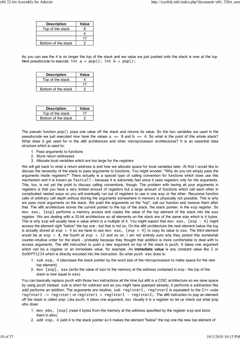
As you can see the 4 is no longer the top of the stack and we value we just pushed onto the stack is now at the top.
Next pseudocode to execute: int a = pop(); int b = pop();
Description Value
Top of the stack 4
17
Bottom of the stack 2
Description Value
Top of the stack 17
Bottom of the stack 2
The pseudo function pop() pops one value off the stack and returns its value. So the two variables we used in the
pseudocode we just executed now have the values a == 8 and b == 4. So what is the point of this whole stack?
What does it get used for in the x86 architecture and other microprocessor architectures? It is an essential data
structure which is used to:
Pass arguments to functions1.
Store return addresses2.
Allocate local variables which are too large for the registers3.
We will get back to what a return address is and how we allocate space for local variables later. At first I would like to
discuss the necessity of the stack to pass arguments to functions. You might wonder: "Why do you not simply pass the
arguments inside registers?" There actually is a special type of calling convention for functions which does use this
mechanism and it is known as fastcall - because it is extremely fast since it uses registers only for the arguments.
This, too, is not yet the point to discuss calling conventions, though. The problem with having all your arguments in
registers is that you have a very limited amount of registers but a large amount of functions which call each other in
complicated nested ways so you will eventually run out of registers to use in one way or the other. Recursive function
calls of arbitrary call depth without storing the arguments somewhere in memory is physically not possible. This is why
we pass most arguments on the stack. We push the arguments on the "top", call our function and remove them after
that. The x86 architecture stores the current pointer to the top of the stack, the stack pointer, in the esp register. So
mov eax, [esp] performs a memory access and copies the value of the top element of the stack into the eax
register. We are dealing with a 32-bit architecture so all elements on the stack are of the same size which is 4 bytes.
This is why esp will usually have a value which is a multiple of 4. You might expect that mov eax, [esp - 4] might
access the element right "below" the top one - but that is not so. On the x86 architecture the next element below the top
is actually stored at esp + 4 so we have to use mov eax, [esp + 4] to copy its value to eax. The third element
would be at esp + 8, the fourth at esp + 12 and so on. I am not entirely sure why they picked this somewhat
counter-intuitive order for the stack - probably because they thought that addition is more comfortable to deal with to
access arguments. The x86 instruction to push a new argument on top of the stack is push. It takes one argument
which can be a register or an immediate value, for example. An immediate value is any constant value like 2 or
0x00ff1234 which is directly encoded into the instruction. So what push eax does is:
sub esp, 4 (decrease the stack pointer by the word size of the microprocessor to make space for the new
top element)
1.
mov [esp], eax (write the value of eax to the memory at the address contained in esp - the top of the
stack is now equal to eax)
2.
You can basically replace push with those two instructions all the time but x86 is a CISC architecture so we save space
by using push instead. sub is short for subtract and as you might have guessed already, it performs a subtraction like
add performs an addition. The arguments are intuitive, sub register1, register2 is equivalent to the C++ code
register1 -= register; or register1 = register1 - register2;. The x86 instruction to pop an element
off the stack is called pop. Like push, it takes one argument, too. Usually it is a register so let us check out what pop
ebx does:
mov ebx, [esp] (read 4 bytes from the memory at the address specified by the register esp and store
them in ebx)
1.
add esp, 4 (add 4 to the stack pointer so it makes the element "below" the top one the new top element of2.
x86 32-bit Assembly for Atheists http://siyobik.info/index.php?document=x86_32bit_asm
10 of 37 10/5/2010 10:15 PM
the stack)
So, to get back to the piece of x86 ASM we were previously discussing: What mov ebx, [esp + 4] really does is
copying the first argument passed to the function into the ebx register. The first argument is the second element of the
stack, the second argument is the third and so on. So what does the top of the stack contain? What is stored at
[esp]? This is the so called return address which is necessary for a function to know where it was originally called
from so eip, the instruction pointer, can be set to the right value after the function returns. We want our program to
resume execution with the instruction after our call, after all.
The start label is not really relevant for the understanding of the principle but I simply wanted to point out where the
execution actually started in case somebody got confused by the stream of x86 ASM instructions. The assembly code
push 20, call calculate_sum first pushes the immediate value 20 on top of the stack and then calls the function.
Remember that we only see this label in our assembly language code. It does not exist is such in the actual binary file.
In the executable file you will simply see the call with an address after it. This address points to the first instruction of
the function we marked with the label calculate_sum. In this case it is the instruction mov eax, 1. This is what
call address actually does:
esp -= 4; (make space for the return address on the stack)1.
*esp = address_of_next_instruction; (stores the address of the instruction after the call on the
stack)
2.
eip = address; (modify the instruction pointer so it resumes execution in the body of the function)3.
As you can see I did not use x86 ASM instructions to describe what this function does. Instead, I resorted to the C++
pseudo code I use occasionally. This is because we cannot modify eip like a normal register. It takes a jump or a call
(which is similar to a jump) to achieve that. What the combination of push 20 and call calculate_sum really
translates to in C++ is calculate_sum(20);. The function calculate_sum is called with the argument 20 - which is
what we originally wanted. You will see the push/call construct quite frequently. usually functions have even more than
one argument so you will see multiple pushes prior to a call. Perhaps you have noticed that another element has been
added to the function. The ret instruction is used to return from a function after it has been called. Additionally it can
take an argument which in the case of ret 4 is equal to 4. Let us have a look at what this ret argument instruction
does:
eip = *esp (copy the instruction pointer from the stack back to the instruction pointer to resume execution at
the instruction after the call)
1.
esp += 4 + argument; (remove the return address from the stack and, if necessary, arguments that were
pushed onto the stack for the function)
2.
If a function takes arguments you will usually return from it with the instruction . If the function is nullary
(if it takes no arguments), you can simply use ret instead of ret 0. You also might have noticed the additional mov
eax, ecx I inserted prior to the ret 4. I did this because it is a common calling convention to return the result of a
function in the eax register which is the first of the 8 (or rather 7 without esp) general purpose registers. Of course you
do not have to do this but if you interface with C/C++ code you will have to know this of course. Now that we have
covered the basics of calling and returning we can move on to the topic of calling conventions. You might remember me
talking about the fastcall convention - it is one of them. If you are an experienced C/C++ programmer you should
already be familiar with a few of them. They differ in the following regards:
How do arguments get passed? On the stack? In registers?1.
In what order are arguments passed?2.
Who is responsible for fixing the stack after the function has processed the arguments?3.
What registers must be preserved by the function?4.
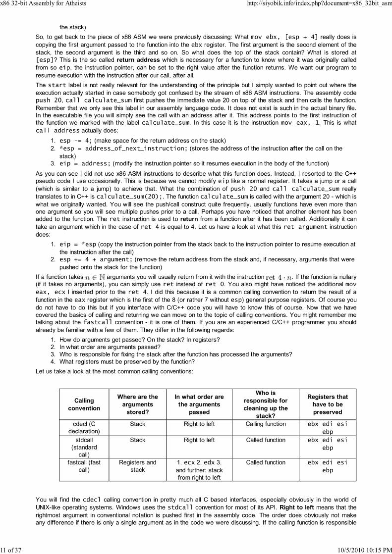
Let us take a look at the most common calling conventions:
Calling
convention
Where are the
arguments
stored?
In what order are
the arguments
passed
Who is
responsible for
cleaning up the
stack?
Registers that
have to be
preserved
cdecl (C
declaration)
Stack Right to left Calling function ebx edi esi
ebp
stdcall
(standard
call)
Stack Right to left Called function ebx edi esi
ebp
fastcall (fast
call)
Registers and
stack
1. ecx 2. edx 3.
and further: stack
from right to left
Called function ebx edi esi
ebp
You will find the cdecl calling convention in pretty much all C based interfaces, especially obviously in the world of
UNIX-like operating systems. Windows uses the stdcall convention for most of its API. Right to left means that the
rightmost argument in conventional notation is pushed first in the assembly code. The order does obviously not make
any difference if there is only a single argument as in the code we were discussing. If the calling function is responsible
x86 32-bit Assembly for Atheists http://siyobik.info/index.php?document=x86_32bit_asm
11 of 37 10/5/2010 10:15 PM

for fixing the stack - that is, getting rid of the arguments below the return address which were passed to the function - it
simply does what our code does: it uses the ret instruction with the right argument to clean up the stack. If the calling
function is responsible for cleaning up the stack, the function in question usually simply calls ret and leaves all the work
for whoever called him. Let us clarify by example:
void __cdecl test1(int a, int b, int c){}
void __stdcall test2(int a, int b, int c){}
test1(1, 2, 3);
test2(1, 2, 3);
This C++ code would look something like this in x86 ASM:
test1:ret
test2:ret 12
start:push 3push 2push 1call test1add esp, 12
push 3push 2push 1call test2
So the differences between these two function calls are:
Calling convention Description
cdecl (C declaration) Uses ret to return and forces the calling function to add esp, 12 to fix the
stack.
stdcall (standard
call)
Uses ret 12 to return so the calling function does not have to fix the stack.
stdcall is more efficient than cdecl because it requires one instruction less to execute. Do not be fooled by the
number of instructions - there are tons of examples in which code which uses more instructions to solve the same
problem is actually faster but in this case it happens to be intuitively right because all these simple instructions get
executed at about the same speed. However, it is not yet the time to talk optimisations in general so let us return to the
matter at hand. Now that we have covered some of the fundamentals of x86 assembly programming we can finally start
writing simple programs that actually interact with the API of the underlying OS. We are going to implement the same
basic command line program on different operating systems using various assembler programs in the next section of
this document. This program will simply be an extension of what we have already written.
Writing Windows Applications Using x86 32-bit
Assembly
x86 32-bit Assembly for Atheists http://siyobik.info/index.php?document=x86_32bit_asm
12 of 37 10/5/2010 10:15 PM

At first we are going to take a look at how to write assembly for the popular Windows operating system. We are going
to check out the Microsoft (R) Macro Assembler Version 9.00.21022.08 (short MASM), the great open source program
flat assembler 1.67.27 for Windows (short FASM) and the netwide assembler 2.04 RC 1 (short NASM).
MASM
This is the most used assembler for writing assembly code for the Microsoft Windows operating systems. Before I am
going to just throw the code right into your face I would like to dedicate a few words to what is known as MASM32 - a
great source of confusion and frustration.
MASM32 (from movsd.com/masm32.com) does not have anything to do with Microsoft or MASM as such. It is a
package mostly made by an Australian known as Steve Hutchesson (aka hutch). This package contains lots of headers
and example code and it uses the Microsoft ml/link binaries version 6.x from 1998 or so. It is absolutely useless for any
modern x86 32-bit Windows assembly programming. Never make the mistake of mixing up MASM and MASM32. I see
a lot of people making this mistake. I have even seen people give up on MASM because they thought that MASM32
was it. It is really sickening. As for the actual package itself, the example code may be useful for new ASM
programmers but you should stay away from the MASM32 "library" and the outdated headers which give you parsing
errors in new versions of MASM.
Let us get back to the actual code. We will go through it line by line:
;Arithmetic sum program.686p.model flat, stdcall
option epilogue: noneoption prologue: none
GetStdHandle proto :dwordwsprintfA proto c :varargWriteConsoleA proto :dword, :dword, :dword, :dword, :dwordExitProcess proto :dword
STD_OUTPUT_HANDLE equ -11
.data
sum_string db "Arithmetic sum for the limit %d is %d", 10, 0
.data?
buffer db 64 dup(?)bytes_written dd ?
.code
calculate_sum proc limit:dwordxor esi, esimov edi, 1jmp loop_start
sum_loop:add esi, ediinc edi
loop_start:cmp edi, [esp + 4]jle sum_loopret
calculate_sum endp
public main
main procinvoke GetStdHandle, STD_OUTPUT_HANDLEmov ebp, eaxxor ebx, ebx
main_loop:
x86 32-bit Assembly for Atheists http://siyobik.info/index.php?document=x86_32bit_asm
13 of 37 10/5/2010 10:15 PM

invoke calculate_sum, ebxinvoke wsprintfA, addr buffer, addr sum_string, ebx, esiinvoke WriteConsoleA, ebp, addr buffer, eax, addr bytes_written, 0inc ebxcmp ebx, 20jle main_loopinvoke ExitProcess, 0
main endp
end
;Arithmetic sum program is a comment. In MASM comments are made using the semicolon character. There are
only single line comments so it is pretty much the equivalent of the C/C++ //. Unluckily there is no multi line comment
feature. .686p specifies what instructions are allowed to be used in the assembly code. There are numerous other
ones but this is a nobrainer really. .686p is simply the most "modern" one. .model flat, stdcall specifies two
things. For one it specifies the memory model to be used. The flat memory model is the only one supported by
modern Windows operating systems so it is hardly worth discussing. The stdcall part specifies the default calling
convention. Since we are dealing with Windows API code we definitely should use stdcall. option epilogue:
none and option prologue: none tells the assembler that we do not want to use the default MASM
epilogues/prologues. These are instructions that are automatically appended at the front of your function and whereever
you call ret. It is a nice feature to support but it is very annoying that it actually puts some instructions there you do not
see in your code - instructions you never expected to be there until you run your binary in a debugger to find out that
some strange feature is totally breaking your assembly! In the case of MASM the default code is establishing a so
called frame stack. This is mostly a nasty relic of the past which is still used by unenlightened copycats who never
bother to actually check whether such features actually make sense or not. I am just going to demonstrate this dumb
practice to you once:
;non-sensical functionsome_function proc
xor eax, eaxjmp returnret
return:mov eax, 1ret
This function does not perform any meaningful task, it is merely an example. With the default epilogue/prologue code
this will assemble to:
push ebpmov ebp, espxor eax, eaxjmp some_constant ;I do not know the immediate value that will be used here so I just made up some namepop ebpretmov eax, 1pop ebpret
So as you can see every proc (a fancy way of declaring a function, short for "procedure") will generate an additional
push ebp, mov ebp, esp and an additional pop ebp prior to every single ret. So at first the value of ebp is
supposed to get preserved by being copied to the stack. Then esp is copied to ebp. In the end the original value of
ebp gets restored by pop ebp. So, what is the point of all this? When you manipulate esp in your function body you
will have to watch what offset your original arguments which were passed to your function are at. The idea of the stack
frame is to preserve the original value so you do not have to do any thinking to come up with the offset. The truth is that
stack frames are useless unless you are performing operations which do not let you predict the argument
x86 32-bit Assembly for Atheists http://siyobik.info/index.php?document=x86_32bit_asm
14 of 37 10/5/2010 10:15 PM
offset at assembly time. It is a waste of instructions. All you usually achieve is being able to write stuff like mov eax,
[ebp + 4] instead of mov eax, [esp + 4] which is really idiotic in general. So do not use this feature. Now that
we have cleared this up, let us get back to the code at hand.
GetStdHandle proto :dword declares the prototype (proto) of a function called GetStdHandle which uses the
default calling convention we specified. We specified stdcall in the .model directive. We could even have used
GetStdHandle proto stdcall :dword to be even more explicit about it but it is unnecessary in this case since
we already specified a default calling convention. If you do not know what a particular function does you should
definitely look it up on MSDN. You might even know some of these Windows API calls but you are probably surprised
by these -A prefixes some of these have. The Windows API uses the -A prefix for "ASCII" and the -W prefix for "Wide
chars" - Unicode. They are redirected according to the preprocessor definitions in the C interface. The -A variants
usually simply call the -W ones after a few string conversions. Windows handles most strings internally as Unicode. It is
more convenient to use ASCII in this case, though, so we use the -A interfaces. On the next few lines a few more
prototypes are declared and the majority of them are just like this one but the the wsprintfA one stands out because
of the vararg part. This nasty function takes a variable amount of arguments and it is up to us to fix them later. It uses
the C calling convention, hence the c part. These prototypes basically work like the function declarations in C/C++. We
definitely need to use them for external calls so we need to declare them as prototypes using the proto directive first
before we can use them. STD_OUTPUT_HANDLE equ -11 is a directive which will replace all future occurences of the
name STD_OUTPUT_HANDLE with the constant -11. We need this one for GetStdHandle. The .data directive
declares the start of the data section. This is where we store static data/global variables, so to say. sum_string db
"Arithmetic sum for the limit %d is %d", 10, 0 declares a zero terminated string "Arithmetic sum for
the limit %d is %d\n" by the name of format_string. db is short for "declare byte(s)", I believe. Consecutive bytes
can simply be declared using the comma notation you can see in those lines. The .data? directive introduces the
uninitialised data section. We store static variables which have no predefined value in this part of the program. buffer
db 64 dup (?) declares a range of 64 bytes which have no defined value as specified in the parenthesis (?). dup is
short for "duplicate", or so, I believe. bytes_written dd ? uses the dd directive which is short for "declare
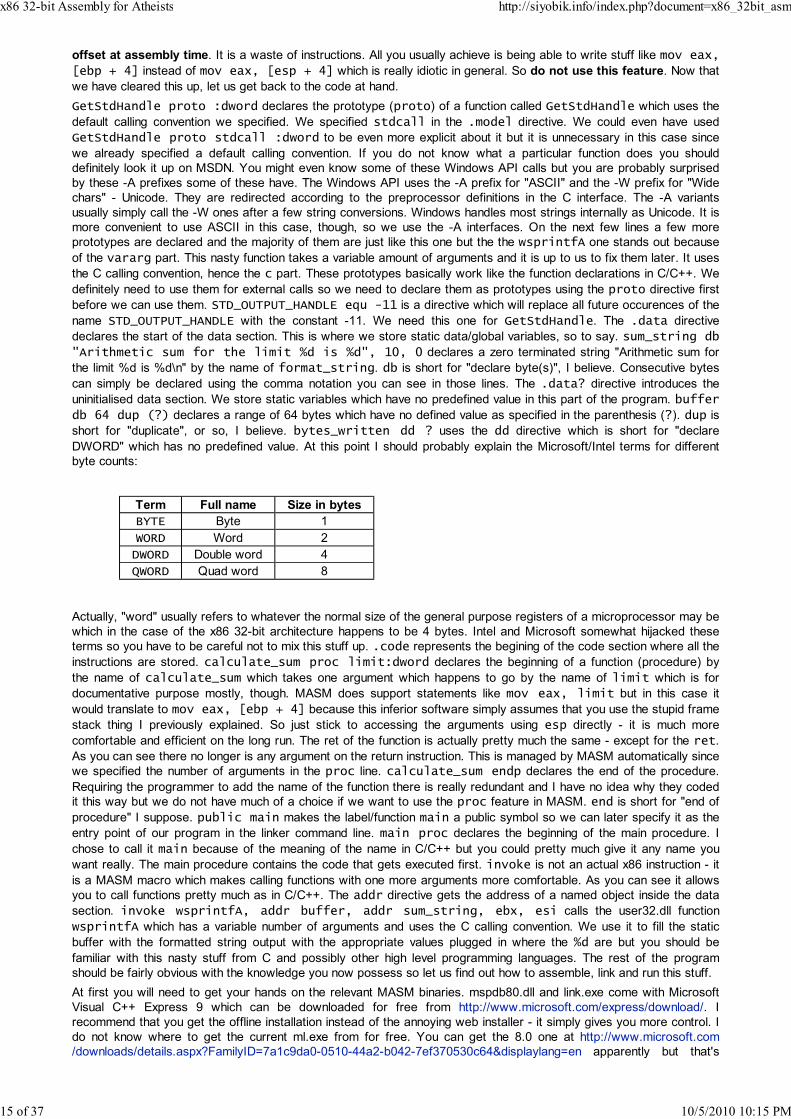
DWORD" which has no predefined value. At this point I should probably explain the Microsoft/Intel terms for different
byte counts:
Term Full name Size in bytes
BYTE Byte 1
WORD Word 2
DWORD Double word 4
QWORD Quad word 8
Actually, "word" usually refers to whatever the normal size of the general purpose registers of a microprocessor may be
which in the case of the x86 32-bit architecture happens to be 4 bytes. Intel and Microsoft somewhat hijacked these
terms so you have to be careful not to mix this stuff up. .code represents the begining of the code section where all the
instructions are stored. calculate_sum proc limit:dword declares the beginning of a function (procedure) by
the name of calculate_sum which takes one argument which happens to go by the name of limit which is for
documentative purpose mostly, though. MASM does support statements like mov eax, limit but in this case it
would translate to mov eax, [ebp + 4] because this inferior software simply assumes that you use the stupid frame
stack thing I previously explained. So just stick to accessing the arguments using esp directly - it is much more
comfortable and efficient on the long run. The ret of the function is actually pretty much the same - except for the ret.
As you can see there no longer is any argument on the return instruction. This is managed by MASM automatically since
we specified the number of arguments in the proc line. calculate_sum endp declares the end of the procedure.
Requiring the programmer to add the name of the function there is really redundant and I have no idea why they coded
it this way but we do not have much of a choice if we want to use the proc feature in MASM. end is short for "end of
procedure" I suppose. public main makes the label/function main a public symbol so we can later specify it as the
entry point of our program in the linker command line. main proc declares the beginning of the main procedure. I
chose to call it main because of the meaning of the name in C/C++ but you could pretty much give it any name you
want really. The main procedure contains the code that gets executed first. invoke is not an actual x86 instruction - it
is a MASM macro which makes calling functions with one more arguments more comfortable. As you can see it allows
you to call functions pretty much as in C/C++. The addr directive gets the address of a named object inside the data
section. invoke wsprintfA, addr buffer, addr sum_string, ebx, esi calls the user32.dll function
wsprintfA which has a variable number of arguments and uses the C calling convention. We use it to fill the static
buffer with the formatted string output with the appropriate values plugged in where the %d are but you should be
familiar with this nasty stuff from C and possibly other high level programming languages. The rest of the program
should be fairly obvious with the knowledge you now possess so let us find out how to assemble, link and run this stuff.
At first you will need to get your hands on the relevant MASM binaries. mspdb80.dll and link.exe come with Microsoft
Visual C++ Express 9 which can be downloaded for free from http://www.microsoft.com/express/download/. I
recommend that you get the offline installation instead of the annoying web installer - it simply gives you more control. I
do not know where to get the current ml.exe from for free. You can get the 8.0 one at http://www.microsoft.com
/downloads/details.aspx?FamilyID=7a1c9da0-0510-44a2-b042-7ef370530c64&displaylang=en apparently but that's
x86 32-bit Assembly for Atheists http://siyobik.info/index.php?document=x86_32bit_asm
15 of 37 10/5/2010 10:15 PM

outdated. If you already own a legal or illegal copy of Microsoft Visual C++ 9 you will not need to download it,
obviously. We only care about three files out of the installation anyways. They are:
ml.exe (771 KiB)1.
link.exe (349 KiB)2.
mspdb80.dll (188 KiB)3.
Ok, actually we can use more of the files - the lib and dll files. Here is the commandline I used to assemble and link this
program:
D:\Code\Assembly\calculate_sum\source>"D:\Code\Assembly\binaries\32\ml.exe" /c /Cx /c Assembling: calculate_sum.asm D:\Code\Assembly\calculate_sum\binary>"D:\Code\Assembly\binaries\32\link.exe" /MACHIN/OUT:calculate_sum.exe /SUBSYSTEM:CONSOLE calculate_sum.obj /LIBPATH:"C:\Program File8\VC\PlatformSDK\Lib" kernel32.lib "C:\Program Files (x86)\Microsoft Visual Studio 9.
ml.exe is the actual Microsoft Macro Assembler which we use to produce object files. link.exe is the Microsoft linker
which produces the actual binaries from the object files. Let us first quickly go through the arguments of each program.
/c tells it that you want to generate a single object file without having ml produce an .exe directly. /Cx makes it case
sensitive: "Preserve case in publics, externs". /coff makes it generate COFF files which is the standard object format
Windows uses. /nologo suppresses the Microsoft copyright message which increases the file size for no particular
reason. calculate_sum.asm is simply the name of the source file in which I stored the assembly code.
Mow for the linker arguments. /MACHINE:X86 specifies the x86 machine as target platform. /NODEFAULTLIB
specifies that it must not use default libraries. /NOLOGO does the same thing as before. /ENTRY:main specifies the
main entry point of the program - this is the place where the execution starts first. This is directly related to the public
main in our assembly code. /OUT:calculate_sum.exe specifies the output file name which is our binary -
calculate_sum.exe. /SUBSYSTEM:CONSOLE specifies the subsystem to use. In this case we want a console by
default so we're using the Windows PE Loader Console setting. calculate_sum.obj is the output from ml.exe.
/LIBPATH:"C:\Program Files (x86)\Microsoft Visual Studio 8\VC\PlatformSDK\Lib" specifies
the default path where link.exe should look for library files to link with. kernel32.lib is an essential library which we
need for the ExitProcess call. "C:\Program Files (x86)\Microsoft Visual Studio 9.0\VC
\lib\msvcrt.lib" links the object file with the Microsoft Visual C runtime. We need this to use all the C library
functions we are using. So after executing both lines we should have a working small 2.5 KiB executable which we are
going to run now:
D:\Code\Assembly\calculate_sum\binary>calculate_sum.exeArithmetic sum for the limit 0 is 0Arithmetic sum for the limit 1 is 1Arithmetic sum for the limit 2 is 3Arithmetic sum for the limit 3 is 6Arithmetic sum for the limit 4 is 10Arithmetic sum for the limit 5 is 15Arithmetic sum for the limit 6 is 21Arithmetic sum for the limit 7 is 28Arithmetic sum for the limit 8 is 36Arithmetic sum for the limit 9 is 45Arithmetic sum for the limit 10 is 55Arithmetic sum for the limit 11 is 66Arithmetic sum for the limit 12 is 78Arithmetic sum for the limit 13 is 91Arithmetic sum for the limit 14 is 105Arithmetic sum for the limit 15 is 120Arithmetic sum for the limit 16 is 136Arithmetic sum for the limit 17 is 153Arithmetic sum for the limit 18 is 171Arithmetic sum for the limit 19 is 190Arithmetic sum for the limit 20 is 210
D:\Code\Assembly\calculate_sum\binary>
x86 32-bit Assembly for Atheists http://siyobik.info/index.php?document=x86_32bit_asm
16 of 37 10/5/2010 10:15 PM

FASM
Flat assembler is a great multi platform open source program which you can download at http://flatassembler.net
/download.php. Here is the equivalent code:
format PE Console 4.0entry start
include 'D:\Downloads\fasmw16727\INCLUDE\win32a.inc'include 'D:\Downloads\fasmw16727\INCLUDE\macro\masm.inc'
option prologue:noneoption epilogue:none
section '.data' data readable writeable
sum_string db 'Arithmetic sum for the limit %d is %d', 10, 0
section '.bss' readable writeable
buffer db 64 dup (?)bytes_written dd ?
section '.code' code readable executable
proc calculate_sum limitxor esi, esimov edi, 1jmp loop_start
sum_loop:add esi, ediinc edi
loop_start:cmp edi, [esp + 4]jle sum_loopret 4
endp
start:invoke GetStdHandle, STD_OUTPUT_HANDLEmov ebp, eaxxor ebx, ebx
main_loop:stdcall calculate_sum, ebxinvoke wsprintfA, buffer, sum_string, ebx, esiinvoke WriteConsoleA, ebp, buffer, eax, bytes_written, 0inc ebxcmp ebx, 20jle main_loopinvoke ExitProcess, 0
section '.idata' import data readable
library\kernel32, 'kernel32.dll',\user32, 'user32.dll'
import kernel32,\GetStdHandle, 'GetStdHandle',\WriteConsoleA, 'WriteConsoleA',\ExitProcess, 'ExitProcess'
import user32,\wsprintfA, 'wsprintfA'
x86 32-bit Assembly for Atheists http://siyobik.info/index.php?document=x86_32bit_asm
17 of 37 10/5/2010 10:15 PM
format PE Console 4.0 specifies the format of the output file. As you can see from this FASM is both an
assembler and a linker. It specifies the portable executable format (PE) which is used by Windows and the console
subsystem just like last time. entry start specifies the entry point - in this case it is the label start. The include
directive includes another FASM file. In this case I included files from the FASM installation which contain information
about the Win32 API and a file which contains macros. We require those macros for the next two lines: option
prologue:none, option epilogue:none are basically equivalent to the MASM directives. Unluckily FASM, too,
uses a stack frame for procs by default - what a shame. So we need to use those directives to get rid of the stuff
again. The section directives declare new sections, their names and their properties. The following lines do not
require any special explanations with two exceptions. The .bss section is used for uninitialised data and it is basically
equivalent to MASM's .data?. stdcall calculate_sum, ebx is different, aswell. For some peculiar reason you
cannot use the invoke macro in that case and I really have no idea why. It will give you an assembler error if you do.
The only difference between between those calls is the fact that the invoke lines operate on imported functions
whereas calculate_sum was defined by us. Another difference to MASM is the section '.idata' import data
readable part which actually defines an import section. This part is not visible in MASM as such. We define which
functions to import from dynamic Windows libraries (DLL) in this part of the code so we can call and use them. The
command line is unspectacular:
D:\Downloads\fasmw16727>FASM.EXE D:\code\Assembly\calculate_sum_fasm\calculate_sum.as\calculate_sum.exeflat assembler version 1.67.27 (1207647 kilobytes memory)3 passes, 2048 bytes.
D:\Downloads\fasmw16727>
The output of the executable is the same as before so we do not need to go over it again.
NASM
The netwide assembler is another multi platform open source assembler which I do not have much experience with.
Windows include files come in a separate package known as NASMX and unluckily it is outdated and does not work
well with the current version of NASM (produces warnings, possibly errors). I tried to use it at first for this small
example but eventually I gave up on it and went the hard way. I shall link NASMX here aswell in case it gets updated at
some point but I cannot recommend getting it right now except as example code. Go to http://nasm.sourceforge.net/ to
download NASM and http://www.asmcommunity.net/projects/nasmx/ to get the outdated NASMX. I am using the
Microsoft linker with the NASM object file output in this example but you can use other linkers aswell. The NASMX
package comes with a different linker but I will stick with Microsoft's current linker which comes with Visual Studio 2008.
Here is the equivalent code in NASM which is "rawer" than the MASM and FASM one:
%define STD_OUTPUT_HANDLE -11
extern _GetStdHandle@4extern _WriteConsoleA@20extern _wsprintfAextern _ExitProcess@4
global _start
[section .data]
format_string db 'Arithmetic sum for the limit %d is %d', 10, 0
[section .bss]
buffer resb 64
x86 32-bit Assembly for Atheists http://siyobik.info/index.php?document=x86_32bit_asm
18 of 37 10/5/2010 10:15 PM
bytes_written resd 1
[section .text]
calculate_sum:xor esi, esimov edi, 1jmp loop_start
sum_loop:add esi, ediinc edi
loop_start:cmp edi, [esp + 4]jle sum_loopret
_start:push STD_OUTPUT_HANDLEcall _GetStdHandle@4mov ebp, eaxxor ebx, ebx
main_loop:push ebxcall calculate_sumpush esipush ebxpush format_stringpush buffercall _wsprintfAadd esp, 16push 0push bytes_writtenpush eaxpush bufferpush ebpcall _WriteConsoleA@20inc ebxcmp ebx, 20jle main_looppush 0call _ExitProcess@4
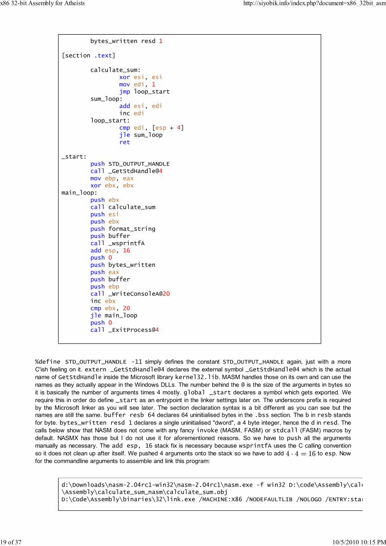
%define STD_OUTPUT_HANDLE -11 simply defines the constant STD_OUTPUT_HANDLE again, just with a more
C'ish feeling on it. extern _GetStdHandle@4 declares the external symbol _GetStdHandle@4 which is the actual
name of GetStdHandle inside the Microsoft library kernel32.lib. MASM handles those on its own and can use the
names as they actually appear in the Windows DLLs. The number behind the @ is the size of the arguments in bytes so
it is basically the number of arguments times 4 mostly. global _start declares a symbol which gets exported. We
require this in order do define _start as an entrypoint in the linker settings later on. The underscore prefix is required
by the Microsoft linker as you will see later. The section declaration syntax is a bit different as you can see but the
names are still the same. buffer resb 64 declares 64 uninitialised bytes in the .bss section. The b in resb stands
for byte. bytes_written resd 1 declares a single uninitialised "dword", a 4 byte integer, hence the d in resd. The
calls below show that NASM does not come with any fancy invoke (MASM, FASM) or stdcall (FASM) macros by
default. NASMX has those but I do not use it for aforementioned reasons. So we have to push all the arguments
manually as necessary. The add esp, 16 stack fix is necessary because wsprintfA uses the C calling convention
so it does not clean up after itself. We pushed 4 arguments onto the stack so we have to add to esp. Now
for the commandline arguments to assemble and link this program:
d:\Downloads\nasm-2.04rc1-win32\nasm-2.04rc1\nasm.exe -f win32 D:\code\Assembly\calcu\Assembly\calculate_sum_nasm\calculate_sum.objD:\Code\Assembly\binaries\32\link.exe /MACHINE:X86 /NODEFAULTLIB /NOLOGO /ENTRY:start
x86 32-bit Assembly for Atheists http://siyobik.info/index.php?document=x86_32bit_asm
19 of 37 10/5/2010 10:15 PM

d:\Code\Assembly\calculate_sum_nasm\calculate_sum.obj /LIBPATH:"C:\Program Files (x868\VC\PlatformSDK\Lib" kernel32.lib user32.lib
This does not require much explanation really since it is the same stuff all over again. One notable thing is the
/ENTRY:start part. The Microsoft linker prefixes all those names with an underscore (_) when it actually looks them
up inside the objects files which is why your entry point must have this prefix inside the code, hence the name _start in
the source code. The output is the same as usual so we should move on.
Writing Linux/BSD Applications Using x86 32-bit
Assembly
Now that we have covered Windows x86 programming with various assemblers it is time to find out how to implement
this program on Linux/BSD, too. FASM runs on x86 Linux/BSD and NASM will run on any Linux/BSD aswell but I have
already demonstrated the syntax for those so I am just going to cover the infamous GNU assembler version 2.17 in
this section.
as
as is the command to call the GNU assembler (short gas) on Linux/BSD systems. It comes with any sane distro so I
really do not need to tell you where to get it. Consult apt-get or emerge otherwise. It is generally agreed upon that
the gas syntax is very archaic and esoteric. It uses the AT&T syntax (as opposed to the Intel syntax I have been
using so far) in which basically the order of all arguments for the x86 instructions is reversed. Additionally it uses
customised instruction names with -b, -w, -l suffixes to imply byte/word/long (1 byte, 2 bytes, 4 bytes). Additionally it
introduces terribly redundant and complicated notations for offsets and cryptic register and number prefixes. Luckily, a
feature was introduced which enables crude Intel syntax support. I am going to use this feature in the following code.
Unluckily I had to use a silly hack to make it work properly because I could not find proper documentation on
replacements for standard operations which are not possible in the Intel syntax mode using the conventional ways. I am
going to show you some examples of conventional gas code later. For the record: I am using GNU assembler
version 2.17 (i486-linux-gnu) using BFD version 2.17 Debian GNU/Linux and collect2
version 4.1.2 20061115 (prerelease) (Debian 4.1.1-21) (i386 Linux/ELF) in this example. Here is
my code:
.code32
.intel_syntax noprefix
.section .data
format_string: .string "Arithmetic sum for the limit %d is %d\n"
.section .text
calculate_sum:xor esi, esimov edi, 1jmp loop_start
sum_loop:add esi, ediinc edi
loop_start:cmp edi, [esp + 4]jle sum_loopret 4
.global main
main:xor ebx, ebx
main_loop:
x86 32-bit Assembly for Atheists http://siyobik.info/index.php?document=x86_32bit_asm
20 of 37 10/5/2010 10:15 PM
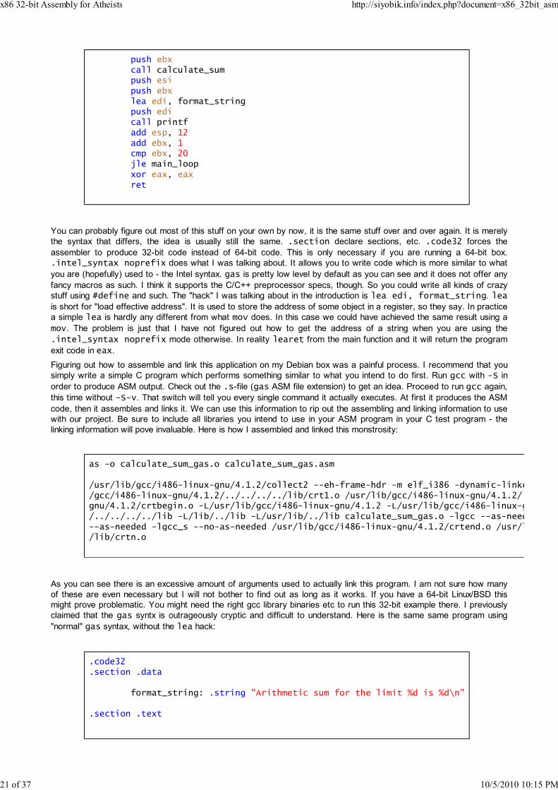
push ebxcall calculate_sumpush esipush ebxlea edi, format_stringpush edicall printfadd esp, 12add ebx, 1cmp ebx, 20jle main_loopxor eax, eaxret
You can probably figure out most of this stuff on your own by now, it is the same stuff over and over again. It is merely
the syntax that differs, the idea is usually still the same. .section declare sections, etc. .code32 forces the
assembler to produce 32-bit code instead of 64-bit code. This is only necessary if you are running a 64-bit box.
.intel_syntax noprefix does what I was talking about. It allows you to write code which is more similar to what
you are (hopefully) used to - the Intel syntax. gas is pretty low level by default as you can see and it does not offer any
fancy macros as such. I think it supports the C/C++ preprocessor specs, though. So you could write all kinds of crazy
stuff using #define and such. The "hack" I was talking about in the introduction is lea edi, format_string. lea
is short for "load effective address". It is used to store the address of some object in a register, so they say. In practice
a simple lea is hardly any different from what mov does. In this case we could have achieved the same result using a
mov. The problem is just that I have not figured out how to get the address of a string when you are using the
.intel_syntax noprefix mode otherwise. In reality learet from the main function and it will return the program
exit code in eax.
Figuring out how to assemble and link this application on my Debian box was a painful process. I recommend that you
simply write a simple C program which performs something similar to what you intend to do first. Run gcc with -S in
order to produce ASM output. Check out the .s-file (gas ASM file extension) to get an idea. Proceed to run gcc again,
this time without -S-v. That switch will tell you every single command it actually executes. At first it produces the ASM
code, then it assembles and links it. We can use this information to rip out the assembling and linking information to use
with our project. Be sure to include all libraries you intend to use in your ASM program in your C test program - the
linking information will pove invaluable. Here is how I assembled and linked this monstrosity:
as -o calculate_sum_gas.o calculate_sum_gas.asm
/usr/lib/gcc/i486-linux-gnu/4.1.2/collect2 --eh-frame-hdr -m elf_i386 -dynamic-linker/gcc/i486-linux-gnu/4.1.2/../../../../lib/crt1.o /usr/lib/gcc/i486-linux-gnu/4.1.2/..gnu/4.1.2/crtbegin.o -L/usr/lib/gcc/i486-linux-gnu/4.1.2 -L/usr/lib/gcc/i486-linux-gn/../../../../lib -L/lib/../lib -L/usr/lib/../lib calculate_sum_gas.o -lgcc --as-neede--as-needed -lgcc_s --no-as-needed /usr/lib/gcc/i486-linux-gnu/4.1.2/crtend.o /usr/li/lib/crtn.o
As you can see there is an excessive amount of arguments used to actually link this program. I am not sure how many
of these are even necessary but I will not bother to find out as long as it works. If you have a 64-bit Linux/BSD this
might prove problematic. You might need the right gcc library binaries etc to run this 32-bit example there. I previously
claimed that the gas syntx is outrageously cryptic and difficult to understand. Here is the same same program using
"normal" gas syntax, without the lea hack:
.code32
.section .data
format_string: .string "Arithmetic sum for the limit %d is %d\n"
.section .text
x86 32-bit Assembly for Atheists http://siyobik.info/index.php?document=x86_32bit_asm
21 of 37 10/5/2010 10:15 PM

calculate_sum:xorl %esi, %esimovl $1, %edijmp loop_start
sum_loop:addl %edi, %esiincl %edi
loop_start:cmpl 4(%esp), %edijle sum_loopretl $4
.global main
main:xorl %ebx, %ebx
main_loop:pushl %ebxcall calculate_sumpushl %esipushl %ebxpush $format_stringcall printfaddl $12, %espaddl $1, %ebxcmp $20, %ebxjle main_loopxorl %eax, %eaxret
The real gas syntax uses so many special characters that you get the feeling of looking at some esoteric programming
language like brainfuck. As long as I have a choice between various assemblers I definitely would not pick this one. gcc
inline assembly has an even more outrageous and complicated syntax.
Partial Registers
One thing I did not tell you on purpose about until now are the partial registers of the x86 architecture. This is because
they frequently do harm and slow down programs when used incorrectly. On the x86 architecture it is possible to
access lower parts of all general purpose registers according to the following pattern which I am going to demonstrate
on eax:
Bits 31 - 24 Bits 23 - 16 Bits 15 - 8 Bits 7 - 0
eax
ax
ah al
So eax can contain 32-bits, alright, we already knew that. But eax also has the three partial registers ax, ah and al.
These point to the data eax contains - they just show a smaller part of the same register. So ax represents the lower
16 bits of eax. ah represents the upper 8 bits of ax and al gives you the lower 8 bits of it. This has mostly backward
compabitibility reasons. ax is the original 16-bit accumulator register the x86 architecture started with. The e in eax
stands for "extended" since it is an extended version of ax. The l and the h in al/ah stand for low/high. Not all general
purpose registers feature the "high"/"low" partial registers. They are only available on eax, ebx, ecx and edx. You can
write to them and read from them just like normal registers. Here is a full list of all the other 32-bit registers and their
partial registers:
Bits 31 - 24 Bits 23 - 16 Bits 15 - 8 Bits 7 - 0
eax
ax
x86 32-bit Assembly for Atheists http://siyobik.info/index.php?document=x86_32bit_asm
22 of 37 10/5/2010 10:15 PM

ah al
ebx
bx
bh bl
ecx
cx
ch cl
edx
dx
dh dl
ebp
bp
esp
sp
esi
si
edi
di
The problem with using partial registers in 32-bit code is that they can cause so called partial register stalls. Reading
from partial registers and writing to partial registers causes more dependencies than doing the same to the full
registers. This can stall the execution pipelines of the processor which results in a slowdown of your code.
Understanding what the execution pipeline is and how it works on modern CPUs requires a lot of explaining and it is not
yet the time to cover this topic. So all you should keep in mind for now is that you should always avoid using partial
registers. There usually is a faster solution which minimises partial register usage - usually totally eliminating it. Both the
Intel Optimization Manual and the AMD Software Optimization Guide strongly discourage the use of partial registers for
this very reason. Here are a few examples of how partial registers work:
;in MASM syntax you use the following notation for hex numbers:mov eax, 012345678h;this writes 0x12345678 to eax, the decisive parts are the 0-prefix and the h-suffix
;the x86 instruction movzx is usually used to move values from 1-byte or 2-byte sized;it writes them to the lower part of the register and sets the rest of the register t;the "zx" part stands for "zero extend"
;read al, zero extend it and write it to ebx:movzx ebx, al
;ebx now contains 0x00000078
;read ah, zero extend it and write it to ebx:movzx ebx, ah
;ebx now contains 0x00000056
;read ax, zero extend it and write it to ebx:movzx ebx, ax
;ebx now contains 0x00005678
;normal mov:mov ebx, eax
;ebx now contains 0x12345678
Addresses
The x86 architecture allows us to use fairly complex expressions when we are addressing memory. The pattern it
x86 32-bit Assembly for Atheists http://siyobik.info/index.php?document=x86_32bit_asm
23 of 37 10/5/2010 10:15 PM

supports is:
address = base + index * scale + offset
The variables used in the pattern have the following meaning:
base: general purpose register1.
index: general purpose register2.
scale: 1, 2, 4 or 83.
offset: 32-bit integers4.
To fully comprehend what this means you should take a look at the following example:
;ebx <<= 3, shift it left by 3 bitsshl ebx, 3
add eax, ebxadd eax, 17
;the "byte ptr" signifies that we want to read a single byte only and not 2 or even 4;I have to use movzx because ecx is a 32-bit register and the byte is only 8 bits in movzx ecx, byte ptr [eax]
So what this basically does is reading a single byte from memory. This byte is stored at the address eax + (ebx <<
3) + 17. Shifts can be expressed with multiplication/division with powers of two, in case you never heard about it.
Shifting ebx 3 bits to the left is the same as multiplying it by 8 because two to the power of three is equal to 8. In
general n <<= a; is equivalent to n *= static_cast(std::pow(2.0, static_cast(a))); and n >>= a; is equivalent to
n /= static_cast(std::pow(2.0, static_cast(a)));, assuming that a and n are both of type long. This is a direct
result of the positional notation I formulated mathematically at the beginning of this document. By shifting you basically
add zeroes or remove digits from the sequence of digits. This leads to multiplications by the powers of the base or
integer divisions with the same. The great thing is that the x86 architecture allows us to do all of those things in a single
step:
movzx ecx, byte ptr [eax + ebx * 8 + 17]
It is a really useful feature and has lots of applications. In combination with lea you can even use it to accelerate simple
arithmetic operations which would usually require several steps for multiplication and addition so do keep it in mind.
Control Structures
In the introduction I stated that this document is intended for people who are already familiar with iterative high level
programming languages such as C/C++. At the beginning it is difficult to stop thinking in terms of if, for and while
and to start thinking in terms of labels and conditional jumps so I wanted to show you a few examples which
demonstrate how to translate these standard control structures to x86 32-bit assembly. My apology to Linux/BSD users
- but I am going to use Windows specific API calls in these examples occasionally.
The first thing we are going to check out is the basic ifififif-construct:
if(lstrlen(some_string) > 32)return -1;
return 0;
Here is the equivalent x86 32-bit ASM code:
x86 32-bit Assembly for Atheists http://siyobik.info/index.php?document=x86_32bit_asm
24 of 37 10/5/2010 10:15 PM

invoke lstrlen, addr some_stringcmp eax, 32jle return_zeromov eax, -1ret
return_zero:xor eax, eaxret
So the original comparison operator was "greater than" but in x86 assembly we jump away from the if-body so we
need to check for the exact opposite of the original condition. The logical negation of "greater than" is "less than or
equal to" so we use jle in this case. Here is a list of logical negations of standard operators:
Original operator Logical negation
== !=
!= ==
< >=
> <=
<= >
>= <
The ifififif-elseelseelseelse construct is next:
void divisor_check(int divisor){
if(divisor == 0)puts("Division by zero!");
elseputs("Valid division");
puts("This gets executed in either case");}
The approximate equivalent in x86 ASM is:
.data
division_by_zero db "Division by zero!", 0valid_division db "Valid division", 0either_case db "This gets executed in either case", 0
.text
divisor_check proc divisor:dwordcmp [esp + 4], 0jne else_labelinvoke puts, addr division_by_zerojmp end_of_if
else_label:invoke puts, addr valid_division
end_of_if:invoke puts, addr either_caseret
x86 32-bit Assembly for Atheists http://siyobik.info/index.php?document=x86_32bit_asm
25 of 37 10/5/2010 10:15 PM

So if the result of the comparison implies that the else body must be executed we jump to the else-label and simply
continue the execution after that because it gets us right where we are supposed to be anyways. In the other case the
first jump is not taken but we must not fall through to the else-body so an unconditional jump is necessary to take us to
the end of the if-structure.
Let us move on to the whilewhilewhilewhile-construct:
long i = 0;while(data[i] >= 128 || some_function(data[i]))
i++;
Let us assume that i gets stored in the general purpose register eax and that data is a string/an array of bytes. then
the approximate equivalent in x86 ASM is:
xor eax, eaxloop:
movzx ebx, byte ptr [array + eax]cmp ebx, 128jge iterateinvoke some_function, ebxtest eax, eaxjz end_of_loop
iterate:inc eaxjmp loop
end_of_loop:
I am using the new instruction test in this example. test is to the logical AND what cmp is to subtraction. It performs
the a logical AND using the operands behind the instruction as arguments for the logical function but it does not store the
result of it anywhere. It is simply used to set the flags. If you look closely at the logical table for AND you will realise that
for all boolean values a the term a & a evaluates to a. This is called idempotence. An idempotent operation can be
applied to a variable over and over again but in the end it always evaluate to the same variable again. The logical OR
operation is idempotent aswell. So what test eax, eax really does is checking the value of eax and setting the flags
accordingly. In this case we use it to determine whether the register is equal to zero. In case you are not used to this
particular feature of C/C++: while(data[i] >= 128 || some_function(data[i])) is equivalent to
while(data[i] >= 128 || some_function(data[i]) != 0) - which is why we jump out of the loop if that
part of the boolean term fails, too. We could even optimise this loop by using an initial jump to enter the loop and putting
the iteration at the beginning of the body:
xor eax, eaxjmp enter_loop
iterate:inc eax
enter_loop:movzx ebx, byte ptr [array + eax]cmp ebx, 128jge iterateinvoke some_function, ebxtest eax, eaxjnz iterate
We do have that additional jump at the beginning now but you always have to keep in mind that 99% of all CPU time is
spent inside loops. Optimising the body of a loop greatly outweighs such a one-time operation. The new body looks
unintuitive and does not remind one of the original C/C++ code at all so I did not want to start with it right away and
used the less optimised version first.
x86 32-bit Assembly for Atheists http://siyobik.info/index.php?document=x86_32bit_asm
26 of 37 10/5/2010 10:15 PM
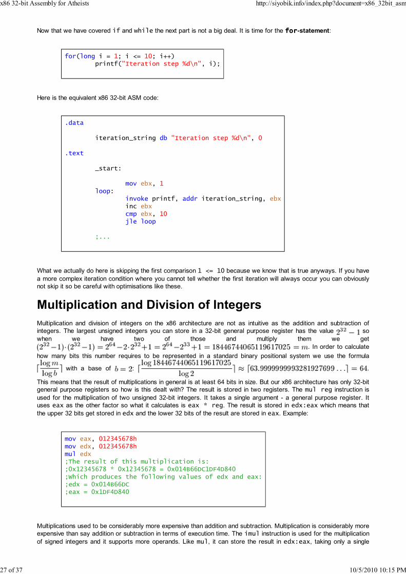
Now that we have covered if and while the next part is not a big deal. It is time for the forforforfor-statement:
for(long i = 1; i <= 10; i++)printf("Iteration step %d\n", i);
Here is the equivalent x86 32-bit ASM code:
.data
iteration_string db "Iteration step %d\n", 0
.text
_start:
mov ebx, 1loop:
invoke printf, addr iteration_string, ebxinc ebxcmp ebx, 10jle loop
;...
What we actually do here is skipping the first comparison 1 <= 10 because we know that is true anyways. If you have
a more complex iteration condition where you cannot tell whether the first iteration will always occur you can obviously
not skip it so be careful with optimisations like these.
Multiplication and Division of Integers
Multiplication and division of integers on the x86 architecture are not as intuitive as the addition and subtraction of
integers. The largest unsigned integers you can store in a 32-bit general purpose register has the value so
when we have two of those and multiply them we get
. In order to calculate
how many bits this number requires to be represented in a standard binary positional system we use the formula
with a base of : .
This means that the result of multiplications in general is at least 64 bits in size. But our x86 architecture has only 32-bit
general purpose registers so how is this dealt with? The result is stored in two registers. The mul reg instruction is
used for the multiplication of two unsigned 32-bit integers. It takes a single argument - a general purpose register. It
uses eax as the other factor so what it calculates is eax * reg. The result is stored in edx:eax which means that
the upper 32 bits get stored in edx and the lower 32 bits of the result are stored in eax. Example:
mov eax, 012345678hmov edx, 012345678hmul edx;The result of this multiplication is:;0x12345678 * 0x12345678 = 0x014B66DC1DF4D840;Which produces the following values of edx and eax:;edx = 0x014B66DC;eax = 0x1DF4D840
Multiplications used to be considerably more expensive than addition and subtraction. Multiplication is considerably more
expensive than say addition or subtraction in terms of execution time. The imul instruction is used for the multiplication
of signed integers and it supports more operands. Like mul, it can store the result in edx:eax, taking only a single
x86 32-bit Assembly for Atheists http://siyobik.info/index.php?document=x86_32bit_asm
27 of 37 10/5/2010 10:15 PM
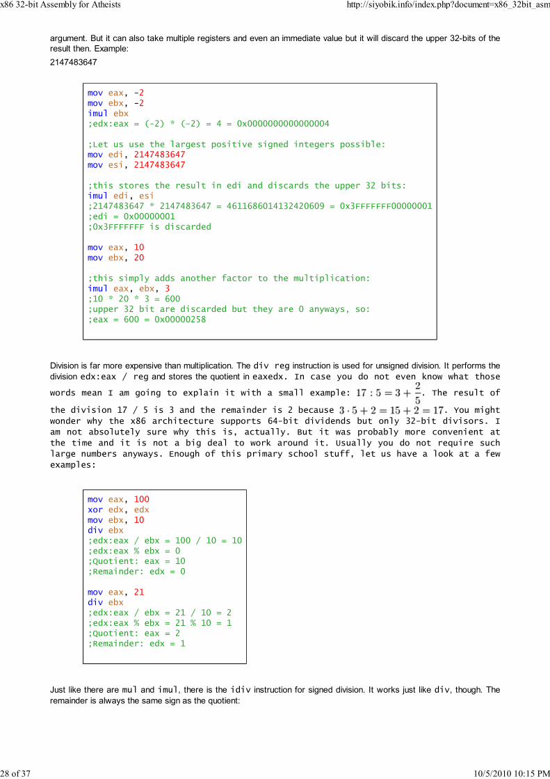
argument. But it can also take multiple registers and even an immediate value but it will discard the upper 32-bits of the
result then. Example:
2147483647
mov eax, -2mov ebx, -2imul ebx;edx:eax = (-2) * (-2) = 4 = 0x0000000000000004
;Let us use the largest positive signed integers possible:mov edi, 2147483647mov esi, 2147483647
;this stores the result in edi and discards the upper 32 bits:imul edi, esi;2147483647 * 2147483647 = 4611686014132420609 = 0x3FFFFFFF00000001;edi = 0x00000001;0x3FFFFFFF is discarded
mov eax, 10mov ebx, 20
;this simply adds another factor to the multiplication:imul eax, ebx, 3;10 * 20 * 3 = 600;upper 32 bit are discarded but they are 0 anyways, so:;eax = 600 = 0x00000258
Division is far more expensive than multiplication. The div reg instruction is used for unsigned division. It performs the
division edx:eax / reg and stores the quotient in eaxedx. In case you do not even know what those
words mean I am going to explain it with a small example: . The result of
the division 17 / 5 is 3 and the remainder is 2 because . You might
wonder why the x86 architecture supports 64-bit dividends but only 32-bit divisors. I
am not absolutely sure why this is, actually. But it was probably more convenient at
the time and it is not a big deal to work around it. Usually you do not require such
large numbers anyways. Enough of this primary school stuff, let us have a look at a few
examples:
mov eax, 100xor edx, edxmov ebx, 10div ebx;edx:eax / ebx = 100 / 10 = 10;edx:eax % ebx = 0;Quotient: eax = 10;Remainder: edx = 0
mov eax, 21div ebx;edx:eax / ebx = 21 / 10 = 2;edx:eax % ebx = 21 % 10 = 1;Quotient: eax = 2;Remainder: edx = 1
Just like there are mul and imul, there is the idiv instruction for signed division. It works just like div, though. The
remainder is always the same sign as the quotient:
x86 32-bit Assembly for Atheists http://siyobik.info/index.php?document=x86_32bit_asm
28 of 37 10/5/2010 10:15 PM

;Set edx:eax to -100mov eax, -100mov edx, -1;-1 because we want all upper bits to be 1 - it is Two's complement!
mov ebx, 10idiv ebx;edx:eax / ebx = - 100 / 10 = - 10;edx:eax % ebx = 0;Quotient: eax = 10;Remainder: edx = 0
mov eax, -21mov edx, -1div ebx;edx:eax / ebx = - 21 / 10 = - 2;edx:eax % ebx = - 21 % 10 = - 1;Quotient: eax = - 2;Remainder: edx = - 1
Floating Point Operations
Now that we have covered the most important integer operations we should move on to floating point instructions. The
CPU contains many different units which work together when a program is executed. Instructions like add, sub, xor,
shl, mul and idiv are all executed on the so called Arithmetic Logical Unit (ALU). The operations we are going to
concern ourselves with are executed in a completely different unit. It is called the Floating Point Unit (FPU). This
is where stuff like 0.942 - 7.183 = -6.241 is calculated. The x86 architecture implements the IEEE-754 standard
(http://en.wikipedia.org/wiki/IEEE_floating-point_standard) and offers support for three different precision formats:
Single precision 32-bit floating point numbers (float in C/C++)1.
Double precision 64-bit floating point numbers (double in C/C++)2.
Extended precision 80-bit floating point numbers (long double in C/C++)3.
We are going to explore the mathematical concept behind this system first. The real numbers know no bounds and
even if we specify boundaries for them they are still not discrete. There are infinitely many real values between the
numbers 0 and 1 so we have to make sacrifices to represent real numbers with boundaries and approximative
capabilities that meet our requirements. We can only represent approximations of most real values using this concept. A
few of them which are composed of sums of positive/negative powers of 2 can be represented flawlessly without error
using IEEE-754. We are going to examine the smallest of the three formats in this part of the document only. The others
are based on the same idea and just use different parameters really.
The IEEE-754 32-bit precision format divides the 32-bit value into 3 different sections:
Section Size Bit range
Sign 1 bit 31 - 31
Biased exponent 8 bits 30 - 23
Mantissa 23 bits 22 - 0
The mantissa expresses a fraction of the form 1.x where x is expressed by the mantissa. The numbers are encoded
using the Big Endian format (most significant bit first). Let stand for the sign bit, for the biased exponent and
with for the mantissa bits (they are read from the left to the right), then the value
most IEEE-754 encoded reals represent can be determined using the following formula:
The part simply changes the sign according to the sign bit. The value is negative if the sign bit is set to 1 and
positive if it is set to 0. is where the the power of 2 gets expressed through the actual exponent
. The "bias" I was talking about is a necessity to allow the exponent to be negative. Otherwise we would
have positive/zero exponents only and we would be unable to express numbers since this requires
negative powers of 2. The mantisa represents the binary digits to the right of the point in a number like which
x86 32-bit Assembly for Atheists http://siyobik.info/index.php?document=x86_32bit_asm
29 of 37 10/5/2010 10:15 PM

had the leading "1." simply chopped off. Let us manually convert the number 149.8 to the IEEE-754 single precision
format. At first we require a binary representation of this decimal number. We examine the part to the left of the point
first and repeatedly perform divisions by 2, splitting the result into an integer part and a rational part after each step.
Then we repeat the procedure with this integer part until it eventually becomes zero.
149 / 2 = 74 + 1 / 2 74 / 2 = 37 + 0 / 2 37 / 2 = 18 + 1 / 2 18 / 2 = 9 + 0 / 2 9 / 2 = 4 + 1 / 2 4 / 2 = 2 + 0 / 2 2 / 2 = 1 + 0 / 2 1 / 2 = 0 + 1 / 2
You get the binary representation of the left part of the number by reading the "bit stream" on the right bottom-up, which
gives us the binary number 10010101 which is indeed equal to the decimal representation 149. The part to the right of
the of the point works in a similar fashion but it can be tricky at times because some numbers cannot be expressed with
a finite number of digits in another base. We chop off the left part of the number and replace it with 0. We repeatedly
multiply it by 2, chopping off the leading digit to replace it with 0 each step. We are done until there is a 0 left or until we
discover a periodic pattern or until we simply hit the limit for the precision:
0.8 * 2 = 1.6 => 1 <--+0.6 * 2 = 1.2 => 1 | periodic pattern detected0.2 * 2 = 0.4 => 0 |0.4 * 2 = 0.8 => 0 ---+
We discovered a periodic pattern which means that 0.8 cannot be written in binary notation in a finite number of digits
without any loss of precision. We conclude:
We can prove this mathematically by making use of geometric series with :
All we need to do is to perform some index shifts and splitting up of sums to show the desired result:
The next step in the conversion process is shifting our binary representation of the number to the left or to the right such
that it has the form "1.x". We have to keep track of the number of shifting steps we performed and of the direction
aswell. We store this information in the exponent of a power of two:
As you can see I algebraically manipulated the term so it matches the pattern in the original formula I showed to you.
Now we can simply read off the values:
We are nearly done, we simply need to convert the biased exponent to its 8-bit binary representation now:
134 / 2 = 67 + 0 / 2 67 / 2 = 33 + 1 / 2 33 / 2 = 16 + 1 / 2
x86 32-bit Assembly for Atheists http://siyobik.info/index.php?document=x86_32bit_asm
30 of 37 10/5/2010 10:15 PM

16 / 2 = 8 + 0 / 2 8 / 2 = 4 + 0 / 2 4 / 2 = 2 + 0 / 2 2 / 2 = 1 + 0 / 2 1 / 2 = 0 + 1 / 2
This is the same algorithm we used before and it tells us that the binary representation is 10000110. So the IEEE-754
representation of the decimal value 149.8 is:
Sign : biased exponent : mantissa
0 : 10000110 : 00101011100110011001100
= 01000011 00010101 11001100 11001100
In the case of periodic binary representations you simply repeat the periodic digit group until you hit the limits imposed
by the 23 bit boundary for the mantissa. Let us get back to the x86 architecture. The other formats simply use different
biased exponent and mantissa sizes which also forces them to use different bias values, obviously. There are certain
special cases for invalid numbers, infinity and zero and such but it is not relevant for this document, really. Check out
http://en.wikipedia.org/wiki/IEEE_floating-point_standard if you are interested in the topic.
The FPU contains 8 80-bit elements called st(0), st(1), ..., st(7). I did not say "register" because they are
implemented as a stack so st(0) always refers to the top element, st(1) to the below the top, etc. This makes it
quite tricky to use. Honestly, I am not even quite sure why they implemented it this way. Maybe it makes some common
operations shorter this way or something like that. FPU code is very fragile and often hard to read. I strongly
recommend reading a good instruction set reference simultaneously when you are working with FPU code. There are
lots of details you have to pay attention to and it is easy to make mistakes so be extra careful with FPU code. Let us
start out with some easy examples to see how the FPU stack works. Here is the state of the FPU at the beginning of
the program:
Position Value
st(0) undefined
st(1) undefined
st(2) undefined
st(3) undefined
st(4) undefined
st(5) undefined
st(6) undefined
st(7) undefined
All FPU instructions have the f- prefix. If they have a -p suffix it means that they pop the top element off the stack at
the end of their execution. We are going to execute the following instructions on the FPU now:
;...
;push one on top of the stackfld1;push zero on top of the stackfldz;add them up and store the result in st(0)fadd st(0), st(1);add the top two elements up and store the result in st(1), pop the stackfaddp st(1), st(0)
;...
x86 32-bit Assembly for Atheists http://siyobik.info/index.php?document=x86_32bit_asm
31 of 37 10/5/2010 10:15 PM
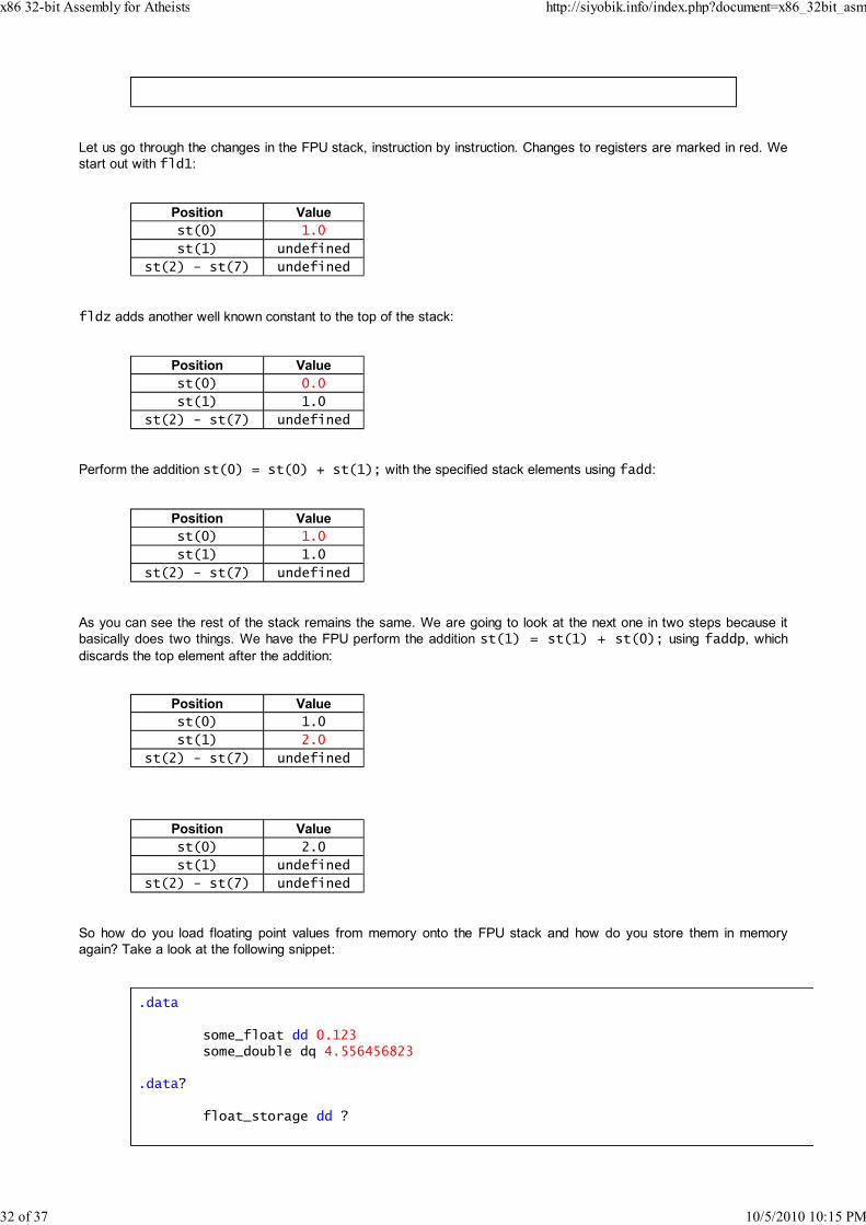
Let us go through the changes in the FPU stack, instruction by instruction. Changes to registers are marked in red. We
start out with fld1:
Position Value
st(0) 1.0
st(1) undefined
st(2) - st(7) undefined
fldz adds another well known constant to the top of the stack:
Position Value
st(0) 0.0
st(1) 1.0
st(2) - st(7) undefined
Perform the addition st(0) = st(0) + st(1); with the specified stack elements using fadd:
Position Value
st(0) 1.0
st(1) 1.0
st(2) - st(7) undefined
As you can see the rest of the stack remains the same. We are going to look at the next one in two steps because it
basically does two things. We have the FPU perform the addition st(1) = st(1) + st(0); using faddp, which
discards the top element after the addition:
Position Value
st(0) 1.0
st(1) 2.0
st(2) - st(7) undefined
Position Value
st(0) 2.0
st(1) undefined
st(2) - st(7) undefined
So how do you load floating point values from memory onto the FPU stack and how do you store them in memory
again? Take a look at the following snippet:
.data
some_float dd 0.123some_double dq 4.556456823
.data?
float_storage dd ?
x86 32-bit Assembly for Atheists http://siyobik.info/index.php?document=x86_32bit_asm
32 of 37 10/5/2010 10:15 PM
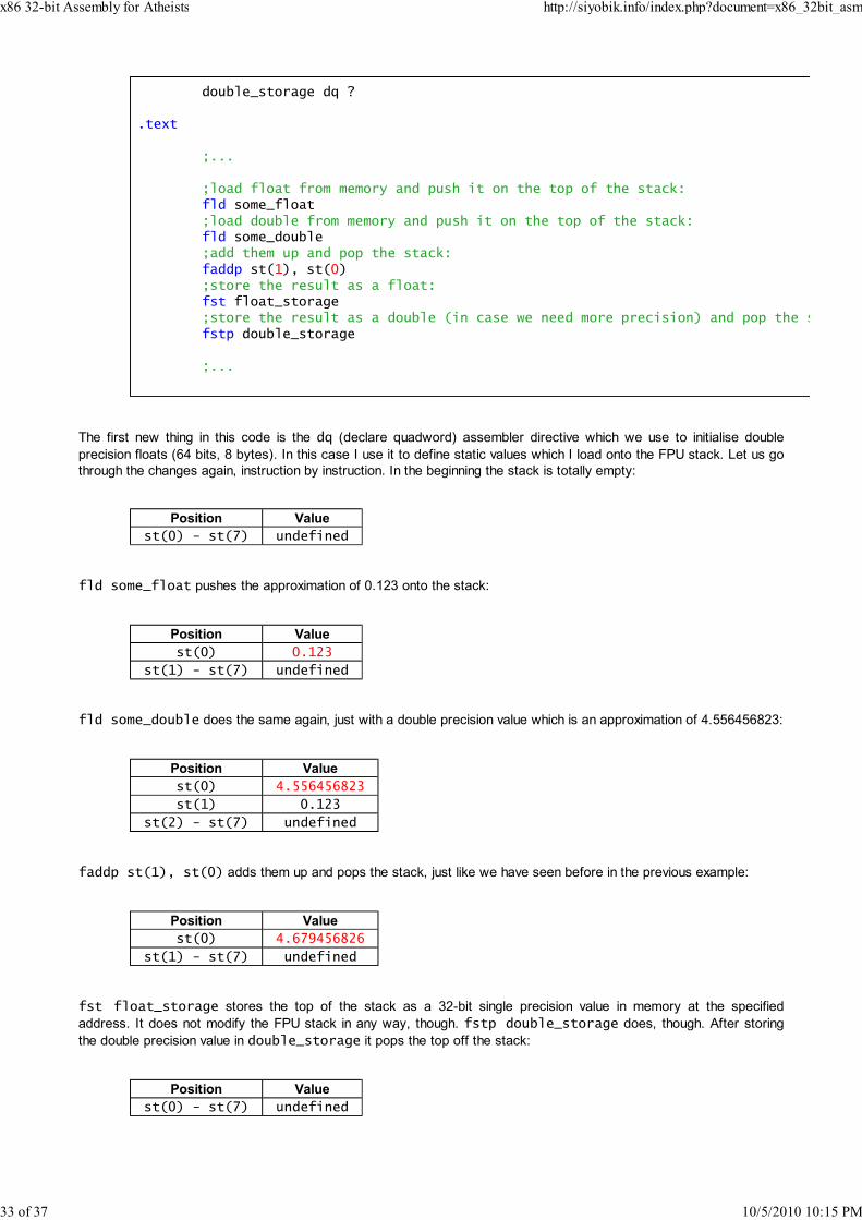
double_storage dq ?
.text
;...
;load float from memory and push it on the top of the stack:fld some_float;load double from memory and push it on the top of the stack:fld some_double;add them up and pop the stack:faddp st(1), st(0);store the result as a float:fst float_storage;store the result as a double (in case we need more precision) and pop the stack so ifstp double_storage
;...
The first new thing in this code is the dq (declare quadword) assembler directive which we use to initialise double
precision floats (64 bits, 8 bytes). In this case I use it to define static values which I load onto the FPU stack. Let us go
through the changes again, instruction by instruction. In the beginning the stack is totally empty:
Position Value
st(0) - st(7) undefined
fld some_float pushes the approximation of 0.123 onto the stack:
Position Value
st(0) 0.123
st(1) - st(7) undefined
fld some_double does the same again, just with a double precision value which is an approximation of 4.556456823:
Position Value
st(0) 4.556456823
st(1) 0.123
st(2) - st(7) undefined
faddp st(1), st(0) adds them up and pops the stack, just like we have seen before in the previous example:
Position Value
st(0) 4.679456826
st(1) - st(7) undefined
fst float_storage stores the top of the stack as a 32-bit single precision value in memory at the specified
address. It does not modify the FPU stack in any way, though. fstp double_storage does, though. After storing
the double precision value in double_storage it pops the top off the stack:
Position Value
st(0) - st(7) undefined
x86 32-bit Assembly for Atheists http://siyobik.info/index.php?document=x86_32bit_asm
33 of 37 10/5/2010 10:15 PM

Now that we have covered the basics of the FPU stack is time to move on to a more elaborate example of how to use
the FPU. Here is the original C++ code we are going to translate to x86 32-bit assembly:
double f(double x){
char buffer[10];return std::sin(x * x + 1.0) / 2.0;
}
int main(){
for(double i = 0.0; i < 1.0; i += 0.1){
double value = f(i);printf("f(%.1f) = %.4f, first two digits: %ld\n", i, value, static_cast
}std::cin.get();return 0;
}
The FPU example code I came up with is quite nasty I must say. I apologise in advance. Here is my translation to x86
ASM:
.686p
.model flat, stdcall
option epilogue: noneoption prologue: none
GetStdHandle proto :dwordwsprintfA proto c :varargWriteConsoleA proto :dword, :dword, :dword, :dword, :dwordExitProcess proto :dword
STD_OUTPUT_HANDLE equ -11
.data
format_string db "f(%s) = %s, first two digits: %d", 10, 0iteration_step dq 0.1hundred dq 100.0ten dq 10.0half dq 0.5
fuck_off dq 123.456789
.data?
number_buffer db 16 dup (?)number_buffer2 db 16 dup (?)buffer db 64 dup (?)bytes_written dd ?
iterator dq ?
.code
f procfmul st(0), st(0)fld1faddp st(1), st(0)
x86 32-bit Assembly for Atheists http://siyobik.info/index.php?document=x86_32bit_asm
34 of 37 10/5/2010 10:15 PM

fsinfmul halfret
f endp
write_double proc double_buffer:dword, precision:dwordfst qword ptr [esp - 12]mov esi, [esp + 4]mov byte ptr [esi], '.'fld st(0)fisttp dword ptr [esp - 4]mov eax, [esp - 4]mov ecx, 10
write_left_digits:xor edx, edxdiv ecxadd edx, '0'dec esimov byte ptr [esi], dltest eax, eaxjnz write_left_digitsmov ecx, [esp + 4]mov eax, [esp + 8]
write_right_digits:fild dword ptr [esp - 4]fsubp st(1), st(0)fmul tenfld st(0)fisttp dword ptr [esp - 4]mov ebx, [esp - 4]add ebx, '0'inc ecxmov byte ptr [ecx], bldec eaxjnz write_right_digitsmov byte ptr [ecx + 1], 0fstp st(0)fld qword ptr [esp - 12]ret 8
write_double endp
public main
main:invoke GetStdHandle, STD_OUTPUT_HANDLE
mov ebp, eax
fldz
main_loop:fst iteratorinvoke write_double, addr number_buffer + 8, 4mov edi, esicall finvoke write_double, addr number_buffer2 + 8, 6fld st(0)fmul hundredfisttp dword ptr [esp - 4]mov eax, [esp - 4]invoke wsprintfA, addr buffer, addr format_string, edi, esi, eaxinvoke WriteConsoleA, ebp, addr buffer, eax, addr bytes_written, 0fstp st(0)fld iteratorfadd iteration_stepfld1
x86 32-bit Assembly for Atheists http://siyobik.info/index.php?document=x86_32bit_asm
35 of 37 10/5/2010 10:15 PM

fcomip st(0), st(1)jnb main_loopinvoke ExitProcess, 0
end
Let us start with the main code. fldz pushes the zero constant on the stack. So after execution this instruction st(0)
contains zero while all other FPU registers are still undefined/empty. If you use such an undefined register in an FPU
operation you will cause an exception. If you try to pop an element off an empty stack - meaning, all values are
undefined - you will get an exception, too. Another thing you have to watch out for is stack overflow. You cannot just
keep on adding more elements onto the stack. If all registers have been set and you push an additional element onto
the stack you will cause an FPU stack overflow so keep track of the height of your FPU stack at all times. fst
iterator reads the 64-bit value from st(0) and stores it at the memory location iterator - the stack remains the
same. On the next line write_double gets called for the first time. This is a stupid workaround I had to come up with
because the Windows API does not offer any functions which allow you to convert floating point numbers to strings to
my knowledge. I tried to use the Microsoft Visual C Runtime but those attempts did not bear any fruit either because
using msvcrt in ASM is pretty tricky nowadays. You have to link the application with those silly manifest files and
annoying stuff like that so I eventually gave up on making, say, printf work and wrote my own double -> string
converter.
The write_double body starts out with fst dword ptr [esp - 12]. This is not any different from the previous
fst store call really, it simply does not use an address which is known as compile time. Instead we use unused bytes
on the stack to store it temporarily locally. The qword ptr part is necessary because the assembler cannot magically
know what format we actually want to store. It could be single precision, double precision or even extended precision -
it simply cannot tell. With the prior fst call this was not necessary because the size of that object is defined in the data
section. The fld loads values and pushes them on top of the stack. This value can be a location in memory or even an
FPU register. In this case we are using fld st(0) which basically just duplicates the top of the stack. fisttp
dword ptr [esp - 4] performs a double to int conversion and stores the result at the specified memory
location. This function simply truncates the digits to the right of the decimal point away. So we would convert something
like 2.913 to 2. In the following loop we perform a conventional integer to decimal ASCII number conversion by
repeatedly dividing the integer by 10, adding 0x30 to it, and writing the lower byte of the register to a buffer. This buffer
gets first filled from right to left, starting with the decimal point. In the write_right_digits section we read the
decimal digits to the right of the decimal point from the number by repeatedly multiplying it by 10, converting it to an
integer, converting the integer to a decimal digit which gets added to the buffer and by eventually subtracting the integer
from the double again to get rid of the digit to the left of the decimal point. The buffer gets filled from the left to the right,
starting with the byte to the right of the decimal point. It starts with fild dword ptr [esp - 4]. This instruction
loads an integer from memory, converts it to a double and pushes it onto the FPU stack so we can access it via s(0).
fsubp st(1), st(0) performs the calculation st(1) - st(0) and stores the result in std(1). Additionally it
pops off the top of the stack so what was once st(1) is now st(0). You can tell this from the -p suffix in the
mnemonic. fmul ten multiplies st(0) with the value 10.0 which is stored in memory. The result of the operation gets
stored in std(0) again. It is followed by another fld st(0) which duplicates the top of the stack. It is necessary
because we are going to use fisttp on the next line. Unlickily this instruction does not feature any non -p version so
we are forced to perform that somewhat redundant additional FPU stack push. So what this loop does is simply writing
a certain number of digits to the right of the decimal point. The number is specified by the second agument precision.
At the end of the function you can see a fstp st(0). This stores st(0) in st(0) and pops the top element of the
stack (which is st(0). So it basically works like a pop - with the exception of being somewhat unintuitive and cryptic. At
the very end fld qword ptr [esp - 12] is called. This restores the original value st(0) had when the function
was first called because we wrote it to that part of the memory in the beginning.
After returning from write_double for the first time the function f is called. This is pretty much a direct translation of
the corresponing C/C++ function we defined earlier. fmul st(0), st(0) is basically equivalent to st(0) = st(0)
* st(0); in C/C++ pseudo code. fld1 is another "load constant" function, just like ldz. It pushes the value zero on
top of the stack. faddp st(1), st(0) adds st(1) to st(0) and stores the reslt in st(1). After this step the top
element of the stack gets popped off so the result is in st(0). fsin performs st(0) = sin(st(0)). And last but
not least we divide the resulting value by 2.0 using fmul half. This actually multiplies st(0) with 0.5 but it is
obviously the same as dividing by zero since . The value of f is returned in st(0) and written into a
buffer. Most of the following instructions have already been explained, with the exception of fcomip st(0), st(1).
This compares the values of st(0) and st(1) and sets the flags Zero/Parity/Carry flags according to a particular
pattern. More importantly, it specifies CF = 1 if and only if st(0) < st(i) - which is exactly what we want. The jnb
instruction jumps only if the iterator is still smaller than 1.0. Here is the actual output of the function:
x86 32-bit Assembly for Atheists http://siyobik.info/index.php?document=x86_32bit_asm
36 of 37 10/5/2010 10:15 PM

f(0.0000) = 0.420735, first two digits: 42f(0.1000) = 0.423415, first two digits: 42f(0.2000) = 0.431202, first two digits: 43f(0.3000) = 0.443313, first two digits: 44f(0.4000) = 0.458401, first two digits: 45f(0.5000) = 0.474492, first two digits: 47f(0.6000) = 0.488932, first two digits: 48f(0.7000) = 0.498368, first two digits: 49f(0.7999) = 0.498803, first two digits: 49f(0.9000) = 0.485763, first two digits: 48f(0.9999) = 0.454648, first two digits: 45
As you can see there are a few errors in the iterator such as 0.7999 and 0.9999. You should probably already be
familiar with the problem of rounding errors on floating point numbers from imperative high level programming
languages. It is simply a result of the system we use. Not every number can be perfectly represented. Most of them
have certain small errors and the results of arithmetic operations on them are inaccurate. There are many FPU
instructions with extremely specific applications and I am not going to cover them here. Rule of thumb: If you want to
know how something works, write it in C/C++, turn on assembly listings and read the code in combination with an x86
Instruction Set Reference.
x86 32-bit Assembly for Atheists http://siyobik.info/index.php?document=x86_32bit_asm
37 of 37 10/5/2010 10:15 PM