xaui/xgxs proposal - ieeegrouper.ieee.org/groups/802/3/ae/public/mar00/taborek_1_0300.pdf · ieee...
TRANSCRIPT
IEEE 802.3ae
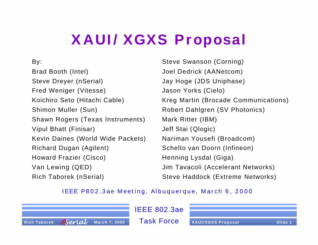
Task Force XAUI /XGXS Proposal S l ide 1 Rich Taborek March 7, 2000nnnnnnnnSerialSerial
XAUI/XGXS ProposalBy:
Brad Booth (Intel)
Steve Dreyer (nSerial)
Fred Weniger (Vitesse)
Koichiro Seto (Hitachi Cable)
Shimon Muller (Sun)
Shawn Rogers (Texas Instruments)
Vipul Bhatt (Finisar)
Kevin Daines (World Wide Packets)
Richard Dugan (Agilent)
Howard Frazier (Cisco)
Van Lewing (QED)
Rich Taborek (nSerial)
IEEE P802.3ae Meet ing , A lbuquerque, March 6 , 2000
Steve Swanson (Corning)
Joel Dedrick (AANetcom)
Jay Hoge (JDS Uniphase)
Jason Yorks (Cielo)
Kreg Martin (Brocade Communications)
Robert Dahlgren (SV Photonics)
Mark Ritter (IBM)
Jeff Stai (Qlogic)
Nariman Yousefi (Broadcom)
Schelto van Doorn (Infineon)
Henning Lysdal (Giga)
Jim Tavacoli (Accelerant Networks)
Steve Haddock (Extreme Networks)

IEEE 802.3ae
Task Force XAUI /XGXS Proposal S l ide 2 Rich Taborek March 7, 2000nnnnnnnnSerialSerial
Presentation Purpose
§ Consolidation of Hari proposals
§ Alignment with proposed Layered Model and Document Structure
§ No new material is introduced
§ It’s homeless Hari with a new name and home

IEEE 802.3ae
Task Force XAUI /XGXS Proposal S l ide 3 Rich Taborek March 7, 2000nnnnnnnnSerialSerial
Description§ XAUI = 10 Gigabit eXtended Attachment Unit Inter face
§ XGXS = XGMI I eX tende r Sub laye r
§ Based on prev ious Har i proposals
§ C D R - based, 4 lane ser ial , sel f -t imed interface
§ 3.125 Gbaud, 8B/10B encoded over 20” FR-4 PCB t r aces
§ PHY and Protocol independent scalable archi tecture
§ Convenient implementat ion part i t ion
§ May be imp l emen t ed i n CMOS , B iCMOS , S iGe
§ Direct mapping of XGMII data to/from PCS
§ XGMII proposed by Howard Frazier, Cisco, et. al.http://grouper. ieee.org/groups/802/3/10G_study/publ ic/ ju ly99/ f raz ie r_ 1 _ 0 7 9 9 . p d f
IEEE 802.3ae
Task Force XAUI /XGXS Proposal S l ide 4 Rich Taborek March 7, 2000nnnnnnnnSerialSerial
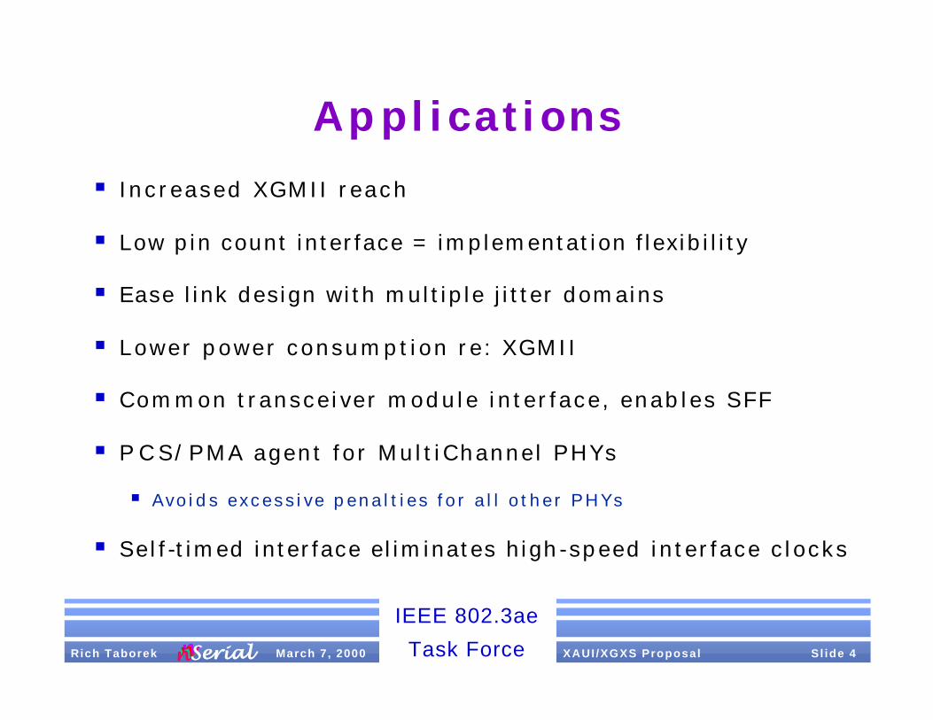
Applications
§ Increased XGMII reach
§ Low pin count interface = implementation flexibility
§ Ease link design with multiple jitter domains
§ Lower power consumption re: XGMII
§ Common transceiver module interface, enables SFF
§ P C S/PMA agent for Mult iChannel PHYs
§ Avo ids excess ive pena l t ies for a l l o ther PHYs
§ Self-timed interface eliminates high-speed interface clocks

IEEE 802.3ae
Task Force XAUI /XGXS Proposal S l ide 5 Rich Taborek March 7, 2000nnnnnnnnSerialSerial
Highlights
§ Increased reach
§ XGMII is ~3” (~7 cm)
§ XAUI is ~20” (~50 cm)
§ Lower connection count
§ XGMII is 74 wires (2 sets of 32 data, 4 control & 1 clock)
§ XAUI is 16 wires (2 sets of 4 differential pairs)
§ Better jitter control
§ XGMII does not attenuate jitter (neither does OIF99.102)
§ XAUI self -timed interface enables excellent jitter control at PCS

IEEE 802.3ae
Task Force XAUI /XGXS Proposal S l ide 6 Rich Taborek March 7, 2000nnnnnnnnSerialSerial
Location - Layer Model
PHYSICAL
DATA LINK
NETWORK
TRANSPORT
SESSION
PRESENTATION
APPLICATION
OSIREFERENCE
MODELLAYERS
Reconciliation
MAC
MAC Control (Optional)
LLC
XAUI
LANLAYERS
HIGHER LAYERS
MDI = Medium Dependent InterfaceXGMII = 10 Gigabit Media Independent InterfaceXAUI = 10 Gigabit Attachment Unit InterfacePCS = Physical Coding Sublayer
XGXS = XGMII Extender SublayerPMA = Physical Medium AttachmentPHY = Physical Layer DevicePMD = Physical Medium Dependent
PMD
MEDIUM
MDI
XGXS
XGMII
PMA
PCS
XGXS

IEEE 802.3ae
Task Force XAUI /XGXS Proposal S l ide 7 Rich Taborek March 7, 2000nnnnnnnnSerialSerial
Implementation Example
TXC
TXD
R X C
R X D
PHY
MAC RS 36
36
XAUIXGMII
XGXS
MDI
X G X SPCS
PMA
PMD
“Big Chip” “LittleChip”
TransceiverForm Factor varies
from “daughter card”to small-form-factor

IEEE 802.3ae
Task Force XAUI /XGXS Proposal S l ide 8 Rich Taborek March 7, 2000nnnnnnnnSerialSerial
Layer Model Proposal
§ Def ine the XGMII as the standardized instant iat ion of the PCS Serv ice Interface and Reconci l iat ion Sublayer interface
§ Def ine the XGXS and the XAUI as an opt iona l ex tens ion to the
X G M I I
§ Def ine the XAUI as the standardized instant iat ion of the XGXS Serv ice Inter face
§ In te r face be tween PCS and XGXS has no s tandard ized instantiation - implementat ion specif ic
§ Def ine the Mul t iChanne l PHYs (e .g . WWDM, Para l le l Opt ics ) to o p t i o n a l l y u s e t h e X G X S C O D E C / S E R D E S a s i t s P C S / P M A

IEEE 802.3ae
Task Force XAUI /XGXS Proposal S l ide 9 Rich Taborek March 7, 2000nnnnnnnnSerialSerial
X G X S Funct ions§ Use 8B/10B transmission code
§ Perform column striping across 4 independent serial lanes
§ Identi f ied as lane 0, lane 1, lane 2, lane 3
§ Perform XAUI lane and interface (link) synchronization
§ Idle pattern adequate for link initialization
§ Perform lane-to-lane deskew
§ Perform clock tolerance compensation
§ Provide robust packet delimiters
§ Perform error control to prevent error propagation

IEEE 802.3ae
Task Force XAUI /XGXS Proposal S l ide 10 Rich Taborek March 7, 2000nnnnnnnnSerialSerial
Basic Code Groups
§ Similar to GbE
§ No even/odd al ignment, new Skip and Al ign
/A/ K28.3 (Align) - Lane deskew v ia code - group alignment
/K/ K28.5 (Sync) - Synchronization, EOP Padding
/R/ K28.0 (Skip) - Clock tolerance compensation
/S/ K27.7 (Start) - Start-of-Packet (SOP), Lane 0 ID
/T/ K29.7 (Terminate) - End-of- Packet (EOP)
/E/ K30.7 (Error) - Signaled upon detection of error
/d/ Dxx.y (data) - Packet data

IEEE 802.3ae
Task Force XAUI /XGXS Proposal S l ide 11 Rich Taborek March 7, 2000nnnnnnnnSerialSerial
“Extra” Code Groups
§ The following are included in related proposals:
/Kb/ K28.1 (Busy Sync) - Synchronization/Rate control
/Rb/ K23.7 (Busy Skip) - Clock tolerance comp/Rate control
/O/ K28.2 (FC O S ) - Fibre Channel Ordered Set
§ The following remaining 8B/10B special code- groups are are not used:
K28.4, K28.6, K28.7*
* (Be careful not to follow /K28.7/ with /K28.x/, /D3.x/, /D11.x/, /D12.x/, /D19.x/, /D20.x/, or /D28.x/, as a comma is generated across the boundaries of the two adjacent code -groups and may resul t in fa lse code- group al ignment)

IEEE 802.3ae
Task Force XAUI /XGXS Proposal S l ide 12 Rich Taborek March 7, 2000nnnnnnnnSerialSerial
Data Mapping§ XGMII data is direct ly mapped through XGXS to PCS
§ XGMII data is 32-bits wide with one control bit “K” per byte
§ XGMII<0:31> maps to parallel bytes/lanes <0:3>; XGMIIn, n=0:3
§ XGMII0<7:0,K> maps to parallel lane 0, XGMII1<7:0,K> maps to…
§ XGMII<7> is MSB, XGMII<0> is LSB,
§ XGMII<K0:K3> maps to parallel lanes 0:3
§ XGMII lanes 0:3 map directly to XGXS lanes <0:3>
§ XGXS lane<n> = X G X S n<7:0,K>
§ Encode input X G X S n<7:0,K> = X G X S n<H,G,F,E,D,C,B,A,K>
§ Encode output X G X S n<7:0,K> = X G X S n<a,b,c,d,e,i,f,g,h,j> = XAUIn<0:9>
§ XAUIn<0:9> serially transmitted/received on XAUI. Bit 0 is first (Tx/ Rx)
§ See backup sl ides for an i l lustration

IEEE 802.3ae
Task Force XAUI /XGXS Proposal S l ide 13 Rich Taborek March 7, 2000nnnnnnnnSerialSerial
Data Mapping Example
Lane 0 K R S dp d d --- d d d df A K R K
Lane 1 K R dp dp d d --- d d df T A K R K
Lane 2 K R dp dp d d --- d d df K A K R K
Lane 3 K R dp ds d d --- d d df K A K R K
XGXS Encoded Da ta
XGMI I
D<7:0,K0> I I S dp d d --- d d d df I I I I
D<15:8,K1> I I dp dp d d --- d d df T I I I I
D<23:16,K2> I I dp dp d d --- d d df I I I I I
D<31:24,K3> I I dp ds d d --- d d df I I I I I

IEEE 802.3ae
Task Force XAUI /XGXS Proposal S l ide 14 Rich Taborek March 7, 2000nnnnnnnn S e r i a lS e r i a l
Idle Encoding§ Id le (no data to send) is conveyed by the repeat ing sequence:
A K R K R K R K R K R K R K R K A K R K R ... . on each of 4 XAU I l anes
§ /A/ used to deskew and a l ign XAUI lanes at rece iver
§ /K/ contains a comma. The a l ternat ing sequence KRKR contains both running d ispar i ty vers ions of comma (comma+, comma- ).
§ /R/ selected for its spectral properties when combined with /K/ and sometimes /A/ during Idle. Disparity neutral enabling insertion/remova l without affecting lane running disparity.
§ /A/, /K/ and /R/ are all a hamming distance of 3 from each other
§ “Even/Odd” code- group a l ignment (GbE) is super f luous and not used

IEEE 802.3ae
Task Force XAUI /XGXS Proposal S l ide 15 Rich Taborek March 7, 2000nnnnnnnn S e r i a lS e r i a l
Synchronizat ion§ X A U I 4 -lane l ink synchronizat ion is a 5 step process
1-4 acquire sync on all 4 lanes individually
5 align/deskew synchronized lanes
§ Loss o f sync on any lane resul ts in XAUI l ink loss -of - sync
§ Lane sync acquis i t ion s imi lar to 1000BASE- X P C S
§ Employ hysteresis to preclude false sync and loss-of-sync due to bit errors
§ “Hot-sync” not an appropriate implementation technique
§ Periodic Align (/A/-column) check a good link health check
§ XAUI Link Sync is fast , straightforward and rel iable
§ See backup sl ides for an i l lustration

IEEE 802.3ae
Task Force XAUI /XGXS Proposal S l ide 16 Rich Taborek March 7, 2000nnnnnnnn S e r i a lS e r i a l
Deskew§ Skew is imparted by act ive and pass ive l ink e lements
§ XGXS deskew accounts fo r a l l skew present a t the Rx
§ Lane deskew per formed by a l ignment to deskew pattern present in Idle stream: Al ign code- groups in a l l lanes
§ /A/ columns are issued as the f irst and every 16th column of the I P G
§ 40 UI deskew pattern needs to be 80 bits. Idle is 160 bits
Skew Source # Skew Total Skew
SerDes Tx 1 1 UI 1 UI
PCB 2 1 UI 2 UI
Medium 1 <16 UI <16 UI
SerDes Rx 1 20 UI 20 UI
Total <39 UI

IEEE 802.3ae
Task Force XAUI /XGXS Proposal S l ide 17 Rich Taborek March 7, 2000nnnnnnnn S e r i a lS e r i a l
X G X S Deskew
Lane 3 K R K A K R K R K R K R
Lane 0 K R K A K R K R K R K R
Lane 1 K R K A K R K R K R K R
Lane 2 K R K A K R K R K R K R
Skewed data at receiver input. Skew ~18 bits
Lane 1 K R K A K R K R K R K R
Lane 2 K R K A K R K R K R K R
Lane 3 K R K A K R K R K R K R
Lane 0 K R K A K R K R K R K R
Deskew lanes by l ining up Align code-groups
IEEE 802.3ae
Task Force XAUI /XGXS Proposal S l ide 18 Rich Taborek March 7, 2000nnnnnnnn S e r i a lS e r i a l
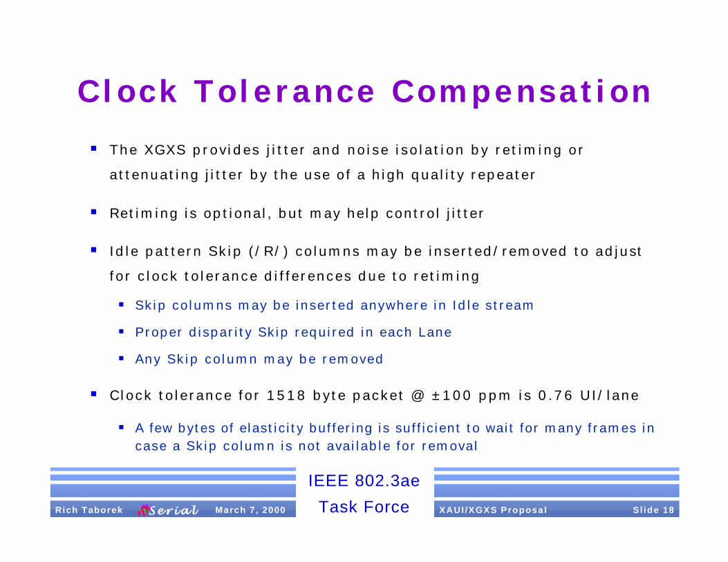
Clock Tolerance Compensation
§ The XGXS provides j i t ter and noise isolat ion by ret iming or
attenuating j i tter by the use of a high quality repeater
§ Retiming is optional, but may help control j itter
§ Idle pattern Skip (/R/) columns may be inserted/removed to adjust
for c lock tolerance di f ferences due to ret iming
§ Skip columns may be inserted anywhere in Idle stream
§ Proper disparity Skip required in each Lane
§ Any Skip column may be removed
§ Clock tolerance for 1518 byte packet @ ±100 ppm is 0.76 UI/lane
§ A few bytes of elasticity buffering is sufficient to wait for many frames in case a Skip column is not available for removal

IEEE 802.3ae
Task Force XAUI /XGXS Proposal S l ide 19 Rich Taborek March 7, 2000nnnnnnnn S e r i a lS e r i a l
Skip Column Insert Example
Lane 0 K R S dp d d --- d d d df A K R K
Lane 1 K R dp dp d d --- d d df T A K R K
Lane 2 K R dp dp d d --- d d df K A K R K
Lane 3 K R dp ds d d --- d d df K A K R K
Lane 0 K R S dp d d --- d d d df A R K R
Lane 1 K R dp dp d d --- d d df T A R K R
Lane 2 K R dp dp d d --- d d df K A R K R
Lane 3 K R dp ds d d --- d d df K A R K R
PMD Inserts Skip column here

IEEE 802.3ae
Task Force XAUI /XGXS Proposal S l ide 20 Rich Taborek March 7, 2000nnnnnnnn S e r i a lS e r i a l
Error Control
§ Packets with detected errors must be aborted
§ 8B/10B code v iolat ion detect ion may be propagated forward
§ IPG spec ia l code -groups stop error propagation (e.g. /A/, /K/, /R/)
§ Rule: Signal Error code upon detected error or in column containing EOP if the error is detected during the IPG. Error signaling is a lane function since disparity is checked per lane.
§ XGXS checks received packets for proper formation
§ Rules TBD, shou ld be PHY/Protoco l independent

IEEE 802.3ae
Task Force XAUI /XGXS Proposal S l ide 21 Rich Taborek March 7, 2000nnnnnnnn S e r i a lS e r i a l
Electrical
§ Electrical interface is based on low swing AC coupled differential interface
§ AC coupling is required at receiver inputs
§ Link compliance point is at the receiver
§ Transmitter may use equalization as long as receiver specif ications are not exceeded

IEEE 802.3ae
Task Force XAUI /XGXS Proposal S l ide 22 Rich Taborek March 7, 2000nnnnnnnn S e r i a lS e r i a l
XAUI Rx/Tx & Interconnect
Transmitter Parameter Value
Vo Dif(max) 800 mv
Vo Dif(min) 500 mv
Voh AC
Vol AC
Input nominal 6.5 ma
Differential Skew(max) 15 ps
Receiver Parameter Value
Vin Dif(max) 1000 mv
Vin Dif(min) 175 mv
Loss 50ΩΩ 9.1 dB
Differential Skew(max) 75 ps
Interconnect Parameter Value
Tr/Tf Min, 20%-80% 60 ps1
Tr/Tf Max, 20%-80% 131 ps1
PCB Impedance 100 ±10ΩΩ
Connector Impedance 100 ±30ΩΩ
Source Impedance 100 ±20ΩΩ
Load Termination 100 ±20ΩΩ
Return Loss 10 dB2
1. Optional if transmitter meets the receiver
jitter and eye mask with golden PCB
2. SerDes inputs must meet the return loss from 100 MHz to 2.5 GHz (0.8 x 3.125 Gbaud)

IEEE 802.3ae
Task Force XAUI /XGXS Proposal S l ide 23 Rich Taborek March 7, 2000nnnnnnnn S e r i a lS e r i a l
XAUI Loss Budget
Item Loss
Connector Loss 1 dB
Next + Fext Loss 0.75 dB
PCB Loss 7.35 dB
Loss Budget 9.1 dB
PCB Condition 1 Normal Worst
MSTL Loss Max (dB/in) 0.32 0.43
Max Distance (in) 23” 17.1”
PCB Condition 2 Normal Worst
STL Loss Max (dB/in) 0.41 0.55
Max Distance (in) 18” 13.4”
Normal PCB was assumed with loss tangent of 0.22, worst case it was assumed high temperature and humidity 85/ 85. Better grade of FR4 may reduce the loss by as much as 50%.
HP test measurement for 20" line showed 5.2 dB loss or 0.26dB/ in based on the eye loss, the loss assumed here is very conservative.

IEEE 802.3ae
Task Force XAUI /XGXS Proposal S l ide 24 Rich Taborek March 7, 2000nnnnnnnn S e r i a lS e r i a l
XAUI Jitter
Jitter Compliance Point Tx1 Rx
Deterministic Jitter 0.17 UI 0.41 UI Total Jitter 0.35 UI2 0.65 UI 1-sigma RJ @ max DJ for 10-12 BER3 4.11 ps 5.49 ps 1-sigma RJ @ max DJ for 10-12 BER3 3.92 ps 5.23 ps
1. Tx point is for reference. Rx point is for compliance.
2. The SerDes component should have better jitter performance than specified here to allow for system noise.
3. 1-Sigma value listed here are at maximum DJ, if the DJ value is smaller then the 1-Sigma RJ may increase to the total jitter value.

IEEE 802.3ae
Task Force XAUI /XGXS Proposal S l ide 25 Rich Taborek March 7, 2000nnnnnnnn S e r i a lS e r i a l
Summary
§ PHY and Protocol independent scalable archi tecture
§ X A U I/XGXS prov ide PHY, Protoco l & Appl icat ion independence
§ Common in ter face/ru les for 10 GbE, 10 GFC, In f in iBand™ & UniPHY
§ Based on gener ic 10 Gbps ch ip -to -chip interconnect architecture
§ Archi tecture resembles s imple and fami l iar 1000BASE- X P H Y
§ Low complexity, low latency, quick synchronizing rel iable interf ace
§ Enab le r fo r ear l y 10 GbE PHYs
§ May be integrated into MAC/RS ASIC, e l iminat ing XGMII
IEEE 802.3ae
Task Force XAUI /XGXS Proposal S l ide 26Rich Taborek March 7, 2000nnnnnnnn S e r i a lS e r i a l
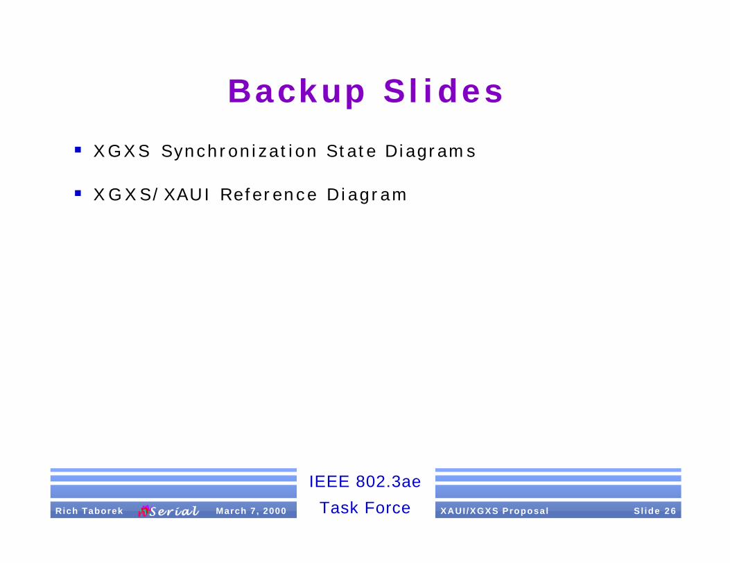
Backup Slides
§ X G X S Synchronization State Diagrams
§ X G X S/XAUI Reference Diagram

Comma_Detect_2
Loss_of_Sync
Sync_Status <= FAILEnable_CDET <= TRUE
cg_bad
Comma_Detect_3
Comma_Detect_1
Enable_CDET <= FALSE
Reset
Sync_Complete
cg_comma
Sync_Acq’d_1
Sync_Status <= OK
Sync_Acq’d_2A
Gd_cg <= Gd_cg + 1 cg_good * Gd_cg != 3
Sync_Acq’d_2
Gd_cg <= 0
Sync_Acq’d_3
Gd_cg <= 0
Sync_Acq’d_4
Gd_cg <= 0
Sync_Acq’d_3A
Gd_cg <= Gd_cg + 1 * Gd_cg != 3cg_good
Sync_Acq’d_4A
Gd_cg <= Gd_cg + 1 * Gd_cg != 3cg_good
* Gd_cg = 3cg_good
* Gd_cg = 3cg_good
* Gd_cg = 3cg_good
cg_bad
cg_bad
cg_comma
cg_comma
cg_good
cg_bad
cg_bad
cg_bad
cg_bad
cg_bad
cg_bad
cg_good
cg_good
cg_bad
Note1: cg_bad may haveprogrammable count todisable back-2-back errors
Note2: cg_bad may bedisabled when Enable_DSkewis TRUE and in Sync_Acq’d_1
Note3: no_comma containsprogrammable timer to count time between comma code groups
Sync_Acq’d_1A
Sync_Status <= OK_NOC
cg_commacg_bad
no_comma
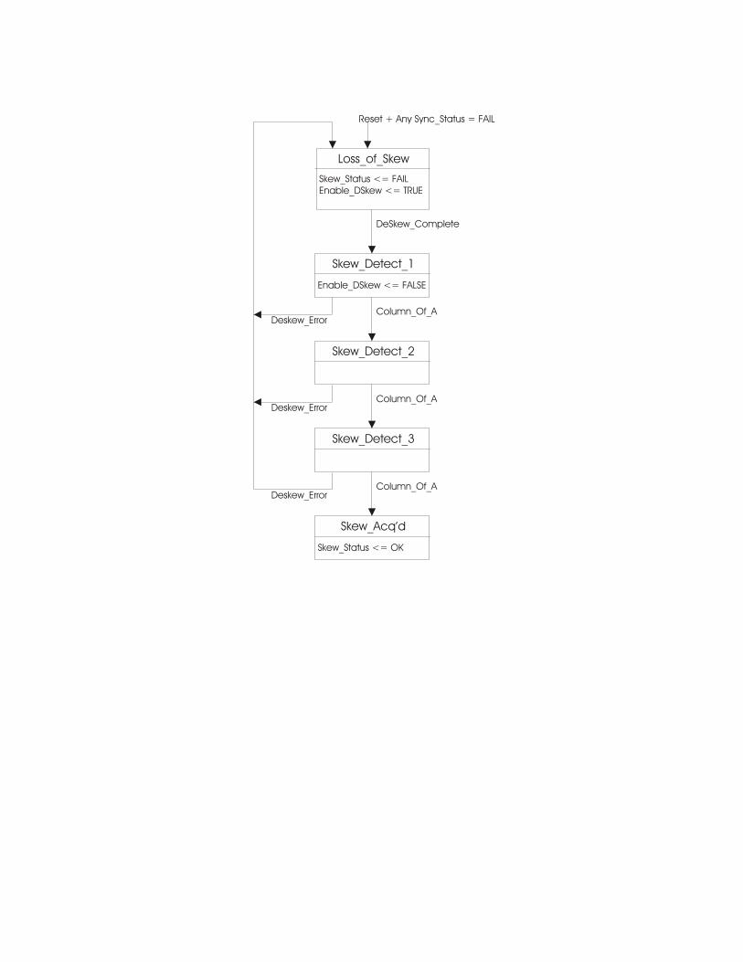
Skew_Detect_2
Loss_of_Skew
Skew_Status <= FAIL Enable_DSkew <= TRUE
Deskew_Error
Skew_Detect_3
Skew_Detect_1
Enable_DSkew <= FALSE
Reset + Any Sync_Status = FAIL
DeSkew_Complete
Column_Of_A
Skew_Acq’d
Skew_Status <= OK
Deskew_Error
Deskew_Error
Column_Of_A
Column_Of_A
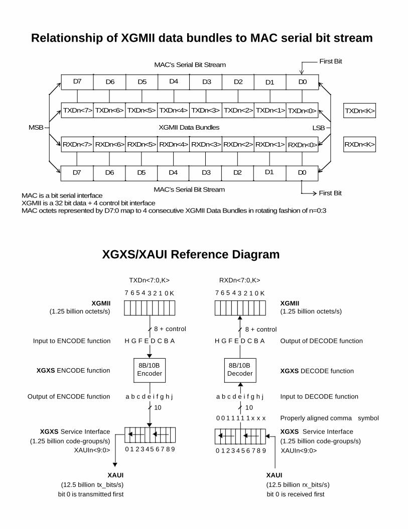
D7 D6 D5 D4 D3 D2 D1 D0
MAC’s Serial Bit Stream First Bit
D7 D6 D5 D4 D3 D2 D1 D0
MAC’s Serial Bit Stream First Bit
TXDn<0>
XGMII Data Bundles
RXDn<0>
TXDn<1>
RXDn<1>
TXDn<2>
RXDn<2>
TXDn<3>
RXDn<3>
TXDn<4>
RXDn<4>
TXDn<5>
RXDn<5>
TXDn<6>
RXDn<6>
TXDn<7>
RXDn<7>
LSBMSB
TXDn<K>
RXDn<K>
Relationship of XGMII data bundles to MAC serial bit stream
8B/10BEncoder
TXDn<7:0,K>
(1.25 billion octets/s)
XGXS Service Interface
(1.25 billion code-groups/s)
8B/10BDecoder
XGXS Service Interface
(1.25 billion code-groups/s)
0 1 2 3 4 5 6 7 8 90 1 2 3 45 6 7 8 9
XGXS DECODE functionXGXS ENCODE function
7 6 5 4 3 2 1 0
Output of ENCODE function Input to DECODE function
10
8 + control 8 + control
10
0 0 1 1 11 1 x x x Properly aligned comma+ symbol
XAUIn<9:0>XAUIn<9:0>
a b c d e i f g h j a b c d e i f g h j
Input to ENCODE function Output of DECODE functionH G F E D C B A H G F E D C B A
XAUI(12.5 billion rx_bits/s)
bit 0 is received first
XAUI(12.5 billion tx_bits/s)
bit 0 is transmitted first
XGMII(1.25 billion octets/s)XGMII
XGXS/XAUI Reference Diagram
K
RXDn<7:0,K>
7 6 5 4 3 2 1 0 K
MAC is a bit serial interface
MAC octets represented by D7:0 map to 4 consecutive XGMII Data Bundles in rotating fashion of n=0:3 XGMII is a 32 bit data + 4 control bit interface