xerox docu color 2240-1632
TRANSCRIPT

8/13/2019 Xerox Docu Color 2240-1632
http://slidepdf.com/reader/full/xerox-docu-color-2240-1632 1/1118
701P38648
July, 2002
DocuColor 2240/1632 Service
ManualInitial Issue
THE DOCUMENT COMPANY
XEROX
CAUTION
Certain components in the DocuColor 1632/2240 are
susceptible to damage from electrostatic discharge.
Observe all ESD procedures to avoid component
damage.
8/13/2019 Xerox Docu Color 2240-1632
http://slidepdf.com/reader/full/xerox-docu-color-2240-1632 2/1118

8/13/2019 Xerox Docu Color 2240-1632
http://slidepdf.com/reader/full/xerox-docu-color-2240-1632 3/1118
7/02
iDC 2240/1632
IntroductionInitial Issue
IntroductionAbout this Manual ........................................................................................................... iii
Organization.................................................................................................................... iii
How to Use this Documentation...................................................................................... iii
Symbology and Nomenclature........................................................................................ iii
Translated Warnings....................................................................................................... vii

8/13/2019 Xerox Docu Color 2240-1632
http://slidepdf.com/reader/full/xerox-docu-color-2240-1632 4/1118
7/02
ii DC 2240/1632
Initial IssueIntroduction

8/13/2019 Xerox Docu Color 2240-1632
http://slidepdf.com/reader/full/xerox-docu-color-2240-1632 5/1118

8/13/2019 Xerox Docu Color 2240-1632
http://slidepdf.com/reader/full/xerox-docu-color-2240-1632 6/1118

8/13/2019 Xerox Docu Color 2240-1632
http://slidepdf.com/reader/full/xerox-docu-color-2240-1632 7/1118
7/02
vDC 2240/1632
IntroductionInitial Issue
Electrostatic Discharge (ESD) Field Service Kit
The purpose of the ESD Protection Program is to preserve the inherent reliability and quality of
electronic components that are handled by the Field Service Personnel. This program is being
implemented now as a direct result of advances in microcircuitry technology, as well as a new
acknowledgment of the magnitude of the ESD problem in the electronics industry today.
This program will reduce Field Service costs that are charged to PWB failures. Ninety percent
of all PWB failures that are ESD related do not occur immediately. Using the ESD Field ServiceKit will eliminate these delayed failures and intermittent problems caused by ESD. This will
improve product reliability and reduce callbacks.
The ESD Field Service Kit should be used whenever Printed Wiring Boards or ESD sensitive
components are being handled. This includes activities like replacing or reseating of circuit
boards or connectors. The kit should also be used in order to prevent additional damage when
circuit boards are returned for repair.
The instructions for using the ESD Field Service Kit can be found in ESD Field Service Kit
Usage in the General Procedures section of the Service Documentation.
Illustration Symbols
Figure 6 shows symbols and conventions that are commonly used in illustrations.
Figure 6 Illustration Symbols

8/13/2019 Xerox Docu Color 2240-1632
http://slidepdf.com/reader/full/xerox-docu-color-2240-1632 8/1118
7/02
vi DC 2240/1632
Initial IssueIntroduction
Signal Nomenclature
Refer to Figure 7 for an example of Signal Nomenclature used in Circuit Diagrams and BSDs.
Figure 7 Signal Nomenclature
Voltage Measurement and Specifications
Measurements of DC voltage must be made with reference to the specified DC Common,
unless some other point is referenced in a diagnostic procedure. All measurements of AC volt-
age should be made with respect to the adjacent return or ACN wire.
Logic Voltage Levels
Measurements of logic levels must be made with reference to the specified DC Common,
unless some other point is referenced in a diagnostic procedure.
DC Voltage Measurements in RAPs
The RAPs have been designed so that when it is required to use the DMM to measure a DC
voltage, the first test point listed is the location for the red (+) meter lead and the second test
point is the location for the black meter lead. For example, the following statement may be
found in a RAP:
There is +5 VDC from TP7 to TP68.
In this example, the red meter lead would be placed on TP7 and the black meter lead on TP68.
Another example of a statement found in a RAP might be:
There is -15 VDC from TP21 to TP33.
In this example, the red meter lead would be placed on TP21 and the black meter lead would
be placed on TP33.
If a second test point is not given, it is assumed that the black meter lead may be attached to
the copier frame.
Table 1 Voltage Measurement and SpecificationsVOLTAGE SPECIFICATION
INPUT POWER 220 V 198 VAC TO 242 VAC
INPUT POWER 100 V 90 VAC TO 135 VAC
INPUT POWER 120 V 90 VAC TO 135 VAC
+5 VDC +4.75 VDC TO +5.25 VDC
+24 VDC +23.37 VDC TO +27.06 VDC
Table 2 Logic Levels
VOLTAGE H/L SPECIFICATIONS
+5 VDC H= +3.00 TO +5.25 VDC
L= 0.0 TO 0.8 VDC
+24 VDC H= +23.37 TO +27.06 VDC
L= 0.0 TO 0.8 VDC
8/13/2019 Xerox Docu Color 2240-1632
http://slidepdf.com/reader/full/xerox-docu-color-2240-1632 9/1118
7/02
viiDC 2240/1632
IntroductionInitial Issue
Translated Warnings
8/13/2019 Xerox Docu Color 2240-1632
http://slidepdf.com/reader/full/xerox-docu-color-2240-1632 10/1118

8/13/2019 Xerox Docu Color 2240-1632
http://slidepdf.com/reader/full/xerox-docu-color-2240-1632 11/1118
8/13/2019 Xerox Docu Color 2240-1632
http://slidepdf.com/reader/full/xerox-docu-color-2240-1632 12/1118
8/13/2019 Xerox Docu Color 2240-1632
http://slidepdf.com/reader/full/xerox-docu-color-2240-1632 13/1118

8/13/2019 Xerox Docu Color 2240-1632
http://slidepdf.com/reader/full/xerox-docu-color-2240-1632 14/1118

8/13/2019 Xerox Docu Color 2240-1632
http://slidepdf.com/reader/full/xerox-docu-color-2240-1632 15/1118
8/13/2019 Xerox Docu Color 2240-1632
http://slidepdf.com/reader/full/xerox-docu-color-2240-1632 16/1118
8/13/2019 Xerox Docu Color 2240-1632
http://slidepdf.com/reader/full/xerox-docu-color-2240-1632 17/1118
8/13/2019 Xerox Docu Color 2240-1632
http://slidepdf.com/reader/full/xerox-docu-color-2240-1632 18/1118

8/13/2019 Xerox Docu Color 2240-1632
http://slidepdf.com/reader/full/xerox-docu-color-2240-1632 19/1118
8/13/2019 Xerox Docu Color 2240-1632
http://slidepdf.com/reader/full/xerox-docu-color-2240-1632 20/1118

8/13/2019 Xerox Docu Color 2240-1632
http://slidepdf.com/reader/full/xerox-docu-color-2240-1632 21/1118

8/13/2019 Xerox Docu Color 2240-1632
http://slidepdf.com/reader/full/xerox-docu-color-2240-1632 22/1118
7/02
xx DC 2240/1632
Initial IssueIntroduction

8/13/2019 Xerox Docu Color 2240-1632
http://slidepdf.com/reader/full/xerox-docu-color-2240-1632 23/1118
7/02
1-1DC 2240/1632
Service Call ProceduresInitial Issue
1 Service Call ProceduresService Call Procedures.................................................................................................. 1-3
Initial Actions ................................................................................................................... 1-4
Call Flow ......................................................................................................................... 1-5
Detailed Maintenance Activities (HFSI)........................................................................... 1-6
Cleaning Procedures....................................................................................................... 1-7
Final Actions.................................................................................................................... 1-7

8/13/2019 Xerox Docu Color 2240-1632
http://slidepdf.com/reader/full/xerox-docu-color-2240-1632 24/1118
7/02
1-2 DC 2240/1632
Initial IssueService Call Procedures
Service Call Procedures
8/13/2019 Xerox Docu Color 2240-1632
http://slidepdf.com/reader/full/xerox-docu-color-2240-1632 25/1118
7/02
1-3DC 2240/1632 Service Call ProceduresService Call ProceduresInitial Issue
Service Call ProceduresService Strategy
The service strategy for the DocuColor 2240/1632 Copier/Printer is to perform any High Fre-
quency Service Item (HFSI) actions before attempting to repair any problems. Some problems
will be corrected by this strategy without the need to diagnose them. The Repair Analysis Pro-
cedures (RAPs) will be used for any remaining problems.
Problems that occur in the Basic Printer mode will be repaired before problems that occurwhen using the accessories.
Image Quality problems should be repaired after all other problems are repaired.
Service Call Procedures
The Service Call Procedures are a guide for performing any service on this machine. The
procedures are designed to be used with the Service Manual. Perform each step in order.
Initial Actions
The Initial Actions gather information about the condition of the machine and the problem thatcaused the service call.
Call Flow
Call Flow summarizes the sequence of the Service Call Procedures.
Detailed Maintenance Activities
This section provides the information needed to perform the DC135 High Frequency Service
Item (HFSI) actions.
Cleaning Procedures
The cleaning procedures list what needs to be cleaned at each service call.
Final Actions
The Final Actions will test the copier/printer and return it to the customer. Administrative activi-
ties are also performed in the Final Actions.
Initial Actions

8/13/2019 Xerox Docu Color 2240-1632
http://slidepdf.com/reader/full/xerox-docu-color-2240-1632 26/1118
7/02
1-4 DC 2240/1632Initial ActionsInitial IssueService Call Procedures
t a ct o sPurpose
The purpose of the Initial Action section of the Service Call Procedures is to determine the rea-
son for the service call and to identify and organize the actions which must be performed.
Procedure
1. Gather the information about the service call and the condition of the copier/printer.
a. Question the operator(s). Ask about the location of most recent paper jams. Ask
about the image quality and the copier/printer performance in general, including any
unusual sounds or other indications.
b. After informing the customer, disconnect the machine from the customer’s network.
c. Check that the power cords are in good condition, correctly plugged in the power
source, and free from any defects that would be a safety hazard. Repair or replace
the power cords as required. Check that the circuit breakers are not tripped.
d. Inspect any rejected copies. Inquire as to, or otherwise determine, the paper quality
and weight. The specified paper for optimum image quality with this machine is TBD.
Look for any damage to the copies, oil marks, image quality defects, or other indica-
tions of a problem.
e. Record the billing meter readings.
f. Connect the PWS to the machine. Enter the Diagnostics Mode.
NOTE: If a fault code is displayed while performing a diagnostics procedure, go to
that fault code RAP and repair the fault. Return to Diagnostics and continue with the
dC procedure that you were performing.
g. Go to dC135 and determine what HSFI action is required based on the customer
output volume. Refer to the Detailed Maintenance Activities section for the detailed
HSFI information. Record any items that require action.
h. Select the History File. Display and record the information in the Fail History, JamHistory, Fail Counter, and Jam Counter. Classify this information into categories:
Information that is related to the problem that caused the service call.
Information that is related to secondary problems.
Information that does not require action, such as a single occurrence of a prob-
lem.
i. Check the Service Log for any recent activities that are related to the problem that
caused the service call or any secondary problem.
2. Perform any required HSFI activities identified above. Refer to the Detailed Maintenance
Activities section.
3. Exit diagnostics. Try to duplicate the problem by running the same jobs that the customer
was running.
4. Go to Call Flow.

8/13/2019 Xerox Docu Color 2240-1632
http://slidepdf.com/reader/full/xerox-docu-color-2240-1632 27/1118
Detailed Maintenance Activities (HFSI) 3. Perform the Service Actions in Table 1 for any High Frequency Service Item (HFSI)
counters that are over threshold or approaching the threshold Using the customer’s out

8/13/2019 Xerox Docu Color 2240-1632
http://slidepdf.com/reader/full/xerox-docu-color-2240-1632 28/1118
7/02
1-6 DC 2240/1632Detailed Maintenance ActivitiesInitial IssueService Call Procedures
Procedure
1. Clean the ADC Sensor on every call.
2. Enter Diagnostics and select dC135.
counters that are over threshold or approaching the threshold. Using the customer’s out-
put volume numbers (high, medium, or low volume), evaluate which HFSI actions should
be accomplished now to avoid an additional service call in the near future.
4. Refer to Cleaning Procedures for detailed cleaning instructions.
Table 1
Counter Name Threshold Service Action to be performed
006-802 IIT Scan
No. of scans (Including pre-scan) after HFSI
counter cleared
0 No action required - counter only
005-805 Document Feed
No. of DADF Feed after HFSI Counter
Cleared.
0 No action required - counter only
954-801 IBT Assembly 480K
increments by 1 for letter size
or smaller; by 2 for longer
than letter size
Replace the IBT Assembly (PL 5.3)
Warning at 478.5K
954-802 2nd BTR Unit 150K Replace the 2nd BTR Unit (PL 2.8)
Warning at 98.5K
954-803 IBT Belt Cleaner Assy 100K Replace the IBT Belt Cleaner (PL 5.3)
Warning at 98.5K
954-804 Fuser 10000000
Area conversion, with
A4L=100 counts
Replace the Fuser (PL 7.1)
Warning at 9000000
954-806 Tray 1 Feed counter 300000 Replace the Roll Kit (PL 2.5).
954-807 Tray 5 Feed counter 300000 Replace the Feed Roll Assembly and Retard Pad (PL 2.14).
954-808 Tray 2 Feed counter 300000 Replace the Roll Kit (PL 16.8).954-809 Tray 3 Feed counter 300000 Replace the Roll Kit (PL 16.10).
954-810 Tray 4 Feed counter 300000 Replace the Roll Kit (PL 16.12).

8/13/2019 Xerox Docu Color 2240-1632
http://slidepdf.com/reader/full/xerox-docu-color-2240-1632 29/1118
8/13/2019 Xerox Docu Color 2240-1632
http://slidepdf.com/reader/full/xerox-docu-color-2240-1632 30/1118
7/02
1-8 DC 2240/1632Cleaning Procedures, Final ActionsInitial IssueService Call Procedures

8/13/2019 Xerox Docu Color 2240-1632
http://slidepdf.com/reader/full/xerox-docu-color-2240-1632 31/1118

8/13/2019 Xerox Docu Color 2240-1632
http://slidepdf.com/reader/full/xerox-docu-color-2240-1632 32/1118

8/13/2019 Xerox Docu Color 2240-1632
http://slidepdf.com/reader/full/xerox-docu-color-2240-1632 33/1118

8/13/2019 Xerox Docu Color 2240-1632
http://slidepdf.com/reader/full/xerox-docu-color-2240-1632 34/1118

8/13/2019 Xerox Docu Color 2240-1632
http://slidepdf.com/reader/full/xerox-docu-color-2240-1632 35/1118

8/13/2019 Xerox Docu Color 2240-1632
http://slidepdf.com/reader/full/xerox-docu-color-2240-1632 36/1118

8/13/2019 Xerox Docu Color 2240-1632
http://slidepdf.com/reader/full/xerox-docu-color-2240-1632 37/1118
8/13/2019 Xerox Docu Color 2240-1632
http://slidepdf.com/reader/full/xerox-docu-color-2240-1632 38/1118
7/02
2-8 DC 2240/1632
Initial IssueStatus Indicator RAPs
1-300 RAPLeft Cover is open.

8/13/2019 Xerox Docu Color 2240-1632
http://slidepdf.com/reader/full/xerox-docu-color-2240-1632 39/1118
7/02
2-9DC 2240/1632 1-300Status Indicator RAPsInitial Issue
Procedure
Enter dC330 [001-301] and press Start. Open and close Left Cover (PL 2.7). Display
changes state.
Y N
Measure the voltage between +24 LVPS P/J502-1 and GND(-). +24 VDC measured.
Y N
Replace LVPS (PL 9.1).
Disconnect P/J172 from Left Cover Interlock Switch (PL 2.10). Check resistance
between A1 and B1 when switch is actuated. Resistance is less than 3 ohms.
Y N
Replace Left Cover Interlock Switch (PL 2.10).
Reinstall switch. Close the Left Cover (PL 2.7). Measure the voltage at P/J535-A1 on the
I/F PWB. +24 VDC measured.
Y NRepair the open circuit between the +24 VDC LVPS and the I/F PWB.
Replace the I/F PWB (PL 9.1).
If the problem continues, replace the MCU PWB (PL 13.1).
Check installation of Cover/Actuator.
Figure 1 Left Cover Interlock Switch CD
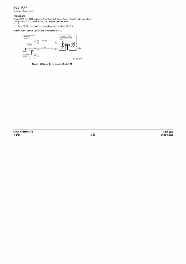
1-301 RAPLeft Lower Cover is open
8/13/2019 Xerox Docu Color 2240-1632
http://slidepdf.com/reader/full/xerox-docu-color-2240-1632 40/1118
7/02
2-10 DC 2240/16321-301Initial IssueStatus Indicator RAPs
Procedure
Enter dC330 [001-302] and press Start. Open Left Lower Cover. Actuate Left Lower Cover
Interlock Switch (PL 2.3) with screwdriver. Display changes state.
Y N
Go to OF 99-2 and repair LH Lower Cover Interlock Switch (PL 2.3).
Check Actuator and Left Lower Cover installation (PL 2.3).
Figure 1 LH Lower Cover Interlock Switch CD
1-302 RAPFront Cover or is open
Initial Actions

8/13/2019 Xerox Docu Color 2240-1632
http://slidepdf.com/reader/full/xerox-docu-color-2240-1632 41/1118
7/02
2-11DC 2240/1632 1-302Status Indicator RAPsInitial Issue
Initial Actions
Check the operation of the Actuator and the switch.
Procedure
Open the Front Cover. Cheat the Front Interlock Switch (PL 10.1). 001-302 is cleared.
Y N+24VDC is measured between the I/F PWB P/J531-1 (+) and GND (-).
Y N
+24VDC is measured between the Front Interlock Switch P/J171-B1 (+) and
GND (-).
Y N
24VDC is measured between the Front Interlock Switch P/J171-A1 (+) and
GND (-).
Y N
Repair the open circuit between the Left Cover Interlock Switch P/J172-
B1 and the Front Interlock Switch P/J171-A1.
Replace the Front Interlock Switch (PL 10.1).
+24VDC is measured between the RH Cover Interlock Switch P/ J173-B1 (+)
and GND (-).
Y N
+24VDC is measured between the RH Cover Interlock Switch P/ J173-A1
(+) and GND (-).
Y N
Repair the open circuit between the Front Interlock Switch P/J171-B1 and
the RH Cover Interlock Switch P/ J173-A1.
Replace the RH Cover Interlock Switch (PL 10.1).
Check the wire for an open circuit between the RH Cover Interlock Switch P/ J173-
B1 and the Interlock Relay PWB P/J569-2.
Check the wire for an open circuit between the Interlock Relay PWB P/J569-1 and
the I/F PWB P/J531-1.
Replace the I/F PWB (PL 9.1).
If the problem continues, replace the MCU PWB (PL 13.1).
Check installation of Cover/Actuator (PL 10.1).
Figure 1 Front Cover / Right Cover Interlock CD
Figure 2 Front Interlock Switch Location
Figure 3 Left Cover Interlock Switch Location
Front InterlockSwitch
Left CoverInterlock Switch
1-303 RAPTray Module Left Door is open.

8/13/2019 Xerox Docu Color 2240-1632
http://slidepdf.com/reader/full/xerox-docu-color-2240-1632 42/1118
7/02
2-12 DC 2240/16321-303Initial IssueStatus Indicator RAPs
Procedure
Enter dC330 [001-304] and press Start. Actuate Tray Module LH Cover Interlock Switch (PL
16.13) with a screwdriver. Display changes state.
Y N
Check voltage between Tray Module PWB P/J554-3(+) and GND(-). +24 VDC is mea-
sured.
Y N
Check the wires from the Tray Module PWB P/J554-3 to Tray Module Cover Inter-
lock Switch FS813 for damage. If the wires are good, replace Tray Module Cover
Interlock Switch (PL 16.13).
Replace Tray Module PWB (PL 16.15).
Check Cover Actuator and Cover installation (PL 16.13).
Figure 1 Tray Module LH Cover Interlock Switch Cd
1-306 RAPDuplex Door is open.

8/13/2019 Xerox Docu Color 2240-1632
http://slidepdf.com/reader/full/xerox-docu-color-2240-1632 43/1118
7/02
2-13DC 2240/1632 1-306Status Indicator RAPsInitial Issue
Procedure
Enter dC330 [008-300] and press Start. Open Duplex Transport. Actuate Duplex Cover Inter-
lock Switch (PL 12.2) with a screwdriver. Display changes state.
Y N
Deactuate Duplex Cover Interlock Switch. Check voltage on the Drawer Connector
between P/ J626-A6 (+) and GND(-). +5 VDC is measured.
Y N
Check voltage between MCU PWB P/J406-A9 and GND(-). +5 VDC is measured.
Y N
Replace MCU PWB (PL 13.1).
Repair the open circuit between the MCU PWB P/J406-A9 and Drawer Connector
between P/ J626-A6
Check the wires between Drawer Connector between P/ J626-A6 and Duplex PWB P/
J540-1. If the wires are good, replace the Duplex Cover Interlock Switch (PL 12.2).
Check Cover Actuator and Cover installation. If there is no problem, replace MCU PWB ( PL
13.1).
Figure 1 Duplex Cover Interlock Switch CD

8/13/2019 Xerox Docu Color 2240-1632
http://slidepdf.com/reader/full/xerox-docu-color-2240-1632 44/1118
7/02
2-14 DC 2240/16321-306Initial IssueStatus Indicator RAPs
3-317 IIT Software FailureConfiguration mismatch
Procedure
3-318 IIT Software FailureProcedure
Switch the power off then on. The problem continues.

8/13/2019 Xerox Docu Color 2240-1632
http://slidepdf.com/reader/full/xerox-docu-color-2240-1632 45/1118
7/02
2-15DC 2240/1632 3-317 , 3-318Status Indicator RAPsInitial Issue
Procedure
Change the position of the document sensor. The problem continues.
Y N
Return to Service Call Procedures.
Rewrite the NVM values.
Y N
Return to Service Call Procedures.
Reinstall the software. If the problem continues, check the ESS PWB connectors. If the check
is OK, replace the ESS PWB (PL 13.1).
3-319 IIT Video Driver FailureProcedure
Switch the power off then on. The problem continues.
3-320 IIT-ESS Communication Failure 1Controller received check code error.
Procedure
8/13/2019 Xerox Docu Color 2240-1632
http://slidepdf.com/reader/full/xerox-docu-color-2240-1632 46/1118
7/02
2-16 DC 2240/16323-319 , 3-320Initial IssueStatus Indicator RAPs
Y N
Return to Service Call Procedures.
Reinstall the software. If the problem continues, check the ESS PWB connectors. If the check
is OK, replace the ESS PWB (PL 13.1).
Procedure
Switch the power off then on. The problem continues.
Y N
Return to Service Call Procedures.
Reinstall the software. If the problem continues, check the IIT/IPS PWB connectors. If thecheck is OK, replace the IIT/IPS PWB (PL 18.3).
3-321 IIT-ESS Communication Failure 2Controller received check code error.
Procedure
3-322 IIT-ESS Communication Failure 3Controller received check code error.
Procedure

8/13/2019 Xerox Docu Color 2240-1632
http://slidepdf.com/reader/full/xerox-docu-color-2240-1632 47/1118
7/02
2-17DC 2240/1632 3-321, 3-322Status Indicator RAPsInitial Issue
Procedure
Switch the power off then on. The problem continues.
Y N
Return to Service Call Procedures.
Reinstall the software. If the problem continues, check the IIT/IPS PWB connectors. If thecheck is OK, replace the IIT/IPS PWB (PL 18.3).
Procedure
Switch the power off then on. The problem continues.
Y N
Return to Service Call Procedures.
Reinstall the software. If the problem continues, check the IIT/IPS PWB connectors. If thecheck is OK, replace the IIT/IPS PWB (PL 18.3).
3-323 IIT-ESS Communication Failure 4Controller received check code error.
Procedure
3-324 IIT-ESS Communication Failure 5Controller received check code error.
Procedure
8/13/2019 Xerox Docu Color 2240-1632
http://slidepdf.com/reader/full/xerox-docu-color-2240-1632 48/1118
7/02
2-18 DC 2240/16323-323, 3-324Initial IssueStatus Indicator RAPs
Procedure
Switch the power off then on. The problem continues.
Y N
Return to Service Call Procedures.
Reinstall the software. If the problem continues, check the IIT/IPS PWB connectors. If thecheck is OK, replace the IIT/IPS PWB (PL 18.3).
Procedure
Switch the power off then on. The problem continues.
Y N
Return to Service Call Procedures.
Reinstall the software. If the problem continues, check the IIT/IPS PWB connectors. If thecheck is OK, replace the IIT/IPS PWB (PL 18.3).
3-325 IIT-ESS Communication Failure 6Controller received check code error.
Procedure
3-326 IIT-ESS Communication Failure 7Controller received check code error.
Procedure

8/13/2019 Xerox Docu Color 2240-1632
http://slidepdf.com/reader/full/xerox-docu-color-2240-1632 49/1118
7/02
2-19DC 2240/1632 3-325, 3-326Status Indicator RAPsInitial Issue
Switch the power off then on. The problem continues.
Y N
Return to Service Call Procedures.
Reinstall the software. If the problem continues, check the IIT/IPS PWB connectors. If thecheck is OK, replace the IIT/IPS PWB (PL 18.3).
Switch the power off then on. The problem continues.
Y N
Return to Service Call Procedures.
Reinstall the software. If the problem continues, check the IIT/IPS PWB connectors. If thecheck is OK, replace the IIT/IPS PWB (PL 18.3).
3-327 IIT-ESS Communication Failure 8Controller received check code error.
Procedure
3-328 IIT-ESS Communication Failure 9Controller received check code error.
Procedure

8/13/2019 Xerox Docu Color 2240-1632
http://slidepdf.com/reader/full/xerox-docu-color-2240-1632 50/1118
7/02
2-20 DC 2240/16323-327, 3-328Initial IssueStatus Indicator RAPs
Switch the power off then on. The problem continues.
Y N
Return to Service Call Procedures.
Reinstall the software. If the problem continues, check the IIT/IPS PWB connectors. If thecheck is OK, replace the IIT/IPS PWB (PL 18.3).
Switch the power off then on. The problem continues.
Y N
Return to Service Call Procedures.
Reinstall the software. If the problem continues, check the IIT/IPS PWB connectors. If thecheck is OK, replace the IIT/IPS PWB (PL 18.3).
3-329 IIT-ESS Communication Failure 10Controller received check code error.
Procedure
3-330 IIT-ESS Communication Failure 11Controller received check code error.
Procedure

8/13/2019 Xerox Docu Color 2240-1632
http://slidepdf.com/reader/full/xerox-docu-color-2240-1632 51/1118
7/02
2-21DC 2240/1632 3-329, 3-330Status Indicator RAPsInitial Issue
Switch the power off then on. The problem continues.
Y N
Return to Service Call Procedures.
Reinstall the software. If the problem continues, check the IIT/IPS PWB connectors. If thecheck is OK, replace the IIT/IPS PWB (PL 18.3).
Switch the power off then on. The problem continues.
Y N
Return to Service Call Procedures.
Reinstall the software. If the problem continues, check the IIT/IPS PWB connectors. If thecheck is OK, replace the IIT/IPS PWB (PL 18.3).
3-331 IIT-ESS Communication Failure 12Controller received check code error.
Procedure
3-332 IIT-ESS Communication Failure 13Controller received check code error.
Procedure

8/13/2019 Xerox Docu Color 2240-1632
http://slidepdf.com/reader/full/xerox-docu-color-2240-1632 52/1118
7/02
2-22 DC 2240/16323-331, 3-332Initial IssueStatus Indicator RAPs
Switch the power off then on. The problem continues.
Y N
Return to Service Call Procedures.
Reinstall the software. If the problem continues, check the IIT/IPS PWB connectors. If thecheck is OK, replace the IIT/IPS PWB (PL 18.3).
Switch the power off then on. The problem continues.
Y N
Return to Service Call Procedures.
Reinstall the software. If the problem continues, check the IIT/IPS PWB connectors. If thecheck is OK, replace the IIT/IPS PWB (PL 18.3).
3-333 IIT-ESS Communication Failure 14Controller received check code error.
Procedure
S i h h ff h Th bl i
3-334 IIT-ESS Communication Failure 15Controller received check code error.
Procedure
S i h h ff h Th bl i

8/13/2019 Xerox Docu Color 2240-1632
http://slidepdf.com/reader/full/xerox-docu-color-2240-1632 53/1118
7/02
2-23DC 2240/1632 3-333, 3-334Status Indicator RAPsInitial Issue
Switch the power off then on. The problem continues.
Y N
Return to Service Call Procedures.
Reinstall the software. If the problem continues, check the IIT/IPS PWB connectors. If thecheck is OK, replace the IIT/IPS PWB (PL 18.3).
Switch the power off then on. The problem continues.
Y N
Return to Service Call Procedures.
Reinstall the software. If the problem continues, check the IIT/IPS PWB connectors. If thecheck is OK, replace the IIT/IPS PWB (PL 18.3).
3-335 IIT-ESS Communication Failure 16Controller received check code error.
Procedure
Switch the power off then on The problem continues
3-336 IIT-ESS Communication Failure 17Controller received check code error.
Procedure
Switch the power off then on The problem continues

8/13/2019 Xerox Docu Color 2240-1632
http://slidepdf.com/reader/full/xerox-docu-color-2240-1632 54/1118
7/02
2-24 DC 2240/16323-335, 3-336Initial IssueStatus Indicator RAPs
Switch the power off then on. The problem continues.
Y N
Return to Service Call Procedures.
Reinstall the software. If the problem continues, check the IIT/IPS PWB connectors. If thecheck is OK, replace the IIT/IPS PWB (PL 18.3).
Switch the power off then on. The problem continues.
Y N
Return to Service Call Procedures.
Reinstall the software. If the problem continues, check the IIT/IPS PWB connectors. If thecheck is OK, replace the IIT/IPS PWB (PL 18.3).
3-340 IOT-ESS Communication Failure 1Controller received check code error.
Procedure
Switch the power off then on The problem continues
3-341 IOT-ESS Communication Failure 2Controller received check code error.
Procedure
Switch the power off then on The problem continues

8/13/2019 Xerox Docu Color 2240-1632
http://slidepdf.com/reader/full/xerox-docu-color-2240-1632 55/1118
7/02
2-25DC 2240/1632 3-340, 3-341Status Indicator RAPsInitial Issue
Switch the power off then on. The problem continues.
Y N
Return to Service Call Procedures.
Reinstall the software. If the problem continues, check the MCU PWB connectors. If the checkis OK, replace the MCU PWB (PL 13.1).
Switch the power off then on. The problem continues.
Y N
Return to Service Call Procedures.
Reinstall the software. If the problem continues, check the MCU PWB connectors. If the checkis OK, replace the MCU PWB (PL 13.1).
3-342 IOT-ESS Communication Failure 3Controller received check code error.
Procedure
Switch the power off then on. The problem continues.
3-343 IOT-ESS Communication Failure 4Controller received check code error.
Procedure
Switch the power off then on. The problem continues.

8/13/2019 Xerox Docu Color 2240-1632
http://slidepdf.com/reader/full/xerox-docu-color-2240-1632 56/1118
7/02
2-26 DC 2240/16323-342, 3-343Initial IssueStatus Indicator RAPs
Switch the power off then on. The problem continues.
Y N
Return to Service Call Procedures.
Reinstall the software. If the problem continues, check the MCU PWB connectors. If the checkis OK, replace the MCU PWB (PL 13.1).
Switch the power off then on. The problem continues.
Y N
Return to Service Call Procedures.
Reinstall the software. If the problem continues, check the MCU PWB connectors. If the checkis OK, replace the MCU PWB (PL 13.1).
3-345 IOT-ESS Communication Failure 5Controller received check code error.
Procedure
Switch the power off then on. The problem continues.
3-346 IOT-ESS Communication Failure 6Controller received check code error.
Procedure
Switch the power off then on. The problem continues.
8/13/2019 Xerox Docu Color 2240-1632
http://slidepdf.com/reader/full/xerox-docu-color-2240-1632 57/1118
7/02
2-27DC 2240/1632 3-345, 3-346Status Indicator RAPsInitial Issue
p p
Y N
Return to Service Call Procedures.
Reinstall the software. If the problem continues, check the MCU PWB connectors. If the checkis OK, replace the MCU PWB (PL 13.1).
p p
Y N
Return to Service Call Procedures.
Reinstall the software. If the problem continues, check the MCU PWB connectors. If the checkis OK, replace the MCU PWB (PL 13.1).
3-347 IOT-ESS Communication Failure 7Controller received check code error.
Procedure
Switch the power off then on. The problem continues.
3-348 IOT-ESS Communication Failure 8Controller received check code error.
Procedure
Switch the power off then on. The problem continues.
8/13/2019 Xerox Docu Color 2240-1632
http://slidepdf.com/reader/full/xerox-docu-color-2240-1632 58/1118
7/02
2-28 DC 2240/16323-347, 3-348Initial IssueStatus Indicator RAPs
Y N
Return to Service Call Procedures.
Reinstall the software. If the problem continues, check the MCU PWB connectors. If the checkis OK, replace the MCU PWB (PL 13.1).
Y N
Return to Service Call Procedures.
Reinstall the software. If the problem continues, check the MCU PWB connectors. If the checkis OK, replace the MCU PWB (PL 13.1).
3-349 IOT-ESS Communication Failure 9Controller received check code error.
Procedure
Switch the power off then on. The problem continues.
3-350 IOT-ESS Communication Failure 10Controller received check code error.
Procedure
Switch the power off then on. The problem continues.

8/13/2019 Xerox Docu Color 2240-1632
http://slidepdf.com/reader/full/xerox-docu-color-2240-1632 59/1118
7/02
2-29DC 2240/1632 3-349, 3-350Status Indicator RAPsInitial Issue
Y N
Return to Service Call Procedures.
Reinstall the software. If the problem continues, check the MCU PWB connectors. If the checkis OK, replace the MCU PWB (PL 13.1).
Y N
Return to Service Call Procedures.
Reinstall the software. If the problem continues, check the MCU PWB connectors. If the checkis OK, replace the MCU PWB (PL 13.1).
3-351 IOT-ESS Communication Failure 11Controller received check code error.
Procedure
Switch the power off then on. The problem continues.
Y N
3-352 IOT-ESS Communication Failure 12Controller received check code error.
Procedure
Switch the power off then on. The problem continues.
Y N

8/13/2019 Xerox Docu Color 2240-1632
http://slidepdf.com/reader/full/xerox-docu-color-2240-1632 60/1118
7/02
2-30 DC 2240/16323-351, 3-352Initial IssueStatus Indicator RAPs
Y N
Return to Service Call Procedures.
Reinstall the software. If the problem continues, check the MCU PWB connectors. If the checkis OK, replace the MCU PWB (PL 13.1).
Y N
Return to Service Call Procedures.
Reinstall the software. If the problem continues, check the MCU PWB connectors. If the checkis OK, replace the MCU PWB (PL 13.1).
3-353 IOT-ESS Communication Failure 13Controller received check code error.
Procedure
Switch the power off then on. The problem continues.
Y N
3-354 IOT-ESS Communication Failure 14Controller received check code error.
Procedure
Switch the power off then on. The problem continues.
Y N

8/13/2019 Xerox Docu Color 2240-1632
http://slidepdf.com/reader/full/xerox-docu-color-2240-1632 61/1118
7/02
2-31DC 2240/1632 3-353, 3-354Status Indicator RAPsInitial Issue
Y N
Return to Service Call Procedures.
Reinstall the software. If the problem continues, check the MCU PWB connectors. If the checkis OK, replace the MCU PWB (PL 13.1).
Y N
Return to Service Call Procedures.
Reinstall the software. If the problem continues, check the MCU PWB connectors. If the checkis OK, replace the MCU PWB (PL 13.1).
3-355 IOT-ESS Communication Failure 15Controller received check code error.
Procedure
Switch the power off then on. The problem continues.
Y N
3-356 IOT-ESS Communication Failure 16Controller received check code error.
Procedure
Switch the power off then on. The problem continues.
Y N

8/13/2019 Xerox Docu Color 2240-1632
http://slidepdf.com/reader/full/xerox-docu-color-2240-1632 62/1118
7/02
2-32 DC 2240/16323-355, 3-356Initial IssueStatus Indicator RAPs
Y N
Return to Service Call Procedures.
Reinstall the software. If the problem continues, check the MCU PWB connectors. If the checkis OK, replace the MCU PWB (PL 13.1).
Y N
Return to Service Call Procedures.
Reinstall the software. If the problem continues, check the MCU PWB connectors. If the checkis OK, replace the MCU PWB (PL 13.1).
3-357 IOT-ESS Communication Failure 17Controller received check code error.
Procedure
Switch the power off then on. The problem continues.
Y N
3-358 IOT-ESS Communication Failure 1Controller received check code error.
Procedure
Switch the power off then on. The problem continues.
Y N

8/13/2019 Xerox Docu Color 2240-1632
http://slidepdf.com/reader/full/xerox-docu-color-2240-1632 63/1118
7/02
2-33DC 2240/1632 3-357, 3-358Status Indicator RAPsInitial Issue
Return to Service Call Procedures.
Reinstall the software. If the problem continues, check the MCU PWB connectors. If the checkis OK, replace the MCU PWB (PL 13.1).
Return to Service Call Procedures.
Reinstall the software. If the problem continues, check the MCU PWB connectors. If the checkis OK, replace the MCU PWB (PL 13.1).
3-359 IOT-ESS Communication Failure 19Controller received check code error.
Procedure
Switch the power off then on. The problem continues.
Y N
3-360 IOT-ESS Initialization FailureController received check code error.
Procedure
Switch the power off then on. The problem continues.
Y N
8/13/2019 Xerox Docu Color 2240-1632
http://slidepdf.com/reader/full/xerox-docu-color-2240-1632 64/1118
7/02
2-34 DC 2240/16323-359 , 3-360Initial IssueStatus Indicator RAPs
Return to Service Call Procedures.
Reinstall the software. If the problem continues, check the MCU PWB connectors. If the checkis OK, replace the MCU PWB (PL 13.1).
Return to Service Call Procedures.
Reinstall the software. If the problem continues, check the MCU PWB connectors. If the checkis OK, replace the MCU PWB (PL 13.1).
3-362 Page Sync Illegal StartAt IOT output, the PageSync is active before the FIFO becomes full by writing the output data
Procedure
Switch the power off then on. The problem continues.
Y N
3-363 Page Sync Illegal StopAt IOT output, PageSync is negated before the specified paper size is output
Procedure
Switch the power off then on. The problem continues.
Y N

8/13/2019 Xerox Docu Color 2240-1632
http://slidepdf.com/reader/full/xerox-docu-color-2240-1632 65/1118
7/02
2-35DC 2240/1632 3-362, 3-363Status Indicator RAPsInitial Issue
Return to Service Call Procedures.
Replace the ESS PWB (PL 13.1).
Return to Service Call Procedures.
Replace the ESS PWB (PL 13.1).
3-364 DMA Transfer FailureCompression/extraction did not complete.
Procedure
Switch the power off then on. The problem continues.
Y N
R t t S i C ll P d
3-365 Overflow on Write Loop BackThe extended data exceeds the reserved buffer size
Procedure
Switch the power off then on. The problem continues.
Y N
R t t S i C ll P d

8/13/2019 Xerox Docu Color 2240-1632
http://slidepdf.com/reader/full/xerox-docu-color-2240-1632 66/1118
7/02
2-36 DC 2240/16323-364, 3-365Initial IssueStatus Indicator RAPs
Return to Service Call Procedures.
Replace the RAM (PL 13.1).If the problem continues, replace then the HDD (PL 13.1).
If the problem continues, replace the ESS PWB (PL 13.1).
Return to Service Call Procedures.
Replace the ESS PWB (PL 13.1).
3-366 Library FailProcedure
Switch the power off then on. The problem continues.
Y N
Return to Service Call Procedures.
Replace the ESS PWB (PL 13 1)
3-370 Marker Code Detect FailureThe end code cannot be found in the compressed data.
Procedure
Switch the power off then on. The problem continues.
Y N
Return to Service Call Procedures

8/13/2019 Xerox Docu Color 2240-1632
http://slidepdf.com/reader/full/xerox-docu-color-2240-1632 67/1118
7/02
2-37DC 2240/1632 3-366, 3-370Status Indicator RAPsInitial Issue
Replace the ESS PWB (PL 13.1). Return to Service Call Procedures.
Replace the RAM (PL 13.1).If the problem continues, replace then the HDD (PL 13.1).
If the problem continues, replace the ESS PWB (PL 13.1).
3-747 Print Instruction FailureThe print parameter is incorrect.
Procedure
Switch the power off then on. The problem continues.
Y N
Return to Service Call Procedures
3-750 Insufficient Number of Document PagesInsufficient number of pages programed when making a book.
Procedure
Switch the power off then on. The problem continues.
Y N
Return to Service Call Procedures

8/13/2019 Xerox Docu Color 2240-1632
http://slidepdf.com/reader/full/xerox-docu-color-2240-1632 68/1118
7/02
2-38 DC 2240/16323-747, 3-750Initial IssueStatus Indicator RAPs
Return to Service Call Procedures.
Change the print parameter and print again.
Return to Service Call Procedures.
Set the number of document pages to the maximum count.
3-761 Tray Select ErrorThe paper sizes are different than the tray that will be selected by the APS.
Procedure
Switch the power off then on. The problem continues.
Y N
Return to Service Call Procedures.
3-941 Insufficient Page MemoryProcedure
Switch the power off then on. The problem continues.
Y N
Return to Service Call Procedures.
Perform the operation again.

8/13/2019 Xerox Docu Color 2240-1632
http://slidepdf.com/reader/full/xerox-docu-color-2240-1632 69/1118
7/02
2-39DC 2240/1632 3-761, 3-941Status Indicator RAPsInitial Issue
Return to Service Call Procedures.
Select an appropriate tray.
Perform the operation again.
3-942 Document Size ErrorProcedure
Switch the power off then on. The problem continues.
Y N
Return to Service Call Procedures.
Perform the operation again.
3-946 Tray 1 Not In PositionTray 1 not in ready position.
Initial Actions
• Check that the paper size setting is correct.
• Check the Paper Size Sensor for obstructions or damage.
Procedure

8/13/2019 Xerox Docu Color 2240-1632
http://slidepdf.com/reader/full/xerox-docu-color-2240-1632 70/1118
7/02
2-40 DC 2240/16323-942, 3-946Initial IssueStatus Indicator RAPs
p gProcedure
Ensure Tray 1 is closed. The voltage measured at P/J536-B9 on the I/F PWB corresponds
to the paper size in the table.
Y N
There is +3.3VDC measured at P/J536-B10.
Y N
Check the connection between the I/F PWB and the MCU PWB. If the check is OK,
replace the I/F PWB (PL 9.1).
If the problem continues, replace the MCU PWB (PL 13.1).
Check the wires and connectors. If the check is OK, replace the Tray 1 Paper Size Sensor
(PL 2.1).
Check the connection between I/F PWB and MCU PWB. If the check is OK, replace the MCU
PWB (PL 13.1).
Figure 1 Tray 1 Paper Size Sensor
3-947 Tray 2 Not In PositionTray 2 not in ready position.
Initial Actions
• Check that the paper size setting is correct.
• Check the Paper Size Sensor for obstructions or damage.
Procedure
3-948 Tray 3 Not In PositionTray 3 not in ready position.
Initial Actions
• Check that the paper size setting is correct.
• Check the Paper Size Sensor for obstructions or damage.
Procedure

8/13/2019 Xerox Docu Color 2240-1632
http://slidepdf.com/reader/full/xerox-docu-color-2240-1632 71/1118
7/02
2-41DC 2240/1632 3-947, 3-948Status Indicator RAPsInitial Issue
Procedure
Ensure Tray 2 is closed. The voltage measured at P/J546-8 on the Tray Module PWB (PL
16.15) corresponds to the paper size in the table.
Y N
There is +5VDC measured at P/J546-9 on the Tray Module PWB (PL 16.15).
Y N
Check the wires and connectors. If the check is OK, replace the Tray Module PWB
(PL 16.15).
Check the wires and connectors. If the check is OK, replace the Tray 2 Paper Size Sensor
(PL 16.1).
Check the wires and connectors, If the check is OK, replace the Tray Module PWB (PL 16.15).If the problem continues, replace the Tray 2 Paper Size Sensor (PL 16.1).
Figure 1 Tray 2 Paper Size Sensor
Procedure
Ensure Tray 3 is closed. The voltage measured at P/J548-11 on the Tray Module PWB (PL
16.15) corresponds to the paper size in the table.
Y N
There is +5VDC measured at P/J548-12 on the Tray Module PWB (PL 16.15).
Y N
Check the wires and connectors. If the check is OK, replace the Tray Module PWB
(PL 16.15).
Check the wires and connectors. If the check is OK, replace the Tray 3 Paper Size Sensor
(PL 16.1).
Check the wires and connectors, If the check is OK, replace the Tray Module PWB (PL 16.15).If the problem continues, replace the Tray 3 Paper Size Sensor (PL 16.1).
Figure 1 Tray 3 Paper Size Sensor
3-949 Tray 4 Not In PositionTray 4 not in ready position.
Initial Actions
• Check that the paper size setting is correct.
• Check the Paper Size Sensor for obstructions or damage.
Procedure
3-950 Tray 1 No PaperNo paper in Tray 1
Procedure
Enter dC330 [007-120] and press Start. Actuate Tray 1 No Paper Sensor. The display
changes state.
Y N

8/13/2019 Xerox Docu Color 2240-1632
http://slidepdf.com/reader/full/xerox-docu-color-2240-1632 72/1118
7/02
2-42 DC 2240/16323-949, 3-950Initial IssueStatus Indicator RAPs
Procedure
Ensure Tray 4 is closed. The voltage measured at P/J548-5 on the Tray Module PWB (PL
16.15) corresponds to the paper size in the table.
Y N
There is +5VDC measured at P/J548-6 on the Tray Module PWB (PL 16.15).
Y N
Check the wires and connectors. If the check is OK, replace the Tray Module PWB
(PL 16.15).
Check the wires and connectors. If the check is OK, replace the Tray 2 Paper Size Sensor
(PL 16.1).
Check the wires and connectors, If the check is OK, replace the Tray Module PWB (PL 16.15).If the problem continues, replace the Tray 4 Paper Size Sensor (PL 16.1).
Figure 1 Tray 4 Paper Size Sensor
Go to OF 99-2 Transmissive Sensor RAP, repair Tray 1 No Paper Sensor (PL 2.4) (Figure
1).
Replace MCU PWB (PL 13.1).
Figure 1 Tray 1 No Paper Sensor CD
3-951 Tray 2 No PaperNo paper in Tray 2
Procedure
Enter dC330 [007-121] and press Start. Actuate Tray 2 No Paper Sensor. Display changes
state.
Y N
G t OF 99 2 T i i S RAP i T 2 N P S (PL 16 7) (Fi
3-952 Tray 3 No PaperNo paper in Tray 3
Procedure
Enter dC330 [007-122] and press Start. Actuate Tray 3 No Paper Sensor. Display changes
state.
Y N
G t OF 99 2 T i i S RAP i T 3 N P S (PL 16 9) (Fi

8/13/2019 Xerox Docu Color 2240-1632
http://slidepdf.com/reader/full/xerox-docu-color-2240-1632 73/1118
7/02
2-43DC 2240/1632 3-951, 3-952Status Indicator RAPsInitial Issue
Go to OF 99-2 Transmissive Sensor RAP, repair Tray 2 No Paper Sensor (PL 16.7) (Fig-
ure 1).
Replace MCU PWB (PL 13.1).
Figure 1 Tray 2 No Paper Sensor CD
Go to OF 99-2 Transmissive Sensor RAP, repair Tray 3 No Paper Sensor (PL 16.9) (Fig-
ure 1).
Replace MCU PWB (PL 13.1).
Figure 1 Tray 3 No Paper Sensor
3-953 Tray 4 No PaperNo paper in Tray 4.
Procedure
Enter dC330 [007-123] and press Start. Actuate Tray 4 No Paper Sensor. Display changes
state.
Y N
Go to OF 99 2 Transmissive Sensor RAP repair Tray 4 No Paper Sensor (PL 16 1) (Fig
3-954 Tray 5 EmptyTray 5 is empty.
Procedure
Enter dC330 [007-125] and press Start. Actuate the Tray 5 No Paper Sensor. Display
changes state.
Y N
Go to OF 99 2 Transmissive Sensor RAP repair the Tray 5 No Paper Sensor (PL 2 13)

8/13/2019 Xerox Docu Color 2240-1632
http://slidepdf.com/reader/full/xerox-docu-color-2240-1632 74/1118
7/02
2-44 DC 2240/16323-953, 3-954Initial IssueStatus Indicator RAPs
Go to OF 99-2 Transmissive Sensor RAP, repair Tray 4 No Paper Sensor (PL 16.1) (Fig-
ure 1).
Replace MCU PWB (PL 13.1).
Figure 1 Tray 4 No Paper Sensor CD
Go to OF 99-2 Transmissive Sensor RAP, repair the Tray 5 No Paper Sensor (PL 2.13)
(Figure 1).
Replace I/F PWB (PL 9.1). If the problem continues, replace the MCU PWB (PL 13.1).
Figure 1 Tray 5 No Paper Sensor CD
3-958 Tray 5 Paper Size MismatchThe paper in the Tray 5 does not match the paper size selected.
Procedure
The correct size paper is loaded in Tray 5.
Y N
Load the correct size paper and return to Service Call Procedures.
3-959 Tray 1 Paper Size MismatchThe paper in Tray 1 does not match the paper size selected.
Procedure
The correct size paper is loaded in Tray 1.
Y N
Load the correct size paper and return to Service Call Procedures.

8/13/2019 Xerox Docu Color 2240-1632
http://slidepdf.com/reader/full/xerox-docu-color-2240-1632 75/1118
7/02
2-45DC 2240/1632 3-958, 3-959Status Indicator RAPsInitial Issue
Go to 7-954. Go to 7-270.
3-960 Tray 2 Paper Size MismatchThe paper in Tray 2 does not match the paper size selected.
Procedure
The correct size paper is loaded in Tray 2.
Y N
Load the correct size paper and return to Service Call Procedures.
3-961 Tray 3 Paper Size MismatchThe paper in Tray 3 does not match the paper size selected.
Procedure
The correct size paper is loaded in Tray 3.
Y N
Load the correct size paper and return to Service Call Procedures.

8/13/2019 Xerox Docu Color 2240-1632
http://slidepdf.com/reader/full/xerox-docu-color-2240-1632 76/1118
7/02
2-46 DC 2240/16323-960, 3-961Initial IssueStatus Indicator RAPs
Go to 7-271. Go to 7-276.
3-962 Tray 4 Paper Size MismatchThe paper in Tray 4 does not match the paper size selected.
Procedure
The correct size paper is loaded in Tray 4.
Y N
Load the correct size paper and return to Service Call Procedures.
3-965 No PaperThe paper does not match the paper size selected.
Procedure
The correct size paper is loaded.
Y N
Load the correct size paper and return to Service Call Procedures.

8/13/2019 Xerox Docu Color 2240-1632
http://slidepdf.com/reader/full/xerox-docu-color-2240-1632 77/1118
7/02
2-47DC 2240/1632 3-962, 3-965Status Indicator RAPsInitial Issue
Go to 7-277. Go to the appropriate paper size sensor RAP.
Tray 1 size mismatch, 7-270
Tray 2 size mismatch, 7-271
Tray 3 size mismatch, 7-276
Tray 4 size mismatch, 7-277
Tray 5 size mismatch, 7-959 or 7-960
3-971 MagnificationIncompatible Magnification
Procedure
Switch the power off then on. The problem continues.
Y N
Return to Service Call Procedures.
3-972 Over Number of Document Pages StoredProcedure
Switch the power off then on. The problem continues.
Y N
Return to Service Call Procedures.
Set the number of document pages to the maximum count.
8/13/2019 Xerox Docu Color 2240-1632
http://slidepdf.com/reader/full/xerox-docu-color-2240-1632 78/1118
7/02
2-48 DC 2240/16323-971, 3-972Initial IssueStatus Indicator RAPs
Change parameters and rerun job.
3-974 Next Document SpecifiedManual placement of Next Document Specified
Procedure
Manually change documents on platen glass. The problem continues.
Y N
Return to Service Call Procedures.
S it h th ff th
3-975 Document replacement requestDocument replacement request when 2-sided is selected when the Platen is used for scanning
Procedure
Manually change documents on platen glass. The problem continues.
Y N
Return to Service Call Procedures.

8/13/2019 Xerox Docu Color 2240-1632
http://slidepdf.com/reader/full/xerox-docu-color-2240-1632 79/1118
7/02
2-49DC 2240/1632 3-974, 3-975Status Indicator RAPsInitial Issue
Switch the power off then on.
Switch the power off then on.
3-980 Stapler Position ErrorThe Stapler is not available at the specified position.
Procedure
Switch the power off then on. The problem continues.
Y N
Return to Service Call Procedures.
Re set the parameters
3-985 Tray 5 Pause CheckThe Tray 5 tray jammed.
Procedure
Switch the power off then on. The problem continues.
Y N
Return to Service Call Procedures.
Go to 7 959

8/13/2019 Xerox Docu Color 2240-1632
http://slidepdf.com/reader/full/xerox-docu-color-2240-1632 80/1118
7/02
2-50 DC 2240/16323-980, 3-985Initial IssueStatus Indicator RAPs
Re-set the parameters. Go to 7-959.
3-986 Print Completion ErrorThe number of spooled pages does not match the output.
Procedure
Switch the power off then on. The problem continues.
Y N
Return to Service Call Procedures.
Count the number of prints to ensure job integrity

8/13/2019 Xerox Docu Color 2240-1632
http://slidepdf.com/reader/full/xerox-docu-color-2240-1632 81/1118
7/02
2-51DC 2240/1632 3-986Status Indicator RAPsInitial Issue
Count the number of prints to ensure job integrity.
8/13/2019 Xerox Docu Color 2240-1632
http://slidepdf.com/reader/full/xerox-docu-color-2240-1632 82/1118
7/02
2-52 DC 2240/16323-986Initial IssueStatus Indicator RAPs
4-340 IOT RAMMCU PWB RAM test failed.
Procedure
Switch the power off then on. The problem continues.
Y N
Return to Service Call Procedures.
Replace the MCU PWB (PL 13.1).
8/13/2019 Xerox Docu Color 2240-1632
http://slidepdf.com/reader/full/xerox-docu-color-2240-1632 83/1118
7/02
2-53DC 2240/1632 4-340Status Indicator RAPsInitial Issue
p ( )
CAUTION
Careful completion of replacement steps of MCU NVM PWB ( REP 1.2 ) is important to avoid
serious machine failure.
If the problem continues, replace the MCU NVM PWB (PL 13.1) (REP 1.2) (REP 1.2).
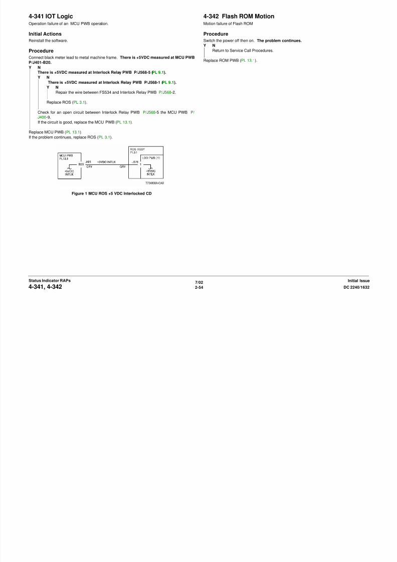
4-341 IOT LogicOperation failure of an MCU PWB operation.
Initial Actions
Reinstall the software.
Procedure
Connect black meter lead to metal machine frame. There is +5VDC measured at MCU PWB
4-342 Flash ROM MotionMotion failure of Flash ROM
Procedure
Switch the power off then on. The problem continues.
Y N
Return to Service Call Procedures.
Replace ROM PWB (PL 13.1).
8/13/2019 Xerox Docu Color 2240-1632
http://slidepdf.com/reader/full/xerox-docu-color-2240-1632 84/1118
7/02
2-54 DC 2240/16324-341, 4-342Initial IssueStatus Indicator RAPs
P/J401-B20.Y N
There is +5VDC measured at Interlock Relay PWB P/J568-5 (PL 9.1).
Y N
There is +5VDC measured at Interlock Relay PWB P/J568-1 (PL 9.1).
Y N
Repair the wire between FS534 and Interlock Relay PWB P/J568-2.
Replace ROS (PL 3.1).
Check for an open circuit between Interlock Relay PWB P/J568-5 the MCU PWB P/
J400-9.If the circuit is good, replace the MCU PWB (PL 13.1).
Replace MCU PWB (PL 13.1).
If the problem continues, replace ROS (PL 3.1).
Figure 1 MCU ROS +5 VDC Interlocked CD
4-343 IOT Flash ROM Read WriteThere is a FLASH ROM operation failure.
Procedure
Switch the power off then on. The problem continues.
Y N
Return to Service Call Procedures.
Replace the MCU PWB (PL 13.1).
4-344 IOT Micro PitchThe MICRO PIT did not occur within the specified time.
Procedure
Switch the power off then on. The problem continues.
Y N
Return to Service Call Procedures.
Replace the MCU PWB (PL 13.1).
8/13/2019 Xerox Docu Color 2240-1632
http://slidepdf.com/reader/full/xerox-docu-color-2240-1632 85/1118
7/02
2-55DC 2240/1632 4-343, 4-344Status Indicator RAPsInitial Issue
4-345 MCU HVPS CommunicationCommunication error between MCU PWB and HVPS Control PWB
Procedure
Measure voltage between MCU PWB P/J406-B1(+) and GND(-). +5 VDC is measured.
Y N
+3.3 VDC is measured.
Y N
Check for short circuit between MCU PWB P/J406-B1 and HVPS Control PWB P/

8/13/2019 Xerox Docu Color 2240-1632
http://slidepdf.com/reader/full/xerox-docu-color-2240-1632 86/1118
7/02
2-56 DC 2240/16324-345Initial IssueStatus Indicator RAPs
J574-9. If the circuit is not shorted, replace MCU PWB (PL 13.1).
Check for wire damage or bad connection between MCU PWB P/J406-B1 and HVPS
Control PWB P/J574-9.
Switch the power off. Measure resistance of following.
Measure resistance between HVPS Control PWB P/J574-7 and MCU PWB P/J406-B3
Measure resistance between HVPS Control PWB P/J574-6 and MCU PWB P/J406-B4. 10
ohms or less is measured.
Y N
Repair wires or bad connection.
10 ohms or less is measured between HVPS Control PWB P/J574-8 and MCU PWB P/
J406-B2.
Y N
Repair wires or bad connection.
Replace MCU PWB (PL 13.1).
If the problem continues, replace HVPS Control PWB (PL 9.1).
Figure 1 MCU HVPS Control PWB CD
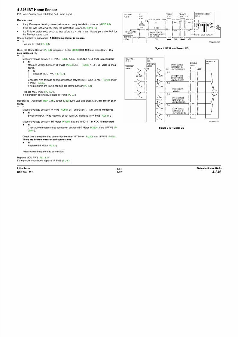
4-346 IBT Home SensorIBT Home Sensor does not detect Belt Home signal.
Procedure
• If any Developer Housings were just serviced, verify installation is correct (REP 9.9).
• If the IBT was just serviced, verify the installation is correct (REP 9.15).
• If a Finisher status code occurred just before the 4-346 in fault history, go to the RAP for
the Finisher status code.
Ch k th B lt H M k A B lt H M k i t
8/13/2019 Xerox Docu Color 2240-1632
http://slidepdf.com/reader/full/xerox-docu-color-2240-1632 87/1118
7/02
2-57DC 2240/1632 4-346Status Indicator RAPsInitial Issue
Check the Belt Home Marker. A Belt Home Marker is present.Y N
Replace IBT Belt (PL 5.3).
Block IBT Home Sensor (PL 5.4) with paper. Enter dC330 [004-100] and press Start. Dis-
play indicates Hi.
Y N
Measure voltage between I/F PWB P/J533-A13(+) and GND(-). +5 VDC is measured.
Y N
Measure voltage between I/F PWB P/J533-A9(+) P/J533-A12(-). +5 VDC is mea-
sured.
Y NReplace MCU PWB (PL 13.1).
Check for wire damage or bad connection between IBT Home Sensor P/J121 and I/
F PWB P/J533.
If no problems are found, replace IBT Home Sensor (PL 5.4).
Replace MCU PWB (PL 13.1).
If the problem continues, replace I/F PWB (PL 9.1).
Reinstall IBT Assembly (REP 9.15). Enter dC330 [004-002] and press Start. IBT Motor ener-
gizes.Y N
Measure voltage between I/F PWB P/J551-3(+) and GND(-). +24 VDC is measured.
Y N
By following Ch7 Wire Network, check +24VDC circuit up to I/F PWB P/J551-3
Measure voltage between IBT Motor P/J208-3(+) and GND(-). +24 VDC is measured.
Y N
Check wire damage or bad connection between IBT Motor P/J208-3 and I/FPWB P/
J551-3.
Check wire damage or bad connection between IBT Motor P/J208 and I/FPWB P/J551.
There are broken wires or bad connections.
Y N
Replace IBT Motor (PL 1.1).
Repair wire damage or bad connection.
Replace MCU PWB (PL 13.1).
If the problem continues, replace I/F PWB (PL 9.1).
Figure 1 IBT Home Sensor CD
Figure 2 IBT Motor CD
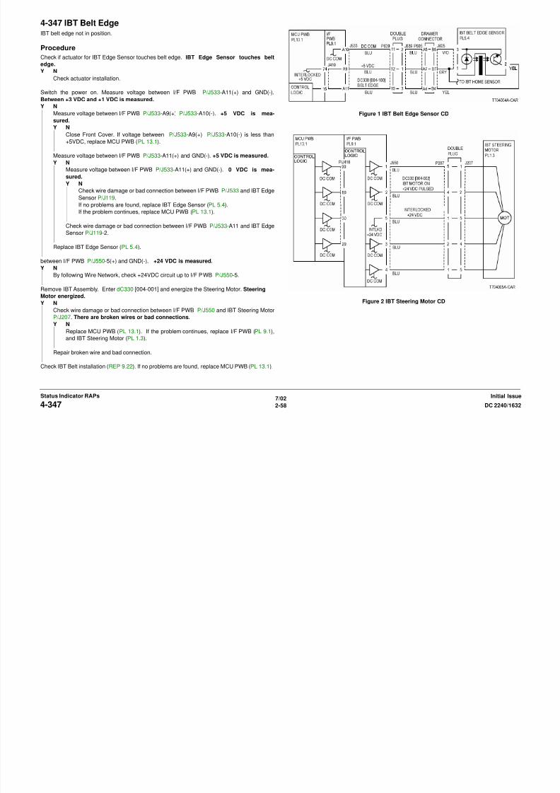
4-347 IBT Belt EdgeIBT belt edge not in position.
Procedure
Check if actuator for IBT Edge Sensor touches belt edge. IBT Edge Sensor touches belt
edge.
Y N
Check actuator installation.
Switch the power on Measure voltage between I/F PWB P/J533 A11(+) and GND( )
8/13/2019 Xerox Docu Color 2240-1632
http://slidepdf.com/reader/full/xerox-docu-color-2240-1632 88/1118
7/02
2-58 DC 2240/16324-347Initial IssueStatus Indicator RAPs
Switch the power on. Measure voltage between I/F PWB P/J533-A11(+) and GND(-).Between +3 VDC and +1 VDC is measured.
Y N
Measure voltage between I/F PWB P/J533-A9(+) P/J533-A10(-). +5 VDC is mea-
sured.
Y N
Close Front Cover. If voltage between P/J533-A9(+) P/J533-A10(-) is less than
+5VDC, replace MCU PWB (PL 13.1).
Measure voltage between I/F PWB P/J533-A11(+) and GND(-). +5 VDC is measured.
Y N
Measure voltage between I/F PWB P/J533-A11(+) and GND(-). 0 VDC is mea-
sured.
Y N
Check wire damage or bad connection between I/F PWB P/J533 and IBT Edge
Sensor P/J119.
If no problems are found, replace IBT Edge Sensor (PL 5.4).
If the problem continues, replace MCU PWB (PL 13.1).
Check wire damage or bad connection between I/F PWB P/J533-A11 and IBT Edge
Sensor P/J119-2.
Replace IBT Edge Sensor (PL 5.4).
between I/F PWB P/J550-5(+) and GND(-). +24 VDC is measured.
Y N
By following Wire Network, check +24VDC circuit up to I/F PWB P/J550-5.
Remove IBT Assembly. Enter dC330 [004-001] and energize the Steering Motor. Steering
Motor energized.
Y N
Check wire damage or bad connection between I/F PWB P/J550 and IBT Steering Motor
P/J207. There are broken wires or bad connections.Y N
Replace MCU PWB (PL 13.1). If the problem continues, replace I/F PWB (PL 9.1),
and IBT Steering Motor (PL 1.3).
Repair broken wire and bad connection.
Check IBT Belt installation (REP 9.22). If no problems are found, replace MCU PWB (PL 13.1).
Figure 1 IBT Belt Edge Sensor CD
Figure 2 IBT Steering Motor CD
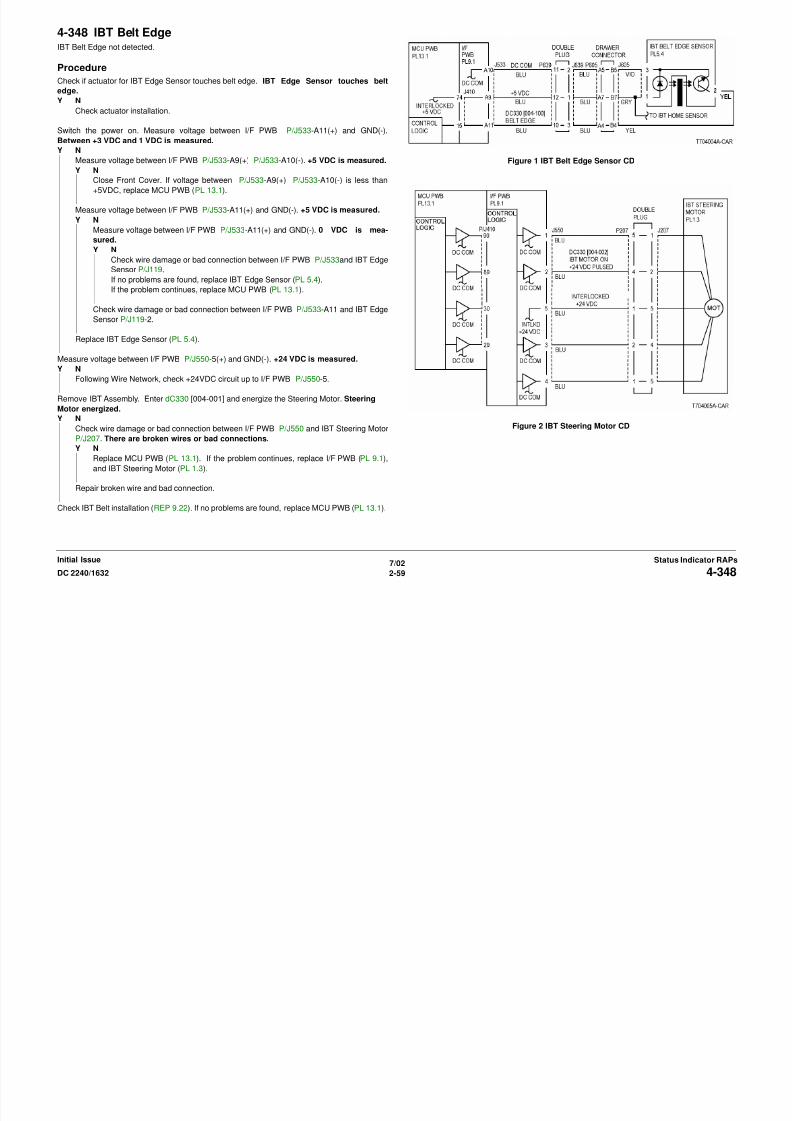
4-348 IBT Belt EdgeIBT Belt Edge not detected.
Procedure
Check if actuator for IBT Edge Sensor touches belt edge. IBT Edge Sensor touches belt
edge.
Y N
Check actuator installation.
Switch the power on Measure voltage between I/F PWB P/J533-A11(+) and GND(-)
8/13/2019 Xerox Docu Color 2240-1632
http://slidepdf.com/reader/full/xerox-docu-color-2240-1632 89/1118
7/02
2-59DC 2240/1632 4-348Status Indicator RAPsInitial Issue
Switch the power on. Measure voltage between I/F PWB P/J533-A11(+) and GND(-).Between +3 VDC and 1 VDC is measured.
Y N
Measure voltage between I/F PWB P/J533-A9(+) P/J533-A10(-). +5 VDC is measured.
Y N
Close Front Cover. If voltage between P/J533-A9(+) P/J533-A10(-) is less than
+5VDC, replace MCU PWB (PL 13.1).
Measure voltage between I/F PWB P/J533-A11(+) and GND(-). +5 VDC is measured.
Y N
Measure voltage between I/F PWB P/J533-A11(+) and GND(-). 0 VDC is mea-
sured.
Y N
Check wire damage or bad connection between I/F PWB P/J533and IBT Edge
Sensor P/J119.
If no problems are found, replace IBT Edge Sensor (PL 5.4).
If the problem continues, replace MCU PWB (PL 13.1).
Check wire damage or bad connection between I/F PWB P/J533-A11 and IBT Edge
Sensor P/J119-2.
Replace IBT Edge Sensor (PL 5.4).
Measure voltage between I/F PWB P/J550-5(+) and GND(-). +24 VDC is measured.
Y N
Following Wire Network, check +24VDC circuit up to I/F PWB P/J550-5.
Remove IBT Assembly. Enter dC330 [004-001] and energize the Steering Motor. Steering
Motor energized.
Y N
Check wire damage or bad connection between I/F PWB P/J550 and IBT Steering Motor
P/J207. There are broken wires or bad connections.
Y NReplace MCU PWB (PL 13.1). If the problem continues, replace I/F PWB (PL 9.1),
and IBT Steering Motor (PL 1.3).
Repair broken wire and bad connection.
Check IBT Belt installation (REP 9.22). If no problems are found, replace MCU PWB (PL 13.1).
Figure 1 IBT Belt Edge Sensor CD
Figure 2 IBT Steering Motor CD
8/13/2019 Xerox Docu Color 2240-1632
http://slidepdf.com/reader/full/xerox-docu-color-2240-1632 90/1118

8/13/2019 Xerox Docu Color 2240-1632
http://slidepdf.com/reader/full/xerox-docu-color-2240-1632 91/1118
4-362 IOT NVM Read WriteRead Write at the MCU PWB NVM R/W.
Procedure
Switch the power off then on. The problem continues.
Y N
Return to Service Call Procedures.
Check the connection between the MCU PWB and the MCU NVM PWB.
If the problem continues, replace the MCU PWB (PL 13.1).CAUTION
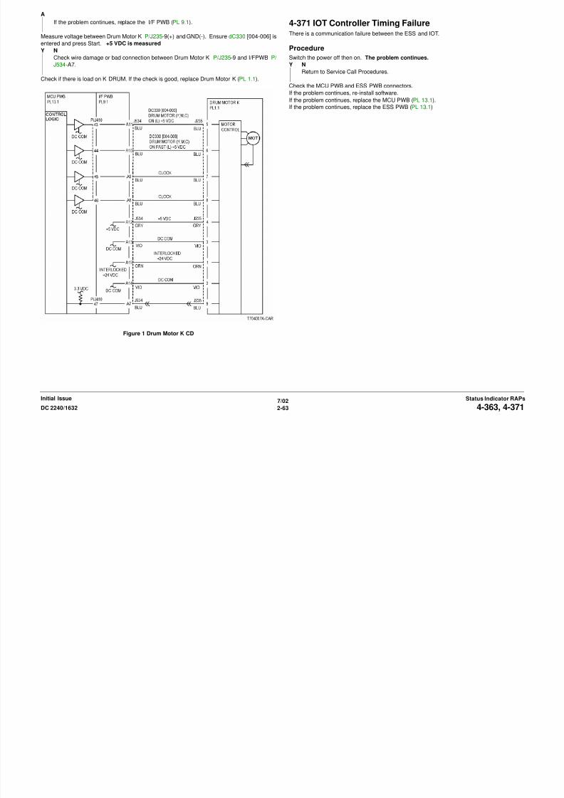
4-363 K Drum MotorDrum Motor K failure
Procedure
Remove K DRUM. Enter dC330 [004-006] and press Start. Drum Motor K energizes.
Y N
Measure voltage between Drum Motor K P/J235-4(+) and GND(-). +5 VDC is mea-
sured.
Y N
Following Wire Network, check +5VDC circuit to Drum Motor K P/J235-4.

8/13/2019 Xerox Docu Color 2240-1632
http://slidepdf.com/reader/full/xerox-docu-color-2240-1632 92/1118
7/02
2-62 DC 2240/16324-362, 4-363Initial IssueStatus Indicator RAPs
p p ( )CAUTION
Careful completion of replacement steps of MCU NVM PWB ( REP 1.2 ) is important to avoid
serious machine failure.
If the problem continues, replace the MCU NVM PWB (PL 13.1) (REP 1.2).
g
Measure voltage between Drum Motor K P/J235-2(+) and GND(-). +24 VDC is mea-
sured.
Y N
Following Ch7 Wire Network, check +24VDC circuit to Drum Motor K P/J235-2.
Measure voltage between Drum Motor K P/J235-5(+) and GND(-). Ensure dC330 [004-
006] is entered and press Start. 0 VDC is measured.
Y N
Measure voltage between I/F PWB P/J534-A11(+) and GND(-). Ensure dC330
[004-006] is entered and press Start. 0 VDC is measured.Y N
Check connection between MCU PWB and I/F PWB P410.
If no problems are found, replace MCU PWB (PL 13.1).
If the problem continues, replace I/F PWB (PL 9.1).
Check wire damage or bad connection between I/F PWB P/J534-A11 and Drum
Motor K P/J235-5
Measure voltage between Drum Motor K P/J235-8(+) and GND(-). Ensure dC330 [004-
006] is entered and press Start. Frequency is between 1KHz and 1.3 KHz.
Y N
Measure voltage between I/F PWB P/J534-A8 and GND (-). Frequency is
between 1KHz and 1.3 KHz.
Y N
Check connection between MCU PWB and I/F PWB P410.
If no problems are found, replace MCU PWB (PL 13.1).
If the problem continues, replace the I/F PWB (PL 9.1).
Check wire damage or bad connection between I/F PWB P/J534-A8 and Drum
Motor K P/J235-8.
Measure voltage between I/F PWB P/J534-A10 and Drum Motor K P/J235-6
between I/F PWB P/J534-A9 and Drum Motor K P/J235-7
If no problems are found, replace Drum Motor K (PL 1.1).
Measure voltage between I/F PWB P/J534-A7(+) and GND(-). Enter dC330 [004-006] and
press Start.
Y N
Check connector between MCU PWB and I/F PWB P410. If the check is good, replace
MCU PWB (PL 13.1).
A
If the problem continues, replace the I/F PWB (PL 9.1).
Measure voltage between Drum Motor K P/J235-9(+) and GND(-). Ensure dC330 [004-006] is
entered and press Start. +5 VDC is measured
Y N
Check wire damage or bad connection between Drum Motor K P/J235-9 and I/FPWB P/
J534-A7.
Check if there is load on K DRUM. If the check is good, replace Drum Motor K (PL 1.1).
4-371 IOT Controller Timing FailureThere is a communication failure between the ESS and IOT.
Procedure
Switch the power off then on. The problem continues.
Y N
Return to Service Call Procedures.
Check the MCU PWB and ESS PWB connectors.
If the problem continues, re-install software.If the problem continues replace the MCU PWB (PL 13 1)
A
8/13/2019 Xerox Docu Color 2240-1632
http://slidepdf.com/reader/full/xerox-docu-color-2240-1632 93/1118
7/02
2-63DC 2240/1632 4-363, 4-371Status Indicator RAPsInitial Issue
Figure 1 Drum Motor K CD
If the problem continues, replace the MCU PWB (PL 13.1).
If the problem continues, replace the ESS PWB (PL 13.1)
4-414 IBT Belt CleanerIBT Belt Cleaner near end of life.
Procedure
Replace the Cleaner Assembly. The problem continues.
Y N
Return to Service Call Procedures.
Replace the MCU PWB (PL 13.1).
CAUTIONCareful completion of replacement steps of MCU NVM PWB (REP 1 2) is important to avoid
4-415 2nd BTR UnitIt is time to replace the 2nd BTR UNIT.
Procedure
Replace the 2nd BTR Unit. The problem continues.
Y N
Return to Service Call Procedures.
Replace the MCU PWB (PL 13.1).
CAUTIONCareful completion of replacement steps of MCU NVM PWB (REP 1 2) is important to avoid

8/13/2019 Xerox Docu Color 2240-1632
http://slidepdf.com/reader/full/xerox-docu-color-2240-1632 94/1118
7/02
2-64 DC 2240/16324-414, 4-415Initial IssueStatus Indicator RAPs
Careful completion of replacement steps of MCU NVM PWB ( REP 1.2 ) is important to avoid
serious machine failure.
If the problem continues, replace the MCU NVM PWB (PL 13.1) (REP 1.2).
Careful completion of replacement steps of MCU NVM PWB ( REP 1.2 ) is important to avoid
serious machine failure.
If the problem continues, replace the MCU NVM PWB (PL 13.1) (REP 1.2)
4-417 1st BTR UnitIBT Belt Unit near end of life.
Procedure
Replace the IBT Belt (PL 5.3). The problem continues.
Y N
Return to Service Call Procedures.
Replace the MCU PWB (PL 13.1)
CAUTIONCareful completion of replacement steps of MCU NVM PWB (REP 1 2) is important to avoid
4-420 1st BTR UnitIBT Belt Unit end of life.
Procedure
Replace the 1st IBT Belt Unit The problem continues.
Y N
Return to Service Call Procedures.
Replace the MCU PWB (PL 13.1).
CAUTIONCareful completion of replacement steps of MCU NVM PWB (REP 1 2) is important to avoid
8/13/2019 Xerox Docu Color 2240-1632
http://slidepdf.com/reader/full/xerox-docu-color-2240-1632 95/1118
7/02
2-65DC 2240/1632 4-417, 4-420Status Indicator RAPsInitial Issue
Careful completion of replacement steps of MCU NVM PWB ( REP 1.2 ) is important to avoid
serious machine failure.
If the problem continues, replace the MCU NVM PWB (PL 13.1) (REP 1.2)
Careful completion of replacement steps of MCU NVM PWB ( REP 1.2 ) is important to avoid
serious machine failure.
If the problem continues, replace the MCU NVM PWB (PL 13.1) (REP 1.2).
4-421 IBT Belt Cleaner Life EndIBT Belt Cleaner Assembly end of life.
Procedure
Replace the IBT Belt Cleaner Assembly (PL 5.2). The problem continues.
Y N
Return to Service Call Procedures.
If the problem continues, replace the MCU PWB (PL 13.1).
CAUTIONCareful completion of replacement steps of MCU NVM PWB (REP 1.2) is important to avoid
4-605 IOT NVM CorruptThe system detected that the NVM of the IOT is empty.
Procedure
Switch the power off then on. The problem continues.
Y N
Return to Service Call Procedures.
Replace the MCU PWB (PL 13.1).
CAUTIONCareful completion of replacement steps of MCU NVM PWB (REP 1.2) is important to avoid

8/13/2019 Xerox Docu Color 2240-1632
http://slidepdf.com/reader/full/xerox-docu-color-2240-1632 96/1118
7/02
2-66 DC 2240/16324-421, 4-605Initial IssueStatus Indicator RAPs
Careful completion of replacement steps of MCU NVM PWB ( REP 1.2 ) is important to avoid
serious machine failure.
If the problem continues, replace the MCU NVM PWB (PL 13.1) (REP 1.2).
Careful completion of replacement steps of MCU NVM PWB ( REP 1.2 ) is important to avoid
serious machine failure.
If the problem continues, replace the MCU NVM PWB (PL 13.1) (REP 1.2).
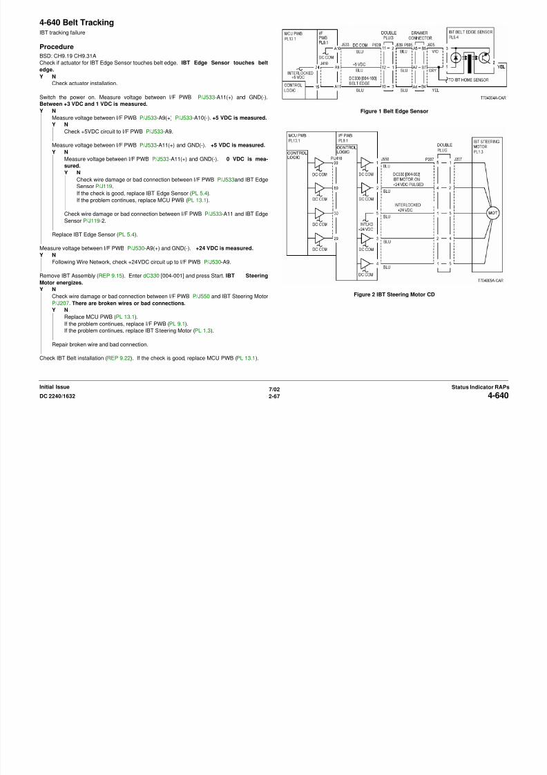
4-640 Belt TrackingIBT tracking failure
Procedure
BSD: CH9.19 CH9.31A
Check if actuator for IBT Edge Sensor touches belt edge. IBT Edge Sensor touches belt
edge.
Y N
Check actuator installation.
Switch the power on. Measure voltage between I/F PWB P/J533-A11(+) and GND(-).
8/13/2019 Xerox Docu Color 2240-1632
http://slidepdf.com/reader/full/xerox-docu-color-2240-1632 97/1118
7/02
2-67DC 2240/1632 4-640Status Indicator RAPsInitial Issue
Between +3 VDC and 1 VDC is measured.
Y N
Measure voltage between I/F PWB P/J533-A9(+) P/J533-A10(-). +5 VDC is measured.
Y N
Check +5VDC circuit to I/F PWB P/J533-A9.
Measure voltage between I/F PWB P/J533-A11(+) and GND(-). +5 VDC is measured.
Y N
Measure voltage between I/F PWB P/J533-A11(+) and GND(-). 0 VDC is mea-
sured.Y N
Check wire damage or bad connection between I/F PWB P/J533and IBT Edge
Sensor P/J119.
If the check is good, replace IBT Edge Sensor (PL 5.4).
If the problem continues, replace MCU PWB (PL 13.1).
Check wire damage or bad connection between I/F PWB P/J533-A11 and IBT Edge
Sensor P/J119-2.
Replace IBT Edge Sensor (PL 5.4).
Measure voltage between I/F PWB P/J530-A9(+) and GND(-). +24 VDC is measured.
Y N
Following Wire Network, check +24VDC circuit up to I/F PWB P/J530-A9.
Remove IBT Assembly (REP 9.15). Enter dC330 [004-001] and press Start. IBT Steering
Motor energizes.
Y N
Check wire damage or bad connection between I/F PWB P/J550 and IBT Steering Motor
P/J207. There are broken wires or bad connections.
Y NReplace MCU PWB (PL 13.1).
If the problem continues, replace I/F PWB (PL 9.1).
If the problem continues, replace IBT Steering Motor (PL 1.3).
Repair broken wire and bad connection.
Check IBT Belt installation (REP 9.22). If the check is good, replace MCU PWB (PL 13.1).
Figure 1 Belt Edge Sensor
Figure 2 IBT Steering Motor CD
4-641 Belt EdgeIBT belt edge not detected.
Procedure
Check if actuator for IBT Edge Sensor touches belt edge. IBT Edge Sensor touches belt
edge.
Y N
Check actuator installation.
Switch the power on. Measure voltage between I/F PWB P/J533-A11(+) and GND(-).Between +3 VDC and 1 VDC is measured.
Y N
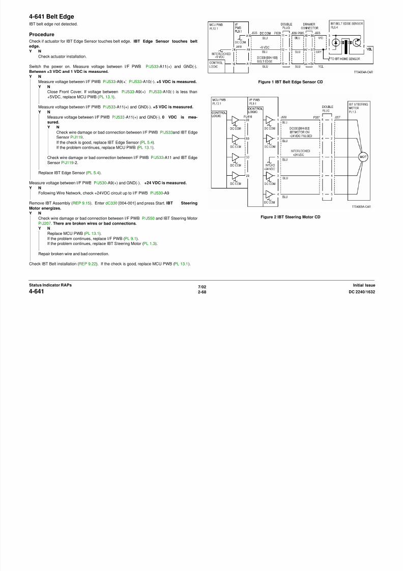
8/13/2019 Xerox Docu Color 2240-1632
http://slidepdf.com/reader/full/xerox-docu-color-2240-1632 98/1118
7/02
2-68 DC 2240/16324-641Initial IssueStatus Indicator RAPs
Y N
Measure voltage between I/F PWB P/J533-A9(+) P/J533-A10(-). +5 VDC is measured.
Y N
Close Front Cover. If voltage between P/J533-A9(+) P/J533-A10(-) is less than
+5VDC, replace MCU PWB (PL 13.1).
Measure voltage between I/F PWB P/J533-A11(+) and GND(-). +5 VDC is measured.
Y N
Measure voltage between I/F PWB P/J533-A11(+) and GND(-). 0 VDC is mea-
sured.Y N
Check wire damage or bad connection between I/F PWB P/J533and IBT Edge
Sensor P/J119.
If the check is good, replace IBT Edge Sensor (PL 5.4).
If the problem continues, replace MCU PWB (PL 13.1).
Check wire damage or bad connection between I/F PWB P/J533-A11 and IBT Edge
Sensor P/J119-2.
Replace IBT Edge Sensor (PL 5.4).
Measure voltage between I/F PWB P/J530-A9(+) and GND(-). +24 VDC is measured.
Y N
Following Wire Network, check +24VDC circuit up to I/F PWB P/J530-A9
Remove IBT Assembly (REP 9.15). Enter dC330 [004-001] and press Start. IBT Steering
Motor energizes.
Y N
Check wire damage or bad connection between I/F PWB P/J550 and IBT Steering Motor
P/J207. There are broken wires or bad connections.
Y N
Replace MCU PWB (PL 13.1).
If the problem continues, replace I/F PWB (PL 9.1).
If the problem continues, replace IBT Steering Motor (PL 1.3).
Repair broken wire and bad connection.
Check IBT Belt installation (REP 9.22). If the check is good, replace MCU PWB (PL 13.1).
Figure 1 IBT Belt Edge Sensor CD
Figure 2 IBT Steering Motor CD
4-642 Belt EdgeIBT belt edge not in position.
Procedure
Check if actuator for IBT Edge Sensor touches belt edge. IBT Edge Sensor touches belt
edge.
Y N
Check actuator installation.
Switch the power on. Measure voltage between I/F PWB P/J533-A11(+) and GND(-).Between +3 VDC and 1 VDC is measured.
Y N

8/13/2019 Xerox Docu Color 2240-1632
http://slidepdf.com/reader/full/xerox-docu-color-2240-1632 99/1118
7/02
2-69DC 2240/1632 4-642Status Indicator RAPsInitial Issue
Y N
Measure voltage between I/F PWB P/J533-A9(+) P/J533-A10(-). +5 VDC is measured.
Y N
Close Front Cover. If voltage between P/J533-A9(+) P/J533-A10(-) is less than
+5VDC, replace MCU PWB (PL 13.1).
Measure voltage between I/F PWB P/J533-A11(+) and GND(-). +5 VDC is measured.
Y N
Measure voltage between I/F PWB P/J533-A11(+) and GND(-). 0 VDC is mea-
sured.Y N
Check wire damage or bad connection between I/F PWB P/J533and IBT Edge
Sensor P/J119.
If the check is good, replace IBT Edge Sensor (PL 5.4).
If the problem continues, replace MCU PWB (PL 13.1).
Check wire damage or bad connection between I/F PWB P/J533-A11 and IBT Edge
Sensor P/J119-2.
Replace IBT Edge Sensor (PL 5.4).
Measure voltage between I/F PWB P/J530-A9(+) and GND(-). +24 VDC is measured.
Y N
Following Wire Network, check +24VDC circuit up to I/F PWB P/J530-A9
Remove IBT Assembly (REP 9.15). Enter dC330 [004-001] and press Start. IBT Steering
Motor energizes.
Y N
Check wire damage or bad connection between I/F PWB P/J550 and IBT Steering Motor
P/J207. There are broken wires or bad connections.
Y N
Replace MCU PWB (PL 13.1).
If the problem continues, replace I/F PWB (PL 9.1).
If the problem continues, replace IBT Steering Motor (PL 1.3).
Repair broken wire and bad connection.
Check IBT Belt installation (REP 9.22). If the check is good, replace MCU PWB (PL 13.1).
Figure 1 IBT Belt Edge Sensor CD
Figure 2 IBT Steering Motor CD
4-650 IOT Cycle Down Time OutIncorrect print processing continued for 2 minutes.
Procedure
Check the harness connections between the ESS PWB (PL 13.1) and the MCU PWB (PL
13.1). The problem continues.
Y N
Return to Service Call Procedures.
Replace the ESS PWB (PL 13.1)
4-908 2nd BTR Life End2nd BTR end of life.
Procedure
Replace the 2nd BTR (PL 2.8) (REP 9.24). The problem continues.
Y N
Return to Service Call Procedures.
Replace the MCU PWB (PL 13.1).
CAUTIONCareful completion of replacement steps of MCU NVM PWB ( REP 1.2 ) is important to avoid
i hi f il

8/13/2019 Xerox Docu Color 2240-1632
http://slidepdf.com/reader/full/xerox-docu-color-2240-1632 100/1118
7/02
2-70 DC 2240/16324-650, 4-908Initial IssueStatus Indicator RAPs
serious machine failure.
If the problem continues, replace the MCU NVM PWB (PL 13.1) (REP 1.2).
5-110 Registration Sensor On
Registration Sensor did not detect a document after the Feed Motor energized.
Initial Actions
• Ensure document path is clear.
• Ensure Feed and Nudger Rolls are free of contamination and wear (PL 20.4).
Procedure
Feed a document and observe the Feed Rolls and prefeed action. The Feed Rolls move
down.Y N
Remove following:

8/13/2019 Xerox Docu Color 2240-1632
http://slidepdf.com/reader/full/xerox-docu-color-2240-1632 101/1118
7/02
2-71DC 2240/1632 5-110Status Indicator RAPsInitial Issue
Remove following:
• Front Cover (PL 20.1).
• Entrance Tray (PL 20.1).
• Document Feed Lower Chute (REP 5.8).
Check Set Gate Solenoid linkage.
If the linkage is good, go to OF 99-8 and check the circuit of the Set Gate Solenoid (Fig-
ure 1).
Clear the jam and feed a document. The Document prefeeds into the DADF.Y N
Remove Rear Cover (REP 5.18). Check Fuse F3 on DADF Control PWB (Figure 4).
Fuse is good.
Y N
If a fuse is not available, replace the DADF Control PWB (PL 20.3) .
Check the +24 VDC wires on the Feed Motor (Figure 2) for a short circuit to frame.
If the wires are good, and the problem continues, replace the Feed Motor (PL 20.4).
Access the Feed Rolls (REP 5.7). Check the Feed Roll Drives. Repair as required (PL
20.4). If the drives are good, check the circuit of the Feed Motor (Figure 2).
Go to OF 99-2 and check the circuit of the Registration Sensor (Figure 3).
Figure 1 Set Gate Solenoid CD
Figure 2 Feed Motor CD
Figure 3 Registration Sensor CD
Figure 4 DADF Control PWB
5-111 Registration Sensor Off
The document did not deactuate the Registration Sensor after the DADF Belt Motor energized.
Initial Actions
Ensure document path is clear.
Procedure
Feed a document and observe the Platen Belt. The Platen Belt rotates.
Y NRemove Rear Cover (REP 5.18).
Check drive components for DADF Belt Motor (PL 20.6).
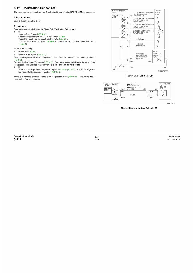
8/13/2019 Xerox Docu Color 2240-1632
http://slidepdf.com/reader/full/xerox-docu-color-2240-1632 102/1118
7/022-72 DC 2240/16325-111
Initial IssueStatus Indicator RAPs
p ( )
Check the Fuse F1 on the DADF Control PWB (Figure 3).
If no problems are found, go to OF 99-9 and check the circuit of the DADF Belt Motor
(Figure 1).
Remove the following:
• Front Cover (PL 20.1).
• Document Transport (REP 5.17).
Check the Registration Rolls and Registration Pinch Rolls for drive or contamination problems(PL 20.8).
Reinstall the Document Transport (REP 5.17). Feed a document and observe the ends of the
Registration Rolls and Registration Pinch Rolls. The ends of the rolls rotate.
Y N
There is a drives problem. Repair as required (PL 20.6) (PL 20.8). Ensure the Registra-
tion Pinch Roll Springs are in position (REP 5.15).
There is a blockage problem. Remove the Registration Rolls (REP 5.15). Ensure the docu-
ment path is free of obstruction.
Figure 1 DADF Belt Motor CD
Figure 2 Registration Gate Solenoid CD
Figure 3 DADF Control PWB
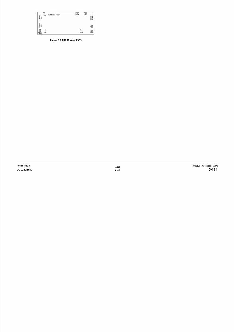
8/13/2019 Xerox Docu Color 2240-1632
http://slidepdf.com/reader/full/xerox-docu-color-2240-1632 103/1118
7/022-73DC 2240/1632 5-111
Status Indicator RAPsInitial Issue
5-112 Registration Sensor Inversion
The document does not actuate the DADF Registration Sensor after the Belt Motor energized
for document inversion.
Procedure
Select 1 to 1 and make a copy. The document exits the DADF.
Y N
Go to the RAP for the displayed status code.
Enter dC330 [005-119] and press Start. Actuate the Duplex Sensor (PL 20.7). The displaychanges.
Y N
Figure 3 DADF Control PWB

8/13/2019 Xerox Docu Color 2240-1632
http://slidepdf.com/reader/full/xerox-docu-color-2240-1632 104/1118
7/022-74 DC 2240/16325-112
Initial IssueStatus Indicator RAPs
Y N
Go to OF 99-2 and check the circuit of the Duplex Sensor (Figure 1).
Enter dC330 [005-075] and press Start. The Registration Gate Solenoid energizes.
Y N
Go to OF 99-4 and check the circuit of the Registration Gate Solenoid (Figure 2).
If the solenoid was already energized, go to OF 99-5 and check the circuit of the Registra-
tion Gate Solenoid (Figure 2).
Check Following:
• The Platen Belt for contamination, wear and a rotation failure (PL 20.10).
• The Platen Belt for an improper tension (REP 5.19).
• The DADF Registration Gate Solenoid for a return failure (PL 20.2).
Figure 1 Duplex Sensor CD
Figure 2 Registration Gate Solenoid CD
5-113 Registration Sensor Inversion
The document does not deactuate the DADF Registration Sensor after the Belt Motor ener-
gized for document inversion.
Procedure
Enter dC330 [005-110] and press Start. Actuate the Registration Sensor (PL 20.5). The dis-
play changes.
Y N
Go to OF 99-2 and check the circuit of the Registration Sensor (Figure 1).
Enter dC330 [005-075] and press Start. The Registration Gate Solenoid energizes.
Y N
Figure 2 Registration Gate Solenoid CD
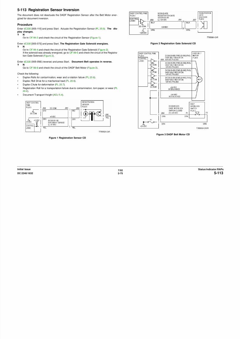
8/13/2019 Xerox Docu Color 2240-1632
http://slidepdf.com/reader/full/xerox-docu-color-2240-1632 105/1118
7/022-75DC 2240/1632 5-113
Status Indicator RAPsInitial Issue
Go to OF 99-4 and check the circuit of the Registration Gate Solenoid (Figure 2).
If the solenoid was already energized, go to OF 99-5 and check the circuit of the Registra-
tion Gate Solenoid (Figure 2).
Enter dC330 [005-056] (reverse) and press Start. Document Belt operates in reverse.
Y N
Go to OF 99-9 and check the circuit of the DADF Belt Motor (Figure 3).
Check the following:
• Duplex Rolls for contamination, wear and a rotation failure (PL 20.6).
• Duplex Roll Drive for a mechanical load (PL 20.6).
• Duplex Chute for deformation (PL 20.7).
• Registration Roll for a transportation failure due to contamination, torn paper, or wear (PL
20.8).
• Document Transport Height (ADJ 5.4).
Figure 1 Registration Sensor CD
Figure 3 DADF Belt Motor CD
Figure 4 DADF Control PWB

8/13/2019 Xerox Docu Color 2240-1632
http://slidepdf.com/reader/full/xerox-docu-color-2240-1632 106/1118
7/022-76 DC 2240/16325-113
Initial IssueStatus Indicator RAPs

8/13/2019 Xerox Docu Color 2240-1632
http://slidepdf.com/reader/full/xerox-docu-color-2240-1632 107/1118
5-116 Exit Sensor OffThe document does not deactuate the DADF Exit Sensor after the DADF Exit Sensor actuated.
Procedure
Enter dC330 [005-115] and press Start. Actuate the DADF Exit Sensor (PL 20.9). The dis-
play changes.
Y N
Go to OF 99-2 and check the circuit of the DADF Exit Sensor (Figure 1).
Enter dC330 [005-081] and press Start. DADF Exit Motor operates (PL 20.9).
Y N
Go to OF 99-9 and check the circuit of the DADF Exit Motor (Figure 2).

8/13/2019 Xerox Docu Color 2240-1632
http://slidepdf.com/reader/full/xerox-docu-color-2240-1632 108/1118
7/022-78 DC 2240/16325-116
Initial IssueStatus Indicator RAPs
Check the following:
• Exit Roll for contamination, wear and a rotation failure (PL 20.9).
• Exit Upper/lower Chute for deformation (PL 20.9).
• Static Eliminator for deformation (PL 20.9).
• Exit Roll Drive Belt for disengagement and damage (PL 20.9).
Figure 1 DADF Exit Sensor CD
Figure 2 Exit Motor CD
Figure 3 DADF Control PWB
5-195 Document Size Mismatch
Different sized documents are detected in the NO MIX mode.
Procedure
Enter dC330 [005-150] and press Start. Actuate DADF Size Sensor 1 (Front) (PL 20.5). The
display changes.
Y N
Go to OF 99-2 and check the circuit of the DADF Size Sensor 1 (Front) (Figure 1).
Enter dC330 [005-151] and press Start. Actuate DADF Size Sensor 2 (Rear) (PL 20.5). Thedisplay changes.
Y N
Go to OF 99 2 and check the circuit of the DADF Size Sensor 2 (Rear) (Figure 2)
Figure 3 DADF Control PWB

8/13/2019 Xerox Docu Color 2240-1632
http://slidepdf.com/reader/full/xerox-docu-color-2240-1632 109/1118
7/022-79DC 2240/1632 5-195
Status Indicator RAPsInitial Issue
Go to OF 99-2 and check the circuit of the DADF Size Sensor 2 (Rear) (Figure 2).
Check the following:
• Size Sensor for correct installation (REP 5.12).
• Multiple feed due to retard malfunction (PL 20.5).
• DADF document skew caused by misadjustments (ADJ 5.2) (ADJ 5.3) (ADJ 5.4).
• Document meets specification
• Different document size (mixed documents)
Figure 1 Size Sensor 1 Rear CD
Figure 2 Size Sensor 2 Front CD
5-274 Original Size SensorAt power on, the DADF Registration Sensor turns off, and the DADF Size Sensor 1 or the
DADF Size Sensor 2 turns on when the document is loaded (Size Sensor detection failure)
Procedure
Enter [5-150] and press Start. press Start. Actuate sensor. The display changes?
Y N
Remove DADF Entrance Tray (PL 20.1). Disconnect the DADF Size Sensor 1 P/J582
(REP 5.12). The display changes
Y NDisconnect P/J599 on the DADF Control PWB. Measure the resistance between
the pin J599-8 and the frame. Resistance 3 Ohm or less.
Y N
Figure 2 Size Sensor 2 Front CD

8/13/2019 Xerox Docu Color 2240-1632
http://slidepdf.com/reader/full/xerox-docu-color-2240-1632 110/1118
7/022-80 DC 2240/16325-274
Initial IssueStatus Indicator RAPs
Y N
Replace DADF Control PWB (PL 20.3).
Check wire between DADF Size Sensor 1 P/J582-2 and DADF Control PWB P/
J599-8 for a short circuit to frame (Figure 1).
Replace DADF Size Sensor 1 (PL 20.5).
Enter dC330 [005-151] and press Start. H is displayed.Y N
Remove the DADF Entrance Tray (PL 20.1). Disconnect the DADF Size Sensor 2 J583.
The display changes.
Y N
Disconnect P/J599 on the DADF Control PWB. Measure the resistance between
J599-11 and frame. The resistance 3 Ohm or less.
Y N
Replace DADF Control PWB (PL 20.3).
Check the wire between the DADF Size Sensor 2 P/J583-2 and the DADF Control
PWB P/J599-11 for a short circuit to the frame (Figure 2).
Replace DADF Size Sensor 2 (PL 20.5).
Replace DADF Control PWB (PL 20.3).
Figure 1 Size Sensor 1 Rear CD
Figure 3 DADF Control PWB
5-275 DADF Ram FailureRAM failure of the DADF PWB.
Procedure
Switch the power off then on. The problem continues.
Y N
Return to Service Call Procedures.
Replace the DADF Control PWB (PL 20.3).

8/13/2019 Xerox Docu Color 2240-1632
http://slidepdf.com/reader/full/xerox-docu-color-2240-1632 111/1118
7/022-81DC 2240/1632 5-275
Status Indicator RAPsInitial Issue
5-301 Top Cover Interlock OpenThe Top Cover is open.
Procedure
Manually actuate DADF Top Cover Interlock Switch (front/rear) at the same t ime. 5-301 is
cleared.
Y N
Remove DADF Rear Cover (REP 5.18). Close the DADF Top Cover. +5VDC is mea-
sured between the DADF Control PWB P/J599-17 (+) and GND (-).
Y N+5VDC is measured between the DADF Control PWB P/J599-22 (+) and GND (-
).
Y NFigure 2 Top Cover Interlock Switch (rear)

8/13/2019 Xerox Docu Color 2240-1632
http://slidepdf.com/reader/full/xerox-docu-color-2240-1632 112/1118
7/022-82 DC 2240/16325-301
Initial IssueStatus Indicator RAPs
Replace the DADF Control PWB (PL 20.3).
Cheat J590-1 and -2 of P/J590 for the DADF Top Cover Rear Interlock Switch. 5-
301 is cleared.
Y N
Check the wire between the Top Cover Rear Interlock Switch J590-1 and the
DADF Control PWB P/J599-22, and the wire between the Top Cover Rear
Interlock Switch J690-2 and the DADF Control PWB P/J599-21 for an open cir-cuit or poor contact.
Replace the DADF Top Cover Rear Interlock Switch (PL 20.2).
Cheat Pin J585-1 and -2 of P/J585 for the DADF Top Cover Front Interlock Switch.
0VDC is measured between the DADF Control PWB P/J599-17 (+) and GND (-).
Y N
Check the wire between the Top Cover Front Interlock Switch J585-1 and the DADF
Control PWB J599-17, and the wire between the Top Cover Front Interlock Switch
J585-2 and the DADF Control PWB J599-16 for an open circuit or poor contact.
Replace the DADF Top Cover Front Interlock Switch (PL 20.2).
Check the actuator for breakage and bending, and the Top Cover for correct installation (PL
20.2).
Figure 1 Top Cover Interlock Switch (front)
Figure 3 DADF Control PWB
5-900 Document Sensor TimingA timing error occurred between document sensing and the opening of a DADF Interlock.
Procedure
Switch the power off then on. The problem continues.
Y N
Return to Service Call Procedures.
Replace the DADF Control PWB (PL 20.3).

8/13/2019 Xerox Docu Color 2240-1632
http://slidepdf.com/reader/full/xerox-docu-color-2240-1632 113/1118
7/022-83DC 2240/1632 5-900
Status Indicator RAPsInitial Issue
5-901 Power On Document PresentThe Document Sensor detects a document at Power On.
Procedure
Enter dC330 [005-102] and press Start. Actuate the DADF Document Sensor. The display
changes.
Y N
Disconnect P/J599 from DADF Control PWB. Measure voltage at P/J599-5. +5 VDC is
measured.
Y NReplace DADF Control PWB (PL 20.3).
Check the wire from P/J599-5 to P/J581-2 on the Document Sensor for a short circuit
(Fi 1) If th i i d l th D t S (PL 20 5)

8/13/2019 Xerox Docu Color 2240-1632
http://slidepdf.com/reader/full/xerox-docu-color-2240-1632 114/1118
7/022-84 DC 2240/16325-901
Initial IssueStatus Indicator RAPs
(Figure 1). If the wire is good, replace the Document Sensor (PL 20.5).
Check that the voltage at the customer outlet is in specification and does not drop during
machine start.
Figure 1 Document Sensor CD
5-902 Power On Registration SensorAt Power On, the Registration Sensor detected a document when the Top Cover/platen Inter-
lock was closed.
Procedure
Enter dC330 [005-110] and press Start. Actuate the DADF Registration Sensor. The display
changes.
Y N
Disconnect P/J599 from DADF Control PWB. Measure voltage at P/J599-9. +5 VDC is
measured.
Y N
Replace DADF Control PWB (PL 20.3).
Check the wire from P/J599-9 to P/J580-2 on the Registration Sensor for a short circuit

8/13/2019 Xerox Docu Color 2240-1632
http://slidepdf.com/reader/full/xerox-docu-color-2240-1632 115/1118
7/022-85DC 2240/1632 5-902
Status Indicator RAPsInitial Issue
g
(Figure 1). If the wire is good, replace the Registration Sensor (PL 20.5).
Check that the voltage at the customer outlet is in specification and does not drop during
machine start.
Figure 1 Registration Sensor CD
5-903 Power On Exit SensorAt Power On, the DADF Exit Sensor detected a document when the Top Cover/platen Interlock
was closed.
Procedure
Enter dC330 [005-115] and press Start. Actuate the DADF Exit Sensor. The display
changes.
Y N
Disconnect P/J599 from DADF Control PWB. Measure voltage at P/J599-19. +5 VDC
is measured.Y N
Replace DADF Control PWB (PL 20.3).
Check the wire from P/J599-19 to P/J589-2 on the Exit Sensor for a short circuit (Figure

8/13/2019 Xerox Docu Color 2240-1632
http://slidepdf.com/reader/full/xerox-docu-color-2240-1632 116/1118
7/022-86 DC 2240/16325-903
Initial IssueStatus Indicator RAPs
Check the wire from P/J599 19 to P/J589 2 on the Exit Sensor for a short circuit (Figure
1). If the wire is good, replace the Exit Sensor (PL 20.9).
Check that the voltage at the customer outlet is in specification and does not drop during
machine start.
Figure 1 Exit Sensor CD
5-904 Power On Duplex SensorAt Power On, the DADF Duplex Sensor detected a document when the Top Cover/platen Inter-
lock was closed.
Procedure
Enter dC330 [005-1195] and press Start. Actuate the DADF Duplex Sensor. The display
changes.
Y N
Disconnect P/J599 from DADF Control PWB. Measure voltage at P/J599-14. +5 VDC
is measured.Y N
Replace DADF Control PWB (PL 20.3).
Check the wire from P/J599-14 to P/J765-2 on the Duplex Sensor for a short circuit (Fig-

8/13/2019 Xerox Docu Color 2240-1632
http://slidepdf.com/reader/full/xerox-docu-color-2240-1632 117/1118
7/022-87DC 2240/1632 5-904
Status Indicator RAPsInitial Issue
Check the wire from P/J599 14 to P/J765 2 on the Duplex Sensor for a short circuit (Fig
ure 1). If the wire is good, replace the Duplex Sensor (PL 20.7).
Check that the voltage at the customer outlet is in specification and does not drop during
machine start.
Figure 1 Duplex Sensor CD
5-940 Document Removed During StartControl Logic detected that the document was removed immediately after the DADF started.
Procedure
Rerun job. 5-940 is declared again.
Y N
Return to Service Call Procedures.
Replace the DADF Control PWB (PL 20.3).

8/13/2019 Xerox Docu Color 2240-1632
http://slidepdf.com/reader/full/xerox-docu-color-2240-1632 118/1118
7/022-88 DC 2240/16325-940
Initial IssueStatus Indicator RAPs
5-941 Document MiscountDocument miscount.
Procedure
Rerun job. 5-941 continues.
Y N
Return to Service Call Procedures.
Replace the DADF Control PWB (PL 20.3).
8/13/2019 Xerox Docu Color 2240-1632
http://slidepdf.com/reader/full/xerox-docu-color-2240-1632 119/1118
7/022-89DC 2240/1632 5-941
Status Indicator RAPsInitial Issue
8/13/2019 Xerox Docu Color 2240-1632
http://slidepdf.com/reader/full/xerox-docu-color-2240-1632 120/1118
7/022-90 DC 2240/16325-941
Initial IssueStatus Indicator RAPs
6-277 ESS DADF CommunicationCommunication cannot be established between the IIT/IPS and the DADF Control PWB.
Procedure
Switch the power on. The CR4 on the DADF Control PWB illuminates.
Y N
+5VDC is measured between the DADF Control PWB P/J550-6 (+) and ground (-).
Y N
Check the +5VDC circuit to the DADF Control PWB P/J550-6 by referring to Section
7 Wiring Data (DADF+5VDC)
Replace the DADF Control PWB (PL 20.3).
Switch the power off. Check resistance of the following:
Between IIT/IPS PWB P/J725-20 and DADF Control PWB P/J551-A1
6-300 DADF OpenThe DADF was opened during the DADF Job.
Procedure
Enter dC330 [006-300] and place a magnet over the Platen Open Switch (PL 18.4). The
display changes.
Y N
Remove the Platen Glass (REP 6.2). Remove IIT/IPS Cover (PL 18.3). Connect a jumper
between P/J722-A2 and ground. The display changes.
Y N
Replace the IPS/IIT PWB (PL 18.3).
Check the circuit of the Platen Open Switch for an open circuit ( Figure 1). If the wires are
good, Replace the Platen Open Switch (PL 18.4).
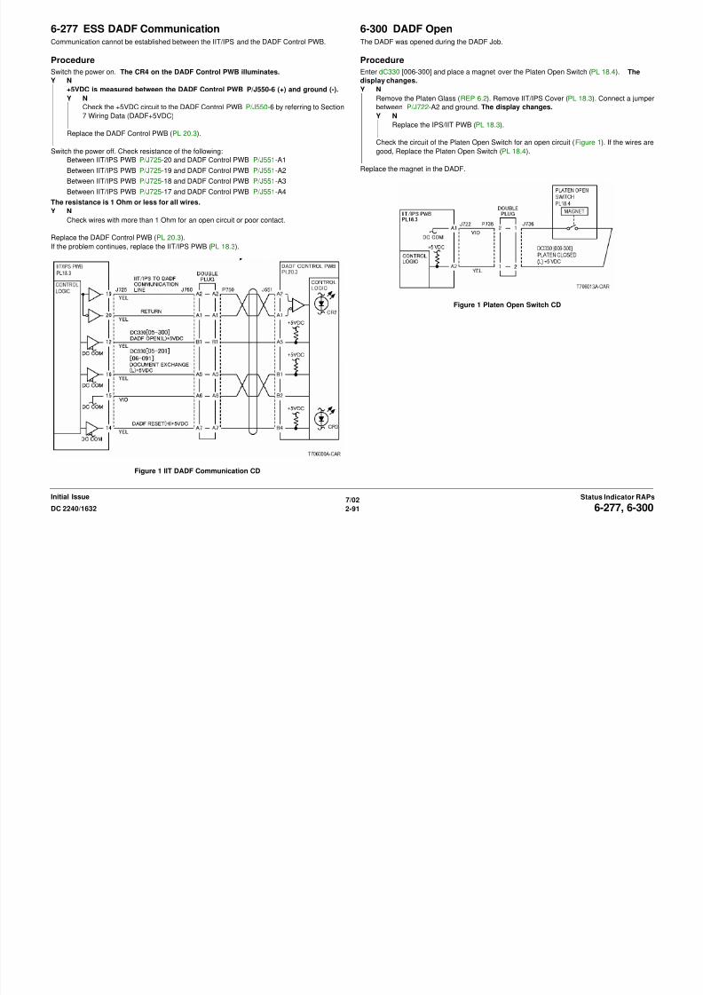
8/13/2019 Xerox Docu Color 2240-1632
http://slidepdf.com/reader/full/xerox-docu-color-2240-1632 121/1118
7/022-91DC 2240/1632 6-277, 6-300
Status Indicator RAPsInitial Issue
et ee / S /J 5 0 a d Co t o /J55
Between IIT/IPS PWB P/J725-19 and DADF Control PWB P/J551-A2
Between IIT/IPS PWB P/J725-18 and DADF Control PWB P/J551-A3
Between IIT/IPS PWB P/J725-17 and DADF Control PWB P/J551-A4
The resistance is 1 Ohm or less for all wires.
Y N
Check wires with more than 1 Ohm for an open circuit or poor contact.
Replace the DADF Control PWB (PL 20.3).
If the problem continues, replace the IIT/IPS PWB (PL 18.3).
Figure 1 IIT DADF Communication CD
Replace the magnet in the DADF.
Figure 1 Platen Open Switch CD
6-312 IIT Memory Hot LineThe system detected an open circuit in the IIT Memory Hot Line.
Procedure
Check connections at IIT/IPS PWB. The problem continues.
Y N
Return to Service Call Procedures.
Replace the IIT/IPS PWB (PL 18.3).

8/13/2019 Xerox Docu Color 2240-1632
http://slidepdf.com/reader/full/xerox-docu-color-2240-1632 122/1118
7/022-92 DC 2240/16326-312
Initial IssueStatus Indicator RAPs
6-340 ESS RAM Test ErrorAt power on, the system detected a I IT/IPS PWB RAM test error.
Procedure
Switch power off then on. The problem continues.
Y N
Return to Service Call Procedures.
Replace the IIT/IPS PWB (PL 18.3).

8/13/2019 Xerox Docu Color 2240-1632
http://slidepdf.com/reader/full/xerox-docu-color-2240-1632 123/1118
7/022-93DC 2240/1632 6-340Status Indicator RAPsInitial Issue
6-345 ESS ROM• The NVM value cannot be written at the IIT/IPS PWB Write.
• A communication failure with the ROM was detected.
Procedure
Check connections at IIT/IPS PWB (PL 18.3). The problem continues.
Y N
Return to Service Call Procedures.
Replace the IIT/IPS PWB (PL 18.3).

8/13/2019 Xerox Docu Color 2240-1632
http://slidepdf.com/reader/full/xerox-docu-color-2240-1632 124/1118
7/022-94 DC 2240/16326-345Initial IssueStatus Indicator RAPs
6-355 IPS FanIPS Fan failure.
Procedure
Enter dC330 [006-014] and press Start. The IPS FAN (PL 18.4) energizes.
Y N
Enter dC330 [006-014] and press Start. +24VDC is measured between the IIT/IPS
PWB P/J722-B8 (+) and ground (-).
Y N
Replace the IIT/IPS PWB (PL 18.3).
Switch the power off. Check the resistance of the following.
Between the IIT/IPS PWB P/J722-B8 and the IPS FAN P/J738-1
Between the IIT/IPS PWB P/J722-B9 and the IPS FAN P/J738-2
Between the IIT/IPS PWB P/J722-B10 and the IPS FAN P/J738-3
6-360 Carriage PositionThe CRG Position error was detected.
Procedure
Switch the power off. Remove the Platen Glass (REP 6.2). Manually move the Full Rate Car-
riage. The Carriage moves easily.
Y N
Repair as required (PL 18.5).
Switch the power on. Enter dC330 [006-212] and press Start. Manually move the Full Rate
Carriage to actuate the IIT Registration Sensor on/off. The display changes.Y N
Go to OF 99-2 and check the circuit of the IIT Registration Sensor (Figure 1).
Enter dC330 [006-005] (Scan) or [006-006] (Return) and press Start. The Carriage Motor
energizes

8/13/2019 Xerox Docu Color 2240-1632
http://slidepdf.com/reader/full/xerox-docu-color-2240-1632 125/1118
7/022-95DC 2240/1632 6-355, 6-360Status Indicator RAPsInitial Issue
Between the IIT/IPS PWB P/J722-B11 and the IPS FAN P/J738-4
Less than 5 ohms is measured.
Y N
Repair the wire.
Replace the IPS FAN (PL 18.4).
+5VDC is measured at the IIT/IPS J722-B10
Y N
Replace the IIT/IPS PWB (PL 18.3).
Replace the IPS FAN (PL 18.4).
Figure 1 IPS Fan CD
energizes.
Y N
Connect black meter lead to ground. Measure voltage at each pin of P/J725. +24 VDC
is measured at each pin.
Y N
Disconnect P/J725 or P/J739. Measure voltage at P/J725-1 and P/J725-2. +24
VDC is measured.
Y N
Switch machine off then on. Measure voltage at P/J725-1 and P/J725-2.
+24 VDC is measured.
Y N
Replace the IIT/IPS PWB (PL 18.3) and check motor wires for a short cir-
cuit.
Check the motor wires for a short circuit. If the wires are good, replace the Car-
riage Motor (PL 18.5).
Check the motor wires for obvious damage or a short circuit. If the wires are good,
replace the Carriage Motor (PL 18.5).
Replace the IIT/IPS PWB (PL 18.3).
Check the following:
• Carriage Motor Belt for disengagement, damage, or no tension (PL 18.5).
• Carriage Capstan Shaft/pulley damage (PL 18.5).
• Full Rate/Half Rate Carriage Position Adjustment (ADJ 6.1).
Figure 1 IIT Registration Sensor CD
6-361 Scan Registration SensorRegistration Sensor failure at CRG INIT
Procedure
Switch the power off. Remove the Platen Glass. Manually move the Full Rate Carriage.
The Carriage moves easily.
Y N
Repair as required (PL 18.5).
Switch the power on. Enter dC330 [006-212] and press Start. Manually move the Full Rate
Carriage and actuate the IIT Registration Sensor. The display changes.Y N
Go to OF 99-2 and check the circuit of the IIT Registration Sensor (Figure 1).
Enter dC330 [006-005] (Scan) or [06-006] (Return) and press Start. The Carriage Motor
energizes
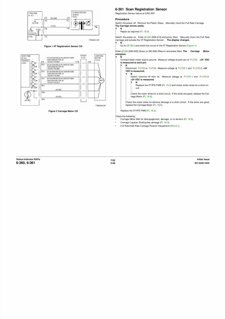
8/13/2019 Xerox Docu Color 2240-1632
http://slidepdf.com/reader/full/xerox-docu-color-2240-1632 126/1118
7/022-96 DC 2240/16326-360, 6-361Initial IssueStatus Indicator RAPs
Figure 2 Carriage Motor CD
energizes.
Y N
Connect black meter lead to ground. Measure voltage at each pin of P/J725. +24 VDC
is measured at each pin.
Y N
Disconnect P/J725 or P/J739. Measure voltage at P/J725-1 and P/J725-2. +24
VDC is measured.
Y N
Switch machine off then on. Measure voltage at P/J725-1 and P/J725-2.
+24 VDC is measured.
Y N
Replace the IIT/IPS PWB (PL 18.3) and check motor wires for a short cir-
cuit.
Check the motor wires for a short circuit. If the wires are good, replace the Car-
riage Motor (PL 18.5).
Check the motor wires for obvious damage or a short circuit. If the wires are good,
replace the Carriage Motor (PL 18.5).
Replace the IIT/IPS PWB (PL 18.3).
Check the following:
• Carriage Motor Belt for disengagement, damage, or no tension (PL 18.5).
• Carriage Capstan Shaft/pulley damage (PL 18.5).
• Full Rate/Half Rate Carriage Position Adjustment (ADJ 6.1).
Figure 1 IIT Registration Sensor CD
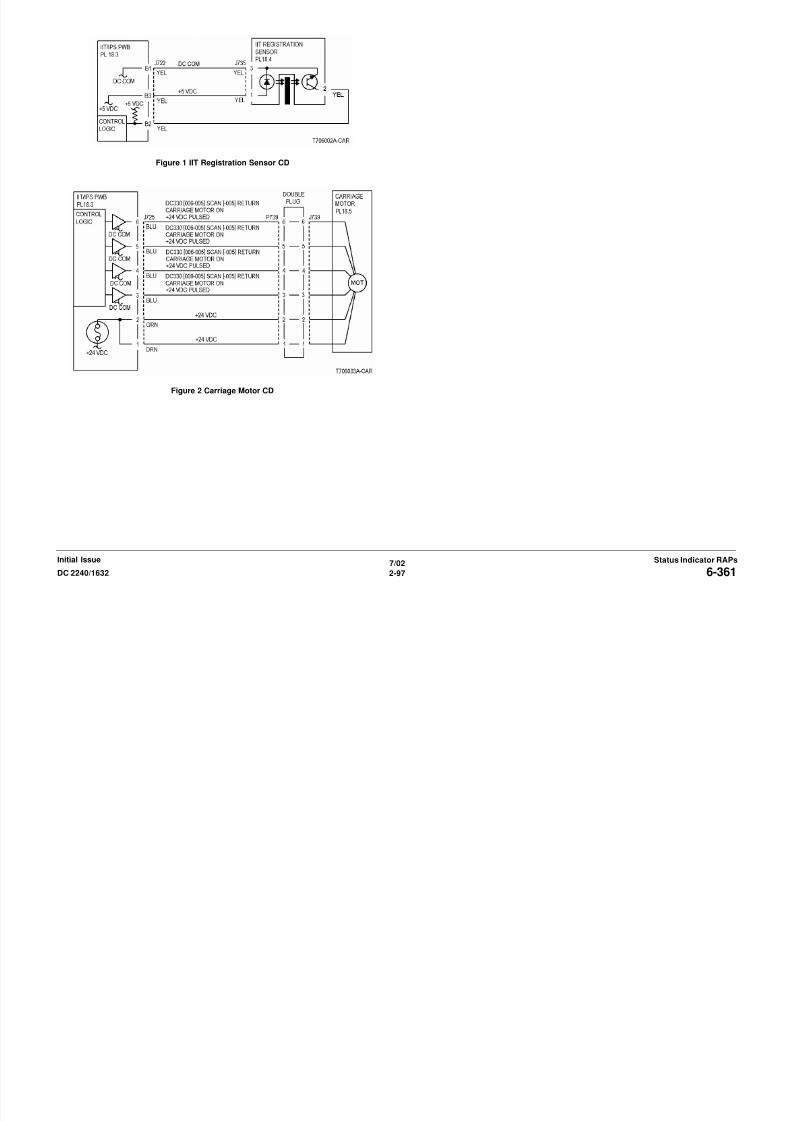
8/13/2019 Xerox Docu Color 2240-1632
http://slidepdf.com/reader/full/xerox-docu-color-2240-1632 127/1118
7/022-97DC 2240/1632 6-361Status Indicator RAPsInitial Issue
Figure 2 Carriage Motor CD
6-371 Exposure LampOpen circuit of the Lamp was detected.
Procedure
Enter dC330 [006-002]. Press Start. The Exposure Lamp illuminates.
Y N
Switch off the power. Remove the Platen Glass (REP 6.2) and the IPS Cover (PL 18.3).
Switch the power on. There is +24VDC between P/J720-1 or -4 (+) on the IIT/IPS
PWB and ground (-).
Y N
Remove the DADF (REP 5.1) and the IIT Top Cover (REP 6.3). There is +24VDCbetween P/J702-1 on the IIT LVPS (+) and ground (-).
Y N
Switch the power off. Disconnect P/J702 from the IIT LVPS. Switch on the
power. There is +24VDC between the IIT LVPS P 502-1 (+) and ground (-).
Y N
If the problem continues, replace the IIT/IPS PWB (PL 18.3).

8/13/2019 Xerox Docu Color 2240-1632
http://slidepdf.com/reader/full/xerox-docu-color-2240-1632 128/1118
7/022-98 DC 2240/16326-371Initial IssueStatus Indicator RAPs
Check for IIT LVPS On signal from ESS.
Check the input power (ACH) to the IIT LVPS.
If no problems are found, replace the I IT LVPS (PL 18.4).
Check for a short circuit. Refer to the IIT+24VDC wirenet.
Check the wires from P/J702 on the IIT LVPS to P/J720 on the IIT/IPS PWB for an
open or short circuit.
There is +24VDC from P/J724-3 on the IIT/IPS PWB to ground (-).
Y N
There is +24VDC from P/J724-1 to P/J724-4 on the IIT/IPS PWB.
Y N
Replace the IIT/IPS PWB (PL 18.3).
Replace the Lamp Wire Harness (PL 18.6).
If the problem continues, replace the Lamp Ballast PWB (PL 18.6).
If the problem continues, replace the IIT/IPS PWB (PL 18.3).
Enter dC 330 [006-002]. Press Start. The voltage at P/J724-3 drops to approximately
7.5 VDC.
Y N
Replace the IIT/IPS PWB (PL 18.3).
Replace the Exposure Lamp (PL 18.6).
If the problem continues, replace the Lamp Wire Harness (PL 18.6).
If the problem continues, replace Lamp Ballast PWB (PL 18.6).
Check the following:
• The White Reference Strip, under the frame that is below the Registration Edge, for
excessive contamination (REP 6.13).
• The optical light path for contamination.
If the Strip and optics are clean, replace the Exposure Lamp (PL 18.6).
If the problem continues, replace the Lamp Ballast PWB (PL 18.6).
Figure 1 IIT LVPS +24 VDC CD
Figure 2 Exposure Lamp CD
6-372 ROS Polygon MotorROS Motor failure.
Procedure
Enter dC330 [006-031]. +3.3VDC is measured between the MCU PWB P/J402-3 (+) and
ground (-)
Y N
Check the wire between the ROS Relay Connector P/J518-4 and the MCU PWB P/J402-
3 for an open circuit.
+24VDC is measured between the MCU PWB P/J402-6 (+) and ground (-).Y N
+24VDC is measured between the MCU PWB P/J402-6 (+) and ground (-)
Y N
Check the +24VDC circuit to the MCU MF PWB P/J402-6 by referring to Section 7
Wiring Data (+24V).

8/13/2019 Xerox Docu Color 2240-1632
http://slidepdf.com/reader/full/xerox-docu-color-2240-1632 129/1118
7/02
2-99DC 2240/1632 6-372Status Indicator RAPsInitial Issue
Check the wire between the MCU PWB P/J402-6 and the ROS Relay Connector P/J518-
1 for an open circuit.
Enter dC330 [006-031]. 0VDC is measured between the MCU PWB P/J402-4 (+) and
ground (-)Y N
Check the wire between the MCU PWB P/J402-4 and the ROS Relay Connector P/J518-
3 for an open circuit. If no problems are found, replace the PWB (PL 13.1).
Check the wire between the MCU PWB P/J402-4 and the ROS Relay Connector P/J518-3 for
an open circuit.
Enter dC330 [006-031]. The frequency between the MCU PWB P/J402-4 (+) and ground
(-) is 2 KHz to 2.5 KHz.
Y N
Check the wire between the MCU PWB P/J402-2 and the ROS Relay Connector P/J518-
5 for an open circuit. If no problems are found, replace the PWB (PL 13.1).
Check the wire between the MCU PWB P/J402-2 and the ROS Relay Connector P/J518-5 for
an open circuit.
Check the wiring status of the Harness in the ROS. If no problems are found, replace the ROS
(PL 3.1).
Figure 1 Polygon Motor Control CD
6-380 ROS SOS Y LengthThe interval of the ROS SOS (Y) signals exceeds the specified value.
Procedure
+5VDC is measured between the MCU PWB P/J401-B20 (+) and ground (-)
Y N
Replace the MCU PWB (PL 13.1).
Check the wire between the SOS PWB (Y) P/J516-1 and the MCU PWB P/J401 for an open
circuit.
Check the wire between the LD Drive (Y) J529 and the MCU PWB P/J401 for an open circuit.If no problems are found, replace the ROS Assembly (PL 3.1).
If the problem continues, replace the MCU PWB (PL 13.1).

8/13/2019 Xerox Docu Color 2240-1632
http://slidepdf.com/reader/full/xerox-docu-color-2240-1632 130/1118
7/02
2-100 DC 2240/16326-380Initial IssueStatus Indicator RAPs
Figure 1 ROS SOS Y CD
6-381 ROS SOS M LengthThe interval of the ROS SOS (M) signals exceeds the specified value.
Procedure
Check the voltage between P/J401-B20 (+) and ground (-) on MCU PWB. +5VDC is mea-
sured between the MCU PWB P/J401-B20 (+) and ground (-).
Y N
Replace the MCU PWB (PL 13.1).
Check the wire between the SOS PWB (M) P/J517-1 and the MCU PWB P/J401 for an open
circuit.Check the wire between the LD Drive M J528 and the MCU PWB P/J401 for an open circuit.
If no problems are found, replace the ROS Assembly (PL 3.1).
If the problem continues, replace the MCU PWB (PL 13.1).
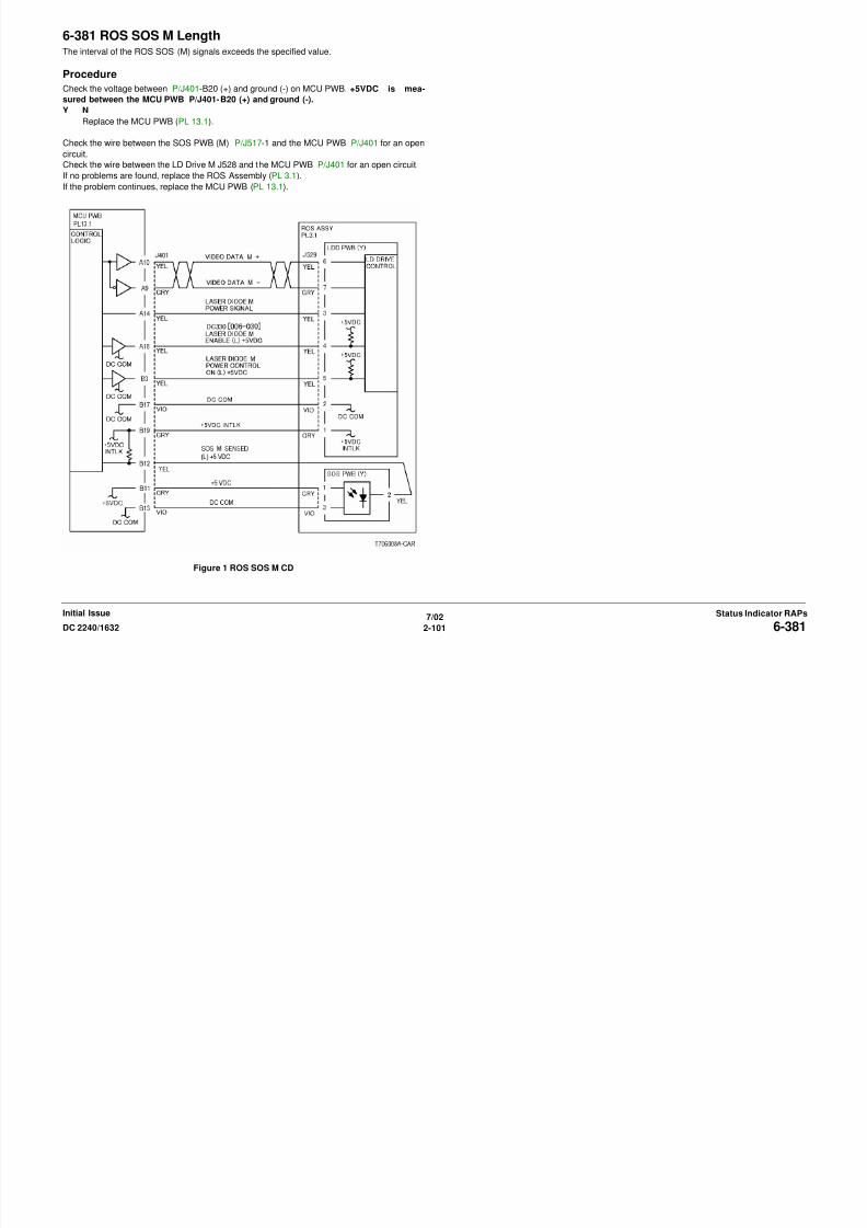
8/13/2019 Xerox Docu Color 2240-1632
http://slidepdf.com/reader/full/xerox-docu-color-2240-1632 131/1118
7/02
2-101DC 2240/1632 6-381
Status Indicator RAPsInitial Issue
Figure 1 ROS SOS M CD
6-382 ROS SOS C LengthThe interval of the ROS SOS (C) signals exceeds the specified value.
Procedure
+5VDC is measured between the MCU PWB P/J401-B20 (+) and ground (-).
Y N
Replace the MCU PWB (PL 13.1).
Check the wire between the SOS PWB (C) P/J514-1 and the MCU PWB P/J401 for an open
circuit.
Check the wire between the LD Drive C J527 and the MCU PWB P/J401 for an open circuit.If no problems are found, replace the ROS Assembly (PL 3.1).
If the problem continues, replace the MCU PWB (PL 13.1).
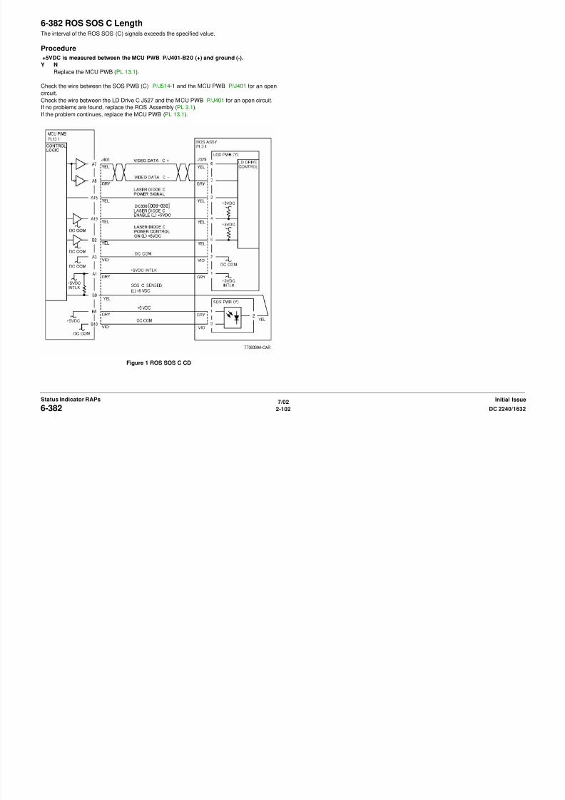
8/13/2019 Xerox Docu Color 2240-1632
http://slidepdf.com/reader/full/xerox-docu-color-2240-1632 132/1118
7/02
2-102 DC 2240/16326-382
Initial IssueStatus Indicator RAPs
Figure 1 ROS SOS C CD
6-383 ROS SOS K LengthThe interval of the ROS SOS (K) signals exceeds the specified value.
Procedure
Check the voltage between the MCU PWB P/J401-B20 (+) and ground (-). +5VDC is mea-
sured.
Y N
Replace the MCU PWB (PL 13.1).
Check the wire between the SOS PWB (K) P/J515-1 and the MCU PWB P/J401 for an open
circuit.Check the wire between the LD Drive K P/J526 and the MCU PWB P/J401 for an open circuit.
If no problems are found, replace the ROS Assembly (PL 3.1).
If the problem continues, replace the MCU PWB (PL 13.1).

8/13/2019 Xerox Docu Color 2240-1632
http://slidepdf.com/reader/full/xerox-docu-color-2240-1632 133/1118
7/02
2-103DC 2240/1632 6-383
Status Indicator RAPsInitial Issue
Figure 1 ROS SOS K CD
6-385 ROS ASICOperation failure of the ROS ASIC in the MCU PWB.
Procedure
Switch power off then on. The problem continues.
Y N
Return to Service Call Procedures.
Replace the MCU PWB (PL 13.1).

8/13/2019 Xerox Docu Color 2240-1632
http://slidepdf.com/reader/full/xerox-docu-color-2240-1632 134/1118
7/02
2-104 DC 2240/16326-385
Initial IssueStatus Indicator RAPs
6-389 Carriage Over Run RightThe carriage has overrun at the Scan End.
Procedure
Switch the power off. Remove the Platen Glass. Manually move the Full Rate Carriage. The
Carriage moves easily.
Y N
Repair as required (PL 18.5).
Switch the power on. Enter dC330 [006-212] and press Start. Manually move the Full Rate
Carriage and actuate the IIT Registration Sensor. The display changes.Y N
Go to OF 99-2 and check the circuit of the IIT Registration Sensor (Figure 1).
Enter dC330 [006-005] (Scan) or [06-006] (Return) and press Start. The Carriage Motor
energizes.
Y N
Figure 1 IIT Registration Sensor CD
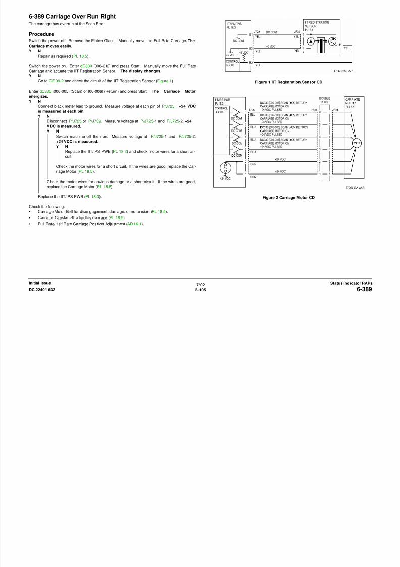
8/13/2019 Xerox Docu Color 2240-1632
http://slidepdf.com/reader/full/xerox-docu-color-2240-1632 135/1118
7/02
2-105DC 2240/1632 6-389
Status Indicator RAPsInitial Issue
Connect black meter lead to ground. Measure voltage at each pin of P/J725. +24 VDC
is measured at each pin.
Y N
Disconnect P/J725 or P/J739. Measure voltage at P/J725-1 and P/J725-2. +24
VDC is measured.Y N
Switch machine off then on. Measure voltage at P/J725-1 and P/J725-2.
+24 VDC is measured.
Y N
Replace the IIT/IPS PWB (PL 18.3) and check motor wires for a short cir-
cuit.
Check the motor wires for a short circuit. If the wires are good, replace the Car-
riage Motor (PL 18.5).
Check the motor wires for obvious damage or a short circuit. If the wires are good,
replace the Carriage Motor (PL 18.5).
Replace the IIT/IPS PWB (PL 18.3).
Check the following:
• Carriage Motor Belt for disengagement, damage, or no tension (PL 18.5).
• Carriage Capstan Shaft/pulley damage (PL 18.5).
• Full Rate/Half Rate Carriage Position Adjustment (ADJ 6.1).
Figure 2 Carriage Motor CD
6-390 Carriage Over Run LeftThe CRG has overrun at the Home End.
Procedure
Switch the power off. Remove the Platen Glass.
Manually move the Full Rate Carriage. The Carriage moves easily.
Y N
Repair as required (PL 18.5).
Switch the power on. Enter dC330 [006-212] and press Start.
Manually move the Full Rate Carriage and actuate the IIT Registration Sensor. The displaychanges.
Y N
Go to OF 99-2 and check the circuit of the IIT Registration Sensor (Figure 1).
Enter dC330 [006-005] (Scan) or [06-006] (Return) and press Start. The Carriage Motor
energizes.
Figure 1 IIT Registration Sensor CD

8/13/2019 Xerox Docu Color 2240-1632
http://slidepdf.com/reader/full/xerox-docu-color-2240-1632 136/1118
7/02
2-106 DC 2240/16326-390
Initial IssueStatus Indicator RAPs
Y N
Connect black meter lead to ground. Measure voltage at each pin of P/J725. +24 VDC
is measured at each pin.
Y N
Disconnect P/J725 or P/J739. Measure voltage at P/J725-1 and P/J725-2. +24VDC is measured.
Y N
Switch machine off then on. Measure voltage at P/J725-1 and P/J725-2.
+24 VDC is measured.
Y N
Replace the IIT/IPS PWB (PL 18.3) and check motor wires for a short cir-
cuit.
Check the motor wires for a short circuit. If the wires are good, replace the Car-
riage Motor (PL 18.5).
Check the motor wires for obvious damage or a short circuit. If the wires are good,
replace the Carriage Motor (PL 18.5).
Replace the IIT/IPS PWB (PL 18.3).
Check the following:
• Carriage Motor Belt for disengagement, damage, or no tension (PL 18.5).
• Carriage Capstan Shaft/pulley damage (PL 18.5).
• Full Rate/Half Rate Carriage Position Adjustment (ADJ 6.1).
Figure 2 Carriage Motor CD
6-391 Scan Initialize Motor DriverThe Carriage Motor error was detected after the initialization was started.
Procedure
Enter dC330 [006-005] (Scan) or [06-006] (Return) and press Start. The Carriage Motor
energizes.
Y N
Connect black meter lead to ground. Measure voltage at each pin of P/J725. +24 VDC
is measured at each pin.
Y N
Disconnect P/J725 or P/J739. Measure voltage at P/J725-1 and P/J725-2. +24VDC is measured.
Y N
Switch machine off then on. Measure voltage at P/J725-1 and P/J725-2.+24 VDC is measured.
Y N
Replace the IIT/IPS PWB (PL 18.3) and check motor wires for a short cir-
it

8/13/2019 Xerox Docu Color 2240-1632
http://slidepdf.com/reader/full/xerox-docu-color-2240-1632 137/1118
7/02
2-107DC 2240/1632 6-391
Status Indicator RAPsInitial Issue
cuit.
Check the motor wires for a short circuit. If the wires are good, replace the Car-
riage Motor (PL 18.5).
Check the motor wires for obvious damage or a short circuit. If the wires are good,
replace the Carriage Motor (PL 18.5).
Replace the IIT/IPS PWB (PL 18.3).
Replace the IIT/IPS PWB (PL 18.3).
Figure 1 Carriage Motor CD

8/13/2019 Xerox Docu Color 2240-1632
http://slidepdf.com/reader/full/xerox-docu-color-2240-1632 138/1118
7/02
2-108 DC 2240/16326-391
Initial IssueStatus Indicator RAPs
7-104 Tray 1 Feed Out SensorThe Tray 1 Feed Out Sensor does not detect paper after feeding from Tray 1.
Initial Actions
• Check condition and specification of paper in Tray 1.
• Check the paper path for obstructions.
• Check for wear and clean the Tray 1 Feeder Roll, Takeaway Roll and the Nudger Roll.
Procedure
Enter dC330 [008-100] and press Start. Block and unblock Tray 1 Feed Out Sensor (PL 2.3).
The display changes.Y N
Go to OF 99-2 and check the circuit of the Tray 1 Feed Out Sensor (Figure 1).
Enter dC330 [008-106] and press Start. Block and unblock the Takeaway Sensor (PL 16.6).
The display changes.
Y N
Go to OF 99-2 and check the circuit of the Takeaway Sensor (Figure 2)
Figure 2 Takeaway Sensor CD
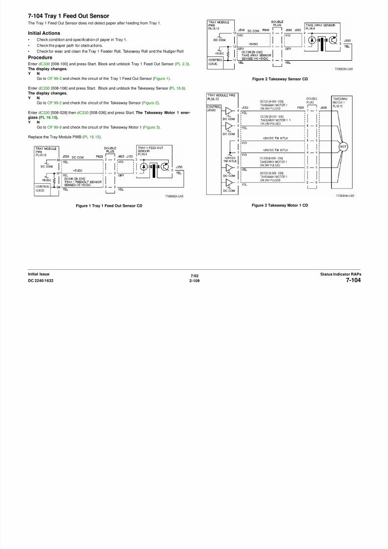
8/13/2019 Xerox Docu Color 2240-1632
http://slidepdf.com/reader/full/xerox-docu-color-2240-1632 139/1118
7/02
2-109DC 2240/1632 7-104
Status Indicator RAPsInitial Issue
Go to OF 99-2 and check the circuit of the Takeaway Sensor (Figure 2).
Enter dC330 [008-029] then dC330 [008-036] and press Start. The Takeaway Motor 1 ener-
gizes (PL 16.15).
Y NGo to OF 99-9 and check the circuit of the Takeaway Motor 1 (Figure 3).
Replace the Tray Module PWB (PL 16.15).
Figure 1 Tray 1 Feed Out Sensor CD Figure 3 Takeaway Motor 1 CD
7-105 Tray 1 MisfeedThe Tray 1 Feed Out Sensor does not detect paper after feeding from Tray 1.
Initial Actions
• Check condition and specification of paper in Tray 1.
• Check the paper path for obstructions.
• Check for wear and clean the Tray 1 Feed Roll, Takeaway Roll and the Nudger Roll.
Procedure
Enter dC330 [008-100] and press Start. Block and unblock the Tray 1 Feed Out Sensor (PL
2.3). The display changes.Y N
Go to OF 99-2 and check the circuit of the Tray 1 Feed Out Sensor (Figure 1).
Enter dC330 [008-001] and press Start. The Tray 1 Feed/Lift motor energizes (PL 2.4).
Y N
Go to OF 99-9 and check the circuit of the Tray 1 Feed/Lift Motor (Figure 2).

8/13/2019 Xerox Docu Color 2240-1632
http://slidepdf.com/reader/full/xerox-docu-color-2240-1632 140/1118
7/02
2-110 DC 2240/16327-105
Initial IssueStatus Indicator RAPs
Enter dC330 [008-029] then dC330 [008-036] and press Start. The Takeaway Motor 1 ener-
gizes PL 16.15).
Y N
Go to the OF 99-9 and check the circuit of the Takeaway Motor 1 (Figure 3).
Replace the I/F PWB (PL 9.1).
If the problem continues, replace the MCU PWB (PL 13.1).
Figure 1 Tray 1 Feed out Sensor CD
Figure 2 Tray 1 Feed/Lift Motor CD
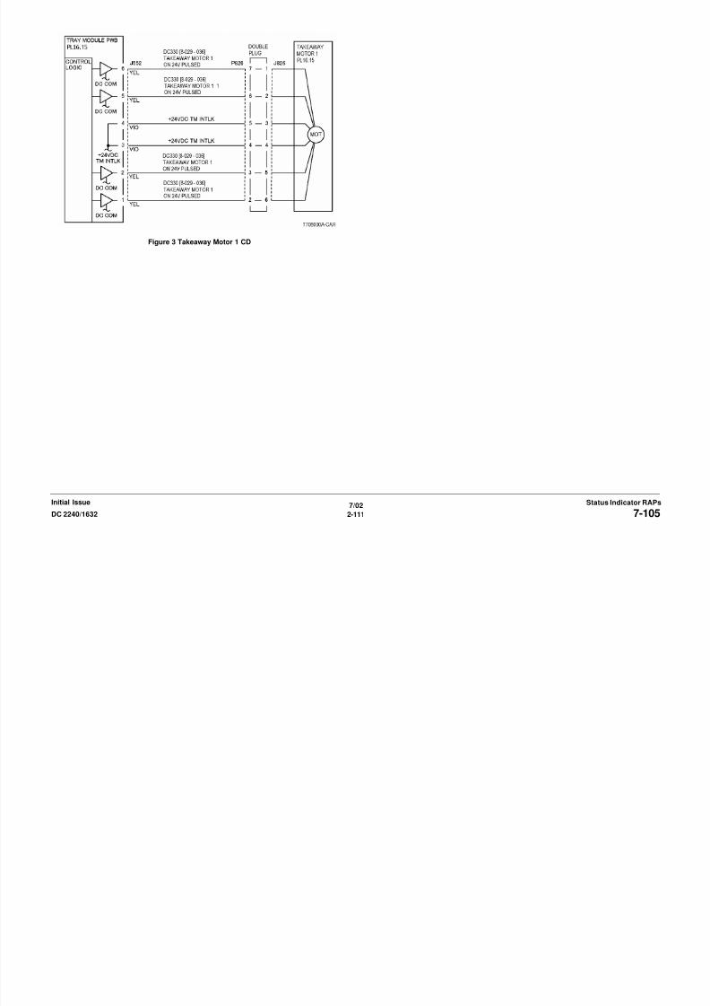
8/13/2019 Xerox Docu Color 2240-1632
http://slidepdf.com/reader/full/xerox-docu-color-2240-1632 141/1118
7/02
2-111DC 2240/1632 7-105
Status Indicator RAPsInitial Issue
Figure 3 Takeaway Motor 1 CD
7-110 Tray 2 MisfeedThe Takeaway Sensor does not detect paper after feeding from Tray 2.
Initial Actions
• Check condition and specification of paper in Tray 2.
• Check the paper path for obstructions.
• Check for wear and clean the Tray 2 Feeder Roll, Takeaway Roll and the Nudger Roll.
Procedure
Enter dC330 [008-106] and press Start. Block and unblock the Takeaway Sensor (PL 16.6).
The display changes.Y N
Go to OF 99-2 and check the circuit of the Takeaway Sensor (Figure 1).
Enter dC330 [008-003] and press Start. The Tray 2 Feed/Lift motor energizes (PL 16.7).
Y N
Go to OF 99-9 and check the circuit of the Tray 2 Feed/Lift Motor (Figure 2).

8/13/2019 Xerox Docu Color 2240-1632
http://slidepdf.com/reader/full/xerox-docu-color-2240-1632 142/1118
7/02
2-112 DC 2240/16327-110
Initial IssueStatus Indicator RAPs
Enter dC330 [008-029] then dC330 [008-036] and press Start. The Takeaway Motor 1 ener-
gizes (PL 16.15).
Y N
Go to OF 99-9 and check the circuit of the Takeaway Motor 1 (Figure 3).
Check the wires and connectors. If the check is OK, replace the Tray Module PWB (PL 16.15).
Figure 1 Takeaway Sensor CD
Figure 2 Tray 2 Feed/Lift Motor CD

8/13/2019 Xerox Docu Color 2240-1632
http://slidepdf.com/reader/full/xerox-docu-color-2240-1632 143/1118
7-115 Tray 3 MisfeedThe Takeaway Sensor does not detect paper after feeding from Tray 3.
Initial Actions
• Check condition and specification of paper in Tray 3.
• Check the paper path for obstructions.
• Check for wear and clean the Tray 3 Feeder Roll, Takeaway Roll and the Nudger Roll.
Procedure
Enter dC330 [008-102] and press Start. Block and unblock the Tray 3 Feed Out Sensor (PL
16.6). The display changes.Y N
Go to OF 99-2 and check the circuit of the Tray 3 Feed Out Sensor (Figure 1).
Enter dC330 [008-005] and press Start. The Tray 3 Feed/Lift Motor energizes (PL 16.9).
Y N
Go to OF 99-9 and check the circuit of the Tray 3 Feed/Lift Motor (Figure 2).
E t dC330 [008 029] d St t The Takea a Motor 1 energi es (PL 16 15)

8/13/2019 Xerox Docu Color 2240-1632
http://slidepdf.com/reader/full/xerox-docu-color-2240-1632 144/1118
7/02
2-114 DC 2240/16327-115
Initial IssueStatus Indicator RAPs
Enter dC330 [008-029] and press Start. The Takeaway Motor 1 energizes (PL 16.15).
Y N
Go to OF 99-9 and check the circuit of the Takeaway Motor 1 (Figure 3).
Check the wires and connectors. If the check is OK, replace the Tray Module PWB (PL 16.15).
Figure 1 Tray 3 Feedout Sensor CD
Figure 2 Tray 3 Feed/Lift Motor CD

8/13/2019 Xerox Docu Color 2240-1632
http://slidepdf.com/reader/full/xerox-docu-color-2240-1632 145/1118
7/02
2-115DC 2240/1632 7-115
Status Indicator RAPsInitial Issue
Figure 3 Takeaway Motor 1 CD
7-119 Tray 4 MisfeedThe Feed Out Sensor does not detect paper after feeding from Tray 4.
Initial Actions
• Check condition and specification of paper in Tray 4.
• Check the paper path for obstructions.
• Check for wear and clean the Tray 4 Feeder Roll, Takeaway Roll and the Nudger Roll.
Procedure
Enter dC330 [008-103] and press Start. Block and unblock the Tray 4 Feed out Sensor (PL
16.5). The display changes.
Y N
Go to OF 99-2 and check the circuit of the Tray 4 Feed Out Sensor (Figure 1).
Enter dC330 [008-007] and press Start. The Tray 4 Feed/Lift motor energizes (PL 16.11).
Y N
Go to OF 99-9 and check the circuit of the Tray 4 Feed/Lift Motor (Figure 2).
Enter dC330 [008-029] and press Start The Takeaway Motor 2 energizes (PL 16 15)
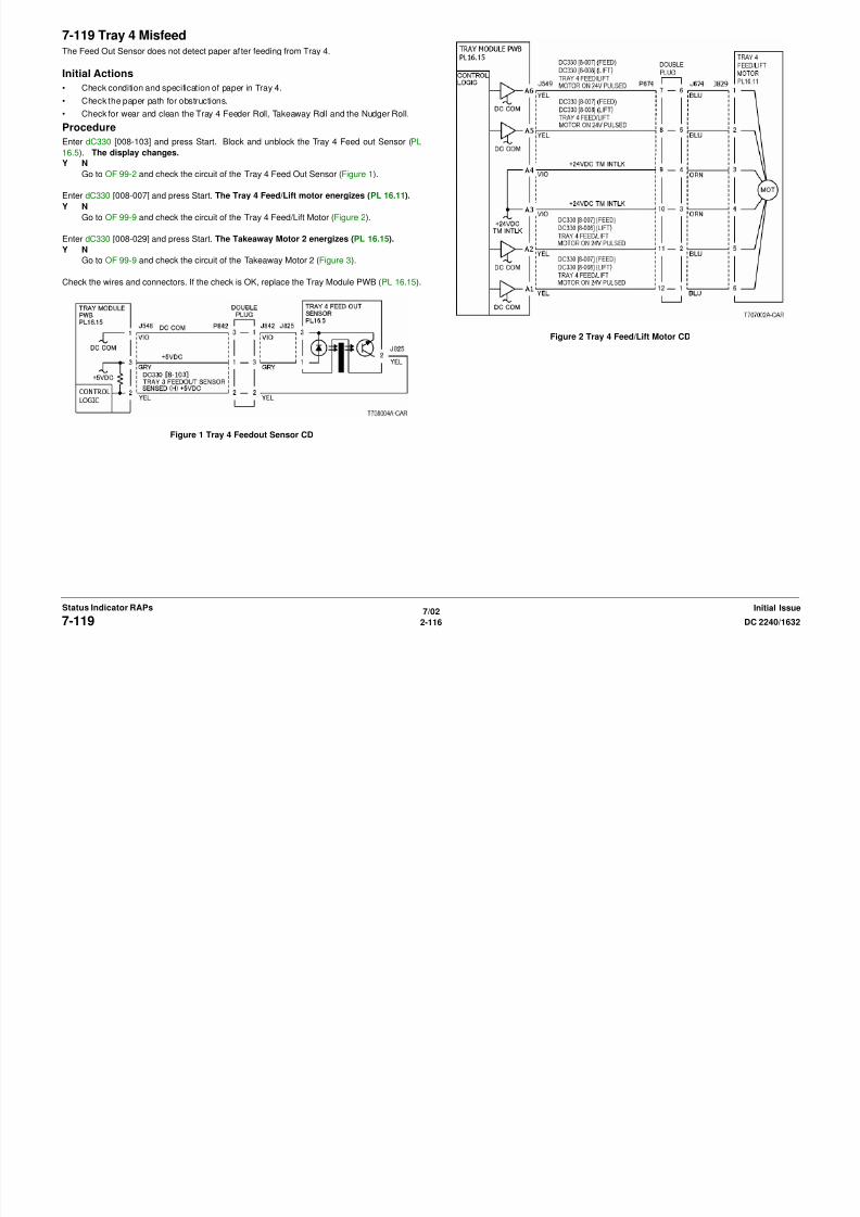
8/13/2019 Xerox Docu Color 2240-1632
http://slidepdf.com/reader/full/xerox-docu-color-2240-1632 146/1118
7/02
2-116 DC 2240/16327-119
Initial IssueStatus Indicator RAPs
Enter dC330 [008 029] and press Start. The Takeaway Motor 2 energizes (PL 16.15).
Y N
Go to OF 99-9 and check the circuit of the Takeaway Motor 2 (Figure 3).
Check the wires and connectors. If the check is OK, replace the Tray Module PWB (PL 16.15).
Figure 1 Tray 4 Feedout Sensor CD
Figure 2 Tray 4 Feed/Lift Motor CD

8/13/2019 Xerox Docu Color 2240-1632
http://slidepdf.com/reader/full/xerox-docu-color-2240-1632 147/1118
7-122 Tray 4 OpenedThe Tray 4 Feed Out Sensor detected paper when Tray 4 is pulled out and pushed in during a
print.
Initial Actions
• Check condition and specification of paper in Tray 4.
• Check the paper path for obstructions and clean the Tray 4 Feed out Sensor.
• Check the Tray 4 mechanical operation.
Procedure
Enter dC330 [008-103] and press Start. Block and unblock the Tray 4 Feed out Sensor (PL
16.5). The display changes.
Y N
Go to OF 99-2 and check the circuit of the Tray 4 Feed Out Sensor (Figure 1).
Check the machine Shutdown History Report. If there is a history of this failure, replace the
Tray 4 Feed Out Sensor (PL 16.5).
If the problem continues, replace the Tray Module PWB (PL 16.15).

8/13/2019 Xerox Docu Color 2240-1632
http://slidepdf.com/reader/full/xerox-docu-color-2240-1632 148/1118
7/02
2-118 DC 2240/16327-122
Initial IssueStatus Indicator RAPs
Figure 1 Tray 4 Feedout Sensor CD
7-250 Tray CommunicationCommunication fault between Tray Module PWB and MCU PWB.
Procedure
+5 VDC is measured at P/J541-9 on the Tray Module PWB (PL 16.15).
Y N
Check the wires and connectors. If the check is OK, replace the MCU PWB (PL 13.1).
If the problem continues, replace the I/F PWB (PL 13.1)
CAUTION
ESS PWB and MCU PWB cannot be replaced at the same time.
Check the wires and connectors. If the check is OK, replace the Tray Module PWB (PL 16.15).
If the problem continues, replace the MCU PWB (PL 13.1).
If the problem continues, replace the ESS PWB (PL 13.1).
A
A

8/13/2019 Xerox Docu Color 2240-1632
http://slidepdf.com/reader/full/xerox-docu-color-2240-1632 149/1118
7/02
2-119DC 2240/1632 7-250
Status Indicator RAPsInitial Issue
Figure 1 Tray Communication
7-252 Out Module LogicIncorrect software data was detected.
Procedure
Switch the power off then on. The problem continues.
Y N
Return to Service Call Procedures.
Reinstall the software.
If the problem continues, replace the MCU PWB (PL 13.1).
7-270 Tray 1 Paper Size SensorAn abnormal AD value was detected by the Tray 1 Paper Size Sensor.
Initial Actions
Ensure that the Paper Guide Tab makes contact with the sensor.
Procedure
Ensure that Tray 1 is fully seated. The voltages measured at P/J536-B9 on the I/F PWB
corresponds with the table on BSD 7.1
Y N
+3.3 VDC is measured between P/J115-1 and 3 on the Paper Size Sensor.Y N
Check the wires and connectors. If the check is OK, replace the I/F PWB (PL 9.1).
If the problem continues replace the MCU PWB (PL 13.1).
Replace the Tray 1 Paper Size Sensor (PL 2.1).
Replace the I/F PWB (PL 9.1).
If the problem continues replace the MCU PWB (PL 13.1).

8/13/2019 Xerox Docu Color 2240-1632
http://slidepdf.com/reader/full/xerox-docu-color-2240-1632 150/1118
7/02
2-120 DC 2240/16327-252, 7-270
Initial IssueStatus Indicator RAPs
p p ( )
Figure 1 Tray 1 Paper Size Sensor
7-271 Tray 2 Paper Size SensorAn abnormal AD value was detected by the Tray 2 Paper Size Sensor.
Initial Actions
Ensure that the Paper Guide Tab makes contact with the sensor.
Procedure
Ensure that Tray 2 is fully seated. The voltages measured at P/J546-8 on the Tray Module
PWB corresponds with the table on BSD 7.2
Y N
+5 VDC is measured between P/J816-1 and 3 on the Tray 2 Paper Size Sensor.Y N
Check the wires and connectors. If the check is OK, replace the Tray Module PWB
(PL 16.15).
Replace the Tray 2 Paper Size Sensor (PL 16.1).
Replace the Tray Module PWB (PL 16.15).
7-274 Tray 5 Paper Size SensorAn abnormal AD value was detected by the MSI Paper Size Sensor.
Initial Actions
Check the connectors between the Tray 5 Paper Size Sensor and the I/F PWB
Procedure
Enter dC140 [007-100] and press Start. Move the Tray 5 Paper Size Sensor (PL 2.15). The
AD value changed.
Y N
+3.3 VDC is measured at P/J265-3 on the Tray 5 Paper Size Sensor.Y N
Check the wires and connectors. If the check is OK, replace the I/F PWB (PL 9.1)
Enter dC140 [007-100] and press Start. Move the Tray 5 Paper Size Sensor (PL 2.15).
The voltage at P/J265-2 changes.
Y N
Check the wires and connectors. If the check is OK, replace the Tray 5 Paper Size
Sensor (PL 2.15).

8/13/2019 Xerox Docu Color 2240-1632
http://slidepdf.com/reader/full/xerox-docu-color-2240-1632 151/1118
7/02
2-121DC 2240/1632 7-271, 7-274
Status Indicator RAPsInitial Issue
Figure 1 Tray 2 Paper Size Sensor
Replace the MCU PWB (PL 13.1).
If the problem continues, replace the I/F PWB (PL 9.1).
Replace the MCU PWB (PL 13.1).
If the problem continues, replace the I/F PWB (PL 9.1).
Figure 1 Tray 2 Paper Size Sensor
7-276 Tray 3 Paper Size SensorAn abnormal AD value was detected by the Tray 3 Paper Size Sensor.
Initial Actions
Ensure that the Paper Guide Tab makes contact with the sensor.
Procedure
Ensure that Tray 3 is fully seated. The voltages measured at P P/J548-11 on the Tray Mod-
ule PWB corresponds with the table on BSD 7.4
Y N
+5 VDC is measured between P/J820-1 and 3 on the Tray 3 Paper Size Sensor (PL16.1).
Y N
Check the wires and connectors. If the check is OK, replace the Tray Module PWB
(PL 16.15).
Replace the Tray 3 Paper Size Sensor (PL 16.1).
Replace the Tray Module PWB (PL 16.15).
7-277 Tray 4 Paper Size SensorAn abnormal AD value was detected by the Tray 4 Paper Size Sensor.
Initial Actions
Ensure that the Paper Guide Tab makes contact with the sensor.
Procedure
Ensure that Tray 4 is fully seated. The voltages measured at P/J548-5 on the Tray Module
PWB corresponds with the table on BSD 7.6
Y N
+5 VDC is measured between P/J824-1 and 3 on the Tray 4 Paper Size Sensor (PL16.1).
Y N
Check the wires and connectors. If the check is OK, replace the Tray Module PWB
(PL 16.15).
Replace the Tray 4 Paper Size Sensor (PL 16.1).
Replace the Tray Module PWB (PL 16.15).

8/13/2019 Xerox Docu Color 2240-1632
http://slidepdf.com/reader/full/xerox-docu-color-2240-1632 152/1118
7/02
2-122 DC 2240/16327-276, 7-277
Initial IssueStatus Indicator RAPs
Figure 1 Tray 3 Paper Size Sensor Figure 1 Tray 3 Paper Size Sensor
7-281 Tray 1 LiftThe Tray 1 Level Sensor does not detect tray lift.
Initial Actions
Check drive of the following:
• Manually turn the gear at rear of the TRAY 1 to check that the Bottom Plate moves up and
down smoothly.
• Gently push Tray 1 in to check the drive transmission is firmly engaged.
Procedure
Enter dC330 [008-002] and press Start. The Tray 1 Feed/Lift motor energizes (PL 2.4).Y N
Go to OF 99-9 and check the circuit of the Tray 1 Feed/Lift Motor (Figure 1).
Enter dC330 [007-116] and press Start. Open and close Tray 1. The display changes.
Y N
Go to OF 99-2 and check the circuit of the Tray 1 Level Sensor (Figure 2).
Check the wires and connectors. If the check is OK, replace the I/F PWB (PL 9.1).
Figure 2 Tray 1 Level Sensor CD

8/13/2019 Xerox Docu Color 2240-1632
http://slidepdf.com/reader/full/xerox-docu-color-2240-1632 153/1118
7/02
2-123DC 2240/1632 7-281
Status Indicator RAPsInitial Issue
p ( )
Figure 1 Tray 1 Lift/Feed Motor CD
7-282 Tray 2 LiftThe Tray 2 Level Sensor does detect tray lift.
Initial Actions
Check drive of the following:
• Manually turn the gear at rear of the Tray 2 to check that the Bottom Plate moves up and
down smoothly.
• Gently push Tray 2 in to check the drive transmission is firmly engaged.
Procedure
Enter dC330 [008-004] and press Start. The Tray 2 Feed/Lift motor energizes (PL 16.7).Y N
Go to OF 99-9 and check the circuit of the Tray 2 Feed/Lift Motor (Figure 1).
Enter dC330 [007-117] and press Start. Open and close Tray 2. The display changes.
Y N
Go to OF 99-2 and check the circuit of the Tray 2 Level Sensor (Figure 2).
Check the wires and connectors. If the check is OK, replace the Tray Module PWB (PL 16.15).
Figure 2 Tray 2 Level Sensor CD
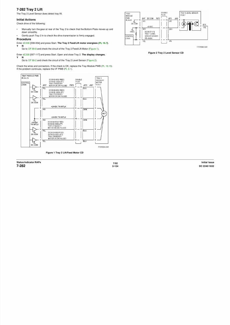
8/13/2019 Xerox Docu Color 2240-1632
http://slidepdf.com/reader/full/xerox-docu-color-2240-1632 154/1118
7/02
2-124 DC 2240/16327-282
Initial IssueStatus Indicator RAPs
If the problem continues, replace the I/F PWB (PL 9.1).
Figure 1 Tray 2 Lift/Feed Motor CD
7-291 Tray 3 LiftThe Tray 3 Level Sensor does detect tray lift.
Initial Actions
• Manually turn the gear at rear of the TRAY 3 to check that the Bottom Plate moves up and
down smoothly.
• Gently push Tray 3 in to check the drive transmission is firmly engaged.
Procedure
Enter dC330 [008-006] and press Start. The Tray 3 Feed/Lift motor energizes (PL 16.9).
Y N
Go to OF 99-9 and check the circuit of the Tray 3 Feed/Lift Motor (Figure 1).
Enter dC330 [007-118] and press Start. Open and close Tray 3. The display changes.
Y N
Go to OF 99-2 and check the circuit of the Tray 3 Level Sensor (Figure 2).
Check the wires and connectors. If the check is OK, replace the Tray Module PWB (PL 16.15).
If the problem continues, replace the I/F PWB (PL 9.1).
Figure 2 Tray 3 Level Sensor CD

8/13/2019 Xerox Docu Color 2240-1632
http://slidepdf.com/reader/full/xerox-docu-color-2240-1632 155/1118
7/02
2-125DC 2240/1632 7-291
Status Indicator RAPsInitial Issue
Figure 1 Tray 3 Lift/Feed Motor CD
7-293 Tray 4 LiftThe Tray 4 Level Sensor does detect tray lift.
Initial Actions
Check drive of the following:
• Manually turn the gear at rear of the TRAY 4 to check that the Bottom Plate moves up and
down smoothly.
• Gently push Tray 4 in to check the drive transmission is firmly engaged.
Procedure
Enter dC330 [008-008] and press Start. The Tray 4 Feed/Lift motor energizes (PL 16.11).Y N
Go to OF 99-9 and check the circuit of the Tray 4 Feed/Lift Motor (Figure 1).
Enter dC330 [007-119] and press Start. Open and close Tray 4. The display changes.
Y N
Go to OF 99-2 and check the circuit of the Tray 4 level Sensor (Figure 2).
Check the wires and connectors. If the check is OK, replace the Tray Module PWB (PL 16.15).
If the problem continues replace the I/F PWB (PL 9 1)
Figure 2 Tray 4 Level Sensor CD

8/13/2019 Xerox Docu Color 2240-1632
http://slidepdf.com/reader/full/xerox-docu-color-2240-1632 156/1118
7/02
2-126 DC 2240/16327-293
Initial IssueStatus Indicator RAPs
If the problem continues, replace the I/F PWB (PL 9.1).
Figure 1 Tray 4 Lift/Feed Motor CD
7-397 All Trays Lift SensorsAll the Tray Level Sensors did not energize.
Procedure
Check the dC122 Shutdown History. 007-281, 007-282, 007-283, 007-284, 007-291, or 007-
293 fault has occurred.
Y N
+24 VDC is measured at P/J555-7 on the Tray Module PWB (PL 16.5).
Y N
Go to the +24VDC Wirenets to troubleshoot.
+5 VDC is measured at P/J555-1 on the Tray Module PWB (PL 16.5).Y N
Go to the +5 VDC Wirenets to troubleshoot.
+3.3 VDC is measured at P/J555-5 on the Tray Module PWB (PL 16.5).
Y N
Go to the +3.3 VDC Wirenets to troubleshoot.
Replace the following in sequence:
Tray Module PWB (PL 16 15)

8/13/2019 Xerox Docu Color 2240-1632
http://slidepdf.com/reader/full/xerox-docu-color-2240-1632 157/1118
7/02
2-127DC 2240/1632 7-397
Status Indicator RAPsInitial Issue
• Tray Module PWB (PL 16.15)
• MCU PWB (PL 13.1) (Tray 1 only)
Go to the appropriate RAP.
Figure 1 +24VDC to the Tray Module PWB
Figure 2 +5 VDC to the Tray Module PWB
Figure 3 3.3VDC to the Tray Module PWB
7-930 Tray 1 Paper Size MismatchThe paper in Tray 1 does not match the paper size selected.
Procedure
The correct size paper is loaded in Tray 1 and the paper guides are set correctly.
Y N
Load the correct size paper.
Go to 7-270.
8/13/2019 Xerox Docu Color 2240-1632
http://slidepdf.com/reader/full/xerox-docu-color-2240-1632 158/1118
7/02
2-128 DC 2240/16327-930
Initial IssueStatus Indicator RAPs
7-931 Tray 2 Paper Size MismatchThe paper in Tray 2 does not match the paper size selected.
Procedure
The correct size paper is loaded in Tray 2 and the paper guides are set correctly.
Y N
Ensure Paper Guides are correctly adjusted.
Load the correct size paper.
Go to 7-271.
7-932 Tray 3 Paper Size MismatchThe paper in Tray 3 does not match the paper size selected.
Procedure
The correct size paper is loaded in Tray 3 and the paper guides are set correctly.
Y N
Ensure Paper Guides are correctly adjusted.
Load the correct size paper.
Go to 7-276.

8/13/2019 Xerox Docu Color 2240-1632
http://slidepdf.com/reader/full/xerox-docu-color-2240-1632 159/1118
7/02
2-129DC 2240/1632 7-931, 7-932
Status Indicator RAPsInitial Issue
7-933 Tray 4 Paper Size MismatchThe paper in Tray 4 does not match the paper size selected.
Procedure
The correct size paper is loaded in Tray 4 and the paper guides are set correctly.
Y N
Ensure Paper Guides are correctly adjusted.
Load the correct size paper.
Go to 7-277.
7-935 Job Continue Not AvailableAutomatic Tray switching cannot be continued because a tray was not programed.
Procedure
Program the appropriate tray. The problem continues.
Y N
Return to Service Call Procedures.
Refer to the User Guide, Section 2, Loading Paper for Auto Tray Switching.

8/13/2019 Xerox Docu Color 2240-1632
http://slidepdf.com/reader/full/xerox-docu-color-2240-1632 160/1118
7/02
2-130 DC 2240/16327-933, 7-935
Initial IssueStatus Indicator RAPs
7-954 Tray 5 Size Mismatch (Slow Scan Direction)The paper in the slow scan direction is shorter than the specified paper size.
Procedure
The correct size paper is loaded in the Tray 5.
Y N
Load the correct size paper.
Replace the Registration Sensor. (PL 2.6).
7-959 Tray 5 Paper Mismatch 1Other than dedicated stock is detected by the OHP sensor.
Initial Actions
• Ensure that dedicated stock is used.
• Check that the transparencies are oriented correctly.
• Check for obstructions and clean the OHP Sensor.
Procedure
Enter dC330 [008-110] and press Start. Block the OHP Sensor R using plain paper (PL 2.6).
The display changes.
Y NGo to OF 99-1 and check the circuit of the OHP Sensor (PL 2.6) (Figure 1).
Check the wires and connectors. If the check is OK, replace the MCU PWB (PL 13.1).
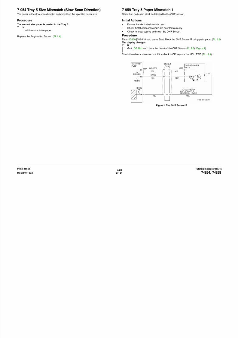
8/13/2019 Xerox Docu Color 2240-1632
http://slidepdf.com/reader/full/xerox-docu-color-2240-1632 161/1118
7/02
2-131DC 2240/1632 7-954, 7-959
Status Indicator RAPsInitial Issue
Figure 1 The OHP Sensor R
7-960 Tray 5 Paper Mismatch 2 A different paper type or transparency was detected when plain/heavyweight paper was spec-
ified.
Initial Actions
• Check that the loaded paper type matches the UI selection.
• Check the OHP sensor area for foreign substances
Procedure
Enter dC330 [8-110]. Block the OHP Sensor R (PL 2.6) using plain paper. The display
changes.
Y NGo to OF 99-1 and check the circuit of the OHP Sensor R (PL 2.6) (Figure 1).
Replace the MCU PWB (PL 13.1).
7-969 Full Paper StackThe Full Paper Stack Sensor detects that Face Down Tray is full.
Initial Actions
Check the Full Paper Stack Sensor for obstructions and actuator operation.
Procedure
Enter dC330 [010-102] and press Start. Move the Full Paper Stack Sensor (PL 10.2) actuator
up and down. The display changes.
Y N
Go to OF 99-2 and check the circuit of the Full Paper Stack Sensor (Figure 1).
Check the connectors and wires. If the check is OK, replace the MCU PWB (13.1).
If the problem continues, replace the I/F PWB (PL 9.1).

8/13/2019 Xerox Docu Color 2240-1632
http://slidepdf.com/reader/full/xerox-docu-color-2240-1632 162/1118
7/02
2-132 DC 2240/16327-960, 7-969
Initial IssueStatus Indicator RAPs
Figure 1 The OHP Sensor R
Figure 1 The Full Paper Stack Sensor
8-151 Tray 3 Takeaway Sensor OnThe Takeaway Sensor does not detect paper fed from Tray 3.
Initial Actions
• Check condition and specification of paper in Tray 3.
• Check the paper path and sensor area for obstructions.
• Check for wear and clean the Tray2 and Tray3 Feeder Roll, Takeaway Roll and the
Nudger Roll.
Procedure
Enter dC330 [008-106] and press Start. Block and unblock the Takeaway Sensor (PL 16.6).
The display changes state.Y N
Go to OF 99-2 and check the circuit of the Takeaway Sensor (Figure 1).
Enter dC330 [008-029]. The Takeaway Motor 1 energizes.
Y N
Go to OF 99-9 and check the circuit of the Takeaway Motor 1 (Figure 2).
Replace the Tray Module PWB (PL 16.15).
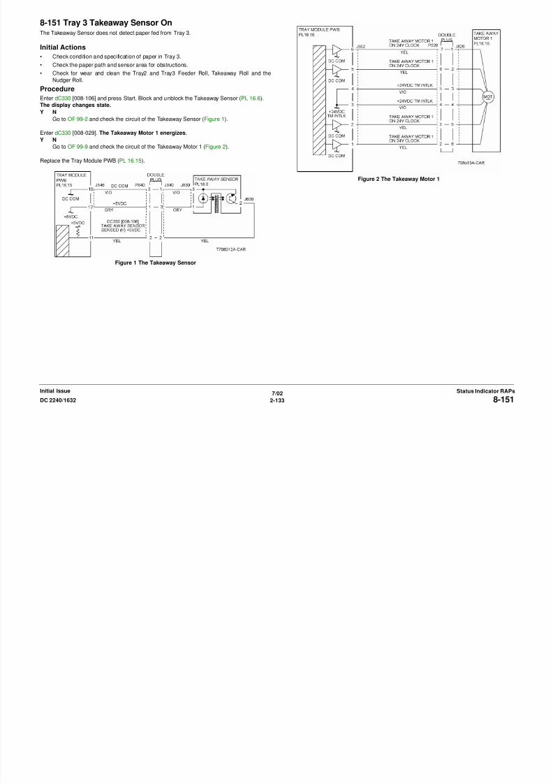
8/13/2019 Xerox Docu Color 2240-1632
http://slidepdf.com/reader/full/xerox-docu-color-2240-1632 163/1118
7/02
2-133DC 2240/1632 8-151
Status Indicator RAPsInitial Issue
Figure 1 The Takeaway Sensor
Figure 2 The Takeaway Motor 1
8-152 Tray 4 Takeaway Sensor OnThe Takeaway Sensor does not detect paper fed from Tray 4.
Initial Actions
• Check condition and specification of paper in Tray 4.
• Check the paper path and sensor area for obstructions.
• Check for wear and clean the Tray 4 Feeder Roll, Takeaway Roll and the Nudger Roll.
Procedure
Enter dC330 [008-106] and press Start. Block and unblock the Takeaway Sensor (PL 16.6).
The display changes state.
Y NGo to OF 99-2 and check the circuit of the Takeaway Sensor (Figure 1).
Enter dC330 [008-029] and press Start. The Takeaway Motor 1 (PL 16.15) energizes.
Y N
Go to OF 99-9 and check the circuit of the Takeaway Motor 1 (Figure 2).
Enter dC330 [008-047] and press Start. The Takeaway Motor 2 (PL 16.15) energizes.
Y N
Go to OF 99-9 and check the circuit of the Takeaway Motor 2 (Figure 3).

8/13/2019 Xerox Docu Color 2240-1632
http://slidepdf.com/reader/full/xerox-docu-color-2240-1632 164/1118
7/02
2-134 DC 2240/16328-152
Initial IssueStatus Indicator RAPs
Replace the Tray Module PWB (PL 16.15).
Figure 1 The Takeaway Sensor
Figure 2 The Takeaway Motor 1
Figure 3 The Takeaway Motor 2
8-164 POB SensorThe POB Sensor did not detect paper after the Registration Clutch Energized.
Initial Actions
• Check condition and specification of the paper supply.
• Check for paper on the IBT.
• Check for obstructions in the paper feed path
• Clean the POB Sensor.
• Check the 2nd BTR transmission gears for breakage
• Clean the Registration Roll and check for damage or ware.
Procedure
NOTE: Cheat the Left Cover Interlock.
Enter dC330 [009-201] and press Start. Block and unblock the POB Sensor (PL 2.9). The
display changes state.
Y N
Go to OF 99-1 and check the circuit of the POB Sensor (Figure 1).
Enter dC330 [008-037] and press Start. The Registration Clutch energizes (PL 2.6).
Y N
Figure 2 Registration Clutch CD

8/13/2019 Xerox Docu Color 2240-1632
http://slidepdf.com/reader/full/xerox-docu-color-2240-1632 165/1118
7/02
2-135DC 2240/1632
8-164
Status Indicator RAPsInitial Issue
Go to OF 99-4 and check the circuit of the Registration Clutch (Figure 2).
In sequence enter the following: dC330 [009-051] then dC330 [009-052] and press Start. The
2BTR contacts and retracts.
Y N
Go to 9-342 for a contact failure or go to 9-343 for a retract failure.
Check the wires and connectors. If the check is OK, replace the ESS PWB (PL 13.1)
Figure 1 POB Sensor CD
8-175 Registration Sensor On Jam Tray 5The Registration Sensor does not detect paper fed from the MSI.
Initial Actions
• Check condition and specification of the paper supply.
• Check for obstructions in the paper feed path
• Clean the MSI Feed Roll and check for ware.
• Clean the Takeaway Roll and check for ware.
• Check the drive transmissions for damage or ware.
Procedure
Enter dC330 [008-104] and press Start. Block and unblock the Registration Sensor (PL 2.6).
The display changes state.
Y N
Go to OF 99-1 and check the circuit of the Registration Sensor (Figure 1).
Enter dC330 [007-003] and press Start. The Tray 5 Feed Solenoid energizes (PL 2.14).
Y N
Go to OF 99-4 and check the circuit of the Tray 5 Feed Solenoid (Figure 2).
Check the wires and connectors. If the check is OK, replace the ESS PWB (PL 13.1).

8/13/2019 Xerox Docu Color 2240-1632
http://slidepdf.com/reader/full/xerox-docu-color-2240-1632 166/1118
7/02
2-136 DC 2240/1632
8-175
Initial IssueStatus Indicator RAPs
Figure 1 The Registration Sensor
Figure 2 The Tray 5 Feed Solenoid
8-176 Registration Sensor On Jam Tray 1-4The Registration Sensor does not detect paper fed f rom each Tray.
Initial Actions
• Ensure customer closes Left Lower Cover (PL 2.3) firmly if dog ears also occur.
• Check condition and specification of the paper supply.
• Check for obstructions in the paper feed path
• Clean the Takeaway Roll and check for ware.
• Check the drive transmissions for damage or ware.
Procedure
Enter dC330 [008-104] and press Start. Block and unblock the Registration Sensor. The dis-
play changes state.
Y N
Go to OF 99-1 and check the circuit of the Registration Sensor (Figure 1).
Enter dC330 [008-038] and press Start. The Takeaway Clutch energizes (PL 1.2).
Y N
Go to OF 99-4 and check the circuit of the Takeaway Clutch (Figure 2).
Check the wires and connectors. If the check is OK, replace the ESS PWB (PL 13.1).
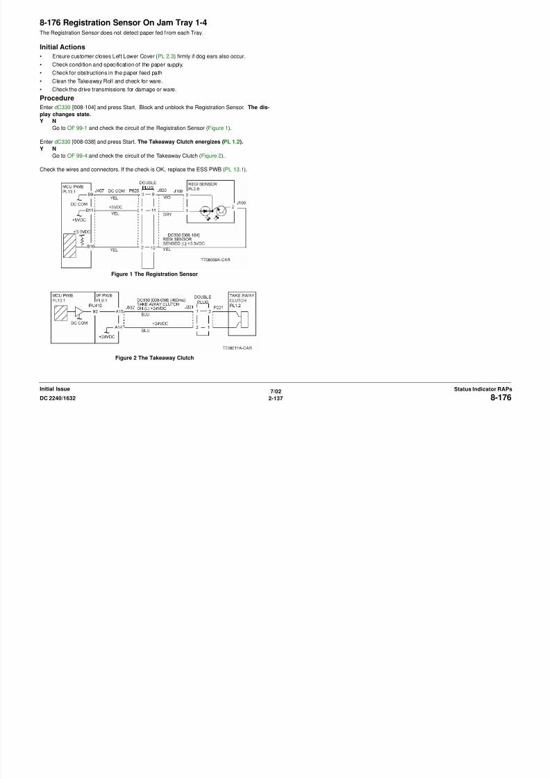
8/13/2019 Xerox Docu Color 2240-1632
http://slidepdf.com/reader/full/xerox-docu-color-2240-1632 167/1118
7/02
2-137DC 2240/1632
8-176
Status Indicator RAPsInitial Issue
Figure 1 The Registration Sensor
Figure 2 The Takeaway Clutch
8-180 Registration Sensor On DuplexThe Registration Sensor does not detect paper after a duplex feed.
Initial Actions
• Check condition and specification of the paper supply.
• Check for obstructions in the paper feed path.
• Clean the Exit Roll, Transport Roll, Wait Roll and check for ware.
• Check the drive transmissions for damage or ware.
Procedure
Enter dC330 [008-104] and press Start. Block and unblock the Registration Sensor (PL 2.6).
The display changes state.Y N
Go to OF 99-1 and check the circuit of the Registration Sensor (Figure 1).
Enter dC330 [008-112] and press Start. The Duplex Motor energizes (PL 12.2).
Y N
Go to OF 99-6 and check the circuit of the Duplex Motor (Figure 2).
Enter dC330 [008-043] and press Start. The Inverter Reverse Clutch energizes (PL 11.2).
Y N
Go to OF 99-4 and check the circuit of the Inverter Reverse Clutch (Figure 3).
Enter dC330 [008-046] and press Start. The Duplex Gate Solenoid energizes (PL 11.2).
Y NGo to OF 99-4 and check the circuit of the Duplex Gate Solenoid (Figure 4).
Check the wires and connectors. If the check is OK, replace the Duplex PWB (PL 12.2).
Figure 1 The Registration Sensor
A
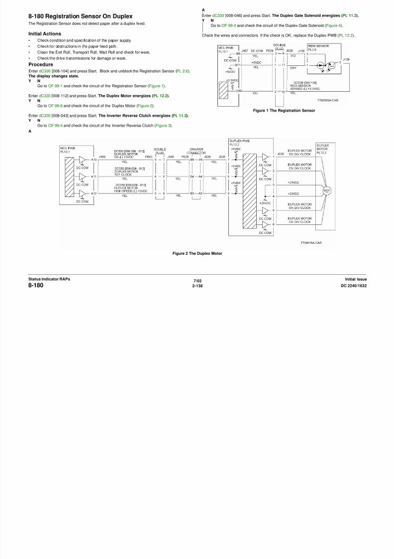
8/13/2019 Xerox Docu Color 2240-1632
http://slidepdf.com/reader/full/xerox-docu-color-2240-1632 168/1118
7/02
2-138 DC 2240/1632
8-180
Initial IssueStatus Indicator RAPs
( g )
Figure 2 The Duplex Motor
A
Figure 3 The Inverter Reverse Clutch
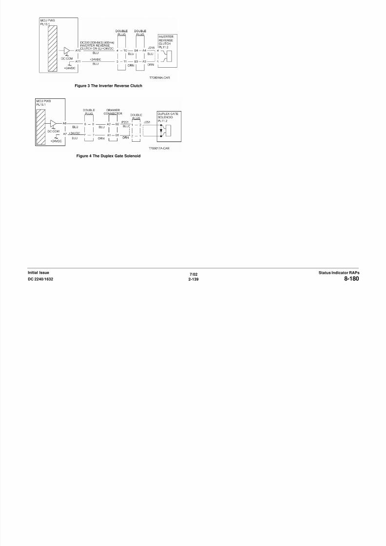
8/13/2019 Xerox Docu Color 2240-1632
http://slidepdf.com/reader/full/xerox-docu-color-2240-1632 169/1118
7/02
2-139DC 2240/1632 8-180Status Indicator RAPsInitial Issue
Figure 4 The Duplex Gate Solenoid
8-181 Registration Sensor On Wait SensorThe Registration Sensor does not detect paper after the Duplex Wait Sensor was energized.
Initial Actions
• Check condition and specification of the paper supply.
• Check for obstructions in the paper feed path.
• Clean the Takeaway Roll and check for ware.
• Check the drive transmissions for damage or ware.
Procedure
Enter dC330 [008-104] and press Start. Block and unblock the Registration Sensor (PL 2.6).
The display changes state.Y N
Go to OF 99-1 and check the circuit of the Registration Sensor (Figure 1).
Enter dC330 [008-105] and press Start. Block and unblock the Duplex Wait Sensor (PL 12.2).
The display changes state.
Y N
Go to OF 99-2 and check the circuit of the Duplex Wait Sensor (Figure 2).
Enter dC330 [008-112] and press Start. The Duplex Motor energizes (PL 12.2).
Y NGo to OF 99-9 and check the circuit of the Duplex Motor (Figure 3).
Check the wires and connectors. If the check is OK, replace the Duplex PWB (PL 12.2).
Figure 1 The Registration Sensor
A
A

8/13/2019 Xerox Docu Color 2240-1632
http://slidepdf.com/reader/full/xerox-docu-color-2240-1632 170/1118
7/02
2-140 DC 2240/16328-181Initial IssueStatus Indicator RAPs
Figure 2 The Duplex Wait Sensor

8/13/2019 Xerox Docu Color 2240-1632
http://slidepdf.com/reader/full/xerox-docu-color-2240-1632 171/1118
7/02
2-141DC 2240/1632 8-181Status Indicator RAPsInitial Issue
Figure 3 The Duplex Motor
8-184 Registration Sensor Off
The Fuser Exit Switch did not detect paper after the Registration Clutch was energized.
Initial Actions
• Check condition and specification of the paper supply.
• Check for obstructions in the paper feed path.
• Check the Fuser Belt and the Heat Roll for damage or ware.
• Clean the Registration Roll and check for ware or damage.
• Check the drive transmissions for damage or ware.
Procedure
Enter dC330 [010-101] and press Start. Actuate the Fuser Exit Switch (PL 2.8). The displaychanges state.
Y N
Go to OF 99-3 and check the circuit of the Fuser Exit Switch (Figure 1).
Enter dC330 [008-037] and press Start. The Registration Clutch energizes (PL 2.6).
Y N
Go to OF 99-4 Registration Clutch (Figure 2).
In sequence enter the following: dC330 [009-051] then dC330 [009-052] and press Start. The
2nd BTR Retract Motor energizes (PL 2.9).
Y N
Figure 2 Registration Clutch CD

8/13/2019 Xerox Docu Color 2240-1632
http://slidepdf.com/reader/full/xerox-docu-color-2240-1632 172/1118
7/02
2-142 DC 2240/16328-184Initial IssueStatus Indicator RAPs
Y N
Go to 9-342 for a contact failure or go to 9-343 for a retract failure.
Check the wires and connectors. If the check is OK, replace the Duplex PWB (PL 12.2).
Figure 1 Fuser Exit Switch CD
8-620 Regicon Temp Sensor
Environment Sensor not in range.
Procedure
NOTE: Machine operation continues. Status Code not displayed on UI. Status Code logged in
History.
Turn the power off. Disconnect the Environment Sensor (PL 1.3).
Measure the resistance between the following:
• I/F PWB P/J536-B4 and P/J255-1
• I/F PWB P/J536-B2 and P/J255-3
• I/F PWB P/J536-B1 and P/J255-4
The Resistance is 1 ohm or less.Y N
Check the wires and connectors. If the check is OK, replace the replace MCU PWB ( PL
13.1).
Measure resistance between P/J255-3 and P/J255-4 on Environment Sensor. 6k ohms to
20k ohms is measured.
Y N
Replace Environment Sensor (PL 1.3).
Replace MCU PWB (PL 13.1). If problem continues, replace ESS PWB (PL 13.1).
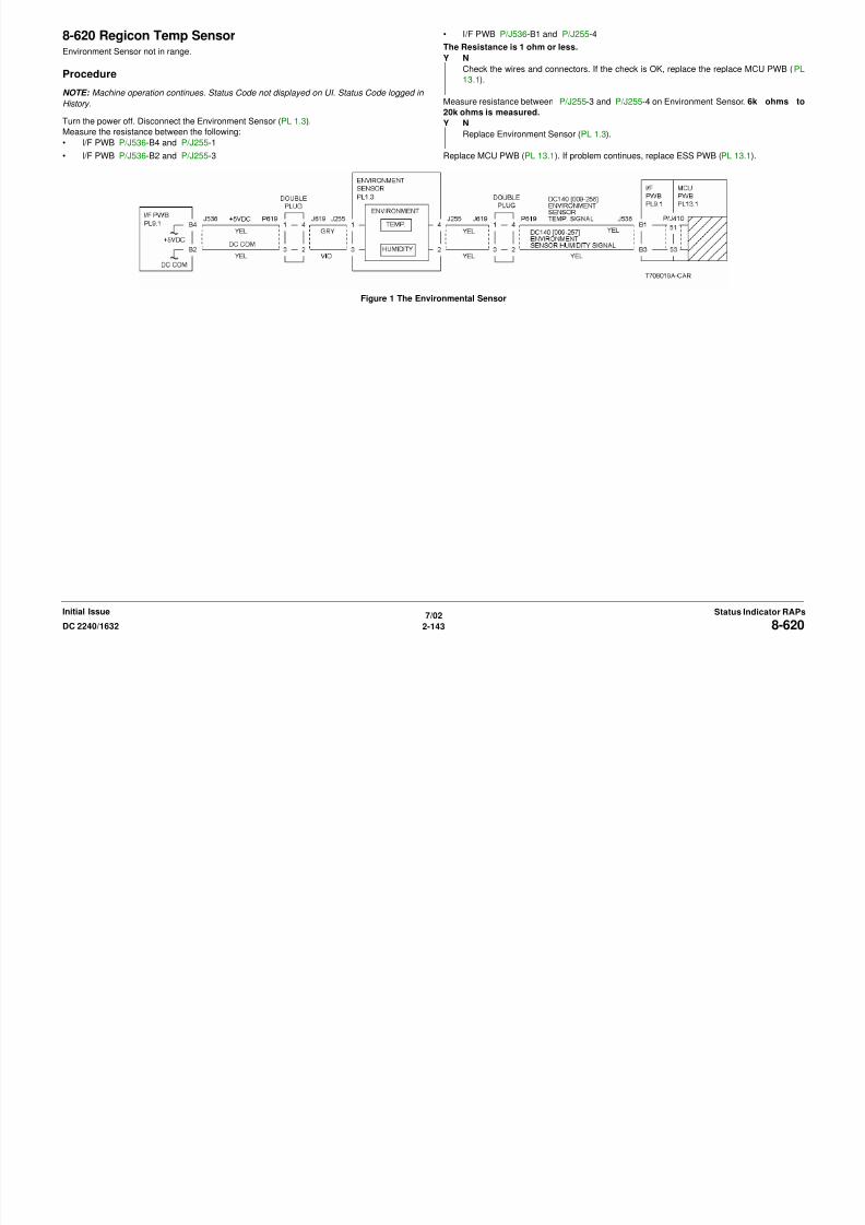
8/13/2019 Xerox Docu Color 2240-1632
http://slidepdf.com/reader/full/xerox-docu-color-2240-1632 173/1118
7/02
2-143DC 2240/1632 8-620Status Indicator RAPsInitial Issue
Figure 1 The Environmental Sensor
8-622 Regicon Data Overflow (A1 Patch X)
At A1 patch detection, the XSO correction setting value for either Y, M, C, or K exceeds the set-ting range (NVM value 0 to 472).
NOTE: Status Code not displayed on UI. Machine operation continues.
Procedure
Check the IBT Belt and Drum for a scratch or contamination. The check is OK.
Y N
Replace as required.
Go to Color Registration dC685 (ADJ 9.6).
8-623 Regicon Data Overflow (A2 Patch Y)
At A2 patch detection, the YSO correction setting value of either Y, M, C, or K exceeds the set-ting range (NVM value 0 to 474).
NOTE: Status Code not displayed on UI. Machine operation continues.
Procedure
Check the IBT Belt and Drum for a scratch or contamination. The check is OK.
Y N
Replace as required.
Go to Color Registration dC685 (ADJ 9.6).

8/13/2019 Xerox Docu Color 2240-1632
http://slidepdf.com/reader/full/xerox-docu-color-2240-1632 174/1118
7/02
2-144 DC 2240/16328-622, 8-623Initial IssueStatus Indicator RAPs
8-624 Regicon Data Overflow (Patch Magnification)
MAG Adjusted Set Point of operation results for each of Y,M,C exceeded the set range (NVMvalue: 0~1432).
NOTE: Status Code not displayed on UI. Machine operation continues.
Procedure
Check the IBT Belt and Drum for a scratch or contamination. The check is OK.
Y N
Replace as required.
Go to Color Registration dC685 (ADJ 9.6).
8-625 Regicon Sample Block (A1 Patch-rear)
At A1 (IN) patch detection, the number of the sample blocks does not reach the specified num-ber.
NOTE: Status Code not displayed on UI. Machine operation continues.
Procedure
Check the IBT Belt and Drum for a scratch or contamination. The check is OK.
Y N
Replace as required.
Go to Color Registration dC685 (ADJ 9.6).

8/13/2019 Xerox Docu Color 2240-1632
http://slidepdf.com/reader/full/xerox-docu-color-2240-1632 175/1118
7/02
2-145DC 2240/1632 8-624, 8-625Status Indicator RAPsInitial Issue
8-626 Regicon Sample Block (A1 Patch-front)
At A1 (OUT) patch detection, the number of the sample blocks does not reach the specifiednumber.
NOTE: Status Code not displayed on UI. Machine operation continues.
Procedure
Check the IBT Belt and Drum for a scratch or contamination. The check is OK.
Y N
Replace as required.
Go to Color Registration dC685 (ADJ 9.6).
8-627 Regicon Sample Lateral (A1 Patch-rear)
At A1 (IN) patch detection, the Fast Scan scan position of CYAN color that is the standard forthe rest is incorrect. (Against the MOB SENSOR, the center position of the CYAN pattern is
shifted by ±500µm or more.)
NOTE: Status Code not displayed on UI. Machine operation continues.
Procedure
Check the IBT Belt and Drum for a scratch or contamination. The check is OK.
Y N
Replace as required.
Go to Color Registration dC685 (ADJ 9.6).

8/13/2019 Xerox Docu Color 2240-1632
http://slidepdf.com/reader/full/xerox-docu-color-2240-1632 176/1118
7/02
2-146 DC 2240/16328-626, 8-627Initial IssueStatus Indicator RAPs
8-628 Regicon Sample Lateral (A1 Patch-front)
At A1 (OUT) patch detection, the scan position of CYAN color that is the standard for the rest isincorrect. (Against the MOB SENSOR, the center position of the CYAN pattern is shifted by
±500µm or more.?
NOTE: Status Code not displayed on UI. Machine operation continues.
Procedure
Check the IBT Belt and Drum for a scratch or contamination. The check is OK.
Y N
Replace as required.
Go to Color Registration dC685 (ADJ 9.6).
8-629 Regicon Skew (Patch Y)
During A1 Patch detection, skew deviation for Y exceeded tolerance.
NOTE: Machine operation continues. Status Code not displayed on UI. Status Code logged in
History.
Initial Actions
Clean MOB Sensor.
Procedure
Check the IBT Belt and Drum for a scratch or contamination. The check is OK.
Y NReplace as required.
Go to Color Registration dC685 (ADJ 9.6).
8/13/2019 Xerox Docu Color 2240-1632
http://slidepdf.com/reader/full/xerox-docu-color-2240-1632 177/1118
7/02
2-147DC 2240/1632 8-628, 8-629Status Indicator RAPsInitial Issue
8-630 Regicon Skew (Patch M)
During A1 Patch detection, skew deviation for M exceeded tolerance.
NOTE: Machine operation continues. Status Code not displayed on UI. Status Code logged in
History.
Initial Actions
Clean MOB Sensor.
Procedure
Check the IBT Belt and Drum for a scratch or contamination. The check is OK.
Y NReplace as required.
Go to Color Registration dC685 (ADJ 9.6).
8-631 Regicon Skew (Patch K)
During A1 Patch detection, skew deviation for K exceeded tolerance.
NOTE: Machine operation continues. Status Code not displayed on UI. Status Code logged in
History.
Initial Actions
Clean MOB Sensor.
Procedure
Check the IBT Belt and Drum for a scratch or contamination. The check is OK.
Y NReplace as required.
Go to Color Registration dC685 (ADJ 9.6).

8/13/2019 Xerox Docu Color 2240-1632
http://slidepdf.com/reader/full/xerox-docu-color-2240-1632 178/1118
7/02
2-148 DC 2240/16328-630, 8-631Initial IssueStatus Indicator RAPs
8-900 Static Jam
When the machine power is turned off then on before a paper path fault is cleared, an 8-900fault will be displayed. A voltage drop or interruption can also cause this fault.
Initial Actions
• Check the entire paper path for paper or obstructions.
• Clean all the paper path sensors.
• Check the Fault History for the last paper path fault. Go to that paper path fault RAP.
Procedure
In sequence, enter the following dC330 codes:
Block and unblock each sensor• 8-100 Tray 1 Mis-feed, (7-105).
• 8-106 Tray 2 Mis-feed, (7-110).
• 8-102 Tray 3 Mis-feed, (7-115).
• 8-103 Tray 4 Mis-feed, (7-119).
• 8-104 Registration Sensor, (8-175).
• 9-201 POB On Jam, (8-164)
The display for each code changes.
Y N
Go to the appropriate paper path fault RAP.
Check the machine input voltage if the problem continues replace the ESS PWB (PL 13 1)

8/13/2019 Xerox Docu Color 2240-1632
http://slidepdf.com/reader/full/xerox-docu-color-2240-1632 179/1118
7/02
2-149DC 2240/1632 8-900Status Indicator RAPsInitial Issue
Check the machine input voltage, if the problem continues, replace the ESS PWB (PL 13.1).
8/13/2019 Xerox Docu Color 2240-1632
http://slidepdf.com/reader/full/xerox-docu-color-2240-1632 180/1118
7/02
2-150 DC 2240/16328-900Initial IssueStatus Indicator RAPs
9-342 2nd BTR Contact
The 2nd BTR did not reach the contact position.
Initial Actions
• Clean the 2nd BTR Retract Sensor (PL 2.9) and check for damage.
• Check the 2nd BTR gears (PL 2.8) for breakage.
Procedure
Enter dC330 [009-200]. Open the Left Cover and block and unblock the 2nd BTR Retract Sen-
sor with a piece of paper. The display change state.
Y N
Disconnect P/J140. There is +5VDC from J140-3 to J140-1 (Figure 1).
Y N
Check the wires from P/J533 on the I/F PWB to the sensor. If the wires are OK,
replace the I/F PWB (PL 9.1).
There is +3.3VDC from J140-2 to GND.
Y N
Check the wire from P/J533-B19 on the I/F PWB to J140-2 for an open or a short
circuit to GND. If the wires are OK, replace the I/F PWB ( PL 9.1). If the problem is
not solved, replace the MCU PWB (PL 13.1).
Replace the 2nd BTR Retract Sensor (PL 2.9).
I t th f ll i dC330 [009 051] th dC330 [009 052] Th 2 d BTR
Figure 1 2ND BTR Retract Sensor Circuit Diagram

8/13/2019 Xerox Docu Color 2240-1632
http://slidepdf.com/reader/full/xerox-docu-color-2240-1632 181/1118
7/02
2-151DC 2240/1632 9-342Status Indicator RAPsInitial Issue
In sequence, enter the following: dC330 [009-051] then dC330 [009-052]. The 2nd BTR con-
tacts and retracts.
Y N
There is +24VDC from P/J533-B9 on the I/F PWB to GND (Figure 2).
Y N
Go to the +24 VDC Wirenets (Figure 1) and troubleshoot the problem.
Check the wires between P/J533 and P/J216 (Figure 2) on the 2nd BTR Retract Motor
for opens, shorts, or loose connections. If the wires are OK, replace the 2nd BTR Retract
Motor (PL 2.9). If the problem continues, replace the MCU PWB (PL 13.1). If the problemcontinues, replace the I/F PWB (PL 9.1).
Check for mechanical problems preventing the movement of the assembly. Check for debris
blocking the sensor.
D C D
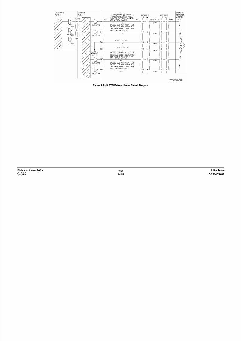
8/13/2019 Xerox Docu Color 2240-1632
http://slidepdf.com/reader/full/xerox-docu-color-2240-1632 182/1118
7/02
2-152 DC 2240/16329-342Initial IssueStatus Indicator RAPs
Figure 2 2ND BTR Retract Motor Circuit Diagram
9-343 2nd BTR Retract
The 2nd BTR did not reach the retract position.
Initial Actions
• Clean the 2nd BTR Retract Sensor (PL 2.9) and check for damage.
• Check the 2nd BTR gears (PL 2.8) for breakage.
Procedure
Enter dC330 [009-200]. Open the Left Cover and block and unblock the 2nd BTR Retract Sen-
sor with a piece of paper. The display changes state.
Y N
Disconnect P/J140. There is +5VDC from J140-3 to J140-1 (Figure 1).
Y N
Check the wires from P/J533 on the I/F PWB to the sensor. If the wires are OK,
replace the I/F PWB (PL 9.1).
There is +3.3VDC from J140-2 to GND.
Y N
Check the wire from P/J533-B19 on the I/F PWB to J140-2 for an open or a short
circuit to GND. If the wires are OK, replace the I/F PWB ( PL 9.1). If the problem is
not solved, replace the MCU PWB (PL 13.1).
Replace the 2nd BTR Retract Sensor (PL 2.9).
In sequence enter the following: dC330 [009-051] then dC330 [009-052] The 2nd BTR con-
Figure 1 2ND BTR Retract Sensor Circuit Diagram

8/13/2019 Xerox Docu Color 2240-1632
http://slidepdf.com/reader/full/xerox-docu-color-2240-1632 183/1118
7/02
2-153DC 2240/1632 9-343Status Indicator RAPsInitial Issue
In sequence, enter the following: dC330 [009-051] then dC330 [009-052]. The 2nd BTR con-
tacts and retracts.
Y N
There is +24VDC from P/J533-B9 on the I/F PWB to GND (Figure 2).
Y N
Go to the +24 VDC Wirenets (Figure 1) and troubleshoot the problem.
Check the wires between P/J533 and P/J216 (Figure 2) on the 2nd BTR Retract Motor
for opens, shorts, or loose connections. If the wires are OK, replace the 2nd BTR Retract
Motor (PL 2.9). If the problem continues, replace the MCU PWB (PL 13.1). If the problemcontinues, replace the I/F PWB (PL 9.1).
Check for mechanical problems preventing the movement of the assembly. Check for debris
blocking the sensor.
Figure 2 2ND BTR Retract Motor Circuit Diagram

8/13/2019 Xerox Docu Color 2240-1632
http://slidepdf.com/reader/full/xerox-docu-color-2240-1632 184/1118
7/02
2-154 DC 2240/16329-343Initial IssueStatus Indicator RAPs
Figure 2 2ND BTR Retract Motor Circuit Diagram
9-348 1st BTR Contact
The 1st BTR did not reach the contact position.
Initial Actions
• Clean the 1st BTR Retract Sensor (PL 5.4) and check for damage
• Check the 1st BTR Worm Gear and Retract Shaft (PL 5.4) for breakage
Procedure
In sequence, enter the following: dC330 [009-054] then dC330 [009-055]. The 1st BTR con-
tacts and retracts.
Y N
There is +24VDC from P/J533-A16 on the I/F PWB to GND (Figure 2).
Y NGo to the +24 VDC Wirenets (Figure 1) and troubleshoot the problem.
Check the wires between P/J533 and P/J237 (Figure 2) on the 1st BTR Retract Motor for
opens, shorts, or loose connections. If the wires are OK, replace the 1st BTR Retract
Motor (PL 5.4). If the problem continues, replace the MCU PWB (PL 13.1). If the problemcontinues, replace the I/F PWB (PL 9.1).
Stack dC330 input codes [004--014] (1st BTR Retract Sensor Power) and [009-203] (1st BTR
Retract Sensor). Then, in sequence, enter the following: dC330 [009-054] then dC330 [009-
055]. The 1st BTR Retract Sensor changes state.
Y N
Go to Figure 1. Check the circuit of the 1st BTR Retract Sensor (PL 5.4).
Replace the MCU PWB (PL 13.1).
A
A
B
B

8/13/2019 Xerox Docu Color 2240-1632
http://slidepdf.com/reader/full/xerox-docu-color-2240-1632 185/1118
7/02
2-155DC 2240/1632 9-348Status Indicator RAPsInitial Issue
Figure 1 1ST BTR Retract Sensor Circuit Diagram
Figure 2 1ST BTR Retract Motor Circuit Diagram

8/13/2019 Xerox Docu Color 2240-1632
http://slidepdf.com/reader/full/xerox-docu-color-2240-1632 186/1118
7/02
2-156 DC 2240/16329-348Initial IssueStatus Indicator RAPs
9-349 1st BTR Retract
The 1st BTR did not reach the retract position.
Initial Actions
• Clean the 1st BTR Retract Sensor (PL 5.4) and check for damage.
• Check the 1st BTR Worm Gear and Retract Shaft (PL 5.4) for breakage.
Procedure
In sequence, enter the following: dC330 [009-054] then dC330 [009-055]. The 1st BTR con-
tacts and retracts.
Y N
There is +24VDC from P/J533-A16 on the I/F PWB to GND (Figure 2).
Y NGo to the +24 VDC Wirenets (Figure 1) and troubleshoot the problem.
Check the wires between P/J533 and P/J237 (Figure 2) on the 1st BTR Retract Motor for
opens, shorts, or loose connections. If the wires are OK, replace the 1st BTR Retract
Motor (PL 5.4). If the problem continues, replace the MCU PWB (PL 13.1). If the problemcontinues, replace the I/F PWB (PL 9.1).
Stack dC330 input codes [004--014] (1st BTR Retract Sensor Power) and [009-203] (1st BTR
Retract Sensor). Then, in sequence, enter the following: dC330 [009-054] then dC330 [009-
055]. The 1st BTR Retract Sensor changes state.
Y N
Go to Figure 1.Check the circuit of the 1st BTR Retract Sensor (PL 5.4).
Replace the MCU PWB (PL 13.1).
A
A
B
B
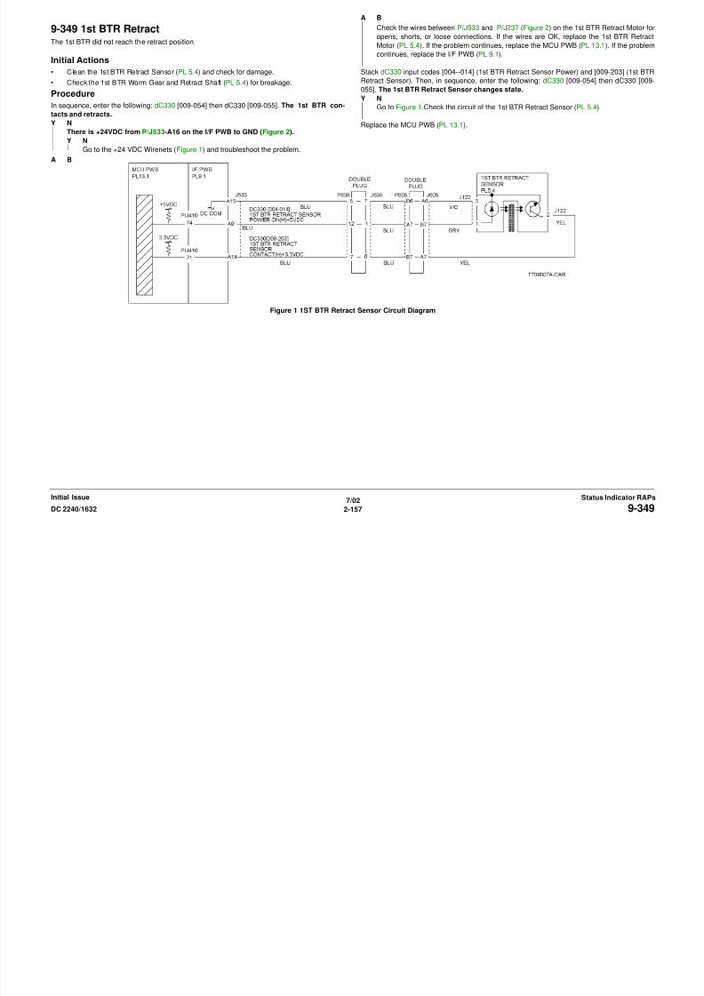
8/13/2019 Xerox Docu Color 2240-1632
http://slidepdf.com/reader/full/xerox-docu-color-2240-1632 187/1118
7/02
2-157DC 2240/1632 9-349Status Indicator RAPsInitial Issue
Figure 1 1ST BTR Retract Sensor Circuit Diagram
Figure 2 1ST BTR Retract Motor Circuit Diagram

8/13/2019 Xerox Docu Color 2240-1632
http://slidepdf.com/reader/full/xerox-docu-color-2240-1632 188/1118
7/02
2-158 DC 2240/16329-349Initial IssueStatus Indicator RAPs
9-350 IBT Home Sensor
The IBT Home Sensor detected the IBT position strip before the IBT Belt made a complete rev-olution.
Initial Actions
• Ensure that the Transfer Belt is installed correctly.
• Clean the IBT Home Sensor (PL 5.4) and check for damage
• Check the IBT drives for damage (PL 1.1).
Procedure
Remove the IBT Assembly. Enter dC330 [004-002]. The IBT Motor operates.
Y N
There is +24VDC from P/J551-3 on the I/F PWB to GND (Figure 1).
Y N
Go to the +24 VDC Wirenets (Figure 1) and troubleshoot the problem.
Check the wires between P/J551 and the IBT Motor (Figure 1) for opens, shorts, or loose
connections. If the wires are OK, replace the IBT Motor (PL 1.1). If the problem continues,
replace the MCU PWB (PL 13.1). If the problem continues, replace the I/F PWB (PL 9.1).
Enter dC330 [004-014]. There is +5VDC from P/J533-A9 to A12 on the I/F PWB
Y N
Go to Figure 2 and check the wire from P/J533-A9 to P/J605 on the IBT Assembly for ashort circuit. If the wire is OK, replace the MCU PWB (PL 13.1). If the problem continues,
replace the I/F PWB (PL 9.1).
Go to Figure 2 and check the wires from P/J533 to the IBT Home Sensor for an open wire,
loose connection, or a short circuit. If the wires are OK, replace the IBT Home Sensor (PL 5.4).
If the problem continues, replace the MCU PWB (PL 13.1). If the problem continues, replacethe I/F PWB (PL 9.1).
A

8/13/2019 Xerox Docu Color 2240-1632
http://slidepdf.com/reader/full/xerox-docu-color-2240-1632 189/1118
7/02
2-159DC 2240/1632 9-350Status Indicator RAPsInitial Issue
There is +3.3VDC from P/J533-A13 to A12 on the I/F PWB.
Y N
Go to Figure 2 and check the wire from P/J533-A13 to P/J605 on the IBT Assembly for a
short circuit. If the wire is OK, replace the MCU PWB (PL 13.1). If the problem continues,
replace the I/F PWB (PL 9.1).Figure 1 IBT Motor Circuit Diagram
Figure 2 IBT Home Sensor Circuit Diagram
A
9-351 Drive Logic
The IBT Edge Sensor detected that the IBT Belt is not tracking correctly.
Initial Actions
• Check the IBT Edge Sensor for damage. Ensure that the actuator is touching the edge of
the belt.
• Check the IBT steering drives for damage.
Procedure
Switch on the power. There is +1VDC to +3VDC from P/J533-A11 to GND.
Y N
There is +5VDC measured between P/J533-A10 and P/J533-A9 on the I/F PWB.
Y NReplace the MCU PWB (PL 13.1).
There is +5VDC from P/J 533-A11 on the I/F PWB to GND.
Y N
Go to Figure 2. Check the connectors and wires. If the check is OK, replace the IBT
Edge Sensor (PL 5.4). If the problem continues, replace the MCU PWB (PL 13.1).
Replace the IBT Sensor (PL 5.4).
Remove the IBT Assembly. Enter dC330 [004-001]. The IBT Steering Motor rotates.
Y N
There is +24 VDC from P/J550 on the I/F PWB to GND.
Y N
Figure 1 IBT Steering Motor

8/13/2019 Xerox Docu Color 2240-1632
http://slidepdf.com/reader/full/xerox-docu-color-2240-1632 190/1118
7/02
2-160 DC 2240/16329-351Initial IssueStatus Indicator RAPs
Y N
Go to the +24 VDC Wirenets (Figure 1) and troubleshoot the problem.
Check the wires (Figure 1) from P/J550 on the I/F PWB to P/J207 on the IBT Steering
Motor for shorts, opens, or loose connections. If the wires are OK, replace the MCU PWB
(PL 13.1). if the problem persists replace the I/F PWB (PL 9.1), then the IBT Steering
Motor (PL 1.3).
Check the installation of the Transfer Belt and the IBT Assembly (PL 5.3). Repair or replace asrequired. If the check is good, replace the MCU PWB (PL 13.1).
Figure 2 IBT Edge Sensor

8/13/2019 Xerox Docu Color 2240-1632
http://slidepdf.com/reader/full/xerox-docu-color-2240-1632 191/1118
7/02
2-161DC 2240/1632 9-351Status Indicator RAPsInitial Issue
9-358 Full Toner Sensor
The Full Toner Sensor detects a full toner condition.
Initial Actions
• Ensure that the Waste Toner Cartridge is not full.
• Check the sensor for toner contamination and foreign substances.
Procedure
Remove the Full Toner Sensor from the bottle. Enter dC330 [009-150]. Block and unblock the
Full Toner Sensor (PL 4.1). The display changes state.
Y N
Disconnect P/J133. There is +5VDC from J133-1 to J133-3 (Figure 1).
Y NCheck the wires from J133, pins 1 and 3 to P/J407 on the MCU PWB for opens,
shorts, or loose connections. If the wires are OK, replace the MCU PWB (PL 13.1).
There is +3.3VDC from J133-2 to GND.
Y N
Check the wire from J133-2 to P/J407 on the MCU PWB for opens, shorts, or loose
connections. If the wire is OK, replace the MCU PWB (PL 13.1).
Replace the Full Toner Sensor (PL 4.1).
The problem may be intermittent. If the condition continues, replace the MCU PWB. (PL 13.1).
9-360 Yellow Drum Cartridge Communication
A communication failure with the Yellow Drum Cartridge was detected.
Initial Actions
Check that the Yellow Drum Cartridge is seated correctly.
Procedure
Enter dC330 [009-151]. The display is H.
Y N
Go to Figure 1. Check the wires between P/J405 and P/J151. If the check is OK, replace
the Yellow Drum Cartridge (refer to Section 6, Machine Consumables).
Replace the MCU PWB (PL 13.1).
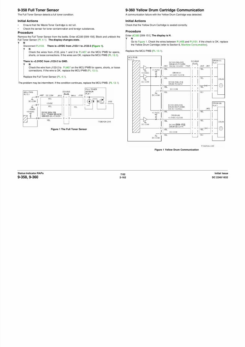
8/13/2019 Xerox Docu Color 2240-1632
http://slidepdf.com/reader/full/xerox-docu-color-2240-1632 192/1118
7/02
2-162 DC 2240/16329-358, 9-360Initial IssueStatus Indicator RAPs
Figure 1 The Full Toner Sensor
Figure 1 Yellow Drum Communication
9-361 Magenta Drum Cartridge Communication
A communication failure with Magenta Drum Cartridge was detected.
Initial Actions
Check that the Magenta Drum Cartridge is seated correctly.
Procedure
Enter dC330 [009-152]. The display is H.
Y N
Go to Figure 1. Check the wires between P/J405 and P/J152. If the check is OK, replace
the Magenta Drum Cartridge (refer to Section 6, Machine Consumables).
Replace the MCU PWB. (PL 13.1).
9-362 Cyan Drum Cartridge Communication
A communication failure with the Cyan Drum Cartridge was detected.
Initial Actions
Check that the Cyan Drum Cartridge is seated correctly.
Procedure
Enter dC330 [009-153]. The display is H.
Y N
Go to Figure 1. Check the wires between P/J405 and P/J154. If the check is OK, replace
the Cyan Drum Cartridge (refer to Section 6, Machine Consumables).
Replace the MCU PWB (PL 13.1).
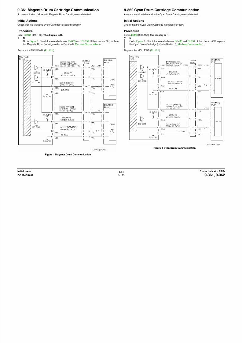
8/13/2019 Xerox Docu Color 2240-1632
http://slidepdf.com/reader/full/xerox-docu-color-2240-1632 193/1118
7/02
2-163DC 2240/1632 9-361, 9-362Status Indicator RAPsInitial Issue
Figure 1 Magenta Drum Communication
Figure 1 Cyan Drum Communication
9-363 Black Drum Cartridge CommunicationA communication failure with the Black Drum Cartridge was detected.
Initial Actions
Check that the Black Drum Cartridge is seated correctly.
Procedure
Enter dC330 [009-154]. The display is H.
Y N
Go to Figure 1. Check the wires between P/J405 and P/J153. If the check is OK, replace
the Black Drum Cartridge (refer to Section 6, Machine Consumables).
Replace the MCU PWB (PL 13.1).
9-380 ATC Sensor (Y)The ATC Sensor (Y) detects a low TC (toner concentration).
Initial Actions
• Check that Toner/Developer is present.
• Check the ATC Sensor (Y) for contamination. Ensure that the sensor is seated correctly.
Procedure
NOTE: To clear this fault, enter dC131 and set the value of NVM location 752-109 to 0.
Record the value in NVM location 752-324, then set the value to 1. Perform ADJ 9.3. After the
measurement has completed, restore the value. The ATC Sensor (Y) fail judgement is OK.
Y NCheck connector P/J129. If the check is OK, replace the ATC Sensor (Y) (PL 6.2).
If the problem continues, replace the MCU PWB (PL 13.1).
After checking that no failures are detected during normal operation, go to call close out.
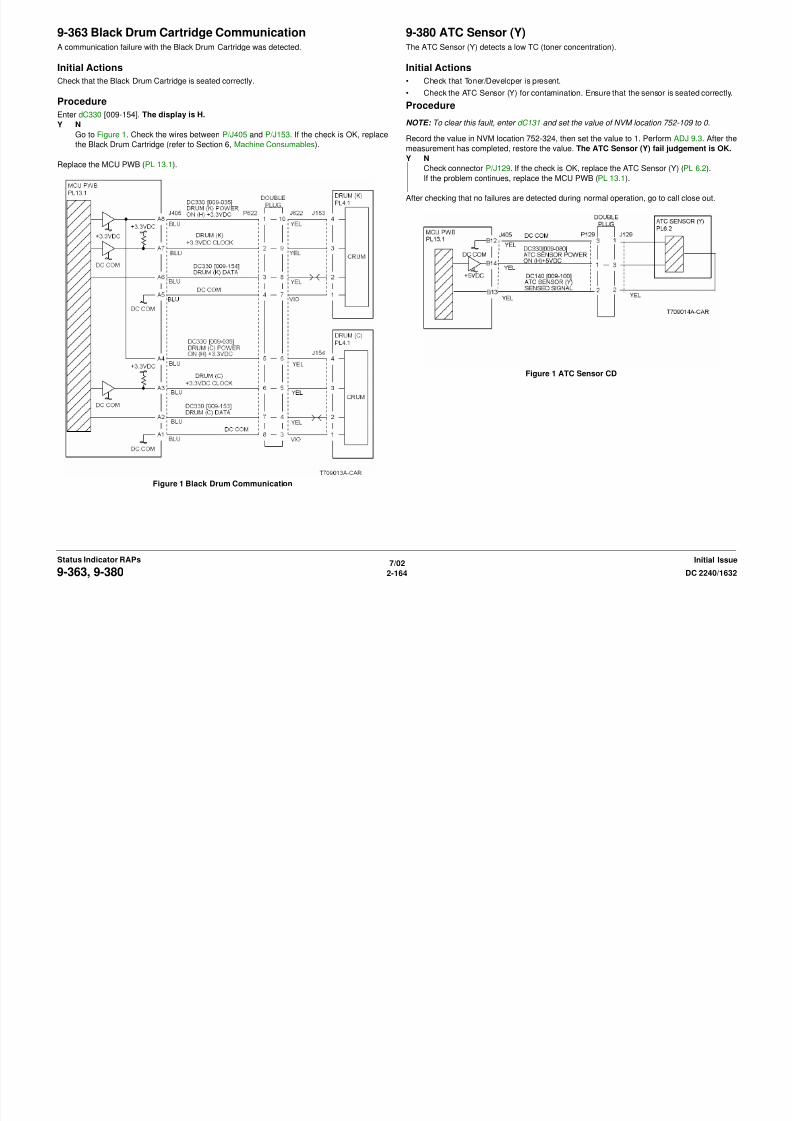
8/13/2019 Xerox Docu Color 2240-1632
http://slidepdf.com/reader/full/xerox-docu-color-2240-1632 194/1118
7/02
2-164 DC 2240/16329-363, 9-380Initial IssueStatus Indicator RAPs
Figure 1 Black Drum Communication
Figure 1 ATC Sensor CD
9-381 ATC Sensor (M)The ATC Sensor (M) detects a low TC (toner concentration)
Initial Actions
• Check that Toner/Developer is present.
• Check the ATC Sensor (M) for contamination. Ensure that the sensor is seated correctly.
Procedure
NOTE: To clear this fault, enter dC131 and set the value of NVM location 752-110 to 0.
Record the value in NVM location 752-324, then set the value to 1. Perform ADJ 9.3. After the
measurement has completed, restore the value. The ATC Sensor (M) fail judgement is OK.
Y NCheck connector P/J130. If the check is OK, replace the ATC Sensor (M) (PL 6.2). If the
problem continues, replace the MCU PWB (PL 13.1).
After checking that no failures are detected during normal operation, go to call close out.
9-382 ATC Sensor (C)The ATC Sensor (C) detects a low TC (toner concentration)
Initial Actions
• Check that Toner/Developer is present.
• Check the ATC Sensor (C) for contamination. Ensure that the sensor is seated correctly.
Procedure
NOTE: To clear this fault, enter dC131 and set the value of NVM location 752-111 to 0.
Record the value in NVM location 752-324, then set the value to 1. Perform ADJ 9.3. After the
measurement has completed, restore the value. The ATC Sensor (C) fail judgement is OK.
Y NCheck connector P/J131. If the check is OK, replace the ATC Sensor (C) (PL 6.2). If the
problem continues, replace the MCU PWB (PL 13.1).
After checking that no failures are detected during normal operation, go to call close out.
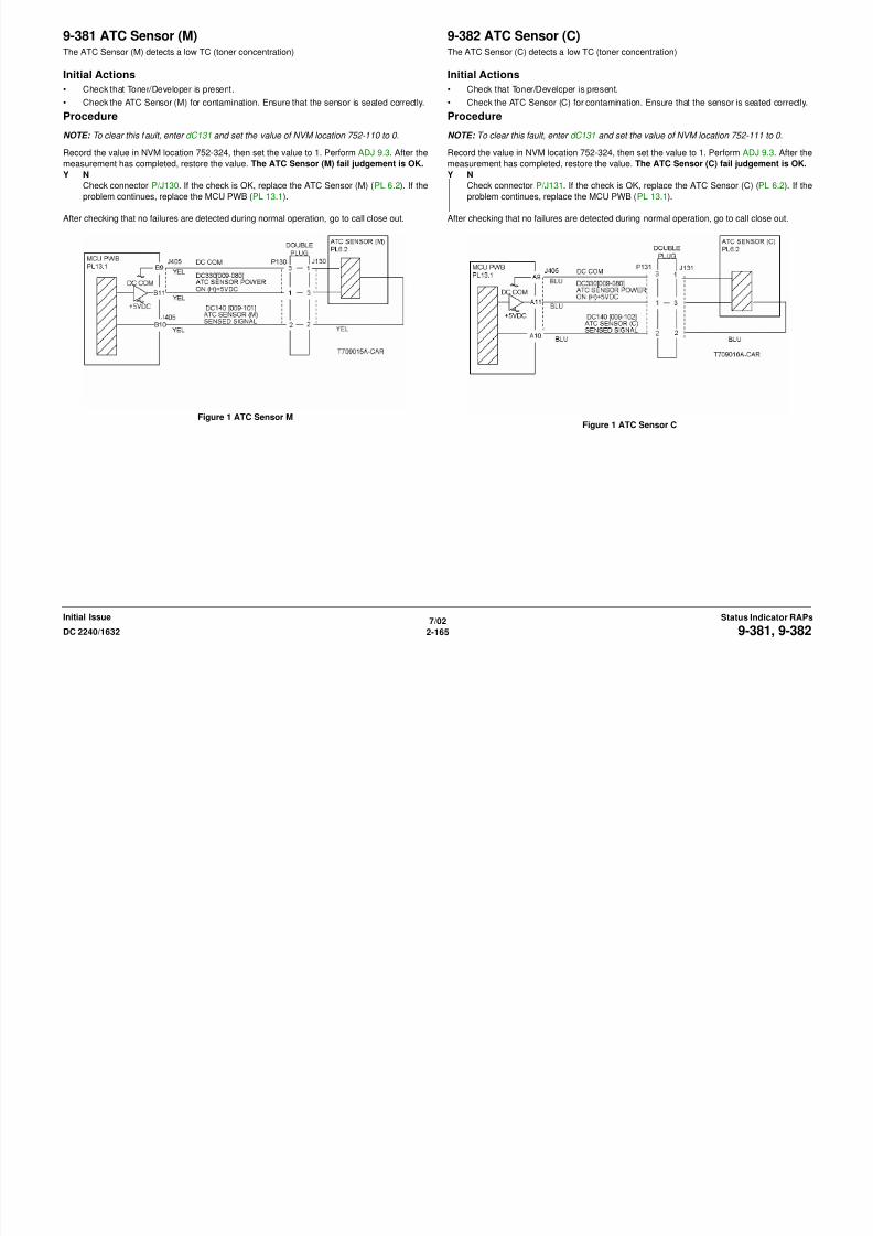
8/13/2019 Xerox Docu Color 2240-1632
http://slidepdf.com/reader/full/xerox-docu-color-2240-1632 195/1118
7/02
2-165DC 2240/1632 9-381, 9-382Status Indicator RAPsInitial Issue
Figure 1 ATC Sensor MFigure 1 ATC Sensor C

8/13/2019 Xerox Docu Color 2240-1632
http://slidepdf.com/reader/full/xerox-docu-color-2240-1632 196/1118

8/13/2019 Xerox Docu Color 2240-1632
http://slidepdf.com/reader/full/xerox-docu-color-2240-1632 197/1118
9-393 New Toner Cartridge (Y)When a new Toner Cartridge was installed, the level of the New Cartridge Detect Switch (Y)
remained L when it should be changed to H by the Dispense Motor drive.
Initial Actions
• Re-install the Toner Cartridge ensuring that the Dispense Motor and the Toner Cartridge
is engaged.
• Check that the New/Old Detection Switch (metal part) at the rear of the Toner Cartridge is
raised. If the New/Old Detection Switch is not raised, lift it up, then set the value of NVM
location 752-683 (Accumulative Dispense Time Value Y) to 0.
• Check that the Dispense Motor is operating; check dC330 [009-001, Dispense Motor (C)].
ProcedureDisconnect P/J405 from the MCU PWB. The fault has cleared.
Y N
Replace the MCU PWB. (PL 13.1).
Remove the yellow toner cartridge and check the Dispense Motor Assembly for wear or dam-
age.
Disconnect FS180 and FS181 at both edges of the New Cartridge Detect Switch (Y).
Check continuity at both edges of the New Cartridge Detect Switch (Y). There is continuity
when the Switch is not engaged.
Y N
Check the wire between the connector J405-B18 and FS181 on the New Cartridge Detect
Switch (Y) for a short circuit to the frame (Figure 1).
Replace the New Cartridge Detect Switch (Y) (PL 6.1).
9-408 Waste Toner Cartridge Near FullThe Waste Toner Cartridge is nearly full. This fault requires service only if the message
appears before the Toner Cartridge is depleted.
Initial Actions
Replace the Waste Toner Cartridge. Check the Full Toner Sensor for contaminants.
Procedure
If the problem persists, go to the 9-358 RAP.

8/13/2019 Xerox Docu Color 2240-1632
http://slidepdf.com/reader/full/xerox-docu-color-2240-1632 198/1118
7/02
2-168 DC 2240/16329-393, 9-408Initial IssueStatus Indicator RAPs
Replace the New Cartridge Detect Switch (Y) (PL 6.1).
Figure 1 New Cartridge Detect Switch (Y)
9-410 Toner Cartridge (Y) Near EmptyThe Yellow Toner Cartridge is nearly empty/empty. This fault requires service only if the mes-
sage appears before the Toner Cartridge is depleted.
NOTE: Continuous running of high density prints can temporarily deplete the toner supply.
Initial Actions
• Ensure that there is toner and the toner is evenly distributed in the cartridge (Y).
• Check the ATC Sensor (Y) for blockage or contaminants.
• Check the drive system from the Developer Drive Motor to the Developer Housing (Y) for
damage.
Procedure
Enter dC330 [009-001]. The Yellow Toner Dispense Motor (PL 6.1) energizes.
Y N
Go to Figure 1. There is +24 VDC from P/J533-A2 to GND.
Y N
Go to the +24 VDC Wirenets (Figure 1) and troubleshoot the problem.
There is +24 VDC from P/J533-A1 to GND.
Y N
Check the wires from P/J533 to P/J227for an open circuit. If the wires are OK,
replace the Yellow Toner Dispense Motor (PL 6.1).
Enter dC330 [009-001]. The voltage from P/J533-A1 to GND drops to less than 1
VDC.
Y N
R l th MCU PWB (PL 13 1) If th bl ti l th I/F PWB (PL
After checking that no failures are detected during normal operation, go to call closeout.
Figure 1 Toner Dispenser Motor Y
A
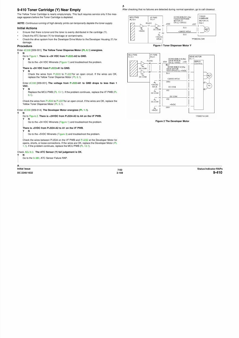
8/13/2019 Xerox Docu Color 2240-1632
http://slidepdf.com/reader/full/xerox-docu-color-2240-1632 199/1118
7/02
2-169DC 2240/1632 9-410Status Indicator RAPsInitial Issue
Replace the MCU PWB (PL 13.1). If the problem continues, replace the I/F PWB (PL
9.1).
Check the wires from P/J533 to P/J227for an open circuit. If the wires are OK, replace the
Yellow Toner Dispense Motor (PL 6.1).
Enter dC330 [009-014]. The Developer Motor energizes (PL 1.1).
Y NGo to Figure 2. There is +24VDC from P/J534-A3 to A4 on the I/F PWB.
Y N
Go to the +24 VDC Wirenets (Figure 1) and troubleshoot the problem.
There is +5VDC from P/J534-A2 to A1 on the I/F PWB.
Y N
Go to the +5VDC Wirenets (Figure 3) and troubleshoot the problem.
Check the wires between P/J534 on the I/F PWB and P/J232 at the Developer Motor for
opens, shorts, or loose connections. If the wires are OK, replace the Developer Motor (PL
1.1). If the problem continues, replace the MCU PWB (PL 13.1).
Check ADJ 9.3. The ATC Sensor (Y) fail judgement is OK.
Y N
Go to the 9-380, ATC Sensor Failure RAP.
Figure 2 The Developer Motor
A
9-411 Toner Cartridge (M) Near EmptyThe Magenta Toner Cartridge is nearly empty. This fault requires service only if the message
appears before the Toner Cartridge is depleted.
NOTE: Continuous running of high density prints can temporarily deplete the toner supply.
Initial Actions
• Ensure that there is toner and the toner is evenly distributed in the cartridge (M).
• Check the ATC Sensor (M) for blockage or contaminants.
• Check the drive system from the Developer Drive Motor to the Developer Housing (M) for
damage.
Procedure
Enter dC330 [009-002]. The Magenta Toner Dispense Motor (PL 6.1) energizes.
Y N
Go to Figure 1. There is +24 VDC from P/J533-A4 to GND.
Y N
Go to the +24 VDC Wirenets (Figure 1) and troubleshoot the problem.
There is +24 VDC from P/J533-A3 to GND.
Y N
Check the wires from P/J533 to P/J228 for an open circuit. If the wires are OK,
replace the Magenta Toner Dispense Motor (PL 6.1).
Enter dC330 [009-002]. The voltage from P/J533-A3 to GND drops to less than 1
VDC.
Y N
Replace the MCU PWB (PL 13 1) If the problem continues replace the I/F PWB (PL
After checking that no failures are detected during normal operation, go to call closeout.
Figure 1 Toner Dispense Motor M
A
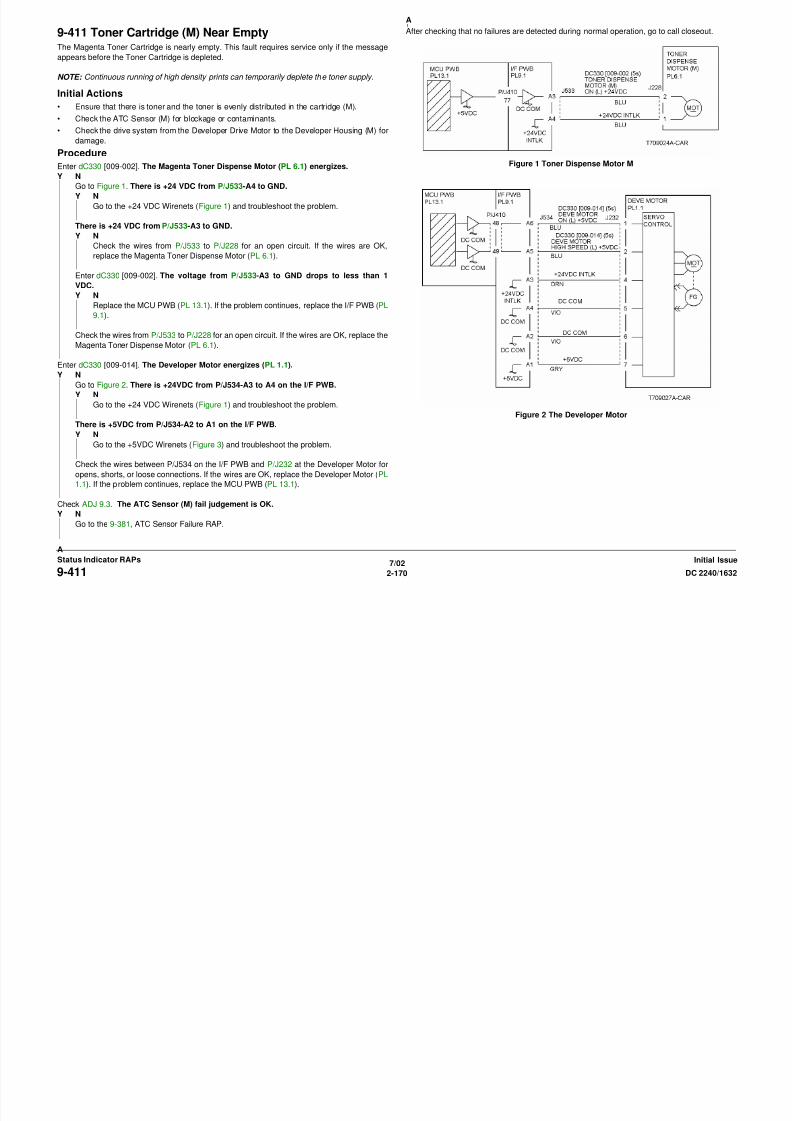
8/13/2019 Xerox Docu Color 2240-1632
http://slidepdf.com/reader/full/xerox-docu-color-2240-1632 200/1118
7/02
2-170 DC 2240/16329-411Initial IssueStatus Indicator RAPs
Replace the MCU PWB (PL 13.1). If the problem continues, replace the I/F PWB (PL
9.1).
Check the wires from P/J533 to P/J228 for an open circuit. If the wires are OK, replace the
Magenta Toner Dispense Motor (PL 6.1).
Enter dC330 [009-014]. The Developer Motor energizes (PL 1.1).
Y NGo to Figure 2. There is +24VDC from P/J534-A3 to A4 on the I/F PWB.
Y N
Go to the +24 VDC Wirenets (Figure 1) and troubleshoot the problem.
There is +5VDC from P/J534-A2 to A1 on the I/F PWB.
Y N
Go to the +5VDC Wirenets (Figure 3) and troubleshoot the problem.
Check the wires between P/J534 on the I/F PWB and P/J232 at the Developer Motor for
opens, shorts, or loose connections. If the wires are OK, replace the Developer Motor (PL
1.1). If the problem continues, replace the MCU PWB (PL 13.1).
Check ADJ 9.3. The ATC Sensor (M) fail judgement is OK.
Y N
Go to the 9-381, ATC Sensor Failure RAP.
Figure 2 The Developer Motor
A
9-412 Toner Cartridge (C) Near EmptyThe Cyan Toner Cartridge is nearly empty/empty. This fault requires service only if the mes-
sage appears before the Toner Cartridge is depleted.
NOTE: Continuous running of high density prints can temporarily deplete the toner supply.
Initial Actions
• Ensure that there is toner and the toner is evenly distributed in the cartridge (C).
• Check the ATC Sensor (C) for blockage or contaminants.
• Check the drive system from the Developer Drive Motor to the Developer Housing (C) for
damage.
Procedure
Enter dC330 [009-003]. The Cyan Toner Dispense Motor (PL 6.1) energizes.
Y N
Go to Figure 1. There is +24 VDC from P/J533-A6 to GND.
Y N
Go to the +24 VDC Wirenets (Figure 1) and troubleshoot the problem.
There is +24 VDC from P/J533-A5 to GND.
Y N
Check the wires from P/J533 to P/J229 for an open circuit. If the wires are OK,
replace the Cyan Toner Dispense Motor (PL 6.1).
Enter dC330 [009-003]. The voltage from P/J533-A5 to GND drops to less than 1
VDC.
Y N
Replace the MCU PWB (PL 13 1) If the problem continues replace the I/F PWB (PL
After checking that no failures are detected during normal operation, go to call closeout.
Figure 1 Toner Dispense Motor C
A

8/13/2019 Xerox Docu Color 2240-1632
http://slidepdf.com/reader/full/xerox-docu-color-2240-1632 201/1118
7/02
2-171DC 2240/1632 9-412Status Indicator RAPsInitial Issue
Replace the MCU PWB (PL 13.1). If the problem continues, replace the I/F PWB (PL
9.1).
Check the wires from P/J533 to P/J229 for an open circuit. If the wires are OK, replace the
Cyan Toner Dispense Motor (PL 6.1).
Enter dC330 [009-014]. The Developer Motor energizes (PL 1.1).
Y NGo to Figure 2. There is +24VDC from P/J534-A3 to A4 on the I/F PWB.
Y N
Go to the +24 VDC Wirenets (Figure 1) and troubleshoot the problem.
There is +5VDC from P/J534-A2 to A1 on the I/F PWB.
Y N
Go to the +5VDC Wirenets (Figure 3) and troubleshoot the problem.
Check the wires between P/J534 on the I/F PWB and P/J232 at the Developer Motor for
opens, shorts, or loose connections. If the wires are OK, replace the Developer Motor (PL
1.1). If the problem continues, replace the MCU PWB (PL 13.1).
Check ADJ 9.3. The ATC Sensor (C) fail judgement is OK.
Y N
Go the 9-382, ATC Sensor Failure (C) RAP.
Figure 2 The Developer Motor
A
9-413 Toner Cartridge (K) Near EmptyThe Black Toner Cartridge is nearly empty. This fault requires service only if the message
appears before the Toner Cartridge is depleted.
NOTE: Continuous running of high density prints can temporarily deplete the toner supply.
Initial Actions
• Ensure that there is toner and the toner is evenly distributed in the cartridge (K).
• Check the ATC Sensor (K) for blockage or contaminants.
• Check the drive system from the Main Drive Motor to the Developer Housing (K) for dam-
age.
Procedure
Enter dC330 [009-004]. The Toner Dispense Motor (K) energizes (PL 6.1).
Y N
Go to Figure 1. There is +24 VDC from P/J533-A8 to GND.
Y N
Go to the +24 VDC Wirenets (Figure 1) and troubleshoot the problem.
There is +24 VDC from P/J533-A7 to GND.
Y N
Check the wires from P/J533 to P/J230 for an open circuit. If the wires are OK,
replace the Cyan Toner Dispense Motor (PL 6.1).
Enter dC330 [009-003]. The voltage from P/J533-A7 to GND drops to less than 1
VDC.
Y N
Replace the MCU PWB (PL 13.1). If the problem continues, replace the I/F PWB (PL
Figure 1 Toner Dispense Motor K
Figure 2 Dev Clutch K Circuit Diagram
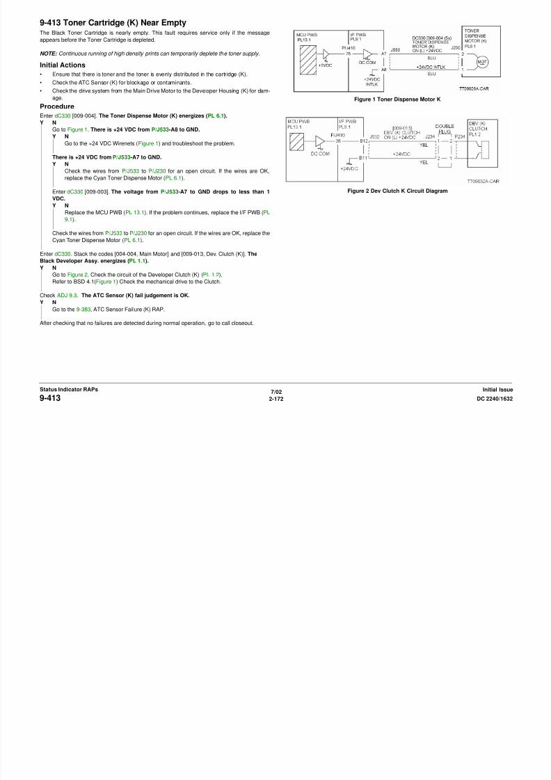
8/13/2019 Xerox Docu Color 2240-1632
http://slidepdf.com/reader/full/xerox-docu-color-2240-1632 202/1118
7/02
2-172 DC 2240/16329-413Initial IssueStatus Indicator RAPs
Replace the MCU PWB (PL 13.1). If the problem continues, replace the I/F PWB (PL
9.1).
Check the wires from P/J533 to P/J230 for an open circuit. If the wires are OK, replace the
Cyan Toner Dispense Motor (PL 6.1).
Enter dC330. Stack the codes [004-004, Main Motor] and [009-013, Dev. Clutch (K)]. The
Black Developer Assy. energizes (PL 1.1).Y N
Go to Figure 2. Check the circuit of the Developer Clutch (K) (PL 1.2).
Refer to BSD 4.1(Figure 1) Check the mechanical drive to the Clutch.
Check ADJ 9.3. The ATC Sensor (K) fail judgement is OK.
Y N
Go to the 9-383, ATC Sensor Failure (K) RAP.
After checking that no failures are detected during normal operation, go to call closeout.
9-428 Change Drum Cartridge (K) SoonThe Drum Cartridge (K) needs to be replaced soon/reached end of life.
Procedure
Replace the Black Drum Cartridge (refer to Section 6, Machine Consumables). The problem
is corrected.
Y N
Replace the MCU PWB (PL 13.1).
Return to Service Call Procedures.
9-429 Change Drum Cartridge (Y) SoonThe Drum Cartridge (Y) needs to be replaced soon.
Procedure
Replace the Yellow Drum Cartridge (refer to Section 6, Machine Consumables). The problem
is corrected.
Y N
Replace the MCU PWB. (PL 13.1).
Return to Service Call Procedures.

8/13/2019 Xerox Docu Color 2240-1632
http://slidepdf.com/reader/full/xerox-docu-color-2240-1632 203/1118
7/02
2-173DC 2240/1632 9-428, 9-429Status Indicator RAPsInitial Issue
9-430 Change Drum Cartridge (M) SoonThe Drum Cartridge (M) needs to be replaced soon.
Procedure
Replace the Magenta Drum Cartridge (refer to Section 6, Machine Consumables). The prob-
lem is corrected.
Y N
Replace the MCU PWB. (PL 13.1).
Return to Service Call Procedures.
9-431 Change Drum Cartridge (C) SoonThe Drum Cartridge (C) needs to be replaced soon.
Procedure
Replace the Cyan Drum Cartridge (refer to Section 6, Machine Consumables). The problem
is corrected.
Y N
Replace the MCU PWB. (PL 13.1).
Return to Service Call Procedures.

8/13/2019 Xerox Docu Color 2240-1632
http://slidepdf.com/reader/full/xerox-docu-color-2240-1632 204/1118
7/02
2-174 DC 2240/16329-430, 9-431Initial IssueStatus Indicator RAPs
9-654 ADC SensorThe machine logic detected an ADC Sensor operation failure.
Procedure
Check ADJ 9.4. The fail judgement of the ADC Sensor is OK.
Y N
There is +5VDC from P/J536-A13 on the I/F PWB to GND.
Y N
Go to Figure 1. Check the wires and connectors. If the check is OK, replace the I/F
PWB (PL 9.1). If the problem continues replace the MCU PWB (PL 13.1).
Enter dC330 [009-078]. The ADC Shutter Solenoid energized (PL 1.3).
Y NCheck the wires and connectors. If the check is OK, replace the I/F PWB (PL 9.1). If
the problem continues replace the MCU PWB (PL 13.1).
Enter dC330 [009-078]. There is 0VDC from P/J536-A8 on the I/F PWB to GND.
Y N
Check the wires and connectors. If the check is OK, replace the I/F PWB (PL 9.1). Ifthe problem continues replace the MCU PWB (PL 13.1).
Enter dC330 [009-079]. The voltage from P/J536-A6 to GND changed to 0VDC
momentarily.
Y N
Check the wires and connectors. If the check is OK, replace the I/F PWB (PL 9.1). If
the problem continues replace the MCU PWB (PL 13.1).
Check the wires and connectors. If the check is OK, replace the, replace the ADC Sensor
Assembly (PL 1.3).
After checking that no failures are detected during normal operation, go to call closeout.
A
A
B
B

8/13/2019 Xerox Docu Color 2240-1632
http://slidepdf.com/reader/full/xerox-docu-color-2240-1632 205/1118
7/02
2-175DC 2240/1632 9-654Status Indicator RAPsInitial Issue
Figure 1 The ADC Sensor
9-660 Environment Sensor TemperatureAn incorrect value was detected by the Environment Sensor (Temperature).
Procedure
Disconnect P/J255. There is 1 Ohm or less measured between P255-3 and P255-4 on the
Environment Sensor.
Y N
Replace the Environment Sensor (PL 1.3).
Replace the I/F PWB (PL 9.1) and MCU PWB (PL 13.1) in sequence.
Figure 1 The Environment Sensor
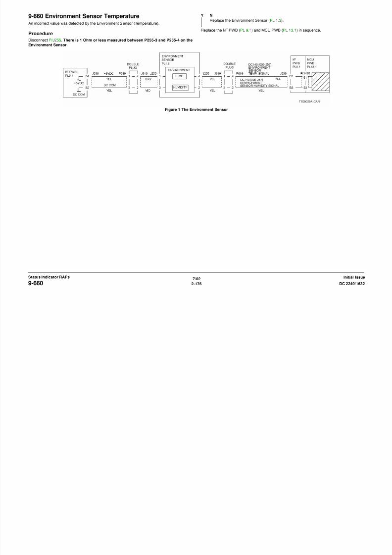
8/13/2019 Xerox Docu Color 2240-1632
http://slidepdf.com/reader/full/xerox-docu-color-2240-1632 206/1118
7/02
2-176 DC 2240/16329-660Initial IssueStatus Indicator RAPs
9-661 Environment Sensor HumidityAn incorrect value was detected by the Environment Sensor (Humidity).
Procedure
There is +0.4VDC to +17VDC from P/J536-B3 on the I/F PWB to GND.
Y N
There is +5VDC from P/J536-B4 on the I/F PWB to GND.
Y N
Go to Figure 1. Check the wires and connectors. If the check is OK, replace the
MCU PWB (PL 13.1).
Go to Figure 1. Check for an open circuit and poor contact if the check is OK replace the
Environment Sensor (PL 1.3).
Replace the I/F PWB (PL 9.1). If the problem continues, replace the MCU PWB (PL 13.1).
Figure 1 The Environment Sensor
A
A
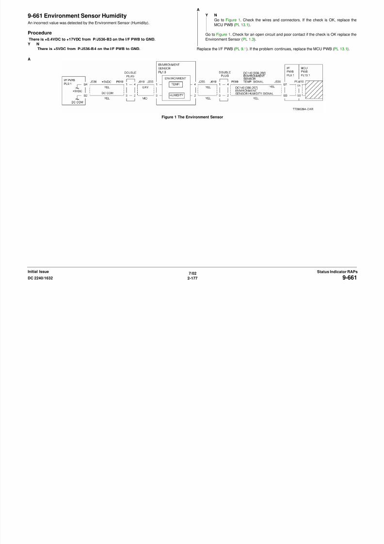
8/13/2019 Xerox Docu Color 2240-1632
http://slidepdf.com/reader/full/xerox-docu-color-2240-1632 207/1118
7/02
2-177DC 2240/1632 9-661Status Indicator RAPsInitial Issue
9-670 New Toner Cartridge (K) DetectedThe machine logic detected that the Toner Cartridge has been replaced. This is a message
fault only.
Procedure
Switch the power off, then on. The message fault clears.
Y N
Go to the 9-390 RAP.
Return to Service Call Procedures.
9-671 New Toner Cartridge (C) DetectedThe machine logic detected that the Toner Cartridge has been replaced. This is a message
fault only.
Procedure
Switch the power off, then on. The message fault clears.
Y N
Go to the 9-391 RAP.
Return to Service Call Procedures.
8/13/2019 Xerox Docu Color 2240-1632
http://slidepdf.com/reader/full/xerox-docu-color-2240-1632 208/1118
7/02
2-178 DC 2240/16329-670, 9-671Initial IssueStatus Indicator RAPs
9-672 New Toner Cartridge (M) DetectedThe machine logic detected that the Toner Cartridge has been replaced. This is a message
fault only.
Procedure
Switch the power off, then on. The message fault clears.
Y N
Go to the 9-392 RAP.
Return to Service Call Procedures.
9-673 New Toner Cartridge (Y) DetectedThe machine logic detected that the Toner Cartridge has been replaced.This is a message fault
only.
Procedure
Switch the power off, then on. The message fault clears.
Y N
Go to the 9-393 RAP.
Return to Service Call Procedures.

8/13/2019 Xerox Docu Color 2240-1632
http://slidepdf.com/reader/full/xerox-docu-color-2240-1632 209/1118
7/02
2-179DC 2240/1632 9-672, 9-673Status Indicator RAPsInitial Issue
9-684 ADC ShutterThe machine logic detected an ADC Shutter operation failure.
Procedure
BSD 9.16, 9.31D
Enter dC330 [009-078]. The ADC Shutter Solenoid energized.
Y N
There is +24VDC from P/J536-A7 on the I/F PWB to GND.
Y N
Go to Figure 1. Check the wires and connectors. If the check is OK, replace the I/F
PWB (PL 9.1). If the problem continues, replace the ADC Sensor (PL 1.3).
Enter dC330 [009-078]. There is 0VDC from P/J536-A8 on the I/F PWB to GND.
Y N
Check the wires and connectors. If the check is OK, replace the I/F PWB (PL 9.1). If
the problem continues, replace the MCU PWB (PL 13.1). If the problem continues,
replace the ADC Sensor (PL 1.3).
Enter dC330 [009-079]. The voltage from P/J536-A6 on the I/F PWB to GND changed
to 0VDC momentarily.
Y N
Go to Figure 1. Check the wires and connectors. If the check is OK, replace the I/F
PWB (PL 9.1). If the problem continues, replace the MCU PWB (PL 13.1). If the
problem continues, replace the ADC Sensor (PL 1.3).
Go to Figure 1. Check the wires and connectors. If the check is OK, replace the ADC Sen-
sor (PL 1.3).
After checking that no failures are detected during normal operation, go to call closeout.
A
A

8/13/2019 Xerox Docu Color 2240-1632
http://slidepdf.com/reader/full/xerox-docu-color-2240-1632 210/1118
7/02
2-180 DC 2240/16329-684Initial IssueStatus Indicator RAPs
Figure 1 The ADC Sensor
9-910 Drum (Y) Type MismatchDrum Type Mismatch
Initial Actions
Ensure that the correct drum type is installed.
Procedure
Enter dC330 [009-151], (Drum (Y) Data). The display is H.
Y N
Go to Figure 1. Check the wires and connectors. If the check is OK, replace the Yellow
Drum Cartridge (refer to Section 6, Machine Consumables).
Replace the MCU PWB (PL 13.1).
9-911 Drum (M) Type MismatchDrum Type Mismatch
Initial Actions
Ensure that the correct drum type is installed.
Procedure
Enter dC330 [009-152] (Drum (M) Data). The display is H.
Y N
Go to Figure 1. Check the wires and connectors. If the check is OK, replace the Magenta
Drum Cartridge (refer to Section 6, Machine Consumables).
Replace the MCU PWB (PL 13.1).
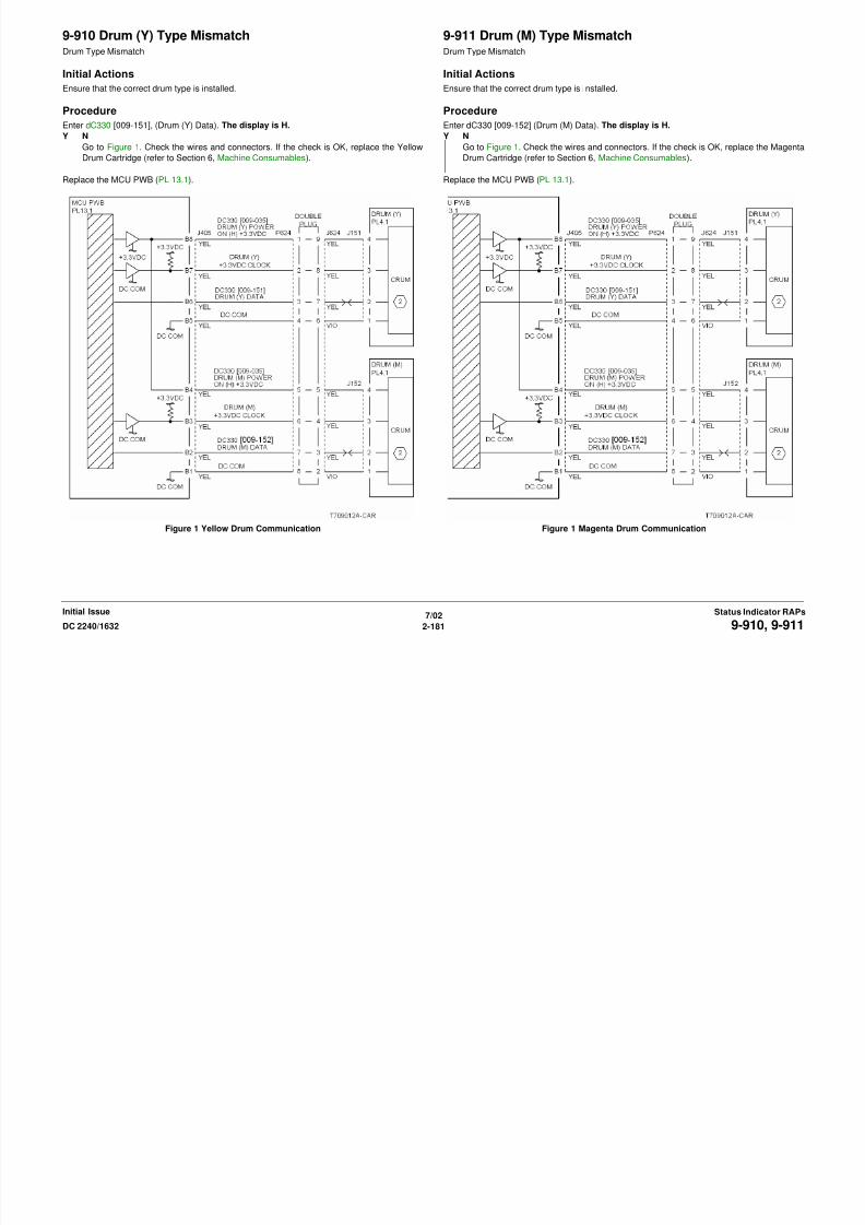
8/13/2019 Xerox Docu Color 2240-1632
http://slidepdf.com/reader/full/xerox-docu-color-2240-1632 211/1118
7/02
2-181DC 2240/1632 9-910, 9-911Status Indicator RAPsInitial Issue
Figure 1 Yellow Drum Communication Figure 1 Magenta Drum Communication
9-912 Drum (C) Type MismatchDrum Type Mismatch
Initial Actions
Ensure that the correct drum type is installed.
Procedure
Enter dC330 [009-153] (Drum (C) Data). The display is H.
Y N
Check the wires and connectors. If the check is OK, replace the Cyan Drum Cartridge
(refer to Section 6, Machine Consumables).
Replace the MCU PWB. (PL 13.1).
9-913 Drum (K) Type MismatchDrum Type Mismatch
Initial Actions
Ensure that the correct drum type is installed.
Procedure
Enter dC330 [009-154] (Drum (K) Data). The display is H.
Y N
Check the wires and connectors. If the check is OK, replace the Black Drum Cartridge
(refer to Section 6, Machine Consumables).
Replace the MCU PWB. (PL 13.1).

8/13/2019 Xerox Docu Color 2240-1632
http://slidepdf.com/reader/full/xerox-docu-color-2240-1632 212/1118
7/02
2-182 DC 2240/16329-912, 9-913Initial IssueStatus Indicator RAPs
Figure 1 Cyan Drum Communication Figure 1 Black Drum Communication
9-920 Toner Cartridge (Y) EmptyThe Yellow Toner Cartridge is empty. This fault requires service only if the message appears
before the Toner Cartridge is depleted.
NOTE: Continuous running of high density prints can temporarily deplete the toner supply.
Initial Actions
• Ensure that there is toner and the toner is evenly distributed in the cartridge (Y).
• Check the ATC Sensor (Y) for blockage or contaminants.
• Check the drive system from the Developer Drive Motor to the Developer Housing (Y) for
damage.
Procedure
Replace the Toner Cartridge. If the problem continues, go to the 9-410 RAP.
9-921 Toner Cartridge (M) EmptyThe Yellow Toner Cartridge is empty. This fault requires service only if the message appears
before the Toner Cartridge is depleted.
NOTE: Continuous running of high density prints can temporarily deplete the toner supply.
Initial Actions
• Ensure that there is toner and the toner is evenly distributed in the cartridge (M).
• Check the ATC Sensor (M) for blockage or contaminants.
• Check the drive system from the Developer Drive Motor to the Developer Housing (M) for
damage.
Procedure
Replace the Toner Cartridge. If the problem continues, go to the 9-411 RAP.
8/13/2019 Xerox Docu Color 2240-1632
http://slidepdf.com/reader/full/xerox-docu-color-2240-1632 213/1118
7/02
2-183DC 2240/1632 9-920, 9-921Status Indicator RAPsInitial Issue
9-922 Toner Cartridge (C) EmptyThe Cyan Toner Cartridge is empty. This fault requires service only if the message appears
before the Toner Cartridge is depleted.
NOTE: Continuous running of high density prints can temporarily deplete the toner supply.
Initial Actions
• Ensure that there is toner and the toner is evenly distributed in the cartridge (C).
• Check the ATC Sensor (C) for blockage or contaminants.
• Check the drive system from the Developer Drive Motor to the Developer Housing (C) for
damage.
Procedure
Replace the Toner Cartridge. If the problem continues, go to the 9-412 RAP.
9-923 Toner Cartridge (K) EmptyThe Black Toner Cartridge is empty. This fault requires service only if the message appears
before the Toner Cartridge is depleted.
NOTE: Continuous running of high density prints can temporarily deplete the toner supply.
Initial Actions
• Ensure that there is toner and the toner is evenly distributed in the cartridge (K).
• Check the ATC Sensor (K) for blockage or contaminants.
• Check the drive system from the Main Drive Motor to the Developer Housing (K) for dam-
age.
Procedure
Replace the Toner Cartridge. If the problem continues, go to the 9-413 RAP.

8/13/2019 Xerox Docu Color 2240-1632
http://slidepdf.com/reader/full/xerox-docu-color-2240-1632 214/1118
7/02
2-184 DC 2240/16329-922, 9-923Initial IssueStatus Indicator RAPs
9-924 Waste Toner Cartridge FullThe Waste Toner Cartridge is full.
Initial Actions
Replace the Waste Toner Cartridge. Check the Full Toner Sensor for contaminants.
Procedure
If the problem persists, go to the 9-358 RAP.
9-925 Waste Toner Cartridge Not SetThe Waste Toner Cartridge was not installed correctly
Initial Actions
Ensure that the Waste Toner Cartridge is installed correctly.
Procedure
There is +5VDC from P/J535-A3 on the I/F PWB to GND.
Y N
There is +5VDC measured at FS135 on the Waste Toner Cartridge Interlock Switch.
Y N
Check the +5VDC circuit to the Waste Toner Cartridge Interlock Switch FS135.
There is +5VDC measured at FS134 on the Waste Toner Cartridge Interlock Switch.
Y N
Replace the Waste Toner Cartridge Interlock Switch (PL 4.1).
Go to Figure 1. Check the wire between the Waste Toner Cartridge Interlock Switch
FS134 and the I/F PWB P/J535-A3 for an open circuit or poor contact.
Check the connector P410 between the I/F PWB and the MCU PWB. If no problems are
found, replace the MCU PWB. (PL 13.1).
If the problem persists, replace the I/F PWB. (PL 9.1).

8/13/2019 Xerox Docu Color 2240-1632
http://slidepdf.com/reader/full/xerox-docu-color-2240-1632 215/1118
7/02
2-185DC 2240/1632 9-924, 9-925Status Indicator RAPsInitial Issue
Figure 1 The Waste Toner Bottle Interlock Switch
9-926 Drum Cartridge (K) End Of LifeThe Drum Cartridge (K) needs to be replaced.
Procedure
Replace the Black Drum Cartridge (refer to Section 6, Machine Consumables). The problem
is corrected.
Y N
Replace the MCU PWB. (PL 13.1).
Return to Service Call Procedures.
9-927 Change Drum Cartridge (C) End Of LifeThe Drum Cartridge (C) needs to be replaced.
Procedure
Replace the Cyan Drum Cartridge (refer to Section 6, Machine Consumables). The problem
is corrected.
Y N
Replace the MCU PWB. (PL 13.1).
Return to Service Call Procedures.

8/13/2019 Xerox Docu Color 2240-1632
http://slidepdf.com/reader/full/xerox-docu-color-2240-1632 216/1118
7/02
2-186 DC 2240/16329-926, 9-927Initial IssueStatus Indicator RAPs
9-928 Drum Cartridge (M) End Of LifeThe Drum Cartridge (M) needs to be replaced.
Procedure
Replace the Magenta Drum Cartridge (refer to Section 6, Machine Consumables). The prob-
lem is corrected.
Y N
Replace the MCU PWB. (PL 13.1).
Return to Service Call Procedures.
9-929 Drum Cartridge (Y) End Of LifeThe Drum Cartridge (Y) needs to be replaced.
Procedure
Replace the Yellow Drum Cartridge (refer to Section 6, Machine Consumables). The problem
is corrected.
Y N
Replace the MCU PWB. (PL 13.1).
Return to Service Call Procedures.

8/13/2019 Xerox Docu Color 2240-1632
http://slidepdf.com/reader/full/xerox-docu-color-2240-1632 217/1118
7/02
2-187DC 2240/1632 9-928, 9-929Status Indicator RAPsInitial Issue
9-930 Black Drum Cartridge Not DetectedThe machine logic detected that Black Drum Cartridge is not installed.
Initial Actions
• Ensure Black Drum Cartridge is installed correctly.
• Switch the power off, then on.
Procedure
Swap Black Drum Cartridge with Drum (Y), (C) or (M). The problem is corrected.
Y N
Check that P/J405 on the MCU PWB and P/J622 are connected. Go to Figure 1 and
check the wires for an open or short. If the check is OK, replace the MCU PWB (PL 13.1).
If the problem continues, replace the ESS PWB (PL 13.1).
Replace the defective Drum Cartridge (refer to Section 6, Machine Consumables).
9-931 Cyan Drum Cartridge Not DetectedThe machine logic detected that Cyan Drum Cartridge is not installed.
Initial Actions
• Ensure Cyan Drum Cartridge is installed correctly.
• Switch the power off, then on.
Procedure
Swap Cyan Drum Cartridge with Drum (Y), (K) or (M). The problem is corrected.
Y N
Check that P/J405 on the MCU PWB and P/J622 are connected. Go to Figure 1 and
check the wires for an open or short. If the check is OK, replace the MCU PWB (PL 13.1).
If the problem continues, replace the ESS PWB (PL 13.1).
Replace the defective Drum Cartridge (refer to Section 6, Machine Consumables).

8/13/2019 Xerox Docu Color 2240-1632
http://slidepdf.com/reader/full/xerox-docu-color-2240-1632 218/1118
7/02
2-188 DC 2240/16329-930, 9-931Initial IssueStatus Indicator RAPs
Figure 1 Drum C Communication Figure 1 Drum C Communication
9-932 Magenta Drum Cartridge Not DetectedThe machine logic detected that Magenta Drum Cartridge is not installed.
Initial Actions
• Ensure Magenta Drum Cartridge is installed correctly.
• Switch the power off, then on.
Procedure
Swap Magenta Drum Cartridge with Drum (Y), (C) or K). The problem is corrected.
Y N
Check that P/J405 on the MCU PWB and P/J624 are connected. Go to Figure 1 and
check the wires for an open or short. If the check is OK, replace the MCU PWB (PL 13.1).
If the problem continues, replace the ESS PWB (PL 13.1).
Replace the defective Drum Cartridge (refer to Section 6, Machine Consumables).
9-933 Yellow Drum Cartridge Not DetectedThe machine logic detected that the Yellow Drum Cartridge is not installed.
Initial Actions
• Ensure Yellow Drum Cartridge is installed correctly.
• Switch the power off, then on.
Procedure
Swap Yellow Drum Cartridge with Drum (K), (C) or (M). The problem is corrected.
Y N
Check that P/J405 on the MCU PWB and P/J624 are connected. Go to Figure 1 and
check the wires for an open or short. If the check is OK, replace the MCU PWB (PL 13.1).
If the problem continues, replace the ESS PWB (PL 13.1).
Replace the defective Drum Cartridge (refer to Section 6, Machine Consumables).

8/13/2019 Xerox Docu Color 2240-1632
http://slidepdf.com/reader/full/xerox-docu-color-2240-1632 219/1118
7/02
2-189DC 2240/1632 9-932, 9-933Status Indicator RAPsInitial Issue
Figure 1 Drum M Communication Figure 1 Drum Y Communication
8/13/2019 Xerox Docu Color 2240-1632
http://slidepdf.com/reader/full/xerox-docu-color-2240-1632 220/1118
7/02
2-190 DC 2240/16329-932, 9-933Initial IssueStatus Indicator RAPs
10-105 Face Up Exit Sensor OnThe Face Up Exit Sensor did not energize.
Initial Actions
• Check condition and specification of the paper supply.
• Check for obstructions in the paper feed path.
• Clean the Exit Roll and check for wear.
• Check the drive transmissions for damage or wear.
Procedure
Enter dC330 [010-103] and press Start. Block and unblock the Face Up Exit Sensor (PL 11.2).
The display changes state.
Y NGo to OF 99-2 and check the circuit of the Face Up Exit Sensor (Figure 1).
Enter dC330 [010-101] and press Start. Actuate the Fuser Exit Switch (PL 2.8). The display
changes state.
Y N
Go to OF 99-3 and check the circuit of the Fuser Exit Switch (Figure 2).
Enter dC330 [008-046] and press Start. The Duplex Gate Solenoid energizes (PL 11.2).
Y N
Go to OF 99-4 and check the circuit of the Duplex Gate Solenoid (Figure 3).
Enter dC330 [008-045] and press Start. The Exit Gate Solenoid energizes (PL 11.2).
Y N
Go to OF 99-4 and check the circuit of the Exit Gate Solenoid (Figure 4).
Check the wires and connectors. If the check is OK, replace the MCU PWB (PL 13.1).
Figure 2 Fuser Exit Switch CD
Figure 3 Duplex Exit Gate Solenoid

8/13/2019 Xerox Docu Color 2240-1632
http://slidepdf.com/reader/full/xerox-docu-color-2240-1632 221/1118
7/02
2-191DC 2240/1632 10-105Status Indicator RAPsInitial Issue
Figure 1 The Face Up Exit Sensor CD
Figure 4 The Exit Gate Solenoid CD
Figure 5 The Registration Clutch CD

8/13/2019 Xerox Docu Color 2240-1632
http://slidepdf.com/reader/full/xerox-docu-color-2240-1632 222/1118
7/02
2-192 DC 2240/163210-105Initial IssueStatus Indicator RAPs
Figure 6 The 2ND BTR Retract Motor CD
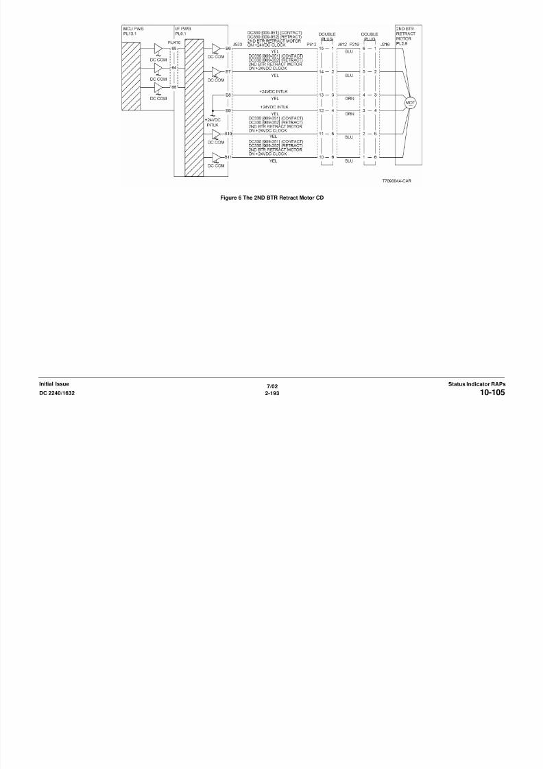
8/13/2019 Xerox Docu Color 2240-1632
http://slidepdf.com/reader/full/xerox-docu-color-2240-1632 223/1118
7/02
2-193DC 2240/1632 10-105Status Indicator RAPsInitial Issue
10-106 Face Up Exit Sensor OffThe Face Up Exit Sensor did not de-energize.
Initial Actions
• Check condition and specification of the paper supply.
• Check for obstructions in the paper feed path.
• Clean the Fuser Exit Roll and check for wear.
• Check the drive transmissions for damage or wear.
Procedure
Enter dC330 [010-103] and press Start. Block and unblock the Face Up Exit Sensor (PL 11.2).
The display changes state.
Y NGo to OF 99-2 and check the circuit of the Face Up Exit Sensor (Figure 1).
Check the wires and connectors. If the check is OK, replace the MCU PWB (PL 13.1).
Figure 1 The Face Up Exit Sensor CD
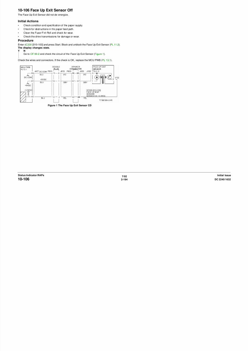
8/13/2019 Xerox Docu Color 2240-1632
http://slidepdf.com/reader/full/xerox-docu-color-2240-1632 224/1118
7/02
2-194 DC 2240/163210-106Initial IssueStatus Indicator RAPs
10-110 Fuser Exit Switch On (Face Down/duplex)The Fuser Exit Switch did not energize.
Initial Actions
• Check condition and specification of the paper supply.
• Check for obstructions in the paper feed path.
• Clean the Fuser Exit Roll and check for wear.
• Check the drive transmissions for damage or wear.
Procedure
Check the Fuser Stripper Fingers and Fuser Roll for dirt build up, wear or damage. The
check is OK.
Y N
Clean or replace the Fuser Assembly (PL 7.1).
Enter dC330 [010-101] and press Start. Actuate the Fuser Exit Switch (PL 2.8). The display
changes state.
Y N
Go to OF 99-3 and check the circuit of the .
Enter dC330 [008-045] and press Start. The Exit Gate Solenoid energizes (PL 11.2).
Y N
Go to OF 99-4 and check the circuit of the Exit Gate Solenoid (Figure 2).
Enter dC330 [008-037] and press Start. The Registration Clutch energizes (PL 2.6).
Y N
Go to OF 99-4 and check the circuit of the Registration Clutch (Figure 3).
In sequence enter the following: dC330 [009-051] then dC330 [009-052] and press Start. The
2nd BTR Retract Motor contacts and retracts (PL 2.9).
Y N
Go to 9-342 for a contact failure or go to 9-343 for a retract failure.
Check the wires and connectors. If the check is OK, replace the MCU PWB (PL 13.1).
Figure 1 Fuser Exit Switch CD
A
A

8/13/2019 Xerox Docu Color 2240-1632
http://slidepdf.com/reader/full/xerox-docu-color-2240-1632 225/1118
7/02
2-195DC 2240/1632 10-110Status Indicator RAPsInitial Issue
Figure 2 Exit Gate Solenoid CD
Figure 3 Registration Clutch CD
Figure 4 2ND BTR Retract Motor

8/13/2019 Xerox Docu Color 2240-1632
http://slidepdf.com/reader/full/xerox-docu-color-2240-1632 226/1118
7/02
2-196 DC 2240/163210-110Initial IssueStatus Indicator RAPs
10-111 Fuser Exit Switch Off (Face Down)The Fuser Exit Switch did not de-energize.
Initial Actions
• Check condition and specification of the paper supply.
• Check for obstructions in the paper feed path.
• Clean the Fuser Exit Roll and check for wear.
• Check the drive transmissions for damage or wear.
Procedure
Check the Fuser Stripper Fingers and Fuser Roll for dirt build up, wear or damage. The
check is OK.
Y N
Clean or replace the Fuser Assembly (PL 7.1).
Enter dC330 [010-101] and press Start. Actuate the Fuser Exit Switch (PL 2.8). The display
changes state.
Y N
Go to OF 99-3 and check the circuit of the Fuser Exit Switch (Figure 1).
Enter dC330 [008-045] and press Start. The Exit Gate Solenoid energizes (PL 11.2).
Y N
Go to OF 99-4 and check the circuit of the Exit Gate Solenoid (Figure 2).
The switch and solenoid are operating correctly. If the problem continues, check the wires and
connectors. If the check is OK, replace the MCU PWB (PL 13.1).
Figure 1 Fuser Exit Switch CD
A
A
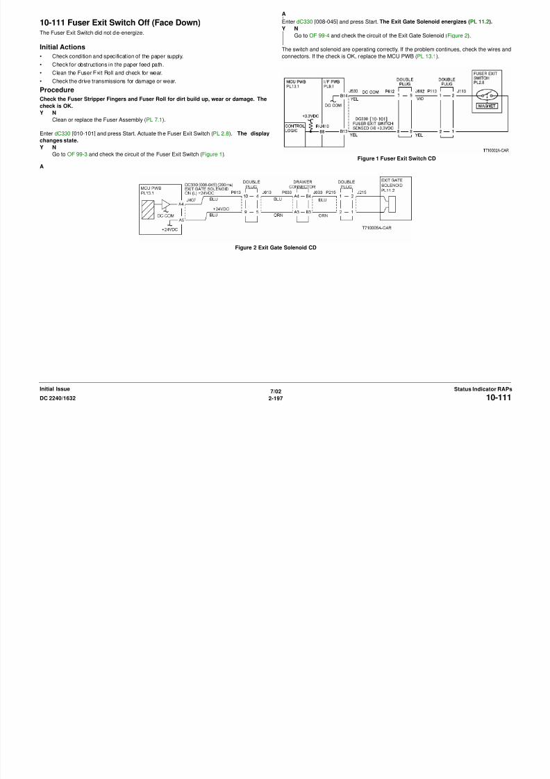
8/13/2019 Xerox Docu Color 2240-1632
http://slidepdf.com/reader/full/xerox-docu-color-2240-1632 227/1118
7/02
2-197DC 2240/1632 10-111Status Indicator RAPsInitial Issue
Figure 2 Exit Gate Solenoid CD
10-125 Duplex Wait Sensor OnThe Duplex Wait Sensor did not energize
Initial Actions
• Check condition and specification of paper in Tray 2.
• Check the paper path for obstructions.
• Check for wear and clean the Duplex Drive Rolls.
• Check the exit transmission gears for breakage and wear.
Procedure
Enter dC330 [008-105] and press Start. Block and unblock the Duplex Wait Sensor (PL 12.2).
The display changes state.
Y N
Go to OF 99-1 and check the circuit of the Duplex Wait Sensor (Figure 1).
Enter dC330 [008-009] and press Start. The Duplex Motor energizes (PL 12.2).
Y N
Go to OF 99-9 and check the circuit of the Duplex Motor between the Duplex PWB and
Duplex Motor (Figure 2).
Enter dC330 [008-046] and press Start. The Duplex Gate Solenoid energizes.
Y N
Go to OF 99-4 and check the circuit of the Duplex Gate Solenoid (Figure 3).
Enter dC330 [008-042] and press Start. The Inverter Forward Clutch (CW) Energizes.
Y N
Go to OF 99-4 and check the circuit of the Inverter Forward Clutch (Figure 4).
Enter dC330 [008-043] and press Start. The Inverter Reverse Clutch (CCW) Energizes.
Y N
Go to OF 99-4 and check the circuit of the Inverter Reverse Clutch (Figure 5).
The circuits are operating correctly, re-check the Drawer connector and the duplex mechanical
drives. If the problem continues, check the wires and connectors. If the check is OK, replace
the MCU PWB (PL 13.1).

8/13/2019 Xerox Docu Color 2240-1632
http://slidepdf.com/reader/full/xerox-docu-color-2240-1632 228/1118
7/02
2-198 DC 2240/163210-125Initial IssueStatus Indicator RAPs
Figure 1 Duplex Wait Sensor CD
Figure 2 Duplex Motor CD

8/13/2019 Xerox Docu Color 2240-1632
http://slidepdf.com/reader/full/xerox-docu-color-2240-1632 229/1118
7/02
2-199DC 2240/1632 10-125Status Indicator RAPsInitial Issue
Figure 3 Duplex Exit Gate SolenoidFigure 4 Inverter Forward Clutch CD
Figure 5 Inverter Reverse Clutch CD
10-348 Main Heater Over HeatThe Front Thermistor detected an overheat condition.
Procedure
NOTE: To clear this fault, re-set the value of dC131 [744-003] to "0".
Turn off the power, remove the Fuser Assembly. and allow i t to cool down.
Measure the resistance between P/J600-4 and P/J600-6 on the Fuser Assembly.
The resistance is between 30 and 190 K Ohm’s.
Y N
Check the Front Thermistor for an open circuit and poor contact. If the check is OK,
replace the Sensor Assembly (PL 7.2).
Reinstall the Fuser Assembly, turn the power ON. Enter dC140 [010-100] and press Start. Thedisplay value is between 678 and 699.
Y N
Turn the power off. Check for an open or poor connection between P/J404-12 and P/
J404-11on the MCU PWB (PL 13.1). If the check is OK, replace the MCU PWB (PL 13.1).
+3.4VDC measured at P/J404-5 on the MCU PWB.
Y N
Replace the MCU PWB (PL 13.1).
Check the wires and connectors. If the check is OK, replace the AC Drive PWB (PL 9.2).

8/13/2019 Xerox Docu Color 2240-1632
http://slidepdf.com/reader/full/xerox-docu-color-2240-1632 230/1118
7/02
2-200 DC 2240/163210-125, 10-348Initial IssueStatus Indicator RAPs
Figure 1 Fuser Front and Rear Thermistor CD
Figure 2 Fuser Main Heater and Sub Heater CD
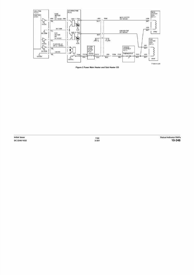
8/13/2019 Xerox Docu Color 2240-1632
http://slidepdf.com/reader/full/xerox-docu-color-2240-1632 231/1118
7/02
2-201DC 2240/1632 10-348Status Indicator RAPsInitial Issue
10-349 Front Thermistor OpenThe machine logic detected an open circuit in the Front Thermistor.
Procedure
Turn off the power, remove the Fuser Assembly, and allow it to cool down.
Measure the resistance between P/J600-4 and P/J600-6 on the Fuser Assembly. The resis-
tance is between 30 and 190 K Ohm’s.
Y N
Check the Front Thermistor for an open circuit and poor contact. If no problems are found,
replace the Sensor Assembly (PL 7.1).
Reinstall the Fuser Assembly, turn the power on, enter dC140 [010-101] and press Start. The
display value is between 900 and 1000.
Y NTurn the power off. Check for an open or poor connection between P/J404-12 on the
MCU PWB and P/J600-4 on the Fuser Assembly. If the check is OK, replace the MCU
PWB (PL 13.1).
Replace the MCU PWB (PL 13.1).

8/13/2019 Xerox Docu Color 2240-1632
http://slidepdf.com/reader/full/xerox-docu-color-2240-1632 232/1118
7/02
2-202 DC 2240/163210-349Initial IssueStatus Indicator RAPs
Figure 1 Fuser Front and Rear Thermistor CD
10-350 Sub Heater Over HeatThe Rear Thermistor detected an over heat condition.
Procedure
NOTE: To clear this fault, re-set the value of dC131 [744-003] to "0".
Turn off the power, remove the Fuser Assembly and allow it to cool down.
Measure the resistance between P/J600-7 and P/J600-9 on the Fuser Assembly.
The resistance is between 30 and 190 K Ohm’s.
Y N
Check the Rear Thermistor for an open circuit and poor contact. If the check is OK,
replace the Sensor Assembly (PL 7.2).
Reinstall the Fuser Assembly, turn the power ON. Enter dC140 [010-101] and press Start. Thedisplay value is between 676 and 699.
Y N
Turn the power off. Check for an open or poor connection between P/J404-14 and P/
J404-13 on the MCU PWB (PL 13.1). If the check is OK, replace the MCU PWB (PL 13.1).
+3.4VDC measured at P/J404-7 on the MCU PWB (PL 13.1).
Y N
Replace the MCU PWB (PL 13.1).
Check the wires and connectors. If the check is OK, replace the AC Drive PWB (PL 9.2).
Figure 1 Fuser Front and Rear Thermistor CD
A
A

8/13/2019 Xerox Docu Color 2240-1632
http://slidepdf.com/reader/full/xerox-docu-color-2240-1632 233/1118
7/02
2-203DC 2240/1632 10-350Status Indicator RAPsInitial Issue
Figure 2 Fuser Main Heater and Sub Heater CD
10-351 Rear Thermistor OpenThe machine logic detected an open circuit in the Rear Thermistor.
Procedure
Turn off the power, remove the Fuser Assembly and allow it to cool down.
Measure the resistance between P/J600-7 and P/J600-9 on the Fuser Assembly. The resis-
tance is between 30 and 190 K Ohm’s.
Y N
Check the Rear Thermistor for an open circuit and poor contact. If the check is OK,
replace the Sensor Assembly (PL 7.2).
Reinstall the Fuser Assembly, turn the power on, enter dC140 [010-101] and press Start. The
display is between 678 and 699.
Y NTurn the power off. Check for an open or poor connection between P/J404-13 on the
MCU PWB and P/J600-7on the Fuser Assembly. If the check is OK, replace the MCU
PWB (PL 13.1).
Replace the MCU PWB (PL 13.1).
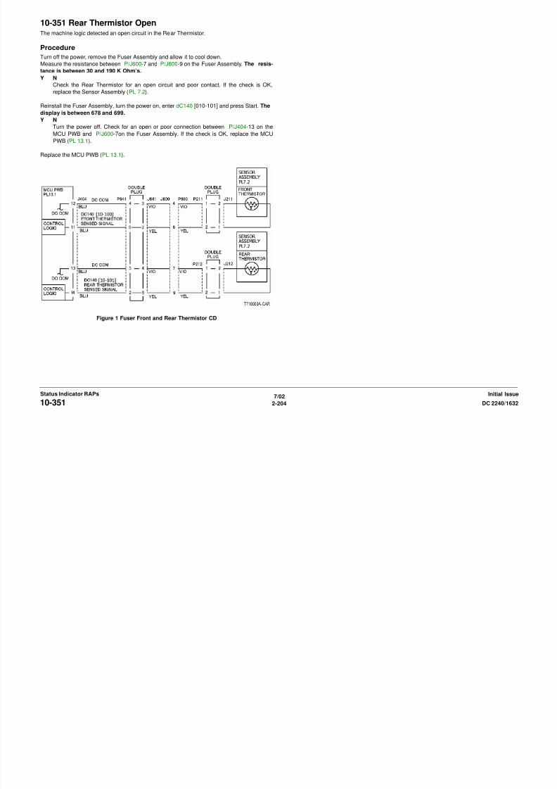
8/13/2019 Xerox Docu Color 2240-1632
http://slidepdf.com/reader/full/xerox-docu-color-2240-1632 234/1118
7/02
2-204 DC 2240/163210-351Initial IssueStatus Indicator RAPs
Figure 1 Fuser Front and Rear Thermistor CD
10-352 Main Heater Warm UpThe temperature did not reach the READY temperature within the specified time.
Procedure
Turn off the power, remove the Fuser Assembly. and allow it to cool down.
Measure the resistance between P/J600-4 and P/J600-6 on the Fuser Assembly.
The resistance is between 30 and 190 K Ohm’s.
Y N
Check the Front Thermistor for an open circuit and poor contact. If the check is OK,
replace the Sensor Assembly (PL 7.2).
Measure the resistance between P/J600-3 and P/J600-12 on the Fuser Assembly. The
resistance is 20 Ohm’s or less.
Y NReplace the Fuser Assembly (PL 7.1).
Reinstall the Fuser Assembly, turn the power on, enter dC140 [010-100] and press Start. The
display is between 678 and 699.
Y N
Turn the power off. Check for an open or poor connection between P/J404-12 on the
MCU PWB and P/J600-6 on the Fuser Assembly. If the check is OK, replace the MCU
PWB (PL 13.1).
AC Line Voltage measured at FS41 on the AC Drive PWB (PL 9.2).
Y N
+5VDC measured at P/J590-5 on the AC Drive PWB (PL 9.2).
Y N
Check the wires and connectors. If the check is OK, replace the MCU PWB (PL
13.1).
+24VDC measured at P/J590-1 on the AC Drive PWB (PL 9.2).
Y N
Check the wires and connectors If the check is OK replace the MCU PWB (PL
Figure 1 Fuser Front and Rear Thermistor CD

8/13/2019 Xerox Docu Color 2240-1632
http://slidepdf.com/reader/full/xerox-docu-color-2240-1632 235/1118
7/02
2-205DC 2240/1632 10-352Status Indicator RAPsInitial Issue
Check the wires and connectors. If the check is OK, replace the MCU PWB (PL
13.1).
Replace the AC Drive PWB (PL 9.2).
Check the wires and connectors. If the check is OK, replace the Fuser Assembly (PL 7.1).
Figure 2 Fuser Main Heater and Sub Heater CD

8/13/2019 Xerox Docu Color 2240-1632
http://slidepdf.com/reader/full/xerox-docu-color-2240-1632 236/1118
7/02
2-206 DC 2240/163210-352Initial IssueStatus Indicator RAPs
10-353 Main Heater On TimeThe Main Heater remained on for more than the specified time.
Procedure
Turn off the power, remove the Fuser Assembly. and allow it to cool down.
Measure the resistance between P/J600-4 and P/J600-6 on the Fuser Assembly.
The resistance is between 30 and 190 K Ohm’s.
Y N
Check the Front Thermistor for an open circuit and poor contact. If the check is OK,
replace the Sensor Assembly (PL 7.2).
Measure the resistance between P/J600-3 and P/J60012 on the Fuser Assembly. The resis-
tance is 20 Ohm’s or less.
Y NReplace the Fuser Assembly (PL 7.2).
Reinstall the Fuser Assembly, turn the power on, enter dC140 [010-100]. The display is
between 676 and 699.
Y N
Turn the power off. Check for an open or poor connection between P/J404-12 on the
MCU PWB and P/J600-6 on the Fuser Assembly. If the check is OK, replace the MCU
PWB (PL 13.1).
AC Line Voltage measured at FS41 on the AC Drive PWB (PL 9.2).
Y N+5VDC measured at P/J590-5 on the AC Drive PWB (PL 9.2).
Y N
Check the wires and connectors. If the check is OK, replace the MCU PWB (PL
13.1).
+24VDC measured at P/J590-1 on the AC Drive PWB PL 9.2.
Y N
Check the wires and connectors. If the check is OK, replace the MCU PWB (PL
Figure 1 Fuser Front and Rear Thermistor CD
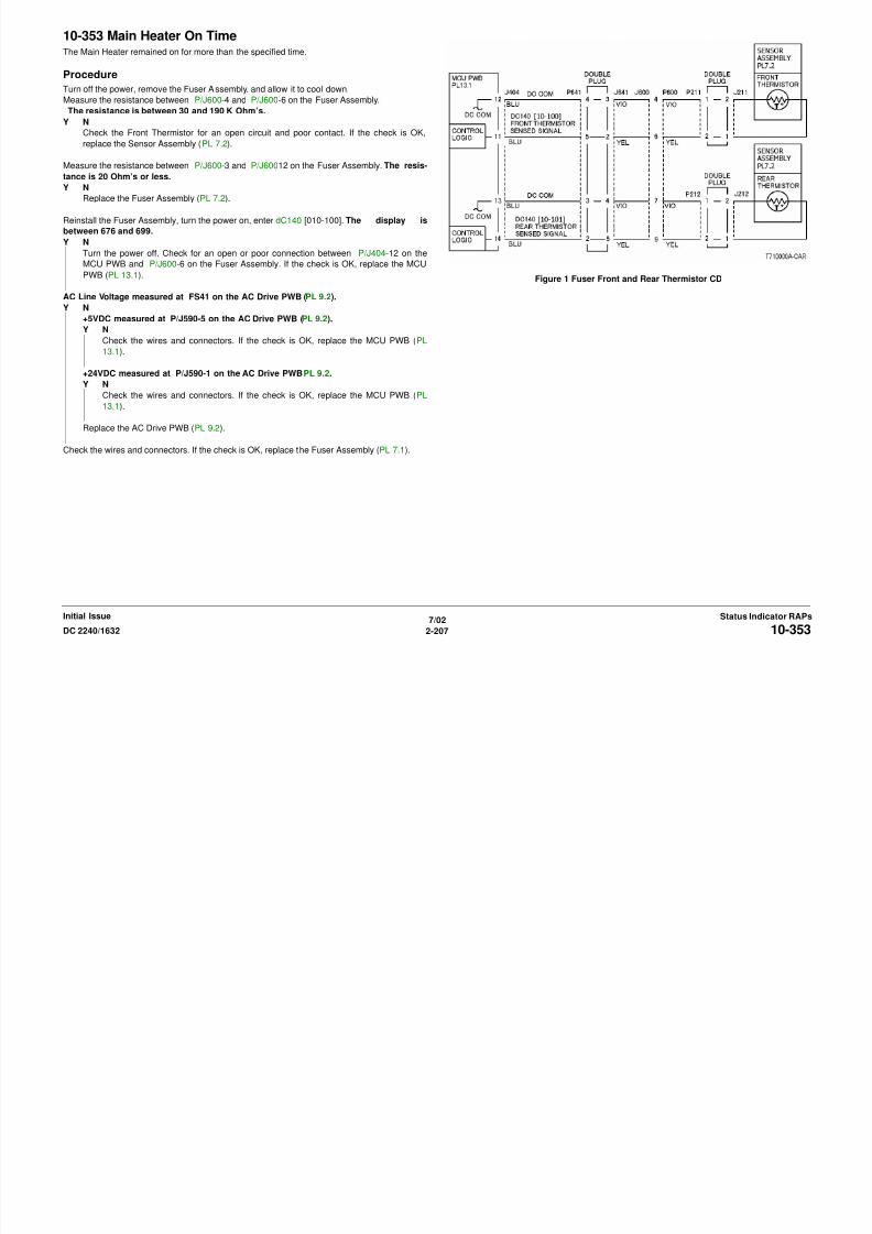
8/13/2019 Xerox Docu Color 2240-1632
http://slidepdf.com/reader/full/xerox-docu-color-2240-1632 237/1118
7/02
2-207DC 2240/1632 10-353Status Indicator RAPsInitial Issue
Check the wires and connectors. If the check is OK, replace the MCU PWB (PL
13.1).
Replace the AC Drive PWB (PL 9.2).
Check the wires and connectors. If the check is OK, replace the Fuser Assembly (PL 7.1).
Figure 2 Fuser Main Heater and Sub Heater CD

8/13/2019 Xerox Docu Color 2240-1632
http://slidepdf.com/reader/full/xerox-docu-color-2240-1632 238/1118
7/02
2-208 DC 2240/163210-353Initial IssueStatus Indicator RAPs
10-354 Sub Heater Warm UpThe temperature did not reach the READY temperature.
Procedure
NOTE: To clear this fault, re-set the value of dC131-744-003 to "0".
Turn off the power, remove the Fuser Assembly. and allow it to cool down. Measure the resis-
tance between P/J600-4 and P/J600-6 on the Fuser Assembly. The resistance is between
30 and 190 K Ohm’s.
Y N
Check the Front Thermistor for an open circuit and poor contact. If the check is OK,
replace the Sensor Assembly (PL 7.2).
Reinstall the Fuser Assembly, turn the power ON. Enter dC140 [010-100]. The display valueis between 678 and 699.
Y N
Turn the power off. Check for an open or poor connection between P/J404-12 and P/
J404-11on the MCU PWB (PL 13.1). If the check is OK, replace the MCU PWB (PL 13.1).
+3.4VDC measured at P/J404-5 on the MCU PWB.
Y N
Replace the MCU PWB (PL 13.1).
Check the wires and connectors. If the check is OK, replace the AC Drive PWB (PL 9.2).
Figure 1 Fuser Front and Rear Thermistor CD
A
A
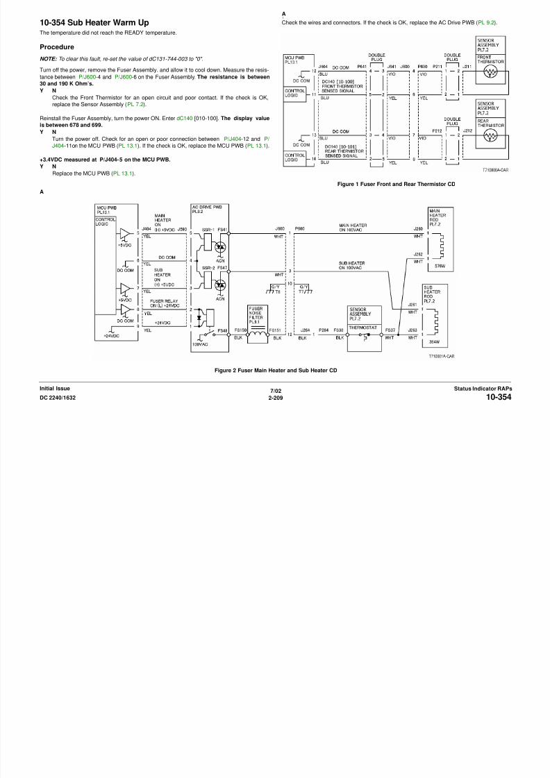
8/13/2019 Xerox Docu Color 2240-1632
http://slidepdf.com/reader/full/xerox-docu-color-2240-1632 239/1118
7/02
2-209DC 2240/1632 10-354Status Indicator RAPsInitial Issue
Figure 2 Fuser Main Heater and Sub Heater CD
10-356 Sub Heater On TimeThe Sub Heater remained on for more than the specified time.
Procedure
Turn off the power, remove the Fuser Assembly. and allow it to cool down.
Measure the resistance between P/J600-7 and P/J600-9 on the Fuser Assembly. The resis-
tance is between 30 and 190 K Ohm’s.
Y N
Check the Rear Thermistor for an open circuit and poor contact. If the check is OK,
replace the Sensor Assembly (PL 7.2).
Measure the resistance between P/J600-3 and P/J600-12 on the Fuser Assembly. The
resistance is 20 Ohm’s or less.
Y NReplace the Fuser Assembly (PL 7.1).
Reinstall the Fuser Assembly, turn the power on, enter dC140 [010-101]. The display is
between 678 and 699.
Y N
Turn the power off. Check for an open or poor connection between P/J404-13 on the
MCU PWB and P/J600-7 on the Fuser Assembly. If the check is OK, replace the MCU
PWB (PL 13.1).
AC Line Voltage measured at FS47 on the AC Drive PWB (PL 9.2).
Y N+5VDC measured at P/J590-3 on the AC Drive PWB (PL 9.2).
Y N
Check the wires and connectors. If the check is OK, replace the MCU PWB (PL
13.1).
+24VDC measured at P/J590-1 on the AC Drive PWB (PL 9.2)
Y N
Check the wires and connectors. If the check is OK, replace the MCU PWB (PL
13 1)
Figure 1 Fuser Front and Rear Thermistor CD

8/13/2019 Xerox Docu Color 2240-1632
http://slidepdf.com/reader/full/xerox-docu-color-2240-1632 240/1118
7/02
2-210 DC 2240/163210-356Initial IssueStatus Indicator RAPs
13.1).
Replace the AC Drive PWB (PL 9.2).
Check the wires and connectors. If the check is OK, replace the Fuser Assembly (PL 7.1).
Figure 2 Fuser Main Heater and Sub Heater CD

8/13/2019 Xerox Docu Color 2240-1632
http://slidepdf.com/reader/full/xerox-docu-color-2240-1632 241/1118
7/02
2-211DC 2240/1632 10-356Status Indicator RAPsInitial Issue
10-398 Fan LockThe machine logic detected a failure of the Fuser Fan, LVPS Fan or the Rear Fan.
ProcedureEnter dC330 [004-050]. The Fuser Fan (PL 8.1) revolves at high speed.
Y N
+24VDC measured at P/J222-4.
Y N
Check the wires and connectors. If the check is OK, replace the MCU PWB (PL
13.1).
With dC330 [004-050] entered, stack dC330 [004-200] and press Start. The display is H.
Y N
Check the wires and connectors. If the check is OK, replace the MCU PWB (PL13.1).
Replace the Fuser Fan (PL 8.1).
The Rear Fan revolves at high speed (PL 8.1).
Y N
+24VDC measured at P/J552-1.
Y N
Check the wires and connectors. If the check is OK, replace the MCU PWB (PL
13.1). If the problem continues replace the I/F PWB (PL 9.1).
With dC330 [004-050] entered, stack dC330 [004-200] and press Start. The display is H.
Y N
Check the wires and connectors. If the check is OK, replace the MCU PWB (PL
13.1).
Replace the Rear Fan (PL 8.1).
The LVPS Fan revolves at high speed (PL 9.1).
Y N
Figure 1 The Fuser Fan CD
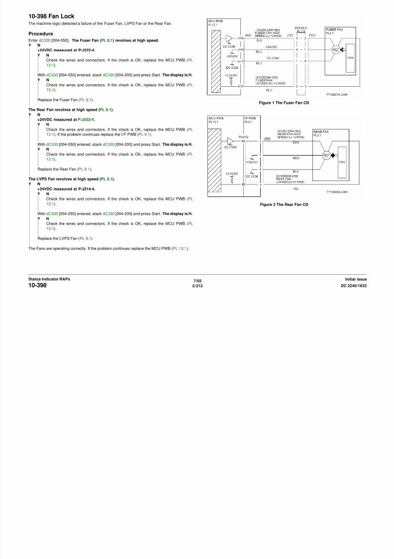
8/13/2019 Xerox Docu Color 2240-1632
http://slidepdf.com/reader/full/xerox-docu-color-2240-1632 242/1118
7/02
2-212 DC 2240/163210-398Initial IssueStatus Indicator RAPs
Y N
+24VDC measured at P/J214-4.
Y N
Check the wires and connectors. If the check is OK, replace the MCU PWB (PL
13.1).
With dC330 [004-050] entered, stack dC330 [004-200] and press Start. The display is H.
Y N
Check the wires and connectors. If the check is OK, replace the MCU PWB (PL
13.1).
Replace the LVPS Fan (PL 9.1).
The Fans are operating correctly. If the problem continues replace the MCU PWB (PL 13.1).
Figure 2 The Rear Fan CD
Figure 3 The LPVS Fan CD
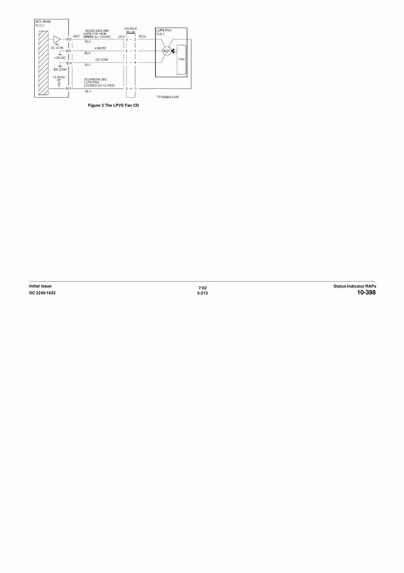
8/13/2019 Xerox Docu Color 2240-1632
http://slidepdf.com/reader/full/xerox-docu-color-2240-1632 243/1118
7/02
2-213DC 2240/1632 10-398Status Indicator RAPsInitial Issue
10-420 Fuser Near End Of LifeReplace the Fuser Assembly in X copies.
ProcedureThe Fuser Assembly was replaced.
Y N
Replace the Fuser Assembly (PL 7.2)
Run the dC135 [954-804]. The initial value is 0.
Y N
Replace the MCU PWB (PL 13.1).
Ensure that the LIFE setting value is 100K, switch power off then on.
If the problem continues, replace the MCU PWB (PL 13.1).

8/13/2019 Xerox Docu Color 2240-1632
http://slidepdf.com/reader/full/xerox-docu-color-2240-1632 244/1118
7/02
2-214 DC 2240/163210-420Initial IssueStatus Indicator RAPs
10-421 Fuser End Of LifeFuser at end of life.
ProcedureThe Fuser Assembly was replaced.
Y N
Replace the Fuser Assembly (PL 7.2).
Run the dC135 [954-804]. The initial value is 0.
Y N
Replace the MCU PWB (PL 13.1).
Ensure that the LIFE setting value is 100K, switch power off then on.
If the problem continues, replace the MCU PWB (PL 13.1).
8/13/2019 Xerox Docu Color 2240-1632
http://slidepdf.com/reader/full/xerox-docu-color-2240-1632 245/1118
7/02
2-215DC 2240/1632 10-421Status Indicator RAPsInitial Issue

8/13/2019 Xerox Docu Color 2240-1632
http://slidepdf.com/reader/full/xerox-docu-color-2240-1632 246/1118
7/02
2-216 DC 2240/163210-421Initial IssueStatus Indicator RAPs
12-100 H Transport Entrance Sensor OnThe H Transport Entrance Sensor does not detect paper after the Registration Clutch (in IOT)
energized.
Procedure
Enter dC330 [012-001] and press Start. The Finisher Drive Motor energizes.
Y N
Press Stop. Check the drives as required for mechanical problems (PL 17.7). If the
drives are mechanically good, perform following check of the Finisher Drive Motor (Figure
4). +5 VDC is measured between P/J846-3 on the Finisher PWB and ground.
Y N
Check the wire between P/J846-3 on the Finisher PWB and P/J879-1 on the Fin-
isher Drive Motor PWB.
If the wire is good, replace the Finisher Drive Motor (PL 17.7).
Press Start and check the voltage between P/J846-3 on the Finisher PWB and ground.
Less than +1 VDC is measured.
Y N
Replace the Finisher PWB (PL 17.3).
Check the voltage between P/J846-7 and -5 on the Finisher PWB and ground. +24
VDC is measured.
Y N
Replace the Finisher PWB (PL 17.3).
Check the resistance between P/J846-11 and -9 on the Finisher PWB and ground. Less
than 10 ohms is measured.
Y N
Replace the Finisher PWB (PL 17.3).
Replace the Finisher Drive Motor (PL 17.3).
Enter dC330 [012-103] and press Start. Actuate the H Transport Entrance Sensor. The dis-
play changes.
Y N
Figure 1 Component Location
Figure 2 H Transport Entrance Sensor CD
EntranceSensor
Gate InSolenoid

8/13/2019 Xerox Docu Color 2240-1632
http://slidepdf.com/reader/full/xerox-docu-color-2240-1632 247/1118
7/02
2-217DC 2240/1632 12-100Status Indicator RAPsInitial Issue
Y N
Check the sensor components as required for mechanical problems (PL 17.4). If thesensor is mechanically good, go to OF 99-2 and check the circuit of the H Transport
Entrance Sensor (Figure 2).
Enter dC330 [012-060 or 061] and press Start. The gate changes position.
Y N
Check the gate components as required for mechanical problems (PL 17.4). If the gate
linkage is mechanically good, check the wires of the Gate In Solenoid for obvious damage
(Figure 3).
If the wires are good, replace the Gate in Solenoid (PL 17.4).
Check the following:
• Paper path for burr, blockage, or contamination.
• H-Transport Belt for contamination, wear and a drive failure (PL 17.4).
• Sensor Actuator for breakage (PL 17.4).Figure 3 Gate In Solenoid CD
Figure 4 Finisher Drive Motor CD

8/13/2019 Xerox Docu Color 2240-1632
http://slidepdf.com/reader/full/xerox-docu-color-2240-1632 248/1118
7/02
2-218 DC 2240/163212-100Initial IssueStatus Indicator RAPs
Figure 5 Finisher PWB
12-102 H Transport Entrance Sensor OffPaper did not deactuate the H Transport Entrance Sensor.
ProcedureOpen the H Transport. Check H Transport Belts, H Transport Belt Drive Rolls, and Guides on
H Transport Cover for installation or damage problems (PL 17.3, PL 17.4). The components
are good.
Y N
Repair as required (PL 17.3, PL 17.4).
Rerun the job. The problem continues.
Y N
Return to Service Call Procedures.
Replace the H Transport Entrance Sensor for intermittent operation (PL 17.4).
NOTE: If the sensor fails H, 12-901 is declared after power is switched on.
Figure 1 Component Location
EntranceSensor

8/13/2019 Xerox Docu Color 2240-1632
http://slidepdf.com/reader/full/xerox-docu-color-2240-1632 249/1118
7/02
2-219DC 2240/1632 12-102Status Indicator RAPsInitial Issue
Figure 1 Component Location
12-104 H Transport Exit Sensor OnThe H Transport Exit Sensor did not detect paper within the specific time after the H Transport
Entrance Sensor has detected the paper. (The specified time differs depending on the paper
size.)
Procedure
Enter dC330 [012-104] and press Start. Actuate the H Transport Exit Sensor (PL 17.4). The
display changes.
Y N
Check the sensor components as required for mechanical problems (PL 17.4). If the
sensor is mechanically good, go to OF 99-2 and check the circuit of the H Transport Exit
Sensor (Figure 2).
Check H Transport Belts, H Transport Belt Drive Rolls, and Guides on H Transport Cover forinstallation or damage problems. Repair as required (PL 17.3, PL 17.4).
Figure 1 Component Location
Figure 3 Finisher PWBEntranceSensor
ExitSensor
InterlockSensor

8/13/2019 Xerox Docu Color 2240-1632
http://slidepdf.com/reader/full/xerox-docu-color-2240-1632 250/1118
7/02
2-220 DC 2240/163212-104Initial IssueStatus Indicator RAPs
Figure 2 H Transport Exit Sensor CD
12-106 H Transport Exit Sensor OffPaper did not deactuate the H Transport Exit Sensor.
ProcedureEnter dC330 [012-217] and press Start. Actuate the Decurler Cam Home Sensor ( PL 17.7).
The display changes.
Y N
Check the sensor components as required for mechanical problems (PL 17.8). If the
components are mechanically good, go to OF 99-2 and check the circuit of the Decurler
Cam Home Sensor (Figure 2).
Enter dC330 [012-070] and press Start. The Decurler Cam Clutch (PL 17.7) energizes.
Y N
Check the clutch components for mechanical problems. If the components are good, goto OF 99-4 and check the circuit of the Decurler Cam Clutch (Figure 3).
Check the following:
• Paper path for burr and foreign substance (PL 17.3, PL 17.4, PL 17.6, PL 17.7).
• H Transport Belt Drive Roll for contamination, wear and a drive failure (PL 17.4).
• Drive Transmission Gear from the Finisher Drive Motor for wear and breakage (PL 17.7).
• H Transport and Finisher for a docking failure (PL 17.1).
• Decurler Roll/pinch Roll for a drive failure (PL 17.7).
• Compiler Entrance Roll for a drive failure (PL 17.10, PL 17.12).
Figure 2 Decurler Cam Home Sensor CD
Figure 3 Decurler Cam Clutch CDDecurlerClutch
DecurlerCamHome
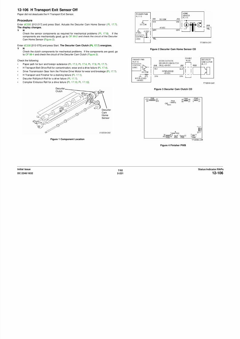
8/13/2019 Xerox Docu Color 2240-1632
http://slidepdf.com/reader/full/xerox-docu-color-2240-1632 251/1118
7/02
2-221DC 2240/1632 12-106Status Indicator RAPsInitial Issue
Figure 1 Component Location
Figure 4 Finisher PWB
HomeSensor
12-120 Compiler Entrance Sensor OnThe Compiler Entrance Sensor did not detect paper.
ProcedureEnter dC330 [012-101] and press Start. Actuate the Complier Entrance Sensor (PL 17.12).
The display changes.
Y N
Check the sensor components for mechanical problems. If the components are good, go
to OF 99-2 and check the circuit of the Complier Entrance Sensor (Figure 2).
Check the following:
• Complier Entrance Sensor Actuator for breakage and bending (PL 17.12).
• Paper path failure for burr and foreign substance.
• Decurler Roll/pinch Roll for a drive failure (PL 17.7).
• Drive Transmission Gear from the Finisher Drive Motor for wear and breakage (PL 17.7).
Figure 1 Component Location
Figure 3 Finisher PWB
CompilerEntranceSensor
HomeSensor
ecurer u c

8/13/2019 Xerox Docu Color 2240-1632
http://slidepdf.com/reader/full/xerox-docu-color-2240-1632 252/1118
7/02
2-222 DC 2240/163212-120Initial IssueStatus Indicator RAPs
Figure 2 Compiler Entrance Sensor CD
12-122 Compiler Entrance Sensor OffPaper does not deactuate the Compiler Entrance Sensor.
ProcedureMake a copy and observe paper in the Compiler Tray. The copy enters the Compiler Tray.
Y N
There is a drives problem. Check the following:
• The paper path failure for burr and foreign substance.
• The Drive Transmission Gear from the Finisher Drive Motor for wear and breakage
(PL 17.7).
• The Decurler Roll/pinch Roll for a drive failure (PL 17.7).
• The Compiler Entrance Roll for a drive failure (PL 17.10, PL 17.12).
Check the sensor components as required for mechanical problems (PL 17.4). If the sensor is
mechanically good, replace the Compiler Entrance Sensor (PL 17.4).
Figure 1 Component Location
CompilerEntranceSensor
HomeSensor
ecurer u c

8/13/2019 Xerox Docu Color 2240-1632
http://slidepdf.com/reader/full/xerox-docu-color-2240-1632 253/1118
7/02
2-223DC 2240/1632 12-122Status Indicator RAPsInitial Issue
12-170 Set EjectThe Compiler Paper Sensor did not deactuate after the Eject Motor energized.
ProcedureEnter dC330 [012-102] and press Start. Actuate the Compiler Paper Sensor. The display
changes.
Y N
Check the sensor components as required for mechanical problems (PL 17.10). If the
sensor is mechanically good, go to OF 99-2 and check the circuit of the Compiler Paper
Sensor(PL 17.10).
Check the following:
• Eject Roll for contamination, wear and a drive failure (PL 17.6).
• Drive Transmission Gear from the Eject Motor for wear and breakage (PL 17.8).• Eject Clamp for an up and down movement failure (PL 17.8).
• Stacker Tray for foreign substance (PL 17.1).
Figure 1 Component Location
Figure 3 Finisher PWB
CompilerPaperSensor

8/13/2019 Xerox Docu Color 2240-1632
http://slidepdf.com/reader/full/xerox-docu-color-2240-1632 254/1118
7/02
2-224 DC 2240/163212-170Initial IssueStatus Indicator RAPs
Figure 2 Compiler Paper Sensor CD
12-241 Staple Move Sensor On• The Staple Move Sensor did not turn on after the Stapler moved to the Staple Position.
• The Staple Move Sensor did not turn actuate after the Stapler is in position.
Procedure
Manually move the Stapler toward rear and front. The Stapler moves smoothly.
Y N
Repair as required (PL 17.9).
Cheat the Front Cover Interlock Switch. Enter dC330 [012-224] and press Start. Actuate the
Staple Move Sensor. The display changes.
Y N
Check the sensor components for mechanical problems. If the components are good, go
to OF 99-2 and check the circuit of the Staple Move Sensor (Figure 2).
Enter dC330 [012-081] (front) or [12-083] (rear) and press Start. The Staple Move Motor
energized.
Y N
Connect black meter lead to ground. Measure voltage at each pin of P/J847. +24 VDC
is measured at each pin.
Y N
Disconnect P/J847. Measure voltage at P847-3 and -4. +24 VDC is measured.
Y N
Switch machine off then on. Measure voltage at P847-3 and -4. +24 VDC is
measured.
Y NReplace the Finisher PWB (PL 17.13).
Check the motor wires for a short circuit. If the wires are good, replace the Sta-
ple Move Motor (PL 17.9).
Check the motor wires for obvious damage. If the wires are good, replace the Staple
Move Motor (PL 17.9).
Replace the Finisher PWB (PL 17.13).
Figure 1 Component Location
Figure 2 Stapler Move Sensor CD
Staple Move Sensor
Staple FrontCorner Sensor

8/13/2019 Xerox Docu Color 2240-1632
http://slidepdf.com/reader/full/xerox-docu-color-2240-1632 255/1118
7/02
2-225DC 2240/1632 12-241Status Indicator RAPsInitial Issue
Replace the Finisher PWB (PL 17.13).
Figure 3 Staple Move Motor CD
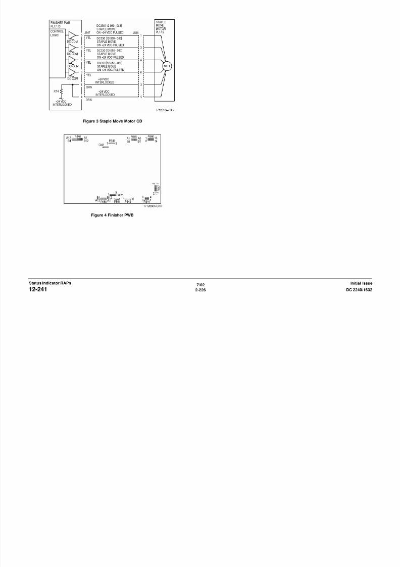
8/13/2019 Xerox Docu Color 2240-1632
http://slidepdf.com/reader/full/xerox-docu-color-2240-1632 256/1118
7/02
2-226 DC 2240/163212-241Initial IssueStatus Indicator RAPs
Figure 4 Finisher PWB
12-242 Staple Move Sensor Off• The Staple Move Sensor did not turn off after the move to the Staple Position started.
• The Staple Move Sensor turned off after Staple Position has been fixed.
• The Staple Move Sensor did not turn off after it turned on when paper passed through the1st position of the Dual Staple when moving to the Rear Staple Position.
Procedure
Open the Finisher Front Cover. Turn the Stapler Assembly manually.
Y N
Remove the cause of Staple Head not moving, such as rail breakage, drag, and gnawed
gear.
Cheat the Front Cover Interlock Switch. Enter dC330 [12-224] and press Start. Actuate the
Staple Move Sensor. The display changes.
Y NCheck the sensor components for mechanical problems. If the components are good, go
to OF 99-2 and check the circuit of the Staple Move Sensor (Figure 2).
Enter dC330 [012-081] (front) or [12-083] (rear) and press Start. The Staple Move Motor
energized.
Y N
Connect black meter lead to ground. Measure voltage at each pin of P/J847. +24 VDC
is measured at each pin.
Y N
Disconnect P/J847. Measure voltage at P847-3 and -4. +24 VDC is measured.
Y N
Switch machine off then on. Measure voltage at P847-3 and -4. +24 VDC is
measured.
Y N
Replace the Finisher PWB (PL 17.13).
Check the motor wires for a short circuit. If the wires are good, replace the Sta-
ple Move Motor (PL 17.9).
Check the motor wires for obvious damage. If the wires are good, replace the Staple
Move Motor (PL 17 9)
Figure 1 Component Location
Figure 2 Stapler Move Sensor CD
Staple Move Sensor
Staple FrontCorner Sensor

8/13/2019 Xerox Docu Color 2240-1632
http://slidepdf.com/reader/full/xerox-docu-color-2240-1632 257/1118
7/02
2-227DC 2240/1632 12-242Status Indicator RAPsInitial Issue
Move Motor (PL 17.9).
Replace the Finisher PWB (PL 17.13).
Replace the Finisher PWB (PL 17.13)
Figure 3 Staple Move Motor CD

8/13/2019 Xerox Docu Color 2240-1632
http://slidepdf.com/reader/full/xerox-docu-color-2240-1632 258/1118
7/02
2-228 DC 2240/163212-242Initial IssueStatus Indicator RAPs
Figure 4 Finisher PWB
12-244 Staple Home SensorThe Staple Head Home Sensor did not actuate after the Stapler Motor energized to open the
Stapler.
Procedure
Enter dC330 [012-207] and press Start. Turn the Staple Motor Gear manually to actuate the
Staple Head Home Sensor. The display changes.
Y N
+5 VDC is measured at Stapler Assembly between P/J886-5 and P/J886-1.
Y N
+5 VDC is measured at the Finisher PWB between P/J852-1 and P/J852-5.
Y N
Replace the Finisher PWB (PL 17.13).
Check the wire between the Finisher PWB P/J852 and the Stapler Assembly P/
J886 for an open circuit or poor contact.
Turn the Staple Motor Gear manually to deactuate and actuate the Staple Head Home
Sensor. The voltage changes between the Stapler P/J886-4 and Finisher Frame.
Y N
Switch off the power. Disconnect P/J852 on the Finisher PWB. Switch the power
on. +5 VDC is measured at the Finisher PWB P852-2.
Y N
Replace the Finisher PWB (PL 17.13).
Check the wires between the Finisher P/J852 and the Stapler Assembly P/J886 for
obvious damage (Figure 2).
If the wires are good, replace the Stapler Assembly (PL 17.9).
Replace the Finisher PWB (PL 17.13).
Position paper in stapler. Enter dC330 [012-020] and press Start. The Staple Motor ener-
gizes.
Y N
With [12-020] running, +24 VDC is measured at the Finisher PWB P/J847-7.
Y N
Figure 1 Component Location
Figure 2 Staple Head Home Sensor
Staple Move Sensor
Staple FrontCorner Sensor

8/13/2019 Xerox Docu Color 2240-1632
http://slidepdf.com/reader/full/xerox-docu-color-2240-1632 259/1118
7/02
2-229DC 2240/1632 12-244Status Indicator RAPsInitial Issue
Replace the Finisher PWB (PL 17.13).
Check resistance of the following:
• Between the Finisher PWB P/J847-7 and Stapler Assembly P/J887-1
• Between the Finisher PWB P/J847-8 and Stapler Assembly P/J887-2
• Between the Finisher PWB P/J847 -9 and Stapler Assembly P/J887-3
• Between the Finisher PWB P/J847-10 and Stapler Assembly P/J887-4
If no problems are found, replace the Stapler Assembly (PL 17.9).
If the problem continues, replace the Finisher PWB (PL 17.13).
Replace the Finisher PWB (PL 17.13). Figure 3 Stapler Assembly Logic Power CD
Figure 4 Finisher PWB

8/13/2019 Xerox Docu Color 2240-1632
http://slidepdf.com/reader/full/xerox-docu-color-2240-1632 260/1118
7/02
2-230 DC 2240/163212-244Initial IssueStatus Indicator RAPs
12-252 Front Tamper• With the Front Tamper Home Sensor off the Front Tamper Home Sensor did not turn on
after move to the Front Tamper Home position began.
• With the Front Tamper Home Sensor on, the Front Tamper Sensor did not turn off whenthe Front Tamper Home Sensor deactuates.
Procedure
Enter dC330 [012-091] (front) or [12-094] (rear) and press Start. The Front Tamper Guide
moves.
Y N
The Front Tamper Motor energized.
Y N
+24 VDC is measured between J848-B7 or B9 or B10 or B12 on the Finisher
PWB and ground.
Y N+24 VDC is measured between J848-B8 or B11 on the Finisher PWB and
ground.
Y N
Replace the Finisher PWB (PL 17.13).
Check the wire between the Finisher PWB J848 and the Front Tamper Motor
J877 for a short circuit, open circuit, or poor contact.
If the wires and connections are good, replace the Front Tamper Motor (PL
17.10).
Replace the Finisher PWB (PL 17.13).
Check the tamper mechanism for load or drive transmission failure (gear wear or break-
age.).
Enter dC330 [012-216] and press Start.
Move the Front Tamper manually and turn the Front Tamper Home Sensor on/off. The display
changes.
Y N
Check the Front Tamper Home Sensor using the Generic Transmissive Sensor RAP.
Replace the Finisher PWB (PL 17.13).
Figure 1 Component Location
Figure 2 Front Tamper Home Sensor CD
Rear TamperHome Sensor
FrontTamperHome
Sensor
Front Tamper MotorConnection
Rear Tamper MotorConnection
CompilerPaperSensor

8/13/2019 Xerox Docu Color 2240-1632
http://slidepdf.com/reader/full/xerox-docu-color-2240-1632 261/1118
7/02
2-231DC 2240/1632
Status Indicator RAPsInitial Issue
p ( )
Figure 3 Front Tamper Motor CD

8/13/2019 Xerox Docu Color 2240-1632
http://slidepdf.com/reader/full/xerox-docu-color-2240-1632 262/1118
7/02
2-232 DC 2240/1632
Initial IssueStatus Indicator RAPs
Figure 4 Finisher PWB
12-253 Rear Tamper• With the Rear Tamper Home Sensor off The Rear Tamper Home Sensor did not turn on
within 800ms after move to the Rear Tamper Home position has begun.
• With the Rear Tamper Home Sensor on: The Rear Tamper Home Sensor did not turn offwhen the Rear Tamper Home Sensor is deactuating.
Procedure
Enter dC330 [012-010] (front) or [12-013] (rear) and press Start. The Rear Tamper Guide
energizes.
Y N
The Rear Tamper Motor energizes.
Y N
+24 VDC is measured between J848-B1 or B3 or B4 or B6 on the Finisher PWB
and ground.
Y N+24 VDC is measured between J848-B2 or B5 on the Finisher PWB and
ground.
Y N
Replace the Finisher PWB (PL 17.13).
Check the wire between the Finisher PWB J848 and the Rear Tamper Motor
J878A for a short circuit, open circuit, or poor contact.
If the wires and connections are good, replace the Front Tamper Motor (PL
17.10).
Replace the Finisher PWB (PL 17.13).
Check the tamper mechanism for load or drive transmission failure (gear wear or break-
age).
Enter dC330 [012-212] and press Start. Move the Rear Tamper manually to actuate the Rear
Tamper Home Sensor. The display changes.
Y N
Check the sensor components for mechanical problems. If the components are good, go
to OF 99-2 and check the circuit of the Rear Tamper Home Sensor (Figure 2).
Replace the Finisher PWB (PL 17.13).
Figure 1 Component Location
Figure 2 Rear Tamper Home Sensor CD
Rear TamperHome Sensor
FrontTamperHome
Sensor
Front Tamper MotorConnection
Rear Tamper MotorConnection
CompilerPaperSensor

8/13/2019 Xerox Docu Color 2240-1632
http://slidepdf.com/reader/full/xerox-docu-color-2240-1632 263/1118
7/02
2-233DC 2240/1632 12-253Status Indicator RAPsInitial Issue
Figure 3 Rear Tamper Motor CD
8/13/2019 Xerox Docu Color 2240-1632
http://slidepdf.com/reader/full/xerox-docu-color-2240-1632 264/1118
12-254 Stacker Tray• The Stack Height Sensor did not detect that the tray went down after the Stacker Tray
lowered at initialization.
• The Stack Height Sensor did not detect that the tray went up after the Stacker Motor wasenergized.
Procedure
Check the Stack Height Sensor Actuator for disengagement, bending, and breakage.
Enter dC330 [012-201] and press Start. Actuate the Stack Height Sensor. The display
changes.
Y N
Check the sensor components for mechanical problems. If the components are good, go
to OF 99-2 and check the circuit of the Stack Height Sensor (Figure 2).
Rotate the Stacker Motor Drive pulley manually (PL 17.11). The pulley is difficult or impos-sible to rotate.
Y N
Disconnect Stacker Motor P/J889. Measure the resistance between pin 1 and pin 2 of
the motor connector. Between 12 to 40 ohms is measured while the pulley is rotated
manually.
Y N
Replace the Stacker Motor (PL 17.11).
Check the wires between the motor connector and the Finisher PWB P/J847 for obvious
damage. Repair the wires as required. If the wires are good, replace the Finisher PWB
(PL 17.13).
Check the following and repair the Stacker Drives as required (PL 17.11).
• Stacker Motor Gear for wear and damage
• Stacker Tray for dragging and incorrect installation
• Stacker Elevator Belt/rack/gear for wear and damage
NOTE: The large white Stacker Drive Pulley can be pulled out to release the Stacker Drives to
free the Stacker Tray ( REP 12.20 ).
Figure 1 Component Location
Figure 2 Stack Height Sensor
StackHeightSensor
StackerMotor

8/13/2019 Xerox Docu Color 2240-1632
http://slidepdf.com/reader/full/xerox-docu-color-2240-1632 265/1118
7/02
2-235DC 2240/1632 12-254Status Indicator RAPsInitial Issue
Figure 3 Stacker Motor CD
Figure 4 Finisher PWB
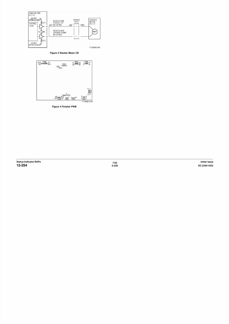
8/13/2019 Xerox Docu Color 2240-1632
http://slidepdf.com/reader/full/xerox-docu-color-2240-1632 266/1118
7/02
2-236 DC 2240/163212-254Initial IssueStatus Indicator RAPs
12-255 Stacker Tray Upper Limit• The system detected that the Stacker Tray Upper Limit Sensor was turned on after the
Stacker Tray had begun lifting up.
• The system detected that the Stacker Tray Upper Limit Sensor remained on when lower-ing down of the Stacker Tray has completed.
Procedure
Enter dC330 [012-202] and press Start. Actuate the Upper Limit Sensor (PL 17.11). The dis-
play changes.
Y N
Check the sensor components for mechanical problems. If the components are good, go
to OF 99-2 and check the circuit of the Upper Limit Sensor (Figure 2).
Enter dC330 [012-201] and press Start. Actuate the Stack Height Sensor. The display
changes.Y N
Check the sensor components for mechanical problems. If the components are good, go
to OF 99-2 and check the circuit of the Stack Height Sensor (Figure 3).
Enter dC330 [012-051] (down) or [012-051] (up) and press Start. The Stacker Tray moves.
Y N
The Stacker Motor energized.
Y N
Disconnect Stacker Motor P/J889. Measure the resistance between pin 1 and pin 2
of the motor connector. Between 12 to 40 ohms is measured while the pulley is
rotated manually.Y N
Replace the Stacker Motor (PL 17.11).
Check the wires between the motor connector and the Finisher PWB P/J847 for
obvious damage. Repair the wires as required. If the wires are good, replace the
Finisher PWB (PL 17.13).
Check the following:
• The Stacker Motor Gear for wear and damage
• The Stacker Tray for dragging and improper installation
• The Stacker Elevator Belt/rack/gear for wear and damage
Remove the other mechanical causes of the Stacker Tray not operating
NOTE: The large white Stacker Drive Pulley can be pulled out to release the Stacker
Drives to free the Stacker Tray ( REP 12.20 ).
Figure 1 Component Location
Figure 2 Upper Limit Sensor CD
UpperLimitSensor
Stack ASensor
Stack BSensor Stacker
Motor
StackHeightSensor

8/13/2019 Xerox Docu Color 2240-1632
http://slidepdf.com/reader/full/xerox-docu-color-2240-1632 267/1118
7/02
2-237DC 2240/1632 12-255Status Indicator RAPsInitial Issue
Remove the other mechanical causes of the Stacker Tray not operating.
Check the following and repair the Stacker Drives as required (PL 17.11).
• Stacker Motor Gear for wear and damage
• Stacker Tray for dragging and incorrect installation
• Stacker Elevator Belt/rack/gear for wear and damage
Figure 3 Stack Height Sensor
Figure 4 Stacker Motor CD

8/13/2019 Xerox Docu Color 2240-1632
http://slidepdf.com/reader/full/xerox-docu-color-2240-1632 268/1118
7/02
2-238 DC 2240/163212-255Initial IssueStatus Indicator RAPs
Figure 5 Finisher PWB
12-256 Staple Front Corner Sensor On• The Stapler Front Corner Sensor does not turn on within 2sec after starting to move to
Front Corner.
• The Stapler Front Corner Sensor remained on when starting to move to Front Corner.Procedure
Open the Finisher Front Cover. Turn the Stapler Assembly manually. The Staple Head
moves smoothly without any load.
Y N
Repair the cause of Staple Head not moving, such as rail breakage, drag, or damaged
gear.
Enter dC330 [012-225] and press Start. Actuate the Staple Front Corner Sensor. The dis-
play changes.
Y N
Check the sensor components for mechanical problems. If the components are good, go
to OF 99-2 and check the circuit of the Staple Front Corner Sensor (Figure 2).
Cheat the Front Cover Interlock Switch. Enter dC330 [012-081] (front direction) or [12-083]
(rear direction) and press Start. Staple Move Motor energized.
Y N
Connect black meter lead to ground. Measure voltage at each pin of P/J847. +24 VDC
is measured at each pin.
Y N
Disconnect P/J847. Measure voltage at P847-3 and -4. +24 VDC is measured.
Y NSwitch machine off then on. Measure voltage at P847-3 and -4. +24 VDC is
measured.
Y N
Replace the Finisher PWB (PL 17.13).
Check the motor wires for a short circuit. If the wires are good, replace the Sta-
ple Move Motor (PL 17.9).
Check the motor wires for obvious damage. If the wires are good, replace the Staple
Move Motor (PL 17.9).
Replace the Finisher PWB (PL 17.13).
Figure 1 Component Location
Figure 2 Stapler Front Corner Sensor CD
Staple Move Sensor
Staple FrontCorner Sensor
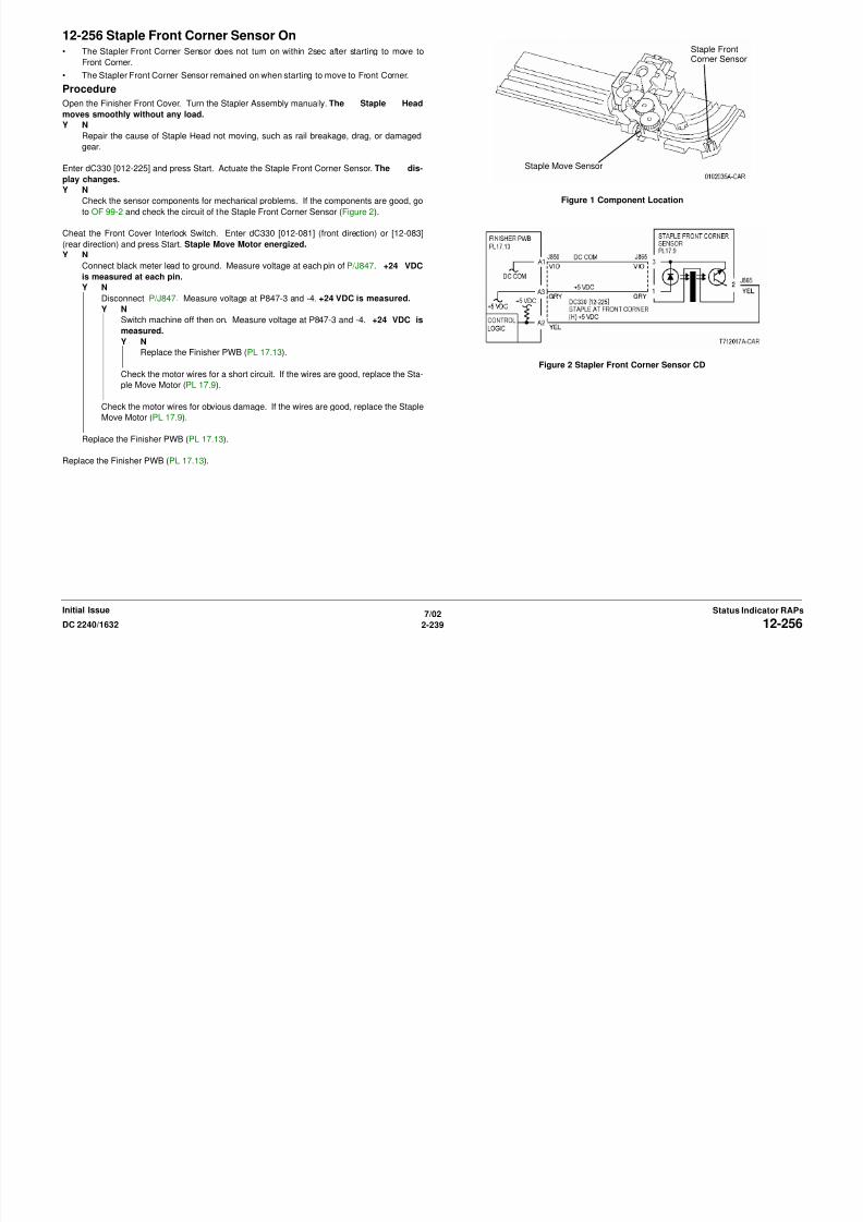
8/13/2019 Xerox Docu Color 2240-1632
http://slidepdf.com/reader/full/xerox-docu-color-2240-1632 269/1118
7/02
2-239DC 2240/1632 12-256Status Indicator RAPsInitial Issue
Replace the Finisher PWB (PL 17.13).
Figure 3 Stapler Move Motor CD
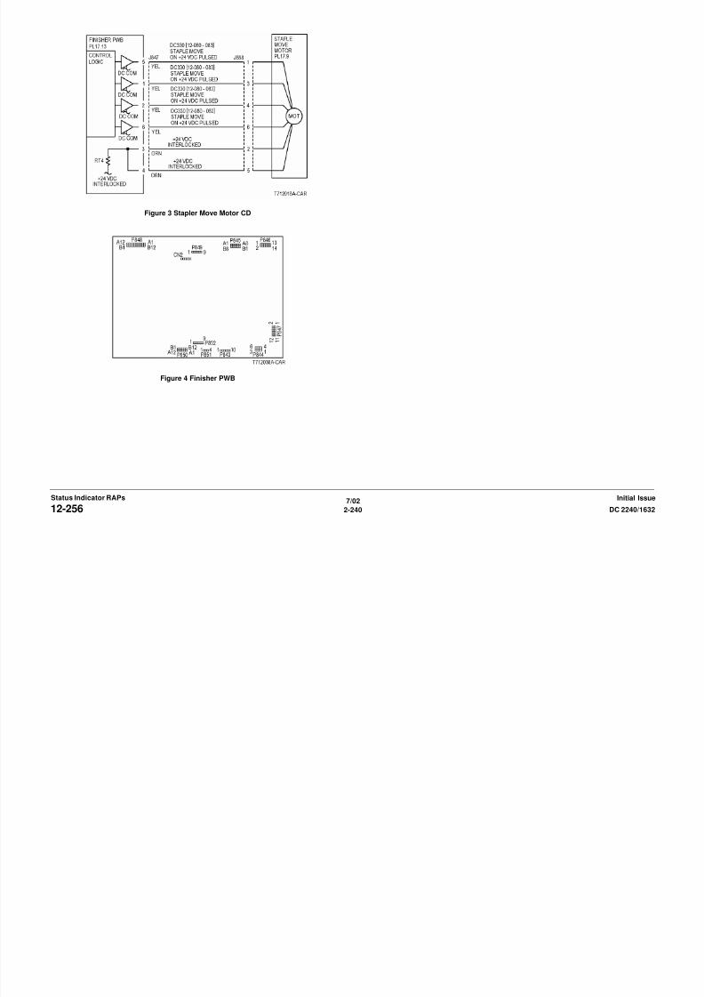
8/13/2019 Xerox Docu Color 2240-1632
http://slidepdf.com/reader/full/xerox-docu-color-2240-1632 270/1118
7/02
2-240 DC 2240/163212-256Initial IssueStatus Indicator RAPs
Figure 4 Finisher PWB
12-257 Staple Front Corner Sensor Off• The Staple Front Corner Sensor does not turn off after the move from Front Corner has
completed.
• The Staple Front Corner Sensor does not turn off after starting to move from Front Corner.Procedure
Open the Finisher Front Cover. Turn the Stapler Assembly manually. The Staple Head
moves smoothly without any load.
Y N
Remove the cause of Staple Head not moving, such as rail breakage, drag, and gear
damage.
Enter dC330 [012-225] and press Start. Actuate the Staple Front Corner Sensor. The dis-
play changes.
Y N
Check the sensor components for mechanical problems. If the components are good, go
to OF 99-2 and check the circuit of the Staple Front Corner Sensor (Figure 2).
Cheat the Front Cover Interlock Switch. Enter dC330 [012-081] (front) or [12-083] (rear) and
press Start. The Staple Move Motor energized.
Y N
Connect black meter lead to ground. Measure voltage at each pin of P/J847. +24 VDC
is measured at each pin.
Y N
Disconnect P/J847. Measure voltage at P847-3 and -4. +24 VDC is measured.
Y NSwitch machine off then on. Measure voltage at P847-3 and -4. +24 VDC is
measured.
Y N
Replace the Finisher PWB (PL 17.13).
Check the motor wires for a short circuit. If the wires are good, replace the Sta-
ple Move Motor (PL 17.9).
Check the motor wires for obvious damage. If the wires are good, replace the Staple
Move Motor (PL 17.9).
Replace the Finisher PWB (PL 17.13).
Figure 1 Component Location
Figure 2 Stapler Front Corner Sensor CD
Staple Move Sensor
Staple FrontCorner Sensor

8/13/2019 Xerox Docu Color 2240-1632
http://slidepdf.com/reader/full/xerox-docu-color-2240-1632 271/1118
7/02
2-241DC 2240/1632 12-257Status Indicator RAPsInitial Issue
Replace the Finisher PWB (PL 17.13).
Figure 3 Stapler Move Motor CD

8/13/2019 Xerox Docu Color 2240-1632
http://slidepdf.com/reader/full/xerox-docu-color-2240-1632 272/1118
7/02
2-242 DC 2240/163212-257Initial IssueStatus Indicator RAPs
Figure 4 Finisher PWB
12-260 Eject Clamp Home Sensor OnThe Eject Clamp Home Sensor does not turn on after the Eject Clamp up started.
ProcedureRemove the Eject Clamp Home Sensor bracket. Connect Eject Clamp Home Sensor.
Enter dC330 [012-210] and press Start. Actuate the Eject Clamp Home Sensor. The display
changes.
Y N
Check the sensor components for mechanical problems. If the components are good, go
to OF 99-2 and check the circuit of the Eject Clamp Home Sensor (Figure 2).
Restore the Sensor to the original state.
Enter dC330 [012-034] and press Start. Eject Clamp moves up.
Y N
Eject Motor energized.Y N
Connect black meter lead to ground. Measure voltage at each pin of P/J846. +24
VDC is measured at each pin.
Y N
Disconnect P/J846. Measure voltage at P846-6 and -12. +24 VDC is mea-
sured.
Y N
Switch machine off then on. Measure voltage at P846-6 and -12. +24
VDC is measured.
Y N
Replace the Finisher PWB (PL 17.13).
Check the Eject Motor wires for a short circuit. If the wires are good,
replace the Eject Motor (PL 17.8).
Check the motor wires for obvious damage. If the wires are good, replace the
Eject Motor (PL 17.8).
Replace the Finisher PWB (PL 17.13).
Repair Eject Clamp, Eject Cam, gears or belts as required (PL 17.13).
Replace the Finisher PWB (PL 17.13).
Figure 1 Component Location
Figure 2 Eject Clamp Home Sensor
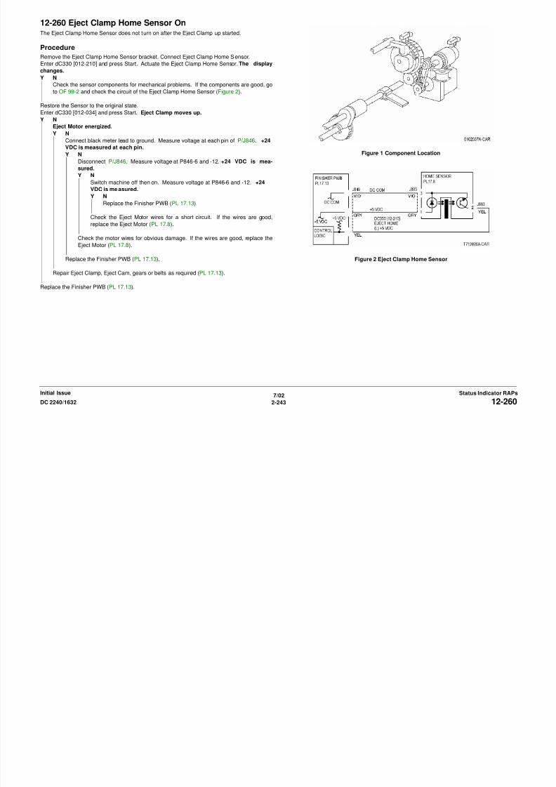
8/13/2019 Xerox Docu Color 2240-1632
http://slidepdf.com/reader/full/xerox-docu-color-2240-1632 273/1118
7/02
2-243DC 2240/1632 12-260Status Indicator RAPsInitial Issue
Figure 3 Eject Motor CD
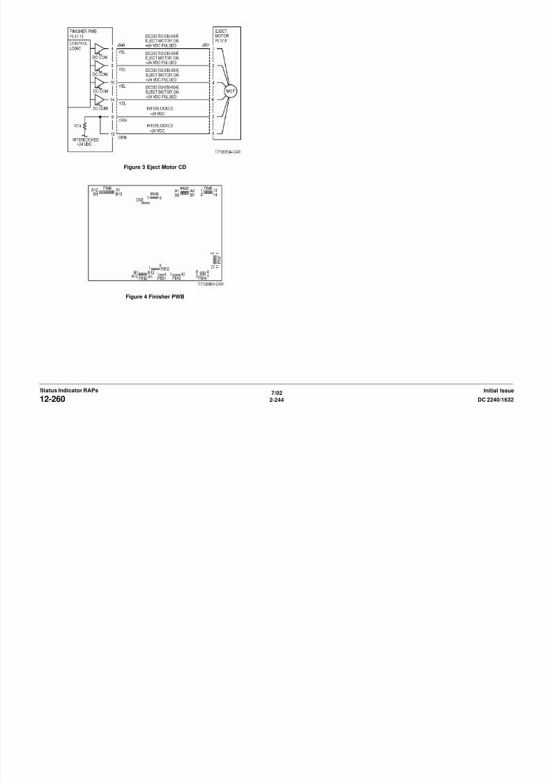
8/13/2019 Xerox Docu Color 2240-1632
http://slidepdf.com/reader/full/xerox-docu-color-2240-1632 274/1118
7/02
2-244 DC 2240/163212-260Initial IssueStatus Indicator RAPs
Figure 4 Finisher PWB

8/13/2019 Xerox Docu Color 2240-1632
http://slidepdf.com/reader/full/xerox-docu-color-2240-1632 275/1118
Figure 3 Eject Motor CD

8/13/2019 Xerox Docu Color 2240-1632
http://slidepdf.com/reader/full/xerox-docu-color-2240-1632 276/1118
7/02
2-246 DC 2240/163212-262Initial IssueStatus Indicator RAPs
Figure 4 Finisher PWB
12-267 DecurlerThe Decurler Cam Home Sensor did not actuate after the Decurler Cam Clutch energized.
Procedure
Open H Transport Cover and cheat the H Transport Cover Interlock Sensor (Figure 1). The H
Transport Belts rotate.
Y N
Go to 12-100.
Enter dC330 [012-217] and press Start. Actuate the Decurler Cam Home Sensor. The dis-
play changes.
Y N
Check the sensor components for mechanical problems. If the components are good, go
to OF 99-2 and check the circuit of the Decurler Cam Home Sensor (Figure 3).
Enter dC330 [012-070] and press Start. The Decurler Cam Clutch energized.
Y N
Check the Decurler Cam Clutch using the Solenoid/Clutch Open RAP.
Enter dC330 [012-071] and press Start. The Decurler Cam rotates.
Y N
Check the following:
• The Decurler Cam Clutch for slippage
• The Driver Gear for wear, a drive failure, and breakage
• The belt for disengagement, breakage, and improper tensionRemove the other mechanical causes of the Decurler Cam not operating.
Replace the Finisher PWB (PL 17.13).
Figure 2 Component Location
Figure 3 Decurler Cam Home Sensor CD
InterlockSensor
Decurler Cam Clutch
DecurlerCamHomeSensor
Compiler
EntranceSensor

8/13/2019 Xerox Docu Color 2240-1632
http://slidepdf.com/reader/full/xerox-docu-color-2240-1632 277/1118
7/02
2-247DC 2240/1632 12-267Status Indicator RAPsInitial Issue
Figure 1 Component Location Figure 4 Decurler Cam Clutch CD
Figure 5 Finisher PWB

8/13/2019 Xerox Docu Color 2240-1632
http://slidepdf.com/reader/full/xerox-docu-color-2240-1632 278/1118
7/02
2-248 DC 2240/163212-267Initial IssueStatus Indicator RAPs
12-281 Set ClampThe Set Clamp Home Sensor does not actuate after the Set Clamp started operation.
Procedure
Enter dC330 [012-211] and press Start. Actuate the Set Clamp Home Sensor. The display
changes.
Y N
Check the sensor components for mechanical problems. If the components are good, go
to OF 99-2 and check the circuit of the Set Clamp Home Sensor (Figure 2).
Enter dC330 [012-040] and press Start. The Set Clamp Solenoid energized.
Y N
Check the Set Clamp Solenoid using the Generic Solenoid/Clutch Open RAP.
Enter [12-034] and press Start to energize Eject Clamp up or [12-032] to lower the EjectClamp. Enter dC330 [012-041] and press Start. The Set Clamp rotated.
Y N
Enter dC330 [012-030] and press Start. The Eject Motor energized.
Y N
Connect black meter lead to ground. Measure voltage at each pin of P/J846. +24
VDC is measured at each pin.
Y N
Disconnect P/J846. Measure voltage at P846-6 and -12. +24 VDC is mea-
sured.
Y N
Switch machine off then on. Measure voltage at P846-6 and -12. +24VDC is measured.
Y N
Replace the Finisher PWB (PL 17.13).
Check the Eject Motor wires for a short circuit. If the wires are good,
replace the Eject Motor (PL 17.8).
Check the motor wires for obvious damage. If the wires are good, replace the
Eject Motor (PL 17.8).
Replace the Finisher PWB (PL 17.13).
Replace the PWB.
Ch k th f ll i
Figure 1 Component Location
Figure 2 Set Clamp Home Sensor
Eject Clamp Home SensorSetClampHome
Sensor
SetClampSolenoid

8/13/2019 Xerox Docu Color 2240-1632
http://slidepdf.com/reader/full/xerox-docu-color-2240-1632 279/1118
7/02
2-249DC 2240/1632 12-281Status Indicator RAPsInitial Issue
Check the following:
• Eject Roll for wear and a drive failure (PL 17.8).
• Eject Shaft for wear and a drive failure (PL 17.8).
• Each Driver Gear for wear, a drive failure, and breakage (PL 17.8).
• Belt for disengagement, breakage, and improper tension (PL 17.8).
Replace the Finisher PWB (PL 17.13). Figure 3 Set Clamp Solenoid
Figure 4 Eject Motor CD
Figure 5 Finisher PWB

8/13/2019 Xerox Docu Color 2240-1632
http://slidepdf.com/reader/full/xerox-docu-color-2240-1632 280/1118
7/02
2-250 DC 2240/163212-281Initial IssueStatus Indicator RAPs
Figure 5 Finisher PWB
12-301 Top Cover InterlockThe Top Cover Interlock is open.
Procedure
Cheat the Top Cover Interlock Switch. 12-301 is cleared.
Y N
Disconnect P/J851 on the Finisher PWB. +5 VDC is measured between the Finisher
PWB P/J851-1 and ground.
Y N
Replace the Finisher PWB (PL 17.13).
There is less than 5 ohms between P851-2 and the finisher metal frame.
Y N
Replace the Finisher PWB (PL 17.13).
Check the wires between the Finisher PWB P/J851 and the Top Cover Interlock Switch
P/J890 for an open circuit or poor contact (Figure 2).
If the wires are good, replace the Top Cover Interlock Switch (PL 17.13).
Check the misalignment between the Top Cover and the Top Cover Interlock Switch.
Check the Top Cover for correct installation and the actuator for breakage or bending ( PL
17.6).
Figure 2 Top Cover Interlock Switch CD
Figure 3 Finisher PWB
DockingInterlockSensor
Front DoorInterlockSwitch
Top CoverInterlock
Switch
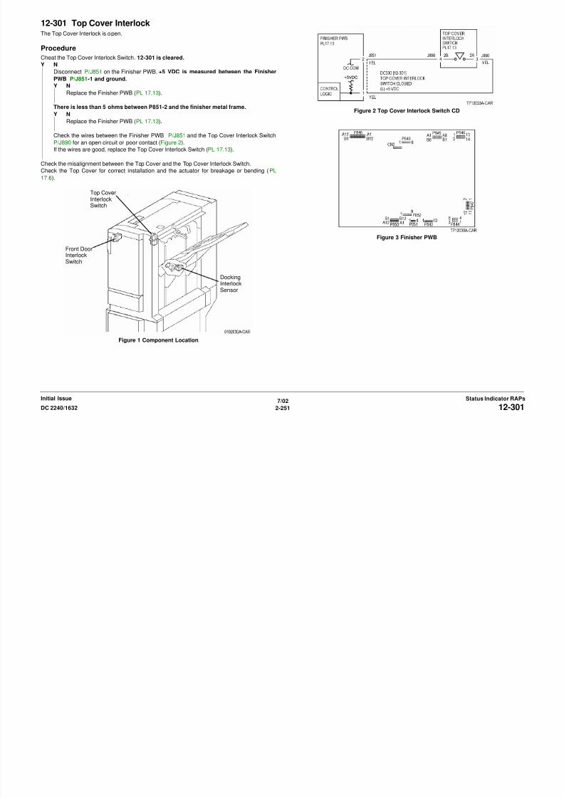
8/13/2019 Xerox Docu Color 2240-1632
http://slidepdf.com/reader/full/xerox-docu-color-2240-1632 281/1118
7/02
2-251DC 2240/1632 12-301Status Indicator RAPsInitial Issue
Figure 1 Component Location
12-302 Front Door Interlock OpenThe Front Door Interlock is open.
Procedure
Cheat the Front Door Interlock Switch. 012-302 is cleared.
Y N
Disconnect P/J851 on the Finisher PWB. +5 VDC is measured between the Finisher
PWB P/J851-3 and ground.
Y N
Replace the Finisher PWB (PL 17.13).
There is less than 5 ohms between P851-4 and the finisher metal frame.
Y N
Replace the Finisher PWB (PL 17.13).
Check the wires between the Finisher PWB P/J851 and the Top Cover Interlock Switch
P/J890 for an open circuit or poor contact (Figure 2).
If the wires are good, replace the Front Door Interlock Switch (PL 17.13).
Check the misalignment between the Front Door and the Front Door Interlock Switch.
Check the Front Door and Front Cover for improper installation, the Actuator for breakage and
bending, and the Magnet for improper mounting.
Figure 2 Front Door Interlock Switch CD
Figure 3 Finisher PWB
DockingInterlockSensor
Front DoorInterlockSwitch
Top CoverInterlock
Switch

8/13/2019 Xerox Docu Color 2240-1632
http://slidepdf.com/reader/full/xerox-docu-color-2240-1632 282/1118
7/02
2-252 DC 2240/163212-302Initial IssueStatus Indicator RAPs
Figure 1 Component Location
12-303 H Transport Interlock OpenThe H Transport Interlock Sensor detected open.
Procedure
Block the H Transport Interlock Sensor with a sheet of paper. 012-303 is cleared.
Y N
+5 VDC is measured between the H Transport Interlock Sensor P/J853-1 and -3.
Y N
Disconnect Finisher PWB P/J845. +5 VDC is measured between Finisher PWB
p845-A1 and -A3.
Y N
Replace the Finisher PWB (PL 17.13).
Repair the open circuit between Finisher PWB J845-A1 and -A3 and H Transport
Interlock Sensor J853-1 and -3.
+5 VDC is measured between Finisher PWB P/J845-A2 and ground.
Y N
Replace the Finisher PWB (PL 17.13)
+5 VDC is measure between H Transport Interlock Sensor P/J853-2 and ground.
Y N
Check the wire between the H Transport Interlock Sensor P/J853-2 and the Finisher
PWB P/J845-A2 for an open circuit or poor contact.
Replace the H Transport Interlock Sensor (PL 17.4).
Check misalignment between the H Transport Cover and the H Transport Interlock Sensor.
Check the H Transport Cover for improper installation, the Actuator for breakage and bending,
and the Magnet for improper mounting.
Figure 2 H Transport Interlock Sensor CD
Figure 3 Finisher PWBInterlockSensor
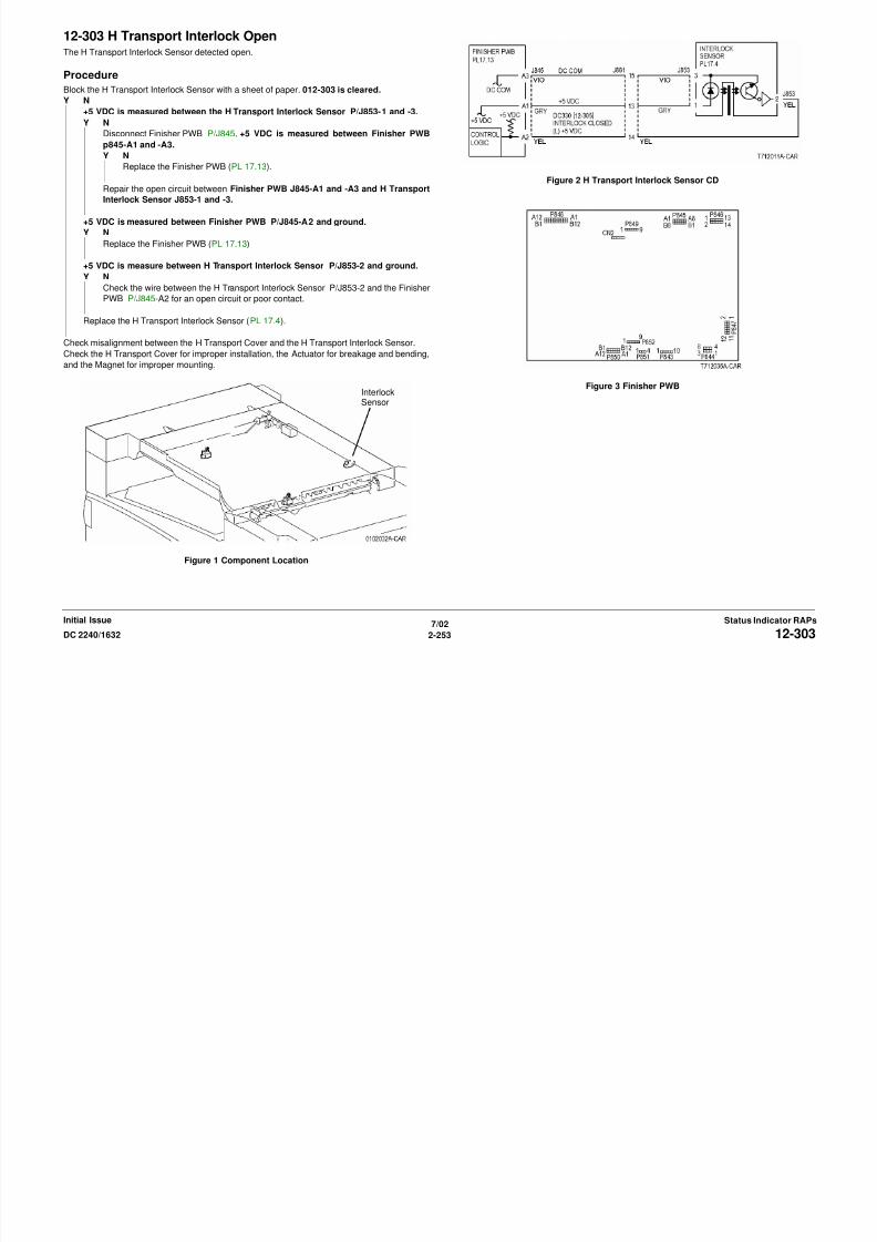
8/13/2019 Xerox Docu Color 2240-1632
http://slidepdf.com/reader/full/xerox-docu-color-2240-1632 283/1118
7/02
2-253DC 2240/1632 12-303Status Indicator RAPsInitial Issue
Figure 1 Component Location
12-305 Docking Interlock OpenThe Docking Interlock is open.
Procedure
Block the Docking Interlock Sensor with a sheet of paper. 012-305 is cleared.
Y N
+5 VDC is measured between the Docking Interlock Sensor P/J866-1 and -3.
Y N
Disconnect Finisher PWB P/J850. +5 VDC is measured between Finisher PWB
P850-A1 and -A3.
Y N
Replace the Finisher PWB (PL 17.13).
Repair the open circuit between Finisher PWB J850-A1 and -A3 and Docking
Interlock Sensor J866-1 and -3.
+5 VDC is measured between Finisher PWB P/J850-A2 and ground.
Y N
Replace the Finisher PWB (PL 17.13)
+5 VDC is measure between Docking Interlock Sensor P/J866-2 and ground.
Y N
Check the wire between the Docking Interlock Sensor P/J866-2 and the Finisher
PWB P/J850-A2 for an open circuit or poor contact.
Replace the Docking Interlock Sensor (PL 17.13).
Mismatching between the Actuator and the Docking Interlock Sensor. Check the Sensor for
improper installation, the Actuator for breakage and bending, and the Finisher and the Main
Processor for the docking failure.
Figure 1 Component Location
Figure 2 Docking Interlock Sensor CD
DockingInterlock
Sensor(rear)
Front DoorInterlockSwitch
Top CoverInterlockSwitch
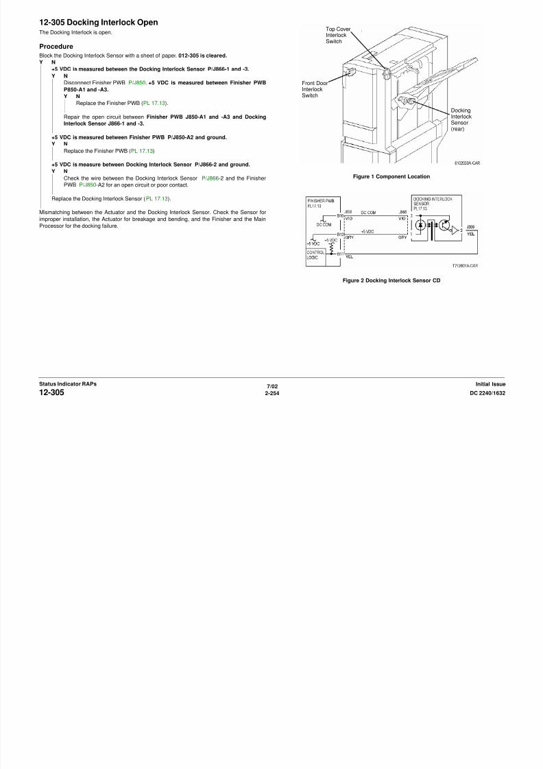
8/13/2019 Xerox Docu Color 2240-1632
http://slidepdf.com/reader/full/xerox-docu-color-2240-1632 284/1118
7/02
2-254 DC 2240/163212-305Initial IssueStatus Indicator RAPs
Figure 3 Finisher PWB

8/13/2019 Xerox Docu Color 2240-1632
http://slidepdf.com/reader/full/xerox-docu-color-2240-1632 285/1118
7/02
2-255DC 2240/1632 12-305Status Indicator RAPsInitial Issue

8/13/2019 Xerox Docu Color 2240-1632
http://slidepdf.com/reader/full/xerox-docu-color-2240-1632 286/1118

8/13/2019 Xerox Docu Color 2240-1632
http://slidepdf.com/reader/full/xerox-docu-color-2240-1632 287/1118

8/13/2019 Xerox Docu Color 2240-1632
http://slidepdf.com/reader/full/xerox-docu-color-2240-1632 288/1118
12-902 Power On H Transport Exit SensorThe H Transport Exit Sensor detected a paper at power on, when all the Interlock were closed,
or at initialization.
ProcedureEnter dC330 [012-104] and press Start. Actuate the H Transport Exit Sensor. The display
changes.
Y N
Disconnect P/J845 from Finisher Control PWB. Measure voltage at P/J845-B7. +5 VDC
is measured.
Y N
Replace Finisher PWB (PL 17.13).
Check the wire from P/J845-B7 to P/J856 on the H Transport Exit Sensor for an open cir-
cuit (Figure 2). If the wire is good, replace the H Transport Exit Sensor (PL 17.4).
Check that the voltage at the customer outlet is in specification and does not drop during
machine start.
Figure 1 Component Location
Figure 2 H Transport Exit Sensor CD
Figure 3 Finisher PWB
ExitSensor

8/13/2019 Xerox Docu Color 2240-1632
http://slidepdf.com/reader/full/xerox-docu-color-2240-1632 289/1118
7/02
2-259DC 2240/1632 12-902Status Indicator RAPsInitial Issue
12-903 Power On Compiler Entrance SensorThe Compiler Entrance Sensor detected a paper at power on, when all the Interlocks are
closed, or at initialization.
ProcedureEnter dC330 [012-101] and press Start. Actuate the Compiler Entrance Sensor. The display
changes.
Y N
Disconnect P/J850 from Finisher Control PWB. Measure voltage at P/J850-B8. +5 VDC
is measured.
Y N
Replace Finisher PWB (PL 17.13).
Check the wire from P/J850-B8 to P/J867 on the Compiler Entrance Sensor for an open
circuit (Figure 2). If the wire is good, replace the Compiler Entrance Sensor (PL 17.12).
Check that the voltage at the customer outlet is in specification and does not drop during
machine start.
Figure 1 Component Location
Figure 2 Compiler Entrance Sensor CD
Figure 3 Finisher PWB
CompilerEntranceSensor
DecurlerHome
Sensor

8/13/2019 Xerox Docu Color 2240-1632
http://slidepdf.com/reader/full/xerox-docu-color-2240-1632 290/1118
7/02
2-260 DC 2240/163212-903Initial IssueStatus Indicator RAPs
12-904 Power On Compiler Paper Sensor• The Compiler Paper Sensor continues to detect paper when the paper was output auto-
matically due to the power on initialization.
• The Compiler Paper Sensor detected paper with no history of paper output to the Com-
piler Tray when all the interlocks were closed.
Procedure
Enter dC330 [012-102] and press Start. Actuate the Compiler Paper Sensor. The display
changes.
Y N
Disconnect P/J848 from Finisher Control PWB. Measure voltage at P/J848-A5. +5 VDC
is measured.
Y N
Replace Finisher PWB (PL 17.13).
Check the wire from P/J848-A5 to P/J875 on the Compiler Paper Sensor for an open cir-cuit (Figure 2). If the wire is good, replace the Compiler Paper Sensor (PL 17.10).
Check that the voltage at the customer outlet is in specification and does not drop during
machine start.
Figure 1 Component Location
Figure 3 Finisher PWB
CompilerPaperSensor

8/13/2019 Xerox Docu Color 2240-1632
http://slidepdf.com/reader/full/xerox-docu-color-2240-1632 291/1118
7/02
2-261DC 2240/1632 12-904Status Indicator RAPsInitial Issue
Figure 2 Compiler Paper Sensor CD
12-910 Staple Feed Ready• At the staple preparation operation at initialization, the Staple Ready Sensor does not go
to ready (L) status after 13 times of stapling operation.
• The Stapler Ready Sensor is turned off (H) just before the Staple.
Procedure
Remove the Stapler Assembly with a connector connected (REP 12.11). Enter dC330 [012-
209] and press Start. Actuate the Staple Ready Sensor. The display changes.
Y N
+5 VDC is measured between the Stapler Assembly P/J886-5 and ground.
Y N
+5 VDC is measured between the Finisher PWB P/J852-1 and ground.
Y N
Replace the Finisher PWB (PL 17.13).
Check the wire between the Finisher PWB P/J852-1 and the Stapler Assembly P/ J886-5 for an open circuit or poor contact.
Pull out the staple cartridge. +5 VDC is measured between the Finisher PWB P/J852-
3 and ground.
Y N
Switch off the power. Disconnect P/J852 on the Finisher PWB. Switch the power
on. +5 VDC is measured between the Finisher PWB P852-3 and ground.
Y N
Replace the Finisher PWB (PL 17.13).
Check the circuit between the Finisher PWB P852 and the Stapler Assembly P/J forobvious damage.
If the wires are good, replace the Stapler Assembly (PL 17.9).
Replace the Finisher PWB (PL 17.13).
Restore the Staple Head to the original status and cheat the Front Interlock Switch.
Position paper in stapler. Enter dC330 [012-020] and press Start. The Staple Motor ener-
gizes.
Y N
With [12-020] running, +24 VDC is measured between the Finisher PWB P/J847-7
and ground.
Y N
Replace the Finisher PWB (PL 17.13).
Check resistance of the following:
Switch the power off. Remove the Stapler Assembly (REP 12.11).
Rotate the Staple Motor Gear manually. The staple needles fed.
Y N
Replace the Stapler Assembly (PL 17.9).
Replace the Finisher PWB (PL 17.13).
Figure 1 Staple Ready Sensor CD
Figure 2 Staple Motor CD
A

8/13/2019 Xerox Docu Color 2240-1632
http://slidepdf.com/reader/full/xerox-docu-color-2240-1632 292/1118
7/02
2-262 DC 2240/163212-910Initial IssueStatus Indicator RAPs
g
• Between the Finisher PWB P/J847-7 and Stapler Assembly P/J887-1
• Between the Finisher PWB P/J847-8 and Stapler Assembly P/J887-2
• Between the Finisher PWB P/J847 -9 and Stapler Assembly P/J887-3
• Between the Finisher PWB P/J847-10 and Stapler Assembly P/J887-4
If no problems are found, replace the Stapler Assembly (PL 17.9).
If the problem continues, replace the Finisher PWB (PL 17.13).
A
Figure 3 Finisher PWB
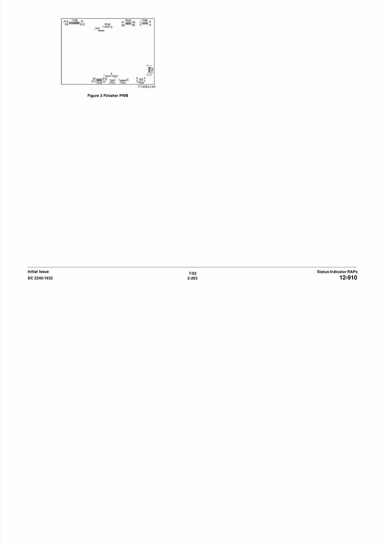
8/13/2019 Xerox Docu Color 2240-1632
http://slidepdf.com/reader/full/xerox-docu-color-2240-1632 293/1118
7/02
2-263DC 2240/1632 12-910Status Indicator RAPsInitial Issue
12-911 Stacker Lower Safety WarningThe Height Alignment was not successful during Stacker Tray lowering while stacking.
Procedure
Remove paper from Stacker Tray. The problem continues.Y N
Return to Service Call Procedures.
Check the following:
• The Actuator of the Stack Height Sensor for smooth operation. Repair as required (PL
17.6).
• Go to OF 99-2 and check the circuit of the Stack Height Sensor (Figure 2).
Figure 1 Component Location
Figure 3 Finisher PWB
Stack
HeightSensor
StackerMotor

8/13/2019 Xerox Docu Color 2240-1632
http://slidepdf.com/reader/full/xerox-docu-color-2240-1632 294/1118
7/02
2-264 DC 2240/163212-911Initial IssueStatus Indicator RAPs
Figure 2 Stack Height Sensor CD
12-914 Stacker Tray Staple SetThe Staple Set count of the Stacker Tray exceeded 50 sets at the Staple Set Eject operation.
Procedure
Remove the Stapled Sets. The problem continues.Y N
Return to Service Call Procedures.
Check the following:
• The Actuators of the Stack Paper Stack Sensor for smooth operation (PL 17.11).
• Go to OF 99-2 and check the circuit of the Paper Stack Sensor (Figure 2).
Figure 1 Component Location
Figure 3 Finisher PWB
StackHeight
Sensor
StackerMotor
StackPaperSensor
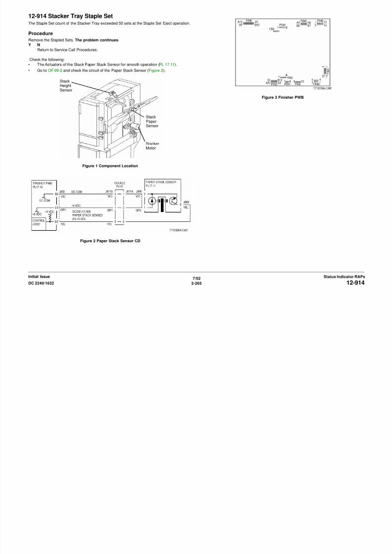
8/13/2019 Xerox Docu Color 2240-1632
http://slidepdf.com/reader/full/xerox-docu-color-2240-1632 295/1118
7/02
2-265DC 2240/1632 12-914Status Indicator RAPsInitial Issue
Figure 2 Paper Stack Sensor CD
12-916 StaplingThe Staple Head Home Sensor turned on by the open operation while the Sensor failed to turn
on (stapling was not available due to an error) after the Staple Head began to close.
ProcedurePosition paper in stapler. Enter dC330 [012-020] and press Start. The Staple Motor ener-
gizes.
Y N
With [12-020] running, +24 VDC is measured between the Finisher PWB P/J847-7
and ground.
Y N
Replace the Finisher PWB (PL 17.13).
Check resistance of the following:
• Between the Finisher PWB P/J847-7 and Stapler Assembly P/J887-1
• Between the Finisher PWB P/J847-8 and Stapler Assembly P/J887-2
• Between the Finisher PWB P/J847 -9 and Stapler Assembly P/J887-3
• Between the Finisher PWB P/J847-10 and Stapler Assembly P/J887-4
If no problems are found, replace the Stapler Assembly (PL 17.9).
If the problem continues, replace the Finisher PWB (PL 17.13).
Turn the gear of the Staple Motor manually to make the Actuator interrupt the Staple Head
Home Sensor. +5 VDC is measured between the Finisher PWB P/J852-2 and ground.
Y N
Replace the Finisher PWB (PL 17.13).
+5 VDC is measured between the Staple Head P/J886-4 and ground.
Y N
Check the wire between the Staple Head P/J886-4 and the Finisher PWB P/J852-2 for
an open circuit or poor contact.
Check resistance of the following:
• Between the Finisher PWB P/J852-1 and the Staple Head P/J886-5
• Between the Finisher PWB P/J852-5 and the Staple Head P/J886-1Resistance is 1 Ohm or less for both wires.
Y N
Repair wires with more than 1 Ohm for an open circuit or poor contact.
Replace the Stapler Assembly (PL 17 9)
Figure 1 Stapler Motor CD
Figure 2 Staple Head Home Sensor

8/13/2019 Xerox Docu Color 2240-1632
http://slidepdf.com/reader/full/xerox-docu-color-2240-1632 296/1118
7/02
2-266 DC 2240/163212-916Initial IssueStatus Indicator RAPs
Replace the Stapler Assembly (PL 17.9).
If the problem continues, replace the Finisher PWB (PL 17.13).
Figure 3 Finisher PWB

8/13/2019 Xerox Docu Color 2240-1632
http://slidepdf.com/reader/full/xerox-docu-color-2240-1632 297/1118
7/02
2-267DC 2240/1632 12-916Status Indicator RAPsInitial Issue
12-960 Stacker Tray Full Stack• The system detected Small Size Paper full during the Stacker Tray Height Adjustment
operation during lowering.
• The system detected Small Size Paper full during the Stacker Tray Height Adjustment
operation (during lowering down) when the Big Size Paper is ejected.• The Big Size Paper was ejected while the system already detected Big Size Paper FULL
(HALF).
Procedure
Remove the Finisher Front Cover. Enter dC330 [012-204] and press Start. Actuate the Stack
A Sensor. The display changes.
Y N
Check the sensor components for mechanical problems. If the components are good, go
to OF 99-2 and check the circuit of the Stack A Sensor (Figure 2).
Enter dC330 [012-205] and press Start. Actuate the Stack B Sensor. The display changes.Y N
Check the sensor components for mechanical problems. If the components are good, go
to OF 99-2 and check the circuit of the Stack B Sensor (Figure 3).
Enter dC330 [012-200] and press Start. Actuate the Paper Stack Sensor. The display
changes.
Y N
Check the sensor components for mechanical problems. If the components are good, go
to OF 99-2 and check the circuit of the Paper Stack Sensor (Figure 4).
Rotate the Stacker Motor Drive pulley manually (PL 17.11). The pulley is difficult or impos-sible to rotate.
Y N
Disconnect Stacker Motor P/J889. Measure the resistance between pin 1 and pin 2 of
the motor connector. Between 12 to 40 ohms is measured while the pulley is rotated
manually.
Y N
Replace the Stacker Motor (PL 17.11).
Check the wires between the motor connector and the Finisher PWB P/J847 for obvious
damage. Repair the wires as required. If the wires are good, replace the Finisher PWB
(PL 17.13).
Check the following and repair the Stacker Drives as required (PL 17.11).
• Stacker Motor Gear for wear and damage
• Stacker Tray for dragging and incorrect installation
S k El B l / k/ f d d
NOTE: The large white Stacker Drive Pulley can be pulled out to release the Stacker Drives to
free the Stacker Tray ( REP 12.20 ).
Figure 1 Component Location
Figure 2 Stack A Sensor CD
UpperLimitSensor
Stack ASensor
Stack B
Sensor

8/13/2019 Xerox Docu Color 2240-1632
http://slidepdf.com/reader/full/xerox-docu-color-2240-1632 298/1118
7/02
2-268 DC 2240/163212-960Initial IssueStatus Indicator RAPs
• Stacker Elevator Belt/rack/gear for wear and damage
Figure 3 Stack B Sensor CD
Figure 4 Paper Stack Sensor CD
Figure 6 Finisher PWB
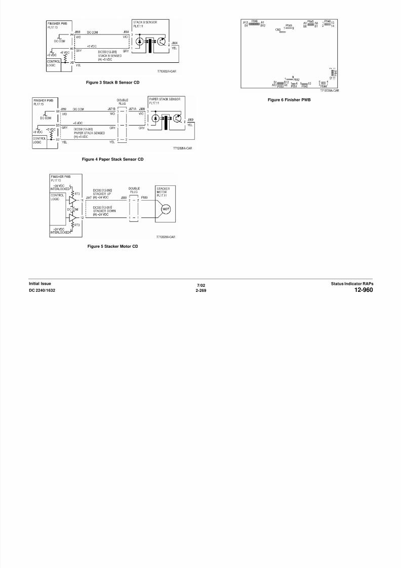
8/13/2019 Xerox Docu Color 2240-1632
http://slidepdf.com/reader/full/xerox-docu-color-2240-1632 299/1118
7/02
2-269DC 2240/1632 12-960Status Indicator RAPsInitial Issue
Figure 5 Stacker Motor CD
12-961 Mix Full Stack• Compared to the maximum paper size that was loaded at the previous job, the paper size
(either feed direction or width direction) of the next job is bigger.
• Staple mode has been changed while the width of the maximum paper size that was
loaded at the previous job is less than 279.4mm.• The maximum paper size that was loaded at the previous job is "unknown".
Procedure
Remove the Finisher Front Cover.
Enter dC330 [012-204] and press Start. Actuate the Stack A Sensor. The display changes.
Y N
Check the sensor components for mechanical problems. If the components are good, go
to OF 99-2 and check the circuit of the Stack A Sensor (Figure 2).
Enter dC330 [012-205] and press Start. Actuate the Stack B Sensor. The display changes.
Y NCheck the sensor components for mechanical problems. If the components are good, go
to OF 99-2 and check the circuit of the Stack B Sensor (Figure 3).
Enter dC330 [012-200] and press Start. Actuate the Paper Stack Sensor. The display
changes.
Y N
Check the sensor components for mechanical problems. If the components are good, go
to OF 99-2 and check the circuit of the Paper Sensor (Figure 4).
Rotate the Stacker Motor Drive pulley manually (PL 17.11). The pulley is difficult or impos-
sible to rotate.Y N
Disconnect Stacker Motor P/J889. Measure the resistance between pin 1 and pin 2 of
the motor connector. Between 12 to 40 ohms is measured while the pulley is rotated
manually.
Y N
Replace the Stacker Motor (PL 17.11).
Check the wires between the motor connector and the Finisher PWB P/J847 for obvious
damage. Repair the wires as required. If the wires are good, replace the Finisher PWB
(PL 17.13).
Check the following and repair the Stacker Drives as required (PL 17.11).
• Stacker Motor Gear for wear and damage
• Stacker Tray for dragging and incorrect installation
• Stacker Elevator Belt/rack/gear for wear and damage
NOTE: The large white Stacker Drive Pulley can be pulled out to release the Stacker Drives to
free the Stacker Tray ( REP 12.20 ).
Figure 1 Component Location
Figure 2 Stack A Sensor CD
UpperLimitSensor
Stack ASensor
Stack B
Sensor
StackPaperSensor
StackerMotor

8/13/2019 Xerox Docu Color 2240-1632
http://slidepdf.com/reader/full/xerox-docu-color-2240-1632 300/1118
7/02
2-270 DC 2240/163212-961Initial IssueStatus Indicator RAPs
Figure 3 Stack B Sensor CD
Figure 4 Paper Stack Sensor CD
Figure 6 Finisher PWB

8/13/2019 Xerox Docu Color 2240-1632
http://slidepdf.com/reader/full/xerox-docu-color-2240-1632 301/1118
7/02
2-271DC 2240/1632 12-961Status Indicator RAPsInitial Issue
Figure 5 Stacker Motor CD
12-965 Staple Near Empty• The Low Staple Switch detected Low Staple at Power On and Interlock Close.
• The Low Staple Switch detected Low Staple at Staple Head Close.
Procedure
Install a new Staple Cartridge loaded with staples. +5VDC measured between the Finisher
PWB P/J852-4 and ground.
Y N
Replace the Finisher PWB (PL 17.13).
+5VDC measured between the Stapler Assembly P/J886-2 and ground).
Y N
Check the wire between the Stapler Assembly P/J and the Finisher PWB P/J for an open
circuit or poor contact.
Check the wire between the Stapler Assembly P/J and the Finisher PWB P/J for an open circuitor poor contact.
If no problems are found, replace the Stapler Assembly (PL 17.9).
If the problem continues, replace the Finisher PWB (PL 17.13).
Figure 1 Low Staple Sensor CD
Figure 2 Finisher PWB

8/13/2019 Xerox Docu Color 2240-1632
http://slidepdf.com/reader/full/xerox-docu-color-2240-1632 302/1118
7/02
2-272 DC 2240/163212-965Initial IssueStatus Indicator RAPs
12-966 Scratch Sheet CompilePaper is output to the compiler that is not part of a print or copy job.
Procedure
Clear the sheets in the Stacker Tray. The problem continues.Y N
Return to service call procedures.
Rerun the job. If the problem continues, replace the Finisher PWB (PL 17.13).

8/13/2019 Xerox Docu Color 2240-1632
http://slidepdf.com/reader/full/xerox-docu-color-2240-1632 303/1118
7/02
2-273DC 2240/1632 12-966Status Indicator RAPsInitial Issue
12-969 IOT Top Tray FullThe Top Tray Full Sensor has detected full status for 10 sec.
Procedure
Enter dC330 [012-215] and press Start. Move paper near the Top Tray Full Sensor, then awayfrom it. The display changes.
Y N
Check the sensor components for mechanical problems. If the components are good, go
to OF 99-1 and check the circuit of the Top Tray Full Sensor (Figure 2).
Check the sensor for improper installation. If no problems are found, replace the Finisher PWB
(PL 17.13).
Figure 1 Component Location
Figure 3 Finisher PWB
Top Tray FullSensor

8/13/2019 Xerox Docu Color 2240-1632
http://slidepdf.com/reader/full/xerox-docu-color-2240-1632 304/1118
7/02
2-274 DC 2240/163212-969Initial IssueStatus Indicator RAPs
Figure 2 Top Tray Full Sensor CD
15-362 X Hard FailureCommunication Failure.
Procedure
Switch the power off then on. The problem continues.Y N
Return to Service Call Procedures.
Check the connectors on the IIT/IPS PWB (PL 18.3). If the check is OK, replace the IIT/IPS
PWB (PL 18.3).
15-367 X PIO FailureCommunication Failure.
Procedure
Switch the power off then on. The problem continues.Y N
Return to Service Call Procedures.
Check the connectors on the IIT/IPS PWB (PL 18.3). If the check is OK, replace the IIT/IPS
PWB (PL 18.3).

8/13/2019 Xerox Docu Color 2240-1632
http://slidepdf.com/reader/full/xerox-docu-color-2240-1632 305/1118
7/02
2-275DC 2240/1632 15-362, 15-367Status Indicator RAPsInitial Issue
15-370 X PIO Initialization Failure 1Communication Failure.
Procedure
Switch the power off then on. The problem continues.Y N
Return to Service Call Procedures.
Check the connectors on the IIT/IPS PWB (PL 18.3) and the ESS PWB (PL 13.1). If the check
is OK, replace the ESS PWB (PL 13.1). If the problem continues, replace the IIT/IPS PWB (PL
18.3).
15-371 X PIO Initialization Failure 2Communication Failure.
Procedure
Switch the power off then on. The problem continues.Y N
Return to Service Call Procedures.
Check the connectors on the IIT/IPS PWB (PL 18.3) and the ESS PWB (PL 13.1). If the check
is OK, replace the ESS PWB (PL 13.1). If the problem continues, replace the IIT/IPS PWB (PL
18.3).

8/13/2019 Xerox Docu Color 2240-1632
http://slidepdf.com/reader/full/xerox-docu-color-2240-1632 306/1118
7/02
2-276 DC 2240/163215-370, 15-371Initial IssueStatus Indicator RAPs
15-372 X PIO Initialization Failure 3Communication Failure.
Procedure
Switch the power off then on. The problem continues.Y N
Return to Service Call Procedures.
Check the connectors on the IIT/IPS PWB (PL 18.3) and the ESS PWB (PL 13.1). If the check
is OK, replace the ESS PWB (PL 13.1). If the problem continues, replace the IIT/IPS PWB (PL
18.3).
15-375 X PIO Before Scan FailureCommunication Failure.
Procedure
Switch the power off then on. The problem continues.Y N
Return to Service Call Procedures.
Check the connectors on the IIT/IPS PWB (PL 18.3) and the ESS PWB (PL 13.1). If the check
is OK, replace the ESS PWB (PL 13.1). If the problem continues, replace the IIT/IPS PWB (PL
18.3).

8/13/2019 Xerox Docu Color 2240-1632
http://slidepdf.com/reader/full/xerox-docu-color-2240-1632 307/1118
7/02
2-277DC 2240/1632 15-372, 15-375Status Indicator RAPsInitial Issue
15-376 X PIO Non-match Failure 1Communication Failure.
Procedure
Switch the power off then on. The problem continues.Y N
Return to Service Call Procedures.
Check the connectors on the IIT/IPS PWB (PL 18.3) and the ESS PWB (PL 13.1). If the check
is OK, replace the ESS PWB (PL 13.1). If the problem continues, replace the IIT/IPS PWB (PL
18.3).
15-377 X PIO Non-match Failure 2Communication Failure.
Procedure
Switch the power off then on. The problem continues.Y N
Return to Service Call Procedures.
Check the connectors on the IIT/IPS PWB (PL 18.3) and the ESS PWB (PL 13.1). If the check
is OK, replace the ESS PWB (PL 13.1). If the problem continues, replace the IIT/IPS PWB (PL
18.3).

8/13/2019 Xerox Docu Color 2240-1632
http://slidepdf.com/reader/full/xerox-docu-color-2240-1632 308/1118
7/02
2-278 DC 2240/163215-376, 15-377Initial IssueStatus Indicator RAPs
15-380 CCD AGCAutomatic Gain Control (AGC) for CCD Channel 1 red failed.
Initial Actions
• Verify that Platen Glass is installed correctly (REP 6.2).• Verify that NVM 715-400 = 1
Procedure
Enter dC330 [6-002] and press Start. The Exposure Lamp illuminates.
Y N
Go to the 6-371.
The Exposure Lamp illumination is bright and steady.
Y N
Go to P/J722 (Figure 1) and P/J724 (Figure 2) and check the wires for an open or short
circuit.Verify that P/J742 on the Lamp Ballast PWB and P/J724 on the IIT/IPS PWB are seated.
If the wires and connectors are good, replace the Exposure Lamp (PL 18.6).
If the problem continues, replace the Lamp Ballast PWB (PL 18.6).
If the problem continues, replace the IIT/IPS PWB (PL 18.3).
Remove the Platen Glass (REP 6.2). The white reference strip on frame under Registra-
tion Gate is clean and undamaged.
Y N
Clean the white reference strip.
Go to P/J721 (Figure 3) and check the flat cable on the IIT/IPS PWB and P/J741 on the CCDPWB for damage. Reseat the flat cable.
If the problem continues, replace the Lens Kit (PL 18.4).
If the problem continues, replace the IIT/IPS PWB (PL 18.3).
Figure 1 P/J722 IPS Fan CD
Figure 2 P/J724 Lamp Ballast CD

8/13/2019 Xerox Docu Color 2240-1632
http://slidepdf.com/reader/full/xerox-docu-color-2240-1632 309/1118
7/02
2-279DC 2240/1632 15-380Status Indicator RAPsInitial Issue
Figure 3 P/J721 P/J741 CCD CD

8/13/2019 Xerox Docu Color 2240-1632
http://slidepdf.com/reader/full/xerox-docu-color-2240-1632 310/1118
7/02
2-280 DC 2240/163215-380Initial IssueStatus Indicator RAPs
15-381 CCD AGCAutomatic Gain Control (AGC) for CCD Channel 2 red failed.
Initial Actions
• Verify that Platen Glass is installed correctly (REP 6.2).• Verify that NVM 715-400 = 1
Procedure
Enter dC330 [6-002] and press Start. The Exposure Lamp illuminates.
Y N
Go to the 6-371.
The Exposure Lamp illumination is bright and steady.
Y N
Go to P/J722 (Figure 1) and P/J724 (Figure 2) and check the wires for an open or short
circuit.Verify that P/J742 on the Lamp Ballast PWB and P/J724 on the IIT/IPS PWB are seated.
If the wires and connectors are good, replace the Exposure Lamp (PL 18.6).
If the problem continues, replace the Lamp Ballast PWB (PL 18.6).
If the problem continues, replace the IIT/IPS PWB (PL 18.3).
Remove the Platen Glass (REP 6.2). The white reference strip on frame under Registra-
tion Gate is clean and undamaged.
Y N
Clean the white reference strip.
Go to P/J721 (Figure 3) and check the flat cable on the IIT/IPS PWB and P/J741 on the CCDPWB for damage. Reseat the flat cable.
If the problem continues, replace the Lens Kit (PL 18.4).
If the problem continues, replace the IIT/IPS PWB (PL 18.3).
Figure 1 P/J722 IPS Fan CD
Figure 2 P/J724 Lamp Ballast CD

8/13/2019 Xerox Docu Color 2240-1632
http://slidepdf.com/reader/full/xerox-docu-color-2240-1632 311/1118
7/02
2-281DC 2240/1632 15-381Status Indicator RAPsInitial Issue
Figure 3 P/J721 P/J741 CCD CD

8/13/2019 Xerox Docu Color 2240-1632
http://slidepdf.com/reader/full/xerox-docu-color-2240-1632 312/1118
7/02
2-282 DC 2240/163215-381Initial IssueStatus Indicator RAPs
15-382 CCD AGCAutomatic Gain Control (AGC) for CCD Channel 3 green failed.
Initial Actions
• Verify that Platen Glass is installed correctly (REP 6.2).• Verify that NVM 715-400 = 1
Procedure
Enter dC330 [6-002] and press Start. The Exposure Lamp illuminates.
Y N
Go to the 6-371.
The Exposure Lamp illumination is bright and steady.
Y N
Go to P/J722 (Figure 1) and P/J724 (Figure 2) and check the wires for an open or short
circuit.Verify that P/J742 on the Lamp Ballast PWB and P/J724 on the IIT/IPS PWB are seated.
If the wires and connectors are good, replace the Exposure Lamp (PL 18.6).
If the problem continues, replace the Lamp Ballast PWB (PL 18.6).
If the problem continues, replace the IIT Driver PWB (PL 18.3).
Remove the Platen Glass (REP 6.2). The white reference strip on frame under Registra-
tion Gate is clean and undamaged.
Y N
Clean the white reference strip.
Go to P/J721 (Figure 3) and check the flat cable on the IIT/IPS PWB and P/J741 on the CCDPWB for damage. Reseat the flat cable.
If the problem continues, replace the Lens Kit (PL 18.4).
If the problem continues, replace the IIT/IPS PWB (PL 18.3).
Figure 1 P/J722 IPS Fan CD
Figure 2 P/J724 Lamp Ballast CD

8/13/2019 Xerox Docu Color 2240-1632
http://slidepdf.com/reader/full/xerox-docu-color-2240-1632 313/1118
7/02
2-283DC 2240/1632 15-382Status Indicator RAPsInitial Issue
Figure 3 P/J721 P/J741 CCD CD

8/13/2019 Xerox Docu Color 2240-1632
http://slidepdf.com/reader/full/xerox-docu-color-2240-1632 314/1118
7/02
2-284 DC 2240/163215-382Initial IssueStatus Indicator RAPs
15-383 CCD AGCAutomatic Gain Control (AGC) for CCD Channel 4 green failed.
Initial Actions
• Verify that Platen Glass is installed correctly (REP 6.2).• Verify that NVM 715-400 = 1
Procedure
Enter dC330 [6-002] and press Start. The Exposure Lamp illuminates.
Y N
Go to the 6-371.
The Exposure Lamp illumination is bright and steady.
Y N
Go to P/J722 (Figure 1) and P/J724 (Figure 2) on 6.1 and check the wires for an open or
short circuit.Verify that P/J742 on the Lamp Ballast PWB and P/J724 on the IIT/IPS PWB are seated.
If the wires and connectors are good, replace the Exposure Lamp (PL 18.6).
If the problem continues, replace the Lamp Ballast PWB (PL 18.6).
If the problem continues, replace the IIT Driver PWB (PL 18.3).
Remove the Platen Glass (REP 6.2). The white reference strip on frame under Registra-
tion Gate is clean and undamaged.
Y N
Clean the white reference strip.
Go to P/J721 (Figure 3) on 6.2 and check the flat cable on the IIT/IPS PWB and P/J741 onthe CCD PWB for damage. Reseat the flat cable.
If the problem continues, replace the Lens Kit (PL 18.4).
If the problem continues, replace the IIT/IPS PWB (PL 18.3).
Figure 1 P/J722 IPS Fan CD
Figure 2 P/J724 Lamp Ballast CD

8/13/2019 Xerox Docu Color 2240-1632
http://slidepdf.com/reader/full/xerox-docu-color-2240-1632 315/1118
7/02
2-285DC 2240/1632 15-383Status Indicator RAPsInitial Issue
Figure 3 P/J721 P/J741 CCD CD

8/13/2019 Xerox Docu Color 2240-1632
http://slidepdf.com/reader/full/xerox-docu-color-2240-1632 316/1118
7/02
2-286 DC 2240/163215-383Initial IssueStatus Indicator RAPs
15-384 CCD AGCAutomatic Gain Control (AGC) for CCD Channel 5 blue fa iled.
Initial Actions
• Verify that Platen Glass is installed correctly (REP 6.2).• Verify that NVM 715-400 = 1
Procedure
Enter dC330 [6-002] and press Start. The Exposure Lamp illuminates.
Y N
Go to the 6-371.
The Exposure Lamp illumination is bright and steady.
Y N
Go to P/J722 (Figure 1) and P/J724 (Figure 2) and check the wires for an open or short
circuit.Verify that P/J742 on the Lamp Ballast PWB and P/J724 on the IIT/IPS PWB are seated.
If the wires and connectors are good, replace the Exposure Lamp (PL 18.6).
If the problem continues, replace the Lamp Ballast PWB (PL 18.6).
If the problem continues, replace the IIT Driver PWB (PL 18.3).
Remove the Platen Glass (REP 6.2). The white reference strip on frame under Registra-
tion Gate is clean and undamaged.
Y N
Clean the white reference strip.
Go to P/J721 (Figure 3) and check the flat cable on the IIT/IPS PWB and P/J741 on the CCDPWB for damage. Reseat the flat cable.
If the problem continues, replace the Lens Kit (PL 18.4).
If the problem continues, replace the IIT/IPS PWB (PL 18.3).
Figure 1 P/J722 IPS Fan CD
Figure 2 P/J724 Lamp Ballast CD

8/13/2019 Xerox Docu Color 2240-1632
http://slidepdf.com/reader/full/xerox-docu-color-2240-1632 317/1118
7/02
2-287DC 2240/1632 15-384Status Indicator RAPsInitial Issue
Figure 3 P/J721 P/J741 CCD CD

8/13/2019 Xerox Docu Color 2240-1632
http://slidepdf.com/reader/full/xerox-docu-color-2240-1632 318/1118
7/02
2-288 DC 2240/163215-384Initial IssueStatus Indicator RAPs
15-385 CCD AGCAutomatic Gain Control (AGC) for CCD Channel 6 blue fa iled.
Initial Actions
• Verify that Platen Glass is installed correctly (REP 6.2).• Verify that NVM 715-400 = 1
Procedure
Enter dC330 [6-002] and press Start. The Exposure Lamp illuminates.
Y N
Go to the 6-371.
The Exposure Lamp illumination is bright and steady.
Y N
Go to P/J722 (Figure 1) and P/J724 (Figure 2) and check the wires for an open or short
circuit.Verify that P/J742 on the Lamp Ballast PWB and P/J724 on the IIT/IPS PWB are seated.
If the wires and connectors are good, replace the Exposure Lamp (PL 18.6).
If the problem continues, replace the Lamp Ballast PWB (PL 18.6).
If the problem continues, replace the IIT Driver PWB (PL 18.3).
Remove the Platen Glass (REP 6.2). The white reference strip on frame under Registra-
tion Gate is clean and undamaged.
Y N
Clean the white reference strip.
Go to P/J721 (Figure 3) and check the flat cable on the IIT/IPS PWB and P/J741 (Figure 3) onthe CCD PWB for damage. Reseat the flat cable.
If the problem continues, replace the Lens Kit (PL 18.4).
If the problem continues, replace the IIT/IPS PWB (PL 18.3).
Figure 1 P/J722 IPS Fan CD
Figure 2 P/J724 Lamp Ballast CD
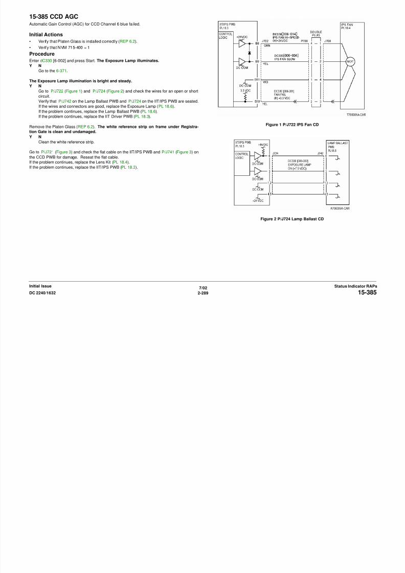
8/13/2019 Xerox Docu Color 2240-1632
http://slidepdf.com/reader/full/xerox-docu-color-2240-1632 319/1118
7/02
2-289DC 2240/1632 15-385Status Indicator RAPsInitial Issue
Figure 3 P/J721 P/J741 CCD CD

8/13/2019 Xerox Docu Color 2240-1632
http://slidepdf.com/reader/full/xerox-docu-color-2240-1632 320/1118
7/02
2-290 DC 2240/163215-385Initial IssueStatus Indicator RAPs
15-790 X Detail FailureCommunication Failure.
Procedure
Switch the power off then on. The problem continues.
Y N
Check the connectors on the IIT/IPS PWB (PL 18.3). If the check is OK, replace the IIT/
IPS PWB (PL 18.3).
Return to Service Call Procedures.

8/13/2019 Xerox Docu Color 2240-1632
http://slidepdf.com/reader/full/xerox-docu-color-2240-1632 321/1118
7/02
2-291DC 2240/1632 15-790Status Indicator RAPsInitial Issue

8/13/2019 Xerox Docu Color 2240-1632
http://slidepdf.com/reader/full/xerox-docu-color-2240-1632 322/1118
7/02
2-292 DC 2240/163215-790Initial IssueStatus Indicator RAPs
16-311 ScannerScanner not detected during power up.
Procedure
Switch power off then on. The problem continues.
Y N
Return to service call procedures.
Check connections between Scanner and IOT. Service as required (PL 18.3) (PL 18.4).
16-315 IIT InterfaceIIT interface error.
Procedure
Switch power off then on. The problem continues.
Y N
Return to service call procedures.
Pivot down T5 T6 HVPS (REP 1.6) to access I/F PWB.
Check that connections on I/F PWB are secure (PL 9.1).
If problem continues, replace I/F PWB (PL 9.1).
8/13/2019 Xerox Docu Color 2240-1632
http://slidepdf.com/reader/full/xerox-docu-color-2240-1632 323/1118
7/02
2-293DC 2240/1632 16-311, 16-315Status Indicator RAPsInitial Issue
16-316 Page MemoryPage memory not detected.
Procedure
Switch power off then on. The problem continues.
Y N
Return to service call procedures.
Check installation of Page Memory of the Scanner.
16-317 Page MemoryPage Memory error.
Procedure
Switch power off then on. The problem continues.
Y N
Return to service call procedures.
Replace the Page Memory of the Scanner.
8/13/2019 Xerox Docu Color 2240-1632
http://slidepdf.com/reader/full/xerox-docu-color-2240-1632 324/1118
7/02
2-294 DC 2240/163216-316, 16-317Initial IssueStatus Indicator RAPs
16-318 Optional Page MemoryOptional page memory error.
Procedure
Switch power off then on. The problem continues.
Y N
Return to service call procedures.
Replace optional Page Memory of the Scanner.
16-450 SMB Host NamePC of the same host name is duplicated on a network.
Procedure
Switch power off then on. The problem continues.
Y N
Return to service call procedures.
Change the host name.

8/13/2019 Xerox Docu Color 2240-1632
http://slidepdf.com/reader/full/xerox-docu-color-2240-1632 325/1118
7/02
2-295DC 2240/1632 16-450Status Indicator RAPsInitial Issue
16-452 IP Address DuplicatedPC of the same IP address exists on a network.
Procedure
Switch power off then on. The problem continues.
Y N
Return to service call procedures.
Change the IP address.
16-453 IP Address AcquisitionThe IP address failed to be granted from the DHCP server.
Procedure
Switch power off then on. The problem continues.
Y N
Return to service call procedures.
Set the IP address.
8/13/2019 Xerox Docu Color 2240-1632
http://slidepdf.com/reader/full/xerox-docu-color-2240-1632 326/1118
7/02
2-296 DC 2240/163216-452, 16-453Initial IssueStatus Indicator RAPs
16-454 Dynamic DNS UpdateDynamic DNS update failed.
Procedure
Switch power off then on. The problem continues.
Y N
Return to service call procedures.
Again, switch power off then on
16-460 Full Status DetectedFull Status Detected at HD Access.
Procedure
Switch power off then on. The problem continues.
Y N
Return to service call procedures.
Again, switch power off then on

8/13/2019 Xerox Docu Color 2240-1632
http://slidepdf.com/reader/full/xerox-docu-color-2240-1632 327/1118
7/02
2-297DC 2240/1632 16-454, 16-460Status Indicator RAPsInitial Issue
16-590 Read Error (Partition A)A verify error occurred in the HD partition A at PC-Diag operation from PWS.
Procedure
Switch power off then on. The problem continues.
Y N
Return to service call procedures.
Set up the HD partition A and perform the verify test again.
16-591 Read Error (Partition B)A verify error occurred in the HD partition B at PC-Diag operation from PWS.
Procedure
Switch power off then on. The problem continues.
Y N
Return to service call procedures.
Set up the HD partition B and perform the verify test again.

8/13/2019 Xerox Docu Color 2240-1632
http://slidepdf.com/reader/full/xerox-docu-color-2240-1632 328/1118
7/02
2-298 DC 2240/163216-590, 16-591Initial IssueStatus Indicator RAPs
16-592 Read Error (Partition C)A verify error occurred in the HD partition C at PC-Diag operation from PWS.
Procedure
Switch power off then on. The problem continues.
Y NReturn to service call procedures.
Set up the HD partition C and perform the verify test again.
16-593 Read Error (Partition D)A verify error occurred in the HD partition D at PC-Diag operation from PWS.
Procedure
Switch power off then on. The problem continues.
Y NReturn to service call procedures.
Set up the HD partition D and perform the verify test again.

8/13/2019 Xerox Docu Color 2240-1632
http://slidepdf.com/reader/full/xerox-docu-color-2240-1632 329/1118
7/02
2-299DC 2240/1632 16-592, 16-593Status Indicator RAPsInitial Issue
16-594 Read Error (Partition E)A verify error occurred in the HD partition E at PC-Diag operation from PWS.
Procedure
Switch power off then on. The problem continues.
Y NReturn to service call procedures.
Set up the HD partition E and perform the verify test again.
16-595 Read Error (Partition H)A verify error occurred in the HD partition H at PC-Diag operation from PWS.
Procedure
Switch power off then on. The problem continues.
Y NReturn to service call procedures.
Set up the HD partition H and perform the verify test again.
8/13/2019 Xerox Docu Color 2240-1632
http://slidepdf.com/reader/full/xerox-docu-color-2240-1632 330/1118
7/02
2-300 DC 2240/163216-594, 16-595Initial IssueStatus Indicator RAPs
16-701 PLW MemoryAn insufficient memory is detected while using the ART EX.
Procedure
Switch power off then on. The problem continues.
Y NReturn to service call procedures.
Decrease the resolution.
NOTE: Decreasing the resolution may have affect of reducing the PLW memory.
16-702 PLW MemorySystem detected insufficient buffer for the print page that cannot be compressed.
Procedure
Switch power off then on. The problem continues.
Y NReturn to service call procedures.
Decrease the resolution.
NOTE: Decreasing the resolution may have affect of reducing the PLW memory.

8/13/2019 Xerox Docu Color 2240-1632
http://slidepdf.com/reader/full/xerox-docu-color-2240-1632 331/1118
7/02
2-301DC 2240/1632 16-701, 16-702Status Indicator RAPsInitial Issue
16-703 Email To Invalid BoxSystem detected an unopened or invalid Mailbox and aborted a job when receiving an Email.
Procedure
Switch power off then on. The problem continues.
Y NReturn to service call procedures.
Open the appropriate Mailbox.
Send an Email to a valid Mailbox.
16-704 Security BoxThe system detected that a Mailbox was full (it exceeded the maximum number of documents
per Box) and aborted a job. Full status was detected at HD access and a job was aborted.
Procedure
Switch power off then on. The problem continues.Y N
Return to service call procedures.
Delete unwanted documents and retry the job.

8/13/2019 Xerox Docu Color 2240-1632
http://slidepdf.com/reader/full/xerox-docu-color-2240-1632 332/1118
7/02
2-302 DC 2240/163216-703, 16-704Initial IssueStatus Indicator RAPs
16-705 Security Storage without HDRegistry for Secure Print has failed because Security Storage cannot be done due to no HD
available.
Procedure
Switch power off then on. The problem continues.Y N
Return to service call procedures.
Check HD (PL 13.1) harness connection.
If the problem occurred at installation, check whether the operations for Secure Print are cor-
rect.
16-706 Maximum User NumberThe system detected that a job exceeded the maximum number of users for Secure and Proof
Prints and aborted the job. Full status was detected at HD access and a job was aborted.
Procedure
Switch power off then on. The problem continues.Y N
Return to service call procedures.
Delete unwanted documents/users and retry printing.
8/13/2019 Xerox Docu Color 2240-1632
http://slidepdf.com/reader/full/xerox-docu-color-2240-1632 333/1118
7/02
2-303DC 2240/1632 16-705, 16-706Status Indicator RAPsInitial Issue
16-709 PLW CommandAn ART EX Command error has occurred during PLW processing.
Procedure
Switch power off then on. The problem continues.
Y NReturn to service call procedures.
Cancel the job and execute the command again.
16-716 Spool TIFF DataUnable to spool TIFF files because disk capacity is exceeded.
Procedure
Switch power off then on. The problem continues.
Y NReturn to service call procedures.
Check HD (PL 13.1) harness connection.

8/13/2019 Xerox Docu Color 2240-1632
http://slidepdf.com/reader/full/xerox-docu-color-2240-1632 334/1118
7/02
2-304 DC 2240/163216-709, 16-716Initial IssueStatus Indicator RAPs
16-721 Other ErrorsAn error occurred during printing that is not defined.
Procedure
Switch power off then on. The problem continues.
Y NReturn to service call procedures.
Run the same job again to check the error status and ask Support G for help.
16-726 Decomposer Auto JudgementCannot switch decomposer; a print Language auto judgement error occurred.
Auto Judgement Error
ProcedureSwitch power off then on. The problem continues.
Y N
Return to service call procedures.
Fix and select the Decomposer from the Operation Panel or with a command.
8/13/2019 Xerox Docu Color 2240-1632
http://slidepdf.com/reader/full/xerox-docu-color-2240-1632 335/1118
7/02
2-305DC 2240/1632 16-721, 16-726Status Indicator RAPsInitial Issue

8/13/2019 Xerox Docu Color 2240-1632
http://slidepdf.com/reader/full/xerox-docu-color-2240-1632 336/1118
16-730 ART CommandART IV Command Invalid.
Procedure
Switch power off then on. The problem continues.
Y NReturn to service call procedures.
Delete the unsupported command from the data and retry printing.
16-731 TIFF DataInvalid TIFF Data. The TIFF data is broken or cut halfway.
Procedure
Switch power off then on. The problem continues.
Y NReturn to service call procedures.
Resend the data.

8/13/2019 Xerox Docu Color 2240-1632
http://slidepdf.com/reader/full/xerox-docu-color-2240-1632 337/1118
7/02
2-307DC 2240/1632 16-730, 16-731Status Indicator RAPsInitial Issue
16-735 Job TemplateThe system tried to output the Job Template List while the Job Template was being updated.
Procedure
Switch power off then on. The problem continues.
Y NReturn to service call procedures.
Run the job again after the Job Template update has completed.
16-737 Server ReadRead error from the Job Template Pool Server
Procedure
Switch power off then on. The problem continues.
Y NReturn to service call procedures.
Check that "Authorization to read" is established for the storage destination server directory set
as resource.
8/13/2019 Xerox Docu Color 2240-1632
http://slidepdf.com/reader/full/xerox-docu-color-2240-1632 338/1118
7/02
2-308 DC 2240/163216-735, 16-737Initial IssueStatus Indicator RAPs
16-739 Job Template PathThe specified path of the Job Template Pool Server cannot be found.
Procedure
Switch power off then on. The problem continues.
Y NReturn to service call procedures.
Set the resource of the storage destination path from a client PC on the CentreWare.
16-740 Job Template LoginJob Template Server Login Error. Cannot log in to the Job Template Pool Server.
Procedure
Switch power off then on. The problem continues.
Y NReturn to service call procedures.
Set the log-in name and password in the Job Template file storage destination.
From some other PC connected to the network, check that you can log in with the above
account.
Set the log-in name and password as a resource from the CentreWare client PC.
8/13/2019 Xerox Docu Color 2240-1632
http://slidepdf.com/reader/full/xerox-docu-color-2240-1632 339/1118
7/02
2-309DC 2240/1632 16-739, 16-740Status Indicator RAPsInitial Issue
16-741 Job Template ConnectionCannot connect to the Job Template Pool Server.
Procedure
Switch power off then on. The problem continues.
Y NReturn to service call procedures.
Connect the cable from the M/C to a network correctly.
From the destination server, check that you can identify the M/C with "ping".
Perform the "ping" test on the destination server from .
From a client PC to check that the FTP connection to the destination server is possible.
16-742 HD FileFile system was full when the Job Template was stored into the local HD.
Procedure
Switch power off then on. The problem continues.
Y NReturn to service call procedures.
Because the scanned images may exceed HD capacity, rerun the job.
If the problem continues, Initialize the HD.
If the problem continues, replace the HD (PL 13.1).
8/13/2019 Xerox Docu Color 2240-1632
http://slidepdf.com/reader/full/xerox-docu-color-2240-1632 340/1118
7/02
2-310 DC 2240/163216-741, 16-742Initial IssueStatus Indicator RAPs
16-743 Job Template InstallationJob template pool server installation error or job template pool server setting failure
Procedure
Switch power off then on. The problem continues.
Y NReturn to service call procedures.
Set the Spool Server related parameters again.
16-744 Job Template AddressThe Job Template Pool Server address cannot be solved (Response to the DNS library error)
Procedure
Switch power off then on. The problem continues.
Y NReturn to service call procedures.
Check the connection to the DNS. Check that the Job Template Pool Server domain name is
the one that has been registered in the DNS.

8/13/2019 Xerox Docu Color 2240-1632
http://slidepdf.com/reader/full/xerox-docu-color-2240-1632 341/1118
7/02
2-311DC 2240/1632 16-743, 16-744Status Indicator RAPsInitial Issue
16-745 Job Template DefinitionThe Job Template Pool Server address cannot be solved (The DNS address is not set)
Procedure
Switch power off then on. The problem continues.
Y NReturn to service call procedures.
Set the DNS address. Or set the Job Template Pool Server address by the IP address.
16-748 HD FullFull status was detected at HD access and a job was aborted.
Procedure
Switch power off then on. The problem continues.
Y NReturn to service call procedures.
Retry printing after making more space of the HD capacity.
8/13/2019 Xerox Docu Color 2240-1632
http://slidepdf.com/reader/full/xerox-docu-color-2240-1632 342/1118
7/02
2-312 DC 2240/163216-745, 16-748Initial IssueStatus Indicator RAPs
16-749 XJCL SyntaxSyntax error of the JCL command was detected.
Procedure
Switch power off then on. The problem continues.
Y NReturn to service call procedures.
Correct the command.
16-757 Auditron UserInvalid Auditron User
Procedure
Switch power off then on. The problem continues.
Y NReturn to service call procedures.
Set a correct account and retry.

8/13/2019 Xerox Docu Color 2240-1632
http://slidepdf.com/reader/full/xerox-docu-color-2240-1632 343/1118
7/02
2-313DC 2240/1632 16-749, 16-757Status Indicator RAPsInitial Issue
16-758 Auditron FunctionAn auditron function is disabled.
Procedure
Switch power off then on. The problem continues.
Y NReturn to service call procedures.
Consult the account administrator to add a right.
Set the new function that is allowed for that account and retry.
16-759 Auditron LimitAuditron reached limit.
Procedure
Switch power off then on. The problem continues.
Y NReturn to service call procedures.
Consult the account administrator to set the number of copies.

8/13/2019 Xerox Docu Color 2240-1632
http://slidepdf.com/reader/full/xerox-docu-color-2240-1632 344/1118
7/02
2-314 DC 2240/163216-758, 16-759Initial IssueStatus Indicator RAPs
16-760 DecomposerError during decompose processing.
Procedure
Switch power off then on. The problem continues.
Y NReturn to service call procedures.
Resend the job. The execution environment/data check are required if the problem persists.
16-761 FIFOImage Enlargement Error, FIFO EMPTY Error.
Procedure
Switch power off then on. The problem continues.
Y NReturn to service call procedures.
Print in fast print mode.
If problem continues, use print guarantee mode.

8/13/2019 Xerox Docu Color 2240-1632
http://slidepdf.com/reader/full/xerox-docu-color-2240-1632 345/1118
7/02
2-315DC 2240/1632 16-760, 16-761Status Indicator RAPsInitial Issue
16-762 DecomposerThe print language is not installed or an unsupported function (print language, print utility.) was
required. The Decomposer specified with PJL or Auto SW is not installed.
Procedure
Switch power off then on. The problem continues.Y N
Return to service call procedures.
Fix and select the Decomposer from the Operation Panel or with a command.
16-763 PatchOriginal patch does not exist.
Procedure
Switch power off then on. The problem continues.
Y NReturn to service call procedures.
Place the Auto Gradation Correction Chart correctly.
8/13/2019 Xerox Docu Color 2240-1632
http://slidepdf.com/reader/full/xerox-docu-color-2240-1632 346/1118
7/02
2-316 DC 2240/163216-762, 16-763Initial IssueStatus Indicator RAPs
16-764 Server TransmissionSMTP Server Connection Error, result code: 421/451
Procedure
Switch power off then on. The problem continues.
Y NReturn to service call procedures.
Retrieve emails in the Server HD. Restart the SMTP service.
16-765 Server StorageSMTP Server HD Full, Result code: 452
Procedure
Switch power off then on. The problem continues.
Y NReturn to service call procedures.
Retrieve emails in the Server HD. Rearrange the server capacity.

8/13/2019 Xerox Docu Color 2240-1632
http://slidepdf.com/reader/full/xerox-docu-color-2240-1632 347/1118
7/02
2-317DC 2240/1632 16-764, 16-765Status Indicator RAPsInitial Issue
16-766 Server StorageSMTP Server File System has a problem, result code: 552.
Procedure
Switch power off then on. The problem continues.
Y NReturn to service call procedures.
Contact the SMTP Server administrator. Rearrange the server capacity limit.
16-767 MailboxMailbox not found, or no access. Email destination address Incorrect, result code: 550/551.
Procedure
Switch power off then on. The problem continues.
Y NReturn to service call procedures.
Check the destination of the email.

8/13/2019 Xerox Docu Color 2240-1632
http://slidepdf.com/reader/full/xerox-docu-color-2240-1632 348/1118
7/02
2-318 DC 2240/163216-766, 16-767Initial IssueStatus Indicator RAPs
16-768 Mail From CommandMail From Command, Sending Address Incorrect, Login Error.
Procedure
Switch power off then on. The problem continues.
Y NReturn to service call procedures.
Check the settings of the self-email address. Check whether it is a valid email address in the
domain.
16-769 DSN UnsupportedSMTP Server Not Applicable to DSN
Procedure
Switch power off then on. The problem continues.
Y NReturn to service call procedures.
Enable the ESMTP function of nearest SMTP Server. Or disable the Sending/Receiving Confir-
mation function when sending an email.

8/13/2019 Xerox Docu Color 2240-1632
http://slidepdf.com/reader/full/xerox-docu-color-2240-1632 349/1118
7/02
2-319DC 2240/1632 16-768, 16-769Status Indicator RAPsInitial Issue
16-770 Template ProcessingThe system aborted a job due to insufficient HD capacity at Job Template processing.
Procedure
Switch power off then on. The problem continues.
Y NReturn to service call procedures.
Create free space for the HD capacity.
16-771 Scan Data RepositoryThe Scanned Data Repository Address cannot be solved. DNS Address is not set.
Procedure
Switch power off then on. The problem continues.
Y NReturn to service call procedures.
Set the DNS address. Or set the Scan Data Repository address by the IP address.

8/13/2019 Xerox Docu Color 2240-1632
http://slidepdf.com/reader/full/xerox-docu-color-2240-1632 350/1118
7/02
2-320 DC 2240/163216-770, 16-771Initial IssueStatus Indicator RAPs
16-772 Scan Data RepositoryThe Scan Data Repository address cannot be solved (Response to the DNS library error)
Procedure
Switch power off then on. The problem continues.
Y NReturn to service call procedures.
Check the connection to the DNS. Or check that the Scanned Data Repository domain name is
the one that has been registered in the DNS.
16-773 IP AddressSelf-machine IP address invalid, DHCP Lease Expired.
Procedure
Switch power off then on. The problem continues.
Y NReturn to service call procedures.
Check the DHCP environment. Set the fixed IP address for the self-machine.
8/13/2019 Xerox Docu Color 2240-1632
http://slidepdf.com/reader/full/xerox-docu-color-2240-1632 351/1118
7/02
2-321DC 2240/1632 16-772, 16-773Status Indicator RAPsInitial Issue
16-774 HD CompressionHD Full at Compression type conversion
HD Full has occurred when the S-Formatter did the compression type conversion of the JBIG
compressed images into the MH system (partition #1).
Procedure
Switch power off then on. The problem continues.
Y N
Return to service call procedures.
Create free space for the HD capacity and retry.
16-775 HD CapacityImage Conversion Error. Insufficient HD capacity is detected during image conversion process
by S-Formatter.
Procedure
Switch power off then on. The problem continues.Y N
Return to service call procedures.
Create free space for the HD capacity and retry.

8/13/2019 Xerox Docu Color 2240-1632
http://slidepdf.com/reader/full/xerox-docu-color-2240-1632 352/1118
7/02
2-322 DC 2240/163216-774, 16-775Initial IssueStatus Indicator RAPs
16-776 Image ConversionAn error has occurred due to other causes than HD Access during image conversion process
by S-Formatter.
Procedure
Switch power off then on. The problem continues.Y N
Return to service call procedures.
Perform the operation again.
16-777 HD AccessThe HD Access Error has occurred during image conversion process by S-Formatter.
Procedure
Switch power off then on. The problem continues.
Y NReturn to service call procedures.
Replace the HD (PL 13.1) and perform the operation again.
8/13/2019 Xerox Docu Color 2240-1632
http://slidepdf.com/reader/full/xerox-docu-color-2240-1632 353/1118
7/02
2-323DC 2240/1632 16-776 Image Conversion, 16-777Status Indicator RAPsInitial Issue
16-778 HD CapacityThe insufficient HD capacity was detected during scanned image conversion process by I-For-
matter.
Procedure
Switch power off then on. The problem continues.Y N
Return to service call procedures.
Check HD (PL 13.1) harness connections and retry scanning.
16-779 Scan Image ConversionAn error has occurred due to other causes than HD Access during scanned image conversion
process by I-Formatter.
Procedure
Switch power off then on. The problem continues.Y N
Return to service call procedures.
Again, switch power off then on and perform the operation again.
8/13/2019 Xerox Docu Color 2240-1632
http://slidepdf.com/reader/full/xerox-docu-color-2240-1632 354/1118
7/02
2-324 DC 2240/163216-778, 16-779Initial IssueStatus Indicator RAPs
16-780 HD AccessThe HD Access Error has occurred during scanned image conversion process by I-Formatter.
Procedure
Switch power off then on. The problem continues.
Y NReturn to service call procedures.
Replace the HD (PL 13.1) and retry scanning.
16-781 Scan ServerNet Connection Error during Scanning. Connection to the Server cannot be established during
Scan to Server file transfer operation.
Procedure
Switch power off then on. The problem continues.Y N
Return to service call procedures.
Set "Sub-net Mask" and "Gateway" of the main processor correctly.
From the destination server, check that you can identify the M/C with "ping".
From a Windows95 or UNIX machine to check that the FTP connection to the destination
server is possible.

8/13/2019 Xerox Docu Color 2240-1632
http://slidepdf.com/reader/full/xerox-docu-color-2240-1632 355/1118
7/02
2-325DC 2240/1632 16-780, 16-781Status Indicator RAPsInitial Issue
16-782 Scan Server LoginServer Login Error during Scanning. Cannot log in to the Server during Scan to Server file
transfer operation.
Procedure
Switch power off then on. The problem continues.
Y N
Return to service call procedures.
Set the log-in name and password in the destination server.
Make correct settings for the attributes of the Job Template file.
From a client PC, set the same account as the above as a resource in CW.
16-783 Server PathServer Path Error at Scanning. The specified path cannot be found at Scan to Server file
transfer operation.
Procedure
Switch power off then on. The problem continues.
Y N
Return to service call procedures.
Make correct settings for the attributes of the Job Template file.
8/13/2019 Xerox Docu Color 2240-1632
http://slidepdf.com/reader/full/xerox-docu-color-2240-1632 356/1118
7/02
2-326 DC 2240/163216-782, 16-783Initial IssueStatus Indicator RAPs
16-784 Server WriteWrite Error at Scanning. The Server cannot be written to at the Scan to Server file transfer.
Procedure
Switch power off then on. The problem continues.
Y N
Return to service call procedures.
Check that there is "Write Authorization:" in the server directory.
Create free space on the server disk.
16-785 Server HD FullServer File Full at Scanning. The Server File System became full during the Scan to Server
file transfer.
Procedure
Switch power off then on. The problem continues.
Y N
Return to service call procedures.
Check that there is "Write Authorization" in the server directory.
Create free space on the server disk.

8/13/2019 Xerox Docu Color 2240-1632
http://slidepdf.com/reader/full/xerox-docu-color-2240-1632 357/1118
7/02
2-327DC 2240/1632 16-784, 16-785Status Indicator RAPsInitial Issue
16-786 HD Scan WriteInternal HD Write Error at Scanning. A temporary file cannot be written to the internal HD at
the Scan to Server file transfer.
Procedure
Switch power off then on. The problem continues.
Y N
Return to service call procedures.
HD may be filled with print jobs. Allow time and retry.
If the problem continues, format the HD.
If the problem continues, replace the HD (PL 13.1).
16-787 Job Template SyntaxThis is a syntax error in the Job Template during Scan to Server operation and limited to the
following cases (because of Redirector detection): Server IP Address Incorrect (IP Syntax
Error)
Procedure
Switch power off then on. The problem continues.
Y N
Return to service call procedures.
Check the contents of the attributes (string RepositoryName) in the Job Template file.
8/13/2019 Xerox Docu Color 2240-1632
http://slidepdf.com/reader/full/xerox-docu-color-2240-1632 358/1118
7/02
2-328 DC 2240/163216-786, 16-787Initial IssueStatus Indicator RAPs
16-788 Mailbox to PCRetrieval Failed at Scan to PC (via Web Browser.
Procedure
Switch power off then on. The problem continues.
Y N
Return to service call procedures.
Improve the connection status to a network.
Check for problem such as duplicated IP addresses.
16-793 MF I/O HD FullMFIO HD Full
Procedure
Switch power off then on. The problem continues.
Y N
Return to service call procedures.
Insufficient Area of Hard Disk (MF I/O).
8/13/2019 Xerox Docu Color 2240-1632
http://slidepdf.com/reader/full/xerox-docu-color-2240-1632 359/1118
7/02
2-329DC 2240/1632 16-788, 16-793 MF I/O HDStatus Indicator RAPsInitial Issue
16-950 Tray 1 EmptyTray 1 Empty
Procedure
Switch power off then on. Add paper. The problem continues.
Y N
Return to service call procedures.
Go to 3-950.
16-951 Tray 2 EmptyTray 2 Empty
Procedure
Switch power off then on. Add paper. The problem continues.
Y N
Return to service call procedures.
Go to 3-951.

8/13/2019 Xerox Docu Color 2240-1632
http://slidepdf.com/reader/full/xerox-docu-color-2240-1632 360/1118
7/02
2-330 DC 2240/163216-950, 16-951Initial IssueStatus Indicator RAPs
16-952 Tray 3 EmptyTray 3 Empty
Procedure
Switch power off then on. Add paper. The problem continues.
Y N
Return to service call procedures.
Go to 3-952.
16-953 Tray 4 EmptyTray 4 Empty
Procedure
Switch power off then on. Add paper. The problem continues.
Y N
Return to service call procedures.
Go to 3-953.
8/13/2019 Xerox Docu Color 2240-1632
http://slidepdf.com/reader/full/xerox-docu-color-2240-1632 361/1118
7/02
2-331DC 2240/1632 16-952, 16-953Status Indicator RAPsInitial Issue
16-954 Tray 5 EmptyTray 5 Empty
Procedure
Switch power off then on. Add paper. The problem continues.
Y N
Return to service call procedures.
Go to 3-954.
16-958 Tray 5 SizeTray 5 Size Mismatch
Procedure
Switch power off then on. The problem continues.
Y N
Return to service call procedures.
Load correct paper in the tray. If problem continues, go to 7-959 or 7-960.

8/13/2019 Xerox Docu Color 2240-1632
http://slidepdf.com/reader/full/xerox-docu-color-2240-1632 362/1118
7/02
2-332 DC 2240/163216-954, 16-958Initial IssueStatus Indicator RAPs
16-959 Tray 1 SizeTray 1 Size Mismatch
Procedure
Switch power off then on. The problem continues.
Y N
Return to service call procedures.
Load proper paper in the tray. If the problem continues, go to 7-270.
16-960 Tray 2 SizeSize Mismatch Tray 2 Size Mismatch
Procedure
Switch power off then on. The problem continues.
Y N
Return to service call procedures.
Load proper paper in the tray. If the problem continues, go to 7-271.

8/13/2019 Xerox Docu Color 2240-1632
http://slidepdf.com/reader/full/xerox-docu-color-2240-1632 363/1118
7/02
2-333DC 2240/1632 16-959, 16-960Status Indicator RAPsInitial Issue
I i i l IS I di RAP
16-961 Tray 3 SizeTray 3 Size Mismatch
Procedure
Switch power off then on. The problem continues.
Y N
Return to service call procedures.
Load proper paper in the tray. If the problem continues, go to 7-276.
16-962 Tray 4 SizeTray 4 Size Mismatch
Procedure
Switch power off then on. The problem continues.
Y N
Return to service call procedures.
Load proper paper in the tray. If the problem continues, go to 7-277.

8/13/2019 Xerox Docu Color 2240-1632
http://slidepdf.com/reader/full/xerox-docu-color-2240-1632 364/1118
7/02
2-334 DC 2240/163216-961, 16-962Initial IssueStatus Indicator RAPs
Status Indicator RAPsInitial Issue
16-965 ATS/APS No PaperAPS/ATS NG No Paper.
Procedure
Switch power off then on. The problem continues.
Y N
Return to service call procedures.
Add paper.
16-966 ATS/APS No DestinationATS/APS No Destination, other than No Paper.
Procedure
Switch power off then on. The problem continues.
Y N
Return to service call procedures.
Change the settings and replace the Trays.

8/13/2019 Xerox Docu Color 2240-1632
http://slidepdf.com/reader/full/xerox-docu-color-2240-1632 365/1118
7/02
2-335DC 2240/1632 16-965, 16-966Status Indicator RAPsInitial Issue
Initial IssueStatus Indicator RAPs
16-981 Full HDFull status was detected at HD access. Full status was not cleared even during waiting for tim-
ing. One or more pages are already stored.
Procedure
Switch power off then on. The problem continues.
Y N
Return to service call procedures.
Service actions depend on the operation specifications.
Again, switch power off then on.
If the problem continues, reload software.
If the problem continues, replace the HD (PL 13.1).
16-982 Full HDFull status was detected at HD access. Full status was not cleared even during waiting for tim-
ing. No pages can be stored.
Procedure
Switch power off then on. The problem continues.
Y N
Return to service call procedures.
Check the HD harness connection (PL 13.1). If the problem continues, replace the HD (PL
13.1).
8/13/2019 Xerox Docu Color 2240-1632
http://slidepdf.com/reader/full/xerox-docu-color-2240-1632 366/1118
7/02
2-336 DC 2240/163216-981, 16-982Initial IssueStatus Indicator RAPs
7/02 Status Indicator RAPsInitial Issue
102-200 Receive Buffer OverflowThe data received from the Controller exceeded the buffer amount of the destination in the
Panel.
Procedure
Switch power off then on. The problem continues.
Y NReturn to service call procedures.
Perform re-installation of the software.
If the problem continues, replace the ESS PWB (PL 13.1)
102-201 Send Buffer OverflowThe data to be sent from the Panel exceeded the buffer amount of the destination in the Panel.
Procedure
Switch power off then on. The problem continues.
Y N
Return to service call procedures.
Perform re-installation of the software.
If the problem continues, replace the ESS PWB (PL 13.1)
8/13/2019 Xerox Docu Color 2240-1632
http://slidepdf.com/reader/full/xerox-docu-color-2240-1632 367/1118
7/02
2-337DC 2240/1632 102-200, 102-201Status Indicator RAPsInitial Issue
7/02 Initial IssueStatus Indicator RAPs
102-202 Request Queue FullThe event that requires more than the processing capability for the request arising in the Panel
has occurred.
Procedure
Switch power off then on. The problem continues.
Y NReturn to service call procedures.
Perform re-installation of the software.
If the problem continues, replace the ESS PWB (PL 13.1)
102-203 Send Request Queue Full DebugData cannot be sent from the Panel to the Controller.
Procedure
Switch power off then on. The problem continues.
Y N
Return to service call procedures.
Perform re-installation of the software.
If the problem continues, replace the ESS PWB (PL 13.1)

8/13/2019 Xerox Docu Color 2240-1632
http://slidepdf.com/reader/full/xerox-docu-color-2240-1632 368/1118
7/02
2-338 DC 2240/1632102-202, 102-203
7/02 Status Indicator RAPsInitial Issue
102-204 SIO ParameterSerial communication failure. Incorrect message size at SIO receiving request, or incorrect
Mailbox ID when a message is sent.
Procedure
Switch power off then on. The problem continues.
Y NReturn to service call procedures.
Perform re-installation of the software.
102-205 SIO CommandSerial communication failure. A command error has occurred at SIO receiving request.
Procedure
Switch power off then on. The problem continues.
Y N
Return to service call procedures.
Perform re-installation of the software.

8/13/2019 Xerox Docu Color 2240-1632
http://slidepdf.com/reader/full/xerox-docu-color-2240-1632 369/1118
7/02
2-339DC 2240/1632 102-204, 102-205
7/02 Initial IssueStatus Indicator RAPs
102-206 SIO StatusSerial communication failure. A header status error of the RX packet or a message status error
of the RX packet has occurred.
Procedure
Switch power off then on. The problem continues.
Y NReturn to service call procedures.
Perform re-installation of the software.
102-207 Communication Manager TargetSerial communication failure. Incorrect Mailbox value on the cm_send_msg statement, or the
target is not SYS when receiving from SIO.
Procedure
Switch power off then on. The problem continues.
Y NReturn to service call procedures.
Perform re-installation of the software.

8/13/2019 Xerox Docu Color 2240-1632
http://slidepdf.com/reader/full/xerox-docu-color-2240-1632 370/1118
2-340 DC 2240/1632102-206, 102-207
7/02
102 208 102 209Status Indicator RAPsInitial Issue
102-208 Communication Manager CommandSerial communication failure. A command error has occurred when receiving from SIO.
Procedure
Switch power off then on. The problem continues.
Y N
Return to service call procedures.
Perform re-installation of the software.
102-209 EVM Returns Wrong ValueReturn value error from EVM. Panel-SW failure
Procedure
Switch power off then on. The problem continues.
Y N
Return to service call procedures.
Perform re-installation of the software.

8/13/2019 Xerox Docu Color 2240-1632
http://slidepdf.com/reader/full/xerox-docu-color-2240-1632 371/1118
2-341DC 2240/1632 102-208, 102-209
7/02
102 310 102 311Initial IssueStatus Indicator RAPs
102-310 Send Queue FullOver the upper limit of the processing capability to send data from the Panel to the Controller.
Procedure
Switch power off then on. The problem continues.
Y N
Return to service call procedures.
Perform re-installation of the software.
102-311 Receive Queue FullThe data received from the Controller exceeded the upper limit of the processing capability in
the Panel.
Procedure
Switch power off then on. The problem continues.
Y NReturn to service call procedures.
Perform re-installation of the software.
8/13/2019 Xerox Docu Color 2240-1632
http://slidepdf.com/reader/full/xerox-docu-color-2240-1632 372/1118
2-342 DC 2240/1632102-310, 102-311
7/02
2 343DC 2240/1632 102 312 102 313Status Indicator RAPsInitial Issue
102-312 EVM Uses Wrong APIIllegal use of API by EVM.
Procedure
Switch power off then on. The problem continues.
Y N
Return to service call procedures.
Perform re-installation of the software.
102-313 AS Uses Wrong APIIllegal use of API by AS
Procedure
Switch power off then on. The problem continues.
Y N
Return to service call procedures.
Perform re-installation of the software.
8/13/2019 Xerox Docu Color 2240-1632
http://slidepdf.com/reader/full/xerox-docu-color-2240-1632 373/1118
2-343DC 2240/1632 102-312, 102-313
7/02
2 344 DC 2240/1632102-314 102-315Initial IssueStatus Indicator RAPs
102-314 Wait Event Time OutTime-Out of the event waiting timer. The response message from the Controller was not noti-
fied for a specified time.
Procedure
Switch power off then on. The problem continues.
Y NReturn to service call procedures.
Perform re-installation of the software.
102-315 CTS InternalCTS Internal Error
Procedure
Switch power off then on. The problem continues.
Y N
Return to service call procedures.
Perform re-installation of the software.

8/13/2019 Xerox Docu Color 2240-1632
http://slidepdf.com/reader/full/xerox-docu-color-2240-1632 374/1118
2-344 DC 2240/1632102-314, 102-315
7/02
2-345DC 2240/1632 102-316 102-317Status Indicator RAPsInitial Issue
102-316 Send Request Queue Full SIOOver the upper limit of the processing capability to send data from the Panel to the Controller.
Procedure
Switch power off then on. The problem continues.
Y N
Return to service call procedures.
Perform re-installation of the software.
102-317 Receive Message Queue FullThe data received from the Controller exceeded the upper limit of the processing capability in
the Panel.
Procedure
Switch power off then on. The problem continues.
Y NReturn to service call procedures.
Perform re-installation of the software.

8/13/2019 Xerox Docu Color 2240-1632
http://slidepdf.com/reader/full/xerox-docu-color-2240-1632 375/1118
2-345DC 2240/1632 102 316, 102 317
7/02
2-346 DC 2240/1632102-318, 102-319Initial IssueStatus Indicator RAPs
102-318 Receive Finish Queue FullThe data received from the Controller exceeded the upper limit of the processing capability in
the Panel.
Procedure
Switch power off then on. The problem continues.
Y NReturn to service call procedures.
Perform re-installation of the software.
102-319 Send with No ACKSerial communication failure. Sending failure, ACK was not returned.
Procedure
Switch power off then on. Status code 116-325 is displayed temporarily, then 102-319 is
displayed.
Y NStatus Code 102-319 is d isplayed.
Y N
Return to service call procedures.
Perform re-installation of the software.
Go to 116-325.

8/13/2019 Xerox Docu Color 2240-1632
http://slidepdf.com/reader/full/xerox-docu-color-2240-1632 376/1118
2 346 DC 2240/1632102 318, 102 319
7/02
2-347DC 2240/1632 102-320, 102-321Status Indicator RAPsInitial Issue
102-320 PollingSerial communication failure. Communication failure (polling error)
Procedure
Switch power off then on. The problem continues.
Y N
Return to service call procedures.
Perform re-installation of the software.
102-321 Send MessageSerial communication failure. Sending message error.
Procedure
Switch power off then on. The problem continues.
Y N
Return to service call procedures.
Perform re-installation of the software.

8/13/2019 Xerox Docu Color 2240-1632
http://slidepdf.com/reader/full/xerox-docu-color-2240-1632 377/1118
,
7/02
2-348 DC 2240/1632102-322, 102-323Initial IssueStatus Indicator RAPs
102-322 TargetSerial communication failure. Target error.
Procedure
Switch power off then on. The problem continues.
Y N
Return to service call procedures.
Perform re-installation of the software.
102-323 AddressSerial communication failure. Address error.
Procedure
Switch power off then on. The problem continues.
Y N
Return to service call procedures.
Perform re-installation of the software.

8/13/2019 Xerox Docu Color 2240-1632
http://slidepdf.com/reader/full/xerox-docu-color-2240-1632 378/1118
7/02
2-349DC 2240/1632 102-324, 102-325Status Indicator RAPsInitial Issue
102-324 SizeSerial communication failure. Size error
Procedure
Switch power off then on. The problem continues.
Y N
Return to service call procedures.
Perform re-installation of the software.
102-325 Object CreationObject creation error. The specified object failed to be created due to a setting or specifying
error on gm_create.
Procedure
Switch power off then on. The problem continues.
Y NReturn to service call procedures.
Perform re-installation of the software.

8/13/2019 Xerox Docu Color 2240-1632
http://slidepdf.com/reader/full/xerox-docu-color-2240-1632 379/1118
7/02
2-350 DC 2240/1632102-326, 102-327Initial IssueStatus Indicator RAPs
102-326 Memory OverflowMemory overflow. The memory in the GUAM exceeded the upper limit.
Procedure
Switch power off then on. The problem continues.
Y N
Return to service call procedures.
Expand the memory in the GUAM.
If the problem continues, perform re-installation of the software.
102-327 Button OverflowButton overflow. The memory for the (synchronous display) button in the GUAM exceeded the
upper limit.
Procedure
Switch power off then on. The problem continues.
Y NReturn to service call procedures.
Expand the memory for the button in the GUAM.
If the problem continues, perform re-installation of the software.
8/13/2019 Xerox Docu Color 2240-1632
http://slidepdf.com/reader/full/xerox-docu-color-2240-1632 380/1118
7/02
2-351DC 2240/1632 102-328, 102-329Status Indicator RAPsInitial Issue
102-328 UI Internal with Out of AreaI/F failure in the UI. The coordination value out of the area of the displayed screen was
detected (W x H = 640 x 240)
Procedure
Switch power off then on. The problem continues.
Y NReturn to service call procedures.
Check the D-RAM and ROM.
If the problem continues, perform re-installation of the software.
102-329 UI Internal with Invalid CoordinatesI/F failure in the UI. The coordination value that cannot be displayed was detected (X = 4 times
number position)
Procedure
Switch power off then on. The problem continues.
Y NReturn to service call procedures.
Check the D-RAM and ROM.
If the problem continues, perform re-installation of the software.

8/13/2019 Xerox Docu Color 2240-1632
http://slidepdf.com/reader/full/xerox-docu-color-2240-1632 381/1118
7/02
2-352 DC 2240/1632102-330, 102-331Initial IssueStatus Indicator RAPs
102-330 Interface with Invalid Parameter LCDInterface failure. Incorrect parameter was detected at the Drv. I/F between the DM and LCD.
Procedure
Switch power off then on. The problem continues.
Y N
Return to service call procedures.
Check the D-RAM and ROM.
If the problem continues, perform re-installation of the software.
102-331 UI Internal with Invalid LED RequestI/F failure in the UI. The request for lighting up an incorrect LED was received.
Procedure
Switch power off then on. The problem continues.
Y N
Return to service call procedures.
Check the D-RAM and ROM.
If the problem continues, perform re-installation of the software.

8/13/2019 Xerox Docu Color 2240-1632
http://slidepdf.com/reader/full/xerox-docu-color-2240-1632 382/1118
7/02
2-353DC 2240/1632 102-332, 102-333Status Indicator RAPsInitial Issue
102-332 Interface with Invalid Parameter CPInterface failure. Incorrect parameter was detected at the Drv. I/F between the DM and CP.
Procedure
Switch power off then on. The problem continues.
Y N
Return to service call procedures.
Check the D-RAM and ROM.
If the problem continues, perform re-installation of the software.
102-333 Interface with Impossible CommunicationInterface failure. Impossible communication with the Control Panel was detected. H/W con-
nection failure in the Panel, or the internal connection was unable to be detected correctly.
Procedure
Switch power off then on. The problem continues.
Y NReturn to service call procedures.
Perform re-installation of the software.

8/13/2019 Xerox Docu Color 2240-1632
http://slidepdf.com/reader/full/xerox-docu-color-2240-1632 383/1118
7/02
2-354 DC 2240/1632102-334, 102-335Initial IssueStatus Indicator RAPs
102-334 Interface with Receiving Error Key CodeInterface failure. Invalid Key Code was received from the Control Panel.
Procedure
Switch power off then on. The problem continues.
Y N
Return to service call procedures.
Repair the Control Panel (PL 18.2)
102-335 Interface with Receiving Invalid CoordinatesInterface failure. Invalid coordination value was received from the Control Panel with a param-
eter.
Procedure
Switch power off then on. The problem continues.
Y NReturn to service call procedures.
Repair the Control Panel (PL 18.2)

8/13/2019 Xerox Docu Color 2240-1632
http://slidepdf.com/reader/full/xerox-docu-color-2240-1632 384/1118
7/02
2-355DC 2240/1632 102-336, 102-337Status Indicator RAPsInitial Issue
102-336 Interface DM - ACD Drv. I/FInterface failure. Incorrect parameter was detected at the Drv. I/F between the DM and ACD.
Procedure
Switch power off then on. The problem continues.
Y N
Return to service call procedures.
Check the D-RAM and ROM.
If the problem continues, perform re-installation of the software.
If the problem continues, replace the Control Panel (PL 18.2)
102-337 Frame Data Error with Invalid Data TypeInvalid frame data was detected. The incorrect value of the Data Type detected by Frame ID
was detected.
Procedure
Switch power off then on. The problem continues.
Y NReturn to service call procedures.
Check the D-RAM and ROM.
If the problem continues, perform re-installation of the software.
If the problem continues, replace the Control Panel (PL 18.2)

8/13/2019 Xerox Docu Color 2240-1632
http://slidepdf.com/reader/full/xerox-docu-color-2240-1632 385/1118
7/02
2-356 DC 2240/1632102-338, 102-339Initial IssueStatus Indicator RAPs
102-338 Frame Data Error Offset Address Out of ScopeInvalid frame data was detected. The Offset Address out of range was extracted from the
Frame ID.
Procedure
Switch power off then on. The problem continues.
Y NReturn to service call procedures.
Check the D-RAM and ROM. Replace the Control Panel (PL 18.2)
If the problem continues, perform re-installation of the software.
102-339 Display Request Code InvalidText Code failure. The system detected that the Code requested to be displayed was incor-
rect.
Procedure
Switch power off then on. The problem continues.
Y NReturn to service call procedures.
Check the D-RAM and ROM. Replace the Control Panel (PL 18.2)
If the problem continues, perform re-installation of the software.

8/13/2019 Xerox Docu Color 2240-1632
http://slidepdf.com/reader/full/xerox-docu-color-2240-1632 386/1118
7/02
2-357DC 2240/1632 102-340, 102-341Status Indicator RAPsInitial Issue
102-340 Interface GUAM - DM I/FInterface failure. Incorrect parameter was detected at the I/F between the GUAM and DM.
Procedure
Switch power off then on. The problem continues.
Y N
Return to service call procedures.
Check the D-RAM and ROM. Replace the Control Panel (PL 18.2)
If the problem continues, perform re-installation of the software.
102-341 Event Queue FullEvent queue full
Procedure
Switch power off then on. The problem continues.
Y N
Return to service call procedures.
Perform re-installation of the software.
If the problem continues, replace the Control Panel (PL 18.2)
8/13/2019 Xerox Docu Color 2240-1632
http://slidepdf.com/reader/full/xerox-docu-color-2240-1632 387/1118
7/02
2-358 DC 2240/1632102-342, 102-343Initial IssueStatus Indicator RAPs
102-342 Event Queue EmptyEvent queue empty
Procedure
Switch power off then on. The problem continues.
Y N
Return to service call procedures.
Perform re-installation of the software.
If the problem continues, replace the Control Panel (PL 18.2)
102-343 Invalid ClassInvalid class
Procedure
Switch power off then on. The problem continues.
Y N
Return to service call procedures.
Perform re-installation of the software.
If the problem continues, replace the Control Panel (PL 18.2)

8/13/2019 Xerox Docu Color 2240-1632
http://slidepdf.com/reader/full/xerox-docu-color-2240-1632 388/1118
7/02
2-359DC 2240/1632 102-344, 102-345Status Indicator RAPsInitial Issue
102-344 Invalid TypeInvalid type
Procedure
Switch power off then on. The problem continues.
Y N
Return to service call procedures.
Perform re-installation of the software.
If the problem continues, replace the Control Panel (PL 18.2)
102-345 Timer Queue FullTimer queue full
Procedure
Switch power off then on. The problem continues.
Y N
Return to service call procedures.
Perform re-installation of the software.
If the problem continues, replace the Control Panel (PL 18.2)

8/13/2019 Xerox Docu Color 2240-1632
http://slidepdf.com/reader/full/xerox-docu-color-2240-1632 389/1118
7/02
2-360 DC 2240/1632102-346, 102-347Initial IssueStatus Indicator RAPs
102-346 Invalid Timer NumberInvalid timer number
Procedure
Switch power off then on. The problem continues.
Y N
Return to service call procedures.
Perform re-installation of the software.
If the problem continues, replace the Control Panel (PL 18.2)
102-347 Undefined TrapUndefined trap
Procedure
Switch power off then on. The problem continues.
Y N
Return to service call procedures.
Perform re-installation of the software.
If the problem continues, replace the Control Panel (PL 18.2)

8/13/2019 Xerox Docu Color 2240-1632
http://slidepdf.com/reader/full/xerox-docu-color-2240-1632 390/1118
7/02
2-361DC 2240/1632 102-348, 102-349Status Indicator RAPsInitial Issue
102-348 Command Access ExceptionExceptional command access
Procedure
Switch power off then on. The problem continues.
Y N
Return to service call procedures.
Perform re-installation of the software.
If the problem continues, replace the Control Panel (PL 18.2)
102-349 Invalid CommandIllegal command
Procedure
Switch power off then on. The problem continues.
Y N
Return to service call procedures.
Perform re-installation of the software.
If the problem continues, replace the Control Panel (PL 18.2)

8/13/2019 Xerox Docu Color 2240-1632
http://slidepdf.com/reader/full/xerox-docu-color-2240-1632 391/1118
7/02
2-362 DC 2240/1632102-350, 102-351Initial IssueStatus Indicator RAPs
102-350 Privilege CommandPrivilege command
Procedure
Switch power off then on. The problem continues.
Y N
Return to service call procedures.
Perform re-installation of the software.
If the problem continues, replace the Control Panel (PL 18.2)
102-351 No FPU Exception Exceptional FPU non-existence
Procedure
Switch power off then on. The problem continues.
Y N
Return to service call procedures.
Perform re-installation of the software.
If the problem continues, replace the Control Panel (PL 18.2)
8/13/2019 Xerox Docu Color 2240-1632
http://slidepdf.com/reader/full/xerox-docu-color-2240-1632 392/1118
7/02
2-363DC 2240/1632 102-352, 102-353Status Indicator RAPsInitial Issue
102-352 Address AlignmentAddress mis-alignment
Procedure
Switch power off then on. The problem continues.
Y N
Return to service call procedures.
Perform re-installation of the software.
If the problem continues, replace the Control Panel (PL 18.2)
102-353 Data Access ExceptionExceptional data access
Procedure
Switch power off then on. The problem continues.
Y N
Return to service call procedures.
Perform re-installation of the software.
If the problem continues, replace the Control Panel (PL 18.2)

8/13/2019 Xerox Docu Color 2240-1632
http://slidepdf.com/reader/full/xerox-docu-color-2240-1632 393/1118
7/02
2-364 DC 2240/1632102-354, 102-355Initial IssueStatus Indicator RAPs
102-354 Tag OverflowTag overflow
Procedure
Switch power off then on. The problem continues.
Y N
Return to service call procedures.
Perform re-installation of the software.
If the problem continues, replace the Control Panel (PL 18.2)
102-355 No Co Processor Exception Exceptional Co Processor non-existence
Procedure
Switch power off then on. The problem continues.
Y N
Return to service call procedures.
Perform re-installation of the software.
If the problem continues, replace the Control Panel (PL 18.2)

8/13/2019 Xerox Docu Color 2240-1632
http://slidepdf.com/reader/full/xerox-docu-color-2240-1632 394/1118
7/02
2-365DC 2240/1632 102-356, 102-357Status Indicator RAPsInitial Issue
102-356 Short of AreaInsufficient area
Procedure
Switch power off then on. The problem continues.
Y N
Return to service call procedures.
Perform re-installation of the software.
If the problem continues, replace the Control Panel (PL 18.2)
102-357 Cancel Wait StatusForced cancellation of the wait status
Procedure
Switch power off then on. The problem continues.
Y N
Return to service call procedures.
Perform re-installation of the software.
If the problem continues, replace the Control Panel (PL 18.2)

8/13/2019 Xerox Docu Color 2240-1632
http://slidepdf.com/reader/full/xerox-docu-color-2240-1632 395/1118
7/02
2-366 DC 2240/1632102-358, 102-359Initial IssueStatus Indicator RAPs
102-358 Time OutTime-Out
Procedure
Switch power off then on. The problem continues.
Y N
Return to service call procedures.
Perform re-installation of the software.
If the problem continues, replace the Control Panel (PL 18.2)
102-359 Queue OverflowQueue overflow
Procedure
Switch power off then on. The problem continues.
Y N
Return to service call procedures.
Switch power off then on.

8/13/2019 Xerox Docu Color 2240-1632
http://slidepdf.com/reader/full/xerox-docu-color-2240-1632 396/1118
7/02
2-367DC 2240/1632 102-360, 102-361Status Indicator RAPsInitial Issue
102-360 ContextContext error
Procedure
Switch power off then on. The problem continues.
Y N
Return to service call procedures.
Perform re-installation of the software.
If the problem continues, replace the Control Panel (PL 18.2)
102-361 ObjectObject error
Procedure
Switch power off then on. The problem continues.
Y N
Return to service call procedures.
Perform re-installation of the software.
If the problem continues, replace the Control Panel (PL 18.2)

8/13/2019 Xerox Docu Color 2240-1632
http://slidepdf.com/reader/full/xerox-docu-color-2240-1632 397/1118
7/02
2-368 DC 2240/1632102-362, 102-363Initial IssueStatus Indicator RAPs
102-362 No ObjectObject non-existence
Procedure
Switch power off then on. The problem continues.
Y N
Return to service call procedures.
Perform re-installation of the software.
If the problem continues, replace the Control Panel (PL 18.2)
102-363 Invalid IDIncorrect ID
Procedure
Switch power off then on. The problem continues.
Y N
Return to service call procedures.
Perform re-installation of the software.
If the problem continues, replace the Control Panel (PL 18.2)

8/13/2019 Xerox Docu Color 2240-1632
http://slidepdf.com/reader/full/xerox-docu-color-2240-1632 398/1118
7/02
2-369DC 2240/1632 102-364, 102-365Status Indicator RAPsInitial Issue
102-364 ParameterParameter error
Procedure
Switch power off then on. The problem continues.
Y N
Return to service call procedures.
Perform re-installation of the software.
If the problem continues, replace the Control Panel (PL 18.2)
102-365 Reserve AttributeReserve attribute
Procedure
Switch power off then on. The problem continues.
Y N
Return to service call procedures.
Perform re-installation of the software.
If the problem continues, replace the Control Panel (PL 18.2)
8/13/2019 Xerox Docu Color 2240-1632
http://slidepdf.com/reader/full/xerox-docu-color-2240-1632 399/1118
7/02
2-370 DC 2240/1632102-366, 102-367Initial IssueStatus Indicator RAPs
102-366 Reserve Function CodeCode number for reserve function
Procedure
Switch power off then on. The problem continues.
Y N
Return to service call procedures.
Perform re-installation of the software.
If the problem continues, replace the Control Panel (PL 18.2)
102-367 Unsupported FunctionUnsupported function
Procedure
Switch power off then on. The problem continues.
Y N
Return to service call procedures.
Perform re-installation of the software.
If the problem continues, replace the Control Panel (PL 18.2)

8/13/2019 Xerox Docu Color 2240-1632
http://slidepdf.com/reader/full/xerox-docu-color-2240-1632 400/1118
7/02
2-371DC 2240/1632 102-368, 102-369Status Indicator RAPsInitial Issue
102-368 Short of UI MemoryInsufficient memory, or connection failure
Procedure
Switch power off then on. The problem continues.
Y N
Return to service call procedures.
Perform re-installation of the software.
If the problem continues, replace the Control Panel (PL 18.2)
102-369 Invalid Interface ValueInvalid interface value. Panel-SW failure
Procedure
Switch power off then on. The problem continues.
Y N
Return to service call procedures.
Perform re-installation of the software.

8/13/2019 Xerox Docu Color 2240-1632
http://slidepdf.com/reader/full/xerox-docu-color-2240-1632 401/1118
7/02
2-372 DC 2240/1632102-370, 102-371Initial IssueStatus Indicator RAPs
102-370 Interface LengthInterface length failure. The parameter notified from the Controller was incorrect.
Procedure
Switch power off then on. The problem continues.
Y N
Return to service call procedures.
Perform re-installation of the software.
102-371 Interface ParameterInterface parameter failure. The parameter notified from the Controller was incorrect.
Procedure
Switch power off then on. The problem continues.
Y N
Return to service call procedures.
Perform re-installation of the software.

8/13/2019 Xerox Docu Color 2240-1632
http://slidepdf.com/reader/full/xerox-docu-color-2240-1632 402/1118
7/02
2-373DC 2240/1632 102-372, 102-373Status Indicator RAPsInitial Issue
102-372 Interface SequenceInterface sequence failure. The initial command from the Controller was not notified for a
specified time.
Procedure
Switch power off then on. The problem continues.
Y N
Return to service call procedures.
Perform re-installation of the software.
102-373 ChannelChannel failure. The channel notified from the Controller was incorrect.
Procedure
Switch power off then on. The problem continues.
Y N
Return to service call procedures.
Perform re-installation of the software.
8/13/2019 Xerox Docu Color 2240-1632
http://slidepdf.com/reader/full/xerox-docu-color-2240-1632 403/1118
7/02
2-374 DC 2240/1632102-374, 102-375Initial IssueStatus Indicator RAPs
102-374 Invalid User Job IDIncorrect User Job ID. The Job ID parameter notified from the Controller was incorrect.
Procedure
Switch power off then on. The problem continues.
Y N
Return to service call procedures.
Perform re-installation of the software.
102-375 Internal ResourceInternal resource failure. Panel-SW failure.
Procedure
Switch power off then on. The problem continues.
Y N
Return to service call procedures.
Perform re-installation of the software.

8/13/2019 Xerox Docu Color 2240-1632
http://slidepdf.com/reader/full/xerox-docu-color-2240-1632 404/1118
7/02
2-375DC 2240/1632 102-376, 102-377Status Indicator RAPsInitial Issue
102-376 Internal MemoryInternal memory failure. Panel-SW failure.
Procedure
Switch power off then on. The problem continues.
Y N
Return to service call procedures.
Perform re-installation of the software.
102-377 UI TimerTimer failure. Panel-SW failure
Procedure
Switch power off then on. The problem continues.
Y N
Return to service call procedures.
Perform re-installation of the software.

8/13/2019 Xerox Docu Color 2240-1632
http://slidepdf.com/reader/full/xerox-docu-color-2240-1632 405/1118
7/02
2-376 DC 2240/1632102-378, 102-379Initial IssueStatus Indicator RAPs
102-378 Interface FormatInterface format failure. The data format notified from the Controller was incorrect.
Procedure
Switch power off then on. The problem continues.
Y N
Return to service call procedures.
Perform re-installation of the software.
102-379 DispatchDispatch failure
Procedure
Switch power off then on. The problem continues.
Y N
Return to service call procedures.
Perform re-installation of the software.

8/13/2019 Xerox Docu Color 2240-1632
http://slidepdf.com/reader/full/xerox-docu-color-2240-1632 406/1118
7/02
2-377DC 2240/1632 102-380, 102-382Status Indicator RAPsInitial Issue
102-380 Copy InterfaceCopy interface failure
Procedure
Switch power off then on. The problem continues.
Y N
Return to service call procedures.
Perform re-installation of the software.
102-382 Scanner InterfaceScanner interface failure
Procedure
Switch power off then on. The problem continues.
Y N
Return to service call procedures.
Perform re-installation of the software.

8/13/2019 Xerox Docu Color 2240-1632
http://slidepdf.com/reader/full/xerox-docu-color-2240-1632 407/1118
7/02
2-378 DC 2240/1632102-383, 102-384Initial IssueStatus Indicator RAPs
102-383 Report InterfaceReport interface failure
Procedure
Switch power off then on. The problem continues.
Y N
Return to service call procedures.
Perform re-installation of the software.
102-384 Server AccessServer access failure
Procedure
Switch power off then on. The problem continues.
Y N
Return to service call procedures.
Perform re-installation of the software.
8/13/2019 Xerox Docu Color 2240-1632
http://slidepdf.com/reader/full/xerox-docu-color-2240-1632 408/1118
7/02
2-379DC 2240/1632 102-385, 102-386Status Indicator RAPsInitial Issue
102-385 Service Object OverflowService object overflow
Procedure
Switch power off then on. The problem continues.
Y N
Return to service call procedures.
Perform re-installation of the software.
102-386 Invalid Service ObjectInvalid service object
Procedure
Switch power off then on. The problem continues.
Y N
Return to service call procedures.
Perform re-installation of the software.

8/13/2019 Xerox Docu Color 2240-1632
http://slidepdf.com/reader/full/xerox-docu-color-2240-1632 409/1118
7/02
2-380 DC 2240/1632102-387, 102-388Initial IssueStatus Indicator RAPs
102-387 Invalid Service Object AttributeInvalid service object attribute
Procedure
Switch power off then on. The problem continues.
Y N
Return to service call procedures.
Perform re-installation of the software.
102-388 AttributeAttribute Error
Procedure
Switch power off then on. The problem continues.
Y N
Return to service call procedures.
Perform re-installation of the software.

8/13/2019 Xerox Docu Color 2240-1632
http://slidepdf.com/reader/full/xerox-docu-color-2240-1632 410/1118
7/02
2-381DC 2240/1632 102-389, 102-390Status Indicator RAPsInitial Issue
102-389 ArgumentArgument Error
Procedure
Switch power off then on. The problem continues.
Y N
Return to service call procedures.
Perform re-installation of the software.
102-390 Job ParameterJob parameter argument error
Procedure
Switch power off then on. The problem continues.
Y N
Return to service call procedures.
Perform re-installation of the software.

8/13/2019 Xerox Docu Color 2240-1632
http://slidepdf.com/reader/full/xerox-docu-color-2240-1632 411/1118
7/02
2-382 DC 2240/1632102-391, 102-392Initial IssueStatus Indicator RAPs
102-391 Job Actual ParameterJob execution argument error
Procedure
Switch power off then on. The problem continues.
Y N
Return to service call procedures.
Again, switch power off then on.
102-392 AuditronInvalid Auditron
Procedure
Switch power off then on. The problem continues.
Y N
Return to service call procedures.
Perform re-installation of the software.

8/13/2019 Xerox Docu Color 2240-1632
http://slidepdf.com/reader/full/xerox-docu-color-2240-1632 412/1118
7/02
2-383DC 2240/1632 102-393, 102-394Status Indicator RAPsInitial Issue
102-393 EPSoftware failure
Procedure
Switch power off then on. The problem continues.
Y N
Return to service call procedures.
Perform re-installation of the software.
102-394 File AccessInvalid file access
Procedure
Switch power off then on. The problem continues.
Y N
Return to service call procedures.
Perform re-installation of the software.
8/13/2019 Xerox Docu Color 2240-1632
http://slidepdf.com/reader/full/xerox-docu-color-2240-1632 413/1118
7/02
2-384 DC 2240/1632102-395, 102-396Initial IssueStatus Indicator RAPs
102-395 NVMNVM failure
Procedure
Switch power off then on. The problem continues.
Y N
Return to service call procedures.
Perform re-installation of the software.
102-396 FFFF error
Procedure
Switch power off then on. The problem continues.
Y N
Return to service call procedures.
Perform re-installation of the software.

8/13/2019 Xerox Docu Color 2240-1632
http://slidepdf.com/reader/full/xerox-docu-color-2240-1632 414/1118
7/02
2-385DC 2240/1632 102-397, 102-398Status Indicator RAPsInitial Issue
102-397 MGRMGR error.
Procedure
Switch power off then on. The problem continues.
Y N
Return to service call procedures.
Perform re-installation of the software.
102-398 Delay Release Queue FullDelay release queue full.
Procedure
Switch power off then on. The problem continues.
Y N
Return to service call procedures.
Perform re-installation of the software.
If the problem continues, replace the Control Panel (PL 18.2)

8/13/2019 Xerox Docu Color 2240-1632
http://slidepdf.com/reader/full/xerox-docu-color-2240-1632 415/1118
7/02
2-386 DC 2240/1632102-399Initial IssueStatus Indicator RAPs
102-399 InternalInternal error.
Procedure
Switch power off then on. The problem continues.
Y N
Return to service call procedures.
Perform re-installation of the software.
If the problem continues, replace the Control Panel (PL 18.2)
103 203 M hi C d F il

8/13/2019 Xerox Docu Color 2240-1632
http://slidepdf.com/reader/full/xerox-docu-color-2240-1632 416/1118
7/02
2-387DC 2240/1632 103-203Status Indicator RAPsInitial Issue
103-203 Machine Code FailureProduct Number Failure (Not initialized).
Procedure
CAUTION
During this procedure, do not make any prints or any copies until clear the fault. If the configu-
ration sheet is enabled, disable it before starting this procedure.
Switch the power off then on. The fault is cleared.Y N
CAUTION
Careful completion of replacement steps of MCU NVM PWB ( REP 1.2 ) is important to
avoid serious machine failure.
Replace the MCU NVM PWB (PL 13.1) (REP 1.2). Switch the power on. A 103-208
should occur. Go to GP 10. The problem continues.
Y N
Return to Service Call Procedures.
Reinstall original MCU NVM PWB (REP 1.2).CAUTION
Careful completion of replacement steps of ESS PWB ( REP 1.12 ) is important to avoid
serious machine failure.
Replace ESS PWB (PL 13.1) (REP 1.12). Switch the power on. A 103-208 should occur.
Go to GP 10. The problem continues.
Y N
Return to Service Call Procedures.
Follow the service call escalation process.
Return to Service Call Procedures.
103 204 Serial Number Failure

8/13/2019 Xerox Docu Color 2240-1632
http://slidepdf.com/reader/full/xerox-docu-color-2240-1632 417/1118
7/02
2-388 DC 2240/1632103-204Initial IssueStatus Indicator RAPs
103-204 Serial Number FailureSerial Number Failure (Not initialized).
Procedure
CAUTION
During this procedure, do not make any prints or any copies until clear the fault. If the configu-
ration sheet is enabled, disable it before starting this procedure.
Switch the power off then on. The fault is cleared.Y N
CAUTION
Careful completion of replacement steps of MCU NVM PWB ( REP 1.2 ) is important to
avoid serious machine failure.
Replace the MCU NVM PWB (PL 13.1) (REP 1.2). Switch the power on. A 103-208
should occur. Go to GP 10. The problem continues.
Y N
Return to Service Call Procedures.
Reinstall original MCU NVM PWB (REP 1.2).CAUTION
Careful completion of replacement steps of ESS PWB ( REP 1.12 ) is important to avoid
serious machine failure.
Replace ESS PWB (PL 13.1) (REP 1.12). Switch the power on. A 103-208 should occur.
Go to GP 10. The problem continues.
Y N
Return to Service Call Procedures.
Follow the service call escalation process.
Return to Service Call Procedures.
103 207 All Machine Codes Mismatch
8/13/2019 Xerox Docu Color 2240-1632
http://slidepdf.com/reader/full/xerox-docu-color-2240-1632 418/1118
7/02
2-389DC 2240/1632 103-207Status Indicator RAPsInitial Issue
103-207 All Machine Codes MismatchAt least one of the three Product codes are mismatched.
Procedure
CAUTION
During this procedure, do not make any prints or any copies until clear the fault. If the configu-
ration sheet is enabled, disable it before starting this procedure.
Switch the power off then on. The fault is cleared.Y N
CAUTION
Careful completion of replacement steps of MCU NVM PWB ( REP 1.2 ) is important to
avoid serious machine failure.
Replace the MCU NVM PWB (PL 13.1) (REP 1.2). Switch the power on. A 103-208
should occur. Go to GP 10. The problem continues.
Y N
Return to Service Call Procedures.
Reinstall original MCU NVM PWB (REP 1.2).CAUTION
Careful completion of replacement steps of ESS PWB ( REP 1.12 ) is important to avoid
serious machine failure.
Replace ESS PWB (PL 13.1) (REP 1.12). Switch the power on. A 103-208 should occur.
Go to GP 10. The problem continues.
Y N
Return to Service Call Procedures.
Follow the service call escalation process.
Return to Service Call Procedures.
103-208 All Serial Numbers Mismatch

8/13/2019 Xerox Docu Color 2240-1632
http://slidepdf.com/reader/full/xerox-docu-color-2240-1632 419/1118
7/02
2-390 DC 2240/1632103-208Initial IssueStatus Indicator RAPs
103-208 All Serial Numbers MismatchAt least one of the three Serial Numbers are mismatched.
Procedure
Switch the power off then on. The fault is cleared.
Y N
Go to GP 10. Serial numbers and billing data on all three PWB’s matches.
Y NAlign the serial numbers. The problem continues.
Y N
Return to Service Call Procedures.
CAUTION
Careful completion of replacement steps of MCU NVM PWB ( REP 1.2 ) is important
to avoid serious machine failure.
Replace the MCU NVM PWB (PL 13.1) (REP 1.2). Go to GP 10. The problem
continues.
Y N
Return to Service Call Procedures.
Reinstall original MCU NVM PWB (REP 1.2).
CAUTION
Careful completion of replacement steps of ESS PWB ( REP 1.12 ) is important to
avoid serious machine failure.
Replace ESS PWB (PL 13.1) (REP 1.12). Go to GP 10. The problem continues.
Y N
Return to Service Call Procedures.
Follow the service call escalation process.
Return to Service Call Procedures.
Return to Service Call Procedures.
103-320 ROM Failure

8/13/2019 Xerox Docu Color 2240-1632
http://slidepdf.com/reader/full/xerox-docu-color-2240-1632 420/1118
7/02
2-391DC 2240/1632 103-320Status Indicator RAPsInitial Issue
103 320 ROM FailureA write error has occurred in the ROM on the ESS PWB.
Procedure
Switch the power off then on. The fault is cleared.
Y N
Replace the ESS PWB (PL 13.1).
Return to Service Call Procedures.
103-321 Backup SRAM Failure 103-330 ESS ROM DIMM #3 Check Failure
8/13/2019 Xerox Docu Color 2240-1632
http://slidepdf.com/reader/full/xerox-docu-color-2240-1632 421/1118
7/02
2-392 DC 2240/1632103-321, 103-330Initial IssueStatus Indicator RAPs
03 3 ac up S a u eA write error has occurred in the NVM on the ESS PWB.
Procedure
Switch the power off then on. The fault is cleared.
Y N
Replace the ESS PWB (PL 13.1).
Return to Service Call Procedures.
03 330 SS O #3 C ec a u eAn ESS ROM DIMM #3 check failure was detected.
Procedure
Switch the power off then on. The fault is cleared.
Y N
Remove and replace the ESS ROM DIMM #3.
If the problem continues, replace the ESS ROM DIMM #3
Return to Service Call Procedures.
103-331 ESS ROM DIMM #1 Not Found 103-332 ESS Standard ROM Error

8/13/2019 Xerox Docu Color 2240-1632
http://slidepdf.com/reader/full/xerox-docu-color-2240-1632 422/1118
7/02
2-393DC 2240/1632 103-331, 103-332Status Indicator RAPsInitial Issue
The system detected that the ESS ROM DIMM #1 was not installed.
Procedure
Switch the power off then on. The fault is cleared.
Y N
Remove and replace the ESS ROM DIMM #1.
If the problem continues, replace the ESS PWB (PL 13.1).
Return to Service Call Procedures.
An error was detected in the ESS built-in standard ROM.
Procedure
Switch the power off then on. The fault is cleared.
Y N
Remove and replace the ESS built-in standard ROM.
If the problem continues, replace the ESS built-in standard ROM.
Return to Service Call Procedures.
103-333 ASIC Failure (Panther-t) 103-334 Standard Post Script Font ROM Error

8/13/2019 Xerox Docu Color 2240-1632
http://slidepdf.com/reader/full/xerox-docu-color-2240-1632 423/1118
7/02
2-394 DC 2240/1632103-333, 103-334Initial IssueStatus Indicator RAPs
An error was detected in the Panther.
Procedure
Switch the power off then on. The fault is cleared.
Y N
Replace the ESS PWB (PL 13.1).
Return to Service Call Procedures.
An error was detected in the standard built-in Post Script Font ROM.
Procedure
Switch the power off then on. The fault is cleared.
Y N
Replace the Post Script Font ROM (PL 13.1).
Return to Service Call Procedures.
103-335 Post Script Font ROM Not Found 103-336 ESS RAM DIMM #3 W/r Check Failure
8/13/2019 Xerox Docu Color 2240-1632
http://slidepdf.com/reader/full/xerox-docu-color-2240-1632 424/1118
7/02
2-395DC 2240/1632 103-335, 103-336Status Indicator RAPsInitial Issue
Post Script Font ROM installation was detected.
Procedure
Switch the power off then on. The fault is cleared.
Y N
Replace the Post Script Font ROM (PL 13.1).
Return to Service Call Procedures.
A failure was detected during Read/Write Check of the ESS RAM DIMM #3.
Procedure
Switch the power off then on. The fault is cleared.
Y N
Remove and replace the ESS RAM DIMM #3.
If the problem continues, replace the ESS ROM DIMM #3
Return to Service Call Procedures.
103-337 ESS Standard RAM Error 103-338 Same Post Script Font ROM’S Found
8/13/2019 Xerox Docu Color 2240-1632
http://slidepdf.com/reader/full/xerox-docu-color-2240-1632 425/1118
7/02
2-396 DC 2240/1632103-337, 103-338Initial IssueStatus Indicator RAPs
An error was detected in the ESS built-in standard RAM.
Procedure
Switch the power off then on. The fault is cleared.
Y N
Replace the ESS PWB (PL 13.1).
Return to Service Call Procedures.
The system detected that the same Post Script Font ROM was installed.
Procedure
Switch the power off then on. The fault is cleared.
Y N
Install the appropriate Post Script Font ROM.
If the problem continues, replace the ESS PWB (PL 13.1).
Return to Service Call Procedures.
103-339 ROM DIMM Of Another Product FoundTh d d h h ROM DIMM f h hi i ll d
103-372 IOT Sc Soft FailureIOT C ll f f il d d

8/13/2019 Xerox Docu Color 2240-1632
http://slidepdf.com/reader/full/xerox-docu-color-2240-1632 426/1118
7/02
2-397DC 2240/1632 103-339, 103-372Status Indicator RAPsInitial Issue
The system detected that the ROM DIMM for another machine was installed.
Procedure
Switch the power off then on. The fault is cleared.
Y N
Install the appropriate ROM DIMM.
If the problem continues, replace the ESS PWB (PL 13.1).
Return to Service Call Procedures.
IOT Controller software failure was detected.
Procedure
Switch the power off then on. The fault is cleared.
Y N
Reinstall the ESS software.
If the problem continues, replace the ESS PWB (PL 13.1).
Return to Service Call Procedures.
103-701 Changed Output Bin: Side To CenterThe output tray was changed (Side Tray to Center Output Tray)
103-702 Changed Output Bin: Finisher To CenterThe output tray was changed (Finisher Tray to Center Output Tray)

8/13/2019 Xerox Docu Color 2240-1632
http://slidepdf.com/reader/full/xerox-docu-color-2240-1632 427/1118
7/02
2-398 DC 2240/1632103-701, 103-702Initial IssueStatus Indicator RAPs
The output tray was changed (Side Tray to Center Output Tray).
Procedure
Switch the power off then on.. The problem continues.
Y N
Return to service call procedures.
Again, switch the power off then on.
The output tray was changed (Finisher Tray to Center Output Tray).
Procedure
Switch the power off then on.. The problem continues.
Y N
Return to service call procedures.
Again, switch the power off then on.
116-200 Main PWBA ICAn error was detected in the IC in the ESS PWB
116-201 HDThe HD was not booted due to a HD error detected on booting

8/13/2019 Xerox Docu Color 2240-1632
http://slidepdf.com/reader/full/xerox-docu-color-2240-1632 428/1118
7/02
2-399DC 2240/1632 116-200, 116-201Status Indicator RAPsInitial Issue
An error was detected in the IC in the ESS PWB.
Procedure
Switch power off then on. The problem continues.
Y N
Return to service call procedures.
Replace the ESS PWB (PL 13.1).
The HD was not booted due to a HD error detected on booting
Procedure
Switch power off then on. The problem continues.
Y N
Return to service call procedures.
Run the HD Diag (DC355).
If the problem continues, replace the HD (PL 13.1)
If the problem continues, replace the ESS PWB (PL 13.1)
116-206 TimerA timer error was detected.
116-207 Ethernet BoardA timer error was detected in the Ethernet board.

8/13/2019 Xerox Docu Color 2240-1632
http://slidepdf.com/reader/full/xerox-docu-color-2240-1632 429/1118
7/02
2-400 DC 2240/1632116-206, 116-207Initial IssueStatus Indicator RAPs
A timer error was detected.
Procedure
Switch power off then on. The problem continues.
Y N
Return to service call procedures.
Perform re-installation of the software.
Replace the ESS PWB (PL 13.1).
A timer error was detected in the Ethernet board.
Procedure
Switch power off then on. The problem continues.
Y N
Return to service call procedures.
Perform re-installation of the software.
116-209 ESS PS-1 ROM CheckA failure was detected when the ESS PS-1 ROM was checked.
116-310 ESS PS-2 ROM CheckA failure was detected when the ESS PS-2 ROM was checked.

8/13/2019 Xerox Docu Color 2240-1632
http://slidepdf.com/reader/full/xerox-docu-color-2240-1632 430/1118
7/02
2-401DC 2240/1632 116-209, 116-310Status Indicator RAPsInitial Issue
Procedure
Switch power off then on. The problem continues.
Y N
Return to service call procedures.
Pull out and insert the PS-1 ROM (PL 13.1).
If the problem continues, replace PS-1 ROM (PL 13.1).
Procedure
Switch power off then on. The problem continues.
Y N
Return to service call procedures.
Pull out and insert the PS-2 ROM (PL 13.1).
If the problem continues, replace PS-2 ROM (PL 13.1).
116-311 ESS Font ROM DIMM #3 CheckA failure was detected when the ESS FONT ROM DIMM #3 was checked.
116-314 Ethernet AddressA Ethernet error was detected.

8/13/2019 Xerox Docu Color 2240-1632
http://slidepdf.com/reader/full/xerox-docu-color-2240-1632 431/1118
7/02
2-402 DC 2240/1632116-311, 116-314Initial IssueStatus Indicator RAPs
Procedure
Switch power off then on. The problem continues.
Y N
Return to service call procedures.
Pull out and insert the ESS FONT ROM DIMM #3.
If the problem continues, replace the ESS FONT ROM DIMM #3.
Procedure
Switch power off then on. The problem continues.
Y N
Return to service call procedures.
Switch power off then on.
If the problem continues, replace the ESS PWB (PL 13.1).
116-315 ESS RAM DIMM #1 W/R CheckA failure was detected during W/R of the ESS RAM DIMM #1.
116-316 ESS RAM DIMM #2 W/R CheckA failure was detected during W/R of the ESS RAM DIMM #2.

8/13/2019 Xerox Docu Color 2240-1632
http://slidepdf.com/reader/full/xerox-docu-color-2240-1632 432/1118
7/02
2-403DC 2240/1632 116-315, 116-316Status Indicator RAPsInitial Issue
Procedure
Switch power off then on. The problem continues.
Y N
Return to service call procedures.
Pull out and insert the ESS RAM DIMM #1.
If the problem continues, replace the ESS RAM DIMM #1.
Procedure
Switch power off then on. The problem continues.
Y N
Return to service call procedures.
Pull out and insert the ESS RAM DIMM #2.
If the problem continues, replace the ESS RAM DIMM #2.
116-317 Standard ROM DIMM CheckAn error was detected when the standard ROM DIMM was checked.
116-318 Option ROM DIMM Check An error was detected when the optional ROM DIMM was checked.

8/13/2019 Xerox Docu Color 2240-1632
http://slidepdf.com/reader/full/xerox-docu-color-2240-1632 433/1118
7/02
2-404 DC 2240/1632116-317, 116-318Initial IssueStatus Indicator RAPs
Procedure
Switch power off then on. The problem continues.
Y N
Return to service call procedures.
Pull out and insert the standard ROM DIMM.
If the problem continues, replace the standard ROM DIMM.
Procedure
Switch power off then on. The problem continues.
Y N
Return to service call procedures.
Pull out and insert the optional ROM DIMM.
If the problem continues, replace the optional ROM DIMM.
116-319 SerialThere is no serial board at the serial board initializat ion failure.
116-320 STREAMZ SoftFatal error of the STREAMZ. Due to an error during the software processing, the subsequent
processes cannot be performed
8/13/2019 Xerox Docu Color 2240-1632
http://slidepdf.com/reader/full/xerox-docu-color-2240-1632 434/1118
7/02
2-405DC 2240/1632 116-319, 116-320Status Indicator RAPsInitial Issue
Procedure
Switch power off then on. The problem continues.
Y N
Return to service call procedures.
Reinstall the serial board.
processes cannot be performed.
Procedure
Switch power off then on. The problem continues.
Y N
Return to service call procedures.
Perform re-installation of the ESS software.
If the problem continues, replace the ESS PWB (PL 13.1).
116-321 System SoftDue to an error during the software processing, the subsequent processes cannot be per-
formed
116-323 ESS NVRAM W/R CheckAn error was detected at the W/R check of the NVM in the ESS PWB.
8/13/2019 Xerox Docu Color 2240-1632
http://slidepdf.com/reader/full/xerox-docu-color-2240-1632 435/1118
7/02
2-406 DC 2240/1632116-321, 116-323Initial IssueStatus Indicator RAPs
formed.
Procedure
Switch power off then on. The problem continues.
Y N
Return to service call procedures.
Perform re-installation of the ESS software.
If the problem continues, replace the ESS PWB (PL 13.1).
Procedure
Switch power off then on. The problem continues.
Y N
Return to service call procedures.
Replace the ESS PWB (PL 13.1).
116-324 Exception ErrorCPU exceptional error.
8/13/2019 Xerox Docu Color 2240-1632
http://slidepdf.com/reader/full/xerox-docu-color-2240-1632 436/1118
7/02
2-407DC 2240/1632 116-324Status Indicator RAPsInitial Issue
Procedure
Switch power off then on. The problem continues.
Y N
Return to Service Call Procedures.
Replace the ESS PWB (PL 13.1).
116-325 ESS FanESS Fan failure is detected or +24 VDC is failed.
+24 VDC RETVio (all on top)

8/13/2019 Xerox Docu Color 2240-1632
http://slidepdf.com/reader/full/xerox-docu-color-2240-1632 437/1118
7/02
2-408 DC 2240/1632116-325Initial IssueStatus Indicator RAPs
Procedure
• Remove Rear Cover (REP 14.2).
• Remove cover from +24V LVPS (PL 9.1).
• Disconnect P502 on +24V LVPS (Figure 1).
Check that power is switched off. Measure resistance of fuse on +24V LVPS. Resistance is 1ohm or less.
Y N
Replace +24V LVPS (PL 9.1).
Switch on the power. Measure the AC voltage between the white and black wires in P/J2 on
the +24 VDC. Line Voltage AC is measured.
Y N
Go to OF 1-4.
Connect the black meter lead to ground (-). Measure DC voltage at P/J505 on the +24V LVPS
(Figure 1). Voltages are measured as shown (Figure 1).Y N
There is a problem with the +24 VDC enable circuit. Go to OF 1-3 .
Ensure P/J502 is still disconnected on the +24V LVPS. Measure the DC voltage at P/J502 on
the +24V LVPS (Figure 1). Voltages are measured as shown.
Y N
Replace the 24V LVPS (PL 9.1).
Connect P/J502 on the +24V LVPS. Measure the DC voltage at P/J502 on the +24V LVPS
(Figure 1). Voltages are measured as shown.
Y N
There is a short circuit in +24 VDC distribution.
Refer to Section 7 wirenets for +24 VDC distribution.
Disconnect the P/J’s in the distribution network. Switch the power on. Connect the P/J’s
while monitoring +24 VDC. The +24 VDC supply will shut down when the P/J with the
shorted circuit is connected.
Replace the ESS Fan (PL 13.1).
If the problem continues, replace the ESS PWB (PL 13.1).
Figure 1 P502, P505 on +24V LVPS
+24V, 0V, +3.3V, +5V
Vio (all on top)
+24 VDCOrn (all)
116-326 ESS ROM DIMM #1 FlashA failure was detected in the ESS ROM DIMM #1 Flash.
116-327 ESS ROM DIMM #2 FlashA failure was detected in the ESS ROM DIMM #2 Flash.

8/13/2019 Xerox Docu Color 2240-1632
http://slidepdf.com/reader/full/xerox-docu-color-2240-1632 438/1118
7/02
2-409DC 2240/1632 116-326, 116-327Status Indicator RAPsInitial Issue
Procedure
Switch power off then on. The problem continues.
Y N
Return to service call procedures.
Pull out and insert the ESS ROM DIMM #1.
If the problem continues, replace the ESS ROM DIMM #1.
Procedure
Switch power off then on. The problem continues.
Y N
Return to service call procedures.
Pull out and insert the ESS ROM DIMM #2.
If the problem continues, replace the ESS ROM DIMM #2.
116-328 L2 CacheA L2 Cache failure was detected.
P d
116-329 Serial I/F SoftThe system call error related to the serial I/F was detected.
P d

8/13/2019 Xerox Docu Color 2240-1632
http://slidepdf.com/reader/full/xerox-docu-color-2240-1632 439/1118
7/02
2-410 DC 2240/1632116-328, 116-329Initial IssueStatus Indicator RAPs
Procedure
Switch power off then on. The problem continues.
Y N
Return to service call procedures.
Replace the ESS PWB (PL 13.1).
Procedure
Switch power off then on. The problem continues.
Y N
Return to service call procedures.
Again, switch the power off then on.
116-330 HD File SystemThe system detected that the an error has occurred or the HD was not formatted during HD
check at power on.
116-332 Invalid Log InfoA failure related to log was detected.
Procedure

8/13/2019 Xerox Docu Color 2240-1632
http://slidepdf.com/reader/full/xerox-docu-color-2240-1632 440/1118
7/02
2-411DC 2240/1632 116-330, 116-332Status Indicator RAPsInitial Issue
Procedure
Switch power off then on. The problem continues.
Y N
Return to service call procedures.
Run the HD Diag (DC355).
If the problem continues, replace the HD (PL 13.1).
If the problem continues, replace the ESS PWB (PL 13.1).
Procedure
Switch power off then on. The problem continues.
Y N
Return to service call procedures.
After removing the HD and switching power off then on. Install the HD again and turn thepower on.
If the problem continues, run the HD Diag (DC355).
If the problem continues, replace the ESS PWB (PL 13.1).
116-333 LocalTalk SoftDue to an error during the software processing, the subsequent processes cannot be per-
formed.
116-335 MFIO HDHD failure to be detected by MFIO
Procedure
8/13/2019 Xerox Docu Color 2240-1632
http://slidepdf.com/reader/full/xerox-docu-color-2240-1632 441/1118
7/02
2-412 DC 2240/1632116-333, 116-335Initial IssueStatus Indicator RAPs
Procedure
Switch power off then on. The problem continues.
Y N
Return to service call procedures.
Perform re-installation of the ESS software.
If the problem continues, replace the ESS PWB (PL 13.1).
Procedure
Switch power off then on. The problem continues.
Y N
Return to service call procedures.
Set up the HD.If the problem continues, replace the HD (PL 13.1).
If the problem continues, replace the ESS PWB (PL 13.1).
116-336 Redirector HDHD failure to be detected by Redirector
Procedure
116-337 Template HD Write Error<Write error in obtaining JT>
An error has occurred when the Job Template was stored in the local HD.

8/13/2019 Xerox Docu Color 2240-1632
http://slidepdf.com/reader/full/xerox-docu-color-2240-1632 442/1118
7/02
2-413DC 2240/1632 116-336, 116-337Status Indicator RAPsInitial Issue
Procedure
Switch power off then on. The problem continues.
Y N
Return to service call procedures.
Set up the HD.If the problem continues, replace the HD (PL 13.1).
If the problem continues, replace the ESS PWB (PL 13.1).
An error has occurred when the Job Template was stored in the local HD.
Procedure
Switch power off then on. The problem continues.
Y N
Return to service call procedures.
Set up the HD.
If the problem continues, replace the HD (PL 13.1).
If the problem continues, replace the ESS PWB (PL 13.1).
116-340 Short of MemoryWhen the system detected that the memory was insufficient.
Procedure
116-341 ROM DIMMs Mismatchseveral invalid ROM DIMM versions that are installed The combination of the installed ROM
DIMMs is invalid for use at the same time. When installing multiple ROM DIMMs, it is neces-
sary to match the major version with the minor version.

8/13/2019 Xerox Docu Color 2240-1632
http://slidepdf.com/reader/full/xerox-docu-color-2240-1632 443/1118
7/02
2-414 DC 2240/1632116-340, 116-341Initial IssueStatus Indicator RAPs
Procedure
Switch power off then on. The problem continues.
Y N
Return to service call procedures.
Add memoryPull out PostScript option.
y j
Procedure
Switch power off then on. The problem continues.
Y N
Return to service call procedures.
Replace PS-1 and PS-2 ROM (PL 13.1).
116-342 JT MonitorFatal errors to be detected by the JT monitor
Procedure
116-344 MF IOFatal errors to be detected by MFIO
Procedure

8/13/2019 Xerox Docu Color 2240-1632
http://slidepdf.com/reader/full/xerox-docu-color-2240-1632 444/1118
7/02
2-415DC 2240/1632 116-342, 116-344Status Indicator RAPsInitial Issue
Switch power off then on. The problem continues.
Y N
Return to service call procedures.
Replace the ESS PWB (PL 13.1).
Switch power off then on. The problem continues.
Y N
Return to service call procedures.
Replace the ESS PWB (PL 13.1).
116-345 Token Ring BoardToken Ring Control IC Access error
Procedure
116-346 FormatterFatal errors to be detected by the Formatter were detected.
Procedure

8/13/2019 Xerox Docu Color 2240-1632
http://slidepdf.com/reader/full/xerox-docu-color-2240-1632 445/1118
7/02
2-416 DC 2240/1632116-345, 116-346Initial IssueStatus Indicator RAPs
Switch power off then on. The problem continues.
Y N
Return to service call procedures.
Again, switch power off then on. Return to service call procedures.
Switch power off then on. The problem continues.
Y N
Return to service call procedures.
Replace the ESS PWB (PL 13.1).
116-348 RedirecterFatal errors to be detected by Redirecter
Procedure
116-349 SIF on Calling Pflite FunctionAn error has occurred when calling the Pflite function with SIF.
Procedure

8/13/2019 Xerox Docu Color 2240-1632
http://slidepdf.com/reader/full/xerox-docu-color-2240-1632 446/1118
7/02
2-417DC 2240/1632 116-348, 116-349Status Indicator RAPsInitial Issue
Switch power off then on. The problem continues.
Y N
Return to service call procedures.
Replace the ESS PWB (PL 13.1).
Switch power off then on. The problem continues.
Y N
Return to service call procedures.
Replace the ESS PWB (PL 13.1).
116-350 AppleTalk SoftOverall fatal errors of the AppleTalk
Due to an error during the software processing, the subsequent processes cannot be per-
formed
116-351 EtherTalk SoftFatal error related to the EtherTalk
Due to an error during the software processing, the subsequent processes cannot be per-
formed

8/13/2019 Xerox Docu Color 2240-1632
http://slidepdf.com/reader/full/xerox-docu-color-2240-1632 447/1118
7/02
2-418 DC 2240/1632116-350, 116-351Initial IssueStatus Indicator RAPs
formed.
Procedure
Switch power off then on. The problem continues.
Y NReturn to service call procedures.
Perform re-installation of the ESS software.
If the problem continues, replace the ESS PWB (PL 13.1).
formed.
Procedure
Switch power off then on. The problem continues.
Y NReturn to service call procedures.
Perform re-installation of the ESS software.
If the problem continues, replace the ESS PWB (PL 13.1).
116-352 NetWare SoftFatal error related to the NetWare
Due to an error during the software processing, the subsequent processes cannot be per-
formed
116-353 lpd SoftFatal error related to the lpd
Due to an error during the software processing, the subsequent processes cannot be per-
formed

8/13/2019 Xerox Docu Color 2240-1632
http://slidepdf.com/reader/full/xerox-docu-color-2240-1632 448/1118
7/02
2-419DC 2240/1632 116-352, 116-353Status Indicator RAPsInitial Issue
formed.
Procedure
Switch power off then on. The problem continues.
Y NReturn to service call procedures.
Perform re-installation of the ESS software.
If the problem continues, replace the ESS PWB (PL 13.1).
formed.
Procedure
Switch power off then on. The problem continues.
Y NReturn to service call procedures.
Perform re-installation of the ESS software.
If the problem continues, replace the ESS PWB (PL 13.1).
116-355 SNMP Agent SoftFatal error related to the SNMP Agent
Due to an error during the software processing, the subsequent processes cannot be per-
formed.
116-356 EWS SoftFatal error related to the EWS
Due to an error during the software processing, the subsequent processes cannot be per-
formed.
8/13/2019 Xerox Docu Color 2240-1632
http://slidepdf.com/reader/full/xerox-docu-color-2240-1632 449/1118
7/02
2-420 DC 2240/1632116-355, 116-356Initial IssueStatus Indicator RAPs
Procedure
Switch power off then on. The problem continues.
Y NReturn to service call procedures.
Perform re-installation of the ESS software.
If the problem continues, replace the ESS PWB (PL 13.1).
Procedure
Switch power off then on. The problem continues.
Y NReturn to service call procedures.
Perform re-installation of the ESS software.
If the problem continues, replace the ESS PWB (PL 13.1).
116-357 PS SoftPS Fatal System Error
Due to an error during the software processing, the subsequent processes cannot be per-
formed.
116-358 Salutation SoftFatal error related to the Salutation
Due to an error during the software processing, the subsequent processes cannot be per-
formed.

8/13/2019 Xerox Docu Color 2240-1632
http://slidepdf.com/reader/full/xerox-docu-color-2240-1632 450/1118
7/02
2-421DC 2240/1632 116-357, 116-358Status Indicator RAPsInitial Issue
Procedure
Switch power off then on. The problem continues.
Y NReturn to service call procedures.
Replace the ESS PWB (PL 13.1).
Procedure
Switch power off then on. The problem continues.
Y NReturn to service call procedures.
Perform re-installation of the ESS software.
If the problem continues, replace the ESS PWB (PL 13.1).
116-359 PLW SoftFatal error in PLW
Due to an error during the software processing, the subsequent processes cannot be per-
formed.
116-360 SMB SoftFatal error related to the SMB
Due to an error during the software processing, the subsequent processes cannot be per-
formed.

8/13/2019 Xerox Docu Color 2240-1632
http://slidepdf.com/reader/full/xerox-docu-color-2240-1632 451/1118
7/02
2-422 DC 2240/1632116-359, 116-360Initial IssueStatus Indicator RAPs
Procedure
Switch power off then on. The problem continues.
Y NReturn to service call procedures.
Perform re-installation of the ESS software.
If the problem continues, replace the ESS PWB (PL 13.1).
Procedure
Switch power off then on. The problem continues.
Y NReturn to service call procedures.
Perform re-installation of the ESS software.
If the problem continues, replace the ESS PWB (PL 13.1).
116-361 Spool Fatal HDFatal error of the SPL HD
The spoolCont detected an error at HD access.
P d
116-365 Spool FatalFatal error of the SPL
Due to an error during the software processing, the subsequent processes cannot be per-
formed.

8/13/2019 Xerox Docu Color 2240-1632
http://slidepdf.com/reader/full/xerox-docu-color-2240-1632 452/1118
7/02
2-423DC 2240/1632 116-361, 116-365Status Indicator RAPsInitial Issue
Procedure
Switch power off then on. The problem continues.
Y N
Return to service call procedures.
Run the HD Diag (DC355).
Replace the HD (PL 13.1).
If the problem continues, replace the ESS PWB (PL 13.1).
Procedure
Switch power off then on. The problem continues.
Y NReturn to service call procedures.
Perform re-installation of the ESS software.
If the problem continues, replace the ESS PWB (PL 13.1).
116-366 Report Generator SoftAn operation failure of the Report Generator
Due to an error during the software processing, the subsequent processes cannot be per-
formed.
116-367 Parallel I/F SoftOverall fatal errors of the Parallel
Due to an error during the software processing, the subsequent processes cannot be per-
formed.
8/13/2019 Xerox Docu Color 2240-1632
http://slidepdf.com/reader/full/xerox-docu-color-2240-1632 453/1118
7/02
2-424 DC 2240/1632116-366, 116-367Initial IssueStatus Indicator RAPs
Procedure
Switch power off then on. The problem continues.
Y NReturn to service call procedures.
Replace the ESS PWB (PL 13.1).
Procedure
Switch power off then on. The problem continues.
Y NReturn to service call procedures.
Perform re-installation of the ESS software.
If the problem continues, replace the ESS PWB (PL 13.1).
116-368 Dump PrintFatal error of DumpPrint
Due to an error during the software processing, the subsequent processes cannot be per-
formed.
116-370 XJCLFatal error of XJCL
Due to an error during the software processing, the subsequent processes cannot be per-
formed.

8/13/2019 Xerox Docu Color 2240-1632
http://slidepdf.com/reader/full/xerox-docu-color-2240-1632 454/1118
7/02
2-425DC 2240/1632 116-368, 116-370Status Indicator RAPsInitial Issue
Procedure
Switch power off then on. The problem continues.
Y NReturn to service call procedures.
Perform re-installation of the ESS software.
If the problem continues, replace the ESS PWB (PL 13.1).
Procedure
Switch power off then on. The problem continues.
Y NReturn to service call procedures.
Perform re-installation of the ESS software.
If the problem continues, replace the ESS PWB (PL 13.1).
116-372 P-FormatterFatal error of P-Formatter
Due to an error during the software processing, the subsequent processes cannot be per-
formed.
116-373 Dynamic DNS SoftFatal error related to DDNS
Due to an error during the software processing, the subsequent processes cannot be per-
formed.

8/13/2019 Xerox Docu Color 2240-1632
http://slidepdf.com/reader/full/xerox-docu-color-2240-1632 455/1118
7/02
2-426 DC 2240/1632116-372, 116-373Initial IssueStatus Indicator RAPs
Procedure
Switch power off then on. The problem continues.
Y NReturn to service call procedures.
Replace the ESS PWB (PL 13.1).
Procedure
Switch power off then on. The problem continues.
Y NReturn to service call procedures.
Again, switch power off then on.
116-374 Auto SwitchFatal error of Auto SW
Due to an error during the software processing, the subsequent processes cannot be per-
formed.
116-375 I-FormatterFormatter problem.
Procedure
Switch power off then on. The problem continues.
Y N

8/13/2019 Xerox Docu Color 2240-1632
http://slidepdf.com/reader/full/xerox-docu-color-2240-1632 456/1118
7/02
2-427DC 2240/1632 116-374, 116-375Status Indicator RAPsInitial Issue
Procedure
Switch power off then on. The problem continues.
Y NReturn to service call procedures.
Perform re-installation of the ESS software.
If the problem continues, replace the ESS PWB (PL 13.1).
Y N
Return to service call procedures.
Replace the ESS PWB (PL 13.1).
116-376 Port 9100 Software[Detection Conditions] Port 9100 Software Fail
Procedure
Switch power off then on. The problem continues.
Y N
116-377 Video DMA[Detection Conditions] Video DMA failure was detected.
Procedure
Switch power off then on. The problem continues.
Y N
8/13/2019 Xerox Docu Color 2240-1632
http://slidepdf.com/reader/full/xerox-docu-color-2240-1632 457/1118
7/02
2-428 DC 2240/1632116-376, 116-377Initial IssueStatus Indicator RAPs
Y N
Return to service call procedures.
Again, switch power off then on.
Y N
Return to service call procedures.
Replace the ESS PWB (PL 13.1).
116-378 MCR SoftFatal error of MCR (Mail Contents Requester)
Procedure
Switch power off then on. The problem continues.
Y N
116-379 MCC SoftFatal error of MCC (Mail Contents Creator)
Procedure
Switch power off then on. The problem continues.
Y N
8/13/2019 Xerox Docu Color 2240-1632
http://slidepdf.com/reader/full/xerox-docu-color-2240-1632 458/1118
7/02
2-429DC 2240/1632 116-378, 116-379Status Indicator RAPsInitial Issue
Return to service call procedures.
Again, switch power off then on.
Return to service call procedures.
Switch power off then on.
116-380 MF UI Cont SoftFatal error of MF UI cont
Due to an error during the software processing, the subsequent processes cannot be per-
formed.
P d
116-381 Data Link Layer Error between Cont and UIPanelController - MF UI panel: Communication error on the Data Link layer
At the communication between the ESS and Panel, the ESS detected an initialization error of
SCOPE, a message sending error, or retrieve error of the received data.

8/13/2019 Xerox Docu Color 2240-1632
http://slidepdf.com/reader/full/xerox-docu-color-2240-1632 459/1118
7/02
2-430 DC 2240/1632116-380, 116-381Initial IssueStatus Indicator RAPs
Procedure
Switch power off then on. The problem continues.
Y NReturn to service call procedures.
Perform re-installation of the ESS software.
If the problem continues, replace the ESS PWB (PL 13.1).
Procedure
Switch power off then on. The problem continues.Y N
Return to service call procedures.
Perform re-installation of the ESS or Panel software.
If the problem continues, replace the ESS PWB (PL 13.1).
If the problem continues, replace the Control Panel (PL 18.2).
116-382 Panel Application Layer Command Error on UIController - MF UI panel: Command error at the application level
A necessary parameter was not sent from the Panel, an length error was detected in a variable
parameter, or the confirmation message was not returned for a specified time after the request
message had been sent to the Panel.
116-388 HD Not ConnectedThe necessary HD was not installed.
Though the system has the configuration requiring the installation of the HD (with Fax), it
detected that the HD was not installed.
Procedure

8/13/2019 Xerox Docu Color 2240-1632
http://slidepdf.com/reader/full/xerox-docu-color-2240-1632 460/1118
7/02
2-431DC 2240/1632 116-382, 116-388Status Indicator RAPsInitial Issue
Procedure
Switch power off then on. The problem continues.Y N
Return to service call procedures.
Perform re-installation of the ESS software.
If the problem continues, replace the ESS PWB (PL 13.1).
Procedure
Switch power off then on. The problem continues.
Y NReturn to service call procedures.
Check HD harness connections (PL 13.1).
116-389 No Add-On RAM that Should BeThe necessary expansion RAM was not installed.
Though the system has the configuration requiring the installation of the expansion RAM (with
the HD), it detected that the expansion RAM was not installed.
Procedure
116-390 Standard ROM and NVM Version MismatchA mismatch of the versions between the standard ROM and NVM was detected.
Procedure
Switch power off then on. The problem continues.
Y N
R t t i ll d
8/13/2019 Xerox Docu Color 2240-1632
http://slidepdf.com/reader/full/xerox-docu-color-2240-1632 461/1118
7/02
2-432 DC 2240/1632116-389, 116-390Initial IssueStatus Indicator RAPs
Procedure
Switch power off then on. The problem continues.
Y NReturn to service call procedures.
Install the expansion RAM.
Return to service call procedures.
Initialize the NVM by following the instructions on the LCD display.(When the NVM is not to be initialized, use the standard ROM whose version is applicable.)
116-395 USB SoftFatal error related to USB
Due to an error during the software processing, the subsequent processes cannot be per-
formed.
Procedure
116-396 Mail IO SoftFatal error related to Mail IO
Due to an error during the software processing, the subsequent processes cannot be per-
formed.
Procedure

8/13/2019 Xerox Docu Color 2240-1632
http://slidepdf.com/reader/full/xerox-docu-color-2240-1632 462/1118
7/02
2-433DC 2240/1632 116-395, 116-396Status Indicator RAPsInitial Issue
Procedure
Switch power off then on. The problem continues.
Y NReturn to service call procedures.
Perform re-installation of the ESS software.
If the problem continues, replace the ESS PWB (PL 13.1).
Procedure
Switch power off then on. The problem continues.
Y NReturn to service call procedures.
Perform re-installation of the ESS software.
If the problem continues, replace the ESS PWB (PL 13.1).
116-398 IPP SoftFatal error related to IPP
Due to an error during the software processing, the subsequent processes cannot be per-
formed.
Procedure
116-399 JME SoftFatal error related to JME
Due to an error during the software processing, the subsequent processes cannot be per-
formed.
Procedure
8/13/2019 Xerox Docu Color 2240-1632
http://slidepdf.com/reader/full/xerox-docu-color-2240-1632 463/1118
7/02
2-434 DC 2240/1632116-398, 116-399Initial IssueStatus Indicator RAPs
Switch power off then on. The problem continues.
Y NReturn to service call procedures.
Perform re-installation of the ESS software.
If the problem continues, replace the ESS PWB (PL 13.1).
Switch power off then on. The problem continues.
Y NReturn to service call procedures.
Perform re-installation of the ESS software.
If the problem continues, replace the ESS PWB (PL 13.1).
116-701 Execute forced separation of two sidesDue to insufficient memory, 2-Sided print is impossible.
Procedure
Switch power off then on. The problem continues.
Y N
Return to service call procedures.
116-702 Perform printing by using a substitution font[Detection Conditions] Printed with a substitution font.
Procedure
Switch power off then on. The problem continues.
Y N
Return to service call procedures.

8/13/2019 Xerox Docu Color 2240-1632
http://slidepdf.com/reader/full/xerox-docu-color-2240-1632 464/1118
7/02
2-435DC 2240/1632 116-701, 116-702Status Indicator RAPsInitial Issue
Return to service call procedures.
Expand the memory or install the HD if the HD is not installed.
Return to service call procedures.
Again, switch power off then on.
116-703 PS Interpret errorAn error has occurred in language analysis
Procedure
Switch power off then on. The problem continues.
Y N
Return to service call procedures.
116-710 HP-GL spool file overflows[Detection Conditions] HP-GL/2 memory overflow
Procedure
Switch power off then on. The problem continues.
Y N
Return to service call procedures.

8/13/2019 Xerox Docu Color 2240-1632
http://slidepdf.com/reader/full/xerox-docu-color-2240-1632 465/1118
7/02
2-436 DC 2240/1632116-703, 116-710Initial IssueStatus Indicator RAPs
p
Correct the job data.
p
Increase the HP-GL spool size. Or install the HD.
116-711 PLW form synthesis errorSynthesis is impossible because the size/orientation of the PLW form’s drawing is different
from that of the paper.
Procedure
Switch power off then on. The problem continues.
Y N
116-712 Insufficient PLW form capacityThe PLW form/logo data cannot be registered because of the insufficient RAM or Hard Disk
space.
Procedure
Switch power off then on. The problem continues.
Y N

8/13/2019 Xerox Docu Color 2240-1632
http://slidepdf.com/reader/full/xerox-docu-color-2240-1632 466/1118
7/02
2-437DC 2240/1632 116-711, 116-712Status Indicator RAPsInitial Issue
Return to service call procedures.
Select the paper with the size and orientation of the registered form.
Return to service call procedures.
Use the Operation Panel to check the registered forms/logos, and delete unnecessary ones.
Or increase the allocated capacity of the RAM disk.
116-714 A HP-GL command error was detected[Detection Conditions] HP-GL/2 command error
Procedure
Switch power off then on. The problem continues.
Y N
Return to service call procedures.
116-715 PLW form registry errorThe PLW form data cannot be registered because of the restriction of the number of forms.
Procedure
Switch power off then on. The problem continues.
Y N
Return to service call procedures.
8/13/2019 Xerox Docu Color 2240-1632
http://slidepdf.com/reader/full/xerox-docu-color-2240-1632 467/1118
7/02
2-438 DC 2240/1632116-714, 116-715Initial IssueStatus Indicator RAPs
Correct or remove the data in the print data that causes the error. Use the Operation Panel to check the registered forms, and delete unnecessary ones. Or
delete unnecessary forms.
116-718 PLW form synthesis errorThe specified form is not registered.
Procedure
Switch power off then on. The problem continues.
Y N
Return to service call procedures.
116-737 Insufficient ART user defined areaThe user defined data (external characters, patterns, etc.) cannot be registered because of
insufficient RAM capacity.
Procedure
Switch power off then on. The problem continues.
Y N
R t t i ll d

8/13/2019 Xerox Docu Color 2240-1632
http://slidepdf.com/reader/full/xerox-docu-color-2240-1632 468/1118
7/02
2-439DC 2240/1632 116-718, 116-737Status Indicator RAPsInitial Issue
Use a registered form, or register a necessary form.
Return to service call procedures.
Delete registered user defined data. Or increase the allocated capacity of the RAM.
116-738 Form synthesis errorSynthesis is impossible because the size/orientation of the form’s drawing is different from that
of the paper.
Procedure
Switch power off then on. The problem continues.
Y N
Return to service call procedures
116-739 Insufficient form/logo capacityThe form/logo data cannot be registered because of the insufficient RAM or Hard Disk space.
Procedure
Switch power off then on. The problem continues.
Y N
Return to service call procedures.

8/13/2019 Xerox Docu Color 2240-1632
http://slidepdf.com/reader/full/xerox-docu-color-2240-1632 469/1118
7/02
2-440 DC 2240/1632116-738, 116-739Initial IssueStatus Indicator RAPs
Return to service call procedures.
Select the paper with the size and orientation of the registered form.
Use the Operation Panel to check the registered forms, and delete unnecessary ones. Or
increase the allocated capacity of the RAM disk.
116-740 Value Calculation ErrorThe number calculated in the interpreter exceeded the limit value.
Procedure
Switch power off then on. The problem continues.
Y N
Return to service call procedures.
116-741 Form registry errorThe form data cannot be registered because of the restriction of the number of forms.
Procedure
Switch power off then on. The problem continues.
Y N
Return to service call procedures.
8/13/2019 Xerox Docu Color 2240-1632
http://slidepdf.com/reader/full/xerox-docu-color-2240-1632 470/1118
7/02
2-441DC 2240/1632 116-740, 116-741Status Indicator RAPsInitial Issue
Remove the data that exceeds the limit value of the printer from the print data. Use the Operation Panel to check the registered forms, and delete unnecessary ones. Or
delete unnecessary forms.
116-742 Logo registry errorThe logo data cannot be registered because of the restriction of the number of logos.
Procedure
Switch power off then on. The problem continues.
Y N
Return to service call procedures.
116-743 Form/logo size overflowThe received data (forms/logos) indicating that forms/logos cannot be registered (due to insuf-
ficient area) exceeded the registered buffer size.
Procedure
Switch power off then on. The problem continues.
Y N
Return to service call procedures.

8/13/2019 Xerox Docu Color 2240-1632
http://slidepdf.com/reader/full/xerox-docu-color-2240-1632 471/1118
7/02
2-442 DC 2240/1632116-742, 116-743Initial IssueStatus Indicator RAPs
Use the Operation Panel utility to check the registered logos, and delete unnecessary ones. Or
delete unnecessary logos with the Print command.
etu to se ce ca p ocedu es
Increase the form registry area size from the Operation Panel. Or install the HD.
116-745 Art Command ErrorThe decomposer checks the syntax error and excess of each limit value at decomposing.
Procedure
Switch power off then on. The problem continues.
Y N
Return to service call procedures.
116-746 Form synthesis errorThe specified form is not registered.
Procedure
Switch power off then on. The problem continues.
Y N
Return to service call procedures.

8/13/2019 Xerox Docu Color 2240-1632
http://slidepdf.com/reader/full/xerox-docu-color-2240-1632 472/1118
7/02
2-443DC 2240/1632 116-745, 116-746Status Indicator RAPsInitial Issue
Correct the command.
Change the ART command where an error has occurred.
Use a registered form, or register a necessary form.
116-747 White page detectedAfter subtracting the paper margin from the valid coordinate area, the result of the calculation
will be negative.
Procedure
Switch power off then on. The problem continues.
Y N
Return to service call procedures.
116-748 White page detected[Detection Conditions] There is no drawing data in the page data.
Procedure
Switch power off then on. The problem continues.
Y N
Return to service call procedures.

8/13/2019 Xerox Docu Color 2240-1632
http://slidepdf.com/reader/full/xerox-docu-color-2240-1632 473/1118
7/02
2-444 DC 2240/1632116-747, 116-748Initial IssueStatus Indicator RAPs
Again, switch power off then on. No actions required.
Again, switch power off then on. No actions required
8/13/2019 Xerox Docu Color 2240-1632
http://slidepdf.com/reader/full/xerox-docu-color-2240-1632 474/1118

8/13/2019 Xerox Docu Color 2240-1632
http://slidepdf.com/reader/full/xerox-docu-color-2240-1632 475/1118
7/02
2-446 DC 2240/1632116-780, 116-790Initial IssueStatus Indicator RAPs
202-399 Internal TimerProcedure
Switch the power off then on. The fault is cleared.
Y N
Reload system software.
Return to Service Call Procedures.

8/13/2019 Xerox Docu Color 2240-1632
http://slidepdf.com/reader/full/xerox-docu-color-2240-1632 476/1118
7/02
2-447DC 2240/1632 202-399Status Indicator RAPsInitial Issue

8/13/2019 Xerox Docu Color 2240-1632
http://slidepdf.com/reader/full/xerox-docu-color-2240-1632 477/1118
7/02
2-448 DC 2240/1632202-399Initial IssueStatus Indicator RAPs
OF 1-1 +3.3 VDC+3.3 VDC failure.
Procedure
Perform following:
• Remove Rear Cover (REP 14.2).
• Til t out HVPS Chassis (REP 1.6).
Check that power is switched off. Measure resistance of fuse on +3.3V LVPS (Figure 1).
8/13/2019 Xerox Docu Color 2240-1632
http://slidepdf.com/reader/full/xerox-docu-color-2240-1632 478/1118
7/02
2-449DC 2240/1632 OF 1-1Status Indicator RAPsInitial Issue
Resistance is 1 ohm or less.Y N
Replace +3.3V LVPS (PL 9.1).
Disconnect P/J510 on the 3.3V LVPS. Switch on the power. Measure the AC voltage
between the white and black wires in P/J15A on the +3.3V LVPS (Figure 1). AC Line Volt-
age is measured.
Y N
Go to OF 1-4.
Connect the black meter lead ground (-). Measure DC voltage at P/J510 on the +3.3 V LVPS
(Figure 1). Voltages are measured as shown (Figure 1).Y N
Replace the 3.3V LVPS (PL 9.1).
There is a short circuit in +3.3 VDC distribution.
Refer to Section 7 wirenets for +3.3 VDC distribution.
Disconnect the P/J’s in the distribution network. Switch the power on. Connect the P/J’s while
monitoring +3.3 VDC. The +3.3 VDC supply will shut down when the P/J with the shorted cir-
cuit is connected.
Figure 1 P15, P510 on +3.3V LVPS
+3.3VDCRETVio
+3.3VDCGry
BlackWire
WhiteWire
OF 1-2 +5 VDC+5 VDC failure.
Procedure
Perform following:
• Remove Rear Cover (REP 14.2).
• Til t out HVPS Chassis (REP 1.6).
Check that power is switched off. Measure resistance of fuse on +5V LVPS (Figure 1).
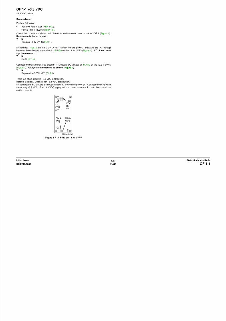
8/13/2019 Xerox Docu Color 2240-1632
http://slidepdf.com/reader/full/xerox-docu-color-2240-1632 479/1118
7/02
2-450 DC 2240/1632OF 1-2Initial IssueStatus Indicator RAPs
Resistance is 1 ohm or less.Y N
Replace +5V LVPS (PL 9.1).
Disconnect P/J511 on the +5V LVPS. Switch on the power. Measure the AC voltage between
the black and white wires in P/J16 on the +5V LVPS (Figure 1). AC Line Voltage is mea-
sured.
Y N
Go to OF 1-4.
Measure the DC voltage at P/J511 on the +5V LVPS (Figure 1). Voltages are measured as
shown.
Y N
Replace the +5V LVPS (PL 9.1).
There is a short circuit in +5 VDC distribution.
Refer to Section 7 wirenets for +5 VDC distribution.
Disconnect the P/J’s in the distribution network. Switch the power on. Connect the P/J’s while
monitoring +5 VDC. The +5 VDC supply will shut down when the P/J with the shorted circuit is
connected.
Figure 1 P16, P511 on +5V LVPS
+5VDCRETVio (all)+5VDC
Orn (3)
OF 1-3 +24 VDC Enable+24V LVPS is not enabled.
Procedure
Measure the voltage between the +24V LVPS P/J505-3 and ground (-). +3.3 VDC is mea-
sured.
Y N
Measure the voltage between I/F PWB P/J534-B4 and ground. +3.3 VDC is measured.
Y N
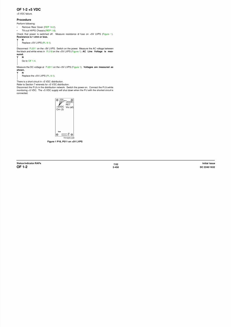
8/13/2019 Xerox Docu Color 2240-1632
http://slidepdf.com/reader/full/xerox-docu-color-2240-1632 480/1118
7/02
2-451DC 2240/1632 OF 1-3Status Indicator RAPsInitial Issue
Go to Flag 1. Repair the open circuit.
Replace the MCU PWB (PL 13.1).
If the problem continues, replace the ESS PWB (PL 13.1).
Measure the voltage between the +24V LVPS P/J505-4 and ground (-). +5 VDC is mea-
sured.
Y N
Measure the voltage between the 5V LVPS P/J511-3 and ground (-). +5 VDC is mea-
sured.
Y N
Replace the 5V LVPS (PL 9.1).
Go to Flag 2. Repair the open circuit between the 24V LVPS and 5V LVPS.
Measure the resistance between the +24V LVPS P/J505-2 and ground. Less than 5 ohms is
measured.
Y N
Go to Flag 3. Repair the open circuit between the 24V LVPS and 5V LVPS.
Replace the 24V LVPS (PL 9.1).
Figure 1 +24V LVPS Enable CD
OF 1-4 AC PowerAC Power Failure
Initial Actions
Check Circuit Breaker.
Procedure
AC Line Voltage is measured between the Noise Filter PWB FS75 (+) and FS74 (-) ( PL
9.2).

8/13/2019 Xerox Docu Color 2240-1632
http://slidepdf.com/reader/full/xerox-docu-color-2240-1632 481/1118
7/02
2-452 DC 2240/1632OF 1-4Initial IssueStatus Indicator RAPs
Y N
AC Line Voltage is measured between the Circuit Breaker P/J72-1 (+) and P/J72-1
(-).
Y N
Disconnect power cord from power outlet. The voltage of the power outlet is AC
Line Voltage.
Y N
Inform customer power is not available.
Check the Power Cord for an open circuit. If no problems are found, replace the Cir-
cuit Breaker (PL 9.2).
Check wire between Circuit Breaker P/J72 and Noise Filter PWB for an open circuit and
poor contact.
AC Line Voltage is measured between the Noise Filter PWB FS77 (+) and FS76 (-).
Y N
If the Circuit Protector on the Noise Filter PWB is tripped, reset it. If it is not tripped,
replace the Noise Filter PWB (PL 9.2).
AC Line Voltage is measured between the Main Power Switch FS57 (+) and Noise Filter
PWB FS76 (-).Y N
Check the wire between the Main Power Switch and the Noise Filter PWB for an open cir-
cuit and poor contact.
AC Line Voltage is measured between the Main Power Switch FS69 (+) and Noise Filter
PWB FS76 (-).
Y N
Replace the Main Power Switch (PL 10.2).
AC Line Voltage is measured between the AC Drive PWB FS40 (+) and the FS39 (-)?
Y N
Check the wire between the AC Drive PWB (PL 9.2) and the Main Power Switch (PL
10.2) for an open circuit and poor contact.
AC Line Voltage is measured between the AC drive PWB P/J43-9 (+) and the P/J43-1 (-).
Y N
Replace the AC Drive PWB (PL 9.2).
Check the AC voltage distribution by referring to Chapter 7 Wiring Data.
OF 2-1 Dark / Blank DisplayUI Display is dark with minimal legibility, or no text or graphics are visible.
Initial Actions
Ensure all external cables and power cords are connected.
Procedure
NOTE: If a Status Code is displayed, go to status code RAP .

8/13/2019 Xerox Docu Color 2240-1632
http://slidepdf.com/reader/full/xerox-docu-color-2240-1632 482/1118
7/02
2-453DC 2240/1632 OF 2-1Status Indicator RAPsInitial Issue
There is some luminance in the UI display.
Y N
Switch off the power. Listen to the cooling fans on the right side and at the rear of the
machine and switch on the power. Cooling fans are audible either momentarily or
continuously.
Y N
There is a +5 VDC failure. Go to OF 1-2.
There is a +3.3 VDC or IIT +24 VDC failure.
Remove the IIT Top Cover (REP 6.3). Measure the AC Line Voltage between P/J705-4
and -3. AC Line Voltage is measured.Y N
Check the condition of the power cord for the IIT. Repair as required (PL 18.4).
If the components are good, check the condition of the outlet on the AC Drive PWB
(PL 9.2).
Measure the voltage between P/J705-3 on the IIT LVPS and ground (-). A (L) DC volt-
age is measured.
Y N
Repair the wire between P/J705-3 on the IIT LVPS and P/J344-70 on the ESS
PWB.
Measure the voltage between P/J705-4 on the IIT LVPS and ground (-). +5 VDC is mea-
sured.
Y N
Repair the wire between P/J705-4 on the IIT LVPS and P/J344-69 on the ESS
PWB.
Go to OF 1-1.
Replace the VR PWB (PL 18.2).
Figure 1 IIT LVPS CD
OF 99-1 Reflective SensorProcedure
Enter dC330 [XXXX-XXX]. Block the Sensor with a blank sheet of paper. The display
changed.
Y N
There is +5VDC measured between the sensor Pin 2 (+) and GND (-).
Y N
Check the wire between the sensor Pin 2 and the PWB Pin 8 for an open circuit or a
poor contact. If the check is OK, replace the PWB

8/13/2019 Xerox Docu Color 2240-1632
http://slidepdf.com/reader/full/xerox-docu-color-2240-1632 483/1118
7/02
2-454 DC 2240/1632OF 99-1Initial IssueStatus Indicator RAPs
There is +5VDC measured between the sensor Pin 1 (+) and Pin 3.
Y N
There is +5VDC measured between the PWB Pin 4 (+) and Pin 5.
Y N
Replace the PWB.
Check the wire between the PWB Pin 4 and the sensor Pin 1 and between the PWB
Pin 5 and the sensor Pin 3 for an open circuit or a poor contact.
Replace the sensor.
Remove the blank sheet of paper from the sensor. The display changed.
Y N
Remove the sensor connector. The display changed.
Y N
Check for a short circuit between the sensor Pin 2 and the PWB Pin 8.
If the check is OK, replace the PWB.
Replace the sensor.
Replace the sensor.
Figure 1 Reflective Sensor CD
OF 99-2 Transmissive SensorProcedure
Enter dC330 [XXX-XXX]. Block the Sensor. The display changed.
Y N
Remove the sensor connector. The display changed.
Y N
Check a short circuit between the sensor Pin 2 and the PWB Pin 8. If the check is
OK, replace the PWB.
Replace the sensor

8/13/2019 Xerox Docu Color 2240-1632
http://slidepdf.com/reader/full/xerox-docu-color-2240-1632 484/1118
7/02
2-455DC 2240/1632 OF 99-2Status Indicator RAPsInitial Issue
Replace the sensor.
Unblock the sensor. The display changed.
Y N
There is +5VDC measured between the sensor Pin 2 (+) and GND (-).
Y N
Check the wire between the sensor Pin 2 and the PWB Pin 8 for an open circuit or a
poor contact. If the check is OK replace the PWB
There is +5VDC measured between the sensor Pin 1 (+) and Pin 3 (-).
Y N
Check the wire between the PWB Pin 4 and the sensor Pin 1 and between the PWB
Pin 5 and the sensor Pin 3 for an open circuit and poor contact. If the check is OK,
replace the PWB.
Replace the sensor.
Replace the sensor.
Figure 1 Transmissive Sensor CD
OF 99-3 SwitchProcedure
Enter dC330 [XXX-XXX]. Actuate the switch. The display changed.
Y N
There is +5VDC measured between Pin 2(+) of the Switch and GND(-).
Y N
Check the wire between the switch Pin 2 and the PWB Pin 3 for an open circuit and
poor contact. If the check is OK, replace the PWB.
There is +5VDC measured between Pin 1(+) of the Switch and GND(-)

8/13/2019 Xerox Docu Color 2240-1632
http://slidepdf.com/reader/full/xerox-docu-color-2240-1632 485/1118
7/02
2-456 DC 2240/1632OF 99-3Initial IssueStatus Indicator RAPs
There is +5VDC measured between Pin 1(+) of the Switch and GND( ).Y N
Replace the switch.
Check the wire between the PWB Pin 4 and the switch Pin 1 for an open circuit and poor
contact. If the check is OK, replace the PWB.
De-actuate the switch. The display changed.
Y N
Disconnect the connector on the switch. The display changed.
Y N
Check for a short between the switch Pin 2 and the PWB Pin 3. If the check is OK,replace the PWB.
Replace the switch.
Replace the switch.
Figure 1 2003
OF 99-4 Solenoid / Clutch OpenProcedure
NOTE: Before performing this RAP, ensure that there is no mechanical problem for the sole-
noid and clutch.
Enter dC330 [XXX-XXX]. There is +24VDC measured between the PWB Pin 3 (+) and GND
(-).
Y N
There is +24VDC measured between Pin 2(+) of the Solenoid/Clutch and GND(-).
Y N
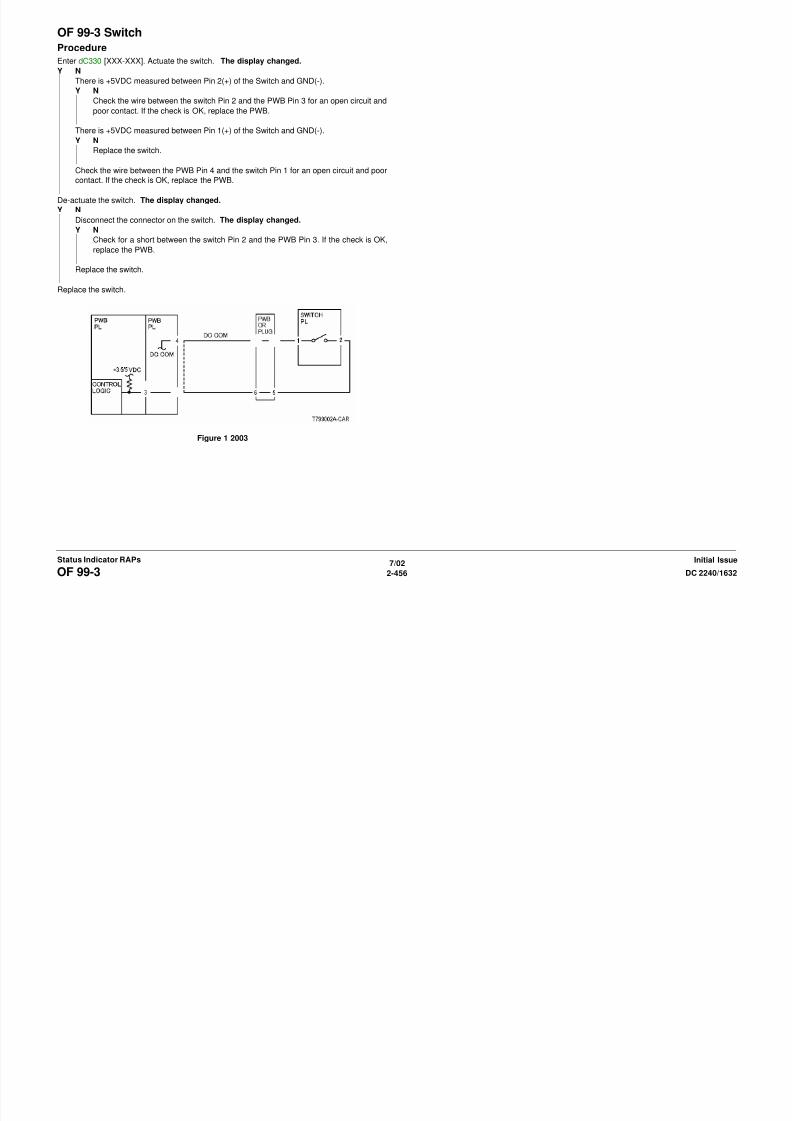
8/13/2019 Xerox Docu Color 2240-1632
http://slidepdf.com/reader/full/xerox-docu-color-2240-1632 486/1118
7/02
2-457DC 2240/1632 OF 99-4Status Indicator RAPsInitial Issue
There is +24VDC measured between Pin 1(+) of the Solenoid/Clutch and GND(-).Y N
Check the wire between the PWB Pin 4 and the solenoid/clutch Pin 1 for an
open circuit and poor contact. If the check is OK, replace the PWB
Replace the solenoid/clutch.
Check the wire for a short between the PWB Pin 3 and the solenoid/clutch Pin 2 for an
open circuit or poor contact.
Replace the PWB.
Figure 1 Solenoid/Clutch CD
OF 99-5 Solenoid / Clutch ShortedProcedure
Turn off the power.
Remove the PWB connector. There is 10 Ohm’s or less measured between the connector
Pin 3 and the frame.
Y N
Replace the PWB.
Check for a short circuit to frame of the circuit between PWB Pin 3 and the solenoid/clutch Pin
2.If th h k i OK l th l id/ l t h

8/13/2019 Xerox Docu Color 2240-1632
http://slidepdf.com/reader/full/xerox-docu-color-2240-1632 487/1118
7/02
2-458 DC 2240/1632OF 99-5Initial IssueStatus Indicator RAPs
If the check is OK, replace the solenoid/clutch.
Figure 1 Solenoid/Clutch CD
OF 99-6 2 Wire Motor OpenProcedure
NOTE: Before performing this RAP, ensure that the motor is free to rotate.
Enter the dC330 [XXX-XXX].
There is +24VDC measured between Pin 3(+) of the PWB and GND(-).
Y N
There is +24VDC measured between the Motor Pin 2(+) of the Motor and GND(-).Y N
There is +24VDC measured between the Motor Pin 1(+) of the Motor and GND(-).Y N

8/13/2019 Xerox Docu Color 2240-1632
http://slidepdf.com/reader/full/xerox-docu-color-2240-1632 488/1118
7/02
2-459DC 2240/1632 OF 99-6Status Indicator RAPsInitial Issue
Y N
There is +24VDC measured between the PWB Pin 4(+) of the PWB and GND(-
).
Y N
Replace the PWB.
Check the wire between the PWB Pin 4 and the Motor Pin 1 for an open circuit
or poor contact.
Replace the motor.
Check the wire between the PWB Pin 3 and the Motor Pin 2 for an open circuit or poor
contact.
Replace the PWB.
Figure 1 Motor CD
OF 99-7 2 Wire Motor OnProcedure
Turn off the power. Remove the PWB connector. There is 10 Ohm’s or less measured
between the connector Pin 3 and the frame.
Y N
Replace the PWB.
Check the wire between the connector Pin 3 and the motor Pin 2 for a short circuit.
If the check is OK, replace the motor.

8/13/2019 Xerox Docu Color 2240-1632
http://slidepdf.com/reader/full/xerox-docu-color-2240-1632 489/1118
7/02
2-460 DC 2240/1632OF 99-7Initial IssueStatus Indicator RAPs
Figure 1 Motor CD
OF 99-8 Set Gate Solenoid OpenProcedure
There is +24VDC measured between the Nip/Release Solenoid Pin 1 (+) and GND (-).
Y N
There is +24VDC measured between the PWB Pin 5 (+) and GND(-).
Y N
Check +24VDC inputs on the PWB. If the check is OK, replace the PWB.
Check the wire between the PWB Pin 5 and the Nip/Release Solenoid Pin 1 for an open
circuit or poor contact.

8/13/2019 Xerox Docu Color 2240-1632
http://slidepdf.com/reader/full/xerox-docu-color-2240-1632 490/1118
7/02
2-461DC 2240/1632 OF 99-8Status Indicator RAPsInitial Issue
Enter dC330 [XXX-XXX]. There is +24VDC measured between the PWB Pin 4 (+) and
GND(-).
Y N
There is +24VDC measured between the Nip/Release Solenoid Pin 3 (+) and GND (-
).
Y N
Replace the Nip/Release Solenoid.
Check the wire between the PWB Pin 4 and the Nip/Release Solenoid Pin 3 for an open
circuit and poor contact.
Follow the following when the release caused a problem.
Go to the dC330 [XXX-XXX]. There is +24VDC measured between the PWB Pin 6 (+) and
GND(-).
Y N
There is +24VDC measured between the Nip/Release Solenoid Pin 2 (+) and GND (-)
Y N
Replace the Nip/Release Solenoid.
Check the wire between the PWB Pin 6 and the Nip/Release Solenoid Pin 2 for an open
circuit or poor contact.
Replace the PWB.
Figure 1 Nip Solenoid CD
OF 99-9 Multiple Wire MotorFor use on DC motors that:
• have 1 or 2 DC power inputs
• are controlled by 2 or more drivers
• have no DC COM connections for return power
• have no specific feedback circuits
Procedure
Connect black meter lead to ground. Measure voltage at each pin of J2. +24 VDC is mea-
sured at each pin.Y N

8/13/2019 Xerox Docu Color 2240-1632
http://slidepdf.com/reader/full/xerox-docu-color-2240-1632 491/1118
7/02
2-462 DC 2240/1632OF 99-9Initial IssueStatus Indicator RAPs
Disconnect J2. Measure voltage at J2-1 and J2-6. +24 VDC is measured.
Y N
Switch machine off then on. Measure voltage at J2-1 and J2-6. +24 VDC is mea-
sured.
Y N
Replace the PWB.
Check the motor wires for a short circuit. If the wires are good, replace the Motor.
Check the motor wires for obvious damage. If the wires are good, replace the Motor.
Replace the PWB.
Figure 1 Motor CD

8/13/2019 Xerox Docu Color 2240-1632
http://slidepdf.com/reader/full/xerox-docu-color-2240-1632 492/1118

8/13/2019 Xerox Docu Color 2240-1632
http://slidepdf.com/reader/full/xerox-docu-color-2240-1632 493/1118
7/02
3-2 DC 2240/1632
Initial IssueImage Quality

8/13/2019 Xerox Docu Color 2240-1632
http://slidepdf.com/reader/full/xerox-docu-color-2240-1632 494/1118
Misregistration/Skew The position and/or alignment of the image relative to the top edge and side edge of the paper is not within specification. Go to the IQ9 RAP
Missing Colors One or more of the primary colors are missing from the image. Go to the IQ17 RAP
Mottle Areas of sol id, or high densi ty coverage that are reproduced with a b lotchy, non-uniform appearance. Go to the IQ15 RAP
Regular (Repeating) Bands, Streaks,
Spots, or Smears
A defect that repeats at an interval from14 to 264 mm, is most noticeable in low density (20-40%) halftone areas of the
copy, and runs perpendicular to process direction.
Lines and bands are generally uniform in shape from one end to the other.
Streaks are generally shorter than lines and are of nonuniform width along their length. They may have a more ragged orfuzzy appearance than lines.
Go to the IQ14 RAP
Table 1 Image Quality Defects
Defect - green indicates hotlink to
image samples
Description Corrective Action
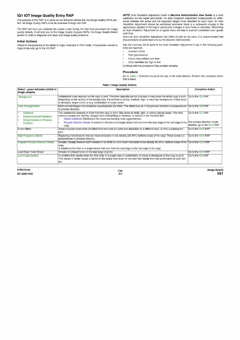
8/13/2019 Xerox Docu Color 2240-1632
http://slidepdf.com/reader/full/xerox-docu-color-2240-1632 495/1118
7/02
3-4 DC 2240/1632IQ1Initial IssueImage Quality
Residual Image A toner image that remains on the photoreceptor or Transfer Belt after cleaning. The next image is placed on top of the
residual image and both images are transferred to the next copy.
Go to the IQ5 RAP
Spots Generally circular in shape, these defects can be caused by an absence of toner in a desired area, or a deposit of toner in
an undesired area
Go to the IQ16 RAP
Unfused prints Image can be rubbed off with little or no pressure Go to the IQ13 RAP
Wrinkled Image Areas of 11x17 in./A3 pr ints have distinctive “worm track” patterns, and/or wrinkles in the paper i tsel f Go to the IQ4 RAP
IQ2 IIT Image Quality Entry RAPThis RAP is for troubleshooting IIT (Scanner/ADF) problems only. Before proceeding, verify
that the defect is present in Copy mode only. If the defect is present in Print mode, go to the
IQ1 RAP.
Initial Actions
Clean the Lens, the top and bottom surface of the Platen Glass, and all Mirrors with Lens and
Mirror Cleaner and a soft, lint-free cloth.
Procedure
Compare the defective copies with the descriptions listed in Table 1. Perform the corrective
action listed for that defect.
Table 1
Defect Corrective Action
Background Clean the Platen Belt.
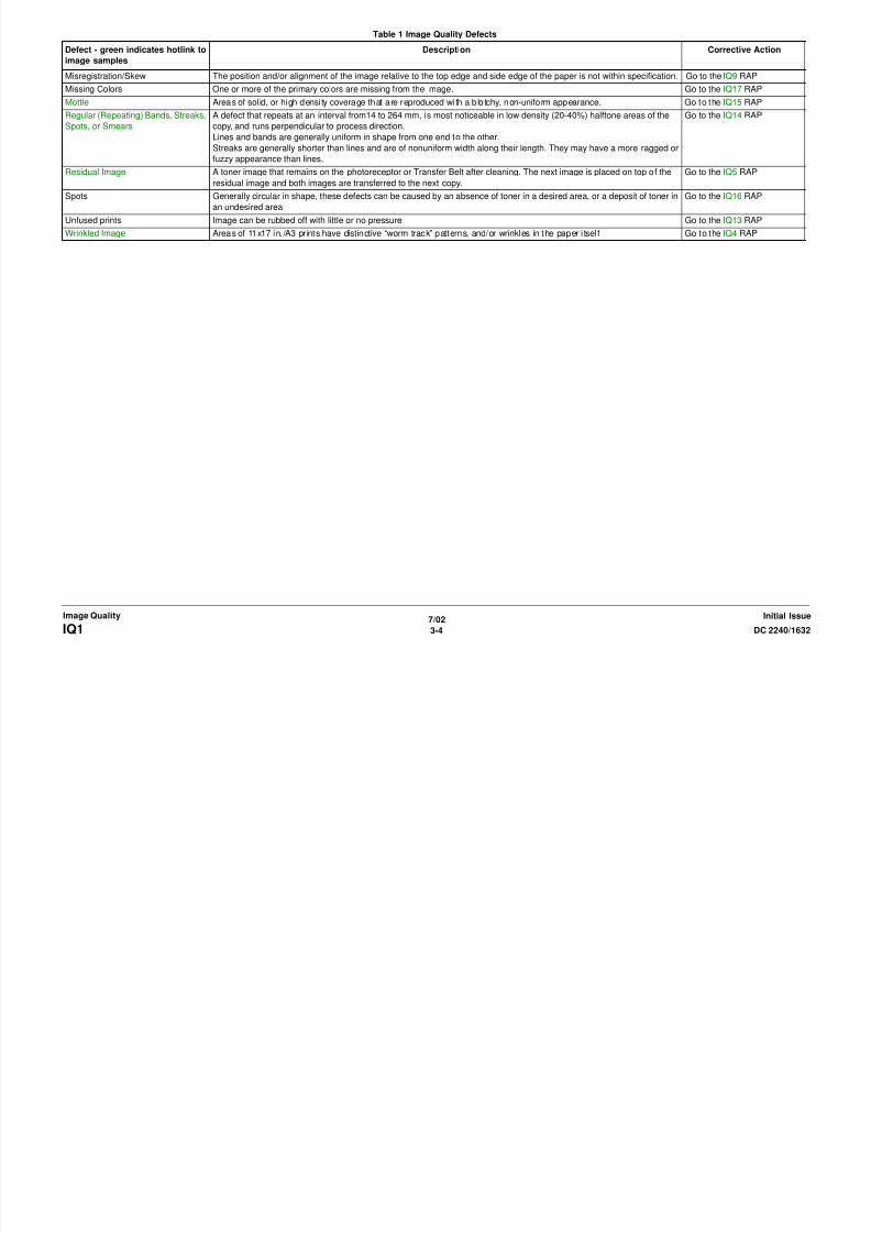
8/13/2019 Xerox Docu Color 2240-1632
http://slidepdf.com/reader/full/xerox-docu-color-2240-1632 496/1118
7/02
3-5DC 2240/1632 IQ2Image QualityInitial Issue
Calibrate the IIT (ADJ 9.7).
Blurred or Streaked Copy Ensure that the Platen Glass is installed correctly.
Check/adjust the carriage alignment (ADJ 6.1).
R/E error Check/adjust IIT magnification (ADJ 9.12).
Deletions Clean the Lens, the top and bottom surface of the Platen Glass, and all Mirrors with Lens and Mirror Cleaner and a soft, lint-free cloth.
If the problem persists, replace the Lens Kit (PL 18.4).
Misregistration/Skew Go to the IQ9 RAP.
MoirePatterns in the image areas of the print that have the
appearance of a screen or grid overlaying the
image. The pattern may be uniform or nonuniform in
area or shape.
• Switch between photo modes and, if necessary, original types, to determine which mode minimizes the defect.• Decrease the Sharpness level.
• Reduce or enlarge the copy slightly.
• Rotate the original on the platen by 90 degrees.
Newton Rings
Repetitive, irregular-shaped marks that occur when
making copies of glossy photographs. These marks
are most noticeable in large low-density or highlight
areas.
Clean the Document Glass
Place a transparency between the document and the glass
IQ3 Low Image Density RAPThis RAP troubleshoots the causes of output images showing image density lower than speci-
fication
Initial Actions
• Clean the ROS windows
• Replace the paper in use with fresh, dry paper of the correct specification
• Determine if the Drum Cartridge or any of the Toner Cartridges are approaching end-of-
life. Replace if necessary.
• Perform Max Setup (ADJ 9.1). If this does not resolve the problem, continue with this
RAP.
IQ4 Wrinkled Image RAPAreas of 11x17 in./A3 prints have distinctive “worm track” patterns, and/or wrinkles in the paper
itself
Initial Actions
Ensure that the paper is dry and fresh.
Use heavier weight paper
Use long-grain paper.
Procedure

8/13/2019 Xerox Docu Color 2240-1632
http://slidepdf.com/reader/full/xerox-docu-color-2240-1632 497/1118
7/023-6 DC 2240/1632IQ3, IQ4
Initial IssueImage Quality
Procedure
Go to dC612. Print Test pattern 12. The defect involves a single color.
Y N
Go to dC612. Print Test pattern 12. Open the Front Door in the middle of the print job
(approximately 7 seconds after selecting Start). Extend the IBT. There is a good toner
image on the Transfer Belt.
Y N
Go to the IQ21 RAP to check the Developer Bias. If this does not resolve the prob-
lem, go to the IQ20 RAP to check the 1st BTR bias.
If the problem continues, check the ROS for contamination of the windows or mis-
alignment.
Check the 2nd BTR for damage or incorrect installation. Go to the IQ22 RAP to check the
Backup Roll bias. If the problem continues, replace 2nd BTR Assembly ( PL 7.1). If this
does not resolve the problem, replace the Transfer Belt (PL 5.3).
Swap the affected Drum Cartridge with an adjacent unit. Print Test Pattern 12 The defect
moved to the new color.Y N
Go to the IQ21 RAP to check the Developer Bias. I f this does not resolve the problem, go
to the IQ20 RAP to check the 1st BTR bias. If the problem continues, replace the Devel-
oper for the affected color (PL 6.2). If this does not resolve the problem, replace the ATC
Sensor for the affected color (PL 6.2).
Replace the Drum Cartridge (see Machine Consumables in Section 6).
Procedure
TBD
IQ5 Residual Image (Ghosting) RAPInitial Actions
• Check the end-of-life counter for the Drum Cartridge. If the unit is at or near end-of-life,
replace the Drum Cartridge (see Machine Consumables in Section 6).
NOTE: Some ghosting on transparencies is unavoidable.
• If the problem occurs only with certain types of media, ensure that the media in use is
within specification, and that the customer is aware of correct operation of print driver.
• If the distance between the intended image and the residual image has a fixed rate of rep-
etition, go to the IQ14 RAP. Return to this procedure if the problem persists.
Procedure

8/13/2019 Xerox Docu Color 2240-1632
http://slidepdf.com/reader/full/xerox-docu-color-2240-1632 498/1118
7/023-7DC 2240/1632 IQ5
Image QualityInitial Issue
The problem is with a single primary color
Y N
Remove the Fuser. Examine the Heat Roll and Pressure Roll for evidence of toner offset-
ting. There is Toner adhering to the Heat Roll.
Y N
Check for a residual image on the Transfer Belt. Repair or replace the IBT Cleaner
(PL 5.3) as required.
Check the 2nd BTR for contamination. Clean/replace as required
Clean the Heat Roll. If the problem persists, replace the Fuser (PL 7.1).
Check the Erase Lamp for the affected color:
• Enter dC330 [009-045] (C, Y, or M), or [009-042] (K), as appropriate.
• Remove the Drum cartridge for the affected color.
• check for light along the mounting rail left side
The Erase lamp is lit.
Y N
Go to Flag 1 (C), Flag 2 (Y), Flag 3 (M), or Flag 4 (K). Check for an open circuit. If the
wires are OK, replace the Erase Lamp (PL 4.2) for the affected color. If the problem per-sists, Replace the MCU PWB (PL 13.1).
Go to the IQ21 RAP. Check for a short circuit in the Developer bias circuit of the affected color.
8/13/2019 Xerox Docu Color 2240-1632
http://slidepdf.com/reader/full/xerox-docu-color-2240-1632 499/1118
7/023-8 DC 2240/1632IQ5
Initial IssueImage Quality
Figure 1 IQ5 RAP Circuit Diagram

8/13/2019 Xerox Docu Color 2240-1632
http://slidepdf.com/reader/full/xerox-docu-color-2240-1632 500/1118
8/13/2019 Xerox Docu Color 2240-1632
http://slidepdf.com/reader/full/xerox-docu-color-2240-1632 501/1118
7/023-10 DC 2240/1632IQ7
Initial IssueImage Quality
Figure 1 IQ7 RAP Circuit Diagram
IQ8 Color-to-Color Misregistration RAPInitial Actions
Adjust the color registration (ADJ 9.6). If the problem remains, continue with this procedure
Procedure
The problem involves a single color.
Y N
Check that the ROS is securely mounted and that the ROS window is not dirty or dam-
aged. If the problem persists, replace the ROS (PL 3.1).
Check the mounting of the Developer Housing for the affected color. Ensure that it is installed
correctly and that it is free from damage. Repair or replace as required (PL 6.2).
IQ9 Skew/Misregistration RAPThis RAP is used when Skew, System Registration, or Magnification are out of specification.
For Color-to-Color-Misregistration, go to the IQ8 RAP.
Initial Actions
Load some new, dry 24 lb. 11X17/A3 Xerox COLOR Xpressions (NASG), or 90 GSM Colortech
+ (ESG) into each paper tray (use 8.5X11/A4 in Tray 1). Make 3 full color copies from each
paper tray. Mark the appropriate paper tray on these copies.
ProcedureThe problem is still present when using the proper paper.
Y N
E l i h h d lb X COLOR X i (NASG)
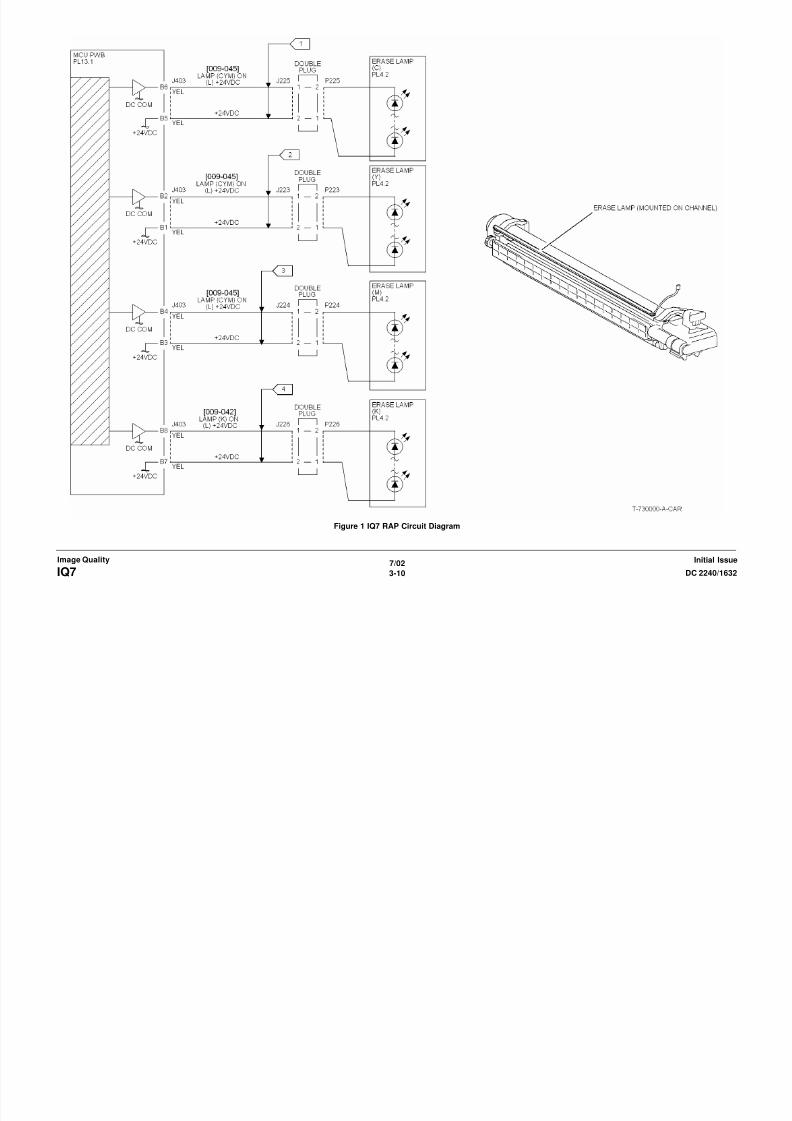
8/13/2019 Xerox Docu Color 2240-1632
http://slidepdf.com/reader/full/xerox-docu-color-2240-1632 502/1118
7/023-11DC 2240/1632 IQ8, IQ9
Image QualityInitial Issue
Explain to the customer that new, dry, 24 lb. Xerox COLOR Xpressions (NASG), or 90
GSM Colortech + (ESG) paper is the specified paper for use in the DocuColor 1632/2240.
The problem occurs only in the Printer Mode
Y N
The defect occurs when the document is manually registered on the platen glass.
Y N
Ensure that the Document Transport Belt is clean. Check the Document Handler
Adjustments (ADJ 5.1 through ADJ 5.7). If the problem continues, check the DADFdrive rolls and pinch rolls for wear or glossing.
The problem is Skew
Y N
The problem is Misregistration
Y N
Adjust the IIT Vertical/Horizontal Magnification (ADJ 9.12) and the IOT Lead
Edge/Side Edge Registration (ADJ 9.9).
Enter dC612. Select Pattern 3. Misregistration is present on the copy
Y N
Adjust the IOT Lead Edge/Side Edge Registration (ADJ 9.9), then the IIT Lead
Edge and Side Edge Registration (ADJ 9.10 and ADJ 9.11).
The defect occurred on copies from all five paper trays.
Y N
Check the IOT Lead Edge/Side Edge Registration (ADJ 9.9) for that tray.
Check the feeder for the affected tray for wear, slipping, damage, or contami-
nation.
• Tray 1 Feeder (PL 2.4)
• Tray 2 Feeder (PL 16.7)
• Tray 3 Feeder (PL 16.9)
• Tray 4 Feeder (PL 16.11)
• Tray 5 Feed Assembly (PL 2.14)
Registration varies from copy to copy.
Y N
Go to ADJ 9.9, Lead/Side Edge Adjustment.
A B C
Check the components in the Registration Transport Assembly (PL 2.6) for wear,slipping, damage, or contamination. Clean/replace as required
The defect occurred on copies from all five paper trays.
Y N
Check the components in the Registration Transport Assembly (PL 2.6) for wear,
slipping, damage, or contamination. Clean/replace as required
Check the IOT Lead Edge/Side Edge Registration (ADJ 9.9) for that tray.
Check the feeder for the affected tray for wear, slipping, damage, or contamination.
• Tray 1 Feeder (PL 2.4)• Tray 2 Feeder (PL 16.7)
• Tray 3 Feeder (PL 16.9)
IQ12 Process Direction Bands, Streaks, and Smears RAPProcedure
NOTE: The repetition rate for Transfer Belt defects varies considerably, depending on paper
size and mode of operation. The defect may appear as frequently as every 3rd sheet, or may
only occur every 14 sheets.
The defect occurs in approximately the same position on multiple prints.
Y N
If the defect occurs intermittently, examine the Developer Housings for evidence of toner
clumping. If clumping is found, replace the Developer (PL 6.2). if this does not resolve the
problem
The defect is a full-width (LE - TE) Streak Deletion in Process Direction.
A B C
8/13/2019 Xerox Docu Color 2240-1632
http://slidepdf.com/reader/full/xerox-docu-color-2240-1632 503/1118
7/023-12 DC 2240/1632IQ9, IQ12
Initial IssueImage Quality
• Tray 4 Feeder (PL 16.11)
• Tray 5 Feed Assembly (PL 2.14)
TBD.
The defect is a full width (LE TE) Streak Deletion in Process Direction.
Y N
Remove the Fuser Assembly. Examine the Heat Roll for damage or contamination. Clean
or replace as required (PL 7.1).
If the Fuser is OK, check the Developer Housing (PL 6.2). Repair or replace as required.
If the problem remains, replace the ROS (PL 3.1).
If the problem is related to a single color, replace the Drum Cartridge (see Machine Con-
sumables in Section 6).
Enter dC612. Select Test Pattern 20% coverage pattern for all colors. The defect is present
for all colors.
Y N
• Check the ROS window for damage or contamination. Clean or replace as required.
• Check Drum Cartridge for affected color. Check for damage or contamination to the
BCR.
• Go to the IQ20 RAP to check the 1st BTR bias circuit for the affected color
• Replace the Developer (PL 6.2) for the affected color. Check the housing for damage
or toner clumping.
Remove the IBT Cleaner (PL 5.3). Inspect the cleaning blade and Mylar seal for damage.
Clean or replace as required.
If the IBT Cleaner is OK, check the Transfer Belt (PL 5.3) for damage or contamination. Ensure
that there is no debris or loose wiring, etc. in contact with the belt. Clean or replace as required.
IQ13 Unfused Copy/Toner Offset RAPInitial Actions
Replace the paper in use with fresh, dry paper of the correct specification.
Ensure that the media being used matches the settings on the UI screen or print driver. Using
the next heavier setting may resolve the problem.
If the Key Operator/Administrator has configured certain trays for a specific type of media,
ensure that the specified media is actually loaded in those trays.
Procedure
Check the following:
Ch k th S A bl (PL 7 2) f t i ti i t ti Cl
IQ14 Repeating Bands, Streaks, Spots, and Smears RAPProcedure
Measure the distance between the repeating defects. Locate the distance on the table below.
Perform the indicated repair actions
Table 1 Repeating Defects
Repetition
spacing Component(s) Repair Actions
<4 mm. High Frequency Band-
ing
Replace the ROS
28.3 mm. Developer Mag Roll Check Developer roll bias for floating or shorting out.
Replace Developer Housing (PL 6.2) if required.

8/13/2019 Xerox Docu Color 2240-1632
http://slidepdf.com/reader/full/xerox-docu-color-2240-1632 504/1118
7/023-13DC 2240/1632 IQ13, IQ14
Image QualityInitial Issue
• Check the Sensor Assembly (PL 7.2) for contamination or incorrect mounting. Clean,
repair, or replace as required.
• Check the Fuser (PL 7.1) for damage, toner offsetting, paper wrap, or incorrect installa-
tion. Clean or replace as required.
After resolving the problem, make 10 blank copies (letter size, Black mode) to cleaner residual
toner from the Fuser Heat Roll and Fuser Belt. If the problem persists, or if Lead Edge contam-
ination is present, remove the Fuser Exit Chute ( PL 7.2) and clean any toner or paper residue
from the Exit Chute and the metal stripper baffle.
p p g ( ) q
44 mm. Drum Cartridge Replace the Drum Cartridge (see Machine Consum-
ables in Section 6).
84 mm. Fuser Heat Roll Remove the Fuser Assembly. Check the Heat Rol l for
damage (nicks, wear, or cuts) or contamination. Clean
or replace as required (PL 7.1).
88 mm. BTR 2 Backup Roll
BTR 2 Roll
Check the 2nd BTR Assembly for damage or contami-
nation. Clean, repair or replace as required (PL 2.8).
Replace the Transfer Belt (PL 5.3).
94 mm. Drum Cartridge
Fuser Belt
Single Color - Replace the Drum Cartridge (see
Machine Consumables in Section 6).
All Colors - Remove the Fuser Assembly. Check the
Heat Roll for damage (nicks, wear, or cuts) or contami-
nation. Clean or replace as required (PL 7.1).

8/13/2019 Xerox Docu Color 2240-1632
http://slidepdf.com/reader/full/xerox-docu-color-2240-1632 505/1118
IQ17 Missing Colors RAPOne or more of the primary (YMCK) colors is missing from the image.
Procedure
Go to the IQ21 Developer Bias RAP to check the developer bias circuit.
If the circuits are OK, ROS for damage or contamination. Clean, repair or replace as required
(PL 3.1).

8/13/2019 Xerox Docu Color 2240-1632
http://slidepdf.com/reader/full/xerox-docu-color-2240-1632 506/1118
7/023-15DC 2240/1632 IQ17
Image QualityInitial Issue
IQ20 1st BTR Checkout RAPProcedure
TBD - refer to Figure 1.

8/13/2019 Xerox Docu Color 2240-1632
http://slidepdf.com/reader/full/xerox-docu-color-2240-1632 507/1118
7/023-16 DC 2240/1632IQ20
Initial IssueImage Quality
8/13/2019 Xerox Docu Color 2240-1632
http://slidepdf.com/reader/full/xerox-docu-color-2240-1632 508/1118
7/023-17DC 2240/1632 IQ20
Image QualityInitial Issue
Figure 1 IQ20 RAP Circuit diagram
IQ21 Developer Bias RAPProcedure
WARNING
HIGH VOLTAGE!
Exercise caution when performing the voltage checks in this procedure.
Enter dC140 [09-026]. Check the voltage at P/J 580 for the affected color(s). There should be
approximately 370 VAC and -540 VDC (+/- 10%) present. The voltages are within range.
Y N
There is +24 VDC from J 501 pin 13 to J 501 pin 10 on the HVPS T5 PWB.
Y NThere is +24 VDC from J 553 pin 2 to J 553 pin 4 on the I/F PWB
Y N
Go the +24 VDC Wirenets to troubleshoot this problem.

8/13/2019 Xerox Docu Color 2240-1632
http://slidepdf.com/reader/full/xerox-docu-color-2240-1632 509/1118
7/023-18 DC 2240/1632IQ21
Initial IssueImage Quality
p
Go to Flag 2. Check for an open circuit
Check that the HVPS Control PWB is seated correctly. If the problem continues, replace
the HVPS T5 PWB (PL 9.1).
Go to Flag 1. Check for an open circuit or a short circuit to ground. Check P/J 580 and the HV
terminals on the Developer Housing(s). for damage or loose connections. If the checks are
good, return the RAP from which you came.
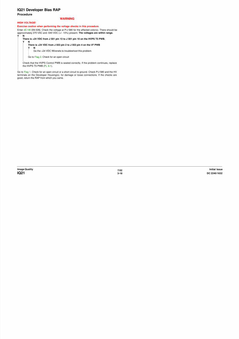
8/13/2019 Xerox Docu Color 2240-1632
http://slidepdf.com/reader/full/xerox-docu-color-2240-1632 510/1118
7/023-19DC 2240/1632 IQ21
Image QualityInitial Issue
Figure 1 IQ21 RAP Circuit Diagram
IQ22 2nd BTR Checkout RAPProcedure
TBD - refer to Figure 1.

8/13/2019 Xerox Docu Color 2240-1632
http://slidepdf.com/reader/full/xerox-docu-color-2240-1632 511/1118
7/023-20 DC 2240/1632IQ22
Initial IssueImage Quality

8/13/2019 Xerox Docu Color 2240-1632
http://slidepdf.com/reader/full/xerox-docu-color-2240-1632 512/1118
7/023-21DC 2240/1632 IQ22
Image QualityInitial Issue
Figure 1 IQ22 RAP Circuit Diagram
IQ23 BCR Checkout RAPProcedure
The problem is very high single-color background
Y N
TBD
Go to Flag 3. Check the wires associated with the problem color for an open circuit. If the wiresare OK., check the HV outputs at P 581 for open circuits or loose contacts. If the problem per-
sists, replace the Drum Cartridge for the affected color (see Machine Consumables in Section
6).
If this does not resolve the problem, replace the HVPS T7 PWB (PL 9.1).
A
A

8/13/2019 Xerox Docu Color 2240-1632
http://slidepdf.com/reader/full/xerox-docu-color-2240-1632 513/1118
7/023-22 DC 2240/1632IQ23
Initial IssueImage Quality
Figure 1 IQ23 RAP Circuit Diagram
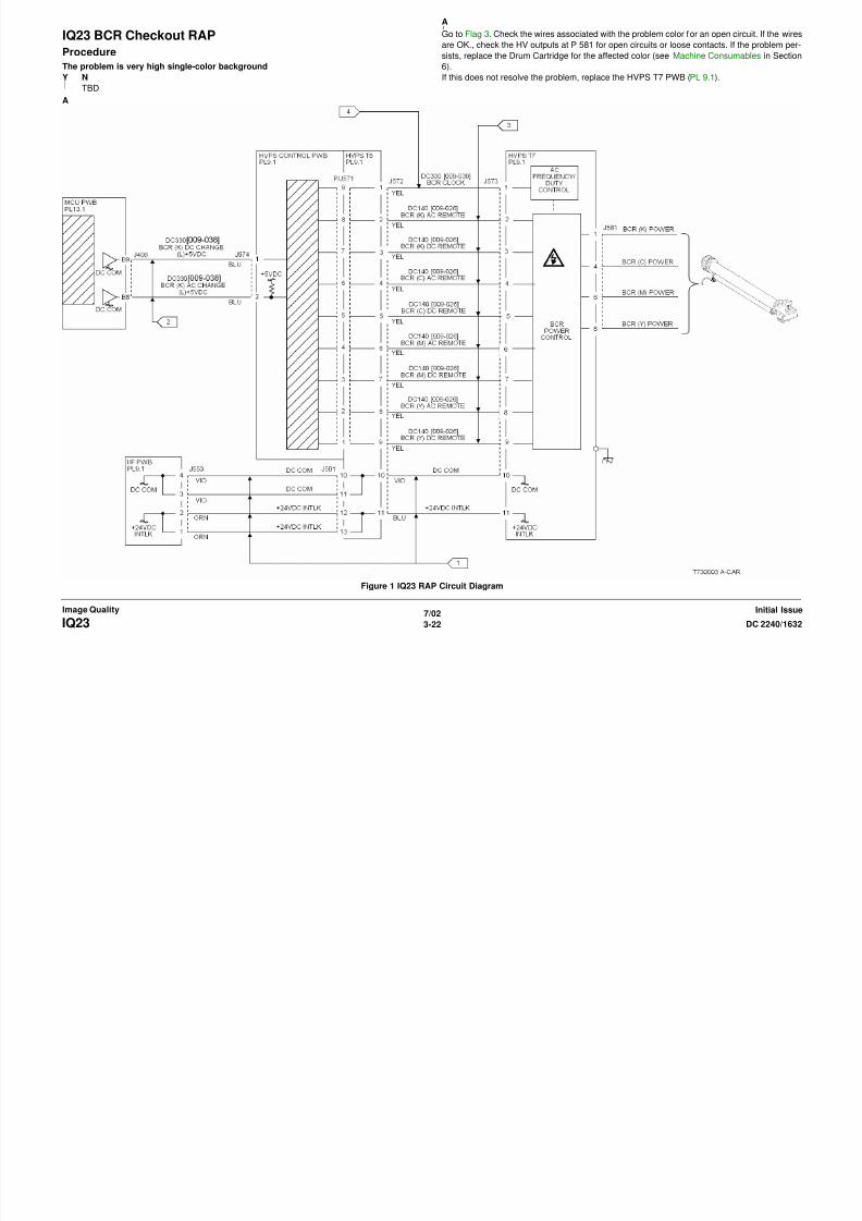
8/13/2019 Xerox Docu Color 2240-1632
http://slidepdf.com/reader/full/xerox-docu-color-2240-1632 514/1118
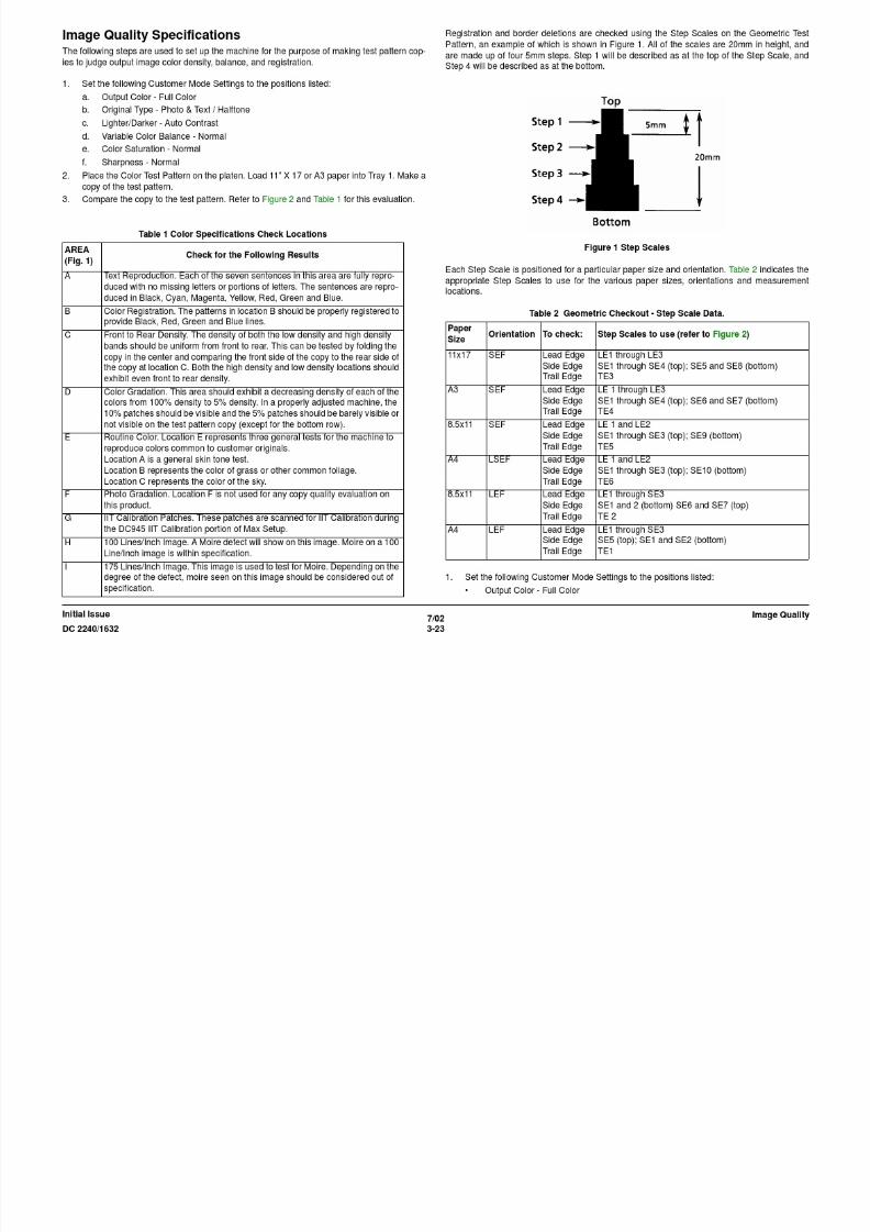
8/13/2019 Xerox Docu Color 2240-1632
http://slidepdf.com/reader/full/xerox-docu-color-2240-1632 515/1118
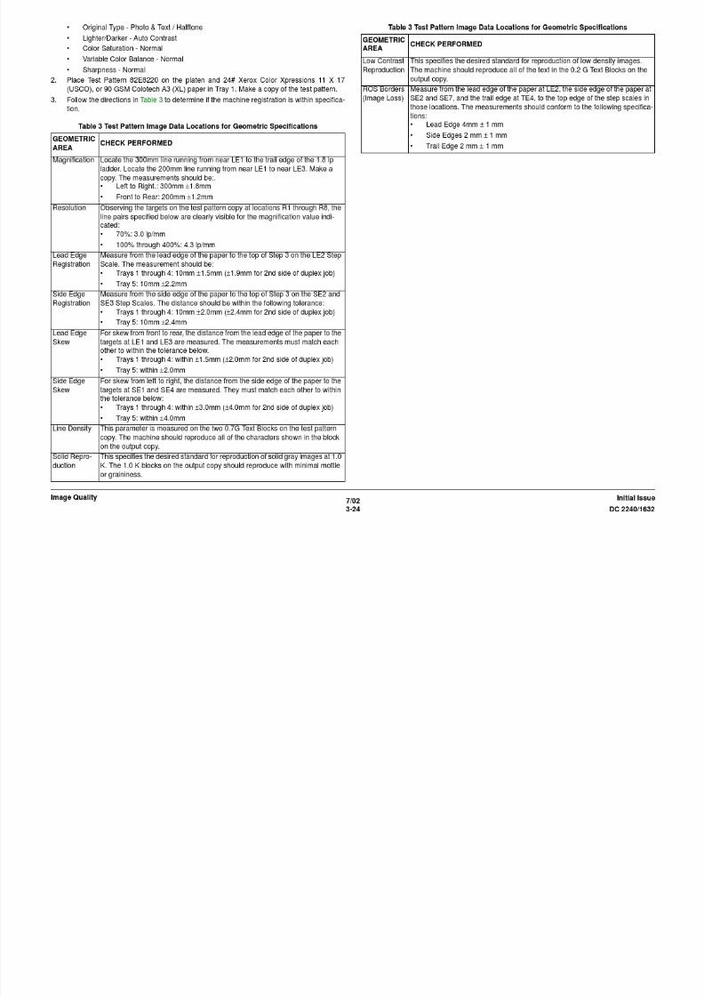
8/13/2019 Xerox Docu Color 2240-1632
http://slidepdf.com/reader/full/xerox-docu-color-2240-1632 516/1118
7/023-25DC 2240/1632
Image QualityInitial Issue
Figure 2 Color and Geometric Test Patterns
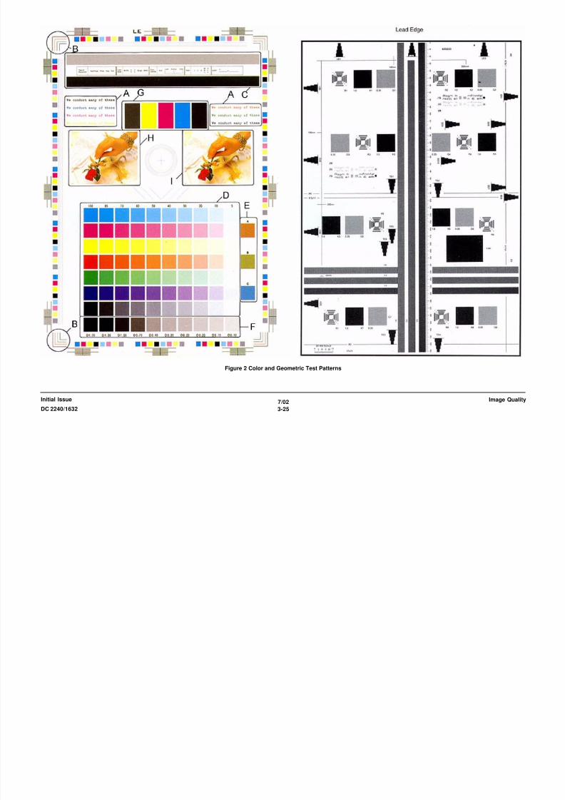
8/13/2019 Xerox Docu Color 2240-1632
http://slidepdf.com/reader/full/xerox-docu-color-2240-1632 517/1118
7/023-26 DC 2240/1632
Initial IssueImage Quality
Image Defect SamplesThe following figures contain examples of defects and their possible causes.
• Background
• Color Misregistration
• Debris-Centered Deletions
• Deletions
• High Frequency Bands
• Irregular Process Direction Streak
• Low Image Density
• Moire
• Mottle
• Newton Rings
• Regular (Repeating) Bands, Streaks, or Smears
Background

8/13/2019 Xerox Docu Color 2240-1632
http://slidepdf.com/reader/full/xerox-docu-color-2240-1632 518/1118
7/023-27DC 2240/1632 BackgroundImage QualityInitial Issue
• Residual Image
• Streak Deletion in Process Direction
• Wrinkled Image
Figure 1 Background Defect Sample
Cause
Incorrect Electrostatics, high TC, faulty ADC Sensor
Corrective Action
Go to the IQ6 RAP.
Color Misregistration Debris-Centered Deletions

8/13/2019 Xerox Docu Color 2240-1632
http://slidepdf.com/reader/full/xerox-docu-color-2240-1632 519/1118
7/023-28 DC 2240/1632Color Misregistration , Debris-Centered DeletionsInitial IssueImage Quality
Figure 1 Color Misregistration Defect Sample
Cause
Failure of the ROS or IBT “walking” from rear to front or front to rear.
Mechanical problem in the IBT Assembly.
Corrective Action
Adjust Color Registration (ADJ 9.6).
Go to theIQ8 RAP.
Figure 1 DCD Defect Sample
Cause
Toner agglomerates cause deletions in the areas surrounding them during transfer.
Corrective Action
Go to the IQ7 RAP.
Deletions High Frequency Bands
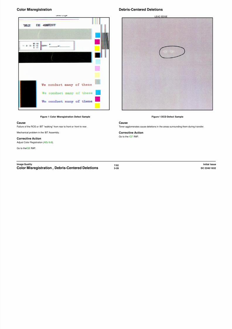
8/13/2019 Xerox Docu Color 2240-1632
http://slidepdf.com/reader/full/xerox-docu-color-2240-1632 520/1118
7/023-29DC 2240/1632 Deletions, High Frequency BandsImage QualityInitial Issue
Figure 1 Deletions Defect Sample
Cause
Defective IBT Belt, damp paper, uneven charge.
Corrective Action
Go to the IQ7 RAP.
Figure 1 High Freq. Bands Defect Sample
Cause
Faulty ROS Assembly or Photoreceptor/Developer Housing gear or bearing problem.
Corrective Action
Go to the IQ14 RAP.
Irregular Process Direction Streak Low Image Density

8/13/2019 Xerox Docu Color 2240-1632
http://slidepdf.com/reader/full/xerox-docu-color-2240-1632 521/1118
7/023-30 DC 2240/1632Irregular Process Direction Streak , Low Image Densi-Initial IssueImage Quality
Figure 1 Streak Defect Sample
Cause
Clog in Developer Housing Trim Bar, malfunction of Belt Cleaner, contaminated ROS window.
Corrective Action
Go to the IQ12 RAP.
Figure 1 Low Density Defect Sample
Cause
Incorrect electrostatics, defective ADC Sensor, low toner concentration or out-of-specification
paper (especially low quality or heavy weight paper).
Corrective ActionGo to the IQ3 RAP.
Moire Mottle

8/13/2019 Xerox Docu Color 2240-1632
http://slidepdf.com/reader/full/xerox-docu-color-2240-1632 522/1118
7/023-31DC 2240/1632 Moire, MottleImage QualityInitial Issue
Figure 1 Moire Defect Sample
Cause
The halftone screen used on the original interferes with the halftone screen used by the copier.
Corrective Action
Go to the IQ2 RAP.
Figure 1 Mottle Defect Sample
Cause
Damp or low quality paper, aged developer, low toner concentration
Corrective Action
Go to the IQ15 RAP.
Newton Rings Regular (Repeating) Bands, Streaks, Spots, or Smears
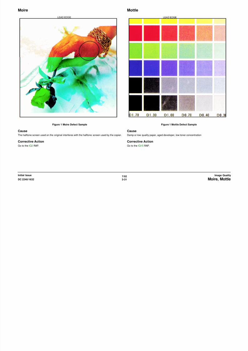
8/13/2019 Xerox Docu Color 2240-1632
http://slidepdf.com/reader/full/xerox-docu-color-2240-1632 523/1118
7/023-32 DC 2240/1632Newton Rings, Regular (Repeating) Bands, Streaks,Initial IssueImage Quality
Figure 1 Newton Rings Defect Sample
Cause
Highly reflective surfaces on a glossy photograph.
Corrective Action
Perform the following:
• Clean the Document Glass
• Place a transparency between the document and the glass
Figure 1 Repeating Defects Sample Image
Cause
Damage, density variation, or deletions caused by rotating component. Spacing equal to effec-
tive circumference of part.
Corrective ActionGo to the IQ14 RAP.
Residual Image Streak Deletion in Process Direction

8/13/2019 Xerox Docu Color 2240-1632
http://slidepdf.com/reader/full/xerox-docu-color-2240-1632 524/1118
7/02
3-33DC 2240/1632 Residual Image, Streak Deletion in Process Direc-Image QualityInitial Issue
Figure 1 Residual Image Defect Sample
Cause
Improper IBT cleaning and/or defective IBT Belt.
Corrective Action
Go to the IQ5 RAP.
Figure 1 Streak Deletion Defect Sample
Cause
Contamination of ROS window, damage to or contact with Transfer Belt or Drum Cartridge
Corrective Action
Go to the IQ12 RAP.
Wrinkled Image
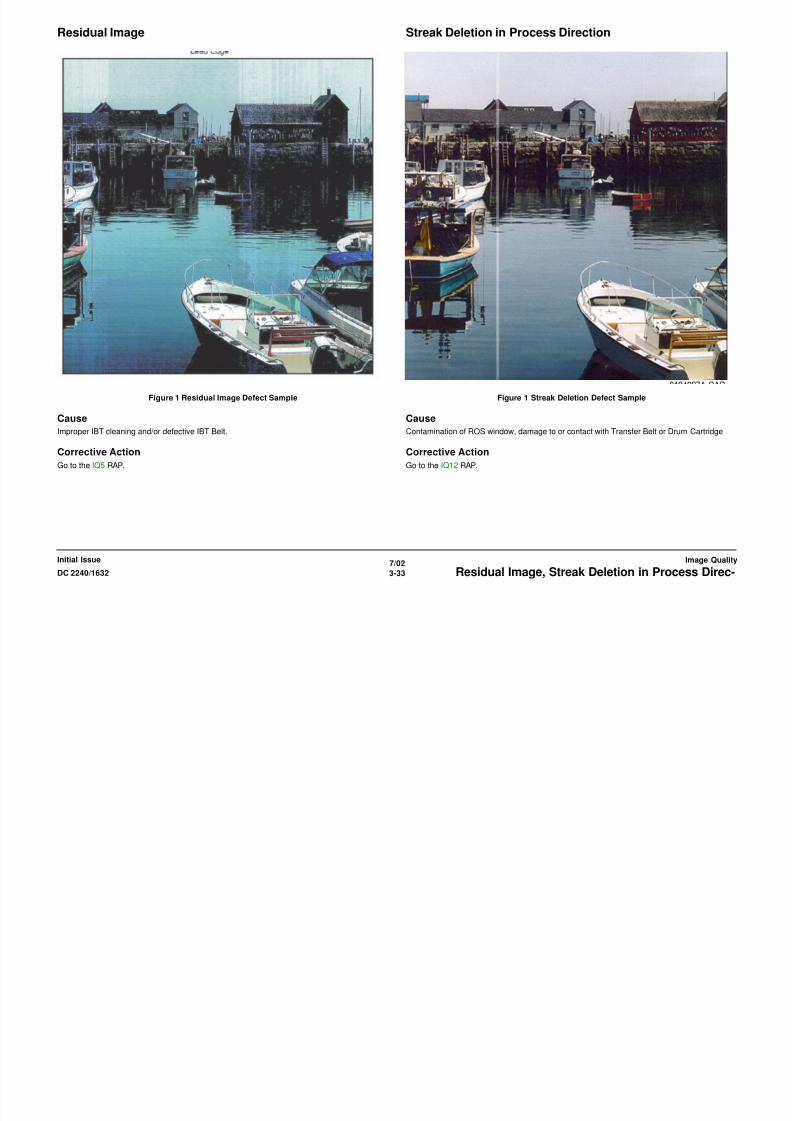
8/13/2019 Xerox Docu Color 2240-1632
http://slidepdf.com/reader/full/xerox-docu-color-2240-1632 525/1118
7/02
3-34 DC 2240/1632Wrinkled ImageInitial IssueImage Quality
Figure 1 Wrinkled Image Defect Sample
Cause
Fuser “tenting” of paper
Corrective Action
Go to the IQ4 RAP.

8/13/2019 Xerox Docu Color 2240-1632
http://slidepdf.com/reader/full/xerox-docu-color-2240-1632 526/1118

8/13/2019 Xerox Docu Color 2240-1632
http://slidepdf.com/reader/full/xerox-docu-color-2240-1632 527/1118
REP 1.1 3.3/5 V LVPS BracketParts List on PL 9.1
Removal
WARNING
To avoid personal injury or shock, do not perform repair or adjustment activities with
the power switch on or electrical power applied to the machine.
CAUTION
PWB’s can be damaged by an electrostatic discharge. Observe all ESD procedures to avoid
component damage.
1. Remove Rear Cover (REP 14.2).
2. Remove High Voltage Power Supply Chassis (REP 1.6).
3. Release 6 harness clips.
4. Remove 3.3/5 VDC Power Supply Chassis (Figure 1).
a. Disconnect Harness P/J’s (4).
b L L S (2)
8/13/2019 Xerox Docu Color 2240-1632
http://slidepdf.com/reader/full/xerox-docu-color-2240-1632 528/1118
7/02
4-3DC 2240/1632 REP 1.1
Repairs and AdjustmentsInitial Issue
b. Loosen Lower Screws (2).
c. Remove upper Screws (2) and remove 3.3/5 VDC Power Supply Chassis.
Figure 1 Removing 3.3/5 VDC Power Supply Chassis
UpperScrew
UpperScrew
LowerScrew
LowerScrew
3.3 VDCLVPS
5 VDCLVPS
Harness P/J’s
Harness P/J’s

8/13/2019 Xerox Docu Color 2240-1632
http://slidepdf.com/reader/full/xerox-docu-color-2240-1632 529/1118
REP 1.3 ESS ChassisParts List on PL 13.1
Removal
WARNING
To avoid personal injury or shock, do not perform repair or adjustment activities with
the power switch on or electrical power applied to the machine.
1. Remove Right Cover (REP 14.3).
2. Remove Top Cover (REP 14.1).
3. Remove Rear Cover (REP 14.2).
CAUTION
PWB’s can be damaged by an electrostatic discharge. Observe all ESD procedures to avoid
component damage.
4. Remove ESS PWB (REP 1.12).
5. Remove ESS Chassis (Figure 1).
a Push Harness Clips (2) down out of Chassis holes
REP 1.4 3.3 V LVPS or 5 V LVPSParts List on PL 9.1
Removal
WARNING
To avoid personal injury or shock, do not perform repair or adjustment activities with
the power switch on or electrical power applied to the machine.
CAUTION
PWB’s can be damaged by an electrostatic discharge. Observe all ESD procedures to avoid
component damage.
1. Remove Rear Cover (REP 14.2).
2. Remove High Voltage Power Supply Chassis (REP 1.6).
3. Remove appropriate LVPS (Figure 1).
a. Disconnect appropriate Harness P/J’s (2).
b. Remove appropriate Screws (4) and remove LVPS.

8/13/2019 Xerox Docu Color 2240-1632
http://slidepdf.com/reader/full/xerox-docu-color-2240-1632 530/1118
7/02
4-5DC 2240/1632 REP 1.3, REP 1.4
Repairs and AdjustmentsInitial Issue
a. Push Harness Clips (2) down out of Chassis holes
b. Disconnect Harness P/J’s (6).
c. Disconnect Harness P/J’s (2).
d. Disconnect Switch from Chassis.
e. Loosen Screws (2) at front and remove Screws (2) at rear of machine.
f. Lift outer end of Chassis to disconnect Hidden Connector and then remove Chassis.
Figure 1 Removing ESS Chassis
Figure 1 Removing LVPS
Screws (2)
Screw
ScrewHarnessClips
HarnessP/J’s (6)
HarnessP/J’s (2)
HiddenConnector Outer
EndSwitch
Screws (2)
Screws(2)
Screws (2)
Screws(2)
3.3 VDCLVPS
5 VDC
LVPS
Harness P/J’s
Harness P/J’s
REP 1.5 24 V LVPSParts List on PL 9.1
Removal
WARNING
To avoid personal injury or shock, do not perform repair or adjustment activities with
the power switch on or electrical power applied to the machine.
1. Remove Rear Cover (REP 14.2).
CAUTION
PWB’s can be damaged by an electrostatic discharge. Observe all ESD procedures to avoid
component damage.
2. Remove 24 V LVPS (Figure 1).
a. Disconnect Harness P/J’s (3).
CAUTION
5 screws with red marks secure LVPS to heat sink. Do not remove them.
b. Loosen Screws (2) and remove LVPS.
REP 1.6 T5 T7 HVPS ChassisParts List on PL 9.1
Removal
WARNING
To avoid personal injury or shock, do not perform repair or adjustment activities with
the power switch on or electrical power applied to the machine.
CAUTION
HVPS can be damaged by an electrostatic discharge. Observe all ESD procedures to avoid
component damage.
1. Remove Rear Cover (REP 14.2).
2. Remove High Voltage Power Supply Chassis (Figure 1).
a. Loosen screw and disconnect Ground Wire.
b. Disconnect Harness P/J’s (2). Do not disconnect Soldered Connection
c. Disconnect High Voltage P/J (1).
d. Disconnect High Voltage P/J’s (2).

8/13/2019 Xerox Docu Color 2240-1632
http://slidepdf.com/reader/full/xerox-docu-color-2240-1632 531/1118
7/02
4-6 DC 2240/1632REP 1.5, REP 1.6
Initial IssueRepairs and Adjustments
b. Loosen Screws (2) and remove LVPS.
Figure 1 Removing 24 VDC Power Supply
d. Disconnect High Voltage P/J s (2).
e. Remove Screws (3).
f. Pivot HVPS down and engage stop strap with frame tab (not shown in figure).
g. Disconnect High Voltage P/J (1) at bottom (not shown in figure).
Figure 1 Removing High Voltage Power Supply
HarnessP/J
Screw
Screw
HarnessP/J’s (2) Soldered
ConnectionHarnessP/J’s (2)
HighVoltageP/J’s (2)
Screws (3)
High Volt-
age P/J
GroundWire
REP 1.7 T5 or T7 High Voltage Power SuppliesParts List on PL 9.1
Removal
WARNING
To avoid personal injury or shock, do not perform repair or adjustment activities with
the power switch on or electrical power applied to the machine.
1. Remove Rear Cover (REP 14.2).
CAUTION
PWB’s can be damaged by an electrostatic discharge. Observe all ESD procedures to avoid
component damage.
2. Remove High Voltage Power Supply Chassis (REP 1.6).
3. Remove High Voltage Power Supplies from Chassis.
• T5 HVPS (Detack/2nd BTR) is power supply toward machine rear.
• T7 HVPS (Developer Bias and Charge) is power supply toward machine front.
REP 1.8 I/F (Interface) PWBParts List on PL 9.1
Removal
WARNING
To avoid personal injury or shock, do not perform repair or adjustment activities with
the power switch on or electrical power applied to the machine.
1. Remove Right Cover (REP 14.3).
2. Remove Top Cover (REP 14.1).
3. Remove Rear Cover (REP 14.2).
4. Pivot down T5 T7 HVPS Chassis (REP 1.6).
CAUTION
PWB’s can be damaged by an electrostatic discharge. Observe all ESD procedures to avoid
component damage.
5. Remove ESS Chassis (REP 1.3).
6. Remove Main PWB Interface PWB (Figure 1).
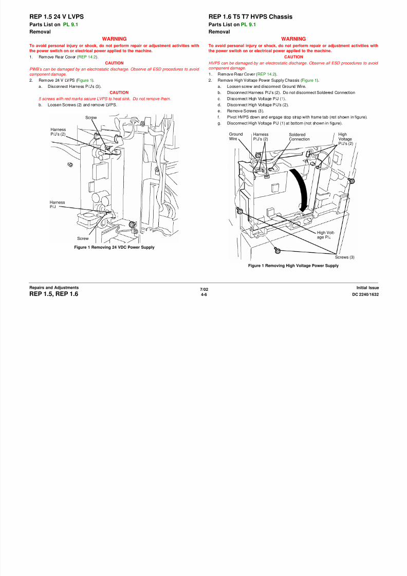
8/13/2019 Xerox Docu Color 2240-1632
http://slidepdf.com/reader/full/xerox-docu-color-2240-1632 532/1118
7/02
4-7DC 2240/1632 REP 1.7, REP 1.8
Repairs and AdjustmentsInitial Issue
( g )
a. Loosen Screws (2).
b. Lift Main PWB Interface PWB until Harness P/J’s (11) can be disconnected.
c. Remove Main PWB Interface PWB from chassis
Figure 1 Removing Interface PWB
Screws (2)
HarnessP/J’s (11)
ReplacementEnsure Screws (2) are positioned in slots as shown before tightening Screws (2) (Figure 2). REP 1.9 24 V LVPS Bracket
Parts List on PL 9.1
Removal
WARNING
To avoid personal injury or shock, do not perform repair or adjustment activities with
the power switch on or electrical power applied to the machine.
1. Remove Rear Cover (REP 14.2).
2. Remove Upper Rear Left Cover (REP 14.4).
3. Remove 24 V LVPS (REP 1.5).
4. Remove 24 VDC LVPS Chassis (Figure 1).
a. Remove Top Screw.
b. Remove upper harnesses from Harness Clips (2).
c. Disconnect Fan P/J and remove harness from Harness Clip.
d. Loosen Screws (4).
e. Remove 24 VDC LVPS Chassis.
Screws (2)
Slot
Slot

8/13/2019 Xerox Docu Color 2240-1632
http://slidepdf.com/reader/full/xerox-docu-color-2240-1632 533/1118
7/02
4-8 DC 2240/1632REP 1.8, REP 1.9
Initial IssueRepairs and Adjustments
Figure 2 Installing Interface PWB
Figure 1 Removing 24 VDC LVPS Bracket Assembly
HarnessClips
HarnessClip
Fan P/J
Screws (2)
Screws (2)
TopScrew
REP 1.10 HVPS T6Parts List on PL 9.1
Removal
WARNING
To avoid personal injury or shock, do not perform repair or adjustment activities with
the power switch on or electrical power applied to the machine.
1. Remove Rear Cover (REP 14.2).
2. Remove 24 V LVPS (REP 1.5).
3. Remove 24 VDC LVPS Chassis (REP 1.9).
4. Remove HVPS T6 (Figure 1).
a. Disconnect P/J’s (4).
b. Disconnect Harness P/J’s (2).
c. Remove Screws (2) and remove High Voltage Power Supply with chassis.
d. Remove High Voltage Power Supply from chassis.
REP 1.11 AC Drive PWBParts List on PL 9.2
Removal
WARNING
To avoid personal injury or shock, do not perform repair or adjustment activities with
the power switch on or electrical power applied to the machine.
1. Remove Rear Cover (REP 14.2).
2. Remove 24 V LVPS (REP 1.5).
3. Remove 24 VDC LVPS Chassis (REP 1.9).
4. Remove HVPS T6 (REP 1.10).
5. Remove AC Drive PWB (Figure 1).
a. Remove Screws (2) and Bracket.
b. Carefully observe position of wiring harnesses and AC wires for later reinstallation
c. Disconnect AC Harness connectors (3), DC connectors (2). and AC Wires (6).
d. Release harness from Harness Clip.

8/13/2019 Xerox Docu Color 2240-1632
http://slidepdf.com/reader/full/xerox-docu-color-2240-1632 534/1118
7/02
4-9DC 2240/1632 REP 1.10, REP 1.11
Repairs and AdjustmentsInitial Issue
Figure 1 Removing HVPS T6
e. Remove Mounting Screws (3). Disengage rear clip (not shown) and remove AC
Drive PWB.
Figure 1 Removing AC Drive PWB
1st BTRP/J’s (4)
HarnessP/J’s (2)
Screws(2)
K
C
M
Y
Screws (2)
andBracket
AC Har-ness con-
nectors (3)and ACwires (6)
MountingScrew
MountingScrew
DC Harnessconnectors
HarnessClip
MountingScrew
P42Blue
P43White
P46
Replacement CAUTION
Ensure White connector P43 and Blue connector is P42. Other connectors are different sizes
to ensure correct connection.
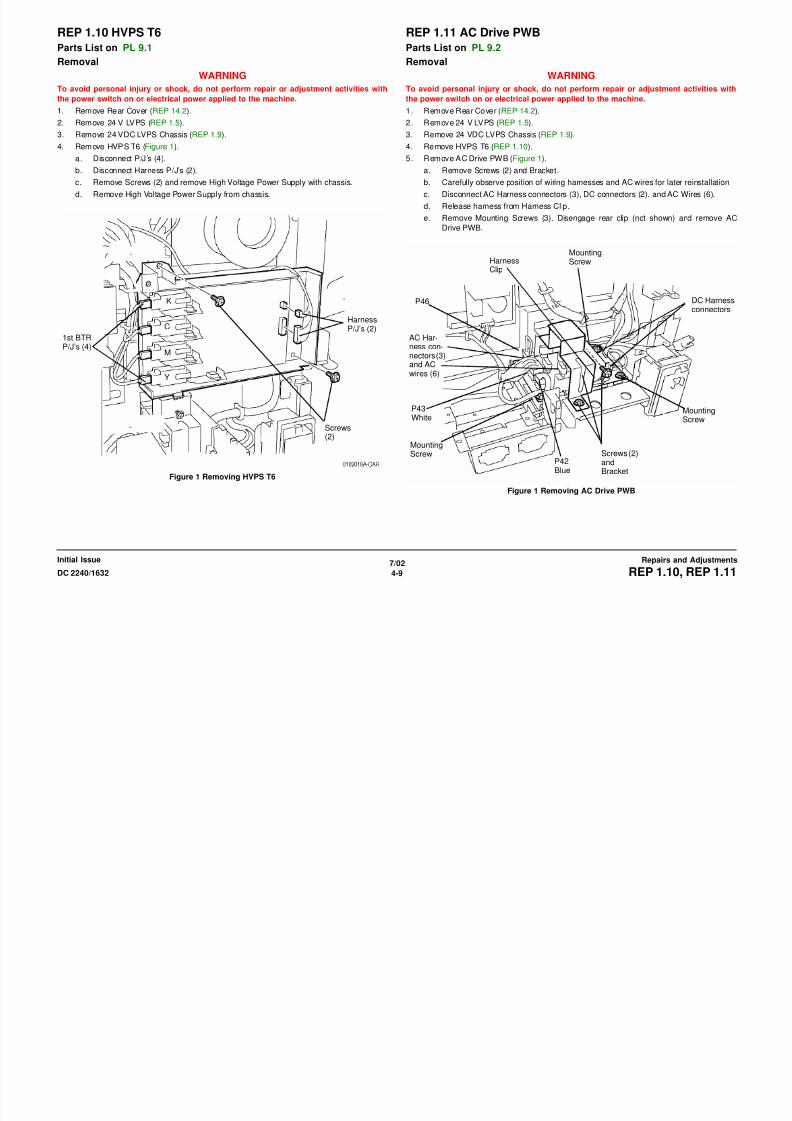
8/13/2019 Xerox Docu Color 2240-1632
http://slidepdf.com/reader/full/xerox-docu-color-2240-1632 535/1118
7/02
4-10 DC 2240/1632REP 1.11
Initial IssueRepairs and Adjustments
REP 1.12 ESS PWBParts List on PL 13.1
Removal
CAUTION
The ESS PWB has a lithium battery. Dispose of the used battery following the manufacturers’
instructions after replacing. Do not throw it away at customer’s site.
1. Gather all available settings information. This includes the machine NVM log, the
Machine Settings floppy disk, copies of the Configuration Report, etc. If possible save the
current Machine Settings to the floppy.
WARNINGTo avoid personal injury or shock, do not perform repair or adjustment activities with
the power switch on or electrical power applied to the machine.
2. Remove Right Cover (REP 14.3).
3. Remove Top Cover (REP 14.1).
4. Remove Rear Cover (REP 14.2).
5 Remove ESS Top Cover (PL 13 1)
6. Remove ESS PWB (Figure 1).
2
RemoveESSNVM
3RemovePostscriptFont ROM
4Remove ESSFirmwareEPROMS
5RemoveRAM
1R
6DisconnectP/J
7Remove
RAM

8/13/2019 Xerox Docu Color 2240-1632
http://slidepdf.com/reader/full/xerox-docu-color-2240-1632 536/1118
7/02
4-11DC 2240/1632 REP 1.12
Repairs and AdjustmentsInitial Issue
5. Remove ESS Top Cover (PL 13.1).
CAUTION
Protect Hard Drive Harness. Hard Drive is mounted to ESS Top Cover. Hard Drive har-
ness remains connected to ESS PWB while removing ESS Top Cover.a. Remove screws (11) from ESS Top Cover.
b. Lift ESS Top Cover and place it upside down on Toner Cartridges.
c. Disconnect Hard Drive harness from ESS PWB.
Figure 1 Removing ESS PWB
Replacement
1. Reinstall the NVM PWB and the ROM/RAM/EPROMs that were removed from the original
PWB. Discard the MAC ROM from the new ESS PWB and install the MAC ROM removed
from the old ESS PWB.
CAUTION
GP10 is used to maintain the integrity of the serial number and billing data when one or more
serialized PWBs must be replaced. Never replace all three listed PWBs at the same time. If
any of the PWBs needs replacing, only replace them one at a time .
• ESS NVM PWB ( PL 13.1 ).• MCU NVM PWB ( PL 13.1 ).
• ESS PWB ( PL 13.1 ).
Failure to comply with GP 10 could result in catastrophic NVM corruption.
2. Follow the procedure in GP 10, to verify that the serial numbers and billing information is
correct.
RemoveMACROM
9DisconnectFan P/J 10
Remove Screws (9) andremove ESS PWB
8Remove jacks fromplate
3. If a good Machine Settings floppy is available, exit, then reenter the PWS Tool. Select
Read from Floppy when starting the tool. If no floppy is available, or if the data on the
existing floppy is questionable, go to step 6.
4. Go to dC351 and select Restore Machine Settings.
5. If a good Machine Settings floppy is not available, or if the data on the existing floppy is
questionable, go to dC351. In the Special Batch Write area, select the appropriate market
region, then press the Batch Write NVM button.
6. Using the resources gathered in step 1 of the removal procedure, reenter NVM data to
restore the machine configuration.
7. Ensure that the network information (IP address, etc.) is correct. Contact the customer’s
system administrator to configure, if necessary.

8/13/2019 Xerox Docu Color 2240-1632
http://slidepdf.com/reader/full/xerox-docu-color-2240-1632 537/1118
7/02
4-12 DC 2240/1632REP 1.12
Initial IssueRepairs and Adjustments
REP 1.13 ESS NVM PWBParts List on PL 13.1
Removal
1. Gather all available settings information. This includes the machine NVM log, the
Machine Settings floppy disk, copies of the Configuration Report, etc. If possible save the
current Machine Settings to the floppy.
WARNING
To avoid personal injury or shock, do not perform repair or adjustment activities with
the power switch on or electrical power applied to the machine.
2. Remove Right Cover (REP 14.3).3. Remove Top Cover (REP 14.1).
4. Remove Rear Cover (REP 14.2).
5. Remove ESS Top Cover (PL 13.1).
CAUTION
Protect Hard Drive Harness. Hard Drive is mounted to ESS Top Cover. Hard Drive har-
ness remains connected to ESS PWB while removing ESS Top Cover.
CAUTION
The ESS PWB has a lithium battery. Dispose of the used battery following the manufacturers’
instructions after replacing. Do not throw it away at customer’s site.
6. Remove the ESS NVM PWB (Figure 1).
ESS NVM PWB

8/13/2019 Xerox Docu Color 2240-1632
http://slidepdf.com/reader/full/xerox-docu-color-2240-1632 538/1118
7/02
4-13DC 2240/1632 REP 1.13
Repairs and AdjustmentsInitial Issue
a. Remove screws (11) from ESS Top Cover.
b. Lift ESS Top Cover and place it upside down on Toner Cartridges.
Figure 1 Removing the ESS NVM PWB
Replacement
1. Install the new ESS NVM PWB. Switch on the power and connect the PWS.
CAUTION
GP10 is used to maintain the integrity of the serial number and billing data, when one or more
serialized PWBs must be replaced.
To maintain the integrity of the serial number and billing data, never replace all three listed
PWBs at the same time. If any of the following billing data PWBs needs replacing, only replace
them one at a time .
• ESS NVM PWB ( PL 13.1 ).
• MCU PWB ( PL 13.1 ).
• ESS PWB ( PL 13.1 ).
Failure to comply with the board replacement procedure in GP 10 could result in catastrophic
NVM corruption.
2. Follow the procedure in GP 10. If two or more serial numbers DO NOT match the M/C
label serial number, escalate the service call to Field Engineering or the NTC.
3. Go to dC301 on the PWS. Initialize SYS-System, then initialize SYS-User.
4. If a good Machine Settings floppy is available, exit, then reenter the PWS Tool. Select
Read from Floppy when starting the tool. If no floppy is available, or if the data on the
existing floppy is questionable, go to step 6.
5. Go to dC351 and select Restore Machine Settings.
6. If a good Machine Settings floppy is not available, or if the data on the existing floppy is
questionable, go to dC351. In the Special Batch Write area, select the appropriate market
region, then press the Batch Write NVM button.
7. Using the resources gathered in step 1 of the removal procedure, reenter NVM data to
restore the machine configuration.
8. Ensure that the network information (IP address, etc.) is correct. Contact the customer’s
system administrator to configure, if necessary.
REP 1.14 PS-1 ROM, PS-2 ROMParts List on PL 13.1
Removal
1. Gather all available settings information. This includes the machine NVM log, the
Machine Settings floppy disk, copies of the Configuration Report, etc. If possible save the
current Machine Settings to the floppy.
WARNING
To avoid personal injury or shock, do not perform repair or adjustment activities with
the power switch on or electrical power applied to the machine.
2. Remove Right Cover (REP 14.3).3. Remove Top Cover (REP 14.1).
4. Remove Rear Cover (REP 14.2).
5. Remove the PS-1 ROM and PS-2 ROM (Figure 1).
1Remove PS-1
d PS 2 ROMS
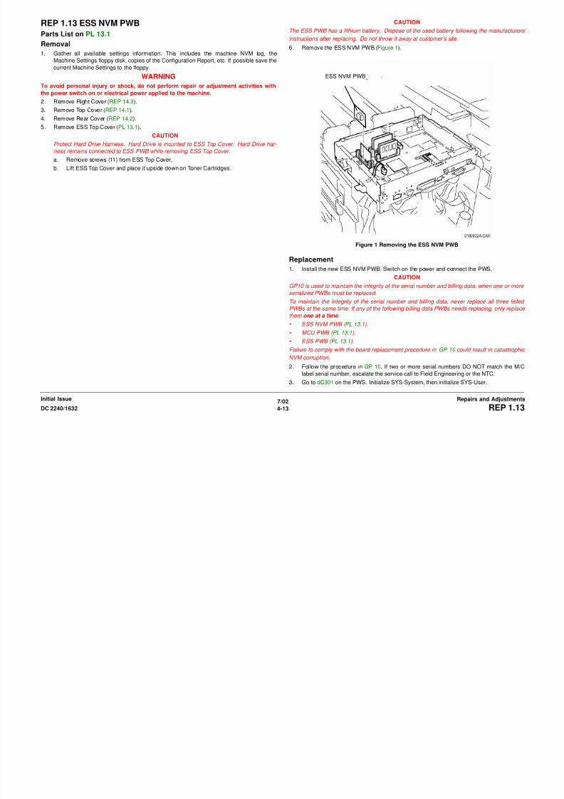
8/13/2019 Xerox Docu Color 2240-1632
http://slidepdf.com/reader/full/xerox-docu-color-2240-1632 539/1118
7/02
4-14 DC 2240/1632REP 1.13, REP 1.14
Initial IssueRepairs and Adjustments
Figure 1 Removing PS-1 ROM and PS-2 ROM
Replacement
1. Install the new MCU PWB and reassemble the machine
2. Switch on the power and connect the PWS.
3. Check the ESS software version to ensure that it matches the system software configura-
tion. Refer to the SW Configuration Table in the system software upgrade instructions
contained on the s/w upgrade CD.
and PS-2 ROMS FRONT
If the software version does not match, reload the software in accordance with the instruc-
tions on the CD.

8/13/2019 Xerox Docu Color 2240-1632
http://slidepdf.com/reader/full/xerox-docu-color-2240-1632 540/1118
7/02
4-15DC 2240/1632 REP 1.14
Repairs and AdjustmentsInitial Issue

8/13/2019 Xerox Docu Color 2240-1632
http://slidepdf.com/reader/full/xerox-docu-color-2240-1632 541/1118
7/02
4-16 DC 2240/1632REP 1.14
Initial IssueRepairs and Adjustments
REP 4.1 Main Drive Motor AssemblyParts List on PL 1.1
Removal
WARNING
To avoid personal injury or shock, do not perform repair or adjustment activities with
the power switch on or electrical power applied to the machine.
1. Remove Fuser Module (REP 10.1).
2. Remove Tray 5 (REP 7.1).
3. Remove Rear Cover (REP 14.2).
4. Remove 24 V LVPS (REP 1.5).5. Remove 24 VDC LVPS Chassis (REP 1.9).
6. Remove Developer High Voltage Power Supply (REP 1.10).
7. Remove AC Drive PWB (REP 1.11).
8. Remove Main Drive Motor Assembly (Figure 1).
a. Carefully observe position of wiring harnesses for later reinstallation
b. Disconnect Harness P/J’s (5). HV
HarnessP/J’s (5)
8/13/2019 Xerox Docu Color 2240-1632
http://slidepdf.com/reader/full/xerox-docu-color-2240-1632 542/1118
7/02
4-17DC 2240/1632 REP 4.1
Repairs and AdjustmentsInitial Issue
c. Disconnect Harness P/J’s (3).
d. Remove harness from Harness Clips (3).
e. Disconnect HV Wire.
NOTE: In next step, do not remove small round head screws that appear to secure Main Drive
Motor Assembly to machine.
f. Remove Screws (5) and remove Main Drive Motor Assembly.
Figure 1 Removing Main Drive Motor
Harness Clips (3)(2 not shown)
HarnessP/J’s (3)
Wire
REP 4.2 IBT MotorParts List on PL 1.1
Removal
WARNING
To avoid personal injury or shock, do not perform repair or adjustment activities with
the power switch on or electrical power applied to the machine.
1. Remove Rear Cover (REP 14.2).
2. Pivot down High Voltage Power Supply Chassis (REP 1.6).
3. Remove Photoreceptor Module Drive Motor.
a. Disconnect Cooling Fan P/J.b. Remove screws (2) and remove Cooling Fan.
c. Disconnect Photoreceptor Module Drive Motor P/J.
d. Remove Photoreceptor Module Drive Motor screws (3) and remove Photoreceptor
Module Drive Motor.
REP 4.3 Developer Drive MotorParts List on PL 1.1
Removal
WARNING
To avoid personal injury or shock, do not perform repair or adjustment activities with
the power switch on or electrical power applied to the machine.
1. Remove Rear Cover (REP 14.2).
2. Remove High Voltage Power Supply Chassis (REP 1.6).
NOTE: Step 3 can be omitted if Low Voltage Power Supply P/J’s are disconnected before per-
forming step 4.
3. Remove 3.3 VDC and 5 VDC Low Voltage Power Supply (REP 1.4).
4. Remove Chassis for 3.3 VDC and 5 VDC Low Voltage Power Supply.
a. Release harnesses from harness clips (3).
b. Remove screws (4) and remove Chassis.
5. Remove Developer Drive Module (Figure 1).
a Disconnect P/JCooling Fan

8/13/2019 Xerox Docu Color 2240-1632
http://slidepdf.com/reader/full/xerox-docu-color-2240-1632 543/1118
7/02
4-18 DC 2240/1632REP 4.2, REP 4.3
Initial IssueRepairs and Adjustments
Figure 1 Removing Photoreceptor Module Drive Motor
a. Disconnect P/J.
b. Remove harness from Harness Clip.
c. Remove Screws (2) and remove Developer Drive Module.
Figure 1 Removing Developer Drive Module
PhotoreceptorModule DriveMotor
Harness Clip
Screw
ScrewP/J
REP 4.4 Drum Motor AssemblyParts List on PL 1.1
Removal
WARNING
To avoid personal injury or shock, do not perform repair or adjustment activities with
the power switch on or electrical power applied to the machine.
1. Remove Right Cover (REP 14.3).
2. Remove Top Cover (REP 14.1).
3. Remove Rear Cover (REP 14.2).
CAUTIONMachine problems will result from careless harness routing during reassembly. Carefully
observe position of wiring harnesses for later reinstallation.
NOTE: Step 6 can be omitted if Low Voltage Power Supply P/J’s are disconnected before per-
forming step 7.
4. Remove 24 V LVPS (REP 1.5).
5. Remove 24 VDC LVPS Chassis (REP 1.9).

8/13/2019 Xerox Docu Color 2240-1632
http://slidepdf.com/reader/full/xerox-docu-color-2240-1632 544/1118
7/02
4-19DC 2240/1632 REP 4.4
Repairs and AdjustmentsInitial Issue
( )
6. Remove Control Chassis (REP 1.3).
7. Remove High Voltage Power Supply Chassis (REP 1.6).
NOTE: In next step, do not disconnect P/J’s.
8. Loosen Interface PWB chassis mounting screws (2) and move chassis up (REP 1.8).
9. Remove Photoreceptor Module Drive Motor (REP 4.2).
10. Remove Developer High Voltage Power Supply (REP 1.10).
11. Remove 3.3/5 VDC Power Supply Chassis (REP 1.1).
12. Remove Print Cartridge Drive Module (Figure 1).
a. Release harness from Harness Clips (3)
b. Remove screws (2) to release Connector from frame.
c. Disconnect P/J.
d. Remove Screws (8) and remove Print Cartridge Drive Module.
Figure 1 Removing Print Cartridge Drive Module
HarnessClips (3)
Con-nector P/J Screws (8)
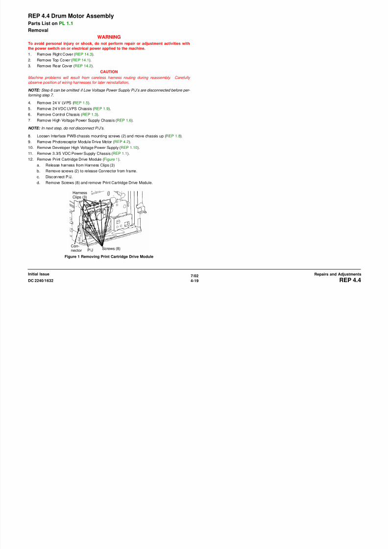
8/13/2019 Xerox Docu Color 2240-1632
http://slidepdf.com/reader/full/xerox-docu-color-2240-1632 545/1118
7/02
4-20 DC 2240/1632REP 4.4
Initial IssueRepairs and Adjustments
REP 5.1 DADFParts List on PL 20.1
Removal
WARNING
To avoid personal injury or shock, do not perform repair or adjustment activities with
the power switch on or electrical power applied to the machine.
1. Disconnect connector (Figure 1).
2. Remove Screws (2) and remove DADF (Figure 2).
Connector

8/13/2019 Xerox Docu Color 2240-1632
http://slidepdf.com/reader/full/xerox-docu-color-2240-1632 546/1118
7/02
4-21DC 2240/1632 REP 5.1
Repairs and AdjustmentsInitial Issue
Figure 1 Disconnecting Connector
Figure 2 Removing DADF
Replacement
1. Check DADF Side Registration (ADJ 5.1).
Check DADF Top Registration (ADJ 5.5).
REP 5.2 Registration Gate SolenoidParts List on PL 20.2
Removal
WARNING
To avoid personal injury or shock, do not perform repair or adjustment activities with
the power switch on or electrical power applied to the machine.
1. Remove Front Cover (PL 20.1).
2. Remove Registration Gate Solenoid (Figure 1).
a. Disconnect connector.
b. Release clamps (2) and remove wire.c. Loosen screws (2).
d. Remove Registration Gate Solenoid.
Connector
Screws (2)
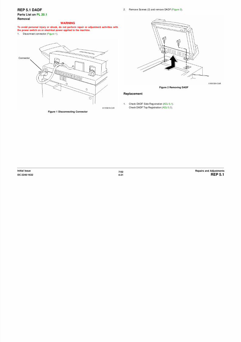
8/13/2019 Xerox Docu Color 2240-1632
http://slidepdf.com/reader/full/xerox-docu-color-2240-1632 547/1118
7/02
4-22 DC 2240/1632REP 5.2
Initial IssueRepairs and Adjustments
Figure 1 Removing Registration Gate Solenoid
Clamps (2)
REP 5.3 Left/Right CounterbalanceParts List on PL 20.3
Removal
WARNING
To avoid personal injury or shock, do not perform repair or adjustment activities with
the power switch on or electrical power applied to the machine.
1. Remove DADF (REP 5.1).
2. Remove Rear Cover (REP 5.18).
3. To remove Left Counterbalance, go to step 4.
To remove Right Counterbalance, go to step 5.4. Remove Left Counter Balance (Figure 1).
a. Remove Screws (4).
b. Remove Left Counterbalance.
c. Mark counterbalance as Left.
5. Remove Right Counterbalance (Figure 2).
a. Remove Terminals (2).
b. Remove Screws (4).
c. Remove Right Counterbalance.
d. Mark counterbalance as Right.
Terminals (2)
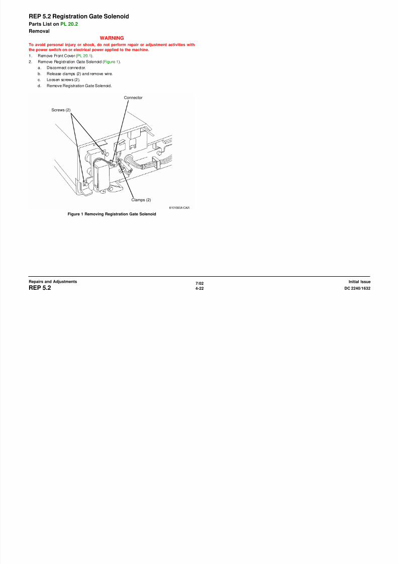
8/13/2019 Xerox Docu Color 2240-1632
http://slidepdf.com/reader/full/xerox-docu-color-2240-1632 548/1118
7/02
4-23DC 2240/1632 REP 5.3
Repairs and AdjustmentsInitial Issue
Figure 1 Removing Left Counterbalance
Figure 2 Removing Right Counterbalance
Screws (4)
Screws (4)
Replacement
1. If new counterbalances are installed, position as shown (Figure 3).
If counterbalances are reinstalled, install according to marks made in steps 4c or 5d.
Left Counterbal-ance
Right Counter-balance

8/13/2019 Xerox Docu Color 2240-1632
http://slidepdf.com/reader/full/xerox-docu-color-2240-1632 549/1118
7/02
4-24 DC 2240/1632REP 5.3
Initial IssueRepairs and Adjustments
Figure 3 Install Left/Right Counterbalance
REP 5.4 DADF Control PWBParts List on PL PL 20.3
Removal
WARNING
To avoid personal injury or shock, do not perform repair or adjustment activities with
the power switch on or electrical power applied to the machine.
1. Remove Rear Cover (REP 5.18).
2. Remove DADF Control PWB (Figure1).
a. Disconnect connectors (7).
b. Remove DADF Control PWB from PWB supports (3).
Connectors
Supports (2)

8/13/2019 Xerox Docu Color 2240-1632
http://slidepdf.com/reader/full/xerox-docu-color-2240-1632 550/1118
7/02
4-25DC 2240/1632 REP 5.4
Repairs and AdjustmentsInitial Issue
Figure 1 Removing DADF Control PWB
Connectors
Support (1)
REP 5.5 Feed Motor AssemblyParts List on PL 20.4
Removal
WARNING
To avoid personal injury or shock, do not perform repair or adjustment activities with
the power switch on or electrical power applied to the machine.
1. Remove Rear Cover (REP 5.18).
2. Remove Feed Motor Assembly (Figure 1).
a. Disconnect connector.
b. Release clamps (3) and remove harness.c. Loosen Screws (2).
d. Remove Feed Motor Assembly.
Connector Clamps (3)

8/13/2019 Xerox Docu Color 2240-1632
http://slidepdf.com/reader/full/xerox-docu-color-2240-1632 551/1118
7/02
4-26 DC 2240/1632REP 5.5
Initial IssueRepairs and Adjustments
Figure 1 Removing Feed Motor Assembly
Screws (2)
REP 5.6 Nudger RollParts List on PL 20.4
Removal
WARNING
To avoid personal injury or shock, do not perform repair or adjustment activities with
the power switch on or electrical power applied to the machine.
1. To install new Nudger Rolls, go to Feed Roll Assembly (REP 5.7) at this time and replace
the Nudger Rolls and Feed Rolls as an assembly. Otherwise, continue below.
2. Open DADF Top Cover and remove Inner Cover (Figure 1).
a. Open Top Cover.b. Loosen screws (2).
c. Remove Inner Cover.
3. Remove Nudger Rolls (Figure 2).
a. Remove Clips (2).
b. Remove Nudger Rolls (2).
T
InnerCover
Clip
NudgerRoll
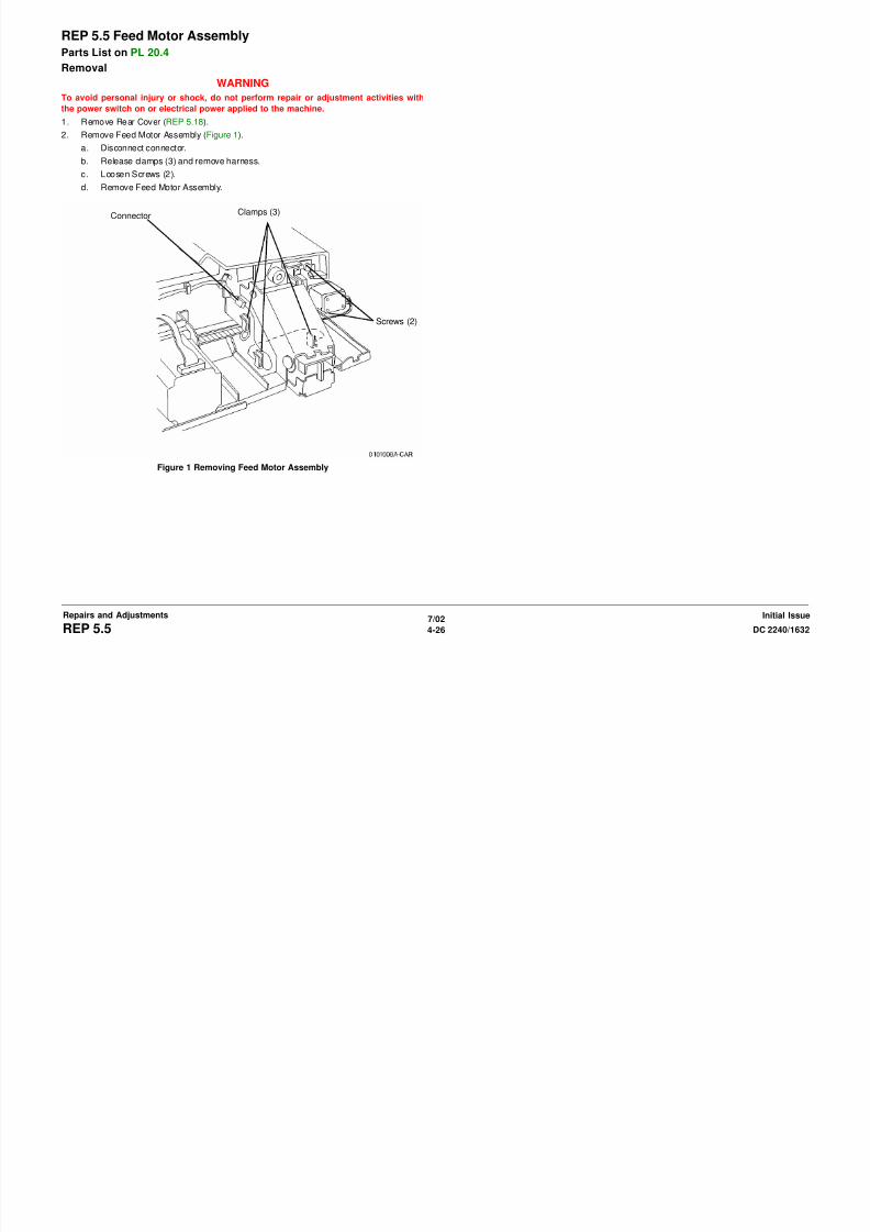
8/13/2019 Xerox Docu Color 2240-1632
http://slidepdf.com/reader/full/xerox-docu-color-2240-1632 552/1118
7/02
4-27DC 2240/1632 REP 5.6
Repairs and AdjustmentsInitial Issue
Figure 1 Removing Inner Cover
Figure 2 Remove Nudger Rolls
Replacement
NOTE: Nudger Rolls rotate freely in direction of document movement.
NOTE: After replacing Nudger Roll, reset HFSI counter. Enter dC135 HFSI Counters Diag.Screen (NVM 005-80).
NOTE: Replace Feed Roll Assembly ( REP 5.7 ).
TopCover
Screws(2)
REP 5.7 Feed Roll AssemblyParts List on PL 20.4
Removal
WARNING
To avoid personal injury or shock, do not perform repair or adjustment activities with
the power switch on or electrical power applied to the machine.
1. Open Top Cover and remove Inner Cover (Figure 1).
a. Open Top Cover.
b. Loosen screws (2).
c. Remove Inner Cover.
2. Remove Feed Roll Assembly (Figure 2).
a. Remove clip.
b. Slide bearing.
c. Remove Feed Roll Assembly.
TopCover
InnerCover
Clip

8/13/2019 Xerox Docu Color 2240-1632
http://slidepdf.com/reader/full/xerox-docu-color-2240-1632 553/1118
7/02
4-28 DC 2240/1632REP 5.7
Initial IssueRepairs and Adjustments
Figure 1 Removing Inner Cover
Figure 2 Removing Feed Roll Assembly
Replacement
NOTE: Feed Rolls rotate freely in direction of document movement.
NOTE: After replacing Feed Roll, reset HFSI counter. Enter dC135 HFSI Counters Diag.
Screen (NVM 005-805).
NOTE: Feed Rolls and Nudger Rolls are replaced at same time.
Screws(2)
Bearing
REP 5.8 Lower Chute AssemblyParts List on PL 20.5
Removal
WARNING
To avoid personal injury or shock, do not perform repair or adjustment activities with
the power switch on or electrical power applied to the machine.
1. Open Top Cover.
2. Remove following:
a. Front Cover (PL 20.1).
b. Entrance Tray (PL 20.1).3. Remove Lower Chute Assembly (Figure 1).
a. Open Document Feed Upper Chute.
b. Loosen screws (2).
c. Remove Lower Chute Assembly.
Screws (2)Document Feeder Upper Chute
Top Cover
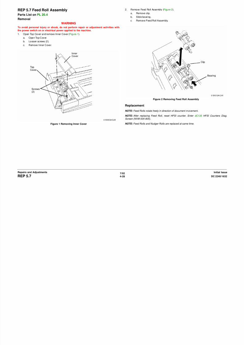
8/13/2019 Xerox Docu Color 2240-1632
http://slidepdf.com/reader/full/xerox-docu-color-2240-1632 554/1118
7/02
4-29DC 2240/1632 REP 5.8
Repairs and AdjustmentsInitial Issue
Figure 1 Removing Lower Chute Assembly
Top Cover
REP 5.9 Retard RollParts List on PL 20.5
Removal
WARNING
To avoid personal injury or shock, do not perform repair or adjustment activities with
the power switch on or electrical power applied to the machine.
1. Open Top Cover.
2. Remove following:
a. Front Cover (PL 20.1).
b. Entrance Tray (PL 20.1).3. Remove Lower Chute Assembly (REP 5.8).
4. Remove Retard Roll (Figure 1).
Replacement
CAUTION
While replacing Retard Roll, make sure that Retard Roll Plastic Guide is in correct position.
2Remove Spring
3Remove Clip
1Make note ofposition of
l ti g id

8/13/2019 Xerox Docu Color 2240-1632
http://slidepdf.com/reader/full/xerox-docu-color-2240-1632 555/1118
7/02
4-30 DC 2240/1632REP 5.9
Initial IssueRepairs and Adjustments
Figure 1 Removing Retard Roll
4Remove Shaft
5RemoveBracket
6Remove Shaftand Retard Roll
plastic guide
REP 5.10 Set Gate Solenoid AssemblyParts List on PL 20.5
Removal
WARNING
To avoid personal injury or shock, do not perform repair or adjustment activities with
the power switch on or electrical power applied to the machine.
1. Open Top Cover.
2. Remove following:
a. Front Cover (PL 20.1).
b. Entrance Tray (PL 20.1).3. Remove Lower Chute Assembly (REP 5.8).
4. Remove Set Gate Solenoid Assembly (Figure 1).
Replacement
1. Engage pin with slot (Figure 2).
2Disconnect
1Make note of pinengagement
Pin
Slot
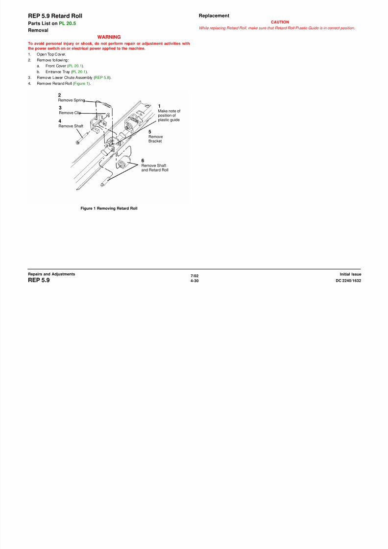
8/13/2019 Xerox Docu Color 2240-1632
http://slidepdf.com/reader/full/xerox-docu-color-2240-1632 556/1118
7/02
4-31DC 2240/1632 REP 5.10
Repairs and AdjustmentsInitial Issue
Figure 1 Removing Set Gate Solenoid Assembly
Figure 2 Engaging Pin with Slot
3Release clampand remove wire
4Loosen screws(2) and removesolenoid
2. Install Set Gate Solenoid Assembly (Figure 3).
1Position Solenoidon Screws
2Move Solenoid asshown and tightenScrews (2)
3Connect and secure
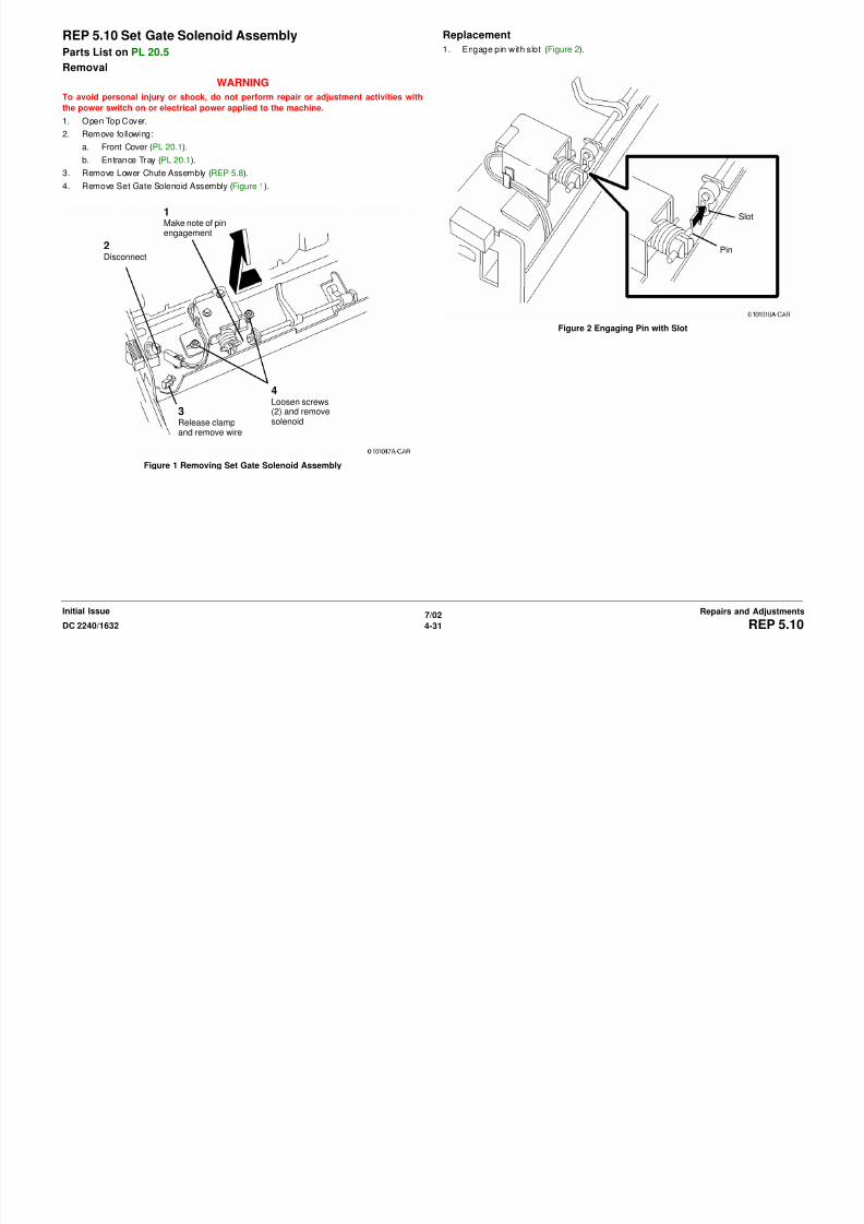
8/13/2019 Xerox Docu Color 2240-1632
http://slidepdf.com/reader/full/xerox-docu-color-2240-1632 557/1118
7/02
4-32 DC 2240/1632REP 5.10
Initial IssueRepairs and Adjustments
Figure 3 Installing Set Gate Solenoid Assembly
Connect and secure
harness in clip
REP 5.11 Registration SensorParts List on PL 20.5
Removal
WARNING
To avoid personal injury or shock, do not perform repair or adjustment activities with
the power switch on or electrical power applied to the machine.
1. Open Top Cover.
2. Remove following:
a. Front Cover (PL 20.1).
b. Entrance Tray (PL 20.1).3. Remove Lower Chute Assembly (REP 5.8).
4. Disconnect P/J580 and remove Registration Sensor (Figure 1).
Replacement
1. When installing Registration Sensor align holes with bumps and tighten screw (Figure 2).
1Loosenscrew
2RemoveRegistrationSensor anddisconnect
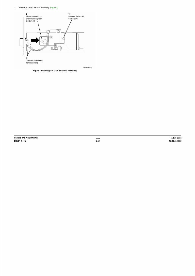
8/13/2019 Xerox Docu Color 2240-1632
http://slidepdf.com/reader/full/xerox-docu-color-2240-1632 558/1118
7/02
4-33DC 2240/1632 REP 5.11
Repairs and AdjustmentsInitial Issue
Figure 1 Removing Registration Sensor
Figure 2 Installing Registration Sensor
REP 5.12 Size Sensors 1/2 (Rear/Front)Parts List on PL 20.5
Removal
WARNING
To avoid personal injury or shock, do not perform repair or adjustment activities with
the power switch on or electrical power applied to the machine.
1. Open Top Cover.
2. Remove following:
a. Front Cover (PL 20.1).
b. Entrance Tray (PL 20.1).3. Remove Lower Chute Assembly (REP 5.8).
4. Remove Set Gate Solenoid Assembly (REP 5.10).
5. Remove Size Sensors 1/2 (front/rear) (Figure 1).
1Removescrews (2)
2Disconnect plugs
3Remove screws (2) andsensors

8/13/2019 Xerox Docu Color 2240-1632
http://slidepdf.com/reader/full/xerox-docu-color-2240-1632 559/1118
7/02
4-34 DC 2240/1632REP 5.12
Initial IssueRepairs and Adjustments
Figure 1 Removing Size Sensors 1/2
REP 5.13 DADF Belt Motor Assembly
Parts List on PL 20.6
Removal
WARNING
To avoid personal injury or shock, do not perform repair or adjustment activities with
the power switch on or electrical power applied to the machine.
1. Remove Rear Cover (REP 5.18).
2. Remove DADF Belt Motor Assembly (Figure 2).
Replacement
NOTE: Align motor bracket with marks on frame before tightening screws.
1Mark position of motor bracket on framenear all four mounting screws

8/13/2019 Xerox Docu Color 2240-1632
http://slidepdf.com/reader/full/xerox-docu-color-2240-1632 560/1118
7/02
4-35DC 2240/1632
REP 5.13
Repairs and AdjustmentsInitial Issue
Figure 1 Removing DADF Belt Motor Assembly
2Disconnectmotor con-nector
3Loosenscrews (4)
4RemoveBelt frommotor pulleyand removemotor
REP 5.14 Duplex Sensor
Parts List on PL 20.7
Removal
WARNING
To avoid personal injury or shock, do not perform repair or adjustment activities with
the power switch on or electrical power applied to the machine.
1. Remove following:
a. Front Cover (PL 20.1).
b. Rear Cover (REP 5.18).
c. Top Cover (PL 20.2).2. Loosen screws (2) and remove Feed Motor from mounting (REP 5.5).
3. Remove Duplex Sensor (Figure 1).
a. Remove screws (2).
b. Lift Duplex Chute to disengage lower mounts.
c. Lift rear end of Duplex Chute so that Duplex Sensor is visible. Harness remains
connected.
d. Remove screw and remove Duplex Sensor.

8/13/2019 Xerox Docu Color 2240-1632
http://slidepdf.com/reader/full/xerox-docu-color-2240-1632 561/1118
7/02
4-36 DC 2240/1632
REP 5.14
Initial IssueRepairs and Adjustments
Figure 1 Removing Duplex Sensor
Screws
Lower Mounts
REP 5.15 Registration Pinch Roll
Parts List on PL 20.8
Removal
WARNING
To avoid personal injury or shock, do not perform repair or adjustment activities with
the power switch on or electrical power applied to the machine.
NOTE: Do not damage or scratch surface of Registration Pinch Roll. (Scratches may cause
skewing.)
1. Remove following:
a. Front Cover (PL 20.1)
b. Rear Cover (REP 5.18).
c. Registration Gate Solenoid (REP 5.2).
2. Preparing to remove the Gate (Figure 1).
4RemoveGate
3RemoveScrews (2)
1Remove Belt from Pulley. RemoveE-Ring and Pulley

8/13/2019 Xerox Docu Color 2240-1632
http://slidepdf.com/reader/full/xerox-docu-color-2240-1632 562/1118
7/02
4-37DC 2240/1632
REP 5.15
Repairs and AdjustmentsInitial Issue
Figure 1 Preparing to remove the Gate
2Removescrews (4)
Gate
3. Remove Gate (Figure 2). 4. Remove Registration Pinch Roll (Figure 3).
3
4Remove Gate whilecontaining Springs
CAUTION
Plastic edge onGate is fragile
1Remove CClip, shorterSpring, andBearing
3Remove Regis-tration Pinch Roll

8/13/2019 Xerox Docu Color 2240-1632
http://slidepdf.com/reader/full/xerox-docu-color-2240-1632 563/1118
7/02
4-38 DC 2240/1632
REP 5.15
Initial IssueRepairs and Adjustments
Figure 2 Removing Gate Figure 3 Removing Registration Pinch Roll
1Observe positionof Springs
RemoveScrews (2)
2Close DADF
2RemoveC ClipandlongerSpring
REP 5.16 Exit Motor Assembly
Parts List on PL 20.9
Removal
WARNING
To avoid personal injury or shock, do not perform repair or adjustment activities with
the power switch on or electrical power applied to the machine.
1. Remove Rear Cover (REP 5.18).
2. Remove Exit Motor Assembly (Figure 1).
a. Disconnect connector.
b. Release clamps (2) and remove wire.
c. Loosen screws (2).
d. Remove belt.
e. Remove Exit Motor Assembly.
Replacement
NOTE: Belt should be tight but not stretched before tightening motor mounting screws (Figure
2 ).
1Disconnect
2Release wiresfrom Clamps

8/13/2019 Xerox Docu Color 2240-1632
http://slidepdf.com/reader/full/xerox-docu-color-2240-1632 564/1118
7/02
4-39DC 2240/1632 REP 5.16Repairs and AdjustmentsInitial Issue
Figure 1 Removing Exit Motor Assembly
Figure 2 Tightening Exit Motor Assembly Mounting Screws
3LoosenScrews (2)
4
RemoveExit MotorAssemblyand Belt
REP 5.17 Document Transport
Parts List on PL 20.10
Removal
WARNING
To avoid personal injury or shock, do not perform repair or adjustment activities with
the power switch on or electrical power applied to the machine.
1. Remove Front Cover (PL 20.1).
2. Remove Document Transport (Figure 1).
a. Loosen screws (3).
CAUTION
Document Handler rises quickly after lowering when Document Transport is removed.
b. Support bottom of Document Transport and remove it by pulling up and off mounting
screws.
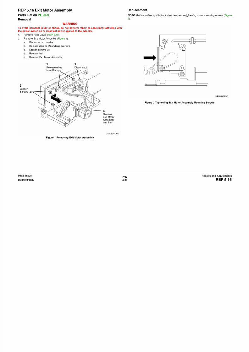
8/13/2019 Xerox Docu Color 2240-1632
http://slidepdf.com/reader/full/xerox-docu-color-2240-1632 565/1118
7/02
4-40 DC 2240/1632REP 5.17Initial IssueRepairs and Adjustments
Figure 1 Removing Document Transport
REP 5.18 Rear Cover
Parts List on PL 20.1
Removal
WARNING
To avoid personal injury or shock, do not perform repair or adjustment activities with
the power switch on or electrical power applied to the machine.
CAUTION
LED harness breakage occurs if Rear Cover is removed without disconnecting LED plug
1. Loosen Screws (3) and remove Rear Cover enough to disconnect LED harness from
DADF Control PWB.

8/13/2019 Xerox Docu Color 2240-1632
http://slidepdf.com/reader/full/xerox-docu-color-2240-1632 566/1118
7/02
4-41DC 2240/1632 REP 5.18Repairs and AdjustmentsInitial Issue
REP 5.19 Platen Belt
Parts List on PL 20.10
Removal
WARNING
To avoid personal injury or shock, do not perform repair or adjustment activities with
the power switch on or electrical power applied to the machine.
NOTE: After replacing Platen Belt, reset HFSI counter. Enter DC135 HFSI Counters Diag.
Screen (NVM 005-805).
WARNING
Switch off the power and disconnect power cord.
1. Remove Front Cover (PL 20.1).
2. Remove Document Transport (REP 5.17).
3. Remove Platen Belt (Figure 1).
a. Loosen screws (2).
b. Move shaft support in direction of arrow.
c. Remove Platen Belt.
Replacement
NOTE: Lock shaft support by matching hole with frame’s detent ( Figure 2 ).

8/13/2019 Xerox Docu Color 2240-1632
http://slidepdf.com/reader/full/xerox-docu-color-2240-1632 567/1118
7/02
4-42 DC 2240/1632REP 5.19Initial IssueRepairs and Adjustments
Figure 1 Removing Platen Belt
Figure 2 Locking shaft support
NOTE: Make sure that both sides of Platen Belt are correctly set in pulley ( Figure 3 ).

8/13/2019 Xerox Docu Color 2240-1632
http://slidepdf.com/reader/full/xerox-docu-color-2240-1632 568/1118
7/02
4-43DC 2240/1632 REP 5.19Repairs and AdjustmentsInitial Issue
Figure 3 Install Platen Belt
1. Connect power cord and switch on power.
2. Enter DC330 [5-055]. Press START button and press the Stop button in 15 seconds.
Check the belt position. If the belt has moved to either side,
3. Rotate Platen Belt for 15 seconds. Press STOP button. Check the Belt position. If the belt
moved to either side, check the installation of the Shaft Supports.
CORRECT INCORRECT

8/13/2019 Xerox Docu Color 2240-1632
http://slidepdf.com/reader/full/xerox-docu-color-2240-1632 569/1118
7/02
4-44 DC 2240/1632REP 5.19Initial IssueRepairs and Adjustments
REP 6.1 ROS
Parts List on PL 3.1Removal
WARNING
To avoid personal injury or shock, do not perform repair or adjustment activities with
the power switch on or electrical power applied to the machine.
1. Remove Right Cover (REP 14.3).
2. Remove Rear Cover (REP 14.2).
CAUTION
Image quality defects result if covers on ROS cleaning openings are removed.
3. Remove ROS (Figure 1).
a. Carefully observe position of wiring harness for later reinstallation.
b. Remove Harness from Harness Clips.
c. Disconnect Harness P/J’s (2).
d. Remove Screws (2).
e. Pull out ROS to remove it.
P/J’sScrews (2)
8/13/2019 Xerox Docu Color 2240-1632
http://slidepdf.com/reader/full/xerox-docu-color-2240-1632 570/1118
7/02
4-45DC 2240/1632 REP 6.1Repairs and AdjustmentsInitial Issue
Figure 1 Removing ROS
Replacement
After machine reassembly perform following:
1. DC956 Belt Edge.
2. DC685 Color Registration Control (ADJ 9.6).
Harness Clips
REP 6.2 Platen Glass
Parts List on PL 18.3 Removal
WARNING
To avoid personal injury or shock, do not perform repair or adjustment activities with
the power switch on or electrical power applied to the machine.
1. Open DADF.
2. Remove Platen Glass (Figure 1).
Replacement
NOTE: Press Platen Glass in direction of arrow A; Press Right Side Plate in direction of arrow B ( Figure 2 ).
1Removescrews (2)
2RemoveGuide

8/13/2019 Xerox Docu Color 2240-1632
http://slidepdf.com/reader/full/xerox-docu-color-2240-1632 571/1118
7/02
4-46 DC 2240/1632REP 6.2Initial IssueRepairs and Adjustments
Figure 1 Removing Platen Glass
Figure 2 Positioning Platen Glass
3RemovePlatenGlass
REP 6.3 IIT Top Cover
RemovalWARNING
To avoid personal injury or shock, do not perform repair or adjustment activities with
the power switch on or electrical power applied to the machine.
1. Remove DADF (REP 5.1).
2. Remove Screws (2) from top front of IIT Top Cover.
3. Loosen Screws (2) under Control Panel, each end.
4. Remove Screw from rear of IIT Top Cover, left side.
5. Remove Document Output Tray.
6. Remove Document Output Tray support bracket Screws (4) and Brackets (2).
7. Lift IIT Top Cover to access harness connectors (2). Disconnect P/J’s and remove IIT Top
Cover.
REP 6.4 Lens Kit
Parts List on PL 18.4Removal
WARNING
To avoid personal injury or shock, do not perform repair or adjustment activities with
the power switch on or electrical power applied to the machine.
1. Remove Platen Glass (REP 6.2).
CAUTION
In the following, do not remove any red screws.
2. Remove the Lens/CCD Chassis (Figure 1).
a. Mark the position of the APS Sensor bracket.
b. Remove the Screw (1) and the APS Sensor with bracket.
c. Remove Lens Cover Screws (6) and Lens Cover.
d. Disconnect CCD Connector (not shown).
e. Remove Lens/CCD Chassis Screws (4) and remove Lens/CCD Chassis.
Lens CoverScrews (3)
Lens CoverScrews (3)

8/13/2019 Xerox Docu Color 2240-1632
http://slidepdf.com/reader/full/xerox-docu-color-2240-1632 572/1118
7/02
4-47DC 2240/1632 REP 6.3, REP 6.4Repairs and AdjustmentsInitial Issue
Figure 1 Removing Lens Cover
Replacement
NOTE: Align APS Sensor with marks made in step 2a before tightening screw.
NOTE: Perform DC945 IIT Calibration ( ADJ 9.7 ).
APS Sen-sor Bracketand Screw
Lens/CCDChassisScrews (2)
Lens/CCDChassisScrews (2)
REP 6.5 IIT/IPS PWB
Parts List on PL 18.3Removal
1. Gather all available settings information. This includes the machine NVM log, the
Machine Settings floppy disk, copies of the Configuration Report, etc. If possible save the
current Machine Settings to the floppy.
WARNING
To avoid personal injury or shock, do not perform repair or adjustment activities with
the power switch on or electrical power applied to the machine.
2. Remove the Platen Glass (REP 6.2).
3. Remove the IPS Cover (PL 18.3).
a. Manually move full rate carriage (PL 18.6) toward your left.
b. Remove front screws (2), left screws (2), and right screws (2) from IPS Cover (PL
18.3).
c. Loosen rear screw and remove cover.
4. Disconnect IOT/IIT Cable and remove Screws from IIT (Figure 1).
5. Remove IIT/IPS PWB (Figure 2).
Remove
Screws
1RemoveScrews (10)
2DisconnectP/J’s (6)
3
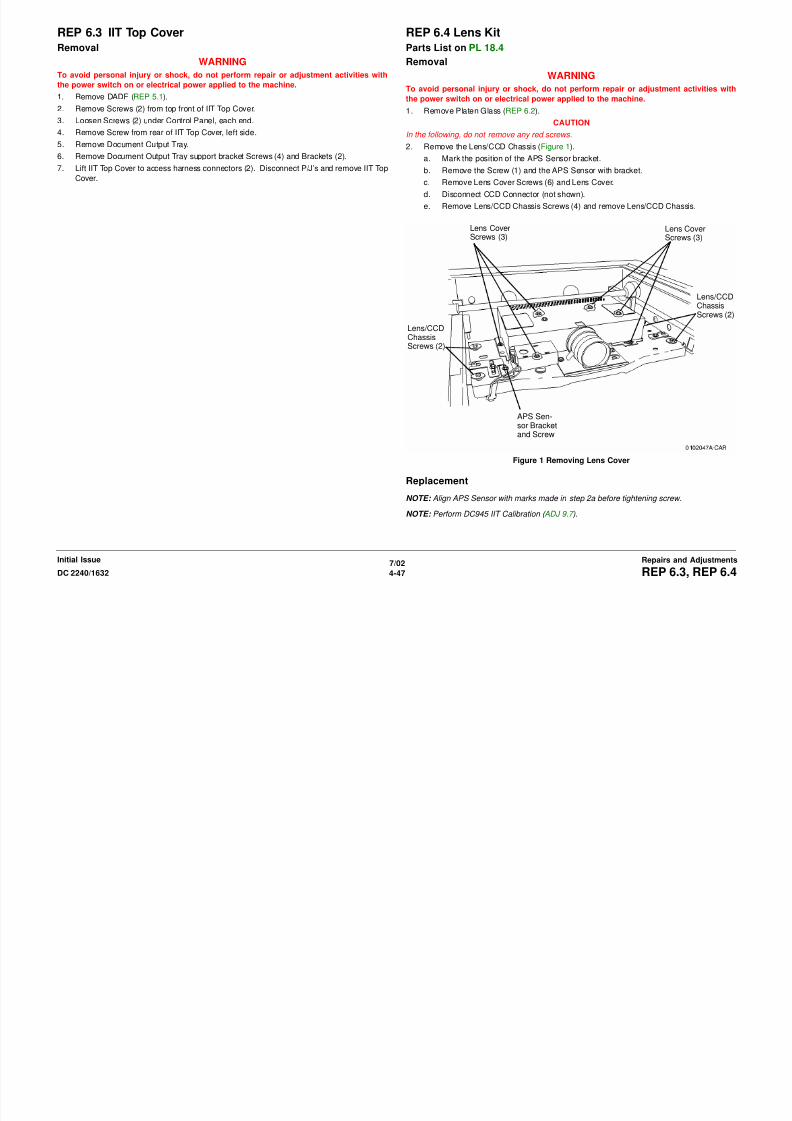
8/13/2019 Xerox Docu Color 2240-1632
http://slidepdf.com/reader/full/xerox-docu-color-2240-1632 573/1118
7/02
4-48 DC 2240/1632REP 6.5Initial IssueRepairs and Adjustments
Figure 1 Disconnecting Cable and Removing Screws from IIT
Figure 2 Removing IIT/IPS PWB
Replacement
1. Install the new IIT/IPS PWB. Switch on the power and connect the PWS.
2. Check the IIT/IISS software version to ensure that it matches the system software config-
uration. Refer to the Software Configuration table in the system software upgrade instruc-
tions contained on the S/W update CD.If the version does not match, reload the software in accordance with the instructions on
the CD.
3. If a good Machine Settings floppy is available, exit, then reenter the PWS Tool. Select
Read from Floppy when starting the tool. If no floppy is available, or if the data on the
existing floppy is questionable, go to step 5.
4. Go to dC351 and select Restore Machine Settings.
5. If a good Machine Settings floppy is not available, or if the data on the existing floppy is
questionable, go to dC351. In the Special Batch Write area, select the appropriate market
region, then press the Batch Write NVM button.
6. Using the resources gathered in step 1 of the removal procedure, reenter NVM data torestore the machine configuration.
7. Ensure that the customer settings are correct. Contact the customer’s system administra-
tor to configure, if necessary.
1Loosen Screws andDisconnect Plug
RemovePWB
REP 6.11 Carriage Cables
Parts List on PL 18.5Removal
WARNING
To avoid personal injury or shock, do not perform repair or adjustment activities with
the power switch on or electrical power applied to the machine.
NOTE: This page describes how to remove Rear Carriage Cable.
NOTE: Do not replace both cables at same time. Remove front and rear cables separately.
1. Remove DADF (REP 5.1).
2. Remove Platen Glass (REP 6.1).
3. Remove IIT Top Cover (REP 6.3).
4. DADF machines: Remove registration gate and plate (Figure 1).
a. 1. Remove screws (2).
b. 2. Remove Registration Gate.
c. 3. Remove screws (2).
d. 4. Remove plate.
6. Move Half Rate Carriage so that position of Carriage Cable Ball on Capstan is one of fol-
lowing: (Figure 2).
• Two Carriage Cable Rolls in front and rear.
• Carriage Cable Ball is directly above.

8/13/2019 Xerox Docu Color 2240-1632
http://slidepdf.com/reader/full/xerox-docu-color-2240-1632 574/1118
7/02
4-49DC 2240/1632 REP 6.11Repairs and AdjustmentsInitial Issue
Figure 1 Removing Registration Gate and Plate
5. Remove Full Rate Carriage from IIT Frame (REP 6.14). Keep lamp wire harness connec-
tor connected.
Figure 2 Positioning Half Rate Carriage
7. Remove Carriage Cable (Figure 3).
a. Remove spring.
b. Separate spring and cable.
c. Pull out ball from hole.
d. Remove cable.
Replacement
1. Wind Carriage Cable into pulley (Figure 4).a. Insert Carriage Cable Ball into groove of pulley.
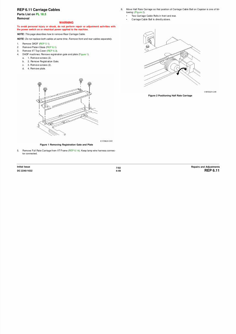
8/13/2019 Xerox Docu Color 2240-1632
http://slidepdf.com/reader/full/xerox-docu-color-2240-1632 575/1118
7/02
4-50 DC 2240/1632REP 6.11Initial IssueRepairs and Adjustments
Figure 3 Removing Carriage Cable
Figure 4 Winding Carriage Cable
b. Wind cable (spring hook side) onto pulley for 2.5 turns. Tape and lock cable (on
spring hook) on frame (Figure 5).
c. Wind cable (ball side) onto pulley for 2.4 turns. Tape and lock cable wound on pulley
(Figure 6).

8/13/2019 Xerox Docu Color 2240-1632
http://slidepdf.com/reader/full/xerox-docu-color-2240-1632 576/1118
7/02
4-51DC 2240/1632 REP 6.11Repairs and AdjustmentsInitial Issue
Figure 5 Locking Cable Figure 6 Locking Cable
d. Check orientation of ends and number of carriage cable windings (front/rear) (Figure
7). Reconfigure as required.
2. Install Carriage Cable (ball side) (Figure 8).
a. Hook cable to pulley (from bottom to top).
b. Hook cable to large pulley in Half Rate Carriage (from top to bottom).
c. Insert ball into frame hole.

8/13/2019 Xerox Docu Color 2240-1632
http://slidepdf.com/reader/full/xerox-docu-color-2240-1632 577/1118
7/02
4-52 DC 2240/1632REP 6.11Initial IssueRepairs and Adjustments
Figure 7 Carriage Cable Windings
Figure 8 Installing Carriage Cable (ball side)
3. Install Carriage Cable (spring hook side) (Figure 9).
a. Hook cable to pulley (from bottom to top).
b. Hook cable to small pulley in Half Rate Carriage (from bottom to top).
c. Hook cable to stud (from bottom to top).
d. Install spring on cable (spring hook side).
e. Hook spring onto frame.
4. Remove tape from cable.
5. Install Full Rate Carriage in IIT Frame.
6. Adjust positions of Full Rate/Half Rate Carriages (ADJ 6.1).
7. Manually move Full Rate Carriage to make sure it moves smoothly.
8. Install remaining parts.
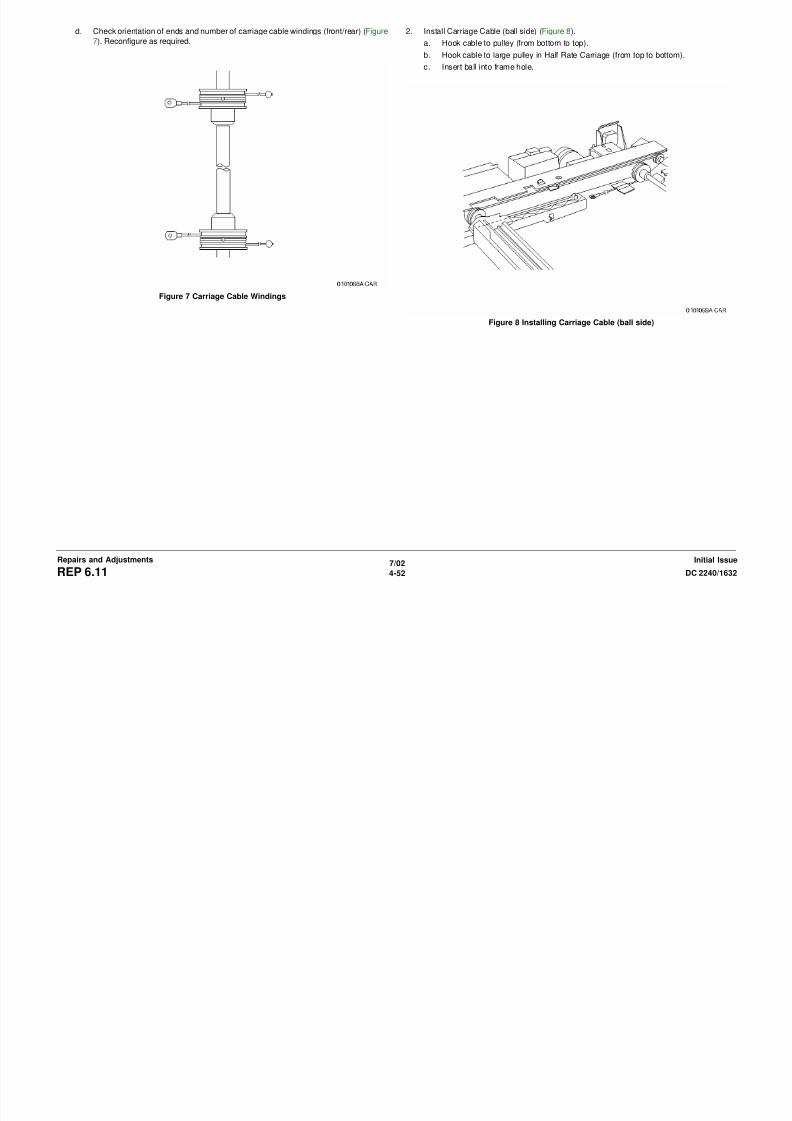
8/13/2019 Xerox Docu Color 2240-1632
http://slidepdf.com/reader/full/xerox-docu-color-2240-1632 578/1118
7/02
4-53DC 2240/1632 REP 6.11Repairs and AdjustmentsInitial Issue
Figure 9 Installing Carriage Cable (spring hook side)
REP 6.12 Carriage Motor
Parts List on PL 18.5Removal
WARNING
To avoid personal injury or shock, do not perform repair or adjustment activities with
the power switch on or electrical power applied to the machine.
1. Remove DADF (REP 5.1).
2. Remove Platen Glass (REP 6.2).
3. Remove IIT Top Cover (REP 6.3).
4. Remove Carriage Motor (Figure 1).
a. Release clamps (2).
b. Disconnect connector.
c. Remove screws (3).
d. Remove spring.
e. Remove Carriage Motor.
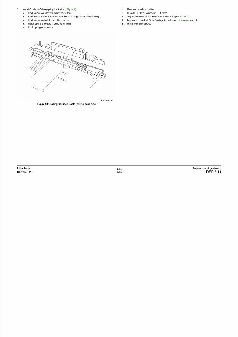
8/13/2019 Xerox Docu Color 2240-1632
http://slidepdf.com/reader/full/xerox-docu-color-2240-1632 579/1118
7/02
4-54 DC 2240/1632REP 6.12Initial IssueRepairs and Adjustments
Figure 1 Removing Carriage Motor

8/13/2019 Xerox Docu Color 2240-1632
http://slidepdf.com/reader/full/xerox-docu-color-2240-1632 580/1118
REP 6.14 Lamp Wire Harness
Parts List on PL 18.6Removal
WARNING
To avoid personal injury or shock, do not perform repair or adjustment activities with
the power switch on or electrical power applied to the machine.
1. Remove DADF (REP 5.1).
2. Remove Platen Glass (REP 6.2).
3. Remove IIT Top Cover (REP 6.3).
4. Disconnect Lamp Wire Harness connector and release Clamp Hook (Figure 1).
a. Disconnect connector.
b. Release clamp.
c. Remove clamp.
d. Release hook.
5. Remove Full Rate Carriage (Figure 2).
a. Remove screws (2).
b. Remove Full Rate Carriage.
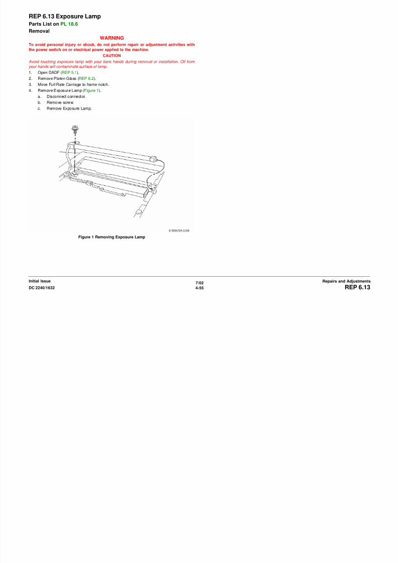
8/13/2019 Xerox Docu Color 2240-1632
http://slidepdf.com/reader/full/xerox-docu-color-2240-1632 581/1118
7/02
4-56 DC 2240/1632REP 6.14Initial IssueRepairs and Adjustments
Figure 1 Disconnecting Lamp Wire Harness
Figure 2 Removing Full Rate Carriage
6. Remove Lamp Wire Harness from Full Rate Carriage (Figure 3).
a. Flip Full Rate Carriage.
b. Remove screw.
c. Remove guide.
d. Disconnect connector.
e. Remove Lamp Wire Harness.

8/13/2019 Xerox Docu Color 2240-1632
http://slidepdf.com/reader/full/xerox-docu-color-2240-1632 582/1118
7/02
4-57DC 2240/1632 REP 6.14Repairs and AdjustmentsInitial Issue
Figure 3 Removing Lamp Wire Harness
ReplacementNOTE: After reinstalling parts, adjust positions of Full Rate/Half Rate Carriages ( ADJ 6.1 ).

8/13/2019 Xerox Docu Color 2240-1632
http://slidepdf.com/reader/full/xerox-docu-color-2240-1632 583/1118
7/02
4-58 DC 2240/1632REP 6.14Initial IssueRepairs and Adjustments
REP 7.1 Tray 5
Parts List on PL 2.2Removal
WARNING
To avoid personal injury or shock, do not perform repair or adjustment activities with
the power switch on or electrical power applied to the machine.
1. Remove Rear Cover (REP 14.2).
2. Remove Power Switch Cover (REP 14.6).
3. Remove Upper Rear Left Cover (REP 14.4).
4. Close Left Door Transport.
5. Remove Tray 5 (Figure 1).
a. Observe position of harness for later reinstallation.
b. Disconnect Tray 5 connector.
c. Disconnect harness Clip from frame.
d. Remove Screws (2).
e. Pull out Tray 5 while applying a small amount of lifting force to right side.
2. Insta ll Tray 5.
Harness
8/13/2019 Xerox Docu Color 2240-1632
http://slidepdf.com/reader/full/xerox-docu-color-2240-1632 584/1118
7/02
4-59DC 2240/1632 REP 7.1Repairs and AdjustmentsInitial Issue
Figure 1 Removing Tray 5
Replacement
CAUTION
Duplex Paper Guide must be in up position before installing Tray 5.
1. Open Left Door Transport. Pivot and hold Duplex Paper Guide against Left Door Trans-
port and then close Left Door Transport.
Clip
Screws (2)
REP 7.2 Tray 5 Feed Roll
Parts List on PL 2.14Removal
WARNING
To avoid personal injury or shock, do not perform repair or adjustment activities with
the power switch on or electrical power applied to the machine.
1. Remove Rear Cover (REP 14.2).
2. Remove Power Switch Cover (REP 14.6).
3. Remove Upper Rear Left Cover (REP 14.4).
4. Close Left Door Transport.
5. Remove Tray 5 (REP 7.1).
6. Remove Chute (Figure 1).
a. Remove Screws (3).
b. Lift to remove Chute.
Figure 2 Removing Feed Roll
Replacement
Ensure Arrow is positioned as shown (Figure 3).
Screws (3)
LockingTab
Lock Roll
FeedRoll

8/13/2019 Xerox Docu Color 2240-1632
http://slidepdf.com/reader/full/xerox-docu-color-2240-1632 585/1118
7/02
4-60 DC 2240/1632REP 7.2Initial IssueRepairs and Adjustments
Figure 1 Removing Chute
7. Remove Feed Roll (Figure 2).
a. Release Locking Tab from groove on shaft and slide Lock Roll away from Feed Roll.
b. Slide Feed Roll to disengage drive pin and remove Feed Roll.
Figure 3 Installing Feed Roll
Chute
Arrow
REP 7.3 Tray 1 Feeder
Parts List on PL 2.3Removal
WARNING
To avoid personal injury or shock, do not perform repair or adjustment activities with
the power switch on or electrical power applied to the machine.
1. Pull out Tray 1 to paper loading position.
2. Open Tray 1 Left Door.
3. Remove Tray 1 Feeder (Figure 1).
REP 7.4 Tray 1 Feed/Lift Motor
Parts List on PL 2.4Removal
WARNING
To avoid personal injury or shock, do not perform repair or adjustment activities with
the power switch on or electrical power applied to the machine.
1. Pull out Tray 1 to paper loading position.
2. Open Tray 1 Left Door.
3. Remove Tray 1 Feeder (REP 7.3).
4. Remove Tray 1 Feed Motor (Figure 1).
1DisconnectHarness
2
Remove Screws(2) and motor
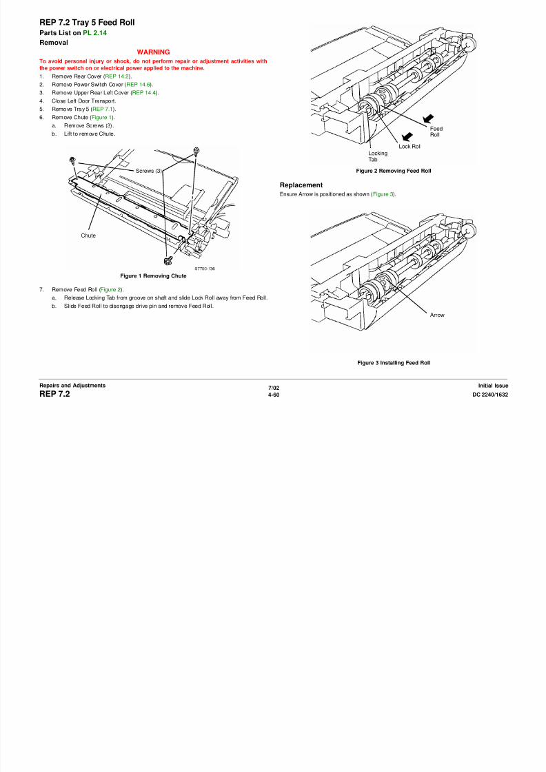
8/13/2019 Xerox Docu Color 2240-1632
http://slidepdf.com/reader/full/xerox-docu-color-2240-1632 586/1118
7/02
4-61DC 2240/1632 REP 7.3, REP 7.4Repairs and AdjustmentsInitial Issue
Figure 1 Removing Tray 1 Feeder
Figure 1 Removing Tray 1 Feed Motor
2RemoveScrews (2)
3RemoveFeeder
REP 7.5 Tray 1 Paper Size Sensor
Parts List on PL 2.1Removal
WARNING
To avoid personal injury or shock, do not perform repair or adjustment activities with
the power switch on or electrical power applied to the machine.
1. Remove Rear Cover (REP 14.2).
2. Remove High Voltage Power Supply Chassis (REP 1.6).
NOTE: Step 3 can be omitted if Low Voltage Power Supply P/J’s are disconnected before per-
forming step 4.
3. Remove 3.3 VDC and 5 VDC Low Voltage Power Supply (REP 1.4).
4. Remove Chassis for 3.3 VDC and 5 VDC Low Voltage Power Supply.
a. Release harnesses from harness clips (3).
b. Remove screws (4) and remove Chassis.
5. Remove Developer Drive Module (REP 4.3).
6. Remove Tray 1 Paper Size Switch (Figure 1).
a. Disconnect P/J.
b. Remove Screws (2) and remove Tray 1 Paper Size Switch.
REP 7.6 Tray 3
Parts List on PL 16.1Removal
WARNING
To avoid personal injury or shock, do not perform repair or adjustment activities with
the power switch on or electrical power applied to the machine.
1. Open HCF Left Door.
2. Remove Tray 3 (Figure 1).
a. Pull out Tray 3.
b. Remove Screw.
c. Pivot bottom of Tray Lock away from Tray 3 and pull out Tray 3 to remove it.
Screw
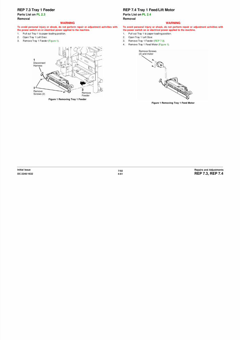
8/13/2019 Xerox Docu Color 2240-1632
http://slidepdf.com/reader/full/xerox-docu-color-2240-1632 587/1118
7/02
4-62 DC 2240/1632REP 7.5, REP 7.6Initial IssueRepairs and Adjustments
Figure 1 Removing Tray Paper Size Switch Figure 1 Removing Tray 3
P/J
Screws (2)
Bottom ofTray Lock
REP 7.7 Tray 4
Parts List on PL 16.1Removal
WARNING
To avoid personal injury or shock, do not perform repair or adjustment activities with
the power switch on or electrical power applied to the machine.
1. Pull out Tray 4.
2. Remove Tray 4 (Figure 1).
a. Pull out Tray 4.
b. Remove Transport Screws (2).
c. Remove Tray Lock Screws (2).d. Remove Tray Lock.
e. Pull out Tray 4 to remove it.
REP 7.8 Tray 1
Parts List on PL 2.1Removal
WARNING
To avoid personal injury or shock, do not perform repair or adjustment activities with
the power switch on or electrical power applied to the machine.
1. Pull out Tray 1.
2. Lift end of tray to disengage lock on rail (not visible) and remove tray.
TransportScrews (2)

8/13/2019 Xerox Docu Color 2240-1632
http://slidepdf.com/reader/full/xerox-docu-color-2240-1632 588/1118
7/02
4-63DC 2240/1632 REP 7.7, REP 7.8Repairs and AdjustmentsInitial Issue
Figure 1 Removing Tray 4
Tray Lock
TrayLockScrews(2)
REP 7.9 Tray 2
Parts List on PL 16.2Removal
WARNING
To avoid personal injury or shock, do not perform repair or adjustment activities with
the power switch on or electrical power applied to the machine.
1. Pull out Tray 2.
2. Lift end of tray to disengage lock on rail (not visible) and remove tray.

8/13/2019 Xerox Docu Color 2240-1632
http://slidepdf.com/reader/full/xerox-docu-color-2240-1632 589/1118
7/02
4-64 DC 2240/1632REP 7.9Initial IssueRepairs and Adjustments
REP 7.10 Tray 2 Feeder
Parts List on PL 16.6Removal
WARNING
To avoid personal injury or shock, do not perform repair or adjustment activities with
the power switch on or electrical power applied to the machine.
1. Pull out Tray 2.
2. Remove the Left Lower Cover. (PL 16.16)
3. Remove the Tray 2 Feeder (Figure 1).
2ReleaseWire Har-ness fromClamp anddisconnectP/J
8/13/2019 Xerox Docu Color 2240-1632
http://slidepdf.com/reader/full/xerox-docu-color-2240-1632 590/1118
7/02
4-65DC 2240/1632 REP 7.10Repairs and AdjustmentsInitial Issue
Figure 1 Removing the Tray 2 Feeder
1LoosenScrew andmove
Bracket
3RemoveScrews (2)and Feeder
REP 7.11 Tray 3 Feeder
Parts List on PL 16.6Removal
WARNING
To avoid personal injury or shock, do not perform repair or adjustment activities with
the power switch on or electrical power applied to the machine.
1. Remove Tray 2.
2. Pull out Tray 3 and Tray 4.
3. Open the Left Cover.
4. Remove the Lower Chute.
5. Remove the Tray 3 Feeder Assembly (Figure 1).
6. Remove the Tray 3 Feeder from mounting bracket (Figure 2).
Figure 2 Removing Tray 3 Feeder from Bracket
2Release WireHarness anddisconnect P/J
3LoosenScrew (1)
Remove theScrews (2)and Bracket

8/13/2019 Xerox Docu Color 2240-1632
http://slidepdf.com/reader/full/xerox-docu-color-2240-1632 591/1118
7/02
4-66 DC 2240/1632REP 7.11Initial IssueRepairs and Adjustments
Figure 1 Removing the Tray 3 Feeder Assembly
1RemoveScrews (2)
4
Remove Screws(2) and Tray 3Feeder Assembly
REP 7.12 Tray 4 Feeder
Parts List on PL 16.11Removal
WARNING
To avoid personal injury or shock, do not perform repair or adjustment activities with
the power switch on or electrical power applied to the machine.
1. Remove the Tray 2.
2. Pull out the Tray 3/4.
3. Remove the Stud Bracket (Figure 1).
4. Remove the Tray 4 Feeder Assembly (Figure 2).
Remove Screwand Bracket
1DisconnectP/J
2LoosenScrew
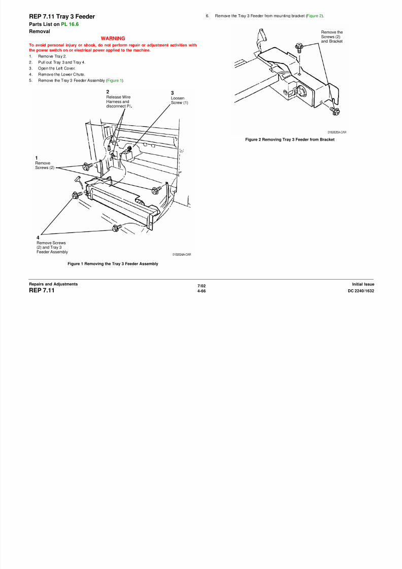
8/13/2019 Xerox Docu Color 2240-1632
http://slidepdf.com/reader/full/xerox-docu-color-2240-1632 592/1118
7/02
4-67DC 2240/1632 REP 7.12Repairs and AdjustmentsInitial Issue
Figure 1 Removing Stud Bracket
Figure 2 Removing the Tray 4 Feeder Assembly
3Remove Screw andFeeder Assembly
5. Remove the Tray 4 Feeder Guides (Figure 3). 6. Remove Brackets from Tray 4 Feeder Assembly (Figure 4).
1Remove Screws (2)and Upper Guide
2Remove Screws (2)and Lower Guide
1RemoveScrews (2)and Bracket
2Remove Screwand Bracket
3Remove Screwand Bracket
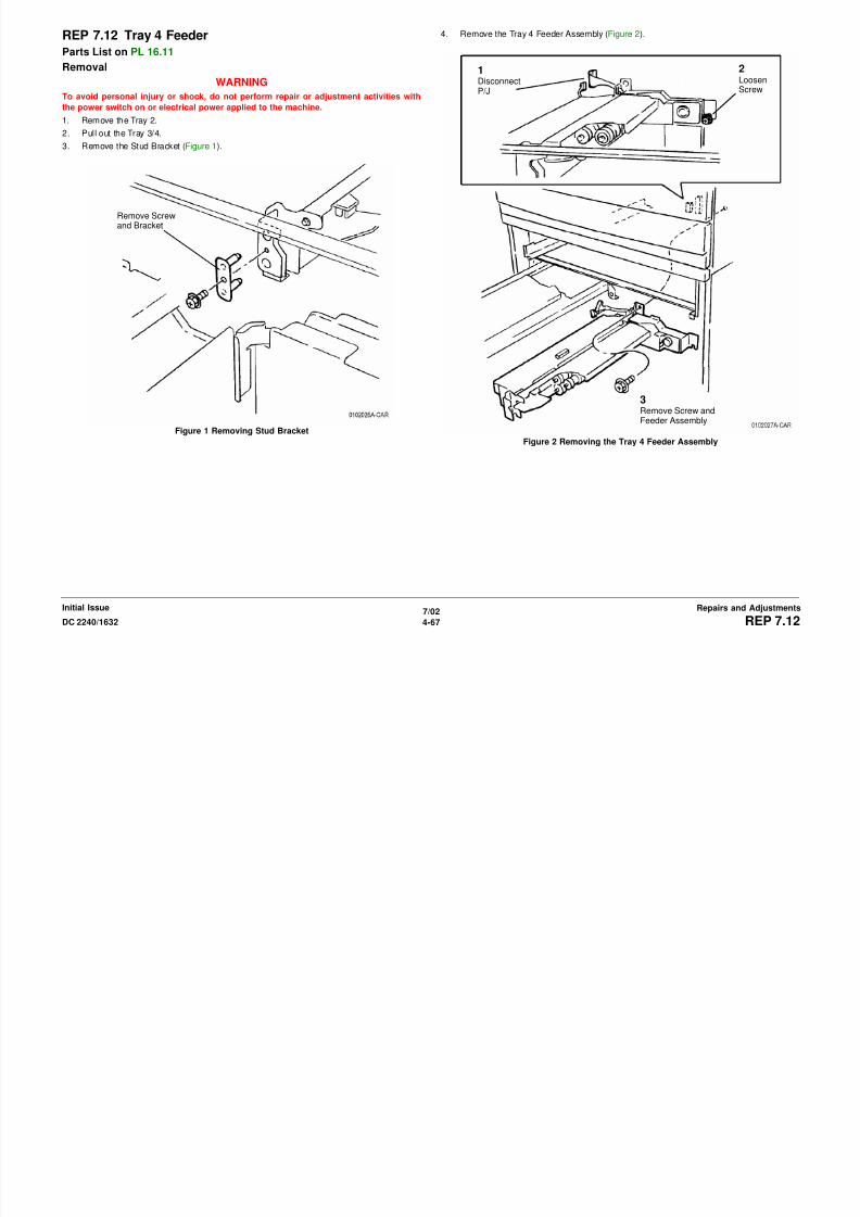
8/13/2019 Xerox Docu Color 2240-1632
http://slidepdf.com/reader/full/xerox-docu-color-2240-1632 593/1118
7/02
4-68 DC 2240/1632REP 7.12Initial IssueRepairs and Adjustments
Figure 3 Removing the GuidesFigure 4 Removing the Brackets
REP 8.1 Left Cover Assembly
Parts List on PL 2.9Removal
WARNING
To avoid personal injury or shock, do not perform repair or adjustment activities with
the power switch on or electrical power applied to the machine.
1. Remove Rear Cover (REP 14.2).
2. Remove Power Switch Cover (REP 14.6).
3. Remove Upper Rear Left Cover (REP 14.4).
4. Close Left Cover Assembly.
5. Remove Tray 5 (REP 7.1).6. Remove Fuser Front Cover (REP 14.8).
7. Disconnect Electrical Connectors (3) (Figure 1).
1Disconnect (3)

8/13/2019 Xerox Docu Color 2240-1632
http://slidepdf.com/reader/full/xerox-docu-color-2240-1632 594/1118
7/02
4-69DC 2240/1632 REP 8.1Repairs and AdjustmentsInitial Issue
Figure 1 Disconnecting Electrical Connectors (3)
2
Remove Screwand Cover
3
Move Harnessesinto this space
8. Remove Left Cover Assembly (Figure 2). CAUTION
Before closing Left Cover Assembly to connect harness, hold up black plastic Duplex Baffle
while closing transport.1Remove Clip anddisconnect Stop
2Support Left CoverAssembly while per-form steps 3 and 4
3RemoveScrew andlift up StopArm Hinge
Pin
Marks onMotionDamper
Stop Pin
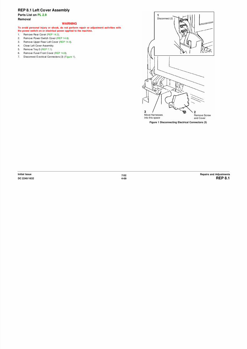
8/13/2019 Xerox Docu Color 2240-1632
http://slidepdf.com/reader/full/xerox-docu-color-2240-1632 595/1118
7/02
4-70 DC 2240/1632REP 8.1Initial IssueRepairs and Adjustments
Figure 2 Removing Left Cover Assembly
Replacement
Install Left Cover Assembly on hinge pins, manually align marks on Motion Damper, then tip
up transport to engage Motion Damper gears and connect stop arm on Stop Pin (Figure 3).
Figure 3 Aligning Marks on Motion Damper
4Lower Left Cover Assembly and thenlift to disengage hinges and remove it
REP 8.2 Duplex ChuteParts List on PL 2.8
Removal
WARNING
To avoid personal injury or shock, do not perform repair or adjustment activities with
the power switch on or electrical power applied to the machine.
1. Remove Rear Cover (REP 14.2).
2. Remove Power Switch Cover (REP 14.6).
3. Remove Upper Rear Left Cover (REP 14.4).
4. Close Left Cover Assembly.
5. Remove Tray 5 (REP 7.1).6. Open and close Left Cover Assembly to allow Duplex Paper Guide to swing down.
7. Swing Duplex Paper Guide back and forth while carefully pushing Duplex Paper Guide
toward rear. Key in front hinge pin will enter hinge pin slot and front hinge pin will disen-
gage hinge pin hole. Move Duplex Paper Guide toward front to disengage rear hinge pin.
Replacement
Install Left Cover Assembly on hinge pins, manually align marks on Motion Damper, then tip
up transport to engage Motion Damper gears and connect stop arm on Stop Pin (Figure 3).
CAUTION
Before closing Left Cover Assembly to connect harness, hold up black plastic Duplex Baffle
while closing transport.
HingePin
Marks onMotionDamper
Stop Pin

8/13/2019 Xerox Docu Color 2240-1632
http://slidepdf.com/reader/full/xerox-docu-color-2240-1632 596/1118
7/02
4-71DC 2240/1632 REP 8.2Repairs and AdjustmentsInitial Issue
Figure 1 Aligning Marks on Motion Damper
REP 8.3 Duplex Transport AssemblyParts List on PL 2.7
Removal
WARNING
To avoid personal injury or shock, do not perform repair or adjustment activities with
the power switch on or electrical power applied to the machine.
1. Remove Duplex Transport Assembly (Figure 1).
a. Remove Clip and Left Upper Cover.
b. Loosen Screws and remove Duplex Transport Assembly.
REP 8.5 Inverter TransportParts List on PL 11.1
Removal
WARNING
To avoid personal injury or shock, do not perform repair or adjustment activities with
the power switch on or electrical power applied to the machine.
1. Open Left Cover Assembly.
2. Remove Inverter Transport (Figure 1).
a. Remove E-rings (2), Bearings (2), and Transport Shaft.
b. Remove Screws (2).
c. Remove Inverter Transport.
Screws
e pperCoverClip
Screw(1)
E-Ring andBearing
TransportShaft
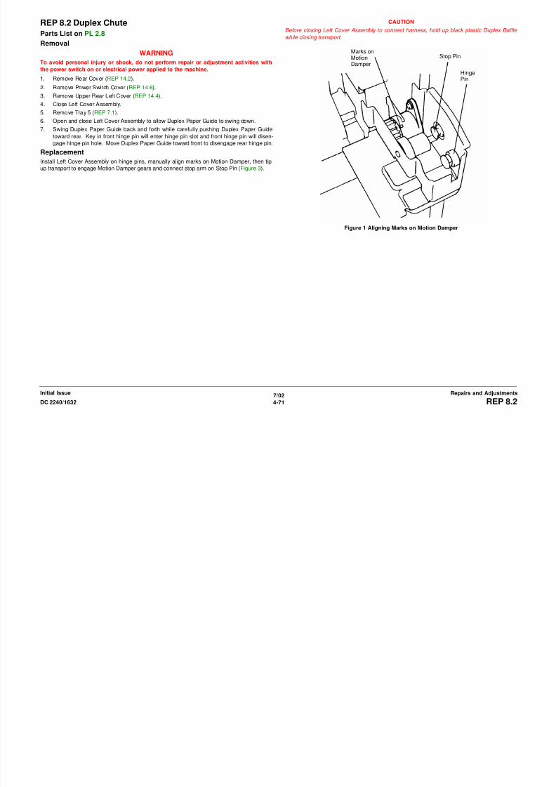
8/13/2019 Xerox Docu Color 2240-1632
http://slidepdf.com/reader/full/xerox-docu-color-2240-1632 597/1118
7/02
4-72 DC 2240/1632REP 8.3, REP 8.5Initial IssueRepairs and Adjustments
Figure 1 Removing Duplex Transport Assembly
Replacement
Figure 1 Removing Inverter Transport
Screws(2)
Screw(1)
InverterTransport
E-Ring andBearing
REP 8.6 Registration Transport AssemblyParts List on PL 2.6
Removal
WARNING
To avoid personal injury or shock, do not perform repair or adjustment activities with
the power switch on or electrical power applied to the machine.
1. Remove Rear Cover (REP 14.2).
2. Remove Power Switch Cover (REP 14.6).
3. Remove Upper Rear Left Cover (REP 14.4).
4. Close Left Cover Assembly.
5. Remove Tray 5 (REP 7.1).6. Remove Left Cover Assembly (REP 8.1).
7. Remove Registration Transport Assembly (Figure 1).
a. Observe position of harness for later reinstallation.
b. Remove Screws (2).
c. Pivot top of Registration Transport out and disconnect Harness.
d. Lift to remove Registration Transport.
Replacement
NOTE: bearing is equipped with two Anti-rotation Tabs. If one breaks during removal, install
bearing so other tab is employed.
NOTE: Check that ground spring is pressing against Bronze bushing after installing it.
Harness

8/13/2019 Xerox Docu Color 2240-1632
http://slidepdf.com/reader/full/xerox-docu-color-2240-1632 598/1118
7/02
4-73DC 2240/1632 REP 8.6Repairs and AdjustmentsInitial Issue
Figure 1 Removing Registration Transport Assembly
Screws (2)
REP 8.7 Exit Transport AssemblyParts List on PL 2.10
Removal
WARNING
To avoid personal injury or shock, do not perform repair or adjustment activities with
the power switch on or electrical power applied to the machine.
1. Open Front Cover.
2. Remove Fuser Front Cover (REP 14.8).
3. Remove Rear Cover (REP 14.2).
4. Remove Power Switch Cover (REP 14.5).
5. Remove Exit Transport (Figure 1).a. Disconnect P/J’s (2).
b. Remove Screws (3)
c. Rotate Exit Transport slightly to disengage Tab and then lift to remove Exit Trans-
port.
P/J’s(2)
Screws (3)
Tab
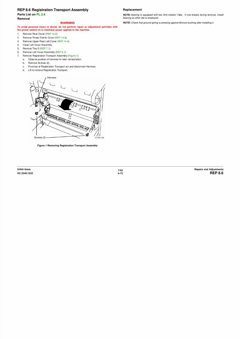
8/13/2019 Xerox Docu Color 2240-1632
http://slidepdf.com/reader/full/xerox-docu-color-2240-1632 599/1118
7/02
4-74 DC 2240/1632REP 8.7Initial IssueRepairs and Adjustments
Figure 1 Removing Exit Transport
(2)
REP 9.1 Drum CartridgeParts List on PL 4.1
Removal
WARNING
To avoid personal injury or shock, do not perform repair or adjustment activities with
the power switch on or electrical power applied to the machine.
1. Remove Drum Cartridge.
a. Open Left Cover Assembly.
b. Open Front Cover.
c. Actuate orange release and pull out Drum Cartridge.
CAUTIONDrum Cartridge photoreceptor damage is likely if Drum Cartridge is handled carelessly.
This results in image quality defects. Use caution when Drum Cartridge is removed from
machine.
d. Place Drum Cartridge in a black bag.
REP 9.2 ROS Shutter MotorParts List on PL 8.1
Removal
WARNING
To avoid personal injury or shock, do not perform repair or adjustment activities with
the power switch on or electrical power applied to the machine.
1. Remove Rear Cover (REP 14.2).
2. Remove Power Switch Cover (REP 14.6).
3. Remove Upper Rear Left Cover (REP 14.4).
4. Close Left Cover Assembly.
5. Remove MSI Tray (REP 7.1).6. Remove Left Cover Assembly (REP 8.1).
7. Remove Registration Transport (REP 8.6).
8. Remove Shutter Actuator(Figure 1).
1Disconnect

8/13/2019 Xerox Docu Color 2240-1632
http://slidepdf.com/reader/full/xerox-docu-color-2240-1632 600/1118
7/02
4-75DC 2240/1632 REP 9.1, REP 9.2Repairs and AdjustmentsInitial Issue
Figure 1 Removing Shutter Actuator
Replacement
Ensure solenoid arm engages
2RemoveScrew
3
Pull outShutterActuator
REP 9.3 Waste Toner Cartridge CoverParts List on PL 4.1
Removal
WARNING
To avoid personal injury or shock, do not perform repair or adjustment activities with
the power switch on or electrical power applied to the machine.
1. Open Front Cover.
2. Remove Waste Cartridge Cover (Figure 1).
a. Open Waste Cartridge Cover.
b. Remove Screw.
c. Remove Waste Toner Cartridge Cover.
REP 9.4 Waste Toner CartridgeParts List on PL 4.1
Removal
WARNING
To avoid personal injury or shock, do not perform repair or adjustment activities with
the power switch on or electrical power applied to the machine.
1. Open Front Cover.
2. Remove Waste Cartridge (Figure 1).
a. Open Waste Cartridge Cover.
b. Release Lever and move half way down.
c. Pull out to remove Waste Cartridge.
WasteCartridgeCover
WasteCartridgeCover

8/13/2019 Xerox Docu Color 2240-1632
http://slidepdf.com/reader/full/xerox-docu-color-2240-1632 601/1118
7/02
4-76 DC 2240/1632REP 9.3, REP 9.4Initial IssueRepairs and Adjustments
Figure 1 Removing Waste Toner Cartridge Cover Figure 1 Removing Waste Cartridge
Screw Waste
Cartridge
Lever
REP 9.5 Full Toner SensorParts List on PL 4.1
Removal
WARNING
To avoid personal injury or shock, do not perform repair or adjustment activities with
the power switch on or electrical power applied to the machine.
1. Open Front Cover.
2. Remove Waste Cartridge (REP 9.4).
3. Remove Waste Cartridge Cover (REP 9.3).
4. Access Waste Cartridge Full Sensor (Figure 1).
a. Lift Left End slightly and pull left to disengage Mounting Tabs.b. Rotate Sensor Support and remove. Left End harness connection limits movement.
Fi 1 A i W t C t id F ll S
REP 9.6 Inner CoverParts List on PL 10.2
Removal
WARNING
To avoid personal injury or shock, do not perform repair or adjustment activities with
the power switch on or electrical power applied to the machine.
1. Open Front Cover.
2. Open Left Cover Assembly.
3. Remove Y, M, C, K, Drum.
4. Remove Fuser Front Cover (REP 14.8).
5. Release and move Xerographic Release Lever half way down.6. Remove Dispenser Assembly Cover (Figure 1).
a. Remove Screws (4).
b. Remove Dispenser Assembly Cover.
LeftEnd
Mounting TabsSensorSupport
ConnectedHarness

8/13/2019 Xerox Docu Color 2240-1632
http://slidepdf.com/reader/full/xerox-docu-color-2240-1632 602/1118
7/02
4-77DC 2240/1632 REP 9.5, REP 9.6Repairs and AdjustmentsInitial Issue
Figure 1 Accessing Waste Cartridge Full Sensor
5. Remove Waste Cartridge Full Sensor (Figure 2).
a. Push against Sensor Head while releasing Locking Tabs.
b. Disconnect sensor from harness.
Figure 2 Removing Waste Cartridge Full Sensor
Figure 1 Removing Toner Transport Cover
LockingTabs
Waste Car-tridge FullSensor
SensorHead
Screws (4)
REP 9.7 Toner DispenserParts List on PL 6.1
Removal
WARNING
To avoid personal injury or shock, do not perform repair or adjustment activities with
the power switch on or electrical power applied to the machine.
1. Open Front Cover.
2. Remove Fuser Front Cover (REP 14.8).
3. Release and move Xerographic Release Lever half way down.
4. Remove Dispenser Assembly Cover (REP 9.6).
5. Remove Drum Cartridges as required.CAUTION
Y must be removed first, followed in order by M, C, then K. They must be reinstalled in reverse
order of removal, which is install K, C, M, and then Y.
6. Prepare to remove Toner Transport (Figure 1).
a. Carefully pull out Toner Outlet Door while holding Housing back to shut off toner out-
let.
CAUTION
Connection Tube may separate from upper or lower housing.
Agitator may disconnect if flex coupling is compressed enough so agitator hits inside bot- tom of lower housing
b. Pull out Upper and Lower Housings together while ensuring flexible Connection
Tube remains connected.
TonerOutletDoor
UpperHousing
LowerHousing
Screw
ConnectionTube

8/13/2019 Xerox Docu Color 2240-1632
http://slidepdf.com/reader/full/xerox-docu-color-2240-1632 603/1118
7/02
4-78 DC 2240/1632REP 9.7Initial IssueRepairs and Adjustments
Figure 1 Closing Toner Outlet
7. Remove Toner Transport (Figure 2).
a. Remove Screw,
Figure 2 Removing Toner TransportHousing
REP 9.8 Plate AssemblyParts List on PL 4.2
Removal
WARNING
To avoid personal injury or shock, do not perform repair or adjustment activities with
the power switch on or electrical power applied to the machine.
1. Remove Front Cover (REP 14.7).
2. Remove Drum Cartridges.
3. Remove Waste Cartridge (REP 9.4).
4. Remove Waste Cartridge Cover (REP 9.3).
5. Remove Fuser Front Cover (REP 14.8).6. Release and move Xerographic Release Lever half way down.
7. Remove Dispenser Assembly Cover (REP 9.6).
8. Remove all Dispenser Assemblies (REP 9.7).
CAUTION
Note position of harnesses. Correct harness routing is required for assembly.
NOTE: In next step, do not remove sensor.
9. Remove housing for Waste Cartridge Full Sensor (REP 9.5).
10. Disconnect Developer Housing Plugs, 4 large and 4 small (small not shown).
Position wires straight out from machine. Wires remain stationary while removing Plate
Assembly (Figure 1).
Figure 1 Disconnecting Developer Housing Plugs
DeveloperHousing Plugs(4 Large)

8/13/2019 Xerox Docu Color 2240-1632
http://slidepdf.com/reader/full/xerox-docu-color-2240-1632 604/1118
7/02
4-79DC 2240/1632 REP 9.8Repairs and AdjustmentsInitial Issue
11. Disconnect Developer Housing Harnesses (Figure 2).
a. Open Harness Clip and remove harness from Clip.
b. Disconnect Harness P/J’s (3).c. Remove Screw from Inner Left Harness Cover and remove cover.
d. Remove Developer Housing Harnesses from additional harness clips (not shown,
under Harness Cover).
12. Remove Plate Assembly (Figure 3).
a. Remove Screws (6).
b. Pull Plate Assembly toward front to remove it. Ensure harnesses are cared for.
Figure 3 Removing Plate Assembly
HarnessP/J’s (3)
HarnessClip
ScrewInner LeftHarnessCover
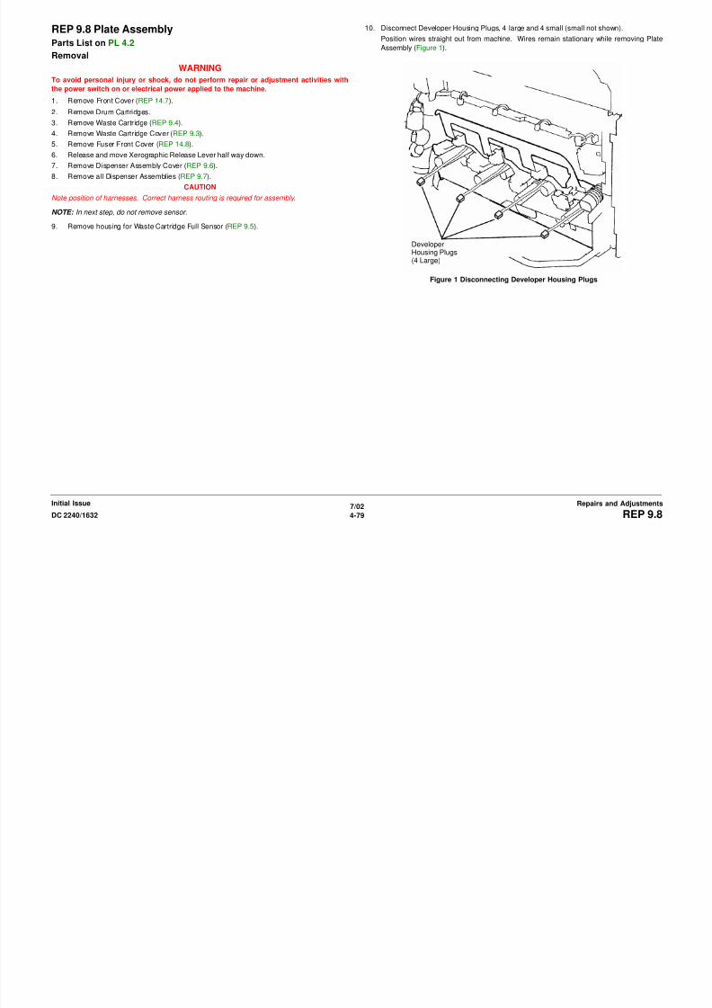
8/13/2019 Xerox Docu Color 2240-1632
http://slidepdf.com/reader/full/xerox-docu-color-2240-1632 605/1118
7/02
4-80 DC 2240/1632REP 9.8Initial IssueRepairs and Adjustments
Figure 2 Disconnecting Developer Harnesses
Cover
REP 9.9 Developer Housing
Parts List on PL 6.2
Removal
WARNING
To avoid personal injury or shock, do not perform repair or adjustment activities with
the power switch on or electrical power applied to the machine.
1. Remove Front Cover (REP 14.7).
2. Remove Drum Cartridges.
3. Remove Waste Cartridge (REP 9.4).
4. Remove Waste Cartridge Cover (REP 9.3).
5. Remove Fuser Front Cover (REP 14.8).
6. Move Xerographic Release Lever up to a mid position.
7. Remove Dispenser Assembly Cover (REP 9.6).
8. Remove all Dispenser Assemblies (REP 9.7).
NOTE: In next step, do not remove sensor.
9. Remove housing for Waste Cartridge Full Sensor (REP 9.5).
NOTE: In next step, it may not be necessary to disconnect harnesses for Plate Assembly (PL
4.2) to remove a developer housing.
10. Remove Plate Assembly (REP 9.8).CAUTION
IBT belt damage results when Developer Housing is removed carelessly.
11. Remove Developer Housing (Figure 1).
Replacement
NOTE: If installing a new Developer Housing, go to step 1. If reinstalling existing developer
housing, go to 5 .
1. Install new Developer (REP 9.10) as required.
2. Remove ATC Sensor Setup Data Tag from new Developer Housing. On tag, highlight K,
C, M, or Y as required for color of developer housing. Tag will be installed during machine
reassembly.
CAUTION
Image quality defects occur when ATC Sensor Data is mishandled in dC921.
3. During machine assembly, install ATC Sensor Setup Data Tag as shown ( Figure 2 ).
1Raise XerographicRelease Le er
2
Tag with Khighlighted
Tag with Chighlighted
Tag with Mhighlighted
Tag with Yhighlighted

8/13/2019 Xerox Docu Color 2240-1632
http://slidepdf.com/reader/full/xerox-docu-color-2240-1632 606/1118
7/02
4-81DC 2240/1632 REP 9.9Repairs and AdjustmentsInitial Issue
Figure 1 Removing Developer Housing
Figure 2 Installing ATC Sensor Setup Data Tag
4. Perform dC921 ATC Sensor Setup (ADJ 9.2).
5. While reinstalling Developer Housing ensure pin at rear of Developer Housing engageshole in rear frame of machine.
Release LeverPosition Tag in correct location highlighted
REP 9.10 DeveloperParts List on PL 6.2
Removal
WARNING
To avoid personal injury or shock, do not perform repair or adjustment activities with
the power switch on or electrical power applied to the machine.
1. Remove Front Cover (REP 14.7).
2. Remove Drum Cartridges.
3. Remove Waste Cartridge (REP 9.4).
4. Remove Waste Cartridge Cover (REP 9.3).
5. Remove Fuser Front Cover (REP 14.8).6. Release and move Xerographic Release Lever half way down.
7. Remove Dispenser Assembly Cover (REP 9.6).
8. Remove all Dispenser Assemblies (REP 9.7).
NOTE: In next step, do not remove sensor.
9. Remove housing for Waste Cartridge Full Sensor (REP 9.5).
NOTE: In next step, it may not be necessary to disconnect harnesses for Plate Assembly (PL
4.2) to remove a developer housing.
10. Remove Plate Assembly (REP 9.8).11. Remove Developer Housing (REP 9.9).
12. Remove Developer. (Figure 1).
a. Carefully observe position of wiring harness for later reinstallation.
Figure 2 Removing Housing Cover
c. Rotate Drive Gear to remove Developer (Figure 3).
1Place Drop Cloth
2
Release tabs andremove Cover
Drive Gear

8/13/2019 Xerox Docu Color 2240-1632
http://slidepdf.com/reader/full/xerox-docu-color-2240-1632 607/1118
7/02
4-82 DC 2240/1632REP 9.10Initial IssueRepairs and Adjustments
Figure 1 Observing position of Harness
b. Remove Housing Cover (Figure 2).
Figure 3 Removing Developer
Replacement
1. Rotate Drive Gear while installing new Developer (Figure 4).
Position of
Harness
Figure 4 Installing Developer
2. Install Developer Housing.
a. Ensure pin at rear of Developer Housing engages hole in rear frame of machine.
b. Reassemble machine.
c. Perform dC921 ATC Sensor Setup (ADJ 9.2).
REP 9.11 Toner Dispenser Base AssemblyParts List on PL 6.1
Removal
WARNING
To avoid personal injury or shock, do not perform repair or adjustment activities with
the power switch on or electrical power applied to the machine.
1. Open Front Cover.
2. Remove Drum Cartridges.
3. Remove Fuser Front Cover (REP 14.8).
4. Release and move Xerographic Release Lever half way down.
5. Remove Dispenser Assembly Cover (REP 9.6).6. Remove all Dispenser Assemblies (REP 9.7).
7. Remove Top Cover (REP 14.1).
8. Remove Right Cover (REP 14.3).
9. Remove Toner Dispense Module (Figure 1).
a. Remove Screws (2).
b. Carefully observe position of wiring harness for later reinstallation
c. Disconnect motor connectors (4).
d. Lift to remove Toner Dispense Module.
HarnessScrews (2)
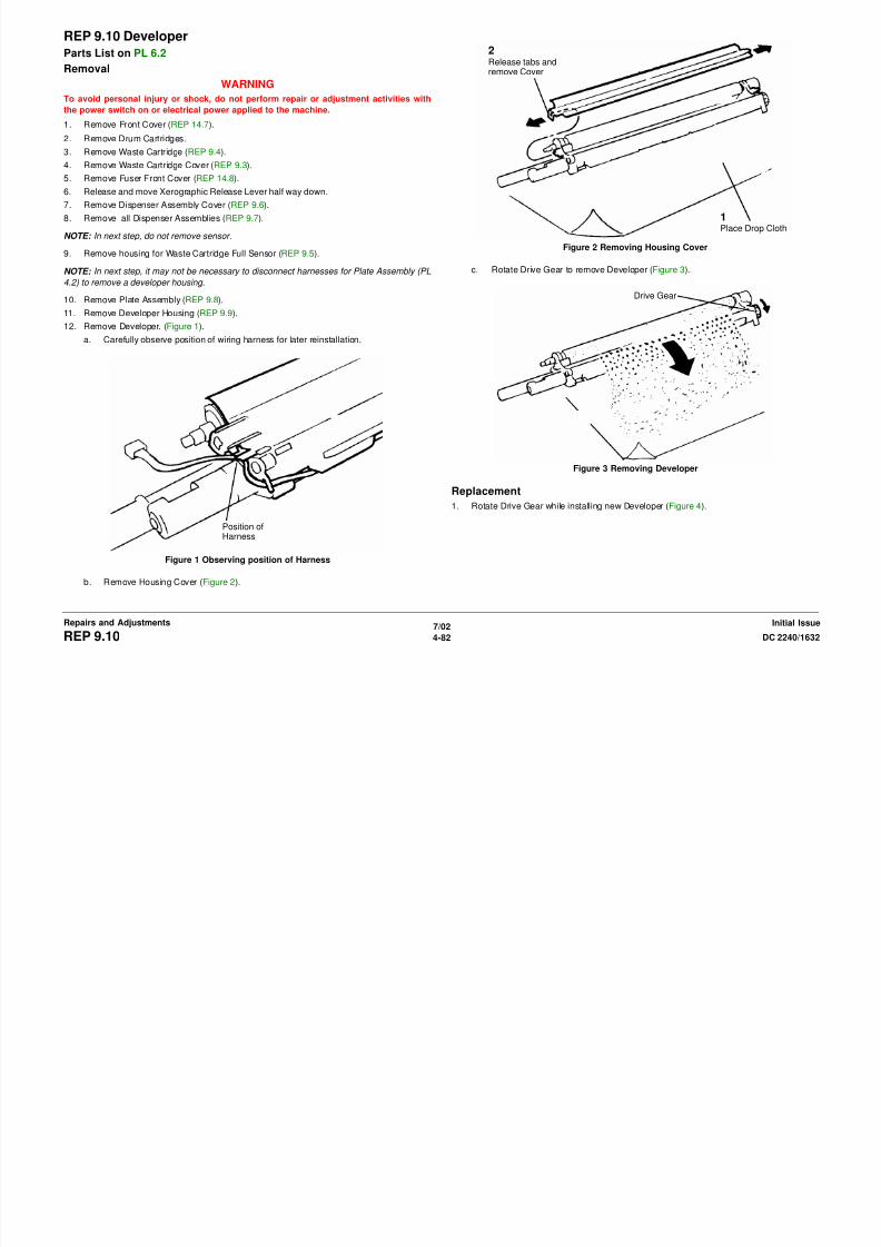
8/13/2019 Xerox Docu Color 2240-1632
http://slidepdf.com/reader/full/xerox-docu-color-2240-1632 608/1118
7/02
4-83DC 2240/1632 REP 9.10, REP 9.11Repairs and AdjustmentsInitial Issue
Figure 1 Removing Toner Dispense Module
Motor P/J’s
REP 9.12 IBT Steering Drive AssemblyParts List on PL 1.3
Removal
WARNING
To avoid personal injury or shock, do not perform repair or adjustment activities with
the power switch on or electrical power applied to the machine.
1. Open Front Cover.
2. Remove Fuser Front Cover (REP 14.8).
3. Release and move Xerographic Release Lever half way down.
4. Remove Dispenser Assembly Cover (REP 9.6).
5. Remove Steering Drive Motor (Figure 1).a. Disconnect Motor P/J.
b. Remove Screws (3).
c. Pull out to remove using care to avoid damage to steering gear.
REP 9.13 Agitator Motor AssemblyParts List on PL 4.1
Removal
WARNING
To avoid personal injury or shock, do not perform repair or adjustment activities with
the power switch on or electrical power applied to the machine.
1. Open Front Cover.
2. Remove Waste Cartridge (REP 9.4).
3. Remove Fuser Front Cover (REP 14.8).
4. Release and move Xerographic Release Lever half way down.
5. Remove Dispenser Assembly Cover (REP 9.6).6. Remove Waste Toner Agitator (Figure 1).
a. Disconnect P/J.
b. Remove Screws (2) and remove Waste Toner Agitator.
Motor P/J
Screws (3)
Screw
P/J
Screw

8/13/2019 Xerox Docu Color 2240-1632
http://slidepdf.com/reader/full/xerox-docu-color-2240-1632 609/1118
7/02
4-84 DC 2240/1632REP 9.12, REP 9.13Initial IssueRepairs and Adjustments
Figure 1 Removing Steering Drive Motor
Figure 1 Removing Waste Toner Agitator
REP 9.14 MOB Sensor AssemblyParts List on PL 1.3
Removal
WARNING
To avoid personal injury or shock, do not perform repair or adjustment activities with
the power switch on or electrical power applied to the machine.
1. Open Front Cover.
2. Remove Waste Cartridge (REP 9.4).
3. Remove Fuser Front Cover (REP 14.8).
4. Release and move Xerographic Release Lever half way down.
5. Remove Dispenser Assembly Cover (REP 9.6).6. Remove Waste Toner Agitator (REP 9.13).
7. Remove MOB Sensor Assembly (Figure 1).
a. Open Harness Clip and remove harness from Clip.
b. Remove Screw and remove Inner Left Harness Cover.
c. Disconnect Harness P/J’s (3)
d. Remove MOB Sensor Assembly Harnesses (violet) from additional harness clips
(not shown).
e. Remove MOB Sensor Assembly Screw and pull out to remove MOB Sensor Assem-
bly. Xerographic Release Lever must be down as shown.
REP 9.15 IBT Belt AssemblyParts List on PL 5.2
Removal
WARNING
To avoid personal injury or shock, do not perform repair or adjustment activities with
the power switch on or electrical power applied to the machine.
1. Open Front Cover.
2. Release and move Xerographic Release Lever down.
3. Open Right Side Door.
4. Remove IBT Belt Assembly (Figure 1).
a. Lift to release Slide Lock.b. Pull out IBT Unit to remove it. Use Handle to transport IBT Unit.
c. Protect IBT Belt Assembly from direct light.
SlideLock
Handle
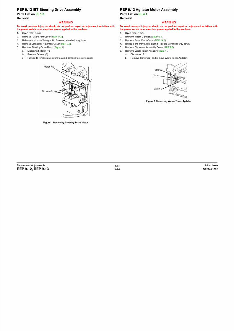
8/13/2019 Xerox Docu Color 2240-1632
http://slidepdf.com/reader/full/xerox-docu-color-2240-1632 610/1118
7/02
4-85DC 2240/1632 REP 9.14, REP 9.15Repairs and AdjustmentsInitial Issue
Figure 1 Removing MOB Sensor Assembly
Figure 1 Removing IBT Belt Assembly
Harness Clip
Inner LeftHarnessCover
HarnessP/J’s (3)
Belt MarkSensorScrew
XerographicReleaseLever
Screw
REP 9.16 IBT Cleaner AssemblyParts List on PL 5.3
Removal
WARNING
To avoid personal injury or shock, do not perform repair or adjustment activities with
the power switch on or electrical power applied to the machine.
1. Open Front Cover.
2. Release and move Xerographic Release Lever down.
3. Remove Right Cover (REP 14.3).
4. Remove IBT Belt Assembly just enough to access Belt Cleaner (REP 9.15).
CAUTIONIn next step, toner may spill out of Belt Cleaner if cleaner is handled carelessly.
5. Remove Screws and remove Belt Cleaner (Figure 1).
REP 9.17 Auger AssemblyParts List on PL 5.2
Removal
WARNING
To avoid personal injury or shock, do not perform repair or adjustment activities with
the power switch on or electrical power applied to the machine.
1. Open Front Cover.
2. Remove Waste Cartridge (REP 9.4).
3. Release and move Xerographic Release Lever down.
4. Remove Right Cover (REP 14.3).
5. Remove Belt Module (REP 9.15).6. Move Xerographic Release Lever to up position.
7. Remove Waste Toner Agitator (Figure 1).
a. Remove Screws (2).
b. Move Waste Auger toward Bearing to disengage Cutout from Bearing.
c. Remove Waste Auger.
Screws(2)
Screws (2) Bearing

8/13/2019 Xerox Docu Color 2240-1632
http://slidepdf.com/reader/full/xerox-docu-color-2240-1632 611/1118
7/02
4-86 DC 2240/1632REP 9.16, REP 9.17Initial IssueRepairs and Adjustments
Figure 1 Removing IBT Cleaner Assembly
Replacement
Ensure both rear locating pins engage holes in IBT Belt Assembly frame during installation of
IBT Cleaner Assembly.
Figure 1 Removing Waste Toner Agitator
Replacement
Move Xerographic Release Lever to down position before reinstalling Belt Module.
Cutout
REP 9.18 LeverParts List on PL 5.1
Removal
WARNING
To avoid personal injury or shock, do not perform repair or adjustment activities with
the power switch on or electrical power applied to the machine.
1. Open Front Cover.
2. Remove Fuser Front Cover (REP 14.8).
3. Remove Waste Cartridge (REP 9.4).
4. Remove Waste Cartridge Cover (REP 9.3).
5. Remove Inner Left Harness Cover (REP 14.10).6. Release and move Xerographic Release Lever down.
7. Remove Drum Cartridges.
8. Remove Right Cover (REP 14.3).
9. Remove Belt Module (REP 9.15).
10. Remove Xerographic Release Lever (Figure 1).
a. Remove Screw, Washer, and Hinge Pin.
b. Remove E-Ring and Hinge Pin.
c. Remove Xerographic Release Lever.
REP 9.19 Left Hinge/Right HingeParts List on PL 5.1
Removal
WARNING
To avoid personal injury or shock, do not perform repair or adjustment activities with
the power switch on or electrical power applied to the machine.
1. Open Front Cover.
2. Remove Fuser Front Cover (REP 14.8).
3. Remove Waste Cartridge (REP 9.4).
4. Remove Waste Cartridge Cover (REP 9.3).
5. Remove Inner Left Harness Cover (REP 14.10).6. Release and move Xerographic Release Lever down.
7. Remove Drum Cartridges.
8. Remove Right Cover (REP 14.3).
9. Remove Belt Module (REP 9.15).
10. Remove Xerographic Release Lever (REP 9.18).
11. Remove Xerographic Release Lever Brackets (Figure 1).
a. Remove Screws (2) and remove Bracket.
b. Remove Screws (2) and remove Bracket.
Screw, Washer,Hinge Pin
Screws(2)
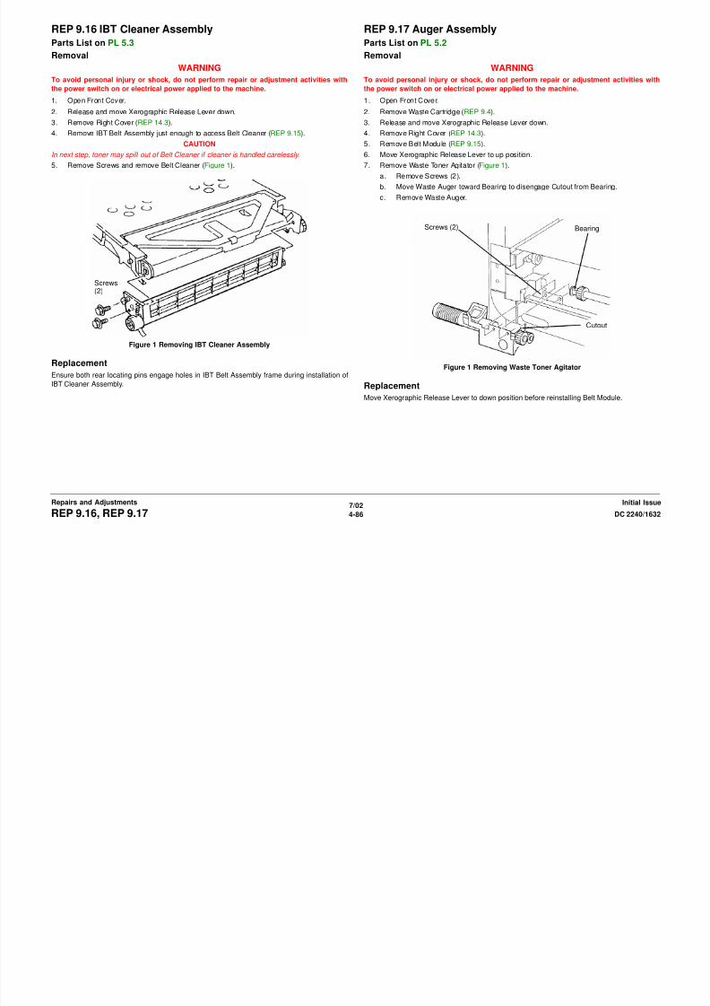
8/13/2019 Xerox Docu Color 2240-1632
http://slidepdf.com/reader/full/xerox-docu-color-2240-1632 612/1118
7/02
4-87DC 2240/1632 REP 9.18, REP 9.19Repairs and AdjustmentsInitial Issue
Figure 1 Removing Xerographic Release Lever
Replacement
Move Xerographic Release Lever to down position before reinstalling Belt Module.
Figure 1 Removing Xerographic Release Lever
Replacement
Move Xerographic Release Lever to down position before reinstalling Belt Module.
E-Ring,
Hinge Pin
Screws
(2)
REP 9.20 Right Lift AssemblyParts List on PL 5.1
Removal
WARNING
To avoid personal injury or shock, do not perform repair or adjustment activities with
the power switch on or electrical power applied to the machine.
1. Open Front Cover.
2. Remove Fuser Front Cover (REP 14.8).
3. Remove Waste Cartridge (REP 9.4).
4. Remove Waste Cartridge Cover (REP 9.3).
5. Remove Inner Left Harness Cover (REP 14.10).
6. Release and move Xerographic Release Lever down.
7. Remove Drum Cartridges.
8. Remove Right Cover (REP 14.3).
9. Remove Belt Module (REP 9.15).
10. Remove Xerographic Release Lever (REP 9.18).
11. Remove Lift Bracket (Figure 1).
a. Remove E-Rings (2) and Washers (2).
b. Remove Screws (4) and remove Lift Bracket.
c. Remove Bearings (2) and Washers (2).
12. Remove Right Xerographic Lift (Figure 2).
a. Remove Auger Mounting Screws (2).
b. Remove Lift Position Screw.c. Remove Secondary Position Screw.
d. Remove Lower Screws (2).
e. Remove Right Xerographic Lift.
Figure 2 Removing Right Xerographic Lift
Replacement
Washer
Bearing
Lift Posi-tionScrew
Lift SecondaryPosition Screw
AugerMountingScrews (2)
Lower Screws (2)

8/13/2019 Xerox Docu Color 2240-1632
http://slidepdf.com/reader/full/xerox-docu-color-2240-1632 613/1118
7/02
4-88 DC 2240/1632REP 9.20Initial IssueRepairs and Adjustments
Figure 1 Removing Lift Bracket
Move Xerographic Release Lever to down position before reinstalling Belt Module.
Washers (2)
E-Rings (2)
Screws (4)
BearingWasher
REP 9.21 Left Lift AssemblyParts List on PL 5.1
Removal
WARNING
To avoid personal injury or shock, do not perform repair or adjustment activities with
the power switch on or electrical power applied to the machine.
1. Open Front Cover.
2. Remove Fuser Front Cover (REP 14.8).
3. Remove Waste Cartridge (REP 9.4).
4. Remove Waste Cartridge Cover (REP 9.3).
5. Remove Inner Left Harness Cover (REP 14.10).
6. Release and move Xerographic Release Lever down.
7. Remove Drum Cartridges.
8. Remove Right Cover (REP 14.3).
9. Remove Belt Module (REP 9.15).
10. Remove Xerographic Release Lever (REP 9.18).
11. Remove Rear Cover (REP 14.2).
12. Remove Power Switch Cover (REP 14.6).
13. Remove Upper Rear Left Cover (REP 14.4).
14. Close Left Cover Assembly.15. Remove MSI Tray (REP 7.1).
16. Remove Left Cover Assembly (REP 8.1).
17. Optional for improved visibility: Remove Fuser Module (REP 10.1).
18. Remove Registration Transport (REP 8.6).
19. Remove Dispenser Assembly Cover (REP 9.6).
b. Remove Screws (4).
c. Remove Left Xerographic Lift and maintain orientation to ensure Bearings (2) and
Washers (2) do not fall off posts.
Figure 1 Removing Left Xerographic Lift
Replacement
1. Install Li ft.
a. Position Lift in frame.
b. Raise or lower xerographic frame as required and push in or pull out Lift actuator as
required to engage lift bearings with slots in xerographic frame.
c. Install front top screw, then front bottom screw, then rear screws (2).
d. Install washers (2) and e-rings (2).
2. Assemble remaining machine components.
E-Ring
E-Ring
Washer
Washer
Screws (2)
Screws (2) Bearing

8/13/2019 Xerox Docu Color 2240-1632
http://slidepdf.com/reader/full/xerox-docu-color-2240-1632 614/1118
7/02
4-89DC 2240/1632 REP 9.21Repairs and AdjustmentsInitial Issue
20. Remove Waste Toner Agitator (REP 9.13).
21. Remove Belt Mark Sensor (REP 9.14).
22. Remove Left Xerographic Release Lever Bracket (REP 9.19).
23. Remove Front Cover (REP 14.7).24. Remove K and C Toner Cartridges.
25. Remove K and C Dispenser Assembly (REP 9.7).
NOTE: In next step, do not remove sensor from housing
26. Remove housing for Waste Cartridge Full Sensor (REP 9.5).
NOTE: In next step, it may not be necessary to disconnect harnesses for Plate Assembly (PL
4.2) to remove a developer housing.
27. Remove Plate Assembly (REP 9.8).
28. Remove K and C Developer Housing (REP 9.9).29. Remove Left Xerographic Lift (Figure 1).
NOTE: In next step, use a magnet to capture E-Ring and Washer while removing them.
a. From inside Developer Housing cavity, remove E-Ring and Washer from each end of
Left Xerographic Lift.
REP 9.22 Transfer BeltParts List on PL 5.3
Removal
WARNING
To avoid personal injury or shock, do not perform repair or adjustment activities with
the power switch on or electrical power applied to the machine.
CAUTION
Cover Transfer Belt in a black bag.
NOTE: Keep your hand off Transfer Belt.
1. Remove IBT Belt Assembly (REP 9.15).
2. Remove IBT Cleaner Assembly (REP 9.16).
3. Remove Stand Plate (Figure 1).
a. Remove Screw (2).
b. Remove Stand Plate in direction of arrow. Stand Plate will be installed in new loca-
tion in step 7.
4. Remove Handle (Figure 2).
Figure 2 Removing Handle
5. Remove screws on both sides (Figure 3).
1RemoveScrews (2)
1RemoveScrew

8/13/2019 Xerox Docu Color 2240-1632
http://slidepdf.com/reader/full/xerox-docu-color-2240-1632 615/1118
7/02
4-90 DC 2240/1632REP 9.22Initial IssueRepairs and Adjustments
Figure 1 Removing Stand Plate
Figure 3 Removing Screws (both sides)
2Move Stand Plate in direc-tion shown to remove it
2Remove Screwfrom same position,other side
6. Position Support (Figure 4) 7. Install Stand Plate (Figure 5).
Figure 5 Installing Stand Plate
1RemoveScrew andSupport
2Install Sup-port andScrew
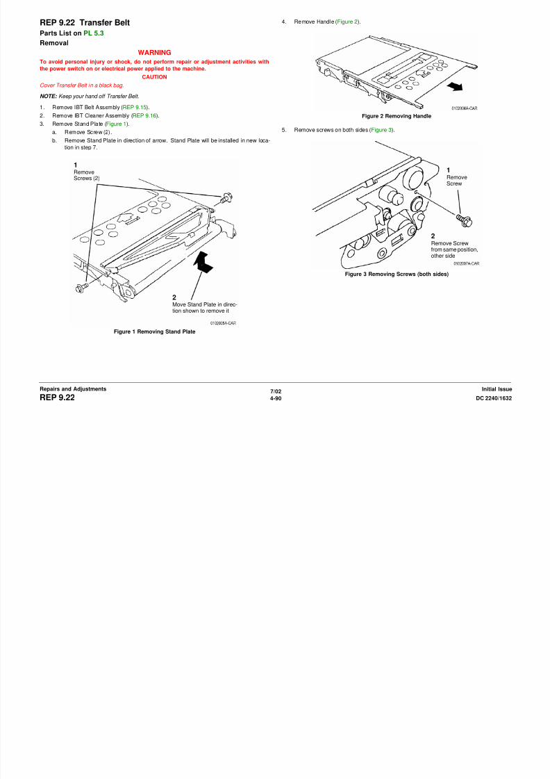
8/13/2019 Xerox Docu Color 2240-1632
http://slidepdf.com/reader/full/xerox-docu-color-2240-1632 616/1118
7/02
4-91DC 2240/1632 REP 9.22Repairs and AdjustmentsInitial Issue
Figure 4 Positioning Latch
8. Place Stand Plate below and stand IBT Belt Assembly.
9. Relax tension of Belt on both sides (Figure 6).
Figure 6 Relaxing Belt Tension
10. Remove Brackets (Figure 7).
Figure 7 Removing Bracket
1Forcefullypush rolland dostep 2 2
Push Tab so Lockengages plate
Lock
Remove Screws (5)and Brackets (2)

8/13/2019 Xerox Docu Color 2240-1632
http://slidepdf.com/reader/full/xerox-docu-color-2240-1632 617/1118
7/02
4-92 DC 2240/1632REP 9.22Initial IssueRepairs and Adjustments
11. Pull out BUR Roll Housing from Hole below and move it in arrow direction (Figure 8).
Figure 8 Pulling Out BUR Roll Housing
12. Remove Transfer Belt (Figure 9).
Figure 9 Removing Transfer Belt
1Lift BURRoll Hous-ing to disen-gage bottom
2RotateHousing 1/4turn

8/13/2019 Xerox Docu Color 2240-1632
http://slidepdf.com/reader/full/xerox-docu-color-2240-1632 618/1118
7/02
4-93DC 2240/1632 REP 9.22Repairs and AdjustmentsInitial Issue
Replacement
1. Install Transfer Belt with Reflector at rear (Figure 10).
Figure 10 Installing Transfer Belt
2. After installing Transfer Belt, move it to center of IBT Frame so that exposed parts of IBT
Drive Roll should be equal (Figure 11).
Figure 11 Positioning Transfer Belt
Reflector
Drive Roll
Equal amount of Exposed part of IBT DriveRoll on each side

8/13/2019 Xerox Docu Color 2240-1632
http://slidepdf.com/reader/full/xerox-docu-color-2240-1632 619/1118
7/02
4-94 DC 2240/1632REP 9.22Initial IssueRepairs and Adjustments
3. If Transfer Belt is skewed or wrinkled, perform following steps: (Figure 12).
a. Relax tension of Belt.
b. Rotate Gear in arrow direction and move Transfer Belt.
Figure 12 Re-positioning Transfer Belt
1Relax BeltTension
Gear
2RepositionBelt whileRotatingGear

8/13/2019 Xerox Docu Color 2240-1632
http://slidepdf.com/reader/full/xerox-docu-color-2240-1632 620/1118
7/02
4-95DC 2240/1632 REP 9.22Repairs and AdjustmentsInitial Issue
REP 9.23 1st BTR RollParts List on PL 5.4
RemovalWARNING
To avoid personal injury or shock, do not perform repair or adjustment activities with
the power switch on or electrical power applied to the machine.
1. Open Front Cover.
2. Release and move Xerographic Release Lever down.
3. Open Right Side Door.
4. Remove IBT Assembly (REP 9.15).
5. Remove Transfer Belt (REP 9.22).
6. Remove 1st BTR Roll (Figure 1).
REP 9.24 2nd BTR RollParts List on PL 2.8
RemovalWARNING
To avoid personal injury or shock, do not perform repair or adjustment activities with
the power switch on or electrical power applied to the machine.
1. Remove 2nd BTR (Figure 1).
a. Open Left Cover Assembly.
b. Remove Screws (4).
c. Remove 2nd BTR with Support Brackets
1RemoveScrew
Screws(2)
Screws (2)
Transfer Roll
SupportBracket

8/13/2019 Xerox Docu Color 2240-1632
http://slidepdf.com/reader/full/xerox-docu-color-2240-1632 621/1118
7/02
4-96 DC 2240/1632REP 9.23, REP 9.24Initial IssueRepairs and Adjustments
Figure 1 Removing 1st BTR Roll
Figure 1 Removing 2nd BTR
Replacement
NOTE: Refer to Detailed Maintenance Activities in Section 1 and reset HFSI counter 954-802.
2RemoveSupport and1st BTR Roll
NOTE: Frontaxle is long- est
FrontAxle
Transfer RollAssembly
SupportBracket
REP 9.26 ATC SensorParts List on PL 6.2
RemovalWARNING
To avoid personal injury or shock, do not perform repair or adjustment activities with
the power switch on or electrical power applied to the machine.
1. Remove Front Cover (REP 14.7).
2. Remove Drum Cartridges.
3. Remove Waste Cartridge (REP 9.4).
4. Remove Waste Cartridge Cover (REP 9.3).
5. Remove Fuser Front Cover (REP 14.8).
6. Release and move Xerographic Release Lever half way down.
7. Remove Dispenser Assembly Cover (REP 9.6).
8. Remove all Dispenser Assemblies (REP 9.7).
NOTE: In next step, do not remove sensor.
9. Remove housing for Waste Cartridge Full Sensor (REP 9.5).
NOTE: In next step, it may not be necessary to disconnect harnesses for Plate Assembly (PL
4.2) to remove a developer housing.
10. Remove Plate Assembly (REP 9.8).
11. Remove Developer Housing (REP 9.9).
12. Release Harness from Harness Clips (Figure 1).
13. Remove ATC Sensor (Figure 2).
Figure 2 Removing ATC Sensor
2Release Tab andremove wires
1Carefully notice posi-tion of wires
1Lift Lockand moveend awayfrom Tab
2Remove Sealfrom underSensor
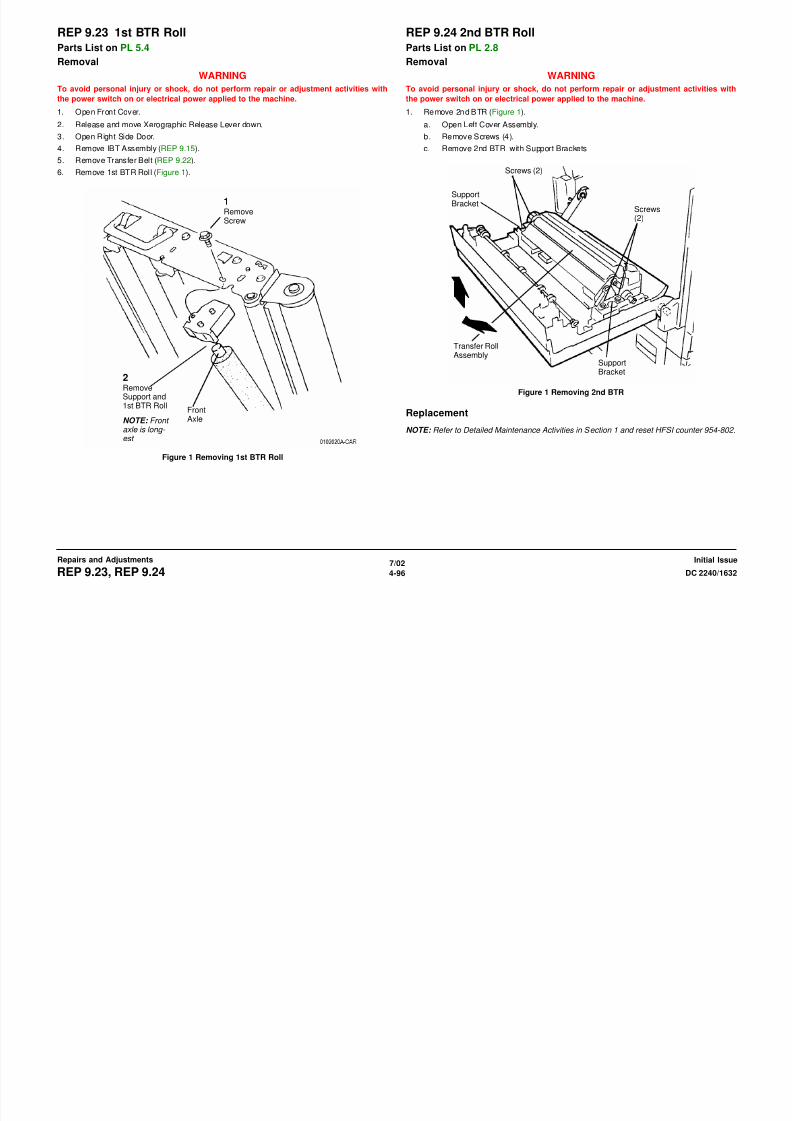
8/13/2019 Xerox Docu Color 2240-1632
http://slidepdf.com/reader/full/xerox-docu-color-2240-1632 622/1118
7/02
4-97DC 2240/1632 REP 9.26Repairs and AdjustmentsInitial Issue
Figure 1 Removing Harness form Clips
3Lift Tab and remove wires
Replacement
NOTE: Remove ATC Sensor Setup Data Tag from new sensor. On tag, highlight K, C, M, or Y
as required for color of developer housing. Raise Xerographic Release Lever and install Tag in position shown ( Figure 3 ).
Figure 3 Installing ATC Sensor Setup Data Tag
NOTE: Perform dC921 ATC Sensor Setup ( ADJ 9.2 ).
1Raise XerographicRelease Lever
2Position Tag in correct location
Tag with Khighlighted
Tag with Chighlighted
Tag with Mhighlighted
Tag with Yhighlighted

8/13/2019 Xerox Docu Color 2240-1632
http://slidepdf.com/reader/full/xerox-docu-color-2240-1632 623/1118
7/02
4-98 DC 2240/1632REP 9.26Initial IssueRepairs and Adjustments
REP 9.27 Retract ShaftParts List on PL 5.4
Replacement
NOTE: Cam and Flag must be aligned as shown, both on the same side ( Figure 1 ).
Figure 1 Cam and Flag Alignment
CorrectAlignment
IncorrectAlignment

8/13/2019 Xerox Docu Color 2240-1632
http://slidepdf.com/reader/full/xerox-docu-color-2240-1632 624/1118
7/02
4-99DC 2240/1632 REP 9.27Repairs and AdjustmentsInitial Issue

8/13/2019 Xerox Docu Color 2240-1632
http://slidepdf.com/reader/full/xerox-docu-color-2240-1632 625/1118
7/02
4-100 DC 2240/1632REP 9.27Initial IssueRepairs and Adjustments
REP 10.1 FuserParts List on PL 7.1
RemovalWARNING
To avoid personal injury or shock, do not perform repair or adjustment activities with
the power switch on or electrical power applied to the machine.
WARNING
Personal injury may result from grasping hot areas of Fuser Module. If a hot Fuser Mod-
ule must be removed, grasp Fuser Module by black plastic frame component (Figure 1).
CAUTION
Damage to work surface may result if a hot Fuser Module is removed and positioned on an
unprotected work surface. Place a hot fuser on ten sheets of paper.1. Open Left Cover Assembly.
2. Remove Fuser Module (Figure 1).
a. Loosen Screws (2). (PL 1.1)
WARNING
If machine was making copies within 30 minutes, Fuser Module is hot. Grasp
Fuser Module using Grip Rings.
b. Use Grip Rings to pull Fuser Module out.
REP 10.2 Fuser FanParts List on PL 8.1
RemovalWARNING
To avoid personal injury or shock, do not perform repair or adjustment activities with
the power switch on or electrical power applied to the machine.
WARNING
Personal injury may result from grasping hot areas of Fuser Module. If a hot Fuser Mod-
ule must be removed, grasp Fuser Module by black plastic frame component (Figure 1).
CAUTION
Damage to work surface may result if a hot Fuser Module is removed and positioned on an
unprotected work surface. Place a hot fuser on ten sheets of paper.1. Open Front Cover.
2. Remove Right Cover (REP 14.3).
3. Remove Top Cover (REP 14.1).
4. Remove Rear Cover (REP 14.2).
5. Remove Fuser Cooling Fan (Figure 1).
a. Disconnect P/J.
b. Remove Screws (2) and lift to remove Fuser Cooling Fan.
P/J
Screws (2)

8/13/2019 Xerox Docu Color 2240-1632
http://slidepdf.com/reader/full/xerox-docu-color-2240-1632 626/1118
7/02
4-101DC 2240/1632 REP 10.1, REP 10.2Repairs and AdjustmentsInitial Issue
Figure 1 Removing Fuser Module
Figure 1 Removing Fuser Cooling FanGrip Rings
Screws (2)

8/13/2019 Xerox Docu Color 2240-1632
http://slidepdf.com/reader/full/xerox-docu-color-2240-1632 627/1118
5. Remove Heater Rods (Figure 3).
Figure 3 Removing Heater Rods
RemoveHeaterRods

8/13/2019 Xerox Docu Color 2240-1632
http://slidepdf.com/reader/full/xerox-docu-color-2240-1632 628/1118
7/02
4-103DC 2240/1632 REP 10.3Repairs and AdjustmentsInitial Issue

8/13/2019 Xerox Docu Color 2240-1632
http://slidepdf.com/reader/full/xerox-docu-color-2240-1632 629/1118
7/02
4-104 DC 2240/1632REP 10.3Initial IssueRepairs and Adjustments
REP 12.1 H Transport AssemblyParts List on PL 17.1
RemovalWARNING
To avoid personal injury or shock, do not perform repair or adjustment activities with
the power switch on or electrical power applied to the machine.
1. Disconnect P/J (Figure 1).
2. Disengage Hook (2) from the Stud on both sides and remove H Transport Assembly (Fig-
ure 2).
P/J
Hooks
8/13/2019 Xerox Docu Color 2240-1632
http://slidepdf.com/reader/full/xerox-docu-color-2240-1632 630/1118
7/02
4-105DC 2240/1632 REP 12.1Repairs and AdjustmentsInitial Issue
Figure 1 Disconnecting P/J
Figure 2 Removing H Transport
REP 12.2 H Transport BeltParts List on PL 17.4
RemovalWARNING
To avoid personal injury or shock, do not perform repair or adjustment activities with
the power switch on or electrical power applied to the machine.
1. Remove the H Transport Assembly (REP 12.1).
2. Remove the following parts:
a. H Transport Front Cover (PL 17.3)
b. H Transport Rear Cover (PL 17.3)
c. Stop (PL 17.3)
3. Remove the H Transport Cover (Figure 1).
4. Remove the Gate In Solenoid Assembly (Figure 2).
Figure 2 Removing the Gate In Solenoid Assembly
1RemoveScrew (2)
2RemoveCover
2
RemoveScrews (2)
1Disconnect Wiresas required
3Remove Sole-noid Assembly

8/13/2019 Xerox Docu Color 2240-1632
http://slidepdf.com/reader/full/xerox-docu-color-2240-1632 631/1118
7/02
4-106 DC 2240/1632REP 12.2Initial IssueRepairs and Adjustments
Figure 1 Removing the H Transport Cover
5. Remove the Entrance Upper Cover (Figure 3)
Figure 3 Removing the Entrance Upper Cover
6. Remove the input H Transport Roll (Figure 4).
Figure 4 Removing the H Transport Roll
1RemoveScrews (4)
2RemoveEntranceUpper Cover
1Remove Clips (2)and Bearings (2)
2Remove HTransportRoll

8/13/2019 Xerox Docu Color 2240-1632
http://slidepdf.com/reader/full/xerox-docu-color-2240-1632 632/1118
7/02
4-107DC 2240/1632 REP 12.2Repairs and AdjustmentsInitial Issue
7. Remove the output H Transport Roll (Figure 5).
1RemoveClip and
Bearing
2RemoveCli P ll
3Remove HTransportRoll
4Remove the HTransport Belts

8/13/2019 Xerox Docu Color 2240-1632
http://slidepdf.com/reader/full/xerox-docu-color-2240-1632 633/1118
7/02
4-108 DC 2240/1632REP 12.2Initial IssueRepairs and Adjustments
Figure 5 Removing the H Transport Roll
Clip, Pulley,and Bearing
REP 12.3 Entrance SensorParts List on PL 17.4
RemovalWARNING
To avoid personal injury or shock, do not perform repair or adjustment activities with
the power switch on or electrical power applied to the machine.
1. Remove the H Transport Assembly (REP 12.1).
2. Remove the following:
a. H Transport Front Cover (PL 17.3)
b. H Transport Rear Cover (PL 17.3)
c. Stop (PL 17.3)
3. Remove the Entrance Upper Cover (REP 12.17).4. Remove the Cover (Figure 1).
a. Push up the hook (2).
b. Remove the Cover, while moving it in the arrow direction.
5. Remove the H Transport Entrance Sensor and Top Tray Full Sensor (Figure 2).
Figure 2 Removing Entrance Sensor and Top Tray Full Sensor
EntranceSensor
Top Tray FullSensor
Disconnectand RemoveSensors

8/13/2019 Xerox Docu Color 2240-1632
http://slidepdf.com/reader/full/xerox-docu-color-2240-1632 634/1118
7/02
4-109DC 2240/1632 REP 12.3Repairs and AdjustmentsInitial Issue
Figure 1 Removing the Cover
REP 12.4 FinisherParts List on PL 17.5
RemovalCAUTION
Make sure to have two people to operate since the Finisher Unit weighs more than 16Kg.
When one person operates, detach the unit following the Steps after making i t weigh less than
16Kg. Take extreme care to avoid lower back injury.
1. Separate IIT and IOT.
2. Remove the following parts:
a. H Transport Assembly (REP 12.2)
b. H Transport Front Cover (PL 17.3)
c. H Transport Rear Cover (PL 17.3)d. Stacker Tray (PL 17.1)
e. Right Lower Cover (PL 17.5)
3. Remove the Thumbscrews (2) (Figure 1).
4. Lift the Finisher from the Rack (Figure 2).
1Remove Thumb-screws (2)

8/13/2019 Xerox Docu Color 2240-1632
http://slidepdf.com/reader/full/xerox-docu-color-2240-1632 635/1118
7/02
4-110 DC 2240/1632REP 12.4Initial IssueRepairs and Adjustments
Figure 1 Removing Thumbscrews
Figure 2 Removing Finisher from Rack
2Push Finisheraway fromRack to disen-gage Finisher
3Lift toRemoveFinisher
REP 12.5 Stack Height Sensor AssemblyParts List on PL 17.6
RemovalWARNING
To avoid personal injury or shock, do not perform repair or adjustment activities with
the power switch on or electrical power applied to the machine.
1. Remove the Links from the Top Cover Assembly (Figure 1).
Figure 1 Removing Links from Top Cover Assembly
2. Remove the Stack Height Sensor Assembly (Figure 2).
Figure 2 Removing Stack Height Sensor Assembly
1Open Top Cover
2RemoveScrews(2) onbothsides
3RemoveLinks onboth sides
1
Remove the Screw
2DisconnectP/J andremove

8/13/2019 Xerox Docu Color 2240-1632
http://slidepdf.com/reader/full/xerox-docu-color-2240-1632 636/1118
7/02
4-111DC 2240/1632 REP 12.5Repairs and AdjustmentsInitial Issue
Figure 1 Removing Links from Top Cover Assembly
REP 12.6 Eject Roll AssemblyParts List on PL 17.6
RemovalWARNING
To avoid personal injury or shock, do not perform repair or adjustment activities with
the power switch on or electrical power applied to the machine.
1. Remove the following parts:
a. Rear Cover (PL 17.5)
b. Stacker Tray (PL 17.1)
c. Right Cover (PL 17.5)
d. Front Cover (PL 17.5)
2. Remove the Bracket (Figure 1).
3. Disconnect P/J (Figure 2).
Figure 2 Disconnecting P/J
1RemoveScrews (4)
2
1RemoveScrew (2)
2RemovePlate
3DisconnectP/J
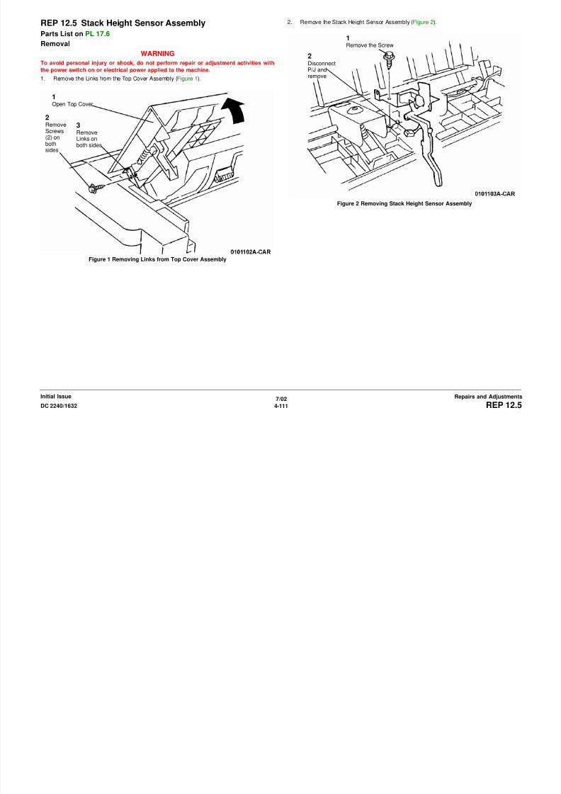
8/13/2019 Xerox Docu Color 2240-1632
http://slidepdf.com/reader/full/xerox-docu-color-2240-1632 637/1118
7/02
4-112 DC 2240/1632REP 12.6Initial IssueRepairs and Adjustments
Figure 1 Remove the Bracket
2
RemoveBracket
4. Remove the Thumbscrews (2) (Figure 3).
Figure 3 Removing Thumbscrews
5. Remove the Tray Guide (Figure 4).
1RemoveScrews (4)
2Remove Fastenerand Cable Clamp
3Remove Cablefrom Cover andremove Cover

8/13/2019 Xerox Docu Color 2240-1632
http://slidepdf.com/reader/full/xerox-docu-color-2240-1632 638/1118
7/02
4-113DC 2240/1632 REP 12.6Repairs and AdjustmentsInitial Issue
Figure 4 Removing Tray Guide
6. Remove the Sensor (Figure 5).
Figure 5 Remove Sensor
7. Remove Eject Roll (Figure 6).
Disconnect harness
and remove Sensor
1
RemoveClip,Actuator,andClutch
2
RemoveCollarand Gear
3
RemoveClip andBearingfrombothends
4

8/13/2019 Xerox Docu Color 2240-1632
http://slidepdf.com/reader/full/xerox-docu-color-2240-1632 639/1118
7/02
4-114 DC 2240/1632REP 12.6Initial IssueRepairs and Adjustments
Figure 6 Removing Eject Roll
Disconnect Hook (2) from Eject
Shaft and remove Eject Roll
8. Remove Eject Shaft (Figure 7).
Figure 7 Removing Eject Shaft
Replacement
NOTE: When replacing Feed Roll or Eject Shaft, replace them simultaneously.
NOTE: When installing the Clutch, ensure to insert the Stop into Clutch grooves ( Figure 8 ).
Figure 8 Inserting Stop into Clutch Grooves
1
RemoveClip andGear
2RemoveClip Bear-ing on bothsides
3RemoveEject Shaft
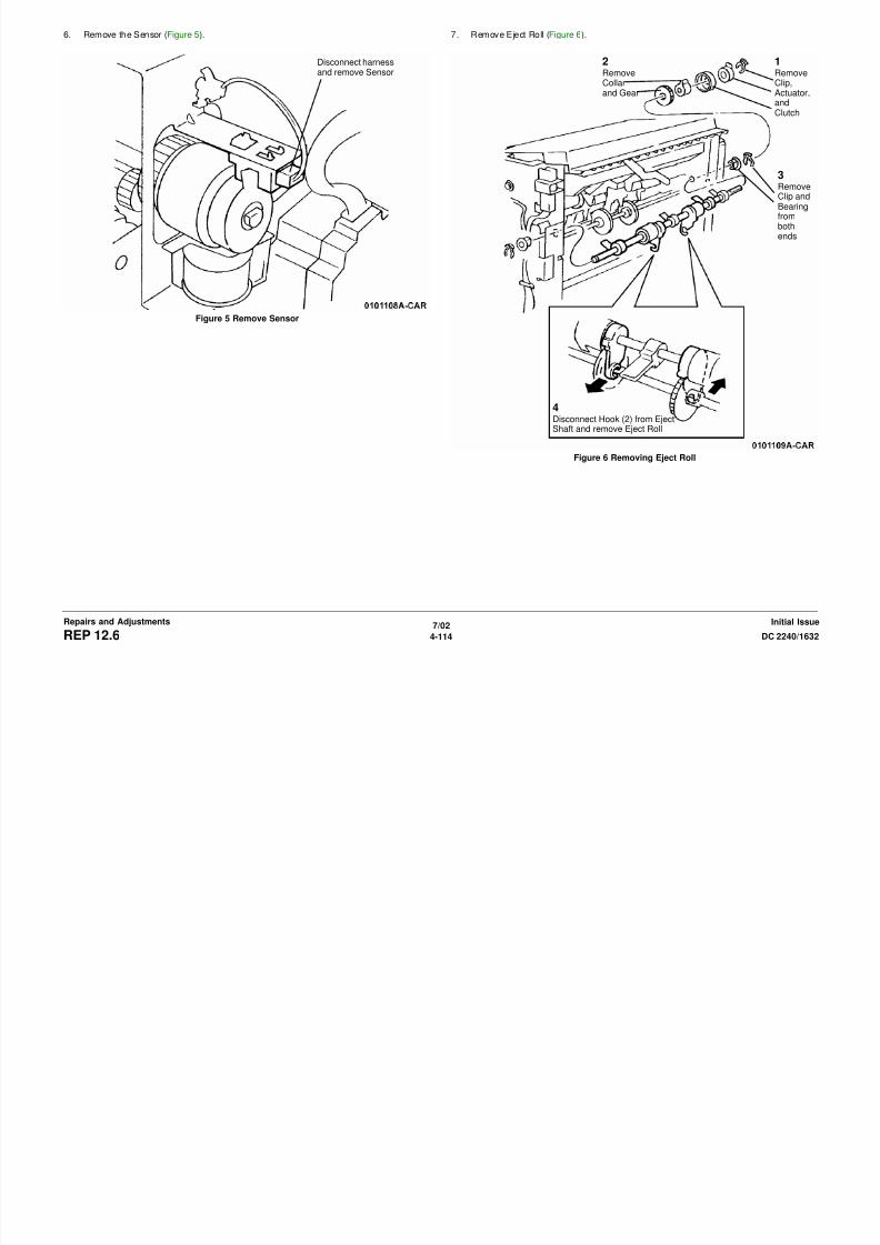
8/13/2019 Xerox Docu Color 2240-1632
http://slidepdf.com/reader/full/xerox-docu-color-2240-1632 640/1118
7/02
4-115DC 2240/1632 REP 12.6Repairs and AdjustmentsInitial Issue
REP 12.7 Decurler RollParts List on PL 17.7
RemovalWARNING
To avoid personal injury or shock, do not perform repair or adjustment activities with
the power switch on or electrical power applied to the machine.
1. Remove the following parts:
a. Front Cover (PL 17.5)
b. Rear Cover (PL 17.5)
c. Top Cover (PL 17.5)
2. Remove the Arm (Figure 1).
3. Remove the Decurler Roll (Figure 2).
Figure 2 Removing the Decurler Roll
1RemoveClip andGear
2RemoveClip andArm
1Remove Clip
2
Insert a sheet ofpaper to keep roll-ers separated
3
RemoveDecurler Roll

8/13/2019 Xerox Docu Color 2240-1632
http://slidepdf.com/reader/full/xerox-docu-color-2240-1632 641/1118
7/02
4-116 DC 2240/1632REP 12.7Initial IssueRepairs and Adjustments
Figure 1 Removing the Arm
REP 12.8 Finisher Drive MotorParts List on PL 17.7
RemovalWARNING
To avoid personal injury or shock, do not perform repair or adjustment activities with
the power switch on or electrical power applied to the machine.
1. Remove the Rear Cover (PL 17.14).
2. Remove the Finisher Drive Motor (Figure 1).
Figure 1 Removing the Finisher Drive Motor
2Disconnect P/J
1Remove Screws(4) and FinisherDrive Motor

8/13/2019 Xerox Docu Color 2240-1632
http://slidepdf.com/reader/full/xerox-docu-color-2240-1632 642/1118
7/02
4-117DC 2240/1632 REP 12.8Repairs and AdjustmentsInitial Issue
Figure 1 Removing the Finisher Drive Motor
Replacement
NOTE: Hang the Belt to the Guide when installing the Drive Motor.
REP 12.9 BeltParts List on PL 17.7
RemovalWARNING
To avoid personal injury or shock, do not perform repair or adjustment activities with
the power switch on or electrical power applied to the machine.
1. Remove the Rear Cover (PL 17.5)
2. Rotate the Actuator (Figure 1).
Figure 1 Rotate the Actuator
3. Release Harnesses (Figure 2).
Figure 2 Releasing Harnesses1Release Sole-noid Pawl
2RotateCam 1/4revolution
1DisconnectP/J’s (3)
2
Remove Clampfrom Frame
4RemoveClampfromFrame
5Remove wiresfrom Clip
Remove wires from
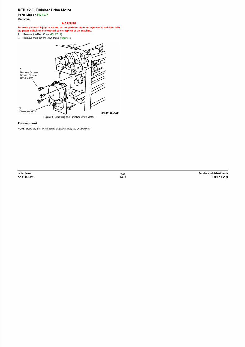
8/13/2019 Xerox Docu Color 2240-1632
http://slidepdf.com/reader/full/xerox-docu-color-2240-1632 643/1118
7/02
4-118 DC 2240/1632REP 12.9Initial IssueRepairs and Adjustments
Figure 1 Rotate the Actuator
4. Remove the Cam Bracket Assembly (Figure 3).
a. Remove the Screws (4).
b. Remove the Cam Bracket Assembly.
Figure 3 Removing the Cam Bracket Assembly
5. Remove the Belt (Figure 4).
Figure 4 Removing the Belt
1RemoveScrews (4)
2RemoveCam BracketAssembly
RemoveClips,Pulleys,and Belt
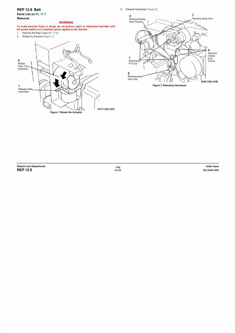
8/13/2019 Xerox Docu Color 2240-1632
http://slidepdf.com/reader/full/xerox-docu-color-2240-1632 644/1118
7/02
4-119DC 2240/1632 REP 12.9Repairs and AdjustmentsInitial Issue
Replacement
NOTE: During assembly, refer to Figure 5 .
Figure 5 Inserting Axle of Cam Bracket Assembly into Hole
NOTE: During assembly, refer to Figure 6 .
Figure 6 Engaging Pawl with Slot
2Align Axlewith Hole
1Raise TopCover to raiseRoller whileperformingstep 2
Rotate Cam soPawl engagesSlot

8/13/2019 Xerox Docu Color 2240-1632
http://slidepdf.com/reader/full/xerox-docu-color-2240-1632 645/1118
7/02
4-120 DC 2240/1632REP 12.9Initial IssueRepairs and Adjustments
REP 12.10 RailParts List on PL 17.9
Removal WARNING
To avoid personal injury or shock, do not perform repair or adjustment activities with
the power switch on or electrical power applied to the machine.
1. Remove the following:
a. Front Cover (PL 17.5)
b. Rear Cover (PL 17.5)
2. Remove Harness from Stapler (Figure 1).
3. Remove Stapler Assembly (Figure 2).
Figure 2 Removing Stapler Assembly
1Disconnect Sta-pler P/J’s (2)
2DisconnectSensor
3DisconnectHarness Clipfrom Frame
4DisconnectHarnessfrom Motorand removeHarness
from Guide
Remove
Screws (2),Ground Wire(1) and Stapler

8/13/2019 Xerox Docu Color 2240-1632
http://slidepdf.com/reader/full/xerox-docu-color-2240-1632 646/1118
7/02
4-121DC 2240/1632 REP 12.10Repairs and AdjustmentsInitial Issue
Figure 1 Removing Harness from Stapler
4. Remove the PWB Cover (Figure 3).
Figure 3 Removing the PWB Cover
5. Move the PWB Chassis down (Figure 4).
Figure 4 Moving PWB Chassis Down
Remove Screws (10)
and Cover 1DisconnectP848 andremove fromGuide
2
DisconnectP849 andP846 andremove fromGuide
3Loosen Screw
4RemoveScrews (2)and allowPWB Chas-sis to hangdown

8/13/2019 Xerox Docu Color 2240-1632
http://slidepdf.com/reader/full/xerox-docu-color-2240-1632 647/1118
7/02
4-122 DC 2240/1632REP 12.10Initial IssueRepairs and Adjustments
6. Remove Rear Rail Mounting Screws (2) (Figure 5).
Figure 5 Removing Rear Rail Mounting Screws (2)
7. Remove Front Rail Mounting Screws (2) (Figure 6).
Figure 6 Removing Front Rail Mounting Screw
RemoveScrews (2)
2Remove Screws (2)
1DisconnectP/J

8/13/2019 Xerox Docu Color 2240-1632
http://slidepdf.com/reader/full/xerox-docu-color-2240-1632 648/1118
7/02
4-123DC 2240/1632 REP 12.10Repairs and AdjustmentsInitial Issue
8. Remove the Rail Assembly (Figure 7).
Figure 7 Removing Rail Assembly
9. Remove the Carriage Assembly (Figure 8).
Figure 8 Removing the Carriage Assembly
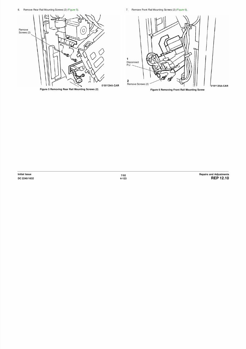
8/13/2019 Xerox Docu Color 2240-1632
http://slidepdf.com/reader/full/xerox-docu-color-2240-1632 649/1118
7/02
4-124 DC 2240/1632REP 12.10Initial IssueRepairs and Adjustments
10. Remove Screws (5) and remove Rail (Figure 9).
Figure 9 Removing Rail
Screws (5)

8/13/2019 Xerox Docu Color 2240-1632
http://slidepdf.com/reader/full/xerox-docu-color-2240-1632 650/1118
7/02
4-125DC 2240/1632 REP 12.10Repairs and AdjustmentsInitial Issue
REP 12.11 Stapler AssemblyParts List on PL 17.9
Removal
WARNING
To avoid personal injury or shock, do not perform repair or adjustment activities with
the power switch on or electrical power applied to the machine.
1. Open the Front Cover.
2. Disconnect Stapler P/J’s (2) (Figure 1).
Figure 1 Disconnecting P/J’s
3. Remove the Stapler Assembly (Figure 2).
Figure 2 Removing Stapler Assembly
Disconnect Sta-pler P/J’s (2)
RemoveScrews (2),Ground Wire(1) and Stapler

8/13/2019 Xerox Docu Color 2240-1632
http://slidepdf.com/reader/full/xerox-docu-color-2240-1632 651/1118
7/02
4-126 DC 2240/1632REP 12.11Initial IssueRepairs and Adjustments
Replacement
NOTE: Insert Stapler Assembly Tab into Slot ( Figure 3 ).
Figure 3 Inserting Tab into Slot
Tab
Slot

8/13/2019 Xerox Docu Color 2240-1632
http://slidepdf.com/reader/full/xerox-docu-color-2240-1632 652/1118
7/02
4-127DC 2240/1632 REP 12.11Repairs and AdjustmentsInitial Issue
REP 12.12 Compiler Tray AssemblyParts List on PL 17.10
Removal
WARNING
To avoid personal injury or shock, do not perform repair or adjustment activities with
the power switch on or electrical power applied to the machine.
1. Remove the following parts:
a. Rear Cover (PL 17.5)
b. Stacker Tray (PL 17.1)
c. Right Cover (PL 17.5)
d. Front Cover (PL 17.5)
2. Remove the Bracket (Figure 1).
3. Disconnect P/J (Figure 2).
Figure 2 Disconnecting P/J
1RemoveScrews (4)
2Remove
Bracket
1
RemoveScrew (2)2RemovePlate
3DisconnectP/J

8/13/2019 Xerox Docu Color 2240-1632
http://slidepdf.com/reader/full/xerox-docu-color-2240-1632 653/1118
7/02
4-128 DC 2240/1632REP 12.12Initial IssueRepairs and Adjustments
Figure 1 Remove the Bracket
Bracket
4. Remove Thumbscrews (2) (Figure 3).
Figure 3 Removing Thumbscrews (2)
5. Remove the Tray Guide (Figure 4).
1RemoveScrews (4)
2
Remove Fastenerand Cable Clamp
3Remove Cablefrom Cover andremove Cover

8/13/2019 Xerox Docu Color 2240-1632
http://slidepdf.com/reader/full/xerox-docu-color-2240-1632 654/1118
7/02
4-129DC 2240/1632 REP 12.12Repairs and AdjustmentsInitial Issue
Figure 4 Removing Tray Guide
6. Release Compiler Tray Harness (Figure 5).
Figure 5 Releasing Compiler Tray Harness
7. Remove the Screw on the Inboard side (Figure 6).
Figure 6 Removing Screw on Inboard Side
1Disconnect andremove formGuide
2Disconnect fromFinisher PWB andremove from Guide
3Move harnessesback throughframe
Screw

8/13/2019 Xerox Docu Color 2240-1632
http://slidepdf.com/reader/full/xerox-docu-color-2240-1632 655/1118
7/02
4-130 DC 2240/1632REP 12.12Initial IssueRepairs and Adjustments
8. Remove the Compiler Tray Assembly (Figure 7).
Figure 7 Removing Compiler Tray Assembly
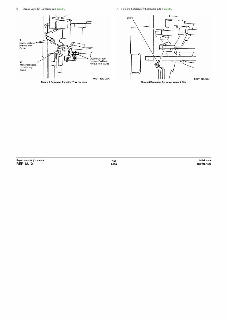
8/13/2019 Xerox Docu Color 2240-1632
http://slidepdf.com/reader/full/xerox-docu-color-2240-1632 656/1118
7/02
4-131DC 2240/1632 REP 12.12Repairs and AdjustmentsInitial Issue
REP 12.13 Stacker Motor AssemblyParts List on PL 17.11
Removal
WARNING
To avoid personal injury or shock, do not perform repair or adjustment activities with
the power switch on or electrical power applied to the machine.
1. Remove the Rear Cover (PL 17.5).
2. Hold Stacker Tray and move Gear to lower the Stack Tray (Figure 1).
Figure 1 Moving Gear to Lower Stack Tray
3. Remove the screws on PWB Chassis (Figure 2).
Figure 2 Removing Screws on PWB Chassis
1LoosenScrew
2RemoveScrews (2)
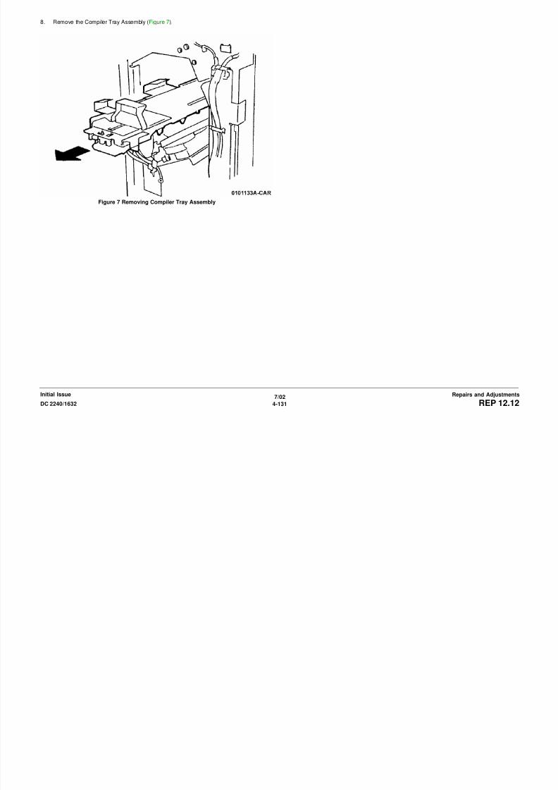
8/13/2019 Xerox Docu Color 2240-1632
http://slidepdf.com/reader/full/xerox-docu-color-2240-1632 657/1118
7/02
4-132 DC 2240/1632REP 12.13Initial IssueRepairs and Adjustments
4. Remove the Stacker Motor Assembly (Figure 3).
a. Remove the screws (3) while sliding the PWB Chassis upward.
b. Slide the Gear.
c. Remove the Stacker Motor Assembly.
1Lift PWB Chassisand RemoveScrews (2)
2
RemoveScrew(1)3
MoveGear andRemoveStackerMotorDiscon-nect P/J

8/13/2019 Xerox Docu Color 2240-1632
http://slidepdf.com/reader/full/xerox-docu-color-2240-1632 658/1118
7/02
4-133DC 2240/1632 REP 12.13Repairs and AdjustmentsInitial Issue
Figure 3 Removing Stacker Motor Assembly
REP 12.14 Front Elevator BracketParts List on PL 17.11
Removal
WARNING
To avoid personal injury or shock, do not perform repair or adjustment activities with
the power switch on or electrical power applied to the machine.
1. Remove the following parts:
a. Rear Cover (PL 17.5)
b. Stacker Tray (PL 17.1)
c. Right Cover (PL 17.5)
d. Front Cover (PL 17.5)
2. Remove the Bracket (Figure 1).
3. Disconnect P/J (Figure 2).
Figure 2 Disconnecting P/J
1RemoveScrews (4)
2Remove
Bracket
1
RemoveScrew (2)
2RemovePlate
3DisconnectP/J

8/13/2019 Xerox Docu Color 2240-1632
http://slidepdf.com/reader/full/xerox-docu-color-2240-1632 659/1118
7/02
4-134 DC 2240/1632REP 12.14Initial IssueRepairs and Adjustments
Figure 1 Remove the Bracket
4. Remove the Thumbscrews (2) (Figure 3).
Figure 3 Removing Thumbscrews
5. Remove the Tray Guide (Figure 4).
1
RemoveScrews (4)
2
Remove Fastenerand Cable Clamp
3Remove Cablefrom Cover andremove Cover

8/13/2019 Xerox Docu Color 2240-1632
http://slidepdf.com/reader/full/xerox-docu-color-2240-1632 660/1118
7/02
4-135DC 2240/1632 REP 12.14Repairs and AdjustmentsInitial Issue
Figure 4 Removing Tray Guide
6. Move PWB Chassis (Figure 5). 7. Remove Front Elevator Bracket (Figure 6).
Figure 6 Removing Elevator Belt Assembly
1ReleaseWires fromClamp
2LoosenScrew
2
RemoveScrews(2)
4Move PWBChassis
RemoveScrews (3)and ElevatorBelt Assembly
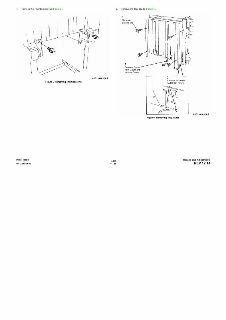
8/13/2019 Xerox Docu Color 2240-1632
http://slidepdf.com/reader/full/xerox-docu-color-2240-1632 661/1118
7/02
4-136 DC 2240/1632REP 12.14Initial IssueRepairs and Adjustments
Figure 5 Moving PWB Chassis
REP 12.15 Paddle Gear ShaftParts List on PL 17.12
Removal
WARNING
To avoid personal injury or shock, do not perform repair or adjustment activities with
the power switch on or electrical power applied to the machine.
1. Remove the following parts:
a. Stapler Assembly (REP 12.11).
b. Rear Cover (PL 17.5).
2. Remove the Cam Bracket Assembly (REP 12.18).
3. Remove the Bearing (Figure 1).
4. Remove Screw on Paddle Gear Shaft (Figure 2).
Figure 2 Removing Screw on Paddle Gear Shaft
RemoveClip, Gear,and Bearing
RemoveScrew
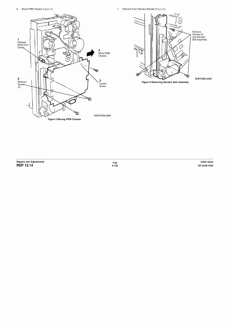
8/13/2019 Xerox Docu Color 2240-1632
http://slidepdf.com/reader/full/xerox-docu-color-2240-1632 662/1118
7/02
4-137DC 2240/1632 REP 12.15Repairs and AdjustmentsInitial Issue
Figure 1 Removing Bearing
5. Remove the Paddle Gear Shaft (Figure 3).
Figure 3 Removing Paddle Gear Shaft
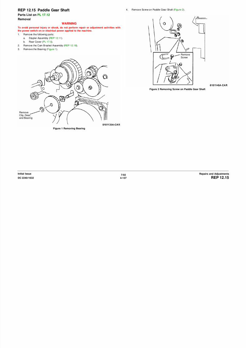
8/13/2019 Xerox Docu Color 2240-1632
http://slidepdf.com/reader/full/xerox-docu-color-2240-1632 663/1118
7/02
4-138 DC 2240/1632REP 12.15Initial IssueRepairs and Adjustments
REP 12.16 Finisher PWBParts List on PL 17.13
Removal
WARNING
To avoid personal injury or shock, do not perform repair or adjustment activities with
the power switch on or electrical power applied to the machine.
1. Remove Rear Cover (PL 17.5).
2. Remove the PWB Cover (Figure 1).
Figure 1 Removing PWB Cover
3. Disconnect P/J’s (Figure 2).
Figure 2 Disconnecting P/J’s
1Remove
Screws(10)
2RemovePWBCover
1DisconnectP/J’s (10)
2RemoveWire Har-ness fromGuides (4)

8/13/2019 Xerox Docu Color 2240-1632
http://slidepdf.com/reader/full/xerox-docu-color-2240-1632 664/1118
7/02
4-139DC 2240/1632 REP 12.16Repairs and AdjustmentsInitial Issue
4. Remove the Finisher PWB (Figure 3).
Figure 3 Removing Finisher PWB
Replacement
NOTE: When installing, keep the Core ( Figure 2 ) inside the PWB Box.
Remove
Screws (6)and PWB

8/13/2019 Xerox Docu Color 2240-1632
http://slidepdf.com/reader/full/xerox-docu-color-2240-1632 665/1118
7/02
4-140 DC 2240/1632REP 12.16Initial IssueRepairs and Adjustments
REP 12.17 Entrance Upper CoverParts List on PL 17.3
Removal
1. Remove the H Transport Assembly (REP 12.1).
2. Remove the following:
a. H Transport Front Cover (PL 17.3)
b. H Transport Rear Cover (PL 17.3)
c. Stop (PL 17.3)
3. Remove the H Transport Cover (Figure 1).
Figure 1 Removing the H Transport Cover
1RemoveScrew (2)
2RemoveCover

8/13/2019 Xerox Docu Color 2240-1632
http://slidepdf.com/reader/full/xerox-docu-color-2240-1632 666/1118
7/02
4-141DC 2240/1632 REP 12.17Repairs and AdjustmentsInitial Issue
REP 12.18 Cam Bracket AssemblyParts List on PL 17.8
Removal
WARNINGTo avoid personal injury or shock, do not perform repair or adjustment activities with
the power switch on or electrical power applied to the machine.
1. Remove the Rear Cover (PL 17.5)
2. Rotate the Actuator (Figure 1).
Figure 1 Rotate the Actuator
3. Release Harnesses (Figure 2).
Figure 2 Releasing Harnesses1Release Sole-noid Pawl
2RotateCam 1/4revolution
1DisconnectP/J’s (3)
2Remove Clamp
from Frame
4
RemoveClampfromFrame
5Remove wiresfrom Clip
Remove wires from
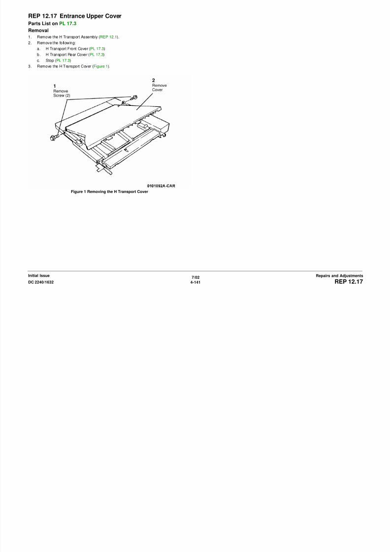
8/13/2019 Xerox Docu Color 2240-1632
http://slidepdf.com/reader/full/xerox-docu-color-2240-1632 667/1118
7/02
4-142 DC 2240/1632REP 12.18Initial IssueRepairs and Adjustments
4. Remove the Cam Bracket Assembly (Figure 3).
a. Remove the Screws (4).
b. Remove the Cam Bracket Assembly.
Figure 3 Removing the Cam Bracket Assembly
Replacement
NOTE: During assembly, refer to Figure 4 .
Figure 4 Inserting Axle of Cam Bracket Assembly into Hole
1RemoveScrews (4)
2Remove
Cam BracketAssembly
2
Align Axlewith Hole
1Raise TopCover to raiseRoller whileperformingstep 2

8/13/2019 Xerox Docu Color 2240-1632
http://slidepdf.com/reader/full/xerox-docu-color-2240-1632 668/1118
7/02
4-143DC 2240/1632 REP 12.18Repairs and AdjustmentsInitial Issue
NOTE: During assembly, refer to Figure 5 .
Figure 5 Engaging Pawl with Slot
Rotate Cam soPawl engagesSlot

8/13/2019 Xerox Docu Color 2240-1632
http://slidepdf.com/reader/full/xerox-docu-color-2240-1632 669/1118
7/02
4-144 DC 2240/1632REP 12.18Initial IssueRepairs and Adjustments
REP 12.19 Finisher Rack AssemblyParts List on PL 17.1
Removal
WARNINGTo avoid personal injury or shock, do not perform repair or adjustment activities with
the power switch on or electrical power applied to the machine.
1. Remove Finisher (REP 12.4).
2. Loosen Feet (Figure 1).
Figure 1 Loosening Feet
3. Remove Bottom Plate (Figure 2).
Figure 2 Removing Bottom PlateLoosen Feet

8/13/2019 Xerox Docu Color 2240-1632
http://slidepdf.com/reader/full/xerox-docu-color-2240-1632 670/1118
7/02
4-145DC 2240/1632 REP 12.19Repairs and AdjustmentsInitial Issue
4. Remove Rear Rack (Figure 3).
Figure 3 Removing Rear Rack
5. Remove Front Rack (Figure 4).
Figure 4 Removing Front Rack
1RemoveThumbscrew
2Lift toRemoveRack
1RemoveThumbscrew
2Lift toRemoveRack

8/13/2019 Xerox Docu Color 2240-1632
http://slidepdf.com/reader/full/xerox-docu-color-2240-1632 671/1118
7/02
4-146 DC 2240/1632REP 12.19Initial IssueRepairs and Adjustments
REP 12.20 Lowering Stacker TrayParts List on PL 17.1
Removal
If the need arises to lower the Stacker Tray quickly or without power applied perform following:
WARNING
To avoid personal injury or shock, do not perform repair or adjustment activities with
the power switch on or electrical power applied to the machine.
1. Remove Finisher Rear Cover (PL 17.5).
2. While holding the Stacker Tray, move the gear outward and the Stacker Tray is released
(Figure 1).
Figure 1 Moving Gear to Lower Stack Tray

8/13/2019 Xerox Docu Color 2240-1632
http://slidepdf.com/reader/full/xerox-docu-color-2240-1632 672/1118
7/02
4-147DC 2240/1632 REP 12.20Repairs and AdjustmentsInitial Issue

8/13/2019 Xerox Docu Color 2240-1632
http://slidepdf.com/reader/full/xerox-docu-color-2240-1632 673/1118
7/02
4-148 DC 2240/1632REP 12.20Initial IssueRepairs and Adjustments
REP 14.1 Top CoverParts List on PL 10.2
Removal
WARNINGTo avoid personal injury or shock, do not perform repair or adjustment activities with
the power switch on or electrical power applied to the machine.
1. Without Finisher, go to 7.
With Finisher, go to 2.
2. Remove Finisher H Transport (REP 12.1).
3. Remove Finisher (REP 12.4).
4. Remove Front and Rear Brackets (Figure 1).
Figure 1 Removing Brackets
5. Remove Finisher Rack Assembly (REP 12.19).
6. Remove Gate Cover (Figure 2).
Figure 2 Removing Gate Cover
7. Remove Right Cover (REP 14.3).
8. Remove Top Cover (Figure 3).
a. Open Front Cover.
b. Remove Screws (3).
c. Remove Top Cover.
Remove Thumbscrews (2)and Brackets
Release
Clips (2)andRemoveGateCover

8/13/2019 Xerox Docu Color 2240-1632
http://slidepdf.com/reader/full/xerox-docu-color-2240-1632 674/1118
7/02
4-149DC 2240/1632 REP 14.1Repairs and AdjustmentsInitial Issue
Figure 3 Removing Top Cover
Screws (3)
REP 14.2 Rear CoverParts List on PL 10.3
Removal
WARNINGTo avoid personal injury or shock, do not perform repair or adjustment activities with
the power switch on or electrical power applied to the machine.
1. Remove Rear Cover (Figure 1).
a. Open Harness Cover and disconnect Harnesses
b. Remove Screws (4).
c. Remove Rear Cover.
Figure 1 Removing Rear Cover
REP 14.3 Right CoverParts List on PL 10.1
Removal
WARNINGTo avoid personal injury or shock, do not perform repair or adjustment activities with
the power switch on or electrical power applied to the machine.
1. Open Front Cover.
2. With Finisher, Remove Finisher (REP 12.4) and remove Finisher Rack Assembly (REP
12.19). Then go to 3.
Without Finisher, go to 3.
3. Remove Right Cover (Figure 1).
a. Open Right Door.
b. Remove Screws (3).c. Push cover down, or allow cover to drop slightly to release Hidden Tabs, then pull
cover away and remove it.
Figure 1 Removing Right Cover
Harness Cover
Harnesses
Screws (4)
RearCover
Hidden Tabs

8/13/2019 Xerox Docu Color 2240-1632
http://slidepdf.com/reader/full/xerox-docu-color-2240-1632 675/1118
7/02
4-150 DC 2240/1632REP 14.2, REP 14.3Initial IssueRepairs and Adjustments
REP 14.4 Rear Left Middle CoverParts List on PL 10.3
Removal
WARNINGTo avoid personal injury or shock, do not perform repair or adjustment activities with
the power switch on or electrical power applied to the machine.
1. Remove Rear Cover (REP 14.2).
2. Open Left Cover Assembly.
3. Remove Power Switch Cover (REP 14.5).
4. Remove Upper Rear Left Cover (Figure 1).
a. Remove Screw (1).
b. Lift slightly to disengage hidden tab and remove Upper Rear Left Cover.
Figure 1 Removing Upper Rear Left Cover
REP 14.5 Rear Left Upper CoverParts List on PL 10.3
Removal
WARNINGTo avoid personal injury or shock, do not perform repair or adjustment activities with
the power switch on or electrical power applied to the machine.
1. Remove Rear Cover (REP 14.2).
2. Open Left Cover Assembly.
3. Remove Power Switch Cover (Figure 1).
a. Remove Screw (1).
b. Push end of cover in direction shown to release Hidden Tabs (2).
c. Pull up to release Hidden Tab (1) and remove Power Switch Cover.
Figure 1 Removing Power Switch Cover
HiddenTabs (2) Hidden
Tab (1)
Screw
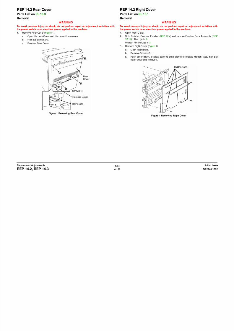
8/13/2019 Xerox Docu Color 2240-1632
http://slidepdf.com/reader/full/xerox-docu-color-2240-1632 676/1118
7/02
4-151DC 2240/1632 REP 14.4, REP 14.5Repairs and AdjustmentsInitial Issue
REP 14.6 Left Lower Cover AssemblyParts List on PL 2.3
Removal
WARNINGTo avoid personal injury or shock, do not perform repair or adjustment activities with
the power switch on or electrical power applied to the machine.
1. Remove Lower Left Cover (Figure 1).
a. Open Left Lower Cover Assembly.
b. Carefully observe position of wiring harness for later reinstallation.
c. Disconnect harness connector and remove harness from harness guide.
d. Use flat tipped screwdriver to pry out Pivot Lock.
e. Remove Pivot Pin Sleeve.
f. Remove Lower Left Cover.
REP 14.7 Cover AssemblyParts List on PL 10.1
Removal
WARNINGTo avoid personal injury or shock, do not perform repair or adjustment activities with
the power switch on or electrical power applied to the machine.
1. Remove Front Cover (Figure 1).
a. Open Tray 1 approximately 100 mm for possible cover support.
b. Open Front Cover.
c. Remove screw to disconnect Support Strap from cover.
d. Repeat c for other strap.
e. Remove screws (2) on Hinge Pin Locks and remove hinge pin locks.
f. Remove Front Cover.
PivotLock
PivotSleeve

8/13/2019 Xerox Docu Color 2240-1632
http://slidepdf.com/reader/full/xerox-docu-color-2240-1632 677/1118
7/02
4-152 DC 2240/1632REP 14.6, REP 14.7Initial IssueRepairs and Adjustments
Figure 1 Removing Left Lower Cover Assembly
Replacement
NOTE: Partially install Pivot Sleeve. Then install Left Lower Cover Assembly and push in Pivot
Sleeve.
Figure 1 Removing Front Cover
REP 14.8 Fuser CoverParts List on PL 10.2
Removal
WARNINGTo avoid personal injury or shock, do not perform repair or adjustment activities with
the power switch on or electrical power applied to the machine.
1. Open Front Cover.
2. Remove Fuser Cover (Figure 1).
a. Remove Screws (2).
b. Move cover up to release Hidden Tabs (3) and pull out to remove cover.
Figure 1 Removing Fuser Cover
Support
Strap
Hinge Pin:Locks
HiddenTabs

8/13/2019 Xerox Docu Color 2240-1632
http://slidepdf.com/reader/full/xerox-docu-color-2240-1632 678/1118
7/02
4-153DC 2240/1632 REP 14.7, REP 14.8Repairs and AdjustmentsInitial Issue
REP 14.9 Rear CoverParts List on PL 16.16
Removal
WARNINGTo avoid personal injury or shock, do not perform repair or adjustment activities with
the power switch on or electrical power applied to the machine.
1. Remove Thumbscrews (4).
2. Remove Screws (4) and remove Lower Rear Cover.
REP 14.10 Inner CoverParts List on PL 8.1
Removal
WARNINGTo avoid personal injury or shock, do not perform repair or adjustment activities with
the power switch on or electrical power applied to the machine.
1. Open Front Cover.
2. Remove Fuser Front Cover (REP 14.8).
3. Remove Waste Cartridge Cover (REP 9.3).
4. Remove Inner Cover (Figure 1).
a. Open Harness Clip and remove harness from Clip.
b. Remove Screw and remove Harness Cover.
Figure 1 Removing Inner Cover
Harness Clip
InnerCover
Screw

8/13/2019 Xerox Docu Color 2240-1632
http://slidepdf.com/reader/full/xerox-docu-color-2240-1632 679/1118
7/02
4-154 DC 2240/1632REP 14.9, REP 14.10Initial IssueRepairs and Adjustments
Figure 1 Removing Inner Cover
REP 14.11 Left Cover AssemblyParts List on PL 16.13
Removal
WARNINGTo avoid personal injury or shock, do not perform repair or adjustment activities with
the power switch on or electrical power applied to the machine.
1. Remove Lower Cover (REP 14.12).
2. Remove Left Cover Assembly (Figure 1).
a. Remove Screws (2) and Straps (2) from frame.
b. Remove Screw (1) and Pivot Support and remove Left Cover Assembly.
REP 14.12 Lower CoverParts List on PL 16.16
Removal
WARNINGTo avoid personal injury or shock, do not perform repair or adjustment activities with
the power switch on or electrical power applied to the machine.
1. Remove Lower Cover (Figure 1).
Figure 1 Removing Lower Cover
Left CoverAssembly
1RemoveScrews (2)
Screws (2)

8/13/2019 Xerox Docu Color 2240-1632
http://slidepdf.com/reader/full/xerox-docu-color-2240-1632 680/1118
7/02
4-155DC 2240/1632 REP 14.11, REP 14.12Repairs and AdjustmentsInitial Issue
Figure 1 Removing Left Cover Assembly

8/13/2019 Xerox Docu Color 2240-1632
http://slidepdf.com/reader/full/xerox-docu-color-2240-1632 681/1118
7/02
4-156 DC 2240/1632REP 14.11, REP 14.12Initial IssueRepairs and Adjustments
ADJ 5.1 DADF Side RegistrationPurpose
Align image scanned from document with left side edge of paper.
Check
1. Make two copies from the Platen Glass to be used as DADF originals.
a. Register Test Chart 82E8220 on Platen with side edge metrics SE1 through SE4
against rear registration guide.
b. Select the following:
• 1 to 1 sided
• A3 or 11 x 17 Paper Supply
• 100% Reduce/Enlarge
• 2 Copies
c. Press Start and write DADF Original 1 on first copy and DADF Original 2 on second
copy.
2. Verify side edge registration of DADF Originals.
a. On DADF Original 2 measure and record the distance between the side edge and
the reference line and write A next to this measurement (Figure 1).
b. Check that A is 10.0 ±0.5mm. If A is 10.0 ±0.5 mm, go to step 3.
If A is not 10.0 ±0.5 mm, check both of the following and then return to the beginning
of this procedure.
i. dC129 IOT Lead Edge/Side Edge Registration (ADJ 9.9).
ii. IIT Side Edge Registration (ADJ 9.11)
• 1 to 1-sided
• A3 or 11 x 17 Paper Supply
• 100% Reduce/Enlarge
• 2 Copies
c. Press Start and discard the first copy.
d. On side 1 of copy 2 measure and record the distance between the side edge and the
reference line and write B next to this measurement (Figure 2).
Figure 2 Checking Side Edge Registration of DADF
e. Compare B to A. B must be within ±1.1 mm of A.
If the difference between B and A is greater than 1.1 mm, go to step 1 of the adjust-
ment.
Otherwise go to step 4.
4. Check DADF Side Edge Registration for Side 2.
a. Make a 2-sided test pattern.
i. Load DADF originals 1 and 2 face up, 1 on top, with side edge metrics toward
rear of DADF.
ii. Select 1 to 2-sided and press Start to make the 2-sided test pattern
b. Make test copies.
i. Load 2-sided test pattern with side 1 edge metrics up and toward rear of DADF.
ii Select the follo ing
PaperFeedDirection
A
Manuallylabeled 2
Edge ofCopy
10.0±0.5m
PaperFeedDirection
Edge of
Copy
B

8/13/2019 Xerox Docu Color 2240-1632
http://slidepdf.com/reader/full/xerox-docu-color-2240-1632 682/1118
7/02
4-157DC 2240/1632 ADJ 5.1Repairs and AdjustmentsInitial Issue
Figure 1 Verifying Side Edge Registration of DADF Originals
3. Check DADF Side Edge Registration for Side 1.a. Load both DADF Originals in DADF, 1 on top, with side edge metrics SE1 through
SE4 against rear registration guide. Check that side guide touches documents.
b. Select the following:
ii. Select the following:
• 2 to 1 sided
• A3 or 11 x 17 Paper Supply
• 100% Reduce/Enlarge
• 1 Copy
iii. Press the Start button.c. Check that side edge metrics are same distance from edge of paper for both copies.
If the difference is greater than ±1.1 mm, go to step 2 of the adjustment.
Otherwise DADF Side Registration is good.
Adjustment
1. Adjust Side 1 DADF Side Registration.
a. Enter NVM Rear/Write (dC131) [715-015].
NOTE: Increasing value moves side edge metrics SE1 through SE4 toward edge.
b. If B is more than A, increase the NVM value (15 = approx. 1 mm).
If B is less than A, decrease the NVM value (15 = approx. 1 mm).
c. Check results of adjustment and adjust if required.
2. Adjust Side 2 DADF Side Registration.
a. Enter NVM Rear/Write (dC131) [715-128].
NOTE: Increasing value moves side edge metrics SE1 through SE4 toward edge.
b. If copy 2 edge metric is farther away from edge than copy 1, increase the NVM value
(15 = approx. 1 mm).If copy 2 edge metric is closer to edge than copy 1, decrease the NVM value (15 =
approx. 1 mm).
c. Check results of adjustment and adjust as required.
NOTE: 2 to 2-sided or 2 to 1-sided must be selected to view a change in [715-128].
[715-128] produces no change in 1 to 2-sided copying.
NOTE: Total lead edge deviation for DADF is ±1.6 mm. Total lead edge deviation for IIt is ±0.5
mm. This leaves ±1.1 mm for DADF when a copy paper test pattern is made for use in DADF.

8/13/2019 Xerox Docu Color 2240-1632
http://slidepdf.com/reader/full/xerox-docu-color-2240-1632 683/1118
7/02
4-158 DC 2240/1632ADJ 5.1Initial IssueRepairs and Adjustments
ADJ 5.2 DADF CounterbalancePurpose
Correct DADF opening and closing action.
Check
1. Check DADF opening and closing action.
a. Raise DADF and check that it remains in fully raised position.
b. Check that the DADF closes from a height of 100 ±50mm by its own weight without
excessive noise (Figure 1).
Figure 1 Checking DADF Height
Adjustment
WARNING
To avoid personal injury or shock, do not perform repair or adjustment activities with
the power switch on or electrical power applied to the machine.
CAUTION
When removing the Rear Cover, disconnect LED Connector on DADF PWB.
1. Remove the Rear Cover. (REP 5.18)
2. Adjust the Left Counterbalance (Figure 2).
NOTE: Rotate in A direction for stronger spring pressure
Rotate in B direction for weaker spring pressure
a. Loosen the nut.
b. Rotate the Set Screw for the adjustment.
c . Tighten the nut.
Figure 2 Adjusting Left Counterbalance
100 mm +/- 50 mm A
B
8/13/2019 Xerox Docu Color 2240-1632
http://slidepdf.com/reader/full/xerox-docu-color-2240-1632 684/1118
7/02
4-159DC 2240/1632 ADJ 5.2Repairs and AdjustmentsInitial Issue
Figure 2 Adjusting Left Counterbalance
ADJ 5.3 DADF ParallelismPurpose
Enable parallel Document placement and image scan.
Check
WARNING
To avoid personal injury or shock, do not perform repair or adjustment activities with
the power switch on or electrical power applied to the machine.
1. Remove Front Cover. (PL 20.1)
2. Remove Entrance Tray. (PL 20.1)
3. Remove the Document Transport. (REP 5.17)
4. Check DADF Parallelism.
a. Manually hold down the DADF.
b. Check that the distance between the DADF Rear Frame and the Rear Registration
Edge is 20 ±1 mm (Figure 1).
c. Perform the same check at the left end of the DADF.
If 20 ±1 mm is not measured in each check, or the measurements are different, go to
the adjustment.
Otherwise DADF Parallelism is good.
Adjustment
CAUTION
The DADF Parallelism must be made with in ±1mm of the specified range.
CAUTION
When removing the Rear Cover, disconnect LED Connector on DADF PWB.
1. Remove Rear Cover (REP 5.18).
2. Adjust DADF Parallelism (Figure 2).
Figure 2 Adjusting DADF Parallelism
3. Adjust Left Counterbalance if required.
4. Repeat the check.
DADF Rear Frame
20 mm
Rear Regis-tration Edge
Right Endof DADF
DADF Movesto Rear
DADF Movesto Front
1LoosenScrews (4)
2LoosenScrews (2)
3Adjust Screw
4TightenScrews (6)

8/13/2019 Xerox Docu Color 2240-1632
http://slidepdf.com/reader/full/xerox-docu-color-2240-1632 685/1118
7/02
4-160 DC 2240/1632ADJ 5.3Initial IssueRepairs and Adjustments
Figure 1 Checking DADF Parallelism
Scale
ADJ 5.4 Document Transport HeightPurpose
Enable document feed at the correct speed and free of skew.
Check
WARNING
To avoid personal injury or shock, do not perform repair or adjustment activities with
the power switch on or electrical power applied to the machine.
1. Remove Front Cover (PL 20.1).
2. Entrance Tray (PL 20.1).
3. Check Document Transport Height (Figure 1).
a. At left end of Document Transport, check that there is 24.5 ±0.3 mm between top of
Document Transport Frame and Top of Rear Registration Edge.
b. At Right end of Document Transport, check that there is 24.5 ±0.3 mm between top
of Document Transport Frame and Top of Rear Registration Edge.
c. If there is more or less than specified, perform the adjustment on the counterbalance
for the side that is not in specification. Adjust both counterbalances if required.
Otherwise, Document Transport Height is good.
Adjustment
CAUTION
When removing the Rear Cover, disconnect LED Connector on DADF PWB.
1. Remove Rear Cover (REP 5.18).
2. Raise DADF and loosen the Screws (2) (Figure 2).
Figure 2 Loosening Screws
Document Transport Frame
Top ofRear Reg-istrationEdge
24.5 ±0.3 mm
Left End of Document TransportRight End of
DocumentTransport
Screws
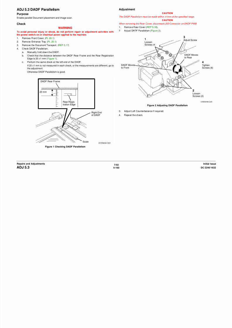
8/13/2019 Xerox Docu Color 2240-1632
http://slidepdf.com/reader/full/xerox-docu-color-2240-1632 686/1118
7/02
4-161DC 2240/1632 ADJ 5.4Repairs and AdjustmentsInitial Issue
Figure 1 Checking Document Transport Height
3. Adjust Document Transport Height (Figure 3).
Figure 3 Adjusting Document Transport Height
4. Repeat check.
Lower DocumentTransport FrameRaise Docu-
ment Trans-port Frame
2AdjustScrew
!Lower DADF
3RaiseDADF
4TightenScrews

8/13/2019 Xerox Docu Color 2240-1632
http://slidepdf.com/reader/full/xerox-docu-color-2240-1632 687/1118
7/02
4-162 DC 2240/1632ADJ 5.4Initial IssueRepairs and Adjustments
ADJ 5.5 DADF Top RegistrationPurpose
Align image scanned from document with top edge of paper.
Check1. Make two DADF originals.
a. Register Test Chart 82E8220 on Platen with lead edge metrics LE1 through LE3
against left registration guide.
b. Select the following:
• 1 to 1 sided
• A4 or 8.5 x 11 Long Edge Feed Paper Supply
• 100% Reduce/Enlarge
• 2 Copies
c. Press Start and write DADF Original 1 on first copy and DADF Original 2 on second
copy.
2. Verify top edge registration of DADF Originals.
a. On copy 2 measure and record the distance between the top edge and the reference
line and write A next to this measurement (Figure 1).
b. Check that A is 10.0 ±0.5 mm. If A is 10.0 ±0.5 mm, go to step 3.
If A is not 10.0 ±0.5 mm, check both of the following and then return to the beginning
of this procedure.
i. IOT Lead Edge/Side Edge Registration (ADJ 9.9).
ii. IIT Side Edge Registration (ADJ 9.11)
3. Check DADF Top Edge Registration for Side 1.
a. Load both DADF Originals in DADF, 1 on top, with top edge metrics LE1 through
LE3 toward right.
b. Select the following:
• 1 to 1-sided• A4 or 8.5 x 11 Long Edge Feed Paper Supply
• 100% Reduce/Enlarge
• 2 Copies
c. Press Start and discard the first copy.
d. On side 1 of copy 2 measure and record the distance between the top edge and the
reference line and write B next to this measurement (Figure 2).
Figure 2 Checking Top Edge Registration of DADF
e. Compare A to B. B must be within 0 ±1.1 mm of A.
If the difference between A and B is greater than 1 mm, go to step 1 of the adjust-
ment.
Otherwise go to step 4.
4. Check DADF Side Edge Registration for Side 2.
a. Make a 2-sided test pattern.
i. Load DADF originals 1 and 2 face up, 1 on top, with top edge metrics toward
right
PaperFeedDirection
Top Edgeof Copy
10.0 ±0.5 mmA
PaperFeedDirection
Top Edgeof Copy
B 10.0 ±1.1 mm

8/13/2019 Xerox Docu Color 2240-1632
http://slidepdf.com/reader/full/xerox-docu-color-2240-1632 688/1118
7/02
4-163DC 2240/1632 ADJ 5.5Repairs and AdjustmentsInitial Issue
Figure 1 Verifying Top Edge Registration of DADF Originals
right.
ii. Select 1 to 2-sided and press Start to make the 2-sided test pattern
b. Make test copies.
i. Load 2-sided test pattern with side 1 edge metrics up and toward right of DADF.
ii. Select the following:
• 2 to 1 sided and press Start.
• A4 or 8.5 x 11 Long Edge Feed Paper Supply
• 100% Reduce/Enlarge
Manuallylabeled 2
• 1 Copy
iii. Press the Start button.
c. Check that top edge metrics are same distance from edge of paper for both copies.
If the difference is greater than 1 mm, go to step 2 of the adjustment.
Otherwise DADF Side Registration is good.
Adjustment
1. Adjust Side 1 DADF Side Registration.
a. Enter NVM Rear/Write (dC131) [710-005].
NOTE: Increasing value moves lead edge metrics LE1 through LE3 toward edge.
b. If B is more than A, increase the NVM value (5 = approx. 1 mm).
If B is less than A, decrease the NVM value (5 = approx. 1 mm).
c. Check results of adjustment and adjust if required.
2. Adjust Side 2 DADF Side Registration.
a. Enter following NVM Rear/Write (dC131)
[710-025] for B5 SEF or smaller
[710-026] for B5 LEF, A4 SEF/LEF, 8.5x11 SEF/LEF
[710-027] for 8.5 x 14, B4, A3, 11x17
NOTE: Decreasing value moves lead edge metrics LE1 through LE3 toward edge.
b. If copy 2 edge metric is farther away from edge than copy 1, decrease the NVM
value ( 5 = approx. 1 mm).
If copy 2 edge metric is closer to edge than copy 1, increase the NVM value (5 =
approx. 1 mm).
c. Check results of adjustment and adjust as required.
NOTE: 2 to 2-sided or 2 to 1-sided must be selected to view A change in [710-02X].
[710-02X] produces no change in 1 to 2-sided copying .
NOTE: Total lead edge deviation for DADF is ±1.6 mm. Total lead edge deviation for IIt is ±0.5mm. This leaves ±1.1 mm for DADF when a copy paper test pattern is made for use in DADF.
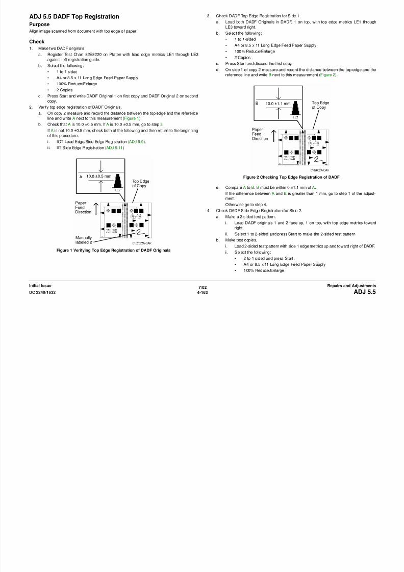
8/13/2019 Xerox Docu Color 2240-1632
http://slidepdf.com/reader/full/xerox-docu-color-2240-1632 689/1118
7/02
4-164 DC 2240/1632ADJ 5.5Initial IssueRepairs and Adjustments
ADJ 5.6 DADF Document CalibrationPurpose
This procedure calibrates the document size detection circuitry in the DADF.
Perform this adjustment whenever any the following occur:
• Replacement of the DADF.
• When an error is detected after replacing Registration Roll, Feed Roll, and Retard Roll.
• When a size detection error is reported.
Adjustment
1. Connect the PWS to the machine and enter Diagnostic Mode (refer to Entering Diagnostic
Mode using the PWS). Select dC527 from the dC Quick menu
2. Set three documents to be transported in the DADF:
XE: A4 LEF
XC: 8.5 x 11 in. LEF
CAUTION
After this routine has started, it cannot be stopped or interrupted until it completes, irrespective
of success or failure.
3. Click Start. The DADF starts feeding the documents and calculating the correction value.
At this point, the [Entering] message appears.
4. When the corresponding NVM data is updated (location 710-003), the PWS screen indi-
cates that the process has been completed.

8/13/2019 Xerox Docu Color 2240-1632
http://slidepdf.com/reader/full/xerox-docu-color-2240-1632 690/1118
7/02
4-165DC 2240/1632 ADJ 5.6Repairs and AdjustmentsInitial Issue

8/13/2019 Xerox Docu Color 2240-1632
http://slidepdf.com/reader/full/xerox-docu-color-2240-1632 691/1118
Scanner
ADJ 6.1 Full/Half Rate CarriagePurpose
Establish Full Rate and Half Rate Carriage position.
Check
WARNING
To avoid personal injury or shock, do not perform repair or adjustment activities with
the power switch on or electrical power applied to the machine.
NOTE: The Half Rate Carriage is checked, and adjusted if required by repositioning a pulley.
Then the Full Rate Carriage is checked, and adjusted if required by repositioning the carriage
on the cable.
1. Remove Platen Glass (REP 6.2).
2. Remove Alignment Tools (2) from Storage (Figure 1).
3. Align Half Rate Carriage with Rail Hole (Figure 2).
a. Manually move Full Rate Carriage away from home position approximately 105 mm
while observing Rail Tool Hole to align with Carriage Tool Hole in Half Rate Carriage.
Figure 2 Aligning Half Rate Carriage with Rail Hole
Remove Screws
(2) and Tools (2)
Rail Hole forAlignment Tool
Carriage Holefor AlignmentTool
Front of Scanner
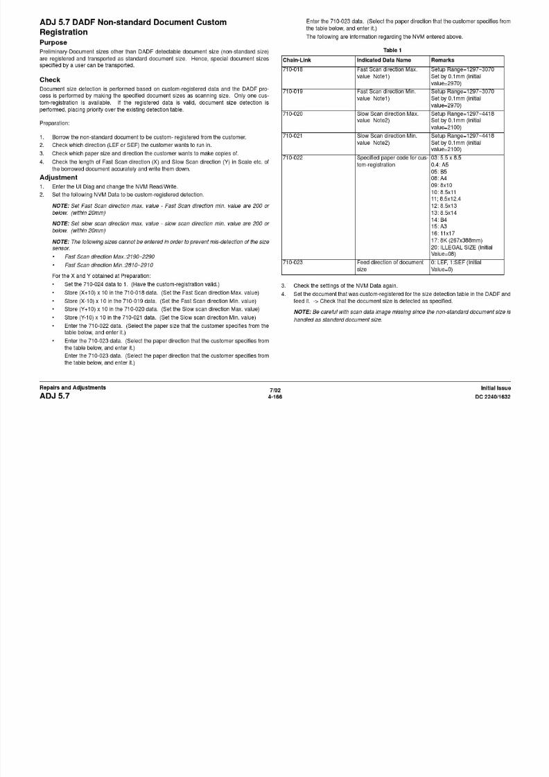
8/13/2019 Xerox Docu Color 2240-1632
http://slidepdf.com/reader/full/xerox-docu-color-2240-1632 692/1118
7/02
4-167DC 2240/1632 ADJ 6.1Repairs and AdjustmentsInitial Issue
Figure 1 Removing Tools
4. Install Alignment Tool in front end of Half Rate Carriage (Figure 3).
Figure 3 Installing Alignment Tool in Front End of Half Rate Carriage
5. Check that tool will install in other end of carriage.
If the tool installs, go to step 6.
If tool does not install, loosen the Set Screw (2) and turn the pulley to align the tool holes
with each other (Figure 4).
Figure 4 Loosening the Set Screw (2)

8/13/2019 Xerox Docu Color 2240-1632
http://slidepdf.com/reader/full/xerox-docu-color-2240-1632 693/1118
7/02
4-168 DC 2240/1632ADJ 6.1Initial IssueRepairs and Adjustments
6. Check that Alignment Tool can be installed through frame into alignment hole in Full Rate
Carriage (Figure 5).
If Alignment Tool fits through frame hole into Full Rate Carriage Alignment Hole, perform
the same check at the rear of the carriage.
If the rear of the carriage is aligned, the check is good.
If the rear of the carriage is not aligned, go to the adjustment.
If Alignment Tool does not fit through frame hole into Full Rate Carriage Alignment Hole,
go to the adjustment.
Figure 5 Checking Alignment Tool in Full Rate Carriage
Adjustment
NOTE: Front of Full Rate Carriage shown. Adjustment steps are same for rear of Full Rate
Carriage.
1. Adjust Full Rate Carriage (Figure 6).
a. Loosen Screw.
b. Move carriage so that Alignment Tool will drop into Alignment Holes.
c . Tighten Screw.
Figure 6 Adjust Full Rate Carriage
ScrewAlignmentHoles

8/13/2019 Xerox Docu Color 2240-1632
http://slidepdf.com/reader/full/xerox-docu-color-2240-1632 694/1118
7/02
4-169DC 2240/1632 ADJ 6.1Repairs and AdjustmentsInitial Issue

8/13/2019 Xerox Docu Color 2240-1632
http://slidepdf.com/reader/full/xerox-docu-color-2240-1632 695/1118
7/02
4-170 DC 2240/1632ADJ 6.1Initial IssueRepairs and Adjustments
ADJ 9.1 Max SetupPurpose
To conduct a check of the machine and set it up so that excellent copy quality can be consis-
tently obtained by stabilizing the development potential and copy density.
Adjustment
Max Setup consists of 5 separate adjustments that should be performed in the following
sequence:
1. ADJ 9.7, IIT Calibration (dC945)
NOTE: Perform ADJ 9.2 only when replacing the ATC Sensor or Developer Housing.
2. ADJ 9.2, ATC Sensor Setup (dC921)
3. ADJ 9.3, TRC Control/Toner Density Setup (dC922)
4. ADJ 9.4, ADC Output (dC934)
NOTE: Perform ADJ 9.5 only when the customer requests.
5. ADJ 9.5, Manual TRC Adjust (dC924)
ADJ 9.2 ATC Sensor Setup (dC921)Purpose
NOTE: This procedure should only be performed when the ATC Sensor or Developer Housing
has been replaced, or when there is reason to believe that the calibration values in NVM are
incorrect.
To set the calibration values [ATC Correction Coefficient], [ATC Correction Offset] in NVM to
calibrate the new ATC Sensor.
Adjustment
1. Connect the PWS to the machine and enter Diagnostic Mode (refer to Entering Diagnostic
Mode using the PWS).
2. Under the Adjustments tab, select Max Setup.
3. Select the TC/ATC Sensor Setup tab.
4. Locate the ATC Sensor calibration code on the ATC Sensor. This is the 3-digit number in
the 3rd line of text on the label (it will always start with a zero).
5. Enter the last 2 digits of this code into the appropriate column of the first row.
6. Select the Read button.
7. Proceed to ADJ 9.3, TRC Control/Toner Density Setup (dC922)

8/13/2019 Xerox Docu Color 2240-1632
http://slidepdf.com/reader/full/xerox-docu-color-2240-1632 696/1118
7/02
4-171DC 2240/1632 ADJ 9.1, ADJ 9.2Repairs and AdjustmentsInitial Issue
8/13/2019 Xerox Docu Color 2240-1632
http://slidepdf.com/reader/full/xerox-docu-color-2240-1632 697/1118
ADJ 9.5 TRC Adjust (dC924)Purpose
CAUTION
Perform this adjustment only to correct a strong customer complaint. Altering the setpoints will
affect both Print and Copy modes. Also, there is quite a bit of overlap among the low, medium,and high densities. For these reasons, it is recommended that this procedure not be used
unless absolutely necessary.
To adjust image quality (TRC) to meet the user’s preference, by increasing or decreasing the
center value of gradation correction for each (YMCK) color, in low density, medium density, and
high density ranges.
Adjustment
1. Connect the PWS to the machine and enter Diagnostic Mode (refer to Entering Diagnostic
Mode using the PWS).
2. Under the Adjustments tab, select Max Setup.
3. Select the TRC Adjust tab.
4. Type in the desired value; the default is 128, and the range is from 0 to 255. the results
on the screen.
5. Select Save.
6. Perform a Temporary Call Closeout, then switch the machine power off then on
7. Make 2 prints or copies; the changes are not implemented until the 2nd print is made.
8. Repeat steps 4 through 7 until the customer is satisfied with the image quality.

8/13/2019 Xerox Docu Color 2240-1632
http://slidepdf.com/reader/full/xerox-docu-color-2240-1632 698/1118
7/02
4-173DC 2240/1632 ADJ 9.5Repairs and AdjustmentsInitial Issue

8/13/2019 Xerox Docu Color 2240-1632
http://slidepdf.com/reader/full/xerox-docu-color-2240-1632 699/1118
4. Select the Center Setup button.
5. Select Start.
CAUTION
Make sure not to hook the wiring harness when moving the MOB Sensor.
6. If Center Setup is OK, dC685 is complete. Use the Cleaning Tool to pull the MOB Sensorback to the original position, and fasten the screw.
If Center Setup fails, ensure MOB Sensor is positioned to the rear. Go back to step 1 of
the Center check.
Check the Rough Skew Setup
1. Select the Skew (Rough) Setup button.
2. Select Start.
3. Check the Judgement window. If NG is displayed, there is a problem with the ROS, the
IBT Assembly, or the MOB Sensor.
4. If OK is displayed in the Judgement window, check the Skew Correction row in the
Skew Values window. If a value greater than 1 is displayed for any color, perform the
Adjustment, then repeat the Fine Skew Setup check.
Adjustment
1. In the Skew Values window, record the value for each color in the Skew Correction
row. This is the required number of rotations of the adjustment screw.
WARNING
To avoid exposure to laser light, reinstall the Waste Cartridge before attempting to
recheck the adjustment.2. Remove the Waste Toner Cartridge (REP 9.4).
3. For each color, rotate the appropriate (CYMK) adjustment screw (Figure 2) in + (CW), or -
(CCW) direction the number of clicks recorded in step 1.
Figure 2 Adjusting Skew
4. Reinstall Waste Toner Cartridge (REP 9.4).
Check IOT Lead Edge/Side Edge (ADJ 9.9) after performing this adjustment.

8/13/2019 Xerox Docu Color 2240-1632
http://slidepdf.com/reader/full/xerox-docu-color-2240-1632 700/1118
7/02
4-175DC 2240/1632 ADJ 9.6Repairs and AdjustmentsInitial Issue

8/13/2019 Xerox Docu Color 2240-1632
http://slidepdf.com/reader/full/xerox-docu-color-2240-1632 701/1118
ADJ 9.9 IOT Registration Series (dC129)Purpose
The purpose is to adjust the position of the printed image on the page. This is done by chang-
ing the value in the appropriate NVM location in dC129. This controls where the ROS writes
the image.
Introduction
This series consists of 4 procedures:
Lead Edge Registration (Trays 1-4)
Side Edge Registration (Trays 1-5)
Duplex (Side 2) Registration
Lead Edge Registration for Tray 5
All procedures must be checked.
Lead Edge Registration (Paper Trays 1 - 4)
Purpose
To correctly set the lead edge of the image in relation to the edge of the paper. There is one
lead edge setting for Trays 1 - 4.
Check
1. Connect the PWS to the machine and enter Diagnostic Mode (refer to Entering Diagnostic
Mode using the PWS). Select dC129 from the DC Quick menu
2. Load Tray 1 with the largest paper used by the customer.
3. Select ALL in the Lead Edge column.
4. Press the Start button on the screen. As the prints are made, mark each to indicate the
lead edge.
5. Take the third pattern that was printed and measure from the lead edge to point ‘A’ on Fig-
ure 1 (the intersection of the 7th line from the left edge and the first line from the lead
edge). Figure 1 Measurement points
6. If the measured value is not 21.6mm±0.5, perform the Adjustment.
Adjustment
1. Use the Right and Left Arrow buttons to move the image toward or away from the leadedge of the paper. Each click on the button moves the image 0.25mm. The cumulative
amount of shift is indicated in the Lead Reg. box.
2. After adjusting the registration, click Set Adjust Value.
NOTE: Changes made to the NVM for LE registration are not implemented unless the
machine exits Diagnostic Mode.
LEAD EDGE
SIDEEDGE
8/13/2019 Xerox Docu Color 2240-1632
http://slidepdf.com/reader/full/xerox-docu-color-2240-1632 702/1118
7/02
4-177DC 2240/1632 ADJ 9.9Repairs and AdjustmentsInitial Issue
3. Go to the Service Exit tab and select Temporary Closeout.
4. After the machine reboots and is ready to copy, reconnect the PWS.
5. Select Start.
6. Repeat the check/adjustment until the specifications are met.
7. Select Save [LR] to save the new NVM settings.
8. Proceed to Side Edge Registration for Paper Trays 1 - 5.

8/13/2019 Xerox Docu Color 2240-1632
http://slidepdf.com/reader/full/xerox-docu-color-2240-1632 703/1118

8/13/2019 Xerox Docu Color 2240-1632
http://slidepdf.com/reader/full/xerox-docu-color-2240-1632 704/1118
Adjustment
1. Enter dC131 [715-301].
2. Change the value:
• Each bit represents 0.036 mm
• Increase the value to move the image toward the lead edge.• Decrease the value to move the image away from the lead edge.
ADJ 9.11 IIT Side Edge RegistrationPurpose
To adjust the IIT scan timing in the Fast Scan direction and to correct the copy position.
CheckCAUTION
Perform this adjustment only if absolutely required; the IIT Lead Edge Registration affects the
precision of the document size detection.
NOTE: Before performing this procedure, make sure that the IOT Side Edge Registration is
correct. (Refer to ADJ 9.9 , IOT Side/Lead Edge Registration.)
1. Load 11 x 17 in. or A3 paper into Tray 2.
2. Place the Geometric Test Pattern on the Platen Glass correctly and make a copy with the
following settings:
• Copy Mode: Black
• Paper Tray: Tray 2
• Magnification: 100%
• No. of Copies: 2
3. On the 2nd copy, check that the distance from the lead edge to the top of Step 3 on the
SE2 and SE3 scales is 10.0mm +/- 1.6mm (Figure 1).
10.0mm+/- 2.1mm
Lead Edge

8/13/2019 Xerox Docu Color 2240-1632
http://slidepdf.com/reader/full/xerox-docu-color-2240-1632 705/1118
7/02
4-180 DC 2240/1632ADJ 9.10, ADJ 9.11Initial IssueRepairs and Adjustments
Figure 1 Checking IIT Side Edge Registration
/
4. If the value is not within the specified range, perform the Adjustment:
Adjustment
1. Enter dC131 [715-014].
2. Change the value:
• Each bit represents 0.036 mm• Increase the value to move the image toward the edge.
• Decrease the value to move the image away from the edge.
ADJ 9.12 IIT Vertical/Horizontal MagnificationPurpose
To correct the horizontal (fast scan)/vertical (slow scan) magnification ratio for a 100% copy.
CheckCAUTION
Perform this procedure only if absolutely required; changing IIT magnification may adversely
affect resolution due to ASIC shift, and may cause a color shift.
NOTE: Before performing this procedure, make sure that the IOT horizontal/vertical magnifica-
tion ratios are correct.
1. Place the Geometric Test Pattern on the Platen Glass and make a copy using the follow-
ing copy mode settings:
• Copy Mode: Black
• Document Type: Text/Photo
• Paper: 11 x17 in. or A3
• Magnification: 100%
• No. of Copies: 2
2. Check the 2nd copy for the following:
3. Check horizontal magnification (Figure 1):
Measure the 200mm line running from near LE1 to near LE3. If the dimension is not
200mm ±1mm, perform the Adjustment.

8/13/2019 Xerox Docu Color 2240-1632
http://slidepdf.com/reader/full/xerox-docu-color-2240-1632 706/1118
7/02
4-181DC 2240/1632 ADJ 9.11, ADJ 9.12Repairs and AdjustmentsInitial Issue
Figure 1 Checking Horizontal Magnification
Lead Edge
200mm+/-1mm
8/13/2019 Xerox Docu Color 2240-1632
http://slidepdf.com/reader/full/xerox-docu-color-2240-1632 707/1118
7/02
4-182 DC 2240/1632ADJ 9.12Initial IssueRepairs and Adjustments
4. Check vertical magnification (Figure 2):
Measure the 300mm line running from near LE1 to the trail edge of the 1.8lp ladder. If the
dimension is not 300mm ±1.5mm, perform the Adjustment.
Figure 2 Checking Vertical Magnification
Adjustment
1. Horizontal Magnification Adjustment• Enter dC131 [715-234]
• Each bit represents 0.1% change:
Increase the value to lengthen the line
Decrease the value to shorten the line
2. Vertical Magnification Adjustment
• Enter dC131 [715-302]
Lead Edge
300mm +/-1.5mm

8/13/2019 Xerox Docu Color 2240-1632
http://slidepdf.com/reader/full/xerox-docu-color-2240-1632 708/1118
7/02
4-183DC 2240/1632 ADJ 9.12Repairs and AdjustmentsInitial Issue
[ ]
• Each bit represents 0.1% change:
Increase the value to lengthen the line
Decrease the value to shorten the line
ADJ 9.13 UI Display CalibrationPurpose
Adjust the display by making the buttons on the display correspond to the Touch Panel, so that
users can correctly select the content indicated on the display.
Perform this adjustment when UI PWB or the Control Panel are replaced.
Adjustment
NOTE: Use the stylus installed under the UI Control Panel for the adjustment. A tapered sub-
stitute can be replaced if the pen has been lost. In this case, care should be taken not to
scratch the UI surface.
1. Switch off the power and remove the Control Panel Cover.
2. Remove the stylus (Figure 1).
Figure 1 Accessing the Stylus
3. Switch on the power while simultaneously holding down the numerical keys 0, 1, and 3
Figure 2 Calibration Screen 1
4. In numeric sequence (P 1 to P 9), touch the intersections of the vertical and horizontal
lines with the stylus. A message is displayed on the screen after each touch.
After pressing down all the buttons, the machine will calculate the deviation and the cor-
rection value on the coordinates. This automatic calculation takes about 0.1 second.
5. Calibration Screen 2 will be displayed (Figure 3).
6. Apply the stylus to each of the four line intersections. A black square should appear at the
point of contact, and a beep should sound.
• If four beeps are heard, adjustment is OK.
• If you don’t hear four beeps, repeat the adjustment from step 3.
Figure 3 Adjustment Screen #2
7. Switch off the power. Restore the stylus to its original place and reinstall the Control Panel
Cover.

8/13/2019 Xerox Docu Color 2240-1632
http://slidepdf.com/reader/full/xerox-docu-color-2240-1632 709/1118
7/02
4-184 DC 2240/1632ADJ 9.13Initial IssueRepairs and Adjustments
on the Control Panel.
Calibration Screen 1 will be displayed (Figure 2).
ADJ 9.14 Inboard/Outboard DensityPurpose
To perform the ROS In/Out light quantity correction with this adjustment, when IN/Out densities
are different but the parameters other than ROS light quantity judges that all is normal.
Adjustment
1. Load A4 paper into Tray 1.
2. Enter dC612.
3. Select the Test Pattern in the modes as shown below and print out the test pattern.
• Pattern name: Binary highlight PG LUT: C-TRA On IOT ON
Pattern No: 13-3
• Color Mode: 4C
• Cin (%): 20%
• Number of prints: 1• Tray: Tray 1/A4LEF
• Resolution: Not specified
• Binary ED screen
• Print: single mode
4. Select the pattern that has the same inclination on the four check points in the test pattern
from the 20 patterns below.
Write down the Pattern number. (Vertical axis shows density, and horizontal axis shows
width direction in the pattern)
Figure 1 Check Point

8/13/2019 Xerox Docu Color 2240-1632
http://slidepdf.com/reader/full/xerox-docu-color-2240-1632 710/1118
7/02
4-185DC 2240/1632 ADJ 9.14Repairs and AdjustmentsInitial Issue
Figure 2 Standard Pattern: Pattern 0
<Group 1: when the patterns become darker along the rear> (Fig. 3)
Figure 3 Group 1
<Group 2: when the patterns become darker along the front> (Fig. 4)
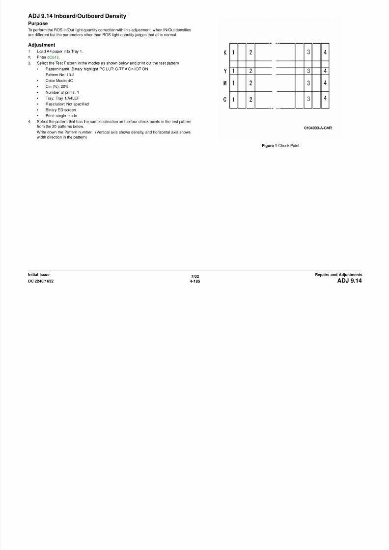
8/13/2019 Xerox Docu Color 2240-1632
http://slidepdf.com/reader/full/xerox-docu-color-2240-1632 711/1118
7/02
4-186 DC 2240/1632ADJ 9.14Initial IssueRepairs and Adjustments
Figure 4 Group 2
Group 3: when the patterns are dark/light for only both edges. (Fig. 5)
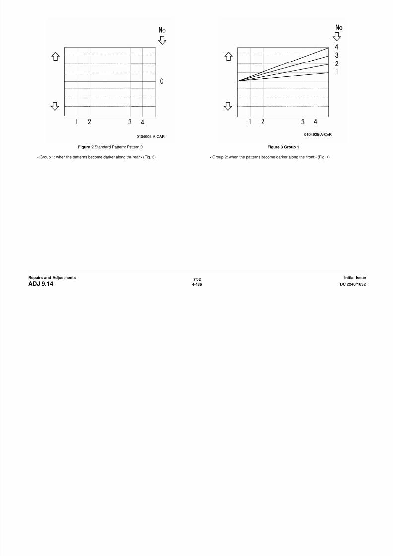
8/13/2019 Xerox Docu Color 2240-1632
http://slidepdf.com/reader/full/xerox-docu-color-2240-1632 712/1118
7/02
4-187DC 2240/1632 ADJ 9.14Repairs and AdjustmentsInitial Issue

8/13/2019 Xerox Docu Color 2240-1632
http://slidepdf.com/reader/full/xerox-docu-color-2240-1632 713/1118
7/02
4-188 DC 2240/1632ADJ 9.14Initial IssueRepairs and Adjustments
Figure 5 Group 3
<Group 4: when the patterns are dark only in the center areas> (Fig. 6)
Figure 6 Group 4
<Group 5: when the patterns are light only in the center areas> (Fig. 7)
Figure 7 Group 5
5. Select a pattern and change the following NVM corresponding to the pattern.
NOTE: Do NOT use the value other than the recommended values below as the NVM
value.
The In/Out density adjustment is available by changing the 6 NVM below.
Table 1
Chain/Link no. NVM names
[753-801] Legible Adjustment (Yellow)[753-802] Legible Adjustment (Magenta)
[753-803] Legible Adjustment (Cyan)
[753-804] Legible Adjustment (Black)
[753-805] InOut Pattern setting (Yellow)
[753-806] InOut Pattern setting (Magenta)
[753-807] InOut Pattern setting (Cyan)
[753-808] InOut Pattern setting (Black)

8/13/2019 Xerox Docu Color 2240-1632
http://slidepdf.com/reader/full/xerox-docu-color-2240-1632 714/1118
7/02
4-189DC 2240/1632 ADJ 9.14Repairs and AdjustmentsInitial Issue
[753 808] InOut Pattern setting (Black)
Reference Information
The correct light quantity value in ROS is normally 1024. If the value is decreased by 5%,
the light quantity decreases too.
Hence, entering the 5 stages of light quantity correction value by 5% is possible as below.
1024: Correct ROS Light Quantity Value
973: Light quantity value of 5% down
922: Light quantity value of 10% down870: Light quantity value of 15% down
919: Light quantity value of 20% down
6. Take test patterns again with the Step 2 mode after changing.
7. Repeat Steps 3~5 until the density distribution that the client requests can be obtained.
8. Check the condition using the customer’s samples. (Or ask the customer to print out the
sample from the same file and check the density on it.)
NOTE B f l i i i b j bl if h dj i
Table 2 Pattern No. 0~9
Pattern #
NVM
0 1 2 3 4 5 6 7 8 9
[753-801] 1024 973 922 870 819 1024 1024 1024 1024 922
[753-802] 1024 973 922 870 819 1024 1024 1024 1024 922
[753-803] 1024 1024 1024 1024 1024 973 922 870 819 1024
[753-804] 1024 1024 1024 1024 1024 973 922 870 819 1024
[753-805] 0 1 2 3 4 5 6 7 8 9
[753-806] 0 1 2 3 4 5 6 7 8 9
[753-807] 0 1 2 3 4 5 6 7 8 9
[753-808] 0 1 2 3 4 5 6 7 8 9
Table 3 Pattern No. 10~9
Pattern #
NVM
10 11 12 13 14 15 16 17 18 19
[753-801] 1024 922 1024 1024 1024 1024 1024 973 922 870
[753-802] 1024 922 1024 1024 1024 1024 1024 973 922 870
[753-803] 922 1024 922 1024 1024 1024 1024 973 922 870
[753-804] 922 1024 922 1024 1024 1024 1024 973 922 870
[753-805] 10 11 12 13 14 15 16 17 18 19
[753-806] 10 11 12 13 14 15 16 17 18 19
[753-807] 10 11 12 13 14 15 16 17 18 19
[753-808] 10 11 12 13 14 15 16 17 18 19

8/13/2019 Xerox Docu Color 2240-1632
http://slidepdf.com/reader/full/xerox-docu-color-2240-1632 715/1118
7/02
4-190 DC 2240/1632ADJ 9.14Initial IssueRepairs and Adjustments
NOTE: Be careful in servicing because tone jump trouble may occur if the adjustment is cor-
rected drastically. The tone jump is a noticeable difference in the midstream of gradations
when the gradations etc. are printed out.
NOTE: When copying, borrow the document or sample that the clients has complained about.
(To show the adjustment result after the adjustment)
ADJ 12.1 Finisher AlignmentPurpose
Align IOT copy output with entrance to Finisher H Transport.
AdjustmentWARNING
To avoid personal injury or shock, do not perform repair or adjustment activities with
the power switch on or electrical power applied to the machine.
1. Ensure H Transport is set correctly (Figure 1) and (Figure 2).
Figure 1 H Transport Clearance
5 mmmax.
10 mm
H Transport Gate
Copy in Exit

8/13/2019 Xerox Docu Color 2240-1632
http://slidepdf.com/reader/full/xerox-docu-color-2240-1632 716/1118
7/02
4-191DC 2240/1632 ADJ 12.1Repairs and AdjustmentsInitial Issue
Figure 2 H Transport Gate Clearance

8/13/2019 Xerox Docu Color 2240-1632
http://slidepdf.com/reader/full/xerox-docu-color-2240-1632 717/1118
7/02
4-192 DC 2240/1632ADJ 12.1Initial IssueRepairs and Adjustments

8/13/2019 Xerox Docu Color 2240-1632
http://slidepdf.com/reader/full/xerox-docu-color-2240-1632 718/1118

8/13/2019 Xerox Docu Color 2240-1632
http://slidepdf.com/reader/full/xerox-docu-color-2240-1632 719/1118
IntroductionOverview
The Parts List section identifies all part numbers and the corresponding location of all spared
subsystem components.
Organization
Parts Lists
Each item number in the part number listing corresponds to an item number in the related
illustration. All the parts in a given subsystem of the machine will be located in the same
illustration or in a series of associated illustrations.
Electrical Connectors and Fasteners
This section contains the illustrations and descriptions of the plugs, jacks, and fasteners used
in the machine. A part number listing of the connectors is included.
Common Hardware
The common hardware is listed in alphabetical order by the letter or letters used to identify
each item in the part number listing and in the illustrations. Dimensions are in millimetres
unless otherwise identified.
Part Number Index
This index lists all the spared parts in the machine in numerical order. Each number is followed
by a reference to the parts list on which the part may be found.
Other Information
Abbreviations
Abbreviations are used in the parts lists and the exploded view illustrations to provide
information in a limited amount of space. The following abbreviations are used in this manual:
Symbology
Symbology used in the Parts List section is identified in the Symbology section.
Service Procedure Referencing
Table 1
Abbreviation Meaning
A3 297 x 594 Millimetres
A4 210 x 297 Millimetres
A5 148 x 210 Millimetres
AD Auto Duplex
AWG American Wire Gauge
EMI Electro Magnetic Induction
GB Gigabyte
KB Kilobyte
MB Megabyte
MM Millimetres
MOD Magneto Optical Drive
NOHAD Noise Ozone Heat Air Dirt
PL Parts List
P/O Part of
R/E Reduction/Enlargement
REF: Refer to
SCSI Small Computer Systems Interface
W/ With
W/O Without
Table 2
Operating Companies
Abbreviation Meaning
AO Americas Operations
NASG - US North American Solutions Group - USNASG -
Canada
North American Solutions Group -
Canada
XE Xerox Europe

8/13/2019 Xerox Docu Color 2240-1632
http://slidepdf.com/reader/full/xerox-docu-color-2240-1632 720/1118
7/02
5-3DC 2240/1632 IntroductionParts ListInitial Issue
Service Procedure Referencing
If a part or assembly has an associated repair or adjustment procedure, the procedure numberwill be listed at the end of the part description in the parts lists e.g. (REP 5.1, ADJ 5.3)
Subsystem InformationUse of the Term "Assembly"
The term "assembly" will be used for items in the part number listing that include other itemized
parts in the part number listing. When the word "assembly” is found in the part number listing,
there will be a corresponding item number on the illustrations followed by a bracket and a
listing of the contents of the assembly.
Brackets
A bracket is used when an assembly or kit is spared, but is not shown in the illustration. The
item number of the assembly or kit precedes the bracket; the item numbers of the piece parts
follow the bracket.
Tag
The notation "W/Tag" in the parts description indicates that the part configuration has been
updated. Check the change Tag index in the General Information section of the Service Data
for the name and purpose of the modification.
In some cases, a part or assembly may be spared in two versions: with the Tag and without the
Tag. In those cases, use whichever part is appropriate for the configuration of the machine on
which the part is to be installed. If the machine does not have a particular Tag and the only
replacement part available is listed as “W/Tag,” install the Tag kit or all of the piece parts. The
Change Tag Index tells you which kit or piece parts you need.
Whenever you install a Tag kit or all the piece parts that make up a Tag, mark the appropriate
number on the Tag matrix.

8/13/2019 Xerox Docu Color 2240-1632
http://slidepdf.com/reader/full/xerox-docu-color-2240-1632 721/1118
7/02
5-4 DC 2240/1632Subsystem InformationInitial IssueParts List
SymbologyA Tag number within a circle pointing to an item number shows that the part has been changed
by the tag number within the circle (Figure 1). Information on the modification is in the Change
Tag Index.
Figure 1 With Tag Symbol
A Tag number within a circle having a shaded bar and pointing to an item number shows that
the configuration of the part shown is the configuration before the part was changed by the Tag
number within the circle (Figure 2).
Figure 2 Without Tag Symbol

8/13/2019 Xerox Docu Color 2240-1632
http://slidepdf.com/reader/full/xerox-docu-color-2240-1632 722/1118
7/02
5-5DC 2240/1632 SymbologyParts ListInitial Issue
A tag number within a circle with no apex shows that the entire drawing has been changed by
the tag number within the circle (Figure 3). Information on the modification is in the Change Tag
Index.
Figure 3 Entire Drawing With Tag Symbol
A tag number within a circle with no apex and having a shaded bar shows that the entire
drawing was the configuration before being changed by the tag number within the circle
(Figure 4).
Figure 4 Entire Drawing Without Tag Symbol
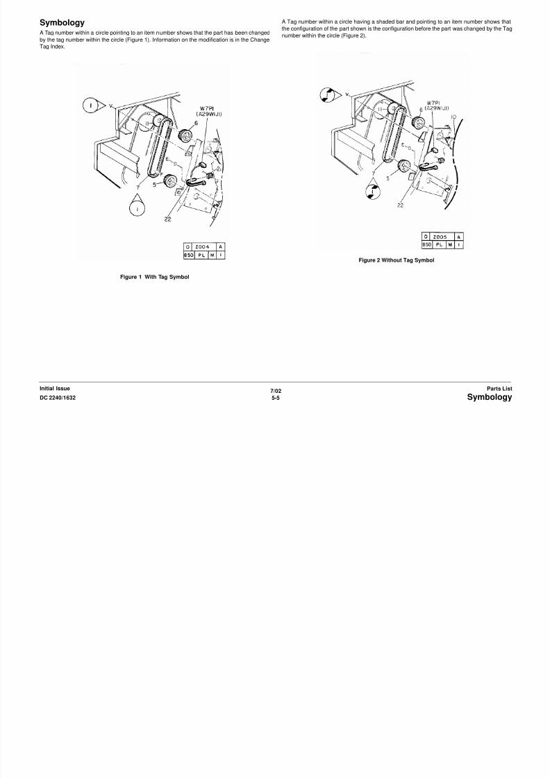
8/13/2019 Xerox Docu Color 2240-1632
http://slidepdf.com/reader/full/xerox-docu-color-2240-1632 723/1118
7/02
5-6 DC 2240/1632SymbologyInitial IssueParts List
PL 1.1 Drive UnitItem Part Description
1 007K85750 Drum Motor Assembly (REP 4.4)
2 – Drum Motor (P/O PL 1.1 Item 1)
3 – Gear Bracket (P/O PL 1.1 Item 1)4 007K87110 IBT Motor Assembly (REP 4.2)
5 – IBT Motor (P/O PL 1.1 Item 4)
6 – Gear Bracket (P/O PL 1.1 Item 4)
7 007K86400 Developer Drive Motor Assembly
(REP 4.3)
8 – Developer Drive Motor (P/O PL 1.1
Item 7)
9 – Gear (47/38T) (P/O PL 1.1 Item 7)
10 – Gear (51/25T) (P/O PL 1.1 Item 7)
11 – Gear (P/O PL 1.1 Item 7) (76T)
12 – Clamp (P/O PL 1.1 Item 7)
13 – Edge Saddle (P/O PL 1.1 Item 7)
14 007K86920 Main Drive Motor Assembly (REP
4.1)
15 007K87220 Developer Gear
16 – Drum Motor (K) (P/O PL 1.1 Item 1)
17 – Screw (P/O PL 1.1 Item 1)

8/13/2019 Xerox Docu Color 2240-1632
http://slidepdf.com/reader/full/xerox-docu-color-2240-1632 724/1118
7/02
5-7DC 2240/1632 PL 1.1Parts ListInitial Issue
PL 1.2 Main Drive Motor AssemblyItem Part Description
1 – Friction Clutch (Not Spared)
2 – Shaft (Not Spared)
3 – Gear (32T) (Not Spared)
4 – Gear (28T) (Not Spared)5 – Bearing (Not Spared)
6 – Shaft (Not Spared)
7 – Gear (20T) (Not Spared)
8 121K22470 Takeaway Clutch
9 – Bearing (Not Spared)
10 – Shaft (Not Spared)
11 – Gear (39T) (Not Spared)
12 – Bearing (Not Spared)
13 121K23270 Developer K Clutch
14 – Gear (69/27T) (Not Spared)
15 – Gear (23T) (Not Spared)
16 – Gear (28/22T) (Not Spared)
17 – Gear (45/30T) (Not Spared)
18 – Gear (41/21T) (Not Spared)
19 – Gear (24/20T) (Not Spared)
20 – Gear (19T) (Not Spared)
21 – Gear (18T) (Not Spared)
22 – Gear (73/23T) (Not Spared)
23 – Spring (Not Spared)
24 – Tension Bracket (Not Spared)
25 – Bracket (Not Spared)26 – Pulley (Not Spared)
27 – Screw (Not Spared)
28 – Main Motor (Not Spared)
29 – Belt (Not Spared)
30 – Clamp (Not Spared)
31 – Clamp (Not Spared)
32 – Connector (Not Spared)
33 – Pulley (Not Spared)

8/13/2019 Xerox Docu Color 2240-1632
http://slidepdf.com/reader/full/xerox-docu-color-2240-1632 725/1118
7/02
5-8 DC 2240/1632PL 1.2Initial IssueParts List
PL 1.3 IBT Steering Motor and MOBSensorItem Part Description
1 007K85580 IBT Steering Motor Assembly (REP
9.12)
2 – IBT Steering Motor (P/O PL 1.3
Item 1)
3 – Plate (P/O PL 1.3 Item 1)
4 130K60865 MOB Sensor Assembly (REP
9.14,ADJ 9.6)
5 – MOB Sensor (P/O PL 1.3 Item 4)
6 – Environment Sensor (P/O PL 1.3
Item 4)
7 – Wire Harness (P/O PL 1.3 Item 4)
8 – Cover (P/O PL 1.3 Item 4)
9 – ADC Sensor (P/O PL 1.3 Item 4)10 – Shutter (P/O PL 1.3 Item 4)
11 – Spring (P/O PL 1.3 Item 4)
12 – Link (P/O PL 1.3 Item 4)
13 – Spacer (P/O PL 1.3 Item 4)
14 – MOB Bracket (P/O PL 1.3 Item 4)
15 – Slide (P/O PL 1.3 Item 4)

8/13/2019 Xerox Docu Color 2240-1632
http://slidepdf.com/reader/full/xerox-docu-color-2240-1632 726/1118
7/02
5-9DC 2240/1632 PL 1.3Parts ListInitial Issue
PL 2.1 Tray 1: 1 of 2Item Part Description
1 003E23672 Stop
2 014E42850 Spacer
3 110K08541 Tray 1 Paper Size Sensor (REP
7.5)4 050K48170 Tray 1 (REP 7.8)
5 – Cover (Not Spared)
6 892E41110 Label (1)
7 – Bracket (Not Spared)

8/13/2019 Xerox Docu Color 2240-1632
http://slidepdf.com/reader/full/xerox-docu-color-2240-1632 727/1118
7/02
5-10 DC 2240/1632PL 2.1Initial IssueParts List
PL 2.2 Tray 1: 2 of 2Item Part Description
1 892E13310 Instruction Label
3 – Max Label (Not Spared)
4 – Tray (Not Spared)
5 – Side Guide (Not Spared)6 – End Guide (Not Spared)
7 – Link (Not Spared)
8 – Stop (Not Spared)
9 – Spring (Not Spared)
10 – Pad (Not Spared)
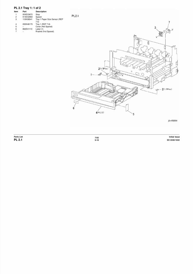
8/13/2019 Xerox Docu Color 2240-1632
http://slidepdf.com/reader/full/xerox-docu-color-2240-1632 728/1118
7/02
5-11DC 2240/1632 PL 2.2Parts ListInitial Issue
PL 2.3 Tray 1 Feeder and Left LowerCover AssemblyItem Part Description
1 059K15573 Tray 1 Feeder (REP 7.3)
2 802K13193 Left Lower Cover Assembly (REP
14.6)
3 – Left Lower Cover (P/O PL 2.3 Item
2)
4 029E31600 Rivet
5 – Bracket (P/O PL 2.3 Item 2)
6 – Spring (P/O PL 2.3 Item 2)
7 – Pinch Roll (P/O PL 2.3 Item 2)
8 – Bearing (P/O PL 2.3 Item 2)
9 – Bearing (P/O PL 2.3 Item 2)
10 – Bearing (P/O PL 2.3 Item 2)
11 130K60851 Tray 1 Feedout Sensor12 – Wire Harness (P/O PL 2.3 Item 2)
13 – Ground Plate (P/O PL 2.3 Item 2)
14 – Magnet (P/O PL 2.3 Item 2)
15 130E82190 LH Lower Cover Interlock Swi tch
16 – Bracket (Not Spared)

8/13/2019 Xerox Docu Color 2240-1632
http://slidepdf.com/reader/full/xerox-docu-color-2240-1632 729/1118
7/02
5-12 DC 2240/1632PL 2.3Initial IssueParts List
PL 2.4 Tray 1 Feeder: 1 of 2Item Part Description
1 127K23230 Tray 1 Feed/Lift Motor (REP 7.4)
2 – Bracket (Not Spared)
3 005K83081 One-way Clutch
4 007K85730 One-way Gear5 – Gear (13T) (Not Spared)
6 – Bearing (Not Spared)
7 – Shaft (Not Spared)
8 – Front Frame (Not Spared)
9 – Upper Frame (Not Spared)
10 – Front Chute (Not Spared)
11 – Actuator (Not Spared)
12 130E82190 Tray 1 Level / No Paper Sensor
13 – Wire Harness (Not Spared)
14 – Support (Not Spared)
15 – Gear (15T) (Not Spared)

8/13/2019 Xerox Docu Color 2240-1632
http://slidepdf.com/reader/full/xerox-docu-color-2240-1632 730/1118
7/02
5-13DC 2240/1632 PL 2.4Parts ListInitial Issue
PL 2.5 Tray 1 Feeder: 2 of 2Item Part Description
1 – Spring (Not Spared)
2 600K78460 Roll Kit (3 Rolls/Kit)
3 005K05890 One-way Clutch
4 – Gear (Not Spared)5 – Shaft (Not Spared)
6 – Chute (Not Spared)
7 – Spring (Not Spared)
8 – Friction Clutch (Not Spared)
9 – Support (Not Spared)
11 – Spacer (Not Spared)
12 – Gear (31T) (Not Spared)
13 – Support (Not Spared)
14 – Bearing (Not Spared)
15 – Gear (Not Spared)
16 – Support (Not Spared)17 – Screw (Not Spared)
18 – Bearing (Not Spared)
19 – Gear (35T) (Not Spared)
20 – Spring (Not Spared)
21 – Lever (Not Spared)
22 – Holder (Not Spared)

8/13/2019 Xerox Docu Color 2240-1632
http://slidepdf.com/reader/full/xerox-docu-color-2240-1632 731/1118
7/02
5-14 DC 2240/1632PL 2.5Initial IssueParts List
PL 2.6 Registration TransportItem Part Description
1 059K24661 Registration Transport Assembly
(REP 8.6)
2 – Bearing (P/O PL 2.6 Item 1)
3 – Bearing (P/O PL 2.6 Item 1)4 – Takeaway Roll (P/O PL 2.6 Item 1)
5 – Gear (22T) (P/O PL 2.6 Item 1)
6 – Paper Guide (P/O PL 2.6 Item 1)
7 – Registration Chute (P/O PL 2.6
Item 1)
8 121K22220 Registration Clutch
9 – Bearing (P/O PL 2.6 Item 1)
10 – Ground Plate (P/O PL 2.6 Item 1)
11 – Registration Roll (P/O PL 2.6 Item
1)
12 130E82650 Registration Sensor13 – Screw (P/O PL 2.6 Item 1)
14 160K46290 OHP Sensor
15 – Registration Support (P/O PL 2.6
Item 1)
16 – Wire Harness (P/O PL 2.6 Item 1)
17 – Ground Plate (Not Spared)

8/13/2019 Xerox Docu Color 2240-1632
http://slidepdf.com/reader/full/xerox-docu-color-2240-1632 732/1118
7/02
5-15DC 2240/1632 PL 2.6Parts ListInitial Issue
PL 2.7 Left Cover UnitItem Part Description
1 007E64740 Damper Gear (11/23T)
2 – Stud (Not Spared)
3 004E11831 Damper (White)
4 – Left Upper Cover (Not Spared)5 802K45490 Left Cover Assembly
6 – Left Cover (P/O PL 2.7 Item 5)
7 – Screw (Not Spared)
8 – Label (P/O PL 2.7 Item 5)
9 – Cover (P/O PL 2.7 Item 5)
10 – Left Cover (Not Spared)

8/13/2019 Xerox Docu Color 2240-1632
http://slidepdf.com/reader/full/xerox-docu-color-2240-1632 733/1118
7/02
5-16 DC 2240/1632PL 2.7Initial IssueParts List
PL 2.8 Left Cover Assembly: 1 of 2Item Part Description
1 054K22410 Registration Chute
2 – Holder (Not Spared)
3 604K07070 2nd BTR (REP 8.1)
4 809E29620 Spring5 015K48381 Support
6 054E16330 Exit Chute
7 007E62630 Gear (22T)
8 059K15611 Exit Roll
9 007E75201 Gear
10 – Bearing (Not Spared)
11 – Holder (Not Spared)
12 110K10650 Fuser Exit Switch
13 – Holder (Not Spared)
14 054K16130 Duplex Chute (REP 8.2)
15 – Stop (Not Spared)16 – Left Cover (Not Spared)

8/13/2019 Xerox Docu Color 2240-1632
http://slidepdf.com/reader/full/xerox-docu-color-2240-1632 734/1118
7/02
5-17DC 2240/1632 PL 2.8Parts ListInitial Issue
PL 2.9 Left Cover Assembly: 2 of 2Item Part Description
1 – Bearing (Not Spared)
2 007K85522 Gear
3 127K29511 2nd BTR Retract Motor
4 130E82190 2nd BTR Retract Sensor5 – Bracket (Not Spared)
6 130E84300 POB Sensor
7 – Bracket (Not Spared)
8 – Spring (Not Spared)
9 – Bracket (Not Spared)
10 802K27073 Left Cover Assembly (REP 8.1)
11 – Left Cover (P/O PL 2.9 Item 10)
12 – Lever (P/O PL 2.9 Item 10)
13 – Bracket (P/O PL 2.9 Item 10)
14 – Gear (21T) (P/O PL 2.9 Item 10)
15 – Connector Assembly (Not Spared)16 – Spring (P/O PL 2.9 Item 10)
17 007K86931 Damper Gear (45T)

8/13/2019 Xerox Docu Color 2240-1632
http://slidepdf.com/reader/full/xerox-docu-color-2240-1632 735/1118
7/02
5-18 DC 2240/1632PL 2.9Initial IssueParts List
PL 2.10 Exit Transport AssemblyItem Part Description
1 – Frame (Not Spared)
2 – Exit Transport Cover (Not Spared)
3 – Bearing (Not Spared)
4 – Gear (20T) (Not Spared)5 – Exit Roll (Not Spared)
6 – Actuator (Not Spared)
7 – Bracket (Not Spared)
8 130E82190 Full Paper Stack Sensor
9 – Latch (Not Spared)
10 – Spring (Not Spared)
11 – Pinch Roll (Not Spared)
12 – Pinch Roll (Not Spared)
13 – LH Cover Interlock Switch (Not
Spared)
14 – Bracket (Not Spared)15 – Static Eliminator (Not Spared)
16 – Wire Harness (Not Spared)
17 – Front Bracket (Not Spared)

8/13/2019 Xerox Docu Color 2240-1632
http://slidepdf.com/reader/full/xerox-docu-color-2240-1632 736/1118
7/02
5-19DC 2240/1632 PL 2.10Parts ListInitial Issue
PL 2.11 Exit Transport Assembly(OCT)Item Part Description
1 059K24690 Exit Transport Assembly (REP 8.7)
2 – Exit Transport Cover (Part of Item
1)3 – Bearing (Part of Item 1)
4 – Pin (Part of Item 1)
5 – Exit Roll (Part of Item 1)
6 120E18160 Actuator
7 – Bracket (Part of Item 1)
8 130E82190 Full Paper Stack Sensor
9 – Latch (Part of Item 1)
10 – Spring (Part of Item 1)
11 – Pinch Roll (Part of Item 1)
12 – Pinch Roll (Part of Item 1)
13 – LH Cover Interlock Switch (Part of
Item 1)
14 – Bracket (Part of Item 1)
15 – Static Eliminator (Part of Item 1)
16 – Offset Motor (Part of Item 1)
17 – Wire Harness (Part of Item 1)
18 – Screw (Part of Item 1)
19 – Front Bracket (Part of Item 1)
20 – Frame (Part of Item 1)

8/13/2019 Xerox Docu Color 2240-1632
http://slidepdf.com/reader/full/xerox-docu-color-2240-1632 737/1118
7/02
5-20 DC 2240/1632PL 2.11Initial IssueParts List
PL 2.12 Tray 5: 1 of 2Item Part Description
1 059K24801 Tray 5 (REP 7.1)
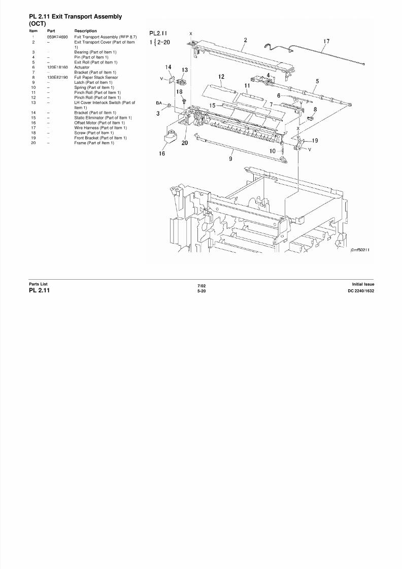
8/13/2019 Xerox Docu Color 2240-1632
http://slidepdf.com/reader/full/xerox-docu-color-2240-1632 738/1118
7/02
5-21DC 2240/1632 PL 2.12Parts ListInitial Issue
PL 2.13 Tray 5: 2 of 2Item Part Description
1 – Spring (Not Spared)
2 – Bracket (Not Spared)
3 – Gear (Not Spared)
4 – Spring (Not Spared)5 050K48181 Tray 5 Assembly
6 – Upper Frame (Not Spared)
7 120E11971 Actuator
8 130E82190 Tray 5 No Paper Sensor
9 – Tray 5 Feed Assembly (Not
Spared)
10 – Spring (Not Spared)
11 – Pinch Roll 1/2 (Not Spared)
12 – Chute (Not Spared)
13 – Guide (Not Spared)
14 – Shaft (Not Spared)15 – Spring (Not Spared)
16 – Spacer (Not Spared)
17 – Pinch Roll 3 (Not Spared)

8/13/2019 Xerox Docu Color 2240-1632
http://slidepdf.com/reader/full/xerox-docu-color-2240-1632 739/1118
7/02
5-22 DC 2240/1632PL 2.13Initial IssueParts List
PL 2.14 Tray 5 Feed AssemblyItem Part Description
1 038E23560 Paper Guide
2 – Takeaway Roll (Not Spared)
3 – Bearing (Not Spared)
4 – Gear (Not Spared)5 – Pick-up Gear (Not Spared)
6 – Cam Gear (Not Spared)
7 – Stop Lever (Not Spared)
8 – Gear Lever (Not Spared)
9 121E87830 Tray 5 Feed Solenoid
10 – Screw (Not Spared)
11 – Spring (Not Spared)
12 – Ground Plate (Not Spared)
13 – Spring (Not Spared)
14 059K24020 Feed Roll Assembly
15 059K24010 Feed Roll (REP 7.2)16 – Cam (P/O PL 2.14 Item 14)
17 – Cam (P/O PL 2.14 Item 14)
18 – Shaft (P/O PL 2.14 Item 14)
19 019K97130 Retard Pad
20 – Spring (Not Spared)
21 – Bottom Plate (Not Spared)
22 – Spring (Not Spared)
23 – Lower Frame (Not Spared)
24 – Spring (Not Spared)
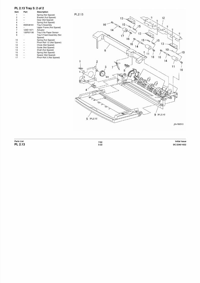
8/13/2019 Xerox Docu Color 2240-1632
http://slidepdf.com/reader/full/xerox-docu-color-2240-1632 740/1118
7/02
5-23DC 2240/1632 PL 2.14Parts ListInitial Issue
PL 2.15 Tray AssemblyItem Part Description
1 – Lower Tray (Not Spared)
2 – Cover (Not Spared)
3 – Paper Size Sensor (Not Spared)
4 – Side Guide (Not Spared)5 – Attention Label (Not Spared)
6 – Instruction Label (Not Spared)
7 – Label (Not Spared)
8 – Label (Not Spared)
9 – Max Label (Not Spared)
10 – Registration Guide (Not Spared)
11 – Holder (Not Spared)
12 – Tray (Not Spared)
13 – Spring (Not Spared)
14 – Link (Not Spared)

8/13/2019 Xerox Docu Color 2240-1632
http://slidepdf.com/reader/full/xerox-docu-color-2240-1632 741/1118
7/02
5-24 DC 2240/1632PL 2.15Initial IssueParts List
PL 3.1 ROS AssemblyItem Part Description
1 – Bracket (Not Spared)
2 062K10881 ROS (REP 6.1,ADJ 9.6)
3 – Seal Glass (Y) (Not Spared)
4 – Seal Glass (M) (Not Spared)5 – Seal Glass (C) (Not Spared)
6 – Seal Glass (K) (Not Spared)

8/13/2019 Xerox Docu Color 2240-1632
http://slidepdf.com/reader/full/xerox-docu-color-2240-1632 742/1118
7/02
5-25DC 2240/1632 PL 3.1Parts ListInitial Issue
PL 4.1 Xerographic Module: 1 of 2Item Part Description
1 802K47090 Waste Toner Cartridge Cover (REP
9.3)
2 – Waste Toner Cartridge (Not
Spared) (REP 9.4)3 003K86121 Sensor Holder Assembly
4 – Lever (P/O PL 4.1 Item 3)
5 – Waste Toner Cartridge Interlock
Switch (P/O PL 4.1 Item 3)
6 – Holder (P/O PL 4.1 Item 3)
7 – Drum Cartridge (Not Spared) (REP
9.1)
8 127K29242 Agitator Motor Assembly (REP
9.13)
9 – Bracket (P/O PL 4.1 Item 8)
10 – Agitator Motor (P/O PL 4.1 Item 8)11 130E91010 Full Toner Sensor (REP 9.5)
12 – Wire Harness (P/O PL 4.1 Item 3)
13 – Damper (P/O PL 4.1 Item 8)
14 – Screw (P/O PL 4.1 Item 8)

8/13/2019 Xerox Docu Color 2240-1632
http://slidepdf.com/reader/full/xerox-docu-color-2240-1632 743/1118
7/02
5-26 DC 2240/1632PL 4.1Initial IssueParts List
PL 4.2 Xerographic Module: 2 of 2Item Part Description
1 015K52320 Plate Assembly (REP 9.8)
2 – Wire Harness (P/O PL 4.2 Item 1)
3 – Xero PLate (P/O PL 4.2 Item 1)
4 – Block (M, C, K) (P/O PL 4.2 Item 1)
5 – Block (Y) (P/O PL 4.2 Item 1)
6 122K93330 Erase Lamp w/Rail (Y, M, C)
7 122K93340 Erase Lamp w/Rail (K)
8 – Bracket (Not Spared)
9 – Screw (Not Spared)

8/13/2019 Xerox Docu Color 2240-1632
http://slidepdf.com/reader/full/xerox-docu-color-2240-1632 744/1118
7/02
5-27DC 2240/1632 PL 4.2Parts ListInitial Issue
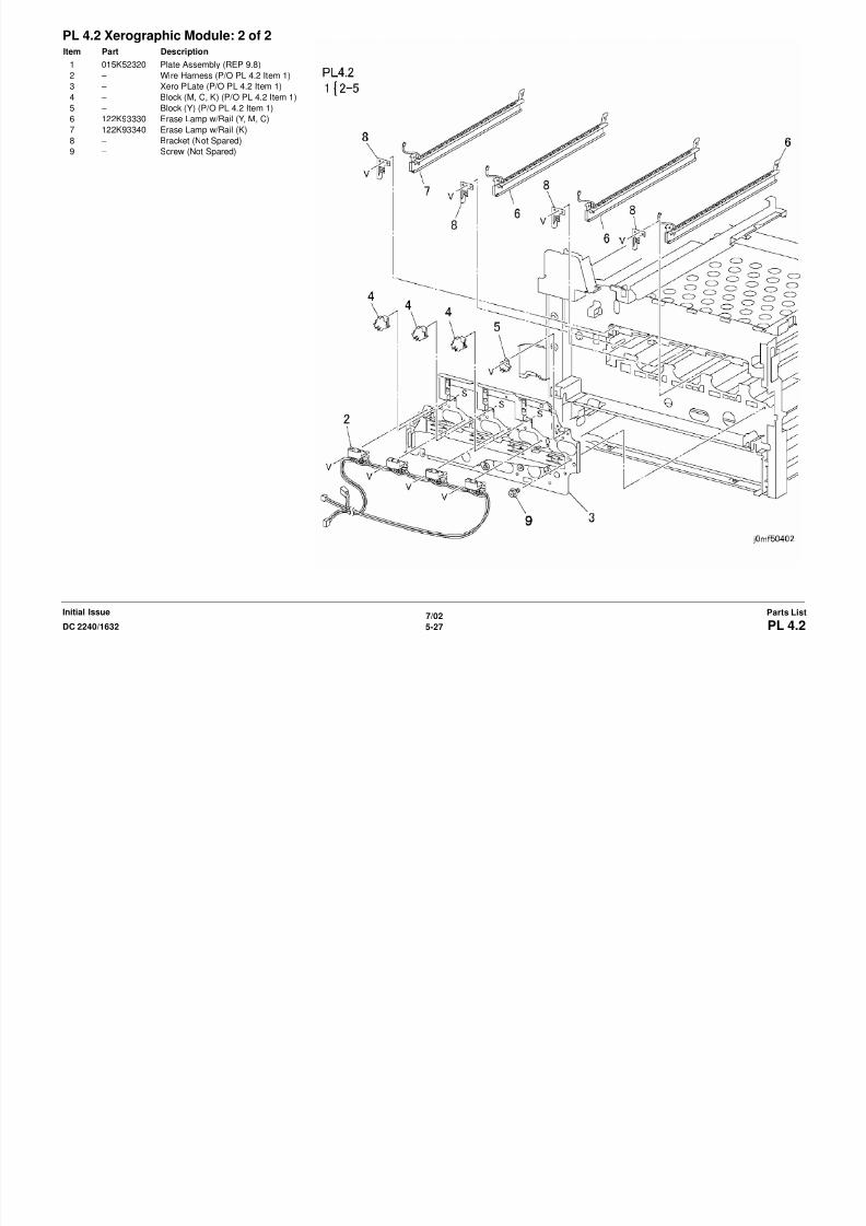
8/13/2019 Xerox Docu Color 2240-1632
http://slidepdf.com/reader/full/xerox-docu-color-2240-1632 745/1118
PL 5.2 IBT UnitItem Part Description
1 604K07050 IBT Belt Assembly (REP 9.15,ADJ
9.6)
2 003K12650 Removal Support
3 – Bearing (Not Spared)
4 007E61910 Gear (14T)
5 007E61890 Gear (18T)
6 – Shaft (Not Spared)
7 802K12950 Auger Assembly (REP 9.17)
8 – Screw (Not Spared)
9 – IBT Belt Assembly (P/O PL 5.2 Item
1)
10 604K07060 IBT Belt Cleaner Assembly

8/13/2019 Xerox Docu Color 2240-1632
http://slidepdf.com/reader/full/xerox-docu-color-2240-1632 746/1118
7/02
5-29DC 2240/1632 PL 5.2Parts ListInitial Issue
PL 5.3 IBT Belt AssemblyItem Part Description
1 – IBT Belt Cleaner Assembly (P/O PL
5.2 Item 1) (REP 9.16)
2 – Blade (P/O PL 5.3 Item 1)
3 – Seal (P/O PL 5.3 Item 1)
4 – Screw (P/O PL 5.3 Item 1)
5 – Spring (P/O PL 5.3 Item 1)
6 – Housing (P/O PL 5.3 Item 1)
7 064K91451 Transfer Belt (ADJ 9.6)
8 – Support (P/O PL 5.2 Item 9)
9 – IBT Frame (P/O PL 5.2 Item 9)
10 – Right Handle (P/O PL 5.2 Item 9)
11 – Left Handle (P/O PL 5.2 Item 9)
12 – Bracket (P/O PL 5.2 Item 9)
13 – Housing (P/O PL 5.2 Item 9)
14 – Housing (P/O PL 5.2 Item 9)15 059K23150 Backup Roll
16 – Bearing (P/O PL 5.2 Item 9)
17 – Pre Roll (P/O PL 5.2 Item 9)
18 013E18980 Bearing
19 – Screw (P/O PL 5.2 Item 1)

8/13/2019 Xerox Docu Color 2240-1632
http://slidepdf.com/reader/full/xerox-docu-color-2240-1632 747/1118
7/02
5-30 DC 2240/1632PL 5.3Initial IssueParts List
PL 5.4 IBT Frame Assembly: 1 of 2Item Part Description
1 – Frame (Not Spared)
2 130E84270 IBT Home Sensor (ADJ 9.6)
3 – Spring (Not Spared)
4 – Clamp (Not Spared)
5 130K60830 IBT Edge Sensor (ADJ 9.6)
6 162K56020 Connector (C, K)
7 – Connector (Not Spared)
8 162K61090 Connector (Y, M)
9 – Screw (Not Spared)
10 – Rear Frame (Not Spared)
11 – Connector (Not Spared)
12 019K98200 Front Holder
13 059K21260 1st BTR Roll
14 019K98190 Rear Holder
15 127K33950 Retract Motor16 130E82190 Retract Sensor
17 – Worm Gear (Not Spared)
18 – Retract Shaft (Not Spared)
19 019K97550 Front Holder
20 019K97540 Rear Holder
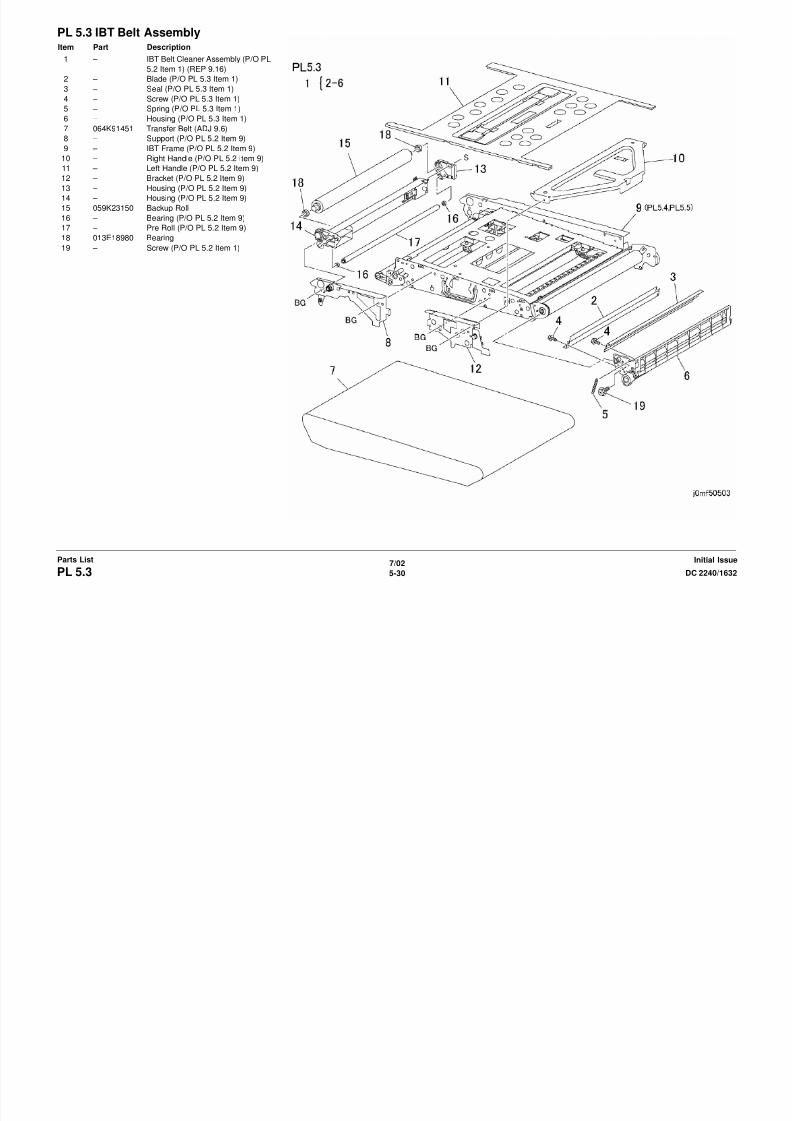
8/13/2019 Xerox Docu Color 2240-1632
http://slidepdf.com/reader/full/xerox-docu-color-2240-1632 748/1118
7/02
5-31DC 2240/1632 PL 5.4Parts ListInitial Issue
PL 5.5 IBT Frame Assembly: 2 of 2Item Part Description
1 – Handle (Not Spared)
2 – Spring (Not Spared)
3 – Gear (Not Spared)
4 – Plate (Not Spared)
5 – Gear (Not Spared)
6 – Bracket (Not Spared)
7 – Top Roll (Not Spared)
8 – Front Bracket (Not Spared)
9 – Bearing (Not Spared)
10 – Bearing (Not Spared)
11 – Roll (Not Spared)
12 – Roll (Not Spared)
13 – Rear Bracket (Not Spared)
14 – Collar (Not Spared)
15 – Latch (Not Spared)16 – Bracket (Not Spared)
17 – Roll (Not Spared)

8/13/2019 Xerox Docu Color 2240-1632
http://slidepdf.com/reader/full/xerox-docu-color-2240-1632 749/1118
7/02
5-32 DC 2240/1632PL 5.5Initial IssueParts List
PL 5.6 IBT ElevatorItem Part Description
1 809E26330 Spring
2 015K49480 Rear Plunger
3 015K49310 Front Plunger
4 – Frame (Not Spared)
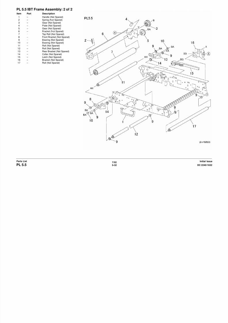
8/13/2019 Xerox Docu Color 2240-1632
http://slidepdf.com/reader/full/xerox-docu-color-2240-1632 750/1118
7/02
5-33DC 2240/1632 PL 5.6Parts ListInitial Issue
PL 6.1 Developer Unit: 1 of 2Item Part Description
1 802K45910 Toner Dispenser (Y) (REP 9.7)
2 – Toner Cartridge (Not Spared)
3 802K45920 Toner Dispenser (M) (REP 9.7)
4 – Toner Cartridge (Not Spared)
5 802K45930 Toner Dispenser (C) (REP 9.7)
6 – Toner Cartridge (Not Spared)
7 802K45940 Toner Dispenser (K) (REP 9.7)
8 – Toner Cartridge (Not Spared)
9 802K33090 Toner Dispenser Base Assembly
(REP 9.11)
10 – Toner Dispenser Base (P/O PL 6.1
Item 9)
11 – Gear (P/O PL 6.1 Item 9)
12 127K33930 Toner Dispenser Motor (Y, M, C)
13 127K33940 Toner Dispenser Motor (K)14 – Shaft (P/O PL 6.1 Item 9)
15 116K90810 New Cartridge Detect Switch

8/13/2019 Xerox Docu Color 2240-1632
http://slidepdf.com/reader/full/xerox-docu-color-2240-1632 751/1118
7/02
5-34 DC 2240/1632PL 6.1Initial IssueParts List
PL 6.2 Developer Unit: 2 of 2Item Part Description
1 802K28891 Developer Housing (Y, M, K, C)
(REP 9.9,ADJ 9.1)
2 – Developer Housing (P/O PL 6.2
Item 1)
3 130K63000 ATC Sensor (Y, M, K, C) (REP
9.26,ADJ 9.1)
4 035E65010 Seal
5 604K07520 Developer (K) (REP 9.10,ADJ 9.1)
6 604K07490 Developer (Y) (REP 9.10,ADJ 9.1)
7 604K07500 Developer (M) (REP 9.10,ADJ 9.1)
8 604K07510 Developer (C) (REP 9.10,ADJ 9.1)

8/13/2019 Xerox Docu Color 2240-1632
http://slidepdf.com/reader/full/xerox-docu-color-2240-1632 752/1118
7/02
5-35DC 2240/1632 PL 6.2Parts ListInitial Issue
PL 7.1 Fuser Assembly: 1 of 2Item Part Description
1 126K14890 Fuser (220V) (REP 10.1)
– 126K13940 Fuser (120V) (REP 10.1)

8/13/2019 Xerox Docu Color 2240-1632
http://slidepdf.com/reader/full/xerox-docu-color-2240-1632 753/1118
7/02
5-36 DC 2240/1632PL 7.1Initial IssueParts List
PL 7.2 Fuser Assembly: 2 of 2Item Part Description
1 – Front Cover (Not Spared)
2 – Rear Cover (Not Spared)
3 – Front Lamp Bracket (Not Spared)
4 126K13950 Main Heater Rod (REF:) PL 7.2)
(REP 10.3) – 126K13980 Main Heater Rod (220V) (REP
10.3)
5 126K13990 Sub Heater Rod (220V) (REP 10.3)
– 126K13960 Sub Heater Rod (110V) (REP 10.3)
6 – Exit Chute (Not Spared)
7 – Cap (Not Spared)
8 – Handle (Not Spared)
9 – Upper Cover (Not Spared)
10 – Lower Cover (Not Spared)
11 130K61020 Sensor Assembly
12 – Fuser (Not Spared)
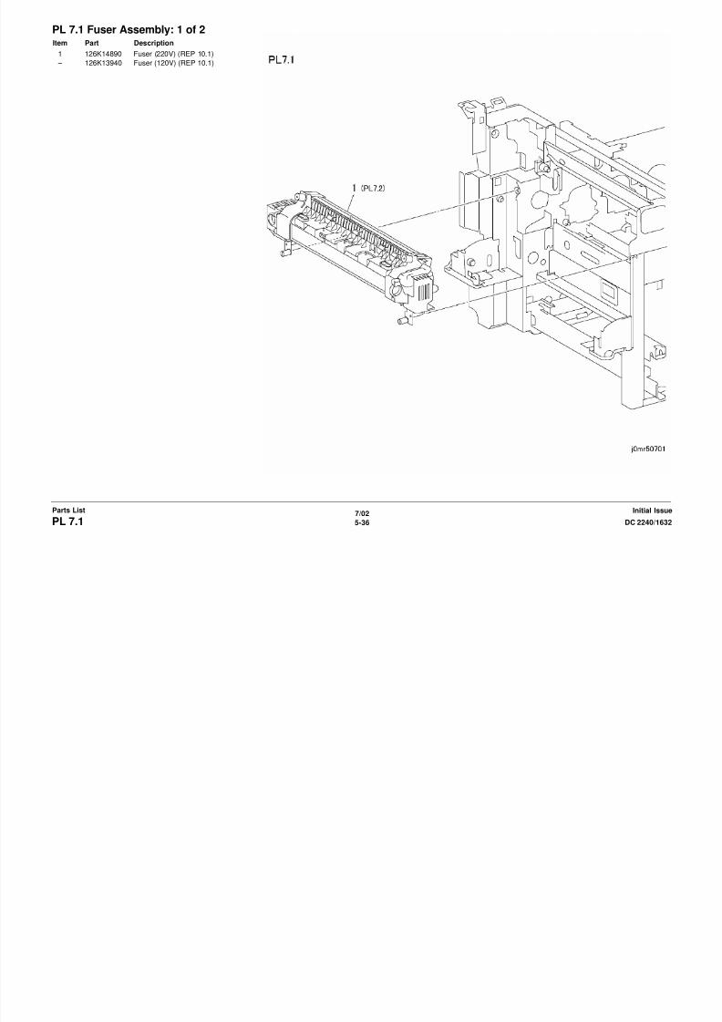
8/13/2019 Xerox Docu Color 2240-1632
http://slidepdf.com/reader/full/xerox-docu-color-2240-1632 754/1118
7/02
5-37DC 2240/1632 PL 7.2Parts ListInitial Issue
PL 8.1 Air SystemItem Part Description
1 127K32730 ROS Shutter Motor (REP 9.2)
2 – Link (Not Spared)
3 – Spring (Not Spared)
4 – Inner Cover (Not Spared) (REP
14.10)5 – Duct (Not Spared)
6 127K29340 Fuser Fan (REP 10.2)
7 – Duct (Not Spared)
8 127K36640 ROS Fan
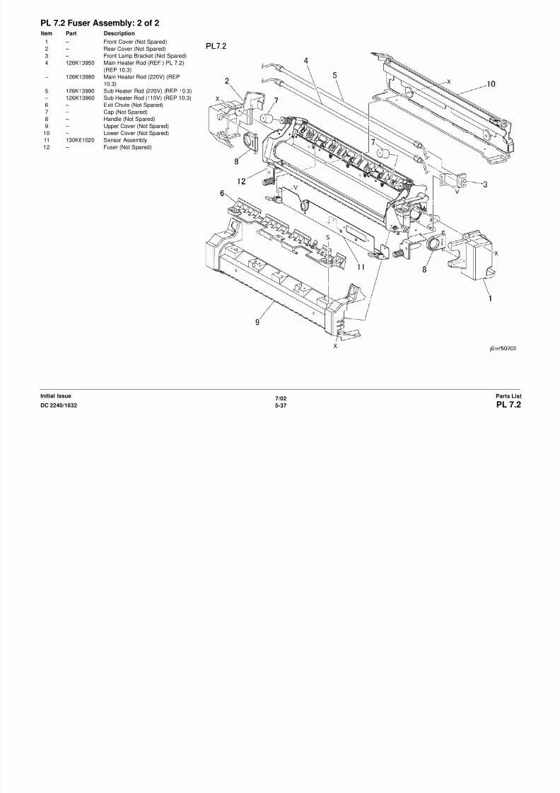
8/13/2019 Xerox Docu Color 2240-1632
http://slidepdf.com/reader/full/xerox-docu-color-2240-1632 755/1118
7/02
5-38 DC 2240/1632PL 8.1Initial IssueParts List
PL 9.1 Electrical Components: 1 of 3Item Part Description
1 105K18771 HVPS (T5) (REP 1.6 REP 1.7)
2 105E09980 HVPS (T7) (REP 1.6 REP 1.7)
3 – LVPS Bracket (Not Spared) (REP
1.1)
4 105E11130 3.3V LVPS (110V) (REP 1.4) – 105E09810 3.3V LVPS (220V) (REP 1.4)
5 105E09820 5V LVPS (110V) (REP 1.4)
– 105E09830 5V LVPS (220V) (REP 1.4)
6 160K76802 I/F PWB (REP 1.8)
7 – LVPS Bracket (Not Spared) (REP
1.9)
8 – Screw (Not Spared)
9 105E09760 24V LVPS (220V) (REP 1.5)
– 105K18641 24V LVPS (110V) (REP 1.5)
10 – Bracket (Not Spared) (REP 1.9)
11 127K29330 LVPS Fan
12 – Screw (Not Spared)
13 – HVPS Control PWB (P/O PL 9.1
Item 1)
14 105E09970 HVPS (T6) (REP 1.10)
15 – Connector Chassis (Not Spared)
16 – T5/T7 HVPS Chassis (P/O PL 9.1
Item 1)
17 103E27220 Resistor (220V)
– 104E93610 Choke Coil (110V)
18 160K84400 Fuser Noise Filter19 – Plate (Not Spared)
20 160K87730 Interlock Relay PWB

8/13/2019 Xerox Docu Color 2240-1632
http://slidepdf.com/reader/full/xerox-docu-color-2240-1632 756/1118
7/02
5-39DC 2240/1632 PL 9.1Parts ListInitial Issue
PL 9.2 Electrical Components: 2 of 3Item Part Description
1 101K38980 AC Power Chassis Assembly
(220V)
– 101K38810 AC Power Chassis Assembly
(110V)
2 – Bracket (P/O PL 9.2 Item 1)3 160K84820 AC Drive PWB (220V) (REP 1.11)
– 160K76770 AC Drive PWB (110V) (REP 1.11)
4 – Clamp (P/O PL 9.2 Item 1)
5 160K84800 Noise Filter PWB (220V)
– 160K76760 Noise Filter PWB (110V)
6 908W01200 GFI Breaker
7 962K08820 Wire Harness
8 – Wire Harness (P/O PL 9.2 Item 1)
9 – Wire Harness (P/O PL 9.2 Item 1)
10 – Wire Harness (P/O PL 9.2 Item 1)
11 – Screw (P/O PL 9.2 Item 1)
12 – Wire Harness (P/O PL 9.2 Item 1)
13 074K94320 Outlet Panel
14 917W00723 Power Cord (110V)
– 117E94370 Power Cord (220V)
15 162K69330 Wire Harness
16 – Wire Harness (P/O PL 9.2 Item 1)
17 – AC Power Chassis (P/O PL 9.2
Item 1)
18 160K77201 Delay PWB

8/13/2019 Xerox Docu Color 2240-1632
http://slidepdf.com/reader/full/xerox-docu-color-2240-1632 757/1118
7/02
5-40 DC 2240/1632PL 9.2Initial IssueParts List
PL 9.3 Electrical Components: 3 of 3Item Part Description
1 014K81604 Developer Block
2 162K62110 Wire Harness
3 162K55941 Wire Harness (Y, M)
4 162K55971 Wire Harness (C, K)
5 162K56000 2nd Wire Harness6 113K82310 DTS Connector
7 162K56031 DTS Wire Harness
8 962K09800 DC Wire Harness

8/13/2019 Xerox Docu Color 2240-1632
http://slidepdf.com/reader/full/xerox-docu-color-2240-1632 758/1118
7/02
5-41DC 2240/1632 PL 9.3Parts ListInitial Issue
I i i l IP Li
PL 10.1 Front CoverItem Part Description
1 891E75951 Logo Plate
2 892E78280 Name Plate (16/32)
– 892E78290 Name Plate (22/40)
3 802K46050 Front Cover Assembly (REP 14.7)
4 – Front Cover (P/O PL 10.1 Item 3)5 – Magnet (P/O PL 10.1 Item 3)
6 – Strip (P/O PL 10.1 Item 3)
7 042K91990 Rod Cleaner Assembly
8 – Rod Cleaner (P/O PL 10.1 Item 7)
9 – Cleaner Base (P/O PL 10.1 Item 7)
10 110E94770 Front Interlock Switch, Right
Interlock Switch
11 – Label (P/O PL 10.1 Item 3)
12 802K46060 Right Cover (REP 14.3)
13 – Hinge (Not Spared)
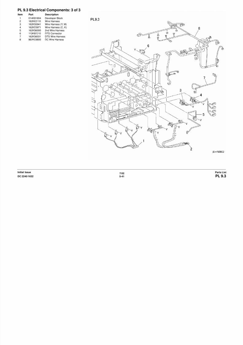
8/13/2019 Xerox Docu Color 2240-1632
http://slidepdf.com/reader/full/xerox-docu-color-2240-1632 759/1118
7/02
5-42 DC 2240/1632PL 10.1Initial IssueParts List
Parts ListInitial Issue
PL 10.2 Top Covers and Inner CoversItem Part Description
1 802K29610 Top Cover Assembly (REP 14.1)
2 – Top Cover (P/O PL 10.2 Item 1)
3 – Stop (P/O PL 10.2 Item 1)
4 802E12400 Connector Cover
5 – Panel (P/O PL 10.2 Item 1)6 110K11211 Main Power Switch
7 802E12430 Fuser Cover (REP 14.8)
8 802K45710 Inner Cover (REP 9.6)
9 012K94260 Link
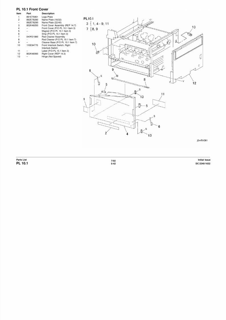
8/13/2019 Xerox Docu Color 2240-1632
http://slidepdf.com/reader/full/xerox-docu-color-2240-1632 760/1118
7/02
5-43DC 2240/1632 PL 10.2Parts ListInitial Issue
Initial IssueParts List
PL 10.3 Rear CoverItem Part Description
1 – Data Plate (Not Spared)
2 802E12480 Blind Cover
3 802K28110 Rear Cover Assembly
4 – Rear Cover (P/O PL 10.3 Item 3)
(REP 14.2)5 802E12490 Blind Cover
6 802E12500 Rear Left Middle Cover (REP 14.4)
7 – Rear Left Lower Cover (Not
Spared)
8 – Front Left Cover (Not Spared)
9 802E27860 Rear Left Upper Cover (REP 14.5)

8/13/2019 Xerox Docu Color 2240-1632
http://slidepdf.com/reader/full/xerox-docu-color-2240-1632 761/1118
7/02
5-44 DC 2240/1632PL 10.3Initial IssueParts List
7/02 Parts ListInitial Issue
PL 11.1 Inverter Transport: 1 of 2Item Part Description
1 059K16742 Inverter Transport (REP 8.5)
2 – Face-up Tray (Not Spared)
3 – Cover (Not Spared)
4 – Front Cover (Not Spared)
5 – Rear Cover (Not Spared)

8/13/2019 Xerox Docu Color 2240-1632
http://slidepdf.com/reader/full/xerox-docu-color-2240-1632 762/1118
7/02
5-45DC 2240/1632 PL 11.1Parts ListInitial Issue
7/02 Initial IssueParts List
PL 11.2 Inverter Transport: 2 of 2Item Part Description
1 – Cover (Not Spared)
2 015K45802 Clutch Assembly
3 – Wire Harness (Not Spared)
4 – Bracket (Not Spared)
5 121K23560 Duplex Gate Solenoid6 – Link (Not Spared)
7 – Bracket (Not Spared)
8 – Bracket (Not Spared)
9 121K82870 Exit Gate Solenoid
10 – Link (Not Spared)
11 – Spring (Not Spared)
12 – Spring (Not Spared)
13 054K17241 Inverter Chute Assembly
14 054K17252 Exit Gate
15 130K93230 Face-up Sensor
16 059K16750 Roll17 – Pinch Roll Assembly (Not Spared)
18 – Bearing (Not Spared)
19 – Bearing (Not Spared)
20 – Bracket (Not Spared)
21 – Holder (Not Spared)
22 – Upper Chute (P/O PL 11.2 Item 13)
23 – Lower Chute (P/O PL 11.2 Item 13)
24 – Duplex Gate (P/O PL 11.2 Item 13)
25 – Bracket (P/O PL 11.2 Item 2)
26 – Gear (P/O PL 11.2 Item 2)
27 – Gear (P/O PL 11.2 Item 2)
28 – Spacer (P/O PL 11.2 Item 2)
29 121K22860 Forward Clutch
30 – Gear (23T) (P/O PL 11.2 Item 2)
31 – Bearing (P/O PL 11.2 Item 2)
32 – Shaft (P/O PL 11.2 Item 2)
33 – Gear (23T) (P/O PL 11.2 Item 2)
34 121K22870 Reverse Clutch
35 011E10711 Interlock Actuator
36 – Plunger (P/O PL 11.2 Item 5)
37 – Linear Solenoid (P/O PL 11.2 Item5)

8/13/2019 Xerox Docu Color 2240-1632
http://slidepdf.com/reader/full/xerox-docu-color-2240-1632 763/1118
7/02
5-46 DC 2240/1632PL 11.2
7/02 Parts ListInitial Issue
PL 12.1 Duplex Transport Assembly:1 of 2Item Part Description
1 – Duplex Transport Upper Cover (Not
Spared)
2 059K18714 Duplex Transport Assembly (REP
8.3)
3 – One-way Pulley (P/O PL 12.1 Item
2)
4 – Bearing (P/O PL 12.1 Item 2)
5 – Bearing (P/O PL 12.1 Item 2)
6 059K23960 Duplex Transport Roll
7 – Handle (P/O PL 12.1 Item 2)
8 – Lower Cover (P/O PL 12.1 Item 2)
9 – Screw (P/O PL 12.1 Item 2)
10 – Nylon Washer (P/O PL 12.1 Item 2)
11 – Cover (P/O PL 12.1 Item 2)12 – Spring (P/O PL 12.1 Item 2)
13 – Duplex Transport (P/O PL 12.1
Item 2)
14 – Label (P/O PL 12.1 Item 2)
15 – Wire Harness (Not Spared)
16 – Bracket (Not Spared)
17 – Screw (Not Spared)
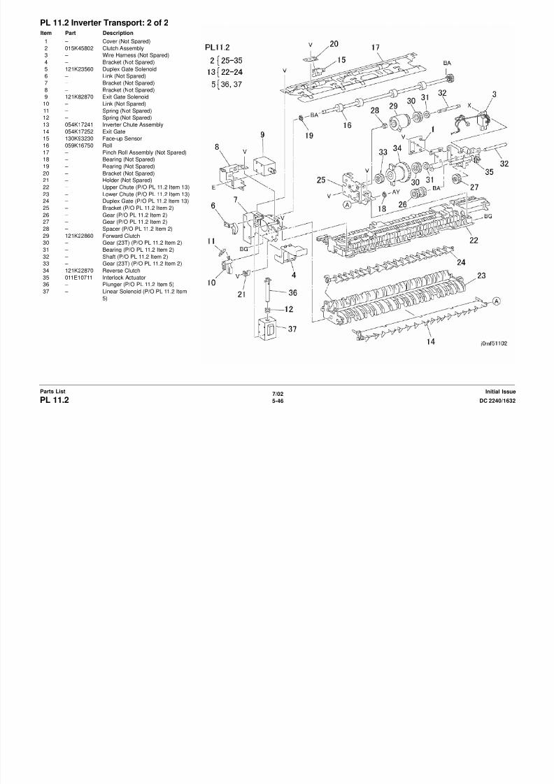
8/13/2019 Xerox Docu Color 2240-1632
http://slidepdf.com/reader/full/xerox-docu-color-2240-1632 764/1118
7/02
5-47DC 2240/1632 PL 12.1
7/02 Initial IssueParts List
PL 12.2 Duplex Transport Assembly:2 of 2Item Part Description
1 – Spring (Not Spared)
2 022K33920 Pinch Roll
3 – Cover (Not Spared)
4 160K66860 Duplex Transport PWB
5 – Wire Harness (Not Spared)
6 – Bracket (Not Spared)
7 130K61250 Duplex Transport Wait Sensor
8 – Spring (Not Spared)
9 059K23980 Pinch Roll
10 127K29930 Duplex Transport Motor
11 – Pulley (20/21T) (Not Spared)
12 – Pulley (16T) (Not Spared)
13 – Screw (Not Spared)
14 – Belt (Not Spared)15 – Bearing (Not Spared)
16 059K23970 Wait Roll
17 – Cover (Not Spared)
18 – Interlock Switch (Not Spared)
19 – Inner Chute (Not Spared)
20 – Outer Chute (Not Spared)
21 – Belt (Not Spared)
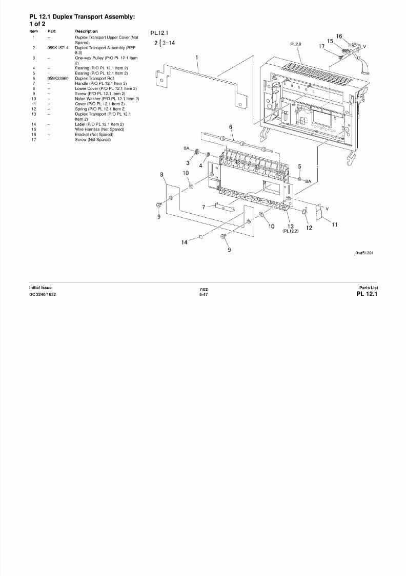
8/13/2019 Xerox Docu Color 2240-1632
http://slidepdf.com/reader/full/xerox-docu-color-2240-1632 765/1118
5-48 DC 2240/1632PL 12.2
7/02
PL 13 1Parts ListInitial Issue
PL 13.1 ESSItem Part Description
1 160K74231 ESS PWB (REP 1.12)
2 160K90840 MCU PWB (Includes PL13.1 Item
19) (REP 1.2)
3 – Rear Panel (Not Spared)
4 – DIMM Cover (Not Spared)5 – Top Cover (Not Spared)
6 537K62680 PS-2 ROM (REP 1.14)
7 133K22400 SDRAM 256MB
8 160K82222 ESS NVM PWB (REP 1.13)
9 – ESS Chassis (Not Spared) (REP
1.3)
10 – Seal (Not Spared)
11 – Screw (Not Spared)
12 – Support (Not Spared)
13 – Cover (Not Spared)
14 121K27751 HDD (ADJ 9.8)15 962K08641 HDD Harness Assembly
16 – Bracket (Not Spared)
17 – Screw (Not Spared)
18 538K94570 Font ROM
19 160K76650 MCU NVM PWB (REP 1.2)
20 537K61180 MAC ROM
21 127K32920 ESS Fan
22 537K62670 PS-1 ROM (REP 1.14)
23 133K21100 SDRAM 64MB
– 133K21200 SDRAM 128MB
24 – Screw (Not Spared)
25 – Screw (Not Spared)
26 – Blind Panel (Not Spared)
27 – Blind Panel (Not Spared)
28 – Option Panel (Not Spared)
29 – Screw (Not Spared)
30 – Fan Guard (Not Spared)
8/13/2019 Xerox Docu Color 2240-1632
http://slidepdf.com/reader/full/xerox-docu-color-2240-1632 766/1118
5-49DC 2240/1632 PL 13.1
7/02
PL 16 1Initial IssueParts List
PL 16.1 Tray 2/3/4 AssemblyItem Part Description
1 891E49060 Label (Tray 2)
2 050K48170 Tray 2 (REP 7.9)
3 003E23672 Stop
4 014E42850 Spacer
5 – Tray 3 Stop (Not Spared)6 – Tray 4 Stop (Not Spared)
7 050K43130 Tray 3 (REP 7.6)
8 050K43120 Tray 4 (REP 7.7)
9 110K08541 Tray 2 Paper Size Switch
10 110K10880 Tray 3/4 Paper Size Switch
11 059E95930 Roll
12 – Shaft (Not Spared)
13 – Bracket (Not Spared)
14 – Roll (Not Spared)
15 – Shaft (Not Spared)
16 – Max Label (Not Spared)17 891E49510 Label (Tray 3)
18 891E49520 Label (Tray 4)
19 892E28491 Label
20 – Instruction Label (Not Spared)

8/13/2019 Xerox Docu Color 2240-1632
http://slidepdf.com/reader/full/xerox-docu-color-2240-1632 767/1118
5-50 DC 2240/1632PL 16.1
7/02
5 51DC 2240/1632 PL 16 2Parts ListInitial Issue
PL 16.2 Tray 2Item Part Description
1 892E74500 Instruction Label
2 – Pad (Not Spared)
3 – Max Label (Not Spared)
4 – Tray (Not Spared)
5 – Side Guide (Not Spared)6 – End Guide (Not Spared)
7 – Link (Not Spared)
8 – Stop (Not Spared)
9 – Spring (Not Spared)

8/13/2019 Xerox Docu Color 2240-1632
http://slidepdf.com/reader/full/xerox-docu-color-2240-1632 768/1118
5-51DC 2240/1632 PL 16.2
7/02
5 52 DC 2240/1632PL 16 3Initial IssueParts List
PL 16.3 Tray 3Item Part Description
1 802E23990 Tray 3 Cover
2 – Pulley (Not Spared)
3 – Lift Shaft (Not Spared)
4 – Bearing (Not Spared)
5 – Pulley (Not Spared)6 – Pulley (Not Spared)
7 – Cable Guide (Not Spared)
8 020E93120 Tray Cable
9 – Cable Guide (Not Spared)
10 – Bottom Plate (Not Spared)
11 – Pad (Not Spared)
12 – Side Guide (Not Spared)
13 – Knob (Not Spared)
14 – Knob (Not Spared)
15 009E26970 Spring
16 – Frame (Not Spared)17 – Bracket (Not Spared)
18 – Spacer (Not Spared)
19 – Spacer (Not Spared)
20 – Bracket (Not Spared)
21 – Brake (Not Spared)
22 – Latch (Not Spared)
23 – Actuator (Not Spared)

8/13/2019 Xerox Docu Color 2240-1632
http://slidepdf.com/reader/full/xerox-docu-color-2240-1632 769/1118
5-52 DC 2240/1632PL 16.3
7/02
5-53DC 2240/1632 PL 16 4Parts ListInitial Issue
PL 16.4 Tray 4Item Part Description
1 802E23980 Tray 4 Cover
2 – Tray Front Frame (Not Spared)
3 – Lift Shaft (Not Spared)
4 – Lift Gear (Not Spared)
5 – Bearing (Not Spared)6 – Brake (Not Spared)
7 – Pulley (Not Spared)
8 – Cable Guide (Not Spared)
9 012E10070 Tray Cable
10 – Bottom Plate (Not Spared)
11 – Pad (Not Spared)
12 – Side Guide (Not Spared)
13 – Knob (Not Spared)
14 – Knob (Not Spared)
15 009E26970 Spring
16 – Tray Frame (Not Spared)17 – Bracket (Not Spared)
18 – Latch (Not Spared)
19 – Actuator (Not Spared)
20 – Shaft (Not Spared)
21 059E95920 Roll

8/13/2019 Xerox Docu Color 2240-1632
http://slidepdf.com/reader/full/xerox-docu-color-2240-1632 770/1118
5-53DC 2240/1632 PL 16.4
7/02
5-54 DC 2240/1632PL 16.5Initial IssueParts List
PL 16.5 Paper Feeder: 1 of 2Item Part Description
1 – Spacer (Not Spared)
2 – Guide (Not Spared)
3 – Stop (Not Spared)
4 059K21790 Tray 4 Transport Assembly
5 – Upper Chute (P/O PL 16.5 Item 4)6 – Takeaway Roll (P/O PL 16.5 Item 4)
7 – Bearing (P/O PL 16.5 Item 4)
8 – Cover (P/O PL 16.5 Item 4)
9 – Pinch Roll (P/O PL 16.5 Item 4)
10 – Bearing (P/O PL 16.5 Item 4)
11 – Spring (P/O PL 16.5 Item 4)
12 – Spacer (P/O PL 16.5 Item 4)
13 – Spacer (P/O PL 16.5 Item 4)
14 – Lower Chute (P/O PL 16.5 Item 4)
15 – Bracket (Not Spared)
16 059K18283 Tray 4 Feeder17 – Bracket (Not Spared)
18 – Bracket (Not Spared)
19 130E82650 Tray 4 Feedout Sensor
20 054E18540 Upper Chute
21 054E18530 Lower Chute
22 – Bracket (Not Spared)

8/13/2019 Xerox Docu Color 2240-1632
http://slidepdf.com/reader/full/xerox-docu-color-2240-1632 771/1118
5 54 DC 2240/1632PL 16.5
7/02
5-55DC 2240/1632 PL 16.6Parts ListInitial Issue
PL 16.6 Paper Feeder: 2 of 2Item Part Description
1 059K18900 Takeaway Roll
2 – Bearing (Not Spared)
3 – Chute (Not Spared)
4 – Cover (Not Spared)
5 130K61510 Takeaway Sensor6 162K62810 Wire Harness
7 059K15573 Tray 2 Feeder
8 054K18270 Chute Assembly
9 – Actuator (P/O PL 16.6 Item 8)
10 130E81600 Tray 3 Feedout Sensor
11 – Wire Harness (P/O PL 16.6 Item 8)
12 – Chute (P/O PL 16.6 Item 8)
13 054E18520 Lower Chute
14 – Bracket (Not Spared)
15 – Tray 3 Feeder (Not Spared)

8/13/2019 Xerox Docu Color 2240-1632
http://slidepdf.com/reader/full/xerox-docu-color-2240-1632 772/1118
7/02
5-56 DC 2240/1632PL 16.7Initial IssueParts List
PL 16.7 Tray 2 Feeder: 1 of 2Item Part Description
1 127K23230 Tray 2 Feed/Lift Motor
2 – Bracket (Not Spared)
3 005K83081 One-way Clutch
4 007K85730 One-way Gear
5 – Gear (13T) (Not Spared)6 – Bearing (Not Spared)
7 – Shaft (Not Spared)
8 – Front Frame (Not Spared)
9 – Upper Frame (Not Spared)
10 – Front Chute (Not Spared)
11 – Actuator (Not Spared)
12 130E82190 Tray 2 Level Sensor
13 – Wire Harness (Not Spared)
14 – Support (Not Spared)
15 – Gear (29T) (Not Spared)

8/13/2019 Xerox Docu Color 2240-1632
http://slidepdf.com/reader/full/xerox-docu-color-2240-1632 773/1118
7/02
5-57DC 2240/1632 PL 16.8Parts ListInitial Issue
PL 16.8 Tray 2 Feeder: 2 of 2Item Part Description
1 – Spring (Not Spared)
2 600K78460 Roll Kit (3 Rolls/Kit)
3 005K05890 One-way Clutch
4 – Gear (Not Spared)
5 – Shaft (Not Spared)6 – Chute (Not Spared)
7 – Spring (Not Spared)
8 – Friction Clutch (Not Spared)
9 – Support (Not Spared)
10 – Holder (Not Spared)
11 – Spacer (Not Spared)
12 – Gear (31T) (Not Spared)
13 – Support (Not Spared)
14 – Bearing (Not Spared)
15 – Gear (Not Spared)
16 – Support (Not Spared)17 – Screw (Not Spared)
18 – Bearing (Not Spared)
19 – Gear (35T) (Not Spared)
20 – Spring (Not Spared)
21 – Lever (Not Spared)

8/13/2019 Xerox Docu Color 2240-1632
http://slidepdf.com/reader/full/xerox-docu-color-2240-1632 774/1118
7/02
5-58 DC 2240/1632PL 16.9Initial IssueParts List
PL 16.9 Tray 3 Feeder: 1 of 2Item Part Description
1 127K23230 Tray 3 Feed/Lift Motor
2 – Bracket (Not Spared)
3 005K83081 One-way Clutch
4 007K85730 One-way Gear
5 – Gear (13T) (Not Spared)6 – Bearing (Not Spared)
7 – Shaft (Not Spared)
8 – Front Frame (Not Spared)
9 – Upper Frame (Not Spared)
10 – Front Chute (Not Spared)
11 – Actuator (Not Spared)
12 130E82190 Tray 3 Level/No Paper Sensor
13 – Wire Harness (Not Spared)
14 – Support (Not Spared)
15 – Gear (29T) (Not Spared)

8/13/2019 Xerox Docu Color 2240-1632
http://slidepdf.com/reader/full/xerox-docu-color-2240-1632 775/1118
7/02
5-59DC 2240/1632 PL 16.10Parts ListInitial Issue
PL 16.10 Tray 3 Feeder: 2 of 2Item Part Description
1 – Spring (Not Spared)
2 600K78460 Roll Kit (3 Rolls/Kit)
3 005K05890 One-way Clutch
4 – Gear (Not Spared)
5 – Shaft (Not Spared)6 – Chute (Not Spared)
7 – Spring (Not Spared)
8 – Friction Clutch (Not Spared)
9 – Support (Not Spared)
10 – Holder (Not Spared)
11 – Spacer (Not Spared)
12 – Gear (31T) (Not Spared)
13 – Support (Not Spared)
14 – Bearing (Not Spared)
15 – Gear (Not Spared)
16 – Support (Not Spared)17 – Screw (Not Spared)
18 – Bearing (Not Spared)
19 – Gear (35T) (Not Spared)
20 – Spring (Not Spared)
21 – Lever (Not Spared)

8/13/2019 Xerox Docu Color 2240-1632
http://slidepdf.com/reader/full/xerox-docu-color-2240-1632 776/1118
7/02
5-60 DC 2240/1632PL 16.11Initial IssueParts List
PL 16.11 Tray 4 Feeder: 1 of 2Item Part Description
1 127K23230 Tray 4 Feed/Lift Motor
2 – Bracket (Not Spared)
3 005K83081 One-way Clutch
4 007K85730 One-way Gear
5 – Gear (13T) (Not Spared)6 – Bearing (Not Spared)
7 – Shaft (Not Spared)
8 – Front Frame (Not Spared)
9 – Upper Frame (Not Spared)
10 – Front Chute (Not Spared)
11 – Actuator (Not Spared)
12 130E82190 Tray 4 Level/No Paper Sensor
13 162K56590 Wire Harness
14 – Support (Not Spared)
15 – Gear (29T) (Not Spared)

8/13/2019 Xerox Docu Color 2240-1632
http://slidepdf.com/reader/full/xerox-docu-color-2240-1632 777/1118
7/02
5-61DC 2240/1632 PL 16.12Parts ListInitial Issue
PL 16.12 Tray 4 Feeder: 2 of 2Item Part Description
1 – Spring (Not Spared)
2 600K78460 Roll Kit (3 Rolls/Kit)
3 005K05890 One-way Clutch
4 – Gear (Not Spared)
5 – Shaft (Not Spared)6 – Chute (Not Spared)
7 – Spring (Not Spared)
8 – Friction Clutch (Not Spared)
9 – Support (Not Spared)
10 – Holder (Not Spared)
11 – Spacer (Not Spared)
12 – Gear (31T) (Not Spared)
13 – Support (Not Spared)
14 – Bearing (Not Spared)
15 – Gear (Not Spared)
16 – Support (Not Spared)17 – Screw (Not Spared)
18 – Bearing (Not Spared)
19 – Gear (35T) (Not Spared)
20 – Spring (Not Spared)
21 – Lever (Not Spared)
8/13/2019 Xerox Docu Color 2240-1632
http://slidepdf.com/reader/full/xerox-docu-color-2240-1632 778/1118
7/02
5-62 DC 2240/1632PL 16.13Initial IssueParts List
PL 16.13 Left Cover AssemblyItem Part Description
1 802K25731 Left Cover Assembly (REP 14.11)
2 003E53700 Shaft
3 003E53710 Hook
4 011E10800 Handle
5 – Left Cover (P/O PL 16.13 Item 1)6 – Support (P/O PL 16.13 Item 1)
7 – Chute (P/O PL 16.13 Item 1)
8 – Actuator (P/O PL 16.13 Item 1)
9 – Spring (P/O PL 16.13 Item 1)
10 – Bearing (P/O PL 16.13 Item 1)
11 – Bearing (P/O PL 16.13 Item 1)
12 – Pinch Roll (P/O PL 16.13 Item 1)
13 809E28960 Spring
14 – Bracket (P/O PL 16.13 Item 1)
15 809E28980 Spring
16 – Bracket (P/O PL 16.13 Item 1)17 015K49470 Interlock Switch
18 – Bracket (Not Spared)

8/13/2019 Xerox Docu Color 2240-1632
http://slidepdf.com/reader/full/xerox-docu-color-2240-1632 779/1118
7/02
5-63DC 2240/1632 PL 16.14Parts ListInitial Issue
PL 16.14 Tray 3/4 Lift Gear AssemblyItem Part Description
1 – Transport Guide (Not Spared)
2 015K49460 Gear Assembly (Tray 3)
3 015K49450 Gear Assembly (Tray 4)
4 007E66080 Lift Gear
5 011K96790 Coupling6 – Bearing (Not Spared)

8/13/2019 Xerox Docu Color 2240-1632
http://slidepdf.com/reader/full/xerox-docu-color-2240-1632 780/1118
7/02
5-64 DC 2240/1632PL 16.15Initial IssueParts List
PL 16.15 Electrical Components andCastersItem Part Description
1 007E66060 Gear (23/46T)
2 007E66070 Gear (46T)
3 007E66050 Gear (33T)
4 127K31840 Takeaway Motor 25 127K36020 Takeaway Motor 1
6 – Left Coupling (Not Spared)
7 – Right Coupling (Not Spared)
8 – Foot (Not Spared)
9 017K92350 Caster
10 017K92360 Caster
11 – Bracket (Not Spared)
12 160K85980 Tray Module PWB
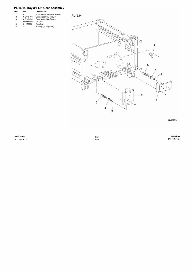
8/13/2019 Xerox Docu Color 2240-1632
http://slidepdf.com/reader/full/xerox-docu-color-2240-1632 781/1118
7/02
5-65DC 2240/1632 PL 16.16Parts ListInitial Issue
PL 16.16 CoversItem Part Description
1 – Right Cover (Not Spared)
2 802E23950 Front Upper Cover
3 802E23960 Front Lower Cover
4 802K36580 Rear Cover (REP 14.9)
5 802E23930 Left Lower Cover (REP 14.12)

8/13/2019 Xerox Docu Color 2240-1632
http://slidepdf.com/reader/full/xerox-docu-color-2240-1632 782/1118
7/02
5-66 DC 2240/1632PL 17.1Initial IssueParts List
PL 17.1 FinisherItem Part Description
1 802K36650 Gate Assembly
2 801K02480 H-Transport Assembly (REP 12.1)
3 – Stapler Finisher (Not Spared)
4 003K12090 Thumbscrew
5 – Rack Assembly (Not Spared) (REP
12.19)
6 – Right Cover (Not Spared)
7 – Stacker Tray (Not Spared) (REP
12.20)
8 026E93560 Screw
9 – Bracket (Not Spared)
10 – Front Bracket (Not Spared)
11 – Stud Screw (Not Spared)
12 – Rear Bracket (Not Spared)

8/13/2019 Xerox Docu Color 2240-1632
http://slidepdf.com/reader/full/xerox-docu-color-2240-1632 783/1118
7/02
5-67DC 2240/1632 PL 17.2Parts ListInitial Issue
PL 17.2 Gate AssemblyItem Part Description
1 – Gate Cover (Not Spared)
2 – Bearing (Not Spared)
3 – Chute (Not Spared)
4 – In Gate (Not Spared)
5 – In Gate Lever (Not Spared)
6 – Gate Bracket (Not Spared)
7 – Link Assembly (Not Spared)
8 – Lever Assembly (Not Spared)
9 – Lever (Not Spared)
10 – Spring (Not Spared)
11 – Gate Link (Not Spared)
12 120E20700 Actuator
13 – Bearing (Not Spared)
14 – Spring (Not Spared)
15 – Exit Chute (Not Spared)
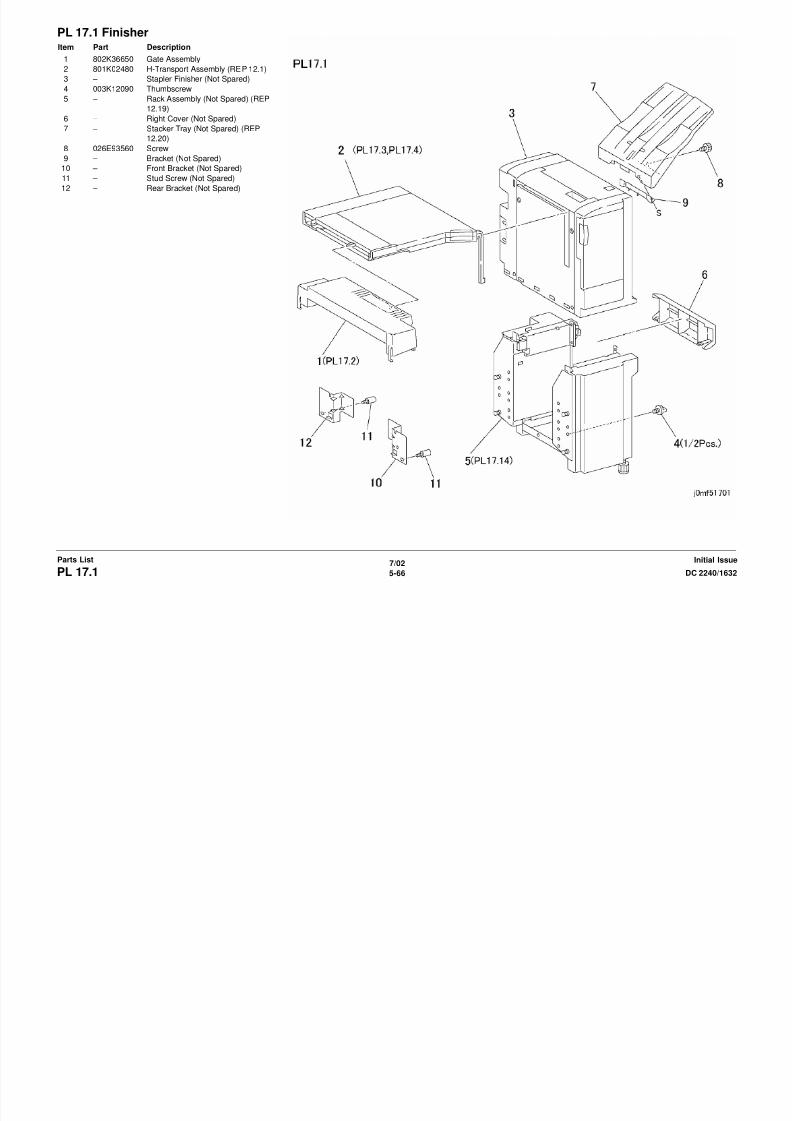
8/13/2019 Xerox Docu Color 2240-1632
http://slidepdf.com/reader/full/xerox-docu-color-2240-1632 784/1118
7/02
5-68 DC 2240/1632PL 17.3Initial IssueParts List
PL 17.3 H-Transport Assembly: 1 of 2Item Part Description
1 802K28600 H-Transport Cover Assembly
2 – H-Transport Cover (P/O PL 17.3
Item 1)
3 – Screw (P/O PL 17.3 Item 1)
4 121E91450 Magnet
5 – Guide (P/O PL 17.3 Item 1)
6 – Roll (P/O PL 17.3 Item 1)
7 – Spring Plate (P/O PL 17.3 Item 1)
8 – Stop (Not Spared)
9 802K28590 Entrance Upper Cover Assembly
10 – Entrance Upper Cover (P/O PL
17.3 Item 9)
11 – Roll (P/O PL 17.3 Item 9)
12 – Spring Plate (P/O PL 17.3 Item 9)
13 – Roll (Not Spared)
14 – Front Cover (Not Spared)15 – Upper Rear Cover (Not Spared)
16 – Rear Cover (Not Spared)
17 – Exit Guide (Not Spared)
18 – Stop (Not Spared)
19 – Support (Not Spared)
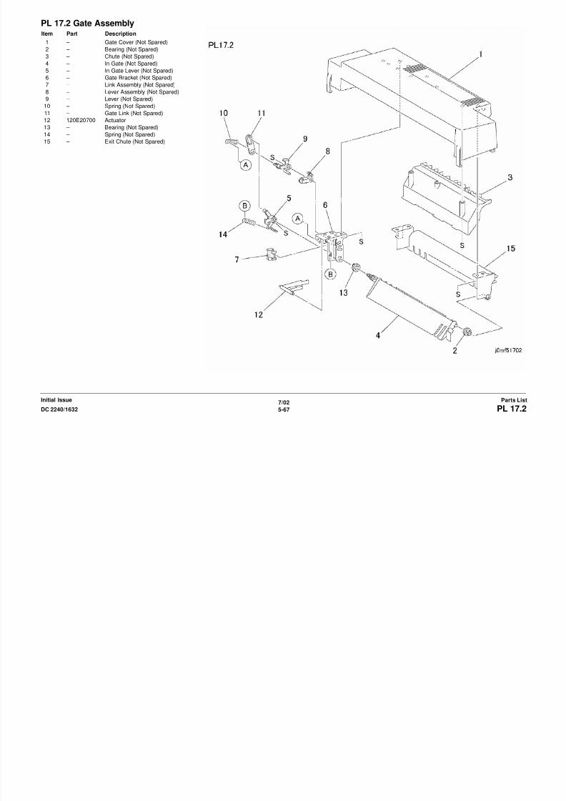
8/13/2019 Xerox Docu Color 2240-1632
http://slidepdf.com/reader/full/xerox-docu-color-2240-1632 785/1118
7/02
5-69DC 2240/1632 PL 17.4Parts ListInitial Issue
PL 17.4 H-Transport Assembly: 2 of 2Item Part Description
1 – H-Transport Roll (In) (Not Spared)
2 – H-Transport Roll (Out) (Not Spared)
3 023E20020 H-Transport Belt (REP 12.2)
4 – Roll (Not Spared)
5 – Support (Not Spared)
6 – Bearing (Not Spared)
7 802E30150 Harness Guide
8 802E30140 Cover
9 130K93360 Entrance Sensor (REP 12.3)
10 130E82970 Top Tray Full Sensor
11 130K62360 Exit Sensor
12 802K28580 Gate In Solenoid Assembly
13 – Gate In Solenoid (P/O PL 17.4 Item
12)
14 – Spring (P/O PL 17.4 Item 12)
15 – LInk (P/O PL 17.4 Item 12)16 – Cover (P/O PL 17.4 Item 12)
17 – Ground Wire (P/O PL 17.4 Item 12)
18 162K69070 Wire Harness
19 162K69060 Wire Harness
20 – Bearing (Not Spared)
21 007E67850 Gear (37T)
22 007E67860 Gear (30T)
23 007E67870 Gear (26T)
24 130E82540 Interlock Sensor
25 – Bracket (Not Spared)
26 038E24650 Paper Guide27 022E88210 Roll
28 – Bracket (Not Spared)
29 – Frame (Not Spared)
30 – Bracket (Not Spared)
31 – Screw (Not Spared)
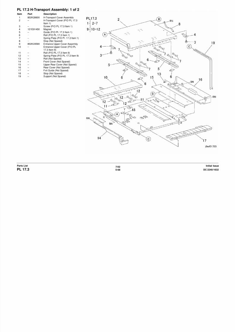
8/13/2019 Xerox Docu Color 2240-1632
http://slidepdf.com/reader/full/xerox-docu-color-2240-1632 786/1118
7/02
5-70 DC 2240/1632PL 17.5Initial IssueParts List
PL 17.5 CoversItem Part Description
1 802E28560 Front Cover
2 802E28520 Rear Cover
3 802E28530 Top Cover
4 802E28540 Left Cover
5 802E28550 Front Cover Door
6 802E28570 Left Panel
7 – Hinge (Not Spared)
8 121E88470 Magnet

8/13/2019 Xerox Docu Color 2240-1632
http://slidepdf.com/reader/full/xerox-docu-color-2240-1632 787/1118
7/02
5-71DC 2240/1632 PL 17.6Parts ListInitial Issue
PL 17.6 Top Cover and Eject RollItem Part Description
1 802K28570 Top Cover
2 – Arm (Not Spared)
3 – Bearing (Not Spared)
4 – Bracket (Not Spared)
5 – Spring (Not Spared)
6 830E81670 Support
7 – Bracket (Not Spared)
8 – Shaft (Not Spared)
9 022K62610 Eject Pinch Roll
10 – Eject Chute (Not Spared)
11 130K61920 Stack Height Sensor Assembly
(REP 12.5)
12 – Actuator (P/O PL 17.6 Item 11)
13 – Bracket (P/O PL 17.6 Item 11)
14 130E82530 Stack Height Sensor
15 – Shaft (Not Spared)16 – Link (Not Spared)
17 120E20970 Actuator
18 005E16220 Clutch
19 005E16510 Collar
20 007E67760 Gear (28Z)
21 – Eject Roll (P/O PL 17.6 Item 25)
22 007K86910 Gear (20T)
23 013E20240 Bearing
24 – Eject Shaft (P/O PL 17.6 Item 25)
25 006K21730 Eject Roll Assembly (REP 12.6)
26 – Link (Not Spared)27 – Static Eliminator (Not Spared)
28 – Collar (Not Spared)
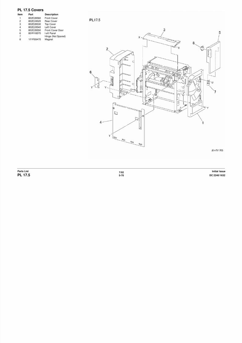
8/13/2019 Xerox Docu Color 2240-1632
http://slidepdf.com/reader/full/xerox-docu-color-2240-1632 788/1118
7/02
5-72 DC 2240/1632PL 17.7Initial IssueParts List
PL 17.7 Paper Transportation: 1 of 2Item Part Description
1 120E20690 Actuator
2 121K24610 Decurler Cam Clutch
3 008E94070 Cam
4 – Shaft (Not Spared)
5 – Bearing (Not Spared)
6 031E94030 Arm
7 059K20210 Decurler Roll (REP 12.7)
8 007E67740 Gear (40Z/20T)
9 007E67750 Gear (40Z)
10 007E72090 Gear (18Z/21T)
11 – Shaft (Not Spared)
12 – Bearing (Not Spared)
13 007E67730 Gear (23Z/52T)
14 023E20160 Belt (REP 12.9)
15 423W29655 Belt
16 127K32840 Finisher Drive Motor (REP 12.8)17 – Bracket (Not Spared)

8/13/2019 Xerox Docu Color 2240-1632
http://slidepdf.com/reader/full/xerox-docu-color-2240-1632 789/1118
7/02
5-73DC 2240/1632 PL 17.8Parts ListInitial Issue
PL 17.8 Paper Transportation: 2 of 2Item Part Description
1 015K52280 Cam Bracket Assembly
2 020E34970 Pulley
3 007E67780 Gear (15Z)
4 423W28054 Belt
5 007E67810 Gear (30Z)
6 – Collar (P/O PL 17.8 Item 1)
7 007E67790 Gear Pulley
8 127K32870 Eject Motor
9 007E67800 Cam Gear
10 007E67770 Gear (42Z/27Z)
11 121K24620 Set Clamp Solenoid
12 – Bracket (P/O PL 17.8 Item 1)
13 – Wire Harness (Not Spared)
14 130E82540 Home Sensor
15 – Plate (Not Spared)
16 – Stop (P/O PL 17.8 Item 1)
17 – Spring (Not Spared)
18 – Bracket (Not Spared)
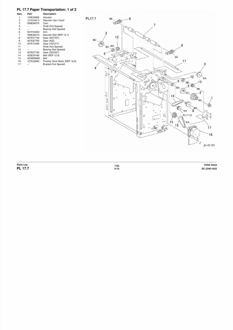
8/13/2019 Xerox Docu Color 2240-1632
http://slidepdf.com/reader/full/xerox-docu-color-2240-1632 790/1118
7/02
5-74 DC 2240/1632PL 17.9Initial IssueParts List
PL 17.9 Stapler UnitItem Part Description
1 041K94260 Carriage Assembly
2 – Bracket (P/O PL 17.9 Item 1)
3 127K32860 Staple Move Motor
4 – Gear (P/O PL 17.9 Item 1)
5 130E82530 Staple Sensor
6 – Roll (P/O PL 17.9 Item 1)7 – Staple Front Corner Sensor (Not
Spared)
8 – Plate (Not Spared)
9 001E59600 Rail (REP 12.10)
10 029K91990 Stapler Assembly (REP 12.11)
11 – Stapler (P/O PL 17.9 Item 10)
12 – Cartridge (P/O PL 17.9 Item 10)
13 – Bracket (Not Spared)
14 962K07440 Stapler Harness

8/13/2019 Xerox Docu Color 2240-1632
http://slidepdf.com/reader/full/xerox-docu-color-2240-1632 791/1118
7/02
5-75DC 2240/1632 PL 17.10Parts ListInitial Issue
PL 17.10 Compiler Tray AssemblyItem Part Description
1 050K43880 Compiler Tray Assembly (REP
12.12)
2 127K32850 Front/Rear Tamper Motor
3 – Plate (P/O PL 17.10 Item 1)
4 130E82530 Front/Rear Tamper Home Sensor
5 – Rack (P/O PL 17.10 Item 1)6 – Actuator (P/O PL 17.10 Item 1)
7 – Tamper (P/O PL 17.10 Item 1)
8 – Finger (P/O PL 17.10 Item 1)
9 – Spring (P/O PL 17.10 Item 1)
10 130E82540 Compiler Paper Sensor
11 – Actuator (P/O PL 17.10 Item 1)
12 038E24410 Paper Guide
13 809E33600 Spring
14 – Wire Harness (P/O PL 17.10 Item
1)
15 – End Guide (P/O PL 17.10 Item 1)

8/13/2019 Xerox Docu Color 2240-1632
http://slidepdf.com/reader/full/xerox-docu-color-2240-1632 792/1118
7/02
5-76 DC 2240/1632PL 17.11Initial IssueParts List
PL 17.11 ElevatorItem Part Description
1 127K33420 Stacker Motor Assembly (REP
12.13)
2 015K50680 Front Elevator Bracket (REP 12.14)
3 019E50340 Clamp
4 – Bearing (Not Spared)
5 007E67830 Rear Gear6 – Actuator (Not Spared)
7 007E67840 Front Gear
8 – Bracket (Not Spared)
9 007E67820 Rack
10 – Tray Guide (Not Spared)
11 015K51640 Paper Stack Sensor Assembly
12 130E82530 Sensor
13 – Actuator (P/O PL 17.11 Item 11)
14 – Bracket (P/O PL 17.11 Item 11)
15 – Spring (P/O PL 17.11 Item 11)
16 – Cover (P/O PL 17.11 Item 11)
17 – Bracket (Not Spared)
18 – Sensor (Not Spared)
19 – Bracket (Not Spared)
20 – Pin (Not Spared)
21 – Bearing (Not Spared)
22 – Shaft (Not Spared)
23 – Rivet (Not Spared)
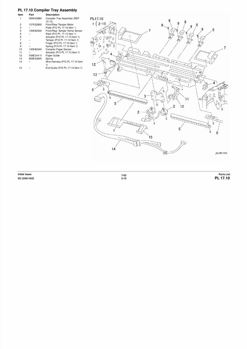
8/13/2019 Xerox Docu Color 2240-1632
http://slidepdf.com/reader/full/xerox-docu-color-2240-1632 793/1118
7/02
5-77DC 2240/1632 PL 17.12Parts ListInitial Issue
PL 17.12 Exit AssemblyItem Part Description
1 007E72080 Gear (48Z)
2 – Bearing (Not Spared)
3 006K21720 Exit Shaft
4 – Collar (Not Spared)
5 007E72070 Gear (32Z/18T)
6 – Bearing (Not Spared)7 006K21970 Paddle Gear Shaft (REP 12.15)
8 013E20250 Paddle Bearing
9 – Lower Exit Chute (Not Spared)
10 022K65880 Pinch Roll
11 – Pinch Roll (Not Spared)
12 – Pinch Roll (Not Spared)
13 – Upper Exit Chute (Not Spared)
14 130K94740 Compiler Entrance Sensor
15 – Spring Plate (Not Spared)
16 – Bracket (Not Spared)
17 105E11320 Static Eliminator

8/13/2019 Xerox Docu Color 2240-1632
http://slidepdf.com/reader/full/xerox-docu-color-2240-1632 794/1118
7/02
5-78 DC 2240/1632PL 17.13Initial IssueParts List
PL 17.13 Electrical ComponentsItem Part Description
1 – PWB Cover (Not Spared)
2 160K76660 Finisher PWB (REP 12.16)
3 537K64070 ROM
4 – PWB Bracket (Not Spared)
5 962K10120 DC Harness
6 962K10130 Cable7 110E97990 Top Cover/Front Door Interlock
Switch
8 130E82530 Docking Interlock Switch
9 – Spring Plate (Not Spared)
10 – Bracket (Not Spared)
11 – Plate (Not Spared)
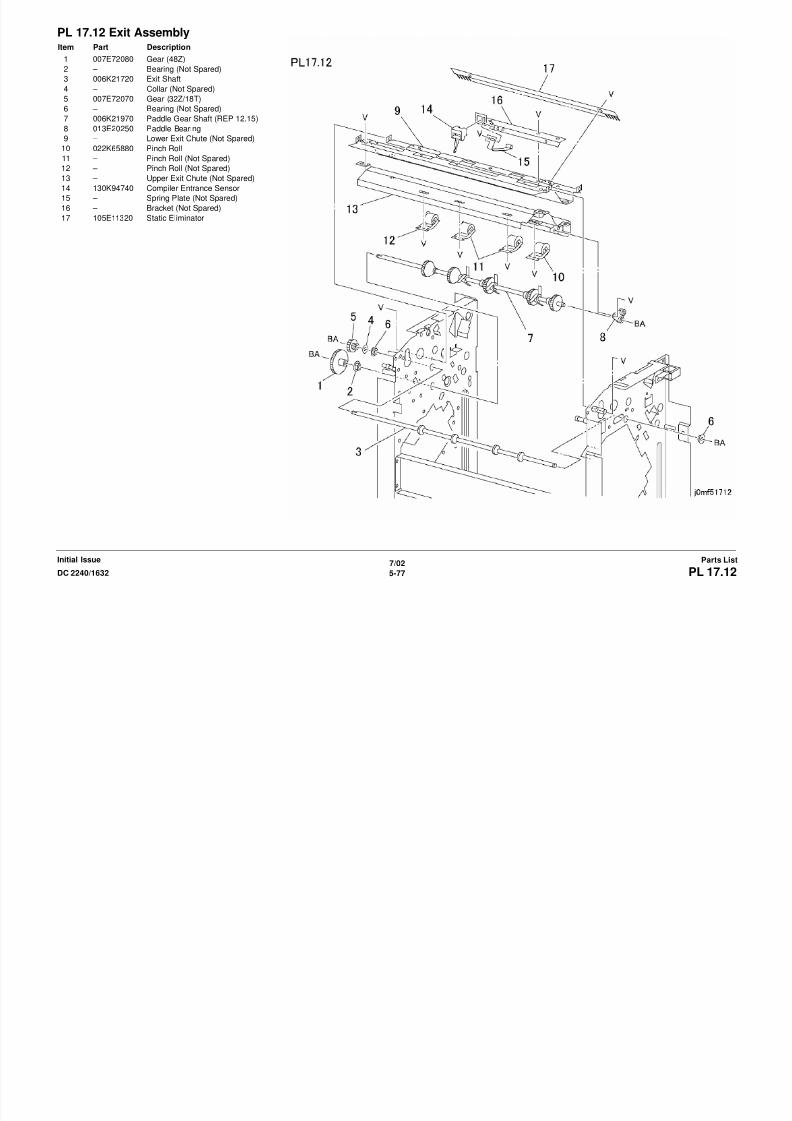
8/13/2019 Xerox Docu Color 2240-1632
http://slidepdf.com/reader/full/xerox-docu-color-2240-1632 795/1118
7/02
5-79DC 2240/1632 PL 17.14Parts ListInitial Issue
PL 17.14 Rack AssemblyItem Part Description
1 802K36660 Front Rack Assembly
2 – Front Cover (P/O PL 17.14 Item 1)
3 003K12090 Knob Screw
4 – Screw (P/O PL 17.14 Item 1,PL
17.14 Item 11)
5 – Bracket (P/O PL 17.14 Item 1,PL17.14 Item 11)
6 – Stop (P/O PL 17.14 Item 1,PL
17.14 Item 11)
7 – Spring Plate (P/O PL 17.14 Item
1,PL 17.14 Item 11)
8 001E60050 Rail
9 017E94660 Foot
10 – Front Rack (P/O PL 17.14 Item 1)
11 802K36670 Rear Rack Assembly
12 – Rear Cover (P/O PL 17.14 Item 11)
13 – Rear Rack (P/O PL 17.14 Item 11)
14 – Bracket (P/O PL 17.14 Item 11)
15 015E77040 Bottom Plate
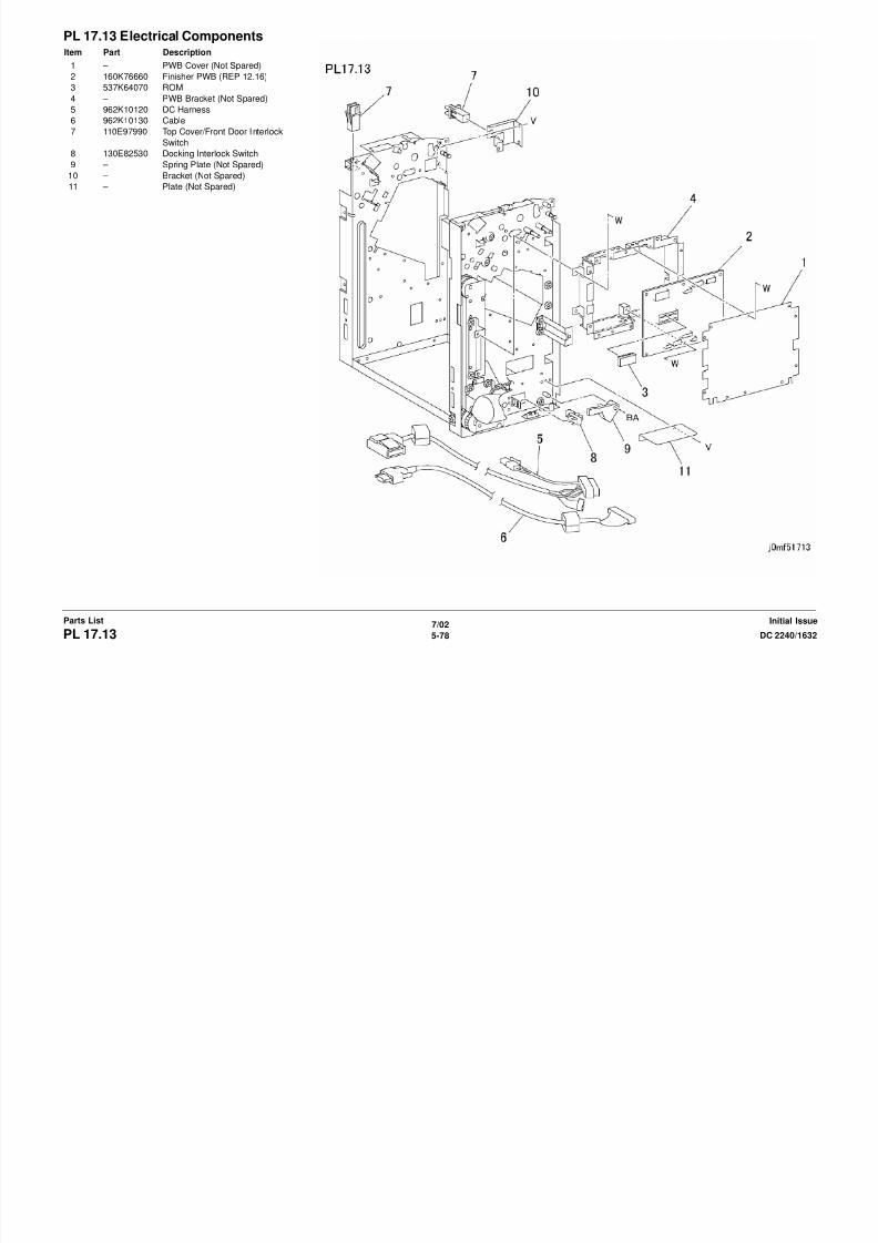
8/13/2019 Xerox Docu Color 2240-1632
http://slidepdf.com/reader/full/xerox-docu-color-2240-1632 796/1118
7/02
5-80 DC 2240/1632PL 18.2Initial IssueParts List
PL 18.2 Control PanelItem Part Description
1 802K46022 Control Panel Assembly
2 – Bracket (P/O PL 18.2 Item 1)
3 – Panel Housing (P/O PL 18.2 Item
1)
4 123K94020 Display
5 110K11100 Touch Panel (ADJ 9.13)6 160K75800 VR PWB (ADJ 9.13)
7 – Screw (P/O PL 18.2 Item 1)
8 – Right Panel (P/O PL 18.2 Item 1)
9 – Center Panel (P/O PL 18.2 Item 1)
10 802E32860 One-touch Panel
11 160K77367 UI PWB Assembly (ADJ 9.13)
12 – UI PWB Base (P/O PL 18.2 Item
11)
13 – ROM (P/O PL 18.2 Item 11)
14 – ROM (P/O PL 18.2 Item 11)
15 – Bracket (P/O PL 18.2 Item 1)
16 – Plate (P/O PL 18.2 Item 1)
17 – Adjust Pen (P/O PL 18.2 Item 1)

8/13/2019 Xerox Docu Color 2240-1632
http://slidepdf.com/reader/full/xerox-docu-color-2240-1632 797/1118
7/02
5-81DC 2240/1632 PL 18.3Parts ListInitial Issue
PL 18.3 Platen GlassItem Part Description
1 – Right Side Plate (Not Spared)
2 090K92820 Platen Glass (REP 6.2)
3 050K43070 Registration Gate
4 – IPS Cover (Not Spared)
5 – Screw (Not Spared)
6 068E10210 Platen Glass Support7 160K90820 ITT/IPS PWB (REP 6.5)
8 117E20840 Cable

8/13/2019 Xerox Docu Color 2240-1632
http://slidepdf.com/reader/full/xerox-docu-color-2240-1632 798/1118
7/02
5-82 DC 2240/1632PL 18.4Initial IssueParts List
PL 18.4 CCD PWB, SensorItem Part Description
1 127K33160 IPS Fan
2 – Bracket (Not Spared)
3 130K62000 IIT Registration Sensor
4 – Bracket (Not Spared)
5 110K08471 Platen Open Switch
6 130K62580 Platen Angle Sensor Assembly7 107E08680 Platen Angle Sensor
8 – Bracket (P/O PL 18.4 Item 6)
9 – Support (P/O PL 18.4 Item 6)
10 – Actuator (P/O PL 18.4 Item 6)
11 009E55450 Spring
12 604K05330 Lens Ki t (Kit contains CCD PWB
and Lens Assembly) (REP 6.4,ADJ
9.7)
13 117K30960 CCD Flat Cable
14 – Lens Cover (Not Spared)
15 – APS Sensor (Not Spared)
16 – Bracket (Not Spared)
17 – Screw (Not Spared)
18 962K05910 AC Harness (220V)
– 962K05900 AC Harness (120V)
19 105E10480 IIT LVPS (100V)
– 105E10650 IIT LVPS (220V)
20 019E49830 Clamp
21 – Plate (Not Spared)
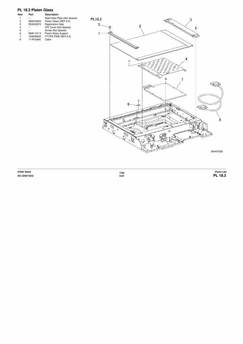
8/13/2019 Xerox Docu Color 2240-1632
http://slidepdf.com/reader/full/xerox-docu-color-2240-1632 799/1118
7/02
5-83DC 2240/1632 PL 18.5Parts ListInitial Issue
PL 18.5 Carriage Cable/ MotorItem Part Description
1 063E94040 Tape
2 – Frame (Not Spared)
3 020E99590 Pulley
4 012K94110 Front Carriage Cable (REP 6.11)
5 012K94120 Rear Carriage Cable (REP 6.11)
6 063E94050 Tape7 020E32740 Timing Pulley
8 023E19300 Belt
9 – Capstan Shaft (Not Spared)
10 020E25090 Capstan Pulley
11 413W10950 Bearing
12 009E62830 Spring
13 017E92060 Foot
14 – Pulley (Not Spared)
15 – Stop Bracket (Not Spared)
16 127K32140 Carriage Motor (REP 6.12)

8/13/2019 Xerox Docu Color 2240-1632
http://slidepdf.com/reader/full/xerox-docu-color-2240-1632 800/1118
7/02
5-84 DC 2240/1632PL 18.6Initial IssueParts List
PL 18.6 Full/Half Rate CarriageItem Part Description
1 – Harness Guard (Not Spared)
2 041K94050 Full-Rate Carriage Assembly (ADJ
6.1)
3 – Full-Rate Carriage (P/O PL 18.6
Item 2)
4 117E19780 Lamp Wire Harness (REP 6.14)5 – No 1 Motor (P/O PL 18.6 Item 2)
6 062E10040 No 1 Mirror
7 019E50400 Clip
8 118E12090 Insulator
9 122E92030 Exposure Lamp (REP 6.13)
10 105E10510 Lamp Ballast PWB
11 – Pad (P/O PL 18.6 Item 2)
12 041K94271 Half-Rate Carriage Assembly (ADJ
6.1)
13 062K10730 No 2 and No 3 Mirror
14 – No 2, No 3 Mirror (P/O PL 18.6 Item12,PL 18.6 Item 13)
15 – Damper (P/O PL 18.6 Item 12,PL
18.6 Item 13)
16 – Single Clip (P/O PL 18.6 Item 12)
17 809E09110 Clip
18 – Half-Rate Carriage (P/O PL 18.6
Item 12)
19 – Shaft (P/O PL 18.6 Item 12)
20 004E06560 Damper Bearing
21 – Pulley (P/O PL 18.6 Item 12)
22 020K94970 Pulley
23 – Harness Pulley (P/O PL 18.6 Item
12)
24 019E49470 Pad
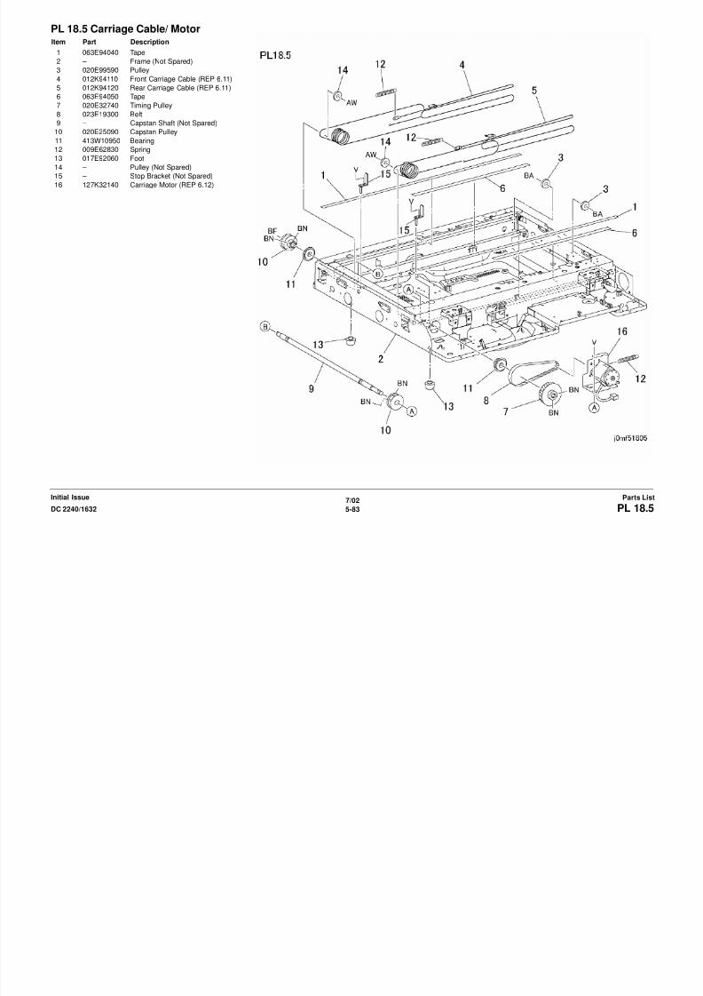
8/13/2019 Xerox Docu Color 2240-1632
http://slidepdf.com/reader/full/xerox-docu-color-2240-1632 801/1118
7/02
5-85DC 2240/1632 PL 19.1Parts ListInitial Issue
PL 19.1 RackItem Part Description
1 – Rack (Not Spared)
2 017E94710 Swivel Caster
3 017E94730 Stationary Caster
4 017E94700 Foot
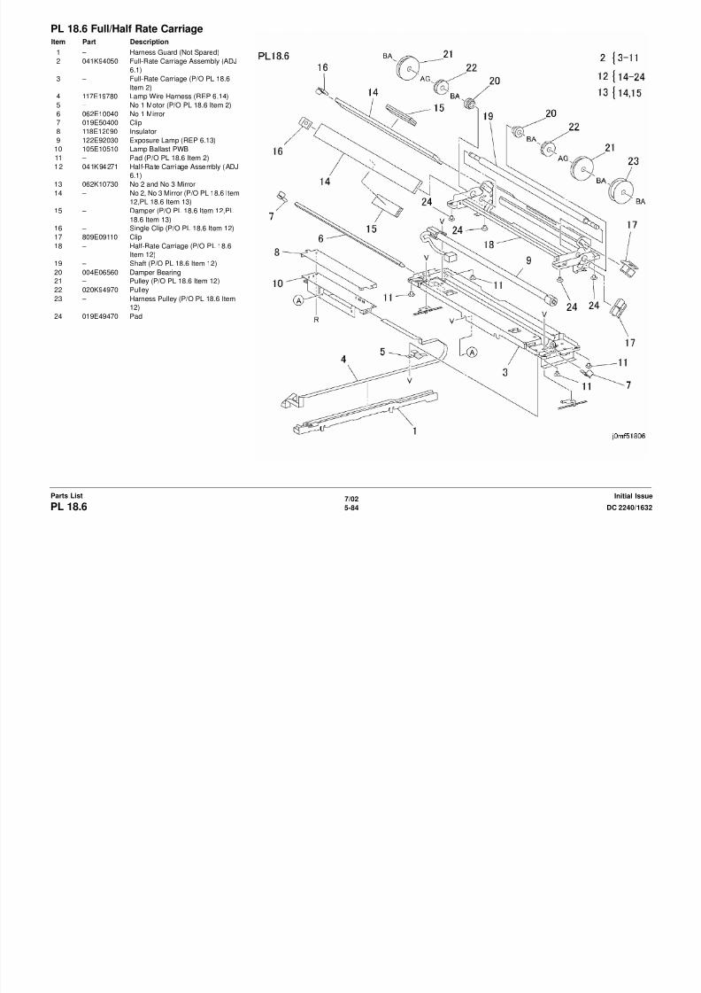
8/13/2019 Xerox Docu Color 2240-1632
http://slidepdf.com/reader/full/xerox-docu-color-2240-1632 802/1118
7/02
5-86 DC 2240/1632PL 20.1Initial IssueParts List
PL 20.1 Front/Rear Cover, EntranceTrayItem Part Description
1 048K76180 Rear Cover Assembly (REP 5.18)
2 – Rear Cover (P/O PL 20.1 Item 1)
3 140K60480 LED PWB
4 – Wire Harness (P/O PL 20.1 Item 1)
5 891E65180 Label (Display)
6 050K36410 Entrance Tray Assembly
7 – Entrance Tray (P/O PL 20.1 Item 6)
8 – Plate (P/O PL 20.1 Item 6)
9 009E26870 Spring Plate
10 032K93800 Document Guide
11 048E64200 Front Cover
12 – Label (Not Spared)
13 891E65210 Size Label
14 – Clamp (Not Spared)

8/13/2019 Xerox Docu Color 2240-1632
http://slidepdf.com/reader/full/xerox-docu-color-2240-1632 803/1118
7/02
5-87DC 2240/1632 PL 20.2Parts ListInitial Issue
PL 20.2 Top Cover, Registration GateSolenoidItem Part Description
1 054K13621 Top Cover Assembly
2 – Top Cover (P/O PL 20.2 Item 1)
3 015E48890 Front Magnet Plate
4 809E11130 Spring
5 059K11880 Pinch Roll
6 015E48900 Front Magnet Plate
7 110K07850 Top Cover Inter lock Switch (Rear)
8 – Bracket (Not Spared)
9 – Screw (Not Spared)
10 121K93870 Magnet
11 – Bracket (Not Spared)
12 110K07870 Top Cover Inter lock Switch (Front)
13 121K22710 Registration Gate Solenoid
Assembly (REP 5.2)
14 – Bracket (P/O PL 20.2 Item 13)15 – Registration Gate Solenoid (P/O PL
20.2 Item 13)
16 – Registration Arm (P/O PL 20.2 Item
13)
17 019E93510 Push Rivet
18 – Label (Not Spared)
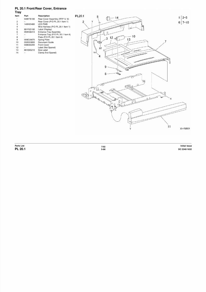
8/13/2019 Xerox Docu Color 2240-1632
http://slidepdf.com/reader/full/xerox-docu-color-2240-1632 804/1118
7/02
5-88 DC 2240/1632PL 20.3Initial IssueParts List
PL 20.3 Counterbalance, DADFControl PWBItem Part Description
1 003K91881 Thumbscrew
2 036K91431 Right Counterbalance (REP 5.3)
3 – Counterbalance (P/O PL 20.3 Item
2) (ADJ 5.2 ADJ 5.3 ADJ 5.4)
4 – DADF Interlock Switch (P/O PL
20.3 Item 2)
5 – Screw (P/O PL 20.3 Item 2)
6 – Screw (Not Spared)
7 – Wire Harness (Not Spared)
8 036K91420 Left Counterbalance (REP 5.3,ADJ
5.2 ADJ 5.3 ADJ 5.4)
9 – PWB Support (Not Spared)
10 – PWB Support (Not Spared)
11 – Screw (Not Spared)
12 – Safety Bracket (Not Spared)
13 – PWB Support (Not Spared)
14 160K83080 DADF Control PWB Assembly
(W/ROM) (REP 5.4)
15 – ROM (P/O PL 20.3 Item 14)
16 – DADF Control PWB (P/O PL 20.3
Item 14)
17 162K64340 Wire Harness
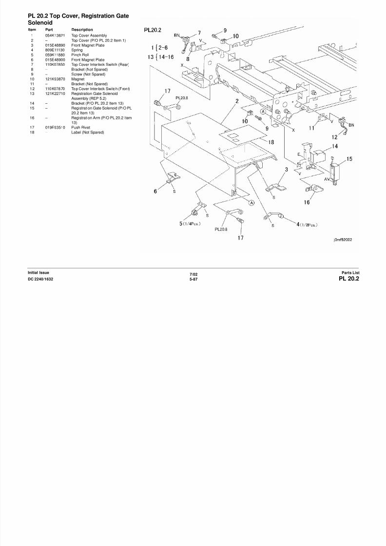
8/13/2019 Xerox Docu Color 2240-1632
http://slidepdf.com/reader/full/xerox-docu-color-2240-1632 805/1118
7/02
5-89DC 2240/1632 PL 20.4Parts ListInitial Issue
PL 20.4 Document Feed Chute(Upper), Feed MotorItem Part Description
1 054K13600 Document Feed Upper Chute
Assembly
2 059K11840 Feed Roll Assembly
3 – Upper Baffle (P/O PL 20.4 Item 1)
4 – Drive Shaft (P/O PL 20.4 Item 1)5 – Gear (P/O PL 20.4 Item 1)
6 013E92760 Bearing
7 – Gear (P/O PL 20.4 Item 1)
8 600K90370 Roll K it (2 Rolls/Kit) (REP 5.6 REP
5.7)
9 012E09750 Link
10 413W77359 Bearing
11 – Gear (P/O PL 20.4 Item 1,PL 20.4
Item 2)
12 – Gear (P/O PL 20.4 Item 1,PL 20.4
Item 2)
13 – Feed Shaft (P/O PL 20.4 Item 1,PL
20.4 Item 2)
14 – Nudger Shaft (P/O PL 20.4 Item
1,PL 20.4 Item 2)
15 – Gear (P/O PL 20.4 Item 1,PL 20.4
Item 2)
16 – Housing (P/O PL 20.4 Item 1,PL
20.4 Item 2)
17 802K08320 Inner Cover Assembly
18 – Inner Cover (P/O PL 20.4 Item 17)19 – Pad (P/O PL 20.4 Item 17)
20 – Pulley (Not Spared)
21 023E20000 Belt
22 – Bearing (Not Spared)
23 127K32680 Feed Motor Assembly (REP 5.5)
24 – Feed Motor (P/O PL 20.4 Item 23)
25 – Motor Bracket (P/O PL 20.4 Item
23)
26 – Damper (P/O PL 20.4 Item 23)
27 – Pulley (P/O PL 20.4 Item 23)
28 – Screw (Not Spared)
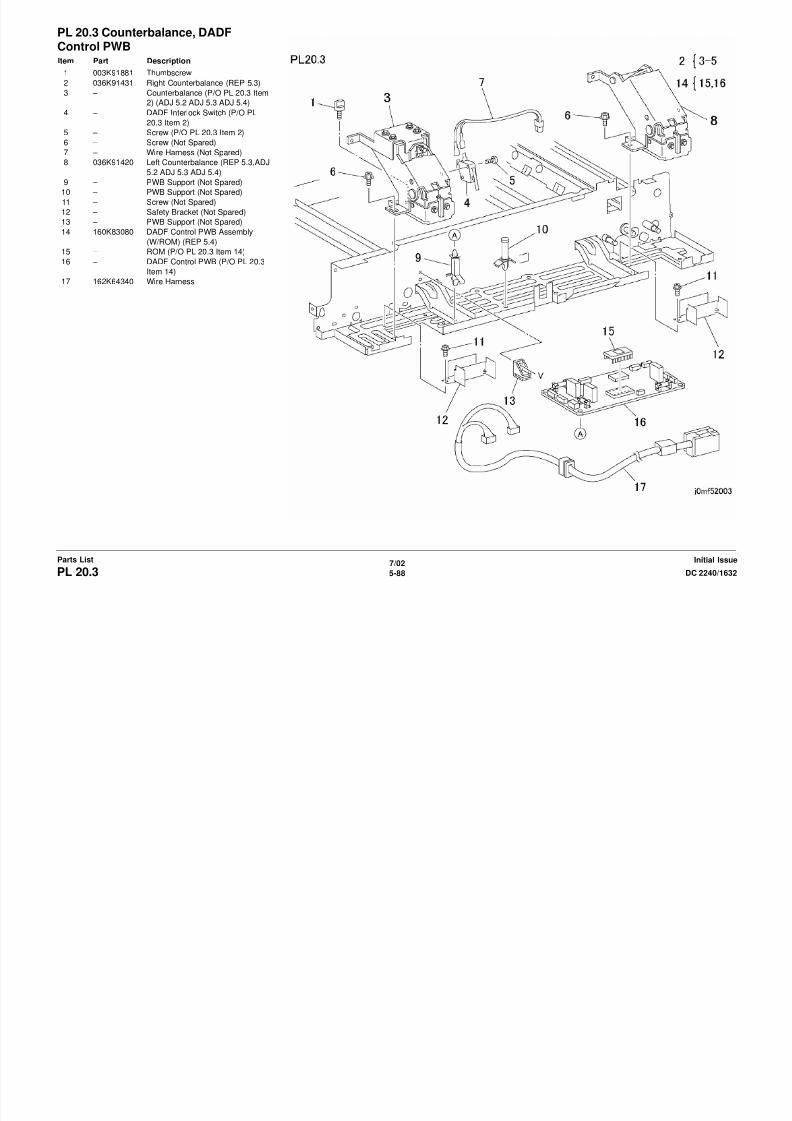
8/13/2019 Xerox Docu Color 2240-1632
http://slidepdf.com/reader/full/xerox-docu-color-2240-1632 806/1118
7/02
5-90 DC 2240/1632PL 20.5Initial IssueParts List
PL 20.5 Document Feed Chute(Lower)Item Part Description
1 054K18780 Lower Chute Assembly (REP 5.8)
2 – Lower Chute (P/O PL 20.5 Item 1)
3 – Spring (P/O PL 20.5 Item 1)
4 059K19720 Retard Roll (REP 5.9)
5 – Spring Plate (P/O PL 20.5 Item 1)6 – Arm (P/O PL 20.5 Item 1)
7 055K19260 Guard
8 – Arm Shaft (P/O PL 20.5 Item 1)
9 – Retard Shaft (P/O PL 20.5 Item 1)
10 – Set Gate (Not Spared)
11 130K60600 Document Sensor, Regist ration
Sensor (REP 5.11)
12 121K22690 Set Gate Solenoid Assembly (REP
5.10)
13 – Bracket (P/O PL 20.5 Item 12)
14 – Set Gate Solenoid (P/O PL 20.5
Item 12)
15 – Spring (P/O PL 20.5 Item 12)
16 – Bracket (Not Spared)
17 130E80890 Size Sensor 1 (Rear), Size Sensor
2 (Front) (REP 5.12)
18 – Bracket (Not Spared)

8/13/2019 Xerox Docu Color 2240-1632
http://slidepdf.com/reader/full/xerox-docu-color-2240-1632 807/1118
7/02
5-91DC 2240/1632 PL 20.6Parts ListInitial Issue
PL 20.6 DADF Belt Motor, Duplex RollItem Part Description
1 127K32690 DADF Belt Motor Assembly (REP
5.13)
2 – DADF Belt Motor (P/O PL 20.6 Item
1)
3 – Damper (P/O PL 20.6 Item 1)
4 – Bracket (P/O PL 20.6 Item 1)5 – Pulley (P/O PL 20.6 Item 1)
6 – Screw (Not Spared)
7 007K86700 Gear Pulley
8 023E19990 Belt
9 – Spacer (Not Spared)
10 – Tension Roll (Not Spared)
11 – Spacer (Not Spared)
12 – Tension Roll (Not Spared)
13 023E20010 Belt
14 020E21050 Pulley
15 – Bearing (Not Spared)16 020K91230 Pulley
17 022K37080 Upper Duplex Roll
18 022K37070 Lower Duplex Roll
19 023E12230 Belt

8/13/2019 Xerox Docu Color 2240-1632
http://slidepdf.com/reader/full/xerox-docu-color-2240-1632 808/1118
7/02
5-92 DC 2240/1632PL 20.7Initial IssueParts List
PL 20.7 Duplex ChuteItem Part Description
1 – Duplex Chute (Not Spared)
2 – Wire Harness (Not Spared)
3 130K60600 Duplex Sensor (REP 5.14)
4 050K46690 Gate
5 – Screw (Not Spared)
6 – Screw (Not Spared)7 054K18790 Lower Chute Assembly
8 – Lower Chute (P/O PL 20.7 Item 7)
9 – Pinch Roll (P/O PL 20.7 Item 7)
10 121E90640 Open Switch Magnet
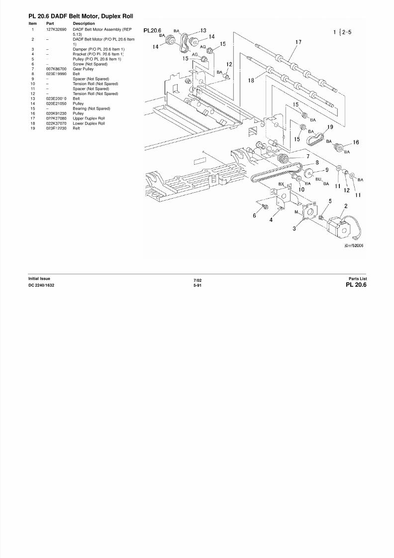
8/13/2019 Xerox Docu Color 2240-1632
http://slidepdf.com/reader/full/xerox-docu-color-2240-1632 809/1118
7/02
5-93DC 2240/1632 PL 20.8Parts ListInitial Issue
PL 20.8 Registration RollItem Part Description
1 – Spacer (Not Spared)
2 007K81120 Gear Pulley
3 – Bearing (Not Spared)
4 059K19750 Registration Roll
5 012E09760 Link
6 809E04210 Rear Spring7 005E80250 Clip
8 013E94561 Bearing
9 008E90941 Rear Cam
10 012E91960 Link
11 022K38040 Registration Pinch Roll (REP 5.15)
12 008E90931 Front Cam
13 809E04220 Front Spring
14 009E28570 Spring
15 050K46690 Gate
16 009E28560 Spring
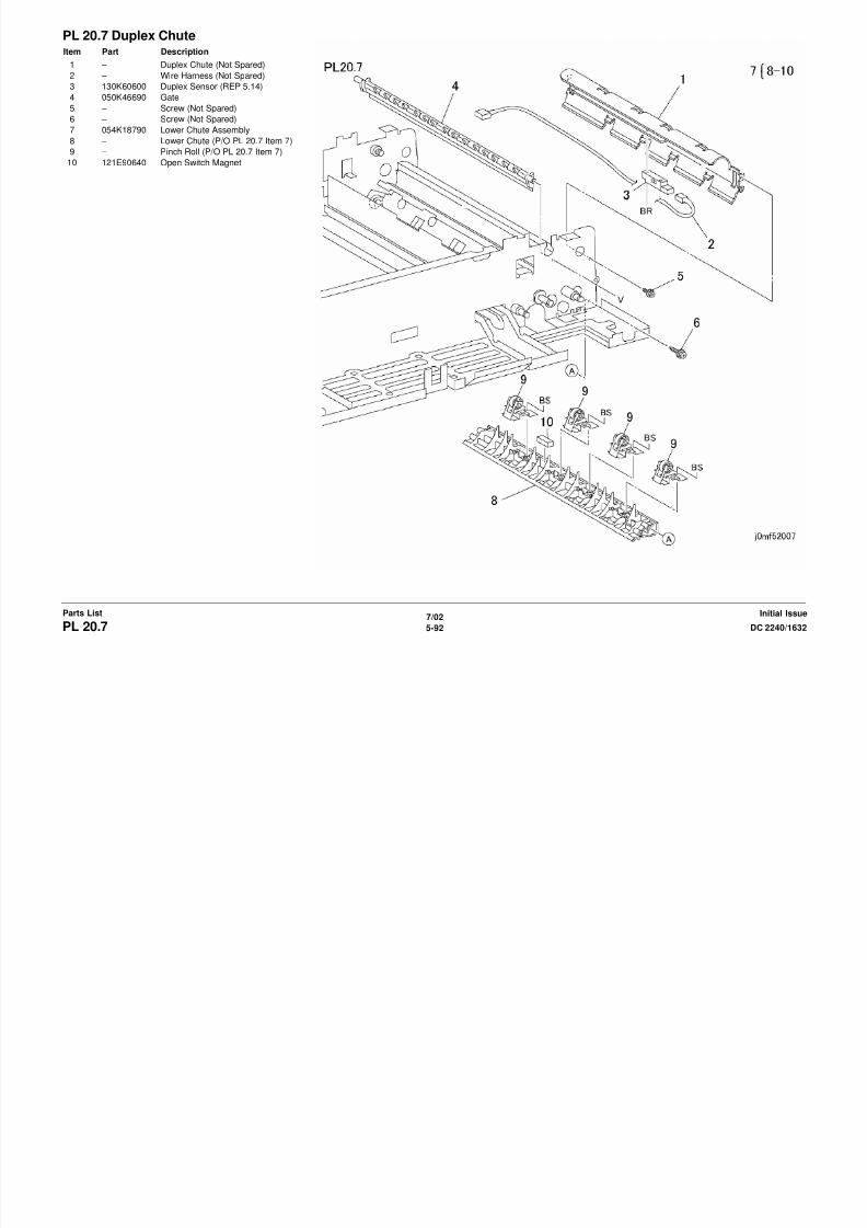
8/13/2019 Xerox Docu Color 2240-1632
http://slidepdf.com/reader/full/xerox-docu-color-2240-1632 810/1118
7/02
5-94 DC 2240/1632PL 20.9Initial IssueParts List
PL 20.9 Exit Motor/ChuteItem Part Description
1 127K32640 Exit Motor Assembly (REP 5.16)
2 – Exit Motor (P/O PL 20.9 Item 1)
3 – Pulley (P/O PL 20.9 Item 1)
4 – Damper (P/O PL 20.9 Item 1)
5 – Bracket (P/O PL 20.9 Item 1)
6 – Spacer (Not Spared)7 023E20000 Belt
8 020E93230 Pulley
9 – Bearing (Not Spared)
10 059K11860 Exit Roll
11 130K60600 DADF Exit Sensor
12 – Bracket (Not Spared)
13 – Plate (P/O PL 20.9 Item 17)
14 105E06910 Static Eliminator
15 – Exit Upper Chute (Not Spared)
16 055K26060 Document Guard
17 054K13081 Lower Exit Chute18 – Exit Lower Chute (P/O PL 20.9 Item
17)
19 – Sensor Pad (P/O PL 20.9 Item 17)
20 059K11821 Pinch Roll
PL 20 10 D t T t Pl t
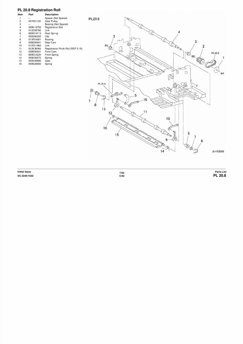
8/13/2019 Xerox Docu Color 2240-1632
http://slidepdf.com/reader/full/xerox-docu-color-2240-1632 811/1118
7/02
5-95DC 2240/1632 PL 20.10Parts ListInitial Issue
PL 20.10 Document Transport, PlatenBeltItem Part Description
1 – Damper (Not Spared)
2 – Static Eliminator (Not Spared)
3 007E66340 Gear
4 – Collar (Not Spared)
5 013E80970 Bearing6 049E91070 Tension Plate
7 022K39710 Idler Roll
8 023E15690 Platen Belt (REP 5.19)
9 – Drive Roll (Not Spared)
10 – Belt Guide (Not Spared)
11 – Belt Guide (Not Spared)
12 – Transport Frame (Not Spared)
13 – Deflector (Not Spared)
14 – Pinch Roll (Not Spared)
15 – Pinch Roll (Not Spared)
16 – Pinch Roll (Not Spared)
17 – Damper (Not Spared)
PL 20 11 Platen Glass Registration
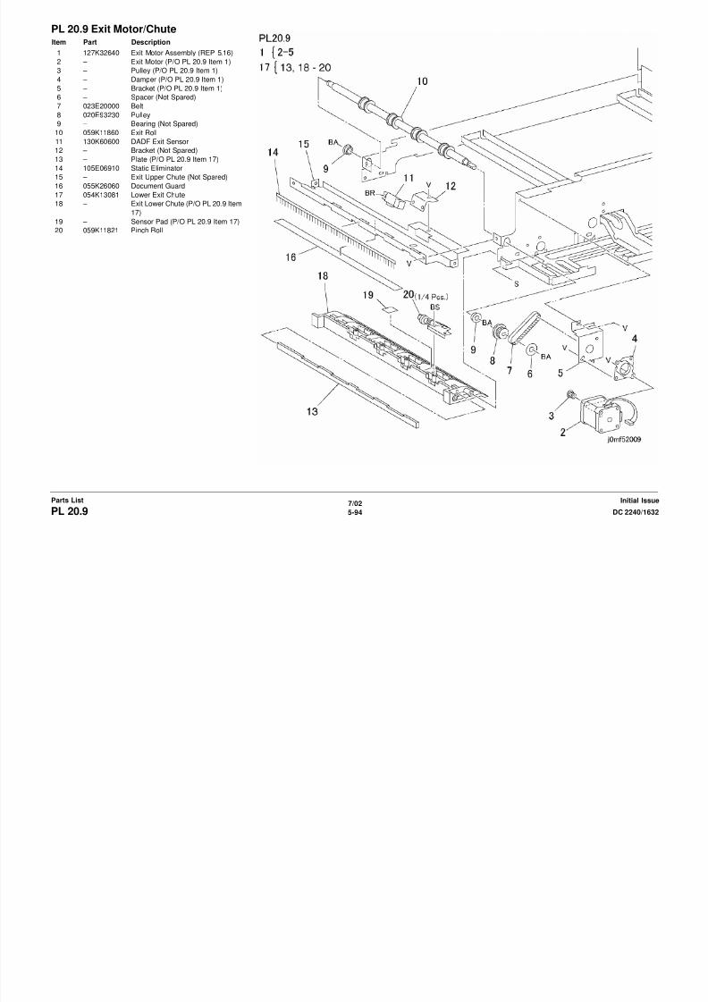
8/13/2019 Xerox Docu Color 2240-1632
http://slidepdf.com/reader/full/xerox-docu-color-2240-1632 812/1118
7/02
5-96 DC 2240/1632PL 20.11Initial IssueParts List
PL 20.11 Platen Glass, RegistrationGate, Exit TrayItem Part Description
1 090K92820 Platen Glass (REP 6.2)
2 050K43070 Registration Gate
3 015K83700 Plate
4 673K51382 Exit Tray
5 003E43840 Thumbscrew6 830E17490 Bracket
7 050E88440 Wing Tray
Common Hardware BB 354W24254 K-Clip (4)

8/13/2019 Xerox Docu Color 2240-1632
http://slidepdf.com/reader/full/xerox-docu-color-2240-1632 813/1118
7/02
5-97DC 2240/1632 Common HardwareParts ListInitial Issue
Common HardwareItem Part Description
A 112W27651 Screw (M3x6)
B 112W27659 Screw (M3x6)
C 112W27851 Screw (M3x8)
D 112W28451 Screw (M3x14)
E 113W20457 Screw (M3x4)
F 113W20651 Screw (M3x6)G 113W20857 Screw (M3x8)
H 113W21057 Screw (M3x10)
J 113W21657 Screw (M3x16)
K 113W27451 Screw (M3x4)
L 113W27551 Screw (M3x5)
M 113W27651 Screw (M3x6)
N 113W27851 Screw (M3x8)
P 113W28051 Screw (M3x10)
Q 113W28851 Screw (M3x20)
R 153W17655 Thread-forming Screw (M3x6)
S 153W17855 Thread-forming Screw (M3x8)T 153W18055 Thread-forming Screw (M3x10)
U 153W27855 Thread-forming Screw (M3x8)
V 158W27655 Screw (M3x6)
W 158W27663 Screw (M3x6)
X 158W27855 Screw (M3x8)
Y 158W27863 Screw (M3x8)
Z 158W28255 Screw (m3x12)
AA 158W35855 Screw (M4x8)
AB 220W21250 Flange Nut (M3)
AC 251W24251 Washer (4)
AD 251W24450 Washer (4)AE 252W24250 Nylon Washer (4)
AF 252W26450 Nylon Washer (5)
AG 252W27350 Nylon Washer (6)
AH 252W27450 Nylon Washer (6)
AJ 252W29450 Nylon Washer (8)
AK 271W16050 Dowel Pin (2x10)
AL 271W28250 Dowel Pin (3x12)
AM 271W28650 Dowel Pin (3x16)
AN 271W28950 Dowel Pin (3x22)
AP 271W36850 Dowel Pin (4x20)
AQ 285W15651 Spring Pin (2x6)
AR 285W15851 Spring Pin (2x8)
AS 285W16251 Spring Pin (2x12)
AT 285W28051 Spring Pin (3x10)
AU 285W28251 Spring Pin (3x12)
AV 285W28651 Spring Pin (3x16)
AW 354W15251 E-Clip (2)
AX 354W19251 E-Clip (2.5)
AY 354W21251 E-Clip (3)
AZ 354W21254 K-Clip (3)
BA 354W24251 E-Clip (4)
BB 354W24254 K Clip (4)
BC 354W26251 E-Clip (5)
BD 354W27251 E-Clip (6)
BE 354W27254 K-Clip (6)
BF 354W29251 E-Clip (8)
BG 113W20657 Screw (M3x6)
BH 113W16051 Screw (M2x10)
BJ 158W45055 Screw (M5x10)
BK 158W36355 Screw (M4x12)BL 251W24451 Washer (4)
BM 113W20557 Screw (M3x5)
BN 113W15851 Screw
BP 113W28056 Screw (M3x10)
BQ 113W28251 Screw (M3x12)
BR 113W28256 Screw (M3x12)
BS 153W27650 Thread-forming Screw (M3x6)
BT 153W27850 Thread-forming Screw (M3x8)
BU 252W27250 Nylon Washer (6)
BV 252W29350 Nylon Washer (8)
BW 285W29151 Spring Pin (3x25)BX 158W35655 Screw (M4x6)
Part Number Index Table 1 Part Number Index
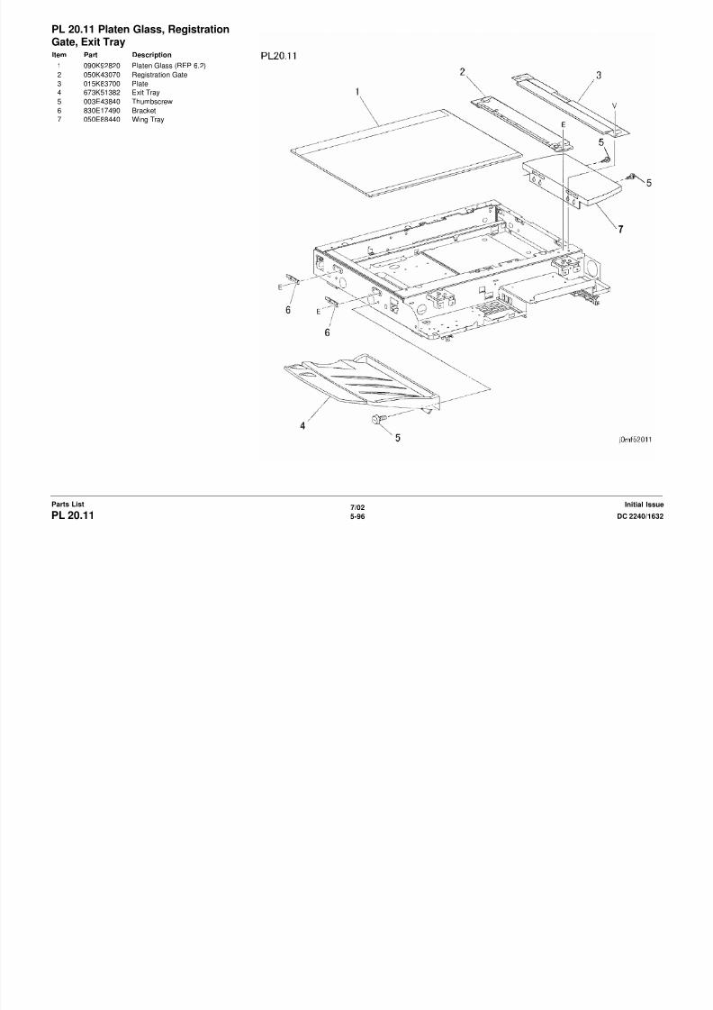
8/13/2019 Xerox Docu Color 2240-1632
http://slidepdf.com/reader/full/xerox-docu-color-2240-1632 814/1118
7/02
5-98 DC 2240/1632Part Number IndexInitial IssueParts List
Part Number Index
Table 1 Part Number Index
Part Number Part List
001E59600 PL 17.9
001E60050 PL 17.14
001K70542 PL 5.1
001K70551 PL 5.1
003K12090 PL 17.1
PL 17.14
003K12650 PL 5.2
003K12880 PL 5.1
003E23672 PL 16.1
PL 2.1
003E43840 PL 20.11
003E52290 PL 5.1
003E52300 PL 5.1
003E53700 PL 16.13
003E53710 PL 16.13
003K86121 PL 4.1
003K91881 PL 20.3
004E06560 PL 18.6
004E11831 PL 2.7
005K05890 PL 16.10
PL 16.8
PL 2.5
PL 16.12
005E16220 PL 17.6
005E16510 PL 17.6
005E80250 PL 20.8
005K83081 PL 16.11
PL 16.7
PL 16.9
PL 2.4006K21720 PL 17.12
006K21730 PL 17.6
006K21970 PL 17.12
006E71740 PL 5.1
007E61890 PL 5.2
007E61910 PL 5.2
007E62630 PL 2.8
007E64740 PL 2.7
007E66050 PL 16.15
007E66060 PL 16.15
007E66070 PL 16.15
007E66080 PL 16.14
007E66340 PL 20.10
007E67730 PL 17.7
007E67740 PL 17.7
007E67750 PL 17.7
007E67760 PL 17.6
007E67770 PL 17.8
007E67780 PL 17.8
007E67790 PL 17.8
007E67800 PL 17.8
007E67810 PL 17.8
007E67820 PL 17.11
007E67830 PL 17.11
007E67840 PL 17.11
007E67850 PL 17.4
007E67860 PL 17.4
007E67870 PL 17.4
007E72070 PL 17.12
007E72080 PL 17.12
007E72090 PL 17.7
007E75201 PL 2.8
007K81120 PL 20.8
007K85522 PL 2.9
007K85580 PL 1.3
007K85730 PL 16.11
PL 2.4
PL 16.9
PL 16.7
007K85750 PL 1.1
007K86400 PL 1.1007K86700 PL 20.6
007K86910 PL 17.6
007K86920 PL 1.1
007K86931 PL 2.9
007K87110 PL 1.1
007K87220 PL 1.1
008E90931 PL 20.8
008E90941 PL 20.8
008E94070 PL 17.7
Table 1 Part Number Index
Part Number Part List
Table 1 Part Number Index Table 1 Part Number Index

8/13/2019 Xerox Docu Color 2240-1632
http://slidepdf.com/reader/full/xerox-docu-color-2240-1632 815/1118
7/02
5-99DC 2240/1632 Part Number IndexParts ListInitial Issue
009E26870 PL 20.1
009E26970 PL 16.3
PL 16.4
009E28560 PL 20.8
009E28570 PL 20.8
009E55450 PL 18.4
009E62830 PL 18.5
011E10711 PL 11.2
011E10800 PL 16.13
011K94970 PL 5.1
011K96790 PL 16.14
012E09750 PL 20.4
012E09760 PL 20.8
012E10070 PL 16.4
012E91960 PL 20.8
012K94110 PL 18.5
012K94120 PL 18.5
012K94260 PL 10.2
013E18980 PL 5.3
013E20240 PL 17.6
013E20250 PL 17.12
013E80970 PL 20.10
013E92760 PL 20.4
013E94561 PL 20.8
014E42850 PL 16.1
PL 2.1
014K81604 PL 9.3
015K45802 PL 11.2
015K48381 PL 2.8
015E48890 PL 20.2
015E48900 PL 20.2
015K49310 PL 5.6
015K49450 PL 16.14
015K49460 PL 16.14
015K49470 PL 16.13
015K49480 PL 5.6
015K50680 PL 17.11
015K51640 PL 17.11
015K52280 PL 17.8
015K52320 PL 4.2
015E77040 PL 17.14
Part Number Part List
015K83700 PL 20.11
017E92060 PL 18.5
017K92350 PL 16.15
017K92360 PL 16.15
017E94660 PL 17.14
017E94700 PL 19.1
017E94710 PL 19.1
017E94730 PL 19.1
019E49470 PL 18.6
019E49830 PL 18.4
019E50340 PL 17.11
019E50400 PL 18.6
019E93510 PL 20.2
019K97130 PL 2.14
019K97540 PL 5.4
019K97550 PL 5.4
019K98190 PL 5.4
019K98200 PL 5.4
020E21050 PL 20.6
020E25090 PL 18.5
020E32740 PL 18.5
020E34970 PL 17.8
020K91230 PL 20.6
020E93120 PL 16.3
020E93230 PL 20.9
020K94970 PL 18.6
020E99590 PL 18.5
022K33920 PL 12.2
022K37070 PL 20.6
022K37080 PL 20.6
022K38040 PL 20.8
022K39710 PL 20.10
022K62610 PL 17.6
022K65880 PL 17.12
022E88210 PL 17.4
023E12230 PL 20.6
023E15690 PL 20.10
023E19300 PL 18.5
023E19990 PL 20.6
023E20000 PL 20.4
PL 20.9
Part Number Part List
Table 1 Part Number Index Table 1 Part Number Index
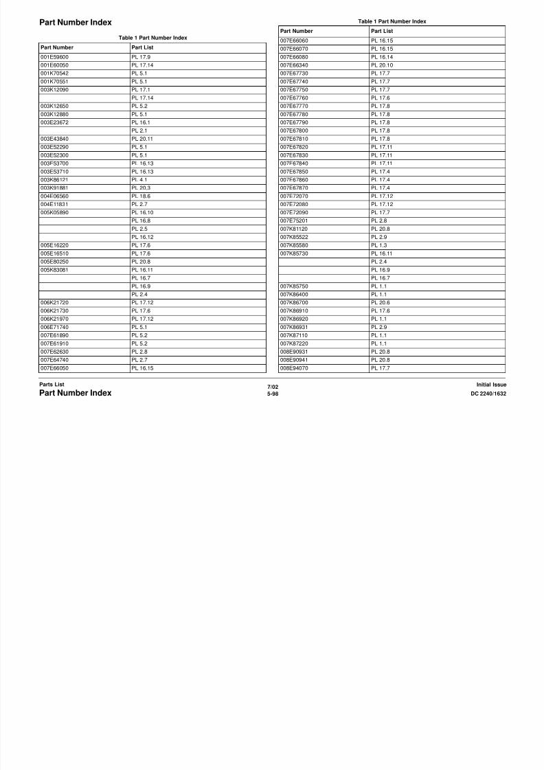
8/13/2019 Xerox Docu Color 2240-1632
http://slidepdf.com/reader/full/xerox-docu-color-2240-1632 816/1118
7/02
5-100 DC 2240/1632Part Number IndexInitial IssueParts List
023E20010 PL 20.6
023E20020 PL 17.4
023E20160 PL 17.7
026E93560 PL 17.1
029E31600 PL 2.3
029K91990 PL 17.9
031E94030 PL 17.7
032K93800 PL 20.1
035E65010 PL 6.2
036K91420 PL 20.3
036K91431 PL 20.3
038E23560 PL 2.14
038E24410 PL 17.10
038E24650 PL 17.4
041K94050 PL 18.6
041K94260 PL 17.9
041K94271 PL 18.6
042K91990 PL 10.1
048E64200 PL 20.1
048K76180 PL 20.1
049E91070 PL 20.10
050K36410 PL 20.1
050K43070 PL 18.3
PL 20.11
050K43120 PL 16.1
050K43130 PL 16.1
050K43880 PL 17.10
050K46690 PL 20.7
PL 20.8
050K48170 PL 16.1
PL 2.1
050K48181 PL 2.13
050E88440 PL 20.11
054K13081 PL 20.9
054K13600 PL 20.4
054K13621 PL 20.2
054K16130 PL 2.8
054E16330 PL 2.8
054K17241 PL 11.2
054K17252 PL 11.2
054K18270 PL 16.6
Part Number Part List
054E18520 PL 16.6
054E18530 PL 16.5
054E18540 PL 16.5
054K18780 PL 20.5
054K18790 PL 20.7
054K22410 PL 2.8
055K19260 PL 20.5
055K26060 PL 20.9
059K11821 PL 20.9
059K11840 PL 20.4
059K11860 PL 20.9
059K11880 PL 20.2
059K15573 PL 16.6
PL 2.3
059K15611 PL 2.8
059K16742 PL 11.1
059K16750 PL 11.2
059K18283 PL 16.5
059K18714 PL 12.1
059K18900 PL 16.6
059K19720 PL 20.5
059K19750 PL 20.8
059K20210 PL 17.7
059K21260 PL 5.4
059K21790 PL 16.5
059K23150 PL 5.3
059K23960 PL 12.1
059K23970 PL 12.2
059K23980 PL 12.2
059K24010 PL 2.14
059K24020 PL 2.14
059K24661 PL 2.6
059K24690 PL 2.11
059K24801 PL 2.12
059E95920 PL 16.4
059E95930 PL 16.1
062E10040 PL 18.6
062K10730 PL 18.6
062K10881 PL 3.1
063E94040 PL 18.5
063E94050 PL 18.5
Part Number Part List
Table 1 Part Number Index Table 1 Part Number Index

8/13/2019 Xerox Docu Color 2240-1632
http://slidepdf.com/reader/full/xerox-docu-color-2240-1632 817/1118
7/02
5-101DC 2240/1632 Part Number IndexParts ListInitial Issue
064K91451 PL 5.3
068E10210 PL 18.3
074K94320 PL 9.2
090K92820 PL 18.3
PL 20.11
101K38810 PL 9.2
101K38980 PL 9.2
103E27220 PL 9.1
104E93610 PL 9.1
105E06910 PL 20.9
105E09760 PL 9.1
105E09810 PL 9.1
105E09820 PL 9.1
105E09830 PL 9.1
105E09970 PL 9.1
105E09980 PL 9.1
105E10480 PL 18.4
105E10510 PL 18.6
105E10650 PL 18.4
105E11130 PL 9.1
105E11320 PL 17.12
105K18641 PL 9.1
105K18771 PL 9.1
107E08680 PL 18.4
110K07850 PL 20.2
110K07870 PL 20.2
110K08471 PL 18.4
110K08541 PL 16.1
PL 2.1
110K10650 PL 2.8
110K10880 PL 16.1
110K11100 PL 18.2
110K11211 PL 10.2
110E94770 PL 10.1
110E97990 PL 17.13
113K82310 PL 9.3
116K90810 PL 6.1
117E19780 PL 18.6
117E20840 PL 18.3
117K30960 PL 18.4
117E94370 PL 9.2
Part Number Part List
118E12090 PL 18.6
120E11971 PL 2.13
120E18160 PL 2.11
120E20690 PL 17.7
120E20700 PL 17.2
120E20970 PL 17.6
121K22220 PL 2.6
121K22470 PL 1.2
121K22690 PL 20.5
121K22710 PL 20.2
121K22860 PL 11.2
121K22870 PL 11.2
121K23270 PL 1.2
121K23560 PL 11.2
121K24610 PL 17.7
121K24620 PL 17.8
121K27751 PL 13.1
121K82870 PL 11.2
121E87830 PL 2.14
121E88470 PL 17.5
121E90640 PL 20.7
121E91450 PL 17.3
121K93870 PL 20.2
122E92030 PL 18.6
122K93330 PL 4.2
122K93340 PL 4.2
123K94020 PL 18.2
126K13940 PL 7.1
126K13950 PL 7.2
126K13960 PL 7.2
126K13980 PL 7.2
126K13990 PL 7.2
126K14890 PL 7.1
127K23230 PL 16.11
PL 16.9
PL 2.4
PL 16.7
127K29242 PL 4.1
127K29330 PL 9.1
127K29340 PL 8.1
127K29511 PL 2.9
Part Number Part List
Table 1 Part Number Index Table 1 Part Number Index
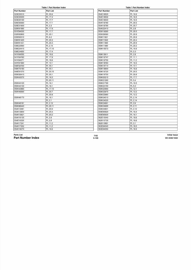
8/13/2019 Xerox Docu Color 2240-1632
http://slidepdf.com/reader/full/xerox-docu-color-2240-1632 818/1118
7/02
5-102 DC 2240/1632Part Number IndexInitial IssueParts List
127K29930 PL 12.2
127K31840 PL 16.15
127K32140 PL 18.5
127K32640 PL 20.9
127K32680 PL 20.4
127K32690 PL 20.6
127K32730 PL 8.1
127K32840 PL 17.7
127K32850 PL 17.10
127K32860 PL 17.9
127K32870 PL 17.8
127K32920 PL 13.1
127K33160 PL 18.4
127K33420 PL 17.11
127K33930 PL 6.1
127K33940 PL 6.1
127K33950 PL 5.4
127K36020 PL 16.15
127K36640 PL 8.1
130K60600 PL 20.5
PL 20.9
PL 20.7
130K60830 PL 5.4
130K60851 PL 2.3
130K60865 PL 1.3
130K61020 PL 7.2
130K61250 PL 12.2
130K61510 PL 16.6
130K61920 PL 17.6
130K62000 PL 18.4
130K62360 PL 17.4
130K62580 PL 18.4
130K63000 PL 6.2
130E80890 PL 20.5
130E81600 PL 16.6
130E82190 PL 16.11
PL 2.3
PL 2.9
PL 5.4
PL 2.4
PL 2.13
Part Number Part List
PL 16.9
PL 16.7
PL 2.11
PL 2.10
130E82530 PL 17.10
PL 17.6
PL 17.9
PL 17.11
PL 17.13
130E82540 PL 17.10
PL 17.8
PL 17.4
130E82650 PL 16.5
PL 2.6
130E82970 PL 17.4
130E84270 PL 5.4
130E84300 PL 2.9
130E91010 PL 4.1
130K93230 PL 11.2
130K93360 PL 17.4
130K94740 PL 17.12
133K21100 PL 13.1
133K21200 PL 13.1
133K22400 PL 13.1
140K60480 PL 20.1
160K46290 PL 2.6
160K66860 PL 12.2
160K74231 PL 13.1
160K75800 PL 18.2
160K76650 PL 13.1
160K76660 PL 17.13
160K76760 PL 9.2
160K76770 PL 9.2
160K76802 PL 9.1
160K77201 PL 9.2
160K77367 PL 18.2
160K82222 PL 13.1
160K83080 PL 20.3
160K84400 PL 9.1
160K84800 PL 9.2
160K84820 PL 9.2
Part Number Part List
Table 1 Part Number Index Table 1 Part Number Index

8/13/2019 Xerox Docu Color 2240-1632
http://slidepdf.com/reader/full/xerox-docu-color-2240-1632 819/1118
7/02
5-103DC 2240/1632 Part Number IndexParts ListInitial Issue
160K85980 PL 16.15
160K87730 PL 9.1
160K90820 PL 18.3
160K90840 PL 13.1
162K55941 PL 9.3
162K55971 PL 9.3
162K56000 PL 9.3
162K56020 PL 5.4
162K56031 PL 9.3
162K56590 PL 16.11
162K61090 PL 5.4
162K62110 PL 9.3
162K62810 PL 16.6
162K64340 PL 20.3
162K69060 PL 17.4
162K69070 PL 17.4
162K69330 PL 9.2
413W10950 PL 18.5
413W77359 PL 20.4
423W28054 PL 17.8
423W29655 PL 17.7
537K61180 PL 13.1
537K62670 PL 13.1
537K62680 PL 13.1
537K64070 PL 17.13
538K94570 PL 13.1
600K78460 PL 16.10
PL 2.5
PL 16.8
PL 16.12
600K90370 PL 20.4
604K05330 PL 18.4
604K07050 PL 5.2
604K07060 PL 5.2
604K07070 PL 2.8
604K07490 PL 6.2
604K07500 PL 6.2
604K07510 PL 6.2
604K07520 PL 6.2
673K51382 PL 20.11
801K02480 PL 17.1
Part Number Part List
802K08320 PL 20.4
802E12400 PL 10.2
802E12430 PL 10.2
802E12480 PL 10.3
802E12490 PL 10.3
802E12500 PL 10.3
802K12950 PL 5.2
802K13193 PL 2.3
802E23930 PL 16.16
802E23950 PL 16.16
802E23960 PL 16.16
802E23980 PL 16.4
802E23990 PL 16.3
802K25731 PL 16.13
802K27073 PL 2.9
802E27860 PL 10.3
802K28110 PL 10.3
802E28520 PL 17.5
802E28530 PL 17.5
802E28540 PL 17.5
802E28550 PL 17.5
802E28560 PL 17.5
802E28570 PL 17.5
802K28570 PL 17.6
802K28580 PL 17.4
802K28590 PL 17.3
802K28600 PL 17.3
802K28891 PL 6.2
802K29610 PL 10.2
802E30140 PL 17.4
802E30150 PL 17.4
802E32860 PL 18.2
802K33090 PL 6.1
802K36580 PL 16.16
802K36650 PL 17.1
802K36660 PL 17.14
802K36670 PL 17.14
802K45490 PL 2.7
802K45710 PL 10.2
802K45910 PL 6.1
802K45920 PL 6.1
Part Number Part List
Table 1 Part Number Index
P t N b P t Li t

8/13/2019 Xerox Docu Color 2240-1632
http://slidepdf.com/reader/full/xerox-docu-color-2240-1632 820/1118
7/02
5-104 DC 2240/1632Part Number IndexInitial IssueParts List
802K45930 PL 6.1
802K45940 PL 6.1
802K46022 PL 18.2
802K46050 PL 10.1
802K46060 PL 10.1
802K47090 PL 4.1
809E04210 PL 20.8
809E04220 PL 20.8
809E09110 PL 18.6
809E11130 PL 20.2
809E26330 PL 5.6
809E28960 PL 16.13
809E28980 PL 16.13
809E29620 PL 2.8
809E33600 PL 17.10
830E17490 PL 20.11
830E81670 PL 17.6
891E49060 PL 16.1
891E49510 PL 16.1
891E49520 PL 16.1
891E65180 PL 20.1
891E65210 PL 20.1
891E75951 PL 10.1
892E13310 PL 2.2
892E28491 PL 16.1
892E41110 PL 2.1
892E74500 PL 16.2
892E78280 PL 10.1
892E78290 PL 10.1
908W01200 PL 9.2
917W00723 PL 9.2
962K05900 PL 18.4
962K05910 PL 18.4
962K07440 PL 17.9
962K08641 PL 13.1
962K08820 PL 9.2
962K09800 PL 9.3
962K10120 PL 17.13
962K10130 PL 17.13
Part Number Part List

8/13/2019 Xerox Docu Color 2240-1632
http://slidepdf.com/reader/full/xerox-docu-color-2240-1632 821/1118
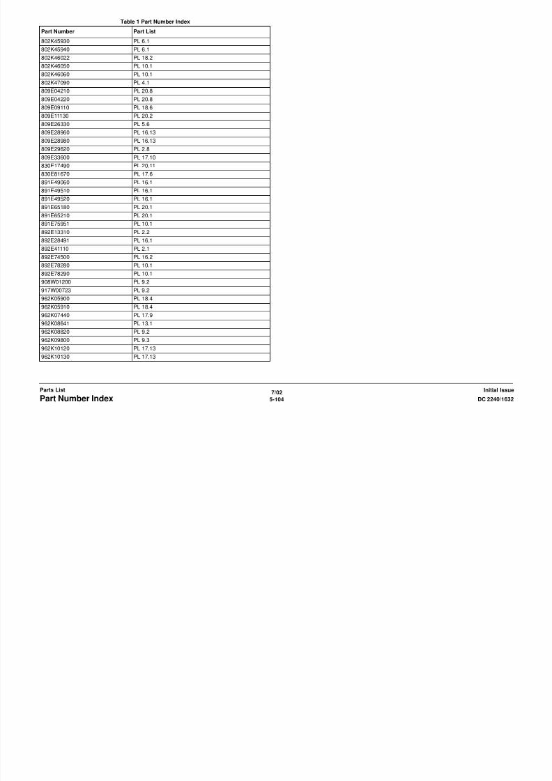
8/13/2019 Xerox Docu Color 2240-1632
http://slidepdf.com/reader/full/xerox-docu-color-2240-1632 822/1118
7/02
6-2 DC 2240/1632
Initial IssueGeneral Procedures and Information

8/13/2019 Xerox Docu Color 2240-1632
http://slidepdf.com/reader/full/xerox-docu-color-2240-1632 823/1118
UI Diagnostic ModeDiagnostic routines are mainly instructed/executed through the PWS. The UI Diagnostic mode
Exiting UI Diagnostic mode
CAUTION

8/13/2019 Xerox Docu Color 2240-1632
http://slidepdf.com/reader/full/xerox-docu-color-2240-1632 824/1118
7/02
6-4 DC 2240/1632UI Diagnostic ModeInitial IssueGeneral Procedures and Information
Diagnostic routines are mainly instructed/executed through the PWS. The UI Diagnostic mode
tis provided for simple tasks that do not require connection with the PWS.
Procedure
Access the UI Diagnostic mode by following the procedures below.
Entering the UI Diagnostic mode
1. At the Control Panel, press and hold the 0 key for 5 seconds, then press the Start button
while still pressing the 0 key.
The CE Mode - Password Entry screen will appear.
2. Enter the Access Number (6789) and press Confirm.
The colors on the display will be reversed to indicate that the mode has changed to the UI
Diagnostic mode.
Accessing Diagnostic routines
1. Press the Access button on the Control Panel
2. Press the System Settings button on the display
3. Press the Common Settings button on the display
4. Press the Diagnostics button on the display
5. The following dC routines can be accessed from the UI screen
a. DC301 NVM Initialization
- Select the subsystem to be initialized and press the Start button on the display.
Refer to dC301 for details.
b. DC355 Hard Disk Initialization
- Only Partition A can be initialized. For full initialization, refer to ADJ 9.8.
c. DC131 NVM Read/Write
- follow the instructions on the screen. If one or more NVM locations is changed, themachine will reboot upon exit. Refer to dC131 for details.
Printing Service Reports
1. To access Service reports, follow the Entering the UI Diagnostic mode procedure.
2. After entering the Access Number, press the Machine Status button on the Control
Panel.
3. Select the Billing Meter/Print Reports tab on the display.
4. Press the Print Reports/List button.
5. Press the CE button
6. The following reports can be printed.a. Debug Log
b. HFSI Report
c. Jam Report
d. Shutdown Report
e. Fail Report
Ensure that the machine is not inadvertently left in UI Diagnostic Mode.
There are three ways to exit from the UI Diagnostic mode.
• Switch the power off and on.
• perform the following:
– Press Close to exit any of the service screens that were opened.
– When the System Settings screen is displayed, press Exit – When the reversed-color Copy Mode screen is displayed, press the Start button
while the 0 key is pressed.
• If the Restart button is displayed in the screen, pressing the button will restart the opera-
tion and exit from the mode.

8/13/2019 Xerox Docu Color 2240-1632
http://slidepdf.com/reader/full/xerox-docu-color-2240-1632 825/1118
dC100 Service EntryWhen entering Diagnostics, this routine allows you to view faults in progress, Non-Zero Jams
Table 1 dC Routines
dC Number Name Description
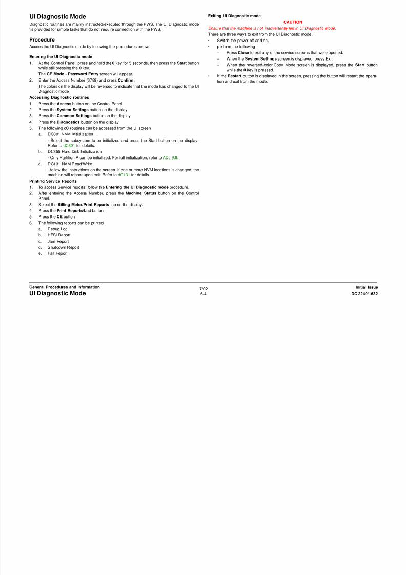
8/13/2019 Xerox Docu Color 2240-1632
http://slidepdf.com/reader/full/xerox-docu-color-2240-1632 826/1118
7/02
6-6 DC 2240/1632DC Quick, dC100Initial IssueGeneral Procedures and Information
and HFSI items requiring replacement. Service entry allows you to view product information,
such as:
• Product Code
• Machine Serial Number
• Total Copies
• Copies since Last Call
• IOT Software Version
Procedure
1. Enter the Diagnostic Mode. Refer to Entering Diagnostic Mode using the PWS.
2. Check the HFSI Requiring Replacement.
3. Check the Non-Zero Jams. Jams that have occurred since the last service exit with the
Complete Closeout option selected. Check for any Jams that have a high number of
occurrences.
4. Check the Faults In Progress. If any faults in progress are displayed, troubleshoot
accordingly.
5. Select the Refresh button to have the PWS request and receive the latest information on
Total Copies, Copies Since Last Call, Non-Zero Jams or HFSI Requiring Replacement.
371 Configuration Page Allows viewing of current software version
and Market Place setting, Machine Con-
figuration, Output Device(s), Accessories,
Feature Config., and Input Device.
These settings can be changed to align
with the machine configuration.
612 Color Test Pattern Print Generates test pattern from the pattern
generator in the machine. Patterns for use
in identifying IQ problems, setting registra-
tion, and performing adjustments
685 Regicon Color Registration/Skew setup
921 ATC Calibration Enter ATC Sensor Calibration code into
NVM.
922 TRC Control/Toner Density
Adjustment
Measure the gray scale patch by the ADC
sensor. Make the LUT for IOT TRC cor-
rection.
924 TRC Adjustment Manually fine adjust each color (low/mid/
high density) in PG.
934 ADC/AGC Setup Execute automatic adjustment of the ADC
Sensor Gain.
945 IIT calibration 1. Calculate and set the white reference
compensation coefficient.
2. Correct the IIT sensitivity variation.
956 Belt Edge Learn Set up the Belt Edge Sensor.
dC118 Jam CounterPurpose
dC120 Fault CounterPurpose

8/13/2019 Xerox Docu Color 2240-1632
http://slidepdf.com/reader/full/xerox-docu-color-2240-1632 827/1118
7/02
6-7DC 2240/1632 dC118, dC120General Procedures and InformationInitial Issue
Displays the number of occurrences of Jams from time of previous Complete Closeout on ser-
vice exit until present.
NOTE: This procedure does not count jams detected while in the Service Mode.
Procedure
1. Enter the Diagnostic Mode. Refer to Entering Diagnostic Mode using the PWS.
2. Select Maintenance on the Service Entry Screen.
3. Select the Jam Counters (dC 118).
4. The screen displays all jam-related fault codes, and the number of times that the fault has
occurred since the last time the Complete Closeout option was selected when exiting
Diagnostic Mode.
5. The following subsets of data are selectable:
• All Jams
- This is the default. All jam-related faults are listed
• DADF Jams
- Selecting this tab lists only the DADF jam codes.
• Paper Jams
- Selecting this tab lists only the paper supply and paper feeding jam codes.
• Non-Zero Jams
- Selecting this tab lists only those jam codes that have had at least one occurrence
since the last time the Complete Closeout option was selected.
Displays the number of occurrences of each fault since the last Service Exit with the Complete
Closeout option selected.
NOTE:
• The machine does not count the faults detected while in the Service Mode.
• The machine does not count interlock open detected faults while the Main Processor is stopped.
Procedure
1. Enter the Diagnostic Mode. Refer to Entering Diagnostic Mode using the PWS.
2. Select Maintenance on the Service Entry Screen.
3. Select the Fail Counters (dC120) tab.
4. The screen displays all fault codes that have occurred since the last time the Complete
Closeout option was selected when exiting Diagnostic Mode.
The codes are listed in ascending order; to list in descending order, click on ID in the table
header.If machine data was previously saved to diskette, and Diagnostic Mode was entered with
the Read From Diskettes option selected, the previous fault history #Occurrence will dis-
play in the P1 column. If this same procedure was performed previously, the fault history
#Occurrence will display in P2, then P3, up to columns P7.
5. The following subsets of data are selectable:
• All Faults
• DADF Faults
• System faults
• Xero Faults
dC122 Shutdown HistoryPurpose
dC129 System Registration SetupPurpose

8/13/2019 Xerox Docu Color 2240-1632
http://slidepdf.com/reader/full/xerox-docu-color-2240-1632 828/1118
7/02
6-8 DC 2240/1632dC122, dC129Initial IssueGeneral Procedures and Information
To display the Last 40 Faults (History).
NOTE:
1. fault detected while in Service Mode are not counted.
2. An Interlock open while the machine is stopped is not counted.
3. If multiple faults occurred in the machine, the primary fault is recorded.
Procedure
1. Enter the Diagnostic Mode. Refer to Entering Diagnostic Mode using the PWS.
2. Select the Diagnostics Tab.
3. Select the Shutdown Hist (dC122) tab.
4. The system displays the faults that occurred in Customer Mode since the last service call
closeout, up to a maximum of 40 faults.
5. The information in the lower right corner of the screen (Input, Original, Paper, Tray, Out-
put) reflects the fault highlighted in the Table.
6. The following subsets of data are available:
• Last 40 Faults History (default screen).
- displays the 40 newest faults and lists copy count when each occurred.
• Last 40 Faults Occurrences
- displays the 40 newest faults and lists the number of occurrences.
• DADF Jams
- displays the 40 newest DADF jams and lists copy count when each occurred.
• Paper Jams
- displays the 40 newest paper jams and lists copy count when each occurred.
• Faults
- displays the 40 newest non-jam faults and lists copy count when each occurred.
7. To clear the shutdown history, select Complete Closeout in the Service Mode Exit
screen (dC188). Exiting from the Service Mode clears all data in the Shut-Down History.
Performs the Lead Registration and Side Registration adjustments by looking at the output of
the built-in Test Pattern.
NOTE: For details on the dC129 System Registration adjustment, see ADJ 9.9 IOT Registra-
tion Series (dC129).
dC131 NVM Read/WritePurpose
a. If the input value is valid (within the range), the system writes the new NVM value in
the NVM location in the machine.
b. If the input value is invalid, the system displays the following message in the infor-

8/13/2019 Xerox Docu Color 2240-1632
http://slidepdf.com/reader/full/xerox-docu-color-2240-1632 829/1118
7/02
6-9DC 2240/1632 dC131General Procedures and InformationInitial Issue
Reads, sets or changes the NVM data.
Procedure
Module Selection
1. Enter the Diagnostic Mode. Refer to Entering Diagnostic Mode using the PWS.
2. Select Adjustments in the Service Entry Screen.
3. The system displays one of the Read/Write Screens. dC131 NVM Read/Write is the
default screen.
4. Select a Sub-System from the Vertical Left Tab List. The default tab is All.
Reading NVM
1. Select an ID from the Sub-System Table, then click Read NVM, or double click on the lineID and the value will be read in the Value column.
The Range Check column will fill in.
Writing NVM
1. To change a value, enter a new value in the New column and press Enter.
2. When a new value is entered, the Changed tab will turn green. The number in parenthe-
ses count the number of pending NVM values. Clicking this tab will show a list of all the
changed values. These locations can be written individually or as a block from this tab, or
can be canceled.
3. Select Write NVM.
p , y p y g g
mation screen, The given NVM value is out of range. NVM was not changed .
c. If the NVM cannot be changed (Write protected NVM), the system displays the fol-
lowing message, The specified NVM is read only.
4. When the system writes the new value in the specified NVM code, the value is updated in
the New box and reduces the count in the Changed Tab.
Table 1 Module Selection
Module item Chain number allocation
All 700 - 999
UI/Tools 700, 720
IISS 715Config/System 719, 740
Xfer 746
RegiCon 760
PHM 742
DADF 710
Xero 751
Drives / Output 741, 764
ProCon 752
Developer 762
Fuser 744
Other 755, 769
Errors (number of errors) Displays and NVM outside of the ranges listed in the
PWS database.
Changed (number pending change) Displays any with new value entered in the New col-
umn, but not written yet.
dC131 NVM Tables700-xxx ESS Configuration NVM List

8/13/2019 Xerox Docu Color 2240-1632
http://slidepdf.com/reader/full/xerox-docu-color-2240-1632 830/1118
7/02
6-10 DC 2240/1632
Initial IssueGeneral Procedures and Information
Table 1 Chain 700
Chain-Link Name Default Range Description
700-006 Configuration - 0x00~0x08 [P, SP, CSP, CFSP] Set up at factory production. It allocates bits in the following P(rinter), F(ax), C(opy), S(can).
P = 0x01, F = 0x02, C = 0x04, S = 0x08.
700-073 Page Memory Size - 64*1024*102
4~256*1024*
1024
bytes (Auto Setting)
700-075 ART User Buffer Size 32KB 32*1024~204
8*1024
32KB~2048KB (32KB interval)
700-076 PostScript Buffer Size 8*1024*1024
~32*1024*10
24
Color machine = [8 MB~32 MB] B/W machine = [4.5 MB~32 MB] (0.25 MB interval)
700-078 Form Buffer Size 128 KB 128*1024~20
48*1024
128 KB~2048 KB
700-080 HPGL/Auto Layout Buffer Size 64 KB 64*1024~512
0*1024
64 KB~5120 KB (32 KB interval)
700-081 Parallel Buffer Size 64KB - 64 KB~1 MB (32 KB interval)
700-082 TBD 256KB 64*1024~1*1
024*1024
64 KB~1 MB (32 KB interval)
700-083 Lpd Buffer Size 256KB 64*1024~1*1
024*1024
64 KB~1 MB (32 KB interval)
700-084 NetWare Buffer Size 256KB 64*1024~1*1
024*1024
64 KB~1 MB (32 KB interval)
700-085 AppleTalk Buffer Size 256KB - 64 KB~1 MB (32 KB interval)
700-086 SMB Buffer Size 256KB 64*1024~1*1
024*1024
64 KB~1 MB (32 KB interval)
700-087 IPP Buffer Size 256KB 64*1024~1*1
024*1024
64 KB~1 MB (32 KB interval)
700-088 Salutation Buffer Size 256KB - 64 KB~1 MB (32 KB interval)
700-089 HDD Status - -2~0 0 = Yes, -1 = Error, -2 = No (Auto Detect)
700-120 Time Zone 540 - Displays the Time difference from GMT. E.g. Japan = 540, Hawaii = -600
700-122 Date Format - - XC = 2; XE = 3
700-123 Clock Format - -
700-124 Auto Clear Timer 1min 0~240 MF = 0, 1~4 = [Disable (0), 1~4min] (in increments of 1min) P = 0, 1~30 = [Disable (0), 1~30min] (in incre-
ments of 1min)
700-125 Job Cancel Timer 10min 0~5940 0 = Disable 240~5940 = 4~99min (in increments of 1min)
700-126 Operating Timer 10sec 0~240 0 = Disable 1~240 = [1~240sec] (in increments of 1sec)
700-127 Job End Timer 6sec 0~240 0 = Disable 1~240 = [1~240sec] (in increments of 1sec)
700-128 Scanning Timer 4sec 1~20 1~20 = [1~20sec (1sec unit)
700-129 LowPower Mode Timer 15 6~240 6~240 = [6~240min (in increments of 1min)]
700-130 Sleep Mode Timer 60min 15~240 15~240 = [15~240min (in increments of 1min)]
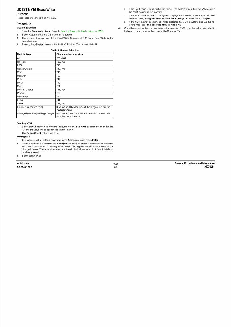
8/13/2019 Xerox Docu Color 2240-1632
http://slidepdf.com/reader/full/xerox-docu-color-2240-1632 831/1118
700-308 SEEPROM Serial# (8th digit) - - Alphanumerics (ASCII)
Table 1 Chain 700
Chain-Link Name Default Range Description

8/13/2019 Xerox Docu Color 2240-1632
http://slidepdf.com/reader/full/xerox-docu-color-2240-1632 832/1118
7/02
6-12 DC 2240/1632
Initial IssueGeneral Procedures and Information
700 308 SEEPROM Serial# (8th digit) Alphanumerics (ASCII)
700-309 SEEPROM Serial# (9th digit) - - Alphanumerics (ASCII)
700-310 SEEPROM Serial# (10th digit) - - Alphanumerics (ASCII)
700-311 Battery Backup SRAM Serial # (1st
digit)
- - Alphanumerics (ASCII)
700-312 Battery Backup SRAM Serial # (2nddigit)
- - Alphanumerics (ASCII)
700-313 Battery Backup SRAM Serial # (3rd
digit)
- - Alphanumerics (ASCII)
700-314 Battery Backup SRAM Serial # (4th
digit)
- - Alphanumerics (ASCII)
700-315 Battery Backup SRAM Serial # (5th
digit)
- - Alphanumerics (ASCII)
700-316 Battery Backup SRAM Serial # (6th
digit)
- - Alphanumerics (ASCII)
700-317 Battery Backup SRAM Serial # (7thdigit)
- - Alphanumerics (ASCII)
700-318 Battery Backup SRAM Serial # (8th
digit)
- - Alphanumerics (ASCII)
700-319 Battery Backup SRAM Serial # (9th
digit)
- - Alphanumerics (ASCII)
700-320 Battery Backup SRAM Serial # (10th
digit)
- - Alphanumerics (ASCII)
700-321 SEEPROM Product # (1st digit) - - Alphanumeric (ASCII)
700-322 SEEPROM Product # (2nd digit) - - Alphanumeric (ASCII)
700-323 SEEPROM Product # (3rd digit) - - Alphanumeric (ASCII)
700-324 SEEPROM Product #(4th digit) - - Alphanumeric (ASCII)
700-325 Battery Backup SRAM Product # (1st
digit)
- - Alphanumeric (ASCII)
700-326 Battery Backup SRAM Product # (2nd
digit)
- - Alphanumeric (ASCII)
700-327 Battery Backup SRAM Product # (3rd
digit)
- - Alphanumeric (ASCII)
700-328 Battery Backup SRAM Product # (4th
digit)
- - Alphanumeric (ASCII)
700-329 SEEPROM Product Code (1st digit) - - Alphanumerics (ASCII)
700-330 SEEPROM Product Code (2nd digit) - - Alphanumerics (ASCII)
700-331 SEEPROM Product Code (3rd digit) - - Alphanumerics (ASCII)
700-332 SEEPROM Product Code (4th digit) - - Alphanumerics (ASCII)
700-333 SEEPROM Product Code (5th digit) - - Alphanumerics (ASCII)
700-334 SEEPROM Product Code (6th digit) - - Alphanumerics (ASCII)
700-335 SEEPROM Product Code (7th digit) - - Alphanumerics (ASCII)
700-336 SEEPROM Product Code (8th digit) - - Alphanumerics (ASCII)
700-337 Configuration (info. On SEEPROM) - - [P, SP, CSP, CFSP (C)] Set at factory. It allocates bits in the following into P(rinter), F(ax), C(opy), S(can)
Table 1 Chain 700
Chain-Link Name Default Range Description

8/13/2019 Xerox Docu Color 2240-1632
http://slidepdf.com/reader/full/xerox-docu-color-2240-1632 833/1118
7/02
6-13DC 2240/1632
General Procedures and InformationInitial Issue
710-xxx DADF NVM List
g ( ) [ , , , ( )] y g ( ), ( ), ( py), ( )
respectively and display it in that disjunction. P = 0x01, F = 0x02, C = 0x04, S = 0x08
700-338 Market Region (SEEPROM) - 1~4 1=FX, 2=XC, 3=XE, 4=AP
700-339 IOT ROM Major version - - (Auto Setting)
700-340 IOT ROM Minor version - - (Auto Setting)
700-341 IOT ROM Revision version - - (Auto Setting)700-342 Sys Main ROM Major - - (Auto Setting)
700-343 Sys Main ROM Minor - - (Auto Setting)
700-344 Sys Main ROM Revision - - (Auto Setting)
700-348 IIT ROM Major - - (Auto Setting)
700-349 IIT ROM Minor - - (Auto Setting)
700-350 IIT ROM Revision - - (Auto Setting)
700-351 DADF ROM Major - - (Auto Setting)
700-352 DADF ROM Minor - - (Auto Setting)
700-353 DADF ROM Revision - - (Auto Setting)700-354 UI Frame ROM Major - - (Auto Setting)
700-355 UI Frame ROM Minor - - (Auto Setting)
700-356 UI Frame ROM Revision - - (Auto Setting)
700-357 UI control ROM Major - - (Auto Setting)
700-358 UI control ROM Minor - - (Auto Setting)
700-359 UI control ROM Revision - - (Auto Setting)
700-360 Product Code (1st digit) - - Alphanumerics (ASCII)
700-361 Product Code (2nd digit) - - Alphanumerics (ASCII)
700-362 Product Code (3rd digit) - - Alphanumerics (ASCII)700-363 Product Code (4th digit) - - Alphanumerics (ASCII)
700-364 Product Code (5th digit) - - Alphanumerics (ASCII)
700-365 Product Code (6th digit) - - Alphanumerics (ASCII)
700-366 Product Code (7th digit) - - Alphanumerics (ASCII)
700-367 Product Code (8th digit) - - Alphanumerics (ASCII)
700-368 Lpd Buffer Size (Memory Spool) 1MB
1*1024*1024
512*1024~32
*1024*1024
Memory Spool = [512 KB~32 MB] (256 KB interval)
700-397 Report paper size 44 = 8.5 x 11; 5 = A4
Table 2 Chain 710
Chain-Link Name Default Range Description
710-001 ADF Fail Bypass 0 0~1 0 = Bypass ON 1 = Bypass OFF
710-002 JAM Bypass 0 0~1 0 = Bypass ON 1 = Bypass OFF
710-005 Regi Sensor Off to Belt Motor Slow-
down Step (Non CVT Mode)
250 217~283 No. of Steps after the Regi Sensor turned Off and until the Belt Motor started to reduce speed in the Non CVT
Mode. Lead Regi Adjustment Value = 5 +/-5mm

8/13/2019 Xerox Docu Color 2240-1632
http://slidepdf.com/reader/full/xerox-docu-color-2240-1632 834/1118

8/13/2019 Xerox Docu Color 2240-1632
http://slidepdf.com/reader/full/xerox-docu-color-2240-1632 835/1118
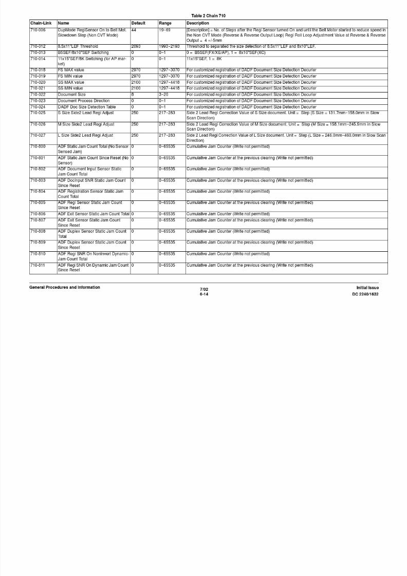
8/13/2019 Xerox Docu Color 2240-1632
http://slidepdf.com/reader/full/xerox-docu-color-2240-1632 836/1118
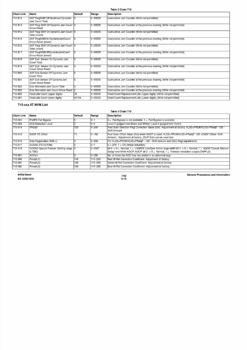
8/13/2019 Xerox Docu Color 2240-1632
http://slidepdf.com/reader/full/xerox-docu-color-2240-1632 837/1118

8/13/2019 Xerox Docu Color 2240-1632
http://slidepdf.com/reader/full/xerox-docu-color-2240-1632 838/1118
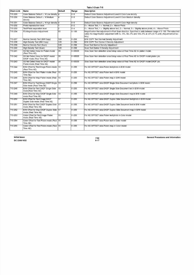
8/13/2019 Xerox Docu Color 2240-1632
http://slidepdf.com/reader/full/xerox-docu-color-2240-1632 839/1118

8/13/2019 Xerox Docu Color 2240-1632
http://slidepdf.com/reader/full/xerox-docu-color-2240-1632 840/1118
719-010 ADF Major Version 0 0~65535 ADF Major Version No.
719-011 ADF Minor Version 0 0~65535 ADF Minor Version No.
Table 4 Chain 719
Chain-Link Name Default Range Description
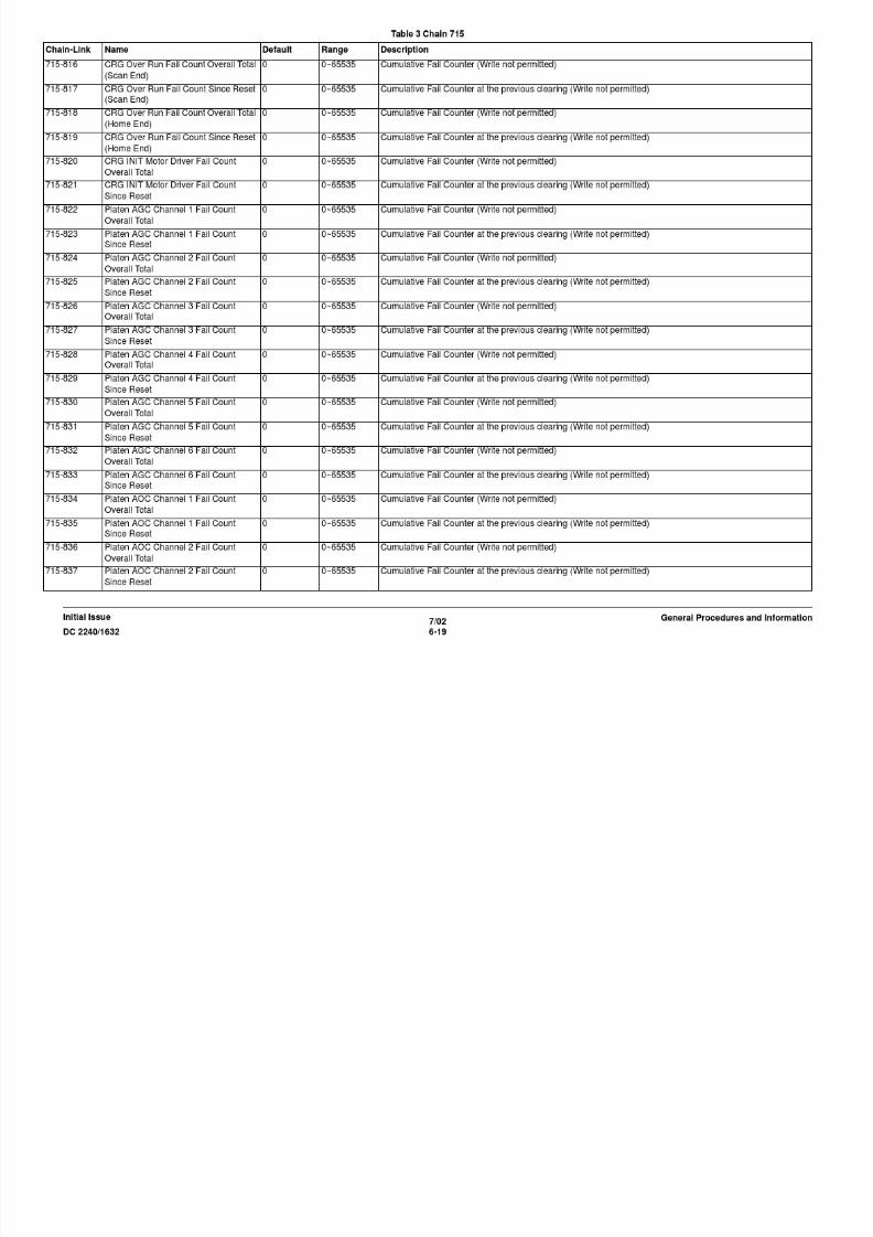
8/13/2019 Xerox Docu Color 2240-1632
http://slidepdf.com/reader/full/xerox-docu-color-2240-1632 841/1118
7/02
6-21DC 2240/1632
General Procedures and InformationInitial Issue
720-xxx ESS Meter/Counter NVM List
740--xxx IOT Manager NVM List
719-012 ADF Revision Version 0 0~65535 ADF Revision Version No.
719-013 ADF Patch Version 0 0~65535 ADF Patch Version No.
Table 5 Chain 720
Chain-Link Name Default Range Description
720-002 Billing PFV BILL-
ING TYPE1
1~6 1 = Billing1, 2 = Billing2, 3 = Billing3, 4 = Billing4, 5 = Billing5, 6 = Billing6
720-003 Master Print-Full Color - 0~1999999 0~1,999,999
720-004 Master Print-Color1 - 0~1999999 0~1,999,999
720-005 Master Print-Color2 - 0~1999999 0~1,999,999
720-006 Master Print-B&W - 0~1999999 0~1,999,999720-012 Backup1 Print-Full Color - 0~1999999 0~1,999,999
720-013 Backup1 Print-Color1 - 0~1999999 0~1,999,999
720-014 Backup1 Print-Color2 - 0~1999999 0~1,999,999
720-015 Backup1 Print-B&W - 0~1999999 0~1,999,999
720-040 [PSW Display] Group 0 0~999999999
999
0~999999999999 (0 means not set up)
720-041 TBD 0 0~999999999
999
0~999999999999 (0 means not set up)
720-042 TBD 0 0~3 0 = FreeAccess, 1 = Color Only, 2 = B&W Only, 3 = Cannot be used
720-043 TBD 0 0~3 0 = FreeAccess, 1 = Color Only, 2 = B&W Only, 3 = Cannot be used
720-044 Group C Mode to use 0 0~3 0 = FreeAccess, 1 = Color Only, 2 = B&W Only, 3 = Cannot be used
Table 6 Chain 740
Chain-Link Name Default Range Description
740-020 Market Code - - XC = 2; XE = 3
740-024 RegiCon Request Flag 0 0~255 0 = Performed, 1 = Not performed
740-025 Edge Check Request Flag 0 0~255 0 = Performed, 1 = Not performed
740-026 ProCon Request Flag 0 0~255 0 = Performed, 1 = Not performed

8/13/2019 Xerox Docu Color 2240-1632
http://slidepdf.com/reader/full/xerox-docu-color-2240-1632 842/1118
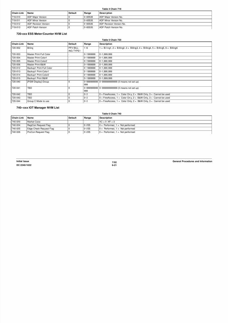
8/13/2019 Xerox Docu Color 2240-1632
http://slidepdf.com/reader/full/xerox-docu-color-2240-1632 843/1118

8/13/2019 Xerox Docu Color 2240-1632
http://slidepdf.com/reader/full/xerox-docu-color-2240-1632 844/1118
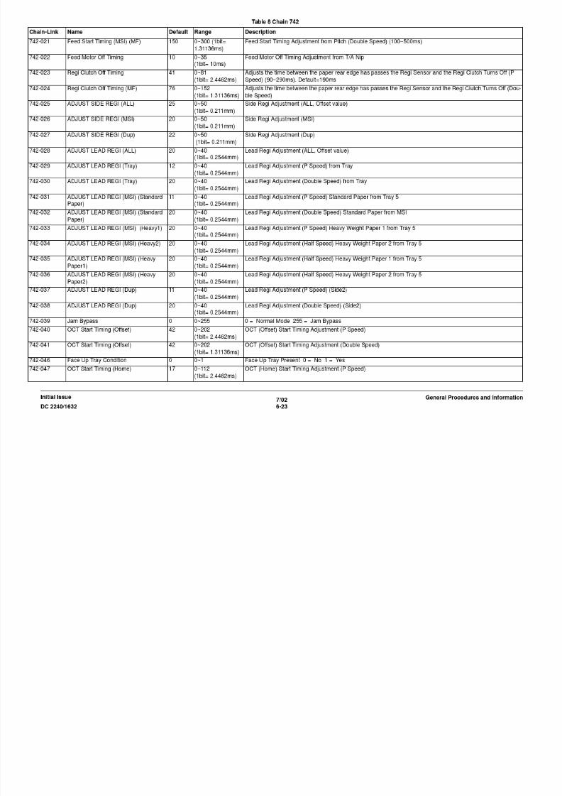
8/13/2019 Xerox Docu Color 2240-1632
http://slidepdf.com/reader/full/xerox-docu-color-2240-1632 845/1118
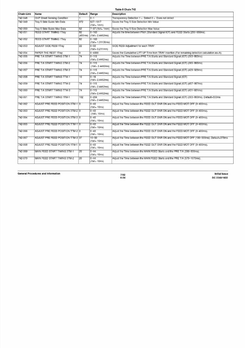
8/13/2019 Xerox Docu Color 2240-1632
http://slidepdf.com/reader/full/xerox-docu-color-2240-1632 846/1118

8/13/2019 Xerox Docu Color 2240-1632
http://slidepdf.com/reader/full/xerox-docu-color-2240-1632 847/1118

8/13/2019 Xerox Docu Color 2240-1632
http://slidepdf.com/reader/full/xerox-docu-color-2240-1632 848/1118
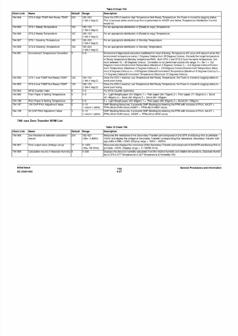
8/13/2019 Xerox Docu Color 2240-1632
http://slidepdf.com/reader/full/xerox-docu-color-2240-1632 849/1118

8/13/2019 Xerox Docu Color 2240-1632
http://slidepdf.com/reader/full/xerox-docu-color-2240-1632 850/1118

8/13/2019 Xerox Docu Color 2240-1632
http://slidepdf.com/reader/full/xerox-docu-color-2240-1632 851/1118

8/13/2019 Xerox Docu Color 2240-1632
http://slidepdf.com/reader/full/xerox-docu-color-2240-1632 852/1118

8/13/2019 Xerox Docu Color 2240-1632
http://slidepdf.com/reader/full/xerox-docu-color-2240-1632 853/1118

8/13/2019 Xerox Docu Color 2240-1632
http://slidepdf.com/reader/full/xerox-docu-color-2240-1632 854/1118

8/13/2019 Xerox Docu Color 2240-1632
http://slidepdf.com/reader/full/xerox-docu-color-2240-1632 855/1118
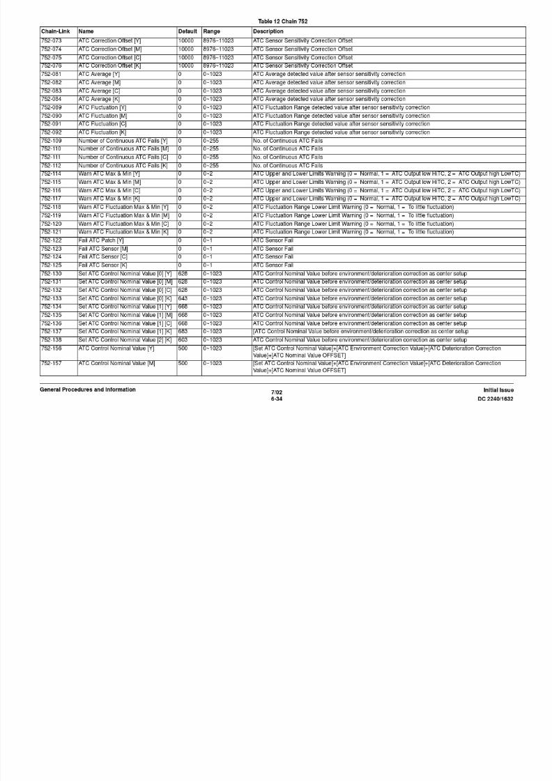
8/13/2019 Xerox Docu Color 2240-1632
http://slidepdf.com/reader/full/xerox-docu-color-2240-1632 856/1118

8/13/2019 Xerox Docu Color 2240-1632
http://slidepdf.com/reader/full/xerox-docu-color-2240-1632 857/1118
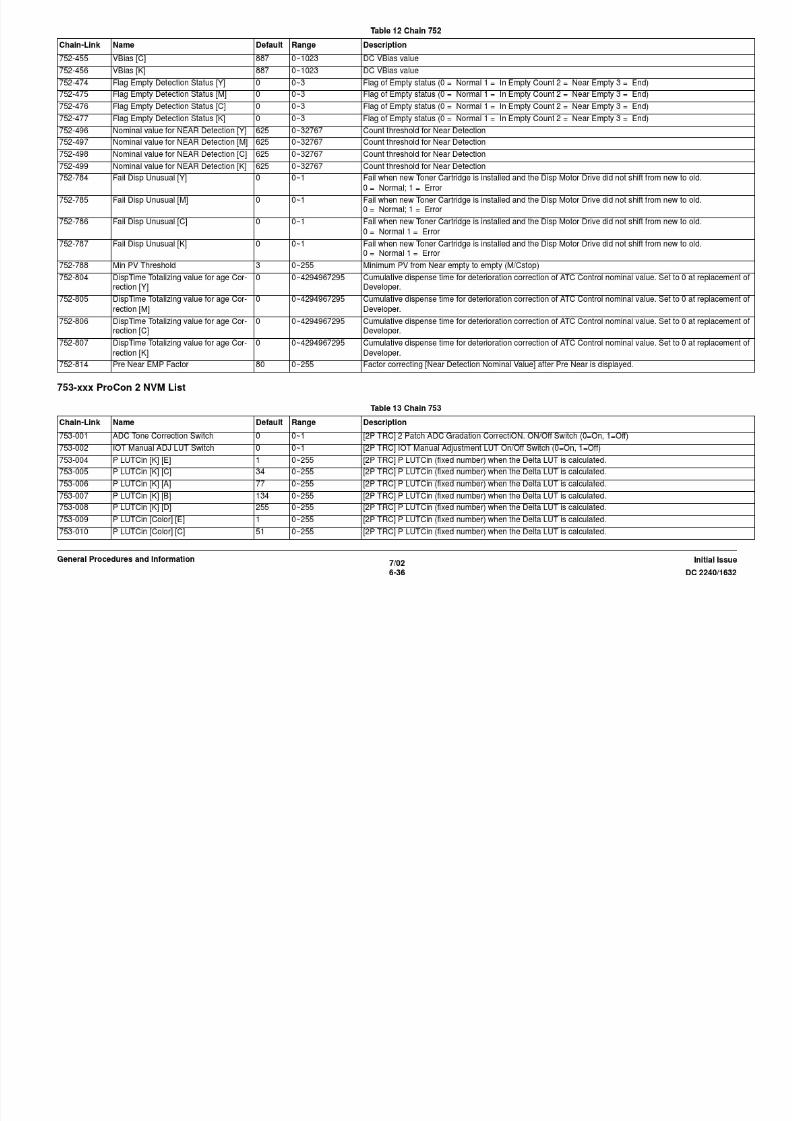
8/13/2019 Xerox Docu Color 2240-1632
http://slidepdf.com/reader/full/xerox-docu-color-2240-1632 858/1118

8/13/2019 Xerox Docu Color 2240-1632
http://slidepdf.com/reader/full/xerox-docu-color-2240-1632 859/1118

8/13/2019 Xerox Docu Color 2240-1632
http://slidepdf.com/reader/full/xerox-docu-color-2240-1632 860/1118
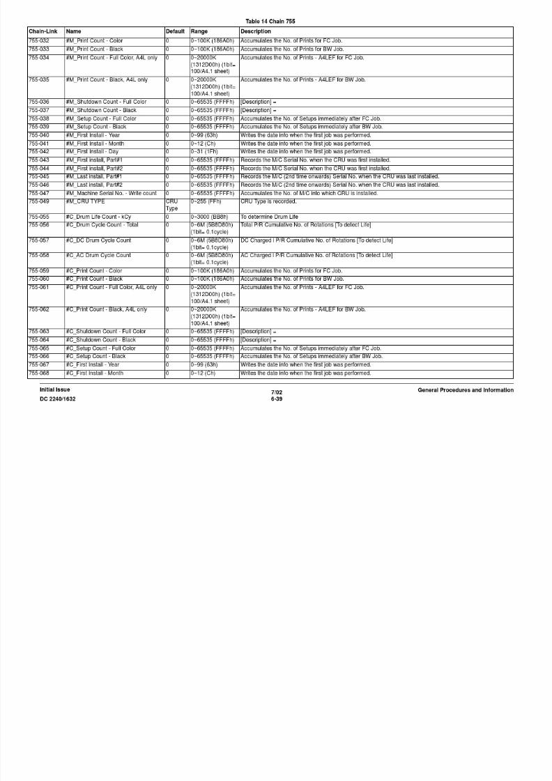
8/13/2019 Xerox Docu Color 2240-1632
http://slidepdf.com/reader/full/xerox-docu-color-2240-1632 861/1118
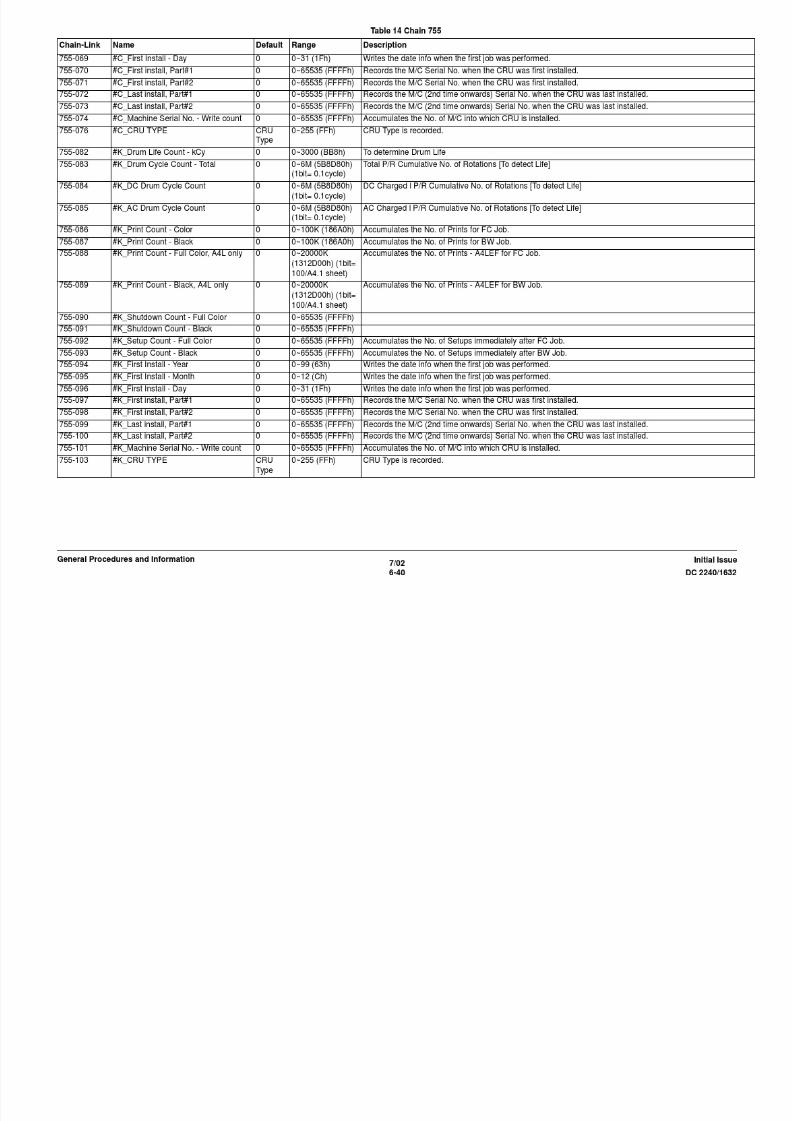
8/13/2019 Xerox Docu Color 2240-1632
http://slidepdf.com/reader/full/xerox-docu-color-2240-1632 862/1118

8/13/2019 Xerox Docu Color 2240-1632
http://slidepdf.com/reader/full/xerox-docu-color-2240-1632 863/1118

8/13/2019 Xerox Docu Color 2240-1632
http://slidepdf.com/reader/full/xerox-docu-color-2240-1632 864/1118

8/13/2019 Xerox Docu Color 2240-1632
http://slidepdf.com/reader/full/xerox-docu-color-2240-1632 865/1118
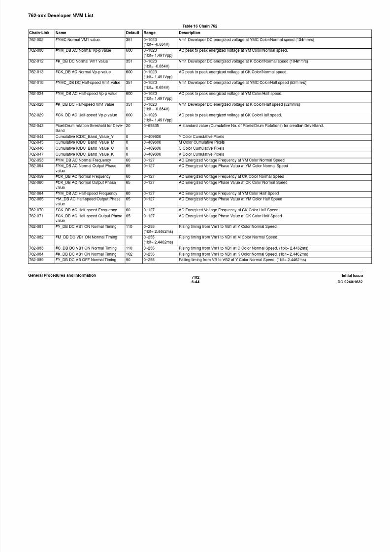
8/13/2019 Xerox Docu Color 2240-1632
http://slidepdf.com/reader/full/xerox-docu-color-2240-1632 866/1118

8/13/2019 Xerox Docu Color 2240-1632
http://slidepdf.com/reader/full/xerox-docu-color-2240-1632 867/1118
762-245 #Y_DB DC Vm1 OFF Hi-speed Timing 366 0~2000 (1bit=
1.3114ms)
Falling timing from Vm1 to Vm0 at Y Color High Speed.
762-246 #M_DB DC Vm1 OFF Hi-speed Timing 366 0~2000 (1bit=
1.3114ms)
Falling timing from Vm1 to Vm0 at M Color High Speed.
762-247 #C_DB DC Vm1 OFF Hi-speed Timing 366 0~2000 (1bit=
1.3114ms)
Falling timing from Vm1 to Vm0 at C Color High Speed.
Table 16 Chain 762
Chain-Link Name Default Range Description

8/13/2019 Xerox Docu Color 2240-1632
http://slidepdf.com/reader/full/xerox-docu-color-2240-1632 868/1118
7/02
6-48 DC 2240/1632
Initial IssueGeneral Procedures and Information
764-xxx Output (Finisher) NVM List
)
762-248 #Y_DB DC VB1 ON Hi-speed Timing 366 0~2000 (1bit=1.3114ms)
Rising timing from Vm1 to VB1 at Y Color High Speed.
762-249 #M_DB DC VB1 ON Hi-speed Timing 366 0~2000 (1bit=
1.3114ms)
Rising timing from Vm1 to VB1 at M Color High Speed.
762-250 #C_DB DC VB1 ON Hi-speed Timing 366 0~2000 (1bit=
1.3114ms)
Rising timing from Vm1 to VB1 at C Color High Speed.
762-251 #Y_DB DC VB OFF Hi-speed Timing 366 0~2000 (1bit=
1.3114ms)
Falling timing from VB to VB2 at Y Color High Speed.
762-252 #M_DB DC VB OFF Hi-speed Timing 366 0~2000 (1bit=
1.3114ms)
Falling timing from VB to VB2 at M Color High Speed.
762-253 #C_DB DC VB OFF Hi-speed Timing 366 0~2000 (1bit=1.3114ms)
Falling timing from VB to VB2 at C Color High Speed.
762-254 #YM_DB AC ON Hi-speed Timing 366 0~2000 (1bit=
1.3114ms)
AC Voltage Energized timing at YM Color High Speed.
762-255 #YM_DB AC OFF Hi-speed Timing 366 0~2000 (1bit=
1.3114ms)
AC Voltage off timing at YM Color High Speed.
762-256 #Y_DB DC VB ON Hi-speed Timing 1382 0~2000 (1bit=
1.3114ms)
Rising timing from VB3 to VB at Y Color High Speed.
762-257 #M_DB DC VB ON Hi-speed Timing 1382 0~2000 (1bit=
1.3114ms)
Rising timing from VB3 to VB at M Color High Speed.
762-258 #C_DB DC VB ON Hi-speed Timing 1382 0~2000 (1bit=1.3114ms)
Rising timing from VB3 to VB at C Color High Speed.
762-259 FPOT DB Vm0 ON Normal Timing 110 0~255 (1bit=
2.4462ms)
Rising timing from 0v to Vm0 at K Color FPOT.
762-260 FPOT DB Vm0 ON Hi-speed Timing 110 0~255 (1bit=
1.3114ms)
Rising timing from 0v to Vm0 at K Color FPOT.
762-261 FPOT DB AC ON Normal Timing 110 0~255 AC Voltage Energized timing at FPOT Normal Speed. (1bit= 2.4462ms)
762-262 FPOT DB AC ON Hi-speed Timing 110 0~255 (1bit=
1.3114ms)
AC Voltage Energized timing at FPOT High Speed.
Table 17 Chain 764
Chain-Link Name Default Range Description
764-001 Mix Stack 0 0~1 0 = Disable 1 = Enable
764-002 Set Count 50 10~100 Maximum No. of sets allowed
764-003 Unstaple Compile Sheet Count (Small
Size)
50 10~100 No. of Small Size paper compiled.

8/13/2019 Xerox Docu Color 2240-1632
http://slidepdf.com/reader/full/xerox-docu-color-2240-1632 869/1118
770-061 Lpd Print Mode Type Auto - 1 = Auto, 16 = ART, 17 = PLW, 3 = HPGL2, 8 = ESCP, 5 = PostScript, 10 = TIFF, 23 = Dump (AP Version 1 =
Auto, 2 = PCL6, 5 = PostScript)
770-062 Lpd JCL Enable is Lpd PJL Enable for
AP
ON FALSE~TRUE 0 = OFF 1 = ON
770-063 TBCP Valid Flag None FALSE~TRUE 0 = None 1 = TBCP
770-064 Lpd Spool Mode Non - 0 = Non Spool 1 = Spool
Table 18 Chain 770
Chain-Link Name Default Range Description

8/13/2019 Xerox Docu Color 2240-1632
http://slidepdf.com/reader/full/xerox-docu-color-2240-1632 870/1118
7/02
6-50 DC 2240/1632
Initial IssueGeneral Procedures and Information
Spool770-065 Lpd Time-out 16sec - 2~3600sec (Setup range = 2~65,535)
770-070 Lpd Address Limitation No - 1 = Yes 0 = No
770-071 lpd Valid IP Address 1 0.0.0.0 - 00000000~FFFFFFFF
770-072 lpd Valid IP Address 2 0.0.0.0 - 00000000~FFFFFFFF
770-073 lpd Valid IP Address 3 0.0.0.0 - 00000000~FFFFFFFF
770-074 lpd Valid IP Address 4 0.0.0.0 - 00000000~FFFFFFFF
770-075 lpd Valid IP Address 5 0.0.0.0 - 00000000~FFFFFFFF
770-080 SMB Port Enable Start Up 0~1 0 = Stop 1 = Start Up
770-081 SMB Print Mode Type Auto - 1 = Auto, 16 = ART, 17 = PLW, 3 = HPGL2, 8 = ESCP, 5 = PostScript, 10 = TIFF, 23 = Dump (AP Version 1 =Auto, 2 = PCL6, 5 = PostScript)
770-082 SMB JCL Enable is SMB PJL Enable
for AP
ON FALSE~TRUE 0 = OFF 1 = ON
770-083 SMB TBCP Valid Flag None FALSE~TRUE 0 = None 1 = TBCP
770-084 SMB Spool Mode Non
Spool
- 0 = Non Spool 1 = Spool
770-085 SMB Transport Protocol both - 2 = TCP/IP, 4 = NetBeui, 6 = both
770-090 IPP Port Enable Stop 0~1 0 = Stop 1 = Start Up
770-091 IPP Print Mode Type Auto - 1 = Auto, 16 = ART, 17 = PLW, 3 = HPGL2, 8 = ESCP, 5 = PostScript, 10 = TIFF, 23 = Dump (AP Version 1 =
Auto, 2 = PCL6, 5 = PostScript)
770-092 IPP JCL Enable is IPP PJL Enable for
AP
ON FALSE~TRUE 0 = OFF 1 = ON
770-093 IPP TBCP Valid Flag None FALSE~TRUE 0 = None 1 = TBCP
770-094 Acl Authorization OFF
(none)
- 0 = OFF 1 = ON
770-095 Use DNS Name On FALSE~TRUE On, Off
770-097 Port no. 80 0~9999 0, 80, any one value between 8000~9999
770-098 IPP Spool Mode Non
Spool
- 0 = Non Spool 1 = Spool
770-099 Time Out 60 0~65535 0~65535 [Sec]
770-100 DHCP Mode DHCP - 0x10 = Manual, 4 = BOOTP, 2 = DHCP, 1 = RARP
770-101 IP Address 0.0.0.0 0x00000000~0xFF
FFFFFF
00000000~FFFFFFFF
770-102 Subnet Mask 0.0.0.0 0x00000000~0xFF
FFFFFF
00000000~FFFFFFFF
770-103 Gateway Address 0.0.0.0 0x00000000~0xFF
FFFFFF
00000000~FFFFFFFF

8/13/2019 Xerox Docu Color 2240-1632
http://slidepdf.com/reader/full/xerox-docu-color-2240-1632 871/1118

8/13/2019 Xerox Docu Color 2240-1632
http://slidepdf.com/reader/full/xerox-docu-color-2240-1632 872/1118

8/13/2019 Xerox Docu Color 2240-1632
http://slidepdf.com/reader/full/xerox-docu-color-2240-1632 873/1118
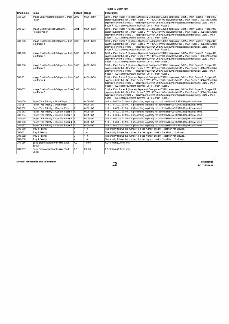
8/13/2019 Xerox Docu Color 2240-1632
http://slidepdf.com/reader/full/xerox-docu-color-2240-1632 874/1118
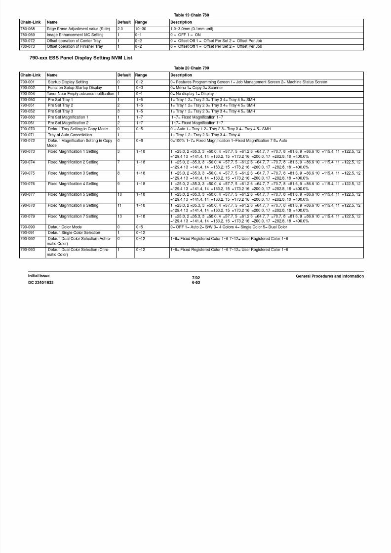
8/13/2019 Xerox Docu Color 2240-1632
http://slidepdf.com/reader/full/xerox-docu-color-2240-1632 875/1118

8/13/2019 Xerox Docu Color 2240-1632
http://slidepdf.com/reader/full/xerox-docu-color-2240-1632 876/1118

8/13/2019 Xerox Docu Color 2240-1632
http://slidepdf.com/reader/full/xerox-docu-color-2240-1632 877/1118

8/13/2019 Xerox Docu Color 2240-1632
http://slidepdf.com/reader/full/xerox-docu-color-2240-1632 878/1118
810-xxx ESS Copy Service Setting
Table 22 Chain 810
Chain/Link Name Default Range Description
810-002 Y Component "80%" 0~128 "0%"~"100%", 1/128% unit (0~128)
810-003 M Component "100%" 0~128 "0%"~"100%", 1/128% unit (0~128)
810-004 C Component "0%" 0~128 "0%"~"100%", 1/128% unit (0~128)
810-005 Y Component "92%" 0~128 "0%"~"100%", 1/128% unit (0~128)
810-006 M Component "0%" 0~128 "0%"~"100%" 1/128% unit (0~128)

8/13/2019 Xerox Docu Color 2240-1632
http://slidepdf.com/reader/full/xerox-docu-color-2240-1632 879/1118
7/02
6-59DC 2240/1632
General Procedures and InformationInitial Issue
810-006 M Component 0% 0~128 0% ~ 100% , 1/128% unit (0~128)810-007 C Component "100%" 0~128 "0%"~"100%", 1/128% unit (0~128)
810-008 Y Component "0%" 0~128 "0%"~"100%", 1/128% unit (0~128)
810-009 M Component "80%" 0~128 "0%"~"100%", 1/128% unit (0~128)
810-010 C Component "100%" 0~128 "0%"~"100%", 1/128% unit (0~128)
810-011 Y Component "100%" 0~128 "0%"~"100%", 1/128% unit (0~128)
810-012 M Component "0%" 0~128 "0%"~"100%", 1/128% unit (0~128)
810-013 C Component "0%" 0~128 "0%"~"100%", 1/128% unit (0~128)
810-014 Y Component "0%" 0~128 "0%"~"100%", 1/128% unit (0~128)
810-015 M Component "100%" 0~128 "0%"~"100%", 1/128% unit (0~128)810-016 C Component "0%" 0~128 "0%"~"100%", 1/128% unit (0~128)
810-017 Y Component "0%" 0~128 "0%"~"100%", 1/128% unit (0~128)
810-018 M Component "0%" 0~128 "0%"~"100%", 1/128% unit (0~128)
810-019 C Component "100%" 0~128 "0%"~"100%", 1/128% unit (0~128)
810-020 Y Component 0 0~128 "0%"~"100%", 1/128% unit (0~128)
810-021 M Component 0 0~128 "0%"~"100%", 1/128% unit (0~128)
810-022 C Component 0 0~128 "0%"~"100%", 1/128% unit (0~128)
810-023 Y Component 0 0~128 "0%"~"100%", 1/128% unit (0~128)
810-024 M Component 0 0~128 "0%"~"100%", 1/128% unit (0~128)810-025 C Component 0 0~128 "0%"~"100%", 1/128% unit (0~128)
810-026 Y Component 0 0~128 "0%"~"100%", 1/128% unit (0~128)
810-027 M Component 0 0~128 "0%"~"100%", 1/128% unit (0~128)
810-028 C Component 0 0~128 "0%"~"100%", 1/128% unit (0~128)
810-029 Y Component 0 0~128 "0%"~"100%", 1/128% unit (0~128)
810-030 M Component 0 0~128 "0%"~"100%", 1/128% unit (0~128)
810-031 C Component 0 0~128 "0%"~"100%", 1/128% unit (0~128)
810-032 Y Component 0 0~128 "0%"~"100%", 1/128% unit (0~128)
810-033 M Component 0 0~128 "0%"~"100%", 1/128% unit (0~128)810-034 C Component 0 0~128 "0%"~"100%", 1/128% unit (0~128)
810-035 Y Component 0 0~128 "0%"~"100%", 1/128% unit (0~128)
810-036 M Component 0 0~128 "0%"~"100%", 1/128% unit (0~128)
810-037 C Component 0 0~128 "0%"~"100%", 1/128% unit (0~128)
810-038 Background Suppression "No" 0~1 "Yes", "No"
810-039 Density Adjustment "Lighter
1"
0~6 "Lighter 3", "Lighter 2", "Lighter 1", "Normal", "Darker 1", "Darker 2", "Darker 3"

8/13/2019 Xerox Docu Color 2240-1632
http://slidepdf.com/reader/full/xerox-docu-color-2240-1632 880/1118
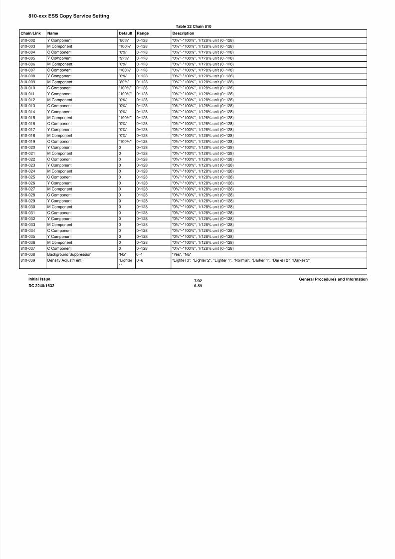
8/13/2019 Xerox Docu Color 2240-1632
http://slidepdf.com/reader/full/xerox-docu-color-2240-1632 881/1118
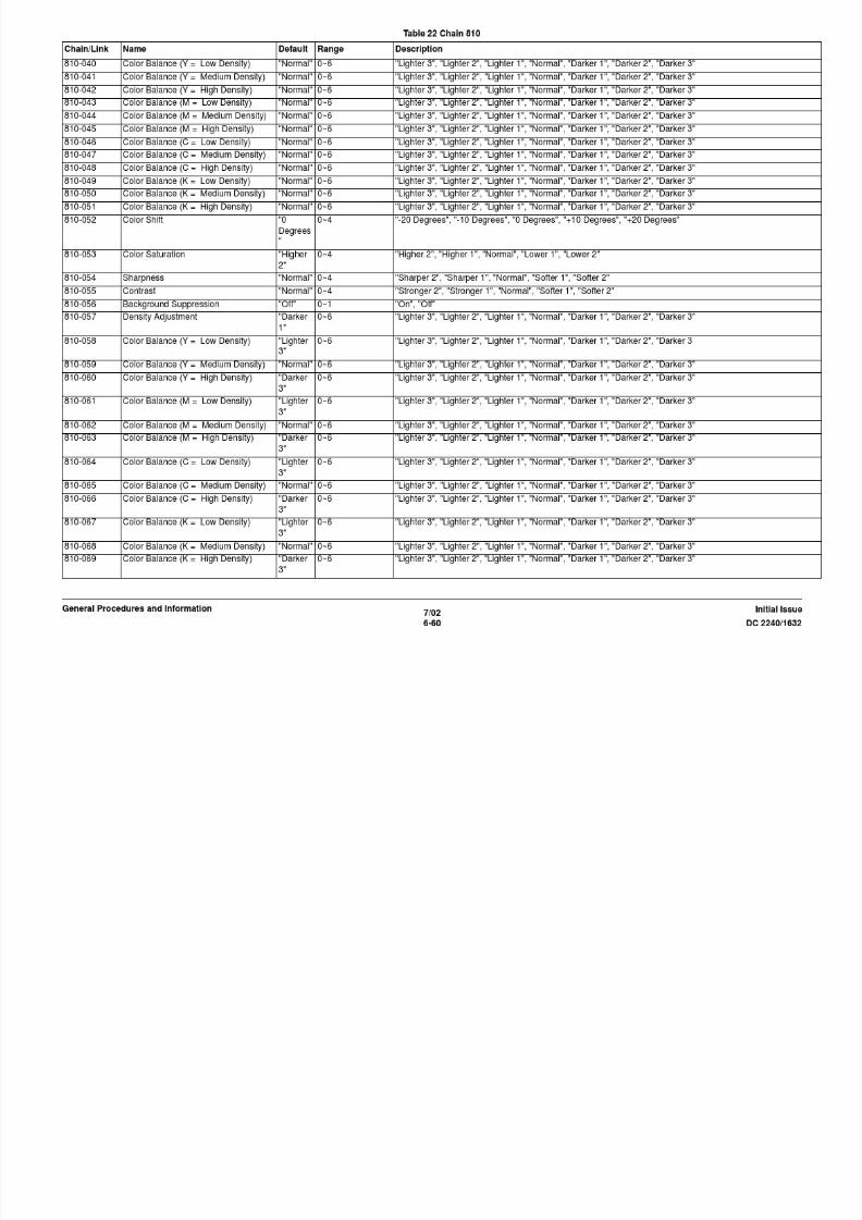
8/13/2019 Xerox Docu Color 2240-1632
http://slidepdf.com/reader/full/xerox-docu-color-2240-1632 882/1118
810-125 Color Saturation "Normal" 0~4 "Higher 2", "Higher 1", "Normal", "Lower 1", "Lower 2"
810-126 Sharpness "Normal" 0~4 "Sharper 2", "Sharper 1", "Normal", "Softer 1", "Softer 2"
810-127 Contrast "Sharper
1"
0~4 "Stronger 2", "Stronger 1", "Normal", "Softer 1", "Softer 2"
810-128 Operation when Memory Overflow
occurs
0 0~1 0 = Stop, 1 = Print
810-129 Max. No. of Copy Sheets accumulated 999 1~999 1-999 = [1~999 pages]
810-130 Build Job Setup Menu Display No dis- 0~1 0 = No display 1 = Display
Table 22 Chain 810
Chain/Link Name Default Range Description

8/13/2019 Xerox Docu Color 2240-1632
http://slidepdf.com/reader/full/xerox-docu-color-2240-1632 883/1118
7/02
6-63DC 2240/1632
General Procedures and InformationInitial Issue
840-xxx ESS Scan Setting NVM List
870-xxx ESS Diagnosis Setting NVM List
810 130 Build Job Setup Menu Display No dis
play
0 1 0 = No display 1 = Display
Table 23 Chain 840
Chain/Link Name Default Range Description
840-001 SCAN Feature Setting 0 0~1 0 = Enable1 = Disable
840-002 [NVM Name] = (Scan Illegal Operation) 1 0~1 0 = Discards the stored document 1 = Validates the stored document
840-003 Maximum No. of Storage 999 1~999 1~999 sheets
840-004 Brightness 3 Setting TBD 0~200 0~200 = [-100~100]
840-005 Brightness 2 Setting TBD 0~200 0~200 = [-100~100]
840-006 Brightness 1 Setting TBD 0~200 0~200 = [-100~100]
840-007 Brightness -1 Setting TBD 0~200 0~200 = [-100~100]
840-008 Brightness -2 Setting TBD 0~200 0~200 = [-100~100]
840-009 Brightness -3 Setting TBD 0~200 0~200 = [-100~100]
840-010 Brightest Setting TBD 0~200 0~200 = [-100~100]
840-011 Brighter Setting TBD 0~200 0~200 = [-100~100]
840-012 Softer Setting TBD 0~200 0~200 = [-100~100]
840-013 Softest Setting TBD 0~200 0~200 = [-100~100]
840-019 RGB Color Space 0 0~1 [Standard Color Space] = 0 [Device Color Space] = 1
Table 24 Chain 870
Chain/Link Name Default Range Description
870-001 TBD Normal - Normal, Diag (Auto setting)
870-010 XERO = CRU #1 PR Wear previous
value
- - 0~99999999
870-011 XERO = CRU #2 PR Wear previous
value
- - 0~99999999
870-012 XERO = CRU #3 PR Wear previous
value
- - 0~99999999
870-013 XERO = CRU #4 PR Wear previous
value
- - 0~99999999
870-014 XERO = #1CRU WARNING previous
value
- - 0~99999999
870-015 XERO = #1DRUM Total CYCLE previ-
ous value
- - 0~99999999
870-016 XERO = #2DRUM Total CYCLE previ-
ous value
- - 0~99999999
870-017 XERO = #3DRUM Total CYCLE previ-
ous value
- - 0~99999999
Table 24 Chain 870
Chain/Link Name Default Range Description
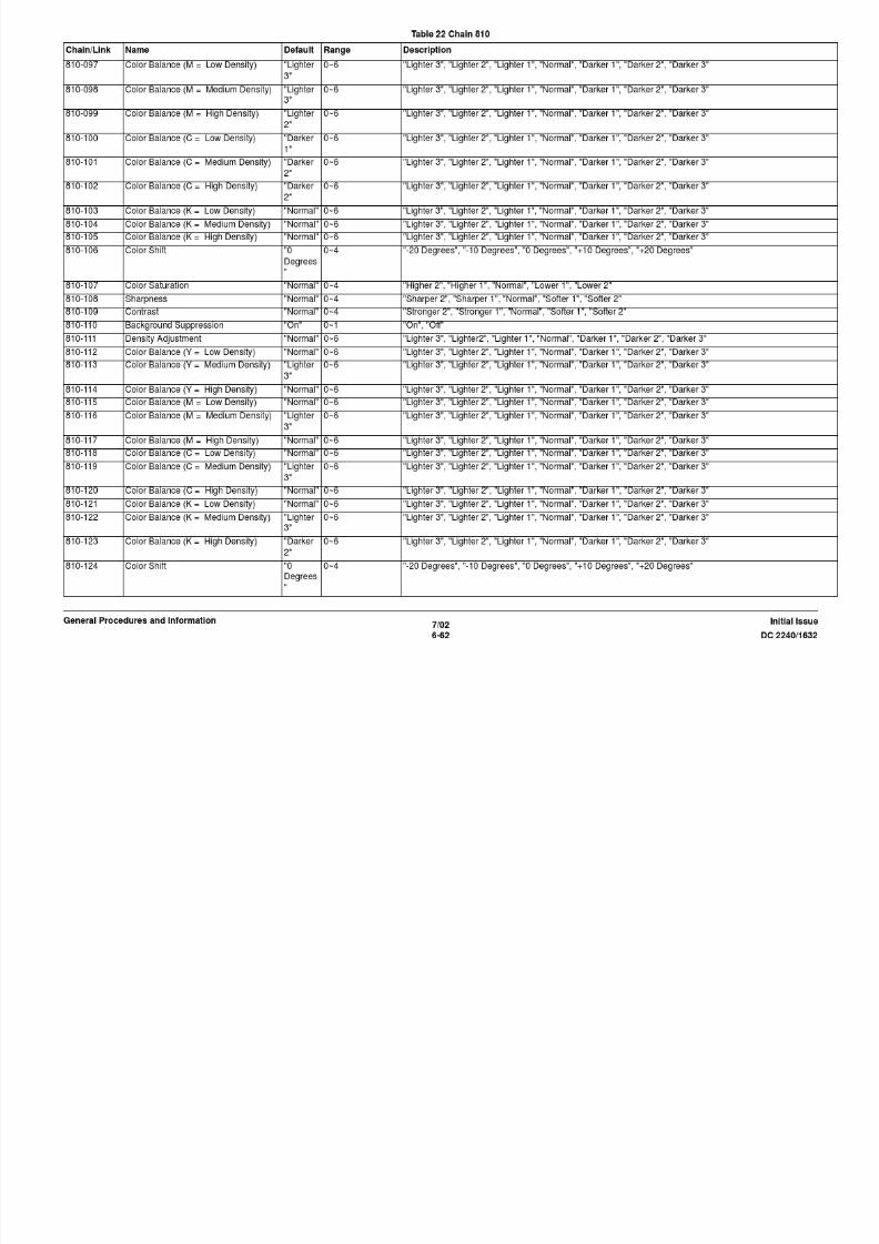
8/13/2019 Xerox Docu Color 2240-1632
http://slidepdf.com/reader/full/xerox-docu-color-2240-1632 884/1118
7/02
6-64 DC 2240/1632
Initial IssueGeneral Procedures and Information
870-018 XERO = #4DRUM Total CYCLE previ-
ous value
- - 0~99999999
870-019 XERO = #1DRUM DC CYCLE previ-
ous value
- - 0~99999999
870-020 XERO = #2DRUM DC CYCLE previ-
ous value
- - 0~99999999
870-021 XERO = #3DRUM DC CYCLE previ-
ous value
- - 0~99999999
870-022 XERO = #4DRUM DC CYCLE previ-ous value - - 0~99999999
870-023 XERO = #1DRUM AC CYCLE previ-
ous value
- - 0~99999999
870-024 XERO = #2DRUM AC CYCLE previ-
ous value
- - 0~99999999
870-025 XERO = #3DRUM AC CYCLE previ-
ous value
- - 0~99999999
870-026 XERO = #4DRUM AC CYCLE previ-
ous value
- - 0~99999999
870-027 Xfer = IBT Belt (IMPS) previous value - - 0~99999999870-028 Xfer = IBT Belt (CYCLE) previous
value
- - 0~99999999
870-029 Xfer = 1st BTR previous value - - 0~99999999
870-030 Xfer = Back Up Roll previous value - - 0~99999999
870-031 Xfer = 2nd BTR Unit previous value - - 0~99999999
870-032 Xfer = Bearing BTR previous value - - 0~99999999
870-033 Xfer = Trim within Transfer Module pre-
vious value
- - 0~99999999
870-034 Xfer = Belt Cleaner Blade previous
value
- - 0~99999999
870-035 Xfer = BBelt Cleaner Film Seal previ-
ous value
- - 0~99999999
870-036 PH = 1Tray NMBR of Feeds previous
value
- - 0~99999999
870-037 PH = Tray 5 NMBR of Feeds previous
value
- - 0~99999999
870-038 PH = 3TM 2Tray NMBR of Feeds pre-
vious value
- - 0~99999999
870-039 PH = 3TM 3Tray NMBR of Feeds pre-
vious value
- - 0~99999999
870-040 PH = 3TM 4Tray NMBR of Feeds pre-
vious value
- - 0~99999999
870-041 PH = 1TM 2Tray NMBR of Feeds previ-
ous value
- - 0~99999999
Table 24 Chain 870
Chain/Link Name Default Range Description

8/13/2019 Xerox Docu Color 2240-1632
http://slidepdf.com/reader/full/xerox-docu-color-2240-1632 885/1118
7/02
6-65DC 2240/1632
General Procedures and InformationInitial Issue
900-xxx ESS Tag-Matrix NVM List
870-042 PH = TTM 2Tray NMBR of Feeds pre-
vious value
- - 0~99999999
870-043 PH = TTM 3Tray NMBR of Feeds pre-
vious value
- - 0~99999999
870-044 PH = TTM 4Tray NMBR of Feeds pre-
vious value
- - 0~99999999
870-045 PV (CV) Counter for FILTER Life previ-
ous value
- - 0~99999999
Table 25 Chain 900
Chain/Link Name Default Range Description
900-001 Tag 1V 0 0~1 Tag Information 1V
900-002 Tag 2V 0 0~1 Tag Information 2V [0 = OFF, 1 = ON]
900-003 Tag 3V 0 0~1 Tag Information 3V [0 = OFF, 1 = ON]
900-004 Tag 4V 0 0~1 Tag Information 4V [0 = OFF, 1 = ON]
900-005 Tag 5V 0 0~1 Tag Information 5V [0 = OFF, 1 = ON]900-006 Tag 6V 0 0~1 Tag Information 6V [0 = OFF, 1 = ON]
900-007 Tag 7V 0 0~1 Tag Information 7V [0 = OFF, 1 = ON]
900-008 Tag 8V 0 0~1 Tag Information 8V [0 = OFF, 1 = ON]
900-009 Tag 9V 0 0~1 Tag Information 9V [0 = OFF, 1 = ON]
900-010 Tag 10V 0 0~1 Tag Information 10V [0 = OFF, 1 = ON]
900-011 Tag 11V 0 0~1 Tag Information 11V [0 = OFF, 1 = ON]
900-012 Tag 12V 0 0~1 Tag Information 12V [0 = OFF, 1 = ON]
900-013 Tag 13V 0 0~1 Tag Information 13V [0 = OFF, 1 = ON]
900-014 Tag 14V 0 0~1 Tag Information 14V [0 = OFF, 1 = ON]900-015 Tag 15V 0 0~1 Tag Information 15V [0 = OFF, 1 = ON]
900-016 Tag 16V 0 0~1 Tag Information 16V [0 = OFF, 1 = ON]
900-017 Tag 17V 0 0~1 Tag Information 17V [0 = OFF, 1 = ON]
900-018 Tag 18V 0 0~1 Tag Information 18V [0 = OFF, 1 = ON]
900-019 Tag 19V 0 0~1 Tag Information 19V [0 = OFF, 1 = ON]
900-020 Tag 20V 0 0~1 Tag Information 20V [0 = OFF, 1 = ON]
900-021 Tag 21V 0 0~1 Tag Information 21V [0 = OFF, 1 = ON]
900-022 Tag 22V 0 0~1 Tag Information 22V [0 = OFF, 1 = ON]
900-023 Tag 23V 0 0~1 Tag Information 23V [0 = OFF, 1 = ON]
900-024 Tag 24V 0 0~1 Tag Information 24V [0 = OFF, 1 = ON]
900-025 Tag 25V 0 0~1 Tag Information 25V [0 = OFF, 1 = ON]
900-026 Tag 26V 0 0~1 Tag Information 26V [0 = OFF, 1 = ON]
900-027 Tag 27V 0 0~1 Tag Information 27V [0 = OFF, 1 = ON]
900-028 Tag 28V 0 0~1 Tag Information 28V [0 = OFF, 1 = ON]900-029 Tag 29V 0 0~1 Tag Information 29V [0 = OFF, 1 = ON]
Table 25 Chain 900
Chain/Link Name Default Range Description
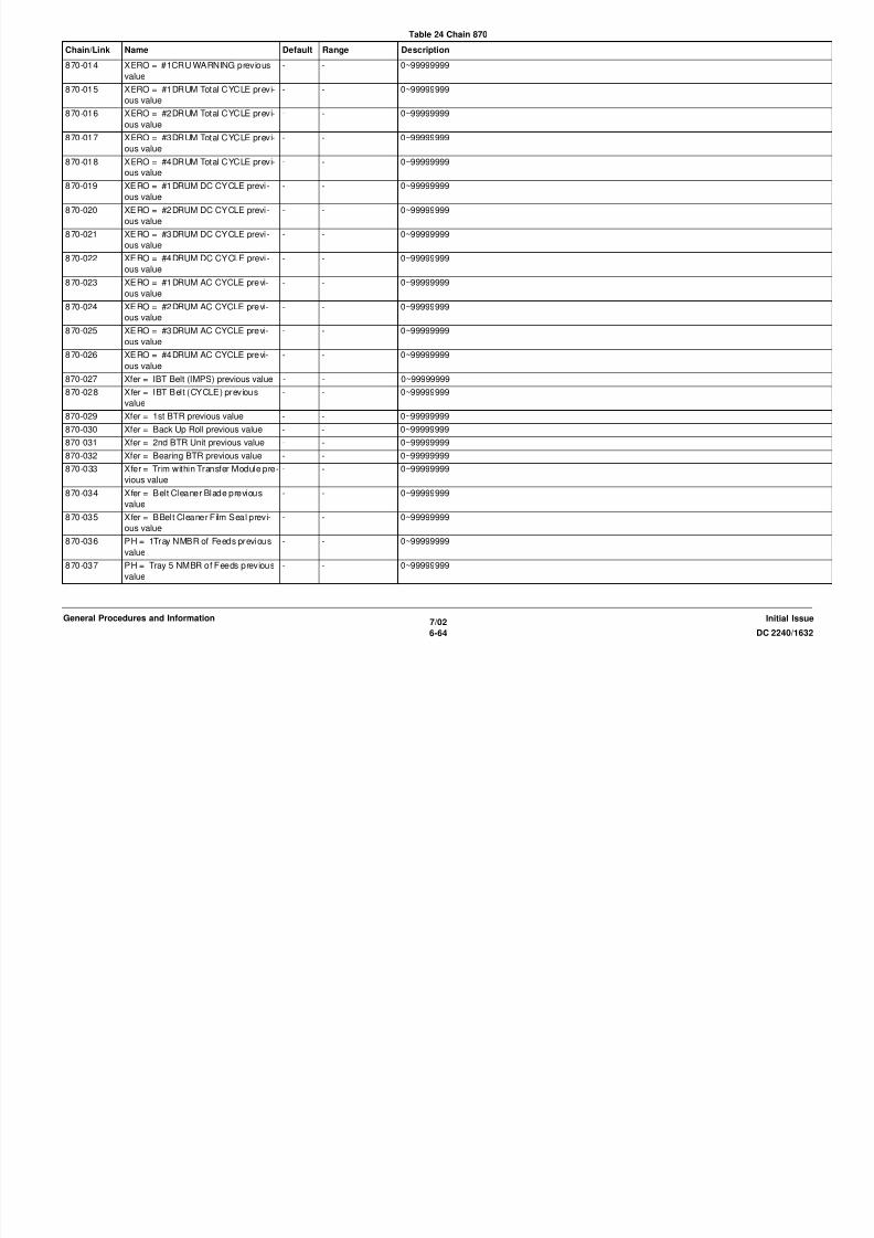
8/13/2019 Xerox Docu Color 2240-1632
http://slidepdf.com/reader/full/xerox-docu-color-2240-1632 886/1118
7/02
6-66 DC 2240/1632
Initial IssueGeneral Procedures and Information
900 029 Tag 29V 0 0 1 Tag Information 29V [0 OFF, 1 ON]
900-030 Tag 30V 0 0~1 Tag Information 30V [0 = OFF, 1 = ON]
900-031 Tag 31V 0 0~1 Tag Information 31V [0 = OFF, 1 = ON]
900-032 Tag 32V 0 0~1 Tag Information 32V [0 = OFF, 1 = ON]
dC132 Serial Number/Billing Meter SynchronizationPurpose
Checks the Billing Meters and sets the Machine Serial Number when fault 103-208 occurs.
This routine also reads the Billing Meters and can be accessed at any time for this purpose.
Procedure
CAUTION
Failure to comply with the board replacement procedure in GP 10 , could result in catastrophic
NVM corruption.
Follow the procedure described in GP 10.
dC135 HFSI CountersPurpose
This routine displays the service life (Threshold) and the current value (count) of the periodic
replacement parts. Replacement life change, and current value resets are possible.
Procedure
1. Enter the Diagnostic Mode. Refer to Entering Diagnostic Mode using the PWS.
2. Select dC135 from the DC Quick menu, or click on Maintenance on the Service Entry
Screen. The All Jams screen displays as the default screen.
3. Select HFSI Counters (dC135) tab on the Maintenance screen.

8/13/2019 Xerox Docu Color 2240-1632
http://slidepdf.com/reader/full/xerox-docu-color-2240-1632 887/1118
7/02
6-67DC 2240/1632 dC132, dC135General Procedures and InformationInitial Issue
4. The HFSI Counters screen displays the replacement life (Threshold) and the current
value (count) of the periodic replacement parts. Two vertical tabs allow display of all HFSI
counters, or only those counters that are over threshold.
5. Refer to Detailed Maintenance Activities in Section 1. Perform the l isted Service Action for
all HSFI counters that are at or near threshold (near threshold indicated by yellow dia-
mond in the % column).
6. To reset the count after replacing the parts, select the appropriate HFSI item, then select
the Reset Counter button.

8/13/2019 Xerox Docu Color 2240-1632
http://slidepdf.com/reader/full/xerox-docu-color-2240-1632 888/1118
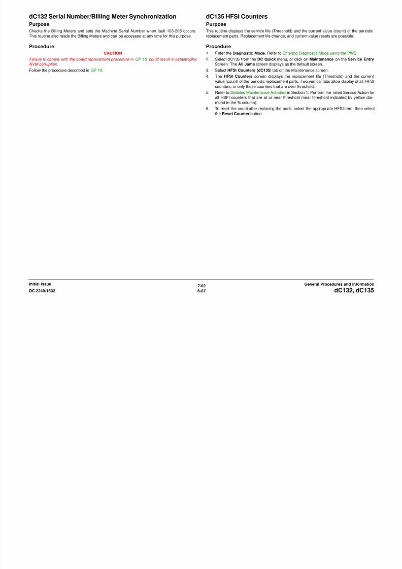
8/13/2019 Xerox Docu Color 2240-1632
http://slidepdf.com/reader/full/xerox-docu-color-2240-1632 889/1118
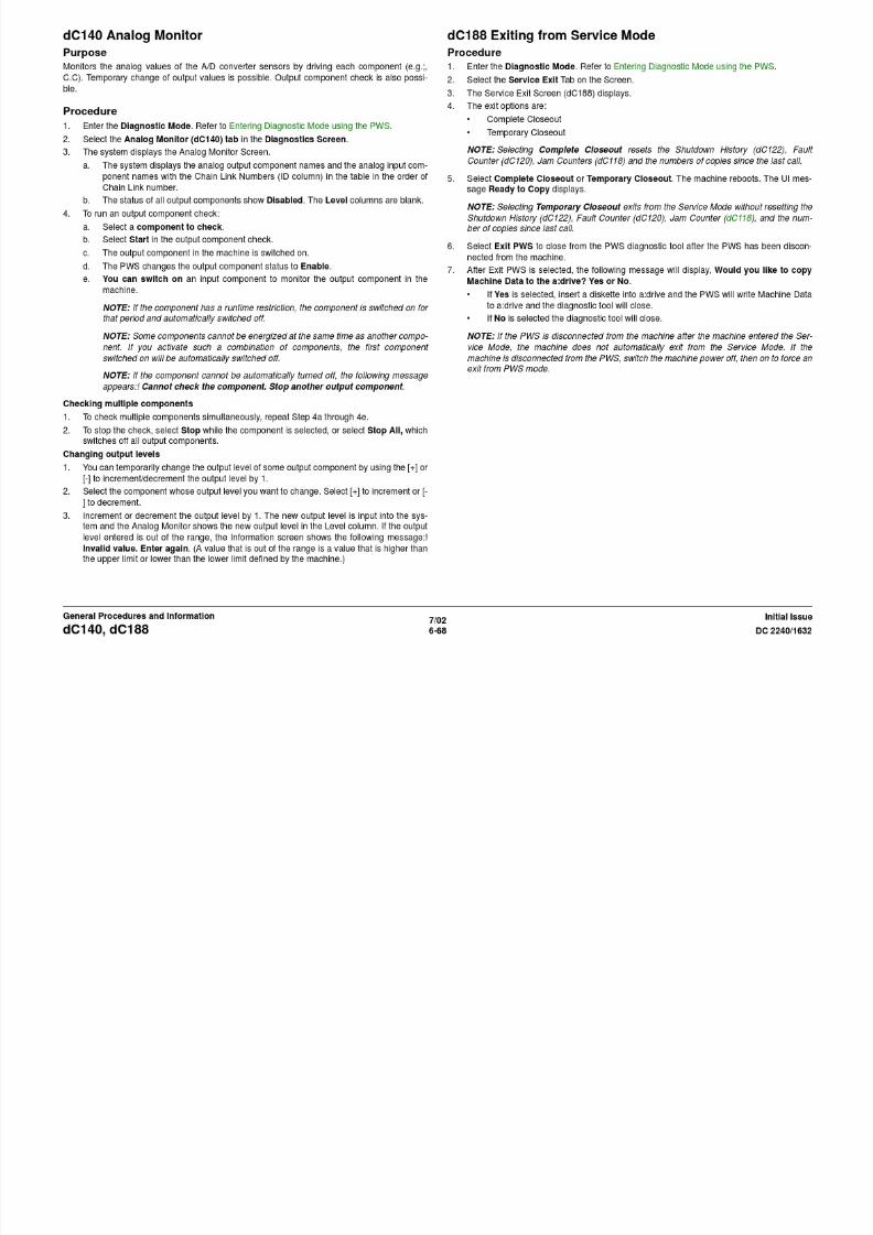
8/13/2019 Xerox Docu Color 2240-1632
http://slidepdf.com/reader/full/xerox-docu-color-2240-1632 890/1118

8/13/2019 Xerox Docu Color 2240-1632
http://slidepdf.com/reader/full/xerox-docu-color-2240-1632 891/1118

8/13/2019 Xerox Docu Color 2240-1632
http://slidepdf.com/reader/full/xerox-docu-color-2240-1632 892/1118

8/13/2019 Xerox Docu Color 2240-1632
http://slidepdf.com/reader/full/xerox-docu-color-2240-1632 893/1118

8/13/2019 Xerox Docu Color 2240-1632
http://slidepdf.com/reader/full/xerox-docu-color-2240-1632 894/1118

8/13/2019 Xerox Docu Color 2240-1632
http://slidepdf.com/reader/full/xerox-docu-color-2240-1632 895/1118

8/13/2019 Xerox Docu Color 2240-1632
http://slidepdf.com/reader/full/xerox-docu-color-2240-1632 896/1118

8/13/2019 Xerox Docu Color 2240-1632
http://slidepdf.com/reader/full/xerox-docu-color-2240-1632 897/1118
dC355 Hard Disk Diagnostic ProgramPurpose
NOTE: For details on dC355 Hard Disk Diagnostic Program, see Adjustments: ADJ 9.8 .
dC371 Configuration PagePurpose
Allows easy viewing and set-up of machine configuration.
Procedure
1. Enter the Diagnostic Mode. Refer to Entering Diagnostic Mode using the PWS.
2. Select Adjustments on the Service Entry Screen.
3. Select NVM Init, S/R (the default screen).
4. Select Configuration Page (dC371). The Configuration Page Screen is displayed.
5. Make selections on the screen from the following categories:
a. Market Place

8/13/2019 Xerox Docu Color 2240-1632
http://slidepdf.com/reader/full/xerox-docu-color-2240-1632 898/1118
7/026-78 DC 2240/1632dC355, dC371
Initial IssueGeneral Procedures and Information
• XC (NASG)
• XE (ESG)
• FX
• FX / AP
b. Machine Config
• Digital Copier
• Copier / Printer• Copier / Printer / Scanner
• Printer with UI
c. Output Device(s)
• Simple Catch Tray
• Offsetting Catch Tray
• Finisher
d. Input Device
• DADF
• Platen Only6. Select Save to save the options or select Reset to reset the default settings back to origi-
nal options prior to entering Configuration Page (dC371).
dC527 DADF Document CalibrationPurpose
NOTE: For details on dC527 DADF Document Calibration, see Adjustments Section 4: ADJ
5.6 .
dC612 Color Test Pattern PrintPurpose
Prints the test patterns in the machine, to help identify Image Quality problems.
Procedure
1. Enter the Diagnostic Mode. Refer to Entering Diagnostic Mode using the PWS.
2. Select Diagnostics in the Service Entry Screen.
3. Select Test Pattern (dc612).
4. Select the Pattern Number from the menu.
NOTE: Not all of the following parameters are applicable to all test patterns; patterns 5 through
36-3 require A4 paper and can be output only from Tray 1

8/13/2019 Xerox Docu Color 2240-1632
http://slidepdf.com/reader/full/xerox-docu-color-2240-1632 899/1118
7/026-79DC 2240/1632 dC527, dC612
General Procedures and InformationInitial Issue
5. Select the Paper Tray.
6. Select Simplex/Duplex
7. Select Paper Type
8. Select Screen Type
9. Select Color Mode
10. Set the number of prints to output in the Print Count Box and select Start.
Test PatternsFor details on the test pattern generation location and output path, see Table 1:
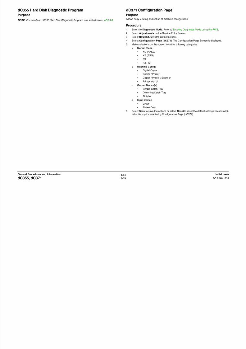
8/13/2019 Xerox Docu Color 2240-1632
http://slidepdf.com/reader/full/xerox-docu-color-2240-1632 900/1118

8/13/2019 Xerox Docu Color 2240-1632
http://slidepdf.com/reader/full/xerox-docu-color-2240-1632 901/1118
35-3 Multi-level_Process
Control PG
Gradation pattern for density control
LUT: Ctrax ON; IOT ON
The Primary color/Secondary color/Tertiary color gradation reproduc-
ibility can be checked by crossing over to entire gradation. For
checking TRC
IPS
36-0 Multi-level_Highlight PG (Highlight gradation check) Gradation pattern for highlight adjustment
LUT: Ctrax OFF; IOT OFF
In the gradation reproducibility of Primary color/Secondary color/Ter-
tiary color, the highlight parts easily varied can be checked in detail.
For checking TRC.
IPS
36-1 Multi-level_Highlight PG (Highlight gradation check) Gradation pattern for highlight adjustment
LUT: Ctrax OFF; IOT ON
In the gradation reproducibility of Primary color/Secondary color/Ter-
tiary color, the highlight parts easily varied can be checked in detail.For checking TRC.
IPS
36-2 Multi-level_Highlight PG (Highlight gradation check) Gradation pattern for highlight adjustment
LUT: Ctrax ON; IOT OFF
In the gradation reproducibility of Primary color/Secondary color/Ter-
tiary color, the highlight parts easily varied can be checked in detail.
IPS
Table 1 Test Patterns
No. Description Overview Purpose Location
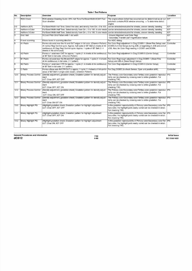
8/13/2019 Xerox Docu Color 2240-1632
http://slidepdf.com/reader/full/xerox-docu-color-2240-1632 902/1118
7/026-82 DC 2240/1632dC612
Initial IssueGeneral Procedures and Information
For checking TRC.
36-3 Multi-level_Highlight PG (Highlight gradation check) Gradation pattern for highlight adjustment
LUT: Ctrax ON; IOT ON
In the gradation reproducibility of Primary color/Secondary color/Ter-
tiary color, the highlight parts easily varied can be checked in detail.
For checking TRC.
IPS
dC685 Color RegistrationPurpose
NOTE: For details on dC685 Color Registration, see Adjustments Section 4: ADJ 9.6 .
dC921 TC/ATC Sensor SetupPurpose
NOTE: For details on dC921 TC/ATC Sensor Setup, see Adjustments Section 4: ADJ 9.2 .

8/13/2019 Xerox Docu Color 2240-1632
http://slidepdf.com/reader/full/xerox-docu-color-2240-1632 903/1118
7/026-83DC 2240/1632 dC685, dC921
General Procedures and InformationInitial Issue
dC922 TRC ControlPurpose
NOTE: For details on dC922 TRC Control, see Adjustments Section 4: ADJ 9.3 dC922 TRC
Control Adjustment.
dC924 TRC AdjustPurpose
To manually fine adjust the low/medium/high densities (TRC) for each color.
NOTE: For details on TRC Adjust, see Adjustments Section 4: ADJ 9.5 .

8/13/2019 Xerox Docu Color 2240-1632
http://slidepdf.com/reader/full/xerox-docu-color-2240-1632 904/1118
7/026-84 DC 2240/1632dC922, dC924
Initial IssueGeneral Procedures and Information
dC929 Max SetupPurpose
NOTE: For the execution sequence of the Max Setup Functions, see Adjustments Section 4:
ADJ 9.1.
dC934 ADC/AGC SetupPurpose
Automatically adjusts the ADC Sensor Gain.
NOTE: For details on dC934 ADC/AGC Setup, see Adjustment Section 4: ADJ 9.4 .

8/13/2019 Xerox Docu Color 2240-1632
http://slidepdf.com/reader/full/xerox-docu-color-2240-1632 905/1118
7/026-85DC 2240/1632 dC929, dC934
General Procedures and InformationInitial Issue
dC945 IIT CalibrationPurpose
Functional details:
• Computes and sets the White Reference Correction Coefficient.
• Corrects the IIT Sensitivity Dispersion.
NOTE: For details on dC945 IIT Calibration, see Adjustments Section 4: ADJ 9.7 .
dC956 Belt Edge Learn ModePurpose
NOTE: For details on dC956 Belt Edge Learn Mode, see Adjustments Section 4: ADJ 9.6 .

8/13/2019 Xerox Docu Color 2240-1632
http://slidepdf.com/reader/full/xerox-docu-color-2240-1632 906/1118
7/026-86 DC 2240/1632dC945, dC956
Initial IssueGeneral Procedures and Information

8/13/2019 Xerox Docu Color 2240-1632
http://slidepdf.com/reader/full/xerox-docu-color-2240-1632 907/1118

8/13/2019 Xerox Docu Color 2240-1632
http://slidepdf.com/reader/full/xerox-docu-color-2240-1632 908/1118

8/13/2019 Xerox Docu Color 2240-1632
http://slidepdf.com/reader/full/xerox-docu-color-2240-1632 909/1118
GP 12 Printing ReportsDescription
This procedure describes how to print the various reports that are available. Printing reports
can help you troubleshoot and configure the machine.
Procedure
Printing the Settings List (Configuration Report)
NOTE: Make sure dC371 is set for the correct Market Region. If paper size errors still occur
when attempting to print reports, check that NVM location 700-397 is set for the appropriate
paper size (44 = 8.5 x 11 in.; 5 = A4).
1. Press the Machine Status button on the Control Panel.
2. Select the Billing Meter/Print Report tab on the display.
3 Press the Print Report/List button

8/13/2019 Xerox Docu Color 2240-1632
http://slidepdf.com/reader/full/xerox-docu-color-2240-1632 910/1118
7/026-90 DC 2240/1632GP 12
Initial IssueGeneral Procedures and Information
3. Press the Print Report/List button.
4. Select the Copy Mode Settings button.
5. Select the Settings List button.
6. Press the Start button.
Other Reports
The following reports can be printed from the UI Diagnostic Mode:
1. Debug Log
2. HFSI Report
3. Jam Report
4. Shutdown Report
5. Fail Report
Space RequirementsInstallation space requirements are shown in Figure 1 (w/out Finisher) and Figure 2 (w/Fin-
isher).
100 mm 3.9 in.
1770 mm 69.5 in
401mm15.8 in.
2217 mm 87.3 in.
848 mm 33.4 in.
100 mm3.9 in.
50 mm 2 in.
1705 mm 67.1 in.
425 mm
50 mm 2 in.

8/13/2019 Xerox Docu Color 2240-1632
http://slidepdf.com/reader/full/xerox-docu-color-2240-1632 911/1118
7/026-91DC 2240/1632 Space Requirements
General Procedures and InformationInitial Issue
Figure 1 Space Requirement w/out Finisher
Figure 2 Space Requirement w/Finisher
50 mm2 in. 50 mm
2 in.
425 mm
16.7 in.677 mm 26.7 in.
1705 mm 67.1 in.
400 mm 15.7 in.
677 mm 26.7 in.
425 mm 16.7 in.
400 mm 15.7 in.
Product Specs.Product Codes
– legal size: 11 ppm – A3/11x17 in.: 9 ppm
DocuColor 2240
• B/W (plain paper; simplex; fed from Tray 1)
– letter size LEF: 40 ppm
– letter size SEF: 30 ppm
– legal size: 24 ppm
– A3/11x17 in.: 20 ppm
• Color (plain paper; simplex; fed from Tray 1)
– letter size LEF: 22 ppm – letter size SEF: 16 ppm
– B4/legal size: 13 ppm
– A3/11x17 in.: 11 ppm
Table 1 Product Codes
Item Product Code
DocuColor 1632 IOT 120 VAC LVE
DocuColor 1632 IOT 220 VAC LVF
Scanner/UI/DADF (XC) 120 VAC LVM
Scanner/UI/DADF (XE) 220 VAC LVN
Speed Upgrade Kit (1632 to 2240) MDU
Finisher KMT
Token Ring Kit MLH
Left Wing Kit MLG
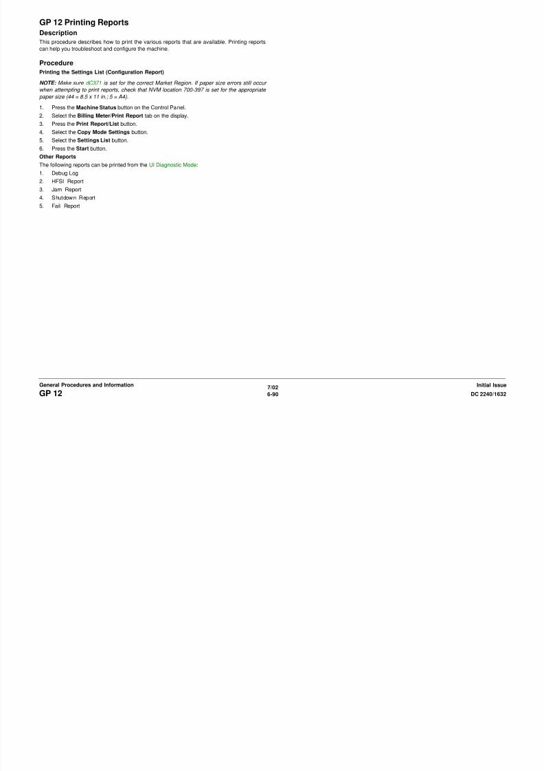
8/13/2019 Xerox Docu Color 2240-1632
http://slidepdf.com/reader/full/xerox-docu-color-2240-1632 912/1118
7/026-92 DC 2240/1632Product Specs.
Initial IssueGeneral Procedures and Information
Paper Capacities
Copy Speed
DocuColor 1632
• B/W (plain paper; simplex; fed from Tray 1)
– letter size LEF: 32 ppm
– letter size SEF: 24 ppm
– legal size: 20 ppm
– A3/11x17 in.: 17 ppm
• Color (plain paper; simplex; fed from Tray 1)
– letter size LEF: 16 ppm
– letter size SEF: 13 ppm
FCOT/FPOT
First Copy Output Time (original on platen); 8.5” x 11” (A4); Tray 1;
• Color - 12.3 sec. max
• B/W - 4.6 sec. max
First Print Output Time (does not include ESS process time for prints); 8.5” x 11” (A4); Tray 1;
• Color - 11.8 sec. max
• B/W - 4.1 sec. max
Voltage Requirements
• Single phase (two wires plus ground)
• 110 - 127 VAC/60 Hz (99 - 135 VAC, 55 to 62 Hz)
• 220 - 240 VAC/50 Hz (198 to 255 VAC, 48.5 to 51.5 Hz)
Power Consumption (5 minute average)
• Machine Running: 1.584 kVA - NASG; 2.20 kVA ESG max.
• Low Power: 204 watts max.
• Sleep Mode: 80 watts max.
Warm up time: 66 sec. max.
Environmental Data and Requirements
Ambient Temperature and Humidity requirement:
• Minimum: 10º C/50ºF at 15% humidity
• Maximum: 35º C/99ºF at 85% humidity
g
Table 2 Paper Capacities
Specification Paper Trays 1 - 4 Tray 5 (MSI)
Paper Sizes Trays 1 & 2
• Min.: A5 SEF (148 x 210
mm)
• Max: A3/11 x 17 in.
Trays 3 & 4
• A4, 8.5 x 11 in., and B5 LEF
only
Paper
• Min.: 100 x 140 mm (postcard)
• Max: 305 x 483 mm/12 x 19 in.
Envelopes
• Min.: 98 x 190 mm (Monarch 7
3/4 size)
Paper Weights Optimum: 24 lb./90 gsm
Range: 64 - 105 gsm
Range: 55 - 220 gsm
Capacities 20 lb.(80 gsm)
3040 sheets total:
• Tray 1: 520 sheets
• Tray 2: 520 sheets
• Tray 3: 867 sheets
• Tray 4: 1133 sheets
100 sheets
IIT/DADF Specifications Common Tools
Table 3 DADF Specifications
Document Size: Platen Max size: 334 x 452 mm
Max scannable area: 297 x 432 mm
Document Size: DADF 5.5” x 8.5” (A5) LEF to 11” x 17” SEF (A3)
Max: 297 x 432 mm
Min.: 148.5 x 210 mm
Document Weight: DADF Min:38 gsm/16lb (50 gsm in Duplex mode)
Max: 128 gsm/32lb (110 gsm in Duplex mode)
Document Capacity: DADF 50 sheets 100 gsm or less
40 sheets 101 to 128 gsm
R/E Capability: Variable Percentages: 25% to 400% in 1% increments
Preset Percentages:
• 25%
Table 1 Common Tools
Description Part Number
Screw Driver (-) 3 x 50 600T40205
Screw Driver (+) 6 x 100 600T1989
Screw Driver (+) NO.1 499T356
Stubby Driver (+) (-) 600T40210
Screw Driver (=) 100MM 499T355
Spanner and Wrench 5.5 x 5.5 600T40501
Spanner and Wrench 7x 7 600T40502
Hex Key Set 600T02002
Box Driver 5.5MM 600T1988

8/13/2019 Xerox Docu Color 2240-1632
http://slidepdf.com/reader/full/xerox-docu-color-2240-1632 913/1118
7/026-93DC 2240/1632 Product Specs., Common ToolsGeneral Procedures and InformationInitial Issue
• 25%
• 50% (A3 to A5)
• 64% (11 x17 in. to 8.5 x 11 in.)
• 70% (A3 to A4; B4 to B5)
• 100%
• 129% (8.5 x 11 in. to 11 x17 in.)• 141% (A4 to A3; B5 to B4)
• 400%
Presets can be changed in Tools mode
Side Cutting Nipper 600T40903
Round Nose Pliers 600T40901
Digital Multi-meter Set 600T2020
Interlock Cheater 600T91616
Silver Scale 150MM 600T41503
CE Tool Case 600T1901
Magnetic Screw Pick-up Tool 600T41911
Scriber Tool 600T41913
Magnetic pickup 600T41911
Loupe 600T42008
Flash Light 600T1824
Brush 600T41901
Tester Lead Wire (red) 600T 9583
Tester Lead Wire (black) 600T2030
Product Tools and Test Patterns Cleaning Materials
Table 1 Tools and Test Patterns
Description Part Number
Color Test Pattern 82E13120
Geometric Test Pattern 82E8220
HVPS test probe (1/10X) 600T1653
HVPS test probe adapter 600T1996
Copy Paper Carrying Case 600T1999
Copy Paper Zip Lock Bag 600T2000
Xerox Color Xpressions Plus 24# 11×17 in, 3R5465
Colotech Plus - 90 gsm - A3 3R94642
Service and Machine NVM Log 700P97436
S i l C bl 600T2058
Table 1 Cleaning Materials
DescriptionNASG Part
Number
ESG Part
Number
Cleaning fluid
(8oz., Formula A)
43P48 8R90034
Film remover (8 oz.) 43P45 8R90176
Lens/mirror cleaner 43P81 8R90178
Lint-free (white) cleaning cloth 19P3025 19P3025Lint-free Optics cleaning cloth 499T90417 499T90417
Cleaning towels 35P3191 600S4372
Drop cloth 35P1737 35P1737
Cotton Swab 35P2162 35P2162

8/13/2019 Xerox Docu Color 2240-1632
http://slidepdf.com/reader/full/xerox-docu-color-2240-1632 914/1118
7/026-94 DC 2240/1632Product Tools and Test Patterns, Cleaning MaterialsInitial IssueGeneral Procedures and Information
Serial Cable 600T2058
Parallel Printer Cable 117E19340
PWS power cord adapter 600T2018
L Probe 600T02177
Cotton Swab 35P2162 35P2162
Machine Consumables Glossary of Terms
Table 1 Consumables
Name Part Number
Drum Cartridge 13R586
Black Toner Cartridge 6R1122
Cyan Toner Cartridge 6R1123
Magenta Toner Cartridge 6R1124
Yellow Toner Cartridge 6R1125
Waste Toner Bottle 8R12903
Staple Cartridge 8R12915
Table 1
Term Description
A3 Paper size 297 millimeters (11.69 inches) x 420 millimeters (16.54 inches).
A4 Paper size 210 millimeters (8.27 inches) x 297 millimeters (11.69 inches).
AC Alternating Current is type of current available at power source for machine.
ACT Advanced Customer Training: teaches customers to perform some of service that is
normally performed by Xerox Service Representative.
A/D Analog to Digital refers to conversion of signalADJ Adjustment Procedure
Bit Binary digit, either 1 or 0, representing an electrical state.
CCD Charge Coupled Device (Photoelectric Converter)
CD 1:Circuit Diagram; 2: Compact Disc

8/13/2019 Xerox Docu Color 2240-1632
http://slidepdf.com/reader/full/xerox-docu-color-2240-1632 915/1118
7/026-95DC 2240/1632 Machine Consumables, Glossary of TermsGeneral Procedures and InformationInitial Issue
CD 1:Circuit Diagram; 2: Compact Disc
Chip Integrated Circuit (IC)
CRU Customer Replaceable Unit
CYMK Toner colors for machine; Y=yellow, C=cyan, M=magenta, and K=black
DADF Duplexing Automatic Document Feeder
DC Direct Current is type of power for machine components. Machine converts ACpower from power source to DC power.
DMM Digital Multimeter is generic name for meter that measures voltage, current, or elec-
trical resistance.
Duplex 2-sided printing or copying
EME Electromagnetic Emissions are emitted from machine during normal operation and
power of these emissions are reduced by machine design features.
ESD Electrostatic Discharge. A transfer of charge between bodies at different electrostatic
potential.
FS Fast Scan (direction) - Inboard-to Outboard
GND Ground
HFSI High Frequency Service Item
HVPS High Voltage Power Supply
Hz Hertz (Cycles per second)
IIT Image Input Terminal - the Scanner/CCD portion of the machine
IOT Image Output Terminal - the ROS/Xero/paper handling/ fusing portion of the
machine
IQ Image Quality
KC 1000 copies
LCD Liquid Crystal Display
LE Lead Edge of copy or print paper, with reference to definition of term TE
LED Light Emitt ing Diode
LEF Long Edge Feed
LTR Letter size paper (8.5 x 11 inches)
LUT Look Up Table - array of NVM locations that store process control data
LVPS Low Voltage Power Supply
MF Multi-Function
MN Multinational
NIC Network Interface Card
NVM Non Volati le Memory
OEM Original equipment manufacturer
OGM On-going Maintenance
PC Personal Computer
PL Parts List
PO Part of (Assembly Name)
PWB Printed Wiring Board
PWS Portable Workstation for Service
PJ Plug Jack (electrical connections)
Table 1Term Descrip tion
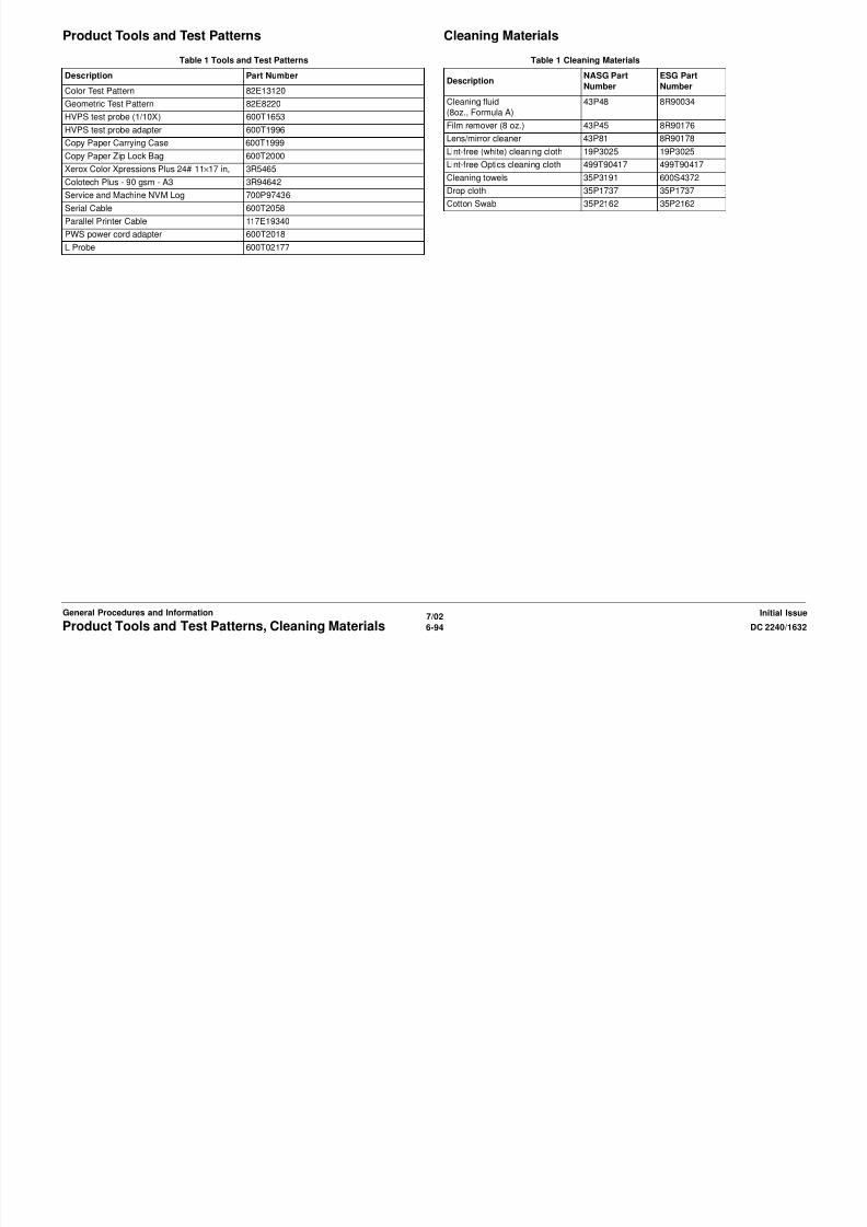
8/13/2019 Xerox Docu Color 2240-1632
http://slidepdf.com/reader/full/xerox-docu-color-2240-1632 916/1118
7/026-96 DC 2240/1632Glossary of TermsInitial IssueGeneral Procedures and Information
PJ Plug Jack (electrical connections)
RAM Random Access Memory
RAP Repair Analysis Procedure for diagnosis of machine status codes and abnormal con-
ditions
R/E Reduction/Enlargement refers to features selection or components that enable
reduction or enlargementREP Repair Procedure for disassembly and reassembly of component on machine
RIS Raster Input Scanner
ROM Read Only Memory
ROS Raster Output Scanner - Device that transfers digitally processed image, using laser
light, to photoreceptor.
SAD Sol id Area Densi ty
SCP Service Call Procedure
SEF Short Edge Feed
Self-test
An automatic process that is used to check Control Logic circuitry. Any fault that isdetected during self-test is displayed by fault code or by LEDs on PWB.
SIMM Single Inline Memory Module used to increase printing capacity
Simplex Single sided copies
FS Fast Scan (direction) - LE - to - TE
TE Trail Edge of copy or print paper, with reference to definition of term LE
UM Unscheduled Maintenance
UI User Interface
USB Universal Serial Bus
W/ With - indicates machine condition where specified condition is presentW/O Without - indicates machine condition where specified condition is not present
XBRA Xerox Brazi l
XE Xerox Europe - also referred to as ESG (European Solutions Group)
XLA Xerox Latin America
YCMK Toner colors for machine; Y=yellow, C=cyan, M=magenta, and K=black
XMEX Xerox Mexico
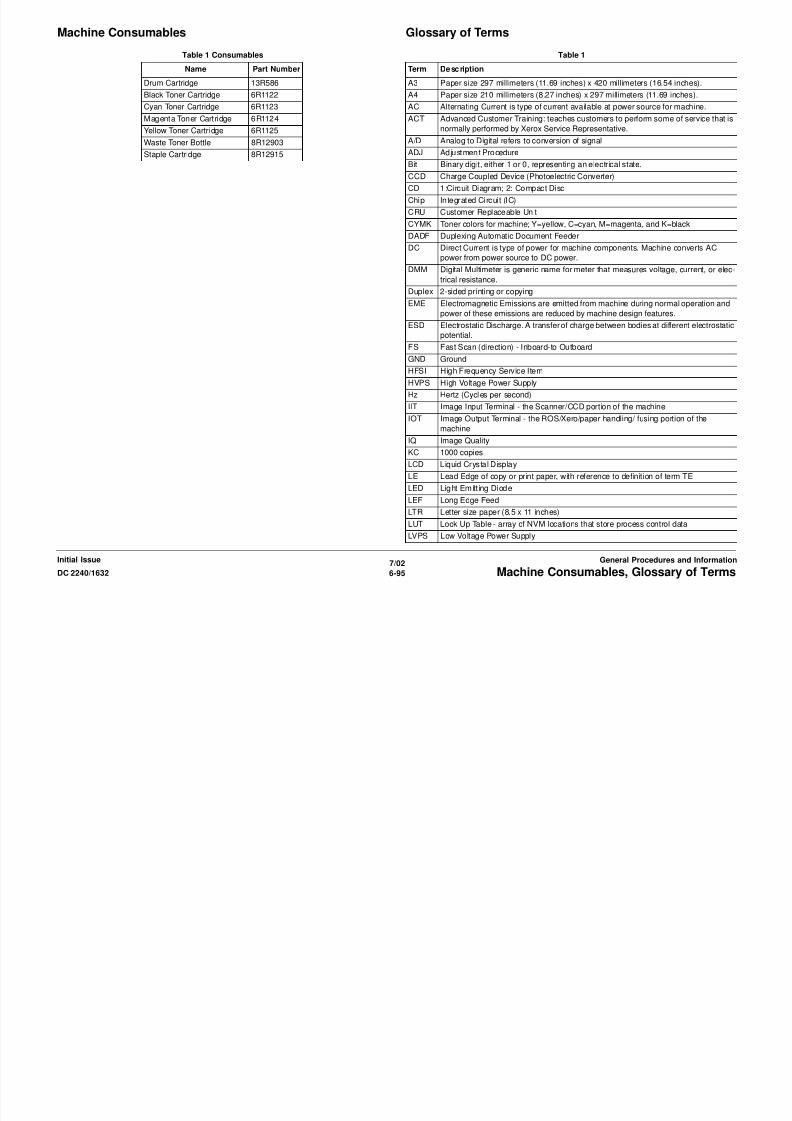
8/13/2019 Xerox Docu Color 2240-1632
http://slidepdf.com/reader/full/xerox-docu-color-2240-1632 917/1118

8/13/2019 Xerox Docu Color 2240-1632
http://slidepdf.com/reader/full/xerox-docu-color-2240-1632 918/1118
7/027-2 DC 2240/1632
Initial IssueWiring Data
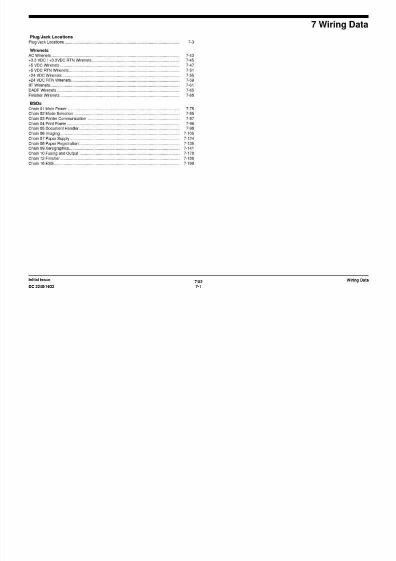
8/13/2019 Xerox Docu Color 2240-1632
http://slidepdf.com/reader/full/xerox-docu-color-2240-1632 919/1118

8/13/2019 Xerox Docu Color 2240-1632
http://slidepdf.com/reader/full/xerox-docu-color-2240-1632 920/1118
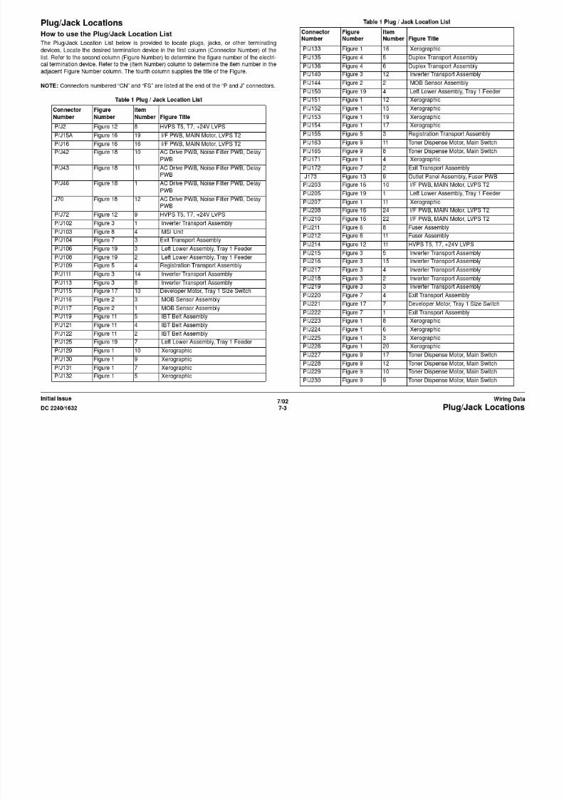
8/13/2019 Xerox Docu Color 2240-1632
http://slidepdf.com/reader/full/xerox-docu-color-2240-1632 921/1118

8/13/2019 Xerox Docu Color 2240-1632
http://slidepdf.com/reader/full/xerox-docu-color-2240-1632 922/1118

8/13/2019 Xerox Docu Color 2240-1632
http://slidepdf.com/reader/full/xerox-docu-color-2240-1632 923/1118
FS182 Figure 9 2 Toner Dispense Motor (Y,M,C,K), Main
Switch
FS183 Figure 9 3 Toner Dispense Motor (Y,M,C,K), Main
Switch
FS184 Figure 9 4 Toner Dispense Motor (Y,M,C,K), Main
Switch
FS185 Figure 9 5 Toner Dispense Motor (Y,M,C,K), Main
Switch
FS186 Figure 9 6 Toner Dispense Motor (Y,M,C,K), Main
Switch
FS187 Figure 9 7 Toner Dispense Motor (Y,M,C,K), Main
Switch
FS812 Figure 20 1 TT Module (Tray 2,3 feeder)
Table 1 Plug / Jack Location ListConnector
Number
Figure
Number
Item
Number Figure Title

8/13/2019 Xerox Docu Color 2240-1632
http://slidepdf.com/reader/full/xerox-docu-color-2240-1632 924/1118
7/02
7-8 DC 2240/1632Plug/Jack Locations
Initial IssueWiring Data
S8 gu e 0 odu e ( ay ,3 eede )
FS813 Figure 20 2 TT Module (Tray 2,3 feeder)
LCD CN1 Figure 24 12 Control Panel
Plug/Jack Illustrations

8/13/2019 Xerox Docu Color 2240-1632
http://slidepdf.com/reader/full/xerox-docu-color-2240-1632 925/1118
7/02
7-9DC 2240/1632 Plug/Jack Locations
Wiring DataInitial Issue
Figure 1 Xerographics
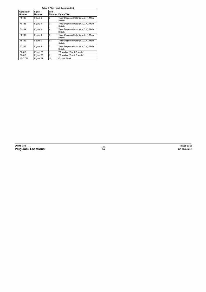
8/13/2019 Xerox Docu Color 2240-1632
http://slidepdf.com/reader/full/xerox-docu-color-2240-1632 926/1118
7/02
7-10 DC 2240/1632Plug/Jack Locations
Initial IssueWiring Data

8/13/2019 Xerox Docu Color 2240-1632
http://slidepdf.com/reader/full/xerox-docu-color-2240-1632 927/1118
7/02
7-11DC 2240/1632 Plug/Jack Locations
Wiring DataInitial Issue
Figure 2 MOB Sensor Assembly
8/13/2019 Xerox Docu Color 2240-1632
http://slidepdf.com/reader/full/xerox-docu-color-2240-1632 928/1118
7/02
7-12 DC 2240/1632Plug/Jack Locations
Initial IssueWiring Data
Figure 3 Inverter transport Assembly

8/13/2019 Xerox Docu Color 2240-1632
http://slidepdf.com/reader/full/xerox-docu-color-2240-1632 929/1118
7/02
7-13DC 2240/1632 Plug/Jack Locations
Wiring DataInitial Issue
Figure 4 Duplex Transport Assembly

8/13/2019 Xerox Docu Color 2240-1632
http://slidepdf.com/reader/full/xerox-docu-color-2240-1632 930/1118
7/02
7-14 DC 2240/1632Plug/Jack Locations
Initial IssueWiring Data
Figure 5 Registration Transport Assembly

8/13/2019 Xerox Docu Color 2240-1632
http://slidepdf.com/reader/full/xerox-docu-color-2240-1632 931/1118
7/02
7-15DC 2240/1632 Plug/Jack Locations
Wiring DataInitial Issue
Figure 6 Fuser Assembly

8/13/2019 Xerox Docu Color 2240-1632
http://slidepdf.com/reader/full/xerox-docu-color-2240-1632 932/1118
7/02
7-16 DC 2240/1632Plug/Jack Locations
Initial IssueWiring Data
Figure 7 Exit Transport Assembly (OCT)
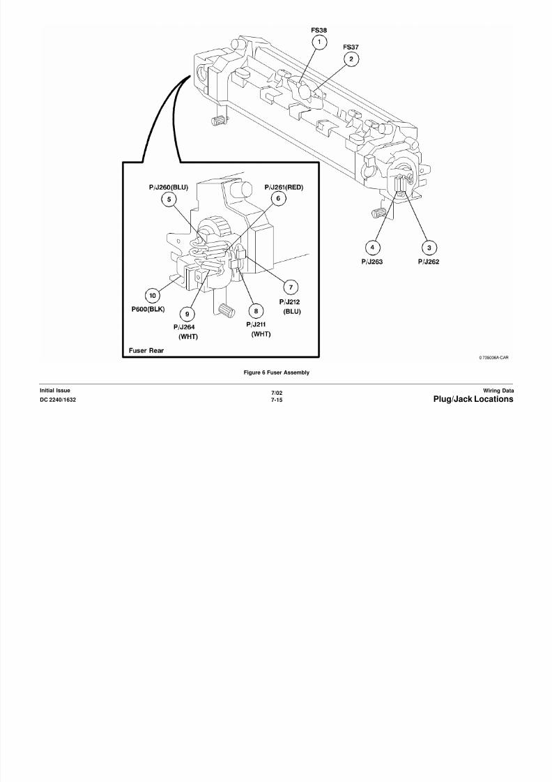
8/13/2019 Xerox Docu Color 2240-1632
http://slidepdf.com/reader/full/xerox-docu-color-2240-1632 933/1118
7/02
7-17DC 2240/1632 Plug/Jack Locations
Wiring DataInitial Issue
Figure 8 TRAY 5

8/13/2019 Xerox Docu Color 2240-1632
http://slidepdf.com/reader/full/xerox-docu-color-2240-1632 934/1118
7/02
7-18 DC 2240/1632Plug/Jack Locations
Initial IssueWiring Data
Figure 9 Toner Dispense Motor (Y,M,C,K), Main Switch

8/13/2019 Xerox Docu Color 2240-1632
http://slidepdf.com/reader/full/xerox-docu-color-2240-1632 935/1118
7/02
7-19DC 2240/1632 Plug/Jack Locations
Wiring DataInitial Issue
Figure 10 ROS Assembly
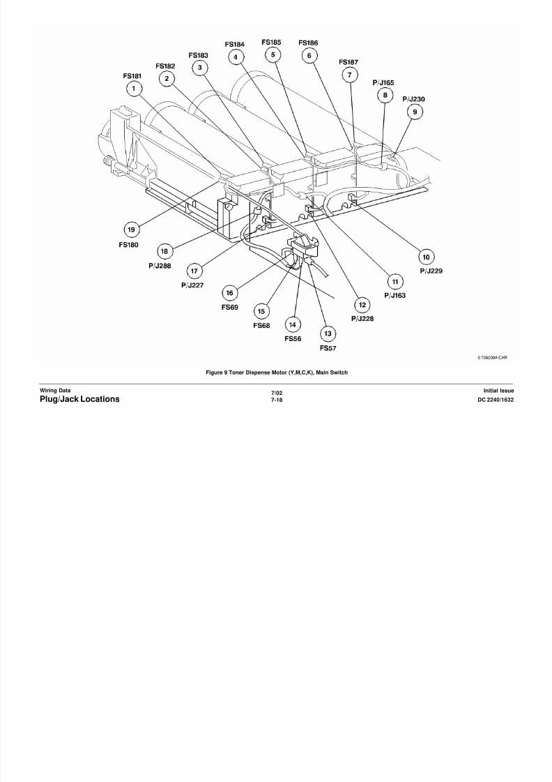
8/13/2019 Xerox Docu Color 2240-1632
http://slidepdf.com/reader/full/xerox-docu-color-2240-1632 936/1118
7/02
7-20 DC 2240/1632Plug/Jack Locations
Initial IssueWiring Data
Figure 11 IBT Belt Assembly

8/13/2019 Xerox Docu Color 2240-1632
http://slidepdf.com/reader/full/xerox-docu-color-2240-1632 937/1118
7/02
7-21DC 2240/1632 Plug/Jack Locations
Wiring DataInitial Issue
Figure 12 HVPS T5, T7, +24V LVPS
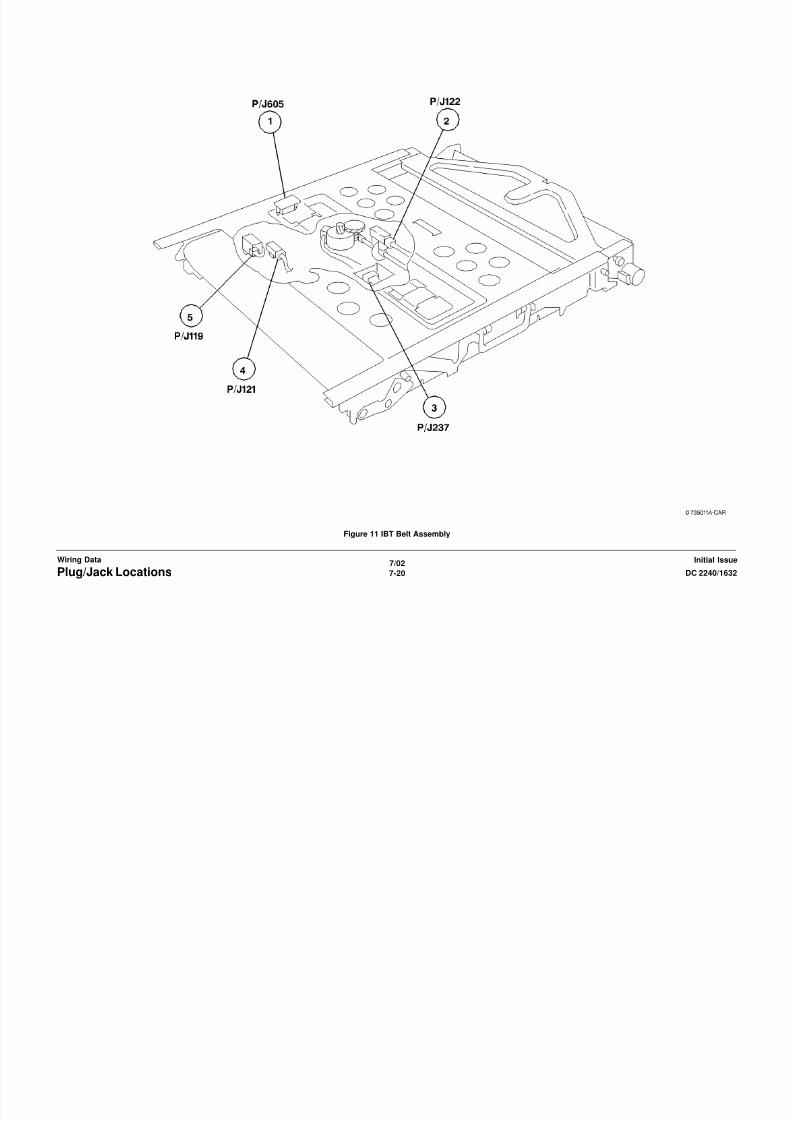
8/13/2019 Xerox Docu Color 2240-1632
http://slidepdf.com/reader/full/xerox-docu-color-2240-1632 938/1118
7/02
7-22 DC 2240/1632Plug/Jack Locations
Initial IssueWiring Data
Figure 13 Outlet Panel Assembly, Fuser PWB

8/13/2019 Xerox Docu Color 2240-1632
http://slidepdf.com/reader/full/xerox-docu-color-2240-1632 939/1118
7/02
7-23DC 2240/1632 Plug/Jack Locations
Wiring DataInitial Issue
Figure 14 ESS Assembly

8/13/2019 Xerox Docu Color 2240-1632
http://slidepdf.com/reader/full/xerox-docu-color-2240-1632 940/1118
7/02
7-24 DC 2240/1632Plug/Jack Locations
Initial IssueWiring Data
Figure 15 MCU PWB
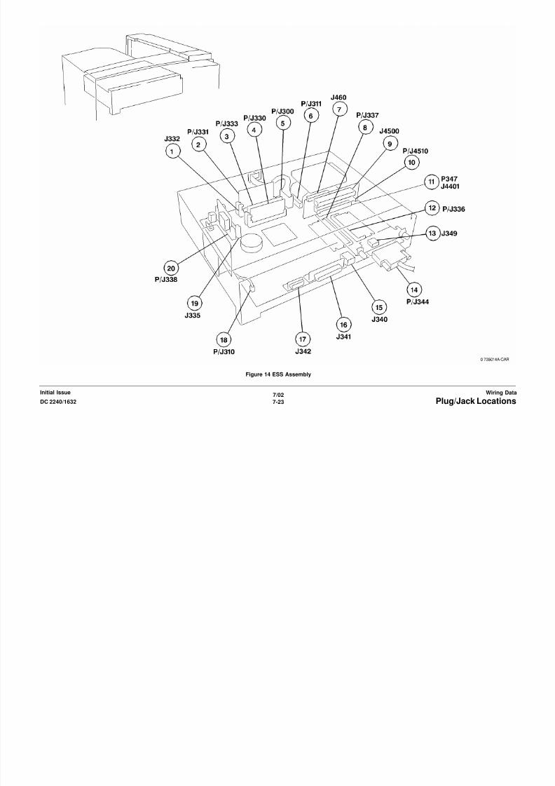
8/13/2019 Xerox Docu Color 2240-1632
http://slidepdf.com/reader/full/xerox-docu-color-2240-1632 941/1118
7/02
7-25DC 2240/1632 Plug/Jack Locations
Wiring DataInitial Issue
Figure 16 I/F PWB, Main Motor, LVPS T2

8/13/2019 Xerox Docu Color 2240-1632
http://slidepdf.com/reader/full/xerox-docu-color-2240-1632 942/1118
7/02
7-26 DC 2240/1632Plug/Jack Locations
Initial IssueWiring Data
Figure 17 Developer Motor, Tray 1 Size Switch
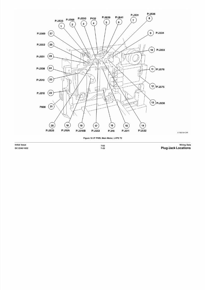
8/13/2019 Xerox Docu Color 2240-1632
http://slidepdf.com/reader/full/xerox-docu-color-2240-1632 943/1118
7/02
7-27DC 2240/1632 Plug/Jack Locations
Wiring DataInitial Issue
Figure 18 AC Drive PWB, Noise Filter PWB, Delay PWB

8/13/2019 Xerox Docu Color 2240-1632
http://slidepdf.com/reader/full/xerox-docu-color-2240-1632 944/1118
7/02
7-28 DC 2240/1632Plug/Jack Locations
Initial IssueWiring Data
Figure 19 Left Lower Assembly, Tray 1 Feeder

8/13/2019 Xerox Docu Color 2240-1632
http://slidepdf.com/reader/full/xerox-docu-color-2240-1632 945/1118
7/02
7-29DC 2240/1632 Plug/Jack Locations
Wiring DataInitial Issue
Figure 20 TT Module (Tray 2, 3 feeder)

8/13/2019 Xerox Docu Color 2240-1632
http://slidepdf.com/reader/full/xerox-docu-color-2240-1632 946/1118
7/02
7-30 DC 2240/1632Plug/Jack Locations
Initial IssueWiring Data
Figure 21 TT Module (Tray 4 Feeder)
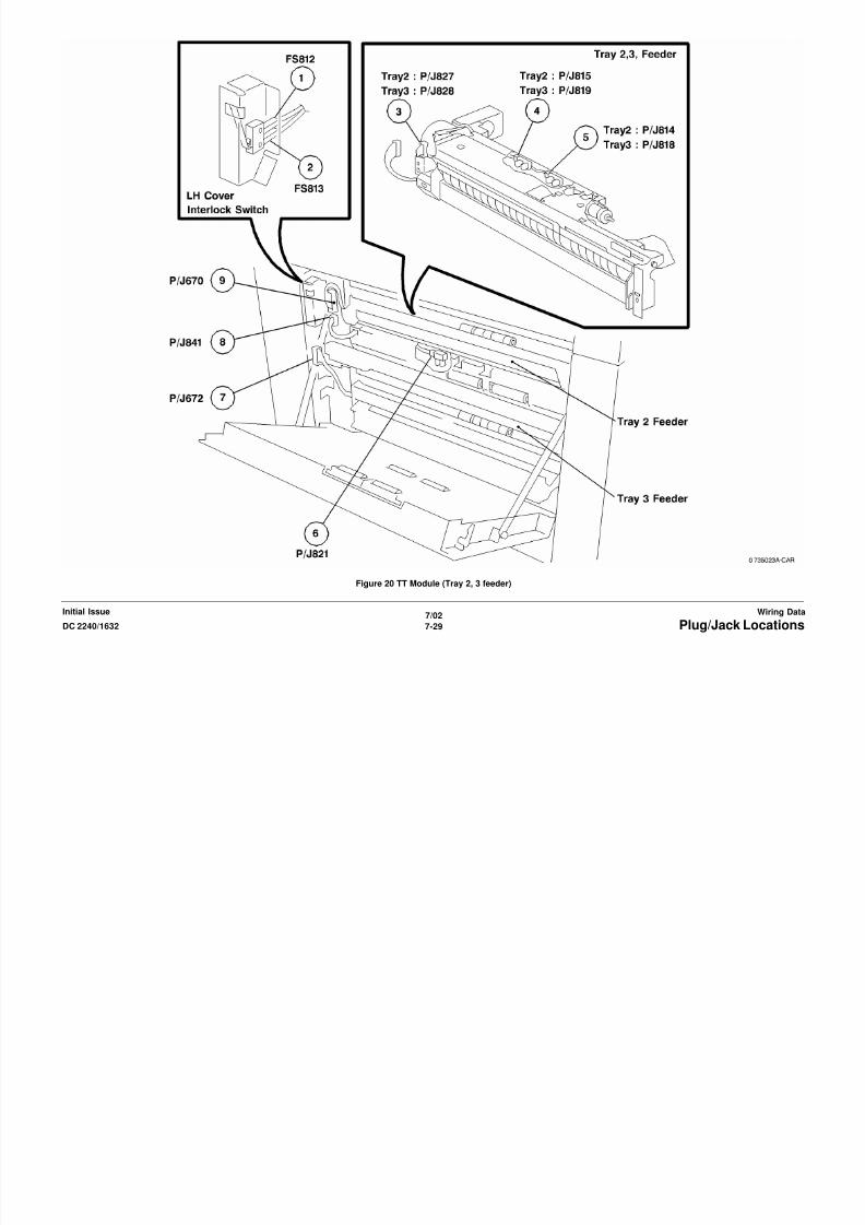
8/13/2019 Xerox Docu Color 2240-1632
http://slidepdf.com/reader/full/xerox-docu-color-2240-1632 947/1118
7/02
7-31DC 2240/1632 Plug/Jack Locations
Wiring DataInitial Issue
Figure 22 TT Module (Tray 2,3,4 Paper Size Switches)

8/13/2019 Xerox Docu Color 2240-1632
http://slidepdf.com/reader/full/xerox-docu-color-2240-1632 948/1118
7/02
7-32 DC 2240/1632Plug/Jack Locations
Initial IssueWiring Data
Figure 23 TT Module (rear)

8/13/2019 Xerox Docu Color 2240-1632
http://slidepdf.com/reader/full/xerox-docu-color-2240-1632 949/1118
7/02
7-33DC 2240/1632 Plug/Jack Locations
Wiring DataInitial Issue
Figure 24 Control Panel

8/13/2019 Xerox Docu Color 2240-1632
http://slidepdf.com/reader/full/xerox-docu-color-2240-1632 950/1118
7/02
7-34 DC 2240/1632Plug/Jack Locations
Initial IssueWiring Data
Figure 25 DADF (1 of 2)
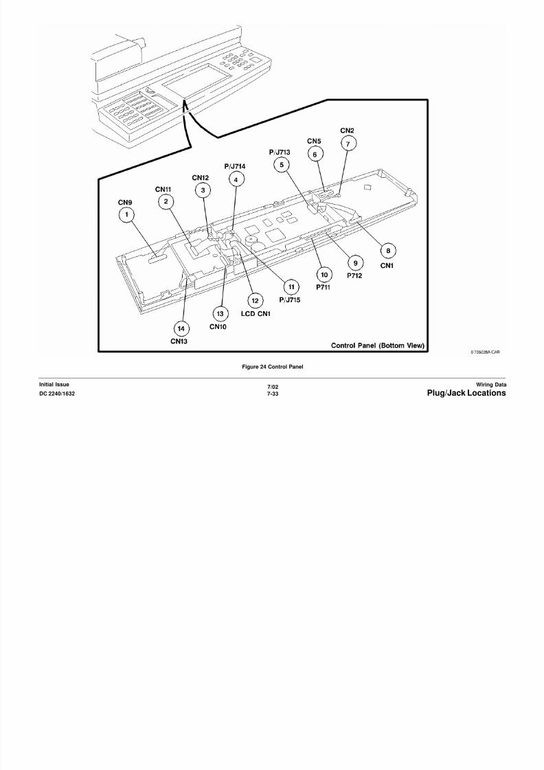
8/13/2019 Xerox Docu Color 2240-1632
http://slidepdf.com/reader/full/xerox-docu-color-2240-1632 951/1118
7/02
7-35DC 2240/1632 Plug/Jack Locations
Wiring DataInitial Issue
Figure 26 DADF (2 of 2)

8/13/2019 Xerox Docu Color 2240-1632
http://slidepdf.com/reader/full/xerox-docu-color-2240-1632 952/1118
7/02
7-36 DC 2240/1632Plug/Jack Locations
Initial IssueWiring Data
Figure 27 IIT (front)

8/13/2019 Xerox Docu Color 2240-1632
http://slidepdf.com/reader/full/xerox-docu-color-2240-1632 953/1118
7/02
7-37DC 2240/1632 Plug/Jack Locations
Wiring DataInitial Issue
Figure 28 IIT (rear)

8/13/2019 Xerox Docu Color 2240-1632
http://slidepdf.com/reader/full/xerox-docu-color-2240-1632 954/1118
7/02
7-38 DC 2240/1632Plug/Jack Locations
Initial IssueWiring Data
Figure 29 H - Transport Assembly

8/13/2019 Xerox Docu Color 2240-1632
http://slidepdf.com/reader/full/xerox-docu-color-2240-1632 955/1118
7/02
7-39DC 2240/1632
Plug/Jack Locations
Wiring DataInitial Issue
Figure 30 Tamper Unit, Staple Unit
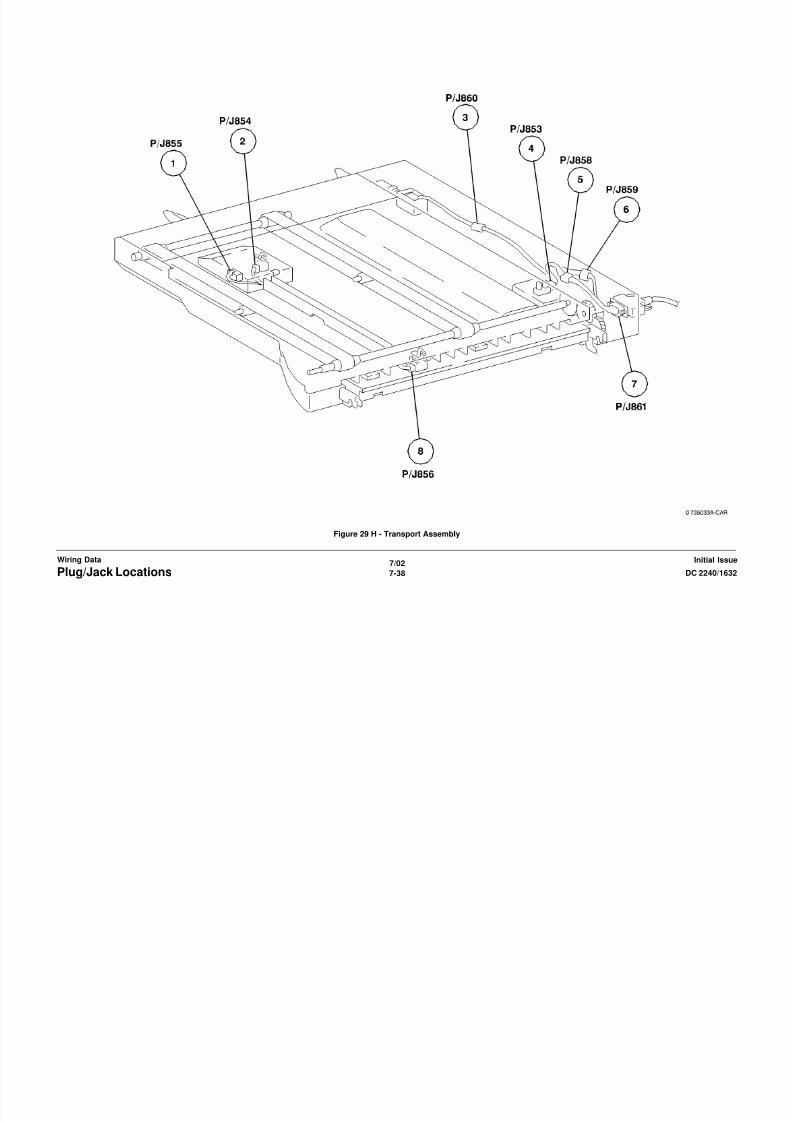
8/13/2019 Xerox Docu Color 2240-1632
http://slidepdf.com/reader/full/xerox-docu-color-2240-1632 956/1118
7/02
7-40 DC 2240/1632
Plug/Jack Locations
Initial IssueWiring Data
Figure 31 Finisher (rear) (1 of 2)

8/13/2019 Xerox Docu Color 2240-1632
http://slidepdf.com/reader/full/xerox-docu-color-2240-1632 957/1118
7/02
7-41DC 2240/1632
Plug/Jack Locations
Wiring DataInitial Issue
Figure 32 Finisher PWB

8/13/2019 Xerox Docu Color 2240-1632
http://slidepdf.com/reader/full/xerox-docu-color-2240-1632 958/1118
7/02
7-42 DC 2240/1632
Plug/Jack Locations
Initial IssueWiring Data
AC Wirenets
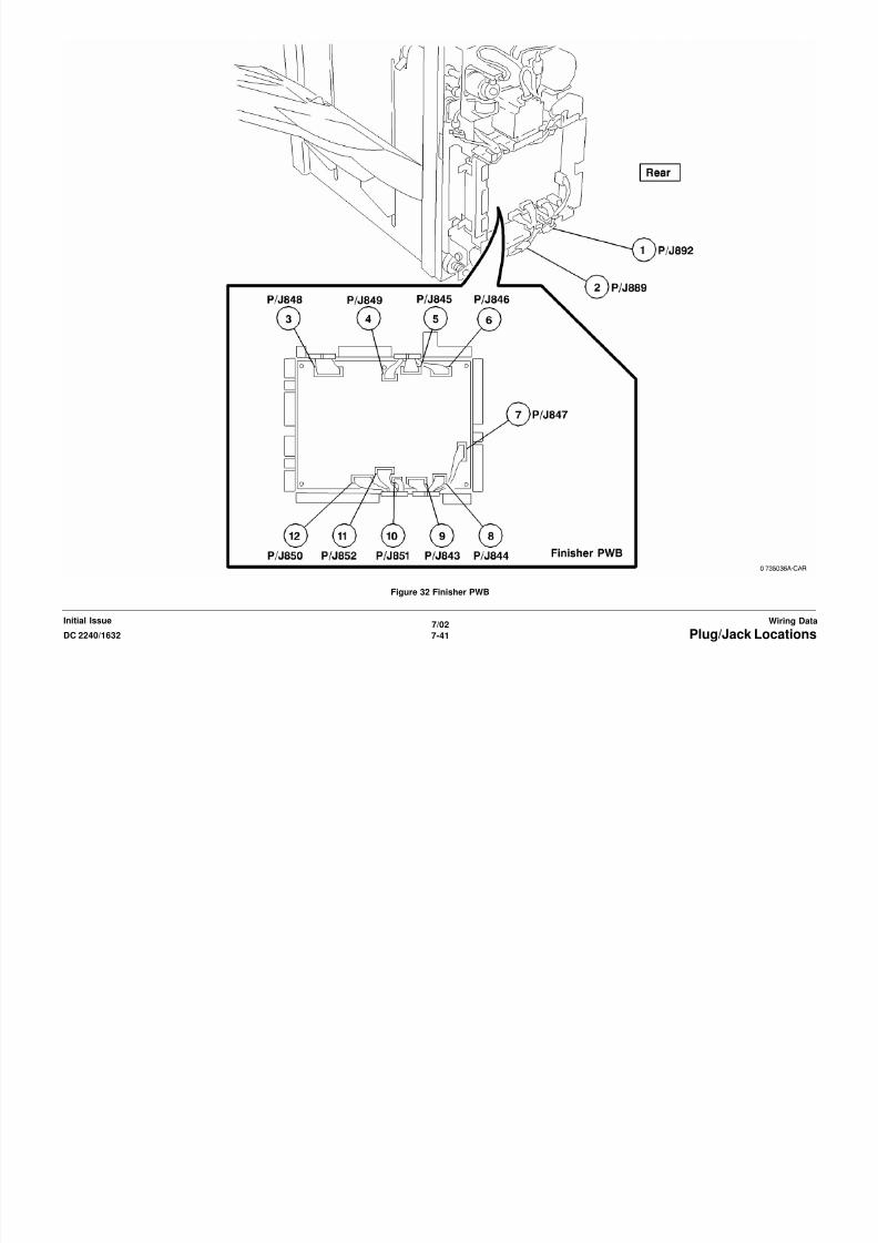
8/13/2019 Xerox Docu Color 2240-1632
http://slidepdf.com/reader/full/xerox-docu-color-2240-1632 959/1118
7/02
7-43DC 2240/1632 AC WirenetsWiring DataInitial Issue
Figure 1 ACH Wirenet

8/13/2019 Xerox Docu Color 2240-1632
http://slidepdf.com/reader/full/xerox-docu-color-2240-1632 960/1118
7/02
7-44 DC 2240/1632AC WirenetsInitial IssueWiring Data
Figure 2 ACN Wirenet
+3.3 VDC / +3.3VDC RTN Wirenets

8/13/2019 Xerox Docu Color 2240-1632
http://slidepdf.com/reader/full/xerox-docu-color-2240-1632 961/1118
7/02
7-45DC 2240/1632 +3.3 VDC / +3.3VDC RTN WirenetsWiring DataInitial Issue
Figure 1 +3.3VDC Wirenet

8/13/2019 Xerox Docu Color 2240-1632
http://slidepdf.com/reader/full/xerox-docu-color-2240-1632 962/1118
7/02
7-46 DC 2240/1632+3.3 VDC / +3.3VDC RTN WirenetsInitial IssueWiring Data
Figure 2 3.3V RTN Wirenet
+5 VDC Wirenets

8/13/2019 Xerox Docu Color 2240-1632
http://slidepdf.com/reader/full/xerox-docu-color-2240-1632 963/1118
7/02
7-47DC 2240/1632 +5 VDC WirenetsWiring DataInitial Issue
Figure 1 +5.5VDC (1 of 4) Wirenet

8/13/2019 Xerox Docu Color 2240-1632
http://slidepdf.com/reader/full/xerox-docu-color-2240-1632 964/1118
7/02
7-48 DC 2240/1632+5 VDC WirenetsInitial IssueWiring Data
Figure 2 +5.5VDC (2 of 4) Wirenet

8/13/2019 Xerox Docu Color 2240-1632
http://slidepdf.com/reader/full/xerox-docu-color-2240-1632 965/1118
7/02
7-49DC 2240/1632 +5 VDC WirenetsWiring DataInitial Issue
Figure 3 +5.5VDC (3 of 4) Wirenet

8/13/2019 Xerox Docu Color 2240-1632
http://slidepdf.com/reader/full/xerox-docu-color-2240-1632 966/1118
7/02
7-50 DC 2240/1632+5 VDC WirenetsInitial IssueWiring Data
Figure 4 +5.5VDC (4 of 4) Wirenet
+5 VDC RTN Wirenets

8/13/2019 Xerox Docu Color 2240-1632
http://slidepdf.com/reader/full/xerox-docu-color-2240-1632 967/1118
7/02
7-51DC 2240/1632 +5 VDC RTN WirenetsWiring DataInitial Issue
Figure 1 5V RTN (1 of 4) Wirenet

8/13/2019 Xerox Docu Color 2240-1632
http://slidepdf.com/reader/full/xerox-docu-color-2240-1632 968/1118
7/02
7-52 DC 2240/1632+5 VDC RTN WirenetsInitial IssueWiring Data
Figure 2 5V RTN (2 of 4) Wirenet

8/13/2019 Xerox Docu Color 2240-1632
http://slidepdf.com/reader/full/xerox-docu-color-2240-1632 969/1118
7/02
7-53DC 2240/1632 +5 VDC RTN WirenetsWiring DataInitial Issue
Figure 3 5V RTN (3 of 4) Wirenet
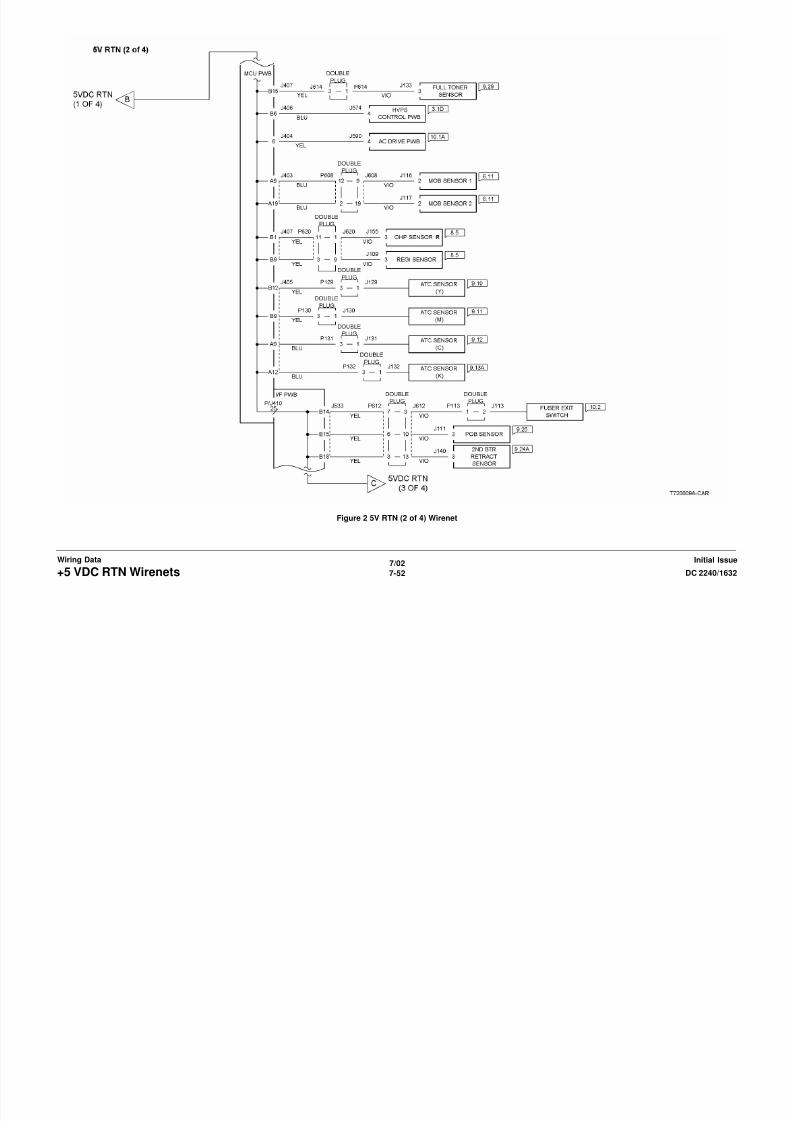
8/13/2019 Xerox Docu Color 2240-1632
http://slidepdf.com/reader/full/xerox-docu-color-2240-1632 970/1118
7/02
7-54 DC 2240/1632+5 VDC RTN WirenetsInitial IssueWiring Data
Figure 4 5V RTN (4 of 4) Wirenet
+24 VDC Wirenets

8/13/2019 Xerox Docu Color 2240-1632
http://slidepdf.com/reader/full/xerox-docu-color-2240-1632 971/1118
7/02
7-55DC 2240/1632 +24 VDC WirenetsWiring DataInitial Issue
Figure 1 +24VDC (1 of 2)
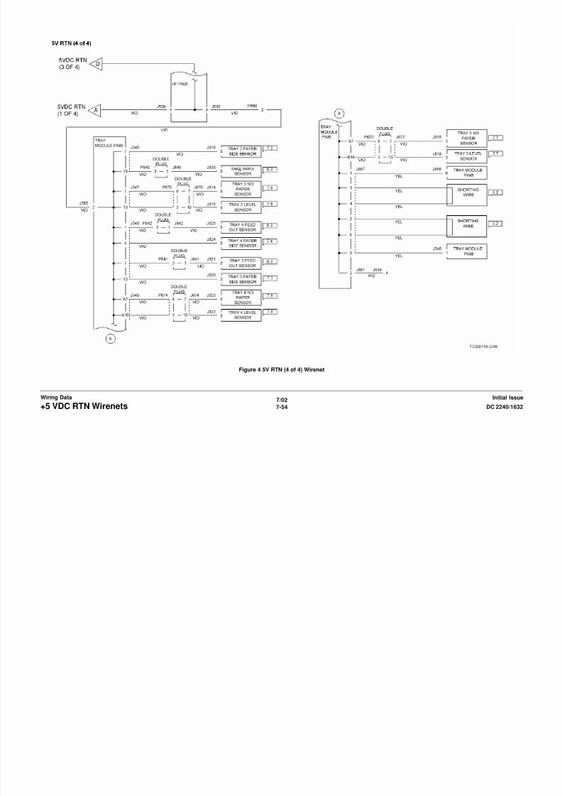
8/13/2019 Xerox Docu Color 2240-1632
http://slidepdf.com/reader/full/xerox-docu-color-2240-1632 972/1118
7/02
7-56 DC 2240/1632+24 VDC WirenetsInitial IssueWiring Data
Figure 2 +24VDC (2 of 4)
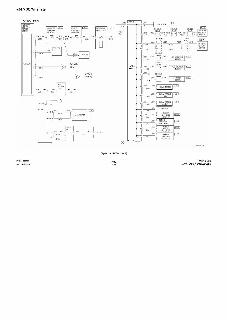
8/13/2019 Xerox Docu Color 2240-1632
http://slidepdf.com/reader/full/xerox-docu-color-2240-1632 973/1118
7/02
7-57DC 2240/1632 +24 VDC WirenetsWiring DataInitial Issue
Figure 3 +24VDC (3 of 4)

8/13/2019 Xerox Docu Color 2240-1632
http://slidepdf.com/reader/full/xerox-docu-color-2240-1632 974/1118
7/02
7-58 DC 2240/1632+24 VDC WirenetsInitial IssueWiring Data
Figure 4 +24VDC (4 of 4)
+24 VDC RTN Wirenets

8/13/2019 Xerox Docu Color 2240-1632
http://slidepdf.com/reader/full/xerox-docu-color-2240-1632 975/1118
7/02
7-59DC 2240/1632 +24 VDC RTN WirenetsWiring DataInitial Issue
Figure 1 24V RTN (1 of 2)

8/13/2019 Xerox Docu Color 2240-1632
http://slidepdf.com/reader/full/xerox-docu-color-2240-1632 976/1118
7/02
7-60 DC 2240/1632+24 VDC RTN WirenetsInitial IssueWiring Data
Figure 2 24V RTN (2 of 2)
IIT Wirenets

8/13/2019 Xerox Docu Color 2240-1632
http://slidepdf.com/reader/full/xerox-docu-color-2240-1632 977/1118
7/02
7-61DC 2240/1632 IIT WirenetsWiring DataInitial Issue
Figure 1 IIT +3.3VDC & 3.3V RTN Wirenets

8/13/2019 Xerox Docu Color 2240-1632
http://slidepdf.com/reader/full/xerox-docu-color-2240-1632 978/1118

8/13/2019 Xerox Docu Color 2240-1632
http://slidepdf.com/reader/full/xerox-docu-color-2240-1632 979/1118
7/02
7-63DC 2240/1632 IIT WirenetsWiring DataInitial Issue
Figure 3 IIT +24VDC Wirenet
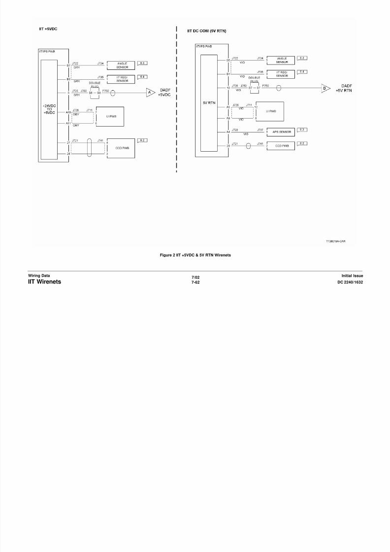
8/13/2019 Xerox Docu Color 2240-1632
http://slidepdf.com/reader/full/xerox-docu-color-2240-1632 980/1118
7/02
7-64 DC 2240/1632IIT WirenetsInitial IssueWiring Data
Figure 4 IIT 24V RTN
DADF Wirenets

8/13/2019 Xerox Docu Color 2240-1632
http://slidepdf.com/reader/full/xerox-docu-color-2240-1632 981/1118
7/02
7-65DC 2240/1632 DADF WirenetsWiring DataInitial Issue
Figure 1 DADF +5VDC Wirenet

8/13/2019 Xerox Docu Color 2240-1632
http://slidepdf.com/reader/full/xerox-docu-color-2240-1632 982/1118
7/02
7-66 DC 2240/1632DADF WirenetsInitial IssueWiring Data
Figure 2 DADF 5V RTN

8/13/2019 Xerox Docu Color 2240-1632
http://slidepdf.com/reader/full/xerox-docu-color-2240-1632 983/1118
7/02
7-67DC 2240/1632 DADF WirenetsWiring DataInitial Issue
Figure 3 DADF +24VDC Wirenet
Finisher Wirenets

8/13/2019 Xerox Docu Color 2240-1632
http://slidepdf.com/reader/full/xerox-docu-color-2240-1632 984/1118
7/02
7-68 DC 2240/1632Finisher WirenetsInitial IssueWiring Data
Figure 1 finisher +5VDC (1 of 2) Wirenet

8/13/2019 Xerox Docu Color 2240-1632
http://slidepdf.com/reader/full/xerox-docu-color-2240-1632 985/1118
7/02
7-69DC 2240/1632 Finisher WirenetsWiring DataInitial Issue
Figure 2 +5VDC (2 of 2) Wirenet

8/13/2019 Xerox Docu Color 2240-1632
http://slidepdf.com/reader/full/xerox-docu-color-2240-1632 986/1118
7/02
7-70 DC 2240/1632Finisher WirenetsInitial IssueWiring Data
Figure 3 5V RTN (1 of 2) Wirenet
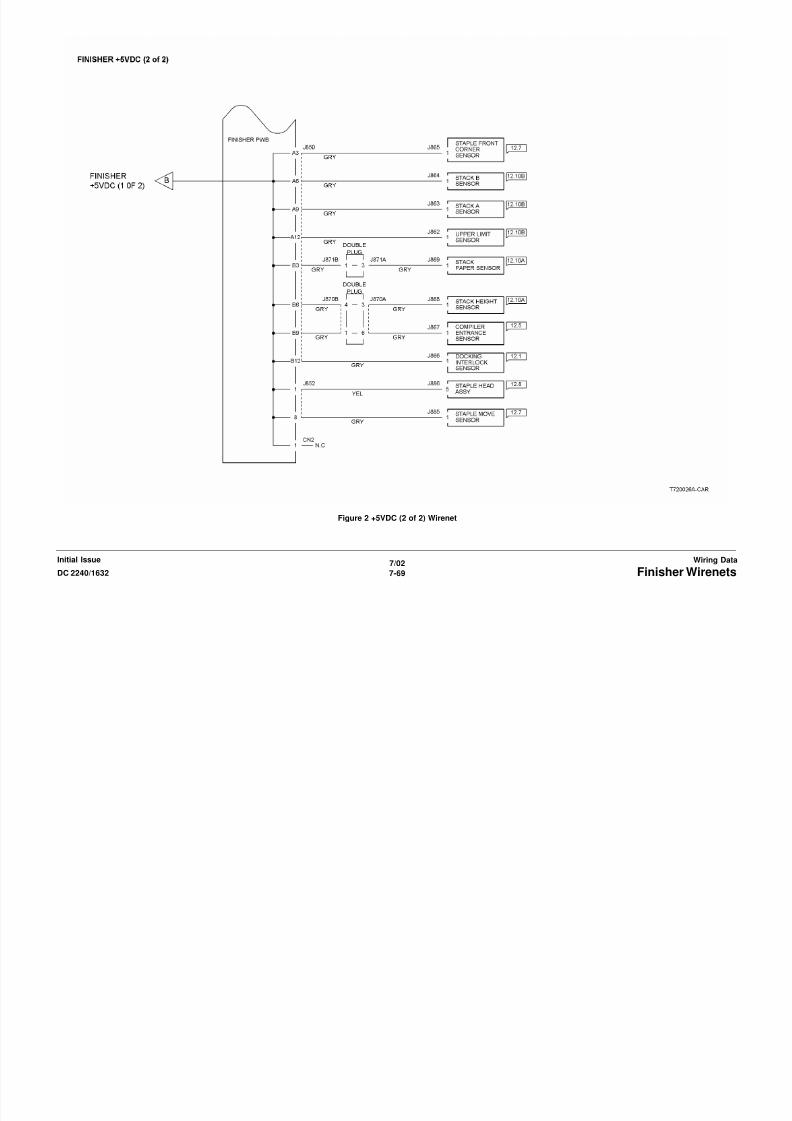
8/13/2019 Xerox Docu Color 2240-1632
http://slidepdf.com/reader/full/xerox-docu-color-2240-1632 987/1118
7/02
7-71DC 2240/1632 Finisher WirenetsWiring DataInitial Issue
Figure 4 5V RTN (2 of 2) Wirenet
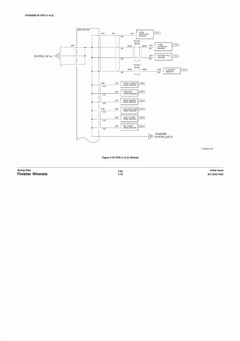
8/13/2019 Xerox Docu Color 2240-1632
http://slidepdf.com/reader/full/xerox-docu-color-2240-1632 988/1118
7/02
7-72 DC 2240/1632Finisher WirenetsInitial IssueWiring Data
Figure 5 Finisher +24VDC Wirenet

8/13/2019 Xerox Docu Color 2240-1632
http://slidepdf.com/reader/full/xerox-docu-color-2240-1632 989/1118
7/02
7-73DC 2240/1632 Finisher WirenetsWiring DataInitial Issue
Figure 6 Finisher 24V RTN Wirenet
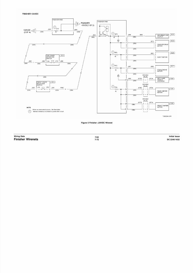
8/13/2019 Xerox Docu Color 2240-1632
http://slidepdf.com/reader/full/xerox-docu-color-2240-1632 990/1118
7/02
7-74 DC 2240/1632Finisher WirenetsInitial IssueWiring Data
Chain 01 Main Power

8/13/2019 Xerox Docu Color 2240-1632
http://slidepdf.com/reader/full/xerox-docu-color-2240-1632 991/1118
7/02
7-75DC 2240/1632 Chain 01 Main PowerWiring DataInitial Issue
Figure 1 Main Power On (1 of 2)

8/13/2019 Xerox Docu Color 2240-1632
http://slidepdf.com/reader/full/xerox-docu-color-2240-1632 992/1118
7/02
7-76 DC 2240/1632Chain 01 Main PowerInitial IssueWiring Data
Figure 2 Main Power On (2 of 2)
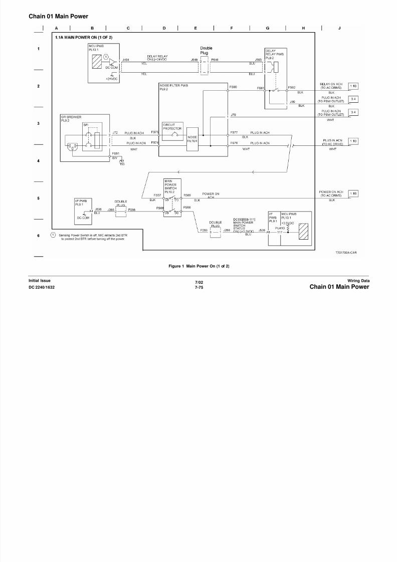
8/13/2019 Xerox Docu Color 2240-1632
http://slidepdf.com/reader/full/xerox-docu-color-2240-1632 993/1118
7/02
7-77DC 2240/1632 Chain 01 Main PowerWiring DataInitial Issue
Figure 3 LVPS Control
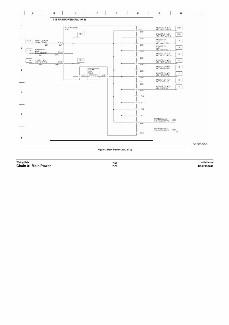
8/13/2019 Xerox Docu Color 2240-1632
http://slidepdf.com/reader/full/xerox-docu-color-2240-1632 994/1118
7/02
7-78 DC 2240/1632Chain 01 Main PowerInitial IssueWiring Data
Figure 4 DC Power Generation (+3.3VDC)

8/13/2019 Xerox Docu Color 2240-1632
http://slidepdf.com/reader/full/xerox-docu-color-2240-1632 995/1118
7/02
7-79DC 2240/1632 Chain 01 Main PowerWiring DataInitial Issue
Figure 5 DC Power Generation

8/13/2019 Xerox Docu Color 2240-1632
http://slidepdf.com/reader/full/xerox-docu-color-2240-1632 996/1118
7/02
7-80 DC 2240/1632Chain 01 Main PowerInitial IssueWiring Data
Figure 6 DC Power Generation (+24VDC)
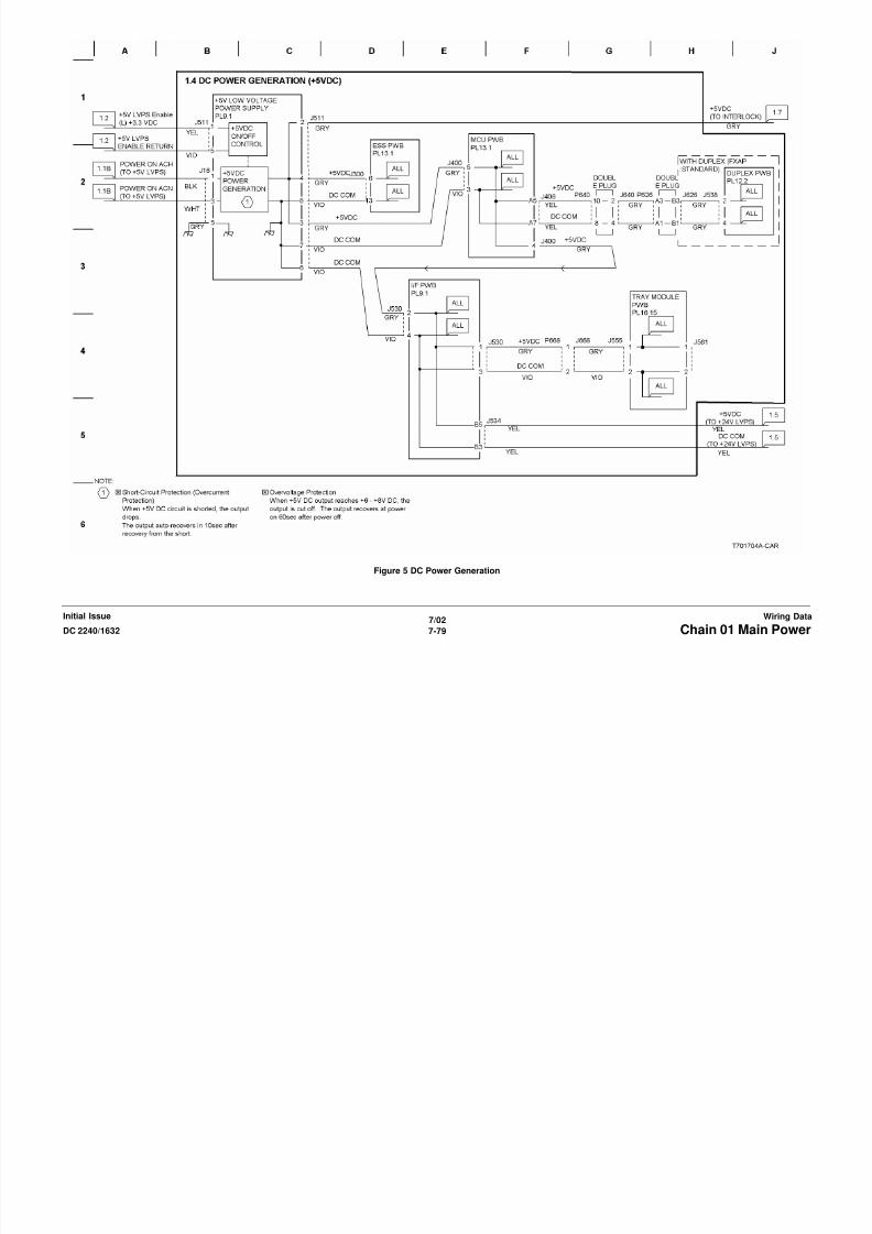
8/13/2019 Xerox Docu Color 2240-1632
http://slidepdf.com/reader/full/xerox-docu-color-2240-1632 997/1118
7/02
7-81DC 2240/1632 Chain 01 Main PowerWiring DataInitial Issue
Figure 7 DC Power Generation (IIT LVPS)

8/13/2019 Xerox Docu Color 2240-1632
http://slidepdf.com/reader/full/xerox-docu-color-2240-1632 998/1118
7/02
7-82 DC 2240/1632Chain 01 Main PowerInitial IssueWiring Data
Figure 8 Power Interlock Switching

8/13/2019 Xerox Docu Color 2240-1632
http://slidepdf.com/reader/full/xerox-docu-color-2240-1632 999/1118
7/02
7-83DC 2240/1632 Chain 01 Main PowerWiring DataInitial Issue
Figure 9 Tray Module Power Interlock Switching
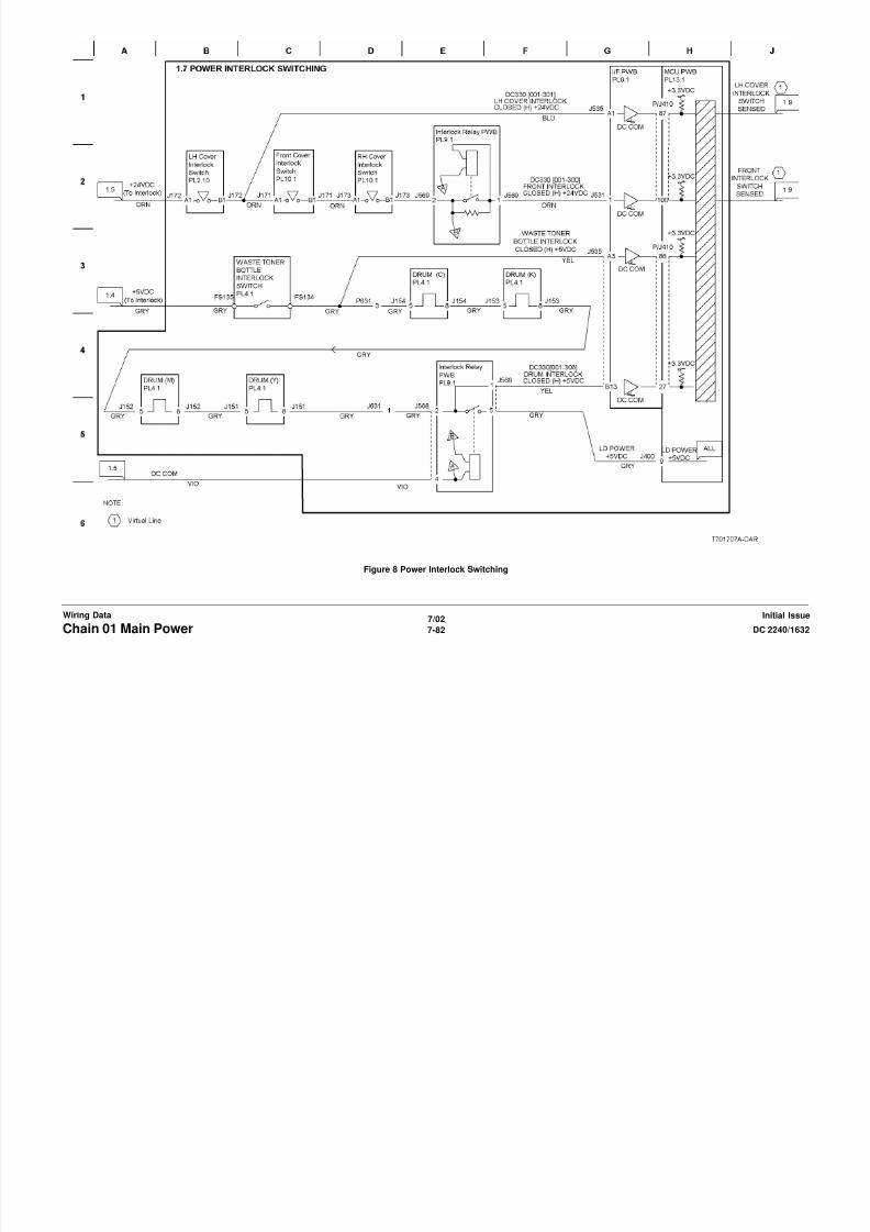
8/13/2019 Xerox Docu Color 2240-1632
http://slidepdf.com/reader/full/xerox-docu-color-2240-1632 1000/1118
7/02
7-84 DC 2240/1632Chain 01 Main PowerInitial IssueWiring Data
Figure 10 Monitoring
Chain 02 Mode Selection
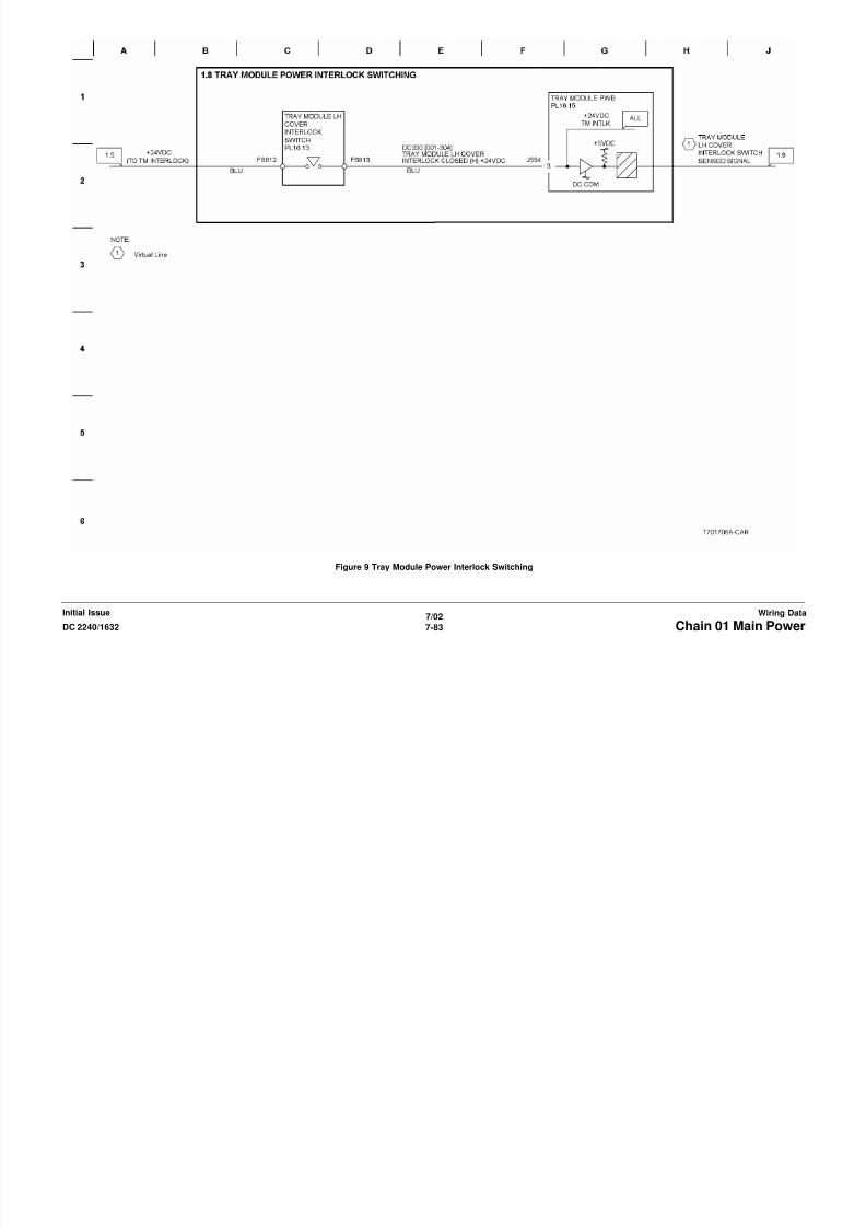
8/13/2019 Xerox Docu Color 2240-1632
http://slidepdf.com/reader/full/xerox-docu-color-2240-1632 1001/1118
7/02
7-85DC 2240/1632 Chain 02 Mode SelectionWiring DataInitial Issue
Figure 1 Control Panel
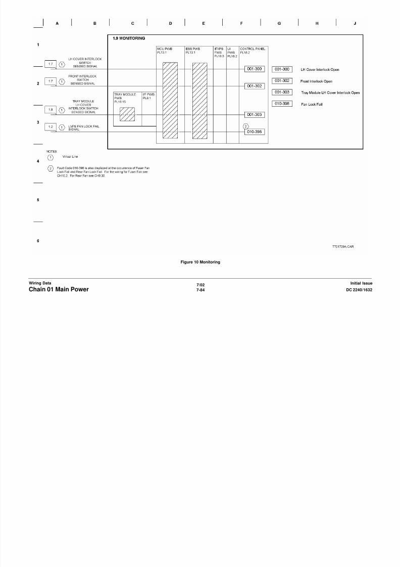
8/13/2019 Xerox Docu Color 2240-1632
http://slidepdf.com/reader/full/xerox-docu-color-2240-1632 1002/1118
7/02
7-86 DC 2240/1632Chain 02 Mode SelectionInitial IssueWiring Data
Figure 2 LCD Control
Chain 03 Printer Communication
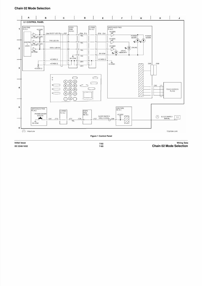
8/13/2019 Xerox Docu Color 2240-1632
http://slidepdf.com/reader/full/xerox-docu-color-2240-1632 1003/1118
7/02
7-87DC 2240/1632 Chain 03 Printer CommunicationWiring DataInitial Issue
Figure 1 PWBs Communication (1 0f 4)

8/13/2019 Xerox Docu Color 2240-1632
http://slidepdf.com/reader/full/xerox-docu-color-2240-1632 1004/1118
7/02
7-88 DC 2240/1632Chain 03 Printer CommunicationInitial IssueWiring Data
Figure 2 PWB Communication (2 0f 4)
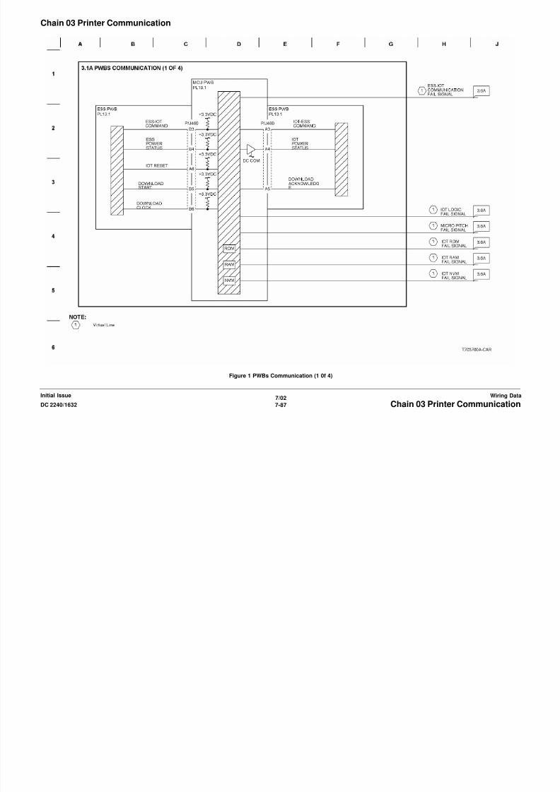
8/13/2019 Xerox Docu Color 2240-1632
http://slidepdf.com/reader/full/xerox-docu-color-2240-1632 1005/1118
7/02
7-89DC 2240/1632 Chain 03 Printer CommunicationWiring DataInitial Issue
Figure 3 PWB Communication (3 0f 4)
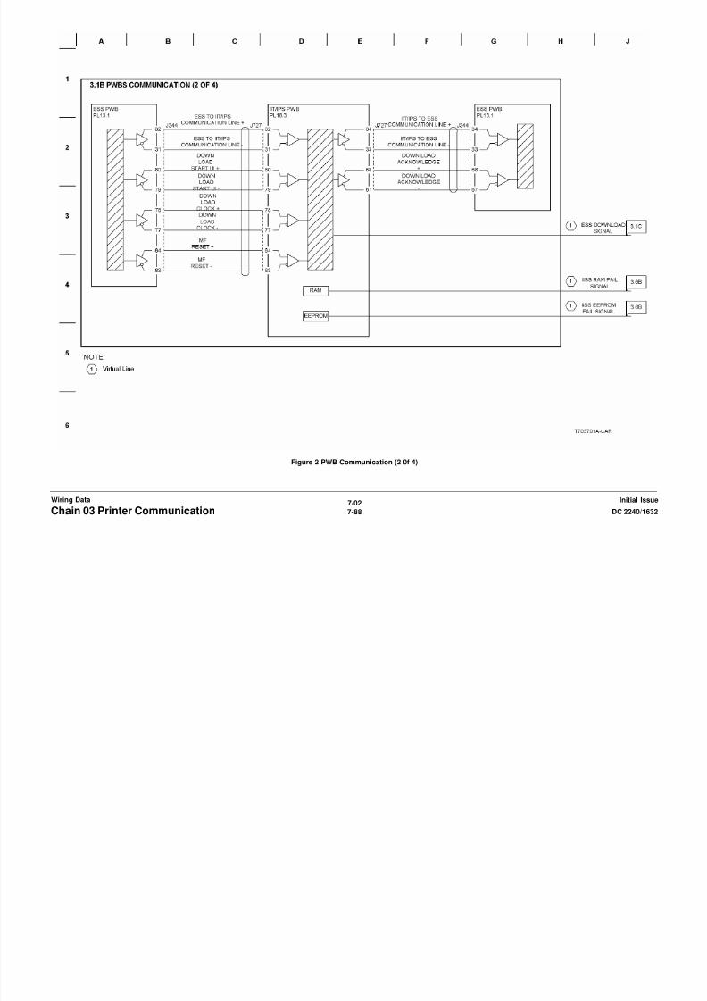
8/13/2019 Xerox Docu Color 2240-1632
http://slidepdf.com/reader/full/xerox-docu-color-2240-1632 1006/1118
7/02
7-90 DC 2240/1632Chain 03 Printer CommunicationInitial IssueWiring Data
Figure 4 PWB Communication (4 0f 4)

8/13/2019 Xerox Docu Color 2240-1632
http://slidepdf.com/reader/full/xerox-docu-color-2240-1632 1007/1118
7/02
7-91DC 2240/1632 Chain 03 Printer CommunicationWiring DataInitial Issue
Figure 5 Option Device Detection

8/13/2019 Xerox Docu Color 2240-1632
http://slidepdf.com/reader/full/xerox-docu-color-2240-1632 1008/1118
7/02
7-92 DC 2240/1632Chain 03 Printer CommunicationInitial IssueWiring Data
Figure 6 PWS Interface

8/13/2019 Xerox Docu Color 2240-1632
http://slidepdf.com/reader/full/xerox-docu-color-2240-1632 1009/1118
7/02
7-93DC 2240/1632 Chain 03 Printer CommunicationWiring DataInitial Issue
Figure 7 Billing

8/13/2019 Xerox Docu Color 2240-1632
http://slidepdf.com/reader/full/xerox-docu-color-2240-1632 1010/1118
7/02
7-94 DC 2240/1632Chain 03 Printer CommunicationInitial IssueWiring Data
Figure 8 Monitoring

8/13/2019 Xerox Docu Color 2240-1632
http://slidepdf.com/reader/full/xerox-docu-color-2240-1632 1011/1118
7/02
7-95DC 2240/1632 Chain 03 Printer CommunicationWiring DataInitial Issue
Figure 9 Monitoring (2 of 2)
Chain 04 Print Power

8/13/2019 Xerox Docu Color 2240-1632
http://slidepdf.com/reader/full/xerox-docu-color-2240-1632 1012/1118
7/02
7-96 DC 2240/1632Chain 04 Print PowerInitial IssueWiring Data
Figure 1 Main Drive (1 of 2)

8/13/2019 Xerox Docu Color 2240-1632
http://slidepdf.com/reader/full/xerox-docu-color-2240-1632 1013/1118
7/02
7-97DC 2240/1632 Chain 04 Print PowerWiring DataInitial Issue
Figure 2 Main Drive (2 of 2)
Chain 05 Document Handler

8/13/2019 Xerox Docu Color 2240-1632
http://slidepdf.com/reader/full/xerox-docu-color-2240-1632 1014/1118
7/02
7-98 DC 2240/1632Chain 05 Document HandlerInitial IssueWiring Data
Figure 1 DADF DC Power and Interlocks

8/13/2019 Xerox Docu Color 2240-1632
http://slidepdf.com/reader/full/xerox-docu-color-2240-1632 1015/1118
7/02
7-99DC 2240/1632 Chain 05 Document HandlerWiring DataInitial Issue
Figure 2 PWB Communications
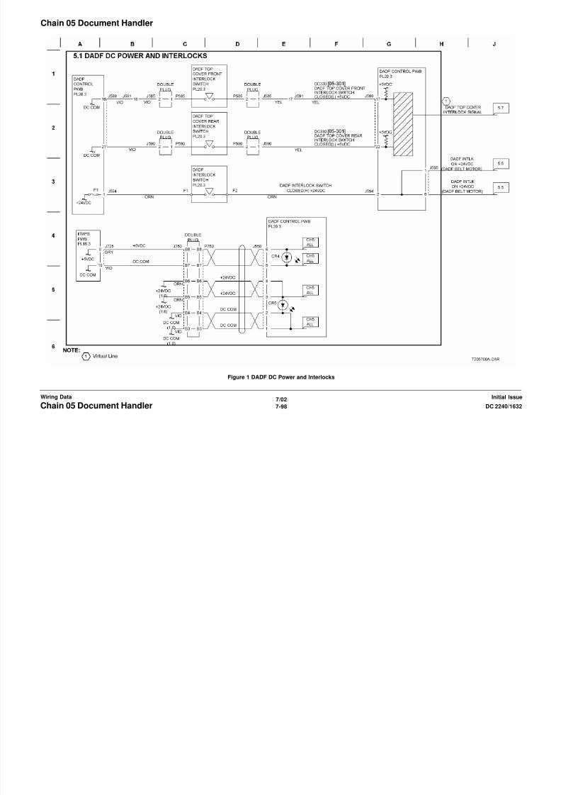
8/13/2019 Xerox Docu Color 2240-1632
http://slidepdf.com/reader/full/xerox-docu-color-2240-1632 1016/1118
7/02
7-100 DC 2240/1632Chain 05 Document HandlerInitial IssueWiring Data
Figure 3 Document Setting and Feeding

8/13/2019 Xerox Docu Color 2240-1632
http://slidepdf.com/reader/full/xerox-docu-color-2240-1632 1017/1118
7/02
7-101DC 2240/1632 Chain 05 Document HandlerWiring DataInitial Issue
Figure 4 Document Transportation
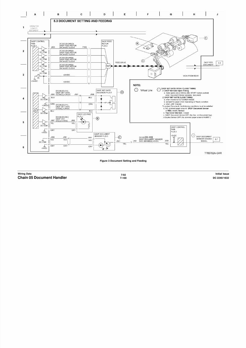
8/13/2019 Xerox Docu Color 2240-1632
http://slidepdf.com/reader/full/xerox-docu-color-2240-1632 1018/1118
7/02
7-102 DC 2240/1632Chain 05 Document HandlerInitial IssueWiring Data
Figure 5 Document Transport

8/13/2019 Xerox Docu Color 2240-1632
http://slidepdf.com/reader/full/xerox-docu-color-2240-1632 1019/1118
7/02
7-103DC 2240/1632 Chain 05 Document HandlerWiring DataInitial Issue
Figure 6 Document Exit Transportation
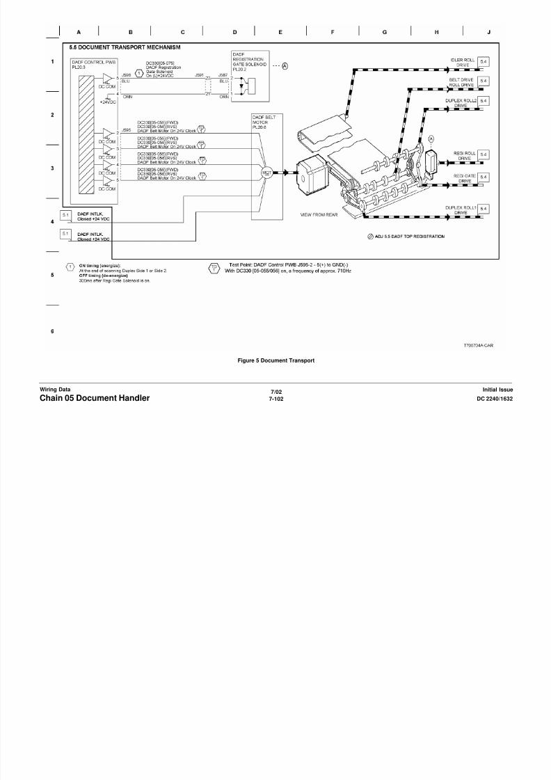
8/13/2019 Xerox Docu Color 2240-1632
http://slidepdf.com/reader/full/xerox-docu-color-2240-1632 1020/1118
7/02
7-104 DC 2240/1632Chain 05 Document HandlerInitial IssueWiring Data
Figure 7 DADF Monitoring

8/13/2019 Xerox Docu Color 2240-1632
http://slidepdf.com/reader/full/xerox-docu-color-2240-1632 1021/1118
7/02
7-105DC 2240/1632 Chain 06 ImagingWiring DataInitial Issue

8/13/2019 Xerox Docu Color 2240-1632
http://slidepdf.com/reader/full/xerox-docu-color-2240-1632 1022/1118
7/02
7-106 DC 2240/1632Chain 06 ImagingInitial IssueWiring Data
Figure 1 Document Illumination

8/13/2019 Xerox Docu Color 2240-1632
http://slidepdf.com/reader/full/xerox-docu-color-2240-1632 1023/1118
7/02
7-107DC 2240/1632 Chain 06 ImagingWiring DataInitial Issue
Figure 2 Image Input
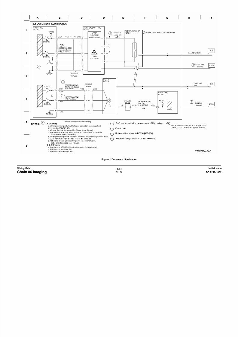
8/13/2019 Xerox Docu Color 2240-1632
http://slidepdf.com/reader/full/xerox-docu-color-2240-1632 1024/1118
7/02
7-108 DC 2240/1632Chain 06 ImagingInitial IssueWiring Data
Figure 3 Platen Document Setting

8/13/2019 Xerox Docu Color 2240-1632
http://slidepdf.com/reader/full/xerox-docu-color-2240-1632 1025/1118
7/02
7-109DC 2240/1632 Chain 06 ImagingWiring DataInitial Issue
Figure 4 Carriage Control

8/13/2019 Xerox Docu Color 2240-1632
http://slidepdf.com/reader/full/xerox-docu-color-2240-1632 1026/1118
7/02
7-110 DC 2240/1632Chain 06 ImagingInitial IssueWiring Data
Figure 5 Laser Control and Scanning (Y) (1 of 2)

8/13/2019 Xerox Docu Color 2240-1632
http://slidepdf.com/reader/full/xerox-docu-color-2240-1632 1027/1118
7/02
7-111DC 2240/1632 Chain 06 ImagingWiring DataInitial Issue
Figure 6 Laser Control and Scanning (Y) (2 of 2)

8/13/2019 Xerox Docu Color 2240-1632
http://slidepdf.com/reader/full/xerox-docu-color-2240-1632 1028/1118
7/02
7-112 DC 2240/1632Chain 06 ImagingInitial IssueWiring Data
Figure 7 Laser Control and Scanning (M) (1 of 2)

8/13/2019 Xerox Docu Color 2240-1632
http://slidepdf.com/reader/full/xerox-docu-color-2240-1632 1029/1118
7/02
7-113DC 2240/1632 Chain 06 ImagingWiring DataInitial Issue
Figure 8 Laser Control and Scanning (M) (2 of 2)

8/13/2019 Xerox Docu Color 2240-1632
http://slidepdf.com/reader/full/xerox-docu-color-2240-1632 1030/1118
7/02
7-114 DC 2240/1632Chain 06 ImagingInitial IssueWiring Data
Figure 9 Laser Control and Scanning (C) (1 of 2)
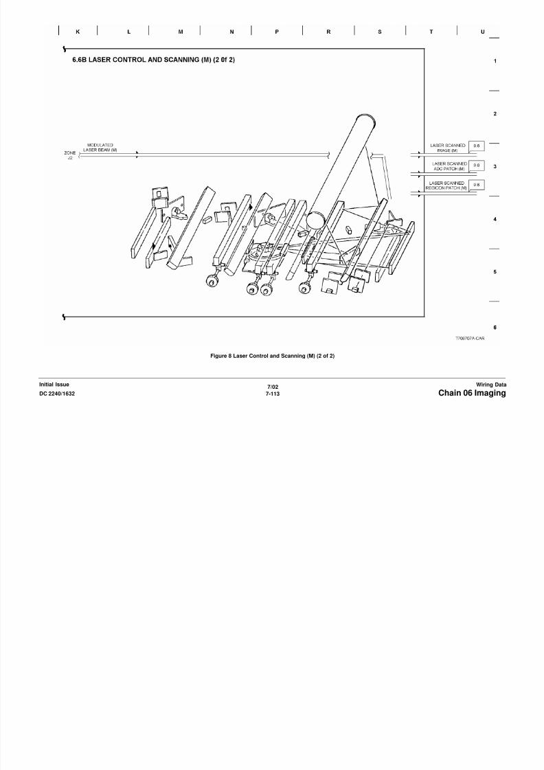
8/13/2019 Xerox Docu Color 2240-1632
http://slidepdf.com/reader/full/xerox-docu-color-2240-1632 1031/1118
7/02
7-115DC 2240/1632 Chain 06 ImagingWiring DataInitial Issue
Figure 10 Laser Control and Scanning (C) (2 of 2)

8/13/2019 Xerox Docu Color 2240-1632
http://slidepdf.com/reader/full/xerox-docu-color-2240-1632 1032/1118
7/02
7-116 DC 2240/1632Chain 06 ImagingInitial IssueWiring Data
Figure 11 Laser Control and Scanning (K) (1 of 2)

8/13/2019 Xerox Docu Color 2240-1632
http://slidepdf.com/reader/full/xerox-docu-color-2240-1632 1033/1118
7/02
7-117DC 2240/1632 Chain 06 ImagingWiring DataInitial Issue
Figure 12 Laser Control and Scanning (K) (2 of 2)

8/13/2019 Xerox Docu Color 2240-1632
http://slidepdf.com/reader/full/xerox-docu-color-2240-1632 1034/1118
7/02
7-118 DC 2240/1632Chain 06 ImagingInitial IssueWiring Data
Figure 13 Laser Scan Drive Control

8/13/2019 Xerox Docu Color 2240-1632
http://slidepdf.com/reader/full/xerox-docu-color-2240-1632 1035/1118
7/02
7-119DC 2240/1632 Chain 06 ImagingWiring DataInitial Issue
Figure 14 Ross Shutter Control

8/13/2019 Xerox Docu Color 2240-1632
http://slidepdf.com/reader/full/xerox-docu-color-2240-1632 1036/1118
7/02
7-120 DC 2240/1632Chain 06 ImagingInitial IssueWiring Data
Figure 15 Color Registration Control
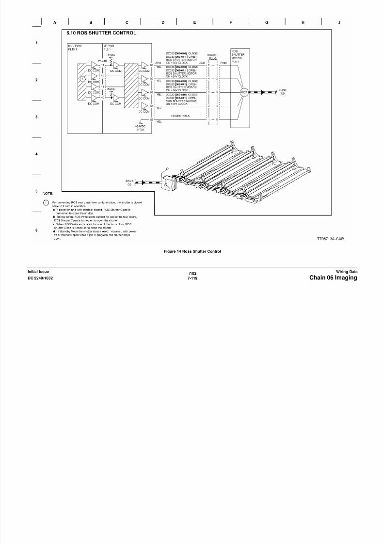
8/13/2019 Xerox Docu Color 2240-1632
http://slidepdf.com/reader/full/xerox-docu-color-2240-1632 1037/1118
7/02
7-121DC 2240/1632 Chain 06 ImagingWiring DataInitial Issue
Figure 16 Image Monitoring (1 of 3)

8/13/2019 Xerox Docu Color 2240-1632
http://slidepdf.com/reader/full/xerox-docu-color-2240-1632 1038/1118
7/02
7-122 DC 2240/1632Chain 06 ImagingInitial IssueWiring Data
Figure 17 Image Monitoring (2 of 3)
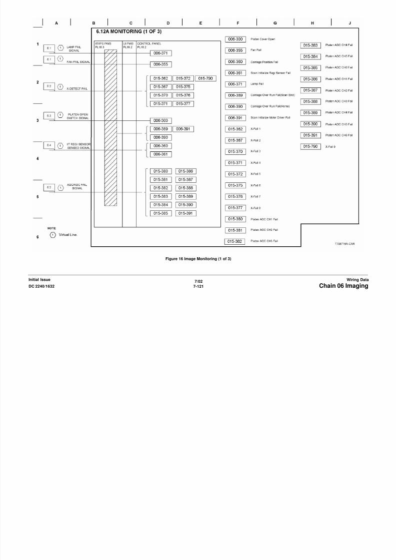
8/13/2019 Xerox Docu Color 2240-1632
http://slidepdf.com/reader/full/xerox-docu-color-2240-1632 1039/1118
7/02
7-123DC 2240/1632 Chain 06 ImagingWiring DataInitial Issue
Figure 18 Image Monitoring (3 of 3)
Chain 07 Paper Supply
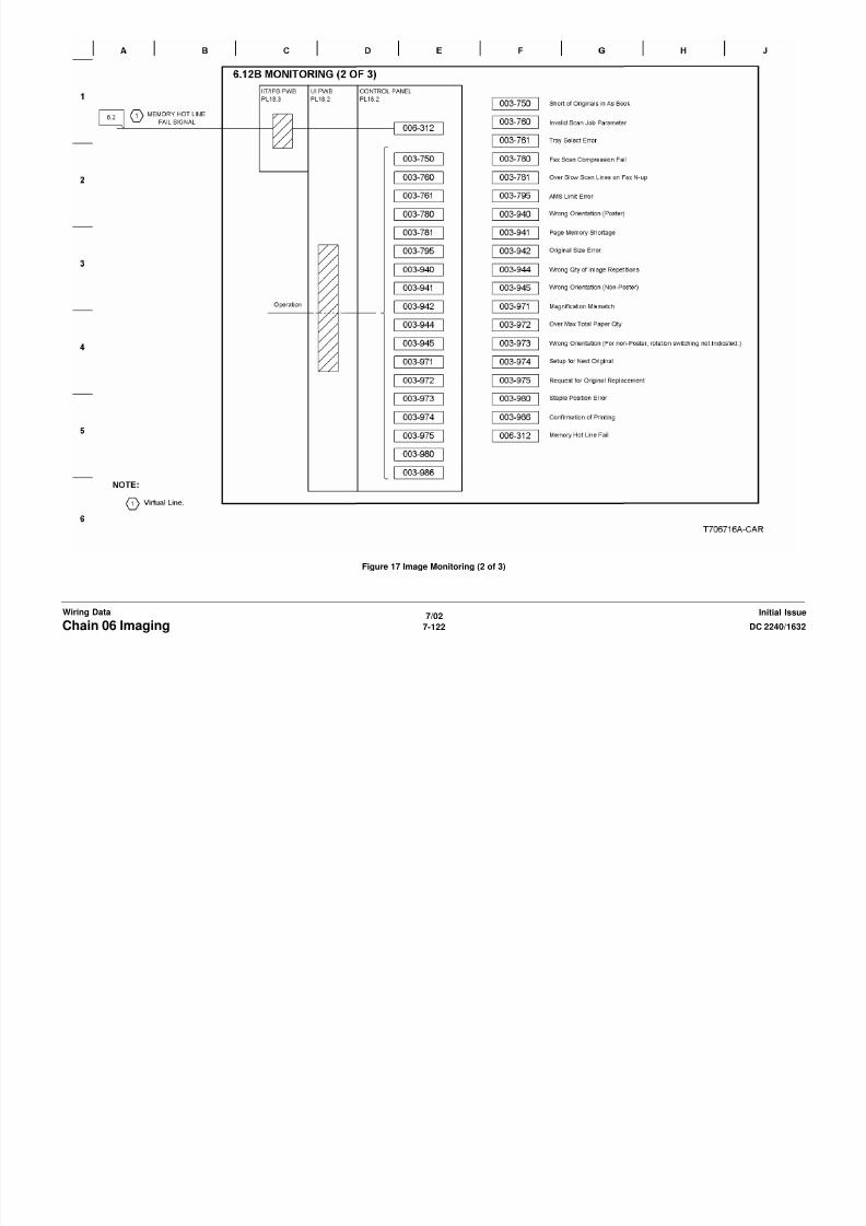
8/13/2019 Xerox Docu Color 2240-1632
http://slidepdf.com/reader/full/xerox-docu-color-2240-1632 1040/1118
7/02
7-124 DC 2240/1632Chain 07 Paper SupplyInitial IssueWiring Data
Figure 1 Tray 1 Paper Size Sensing

8/13/2019 Xerox Docu Color 2240-1632
http://slidepdf.com/reader/full/xerox-docu-color-2240-1632 1041/1118
7/02
7-125DC 2240/1632 Chain 07 Paper SupplyWiring DataInitial Issue
Figure 2 Tray 2 Paper Size Sensing
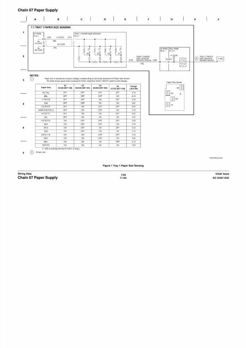
8/13/2019 Xerox Docu Color 2240-1632
http://slidepdf.com/reader/full/xerox-docu-color-2240-1632 1042/1118
7/02
7-126 DC 2240/1632Chain 07 Paper SupplyInitial IssueWiring Data
Figure 3 Tray 3 Paper Size Sensing
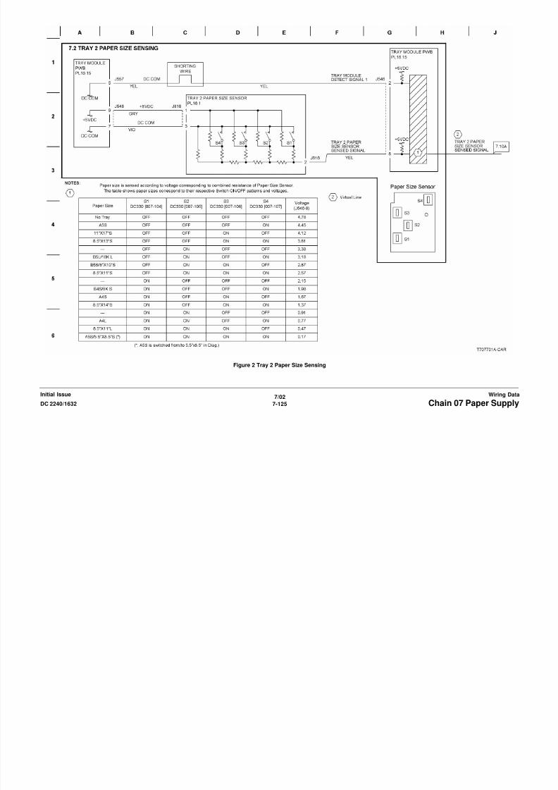
8/13/2019 Xerox Docu Color 2240-1632
http://slidepdf.com/reader/full/xerox-docu-color-2240-1632 1043/1118
7/02
7-127DC 2240/1632 Chain 07 Paper SupplyWiring DataInitial Issue
Figure 4 Tray 4 Paper Size Sensing
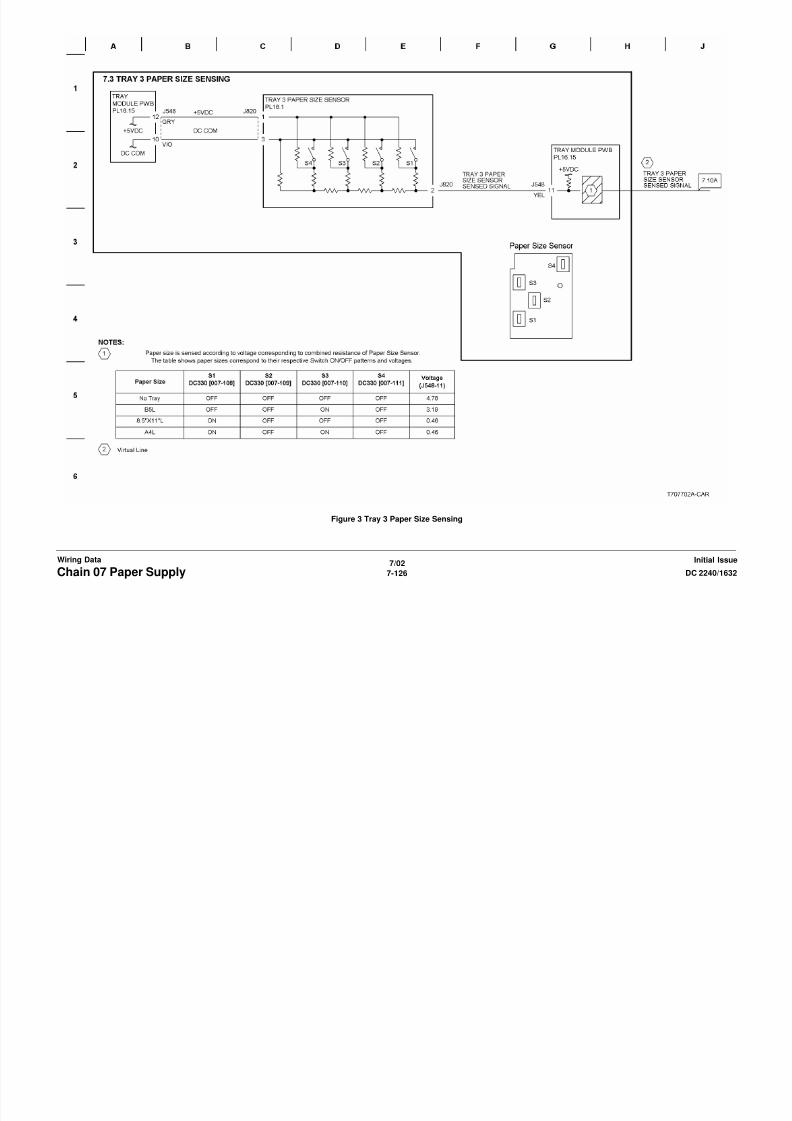
8/13/2019 Xerox Docu Color 2240-1632
http://slidepdf.com/reader/full/xerox-docu-color-2240-1632 1044/1118
7/02
7-128 DC 2240/1632Chain 07 Paper SupplyInitial IssueWiring Data
Figure 5 Tray 1 Paper Stacking
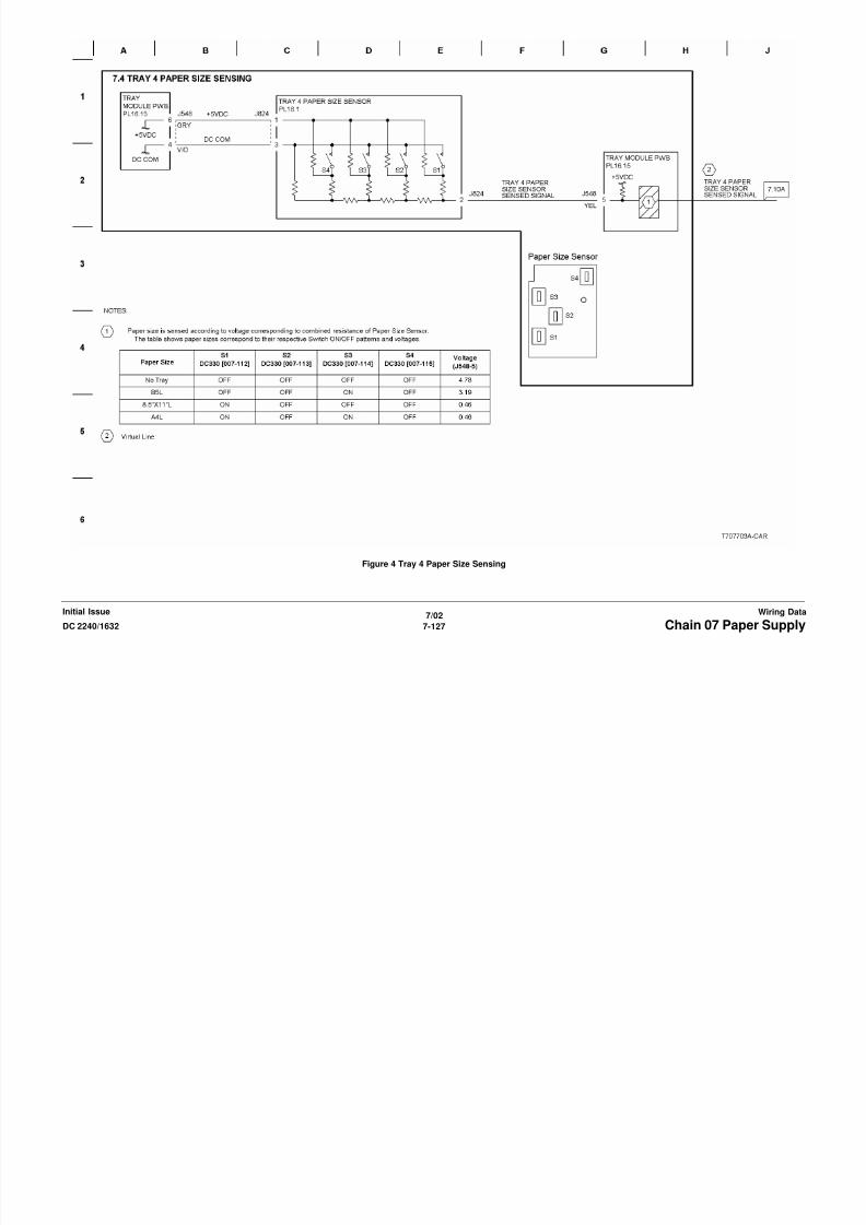
8/13/2019 Xerox Docu Color 2240-1632
http://slidepdf.com/reader/full/xerox-docu-color-2240-1632 1045/1118
7/02
7-129DC 2240/1632 Chain 07 Paper SupplyWiring DataInitial Issue
Figure 6 Tray 2 Paper Stacking
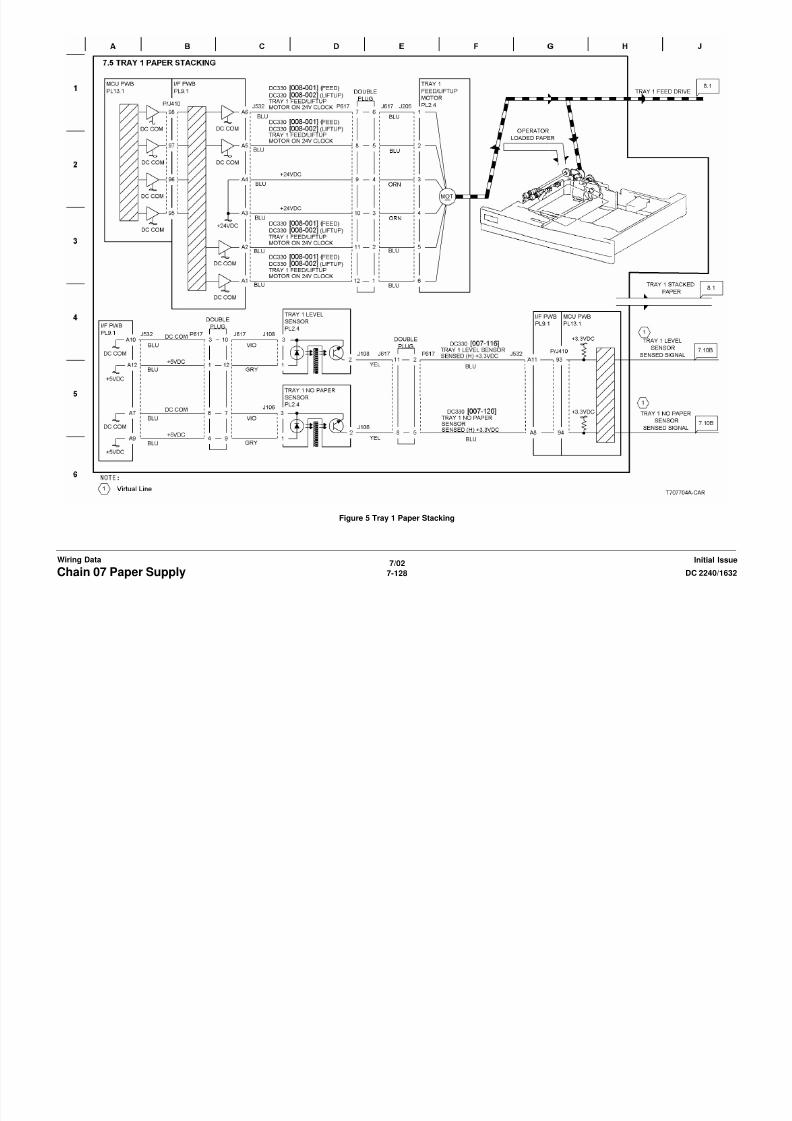
8/13/2019 Xerox Docu Color 2240-1632
http://slidepdf.com/reader/full/xerox-docu-color-2240-1632 1046/1118
7/02
7-130 DC 2240/1632Chain 07 Paper SupplyInitial IssueWiring Data
Figure 7 Tray 3 Paper Stacking

8/13/2019 Xerox Docu Color 2240-1632
http://slidepdf.com/reader/full/xerox-docu-color-2240-1632 1047/1118
7/02
7-131DC 2240/1632 Chain 07 Paper SupplyWiring DataInitial Issue
Figure 8 Tray 4 Paper Stacking

8/13/2019 Xerox Docu Color 2240-1632
http://slidepdf.com/reader/full/xerox-docu-color-2240-1632 1048/1118
7/02
7-132 DC 2240/1632Chain 07 Paper SupplyInitial IssueWiring Data
Figure 9 Tray 5 Paper Stacking

8/13/2019 Xerox Docu Color 2240-1632
http://slidepdf.com/reader/full/xerox-docu-color-2240-1632 1049/1118
7/02
7-133DC 2240/1632 Chain 07 Paper SupplyWiring DataInitial Issue
Figure 10 Paper Feed Monitoring (1 of 2)
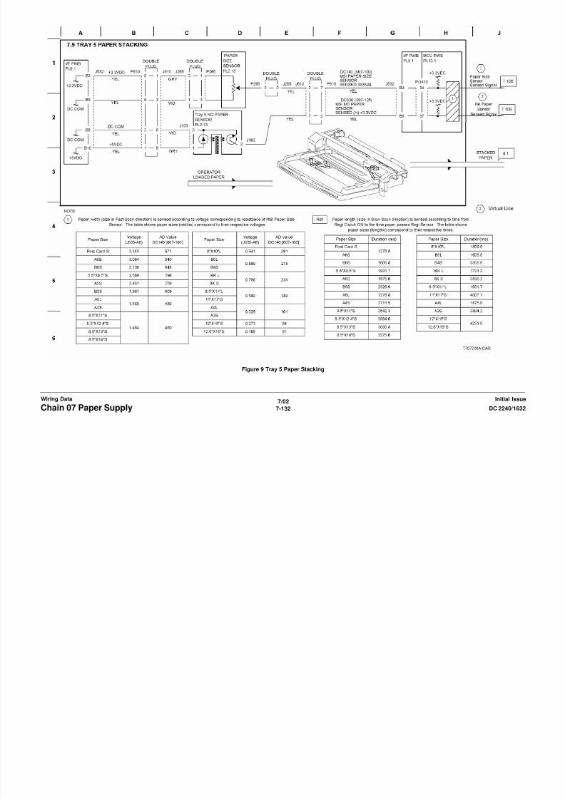
8/13/2019 Xerox Docu Color 2240-1632
http://slidepdf.com/reader/full/xerox-docu-color-2240-1632 1050/1118
7/02
7-134 DC 2240/1632Chain 07 Paper SupplyInitial IssueWiring Data
Figure 11 Paper Feed Monitoring (2 of 2)
Chain 08 Paper Registration
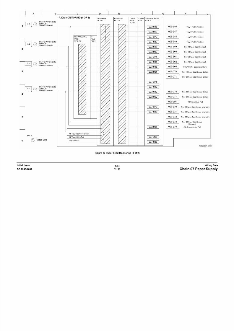
8/13/2019 Xerox Docu Color 2240-1632
http://slidepdf.com/reader/full/xerox-docu-color-2240-1632 1051/1118
7/02
7-135DC 2240/1632 Chain 08 Paper RegistrationWiring DataInitial Issue
Figure 1 Tray 1 - 5 Paper Feeding

8/13/2019 Xerox Docu Color 2240-1632
http://slidepdf.com/reader/full/xerox-docu-color-2240-1632 1052/1118
7/02
7-136 DC 2240/1632Chain 08 Paper RegistrationInitial IssueWiring Data
Figure 2 IOT Paper Transportation
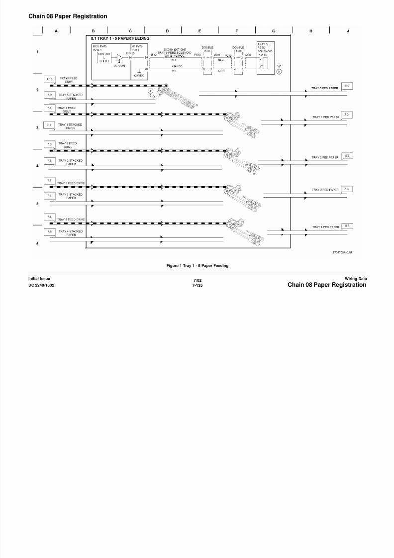
8/13/2019 Xerox Docu Color 2240-1632
http://slidepdf.com/reader/full/xerox-docu-color-2240-1632 1053/1118
7/02
7-137DC 2240/1632 Chain 08 Paper RegistrationWiring DataInitial Issue
Figure 3 Tray Module Paper Transportation
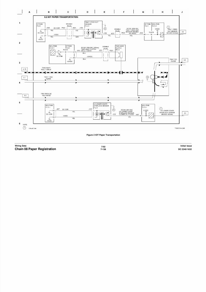
8/13/2019 Xerox Docu Color 2240-1632
http://slidepdf.com/reader/full/xerox-docu-color-2240-1632 1054/1118
7/02
7-138 DC 2240/1632Chain 08 Paper RegistrationInitial IssueWiring Data
Figure 4 Tray Module Paper Transportation Drive Control

8/13/2019 Xerox Docu Color 2240-1632
http://slidepdf.com/reader/full/xerox-docu-color-2240-1632 1055/1118
7/02
7-139DC 2240/1632 Chain 08 Paper RegistrationWiring DataInitial Issue
Figure 5 Registration

8/13/2019 Xerox Docu Color 2240-1632
http://slidepdf.com/reader/full/xerox-docu-color-2240-1632 1056/1118
7/02
7-140 DC 2240/1632Chain 08 Paper RegistrationInitial IssueWiring Data
Figure 6 Monitoring
Chain 09 Xerographics
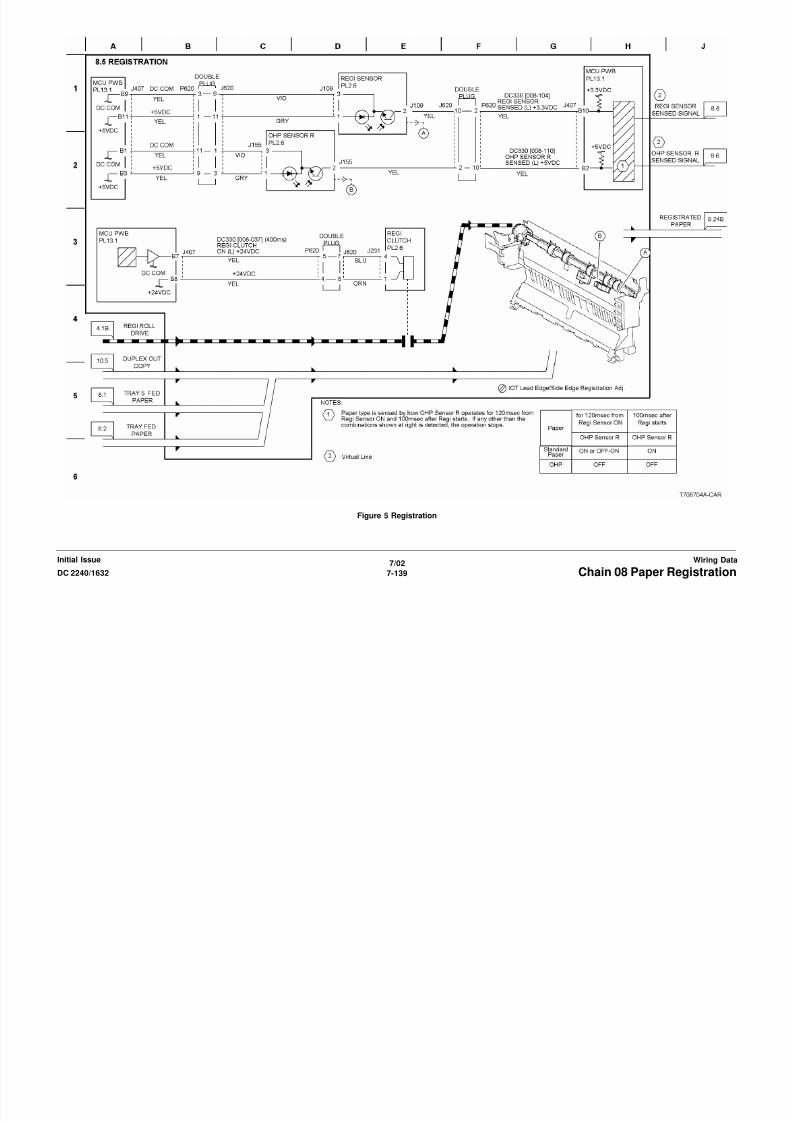
8/13/2019 Xerox Docu Color 2240-1632
http://slidepdf.com/reader/full/xerox-docu-color-2240-1632 1057/1118
7/02
7-141DC 2240/1632 Chain 09 XerographicsWiring DataInitial Issue
Figure 1 Drum Drive Control (Y, M, C)

8/13/2019 Xerox Docu Color 2240-1632
http://slidepdf.com/reader/full/xerox-docu-color-2240-1632 1058/1118
7/02
7-142 DC 2240/1632Chain 09 XerographicsInitial IssueWiring Data
Figure 2 Drum Drive Control (K)
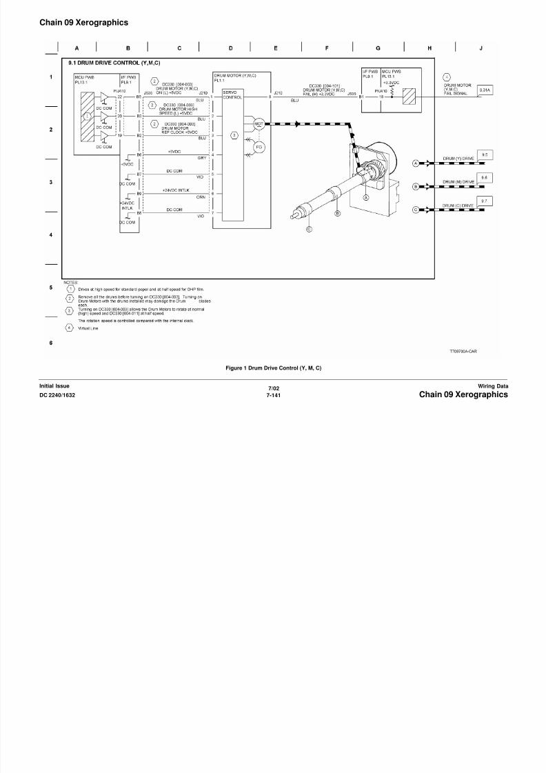
8/13/2019 Xerox Docu Color 2240-1632
http://slidepdf.com/reader/full/xerox-docu-color-2240-1632 1059/1118
7/02
7-143DC 2240/1632 Chain 09 XerographicsWiring DataInitial Issue
Figure 3 Drum Life Control (Y,M)

8/13/2019 Xerox Docu Color 2240-1632
http://slidepdf.com/reader/full/xerox-docu-color-2240-1632 1060/1118
7/02
7-144 DC 2240/1632Chain 09 XerographicsInitial IssueWiring Data
Figure 4 Drum Life Control (C,K)
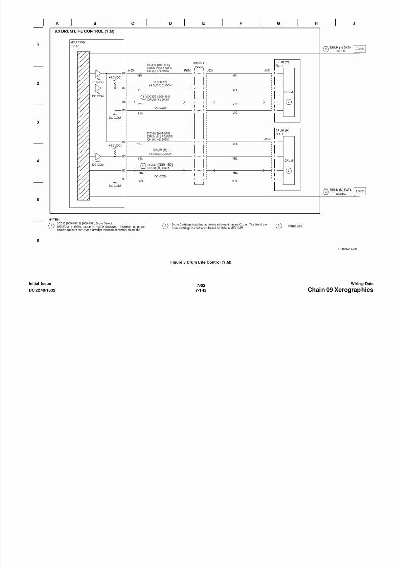
8/13/2019 Xerox Docu Color 2240-1632
http://slidepdf.com/reader/full/xerox-docu-color-2240-1632 1061/1118
7/02
7-145DC 2240/1632 Chain 09 XerographicsWiring DataInitial Issue
Figure 5 Charging and Exposure (Y)

8/13/2019 Xerox Docu Color 2240-1632
http://slidepdf.com/reader/full/xerox-docu-color-2240-1632 1062/1118
7/02
7-146 DC 2240/1632Chain 09 XerographicsInitial IssueWiring Data
Figure 6 Charging and Exposure (M)
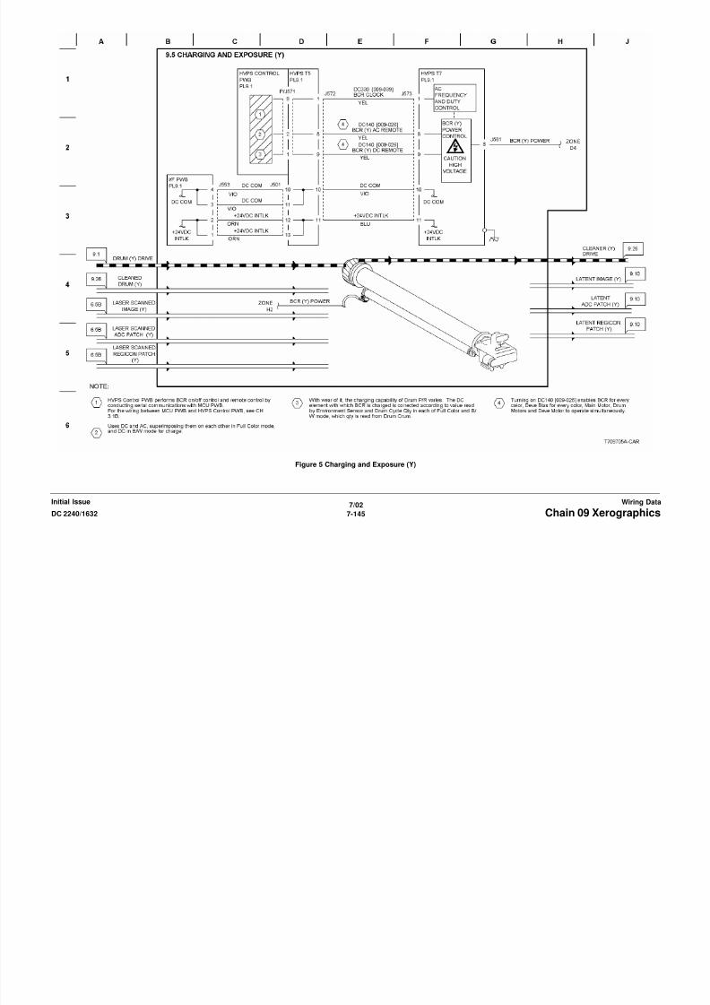
8/13/2019 Xerox Docu Color 2240-1632
http://slidepdf.com/reader/full/xerox-docu-color-2240-1632 1063/1118

8/13/2019 Xerox Docu Color 2240-1632
http://slidepdf.com/reader/full/xerox-docu-color-2240-1632 1064/1118
7/02
7-148 DC 2240/1632Chain 09 XerographicsInitial IssueWiring Data
Figure 8 Charging and Exposure (K)

8/13/2019 Xerox Docu Color 2240-1632
http://slidepdf.com/reader/full/xerox-docu-color-2240-1632 1065/1118
7/02
7-149DC 2240/1632 Chain 09 XerographicsWiring DataInitial Issue
Figure 9 Developer Drive Control
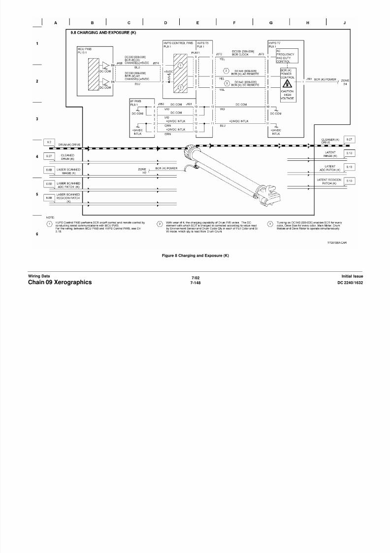
8/13/2019 Xerox Docu Color 2240-1632
http://slidepdf.com/reader/full/xerox-docu-color-2240-1632 1066/1118
7/02
7-150 DC 2240/1632Chain 09 XerographicsInitial IssueWiring Data
Figure 10 Development (Y)

8/13/2019 Xerox Docu Color 2240-1632
http://slidepdf.com/reader/full/xerox-docu-color-2240-1632 1067/1118
7/02
7-151DC 2240/1632 Chain 09 XerographicsWiring DataInitial Issue
Figure 11 Development (M)

8/13/2019 Xerox Docu Color 2240-1632
http://slidepdf.com/reader/full/xerox-docu-color-2240-1632 1068/1118
7/02
7-152 DC 2240/1632Chain 09 XerographicsInitial IssueWiring Data
Figure 12 Development (C)

8/13/2019 Xerox Docu Color 2240-1632
http://slidepdf.com/reader/full/xerox-docu-color-2240-1632 1069/1118
7/02
7-153DC 2240/1632 Chain 09 XerographicsWiring DataInitial Issue
Figure 13 Development (K) (1 of 2)

8/13/2019 Xerox Docu Color 2240-1632
http://slidepdf.com/reader/full/xerox-docu-color-2240-1632 1070/1118
7/02
7-154 DC 2240/1632Chain 09 XerographicsInitial IssueWiring Data
Figure 14 Development (K) (2 of 2)

8/13/2019 Xerox Docu Color 2240-1632
http://slidepdf.com/reader/full/xerox-docu-color-2240-1632 1071/1118
7/02
7-155DC 2240/1632 Chain 09 XerographicsWiring DataInitial Issue
Figure 15 New Toner Cartridge Detection

8/13/2019 Xerox Docu Color 2240-1632
http://slidepdf.com/reader/full/xerox-docu-color-2240-1632 1072/1118
7/02
7-156 DC 2240/1632Chain 09 XerographicsInitial IssueWiring Data
Figure 16 Toner Dispense Control

8/13/2019 Xerox Docu Color 2240-1632
http://slidepdf.com/reader/full/xerox-docu-color-2240-1632 1073/1118
7/02
7-157DC 2240/1632 Chain 09 XerographicsWiring DataInitial Issue
Figure 17 ADC and Environment Sensing
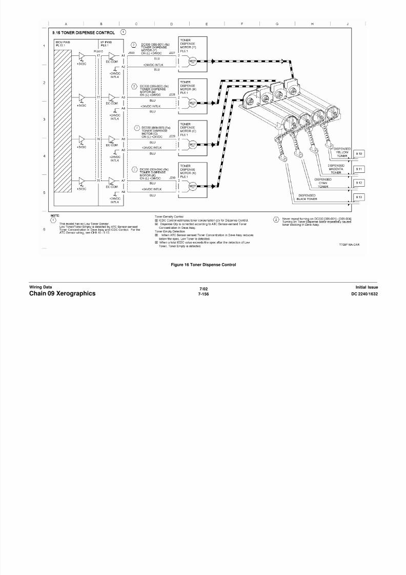
8/13/2019 Xerox Docu Color 2240-1632
http://slidepdf.com/reader/full/xerox-docu-color-2240-1632 1074/1118
7/02
7-158 DC 2240/1632Chain 09 XerographicsInitial IssueWiring Data
Figure 18 IBT Drive Control

8/13/2019 Xerox Docu Color 2240-1632
http://slidepdf.com/reader/full/xerox-docu-color-2240-1632 1075/1118
7/02
7-159DC 2240/1632 Chain 09 XerographicsWiring DataInitial Issue
Figure 19 1ST BTR Contact Retract Control
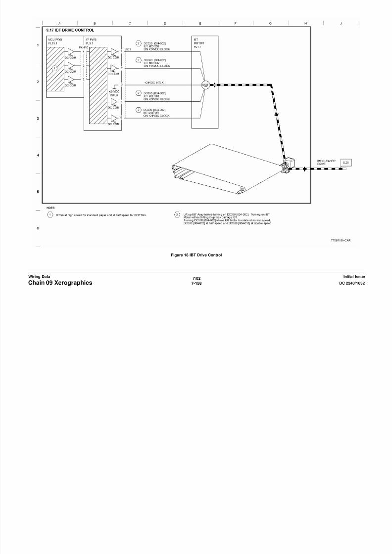
8/13/2019 Xerox Docu Color 2240-1632
http://slidepdf.com/reader/full/xerox-docu-color-2240-1632 1076/1118
7/02
7-160 DC 2240/1632Chain 09 XerographicsInitial IssueWiring Data
Figure 20 IBT Positioning
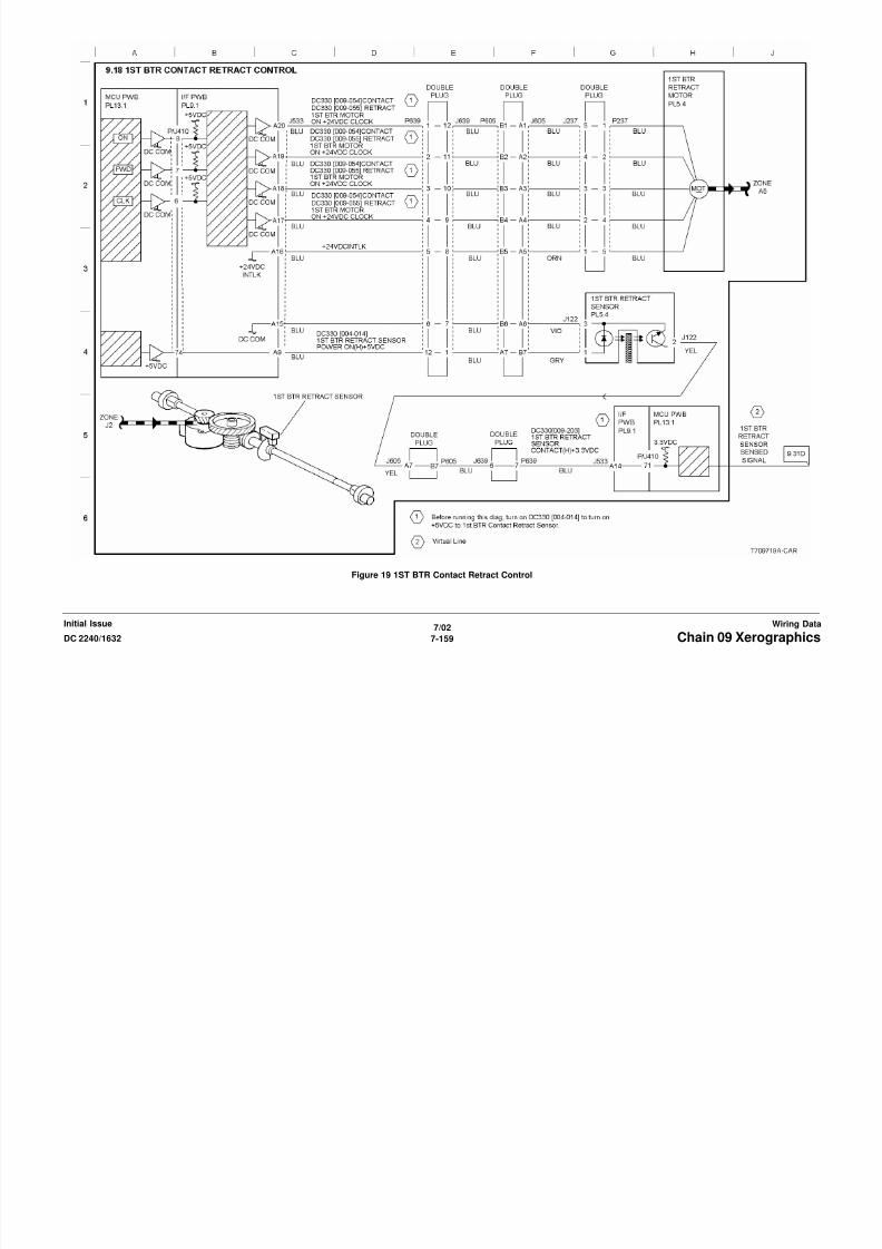
8/13/2019 Xerox Docu Color 2240-1632
http://slidepdf.com/reader/full/xerox-docu-color-2240-1632 1077/1118
7/02
7-161DC 2240/1632 Chain 09 XerographicsWiring DataInitial Issue
Figure 21 Image Transfer To IBT (Y)
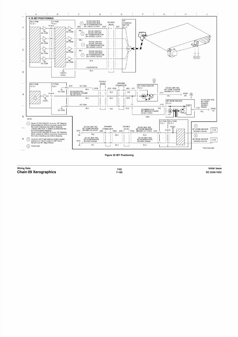
8/13/2019 Xerox Docu Color 2240-1632
http://slidepdf.com/reader/full/xerox-docu-color-2240-1632 1078/1118
7/02
7-162 DC 2240/1632Chain 09 XerographicsInitial IssueWiring Data
Figure 22 Image Transfer To IBT (M)

8/13/2019 Xerox Docu Color 2240-1632
http://slidepdf.com/reader/full/xerox-docu-color-2240-1632 1079/1118
7/02
7-163DC 2240/1632 Chain 09 XerographicsWiring DataInitial Issue
Figure 23 Image Transfer To IBT (C)

8/13/2019 Xerox Docu Color 2240-1632
http://slidepdf.com/reader/full/xerox-docu-color-2240-1632 1080/1118
7/02
7-164 DC 2240/1632Chain 09 XerographicsInitial IssueWiring Data
Figure 24 Image Transfer To IBT (K)
PL 2.9
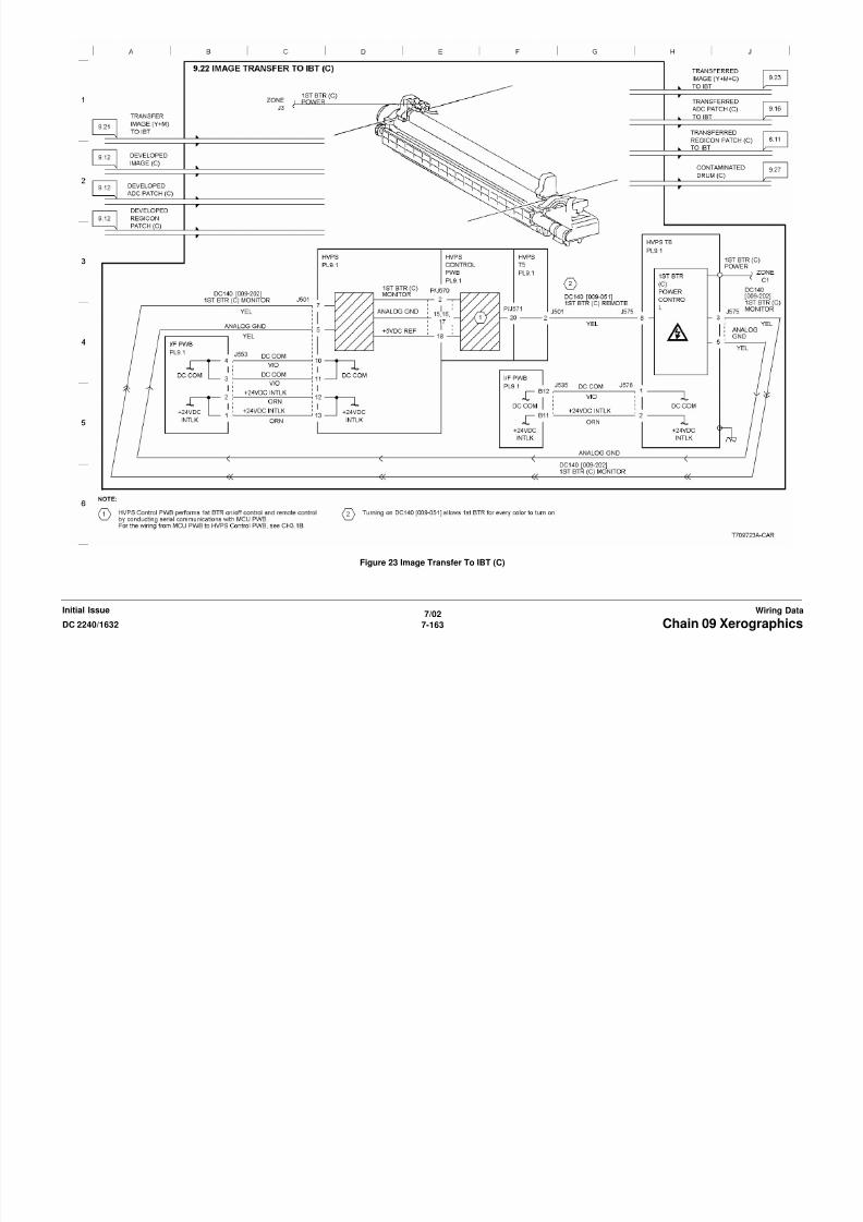
8/13/2019 Xerox Docu Color 2240-1632
http://slidepdf.com/reader/full/xerox-docu-color-2240-1632 1081/1118
7/02
7-165DC 2240/1632 Chain 09 XerographicsWiring DataInitial Issue
Figure 25 Image Transfer To Paper (1 of 2)
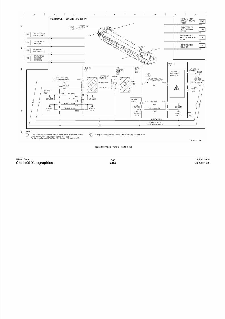
8/13/2019 Xerox Docu Color 2240-1632
http://slidepdf.com/reader/full/xerox-docu-color-2240-1632 1082/1118
7/02
7-166 DC 2240/1632Chain 09 XerographicsInitial IssueWiring Data
Figure 26 Image Transfer To Paper (2 of 2)

8/13/2019 Xerox Docu Color 2240-1632
http://slidepdf.com/reader/full/xerox-docu-color-2240-1632 1083/1118
7/02
7-167DC 2240/1632 Chain 09 XerographicsWiring DataInitial Issue
Figure 27 Stripping

8/13/2019 Xerox Docu Color 2240-1632
http://slidepdf.com/reader/full/xerox-docu-color-2240-1632 1084/1118
7/02
7-168 DC 2240/1632Chain 09 XerographicsInitial IssueWiring Data
Figure 28 Drum Cleaning (Y,M)

8/13/2019 Xerox Docu Color 2240-1632
http://slidepdf.com/reader/full/xerox-docu-color-2240-1632 1085/1118
7/02
7-169DC 2240/1632 Chain 09 XerographicsWiring DataInitial Issue
Figure 29 Drum Cleaning (C,K)
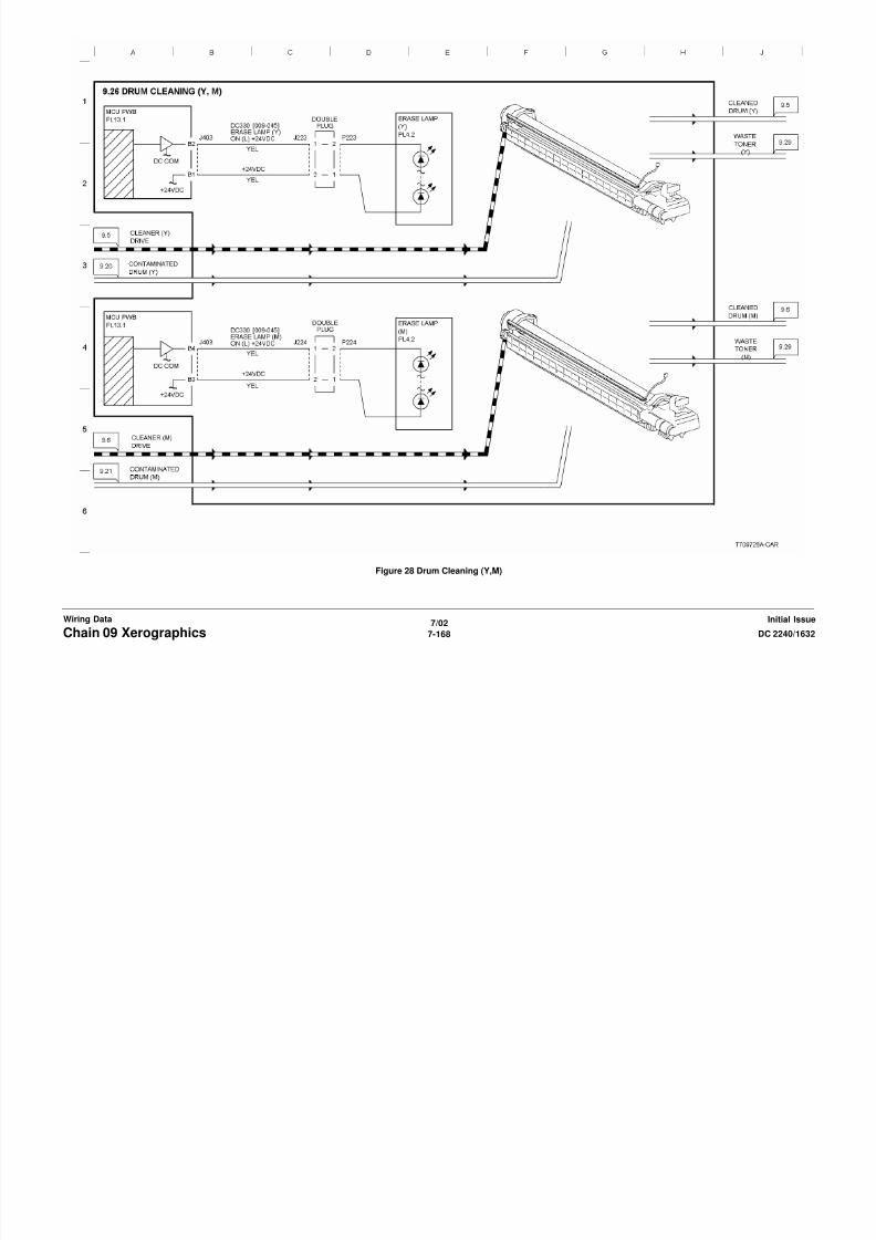
8/13/2019 Xerox Docu Color 2240-1632
http://slidepdf.com/reader/full/xerox-docu-color-2240-1632 1086/1118
7/02
7-170 DC 2240/1632Chain 09 XerographicsInitial IssueWiring Data
Figure 30 IBT Cleaning

8/13/2019 Xerox Docu Color 2240-1632
http://slidepdf.com/reader/full/xerox-docu-color-2240-1632 1087/1118
7/02
7-171DC 2240/1632 Chain 09 XerographicsWiring DataInitial Issue
Figure 31 Waste Toner Disposal
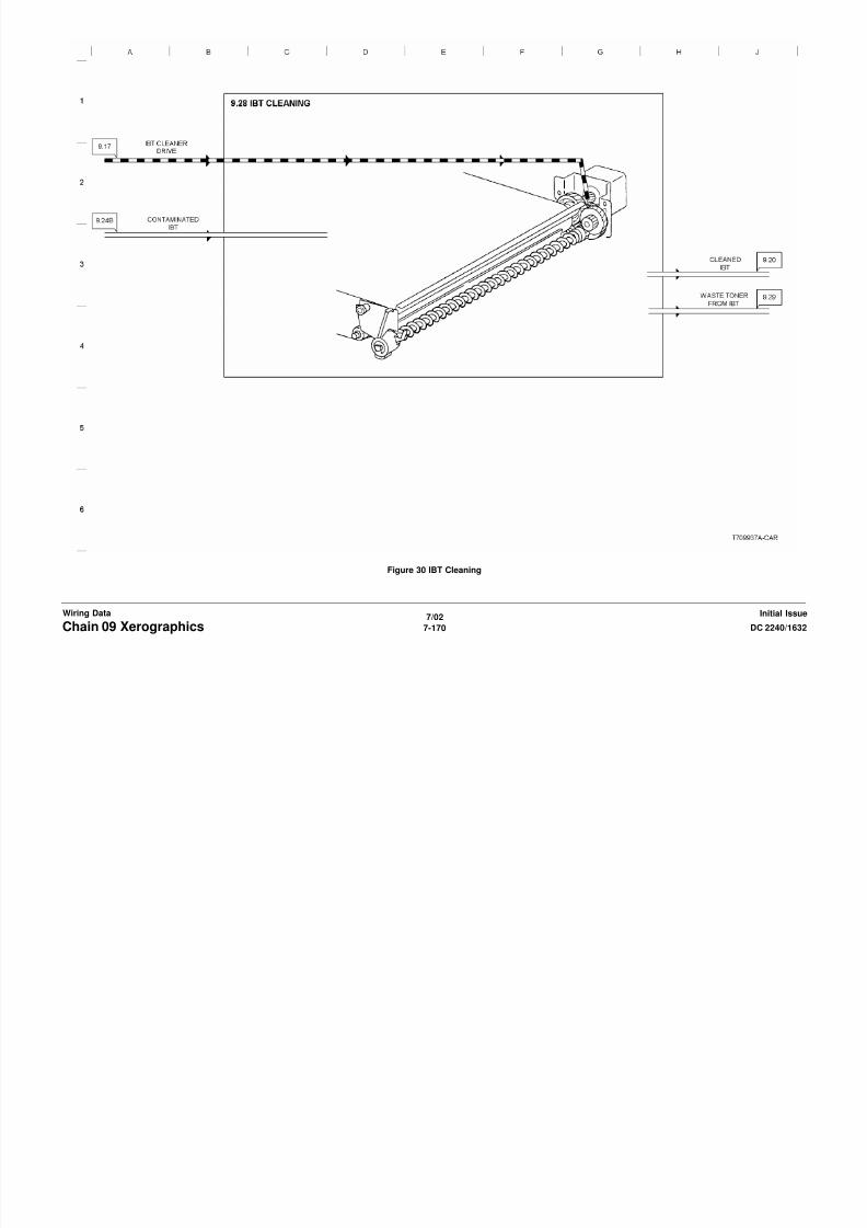
8/13/2019 Xerox Docu Color 2240-1632
http://slidepdf.com/reader/full/xerox-docu-color-2240-1632 1088/1118
7/02
7-172 DC 2240/1632Chain 09 XerographicsInitial IssueWiring Data
Figure 32 Rear Fan Control
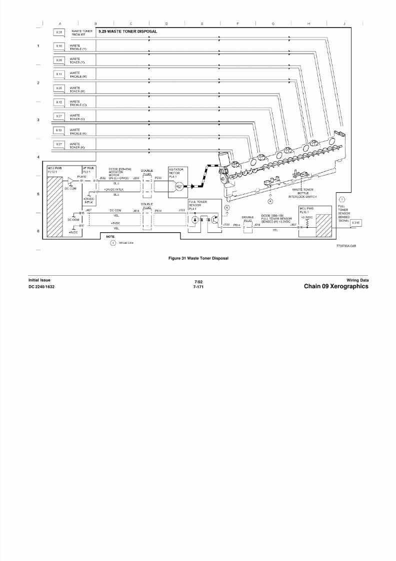
8/13/2019 Xerox Docu Color 2240-1632
http://slidepdf.com/reader/full/xerox-docu-color-2240-1632 1089/1118
7/02
7-173DC 2240/1632 Chain 09 XerographicsWiring DataInitial Issue
Figure 33 Monitoring (1 of 5)

8/13/2019 Xerox Docu Color 2240-1632
http://slidepdf.com/reader/full/xerox-docu-color-2240-1632 1090/1118
7/02
7-174 DC 2240/1632Chain 09 XerographicsInitial IssueWiring Data
Figure 34 Monitoring (2 of 5)

8/13/2019 Xerox Docu Color 2240-1632
http://slidepdf.com/reader/full/xerox-docu-color-2240-1632 1091/1118
7/02
7-175DC 2240/1632 Chain 09 XerographicsWiring DataInitial Issue
Figure 35 Monitoring (3 of 5)

8/13/2019 Xerox Docu Color 2240-1632
http://slidepdf.com/reader/full/xerox-docu-color-2240-1632 1092/1118
7/02
7-176 DC 2240/1632Chain 09 XerographicsInitial IssueWiring Data
Figure 36 Monitoring (4 of 5)

8/13/2019 Xerox Docu Color 2240-1632
http://slidepdf.com/reader/full/xerox-docu-color-2240-1632 1093/1118
7/02
7-177DC 2240/1632 Chain 09 XerographicsWiring DataInitial Issue
Figure 37 Monitoring (5 of 5)
Chain 10 Fusing and Output

8/13/2019 Xerox Docu Color 2240-1632
http://slidepdf.com/reader/full/xerox-docu-color-2240-1632 1094/1118
7/02
7-178 DC 2240/1632Chain 10 Fusing and OutputInitial IssueWiring Data
Figure 1 Fusing Heat Control (1 of 2)

8/13/2019 Xerox Docu Color 2240-1632
http://slidepdf.com/reader/full/xerox-docu-color-2240-1632 1095/1118
7/02
7-179DC 2240/1632 Chain 10 Fusing and OutputWiring DataInitial Issue
Figure 2 Fusing Heat Control (2 of 2)
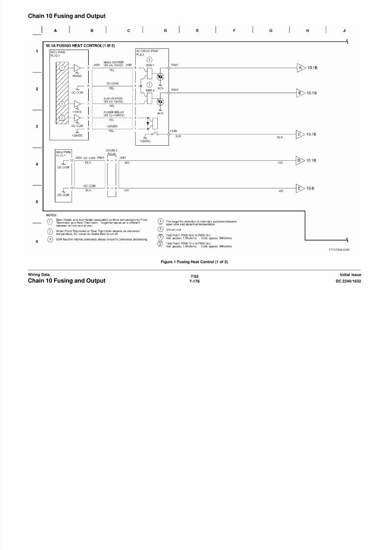
8/13/2019 Xerox Docu Color 2240-1632
http://slidepdf.com/reader/full/xerox-docu-color-2240-1632 1096/1118
7/02
7-180 DC 2240/1632Chain 10 Fusing and OutputInitial IssueWiring Data
Figure 3 Fusing

8/13/2019 Xerox Docu Color 2240-1632
http://slidepdf.com/reader/full/xerox-docu-color-2240-1632 1097/1118
7/02
7-181DC 2240/1632 Chain 10 Fusing and OutputWiring DataInitial Issue
Figure 4 Inverter (1 of 2)

8/13/2019 Xerox Docu Color 2240-1632
http://slidepdf.com/reader/full/xerox-docu-color-2240-1632 1098/1118
7/02
7-182 DC 2240/1632Chain 10 Fusing and OutputInitial IssueWiring Data
Figure 5 Inverter (2 of 2)
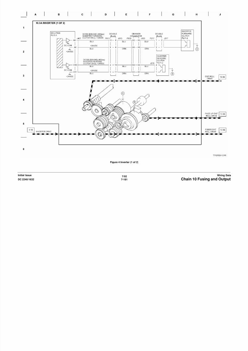
8/13/2019 Xerox Docu Color 2240-1632
http://slidepdf.com/reader/full/xerox-docu-color-2240-1632 1099/1118
7/02
7-183DC 2240/1632 Chain 10 Fusing and OutputWiring DataInitial Issue
Figure 6 Duplex Drive Control

8/13/2019 Xerox Docu Color 2240-1632
http://slidepdf.com/reader/full/xerox-docu-color-2240-1632 1100/1118
7/02
7-184 DC 2240/1632Chain 10 Fusing and OutputInitial IssueWiring Data
Figure 7 Duplex Drive

8/13/2019 Xerox Docu Color 2240-1632
http://slidepdf.com/reader/full/xerox-docu-color-2240-1632 1101/1118
7/02
7-185DC 2240/1632 Chain 10 Fusing and OutputWiring DataInitial Issue
Figure 8 Monitoring
Chain 12 Finisher

8/13/2019 Xerox Docu Color 2240-1632
http://slidepdf.com/reader/full/xerox-docu-color-2240-1632 1102/1118
7/02
7-186 DC 2240/1632Chain 12 FinisherInitial IssueWiring Data
Figure 1 DC Power and Interlocks

8/13/2019 Xerox Docu Color 2240-1632
http://slidepdf.com/reader/full/xerox-docu-color-2240-1632 1103/1118
7/02
7-187DC 2240/1632 Chain 12 FinisherWiring DataInitial Issue
Figure 2 PWBS Communications

8/13/2019 Xerox Docu Color 2240-1632
http://slidepdf.com/reader/full/xerox-docu-color-2240-1632 1104/1118
7/02
7-188 DC 2240/1632Chain 12 FinisherInitial IssueWiring Data
Figure 3 Copy and Drive Delivery
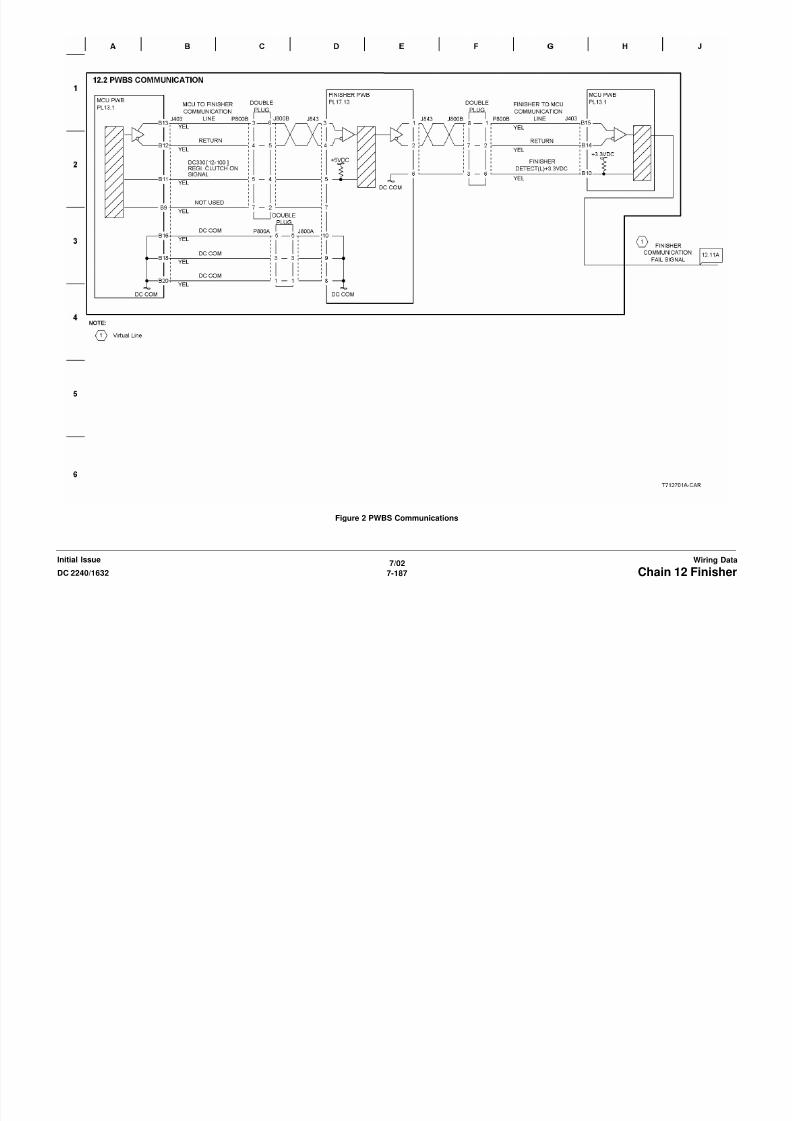
8/13/2019 Xerox Docu Color 2240-1632
http://slidepdf.com/reader/full/xerox-docu-color-2240-1632 1105/1118
7/02
7-189DC 2240/1632 Chain 12 FinisherWiring DataInitial Issue
Figure 4 Horizontal Transportation

8/13/2019 Xerox Docu Color 2240-1632
http://slidepdf.com/reader/full/xerox-docu-color-2240-1632 1106/1118
7/02
7-190 DC 2240/1632Chain 12 FinisherInitial IssueWiring Data
Figure 5 Decurler and Paper Transportation

8/13/2019 Xerox Docu Color 2240-1632
http://slidepdf.com/reader/full/xerox-docu-color-2240-1632 1107/1118
7/02
7-191DC 2240/1632 Chain 12 FinisherWiring DataInitial Issue
Figure 6 Tamping and Offset

8/13/2019 Xerox Docu Color 2240-1632
http://slidepdf.com/reader/full/xerox-docu-color-2240-1632 1108/1118
7/02
7-192 DC 2240/1632Chain 12 FinisherInitial IssueWiring Data
Figure 7 Staple Positioning

8/13/2019 Xerox Docu Color 2240-1632
http://slidepdf.com/reader/full/xerox-docu-color-2240-1632 1109/1118
7/02
7-193DC 2240/1632 Chain 12 FinisherWiring DataInitial Issue
Figure 8 Staple Control
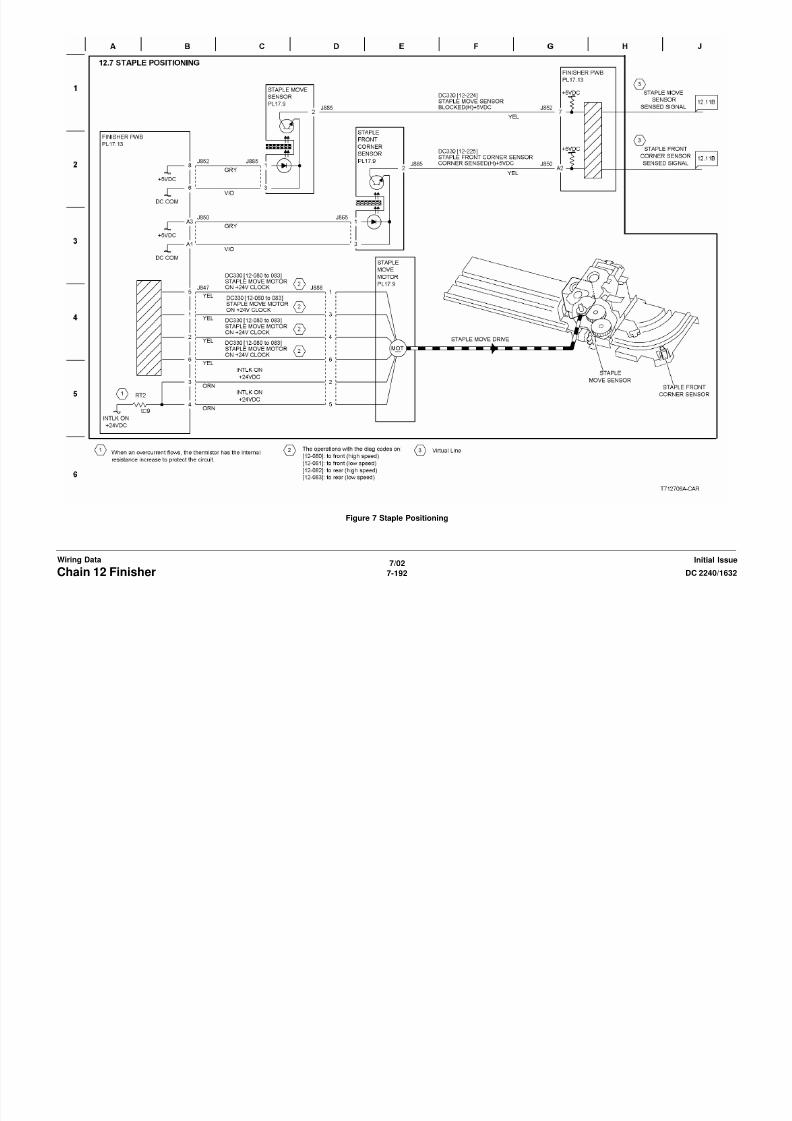
8/13/2019 Xerox Docu Color 2240-1632
http://slidepdf.com/reader/full/xerox-docu-color-2240-1632 1110/1118
7/02
7-194 DC 2240/1632Chain 12 FinisherInitial IssueWiring Data
Figure 9 Set Eject

8/13/2019 Xerox Docu Color 2240-1632
http://slidepdf.com/reader/full/xerox-docu-color-2240-1632 1111/1118

8/13/2019 Xerox Docu Color 2240-1632
http://slidepdf.com/reader/full/xerox-docu-color-2240-1632 1112/1118
7/02
7-196 DC 2240/1632Chain 12 FinisherInitial IssueWiring Data
Figure 11 Stacker Tray Control (2 of 2)

8/13/2019 Xerox Docu Color 2240-1632
http://slidepdf.com/reader/full/xerox-docu-color-2240-1632 1113/1118
7/02
7-197DC 2240/1632 Chain 12 FinisherWiring DataInitial Issue
Figure 12 Monitoring (1 of 2)

8/13/2019 Xerox Docu Color 2240-1632
http://slidepdf.com/reader/full/xerox-docu-color-2240-1632 1114/1118
7/02
7-198 DC 2240/1632Chain 12 FinisherInitial IssueWiring Data
Figure 13 Monitoring (2 of 2)
Chain 16 ESS

8/13/2019 Xerox Docu Color 2240-1632
http://slidepdf.com/reader/full/xerox-docu-color-2240-1632 1115/1118
7/02
7-199DC 2240/1632 Chain 16 ESSWiring DataInitial Issue
Figure 1 ESS PWB
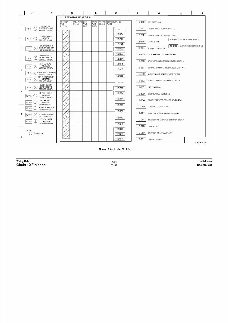
8/13/2019 Xerox Docu Color 2240-1632
http://slidepdf.com/reader/full/xerox-docu-color-2240-1632 1116/1118
7/02
7-200 DC 2240/1632Chain 16 ESSInitial IssueWiring Data
Figure 2 ESS Monitoring (1 of 3)

8/13/2019 Xerox Docu Color 2240-1632
http://slidepdf.com/reader/full/xerox-docu-color-2240-1632 1117/1118
7/02
7-201DC 2240/1632 Chain 16 ESSWiring DataInitial Issue
Figure 3 ESS Monitoring (2 of 3)
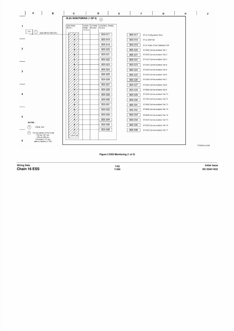
8/13/2019 Xerox Docu Color 2240-1632
http://slidepdf.com/reader/full/xerox-docu-color-2240-1632 1118/1118
7/02
7-202 DC 2240/1632Chain 16 ESSInitial IssueWiring Data
Figure 4 ESS Monitoring (3 of 3)