xerox scanner 7356 service manual
DESCRIPTION
Xerox Scanner 7356 Service ManualTRANSCRIPT
7346/56 Scanner
7346/56 Scanner

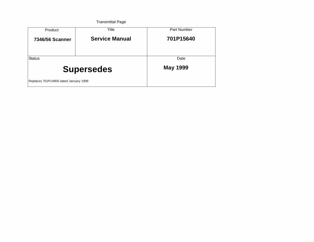
Transmittal Page
Product
7346/56 Scanner
Title
Service Manual
Part Number
701P15640
Status
Supersedes Replaces 701P14900 dated January 1999
Date
May 1999

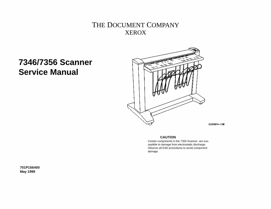
701P156400May 1999
7346/7356 ScannerService Manual
THE DOCUMENT COMPANYXEROX
CAUTIONCertain components in the 7356 Scanner are sus-ceptible to damage from electrostatic discharge. Observe all ESD procedures to avoid component damage.
Prepared by:Xerox Corporation800 Phillips RoadBldg. 845-17SWebster, New York 14580-9791USA
© 1998, 1999 by Xerox Corporation.Xerox® and The Document Company® are trademarks of Xerox Corporation.Xerox product names mentioned in this publication are trademarks of the XEROX CORPORATION.
NOTICEWhile every care has been taken in the preparation of this manual, no liabil-ity will be accepted by Xerox Corporation arising out of any inaccuracies oromissions.
NOTICEAll service documentation is supplied to Xerox external customers for infor-mational purposes only. Xerox service documentation is intended for use bycertified product trained service personal only. Xerox does not warrant orrepresent that such documentation is complete, nor does Xerox representor warrant that it will notify or provide to such customer any future changesto this documentation. Customer performed service of equipment, or mod-ules, components or parts of such equipment may affect the warrantyoffered by Xerox with respect to such equipment. You should consult theapplicable warranty for its terms regarding customer or third party providedservice. If the customer services such equipment, modules, components orparts thereof, the customer releases Xerox from any and all liability for thecustomer actions, and the customer agrees to indemnify, defend and holdXerox harmless from any third party claims which arise directly or indirectlyfrom such service.
Product
7346/7356 Scanner
Title
Service Manual
Part Number
701P15640
Date
5/99
Revision Control List
All pages dated 5/99
Product
7346/7356 Scanner
Title
Service Manual
Part Number
701P15640
Date
5/99
Revision Control List
Page No. Rev.
All pages dated 5/99
5/99I7346/7356 Scanner Section Contents
Introduction
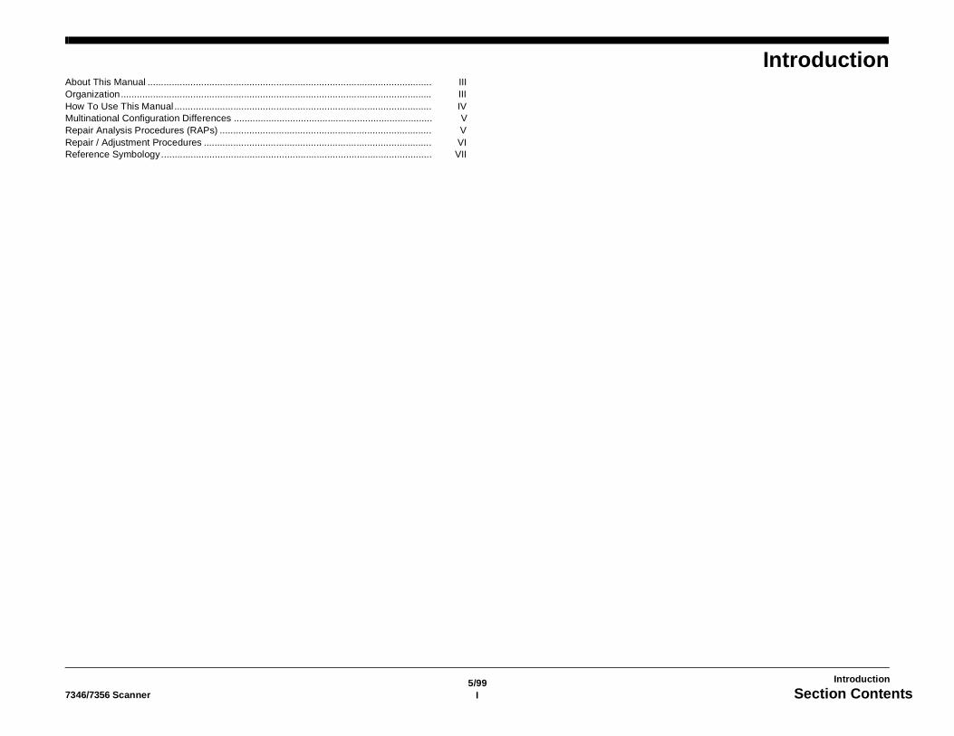
IntroductionAbout This Manual .......................................................................................................... IIIOrganization.................................................................................................................... IIIHow To Use This Manual ................................................................................................ IVMultinational Configuration Differences .......................................................................... VRepair Analysis Procedures (RAPs) ............................................................................... VRepair / Adjustment Procedures ..................................................................................... VIReference Symbology..................................................................................................... VII

5/99II 7356 Scanner
Introduction
5/99III7356 Scanner
Introduction
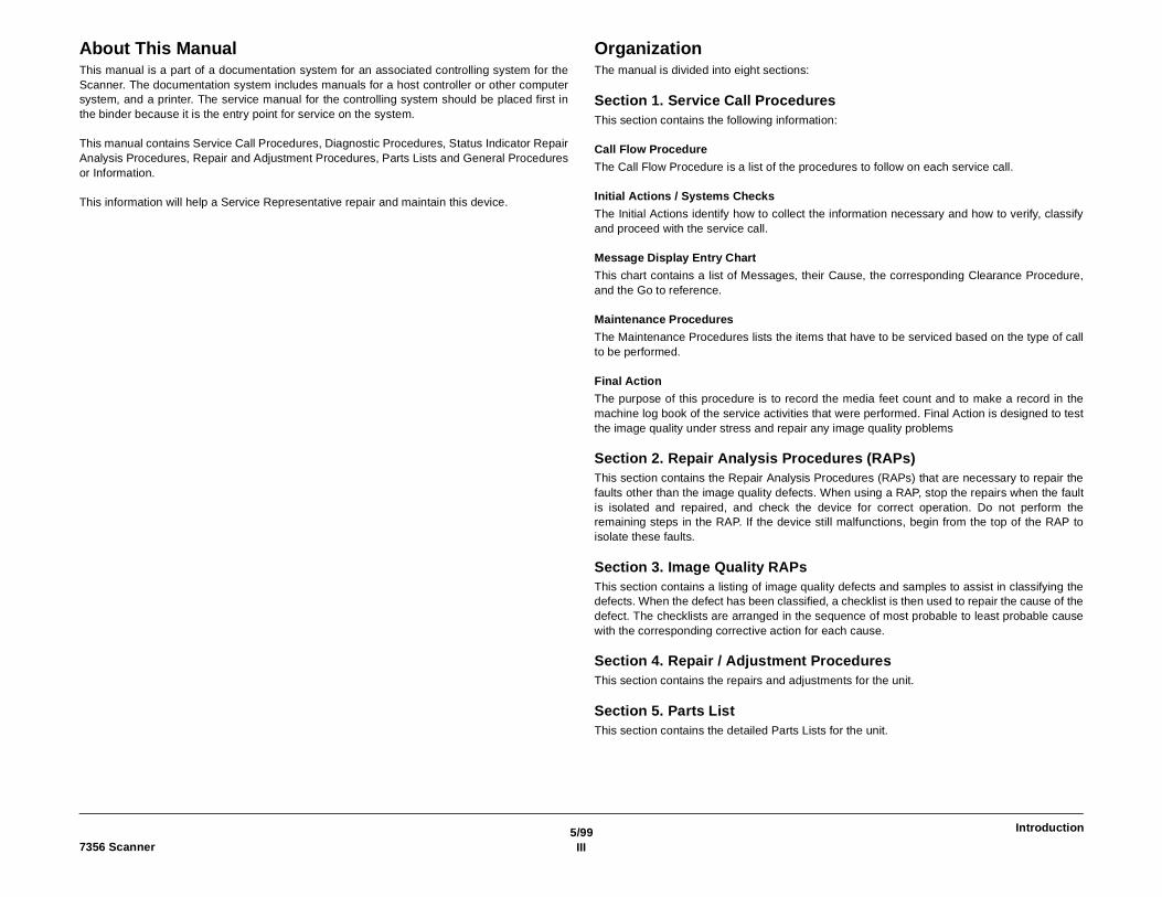
About This ManualThis manual is a part of a documentation system for an associated controlling system for theScanner. The documentation system includes manuals for a host controller or other computersystem, and a printer. The service manual for the controlling system should be placed first inthe binder because it is the entry point for service on the system.
This manual contains Service Call Procedures, Diagnostic Procedures, Status Indicator RepairAnalysis Procedures, Repair and Adjustment Procedures, Parts Lists and General Proceduresor Information.
This information will help a Service Representative repair and maintain this device.
OrganizationThe manual is divided into eight sections:
Section 1. Service Call ProceduresThis section contains the following information:
Call Flow Procedure
The Call Flow Procedure is a list of the procedures to follow on each service call.
Initial Actions / Systems Checks
The Initial Actions identify how to collect the information necessary and how to verify, classifyand proceed with the service call.
Message Display Entry Chart
This chart contains a list of Messages, their Cause, the corresponding Clearance Procedure,and the Go to reference.
Maintenance Procedures
The Maintenance Procedures lists the items that have to be serviced based on the type of callto be performed.
Final Action
The purpose of this procedure is to record the media feet count and to make a record in themachine log book of the service activities that were performed. Final Action is designed to testthe image quality under stress and repair any image quality problems
Section 2. Repair Analysis Procedures (RAPs)This section contains the Repair Analysis Procedures (RAPs) that are necessary to repair thefaults other than the image quality defects. When using a RAP, stop the repairs when the faultis isolated and repaired, and check the device for correct operation. Do not perform theremaining steps in the RAP. If the device still malfunctions, begin from the top of the RAP toisolate these faults.
Section 3. Image Quality RAPsThis section contains a listing of image quality defects and samples to assist in classifying thedefects. When the defect has been classified, a checklist is then used to repair the cause of thedefect. The checklists are arranged in the sequence of most probable to least probable causewith the corresponding corrective action for each cause.
Section 4. Repair / Adjustment ProceduresThis section contains the repairs and adjustments for the unit.
Section 5. Parts ListThis section contains the detailed Parts Lists for the unit.
5/99IV 7356 Scanner
Introduction
Section 6. General ProceduresThis section contains the Diagnostic Procedures, Product Specifications, Supplemental Toolsand Supplies, Generic RAPs, Installation and Removal procedures, and other information.
Section 7. Wiring DataThis section contains the Block Schematic Diagrams.
How To Use This ManualAlways begin with the Service Call Procedures, Section 1. Perform the Initial Actions to identifyand classify the problem.
Then, proceed to one of the following sections of the manual to correct the problem.
Section 2 contains the Status Indicator RAPs. Use these RAPS if the unit is not operational,such as when a Status Code is displayed, or there is an improper indication or “blank” display,etc.
Section 3 is used to troubleshoot Image Quality problems. If you are not sure of the type ofimage quality defect that is occurring, use the contents page in Section 3 to find a defect thatthe best represents the type of defect that is on the copy.
When using Section 2 or Section 3, you may be directed to Section 4 to perform repair oradjustment procedures, or to Section 5, Parts List.
Next, perform the Normal Call procedures.
After performing Normal Call procedure, perform Final Actions to ensure that the unit meetsthe copy specifications.
5/99V7356 Scanner
Introduction
Multinational Configuration DifferencesThis manual contains information that applies to USO/NACO (USA), EO (European Opera-tions), XCL Canada and XLA/AO (Latin America).
Repair Analysis Procedures (RAPs)A RAP is either a table of faults and possible solutions, or a series of steps designed to leadyou to the cause of a problem. In each step, you will perform an action or observe an occur-rence. For fault tree RAPS, at each step, a statement is made that has a Yes (Y) or No (N)answer.
If the answer is NO, perform the action following the NO. If the answer is YES, proceed to thenext step.
When several items are listed, perform them in the order listed.
Proceed through the steps only until the observed problem is isolated and solved. Then evalu-ate the unit for proper performance. If a further defect is observed, go to the appropriate RAPand perform the steps it contains until the additional fault is located and repaired.
5/99VI 7356 Scanner
Introduction
Repair / Adjustment ProceduresThe repair procedures provide detailed steps on how to remove and replace components. Theadjustment procedures provide detailed steps on how to check and adjust components. Someunits have been modified by various design changes. Each change or modification is labeledwith a Tag/ MOD (modification) number. The Tag/ MOD numbers are identified in the ChangeTag/ MOD Index in Section 6 of this Service Manual.
When a modification affects how a particular procedure is performed, the procedure or stepsare identified with either a W/ Tag/ MOD or a W/ O Tag/ MOD statement. Each procedure orstep that is affected by a modification is identified with the statement, W/ Tag/ MOD, followedby the modification number. The W/ in the statement indicates that this step must be per-formed on units that are assembled with that specific modification.
When the procedure or steps are not affected by a particular modification, they are identifiedwith the statement, W/ O Tag/ MOD, followed by the modification number. The W/ O in thestatement indicates that this step must be performed on units assembled without that specificmodification.
5/99VII7356 Scanner
Introduction
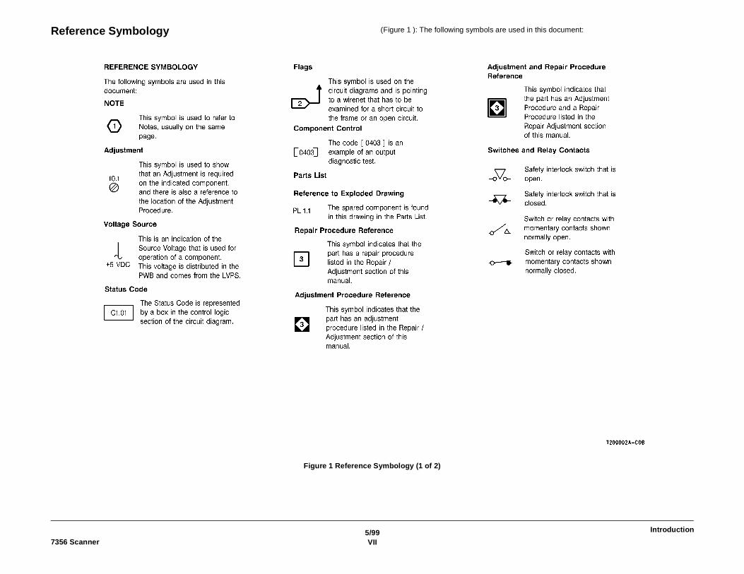
Reference Symbology (Figure 1 ): The following symbols are used in this document:
Figure 1 Reference Symbology (1 of 2)
5/99VIII 7356 Scanner
Introduction
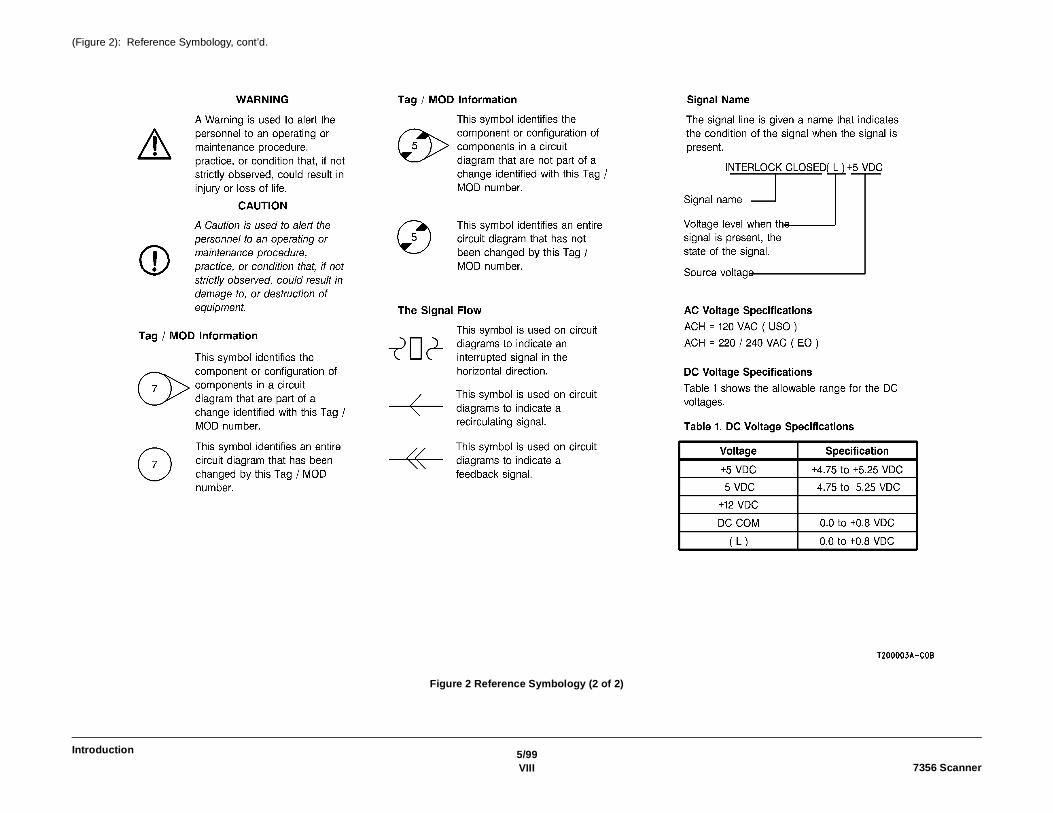
(Figure 2): Reference Symbology, cont’d.
Figure 2 Reference Symbology (2 of 2)
1/991-17356 Scanner Section Contents
Service Call Procedures
1. Service Call ProceduresIntroduction ..................................................................................................................... 1-3Call Flow Procedure........................................................................................................ 1-4Initial Actions / System Checks ....................................................................................... 1-4Message Display Entry Chart.......................................................................................... 1-5Maintenance Procedures ................................................................................................ 1-7Final Action ..................................................................................................................... 1-7

1/991-2 7356 Scanner
Service Call Procedures
1/991-37356 Scanner Introduction
Service Call Procedures
IntroductionThe Xerox 7356 Scanner is designed to function as an Information Input Terminal (IIT) for sev-eral modular systems, as well as to scan images into a standalone host computer for storageand later disposition. The scanner relies on software in a host computer to provide a user inter-face (UI) and the display of fault indicators.
In the case of the ES8150 or XPC, this UI resides in the host Personal Computer (PC) insidethe System Interconnection Module (SIM) or Xerox Productivity Centre (XPC).
In the case of the 8830 DDS, the software resides in the 8830 Controller. The 8830 DDS Con-trol Panel, connected to the Controller and mounted on the top cover of the Scanner, acts asthe user interface.
The Service Call Procedures, Section 1, are designed to assist the Service Representative toidentify faults, perform the necessary corrective action, and perform the correct MaintenanceProcedures. The Service Call Procedures are designed to be used with the 7356 Service Man-ual and are the entry level for all service calls.
The Service manual for the product is the entry point for the fault isolation process at the sys-tems level. Begin the service call with the Systems Level Call Flow Diagram within the ServiceCall Procedures, Section 1. The Call Flow Diagram will help you isolate the problem down tothe system module. The diagram may direct you to a section in the 7356 service manual ordirect you to other service manuals to continue identify and repair the problem.
In the case of a standalone host computer/7356 configuration, the Customer Service Repre-sentative must isolate the fault to the 7356 Scanner and then go to Call Flow Procedure in the7356 Service Manual.
Call Flow ProcedureThis procedure outlines the major activities that are performed when a service call is made.The Initial Actions System Checks assist the Service Representative through the customerinterface and help to identify the problem. The procedure also directs the CSE to verify, clas-sify, repair the problem, and perform the correct Maintenance Procedure.
Initial Actions / System ChecksThis diagram is designed to identify and classify the scanner problem and to refer you to theappropriate RAP in order to repair the problem. When the problem has been repaired, performthe Final Action.
Message Display Entry ChartThis chart contains a list of Messages, their Cause, the corresponding Clearance Procedure,and the Go to reference. The charts are designed to direct the Representative to the appropri-ate Clearance Procedure. If the Procedure does not clear the Status Code, the Representativerefers to the Go to column. This column contains the information to be followed in order torepair the problem. When the problem has been repaired, go to the Call Flow Procedure andcontinue the Service Call.
Maintenance ProceduresThis procedure contains the tasks that are performed after the main cause for the service callhas been corrected. The tasks identified in the procedure are performed at the interval indi-cated. The interval may be after a specified number of feet, for example, 10K. The interval mayalso be specified as a Normal Call (NC).
Normal Call activities are designed to be performed on all service calls. The specific intervaland Normal Call activities include cleaning and replacing parts that require more frequent ser-vice and inspections The maintenance Procedure activities are designed to restore the deviceto an initially clean and functional condition.
Final ActionThe purpose of this procedure is to record the media feet count and to make a record in themachine log book of the service activities that were performed. Final Action is designed to testthe image quality under stress and repair any image quality problems. A copy of test pattern82E5980 or 499T286 is made and compared with the image copy quality specifications locatedin Section 3 of the manual.
1/991-4 7356 ScannerCall Flow Procedure, Initial Actions / System Checks
Service Call Procedures
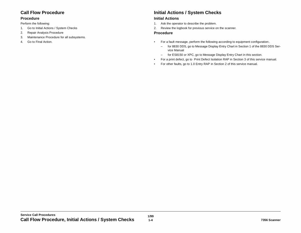
Call Flow ProcedureProcedurePerform the following:
1. Go to Initial Actions / System Checks
2. Repair Analysis Procedure
3. Maintenance Procedure for all subsystems.
4. Go to Final Action.
Initial Actions / System ChecksInitial Actions1. Ask the operator to describe the problem.
2. Review the logbook for previous service on the scanner.
Procedure
• For a fault message, perform the following according to equipment configuration:.
– for 8830 DDS, go to Message Display Entry Chart in Section 1 of the 8830 DDS Ser-vice Manual
– for ES8150 or XPC, go to Message Display Entry Chart in this section.
• For a print defect, go to Print Defect Isolation RAP in Section 3 of this service manual.
• For other faults, go to 1.0 Entry RAP in Section 2 of this service manual.
1/991-57356 Scanner Message Display Entry Chart
Service Call Procedures
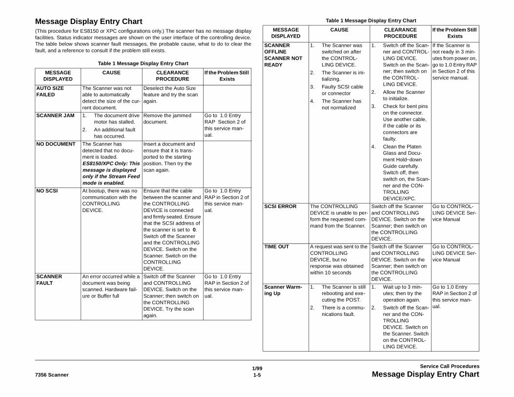
Message Display Entry Chart(This procedure for ES8150 or XPC configurations only.) The scanner has no message displayfacilities. Status indicator messages are shown on the user interface of the controlling device.The table below shows scanner fault messages, the probable cause, what to do to clear thefault, and a reference to consult if the problem still exists.
Table 1 Message Display Entry Chart
MESSAGE DISPLAYED
CAUSE CLEARANCE PROCEDURE
If the Problem Still Exists
AUTO SIZE FAILED
The Scanner was not able to automatically detect the size of the cur-rent document.
Deselect the Auto Size feature and try the scan again.
SCANNER JAM 1. The document drive motor has stalled.
2. An additional fault has occurred.
Remove the jammed document.
Go to 1.0 Entry RAP Section 2 of this service man-ual.
NO DOCUMENT The Scanner has detected that no docu-ment is loaded.ES8150/XPC Only: This message is displayed only if the Stream Feed mode is enabled.
Insert a document and ensure that it is trans-ported to the starting position. Then try the scan again.
NO SCSI At bootup, there was no communication with the CONTROLLING DEVICE.
Ensure that the cable between the scanner and the CONTROLLING DEVICE is connected and firmly seated. Ensure that the SCSI address of the scanner is set to 0.Switch off the Scanner and the CONTROLLING DEVICE. Switch on the Scanner. Switch on the CONTROLLING DEVICE.
Go to 1.0 Entry RAP in Section 2 of this service man-ual.
SCANNER FAULT
An error occurred while a document was being scanned. Hardware fail-ure or Buffer full
Switch off the Scanner and CONTROLLING DEVICE. Switch on the Scanner; then switch on the CONTROLLING DEVICE. Try the scan again.
Go to 1.0 Entry RAP in Section 2 of this service man-ual.
SCANNER OFFLINESCANNER NOT READY
1. The Scanner was switched on after the CONTROL-LING DEVICE.
2. The Scanner is ini-tializing.
3. Faulty SCSI cable or connector
4. The Scanner has not normalized
1. Switch off the Scan-ner and CONTROL-LING DEVICE. Switch on the Scan-ner; then switch on the CONTROL-LING DEVICE.
2. Allow the Scanner to initialize.
3. Check for bent pins on the connector. Use another cable, if the cable or its connectors are faulty.
4. Clean the Platen Glass and Docu-ment Hold−down Guide carefully. Switch off, then switch on, the Scan-ner and the CON-TROLLING DEVICE/XPC.
If the Scanner is not ready in 3 min-utes from power on, go to 1.0 Entry RAP in Section 2 of this service manual.
SCSI ERROR The CONTROLLING DEVICE is unable to per-form the requested com-mand from the Scanner.
Switch off the Scanner and CONTROLLING DEVICE. Switch on the Scanner; then switch on the CONTROLLING DEVICE.
Go to CONTROL-LING DEVICE Ser-vice Manual
TIME OUT A request was sent to the CONTROLLING DEVICE, but no response was obtained within 10 seconds
Switch off the Scanner and CONTROLLING DEVICE. Switch on the Scanner; then switch on the CONTROLLING DEVICE.
Go to CONTROL-LING DEVICE Ser-vice Manual
Scanner Warm-ing Up
1. The Scanner is still rebooting and exe-cuting the POST.
2. There is a commu-nications fault.
1. Wait up to 3 min-utes; then try the operation again.
2. Switch off the Scan-ner and the CON-TROLLING DEVICE. Switch on the Scanner. Switch on the CONTROL-LING DEVICE.
Go to 1.0 Entry RAP in Section 2 of this service man-ual.
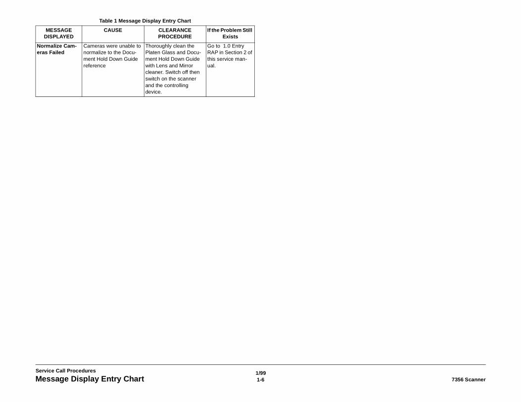
Table 1 Message Display Entry Chart
MESSAGE DISPLAYED
CAUSE CLEARANCE PROCEDURE
If the Problem Still Exists
1/991-6 7356 ScannerMessage Display Entry Chart
Service Call Procedures
Normalize Cam-eras Failed
Cameras were unable to normalize to the Docu-ment Hold Down Guide reference
Thoroughly clean the Platen Glass and Docu-ment Hold Down Guide with Lens and Mirror cleaner. Switch off then switch on the scanner and the controlling device.
Go to 1.0 Entry RAP in Section 2 of this service man-ual.
Table 1 Message Display Entry Chart
MESSAGE DISPLAYED
CAUSE CLEARANCE PROCEDURE
If the Problem Still Exists
1/991-77356 Scanner Maintenance Procedures, Final Action
Service Call Procedures
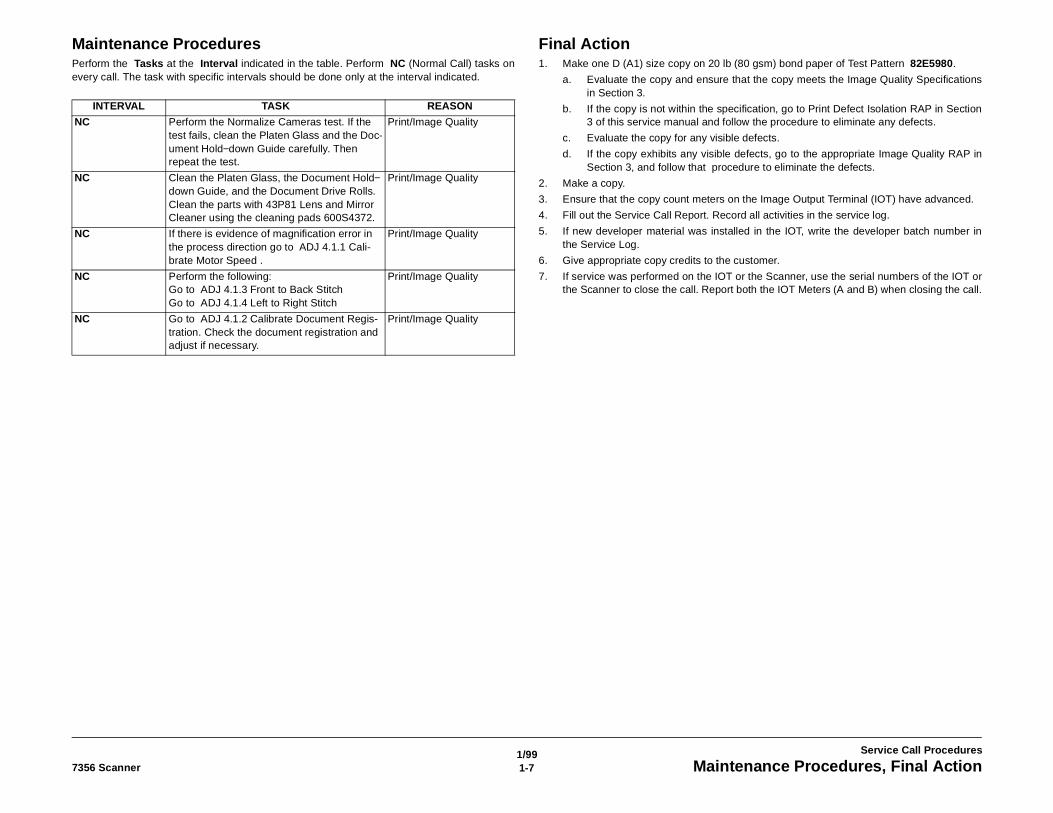
Maintenance ProceduresPerform the Tasks at the Interval indicated in the table. Perform NC (Normal Call) tasks onevery call. The task with specific intervals should be done only at the interval indicated.
Final Action1. Make one D (A1) size copy on 20 lb (80 gsm) bond paper of Test Pattern 82E5980.
a. Evaluate the copy and ensure that the copy meets the Image Quality Specificationsin Section 3.
b. If the copy is not within the specification, go to Print Defect Isolation RAP in Section3 of this service manual and follow the procedure to eliminate any defects.
c. Evaluate the copy for any visible defects.
d. If the copy exhibits any visible defects, go to the appropriate Image Quality RAP inSection 3, and follow that procedure to eliminate the defects.
2. Make a copy.
3. Ensure that the copy count meters on the Image Output Terminal (IOT) have advanced.
4. Fill out the Service Call Report. Record all activities in the service log.
5. If new developer material was installed in the IOT, write the developer batch number inthe Service Log.
6. Give appropriate copy credits to the customer.
7. If service was performed on the IOT or the Scanner, use the serial numbers of the IOT orthe Scanner to close the call. Report both the IOT Meters (A and B) when closing the call.
INTERVAL TASK REASON
NC Perform the Normalize Cameras test. If the test fails, clean the Platen Glass and the Doc-ument Hold−down Guide carefully. Then repeat the test.
Print/Image Quality
NC Clean the Platen Glass, the Document Hold−down Guide, and the Document Drive Rolls. Clean the parts with 43P81 Lens and Mirror Cleaner using the cleaning pads 600S4372.
Print/Image Quality
NC If there is evidence of magnification error in the process direction go to ADJ 4.1.1 Cali-brate Motor Speed .
Print/Image Quality
NC Perform the following:Go to ADJ 4.1.3 Front to Back StitchGo to ADJ 4.1.4 Left to Right Stitch
Print/Image Quality
NC Go to ADJ 4.1.2 Calibrate Document Regis-tration. Check the document registration and adjust if necessary.
Print/Image Quality

1/991-8 7356 ScannerMaintenance Procedures, Final Action
Service Call Procedures
1/992-17356 Scanner Section Contents
Repair Analysis Procedures
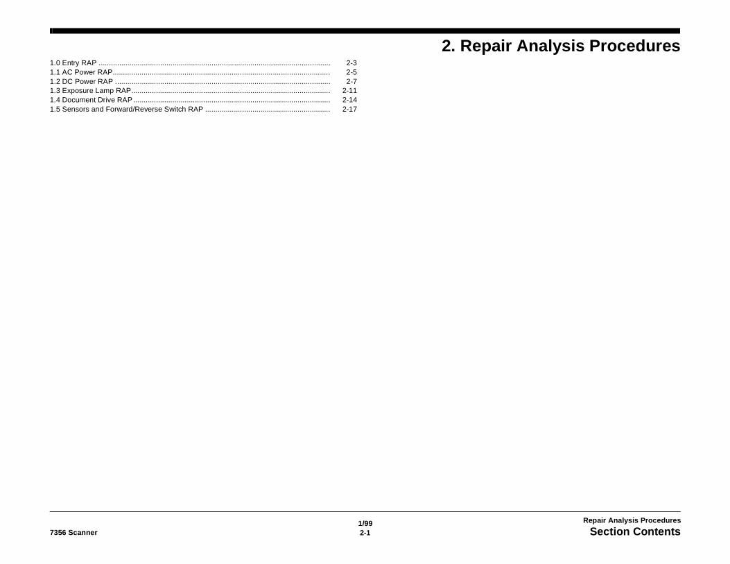
2. Repair Analysis Procedures1.0 Entry RAP ................................................................................................................. 2-31.1 AC Power RAP.......................................................................................................... 2-51.2 DC Power RAP ......................................................................................................... 2-71.3 Exposure Lamp RAP................................................................................................. 2-111.4 Document Drive RAP ................................................................................................ 2-141.5 Sensors and Forward/Reverse Switch RAP ............................................................. 2-17

1/992-2 7356 Scanner
Repair Analysis Procedures
1/992-37356 Scanner 1.0 Entry RAP
Repair Analysis Procedures
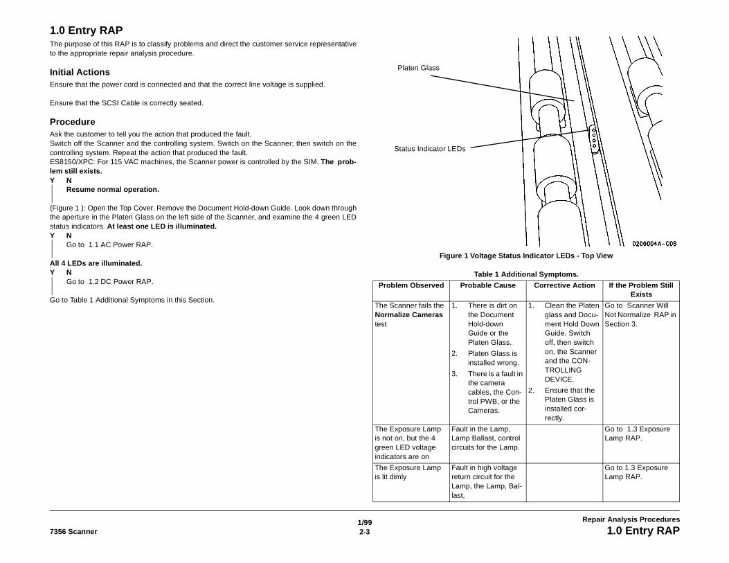
1.0 Entry RAPThe purpose of this RAP is to classify problems and direct the customer service representativeto the appropriate repair analysis procedure.
Initial ActionsEnsure that the power cord is connected and that the correct line voltage is supplied.
Ensure that the SCSI Cable is correctly seated.
ProcedureAsk the customer to tell you the action that produced the fault.Switch off the Scanner and the controlling system. Switch on the Scanner; then switch on thecontrolling system. Repeat the action that produced the fault.ES8150/XPC: For 115 VAC machines, the Scanner power is controlled by the SIM. The prob-lem still exists.Y N
Resume normal operation.
(Figure 1 ): Open the Top Cover. Remove the Document Hold-down Guide. Look down throughthe aperture in the Platen Glass on the left side of the Scanner, and examine the 4 green LEDstatus indicators. At least one LED is illuminated.Y N
Go to 1.1 AC Power RAP.
All 4 LEDs are illuminated.Y N
Go to 1.2 DC Power RAP.
Go to Table 1 Additional Symptoms in this Section.
Figure 1 Voltage Status Indicator LEDs - Top View
Table 1 Additional Symptoms.
Problem Observed Probable Cause Corrective Action If the Problem Still Exists
The Scanner fails the Normalize Cameras test
1. There is dirt on the Document Hold-down Guide or the Platen Glass.
2. Platen Glass is installed wrong.
3. There is a fault in the camera cables, the Con-trol PWB, or the Cameras.
1. Clean the Platen glass and Docu-ment Hold Down Guide. Switch off, then switch on, the Scanner and the CON-TROLLING DEVICE.
2. Ensure that the Platen Glass is installed cor-rectly.
Go to Scanner Will Not Normalize RAP in Section 3.
The Exposure Lamp is not on, but the 4 green LED voltage indicators are on
Fault in the Lamp, Lamp Ballast, control circuits for the Lamp.
Go to 1.3 Exposure Lamp RAP.
The Exposure Lamp is lit dimly
Fault in high voltage return circuit for the Lamp, the Lamp, Bal-last,
Go to 1.3 Exposure Lamp RAP.
Platen Glass
Status Indicator LEDs
1/992-4 7356 Scanner1.0 Entry RAP
Repair Analysis Procedures
The Scanner does not transport an inserted document to the regis-tered position, but the Exposure Lamp is on.
1. The Scanner is normalizing cam-eras after being switched on.
2. Sensor fault
3. Fault in the docu-ment drive cir-cuitry or mechanical drive
Wait 1 minute and try again.
1. Go to 1.5 Sen-sors and For-ward/Reverse Switch RAP.
2. Go to 1.4 Docu-ment Drive RAP.
The image appears stretched or com-pressed in the pro-cess direction
Fault in the Docu-ment Transportation system.
Go to 1.4 Document Drive RAP.
The image has a gap or an overlap region along the process direction
The Stitch adjustment is incorrect.
Configure for diagnos-tics. Perform the fol-lowing: go to ADJ 4.1.3 Front to Back Stitch, and, go to ADJ 4.1.4 Left to Right Stitch.
If the tests fail repeat-edly or a satisfactory adjustment cannot be made, the Scanner must be exchanged.
Document does not scan but does regis-ter.
1. SCSI Cable between Scan-ner and SIM is not securely seated
2. Faulty SCSI cable between Scanner and SIM
1. Reconnect the cable. Switch off the Controlling Device and Scanner. Switch on the Scanner. Switch on the Controlling Device
2. Replace the Cable. Recon-nect the cable. Switch off the Controlling Device and Scanner. Switch on the Scanner. Switch on the Controlling Device
Go to Initial Actions / Systems Checks in the Controlling Device service manual.
Table 1 Additional Symptoms.
1/992-57356 Scanner 1.1 AC Power RAP
Repair Analysis Procedures
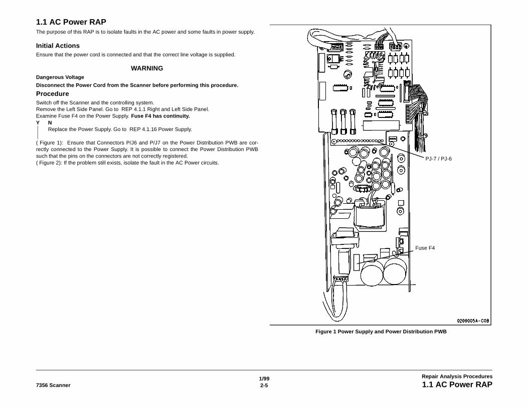
1.1 AC Power RAPThe purpose of this RAP is to isolate faults in the AC power and some faults in power supply.
Initial ActionsEnsure that the power cord is connected and that the correct line voltage is supplied.
WARNINGDangerous Voltage
Disconnect the Power Cord from the Scanner before performing this procedure.
ProcedureSwitch off the Scanner and the controlling system.Remove the Left Side Panel. Go to REP 4.1.1 Right and Left Side Panel.Examine Fuse F4 on the Power Supply. Fuse F4 has continuity.Y N
Replace the Power Supply. Go to REP 4.1.16 Power Supply.
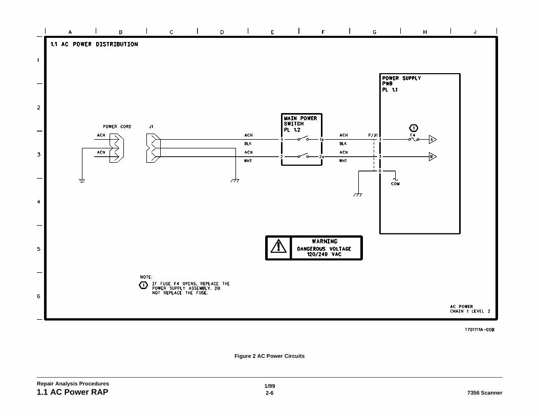
( Figure 1): Ensure that Connectors P/J6 and P/J7 on the Power Distribution PWB are cor-rectly connected to the Power Supply. It is possible to connect the Power Distribution PWBsuch that the pins on the connectors are not correctly registered.( Figure 2): If the problem still exists, isolate the fault in the AC Power circuits.
Figure 1 Power Supply and Power Distribution PWB
PJ-7 / PJ-6
Fuse F4
1/992-6 7356 Scanner1.1 AC Power RAP
Repair Analysis Procedures
Figure 2 AC Power Circuits
1/992-77356 Scanner 1.2 DC Power RAP
Repair Analysis Procedures
1.2 DC Power RAPThe purpose of this RAP is to isolate faults in the DC power and distribution circuits.
Initial ActionsNone
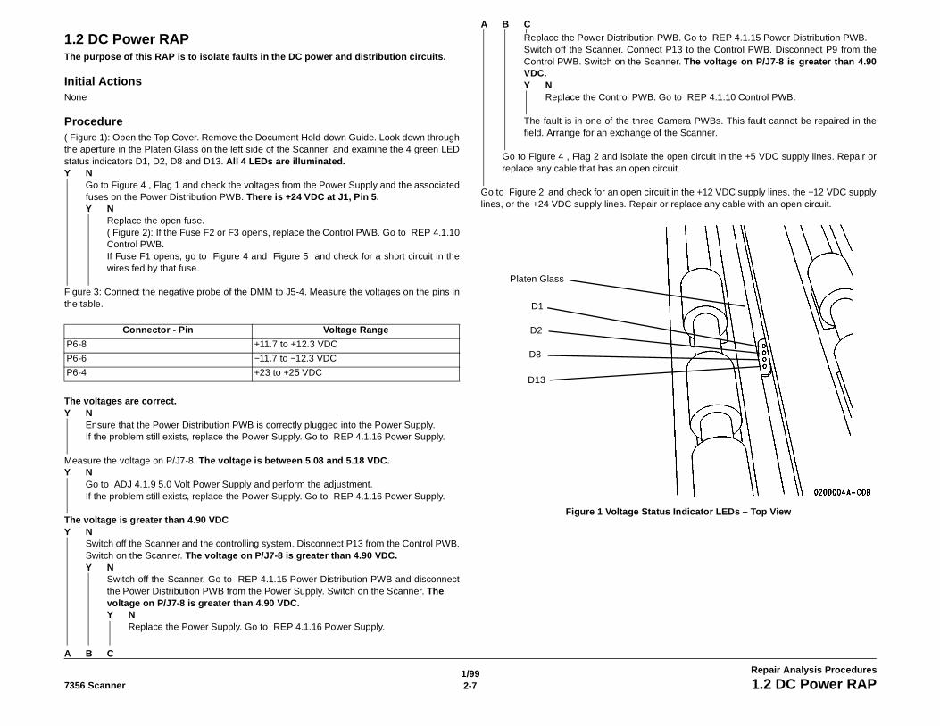
Procedure( Figure 1): Open the Top Cover. Remove the Document Hold-down Guide. Look down throughthe aperture in the Platen Glass on the left side of the Scanner, and examine the 4 green LEDstatus indicators D1, D2, D8 and D13. All 4 LEDs are illuminated.Y N
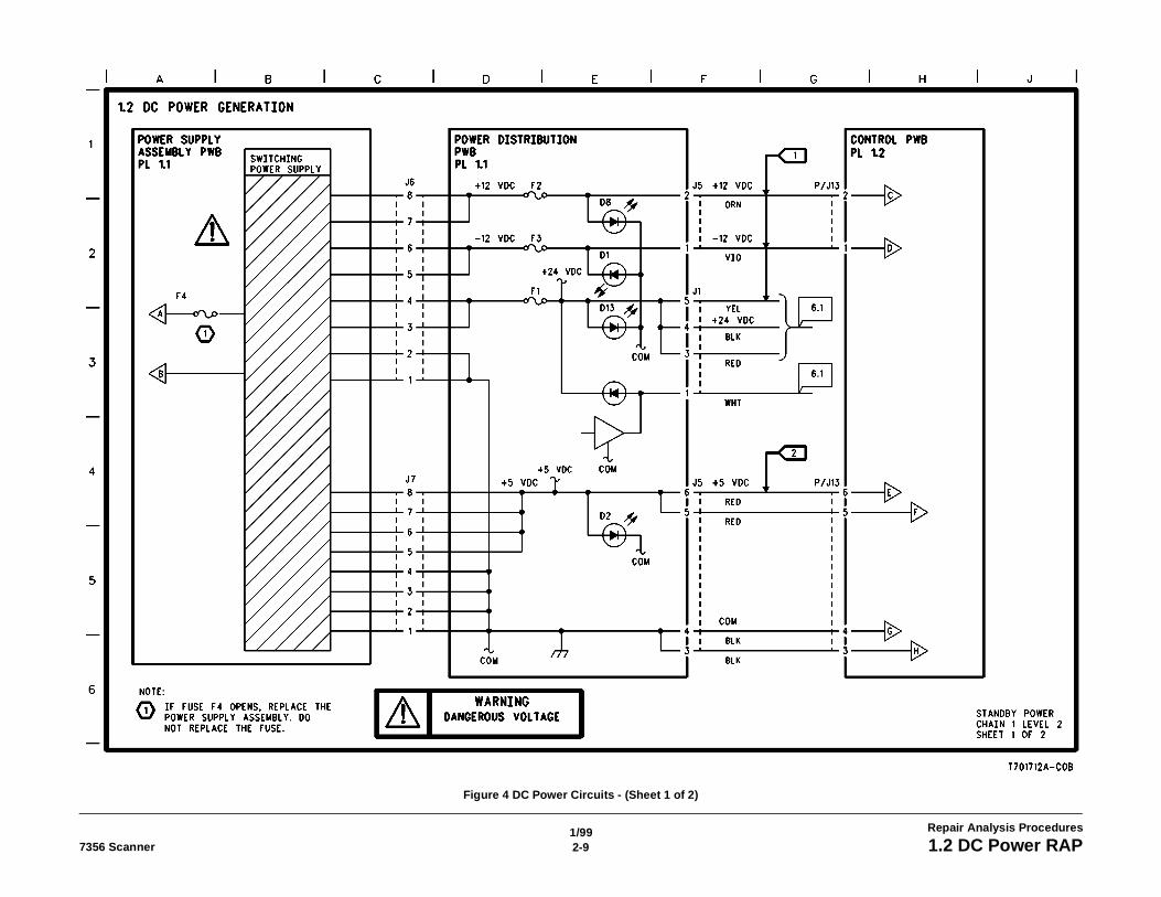
Go to Figure 4 , Flag 1 and check the voltages from the Power Supply and the associatedfuses on the Power Distribution PWB. There is +24 VDC at J1, Pin 5.Y N
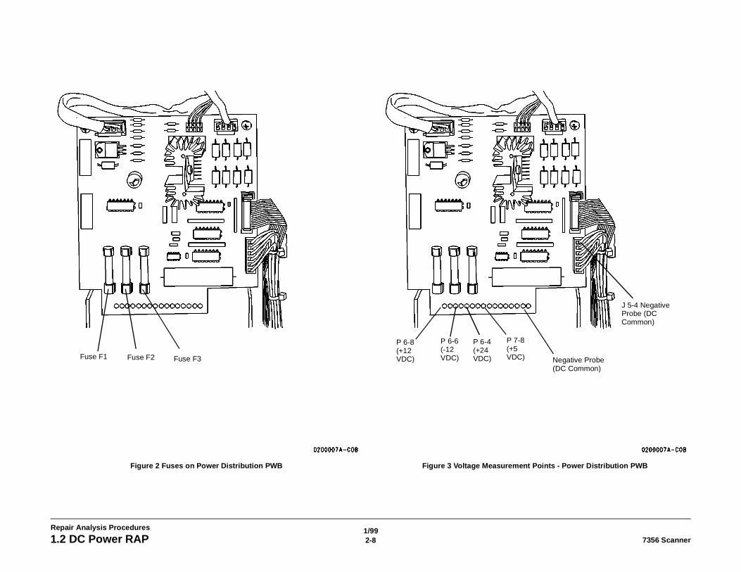
Replace the open fuse.( Figure 2): If the Fuse F2 or F3 opens, replace the Control PWB. Go to REP 4.1.10Control PWB.If Fuse F1 opens, go to Figure 4 and Figure 5 and check for a short circuit in thewires fed by that fuse.
Figure 3: Connect the negative probe of the DMM to J5-4. Measure the voltages on the pins inthe table.
The voltages are correct.Y N
Ensure that the Power Distribution PWB is correctly plugged into the Power Supply.If the problem still exists, replace the Power Supply. Go to REP 4.1.16 Power Supply.
Measure the voltage on P/J7-8. The voltage is between 5.08 and 5.18 VDC.Y N
Go to ADJ 4.1.9 5.0 Volt Power Supply and perform the adjustment.If the problem still exists, replace the Power Supply. Go to REP 4.1.16 Power Supply.
The voltage is greater than 4.90 VDCY N
Switch off the Scanner and the controlling system. Disconnect P13 from the Control PWB.Switch on the Scanner. The voltage on P/J7-8 is greater than 4.90 VDC.Y N
Switch off the Scanner. Go to REP 4.1.15 Power Distribution PWB and disconnectthe Power Distribution PWB from the Power Supply. Switch on the Scanner. Thevoltage on P/J7-8 is greater than 4.90 VDC.Y N
Replace the Power Supply. Go to REP 4.1.16 Power Supply.
Replace the Power Distribution PWB. Go to REP 4.1.15 Power Distribution PWB.Switch off the Scanner. Connect P13 to the Control PWB. Disconnect P9 from theControl PWB. Switch on the Scanner. The voltage on P/J7-8 is greater than 4.90VDC.Y N
Replace the Control PWB. Go to REP 4.1.10 Control PWB.
The fault is in one of the three Camera PWBs. This fault cannot be repaired in thefield. Arrange for an exchange of the Scanner.
Go to Figure 4 , Flag 2 and isolate the open circuit in the +5 VDC supply lines. Repair orreplace any cable that has an open circuit.
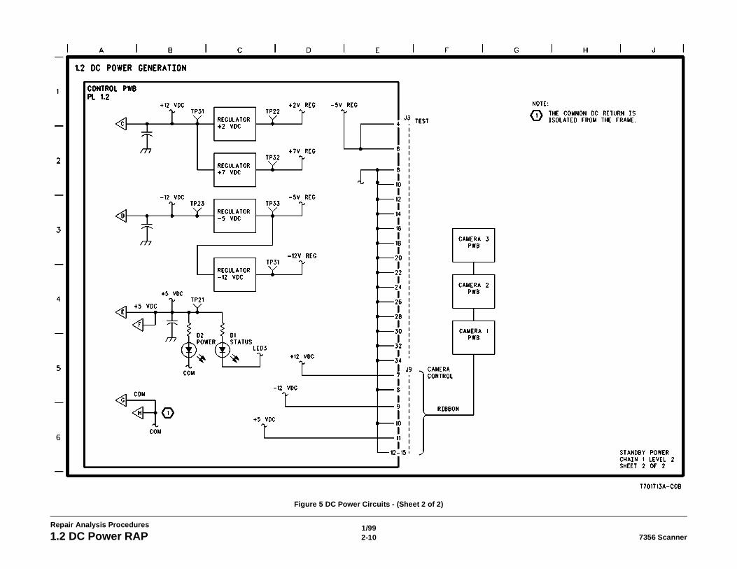
Go to Figure 2 and check for an open circuit in the +12 VDC supply lines, the −12 VDC supplylines, or the +24 VDC supply lines. Repair or replace any cable with an open circuit.
Figure 1 Voltage Status Indicator LEDs – Top View
Connector - Pin Voltage Range
P6-8 +11.7 to +12.3 VDC
P6-6 −11.7 to −12.3 VDC
P6-4 +23 to +25 VDC
Platen Glass
D1
D2
D8
D13
A
A
B
B
C
C
1/992-8 7356 Scanner1.2 DC Power RAP
Repair Analysis Procedures
Figure 2 Fuses on Power Distribution PWB Figure 3 Voltage Measurement Points - Power Distribution PWB
Fuse F3Fuse F2Fuse F1
P 6-8 (+12 VDC)
P 6-6 (-12 VDC)
P 6-4 (+24 VDC)
P 7-8 (+5 VDC) Negative Probe
(DC Common)
J 5-4 Negative Probe (DC Common)
1/992-97356 Scanner 1.2 DC Power RAP
Repair Analysis Procedures
Figure 4 DC Power Circuits - (Sheet 1 of 2)
1/992-10 7356 Scanner1.2 DC Power RAP
Repair Analysis Procedures
Figure 5 DC Power Circuits - (Sheet 2 of 2)
1/992-117356 Scanner 1.3 Exposure Lamp RAP
Repair Analysis Procedures
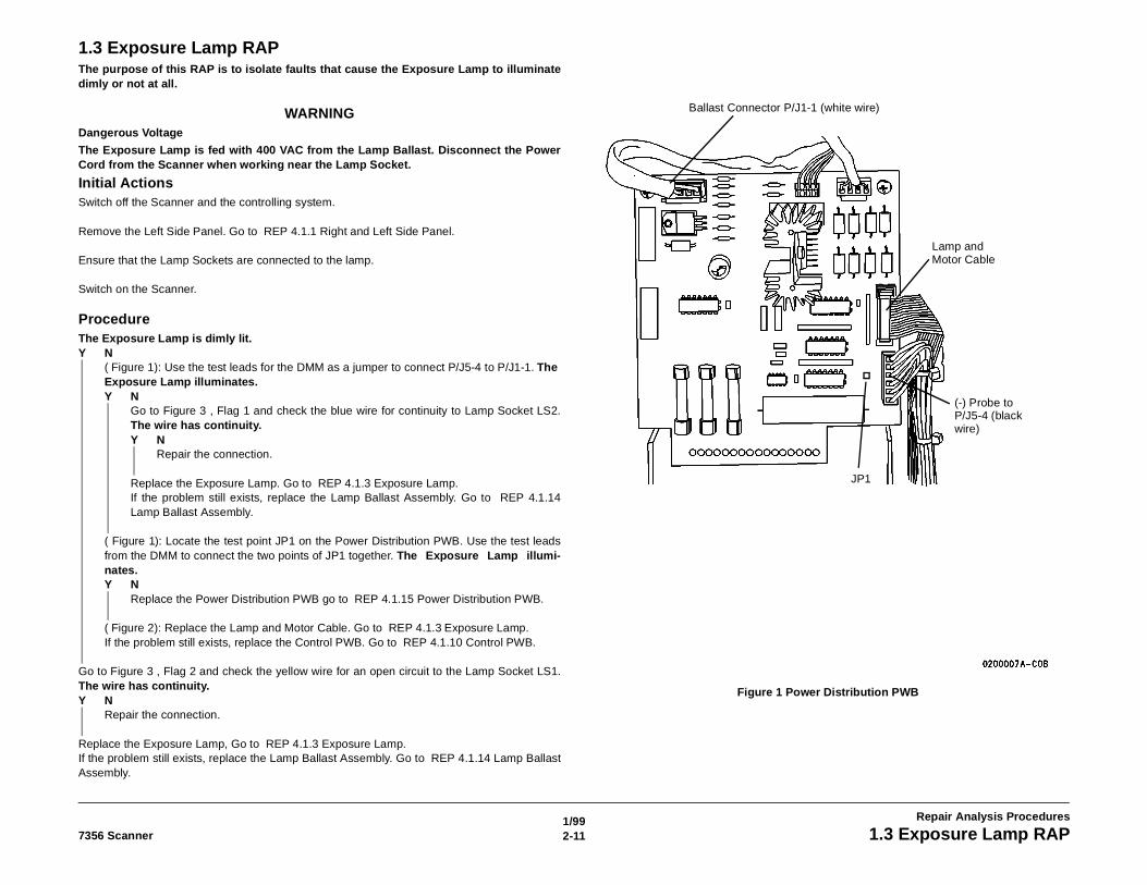
1.3 Exposure Lamp RAPThe purpose of this RAP is to isolate faults that cause the Exposure Lamp to illuminatedimly or not at all.
WARNINGDangerous Voltage
The Exposure Lamp is fed with 400 VAC from the Lamp Ballast. Disconnect the PowerCord from the Scanner when working near the Lamp Socket.
Initial ActionsSwitch off the Scanner and the controlling system.
Remove the Left Side Panel. Go to REP 4.1.1 Right and Left Side Panel.
Ensure that the Lamp Sockets are connected to the lamp.
Switch on the Scanner.
ProcedureThe Exposure Lamp is dimly lit.Y N
( Figure 1): Use the test leads for the DMM as a jumper to connect P/J5-4 to P/J1-1. TheExposure Lamp illuminates.Y N
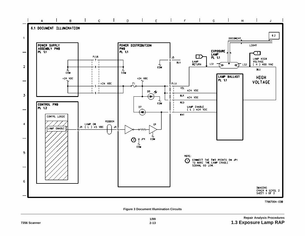
Go to Figure 3 , Flag 1 and check the blue wire for continuity to Lamp Socket LS2.The wire has continuity.Y N
Repair the connection.
Replace the Exposure Lamp. Go to REP 4.1.3 Exposure Lamp.If the problem still exists, replace the Lamp Ballast Assembly. Go to REP 4.1.14Lamp Ballast Assembly.
( Figure 1): Locate the test point JP1 on the Power Distribution PWB. Use the test leadsfrom the DMM to connect the two points of JP1 together. The Exposure Lamp illumi-nates.Y N
Replace the Power Distribution PWB go to REP 4.1.15 Power Distribution PWB.
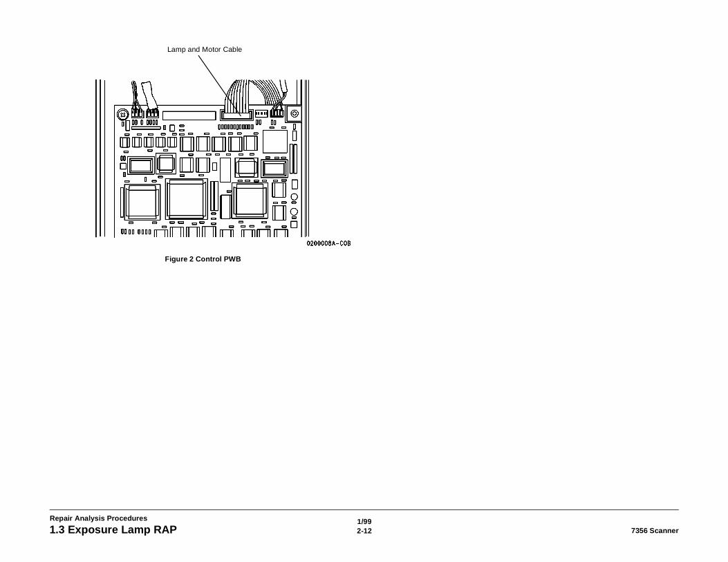
( Figure 2): Replace the Lamp and Motor Cable. Go to REP 4.1.3 Exposure Lamp.If the problem still exists, replace the Control PWB. Go to REP 4.1.10 Control PWB.
Go to Figure 3 , Flag 2 and check the yellow wire for an open circuit to the Lamp Socket LS1.The wire has continuity.Y N
Repair the connection.
Replace the Exposure Lamp, Go to REP 4.1.3 Exposure Lamp.If the problem still exists, replace the Lamp Ballast Assembly. Go to REP 4.1.14 Lamp BallastAssembly.
Figure 1 Power Distribution PWB
Ballast Connector P/J1-1 (white wire)
Lamp and Motor Cable
(-) Probe to P/J5-4 (black wire)
JP1
1/992-12 7356 Scanner1.3 Exposure Lamp RAP
Repair Analysis Procedures
Figure 2 Control PWB
Lamp and Motor Cable
1/992-137356 Scanner 1.3 Exposure Lamp RAP
Repair Analysis Procedures
Figure 3 Document Illumination Circuits

1.4 Documenynt Drive RAPPThe purpose of this s RAP is to isolate fauts in the document ment drive system in BSD 4.1
[unresolved], BSD 4.2 [unresolved], and BSD 5.1, [unresolved ] In SectIo n 7, contaI n usefulinformation.
Initial ActionsEnsure that the Scanner and the controlling system are ready.
ProcedureAlternately press the Forward Switch at least 10 times.If the Document Drive Rolls operate erratically (sometimes forward, sometimes reverse, some-times not at all), the Motor has an internal fault or the controlling circuit on the Power Distribu-tion PWB has a fault. Go to REP 4.1.12 Motor Assembly and Main Drive Belt and replace theMotor Assembly. If the problem still exists, go to REP 4.1.15 Power Distribution PWB andreplace the Power Distribution PWB.If the Document Drive Rolls always operate forward, continue with the procedure.Attempt to scan a large (ANSI D or ISO Al) document at 25% (1:4) reduction factor.Listen carefully for noises indicating slippage of the Main Drive Belt.
(Figure 1): Try scanning a document several times, The documen t Is registere d every timethat It Is inserted.
NThe document was transported smoothly forward and then smoothly back.
There was noise Indicating that the motor was running.
Remove the Left Side Panel. Goto REP 4.1.1 Right and Left Side Panel.Configure the system for diagnostic operation:• ES8150/XPC: See Configuring for Extended Diagnostics in Section 6 of
this manual.• 8830 DDS: Go to Motor Direction and operate the motor in both the for-
ward and reverse directions.The motor operates correctly in both directions.
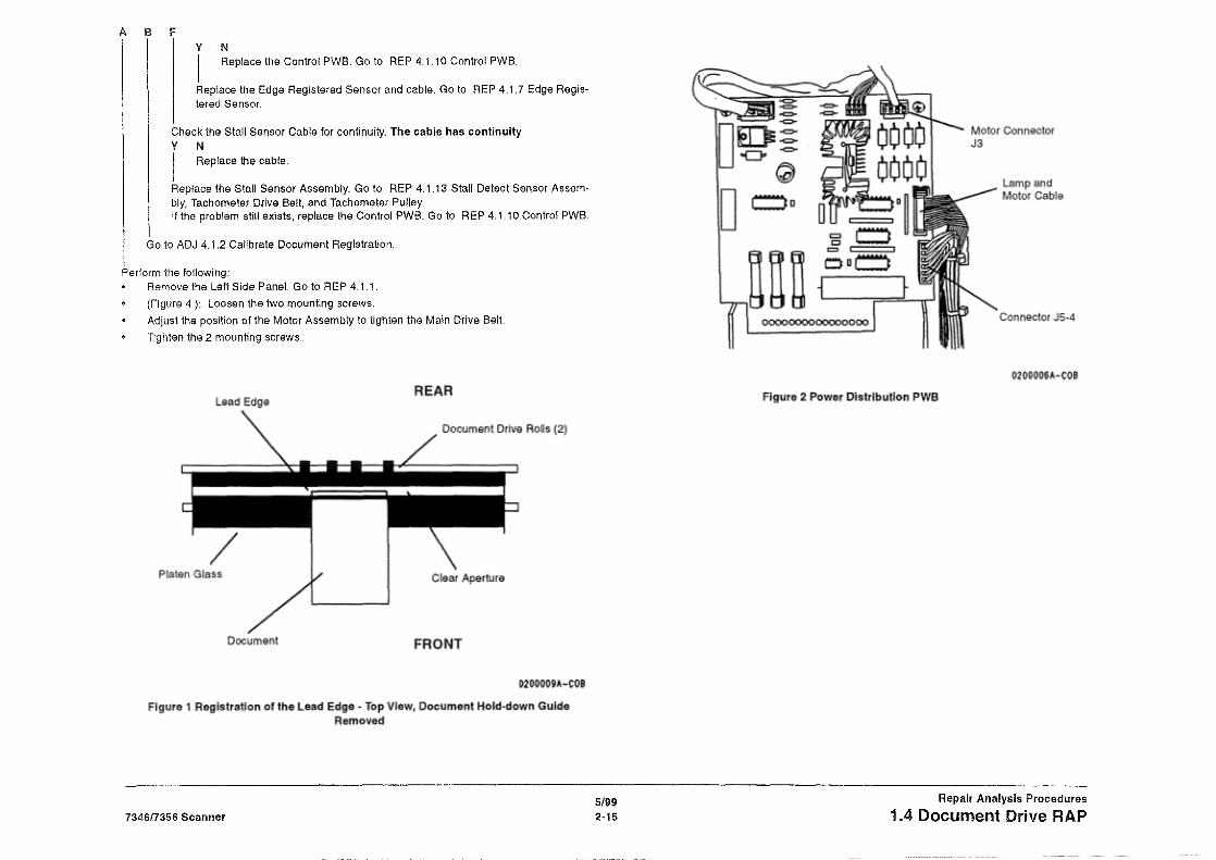
(Figure 2): Connect the (-) probe to J5-4. Measure the voltage on all pinsof Connector J3 while commanding the Motor to operate. The voltage isbetween 15.0 and 19.0 VDC when the moto r Is commanded to oper-ate, and less than 1.5 VDC when the motor is not commanded tooperate.
NCheck for the following possible faults:1. the Lamp and Motor Cable is not seated. Reseat the cable con-
nectors at each end.2. The motor control circuitry on the Power Distribution PWB is
defective. Replace the Power Distribution PWB. Go to REP4.1.15 Power Distribution PWB.
3. The Control PWB cannot signal the motor to operate. Replacethe Control PWB. Go to REP 4.1.10 Control PWB.
CD EMotor is defective. Replace the Motor Assembly. Go to REP 4.1.12
Motor Assembly and Main Drive Belt.
The Document DriveRolls moved when the motor operated.f Replace the Main Drive Belt. Go to REP 4.1.12.
Replace the the Edge Present Sensor. Go to REP 4.1.6. If the problem stillexists, replace the Control PWB. Go to REP 4.1.10.
When the document was inserted, the document moved forward, thenstopped. The document failed to reverse.V N
Press the Forward Switch several times and then press the Reverse Switchseveral times. Observe the direction of rotation for the Document Drive Rolls.The dIrection of rotation of the Document Drive Rolls was correct andconsistent.V N
Remove the Left Side Cover. Go to REP 4.1.1 Right and Left Side Panel.Check the Main Drive Belt and the Tachometer Drive Belt for breakageand tension.If the problem still exists, go to 1.5 Sensors and Forward/Reverse SwitchRAP, Sensors and Forward/Reverse Switch RAP, and check that the sen-sors and switch operate correctly.
Measure the voltage on all pins of Connector J3 while commanding the Motorto operate. The voltage Is between 18.0 and 19.0 VDC when the motor Iscommanded to operate, and less than 1.5 VDC when the motor is notcommanded to operate.V N
Replace the Motor Assembly. Go to REP 4.1.12 Motor Assembly and MainDrive Belt.Calibrate the document registration. Go to ADJ 4.1.2 Calibrate Document Reg-istration.
Configure the system for diagnostic operation:ES8150/XPC: Go to Configuring for Extended Diagnostics in Section 6 of thismanual.DDS: Go to LED Test in Section 6 of the 8830 DDS Service Manual for instruc-tions in performing this procedure.
Start the diagnostic software.Manually actuate the Edge Registered Sensor, and observe the diagnostic screen.The signal goes low.YN
low.
A B
Replace the Power Distribution PWB. Go to REP 4.1.15 Power Distribu-tion PWB.
A B CD E A B FRepair Analysis Procedures 5/99
1.4 Document Drive RAP
Go to BSD 5.1, [unresolved]. Disconnect Connector P6 from the Control PWB.Connect J6-2 to J6-4, and observe the diagnostic screen. The signal goes
2-14 73anner
A B F
Replace the Control PWB. Go to REP 4.1.10 Control PWB.
Replace the Edge Registered Sensor and cable. Go to REP 4.1.7 Edge Regis-tered Sensor.
Check the Stall Sensor Cable for continuity. The cable has continuityV N
Replace the cable.
Replace the Stall Sensor Assembly. Go to REP 4.1.13 Stall Detect Sensor Assem-bly, Tachometer Drive Belt, and Tachometer Pulley.If the problem still exists, replace the Control PWB. Go to REP 4.1.10 Control PWB.
Go to ADJ 4.1.2 Calibrate Document Registration.
Perform the following:Remove the Left Side Panel. Go to REP 4.1.1.(Figure 4): Loosen the two mounting screws.Adjust the position of the Motor Assembly to tighten the Main Drive Belt.
Tighten the 2 mounting screws.
5/99 Repair Analysis Procedures
7346/7356 Scanner 2-15 IA Document Drive RAP
1/992-16 7356 Scanner1.4 Document Drive RAP
Repair Analysis Procedures
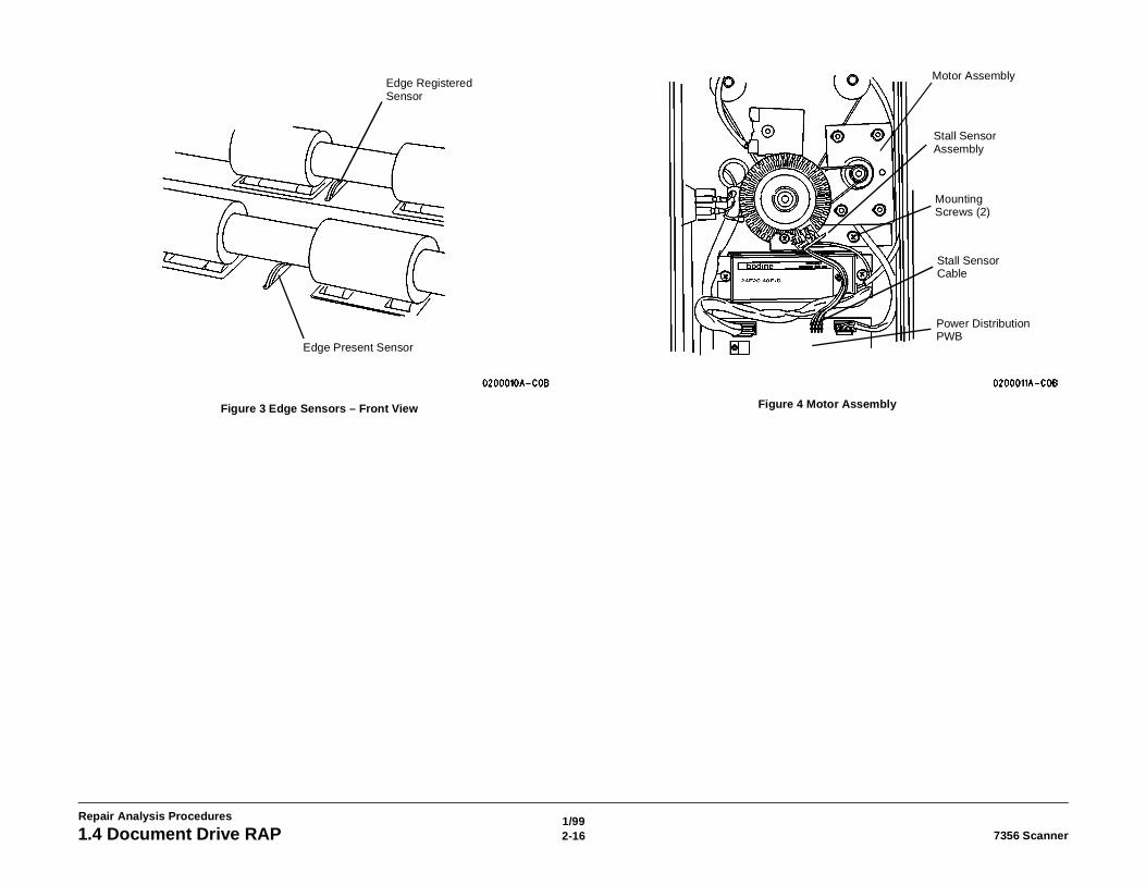
Figure 3 Edge Sensors – Front View Figure 4 Motor Assembly
Edge Registered Sensor
Edge Present Sensor
Motor Assembly
Stall Sensor Assembly
Mounting Screws (2)
Stall Sensor Cable
Power Distribution PWB
1/992-177356 Scanner 1.5 Sensors and Forward/Reverse Switch RAP
Repair Analysis Procedures
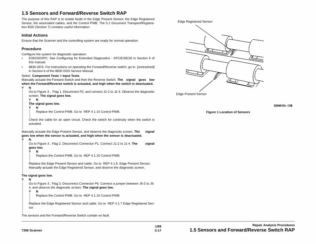
1.5 Sensors and Forward/Reverse Switch RAPThe purpose of this RAP is to isolate faults in the Edge Present Sensor, the Edge RegisteredSensor, the associated cables, and the Control PWB. The 5.1 Document Transport/Registra-tion BSD (Section 7) contains useful information.
Initial ActionsEnsure that the Scanner and the controlling system are ready for normal operation.
ProcedureConfigure the system for diagnostic operation:• ES8150/XPC: See Configuring for Extended Diagnostics - XPC/ES8150 in Section 6 of
this manual.
• 8830 DDS: For instructions on operating the Forward/Reverse switch, go to [unresolved]in Section 6 of the 8830 DDS Service Manual.
Select Component Tests > Input Tests.Manually actuate the Forward Switch and then the Reverse Switch. The signal goes lowwhen the Forward/Reverse switch is actuated, and high when the switch is deactuated.Y N
Go to Figure 3 , Flag 1. Disconnect P2, and connect J2-2 to J2-4. Observe the diagnosticscreen. The signal goes low.Y NThe signal goes low.Y N
Replace the Control PWB. Go to REP 4.1.10 Control PWB.
Check the cable for an open circuit. Check the switch for continuity when the switch isactuated.
Manually actuate the Edge Present Sensor, and observe the diagnostic screen. The signalgoes low when the sensor is actuated, and high when the sensor is deactuated.Y N
Go to Figure 3 , Flag 2. Disconnect Connector P1. Connect J1-2 to J1-4. The signalgoes low.Y N
Replace the Control PWB. Go to REP 4.1.10 Control PWB.
Replace the Edge Present Sensor and cable. Go to REP 4.1.6. Edge Present Sensor.Manually actuate the Edge Registered Sensor, and observe the diagnostic screen.
The signal goes low.Y N
Go to Figure 3 , Flag 3. Disconnect Connector P6. Connect a jumper between J6-2 to J6-4, and observe the diagnostic screen. The signal goes low.Y N
Replace the Control PWB. Go to REP 4.1.10 Control PWB.
Replace the Edge Registered Sensor and cable. Go to REP 4.1.7 Edge Registered Sen-sor.
The sensors and the Forward/Reverse Switch contain no fault.
Figure 1 Location of Sensors
Edge Registered Sensor
Edge Present Sensor
1/992-18 7356 Scanner1.5 Sensors and Forward/Reverse Switch RAP
Repair Analysis Procedures
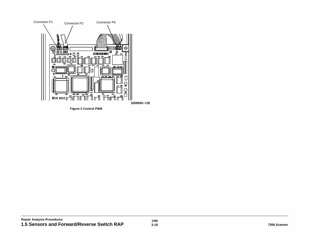
Figure 2 Control PWB
Connector P1 Connector P2 Connector P6
1/992-197356 Scanner 1.5 Sensors and Forward/Reverse Switch RAP
Repair Analysis Procedures
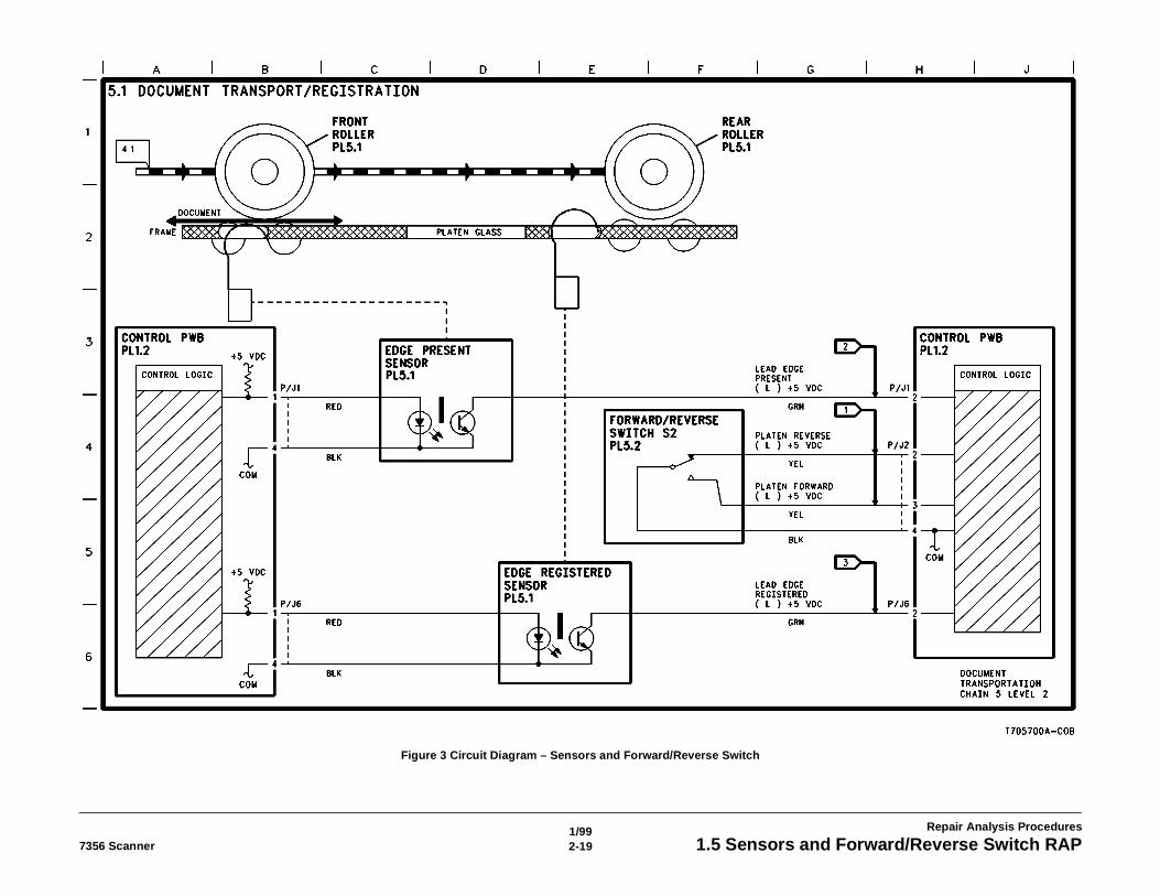
Figure 3 Circuit Diagram – Sensors and Forward/Reverse Switch

1/992-20 7356 Scanner1.5 Sensors and Forward/Reverse Switch RAP
Repair Analysis Procedures
1/993-17356 Scanner Section Contents
Image Quality RAPs
3. Image Quality RAPsPrint Defect Isolation RAP............................................................................................... 3-3Scanner Will Not Normalize RAP.................................................................................... 3-7

1/993-2 7356 Scanner
Image Quality RAPs
1/993-37356 Scanner Print Defect Isolation RAP
Image Quality RAPs
Print Defect Isolation RAPThe purpose of this RAP is to classify image quality problems and direct the customer servicerepresentative to the appropriate repair analysis procedure. The procedure may be in this sec-tion or in Section 2.
Before trying the procedures and corrective actions in this service manual, the customer ser-vice representative should first determine that the image quality fault is not caused by a mal-function in the device that controls the Scanner, or in the Image Output Terminal (IOT) device.This controlling system may be a Xerox ES8150 SIM, a Xerox Productivity Centre (XPC), an8830 Controller, a standalone controlling computer, or other controlling device.
The diagnostic software (SCSI7356) contains a viewer so that you can directly view an imagemade by the scanner on the screen of the computer that runs the diagnostic program. In thecase of the ES8150 or the XPC, you must first connect the Scanner to the SCSI port of the SIMcomputer before running the diagnostic program. Others will require the use of a laptop com-puter with the SCSI7356 Diagnostic software loaded to view the image. Detailed instructionsare contained in Section 6.
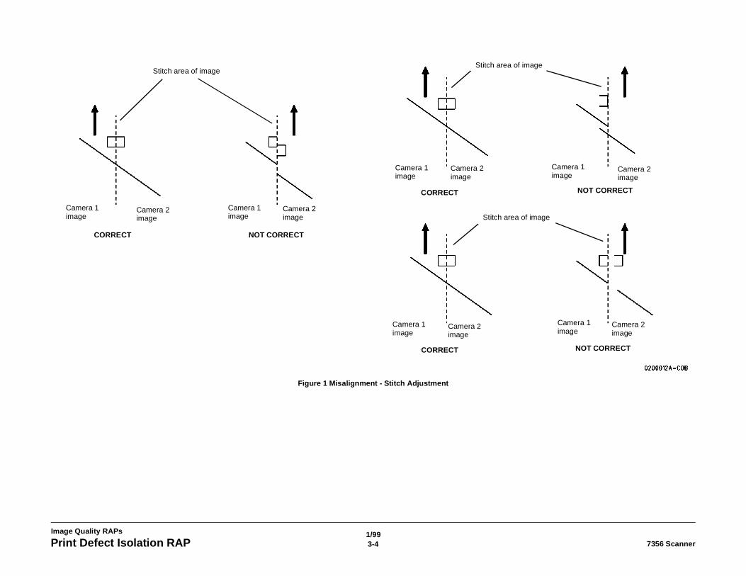
(Figure 1 ): Illustration of stitch misalignment and adjustment.
Initial ActionsAsk the customer to tell you the action that produced the fault.
Switch off the Scanner and the controlling system. Switch on the Scanner; then switch on thecontrolling system. Repeat the action that produced the fault.
ProcedureMake a copy of a test pattern that is stored internally on the IOT. The image is correct.Y N
Repair the problem in the IOT.
Make a copy of a test pattern or image stored internally in the controlling device. If there is nocontrolling device, continue down the Y path; the fault is in the scanner. The image is cor-rect.Y N
Repair the problem in the controlling device.
Make a copy of the 82E5980 Test Pattern. Evaluate the copy using Figure 1 and Table 1 in thisprocedure.
1/993-4 7356 ScannerPrint Defect Isolation RAP
Image Quality RAPs
Figure 1 Misalignment - Stitch Adjustment
Stitch area of image
Camera 1 image
Camera 1 image
Camera 1 image
Camera 1 image
Camera 1 image
Camera 1 image
Camera 2 image
Camera 2 image
Camera 2 image
Camera 2 image
Camera 2 image
Camera 2 image
Stitch area of image
Stitch area of image
CORRECT
CORRECT
CORRECT
NOT CORRECT
NOT CORRECT
NOT CORRECT
1/993-57356 Scanner Print Defect Isolation RAP
Image Quality RAPs
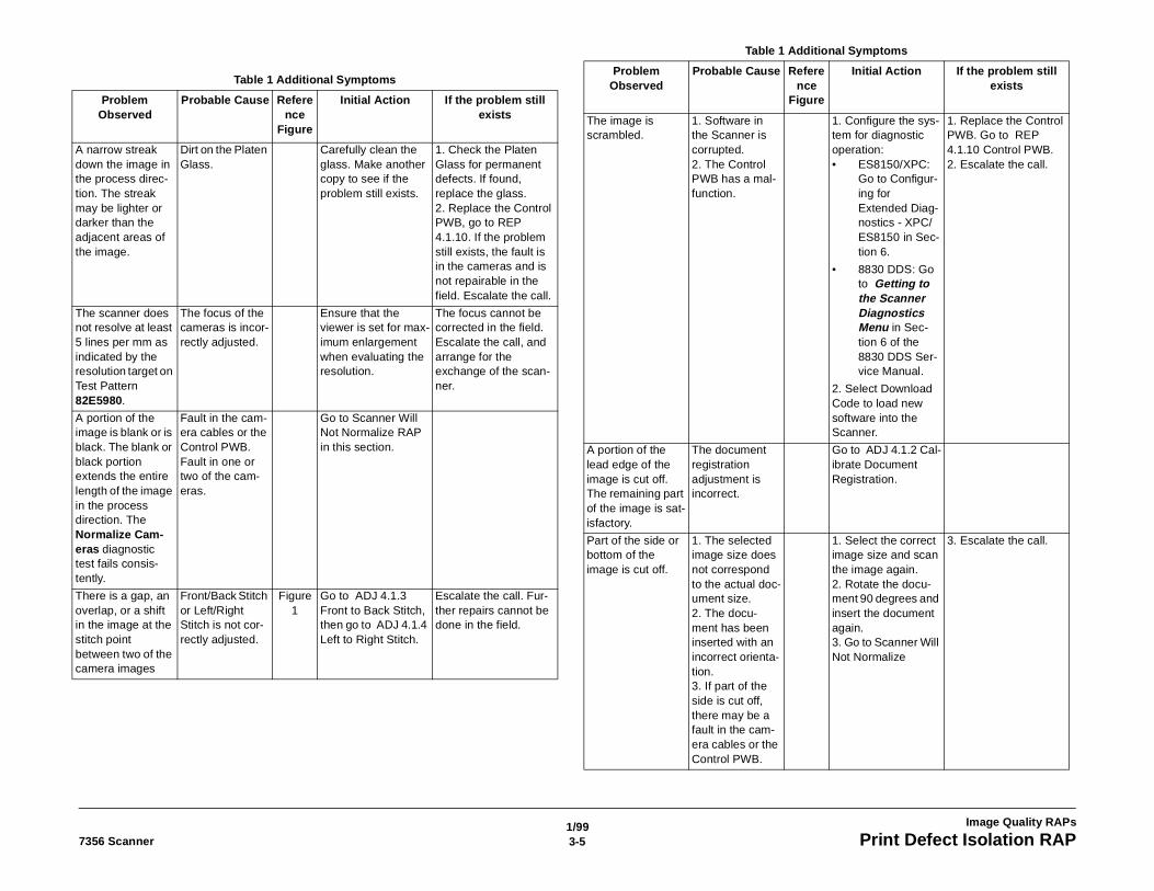
Table 1 Additional Symptoms
Problem Observed
Probable Cause Reference
Figure
Initial Action If the problem still exists
A narrow streak down the image in the process direc-tion. The streak may be lighter or darker than the adjacent areas of the image.
Dirt on the Platen Glass.
Carefully clean the glass. Make another copy to see if the problem still exists.
1. Check the Platen Glass for permanent defects. If found, replace the glass.2. Replace the Control PWB, go to REP 4.1.10. If the problem still exists, the fault is in the cameras and is not repairable in the field. Escalate the call.
The scanner does not resolve at least 5 lines per mm as indicated by the resolution target on Test Pattern 82E5980.
The focus of the cameras is incor-rectly adjusted.
Ensure that the viewer is set for max-imum enlargement when evaluating the resolution.
The focus cannot be corrected in the field. Escalate the call, and arrange for the exchange of the scan-ner.
A portion of the image is blank or is black. The blank or black portion extends the entire length of the image in the process direction. The Normalize Cam-eras diagnostic test fails consis-tently.
Fault in the cam-era cables or the Control PWB. Fault in one or two of the cam-eras.
Go to Scanner Will Not Normalize RAP in this section.
There is a gap, an overlap, or a shift in the image at the stitch point between two of the camera images
Front/Back Stitch or Left/Right Stitch is not cor-rectly adjusted.
Figure 1
Go to ADJ 4.1.3 Front to Back Stitch, then go to ADJ 4.1.4 Left to Right Stitch.
Escalate the call. Fur-ther repairs cannot be done in the field.
The image is scrambled.
1. Software in the Scanner is corrupted.2. The Control PWB has a mal-function.
1. Configure the sys-tem for diagnostic operation:• ES8150/XPC:
Go to Configur-ing for Extended Diag-nostics - XPC/ES8150 in Sec-tion 6.
• 8830 DDS: Go to Getting to the Scanner Diagnostics Menu in Sec-tion 6 of the 8830 DDS Ser-vice Manual.
2. Select Download Code to load new software into the Scanner.
1. Replace the Control PWB. Go to REP 4.1.10 Control PWB.2. Escalate the call.
A portion of the lead edge of the image is cut off. The remaining part of the image is sat-isfactory.
The document registration adjustment is incorrect.
Go to ADJ 4.1.2 Cal-ibrate Document Registration.
Part of the side or bottom of the image is cut off.
1. The selected image size does not correspond to the actual doc-ument size.2. The docu-ment has been inserted with an incorrect orienta-tion.3. If part of the side is cut off, there may be a fault in the cam-era cables or the Control PWB.
1. Select the correct image size and scan the image again.2. Rotate the docu-ment 90 degrees and insert the document again.3. Go to Scanner Will Not Normalize
3. Escalate the call.
Table 1 Additional Symptoms
Problem Observed
Probable Cause Reference
Figure
Initial Action If the problem still exists
1/993-6 7356 ScannerPrint Defect Isolation RAP
Image Quality RAPs
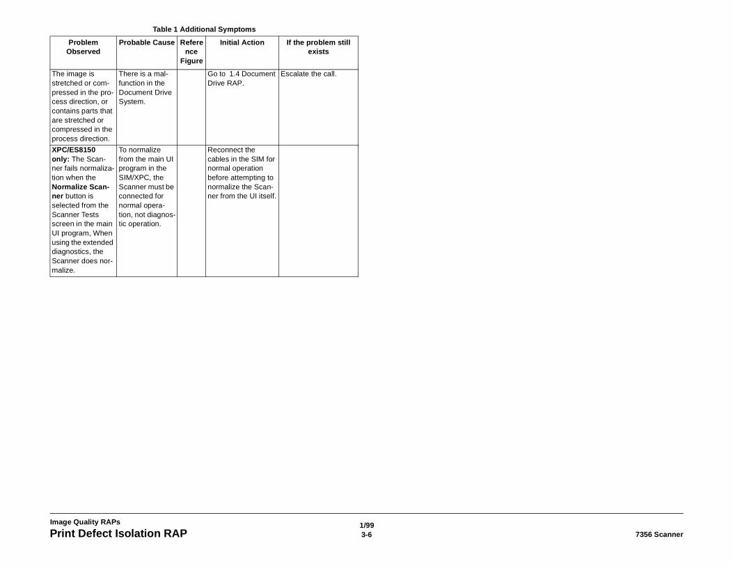
The image is stretched or com-pressed in the pro-cess direction, or contains parts that are stretched or compressed in the process direction.
There is a mal-function in the Document Drive System.
Go to 1.4 Document Drive RAP.
Escalate the call.
XPC/ES8150 only: The Scan-ner fails normaliza-tion when the Normalize Scan-ner button is selected from the Scanner Tests screen in the main UI program, When using the extended diagnostics, the Scanner does nor-malize.
To normalize from the main UI program in the SIM/XPC, the Scanner must be connected for normal opera-tion, not diagnos-tic operation.
Reconnect the cables in the SIM for normal operation before attempting to normalize the Scan-ner from the UI itself.
Table 1 Additional Symptoms
Problem Observed
Probable Cause Reference
Figure
Initial Action If the problem still exists
1/993-77356 Scanner Scanner Will Not Normalize
Image Quality RAPs
Scanner Will Not Normalize RAPThe purpose of this RAP is to isolate faults that can cause the Scanner to be unable to normal-ize the cameras.
Initial Actions
NOTE: The Scanner is extremely sensitive to dirt on the Platen Glass or the Document Hold−down Guide. Even a fingerprint on the glass can prevent a successful normalization.
Carefully clean the Platen Glass and the Document Hold−down Guide, using Xerox Lens andMirror Cleaner 43P81. Both sides of the glass may require the cleaning.
Configure the system for diagnostic operation:
• ES8150/XPC: Go to Configuring for Extended Diagnostics - XPC/ES8150 in Section 6.
• 8830 DDS: Go to ADJ 4.1.5 Camera Normalization. If the test fails, perform the proce-dure below.
Start the diagnostic software, and perform the ADJ 4.1.5 Camera Normalization again. If thetest fails, perform the procedure below.
ProcedureSwitch off the Scanner and the controlling system. Switch on the Scanner; then switch on thecontrolling system. Restart the diagnostic software, and repeat the ADJ 4.1.5 Camera Normal-ization test. The test fails.Y N
Configure the system for normal operation, and resume normal operation.
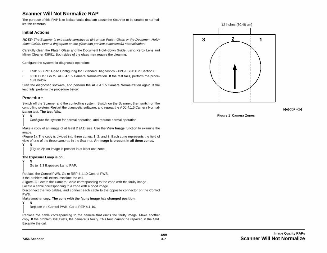
Make a copy of an image of at least D (A1) size. Use the View Image function to examine theimage.(Figure 1): The copy is divided into three zones, 1, 2, and 3. Each zone represents the field ofview of one of the three cameras in the Scanner. An image is present in all three zones.Y N
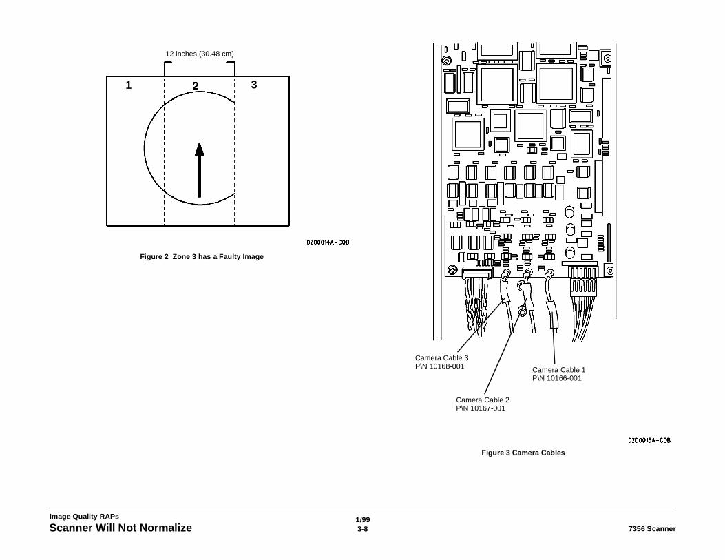
(Figure 2): An image is present in at least one zone.
The Exposure Lamp is on.Y N
Go to 1.3 Exposure Lamp RAP.
Replace the Control PWB. Go to REP 4.1.10 Control PWB.If the problem still exists, escalate the call.(Figure 3): Locate the Camera Cable corresponding to the zone with the faulty image.Locate a cable corresponding to a zone with a good image.Disconnect the two cables, and connect each cable to the opposite connector on the ControlPWB.Make another copy. The zone with the faulty image has changed position.Y N
Replace the Control PWB. Go to REP 4.1.10.
Replace the cable corresponding to the camera that emits the faulty image. Make anothercopy. If the problem still exists, the camera is faulty. This fault cannot be repaired in the field.Escalate the call.
Figure 1 Camera Zones
12 inches (30.48 cm)
1/993-8 7356 ScannerScanner Will Not Normalize
Image Quality RAPs
Figure 2 Zone 3 has a Faulty Image
Figure 3 Camera Cables
12 inches (30.48 cm)
1 3
Camera Cable 3 P\N 10168-001
Camera Cable 2 P\N 10167-001
Camera Cable 1 P\N 10166-001
1/994-17356 Scanner Section Contents
Repairs and Adjustments
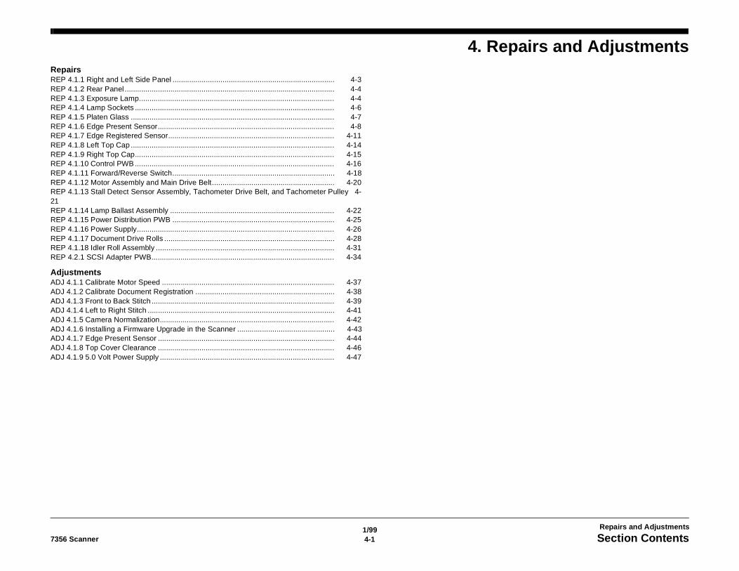
4. Repairs and AdjustmentsRepairsREP 4.1.1 Right and Left Side Panel .............................................................................. 4-3REP 4.1.2 Rear Panel ..................................................................................................... 4-4REP 4.1.3 Exposure Lamp.............................................................................................. 4-4REP 4.1.4 Lamp Sockets ................................................................................................ 4-6REP 4.1.5 Platen Glass .................................................................................................. 4-7REP 4.1.6 Edge Present Sensor..................................................................................... 4-8REP 4.1.7 Edge Registered Sensor................................................................................ 4-11REP 4.1.8 Left Top Cap .................................................................................................. 4-14REP 4.1.9 Right Top Cap................................................................................................ 4-15REP 4.1.10 Control PWB ................................................................................................ 4-16REP 4.1.11 Forward/Reverse Switch.............................................................................. 4-18REP 4.1.12 Motor Assembly and Main Drive Belt........................................................... 4-20REP 4.1.13 Stall Detect Sensor Assembly, Tachometer Drive Belt, and Tachometer Pulley 4-21REP 4.1.14 Lamp Ballast Assembly ............................................................................... 4-22REP 4.1.15 Power Distribution PWB .............................................................................. 4-25REP 4.1.16 Power Supply............................................................................................... 4-26REP 4.1.17 Document Drive Rolls .................................................................................. 4-28REP 4.1.18 Idler Roll Assembly ...................................................................................... 4-31REP 4.2.1 SCSI Adapter PWB........................................................................................ 4-34
AdjustmentsADJ 4.1.1 Calibrate Motor Speed ................................................................................... 4-37ADJ 4.1.2 Calibrate Document Registration ................................................................... 4-38ADJ 4.1.3 Front to Back Stitch ........................................................................................ 4-39ADJ 4.1.4 Left to Right Stitch .......................................................................................... 4-41ADJ 4.1.5 Camera Normalization.................................................................................... 4-42ADJ 4.1.6 Installing a Firmware Upgrade in the Scanner ............................................... 4-43ADJ 4.1.7 Edge Present Sensor ..................................................................................... 4-44ADJ 4.1.8 Top Cover Clearance ..................................................................................... 4-46ADJ 4.1.9 5.0 Volt Power Supply .................................................................................... 4-47

1/994-2 7356 Scanner
Repairs and Adjustments
5/994-37356 Scanner REP 4.1.1
Repairs and Adjustments
REP 4.1.1 Right and Left Side PanelParts List on PL 14.2Removal
WARNINGSwitch off the Scanner and disconnect the Power Cord.
NO
TE:
Th
e R
igh
t S
ide
P
a
n
e
l pr
oc
ed
ur
e
is
s
h
o
w
n.
Th
e L
e
ft
S
id
e
P
a
n
e
l is
r
e
m
o
ve
d
in t
h
e
s
a
m
ewa
y
.
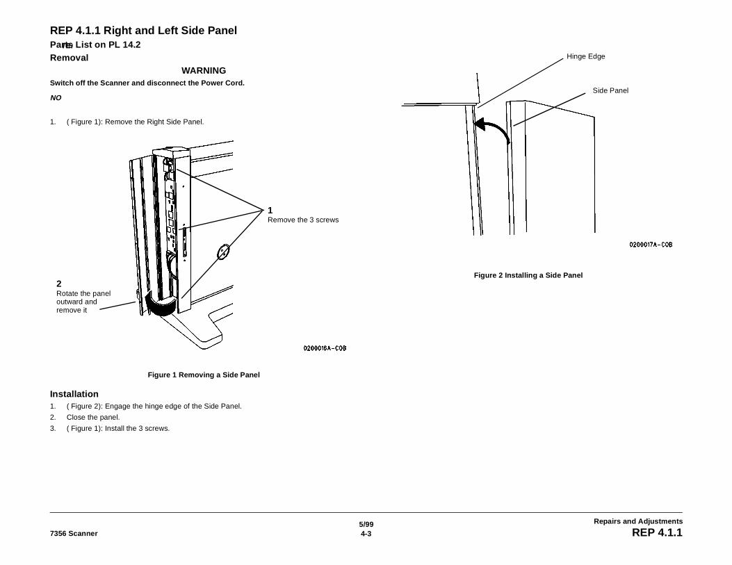
1. ( Figure 1): Remove the Right Side Panel.
Figure 1 Removing a Side Panel
Installation1. ( Figure 2): Engage the hinge edge of the Side Panel.
2. Close the panel.
3. ( Figure 1): Install the 3 screws.
Figure 2 Installing a Side Panel
1Remove the 3 screws
2Rotate the panel outward and remove it
Hinge Edge
Side Panel
1/994-4 7356 ScannerREP 4.1.2, REP 4.1.3
Repairs and Adjustments
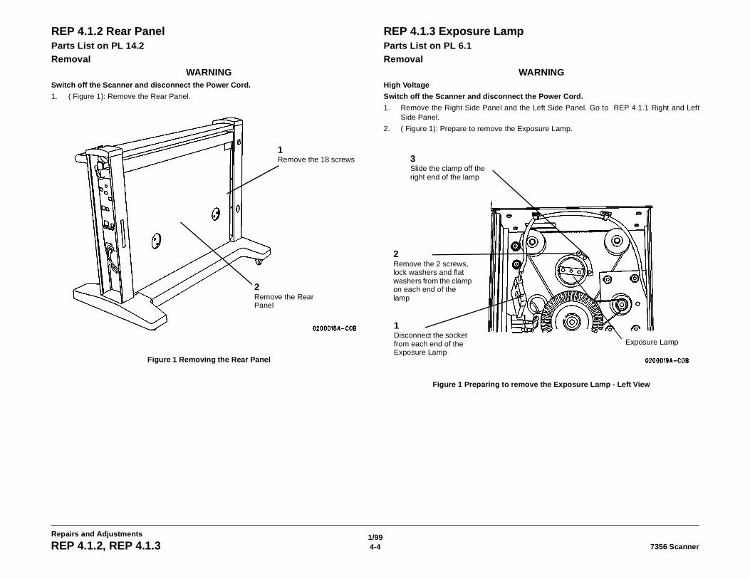
REP 4.1.2 Rear PanelParts List on PL 14.2Removal
WARNINGSwitch off the Scanner and disconnect the Power Cord.
1. ( Figure 1): Remove the Rear Panel.
Figure 1 Removing the Rear Panel
REP 4.1.3 Exposure LampParts List on PL 6.1Removal
WARNINGHigh Voltage
Switch off the Scanner and disconnect the Power Cord.
1. Remove the Right Side Panel and the Left Side Panel. Go to REP 4.1.1 Right and LeftSide Panel.
2. ( Figure 1): Prepare to remove the Exposure Lamp.
Figure 1 Preparing to remove the Exposure Lamp - Left View
1Remove the 18 screws
2Remove the Rear Panel
1Disconnect the socket from each end of the Exposure Lamp
2Remove the 2 screws, lock washers and flat washers from the clamp on each end of the lamp
3Slide the clamp off the right end of the lamp
Exposure Lamp
1/994-57356 Scanner REP 4.1.3
Repairs and Adjustments
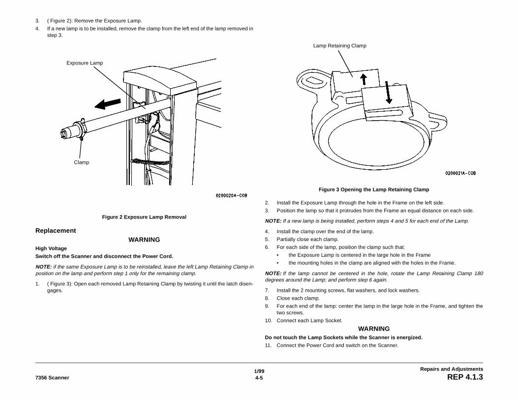
3. ( Figure 2): Remove the Exposure Lamp.
4. If a new lamp is to be installed, remove the clamp from the left end of the lamp removed instep 3.
Figure 2 Exposure Lamp Removal
ReplacementWARNING
High Voltage
Switch off the Scanner and disconnect the Power Cord.
NOTE: if the same Exposure Lamp is to be reinstalled, leave the left Lamp Retaining Clamp inposition on the lamp and perform step 1 only for the remaining clamp.
1. ( Figure 3): Open each removed Lamp Retaining Clamp by twisting it until the latch disen-gages.
Figure 3 Opening the Lamp Retaining Clamp
2. Install the Exposure Lamp through the hole in the Frame on the left side.
3. Position the lamp so that it protrudes from the Frame an equal distance on each side.
NOTE: If a new lamp is being installed, perform steps 4 and 5 for each end of the Lamp.
4. Install the clamp over the end of the lamp.
5. Partially close each clamp.
6. For each side of the lamp, position the clamp such that:
• the Exposure Lamp is centered in the large hole in the Frame
• the mounting holes in the clamp are aligned with the holes in the Frame.
NOTE: If the lamp cannot be centered in the hole, rotate the Lamp Retaining Clamp 180degrees around the Lamp; and perform step 6 again.
7. Install the 2 mounting screws, flat washers, and lock washers.
8. Close each clamp.
9. For each end of the lamp: center the lamp in the large hole in the Frame, and tighten thetwo screws.
10. Connect each Lamp Socket.
WARNINGDo not touch the Lamp Sockets while the Scanner is energized.
11. Connect the Power Cord and switch on the Scanner.
Clamp
Exposure Lamp
Lamp Retaining Clamp
1/994-6 7356 ScannerREP 4.1.3, REP 4.1.4
Repairs and Adjustments
12. Ensure that the Exposure Lamp illuminates. If the lamp does not illuminate, ensure thatthe sockets are correctly connected to the lamp and that the connector wires are not bro-ken. If the lamp still does not illuminate, go to 1.3 Exposure Lamp RAP and isolate thefault.
13. Install the Left Side Panel and the Right Side Panel. Go to REP 4.1.1 Right and Left SidePanel.
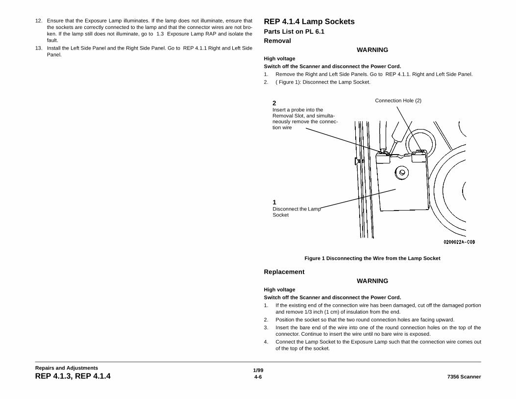
REP 4.1.4 Lamp SocketsParts List on PL 6.1Removal
WARNINGHigh voltage
Switch off the Scanner and disconnect the Power Cord.
1. Remove the Right and Left Side Panels. Go to REP 4.1.1. Right and Left Side Panel.
2. ( Figure 1): Disconnect the Lamp Socket.
Figure 1 Disconnecting the Wire from the Lamp Socket
ReplacementWARNING
High voltage
Switch off the Scanner and disconnect the Power Cord.
1. If the existing end of the connection wire has been damaged, cut off the damaged portionand remove 1/3 inch (1 cm) of insulation from the end.
2. Position the socket so that the two round connection holes are facing upward.
3. Insert the bare end of the wire into one of the round connection holes on the top of theconnector. Continue to insert the wire until no bare wire is exposed.
4. Connect the Lamp Socket to the Exposure Lamp such that the connection wire comes outof the top of the socket.
1Disconnect the Lamp Socket
Connection Hole (2)2Insert a probe into the Removal Slot, and simulta-neously remove the connec-tion wire
1/994-77356 Scanner REP 4.1.4, REP 4.1.5
Repairs and Adjustments
WARNINGHigh Voltage
Do not touch the Lamp Sockets while the Scanner is energized.
5. Connect the Power Cord and switch on the Scanner.
6. Ensure that the Exposure Lamp illuminates.
NOTE: If the lamp does not illuminate, ensure that the sockets are correctly connected to thelamp and that the connector wires are not broken. If the lamp still does not illuminate, go to 1.3Exposure Lamp RAP.
7. Install the Left Side Panel and the Right Side Panel. Go to REP 4.1.1. Right and Left SidePanel
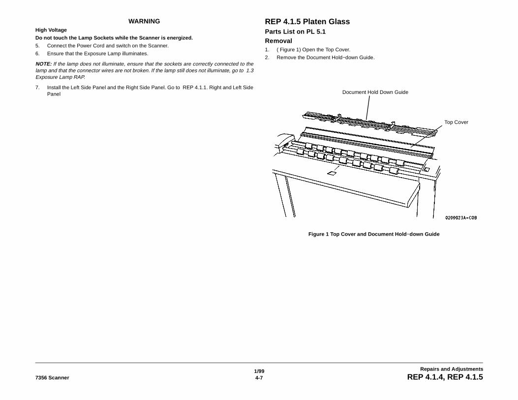
REP 4.1.5 Platen GlassParts List on PL 5.1Removal1. ( Figure 1) Open the Top Cover.
2. Remove the Document Hold−down Guide.
Figure 1 Top Cover and Document Hold−down Guide
Document Hold Down Guide
Top Cover
1/994-8 7356 ScannerREP 4.1.5
Repairs and Adjustments
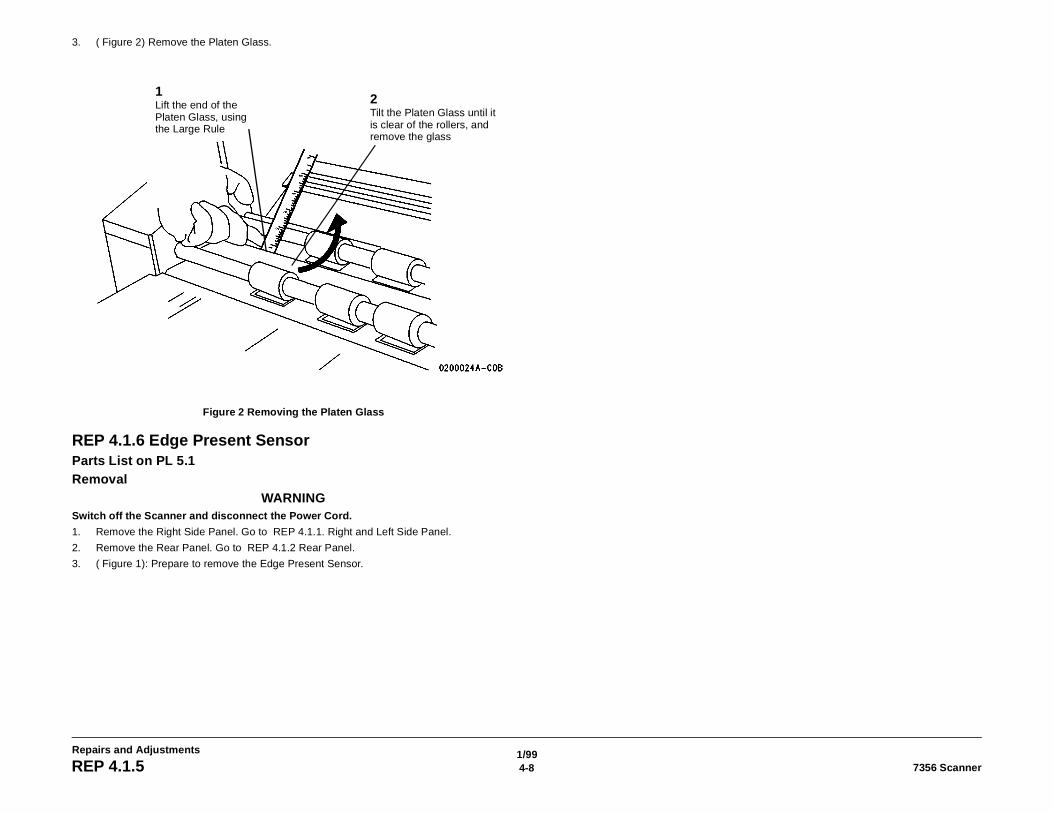
3. ( Figure 2) Remove the Platen Glass.
Figure 2 Removing the Platen Glass
REP 4.1.6 Edge Present SensorParts List on PL 5.1Removal
WARNINGSwitch off the Scanner and disconnect the Power Cord.
1. Remove the Right Side Panel. Go to REP 4.1.1. Right and Left Side Panel.
2. Remove the Rear Panel. Go to REP 4.1.2 Rear Panel.
3. ( Figure 1): Prepare to remove the Edge Present Sensor.
1Lift the end of the Platen Glass, using the Large Rule
2Tilt the Platen Glass until it is clear of the rollers, and remove the glass
1/994-97356 Scanner REP 4.1.6
Repairs and Adjustments
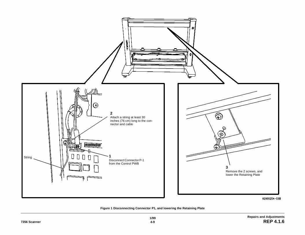
Figure 1 Disconnecting Connector P1, and lowering the Retaining Plate
1Disconnect Connector P-1 from the Control PWB
2Attach a string at least 30 inches (76 cm) long to the con-nector and cable
3Remove the 2 screws, and lower the Retaining Plate
String
1/994-10 7356 ScannerREP 4.1.6
Repairs and Adjustments
NOTE: The string attached in step 3b is used later to pull the cable back through the channelwhen the sensor is reinstalled.
4. ( Figure 1): Detach the Retaining Plate.
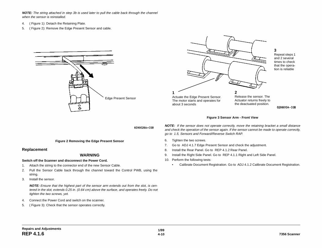
5. ( Figure 2): Remove the Edge Present Sensor and cable.
Figure 2 Removing the Edge Present Sensor
ReplacementWARNING
Switch off the Scanner and disconnect the Power Cord.
1. Attach the string to the connector end of the new Sensor Cable.
2. Pull the Sensor Cable back through the channel toward the Control PWB, using thestring.
3. Install the sensor.
NOTE: Ensure that the highest part of the sensor arm extends out from the slot, is cen-tered in the slot, extends 0.25 in. (0.64 cm) above the surface, and operates freely. Do nottighten the two screws, yet.
4. Connect the Power Cord and switch on the scanner.
5. ( Figure 3): Check that the sensor operates correctly.
Figure 3 Sensor Arm - Front View
NOTE: If the sensor does not operate correctly, move the retaining bracket a small distanceand check the operation of the sensor again. If the sensor cannot be made to operate correctly,go to 1.5, Sensors and Forward/Reverse Switch RAP.
6. Tighten the two screws.
7. Go to ADJ 4.1.7 Edge Present Sensor and check the adjustment.
8. Install the Rear Panel. Go to REP 4.1.2 Rear Panel.
9. Install the Right Side Panel. Go to REP 4.1.1 Right and Left Side Panel.
10. Perform the following tests:
• Calibrate Document Registration. Go to ADJ 4.1.2 Calibrate Document Registration.
Edge Present Sensor
1Actuate the Edge Present Sensor. The motor starts and operates for about 3 seconds
2Release the sensor. The Actuator returns freely to the deactuated position.
3Repeat steps 1 and 2 several times to check that the opera-tion is reliable
1/994-117356 Scanner REP 4.1.7
Repairs and Adjustments
REP 4.1.7 Edge Registered SensorParts List on PL 5.1Removal
WARNINGSwitch off the Scanner and disconnect the Power Cord.
1. Remove the Exposure Lamp. Go to REP 4.1.3 Exposure Lamp.
2. Remove the Platen Glass. Go to REP 4.1.5 Platen Glass.
3. ( Figure 1): Prepare to remove the Edge Registered Sensor.
4. ( Figure 1): Remove the Edge Registered Sensor.
1/994-12 7356 ScannerREP 4.1.7
Repairs and Adjustments
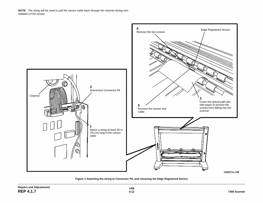
NOTE: The string will be used to pull the sensor cable back through the channel during rein-stallation of the sensor.
Figure 1 Attaching the string to Connector P6, and removing the Edge Registered Sensor
1Attach a string at least 30 in. (76 cm) long to the sensor cable
2Disconnect Connector P6
3Cover the optical path slot with paper to prevent the screws from falling into the scanner
4Remove the two screws
5Remove the sensor and cable
Channel
Edge Registered Sensor
1/994-137356 Scanner REP 4.1.7
Repairs and Adjustments
ReplacementWARNING
Switch off the Scanner and disconnect the Power Cord.
1. Pull the Sensor Cable back through the channel, using the string installed during removal.
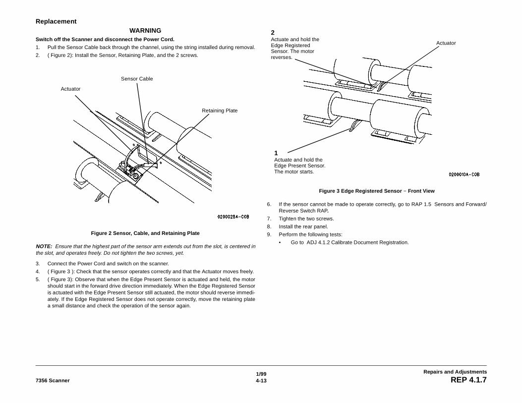
2. ( Figure 2): Install the Sensor, Retaining Plate, and the 2 screws.
Figure 2 Sensor, Cable, and Retaining Plate
NOTE: Ensure that the highest part of the sensor arm extends out from the slot, is centered inthe slot, and operates freely. Do not tighten the two screws, yet.
3. Connect the Power Cord and switch on the scanner.
4. ( Figure 3 ): Check that the sensor operates correctly and that the Actuator moves freely.
5. ( Figure 3): Observe that when the Edge Present Sensor is actuated and held, the motorshould start in the forward drive direction immediately. When the Edge Registered Sensoris actuated with the Edge Present Sensor still actuated, the motor should reverse immedi-ately. If the Edge Registered Sensor does not operate correctly, move the retaining platea small distance and check the operation of the sensor again.
Figure 3 Edge Registered Sensor − Front View
6. If the sensor cannot be made to operate correctly, go to RAP 1.5 Sensors and Forward/Reverse Switch RAP.
7. Tighten the two screws.
8. Install the rear panel.
9. Perform the following tests:
• Go to ADJ 4.1.2 Calibrate Document Registration.
Sensor Cable
Actuator
Retaining Plate
1Actuate and hold the Edge Present Sensor. The motor starts.
2Actuate and hold the Edge Registered Sensor. The motor reverses.
Actuator
1/994-14 7356 ScannerREP 4.1.8
Repairs and Adjustments
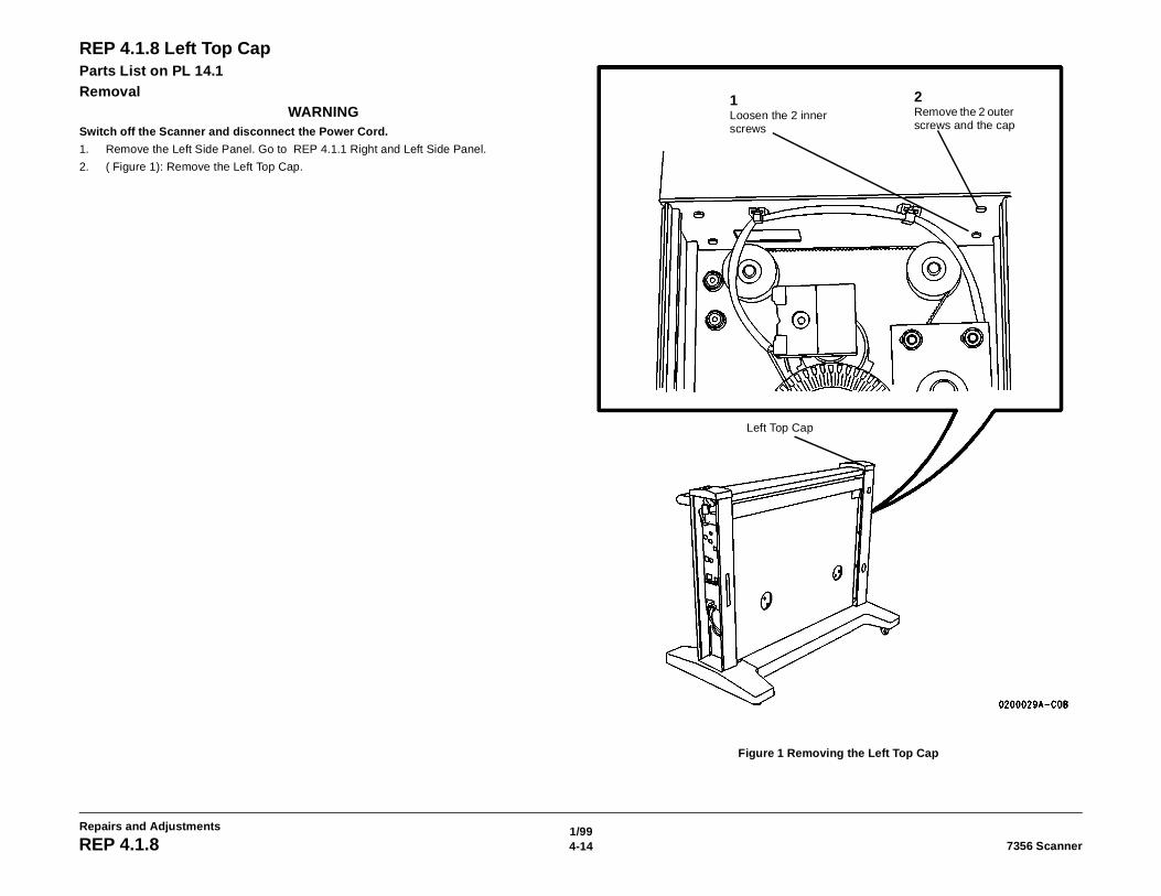
REP 4.1.8 Left Top CapParts List on PL 14.1Removal
WARNINGSwitch off the Scanner and disconnect the Power Cord.
1. Remove the Left Side Panel. Go to REP 4.1.1 Right and Left Side Panel.
2. ( Figure 1): Remove the Left Top Cap.
Figure 1 Removing the Left Top Cap
2Remove the 2 outer screws and the cap
1Loosen the 2 inner screws
Left Top Cap
1/994-157356 Scanner REP 4.1.9
Repairs and Adjustments
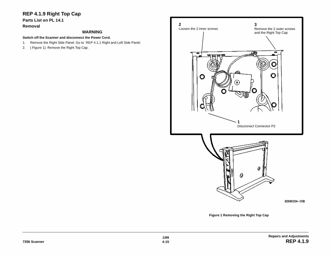
REP 4.1.9 Right Top CapParts List on PL 14.1Removal
WARNINGSwitch off the Scanner and disconnect the Power Cord.
1. Remove the Right Side Panel. Go to REP 4.1.1 Right and Left Side Panel.
2. ( Figure 1): Remove the Right Top Cap.
Figure 1 Removing the Right Top Cap
3Remove the 2 outer screws and the Right Top Cap
1Disconnect Connector P2
2Loosen the 2 inner screws
1/994-16 7356 ScannerREP 4.1.10
Repairs and Adjustments
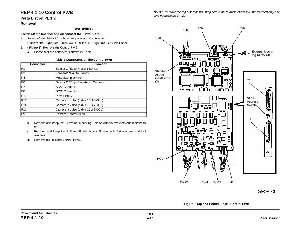
REP 4.1.10 Control PWBParts List on PL 1.2Removal
WARNINGSwitch off the Scanner and disconnect the Power Cord.
1. Switch off the SIM/XPC or host computer and the Scanner.
2. Remove the Right Side Panel. Go to REP 4.1.1 Right and Left Side Panel.
3. ( Figure 1): Remove the Control PWB.
a. Disconnect the connectors shown in Table 1.
b. Remove and keep the 3 External Mounting Screws with flat washers and lock wash-ers.
c. Remove and keep the 3 Standoff Attachment Screws with flat washers and lockwashers.
d. Remove the existing Control PWB.
NOTE: Remove the top external mounting screw last to avoid excessive stress when only onescrew retains the PWB.
Figure 1 Top and Bottom Edge - Control PWB
Table 1 Connectors on the Control PWB
Connector Function
P1 Sensor 1 (Edge Present Sensor)
P2 Forward/Reverse Switch
P4 Motor/Lamp control
P6 Sensor 2 (Edge Registered Sensor)
P7 SCSI Connector
P8 SCSI Connector
P13 Power Entry
P12 Camera 1 video (cable 10166−001)
P11 Camera 2 video (cable 10167−001)
P10 Camera 3 video (cable 10168−001)
P9 Camera Control Cable
P/J6P/J4P/J2
P/J1
Standoff Attach-ment Screw (3) J7
J8
SCSI Address Switch
P/J13P/J12P/J11P/J10
P/J9
External Mount-ing Screw (3)
1/994-177356 Scanner REP 4.1.10
Repairs and Adjustments
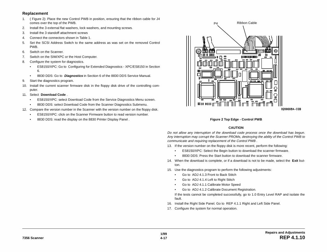
Replacement1. ( Figure 2): Place the new Control PWB in position, ensuring that the ribbon cable for J4
comes over the top of the PWB.
2. Install the 3 external flat washers, lock washers, and mounting screws.
3. Install the 3 standoff attachment screws
4. Connect the connectors shown in Table 1.
5. Set the SCSI Address Switch to the same address as was set on the removed ControlPWB.
6. Switch on the Scanner.
7. Switch on the SIM/XPC or the Host Computer.
8. Configure the system for diagnostics.
• ES8150/XPC: Go to Configuring for Extended Diagnostics - XPC/ES8150 in Section6.
• 8830 DDS: Go to Diagnostics in Section 6 of the 8830 DDS Service Manual.
9. Start the diagnostics program.
10. Install the current scanner firmware disk in the floppy disk drive of the controlling com-puter.
11. Select Download Code .
• ES8150/XPC: select Download Code from the Service Diagnostics Menu screen.
• 8830 DDS: select Download Code from the Scanner Diagnostics Submenu.
12. Compare the version number in the Scanner with the version number on the floppy disk.
• ES8150/XPC: click on the Scanner Firmware button to read version number.
• 8830 DDS: read the display on the 8830 Printer Display Panel . Figure 2 Top Edge - Control PWB
CAUTION
Do not allow any interruption of the download code process once the download has begun.Any interruption may corrupt the Scanner PROMs, destroying the ability of the Control PWB tocommunicate and requiring replacement of the Control PWB .
13. If the version number on the floppy disk is more recent, perform the following:
• ES8150/XPC: Select the Begin button to download the scanner firmware.
• 8830 DDS: Press the Start button to download the scanner firmware.
14. When the download is complete, or if a download is not to be made, select the Exit but-ton.
15. Use the diagnostics program to perform the following adjustments:
• Go to ADJ 4.1.3 Front to Back Stitch
• Go to ADJ 4.1.4 Left to Right Stitch
• Go to ADJ 4.1.1 Calibrate Motor Speed
• Go to ADJ 4.1.2 Calibrate Document Registration.
If the tests cannot be completed successfully, go to 1.0 Entry Level RAP and isolate thefault.
16. Install the Right Side Panel. Go to REP 4.1.1 Right and Left Side Panel.
17. Configure the system for normal operation.
Ribbon CableP4
1/994-18 7356 ScannerREP 4.1.11
Repairs and Adjustments
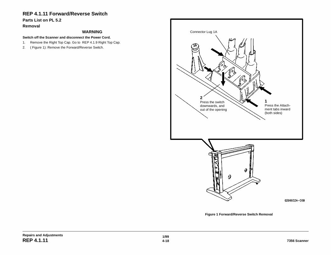
REP 4.1.11 Forward/Reverse SwitchParts List on PL 5.2Removal
WARNINGSwitch off the Scanner and disconnect the Power Cord.
1. Remove the Right Top Cap. Go to REP 4.1.9 Right Top Cap.
2. ( Figure 1): Remove the Forward/Reverse Switch.
Figure 1 Forward/Reverse Switch Removal
1Press the Attach-ment tabs inward (both sides)
2Press the switch downwards, and out of the opening
Connector Lug 1A
1/994-197356 Scanner REP 4.1.11
Repairs and Adjustments
Replacement1. Remove each connector from the existing switch and immediately connect it to the corre-
sponding connector on the new switch.
2. Position the new switch such that Connector Lug 1A is nearest the word REVERSE onthe top cap.
3. Insert the switch into the opening on the top cap until the switch is fully seated andengaged.
4. Feed the connector wires through the hole in the frame and install the Right Top Cap. Goto REP 4.1.9 Right Top Cap.
1/994-20 7356 ScannerREP 4.1.12
Repairs and Adjustments
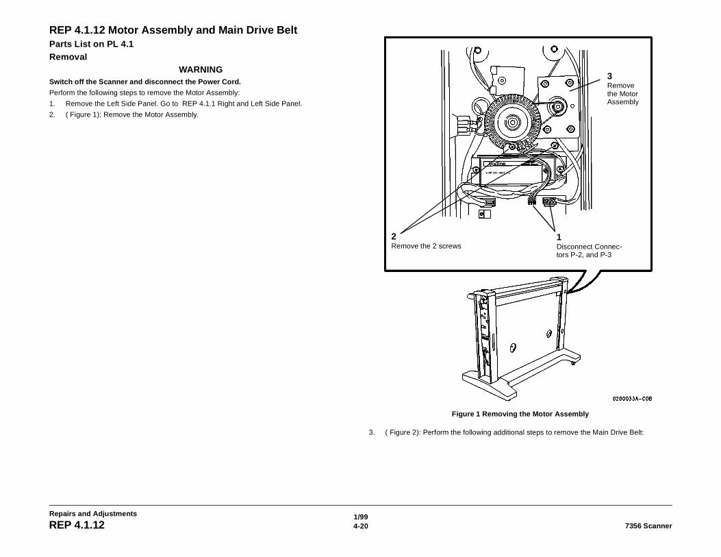
REP 4.1.12 Motor Assembly and Main Drive BeltParts List on PL 4.1Removal
WARNINGSwitch off the Scanner and disconnect the Power Cord.
Perform the following steps to remove the Motor Assembly:
1. Remove the Left Side Panel. Go to REP 4.1.1 Right and Left Side Panel.
2. ( Figure 1): Remove the Motor Assembly.
Figure 1 Removing the Motor Assembly
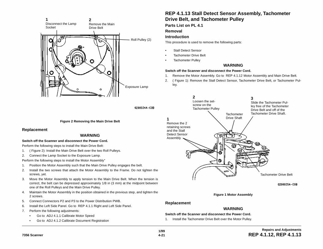
3. ( Figure 2): Perform the following additional steps to remove the Main Drive Belt:
1Disconnect Connec-tors P-2, and P-3
2Remove the 2 screws
3Remove the Motor Assembly
1/994-217356 Scanner REP 4.1.12, REP 4.1.13
Repairs and Adjustments
Figure 2 Removing the Main Drive Belt
ReplacementWARNING
Switch off the Scanner and disconnect the Power Cord.
Perform the following steps to install the Main Drive Belt:
1. ( Figure 2): Install the Main Drive Belt over the two Roll Pulleys.
2. Connect the Lamp Socket to the Exposure Lamp.
Perform the following steps to install the Motor Assembly”
1. Position the Motor Assembly such that the Main Drive Pulley engages the belt.
2. Install the two screws that attach the Motor Assembly to the Frame. Do not tighten thescrews, yet.
3. Move the Motor Assembly to apply tension to the Main Drive Belt. When the tension iscorrect, the belt can be depressed approximately 1/8 in (3 mm) at the midpoint betweenone of the Roll Pulleys and the Main Drive Pulley.
4. Maintain the Motor Assembly in the position obtained in the previous step, and tighten the2 screws.
5. Connect Connectors P2 and P3 to the Power Distribution PWB.
6. Install the Left Side Panel. Go to REP 4.1.1 Right and Left Side Panel.
7. Perform the following adjustments:
• Go to ADJ 4.1.1 Calibrate Motor Speed
• Go to ADJ 4.1.2 Calibrate Document Registration
REP 4.1.13 Stall Detect Sensor Assembly, Tachometer Drive Belt, and Tachometer PulleyParts List on PL 4.1 RemovalIntroductionThis procedure is used to remove the following parts:
• Stall Detect Sensor
• Tachometer Drive Belt
• Tachometer Pulley
WARNINGSwitch off the Scanner and disconnect the Power Cord.
1. Remove the Motor Assembly. Go to REP 4.1.12 Motor Assembly and Main Drive Belt.
2. ( Figure 1): Remove the Stall Detect Sensor, Tachometer Drive Belt, or Tachometer Pul-ley.
Figure 1 Motor Assembly
ReplacementWARNING
Switch off the Scanner and disconnect the Power Cord.
1. Install the Tachometer Drive Belt over the Motor Pulley.
1Disconnect the Lamp Socket
2Remove the Main Drive Belt
Roll Pulley (2)
Exposure Lamp
1Remove the 2 retaining screws and the Stall Detect Sensor Assembly
2Loosen the set-screw on the Tachometer Pulley
3Slide the Tachometer Pul-ley free of the Tachometer Drive Belt and off of the Tachometer Drive Shaft.Tachometer
Drive Shaft
Tachometer Drive Belt
1/994-22 7356 ScannerREP 4.1.13, REP 4.1.14
Repairs and Adjustments
2. Install the Tachometer Pulley onto the Tachometer Drive Shaft, and work the TachometerDrive Belt onto the pulley.
NOTE: Do not tighten the setscrew, yet. Press the pulley down until it makes contact with thetop surface of the shaft bearing.
3. Install the Stall Detect Sensor Assembly, and tighten the two screws.
4. Position the disk on the Tachometer Pulley such that the disk does not make contact withsurfaces of the sensor, and tighten the setscrew.
5. Manually operate the motor to ensure that the edge of the Tachometer Drive Belt does notbind against the edge of any pulley.
NOTE: If the belt binds, loosen the setscrew on the Tachometer pulley and adjust the pulleyuntil binding does not occur. Then tighten the setscrew.
6. Install the Motor Assembly. Go to REP 4.1.12 Motor Assembly and Main Drive Belt.
7. Install the Left Side Panel. Go to REP 4.1.1 Right and Left Side Panel.
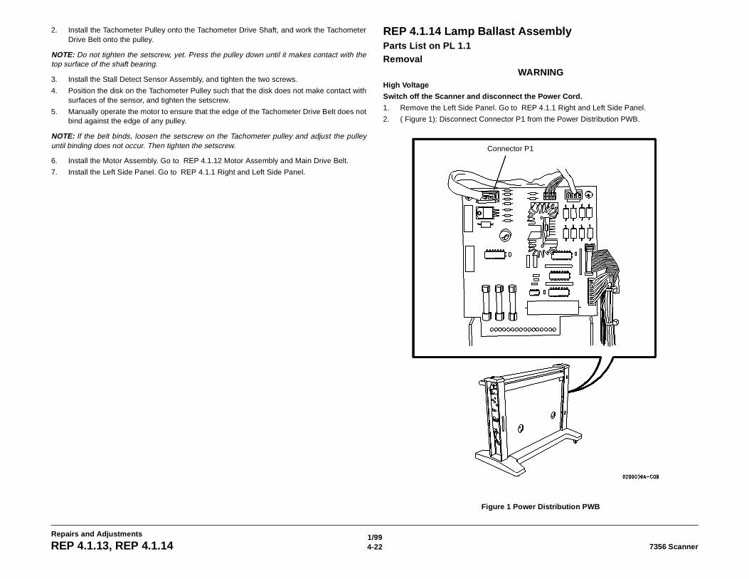
REP 4.1.14 Lamp Ballast AssemblyParts List on PL 1.1Removal
WARNINGHigh Voltage
Switch off the Scanner and disconnect the Power Cord.
1. Remove the Left Side Panel. Go to REP 4.1.1 Right and Left Side Panel.
2. ( Figure 1): Disconnect Connector P1 from the Power Distribution PWB.
Figure 1 Power Distribution PWB
Connector P1
1/994-237356 Scanner REP 4.1.14
Repairs and Adjustments
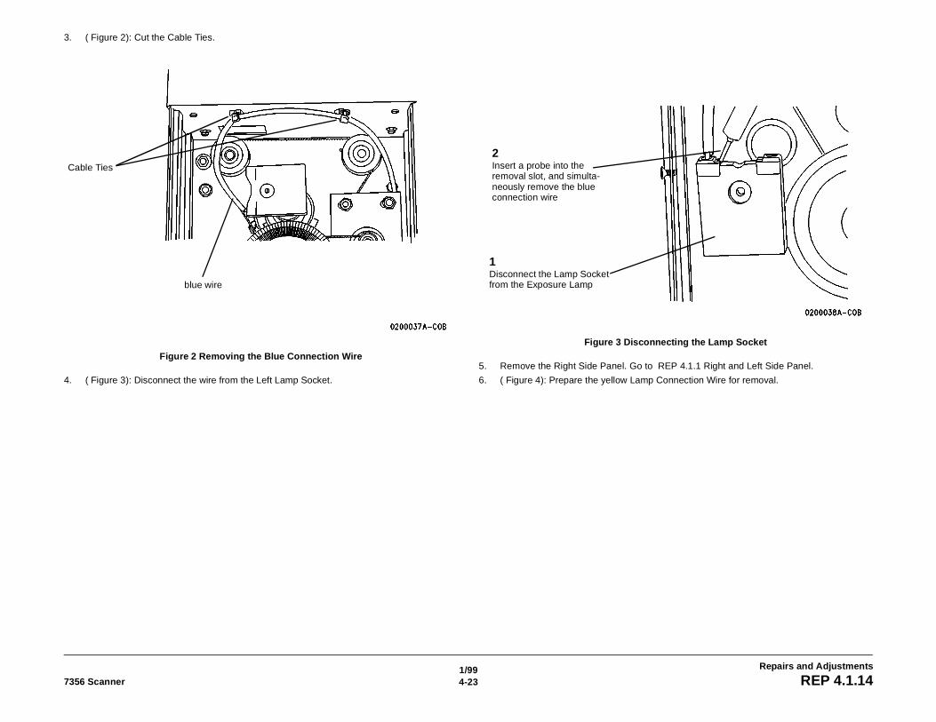
3. ( Figure 2): Cut the Cable Ties.
Figure 2 Removing the Blue Connection Wire
4. ( Figure 3): Disconnect the wire from the Left Lamp Socket.
Figure 3 Disconnecting the Lamp Socket
5. Remove the Right Side Panel. Go to REP 4.1.1 Right and Left Side Panel.
6. ( Figure 4): Prepare the yellow Lamp Connection Wire for removal.
Cable Ties
blue wire
1Disconnect the Lamp Socket from the Exposure Lamp
2Insert a probe into the removal slot, and simulta-neously remove the blue connection wire
1/994-24 7356 ScannerREP 4.1.14
Repairs and Adjustments
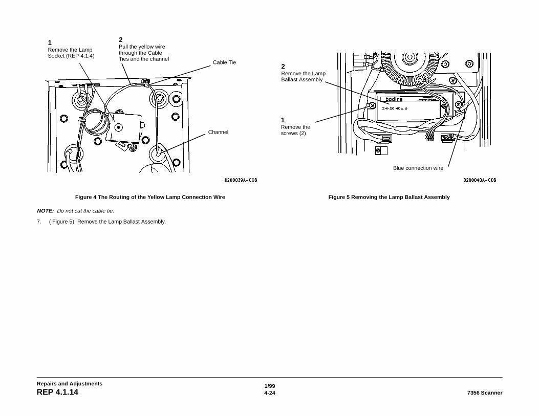
Figure 4 The Routing of the Yellow Lamp Connection Wire
NOTE: Do not cut the cable tie.
7. ( Figure 5): Remove the Lamp Ballast Assembly.
Figure 5 Removing the Lamp Ballast Assembly
2Pull the yellow wire through the Cable Ties and the channel
1Remove the Lamp Socket (REP 4.1.4)
Cable Tie
Channel
2Remove the Lamp Ballast Assembly
1Remove the screws (2)
Blue connection wire
1/994-257356 Scanner REP 4.1.15
Repairs and Adjustments
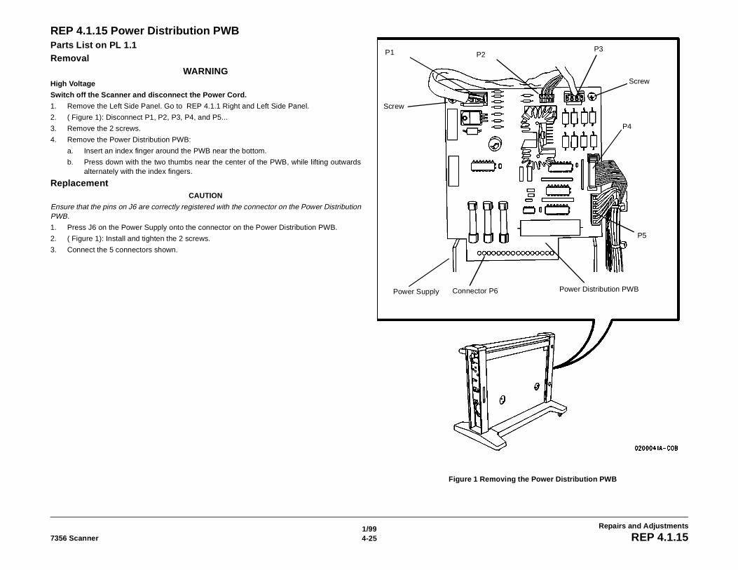
REP 4.1.15 Power Distribution PWBParts List on PL 1.1Removal
WARNINGHigh Voltage
Switch off the Scanner and disconnect the Power Cord.
1. Remove the Left Side Panel. Go to REP 4.1.1 Right and Left Side Panel.
2. ( Figure 1): Disconnect P1, P2, P3, P4, and P5...
3. Remove the 2 screws.
4. Remove the Power Distribution PWB:
a. Insert an index finger around the PWB near the bottom.
b. Press down with the two thumbs near the center of the PWB, while lifting outwardsalternately with the index fingers.
ReplacementCAUTION
Ensure that the pins on J6 are correctly registered with the connector on the Power DistributionPWB.
1. Press J6 on the Power Supply onto the connector on the Power Distribution PWB.
2. ( Figure 1): Install and tighten the 2 screws.
3. Connect the 5 connectors shown.
Figure 1 Removing the Power Distribution PWB
Power Supply Connector P6 Power Distribution PWB
Screw
P1 P2P3
Screw
P4
P5
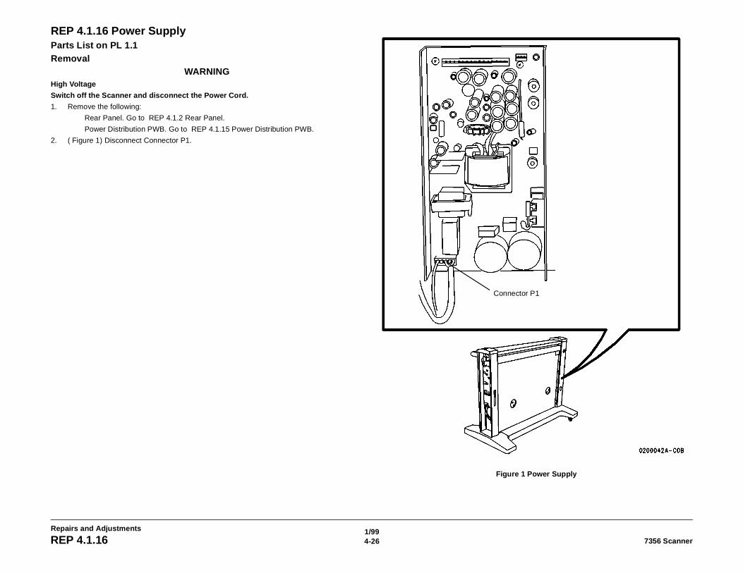
1/994-26 7356 ScannerREP 4.1.16
Repairs and Adjustments
REP 4.1.16 Power SupplyParts List on PL 1.1Removal
WARNINGHigh Voltage
Switch off the Scanner and disconnect the Power Cord.
1. Remove the following:
Rear Panel. Go to REP 4.1.2 Rear Panel.
Power Distribution PWB. Go to REP 4.1.15 Power Distribution PWB.
2. ( Figure 1) Disconnect Connector P1.
Figure 1 Power Supply
Connector P1
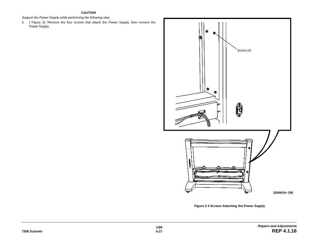
1/994-277356 Scanner REP 4.1.16
Repairs and Adjustments
CAUTION
Support the Power Supply while performing the following step.
3. ( Figure 2): Remove the four screws that attach the Power Supply, then remove thePower Supply.
Figure 2 4 Screws Attaching the Power Supply
Screw (4)
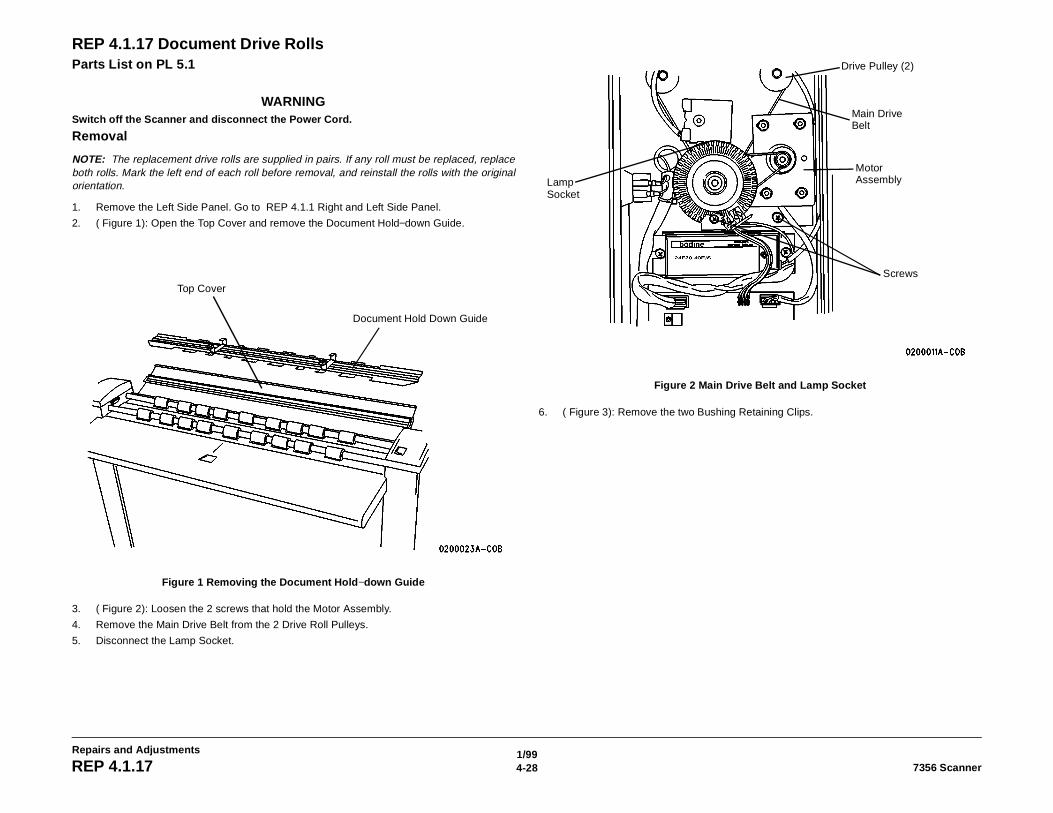
1/994-28 7356 ScannerREP 4.1.17
Repairs and Adjustments
REP 4.1.17 Document Drive RollsParts List on PL 5.1
WARNINGSwitch off the Scanner and disconnect the Power Cord.
Removal
NOTE: The replacement drive rolls are supplied in pairs. If any roll must be replaced, replaceboth rolls. Mark the left end of each roll before removal, and reinstall the rolls with the originalorientation.
1. Remove the Left Side Panel. Go to REP 4.1.1 Right and Left Side Panel.
2. ( Figure 1): Open the Top Cover and remove the Document Hold−down Guide.
Figure 1 Removing the Document Hold−down Guide
3. ( Figure 2): Loosen the 2 screws that hold the Motor Assembly.
4. Remove the Main Drive Belt from the 2 Drive Roll Pulleys.
5. Disconnect the Lamp Socket.
Figure 2 Main Drive Belt and Lamp Socket
6. ( Figure 3): Remove the two Bushing Retaining Clips.
Top Cover
Document Hold Down Guide
Drive Pulley (2)
Main Drive Belt
Motor Assembly
Screws
Lamp Socket
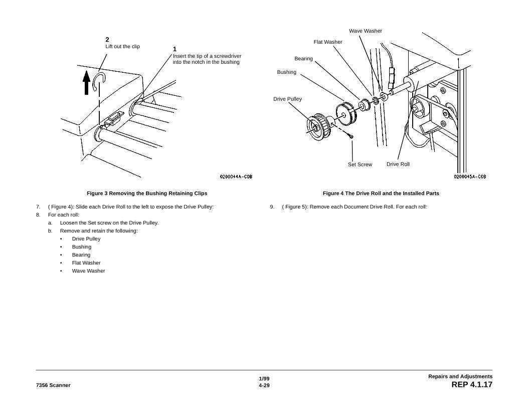
1/994-297356 Scanner REP 4.1.17
Repairs and Adjustments
Figure 3 Removing the Bushing Retaining Clips
7. ( Figure 4): Slide each Drive Roll to the left to expose the Drive Pulley:
8. For each roll:
a. Loosen the Set screw on the Drive Pulley.
b. Remove and retain the following:
• Drive Pulley
• Bushing
• Bearing
• Flat Washer
• Wave Washer
Figure 4 The Drive Roll and the Installed Parts
9. ( Figure 5): Remove each Document Drive Roll. For each roll:
1Insert the tip of a screwdriver into the notch in the bushing
2Lift out the clip
Bushing
Drive Pulley
Bearing
Flat Washer
Wave Washer
Drive RollSet Screw
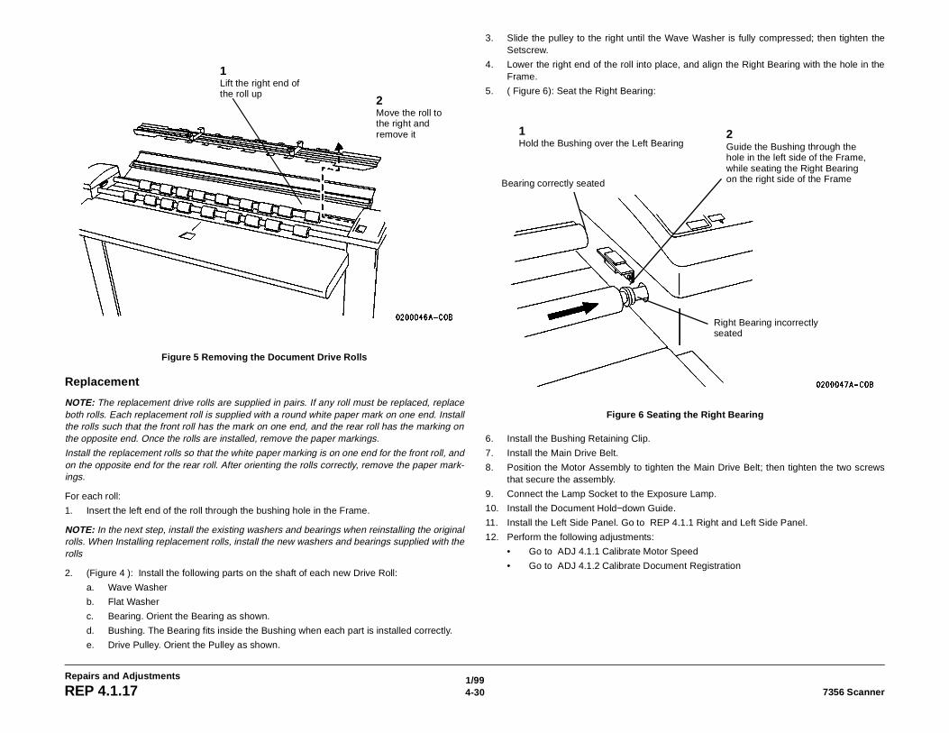
1/994-30 7356 ScannerREP 4.1.17
Repairs and Adjustments
Figure 5 Removing the Document Drive Rolls
Replacement
NOTE: The replacement drive rolls are supplied in pairs. If any roll must be replaced, replaceboth rolls. Each replacement roll is supplied with a round white paper mark on one end. Installthe rolls such that the front roll has the mark on one end, and the rear roll has the marking onthe opposite end. Once the rolls are installed, remove the paper markings.
Install the replacement rolls so that the white paper marking is on one end for the front roll, andon the opposite end for the rear roll. After orienting the rolls correctly, remove the paper mark-ings.
For each roll:
1. Insert the left end of the roll through the bushing hole in the Frame.
NOTE: In the next step, install the existing washers and bearings when reinstalling the originalrolls. When Installing replacement rolls, install the new washers and bearings supplied with therolls
2. (Figure 4 ): Install the following parts on the shaft of each new Drive Roll:
a. Wave Washer
b. Flat Washer
c. Bearing. Orient the Bearing as shown.
d. Bushing. The Bearing fits inside the Bushing when each part is installed correctly.
e. Drive Pulley. Orient the Pulley as shown.
3. Slide the pulley to the right until the Wave Washer is fully compressed; then tighten theSetscrew.
4. Lower the right end of the roll into place, and align the Right Bearing with the hole in theFrame.
5. ( Figure 6): Seat the Right Bearing:
Figure 6 Seating the Right Bearing
6. Install the Bushing Retaining Clip.
7. Install the Main Drive Belt.
8. Position the Motor Assembly to tighten the Main Drive Belt; then tighten the two screwsthat secure the assembly.
9. Connect the Lamp Socket to the Exposure Lamp.
10. Install the Document Hold−down Guide.
11. Install the Left Side Panel. Go to REP 4.1.1 Right and Left Side Panel.
12. Perform the following adjustments:
• Go to ADJ 4.1.1 Calibrate Motor Speed
• Go to ADJ 4.1.2 Calibrate Document Registration
1Lift the right end of the roll up
2Move the roll to the right and remove it 1
Hold the Bushing over the Left Bearing2Guide the Bushing through the hole in the left side of the Frame, while seating the Right Bearing on the right side of the FrameBearing correctly seated
Right Bearing incorrectly seated
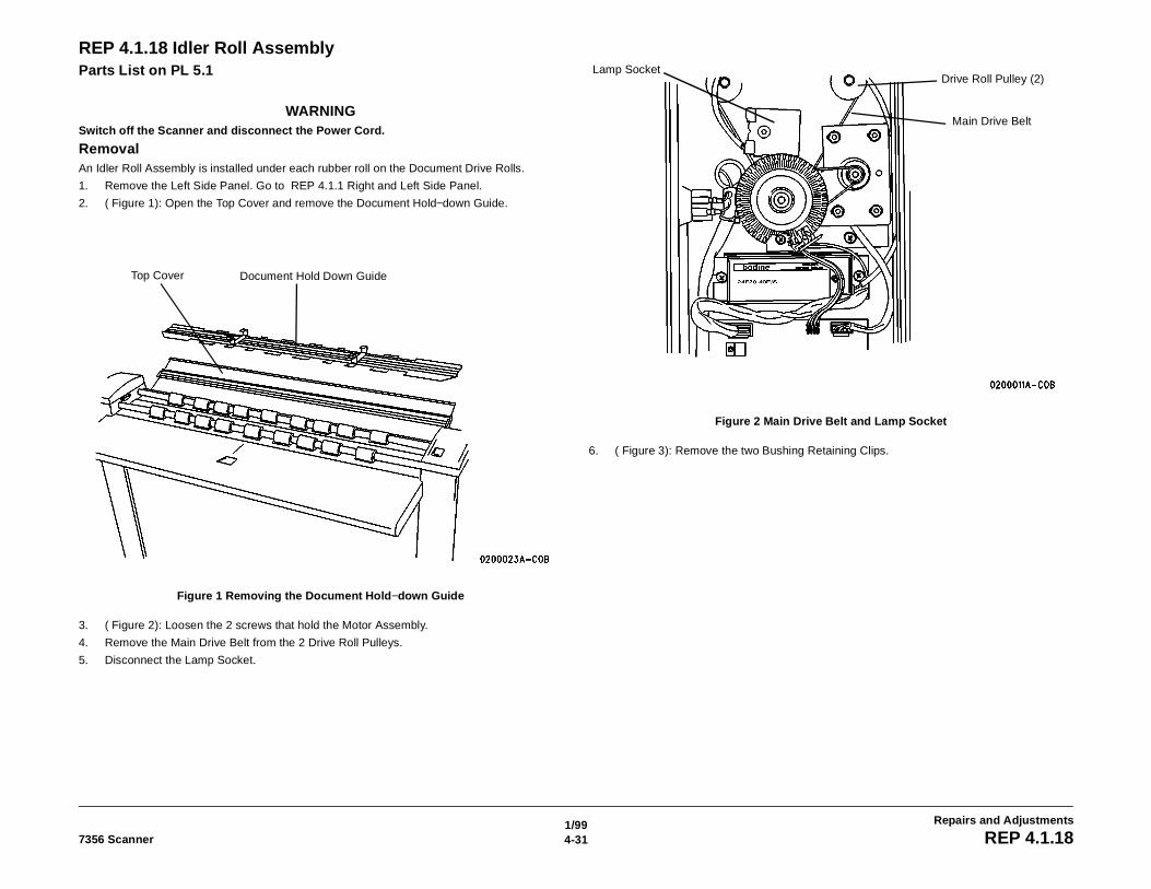
1/994-317356 Scanner REP 4.1.18
Repairs and Adjustments
REP 4.1.18 Idler Roll AssemblyParts List on PL 5.1
WARNINGSwitch off the Scanner and disconnect the Power Cord.
RemovalAn Idler Roll Assembly is installed under each rubber roll on the Document Drive Rolls.
1. Remove the Left Side Panel. Go to REP 4.1.1 Right and Left Side Panel.
2. ( Figure 1): Open the Top Cover and remove the Document Hold−down Guide.
Figure 1 Removing the Document Hold−down Guide
3. ( Figure 2): Loosen the 2 screws that hold the Motor Assembly.
4. Remove the Main Drive Belt from the 2 Drive Roll Pulleys.
5. Disconnect the Lamp Socket.
Figure 2 Main Drive Belt and Lamp Socket
6. ( Figure 3): Remove the two Bushing Retaining Clips.
Top Cover Document Hold Down Guide
Lamp SocketDrive Roll Pulley (2)
Main Drive Belt
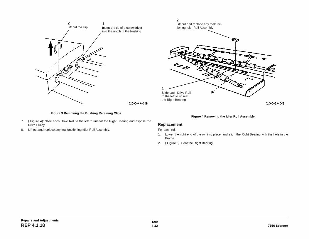
1/994-32 7356 ScannerREP 4.1.18
Repairs and Adjustments
Figure 3 Removing the Bushing Retaining Clips
7. ( Figure 4): Slide each Drive Roll to the left to unseat the Right Bearing and expose theDrive Pulley
8. Lift out and replace any malfunctioning Idler Roll Assembly.
Figure 4 Removing the Idler Roll Assembly
ReplacementFor each roll:
1. Lower the right end of the roll into place, and align the Right Bearing with the hole in theFrame.
2. ( Figure 5): Seat the Right Bearing:
1Insert the tip of a screwdriver into the notch in the bushing
2Lift out the clip
1Slide each Drive Roll to the left to unseat the Right Bearing
2Lift out and replace any malfunc-tioning Idler Roll Assembly
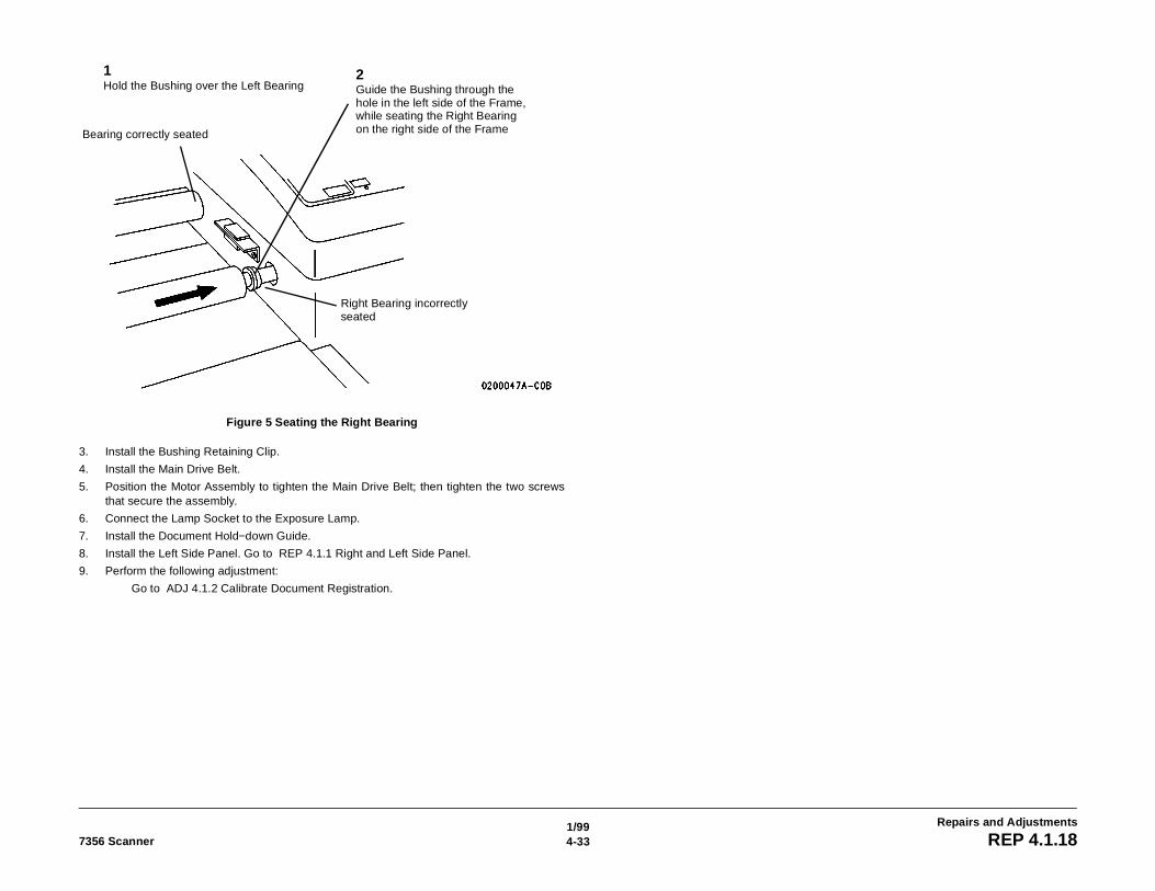
1/994-337356 Scanner REP 4.1.18
Repairs and Adjustments
Figure 5 Seating the Right Bearing
3. Install the Bushing Retaining Clip.
4. Install the Main Drive Belt.
5. Position the Motor Assembly to tighten the Main Drive Belt; then tighten the two screwsthat secure the assembly.
6. Connect the Lamp Socket to the Exposure Lamp.
7. Install the Document Hold−down Guide.
8. Install the Left Side Panel. Go to REP 4.1.1 Right and Left Side Panel.
9. Perform the following adjustment:
Go to ADJ 4.1.2 Calibrate Document Registration.
1Hold the Bushing over the Left Bearing
2Guide the Bushing through the hole in the left side of the Frame, while seating the Right Bearing on the right side of the FrameBearing correctly seated
Right Bearing incorrectly seated
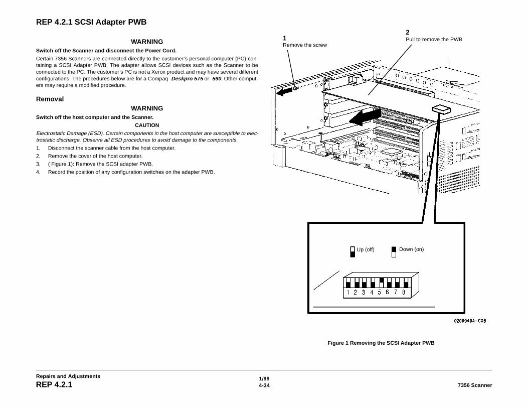
1/994-34 7356 ScannerREP 4.2.1
Repairs and Adjustments
REP 4.2.1 SCSI Adapter PWB
WARNINGSwitch off the Scanner and disconnect the Power Cord.
Certain 7356 Scanners are connected directly to the customer’s personal computer (PC) con-taining a SCSI Adapter PWB. The adapter allows SCSI devices such as the Scanner to beconnected to the PC. The customer’s PC is not a Xerox product and may have several differentconfigurations. The procedures below are for a Compaq Deskpro 575 or 590. Other comput-ers may require a modified procedure.
RemovalWARNING
Switch off the host computer and the Scanner.
CAUTION
Electrostatic Damage (ESD). Certain components in the host computer are susceptible to elec-trostatic discharge. Observe all ESD procedures to avoid damage to the components.
1. Disconnect the scanner cable from the host computer.
2. Remove the cover of the host computer.
3. ( Figure 1): Remove the SCSI adapter PWB.
4. Record the position of any configuration switches on the adapter PWB.
Figure 1 Removing the SCSI Adapter PWB
1Remove the screw
2Pull to remove the PWB
Up (off) Down (on)
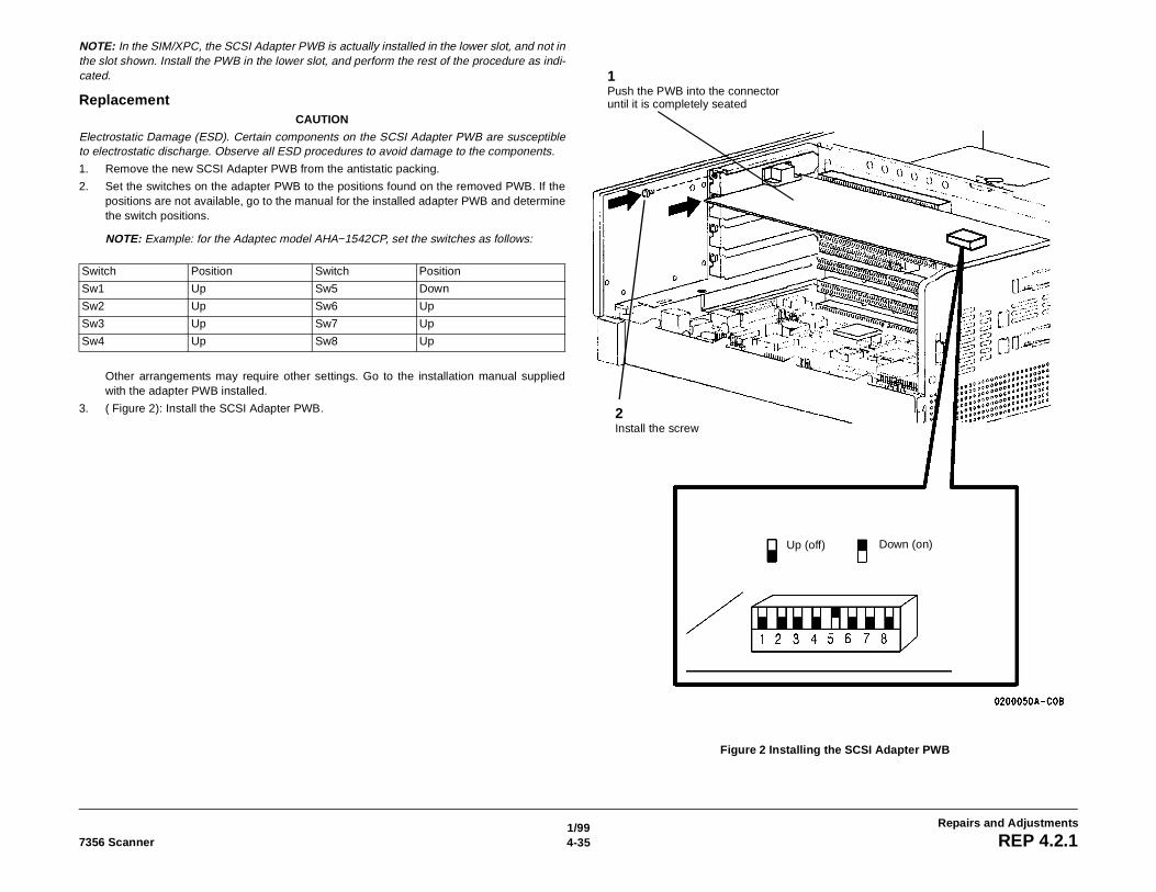
1/994-357356 Scanner REP 4.2.1
Repairs and Adjustments
NOTE: In the SIM/XPC, the SCSI Adapter PWB is actually installed in the lower slot, and not inthe slot shown. Install the PWB in the lower slot, and perform the rest of the procedure as indi-cated.
ReplacementCAUTION
Electrostatic Damage (ESD). Certain components on the SCSI Adapter PWB are susceptibleto electrostatic discharge. Observe all ESD procedures to avoid damage to the components.
1. Remove the new SCSI Adapter PWB from the antistatic packing.
2. Set the switches on the adapter PWB to the positions found on the removed PWB. If thepositions are not available, go to the manual for the installed adapter PWB and determinethe switch positions.
NOTE: Example: for the Adaptec model AHA−1542CP, set the switches as follows:
Other arrangements may require other settings. Go to the installation manual suppliedwith the adapter PWB installed.
3. ( Figure 2): Install the SCSI Adapter PWB.
Figure 2 Installing the SCSI Adapter PWB
Switch Position Switch Position
Sw1 Up Sw5 Down
Sw2 Up Sw6 Up
Sw3 Up Sw7 Up
Sw4 Up Sw8 Up
Up (off) Down (on)
1Push the PWB into the connector until it is completely seated
2Install the screw

1/994-36 7356 ScannerREP 4.2.1
Repairs and Adjustments
1/994-377356 Scanner ADJ 4.1.1
Repairs and Adjustments
ADJ 4.1.1 Calibrate Motor SpeedPurposeThe purpose is to compensate for magnification errors in the direction of document travel.These errors may be caused by wear of the Document Drive Rolls. This test determines aspeed correction factor that is applied to the machine motor speed. The correction factor isautomatically stored in non−volatile memory (NVM).
Procedure
NOTE: This procedure uses the SCSI7356 software as loaded onto a Personal Workstation orother personal computer. The computer is directly connected to the SCSI port of the Scanner.If the controlling system has its own built−in diagnostics, see the service manual for the con-trolling system.
Check1. Start the diagnostic software using the procedure appropriate for the system to which the
Scanner is connected:
• ES8150/XPC: Go to Configuring for Extended Diagnostics - XPC/ES8150 in Section6.
• 8830 DDS: Go to ADJ 4.4.8 Motor Speed in the 8830 DDS Service Manual to makethe Motor Speed test and adjustment (if needed).
2. Select Component Tests:
• For XPC/ES8150: Select the Component Tests button from the Service DiagnosticsMenu.
3. Select the Calibrate Motor Speed button.
4. Insert Test Pattern 082E11490 face down and with the short edge as the lead edge.
5. Select the Begin button (XPC\ES8150) or press the Start button (8830 DDS).
NOTE: The motor speed is checked and is adjusted automatically if not correct. The screendisplays Passed if the speed was successfully adjusted; otherwise, FAILED is displayed. IfFAILED is displayed, repeat the test again. If the problem still exists, go to 1.0 Entry RAP, inSection 2.
AdjustmentAdjustment occurs automatically when the Calibrate Motor Speed function is selected.
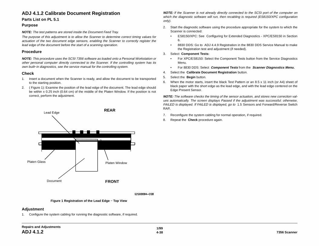
1/994-38 7356 ScannerADJ 4.1.2
Repairs and Adjustments
ADJ 4.1.2 Calibrate Document RegistrationParts List on PL 5.1Purpose
NOTE: The test patterns are stored inside the Document Feed Tray.
The purpose of this adjustment is to allow the Scanner to determine correct timing values foractuation of the two document edge sensors, enabling the Scanner to correctly register thelead edge of the document before the start of a scanning operation.
Procedure
NOTE: This procedure uses the SCSI 7356 software as loaded onto a Personal Workstation orother personal computer directly connected to the Scanner. If the controlling system has itsown built−in diagnostics, see the service manual for the controlling system.
Check1. Insert a document when the Scanner is ready, and allow the document to be transported
to the starting position.
2. ( Figure 1): Examine the position of the lead edge of the document. The lead edge shouldbe within ± 0.25 inch (0.64 cm) of the middle of the Platen Window. If the position is notcorrect, perform the adjustment.
Figure 1 Registration of the Lead Edge − Top View
Adjustment1. Configure the system cabling for running the diagnostic software, if required.
NOTE: If the Scanner is not already directly connected to the SCSI port of the computer onwhich the diagnostic software will run, then recabling is required (ES8150/XPC configurationonly).
2. Start the diagnostic software using the procedure appropriate for the system to which theScanner is connected:
• ES8150/XPC: See Configuring for Extended Diagnostics - XPC/ES8150 in Section6.
• 8830 DDS: Go to ADJ 4.4.9 Registration in the 8830 DDS Service Manual to makethe Registration test and adjustment (if needed).
3. Select Component Tests:
• For XPC/ES8150: Select the Component Tests button from the Service DiagnosticsMenu.
• For 8830 DDS: Select Component Tests from the Scanner Diagnostics Menu.4. Select the Calibrate Document Registration button.
5. Select the Begin button.
6. When the motor starts, insert the black Test Pattern or an 8.5 x 11 inch (or A4) sheet ofblack paper with the short edge as the lead edge, and with the lead edge centered on theEdge Present Sensor.
NOTE: The software checks the timing of the sensor actuation, and stores new correction val-ues automatically. The screen displays Passed if the adjustment was successful; otherwise,FAILED is displayed. If FAILED is displayed, go to 1.5 Sensors and Forward/Reverse SwitchRAP.
7. Reconfigure the system cabling for normal operation, if required.
8. Repeat the Check procedure again.
Lead Edge
Platen Glass
Document
Platen Window
REAR
FRONT
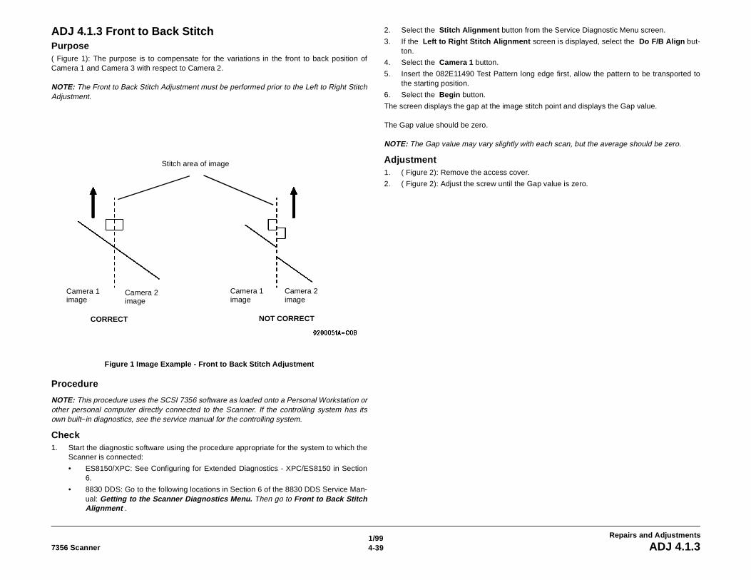
1/994-397356 Scanner ADJ 4.1.3
Repairs and Adjustments
ADJ 4.1.3 Front to Back StitchPurpose( Figure 1): The purpose is to compensate for the variations in the front to back position ofCamera 1 and Camera 3 with respect to Camera 2.
NOTE: The Front to Back Stitch Adjustment must be performed prior to the Left to Right StitchAdjustment.
Figure 1 Image Example - Front to Back Stitch Adjustment
Procedure
NOTE: This procedure uses the SCSI 7356 software as loaded onto a Personal Workstation orother personal computer directly connected to the Scanner. If the controlling system has itsown built−in diagnostics, see the service manual for the controlling system.
Check1. Start the diagnostic software using the procedure appropriate for the system to which the
Scanner is connected:
• ES8150/XPC: See Configuring for Extended Diagnostics - XPC/ES8150 in Section6.
• 8830 DDS: Go to the following locations in Section 6 of the 8830 DDS Service Man-ual: Getting to the Scanner Diagnostics Menu. Then go to Front to Back StitchAlignment .
2. Select the Stitch Alignment button from the Service Diagnostic Menu screen.
3. If the Left to Right Stitch Alignment screen is displayed, select the Do F/B Align but-ton.
4. Select the Camera 1 button.
5. Insert the 082E11490 Test Pattern long edge first, allow the pattern to be transported tothe starting position.
6. Select the Begin button.
The screen displays the gap at the image stitch point and displays the Gap value.
The Gap value should be zero.
NOTE: The Gap value may vary slightly with each scan, but the average should be zero.
Adjustment1. ( Figure 2): Remove the access cover.
2. ( Figure 2): Adjust the screw until the Gap value is zero.
Stitch area of image
Camera 1 image
Camera 1 image
Camera 2 image
Camera 2 image
CORRECT NOT CORRECT
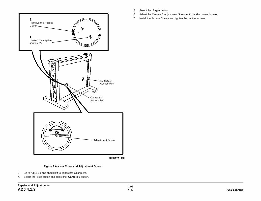
1/994-40 7356 ScannerADJ 4.1.3
Repairs and Adjustments
Figure 2 Access Cover and Adjustment Screw
3 Go to Adj 4.1.4 and check left to right stitch allignment.
4. Select the Stop button and select the Camera 3 button.
5. Select the Begin button.
6. Adjust the Camera 3 Adjustment Screw until the Gap value is zero.
7. Install the Access Covers and tighten the captive screws.
1Loosen the captive screws (2)
2Remove the Access Cover
Camera 1 Access Port
Camera 3 Access Port
Adjustment Screw
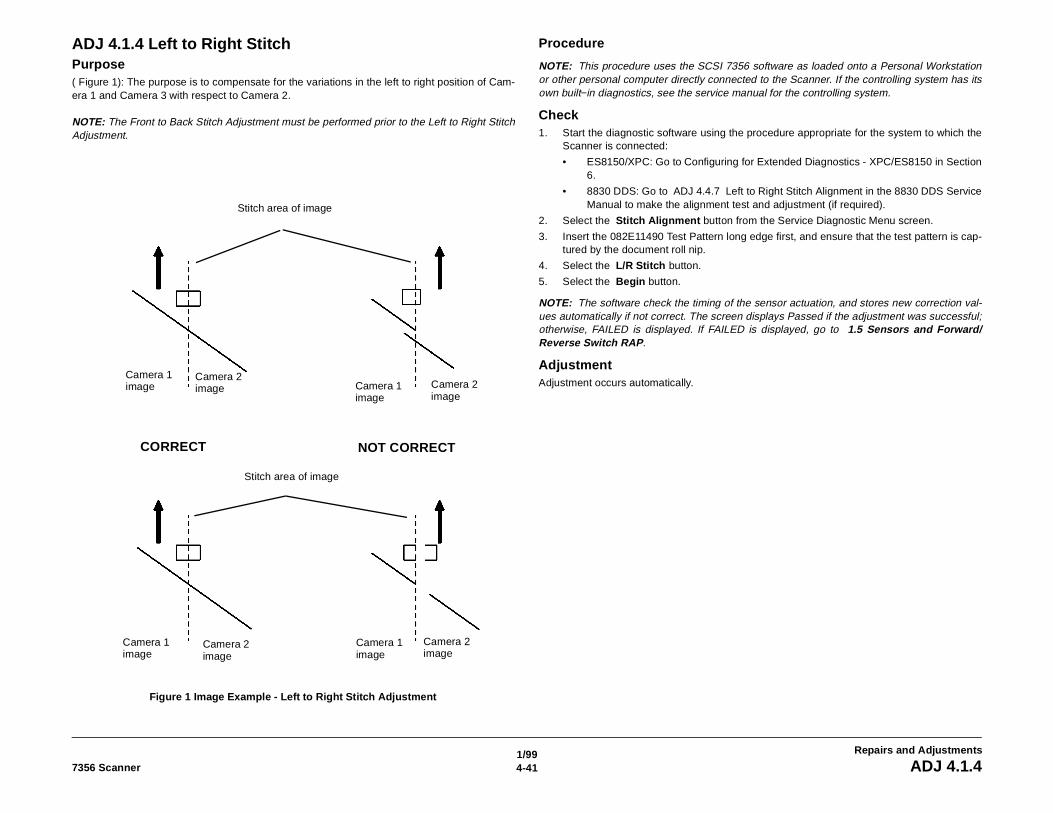
1/994-417356 Scanner ADJ 4.1.4
Repairs and Adjustments
ADJ 4.1.4 Left to Right StitchPurpose( Figure 1): The purpose is to compensate for the variations in the left to right position of Cam-era 1 and Camera 3 with respect to Camera 2.
NOTE: The Front to Back Stitch Adjustment must be performed prior to the Left to Right StitchAdjustment.
Figure 1 Image Example - Left to Right Stitch Adjustment
Procedure
NOTE: This procedure uses the SCSI 7356 software as loaded onto a Personal Workstationor other personal computer directly connected to the Scanner. If the controlling system has itsown built−in diagnostics, see the service manual for the controlling system.
Check1. Start the diagnostic software using the procedure appropriate for the system to which the
Scanner is connected:
• ES8150/XPC: Go to Configuring for Extended Diagnostics - XPC/ES8150 in Section6.
• 8830 DDS: Go to ADJ 4.4.7 Left to Right Stitch Alignment in the 8830 DDS ServiceManual to make the alignment test and adjustment (if required).
2. Select the Stitch Alignment button from the Service Diagnostic Menu screen.
3. Insert the 082E11490 Test Pattern long edge first, and ensure that the test pattern is cap-tured by the document roll nip.
4. Select the L/R Stitch button.
5. Select the Begin button.
NOTE: The software check the timing of the sensor actuation, and stores new correction val-ues automatically if not correct. The screen displays Passed if the adjustment was successful;otherwise, FAILED is displayed. If FAILED is displayed, go to 1.5 Sensors and Forward/Reverse Switch RAP.
AdjustmentAdjustment occurs automatically.
Camera 1 image
Camera 1 image
Camera 1 image
Camera 2 image Camera 2
image
Camera 2 image
Camera 2 image
Stitch area of image
NOT CORRECTCORRECT
Stitch area of image
Camera 1 image
1/994-42 7356 ScannerADJ 4.1.5
Repairs and Adjustments
ADJ 4.1.5 Camera NormalizationPurposeThe purpose of the Camera Normalization adjustment is to calibrate the camera signal withrespect to a standard reference. The standard reference is the reflectivity of the DocumentHold−down Guide.
Procedure
NOTE: This procedure uses the SCSI 7356 software as loaded onto a Personal Workstation,Xerox Productivity System (XPC) or other personal computer directly connected to the Scan-ner. If the controlling system has its own built−in diagnostics, refer to the service manual for thecontrolling system.
NOTE: If using an 8830 Digital Document System (DDS) go to Normalize Cameras in Section6 of the 8830 DDS Service Manual to perform this procedure.
CheckMethod 1 − Used only for the Xerox Productivity Centre in normal operation. This methoddoes not require connecting the Scanner directly to the UI Computer first.
1. Enter the diagnostic mode. by holding the <control> key down while pressing the <F12>key.
2. Enter the password 7336884 and press the OK button.
3. Select the Scanner Tests button on the screen.
The Scanner Tests screen appears.
4. Select the Normalize Scanner button and press the OK button.
• The Scanner normalizes. If the normalization process fails, the screen displays “Nor-malization Failed”. Go to If the test fails later in this procedure.
Method 2 – This method uses the diagnostic software. If the Scanner is connected to anES8150 or a Xerox Productivity Centre module, the Scanner must be connected directly to theUser Interface (UI) computer. Refer to Configuring for Extended Diagnostics – XPC/ES8150 inSection 6.
1. Start the diagnostic software, using the procedure appropriate for the system to which theScanner is connected. This matter is discussed in Section 6.
2. Select the Normalize Cameras button from the Service Diagnostic Menu screen
3. Select the Begin button.
• The Scanner normalizes the cameras with reference to the reflectivity of the Docu-ment Hold−down Guide.
• When the test is complete, the screen displays either Passed or Failed.
NOTE: Other diagnostic tests cannot be run until the normalization test is passed. The reasonfor this is that the results from the other tests may be invalid if the cameras are not normalizedfirst.
If the test fails1. Remove and inspect the bottom of the Document Hold−down Guide. If any dirt or marks
are found, clean the Document Hold−down Guide.
2. Inspect the Platen Glass. If any dirt or marks are found, clean the Platen Glass.
3. Install the Document Hold−down Guide.
4. Try the test again. If the problem still exists, switch off the Scanner and the controllingdevice. Then switch on the Scanner, and then the controlling device. Wait for the Scannerand the controlling device to initialize; then try the test again.
5. If the problem still exists, go to 1.0 Entry RAP in Section 2 of this service manual and iso-late the fault.
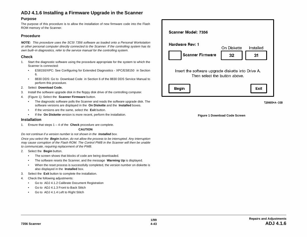
1/994-437356 Scanner ADJ 4.1.6
Repairs and Adjustments
ADJ 4.1.6 Installing a Firmware Upgrade in the ScannerPurposeThe purpose of this procedure is to allow the installation of new firmware code into the FlashROM memory of the Scanner.
Procedure
NOTE: This procedure uses the SCSI 7356 software as loaded onto a Personal Workstationor other personal computer directly connected to the Scanner. If the controlling system has itsown built−in diagnostics, refer to the service manual for the controlling system.
Check1. Start the diagnostic software using the procedure appropriate for the system to which the
Scanner is connected:
• ES8150/XPC: See Configuring for Extended Diagnostics - XPC/ES8150 in Section6.
• 8830 DDS: Go to Download Code in Section 6 of the 8830 DDS Service Manual toperform this procedure.
2. Select Download Code.
3. Install the software upgrade disk in the floppy disk drive of the controlling computer.
4. (Figure 1): Select the Scanner Firmware button.
• The diagnostic software polls the Scanner and reads the software upgrade disk. Thesoftware versions are displayed in the On Diskette and the Installed boxes.
• If the versions are the same, select the Exit button.
• If the On Diskette version is more recent, perform the installation.
Installation1. Ensure that steps 1 – 4 of the Check procedure are complete.
CAUTION
Do not continue if a version number is not shown in the Installed box.
Once you select the Begin button, do not allow the process to be interrupted. Any interruptionmay cause corruption of the Flash ROM. The Control PWB in the Scanner will then be unableto communicate, requiring replacement of the PWB.
2. Select the Begin button.
• The screen shows that blocks of code are being downloaded.
• The software resets the Scanner, and the message Warming Up is displayed.
• When the reset process is successfully completed, the version number on diskette isalso displayed in the Installed box.
3. Select the Exit button to complete the installation.
4. Check the following adjustments:
• Go to ADJ 4.1.2 Calibrate Document Registration
• Go to ADJ 4.1.3 Front to Back Stitch
• Go to ADJ 4.1.4 Left to Right Stitch
Figure 1 Download Code Screen
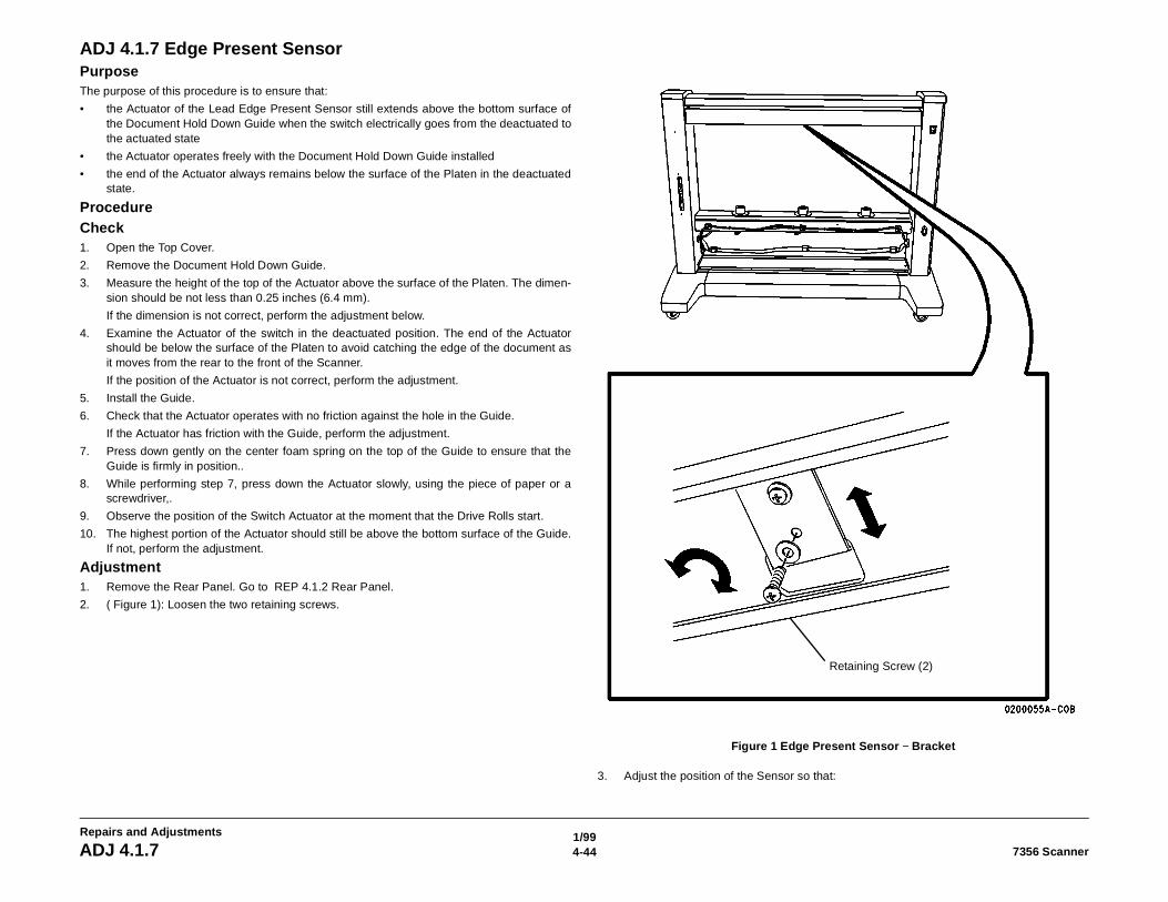
1/994-44 7356 ScannerADJ 4.1.7
Repairs and Adjustments
ADJ 4.1.7 Edge Present SensorPurposeThe purpose of this procedure is to ensure that:
• the Actuator of the Lead Edge Present Sensor still extends above the bottom surface ofthe Document Hold Down Guide when the switch electrically goes from the deactuated tothe actuated state
• the Actuator operates freely with the Document Hold Down Guide installed
• the end of the Actuator always remains below the surface of the Platen in the deactuatedstate.
ProcedureCheck1. Open the Top Cover.
2. Remove the Document Hold Down Guide.
3. Measure the height of the top of the Actuator above the surface of the Platen. The dimen-sion should be not less than 0.25 inches (6.4 mm).
If the dimension is not correct, perform the adjustment below.
4. Examine the Actuator of the switch in the deactuated position. The end of the Actuatorshould be below the surface of the Platen to avoid catching the edge of the document asit moves from the rear to the front of the Scanner.
If the position of the Actuator is not correct, perform the adjustment.
5. Install the Guide.
6. Check that the Actuator operates with no friction against the hole in the Guide.
If the Actuator has friction with the Guide, perform the adjustment.
7. Press down gently on the center foam spring on the top of the Guide to ensure that theGuide is firmly in position..
8. While performing step 7, press down the Actuator slowly, using the piece of paper or ascrewdriver,.
9. Observe the position of the Switch Actuator at the moment that the Drive Rolls start.
10. The highest portion of the Actuator should still be above the bottom surface of the Guide.If not, perform the adjustment.
Adjustment1. Remove the Rear Panel. Go to REP 4.1.2 Rear Panel.
2. ( Figure 1): Loosen the two retaining screws.
Figure 1 Edge Present Sensor − Bracket
3. Adjust the position of the Sensor so that:
Retaining Screw (2)
1/994-457356 Scanner ADJ 4.1.7
Repairs and Adjustments
• the Actuator of the Sensor still extends above the bottom surface of the DocumentHold Down Guide when the Sensor electrically goes from the deactuated to the actu-ated state
• the Actuator operates freely with the Document Hold Down Guide installed
• the end of the Actuator is below the surface of the Platen in the deactuated state.
4. Tighten the two Retaining Screws.
5. Check that the operation of the Sensor is still within the specification.
6. Install the Rear Panel. Go to REP 4.1.2 Rear Panel.
7. Close the Top Cover.
8. Go to ADJ 4.1.2 Calibrate Document Registration.
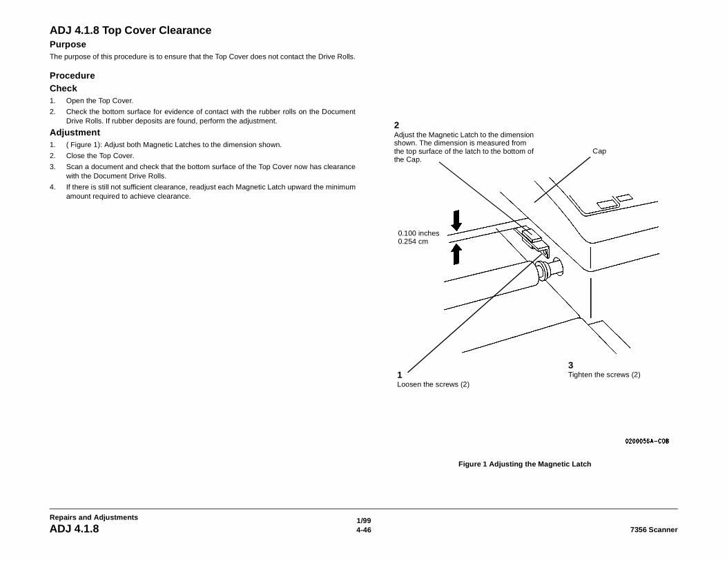
1/994-46 7356 ScannerADJ 4.1.8
Repairs and Adjustments
ADJ 4.1.8 Top Cover ClearancePurposeThe purpose of this procedure is to ensure that the Top Cover does not contact the Drive Rolls.
ProcedureCheck1. Open the Top Cover.
2. Check the bottom surface for evidence of contact with the rubber rolls on the DocumentDrive Rolls. If rubber deposits are found, perform the adjustment.
Adjustment1. ( Figure 1): Adjust both Magnetic Latches to the dimension shown.
2. Close the Top Cover.
3. Scan a document and check that the bottom surface of the Top Cover now has clearancewith the Document Drive Rolls.
4. If there is still not sufficient clearance, readjust each Magnetic Latch upward the minimumamount required to achieve clearance.
Figure 1 Adjusting the Magnetic Latch
0.100 inches 0.254 cm
Cap
3Tighten the screws (2)1
Loosen the screws (2)
2Adjust the Magnetic Latch to the dimension shown. The dimension is measured from the top surface of the latch to the bottom of the Cap.
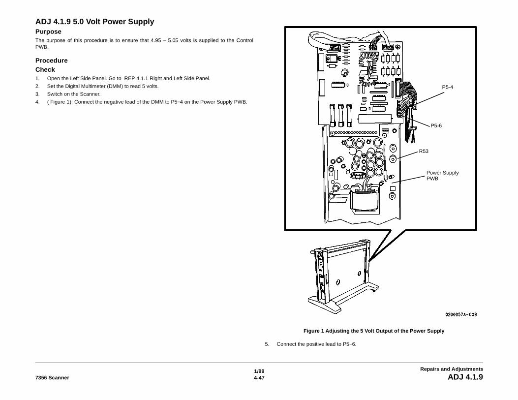
1/994-477356 Scanner ADJ 4.1.9
Repairs and Adjustments
ADJ 4.1.9 5.0 Volt Power SupplyPurposeThe purpose of this procedure is to ensure that 4.95 – 5.05 volts is supplied to the ControlPWB.
ProcedureCheck1. Open the Left Side Panel. Go to REP 4.1.1 Right and Left Side Panel.
2. Set the Digital Multimeter (DMM) to read 5 volts.
3. Switch on the Scanner.
4. ( Figure 1): Connect the negative lead of the DMM to P5−4 on the Power Supply PWB.
Figure 1 Adjusting the 5 Volt Output of the Power Supply
5. Connect the positive lead to P5−6.
P5-4
P5-6
R53
Power Supply PWB
1/994-48 7356 ScannerADJ 4.1.9
Repairs and Adjustments
6. Read the voltage. The voltage must be between 5.08 and 5.18 VDC. If the voltage is notwithin the specification, perform the adjustment.
NOTE: A drop in voltage of about 0.13 VDC occurs across the wiring harness between thePower Distribution PWB and the Control PWB.
Adjustment1. Adjust Potentiometer R53 until the DMM displays 5.13 volts.
2. Disconnect the DMM.
3. Install the Left Side Panel. Go to REP 4.1.1 Right and Left Side Panel.
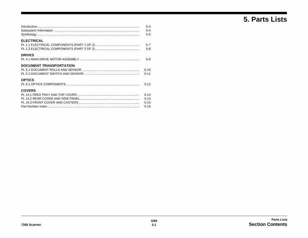
5/995-17356 Scanner Section Contents
Parts Lists
5. Parts ListsIntroduction ..................................................................................................................... 5-3Subsystem Information ................................................................................................... 5-4Symbology ...................................................................................................................... 5-5
ELECTRICALPL 1.1 ELECTRICAL COMPONENTS (PART 1 OF 2) ................................................... 5-7PL 1.2 ELECTRICAL COMPONENTS (PART 2 OF 2) ................................................... 5-8
DRIVESPL 4.1 MAIN DRIVE MOTOR ASSEMBLY ..................................................................... 5-9
DOCUMENT TRANSPORTATIONPL 5.1 DOCUMENT ROLLS AND SENSOR .................................................................. 5-10PL 5.2 DOCUMENT SWITCH AND SENSOR ................................................................ 5-11
OPTICSPL 6.1 OPTICS COMPONENTS..................................................................................... 5-12
COVERSPL 14.1 FEED TRAY AND TOP COVER........................................................................ 5-13PL 14.2 REAR COVER AND SIDE PANEL .................................................................... 5-14PL 14.3 FRONT COVER AND CASTERS ...................................................................... 5-15Part Number Index .......................................................................................................... 5-16

5/995-2 7356 Scanner
Parts Lists
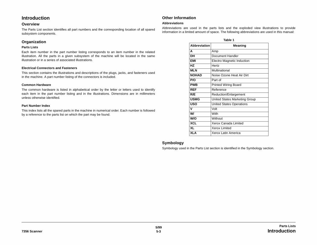
5/995-37356 Scanner Introduction
Parts Lists
IntroductionOverviewThe Parts List section identifies all part numbers and the corresponding location of all sparedsubsystem components.
OrganizationParts Lists
Each item number in the part number listing corresponds to an item number in the relatedillustration. All the parts in a given subsystem of the machine will be located in the sameillustration or in a series of associated illustrations.
Electrical Connectors and Fasteners
This section contains the illustrations and descriptions of the plugs, jacks, and fasteners usedin the machine. A part number listing of the connectors is included.
Common Hardware
The common hardware is listed in alphabetical order by the letter or letters used to identifyeach item in the part number listing and in the illustrations. Dimensions are in millimetersunless otherwise identified.
Part Number Index
This index lists all the spared parts in the machine in numerical order. Each number is followedby a reference to the parts list on which the part may be found.
Other InformationAbbreviations
Abbreviations are used in the parts lists and the exploded view illustrations to provideinformation in a limited amount of space. The following abbreviations are used in this manual:
SymbologySymbology used in the Parts List section is identified in the Symbology section.
Table 1
Abbreviation Meaning
A Amp
DH Document Handler
EMI Electro Magnetic Induction
HZ Hertz
MLN Multinational
NOHAD Noise Ozone Heat Air Dirt
P/O Part of
PWB Printed Wiring Board
REF Reference
R/E Reduction/Enlargement
USMG United States Marketing Group
USO United States Operations
V Volt
W/ With
W/O Without
XCL Xerox Canada Limited
XL Xerox Limited
XLA Xerox Latin America
5/995-4 7356 ScannerSubsystem Information
Parts Lists
Subsystem InformationUse of the Term "Assembly"The term "assembly" will be used for items in the part number listing that include other itemizedparts in the part number listing. When the word "assembly is found in the part number listing,there will be a corresponding item number on the illustrations followed by a bracket and alisting of the contents of the assembly.
BracketsA bracket is used when an assembly or kit is spared, but is not shown in the illustration. Theitem number of the assembly or kit precedes the bracket; the item numbers of the piece partsfollow the bracket.
TagThe notation “Tag" in the part description indicates that the item is the entire Tag. The notation“P/O Tag” indicates that the item is only part of a tag change, or modification, to the equipment.
When a part or an item assembly has a Tag associated with it, check the change Tag Index inthe General Information section of the Service Data for the name and purpose of themodification.
In some cases, a part or assembly may be spared in two versions: with the Tag and without theTag. In those cases, use whichever part is appropriate for the configuration of the machine onwhich the part is to be installed. If the machine does not have a particular Tag and the onlyreplacement part available is listed as "W/Tag," install the Tag kit or all of the piece parts. TheChange Tag Index tells you which kit or piece parts you need.
Whenever you install a Tag kit or all the piece parts that make up a Tag, mark the appropriatenumber on the Tag matrix.
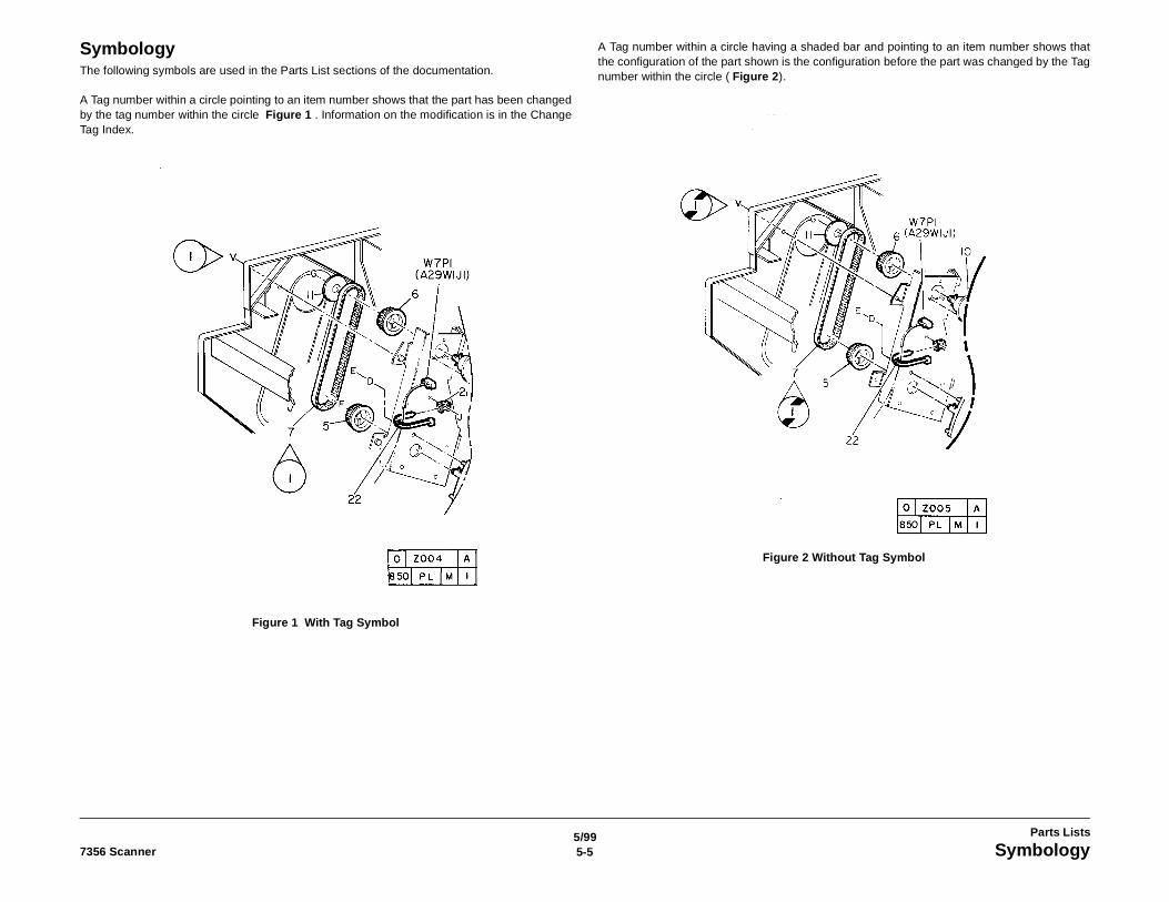
5/995-57356 Scanner Symbology
Parts Lists
SymbologyThe following symbols are used in the Parts List sections of the documentation.
A Tag number within a circle pointing to an item number shows that the part has been changedby the tag number within the circle Figure 1 . Information on the modification is in the ChangeTag Index.
Figure 1 With Tag Symbol
A Tag number within a circle having a shaded bar and pointing to an item number shows thatthe configuration of the part shown is the configuration before the part was changed by the Tagnumber within the circle ( Figure 2).
Figure 2 Without Tag Symbol
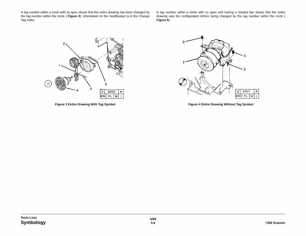
5/995-6 7356 ScannerSymbology
Parts Lists
A tag number within a circle with no apex shows that the entire drawing has been changed bythe tag number within the circle ( Figure 3). Information on the modification is in the ChangeTag Index.
Figure 3 Entire Drawing With Tag Symbol
A tag number within a circle with no apex and having a shaded bar shows that the entiredrawing was the configuration before being changed by the tag number within the circle (Figure 4).
Figure 4 Entire Drawing Without Tag Symbol
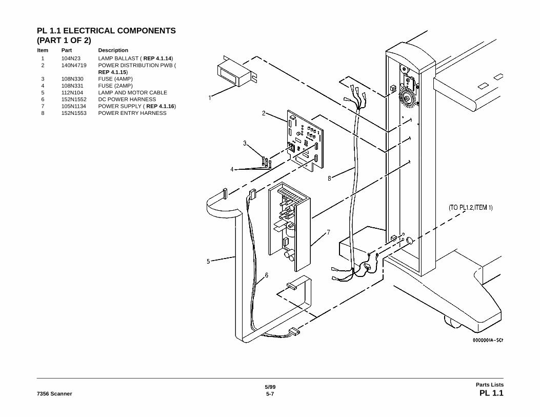
5/995-77356 Scanner PL 1.1
Parts Lists
PL 1.1 ELECTRICAL COMPONENTS (PART 1 OF 2)Item Part Description
1 104N23 LAMP BALLAST ( REP 4.1.14)2 140N4719 POWER DISTRIBUTION PWB (
REP 4.1.15)3 108N330 FUSE (4AMP)4 108N331 FUSE (2AMP)5 112N104 LAMP AND MOTOR CABLE6 152N1552 DC POWER HARNESS7 105N1134 POWER SUPPLY ( REP 4.1.16)8 152N1553 POWER ENTRY HARNESS
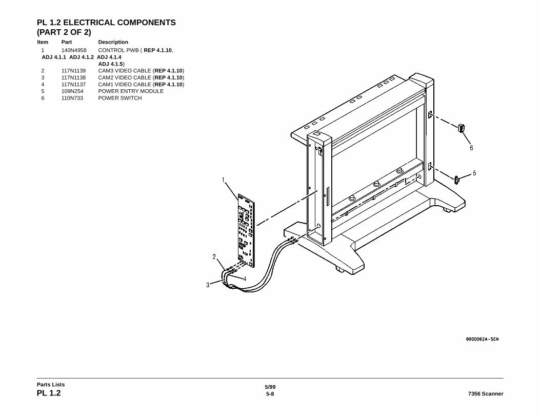
5/995-8 7356 ScannerPL 1.2
Parts Lists
PL 1.2 ELECTRICAL COMPONENTS (PART 2 OF 2)Item Part Description
1 140N4958 CONTROL PWB ( REP 4.1.10, ADJ 4.1.1 ADJ 4.1.2 ADJ 4.1.4
ADJ 4.1.5)2 117N1139 CAM3 VIDEO CABLE (REP 4.1.10)3 117N1138 CAM2 VIDEO CABLE (REP 4.1.10)4 117N1137 CAM1 VIDEO CABLE (REP 4.1.10)5 109N254 POWER ENTRY MODULE6 110N733 POWER SWITCH
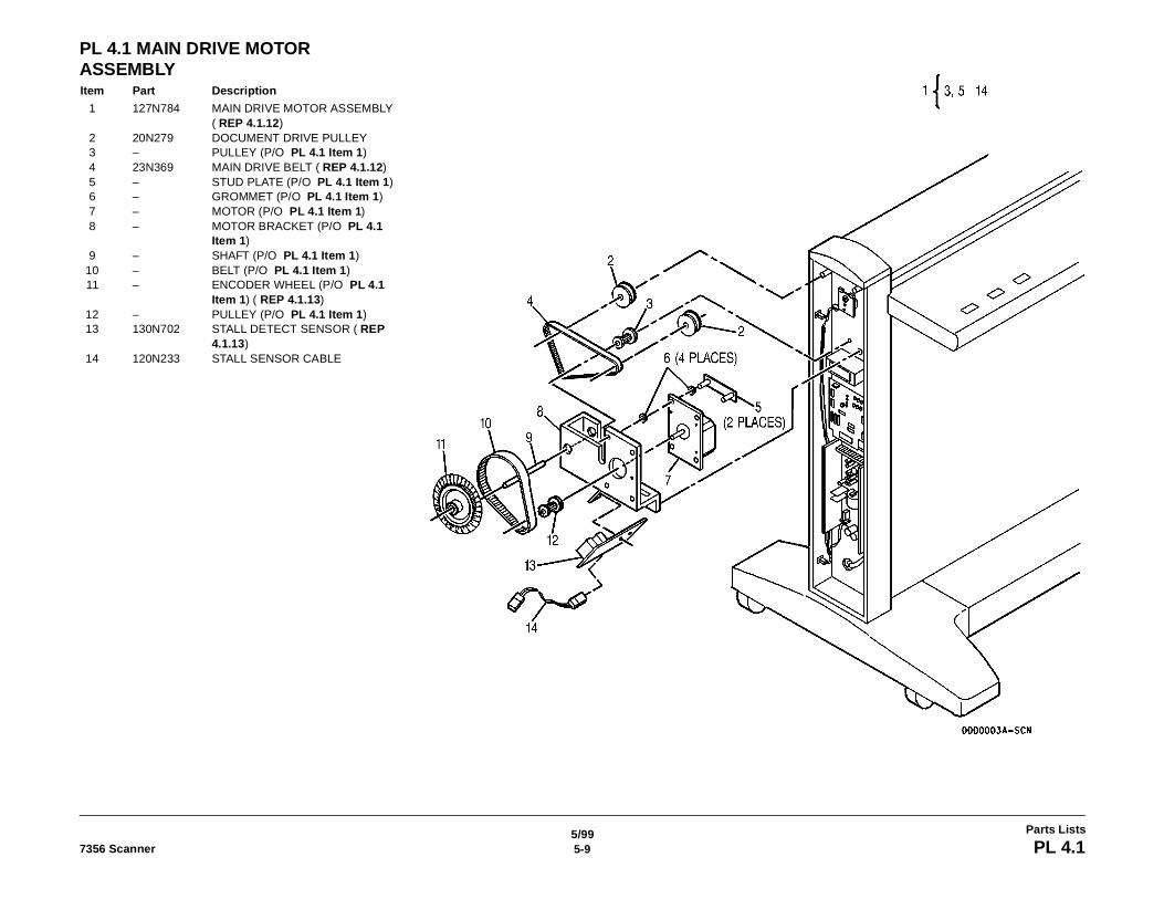
5/995-97356 Scanner PL 4.1
Parts Lists
PL 4.1 MAIN DRIVE MOTOR ASSEMBLYItem Part Description
1 127N784 MAIN DRIVE MOTOR ASSEMBLY ( REP 4.1.12)
2 20N279 DOCUMENT DRIVE PULLEY3 – PULLEY (P/O PL 4.1 Item 1)4 23N369 MAIN DRIVE BELT ( REP 4.1.12)5 – STUD PLATE (P/O PL 4.1 Item 1)6 – GROMMET (P/O PL 4.1 Item 1)7 – MOTOR (P/O PL 4.1 Item 1)8 – MOTOR BRACKET (P/O PL 4.1
Item 1)9 – SHAFT (P/O PL 4.1 Item 1)
10 – BELT (P/O PL 4.1 Item 1)11 – ENCODER WHEEL (P/O PL 4.1
Item 1) ( REP 4.1.13)12 – PULLEY (P/O PL 4.1 Item 1)13 130N702 STALL DETECT SENSOR ( REP
4.1.13)14 120N233 STALL SENSOR CABLE
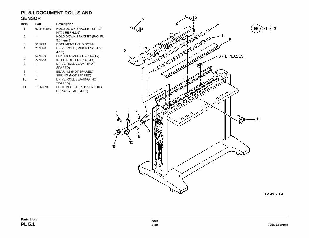
5/995-10 7356 ScannerPL 5.1
Parts Lists
PL 5.1 DOCUMENT ROLLS AND SENSORItem Part Description
1 600K64650 HOLD DOWN BRACKET KIT (2/KIT) ( REP 4.1.5)
2 – HOLD DOWN BRACKET (P/O PL 5.1 Item 1)
3 50N213 DOCUMENT HOLD DOWN4 23N370 DRIVE ROLL ( REP 4.1.17, ADJ
4.1.2)5 62N100 PLATEN GLASS ( REP 4.1.15)6 22N658 IDLER ROLL ( REP 4.1.18)7 – DRIVE ROLL CLAMP (NOT
SPARED)8 – BEARING (NOT SPARED)9 – SPRING (NOT SPARED)
10 – DRIVE ROLL BEARING (NOT SPARED)
11 130N770 EDGE REGISTERED SENSOR ( REP 4.1.7, ADJ 4.1.2)
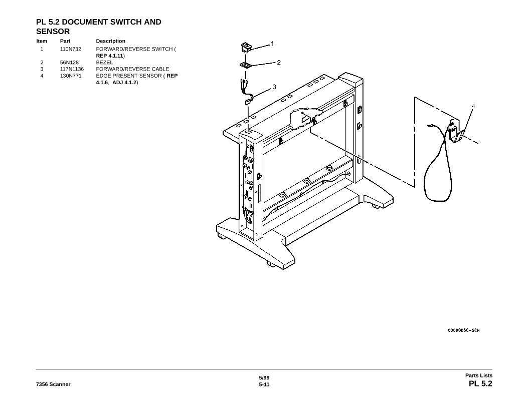
5/995-117356 Scanner PL 5.2
Parts Lists
PL 5.2 DOCUMENT SWITCH AND SENSORItem Part Description
1 110N732 FORWARD/REVERSE SWITCH ( REP 4.1.11)
2 56N128 BEZEL3 117N1136 FORWARD/REVERSE CABLE4 130N771 EDGE PRESENT SENSOR ( REP
4.1.6, ADJ 4.1.2)

5/995-12 7356 ScannerPL 6.1
Parts Lists
PL 6.1 OPTICS COMPONENTSItem Part Description
1 19N357 LAMP CLAMP2 113N280 LAMP SOCKET3 122N103 FLUORESCENT LAMP ( REP
4.1.3)
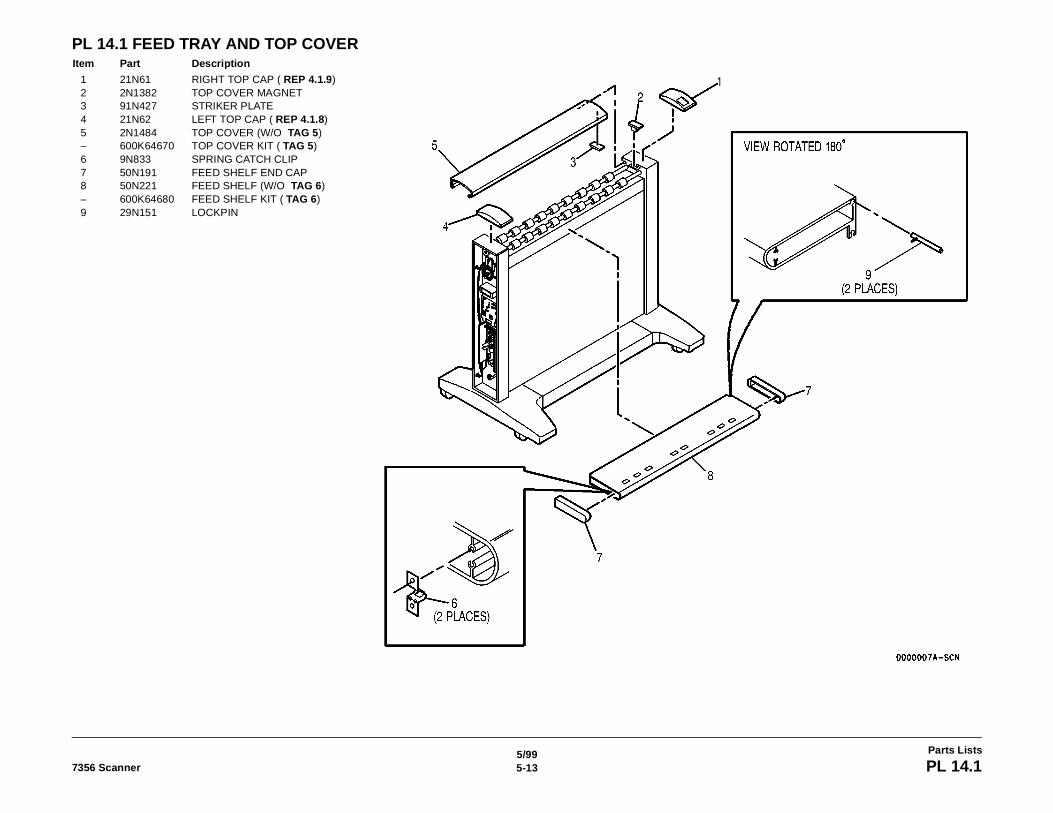
5/995-137356 Scanner PL 14.1
Parts Lists
PL 14.1 FEED TRAY AND TOP COVERItem Part Description
1 21N61 RIGHT TOP CAP ( REP 4.1.9)2 2N1382 TOP COVER MAGNET3 91N427 STRIKER PLATE4 21N62 LEFT TOP CAP ( REP 4.1.8)5 2N1484 TOP COVER (W/O TAG 5)– 600K64670 TOP COVER KIT ( TAG 5)6 9N833 SPRING CATCH CLIP7 50N191 FEED SHELF END CAP8 50N221 FEED SHELF (W/O TAG 6)– 600K64680 FEED SHELF KIT ( TAG 6)9 29N151 LOCKPIN
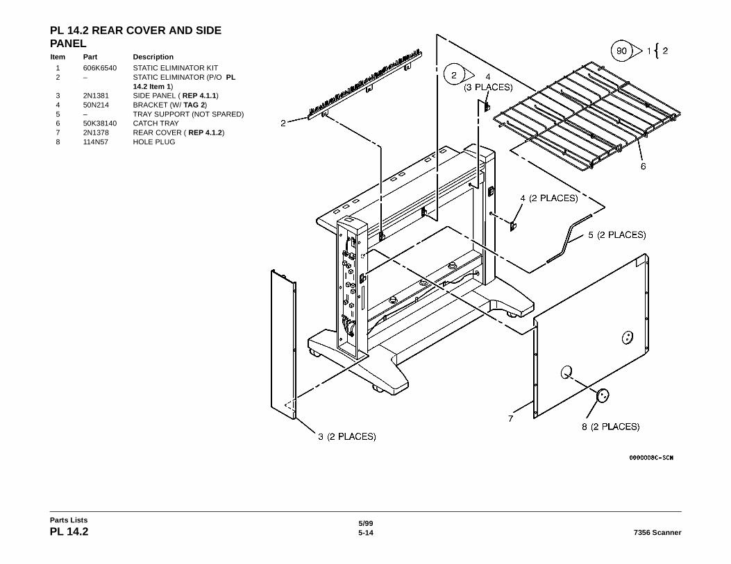
5/995-14 7356 ScannerPL 14.2
Parts Lists
PL 14.2 REAR COVER AND SIDE PANELItem Part Description
1 606K6540 STATIC ELIMINATOR KIT 2 – STATIC ELIMINATOR (P/O PL
14.2 Item 1)3 2N1381 SIDE PANEL ( REP 4.1.1)4 50N214 BRACKET (W/ TAG 2)5 – TRAY SUPPORT (NOT SPARED)6 50K38140 CATCH TRAY7 2N1378 REAR COVER ( REP 4.1.2)8 114N57 HOLE PLUG
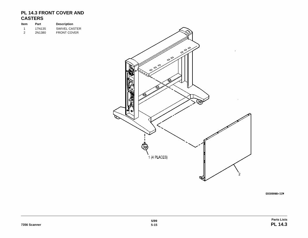
5/995-157356 Scanner PL 14.3
Parts Lists
PL 14.3 FRONT COVER AND CASTERSItem Part Description
1 17N135 SWIVEL CASTER2 2N1380 FRONT COVER
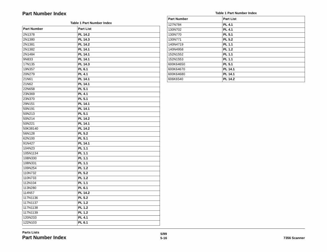
5/995-16 7356 ScannerPart Number Index
Parts Lists
Part Number Index
Table 1 Part Number Index
Part Number Part List
2N1378 PL 14.2
2N1380 PL 14.3
2N1381 PL 14.2
2N1382 PL 14.1
2N1484 PL 14.1
9N833 PL 14.1
17N135 PL 14.3
19N357 PL 6.1
20N279 PL 4.1
21N61 PL 14.1
21N62 PL 14.1
22N658 PL 5.1
23N369 PL 4.1
23N370 PL 5.1
29N151 PL 14.1
50N191 PL 14.1
50N213 PL 5.1
50N214 PL 14.2
50N221 PL 14.1
50K38140 PL 14.2
56N128 PL 5.2
62N100 PL 5.1
91N427 PL 14.1
104N23 PL 1.1
105N1134 PL 1.1
108N330 PL 1.1
108N331 PL 1.1
109N254 PL 1.2
110N732 PL 5.2
110N733 PL 1.2
112N104 PL 1.1
113N280 PL 6.1
114N57 PL 14.2
117N1136 PL 5.2
117N1137 PL 1.2
117N1138 PL 1.2
117N1139 PL 1.2
120N233 PL 4.1
122N103 PL 6.1
127N784 PL 4.1
130N702 PL 4.1
130N770 PL 5.1
130N771 PL 5.2
140N4719 PL 1.1
140N4958 PL 1.2
152N1552 PL 1.1
152N1553 PL 1.1
600K64650 PL 5.1
600K64670 PL 14.1
600K64680 PL 14.1
606K6540 PL 14.2
Table 1 Part Number Index
Part Number Part List
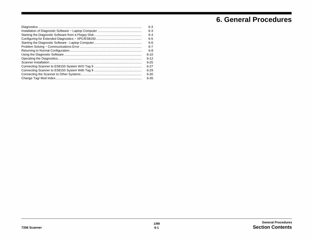
1/996-17356 Scanner Section Contents
General Procedures
6. General ProceduresDiagnostics ..................................................................................................................... 6-3Installation of Diagnostic Software − Laptop Computer .................................................. 6-3Starting the Diagnostic Software from a Floppy Disk...................................................... 6-4Configuring for Extended Diagnostics − XPC/ES8150.................................................... 6-5Starting the Diagnostic Software - Laptop Computer...................................................... 6-6Problem Solving − Communications Error ...................................................................... 6-7Returning to Normal Configuration.................................................................................. 6-8Using the Diagnostic Software ........................................................................................ 6-10Operating the Diagnostics............................................................................................... 6-12Scanner Installation......................................................................................................... 6-25Connecting Scanner to ES8150 System W/O Tag 9 ...................................................... 6-27Connecting Scanner to ES8150 System With Tag 9 ...................................................... 6-29Connecting the Scanner to Other Systems..................................................................... 6-30Change Tag/ Mod Index.................................................................................................. 6-35

1/996-2 7356 Scanner
General Procedures
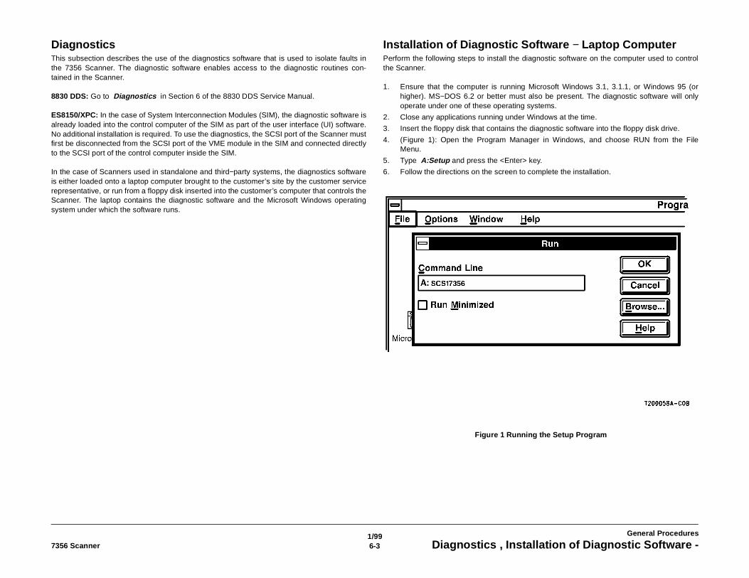
1/996-37356 Scanner Diagnostics , Installation of Diagnostic Software -
General Procedures
Diagnostics This subsection describes the use of the diagnostics software that is used to isolate faults inthe 7356 Scanner. The diagnostic software enables access to the diagnostic routines con-tained in the Scanner.
8830 DDS: Go to Diagnostics in Section 6 of the 8830 DDS Service Manual.
ES8150/XPC: In the case of System Interconnection Modules (SIM), the diagnostic software isalready loaded into the control computer of the SIM as part of the user interface (UI) software.No additional installation is required. To use the diagnostics, the SCSI port of the Scanner mustfirst be disconnected from the SCSI port of the VME module in the SIM and connected directlyto the SCSI port of the control computer inside the SIM.
In the case of Scanners used in standalone and third−party systems, the diagnostics softwareis either loaded onto a laptop computer brought to the customer’s site by the customer servicerepresentative, or run from a floppy disk inserted into the customer’s computer that controls theScanner. The laptop contains the diagnostic software and the Microsoft Windows operatingsystem under which the software runs.
Installation of Diagnostic Software − Laptop ComputerPerform the following steps to install the diagnostic software on the computer used to controlthe Scanner.
1. Ensure that the computer is running Microsoft Windows 3.1, 3.1.1, or Windows 95 (orhigher). MS−DOS 6.2 or better must also be present. The diagnostic software will onlyoperate under one of these operating systems.
2. Close any applications running under Windows at the time.
3. Insert the floppy disk that contains the diagnostic software into the floppy disk drive.
4. (Figure 1): Open the Program Manager in Windows, and choose RUN from the FileMenu.
5. Type A:Setup and press the <Enter> key.
6. Follow the directions on the screen to complete the installation.
Figure 1 Running the Setup Program
1/996-4 7356 ScannerStarting the Diagnostic Software from a Floppy Disk
General Procedures
Starting the Diagnostic Software from a Floppy Disk1. Ensure that the computer is running Microsoft Windows 3.1, 3.1.1, or Windows 95 (or
higher). MS−DOS 6.2 or better must also be present. The diagnostic software will onlyoperate under one of these operating systems.
2. Close the Windows Program Manager.
3. Switch off the computer and the Scanner.
4. Connect the SCSI cable from the Scanner to the SCSI port of the computer on which thediagnostics will be run.
5. Switch on the Scanner.
6. Switch on the computer, and allow it to boot up (initialize).
7. Insert the SCSI7356 floppy disk into the floppy disk drive.
8. Open the Program Manager in Windows, and choose RUN from the File Menu.
9. Type A:SCSI7356 and press the <Enter> key.
• The software starts. Enter the password ES8150 and press the <Enter> key on thekeyboard. Then select the Begin button. Go to Using the Diagnostic Software (inthis section) for further instructions.
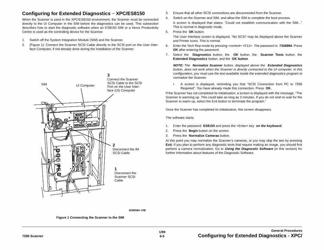
1/996-57356 Scanner Configuring for Extended Diagnostics - XPC/
General Procedures
Configuring for Extended Diagnostics − XPC/ES8150When the Scanner is used in the XPC/ES8150 environment, the Scanner must be connecteddirectly to the UI Computer in the SIM before the diagnostics can be used. This subsectiondescribes how to start the diagnostic software when an ES8150 SIM or a Xerox ProductivityCentre is used as the controlling device for the Scanner.
1. Switch off the System Integration Module (SIM) and the Scanner.
2. (Figure 1): Connect the Scanner SCSI Cable directly to the SCSI port on the User Inter-face Computer, if not already done during the installation of the Scanner.
Figure 1 Connecting the Scanner to the SIM
3. Ensure that all other SCSI connections are disconnected from the Scanner.
4. Switch on the Scanner and SIM, and allow the SIM to complete the boot process.
A screen is displayed that states: “Could not establish communication with the SIM...”This is normal in diagnostic mode.
5. Press the OK button.
The User Interface screen is displayed. “No SCSI” may be displayed above the Scannerand Printer icons. This is normal.
6. Enter the Tech Rep mode by pressing <control> <F12>. The password is 7336884. PressOK after entering the password.
7. Select the Diagnostics button, the OK button, the Scanner Tests button, theExtended Diagnostics button, and the OK button.
NOTE: The Normalize Scanner button, displayed above the Extended Diagnosticsbutton, does not work when the Scanner is directly connected to the UI computer. In thisconfiguration, you must use the test available inside the extended diagnostics program tonormalize the Scanner.
• A screen is displayed, reminding you that “SCSI Connection from PC to 7356Required”. You have already made this connection. Press OK.
If the Scanner has not completed its initialization, a screen is displayed with the message, “TheScanner is warming up. This could take as long as 3 minutes. If you do not wish to wait for theScanner to warm up, select the Exit button to terminate the program.”
Once the Scanner has completed its initialization, this screen disappears.
The software starts.
1. Enter the password ES8150 and press the <Enter> key on the keyboard.2. Press the Begin button on the screen.
3. Press the Normalize Cameras button.
At this point you may normalize the Scanner’s cameras, or you may skip the test by pressingExit. If you plan to perform any diagnostic tests that require making an image, you should firstperform a camera normalization. Go to Using the Diagnostic Software (in this section) forfurther information about features of the Diagnostic Software.
1Disconnect the Scanner SCSI Cable
3Connect the Scanner SCSI Cable to the SCSI Port on the User Inter-face (UI) Computer
2Disconnect the IM SCSI Cable
UI ComputerSIM
1/996-6 7356 ScannerStarting the Diagnostic Software - Laptop Computer
General Procedures
Starting the Diagnostic Software - Laptop ComputerPerform the following steps to start the diagnostic software when a laptop computer is used torun the diagnostics for the Scanner.
NOTE: For an illustration of the connections, see Returning to Normal Configuration, (Figure 2)in this section.
1. Switch off the Scanner, the laptop computer, and the control computer for the system towhich the Scanner is connected.
2. Disconnect the Scanner SCSI Cable from the control computer.
3. Connect the Laptop Computer SCSI cable to the Scanner.
4. Ensure that all other SCSI connections are disconnected from the Scanner.
5. Switch on the Scanner and wait 10 seconds.
6. Switch on the Laptop Computer and allow it to complete the boot process.
7. Locate the SCSI7356 program and start it.
8. Enter the password ES8150 and press the <Enter> key on the keyboard.9. Press the Begin button on the screen.
10. Press the Normalize Cameras button.
At this point you may normalize the Scanner’s cameras, or you may skip the test bypressing Exit. If you plan to perform any diagnostic tests that require making an image,you should first perform a camera normalization. Go to Using the Diagnostic Software (inthis section) for further information about features of the Diagnostic Software..
1/996-77356 Scanner Problem Solving - Communications Error
General Procedures
Problem Solving − Communications ErrorIf the Communications Error screen is displayed after starting the SCSI7356 software:
1. Switch off the Scanner and the controlling computer.
2. Check that the SCSI cable is firmly connected to the Scanner and the SCSI adapter portof the computer.
3. Switch on the Scanner; then switch on the computer.
4. During the boot process, check that the following message is displayed:
Host Adapter #0 - SCSI ID 0 - LUN 0: Xerox 7356 00xxIf the message is not displayed, or “No SCSI devices found!” is displayed, then there is aSCSI communications problem between the Scanner and the computer that must be resolvedbefore the software can operate.
1. If the computer has communicated successfully with other SCSI devices, then the fault isprobably in the Scanner or the SCSI cable. Go to 1.0 Entry RAP of this Service Manualand isolate the fault.
2. If the Scanner has communicated successfully with the customer’s host system duringthe service call, but not with the computer being used to run the SCSI7356 software, thenthe fault is probably in the SCSI cable or the computer. Check the cable, by substitution ifpossible. If the fault still exists, then the fault must be corrected in the computer or theSCSI adapter in the computer.
3. If the customer’s computer is running the SCSI7356 software, isolate the fault by usingthe laptop computer instead.
4. If the laptop computer is running the SCSI7356 software, isolate the fault by using thecustomer’s computer instead. The software may be run from a floppy disk, avoiding theneed to actually install the software on the customer’s computer.
5. the SCSI cable may be too long
6. The SCSI bus may not be terminated correctly. Go to Connecting the Scanner to OtherSystems for more information.
If the message is displayed, then:
1. the SCSI cable may be too long
2. The SCSI bus may not be terminated correctly. Go to Connecting the Scanner to OtherSystems in this section for more information.
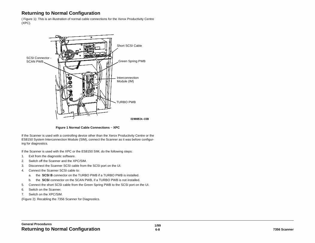
1/996-8 7356 ScannerReturning to Normal Configuration
General Procedures
Returning to Normal Configuration( Figure 1): This is an illustration of normal cable connections for the Xerox Productivity Centre(XPC).
Figure 1 Normal Cable Connections − XPC
If the Scanner is used with a controlling device other than the Xerox Productivity Centre or theES8150 System Interconnection Module (SIM), connect the Scanner as it was before configur-ing for diagnostics.
If the Scanner is used with the XPC or the ES8150 SIM, do the following steps:
1. Exit from the diagnostic software.
2. Switch off the Scanner and the XPC/SIM.
3. Disconnect the Scanner SCSI cable from the SCSI port on the UI.
4. Connect the Scanner SCSI cable to:
a. the SCSI B connector on the TURBO PWB if a TURBO PWB is installed.
b. the SCSI connector on the SCAN PWB, if a TURBO PWB is not installed.
5. Connect the short SCSI cable from the Green Spring PWB to the SCSI port on the UI.
6. Switch on the Scanner.
7. Switch on the XPC/SIM.
(Figure 2): Recabling the 7356 Scanner for Diagnostics.
Interconnection Module (IM)
Green Spring PWB
Short SCSI CableSCSI Connector - SCAN PWB
TURBO PWB
Short SCSI Cable

1/996-97356 Scanner Returning to Normal Configuration
General Procedures
Figure 2 Re−cabling the Scanner for Diagnostics
SCSI Port
SCSI Address Selector
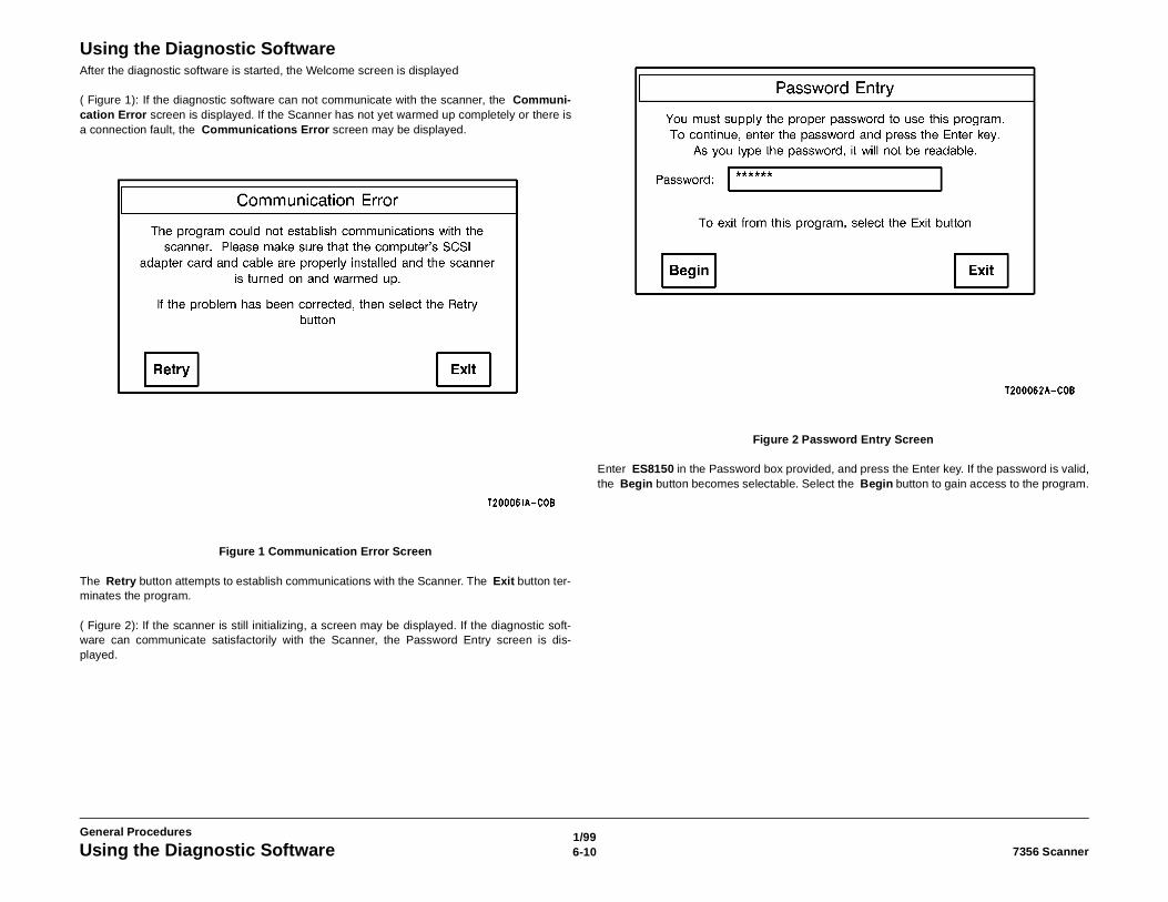
1/996-10 7356 ScannerUsing the Diagnostic Software
General Procedures
Using the Diagnostic SoftwareAfter the diagnostic software is started, the Welcome screen is displayed
( Figure 1): If the diagnostic software can not communicate with the scanner, the Communi-cation Error screen is displayed. If the Scanner has not yet warmed up completely or there isa connection fault, the Communications Error screen may be displayed.
Figure 1 Communication Error Screen
The Retry button attempts to establish communications with the Scanner. The Exit button ter-minates the program.
( Figure 2): If the scanner is still initializing, a screen may be displayed. If the diagnostic soft-ware can communicate satisfactorily with the Scanner, the Password Entry screen is dis-played.
Figure 2 Password Entry Screen
Enter ES8150 in the Password box provided, and press the Enter key. If the password is valid,the Begin button becomes selectable. Select the Begin button to gain access to the program.
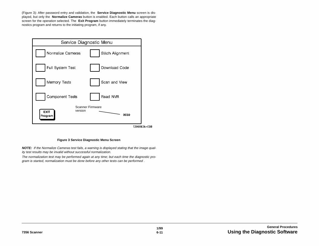
1/996-117356 Scanner Using the Diagnostic Software
General Procedures
(Figure 3): After password entry and validation, the Service Diagnostic Menu screen is dis-played, but only the Normalize Cameras button is enabled. Each button calls an appropriatescreen for the operation selected. The Exit Program button immediately terminates the diag-nostics program and returns to the initiating program, if any.
Figure 3 Service Diagnostic Menu Screen
NOTE: If the Normalize Cameras test fails, a warning is displayed stating that the image qual-ity test results may be invalid without successful normalization.
The normalization test may be performed again at any time; but each time the diagnostic pro-gram is started, normalization must be done before any other tests can be performed .
Scanner Firmware version
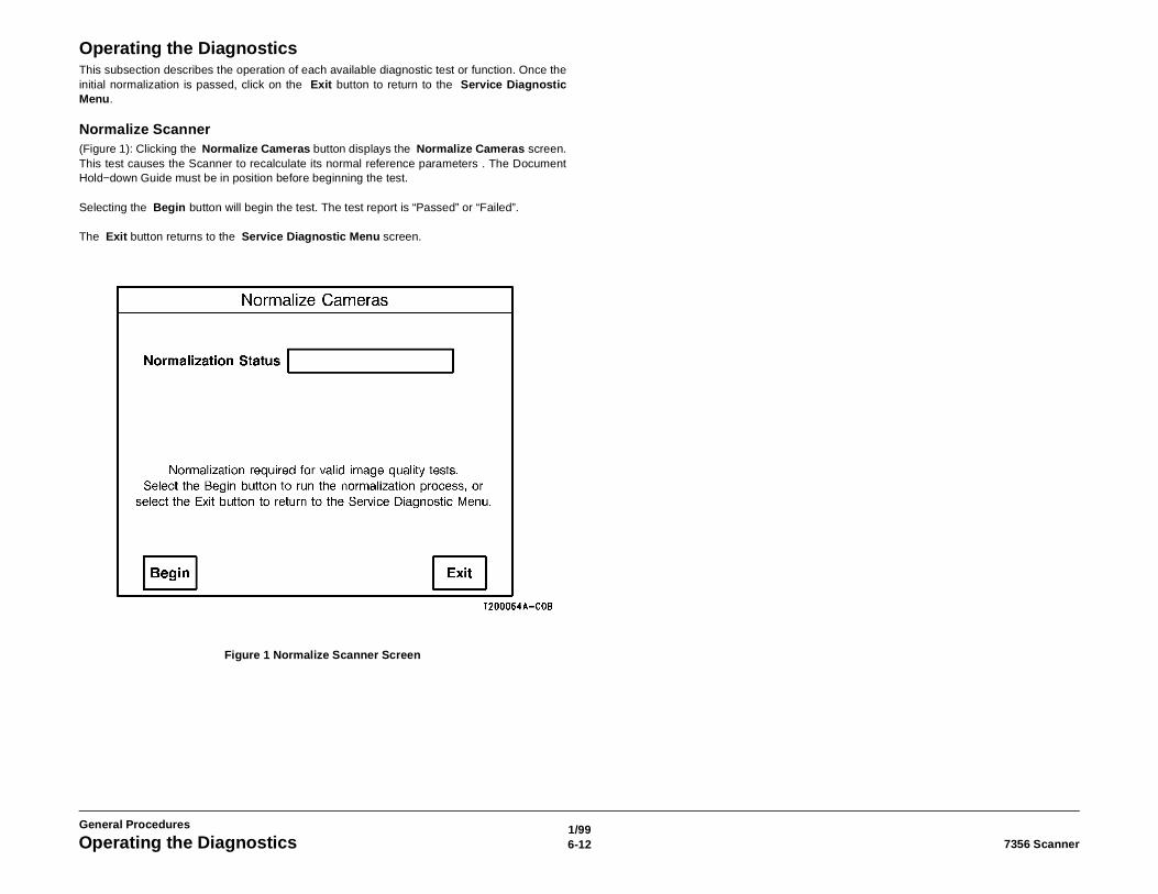
1/996-12 7356 ScannerOperating the Diagnostics
General Procedures
Operating the DiagnosticsThis subsection describes the operation of each available diagnostic test or function. Once theinitial normalization is passed, click on the Exit button to return to the Service DiagnosticMenu.
Normalize Scanner(Figure 1): Clicking the Normalize Cameras button displays the Normalize Cameras screen.This test causes the Scanner to recalculate its normal reference parameters . The DocumentHold−down Guide must be in position before beginning the test.
Selecting the Begin button will begin the test. The test report is “Passed” or “Failed”.
The Exit button returns to the Service Diagnostic Menu screen.
Figure 1 Normalize Scanner Screen
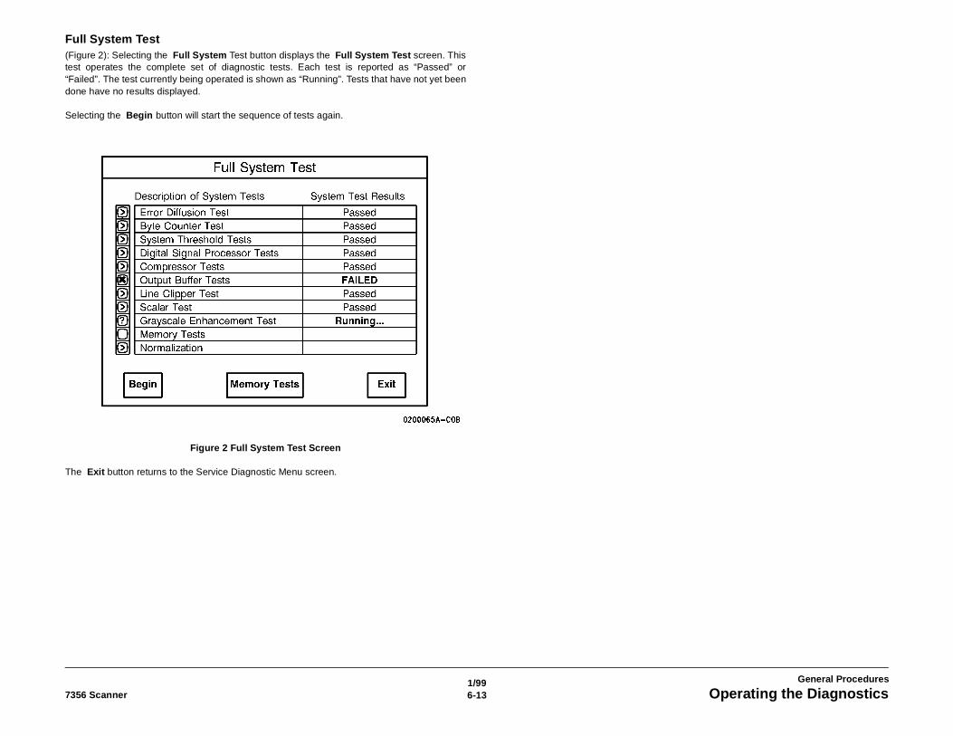
1/996-137356 Scanner Operating the Diagnostics
General Procedures
Full System Test(Figure 2): Selecting the Full System Test button displays the Full System Test screen. Thistest operates the complete set of diagnostic tests. Each test is reported as “Passed” or“Failed”. The test currently being operated is shown as “Running”. Tests that have not yet beendone have no results displayed.
Selecting the Begin button will start the sequence of tests again.
Figure 2 Full System Test Screen
The Exit button returns to the Service Diagnostic Menu screen.
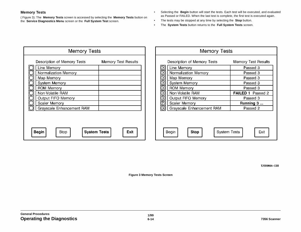
1/996-14 7356 ScannerOperating the Diagnostics
General Procedures
Memory Tests( Figure 3): The Memory Tests screen is accessed by selecting the Memory Tests button onthe Service Diagnostics Menu screen or the Full System Test screen.
• Selecting the Begin button will start the tests. Each test will be executed, and evaluatedas Passed or FAILED. When the last test is complete, the first test is executed again.
• The tests may be stopped at any time by selecting the Stop button.
• The System Tests button returns to the Full System Tests screen.
Figure 3 Memory Tests Screen
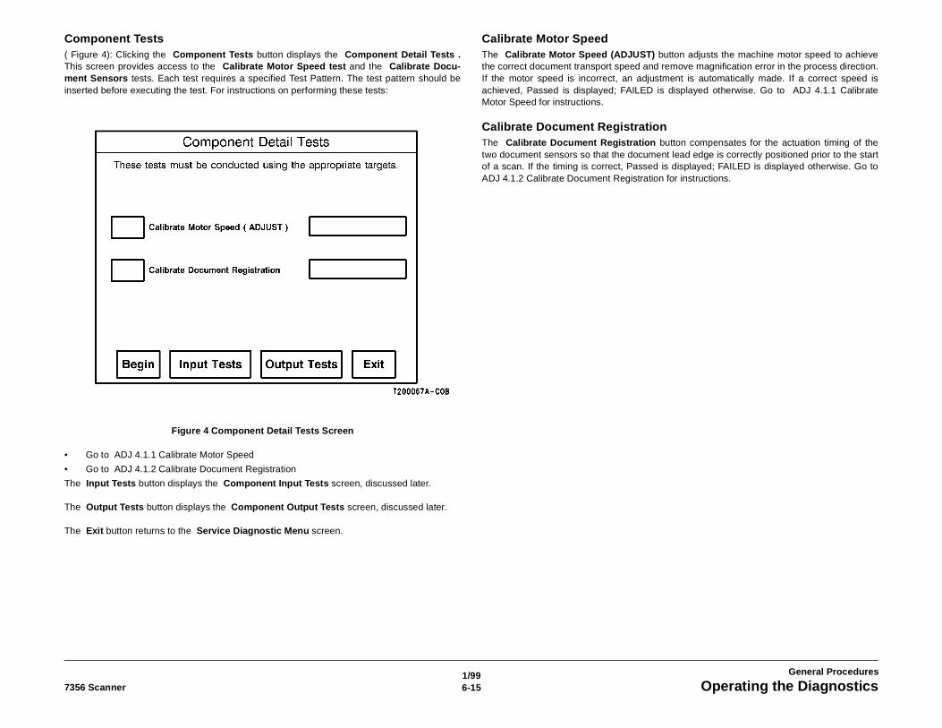
1/996-157356 Scanner Operating the Diagnostics
General Procedures
Component Tests( Figure 4): Clicking the Component Tests button displays the Component Detail Tests .This screen provides access to the Calibrate Motor Speed test and the Calibrate Docu-ment Sensors tests. Each test requires a specified Test Pattern. The test pattern should beinserted before executing the test. For instructions on performing these tests:
Figure 4 Component Detail Tests Screen
• Go to ADJ 4.1.1 Calibrate Motor Speed
• Go to ADJ 4.1.2 Calibrate Document Registration
The Input Tests button displays the Component Input Tests screen, discussed later.
The Output Tests button displays the Component Output Tests screen, discussed later.
The Exit button returns to the Service Diagnostic Menu screen.
Calibrate Motor SpeedThe Calibrate Motor Speed (ADJUST) button adjusts the machine motor speed to achievethe correct document transport speed and remove magnification error in the process direction.If the motor speed is incorrect, an adjustment is automatically made. If a correct speed isachieved, Passed is displayed; FAILED is displayed otherwise. Go to ADJ 4.1.1 CalibrateMotor Speed for instructions.
Calibrate Document RegistrationThe Calibrate Document Registration button compensates for the actuation timing of thetwo document sensors so that the document lead edge is correctly positioned prior to the startof a scan. If the timing is correct, Passed is displayed; FAILED is displayed otherwise. Go toADJ 4.1.2 Calibrate Document Registration for instructions.

1/996-16 7356 ScannerOperating the Diagnostics
General Procedures
Component Input Tests( Figure 5): The Component Input Tests screen allows the testing of the Forward/ReverseSwitch and the two document edge sensors.
Figure 5 Component Input Test Screens
Once the Begin button is selected, the logic states of the signal lines connected to the compo-nent are displayed. The states are displayed as HIGH or LOW. During these tests, no otherchanges in machine state occur.
• The Begin button executes the selected test, and must be selected before any signalstatus indications can be observed.
• The Halt button halts the selected test.
• The Detail Tests button returns to the Component Detail Tests screen.
• The Output Tests button advances to the Component Output Tests screen.
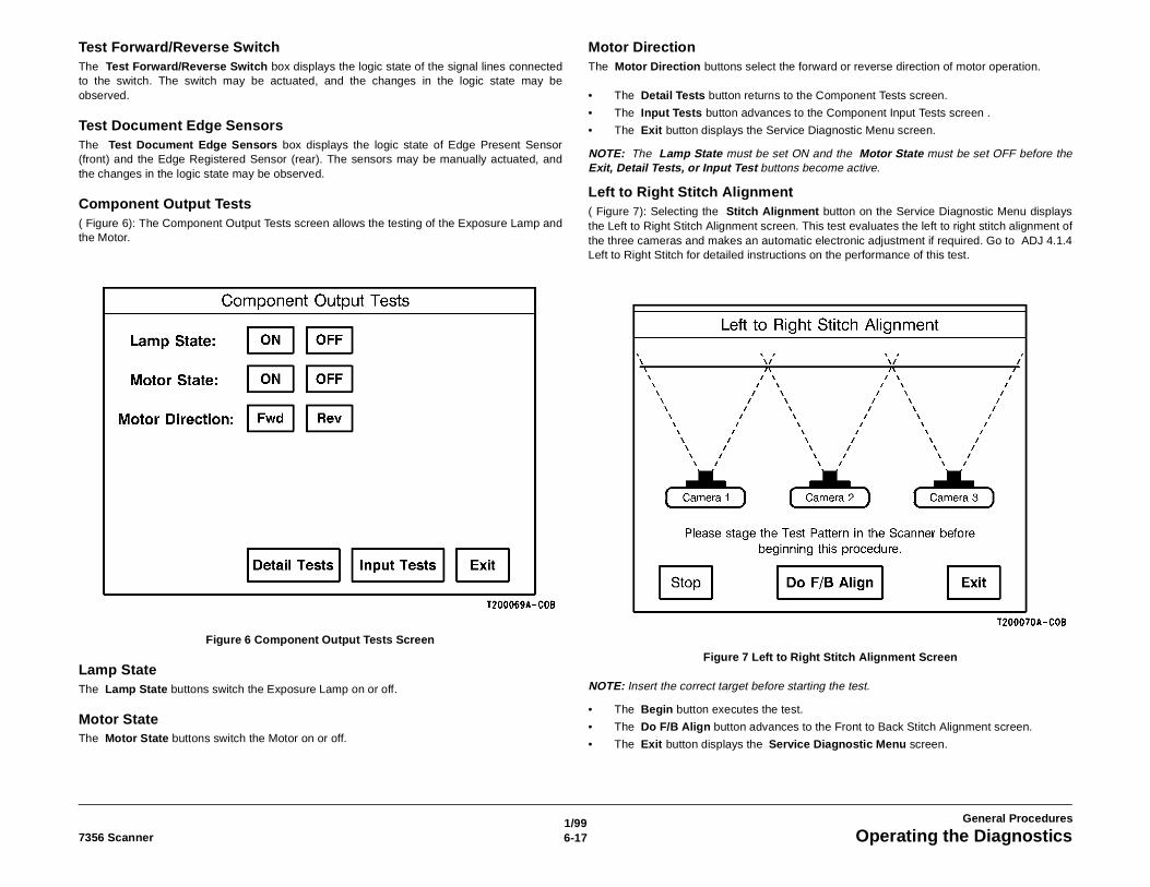
1/996-177356 Scanner Operating the Diagnostics
General Procedures
Test Forward/Reverse SwitchThe Test Forward/Reverse Switch box displays the logic state of the signal lines connectedto the switch. The switch may be actuated, and the changes in the logic state may beobserved.
Test Document Edge SensorsThe Test Document Edge Sensors box displays the logic state of Edge Present Sensor(front) and the Edge Registered Sensor (rear). The sensors may be manually actuated, andthe changes in the logic state may be observed.
Component Output Tests( Figure 6): The Component Output Tests screen allows the testing of the Exposure Lamp andthe Motor.
Figure 6 Component Output Tests Screen
Lamp StateThe Lamp State buttons switch the Exposure Lamp on or off.
Motor StateThe Motor State buttons switch the Motor on or off.
Motor DirectionThe Motor Direction buttons select the forward or reverse direction of motor operation.
• The Detail Tests button returns to the Component Tests screen.
• The Input Tests button advances to the Component Input Tests screen .
• The Exit button displays the Service Diagnostic Menu screen.
NOTE: The Lamp State must be set ON and the Motor State must be set OFF before theExit, Detail Tests, or Input Test buttons become active.
Left to Right Stitch Alignment( Figure 7): Selecting the Stitch Alignment button on the Service Diagnostic Menu displaysthe Left to Right Stitch Alignment screen. This test evaluates the left to right stitch alignment ofthe three cameras and makes an automatic electronic adjustment if required. Go to ADJ 4.1.4Left to Right Stitch for detailed instructions on the performance of this test.
Figure 7 Left to Right Stitch Alignment Screen
NOTE: Insert the correct target before starting the test.
• The Begin button executes the test.
• The Do F/B Align button advances to the Front to Back Stitch Alignment screen.
• The Exit button displays the Service Diagnostic Menu screen.
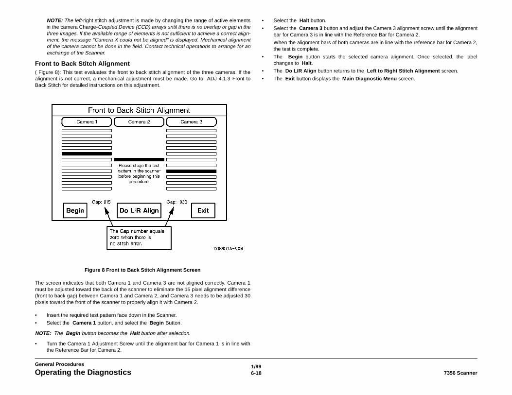
1/996-18 7356 ScannerOperating the Diagnostics
General Procedures
NOTE: The left-right stitch adjustment is made by changing the range of active elementsin the camera Charge-Coupled Device (CCD) arrays until there is no overlap or gap in thethree images. If the available range of elements is not sufficient to achieve a correct align-ment, the message “Camera X could not be aligned” is displayed. Mechanical alignmentof the camera cannot be done in the field. Contact technical operations to arrange for anexchange of the Scanner.
Front to Back Stitch Alignment( Figure 8): This test evaluates the front to back stitch alignment of the three cameras. If thealignment is not correct, a mechanical adjustment must be made. Go to ADJ 4.1.3 Front toBack Stitch for detailed instructions on this adjustment.
Figure 8 Front to Back Stitch Alignment Screen
The screen indicates that both Camera 1 and Camera 3 are not aligned correctly. Camera 1must be adjusted toward the back of the scanner to eliminate the 15 pixel alignment difference(front to back gap) between Camera 1 and Camera 2, and Camera 3 needs to be adjusted 30pixels toward the front of the scanner to properly align it with Camera 2.
• Insert the required test pattern face down in the Scanner.
• Select the Camera 1 button, and select the Begin Button.
NOTE: The Begin button becomes the Halt button after selection.
• Turn the Camera 1 Adjustment Screw until the alignment bar for Camera 1 is in line withthe Reference Bar for Camera 2.
• Select the Halt button.
• Select the Camera 3 button and adjust the Camera 3 alignment screw until the alignmentbar for Camera 3 is in line with the Reference Bar for Camera 2.
When the alignment bars of both cameras are in line with the reference bar for Camera 2,the test is complete.
• The Begin button starts the selected camera alignment. Once selected, the labelchanges to Halt.
• The Do L/R Align button returns to the Left to Right Stitch Alignment screen.
• The Exit button displays the Main Diagnostic Menu screen.
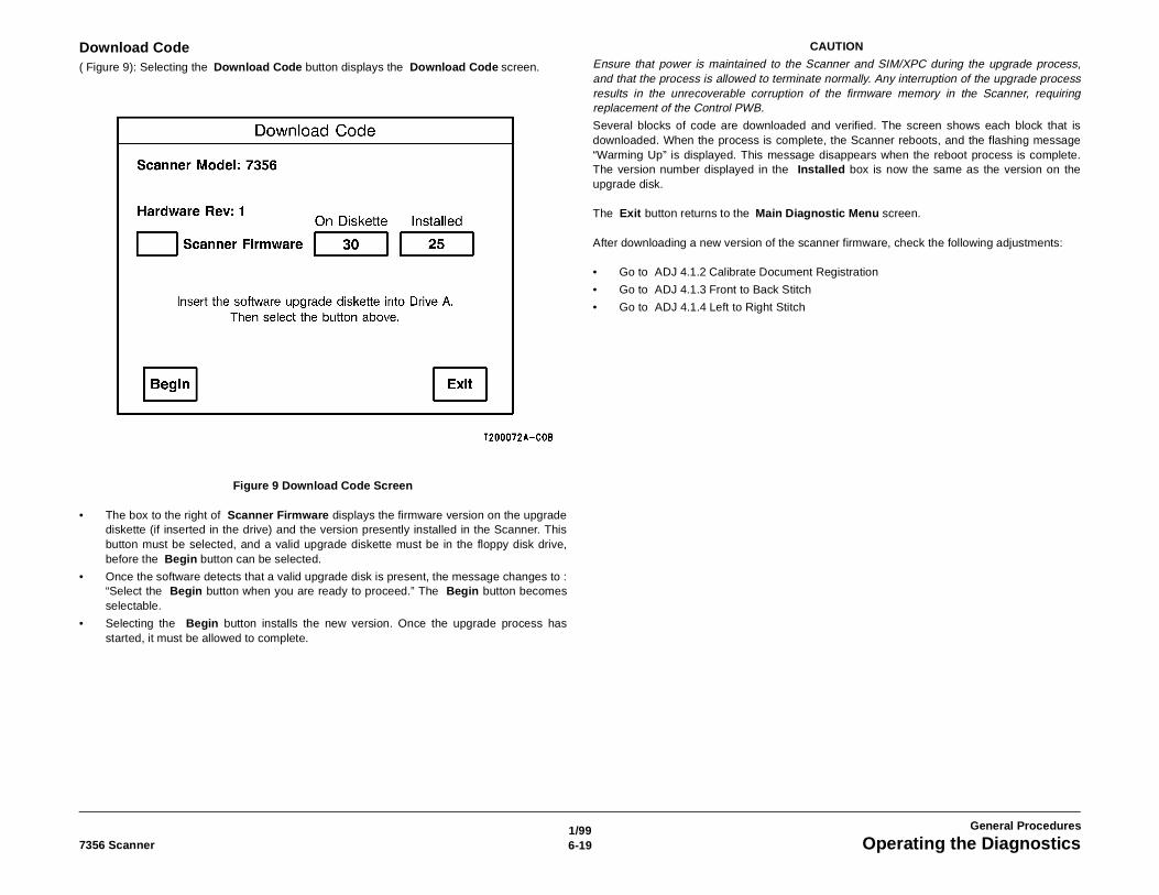
1/996-197356 Scanner Operating the Diagnostics
General Procedures
Download Code( Figure 9): Selecting the Download Code button displays the Download Code screen.
Figure 9 Download Code Screen
• The box to the right of Scanner Firmware displays the firmware version on the upgradediskette (if inserted in the drive) and the version presently installed in the Scanner. Thisbutton must be selected, and a valid upgrade diskette must be in the floppy disk drive,before the Begin button can be selected.
• Once the software detects that a valid upgrade disk is present, the message changes to :“Select the Begin button when you are ready to proceed.” The Begin button becomesselectable.
• Selecting the Begin button installs the new version. Once the upgrade process hasstarted, it must be allowed to complete.
CAUTION
Ensure that power is maintained to the Scanner and SIM/XPC during the upgrade process,and that the process is allowed to terminate normally. Any interruption of the upgrade processresults in the unrecoverable corruption of the firmware memory in the Scanner, requiringreplacement of the Control PWB.
Several blocks of code are downloaded and verified. The screen shows each block that isdownloaded. When the process is complete, the Scanner reboots, and the flashing message“Warming Up” is displayed. This message disappears when the reboot process is complete.The version number displayed in the Installed box is now the same as the version on theupgrade disk.
The Exit button returns to the Main Diagnostic Menu screen.
After downloading a new version of the scanner firmware, check the following adjustments:
• Go to ADJ 4.1.2 Calibrate Document Registration
• Go to ADJ 4.1.3 Front to Back Stitch
• Go to ADJ 4.1.4 Left to Right Stitch
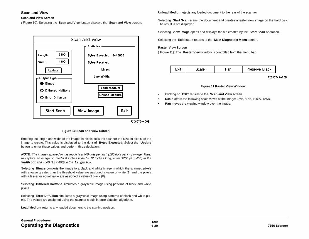
1/996-20 7356 ScannerOperating the Diagnostics
General Procedures
Scan and ViewScan and View Screen
( Figure 10): Selecting the Scan and View button displays the Scan and View screen.
Figure 10 Scan and View Screen.
Entering the length and width of the image, in pixels, tells the scanner the size, in pixels, of theimage to create. This value is displayed to the right of Bytes Expected. Select the Updatebutton to enter these values and perform this calculation.
NOTE: The image captured in this mode is a 400 dots per inch (160 dots per cm) image. Thus,to capture an image on media 8 inches wide by 12 inches long, enter 3200 (8 x 400) in theWidth box and 4800 (12 x 400) in the Length box.
Selecting Binary converts the image to a black and white image in which the scanned pixelswith a value greater than the threshold value are assigned a value of white (1) and the pixelswith a lesser or equal value are assigned a value of black (0).
Selecting Dithered Halftone simulates a grayscale image using patterns of black and whitepixels.
Selecting Error Diffusion simulates a grayscale image using patterns of black and white pix-els. The values are assigned using the scanner’s built in error diffusion algorithm.
Load Medium returns any loaded document to the starting position.
Unload Medium ejects any loaded document to the rear of the scanner.
Selecting Start Scan scans the document and creates a raster view image on the hard disk.The result is not displayed.
Selecting View Image opens and displays the file created by the Start Scan operation.
Selecting the Exit button returns to the Main Diagnostic Menu screen.
Raster View Screen
( Figure 11): The Raster View window is controlled from the menu bar.
Figure 11 Raster View Window
• Clicking on EXIT returns to the Scan and View screen.
• Scale offers the following scale views of the image: 25%, 50%, 100%, 125%.
• Pan moves the viewing window over the image.
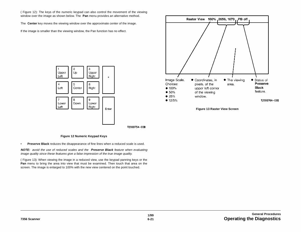
1/996-217356 Scanner Operating the Diagnostics
General Procedures
( Figure 12): The keys of the numeric keypad can also control the movement of the viewingwindow over the image as shown below. The Pan menu provides an alternative method.
The Center key moves the viewing window over the approximate center of the image.
If the image is smaller than the viewing window, the Pan function has no effect.
Figure 12 Numeric Keypad Keys
• Preserve Black reduces the disappearance of fine lines when a reduced scale is used.
NOTE: avoid the use of reduced scales and the Preserve Black feature when evaluatingimage quality since these features give a false impression of the true image quality.
( Figure 13): When viewing the image in a reduced view, use the keypad panning keys or thePan menu to bring the area into view that must be examined. Then touch that area on thescreen. The image is enlarged to 100% with the new view centered on the point touched.
Figure 13 Raster View Screen
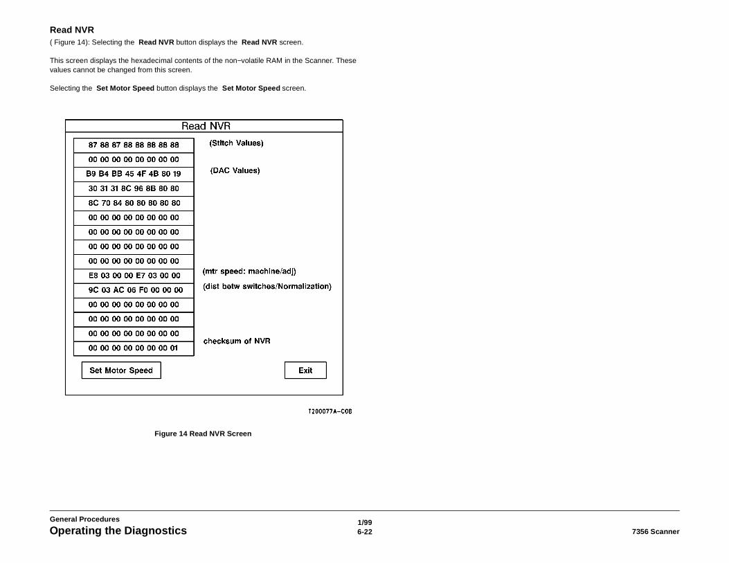
1/996-22 7356 ScannerOperating the Diagnostics
General Procedures
Read NVR( Figure 14): Selecting the Read NVR button displays the Read NVR screen.
This screen displays the hexadecimal contents of the non−volatile RAM in the Scanner. Thesevalues cannot be changed from this screen.
Selecting the Set Motor Speed button displays the Set Motor Speed screen.
Figure 14 Read NVR Screen
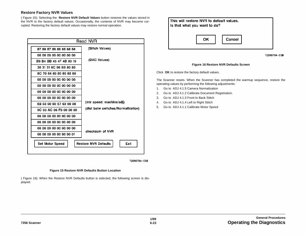
1/996-237356 Scanner Operating the Diagnostics
General Procedures
Restore Factory NVR Values( Figure 15): Selecting the Restore NVR Default Values button restores the values stored inthe NVR to the factory default values. Occasionally, the contents of NVR may become cor-rupted. Restoring the factory default values may restore normal operation.
Figure 15 Restore NVR Defaults Button Location
( Figure 16): When the Restore NVR Defaults button is selected, the following screen is dis-played:
Figure 16 Restore NVR Defaults Screen
Click OK to restore the factory default values.
The Scanner resets. When the Scanner has completed the warmup sequence, restore theoperating values by performing the following adjustments:
1. Go to ADJ 4.1.5 Camera Normalization
2. Go to ADJ 4.1.2 Calibrate Document Registration.
3. Go to ADJ 4.1.3 Front to Back Stitch
4. Go to ADJ 4.1.4 Left to Right Stitch
5. Go to ADJ 4.1.1 Calibrate Motor Speed
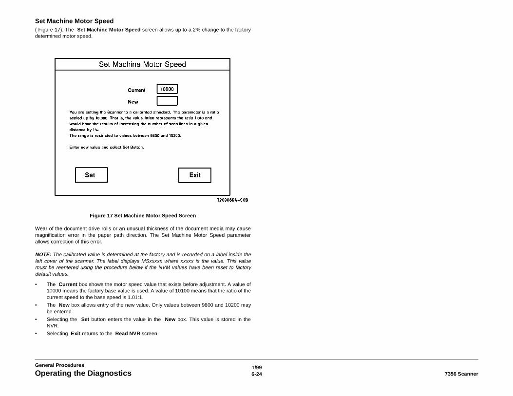
1/996-24 7356 ScannerOperating the Diagnostics
General Procedures
Set Machine Motor Speed( Figure 17): The Set Machine Motor Speed screen allows up to a 2% change to the factorydetermined motor speed.
Figure 17 Set Machine Motor Speed Screen
Wear of the document drive rolls or an unusual thickness of the document media may causemagnification error in the paper path direction. The Set Machine Motor Speed parameterallows correction of this error.
NOTE: The calibrated value is determined at the factory and is recorded on a label inside theleft cover of the scanner. The label displays MSxxxxx where xxxxx is the value. This valuemust be reentered using the procedure below if the NVM values have been reset to factorydefault values.
• The Current box shows the motor speed value that exists before adjustment. A value of10000 means the factory base value is used. A value of 10100 means that the ratio of thecurrent speed to the base speed is 1.01:1.
• The New box allows entry of the new value. Only values between 9800 and 10200 maybe entered.
• Selecting the Set button enters the value in the New box. This value is stored in theNVR.
• Selecting Exit returns to the Read NVR screen.
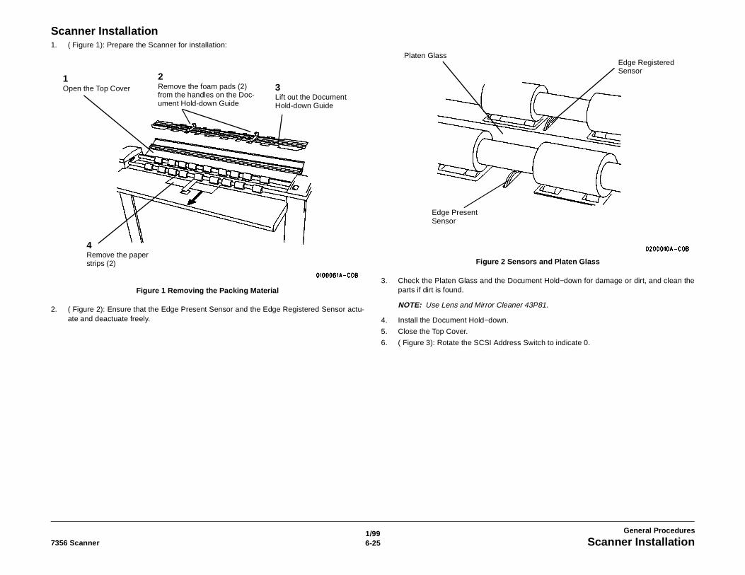
1/996-257356 Scanner Scanner Installation
General Procedures
Scanner Installation1. ( Figure 1): Prepare the Scanner for installation:
Figure 1 Removing the Packing Material
2. ( Figure 2): Ensure that the Edge Present Sensor and the Edge Registered Sensor actu-ate and deactuate freely.
Figure 2 Sensors and Platen Glass
3. Check the Platen Glass and the Document Hold−down for damage or dirt, and clean theparts if dirt is found.
NOTE: Use Lens and Mirror Cleaner 43P81.
4. Install the Document Hold−down.
5. Close the Top Cover.
6. ( Figure 3): Rotate the SCSI Address Switch to indicate 0.
2Remove the foam pads (2) from the handles on the Doc-ument Hold-down Guide
3Lift out the Document Hold-down Guide
1Open the Top Cover
4Remove the paper strips (2)
Platen Glass
Edge Present Sensor
Edge Registered Sensor
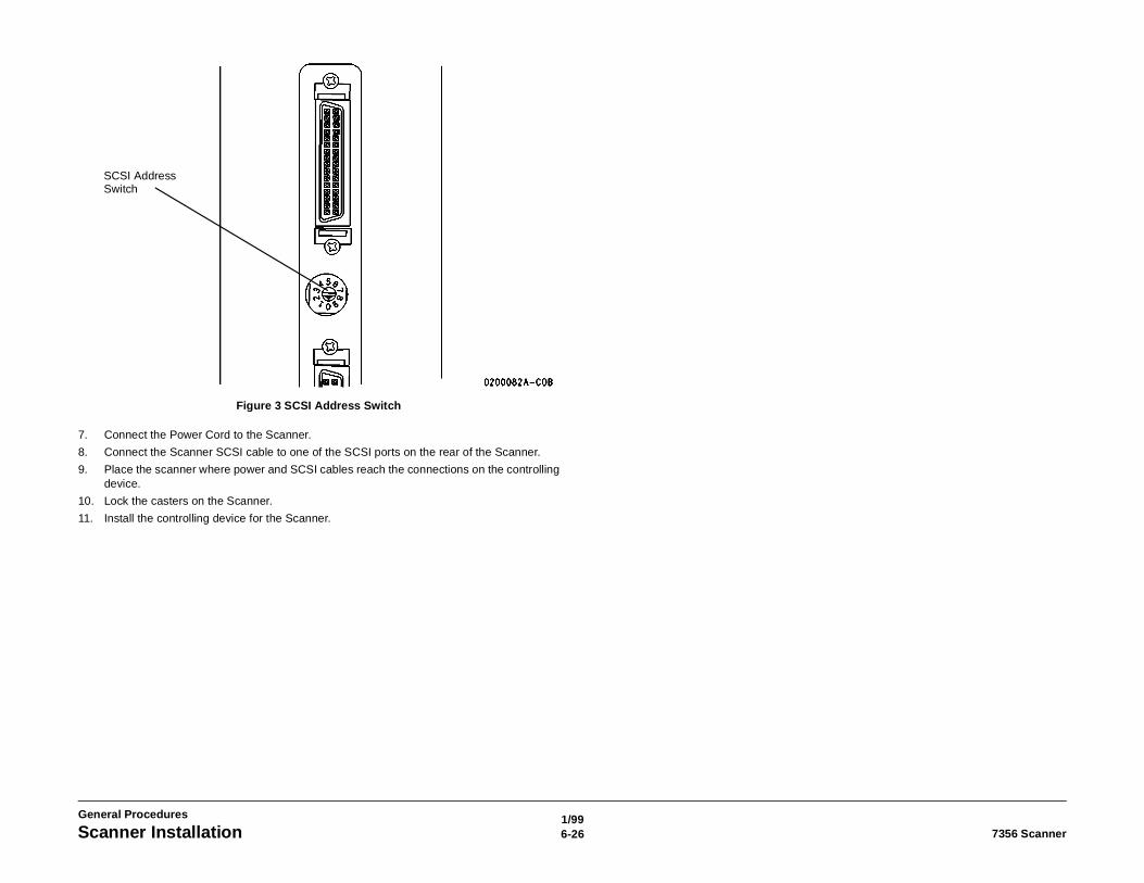
1/996-26 7356 ScannerScanner Installation
General Procedures
Figure 3 SCSI Address Switch
7. Connect the Power Cord to the Scanner.
8. Connect the Scanner SCSI cable to one of the SCSI ports on the rear of the Scanner.
9. Place the scanner where power and SCSI cables reach the connections on the controllingdevice.
10. Lock the casters on the Scanner.
11. Install the controlling device for the Scanner.
SCSI Address Switch
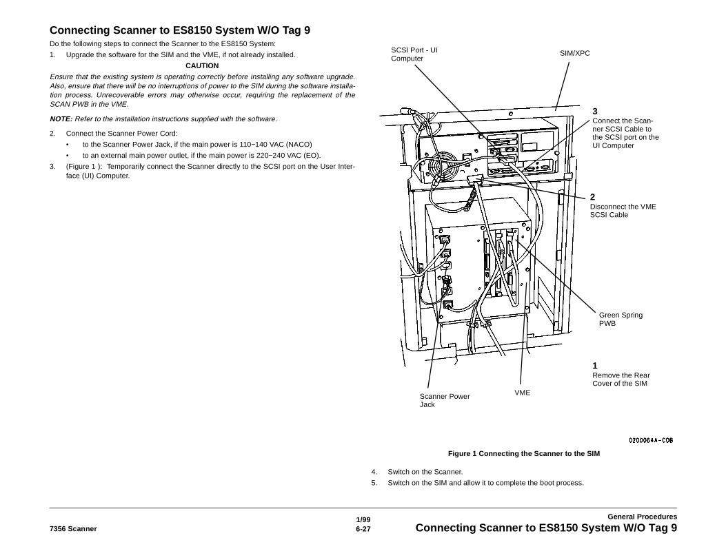
1/996-277356 Scanner Connecting Scanner to ES8150 System W/O Tag 9
General Procedures
Connecting Scanner to ES8150 System W/O Tag 9Do the following steps to connect the Scanner to the ES8150 System:
1. Upgrade the software for the SIM and the VME, if not already installed.
CAUTION
Ensure that the existing system is operating correctly before installing any software upgrade.Also, ensure that there will be no interruptions of power to the SIM during the software installa-tion process. Unrecoverable errors may otherwise occur, requiring the replacement of theSCAN PWB in the VME.
NOTE: Refer to the installation instructions supplied with the software.
2. Connect the Scanner Power Cord:
• to the Scanner Power Jack, if the main power is 110−140 VAC (NACO)
• to an external main power outlet, if the main power is 220−240 VAC (EO).
3. (Figure 1 ): Temporarily connect the Scanner directly to the SCSI port on the User Inter-face (UI) Computer.
Figure 1 Connecting the Scanner to the SIM
4. Switch on the Scanner.
5. Switch on the SIM and allow it to complete the boot process.
SCSI Port - UI Computer
SIM/XPC
Green Spring PWB
VMEScanner Power Jack
2Disconnect the VME SCSI Cable
1Remove the Rear Cover of the SIM
3Connect the Scan-ner SCSI Cable to the SCSI port on the UI Computer
1/996-28 7356 ScannerConnecting Scanner to ES8150 System W/O Tag 9
General Procedures
6. Start the diagnostic software. Go to Configuring for Extended Diagnostics - XPC/ES8150(in this section).
7. Perform a Normalize Cameras test. If the test fails, clean the Platen Glass and the Docu-ment Hold−down guide carefully; then repeat the test.
8. Perform the following:
• Go to ADJ 4.1.3 Front to Back Stitch.
• Go to ADJ 4.1.4 Left to Right Stitch.
• Go to ADJ 4.1.2 Calibrate Document Registration. If the adjustment is not correct,perform the adjustment procedure.
9. Exit the diagnostic software.
10. Switch off the SIM/XPC.
11. Switch off the Scanner.
12. Disconnect the Scanner SCSI Cable from the computer.
13. Connect the Scanner SCSI Cable to J1 on the SCAN PWB.
14. Connect one end of the VME SCSI cable to the SCSI port on the computer.
15. Connect the other end of the VME SCSI cable to the top SCSI connector on the GreenSpring PWB.
16. Switch on the Scanner.
17. Switch on the SIM.
18. Make a copy using Test Pattern 082E11490. Ensure that the copy has satisfactory copyquality − no stitch overlaps of discontinuities in the lines of the test image.
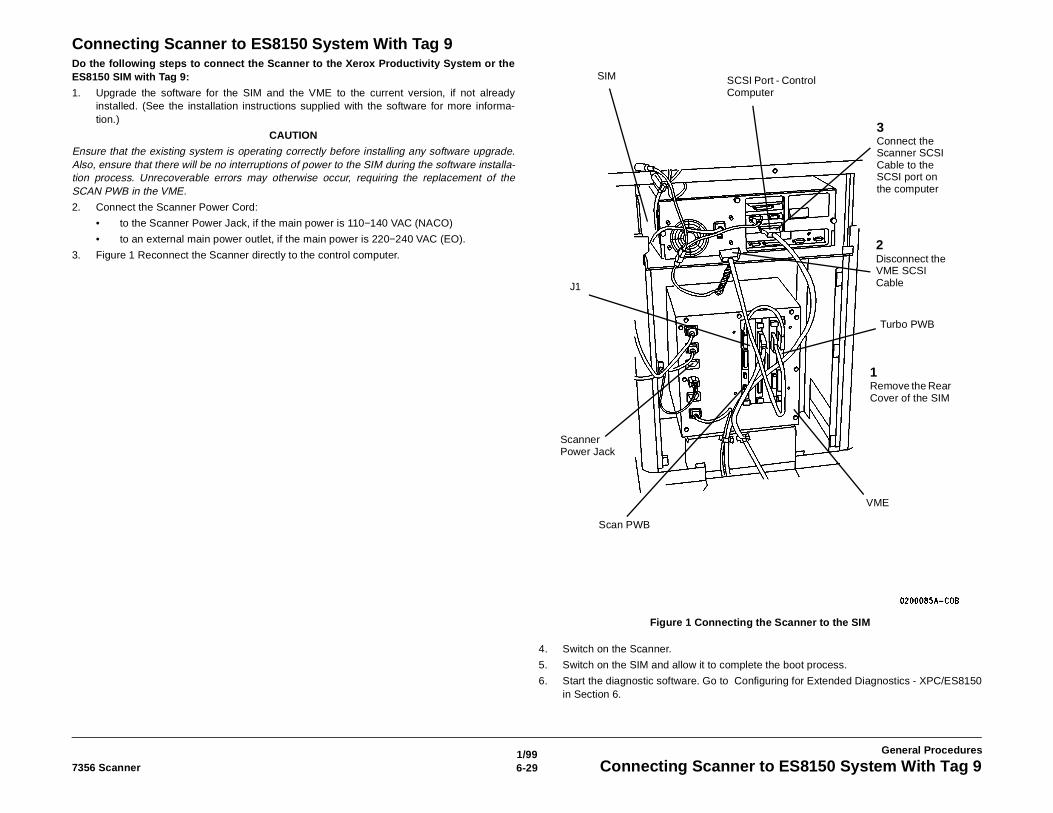
1/996-297356 Scanner Connecting Scanner to ES8150 System With Tag 9
General Procedures
Connecting Scanner to ES8150 System With Tag 9Do the following steps to connect the Scanner to the Xerox Productivity System or theES8150 SIM with Tag 9:
1. Upgrade the software for the SIM and the VME to the current version, if not alreadyinstalled. (See the installation instructions supplied with the software for more informa-tion.)
CAUTION
Ensure that the existing system is operating correctly before installing any software upgrade.Also, ensure that there will be no interruptions of power to the SIM during the software installa-tion process. Unrecoverable errors may otherwise occur, requiring the replacement of theSCAN PWB in the VME.
2. Connect the Scanner Power Cord:
• to the Scanner Power Jack, if the main power is 110−140 VAC (NACO)
• to an external main power outlet, if the main power is 220−240 VAC (EO).
3. Figure 1 Reconnect the Scanner directly to the control computer.
Figure 1 Connecting the Scanner to the SIM
4. Switch on the Scanner.
5. Switch on the SIM and allow it to complete the boot process.
6. Start the diagnostic software. Go to Configuring for Extended Diagnostics - XPC/ES8150in Section 6.
1Remove the Rear Cover of the SIM
2Disconnect the VME SCSI Cable
SCSI Port - Control Computer
Turbo PWB
VME
Scan PWB
J1
Scanner Power Jack
SIM
3Connect the Scanner SCSI Cable to the SCSI port on the computer
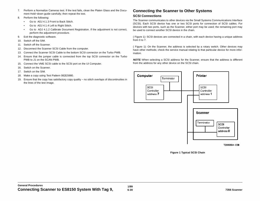
1/996-30 7356 ScannerConnecting Scanner to ES8150 System With Tag 9,
General Procedures
7. Perform a Normalize Cameras test. If the test fails, clean the Platen Glass and the Docu-ment Hold−down guide carefully; then repeat the test.
8. Perform the following:
• Go to ADJ 4.1.3 Front to Back Stitch.
• Go to ADJ 4.1.4 Left to Right Stitch.
• Go to ADJ 4.1.2 Calibrate Document Registration. If the adjustment is not correct,perform the adjustment procedure.
9. Exit the diagnostic software.
10. Switch off the SIM.
11. Switch off the Scanner.
12. Disconnect the Scanner SCSI Cable from the computer.
13. Connect the Scanner SCSI Cable to the bottom SCSI connector on the Turbo PWB.
14. Ensure that the jumper cable is connected from the top SCSI connector on the TurboPWB to J1 on the SCAN PWB.
15. Connect the VME SCSI cable to the SCSI port on the UI Computer.
16. Switch on the Scanner.
17. Switch on the SIM.
18. Make a copy using Test Pattern 082E5980.
19. Ensure that the copy has satisfactory copy quality − no stitch overlaps of discontinuities inthe lines of the test image.
Connecting the Scanner to Other SystemsSCSI ConnectionsThe Scanner communicates to other devices via the Small Systems Communications Interface(SCSI). Each SCSI device has one or two SCSI ports for connection of SCSI cables. Fordevices with two ports, such as the Scanner, either port may be used; the remaining port maybe used to connect another SCSI device in the chain.
( Figure 1): SCSI devices are connected in a chain, with each device having a unique addressfrom 0 to 7.
( Figure 1): On the Scanner, the address is selected by a rotary switch. Other devices mayhave other methods; check the service manual relating to that particular device for more infor-mation.
NOTE: When selecting a SCSI address for the Scanner, ensure that the address is differentfrom the address for any other device on the SCSI chain.
Figure 1 Typical SCSI Chain
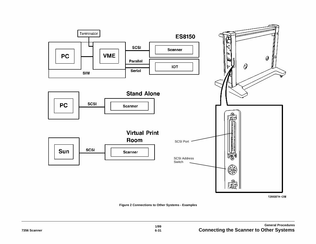
1/996-317356 Scanner Connecting the Scanner to Other Systems
General Procedures
Figure 2 Connections to Other Systems - Examples
SCSI Port
SCSI Address Switch
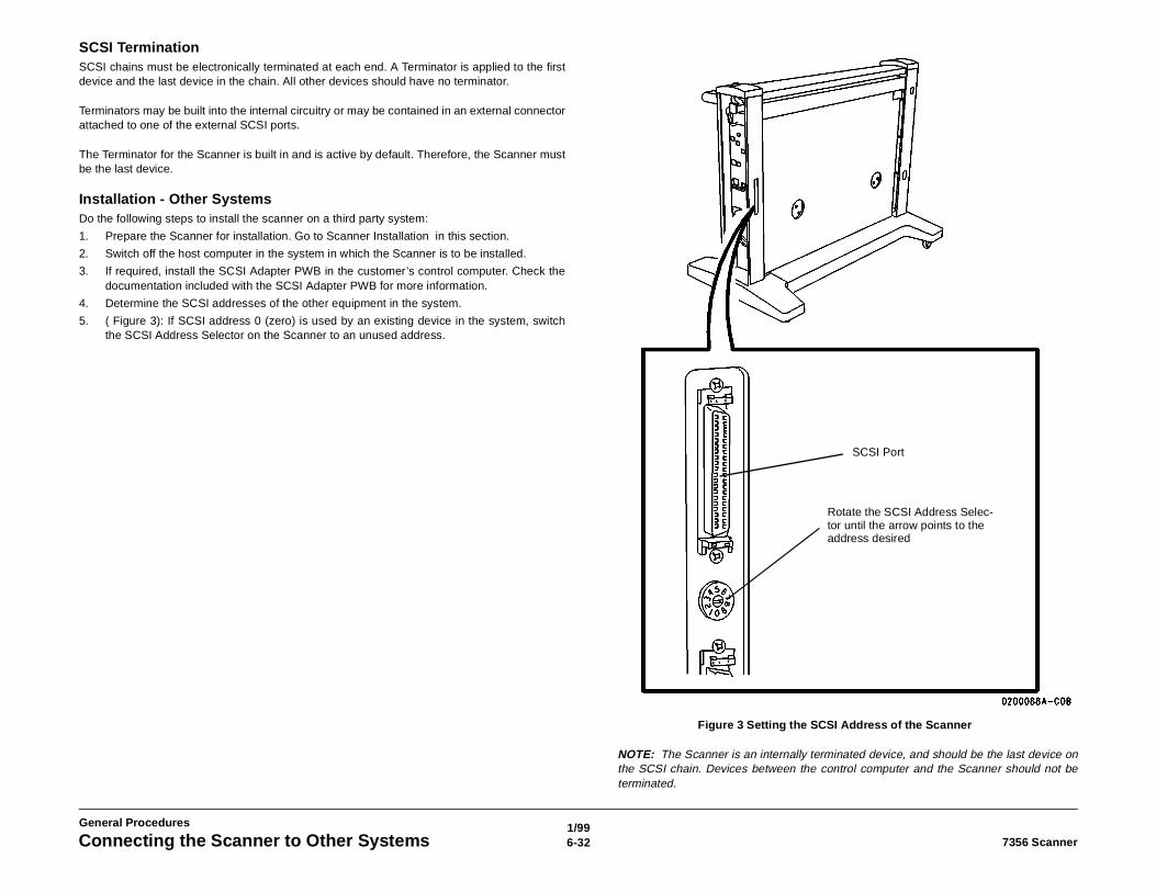
1/996-32 7356 ScannerConnecting the Scanner to Other Systems
General Procedures
SCSI TerminationSCSI chains must be electronically terminated at each end. A Terminator is applied to the firstdevice and the last device in the chain. All other devices should have no terminator.
Terminators may be built into the internal circuitry or may be contained in an external connectorattached to one of the external SCSI ports.
The Terminator for the Scanner is built in and is active by default. Therefore, the Scanner mustbe the last device.
Installation - Other SystemsDo the following steps to install the scanner on a third party system:
1. Prepare the Scanner for installation. Go to Scanner Installation in this section.
2. Switch off the host computer in the system in which the Scanner is to be installed.
3. If required, install the SCSI Adapter PWB in the customer’s control computer. Check thedocumentation included with the SCSI Adapter PWB for more information.
4. Determine the SCSI addresses of the other equipment in the system.
5. ( Figure 3): If SCSI address 0 (zero) is used by an existing device in the system, switchthe SCSI Address Selector on the Scanner to an unused address.
Figure 3 Setting the SCSI Address of the Scanner
NOTE: The Scanner is an internally terminated device, and should be the last device onthe SCSI chain. Devices between the control computer and the Scanner should not beterminated.
SCSI Port
Rotate the SCSI Address Selec-tor until the arrow points to the address desired
1/996-337356 Scanner Connecting the Scanner to Other Systems
General Procedures
6. Using a SCSI cable with the correct connectors, connect the SCSI Port on the Scanner tothe SCSI port on the last device in the existing system.
7. Remove any SCSI Terminator from the device to which the Scanner was connected in theprevious step.
8. Switch on the Scanner.
9. Switch on the other devices in the system.
10. Switch on the host computer and allow it to complete the boot process.
11. Install the floppy disk containing the scanner diagnostic software into the A: floppy diskdrive.
12. If the Windows operating program is not already started on the host computer after theboot process, then start Windows, by typing WIN and pressing the <enter> key.
13. Type a:SCSI7356 and press the <enter> key. The diagnostic software starts. Go to Usingthe Diagnostic Software, located in this section, for information about the operation of thissoftware. The password is ES8150.
14. Go to ADJ 4.1.3 Front to Back Stitch.
15. Go to ADJ 4.1.4 Left to Right Stitch.
16. Exit the diagnostic software.
17. Remove the disk from the A: drive.
18. Install the Scanner application software on the customer’s host computer:
a. Ensure that Windows is running.
b. Terminate any other applications that are currently running.
c. Insert disk 1 into the A: floppy disk drive.
d. Type A:SETUP and press the <enter> key.
e. Follow the instructions on the screen.
19. Make a test scan of the 082E11490 test pattern and view the image.
20. Examine the image for correct image quality.
• Ensure that the horizontal and diagonal lines have no objectionable discontinuitydue to stitch error.
• Also ensure that there are no deletions or distortions of the image.
1/996-34 7356 ScannerConnecting the Scanner to Other Systems
General Procedures
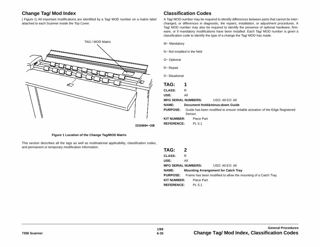
1/996-357356 Scanner Change Tag/ Mod Index, Classification Codes
General Procedures
Change Tag/ Mod Index( Figure 1) All important modifications are identified by a Tag/ MOD number on a matrix labelattached to each Scanner inside the Top Cover.
Figure 1 Location of the Change Tag/MOD Matrix
This section describes all the tags as well as multinational applicability, classification codes,and permanent or temporary modification information.
Classification CodesA Tag/ MOD number may be required to identify differences between parts that cannot be inter-changed, or differences in diagnostic, the repairs, installation, or adjustment procedures. ATag/ MOD number may also be required to identify the presence of optional hardware, firm-ware, or if mandatory modifications have been installed. Each Tag/ MOD number is given aclassification code to identify the type of a change the Tag/ MOD has made.
M− Mandatory
N− Not installed in the field
O− Optional
R− Repair
S− Situational
TAG: 1CLASS: R
USE: All
MFG SERIAL NUMBERS: USO: All EO: All
NAME: Document Hold−down Guide
PURPOSE: Guide has been modified to ensure reliable actuation of the Edge Registered Sensor.
KIT NUMBER: Piece Part
REFERENCE: PL 5.1
TAG: 2CLASS: R
USE: All
MFG SERIAL NUMBERS: USO: All EO: All
NAME: Mounting Arrangement for Catch Tray
PURPOSE: Frame has been modified to allow the mounting of a Catch Tray.
KIT NUMBER: Piece Part
REFERENCE: PL 5.1
TAG / MOD Matrix
5/996-36 7356 Scanner
General Procedures
TAG: 3CLASS: R
USE: All
MFG SERIAL NUMBERS: USO: All EO: All
NAME: Change in alignment of Edge Sensors
PURPOSE: Edge Present Sensor and Edge Registered Sensor have been aligned to new specifications to ensure more reliable actuation
KIT NUMBER: Piece Part
REFERENCE: PL 5.1, PL 5.2
TAG: 4CLASS: R
USE: All
MFG SERIAL NUMBERS: USO: All, EO: All
NAME: Modified Main Control PWB
PURPOSE: PURPOSE: PWB has been modified with additional test points. Filter Capacitor C140 was relocated from wiring harness to PWB.
KIT NUMBER: Piece Part
REFERENCE: PL 1.2
TAG: 5CLASS: O
USE: All
MFG SERIAL NUMBERS: USO: All EO: All
NAME: Modified Top Cover
PURPOSE: The Top Cover has three holes drilled to enable a future upgrade.
KIT NUMBER: 600K64670
REFERENCE: PL 14.1
TAG: 6CLASS: O
USE: All
MFG SERIAL NUMBERS: USO: All, EO: All
NAME: Modified Feed Shelf
PURPOSE: The Feed Shelf has three holes drilled to mount a Document Organizer.
KIT NUMBER: 600K64680
REFERENCE: PL 14.1
TAG: 7CLASS: R
USE: All
MFG SERIAL NUMBERS: USO: All, EO: All
NAME: Scanner Firmware
PURPOSE: PURPOSE: Updated firmware to support the 7356 Scanner.
KIT NUMBER: 600K62292
REFERENCE:
5/996-37 7356 Scanner
General Procedures
TAG 89CLASS: R
USE: All
MFG SERIAL NUMBERS: USO: All EO: All
NAME: Hold Down Bracket
PURPOSE To provide additional hold down force to ensure more reliable feeding of widw documents
KIT NUMBER: 600K64650
REFERENCE: PL 5.1
TAG: 90CLASS: R
USE: All
MFG SERIAL NUMBERS: USO: All, EO: All
NAME: Static Eliminator
PURPOSE: To reduce the static electricity effects on document feeding to improve the reliability of feeding documents in dirty environments.
KIT NUMBER: 606K6540
REFERENCE: PL 14.2

5/996-38 7356 Scanner
General Procedures
5/997-17356 Scanner Section Contents
Wiring-Data
7. Wiring-DataBSD 1.1 AC Power Distribution....................................................................................... 7-3BSD 1.2 DC Power Generation....................................................................................... 7-4BSD 4.1 Main Drive Motor Control .................................................................................. 7-6BSD 4.2 Mechanical Power ............................................................................................ 7-7BSD 5.1 Document Transport/ Registration.................................................................... 7-8BSD 6.1 Document Illumination ...................................................................................... 7-9BSD 6.2 Image Projection............................................................................................... 7-10BSD 14.1 Communication............................................................................................... 7-11

5/997-2 7356 Scanner
Wiring-Data
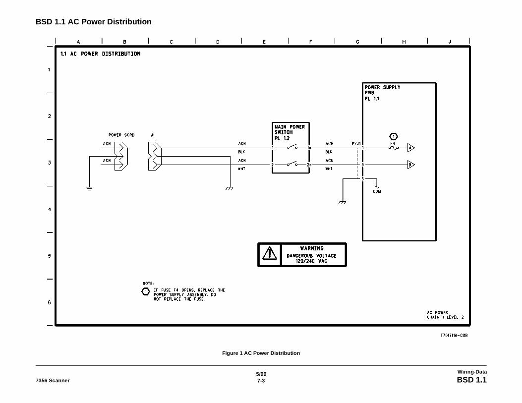
5/997-37356 Scanner BSD 1.1
Wiring-Data
BSD 1.1 AC Power Distribution
Figure 1 AC Power Distribution
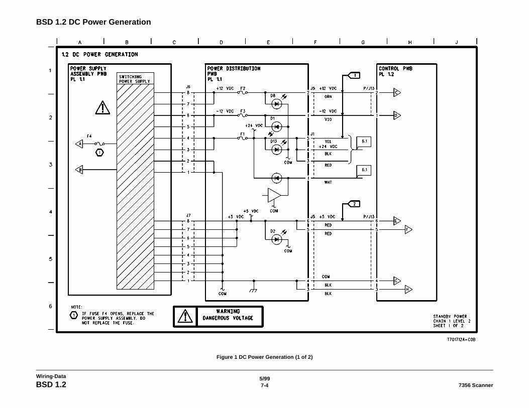
5/997-4 7356 ScannerBSD 1.2
Wiring-Data
BSD 1.2 DC Power Generation
Figure 1 DC Power Generation (1 of 2)
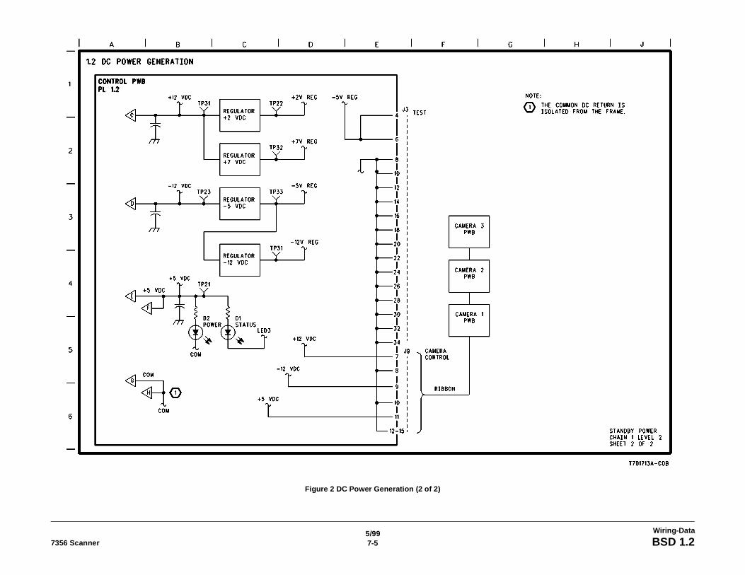
5/997-57356 Scanner BSD 1.2
Wiring-Data
Figure 2 DC Power Generation (2 of 2)
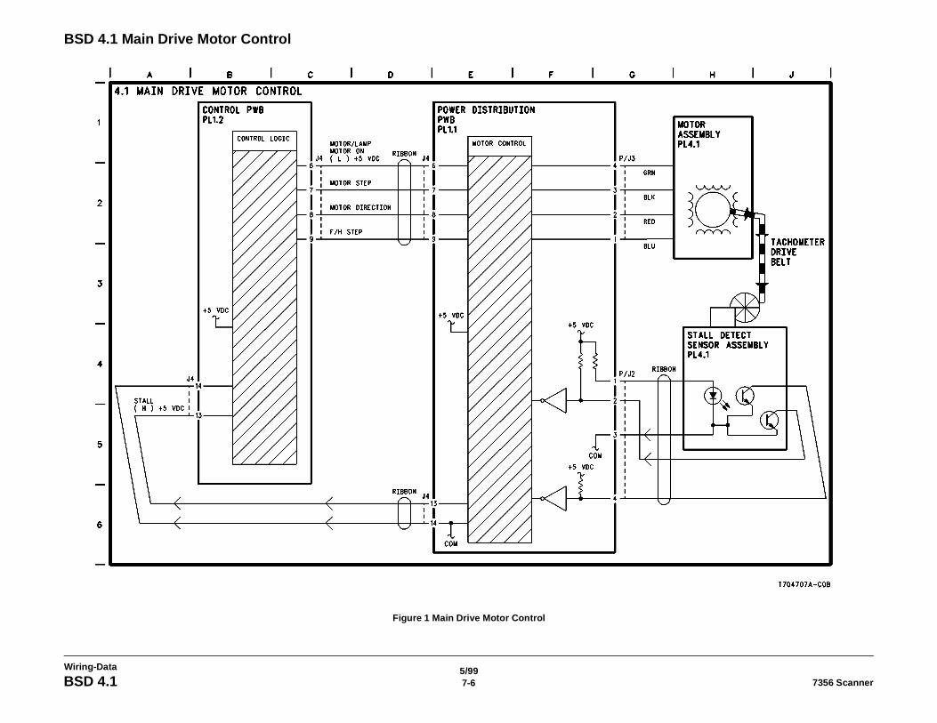
5/997-6 7356 ScannerBSD 4.1
Wiring-Data
BSD 4.1 Main Drive Motor Control
Figure 1 Main Drive Motor Control
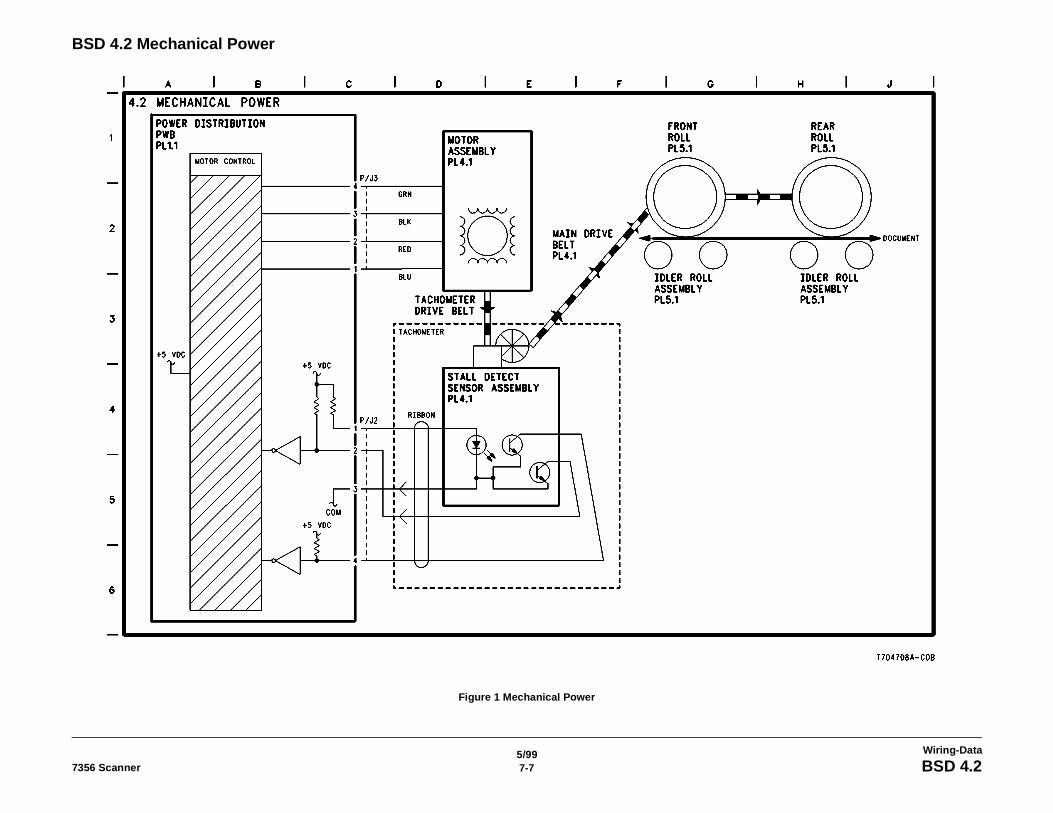
5/997-77356 Scanner BSD 4.2
Wiring-Data
BSD 4.2 Mechanical Power
Figure 1 Mechanical Power
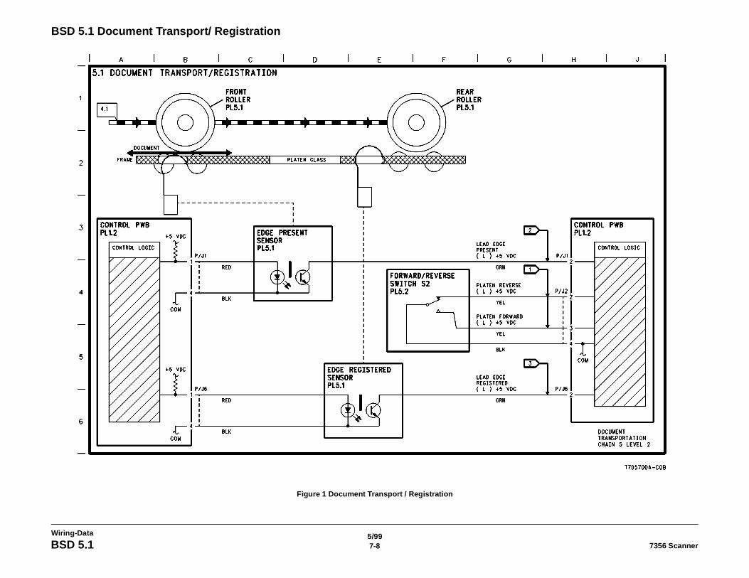
5/997-8 7356 ScannerBSD 5.1
Wiring-Data
BSD 5.1 Document Transport/ Registration
Figure 1 Document Transport / Registration
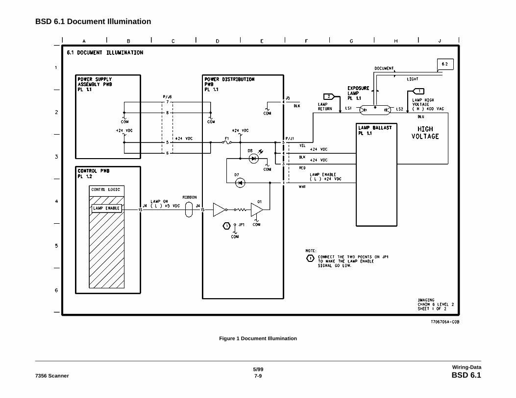
5/997-97356 Scanner BSD 6.1
Wiring-Data
BSD 6.1 Document Illumination
Figure 1 Document Illumination

5/997-10 7356 ScannerBSD 6.2
Wiring-Data
BSD 6.2 Image Projection
Figure 1 Image Projection
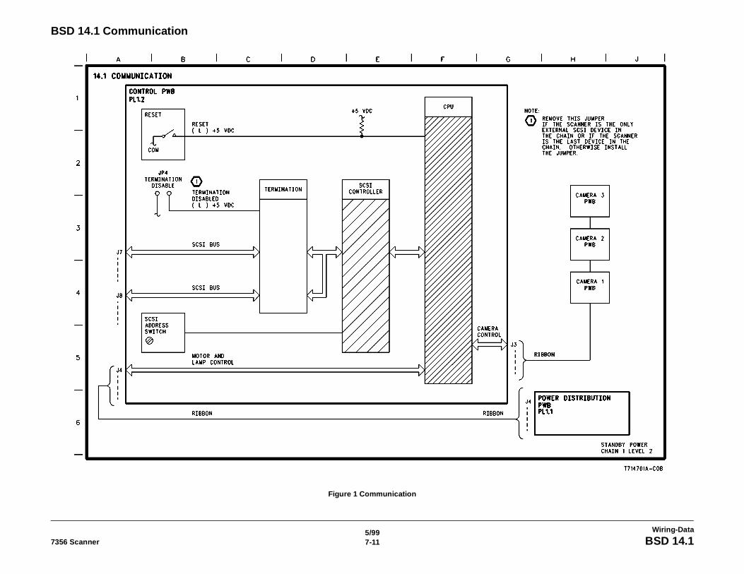
5/997-117356 Scanner BSD 14.1
Wiring-Data
BSD 14.1 Communication
Figure 1 Communication

5/997-12 7356 ScannerBSD 14.1
Wiring-Data