xfc xrc series start-up guide - abb ltd · this startup guide is to assist in the startup of any...
TRANSCRIPT

XFC SeriesRCX/
X
Start-Up Guide
SERIES
2
Introduction: This startup guide is to assist in the startup of any flow computer or remote controller of the XFC (flow computer) or XRC (remote controller) series. It is however, primarily intended for gas orifice applications. It is hoped that this guide in conjunction with other drawings and documentation that accompanies your order will result in a smooth installation. If for some reason, you have questions that are not answered in this guide or your other documentation, call your local Totalflow representative or call the number listed on the back page of this guide.
Installation & Start-Up Sequence HINT: Step 1 thru 22 is a recommended start-up sequence and some of the steps do not go into any great detail. Some steps because detail is not needed and some because more information is available later in the Start-Up Guide. For example there are later topics for installing and wiring the RTD, installing the main battery, solar panel Installation plus other information. So, scan through the guide to see what information is available before you begin the installation.
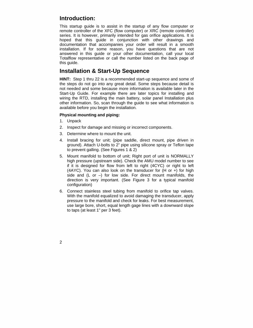
Physical mounting and piping: 1. Unpack 2. Inspect for damage and missing or incorrect components. 3. Determine where to mount the unit. 4. Install bracing for unit; (pipe saddle, direct mount, pipe driven in
ground). Attach U-bolts to 2” pipe using silicone spray or Teflon tape to prevent galling. (See Figures 1 & 2)
5. Mount manifold to bottom of unit; Right port of unit is NORMALLY high pressure (upstream side). Check the AMU model number to see if it is designed for flow from left to right (4CYC) or right to left (4AYC). You can also look on the transducer for (H or +) for high side and (L or –) for low side. For direct mount manifolds, the direction is very important. (See Figure 3 for a typical manifold configuration)
6. Connect stainless steel tubing from manifold to orifice tap valves. With the manifold equalized to avoid damaging the transducer, apply pressure to the manifold and check for leaks. For best measurement, use large bore, short, equal length gage lines with a downward slope to taps (at least 1" per 3 feet).

3
2" x 40"Mounting Pipe
Meter Run"U" MountingBolt
Saddle
Figure 1 (Saddle Mount)
Flat and lock washers
2 " Mounting Pipe
U - Boltwith 9/16" bolt
Figure 3 (Typical Manifold Mount)
Figure 2 (Pipe Mount)
4
Install RTD Probe: 7. Install RTD and connect wiring to connector block J7 on the XFC
board. The XRC board does not have RTD inputs. (See Figure 5)
Install Battery(s): 8. Verify that Memory Backup is Enabled. This is J13 on the XFC and
J1 on the XRC. (See Figures 5 & 6) 9. Mount and connect a fully charged battery to J1 on the XFC board or
J16 on the XRC board. The connectors are located in the same position on both boards. (See Page 7 & Figures 5 & 6)
10. The display should go quickly through the startup routine then start scrolling through the default display items. (If not, see Tip on Page 19) This typically insures that the components and wiring are good. Refer to "Standard Displays" on page 15 for typical default displays. Refer to "Visual Alarm & Status Codes" on page 16 for location, symbols, and descriptions. You should see a L
C code in the A7 (upper right) annunciator since the charging source has not been connected. This is the typical annunciator for the I/O Subsystem but could possibly vary on different systems. Install Solar Panel:
11. Assemble, mount, and connect solar panel or AC charger. NEVER CONNECT CHARGER WITH THE MAIN BATTERY PACK DISCONNECTED. (See pages 8 & 9) The L
C code should go away after the charging source is connected. Solar powered units will naturally depend on available sunlight.
Setup: 12. Connect FS/2 or laptop running PCCU32 to the unit. To use an FS/2,
system must have been ordered from factory as single tube application and with FS/2 support. PCCU32 must have software Version 4.3 or higher and FS/2 must be 2018583-007 or higher.
13. Set date/time, ID, location and AGA setup using Entry Mode in PCCU32 or an FS/2.
14. In Calibration Mode, verify registers for Static pressure, Differential pressure and Temperature. (PCCU32 Only)
15. In Calibration Mode, select RTD Installed, un-check Use Fixed TF, and adjust RTD Bias if a temperature standard is used.
16. In Calibration Mode, perform as found calibration checks.

5
17. If calibration is needed, calibrate static pressure first, then differential pressure, using a deadweight tester or acceptable standard. Insure that both orifice taps are closed and bypass valves are open during AP calibration to avoid a false DP. Make sure there are no leaks in the manifold or test equipment.
18. Perform as left calibration checks as needed. 19. Place unit on line: To avoid inducing toggle and/or a calibration shift,
close vent valve, open both bypass valves, then open orifice tap valves SLOWLY (high pressure side first). Once both orifice tap valves are fully opened, the bypass valves can be closed.
20. Verify that the unit is calculating volume correctly. Watch the display or look at the Current Values in the Entry Mode of PCCU32.
21. Collect data and review the event and characteristic files to insure all parameters are set properly.
22. Optional: When you are reasonably sure that all setup and calibration is complete and the unit is on line calculating volume, it is recommended that a Reset Volume command be sent using PCCU. This allows the unit to have what might be considered as an official starting point for good live data. The Reset Volume will be recorded in the Events file to mark the date and time.
6
Installing and Wiring RTD and Probe The RTD measures flowing gas temperature. Procedures presented in this section enable the user to install the RTD into the meter run and wire leads to the main electronics board. This procedure is for the XFC; the XRC does not have RTD inputs.
Totalflow Materials Supplied ♦ RTD Probe with 10’ of cable. Optional lengths 15’, 25’, 30’, 40’,
and 50’. ♦ One (1) thermowell with ¾" NPT threads. Optional threads are
½" and 1". ♦ Nylon tie wraps
Customer Materials Supplied • Customer must specify or provide Thermowell "U" length. • Teflon tape
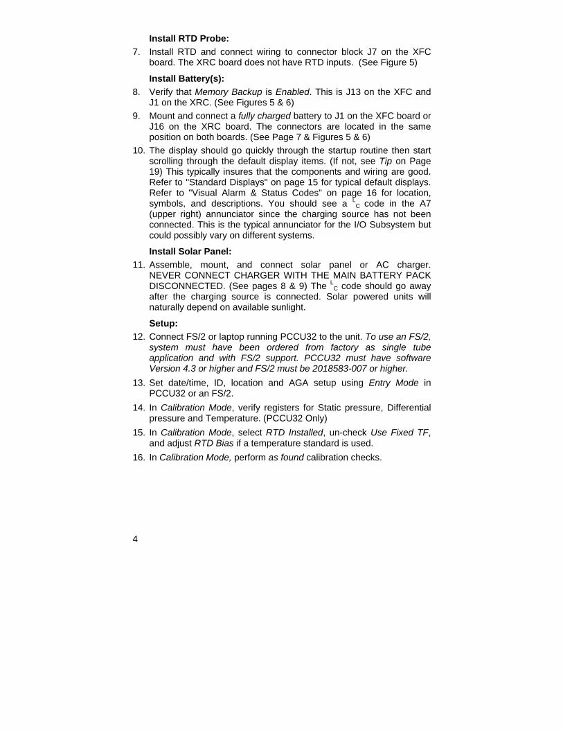
1. Install thermowell into meter run.
2. Using snap ring pliers, adjust probe length so that it is spring loaded against bottom of thermowell.
3. Remove one of the hole plugs and install cord connector. Remove nut, sealing ring and rubber grommet from cord connector. Slide nut, sealing ring and grommet over RTD cable and insert cable through body of cord connector. Allow enough cable to extend into unit for connecting wires to RTD termination block J7.
4. Secure the cable with the grommet, sealing ring and nut.
Note: Charging source and Power should be removed from unit before performing any field wiring.
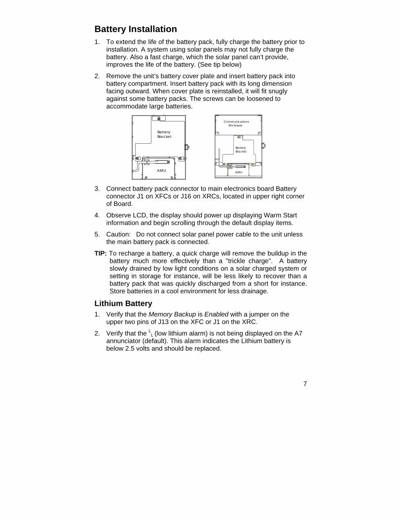
5. Connect RTD probe to the XFC’s RTD connector as follows: Before making connections to terminal block, remove spade lugs if attached and trim wire ends back 1/4". Remove J7 terminal block from the XFC main electronics board. (See Figure 5)
6. Loosen terminal block securing screws, insert wire and then retighten. Reinstall terminal block with wires attached.
7
Battery Installation 1. To extend the life of the battery pack, fully charge the battery prior to
installation. A system using solar panels may not fully charge the battery. Also a fast charge, which the solar panel can’t provide, improves the life of the battery. (See tip below)
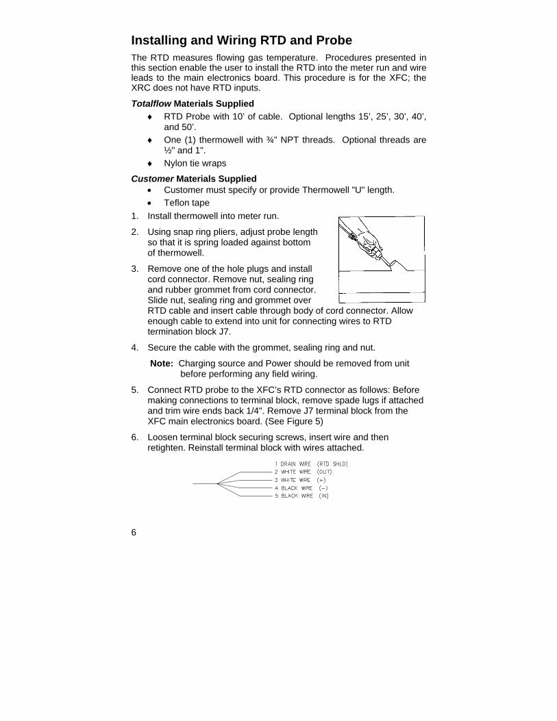
2. Remove the unit’s battery cover plate and insert battery pack into battery compartment. Insert battery pack with its long dimension facing outward. When cover plate is reinstalled, it will fit snugly against some battery packs. The screws can be loosened to accommodate large batteries.
3. Connect battery pack connector to main electronics board Battery connector J1 on XFCs or J16 on XRCs, located in upper right corner of Board.
4. Observe LCD, the display should power up displaying Warm Start information and begin scrolling through the default display items.
5. Caution: Do not connect solar panel power cable to the unit unless the main battery pack is connected.
TIP: To recharge a battery, a quick charge will remove the buildup in the battery much more effectively than a "trickle charge". A battery slowly drained by low light conditions on a solar charged system or setting in storage for instance, will be less likely to recover than a battery pack that was quickly discharged from a short for instance. Store batteries in a cool environment for less drainage.
Lithium Battery 1. Verify that the Memory Backup is Enabled with a jumper on the
upper two pins of J13 on the XFC or J1 on the XRC.
2. Verify that the LL (low lithium alarm) is not being displayed on the A7 annunciator (default). This alarm indicates the Lithium battery is below 2.5 volts and should be replaced.
AMU
BracketBattery
CommunicationsEnclosure
AMU
BracketBattery
8
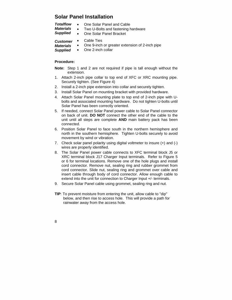
Solar Panel Installation Totalflow Materials Supplied
• One Solar Panel and Cable • Two U-Bolts and fastening hardware • One Solar Panel Bracket
Customer Materials Supplied
• Cable Ties • One 9-inch or greater extension of 2-inch pipe • One 2-inch collar
Procedure: Note: Step 1 and 2 are not required if pipe is tall enough without the
extension. 1. Attach 2-inch pipe collar to top end of XFC or XRC mounting pipe.
Securely tighten. (See Figure 4) 2. Install a 2-inch pipe extension into collar and securely tighten. 3. Install Solar Panel on mounting bracket with provided hardware. 4. Attach Solar Panel mounting plate to top end of 2-inch pipe with U-
bolts and associated mounting hardware. Do not tighten U-bolts until Solar Panel has been correctly oriented.
5. If needed, connect Solar Panel power cable to Solar Panel connector on back of unit. DO NOT connect the other end of the cable to the unit until all steps are complete AND main battery pack has been connected.
6. Position Solar Panel to face south in the northern hemisphere and north in the southern hemisphere. Tighten U-bolts securely to avoid movement by wind or vibration.
7. Check solar panel polarity using digital voltmeter to insure (+) and (-) wires are properly identified.
8. The Solar Panel power cable connects to XFC terminal block J5 or XRC terminal block J17 Charger Input terminals. Refer to Figure 5 or 6 for terminal locations. Remove one of the hole plugs and install cord connector. Remove nut, sealing ring and rubber grommet from cord connector. Slide nut, sealing ring and grommet over cable and insert cable through body of cord connector. Allow enough cable to extend into the unit for connection to Charger Input +/- terminals.
9. Secure Solar Panel cable using grommet, sealing ring and nut. TIP: To prevent moisture from entering the unit, allow cable to "dip"
below, and then rise to access hole. This will provide a path for rainwater away from the access hole.

9
Solar PanelMounting Bracket
2 " Collar
2 " Extension Pipe
Flow Computer
CableSolar Panel
U - Bolts
Figure 4 (Solar Panel Mounting)
10
• • •
• •
• • •
••
• •
• •
• •
• •
•
•
•
•
• •
• •
• •
•
•
• •
• •
• •
• •
•
• •
•
•
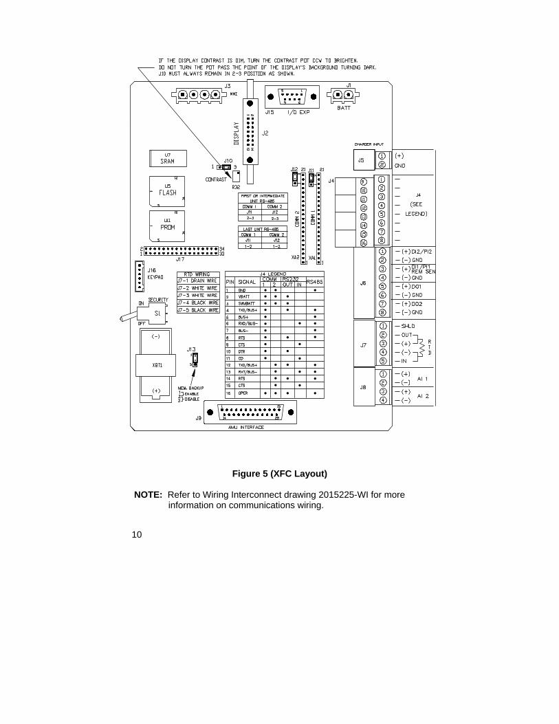
Figure 5 (XFC Layout)
NOTE: Refer to Wiring Interconnect drawing 2015225-WI for more information on communications wiring.
11
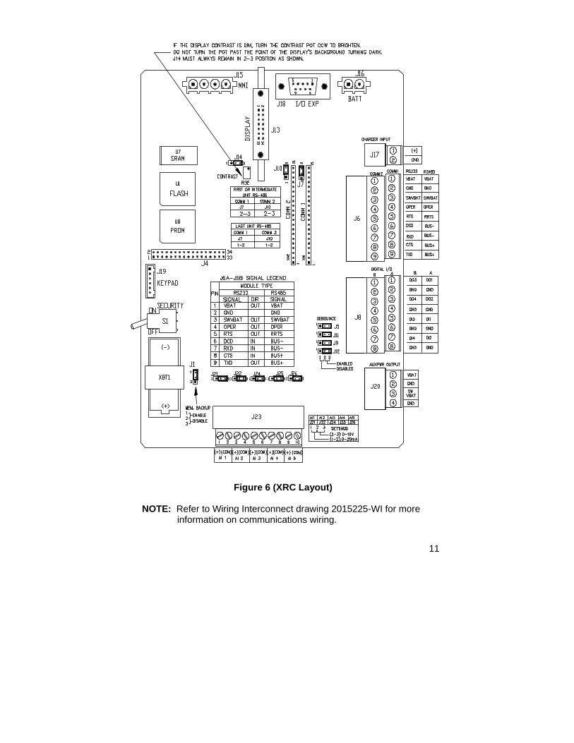
Figure 6 (XRC Layout)
NOTE: Refer to Wiring Interconnect drawing 2015225-WI for more information on communications wiring.
12
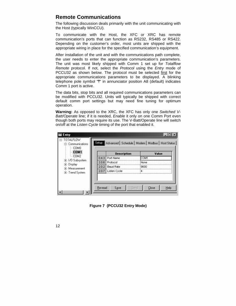
Remote Communications The following discussion deals primarily with the unit communicating with the Host (typically WinCCU).
To communicate with the Host, the XFC or XRC has remote communication’s ports that can function as RS232, RS485 or RS422. Depending on the customer’s order, most units are shipped with the appropriate wiring in place for the specified communication’s equipment.
After installation of the unit and with the communications path complete, the user needs to enter the appropriate communication’s parameters. The unit was most likely shipped with Comm 1 set up for Totalflow Remote protocol. If not, select the Protocol using the Entry mode of PCCU32 as shown below. The protocol must be selected first for the appropriate communications parameters to be displayed. A blinking telephone pole symbol " " in annunciator position A8 (default) indicates Comm 1 port is active. The data bits, stop bits and all required communications parameters can be modified with PCCU32. Units will typically be shipped with correct default comm port settings but may need fine tuning for optimum operation. Warning: As opposed to the XRC, the XFC has only one Switched V-Batt/Operate line; if it is needed, Enable it only on one Comm Port even though both ports may require its use. The V-Batt/Operate line will switch on/off at the Listen Cycle timing of the port that enabled it.
Figure 7 (PCCU32 Entry Mode)
13
Communications Troubleshooting A new radio or modem system that doesn’t communicate is difficult to troubleshoot because proper operation has never been proven, and all the initial hardware and software settings are suspect. More than one problem can be present, causing component replacement to be an inadequate trouble shooting technique. Use the following checklist as an aid. • Does the " " flash (Totalflow Remote Protocol only) with the Listen
Cycle time in the A8 display (default position)? If no, 1) The Protocol needs to be selected in the Entry Mode using
PCCU32. 2) The communication’s module in Comm 1 or Comm 2 is missing
or bad or the module is the wrong type (RS232 or RS485). Note: Comm 1 and Comm 2 are in opposite locations when compared to the previous electronics board (2015333).
3) Inadequate 12 VDC battery voltage. • Insure base radio is working for other locations. • Verify Station ID and Device ID matches with WinCCU and is the
only Totalflow device with that ID. • Verify Baud rate, Stop Bits, Security Code, and Link Establishment
time are same as CCU. • Verify WinCCU is using Packet Protocol. X Series devices support
only DB2 Packet Protocol. • Verify wiring to antenna, to UCI, UCI to Radio for RS485 installation
or to Radio/Modem for RS232 installation. TIP: To check for wiring shorts or opens with two or more wire
connections, use a multimeter set on continuity (resistance). Check two wires at a time from one unit to another. If black and white wires are to be tested, disconnect both wires at both ends, set one probe on black, the other on white. The meter should read OL or OFL (over range) if no shorts. Jumper the two wires at the other end. The meter should read a low resistance if no opens. This method requires only one end of wiring to be tested, no matter how far the units are apart.
14
• If a radio is used, verify directional antenna with correct frequency range is pointed toward base (± 6°). The antenna should be mounted vertically, with the vanes perpendicular to the ground. Verify radio is good, with the same frequencies used.
• If a modem is used, verify dial tone on line at the telephone company’s termination box by checking Tip and Ring. Check wiring from phone company’s box to dial-up modem. If cellular, also check for proper Tip & Ring voltage. Insure that the phone number is correct in the unit and WinCCU.
NOTE: Telephone companies in the United States typically use a 48
volt power supply so the on-hook voltage between the Tip and Ring wires should be something less than 48 volts. Measuring another way, Tip to ground is approx. zero volts and Ring to ground is approx. –48 volts. In the off-hook condition; Tip to ground will be approx. –20 volts while Ring to ground will be approx. –28 volts or approx. 8 volts between Tip and Ring. Users in other countries will need to consult with their local telephone company.
Wiring Specific wiring drawings are sent with each unit, based on the options ordered. Most wiring diagrams, including communications are available on the web at http://www.abb.com/totalflow. Select “Continuing Customer Service and Support”, and then select “Wiring Instructions”. Communications pin-outs of the XFC and XRC are shown on pages 10 and 11 of this guide.

15
Standard Displays Items that appear on the unit’s display are programmable by the user, however based on the measurement application; units will be shipped with some default display items. The following table is a typical set of default displays for an AGA-3 application. Engineering units may vary from those shown if the unit supports the “Selectable Units” feature.
Description Standard Display
Current Date and Time 24 hour clock
DATE/TIME MM/DD/YY HH:MM:SS
Yesterday’s Percent DP Low Limit Percent time below DP Low Set Point
Yest DP Low NN PERCENT
Yesterday’s Percent DP High Limit Percent time above DP High Set Point
Yest DP High NN PERCENT
Current Flow Rate Programmable SCF, MCF or MMCF
Flow Rate NNNNNN.N SCF/HR
Total Accumulated Volume Programmable SCF, MCF or MMCF
Total Accum. Volume NNNNNN.NN MCF
Battery Voltage Displayed in Volts
Battery Voltage NN.N VOLTS
Station ID ID of the box.
Station ID
Differential Pressure Inches H2O
Diff. Pressure NNN.N IN. H2O
Static Pressure Absolute PSIA
Static Pressure NNN.N PSIA
Flowing Temperature °F
Temperature NN.N DEG. F
Yesterday’s Volume Programmable SCF, MCF or MMCF
Yesterday’s Volume NNNN.N MCF
Previous Calculation Period Volume Last Calc. Volume NNNN.N SCF
Device ID Individual application ID
Device ID
Charger Voltage Charger NN.N VOLTS
The duration that each parameter is displayed can vary from 1 to 255 seconds (default is 4 seconds); a setting of 0 seconds will turn that display item off.
16
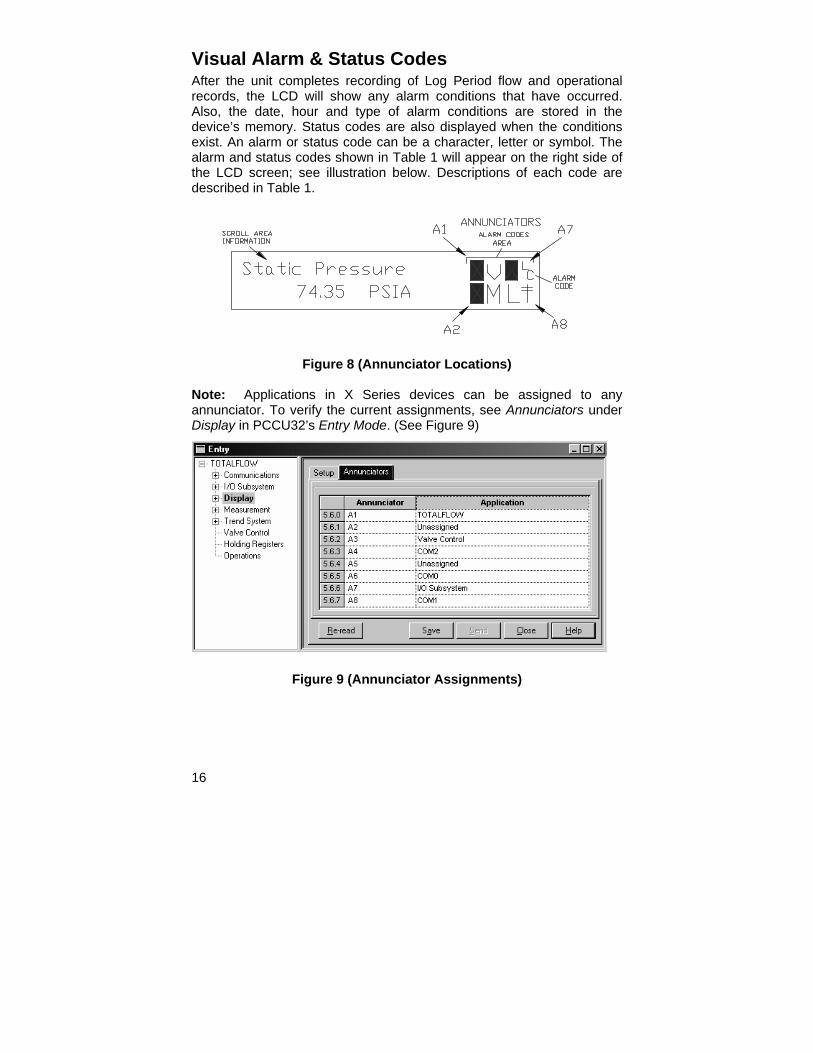
Visual Alarm & Status Codes After the unit completes recording of Log Period flow and operational records, the LCD will show any alarm conditions that have occurred. Also, the date, hour and type of alarm conditions are stored in the device’s memory. Status codes are also displayed when the conditions exist. An alarm or status code can be a character, letter or symbol. The alarm and status codes shown in Table 1 will appear on the right side of the LCD screen; see illustration below. Descriptions of each code are described in Table 1.
Figure 8 (Annunciator Locations) Note: Applications in X Series devices can be assigned to any annunciator. To verify the current assignments, see Annunciators under Display in PCCU32’s Entry Mode. (See Figure 9)
Figure 9 (Annunciator Assignments)
17
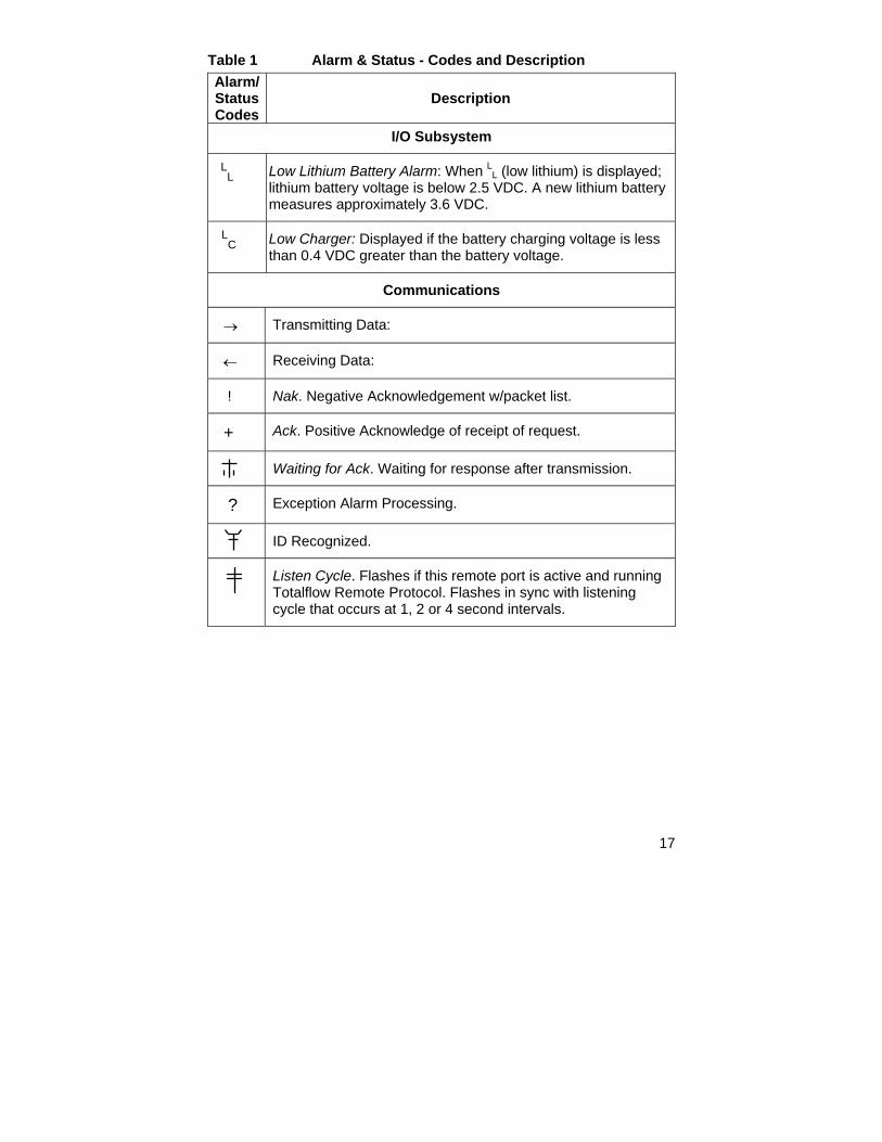
Table 1 Alarm & Status - Codes and Description Alarm/ Status Codes
Description
I/O Subsystem
LL Low Lithium Battery Alarm: When LL (low lithium) is displayed;
lithium battery voltage is below 2.5 VDC. A new lithium battery measures approximately 3.6 VDC.
LC
Low Charger: Displayed if the battery charging voltage is less than 0.4 VDC greater than the battery voltage.
Communications
→ Transmitting Data:
← Receiving Data:
! Nak. Negative Acknowledgement w/packet list.
+ Ack. Positive Acknowledge of receipt of request.
Waiting for Ack. Waiting for response after transmission.
? Exception Alarm Processing.
ID Recognized.
Listen Cycle. Flashes if this remote port is active and running Totalflow Remote Protocol. Flashes in sync with listening cycle that occurs at 1, 2 or 4 second intervals.

18
M MODBUS ASCII: Modbus ASCII protocol is selected for this port.
m MODBUS RTU: Modbus RTU protocol is selected for this port.
L Local Protocol: Displayed when PCCU32 port is active and running Totalflow Local Protocol.
¥ Packet Protocol: Totalflow Packet Protocol is active on this port.
R LevelMaster Protocol: LevelMaster protocol is selected for this port.
Valve Control
V Valve Control: Displayed when the Valve Control option is installed and no other Valve Control symbols are valid.
= Valve Control: Valve Control option installed. Process Value (PV) is within the user set dead band. No control action required.
⎡ Valve Control: Valve Control option installed. Valve is in full open position.
⎦ Valve Control: Valve Control option installed. Valve is in full closed position.
↑ Valve Control: Valve Control option installed. Valve is opening (open signal is being sent to valve actuator).
↓ Valve Control: Valve Control option installed. Valve is closing. (Close signal is being sent to valve actuator).
Ö Valve Control: Valve Control option installed. Valve controller override conditions met (DP/SP override set point or Low Battery).
LL Valve Control: Valve Control option installed. Local Lock-out
is initiated.
19
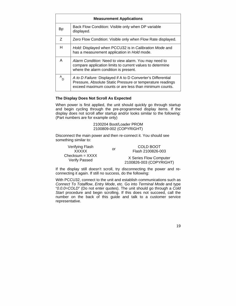
Measurement Applications
BF Back Flow Condition: Visible only when DP variable displayed.
Z Zero Flow Condition: Visible only when Flow Rate displayed.
H Hold: Displayed when PCCU32 is in Calibration Mode and has a measurement application in Hold mode.
A Alarm Condition: Need to view alarm. You may need to compare application limits to current values to determine where the alarm condition is present.
AD
A to D Failure: Displayed if A to D Converter’s Differential Pressure, Absolute Static Pressure or temperature readings exceed maximum counts or are less than minimum counts.
The Display Does Not Scroll As Expected When power is first applied, the unit should quickly go through startup and begin cycling through the pre-programmed display items. If the display does not scroll after startup and/or looks similar to the following: (Part numbers are for example only)
2100204 Boot/Loader PROM 2100809-002 (COPYRIGHT)
Disconnect the main power and then re-connect it. You should see something similar to:
Verifying Flash XXXXX
Checksum = XXXX Verify Passed
or COLD BOOT Flash 2100826-003
X Series Flow Computer 2100826-003 (COPYRIGHT)
If the display still doesn’t scroll, try disconnecting the power and re-connecting it again. If still no success, do the following: With PCCU32, connect to the unit and establish communications such as Connect To Totalflow, Entry Mode, etc. Go into Terminal Mode and type “0.0.0=COLD” (Do not enter quotes). The unit should go through a Cold Start procedure and begin scrolling. If this does not succeed, call the number on the back of this guide and talk to a customer service representative.

ABB Inc. Totalflow Products 7051 Industrial Blvd. Bartlesville, Oklahoma 74006 Tel: USA (800) 442-3097
International 001-918-338-4880