xiaobo ren effect of welding residual stress on fracture
TRANSCRIPT

Doctoral theses at NTNU, 2010:77
Xiaobo RenEffect of welding residual stress onfracture
ISBN 978-82-471-2115-3 (printed ver.)ISBN 978-82-471-2116-0 (electronic ver.)
ISSN 1503-8181
NTN
UN
orw
egia
n U
nive
rsity
of
Scie
nce
and
Tech
nolo
gyTh
esis
for
the
degr
ee o
fph
iloso
phia
e do
ctor
Facu
lty
of E
ngin
eeri
ng S
cien
ce a
nd T
echn
olog
yD
epar
tmen
t of S
truc
tura
l Eng
inee
ring
Doctoral theses at N
TNU
, 2010:77Xiaobo R
en

Xiaobo Ren
Effect of welding residual stress
on fracture
Thesis for the degree of philosophiae doctor
Trondheim, June 2010
Norwegian University of
Science and Technology
Faculty of Engineering Science and Technology
Department of Structural Engineering
Xiaobo Ren
Effect of welding residual stress
on fracture
Thesis for the degree of philosophiae doctor
Trondheim, June 2010
Norwegian University of
Science and Technology
Faculty of Engineering Science and Technology
Department of Structural Engineering
Xiaobo Ren
Effect of welding residual stress
on fracture
Thesis for the degree of philosophiae doctor
Trondheim, June 2010
Norwegian University of
Science and Technology
Faculty of Engineering Science and Technology
Department of Structural Engineering
Xiaobo Ren
Effect of welding residual stress
on fracture
Thesis for the degree of philosophiae doctor
Trondheim, June 2010
Norwegian University of
Science and Technology
Faculty of Engineering Science and Technology
Department of Structural Engineering

NTNUNorwegian University of Science and Technology
Thesis for the degree of philosophiae doctor
Faculty of Engineering Science and Technology
Department of Structural Engineering
©Xiaobo Ren
ISBN 978-82-471-2115-3 (printed ver.)
ISBN 978-82-471-2116-0 (electronic ver.)
ISSN 1503-8181
Doctoral Theses at NTNU, 2010:77
Printed by Tapir Uttrykk

Effect of welding residual stresson fracture
Xiaobo Ren
Norwegian University of Science and TechnologyFaculty of Engineering Science and Technology
Department of Structural EngineeringTrondheim, Norway
Effect of welding residual stresson fracture
Xiaobo Ren
Norwegian University of Science and TechnologyFaculty of Engineering Science and Technology
Department of Structural EngineeringTrondheim, Norway
Effect of welding residual stresson fracture
Xiaobo Ren
Norwegian University of Science and TechnologyFaculty of Engineering Science and Technology
Department of Structural EngineeringTrondheim, Norway
Effect of welding residual stresson fracture
Xiaobo Ren
Norwegian University of Science and TechnologyFaculty of Engineering Science and Technology
Department of Structural EngineeringTrondheim, Norway

To my wife, parents and other family members To my wife, parents and other family members
To my wife, parents and other family members To my wife, parents and other family members

Preface
This doctoral thesis is submitted to the Norwegian University of Scienceand Technology (NTNU) for the degree of Philosophiae Doctor. This workhas been carried out at Department of Structural Engineering and sup-ported by the Research Council of Norway through the "STORFORSK"Project No.167397/V30, RESIA. Prof. Zhiliang Zhang has been my super-visor.
Different people have different perspective for a PhD. I have it as adream deeply in my heart and regard it as a meaningful journey of mywhole life. I enjoy the process much more than the ending. I could neverhave accomplished this task without the inspiration of so many generouspeople.
First, I would like to acknowledge my supervisor Prof. Zhiliang Zhangwho initially offered me the opportunity to do this work and experiencedifferent culture and life. I appreciate his encouragement, great ideas, ex-cellent advice and critical reviews for this work. Most importantly, I wantto express my gratitude for him as a model of life to follow: positive, opti-mistic, self-confident and honest.
I would also like to express my sincere thanks to Prof. Wenxian Wangat Taiyuan University of Technology where I got my Bachelor degree andProf. Hongyang Jing at Tianjin University where I earned my Master de-gree. Without their example I would not be where I am today.
I feel fortunate to have been a member of RESIA team, in which I wassurrounded and inspired by professional colleagues at NTNU, SINTEFand IFE. Special thanks are directed to Mr. Bård Nyhus at SINTEF, forhis valuable comments and generous help; Dr. Jun Liu at DNV, for greatfriendship, encouragement and help; Dr. Sigmund K. Ås at SINTEF, forhis comments and help for English writing; Prof. Asbjørn Mo, Prof. OddM. Akselsen, for their encouragement and support.

II PREFACE
Dr. Erling Østby at SINTEF, Dr. Junhua Zhao and Dr. Junyan Liu atNTNU deserve my thanks for helpful discussions. Many thanks go to Prof.Robert A. Ainsworth at British Energy for his constructive suggestion dur-ing a-cup-of-beer discussion at the corner of the Quality Hotel AugustinTrondheim.
I would like to thank all the PhD students and colleagues at Depart-ment of Structural Engineering for the support, inspiration and social gath-ering during these years. Special thanks go to Miriam for memorablestart of Norwegian life, Lingyun, Jianying and Jie for home-like life, Es-pen and Victoria for kind help of Latex and subversion control, Jim Stianand Julien for interesting talks. Constant interaction with many friends,both in Trondheim and elsewhere, helped me to maintain my perspective,thank you all.
My deepest acknowledgment is directed to my loving wife and con-stant companion, Lin, for her understanding and infinite support duringthese years of study. My parents, parents in-law, my sister Xiaona andmy brother Xiaowei deserve special thanks for their always understand-ing and support.
Finally, my gratitude goes to my hometown Qianpo and my folks.Home is where my heart is!
Xiaobo Ren

Abstract
Residual stresses are unavoidable in welded constructions. How to cor-rectly predict residual stresses and assess their effect on structural integrityis a fundamental issue. One of the most difficult aspects in structural in-tegrity assessment is to incorporate the effect of residual stresses in a safemanner, without making unduly conservative assumptions about the levelof stress that may be present. Current structural assessment procedurestypically assume upper bound residual stress solution, which can over-estimate or underestimate the effect of residual stresses. The objective ofthis study is to fundamentally understand the effect of residual stresseson fracture behaviour and try to incorporate the effect into the integrityassessment procedure in a quantitative manner.
This study concerns an ideal problem. A large cylinder with a weld inthe center was studied. The cylinder was simulated by a 2D plane strainmodified boundary layer model with the remote boundary governed bythe elastic K-field and T-stress. A sharp crack was embedded in the weldregion. The eigenstrain method was employed to introduce a local tensileor compressive residual stress field into the finite element model. Theconcept of the study is to investigate the difference between the referencecase and the case including residual stresses.
Residual stress-induced the crack-tip constraint has been investigatedfirst. Based on the difference of the opening stress between the case withresidual stresses and the reference case, a parameter R was defined to char-acterize the crack-tip constraint induced by residual stresses. The effectsof external loading, material hardening, loading path and geometry con-straint on R have also been studied. It has been found that the residualstress-induced crack-tip constraint is smaller for the case with higher ge-ometry constraint.
Effect of residual stress on cleavage fracture toughness was investi-

IV ABSTRACT
gated by using the cohesive zone model with a bilinear traction-separation-law. Several cases were studied to understand the effect of residual stresseson the cleavage fracture toughness. Results suggest that the behaviour ofresidual stress is very similar to T-stress. Tensile residual stress compressesthe plastic zone of the surrounding material and moves the plastic zonebackward, which in turn reduces the cleavage fracture toughness. In con-trast, the compressive residual stress enlarges the plastic zone and shiftsthe plastic zone forward, and enhances the cleavage toughness. The effectof residual stresses on cleavage fracture toughness has also been investi-gated for geometrically similar weld with different sizes, different damageparameters, hardening exponents and T-stresses.
Ductile crack growth resistance is important for assessing the struc-tural integrity, and the effect of residual stresses on ductile crack growthresistance has also been studied. The study reveals that tensile residualstresses decrease the crack growth resistance while the compressive resid-ual stresses have the opposite effect. With the increase of crack growth, theeffect of residual stress tends to diminish. Under certain conditions, the ef-fect of residual stresses on crack growth resistance curve is independent ofthe size of geometrically similar weld. Thus, a "master curve" can be ob-tained and applied for the integrity assessment. Effect of residual stress onthe crack growth resistance also depends on the material hardening, initialvoid volume fraction and T-stress.
It has not been completed to incorporate the effect of residual stressesinto the integrity assessment by a quantitative manner in this study. How-ever, some guidelines were outlined in the thesis for future work.

List of Publications
P1 X.B. Ren, Z.L. Zhang and B. Nyhus. Effect of residual stresses onthe crack-tip constraint in a modified boundary layer model, Interna-tional Journal of Solids and Structures, 46:2629-2641, 2009.
P2 X.B. Ren, Z.L. Zhang and B. Nyhus. Effect of residual stresses on duc-tile crack growth resistance, Engineering Fracture Mechanics, 77:1325-1337, 2010.
P3 X.B. Ren, Z.L. Zhang and B. Nyhus. Effect of residual stresses oncleavage fracture toughness by using cohesive zone model, submit-ted.
P4 X.B. Ren, Z.L. Zhang and B. Nyhus. Residual stress induced crack-tip constraint: a parametric study, In Proceeding of 17th European Con-ference on Fracture (ECF-17), Brno, Czech Republic, 2008.
P5 X.B. Ren, Z.L. Zhang and B. Nyhus. Effect of residual stresses onbrittle fracture by cohesive zone modeling, In Proceeding of 12th Inter-national Conference on Fracture (ICF-12), Ottawa, Canada, 2009.
P6 X.B. Ren, Z.L. Zhang and B. Nyhus. Effect of residual stresses onbrittle fracture by cohesive zone modeling, In Proceeding of 21st NordicSeminar on Computational Mechanics (NSCM-21), Trondheim, Norway,2008.
P7 X.B. Ren, Z.L. Zhang and B. Nyhus. Numerical investigation on theeffect of residual stresses on the ductile crack growth resistance, InProceeding of 29th International Conference on Ocean, Offshore and ArcticEngineering (OMAE-2010), Shanghai, China, 2010.

Contents
Preface i
Abstract iii
List of Publications v
List of Figures xi
1 Introduction 11.1 Background . . . . . . . . . . . . . . . . . . . . . . . . . . . . 11.2 Fracture mechanics . . . . . . . . . . . . . . . . . . . . . . . . 3
1.2.1 Crack driving force . . . . . . . . . . . . . . . . . . . . 31.2.2 Crack-tip constraint . . . . . . . . . . . . . . . . . . . 61.2.3 Cleavage fracture . . . . . . . . . . . . . . . . . . . . . 101.2.4 Ductile fracture . . . . . . . . . . . . . . . . . . . . . . 12
1.3 Integrity assessment . . . . . . . . . . . . . . . . . . . . . . . 141.3.1 Description . . . . . . . . . . . . . . . . . . . . . . . . 141.3.2 FAD method . . . . . . . . . . . . . . . . . . . . . . . . 151.3.3 Treatment of residual stresses . . . . . . . . . . . . . . 17
1.4 Objectives . . . . . . . . . . . . . . . . . . . . . . . . . . . . . 191.5 Organization of this thesis . . . . . . . . . . . . . . . . . . . . 20
2 Residual stress 212.1 Origin of residual stress . . . . . . . . . . . . . . . . . . . . . 212.2 Classification . . . . . . . . . . . . . . . . . . . . . . . . . . . . 222.3 Measurement techniques . . . . . . . . . . . . . . . . . . . . . 242.4 Numerical prediction . . . . . . . . . . . . . . . . . . . . . . . 29
2.4.1 Description . . . . . . . . . . . . . . . . . . . . . . . . 29

VIII CONTENTS
2.4.2 WeldsimS . . . . . . . . . . . . . . . . . . . . . . . . . 312.5 Effect of residual stress on failure . . . . . . . . . . . . . . . . 32
3 Methodology 353.1 Problem description . . . . . . . . . . . . . . . . . . . . . . . 353.2 Modified boundary layer model . . . . . . . . . . . . . . . . 353.3 Complete Gurson model . . . . . . . . . . . . . . . . . . . . . 37
3.3.1 Gurson model . . . . . . . . . . . . . . . . . . . . . . . 373.3.2 Thomason’s coalescence criterion . . . . . . . . . . . . 393.3.3 Complete Gurson model . . . . . . . . . . . . . . . . . 41
3.4 Cohesive zone model . . . . . . . . . . . . . . . . . . . . . . . 413.4.1 Concept . . . . . . . . . . . . . . . . . . . . . . . . . . 423.4.2 Traction-separation-law . . . . . . . . . . . . . . . . . 42
3.5 Eigenstrain method . . . . . . . . . . . . . . . . . . . . . . . . 443.5.1 Description . . . . . . . . . . . . . . . . . . . . . . . . 443.5.2 Simplification . . . . . . . . . . . . . . . . . . . . . . . 453.5.3 Application . . . . . . . . . . . . . . . . . . . . . . . . 47
4 Effect of residual stress on crack-tip constraint 494.1 Problem description . . . . . . . . . . . . . . . . . . . . . . . 494.2 Residual stress field . . . . . . . . . . . . . . . . . . . . . . . . 514.3 Results . . . . . . . . . . . . . . . . . . . . . . . . . . . . . . . 51
4.3.1 Reference solution and Q field . . . . . . . . . . . . . 534.3.2 Definition of R-parameter . . . . . . . . . . . . . . . . 564.3.3 Effect of external load on R . . . . . . . . . . . . . . . 604.3.4 Interaction of R and Q . . . . . . . . . . . . . . . . . . 614.3.5 Effect of material hardening on R . . . . . . . . . . . . 654.3.6 Effect of loading path on R and Q . . . . . . . . . . . 66
4.4 Conclusions . . . . . . . . . . . . . . . . . . . . . . . . . . . . 68
5 Effect of residual stress on cleavage fracture 715.1 Problem description . . . . . . . . . . . . . . . . . . . . . . . 715.2 Residual stress field . . . . . . . . . . . . . . . . . . . . . . . . 725.3 Results . . . . . . . . . . . . . . . . . . . . . . . . . . . . . . . 74
5.3.1 Effect on cleavage toughness . . . . . . . . . . . . . . 765.3.2 Effect of weld zone size . . . . . . . . . . . . . . . . . 805.3.3 Effect of material hardening . . . . . . . . . . . . . . . 825.3.4 Effect of damage parameters . . . . . . . . . . . . . . 84

CONTENTS IX
5.3.5 Effect of T-stress . . . . . . . . . . . . . . . . . . . . . . 855.4 Conclusions . . . . . . . . . . . . . . . . . . . . . . . . . . . . 89
6 Effect of residual stress on ductile fracture 916.1 Problem description . . . . . . . . . . . . . . . . . . . . . . . 916.2 Residual stress field . . . . . . . . . . . . . . . . . . . . . . . . 936.3 Results . . . . . . . . . . . . . . . . . . . . . . . . . . . . . . . 94
6.3.1 Effect on ductile crack growth resistance . . . . . . . 946.3.2 Effect of weld zone size . . . . . . . . . . . . . . . . . 986.3.3 Effect of material hardening . . . . . . . . . . . . . . . 1076.3.4 Effect of initial void volume fraction . . . . . . . . . . 1076.3.5 Effect of T-stress . . . . . . . . . . . . . . . . . . . . . . 110
6.4 Conclusions . . . . . . . . . . . . . . . . . . . . . . . . . . . . 112
7 Summary 115
8 Future work 119
Bibliography 121


List of Figures
1.1 Main tasks of RESIA project . . . . . . . . . . . . . . . . . . . 21.2 Illustration of the contour integration . . . . . . . . . . . . . 51.3 SEM fractographs of cleavage in an A508 Class 3 alloy . . . . 101.4 Illustration of Ritchie-Knott-Rice model . . . . . . . . . . . . 111.5 Dimple type fracture surface . . . . . . . . . . . . . . . . . . . 121.6 Illustration of ductile fracture mechanisms . . . . . . . . . . 131.7 Illustration of integrity assessment approaches . . . . . . . . 161.8 Schematic plot of the contribution of residual stress . . . . . 18
2.1 The coupling of temperature, stress and microstructure . . . 222.2 Origin of residual stresses . . . . . . . . . . . . . . . . . . . . 232.3 Residual stress decomposition for a T fillet weld . . . . . . . 242.4 Illustration of hole drilling method . . . . . . . . . . . . . . . 262.5 Illustration of contour method . . . . . . . . . . . . . . . . . . 272.6 Illustration of X-ray diffraction method . . . . . . . . . . . . 282.7 Residual stress and distortion evolution in welded joints . . 302.8 Basic elements of unified weld constitutive model . . . . . . 31
3.1 Illustration of the problem . . . . . . . . . . . . . . . . . . . . 363.2 Two deformation modes in the Thomason theory . . . . . . . 403.3 Concept of cohesive zone model . . . . . . . . . . . . . . . . 423.4 Traction-separation-law used in the analysis . . . . . . . . . 433.5 Illustration of the simplified eigenstrain method . . . . . . . 463.6 Residual stress on pipe inner surface . . . . . . . . . . . . . . 47
4.1 Modified boundary layer model . . . . . . . . . . . . . . . . 504.2 Redistribution of the residual stress fields . . . . . . . . . . . 524.3 SSY solution without residual stresses . . . . . . . . . . . . . 54

XII LIST OF FIGURES
4.4 Opening stresses at different T-stress . . . . . . . . . . . . . . 554.5 Relationship between Q and T . . . . . . . . . . . . . . . . . . 564.6 Comparison of near tip stress fields . . . . . . . . . . . . . . . 574.7 Different stress field . . . . . . . . . . . . . . . . . . . . . . . . 584.8 Definition of R . . . . . . . . . . . . . . . . . . . . . . . . . . . 594.9 Difference stress fields with external loading . . . . . . . . . 604.10 Effect of external loading . . . . . . . . . . . . . . . . . . . . . 624.11 Difference fields for combined effect . . . . . . . . . . . . . . 634.12 Comparison of R and Q . . . . . . . . . . . . . . . . . . . . . 644.13 Effect of material hardening on R . . . . . . . . . . . . . . . . 654.14 Effect of the loading path on the crack-tip constraint . . . . . 67
5.1 Schematic plot of the assumption made in the study . . . . . 725.2 Finite element mesh . . . . . . . . . . . . . . . . . . . . . . . . 735.3 Residual stress distribution in MBL model . . . . . . . . . . . 755.4 Cleavage toughness as the function of crack growth length . 765.5 Cleavage fracture toughness as the function of α22 . . . . . . 775.6 Plasticity contribution from the surrounding materials . . . 795.7 Plastic zone size when cleavage fracture occurs . . . . . . . . 795.8 Schematic plot of different weld zone sizes . . . . . . . . . . 805.9 Residual stress distribution for different weld zone sizes . . 815.10 Effect of weld zone size on cleavage fracture toughness . . . 825.11 Effect of material hardening . . . . . . . . . . . . . . . . . . . 835.12 Cleavage fracture toughness as a function of σmax . . . . . . 845.13 Relationship between JC and Γ0 . . . . . . . . . . . . . . . . . 865.14 Effect of the residual stress on FPZ and plastic zone size . . . 875.15 Effect of residual stresses on the JC for different T/σ0 . . . . 885.16 Plastic zone size for different geometry constraint . . . . . . 89
6.1 Modified boundary layer model . . . . . . . . . . . . . . . . 926.2 Illustration of the weld region . . . . . . . . . . . . . . . . . 946.3 Residual stress distribution with a larger round weld . . . . 956.4 Effect of residual stresses on crack growth resistance . . . . . 976.5 Illustration of the rectangular weld region . . . . . . . . . . . 986.6 Residual stress distribution with a rectangular weld . . . . . 996.7 Residual stresses affects the resistance for rectangular weld . 1006.8 Triaxiality values ahead the crack tip . . . . . . . . . . . . . . 1016.9 Illustration of weld size . . . . . . . . . . . . . . . . . . . . . 102
LIST OF FIGURES XIII
6.10 Residual stress distribution for different weld size . . . . . . 1036.11 Effect of weld size on crack growth resistance . . . . . . . . . 1046.12 Master curve . . . . . . . . . . . . . . . . . . . . . . . . . . . . 1056.13 Normalized residual stress distribution . . . . . . . . . . . . 1066.14 Effect of material hardening . . . . . . . . . . . . . . . . . . . 1086.15 Effect of initial void volume fraction . . . . . . . . . . . . . . 1096.16 Effect of T-stress . . . . . . . . . . . . . . . . . . . . . . . . . . 111


Chapter 1
Introduction
1.1 Background
Welding technique has been widely used in industry to fabricate and re-pair the structures. The safety and integrity of welded structures is animportant issue that should be take into account for both human and en-vironment impacts. It is widely accepted that the presence of the weldingresidual stress can have a significant effect on the subsequent failure char-acteristics of engineering components and structures [1]. However, com-pared with the role of primary load and defects, the role of residual stresson failure and integrity assessment has received relatively little attention,which due largely to historical difficulties associated with the measure-ment and prediction of residual stress [2]. It has been demonstrated thatthe current procedures can significantly overestimate the residual stress ef-fects in most cases and underestimate their effects in others [3]. Large sav-ings can probably be done if the origins of residual stress are recognized,means for predicting their evolution in-service developed, and their influ-ence on failure processes understood. In this way residual stresses can beincorporated into structural integrity assessment in a safe manner, with-out making unduly conservative assumptions about the levels of residualstress that may be present [4].
Project RESIA (Residual Stress Simulation for Integrity Assessment)was established with the purpose of developing the scientific platformfor next generation quantitative modeling of residual stresses and asso-ciated integrity assessment for welded steel components and structures.
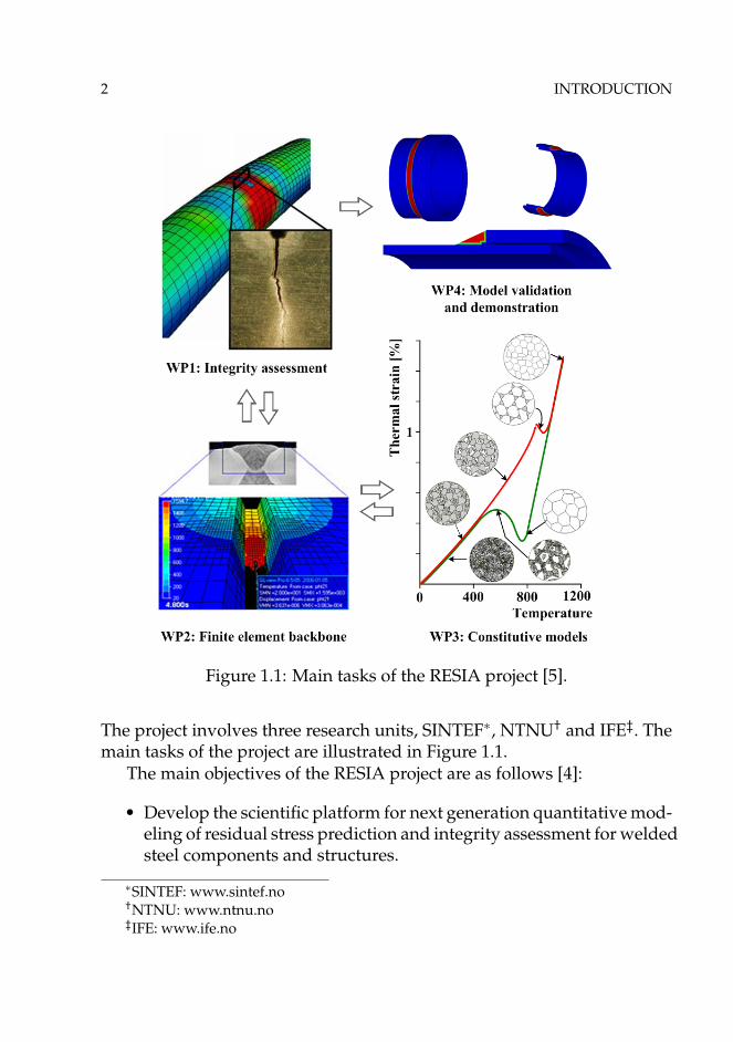
2 INTRODUCTION
Figure 1.1: Main tasks of the RESIA project [5].
The project involves three research units, SINTEF∗, NTNU† and IFE‡. Themain tasks of the project are illustrated in Figure 1.1.
The main objectives of the RESIA project are as follows [4]:
• Develop the scientific platform for next generation quantitative mod-eling of residual stress prediction and integrity assessment for weldedsteel components and structures.
∗SINTEF: www.sintef.no†NTNU: www.ntnu.no‡IFE: www.ife.no

1.2 FRACTURE MECHANICS 3
• Unified constitutive equations that couple the temperature, strainrate effect, microstructure and phase transformation plasticity willbe modified and extended to high strength steels.
• Develop a reliable thermal mechanical testing method for inverselyretrieving the microstructure and temperature dependent materialparameters used in the constitutive equations.
• Establish welding residual stress distribution for typical applicationsand develop an improved failure assessment procedure for effec-tively incorporating the quantitative effect of residual stresses.
The work presented in this thesis belongs to work-package 1 (WP1) ofthe RESIA project, which focuses on the effect of residual stresses on the in-tegrity assessment from the viewpoint of fracture mechanics, such as theeffect of residual stresses on crack driving force, residual stress-inducedcrack-tip constraint, the influence of residual stress on failure mechanismsand how to incorporate the effect of residual stress into the current in-tegrity assessment procedure.
1.2 Fracture mechanics
The effect of residual stress on fracture is the main concern in this thesis.A description of the theory of fracture mechanics used in this study willbe presented in this section, and the effect of residual stresses on fracturebehaviour will also be briefly introduced.
1.2.1 Crack driving force
Crack driving force is defined as the rate of change in potential energywith the crack area, which refers to the derivative with respect to the crackarea [6]. In linear elastic fracture mechanics (LEFM), the stress intensity fac-tor defines the amplitude of the crack-tip singularity and is used as crackdriving force parameter. For mode I loading conditions, K has the follow-ing form:
KI = σ√
πa (1.1)
where σ is the stress and a is the crack length. When residual stress ispresent, the contribution to the crack driving force must be included in the

4 INTRODUCTION
analysis, and the total stress intensity is simply the sum of the contributionfrom applied load and residual stresses:
KTotal = KAppl + KRs (1.2)
where the superscripts Appl and Rs denote applied load and residual stressrespectively. For an elastic-plastic body a more complex analysis is re-quired which cannot be evaluated by a simple linear addition of the vari-ous K terms resulting from the residual and applied stress component [2].
In elastic-plastic fracture mechanics (EPFM), two parameters are pro-posed and widely used as the measure of fracture toughness, and to char-acterize the near tip stress and strain fields: one is crack tip opening dis-placement (δ, CTOD) proposed by Wells [7] and J-integral proposed byRice [8] for deformation plasticity (nonlinear elastic) materials. CTOD isusually defined as the displacement at the original crack tip or the dis-placement at the intersection of a 90◦ vertex with the crack flanks. Shih [9]has shown that there is a unique link between the J and CTOD for a givenelastic-plastic material.
J-integral is a measure of the nonlinear elastic energy release rate andthe intensity of the crack tip fields under J-dominant conditions. For atwo-dimensional body with a crack directed along the x1 axis under quasi-static conditions, a general definition of the J-integral is [10]:
J = limΓ→0
∫Γ
(Wδ1i − σij
∂uj
∂x1
)nids (1.3)
where W is the strain energy density, σij and ui are components of stressand displacement in Cartesian coordinates respectively, Γ is an arbitrarycounterclockwise path around the crack tip, and ds is the path lengthalong Γ. J-integral is path independent given the assumption that thestrain energy density is a single-valued function of the strain (or stress),e.g. linear/nonlinear elastic materials. However, J-integral is not path in-dependent in case of non-proportional loading or when residual stress ispresent [11, 12]. When residual stresses are regarded as secondary stressesand assumed only to contribute to the elastic part of the J-integral, the ef-fect of residual stresses can be incorporated into J-integral as follows [13]:
JTotal ={√
JApplEL +
√JRS
}2
+ JApplPL (1.4)
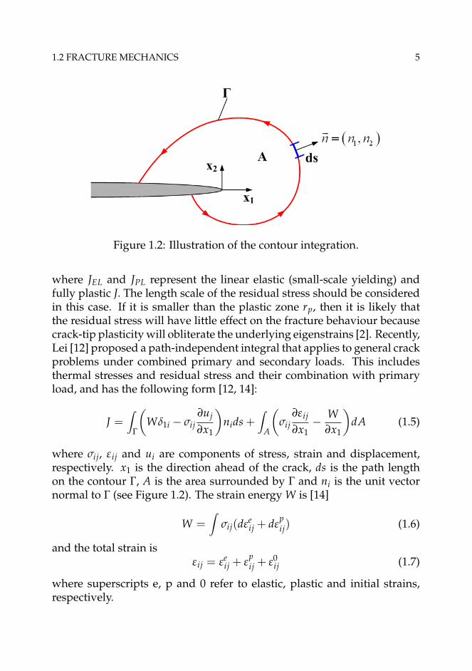
1.2 FRACTURE MECHANICS 5
Figure 1.2: Illustration of the contour integration.
where JEL and JPL represent the linear elastic (small-scale yielding) andfully plastic J. The length scale of the residual stress should be consideredin this case. If it is smaller than the plastic zone rp, then it is likely thatthe residual stress will have little effect on the fracture behaviour becausecrack-tip plasticity will obliterate the underlying eigenstrains [2]. Recently,Lei [12] proposed a path-independent integral that applies to general crackproblems under combined primary and secondary loads. This includesthermal stresses and residual stress and their combination with primaryload, and has the following form [12, 14]:
J =∫
Γ
(Wδ1i − σij
∂uj
∂x1
)nids +
∫A
(σij
∂εij
∂x1− W
∂x1
)dA (1.5)
where σij, εij and ui are components of stress, strain and displacement,respectively. x1 is the direction ahead of the crack, ds is the path lengthon the contour Γ, A is the area surrounded by Γ and ni is the unit vectornormal to Γ (see Figure 1.2). The strain energy W is [14]
W =∫
σij(dεeij + dε
pij) (1.6)
and the total strain isεij = εe
ij + εpij + ε0
ij (1.7)
where superscripts e, p and 0 refer to elastic, plastic and initial strains,respectively.

6 INTRODUCTION
Hou and Pan [15] also proposed a finite element procedure to deter-mine a potential fracture parameter J1d for welded structures with residualstresses, which is based on the concept of the energy difference under theload-displacement curves of the two cracked solids with slightly differentcrack sizes.
1.2.2 Crack-tip constraint
Although fracture mechanics has been developed for over 50 years, thesubject of "constraint effect in fracture" is relatively recent, which onlystarted in early 1990’s [16]. Constraint in fracture mechanics is a term thatis widely used but vaguely defined or understood. In the present con-text we prefer to understand the level of constraint as an indicator of thenear-tip stress state, and the constraint is regarded as the factors or con-ditions which influence the transferability and invalidate the one-to-onerelation between the crack driving force and near-tip stress field [17]. Ina weldment there are basically four factors which influence the level of acrack-tip constraint. The geometry constraint is caused by the crack size,specimen dimensions and loading mode; inhomogeneous material prop-erties can induce the mismatch constraint at the crack tip [18–20]; Boththe prestrain history [21] and the welding residual stresses influence thecrack-tip constraint as well.
Conventional single parameter fracture mechanics approaches rely onthe similarity of the crack tip stress and deformation fields [22]. Underwell-contained near tip plasticity, a single parameter, such as the linearelastic stress intensity factor K, and the J-integral or equivalently crack tipopening displacement (CTOD), can uniquely scales the elastic-plastic neartip field. However, the single parameter characterization is not satisfiedin most practical situations because certain high constraint condition cannot be satisfied [23]. The arguments that a single parameter might notbe sufficient to characterize the near-tip behaviour or cracked geometriesunder large-scale yielding condition motivated the development of two-parameter fracture theories.
According to Williams’s solution, the first two terms of small-strainlinear elastic expansion of the crack-tip stress field possess the followingform [24]:
σij =KI√2πr
fij(θ) + Tδ1iδ1j (1.8)

1.2 FRACTURE MECHANICS 7
where KI is the Mode I elastic stress intensity factor and T is a stress par-allel to the crack. Larsson and Carlsson [25] demonstrated that the secondterm in the series was important to modify the boundary solution to fitthe real crack problem, and the T-stress has a significant effect on the plas-tic zone size and shape. Du and Hancock [26] studied the effect of T-stresson the small scale yielding field of a crack in plain strain conditions andfound that a positive T-stress causes plasticity to envelop the crack tip andexhibits a Prandtl field. This corresponds to the limit solution of the HRRfield [27, 28] for a non-hardening material, while a compressive T-stress re-duces the stress triaxiality state at the crack tip. Betegón and Hancock [29]suggested a two-parameter framework J-T to characterize the effect of theconstraint induced by the geometry. But, T-stress is only valid in an elasticregime.
O’Dowd and Shih [30, 31] developed the J-Q two-parameter theory andgave a precise meaning to the term constraint caused by the geometry andloading mode. They showed that the full range of high- and low-triaxialityfields within the J-Q annulus are members of a family of solutions parame-terized by Q when distances are normalized by J/σ0, where σ0 is the yieldstress. The near-tip stress field can be expressed by two-term expansion:
σij = σHRRij + Qσ0(
rJ/σ0
)qσij(θ, n) (1.9)
whereσHRR
ij = (J
αε0σ0 Inr)
1n+1 σ0σij(θ, n) (1.10)
is the J-controlled HRR stress field, r and θ are polar coordinates centeredat the crack tip; n is the power hardening exponent; ε0 is the yield strain(ε0 = σ0/E), and α is a material constant.
Their study showed that |q| � 1; and when |θ| < π/2, 1 < r/(J/σ0) <5, the stress components σrr ≈ σθθ ≈ constant and |σrθ| � |σθθ|. Thus, Qis a hydrostatic stress parameter. In this two-parameter formulation, J setsthe size scale over which large stress and strains develop, and Q charac-terizes the crack-tip stress distribution and the stress triaxiality achievedahead of the crack. Q is therefore a quantitative measure of the crack-tip constraint caused by geometry. It should be noted that the J-Q theoryfails to characterize the crack-tip fields and quantify the constraint level ina bending-dominated large deformation regime. Zhu and Leis [32] pro-posed a bending modified J-Q theory, by which the crack-tip stress fields
8 INTRODUCTION
for bending specimens at all deformation levels can be characterized. Forgeometry constraint characterization, Chao et al. [33], Chao and Zhu [34]also proposed J-A2 theory, and an engineering crack-tip constraint param-eter Γ was suggested by Schindler [35] as well. The above constraint mea-sures are developed for in-plane constraint. For the effect of out-of-planeconstraint, Guo extended the HRR analysis in a series of papers [36–38] tothe 3D case. In Guo’s solution the thickness effect entered the final resultthrough functions Tz(n, r, x3), In(n, Tz) and σij(θ, n, Tz) of Eq. 1.10, and theparameter Tz is defined as:
Tz =σ33
σ11 + σ22(1.11)
Within the plastic domain in front of the crack Tz changes from 0 forplane stress to 0.5 for plane strain. Guo also proposed an analytical ap-proximate formula to compute Tz.
In welded components, the crack located at the interface between theweld metal and the heat affected zone is generally the most critical one.Because of the nature of welding, there is often a mismatch between theweld metal and the base metal. By considering the interface crack as abi-material system, Zhang et al. [18] carried out a numerical investigationon the near-tip stress field and found that the near-tip field in the forwardsector can be separated into two parts. The first is characterized by theJ-integral for a reference material; the second part which influences theabsolute levels of stresses at the crack tip and measures the deviation ofthe field from the first part can be described by a mismatch constraint pa-rameter, M [39]:
σij ≈ σRe fij (J) + Mσ0Re f f M
ij (θ + 12β) (1.12)
where β = 0 for overmatch and β = 1 for undermatch, σ0Re f is the yieldstress of reference material and f M
ij represents the angular function of thedifference fields caused by mismatch, which only depends on the refer-ence material. The study also showed that radial dependence of M-field isweak. Similar studies have been carried out for the crack in the middle ofweld [19, 20].
Zhang et al. [40] further studied the effect of T-stress on the crack-tipstress field of an elastic-plastic interface crack. They found that the T-stress

1.2 FRACTURE MECHANICS 9
can shift the near-tip stress level up and down without significantly affect-ing the mismatch constraint parameter M, which indicates that the con-straints caused by geometry and mismatch are independent of each other.A so-called J-Q-M formulation to describe the near-tip stress field in thepresence of both geometry and material mismatch constraints was thenproposed:
σij ≈ σM=0;T=0ij + Qσ0Re f f Q
ij (θ) + Mσ0Re f f Mij (θ + 12β) (1.13)
Here, the Q parameter describes the geometry constraint. Similarly, theM value is used to rank the material mismatch effect on the crack-tip con-straint.
Plastic prestrain history common in reeled pipes has also been found toinfluence on the crack driving force and crack-tip stress field. By consider-ing single prestrain cycles, Eikrem et al. [21] developed a new parameterto quantify the prestrain induced crack-tip constraint:
P = (�σθθ
σ0)x/δ=4 = {(σθθ
σ0)ε − (
σθθ
σ0)ε=0}x/δ=4, θ = 0 (1.14)
where (σθθθ0
)ε implies the case with prestrain history and (σθθθ0
)ε=0 denotesthe monotonic loading case. Thus, P value represents the amplitude ofthe difference stress field caused by the prestrain history and can be usedto rank its constraint. A three parameter formulation CTOD-Q-P is sug-gested to describe the near-tip stress field of a cracked specimen with pre-strain history. Here, CTOD has been used as the crack driving force. Theformulation is as following:
σεθθ(x) = σε=0
θθ (x, δ, σ0, n) + Q + P at θ = 0 (1.15)
The study of the effect of residual stresses on the crack-tip constrainthas also received attention recently. The studies carried out by Panontinand Hill [41], Hill and Panontin [42] confirm that the residual stresses con-tribute to both the crack driving force and the crack-tip constraint. Xu andBurdekin [43] investigated the effect of residual stresses on the crack-tipconstraint and found that the tensile residual stresses parallel to the crackflank increase the constraint at the crack tip while compressive residualstresses in this direction have the opposite effect, but a biaxial residual

10 INTRODUCTION
(a) (b)
Figure 1.3: SEM fractographs of cleavage in an A 508 Class 3 alloy, (a)multifaceted surface, and (b) river patterns [6].
stress state may also increase the crack-tip constraint despite the resid-ual stress component parallel to the crack flank being compressive. Liuet al. [44] studied a one-dimensional residual stress field perpendicular tothe crack plane in single edge notched tension and bending specimens.They showed that residual stress can enhance the crack-tip constraint anddefined a parameter R to characterize the effect. Following the same ap-proach for investigating crack-tip constraint [18, 21, 30, 31] the structureand behaviour of the near-tip stress field under the combined load ofa two-dimensional residual stress field and external load in a well de-fined modified boundary layer (MBL) model will be studied in this thesis,and the parameter R used to quantify the constraint induced by residualstresses will be further investigated.
1.2.3 Cleavage fracture
Cleavage fracture can be defined as the rapid propagation of a crack alonga particular crystallographic plane [6], and there is little or no evidence oflocal micro-scale plasticity accompanying the unstable crack growth. Typ-ically, cleavage fracture has multifaceted fracture surface in a polycrys-talline material or so-called "river pattern", as shown in Figure 1.3. Themechanism of cleavage fracture has been well discussed in Ref. [45].
Micromechanical models using continuum representation of stress and

1.2 FRACTURE MECHANICS 11
Figure 1.4: Illustration of Ritchie-Knott-Rice model.
strain are generally used to predict local conditions for cleavage fracture.For cleavage fracture to happen, the opening stress should reach the criti-cal value σc at a certain distance from the crack tip lc or within a certain vol-ume in front of the crack tip [46]. This physical scale must be considered instudying the micromechanisms of fracture in order to consider microstruc-tural features necessary for the physical failure mechanism. Ritchie, Knottand Rice (RKR) [47] introduced a simple model to relate fracture stress tofracture toughness, and they postulated that cleavage failure occurs whenthe stress ahead of the crack tip exceeds σf over a characteristic distance,as illustrated in Figure 1.4.
Previous studies concerning cleavage fracture indicate that the criticalfracture stress ranges from 3 to 4 times the yield strength of the material,and that is relatively independent of temperature and strain rate. Esti-mates of the characteristic length or distance in mild steels range from 2 to5 grain diameters [41]. However, in real elastic-plastic materials, the largeplastic deformations are often necessary to initiate the cleavage fracture.Therefore, Neimitz et al. [46] proposed an alternative formulation of theRKR criterion. The cleavage fracture was demonstrated as a synergisticaction of the stress and deformation at the critical moment. It has been

12 INTRODUCTION
Figure 1.5: Dimple type fracture surface of A6082 aluminum alloy [49].
demonstrated that for fracture to occur it is not sufficient that the openingstress reaches the critical value alone, but it is also necessary that the loca-tion of this maximum from the crack tip must be over the distance l � lc,where lc is considered as a material parameter.
Experimental work undertaken by Mirzaee-Sisan et al. [48] indicatedan apparent reduction in mean cleavage fracture toughness of an A553-Bferritic steel of 50% from conventional fracture toughness data. Panon-tin and Hill [41] utilized the RKR (Ritchie-Knott-Rice) [47] model to pre-dict the effect of residual stresses on brittle fracture initiation and foundthat the constraint generated by the residual stress decreases the initiationtoughness of brittle fracture. The fundamental understanding of the effectof residual stress on cleavage fracture toughness will be carried out in thiswork.
1.2.4 Ductile fracture
Ductile fracture is a common failure mechanism, which is characterized byslow crack propagation and large amount of plastic deformation. The duc-tile fracture usually shows dimpled fracture surface, or cup-cone fracturesurface that is commonly observed in uniaxial tensile test [6]. Figure 1.5shows the dimples observed in the fracture surface of A6028 aluminumalloy.
For polycrystalline metals, it has been observed that ductile fracture iscontrolled by nucleation, growth and coalescence of microvoids [49]. Thecommon observed stages in ductile fracture are as follows [6]:

1.2 FRACTURE MECHANICS 13
Figure 1.6: Illustration of ductile fracture mechanisms: (a) void nucleation,(b) void growth, (c) beginning of void coalescence and (d) end of voidcoalescence.
• Void nucleation from large inclusions and second phase particles byparticle fracture or interracial decohesion [50].
• Growth of the void around the particles, by means of plastic strainand hydrostatic stress.
• Coalescence of the growing void with adjacent voids.
The mechanism of ductile fracture is illustrated in Figure 1.6. It shouldbe noted that process before void coalescence, the plastic deformation ofa void containing material is dilatational and macroscopically homoge-neous. i.e. process (a) and (b). Once the coalescence process begins, thehomogeneous deformation terminates and shifts to a localized plastic de-formation [49].
It has been found that residual stress can influence the ductile fracturebehaviour. Panontin and Hill [41] predicted the brittle and ductile initi-ation by micromechanical models and showed that the effect of residual

14 INTRODUCTION
stress on the ductile fracture initiation toughness is negligible. Sherry etal. [51] demonstrated that a high strength low toughness aluminum alloyAL2024-T351 showed a marked reduction in initiation and tearing tough-ness for specimens containing a mechanically induced residual stress field.Experimental work undertaken by Sharples et al. [52] on wide plate speci-mens has also demonstrated that residual stress can significantly influencethe ductile tearing behaviour of engineering materials. However, the ex-periments performed by Mirzaee-Sisan et al. [53] on the AISI Type 361Hstainless steel indicates a negligible impact on ductile tearing toughness atload ratio Lr close to 1, i.e. close to the plastic collapse of the specimen.The observation is in contrast to their previous experiments performed onthe A533B unstable cleavage fracture in ferritic steels at −150◦C [48]. Areduction of approximately 46% was observed in apparent fracture tough-ness for specimens containing a residual stress field compared with speci-mens in the as-received condition. Mahmoudi et al. [54] employed a localout-of-plane compression method to introduce residual stresses into C(T)specimens for aluminum alloys A12024, and the ductile tearing resistanceof A12024 also decreased when tensile residual stresses are present. Todate, the fundamental understanding of the effect of the residual stresseson ductile fracture resistance remains an open challenge. Thus, the effectof residual stress on ductile fracture behaviour will be investigated in thisthesis.
1.3 Integrity assessment
1.3.1 Description
Structural integrity assessment is the techniques used to assess the fitness-for-purpose of critical components and welded structures, which is fun-damental to the safe and economic operation of structural components.Such approaches can be used at the design stage to provide assurance fornew structures, at the fabrication phase to ensure the integrity in the con-struction and at the operation phase to provide assurance throughout thelife of the structure [55]. Used correctly, they can prevent over-design andunnecessary inspection and provide the tools to enable a balance betweensafety and economy to be achieved.
The procedure of structural integrity assessment consists following four
1.3 INTEGRITY ASSESSMENT 15
tasks [55]:
• Determination of the time profile of all the significant external loadsand operating temperature, and performing a complete stress anal-ysis including evaluation of the residual stresses in and around theweld seams in all critical locations.
• Mechanical fracture characterization of the base and weld materials,e.g. tensile properties, fracture toughness etc. The investigation ofa possible variation of the fracture toughness in heat affected zone(HAZ) is also important.
• Obtaining a reliable map of significant existing flaws through a va-riety of non-destructive flaw detection techniques. The distribution,size, and the nature of flaws should be obtained.
• Carrying out the appropriate fracture and safety assessment.
Several codes and procedures have been defined for integrity assess-ment, e.g. BS 7910 [56], the low-temperature fracture assessment proce-dure R6 [57], the high-temperature procedure R5 [58] and structural in-tegrity assessment procedure for European industry, SINTAP [59]. Exist-ing defect assessment approaches present the results of an assessment interms of either a failure assessment diagram (FAD) or a crack driving force(CFD) [60], as illustrated in Figure 1.7. In the FAD approach, the combina-tion of loading and the materials resistance to the fracture is representedby a point on an FAD; failure is conceded when the point lies outside abounding failure assessment curve. In the CFD method, the crack driv-ing force, such as J-integral or CTOD is represented by a curve which de-scribes the increase in CFD with increasing load; failure is conceded whenthe parameter reaches a limiting value derived from fracture toughnesstests [60].
1.3.2 FAD method
The FAD method is probably the most widely used methodology for struc-tural integrity assessment, which is easy to implement and also very ver-satile [6]. The concept of a two-criterion FAD to describe the interactionbetween brittle fracture and fully ductile rupture was introduce by Dowl-ing and Townley [61] and Harrison et al. [62]. The first FAD was derived

16 INTRODUCTION
(a) (b)
Figure 1.7: Illustration of integrity assessment approaches, (a)Failure As-sessment Diagram (FAD), and (b) Crack Driving Force (CDF) curve. A:safe, B: critical and C: unsafe [55].
from a modified version of the strip-yield model. Considering primaryloading on its own, the basis of the FAD is the use of two dimensionlessparameters [63], the load ratio Lr and the toughness ratio Kr. Kr was de-fined as follows:
Kr =KI
Kmat(1.16)
where KI is applied tensile (Mode I) stress intensity factor, Kmat is the ma-terial toughness measured by the stress intensity factor. It should be notedthat toughness can be measured in terms of the J-integral or CTOD andconverted to the equivalent Kmat. The load ratio Lr is defined as follows:
Lr =σre f
σY(1.17)
where σY is the yield stress, and σre f is the reference stress and defined as:
σre f = (P/P0)σ0 (1.18)
where P is the remote load and P0 is the reference load.BS 7910:1999 [56] procedure includes three assessment levels, which
are in order of increasing complexity and decreasing conservatism [64],
• Level 1: a preliminary screening procedure.

1.3 INTEGRITY ASSESSMENT 17
• Level 2: the usual assessment method for structural applications andthat generally used for offshore structures. The level 2 method yieldsrealistic predictions for situations, where ductile tearing is limited.
• Level 3: this procedure is appropriate to ductile materials which ex-hibit stable tearing.
A particular conservatism in integrity assessment procedure may arisefrom the application of high constraint toughness values to assess low con-straint structure components [55]. Thus, constraint-based failure assess-ment diagrams [65, 66] have been developed and included in R6 proce-dure [67] and SINTAP procedure [68]. To assess constraint effect, both thestructural constraint and the dependence of material toughness on con-straint should be considered. The latter dependence can be assessed bycomparing a constraint dependent toughness Kc
mat with Kmat measuredunder high constraint conditions. For negative constraint, the relation be-tween Kc
mat and Kmat can be approximated expressed as [65]
Kcmat = Kmat[1 + α(−βLr)p] (1.19)
where α, p are constants and β represents the structural constraint, beingdefined (under primary load only) either in terms of the elastic T-stress(βT Lr = T/σy) or the elastic-plastic Q-stress (βQLr = Q) [55]. For posi-tive constraint, Kc
mat ≈ Kmat. Eq. 1.19 can be written in a equivalent formas [65], and a modified FAD including the effect of constraint can be ob-tained as:
Kr = f (Lr)[1 + α(−βLr)p] (1.20)
1.3.3 Treatment of residual stresses
Residual stresses can have a detrimental effect on structural integrity andare an important consideration in the defect assessment of welded struc-tures [64]. Under linear elastic conditions, residual stresses can be treatedby the superposition principle, as shown in Eq. 1.2. However, local orglobal plastic deformation may relax or redistribute residual stresses. Fig-ure 1.8 schematically shows how residual stress contribute to the crackdriving force, and the modification of FAD.
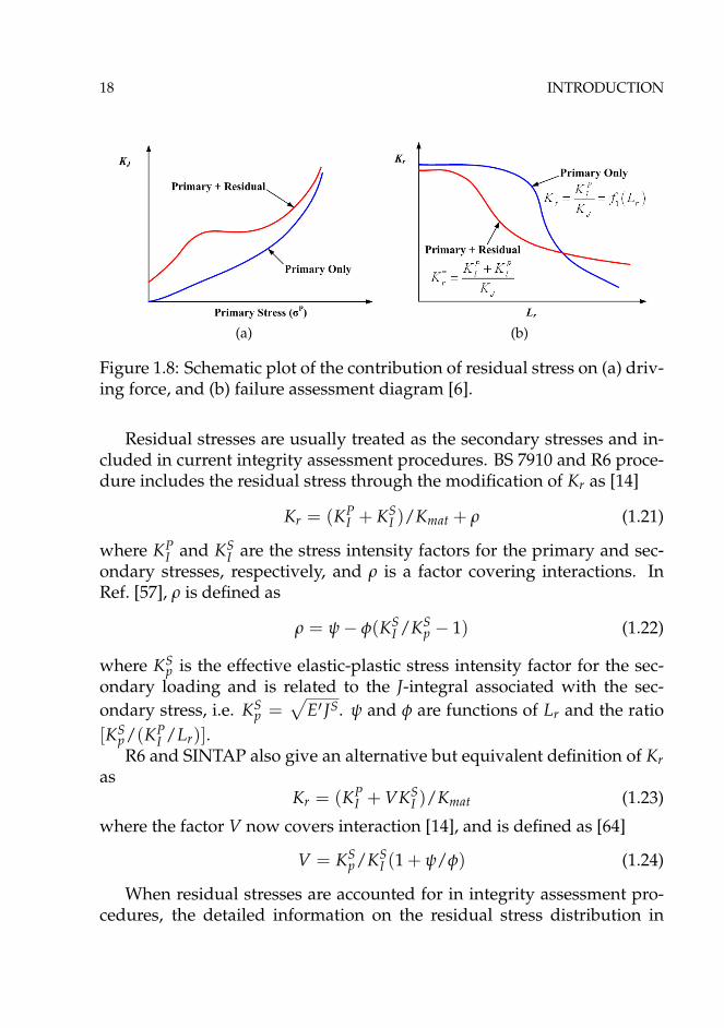
18 INTRODUCTION
(a) (b)
Figure 1.8: Schematic plot of the contribution of residual stress on (a) driv-ing force, and (b) failure assessment diagram [6].
Residual stresses are usually treated as the secondary stresses and in-cluded in current integrity assessment procedures. BS 7910 and R6 proce-dure includes the residual stress through the modification of Kr as [14]
Kr = (KPI + KS
I )/Kmat + ρ (1.21)
where KPI and KS
I are the stress intensity factors for the primary and sec-ondary stresses, respectively, and ρ is a factor covering interactions. InRef. [57], ρ is defined as
ρ = ψ − φ(KSI /KS
p − 1) (1.22)
where KSp is the effective elastic-plastic stress intensity factor for the sec-
ondary loading and is related to the J-integral associated with the sec-ondary stress, i.e. KS
p =√
E′ JS. ψ and φ are functions of Lr and the ratio[KS
p/(KPI /Lr)].
R6 and SINTAP also give an alternative but equivalent definition of Kras
Kr = (KPI + VKS
I )/Kmat (1.23)
where the factor V now covers interaction [14], and is defined as [64]
V = KSp/KS
I (1 + ψ/φ) (1.24)
When residual stresses are accounted for in integrity assessment pro-cedures, the detailed information on the residual stress distribution in

1.5 OBJECTIVES 19
the component is very important and should be known [69]. However,such information is often not directly available, and upper-bound residualstress profiles are generally recommended for use. Thus, it is fatal to pre-dict or measure realistic residual stress distribution, and well-characterizedresidual stress profiles can be obtained [70]. An accurate measurement ofthe crack driving force that includes the residual stress can be anotherapproach to incorporate the effect of residual stress into the structuralintegrity assessment. To this end, the modified J-integral proposed byLei [12] can be a good candidate.
1.4 Objectives
The objective of this thesis is to investigate and quantify the effect of theresidual stress on fracture behaviour, and further incorporate the effectinto the structural integrity assessment procedure. The main objectives ofthis thesis are as follows:
• Employ an efficient method to introduce residual stresses into thefinite element model. Tensile residual stress is generally detrimentalfor structures, thus, introducing a proper tensile stress field near thecrack tip is the starting point of the study.
• Crack tip constraint is a very important factor to take into accountwhen performing the structural integrity assessment. However, theeffect of residual stresses on the crack-tip constraint has not beensystematically studied. Thus, the residual stress-induced crack-tipconstraint will be investigated in this thesis, and a new constraintparameter R will be defined and further investigated.
• Understand the effect of residual stresses on cleavage fracture andductile crack growth resistance. It is also aimed to link the effect ofresidual stresses on failure mechanisms to parameter R.
• With the above framework, the effect of residual stresses will be in-corporated into available integrity assessment procedure by a quan-titative manner, and an improved failure assessment diagram will beproposed.

20 INTRODUCTION
1.5 Organization of this thesis
This thesis consists of eight chapters. The first chapter introduces the back-ground of the thesis, the ground theory of this study and the objectives.Chapter 2 gives a brief review of the residual stress and its effect on frac-ture. The methodology employed in this thesis is described in Chapter 3.Study of the effect of residual stress on the crack-tip constraint is presentedin Chapter 4. Chapter 5 summarizes the investigation of the effect of resid-ual stress on cleavage fracture, and the effect of residual stress on ductilecrack growth resistance is reported in Chapter 6. The thesis is concludedin Chapter 7, and the future work is also suggested in Chapter 8.

Chapter 2
Residual stress
2.1 Origin of residual stress
Residual stresses are those stresses which retained within a body when noexternal forces are acting [2], which are stationary and at equilibrium withtheir surroundings [71].
Residual stresses can be very detrimental to the performance of a ma-terial or the life of a component. Alternatively, beneficial residual stressescan be introduced deliberately. Residual stresses are developed duringmost manufacturing processes involving material deformation, heat treat-ment, machining or processing operations that transform the shape orchange of the properties of a material, and can be regarded as a conse-quences of interaction among time, temperature, deformation, and mi-crostructure, as illustrated in Figure 2.1. There are several material ormaterial related factors that can influence the development of residualstresses, e.g. thermal conductivity, heat capacity, thermal expansion co-efficient, plasticity, mechanisms of transformations, and transformationplasticity etc. [72].
The source of residual stresses can be regarded as the misfits betweendifferent regions of the materials, component or assembly, as shown in Fig-ure 2.2. The misfit strain field could be produced by plastic deformation,thermal strain, phase-transformation or other means [73], which are re-ferred as "eigenstrain" by Mura [74]. Residual stresses are often describedby the distribution of eigenstrain ε∗kl through the following form [2]:
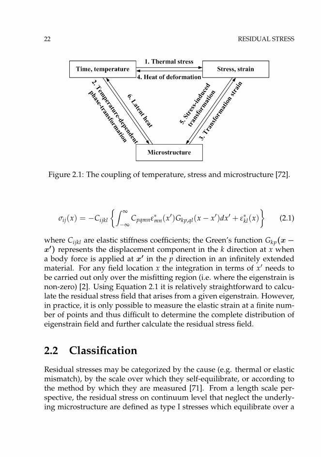
22 RESIDUAL STRESS
Figure 2.1: The coupling of temperature, stress and microstructure [72].
σij(x) = −Cijkl
{∫ ∞
−∞Cpqmnε∗mn(x′)Gkp,ql(x − x′)dx′ + ε∗kl(x)
}(2.1)
where Cijkl are elastic stiffness coefficients; the Green’s function Gkp(x −x′) represents the displacement component in the k direction at x whena body force is applied at x′ in the p direction in an infinitely extendedmaterial. For any field location x the integration in terms of x′ needs tobe carried out only over the misfitting region (i.e. where the eigenstrain isnon-zero) [2]. Using Equation 2.1 it is relatively straightforward to calcu-late the residual stress field that arises from a given eigenstrain. However,in practice, it is only possible to measure the elastic strain at a finite num-ber of points and thus difficult to determine the complete distribution ofeigenstrain field and further calculate the residual stress field.
2.2 Classification
Residual stresses may be categorized by the cause (e.g. thermal or elasticmismatch), by the scale over which they self-equilibrate, or according tothe method by which they are measured [71]. From a length scale per-spective, the residual stress on continuum level that neglect the underly-ing microstructure are defined as type I stresses which equilibrate over a

2.2 CLASSIFICATION 23
Figure 2.2: Residual stress arises from misfit either between different re-gions or different phases within the material. Examples of different typesof macro- and micro-residual stress are illustrated schematically. In eachcase the process is indicated on the left, the misfit in the center and theresulting stress pattern on the right-hand side [2].
length scale comparable to the extend of the component or structure. TypeII residual stresses are microstructurally related and equilibrate on a scaleof a few grain diameters. Type III microstresses are arising from hetero-geneous behaviour at the atomic scale, these might arise from line defects(dislocations), point defects such as might arise from radiation damage ordoping with atoms of a different size [2].
In practice, it is conceptually satisfying to consider the whole three di-mensional stress field within a component. However, it is usually costlyand impractical to depict the whole stress field. Thus, in structural in-tegrity assessment, residual stresses are often decomposed across a regionof concern into the membrane stress σm, through-section bending stress σband locally self-equilibrated σse. It is useful to decompose residual stressesinto different components, and a length-scale concept can be applied [75].By using the length-scale concept, a consistent characterization of stressesfrom various sources can be obtained based on their length scales. Also,the contributions of different stress components to fracture driving forcecan be quantified in terms of their characteristic length scales. Figure 2.3

24 RESIDUAL STRESS
Figure 2.3: Illustration of residual stress decomposition in terms ofthrough-thickness membrane, bending and self-equilibrating componentsfor a T fillet weld [75].
shows a example of the decomposition of residual stress into differentcomponents with respect to the thickness of a T fillet weld [75].
2.3 Measurement techniques
Just as residual stress can present over a range of scales, from atomic scaleto structural scale, failure can also occur at the material level or at macrostructure level. Residual stresses tend to affect the micromechnisms offailure at smaller scale and have influence on structural integrity at thecontinuum level. Thus, it is very important to obtain realistic distributionof residual stresses. There are basically two types of methods to obtain theresidual stress field, the numerical simulation and experimental measure-ment. For experimental measurement, destructive methods (e.g. section-ing, hole drilling, contour method) and non-destructive tests (NDT), suchas ultrasonic, X-ray diffraction method, neutron diffraction method, areoften employed. A review of residual stress measurement methods can
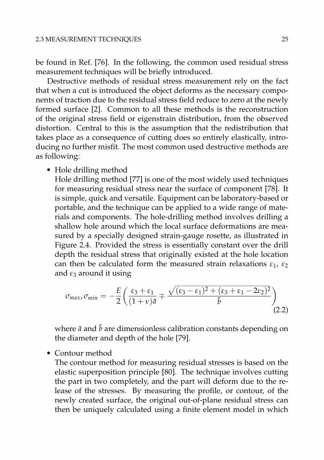
2.3 MEASUREMENT TECHNIQUES 25
be found in Ref. [76]. In the following, the common used residual stressmeasurement techniques will be briefly introduced.
Destructive methods of residual stress measurement rely on the factthat when a cut is introduced the object deforms as the necessary compo-nents of traction due to the residual stress field reduce to zero at the newlyformed surface [2]. Common to all these methods is the reconstructionof the original stress field or eigenstrain distribution, from the observeddistortion. Central to this is the assumption that the redistribution thattakes place as a consequence of cutting does so entirely elastically, intro-ducing no further misfit. The most common used destructive methods areas following:
• Hole drilling methodHole drilling method [77] is one of the most widely used techniquesfor measuring residual stress near the surface of component [78]. Itis simple, quick and versatile. Equipment can be laboratory-based orportable, and the technique can be applied to a wide range of mate-rials and components. The hole-drilling method involves drilling ashallow hole around which the local surface deformations are mea-sured by a specially designed strain-gauge rosette, as illustrated inFigure 2.4. Provided the stress is essentially constant over the drilldepth the residual stress that originally existed at the hole locationcan then be calculated form the measured strain relaxations ε1, ε2and ε3 around it using
σmax, σmin = −E2
(ε3 + ε1
(1 + ν)a∓
√(ε3 − ε1)2 + (ε3 + ε1 − 2ε2)2
b
)(2.2)
where a and b are dimensionless calibration constants depending onthe diameter and depth of the hole [79].
• Contour methodThe contour method for measuring residual stresses is based on theelastic superposition principle [80]. The technique involves cuttingthe part in two completely, and the part will deform due to the re-lease of the stresses. By measuring the profile, or contour, of thenewly created surface, the original out-of-plane residual stress canthen be uniquely calculated using a finite element model in which

26 RESIDUAL STRESS
Figure 2.4: Illustration of hole drilling method.
the distorted surface is forced back into a planar state. Figure 2.5illustrates the principle of the contour method.
• Slotting methodThe slotting method, also called the crack compliance method, gen-erally provides a measure of the stress perpendicular to the slot andis applicable when there is little stress variation parallel to the lineof the slot [81]. A slot is cut incrementally and the change in gaugeslocated on both the top and bottom surfaces recorded [2].
Non-destructive method of determine residual stresses rely on diffrac-tion within crystalline materials and engineering components. The crys-talline lattice is used like an atomic strain gauge, and the lattice strain canbe related directly to stress using appropriate elastic constants. Three maintypes of radiation are available with wavelength suitable for measuringatomic lattice spacing, namely, electron, X-ray photon and neutron beams.The three beams can travel very different distances into crystalline ma-terials before attenuation becomes significant and so their uses are quitedifferent [2]. The following non-destructive methods are often used:
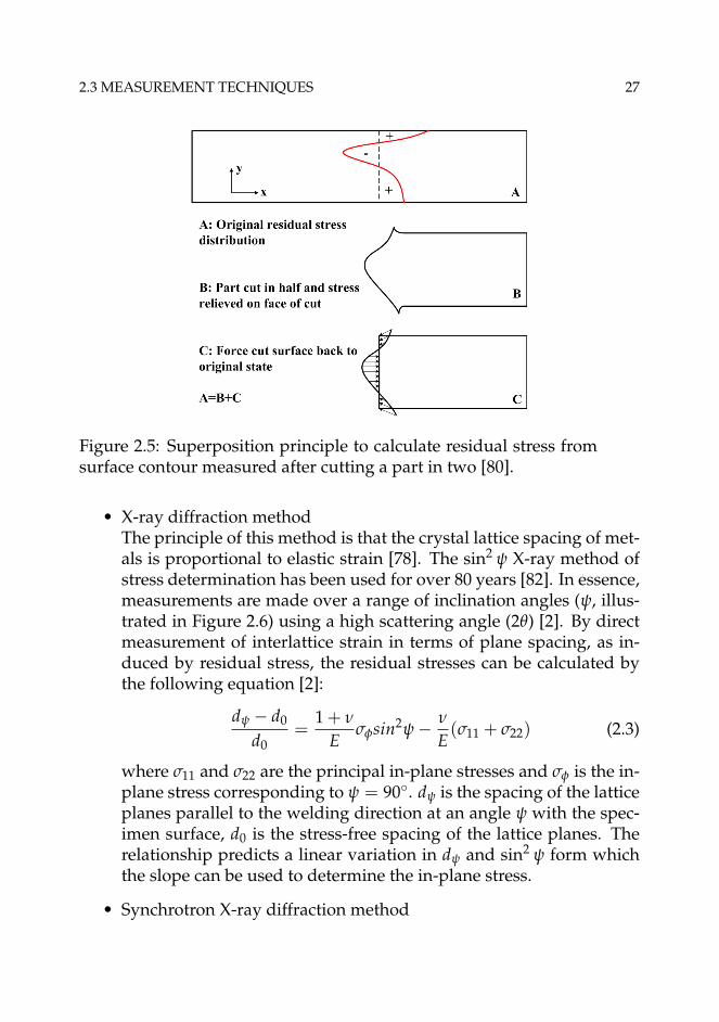
2.3 MEASUREMENT TECHNIQUES 27
Figure 2.5: Superposition principle to calculate residual stress fromsurface contour measured after cutting a part in two [80].
• X-ray diffraction methodThe principle of this method is that the crystal lattice spacing of met-als is proportional to elastic strain [78]. The sin2 ψ X-ray method ofstress determination has been used for over 80 years [82]. In essence,measurements are made over a range of inclination angles (ψ, illus-trated in Figure 2.6) using a high scattering angle (2θ) [2]. By directmeasurement of interlattice strain in terms of plane spacing, as in-duced by residual stress, the residual stresses can be calculated bythe following equation [2]:
dψ − d0
d0=
1 + ν
Eσφsin2ψ − ν
E(σ11 + σ22) (2.3)
where σ11 and σ22 are the principal in-plane stresses and σφ is the in-plane stress corresponding to ψ = 90◦. dψ is the spacing of the latticeplanes parallel to the welding direction at an angle ψ with the spec-imen surface, d0 is the stress-free spacing of the lattice planes. Therelationship predicts a linear variation in dψ and sin2 ψ form whichthe slope can be used to determine the in-plane stress.
• Synchrotron X-ray diffraction method

28 RESIDUAL STRESS
Figure 2.6: Schematic illustrating the sin2 ψ technique whereby thein-plane stress can be deduced from the variation in atomic latticespacing as the ψ angle is increased [2].
Synchrotron, or hard X-rays, provide very intense beams of high en-ergy X-rays [2]. There X-rays have a much higher depth penetra-tion than the conventional X-rays, typically around 50 mm in alu-minum [76]. Thus, this method is capable of providing high spatialresolution, 3D maps of the strain distribution to millimeter depths inengineering components. Another great advantage that synchrotronhas is that intense narrow beams of 1mm to 10 μm in size are pos-sible, which leads to spatial resolutions that are limited not by theinstrument but by the crystallite size within the sample.
• Neutron diffractionNeutrons have the advantage over X-rays that for wavelengths com-parable to the atomic spacing, their penetration into engineering ma-terials is typically many centimeters [71]. With high spatial reso-lution, neutron diffraction can provide complete three-dimensionalstrain maps of engineering components [76].There are essentially twoneutron diffraction techniques, namely, conventional θ/2θ scanningand time of flight approach [71]. Compared to other diffraction tech-niques, the cost of neutron diffraction method is much higher andthe availability is very much lower.
• Ultrasonic methodUltrasonic methods utilize the sensitivities of the velocity of ultra-sound waves traveling through a solid to the stress level within the

2.4 NUMERICAL PREDICTION 29
solid body [76]. Changes in the speed of ultrasonic waves in a ma-terial are directly affected by the magnitude and direction of stressespresent. Because the velocity changes are small and are sensitiveto the material’s texture, it is often more practical to measure tran-sit times as the ultrasonic path length is usually not known to suffi-ciently high precision. This method has the advantage of being ableto measure in the bulk of the material and are therefore well suitedto routine inspection operations [71].
There are many other methods to measure the residual stresses in engi-neering materials. It is important to consider the characteristic length-scaleof the residual stress, which can be helpful for selecting a proper measure-ment technique. The ability to measure and monitor the development ofresidual stresses during the whole material processing procedure can behelpful to manage residual stresses for different processing stages.
2.4 Numerical prediction
2.4.1 Description
The thermal and thermal-mechanical process associated with welding resid-ual stress evolution during welding can be extremely complex [3], as illus-trated in Figure 2.7. The distribution of welding residual stress dependson several main factors such as structural dimensions, material proper-ties, restraint conditions, heat input, number of weld pass and weldingsequences [83]. Due to the complexity of physical processes involved inwelding, it is impossible for any experimental technique to obtain a com-plete mapping of the residual stress and distortion distribution in a gen-eral welded structures [84]. With advances in computer hardwares andfinite element method (FEM) software, numerical simulations now playan important role in predicting residual stresses. A series of review pa-pers on numerical modeling of welding can be found in Ref. [85–88].
There are several challenges in numerical prediction of residual stresses.Among all challenges, it is critical to formulate an accurate constitutivemodel that can properly describe the time-dependent properties of the ma-terials. A unified welding constitutive model may include many internalstate variables, as illustrated in Figure 2.8. The constitutive model can then

30 RESIDUAL STRESS
Figure 2.7: Residual stress and distortion evolution in welded joints [3].
be implemented into finite element platforms and perform the simulationsof welding residual stresses. It is also very important to obtain the reli-able material properties, including temperature-dependent properties, theproperties of different phases and the phase-transformation temperatureetc. Another important issue for the numerical simulation is the properheat source model. In practice, for different welding methods, differentheat source model should be utilized, e.g. the keyhole cylinder volumetricheat source together with a surface Gaussian heat source model is usedfor laser welding, and the volume Gaussian double ellipsoid heat sourcemodel can be used for arc welding.
For predicting residual stresses different types of special purpose oradapted general purpose computer codes have been applied. SYSWELDfrom ESI group∗ is the leading tool for the simulation of welding and weld-ing assembly processes. In the RESIA project, a new platform, namelyWeldsimS, for predicting the welding residual stresses and microstruc-tures of high strength steels has been developed based on IFE’s in-houseFEM software package, IfeFEM.
∗www.esi-group.com

2.4 NUMERICAL PREDICTION 31
Figure 2.8: Basic elements of unified weld constitutive model [3].
2.4.2 WeldsimS
WeldsimS [89] is part of the computer programs WLEDSIM/ALSIMS de-veloped by IFE. The main function of WeldsimS is the prediction of weld-ing residual stresses and hydrogen diffusion as well. The codes accountfor a series of complex phenomena such as the moving heat source, melt-ing and solidification, solid-state phase transformations, work hardening,strain rate sensitivity and the flow stress dependency on the specific mix-ture of phases appearing at the different temperatures. Specific WeldsimSfeatures are:
• Different properties in base and weld metal can be handled.
• Build-up of fillet regions in multi-pass welding, which is simulatedby pre-defined weld metal elements being successively activated foreach pass.
• Adaptive mesh refinement for numerical accuracy and high spatialresolution of the stress field.

32 RESIDUAL STRESS
• Export of the stress field to failure assessment analyses in 3D do-mains or 2D cross sections
It should be noted that WeldsimS only contains the main solver, and thepre-process and post-process should be accomplished in other commer-cial software. Also, WeldsimS cannot perform fracture mechanics analysisnow. Simulated results should be exported into ABAQUS to perform fur-ther analysis.
2.5 Effect of residual stress on failure
Residual stresses plays an important role in material failure. This studyfocuses on the effect of residual stresses on cleavage and ductile fracturebehaviour. However, residual stresses can also have effect on other failuremechanisms. A review on this topic has been reported by Withers [2]. Inthe following context, the effect of residual stresses on fatigue, creep andhydrogen embrittlement will be briefly introduced.
The fatigue behaviour of structural components is a strong functionof the load history. The amplitude of the applied load cycles is a pri-mary variable influencing the fatigue lifetime, and the mean (or maxi-mum) value of the load in each cycle is a secondary variable that can alsohave a major influence on fatigue [90]. Fatigue crack growth includes nu-cleation and propagation of crack. Fatigue nucleation life is a function ofthe alternating stress amplitude but not the mean stress, while the growthrates of fatigue cracks are a function of both the stress amplitude and meanstress. Thus, it implies that residual stresses have relatively little influenceon fatigue crack nucleation, but potentially a significant influence on fa-tigue crack growth. There are two types of fatigue, i.e. low cycle fatigue(LCF) and high cycle fatigue (HCF) [91]. Residual stress often has littleeffect on LCF life. However, HCF is very sensitive to residual stresses [2].To the extent that the S-N curve is driven by crack nucleation behaviour,the effects of residual stresses may be small, but to the extent that the S-Ncurve is driven by crack growth, including the growth of microcracks, theeffects of residual stresses may be large.
Time-dependent plasticity, or "creep", is an important failure mecha-nism at elevated temperatures. The failure mode of creep is often char-acterized by the growth of cavities on grain boundaries [92]. If the accu-
2.5 EFFECT OF RESIDUAL STRESS ON FAILURE 33
mulated creep strains exhaust the creep ductility of the material, crackswill initiate. Creep strain and ultimate cracking can be driven by residualstresses, for example, as a means of thermal relaxation of weld residualstress in areas with poor material creep ductility at the operating tempera-ture and creep deformation rate [2]. Also, a highly triaxility stress state canreduce the creep ductility relative to the uniaxial response substantially.
Hydrogen embrittlement is a general phenomenon which lowers thefracture resistance of high-strength steels, and therefore raises the failurerisk of the components [93]. In the case of hydrogen induced fracture, therole of the residual stresses is potentially twofold [94]. First, the mechan-ical effect of residual stresses is additive to the stresses caused by appliedload. In addition, the heterogeneous fields of residual stresses affect therate of hydrogen transportation toward potential rupture sites in the com-ponents by the stress-assisted diffusion governed by the gradient of thehydrostatic component of stresses.


Chapter 3
Methodology
3.1 Problem description
This study concerns an ideal problem. A large cylinder with a weld in thecenter was studied. The reason for selecting such model is that it can beeasily modeled by a 2D plane strain MBL model. With the MBL model, areference case can be well established, and the constraint conditions can beeasily handled by changing the remote boundary governed by the elasticK-field and T-stress. A sharp crack was embedded in the weld region. Theanalysis procedure, as illustrated in Figure 3.1, consists of the followingsteps: 1) enforce a welding procedure, which introduces a residual stressfield; 2)introduce a sharp crack; 3) apply the external load. The possiblecontact between the upper and lower free surfaces of the crack has alsobeen considered when the residual stress was introduced.
3.2 Modified boundary layer model
One of the basic assumptions behind the application of linear elastic frac-ture mechanics to elastic-plastic materials is that plastic deformation at thecrack tip is governed by the intensity of the elastic stress singularity, KI .In this case, the plastic zone size is small compared to other geometricdimensions of the problem. The crack problem can be solved by using aboundary layer approach, which assumes that the boundary value stressesof the elastic-plastic crack problem are given by the extension of the valid-ity of the singularity term (Eq. 3.1) in the elastic stress solution to large

36 METHODOLOGY
Figure 3.1: Illustration of the problem, (a) welding at the center of theround cylinder, (b) introduce a sharp crack, and (c) apply the external load.
values of r and small-scale-yielding [25]
σij =KI
(2πr)1/2 fij(θ) (3.1)
where r and θ are polar co-ordinates referred to the crack tip, and the func-tion fij are given by the elastic solution.
Analytically, the stress state at the crack tip in the elastic case is givenby a singular stress component and non-singular terms. As shown inChapter 1, Williams [24] proposed an analytical expansion to represent thestress state at the crack tip, and the first two terms has the form of Eq. 1.8.It should be noted that the second term is independent of r. Larsson andCarlsson [25] demonstrated that the second term in the series was impor-tant to modify the boundary solution to fit the real crack problem, and theT-stress has a significant effect on the plastic zone size and shape. In thisway, a modified boundary layer solution is obtained which is expected toagree with the solution for the actual geometry.
In this study, the modified boundary layer analysis was performed tostudy the effect of residual stresses on fracture behaviour, and the bound-ary conditions on the remote edges of the model is applied through a dis-placement field (u, v) controlled by the elastic asymptotic stress field of aplane strain mode I crack

3.3 COMPLETE GURSON MODEL 37
u(r, θ) = KI1 + ν
E
√r
2πcos(
12
θ)(3 − 4ν − cos θ) + T1 − ν2
Er cos θ
v(r, θ) = KI1 + ν
E
√r
2πsin(
12
θ)(3 − 4ν − cos θ) − Tν(1 + ν)
Er sin θ
(3.2)
where KI=√
EJ/(1 − ν2) under plane strain condition; E is Young’s mod-ulus, ν is Poisson’s ratio; r and θ are polar coordinates centered at the cracktip with θ=0 corresponding to the crack tip.
3.3 Complete Gurson model
The complete Gurson model has been employed to study the effect ofresidual stress on ductile crack growth resistance in this thesis. It seemsthat conventional plasticity theories lose their applicability when ductilefracture is involved [95]. Also, the ductility or fracture toughness of a ma-terial varies with the change of geometry constraint level and cannot bedirectly transfered from one geometry to another [49]. Thus, both the evo-lution of matrix stress and the material deterioration due to the damageshould be considered when the full stress-strain relationship of the mate-rial is to be described.
3.3.1 Gurson model
The accuracy of the ductile fracture simulation depends on the model-ing of physical behaviour of solids. Using the micro-mechanical model-based constitutive equations to predict the ductile fracture process has at-tracted much efforts in last decades. One of the best well-known micro-mechanical models is Gurson [96] model, which is based on the work byRice and Tracy [97] and McClintok [98]. The Gurson model has later beenmodified by Tvergaard and Needleman [99–101], thus, it is most often re-ferred to as the Gurson-Tvergaard-Needleman (GTN) model. The GTNmodel is in fact a void growth model. The effect of void coalescence can beconsidered with the introduction of a so-called critical void volume frac-tion, which is not a physical mechanism-based coalescence criterion. InGTN model, the softening effect due to the presence of voids was reflected

38 METHODOLOGY
in a yielding function. By idealizing the true void distribution into a unitcell containing on spherical void and carrying out the rigid-plastic upperbound analysis, the following yield function was obtained:
φ(q, σ, f , σm) =q2
σ2f
+ 2q1 f cosh(
3q2σm
2σ
)− 1 − (q1 f )2 = 0 (3.3)
where f is the void volume fraction, σm is the mean macroscopic stress, q isthe von Mises stress, σf is the flow stress, and q1 and q2 are parameters in-troduced by Tvergaard [99, 100]. Unlike many soil material models whereyielding is also dependent on hydrostatic stress but yield surface is fixedin stress space, the yield surface of the Gurson model decreases with theincrease of damage until the complete loss of load-carrying capacity [49].Due to the incompressible nature of the matrix material the growth of ex-isting voids can be expressed as:
d fgrowth = (1 − f )dεp : I (3.4)
where εp is the plastic strain tensor and I is the second-order unit tensor. Inthe original Gurson model (q1=q2=1), material softening with the increaseof void volume fraction is a continuous process, and complete loss of loadcarrying capacity would occur only when the void has grown to the ul-timate value f =100%, which is an unrealistic situation [49]. Even withthe modification made by Tvergaard, the void volume fraction at whichthe Gurson model will lose load carrying capacity is still unrealisticallylarge as f =1/q1. However, the void volume fraction is much smaller thanf =1/q1 and usually less than 15% according to both experimental observa-tions [102] and numerical analysis [103]. It thus indicates that the Gursonmodel can not naturally predict void coalescence and an extra void coales-cence criterion should be used [49]. Then, so-called critical void volumefraction criterion for void coalescence has been proposed, which assumesthat void coalescence appears when a critical void volume fraction fc isreached. A review on the development of this criterion has been madeby Zhang [104]. Once the void coalescence has been determined to oc-cur according to a criterion, the post-coalescence deformation behaviourof the Gurson model is numerically simulated by an artificial acceleration

3.3 COMPLETE GURSON MODEL 39
of void growth, as suggested by Tvergaard and Needleman [101]:
f ∗ =
{f for f � fc
fc + f ∗u− fcfF− fc
( f − fc) for f > fc(3.5)
where f ∗u =1/q1 and fF is the void volume fraction at the end of void coa-lescence. Here, fF=0.15+2 f0, where f0 is the initial void volume fraction.When the coalescence starts and f > fc, f ∗ replaces f in Eq.(3.3).
Before any growth, voids should be nucleated first. Void nucleationcan be stress controlled or strain controlled [105]. The strain controllednucleation can be written as:
d fnucleation = fε(εp)dεp (3.6)
where fε is the void nucleation intensity, and εp is the equivalent plasticstrain. Two types of void nucleation models may be used for engineeringmaterials, the cluster nucleation model and continuous void nucleationmodel. The detailed description of such models can be found in Ref. [105].
3.3.2 Thomason’s coalescence criterion
As described in Section 1.2.4, the fracture of ductile material displays twodistinct phases, the homogeneous phase and localized phase. Thomasondeveloped a so-called dual dilatational constitutive equation theory forductile fracture [106–108], and argued that two fracture phases are in com-petition for a void-containing material, as shown in Figure 3.2.
Both deformation modes are dilatational, by which plastic deforma-tion will result in change of material volume and the material will alwaysfollow the deformation mode which needs less energy. In the early stageof deformation, the voids are small and it is easier to follow the homoge-neous deformation mode (the stress required for going to homogeneousdeformation is less than the stress required for going to a localized defor-mation mode), and with the advance of plastic deformation and increaseof void volume fraction, the stress required for localized deformation de-creases [105]. When the stress for localized deformation is equal to thestress for homogeneous deformation, the void coalescence occurs. Theplastic limit criterion by Thomason states that no coalescence will occur aslong as the following conditions is satisfied [108, 109]:

40 METHODOLOGY
Figure 3.2: The competition of the two deformation modes in the Thoma-son theory [49]
σ1
σ<
(α
(1r− 1
)2
+β√
r
)(1 − πr2) (3.7)
Coalescence will first happen when the left-hand side becomes equalto the right-hand side in Eq. 3.7, and the void volume fraction at coales-cence will be taken as the fc. In Eq. 3.7, σ1 is the current maximum princi-pal stress, r is the void space ratio, r= 3
√(3 f /4π)eε1+ε2+ε3/(
√eε2+ε3/2) and
ε1 is the maximum principal strain, ε2 and ε3 are the two other principalstrains, α=0.1 and β=1.2 are constants fitted by Thomason [108]. For planestrain problem, Eq. 3.7 can still be used, but with ε3=0. This work has beenlater improved by Pardoen and Hutchinson [110] and Zhang et al. [105]to take the effect of hardening into account and the following relation hasbeen found:
α(n) = 0.12 + 1.68n (3.8)
where n is the hardening exponent, improves the prediction of coales-cence.

3.4 COHESIVE ZONE MODEL 41
3.3.3 Complete Gurson model
By combining the GTN model for void growth and Thomason’s plasticlimit load model for coalescence a so-called "complete Gurson model" hasbeen proposed by Zhang et al. [105], with which the complete process ofductile fracture can be simulated. The complete Gurson model has beenverified [49] for non-hardening material against the finite element resultsby Koplik and Needleman [103]. It was found that the complete Gursonmodel was very accurate, in particular, for small initial void volume frac-tion cases [105]. By using the complete Gurson model, ductile fracture isexclusively linked to the void nucleation parameters and the mesh size.
Because the yield surface of the Gurson model is changing with theincrease of damage, the computer implementation of the Gurson model iscomplicated, especially for the finite element programs which use implicitalgorithms [49]. Zhang and Niemi [111], Zhang [112, 113] performed thenumerical treatment of the Gurson model and a family of the generalized-midpoint algorithms has been proposed. The complete Gurson model isthen implemented into ABAQUS [114] using the algorithms developed byZhang via the material user subroutine UMAT.
3.4 Cohesive zone model
Linear elastic fracture mechanics (LEFM) has been proven a useful tool forsolving fracture problems provided a crack-like notch or flaw exists in thebody and the nonlinear zone ahead of the crack tip is negligible. However,an important issue when considering failure is the observation that mostengineering materials are not perfectly in the Griffith sense, but displaysome ductility after reaching the strength limit [115]. The nonlinear zonedue to plasticity or microcracking for ductile metals or cementitious mate-rials is not negligible in comparison with other dimensions of the crackedgeometry [116], and small-scale-yielding, micro-cracking and void initi-ation, growth and coalescence may take place. A proper process zonemodel is then needed to characterize the fracture process and describe thelocal fracture behaviour. Among the various process models, the cohesivezone model seems particularly attractive for practical application since itis applicable to a wide range of materials and fracture mechanisms [117].

42 METHODOLOGY
Figure 3.3: Schematic plot of the concept of cohesive zone model [117].
3.4.1 Concept
The cohesive zone model was introduced by Barenblatt [118] and Dug-dale [119] for elastic-plastic fracture in ductile metals and for quasi-brittlematerials by Hillerborg et al. [120] under the name of fictitious crack model.The fundamental concept of the cohesive zone model is a so-called traction-separation-law (TSL), which is a function described by the cohesive stress(σ) and separation (δ) [121]. The area under the traction-separation rela-tion represents the cohesive energy Γ0. The basic parameters necessaryto describe the traction-separation-law are two among the critical tractionσmax, the critical separation δc and the cohesive energy Γ0 [122]. The basicconcept of the cohesive zone model is shown in Figure 3.3.
3.4.2 Traction-separation-law
One of the key problems in the application of the cohesive zone modelis the choice of the TSL within the cohesive zone. Needleman first pro-posed a polynomial law [123], and later an exponential law was intro-duced by Xu and Needleman [124]. Tvergaard and Hutchinson [122] pro-

3.5 COHESIVE ZONE MODEL 43
Figure 3.4: Schematic plot of the traction-separation-law used in the anal-ysis.
posed a trapezoidal law for ductile fracture. The traction-separation-lawused in this paper is a bilinear relationship between the traction and theseparation, which is characteristic of brittle materials [117]. The traction-separation-law used in this thesis is a bilinear relationship between thetraction and the separation, as shown in Figure 3.4, which is characteristicof brittle materials [117]. The dominant parameters are cohesive energy Γ0and the maximum cohesive stress σmax.
When a cohesive zone model is employed to simulate the crackingbehaviour of a brittle thin interface, the softening part of the TSL maycause some problems to the solution algorithm. A snap-back instabil-ity can occur depending on interface thickness, stiffness and the lengthof the elements adjacent to the cohesive zone [125]. If a discontinuity ofthe response occurs, the simulation can stop. A possible solution is theviscous regularization method proposed by Chaboche et al. [125], whichintroduces a fictitious viscosity parameter in the constitutive equation ofthe cohesive elements. In turn, the convergence of the solution can beachieved by dissipating excess energy; but the value of the viscosity pa-rameter should be small enough to not affect the results. Pezzotta andZhang [126] demonstrated that when the viscosity value v ≤1.0E-5 thepredicted failure becomes independent of the viscosity parameter whenother parameters are fixed. Thus, the value v=1.0E-5 was used for all thecalculations in this study.

44 METHODOLOGY
3.5 Eigenstrain method
The complete Gurson model and the cohesive zone model are constitutivemodels to describe the fracture mechanisms. In this thesis, the eigenstrainmethod was utilized to introduce the residual stresses into the MBL model.The eigenstrain method will be further investigated and described in thissection. The background regarding the nature of residual stress and a for-mulation of eigenstrain approach to residual stress determination will bedescribed. Then, the application of the eigenstrain method in this thesiswill be discussed.
3.5.1 Description
Generally, the stress contained in a self-balanced body is called residualstress. In the body, the source of residual stress is an incompatible strainfield. The incompatible strain field could be produced by plastic defor-mation, thermal strain, phase-transformation, or other means. Ueda etal. [127] refers to the sum total of all such possible causes of incompatiblestrain as the "inherent strain" presented in the body. In this study, we adoptMura’s [74] terminology in calling the incompatible strain as "eigenstrain".
When a body contains residual stress, cutting the body along an arbi-trary plane will alter the stress. This fact is problematic for many stressmeasurement techniques, but is employed by the present method. If wehave an ideal cutting process, the eigenstrain in each piece of the originalbody will not be altered by the process. Sectioning of the body changesthe distribution of residual stress, but not that of eigenstrain. By measur-ing the stress change when the body is sectioned, the eigenstrain can bedetermined. Further, it need not be assumed that residual stress is entirelyrelieved by the cutting process in applying this method [78]. When certainassumptions about the spatial distribution of the source of residual stresscan be made, estimates of residual stress can be generated for locationswhich are remote from strain measurement points. Thus, the eigenstrainmethod is basically a hybrid experimental/analytical method.
In the welding procedure, elastic-plastic phenomena of the materialessentially occur, and eigenstrain always generates in the body. Therefore,the elastic response equations are generally derived as the relationshipsbetween the vectors of eigenstrain ε∗, elastic strain εe, and stress σ. These

3.5 EIGENSTRAIN METHOD 45
vectors are related as follows [128, 129]:
εe = [H∗]ε∗ (3.9)
σ = [D]εe = [D][H∗]ε∗ (3.10)
where [H∗] is the matrix relating elastic strain to eigenstrain, and [D] isthe matrix relating elastic stress to strain. The matrix [H∗] links the overallfields of eigenstrain to the overall fields of elastic strain, and depends onthe domain occupied by the body and its boundary conditions.
When the vectors of inherent strain ε∗ are known, the residual stresscan be obtained by elastic analysis without calculating [H∗] correspondingto the initial body through
σ = [D](ε− ε∗) (3.11)
where ε is total strain and can be expressed as the sum of the eigenstrainand the elastic strain εe. The magnitude of eigenstrain depends on thewelding conditions and configurations of the welded joints.
3.5.2 Simplification
The analytical and experimental requirements of the eigenstrain methodmake its application expensive. Some efforts have been made to improvethe applicability of this method, e.g. localized eigenstrain technique [78],which allows residual stress estimates to be made inside a small regionof interest near the weld bead. By using this technique, the experimentaleffort required is reduced by up to five times relative to Ueda’s method.Also, this new method was verified by numerical simulation and shownto be as accurate as the original Ueda’s method.
Another approach was introduced by Mochizuki et al. [128] to sim-plify the distribution of the eigenstrain in complicated weld structures andresidual stresses can be calculated based on such distribution. The eigen-strain of various welded joints with shapes were shown to have trape-zoidal distributions in three vertical paths around the weld metal, andshear components near zero. The width and magnitude of the eigenstraindistribution depend on the kind of material, heat input, and the config-uration of the joint. An example of pipe penetrating the thick plate wasshow in Figure 3.5, and the calculated residual stresses were compared

46 METHODOLOGY
Figure 3.5: Illustration of the simplified eigenstrain method, (a) definitionof the direction around weld metal, and (b) assumed eigenstrain and theirdistribution zone [128].
46 METHODOLOGY
Figure 3.5: Illustration of the simplified eigenstrain method, (a) definitionof the direction around weld metal, and (b) assumed eigenstrain and theirdistribution zone [128].
46 METHODOLOGY
Figure 3.5: Illustration of the simplified eigenstrain method, (a) definitionof the direction around weld metal, and (b) assumed eigenstrain and theirdistribution zone [128].
46 METHODOLOGY
Figure 3.5: Illustration of the simplified eigenstrain method, (a) definitionof the direction around weld metal, and (b) assumed eigenstrain and theirdistribution zone [128].

3.5 EIGENSTRAIN METHOD 47
Figure 3.6: Residual stress on pipe inner surface for perpendicular weldedjoint (θ = 90deg) [128].
with the experimental measurement stress in Figure 3.6. It can be seenthat the distribution from the eigenstrain analysis agrees well with the di-rect measurement values in both circumferential and axial direction.
3.5.3 Application
The main objective of this thesis is to investigate the effect of residualstresses on crack-tip constraint and failure mechanisms, and to obtain theaccurate distribution of the residual stresses is out of the scope. Therefore,a simplified method was utilized to introduce residual stress fields intothe finite element model.
Residual stress field was introduced by the eigenstrain method throughthe following steps:
• Assume different eigenstrain distribution in base metal and weldmetal respectively. Set the eigenstrain values equal to the thermalexpansion coefficients of different regions.
• Load the model by a unit temperature change.
• Insert the crack and residual stress redistributes.


Chapter 4
Effect of residual stress oncrack-tip constraint
Transferability of test data from small specimen to predicting fracture be-haviour of large scale components is alway a main concerning factor whenapplying traditional fracture mechanics approaches. It has been well rec-ognized that crack-tip constraint due to geometry, mismatch, pre-strainand residual stress affect the distribution of stresses around a crack andconsequently preclude the use of a single parameter characterization ofthe crack tip stress field [44]. In this chapter, the effect of residual stress oncrack-tip constraint will be investigated.
4.1 Problem description
The modified boundary layer (MBL) model consisting a weld metal re-gion located in the center of the model and an outer base metal region wasutilized to study the problem under Mode I plane strain conditions. Theload was applied to the remote edges of the model through a displace-ment field (u,v) controlled by the elastic asymptotic stress field, as shownin Eq. 3.2. Only the upper-half plane was modeled because of symmetry.The crack is assumed to be a sharp crack without initial radius and theradius of the MBL model was taken as 1000 mm to ensure that the small-scale-yielding condition is fulfilled. The model was meshed by standardeight-node elements with reduced integration, CPE8R, with a finer meshin the crack-tip region and the interface between the weld metal region

50 EFFECT OF RESIDUAL STRESS ON CRACK-TIP CONSTRAINT
(a)
(b)
Figure 4.1: Modified boundary layer model, (a) global mesh; (b) crack-tipmesh.
and the base metal region. The size of smallest elements near the crack tipis 0.1 mm. The finite element model has 1408 elements and the meshes areshown in Figure 4.1.
The weld metal and base metal were assumed to have the same elasticproperties (E=2×10⁵ MPa, ν=0.3) and plastic properties. The rate inde-pendent power law strain hardening materials were assumed to have theform of
σf = σ0(1 +εp
ε0)n (4.1)
where σf is the flow stress; εp is the equivalent plastic strain, σ0=400 MPathe yield stress, ε0 = σ0/E the yield strain and n is the plastic strain

4.3 RESIDUAL STRESS FIELD 51
hardening exponent. Different thermal expansion coefficients for the basemetal (αb) and weld metal (αw) are assumed to introduce the residualstresses into the model by eigenstrain method. It should be noted that thethermal expansion coefficients here are not physical thermal coefficients,but are just used to introduce the residual stress into the computationalmodel.
4.2 Residual stress field
The eigenstrain method was employed to introduce residual stress into theFE model, in which a "spot" weld with a round shape located in the centerof the model was assumed. The eigenstrain for the base metal was as-sumed to be zero, and isotropic non-zero value for the weld was assigned.The size of the weld region was described by radius c, and three differentsizes were investigated. Figure 4.2 shows the redistributed residual stressafter the crack was introduced for the case with αw=0.003 and αb=0. Thestress components were normalized by the yield stress, and the distancefrom the crack tip was normalized by c.
It can be seen that the residual stresses along both the parallel andopening directions have a sharp turning point at the interface betweenthe base metal and weld metal. The reason for this sharp turning point isthat the assumption of eigenstrain distribution is not continuous betweenthe two regions. It can also be observed that the normalized residual stressfields collapse into one curve for different weld regions. Both the paralleland opening residual stress components in the weld metal are tensile andthe peak values are approximately 1000 MPa and 1520 MPa, respectively.In the base metal region, the residual stress parallel to the crack plane isalso tensile in a large range while the opening residual stress component iscompressive to counter balance the tensile stress in the weld. The effect ofthe biaxial residual stress on the crack-tip constraint will be investigatedin the following by using the residual stress field with weld size c=20 mm.
4.3 Results
The J-integral is adopted by the majority of the integrity assessment pro-cedures currently used as the elastic-plastic fracture parameter. But for

52 EFFECT OF RESIDUAL STRESS ON CRACK-TIP CONSTRAINT
0 1 2 3 4 50
1
2
3
4
x/c
σ 11/σ
0
c=10 mmc=15 mmc=20 mm
(a)
0 1 2 3 4 5−1
0
1
2
3
4
x/c
σ 22/σ
0
c=10 mmc=15 mmc=20 mm
(b)
Figure 4.2: The redistribution of the residual stress fields after the crackwas introduced. (a)σR
11; (b)σR22. E/σ0=500, ν=0.3, n=0.1; αw=0.003 and αb=0.

4.3 RESULTS 53
a crack in a residual stress field or the combination of mechanical andresidual stresses a general path-independent J-integral appears to be path-dependent [11]. In our study, the computed J-integral by ABAQUS [114]has been investigated and compared with the applied J-integral (exter-nal loading) to the MBL model. Residual stresses as an additional stressfield induce an initial J-integral, which is about 0.04% of the final J-integralcaused by the combination of residual stress and external load. The resid-ual stress was found to have significant effect on the path independence atthe early stage of loading, while the path dependence becomes less severewith the increase of external loading. We also found that the J-integral inboth the cases with and without residual stress loses path independencein the finite strain region, beyond which the J-integral are practically path-independent. The difference between the computed J-integral and appliedJ-integral is 0.2% ∼ 2.78% when a residual stress is present with appliedJ-integral from 200 N/mm to 600 N/mm, and it is 1.1% ∼ 3.25% for thecase without residual stresses. The calculated J-integral has been used inthe calculation of the stress field, J in the following means the computedJ-integral.
4.3.1 Reference solution and Q field
The reference solution is important for studying the crack-tip constraint.The stress field distribution according to the HRR singularity or the smallscale yielding solution (SSY) from MBL analysis is generally consideredas the reference field. The difference between the HRR singularity andSSY solution was found to be very small. Dodds et al. [130] showed thatthe choice of HRR field or SSY solution as reference field does not resultin significant difference. But, applying SSY solution as the reference fieldcan extend the applicability of the approach to a much broader range ofmaterials, because the HRR singularity is limited to deformation plasticity.
In this study, we used a homogeneous SSY solution without residualstresses and the T-stress as the reference field. Small scale yielding con-ditions are enforced by not allowing the plastic zone size rp to exceed 0.2times the radius of the MBL model. The stress distribution obtained fromthe small strain analysis for T=0 under different loading levels is presentedin Figure 4.3.
Here, opening stresses are normalized by the yield stress σ0; r is the

54 EFFECT OF RESIDUAL STRESS ON CRACK-TIP CONSTRAINT
0 1 2 3 4 50
1
2
3
4
5
6
r/(J/σ0)
σ 22/σ
0
Japplied=200 N/mm
Japplied=300 N/mm
Japplied=400 N/mm
Japplied=500 N/mm
Japplied=600 N/mm
Figure 4.3: Small scale yielding solution without residual stresses and theT-stress. E/σ0 = 500, n=0.1, ν=0.3.
radial distance of the material in the undeformed state measured from thecrack tip and normalized by J/σ0. As shown in Figure 4.3, the openingstresses for different external loadings collapsed into a single curve. Inother words, the reference field is independent of applied load. In thisstudy, solution with Japplied=200 N/mm was taken as the reference one.
In order to better understand the effect of residual stresses on the crack-tip constraint, the Q-field is revisited. The Q value in the J-Q theory [30, 31]represents the crack-tip constraint induced by specimen geometry, cracksize or loading mode. The small scale yielding solution was used as thereference solution to measure the Q value. Fields of different crack-tip con-straint levels were induced by applying different combinations of K and T.Bilby et al. [131] showed that the near-tip stress distribution depends on T,but is independent of K. Therefore, the K-field was fixed in this section, butthe T-stress varied in the range of -1<T/σ0<1. The effect of loading pathwill be further investigated in Section 4.3.6. The opening stresses of the

4.3 RESULTS 55
0 1 2 3 4 51
2
3
4
5
r/(J/σ0)
σ 22/σ
0
SSY
−1.0
−0.75
−0.5
−0.25
+0.50.0
+1.0
T/σ0:
Figure 4.4: Opening stresses at different T-stress. E/σ0 = 500, n=0.1, ν=0.3.
case with different T are showed in Figure 4.4.It can be seen that the finite-strain effect is significant in the range
r/(J/σ0)<1, beyond which the stress field shows similarity. The stress dis-tribution of T/σ0=0 corresponds to the SSY solution and the stress distri-bution for T/σ0=0.5 and 1 are almost identical. The reason for this is thatthe crack-tip field will approach full plasticity and a further increase ofT-stress does not change the crack-tip field anymore when T/σ0 is greaterthan certain value, as was shown by Du and Hancock [26]. However, neg-ative T/σ0 values cause a significant downward shift of the stress field.
O’Dowd and Shih [31] have demonstrated that there was a one-to-one correspondence between T and Q under the conditions that the re-mote stress field is given by the first two terms of the small-displacement-gradient linear elastic solution, in which the applied load and geometryaffect Q only through T. i.e.
Q = F(T/σ0; n) (4.2)
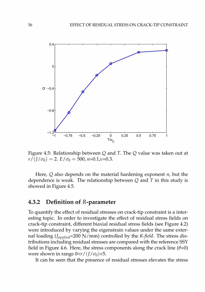
56 EFFECT OF RESIDUAL STRESS ON CRACK-TIP CONSTRAINT
−1 −0.75 −0.5 −0.25 0 0.25 0.5 0.75 1−1.2
−0.8
−0.4
0
0.4
T/σ0
Q
Figure 4.5: Relationship between Q and T. The Q value was taken out atr/(J/σ0) = 2. E/σ0 = 500, n=0.1,ν=0.3.
Here, Q also depends on the material hardening exponent n, but thedependence is weak. The relationship between Q and T in this study isshowed in Figure 4.5.
4.3.2 Definition of R-parameter
To quantify the effect of residual stresses on crack-tip constraint is a inter-esting topic. In order to investigate the effect of residual stress fields oncrack-tip constraint, different biaxial residual stress fields (see Figure 4.2)were introduced by varying the eigenstrain values under the same exter-nal loading (Japplied=200 N/mm) controlled by the K-field. The stress dis-tributions including residual stresses are compared with the reference SSYfield in Figure 4.6. Here, the stress components along the crack line (θ=0)were shown in range 0<r/(J/σ0)<5.
It can be seen that the presence of residual stresses elevates the stress

4.3 RESULTS 57
0 1 2 3 4 5
1.5
2
2.5
3
r/(J/σ0)
σ 11/σ
0
SSYαw=0.002
αw=0.0025
αw=0.003
αw=0.0035
αw=0.004
(a)
0 1 2 3 4 51.5
2
2.5
3
3.5
4
4.5
r/(J/σ0)
σ 22/σ
0
SSYαw=0.002
αw=0.0025
αw=0.003
αw=0.0035
αw=0.004
(b)
Figure 4.6: Comparison of the reference field and the stress field includingresidual stresses along θ=0, Japplied=200 N/mm. n=0.1, E/σ0 = 500, ν=0.3.(a) σ11; (b) σ22.

58 EFFECT OF RESIDUAL STRESS ON CRACK-TIP CONSTRAINT
1 2 3 4 5−0.6
−0.4
−0.2
0
0.2
0.4
0.6
r/(J/σ0)
Δσij/σ
0
Δσ11,αw=0.002
Δσ22,αw=0.002
Δσ11,αw=0.0025
Δσ22,αw=0.0025
Δσ11,αw=0.003
Δσ22,αw=0.003
Figure 4.7: Difference stress between the full stress field and reference fieldalong θ=0 with T=0. n=0.1, E/σ0 = 500, ν=0.3.
level compared with reference solution, and the elevation of the stresslevel increases with the increase of the eigenstrain level. It can be observedthat the finite-strain effects are significant in the range r/(J/σ0) < 1.5,beyond which the stress distributions seem to be parallel to each other.It should be noted that the magnitudes of normalized opening stress aregreater than that of the stress component parallel to the crack flank. Dueto the symmetrical condition, the shear stress component is zero.
A difference stress field has been calculated between the full stressfield with residual stresses and the reference solution (�σij = σwith
ij −σ
re fij , where σwith
ij is the stress field with residual stresses and σre fij is ref-
erence SSY solution). The difference fields for the three eigenstrain levelsαw=0.002, 0.0025 and 0.003 are shown in Figure 4.7. In our earlier work, Liuet al. [44] showed that the residual stress-induced difference field couldbe approximated by a hydrostatic stress with both principle components

4.3 RESULTS 59
Figure 4.8: Illustration of the definition of parameter R.
almost identical and shear component zero. However, as shown in Fig-ure 4.7, �σ11 and �σ22 are different for the same eigenstrain level. Withthe increase in the eigenstrain level, the difference between �σ11 and �σ22increases. It should be noted that uniaxial residual stresses perpendicularto the crack flank were used in [44] while biaxial residual stress fields wereintroduced in this study. The difference between the present results andthe results in [44] may be explained by the different residual stress com-ponents. Biaxial residual stresses tend to have more significant effects onthe crack-tip constraint than uniaxial ones. Similar features have also beenreported by Xu and Burdekin [43].
It is known that the cleavage fracture is controlled by the critical levelsof the opening stress acting over a microstructurally significant distanceahead of the crack tip [130]. In order to quantify the effect of residualstresses on the crack-tip constraint, a parameter R can be defined basedon the difference in the opening stresses. The same reference stress usedin the previous section was used here. The definition of R is illustrated inFigure 4.8, and has the form as Eq. 4.3.
R =σ22 − (σ22)SSY,T=0
σ0at r = 2J/σ0 (4.3)
The distance r/(J/σ0) = 2 is chosen so that R is evaluated outside

60 EFFECT OF RESIDUAL STRESS ON CRACK-TIP CONSTRAINT
0 1 2 3 4 52
2.5
3
3.5
4
4.5
r/(J/σ0)
σ 22/σ
0
SSYJapplied=200 N/mm
Japplied=300 N/mm
Japplied=400 N/mm
Japplied=500 N/mm
Japplied=600 N/mm
Figure 4.9: Comparison of reference field with stress field combining ex-ternal loading and residual stresses along θ = 0 with T=0. E/σ0 = 500,ν=0.3.
the finite-strain region. It can also be seen that the difference between thefinite strain solution with T=0 and reference small scale yielding solutionis negligible when the distance is greater than r/(J/σ0) = 2.
4.3.3 Effect of external load on R
Welded structures with residual stresses are subject to various service load-ing conditions. It is interesting to investigate the effects of external loadingon the crack-tip constraint induced by residual stresses. A residual stressfield with eigenstrain value αb=0, αw=0.003 was introduced into the MBLmodel, and the crack-tip constraint was investigated under five externalloading levels ( Japplied=200, 300, 400, 500 and 600 N/mm ). The openingstresses of combined external loading and residual stresses are shown inFigure 4.9 together with the reference solution.
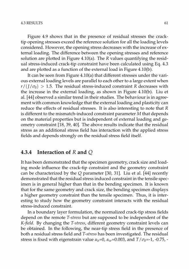
4.3 RESULTS 61
Figure 4.9 shows that in the presence of residual stresses the crack-tip opening stresses exceed the reference solution for all the loading levelsconsidered. However, the opening stress decreases with the increase of ex-ternal loading. The difference between the opening stresses and referencesolution are plotted in Figure 4.10(a). The R values quantifying the resid-ual stress-induced crack-tip constraint have been calculated using Eq. 4.3and are plotted as a function of the external load in Figure 4.10(b).
It can be seen from Figure 4.10(a) that different stresses under the vari-ous external loading levels are parallel to each other to a large extent whenr/(J/σ0) > 1.5. The residual stress-induced constraint R decreases withthe increase in the external loading, as shown in Figure 4.10(b). Liu etal. [44] observed a similar trend in their studies. The behaviour is in agree-ment with common knowledge that the external loading and plasticity canreduce the effects of residual stresses. It is also interesting to note that Ris different to the mismatch-induced constraint parameter M that dependson the material properties but is independent of external loading and ge-ometry constraint [18, 39, 40]. The above results indicate that the residualstress as an additional stress field has interaction with the applied stressfields and depends strongly on the residual stress field itself.
4.3.4 Interaction of R and Q
It has been demonstrated that the specimen geometry, crack size and load-ing mode influence the crack-tip constraint and the geometry constraintcan be characterized by the Q parameter [30, 31]. Liu et al. [44] recentlydemonstrated that the residual stress induced constraint in the tensile spec-imen is in general higher than that in the bending specimen. It is knownthat for the same geometry and crack size, the bending specimen displaysa higher geometry constraint than the tensile specimen. Thus, it is inter-esting to study how the geometry constraint interacts with the residualstress-induced constraint.
In a boundary layer formulation, the normalized crack-tip stress fieldsdepend on the remote T-stress but are supposed to be independent of theK-field. By changing the T-stress, different geometry constraint levels canbe obtained. In the following, the near-tip stress field in the presence ofboth a residual stress field and T-stress has been investigated. The residualstress is fixed with eigenstrain value αb=0, αw=0.003, and T/σ0=-1, -0.75, -

62 EFFECT OF RESIDUAL STRESS ON CRACK-TIP CONSTRAINT
1 2 3 4 5−0.2
0
0.2
0.4
0.6
r/(J/σ0)
Δσ22
/σ0
Japplied=200 N/mm
Japplied=300 N/mm
Japplied=400 N/mm
Japplied=500 N/mm
Japplied=600 N/mm
(a)
200 250 300 350 400 450 500 550 6000.3
0.32
0.34
0.36
0.38
0.4
0.42
Japplied
R
(b)
Figure 4.10: Effect of external loading. (a) different opening stress fieldsalong θ=0; (b) R as a function of external loading. T=0, n=0.1, E/σ0 = 500,ν=0.3.

4.3 RESULTS 63
0 1 2 3 4 51
2
3
4
5
r/(J/σ0)
σ 22/σ
0
SSY
−0.5−0.250.0+0.5
+1.0
−0.75
−1.0
T/σ0:
Figure 4.11: Comparison of reference solution with stress field includingresidual stress and geometry effects along θ=0. n=0.1,E/σ0 = 500, ν=0.3.
0.5, -0.25, 0, 0.25, 0.5 and 1 have been considered. The normalized openingstresses at Japplied=200 N/mm are shown in Figure 4.11.
Figure 4.11 shows that the stress field was shifted up and down bydifferent T-stresses compared with the reference solution. It can be seenthat the compressive T-stress affects the stress field more significantly thanthe tensile T-stress.
In order to investigate the interaction between R and Q, R was calcu-lated according to Eq. 4.3 for different T-stresses and compared with Q.Here, it should be noted that R defined in Eq. 4.3 represents the crack-tipconstraint induced purely by the residual stress. However, the R valuehere (designated as RQ) includes both the residual stress-induced con-straint and geometry constraint, i.e. RQ = R + Q. The comparison ofRQ and Q with different T is plotted in Figure 4.12.

64 EFFECT OF RESIDUAL STRESS ON CRACK-TIP CONSTRAINT
−1 −0.75 −0.5 −0.25 0 0.25 0.5 0.75 1−1.2
−0.9
−0.6
−0.3
0
0.3
0.6
T/σ0
Con
stra
int
RQR+Q
Figure 4.12: Comparison of R and Q. n=0.1, E/σ0=500, ν=0.3, αb=0,αw=0.003.
The difference between RQ and Q is the constraint induced by theresidual stress, i.e. R showed by the shaded area in Figure 4.12. It can beseen that the difference between RQ and Q decreases with the increase ofT/σ0, which indicates that the higher the geometry constraint, the weakerthe residual stress effect on the crack-tip constraint. T-stress was appliedas a uniaxial tension or compression parallel to the crack flank to changethe crack-tip stress triaxiality in the boundary layer formulation. In thisstudy, the T-stress which generates different Q stresses was designated asTQ. The biaxial residual stress component parallel to the crack flank canalso be considered as a T-stress component, designated as TR. Thus, theinteraction between R and Q can be explained as the interaction of TR andTQ. As shown in Figure 4.2, the residual stress component parallel to thecrack flank is mainly tensile. Therefore, the superposition of TQ and TR
enhances the total T-stress that results in a higher crack-tip constraint. A

4.3 RESULTS 65
1 2 3 4 5−1
−0.5
0
0.5
1
r/(J/σ0)
Δσ22
/σ0
n=0.05n=0.1n=0.2
0.7747
0.4417
0.3402
Figure 4.13: Difference opening stress for the stress fields with residualstresses and the corresponding reference solution with n= 0.05, 0.1, and0.2 along θ=0. E/σ0=500, ν=0.3
positive TR can reduce the constraint loss significantly when TQ is com-pressive while it has a weak effect on the crack-tip constraint when TQ ispositive. However, when the crack-tip achieved the full plasticity, a fur-ther increase in tensile T-stress does not have any significant effect.
4.3.5 Effect of material hardening on R
Finally, it is interesting to investigate the influence of material propertieson the residual stress-induced constraint. The same residual stress fieldgenerated by eigenstrain values αb=0 and αw=0.003 was introduced andthe same external loading Japplied=200 N/mm was applied for three hard-ening components. Figure 4.13 shows the difference in the opening stressbetween the case with residual stresses and the corresponding referencesolution. The values of R for different n were marked by circles.

66 EFFECT OF RESIDUAL STRESS ON CRACK-TIP CONSTRAINT
Figure 4.13 shows that the difference in the opening stresses increaseswith the increase of the strain hardening exponent. R is also higher for thecase with stronger strain hardening. For the materials with weak harden-ing, the crack tip can easily develop full plasticity. Thus, for the same resid-ual stress field, its effect on the crack-tip constraint is smaller for weakerhardening materials. It should also be noted that the finite strain effectbecomes more significant for a material with weaker strain hardening.
4.3.6 Effect of loading path on R and Q
For the same external displacement field applied at the outer boundaryof the MBL model, different loading path may induce a different crack-tip constraint, which was generally neglected by most of the work in theliterature. There are generally two loading paths to apply to remote dis-placements: the proportional loading path controlled by fixing the ratioof K/T (Path I); and the sequent loading path by applying the T-field firstand then the K-field (Path II). In this study, the effect of the loading path onthe crack-tip constraint was investigated both with and without residualstress cases. T/σ0=-0.5 and K-field with Japplied=200,300,400,500 and 600N/mm were studied and the same reference field was used. Figure 4.14(a)and (b) show the effect of the loading path on Q and R, respectively.
It can be seen that proportional loading path can generate a highercrack-tip constraint than the sequent loading path both with and withoutthe residual stress cases. It should be noted that the compressive T-stressrepresents the loss of crack-tip constraint. Thus, the lower crack-tip con-straint induced by loading path II indicates that the T-stress applied as anadditional field affects the crack-tip constraint. We also observed that theeffect of the loading path on R is stronger than the effect on Q for the sameexternal loading. This indicates that the effect of residual stresses on thecrack-tip constraint can be regarded as the superposition of componentsparallel to the crack flank and the additional T-field. It was also foundthat under the same geometry constraint level (T/σ0 = −0.5), the effect ofresidual stresses decreases with the increase in external loading, as shownin Figure 4.14(b).

4.4 RESULTS 67
200 300 400 500 600−0.7
−0.65
−0.6
−0.55
−0.5
−0.45
−0.4
Japplied
Q
Path IPath II
(a)
200 300 400 500 600−0.2
−0.15
−0.1
−0.05
0
0.05
0.1
Japplied
R
Path IPath II
(b)
Figure 4.14: Effect of the loading path on the crack-tip constraint withT=-0.5, n=0.1, E/σ0 = 500, ν=0.3. (a) effect on Q; (b) effect on R. αb=0,αw=0.003.

68 EFFECT OF RESIDUAL STRESS ON CRACK-TIP CONSTRAINT
4.4 Conclusions
Welding residual stresses are unavoidable and play a crucial role in theintegrity assessment procedure. Residual stresses affect both the crackdriving force and the crack-tip constraint. This study has focused on thelatter effect by using a new parameter to quantify its effect. The modifiedboundary layer model with a remote displacement field controlled by theK-field and T-stress was used. A two-dimensional residual stress field wasintroduced into the model by the eigenstrain method. A small scale yield-ing solution without residual stress and geometry constraint (T/σ0=0) wastaken as the reference field.
It has been shown that the difference in the stress fields between thefull stress field with residual stresses and the reference solution show sim-ilarity. Unlike previous findings, we found that the stress components ofthe difference fields parallel and perpendicular to the crack flank are notequal. Thus, parameter R is not a hydrostatic term for the cases examined.Since the cleavage fracture is more sensitive to the opening stress, a pa-rameter R was defined based on the opening stress difference to quantifythe welding residual stress-induced constraint.
The results showed that external loading can remedy the residual stress-induced constraint R that decreases with the increase in the external load-ing. R is different to the mismatch-induced constraint parameter M whichis independent of the external loading.
The results also indicate that the geometry constraint interacts withthe constraint induced by the residual stresses. For a higher geometryconstraint, the effect of the residual stresses becomes weaker. This couldbe explained by the fact that the residual stress components parallel to thecrack flank interact with the remote T-stress.
The study also indicates that a sequential loading path with the T-fieldtaken as an additional field will result in lower crack-tip constraint. Theloading path effect is stronger for the cases with residual stresses.
The residual stress-induced constraint depends on the material hard-ening exponent as well. R increases with the increase of the hardening,in which the near-tip plasticity plays an important role. Full plasticity iseasier to cover the crack tip for the weaker hardening material and thenthe residual stresses have a smaller effect on the crack-tip constraint.
The present work is concerned with the residual stress-induced crack-tip constraint. The parameter R was defined to quantify the residual stress-

4.4 CONCLUSIONS 69
induced crack-tip constraint. The parameter R can be constructed as [132]:
R = F(ε∗, n, Q, P) (4.4)
where ε∗ represents the eigenstrain; n is the hardening exponent; Q mea-sures the geometry constraint, and P characterizes the external loading.
4.4 CONCLUSIONS 69
induced crack-tip constraint. The parameter R can be constructed as [132]:
R = F(ε∗, n, Q, P) (4.4)
where ε∗ represents the eigenstrain; n is the hardening exponent; Q mea-sures the geometry constraint, and P characterizes the external loading.
4.4 CONCLUSIONS 69
induced crack-tip constraint. The parameter R can be constructed as [132]:
R = F(ε∗, n, Q, P) (4.4)
where ε∗ represents the eigenstrain; n is the hardening exponent; Q mea-sures the geometry constraint, and P characterizes the external loading.
4.4 CONCLUSIONS 69
induced crack-tip constraint. The parameter R can be constructed as [132]:
R = F(ε∗, n, Q, P) (4.4)
where ε∗ represents the eigenstrain; n is the hardening exponent; Q mea-sures the geometry constraint, and P characterizes the external loading.


Chapter 5
Effect of residual stress oncleavage fracture
Cleavage fracture featured with negligible plastic tearing before final fail-ure is often the most dangerous failure mode. It occurs by the unstablepropagation of microcracks formed within grain boundary particles bytwinning or slip dislocation pile-ups and then grows into the ferrite matrixunder the action of tensile stress [41]. The cleavage fracture toughness ex-hibits sensitivity to the local stress and deformation fields due to its highlylocalized character of the failure mechanism [133]. Understanding howresidual stresses influence the cleavage fracture behaviour becomes moreand more important when high strength steels are increasingly utilized inoffshore industry.
5.1 Problem description
This chapter presents the effect of residual stresses on cleavage fracturetoughness by using the cohesive zone model under Mode I, plane stainconditions. Modified boundary layer simulations were performed withthe remote boundary conditions governed by the elastic K-field and T-stress. The eigenstrain method was used to introduce residual stressesinto the finite element model. A layer of cohesive elements was deployedahead of the crack tip to simulate the fracture process zone. A bilineartraction-separation-law (see Figure 3.4) was used to characterize the be-haviour of the cohesive elements. It was assumed that the initiation of the

72 EFFECT OF RESIDUAL STRESS ON CLEAVAGE FRACTURE
Figure 5.1: Schematic plot of the assumption made in the study.
crack occurs when the opening stress drops to zero at the first integrationpoint of the first cohesive element ahead of the crack tip, as illustrated inFigure 5.1.
The finite element computations were performed using ABAQUS [114].The radius of the MBL model was taken as 200 mm. A layer of uniform-sized cohesive elements was deployed along the central line ahead of thecrack tip to simulate the fracture process. The length of the cohesive ele-ment layer is 20 mm, and the size of the uniform cohesive element lc is 0.1mm. The thickness of the cohesive elements is 2.5 × 10⁻⁴ mm. The weldmetal and base metal region of the model was meshed by standard fullintegration 4-node 2D plane strain elements. The cohesive elements arestandard cohesive element COH2D4. The finite element model has 4992elements and the meshes are shown in Figure 5.2.
5.2 Residual stress field
Te eigenstrain method was used to introduce residual stresses into the fi-nite element model. A rectangular weld region was constructed in thecenter of the MBL model, as illustrated in Figure 5.2(b). The thermal ex-pansion coefficient of the base metal αb was assumed to be zero, and itwas assumed to be orthogonal and represented by α11 and α22 for weldmetal. The ratio α11/α22 was fixed to be 2, and by setting α22= -0.0005,0.0005, 0.001 and 0.002, four residual stress fields were generated and

5.2 RESIDUAL STRESS FIELD 73
(a)
(b)
Figure 5.2: Finite element meshes for the modified boundary layer model,(a) global view; (b) crack-tip region and the illustration of the weld region.
5.2 RESIDUAL STRESS FIELD 73
(a)
(b)
Figure 5.2: Finite element meshes for the modified boundary layer model,(a) global view; (b) crack-tip region and the illustration of the weld region.
5.2 RESIDUAL STRESS FIELD 73
(a)
(b)
Figure 5.2: Finite element meshes for the modified boundary layer model,(a) global view; (b) crack-tip region and the illustration of the weld region.
5.2 RESIDUAL STRESS FIELD 73
(a)
(b)
Figure 5.2: Finite element meshes for the modified boundary layer model,(a) global view; (b) crack-tip region and the illustration of the weld region.

74 EFFECT OF RESIDUAL STRESS ON CLEAVAGE FRACTURE
designated as RsField0, RsField1, RsField2 and RsField3 respectively, asshown in Figure 5.3. It should be noted that the eigenstrain values se-lected here are taken from the experimental measurement results in liter-ature [129, 134]. The residual stress fields generated by these values havesimilar distribution to that showed in Ref. [135]. To obtain accurate dis-tribution of the residual stress fields by eigenstrain method, one shouldcarry out the experiments to measure the distribution of the eigenstrain.However, the main objective of this study is to investigate the effect ofthe residual stresses, the prediction of the real distribution of the resid-ual stress field is outside the scope. Note that the stress components arenormalized by the yield stress, and the distance from the crack tip x isnormalized by the size of the uniform element size lc.
It can be seen that the negative eigenstrain value introduces the com-pressive residual stress at the weld region while the positive ones gener-ate tensile residual stresses. Both tensile and compressive residual stressesparallel to the crack front converge to zero far from the crack tip. Theopening residual stresses are self-balanced ahead of the crack tip. There isa sharp turning point in the distribution of the opening residual stresses,which is the region where eigenstrain discontinuities have been introducedinto the FE model, namely a weld metal-base metal boundary. The tensileresidual stresses also show similarity, and the level of the tensile residualstress increases with the increase of α22. Due to the crack-tip singularity,σ11 is about 960 MPa and σ22 is about 1380 MPa at the crack tip for Rs-Field3.
5.3 Results
Cleavage fracture toughness exhibits a strong sensitivity to the local stressand deformation fields due to its highly localized character. Residualstresses affect both the crack driving forces and crack tip constraint [11,17, 41, 44], which may further influence the cleavage fracture toughness.Therefore, the effect of residual stresses on cleavage fracture toughnesswas investigated in this study. The contour J-integral [8] was utilized asthe measure of the cleavage fracture toughness. Lei et al. [11] and Lei [12]showed that the J-integral shows path-dependent with the presence ofthe residual stresses. In our study, the computed far-field J-integral byABAQUS shows practically path-independence beyond the large strain

5.3 RESULTS 75
0 50 100 150 200−2
−1
0
1
2
3
x/lc
σ 11/σ
0
RsField0RsField1RsField2RsField3
(a)
0 50 100 150 200−2
−1
0
1
2
3
x/lc
σ 22/σ
0
RsField0RsField1RsField2RsField3
(b)
Figure 5.3: Residual stress distribution in MBL model, (a) components par-allel to the crack plane; (b) normal to the crack plane. Four different resid-ual stress cases were considered, where RsField0 is compressive and theremaining 3 are tensile. α11/α22=2, α22=-0.0005 is for RsField0, α22=0.0005,0.001 and 0.002 for RsField1, RsField2 and Rsfield3 respectively.

76 EFFECT OF RESIDUAL STRESS ON CLEAVAGE FRACTURE
0 1 2 3 4 5 6 7 860
80
100
120
140
160
180
Δa [mm]
J [N
/mm
]
no/resRsField0RsField1RsField2RsField3
Figure 5.4: Cleavage toughness as the function of crack growth lengthwhen the incremental plasticity model is used for surrounding materials.E/σ0=450, ν=0.3; n=0.1; Γ0 = 100 N/mm, σmax = 3σ0.
region for the cases investigated. The J-integral in the following meansthe calculated J-integral.
5.3.1 Effect on cleavage toughness
Cleavage fracture is a crucial failure mode in practice, and understandinghow residual stresses affect the cleavage fracture is very important. Theeffect of residual stresses, i.e. Figure 5.3, on cleavage fracture toughnesswas investigated in this section. Cohesive parameters Γ0=100 N/mm wasselected and the maximum cohesive stress σmax was set to be 3σ0. Thecleavage toughness was plotted as the function of crack growth length inFigure 5.4.
It can be seen that the crack growth resistances are almost flat for bothwith and without residual stress cases. Figure 5.4 also indicates that the

5.3 RESULTS 77
−5 0 5 10 15 20
x 10−4
0.6
0.8
1
1.2
1.4
1.6
1.8
α22
J C/Γ
0
Deformation plasticityElasticIncremental plasticity
Figure 5.5: Cleavage fracture toughness as the function of α22. n=0.1; Γ0 =100N/mm, σmax = 3σ0.
cohesive zone model with bilinear traction-separation-law is applicable topredict the cleavage fracture toughness. In the following context, the initi-ation fracture toughness (JC) predicted according to the assumption madein Section 5.1 will be investigated. Residual stresses may influence boththe fracture process zone and plasticity of surrounding materials. There-fore, three different constitutive models, i.e. incremental plasticity, defor-mation plasticity and elastic, were employed to characterize different be-haviour of surrounding materials. The relationship between JC and theeigenstrain value α22 was showed in Figure 5.5. It should be noted thatα22=0 represents the reference case without residual stresses.
As shown in Figure 5.5, the compressive residual stress (α22 < 0) in-creases the cleavage fracture toughness while the tensile residual stressesdecrease the cleavage fracture toughness. With the increase of tensile resid-ual stress, the cleavage fracture toughness decreases. Also observe that theeffect of residual stress on fracture toughness is almost the same for elastic
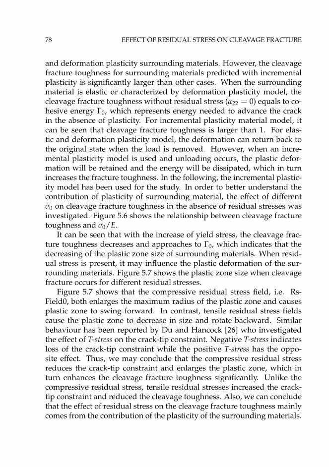
78 EFFECT OF RESIDUAL STRESS ON CLEAVAGE FRACTURE
and deformation plasticity surrounding materials. However, the cleavagefracture toughness for surrounding materials predicted with incrementalplasticity is significantly larger than other cases. When the surroundingmaterial is elastic or characterized by deformation plasticity model, thecleavage fracture toughness without residual stress (α22 = 0) equals to co-hesive energy Γ0, which represents energy needed to advance the crackin the absence of plasticity. For incremental plasticity material model, itcan be seen that cleavage fracture toughness is larger than 1. For elas-tic and deformation plasticity model, the deformation can return back tothe original state when the load is removed. However, when an incre-mental plasticity model is used and unloading occurs, the plastic defor-mation will be retained and the energy will be dissipated, which in turnincreases the fracture toughness. In the following, the incremental plastic-ity model has been used for the study. In order to better understand thecontribution of plasticity of surrounding material, the effect of differentσ0 on cleavage fracture toughness in the absence of residual stresses wasinvestigated. Figure 5.6 shows the relationship between cleavage fracturetoughness and σ0/E.
It can be seen that with the increase of yield stress, the cleavage frac-ture toughness decreases and approaches to Γ0, which indicates that thedecreasing of the plastic zone size of surrounding materials. When resid-ual stress is present, it may influence the plastic deformation of the sur-rounding materials. Figure 5.7 shows the plastic zone size when cleavagefracture occurs for different residual stresses.
Figure 5.7 shows that the compressive residual stress field, i.e. Rs-Field0, both enlarges the maximum radius of the plastic zone and causesplastic zone to swing forward. In contrast, tensile residual stress fieldscause the plastic zone to decrease in size and rotate backward. Similarbehaviour has been reported by Du and Hancock [26] who investigatedthe effect of T-stress on the crack-tip constraint. Negative T-stress indicatesloss of the crack-tip constraint while the positive T-stress has the oppo-site effect. Thus, we may conclude that the compressive residual stressreduces the crack-tip constraint and enlarges the plastic zone, which inturn enhances the cleavage fracture toughness significantly. Unlike thecompressive residual stress, tensile residual stresses increased the crack-tip constraint and reduced the cleavage toughness. Also, we can concludethat the effect of residual stress on the cleavage fracture toughness mainlycomes from the contribution of the plasticity of the surrounding materials.

5.3 RESULTS 79
1.9 2 2.1 2.2 2.3 2.4 2.5 2.6 2.7 2.8
x 10−3
1
1.1
1.2
1.3
1.4
1.5
1.6
1.7
1.8
1.9
σ0/E
J C/Γ
0
Figure 5.6: Plasticity contribution from the surrounding materials at thecrack initiation. n=0.1; Γ0 = 100N/mm, σmax = 3σ0
Figure 5.7: Plastic zone size when cleavage fracture occurs, εp=1%.E/σ0=450, ν=0.3; n=0.1; Γ0 = 100 N/mm, σmax = 3σ0.

80 EFFECT OF RESIDUAL STRESS ON CLEAVAGE FRACTURE
Figure 5.8: Schematic plot of different weld zone sizes considered in thestudy.
5.3.2 Effect of weld zone size
The length scale of residual stress field may play an important role on theeffect of residual stress on cleavage fracture toughness. To better demon-strate this, three geometrically similar rectangular weld regions were con-structed, as shown in Figure 5.8. The size of the weld is designated asc. Eigenstrain values α11=0.004 and α22=0.002 have been used to gener-ate residual stress field for all welds. Residual stress fields representedby Size1, Size2 and Size3 respectively are showed in Figure 5.9, in whichresidual stresses are normalized by the yield stress and the distance fromthe crack tip is normalized by lc. Residual stresses are tensile in the weldmetal and show similar feature as the previous residual stresses showedin Figure 5.3. With the increase of the weld zone size, residual stress com-ponents parallel to the crack plane increases, and the size of the tensiledominated region of opening stress also increases.

5.3 RESULTS 81
0 50 100 150 2000
0.5
1
1.5
2
x/lc
σ 11/σ
0Size1Size2Size3
(a)
0 50 100 150 200−0.5
0
0.5
1
1.5
2
2.5
3
3.5
x/lc
σ 22/σ
0
Size1Size2Size3
(b)
Figure 5.9: Residual stress distribution in MBL model for different weldzone sizes, (a) components parallel to the crack plane, and (b) normalto the crack plane. lc is the uniform element size close to the cracktip. E/σ0=450, ν=0.3; n=0.1; Γ0 = 100 N/mm, σmax = 3σ0; α11=0.004,α22=0.002.
5.3 RESULTS 81
0 50 100 150 2000
0.5
1
1.5
2
x/lc
σ 11/σ
0
Size1Size2Size3
(a)
0 50 100 150 200−0.5
0
0.5
1
1.5
2
2.5
3
3.5
x/lc
σ 22/σ
0
Size1Size2Size3
(b)
Figure 5.9: Residual stress distribution in MBL model for different weldzone sizes, (a) components parallel to the crack plane, and (b) normalto the crack plane. lc is the uniform element size close to the cracktip. E/σ0=450, ν=0.3; n=0.1; Γ0 = 100 N/mm, σmax = 3σ0; α11=0.004,α22=0.002.

82 EFFECT OF RESIDUAL STRESS ON CLEAVAGE FRACTURE
0 2 4 6 8 100.7
0.9
1.1
1.3
1.5
c [mm]
J c/Γ0
y = − 0.05423*x + 1.409
Figure 5.10: Effect of weld zone size on cleavage fracture toughness.E/σ0=450, ν=0.3; n=0.1; Γ0 = 100N/mm, σmax = 3σ0; α11=0.004, α22=0.002.
Figure 5.10 shows that the cleavage fracture toughness decreases withthe increase of the weld region size c, which can be expected because boththe residual stress level and tensile dominated residual stress region in-creases with the increase of the weld zone size. Furthermore, it is in-teresting to observe that the relationship between the cleavage fracturetoughness and the weld zone size can be fitted by a linear function, i.e.y = −0.05432x + 1.409, which can possibly be used to predict the effect ofresidual stress on the cleavage fracture toughness for geometrically similarwelds.
5.3.3 Effect of material hardening
In this study, the effect of the residual stress on the cleavage fracture tough-ness was investigated for three hardening exponents, i.e. n=0.05, 0.1 and0.2. Residual stress field with α11=0.004 and α22=0.002, i.e. RsField3, was
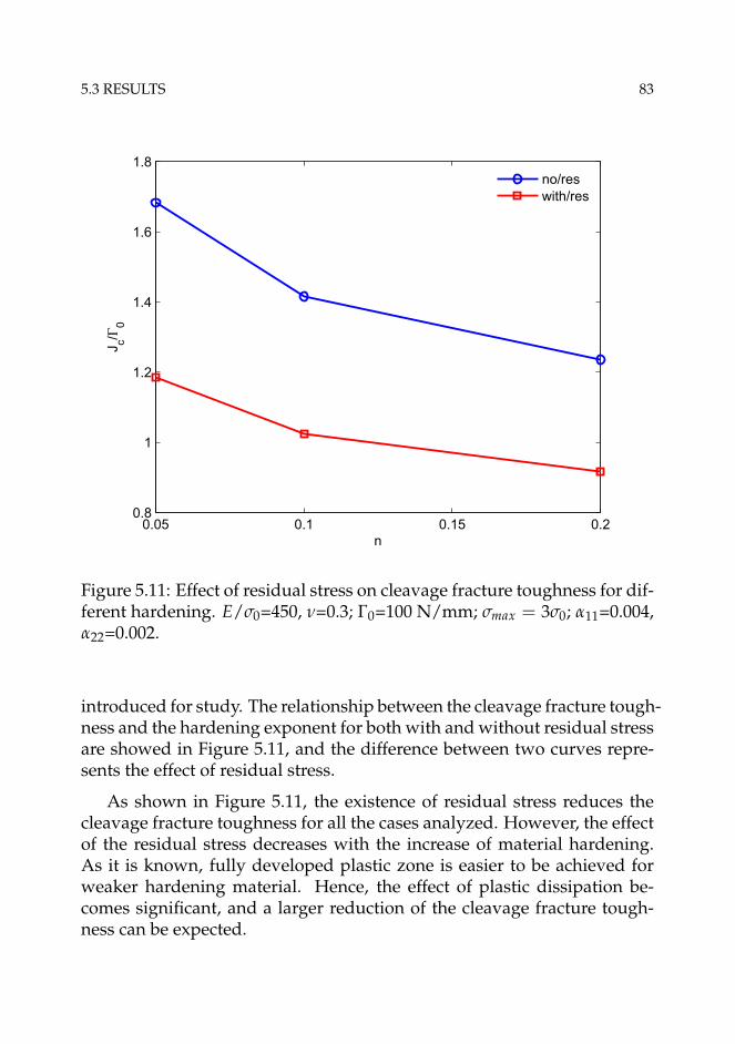
5.3 RESULTS 83
0.05 0.1 0.15 0.20.8
1
1.2
1.4
1.6
1.8
n
J c/Γ0
no/reswith/res
Figure 5.11: Effect of residual stress on cleavage fracture toughness for dif-ferent hardening. E/σ0=450, ν=0.3; Γ0=100 N/mm; σmax = 3σ0; α11=0.004,α22=0.002.
introduced for study. The relationship between the cleavage fracture tough-ness and the hardening exponent for both with and without residual stressare showed in Figure 5.11, and the difference between two curves repre-sents the effect of residual stress.
As shown in Figure 5.11, the existence of residual stress reduces thecleavage fracture toughness for all the cases analyzed. However, the effectof the residual stress decreases with the increase of material hardening.As it is known, fully developed plastic zone is easier to be achieved forweaker hardening material. Hence, the effect of plastic dissipation be-comes significant, and a larger reduction of the cleavage fracture tough-ness can be expected.

84 EFFECT OF RESIDUAL STRESS ON CLEAVAGE FRACTURE
2.8 2.9 3 3.1 3.2 3.30.8
1
1.2
1.4
1.6
1.8
σmax/σ0
J c/Γ0
no/reswith/res
Figure 5.12: Cleavage fracture toughness as a function of maximum co-hesive stress for both with and without residual stress cases. E/σ0=450,ν=0.3; n=0.1; Γ0=100 N/mm; α11=0.004, α22=0.002.
5.3.4 Effect of damage parameters
The cohesive energy Γ0 and the maximum cohesive stress σmax are twodominant parameters of the traction-separation-law. The effect of the resid-ual stress on the cleavage fracture toughness may vary for different cohe-sive zone parameters. In present study, the effect of residual stress onthe cleavage fracture toughness for three maximum cohesive stresses, i.e.σmax/σ0 = 2.8, 3.0 and 3.3 were studied firstly. Residual stress field withα11=0.004 and α22=0.002, i.e. RsField3, was used. Cohesive energy Γ0 wasfixed to be 100 N/mm. The relationship between the cleavage fracturetoughness and the maximum cohesive stress is showed in Figure 5.12.
It can be seen that with the increase of σmax, the reduction of cleavagefracture toughness due to residual stress increases. When the maximumcohesive stress is smaller, the energy needed to initiate a crack is less, and

5.3 RESULTS 85
a fully developed plastic zone cannot be formed. It has been shown thatplastic dissipation only becomes significant compared to Γ0 when fullydeveloped plastic zone can form [122]. Thus, a stronger effect of residualstress on the cleavage fracture toughness can be expected for higher σmax.
Γ0 is another important parameter in cohesive zone model. In thisstudy, the effect of the residual stress on the cleavage fracture toughnessfor different Γ0 with same σmax has also been investigated. Residual stressfield with α11=0.004 and α22=0.002, i.e. RsField3, was introduced for thestudy. Figure 5.13 shows the comparison of the cleavage fracture tough-ness JC for both with and without residual stress as the function of cohe-sive energy.
It can be seen that with the increase of the cohesive energy Γ0, thecleavage fracture toughness increases for both with and without residualstresses, as shown in Figure 5.13(a). Figure 5.13(b) shows that the nor-malized cleavage fracture toughness tends to converge to the case withoutresidual stress with increasing Γ0. Note that the cleavage fracture tough-ness with residual stress was normalized by the toughness without resid-ual stress effect. Figure 5.14 shows the effect of the residual stress on theplastic zone for different Γ0, and the length of the fracture process zone(FPZ), which measures the distance between the point where all tractionis lost and where the peak stress is first attained [122].
As shown in Figure 5.14(a) the residual stress increases the length ofFPZ when Γ0<150 N/mm, beyond which the residual stress does not affectthe FPZ for the cases studied. However, the tensile residual stress bothreduces the size of the plastic zone and rotates the plastic zone backwardfor all Γ0, as shown in Figure 5.14(b). We can also observe that with theincrease of Γ0, the plastic zone size increases for both with and withoutresidual stress cases, which can explain the increasing cleavage fracturetoughness showed in Figure 5.13(a).
5.3.5 Effect of T-stress
In this study, no real structural component was considered. It is thus in-teresting to investigate the effect of residual stress on the cleavage frac-ture toughness for different geometry constraint levels characterized byT-stress. The outer boundary condition for the MBL model is governed bythe elastic K-field and a T-stress under small-scale-yielding condition. For

86 EFFECT OF RESIDUAL STRESS ON CLEAVAGE FRACTURE
50 75 100 125 150 175 2000
50
100
150
200
250
300
Γ0 [N/mm]
J C [N
/mm
]
no/reswith/res
(a)
50 75 100 125 150 175 2000.5
0.6
0.7
0.8
0.9
1
Γ0 [N/mm]
J C/J
with
out
(b)
Figure 5.13: Relationship between the fracture toughness and cohesive en-ergy, (a) absolute difference between the case with and without residualstress, and (b) normalized values. E/σ0=450, ν=0.3; n=0.1; σmax = 3σ0;α11=0.004, α22=0.002.

5.3 RESULTS 87
50 80 110 140 170 2002
4
6
8
10
12
14
Γ0 [N/mm]
Leng
th o
f FP
Z [m
m]
no/reswith/res
(a)
(b)
Figure 5.14: Effect of the residual stress on (a) the fracture process zone,and (b) plastic zone size of surrounding materials for εp=1%. E/σ0=450,ν=0.3; n=0.1; σmax = 3σ0; α11=0.004, α22=0.002.

88 EFFECT OF RESIDUAL STRESS ON CLEAVAGE FRACTURE
−0.5 −0.25 0 0.25 0.50.8
1
1.2
1.4
1.6
1.8
T/σ0
J c/Γ0
no/reswith/res
Figure 5.15: Effect of residual stresses on the cleavage fracture toughnessfor different T/σ0. E/σ0=450, ν=0.3; n=0.1; Γ0=100 N/mm, σmax = 3σ0;α11=0.004, α22=0.002.
Mode I loading, K is the amplitude of the singular stress field, while the Tis a non-singular stress term, acting parallel to the crack plane. Geometryconstraint effects on fracture behaviour can be investigated by utilizingthe T-stress [136]. In current study, T-stress with the value of T/σ0= -0.5,-0.25, 0, and 0.5 was studied. The same residual stress field as previouswith α11=0.004 and α22, i.e. RsField3, was used. The cleavage fracturetoughness was plotted as the function of T/σ0 in Figure 5.15.
It can be seen that with the increase of the T-stress, the cleavage frac-ture toughness decreases for both with and without residual stresses. Asexpected, with the increase of the T-stress the crack-tip constraint increasesand thus the plastic zone shrinks. Similar results were also reported byTvergaard and Hutchinson [137] in their study on the effect of T-stress onMode I crack growth resistance in a ductile solid. It is interesting to ob-serve that with the increase of the T-stress the effect of the residual stress

5.4 CONCLUSIONS 89
Figure 5.16: Effect of residual stress on size of plastic zone for differentgeometry constraint when εp=1% at initiation. E/σ0=450, ν=0.3; n=0.1;Γ0=100 N/mm, σmax = 3σ0; α11=0.004, α22=0.002. "N" represents the casewithout residual stress; "W" denotes the case with residual stress.
decreases. Figure 5.16 shows the effect of the residual stress on plasticzone size for different T-stress.
It can be seen that the negative T-stress enlarges the plastic zone. How-ever, the presence of tensile residual stress significantly decreases the sizeof the plastic zone and rotates the plastic zone backward slightly. The pos-itive T-stress shrinks the plastic zone, and the residual stress further rotatesthe plastic zone backward. We thus can conclude that the tensile residualstress influences the cleavage fracture toughness similar way as the posi-tive T-stress.
5.4 Conclusions
In this paper the effect of residual stresses on cleavage fracture toughnesshas been investigated. The damage mechanics-based cohesive zone modelwas utilized to simulate the fracture process zone. The modified bound-ary layer model simulations were performed under Mode I, plane strain

90 EFFECT OF RESIDUAL STRESS ON CLEAVAGE FRACTURE
conditions, and the remote boundary conditions of the model is governedby elastic K-field and T-stress. Residual stresses were introduced into theFE model by the eigenstrain method. Cleavage fracture was assumed tooccur when the opening stress of the first integration point of the first co-hesive element ahead of the crack tip dropped to zero. Far-field contourJ-integral has been employed to quantify the cleavage fracture toughness.
Cohesive zone model with a bilinear traction-separation-law was em-ployed to study the effect of residual stresses on cleavage fracture be-haviour. The introduction of a small fictitious viscosity in the traction-separation-law in combination with the use of a small step-increment inthe simulations, improved the convergence rate, and its effect on the re-sults is negligible.
Results show that residual stresses affect both the length of the fractureprocess zone and surrounding plasticity. Local compressive residual stressenhances the cleavage fracture toughness while positive residual stresseshave opposite influences. The compressive residual stress enlarges theplastic zone significantly while tensile residual stresses shrink the plas-tic zone and shift the plastic zone backward. When the welds are geo-metrically similar, the effect of residual stresses on the cleavage fracturetoughness is a linear function of the size of the weld. The dominant co-hesive parameters Γ0 and σmax also play an important role on the effect ofresidual stresses on the cleavage fracture toughness. With the increase ofcohesive energy, the effect of residual stresses on the cleavage toughnessdecreases. The reduction of the toughness caused by the residual stressincreases with the increase of the maximum cohesive stress.
The effect of residual stresses on the cleavage fracture toughness be-comes weaker for higher geometry constraint configuration. It has beenfound that residual stresses show similar behaviour as the T-stress. Whencombining the residual stresses with T-stress, the superposition principlecan be applied. For higher geometry constraint configuration, the effectof tensile residual stress becomes smaller. However, for lower geometryconstraint case, the combined effect can induce a significant reduction ofthe cleavage fracture toughness.

Chapter 6
Effect of residual stress on ductilefracture
Ductile crack growth plays an important role in the analysis of the fracturebehaviour of structures [109]. Crack extension reduces the load-bearingligament and will influence the capacity of the structures. Ductile crackgrowth may also change the near-tip stress/strain fields and promote thetransition to unstable cleavage fracture. The mechanism of ductile frac-ture in metallic materials may be considered as a three-stage process: nu-cleation, growth and coalescence of microvoids. The ductile fracture pro-cess is influenced by the local conditions of stress triaxiality and plasticstrain within the vicinity of a stress concentrator such as a notch or a crack-tip [51]. Liu et al. [44] and Ren et al. [17] have demonstrated that residualstresses can induce an additional crack-tip constraint, and a parameter Rwas defined based on the difference between the full stress field and thereference field to quantify the residual stress-induced crack-tip constraint.It is thus interesting to further investigate how residual stresses influencethe local failure mechanisms and global ductile crack resistance.
6.1 Problem description
The present analyses were carried out for the conditions of small-scale-yielding. The MBL model used for this study consists of a weld regionlocated in the center of the model, an outer base metal region, and a sharpcrack in the center of weld. The load was applied to the remote edges of
92 EFFECT OF RESIDUAL STRESS ON DUCTILE FRACTURE
(a)
(b)
Figure 6.1: Modified boundary layer model, (a) global view; (b) crack-tipmesh.
the model through a displacement field (u, v), as shown in Eq. 3.2. Thefinite element computations were performed using ABAQUS [114]. Dueto symmetry, only the upper half of the geometry is modeled. The meshis shown in Figure 6.1. The radius of the MBL model is taken as 1000 mmto ensure the small-scale-yielding condition is fulfilled. Close to the cracktip, there is a rectangular region (9.4 mm ahead of the initial crack tip and1.6 above the symmetry line) with uniform mesh sizes of 0.1 × 0.05 mmfor the first layer and 0.1 × 0.1 mm for the rest of the layers are created.Full integration 4-node 2D plane strain elements are used. The finite el-ement model has 2616 elements. Nonlinear geometry effects (NLGEOMin ABAQUS) are accounted for in the analyses. An initial opening of 0.02mm is applied for the upper half model. When the residual stresses areintroduced into the model, the crack faces can be partly closed. Thus, arigid analytical plane is defined in the model to simulate the contact of thecrack surfaces.

6.3 RESIDUAL STRESS FIELD 93
Two scenarios have been considered to study the effect of the residualstresses on the crack growth resistance in this thesis. Firstly, the effect ofresidual stresses on ductile crack resistance in a large round weld regionwas investigated. In such a way, the final crack growth length still locatesin weld region. Secondary, a much smaller rectangular weld region wasconstructed, where the crack can propagate through the whole weld re-gion. The effect of the weld zone size was also taken into account andstudied. In addition, the effects of initial void volume fraction and mate-rial hardening have also been studied.
6.2 Residual stress field
The eigenstrain method was used to introduce residual stresses into thefinite element model. A round weld region was introduced in the cen-ter of the model, as illustrated in Figure 6.2. According to the eigenstrainmethod, the thermal expansion coefficients of both the weld metal (αw)and base metal (αb) were assumed to be isotropic and equal to the eigen-strain values respectively. In this section, we assume αb=0. Four residualstress fields were generated by setting αw= -0.001, 0.001, 0.002 and 0.003and designated as RsField0, RsField1, RsField2 and RsField3 respectively.Figure 6.3 shows the distribution of the residual stresses both before andafter the crack was inserted. Note that the stresses are normalized by theyield stress, and the distance from the crack tip x is normalized by the sizeof the uniform element, i.e. lc.
It can be seen that the negative eigenstrain value introduces the com-pressive residual stress at the weld region while the positive ones gener-ate tensile residual stresses. Both tensile and compressive residual stressesparallel to the crack front converge to zero far from the crack tip. Theopening residual stresses are self-balanced ahead of the crack tip. There isa sharp turning point in the distribution of the opening residual stresses,which is the region where eigenstrain discontinuities have been introducedinto the FE model, namely the weld metal-base metal boundary. The ten-sile residual stresses also show similarity, and the level of the tensile resid-ual stress increases with the increasing αw. Due to the singularity, σ11 isabout 800 MPa and σ22 is about 1200 MPa at the crack tip for RsField2.Figure 4 also shows that residual stress components are smaller than theyield stress before the crack was inserted.

94 EFFECT OF RESIDUAL STRESS ON DUCTILE FRACTURE
Figure 6.2: Illustration of the weld region (gray area). The radius of theweld is 20 mm.
6.3 Results
In fracture mechanics, the J-integral [8] or Crack Tip Opening Displace-ment (δ, CTOD) are used to characterize the crack-tip driving force of acracked body made of an elastic-plastic material. The J-integral is a path-independent integral based on the assumption that the strain energy den-sity is a single-valued function of the strain (or stress) [12]. However, non-proportional loading may occur in the region where the J-integral is evalu-ated and lead to path-dependence, for example, in the case of ductile crackgrowth [109], or in the presence of a residual stress field [11]. In this study,the J-integral is evaluated on contours far away from the zone of highlynon-proportional loading, and displays practically path independence inboth cases with and without residual stresses. J in the following contextthus represents far-field J-integral.
6.3.1 Effect on ductile crack growth resistance
Ductile crack growth resistance is important for structural integrity assess-ment, and it is interesting to investigate the effect of residual stresses onit. In this section, effects of residual stress fields on the crack growth re-sistance were studied. The initial void volume fraction f0 is fixed to be

6.3 RESULTS 95
0 100 200 300 400 500−2
−1
0
1
2
3
x/lc
σ 11/σ
0
RsField0crack
RsField0RsField1crack
RsField1RsField2crack
RsField2RsField3crack
RsField3
(a)
0 100 200 300 400 500−2
−1
0
1
2
3
4
x/lc
σ 22/σ
0
RsField0crack
RsField0RsField1crack
RsField1RsField2crack
RsField2RsField3crack
RsField3
(b)
Figure 6.3: Comparison of the residual stress distribution in MBL modelwith a large round weld before (bold line) and after (thin line) the crackwas inserted, (a) components parallel to the crack plane, and (b) normalto the crack plane. Four different residual stress cases were considered,where RsField0 is compressive and the remaining 3 are tensile. αb=0, αw=-0.001, 0.001, 0.002 and 0.003.
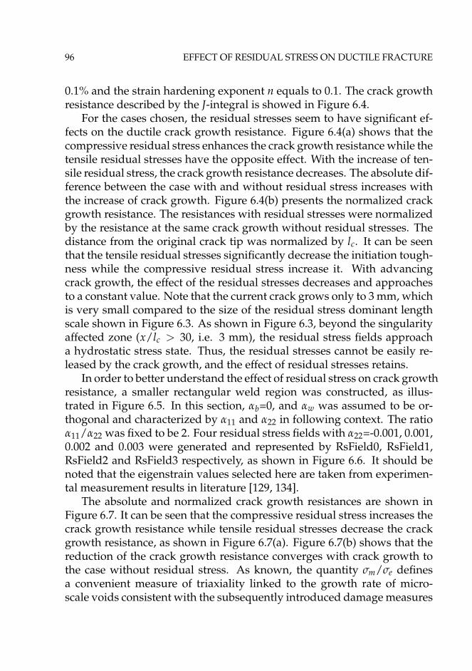
96 EFFECT OF RESIDUAL STRESS ON DUCTILE FRACTURE
0.1% and the strain hardening exponent n equals to 0.1. The crack growthresistance described by the J-integral is showed in Figure 6.4.
For the cases chosen, the residual stresses seem to have significant ef-fects on the ductile crack growth resistance. Figure 6.4(a) shows that thecompressive residual stress enhances the crack growth resistance while thetensile residual stresses have the opposite effect. With the increase of ten-sile residual stress, the crack growth resistance decreases. The absolute dif-ference between the case with and without residual stress increases withthe increase of crack growth. Figure 6.4(b) presents the normalized crackgrowth resistance. The resistances with residual stresses were normalizedby the resistance at the same crack growth without residual stresses. Thedistance from the original crack tip was normalized by lc. It can be seenthat the tensile residual stresses significantly decrease the initiation tough-ness while the compressive residual stress increase it. With advancingcrack growth, the effect of the residual stresses decreases and approachesto a constant value. Note that the current crack grows only to 3 mm, whichis very small compared to the size of the residual stress dominant lengthscale shown in Figure 6.3. As shown in Figure 6.3, beyond the singularityaffected zone (x/lc > 30, i.e. 3 mm), the residual stress fields approacha hydrostatic stress state. Thus, the residual stresses cannot be easily re-leased by the crack growth, and the effect of residual stresses retains.
In order to better understand the effect of residual stress on crack growthresistance, a smaller rectangular weld region was constructed, as illus-trated in Figure 6.5. In this section, αb=0, and αw was assumed to be or-thogonal and characterized by α11 and α22 in following context. The ratioα11/α22 was fixed to be 2. Four residual stress fields with α22=-0.001, 0.001,0.002 and 0.003 were generated and represented by RsField0, RsField1,RsField2 and RsField3 respectively, as shown in Figure 6.6. It should benoted that the eigenstrain values selected here are taken from experimen-tal measurement results in literature [129, 134].
The absolute and normalized crack growth resistances are shown inFigure 6.7. It can be seen that the compressive residual stress increases thecrack growth resistance while tensile residual stresses decrease the crackgrowth resistance, as shown in Figure 6.7(a). Figure 6.7(b) shows that thereduction of the crack growth resistance converges with crack growth tothe case without residual stress. As known, the quantity σm/σe definesa convenient measure of triaxiality linked to the growth rate of micro-scale voids consistent with the subsequently introduced damage measures
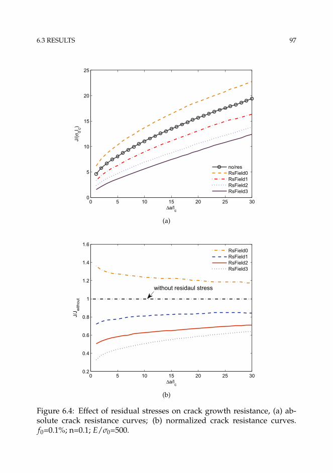
6.3 RESULTS 97
0 5 10 15 20 25 300
5
10
15
20
25
Δa/lc
J/(σ
0l c)
no/resRsField0RsField1RsField2RsField3
(a)
0 5 10 15 20 25 300.2
0.4
0.6
0.8
1
1.2
1.4
1.6
Δa/lc
J/J w
ithou
t
RsField0RsField1RsField2RsField3
without residaul stress
(b)
Figure 6.4: Effect of residual stresses on crack growth resistance, (a) ab-solute crack resistance curves; (b) normalized crack resistance curves.f0=0.1%; n=0.1; E/σ0=500.
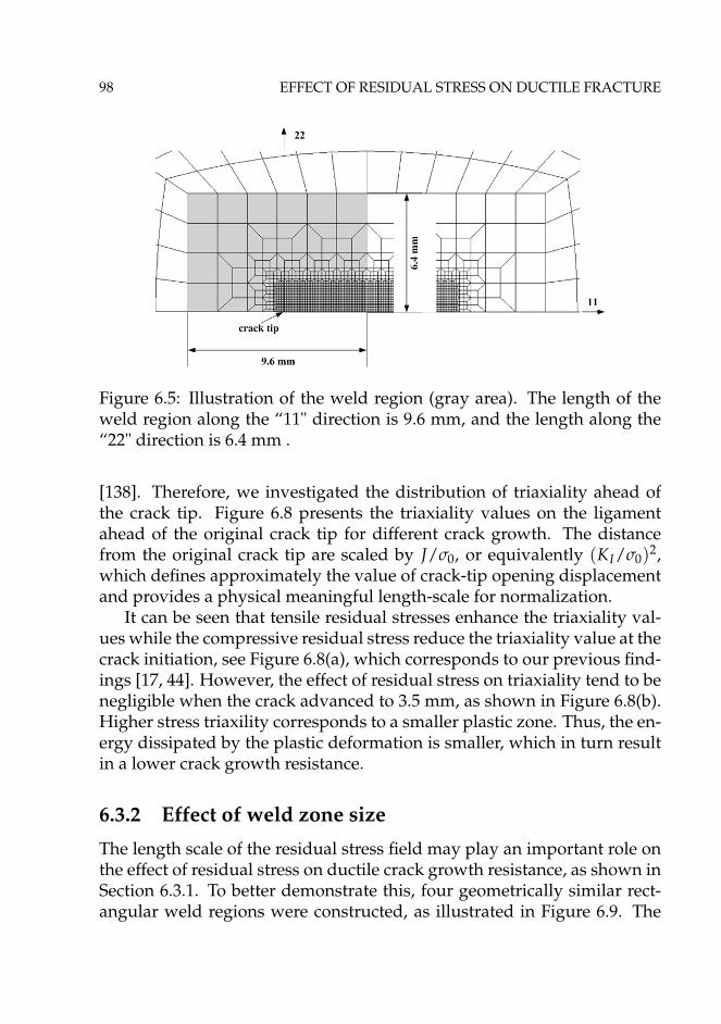
98 EFFECT OF RESIDUAL STRESS ON DUCTILE FRACTURE
Figure 6.5: Illustration of the weld region (gray area). The length of theweld region along the “11" direction is 9.6 mm, and the length along the“22" direction is 6.4 mm .
[138]. Therefore, we investigated the distribution of triaxiality ahead ofthe crack tip. Figure 6.8 presents the triaxiality values on the ligamentahead of the original crack tip for different crack growth. The distancefrom the original crack tip are scaled by J/σ0, or equivalently (KI/σ0)2,which defines approximately the value of crack-tip opening displacementand provides a physical meaningful length-scale for normalization.
It can be seen that tensile residual stresses enhance the triaxiality val-ues while the compressive residual stress reduce the triaxiality value at thecrack initiation, see Figure 6.8(a), which corresponds to our previous find-ings [17, 44]. However, the effect of residual stress on triaxiality tend to benegligible when the crack advanced to 3.5 mm, as shown in Figure 6.8(b).Higher stress triaxility corresponds to a smaller plastic zone. Thus, the en-ergy dissipated by the plastic deformation is smaller, which in turn resultin a lower crack growth resistance.
6.3.2 Effect of weld zone size
The length scale of the residual stress field may play an important role onthe effect of residual stress on ductile crack growth resistance, as shown inSection 6.3.1. To better demonstrate this, four geometrically similar rect-angular weld regions were constructed, as illustrated in Figure 6.9. The

6.3 RESULTS 99
0 50 100 150 200−2
−1
0
1
2
3
x/lc
σ 11/σ
0
RsField0RsField1RsField2RsField3
(a)
0 50 100 150 200−2
−1
0
1
2
3
x/lc
σ 22/σ
0
RsField0RsField1RsField2RsField3
(b)
Figure 6.6: Residual stress distribution in MBL model with a rectangularweld after the crack was inserted, (a) components parallel to the crackplane, and (b) normal to the crack plane. Four different residual stresscases were considered, where RsField0 is compressive and the remaining3 are tensile. α11/α22=2, α22=-0.001, 0.001, 0.002 and 0.003.

100 EFFECT OF RESIDUAL STRESS ON DUCTILE FRACTURE
0 5 10 15 20 25 30 35 400
5
10
15
20
25
Δa/lc
J/(σ
0l c)
no/resRsField0RsField1RsField2RsField3
(a)
0 10 20 30 400.5
0.6
0.7
0.8
0.9
1
1.1
1.2
Δa/lc
J/J w
ithou
t
RsField0RsField1RsField2RsField3
(b)
Figure 6.7: Effect of residual stresses on crack growth resistance, (a) ab-solute crack resistance curves; (b) normalized crack resistance curves.f0=0.1%; n=0.1; E/σ0=500.

6.3 RESULTS 101
1 2 3 4 51.5
1.75
2
2.25
2.5
2.75
3
x/(J/σ0)
σ m/σ
e
no/resRsField0RsField1RsField2RsField3
(a)
1 2 3 4 51.5
1.75
2
2.25
2.5
2.75
3
x/(J/σ0)
σ m/σ
e
no/resRsField0RsField1RsField2RsField3
(b)
Figure 6.8: Triaxiality values ahead the crack tip for different crack propa-gation, (a) Δa=0.1 mm; (b) Δa=3.5 mm. f0=0.1%; n=0.1; E/σ0=500.

102 EFFECT OF RESIDUAL STRESS ON DUCTILE FRACTURE
Figure 6.9: Illustration of weld size. The size increases by a scale of 2.
size of the weld is designated as c. The orthogonal thermal expansion co-efficient was used with a value of α11=0.004 and α22=0.002 for all welds.The residual stress fields designated as Size1, Size2, Size3 and Size4 re-spectively are showed in Figure 6.10. The residual stresses are tensile inthe weld metal and show similar features as the previous residual stressesshown in Figure 6.6. With increasing weld size, the residual stresses par-allel to the crack plane increase; and the size of tensile dominated regionof the opening stress also increases.
Figure 6.11(a) presents the absolute crack growth resistance. In Fig-ure 6.11(b), crack growth length was normalized by lc. It can be seen thatthe residual stresses generated in the larger welds influence more signifi-cantly the crack growth resistance. With increasing crack growth, the effectof the residual stresses on the crack growth resistance converges to the casewithout residual stresses. However, an interesting pattern emerges whennormalizing the crack growth length by the weld zone size c, as shownin Figure 6.12. Surprisingly, the normalized crack growth resistances col-lapse into one curve, which indicates that the effect of the residual stresseson the crack growth resistance is nearly independent of the weld zone size.

6.3 RESULTS 103
0 50 100 150 2000
0.5
1
1.5
2
x/lc
σ 11/σ
0Size1Size2Size3Size4
(a)
0 50 100 150 200−0.5
0
0.5
1
1.5
2
x/lc
σ 22/σ
0
Size1Size2Size3Size4
(b)
Figure 6.10: Residual stress distribution in MBL model with geometricallysimilar welds after the crack was inserted, (a) components parallel to thecrack plane; (b) normal to the crack plane. α11=0.004, α22=0.002.
6.3 RESULTS 103
0 50 100 150 2000
0.5
1
1.5
2
x/lc
σ 11/σ
0
Size1Size2Size3Size4
(a)
0 50 100 150 200−0.5
0
0.5
1
1.5
2
x/lc
σ 22/σ
0
Size1Size2Size3Size4
(b)
Figure 6.10: Residual stress distribution in MBL model with geometricallysimilar welds after the crack was inserted, (a) components parallel to thecrack plane; (b) normal to the crack plane. α11=0.004, α22=0.002.

104 EFFECT OF RESIDUAL STRESS ON DUCTILE FRACTURE
0 5 10 15 20 254
6
8
10
12
14
16
18
Δa/lc
J/(σ
0l c)
no/resSize1Size2Size3Size4
(a)
0 5 10 15 20 250.75
0.8
0.85
0.9
0.95
1
1.05
Δa/lc
J/J w
ithou
t
Size1Size2Size3Size4
(b)
Figure 6.11: Effect of weld size on crack growth resistance, (a) absolutecrack growth resistance, and (b) crack growth resistance normalized by lc.f0=0.1%; n=0.1; E.σ0=500.

6.3 RESULTS 105
0 1 2 3 40.75
0.8
0.85
0.9
0.95
1
1.05
Δa/c
J/J w
ithou
t
Size1Size2Size3Size4
Figure 6.12: "Mater" curve obtained by normalizing the crack growth re-sistance by the weld zone size c.
For the cases specified in this section, when the crack grows approximatelyto 3 times of c, the effect of residual stresses can be neglected. For geomet-rically similar welds, the uniform curve can be used to roughly predict thelength scale of residual stress-affected region beyond which the effect ofthe residual stress can be neglected. To better demonstrate our finding,residual stress fields were presented by normalizing the distance from thecrack tip by weld zone size, as shown in Figure 6.13.
It can be seen that residual stress field collapse into a uniform field,which can explain the results showed in Figure 6.12. In our previousstudy [17], residual stress fields generated in three larger round weld re-gions respectively can also be normalized by the weld size and collapsedinto a uniform field. Thus, a "master" curve similar as the curve shown inFigure 6.12 can also be expected.

106 EFFECT OF RESIDUAL STRESS ON DUCTILE FRACTURE
0 2 4 6 8 100
0.5
1
1.5
2
x/c
σ 11/σ
0
Size1Size2Size3Size4
(a)
0 2 4 6 8 10−0.5
0
0.5
1
1.5
2
x/c
σ 22/σ
0
Size1Size2Size3Size4
(b)
Figure 6.13: Residual stress distribution normalized by the weld zone sizeafter the crack was inserted, (a) components parallel to the crack plane; (b)normal to the crack plane.

6.3 RESULTS 107
6.3.3 Effect of material hardening
It has been shown that the effect of strain hardening on the ductile crackresistance is not fully understood. Xia and Shih [139] demonstrated thatthe ductile resistance increases with increasing hardening capacity. How-ever, Eikrem et al. [140] and Østby et al. [109, 141] reported that decreasingthe hardening exponent will significantly raise the resistance curve. In thisstudy, the effect of strain hardening on the crack growth resistance was in-vestigated for cases both with and without residual stress. It should benoted that in this particular study, the initial volume fraction f0 was fixedto be 0.05%, and the residual stress field was introduced by the rectan-gular weld with orthogonal thermal expansion coefficient α11=0.004 andα22=0.002, i.e. RsField2 in Figure 6.6. The crack growth resistance wasplotted as a function of hardening exponent n in Figure 6.14.
Figure 6.14(a) shows that with decreasing hardening exponent the crackgrowth resistance increases for both with and without residual stress cases,which corresponds to the results demonstrated in Ref. [109, 140, 141]. For agiven hardening exponent, residual stresses reduce both the initial tough-ness and crack growth resistance. Also, the effect of residual stress onthe ductile resistance becomes stronger for stronger hardening material,as shown in Figure 6.14(b). With increasing crack growth, the reductionof the crack growth resistance decreases and tends to converge to the casewithout residual stress. Residual stresses reduce the equivalent plasticstrain significantly at crack initiation, which indicates smaller plastic de-formation. Hence, lower crack growth resistance curves can be expected.With the crack growth, the effect of residual stresses on the equivalentplastic strain becomes negligible for different hardening exponents.
6.3.4 Effect of initial void volume fraction
The initial void volume fraction f0 represents the degree of damage in thematerial. The larger the initial void volume fraction is, the larger damagethe material has. In this section, the effect of residual stress fields on crackgrowth resistance was investigated for three initial void volume fractions,f0 = 0.05%, 0.1% and 0.2%. The residual stress was introduced into a rect-angular weld with α11=0.004 and α22=0.002, i.e. RsField2 in Figure 6.6. Thecrack growth resistance curves are shown in Figure 6.15.
As shown in Figure 6.15(a), for both with and without residual stress
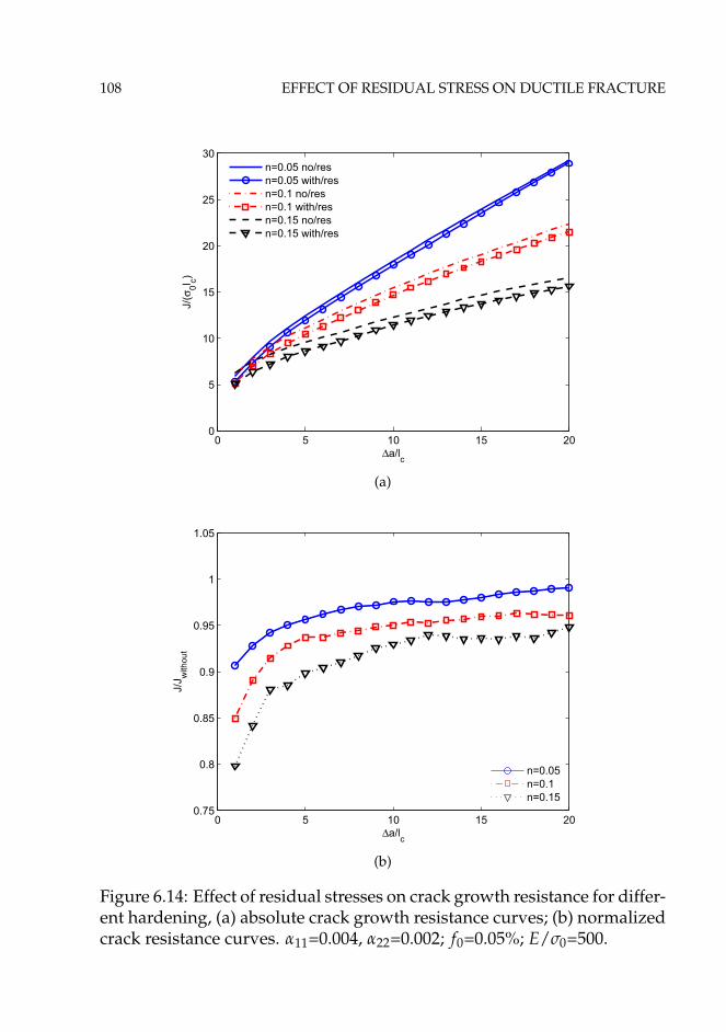
108 EFFECT OF RESIDUAL STRESS ON DUCTILE FRACTURE
0 5 10 15 200
5
10
15
20
25
30
Δa/lc
J/(σ
0l c)n=0.05 no/resn=0.05 with/resn=0.1 no/resn=0.1 with/resn=0.15 no/resn=0.15 with/res
(a)
0 5 10 15 200.75
0.8
0.85
0.9
0.95
1
1.05
Δa/lc
J/J w
ithou
t
n=0.05n=0.1n=0.15
(b)
Figure 6.14: Effect of residual stresses on crack growth resistance for differ-ent hardening, (a) absolute crack growth resistance curves; (b) normalizedcrack resistance curves. α11=0.004, α22=0.002; f0=0.05%; E/σ0=500.
108 EFFECT OF RESIDUAL STRESS ON DUCTILE FRACTURE
0 5 10 15 200
5
10
15
20
25
30
Δa/lc
J/(σ
0l c)
n=0.05 no/resn=0.05 with/resn=0.1 no/resn=0.1 with/resn=0.15 no/resn=0.15 with/res
(a)
0 5 10 15 200.75
0.8
0.85
0.9
0.95
1
1.05
Δa/lc
J/J w
ithou
t
n=0.05n=0.1n=0.15
(b)
Figure 6.14: Effect of residual stresses on crack growth resistance for differ-ent hardening, (a) absolute crack growth resistance curves; (b) normalizedcrack resistance curves. α11=0.004, α22=0.002; f0=0.05%; E/σ0=500.

6.3 RESULTS 109
0 5 10 15 200
5
10
15
20
25
30
35
40
45
Δa/lc
J/(σ
0l c)f0=0.01% no/res
f0=0.01% with/res
f0=0.05% no/res
f0=0.05% with/res
f0=0.1% no/res
f0=0.1% with/res
(a)
0 5 10 15 200.8
0.85
0.9
0.95
1
Δa/lc
J/J w
ithou
t
f0=0.01%
f0=0.05%
f0=0.1%
(b)
Figure 6.15: Effect of residual stresses on crack growth resistance fordifferent initial void volume fraction, (a) absolute crack growth resis-tance curves; (b) normalized crack resistance curves. α11=0.004, α22=0.002;n=0.1; E/σ0=500.
6.3 RESULTS 109
0 5 10 15 200
5
10
15
20
25
30
35
40
45
Δa/lc
J/(σ
0l c)
f0=0.01% no/res
f0=0.01% with/res
f0=0.05% no/res
f0=0.05% with/res
f0=0.1% no/res
f0=0.1% with/res
(a)
0 5 10 15 200.8
0.85
0.9
0.95
1
Δa/lc
J/J w
ithou
t
f0=0.01%
f0=0.05%
f0=0.1%
(b)
Figure 6.15: Effect of residual stresses on crack growth resistance fordifferent initial void volume fraction, (a) absolute crack growth resis-tance curves; (b) normalized crack resistance curves. α11=0.004, α22=0.002;n=0.1; E/σ0=500.
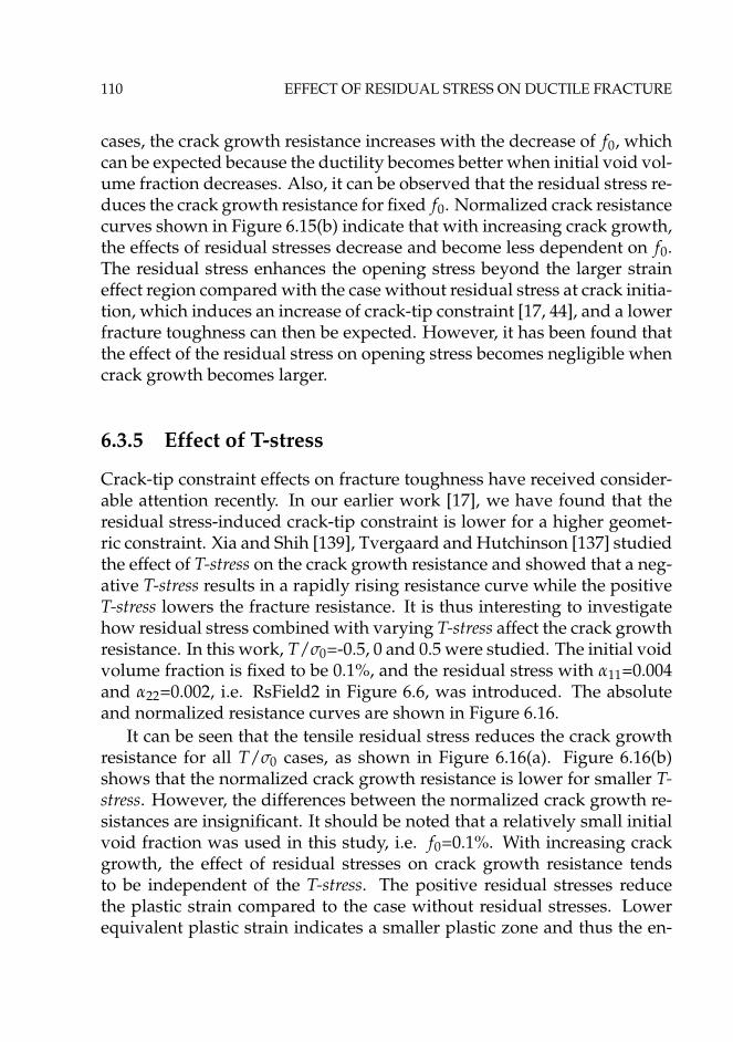
110 EFFECT OF RESIDUAL STRESS ON DUCTILE FRACTURE
cases, the crack growth resistance increases with the decrease of f0, whichcan be expected because the ductility becomes better when initial void vol-ume fraction decreases. Also, it can be observed that the residual stress re-duces the crack growth resistance for fixed f0. Normalized crack resistancecurves shown in Figure 6.15(b) indicate that with increasing crack growth,the effects of residual stresses decrease and become less dependent on f0.The residual stress enhances the opening stress beyond the larger straineffect region compared with the case without residual stress at crack initia-tion, which induces an increase of crack-tip constraint [17, 44], and a lowerfracture toughness can then be expected. However, it has been found thatthe effect of the residual stress on opening stress becomes negligible whencrack growth becomes larger.
6.3.5 Effect of T-stress
Crack-tip constraint effects on fracture toughness have received consider-able attention recently. In our earlier work [17], we have found that theresidual stress-induced crack-tip constraint is lower for a higher geomet-ric constraint. Xia and Shih [139], Tvergaard and Hutchinson [137] studiedthe effect of T-stress on the crack growth resistance and showed that a neg-ative T-stress results in a rapidly rising resistance curve while the positiveT-stress lowers the fracture resistance. It is thus interesting to investigatehow residual stress combined with varying T-stress affect the crack growthresistance. In this work, T/σ0=-0.5, 0 and 0.5 were studied. The initial voidvolume fraction is fixed to be 0.1%, and the residual stress with α11=0.004and α22=0.002, i.e. RsField2 in Figure 6.6, was introduced. The absoluteand normalized resistance curves are shown in Figure 6.16.
It can be seen that the tensile residual stress reduces the crack growthresistance for all T/σ0 cases, as shown in Figure 6.16(a). Figure 6.16(b)shows that the normalized crack growth resistance is lower for smaller T-stress. However, the differences between the normalized crack growth re-sistances are insignificant. It should be noted that a relatively small initialvoid fraction was used in this study, i.e. f0=0.1%. With increasing crackgrowth, the effect of residual stresses on crack growth resistance tendsto be independent of the T-stress. The positive residual stresses reducethe plastic strain compared to the case without residual stresses. Lowerequivalent plastic strain indicates a smaller plastic zone and thus the en-

6.3 RESULTS 111
0 5 10 15 202
4
6
8
10
12
14
16
Δa/lc
J/(σ
0l c)
T/σ0=−0.5 no/res
T/σ0=−0.5 with/res
T/σ0=0 no/res
T/σ0=0 with/res
T/σ0=0.5 no/res
T/σ0=0.5 with/res
(a)
0 5 10 15 200.65
0.75
0.85
0.95
Δa/lc
J/J w
ithou
t
T/σ0=−0.5
T/σ0=0
T/σ0=0.5
(b)
Figure 6.16: Effect of the residual stress on normalized crack growth resis-tances for different T/σ0, (a) absolute crack growth resistance curves; (b)normalized crack resistance curves. α11=0.004, α22=0.002; f0=0.1%; n=0.1;E/σ0=500.

112 EFFECT OF RESIDUAL STRESS ON DUCTILE FRACTURE
ergy dissipated by the plastic deformation decreases. In turn, the ductilecrack toughness decreases. When the crack growth becomes larger, the ef-fect of residual stresses on the equivalent plastic strain becomes negligible.
6.4 Conclusions
This study describes a systematic computational investigation of the effectof residual stresses on ductile crack growth resistance. 2D plane strain fi-nite element analysis have been carried out in a modified boundary layermodel with the remote boundary condition governed by K-field and T-stress. The large strain effect was taken into account in the analysis. Thecomplete Gurson model was utilized to predict the crack growth resistancefor both with and without residual stress situations. Residual stresseswere generated by the eigenstrain method and introduced into the FEmodel. Both the tensile and compressive residual stress fields were intro-duced. However, tensile residual stress was known to be detrimental forthe fracture. Thus, the effect of the tensile residual stress on crack growthresistance was mainly presented. Residual stresses as an additional fielddo not alter the material constitutive relation, however, the residual stressmay influence the near-tip stress state and enhance the level of damagealong the ligament ahead of an advancing crack tip. The following con-clusions can be made:
1. Tensile residual stresses reduce the crack growth resistance whilecompressive residual stress can enhance the crack growth resistance. Withthe increase of crack growth, the effect of residual stresses decreases andconverges to the case without residual stress. The initial damage of theligament elements caused by the residual stress is negligible for the casesstudied.
2. Under certain circumstances, the effect of the residual stresses onductile crack growth resistance can be normalized by the size of the geo-metrically similar weld, and the normalized crack growth resistance curvescollapse into a single curve. One can use this curve to evaluate the effect ofthe residual stress on the structural integrity and simplify the assessmentprocedure. It can also be used to predict the length scale of the residualstress-affected range beyond which the effect of the residual stresses canbe neglected. For the cases specified in this study, when the crack growsto a length of 3c the effect of the residual stresses can be neglected.

6.4 CONCLUSIONS 113
3. The reduction of the crack growth resistance caused by residualstresses is smaller for weaker hardening materials, and the influence ofthe residual stresses decreases with crack propagation.
4. Residual stress reduces the crack growth resistance more signifi-cantly for the materials with larger initial void volume. The influence ofthe residual stresses decreases with the crack growth and becomes inde-pendent of f0.
5. The reduction of the crack growth resistance induced by the residualstress increases with increasing T/σ0 at the early stage of crack growthand then tend to be negligible when the crack growth is larger. The resultsare in line with our earlier findings that the effect of residual stress on thecrack-tip constraint becomes weaker for higher T/σ0.
The present study indicates that residual stress as an additional stressfield can alter the stress state near the crack tip and further influence theductile crack growth resistance. Triaxility or crack-tip constraint was shownto play an important role in the ductile fracture behaviour. Therefore, theresidual stress-induced crack-tip constraint is a very important factor toconsider in structural integrity assessment. In Chapter 4, we have defineda parameter R to quantify the residual stress-induced crack-tip constraint.However, the effect of residual stress on the ductile crack resistance has notbeen linked with R by a quantitative way in this chapter. The reason forthis is that the residual stress field in reality is very complicated, hence oneshould find an efficient way to standardize the distribution of the residualstresses for typical weld joints. To reduce the conservatism of current in-tegrity assessments, a proper description of the residual stress field is veryimportant. Once a proper description of the residual stress is obtained, the"master" curve, though obtained from the MBL model, can be applied toreal engineering structures and components that contain similar residualstress fields under small-scale-yielding conditions. The transferability ofthe results from MBL studies to real structures should be verified in fur-ther studies.


Chapter 7
Summary
Welding is a very important technique in material processing engineering,and welding residual stress is always a critical issue that should be takeninto account. With the rapid development of oil and gas industry, weldingand repair of pipelines and platforms under crucial conditions, e.g. deepwater with the depth over 300 meter, and the arctic region with very lowtemperature, become more and more urgent. Meanwhile, the safety andintegrity of welded components is a stringent issue for the industry as wellas the whole society. It has been shown that welding residual stress canhave significant effect on the structural integrity, which originally moti-vated this study. The research presented in this thesis has advanced thefundamental understanding of the effect of residual stress on structuralintegrity assessment from the fracture mechanics point of view. The mainfocuses are the effect of residual stresses on crack-tip constraint, cleav-age fracture toughness and ductile crack growth resistance. Since tensileresidual stress is detrimental for the fracture, the study mainly concernsthe effect of tensile residual stress on fracture behaviour.
A series of numerical analyses were carried out to investigate the prob-lem. The problem was simplified as an ideal modified boundary layerproblem under Mode I loading and plane strain conditions. The eigen-strain method was utilized to introduce residual stresses into the finite el-ement model. The cohesive zone model and complete Gurson model wereemployed to study the effect of residual stresses on cleavage and ductilefracture behaviour, respectively. The main findings of the thesis are listedbelow.

116 SUMMARY
Main findings
• For given crack tip driving force, tensile residual stress enhances thenear tip stresses compared with the reference field without residualstress while the compressive residual stress has the opposite effect.Thus, tensile residual stress can increase the crack-tip constraint.
• Based on the observation that near tip stress fields show similarity,a parameter R was defined to quantify the residual stress-inducedcrack-tip constraint. Parameter R is defined based on the openingstress difference between the full field including the residual stressand the reference field.
• Results of the cases investigated suggest that the defined parameterR is a non-hydrostatic parameter, which is the function of the resid-ual stress field, external loading, material hardening, loading pathand geometry constraint. For the cases with higher geometry con-straint, the effect of residual stress on crack-tip constraint becomessmaller.
• It has been found that the compressive residual stress enhance thecleavage fracture toughness while positive residual stresses have theopposite effect. For elastic-plastic materials, residual stress affectsboth the fracture process zone size and surrounding material plas-ticity, and the latter effect is more important.
• Compressive residual stress enlarges the plastic zone significantlywhile tensile residual stress compresses the plastic zone and shiftsthe plastic zone backward. Residual stress shows similar effect asT-stress on plastic zone.
• The effect of residual stresses on the cleavage fracture toughness isdependent on the traction-separation-law parameters. With the in-crease of Γ0, the effect of the residual stress on cleavage toughnessdecreases; the effect of residual stresses increases with the increaseof the maximum cohesive stress.
• Effect of residual stress on the cleavage fracture toughness is weakerfor higher geometry constraint configuration. When combining theeffect of residual stresses with T-stress, the superposition principle
SUMMARY 117
can be applied. Thus, for higher geometry constraint configuration,the effect of tensile residual stress is smaller. However, for lowergeometry constraint case, the coupled effect can induce a significantreduction of the cleavage fracture toughness.
• Tensile residual stress reduces the crack growth resistance while com-pressive residual stress can enhance the crack growth resistance. Theeffect of residual stresses is dependent on the amount of crack growth.With the increase of crack growth, the effect of residual stresses de-creases and converges to the case without residual stress.
• The reduction of the crack growth resistance caused by residual stressis smaller for weaker hardening materials, and the influence of theresidual stress decreases with crack propagation. With the increaseof the material hardening, the effect of residual stress on cleavagefracture toughness decreases.
• Residual stress reduces the crack growth resistance more significantlyfor the materials with larger initial void volume. The influence ofthe residual stress decreases with the crack growth and becomes in-dependent of f0. The reduction of the crack growth resistance in-duced by the residual stress increases with increasing T/σ0 at theearly stage of crack growth and then tend to be negligible when thecrack growth becomes larger.
• When the welds are geometrically similar, the effect of residual stresson the cleavage fracture toughness is a linear function of the size ofthe weld. However, the effect of the residual stresses on ductile crackgrowth resistance can be normalized by the size of the geometricallysimilar weld, and the normalized crack growth resistance curves col-lapse into a single curve.


Chapter 8
Future work
This work focused on the fundamental understanding of the effect of resid-ual stresses on the crack-tip constraint, cleavage and ductile fracture be-haviour. However, some important work has not been carried out accord-ing to the objectives of the PhD work and RESIA project. The followingwork can be carried out in future:
• Experimental verification of parameter R is important to further in-corporate this parameter into the structural integrity assessment pro-cedure. A efficient and reproducible method to introduce a realisticresidual stress into the test specimen should be developed.
• To obtain the accurate and whole map of the distribution of resid-ual stresses are critical to assess their effect on fracture. Thus, boththe experimental measurement techniques and numerical predictionmethod should be further developed.
• In integrity assessment procedure, the length scale of residual stressshould be properly defined, and the standardization of distributionof residual stress can be depicted for various welding joints.
• It is also important to verify the effect of residual stresses on cleav-age fracture toughness and ductile crack growth resistance by exper-iments. It is interesting to link the effect of residual stress on failuremechanisms to parameter R.
• It have been shown in literature that residual stresses may also playan important role in fatigue, hydrogen pick-up and diffusion, creep

120 FUTURE WORK
and so on. Thus, both the numerical simulation and experimentalverification of such topics are important.
• Effect of residual stresses on the crack driving force should be fur-ther investigated either in theoretical or other approaches. A moregeneral and accurate crack driving force parameter should be devel-oped to include the effect of residual stress, and it should be friendlyapplicable for industry and structural integrity assessment.
• A improved integrity assessment procedure, which includes the ef-fect of residual stresses on the crack driving force, crack-tip con-straint, different failure mechanisms should be developed.

Bibliography
[1] R. A. Ainsworth, J. K. Sharples, and S. D. Smith. Effects of residualstresses on fracture behaviour-experimental results and assessmentmethods. Journal of Strain Analysis for Engineering Design, 35(4):307–316, 2000.
[2] P. J. Withers. Residual stress and its role in failure. Reports on Progressin Physics, 70(12):2211–2264, 2007.
[3] P. Dong and F. W. Brust. Welding residual stresses and effects onfracture in pressure vessel and piping components: A millenniumreview and beyond. Journal of Pressure Vessel Technology, 122(3):329–338, 2000.
[4] Project description- Residual Stress Simulation and Integrity Assess-ment (RESIA).
[5] http://www.sintef.no/projectweb/resia/work-packages/.
[6] T.L. Anderson. Fracture mechanics: fundamentals and applications. CRCpress, 2005.
[7] A. A. Wells. Unstable crack propagation in metals: cleavage and fastfracture. In Proceedings of the Crack Propagation Symposium, volume 1.College of Aeronautics, 1962.
[8] J. R. Rice. A path independent integral and the approximate analy-sis of strain concentration by notches and cracks. Journal of AppliedMechanics, 35:379–386, 1968.
[9] C. F. Shih. Relationships between the J-integral and the crack open-ing displacement for stationary and extending cracks. Journal of theMechanics and Physics of Solids, 29(4):305–326, 1981.
122 BIBLIOGRAPHY
[10] C. F. Shih, B. Moran, and T. Nakamura. Energy release rate along athree-dimensional crack front in a thermally stressed body. Interna-tional Journal of Fracture, 30(2):79–102, 1986.
[11] Y. Lei, N.P.O’Dowd, and G.A.Webster. Fracture mechanics analysisof a crack in a residual stress field. International Journal of Fracture,106:195–216, 2000.
[12] Y. Lei. J-integral evaluation for cases involving non-proportionalstressing. Engineering Fracture Mechanics, 72(4):577–596, 2005.
[13] V. Kumar, B. I. Schumacher, and M. D. German. Development ofa procedure for incorporating secondary stresses in the engineeringapproach. EPRI Report EPRI NP-3607, 1985.
[14] R. A. Ainsworth and D. G. Hooton. R6 and R5 procedures: The wayforward. International Journal of Pressure Vessels and Piping, 85(3):175–182, 2008.
[15] Y.C. Hou and J. Pan. A fracture parameter for welded structureswith residual stresses. Computational Mechanics, 22(3):281–288, 1998.
[16] Y. J. Chao and Poh-Sang Lam. Constraint effect in fracture-what isit? In Proceeding of the 12th Intermational Conference of Fracture, 2009.
[17] X. B. Ren, Z. L. Zhang, and B. Nyhus. Effect of residual stress oncrack-tip constraint in a boundary layer model. International Journalof Solids and Structures, 46(13):2629–2641, 2009.
[18] Z. L. Zhang, M. Hauge, and C. Thaulow. Two-parameter charac-terization of the near-tip stress fields for a bi-material elastic-plasticinterface crack. International Journal of Fracture, 79(1):65–83, 1996.
[19] C. Betegón and I. Peñuelas. A constraint based parameter for quanti-fying the crack tip stress fields in welded joints. Engineering FractureMechanics, 73(13):1865–1877, 2006.
[20] M. C. Burstow, I. C. Howard, and R. A. Ainsworth. The influence ofconstraint on crack tip stress fields in strength mismatched weldedjoints. Journal of the Mechanics and Physics of Solids, 46(5):845–872,1998.

BIBLIOGRAPHY 123
[21] P. A. Eikrem, Z. L. Zhang, and B. Nyhus. Effect of plastic prestrainon the crack tip constraint of pipeline steels. International Journal ofPressure Vessels and Piping, 84(12):708–715, 2007.
[22] S. Cravero and C. Ruggieri. A two-parameter framework to describeeffects of constraint loss on cleavage fracture and implications forfailure assessments of cracked components. Journal of the BrazilianSociety of Mechanical Sciences and Engineering, 25:403–412, 2003.
[23] A. Neimitz and J. Galkiewicz. Fracture toughness of structural com-ponents: influence of constraint. International Journal of Pressure Ves-sels and Piping, 83(1):42–54, 2006.
[24] M. L. Williams. On the stress distribution at the base of a stationarycrack. Journal of Applied Mechanics, 24:109–1, 1957.
[25] S. G. Larsson and A. J. Carlsson. Influence of non-singular stressterms and specimen geometry on small-scale yielding at crack tips inelastic-plastic materials. Journal of the Mechanics and Physics of Solids,21:263–277, 1973.
[26] Z. Z. Du and J. W. Hancock. The effect of non-singular stresses oncrack-tip constraint. Journal of the Mechanics and Physics of Solids,39:17–26, 1991.
[27] J. W. Hutchinson. Singular behaviour at the end of a tensile crackin a hardening material. Journal of the Mechanics and Physics of Solids,16(1):13–31, 1968.
[28] J. R. Rice and G. F. Rosengren. Plane strain deformation near a cracktip in a power law hardening material. Journal of the Mechanics andPhysics of Solids, 16(1):1–12, 1968.
[29] C. Betegón and J. W. Hancock. Two-parameter characterized ofelastic-plastic crack-tip fields. Journal of Applied Mechanics, 58:104–110, 1991.
[30] N. P. O’Dowd and C. F. Shih. Family of crack-tip fields characterizedby a trixiality paramater-I: structure of fields. Journal of the Mechanicsand Physics of Solids, 39(8):989–1015, 1991.

124 BIBLIOGRAPHY
[31] N. P. O’Dowd and C. F. Shih. Family of crack-tip fields characterizedby a trixiality paramater-II: application. Journal of the Mechanics andPhysics of Solids, 40(5):939–963, 1992.
[32] Xian-Kui Zhu and Brian N. Leis. Bending modified J-Q theory andcrack-tip constraint quantification. International Journal of Fracture,141:115–134, 2006.
[33] Y. J. Chao, S. Yang, and M. A. Sutton. On the fracture of solids char-acterized by one or two parameters: theory and practice. Journal ofthe Mechanics and Physics of Solids, 42:629–629, 1994.
[34] Y. J. Chao and X. K. Zhu. J-A2 characterization of crack-tip fields:Extent of J-A2 dominance and size requirements. International Jour-nal of Fracture, 89(3):285–307, 1998.
[35] H. J. Schindler. An engineering concept to account for crack-tip con-straint. Facta universitatis-series: Mechanics, Automatic Control andRobotics, 3(13):613–622, 2003.
[36] W. Guo. Elastoplastic three dimensional crack border field-I: Singu-lar structure of the field. Engineering Fracture Mechanics, 46(1):93–104, 1993.
[37] W. Guo. Elastoplastic three dimensional crack border field-II:Asymptotic solution for the field. Engineering Fracture Mechanics,46(1):105–113, 1993.
[38] W. Guo. Elasto-plastic three-dimensional crack border field-III: Frac-ture parameters. Engineering Fracture Mechanics, 51(1):51–71, 1995.
[39] Z. L. Zhang, C. Thaulow, and M. Hauge. Effects of crack sizeand weld metal mismatch on the HAZ cleavage toughness of wideplates. Engineering Fracture Mechanics, 57(6):653–664, 1997.
[40] Z. L. Zhang, M. Hauge, and C. Thaulow. The effect of T-stress on thenear tip stress field on an elastic-plastic interface crack. In Advancesin Fracture Research,Proceedings of the 9th International Conference onFracture, volume 5, pages 2463–2650, Sydney, Australia, 1997. Perg-amon, Oxford.
BIBLIOGRAPHY 125
[41] T. L. Panontin and M. R. Hill. The effect of residual stresses on brittleand ductile fracture initiation predicted by micromechanical mod-els. International Journal of Fracture, 82(4):317–333, 1996.
[42] M. R. Hill and T. L. Panontin. Effect of residual stress on brittlefracture testing. Fatigue and Fracture Mechanics: 29th Volume, ASTMSTP, 1332, 1998.
[43] W. G. Xu and F. M. Burdekin. Effects of residual stresses on con-straint and fracture behaviour of wide plates. The Royal Society,A(454):2505–2528, 1998.
[44] J. Liu, Z. L. Zhang, and B. Nyhus. Residual stress induced crack tipconstraint. Engineering Fracture Mechanics, 75(14):4151–4166, 2008.
[45] D. A. Curry. Cleavage micromechanisms of crack extension in steels.Metal Science, 14:319–326, 1980.
[46] A. Neimitz, M. Graba, and J. Galkiewicz. An alternative formulationof the Ritchie-Knott-Rice local fracture criterion. Engineering FractureMechanics, 74(8):1308–1322, 2007.
[47] R. O. Ritchie, J. F. Knott, and J. R. Rice. Relationship between criti-cal tensile stress and fracture toughness in mild steel. Journal of theMechanics and Physics of Solids, 21:395–410, 1973.
[48] A. Mirzaee-Sisan, C. E. Truman, D. J. Smith, and M. C. Smith. Inter-action of residual stress with mechanical loading in a ferritic steel.Engineering Fracture Mechanics, 74(17):2864–2880, 2007.
[49] Z. L. Zhang. Nonlinear Fracture and Damage Mechnics, chapter 8,pages 223–248. WIT Press Southampton, 2001.
[50] S. H. Goods and L. M. Brown. The nucleation of cavities by plasticdeformation. Acta Metall., 27(1):1–15, 1979.
[51] A. H. Sherry, M. A. Wilkes, J. K. Sharples, and P. J. Budden. Theassessment of residual stress effects on ductile tearing using con-tinuum damage mechanics. Journal of Pressure Vessel Technology,130:041212–1–8, 2008.

126 BIBLIOGRAPHY
[52] J. K. Sharples, C .C. France, and R. A. Ainsworth. Experimentalvalidation of R6 treatment of residual stresses. ASME PVP, 392:225–238, 1999.
[53] A. Mirzaee-Sisan, C. E. Truman, D. J. Smith, and M. C. Smith. In-teraction of residual stress with mechanical loading in an austeniticstainless steel. Fatigue & Fracture of Engineering Materials & Struc-tures, 31(3-4):223–233, 2008.
[54] A. H. Mahmoudi, C. E. Truman, and D. J. Smith. Using local out-of-plane compression (LOPC) to study the effects of residual stresson apparent fracture toughness. Engineering Fracture Mechanics,75(6):1516–1534, 2008.
[55] J. Liu. Literature review on current residual stress treatment in in-tegrity assessment. Technical report, SINTEF Materials Technology,2005.
[56] BS7910. Guidance on methods for assessing the acceptability offlaws in metallic structures. British Standards Institution, 1999.
[57] R6. Assessment of the integrity of structures containing defects, Rev.4. British Energy Generation Ltd, UK, 2004.
[58] R5. Assessment procedure for the high temperature response ofstructures, Issue 3. British Energy Generation Ltd, UK, 2003.
[59] SINTAP. Structural integrity assessment procedures for europeanindustry, final procedure. Technical report, British Steel, Sheffield,1999.
[60] R. A. Ainsworth, F. Gutierrez-Solana, and J. R. Ocejo. Analysis lev-els within the SINTAP defect assessment procedures. EngineeringFracture Mechanics, 67(6):515–527, 2000.
[61] A. R. Dowling and C. H. A. Townley. The effect of defects on struc-tural failure: a two-criteria approach. International Journal of PressureVessels and Piping, 3(2):77–107, 1975.
[62] R. P. Harrison, K. Loosemore, and I. Milne. Assessment of Struc-tures Containing Defects. Central Electricity Generating Board ReportR/H/R6, 1976.
BIBLIOGRAPHY 127
[63] E. Smith. Describing the effect of secondary stresses on crack exten-sion in the Kr-Lr format. International Journal of Pressure Vessels andPiping, 72(1):51–55, 1997.
[64] A. Stacey, J. Y. Barthelemy, R. H. Leggatt, and R. A. Ainsworth. In-corporation of residual stresses into the SINTAP defect assessmentprocedure. Engineering Fracture Mechanics, 67(6):573–611, 2000.
[65] R. A. Ainsworth. A constraint-based failure assessment diagram forfracture assessment. The International Journal of Pressure Vessels andPiping, 64(3):277–285, 1995.
[66] I. J. MacLennan and J. W Hancock. Constraint-based failure assess-ment diagrams. The International Journal of Pressure Vessels and Piping,64(3):287–298, 1995.
[67] R. A. Ainsworth and N. P. O’Dowd. Constraint in the failure assess-ment diagram approach for fracture assessment. Journal of PressureVessel Technology, 117:260, 1995.
[68] R. A. Ainsworth, I. Sattari-Far, A. H. Sherry, D. G. Hooton, andI. Hadley. Methods for including constraint effects within the SIN-TAP procedures. Engineering Fracture Mechanics, 67(6):563–571, 2000.
[69] H. Y. Lee, F. R. Biglari, R. Wimpory, and K. M. Nikbin. Treatment ofresidual stress in failure assessment procedure. Engineering FractureMechanics, 73(13):1755–1771, 2006.
[70] R. E. Dolby, R. Leggatt, I. C. Howard, D. Smith, and A. H. Sherry.Some challenges in the treatment of residual stress in flaw tolerancecalculations-A TAGSI view. International Journal of Pressure Vesselsand Piping, 85(3):166–174, 2008.
[71] P. J. Withers and H. K. D. H. Bhadeshia. Residual stress Part 1-Measurement techniques. Materials Science and Technology, 17:355–365, 2001.
[72] H. K. D. H. Bhadeshia. Material factors. ASM International, Mem-ber/Customer Service Center, Materials Park, OH 44073-0002, USA,2002., pages 3–10, 2002.

128 BIBLIOGRAPHY
[73] M. R. Hill and D. V. Nelson. The inherent strain method for resid-ual stress determination and its application to a long welded joint.ASME, Pressure Vessels and Piping Division, 318:343–352, 1995.
[74] T. Mura. Micromechanics of defects in solids. Kluwer Academic Pub,1987.
[75] P. Dong. Length scale of secondary stresses in fracture and fatigue.International Journal of Pressure Vessels and Piping, 85(3):128–143, 2008.
[76] F. A. Kandil, J. D. Lord, A. T. Fry, and P. V. Grant. A review ofresidual stress measurement methods: a guide to technique selec-tion. Technical report, National Physical Laboratory, 2001.
[77] N.J. Rendler and I. Vigness. Hole-drilling strain-gage method ofmeasuring residual stresses. Experimental Mechanics, 6(12):577–586,1966.
[78] M.R. Hill. Determination of residual stress based on the estimation ofeigenstrain. PhD thesis, Stanford University, 1996.
[79] G. S. Schajer. Measurement of non-uniform residual stresses usingthe hole-drilling method. Journal of Engineering Materials and Tech-nology, 103:338–349, 1988.
[80] M. B. Prime. Cross-sectional mapping of residual stresses by mea-suring the surface contour after a cut. Journal of Engineering Materialsand Technology, 123(2):162–168, 2001.
[81] M. B. Prime. Residual stress measurement by successive extensionof a slot: the crack compliance method. Applied Mechanics Reviews,52:75, 1999.
[82] H. H. Lester and R. H. Aborn. Behaviour under Stress of the IronCrystals in Steel. Army Ordnance, 6:120–129, 1925.
[83] D. Deng and H. Murakawa. Numerical simulation of temperaturefield and residual stress in multi-pass welds in stainless steel pipeand comparison with experimental measurements. ComputationalMaterials Science, 37(3):269–277, 2006.

BIBLIOGRAPHY 129
[84] X. K. Zhu and Y. J. Chao. Effects of temperature-dependent ma-terial properties on welding simulation. Computers and Structures,80(11):967–976, 2002.
[85] L. E. Lindgren. Finite element modeling and simulation of welding.Part 1: Increased complexity. Journal of thermal stresses, 24(2):141–192, 2001.
[86] L. E. Lindgren. Finite element modeling and simulation of weld-ing. Part 2: Improved material modeling. Journal of thermal stresses,24(3):195–231, 2001.
[87] L. E. Lindgren. Finite element modeling and simulation of weld-ing. Part 3: efficiency and integration. Journal of thermal stresses,24(4):305–334, 2001.
[88] L. E. Lindgren. Numerical modelling of welding. Computer Methodsin Applied Mechanics and Engineering, 195(48-49):6710–6736, 2006.
[89] WeldsimS reference manual, Version 4.0.
[90] RC McClung. A literature survey on the stability and significance ofresidual stresses during fatigue. Fatigue and Fracture of EngineeringMaterials and Structures, 30(3):173–205, 2007.
[91] M.F. Ashby and D.R.H. Jones. Engineering Materials: An Introduc-tion to Their Properties and Applications. Pergamon, 1980.
[92] P. J. Bouchard, P. J. Withers, S. A0 McDonald, and R. K. Heenan.Quantification of creep cavitation damage around a crack in a stain-less steel pressure vessel. Acta Materialia, 52(1):23–34, 2004.
[93] J. Toribio and M. Elices. Influence of residual stresses on hydrogenembrittlement susceptibility of prestressing steels. International Jour-nal of Solid Structures, 28(6):791–803, 1991.
[94] J. Toribio and V. Kharin. Effect of residual stress-strain profiles onhydrogen-induced fracture of prestressing steel wires. Materials Sci-ence, 42(2):263–271, 2006.

130 BIBLIOGRAPHY
[95] L. Xue and T. Wierzbicki. Ductile fracture characterization of alu-minum alloy 2024-T351 using damage plasticity theory. InternationalJournal of Applied Mechanics, 1(2):267–304, 2009.
[96] A. L. Gurson. Continuum theory of ductile rupture by void growth:Part I–Yield criteria and flow rules for porous ductile media. Journalof Engineering Materials and Technology, 99(2):2–15, 1977.
[97] J. R. Rice and D. M. Tracey. On the ductile enlargement of voidsin triaxial stress fields. Journal of Mechanics and Physics of Solids,17(3):201–217, 1969.
[98] F. A. McClintock. A criterion for ductile fracture by the growth ofholes. Joural of Applied Mechanics, 35(6):363–371, 1968.
[99] V. Tvergaard. Influence of voids on shear band instabilities underplane strain conditions. International Journal of Fracture, 17(4):389–407, 1981.
[100] V. Tvergaard. On localization in ductile materials containing spher-ical voids. International Journal of Fracture, 18(4):237–252, 1982.
[101] V. Tvergaard and A. Needleman. Analysis of the cup-cone fracturein a round tensile bar. Acta Metallurgica, 32(1):157–169, 1984.
[102] L. M. Brown and J. D. Embury. Initiation and Growth of Voids atSecond-Phase Particles. In Proc. Conf. on Microstructure and Designof Alloys, Institute of Metals and Iron and Steel Insitute, London. 1973,1,(33), 164-169, 1973.
[103] J. Koplik and A. Needleman. Void growth and coalescence in porousplastic solids. International Journal of Solids and Structures, 24(8):835–853, 1988.
[104] Z.L. Zhang. A micro-mechanical model based local approac methodol-ogy for the analysis of ductile fracture of welded T-joints. PhD thesis,Lappeenranta University of Technilogy, Finland, 1994.
[105] Z. L. Zhang, C. Thaulow, and J. Ødegård. A complete Gursonmodel approach for ductile fracture. Engineering Fracture Mechan-ics, 67(2):155–168, 2000.

BIBLIOGRAPHY 131
[106] P. F. Thomason. A three-dimensional model for ductile fractureby the growth and coalescence of microvoids. Acta Metallurgica,33(6):1087–1095, 1985.
[107] P. F. Thomason. Three-dimensional models for the plastic limit-loadsat incipient failure of the intervoid matrix in ductile porous solids.Acta Metallurgica, 33(6):1079–1085, 1985.
[108] P. F. Thomason. Ductile Fracture of Metals. Pergamon, 1990.
[109] E. Østby, C. Thaulow, and Z. L. Zhang. Numerical simulationsof specimen size and mismatch effectsin ductile crack growth-PartI:Tearing resistance and crack growth paths. Engineering FractureMechanics, 74:1770–1792, 2007.
[110] T. Pardoen and J. W. Hutchinson. An extended model for voidgrowth and coalescence. Journal of the Mechanics and Physics of Solids,48(12):2467–2512, 2000.
[111] Z. L. Zhang and E. Niemi. A class of generalized mid-point algo-rithms for the Gurson-Tvergaard material model. International Jour-nal for Numerical Methods in Engineering, 38(12):2033–53, 1995.
[112] Z. L. Zhang. On the accuracies of numerical integration algo-rithms for Gurson-based pressure-dependent elastoplastic constitu-tive models. Computer Methods in Applied Mechanics and Engineering,121(1-4):15–28, 1995.
[113] Z. L. Zhang. Explicit consistent tangent moduli with a returnmapping algorithm for pressure-dependent elastoplasticity models.Computer methods in applied mechanics and engineering, 121(1-4):29–44,1995.
[114] ABAQUS Version 6.7 User’s Manual. Hibbit, Karlsson and Sorensen,Inc., 2007.
[115] René. de Borst. Numerical aspects of cohesive-zone models. Engi-neering Fracture Mechanics, 70(14):1743–1757, 2003.
[116] M. Elices, G. V. Guinea, J. Gomez, and J. Planas. The cohesive zonemodel: advantages, limitations and challenges. Engineering FractureMechanics, 69(2):137–163, 2002.

132 BIBLIOGRAPHY
[117] A. Cornec, I. Scheider, and K. H. Schwalbe. On the practical ap-plication of the cohesive model. Engineering Fracture Mechanics,70(14):1963–1987, 2003.
[118] G. I. Barenblatt. The mathematical theory of equilibrium cracks inbrittle fracture. Advances in Applied Mechanics, 7:55–129, 1962.
[119] D. S. Dugdale. Yielding of steel sheets containing slits. Journal of theMechanics and Physics of Solids, 8(2):100–104, 1960.
[120] A. Hillerborg, M. Modeer, and P. E. Petersson. Analysis of crack for-mation and crack growth in concrete by means of fracture mechanicsand finite elements. Cement and Concrete Research, 6(6):773–782, 1976.
[121] V. Olden, C. Thaulow, R. Johnsen, E. Østby, and T. Berstad. Ap-plication of hydrogen influenced cohesive laws in the prediction ofhydrogen induced stress cracking in 25% Cr duplex stainless steel.Engineering Fracture Mechanics, 75(8):2333–2351, 2008.
[122] V. Tvergaard and J. W. Hutchinson. The relation between crackgrowth resistance and fracture process parameters in elastic–plasticsolids. Journal of the Mechanics and Physics of Solids, 40(6):1377–1397,1992.
[123] A. Needleman. A continuum model for void nucleation by inclusiondebonding. Journal of Applied Mechanics, 54(3):525–531, 1987.
[124] X. P. Xu and A. Needleman. Numerical simulations of fast crackgrowth in brittle solids. Journal of the Mechanics and Physics of Solids,42(9):1397–1407, 1994.
[125] J. L. Chaboche, F. Feyel, and Y. Monerie. Interface debonding mod-els: a viscous regularization with a limited rate dependency. Inter-national Journal of Solids and Structures, 38(18):3127–3160, 2001.
[126] M. Pezzotta and Z. L. Zhang. Effect of thermal mismatch inducedresidual stresses on grain boundary micro-cracking of Titanium Di-boride ceramics. Journal of Material Science, doi:10.1007/s10853-009-3952-3, 45:382–391, 2010.

BIBLIOGRAPHY 133
[127] Y. Ueda, K. Fukuda, K. Nakacho, and S. Endo. A new measuringmethod of residual stresses with the aid of finite element methodand reliability of estimated values. Trans. Japan Welding Research In-stitute, 4(2):123–131, 1975.
[128] M. Mochizuki, M. Hayashi, and T. Hattori. Residual stress analysisby simplified inherent strain at welded pipe junctures in a pressurevessel. Journal of Pressure Vessel Technology, 121(4):353–357, 1999.
[129] Y. Ueda, K. Nakacho, and M. Yuan. Application of FEM to the-oretical analysis, measurement and prediction of welding resid-ual stresses. Transactions of the JWRI(Japan Welding Research Insti-tute)(Japan), 20(1):97–107, 1991.
[130] Robert H. Dodds, Jr., C. Fong Shin, and Ted L. Anderson. Contin-uum and micromechanics treatment of constraint in fracture. Inter-national Journal of Fracture, 64:101–133, 1993.
[131] B. A. Bilby, G. E. Cardew, M. R. Goldthorpe, and I. C. Howard. Afinite element investigation of the effect of specimen geometry onthe fields of stress and strain at the tips of stationary cracks. SizeEffects in Fracture. Institution of Mechanical Engineers, London, England,pages 36–46, 1986.
[132] X. B. Ren, Z .L. Zhang, and B. Nyhus. Residual stress induced crack-tip constraint: a paramteric study. In Proceedings of 17th EuropeanConference on Fracture, ECF17, 2008.
[133] X Gao and R. H. Dodds Jr. An engineering approach to assess con-straint effects on cleavage fracture toughness. Engineering FractureMechanics, 68(3):263–283, 2001.
[134] Y. Ueda and K. Fukuda. New measuring method of three-dimensional residual stresses in long welded joints using inherentstrains as parameters–Lz method. Journal of Engineering Materialsand Technology, 111(1):1–8, 1989.
[135] P. J. Bouchard and P. J. Withers. Identification of residual stresslength scales in welds for fracture assessment. In Residual Stress andIts Effects on Fatigue and Fracture: Proceedings of a Special Symposium
134 BIBLIOGRAPHY
Held Within the 16th European Conference of Fracture-ECF16, Alexan-droupolis, Greece, 3-7 July, 2006, page 163, 2006.
[136] X. Gao, C. F. Shih, V. Tvergaard, and A. Needleman. Constraint ef-fects on the ductile-brittle transition in small scale yielding. J. Mech.Phys. Solids, 44:1255–1282, 1996.
[137] V. Tvergaard and J. W. Hutchinson. Effect of T-stress on mode I crackgrowth resistance in a ductile solid. International Journal of Solids andStructures., 31(6):823–833, 1994.
[138] J.C. Sobotka, R.H. Dodds, and P. Sofronis. Effects of hydrogen onsteady, ductile crack growth:computational studies. InternationalJournal of Solids and Structures, 46:4095–4106, 2009.
[139] L. Xia and C. F. Shih. Ductile crack growth-I. A numerical study us-ing computational cells with microstructurally-based length scales.Journal of the Mechanics and Physics of Solids, 43(2):233–259, 1995.
[140] P. A. Eikrem, Z. L. Zhang, E. Østby, and B. Nyhus. Numerical studyon the effect of prestrain history on ductile fracture resistance byusing the complete gurson model. Engineering Fracture Mechanics,75:4568–4582, 2008.
[141] E. Østby, C. Thaulow, and Z. L. Zhang. Numerical simulations ofspecimen size and mismatch effects in ductile crack growth Part II:Near-tip stress fields. Engineering Fracture Mechanics, 74:1793–1809,2007.

DEPARTMENT OF STRUCTURAL ENGINEERINGNORWEGIAN UNIVERSITY OF SCIENCE AND TECHNOLOGY
N-7491 TRONDHEIM, NORWAYTelephone: +47 73 59 47 00 Telefax: +47 73 59 47 01
"Reliability Analysis of Structural Systems using Nonlinear Finite ElementMethods",C. A. Holm, 1990:23, ISBN 82-7119-178-0.
"Uniform Stratified Flow Interaction with a Submerged Horizontal Cylin-der",Ø. Arntsen, 1990:32, ISBN 82-7119-188-8.
"Large Displacement Analysis of Flexible and Rigid Systems ConsideringDisplacement-Dependent Loads and Nonlinear Constraints",K. M. Mathisen, 1990:33, ISBN 82-7119-189-6.
"Solid Mechanics and Material Models including Large Deformations",E. Levold, 1990:56, ISBN 82-7119-214-0, ISSN 0802-3271.
"Inelastic Deformation Capacity of Flexurally-Loaded Aluminium AlloyStructures",T. Welo, 1990:62, ISBN 82-7119-220-5, ISSN 0802-3271.
"Visualization of Results from Mechanical Engineering Analysis",K. Aamnes, 1990:63, ISBN 82-7119-221-3, ISSN 0802-3271.
"Object-Oriented Product Modeling for Structural Design",S. I. Dale, 1991:6, ISBN 82-7119-258-2, ISSN 0802-3271.
"Parallel Techniques for Solving Finite Element Problems on TransputerNetworks",T. H. Hansen, 1991:19, ISBN 82-7119-273-6, ISSN 0802-3271.
136
"Statistical Description and Estimation of Ocean Drift Ice Environments",R. Korsnes, 1991:24, ISBN 82-7119-278-7, ISSN 0802-3271.
"Properties of concrete related to fatigue damage: with emphasis on highstrength concret",G. Petkovic, 1991:35, ISBN 82-7119-290-6, ISSN 0802-3271.
"Turbidity Current Modelling",B. Brørs, 1991:38, ISBN 82-7119-293-0, ISSN 0802-3271.
"Zero-Slump Concrete: Rheology, Degree of Compaction and Strength. Ef-fects of Fillers as Part Cement-Replacement",C. Sørensen, 1992:8, ISBN 82-7119-357-0, ISSN 0802-3271.
"Nonlinear Analysis of Reinforced Concrete Structures Exposed to Tran-sient Loading",K. V. Høiseth, 1992:15, ISBN 82-7119-364-3, ISSN 0802-3271.
"Finite Element Formulations and Solution Algorithms for Buckling andCollapse Analysis of Thin Shells",R. O. Bjærum, 1992:30, ISBN 82-7119-380-5, ISSN 0802-3271.
"Response Statistics of Nonlinear Dynamic Systems",J. M. Johnsen, 1992:42, ISBN 82-7119-393-7, ISSN 0802-3271.
"Digital Models in Engineering. A Study on why and how engineers buildand operate digital models for decisison support",J. Høyte, 1992:75, ISBN 82-7119-429-1, ISSN 0802-3271.
"Sparse Solution of Finite Element Equations",A. C. Damhaug, 1992:76, ISBN 82-7119-430-5, ISSN 0802-3271.
"Some Aspects of Floating Ice Related to Sea Surface Operations in theBarents Sea",S. Løset, 1992:95, ISBN 82-7119-452-6, ISSN 0802-3271.
"Modelling of Cyclic Plasticity with Apnplication to Steel and AluminiumStructures",O. S. Hopperstad, 1993:7, ISBN 82-7119-461-5, ISSN 0802-3271.
"The Free Formulation: Linear Theory and Extensions with Applicationsto Tetrahedral Elements with Rotational Freedoms",G. Skeie, 1993:17, ISBN 82-7119-472-0, ISSN 0802-3271.
137
"Høyfast betongs motstand mot piggdekkslitasje. Analyse av resultaterfra prøving i Veisliter’n",T. Tveter, 1993:62, ISBN 82-7119-522-0, ISSN 0802-3271.
"A Nonlinear Finite Element Based on Free Formulation Theory for Anal-ysis of Sandwich Structures",O. Aamlid, 1993:72, ISBN 82-7119-534-4, ISSN 0802-3271.
"The Effect of Curing Temperature and Silica Fume on Chloride Migrationand Pore Structure of High Strength Concrete",C. J. Hauck, 1993:90, ISBN 82-7119-553-0, ISSN 0802-3271.
"Failure of Concrete under Compressive Strain Gradients",G. Markeset, 1993:110, ISBN 82-7119-575-1, ISSN 0802-3271.
"An experimental study of internal tidal amphidromes in Vestfjorden",J. H. Nilsen, 1994:39, ISBN 82-7119-640-5, ISSN 0802-3271.
"Structural analysis of oil wells with emphasis on conductor design",H. Larsen, 1994:46, ISBN 82-7119-648-0, ISSN 0802-3271.
"Adaptive methods for non-linear finite element analysis of shell struc-tures",K. M. Okstad, 1994:66, ISBN 82-7119-670-7, ISSN 0802-3271.
"On constitutive modelling in nonlinear analysis of concrete structures",O. Fyrileiv, 1994:115, ISBN 82-7119-725-8, ISSN 0802-3271.
"Fluctuating wind load and response of a line-like engineering structurewith emphasis on motion-induced wind forces",J. Bogunovic Jakobsen, 1995:62, ISBN 82-7119-809-2, ISSN 0802-3271.
"An experimental study of beam-columns subjected to combined torsion,bending and axial actions",A. Aalberg, 1995:66, ISBN 82-7119-813-0, ISSN 0802-3271.
"Scaling and cracking in unsealed freeze/thaw testing of Portland cementand silica fume concretes",S. Jacobsen, 1995:101, ISBN 82-7119-851-3, ISSN 0802-3271.
"Damping of water waves by submerged vegetation. A case study of lam-inaria hyperborea",A. M. Dubi, 1995:108, ISBN 82-7119-859-9, ISSN 0802-3271.

138
"The dynamics of a slope current in the Barents Sea",Sheng Li, 1995:109, ISBN 82-7119-860-2, ISSN 0802-3271.
"Modellering av delmaterialenes betydning for betongens konsistens",Ernst Mørtsell, 1996:12, ISBN 82-7119-894-7, ISSN 0802-3271.
"Bending of thin-walled aluminium extrusions",Birgit Søvik Opheim, 1996:60, ISBN 82-7119-947-1, ISSN 0802-3271.
"Material modelling of aluminium for crashworthiness analysis",Torodd Berstad, 1996:89, ISBN 82-7119-980-3, ISSN 0802-3271.
"Estimation of structural parameters from response measurements on sub-merged floating tunnels",Rolf Magne Larssen, 1996:119, ISBN 82-471-0014-2, ISSN 0802-3271.
"Numerical modelling of plain and reinforced concrete by damage me-chanics",Mario A. Polanco-Loria, 1997:20, ISBN 82-471-0049-5, ISSN 0802-3271.
"Nonlinear random vibrations - numerical analysis by path integrationmethods",Vibeke Moe, 1997:26, ISBN 82-471-0056-8, ISSN 0802-3271.
"Numerical prediction of vortex-induced vibration by the finite elementmethod",Joar Martin Dalheim, 1997:63, ISBN 82-471-0096-7, ISSN 0802-3271.
"Time domain calculations of buffeting response for wind sensitive struc-tures",Ketil Aas-Jakobsen, 1997:148, ISBN 82-471-0189-0, ISSN 0802-3271.
"A numerical study of flow about fixed and flexibly mounted circular cylin-ders",Trond Stokka Meling, 1998:48, ISBN 82-471-0244-7, ISSN 0802-3271.
"Estimation of chloride penetration into concrete bridges in coastal areas",Per Egil Steen, 1998:89, ISBN 82-471-0290-0, ISSN 0802-3271.
"Stress-resultant material models for reinforced concrete plates and shells",Jan Arve Øverli, 1998:95, ISBN 82-471-0297-8, ISSN 0802-3271.
"Chloride binding in concrete. Effect of surrounding environment andconcrete composition",Claus Kenneth Larsen, 1998:101, ISBN 82-471-0337-0, ISSN 0802-3271.

139
"Rotational capacity of aluminium alloy beams",Lars A. Moen, 1999:1, ISBN 82-471-0365-6, ISSN 0802-3271.
"Stretch Bending of Aluminium Extrusions",Arild H. Clausen, 1999:29, ISBN 82-471-0396-6, ISSN 0802-3271.
"Aluminium and Steel Beams under Concentrated Loading",Tore Tryland, 1999:30, ISBN 82-471-0397-4, ISSN 0802-3271.
"Engineering Models of Elastoplasticity and Fracture for Aluminium Al-loys",Odd-Geir Lademo, 1999:39, ISBN 82-471-0406-7, ISSN 0802-3271.
"Kapasitet og duktilitet av dybelforbindelser i trekonstruksjoner",Jan Siem, 1999:46, ISBN 82-471-0414-8, ISSN 0802-3271.
"Etablering av distribuert ingeniørarbeid; Teknologiske og organisatoriskeerfaringer fra en norsk ingeniørbedrift",Lars Line, 1999:52, ISBN 82-471-0420-2, ISSN 0802-3271.
"Estimation of Earthquake-Induced Response",Símon Ólafsson, 1999:73, ISBN 82-471-0443-1, ISSN 0802-3271.
"Coastal Concrete Bridges: Moisture State, Chloride Permeability and Ag-ing Effects" Ragnhild Holen Relling, 1999:74, ISBN 82-471-0445-8, ISSN0802-3271.
"Capacity Assessment of Titanium Pipes Subjected to Bending and Exter-nal Pressure",Arve Bjørset, 1999:100, ISBN 82-471-0473-3, ISSN 0802-3271.
"Validation of Numerical Collapse Behaviour of Thin-Walled CorrugatedPanels",Håvar Ilstad, 1999:101, ISBN 82-471-0474-1, ISSN 0802-3271.
"Strength and Ductility of Welded Structures in Aluminium Alloys",Miroslaw Matusiak, 1999:113, ISBN 82-471-0487-3, ISSN 0802-3271.
"Thermal Dilation and Autogenous Deformation as Driving Forces to Self-Induced Stresses in High Performance Concrete",Øyvind Bjøntegaard, 1999:121, ISBN 82-7984-002-8, ISSN 0802-3271.
"Some Aspects of Ski Base Sliding Friction and Ski Base Structure",Dag Anders Moldestad, 1999:137, ISBN 82-7984-019-2, ISSN 0802-3271.

140
"Electrode reactions and corrosion resistance for steel in mortar and con-crete",Roy Antonsen, 2000:10, ISBN 82-7984-030-3, ISSN 0802-3271.
"Hydro-Physical Conditions in Kelp Forests and the Effect on Wave Damp-ing and Dune Erosion. A case study on Laminaria Hyperborea",Stig Magnar Løvås, 2000:28, ISBN 82-7984-050-8, ISSN 0802-3271.
"Random Vibration and the Path Integral Method",Christian Skaug, 2000:39, ISBN 82-7984-061-3, ISSN 0802-3271.
"Buckling and geometrical nonlinear beam-type analyses of timber struc-tures",Trond Even Eggen, 2000:56, ISBN 82-7984-081-8, ISSN 0802-3271.
"Structural Crashworthiness of Aluminium Foam-Based Components",Arve Grønsund Hanssen, 2000:76, ISBN 82-7984-102-4, ISSN 0809-103X.
"Measurements and simulations of the consolidation in first-year sea iceridges, and some aspects of mechanical behaviour",Knut V. Høyland, 2000:94, ISBN 82-7984-121-0, ISSN 0809-103X.
"Kinematics in Regular and Irregular Waves based on a Lagrangian For-mulation",Svein Helge Gjøsund, 2000-86, ISBN 82-7984-112-1, ISSN 0809-103X.
"Self-Induced Cracking Problems in Hardening Concrete Structures",Daniela Bosnjak, 2000-121, ISBN 82-7984-151-2, ISSN 0809-103X.
"Ballistic Penetration and Perforation of Steel Plates",Tore Børvik, 2000:124, ISBN 82-7984-154-7, ISSN 0809-103X.
"Freeze-Thaw resistance of Concrete. Effect of: Curing Conditions, Mois-ture Exchange and Materials",Terje Finnerup Rønning, 2001:14, ISBN 82-7984-165-2, ISSN 0809-103X
"Structural behaviour of post tensioned concrete structures. Flat slab. Slabson ground",Steinar Trygstad, 2001:52, ISBN 82-471-5314-9, ISSN 0809-103X.
"Slipforming of Vertical Concrete Structures. Friction between concreteand slipform panel",Kjell Tore Fosså, 2001:61, ISBN 82-471-5325-4, ISSN 0809-103X.

141
"Some numerical methods for the simulation of laminar and turbulent in-compressible flows",Jens Holmen, 2002:6, ISBN 82-471-5396-3, ISSN 0809-103X.
"Improved Fatigue Performance of Threaded Drillstring Connections byCold Rolling",Steinar Kristoffersen, 2002:11, ISBN: 82-421-5402-1, ISSN 0809-103X.
"Deformations in Concrete Cantilever Bridges: Observations and Theoret-ical Modelling",Peter F. Takâcs, 2002:23, ISBN 82-471-5415-3, ISSN 0809-103X.
"Stiffened aluminium plates subjected to impact loading",Hilde Giæver Hildrum, 2002:69, ISBN 82-471-5467-6, ISSN 0809-103X.
"Full- and model scale study of wind effects on a medium-rise building ina built up area",Jónas Thór Snæbjørnsson, 2002:95, ISBN82-471-5495-1, ISSN 0809-103X.
"Evaluation of Concepts for Loading of Hydrocarbons in Ice-infested wa-ter",Arnor Jensen, 2002:114, ISBN 82-417-5506-0, ISSN 0809-103X.
"Numerical and Physical Modelling of Oil Spreading in Broken Ice",Janne K. Økland Gjøsteen, 2002:130, ISBN 82-471-5523-0, ISSN 0809-103X.
"Diagnosis and protection of corroding steel in concrete",Franz Pruckner, 20002:140, ISBN 82-471-5555-4, ISSN 0809-103X.
"Tensile and Compressive Creep of Young Concrete: Testing and Mod-elling",Dawood Atrushi, 2003:17, ISBN 82-471-5565-6, ISSN 0809-103X.
"Rheology of Particle Suspensions. Fresh Concrete, Mortar and CementPaste with Various Types of Lignosulfonates",Jon Elvar Wallevik, 2003:18, ISBN 82-471-5566-4, ISSN 0809-103X.
"Oblique Loading of Aluminium Crash Components",Aase Reyes, 2003:15, ISBN 82-471-5562-1, ISSN 0809-103X.
"Utilization of Ethiopian Natural Pozzolans",Surafel Ketema Desta, 2003:26, ISSN 82-471-5574-5, ISSN:0809-103X.
"Behaviour and strength prediction of reinforced concrete structures withdiscontinuity regions",
142
Helge Brå, 2004:11, ISBN 82-471-6222-9, ISSN 1503-8181.
"High-strength steel plates subjected to projectile impact. An experimentaland numerical study",Sumita Dey, 2004:38, ISBN 82-471-6281-4 (electronic version), ISBN 82-471-6282-2 (printed version), ISSN 1503-8181.
"Alkali-reactive and inert fillers in concrete. Rheology of fresh mixturesand expansive reactions",Bård M. Pedersen, 2004:92, ISBN 82-471-6401-9 (printed version), ISBN 82-471-6400-0 (electronic version), ISSN 1503-8181.
"On the Shear Capacity of Steel Girders with Large Web Openings",Nils Christian Hagen, 2005:9 ISBN 82-471-6878-2 (printed version), ISBN82-471-6877-4 (electronic version), ISSN 1503-8181.
"Behaviour of aluminium extrusions subjected to axial loading",Østen Jensen, 2005:7, ISBN 82-471-6872-3 (electronic version) , ISBN 82-471-6873-1 (printed version), ISSN 1503-8181.
"Thermal Aspects of corrosion of Steel in Concrete",Jan-Magnus Østvik, 2005:5, ISBN 82-471-6869-3 (printed version) ISBN 82-471-6868 (electronic version), ISSN 1503-8181.
"Mechanical and adaptive behaviour of bone in relation to hip replace-ment. A study of bone remodelling and bone grafting",Sébastien Muller, 2005:34, ISBN 82-471-6933-9 (printed version) (ISBN 82-471-6932-0 (electronic version), ISSN 1503-8181.
"Analysis of geometrical nonlinearities with applications to timber struc-tures",Lars Wollebæk, 2005:74, ISBN 82-471-7050-5 (printed version), ISBN 82-471-7019-1 (electronic version), ISSN 1503-8181.
"Pedestrian induced lateral vibrations of slender footbridges",Anders Rönnquist, 2005:102, ISBN 82-471-7082-5 (printed version), ISBN82-471-7081-7 (electronic version), ISSN 1503-8181.
"Initial Strength Development of Fly Ash and Limestone Blended Cementsat Various Temperatures Predicted by Ultrasonic Pulse Velocity",Tom Ivar Fredvik, 2005:112, ISBN 82-471-7105-8 (printed version), ISBN82-471-7103-1 (electronic version), ISSN 1503-8181.

143
"Behaviour and modelling of thin-walled cast components",Cato Dørum, 2005:128, ISBN 82-471-7140-6 (printed version), ISBN 82-471-7139-2 (electronic version), ISSN 1503-8181.
"Behaviour and modelling of selfpiercing riveted connections",Raffaele Porcaro, 2005:165, ISBN 82-471-7219-4 (printed version), ISBN 82-471-7218-6 (electronic version), ISSN 1503-8181.
"Behaviour and Modelling og Aluminium Plates subjected to CompressiveLoad",Lars Rønning, 2005:154, ISBN 82-471-7169-1 (printed version), ISBN 82-471-7195-3 (electronic version), ISSN 1503-8181
"Bumper beam-longitudinal system subjected to offset impact loading",Satyanarayana Kokkula, 2005:193, ISBN 82-471-7280-1 (printed version),ISBN 82-471-7279-8 (electronic version), ISSN 1503-8181.
"Control of Chloride Penetration into Concrete Structures at Early Age",Guofei Liu, 2006:46, ISBN 82-471-7838-9 (printed version), ISBN 82-471-7837-0 (electronic version), ISSN 1503-8181.
"Modelling of Welded Thin-Walled Aluminium Structures",Ting Wang, 2006:78, ISBN 82-471-7907-5 (printed version), ISBN 82-471-7906-7 (electronic version), ISSN 1503-8181.
"Time-variant reliability of dynamic systems by importance sampling andprobabilistic analysis of ice loads",Anna Ivanova Olsen, 2006:139, ISBN 82-471-8041-3 (printed version), ISBN82-471-8040-5 (electronic version), ISSN 1503-8181.
"Fatigue life prediction of an aluminium alloy automotive component us-ing finite element analysis of surface topography",Sigmund Kyrre Ås, 2006:25, ISBN 82-471-7791-9 (printed version), ISBN82-471-7791-9 (electronic version), ISSN 1503-8181.
"Constitutive models of elastoplasticity and fracture for aluminium alloysunder strain path change",Dasharatha Achani, 2006:76, ISBN 82-471-7903-2 (printed version), ISBN82-471-7902-4 (electronic version), ISSN 1503-8181.
"Simulations of 2D dynamic brittle fracture by the Element-free Galerkinmethod and linear fracture mechanics",Tommy Karlsson, 2006:125, ISBN 82-471-8011-1 (printed version), ISBN

144
82-471-8010-3 (electronic version), ISSN 1503-8181.
"Penetration and Perforation of Granite Targets by Hard Projectiles",Chong Chiang Seah, 2006:188, ISBN 82-471-8150-9 (printed version), ISBN82-471-8149-5 (electronic version) ISSN 1503-8181.
"Deformations, strain capacity and cracking of concrete in plastic and earlyhardening phases",Tor Arne Hammer, 2007:234, ISBN 978-82-471-5191-4 (printed version),ISBN 978-82-471-5207-2 (electronic version) ISSN 1503-8181.
"Crashworthiness of dual-phase high-strength steel: Material and Compo-nent behaviour",Venkatapathi Tarigopula, 2007:230, ISBN 82-471-5076-4 (printed version)ISBN 82-471-5093-1 (electronic version) ISSN 1503-8181.
"Fibre reinforcement in load carrying concrete structures",Åse Lyslo Døssland, 2008:50, ISBN 978-82-471-6910-0 (printed version),ISBN 978-82-471-6924-7 (electronic version), ISSN 1503-8181.
"Low-velocity penetration of aluminium plates",Frode Grytten, 2008:46, ISBN 978-82-471-6826-4 (printed version) ISBN978-82-471-6843-1 (electronic version) ISSN 1503-8181.
"Robustness studies of structures subjected to large deformations",Ørjan Fylling, 2008:24, ISBN 978-82-471-6339-9 (printed version) ISBN 978-82-471-6342-9 (electronic version) ISSN 1503-8181.
"Constitutive modelling of morsellised bone",Knut Birger Lund, 2008:92, ISBN 978-82-471-7829-4 (printed version) ISBN978-82-471-7832-4 (electronic version) ISSN 1503-8181.
"Experimental Investigations of Wind Loading on a Suspension BridgeGirder",Bjørn Isaksen, 2008:131, ISBN 978-82-471-8656-5 (printed version) ISBN978-82-471-8673-2 (electronic version) ISSN 1503-8181.
"Cracking Risk of Concrete Structures in the Hardening Phase",Guomin Ji, 2008:198, ISBN 978-82-471-1079-9 (printed version), ISBN 978-82-471-1080-5 (electronic version) ISSN 1503-8181.
"Modelling and numerical analysis of the porcine and human mitral ap-paratus",Victorien Emile Prot, 2008:249, ISBN 978-82-471-1192-5 (printed version),

145
ISBN 978-82-471-1193-2 (electronic version) ISSN 1503-8181.
"Strength analysis of net structures",Heidi Moe, 2009:48, ISBN 978-82-471-1468-1 (printed version), ISBN 978-82-471-1469-8 (electronic version) ISSN1503-8181.
"Numerical analysis of ductile fracture in surface cracked shells",Espen Berg, 2009:80, ISBN 978-82-471-1537-4 (printed version), ISBN 978-82-471-1538-1 (electronic version) ISSN 1503-8181.
"Subject specific finite element analysis of bone-for evaluation of the heal-ing of a leg lengthening and evaluation of femoral stem design",Sune Hansborg Pettersen, 2009:99, ISBN 978-82-471-1579-4 (printed ver-sion), ISBN 978-82-471-1580-0 (electronic version) ISSN 1503-8181.
"Evaluation of fracture parameters for notched multi-layered structures",Lingyun Shang, 2009:137, ISBN 978-82-471-1662-3 (printed version), ISBN978-82-471-1663-0 (electronic version) ISSN 1503-8181.
"Modelling of Dynamic Material Behaviour and Fracture of AluminiumAlloys for Structural Applications",Yan Chen, 2009:69, ISBN 978-82-471-1515-2 (printed version), ISBN 978-82471-1516-9 (electronic version) ISSN 1503-8181.
"Nanomechanics of polymer and composite particles",Jianying He, 2009:213, ISBN 978-82-471-1828-3 (printed version), ISBN 978-82-471-1829-0 (electronic version) ISSN 1503-8181.
"Mechanical properties of clear wood from Norway spruce",Kristian Berbom Dahl, 2009:250, ISBN 978-82-471-1911-2 (printed version),ISBN 978-82-471-1912-9 (electronic version) ISSN 1503-8181.
"Modeling of the degradation of TiB2 mechanical properties by residualstresses and liquid Al penetration along grain boundaries",Micol Pezzotta, 2009:254, ISBN 978-82-471-1923-5 (printed version), ISBN978-82-471-1924-2 (electronic version) ISSN 1503-8181