xjr1300 - yamaha xjr the owner of the xjr1300, you are benefiting from yamaha’s vast experience...
TRANSCRIPT

DIC183
XJR1300
OWNER’S MANUAL
Read this manual carefully before operating this vehicle.
5WM-28199-E7

EAU26945
Read this manual carefully before operating this vehicle. This manual should stay with this vehicle if it is sold.
DECLARATION of CONFORMITY
YAMAHAMOTOR ELECTRONICS CO., LTD.
1450-6, Mori, Mori-machi, Shuchi-gun, Shizuoka-ken, 437-0292 Japan
General manager of quality assurance div.
1Version up the norm of EN60950 to EN60950-1 To change company name
27 Feb. 20061 Mar. 2007
23
Revision recordNo. Contents Date
To change contact person and integrate type-designation. 9 Jun. 2005
Date of issue: 1 Aug. 2002
Place of issue: Shizuoka, Japan
R&TTE Directive(1999/5/EC)EN300 330-2 v1.1.1(2001-6), EN60950-1(2001)Two or Three-Wheel Motor Vehicles Directive(97/24/EC: Chapter 8, EMC)
is in compliance with following norm(s) or documents:
Kind of equipment: IMMOBILIZERType-designation: 5SL-00
Hereby declare that the product:
Company: YAMAHA MOTOR ELECTRONICS CO., LTD.Address: 1450-6, Mori, Mori-Machi, Shuchi-gun, Shizuoka-Ken, 437-0292 Japan
We
U5WME7E0.book Page 1 Monday, November 16, 2009 9:09 AM

INTRODUCTIONEAU10102
Welcome to the Yamaha world of motorcycling!As the owner of the XJR1300, you are benefiting from Yamaha’s vast experience and newest technology regarding the de-sign and manufacture of high-quality products, which have earned Yamaha a reputation for dependability.Please take the time to read this manual thoroughly, so as to enjoy all advantages of your XJR1300. The Owner’s Manualdoes not only instruct you in how to operate, inspect and maintain your motorcycle, but also in how to safeguard yourself andothers from trouble and injury.In addition, the many tips given in this manual will help keep your motorcycle in the best possible condition. If you have anyfurther questions, do not hesitate to contact your Yamaha dealer.The Yamaha team wishes you many safe and pleasant rides. So, remember to put safety first!Yamaha continually seeks advancements in product design and quality. Therefore, while this manual contains the most cur-rent product information available at the time of printing, there may be minor discrepancies between your motorcycle and thismanual. If there is any question concerning this manual, please consult a Yamaha dealer.
WARNINGEWA10031
Please read this manual carefully and completely before operating this motorcycle.
U5WME7E0.book Page 1 Monday, November 16, 2009 9:09 AM

IMPORTANT MANUAL INFORMATIONEAU10132
Particularly important information is distinguished in this manual by the following notations:
This is the safety alert symbol. It is used to alert you to potential personal injury hazards. Obey all safety messages that follow this symbol to avoid possible injury or death.
A WARNING indicates a hazardous situation which, if not avoided, could result in death or serious injury.
A NOTICE indicates special precautions that must be taken to avoid damage to the vehicle or other property.
A TIP provides key information to make procedures easier or clearer.
WARNING
NOTICE
TIP
U5WME7E0.book Page 1 Monday, November 16, 2009 9:09 AM

IMPORTANT MANUAL INFORMATION
EAU10200
XJR1300OWNER’S MANUAL
©2009 by Yamaha Motor Co., Ltd.1st edition, October 2009
All rights reserved.Any reprinting or unauthorized use without the written permission of
Yamaha Motor Co., Ltd. is expressly prohibited.
Printed in Japan.
U5WME7E0.book Page 2 Monday, November 16, 2009 9:09 AM

TABLE OF CONTENTSSAFETY INFORMATION ..................1-1
DESCRIPTION ..................................2-1Left view ..........................................2-1Right view ........................................2-2Controls and instruments.................2-3
INSTRUMENT AND CONTROL FUNCTIONS .......................................3-1
Immobilizer system .........................3-1Main switch/steering lock ................3-2Indicator and warning lights ............3-4Speedometer ..................................3-5Tachometer ....................................3-5Multi-function display ......................3-6Anti-theft alarm (optional) ...............3-9Handlebar switches ........................3-9Clutch lever ...................................3-10Shift pedal .....................................3-11Brake lever ...................................3-11Brake pedal ..................................3-12Fuel tank cap ................................3-12Fuel ...............................................3-13Fuel tank breather hose ................3-14Catalytic converters ......................3-15Seat ..............................................3-15Helmet holder ...............................3-16Storage compartment ...................3-16Adjusting the front fork ..................3-17Adjusting the shock absorber
assembly ...................................3-19
Luggage strap holders ................. 3-21EXUP system ............................... 3-22Sidestand ..................................... 3-22Ignition circuit cut-off system ........ 3-23
FOR YOUR SAFETY – PRE-OPERATION CHECKS ............. 4-1
OPERATION AND IMPORTANT RIDING POINTS................................. 5-1
Starting the engine ......................... 5-1Shifting ........................................... 5-2Tips for reducing fuel
consumption ............................... 5-3Engine break-in .............................. 5-3Parking ........................................... 5-4
PERIODIC MAINTENANCE AND ADJUSTMENT ................................... 6-1
Owner’s tool kit ............................... 6-1Periodic maintenance chart for the
emission control system ............. 6-2General maintenance and
lubrication chart .......................... 6-3Removing and installing panels ..... 6-7Checking the spark plugs ............... 6-8Engine oil and oil filter element ...... 6-9Replacing the air filter element
and cleaning the check hose .... 6-12Checking the throttle cable free
play ........................................... 6-13
Valve clearance ........................... 6-14Tires ............................................. 6-14Cast wheels ................................. 6-16Clutch lever .................................. 6-17Checking the brake lever free
play ........................................... 6-17Brake light switches ..................... 6-18Checking the front and rear brake
pads .......................................... 6-18Checking the brake and clutch
fluid levels ................................. 6-19Changing the brake and clutch
fluids ......................................... 6-20Drive chain slack .......................... 6-21Cleaning and lubricating the drive
chain ......................................... 6-22Checking and lubricating the
cables ....................................... 6-22Checking and lubricating the
throttle grip and cable ............... 6-23Checking and lubricating the
brake and shift pedals .............. 6-23Checking and lubricating the
brake and clutch levers ............ 6-24Checking and lubricating the
centerstand and sidestand ....... 6-24Lubricating the swingarm
pivots ........................................ 6-25Checking the front fork ................. 6-25Checking the steering .................. 6-26Checking the wheel bearings ....... 6-26
U5WME7E0.book Page 1 Monday, November 16, 2009 9:09 AM

TABLE OF CONTENTSBattery ..........................................6-27Replacing the fuses ......................6-28Replacing the headlight bulb ........6-29Tail/brake light ..............................6-30Replacing a turn signal light
bulb ...........................................6-31Replacing the license plate light
bulb ...........................................6-31Replacing the auxiliary light
bulb ...........................................6-32Front wheel ...................................6-33Rear wheel ...................................6-34Troubleshooting ............................6-35Troubleshooting chart ...................6-37
MOTORCYCLE CARE AND STORAGE ..........................................7-1
Matte color caution .........................7-1Care ................................................7-1Storage ...........................................7-3
SPECIFICATIONS .............................8-1
CONSUMER INFORMATION.............9-1Identification numbers ....................9-1
U5WME7E0.book Page 2 Monday, November 16, 2009 9:09 AM

1-1
1
SAFETY INFORMATION EAU10283
Be a Responsible OwnerAs the vehicle’s owner, you are respon-sible for the safe and proper operationof your motorcycle.Motorcycles are single-track vehicles.Their safe use and operation are de-pendent upon the use of proper ridingtechniques as well as the expertise ofthe operator. Every operator shouldknow the following requirements beforeriding this motorcycle.He or she should:
� Obtain thorough instructions froma competent source on all aspectsof motorcycle operation.
� Observe the warnings and mainte-nance requirements in this Own-er’s Manual.
� Obtain qualified training in safeand proper riding techniques.
� Obtain professional technical ser-vice as indicated in this Owner’sManual and/or when made neces-sary by mechanical conditions.
Safe RidingPerform the pre-operation checks eachtime you use the vehicle to make sure itis in safe operating condition. Failure toinspect or maintain the vehicle properlyincreases the possibility of an accidentor equipment damage. See page 4-1for a list of pre-operation checks.
� This motorcycle is designed to car-ry the operator and a passenger.
� The failure of motorists to detectand recognize motorcycles in traf-fic is the predominating cause ofautomobile/motorcycle accidents.Many accidents have been causedby an automobile driver who didnot see the motorcycle. Makingyourself conspicuous appears tobe very effective in reducing thechance of this type of accident.Therefore:• Wear a brightly colored jacket.• Use extra caution when you are
approaching and passingthrough intersections, since in-tersections are the most likelyplaces for motorcycle accidentsto occur.
• Ride where other motorists cansee you. Avoid riding in anothermotorist’s blind spot.
� Many accidents involve inexperi-enced operators. In fact, many op-erators who have been involved inaccidents do not even have a cur-rent motorcycle license.• Make sure that you are qualified
and that you only lend your mo-torcycle to other qualified opera-tors.
• Know your skills and limits.Staying within your limits mayhelp you to avoid an accident.
• We recommend that you prac-tice riding your motorcyclewhere there is no traffic until youhave become thoroughly famil-iar with the motorcycle and all ofits controls.
� Many accidents have been causedby error of the motorcycle opera-tor. A typical error made by the op-erator is veering wide on a turn
U5WME7E0.book Page 1 Monday, November 16, 2009 9:09 AM

SAFETY INFORMATION
1-2
1
due to excessive speed or under-cornering (insufficient lean anglefor the speed).• Always obey the speed limit and
never travel faster than warrant-ed by road and traffic conditions.
• Always signal before turning orchanging lanes. Make sure thatother motorists can see you.
� The posture of the operator andpassenger is important for propercontrol.• The operator should keep both
hands on the handlebar andboth feet on the operator foot-rests during operation to main-tain control of the motorcycle.
• The passenger should alwayshold onto the operator, the seatstrap or grab bar, if equipped,with both hands and keep bothfeet on the passenger footrests.Never carry a passenger unlesshe or she can firmly place bothfeet on the passenger footrests.
� Never ride under the influence ofalcohol or other drugs.
� This motorcycle is designed for on-road use only. It is not suitable foroff-road use.
Protective apparelThe majority of fatalities from motorcy-cle accidents are the result of head in-juries. The use of a safety helmet is thesingle most critical factor in the preven-tion or reduction of head injuries.
� Always wear an approved helmet.� Wear a face shield or goggles.
Wind in your unprotected eyescould contribute to an impairmentof vision that could delay seeing ahazard.
� The use of a jacket, heavy boots,trousers, gloves, etc., is effective inpreventing or reducing abrasionsor lacerations.
� Never wear loose-fitting clothes,otherwise they could catch on thecontrol levers, footrests, or wheelsand cause injury or an accident.
� Always wear protective clothingthat covers your legs, ankles, andfeet. The engine or exhaust sys-tem become very hot during or af-ter operation and can cause burns.
� A passenger should also observethe above precautions.
Avoid Carbon Monoxide PoisoningAll engine exhaust contains carbonmonoxide, a deadly gas. Breathing car-bon monoxide can cause headaches,dizziness, drowsiness, nausea, confu-sion, and eventually death.Carbon Monoxide is a colorless, odor-less, tasteless gas which may bepresent even if you do not see or smellany engine exhaust. Deadly levels ofcarbon monoxide can collect rapidlyand you can quickly be overcome andunable to save yourself. Also, deadlylevels of carbon monoxide can lingerfor hours or days in enclosed or poorlyventilated areas. If you experience anysymptoms of carbon monoxide poison-ing, leave the area immediately, getfresh air, and SEEK MEDICAL TREAT-MENT.
� Do not run engine indoors. Even ifyou try to ventilate engine exhaustwith fans or open windows anddoors, carbon monoxide can rap-idly reach dangerous levels.
U5WME7E0.book Page 2 Monday, November 16, 2009 9:09 AM

SAFETY INFORMATION
1-3
1
� Do not run engine in poorly venti-lated or partially enclosed areassuch as barns, garages, or car-ports.
� Do not run engine outdoors whereengine exhaust can be drawn intoa building through openings suchas windows and doors.
LoadingAdding accessories or cargo to yourmotorcycle can adversely affect stabili-ty and handling if the weight distributionof the motorcycle is changed. To avoidthe possibility of an accident, use ex-treme caution when adding cargo oraccessories to your motorcycle. Useextra care when riding a motorcyclethat has added cargo or accessories.Here, along with the information aboutaccessories below, are some generalguidelines to follow if loading cargo toyour motorcycle:The total weight of the operator, pas-senger, accessories and cargo mustnot exceed the maximum load limit.Operation of an overloaded vehiclecould cause an accident.
When loading within this weight limit,keep the following in mind:
� Cargo and accessory weightshould be kept as low and close tothe motorcycle as possible. Se-curely pack your heaviest items asclose to the center of the vehicle aspossible and make sure to distrib-ute the weight as evenly as possi-ble on both sides of the motorcycleto minimize imbalance or instabili-ty.
� Shifting weights can create a sud-den imbalance. Make sure that ac-cessories and cargo are securelyattached to the motorcycle beforeriding. Check accessory mountsand cargo restraints frequently.• Properly adjust the suspension
for your load (suspension-ad-justable models only), andcheck the condition and pres-sure of your tires.
• Never attach any large or heavyitems to the handlebar, frontfork, or front fender. These
items, including such cargo assleeping bags, duffel bags, ortents, can create unstable han-dling or a slow steering re-sponse.
� This vehicle is not designed topull a trailer or to be attached toa sidecar.
Genuine Yamaha AccessoriesChoosing accessories for your vehicleis an important decision. GenuineYamaha accessories, which are avail-able only from a Yamaha dealer, havebeen designed, tested, and approvedby Yamaha for use on your vehicle.Many companies with no connection toYamaha manufacture parts and acces-sories or offer other modifications forYamaha vehicles. Yamaha is not in aposition to test the products that theseaftermarket companies produce.Therefore, Yamaha can neither en-dorse nor recommend the use of ac-cessories not sold by Yamaha ormodifications not specifically recom-mended by Yamaha, even if sold andinstalled by a Yamaha dealer.
Maximum load:205 kg (452 lb)
U5WME7E0.book Page 3 Monday, November 16, 2009 9:09 AM

SAFETY INFORMATION
1-4
1
Aftermarket Parts, Accessories, andModificationsWhile you may find aftermarket prod-ucts similar in design and quality togenuine Yamaha accessories, recog-nize that some aftermarket accessoriesor modifications are not suitable be-cause of potential safety hazards to youor others. Installing aftermarket prod-ucts or having other modifications per-formed to your vehicle that change anyof the vehicle’s design or operationcharacteristics can put you and othersat greater risk of serious injury or death.You are responsible for injuries relatedto changes in the vehicle.Keep the following guidelines in mind,as well as those provided under “Load-ing” when mounting accessories.
� Never install accessories or carrycargo that would impair the perfor-mance of your motorcycle. Care-fully inspect the accessory beforeusing it to make sure that it doesnot in any way reduce groundclearance or cornering clearance,
limit suspension travel, steeringtravel or control operation, or ob-scure lights or reflectors.• Accessories fitted to the handle-
bar or the front fork area cancreate instability due to improperweight distribution or aerody-namic changes. If accessoriesare added to the handlebar orfront fork area, they must be aslightweight as possible andshould be kept to a minimum.
• Bulky or large accessories mayseriously affect the stability ofthe motorcycle due to aerody-namic effects. Wind may at-tempt to lift the motorcycle, orthe motorcycle may become un-stable in cross winds. These ac-cessories may also causeinstability when passing or beingpassed by large vehicles.
• Certain accessories can dis-place the operator from his orher normal riding position. Thisimproper position limits the free-dom of movement of the opera-
tor and may limit control ability,therefore, such accessories arenot recommended.
� Use caution when adding electri-cal accessories. If electrical acces-sories exceed the capacity of themotorcycle’s electrical system, anelectric failure could result, whichcould cause a dangerous loss oflights or engine power.
Aftermarket Tires and RimsThe tires and rims that came with yourmotorcycle were designed to match theperformance capabilities and to providethe best combination of handling, brak-ing, and comfort. Other tires, rims, siz-es, and combinations may not beappropriate. Refer to page 6-14 for tirespecifications and more information onreplacing your tires.
U5WME7E0.book Page 4 Monday, November 16, 2009 9:09 AM
DESCRIPTION
2-1
2
EAU10410
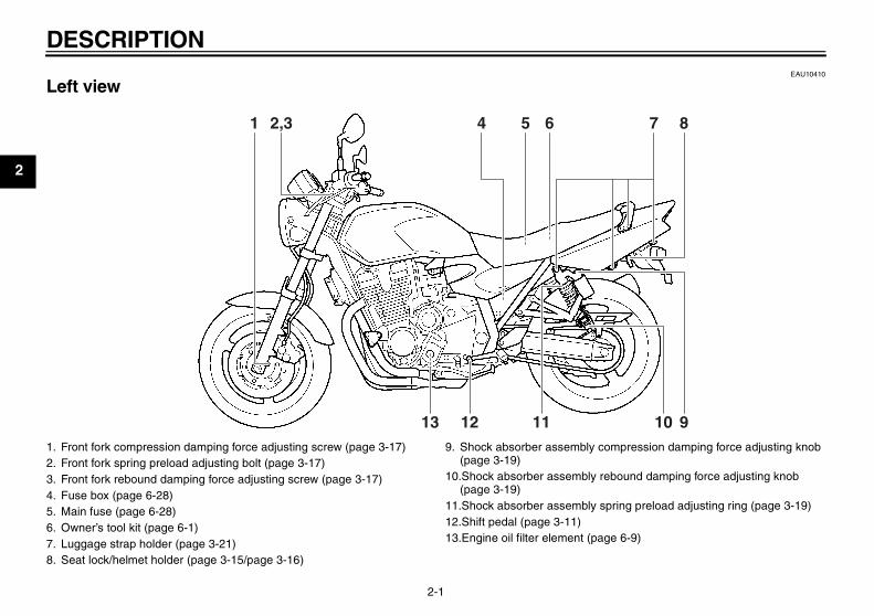
Left view
1 2,3 4 5 6 7 8
13 12 11 10 91. Front fork compression damping force adjusting screw (page 3-17)2. Front fork spring preload adjusting bolt (page 3-17)3. Front fork rebound damping force adjusting screw (page 3-17)4. Fuse box (page 6-28)5. Main fuse (page 6-28)6. Owner’s tool kit (page 6-1)7. Luggage strap holder (page 3-21)8. Seat lock/helmet holder (page 3-15/page 3-16)
9. Shock absorber assembly compression damping force adjusting knob (page 3-19)
10.Shock absorber assembly rebound damping force adjusting knob (page 3-19)
11.Shock absorber assembly spring preload adjusting ring (page 3-19)12.Shift pedal (page 3-11)13.Engine oil filter element (page 6-9)
U5WME7E0.book Page 1 Monday, November 16, 2009 9:09 AM

DESCRIPTION
2-2
2
EAU10420
Right view
1. Luggage strap holder (page 3-21)2. Storage compartment (page 3-16)3. Battery (page 6-27)4. Air filter element (page 6-12)5. Engine oil filler cap (page 6-9)6. Engine oil level check window (page 6-9)7. Engine oil drain bolt (page 6-9)8. Brake pedal (page 3-12)
9. Rear brake light switch (page 6-18)10.Rear brake fluid reservoir (page 6-19)
U5WME7E0.book Page 2 Monday, November 16, 2009 9:09 AM

DESCRIPTION
2-3
2
EAU10430
Controls and instruments
1. Clutch lever (page 3-10)2. Left handlebar switches (page 3-9)3. Clutch fluid reservoir (page 6-19)4. Speedometer (page 3-5)5. Multi-function display (page 3-6)6. Tachometer (page 3-5)7. Front brake fluid reservoir (page 6-19)8. Right handlebar switches (page 3-9)
9. Brake lever (page 3-11)10.Throttle grip (page 6-13)11.Main switch/steering lock (page 3-2)
U5WME7E0.book Page 3 Monday, November 16, 2009 9:09 AM

INSTRUMENT AND CONTROL FUNCTIONS
3-1
3
EAU10976
Immobilizer system
This vehicle is equipped with an immo-bilizer system to help prevent theft byre-registering codes in the standardkeys. This system consists of the fol-lowing:
� a code re-registering key (with ared bow)
� two standard keys (with a blackbow) that can be re-registered withnew codes
� a transponder (which is installed inthe code re-registering key)
� an immobilizer unit� an ECU
� an immobilizer system indicatorlight (See page 3-4.)
The key with the red bow is used to reg-ister codes in each standard key. Sincere-registering is a difficult process, takethe vehicle along with all three keys toa Yamaha dealer to have them re-reg-istered. Do not use the key with the redbow for driving. It should only be usedfor re-registering the standard keys. Al-ways use a standard key for driving.
NOTICEECA11821
� DO NOT LOSE THE CODE RE-REGISTERING KEY! CONTACTYOUR DEALER IMMEDIATELYIF IT IS LOST! If the code re-reg-istering key is lost, registeringnew codes in the standard keysis impossible. The standardkeys can still be used to startthe vehicle, however if code re-registering is required (i.e., if anew standard key is made or allkeys are lost) the entire immobi-lizer system must be replaced.Therefore, it is highly recom-
mended to use either standardkey and keep the code re-regis-tering key in a safe place.
� Do not submerse any key in wa-ter.
� Do not expose any key to exces-sively high temperatures.
� Do not place any key close tomagnets (this includes, but notlimited to, products such asspeakers, etc.).
� Do not place items that transmitelectrical signals close to anykey.
� Do not place heavy items on anykey.
� Do not grind any key or alter itsshape.
� Do not disassemble the plasticpart of any key.
� Do not put two keys of any im-mobilizer system on the samekey ring.
� Keep the standard keys as wellas keys of other immobilizersystems away from this vehi-cle’s code re-registering key.
1. Code re-registering key (red bow)2. Standard keys (black bow)
U5WME7E0.book Page 1 Monday, November 16, 2009 9:09 AM

INSTRUMENT AND CONTROL FUNCTIONS
3-2
3
� Keep other immobilizer systemkeys away from the main switchas they may cause signal inter-ference.
EAU10472
Main switch/steering lock
The main switch/steering lock controlsthe ignition and lighting systems, and isused to lock the steering. The variouspositions are described below.
TIPBe sure to use the standard key (blackbow) for regular use of the vehicle. Tominimize the risk of losing the code re-registering key (red bow), keep it in asafe place and only use it for code re-registering.
EAU43410
ONAll electrical circuits are supplied withpower; the meter lighting, taillights, li-cense plate light and auxiliary lightcome on, and the engine can be start-ed. The key cannot be removed.
TIPThe headlight comes on automaticallywhen the engine is started and stays onuntil the key is turned to “OFF”, even ifthe engine stalls.
EAU10661
OFFAll electrical systems are off. The keycan be removed.
WARNINGEWA10061
Never turn the key to “OFF” or“LOCK” while the vehicle is moving.Otherwise the electrical systems willbe switched off, which may result inloss of control or an accident.
U5WME7E0.book Page 2 Monday, November 16, 2009 9:09 AM

INSTRUMENT AND CONTROL FUNCTIONS
3-3
3
EAU10691
LOCKThe steering is locked, and all electricalsystems are off. The key can be re-moved.
To lock the steering
1. Turn the handlebars all the way tothe left or right.
2. Push the key in from the “OFF” po-sition, and then turn it to “LOCK”while still pushing it.
3. Remove the key.
To unlock the steering
Push the key into the main switch, andthen turn it to “OFF” while still pushingit.
EAU43460
(Parking)The steering is locked, and the tail-lights, license plate light and auxiliarylight are on. The hazard lights and turnsignal lights can be turned on, but allother electrical systems are off. Thekey can be removed.The steering must be locked before thekey can be turned to “ ”.
NOTICEECA11020
Do not use the parking position foran extended length of time, other-wise the battery may discharge.
1. Push.2. Turn.
1. Push.2. Turn.
U5WME7E0.book Page 3 Monday, November 16, 2009 9:09 AM

INSTRUMENT AND CONTROL FUNCTIONS
3-4
3
EAU11004
Indicator and warning lights
EAU11030
Turn signal indicator lights “ ” and “ ” The corresponding indicator light flash-es when the turn signal switch ispushed to the left or right.
EAU11060
Neutral indicator light “ ” This indicator light comes on when thetransmission is in the neutral position.
EAU11080
High beam indicator light “ ” This indicator light comes on when thehigh beam of the headlight is switchedon.
EAU11123
Oil level warning light “ ” This warning light comes on if the en-gine oil level is low.The electrical circuit of the warning lightcan be checked by turning the key to“ON”. The warning light should comeon for a few seconds, and then go off.If the warning light does not come oninitially when the key is turned to “ON”,or if the warning light remains on, havea Yamaha dealer check the electricalcircuit.
TIPEven if the oil level is sufficient, thewarning light may flicker when riding ona slope or during sudden accelerationor deceleration, but this is not a mal-function.
EAU11534
Engine trouble warning light “ ” This warning light comes on or flashesif a problem is detected in the electricalcircuit monitoring the engine. If this oc-curs, have a Yamaha dealer check theself-diagnosis system. (See page 3-7for an explanation of the self-diagnosisdevice.)The electrical circuit of the warning lightcan be checked by turning the key to“ON”. The warning light should comeon for a few seconds, and then go off.If the warning light does not come oninitially when the key is turned to “ON”,or if the warning light remains on, havea Yamaha dealer check the electricalcircuit.
EAU38623
Immobilizer system indicator light The electrical circuit of the indicatorlight can be checked by turning the keyto “ON”. The indicator light shouldcome on for a few seconds, and thengo off.
1. Left turn signal indicator light “ ”2. Engine trouble warning light “ ”3. Neutral indicator light “ ”4. Oil level warning light “ ”5. High beam indicator light “ ”6. Right turn signal indicator light “ ”7. Immobilizer system indicator light
U5WME7E0.book Page 4 Monday, November 16, 2009 9:09 AM

INSTRUMENT AND CONTROL FUNCTIONS
3-5
3
If the indicator light does not come oninitially when the key is turned to “ON”,or if the indicator light remains on, havea Yamaha dealer check the electricalcircuit.When the key is turned to “OFF” and 30seconds have passed, the indicatorlight will start flashing indicating the im-mobilizer system is enabled. After 24hours have passed, the indicator lightwill stop flashing, however the immobi-lizer system is still enabled.This model is also equipped with a self-diagnosis device for the immobilizersystem. (See page 3-7 for an explana-tion of the self-diagnosis device.)
EAU11601
Speedometer
The speedometer shows the ridingspeed.When the key is turned to “ON”, thespeedometer needle will sweep onceacross the speed range and then returnto zero in order to test the electrical cir-cuit.
EAU11872
Tachometer
The electric tachometer allows the riderto monitor the engine speed and keep itwithin the ideal power range.When the key is turned to “ON”, the ta-chometer needle will sweep onceacross the r/min range and then returnto zero r/min in order to test the electri-cal circuit.
NOTICEECA10031
Do not operate the engine in the ta-chometer red zone.Red zone: 9500 r/min and above
1. Speedometer 1. Tachometer2. Tachometer red zone
U5WME7E0.book Page 5 Monday, November 16, 2009 9:09 AM

INSTRUMENT AND CONTROL FUNCTIONS
3-6
3
EAU43248
Multi-function display
WARNINGEWA12312
Be sure to stop the vehicle beforemaking any setting changes to themulti-function display. Changingsettings while riding can distract theoperator and increase the risk of anaccident.
The multi-function display is equippedwith the following:
� an odometer
� two tripmeters (which show thedistance traveled since they werelast set to zero)
� a fuel reserve tripmeter (whichshows the distance traveled on thefuel reserve)
� a fuel meter� a clock� a self-diagnosis device� a display, speedometer, and ta-
chometer brightness control mode
TIPBe sure to turn the key to “ON” beforeusing the select and reset buttons, ex-cept for setting the display, speedome-ter and tachometer brightness controlmode.
Odometer and tripmeter modes
Pushing the select button switches thedisplay between the odometer mode“ODO” and the tripmeter modes “TRIP1” and “TRIP 2” in the following order:ODO → TRIP 1 → TRIP 2 → ODOWhen approximately 4.5 L (1.19 USgal, 0.99 Imp.gal) of fuel remains in thefuel tank, the display will automaticallychange to the fuel reserve tripmetermode “TRIP F” and start counting thedistance traveled from that point. In thatcase, pushing the select button switch-es the display between the various trip-meter and odometer modes in thefollowing order:TRIP F → ODO → TRIP 1 → TRIP 2 →TRIP F
1. Clock2. Fuel meter3. Odometer/tripmeter/fuel reserve tripmeter4. Reset button5. Select button
1. Odometer/tripmeter/fuel reserve tripmeter
U5WME7E0.book Page 6 Monday, November 16, 2009 9:09 AM

INSTRUMENT AND CONTROL FUNCTIONS
3-7
3
To reset a tripmeter, select it by push-ing the select button, and then push thereset button for at least two seconds. Ifyou do not reset the fuel reserve trip-meter manually, it will reset itself auto-matically and the display will return tothe prior mode after refueling and trav-eling 5 km (3 mi).
Fuel meter
The fuel meter indicates the amount offuel in the fuel tank. The display seg-ments of the fuel meter disappear to-wards “E” (Empty) as the fuel leveldecreases. When the fuel level warningindicator “ ” starts flashing, refuel assoon as possible.
TIPThis fuel meter is equipped with a self-diagnosis system. If a problem is de-tected in the electrical circuit, the follow-ing cycle will be repeated until themalfunction is corrected: All the displaysegments and symbol “ ” will flasheight times, then go off for approxi-mately 3 seconds. If this occurs, have aYamaha dealer check the electrical cir-cuit.
Clock mode
To set the clock:1. Turn the key to “ON”.
2. Push the select button and resetbutton together for at least twoseconds.
3. When the hour digits start flashing,push the reset button to set thehours.
4. Push the select button, and theminute digits will start flashing.
5. Push the reset button to set theminutes.
6. Push the select button and then re-lease it to start the clock.
Self-diagnosis device
This model is equipped with a self-diag-nosis device for various electrical cir-cuits.
1. Fuel level warning indicator “ ”2. Fuel meter
1. Clock2. Select button3. Reset button
1
32
1. Error code display
U5WME7E0.book Page 7 Monday, November 16, 2009 9:09 AM

INSTRUMENT AND CONTROL FUNCTIONS
3-8
3
If a problem is detected in any of thosecircuits, the engine trouble warning lightwill come on and the odometer/tripme-ter display will indicate an error code.The self-diagnosis device also detectsproblems in the immobilizer system cir-cuits.If a problem is detected in the immobi-lizer system circuits, the immobilizersystem indicator light will flash and thedisplay will indicate an error code.
TIPIf the display indicates error code 52,this could be caused by transponder in-terference. If this error code appears,try the following.
1. Use the code re-registering key tostart the engine.
TIPMake sure there are no other immobi-lizer keys close to the main switch, anddo not keep more than one immobilizerkey on the same key ring! Immobilizersystem keys may cause signal interfer-ence, which may prevent the enginefrom starting.
2. If the engine starts, turn it off andtry starting the engine with thestandard keys.
3. If one or both of the standard keysdo not start the engine, take thevehicle, the code re-registeringkey and both standard keys to aYamaha dealer and have the stan-dard keys re-registered.
If the display indicates any error codes,note the code number, and then have aYamaha dealer check the vehicle.
NOTICEECA11790
If the multi-function display indi-cates an error code, the vehicleshould be checked as soon as pos-sible in order to avoid engine dam-age.
Display, speedometer and tachome-ter brightness control mode
This function allows you to adjust thebrightness to suit the outside lightingconditions.
To adjust the brightness1. Turn the key to “OFF”.2. Push and hold the select button.3. Turn the key to “ON”, and then re-
lease the select button after fiveseconds.
4. Push the reset button to select thedesired brightness level.
5. Push the select button to confirmthe selected brightness level.
1. Brightness level2. Select button3. Reset button
1
32
U5WME7E0.book Page 8 Monday, November 16, 2009 9:09 AM

INSTRUMENT AND CONTROL FUNCTIONS
3-9
3
EAU12331
Anti-theft alarm (optional) This model can be equipped with anoptional anti-theft alarm by a Yamahadealer. Contact a Yamaha dealer formore information.
EAU12348
Handlebar switches
Left
Right
EAU12360
Pass switch “PASS” Press this switch to flash the headlight.
EAU12400
Dimmer switch “ / ” Set this switch to “ ” for the highbeam and to “ ” for the low beam.
EAU12460
Turn signal switch “ / ” To signal a right-hand turn, push thisswitch to “ ”. To signal a left-handturn, push this switch to “ ”. When re-leased, the switch returns to the center
1. Pass switch “PASS”2. Dimmer switch “ / ”3. Turn signal switch “ / ”4. Horn switch “ ”5. Hazard switch “ ”
1. Engine stop switch “ / ”2. Start switch “ ”
U5WME7E0.book Page 9 Monday, November 16, 2009 9:09 AM

INSTRUMENT AND CONTROL FUNCTIONS
3-10
3
position. To cancel the turn signallights, push the switch in after it has re-turned to the center position.
EAU12500
Horn switch “ ” Press this switch to sound the horn.
EAU12660
Engine stop switch “ / ” Set this switch to “ ” before startingthe engine. Set this switch to “ ” tostop the engine in case of an emergen-cy, such as when the vehicle overturnsor when the throttle cable is stuck.
EAU12711
Start switch “ ” Push this switch to crank the enginewith the starter. See page 5-1 for start-ing instructions prior to starting the en-gine.
EAU41700
The engine trouble warning light willcome on when the key is turned to “ON”and the start switch is pushed, but thisdoes not indicate a malfunction.
EAU12733
Hazard switch “ ” With the key in the “ON” or “ ” posi-tion, use this switch to turn on the haz-ard lights (simultaneous flashing of allturn signal lights).The hazard lights are used in case ofan emergency or to warn other driverswhen your vehicle is stopped where itmight be a traffic hazard.
NOTICEECA10061
Do not use the hazard lights for anextended length of time with the en-gine not running, otherwise the bat-tery may discharge.
EAU12830
Clutch lever
The clutch lever is located at the lefthandlebar grip. To disengage theclutch, pull the lever toward the handle-bar grip. To engage the clutch, releasethe lever. The lever should be pulledrapidly and released slowly for smoothclutch operation.
1. Clutch lever
U5WME7E0.book Page 10 Monday, November 16, 2009 9:09 AM

INSTRUMENT AND CONTROL FUNCTIONS
3-11
3
The clutch lever is equipped with aclutch lever position adjusting dial. Toadjust the distance between the clutchlever and the handlebar grip, turn theadjusting dial while holding the leverpushed away from the handlebar grip.Make sure that the appropriate settingon the adjusting dial is aligned with thearrow mark on the clutch lever.The clutch lever is equipped with aclutch switch, which is part of the igni-tion circuit cut-off system. (See page3-23.)
EAU12870
Shift pedal
The shift pedal is located on the leftside of the engine and is used in com-bination with the clutch lever whenshifting the gears of the 5-speed con-stant-mesh transmission equipped onthis motorcycle.
EAU26823
Brake lever
The brake lever is located at the righthandlebar grip. To apply the frontbrake, pull the lever toward the handle-bar grip.
1. Clutch lever position adjusting dial2. Arrow mark
1. Shift pedal 1. Brake lever
1. “ ” mark2. Brake lever position adjusting dial
U5WME7E0.book Page 11 Monday, November 16, 2009 9:09 AM

INSTRUMENT AND CONTROL FUNCTIONS
3-12
3
The brake lever is equipped with abrake lever position adjusting dial. Toadjust the distance between the brakelever and the handlebar grip, turn theadjusting dial while holding the leverpushed away from the handlebar grip.Make sure that the appropriate settingon the adjusting dial is aligned withthe “ ” mark on the brake lever.
EAU12941
Brake pedal
The brake pedal is on the right side ofthe motorcycle. To apply the rearbrake, press down on the brake pedal.
EAU13074
Fuel tank cap
To open the fuel tank capOpen the fuel tank cap lock cover, in-sert the key into the lock, and then turnit 1/4 turn clockwise. The lock will be re-leased and the fuel tank cap can beopened.
To close the fuel tank cap1. Push the fuel tank cap into position
with the key inserted in the lock.2. Turn the key counterclockwise to
the original position, remove it, andthen close the lock cover.
1. Brake pedal 1. Fuel tank cap lock cover2. Unlock.
U5WME7E0.book Page 12 Monday, November 16, 2009 9:09 AM
INSTRUMENT AND CONTROL FUNCTIONS
3-13
3
TIPThe fuel tank cap cannot be closed un-less the key is in the lock. In addition,the key cannot be removed if the cap isnot properly closed and locked.
WARNINGEWA11091
Make sure that the fuel tank cap isproperly closed after filling fuel.Leaking fuel is a fire hazard.
EAU13221
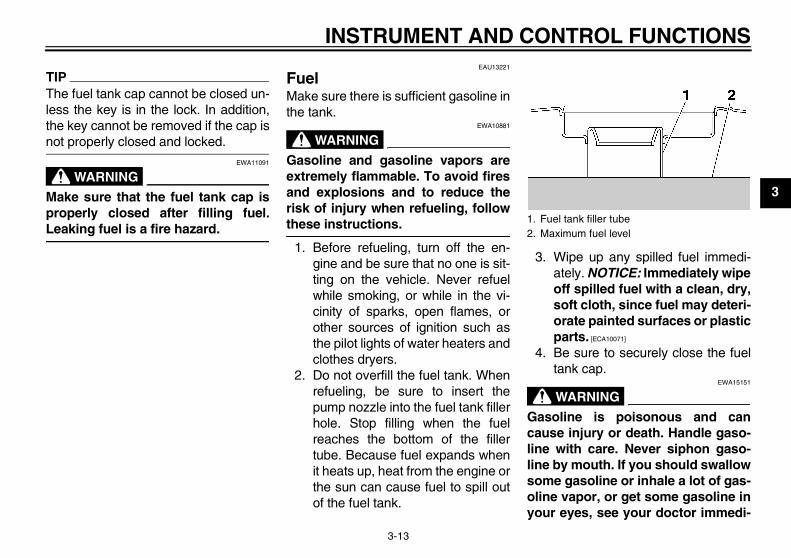
Fuel Make sure there is sufficient gasoline inthe tank.
WARNINGEWA10881
Gasoline and gasoline vapors areextremely flammable. To avoid firesand explosions and to reduce therisk of injury when refueling, followthese instructions.
1. Before refueling, turn off the en-gine and be sure that no one is sit-ting on the vehicle. Never refuelwhile smoking, or while in the vi-cinity of sparks, open flames, orother sources of ignition such asthe pilot lights of water heaters andclothes dryers.
2. Do not overfill the fuel tank. Whenrefueling, be sure to insert thepump nozzle into the fuel tank fillerhole. Stop filling when the fuelreaches the bottom of the fillertube. Because fuel expands whenit heats up, heat from the engine orthe sun can cause fuel to spill outof the fuel tank.
3. Wipe up any spilled fuel immedi-ately. NOTICE: Immediately wipeoff spilled fuel with a clean, dry,soft cloth, since fuel may deteri-orate painted surfaces or plasticparts. [ECA10071]
4. Be sure to securely close the fueltank cap.
WARNINGEWA15151
Gasoline is poisonous and cancause injury or death. Handle gaso-line with care. Never siphon gaso-line by mouth. If you should swallowsome gasoline or inhale a lot of gas-oline vapor, or get some gasoline inyour eyes, see your doctor immedi-
1. Fuel tank filler tube2. Maximum fuel level
U5WME7E0.book Page 13 Monday, November 16, 2009 9:09 AM

INSTRUMENT AND CONTROL FUNCTIONS
3-14
3
ately. If gasoline spills on your skin,wash with soap and water. If gaso-line spills on your clothing, changeyour clothes.
EAU43421
NOTICEECA11400
Use only unleaded gasoline. The useof leaded gasoline will cause severedamage to internal engine parts,such as the valves and piston rings,as well as to the exhaust system.
Your Yamaha engine has been de-signed to use premium unleaded gaso-line with a research octane number of95 or higher. If knocking (or pinging) oc-curs, use a gasoline of a different
brand. Use of unleaded fuel will extendspark plug life and reduce maintenancecosts.
EAU13412
Fuel tank breather hose
Before operating the motorcycle:� Check the fuel tank breather hose
connection.� Check the fuel tank breather hose
for cracks or damage, and replaceit if damaged.
� Make sure that the fuel tankbreather hose is not blocked, andclean it if necessary.
Recommended fuel:PREMIUM UNLEADED GASOLINE ONLY
Fuel tank capacity:21.0 L (5.55 US gal, 4.62 Imp.gal)
Fuel reserve amount (when the fuel level warning indicator flashes):
4.5 L (1.19 US gal, 0.99 Imp.gal)
1. Fuel tank breather hose
U5WME7E0.book Page 14 Monday, November 16, 2009 9:09 AM

INSTRUMENT AND CONTROL FUNCTIONS
3-15
3
EAU13445
Catalytic converters This vehicle is equipped with catalyticconverters in the exhaust system.
WARNINGEWA10862
The exhaust system is hot after op-eration. To prevent a fire hazard orburns:
� Do not park the vehicle nearpossible fire hazards such asgrass or other materials thateasily burn.
� Park the vehicle in a placewhere pedestrians or childrenare not likely to touch the hotexhaust system.
� Make sure that the exhaust sys-tem has cooled down before do-ing any maintenance work.
� Do not allow the engine to idlemore than a few minutes. Longidling can cause a build-up ofheat.
NOTICEECA10701
Use only unleaded gasoline. The useof leaded gasoline will cause unre-pairable damage to the catalyticconverter.
EAU13900
Seat
To remove the seat1. Insert the key into the seat lock,
and then turn it as shown.
2. Pull the seat off.
To install the seat1. Insert the projection on the front of
the seat into the seat holder asshown.
1. Seat lock2. Unlock.
U5WME7E0.book Page 15 Monday, November 16, 2009 9:09 AM

INSTRUMENT AND CONTROL FUNCTIONS
3-16
3
2. Push the rear of the seat down tolock it in place.
3. Remove the key.
TIPMake sure that the seat is properly se-cured before riding.
EAU14351
Helmet holder
To open the helmet holder, insert thekey into the seat lock, and then turn thekey as shown.To lock the helmet holder, turn the keyto the original position, and then re-move it. WARNING! Never ride with ahelmet attached to the helmet hold-er, since the helmet may hit objects,causing loss of control and possiblyan accident. [EWA10161]
EAU14452
Storage compartment
The storage compartment is locatedunder the seat. (See page 3-15.)
WARNINGEWA10961
� Do not exceed the load limit of 3kg (7 lb) for the storage com-partment.
� Do not exceed the maximumload of 205 kg (452 lb) for the ve-hicle.
When storing the Owner’s Manual orother documents in the storage com-partment, be sure to wrap them in aplastic bag so that they will not get wet.
1. Projection2. Seat holder
1. Helmet holder2. Unlock.
1. Storage compartment
U5WME7E0.book Page 16 Monday, November 16, 2009 9:09 AM

INSTRUMENT AND CONTROL FUNCTIONS
3-17
3
When washing the vehicle, be carefulnot to let any water enter the storagecompartment.
EAU14742
Adjusting the front fork
WARNINGEWA10180
Always adjust both fork legs equal-ly, otherwise poor handling and lossof stability may result.
This front fork is equipped with springpreload adjusting bolts, rebound damp-ing force adjusting screws and com-pression damping force adjustingscrews.
NOTICEECA10101
To avoid damaging the mechanism,do not attempt to turn beyond themaximum or minimum settings.
Spring preload
To increase the spring preload andthereby harden the suspension, turnthe adjusting bolt on each fork leg in di-rection (a). To decrease the spring pre-load and thereby soften thesuspension, turn the adjusting bolt oneach fork leg in direction (b).Align the appropriate groove on the ad-justing mechanism with the top of thefront fork cap bolt.
1. Spring preload adjusting bolt
1
(a)
(b)
U5WME7E0.book Page 17 Monday, November 16, 2009 9:09 AM

INSTRUMENT AND CONTROL FUNCTIONS
3-18
3
Rebound damping force
To increase the rebound damping forceand thereby harden the rebound damp-ing, turn the adjusting screw on eachfork leg in direction (a). To decrease therebound damping force and therebysoften the rebound damping, turn theadjusting screw on each fork leg in di-rection (b).
Compression damping force
To increase the compression dampingforce and thereby harden the compres-sion damping, turn the adjusting screwon each fork leg in direction (a). To de-crease the compression damping forceand thereby soften the compressiondamping, turn the adjusting screw oneach fork leg in direction (b).
1. Current setting2. Front fork cap bolt
Spring preload setting:Minimum (soft):
8Standard:
5Maximum (hard):
1
31 2
45
21
1. Rebound damping force adjusting screw
Rebound damping setting:Minimum (soft):
10 click(s) in direction (b)*Standard:
5 click(s) in direction (b)*Maximum (hard):
1 click(s) in direction (b)** With the adjusting screw fully turned
in direction (a)
1(a)
(b)
1. Compression damping force adjusting screw
Compression damping setting:Minimum (soft):
13 click(s) in direction (b)*Standard:
6 click(s) in direction (b)*Maximum (hard):
1 click(s) in direction (b)** With the adjusting screw fully turned
in direction (a)
U5WME7E0.book Page 18 Monday, November 16, 2009 9:09 AM

INSTRUMENT AND CONTROL FUNCTIONS
3-19
3
TIPAlthough the total number of clicks of adamping force adjusting mechanismmay not exactly match the above spec-ifications due to small differences inproduction, the actual number of clicksalways represents the entire adjustingrange. To obtain a precise adjustment,it would be advisable to check the num-ber of clicks of each damping force ad-justing mechanism and to modify thespecifications as necessary.
EAU43255
Adjusting the shock absorber assembly
WARNINGEWA10210
Always adjust both shock absorberassemblies equally, otherwise poorhandling and loss of stability mayresult.
Each shock absorber assembly isequipped with a spring preload adjust-ing ring and rebound and compressiondamping force adjusting knobs.
Spring preloadAdjust the spring preload as follows.
1. Loosen the lock screw 1/2 turncounterclockwise.
2. To increase the spring preload andthereby harden the suspension,turn the adjusting ring in direction(a). To decrease the spring pre-load and thereby soften the sus-pension, turn the adjusting ring indirection (b).
� Use the special wrench in-cluded in the owner’s tool kitto make this adjustment.
� The spring preload setting isdetermined by measuring dis-tance A, shown in the illustra-tion. The longer distance A is,the higher the spring preload;the shorter distance A is, thelower the spring preload. Witheach complete turn of the ad-justing ring, distance A chang-es by 1.5 mm (0.06 in).
� Be sure to turn the adjustingring so that the lock screw isfacing outward.
1. Lock screw
U5WME7E0.book Page 19 Monday, November 16, 2009 9:09 AM

INSTRUMENT AND CONTROL FUNCTIONS
3-20
3 3. Tighten the lock screw to the spec-ified torque.
Rebound damping force
To increase the rebound damping forceand thereby harden the rebound damp-ing, turn the adjusting knob in direction
(a). To decrease the rebound dampingforce and thereby soften the rebounddamping, turn the adjusting knob in di-rection (b).
Compression damping force
To increase the compression dampingforce and thereby harden the compres-sion damping, turn the adjusting knob
1. Special wrench2. Spring preload adjusting ring
1. Distance A
Spring preload setting:Minimum (soft):
Distance A = 0 mm (0 in)Standard:
Distance A = 17 mm (0.67 in)Maximum (hard):
Distance A = 28 mm (1.10 in)
Tightening torque:Lock screw:
0.1 Nm (0.01 m·kgf, 0.07 ft·lbf)
1. Rebound damping force adjusting knob
Rebound damping setting:Minimum (soft):
36 click(s) in direction (b)*Standard:
10 click(s) in direction (b)*Maximum (hard):
1 click(s) in direction (b)** With the adjusting knob fully turned
in direction (a)
1. Compression damping force adjusting knob
U5WME7E0.book Page 20 Monday, November 16, 2009 9:09 AM

INSTRUMENT AND CONTROL FUNCTIONS
3-21
3
in direction (a). To decrease the com-pression damping force and therebysoften the compression damping, turnthe adjusting knob in direction (b).
NOTICEECA10101
To avoid damaging the mechanism,do not attempt to turn beyond themaximum or minimum settings.
TIPTo obtain a precise adjustment, it is ad-visable to check the actual total numberof clicks or turns of each damping forceadjusting mechanism. This adjustmentrange may not exactly match the spec-ifications listed due to small differencesin production.
WARNINGEWA10231
These shock absorber assembliescontain highly pressurized nitrogengas. Read and understand the fol-lowing information before handlingthe shock absorber assemblies.
� Do not tamper with or attempt toopen the cylinder assemblies.
� Do not subject the shock ab-sorber assemblies to an openflame or other high heat source.This may cause the unit to ex-plode due to excessive gaspressure.
� Do not deform or damage thecylinders in any way. Cylinderdamage will result in poordamping performance.
� Do not dispose of a damaged orworn-out shock absorber as-sembly yourself. Take the shockabsorber assembly to a Yamahadealer for any service.
EAU43441
Luggage strap holders
There are three fixed luggage strapholders and one retractable luggagestrap holder on each side of the vehicle.The retractable luggage strap holdercan be turned out for easier access.
Compression damping setting:Minimum (soft):
20 click(s) in direction (b)*Standard:
16 click(s) in direction (b)*Maximum (hard):
1 click(s) in direction (b)** With the adjusting knob fully turned
in direction (a) 1. Luggage strap holder2. Retractable luggage strap holder
1 2
U5WME7E0.book Page 21 Monday, November 16, 2009 9:09 AM

INSTRUMENT AND CONTROL FUNCTIONS
3-22
3
EAU15282
EXUP system This model is equipped with Yamaha’sEXUP (EXhaust Ultimate Power valve)system. This system boosts enginepower by means of a valve that regu-lates the inner diameter of the exhaustpipe. The EXUP system valve is con-stantly adjusted in accordance with theengine speed by a computer-controlledservomotor.
NOTICEECA10191
� The EXUP system has been setand extensively tested at theYamaha factory. Changingthese settings without sufficienttechnical knowledge may resultin poor performance of or dam-age to the engine.
� If the EXUP system cannot beheard when the main switch isturned on, have a Yamaha deal-er check it.
EAU15303
Sidestand The sidestand is located on the left sideof the frame. Raise the sidestand orlower it with your foot while holding thevehicle upright.
TIPThe built-in sidestand switch is part ofthe ignition circuit cut-off system, whichcuts the ignition in certain situations.(See page 3-23 for an explanation ofthe ignition circuit cut-off system.)
WARNINGEWA10240
The vehicle must not be ridden withthe sidestand down, or if the side-stand cannot be properly moved up(or does not stay up), otherwise thesidestand could contact the groundand distract the operator, resultingin a possible loss of control.Yamaha’s ignition circuit cut-offsystem has been designed to assistthe operator in fulfilling the respon-sibility of raising the sidestand be-fore starting off. Therefore, checkthis system regularly as described
below and have a Yamaha dealer re-pair it if it does not function proper-ly.
U5WME7E0.book Page 22 Monday, November 16, 2009 9:09 AM

INSTRUMENT AND CONTROL FUNCTIONS
3-23
3
EAU44902
Ignition circuit cut-off system The ignition circuit cut-off system (com-prising the sidestand switch, clutchswitch and neutral switch) has the fol-lowing functions.
� It prevents starting when the trans-mission is in gear and the side-stand is up, but the clutch lever isnot pulled.
� It prevents starting when the trans-mission is in gear and the clutch le-ver is pulled, but the sidestand isstill down.
� It cuts the running engine when thetransmission is in gear and the sid-estand is moved down.
Periodically check the operation of theignition circuit cut-off system accordingto the following procedure.
U5WME7E0.book Page 23 Monday, November 16, 2009 9:09 AM
INSTRUMENT AND CONTROL FUNCTIONS
3-24
3
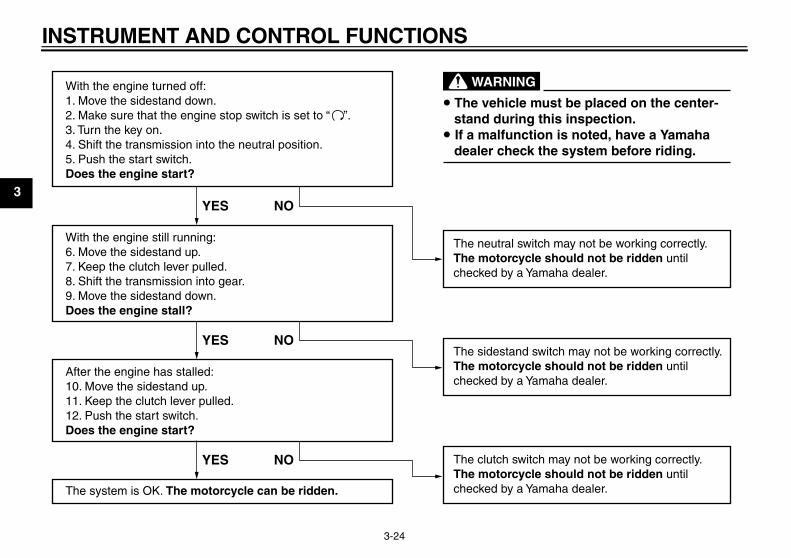
With the engine turned off:1. Move the sidestand down.2. Make sure that the engine stop switch is set to “3. Turn the key on. 4. Shift the transmission into the neutral position.5. Push the start switch.Does the engine start?
With the engine still running:6. Move the sidestand up.7. Keep the clutch lever pulled.8. Shift the transmission into gear.9. Move the sidestand down.Does the engine stall?
After the engine has stalled:10. Move the sidestand up.11. Keep the clutch lever pulled.12. Push the start switch.Does the engine start?
The system is OK. The motorcycle can be ridden.
YES NO
YES NO
YES NO
The neutral switch may not be working correctly.The motorcycle should not be ridden untilchecked by a Yamaha dealer.
The clutch switch may not be working correctly.The motorcycle should not be ridden untilchecked by a Yamaha dealer.
The sidestand switch may not be working correctly.The motorcycle should not be ridden untilchecked by a Yamaha dealer.
• The vehicle must be placed on the center- stand during this inspection.• If a malfunction is noted, have a Yamaha dealer check the system before riding.
WARNING
”.
U5WME7E0.book Page 24 Monday, November 16, 2009 9:09 AM

FOR YOUR SAFETY – PRE-OPERATION CHECKS
4-1
4
EAU15596
Inspect your vehicle each time you use it to make sure the vehicle is in safe operating condition. Always follow the inspectionand maintenance procedures and schedules described in the Owner’s Manual.
WARNINGEWA11151
Failure to inspect or maintain the vehicle properly increases the possibility of an accident or equipment damage.Do not operate the vehicle if you find any problem. If a problem cannot be corrected by the procedures provided inthis manual, have the vehicle inspected by a Yamaha dealer.
Before using this vehicle, check the following points:
ITEM CHECKS PAGE
Fuel
• Check fuel level in fuel tank.• Refuel if necessary.• Check fuel line for leakage.• Check the fuel tank breather/overflow hose for obstructions, cracks or damage,
and check the hose connection.
3-13, 3-14
Engine oil• Check oil level in engine.• If necessary, add recommended oil to specified level.• Check vehicle for oil leakage.
6-9
Front brake
• Check operation.• If soft or spongy, have Yamaha dealer bleed hydraulic system.• Check brake pads for wear.• Replace if necessary.• Check fluid level in reservoir.• If necessary, add recommended brake fluid to specified level.• Check hydraulic system for leakage.
6-18, 6-19
U5WME7E0.book Page 1 Monday, November 16, 2009 9:09 AM

FOR YOUR SAFETY – PRE-OPERATION CHECKS
4-2
4
Rear brake
• Check operation.• If soft or spongy, have Yamaha dealer bleed hydraulic system.• Check brake pads for wear.• Replace if necessary.• Check fluid level in reservoir.• If necessary, add recommended brake fluid to specified level.• Check hydraulic system for leakage.
6-18, 6-19
Clutch
• Check operation.• If soft or spongy, have Yamaha dealer bleed hydraulic system.• Check fluid level in reservoir.• If necessary, add recommended fluid to specified level.• Check hydraulic system for leakage.
6-17, 6-19
Throttle grip
• Make sure that operation is smooth.• Check cable free play.• If necessary, have Yamaha dealer adjust cable free play and lubricate cable and
grip housing.
6-13, 6-23
Control cables • Make sure that operation is smooth.• Lubricate if necessary. 6-22
Drive chain
• Check chain slack.• Adjust if necessary.• Check chain condition.• Lubricate if necessary.
6-21, 6-22
Wheels and tires
• Check for damage.• Check tire condition and tread depth.• Check air pressure.• Correct if necessary.
6-14, 6-16
Brake and shift pedals • Make sure that operation is smooth.• Lubricate pedal pivoting points if necessary. 6-23
Brake and clutch levers • Make sure that operation is smooth.• Lubricate lever pivoting points if necessary. 6-24
Centerstand, sidestand • Make sure that operation is smooth.• Lubricate pivots if necessary. 6-24
ITEM CHECKS PAGE
U5WME7E0.book Page 2 Monday, November 16, 2009 9:09 AM

FOR YOUR SAFETY – PRE-OPERATION CHECKS
4-3
4
Chassis fasteners • Make sure that all nuts, bolts and screws are properly tightened.• Tighten if necessary. —
Instruments, lights, signals and switches
• Check operation.• Correct if necessary. —
Sidestand switch • Check operation of ignition circuit cut-off system.• If system is not working correctly, have Yamaha dealer check vehicle. 3-22
ITEM CHECKS PAGE
U5WME7E0.book Page 3 Monday, November 16, 2009 9:09 AM

OPERATION AND IMPORTANT RIDING POINTS
5-1
5
EAU15951
Read the Owner’s Manual carefully tobecome familiar with all controls. Ifthere is a control or function you do notunderstand, ask your Yamaha dealer.
WARNINGEWA10271
Failure to familiarize yourself withthe controls can lead to loss of con-trol, which could cause an accidentor injury.
EAU46632
TIPThis model is equipped with:
� a lean angle sensor to stop the en-gine in case of a turnover. In thiscase, the multi-function display in-dicates error code 30, but this isnot a malfunction. Turn the key to“OFF” and then to “ON” to clear theerror code. Failing to do so will pre-vent the engine from starting eventhough the engine will crank whenpushing the start switch.
� an engine auto-stop system. Theengine stops automatically if leftidling for 20 minutes. In this case,the multi-function display indicateserror code 70, but this is not a mal-function. Push the start switch toclear the error code and to restartthe engine.
EAU32955
Starting the engine In order for the ignition circuit cut-offsystem to enable starting, one of thefollowing conditions must be met:
� The transmission is in the neutralposition.
� The transmission is in gear withthe clutch lever pulled and the sid-estand up.See page 3-23 for more informa-tion.
1. Turn the key to “ON” and makesure that the engine stop switch isset to “ ”.The following warning lights andindicator light should come on for afew seconds, then go off.
� Oil level warning light� Engine trouble warning light� Immobilizer system indicator
light
NOTICEECA11833
If a warning or indicator light doesnot come on initially when the key isturned to “ON”, or if a warning or in-
U5WME7E0.book Page 1 Monday, November 16, 2009 9:09 AM

OPERATION AND IMPORTANT RIDING POINTS
5-2
5
dicator light remains on, see page3-4 for the corresponding warningand indicator light circuit check.
2. Shift the transmission into the neu-tral position. (See page 5-2.) Theneutral indicator light should comeon. If not, ask a Yamaha dealer tocheck the electrical circuit.
TIPWhen the transmission is in the neutralposition, the neutral indicator lightshould be on, otherwise have aYamaha dealer check the electrical cir-cuit.
3. Start the engine by pushing thestart switch. NOTICE: For maxi-mum engine life, never acceler-ate hard when the engine iscold! [ECA11041]
If the engine fails to start, releasethe start switch, wait a few sec-onds, and then try again. Eachstarting attempt should be as shortas possible to preserve the bat-tery. Do not crank the engine morethan 10 seconds on any one at-tempt.
EAU16671
Shifting
Shifting gears lets you control theamount of engine power available forstarting off, accelerating, climbing hills,etc.The gear positions are shown in the il-lustration.
TIPTo shift the transmission into the neu-tral position, press the shift pedal downrepeatedly until it reaches the end of itstravel, and then slightly raise it.
NOTICEECA10260
� Even with the transmission inthe neutral position, do notcoast for long periods of timewith the engine off, and do nottow the motorcycle for long dis-tances. The transmission isproperly lubricated only whenthe engine is running. Inade-quate lubrication may damagethe transmission.
� Always use the clutch whilechanging gears to avoid damag-ing the engine, transmission,and drive train, which are notdesigned to withstand theshock of forced shifting.
1. Shift pedal2. Neutral position
U5WME7E0.book Page 2 Monday, November 16, 2009 9:09 AM

OPERATION AND IMPORTANT RIDING POINTS
5-3
5
EAU16810
Tips for reducing fuel con-sumption Fuel consumption depends largely onyour riding style. Consider the followingtips to reduce fuel consumption:
� Shift up swiftly, and avoid high en-gine speeds during acceleration.
� Do not rev the engine while shiftingdown, and avoid high enginespeeds with no load on the engine.
� Turn the engine off instead of let-ting it idle for an extended length oftime (e.g., in traffic jams, at trafficlights or at railroad crossings).
EAU16841
Engine break-in There is never a more important periodin the life of your engine than the periodbetween 0 and 1600 km (1000 mi). Forthis reason, you should read the follow-ing material carefully.Since the engine is brand new, do notput an excessive load on it for the first1600 km (1000 mi). The various parts inthe engine wear and polish themselvesto the correct operating clearances.During this period, prolonged full-throt-tle operation or any condition that mightresult in engine overheating must beavoided.
EAU17093
0–1000 km (0–600 mi)Avoid prolonged operation above 4800r/min. NOTICE: After 1000 km (600mi) of operation, the engine oil mustbe changed and the oil filter car-tridge or element replaced. [ECA10302]
1000–1600 km (600–1000 mi)Avoid prolonged operation above 5700r/min.
1600 km (1000 mi) and beyondThe vehicle can now be operated nor-mally.
NOTICEECA10310
� Keep the engine speed out ofthe tachometer red zone.
� If any engine trouble should oc-cur during the engine break-inperiod, immediately have aYamaha dealer check the vehi-cle.
U5WME7E0.book Page 3 Monday, November 16, 2009 9:09 AM

OPERATION AND IMPORTANT RIDING POINTS
5-4
5
EAU17213
Parking When parking, stop the engine, andthen remove the key from the mainswitch.
WARNINGEWA10311
� Since the engine and exhaustsystem can become very hot,park in a place where pedestri-ans or children are not likely totouch them and be burned.
� Do not park on a slope or on softground, otherwise the vehiclemay overturn, increasing therisk of a fuel leak and fire.
� Do not park near grass or otherflammable materials whichmight catch fire.
U5WME7E0.book Page 4 Monday, November 16, 2009 9:09 AM

PERIODIC MAINTENANCE AND ADJUSTMENT
6-1
6
EAU17241
Periodic inspection, adjustment, and lu-brication will keep your vehicle in thesafest and most efficient condition pos-sible. Safety is an obligation of the vehi-cle owner/operator. The most importantpoints of vehicle inspection, adjust-ment, and lubrication are explained onthe following pages.The intervals given in the periodicmaintenance and lubrication chartshould be simply considered as a gen-eral guide under normal riding condi-tions. However, depending on theweather, terrain, geographical location,and individual use, the maintenance in-tervals may need to be shortened.
WARNINGEWA10321
Failure to properly maintain the ve-hicle or performing maintenance ac-tivities incorrectly may increaseyour risk of injury or death duringservice or while using the vehicle. Ifyou are not familiar with vehicle ser-vice, have a Yamaha dealer performservice.
WARNINGEWA15121
Turn off the engine when performingmaintenance unless otherwisespecified.
� A running engine has movingparts that can catch on bodyparts or clothing and electricalparts that can cause shocks orfires.
� Running the engine while ser-vicing can lead to eye injury,burns, fire, or carbon monoxidepoisoning – possibly leading todeath. See page 1-1 for more in-formation about carbon monox-ide.
EAU17381
Owner’s tool kit
The owner’s tool kit is located under theseat. (See page 3-15.)The service information included in thismanual and the tools provided in theowner’s tool kit are intended to assistyou in the performance of preventivemaintenance and minor repairs. How-ever, additional tools such as a torquewrench may be necessary to performcertain maintenance work correctly.
TIPIf you do not have the tools or experi-ence required for a particular job, havea Yamaha dealer perform it for you.
1. Owner’s tool kit
U5WME7E0.book Page 1 Monday, November 16, 2009 9:09 AM

PERIODIC MAINTENANCE AND ADJUSTMENT
6-2
6
EAU46861
TIP� The annual checks must be performed every year, except if a kilometer-based maintenance, or for the UK, a
mileage-based maintenance, is performed instead.� From 50000 km (30000 mi), repeat the maintenance intervals starting from 10000 km (6000 mi).� Items marked with an asterisk should be performed by a Yamaha dealer as they require special tools, data and technical
skills.
EAU46910
Periodic maintenance chart for the emission control system
NO. ITEM CHECK OR MAINTENANCE JOB
ODOMETER READINGANNUAL CHECK1000 km
(600 mi)10000 km (6000 mi)
20000 km (12000 mi)
30000 km (18000 mi)
40000 km (24000 mi)
1 * Fuel line • Check fuel hoses for cracks or damage. √ √ √ √ √
2 Spark plugs• Check condition.• Clean and regap. √ √
• Replace. √ √
3 * Valves • Check valve clearance.• Adjust. Every 20000 km (12000 mi)
4 * Fuel injection sys-tem • Adjust synchronization. √ √ √ √ √
5 * Muffler and exhaust pipe
• Check the screw clamp(s) for looseness. √ √ √ √ √
6 * Air induction sys-tem
• Check the air cut-off valve, reed valve, and hose for damage.
• Replace any damaged parts if necessary.
√ √ √ √ √
U5WME7E0.book Page 2 Monday, November 16, 2009 9:09 AM

PERIODIC MAINTENANCE AND ADJUSTMENT
6-3
6
EAU1770C
General maintenance and lubrication chart
NO. ITEM CHECK OR MAINTENANCE JOB
ODOMETER READINGANNUAL CHECK1000 km
(600 mi)10000 km (6000 mi)
20000 km (12000 mi)
30000 km (18000 mi)
40000 km (24000 mi)
1 Air filter element • Replace. √
2 * Clutch • Check operation, fluid level and vehicle for fluid leakage. √ √ √ √ √
3 * Front brake• Check operation, fluid level and
vehicle for fluid leakage. √ √ √ √ √ √
• Replace brake pads. Whenever worn to the limit
4 * Rear brake• Check operation, fluid level and
vehicle for fluid leakage. √ √ √ √ √ √
• Replace brake pads. Whenever worn to the limit
5 * Brake hoses• Check for cracks or damage. √ √ √ √ √
• Replace. Every 4 years
6 * Wheels • Check runout and for damage. √ √ √ √
7 * Tires
• Check tread depth and for dam-age.
• Replace if necessary.• Check air pressure.• Correct if necessary.
√ √ √ √ √
8 * Wheel bearings • Check bearing for looseness or damage. √ √ √ √
9 * Swingarm
• Check operation and for exces-sive play. √ √ √ √
• Lubricate with lithium-soap-based grease. Every 50000 km (30000 mi)
U5WME7E0.book Page 3 Monday, November 16, 2009 9:09 AM

PERIODIC MAINTENANCE AND ADJUSTMENT
6-4
6
10 Drive chain
• Check chain slack, alignment and condition.
• Adjust and lubricate chain with a special O-ring chain lubricant thoroughly.
Every 1000 km (600 mi) and after washing the motorcycle, riding in the rain or riding in wet areas
11 * Steering bearings
• Check bearing play and steering for roughness. √ √ √ √ √
• Lubricate with lithium-soap-based grease. Every 20000 km (12000 mi)
12 * Chassis fasteners • Make sure that all nuts, bolts and screws are properly tightened. √ √ √ √ √
13 Brake lever pivot shaft • Lubricate with silicone grease. √ √ √ √ √
14 Brake pedal pivot shaft
• Lubricate with lithium-soap-based grease. √ √ √ √ √
15 Clutch lever pivot shaft • Lubricate with silicone grease. √ √ √ √ √
16 Shift pedal pivot shaft
• Lubricate with lithium-soap-based grease. √ √ √ √ √
17 Sidestand, center-stand
• Check operation.• Lubricate with lithium-soap-based
grease.√ √ √ √ √
18 * Sidestand switch • Check operation. √ √ √ √ √ √
19 * Front fork • Check operation and for oil leak-age. √ √ √ √
20 * Shock absorber as-semblies
• Check operation and shock ab-sorbers for oil leakage. √ √ √ √
NO. ITEM CHECK OR MAINTENANCE JOB
ODOMETER READINGANNUAL CHECK1000 km
(600 mi)10000 km (6000 mi)
20000 km (12000 mi)
30000 km (18000 mi)
40000 km (24000 mi)
U5WME7E0.book Page 4 Monday, November 16, 2009 9:09 AM
PERIODIC MAINTENANCE AND ADJUSTMENT
6-5
6
EAU36771
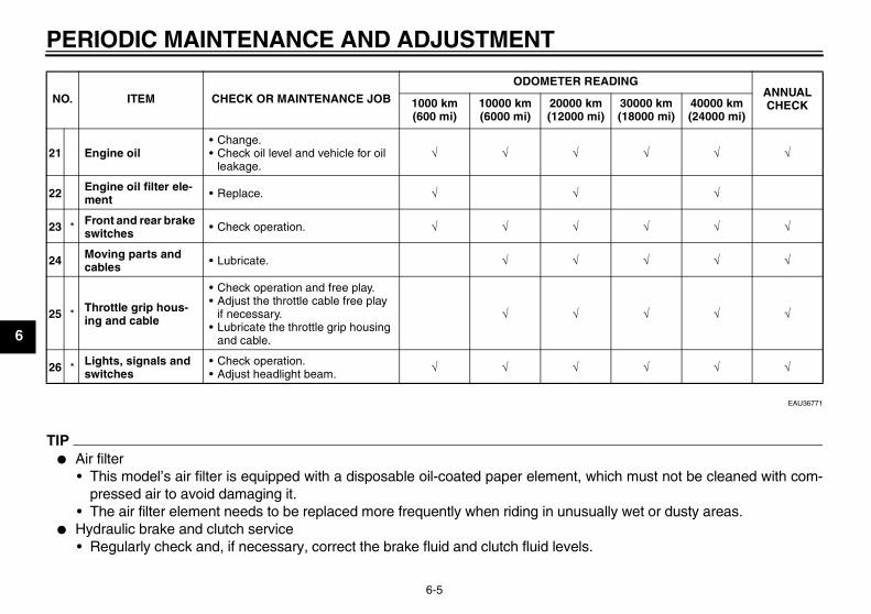
TIP� Air filter
• This model’s air filter is equipped with a disposable oil-coated paper element, which must not be cleaned with com-pressed air to avoid damaging it.
• The air filter element needs to be replaced more frequently when riding in unusually wet or dusty areas.� Hydraulic brake and clutch service
• Regularly check and, if necessary, correct the brake fluid and clutch fluid levels.
21 Engine oil• Change.• Check oil level and vehicle for oil
leakage.√ √ √ √ √ √
22 Engine oil filter ele-ment • Replace. √ √ √
23 * Front and rear brake switches • Check operation. √ √ √ √ √ √
24 Moving parts and cables • Lubricate. √ √ √ √ √
25 * Throttle grip hous-ing and cable
• Check operation and free play.• Adjust the throttle cable free play
if necessary.• Lubricate the throttle grip housing
and cable.
√ √ √ √ √
26 * Lights, signals and switches
• Check operation.• Adjust headlight beam. √ √ √ √ √ √
NO. ITEM CHECK OR MAINTENANCE JOB
ODOMETER READINGANNUAL CHECK1000 km
(600 mi)10000 km (6000 mi)
20000 km (12000 mi)
30000 km (18000 mi)
40000 km (24000 mi)
U5WME7E0.book Page 5 Monday, November 16, 2009 9:09 AM

PERIODIC MAINTENANCE AND ADJUSTMENT
6-6
6
• Every two years replace the internal components of the brake master cylinders and calipers as well as clutch masterand release cylinders, and change the brake and clutch fluids.
• Replace the brake and clutch hoses every four years and if cracked or damaged.
U5WME7E0.book Page 6 Monday, November 16, 2009 9:09 AM

PERIODIC MAINTENANCE AND ADJUSTMENT
6-7
6
EAU18771
Removing and installing pan-els The panels shown need to be removedto perform some of the maintenancejobs described in this chapter. Refer tothis section each time a panel needs tobe removed and installed.
EAU43260
Panels A and B
To remove one of the panels1. Remove the seat. (See page
3-15.)2. Remove the bolt, and then pull the
panel off as shown.
To install the panel1. Place the panel in its original posi-
tion, and then install the bolt.
2. Install the seat.
1. Panel A
1. Panel B2. Panel C
1. Bolt
1
U5WME7E0.book Page 7 Monday, November 16, 2009 9:09 AM

PERIODIC MAINTENANCE AND ADJUSTMENT
6-8
6
EAU19193
Panel C
To remove the panelRemove the bolts, and then take thepanel off.
To install the panelPlace the panel in the original position,and then install the bolts.
EAU19545
Checking the spark plugs The spark plugs are important enginecomponents, which are easy to check.Since heat and deposits will cause anyspark plug to slowly erode, the sparkplugs should be removed and checkedin accordance with the periodic mainte-nance and lubrication chart. In addition,the condition of the spark plugs can re-veal the condition of the engine.
To remove a spark plug1. Remove the spark plug cap.
2. Remove the spark plug as shown,with the spark plug wrench includ-ed in the owner’s tool kit.
To check the spark plugs1. Check that the porcelain insulator
around the center electrode oneach spark plug is a medium-to-light tan (the ideal color when thevehicle is ridden normally).
2. Check that all spark plugs installedin the engine have the same color.
TIPIf any spark plug shows a distinctly dif-ferent color, the engine could be oper-ating improperly. Do not attempt todiagnose such problems yourself. In-stead, have a Yamaha dealer checkthe vehicle.
1. Bolt
1. Spark plug cap
1. Spark plug wrench
U5WME7E0.book Page 8 Monday, November 16, 2009 9:09 AM

PERIODIC MAINTENANCE AND ADJUSTMENT
6-9
6
3. Check each spark plug for elec-trode erosion and excessive car-bon or other deposits, and replaceit if necessary.
4. Measure the spark plug gap with awire thickness gauge and, if nec-essary, adjust the gap to specifica-tion.
To install a spark plug1. Clean the surface of the spark plug
gasket and its mating surface, andthen wipe off any grime from thespark plug threads.
2. Install the spark plug with thespark plug wrench, and then tight-en it to the specified torque.
TIPIf a torque wrench is not available wheninstalling a spark plug, a good estimateof the correct torque is 1/4–1/2 turnpast finger tight. However, the sparkplug should be tightened to the speci-fied torque as soon as possible.
3. Install the spark plug cap.
EAU19698
Engine oil and oil filter ele-ment The engine oil level should be checkedbefore each ride. In addition, the oilmust be changed and the oil filter ele-ment replaced at the intervals specifiedin the periodic maintenance and lubri-cation chart. A slight tilt to the side canresult in a false reading.
To check the engine oil level1. Place the vehicle on the center-
stand.2. Start the engine, warm it up for
several minutes, and then turn itoff.
3. Wait a few minutes until the oil set-tles, and then check the oil levelthrough the check window locatedat the bottom-right side of thecrankcase.
TIPThe engine oil should be between theminimum and maximum level marks.
Specified spark plug:NGK/DPR8EA-9
1. Spark plug gap
Spark plug gap:0.8–0.9 mm (0.031–0.035 in)
Tightening torque:Spark plug:
18 Nm (1.8 m·kgf, 13 ft·lbf)
U5WME7E0.book Page 9 Monday, November 16, 2009 9:09 AM

PERIODIC MAINTENANCE AND ADJUSTMENT
6-10
64. If the engine oil is below the mini-
mum level mark, add sufficient oilof the recommended type to raiseit to the correct level.
To change the engine oil (with orwithout oil filter element replace-ment)
1. Place the vehicle on a level sur-face.
2. Start the engine, warm it up forseveral minutes, and then turn itoff.
3. Place an oil pan under the engineto collect the used oil.
4. Remove the engine oil filler cap,the engine oil drain bolt and itsgasket to drain the oil from thecrankcase.
TIPSkip steps 5–13 if the oil filter elementis not being replaced.
5. Remove panel C. (See page 6-7.)6. Remove the oil filter element drain
screw and its gasket to drain the oilfrom the oil filter element.
7. Remove the oil filter element coverby removing the oil filter elementcover bolt.
8. Remove and replace the oil filterelement and O-rings.
TIPTake care not to lose the compressionspring and washer.
1. Engine oil filler cap2. Engine oil level check window3. Maximum level mark4. Minimum level mark
3
4
1. Engine oil filler cap2. Engine oil drain bolt3. Gasket
2
3
1
1. Oil filter element drain screw2. Gasket3. Oil filter element cover bolt4. Oil filter element cover
1
2
4
3
U5WME7E0.book Page 10 Monday, November 16, 2009 9:09 AM

PERIODIC MAINTENANCE AND ADJUSTMENT
6-11
69. Insert the oil filter element cover
bolt into the element cover.10. Fit the spring, washer and oil filter
element over the bolt.
TIPMake sure the O-rings are properlyseated.
11. Install the engine oil filter elementcover (together with the spring,washer and oil filter element) byaligning the projection on the cover
with the slot in the crankcase, andthen tightening the bolt to thespecified torque.
12. Install the oil filter element drainscrew and its new gasket, andthen tighten the screw to the spec-ified torque.
13. Install the panel.
14. Install the engine oil drain bolt andits new gasket, and then tightenthe bolt to the specified torque.
15. Refill with the specified amount ofthe recommended engine oil, andthen install and tighten the oil fillercap.
TIPBe sure to wipe off spilled oil on anyparts after the engine and exhaust sys-tem have cooled down.
1. O-ring2. Oil filter element cover bolt3. Oil filter element cover4. Compression spring5. Washer6. Oil filter element
2 34 5 6
1
1. Projection2. Slot
Tightening torque:Oil filter element cover bolt:
15 Nm (1.5 m·kgf, 11 ft·lbf)
Tightening torque:Oil filter element drain screw:
7 Nm (0.7 m·kgf, 5.1 ft·lbf)
Tightening torque:Engine oil drain bolt:
43 Nm (4.3 m·kgf, 31 ft·lbf)
Recommended engine oil:See page 8-1.
Oil quantity:Without oil filter element replace-ment:
2.80 L (2.96 US qt, 2.46 Imp.qt)With oil filter element replacement:
3.15 L (3.33 US qt, 2.77 Imp.qt)
U5WME7E0.book Page 11 Monday, November 16, 2009 9:09 AM

PERIODIC MAINTENANCE AND ADJUSTMENT
6-12
6
NOTICEECA11620
� In order to prevent clutch slip-page (since the engine oil alsolubricates the clutch), do notmix any chemical additives. Donot use oils with a diesel speci-fication of “CD” or oils of a high-er quality than specified. Inaddition, do not use oils labeled“ENERGY CONSERVING II” orhigher.
� Make sure that no foreign mate-rial enters the crankcase.
16. Start the engine, and then let it idlefor several minutes while checkingit for oil leakage. If oil is leaking, im-mediately turn the engine off andcheck for the cause.
TIPAfter the engine is started, the engineoil level warning light should go off if theoil level is sufficient.
NOTICEECA10401
If the oil level warning light flickersor remains on even if the oil level iscorrect, immediately turn the engineoff and have a Yamaha dealer checkthe vehicle.
17. Turn the engine off, and thencheck the oil level and correct it ifnecessary.
EAU43451
Replacing the air filter element and cleaning the check hose The air filter element should be re-placed at the intervals specified in theperiodic maintenance and lubricationchart. Replace the air filter elementmore frequently if you are riding in un-usually wet or dusty areas. In addition,the air filter check hose must be fre-quently checked and cleaned if neces-sary.
To replace the air filter element1. Remove panel A. (See page 6-7.)2. Remove the air filter case cover by
removing the screws.
1. Air filter case cover2. Screw
U5WME7E0.book Page 12 Monday, November 16, 2009 9:09 AM

PERIODIC MAINTENANCE AND ADJUSTMENT
6-13
6
3. Pull the air filter element out.
4. Insert a new air filter element intothe air filter case. NOTICE: Makesure that the air filter element isproperly seated in the air filtercase. The engine should neverbe operated without the air filterelement installed, otherwise thepiston(s) and/or cylinder(s) maybecome excessively worn.[ECA10481]
5. Install the air filter case cover by in-stalling the screws.
6. Install the panel.
To clean the air filter check hose1. Check the hose on the front of the
air filter case for accumulated dirtor water.
2. If dirt or water is visible, removethe hose, clean it, and then installit.
EAU21383
Checking the throttle cable free play
The throttle cable free play should mea-sure 3.0–5.0 mm (0.12–0.20 in) at theinner edge of the throttle grip. Periodi-cally check the throttle cable free playand, if necessary, have a Yamaha deal-er adjust it.
1. Air filter element
1. Air filter check hose
1. Throttle cable free play
U5WME7E0.book Page 13 Monday, November 16, 2009 9:09 AM

PERIODIC MAINTENANCE AND ADJUSTMENT
6-14
6
EAU21401
Valve clearance The valve clearance changes with use,resulting in improper air-fuel mixtureand/or engine noise. To prevent thisfrom occurring, the valve clearancemust be adjusted by a Yamaha dealerat the intervals specified in the periodicmaintenance and lubrication chart.
EAU21772
Tires To maximize the performance, durabil-ity, and safe operation of your motorcy-cle, note the following points regardingthe specified tires.
Tire air pressureThe tire air pressure should be checkedand, if necessary, adjusted before eachride.
WARNINGEWA10501
Operation of this vehicle with im-proper tire pressure may cause se-vere injury or death from loss ofcontrol.
� The tire air pressure must bechecked and adjusted on coldtires (i.e., when the temperatureof the tires equals the ambienttemperature).
� The tire air pressure must be ad-justed in accordance with theriding speed and with the totalweight of rider, passenger, car-go, and accessories approvedfor this model.
WARNINGEWA10511
Never overload your vehicle. Opera-tion of an overloaded vehicle couldcause an accident.
Tire air pressure (measured on cold tires):
0–90 kg (0–198 lb):Front:
250 kPa (2.50 kgf/cm², 36 psi)Rear:
250 kPa (2.50 kgf/cm², 36 psi)90–205 kg (198–452 lb):
Front:250 kPa (2.50 kgf/cm², 36 psi)
Rear:290 kPa (2.90 kgf/cm², 42 psi)
High-speed riding:Front:
250 kPa (2.50 kgf/cm², 36 psi)Rear:
290 kPa (2.90 kgf/cm², 42 psi)Maximum load*:
205 kg (452 lb)* Total weight of rider, passenger, car-
go and accessories
U5WME7E0.book Page 14 Monday, November 16, 2009 9:09 AM

PERIODIC MAINTENANCE AND ADJUSTMENT
6-15
6
Tire inspection
The tires must be checked before eachride. If the center tread depth reachesthe specified limit, if the tire has a nail orglass fragments in it, or if the sidewall iscracked, have a Yamaha dealer re-place the tire immediately.
TIPThe tire tread depth limits may differfrom country to country. Always complywith the local regulations.
WARNINGEWA10470
� Have a Yamaha dealer replaceexcessively worn tires. Besidesbeing illegal, operating the vehi-cle with excessively worn tiresdecreases riding stability andcan lead to loss of control.
� The replacement of all wheeland brake related parts, includ-ing the tires, should be left to aYamaha dealer, who has thenecessary professional knowl-edge and experience.
Tire information
This motorcycle is equipped with castwheels and tubeless tires with valves.
WARNINGEWA10481
� The front and rear tires shouldbe of the same make and de-sign, otherwise the handlingcharacteristics of the motorcy-cle may be different, whichcould lead to an accident.
� Always make sure that the valvecaps are securely installed toprevent air pressure leakage.
� Use only the tire valves andvalve cores listed below toavoid tire deflation during ahigh-speed ride.
After extensive tests, only the tires list-ed below have been approved for thismodel by Yamaha Motor Co., Ltd.
1. Tire sidewall2. Tire tread depth
Minimum tire tread depth (front and rear):
1.6 mm (0.06 in)
1. Tire air valve2. Tire air valve core3. Tire air valve cap with seal
U5WME7E0.book Page 15 Monday, November 16, 2009 9:09 AM

PERIODIC MAINTENANCE AND ADJUSTMENT
6-16
6WARNINGEWA10600
This motorcycle is fitted with super-high-speed tires. Note the followingpoints in order to make the most ef-ficient use of these tires.
� Use only the specified replace-ment tires. Other tires may runthe danger of bursting at superhigh speeds.
� Brand-new tires can have a rela-tively poor grip on certain roadsurfaces until they have been“broken in”. Therefore, it is ad-visable before doing any high-
speed riding to ride conserva-tively for approximately 100 km(60 mi) after installing a new tire.
� The tires must be warmed upbefore a high-speed run.
� Always adjust the tire air pres-sure according to the operatingconditions.
EAU21960
Cast wheels To maximize the performance, durabil-ity, and safe operation of your vehicle,note the following points regarding thespecified wheels.
� The wheel rims should be checkedfor cracks, bends or warpage be-fore each ride. If any damage isfound, have a Yamaha dealer re-place the wheel. Do not attempteven the smallest repair to thewheel. A deformed or crackedwheel must be replaced.
� The wheel should be balancedwhenever either the tire or wheelhas been changed or replaced. Anunbalanced wheel can result inpoor performance, adverse han-dling characteristics, and a short-ened tire life.
� Ride at moderate speeds afterchanging a tire since the tire sur-face must first be “broken in” for itto develop its optimal characteris-tics.
Front tire:Size:
120/70 ZR17M/C (58W)Manufacturer/model:
DUNLOP/D252F LRear tire:
Size:180/55 ZR17M/C (73W)
Manufacturer/model:DUNLOP/D252 L
FRONT and REAR:Tire air valve:
TR412Valve core:
#9100 (original)
U5WME7E0.book Page 16 Monday, November 16, 2009 9:09 AM
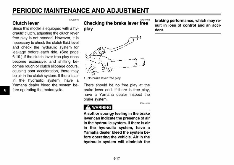
PERIODIC MAINTENANCE AND ADJUSTMENT
6-17
6
EAU22073
Clutch lever Since this model is equipped with a hy-draulic clutch, adjusting the clutch leverfree play is not needed. However, it isnecessary to check the clutch fluid leveland check the hydraulic system forleakage before each ride. (See page6-19.) If the clutch lever free play doesbecome excessive, and shifting be-comes rough or clutch slippage occurs,causing poor acceleration, there maybe air in the clutch system. If there is airin the hydraulic system, have aYamaha dealer bleed the system be-fore operating the motorcycle.
EAU37913
Checking the brake lever free play
There should be no free play at thebrake lever end. If there is free play,have a Yamaha dealer inspect thebrake system.
WARNINGEWA14211
A soft or spongy feeling in the brakelever can indicate the presence of airin the hydraulic system. If there is airin the hydraulic system, have aYamaha dealer bleed the system be-fore operating the vehicle. Air in thehydraulic system will diminish the
braking performance, which may re-sult in loss of control and an acci-dent.
1. No brake lever free play
1
U5WME7E0.book Page 17 Monday, November 16, 2009 9:09 AM

PERIODIC MAINTENANCE AND ADJUSTMENT
6-18
6
EAU22293
Brake light switches
The brake light, which is activated bythe brake pedal and brake lever, shouldcome on just before braking takes ef-fect. If necessary, adjust the rear brakelight switch as follows, but the frontbrake light switch should be adjustedby a Yamaha dealer.
1. Remove panel A. (See page 6-7.)2. Turn the adjusting nut while hold-
ing the rear brake light switch inplace. To make the brake lightcome on earlier, turn the adjustingnut in direction (a). To make thebrake light come on later, turn theadjusting nut in direction (b).
3. Install the panel. EAU22321
Checking the front and rear brake pads
Front brake
Rear brake
1. Rear brake light switch2. Rear brake light switch adjusting nut
1. Brake pad wear indicator groove
1. Brake pad wear indicator groove
U5WME7E0.book Page 18 Monday, November 16, 2009 9:09 AM

PERIODIC MAINTENANCE AND ADJUSTMENT
6-19
6
The front and rear brake pads must bechecked for wear at the intervals spec-ified in the periodic maintenance andlubrication chart. Each brake pad isprovided with a wear indicator groove,which allows you to check the brakepad wear without having to disassem-ble the brake. To check the brake padwear, check the wear indicatorgrooves. If a brake pad has worn to thepoint that the wear indicator groove hasalmost disappeared, have a Yamahadealer replace the brake pads as a set.
EAU22680
Checking the brake and clutch fluid levels
Front brake
Rear brake
Clutch
Insufficient brake fluid may allow air toenter the brake or clutch systems, pos-sibly causing them to become ineffec-tive.Before riding, check that the brake fluidis above the minimum level mark andreplenish if necessary. A low brake fluidlevel may indicate worn brake padsand/or brake system leakage. If thebrake level is low, be sure to check thebrake pads for wear and the brake sys-tem for leakage.
TIPThe rear brake fluid reservoir is locatedbehind panel A. (See page 6-7.)
Observe these precautions:
1. Minimum level mark
1. Minimum level mark
1
1. Minimum level mark
1
U5WME7E0.book Page 19 Monday, November 16, 2009 9:09 AM

PERIODIC MAINTENANCE AND ADJUSTMENT
6-20
6
� When checking the fluid level,make sure that the top of the brakeor clutch fluid reservoir is level.
� Use only the recommended qualitybrake fluid, otherwise the rubberseals may deteriorate, causingleakage and poor braking or clutchperformance.
� Refill with the same type of brakefluid. Mixing fluids may result in aharmful chemical reaction andlead to poor braking or clutch per-formance.
� The brake or clutch fluid reservoirdiaphragm will lose its shape fromthe negative pressure if the fluidlevel goes down too far. Be sure toreturn the diaphragm to its originalshape before installing it into thebrake or clutch fluid reservoir.
� Be careful that water does not en-ter the brake or clutch fluid reser-voir when refilling. Water will
significantly lower the boiling pointof the fluid and may result in vaporlock.
� Brake fluid may deteriorate paint-ed surfaces or plastic parts. Al-ways clean up spilled fluidimmediately.
� As the brake pads wear, it is nor-mal for the brake fluid level to grad-ually go down. However, if thebrake fluid level goes down sud-denly, have a Yamaha dealercheck the cause.
EAU22751
Changing the brake and clutch fluids Have a Yamaha dealer change thebrake and clutch fluids at the intervalsspecified in the TIP after the periodicmaintenance and lubrication chart. Inaddition, have the oil seals of the brakeand clutch master cylinders and cali-pers as well as the brake and clutchhoses replaced at the intervals listedbelow or whenever they are damagedor leaking.
� Oil seals: Replace every twoyears.
� Brake and clutch hoses: Replaceevery four years.
Recommended brake and clutch flu-id:
DOT 4 brake fluid
U5WME7E0.book Page 20 Monday, November 16, 2009 9:09 AM

PERIODIC MAINTENANCE AND ADJUSTMENT
6-21
6
EAU22760
Drive chain slack The drive chain slack should bechecked before each ride and adjustedif necessary.
EAU22793
To check the drive chain slack1. Place the motorcycle on the cen-
terstand.2. Shift the transmission into the neu-
tral position.3. Spin the rear wheel several times
to locate the tightest portion of thedrive chain.
4. Measure the drive chain slack asshown.
5. If the drive chain slack is incorrect,adjust it as follows.
EAU34315
To adjust the drive chain slack1. Loosen the axle nut and the lock-
nut on each side of the swingarm.2. To tighten the drive chain, turn the
drive chain slack adjusting bolt oneach side of the swingarm in direc-tion (a). To loosen the drive chain,turn the adjusting bolt on each sideof the swingarm in direction (b),and then push the rear wheel for-ward. NOTICE: Improper drivechain slack will overload the en-gine as well as other vital partsof the motorcycle and can leadto chain slippage or breakage.To prevent this from occurring,keep the drive chain slack with-in the specified limits. [ECA10571]
TIPUsing the alignment marks on eachside of the swingarm, make sure thatboth drive chain pullers are in the sameposition for proper wheel alignment.
3. Tighten the axle nut, then the lock-nuts to their specified torques.
1. Drive chain slack
1
Drive chain slack:20.0–30.0 mm (0.79–1.18 in)
1. Locknut2. Drive chain slack adjusting bolt3. Axle nut4. Alignment marks5. Drive chain puller
Tightening torques:Axle nut:
150 Nm (15 m·kgf, 108 ft·lbf)Locknut:
16 Nm (1.6 m·kgf, 12 ft·lbf)
U5WME7E0.book Page 21 Monday, November 16, 2009 9:09 AM

PERIODIC MAINTENANCE AND ADJUSTMENT
6-22
6
EAU23025
Cleaning and lubricating the drive chain The drive chain must be cleaned andlubricated at the intervals specified inthe periodic maintenance and lubrica-tion chart, otherwise it will quickly wearout, especially when riding in dusty orwet areas. Service the drive chain asfollows.
NOTICEECA10583
The drive chain must be lubricatedafter washing the motorcycle, ridingin the rain or riding in wet areas.
1. Clean the drive chain with kero-sene and a small soft brush.NOTICE: To prevent damagingthe O-rings, do not clean thedrive chain with steam cleaners,high-pressure washers or inap-propriate solvents. [ECA11121]
2. Wipe the drive chain dry.3. Thoroughly lubricate the drive
chain with a special O-ring chainlubricant. NOTICE: Do not useengine oil or any other lubri-cants for the drive chain, as they
may contain substances thatcould damage the O-rings.[ECA11111]
EAU23101
Checking and lubricating the cables The operation of all control cables andthe condition of the cables should bechecked before each ride, and the ca-bles and cable ends should be lubricat-ed if necessary. If a cable is damagedor does not move smoothly, have aYamaha dealer check or replace it.WARNING! Damage to the outersheath may interfere with proper ca-ble operation and will cause the in-ner cable to rust. Replace adamaged cable as soon as possibleto prevent unsafe conditions. [EWA10721]
Recommended lubricant:Engine oil
U5WME7E0.book Page 22 Monday, November 16, 2009 9:09 AM

PERIODIC MAINTENANCE AND ADJUSTMENT
6-23
6
EAU23112
Checking and lubricating the throttle grip and cable The operation of the throttle grip shouldbe checked before each ride. In addi-tion, the cable should be lubricated by aYamaha dealer at the intervals speci-fied in the periodic maintenance chart.
EAU44272
Checking and lubricating the brake and shift pedals
Brake pedal
Shift pedal
The operation of the brake and shiftpedals should be checked before eachride, and the pedal pivots should be lu-bricated if necessary.
Recommended lubricant:Lithium-soap-based grease
U5WME7E0.book Page 23 Monday, November 16, 2009 9:09 AM

PERIODIC MAINTENANCE AND ADJUSTMENT
6-24
6
EAU43600
Checking and lubricating the brake and clutch levers
Brake lever
Clutch lever
The operation of the brake and clutchlevers should be checked before eachride, and the lever pivots should be lu-bricated if necessary.
EAU23213
Checking and lubricating the centerstand and sidestand
The operation of the centerstand andsidestand should be checked beforeeach ride, and the pivots and metal-to-metal contact surfaces should be lubri-cated if necessary.
Recommended lubricant:Silicone grease
U5WME7E0.book Page 24 Monday, November 16, 2009 9:09 AM
PERIODIC MAINTENANCE AND ADJUSTMENT
6-25
6
WARNINGEWA10741
If the centerstand or sidestand doesnot move up and down smoothly,have a Yamaha dealer check or re-pair it. Otherwise, the centerstand orsidestand could contact the groundand distract the operator, resultingin a possible loss of control.
EAUM1651
Lubricating the swingarm piv-ots The swingarm pivots must be lubricat-ed by a Yamaha dealer at the intervalsspecified in the periodic maintenanceand lubrication chart.
EAU23272
Checking the front fork The condition and operation of the frontfork must be checked as follows at theintervals specified in the periodic main-tenance and lubrication chart.
To check the conditionCheck the inner tubes for scratches,damage and excessive oil leakage.
To check the operation1. Place the vehicle on a level sur-
face and hold it in an upright posi-tion. WARNING! To avoid injury,securely support the vehicle sothere is no danger of it fallingover. [EWA10751]
2. While applying the front brake,push down hard on the handlebarsseveral times to check if the frontfork compresses and reboundssmoothly.
Recommended lubricant:Lithium-soap-based grease
Recommended lubricant:Lithium-soap-based grease
U5WME7E0.book Page 25 Monday, November 16, 2009 9:09 AM

PERIODIC MAINTENANCE AND ADJUSTMENT
6-26
6
NOTICEECA10590
If any damage is found or the frontfork does not operate smoothly,have a Yamaha dealer check or re-pair it.
EAU45511
Checking the steering Worn or loose steering bearings maycause danger. Therefore, the operationof the steering must be checked as fol-lows at the intervals specified in the pe-riodic maintenance and lubricationchart.
1. Place the vehicle on the center-stand. WARNING! To avoid inju-ry, securely support the vehicleso there is no danger of it fallingover. [EWA10751]
2. Hold the lower ends of the frontfork legs and try to move them for-ward and backward. If any freeplay can be felt, have a Yamahadealer check or repair the steering.
EAU23291
Checking the wheel bearings
The front and rear wheel bearings mustbe checked at the intervals specified inthe periodic maintenance and lubrica-tion chart. If there is play in the wheelhub or if the wheel does not turnsmoothly, have a Yamaha dealer checkthe wheel bearings.
U5WME7E0.book Page 26 Monday, November 16, 2009 9:09 AM

PERIODIC MAINTENANCE AND ADJUSTMENT
6-27
6
EAU33654
Battery
This model is equipped with a VRLA(Valve Regulated Lead Acid) battery.There is no need to check the electro-lyte or to add distilled water. However,the battery lead connections need to bechecked and, if necessary, tightened.
WARNINGEWA10760
� Electrolyte is poisonous anddangerous since it contains sul-furic acid, which causes severeburns. Avoid any contact withskin, eyes or clothing and al-ways shield your eyes when
working near batteries. In caseof contact, administer the fol-lowing FIRST AID.• EXTERNAL: Flush with plenty
of water.• INTERNAL: Drink large quan-
tities of water or milk and im-mediately call a physician.
• EYES: Flush with water for 15minutes and seek promptmedical attention.
� Batteries produce explosive hy-drogen gas. Therefore, keepsparks, flames, cigarettes, etc.,away from the battery and pro-vide sufficient ventilation whencharging it in an enclosedspace.
� KEEP THIS AND ALL BATTER-IES OUT OF THE REACH OFCHILDREN.
To charge the batteryHave a Yamaha dealer charge the bat-tery as soon as possible if it seems tohave discharged. Keep in mind that thebattery tends to discharge more quicklyif the vehicle is equipped with optionalelectrical accessories.
NOTICEECA16520
To charge a VRLA (Valve RegulatedLead Acid) battery, a special (con-stant-voltage) battery charger is re-quired. Using a conventional batterycharger will damage the battery. Ifyou do not have access to a con-stant-voltage battery charger, have aYamaha dealer charge your battery.
To store the battery1. If the vehicle will not be used for
more than one month, remove thebattery, fully charge it, and thenplace it in a cool, dry place.NOTICE: When removing thebattery, be sure the key isturned to “OFF”, then discon-nect the negative lead beforedisconnecting the positive lead.[ECA16302]
2. If the battery will be stored for morethan two months, check it at leastonce a month and fully charge it ifnecessary.
3. Fully charge the battery before in-stallation.
1. Negative battery lead (black)2. Positive battery lead (red)
1
2
U5WME7E0.book Page 27 Monday, November 16, 2009 9:09 AM

PERIODIC MAINTENANCE AND ADJUSTMENT
6-28
6
4. After installation, make sure thatthe battery leads are properly con-nected to the battery terminals.
NOTICEECA16530
Always keep the battery charged.Storing a discharged battery cancause permanent battery damage.
EAU43272
Replacing the fuses The main fuse is located under theseat. (See page 3-15.)
The fuse box, which contains the fusesfor the individual circuits, is located be-hind panel B. (See page 6-7.)
If a fuse is blown, replace it as follows.1. Turn the key to “OFF” and turn off
the electrical circuit in question.2. Remove the blown fuse, and then
install a new fuse of the specifiedamperage. WARNING! Do notuse a fuse of a higher amperagerating than recommended toavoid causing extensive dam-age to the electrical system andpossibly a fire. [EWA15131]
1. Main fuse
1. Headlight fuse2. Signaling system fuse3. Ignition fuse4. Taillight fuse5. Fuel injection system fuse6. Backup fuse (for clock and immobilizer sys-
tem)7. Spare fuse
U5WME7E0.book Page 28 Monday, November 16, 2009 9:09 AM

PERIODIC MAINTENANCE AND ADJUSTMENT
6-29
63. Turn the key to “ON” and turn on
the electrical circuit in question tocheck if the device operates.
4. If the fuse immediately blowsagain, have a Yamaha dealercheck the electrical system.
EAU23795
Replacing the headlight bulb This model is equipped with a quartzbulb headlight. If the headlight bulbburns out, replace it as follows.
NOTICEECA10650
Take care not to damage the follow-ing parts:
� Headlight bulbDo not touch the glass part ofthe headlight bulb to keep it freefrom oil, otherwise the transpar-ency of the glass, the luminosityof the bulb, and the bulb life willbe adversely affected. Thor-oughly clean off any dirt and fin-gerprints on the headlight bulbusing a cloth moistened with al-cohol or thinner.
� Headlight lensDo not affix any type of tintedfilm or stickers to the headlightlens.Do not use a headlight bulb of awattage higher than specified.
1. Remove the headlight unit by re-moving the screws.
2. Disconnect the headlight coupler,and then remove the bulb cover.
Specified fuses:Main fuse:
50.0 AHeadlight fuse:
15.0 ATaillight fuse:
7.5 ASignaling system fuse:
7.5 AIgnition fuse:
15.0 AFuel injection system fuse:
15.0 ABackup fuse:
7.5 A
1. Do not touch the glass part of the bulb.
1. Screw
U5WME7E0.book Page 29 Monday, November 16, 2009 9:09 AM

PERIODIC MAINTENANCE AND ADJUSTMENT
6-30
6
3. Unhook the headlight bulb holder,and then remove the burnt-outbulb.
4. Place a new headlight bulb into po-sition, and then secure it with thebulb holder.
5. Install the headlight bulb cover,and then connect the coupler.
6. Install the headlight unit by install-ing the screws.
7. Have a Yamaha dealer adjust theheadlight beam if necessary.
EAU24181
Tail/brake light This model is equipped with an LED-type tail/brake light.If the tail/brake light does not come on,have a Yamaha dealer check it.
1. Headlight coupler2. Headlight bulb cover
1. Headlight bulb holder
U5WME7E0.book Page 30 Monday, November 16, 2009 9:09 AM

PERIODIC MAINTENANCE AND ADJUSTMENT
6-31
6
EAU24204
Replacing a turn signal light bulb
1. Remove the turn signal light lensby removing the screw.
2. Remove the burnt-out bulb bypushing it in and turning it counter-clockwise.
3. Insert a new bulb into the socket,push it in, and then turn it clock-wise until it stops.
4. Install the lens by installing thescrew. NOTICE: Do not over-tighten the screw, otherwise thelens may break. [ECA11191]
EAU24313
Replacing the license plate light bulb
1. Remove the license plate light unitby removing the screws.
2. Remove the license plate light bulbsocket (together with the bulb) bypulling it out.
1. Screw
1. Turn signal light bulb
1. License plate light unit2. Screw
U5WME7E0.book Page 31 Monday, November 16, 2009 9:09 AM

PERIODIC MAINTENANCE AND ADJUSTMENT
6-32
6
3. Remove the burnt-out bulb by pull-ing it out.
4. Insert a new bulb into the socket.5. Install the socket (together with the
bulb) by pushing it in.6. Install the license plate light unit by
installing the screws.
EAU33543
Replacing the auxiliary light bulb If the auxiliary light bulb burns out, re-place it as follows.
1. Remove the headlight unit by re-moving the screws.
2. Remove the socket (together withthe bulb) by pulling it out.
3. Remove the burnt-out bulb bypushing it in and turning it counter-clockwise.
4. Insert a new bulb into the socket,push it in, and then turn it clock-wise until it stops.
5. Install the socket (together with thebulb) by pushing it in.
6. Install the headlight unit by install-ing the screws.
1. License plate light bulb socket
1. Screw
1. Auxiliary light bulb socket
U5WME7E0.book Page 32 Monday, November 16, 2009 9:09 AM

PERIODIC MAINTENANCE AND ADJUSTMENT
6-33
6
EAU24360
Front wheel
EAU38891
To remove the front wheel
WARNINGEWA10821
To avoid injury, securely support thevehicle so there is no danger of itfalling over.
1. Place the motorcycle on the cen-terstand.
2. Loosen the front wheel axle pinchbolt, then the wheel axle and thebrake caliper bolts.
3. Remove the brake hose holder oneach side by removing the bolt.
4. Remove the brake caliper on eachside by removing the bolts.NOTICE: Do not apply the brakeafter the brake calipers havebeen removed, otherwise thebrake pads will be forced shut.[ECA11051]
5. Pull the wheel axle out, and thenremove the wheel.
EAU33661
To install the front wheel1. Lift the wheel up between the fork
legs.
2. Insert the wheel axle.3. Install the brake calipers by install-
ing the bolts.
TIPMake sure that there is enough spacebetween the brake pads before install-ing the brake calipers onto the brakediscs.
4. Install the brake hose holders byinstalling the bolts.
5. Lower the front wheel so that it ison the ground, and then put thesidestand down.
6. Tighten the wheel axle, the frontwheel axle pinch bolt and thebrake caliper bolts to the specifiedtorques.
7. Push down hard on the handlebarseveral times to check for properfork operation.
1. Brake caliper bolt2. Front wheel axle pinch bolt3. Wheel axle
3 2
1 1. Brake caliper bolt2. Brake hose holder3. Brake caliper4. Bolt
Tightening torques:Wheel axle:
72 Nm (7.2 m·kgf, 52 ft·lbf)Front wheel axle pinch bolt:
20 Nm (2.0 m·kgf, 14 ft·lbf)Brake caliper bolt:
40 Nm (4.0 m·kgf, 29 ft·lbf)
U5WME7E0.book Page 33 Monday, November 16, 2009 9:09 AM

PERIODIC MAINTENANCE AND ADJUSTMENT
6-34
6
EAU25080
Rear wheel
EAU25162
To remove the rear wheel
WARNINGEWA10821
To avoid injury, securely support thevehicle so there is no danger of itfalling over.
1. Loosen the axle nut and the brakecaliper bolts.
2. Disconnect the brake torque rodfrom the brake caliper bracket byremoving the nut and the bolt.
3. Place the motorcycle on the cen-terstand.
4. Remove the axle nut and the brakecaliper by removing the bolts.NOTICE: Do not apply the brakeafter the brake caliper has beenremoved, otherwise the brakepads will be forced shut. [ECA11301]
5. Loosen the locknuts, and then turnthe drive chain slack adjusting bolton each side of the swingarm fullyin direction (a).
6. Push the wheel forward, and thenremove the drive chain from therear sprocket.
TIPThe drive chain does not need to bedisassembled in order to remove andinstall the rear wheel.
7. While supporting the wheel andthe brake caliper bracket, pull thewheel axle out.
8. Remove the brake caliper bracketand the wheel.
1. Axle nut2. Brake caliper bolt
1
2
1. Brake caliper bolt2. Brake torque rod3. Bolt4. Brake caliper bracket5. Brake caliper6. Nut
1. Wheel axle2. Drive chain slack adjusting bolt3. Locknut
1
2 3
(a)
U5WME7E0.book Page 34 Monday, November 16, 2009 9:09 AM

PERIODIC MAINTENANCE AND ADJUSTMENT
6-35
6
EAU25842
To install the rear wheel1. Place the wheel and the brake cal-
iper bracket in the original position.2. Insert the wheel axle through the
brake caliper bracket and wheelfrom the right-hand side, and theninstall the axle nut.
3. Install the drive chain onto the rearsprocket, and then adjust the drivechain slack. (See page 6-21.)
4. Connect the brake torque rod tothe brake caliper bracket by install-ing the bolt and the nut.
5. Install the brake caliper by install-ing the bolts.
TIPMake sure that there is enough spacebetween the brake pads before install-ing the brake caliper onto the brakedisc.
6. Lower the rear wheel so that it ison the ground, and then put thesidestand down.
7. Tighten the axle nut, brake caliperbolts and brake torque rod nut tothe specified torques.
EAU25851
Troubleshooting Although Yamaha motorcycles receivea thorough inspection before shipmentfrom the factory, trouble may occur dur-ing operation. Any problem in the fuel,compression, or ignition systems, forexample, can cause poor starting andloss of power.The following troubleshooting chartrepresents a quick and easy procedurefor checking these vital systems your-self. However, should your motorcyclerequire any repair, take it to a Yamahadealer, whose skilled technicians havethe necessary tools, experience, andknow-how to service the motorcycleproperly.Use only genuine Yamaha replace-ment parts. Imitation parts may look likeYamaha parts, but they are often inferi-or, have a shorter service life and canlead to expensive repair bills.
WARNINGEWA15141
When checking the fuel system, donot smoke, and make sure there areno open flames or sparks in the ar-ea, including pilot lights from water
Tightening torques:Axle nut:
150 Nm (15 m·kgf, 108 ft·lbf)Brake caliper bolt:
40 Nm (4.0 m·kgf, 29 ft·lbf)Brake torque rod nut:
23 Nm (2.3 m·kgf, 17 ft·lbf)
U5WME7E0.book Page 35 Monday, November 16, 2009 9:09 AM

PERIODIC MAINTENANCE AND ADJUSTMENT
6-36
6
heaters or furnaces. Gasoline orgasoline vapors can ignite or ex-plode, causing severe injury orproperty damage.
U5WME7E0.book Page 36 Monday, November 16, 2009 9:09 AM

PERIODIC MAINTENANCE AND ADJUSTMENT
6-37
6
EAU42601
Troubleshooting chart
Check the fuel level inthe fuel tank.
1. FuelThere is enough fuel.
There is no fuel.
Check the compression.
Supply fuel. The engine does not start. Check the compression.
Operate the electric starter.
2. CompressionThere is compression.
There is no compression.
Check the ignition.
Have a Yamaha dealercheck the vehicle.
Remove the spark plugsand check the electrodes.
3. Ignition Wipe off with a dry cloth and correct thespark plug gaps, or replace the spark plugs.
Have a Yamaha dealer check the vehicle.
The engine does not start.Have a Yamaha dealercheck the vehicle.
The engine does not start.Check the battery.
Operate the electric starter.
4. BatteryThe engine turns over quickly.
The engine turns over slowly.
The battery is good.
Check the battery lead connections,and charge the battery if necessary.
Dry
Wet Operate the electric starter.
U5WME7E0.book Page 37 Monday, November 16, 2009 9:09 AM

MOTORCYCLE CARE AND STORAGE
7-1
7
EAU37833
Matte color caution
NOTICEECA15192
Some models are equipped withmatte colored finished parts. Besure to consult a Yamaha dealer foradvice on what products to use be-fore cleaning the vehicle. Using abrush, harsh chemical products orcleaning compounds when cleaningthese parts will scratch or damagetheir surface. Wax also should notbe applied to any matte colored fin-ished parts.
EAU26014
Care While the open design of a motorcyclereveals the attractiveness of the tech-nology, it also makes it more vulnera-ble. Rust and corrosion can developeven if high-quality components areused. A rusty exhaust pipe may go un-noticed on a car, however, it detractsfrom the overall appearance of a motor-cycle. Frequent and proper care doesnot only comply with the terms of thewarranty, but it will also keep your mo-torcycle looking good, extend its lifeand optimize its performance.
Before cleaning1. Cover the muffler outlet with a
plastic bag after the engine hascooled down.
2. Make sure that all caps and coversas well as all electrical couplersand connectors, including thespark plug caps, are tightly in-stalled.
3. Remove extremely stubborn dirt,like oil burnt onto the crankcase,with a degreasing agent and abrush, but never apply such prod-
ucts onto seals, gaskets, sprock-ets, the drive chain and wheelaxles. Always rinse the dirt and de-greaser off with water.
Cleaning
NOTICEECA10772
� Avoid using strong acidic wheelcleaners, especially on spokedwheels. If such products areused on hard-to-remove dirt, donot leave the cleaner on the af-fected area any longer than in-structed. Also, thoroughly rinsethe area off with water, immedi-ately dry it, and then apply a cor-rosion protection spray.
� Improper cleaning can damageplastic parts (such as cowlings,panels, windshields, headlightlenses, meter lenses, etc.) andthe mufflers. Use only a soft,clean cloth or sponge with wa-ter to clean plastic. However, ifthe plastic parts cannot be thor-oughly cleaned with water, di-luted mild detergent with watermay be used. Be sure to rinse
U5WME7E0.book Page 1 Monday, November 16, 2009 9:09 AM

MOTORCYCLE CARE AND STORAGE
7-2
7
off any detergent residue usingplenty of water, as it is harmfulto plastic parts.
� Do not use any harsh chemicalproducts on plastic parts. Besure to avoid using cloths orsponges which have been incontact with strong or abrasivecleaning products, solvent orthinner, fuel (gasoline), rust re-movers or inhibitors, brake flu-id, antifreeze or electrolyte.
� Do not use high-pressure wash-ers or steam-jet cleaners sincethey cause water seepage anddeterioration in the following ar-eas: seals (of wheel and swing-arm bearings, fork and brakes),electric components (couplers,connectors, instruments,switches and lights), breatherhoses and vents.
� For motorcycles equipped witha windshield: Do not use strongcleaners or hard sponges asthey will cause dulling orscratching. Some cleaning com-pounds for plastic may leavescratches on the windshield.
Test the product on a small hid-den part of the windshield tomake sure that it does not leaveany marks. If the windshield isscratched, use a quality plasticpolishing compound afterwashing.
After normal useRemove dirt with warm water, a milddetergent, and a soft, clean sponge,and then rinse thoroughly with cleanwater. Use a toothbrush or bottlebrushfor hard-to-reach areas. Stubborn dirtand insects will come off more easily ifthe area is covered with a wet cloth fora few minutes before cleaning.
After riding in the rain, near the sea oron salt-sprayed roadsSince sea salt or salt sprayed on roadsduring winter are extremely corrosive incombination with water, carry out thefollowing steps after each ride in therain, near the sea or on salt-sprayedroads.
TIPSalt sprayed on roads in the winter mayremain well into spring.
1. Clean the motorcycle with cold wa-ter and a mild detergent, after theengine has cooled down.NOTICE: Do not use warm watersince it increases the corrosiveaction of the salt. [ECA10791]
2. Apply a corrosion protection sprayon all metal, including chrome- andnickel-plated, surfaces to preventcorrosion.
After cleaning1. Dry the motorcycle with a chamois
or an absorbing cloth.2. Immediately dry the drive chain
and lubricate it to prevent it fromrusting.
3. Use a chrome polish to shinechrome, aluminum and stainless-steel parts, including the exhaustsystem. (Even the thermally in-duced discoloring of stainless-steel exhaust systems can be re-moved through polishing.)
U5WME7E0.book Page 2 Monday, November 16, 2009 9:09 AM

MOTORCYCLE CARE AND STORAGE
7-3
7
4. To prevent corrosion, it is recom-mended to apply a corrosion pro-tection spray on all metal,including chrome- and nickel-plat-ed, surfaces.
5. Use spray oil as a universal clean-er to remove any remaining dirt.
6. Touch up minor paint damagecaused by stones, etc.
7. Wax all painted surfaces.8. Let the motorcycle dry completely
before storing or covering it.
WARNINGEWA11131
Contaminants on the brakes or tirescan cause loss of control.
� Make sure that there is no oil orwax on the brakes or tires.
� If necessary, clean the brakediscs and brake linings with aregular brake disc cleaner or ac-etone, and wash the tires withwarm water and a mild deter-gent. Before riding at higherspeeds, test the motorcycle’sbraking performance and cor-nering behavior.
NOTICEECA10800
� Apply spray oil and wax spar-ingly and make sure to wipe offany excess.
� Never apply oil or wax to anyrubber and plastic parts, buttreat them with a suitable careproduct.
� Avoid using abrasive polishingcompounds as they will wearaway the paint.
TIP� Consult a Yamaha dealer for ad-
vice on what products to use.� Washing, rainy weather or humid
climates can cause the headlightlens to fog. Turning the headlighton for a short period of time willhelp remove the moisture from thelens.
EAU26181
Storage
Short-termAlways store your motorcycle in a cool,dry place and, if necessary, protect itagainst dust with a porous cover.
NOTICEECA10810
� Storing the motorcycle in apoorly ventilated room or cover-ing it with a tarp, while it is stillwet, will allow water and humid-ity to seep in and cause rust.
� To prevent corrosion, avoiddamp cellars, stables (becauseof the presence of ammonia)and areas where strong chemi-cals are stored.
Long-termBefore storing your motorcycle for sev-eral months:
1. Follow all the instructions in the“Care” section of this chapter.
2. Fill up the fuel tank and add fuelstabilizer (if available) to preventthe fuel tank from rusting and thefuel from deteriorating.
U5WME7E0.book Page 3 Monday, November 16, 2009 9:09 AM

MOTORCYCLE CARE AND STORAGE
7-4
7
3. Perform the following steps to pro-tect the cylinders, piston rings, etc.from corrosion.a. Remove the spark plug caps
and spark plugs.b. Pour a teaspoonful of engine oil
into each spark plug bore.c. Install the spark plug caps onto
the spark plugs, and then placethe spark plugs on the cylinderhead so that the electrodes aregrounded. (This will limit spark-ing during the next step.)
d. Turn the engine over severaltimes with the starter. (This willcoat the cylinder walls with oil.)WARNING! To prevent dam-age or injury from sparking,make sure to ground thespark plug electrodes whileturning the engine over.[EWA10951]
e. Remove the spark plug capsfrom the spark plugs, and theninstall the spark plugs and thespark plug caps.
4. Lubricate all control cables and thepivoting points of all levers andpedals as well as of the side-stand/centerstand.
5. Check and, if necessary, correctthe tire air pressure, and then liftthe motorcycle so that both of itswheels are off the ground. Alterna-tively, turn the wheels a little everymonth in order to prevent the tiresfrom becoming degraded in onespot.
6. Cover the muffler outlet with aplastic bag to prevent moisturefrom entering it.
7. Remove the battery and fullycharge it. Store it in a cool, dryplace and charge it once a month.Do not store the battery in an ex-cessively cold or warm place [lessthan 0 °C (30 °F) or more than 30°C (90 °F)]. For more informationon storing the battery, see page6-27.
TIPMake any necessary repairs beforestoring the motorcycle.
U5WME7E0.book Page 4 Monday, November 16, 2009 9:09 AM

SPECIFICATIONS
8-1
8
Dimensions:Overall length:
2175 mm (85.6 in)Overall width:
765 mm (30.1 in)Overall height:
1115 mm (43.9 in)Seat height:
795 mm (31.3 in)Wheelbase:
1500 mm (59.1 in)Ground clearance:
125 mm (4.92 in)Minimum turning radius:
2800 mm (110.2 in)Weight:
With oil and fuel:245 kg (540 lb)
Engine:Engine type:
Air cooled 4-stroke, DOHCCylinder arrangement:
Forward-inclined parallel 4-cylinderDisplacement:
1251 cm³Bore × stroke:
79.0 × 63.8 mm (3.11 × 2.51 in)Compression ratio:
9.70 :1Starting system:
Electric starterLubrication system:
Wet sump
Engine oil:Recommended brand:
YAMALUBEType:
SAE 10W-30, 10W-40, 10W-50, 15W-40, 20W-40 or 20W-50
Recommended engine oil grade:API service SG type or higher, JASO standard MA
Engine oil quantity:Without oil filter element replacement:
2.80 L (2.96 US qt, 2.46 Imp.qt)With oil filter element replacement:
3.15 L (3.33 US qt, 2.77 Imp.qt)Air filter:
Air filter element:Oil-coated paper element
Fuel:Recommended fuel:
Premium unleaded gasoline onlyFuel tank capacity:
21.0 L (5.55 US gal, 4.62 Imp.gal)
Fuel reserve amount:4.5 L (1.19 US gal, 0.99 Imp.gal)
Fuel injection:Throttle body:
ID mark:5UXB 10
Spark plug(s):Manufacturer/model:
NGK/DPR8EA-9Spark plug gap:
0.8–0.9 mm (0.031–0.035 in)Clutch:
Clutch type:Wet, multiple-disc
Transmission:Primary reduction system:
Spur gearPrimary reduction ratio:
98/56 (1.750)Secondary reduction system:
Chain driveSecondary reduction ratio:
38/17 (2.235)Transmission type:
Constant mesh 5-speedOperation:
Left foot operationGear ratio:
1st:40/14 (2.857)
2nd:36/18 (2.000)
3rd:33/21 (1.571)
–20 –10 0 10 20 30 40 50 ˚C
10 30 50 70 90 1100 130 ˚F
SAE 10W-30
SAE 15W-40
SAE 20W-40
SAE 20W-50
SAE 10W-40
SAE 10W-50
U5WME7E0.book Page 1 Monday, November 16, 2009 9:09 AM

SPECIFICATIONS
8-2
8
4th:31/24 (1.292)
5th:29/26 (1.115)
Chassis:Frame type:
Double cradleCaster angle:
25.50 °Trail:
100.0 mm (3.94 in)Front tire:
Type:Tubeless
Size:120/70 ZR17M/C (58W)
Manufacturer/model:DUNLOP/D252F L
Rear tire:Type:
TubelessSize:
180/55 ZR17M/C (73W)Manufacturer/model:
DUNLOP/D252 LLoading:
Maximum load:205 kg (452 lb)(Total weight of rider, passenger, cargo and accessories)
Tire air pressure (measured on cold tires):
Loading condition:0–90 kg (0–198 lb)
Front:250 kPa (2.50 kgf/cm², 36 psi)
Rear:250 kPa (2.50 kgf/cm², 36 psi)
Loading condition:90–205 kg (198–452 lb)Front:
250 kPa (2.50 kgf/cm², 36 psi)Rear:
290 kPa (2.90 kgf/cm², 42 psi)High-speed riding:
Front:250 kPa (2.50 kgf/cm², 36 psi)
Rear:290 kPa (2.90 kgf/cm², 42 psi)
Front wheel:Wheel type:
Cast wheelRim size:
17M/C x MT3.50Rear wheel:
Wheel type:Cast wheel
Rim size:17M/C x MT5.50
Front brake:Type:
Dual disc brakeOperation:
Right hand operationRecommended fluid:
DOT 4
Rear brake:Type:
Single disc brakeOperation:
Right foot operationRecommended fluid:
DOT 4Front suspension:
Type:Telescopic fork
Spring/shock absorber type:Coil spring/oil damper
Wheel travel:130.0 mm (5.12 in)
Rear suspension:Type:
SwingarmSpring/shock absorber type:
Coil spring/gas-oil damperWheel travel:
110.0 mm (4.33 in)Electrical system:
Ignition system:TCI
Charging system:AC generator
Battery:Model:
YTZ14SVoltage, capacity:
12 V, 11.2 AhHeadlight:
Bulb type:Halogen bulb
U5WME7E0.book Page 2 Monday, November 16, 2009 9:09 AM

SPECIFICATIONS
8-3
8
Bulb voltage, wattage × quantity:Headlight:
12 V, 60 W/55 W × 1Tail/brake light:
LEDFront turn signal light:
12 V, 21.0 W × 2Rear turn signal light:
12 V, 21.0 W × 2Auxiliary light:
12 V, 4.0 W × 1License plate light:
12 V, 5.0 W × 1Meter lighting:
LEDNeutral indicator light:
12 V, 1.7 W × 1High beam indicator light:
12 V, 1.7 W × 1Oil level warning light:
12 V, 1.7 W × 1Turn signal indicator light:
12 V, 1.7 W × 2Engine trouble warning light:
12 V, 1.7 W × 1Immobilizer system indicator light:
LEDFuses:
Main fuse:50.0 A
Headlight fuse:15.0 A
Taillight fuse:7.5 A
Signaling system fuse:7.5 A
Ignition fuse:15.0 A
Fuel injection system fuse:15.0 A
Backup fuse:7.5 A
U5WME7E0.book Page 3 Monday, November 16, 2009 9:09 AM

CONSUMER INFORMATION
9-1
9
EAU48610
Identification numbers Record the vehicle identification num-ber and model label information in thespaces provided below for assistancewhen ordering spare parts from aYamaha dealer or for reference in casethe vehicle is stolen.VEHICLE IDENTIFICATION NUMBER:
MODEL LABEL INFORMATION:
EAU26400
Vehicle identification number
The vehicle identification number isstamped into the steering head pipe.Record this number in the space pro-vided.
TIPThe vehicle identification number isused to identify your motorcycle andmay be used to register your motorcy-cle with the licensing authority in yourarea.
EAU26480
Model label
The model label is affixed to the frameunder the seat. (See page 3-15.)Record the information on this label inthe space provided. This informationwill be needed when ordering spareparts from a Yamaha dealer.
1. Vehicle identification number 1. Model label
U5WME7E0.book Page 1 Monday, November 16, 2009 9:09 AM

INDEXA
Air filter element and check hose, replacing and cleaning ....................... 6-12
Anti-theft alarm (optional) ....................... 3-9Auxiliary light bulb, replacing ................ 6-32
BBattery .................................................. 6-27Brake and clutch fluid levels,
checking ............................................. 6-19Brake and clutch fluids, changing......... 6-20Brake and clutch levers, checking and
lubricating ........................................... 6-24Brake and shift pedals, checking and
lubricating ........................................... 6-23Brake lever ........................................... 3-11Brake lever free play, checking ............ 6-17Brake light switches.............................. 6-18Brake pedal .......................................... 3-12
CCables, checking and lubricating.......... 6-22Care........................................................ 7-1Catalytic converters .............................. 3-15Centerstand and sidestand, checking
and lubricating .................................... 6-24Clutch lever.................................. 3-10, 6-17
DDimmer switch ........................................ 3-9Drive chain, cleaning and lubricating.... 6-22Drive chain slack .................................. 6-21
EEngine break-in ...................................... 5-3Engine oil and oil filter element............... 6-9Engine stop switch................................ 3-10Engine trouble warning light ................... 3-4
EXUP system ........................................3-22F
Front and rear brake pads, checking ....6-18Front fork, adjusting ..............................3-17Front fork, checking...............................6-25Fuel .......................................................3-13Fuel consumption, tips for reducing ........5-3Fuel tank breather hose ........................3-14Fuel tank cap.........................................3-12Fuses, replacing....................................6-28
HHandlebar switches.................................3-9Hazard switch........................................3-10Headlight bulb, replacing.......................6-29Helmet holder........................................3-16High beam indicator light.........................3-4Horn switch ...........................................3-10
IIdentification numbers .............................9-1Ignition circuit cut-off system.................3-23Immobilizer system .................................3-1Immobilizer system indicator light ...........3-4Indicator and warning lights ....................3-4
LLicense plate light bulb, replacing .........6-31Luggage strap holders ..........................3-21
MMain switch/steering lock ........................3-2Maintenance and lubrication, periodic.....6-3Maintenance, emission control system ...6-2Matte color, caution.................................7-1Model label..............................................9-1Multi-function display...............................3-6
NNeutral indicator light .............................. 3-4
OOil level warning light .............................. 3-4
PPanels, removing and installing .............. 6-7Parking.................................................... 5-4Part locations .......................................... 2-1Pass switch............................................. 3-9
SSafety information................................... 1-1Seat ...................................................... 3-15Shifting.................................................... 5-2Shift pedal............................................. 3-11Shock absorber assemblies,
adjusting ............................................. 3-19Sidestand.............................................. 3-22Spark plugs, checking............................. 6-8Specifications.......................................... 8-1Speedometer .......................................... 3-5Starting the engine.................................. 5-1Start switch ........................................... 3-10Steering, checking ................................ 6-26Storage ................................................... 7-3Storage compartment ........................... 3-16Swingarm pivots, lubricating ................. 6-25
TTachometer............................................. 3-5Tail/brake light ...................................... 6-30Throttle cable free play, checking ......... 6-13Throttle grip and cable, checking and
lubricating ........................................... 6-23Tires...................................................... 6-14Tool kit .................................................... 6-1
U5WME7E0.book Page 1 Monday, November 16, 2009 9:09 AM

INDEXTroubleshooting .................................... 6-35Troubleshooting chart ........................... 6-37Turn signal indicator lights ...................... 3-4Turn signal light bulb, replacing ............ 6-31Turn signal switch ................................... 3-9
VValve clearance .................................... 6-14Vehicle identification number .................. 9-1
WWheel bearings, checking..................... 6-26Wheel (front) ......................................... 6-33Wheel (rear) .......................................... 6-34Wheels .................................................. 6-16
U5WME7E0.book Page 2 Monday, November 16, 2009 9:09 AM

U5WME7E0.book Page 3 Monday, November 16, 2009 9:09 AM

PRINTED ON RECYCLED PAPER YAMAHA MOTOR CO., LTD.
PRINTED IN JAPAN2009.12-0.3×1 CR
(E)
DIC183