xli ieee 1588 grandmaster clock (ptpv2) -...
TRANSCRIPT

i XLi IEEE 1588 Grandmaster Clock (PTPv2)2/10/10, XLiIEEE1588(PTPv2)_UG_RevB.pdf
XLi IEEE 1588 Grandmaster Clock (PTPv2)
User Guide
CD Part Number: 098-00121-000

ii XLi IEEE 1588 Grandmaster Clock (PTPv2)2/10/10, XLiIEEE1588(PTPv2)_UG_RevB.pdf
This page intentionally left blank.

iii XLi IEEE 1588 Grandmaster Clock (PTPv2)2/10/10, XLiIEEE1588(PTPv2)_UG_RevB.pdf
NoticesSymmetricom, Inc.Timing Test & Measurement 3750 Westwind Blvd. Santa Rosa, CA 95403-1053http://www.symmetricom.com
Copyright © 2010, Symmetricom, Inc.All rights reserved. Printed in U.S.A.All product names, service marks, trademarks, and registered trademarksused in this document are the property of their respective owners.The manual’s contents do not apply to previously released versions of XLi hardware or software.

iv XLi IEEE 1588 Grandmaster Clock (PTPv2)2/10/10, XLiIEEE1588(PTPv2)_UG_RevB.pdf
This page intentionally left blank.

XLi IEEE 1588 Grandmaster Clock (PTP V2) v
XLiIEEE1588(PTPv2)_UG_RevB.pdf, 2/10/2010
2
5
1
S SSS S SSS S SSS S SSS S SSSS S SSS S SSS S SSS S SSS SS S
Table of Contents
Notices . . . . . . . . . . . . . . . . . . . . . . . . . . . . . . . . . . . . . . . . . . . . . . . . . . . . . . . . . . . iii
Table of Contents . . . . . . . . . . . . . . . . . . . . . . . . . . . . . . . . . . . . . . . . . . . . . . . . . . . . . . . v
1: Equipment Overview . . . . . . . . . . . . . . . . . . . . . . . . . . . . . . . . . . . . . . . . . . . . . . . . . . 1XLi IEEE 1588 V2 Grandmaster Description and Features . . . . . . . . . . . . . . . . . . . . 1
Features and Options . . . . . . . . . . . . . . . . . . . . . . . . . . . . . . . . . . . . . . . . . . . . . . 2Clock Architecture . . . . . . . . . . . . . . . . . . . . . . . . . . . . . . . . . . . . . . . . . . . . . . . . . . . 4
2: System Specifications . . . . . . . . . . . . . . . . . . . . . . . . . . . . . . . . . . . . . . . . . . . . . . . . . 7Mechanical/Environmental . . . . . . . . . . . . . . . . . . . . . . . . . . . . . . . . . . . . . . . . . . . . . 7AC Power Supply . . . . . . . . . . . . . . . . . . . . . . . . . . . . . . . . . . . . . . . . . . . . . . . . . . . . 7System Time & Frequency Accuracy . . . . . . . . . . . . . . . . . . . . . . . . . . . . . . . . . . . . . 8
GPS Receiver . . . . . . . . . . . . . . . . . . . . . . . . . . . . . . . . . . . . . . . . . . . . . . . . . . . . 8Time Code Input . . . . . . . . . . . . . . . . . . . . . . . . . . . . . . . . . . . . . . . . . . . . . . . . . 81 PPS Input . . . . . . . . . . . . . . . . . . . . . . . . . . . . . . . . . . . . . . . . . . . . . . . . . . . . . 9Aux Ref Input . . . . . . . . . . . . . . . . . . . . . . . . . . . . . . . . . . . . . . . . . . . . . . . . . . . 9
Chassis . . . . . . . . . . . . . . . . . . . . . . . . . . . . . . . . . . . . . . . . . . . . . . . . . . . . . . . . . . . . 9Standard Inputs and Outputs . . . . . . . . . . . . . . . . . . . . . . . . . . . . . . . . . . . . . . . . . . . 10
Serial I/O Port . . . . . . . . . . . . . . . . . . . . . . . . . . . . . . . . . . . . . . . . . . . . . . . . . . 10NET – Network Port . . . . . . . . . . . . . . . . . . . . . . . . . . . . . . . . . . . . . . . . . . . . . 10J1 Input – Time Code or Time Interval - Event Time . . . . . . . . . . . . . . . . . . . . 11J2 Output – Rate Out or Programmable Pulse Output . . . . . . . . . . . . . . . . . . . 12J3 Input – Auxiliary Reference or Frequency Measurement . . . . . . . . . . . . . . 121 PPS – Pulse Per Second Output . . . . . . . . . . . . . . . . . . . . . . . . . . . . . . . . . . . 13CODE – Time Code Output . . . . . . . . . . . . . . . . . . . . . . . . . . . . . . . . . . . . . . . 13ALARM Output . . . . . . . . . . . . . . . . . . . . . . . . . . . . . . . . . . . . . . . . . . . . . . . . . 14Time Code Output IRIG-B120 w/ IEEE1344 . . . . . . . . . . . . . . . . . . . . . . . . . . 14Time Code Output IRIG-B000 w/ IEEE1344 . . . . . . . . . . . . . . . . . . . . . . . . . . 16Time Code Input IRIG-B120 w/ IEEE1344 . . . . . . . . . . . . . . . . . . . . . . . . . . . 16Time Code Input IRIG-B000 w/ IEEE1344 . . . . . . . . . . . . . . . . . . . . . . . . . . . 17Manual Leap Second Entry . . . . . . . . . . . . . . . . . . . . . . . . . . . . . . . . . . . . . . . . 18
Certifications . . . . . . . . . . . . . . . . . . . . . . . . . . . . . . . . . . . . . . . . . . . . . . . . . . . . . . . 19
3: Installation/Configuration . . . . . . . . . . . . . . . . . . . . . . . . . . . . . . . . . . . . . . . . . . . . 21Installing the GPS Antenna . . . . . . . . . . . . . . . . . . . . . . . . . . . . . . . . . . . . . . . . . . . 21
Selecting a GPS Antenna Site Outdoors . . . . . . . . . . . . . . . . . . . . . . . . . . . . . . 21Mounting the GPS Antenna . . . . . . . . . . . . . . . . . . . . . . . . . . . . . . . . . . . . . . . . 21Connecting the Antenna to the Receiver . . . . . . . . . . . . . . . . . . . . . . . . . . . . . . 22GPS Signal Strength Requirements . . . . . . . . . . . . . . . . . . . . . . . . . . . . . . . . . . 23GPS-related Accessories . . . . . . . . . . . . . . . . . . . . . . . . . . . . . . . . . . . . . . . . . . 24
Lightning Arrestor . . . . . . . . . . . . . . . . . . . . . . . . . . . . . . . . . . . . . . . . . . . 24Antenna Splitter . . . . . . . . . . . . . . . . . . . . . . . . . . . . . . . . . . . . . . . . . . . . . 24In-Line Antenna Amplifier . . . . . . . . . . . . . . . . . . . . . . . . . . . . . . . . . . . . . 24

vi XLi IEEE 1588 Grandmaster Clock (PTP V2)
XLiIEEE1588(PTPv2)_UG_RevB.pdf, 2/10/2010
S SSS S SSS S SSS S SSS S SSSS S SSS S SSS S SSS S SSS SS S
1
Making Additional Connections . . . . . . . . . . . . . . . . . . . . . . . . . . . . . . . . . . . . . . . .25Connecting the Power Supply . . . . . . . . . . . . . . . . . . . . . . . . . . . . . . . . . . . . . . . . . .25Configuring Network Settings . . . . . . . . . . . . . . . . . . . . . . . . . . . . . . . . . . . . . . . . . .26Configuring the Time Display . . . . . . . . . . . . . . . . . . . . . . . . . . . . . . . . . . . . . . . . . .26Configuring the IEEE 1588 V2 Card(s) . . . . . . . . . . . . . . . . . . . . . . . . . . . . . . . . . .27
PTP Master . . . . . . . . . . . . . . . . . . . . . . . . . . . . . . . . . . . . . . . . . . . . . . . . . . . . .28PTP Slave . . . . . . . . . . . . . . . . . . . . . . . . . . . . . . . . . . . . . . . . . . . . . . . . . . . . . .29
Using the Command Line Interface . . . . . . . . . . . . . . . . . . . . . . . . . . . . . . . . . . . . . .30Connecting to the Serial Port . . . . . . . . . . . . . . . . . . . . . . . . . . . . . . . . . . . . . . .30Connecting to the Network Port (TELNET) . . . . . . . . . . . . . . . . . . . . . . . . . . .31
Using the Web Interface . . . . . . . . . . . . . . . . . . . . . . . . . . . . . . . . . . . . . . . . . . . . . .31Installing or Removing Option Cards . . . . . . . . . . . . . . . . . . . . . . . . . . . . . . . . . . . .32Additional Configuration . . . . . . . . . . . . . . . . . . . . . . . . . . . . . . . . . . . . . . . . . . . . . .32
Standard XLi . . . . . . . . . . . . . . . . . . . . . . . . . . . . . . . . . . . . . . . . . . . . . . . . . . .33XLi with a GPS Reference . . . . . . . . . . . . . . . . . . . . . . . . . . . . . . . . . . . . . . . . .34XLi with GPS and Time Code References . . . . . . . . . . . . . . . . . . . . . . . . . . . . .34Verifying Antenna Installation . . . . . . . . . . . . . . . . . . . . . . . . . . . . . . . . . . . . . .34
Rack Mounting the XLi . . . . . . . . . . . . . . . . . . . . . . . . . . . . . . . . . . . . . . . . . . . . . . .35
4: User Interfaces . . . . . . . . . . . . . . . . . . . . . . . . . . . . . . . . . . . . . . . . . . . . . . . . . . . . . .37Card Positions . . . . . . . . . . . . . . . . . . . . . . . . . . . . . . . . . . . . . . . . . . . . . . . . . . . . . .37Alarm Status LED . . . . . . . . . . . . . . . . . . . . . . . . . . . . . . . . . . . . . . . . . . . . . . . . . . .37Keypad/Display Interface . . . . . . . . . . . . . . . . . . . . . . . . . . . . . . . . . . . . . . . . . . . . .38
Time Display . . . . . . . . . . . . . . . . . . . . . . . . . . . . . . . . . . . . . . . . . . . . . . . . . . .38Status Display . . . . . . . . . . . . . . . . . . . . . . . . . . . . . . . . . . . . . . . . . . . . . . . . . . .39Menu Display . . . . . . . . . . . . . . . . . . . . . . . . . . . . . . . . . . . . . . . . . . . . . . . . . . .39Keypad Operation . . . . . . . . . . . . . . . . . . . . . . . . . . . . . . . . . . . . . . . . . . . . . . . .40Keypad Examples . . . . . . . . . . . . . . . . . . . . . . . . . . . . . . . . . . . . . . . . . . . . . . . .41
Command Line Interface . . . . . . . . . . . . . . . . . . . . . . . . . . . . . . . . . . . . . . . . . . . . . .42Logging In . . . . . . . . . . . . . . . . . . . . . . . . . . . . . . . . . . . . . . . . . . . . . . . . . . . . .42
Operator Login . . . . . . . . . . . . . . . . . . . . . . . . . . . . . . . . . . . . . . . . . . . . . .42Guest Login . . . . . . . . . . . . . . . . . . . . . . . . . . . . . . . . . . . . . . . . . . . . . . . . .42
Logging Out . . . . . . . . . . . . . . . . . . . . . . . . . . . . . . . . . . . . . . . . . . . . . . . . . . . .43Changing Username and Password . . . . . . . . . . . . . . . . . . . . . . . . . . . . . . . . . .43Session Time-out and Priority . . . . . . . . . . . . . . . . . . . . . . . . . . . . . . . . . . . . . .43
Web Interface . . . . . . . . . . . . . . . . . . . . . . . . . . . . . . . . . . . . . . . . . . . . . . . . . . . . . . .44User Privileges . . . . . . . . . . . . . . . . . . . . . . . . . . . . . . . . . . . . . . . . . . . . . . . . . .44Sessions . . . . . . . . . . . . . . . . . . . . . . . . . . . . . . . . . . . . . . . . . . . . . . . . . . . . . . .45User Names and Passwords . . . . . . . . . . . . . . . . . . . . . . . . . . . . . . . . . . . . . . . .45Logging In . . . . . . . . . . . . . . . . . . . . . . . . . . . . . . . . . . . . . . . . . . . . . . . . . . . . .45Navigating . . . . . . . . . . . . . . . . . . . . . . . . . . . . . . . . . . . . . . . . . . . . . . . . . . . . .45Submitting Changes . . . . . . . . . . . . . . . . . . . . . . . . . . . . . . . . . . . . . . . . . . . . . .46Logging Out . . . . . . . . . . . . . . . . . . . . . . . . . . . . . . . . . . . . . . . . . . . . . . . . . . . .46Notes . . . . . . . . . . . . . . . . . . . . . . . . . . . . . . . . . . . . . . . . . . . . . . . . . . . . . . . . . .46
5: Function Reference . . . . . . . . . . . . . . . . . . . . . . . . . . . . . . . . . . . . . . . . . . . . . . . . . . .47Function Summary . . . . . . . . . . . . . . . . . . . . . . . . . . . . . . . . . . . . . . . . . . . . . . . . . . .47F1 – Time Zone Offset . . . . . . . . . . . . . . . . . . . . . . . . . . . . . . . . . . . . . . . . . . . . . . .50

XLi IEEE 1588 Grandmaster Clock (PTP V2) vii
XLiIEEE1588(PTPv2)_UG_RevB.pdf, 2/10/2010
2
5
1
S SSS S SSS S SSS S SSS S SSSS S SSS S SSS S SSS S SSS SS S
F2 – 12/24 Hour Format . . . . . . . . . . . . . . . . . . . . . . . . . . . . . . . . . . . . . . . . . . . . . . 51F3 – Time & Date . . . . . . . . . . . . . . . . . . . . . . . . . . . . . . . . . . . . . . . . . . . . . . . . . . . 52F4 – Serial Port Configuration . . . . . . . . . . . . . . . . . . . . . . . . . . . . . . . . . . . . . . . . . 54F5 – Time-Quality Setup . . . . . . . . . . . . . . . . . . . . . . . . . . . . . . . . . . . . . . . . . . . . . 55F6 – Keypad Lock . . . . . . . . . . . . . . . . . . . . . . . . . . . . . . . . . . . . . . . . . . . . . . . . . . 57F8 - Continuous Time Once-per-Second . . . . . . . . . . . . . . . . . . . . . . . . . . . . . . . . . 58F9 - Time On Request . . . . . . . . . . . . . . . . . . . . . . . . . . . . . . . . . . . . . . . . . . . . . . . . 60F11 - Time Output Format . . . . . . . . . . . . . . . . . . . . . . . . . . . . . . . . . . . . . . . . . . . . 61F13 – Time Error . . . . . . . . . . . . . . . . . . . . . . . . . . . . . . . . . . . . . . . . . . . . . . . . . . . 63F18 – Software Version Request . . . . . . . . . . . . . . . . . . . . . . . . . . . . . . . . . . . . . . . 64F42 – Multicode Output Configuration . . . . . . . . . . . . . . . . . . . . . . . . . . . . . . . . . . 65F50 – GPS Receiver LLA/XYZ Position . . . . . . . . . . . . . . . . . . . . . . . . . . . . . . . . . 69F51 – GPS Antenna Cable Delay . . . . . . . . . . . . . . . . . . . . . . . . . . . . . . . . . . . . . . . 71F52 – Distribution Cable Delay . . . . . . . . . . . . . . . . . . . . . . . . . . . . . . . . . . . . . . . . 73F53 – GPS Operation Mode . . . . . . . . . . . . . . . . . . . . . . . . . . . . . . . . . . . . . . . . . . . 74F60 – GPS Receiver Satellite List . . . . . . . . . . . . . . . . . . . . . . . . . . . . . . . . . . . . . . 76F66 – Daylight Saving Time (DST) Mode . . . . . . . . . . . . . . . . . . . . . . . . . . . . . . . . 79F67 – Manual Leap Second Entry . . . . . . . . . . . . . . . . . . . . . . . . . . . . . . . . . . . . . . 81
Adding a Leap Second: . . . . . . . . . . . . . . . . . . . . . . . . . . . . . . . . . . . . . . . 82Subtracting a leap second: . . . . . . . . . . . . . . . . . . . . . . . . . . . . . . . . . . . . . 82Setting the manual leap second function to no event: . . . . . . . . . . . . . . . . 83
F69 – Time Mode . . . . . . . . . . . . . . . . . . . . . . . . . . . . . . . . . . . . . . . . . . . . . . . . . . . 84F71 – Oscillator Statistics . . . . . . . . . . . . . . . . . . . . . . . . . . . . . . . . . . . . . . . . . . . . . 86F72 – Fault Status . . . . . . . . . . . . . . . . . . . . . . . . . . . . . . . . . . . . . . . . . . . . . . . . . . . 87F73 – Alarm Control / Status . . . . . . . . . . . . . . . . . . . . . . . . . . . . . . . . . . . . . . . . . . 89
Alarms - General Information . . . . . . . . . . . . . . . . . . . . . . . . . . . . . . . . . . . . . . 90Clock Status . . . . . . . . . . . . . . . . . . . . . . . . . . . . . . . . . . . . . . . . . . . . . . . . 91PLL . . . . . . . . . . . . . . . . . . . . . . . . . . . . . . . . . . . . . . . . . . . . . . . . . . . . . . . 92LPN PLL . . . . . . . . . . . . . . . . . . . . . . . . . . . . . . . . . . . . . . . . . . . . . . . . . . 92GPS Primary Receiver and GPS Secondary Receiver . . . . . . . . . . . . . . . . 92IRIG . . . . . . . . . . . . . . . . . . . . . . . . . . . . . . . . . . . . . . . . . . . . . . . . . . . . . . 93Aux Ref . . . . . . . . . . . . . . . . . . . . . . . . . . . . . . . . . . . . . . . . . . . . . . . . . . . 93Primary Power . . . . . . . . . . . . . . . . . . . . . . . . . . . . . . . . . . . . . . . . . . . . . . 94Secondary Power . . . . . . . . . . . . . . . . . . . . . . . . . . . . . . . . . . . . . . . . . . . . 94Rubidium Oscillator . . . . . . . . . . . . . . . . . . . . . . . . . . . . . . . . . . . . . . . . . . 94DAC . . . . . . . . . . . . . . . . . . . . . . . . . . . . . . . . . . . . . . . . . . . . . . . . . . . . . . 94First Time Lock . . . . . . . . . . . . . . . . . . . . . . . . . . . . . . . . . . . . . . . . . . . . . 95Time Error and Time Threshold . . . . . . . . . . . . . . . . . . . . . . . . . . . . . . . . . 95Alarm LED Blink . . . . . . . . . . . . . . . . . . . . . . . . . . . . . . . . . . . . . . . . . . . . 96Timeout and Timeout Delay . . . . . . . . . . . . . . . . . . . . . . . . . . . . . . . . . . . 96Power-On Alarm Suppress . . . . . . . . . . . . . . . . . . . . . . . . . . . . . . . . . . . . . 96NTP . . . . . . . . . . . . . . . . . . . . . . . . . . . . . . . . . . . . . . . . . . . . . . . . . . . . . . 96Clear Alarm Latch . . . . . . . . . . . . . . . . . . . . . . . . . . . . . . . . . . . . . . . . . . . 97
F74 – Clock Source Control . . . . . . . . . . . . . . . . . . . . . . . . . . . . . . . . . . . . . . . . . . 102F90 – Code Output Configuration . . . . . . . . . . . . . . . . . . . . . . . . . . . . . . . . . . . . . 104F100 – Network Port Configuration & XLi Firmware . . . . . . . . . . . . . . . . . . . . . . 106
F100 EA – Ethernet Address . . . . . . . . . . . . . . . . . . . . . . . . . . . . . . . . . . . . . . 108

viii XLi IEEE 1588 Grandmaster Clock (PTP V2)
XLiIEEE1588(PTPv2)_UG_RevB.pdf, 2/10/2010
S SSS S SSS S SSS S SSS S SSSS S SSS S SSS S SSS S SSS SS S
1
F100 IP – IP Address . . . . . . . . . . . . . . . . . . . . . . . . . . . . . . . . . . . . . . . . . . . .108F100 SM – Subnet Mask . . . . . . . . . . . . . . . . . . . . . . . . . . . . . . . . . . . . . . . . .109F100 G – Gateway . . . . . . . . . . . . . . . . . . . . . . . . . . . . . . . . . . . . . . . . . . . . . .110F100 IC – Network Port Settings . . . . . . . . . . . . . . . . . . . . . . . . . . . . . . . . . . .111F100 BASET – 10/100 BASE- T . . . . . . . . . . . . . . . . . . . . . . . . . . . . . . . . . . .112F100 L/LOCK/UNLOCK – Remote Lockout . . . . . . . . . . . . . . . . . . . . . . . . .112F100 L – Remote Lockout . . . . . . . . . . . . . . . . . . . . . . . . . . . . . . . . . . . . . . . .113F100 ST – Self Test Status . . . . . . . . . . . . . . . . . . . . . . . . . . . . . . . . . . . . . . . .114F100 BH – Burn Host . . . . . . . . . . . . . . . . . . . . . . . . . . . . . . . . . . . . . . . . . . . .115F100 BUB – Burn BootLoader . . . . . . . . . . . . . . . . . . . . . . . . . . . . . . . . . . . . .115F100 BU – Burn . . . . . . . . . . . . . . . . . . . . . . . . . . . . . . . . . . . . . . . . . . . . . . . .116F100 BF – Burn File System . . . . . . . . . . . . . . . . . . . . . . . . . . . . . . . . . . . . . .117F100 BUFP – Burn FPGA Firmware . . . . . . . . . . . . . . . . . . . . . . . . . . . . . . . .118F100 CONFIG – Configure NTP & SNMP . . . . . . . . . . . . . . . . . . . . . . . . . . .119F100 J – Factory Mode Jumper . . . . . . . . . . . . . . . . . . . . . . . . . . . . . . . . . . . .120F100 K I L L – Reboot . . . . . . . . . . . . . . . . . . . . . . . . . . . . . . . . . . . . . . . . . . .121F100 P – Change User Password . . . . . . . . . . . . . . . . . . . . . . . . . . . . . . . . . . .122F100 PI – PING . . . . . . . . . . . . . . . . . . . . . . . . . . . . . . . . . . . . . . . . . . . . . . . .123F100 PN – Change User Name . . . . . . . . . . . . . . . . . . . . . . . . . . . . . . . . . . . .123
F108 – Oscillator Configuration . . . . . . . . . . . . . . . . . . . . . . . . . . . . . . . . . . . . . . .125F110 – J1 Input (Time Code, TIET) . . . . . . . . . . . . . . . . . . . . . . . . . . . . . . . . . . . .125F111 – J2 Output (Rate, PPO) . . . . . . . . . . . . . . . . . . . . . . . . . . . . . . . . . . . . . . . . .130F113 – J3 Input (Aux Ref, Freq Meas) . . . . . . . . . . . . . . . . . . . . . . . . . . . . . . . . . .134F116 – Display Brightness Level . . . . . . . . . . . . . . . . . . . . . . . . . . . . . . . . . . . . . .138F117 – Factory Configuration . . . . . . . . . . . . . . . . . . . . . . . . . . . . . . . . . . . . . . . . .139F118 – Option Board Configuration . . . . . . . . . . . . . . . . . . . . . . . . . . . . . . . . . . . .140F119 – GPS Receiver Configuration . . . . . . . . . . . . . . . . . . . . . . . . . . . . . . . . . . . .141F126 – Options Key Entry . . . . . . . . . . . . . . . . . . . . . . . . . . . . . . . . . . . . . . . . . . . .146F132 – PTP V2 Option Card & Clock Config/Status . . . . . . . . . . . . . . . . . . . . . . .147
Enter/Request PTP V2 Reference Clock Configuration . . . . . . . . . . . . . . . . .147Enter/Request PTP V2 Slave Clock Synchronization Jitter Level . . . . . . . . . .148Request PTP V2 Option Card and PTP Clock Status Information . . . . . . . . .150
XLi GENERIC ERROR MESSAGES . . . . . . . . . . . . . . . . . . . . . . . . . . .153F133 – PTP V2 Network Port Configuration . . . . . . . . . . . . . . . . . . . . . . . . . . . . .154
Entry/Request DHCP Setting of PTP V2 Network Port . . . . . . . . . . . . . . . . .154 . . . . . . . . . . . . . . . . . . . . . . . . . . . . . . . . . . . . . . . . . . . . . . . . . . . . . . . . . . . . .156Request PTP V2 Port Ethernet Address . . . . . . . . . . . . . . . . . . . . . . . . . . . . . .156Request Static Internet Configuration of PTP V2 Network Port . . . . . . . . . . .157Enter/Request Static IP Address of PTP V2 Network Port . . . . . . . . . . . . . . .158Enter/Request Static Gateway IP Address of PTP V2 Network Port . . . . . . . .160Enter/Request Static Subnet Mask of PTP V2 Network Port . . . . . . . . . . . . . .162Enter Static Internet Configuration. . . . . . . . . . . . . . . . . . . . . . . . . . . . . . . . . .164
XLi GENERIC ERROR MESSAGES . . . . . . . . . . . . . . . . . . . . . . . . . . .165F134 – PTP V2 Protocol Configuration . . . . . . . . . . . . . . . . . . . . . . . . . . . . . . . . .166
Enter/Request PTP V2 Clock Port Setting . . . . . . . . . . . . . . . . . . . . . . . . . . . .166Return to User Settings . . . . . . . . . . . . . . . . . . . . . . . . . . . . . . . . . . . . . . . . . . .167Return to Factory Defaults . . . . . . . . . . . . . . . . . . . . . . . . . . . . . . . . . . . . . . . .168

XLi IEEE 1588 Grandmaster Clock (PTP V2) ix
XLiIEEE1588(PTPv2)_UG_RevB.pdf, 2/10/2010
2
5
1
S SSS S SSS S SSS S SSS S SSSS S SSS S SSS S SSS S SSS SS S
Enter/Request PTP V2 Clock Priority1 Setting . . . . . . . . . . . . . . . . . . . . . . . . 169Enter/Request PTP V2 Clock Priority2 Setting. . . . . . . . . . . . . . . . . . . . . . . . 170Enter/Request PTP V2 Domain Number . . . . . . . . . . . . . . . . . . . . . . . . . . . . . 171Request PTP V2 Clock Slave Only Setting . . . . . . . . . . . . . . . . . . . . . . . . . . . 172Enter PTP V2 Sync & Min (E2E) Delay Request MSG TX Internal Settings 173Request PTP V2 Clock Sync Message Transmission Interval Setting . . . . . . 174Clock Min Delay Request Msg Transmission Interval Setting . . . . . . . . . . . . 175Clock Announce Message Transmission Interval Setting . . . . . . . . . . . . . . . . 175Enter/Request PTP V2 Clock Min Peer Delay Request Interval Setting . . . . 177Enter/Request PTP V2 Clock Announce Receipt Timeout Multiple Setting . 178Enter/Request PTP V2 Clock Delay Mechanism Setting . . . . . . . . . . . . . . . . 179Request PTP V2 Clock Default Data Set Member Values . . . . . . . . . . . . . . . 181Request PTP Clock Current Data Set Member Values . . . . . . . . . . . . . . . . . . 182Request PTP Clock Parent Data Set Member Values . . . . . . . . . . . . . . . . . . . 183Request PTP Clock Time Properties Member Values . . . . . . . . . . . . . . . . . . 185Request PTP V2 Clock Port Data Set Member Values . . . . . . . . . . . . . . . . . . 187
F135 – PTP V2 Remote Lockout . . . . . . . . . . . . . . . . . . . . . . . . . . . . . . . . . . . . . . 190Entry/Request PTP V2 Remote Lockout Setting . . . . . . . . . . . . . . . . . . . . . . 190
XLi GENERIC ERROR MESSAGES . . . . . . . . . . . . . . . . . . . . . . . . . . . 191
6: Option Cards . . . . . . . . . . . . . . . . . . . . . . . . . . . . . . . . . . . . . . . . . . . . . . . . . . . . . . 193IEEE 1588 v2 card . . . . . . . . . . . . . . . . . . . . . . . . . . . . . . . . . . . . . . . . . . . . . . . . . 193
IEEE 1588 Subsystem . . . . . . . . . . . . . . . . . . . . . . . . . . . . . . . . . . . . . . . 193Physical . . . . . . . . . . . . . . . . . . . . . . . . . . . . . . . . . . . . . . . . . . . . . . . . . . 193Network Port (“1588”) . . . . . . . . . . . . . . . . . . . . . . . . . . . . . . . . . . . . . . . 193PPS Output (“SYNC OUT”) . . . . . . . . . . . . . . . . . . . . . . . . . . . . . . . . . . 194Behavior . . . . . . . . . . . . . . . . . . . . . . . . . . . . . . . . . . . . . . . . . . . . . . . . . . 194User Interface . . . . . . . . . . . . . . . . . . . . . . . . . . . . . . . . . . . . . . . . . . . . . . 194LEDs . . . . . . . . . . . . . . . . . . . . . . . . . . . . . . . . . . . . . . . . . . . . . . . . . . . . . 195
Field Upgrade Procedure for the PTP V2 Option Card . . . . . . . . . . . . . . . . . . 195Procedure to Field Upgrade the XLi PTP V2 Option card . . . . . . . . . . . 195Procedure to determine which PTP V2 S/W versions are installed . . . . . 195Procedure to Switch the PTP V2 Running partitions . . . . . . . . . . . . . . . . 196
Using Multiple IEEE 1588 V2 Cards . . . . . . . . . . . . . . . . . . . . . . . . . . . . . . . 196IEEE 1588 V2 Parameter Settings . . . . . . . . . . . . . . . . . . . . . . . . . . . . . . . . . . . . . 197
6.1. PTP Configuration Parameters . . . . . . . . . . . . . . . . . . . . . . . . . . . . . . . . . 1976.1.1 Network Port Settings . . . . . . . . . . . . . . . . . . . . . . . . . . . . . . . . . . . 1976.1.2 XLI Reference Clock Configuration Settings . . . . . . . . . . . . . . . . . 1996.1.3 PTP Default Data Settings . . . . . . . . . . . . . . . . . . . . . . . . . . . . . . . . 2026.1.4 Port Settings . . . . . . . . . . . . . . . . . . . . . . . . . . . . . . . . . . . . . . . . . . 2046.1.5 PTP Master and Slave Port Settings . . . . . . . . . . . . . . . . . . . . . . . . 2066.1.6 PTP INIT (Reinitialize) Settings . . . . . . . . . . . . . . . . . . . . . . . . . . . 208
6.2 PTP Master and Slave Status Parameters . . . . . . . . . . . . . . . . . . . . . . . . . 2086.2.1 DHCP IP Address, Subnet Mask and Default Gateway . . . . . . . . . 2086.2.2 Part Number . . . . . . . . . . . . . . . . . . . . . . . . . . . . . . . . . . . . . . . . . . 2096.2.3 Software Version . . . . . . . . . . . . . . . . . . . . . . . . . . . . . . . . . . . . . . . 2096.2.4 FPGA Version . . . . . . . . . . . . . . . . . . . . . . . . . . . . . . . . . . . . . . . . . 209

x XLi IEEE 1588 Grandmaster Clock (PTP V2)
XLiIEEE1588(PTPv2)_UG_RevB.pdf, 2/10/2010
S SSS S SSS S SSS S SSS S SSSS S SSS S SSS S SSS S SSS SS S
1
6.2.5 PTP Device Type . . . . . . . . . . . . . . . . . . . . . . . . . . . . . . . . . . . . . . .2106.2.6 PTP Clock Identity . . . . . . . . . . . . . . . . . . . . . . . . . . . . . . . . . . . . . .2106.2.7 PTP Port State . . . . . . . . . . . . . . . . . . . . . . . . . . . . . . . . . . . . . . . . .2116.2.8 Current UTC Offset . . . . . . . . . . . . . . . . . . . . . . . . . . . . . . . . . . . . .2116.2.9 Current UTC Offset Valid . . . . . . . . . . . . . . . . . . . . . . . . . . . . . . . .2116.2.10 Leap59 Flag . . . . . . . . . . . . . . . . . . . . . . . . . . . . . . . . . . . . . . . . . .2126.2.11 Leap61 Flag . . . . . . . . . . . . . . . . . . . . . . . . . . . . . . . . . . . . . . . . . .2126.2.12 Time Traceable . . . . . . . . . . . . . . . . . . . . . . . . . . . . . . . . . . . . . . . .2136.2.13 Frequency Traceable . . . . . . . . . . . . . . . . . . . . . . . . . . . . . . . . . . .2136.2.14 Timescale . . . . . . . . . . . . . . . . . . . . . . . . . . . . . . . . . . . . . . . . . . . .2146.2.15 Time Source . . . . . . . . . . . . . . . . . . . . . . . . . . . . . . . . . . . . . . . . . .2146.2.16 Two Step Flag . . . . . . . . . . . . . . . . . . . . . . . . . . . . . . . . . . . . . . . .2156.2.17 Number of Ports . . . . . . . . . . . . . . . . . . . . . . . . . . . . . . . . . . . . . . .2156.2.18 Port Enabled . . . . . . . . . . . . . . . . . . . . . . . . . . . . . . . . . . . . . . . . . .2166.2.19 Port Number . . . . . . . . . . . . . . . . . . . . . . . . . . . . . . . . . . . . . . . . . .2166.2.20 Clock Variance . . . . . . . . . . . . . . . . . . . . . . . . . . . . . . . . . . . . . . . .2166.2.21 Mean Peer Path Delay also Peer Mean Path Delay . . . . . . . . . . . .2176.2.22 Clock Class . . . . . . . . . . . . . . . . . . . . . . . . . . . . . . . . . . . . . . . . . . .2186.2.23 Clock Accuracy . . . . . . . . . . . . . . . . . . . . . . . . . . . . . . . . . . . . . . .218
6.3 PTP Slave Status Parameters . . . . . . . . . . . . . . . . . . . . . . . . . . . . . . . . . . .2196.3.1 XLI Slave Clock Sync Status . . . . . . . . . . . . . . . . . . . . . . . . . . . . . .2196.3.2 Steps Removed from (Grand)Master . . . . . . . . . . . . . . . . . . . . . . . .2196.3.3 Mean Path Delay . . . . . . . . . . . . . . . . . . . . . . . . . . . . . . . . . . . . . . .2206.3.4 Slave Only . . . . . . . . . . . . . . . . . . . . . . . . . . . . . . . . . . . . . . . . . . . .2206.3.5 Parent Clock Identity . . . . . . . . . . . . . . . . . . . . . . . . . . . . . . . . . . . .2216.3.6 Parent Port Number . . . . . . . . . . . . . . . . . . . . . . . . . . . . . . . . . . . . .2216.3.7 Grandmaster (GM) Clock Identity . . . . . . . . . . . . . . . . . . . . . . . . . .2226.3.8 Grandmaster (GM) Clock Class . . . . . . . . . . . . . . . . . . . . . . . . . . . .2226.3.9 Grandmaster (GM) Clock Accuracy . . . . . . . . . . . . . . . . . . . . . . . .2236.3.10 Grandmaster (GM) Clock Variance . . . . . . . . . . . . . . . . . . . . . . . .2236.3.11 Grandmaster (GM) Priority 1 . . . . . . . . . . . . . . . . . . . . . . . . . . . . .223
6.4 : IEEE 1588 Considerations . . . . . . . . . . . . . . . . . . . . . . . . . . . . . . . . . . . .2246.4.1 Reference Clock and IEEE 1588 Compatibility . . . . . . . . . . . . . . .2246.4.2 IRIG and IEEE 1588 Operational Information . . . . . . . . . . . . . . . .2256.4.3 IRIG and NTP Operational Information . . . . . . . . . . . . . . . . . . . . .2266.4.4 Auxiliary Reference and IEEE 1588 Operational Information . . . .2266.4.5 Leap Second Protocol Warning Periods . . . . . . . . . . . . . . . . . . . . . .2266.4.6 The XLI is a Collection of IEEE 1588 Ordinary Clocks . . . . . . . . .227
Multicode Output (87-6002-XL1) . . . . . . . . . . . . . . . . . . . . . . . . . . . . . . . . . . . . . .229Specifications . . . . . . . . . . . . . . . . . . . . . . . . . . . . . . . . . . . . . . . . . . . . . . . . . .229Installation . . . . . . . . . . . . . . . . . . . . . . . . . . . . . . . . . . . . . . . . . . . . . . . . . . . .229Adjusting Amplitude and Modulation Ratio . . . . . . . . . . . . . . . . . . . . . . . . . .230
GPS C/A Receiver (87-8028-2) . . . . . . . . . . . . . . . . . . . . . . . . . . . . . . . . . . . . . . . .231Introduction . . . . . . . . . . . . . . . . . . . . . . . . . . . . . . . . . . . . . . . . . . . . . . . . . . .231Specifications . . . . . . . . . . . . . . . . . . . . . . . . . . . . . . . . . . . . . . . . . . . . . . . . . .231

XLi IEEE 1588 Grandmaster Clock (PTP V2) xi
XLiIEEE1588(PTPv2)_UG_RevB.pdf, 2/10/2010
2
5
1
S SSS S SSS S SSS S SSS S SSSS S SSS S SSS S SSS S SSS SS S
7: Oscillators . . . . . . . . . . . . . . . . . . . . . . . . . . . . . . . . . . . . . . . . . . . . . . . . . . . . . . . . . 233OCXO Oscillator Upgrade . . . . . . . . . . . . . . . . . . . . . . . . . . . . . . . . . . . . . . . . . . . 233High Stability OCXO Oscillator Upgrade . . . . . . . . . . . . . . . . . . . . . . . . . . . . . . . 233Rubidium Oscillator Upgrade . . . . . . . . . . . . . . . . . . . . . . . . . . . . . . . . . . . . . . . . . 234High Performance Rubidium Oscillator Upgrade . . . . . . . . . . . . . . . . . . . . . . . . . 234
8: Power Supplies . . . . . . . . . . . . . . . . . . . . . . . . . . . . . . . . . . . . . . . . . . . . . . . . . . . . . 235Standard 110 VAC Power Supply . . . . . . . . . . . . . . . . . . . . . . . . . . . . . . . . . . . . . 23512 VDC Power Supply Option (87-8012-12) . . . . . . . . . . . . . . . . . . . . . . . . . . . . . 23524 VDC Power Input Option (87-8012-24) . . . . . . . . . . . . . . . . . . . . . . . . . . . . . . 23648 VDC Power Input Option (87-8012-48) . . . . . . . . . . . . . . . . . . . . . . . . . . . . . . 236
9: Software Options . . . . . . . . . . . . . . . . . . . . . . . . . . . . . . . . . . . . . . . . . . . . . . . . . . . 237Symmetricom TimeMonitor Software . . . . . . . . . . . . . . . . . . . . . . . . . . . . . . . . . . 237
Installing the TimeMonitor Analyzer and Additional Software Modules . . . . 237Procedure for installing the TimeMonitor Analyzer and Software Modules . 237TimeMonitor XLi Measurement Software . . . . . . . . . . . . . . . . . . . . . . . . . . . 238Logging TIET and Freq Meas Data . . . . . . . . . . . . . . . . . . . . . . . . . . . . . . . . . 238Other Features . . . . . . . . . . . . . . . . . . . . . . . . . . . . . . . . . . . . . . . . . . . . . . . . . 239
10: XLi-Generated Messages . . . . . . . . . . . . . . . . . . . . . . . . . . . . . . . . . . . . . . . . . . . 241Error Messages . . . . . . . . . . . . . . . . . . . . . . . . . . . . . . . . . . . . . . . . . . . . . . . . . . . . 241
XLi-Generated Error Messages for the IEEE 1588 V2 option card . . . . . . . . 242Informational Messages . . . . . . . . . . . . . . . . . . . . . . . . . . . . . . . . . . . . . . . . . . . . . 244
A: Using F100 Configuration . . . . . . . . . . . . . . . . . . . . . . . . . . . . . . . . . . . . . . . . . . . 247Configuring NTP & SNMP Parameters . . . . . . . . . . . . . . . . . . . . . . . . . . . . . . . . . 247
Overview of Steps . . . . . . . . . . . . . . . . . . . . . . . . . . . . . . . . . . . . . . . . . . . . . . 247Set up the FTP Server . . . . . . . . . . . . . . . . . . . . . . . . . . . . . . . . . . . . . . . . . . . 247Get the IP Address of the FTP Server/Workstation . . . . . . . . . . . . . . . . . . . . 247Copy the Configuration Files to the FTP Server . . . . . . . . . . . . . . . . . . . . . . . 248Edit the Configuration Files . . . . . . . . . . . . . . . . . . . . . . . . . . . . . . . . . . . . . . 248Move the Configuration Files Back to the XLi . . . . . . . . . . . . . . . . . . . . . . . . 249
B: Upgrading System Firmware . . . . . . . . . . . . . . . . . . . . . . . . . . . . . . . . . . . . . . . . . 251Overview of Procedure . . . . . . . . . . . . . . . . . . . . . . . . . . . . . . . . . . . . . . . . . . 251Set up the FTP Server . . . . . . . . . . . . . . . . . . . . . . . . . . . . . . . . . . . . . . . . . . . 251Open a Command Line Session on the XLi . . . . . . . . . . . . . . . . . . . . . . . . . . 252Upgrade the Firmware . . . . . . . . . . . . . . . . . . . . . . . . . . . . . . . . . . . . . . . . . . . 252Troubleshooting . . . . . . . . . . . . . . . . . . . . . . . . . . . . . . . . . . . . . . . . . . . . . . . . 255FAQ . . . . . . . . . . . . . . . . . . . . . . . . . . . . . . . . . . . . . . . . . . . . . . . . . . . . . . . . . 256
C: SNMP . . . . . . . . . . . . . . . . . . . . . . . . . . . . . . . . . . . . . . . . . . . . . . . . . . . . . . . . . . . . 257SymmetricomTtm-SMIv2.mib . . . . . . . . . . . . . . . . . . . . . . . . . . . . . . . . . . . . . . . . 257xliMainCard-SMIv2.mib . . . . . . . . . . . . . . . . . . . . . . . . . . . . . . . . . . . . . . . . . . . . 267xli-SMIv2.mib . . . . . . . . . . . . . . . . . . . . . . . . . . . . . . . . . . . . . . . . . . . . . . . . . . . . 271xliSystem-SMIv2.mib . . . . . . . . . . . . . . . . . . . . . . . . . . . . . . . . . . . . . . . . . . . . . . . 271Editing snmp.conf . . . . . . . . . . . . . . . . . . . . . . . . . . . . . . . . . . . . . . . . . . . . . . . . . . 282SNMP Private Enterprise MIB Structure . . . . . . . . . . . . . . . . . . . . . . . . . . . . . . . . 283
SNMP Addressing . . . . . . . . . . . . . . . . . . . . . . . . . . . . . . . . . . . . . . . . . . . . . . 283

xii XLi IEEE 1588 Grandmaster Clock (PTP V2)
XLiIEEE1588(PTPv2)_UG_RevB.pdf, 2/10/2010
S SSS S SSS S SSS S SSS S SSSS S SSS S SSS S SSS S SSS SS S
1
New Top Level Structure of Enterprise MIB for XLi . . . . . . . . . . . . . . . . . . .283XLi System Group . . . . . . . . . . . . . . . . . . . . . . . . . . . . . . . . . . . . . . . . . .285The XLi Fault Group . . . . . . . . . . . . . . . . . . . . . . . . . . . . . . . . . . . . . . . . .286The XLi System Status Group . . . . . . . . . . . . . . . . . . . . . . . . . . . . . . . . .287XLi MainCard Group . . . . . . . . . . . . . . . . . . . . . . . . . . . . . . . . . . . . . . . .288
XLi Traps . . . . . . . . . . . . . . . . . . . . . . . . . . . . . . . . . . . . . . . . . . . . . . . . . . . . .288Future Expansion . . . . . . . . . . . . . . . . . . . . . . . . . . . . . . . . . . . . . . . . . . . . . . .288Glossary of SNMP-Related Terms . . . . . . . . . . . . . . . . . . . . . . . . . . . . . . . . . .289
Configuring and Testing SNMP . . . . . . . . . . . . . . . . . . . . . . . . . . . . . . . . . . . . . . .290Materials Needed . . . . . . . . . . . . . . . . . . . . . . . . . . . . . . . . . . . . . . . . . . . . . . .290HP OpenView Configuration . . . . . . . . . . . . . . . . . . . . . . . . . . . . . . . . . . . . . .290XLi Configuration . . . . . . . . . . . . . . . . . . . . . . . . . . . . . . . . . . . . . . . . . . . . . .292Test Procedure . . . . . . . . . . . . . . . . . . . . . . . . . . . . . . . . . . . . . . . . . . . . . . . . .292
D: Network Time Protocol (NTP) . . . . . . . . . . . . . . . . . . . . . . . . . . . . . . . . . . . . . . . .295Leap Indicator . . . . . . . . . . . . . . . . . . . . . . . . . . . . . . . . . . . . . . . . . . . . . . . . . . . . .295Editing ntp.conf . . . . . . . . . . . . . . . . . . . . . . . . . . . . . . . . . . . . . . . . . . . . . . . . . . . .295Editing MD5 keys on the NTP Server . . . . . . . . . . . . . . . . . . . . . . . . . . . . . . . . . . .296Editing MD5 keys on the NTP Client . . . . . . . . . . . . . . . . . . . . . . . . . . . . . . . . . . .297
E: Time Code Formats . . . . . . . . . . . . . . . . . . . . . . . . . . . . . . . . . . . . . . . . . . . . . . . . .299Overview . . . . . . . . . . . . . . . . . . . . . . . . . . . . . . . . . . . . . . . . . . . . . . . . . . . . . . . . .299IRIG . . . . . . . . . . . . . . . . . . . . . . . . . . . . . . . . . . . . . . . . . . . . . . . . . . . . . . . . . . . . .299
Introduction . . . . . . . . . . . . . . . . . . . . . . . . . . . . . . . . . . . . . . . . . . . . . . . . . . .299IRIG Code Format . . . . . . . . . . . . . . . . . . . . . . . . . . . . . . . . . . . . . . . . . . . . . .299IRIG-B Time Quality Flags . . . . . . . . . . . . . . . . . . . . . . . . . . . . . . . . . . . . . . .300
XLi IRIG Time Code Input/Output . . . . . . . . . . . . . . . . . . . . . . . . . . . . . .300NASA 36 . . . . . . . . . . . . . . . . . . . . . . . . . . . . . . . . . . . . . . . . . . . . . . . . . . . . . . . . .301
Introduction . . . . . . . . . . . . . . . . . . . . . . . . . . . . . . . . . . . . . . . . . . . . . . . . . . .301NASA 36 Code Format . . . . . . . . . . . . . . . . . . . . . . . . . . . . . . . . . . . . . . . . . .301
XLi NASA 36 Time Code Input/Output . . . . . . . . . . . . . . . . . . . . . . . . . .301
F: World Map of Time Zones: . . . . . . . . . . . . . . . . . . . . . . . . . . . . . . . . . . . . . . . . . . .303
G: Part Numbers . . . . . . . . . . . . . . . . . . . . . . . . . . . . . . . . . . . . . . . . . . . . . . . . . . . . . .305
H: Sales and Customer Assistance . . . . . . . . . . . . . . . . . . . . . . . . . . . . . . . . . . . . . . .307
I: Certificate of Volatility . . . . . . . . . . . . . . . . . . . . . . . . . . . . . . . . . . . . . . . . . . . . . . .309
Glossary of IEEE 1588-related Terms . . . . . . . . . . . . . . . . . . . . . . . . . . . . . . . . . . . .311
Index . . . . . . . . . . . . . . . . . . . . . . . . . . . . . . . . . . . . . . . . . . . . . . . . . . . . . . . . . . . . . . . . . .1

Xli IEEE 1588 Grandmaster Clock (PTP V2) 1XLiIEEE1588(PTPv2)_UG_RevB.pdf, 2/10/2010,
2
5
1
S SSS S SSS S SSS S SSS S SSSS S SSS S SSS S SSS S SSS SS S
1: Equipment Overview
XLi IEEE 1588 V2 Grandmaster Description and FeaturesThe XLi IEEE 1588 V2 Grandmaster is a customized version of the Symmetricom XLi Time and Frequency system. The heart of the customization is the addition of the IEEE 1588 card.
The XLi IEEE 1588 V2 Grandmaster, also referred to in this manual as the “XLi”, provides a complete implementation of a Precise Time Protocol (PTP) “ordinary clock” over a dedicated IEEE 1588 card. The IEEE 1588 card can be configured to operate as a PTP grandmaster or as a PTP slave.
As a PTP grandmaster, the IEEE 1588 card typically synchronizes PTP slaves on the network to International Atomic Time (TAI). The XLi IEEE 1588 Clock derives TAI from the Global Positioning System (GPS). In addition, Symmetricom designed the XLi IEEE 1588 Clock so the user can distribute Coordinated Universal Time (UTC)1 or user-entered time over PTP2.
As a PTP slave, the IEEE card automatically discovers a PTP master within its subnet/domain number and synchronizes to it. The PTP slave in turn, can be configured as the primary reference source for the XLi IEEE 1588 Clock (the clock synchronizes to the PTP slave).
The XLi’s Time Interval/Event Time (TIET) feature can be used to measure PTP synchronization across timing networks. For example, to measure a PTP slave’s synchronization to the PTP grandmaster, the user connects the PPS output of a PTP slave to the XLi IEEE 1588 Clock and configures F110 to display the time interval between each PPS.
The XLi IEEE 1588 V2 Grandmaster supports IEEE 1588-2008 (PTP v2) Annex J
- Default PTP Profile- Two Step clock operation, (delay request-response mechanism)- Multicast addressing
For more information see:
“IEEE 1588 v2 card” on page 193
F132 – PTP V2 Option Card & Clock Config/Status (page 147)
F133 – PTP V2 Network Port Configuration (page 154)
F134 – PTP V2 Protocol Configuration (page 166)
F135 – PTP V2 Remote Lockout (page 190)
1. The UTC time is computed from the “current UTC Offset”, “Leap59” and “Leap61” packet fields.2. This is comparable with the “Hand_Set” and “ARB” concepts described in the IEEE 1588 ver. 2 specification.
2 XLi IEEE 1588 Grandmaster Clock (PTP V2)XLiIEEE1588(PTPv2)_UG_RevB.pdf, 2/10/2010
S SSS S SSS S SSS S SSS S SSSS S SSS S SSS S SSS S SSS SS S
1
Optional XLi oscillator upgrades provide enhanced short term stability when locked to a reference source, and improved holdover ‘flywheeling’ when a reference source is unavailable. See “7: Oscillators” on page 233 for more information.
Features and Options
Three user interfaces are available for managing the XLi:
• The web interface, available using a browser connected to the network port • The command line interface, available from the serial port and standard network port (telnet)• The keypad/display interface, available on the front panel of the XLi
The XLi’s modular design allows customization for a wide range of applications. The following range of features are available in the standard configuration:
• Voltage-controlled temperature-compensated crystal oscillator (VCTCXO)• 1 PPS Output• Rate Output 1/10/100 PPS, 1/10/100 kPPS, 1/5/10 MPPS• Code Output (IRIG-A, B, IEEE1344 and NASA 36)• Alarm Open Collector Output• Code Input (AM or DC: IRIG-A, B, !EEE1344 and NASA 36)• Auxiliary Reference Frequency Input (1/5/10 MHz)• Network Port (10/100 Base-T)• Command Line Interface (Telnet and Serial Port)• Simple Network Management Protocol (SNMP)• Web Interface (HTTP)• RS-232/422 Serial I/O Port• Vacuum florescent display, 19-button keypad• 90-264 VAC
In addition, the XLi’s standard features can be expanded with the following optional configurations:
• GPS C/A Receiver References (included with XLi GM)• Programmable Pulse Output (PPO)• Network Time Server (NTP)• Multicode Output Card• Oscillator Options: OCXO, Rubidium, High Stability OCXO• Time Interval Event Time Option (included with XLi GM)• DC Power Supplies for 12, 24, and 48 VDC applications• Redundant power supplies• TimeMonitor Software

Xli IEEE 1588 Grandmaster Clock (PTP V2) 3XLiIEEE1588(PTPv2)_UG_RevB.pdf, 2/10/2010,
2
5
1
S SSS S SSS S SSS S SSS S SSSS S SSS S SSS S SSS S SSS SS S
See“6: Option Cards” on page 193 for more information. Optional XLi oscillator upgrades provide enhanced short term stability when locked to a reference source, and improved holdover ‘flywheeling’ when a reference source is unavailable. See “7: Oscillators” on page 233 for more information.

4 XLi IEEE 1588 Grandmaster Clock (PTP V2)XLiIEEE1588(PTPv2)_UG_RevB.pdf, 2/10/2010
S SSS S SSS S SSS S SSS S SSSS S SSS S SSS S SSS S SSS SS S
1
Clock ArchitectureThe following figures provide a simplified view of the XLi’s clock architecture.
Figure 1: Functional Timing Block Diagram
Aux Ref - 1/5/10 MHz
Rate Generation
Code Generation
Clock Machine
Phase Compare
200 MHz PLL
10 MHz Osc.
DAC
DAC Select
Clock DPLL
Phase Measurement
16.384 MHz Osc. PLL
1 PPS Timing Select
Time and Clock Recovery
Code Input
1 PPS Output
Code Output
Rate Output
Aux Ref
1 PPS A1 PPS B
Code Input

Xli IEEE 1588 Grandmaster Clock (PTP V2) 5XLiIEEE1588(PTPv2)_UG_RevB.pdf, 2/10/2010,
2
5
1
S SSS S SSS S SSS S SSS S SSSS S SSS S SSS S SSS S SSS SS S
Figure 2: Interface Architecture Block Diagram
Display Keypad Oscillator Rb Power
Display/Keypad Interface
Backplane Interface
Power SupplyAC +5 V, +/- 12 V
Power SupplyDC +5 V, +/- 12 V T&F CPUOption
10 MHz Power, Vc
I/O
Power I/O Power I/O
110/220 AC9-18 VDC18-36 VDC36-72 VDC
User I/O User I/O

6 XLi IEEE 1588 Grandmaster Clock (PTP V2)XLiIEEE1588(PTPv2)_UG_RevB.pdf, 2/10/2010
S SSS S SSS S SSS S SSS S SSSS S SSS S SSS S SSS S SSS SS S
1This page intentionally left blank.

Xli IEEE 1588 Grandmaster Clock (PTP V2) 7XLiIEEE1588(PTPv2)_UG_RevB.pdf, 2/10/2010,
2
5
1
S SSS S SSS S SSS S SSS S SSSS S SSS S SSS S SSS S SSS SS S
2: System Specifications
Mechanical/Environmental
AC Power Supply
Operating Temperature: 0 °C to +50 °C (+32 °F to +122 °F)
Maximum Rate of Change: 8 °C per hour
Storage Temperature: -55 °C to +85 °C (-67 °F to +185 °F)
Humidity: To 95% non-condensing
Operating Altitude: Maximum 4 km (2.49 mi. or 13147 ft.)
Front Panel Display: Vacuum Fluorescent Display (VFD) 4.38” x 0.88" (11.13cm x 2.24 cm). 160X16 pixels. Displays startup messages, clock status, time and day of year, and interactive clock functions. The TIME button displays Time and Day of Year (TOD) on one full-height line.
Keypad: 0–9, UP, DOWN, LEFT, RIGHT, ENTER, CLR, TIME, STATUS, MENU
Serial I/O: Full user-selectable RS-232/422 communication protocol up to 19200 baud
Input:
Input connector: IEC 320 connector
Input voltage range: UL: 100 – 240 VACUniversal, 90 – 264 VAC and 110 – 370 VDC
Input freq. range: 47 Hz – 440 Hz
Output: +5.2 V (5.0 to 5.4 V), 25 watts, 0 to 5 amps+12 V (11.4 to 12.6 V), 45 watts, 0 to 3.8 amps-12 V (-11.4 to -12.6 V) 32 watts, 0 to 2.7 amps
Wattage: 104 watts
Power Supply Status: The Fault Detector monitors all three output voltages and provides a visual (panel LED) and fault status if any output voltage decreases by 10%.
Alarm Status LED: Green LED on with no fault and AC power applied. Green LED off with fault or no AC power applied.
Fan: Exhaust 3-6 CFM
8 XLi IEEE 1588 Grandmaster Clock (PTP V2)XLiIEEE1588(PTPv2)_UG_RevB.pdf, 2/10/2010
S SSS S SSS S SSS S SSS S SSSS S SSS S SSS S SSS S SSS SS S
1
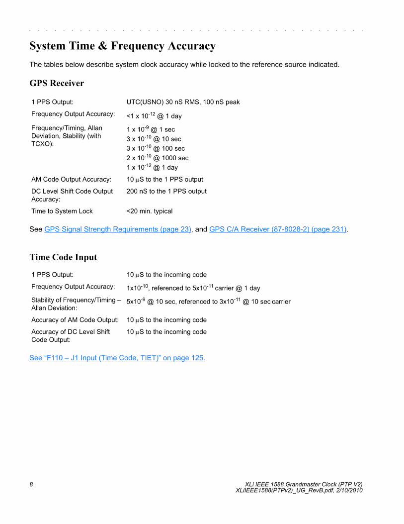
System Time & Frequency AccuracyThe tables below describe system clock accuracy while locked to the reference source indicated.
GPS Receiver
See GPS Signal Strength Requirements (page 23), and GPS C/A Receiver (87-8028-2) (page 231).
Time Code Input
See “F110 – J1 Input (Time Code, TIET)” on page 125.
1 PPS Output: UTC(USNO) 30 nS RMS, 100 nS peak
Frequency Output Accuracy: <1 x 10-12 @ 1 day
Frequency/Timing, Allan Deviation, Stability (with TCXO):
1 x 10⁻⁹ @ 1 sec3 x 10-10 @ 10 sec3 x 10-10 @ 100 sec2 x 10-10 @ 1000 sec1 x 10-12 @ 1 day
AM Code Output Accuracy: 10 μS to the 1 PPS output
DC Level Shift Code Output Accuracy:
200 nS to the 1 PPS output
Time to System Lock <20 min. typical
1 PPS Output: 10 μS to the incoming code
Frequency Output Accuracy: 1x10⁻¹⁰, referenced to 5x10-11 carrier @ 1 day
Stability of Frequency/Timing – Allan Deviation:
5x10⁻⁹ @ 10 sec, referenced to 3x10-11 @ 10 sec carrier
Accuracy of AM Code Output: 10 μS to the incoming code
Accuracy of DC Level Shift Code Output:
10 μS to the incoming code

Xli IEEE 1588 Grandmaster Clock (PTP V2) 9XLiIEEE1588(PTPv2)_UG_RevB.pdf, 2/10/2010,
2
5
1
S SSS S SSS S SSS S SSS S SSSS S SSS S SSS S SSS S SSS SS S
1 PPS Input
Aux Ref Input
If an Aux Ref input is available and enabled, the XLi assumes that Aux Ref is a better frequency source than its own oscillator. If a timing reference is not available (or becomes unavailable) and Aux Ref is enabled, the XLi locks to the Aux Ref input. Under those conditions, frequency output accuracy is equal to the reference < 1 x 10-12. To generate NTP and/or PTP times the total number of TAI Leap Seconds must be enterred manually.
See “6.4.4 Auxiliary Reference and IEEE 1588 Operational Information” on page 226.
Note: Manually set the time and date, when using 1 PPS or Aux Ref as the primary references. Set the date (year) when using IRIG A000, A130, B000, B120, or NASA 36 as the primary reference. See F3 – Time & Date (page 52).
Chassis
1 PPS Output: 10 μS to the incoming 1 PPS
Stability of Frequency/Timing – Allan Deviation:
5x10⁻⁹ @ 10 sec
Accuracy of AM Code Output: 10 μS to the incoming 1 PPS
Accuracy of DC Level Shift Code Output:
10 μS to the incoming 1 PPS
1U Chassis: Standard 19" EIA Rack System, hardware included
Receiver Size: 1.75 in. x 17.1 in. x 15.35 in.
Weight: Standard configuration, without options ~9.25 lb. Fully loaded ~ 10.95 lb

10 XLi IEEE 1588 Grandmaster Clock (PTP V2)XLiIEEE1588(PTPv2)_UG_RevB.pdf, 2/10/2010
S SSS S SSS S SSS S SSS S SSSS S SSS S SSS S SSS S SSS SS S
1
Standard Inputs and OutputsThe following specifications describe the standard (as opposed to optional) inputs and outputs on the standard configuration of the XLi.
Serial I/O Port
The standard serial data port is a bi-directional EIA standard RS-232C interface. The serial data port is configured via the Keypad / Display and Standard network port.
Note: Parity - NONE is only available/valid when Data Bits is set to 8.
See “F4 – Serial Port Configuration” on page 54.
NET – Network Port
The Ethernet port interface has a standard RJ-45 connector that provides IEEE 802.3 frame 10/100 Base-T Ethernet. The XLi can optionally be factory configured as a Network Time Protocol (NTP) server, which can be used to synchronize client computer clocks over a network. This function is only available with GPS and IRIG B input. See “F100 – Network Port Configuration & XLi Firmware” on page 106.
Interface: RS-232 or RS-422
Data Rates: 1200, 2400, 4800, 9600 and 19200 bps
Data Bits: 7 or 8
Parity: even, odd, or none
Stop Bits: 1 or 2
Connector: Male 9-pin D subminiature
Pin Assignment: 1------N/C2------Rx (RS-232)3------Tx (RS-232)4------N/C5------GND6------Rx- (RS-422)7------Rx+ (RS-422)8------Tx- (RS-422)9------Tx+ (RS-422)
Factory settings: 9600, 8, N, 1

Xli IEEE 1588 Grandmaster Clock (PTP V2) 11XLiIEEE1588(PTPv2)_UG_RevB.pdf, 2/10/2010,
2
5
1
S SSS S SSS S SSS S SSS S SSSS S SSS S SSS S SSS S SSS SS S
J1 Input – Time Code or Time Interval - Event Time
Time Code Input Specifications - Modulated (AM) and Demodulated (DC):
The Time Interval - Event Time (TIET) option measures a 1 PPS or Event input signal on J1 against the XLi derived time. The rising edge of the pulse is measured against XLi time with 5 nS resolution.
See “F110 – J1 Input (Time Code, TIET)” on page 125.
Note: Any stray input capacitance loading will impact TIET measurements
Format: IRIG-B120, B000, B120 1344, B000 1344IRIG-A130, A000 NASA 36 AM, NASA 36 DC
Amplitude (AM): 0.5 Vp-p to 10 Vp-p, 100 kΩ to ground
Ratio (AM): 3:1 ±10%
Amplitude (DC):
Logic Low:Logic Hi:
< 1.25V and Min. 300mV> 1.25V and Max 10V
Impedance: 100 kΩ, 50 Ω
Polarity: Positive or negative
Direction: Forward
Quantity: 1
Connector: Female BNC
Related Features Propagation delay 0-99999 μS. Error bypass. (See F110 on page 125)
Pulse Width 100 nS, min.
Active Edge: Rising
Amplitude (DC):
Logic Low:Logic Hi:
< 1.25V and Min. 300mV> 1.25V and Max 10V
Impedance: 100 kΩ, 50 Ω
Polarity: Positive
Resolution: 5 nS, Single Shot
Accuracy Refer to “System Time & Frequency Accuracy” on page 8

12 XLi IEEE 1588 Grandmaster Clock (PTP V2)XLiIEEE1588(PTPv2)_UG_RevB.pdf, 2/10/2010
S SSS S SSS S SSS S SSS S SSSS S SSS S SSS S SSS S SSS SS S
1
J2 Output – Rate Out or Programmable Pulse Output
The Programmable Pulse Output (PPO) option (part number 87-8024) generates a precisely synchronized trigger pulse at an arbitrary time and with arbitrary pulse width in integer multiples of 1 μS. The start and stop edges of the PPO can be programmed with 1 μS resolution.
See “F111 – J2 Output (Rate, PPO)” on page 130.
J3 Input – Auxiliary Reference or Frequency Measurement
Auxiliary Reference (Aux Ref):
Rate: 1 PPS, 10 PPS, 100 PPS, 1 kPPS, 10 kPPS, 100 kPPS, 1 MPPS, 5 MPPS, 10 MPPS, PPO (if PPO option is installed)
Duty cycle: 40-60% ± 10%
Amplitude (TTL): TTL Levels into 50 Ω
Quantity: 1
Connector: Female BNC
Factory Configuration: The Rate Output is default 10 MPPS
Pulse Width: Programmable in 1 μS steps
Start: Rising
Stop: Falling
Amplitude: TTL levels into 50 Ω
Accuracy Refer to “System Time & Frequency Accuracy” on page 8
Frequency: 1, 5, 10 MHz
Amplitude: 1 Vp-p to 10 Vp-p at 1 kΩ to ground
Amplitude: 1 Vp-p to 3 Vp-p at 50 Ω to ground
Impedance: Configurable 1 kΩ or 50 Ω to ground
SNR: >20db
Quantity: 1
Connector: Female BNC
Factory Configuration: Disabled

Xli IEEE 1588 Grandmaster Clock (PTP V2) 13XLiIEEE1588(PTPv2)_UG_RevB.pdf, 2/10/2010,
2
5
1
S SSS S SSS S SSS S SSS S SSSS S SSS S SSS S SSS S SSS SS S
The Frequency Measurement (Freq Meas) option: measures an external frequency applied to the J3 input relative to the XLi’s disciplined frequency.
See “F113 – J3 Input (Aux Ref, Freq Meas)” on page 134.
1 PPS – Pulse Per Second Output
If a time reference is unavailable, 1 PPS is as stable as the frequency reference (e.g., the system oscillator or Aux Ref).
CODE – Time Code Output
Time Code Output Specifications - Modulated (AM) and Demodulated (DC or DCLS)
Frequency: 1, 5, 10 MHz
Resolution 120 x 10-12@ 1 Second Interval12 x 10-12@ 10 Second Interval1 x 10-12@ 100 Second Interval
Range 1000 x10-6
Impedance: 1 kΩ, 50 Ω
Factory Configuration: Disabled
Accuracy Refer to “System Time & Frequency Accuracy” on page 8
Pulse width: 20 μS ±1 μS
On time edge: Rising
Amplitude: TTL Levels into 50 Ω
Quantity: 1
Connector: Female BNC
Format: IRIG-B120, B000, B120 1344, B000 1344IRIG-A130, A000NASA 36 AM, NASA 36 DC
Amplitude (AM): 3 Vp-p, into 50Ω ±10%
Ratio (AM): 3:1 ±10%
Amplitude (DC): TTL into 50Ω
Quantity: 1
Connector: Female BNC
Phasing: In phase with carrier ± 10 μS
Default Configuration: IRIG-B 120

14 XLi IEEE 1588 Grandmaster Clock (PTP V2)XLiIEEE1588(PTPv2)_UG_RevB.pdf, 2/10/2010
S SSS S SSS S SSS S SSS S SSSS S SSS S SSS S SSS S SSS SS S
1
Many IRIG reader devices only decode the BCD time-of-year (TOY) portion of the IRIG frame. Reader devices designed to the IRIG-B122, B002, A132, A002 standard should be compatible with the XLi’s time code outputs.
ALARM Output
Time Code Output IRIG-B120 w/ IEEE1344
The selectable Code output has an additional selection for IRIG-B-120 w/ IEEE1344. Configuration is via the Keypad / Display, RS232/422 and the Network port via telnet and HTML.
IRIG-B-120 IS DEFINED IN IRIG STANDARD 200-04 AS:
• Format B 100 pps• 1 = Sine wave amplitude modulated• 2 = 1KHz carrier/1mSec resolution• 0 = BCD TOY,CF,SBS
IEEE1344 IS DEFINED IN IEEE1344-1995(R2001) ANNEX F AS:
IRIG-B format, <sync>SS:MM:HH:DDD<control bits> <binary seconds>
where
<sync> is the on time marker
SS seconds 00-59 (60 during leap seconds)
MM minutes 00-59
HH hour of day 00-23
DDD day of year 001-366
High Z: Power off
High Z: Alarm (enabled alarm fault)
Low Z: Normal (no enabled alarm faults)
Drive: Open Collector
Max. Voltage: 25 VDC
Max. Current: 50 mA
Quantity: 1
Connector: Female BNC

Xli IEEE 1588 Grandmaster Clock (PTP V2) 15XLiIEEE1588(PTPv2)_UG_RevB.pdf, 2/10/2010,
2
5
1
S SSS S SSS S SSS S SSS S SSSS S SSS S SSS S SSS S SSS SS S
<control> 27 binary control characters, see Table 1 (reference IEEE1344)
<binary seconds> binary seconds of day
OUTPUT:
• Amplitude (AM): 3 Vp-p ±10%, into 50Ω • Ratio (AM): 3:1 ±10%• Qty: 1• Connector: BNC female• Phasing: In phase with the XLi 1PPS ± 10 us
Table 1:
Binary Time quality
Xli Estimated Time Error (ETE)
1111 Initial condition clock unlocked or 10Sec < ETE
1011 Clock unlocked and 1Sec < ETE <= 10Sec
1010 Clock unlocked and 100mSec < ETE <= 1Sec
1001 Clock unlocked and 10mSec < ETE <= 100mSec
1000 Clock unlocked and 1mSec < ETE <= 10mSec
0111 Clock unlocked and 100uSec < ETE <= 1mSec
0110 Clock unlocked and 10uSec < ETE <= 100uSec
0101 Clock unlocked and 1uSec < ETE <= 10uSec
0100 Clock unlocked and 100nSec < ETE <= 1uSec
0011 Clock unlocked and 10nSec < ETE <= 100nSec
0010 Clock unlocked and 1nSec < ETE <= 10nSec
0001 Clock unlocked and ETE <= 1nSec
0000 Clock locked to a reference source

16 XLi IEEE 1588 Grandmaster Clock (PTP V2)XLiIEEE1588(PTPv2)_UG_RevB.pdf, 2/10/2010
S SSS S SSS S SSS S SSS S SSSS S SSS S SSS S SSS S SSS SS S
1
Time Code Output IRIG-B000 w/ IEEE1344
The selectable Code output has an additional selection for IRIG-B-000 w/ IEEE1344, configuration is via the Keypad / Display, RS232/422 and the Network port via telnet and HTML.
IRIG-B-000 IS DEFINED IN IRIG STANDARD 200-04 AS:
• Format B 100 pps• 0 = Pulse width code• 0 = No carrier/index count interval• 0 = BCD TOY,CF,SBS
IEEE1344 IS DEFINED IN IEEE1344-1995(R2001) ANNEX F AS:
See above
OUTPUT:
• Amplitude (DC): TTL into 50 Ω
• Qty: 1• Connector: BNC female• Phasing: In phase with the XLi 1PPS ± 200ns
Time Code Input IRIG-B120 w/ IEEE1344
The selectable Code input has an additional selection for IRIG-B-127. Configuration is via the Keypad / Display, RS232/422 and the Network port via telnet and HTML.
IRIG-B-120 IS DEFINED IN IRIG STANDARD 200-04 AS:
• Format B 100 pps• 1 = Sine wave amplitude modulated• 2 = 1KHz carrier/1mSec resolution• 0 = BCD TOY,CF,SBS

Xli IEEE 1588 Grandmaster Clock (PTP V2) 17XLiIEEE1588(PTPv2)_UG_RevB.pdf, 2/10/2010,
2
5
1
S SSS S SSS S SSS S SSS S SSSS S SSS S SSS S SSS S SSS SS S
IEEE1344 IS DEFINED IN IEEE1344-1995(R2001) ANNEX F AS:
See section TIME CODE OUTPUT IRIG-B120 200-04 W/ IEEE1344 for definition
XLI SYNC:
The XLi first synchronizes to IRIG-B-120 w/ IEEE1344 when the Time Quality control bits are = 0000. The XLi remains synchronized (Locked) while the Time Quality control bits are 0000 through 0101 (ETE < 10uSec). The XLi utilizes the IRIG-B-120 BCD TOY, IEEE1344 year, leap second, and leap second pending bit as the UTC epoch. The XLi time format selection remains on the XLi including the Daylight saving time offset.
INPUT:
• Amplitude (AM): 0.5 Vp-p to 10 Vp-p, 100 kΩ to ground• Ratio (AM): 3:1 ±10%• Qty: 1• Connector: BNC female
Time Code Input IRIG-B000 w/ IEEE1344
The selectable Code input has an additional selection for IRIG-B-000 w/ IEEE1344. Configuration is via the Keypad / Display, RS232/422 and the Network port via telnet and HTML.
IRIG-B-007 IS DEFINED IN IRIG STANDARD 200-04 AS:
• Format B 100 pps• 0 = Pulse width code• 0 = No carrier/index count interval• 0 = BCD TOY,CF,SBS
IEEE1344 IS DEFINED IN IEEE1344-1995(R2001) ANNEX F AS:
See section TIME CODE OUTPUT IRIG-B120 W/ IEEE1344 for definitions
XLI SYNC:
The XLi first synchronizes to IRIG-B-120 w/ IEEE1344 when the Time Quality control bits are = 0000. The XLi remains synchronized (Locked) while the Time Quality control bits are 0000 through 0101 (ETE < 1uSec). The XLi utilizes the IRIG-B-120 BCD TOY, IEEE1344 year, leap second, and leap second pending bit as the UTC epoch. The XLi time format selection remains on the XLi including Daylight saving time offset.
18 XLi IEEE 1588 Grandmaster Clock (PTP V2)XLiIEEE1588(PTPv2)_UG_RevB.pdf, 2/10/2010
S SSS S SSS S SSS S SSS S SSSS S SSS S SSS S SSS S SSS SS S
1
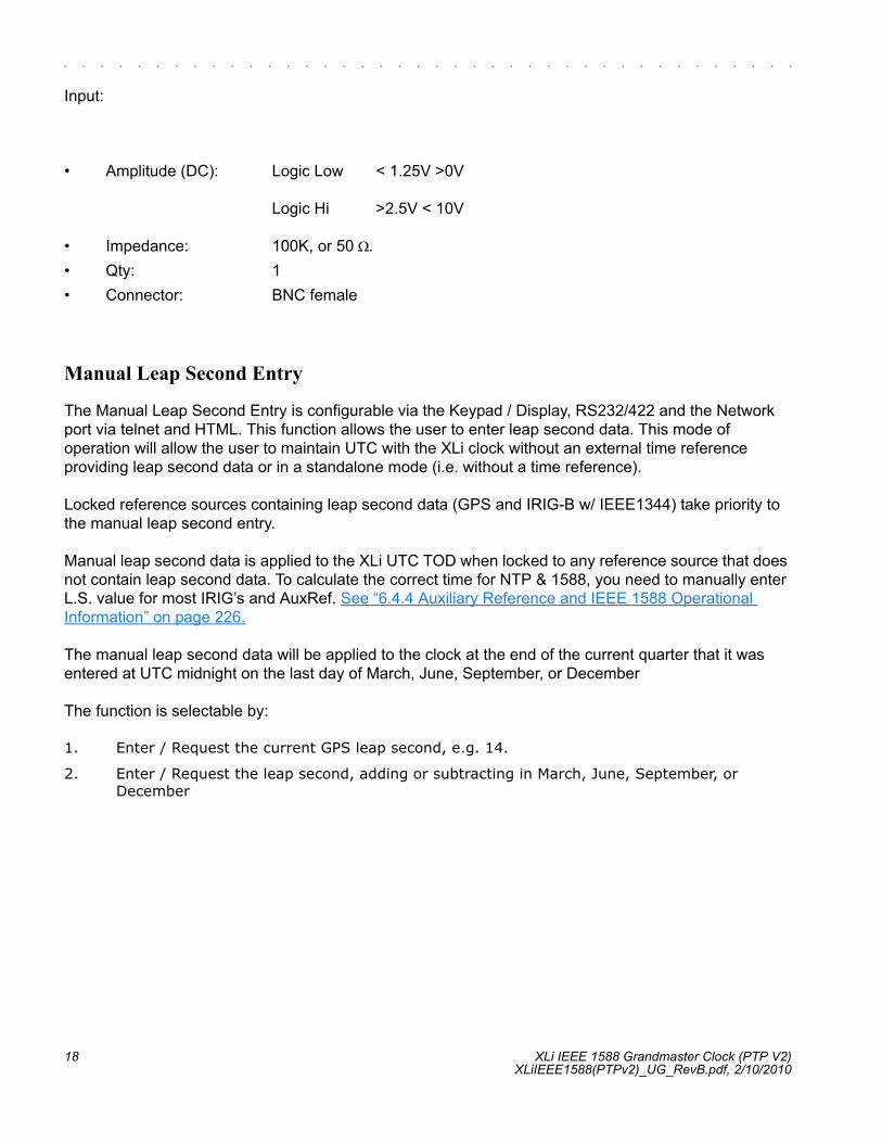
Input:
• Amplitude (DC): Logic Low < 1.25V >0V
Logic Hi >2.5V < 10V
• Impedance: 100K, or 50 Ω.• Qty: 1• Connector: BNC female
Manual Leap Second Entry
The Manual Leap Second Entry is configurable via the Keypad / Display, RS232/422 and the Network port via telnet and HTML. This function allows the user to enter leap second data. This mode of operation will allow the user to maintain UTC with the XLi clock without an external time reference providing leap second data or in a standalone mode (i.e. without a time reference).
Locked reference sources containing leap second data (GPS and IRIG-B w/ IEEE1344) take priority to the manual leap second entry.
Manual leap second data is applied to the XLi UTC TOD when locked to any reference source that does not contain leap second data. To calculate the correct time for NTP & 1588, you need to manually enter L.S. value for most IRIG’s and AuxRef. See “6.4.4 Auxiliary Reference and IEEE 1588 Operational Information” on page 226.
The manual leap second data will be applied to the clock at the end of the current quarter that it was entered at UTC midnight on the last day of March, June, September, or December
The function is selectable by:
1. Enter / Request the current GPS leap second, e.g. 14.
2. Enter / Request the leap second, adding or subtracting in March, June, September, or December

Xli IEEE 1588 Grandmaster Clock (PTP V2) 19XLiIEEE1588(PTPv2)_UG_RevB.pdf, 2/10/2010,
2
5
1
S SSS S SSS S SSS S SSS S SSSS S SSS S SSS S SSS S SSS SS S
CertificationsUL, C-UL: UL 1950/CSA 22.2 950, Standard for Safety, Information Technology
Equipment (ITE)
FCC: FCC Part 15, Subpart B
CE: 89/336/EEC EMC Directive73/23/EEC Low Voltage Safety DirectiveIEC 60950 Safety of Information Technology Equipment (ITE)

20 XLi IEEE 1588 Grandmaster Clock (PTP V2)XLiIEEE1588(PTPv2)_UG_RevB.pdf, 2/10/2010
S SSS S SSS S SSS S SSS S SSSS S SSS S SSS S SSS S SSS SS S
1This page intentionally left blank.

Xli IEEE 1588 Grandmaster Clock (PTP V2) 21XLiIEEE1588(PTPv2)_UG_RevB.pdf, 2/10/2010,
2
5
1
S SSS S SSS S SSS S SSS S SSSS S SSS S SSS S SSS S SSS SS S
3: Installation/Configuration
Installing the GPS AntennaFor units that include the GPS option, install the GPS antenna and cable as described below.
Selecting a GPS Antenna Site Outdoors
Select a site that...
• Is the highest point available• Offers a full 360° view horizontally, to within 10° vertically of the horizon• Is higher than neighboring buildings/obstructions• Is protected from strong radio frequency (RF) and microwave transmissions• Is set away from RF-reflective surfaces that cause multipath interference• Is set 3 ft. (1 m) away from other GPS antennas
Avoid...
• Mounting the antenna between tall buildings or next to walls and equipment• Cable runs from the antenna to the receiver that exceed the specified length• Patching multiple cables together to make a single cable run• Running the cable through bulkheads and along side high-energy cables• Crimping or damaging the cable
Blocked signals and multipath cancellation significantly increase GPS acquisition time. Multipath cancellation is caused by reflected signals that reach the antenna out of phase with the direct signal due to vertical reflective objects positioned to the side and above the antenna. To solve these problems, mast mount the antenna at least 1 meter away from and above the reflecting surface.
Mounting the GPS Antenna
Mount the GPS antenna on an antenna mast (recommended) or on the peak of a building. The GPS antenna kit includes special mounting brackets. For the mast, use 2-inch (5.08-cm) diameter water pipe or conduit that is rigid enough to withstand high winds without flexing. Use guy wires to stabilize masts longer than 10 ft. (3.048 m).
Notes:
• The XLi requires a 12 Volt-compatible antenna. Antennas not rated for 12 V will be damaged.• Use a splitter to connect a GPS antenna to multiple receivers. Avoid using BNC “T” connectors.• The L1 GPS antenna is designed to operate with up to 150 ft. (60.96 m) of RG-59 coax cable. An
optional Down Converter can be used for cable runs of 1,500 ft. (457.2 m) using RG-58 coaxial cable.

22 XLi IEEE 1588 Grandmaster Clock (PTP V2)XLiIEEE1588(PTPv2)_UG_RevB.pdf, 2/10/2010
S SSS S SSS S SSS S SSS S SSSS S SSS S SSS S SSS S SSS SS S
1
Figure 3: L1 GPS Antenna - methods for cabling and mounting
Connecting the Antenna to the Receiver
Note that the pipe in the left image of Figure 3 does not separate from the antenna as shown. It is shown in this image for conceptual purposes.
The antenna itself is mounted inside the top half of white antenna assembly. In the image above, this part has the Symmetricom logo on it and the dotted line with the TNC signal connector below it. The top half of the antenna housing is sealed and therefore weather-proof.
The lower part of the white antenna housing shown above, below the dotted line, is used for support and for protecting the antenna cable connection. The two halves of the white antenna housing are secured together by four 4-40 UNC captive screws. The two antenna housing halves come together with an O-

Xli IEEE 1588 Grandmaster Clock (PTP V2) 23XLiIEEE1588(PTPv2)_UG_RevB.pdf, 2/10/2010,
2
5
1
S SSS S SSS S SSS S SSS S SSSS S SSS S SSS S SSS S SSS SS S
ring and a key tab and groove. Neither the O-ring or key are critical to the antenna operation. The O-ring makes for a more weather proof seal for the antenna connector. The key ensures that the housing always connects in the same orientation.
The pipe that is shown disconnected above, also acts as a protective housing for the optional antenna preamplifier. A preamplifier should be connected to the antenna assembly if the distance between the antenna and receiver is greater than 150 ft. The preamplifier connects to the TNC connector on the antenna housing by a three inch TNC to TNC adapter cable. The other end of the preamplifier is then connected to the signal cable from the receiver.
A 50 ft cable is provided with each antenna assembly. If the distance between the antenna assembly and receiver is greater than 50 ft, replace the 50 ft cable with a longer cable as opposed to adding an extension to the 50 ft cable.
To connect the antenna cable to the antenna assembly, do the following:
1. Separate the antenna by loosening the four captive antenna housing screws.
2. Pass the TNC end of the receiver signal cable through the support pipe and lower half ofthe antenna assembly and connect it to the antenna signal connector.
a. If a preamplifier is to be used, connect the three inch preamplifier adapter cable to the antenna signal connector.
b. Connect the preamplifier to the adapter cable.
c. Connect the receiver signal cable to the preamplifier.
3. Reconnect the antenna by tightening the four captive antenna housing screws. Make sure that the O-Ring is correctly sitting in its groove and that the Key tab and groove are engaged.
GPS Signal Strength Requirements
Refer to Figure 4: GPS Signal Strength Requirements.The required external gain at the GPS receiver’s ANTENNA connector is between 20 and 36 dB.
For example, the Symmetricom GPS antenna provides approximately 41 dB of gain. If one subtracts the 16-21 dB loss of the 150 foot RG-59 coax antenna cable supplied by Symmetricom, the external gain reaching the ANTENNA connector is between 20 and 36 dB, which meets the requirement. Abide by the minimum input gain requirements when using other cable types and GPS antennas.

24 XLi IEEE 1588 Grandmaster Clock (PTP V2)XLiIEEE1588(PTPv2)_UG_RevB.pdf, 2/10/2010
S SSS S SSS S SSS S SSS S SSSS S SSS S SSS S SSS S SSS SS S
1
Other factors, such as radiation, coverage, VSWR, and input impedance also affect system performance. Symmetricom recommends using the standard antenna and cable provided.
Figure 4: GPS Signal Strength Requirements
GPS-related Accessories
The following options can be obtained from Symmetricom to:
• Protect against lightning and field-induced electrical surges.• Connect multiple GPS receivers to a single antenna.• Extend the range of the GPS antenna cable.
Lightning Arrestor
Lightning may damage GPS system components and receiving equipment, even without a direct hit, resulting in costly repairs and critical interruption of service. The lightning arrestor is designed to work in conjunction with a low-resistance, low-inductance ground to protect your GPS receiver and elements of the antenna system from lightning discharges and field-induced electrical surges. In-line lightning arrestors are mounted between the antenna and the point where the cable enters the building and require no additional power or wiring except the ground lead.
Antenna Splitter
An antenna splitter may be used to drive multiple GPS receivers using a single antenna. With built-in amplification to overcome splitter losses, the Active Splitters may be conveniently cascaded without adding separate amplifiers and bias-tees between splitters. Power is conveniently obtained from the GPS receiver(s) connected to the amplifier, eliminating the need for a separate dc power supply and wiring.
In-Line Antenna Amplifier
In-line amplifiers overcome signal attenuation in by amplifying the GPS signal. Mounting the amplifier inside the mounting mast helps protect it from moisture and exposure to the elements. Use the in-line amplifier for cable runs of 150 to 300 feet (45 m to 90 m). Please contact a Symmetricom Sales Representative for information on how to extend the distance from the antenna to the receiver.

Xli IEEE 1588 Grandmaster Clock (PTP V2) 25XLiIEEE1588(PTPv2)_UG_RevB.pdf, 2/10/2010,
2
5
1
S SSS S SSS S SSS S SSS S SSSS S SSS S SSS S SSS S SSS SS S
Making Additional ConnectionsMake the following optional connections to the standard input/output connectors on the XLi back panel:
• The ANTENNA connector to a GPS antenna cable. (Note: Use a 12-volt capable GPS antenna.)• The NET network port (RJ-45) to an ethernet network using Cat 5 cable (supplied). This
connection is needed to manage the XLi remotely, or to use the optional NTP function.• The SERIAL I/O connector to a PC using the supplied RS-232 null modem cable. • J1, J2, and J3, if needed. See “F110 – J1 Input (Time Code, TIET)” on page 125, “F111 – J2
Output (Rate, PPO)” on page 130, “F113 – J3 Input (Aux Ref, Freq Meas)” on page 134
.
Figure 5: Connectors: ANTENNA, SERIAL I/O, J1, J2, J3, NET, 1PPS, CODE, ALARM
Connecting the Power SupplyWarning: Ensure that a disconnect device, such as a switch, with the appropriate voltage/
current rating is provided when operating/installing the XLi.
Connect the Power Supply it to a power source. The green STATUS light indicates that the XLi is receiving power.
Notes for optional DC power supplies:
• Use a 15 amp circuit breaker in series with the DC power source; avoid connecting directly to a DC power source without the breaker.
• 14 gage wire is the minimum recommended for DC power source hookup. • DC power supply only to be used in a restricted access area.• The screw torque range on the Power Terminal Block is 5 to 8 inch pounds.• When connecting to a DC power source, first connect the positive power cable to “+” on the
power supply, then connect the negative power supply cable to “−”.
Upon receiving power, the XLi goes through its startup sequence; displaying “BOOTING”, “LOADING”, and “STARTING”. After approximately 40 seconds, the XLi displays the clock status, and user interfaces (front panel/command line) become available.

26 XLi IEEE 1588 Grandmaster Clock (PTP V2)XLiIEEE1588(PTPv2)_UG_RevB.pdf, 2/10/2010
S SSS S SSS S SSS S SSS S SSSS S SSS S SSS S SSS S SSS SS S
1
Configuring Network SettingsThe following additional steps are required to make the XLi operational on a network. Make the XLi operational on a network if you plan on managing the XLi remotely over the network or distributing timing information from the XLi over the network
Notes:
• To prevent TELNET and web interface (HTTP) access to the XLi, change Remote Lockout to LOCK. Doing this shuts down TELNET and HTTP access through the XLi’s network port so that the XLi’s functions are available only through the keypad/display interface, and through the serial port command line interface.
• For additional information, consult the relevant topics covering the F100 commands in the XLi User’s Guide and Reference Manual.
Configuring the Time DisplayUse the following functions to configure how the XLi to displays time. The keypad button sequences in parentheses provide show how to select these functions and enter the desired settings:
F1 – Time Zone Offset: Enter the difference, in hours, between UTC and the standard time zone of the time display. See “F1 – Time Zone Offset” on page 50 and “F: World Map of Time Zones:” on page 303 for more information.
For example, US Pacific Standard Time is UTC -08:00, while Japan Standard Time is UTC +9. To enter the time zone offset, press the following buttons:
Press Result
ENTER Displays “FUNCTION”
100 Enters 100 as the function number
ENTER Displays Function 100’s first screen: “COMPANY 00-A0-69…”
ENTER Displays “IP ADDRESS…”
1-9… Enter the unit’s IP Address (e.g., 192.168.0.11)
ENTER Displays “SUBNET MASK…”
1-9… Enter the Subnet Mask (e.g., 255.255.255.000)
ENTER Displays “DEFAULT GATEWAY…”
1-9… Enter the Default Gateway’s IP address (e.g., 192.168.0.1)
ENTER Displays “10 100 BASE-T – 10”
ENTER Displays “REMOTE LOCKOUT – UNLOCK” (Leave unchanged)
ENTER (5 times) Displays “SAVE CHANGES – YES”
ENTER Saves the new network parameters, and reboots the XLi

Xli IEEE 1588 Grandmaster Clock (PTP V2) 27XLiIEEE1588(PTPv2)_UG_RevB.pdf, 2/10/2010,
2
5
1
S SSS S SSS S SSS S SSS S SSSS S SSS S SSS S SSS S SSS SS S
The user would enter F1 (ENTER, 1, ENTER), set a positive or negative sign (up/down arrow button), and enter the number of hours (0800 or 0900).
F2 – 12/24-Hour Format: Select a 12 or 24-hour display format. The default setting is the 24-hour display format, which represents 6 PM as “18:00”. The user would enter F2 (ENTER, 2, ENTER), See “F2 – 12/24 Hour Format” on page 51.
F3 – Time Date: If you’re using IRIG time code as the primary reference source, verify or update the current year in F3. If you’re using GPS as the primary reference source, you can skip this step. See “F3 – Time & Date” on page 52.
F66 – Daylight Saving Time (DST): If needed, set when Local time enters and leaves DST. See “F66 – Daylight Saving Time (DST) Mode” on page 79.
F69 – Time Mode: Select the type of time shown on the front panel display and output by functions F8, F9, and F90. See “F69 – Time Mode” on page 84. The five choices are as follows:
• TAI (International Atomic Time) is the basis for UTC and GPS time.• UTC (Coordinated Universal Time) differs from GPS Time by the addition of leap-second
corrections to compensate for variations in the earth’s rotation.• GPS time is derived directly from the GPS constellation and doesn’t contain any leap-second
adjustments or other GPS-to-UTC corrections.• Standard Time is UTC plus a time zone offset. For example, Pacific Standard Time is UTC
minus 8 hours• Local Time is UTC adjusted by the standard time zone offset and the daylight saving time
adjustment (if in effect).
Configuring the IEEE 1588 V2 Card(s)Two versions of the XLi IEEE 1588 clocks are currently available.
The first version has:
• An IEEE 1588 card configured as a PTP master in Option Bay 4• A GPS receiver in Option Bay 1
The second version has:
• • An IEEE 1588 card configured as a PTP master in Option Bay 4• • An IEEE 1588 card configured as a PTP slave in Option Bay 2• • A GPS receiver in Option Bay 1

28 XLi IEEE 1588 Grandmaster Clock (PTP V2)XLiIEEE1588(PTPv2)_UG_RevB.pdf, 2/10/2010
S SSS S SSS S SSS S SSS S SSSS S SSS S SSS S SSS S SSS SS S
1
Note: With two IEEE cards, be mindful of the Option Bay number when changing the settings.
Note: The IEEE 1588 card requires 5 minutes from power up to initialize. Until then, the card does not appear in the user interfaces, or is reported as “PLEASE WAIT FOR PTP V2 INITIALIZATION"
PTP Master
The XLi PTPv2 Configuration Administration Web page is available for determining the configuration of and configuring IEEE 1588 V2 Option cards. The IEEE 1588 V2 Option card located in Option Bay 4 is preconfigured as a PTP master, as shown follows:
• PTP AVAILABILITY - OPTION BAY 4• Static IP Address - 010.050.000.103• Static IP Subnet Mask - 255.255.000.000• Static IP Default Gateway - 010.050.000.001• DHCP – ENABLE• Port – ENABLE
• XLi Reference Clock Configuration - Master• Priority 1 - 128• Priority 2 - 128• Domain Number – 0
• Sync Interval /Min (E2E) Delay Req Interval – 1 sec / 1 sec• Mean Announce Msg Tx Interval – 2 sec• Announce Receipt Timeout Multiple - 3• Delay Mechanism – E2E• Min Peer Delay Req Tx Interval – 1 sec
Use the XLi PTPv2 Configuration Administration Web page to modify the following settings:
• If a DHCP server is not available on the timing network, disable DHCP and set values for the PTP Network Static IP Address, Static IP Subnet Mask, and Static IP Default Gateway.
• Configure the following settings so that the PTP master and PTP slaves match each other:• Sync Interval - The rate at which synchronization packets are sent out. The factory setting, 1
second, is the recommended value.

Xli IEEE 1588 Grandmaster Clock (PTP V2) 29XLiIEEE1588(PTPv2)_UG_RevB.pdf, 2/10/2010,
2
5
1
S SSS S SSS S SSS S SSS S SSSS S SSS S SSS S SSS S SSS SS S
• Priority 1 – Primary setting used to force the selection of a master. The factory default is 128.• Priority 2 – Secondary setting used to force the selection of a master. The factory default is 128• Domain Number - Defines the PTP master as a member of a logical timing network. The factory
default is 0.• Delay Mechanism - The type of mechanism used by the PTP v2 protocol to determine the time
delay between master and slave. The factory default is end-to-end (E2E).
PTP Slave
To reconfigure the IEEE 1588 card from being a PTP master to being a PTP slave, complete the following steps:
1. Having logged in to the XLi web interface, from the XLi Admin Homepage, click the link Option Bay 4 IEEE 1588v2 Master. The selected IEEE 1588 web page takes approximately 3 seconds to load.
2. Set XLi Reference Clock Configuration to Slave Primary.
3. Try operating with Slave Clock Sync Jitter at Low. Timing networks with bursty or heavy traffic, routers, or many layers of hubs and switches may need the Sync Jitter High setting.
4. Click the Submit Changes button.
5. The XLi front panel display should show "LOCKED PTP PRI" soon after.
The IEEE 1588 V2 Option card is now operating as a PTP slave and is also functioning as the primary reference source to the XLi Clock. The GPS receiver, which was previously operating as the primary reference source to the XLi Clock, is now a STANDBY reference source.

30 XLi IEEE 1588 Grandmaster Clock (PTP V2)XLiIEEE1588(PTPv2)_UG_RevB.pdf, 2/10/2010
S SSS S SSS S SSS S SSS S SSSS S SSS S SSS S SSS S SSS SS S
1
Using the Command Line InterfaceThe next two sections show how to connect to the XLi using the serial and network ports. Both the serial port and the network port give the user access to the XLi’s command line interface. While the keypad/display interface provides a simple menu-driven user interface, the command line interface features:
• Additional functions that aren’t available through the keypad/display• Remote access over a network
To use the command line interface, refer to the explanations and examples in the ‘Command Line’ subsections for each function in the XLi User’s Guide and Reference Manual.
Connecting to the Serial Port
Complete the following steps to set up and use the Serial Port to communicate with the XLi.
Verify that the XLi’s serial port settings are as follows: (Keypad: ENTER–4–ENTER. Use the UP/DOWN ARROWs.)
• Serial Port – RS232• Baud rate – 9600• Data bits – 8• Parity – NONE• Stop bits – 1
Note: Parity set to NONE is only valid when Data Bits is set to 8.
Connect a null-modem cable from the PC’s serial port to the XLi’s “SERIAL I/O” port.
If needed, configure your PC’s terminal emulation program to match the serial port settings above (9600, 8, N, 1). Set Flow Control to “None”.
One terminal emulation program, HyperTerminal, is usually found in Microsoft Windows under Programs – Accessories or Programs – Accessories – Communications.
Initiate a serial port connection between the terminal emulation program and the XLi. (The Serial Port connection does not require you to log in.)
Once connected, press the Enter key on your keyboard to get a command prompt.
From the command prompt, “>”, you can use the functions described in the “Function Reference” section of the XLi User’s Guide and Reference Manual. The ‘Command Line’ sub-sections provide instructions and examples.
Troubleshooting Tip: If the terminal emulation software has trouble displaying XLi responses (looks like the unit doesn’t respond to inputs), add a 1 ms/character delay to the software’s serial port settings.

Xli IEEE 1588 Grandmaster Clock (PTP V2) 31XLiIEEE1588(PTPv2)_UG_RevB.pdf, 2/10/2010,
2
5
1
S SSS S SSS S SSS S SSS S SSSS S SSS S SSS S SSS S SSS SS S
Connecting to the Network Port (TELNET)
The network port provides remote access to the XLi’s command line interface. Complete the following steps to connect to the network port.
1. Use function F100 IP – IP Address (page 108), to obtain the XLi’s IP address.
2. Open a telnet session from your PC to the XLi. - In Windows, click Start – Run, enter telnet ###.###.###.### (where the #s are the XLi’s
IP address), and click OK. - Open a telnet session using a program such as HyperTerminal, TeraTerm Pro, or Minicom.
Consult the program’s documentation for instructions.
3. Log in as user name “operator” and password, “janus”. Press Enter on your keyboard to get a command prompt.
From the command prompt, “>”, you can use the functions described in the “Function Reference” section of the XLi User’s Guide and Reference Manual. The ‘Command Line’ sub-sections provide instructions and examples.
Related topics:
• “Configuring Network Settings” on page 26• “F100 L/LOCK/UNLOCK – Remote Lockout” on page 112
Using the Web InterfaceThe network port also provides remote access to the XLi’s web interface. To connect to the web interface:
1. Use function F100 – Network Port Configuration & XLi Firmware (page 106) on the front panel/key-pad or F100 IP – IP Address (page 108)on the command line, to obtain the IP address of the XLi.
2. Enter the XLi’s IP address in the address bar of a web browser.
3. At the XLi Home Page, click the Login button, (see note after step 5).
4. Enter the appropriate user name and password. The factory default settings are “operator1” through “operator10” for the user names, and “zeus” for the passwords. Also “user1” through “user10” for the user names, and “ttm” for the passwords. In some cases, older units that have

32 XLi IEEE 1588 Grandmaster Clock (PTP V2)XLiIEEE1588(PTPv2)_UG_RevB.pdf, 2/10/2010
S SSS S SSS S SSS S SSS S SSSS S SSS S SSS S SSS S SSS SS S
1
been upgraded may have “casey” as the password. Settings are “operator1” through “operator10” for the user names, and “casey” for the passwords. Also “user1” through “user10” for the user names, and “ttm” for the passwords.
5. Click the Login button with your mouse.
Note: Keep track of the user name and password. There is no command to reset the user name and password to the factory default settings.
For more information, see “Web Interface” on page 44.
Installing or Removing Option CardsWarning: Installing and removing option cards can expose dangerous voltages that can cause
electric shock resulting in injury or death. Disconnect all power before installing or removing option cards. Dangerous voltages may be present in option cards and in the unit even when the power is disconnected.
To install an option card:
1. Set the unit up on a clean, safe, stable work surface that provides good visibility and maneuverabil-ity to work with screwdriver.
2. On the back panel, select an option bay and unscrew the retaining screws and remove the small aluminum panel from the option bay.
3. Line up the edges of the card with the guide grooves in the option bay and slide it in.
4. When the card is in almost all the way, push it firmly the rest of the way in until the faceplate of the option card is flush with the back panel.
5. Insert and tighten the retaining screws so the option card is secured in place.
To remove an option card, remove the screws, pull the card out, and secure the small aluminum panel in its place with the screws.
Additional ConfigurationThis section:
• Provides the factory settings of several XLi configurations • Identifies which functions can be used to change those settings, and a cross-reference to the
corresponding page in this manual.• Provides instructions for changing the settings, if needed.
Note: Unless specified, the settings remain the same as those in the Standard XLi.

Xli IEEE 1588 Grandmaster Clock (PTP V2) 33XLiIEEE1588(PTPv2)_UG_RevB.pdf, 2/10/2010,
2
5
1
S SSS S SSS S SSS S SSS S SSSS S SSS S SSS S SSS S SSS SS S
Standard XLi
The standard XLi configuration comes with an AC Power supply and CPU module. The standard XLi does not require changes to its factory settings, which are as follows:
Additionally, the Standard XLi’s factory settings for F73 are as follows:
Description Setting Function & Cross Reference
J1 Configuration IRIG-B (120 AM) “F110 – J1 Input (Time Code, TIET)” on page 125
J1 Time Reference Primary “F110 – J1 Input (Time Code, TIET)” on page 125
J2 Rate Out 10 MPPS “F111 – J2 Output (Rate, PPO)” on page 130
J3 Configuration Aux Ref Disabled “F113 – J3 Input (Aux Ref, Freq Meas)” on page 134
1 PPS 1 PPS – non configurable Non configurable
Code Output Format IRIG-B (120 AM) “F90 – Code Output Configuration” on page 104
Reference Source PRI “F74 – Clock Source Control” on page 102
Indicator/Parameter Name Factory Setting
PLL Locked Alarm Enabled
Low Phase Noise (LPN) PLL Locked Alarm Enabled
GPS Primary Receiver Alarm Disabled
GPS Secondary Receiver Alarm Disabled
IRIG Fault Alarm Enabled
Aux Ref Fault Alarm Disabled
Primary Power Alarm Enabled
Secondary Power Alarm Disabled
Rubidium oscillator (visible on display when Rb Osc is installed) Alarm Disabled
DAC Alarm Disabled
First Time Lock Alarm Enabled
Time Error Alarm Enabled
Time (Error) Threshold 0000 nS
Alarm LED Blink Alarm Enabled
Timeout Alarm Enabled
Timeout Delay 300 sec.
Power-On Alarm Suppress 300 sec.
NTP Alarm Enabled

34 XLi IEEE 1588 Grandmaster Clock (PTP V2)XLiIEEE1588(PTPv2)_UG_RevB.pdf, 2/10/2010
S SSS S SSS S SSS S SSS S SSSS S SSS S SSS S SSS S SSS SS S
1
XLi with a GPS Reference
This XLi configuration includes a GPS receiver factory configured as the primary reference source. Except for the following functions, the factory settings are the same as those for the Standard XLi:
XLi with GPS and Time Code References
To configure an XLi with a GPS Reference to use a time code input on J1 as a secondary reference source, complete the following additional steps:
• Evaluate the relative quality of the time code source versus GPS to ensure that switching from one to the other is acceptable.
• Set the Time Code as ‘SECONDARY’ using F110 – J1 Input (Time Code, TIET). • Set F74 – Clock Source Control to “PRI-SEC-SEC”.• Enable the IRIG alarm in F73 – Alarm Control / Status.
The following table indicates the section to go to for additional information:
Verifying Antenna Installation
After completing the above steps, use the keypad/display to verify the following:
• In F119 – GPS Receiver Configuration (page 141), after approximately 20 minutes of operation, check that GPS STATUS is LOCKED and GPS ANTENNA is OK.
• In F73 – Alarm Control / Status (page 89), check that the GPS PRI is OK and is ALARM ENABLED (the same for GPS SEC, if two GPS receivers are present). Clear any alarm latches if present.
• Press the STATUS key. “LOCKED GPS PRI” should appear on the front panel display without an asterisk. If an asterisk appears, it means that a reference source is not available.
Description Setting Function & Cross Reference
J1 Time Reference STANDBY “F110 – J1 Input (Time Code, TIET)” on page 125
GPS Antenna Cable Delay 60 nS delay “F51 – GPS Antenna Cable Delay” on page 71
GPS Time Reference Bay 1 - Primary “F119 – GPS Receiver Configuration” on page 141
GPS Primary Alarm Enabled “F73 – Alarm Control / Status” on page 89
Description Setting Function & Cross Reference
J1 Time Reference Change from STANDBY to SECONDARY “F110 – J1 Input (Time Code, TIET)” on page 125
Reference Source Change from PRI to PRI – SEC – SEC “F74 – Clock Source Control” on page 102
IRIG (alarm) Change from DISABLED to ENABLED “F73 – Alarm Control / Status” on page 89

Xli IEEE 1588 Grandmaster Clock (PTP V2) 35XLiIEEE1588(PTPv2)_UG_RevB.pdf, 2/10/2010,
2
5
1
S SSS S SSS S SSS S SSS S SSSS S SSS S SSS S SSS S SSS SS S
To troubleshoot a problematic Antenna installation, recheck the physical location of the antenna, the cabling, and the configuration settings described in this manual.
Rack Mounting the XLiThe XLi comes with the following parts needed to mount the XLi securely in any EIA standard 19-inch (48.26-cm) rack:
• 2 mounting brackets• 4 flat-head, Phillips screws
Have the following items ready and available:
• The appropriate AC or DC power source to connect to the XLi’s power supply.• A #2 size Phillips bit screwdriver
To rack mount the XLi:
• Unscrew the four phillips-head screws from the front end of the side panels.• Use the same screws to attach the rack mount brackets, as shown.• Tighten the screws using a #2 size Phillips screwdriver. • Position the XLi in any EIA Standard 19-inch (48.26 cm) rack system, and line up holes in the
brackets with the holes in the rack.• Secure the brackets to the rack using rack mount screws.

36 XLi IEEE 1588 Grandmaster Clock (PTP V2)XLiIEEE1588(PTPv2)_UG_RevB.pdf, 2/10/2010
S SSS S SSS S SSS S SSS S SSSS S SSS S SSS S SSS S SSS SS S
1
Note: Ensure that the ambient operating temperature does not exceed +50° C. Install the XLi chassis so that the top and bottom holes are unobstructed and have sufficient clearance to allow 6 cfm of air to pass through the chassis. To maintain recommended operating temperatures, install a rack-cooling fan capable of 100 cfm in heavily loaded racks.

Xli IEEE 1588 Grandmaster Clock (PTP V2) 37XLiIEEE1588(PTPv2)_UG_RevB.pdf, 2/10/2010,
2
5
1
S SSS S SSS S SSS S SSS S SSSS S SSS S SSS S SSS S SSS SS S
4: User InterfacesThe XLi features three user interfaces for controlling the XLi’s functions:
• A keypad/display interface on the front panel of the XLi• A command line interface, available through the serial and network ports• A web interface, available from a browser connected to the XLi’s network port.
There is also an Alarm Status LED on the front panel.
Card Positions
In the user interfaces, the card positions are referred to by Option Bay number (see Figure 6).
Figure 6: Option bay positions as seen from the rear of the XLi 1 U chassis.
Alarm Status LEDThe Alarm Status LED, located on the front panel, displays the alarm-state of the XLi unit. The LED has four states:
Notes: • The amber LED can turn green again while the reference source input remains unlocked
because:
Dark = Power is off.
Green = No F73-related alarms. The current reference source input is locked.
Amber = No F73 Alarms. Time-out Delay is counting down, but hasn’t elapsed. The current reference source input is unlocked (e.g. broken antenna cable or no GPS signal)
Red = An indicator in F73 has triggered an alarm. Check F73 to find out what the fault/unlock condition is and take appropriate action.

38 XLi IEEE 1588 Grandmaster Clock (PTP V2)XLiIEEE1588(PTPv2)_UG_RevB.pdf, 2/10/2010
S SSS S SSS S SSS S SSS S SSSS S SSS S SSS S SSS S SSS SS S
1
- F119’s ‘GPS Status’ controls whether the LED turns amber. - F73’s ‘Time-out Delay’ controls how long the LED remains amber.
• The blinking of the LED has no meaning. It is a user preference that can be enabled or disabled using the F73’s ‘LED Blink’ setting. If enabled, the LED blinks when it is green and yellow, but stays unblinking when it is red. If disabled, the LED doesn’t blink.
Keypad/Display InterfaceTime Display
Press the TIME button on the keypad to display the time only. Use the TIME button to exit the STATUS, MENU, or function displays. The default time format is DDD:HH:MM:SS.
For example:
Where:
Time Display related functions:
• Select between the 12 or 24 hour format displayed: “F2 – 12/24 Hour Format” on page 51.• Select between Local, Standard, UTC, and GPS time: “F69 – Time Mode” on page 84.
Time related functions:
• “F1 – Time Zone Offset” on page 50• “F3 – Time & Date” on page 52• “F66 – Daylight Saving Time (DST) Mode” on page 79
DDD = Day of year
HH = Hours
MM = Minutes
SS = Seconds
200:21:24:09

Xli IEEE 1588 Grandmaster Clock (PTP V2) 39XLiIEEE1588(PTPv2)_UG_RevB.pdf, 2/10/2010,
2
5
1
S SSS S SSS S SSS S SSS S SSSS S SSS S SSS S SSS S SSS SS S
Status Display
The Status Display comes up automatically when the XLi is rebooted. To manually switch from another display to the Status Display, press STATUS button on the keypad. The display appears with the following format:
For example:
where:
Menu Display
To use the XLi functions that are available from the keypad, press the MENU button on the keypad. “Function Summary” on page 47 lists which functions are available from the Menu Display.
LOCKED = The System Clock is Locked or Unlocked to the current reference source. See Clock Status in “F73 – Alarm Control / Status” on page 89
* = A reference source input has been configured, but is not available. (Note: When using GPS, “*” may remain visible for up to 13 minutes) See “F119 – GPS Receiver Configuration” on page 141
GPS PRI = Shows the reference source type (The function that controls each one is noted below):• GPS PRI, GPS SEC (“F119 – GPS Receiver Configuration” on page 141)• PTP PRI, PTP SEC (“F132 – PTP V2 Option Card & Clock Config/Status”
on page 147”) • IRIG A, IRIG-B, NASA 36 (“F110 – J1 Input (Time Code, TIET)” on
page 125)• AUX REF (“F113 – J3 Input (Aux Ref, Freq Meas)” on page 134)
Automatic switching between the reference sources listed above is controlled by “F74 – Clock Source Control” on page 102.
UTC = Time display mode: GPS, UTC, TAI, Standard, or Local (“F69 – Time Mode” on page 84)
200:21:24:09 2002 = The time, in DDD:HH:MM:SS YYYY format (See “Time Display” on page 38.)
<STATUS> <∗> <REF CLK><TYPE> DDD:HH:MM:SS YYYY
LOCKED ∗ GPS PRIUTC 200:21:24:09 2002

40 XLi IEEE 1588 Grandmaster Clock (PTP V2)XLiIEEE1588(PTPv2)_UG_RevB.pdf, 2/10/2010
S SSS S SSS S SSS S SSS S SSSS S SSS S SSS S SSS S SSS SS S
1
Pressing the MENU key on the front of the XLi displays the first function, F1: TIME ZONE OFFSET:
Pressing the UP ARROW key increments to the next function, F2 - 12/24 HOUR FORMAT, and so on. Pressing the DOWN ARROW key skips to the highest available function, and from there, decrements through the functions.
The section, “5: Function Reference” on page 47, provides detailed information on all of the XLi’s functions.
Keypad Operation
Use XLi’s front panel keypad to operate the menu-driven keypad/display interface.
The following table explains how the individual keys work:
UP ARROW Increase value/Display next choice above
DOWN ARROW Decrease value/Display next choice below
RIGHT ARROW Move cursor right
LEFT ARROW Move cursor left
0-9 Enter numeric values
ENTER Enters currently displayed choice, e.g., a function or yes/confirmation to save changes
CLR Clears the current selection/choice and returns to the last saved value
TIME Displays the current time. Can also be used to exit a function without saving changes.
STATUS Displays the clock status and time. Can be used to exit a function without saving changes.
MENU Displays first item in function menu. Use UP/DOWN ARROWs to display other functions.
F1:TIME ZONE OFFSET

Xli IEEE 1588 Grandmaster Clock (PTP V2) 41XLiIEEE1588(PTPv2)_UG_RevB.pdf, 2/10/2010,
2
5
1
S SSS S SSS S SSS S SSS S SSSS S SSS S SSS S SSS S SSS SS S
Keypad Examples
The following examples show how to use the keypad effectively.
To open a function using ENTER:
To open a function using MENU:
To change the settings in a function, and not save them:
Other ways to abandon new settings in a function:
Press Result
ENTER Displays the “FUNCTION” prompt
2 Enter the function’s number (“2” in this example)
ENTER Displays F2’s first screen, “DISPLAY HOUR FORMAT: 24 HOUR”
Press Result
MENU Displays F1 on the front panel display
UP/DOWN ARROW Scrolls through the list of functions
ENTER Opens the function and displays its first screen
Press Result
MENU Displays “F1: TIME ZONE OFFSET”
ENTER Displays “TIME ZONE OFFSET –08:00”
UP ARROW Changes the minus sign in “– 08:00” to a plus in “+08:00”
RIGHT ARROW Moves the cursor to the right, under “0”.
UP ARROW Changes “0” to “1”, making “+18:00”
ENTER XLi asks “SAVE CHANGES? YES”
UP ARROW Changes “YES” to “NO”
ENTER Abandons the changes and displays the Status Display
Press Result
CLR Abandons all changes and displays to the first screen in the function
TIME Abandons all changes, exits the function, and displays the Time Display
STATUS Abandons all changes, exits the function, and displays the Status Display

42 XLi IEEE 1588 Grandmaster Clock (PTP V2)XLiIEEE1588(PTPv2)_UG_RevB.pdf, 2/10/2010
S SSS S SSS S SSS S SSS S SSSS S SSS S SSS S SSS S SSS SS S
1
To enter numeric values in a function:
Command Line InterfaceTo open a command line session, connect to the serial or network port using a terminal or a terminal emulation program on a PC.
Consult “5: Function Reference” on page 47 for information on the function commands.
Logging In
Two user names are available for logging in to the network port’s command line interface: “operator” and “guest”. The serial port’s command line interface does not require the user to log in.
Operator Login
The Operator has full privileges to change the settings in all the XLi’s functions and to perform firmware updates. As shipped, you can log in as Operator using:
User Name: operatorPassword: janus
To maintain security, change the Operator password at installation. If you are logged in as “operator”, the only command line interface function you cannot perform is changing the Guest password.
Guest Login
Use the guest login to view function settings. As shipped, you can log in as guest using:
User Name: guestPassword: ttm
To maintain security, change the Guest password at installation. If you try to use a function that is not accessible from the guest login, you will see a message such as “Access denied” or “Command canceled”.
Press Result
ENTER Displays the “FUNCTION” prompt
3 Enters “3” as the function number
ENTER Opens Function 3, displays the first screen, “TIME MODE – LOCAL”
ENTER Displays the second parameter, “DATE-TIME…<mm>/<dd>/<yyyy>”
05152002 Enters May 15, 2002 as today’s date. (replace)
ENTER Displays “DATE-TIME”
ENTER XLi asks “SAVE CHANGES? YES”
ENTER Selects “YES”, saves the changes, and displays the Status Display

Xli IEEE 1588 Grandmaster Clock (PTP V2) 43XLiIEEE1588(PTPv2)_UG_RevB.pdf, 2/10/2010,
2
5
1
S SSS S SSS S SSS S SSS S SSSS S SSS S SSS S SSS S SSS SS S
Logging Out
You can log out using any of the following commands: logout logoffexitquit
Changing Username and Password
To change the user name and password, use the following commands:
• “F100 P – Change User Password” on page 122• “F100 PN – Change User Name” on page 123
To reset a lost or forgotten operator username/password, use F100 P and F100 PN commands from the command line interface on the serial port.
Session Time-out and Priority
The XLi’s system firmware closes inactive command line sessions on the network port after 15 minutes. The XLi does not terminate inactive command line sessions on the serial port.
The user can open a network port session and a serial ports session concurrently, provided the other session is inactive (i.e., not actively performing a function such as F8 - Continuous Time Once-per-Second). The XLi does not allow two or more concurrent network port sessions.
A network port session can be active while an inactive serial port session is open. However, if the serial port session receives user input at this point, it takes control away from the network port and does not yield control to the network port again. The network port will show a prompt, but won’t accept additional commands after the serial port has taken control. Attempting to close the network port session and open a new one will fail; a network port connection cannot be re-established until the serial port has been closed. The following transcripts shows a ‘contest’ between a serial and a network port session:
Serial port session:
>f100 icf100 IP:192.168.46.150 SM:255.255.255.0 G:192.168.46.1
>NOTICE: A NEW TELNET SESSION HAS BEEN STARTED ON THE INTERNET PORT!
>f100 icNOTICE: THERE IS ALREADY A TELNET SESSION ON THE INTERNET PORT!NOTICE: YOU HAVE TAKEN CONTROL AWAY FROM THE TELNET SESSION!f100 IP:192.168.46.150 SM:255.255.255.0 G:192.168.46.1
>f100 icf100 IP:192.168.46.150 SM:255.255.255.0 G:192.168.46.1>

44 XLi IEEE 1588 Grandmaster Clock (PTP V2)XLiIEEE1588(PTPv2)_UG_RevB.pdf, 2/10/2010
S SSS S SSS S SSS S SSS S SSSS S SSS S SSS S SSS S SSS SS S
1
Network port session:
WELCOME TO SYMMETRICOM NETWORK INTERFACE!USER NAME: operatorPASSWORD: *****NETWORK INTERFACE 192-8001 (c) 1998 - 2006 SYMMETRICOMALL RIGHTS RESERVEDLOGIN SUCCESSFUL!
>f100 icf100 IP:192.168.46.150 SM:255.255.255.0 G:192.168.46.1
>NOTICE: UTILITY MONITOR SESSION HAS TAKEN PRIORITY FROM THIS TELNET SESSION!
>f100 icNOTICE: CANNOT RESPOND TO COMMAND BECAUSE UTILITY PORT SESSION HAS PRIORITY!
Web InterfaceThe web interface presents most of the XLi’s functions in a convenient and easy-to-use way.
Figure 7. The web interface showing the XLi Admin Homepage
User Privileges
Administrative users can view status information and change the XLi’s configuration. Non-administrative users can view status information, but cannot change the XLi’s configuration.

Xli IEEE 1588 Grandmaster Clock (PTP V2) 45XLiIEEE1588(PTPv2)_UG_RevB.pdf, 2/10/2010,
2
5
1
S SSS S SSS S SSS S SSS S SSSS S SSS S SSS S SSS S SSS SS S
The web interface manages this distinction by providing two sets of web pages. Pages available from the XLi Admin Homepage display status information and let the user change the XLi’s configuration settings. Pages available from the XLi User Homepage only display status information.
Administrative users (e.g., operator1) have access to both the XLi Admin Homepage and the XLi User Homepage sets of pages. Non-administrative users (e.g., user1) only have access to the XLi User Homepage set of pages.
Sessions
Only one user can be logged into the web interface at a time. The web interface does not support concurrent web sessions. If a second user tries to log in, the browser displays a "503 Web Page Server Busy" message.
The XLi supports concurrent user sessions on the web and command line interfaces (on the network or serial port). However, Symmetricom recommends avoiding concurrent administrative user sessions.
The XLi’s web server automatically closes inactive web sessions after 30 minutes of inactivity.
User Names and Passwords
The ten administrative user names, “operator1” through “operator10”, have “zeus” as the default password. Some older units, when upgraded, may have “casey” as the default password.
The ten non-administrative user names, “user1” through “user10”, have “ttm” as the default password.
Only administrative users can change the user names and passwords. User names and passwords must have 1 to 15 characters, and are limited to upper/lower case alphanumeric and underscore (“_”) characters. No “special” characters.
Logging In
To log in, enter the IP address of the XLi’s “NET” network port into the web browser’s address field. At the XLi Home Page, click the Login button. Enter the appropriate user name and password and click the Login button with your mouse. The browser displays the XLi Admin Homepage or XLi User Homepage.
Navigating
Several notes about using the web interface:
• The home page presents an image of the XLi’s front panel to assist with identification, should the user need to find it on a rack.
• The images of the 1U chassis shows the position of the options bays as seen from the rear of the unit.

46 XLi IEEE 1588 Grandmaster Clock (PTP V2)XLiIEEE1588(PTPv2)_UG_RevB.pdf, 2/10/2010
S SSS S SSS S SSS S SSS S SSSS S SSS S SSS S SSS S SSS SS S
1
The links on the left navigation bar provide access to three different aspects of the XLi:
• General - the general status and configuration of the XLi system (e.g., user accounts, clock settings, alarms, SNMP, and NTP).
• System I/O - the status and configuration of the input and output connectors on the rear of the main CPU card (e.g., communication settings, code out, J1, J2, and J3).
• Subsystem - configuration of the option cards located in the option bays
Under Subsystem, the XLi names CPU-aware option cards to the right of the option bay where they are located. Cards that are not CPU-aware can be present and fully operational in an option bay, but are not shown in the web interface. For more information, see F118 – Option Board Configuration (page 140).
Please note that the web interface shows links for four option bays in the left navigation bar. Only option bays with CPU-aware option cards will have active links. Clicking the link of an unpopulated or non-existent option bay simply refreshes the web page.
When clicking on links, allow each page to load before clicking another link. Clicking links too quickly may cause the Login page to appear.
Submitting Changes
When submitting changes, only click the Submit Changes button once. Wait for the web page to load before navigating away from the page or submitting another change.
Logging Out
To log out, click the Logout button located in the upper left corner of the page. If the user closes the browser without logging out, a new session will not be available until the XLi closes the inactive session after 30 minutes.
Notes
Notes for specific pages in the web interface:
• Units equipped with the GPS C/A Receiver (87-8028-2): When the user changes theGPS Mode setting and applies the changes, the GPS receiver goes through several states before attaining the user-specified mode.
• Change Login Page: To change the Operator name, but not the password, leave the password field blank and submit the change.
• The navigation bar on the left side of the page provides links to the following CPU-aware cards (see F118 – Option Board Configuration (page 140)):- “GPS C/A Receiver (87-8028-2)” on page 231 - Multicode Output (87-6002-XL1) (page 229)- IEEE 1588 v2 card (page 193)

Xli IEEE 1588 Grandmaster Clock (PTP V2) 47XLiIEEE1588(PTPv2)_UG_RevB.pdf, 2/10/2010,
2
5
1
S SSS S SSS S SSS S SSS S SSSS S SSS S SSS S SSS S SSS SS S
5: Function Reference
Function SummaryThe following summary lists all the XLi functions, identifies the user interfaces from which each one is available, and provides a brief description of the function.
Available from: K = keypad, N = Network Port (Telnet), S = Serial Port, W = Web
Function AvailableFrom
Description
“F1 – Time Zone Offset”, page 50 K,N,S,W Set the time offset for Standard and Local time
“F2 – 12/24 Hour Format”, page 51 K,N,S,W Apply a 12 or 24-hour format to the Front Panel Display, to F8, F9, and F90.
“F3 – Time & Date”, page 52 K,N,S,W Set the time and date (when not already provided by a reference source)
“F4 – Serial Port Configuration”, page 54
K,N,W Configure the main serial port settings
“F5 – Time-Quality Setup”, page 55 K,N,S,W Set the thresholds for each of the four time quality flags
“F6 – Keypad Lock”, page 57 K*,N,S Lock keypad access to the XLi’s functions. (When locked, F6 is the only function available from the keypad.)
“F8 - Continuous Time Once-per-Second”, page 58
N,S Output the time once-per-second (to the command line)
“F9 - Time On Request”, page 60 N,S Output the time when triggered (to the command line)
“F11 - Time Output Format”, page 61 N,S Change the format of the time output by F8 and F9
“F13 – Time Error”, page 63 K,N,S,W View the current estimated worst case time error
“F18 – Software Version Request”, page 64
K,N,S,W View the XLi’s software version information
“F42 – Multicode Output Configuration”, page 65
K,N,S,W Set the time code type and time reference for specific ports on the optional Multicode Output card(s)
“F50 – GPS Receiver LLA/XYZ Position”, page 69
K,N,S,W Set the frequencies generated by specific ports on the optional N.8 Frequency Synthesizer card(s)
“F50 – GPS Receiver LLA/XYZ Position”, page 69
K,N,S,W View the Latitude/Longitude/Altitude or geocentric X/Y/Z coordinates of one or more GPS antennas.
“F51 – GPS Antenna Cable Delay”, page 71
K,N,S,W Compensate for the delay caused by the length of the GPS antenna cable. (Use F52 to adjust timing outputs.)
“F52 – Distribution Cable Delay”, page 73
K,N,S,W Compensate for the length of the distribution cable on J2.
“F53 – GPS Operation Mode”, page 74 K,N,S,W Operate specific GPS receivers in Auto Mode for static applications, or in Dynamic Mode for mobile applications.

48 XLi IEEE 1588 Grandmaster Clock (PTP V2)XLiIEEE1588(PTPv2)_UG_RevB.pdf, 2/10/2010
S SSS S SSS S SSS S SSS S SSSS S SSS S SSS S SSS S SSS SS S
1
“F60 – GPS Receiver Satellite List”, page 76
K,N,S,W View a list of current and tracked satellites.
“F66 – Daylight Saving Time (DST) Mode”, page 79
K,N,S,W Schedule when DST starts and ends (Local time only)
“F67 - Manual Leap Second Entry” K,N,S,W Manually schedule in section of leap seconds.
“F69 – Time Mode”, page 84 K,N,S,W Set the type of time (GPS, UTC, Standard, Local) displayed on the front panel of the XLi
“F71 – Oscillator Statistics”, page 86 K,N,S,W Display the XLi oscillator’s phase, offset, drift, and DAC values
“F72 – Fault Status”, page 87 K,N,S,W View clock and power supply fault status
“F73 – Alarm Control / Status”, page 89
K,N,S,W View the status of all the alarm indicators. Enable/disable alarms for each indicator. Set alarm thresholds. Enable or disable LED blink
“F74 – Clock Source Control”, page 102
K,N,S,W Select the pattern of switching between reference sources
“F90 – Code Output Configuration”, page 104
K,N,S,W Configure settings for CODE – time code output
“F100 – Network Port Configuration & XLi Firmware”, page 106
K,N,S,W Configure the standard network port settings
F100 EA – Ethernet Address K,N,S,W Display the Ethernet (MAC) address
F100 IP – IP Address K,N,S,W Configure the IP address
F100 SM – Subnet Mask K,N,S,W Configure the subnet mask
F100 G – Gateway K,N,S,W Configure the default gateway
F100 IC – Network Port Settings K,N,S,W Display all the standard network port’s settings
F100 BASET – 10/100 BASE- T K, N, S View network port setting
F100 L/LOCK/UNLOCK – Remote Lockout
K,N,S Lock remote access to the XLi’s standard network port
F100 L – Remote Lockout K,N*,S Display the status of F100 LOCK*Locked through the network port, serial port, and keypad. Can be unlocked only through the keypad or serial port.
F100 ST – Self Test Status K,N,S Display the XLi’s self test results for Flash CRC, RAM, Serial Port, and NVRAM
F100 BH – Burn Host N,S*b Upgrading system firmware: select the FTP host, path, and filename of the system firmware
F100 BUB – Burn BootLoader N,S*b Upgrading system firmware: ‘burn’ the bootloader file (*.bt) selected using F100 BH to flash memory
F100 BU – Burn N,S*b Upgrading system firmware: ‘burn’ the system firmware file (*.bin) selected using F100 BH to flash memory
F100 BF – Burn File System N,S*b Upgrading system firmware: ‘burn’ the file system file (*.fs) selected using F100 BH to flash memory

Xli IEEE 1588 Grandmaster Clock (PTP V2) 49XLiIEEE1588(PTPv2)_UG_RevB.pdf, 2/10/2010,
2
5
1
S SSS S SSS S SSS S SSS S SSSS S SSS S SSS S SSS S SSS SS S
F100 BUFP – Burn FPGA Firmware N,S*b Upgrading system firmware: burn the FPGA program file (*.bin) selected using F100 BH to the flash memory
F100 CONFIG – Configure NTP & SNMP
N,S,W*a Transfer the NTP and SNMP configuration files between the XLi and an FTP server for editing
F100 J – Factory Mode Jumper N,S View the status of the factory mode jumper, which is used by factory technicians. Not of interest to most end users.
F100 K I L L – Reboot N,S,W Reboot the XLi
F100 P – Change User Password N,S,W Change the XLi password
F100 PI – PING N,S Ping from the XLi to another host on the network
F100 PN – Change User Name N,S,W Change the User Name
F108 – Oscillator Configuration K,N,S,W View the oscillator type
F110 – J1 Input (Time Code, TIET) K,N,S,W Configure the J1 input connector
F111 – J2 Output (Rate, PPO) K,N,S,W Configure the J2 output connector
F113 – J3 Input (Aux Ref, Freq Meas) K,N,S,W Configure the J3 input connector
F116 – Display Brightness Level K Set the brightness of the display on the XLi’s front panel
F117 – Factory Configuration K,N,S,W View some of the factory settings such as the serial number or NTP state
F118 – Option Board Configuration K,N,S,W View the contents of each option bay. Only recognizes certain cards
F119 – GPS Receiver Configuration K,N,S,W Configure and display status for GPS Receivers
F126 – Options Key Entry K,N,S Enable an XLi option by entering a software key
F132 – PTP V2 Option Card & Clock Config/Status
K,N,S,W Entry/Request PTP V2 Option Card & Clock Configuration
F133 – PTP V2 Network Port Configuration
K,N,S,W Entry/Request PTP V2 Network Port Configuration
F134 – PTP V2 Protocol Configuration K,N,S,W Entry/Request PTP V2 Protocol Configuration
F135 – PTP V2 Remote Lockout K,N,S Entry/Request PTP V2 Remote Lockout
a.The web interface makes it convenient to edit the SNMP and NTP configuration files directly in the browser. Sym-metricom recommends this approach versus the more complicated approach of transferring configuration files to anFTP server.b. The web interface makes it convenient to upgrade system firmware directly from the web browser. Symmetricomrecommends this approach versus the serial/network command line method.
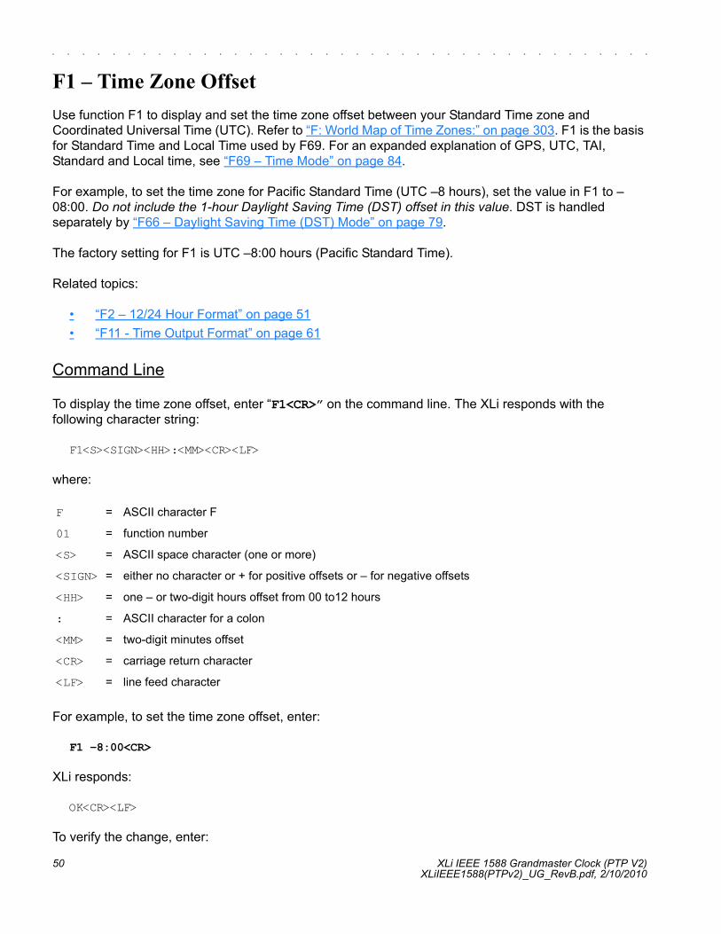
50 XLi IEEE 1588 Grandmaster Clock (PTP V2)XLiIEEE1588(PTPv2)_UG_RevB.pdf, 2/10/2010
S SSS S SSS S SSS S SSS S SSSS S SSS S SSS S SSS S SSS SS S
1
F1 – Time Zone OffsetUse function F1 to display and set the time zone offset between your Standard Time zone and Coordinated Universal Time (UTC). Refer to “F: World Map of Time Zones:” on page 303. F1 is the basis for Standard Time and Local Time used by F69. For an expanded explanation of GPS, UTC, TAI, Standard and Local time, see “F69 – Time Mode” on page 84.
For example, to set the time zone for Pacific Standard Time (UTC –8 hours), set the value in F1 to –08:00. Do not include the 1-hour Daylight Saving Time (DST) offset in this value. DST is handled separately by “F66 – Daylight Saving Time (DST) Mode” on page 79.
The factory setting for F1 is UTC –8:00 hours (Pacific Standard Time).
Related topics:
• “F2 – 12/24 Hour Format” on page 51• “F11 - Time Output Format” on page 61
Command Line
To display the time zone offset, enter “F1<CR>” on the command line. The XLi responds with the following character string:
F1<S><SIGN><HH>:<MM><CR><LF>
where:
For example, to set the time zone offset, enter:
F1 –8:00<CR>
XLi responds:
OK<CR><LF>
To verify the change, enter:
F = ASCII character F
01 = function number
<S> = ASCII space character (one or more)
<SIGN> = either no character or + for positive offsets or – for negative offsets
<HH> = one – or two-digit hours offset from 00 to12 hours
: = ASCII character for a colon
<MM> = two-digit minutes offset
<CR> = carriage return character
<LF> = line feed character

Xli IEEE 1588 Grandmaster Clock (PTP V2) 51XLiIEEE1588(PTPv2)_UG_RevB.pdf, 2/10/2010,
2
5
1
S SSS S SSS S SSS S SSS S SSSS S SSS S SSS S SSS S SSS SS S
F1<CR>
XLi Responds:
F1 –8:00<CR><LF>
F2 – 12/24 Hour FormatUse function F2 to apply a 12 or 24-hour format to the time output by:
• “Keypad/Display Interface” on page 38• “F8 - Continuous Time Once-per-Second” on page 58• “F9 - Time On Request” on page 60• “F90 – Code Output Configuration” on page 104
F2 affects how all four types of time (Local, Standard, UTC, GPS, TAI) appear when displayed or output.
The 12-hour format counts hours from 1 to 12 twice per day, like a conventional wall clock. The 24-hour format counts hours from 0 to 23 once per day. For example, in the 24 hour format, 18:00 is equivalent to 6:00 PM in the 12-hour format (i.e., 18:00 – 12:00 = 6:00 PM).
Note: Local time is commonly displayed in both 12 and 24 formats. The specifications for Standard, UTC, GPS, and TAI call for using the 24-hour format. Applying the 12-hour format to any time type leads to ambiguous time notation. For example, if the 12-hour format is applied to UTC, the clock will display “249:10:21:34” once in the morning, and once at night.
The factory settings for F2 are 24-hour format for the display and 24-hour format for IRIG (F90)
Command Line
To display the current hour format, send:
F2<CR>
The XLi responds:
F2<S>D<HH><SEP>I<HH><CR><LF>

52 XLi IEEE 1588 Grandmaster Clock (PTP V2)XLiIEEE1588(PTPv2)_UG_RevB.pdf, 2/10/2010
S SSS S SSS S SSS S SSS S SSSS S SSS S SSS S SSS S SSS SS S
1
where:
For example, to display the current hour format, send:
F2<CR>
The XLi responds:
F2 D24 I24<CR><LF>
To set the hour format, send:
F2 D12 I24<CR>
XLi responds:
OK<CR><LF>
F3 – Time & DateUse function F3 to set the XLi system clock’s time and date. If the XLi is using GPS as its primary reference source, setting F3 manually is unnecessary. At startup, the XLi synchronizes its time and date to GPS. If the XLi is using IRIG is the primary reference source, use F3 to set the year. (Some IRIG time code does not contain year information).
F3 prompts the user for the Time Mode, the Date in mm/dd/yyyy format, and the Time in hh:mm:ss format. The hours in hh:mm:ss should be given using 24-hour notation (e.g., 6 pm = 18:00).
TIME MODE selects which type of time (Local/Standard/GPS/UTC/TAI) is being entered by the user. The XLi, translates the user entry into its equivalents in other types of time. For example, entering LOCAL - 07/14/2002 - 15:47:10 in F3 shows up on the front keypad display as UTC 198:10:47:10. TIME MODE in F3 defines only the entry of time in F3; it does not control the type of time displayed or output by the XLi. F3’s Time Mode should not be confused with F69 (see “F69 – Time Mode” on page 84). F69 controls the type of time displayed/output on the front panel display, F8 - Continuous Time Once-per-Second, F9 - Time On Request, and F90 – Code Output Configuration.
F = ASCII character F.
02 = Function number.
<S> = ASCII space character (one or more).
D = ASCII character for Display format.
<HH> = 12 or 24.
I = ASCII character for IRIG format
<CR> = Carriage return character.
<LF> = Line feed character.

Xli IEEE 1588 Grandmaster Clock (PTP V2) 53XLiIEEE1588(PTPv2)_UG_RevB.pdf, 2/10/2010,
2
5
1
S SSS S SSS S SSS S SSS S SSSS S SSS S SSS S SSS S SSS SS S
Notes:
• Most IRIG time code doesn’t contain “year” information. For this reason, use F3 to set the year before setting IRIG up as a primary reference source.
• The year used by F3 rolls over automatically at the end of the year if the unit is operating during the transition. If it is not operating during the transition, the user must manually set the year the next time the unit is operating. This is important for scenarios where time code that does not provide year information is being used as a reference source. Should the clock switch, for example, from GPS to the time code reference, and the year is set incorrectly in F3, any time outputs or displays that use year information will be correspondingly affected.
• Avoid saving new F3 settings while the XLi is locked to a reference source and distributing time information. Doing so allows the XLi to distribute the potentially incorrect time set by F3 for up to 8 seconds until the XLi re-synchronizes to the reference source’s time. The XLi will make this switch to and from F3’s time without generating an alarm. In NTP, for example, this means that incorrect time information could be distributed in NTP packets that are marked as having the valid time.
Command Line
To display the time and date, send:
F3<CR>
XLi responds:
F3<S><MM>/<DD>/<YYYY><SEP><hh>:<mm>:<ss><CR><LF>
where:
F3 = ASCII string for function F3.
<S> = ASCII space character (one or more).
<TIME MODE> = the time mode the entered time refers to; LOCAL/STANDARD/GPS/UTC/TAI
<SEP> = one or more separator characters: either space, comma or tab
<MM> = two-digit month
<DD> = two-digit day of month
<YYYY> = four-digit year
/ = ASCII character for slash delimiter
: = ASCII character for a colon delimiter.
<hh> = one- or two-digit hours.
<mm> = two-digit minutes.
<ss> = two-digit seconds.
<CR> = carriage return character.
<LF> = line feed character.

54 XLi IEEE 1588 Grandmaster Clock (PTP V2)XLiIEEE1588(PTPv2)_UG_RevB.pdf, 2/10/2010
S SSS S SSS S SSS S SSS S SSSS S SSS S SSS S SSS S SSS SS S
1
For example, to display the date and time, send:
F3<CR>
XLi responds:
F3 UTC 01/01/2002 00:05:34<CR><LF>
To set the time and date, send:
F3 UTC 07/14/2002 18:20:30<CR>
Only valid times and dates are accepted. The XLi responds:
OK<CR><LF>
F4 – Serial Port ConfigurationUse function F4 to change or display the serial port settings. The factory settings are:
• Interface – RS-232• Baud rate – 9600• Data bits – 8• Parity – NONE (only available/valid when Data Bits is set to 8)• Stop bits – 1
Command Line
To display the Serial Port settings, send:
F4<CR>
XLi responds:
F4<S><RS><SEP><BR><SEP><DB><SEP><P><SEP><SB><CR><LF>

Xli IEEE 1588 Grandmaster Clock (PTP V2) 55XLiIEEE1588(PTPv2)_UG_RevB.pdf, 2/10/2010,
2
5
1
S SSS S SSS S SSS S SSS S SSSS S SSS S SSS S SSS S SSS SS S
where:
Note: Parity - NONE is only available/valid when Data Bits is set to 8.
For example, to display the serial port settings, send:
F4<CR>
The XLi responds:
F4 232 9600 8 none 1<CR><LF>
To set the serial port settings, send:
F4 422 9600 7 even 1<CR>
XLi responds:
OK<CR><LF>
F5 – Time-Quality SetupUse function F5 to enable/disable reporting, and to set the thresholds of the four time-quality flags.
How time quality reporting works in the XLi: When a reference source becomes unavailable, the XLi uses its own oscillator to keep track of time. Without the reference source, the XLi can no longer adjust, or steer, the oscillator to remain synchronized with the reference source. The rate at which the oscillator counts time is slightly faster or slower than the reference source. The resulting difference, time error, accumulates over time.
The XLi estimates the time error based on the oscillator-type and on the degree of steering (DAC value) applied to the oscillator before the reference source became unavailable. As time error grows and
F = ASCII character F.
04 = function number.
<S> = ASCII space character (one or more).
<SEP> = One or more separator characters: either space, comma or tab.
<RS> = Interface type, RS-232 or RS-422
<BR> = Baud Rate, with possible values 1200, 2400, 4800, 9600, or 19200
<DB> = Data Bits, with possible values 7 or 8
<P> = Parity, with possible values “even” or “odd” or “none”
<SB> = Stop Bits, with possible values 1 or 2.
<CR> = Carriage return character.
<LF> = Line feed character.

56 XLi IEEE 1588 Grandmaster Clock (PTP V2)XLiIEEE1588(PTPv2)_UG_RevB.pdf, 2/10/2010
S SSS S SSS S SSS S SSS S SSSS S SSS S SSS S SSS S SSS SS S
1
exceeds the thresholds of each time-quality flag, the XLi generates a different time-quality indicator. The time-quality indicator is represented as a time quality character in the following text-based time outputs:
• “F8 - Continuous Time Once-per-Second” on page 58• “F9 - Time On Request” on page 60
In addition, a time quality indicator is encoded in IRIG-B time code generated by the following function:
• “F90 – Code Output Configuration” on page 104
For more information on time quality indicators, see “IRIG Standard Format A” on page 302.
The XLi accepts threshold values from 200 nS to 40000000000 nS.
The factory settings for F5 are as follows:
• Time quality reporting - enabled• First time quality flag 1000 nS• Second time quality flag 10000 nS• Third time quality flag 100000 nS • Fourth time quality flag 1000000 nS
Related topics (Time Error):
• “F13 – Time Error” on page 63 displays the current time error• “F71 – Oscillator Statistics” on page 86 provides the DAC value
Command Line
To determine if the time quality characters are enabled and what the thresholds are, enter:
F5<CR>
XLi responds The XLi responds:
F5<S><STATE><SEP><FLAG><SEP><FLAG><SEP><FLAG><SEP><FLAG><CR><LF>

Xli IEEE 1588 Grandmaster Clock (PTP V2) 57XLiIEEE1588(PTPv2)_UG_RevB.pdf, 2/10/2010,
2
5
1
S SSS S SSS S SSS S SSS S SSSS S SSS S SSS S SSS S SSS SS S
where:
For example, to display the time quality status and flags, enter:
F5<CR>
XLi responds:
F5 DISABLE 00000001000 00000010000 00000100000 00001000000<CR><LF>
To enable time quality reporting, and change the thresholds of the time quality flags, enter:
F5 ENABLE 2000 20000 200000 2000000<CR>
XLi responds:
OK<CR><LF>
Note: Leading zeros aren’t required for to enter new settings, but are included in readouts of the settings.
F6 – Keypad LockF6 – Keypad Lock enables or disables the keypad, preventing accidental changes to the XLi’s settings. When enabled, the display responds ‘KEYPAD LOCKOUT BY FUNC 6’ when the user attempts to access any function other than F6. F6 remains available through the keypad at all times. The factory setting for F6 – Keypad Lock is disabled.
Command Line
To display the Keypad Lock status, send:
F6<CR>
XLi responds:
F6<S><STATE><CR><LF>
F = ASCII character F
05 = function number
<S> = ASCII space character (one or more)
<SEP> = one or more separator characters; either space, comma or tab
<STATE> = ENABLE or DISABLE
<FLAG> = one error threshold in nanoseconds, 1 to 11 digits with or without leading zeros
<CR> = carriage return character
<LF> = line feed character

58 XLi IEEE 1588 Grandmaster Clock (PTP V2)XLiIEEE1588(PTPv2)_UG_RevB.pdf, 2/10/2010
S SSS S SSS S SSS S SSS S SSSS S SSS S SSS S SSS S SSS SS S
1
where:
For example, to display the Keypad Lock status, send:
F6<CR>
XLi responds:
F6 DISABLE<CR><LF>
To enable Keypad Lock, send the following string:
F6 ENABLE<CR>
XLi responds:
OK<CR><LF>
To disable Keypad Lock, send the following string:
F6 DISABLE<CR>
XLi responds:
OK<CR><LF>
F8 - Continuous Time Once-per-SecondThis function is available through the command line interface only - it is not available through the keypad.
F8 generates time-of-year information (e.g., 199:10:41:08) once-per-second over the XLi's command line interface (available from the serial or network ports). The format and type of time can be modified using F2, F11, and F69.
The command line (standard out) outputs the <CR> character at the end of the time-of-year string at the 1 PPS mark, +/- 1 millisecond.
If F8 is used following startup, while the XLi is acquiring a reference source, F8's displays time-of-year information from the XLi's unsynchronized system clock. When the system clock acquires a reference source and synchronizes with it, F8 displays the new time-of-year information. The transition looks like this:
F = ASCII character F
6 = function number
<S> = ASCII space character (one or more)
<STATE> = ENABLE or DISABLE
<CR> = carriage return character
<LF> = line feed character

Xli IEEE 1588 Grandmaster Clock (PTP V2) 59XLiIEEE1588(PTPv2)_UG_RevB.pdf, 2/10/2010,
2
5
1
S SSS S SSS S SSS S SSS S SSSS S SSS S SSS S SSS S SSS SS S
365:16:00:14?365:16:00:15?365:16:00:16365:16:00:17199:13:56:03199:13:56:04...
In the first two lines above, the unsynchronized time is followed by a "?" time quality character. In this case, the "?" indicates that the XLi system clock is not locked to a reference source. As the XLi locks to the reference source, the "?" disappears. After a couple seconds, the new synchronized time-of-year information appears.
If the reference source becomes unavailable, F8 continues generating time-of-year information based on the synchronized time, and the character for the first time quality flag typically appears as the time error starts increasing.
199:11:19:31199:11:19:32199:11:19:33.199:11:19:34....
The format of time output can be changed using (“F11 - Time Output Format” on page 61"). The default output string format is:
<SOH>DDD:HH:MM:SSQ<CR><LF>
where:
<SOH> = ASCII Start-of-Heading character
<CR> = ASCII Carriage Return character
<LF> = ASCII Line Feed character
DDD = day-of-year.
HH = hours.
MM = minutes.
SS = seconds.
mmm = milliseconds.
: = colon separator.
Q = time quality character (see the following table)

60 XLi IEEE 1588 Grandmaster Clock (PTP V2)XLiIEEE1588(PTPv2)_UG_RevB.pdf, 2/10/2010
S SSS S SSS S SSS S SSS S SSSS S SSS S SSS S SSS S SSS SS S
1
The time quality character, "Q", is one of the following characters:
The four time quality thresholds are set by F5 - Time-Quality Setup. See "“F13 – Time Error” on page 63."
Command Line
For example, to initiate Continuous Time once-per-second, enter:
F8<CR>
The XLi replies:
199:11:19:30<CR><LF>199:11:19:31<CR><LF>199:11:19:32<CR><LF>
To stop F8 Continuous Time Once-Per-Second, press Ctrl-C on your keyboard (hex 03).
F9 - Time On RequestThis function is available through the command line interface only. It is not available from the keypad.
Use function F9 to record the exact time the XLi receives a request from the user.
Enter the command "F9<CR>" to prepare the XLi for the user's request. At the desired moment, send the request to the XLi by entering an upper case "T". The XLi saves the current time-of-day, accurate to within 1μS, to a buffer, and then outputs it to the command line interface. The XLi continues to provide the time-of-day each time it receives a "T" until F9 is cancelled. To cancel F9, enter Ctrl-C on your keyboard. The command line disregards all input other than SHIFT-T and Ctrl-C (hex 03).
The time-of-day output is only available on the network or serial port used to give the F9 command.
F9’s default output string is as follows:
<SOH>DDD:HH:MM:SS.mmmQ<CR><LF>
SPACE = Time error is less than time quality flag 1's threshold
. = Time error has exceeded time quality flag 1's threshold
* = Time error has exceeded time quality flag 2's threshold
# = Time error has exceeded time quality flag 3's threshold
? = Time error has exceeded time quality flag 4's threshold or a reference source is unavailable

Xli IEEE 1588 Grandmaster Clock (PTP V2) 61XLiIEEE1588(PTPv2)_UG_RevB.pdf, 2/10/2010,
2
5
1
S SSS S SSS S SSS S SSS S SSSS S SSS S SSS S SSS S SSS SS S
where:
The time quality character, "Q", is one of the following characters:
For example, to prepare Time on Request, enter:
F9<CR>
Then, to request the current time, enter SHIFT-T on your keyboard. ("T" does not appear). XLi responds:
<SOH>128:20:30:04.357*<CR><LF>
To exit F9 press Ctrl-C on your keyboard.
F11 - Time Output FormatUse function F11 to change the format of the F8 and F9 time output strings. The factory setting for F11 format is null, which enables the default time output formats for F8 and F9:
<SOH>DDD:HH:MM:SSQ<CR><LF> (for F8)<SOH>DDD:HH:MM:SS.mmmQ<CR><LF> (for F9)
To display the default format for F11, enter:
F11
<SOH> = ASCII Start-of-Heading character
<CR> = ASCII Carriage Return character
<LF> = ASCII Line Feed character
YYYY = year
DDD = day-of-year.
HH = hours.
MM = minutes.
SS = seconds.
mmm = milliseconds.
: = colon separator.
Q = time quality character (see the following table)
SPACE = Time error is less than time quality flag 1's threshold
. = Time error has exceeded time quality flag 1's threshold
* = Time error has exceeded time quality flag 2's threshold
# = Time error has exceeded time quality flag 3's threshold
? = Time error has exceeded time quality flag 4's threshold, or a reference source is unavailable
62 XLi IEEE 1588 Grandmaster Clock (PTP V2)XLiIEEE1588(PTPv2)_UG_RevB.pdf, 2/10/2010
S SSS S SSS S SSS S SSS S SSSS S SSS S SSS S SSS S SSS SS S
1
F11 responds:
F11 DDD:HH:MM:SS.mmmQ
where:
The time quality character, "Q", is one of the following characters:
Note: F8 does not display milliseconds, regardless of the format defined in F11.
Suppress the “DDD”, “HH”, “MM”, “SS”, “mmm”, and “Q” segments of F11 by placing an “X” (Shift-X) in the leading position of any segment, followed by any placeholder characters, and the following separator. For example, to suppress “DDD”, enter:
F11 X--:
To see the resulting change to F11, enter:
F11
F11, with “DDD” suppressed, responds:
F11 XDD:HH:MM:SS.mmmQ
With “DDD” suppressed, the output of F8 would look like this example:
:16:23:32*
<SOH> = ASCII Start-of-Heading character
<CR> = ASCII Carriage Return character
<LF> = ASCII Line Feed character
DDD = day-of-year.
HH = hours.
MM = minutes.
SS = seconds.
mmm = milliseconds.
: = colon separator.
Q = time quality character (see the following table)
SPACE = Time error is less than time quality flag 1's threshold
. = Time error has exceeded time quality flag 1's threshold
* = Time error has exceeded time quality flag 2's threshold
# = Time error has exceeded time quality flag 3's threshold
? = Time error has exceeded time quality flag 4's threshold, or a reference source is unavailable

Xli IEEE 1588 Grandmaster Clock (PTP V2) 63XLiIEEE1588(PTPv2)_UG_RevB.pdf, 2/10/2010,
2
5
1
S SSS S SSS S SSS S SSS S SSSS S SSS S SSS S SSS S SSS SS S
Ending a format string early (no “:” or “.” separator at the end) with a carriage return, enables the remaining un-typed characters. This makes it easy to restore the default F11 formatting.
To return F11 to its default format, enter:
F11 D
To display the restored defaults, enter “F11” again. F11 responds:
F11 DDD:HH:MM:SS.mmmQ
The “DDD”, “HH”, “MM”, “SS”, “mmm”, and “Q” segments can not be replaced with characters, they can only be suppressed.
The “:” and “.” separators can be replaced with ASCII characters or suppressed using “X”. For example, to replace the separators with characters, enter:
F11 ---D--H--M--S
When you check the results by entering “F11”, F11 responds:
F11 DDDDHHHMMMSSSmmmQ
With the new formatting, F8 displays:
128D16H41M27*
And F9 displays:
365D16H45M22S680*
F13 – Time ErrorUse function F13 to request the estimated worst-case time error due to oscillator drift during periods of unlock from a reference source. See “System Time & Frequency Accuracy” on page 8 for more information on time error for different reference sources. Time error begins to accumulate when the receiver loses lock to a reference source. The XLi calculates the worst-case time error based on the stability of system clock’s oscillator type, and the time elapsed since loss of lock.
Command Line
The Command line interface will report time error when it receives the following string:
F13<CR>
The XLi responds:
F13<S><ERROR><CR><LF>

64 XLi IEEE 1588 Grandmaster Clock (PTP V2)XLiIEEE1588(PTPv2)_UG_RevB.pdf, 2/10/2010
S SSS S SSS S SSS S SSS S SSSS S SSS S SSS S SSS S SSS SS S
1
where:
For example, to display the time error, enter:
F13<CR>
XLi responds (example):
F13 TIME ERROR -0.002932863<CR><LF>
F18 – Software Version RequestUse function F18 to display the current firmware version numbers of the firmware in the XLi:
• Bootloader• Software (firmware)• File System• Project Rev #• FPGA
Command Line
Use Command Line Function F18 to obtain the system’s firmware version information.For example, enter:
F18<CR>
The XLi responds:
F18 BOOTLOADER 192-8000 SOFTWARE 084-00218-000 FILE SYSTEM 084-00219-000vGM 2-0 PROJ REV # GM 2-0 FPGA # 084-00380-000V65
Note: The values will be different from this example representing the current values.
F13 = ASCII string for function F13
<S> = ASCII space character
<ERROR> = calculated worst-case error in seconds
<CR> = carriage return character
<LF> = line feed

Xli IEEE 1588 Grandmaster Clock (PTP V2) 65XLiIEEE1588(PTPv2)_UG_RevB.pdf, 2/10/2010,
2
5
1
S SSS S SSS S SSS S SSS S SSSS S SSS S SSS S SSS S SSS SS S
F42 – Multicode Output ConfigurationUse function F42 to view or set up the time-code outputs of the Multicode Output (87-6002-XL1) (page 229).
• Board #: Identifies the card to which the following settings will apply. (Select between multiple cards using the UP/DOWN ARROWs buttons on the keypad). The card number is determined by the position of DIP switches on the Multicode card. Each card must have a unique number. (See “Installation” on page 229)
• Output #: Identifies the output to which the settings apply (e.g., J1 through J4)• Code: The time code output by the port. The note below provides a complete list of all the time
code types available.• Time Reference: The type of time (e.g., UTC, Standard, Local, GPS) output by all ports on the
card. Even though this setting is shown for a specific output, it sets the type of time for all ports.
Notes:
• The code output types include: IRIG-A 130, IRIG-A 133, IRIG-B 120, IRIG-B 123, IRIG-E 111, IRIG-E 112, IRIG-E 121, IRIG-E 122, IRIG-G 141, IRIG-G 142, IRIG-H 111, IRIG-H 112, IRIG-H 121, IRIG-H 122, 2137, XR3, NASA 36.
• If IRIG-A 130 or IRIG-A 133 is selected as the output type for a specific port, all other ports set for IRIG-A will be ‘bumped’ to the same type (130 vs. 133). Ports set to other time code types (e.g., IRIG-B) are not affected.
• The same is true for IRIG-G. If IRIG-G 141 or IRIG-G 142 is selected as the output type, all the other ports set for IRIG-G will be ‘bumped’ to the same type (141 vs. 142). Ports set to other time code types (e.g., IRIG-B) are not affected.
• For more information on the code output types, see “E: Time Code Formats” on page 299.• For Time Reference, the following is a summary explanation of the different types of time:
- UTC (Coordinated Universal Time) differs from GPS Time by the addition of leap-second cor-rections to compensate for variations in the earth’s rotation.
- GPS time is derived directly from the GPS constellation. It doesn’t contain leap-second adjustments or other GPS-to-UTC corrections.
- Standard time is UTC plus a time zone adjustment. For example, Pacific Standard Time is UTC minus 8 hours. See “F: World Map of Time Zones:” on page 303 for more information.
- Local time is UTC plus a time zone adjustment and a Daylight Saving Time adjustment.• See “F69 – Time Mode” on page 84 for an expanded explanation of the different types of time.
Note, however, that F69 does not affect F42 or the Multicode Output card.
Command Line
Requesting the board number of installed cards
Use F42 to set up the output on the Multicode Output card(s). Use the following format to request the board number(s) of the installed card(s):
F42<CR><LF>

66 XLi IEEE 1588 Grandmaster Clock (PTP V2)XLiIEEE1588(PTPv2)_UG_RevB.pdf, 2/10/2010
S SSS S SSS S SSS S SSS S SSSS S SSS S SSS S SSS S SSS SS S
1
The XLi responds using the following format:
F42<S>B<S><N><CR><LF> (one board installed)
or
F42<S>B<S><N><S><N>...<CR><LF> (two or more boards installed)
where:
For example, enter:
F42<CR>
The XLi responds that one board, board 2 in this case, is present:
F42 B 2<CR><LF>
Or, that multiple boards, boards 2 and 4 in this case, are present:
F42 B 2 4<CR><LF>
Or, that no boards are present:
NO MULTICODE BOARDS
Requesting the time code settings of a specific output port
Use the following format to request the time code settings of a specific output on a specific card:
F42<S>B<N>O<S><C><CR>
F42 = ASCII string representing the Function Number
<CR> = carriage return character.
<LF> = line feed character.
<S> = space character
B = ASCII character B
N = the board number of a multi code card, 1 to 4
... = Multiple occurrences of <S><N> corresponding to the number of boards present

Xli IEEE 1588 Grandmaster Clock (PTP V2) 67XLiIEEE1588(PTPv2)_UG_RevB.pdf, 2/10/2010,
2
5
1
S SSS S SSS S SSS S SSS S SSSS S SSS S SSS S SSS S SSS SS S
where
For example, to request the time code on board 1, output 1, enter:
F42 B1O 1<CR>
Or, optionally:
F42 B1 O1<CR>
The XLi responds with the time code of the output:
F42 B1 1 IRIG-B 120<CR><LF>
If the time code is IRIG-A or IRIG-G, the response includes a parenthetical reminder that all outputs set to that time code (e.g., IRIG G) are also set to the same time code type (e.g., 141):
F42 B1 1 IRIG-G 141(ALL "G" PORTS)
Setting the time code of a specific output port
Use the following format to set the time code for a specific output port:
F42<S>B<N><S>O<S><C><S><CODE><CR>
F42 = ASCII string representing the Function Number
<S> = one or more separator characters, space, tab or comma
B = ASCII character indicating board number to follow
<N> = the board number, 1 to 10
O = ASCII letter “ohh” indicating output port (not zero)
<C> = output number, 1 to 4
<CR> = carriage return

68 XLi IEEE 1588 Grandmaster Clock (PTP V2)XLiIEEE1588(PTPv2)_UG_RevB.pdf, 2/10/2010
S SSS S SSS S SSS S SSS S SSSS S SSS S SSS S SSS S SSS SS S
1
where:
For example, to set board 1, output 1, to IRIG-B 123, enter:
F42 B1 O 1 IRIG-B 123<CR>
The XLi responds:
OK<CR><LF>
Setting a port to IRIG-A switches all output ports set to IRIG-A to the same IRIG-A type (e.g., IRIG-A 133). The same is true for IRIG-G. Therefore the following example would set all of board 1’s IRIG-A outputs, not just output 1, to IRIG-A 133 time code:
F42 B1 O 1 IRIG-A 133<CR>
The XLi responds:
OK<CR><LF>
Requesting the time reference of a specific board
Use the following format to request the Time Reference of a specific board:
F42<S>B<N>T<CR>
where
The XLi responds with the Time Reference for the selected board.
F42 = string representing the Function Number
<S> = separator
B = ASCII letter indicating board number follows
<N> = board number, 1 to 10
O = ASCII letter indicating output port
<C> = channel number, 1 to 4
<CODE> = IRIG-A 130, IRIG-A 133, IRIG-B 120, IRIG-B 123, IRIG-E 111, IRIG-E 112, IRIG-E 121, IRIG-E 122, IRIG-G 141, IRIG-G 142, IRIG-H 111, IRIG-H 112, IRIG-H 121, IRIG-H 122, 2137, XR3, NASA 36 Note: A dash is required when entering IRIG types. NASA 36 is entered without a dash. 2137 and XR3 have no dashes or spaces when entered.
<CR> = Carriage Return
<N> = board number, 1 to 10.
<S> = ASCII space character.
T = ASCII letter requesting Time Reference.

Xli IEEE 1588 Grandmaster Clock (PTP V2) 69XLiIEEE1588(PTPv2)_UG_RevB.pdf, 2/10/2010,
2
5
1
S SSS S SSS S SSS S SSS S SSSS S SSS S SSS S SSS S SSS SS S
For example, to requests the time reference from board 1, enter:
F42 B1 T<CR>
The XLi responds:
F42 B1 UTC<CR><LF>
Setting the time reference of a specific board
Use the following format to set the type of time output by the boards (For an explanation of the different types, see “F69 – Time Mode” on page 84):
F42<S>B<N><S>T<S><TREF><CR>
where
For example, to have board 1 (all ports) output local time instead of UTC, enter:
F42 B1 T LOCAL<CR>
The XLi responds:
OK<CR><LF>
F50 – GPS Receiver LLA/XYZ Position Use function F50 to display the current GPS position. Specifically, Use function F50 to:
• Display the option bay location of the GPS receiver(s). If multiple GPS receivers are available, use the UP/DOWN ARROW keys to select a receiver.
• Select the positional coordinate system, Latitude Longitude Altitude (LLA) or XYZ (Earth-Centered, Earth-Fixed XYZ coordinates).
• If LLA is selected, Altitude Mode shows the elevation in given meters.
F42 = string representing the Function Number
B = ASCII character indicating board number to follow.
<N> = the board number, 1 to 10
<S> = one or more separator characters, space, tab or comma.
<TREF> = Time Reference, UTC, LOCAL, STANDARD, or GPS

70 XLi IEEE 1588 Grandmaster Clock (PTP V2)XLiIEEE1588(PTPv2)_UG_RevB.pdf, 2/10/2010
S SSS S SSS S SSS S SSS S SSSS S SSS S SSS S SSS S SSS SS S
1
Command Line
Use the following format to display the current settings display the current position for the GPS receiver in LLA coordinates:
F50<S>B<N><SEP>LLA<CR>
XLi responds with the coordinate information in the following format:
F50<S>B<N><SIGN><S><DEG>d<MIN>'<SEC>"<S><SIGN><S><DEG>d<MIN>'<SEC>"<S><ALT><UNITS><CR><LF>
where:
For example, to display the LLA coordinates of the antenna connected to the GPS Receiver card installed in Option Bay #2, enter:
F50 B2 LLA<CR>
XLi responds:
F50 B2 N 38d23'51.3" W 122d42'53.2" 58m<CR><LF>
F50 = Function 50
<S> = ASCII space character one or more.
B = ASCII letter to denote Option Bay number follows
<N> = Option Bay Number, 1 through 4.
<SEP> = Separator
LLA = LLA mode
<CR> = carriage return character.
<SIGN> = N or S for latitude; E or W for longitude; – for negative altitude and <S> or + for positive altitude.
<DEG> = two-digit degrees for latitude or three-digit degrees for longitude.
d = ASCII character d
<MIN> = two-digit minutes.
' = ASCII character '
<SEC> = two-digit seconds + 1 digit 10ths of seconds.
" = ASCII character "
<ALT> = altitude in meters
<UNITS> = unit of altitude, “m” for meters
<LF> = line feed character.

Xli IEEE 1588 Grandmaster Clock (PTP V2) 71XLiIEEE1588(PTPv2)_UG_RevB.pdf, 2/10/2010,
2
5
1
S SSS S SSS S SSS S SSS S SSSS S SSS S SSS S SSS S SSS SS S
To display the present antenna position using ECEF XYZ coordinates in meters, use the following format:
F50<S>B<N><SEP>XYZ<CR>
XLi responds using the following format:
F50B<N><S><SIGN><S><MX>m<S><SIGN><S><MY>m<S><SIGN><MZ>m<CR><LF>
where:
For example:
F50 B2 XYZ<CR>
XLi responds:
F50 B2 X –4474331m Y 2668899m Z –3668099m<CR><LF>
F51 – GPS Antenna Cable DelayUse function F51 to display or configure the GPS antenna cable delay. Setting a positive value for F51 compensates for the time the signal takes to travel the length of the cable from the GPS antenna to the receiver. When multiple GPS receivers are installed, a separate value can be set for each unique receiver. The factory setting for F51 is +60 nS (50 feet of RG-59). If using an optional Down/Up Converter, consult that product’s documentation for directions on setting the correct cable delay.
F51 Guidelines:
• For RG-59: multiply the cable length by 1.24 nS/ft. to get the value for F51.• For RG-58: multiply the cable length by 1.4 nS/ft. to get the value for F51.
F = ASCII character F
50 = function number
<S> = ASCII space character
B = ASCII letter to denote Option Bay number follows
<N> = Option Bay Number, 1 through 4.
<SIGN> = Either + or - for the position of the ECEF XYZ coordinates
<MX> = Antenna X-position in meters to tenths of a meter
<MY> = Antenna Y-position in meters to tenths of a meter
<MZ> = Antenna Z-position in meters to tenths of a meter
m = ASCII character m for Meters
<ALT> = altitude in meters
<CR> = carriage return character
<LF> = line feed character

72 XLi IEEE 1588 Grandmaster Clock (PTP V2)XLiIEEE1588(PTPv2)_UG_RevB.pdf, 2/10/2010
S SSS S SSS S SSS S SSS S SSSS S SSS S SSS S SSS S SSS SS S
1
• Avoid using function F51 to adjust the XLi’s timing outputs; use F52 Distribution Cable Delay instead.
Command Line
Use the following format to display the current Antenna Cable Delay setting:
F51<S>B<N><CR>
The XLi responds using the following format:
F51<S>B<N><SEP><SIGN><DELAY>ns<CR><LF>
where:
For example, to see the antenna cable delay for the GPS card in option bay 4, enter:
F51 B4<CR>
XLi responds:
F51 B4 +000060ns<CR><LF>
To set the antenna cable delay for an option card, use the following format:
F51<S>B<N><S><DELAY>NS<CR>
For example, to set the antenna cable delay for the GPS card in option bay 4 to 100 nS, enter:
F51 B4 100NS<CR>
XLi responds:
OK<CR><LF>
F = ASCII character F (f or F for input string).
51 = the function number.
<S> = ASCII space character one or more.
B = ASCII letter to denote Option Bay number follows
<N> = Option Bay Number of the GPS option card, 1 through 10.
<CR> = carriage return character.
<SEP> = one or more space characters.
<SIGN> = either + or blank
<DELAY> = 1 to 6 digit delay from 0 nS to 999999 nS.
ns = nanoseconds (ns or NS for input string).
<LF> = line feed character.

Xli IEEE 1588 Grandmaster Clock (PTP V2) 73XLiIEEE1588(PTPv2)_UG_RevB.pdf, 2/10/2010,
2
5
1
S SSS S SSS S SSS S SSS S SSSS S SSS S SSS S SSS S SSS SS S
F52 – Distribution Cable DelayUse function F52 to display or set the distribution cable delay for the time code and 1 PPS outputs. F52 compensates for the signal’s travel time from the XLi to its point of use. The distribution cable delay applies uniformly to all output ports. The as-shipped factory setting is +0 ns. The range of possible values is +999,999 ns to –999,999 ns. Positive values advance the timing signals, while negative values retard them.
To calculate what the setting should be, multiply the delay/foot by the length of the cable in feet. The typical delays for the following cable types are:
• RG-58 – approximately 1.4 ns/foot• RG-59 – approximately 1.24 ns/foot
Command Line
To display the current distribution cable delay, enter:
F52<CR>
The XLi responds using the following format:
F52<SEP><SIGN><DELAY>ns<CR><LF>
where:
For example, to display the current distribution cable delay, enter:
F52<CR>
XLi responds:
F52 +000000ns<CR><LF>
To set the distribution cable delay to 60 nS, enter:
F52 +000060nS<CR>
F = ASCII character F (f or F for input string).
52 = the function number.
<S> = one or more space characters.
<SIGN> = either + or –
<D> = 1 to 6 digit delay from +999999 nS to –999999 nS
ns = nanoseconds (ns or NS for input string)
<CR> = carriage return character
<LF> = line feed character

74 XLi IEEE 1588 Grandmaster Clock (PTP V2)XLiIEEE1588(PTPv2)_UG_RevB.pdf, 2/10/2010
S SSS S SSS S SSS S SSS S SSSS S SSS S SSS S SSS S SSS SS S
1
XLi responds:
OK<CR><LF>
F53 – GPS Operation ModeUse function F53 to set the operation mode for all receiver types except the 86-8013, which doesn’t have modes. (If the 86-8013 is the only receiver available, F53 reports “GPS Availability, Not Available”.)
The GPS C/A Receiver (87-8028-2) has two modes:
• Select “Dynamic Mode” if the position of the receiver is subject to frequent change, or if it is in continuous motion. For example, use Dynamic Mode when the XLi is used in mobile vehicles such as ships, land vehicles, or aircraft. With Dynamic Mode selected, the receiver updates the position information repeatedly to arrive at the best time calculations for a mobile environment.
• Select “Time Mode” if the receiver used in a static environment such as a server room. With Time Mode, the receiver averages the position data over time to determine the antenna position and calculate the time precisely and accurately. TRAIM is also supported in Time Mode only.
Keypad
While viewing the Status screen on the XLi front panel display, press the following keypad buttons:
ENTER 53 ENTER
If an GPS C/A Receiver (87-8028-2) is available, F53 displays:
GPS AVAILABILITYOPTION BAY #
Where # is the option bay number where the card is located. (If no GPS is available, F53 displays “GPS AVAILABILTY, NOT AVAILABLE”). If more than one GPS is present, use the UP/DOWN ARROW buttons to select the option bay location of a specific card.
To view the mode the GPS is in, press ENTER again, and F53 displays the current mode:
GPS MODE SELECTAUTO MODE (or DYNAMIC MODE)
To change the mode, use the UP/DOWN ARROW buttons and press ENTER. F53 asks:
SAVE CHANGES?YES
To save changes, press ENTER.

Xli IEEE 1588 Grandmaster Clock (PTP V2) 75XLiIEEE1588(PTPv2)_UG_RevB.pdf, 2/10/2010,
2
5
1
S SSS S SSS S SSS S SSS S SSSS S SSS S SSS S SSS S SSS SS S
Command Line
To request the GPS operation mode of an GPS C/A Receiver (87-8028-2), enter:
F53 B<N>
F53 responds using the following format:
F53<SP>B<N><SEP><STATUS><CR><LF>
where:
For example, enter:
F53 B1
Example response:
F53 B1 AUTO MODE (or DYNAMIC MODE)
To set the GPS Operation Mode, enter a command using the following format:
F53<SP>B<N><SEP><MODE><CR><LF>
where <MODE> equals “DYNAMIC MODE” or “AUTO MODE”.
For example, enter:
F53 B1 DYNAMIC MODE
F53 responds:
OK<CR><LF>
F = ASCII character F (f or F for input string).
53 = the function number.
<SP> = ASCII space character one or more.
B = ASCII letter to denote Option Bay number follows
<N> = Option Bay Number, 1 through 4.
<SEP> = one or more space characters.
<STATUS> = DYNAMIC MODE or AUTO MODE
<CR> = carriage return character.
<LF> = line feed character.
76 XLi IEEE 1588 Grandmaster Clock (PTP V2)XLiIEEE1588(PTPv2)_UG_RevB.pdf, 2/10/2010
S SSS S SSS S SSS S SSS S SSSS S SSS S SSS S SSS S SSS SS S
1
F60 – GPS Receiver Satellite ListUse function F60 to display the identification number and signal strength of tracked or current satellites. ‘Tracked’ means a satellite’s signal is being received and interpreted by the receiver (or that the XLi has GPS data that suggests this satellite should be visible to the antenna).
GPS satellite are grouped into the following categories:
• Tracked: the XLi is receiving the GPS signal, but isn’t using it to calculate time and position.
• Current: the XLi is using the satellite’s GPS signal to calculate time and position.
• Bad: the GPS satellite is transmitting information that it has been removed from service.
• Rejected: the XLi GPS receiver’s TRAIM feature has detected anomalous signals from this satellite and has quarantined it from the timing solution for 12 hours.
GPS satellite signal strengths are reported in units of dBW. Signals below -170 dBW (e.g., -171 dBW) are not usable by the GPS receiver. See “GPS Signal Strength Requirements” on page 23.
If multiple GPS receivers are installed in the XLi, F60 identifies the GPS receiver by the option bay number in which it is located. For a diagram of option bay numbers, see “F118 – Option Board Configuration” on page 140.
If you’re using the keypad/display interface, use the UP/DOWN ARROWs to scroll through the list of satellites.
Command Line
Use Serial Function F60 to request a list of all, current, and tracked satellites. To display the list, enter a string using the following format:
F60<S>B<N><SEP><TYPE><CR>
XLi responds with approximately 32 lines that use the following format:
F60<S>B<N><S>prn<NN><S><STATE> tracked current<LEVEL><CR><LF>

Xli IEEE 1588 Grandmaster Clock (PTP V2) 77XLiIEEE1588(PTPv2)_UG_RevB.pdf, 2/10/2010,
2
5
1
S SSS S SSS S SSS S SSS S SSSS S SSS S SSS S SSS S SSS SS S
where:
For example, to display the complete GPS satellite list, enter:
F60 B1 ALL<CR>
XLi responds:
F60 B1 prn1 good current -159dBWF60 B1 prn2 good current -162dBWF60 B1 prn3 good current -163dBWF60 B1 prn4 unknownF60 B1 prn5 unknownF60 B1 prn6 unknownF60 B1 prn7 unknownF60 B1 prn8 good current -161dBWF60 B1 prn9 unknownF60 B1 prn10 unknownF60 B1 prn11 unknownF60 B1 prn12 unknownF60 B1 prn13 good current -159dBWF60 B1 prn14 unknownF60 B1 prn15 unknownF60 B1 prn16 unknownF60 B1 prn17 unknownF60 B1 prn18 unknownF60 B1 prn19 unknownF60 B1 prn20 unknownF60 B1 prn21 unknownF60 B1 prn22 good current -164dBWF60 B1 prn23 unknownF60 B1 prn24 unknown
F60 = ASCII string indicating function F60.
<S> = ASCII space character one or more.
B = ASCII letter to denote Option Bay number follows
<N> = Option Bay Number, 1 through 4.
<SEP> = One or more separator characters; either space, comma or tab.
<TYPE> = ALL, CURRENT, or TRACKED.
<CR> = Carriage return character.
prn = Pseudo Random Number
<NN> = 1 through 32 (prn<NN> identifies specific GPS satellites)
<STATE> = Good, Bad, or Unknown
tracked = Either “tracked” or blank
current = Either “current” or blank
<LEVEL> = Satellite signal strength in dBW
<LF> = Line feed character

78 XLi IEEE 1588 Grandmaster Clock (PTP V2)XLiIEEE1588(PTPv2)_UG_RevB.pdf, 2/10/2010
S SSS S SSS S SSS S SSS S SSSS S SSS S SSS S SSS S SSS SS S
1
F60 B1 prn25 unknownF60 B1 prn26 unknownF60 B1 prn27 good current -156dBWF60 B1 prn28 unknownF60 B1 prn29 unknownF60 B1 prn30 unknownF60 B1 prn31 unknownF60 B1 prn32 unknown
Similarly, to display a list of the current or tracked satellites, enter:
F60 B1 CURRENT<CR>
Or
F60 B1 TRACKED<CR>

Xli IEEE 1588 Grandmaster Clock (PTP V2) 79XLiIEEE1588(PTPv2)_UG_RevB.pdf, 2/10/2010,
2
5
1
S SSS S SSS S SSS S SSS S SSSS S SSS S SSS S SSS S SSS SS S
F66 – Daylight Saving Time (DST) ModeUse function F66 to enable or disable Daylight Saving Time (DST), and to schedule when Local time enters and leaves DST. The factory setting for F66 is Manual (i.e., DST On). The hour for entering/leaving DST is given in the 24-hour format. Entering/leaving DST can be scheduled for any hour of the day, any day of the year. However, transitions scheduled within 24 hours of the beginning/end of the year may not occur at the desired time. This function also works for locations in the southern hemisphere, where the DST period span the New Year.
Command Line
To display the current status of F66, enter a command using the following format:
F66<CR>
XLi responds using the following format:
F66<S><STATE><ENTER/EXIT><CR>
where:
For example, to disable DST, enter:
F66 Off<CR>
XLi responds:
OK<CR><LF>
To enable DST and set the DST entry and exit times, use the following format:
F66 MANUAL<INHOUR><SEP><INWEEK><SEP><INDAY><SEP><INMONTH><OUTHOUR><SEP> <OUTWEEK><SEP><OUTDAY><SEP><OUTMONTH><CR>
F = ASCII character F
66 = function number
<S> = ASCII space character one or more.
<STATE> = Off or Manual.
<ENTER/EXIT> = If <STATE> is Manual, <ENTER/EXIT> are the dates it enters and exits DST.
<CR> = carriage return character.
<LF> = line feed character.

80 XLi IEEE 1588 Grandmaster Clock (PTP V2)XLiIEEE1588(PTPv2)_UG_RevB.pdf, 2/10/2010
S SSS S SSS S SSS S SSS S SSSS S SSS S SSS S SSS S SSS SS S
1
where:
For example, enter:
F66 MANUAL 02 2 1 03 02 1 1 11
Meaning:
• Manual settings are in effect.• The entry time is 02 a.m., week 2 (second), day 1 (Sunday), month 3 (March)• The exit time is 02 a.m., week 1 (first), day 1 (Sunday), month 11 (November).
To leave the value of any item unchanged, insert a semicolon in its place. For example, to change the week DST begins, enter:
F66 MANUAL ; 0 ; ; ; ; ; ;<CR>
XLi responds to all changes with:
OK<CR><LF>
Meaning that Local time will enter DST on the last week of the month. All other parameters remain unchanged.
The XLi automatically reboots when the user changes the DST entry/exit times in F66.
If any of the items in an input string are invalid, an error message will be returned.
<INHOUR> = time to enter DST in 24-hour format.
<SEP> = one or more separator characters, either space comma or tab characters. For output strings this will be a single space character.
<INWEEK> = which week to enter DST, 1, 2, 3, 4 or 0 (for last).
<INDAY> = day of week to enter DST, 1 through 7 where Sunday is 1.
<INMONTH> = month to enter DST, 1 through 12 where 1 is January.
<OUTHOUR> = hour to exit DST, in 24 hour format.
<OUTWEEK> = which week to exit DST, 1, 2, 3, 4 or 0 (for last).
<OUTDAY> = day in to exit DST, 1 through 7 where Sunday is 1.
<OUTMONTH> = month to exit DST, 1 through 12 where 1 is January
<CR> = carriage return character.
<LF> = line feed character.

Xli IEEE 1588 Grandmaster Clock (PTP V2) 81XLiIEEE1588(PTPv2)_UG_RevB.pdf, 2/10/2010,
2
5
1
S SSS S SSS S SSS S SSS S SSSS S SSS S SSS S SSS S SSS SS S
F67 – Manual Leap Second EntryUse Serial/Network Function F67 to manually enable a leap second insertion into the XLi clock time structure. To request the present status of the manual leap seconds settings, send F67<CR> to the Serial/Network port. The port will respond with the ASCII character string:
F67<SP><LS><SP><SELECT><SP><DATE><CR><LF>
where:
F = ASCII character F.
67 = function number
<SP> = ASCII space character one or more.
<LS> = current leap seconds value in seconds, for GPS Epoch / TAI Epoch
<SELECT> = NONE, ADD or SUB.
<DATE> = Date of next leap second insertion, or blank if <SELECT> is NONE.
<CR> = carriage return character.
<LF> = line feed character.
If the Manual Leap Second function is set with leap second event values, the port will respond with the string described below.
Sample request: F67 <CR>
Response: F67 -14/-33 ADD 12/31/2007 <CR><LF>
To set the current leap second value for UTC / GPS , enter a continuous string of the form:
F67 <SEP>GPSLS<SEP><-nn>
where:
GPSLS= ASCII string indicating a GPS Epoch leap second value will be entered.
<-nn> = Leap second valued entered, -00 to –30.
Sample entry: F67 GPSLS -14<CR>

82 XLi IEEE 1588 Grandmaster Clock (PTP V2)XLiIEEE1588(PTPv2)_UG_RevB.pdf, 2/10/2010
S SSS S SSS S SSS S SSS S SSSS S SSS S SSS S SSS S SSS SS S
1
Response: OK<CR><LF>
To set the current leap second value for UTC / TAI , enter a continuous string of the form:
F67 <SEP>TAILS<SEP><-nn>
where:
TAILS = ASCII string indicating a TAI Epoch leap second value will be entered.
<-nn> = Leap second valued entered, -19 to –49.
Sample entry: F67 TAILS -33<CR>
Response: OK<CR><LF>
Adding a Leap Second:
To set the next leap second insertion time for adding a leap second, enter a continuous string of the form:
F67 <SEP>ADD<SEP><MONTH><SEP><YEAR>
where:
ADD = ASCII string indicating a leap second will be added.
<MONTH> = Month number that the leap second will be added, on the last day of the
month, MAR, JUN, SEP, DEC or NONE.
<YEAR> = Year that the leap second will be subtracted, 2000 to 2030 or NONE.
Subtracting a leap second:
To set the next leap second insertion time for subtracting a leap second, enter a continuous string of the form:
F67 <SEP>SUB<SEP><MONTH><SEP><YEAR><CR>
where:
Xli IEEE 1588 Grandmaster Clock (PTP V2) 83XLiIEEE1588(PTPv2)_UG_RevB.pdf, 2/10/2010,
2
5
1
S SSS S SSS S SSS S SSS S SSSS S SSS S SSS S SSS S SSS SS S
SUB = ASCII string indicating a leap second will be subtracted.
<MONTH> = Month number that the leap second will be subtracted, on the last day of the
month MAR, JUN, SEP, DEC or NONE.
<YEAR> = Year that the leap second will be subtracted, 2001 to 2030 or NONE.
Sample entry: F67 SUB DEC 2007<CR>
Response: OK<CR><LF>
Setting the manual leap second function to no event:
To select no leap second insertion event, enter a continuous string of the form:
F67 <SEP>NONE<CR>
where:
NONE = ASCII string indicating a manual leap second insertion function will be disabled.
The Serial/Network port will respond with the message “ERROR 01 VALUE OUT OF RANGE” if the input string was in the correct format but contained a value, probably numeric, that was out of the range of acceptable values.
The Serial/Network port will respond with the message “ERROR 02 SYNTAX” if it receives a string in an incorrect format, for example the second field should be ADD, SUB or NONE.
The Serial/Network port will respond with the message “ERROR 03 BAD/MISSING FIELD” if the input string lacks a required field.

84 XLi IEEE 1588 Grandmaster Clock (PTP V2)XLiIEEE1588(PTPv2)_UG_RevB.pdf, 2/10/2010
S SSS S SSS S SSS S SSS S SSSS S SSS S SSS S SSS S SSS SS S
1
F69 – Time ModeUse function F69 to select the time type displayed by:
• The XLi’s front panel display• “F8 - Continuous Time Once-per-Second” on page 58 • “F9 - Time On Request” on page 60• “F90 – Code Output Configuration” on page 104
Select between the following types of time:
• TAI (International Atomic Time) is the basis for UTC and GPS time.• UTC (Coordinated Universal Time) differs from GPS Time by the addition of leap-second
corrections to compensate for variations in the earth’s rotation.• GPS Time is derived directly from the GPS constellation and doesn’t contain any leap-second
adjustments or other GPS-to-UTC corrections.• Standard Time is UTC plus a time zone adjustment. For example, Pacific Standard Time is UTC
minus 8 hours• Local Time is UTC plus a time zone and a daylight saving time adjustment.
The factory setting is UTC.
Note: A time error can be created when switching to GPS time when the reference is Time Code (non IRIG 1344). IRIG 1344 resolves this problem.
Related functions:
• “F1 – Time Zone Offset” on page 50• “F66 – Daylight Saving Time (DST) Mode” on page 79• “F8 - Continuous Time Once-per-Second” on page 58• “F9 - Time On Request” on page 60
Command Line
Local Time modifies UTC time to include the Time Zone and Daylight Saving Time adjustments, if enabled by the user.
Use the following format to display the time mode currently used:
F69<CR>
The XLi responds using the following format:
F69<SEP><TT><CR><LF>

Xli IEEE 1588 Grandmaster Clock (PTP V2) 85XLiIEEE1588(PTPv2)_UG_RevB.pdf, 2/10/2010,
2
5
1
S SSS S SSS S SSS S SSS S SSSS S SSS S SSS S SSS S SSS SS S
where:
For example, enter:
F69<CR>
XLi gives one of the following responses:
F69 GPS <CR><LF>F69 UTC <CR><LF>F69 LOCAL <CR><LF>F69 STANDARD <CR><LF>F69 TAI <CR><LF>
To set the time mode, enter a command using the following format:
F69<S><TT><CR>
where:
For example, to change the time mode to local time, enter:
F69 LOCAL<CR>
Or, to change the time mode to UTC, enter:
F69 UTC<CR>
XLi responds to these changes with:
OK<CR><LF>
F = ASCII character F.
69 = Function number.
<SEP> = One or more separator characters, either space comma or tab characters. For output strings this will be a single space character.
<TT> = Time Type. Either GPS, UTC, TAI, LOCAL, or STANDARD.
<CR> = Carriage return character.
<LF> = Line feed character.
F = ASCII character F.
69 = Function number.
<S> = ASCII space character.
<TT> = Time Type. Either GPS, UTC, TAI, LOCAL, or STANDARD.
<CR> = carriage return character.
<LF> = line feed character.

86 XLi IEEE 1588 Grandmaster Clock (PTP V2)XLiIEEE1588(PTPv2)_UG_RevB.pdf, 2/10/2010
S SSS S SSS S SSS S SSS S SSSS S SSS S SSS S SSS S SSS SS S
1
F71 – Oscillator StatisticsUse F71 to display the phase, frequency offset, drift rate, and DAC value of an internal or optional external oscillator.
Definitions:
The phase is the instantaneous error in seconds between the oscillator and the control loop zero servo point. The frequency offset is computed using an averaging time that is equal to the effective averaging time of the oscillator controller. The oscillator Drift Rate is computed using a 24-hour average and is the daily Drift Rate of the oscillator. The oscillator DAC value is the signed 16-bit integer that controls the DAC output voltage. It ranges from 0 to 65536.
Command Line
To display the F71 settings, enter:
F71<CR>
XLi responds using the following format:
F71<S>phase=<SIGN><MULT>E<SIGN><EXP><S>s<S><S>offset=<SIGN><MULT>E<SIGN><EXP><S><S>drift=<SIGN><MULT>E<SIGN><EXP>/DAY<S><S>DAC=<SIGN><INT><CR><LF>
where:
For example, enter:
F71<CR>
XLi responds:
F71 PHASE=-5.678E-09 s OFFSET=-1.986E-07 DRIFT= 6.013E-08/DAY DAC=24567<CR><LF>
F = ASCII string indicating function F71
<S> = ASCII space character one or more.
<MULT> = multiplier, 4 digits with decimal point.
E = ASCII character E for exponent.
s = ASCII character s for seconds abbreviation
<SIGN> = - for negative or <S> for positive.
<EXP> = 2 digit exponent.
/DAY = ASCII characters, units of Drift Rate
<INT> = integer, 5 digits
<CR> = carriage return.
<LF> = line feed.

Xli IEEE 1588 Grandmaster Clock (PTP V2) 87XLiIEEE1588(PTPv2)_UG_RevB.pdf, 2/10/2010,
2
5
1
S SSS S SSS S SSS S SSS S SSSS S SSS S SSS S SSS S SSS SS S
F72 – Fault StatusUse function F72 to display the fault status of the clock.
• Clock PLL (Phase Locked Loop) – Locked or unlocked• Clock Status – Locked or unlocked, followed by the clock reference source• Primary power supply – OK or failed• Secondary power supply – OK or failed• Rubidium oscillator, if installed – OK or fault
Command Line
To display the status of the fault detectors, enter:
F72<CR>
The XLi responds:
F72<SP>PLL: <CLK PLL ><SP> CLK: <CLK STATUS><SP><CLK REF:><SP> PWR1:<PWR1 STATUS><SP> PWR2: <PWR2 STATUS><SP>OSC: <OSC STATUS> <CR><LF>
where:
* Please note:
• Clock Status in F72 and F73 function similarly, but use different thresholds to determine whether the status is LOCKED or UNLOCKED.- F72 Clock Status uses the F73 Time Threshold value.- F73 Clock Status uses 150 nS when the reference source is GPS; 15 uS when the reference
F = ASCII character F
72 = function number
<SP> = ASCII space character one or more.
<CLK PLL> = Clock PLL (Phase Loop Lock) status, LOCKED or UNLOCKED
<CLK STATUS> = Clock Status, LOCKED or UNLOCKED to the reference source shown. When the value of the oscillator's predicted worst-case time error ("F13 - Time Error" on page 51) exceeds the user-configurable value for F73 Time Threshold, F72 CLOCK STATUS becomes UNLOCKED. Otherwise the F72 CLOCK STATUS remains LOCKED. *
<CLK REF> = Clock reference source GPS PRI, GPS SEC, IRIG A, IRIG B, NASA 36, AUX REF, PTP PRI or PTP SEC.
<PWR1 STATUS> = Primary Power Supply status, OK or FAILED
<PWR2 STATUS> = Secondary Power Supply status, OK or FAILED
<OSC STATUS> = Rubidium oscillator status, OK or FAILED (if installed)
<CR><LF> = output line terminator

88 XLi IEEE 1588 Grandmaster Clock (PTP V2)XLiIEEE1588(PTPv2)_UG_RevB.pdf, 2/10/2010
S SSS S SSS S SSS S SSS S SSSS S SSS S SSS S SSS S SSS SS S
1
source is IRIG A, IRIG B, NASA 36 or AUX REF; and Slave Clock Sync Jitter (High or Low) when the reference source is PTP V2.
• Neither F72 nor F73 require that F73 Time Error is enabled.• The Status Display (page 32) on the front panel shows F73 Clock Status.
For example, enter:
F72<CR>
The XLi responds:
F72 CLOCK PLL LOCKED CLOCK STATUS LOCKED GPS PRI PRIMARY POWER SUPPLY OK SECONDARY POWER SUPPLY OK
Note: It is recommended that the Time Threshold is set to zero for the following reasons. If the Time Threshold is set to zero, default values of Time Threshold for each type of reference source are associative to their respective reference sources. For example, the GPS reference source will have 150 nS Time Threshold associated with it, and the IRIG/Time Code reference source would have 15 uS Time Threshold associated with it. When a reference source is changed, it will have its associated Time Threshold associated with it. This prevents errors being generated by having one Time Threshold applied to several different reference sources as would happen as follows. If the Time Threshold is set to any value other than zero, the value that has been selected, is then applied to every reference source. For example, if the Time Threshold is set to 200 nS, all refer-ence sources will alarm when they exceed 200 nS.

Xli IEEE 1588 Grandmaster Clock (PTP V2) 89XLiIEEE1588(PTPv2)_UG_RevB.pdf, 2/10/2010,
2
5
1
S SSS S SSS S SSS S SSS S SSSS S SSS S SSS S SSS S SSS SS S
F73 – Alarm Control / StatusUse function F73 to do the following:
• See the state of an indicator (“Locked/Unlocked” or “OK/Fault”) • Enable or disable the alarm for each indicator• See the state of the Alarm Latch for each indicator and clear the Alarm Latch for all indicators• Enable or disable blinking of the Alarm Status LED on the front panel while it is green or amber• Set the values for Time Threshold, Timeout Delay, and Power-On Alarm Suppress
The following table summarizes F73’s alarm indicators and parameters, as well as the factory settings for an XLi without options. The factory settings vary depending on the options included at the XLi at the time it ships from the factory. For example, for an XLi with an optional GPS receiver, the GPS Primary Receiver indicator setting would be Alarm Enabled.
Upate the alarm settings when adding or removing option cards from the XLi.
Indicator/Parameter Name Status Factory Setting (for XLi without option cards)
Clock Status Locked/Unlocked Always Enabled
PLL Locked Locked/Unlocked Alarm Enabled
Low Phase Noise (LPN) PLL Locked Locked/Unlocked Alarm Enabled
GPS Primary Receiver OK/Fault Alarm Disabled
GPS Secondary Receiver OK/Fault Alarm Disabled
IRIG Fault OK/Fault Alarm Enabled
Aux Ref Fault OK/Fault Alarm Disabled
Primary Power OK/Fault Alarm Enabled
Secondary Power OK/Fault Alarm Disabled
Rubidium oscillator(XLi w. optional Rubidium oscillator)
OK/Fault Alarm Disabled
DAC OK/Fault Alarm Disabled
First Time Lock OK/Fault Alarm Enabled
Time Error OK/Fault Alarm Enabled
Time Threshold (Range 0 to 99,999 nS) 0000 nS
Alarm LED Blink n/a Enabled
Timeout OK/Fault Alarm Enabled
Timeout Delay (Range 0 to 86,400 sec.) 300 sec.
Power-On Alarm Suppress (Range 0 to 86,400 sec.) 300 sec.
NTP Fault(XLi w. NTP option)
OK/Fault Alarm Enabled
Clear Alarm Latch Yes/No No

90 XLi IEEE 1588 Grandmaster Clock (PTP V2)XLiIEEE1588(PTPv2)_UG_RevB.pdf, 2/10/2010
S SSS S SSS S SSS S SSS S SSSS S SSS S SSS S SSS S SSS SS S
1
Alarms - General Information
With Alarm Disabled, an F73 indicator does not trigger an alarm when it enters an Unlocked or Fault state.
With Alarm Enabled, an F73 indicator triggers an alarm when it enters an Unlocked or Fault state, and the following events take place:
• The Alarm Status LED changes color from green to amber or red (See “In the user interfaces, the card positions are referred to by Option Bay number (see Figure 6).” on page 37.)
• The ALARM output on the rear panel changes from low Z to high Z (impedance).• If configured, SNMP sends a trap out over the network port. (See “C: SNMP” on page 257.)
The following items may delay an unlocked or fault state from triggering an alarm immediately:
• Timeout and Timeout Delay postpone Time Error alarms for a user-configured interval. See “Timeout and Timeout Delay” on page 96.
• Power-on Alarm Suppress prevents alarms from being triggered for a user-configured interval after the XLi boots and starts. See “Power-On Alarm Suppress” on page 96.
The following sections provide detailed information about each of the alarm indicators and settings avail-able in function F73.
Table B gives the following information:
• The name of the indicator or setting
• The factory default setting for an XLi with a single GPS receiver installed
• The status reported by each indicator, or the range for each setting
Table B: Indicators and Settings under function F73
Name Default Status
Clock Status Enabled Locked or Unlocked
PLL Locked Enabled Locked or Unlocked
LPN PLL Locked Disabled - *A Locked or Unlocked
GPS Primary Receiver Enabled - *A OK or Fault
GPS Secondary Receiver Disabled - *A OK or Fault
IRIG Fault Disabled - *B OK or Fault
Aux Ref Fault Disabled - *B OK or Fault
Primary Power Enabled OK or Fault
Secondary Power Disabled - *A OK or Fault
Rubidium oscillator Disabled - *A OK or Fault
DAC Disabled - *C OK or Fault

Xli IEEE 1588 Grandmaster Clock (PTP V2) 91XLiIEEE1588(PTPv2)_UG_RevB.pdf, 2/10/2010,
2
5
1
S SSS S SSS S SSS S SSS S SSSS S SSS S SSS S SSS S SSS SS S
Note:
• *A: This indicator is enabled when the XLi is purchased with the corresponding option. Enable this indicator if performing a field installation of the corresponding option.
• *B: Enable this indicator when configuring the XLi with the corresponding reference source.
• *C: Enable this indicator for troubleshooting purposes.
Clock Status
Status: Locked or Unlocked
The Clock Status indicator reports “Locked” when the XLi clock is locked to a reference source (e.g., GPS, IRIG, AUX REF, etc.). This is the normal operational state of the clock. While locked, the XLi clock steers its internal oscillator to the reference source.
The Clock Status indicator reports “Unlocked” when the XLi clock is not locked to a reference source. This may be because the reference source is unlocked or unstable. While unlocked from a reference source, the XLi uses its internal oscillator to keep time until a reference becomes available again.
Note: There are two uses of the word “unlocked” here: one refers to the XLi system clock when it doesn’t have a reference source, the other refers to the reference source (e.g., GPS, IRIG) when it doesn’t have a valid signal.
The XLi can provide stable and accurate time while the Clock Status indicator is “Unlocked”. How long depends on a number of factors including the stability of the internal oscillator and the acceptable amount of time error for the application. The Time Error indicator and the Time Threshold setting can be used to trigger an alarm when the time error exceeds customer-defined limit.
To prevent the Clock Status indicator from coming unlocked, apply the following recommendations:
• Configure the XLi with multiple reference sources. For example, two GPS receiver cards and/or an Aux Ref input from a Cesium primary frequency reference.
• Follow the standard procedures and guidelines for installing and configuring the reference sources (such as for GPS antenna installation).
To investigate and solve a persistent “Unlocked” Clock Status indicator, perform the following steps:
First Time Lock Disabled - *C OK or Fault
Time Error Enabled OK or Fault
Time Threshold 350 nS (Range 0 to 99,999 nS)
Alarm LED Blink Enabled (Enabled or Disabled)
Timeout Disabled OK or Fault
Timeout Delay 300 sec. (Range 0 to 86,400 sec.)
Power-On Alarm Suppress 300 sec. (Range 0 to 86,400 sec.)
NTP Fault Disabled - *A OK or Fault
Clear Alarm Latch No Yes or No

92 XLi IEEE 1588 Grandmaster Clock (PTP V2)XLiIEEE1588(PTPv2)_UG_RevB.pdf, 2/10/2010
S SSS S SSS S SSS S SSS S SSSS S SSS S SSS S SSS S SSS SS S
1
• Investigate the reference sources. Determine whether they are “Locked” or “Unlocked” and whether they are “Primary”, “Secondary”, or “Standby”. For Aux Ref, which doesn’t have Primary/Secondary setting, check F113. For GPS, check F119. For IRIG, check F110. For PTP V2 check F132. For fur-ther guidance, read the Function Reference section for each function in this User Guide.
• Investigate F74, which determines how the XLi switches between Primary and Secondary reference sources. For further guidance, read the Function Reference section for F74 in this User Guide.
• Even though the Aux Ref input is a reference source, it is not treated as a Primary or Secondary ref-erence source by the XLi. If Aux Ref is available, the XLi clock uses it in place of its internal oscillator while no reference source is available.
PLL
Status: Locked or Unlocked
The PLL indicator reports “Locked” during normal operation while the system clock’s PLL is locked to the internal oscillator.
The PLL indicator reports “Unlocked” if the XLi clock’s hardware PLL has failed. While the PLL indicator is “Unlocked”, all XLi clock timing parameters are unreliable and should not be used. Contact Symmetri-com Global Customer Assistance.
LPN PLL
Status: Locked or Unlocked
The LPN (Low Phase Noise) PLL indicator reports “Locked” during normal operation while the LPN oscil-lator on an LPN Card is locked to the XLi’s internal oscillator.
The LPN PLL indicator reports “Unlocked” for several minutes after the unit is started while the LPN oscillator on the card warms up. This is not a significant error, and if needed, can be prevented by extending the duration of the Power-On Alarm Suppress.
If the LPN PLL indicator reports “Unlocked” at any time other than the warm-up period, the LPN card’s PLL has failed or the LPN card’s oscillator can no longer be steered to the internal XLi oscillator. All out-puts from the LPN card are unreliable and should not be used. Contact Symmetricom Global Customer Assistance.
When multiple LPN cards are present, an LPN PLL fault on any one of the LPN cards will change the LPN PLL indicator to “Unlocked”. If so, all LPN card outputs should be considered unreliable and should not be used until the faulty card has been identified. All other outputs, unless in an alarm condition, con-tinue to be available for use. Contact Symmetricom Global Customer Assistance.
GPS Primary Receiver and GPS Secondary Receiver
Status: OK or Fault
GPS Primary Receiver and GPS Secondary Receiver indicators report “OK” when the corresponding GPS receiver card is tracking satellites, has a valid position, and is providing time to the clock without faults. They report “Fault” if any of the preceding conditions aren’t met. This can be due to poor visibility of the GPS satellites, a failed antenna, an open or shorted antenna cable, or a failed GPS receiver card.

Xli IEEE 1588 Grandmaster Clock (PTP V2) 93XLiIEEE1588(PTPv2)_UG_RevB.pdf, 2/10/2010,
2
5
1
S SSS S SSS S SSS S SSS S SSSS S SSS S SSS S SSS S SSS SS S
The GPS Primary Receiver indicator corresponds to the GPS receiver configured as “Primary” in F119. The GPS Secondary Receiver indicator corresponds to the GPS receiver configured as “Secondary” in F119.
The GPS Receiver indicators report “OK” if the corresponding GPS receiver card is configured as “Dis-abled” in F119 or if the card is physically removed from the XLi.
With good conditions and excellent visibility of the sky, the GPS receiver should track multiple GPS sat-ellites on a continuous basis—faults from the GPS Receiver should be very infrequent and short in dura-tion. Under more difficult conditions and with poorer visibility of the sky, faults will be more frequent and last longer, but they should still be intermittent—coming and going as GPS satellites come in and out of view. As long as the Clock Status doesn’t alarm, these brief GPS faults will have little effect on the XLi clock and corresponding outputs. The person operating the XLi should characterize the frequency and duration of faults for a given installation, and should investigate and take action if the pattern of faults changes significantly or doesn’t meet requirements.
When the indicator reports a fault, use F60 to check the number of visible satellites and F119 to check if the GPS antenna cable is showing an “open” or “short” condition. Check that the GPS antenna installa-tion conforms to the guidelines given in the GPS Antenna installation section. Check the antenna, antenna cable, and connections for problems.
Note: Note: When using the GPS receiver with an antenna splitter, an antenna fault may occur due to a DC block in the antenna path. The antenna fault can be avoided by using a splitter that provides a load resistor to simulate the antenna current draw.
If a GPS receiver reports a continuous fault, and the GPS antenna and antenna cable have been tested and found to be good, contact Symmetricom Global Customer Assistance.
IRIG
Status: OK or Fault
The IRIG indicator reports “OK” when an IRIG input on J1 is providing valid time. It reports a “Fault” if one of the following is true:
• The time code signal isn’t connected to J1 on the main CPU card.
• F110 isn’t configured correctly for a given time code format or impedance configuration.
• There is a high signal-to-noise ratio in the AM code.
• The DC level shift code level is inadequate or has too much jitter.
To solve a fault from the IRIG indicator, check that the preceding items are configured/set up correctly.
Depending on how F74 is configured, the user may need to take additional steps to control which refer-ence the XLi uses. See the F74 function reference section in this user guide.
Aux Ref
Status: OK or Fault

94 XLi IEEE 1588 Grandmaster Clock (PTP V2)XLiIEEE1588(PTPv2)_UG_RevB.pdf, 2/10/2010
S SSS S SSS S SSS S SSS S SSSS S SSS S SSS S SSS S SSS SS S
1
The Aux Ref indicator reports “OK” when a valid frequency is connected to the J3 input connector and F113 is configured for the Aux Ref input. It reports Fault if the J3 input isn’t getting a valid Aux Ref input or function F113 isn’t configured for the Aux Ref input.
Primary Power
Status: OK or Fault
The Primary Power indicator reports “OK” when the power supply voltages are normal. It reports “Fault” when the power supply voltages exceed +/-10% of nominal supply regulation.
While the Primary Power indicator reports a fault, all outputs from the XLi are unreliable and should not be used unless a Secondary Power supply is available and operating normally.
When seen from the rear of the XLi, the Primary Power indicator corresponds to the power supply mod-ule in the lowest, left-most bay.
Secondary Power
Status: OK or Fault
The Secondary Power indicator reports “OK” when the power supply voltages are normal. It reports “Fault” when the power supply voltages exceed +/-10% of nominal supply regulation.
While the Secondary Power indicator reports a fault, all outputs from the XLi are unreliable and should not be used unless a Primary Power supply is available and operating normally.
Note: If the Secondary Power Supply is not present or plugged in, no fault will be reported.
When seen from the rear of the XLi, the Secondary Power indicator corresponds to the power supply module in the following locations:
• For the 1U chassis, the Secondary Power supply is located in Option Bays 3 & 4, which are the two vertical bays to the left of the center of the unit.
Rubidium Oscillator
Status: OK or Fault
The Rubidium Oscillator indicator reports “OK” when the Rubidium Oscillator is operating normally. It reports “Fault” when the Rubidium Oscillator is warming up or has a PLL fault.
Faults that occur during the warm up period after the unit is started up are not significant and can be pre-vented by extending the duration of the F73 Power-On Alarm Suppress feature.
Note: When using F73 in the front panel/display interface, the Rubidium Oscillator indicator is only present if the unit is equipped with a Rubidium Oscillator. Otherwise, this indicator is hidden.
DAC
Status: OK or Fault

Xli IEEE 1588 Grandmaster Clock (PTP V2) 95XLiIEEE1588(PTPv2)_UG_RevB.pdf, 2/10/2010,
2
5
1
S SSS S SSS S SSS S SSS S SSSS S SSS S SSS S SSS S SSS SS S
The DAC indicator reports “OK” when the DAC that steers the XLi’s internal oscillator is operating nor-mally. The DAC indicator reports “Fault” when the DAC is operating at or near its limits. This can occur if the oscillator is near its aging rate, has been exposed to extreme temperatures, or if the reference source is intermittent, in error, or changes phase significantly.
If the DAC indicator reports a continuous fault, contact Symmetricom Global Customer Assistance.
This indicator can be enabled for troubleshooting oscillator, environmental, and reference source prob-lems.
First Time Lock
Status: OK or Fault
First Time Lock reports “OK” when the clock has locked one or more times since the unit was powered on. It reports a “Fault” if the clock has not locked once since the unit was powered on.
If this fault persists, contact Symmetricom Global Customer Assistance. While operating with a First Time Lock fault, all outputs from the XLi are unreliable and should not be used.
This indicator can be enabled for troubleshooting to determine if the unit locks at all during an extended testing period.
Time Error and Time Threshold
Status: OK or Fault
Time Threshold sets a limit, measured in nanoseconds, for the XLi clock’s accumulated time error. While the accumulated time error remains below the Time Threshold limit, the Time Error indicator reports “OK”. If the accumulated time error exceeds the Time Threshold limit, the Time Error indicator reports fault.
Typically, the XLi doesn’t experience Time Error faults while locked to a reference source and steering its oscillator. When XLi comes unlocked from its reference source(s) the system clock uses the internal oscillator to keep time. It also starts calculating an estimate of the worst case time error from the last reference. The length of time before this condition triggers a Time Error fault depends on the Time Threshold setting and type of internal oscillator, as well the DAC setting and the estimated worst case time error at the time the reference source became unavailable.
The accumulated time error typically remains below the default values for the given reference source, but may exceed the Time Threshold for brief periods of time. These ‘excursions’ are usually non-critical and can be ignored. For this reason, it is good practice to set the Time Threshold at the maximum time error value that can be tolerated for each application.
The Timeout indicator and Timeout Delay setting can be used to suppress alarms that are caused by ‘excursions’ while still allowing more significant Time Error to trigger an alarm.
If the reference source is GPS, Time Error should be set to 350 nS. For other reference source types, or for a mix of GPS and other reference source types, set Time Error to 15 μS.

96 XLi IEEE 1588 Grandmaster Clock (PTP V2)XLiIEEE1588(PTPv2)_UG_RevB.pdf, 2/10/2010
S SSS S SSS S SSS S SSS S SSSS S SSS S SSS S SSS S SSS SS S
1
Note: The accumulated error that drives this indicator is close to, but not the same as the predicted worst-case time error given by “F13 – Time Error” on page 63.
Alarm LED Blink
Alarm LED Blink is a setting that enables or disables the Alarm Status LED from blinking while it is green or yellow. If the Alarm Status LED is red, it remains on continuously, regardless of the Alarm LED Blink setting. Some users disable Alarm LED Blink to ensure that the color of the Alarm Status LED is visible without interruption.
Timeout and Timeout Delay
Status: OK or Fault
Timeout and Timeout Delay add the dimension of time to the Time Error indicator. With Timeout disabled, a Time Error fault triggers an alarm immediately. With Timeout is enabled, a Time Error fault starts counting down the number of seconds specified by Timeout Delay. When the Timeout Delay countdown finishes, the Time Error fault triggers an alarm. (Note: the Alarm Status LED on the front panel turns amber while the Timeout Delay is counting down). If the Time Error fault returns to an OK state during the Timeout Delay countdown, the countdown clears. A new Time Error fault starts the Timeout Delay countdown from the beginning. In other words, Timeout Delay countdown does not keep track of the cumulative duration of multiple Time Error faults.
Power-On Alarm Suppress
The Power On Alarm Suppress setting prevents all F73 faults/alarms for a user-determined period of time after the XLi is started. The factory default setting is 300 seconds (five minutes). When that interval ends, current and new faults/alarms are reported normally. The operator may need to adjust this interval for options or operating conditions that require more time for the XLi to warm up after starting. Note that a system with a GPS reference will typically lock in less than 20 minutes.
NTP
Status: OK or Fault
Please note: This alarm indicator is only visible on the keypad/display interface when the NTP software option is installed and enabled.
The NTP indicator reports “OK” if the F13 Worst Case Error is under 1 mS. It reports “Fault” if the F13 Worst Case Error exceeds 1 mS. When the NTP indicator reports “Fault”, the NTP “leap indicator” value is set to:
• 3 - Alarm condition (the clock is not synchronized)
The other values for the system leap indicator field are:
• 0 - No warning (the clock is synchronized)
• 1 - Last minute has 61 seconds (the clock is synchronized and the last minute of the day will have an extra second)

Xli IEEE 1588 Grandmaster Clock (PTP V2) 97XLiIEEE1588(PTPv2)_UG_RevB.pdf, 2/10/2010,
2
5
1
S SSS S SSS S SSS S SSS S SSSS S SSS S SSS S SSS S SSS SS S
• 2 - Last-minute has 59 seconds (the clock is synchronized and the last minute of the day will lose one second)
Note: When using F73 in the front panel/display interface, the NTP indicator is only present if the NTP option is installed. Otherwise, this indicator is hidden.
Clear Alarm Latch
Clear Alarm Latch does not report any errors.
Each F73 indicator has an Alarm Latch that is raised by a “Fault” or “Unlocked” condition. When the indicator returns to a “Locked” or “OK” state, the alarm latch remains raised. This is useful for identifying and troubleshooting transient alarms.
The operator typically decides to clear the alarm latch after attempting to fix the cause of some transient alarm so that new transient faults can be identified after they occur.
Note: An indicator must be enabled for the fault/unlock state to raise the latch state. If disabled, a fault or unlocked state will not raise the corresponding latch.
The keyboard/display interface shows the Alarm Latch as an asterisk next to an indicator, as follows:
Keypad
Note: The Alarm Latch asterisk is not the same as the “reference source unavailable” asterisk that can sometimes be seen on the STATUS display.
Command Line
To see the fault status of the alarm indicators, enter the following command:
F73<CR>
XLi replies:
F73<S>S<STATUS><SOURCE><S><123456789ABCDEFGHIJ><CR><LF>
where:
F = ASCII character F
7 = ASCII character 7
3 = ASCII character 3
GPS PRI OK ∗
ALARM ENABLED

98 XLi IEEE 1588 Grandmaster Clock (PTP V2)XLiIEEE1588(PTPv2)_UG_RevB.pdf, 2/10/2010
S SSS S SSS S SSS S SSS S SSSS S SSS S SSS S SSS S SSS SS S
1
<SP> = ASCII space character one or more.
<SEP> = one or more separators characters, space, tab, or comma.
S = ASCII character S, Status delimiter
<STATUS> = 'L' Locked
'U' Unlocked
<SOURCE> = 'A' Clock IRIG A
'B' Clock IRIG B
'N' lock NASA 36
'P' Clock Primary
'S' Clock Secondary
'R' Clock to Aux Ref
'F' None
1 = '-' PLL Synthesizer Locked
'C' PLL Synthesizer Unlocked
2 = '-' LPN PLL Locked
'L' LPN PLL Unlocked
3 = '-' Primary OK
'P' Primary Fault
4 = '-' Secondary OK
'S' Secondary Fault
5 = '-' IRIG OK
'I' IRIG Fault
6 = '-' Aux Ref OK
'A' Aux Ref Fault
7 = '-' Primary Power OK
'W' Primary Power Fault
8 = '-' Secondary Power OK
'w' Secondary Power Fault
9 = '-' Rb oscillator OK
'R' Rb oscillator Fault
A = '-' DAC OK
'X' DAC Fault
B = '-' First time lock OK
'a' Clock Status has locked since power on but still within the user defined power on time out
'A' Clock Status has not locked since power on
Xli IEEE 1588 Grandmaster Clock (PTP V2) 99XLiIEEE1588(PTPv2)_UG_RevB.pdf, 2/10/2010,
2
5
1
S SSS S SSS S SSS S SSS S SSSS S SSS S SSS S SSS S SSS SS S
To see the states the Alarm Latches for all of the indicators, enter:
F73<S>LATCH<CR>
XLi replies:
F73<S>LATCH<SEP><123456789ABCDEFGHIJ><CR><LF>
To clear the Alarm Latches, enter:
F73<S>CLEAR<SEP>ALARM<SEP>LATCH<CR>
XLi replies:
OK
The command line uses a ‘mask’ to enable or disable each indicator’s alarm. To see which indicators are Alarm Enabled, enter:
F73<S>MASK<CR>
XLi replies:
F73<S>MASK<SEP>M<12346789ABCDEFGHIJ><CR><LF><LF>
where:
C = '-' Time error OK
'U' Time error Fault
D = '-' Timeout OK
'T' Timeout Fault
E = '-' NTP OK
'N' NTP Fault
F Future Use
G Future Use
H Future Use
I Future Use
J Future Use
‘E’ = enabled
‘D’ = Disabled

100 XLi IEEE 1588 Grandmaster Clock (PTP V2)XLiIEEE1588(PTPv2)_UG_RevB.pdf, 2/10/2010
S SSS S SSS S SSS S SSS S SSSS S SSS S SSS S SSS S SSS SS S
1
The following reference table identifies the indicators that correspond to each position in F73 mask syntax. Use this table when entering or reviewing MASK settings. This table also provides the factory default settings for a unit with one or two GPS receivers:
Note: Alarm Mask provides a setting for LED BLINK. This is not an alarm on or off, but whether the alarm LED will blink or not. Also, the Rb Oscillator Alarm Enabled setting is available even if a Rubidium oscillator is not present.
To change the Alarm Enabled setting for each indicator, enter to E (Enable), D (Disable), or “-” (Unchanged) using this format:
F73<S>MASK<SEP><123456789ABCDEFGHIJ><CR>
For example, to enter new mask settings, enter:
F73 MASK DDE-EEEEEEEEEEDDDDD
XLi replies:
OK
To verify the changes, enter:
One GPS receiver Two GPS receivers
1 = PLL Synthesizer Alarm Enabled E E
2 = LPN PLL Alarm Enabled E E
3 = Primary Alarm Enabled E E
4 = Secondary Alarm Enabled D E
5 = IRIG Alarm Enabled D D
6 = Aux Ref Alarm Enabled D D
7 = Primary Power Alarm Enabled E E
8 = Secondary Power Alarm Enabled D D
9 = Rb Oscillator Alarm Enabled E E
A = DAC Alarm Enabled D D
B = First time lock Alarm Enabled E E
C = Time error Alarm Enabled E E
D = Time out Alarm Enabled E E
E = NTP Alarm Enabled (if NTP present) E E
F Future Use
G Future Use
H Future Use
I Future Use
J Future Use

Xli IEEE 1588 Grandmaster Clock (PTP V2) 101XLiIEEE1588(PTPv2)_UG_RevB.pdf, 2/10/2010,
2
5
1
S SSS S SSS S SSS S SSS S SSSS S SSS S SSS S SSS S SSS SS S
F73 MASK
XLi replies:
F73 MASK DDE-EEEEEEEEEEDDDDD
To view the Time Threshold setting, enter:
F73<S>THRESHOLD<CR>
XLi replies:
F73<S>THRESHOLD<S><nanoseconds><S>ns<CR><LF>
where <nanoseconds> is the time error threshold in nS
To set a new Time Threshold, enter a new value for <nanoseconds> (Range 0 to 99,999 nS), as follows:
F73<S>THRESHOLD<SEP><nanoseconds><CR>
XLi replies:
OK<CR><LF>
To view Timeout Delay, enter:
F73<S>TIMEOUT<CR>
XLi replies:
F73<S>TIMEOUT<SEP><seconds><S>s<CR><LF>
To enter a new Time Delay, enter a value for <seconds> (Range 0 to 86,400 nS), as follows:
F73<S>TIMEOUT<SEP><seconds><CR>
XLi replies:
OK<CR><LF>
To enable LED Blink, enter:
F73<S>BLINK<SEP> ENABLE<CR>
XLi responds:
OK<CR><LF>
To disable LED Blink, enter:
F73<S>BLINK<SEP> DISABLE<CR>

102 XLi IEEE 1588 Grandmaster Clock (PTP V2)XLiIEEE1588(PTPv2)_UG_RevB.pdf, 2/10/2010
S SSS S SSS S SSS S SSS S SSSS S SSS S SSS S SSS S SSS SS S
1
To view the Power-On Alarm Suppress setting, enter:
F73<S>SUPPRESS<CR>
The XLi responds:
F73 POWER-ON MINOR ALARM SUPPRESS 300
To set a new Power-On Alarm Suppress value, enter the following string, replacing <SEC> with the number of seconds (Range 0 to 86,400 seconds), enter:
F73 SUPPRESS <SEC>
The XLi responds:
OK<CR><LF>
F74 – Clock Source ControlUse function F74 to select the primary and secondary reference sources and configure the fail-over sequences. The switching modes are:
• PRI or “Primary”: Ensures the unit remains connected to the primary source and doesn’t attempt to switch.
• SEC or “Secondary”: Ensures the unit remains connected to the secondary source and doesn’t attempt to switch.
• PRI – SEC – SEC or “Primary – Secondary – Secondary”: the clock synchronizes with the primary source. If the primary source becomes unavailable, it switches to the secondary source and stays there, even if the primary source becomes available again. It stays on secondary even if the secondary source becomes unavailable.
• PRI – SEC – PRI or “Primary – Secondary – Primary”: the clock synchronizes with the primary source. If the primary source becomes unavailable, it switches to the secondary source. When the primary source becomes available again, it switches back to the primary.
• PRI – NSEC – PRI or “Primary – No Secondary – Primary”: the clock synchronizes with the primary source. If the primary source becomes unavailable, it switches to the secondary source. If the secondary source becomes unavailable, AND the primary is available, switches back to the primary.
The default setting is PRI for a single reference source and PRI-SEC-SEC for a dual reference source.
Clock source switching is affected by the setting in F73 Timeout. When a reference source becomes unavailable, or unlocked, the number of seconds set in F73 Timeout must elapse before the switch occurs. While the reference source is unavailable the clock relies on a frequency source, such as its own oscillator or Aux Ref, to keep time. (If Aux Ref is available and enabled, the XLi will use Aux Ref as its frequency source. See “F113 – J3 Input (Aux Ref, Freq Meas)” on page 134 for more information.) After the timeout has elapsed, the switching sequence begins. Note: the switching mode for time out takes place before each switch.

Xli IEEE 1588 Grandmaster Clock (PTP V2) 103XLiIEEE1588(PTPv2)_UG_RevB.pdf, 2/10/2010,
2
5
1
S SSS S SSS S SSS S SSS S SSSS S SSS S SSS S SSS S SSS SS S
When a time reference becomes unavailable, the XLi switches to the other time reference, if available. The configuration of the time reference (e.g., Primary or Secondary) and the settings in F74 – Clock Source Control (page 102) determine if and how switching takes place. If no other time reference is available, the XLi will use an Aux Ref frequency input on J3 (“F113 – J3 Input (Aux Ref, Freq Meas)”, page 134) as its reference. If references are not available, the XLi “flywheels” on its internal oscillator.
Command Line
To display the current settings, enter:
F74<CR>
XLi responds, using the following format:
F74<S><CLK SOURCE><CR><LF>
where:
For example, enter:
F74<CR>
XLi responds (example):
F74 PRI<CR><LF>
To select PRI-SEC-SEC as the new clock source/fail-over pattern, enter:
F74 PRI-SEC-SEC<CR>
XLi responds:
OK<CR><LF >
F = ASCII character F.
74 = function number.
<S> = Space
<CLK SOURCE> = Clock Source: • PRI• SEC• PRI-SEC-SEC• PRI-SEC-PRI• PRI-NSEC-PRI
<CR> = carriage return character.
<LF> = line feed character.

104 XLi IEEE 1588 Grandmaster Clock (PTP V2)XLiIEEE1588(PTPv2)_UG_RevB.pdf, 2/10/2010
S SSS S SSS S SSS S SSS S SSSS S SSS S SSS S SSS S SSS SS S
1
F90 – Code Output ConfigurationUse function F90 to configure the time code output format (IRIG-A, IRIG-B, IRIG-B120 IEEE 1344 or NASA 36) and modulation type (AM or DC) on the XLi’s standard CODE output.
The factory settings for F90 are IRIG-B and AM.
Although the factory configuration outputs UTC time in 24-hour format, the following can be used to modify the code output of F90 for non-standard applications:
• “F2 – 12/24 Hour Format” on page 51 selects between a 12 or 24-hour time format.• “F69 – Time Mode” on page 84 selects between the following timescales: Local, Standard, GPS,
UTC, and TAI.
Command Line
To display the current settings, enter:
F90<CR>
XLi responds using the following format:
F90<S><CODE OUTPUT><TYPE><CR>
where:
For example, enter:
F90<CR>
XLi responds (example):
F90 IRIG-B AM<CR><LF>
To change the Code Output selection enter:
F90 IRIG-B DC<CR>
XLi responds:
F = ASCII character F.
90 = function number.
<S> = Space
<CODE OUTPUT> = IRIG-A, IRIG-B, IRIG-B120 1344, NASA 36
<TYPE> = AM, DC
<CR> = carriage return character.
<LF> = line feed character.

Xli IEEE 1588 Grandmaster Clock (PTP V2) 105XLiIEEE1588(PTPv2)_UG_RevB.pdf, 2/10/2010,
2
5
1
S SSS S SSS S SSS S SSS S SSSS S SSS S SSS S SSS S SSS SS S
OK<CR><LF>
Sample request for Time Code Out with IEEE 1344 extensions:
F90<CR>Response: F90 IRIG-120 1344
To enter the Code Output selection for Time Code with IEEE 1344 extensions, send the following character string to the Serial/Network port:
F90<SP><CODE OUTPUT><CR>where:
Sample entry: F90<SP>IRIG-B120 1344<CR>
Response: OK<CR><LF>
The Serial/Network port will respond with the message “ERROR 01 VALUE OUT OF RANGE” if the input string was in the correct format but contained a value, probably numeric, that was out of the range of acceptable values.
The Serial/Network port will respond with the message “ERROR 02 SYNTAX” if it receives a string in an incorrect format.
The Serial/Network port will respond with the message “ERROR 03 BAD/MISSING FIELD” if the input string lacks a required field.
F = ASCII character F.
90 = function number.
<S> = Space
<CODE OUTPUT> = IRIG-B120 1344 or IRIG-B000 1344
<CR> = carriage return character.
<LF> = line feed character.

106 XLi IEEE 1588 Grandmaster Clock (PTP V2)XLiIEEE1588(PTPv2)_UG_RevB.pdf, 2/10/2010
S SSS S SSS S SSS S SSS S SSSS S SSS S SSS S SSS S SSS SS S
1
F100 – Network Port Configuration & XLi FirmwareF100 provides two groups of commands:
• Group 1, available through the keypad/display and the command line, provides access to network port settings and hardware/Firmware status information.
• Group 2, available through the command line only, provides commands for changing system firmware, changing NTP & SNMP parameters, changing the user name/password, resetting the unit, and pinging other network devices.
Warning: The F100 commands have the capacity to remove the XLi from the network and disable the XLi’s system firmware. Use judiciously.
Reboot Warning: Saving changes to any F100 parameter using the keypad/display will reboot the XLi. Some of the F100 command line commands also reboot the XLi. These are identified in the following documentation.
Group 1
You can use both the keypad/display and the command line interface to access the following parameters:
• Ethernet address: XLi contains a unique Ethernet or Media Access Control (MAC) address comprised of a unique number assigned to the manufacturer, and a unique number assigned to the unit. This is factory set and cannot be changed.
• IP Address: Sets a static Internet Protocol (IP) address for the unit. • Subnet Mask: Sets a valid subnet-mask used in IP addressing. Subnetting allows for the more
efficient allocation of network addresses and management of network traffic.• Default Gateway: The address of the router that handles packets addressed to IP devices
outside the local-area network.• 10 100 BASE-T: View network port setting: 10 or Auto (100 Base-T if available). • Remote Lockout: Enables or disables TELNET access through the XLi’s standard network port.
Enabling Remote Lockout limits users to the front-panel keypad, Serial I/O port, or the web interface (HTTP).
• Flash CRC: Status - Passed or failed.• RAM: Status - Passed or failed.• Serial: Status - Passed or failed.• Version Test: Status - Passed or failed

Xli IEEE 1588 Grandmaster Clock (PTP V2) 107XLiIEEE1588(PTPv2)_UG_RevB.pdf, 2/10/2010,
2
5
1
S SSS S SSS S SSS S SSS S SSSS S SSS S SSS S SSS S SSS SS S
The following table gives the command line equivalents for each of the preceding parameters:
Group 2
The following expanded command set is available through the command line interface:
You can reconfigure two or more network parameters in a single entry by sending the F100 command and entering new values. Leading zeros may be omitted when entering IP Address, Subnet Mask, and Default Gateway. Any field may be omitted and order is not significant. Blanks are allowed on either side of a colon. The unit reboots after any network parameter is changed.
Description “F100” followed by: Comments
Ethernet address(MAC address)
EA Displays information
IP Address IP Displays, configures and reboots
Subnet Mask SM Displays, configures and reboots
Default Gateway G Displays, configures and reboots
IP Address, Subnet Mask, and Default Gateway
IC Displays several IP parameters
10 100 BASE-T BASET Displays network port setting
Remote Lockout L (for status), LOCK, UNLOCK Displays and configures
Flash CRC ST Displays information
RAM ST Displays information
Serial ST Displays information
Version Test (NVRAM Ver)
ST Displays information
Description “F100” followed by: Comments
Burn Host BH Configure
Burn BU Commit action
Burn Bootloader BUB Commit action
Burn Filesystem BF Commit action
Burn FPGA BUFP Commit action
Configure NTP & SNMP Parameters CONFIG Move files
Factory Mode Jumper J Display only
Reboot K I L L Commit action – reboot the XLi
Change User Password P Configure
Ping PI Commit action
Change User Name PN Commit action

108 XLi IEEE 1588 Grandmaster Clock (PTP V2)XLiIEEE1588(PTPv2)_UG_RevB.pdf, 2/10/2010
S SSS S SSS S SSS S SSS S SSSS S SSS S SSS S SSS S SSS SS S
1
F100 EA – Ethernet Address
Use function F100 EA to display the Ethernet Address (MAC Address) (Note: An Ethernet or MAC Address is not the same thing as an IP Address), a fixed, six-byte, hexadecimal value specific to the unit’s standard network port. The first three bytes are registered to Symmetricom Inc.; the last three bytes are the hex value identifying the network port.
To display the Ethernet address of the unit standard network port, enter:
F100 EA<CR>
The XLi responds:
F100 EA:00-A0-69-xx-xx-xx<CR><LF>
where “00-A0-69” is the portion of the address assigned to the manufacturer, and “xx-xx-xx” is unit’s unique address (in hexadecimal).
An example of the response is:
F100 EA:00-A0-69-99-00-37
Attempts to set this field will be rejected with an “ACCESS DENIED!” error.
F100 IP – IP Address
Use function F100 IP to display or change the unit’s IP Address.
Use the following format to display the IP address:
F100<S>IP<CR>
Use the following format to set the IP address and restart the unit, enter:
F100<S>IP<S><nnn.nnn.nnn.nnn><CR>
where:
For example, enter:
F100 IP 206.54.0.21<CR>
F = ASCII character F
100 = unit function number
<S> = space
IP = specify IP command
<nnn.nnn.nnn.nnn> = dotted decimal address (0 to 255)
<CR> = input line terminator

Xli IEEE 1588 Grandmaster Clock (PTP V2) 109XLiIEEE1588(PTPv2)_UG_RevB.pdf, 2/10/2010,
2
5
1
S SSS S SSS S SSS S SSS S SSSS S SSS S SSS S SSS S SSS SS S
XLi responds:
OK<CR><LF>RESETING THE UNIT<CR><LF>PLEASE WAIT…<CR><LF>
To obtain the IP address of the unit Standard network port, enter:
F100 IP<CR>
The XLi responds (example):
F100 IP 206.54.0.21<CR><LF>
The three commands, F100 IP, F100 SM, and F100 G, can be concatenated to set all three values simultaneously. To do so use the following format:
F100<S>IP<S><nnn.nnn.nnn.nnn><S>SM<S><nnn.nnn.nnn.nnn><S>G<S><nnn.nnn.nnn.nnn><CR>
Note: The three commands (i.e., IP, SM, G) can be used in any order relative to each other. A colon separator “:” can be used instead of <S> following IP, SM, and G (e.g., IP:192.168.46.150)
For example, using appropriate values for your network, enter something similar to:
F100 IP 192.169.46.150 SM:255.255.255.0 G 192.168.46.1<CR>
XLi responds:
OK<CR><LF>RESETING THE UNIT<CR><LF>PLEASE WAIT…<CR><LF>
F100 SM – Subnet Mask
Note: F100 SM can be used concurrently with F100 IP and F100 G. See the last example provided in the F100 IP – IP Address section, directly above this one.
Use function F100 SM to display or configure the Subnet Mask. To set the Subnet Mask and restart the unit, enter:
F100<S>SM<S><nnn.nnn.nnn.nnn><CR>

110 XLi IEEE 1588 Grandmaster Clock (PTP V2)XLiIEEE1588(PTPv2)_UG_RevB.pdf, 2/10/2010
S SSS S SSS S SSS S SSS S SSSS S SSS S SSS S SSS S SSS SS S
1
where:
For example, enter:
F100 SM 255.255.255.240<CR>
XLi responds:
OK<CR><LF>RESETING THE UNIT<CR><LF>PLEASE WAIT…<CR><LF>
To obtain the Subnet Mask of the unit Standard network port, enter:
F100 SM<CR>
The XLi responds:
F100 SM <nnn.nnn.nnn.nnn><CR><LF>
where “<nnn.nnn.nnn.nnn>” is the dotted decimal address notation.
An example of the response is:
F100 SM:255.255.255.125<CR><LF>
F100 G – Gateway
Note: F100 G can be used concurrently with F100 IP and F100 SM. See the last example provided in the F100 IP – IP Address section, which starts on page 108.
Use function F100 G to display or configure the Default Gateway. To set the Default Gateway and restart the unit, enter:
F100<S>G<S><nnn.nnn.nnn.nnn><CR>
F = ASCII character F
100 = unit function number
<S> = space
IP = specify IP command
<nnn.nnn.nnn.nnn> = dotted decimal address (0 to 255)
<CR> = input line terminator

Xli IEEE 1588 Grandmaster Clock (PTP V2) 111XLiIEEE1588(PTPv2)_UG_RevB.pdf, 2/10/2010,
2
5
1
S SSS S SSS S SSS S SSS S SSSS S SSS S SSS S SSS S SSS SS S
where:
For example, enter:
F100 G 206.54.0.17<CR>
XLi responds:
OK<CR><LF>RESETING THE UNIT<CR><LF>PLEASE WAIT…<CR><LF>
To obtain the Default Gateway of the unit Standard network port, enter:
F100 G<CR>
The XLi responds:
F100 G <nnn.nnn.nnn.nnn><CR><LF>
where “<nnn.nnn.nnn.nnn>” is the dotted decimal address notation.
An example of the response is:
F100 G:206.54.0.1<CR><LF>
F100 IC – Network Port Settings
Use function F100 IC to review the entire configuration of the standard network port, enter:
F100<S>IC<CR>
An example of the response is:
F100 IP:206.54.0.21 SM:255.255.255.240 G:206.54.0.17<CR><LF>
F = ASCII character F
100 = unit function number
<S> = space
IP = specify IP command
<nnn.nnn.nnn.nnn> = dotted decimal address (0 to 255)
<CR> = input line terminator

112 XLi IEEE 1588 Grandmaster Clock (PTP V2)XLiIEEE1588(PTPv2)_UG_RevB.pdf, 2/10/2010
S SSS S SSS S SSS S SSS S SSSS S SSS S SSS S SSS S SSS SS S
1
F100 BASET – 10/100 BASE- T
The BASET command displays the data rate of the Ethernet port. The user also has the option of selecting between 10 Base-T and Auto, which provides a 100 Base-T connection where appropriate. If you have questions about your unit, contact H: Sales and Customer Assistance (page 307).
To display the current Base-T setting, enter:
F100<S>BASET<CR>
where
The XLi responds:
F100 BASET 10T<CR><LF>
To set the Ethernet port to automatically negotiate the maximum connection speed, enter:
F100<SP>BASET<SP>AUTO<Enter>
To set the Ethernet port’s connection speed to 10 Base-T, enter:
F100<SP>BASET<SP>10<Enter>
XLi responds:
OK <CR><LF>RESETING THE UNIT<CR><LF>PLEASE WAIT…<CR><LF>
F100 L/LOCK/UNLOCK – Remote Lockout
Use function F100 LOCK or UNLOCK to enable/disable TELNET and HTML access to the command line interface through the network port. Use function F100 L to display the status of Remote Lockout. Remote Lockout can also be set using F100 on the keypad/display interface. The factory setting is “Unlocked”. To unlock remote lockout, use the keypad/display, the serial port command line interface.
Warning: F100 L and F100 LOCK terminates any active TELNET sessions and prevents future TELNET sessions. To unlock F100 L or F100 LOCK, use the serial port command line interface or the keypad display.
To lock the unit from a remote location, enter:
F = ASCII character F
100 = unit function number
<S> = Space
BASET = specify Base-T command
<CR> = input line terminator

Xli IEEE 1588 Grandmaster Clock (PTP V2) 113XLiIEEE1588(PTPv2)_UG_RevB.pdf, 2/10/2010,
2
5
1
S SSS S SSS S SSS S SSS S SSSS S SSS S SSS S SSS S SSS SS S
F100 LOCK<CR>
where:
For example, enter:
F100 LOCK<CR>
To users on the serial port, XLi responds:
OK<CR><LF>
Or, to users on the network port, XLi gives the following response and then closes the port:
GOODBYE.<CR><LF>
To unlock remote lockout, use the command line interface on the serial port to enter:
F100 UNLOCK<CR>
Or use the keypad/display’s F100.
F100 L – Remote Lockout
Command Line Only – Not available in display.
Use function F100 L to display the status of the remote lock. For more information, see F100 LOCK above.
To view the lock setting for remote access, enter:
F100 L<CR>
where:
F = ASCII character F
100 = unit function number
<S> = space
LOCK = specify LOCK command
<CR> = input line terminator
F = ASCII character F
100 = unit function number
<S> = space
L = specify L command
<CR> = input line terminator

114 XLi IEEE 1588 Grandmaster Clock (PTP V2)XLiIEEE1588(PTPv2)_UG_RevB.pdf, 2/10/2010
S SSS S SSS S SSS S SSS S SSSS S SSS S SSS S SSS S SSS SS S
1
XLi responds:
F100 L LOCKED<CR><LF>
or
F100 L UNLOCKED<CR><LF>
F100 ST – Self Test Status
Use function F100 ST to display whether the Self Test Status parameters passed or failed. The parameters include: flash-memory checksum test, nonvolatile (NV) RAM, Serial Port, and version check.
To query the self-test status, enter:
F100<S>ST<CR>
where:
The XLi responds:
F100<S>ST<S>FLASH/CRC:<S><STATUS>,<S>RAM:<S><STATUS>,<S>SERIAL:<S><STATUS>,<S>NVRAM<S>VER:<S><STATUS><CR><LF>
F = ASCII character F
100 = unit function number
<S> = space
ST = specify ST command
<CR> = input line terminator

Xli IEEE 1588 Grandmaster Clock (PTP V2) 115XLiIEEE1588(PTPv2)_UG_RevB.pdf, 2/10/2010,
2
5
1
S SSS S SSS S SSS S SSS S SSSS S SSS S SSS S SSS S SSS SS S
where:
An example of the response is:
F100 ST FLASH/CRC : PASS, RAM : PASS, SERIAL : PASS, NVRAM VER : PASS<CR><LF>
F100 BH – Burn Host
Note: Symmetricom recommends using the web Interface (versus F100 commands) as the most conve-nient method for upgrading XLi firmware.
Use function F100 BH, when upgrading firmware, to select the FTP host and the file to be transferred.
To select the FTP host and file for upgrading, enter:
F100 BH <FTP HOST IP ADDRESS><S><UPGRADE FILE PATH>/<FILE NAME><CR>
Use UNIX style forward slashes ‘/’ in path and do not describe the drive (for example, ‘C’) in the path.
For example:
F100 BH 10.1.7.20 truetime/xli/192-8001.bin<CR>
The XLi responds:
BURN HOST IS READY!!!<CR><LF>
F100 BUB – Burn BootLoader
Note: See “B: Upgrading System Firmware” on page 251.
F = ASCII character F
100 = Unit function number
<S> = Space
ST = Specify ST command
FLASH/CRC: = Specify flash checksum result
RAM: = Specify RAM test result
SERIAL: = Specify Serial Port test result.
NVRAM VER: = Specify version test result. This test compares the version of the code against the version recorded in Non-Volatile memory
<STATUS> = Is either ASCII PASS or FAIL
, = ASCII comma
: = ASCII colon
<CR><LF> = Output line terminator

116 XLi IEEE 1588 Grandmaster Clock (PTP V2)XLiIEEE1588(PTPv2)_UG_RevB.pdf, 2/10/2010
S SSS S SSS S SSS S SSS S SSSS S SSS S SSS S SSS S SSS SS S
1
When upgrading the system firmware, use function F100 BUB to burn the BootLoader, to write the BootLoader to flash memory.
To write the BootLoader to the flash, send the F100 BH command with the FTP host, file path and name, and then enter:
F100 BUB<CR>
XLi responds:
OK<CR><LF>
For example:
>f100 bubOKBURNING FILE 192-8000.bt WITH SIZE 452164 TO PARTITION:0 SECTOR:0SEC: 0 RE: 0SEC: 1 RE: 0SEC: 2 RE: 0SEC: 3 RE: 0SEC: 4 RE: 0SEC: 5 RE: 0SEC: 6 RE: 0FLASH SUCCESSFULLY PROGRAMMED CRC32 = 0x9EFBE60A
If more than ten flash sectors are written during this process, you must rewrite both the bootloader sectors (0 to 9) and the program binary sectors (10 to 93).
F100 BU – Burn
Note: See “B: Upgrading System Firmware” on page 251.
Use function F100 BH when upgrading firmware, to write the file selected with F100 BH to the flash memory. Flash memory is checked to ensure that the correct file is used.
To write the file to the flash, send the F100 BH command with the FTP host, file path and name, and then enter:
F100 BU<CR>
XLi responds:
OK<CR><LF>
And, for example, displays the following text:
>f100 buOK
BURNING FILE 192-8001.bin WITH SIZE 803016 TO PARTITION:1 SECTOR:10SEC: 10 RE: 0

Xli IEEE 1588 Grandmaster Clock (PTP V2) 117XLiIEEE1588(PTPv2)_UG_RevB.pdf, 2/10/2010,
2
5
1
S SSS S SSS S SSS S SSS S SSSS S SSS S SSS S SSS S SSS SS S
SEC: 11 RE: 0SEC: 12 RE: 0SEC: 13 RE: 0SEC: 14 RE: 0SEC: 15 RE: 0SEC: 16 RE: 0SEC: 17 RE: 0SEC: 18 RE: 0SEC: 19 RE: 0SEC: 20 RE: 0SEC: 21 RE: 0SEC: 22 RE: 0FLASH SUCCESSFULLY PROGRAMMED CRC32 = 0x2D9A260A
F100 BF – Burn File System
Note: See “B: Upgrading System Firmware” on page 251.
Use function F100 BF to burn file system when upgrading firmware, to write a file system to the flash memory.
To write the file system to the flash, send the F100 BH command with the FTP host, file path and name, and then enter:
F100<S>BF<CR>
XLi responds:
OK<CR><LF>
For example:
>f100 bfOKBURNING FILE 192-8002.fs WITH SIZE 2096640SEC: 94SEC: 95SEC: 96SEC: 97SEC: 98SEC: 99SEC: 100SEC: 101SEC: 102...SEC: 125FILE SYSTEM FLASH BURN COMPLETED

118 XLi IEEE 1588 Grandmaster Clock (PTP V2)XLiIEEE1588(PTPv2)_UG_RevB.pdf, 2/10/2010
S SSS S SSS S SSS S SSS S SSSS S SSS S SSS S SSS S SSS SS S
1
F100 BUFP – Burn FPGA Firmware
Note: See “B: Upgrading System Firmware” on page 251.
F100 BUFP - Burn FPGA firmware from host to target flash
Use Serial/Network port F100 BUFP when upgrading FPGA firmware - to write the FPGA program file selected with F100 BH to the flash memory. Prior to issuing the F100 BUFP command, the host computer must be setup as an FTP server with the new FPGA program file stored on the FTP server. The existence of the FPGA program file on the FTP server and an Ethernet connection is checked when the command is issued.
To write the FPGA program to the flash, send the F100 BH command with the FTP host, file path and name, and then send the following command:
F100 BUFP<Enter>
This command is only valid for XLi with an 86-8000 Rev. G or higher CPU board. If the CPU board is of the wrong version, an error message “ERROR: INVALID COMMAND!” will be displayed.
This command is valid only via the command line interface in the following scenarios: (1) the terminal is communicating to the XLi directly via the serial port, or (2) the terminal is connected to the XLi network port and the user is logged in as an “operator”. If the terminal is connected to the XLi network port and the user is logged in as a “guest”, this command will be deemed invalid and an error message, “ERROR: ACCESS DENIED!” will be displayed.
Prior to burning the FPGA program to the target flash, another error checking step is performed. The new FPGA program size is checked against the designated memory sector in the target flash. If the memory sector is not big enough to store the FPGA program, the command will be aborted, an error message, “FILE FN, EXT (yyy BYTES) TOO LARGE FOR PARTITIONING (zzz BYTES), LOAD ABORTED” will be displayed, and the new program will not be loaded to the flash.
After all the requirements for burning the FPGA program are met, XLi will proceed to burn the FPGA program from the FTP host computer to the target flash by responding with the following output string.
OK<CR><LF>
Then, during the file burning process, output strings will be displayed on the terminal to provide status to the operator. The following is an example of a successful F100 BUFP command execution.
BURNING FILE 084-00380-000.bin WITH SIZE 97652 TO PARTITION:3 SECTOR:10
FILE: 97652 BYTES, PARTITION: 393204 BYTES (24% used)SEC: 10 RE: 0SEC: 11 RE: 0FLASH SUCCESSFULLY PROGRAMMED
To load the FPGA program from the target flash to the FPGA, a reboot of the XLi is required for the new FPGA program to take effect. The XLi can be rebooted via power cycle or by issuing the F100 K I L L command on the serial port interface.

Xli IEEE 1588 Grandmaster Clock (PTP V2) 119XLiIEEE1588(PTPv2)_UG_RevB.pdf, 2/10/2010,
2
5
1
S SSS S SSS S SSS S SSS S SSSS S SSS S SSS S SSS S SSS SS S
F100 CONFIG – Configure NTP & SNMP
Note: Symmetricom recommends using the Web Interface (versus than F100 CONFIG) as the most conve-nient method for editing the SNMP and NTP configuration files.
Notes:
• See “A: Using F100 Configuration” on page 247. • NTP is an optional feature. If purchased at the same time as the XLi, it comes enabled on the
system. To purchase this option after you have purchased the XLi, contact Symmetricom Sales. See “H: Sales and Customer Assistance” on page 307.
F100 CONFIG GET instructs the XLi unit to transfer its NTP and SNMP configuration files to an FTP server. After editing the NTP and SNMP configuration files on the FTP server, the user transfers them back to the XLi using the F100 CONFIG SET command.
Open a Telnet session with the XLi and enter the commands below. Replace <IP Address> with that of the workstation/FTP Server. Leave <subdir> blank (unless you have a specific reason for placing the files in a subdirectory of the anonymous user’s home directory).
To get the NTP config files, type:
>f100 config ntp get host:<IP Address> dir:<subdir><CR>
To get the SNMP config file, type:
>f100 config snmp get host:<IP Address> dir:<subdir><CR>
To get both the SNMP and NTP config files, type:
>f100 config ntp snmp get host:<IP Address> dir:<subdir><CR>
Here’s an example of a successful SNMP and NTP config file transfer:
>f100 config ntp snmp get host:192.168.0.1 dir:Host config ip 192.168.0.1 already configuredSource file /config/snmp.conf bytes read: 1275Dest file snmp.conf bytes written: 1275Source file /etc/ntp.conf bytes read: 1166Dest file ntp.conf bytes written: 1166Source file /etc/ntp.keys bytes read: 44Dest file ntp.keys bytes written: 44Configuration files transferred successfully!
Note: The following steps cause the XLi to reboot.
Using the command line, enter the commands, replacing <IP Address> with the workstation/FTP server’s IP address.
To move the NTP config files back onto the XLi, type:

120 XLi IEEE 1588 Grandmaster Clock (PTP V2)XLiIEEE1588(PTPv2)_UG_RevB.pdf, 2/10/2010
S SSS S SSS S SSS S SSS S SSSS S SSS S SSS S SSS S SSS SS S
1
>f100 config ntp set host:<IP Address> dir:<subdir><CR>
To move the SNMP config file back onto the XLi, type:
>f100 config snmp set host:<IP Address> dir:<subdir><CR>
To move the NTP and SNMP config files back onto the XLi, type:
>f100 config ntp snmp set host:<IP Address> dir:<subdir>
Here’s an example of a successful SNMP and NTP config file transfer:
>>f100 config set ntp snmp host:192.168.0.1 dir:Host config ip 192.168.0.1 already configuredAre you sure(y/N)?ySource file snmp.conf bytes read: 1275Dest file /config/snmp.conf bytes written: 1275Source file ntp.conf bytes read: 1166Dest file /etc/ntp.conf bytes written: 1166Source file ntp.keys bytes read: 44Dest file /etc/ntp.keys bytes written: 44Configuration files transferred successfully!Resetting...
After XLi receives the configuration files, it reboots, and goes through the normal startup process.
F100 J – Factory Mode Jumper
Use function F100 J command to test the state of the ‘factory mode’ jumper. A value of 1 means the jumper is installed and a value of 0 means the jumper is not. The factory mode jumper can be identified because it is the only three-prong jumper on the CPU card, and is labelled “J3”.
Units are shipped to the customer with no jumper installed. The jumper is used by Symmetricom technicians to test and configure the unit. With this jumper installed, the operation and integrity of the XLi are compromised.
Warning: Do not run the XLi with the jumper, unless specifically directed to do so by a qualified Symmetricom technician.
To test the state of the factory mode jumper:
F100<S>J<CR>

Xli IEEE 1588 Grandmaster Clock (PTP V2) 121XLiIEEE1588(PTPv2)_UG_RevB.pdf, 2/10/2010,
2
5
1
S SSS S SSS S SSS S SSS S SSSS S SSS S SSS S SSS S SSS SS S
where:
The XLi responds:
F100 J FACTORY MODE=1<CR><LF>or
F100 J FACTORY MODE=0<CR><LF>
F100 K I L L – Reboot
Use function F100 K I L L to reboot the unit. Use F100 K I L L after upgrading the system firmware.
K I L L is a case-sensitive command. When entering this command, use all capital letters and put spaces between each letter.
To reboot the unit, enter:
F100 K<S>I<S>L<S>L<CR>
For example:
F100 K I L L<CR>
XLi responds:
OK <CR><LF>RESETING THE UNIT<CR><LF>PLEASE WAIT…<CR><LF>
In a network port session, rebooting the XLi terminates the network port session; open a new network port session when the XLi has finished rebooting. In a serial port session, the XLi displays text similar to the following example when the XLi has finished rebooting and is ready to receive additional commands:
>SYSTEM POWER ON SELF TEST RESULTS:SERIAL LOOPBACK TEST PASSED.RAM TEST PASSED.PROG CRC TEST PASSEDNETWORK INTERFACE 192-8001 (c) 1998 - 2009 SYMMETRICOMALL RIGHTS RESERVEDFLASH FILE SYSTEM MOUNTED.SOURCE FILE /config/truetime.conf BYTES READ: 1210FILE SYSTEM REV # 1.80
F = ASCII character F
100 = unit function number
<S> = space
J = specify User Name command
<CR> = input line terminator

122 XLi IEEE 1588 Grandmaster Clock (PTP V2)XLiIEEE1588(PTPv2)_UG_RevB.pdf, 2/10/2010
S SSS S SSS S SSS S SSS S SSSS S SSS S SSS S SSS S SSS SS S
1
SCAN_FOR_OPT_CARD BEGINS.FOUND @ ADDR 30004000H, ID NUM= 86HSCAN_FOR_OPT_CARD ENDS.INSTALL_SMART_OPTIONS BEGINS.FOUND GPS CARD; QTY=1, ID#=8013H.INSTALL_SMART_OPTIONS ENDS.
QUERYING FOR SYMMETRICOM DEVICE. PLEASE WAIT...SYMMETRICOM GPS DEVICE.XLiINITIALIZATION SUCCESSFULLY COMPLETED.>
F100 P – Change User Password
Use function F100 P to change a user password. In a network port session, F100 P changes the password of the user you logged in as; operator or guest. In a serial port session, F100 P changes the password of the operator user. See “Command Line Interface” on page 42.
Valid password size is from no characters to 64 characters. If more than 64 characters are entered, F100 P truncates the string to 64 characters. When selecting a password, use appropriate levels password security for the XLi’s operating environment. Examples include:
• Mixing random alpha and numeric characters• Avoiding words or word combinations that can be found in a dictionary
To change the user password, enter:
F100<S>P<CR>
where:
The XLi responds:
ENTER NEW USER PASSWORD:
When you enter the new password, the XLi responds:
CONFIRM NEW USER PASSWORD:
Enter the same new password again, to confirm the spelling. If the same new password has been entered twice, The XLi responds:
F = ASCII character F
100 = unit function number
<S> = space
P = specify Password command
<CR> = input line terminator

Xli IEEE 1588 Grandmaster Clock (PTP V2) 123XLiIEEE1588(PTPv2)_UG_RevB.pdf, 2/10/2010,
2
5
1
S SSS S SSS S SSS S SSS S SSSS S SSS S SSS S SSS S SSS SS S
OK<CR><LF>
In this case, the new password will be used for the next login. However, if the new password is entered differently the second time, The XLi responds:
ERROR: PASSWORDS DO NOT MATCH. NEW PASSWORD REJECTED.
F100 PI – PING
Use function F100 PI to ping a remote host to see if it is reachable. If no IP Address is provided, F100 PI uses the XLi’s own IP Address, and tests whether the XLi’s network port has a good network connection.
To ping a known host, enter:
F100 PI<S><IP Address><CR>
For example:
F100 PI 206.254.000.021<CR>
The unit responds (example):
PING 206.254.000.021: REMOTE HOST FOUND.<CR><LF>
or
PING 206.254.000.021 : REMOTE HOST NOT FOUND.<CR><LF>
To test if the XLi’s network port has a good connection, enter the following using in a serial port session:
>f100 PI<CR>
The XLi responds:
PING : REMOTE HOST FOUND.<CR><LF>
or it responds:
PING : REMOTE HOST NOT FOUND.<CR><LF>
F100 PN – Change User Name
Use function F100 PN to change a user name. In a network port session, F100 PN changes the name of the user you logged in as; operator or guest. In a serial port session, F100 PN changes the name of the operator user. See “Command Line Interface” on page 42.
To change the user name, enter:
F100<S>PN<CR>

124 XLi IEEE 1588 Grandmaster Clock (PTP V2)XLiIEEE1588(PTPv2)_UG_RevB.pdf, 2/10/2010
S SSS S SSS S SSS S SSS S SSSS S SSS S SSS S SSS S SSS SS S
1
where:
The XLi responds:
ENTER NEW USER NAME:
When you enter a new user name, The XLi responds:
CONFIRM NEW USER NAME:
Enter the same new user name again, to confirm the spelling. If the same new user name has been entered twice, The XLi responds:
OK<CR><LF>
In this case, the new user name will be used for the next login using the command line interface. However, if the new user name is entered differently the second time, The XLi responds:
ERROR: USER NAMES DO NOT MATCH. NEW USERNAME REJECTED!<CR><LF>
In this case, the old user name will be used for the next login using the command line interface.
If you have forgotten the operator or guest user name and/or password, use “Bootloader Mode” to change them. In Bootloader Mode, log in using the default user names (“operator”,”guest”) and passwords (See “Using the Command Line Interface” on page 30.). Then use F100 PN and F100P to set the new user names and passwords. Once this has been completed, reboot the unit and log in using the new username or password. See “F100 P – Change User Password” on page 122.
Bootloader Mode
To enter Bootloader Mode when resetting a forgotten user name (F100 PN) or password (F100 P):
• Reboot the XLi using the F100 K I L L – Reboot command. • Immediately press the MENU key on the keypad and hold down while the XLi is rebooting. The
XLi display will ‘hang’ while displaying “BOOTING”. • After a few moments, release the MENU key. • Open a command line session with the XLi. • Use the F100 PN or F100 P commands as needed and then reboot the XLi again.
F = ASCII character F
100 = unit function number
<S> = space
PN = specify User Name command
<CR> = input line terminator

Xli IEEE 1588 Grandmaster Clock (PTP V2) 125XLiIEEE1588(PTPv2)_UG_RevB.pdf, 2/10/2010,
2
5
1
S SSS S SSS S SSS S SSS S SSSS S SSS S SSS S SSS S SSS SS S
F108 – Oscillator ConfigurationUse function F108 to display the type of oscillator being used:
• TCVCXO • OCXO • HIGH (High Stability OCXO) • RUBIDIUM
For more descriptions of the oscillator types, see “7: Oscillators” on page 233.
Command Line
The oscillator type is defined by the hardware configuration of the clock, and is not configured through the command line or keypad/display user interfaces. To request the oscillator configuration, enter:
F108<S><CR>
The XLi responds:
F108<S>OSCILLATOR<S>CONFIG<S><OSC><CR><LF>
where:
For example, enter the following string:
F108<CR>
The XLi responds (example):
F108 OSCILLATOR CONFIG HIGH_STAB_OCXO<CR><LF>
F110 – J1 Input (Time Code, TIET)Note: Time Interval - Event Time (TIET) is an optional feature. If purchased at the same time as the XLi,
it comes enabled on the system. To purchase this option after you have purchased the XLi, con-tact Symmetricom Sales. See “H: Sales and Customer Assistance” on page 307.
F110 can configure the J1 input port on the main CPU card as a time code reference source for the system clock, or it can configure J1 as the input for TIET operation.
F = ASCII character F
108 = Function number
<S> = ASCII space character one or more
<CR> = Carriage Return, equivalent to pressing the Enter key on a keyboard
<OSC> = Oscillator type: TCVCXO, OCXO, HIGH_STAB_OCXO), or RUBIDIUM

126 XLi IEEE 1588 Grandmaster Clock (PTP V2)XLiIEEE1588(PTPv2)_UG_RevB.pdf, 2/10/2010
S SSS S SSS S SSS S SSS S SSSS S SSS S SSS S SSS S SSS SS S
1
Keypad• J1 Configuration: (IRIG-A, IRIG-B, NASA 36, TIET) Set to match the type of time code input.• J1 Time Reference (Available when J1 Configuration is IRIG-A, IRIG-B, NASA 36, not for TIET):
(Primary, Secondary, Standby) Identify the time code input as a primary or secondary reference source. The function, “F74 – Clock Source Control” on page 102, uses this designation to for reference source switching. Standby disables and removes J1 Input as a valid reference source. Selecting Primary or Secondary automatically bumps another reference source with the same setting (e.g. F119 – GPS Receiver Configuration) to Standby.
Note: Configuring F110 for TIET forces J1 Time Reference to Standby. When reconfiguring the J1 as a time code reference source input, be sure to set J1 Time Reference to Secondary or Primary.
• Input Impedance: Always use 50Ω coaxial cable and terminate it into a 50Ω load.• Input Polarity: Positive, Negative• Propagation Delay: (Range 0 to 99999 μS in 1 μS steps) (Factory setting: 1 μS) Compensates
for delay caused by cable length on the J1 input.• IRIG Mode: (Sync Gen) • Error Bypass: (Off, 1-10 Frames) (Factory setting: 3 frames) Is used when the IRIG input is
intermittent or has a low signal to noise ratio (SNR). This allows the time code input to ‘flywheel’ for the specified number of invalid time code frames before F110 generates an alarm. Off means the F73 IRIG input alarm will alarm on the first invalid time code frame. 1-10 means the F73 IRIG input alarm will alarm after it detects 1-10 consecutive invalid time code frames.
When TIET is selected for J1 Input Configuration, F110 presents the following series of choices:
• Input Impedance: 50Ω / 100κΩ.• Input Polarity: Positive only
Upon changing the settings, the last display prompt asks:
• Save Changes?: (Yes, No) Yes applies the changes. No cancels the changes.
For J1 specifications, see “J1 Input – Time Code or Time Interval - Event Time” on page 11.
Notes:
• Time Code: The XLi expects time code input that provides UTC in 24-hour format. If the time code does not provide UTC in 24-hour format (e.g., it uses standard, local, or GPS time, or is in 12-hour format), the XLi’s internal clock will be set to the wrong time when it uses the time code reference, and its time outputs will be similarly affected.
• Time Code: IRIG and NASA 36 time code don’t contain “year” information. Enter the current year using F3 before using IRIG as a primary or secondary reference source. Failure to do so can cause the incorrect time information to be distributed. See “F3 – Time & Date” on page 52.
• At the end of the year, the year increments by one (e.g., 2004 -> 2005), provided the XLi is operating during the transition. If it is not operating during the transition, the time code reasserts the preceding year when used as a reference source.
• TIET: Put the F110 time code input on STANDBY first before configuring F110 for TIET.

Xli IEEE 1588 Grandmaster Clock (PTP V2) 127XLiIEEE1588(PTPv2)_UG_RevB.pdf, 2/10/2010,
2
5
1
S SSS S SSS S SSS S SSS S SSSS S SSS S SSS S SSS S SSS SS S
• TIET: Stray capacitance loading on the J1 input adversely impacts TIET measurements.
Command Line
F110 can configure the J1 input port to IRIG-A, IRIG-B, NASA 36, TIET Time or TIET Event. Use F110 to enter or request the J1 Input Configuration.
To request the J1 Input Configuration, enter:
F110<CR>
The function responds with the ASCII character string:
F110<S><Code><S><Source><S><Impedance><S><Type><S><Sign><S><Delay><S><Mode><S><Bypass><CR><LF>
Or
F110<S>TIET<S><Impedance><S><Sign><CR><LF>
(when TIET option is enabled and J1 is set to TIET)
Where the F110 entry and request formats are defined as:
F = ASCII character F.
110 = function number.
TIET = ASCII character string “TIET” for configuring J1 for TIET measurement
<S> = ASCII space character one or more
<Code> = Input Code: IRIG-A, IRIG-B, NASA 36Note: F110 Input Code Notes: (1) IRIG doesn't contain “year” information. Enter the current date using F3 before using IRIG as a primary reference source. Failure to do so can cause the incorrect time information to be distributed
<Source> = Clock source: PRIMARY, SECONDARY, STANDBY (Set IRIG to STANDBY for TIET)
<Impedance> = 100K, 50 (50 Ω impedance is selectable with DC type only)Note: If 50 Ω impedance is specified with AM modulation format, XLi will overwrite the impedance input 50 Ω with 100 kΩ.
<Type> = Code Type: AM, DC (AM type is selectable for 100 kΩ impedance only)Note: For DC code, set the appropriate level for the length of the input cable. Short runs (<200 ft.) get 100 kΩ, and long runs (>200 ft.) get 50 Ω.
<Sign> = Code Sign: POSITIVE, NEGATIVE (Note: negative not supported with TIET)
<Delay> = Propagation Delay: 0-99999 μS
<Mode> = IRIG Mode: SYNC GEN
<Bypass> = Error bypass: OFF, 1 FRAME, 2 FRAMES, 3 FRAMES, 4 FRAMES, 5 FRAMES, 6 FRAMES, 7 FRAMES, 8 FRAMES, 9 FRAMES, 10 FRAMES

128 XLi IEEE 1588 Grandmaster Clock (PTP V2)XLiIEEE1588(PTPv2)_UG_RevB.pdf, 2/10/2010
S SSS S SSS S SSS S SSS S SSSS S SSS S SSS S SSS S SSS SS S
1 Sample request:
F110<CR>
The XLi responds (example):
F110 IRIG B PRIMARY 50 DC NEGATIVE 66161 us SYNC GEN OFF<CR><LF>
Or
F110 TIET 50 POSITIVE<CR><LF>
To set the J1 Input Configuration, make a command line entry using the same format as the XLi response above. Only valid values are accepted. For example:
F110 IRIG A SECONDARY 50 DC POSITIVE 1234 US SYNC GEN 1 FRAME<CR>
Or, if the TIET option is available, first put the time code input on standby (example):
F110 IRIG A STANDBY 50 DC POSITIVE 1234 US SYNC GEN 1 FRAME<CR>
And then configure TIET (example):
F110 TIET 100K POSITIVE<CR>
The XLi responds:
OK<CR><LF>
Note: Note: If the TIET is configured, the timestamp(s) of the rising edge of the J1input signal will be dis-played each second. Up to 100 time stamps can be spooled.
To obtain TIET measurement from J1, enter:
F110 TIET TIME<CR>
The XLi responds:
OK<CR><LF>.xxxxxxxxx<CR><LF>
(Time Interval (display continues until function termination with Ctrl+C)
Or, (example):
F110 TIET EVENT<CR>
<CR><LF> = line terminator, either a carriage return and line feed for output strings or a carriage return only for input strings.
F = ASCII character F.

Xli IEEE 1588 Grandmaster Clock (PTP V2) 129XLiIEEE1588(PTPv2)_UG_RevB.pdf, 2/10/2010,
2
5
1
S SSS S SSS S SSS S SSS S SSSS S SSS S SSS S SSS S SSS SS S
The XLi responds:
OK<CR><LF>ddd:hh:mm:ss.xxxxxxxxx<CR><LF>
(Event Timing display continues until function termination with Ctrl+C)
For an IRIG Time Code with the IEEE 1344 extensions, enter F110<CR> to request the J1 Input Configuration, and the port will respond with the ASCII character string:
F110<SP><Code><SP><Source><SP><Impedance><SP><SP><Sign><SP> <Delay><SP><Mode><SP><Bypass><LT>
where:
F = ASCII character F.
110 = function number.
<SP> = ASCII space character one or more
<Code> = Input Code: IRIG-B120 1344 or IRIG-B000 1344
<Source> = Clock source: PRIMARY, SECONDARY, STANDBY
<Impedance>= 100K, 50 (50 ohm impedance is selectable with IRIG-B000/1344) type only)
<Sign> = Code Sign: POSITIVE, NEGATIVE
<Delay> = Propagation Delay: 0-99999uS
<Mode> = IRIG Mode: SYNC GEN
<Bypass> = Error bypass: OFF, 1 FRAME, 2 FRAMES, 3 FRAMES, 4 FRAMES, 5 FRAMES,
6 FRAMES, 7 FRAMES, 8 FRAMES, 9 FRAMES, 10 FRAMES
<LT> = line terminator; for output strings (a carriage return and line feed ) or for input strings (a carriage return only).
Sample request: F110<CR>
Response: F110 IRIG-B000 1344 PRIMARY 50 NEGATIVE 66161 us SYNC GEN OFF<CR><LF>
To set the J1 Input Configuration for an IRIG code with IEEE 1344 extensions, send a character string with the previously defined F110 entry format to the Serial/Network port. Only valid values are accepted.
Sample entry: F110 IRIG-B120 1344 SECONDARY 100 POSITIVE 1234 US SYNC GEN 1 FRAME <CR>
130 XLi IEEE 1588 Grandmaster Clock (PTP V2)XLiIEEE1588(PTPv2)_UG_RevB.pdf, 2/10/2010
S SSS S SSS S SSS S SSS S SSSS S SSS S SSS S SSS S SSS SS S
1
Response: OK<CR><LF>
The Serial/Network port will respond with the message “ERROR 01 VALUE OUT OF RANGE” if the input string was in the correct format but contained a value, probably numeric, that was out of the range of acceptable values.
The Serial/Network port will respond with the message “ERROR 02 SYNTAX” if it receives a string in an incorrect format.
The Serial/Network port will respond with the message “ERROR 03 BAD/MISSING FIELD” if the input string lacks a required field.
F111 – J2 Output (Rate, PPO)Use function F111 to configure the J2 Output to generate rates (listed below), or as an option, to generate Programmable Pulse Outputs (PPO). The following rates are available as a standard feature: 1 PPS, 10 PPS, 100 PPS, 1 kPPS, 10 kPPS, 1 MPPS, 5 MPPS, 10 MPPS. The default factory setting is 10 MPPS.
For J2 specifications, see “J2 Output – Rate Out or Programmable Pulse Output” on page 12.
Notes on F111 PPO:
• PPO is an optional feature. If purchased at the same time as the XLi, it comes enabled on the system. To purchase this option after you have purchased the XLi, contact Symmetricom Sales. See “H: Sales and Customer Assistance” on page 307.
• PPO can provide a single pulse output or repetitive pulse outputs.• PPO can start and stop the pulse at any time in the year, with a resolution of one microsecond. • The repetition rates from PPO are based on “wildcards”. See “Repetitive PPO pulse outputs” on
page 132 regarding usage of “wildcards” to specify PPO repetition rates. • PPO can provide the following sub-second repetition rates: 100 KPPS, 10 KPPS, 1 KPPS, 100
PPS, and 10 PPS.• If PPO only specifies one time, it is the start time. The stop time is automatically set for one
microsecond later.
Keypad
Selecting one of the Standard Rates: Using the keypad, press the ENTER, 111, ENTER buttons. Select one of the standard rates using the up/down arrow buttons and press the ENTER button again. When prompted “Save changes? Yes”, press the ENTER button one more time.

Xli IEEE 1588 Grandmaster Clock (PTP V2) 131XLiIEEE1588(PTPv2)_UG_RevB.pdf, 2/10/2010,
2
5
1
S SSS S SSS S SSS S SSS S SSSS S SSS S SSS S SSS S SSS SS S
Programming the PPO option: If available, “PPO” appears as the first option when you enter F111. Press the ENTER button to start programming PPO (Otherwise, use the up/down arrow buttons to select one of the standard rates). The display shows the “PULSE START TIME” followed by the Time of Year and Time of Day fields. Program the PPO option as explained in the Command Line section, below. Use the CLR key to enter the “X” wildcards, if needed.
Command Line
Requesting the Current Configuration
To request the J2 Output Configuration, enter the following:
F111<CR>
The XLi responds in the following format:
F111<S><RATE><CR><LF>
Or, if the PPO option is active, it responds:
F111<S>PPO<S><START><S><STOP><CR><LF>
Where:
Depending what F111 is currently set up to do, the sample request:
F111<CR>
Displays a fixed 10 PPS rate output (example):
F111 RATE 10PPS<CR><LF>
Or displays the PPO settings (example):
F111 PPO 120:22:56:12.000000 120:22:56:12.000003<CR><LF>
F = ASCII character F
111 = Function number
PPO = ASCII character string “PPO”
<S> = ASCII space character one or more
<RATE> = Output rate or type, RATE 1 PPS, RATE 10 PPS, RATE 100 PPS, RATE 1 kPPS, RATE 10 kPPS, RATE 100 kPPS, RATE 1 MPPS, RATE 5 MPPS, RATE 10 MPPS
<START> & <STOP> = Time-of-year with microsecond resolution in the format of yyy:hh:mm:ss.uuuuuu. Range: [001:00:00:00.000000, 366:23:59:59.999999] Note: Wildcard character: 'X' or 'x' can also be entered. See the section regarding time string with wildcard character. Colon separators (“:”) are required
<CR><LF> = Line terminator: a carriage return and line feed for output strings, or a carriage return for input strings

132 XLi IEEE 1588 Grandmaster Clock (PTP V2)XLiIEEE1588(PTPv2)_UG_RevB.pdf, 2/10/2010
S SSS S SSS S SSS S SSS S SSSS S SSS S SSS S SSS S SSS SS S
1
Setting the J2 Output Configuration
To set the J2 Output Configuration, send a character string with the previously defined F111 entry format to the Serial/Network port. Only valid values are accepted. The J2 Output Configuration can be set to specify one of several predetermined rates, a single PPO pulse outputs, and repetitive PPO pulse outputs. The following sections provide examples (and some explanations) for each.
Predetermined RATE output
For example, to produce a fixed 100 kPPS rate output, enter:
F111 RATE 100KPPS<CR>
The XLi responds:
OK<CR><LF>
Single PPO pulse output
For example, to produce a a single pulse with duration of 1 second on January 1, enter:
F111 PPO 001:00:00:00.000000 001:00:00:01.000000 <CR>
The XLi responds:
OK<CR><LF>
Or, for example, to produce a single pulse with duration of 1 microsecond on January 1, enter:
F111 PPO 001:00:00:00.000000<CR>
The XLi responds:
OK<CR><LF>
Repetitive PPO pulse outputs
Repetitive PPO pulse output function can be used to produce repetitive pulses from once per year up to 100,000 per second.
To issue repetitive pulses using PPO, use “wildcards” in the Start Time and Stop Time fields. Through the command line interface, the user may place 'X' (or 'x') in the time fields of the F111 command. The 'X' (or 'x') character is referred to as the “wildcard” in the PPO time fields. The most significant non-wildcard-digit in the time field is used to specify the Start (or Stop) Time of the repetitive pulses, which in turn specifies the pulse width of the repetitive pulses. The least significant “wildcard” character (the one to the immediate left of the most significant non-wildcard-digit) specifies the period of repetition.
When specifying repetitive rates, the Start Time must include the same number of significant digits as the Stop Time or an ambiguous output may occur.

Xli IEEE 1588 Grandmaster Clock (PTP V2) 133XLiIEEE1588(PTPv2)_UG_RevB.pdf, 2/10/2010,
2
5
1
S SSS S SSS S SSS S SSS S SSSS S SSS S SSS S SSS S SSS SS S
Any time the clock reads a new time that matches the specified least significant digits, a pulse either starts or stops. For example, the following string produces a one-second pulse at midnight on every day of the year with a “1” in the least significant digit:
F111 PPO XX1:00:00:00.000000 XX1:00:00:01.000000<CR>
For example, to produce a repetitive 5 microsecond pulse occurring every 10 microseconds (i.e., repetitive pulses with 100 kHz frequency with the start time or rising-edge on-time and the stop time or falling-edge at 5 μS- or 10 μS pulse period with 5 μS pulse width), enter:
F111 PPO XXX:XX:XX:XX.XXXXX0 XXX:XX:XX:XX.XXXXX5<CR>
The XLi responds:
OK<CR><LF>
Or, for example, to produce a repetitive 50-microsecond pulse occurring every 100 microseconds (i.e., repetitive pulses with 10 kHz frequency with the start time or rising-edge at 5 μS and the stop time or falling-edge at 55 μS - or 100 μS pulse period with 50 μS pulse width), enter:
F111 PPO XXX:XX:XX:XX.XXXX05 XXX:XX:XX:XX.XXXX55<CR>
The XLi responds:
OK<CR><LF>
Or, for example, to produce a repetitive 50-microsecond pulse occurring every 100 milliseconds (i.e., repetitive pulses with 10 PPS frequency with the start time or rising-edge at 5 μS and the stop time or falling-edge at 55 μS - or 100ms pulse period with 50 μS pulse width), enter:
F111 PPO XXX:XX:XX:XX.X00005 XXX:XX:XX:XX.X00055<CR>
The XLi responds:
OK<CR><LF>
Or, for example, to produce a repetitive one-minute pulse occurring every hour, enter:
F111 PPO XXX:XX:10:00.000000 XXX:XX:11:00.000000<CR>
Clock Reading Pulse
001:00:00:00.000000 Start
001:00:00:00.000001 No Change
001:00:00:01.000000 Stop
001:01:00:00.000000 No Change
001:00:00:00.000000 Start (etc...)

134 XLi IEEE 1588 Grandmaster Clock (PTP V2)XLiIEEE1588(PTPv2)_UG_RevB.pdf, 2/10/2010
S SSS S SSS S SSS S SSS S SSSS S SSS S SSS S SSS S SSS SS S
1
The XLi responds:
OK<CR><LF>
Or, for example, to produce a repetitive one-microsecond pulse occurring on every hour, enter:
F111 PPO XXX:XX:10:00.000000<CR>
The XLi responds:
OK<CR><LF>
F113 – J3 Input (Aux Ref, Freq Meas)Note: Frequency Measurement is an optional feature. If purchased at the same time as the XLi, it
comes enabled on the system. To purchase this option after you have purchased the XLi, contact Symmetricom Sales. See “H: Sales and Customer Assistance” on page 307.
Use function F113 to configure the J3 Input on the XLi back panel (section 3, Figure 5) for one of the following settings:
• Auxiliary Reference (Aux Ref) input• Frequency Measurement (Freq Meas) input• Disable all J3 inputs
F113 offers the following keypad settings:• J3 Input Configuration: Aux Ref, Freq Meas, Disabled• J3 Input Frequency: 1 MHz, 5 MHz, 10 MHz• J3 Input Impedance: 1kΩ, 50 Ω
The factory settings are Disabled, 10 MHz, and 1kΩ.
For J3 Input specifications, see “J3 Input – Auxiliary Reference or Frequency Measurement” on page 12.
Auxiliary Reference (Aux Ref) Input:
If an external frequency reference with better long-term stability than the XLi's own oscillator (e.g., a Cesium reference) is available, connect it to the J3 connector and enable Aux Ref using F113. Once this is done, the XLi will use the Aux Ref input (rather than its own oscillator) as its frequency source if the XLi's reference source(s) become unavailable.
For example, with a single GPS receiver card configured as PRIMARY in F119, and F74 Clock Reference set to PRI,
When the XLi reacquires a time reference source and is steering its own internal oscillator, it stops using Aux Ref as its frequency reference.
For Aux Ref to work:• The Aux Ref frequency source must be connected to the J3 input.

Xli IEEE 1588 Grandmaster Clock (PTP V2) 135XLiIEEE1588(PTPv2)_UG_RevB.pdf, 2/10/2010,
2
5
1
S SSS S SSS S SSS S SSS S SSSS S SSS S SSS S SSS S SSS SS S
• F113 Input Configuration must be set to Aux Ref• F113 Input Frequency must be set to the correct frequency• F113 Input Impedance must be set to the correct impedance
Frequency Measurement (Freq Meas) Input
The Frequency Measurement (Freq Meas) option measures an external frequency applied to the J3 input relative to the disciplined XLi oscillator.
Operation: Measurements are displayed on the front panel display and on the command line at the specified measurement interval. The front panel displays the measured frequency offset (FREQ OFFSET) and a countdown (COUNT) to completion of the measurement interval. The command line states the measurement interval (e.g.,“Interval is 1 seconds”) on the first line, and then starts displaying each measurements; each one on a new line.
Limitations: Note that the accuracy of the frequency measurement is based on the accuracy and stability of the disciplined XLi oscillator over the measurement interval. Short interval measurements of external very high stability oscillators (e.g., Cesium) tend to measure the XLi oscillator instead. Refer to “System Time & Frequency Accuracy” on page 8, and to “7: Oscillators” on page 233 for more information for the specifications of disciplined oscillators (while locked to a GPS reference source).
Theory of Operation: Freq Meas uses a heterodyne phase error multiplier to achieve high resolution at short sample periods. Using its internal disciplined frequency, the XLi records or timestamps the zero crossing of the J3 input frequency once per measurement cycle with 240 picosecond resolution. The number of zero crossings between successive measurement intervals is also recorded.
When the measurement interval elapses, the previous measurement timestamp is subtracted from the current one and the difference is divided by the number of zero crossings between the two timestamps. The result is the average period of the external frequency over the interval. The reciprocal of this period is compared to the nominal frequency to determine the fractional frequency offset. The timestamp reported with the resulting measurement is the ending timestamp of the two phase readings used to make the measurement. Since this ending timestamp is now the beginning timestamp for the next measurement, there is no “dead time” in the measurements.
The reported timestamp resolution is sufficient to allow integrating the fractional frequency offset measurements to fully recover the relative phase of the external frequency source being measured versus the disciplined XLi internal or external oscillator.
Display: Freq Meas appears as follows in the front panel display/keypad:
FREQ OFFSET COUNT+x.xxxxxx-xx xxxxxx

136 XLi IEEE 1588 Grandmaster Clock (PTP V2)XLiIEEE1588(PTPv2)_UG_RevB.pdf, 2/10/2010
S SSS S SSS S SSS S SSS S SSSS S SSS S SSS S SSS S SSS SS S
1
Where FREQ OFFSET +x.xxxxxx-xx is the fractional frequency offset measurement divided by the COUNT xxxxxxx measurement interval. These measurements are displayed until a new F113 configuration is selected, or another function performed.
Command Line
To display the J3 Input Configuration, enter:
F113<CR>
The XLi responds using the following formats:
F113<S>DISABLE<CR><LF>
Or:
F113<S>AUX REF<S><FREQ><S><IMP><CR><LF>
Or, when the Frequency Measurement option is enabled:
F113<S>FREQ MEAS<S><FREQ><S><IMP><S><INT><CR><LF>
Where the F113 entry and request formats are defined as:
For example, enter:
F113<CR>
The XLi displays the current configuration (example):
F113 AUX REF 1MHZ 50<CR><LF>
F = ASCII character F.
113 = function number.
SHOW = ASCII character string “SHOW” for displaying frequency measurements.
DISABLE = ASCII character string “DISABLE” to disable J3 as input port
AUX REF = ASCII character string “AUX REF” to set J3 to take auxiliary reference input
FREQ MEAS = ASCII character string “FREQ MEAS” to set J3 to make frequency measurements
<S> = ASCII space character one or more.
<FREQ> = AUX REF or FREQ MEAS Input Frequency: 1MHZ, 5MHZ, 10MHZ
<IMP> = Input Impedance: 1K or 50
<INT> = Frequency Measurement Interval. This is the gate time of the measurement. Range: [000001, 999999] in seconds.
<CR><LF> = line terminator, either a carriage return and line feed for output strings or a carriage return only for input strings.

Xli IEEE 1588 Grandmaster Clock (PTP V2) 137XLiIEEE1588(PTPv2)_UG_RevB.pdf, 2/10/2010,
2
5
1
S SSS S SSS S SSS S SSS S SSSS S SSS S SSS S SSS S SSS SS S
Or
F113 DISABLE<CR><LF>
Or
F113 FREQ MEAS 1MHZ 50 000001<CR><LF>
To set the J3 Input Configuration, enter a character string using the same formats as the preceding XLi responses. Only valid values are accepted.
For example, to enable an Aux Ref 5 MHz input frequency with 1 kΩ input impedance, enter:
F113 AUX REF 5MHZ 1K<CR>
Or, to disable F113, enter:
F113 DISABLE<CR>
Or, to enable Freq Meas of a 1 MHz input with a 50 Ω input impedance every 1 seconds, enter:
F113 FREQ MEAS 1MHZ 50 1<CR>
To all three of the above examples, the XLi responds:
OK<CR><LF>
If enabling Freq Meas, display the Freq Meas measurements using the following format:
F113<S>SHOW<CR>
The XLi responds using the following format:
Interval<S>is<S><INT><S>seconds<CR><LF>+#.######e-##<CR><LF>
Where
Interval is = ASCII character string “Interval is”
<S> = ASCII space character or separator.
<INT> = Frequency Measurement Interval
seconds = ASCII character string “seconds”
+ = ASCII plus “+” or minus “-” character
# = ASCII integer from 0 to 9
e- = ASCII characters “e-”
<CR><LF> = line terminator, either a carriage return and line feed for output strings or a carriage return only for input strings

138 XLi IEEE 1588 Grandmaster Clock (PTP V2)XLiIEEE1588(PTPv2)_UG_RevB.pdf, 2/10/2010
S SSS S SSS S SSS S SSS S SSSS S SSS S SSS S SSS S SSS SS S
1
For example, enter:
F113 SHOW<CR>
The XLi responds (example):
Interval is 1 seconds<CR><LF>+9.600000e-10<CR><LF>+1.080000e-09<CR><LF>+1.560000e-09<CR><LF>
To stop Freq Meas, enter Ctrl+C on the command line.
Note: Freq Meas is remains active while the function is displayed on the front panel or command line. Changing the function on the front panel or command line terminates Freq Meas.
F116 – Display Brightness LevelUse function F116 to adjust the brightness of the front panel display on a range from 1 to 10, with 1 being the dimmest and 10 being the brightest.
Note: F116 is available from the keypad/display only. It is not available using the command line inter-face.

Xli IEEE 1588 Grandmaster Clock (PTP V2) 139XLiIEEE1588(PTPv2)_UG_RevB.pdf, 2/10/2010,
2
5
1
S SSS S SSS S SSS S SSS S SSSS S SSS S SSS S SSS S SSS SS S
F117 – Factory ConfigurationUse function F117 to display the XLi factory Serial Number and the availability of optional software features. Send the string:
F117<CR>
XLi responds:
F117<S>SN<S><SERIAL#><CR><LF> NTP <STATE><CR><LF> FREQ MEAS <STATE><CR><LF> TIET <STATE><CR><LF> PPO <STATE><CR><LF>
where:
For example, enter:
F117<CR>
XLi responds:
F117 SN 31234<CR><LF> NTP ENABLE<CR><LF> FREQ MEAS ENABLE<CR><LF> TIET ENABLE<CR><LF> PPO ENABLE<CR><LF>
F = ASCII character F.
117 = function number.
<S> = ASCII space character one or more.
NTP = NTP option
FREQ MEAS = FREQ MEAS option
TIET = TIET option
PPO = PPO option
<CR> = carriage return.
<STATE> = ENABLE or DISABLE
<LF> = line feed.

140 XLi IEEE 1588 Grandmaster Clock (PTP V2)XLiIEEE1588(PTPv2)_UG_RevB.pdf, 2/10/2010
S SSS S SSS S SSS S SSS S SSSS S SSS S SSS S SSS S SSS SS S
1
F118 – Option Board ConfigurationUse function F118 to query the XLi for the option bay location of CPU-aware cards. The following figure shows the position of the option bays as seen when viewing the XLi from the rear.
Figure 8: Option Bay Positions
The cards recognized by F118 are as follows:
• GPS C/A Receiver (87-8028-2)• “IEEE 1588 v2 card” on page 193
The cards not recognized by F118 are as follows:
• Multicode Output (87-6002-XL1)
Command Line
To display a summary of the XLi option bay information, enter the following command:
F118
The XLi responds:
F118<S>B<N><S><OC><CR><LF>
Xli IEEE 1588 Grandmaster Clock (PTP V2) 141XLiIEEE1588(PTPv2)_UG_RevB.pdf, 2/10/2010,
2
5
1
S SSS S SSS S SSS S SSS S SSSS S SSS S SSS S SSS S SSS SS S
where:
For example, enter:
F118<CR>
XLi responds:
F118 B1 NOT RECOGNIZEDF118 B2 GPS RECEIVERF118 B3 NOT RECOGNIZEDF118 B4 PTP V2 MASTER/SLAVE
To specify a unique option bay, append the character “B” and the bay number. For example, enter:
F118 b2<CR>
XLi responds:
F118 B2 GPS RECEIVER
F119 – GPS Receiver ConfigurationSummary
Use function F119 to select a specific GPS receiver, display its status information, and configure it as a reference source.
F119’s functions apply to all models of GPS receiver option cards available for the XLi. Where differences exist, this manual refers to the card by its name and part number.
In F119, a GPS receivers are identified by number of the option bay where they are located. See Figure 1 on page 4 for a diagram of the option bay numbers.
F = ASCII character F.
118 = function number.
<S> = ASCII space character one or more.
B = ASCII letter to denote Option Bay number follows
<N> = Option Bay Number, 1 through 4.
<OC> = Option Card Name:• GPS RECEIVER or• PTP V2 MASTER/SLAVE or• NOT RECOGNIZED (if no Smart Option Card is
installed)
<CR> = carriage return.
<LF> = line feed.

142 XLi IEEE 1588 Grandmaster Clock (PTP V2)XLiIEEE1588(PTPv2)_UG_RevB.pdf, 2/10/2010
S SSS S SSS S SSS S SSS S SSSS S SSS S SSS S SSS S SSS SS S
1
F119 provides the following GPS receiver information and status:
• Availability (indicates the option bay location)• Part Number• Software Version• FPGA Number• GPS Status (Locked or Unlocked)• GPS Antenna (Ok, Open, or Short)• GPS Acquisition State (Dynamic Mode, Stop Site Survey, Stop TRAIM, Start Site Survey, Start
TRAIM, Survey Position, Position Hold) • GPS Time Reference (Primary, Secondary, or Standby)
Each of F119’s information, status, and configuration items are explained below. Because F119 is an important function, this section explains the behavior of F119 and related functions in some detail.
Part Number, Software Version, and FPGA Number
This information is useful for identifying the option card.
GPS Status (Locked or Unlocked)
During normal operation, “Locked” means the GPS receiver has:
• A valid GPS solution (the position of the antenna)• The current UTC time (the current UTC leap second data)
For additional information on “good current” GPS satellites, see “F60 – GPS Receiver Satellite List” on page 76.
Following power-up and initialization, the receiver requires at least four concurrent “good current” satellites to resolve its current position. In rare cases, when a pair of “good current” satellites are on intersecting paths, the receiver requires additional “good current” satellites or waits for the intersecting satellites to diverge before resolving the current position. Once resolved, the current position information is saved.
While resolving its current position, the GPS receiver also listens for the UTC leap-second offset periodically transmitted by GPS satellites along with GPS time and position information. Up to thirteen minutes may elapse from the time the receiver acquires its first “good current” satellite to the time it receives the UTC leap-second offset. Once received, the UTC leap-second offset is saved.
When the receiver has the UTC leap-second value, it starts providing valid time to the XLi system clock. When the system clock is locked to the GPS time reference and is operating within specifications, the system status is locked. The interval from initialization to system status lock is typically under twenty minutes, under nominal conditions. This transition is illustrated below.
Following initialization, the front panel display of an XLi with only one GPS receiver (GPS Status: Unlocked) would show the following:

Xli IEEE 1588 Grandmaster Clock (PTP V2) 143XLiIEEE1588(PTPv2)_UG_RevB.pdf, 2/10/2010,
2
5
1
S SSS S SSS S SSS S SSS S SSSS S SSS S SSS S SSS S SSS SS S
UNLOCKED * GPS PRILOCAL 365:16:01:05 1969
With the GPS receiver as a valid time reference, the following changes would take place:
• The asterisk (“*”) indicating the absence of a valid reference would disappear• The system status would change to locked
The front panel status display would look like this:
LOCKED GPS PRILOCAL 233:18:21:29 2004
Once the GPS receiver is a valid time reference, it requires at least one “good current” satellite to remain a valid time reference. If “good current” GPS satellites become temporarily unavailable, GPS status changes to unlocked and the XLi stops using the receiver as a valid time reference.
Typically, when a “good current” satellite becomes available again, GPS status locks and the receiver becomes a valid time reference almost immediately. Typically, the receiver does not need extra time to resolve its current position unless it is being used in a very mobile/dynamic environment such as an aircraft.
If the unit is powered-cycled, the receiver repeats the complete position and leap-second acquisition process before GPS status locks.
Note: GPS satellite visibility and signal strength affect the ability of the GPS receiver to lock and provide valid time to the XLi. Therefore, it is very important to select the best possible antenna site.
GPS Antenna (Ok, Open, or Short)
The GPS antenna is powered by 12 volts from the ANTENNA connector on the rear of the XLi. If this circuit is complete (e.g., connected to an antenna) GPS Antenna status is “OK”. If the circuit is incomplete (e.g., no antenna, a cable break, or a splitter) the GPS Antenna status is “Open”. If circuit detects a short, the GPS Antenna status is “Short”.
GPS Time Reference (Primary, Secondary, or Standby)
Configure the GPS receiver as a Primary or Secondary time reference. This setting is used by F74 – Clock Source Control to control switching between reference sources. Selecting Standby makes the receiver unavailable as a reference source.
If one time reference is configured as Primary or Secondary, and another time reference is assigned the same priority, the first time reference is reset to Standby. For example, with GPS receiver 1 configured as Secondary, when an operator configures GPS receiver 2 (or an IRIG input on J1) as Secondary and saves changes, GPS receiver 1 is reset to Standby.
The XLi front panel status display identifies the reference source and its priority (e.g. “GPS PRI”).

144 XLi IEEE 1588 Grandmaster Clock (PTP V2)XLiIEEE1588(PTPv2)_UG_RevB.pdf, 2/10/2010
S SSS S SSS S SSS S SSS S SSSS S SSS S SSS S SSS S SSS SS S
1
GPS Acquisition State
Please note that after starting the GPS receiver, F119 may report several acquisition states before settling on the one that was selected using F53.
With the GPS C/A Receiver (87-8028-2), F119 reports the following GPS acquisition states after a reboot when F53 is in Time Mode:
• Start Site Survey: The receiver is checking for changes in its saved static position (occurs after boot).
• Survey Position: The receiver is establishing an initial position following a reset. If the receiver had “current” satellites prior to being reset, it can establish the position in a matter of seconds; otherwise establishing the position takes a few minutes.
• Stop Site Survey: The receiver is ending site survey. • Position Hold: The receiver has determined its most accurate position, and is using this static
position to calculate its most accurate time solution.• Start TRAIM: (for Time Receiver Autonomous Integrity Monitoring) The receiver is in Position
Hold and is monitoring the integrity of the time solution using redundant satellite measurements in order to eliminate unreliable signal information.
• Stop TRAIM: The receiver is ending TRAIM monitoring.• Dynamic Mode: The user has determined that the position of the system could change and has
set F53 GPS operation mode to Dynamic Mode (see “F53 – GPS Operation Mode”, page 74). The system is resolving its position so that it can compensate for position changes.
With the GPS C/A Receiver (86-8013), F119 does not report GPS acquisition states.
Command Line
To obtain the status of the GPS Receiver, enter:
F119<S>B<N><SEP>S<CR>
For example, enter:
F119 B1 S
XLi responds (example):
F119 B1: GPS PART NUMBER 87-8028-02 SOFTWARE 230-01510-04v1.17 FPGA 184-8024v1 GPS STATUS UNLOCKED GPS ANTENNA OK GPS ACQUISITION STATE: SURVEY POSITION
To obtain the configuration of the GPS receiver, enter the following:
F119<S>B<N><S>C<CR>

Xli IEEE 1588 Grandmaster Clock (PTP V2) 145XLiIEEE1588(PTPv2)_UG_RevB.pdf, 2/10/2010,
2
5
1
S SSS S SSS S SSS S SSS S SSSS S SSS S SSS S SSS S SSS SS S
where:
For example:
F119 B1 C<CR>
XLi responds:
F119 B1 PRIMARY<CR><LF>
To change the configuration of the GPS receiver as a primary or secondary reference source, enter:
F119<S>B<N><S>C<S><CONFIG><CR>
where:
For example to make it a primary reference source, enter:
F119 B1 C PRI<CR><LF>
XLi responds:
OK<CR><LF>
F = ASCII character F.
119 = function number.
<S> = ASCII space character one or more.
B = ASCII letter to denote Option Bay number follows
<N> = Option Bay Number, 1 through 4.
C = ASCII character denotes reference configuration query
<CR><LF> = line terminator, either a carriage return and line feed for output strings or a carriage return only for input strings.
F = ASCII character F.
119 = function number.
<S> = ASCII space character.
B = ASCII letter to denote Option Bay number follows
<N> = Option Bay Number, 1 through 4.
<SEP> = one or more separator characters; either space, comma or tab.
C = ASCII letter denotes reference configuration to follow.
<CONFIG> = Reference Source Configuration: PRI, SEC or STBY

146 XLi IEEE 1588 Grandmaster Clock (PTP V2)XLiIEEE1588(PTPv2)_UG_RevB.pdf, 2/10/2010
S SSS S SSS S SSS S SSS S SSSS S SSS S SSS S SSS S SSS SS S
1
F126 – Options Key EntryUse function F126 to enter the Options Key, which enables certain functions (e.g., PPO, TIET, NTP, FREQ MEAS) if the correct key is entered. To check the status of these XLi options, see “F117 – Factory Configuration” on page 139. After entering the key code using F126, reboot the XLi.
To set the Options Key code, enter the following:
F126<S><KC><CR><LF>
where:
For example, enter:
F126<S>5674397586090<CR>
The XLi responds:
OK<CR><LF>
Use function F117 to verify that the correct code was entered. Then reboot the unit to activate the option.
F = ASCII character F (f or F for input string).
126 = the function number
<S> = ASCII space character one or more
<KC> = Key Code, 0 to 999999999999999. A value of all nines will clear all Option enable flags.
<CR> = carriage return character
<LF> = line feed character

Xli IEEE 1588 Grandmaster Clock (PTP V2) 147XLiIEEE1588(PTPv2)_UG_RevB.pdf, 2/10/2010,
2
5
1
S SSS S SSS S SSS S SSS S SSSS S SSS S SSS S SSS S SSS SS S
F132 – PTP V2 Option Card & Clock Config/StatusUse serial/network Function F132 B<N> commands to set or review IEEE 1588 Version 2 (PTPv2) Option card (089-00152-000) level configuration such as XLi PTPv2 Reference Clock configuration, or XLi PTPv2 Slave Clock Sync Jitter parameter value. In addition, use F132 B<N> commands to obtain IEEE 1588 V2 Option card information such as part numbers and version information, XLi PTP Clock configuration/status, PTPv2 Clock basic information such as PTP V2 Clock Identity, PTPv2 Device Type, PTPv2 Port State, & PTPv2 Status Message.
The three (3) basic F132 commands available on the XLi serial/network port are listed here and explained in detail in the following paragraphs.
If the PTPv2 Option card has not completed power up initialization, Function 132 will respond with “PLEASE WAIT FOR PTP V2 INITIALIZATION”>
Enter/Request PTP V2 Reference Clock Configuration
To enter the PTPv2 Option card Reference Clock Configuration, send the following command to the XLi serial/network port:
F132<SP>B<N><SP>C<SP><CONFIG><LT>
To request for the PTPv2 Option card Reference Clock Configuration, send the following command to the XLi serial/network port:
F132<SP>B<N><SP>C<LT>
Where (for both enter and request):
F = ASCII character F
132 = unit function number
<SP> = ASCII space character one or more
<B> = ASCII character to denote Option Bay number follows
<N> = Option Bay Number, 2 or 4
<LF> = line feed character
C = ASCII character to denote Option Card configuration
<CONFIG> = Supported values: MASTER, SLAVE PRI, SLAVE SEC, or SLAVE STBY. XLi PTP V2 Reference Clock Configuration.
<LT> = line terminator, either a carriage return and line feed for output string or a carriage return only for input strings.

148 XLi IEEE 1588 Grandmaster Clock (PTP V2)XLiIEEE1588(PTPv2)_UG_RevB.pdf, 2/10/2010
S SSS S SSS S SSS S SSS S SSSS S SSS S SSS S SSS S SSS SS S
1
After sending the F132 B<N> C <CONFIG> entry command, XLi serial/network port will respond with a one-line message to indicate the success of setting the PTPv2 Option card reference clock configuration if the setting is different from the prior setting; otherwise, the responce is a notice indicating no changes made. The following example shows the response from XLi serial/network port when this entry command has been sent.
Sample entry:F132 B2 C MASTER<LT>
Response: OK - PTP Clock Config has been applied by the PTP Option Card<LT>
or
Response: Notice - Input same as current setting; no changes made<LT>
After sending the F132 B<N> C query command, the XLi serial/network port will respond with a one-line message to indicate the current PTPv2 Option card reference clock configuration. The following example shows the response from XLi serial/network port when this query command has been sent, following the previous entry command.
Sample entry:F132 B2 C<LT>
Response: F132 B2 C MASTER<LT>
Enter/Request PTP V2 Slave Clock Synchronization Jitter Level
To enter PTPv2 Slave Clock Synchronization Jitter level, send the following command to the XLi serial/network port:
F132<SP>B<N><SP>SSJ<SP><LEVEL><LT>
To request for PTPv2 Slave Clock Synchronization Jitter level, send the following command to the XLi serial/network port:
F132<SP>B<N><SP>SSJ<LT>
Where (for both enter and request):

Xli IEEE 1588 Grandmaster Clock (PTP V2) 149XLiIEEE1588(PTPv2)_UG_RevB.pdf, 2/10/2010,
2
5
1
S SSS S SSS S SSS S SSS S SSSS S SSS S SSS S SSS S SSS SS S
After sending the F132 B<N> SSJ <LEVEL> entry command, XLi serial/network port will respond with a one-line message to indicate the success of setting the level of expected Slave Clock Synchronization Jitter in the network to be used by this slave clock if the setting is different from the prior setting; otherwise, the respond is a notice indicating no changes made. The following example shows the response from XLi serial/network port when this entry command has been sent.
Sample entry:F132 B2 SSJ HIGH<LT>
Response:OK - Slave Clock Jitter has been applied by the PTP Option Card<LT>
or
Response:Notice - Input same as current setting; no changes made<LT>
After sending the F132 B<N> SSJ query command, the XLi serial/network port will respond with a one-line message to indicate the current Slave Clock Synchronization Jitter Level setting. The following example shows the response from XLi serial/network port when this query command has been sent, following the previous entry command.
Sample entry:F132 B2 SSJ<LT>
Response:F132 B2 SSJ HIGH<LT>
See “6.1.2.2 XLI Slave Clock Sync Jitter” on page 201.
F = ASCII character F
132 = unit function number
<SP> = ASCII space character one or more
<B> = ASCII character to denote Option Bay number follows
<N> = Option Bay Number, 2 or 4
SSJ = ASCII characters denote Slave Clock Synchronization Jitter Level setting to follow.
<LEVEL> = Supported values: HIGH or LOW. PTP Slave Clock synchronization jitter level (delay request/response packet delay jitter due to network configuration and traffic).
<LT> = line terminator, either a carriage return and line feed for output string or a carriage return only for input strings.

150 XLi IEEE 1588 Grandmaster Clock (PTP V2)XLiIEEE1588(PTPv2)_UG_RevB.pdf, 2/10/2010
S SSS S SSS S SSS S SSS S SSSS S SSS S SSS S SSS S SSS SS S
1
Request PTP V2 Option Card and PTP Clock Status Information
To obtain all PTPv2 Option card level status information such as part number, version information, slave sync status, and its PTP Clock configuration/status, send the following string to the XLi serial/network port:
F132<SP>B<N><SP>S<LT>
The XLi serial/network port will respond according to the PTP device type. The following example shows response from a PTPv2 Master Clock and a PTPv2 Slave Clock.
Sample request:F132 B2 S<LT>
Response from a PTPv2 Master Clock:
F132 B2:<LT>
1588 V2 BOARD PART NUMBER 089-00152-000<LT>
1588 V2 BOARD SOFTWARE 084-00174-000v1.35<LT>
1588 V2 BOARD FPGA 084-00173-000v065<LT>
XLI REF CLK CONFIG: <CONFIG><LT>
PTP V2 CLOCK IDENTITY: <CLKID><LT>
PTP V2 DEVICE TYPE: <DVC_TYPE><LT>
PTP V2 PORT STATE: <MSTR_PS><LT>
PTP V2 STATUS MESSAGE: <STATS_MSG><LT>
Response from a PTPv2 Slave Clock:
F132 B2:<LT>
1588 V2 BOARD PART NUMBER 089-00152-000<LT>
1588 V2 BOARD SOFTWARE 084-00174-000v1.35<LT>
1588 V2 BOARD FPGA 084-00173-000v065<LT>
XLI REF CLK CONFIG: <CONFIG><LT>
XLI SLAVE CLK SYNC STATUS: <STATUS><LT>
XLI SLAVE CLK SYNC JITTER: <JITTER><LT>
PTP V2 CLOCK IDENTITY: <CLKID><LT>

Xli IEEE 1588 Grandmaster Clock (PTP V2) 151XLiIEEE1588(PTPv2)_UG_RevB.pdf, 2/10/2010,
2
5
1
S SSS S SSS S SSS S SSS S SSSS S SSS S SSS S SSS S SSS SS S
PTP V2 DEVICE TYPE: < DVC_TYPE><LT>
PTP V2 PORT STATE: <SLV_PS><LT>
PTP V2 STATUS MESSAGE: <STATS_MSG><LT>
152 XLi IEEE 1588 Grandmaster Clock (PTP V2)XLiIEEE1588(PTPv2)_UG_RevB.pdf, 2/10/2010
S SSS S SSS S SSS S SSS S SSSS S SSS S SSS S SSS S SSS SS S
1
where: OK;
F = ASCII character F
132 = Function number
<SP> = ASCII space character one or more
<B> = ASCII character to denote Option Bay number follows
<N> = Option Bay Number, 2or 4.
S = ASCII character denotes PTP status to follow.
<LT> = line terminator, either a carriage return and line feed for output string or a carriage return only for input strings.
<CONFIG> = Supported values: MASTER, SLAVE PRI, SLAVE SEC, & SLAVE STBY.XLi PTP Reference Clock Configuration.
<STATUS> = Supported values: LOCKED or UNLOCKED.XLi PTP Slave Clock synchronization status.
<JITTER> = Supported values: HIGH or LOW.XLi PTP Slave Clock synchronization jitter level (delay request/response packet delay jitter due to network configuration and traffic). See “6.1.2.2 XLI Slave Clock Sync Jitter” on page 201.
<CLKID> = PTPv2 clock identity as defined in IEEE Std 1588TM-2008 standard document Section 7.5.2.2.2. It is a string consisting of 8 bytes separated by the ASCII character ‘:’. For Symmetricom implementation, it is the value in which :FF:FE string is inserted between the company portion and the unit portion of the device Ethernet MAC address. Example: a device with 00:A0:69:01:E8:7A Ethernet MAC Address will have PTPv2 clock identity of 00:A0:69:FF:FE:01:E8:7A.
<DVC_TYPE> = Supported values: MASTER ONLY ORDINARY CLK, & SLAVE ONLY ORDINARY CLK. PTPv2 Device Type as defined in IEEE Std 1588TM-2008 standard document (ORDINARY CLOCK).
<MSTR_PS> = Supported values: PTP INITIALIZING, PTP FAULTY, PTP DISABLED, PTP LISTENING, PTP PRE-MASTER, PTP MASTER, PTP PASSIVE, & UNKNOWN.PTPv2 Master Clock Port State as defined in IEEE Std 1588TM-2008 standard document Section 9.2.4 & 9.2.5.
<SLV_PS> = Supported values: PTP INITIALIZING, PTP FAULTY, PTP DISABLED, PTP LISTENING, PTP UNCALIBRATED, PTP SLAVE, & UNKNOWN. PTPv2 Slave Clock Port State as defined in IEEE Std 1588 TM -2008 standard document Section 9.2.4 & 9.2.5.
<STATS_MSG> = PTP Option card status message, indicating overall status of the PTP Option card. This is an XLi specific functionality, not part of the IEEE 1588 standard. Supported values:
• OK; • ERROR – Network Error, cause unknown; • ERROR – The IP Address must be a Class A, B, or C; • ERROR – Subnet for IP Address and Default Gateway must be equal; • ERROR – The IP Network address is out of range; • ERROR – Duplicate IP Address for PTPv2 Option cards; • ERROR – DHCP dynamic setting has Failed, using Static IP.
Xli IEEE 1588 Grandmaster Clock (PTP V2) 153XLiIEEE1588(PTPv2)_UG_RevB.pdf, 2/10/2010,
2
5
1
S SSS S SSS S SSS S SSS S SSSS S SSS S SSS S SSS S SSS SS S
XLi GENERIC ERROR MESSAGES
The serial/network port will respond with the message “ERROR 01 VALUE OUT OF RANGE” if the input string was in the correct format but contained a value, probably numeric, that was out of the range of acceptable values.
The serial/network port will respond with the message “ERROR 02 SYNTAX” if it receives a string in an incorrect format.
The serial/network port will respond with the message “ERROR 03 BAD/MISSING FIELD” if the input string lacks a required field.
The serial/network port will respond with the message “ERROR 04 - BAD DATA / TIMEOUT CONDITION” if option card does not respond to the XLi fast enough. Re-enter the command to receive the data.

154 XLi IEEE 1588 Grandmaster Clock (PTP V2)XLiIEEE1588(PTPv2)_UG_RevB.pdf, 2/10/2010
S SSS S SSS S SSS S SSS S SSSS S SSS S SSS S SSS S SSS SS S
1
F133 – PTP V2 Network Port ConfigurationUse serial/network Function F133 B<N> commands to set the network configuration of the IEEE 1588 Version 2 (PTPv2) Option card (089-00152-000) network port or to review its configuration. Available network port data includes DHCP setting, network IP address, subnet mask and default gateway. Rendering of either static or DHCP network data is dependent upon the DHCP setting.
The seven (7) basic F133 commands available on the XLi serial/network port are listed here and explained in detail in the following paragraphs. In the following paragraphs single quote (') and double quote (") are used to delimit character strings. They are for text clarity and are not to be sent to the PTP Function 133.
If the PTPv2 Option card has not completed powerup initialization, Function 133 will respond with “PLEASE WAIT FOR PTP V2 INITIALIZATION”>
Entry/Request DHCP Setting of PTP V2 Network Port
See “6.1.1.1 Static IP Address” on page 197.
Use serial/network port F133 B<N> DHCP command to set or review the PTP Network port Dynamic Host Configuration Protocol (DHCP) setting on the PTPv2 Option card.
To enter the PTP Network port DHCP setting, send the following command to the XLi serial/network port:
F133<SP>B<N><SP>DHCP<SP><ENA><LT>
The XLi serial/network port will respond with one of four one-line messages to indicate success or failure of the command to set DHCP on the PTPv2 Option card network port if the setting is different from the prior setting; otherwise, the respond is a notice indicating no changes made.
The following example shows the possible responses from XLi serial/network port when DHCP command has been sent with the “ENABLE” <ENA> parameter value.
Sample entry:F133 B2 DHCP ENABLE<LT>
Response after successfully enabled DHCP:
OK - DHCP setting request has been applied by the PTP Option Card<LT>
Response after failure to enable DHCP but able to start network port with static IP configuration:
ERROR – DHCP dynamic setting has Failed, using Static IP<LT>
Response after failure to enable DHCP and the network port is down for unknown reasons:
ERROR - Network Error, cause unknown<LT>
Response when the new setting is the same as the prior setting:

Xli IEEE 1588 Grandmaster Clock (PTP V2) 155XLiIEEE1588(PTPv2)_UG_RevB.pdf, 2/10/2010,
2
5
1
S SSS S SSS S SSS S SSS S SSSS S SSS S SSS S SSS S SSS SS S
Notice - Input same as current setting; no changes made<LT>
The following example shows the possible responses from XLi serial/network port when DHCP command has been sent with the “DISABLE” <SET> parameter value.
Sample entry:F133 B2 DHCP DISABLE<LT>
Response after successfully disabled DHCP and start network port with static IP configuration:
OK - DHCP setting request has been applied by the PTP Option Card<LT>
Response after successfully disabled DHCP but the network port is down due unknown reasons:
ERROR – Network Error, cause unknown<LT>
Response when the new setting is the same as the prior setting:
Notice - Input same as current setting; no changes made<LT>
where:
To request the PTP DHCP setting, send the following command to the XLi serial/network port:
F133<SP>B<N><SP>DHCP<LT>
The XLi serial/network port will respond with the current DHCP setting (and IP configuration if the DHCP setting is enabled). The following example shows response when DHCP setting is “ENABLE” and when it is “DISABLE”.
Sample Request:F133 B2 DHCP<LT>
F = ASCII character F
133 = unit function number
<SP> = ASCII space character one or more
<B> = ASCII character to denote Option Bay number follows
<N> = Option Bay Number, 2 or 4.
DHCP = ASCII characters denote Dynamic Host Configuration Protocol setting to follow.
<ENA> = ENABLE or DISABLE
<LT>=
line terminator, either a carriage return and line feed for output string or a carriage return only for input strings.

156 XLi IEEE 1588 Grandmaster Clock (PTP V2)XLiIEEE1588(PTPv2)_UG_RevB.pdf, 2/10/2010
S SSS S SSS S SSS S SSS S SSSS S SSS S SSS S SSS S SSS SS S
1
Response when DHCP setting is set to “ENABLE”
F133 B2 DHCP ENABLE IP:<IP_ADDR> SM:<SUBNET> G:<GATEWAY><LT>
Response when DHCP setting is set to “DISABLE”
F133 B2 DHCP DISABLE<LT>
where:
Request PTP V2 Port Ethernet Address
Use serial/network port F133 B<N> EA command to review the PTP Network port Ethernet address on the PTPv2 Option card, send the following command:
F133<SP>B<N><SP>EA<LT>
The XLi serial/network port will respond as follows:
F133 B2 EA: <ETH_ADDR><LT>
where:
F = ASCII character F
133 = unit function number
<SP> = ASCII space character one or more
<B> = ASCII character to denote Option Bay number follows
<N> = Option Bay Number, 2 or 4.
DHCP = ASCII characters denote Dynamic Host Configuration Protocol setting to follow.
IP = ASCII characters denote PTP Network port IP Address to follow.
<IP_ADDR> = dotted decimal formatted IP Address of the network port
SM: = ASCII characters denote PTP Network port Subnet Mask to follow.
<SUBNET> = dotted decimal formatted Subnet Mask of the network port
G: = ASCII characters denote PTP Network port Gateway IP Address to follow.
<GATEWAY> = ASCII characters denote PTP Network port Gateway IP Address to follow.
<LT> = line terminator, either a carriage return and line feed for output string or a carriage return only for input strings.

Xli IEEE 1588 Grandmaster Clock (PTP V2) 157XLiIEEE1588(PTPv2)_UG_RevB.pdf, 2/10/2010,
2
5
1
S SSS S SSS S SSS S SSS S SSSS S SSS S SSS S SSS S SSS SS S
Sample Request:F133 B2 EA<LT>
Sample Response:F133 B2 EA: 00-A0-69-01-C0-1C<LT>
Request Static Internet Configuration of PTP V2 Network Port
See “6.1.1.1 Static IP Address” on page 197.
See “6.1.1.2 Static IP Subnet Mask” on page 197.
See “6.1.1.3 Static IP Default Gateway” on page 198.
Use serial/network port F133 B<N> IC command to query the static internet (network) configuration of the PTP network port, send the following command to the XLi serial/network port:
F133<SP>B<N><SP>IC<LT>
The XLi serial/network port will respond with a one line response as follows:
Sample request:F133 B2 IC<LT>
Response:F133 B2 STATIC IP:<IP_ADDR> SM:<SUBNET> G:<GATEWAY><USAGE><LT>
where:
F = ASCII character F
133 = unit function number
<SP> = ASCII space character one or more
<B> = ASCII character to denote Option Bay number follows
<N> = Option Bay Number, 2 or 4.
EA = ASCII character denotes PTP status to follow.
<ETH_ADDR> = 6-byte (48-bit) Ethernet MAC Address of the PTPv2 Port byte-separated by ‘-’. Example: 00-A0-69-01-C0-1C.
<LT> = line terminator, either a carriage return and line feed for output string or a carriage return only for input strings.

158 XLi IEEE 1588 Grandmaster Clock (PTP V2)XLiIEEE1588(PTPv2)_UG_RevB.pdf, 2/10/2010
S SSS S SSS S SSS S SSS S SSSS S SSS S SSS S SSS S SSS SS S
1
Sample Request:F133 B2 IC<LT>
Sample Response:F133 B2 STATIC IP: 192.168.47.194 SM:255.255.0.0 G:192.168.47.1<LT>
Enter/Request Static IP Address of PTP V2 Network Port
See “6.1.1.1 Static IP Address” on page 197.
Use serial/network port F133 B<N> IP command to enter or request the PTP Network port static IP Address.
To enter the PTP Network port static IP address, send the following command to the XLi serial/network port:
F133<SP>B<N><SP>IP<SEP><IP_ADDR><LT>
The XLi serial/network port will respond with one of five one-line messages to indicate success or failure of the command to set static IP Address on the PTPv2 Option card network port if the setting is different from the prior setting; otherwise, the respond is a notice indicating no changes made. The following example shows the possible responses from XLi serial/network port.
F = ASCII character F
133 = unit function number
<SP> = ASCII space character one or more
<B> = ASCII character to denote Option Bay number follows
<N> = Option Bay Number, 2 or 4.
IC = ASCII characters denote PTP Network port Internet Configuration to follow.
IP = ASCII characters denote PTP Network port IP Address to follow.
<IP_ADDR> = dotted decimal formatted IP Address of the network port
SM: = ASCII characters denote PTP Network port Subnet Mask to follow.
<SUBNET> = dotted decimal formatted Subnet Mask of the network port
G: = ASCII characters denote PTP Network port Gateway IP Address to follow.
<GATEWAY> = ASCII characters denote PTP Network port Gateway IP Address to follow.
<USAGE> = null or <SP>“(NOT USED)”. When DHCP is enabled and up and running, the value is <SP>“(NOT USED)” – to indicate to the user the static ip settings are for reference only and are not being used by the PTP port; otherwise, the value is null.
<LT> = line terminator, either a carriage return and line feed for output string or a carriage return only for input strings.

Xli IEEE 1588 Grandmaster Clock (PTP V2) 159XLiIEEE1588(PTPv2)_UG_RevB.pdf, 2/10/2010,
2
5
1
S SSS S SSS S SSS S SSS S SSSS S SSS S SSS S SSS S SSS SS S
Sample entry: F133 B2 IP:192.168.47.194<LT>
Or
F133 B2 IP 192.168.47.194<LT>
Response after successfully set the static IP address:
OK – The IP Address has been applied by the PTP Option Card<LT>
Possible response after failure to set the static IP address:
ERROR – The IP Address must be Class A, B, or C<LT>
ERROR – Subnet for IP Address and Default Gateway must be equal<LT>
ERROR – The IP Network Address is out of range<LT>
ERROR – Duplicate IP Address for PTPv2 Option cards<LT>
ERROR – Network Error, cause unknown<LT>
Response when the new setting is the same as the prior setting:
Notice - Input same as current setting; no changes made<LT>
where:
To request the static IP address of the PTP Network port, send the following command:
F = ASCII character F
133 = unit function number
<SP> = ASCII space character one or more
<B> = ASCII character to denote Option Bay number follows
<N> = Option Bay Number, 2 or 4.
IP = ASCII characters denote PTP Network port IP Address to follow.
<SEP> = ASCII space character or ‘:’ (colon character).
<IP_ADDR> = dotted decimal formatted IP Address of the network port
<LT> = line terminator, either a carriage return and line feed for output string or a carriage return only for input strings.

160 XLi IEEE 1588 Grandmaster Clock (PTP V2)XLiIEEE1588(PTPv2)_UG_RevB.pdf, 2/10/2010
S SSS S SSS S SSS S SSS S SSSS S SSS S SSS S SSS S SSS SS S
1
F133<SP>B<N><SP>IP<LT>
The XLi serial/network port will respond with a one line response as follows:
Sample request:F133 B2 IP<LT>
Response:F133 B2 STATIC IP: <IP_ADDR><USAGE><LT>
where:133 = function number.
Enter/Request Static Gateway IP Address of PTP V2 Network Port
See “6.1.1.3 Static IP Default Gateway” on page 198.
Use serial/network port F133 B<N> G command to enter or request the PTP Network port static default gateway IP Address.
To enter the PTP Network port static default gateway IP address, send the following command to the XLi serial/network port:
F133<SP>B<N><SP>G<SEP><GATEWAY><LT>
The XLi serial/network port will respond with one of five one-line messages to indicate success or failure of the command to set static gateway IP Address on the PTPv2 Option card network port if the setting is different from the prior setting; otherwise, the response is a notice indicating no changes made. The following example shows the possible responses from XLi serial/network port.
Sample entry:F133 B2 G:192.168.47.1<LT>
Or
F133 B2 G 192.168.47.1<LT>
F = ASCII character F
133 = unit function number
<SP> = ASCII space character one or more
<B> = ASCII character to denote Option Bay number follows
<N> = Option Bay Number, 2 or 4.
IP = ASCII characters denote PTP Network port IP Address to follow.
<IP_ADDR> = dotted decimal formatted IP Address of the network port
<USAGE> = null or <SP>“(NOT USED)”. When DHCP is enabled and up and running, the value is <SP>“(NOT USED)” – to indicate to the user the static ip settings are for reference only and are not being used by the PTP port; otherwise, the value is null.
<LT> = line terminator, either a carriage return and line feed for output string or a carriage return only for input strings.

Xli IEEE 1588 Grandmaster Clock (PTP V2) 161XLiIEEE1588(PTPv2)_UG_RevB.pdf, 2/10/2010,
2
5
1
S SSS S SSS S SSS S SSS S SSSS S SSS S SSS S SSS S SSS SS S
Response after successfully set the static default gateway address:
OK – The Default Gateway has been applied by the PTP Option Card<LT>
Possible response after failure to set the static default gateway address:
ERROR – The IP Address must be Class A, B, or C<LT>
ERROR – Subnet for IP Address and Default Gateway must be equal<LT>
ERROR – The IP Network Address is out of range<LT>
ERROR – Duplicate IP Address for PTPv2 Option cards<LT>
ERROR – Network Error, cause unknown<LT>
Response when the new setting is the same as the prior setting:
Notice - Input same as current setting; no changes made<LT>
where:
To request the static default gateway IP address of the PTP Network port, send the following command:
F133<SP>B<N><SP>G<LT>
The XLi serial/network port will respond with a one line response as follows:
Sample request: F133 B2 G<LT>
Response:F133 B2 STATIC G:<GATEWAY><USAGE><LT>
where:
F = ASCII character F
133 = unit function number
<SP> = ASCII space character one or more
<B> = ASCII character to denote Option Bay number follows
<N> = Option Bay Number, 2 or 4.
G = ASCII characters denote PTP Network port gateway IP Address to follow.
<SEP> = ASCII space character or ‘:’ (colon character).
<GATEWAY> = dotted decimal formatted gateway IP Address of the network port
<LT> = line terminator, either a carriage return and line feed for output string or a carriage return only for input strings.

162 XLi IEEE 1588 Grandmaster Clock (PTP V2)XLiIEEE1588(PTPv2)_UG_RevB.pdf, 2/10/2010
S SSS S SSS S SSS S SSS S SSSS S SSS S SSS S SSS S SSS SS S
1
Enter/Request Static Subnet Mask of PTP V2 Network Port
See “6.1.1.2 Static IP Subnet Mask” on page 197.
Use serial/network port F133 B<N> IP command to enter or request the PTP Network port static subnet mask.
To enter the PTP Network port static subnet mask, send the following command to the XLi serial/network port:
F133<SP>B<N><SP>SM<SEP><SUBNET><LT>
The XLi serial/network port will respond with one of five one-line messages to indicate success or failure of the command to set static subnet mask on the PTPv2 Option card network port if the setting is different from the prior setting; otherwise, the response is a notice indicating no changes made. The following example shows the possible responses from XLi serial/network port.
Sample entry:F133 B2 SM:255.255.0.0<LT>
Or
F133 B2 SM 255.255.0.0<LT>
Response after successfully set the static subnet mask:
OK – The Subnet Mask has been applied by the PTP Option Card<LT>
Possible response after failure to set the static default gateway address:
ERROR – The IP Address must be Class A, B, or C<LT>
F = ASCII character F
133 = unit function number
<SP> = ASCII space character one or more
<B> = ASCII character to denote Option Bay number follows
<N> = Option Bay Number, 2 or 4.
G = ASCII characters denote PTP Network port gateway IP Address to follow.
<GATEWAY> = dotted decimal formatted gateway IP Address of the network port
<USAGE> = null or <SP>“(NOT USED)”. When DHCP is enabled and up and running, the value is <SP>“(NOT USED)” – to indicate to the user the static ip settings are for reference only and are not being used by the PTP port; otherwise, the value is null.
<LT> = line terminator, either a carriage return and line feed for output string or a carriage return only for input strings.

Xli IEEE 1588 Grandmaster Clock (PTP V2) 163XLiIEEE1588(PTPv2)_UG_RevB.pdf, 2/10/2010,
2
5
1
S SSS S SSS S SSS S SSS S SSSS S SSS S SSS S SSS S SSS SS S
ERROR – Subnet for IP Address and Default Gateway must be equal<LT>
ERROR – The IP Network Address is out of range<LT>
ERROR – Duplicate IP Address for PTPv2 Option cards<LT>
ERROR – Network Error, cause unknown<LT>
Response when the new setting is the same as the prior setting:
Notice - Input same as current setting; no changes made<LT>
where:
To request the static subnet mask of the PTP Network port, send the following command:
F133<SP>B<N><SP>SM<LT>
The XLi serial/network port will respond with a one line response as follows:
Sample request:F133 B2 SM<LT>
Response:F133 B2 STATIC SM:<SUBNET><USAGE><LT>
where:
F = ASCII character F
133 = unit function number
<SP> = ASCII space character one or more
<B> = ASCII character to denote Option Bay number follows
<N> = Option Bay Number, 2 or 4.
SM = ASCII characters denote PTP Network port Subnet Mask to follow.
<SEP> = ASCII space character or ‘:’ (colon character).
<SUBNET> = dotted decimal formatted Subnet Mask of the network port
<LT> = line terminator, either a carriage return and line feed for output string or a carriage return only for input strings.

164 XLi IEEE 1588 Grandmaster Clock (PTP V2)XLiIEEE1588(PTPv2)_UG_RevB.pdf, 2/10/2010
S SSS S SSS S SSS S SSS S SSSS S SSS S SSS S SSS S SSS SS S
1
Enter Static Internet Configuration.
See “6.1.1.1 Static IP Address” on page 197.
See “6.1.1.2 Static IP Subnet Mask” on page 197.
See “6.1.1.3 Static IP Default Gateway” on page 198.
The three commands, F133 IP, F133 SM, and F133 G, can be concatenated to set all three values simultaneously. To do so use the following format:
F133<SP>B<N><SP>IP<SEP><IP_ADDR><SP>SM<SEP><SUBNET><SP>G<SEP><GATEWAY><LT>
Note: The three commands (i.e. IP, SM, and G) must be entered in the order of IP, SM and G. A colon separator ‘:’ can be used instead of <SP> following IP, SM, and G (e.g. IP:192.168.46.150).
The XLi serial/network port will respond with one of five one-line messages to indicate success or failure of the command to set static network configuration on the PTPv2 Option card network port if any of the setting is different from the prior setting; otherwise, the response is a notice indicating no changes made. The following example shows the possible responses from XLi serial/network port.
Sample entry:
F133 B2 IP:192.168.47.194 SM:255.255.255.0 G:192.168.47.1<LT>
Or
F133 B2 IP 192.168.47.194 SM 255.255.255.0 G 192.168.47.1<LT>
Response after successfully set the static internet configuration:
F = ASCII character F
133 = unit function number
<SP> = ASCII space character one or more
<B> = ASCII character to denote Option Bay number follows
<N> = Option Bay Number, 2 or 4.
SM = ASCII characters denote PTP Network port Subnet Mask to follow.
<SUBNET> = dotted decimal formatted Subnet Mask of the network port
<USAGE> = null or <SP>“(NOT USED)”. When DHCP is enabled and up and running, the value is <SP>“(NOT USED)” – to indicate to the user the static ip settings are for reference only and are not being used by the PTP port; otherwise, the value is null.
<LT> = line terminator, either a carriage return and line feed for output string or a carriage return only for input strings.

Xli IEEE 1588 Grandmaster Clock (PTP V2) 165XLiIEEE1588(PTPv2)_UG_RevB.pdf, 2/10/2010,
2
5
1
S SSS S SSS S SSS S SSS S SSSS S SSS S SSS S SSS S SSS SS S
OK – The Network Port Settings has been applied by the PTP Option Card<LT>
Response after failure to set the static internet configuration:
ERROR – The IP Address must be Class A, B, or C<LT>
ERROR – Subnet for IP Address and Default Gateway must be equal<LT>
ERROR – The IP Network Address is out of range<LT>
ERROR – Duplicate IP Address for PTPv2 Option cards<LT>
ERROR – Network Error, cause unknown<LT>
Response when the new setting is the same as the prior setting:
Notice - Input same as current setting; no changes made<LT>
XLi GENERIC ERROR MESSAGES
The serial/network port will respond with the message “ERROR 01 VALUE OUT OF RANGE” if the input string was in the correct format but contained a value, probably numeric, that was out of the range of acceptable values.
The serial/network port will respond with the message “ERROR 02 SYNTAX” if it receives a string in an incorrect format.
The serial/network port will respond with the message “ERROR 03 BAD/MISSING FIELD” if the input string lacks a required field.
The serial/network port will respond with the message “ERROR 04 - BAD DATA / TIMEOUT CONDITION” if option card does not respond to the XLi fast enough. Re-enter the command to receive the data.

166 XLi IEEE 1588 Grandmaster Clock (PTP V2)XLiIEEE1588(PTPv2)_UG_RevB.pdf, 2/10/2010
S SSS S SSS S SSS S SSS S SSSS S SSS S SSS S SSS S SSS SS S
1
F134 – PTP V2 Protocol ConfigurationUse serial/network Function F134 B<N> commands to enable/disable the PTPv2 clock port, reset PTPv2 option card (089-00152-000) to user settings or to factory defaults, and to set or review the IEEE 1588 Version 2 (PTPv2) Option card protocol-specific configurations. Only data set members supported in the Symmetricom implementation are covered in this function. In the following paragraphs single quote (') and double quote (") are used to delimit character strings. They are for text clarity and are not to be sent to the PTP Function 134.
The nineteen (19) basic F134 commands available on the XLi serial/network port are listed here and explained in detail in the following paragraphs.
If the PTPv2 Option card has not completed powerup initialization, Function 134 will respond with “PLEASE WAIT FOR PTP V2 INITIALIZATION”>
Enter/Request PTP V2 Clock Port Setting
To enter the Port Setting of the PTPv2 Ordinary Clock, send the following command to the XLi serial/network port:
F134<SP>B<N><SP>PORT<SP><ENA><LT>
To request for the Port Setting of the PTPv2 Ordinary Clock, send the following command to the XLi serial/network port:
F134<SP>B<N><SP>PORT<LT>
Where (for both enter and request):
F = ASCII character F
134 = unit function number
<SP> = ASCII space character one or more
<B> = ASCII character to denote Option Bay number follows
<N> = Option Bay Number, 2 or 4.
PORT = ASCII characters denote port setting to follow.
<ENA> = Supported values: ENABLE or DISABLE. Port Setting of the PTPv2 Ordinary Clock. See “6.1.1.5 Enable PTP Port” on page 199.
<LT> = line terminator, either a carriage return and line feed for output string or a carriage return only for input strings.

Xli IEEE 1588 Grandmaster Clock (PTP V2) 167XLiIEEE1588(PTPv2)_UG_RevB.pdf, 2/10/2010,
2
5
1
S SSS S SSS S SSS S SSS S SSSS S SSS S SSS S SSS S SSS SS S
After sending the F134 B<N> PORT <ENA> entry command, XLi serial/network port will respond with a one-line message to indicate the success of enabling or disabling the PTP port if the setting is different from the prior setting; otherwise, the respond is a notice indicating no changes made. The following example shows the response from XLi serial/network port when this entry command has been sent.
Sample entry:F134 B2 PORT ENABLE<LT>
Response:OK – Port Setting has been applied by the PTP Option Card <LT>
Or
Response:Notice - Input same as current setting; no changes made<LT>
After sending the F134 B<N> PORT query command, the XLi serial/network port will respond with a one-line message to indicate the current port setting. The following example shows the response from XLi serial/network port when this query command has been sent, following the previous entry command.
Sample entry:F134 B2 PORT<LT>
Response:F134 B2 PORT ENABLE<LT>
Return to User Settings
See “6.1.6 PTP INIT (Reinitialize) Settings” on page 208.
It is sometimes necessary to reset the PTPv2 protocol. This allows a reset to existing user settings.To set the PTPv2 Option card PTPv2 Clock Port and Protocol values to User Entered Settings, send the following command to the XLi serial/network port:
F134<SP>B<N><SP>RUS<LT>
Where (for both enter and request):
F = ASCII character F
134 = unit function number
<SP> = ASCII space character one or more
<B> = ASCII character to denote Option Bay number follows
<N> = Option Bay Number, 2 or 4.
RUS = ASCII characters denote return to user settings.
<LT> = line terminator, either a carriage return and line feed for output string or a carriage return only for input strings.
168 XLi IEEE 1588 Grandmaster Clock (PTP V2)XLiIEEE1588(PTPv2)_UG_RevB.pdf, 2/10/2010
S SSS S SSS S SSS S SSS S SSSS S SSS S SSS S SSS S SSS SS S
1
After sending the F134 B<N> RUS command, XLi serial/network port will respond with a one-line message to indicate the success of receiving the command to reinitialize to user settings. The following example shows the response from XLi serial/network port when this entry command has been sent.
Sample entry:F134 B2 RUS<LT>
Response:OK - The PTP Option Card Port settings have been initialized to user entered values<LT>
Return to Factory Defaults
See “6.1.6 PTP INIT (Reinitialize) Settings” on page 208.
It is sometimes necessary to reset the PTPv2 protocol. This allows a reset to factory settings.Use this when you need to go back to protocol default values. To set the PTPv2 Option card PTPv2 Clock Port and Protocol values to Factory Defaults, send the following command to the XLi serial/network port:
F134<SP>B<N><SP>RFD<LT>
Where (for both enter and request):
After sending the F134 B<N> RFD command, XLi serial/network port will respond with a one-line message to indicate the success of receiving the command to reinitialize to factory defaults. The following example shows the response from XLi serial/network port when this entry command has been sent.
Sample entry:F134 B2 RFD<LT>
Response:OK - The PTP Option Card Port settings have been Returned to Factory Default values<LT>
Note: See Appendix A for PTPv2 Option Card Factory Defaults.
F = ASCII character F
134 = unit function number
<SP> = ASCII space character one or more
<B> = ASCII character to denote Option Bay number follows
<N> = Option Bay Number, 2 or 4.
RFD = ASCII characters denote return to factory defaults.
<LT> = line terminator, either a carriage return and line feed for output string or a carriage return only for input strings.

Xli IEEE 1588 Grandmaster Clock (PTP V2) 169XLiIEEE1588(PTPv2)_UG_RevB.pdf, 2/10/2010,
2
5
1
S SSS S SSS S SSS S SSS S SSSS S SSS S SSS S SSS S SSS SS S
Enter/Request PTP V2 Clock Priority1 Setting
To enter the PTPv2 Clock priority1 setting, send the following command to the XLi serial/network port:
F134<SP>B<N><SP>PR1<SP><PR1><LT>
To request for the PTPv2 Clock priority1 setting, send the following command to the XLi serial/network port:
F134<SP>B<N><SP>PR1<LT>
Where (for both enter and request):
After sending the F134 B<N> PR1 <PR1> entry command, XLi serial/network port will respond with a one-line message to indicate the success of setting the PTPv2 Option card ptpv2 clock priority1 if the setting is different from the prior setting; otherwise, the respond is a notice indicating no changes made. The following example shows the response from XLi serial/network port when this entry command has been sent.
Sample entry:F134 B2 PR1 32<LT>
Response:OK - Priority 1/2 has been applied by the PTP Option Card<LT>
Or
Response:Notice - Input same as current setting; no changes made<LT>
After sending the F134 B<N> PR1 query command, the XLi serial/network port will respond with a one-line message to indicate the current PTPv2 Option card ptpv2 clock priority1 setting. The following example shows the response from XLi serial/network port when this query command has been sent, following the previous sample entry.
Sample entry:F134 B2 PR1<LT>
F = ASCII character F
134 = unit function number
<SP> = ASCII space character one or more
<B> = ASCII character to denote Option Bay number follows
<N> = Option Bay Number, 2 or 4.
PRI = ASCII characters denote PTPv2 priority1 setting to follow.
<PR1> = Supported range [0,255]. See “6.1.3.1 Priority 1” on page 202.
<LT> = line terminator, either a carriage return and line feed for output string or a carriage return only for input strings.

170 XLi IEEE 1588 Grandmaster Clock (PTP V2)XLiIEEE1588(PTPv2)_UG_RevB.pdf, 2/10/2010
S SSS S SSS S SSS S SSS S SSSS S SSS S SSS S SSS S SSS SS S
1
Response:F134 B2 PTP V2 CLOCK PRIORITY1: 32<LT>
Enter/Request PTP V2 Clock Priority2 Setting.
To enter the PTPv2 Clock priority2 setting, send the following command to the XLi serial/network port:
F134<SP>B<N><SP>PR2<SP><PR2><LT>
To request for the PTPv2 Clock priority2 setting, send the following command to the XLi serial/network port:
F134<SP>B<N><SP>PR2<LT>
Where (for both enter and request):
After sending the F134 B<N> PR2 <PR2> entry command, XLi serial/network port will respond with a one-line message to indicate the success of setting the PTPv2 Option card ptpv2 clock priority2 if the setting is different from the prior setting; otherwise, the respond is a notice indicating no changes made. The following example shows the response from XLi serial/network port when this entry command has been sent.
Sample entry:F134 B2 PR2 36<LT>
Response:OK - Priority 1/2 has been applied by the PTP Option Card<LT>
Or
Response:Notice - Input same as current setting; no changes made<LT>
After sending the F134 B<N> PR2 query command, the XLi serial/network port will respond with a one-line message to indicate the current PTPv2 Option card ptpv2 clock priority2 setting. The following example shows the response from XLi serial/network port when this query command has been sent, following the previous sample entry.
F = ASCII character F
134 = unit function number
<SP> = ASCII space character one or more
<B> = ASCII character to denote Option Bay number follows
<N> = Option Bay Number, 2 or 4.
PR2 = ASCII characters denote PTPv2 priority2 setting to follow.
<PR2> = Supported range [0, 255]. See “6.1.3.2 Priority 2” on page 203.
<LT> = line terminator, either a carriage return and line feed for output string or a carriage return only for input strings.

Xli IEEE 1588 Grandmaster Clock (PTP V2) 171XLiIEEE1588(PTPv2)_UG_RevB.pdf, 2/10/2010,
2
5
1
S SSS S SSS S SSS S SSS S SSSS S SSS S SSS S SSS S SSS SS S
Sample entry:F134 B2 PR2<LT>
Response:F134 B2 PTP V2 CLOCK PRIORITY2: 36<LT>
Enter/Request PTP V2 Domain Number
To enter the PTPv2 Clock domain name setting, send the following command to the XLi serial/network port:
F134<SP>B<N><SP>DN<SP><DN><LT>
To request the PTPv2 Clock domain number setting, send the following command to the XLi serial/network port:
F134<SP>B<N><SP>DN<LT>
Where (for both enter and request):
After sending the F134 B<N> DN <DN> entry command, XLi serial/network port will respond with a one-line message to indicate the success of setting the PTPv2 Option card ptpv2 clock domain number if the setting is different from the prior setting; otherwise, the respond is a notice indicating no changes made. The following example shows the response from XLi serial/network port when this entry command has been sent.
Sample entry:F134 B2 DN 1<LT>
Response:OK - Domain Number has been applied by the PTP Option Card<LT>
Or
F = ASCII character F
134 = unit function number
<SP> = ASCII space character one or more
<B> = ASCII character to denote Option Bay number follows
<N> = Option Bay Number, 2 or 4.
DN = ASCII characters denote PTPv2 domain number setting to follow.
<DN> = Supported range: [0, 127]. See “6.1.3.3 Domain Number” on page 203.
<LT> = line terminator, either a carriage return and line feed for output string or a carriage return only for input strings.

172 XLi IEEE 1588 Grandmaster Clock (PTP V2)XLiIEEE1588(PTPv2)_UG_RevB.pdf, 2/10/2010
S SSS S SSS S SSS S SSS S SSSS S SSS S SSS S SSS S SSS SS S
1
Response:Notice - Input same as current setting; no changes made<LT>
After sending the F134 B<N> DN query command, the XLi serial/network port will respond with a one-line message to indicate the current PTPv2 Option card ptpv2 clock domain number setting. The following example shows the response from XLi serial/network port when this query command has been sent, following the previous sample entry.
Sample entry:F134 B2 DN<LT>
Response:F134 B2 PTP V2 DOMAIN NUMBER: 1<LT>
Request PTP V2 Clock Slave Only Setting
See “6.3.4 Slave Only” on page 220.
To request for the PTPv2 Clock slave only setting, send the following command to the XLi serial/network port:
F134<SP>B<N><SP>SO<LT>
Where (for both enter and request):
After sending the F134 B<N> SO query command, the XLi serial/network port will respond with one of two one-line messages to indicate the current PTPv2 Option card ptpv2 clock slave clock setting. The following example shows the response from XLi serial/network port when this query command has been sent.
Sample entry:F134 B2 SO<LT>
Response when the slave only flag has been set:
F134 B2 SLAVE ONLY: SET<LT>
F = ASCII character F
134 = unit function number
<SP> = ASCII space character one or more
<B> = ASCII character to denote Option Bay number follows
<N> = Option Bay Number, 2 or 4.
SO = ASCII characters denote PTPv2 slave only setting to follow.
<LT> = line terminator, either a carriage return and line feed for output string or a carriage return only for input strings.

Xli IEEE 1588 Grandmaster Clock (PTP V2) 173XLiIEEE1588(PTPv2)_UG_RevB.pdf, 2/10/2010,
2
5
1
S SSS S SSS S SSS S SSS S SSSS S SSS S SSS S SSS S SSS SS S
Response when the slave only flag has not been set:
F134 B2 SLAVE ONLY: NOT SET<LT>
Note: Although the default data set member defaultDS.slaveOnly is a configurable member of the defaultDS data set, its value cannot be set directly via this command by design. To conform to the traditional UI design of XLi, this configurable value is set indirectly via the F132 B<N> C <CONFIG> entry command. Specifically, the value of defaultDS.slaveOnly is set to FALSE when <CONFIG> value is “MASTER”; otherwise, its value is set to TRUE.
Enter PTP V2 Sync & Min (E2E) Delay Request MSG TX Internal Settings
This F134 Serial/Network entry command sets both PTPv2 Sync Message Transmission Interval and Min Delay Request Message Transmission Interval values simultaneously. This command checks the dependencies between the two parameters and the dependencies between the Sync Message Transmission Interval and the Announce Message Transmission Interval. The syntax of this command is as follows:
F134<SP>B<N><SP>SI<SP><SI><SP>DRI<SP><DRI><LT>
Note: The two commands must be entered in the order of SI & DRI.
The XLi serial/network port will respond with the following message to indicate success the command to set these PTPv2 transmission interval settings if any of the settings is different from the prior setting; otherwise, the respond is a notice indicating no changes made.
Sample entry:F134 B2 SI 1 DRI 2<LT>
Response after successfully set the paired transmission intervals:
F = ASCII character F
134 = unit function number
<SP> = ASCII space character one or more
<B> = ASCII character to denote Option Bay number follows
<N> = Option Bay Number, 2 or 4.
SI = ASCII characters denote port data set (portDS) Sync Interval Setting to follow.
<SI> = Supported values: 0.5, 1, & 2. PTPv2 clock port sync interval See “6.1.4.1.1 Sync Interval/ Minimum (E2E) Delay Request Interval” on page 204.
<LT> = line terminator, either a carriage return and line feed for output string or a carriage return only for input strings.
DRI = ASCII characters denote port data set (portDS) Min Delay Request Interval Setting to follow.
<DRI> = Supported values: 1, 2, 4, 8, 16, & 32. PTPv2 clock port minimum delay request interval – See “6.1.4.1.1 Sync Interval/ Minimum (E2E) Delay Request Interval” on page 204.

174 XLi IEEE 1588 Grandmaster Clock (PTP V2)XLiIEEE1588(PTPv2)_UG_RevB.pdf, 2/10/2010
S SSS S SSS S SSS S SSS S SSSS S SSS S SSS S SSS S SSS SS S
1
• OK - Sync Interval / Delay Interval have been applied by the PTP V2 Option card<LT>• Response after failed to set the paired transmission intervals:• ERROR - Mean Ann Msg Tx Interval must be >= Sync Msg Tx Interval<LT>• ERROR – DRI must be within the range of [SI, 32*SI]<LT>• ERROR 01 VALUE OUT OF RANGE!<LT> (returned when either parameter is out of range)• ERROR 03 BAD/MISSING FIELD!<LT> (returned when DRI is within range but not of power of
2)
Response when the new settings are the same as the prior setting:
Notice - Input same as current setting; no changes made<LT>
Request PTP V2 Clock Sync Message Transmission Interval Setting
To request the PTPv2 Clock Sync Interval Setting, send the following command to the XLi serial/network port:
F134<SP>B<N><SP>SI<LT>
Where (for both enter and request):
After sending the F134 B<N> SI query command, the XLi serial/network port will respond with a one-line message to indicate the current PTPv2 Option card ptpv2 clock sync message transmission interval. The following example shows the response from XLi serial/network port when this query command has been sent, following the previous sample entry.
Sample entry:F134 B2 SI<LT>
Response:F134 B2 PTP V2 CLOCK SYNC MSG TX INTERVAL: 2 SEC<LT>
F = ASCII character F
134 = unit function number
<SP> = ASCII space character one or more
<B> = ASCII character to denote Option Bay number follows
<N> = Option Bay Number, 2 or 4.
SI = ASCII characters denote port data set (portDS) Sync Interval Setting to follow.
<SI> = Supported values: 0.5, 1, & 2. PTPv2 clock port sync interval –See “6.1.4.1.1 Sync Interval/ Minimum (E2E) Delay Request Interval” on page 204.
<LT> = line terminator, either a carriage return and line feed for output string or a carriage return only for input strings.

Xli IEEE 1588 Grandmaster Clock (PTP V2) 175XLiIEEE1588(PTPv2)_UG_RevB.pdf, 2/10/2010,
2
5
1
S SSS S SSS S SSS S SSS S SSSS S SSS S SSS S SSS S SSS SS S
Clock Min Delay Request Msg Transmission Interval Setting
To request the PTPv2 Clock Delay Request Interval Setting, send the following command to the XLi serial/network port:
F134<SP>B<N><SP>DRI<LT>
Where (for both enter and request):
After sending the F134 B<N> DRI query command, the XLi serial/network port will respond with a one-line message to indicate the current PTPv2 Option card ptpv2 clock min delay request message transmission interval. The following example shows the response from XLi serial/network port when this query command has been sent, following the previous sample entry.
Sample entry:F134 B2 DRI<LT>
Response:F134 B2 PTP V2 CLOCK MIN (E2E) DELAY REQ MSG TX INTERVAL: 2 SEC<LT>
Clock Announce Message Transmission Interval Setting
To enter the PTPv2 Clock Mean Announce Message Transmission Interval (AI) Setting, send the following command to the XLi serial/network port:
F134<SP>B<N><SP>AI<SP><AI><LT>
F = ASCII character F
134 = unit function number
<SP> = ASCII space character one or more
<B> = ASCII character to denote Option Bay number follows
<N> = Option Bay Number, 2 or 4.
DRI = ASCII characters denote port data set (portDS) Min Delay Request Interval Setting to follow.
<DRI> = Supported values: 1, 2, 4, 8, 16, & 32. PTPv2 clock port minimum delay request interval – See “6.1.4.1.1 Sync Interval/ Minimum (E2E) Delay Request Interval” on page 204.
<LT> = line terminator, either a carriage return and line feed for output string or a carriage return only for input strings.

176 XLi IEEE 1588 Grandmaster Clock (PTP V2)XLiIEEE1588(PTPv2)_UG_RevB.pdf, 2/10/2010
S SSS S SSS S SSS S SSS S SSSS S SSS S SSS S SSS S SSS SS S
1
To request the PTPv2 Clock Announce Interval Setting, send the following command to the XLi serial/network port:
F134<SP>B<N><SP>AI<LT>
Where (for both enter and request):
After sending the F134 B<N> AI <AI> entry command, XLi serial/network port will respond with one of three one-line message to indicate the success of setting the PTPv2 Option card ptpv2 clock mean announce message transmission interval if the setting is different from the prior setting; otherwise, the respond is a notice indicating no changes made. The following example shows the response from XLi serial/network port when this entry command has been sent.
Sample entry:F134 B2 AI 4<LT>
Response after successfully setting the mean announce message transmission intervals:
• OK - Mean Announce Msg Tx Interval has been applied by the PTP V2 Option card<LT>• Response after failed to set the paired transmission intervals:• ERROR - Mean Ann Msg Tx Interval must be >= Sync Msg Tx Interval<LT>• ERROR 01 VALUE OUT OF RANGE!<LT>• ERROR 03 BAD/MISSING FIELD!<LT>
Response when the new setting is the same as the prior setting:
Notice - Input same as current setting; no changes made<LT>
After sending the F134 B<N> AI query command, the XLi serial/network port will respond with a one-line message to indicate the current PTPv2 Option card ptpv2 clock mean announce message transmission
F = ASCII character F
134 = unit function number
<SP> = ASCII space character one or more
<B> = ASCII character to denote Option Bay number follows
<N> = Option Bay Number, 2 or 4.
AI = ASCII characters denote port data set (portDS) Mean Announce Transmission Interval Setting to follow.
<AI> = Supported values: 1, 2, 4, 8, & 16. PTPv2 clock port announce message transmission interval – See “6.1.4.1.2 Mean Announce Message Transmit Interval” on page 205..
<LT> = line terminator, either a carriage return and line feed for output string or a carriage return only for input strings.

Xli IEEE 1588 Grandmaster Clock (PTP V2) 177XLiIEEE1588(PTPv2)_UG_RevB.pdf, 2/10/2010,
2
5
1
S SSS S SSS S SSS S SSS S SSSS S SSS S SSS S SSS S SSS SS S
interval. The following example shows the response from XLi serial/network port when this query command has been sent, following the previous sample entry.
Sample entry:F134 B2 AI<LT>
Response:F134 B2 PTP V2 CLOCK MEAN ANNOUNCE MSG TX INTERVAL: 4 SEC<LT>
Enter/Request PTP V2 Clock Min Peer Delay Request Interval Setting
To enter the PTPv2 Clock Min Peer Delay Request Transmission Interval for peer to peer delay mechanism (PDRI) Setting, send the following command to the XLi serial/network port:
F134<SP>B<N><SP>PDRI<SP><PDLY_REQ><LT>
To request the PTPv2 Clock Min P2P Peer Delay Request Transmission Interval Setting, send the following command to the XLi serial/network port:
F134<SP>B<N><SP>PDRI<LT>
Where (for both enter and request):
After sending the F134 B<N> PDRI <PDRI> entry command, XLi serial/network port will respond with one of three one-line message to indicate the success of setting the PTPv2 Option card ptpv2 clock peer delay request message transmission interval if the setting is different from the prior setting; otherwise, the respond is a notice indicating no changes made. The following example shows the response from XLi serial/network port when this entry command has been sent.
Sample entry:F134 B2 PDRI 2<LT>
Response after successfully set the min peer delay request message transmission intervals:
• OK - Min Peer Delay Interval has been applied by the PTP V2 Option card<LT>• Response after failed to set the paired transmission intervals:• ERROR 01 VALUE OUT OF RANGE!<LT>
F = ASCII character F
134 = unit function number
<SP> = ASCII space character one or more
<B> = ASCII character to denote Option Bay number follows
<N> = Option Bay Number, 2 or 4.
PDRI = ASCII characters denote port data set (portDS) Min Peer Delay Request Transmission Interval Setting to follow.
<PDLY_REQ>
= Supported values: 1, 2, 4, 8, 16, & 32. PTPv2 clock port minimum delay request interval for peer-to-peer delay mechanism – See “6.1.5.3 Minimum Peer Delay Request Transmitted Interval” on page 207.
<LT> = line terminator, either a carriage return and line feed for output string or a carriage return only for input strings.

178 XLi IEEE 1588 Grandmaster Clock (PTP V2)XLiIEEE1588(PTPv2)_UG_RevB.pdf, 2/10/2010
S SSS S SSS S SSS S SSS S SSSS S SSS S SSS S SSS S SSS SS S
1
• ERROR 03 BAD/MISSING FIELD!<LT>
Response when the new setting is the same as the prior setting:
Notice - Input same as current setting; no changes made<LT>
After sending the F134 B<N> PDRI query command, the XLi serial/network port will respond with a one-line message to indicate the current PTPv2 Option card ptpv2 clock min peer delay request transmission message transmission interval. The following example shows the response from XLi serial/network port when this query command has been sent, following the previous sample entry.
Sample entry:F134 B2 PDRI<LT>
Response:F134 B2 PTP V2 CLOCK MIN PEER DELAY REQ MSG TX INTERVAL: 2 SEC<LT>
Enter/Request PTP V2 Clock Announce Receipt Timeout Multiple Setting
To enter the PTPv2 Clock Announce Receipt Timeout (ART) Multiple Setting, send the following command to the XLi serial/network port:
F134<SP>B<N><SP>ART<ART><LT>
To request the PTPv2 Clock Announce Receipt Timeout (ART) Multiple Setting, send the following command to the XLi serial/network port:
F134<SP>B<N><SP>ART<LT>
Where (for both enter and request):
F = ASCII character F
134 = unit function number
<SP> = ASCII space character one or more
<B> = ASCII character to denote Option Bay number follows
<N> = Option Bay Number, 2 or 4.
ART = ASCII characters denote port data set (portDS) Announce Receipt Timeout Multiple Setting to follow.
<ART> = Supported values, 3 through 10, inclusive. PTPv2 clock port announce receipt timeout multiple – See “6.1.5.1 Announce Receipt Timeout Multiple” on page 206.
<LT> = line terminator, either a carriage return and line feed for output string or a carriage return only for input strings.

Xli IEEE 1588 Grandmaster Clock (PTP V2) 179XLiIEEE1588(PTPv2)_UG_RevB.pdf, 2/10/2010,
2
5
1
S SSS S SSS S SSS S SSS S SSSS S SSS S SSS S SSS S SSS SS S
After sending the F134 B<N> ART <ART> entry command, XLi serial/network port will respond with a one-line message to indicate the success of setting the PTPv2 Option card ptpv2 clock announce receipt timeout (multiple) if the setting is different from the prior setting; otherwise, the respond is a notice indicating no changes made. The following example shows the response from XLi serial/network port when this entry command has been sent.
Sample entry:F134 B2 ART 2<LT>
Response after successfully set the announce receipt timeout multiple:
• OK - Announce Receipt Timeout Multiple has been applied by the PTP V2 Option card<LT>
Response when the new setting is the same as the prior setting:
Notice - Input same as current setting; no changes made<LT>
After sending the F134 B<N> ART query command, the XLi serial/network port will respond with a one-line message to indicate the current PTPv2 Option card ptpv2 clock announce receipt timeout multip. The following example shows the response from XLi serial/network port when this query command has been sent, following the previous sample entry.
Sample entry:F134 B2 ART<LT>
Response:F134 B2 PTP V2 CLOCK ANNOUNCE RECEIPT TIMEOUT MULTIPLE: 2<LT>
Enter/Request PTP V2 Clock Delay Mechanism Setting
To enter the PTPv2 Clock Delay Mechanism (DM) Setting, send the following command to the XLi serial/network port:
F134<SP>B<N><SP>DM<SP><DM><LT>
To request the PTPv2 Clock Delay Mechanism Setting, send the following command to the XLi serial/network port:
F134<SP>B<N><SP>DM<LT>
Where (for both enter and request):

180 XLi IEEE 1588 Grandmaster Clock (PTP V2)XLiIEEE1588(PTPv2)_UG_RevB.pdf, 2/10/2010
S SSS S SSS S SSS S SSS S SSSS S SSS S SSS S SSS S SSS SS S
1
After sending the F134 B<N> DM <DM> entry command, XLi serial/network port will respond with a one-line message to indicate the success of setting the PTPv2 Option card ptpv2 delay mechanism if the setting is different from the prior setting; otherwise, the respond is a notice indicating no changes made. The following example shows the response from XLi serial/network port when this entry command has been sent.
Sample entry:F134 B2 DM P2P<LT>
Response after successfully set the ptpv2 delay mechanism:
• OK - Delay Mechanism has been applied by the PTP V2 Option card<LT>
Response when the new setting is the same as the prior setting:
Notice - Input same as current setting; no changes made<LT>
After sending the F134 B<N> DM query command, the XLi serial/network port will respond with a one-line message to indicate the current PTPv2 Option card ptpv2 clock delay mechanism. The following example shows the response from XLi serial/network port when this query command has been sent, following the previous sample entry.
Sample entry:F134 B2 DM<LT>
Response:F134 B2 PTP V2 CLOCK DELAY MECHANISM: P2P – PEER DELAY<LT>
Or
Response:F134 B2 PTP V2 CLOCK DELAY MECHANISM: E2E - DELAY REQ-RESP<LT>
F = ASCII character F
134 = unit function number
<SP> = ASCII space character one or more
<B> = ASCII character to denote Option Bay number follows
<N> = Option Bay Number, 2 or 4.
DM = ASCII characters denote port data set (portDS) Delay Mechanism Setting to follow.
<DM> = Supported values: E2E & P2P. PTPv2 clock port delay mechanism – See “6.1.5.2 Delay Mechanism” on page 206.
<LT> = line terminator, either a carriage return and line feed for output string or a carriage return only for input strings.

Xli IEEE 1588 Grandmaster Clock (PTP V2) 181XLiIEEE1588(PTPv2)_UG_RevB.pdf, 2/10/2010,
2
5
1
S SSS S SSS S SSS S SSS S SSSS S SSS S SSS S SSS S SSS SS S
Request PTP V2 Clock Default Data Set Member Values
To request for the PTPv2 Clock default data set (defaultDS) member values, send the following command to the XLi serial/network port:
F134<SP>B<N><SP>DDS<LT>
The XLi serial/network port will respond with the current values of the Symmetricom supported data set members in the default data set (defaultDS) according to the PTP device type. The following example shows response from a PTPv2 Master Clock and from a PTPv2 Slave Clock when the request is successful.
Sample Request:F134 B2 DDS<LT>
Response from a PTPv2 Master Clock:
F134 B2 PTP V2 MASTER CLOCK DEFAULT DATA SET MEMBER VALUES:<LT>
TWO STEP FLAG: <TWO_STEP><LT>
CLOCK IDENTITY: <CLK_ID><LT>
NUMBER OF PORTS: <NUM_PORTS><LT>
CLOCK CLASS: <CLK_CLASS><LT>
CLOCK ACCURACY: <CLK_ACCU><LT>
CLOCK VARIANCE: <CLK_VAR><LT>
PRORITY1: <PRI1><LT>
PRORITY2: <PRI2><LT>
DOMAIN NUMBER: <DMN_NUM><LT>
Response from a PTPv2 Slave Clock:
F134 B2 PTP V2 SLAVE CLOCK DEFAULT DATA SET MEMBER VALUES:<LT>
TWO STEP FLAG: <TWO_STEP><LT>
CLOCK IDENTITY: <CLK_ID><LT>
NUMBER OF PORTS: <NUM_PORTS><LT>
DOMAIN NUMBER: <DMN_NUM><LT>
SLAVE ONLY FLAG: <SLV_ONLY><LT>

182 XLi IEEE 1588 Grandmaster Clock (PTP V2)XLiIEEE1588(PTPv2)_UG_RevB.pdf, 2/10/2010
S SSS S SSS S SSS S SSS S SSSS S SSS S SSS S SSS S SSS SS S
1
Where:
Request PTP Clock Current Data Set Member Values
To obtain the PTPv2 Clock current data set member values of the PTP Clock on the PTPv2 Option card, send the following string to the XLi serial/network port:
F134<SP>B<N><SP>CDS<LT>
The XLi serial/network port will respond with the current values of the Symmetricom supported data set members in the current data set (currentDS) according to the PTP device type. The following example shows response from a PTPv2 Master Clock and a PTPv2 Slave Clock.
Sample request:F134 B2 CDS<LT>
F = ASCII character F
134 = unit function number
<SP> = ASCII space character one or more
<B> = ASCII character to denote Option Bay number follows
<N> = Option Bay Number, 2 or 4.
DDS = ASCII characters denote PTPv2 default data set (defaultDS).
<TWO_STEP> = This flag should always be “SET”. Two Step Flag setting on the PTPv2 clock –See “6.2.16 Two Step Flag” on page 215.
<CLKID> = PTPv2 clock identity as defined in IEEE Std 1588TM- See “6.2.6 PTP Clock Identity” on page 210.
<NUM_PORTS> = This value is always one (1). Number of ports on the PTPv2 clock –See “6.2.17 Number of Ports” on page 215.
<CLK_CLASS> = Supported values in the Symmetricom implementation are: 6, 7, 187, 248, 255.PTPv2 clock class – defaultDS.clockQuality.clockClass. See “6.2.22 Clock Class” on page 218.
<CLK_ACCU> = PTPv2 clock accuracy – See “6.2.23 Clock Accuracy” on page 218.
<CLK_VAR> = PTPv2 clock variance – See “6.2.20 Clock Variance” on page 216.
<PRI1> = Range: [0,255] PTPv2 clock Priority1 setting – See “6.1.3.1 Priority 1” on page 202.
<PRI2> = Range: [0,255] PTPv2 clock Priority2 setting – See “6.1.3.2 Priority 2” on page 203.
<DMN_NUM> = Range: [0,127] PTPv2 clock domain number – See “6.1.3.3 Domain Number” on page 203.
<SLV_ONLY> = Supported values: SET or NOT SET. PTPv2 clock “slave only” setting – See “6.3.4 Slave Only” on page 220.
<LT> = line terminator, either a carriage return and line feed for output string or a carriage return only for input strings.
Xli IEEE 1588 Grandmaster Clock (PTP V2) 183XLiIEEE1588(PTPv2)_UG_RevB.pdf, 2/10/2010,
2
5
1
S SSS S SSS S SSS S SSS S SSSS S SSS S SSS S SSS S SSS SS S
Response from a PTPv2 Master Clock:
• F134 B2 PTP V2 MASTER CLOCK CURRENT DATA SET MEMBER VALUES:<LT>• STEPS REMOVED FROM GM: 0<LT>
Response from a PTPv2 Slave Clock:
F134 B2 PTP V2 SLAVE CLOCK CURRENT DATA SET MEMBER VALUES:<LT>
STEPS REMOVED FROM GM: <STPS_RMVD><LT>
MEAN PATH DELAY: <MP_DELAY><SP>NS<LT>
where:
Request PTP Clock Parent Data Set Member Values
To obtain the PTPv2 Slave Clock parent data set member values of the PTP Clock on the PTPv2 Option card, send the following string to the XLi serial/network port:
F134<SP>B<N><SP>PADS<LT>
The XLi serial/network port will respond with the current values of the Symmetricom supported data set members in the parent data set (parentDS) according to the PTP device type. The following example shows response from a PTPv2 Master Clock and a PTPv2 Slave Clock.
Sample request:F134 B2 PADS<LT>
Response from a PTPv2 Master Clock:
F = ASCII character F
134 = unit function number
<SP> = ASCII space character one or more
<B> = ASCII character to denote Option Bay number follows
<N> = Option Bay Number, 2 or 4.
CDS = ASCII character denotes PTPv2 current data set (currentDS).
<LT> = line terminator, either a carriage return and line feed for output string or a carriage return only for input strings.
<STPS_RMVD> = The number of communication paths traversed between the local clock and the grandmaster clock. See “6.3.2 Steps Removed from (Grand)Master” on page 219.
< MP_DELAY> PTP Mean Path Delay is implementation specific. See “6.3.3 Mean Path Delay” on page 220.
NS ASCII character denotes nanoseconds.

184 XLi IEEE 1588 Grandmaster Clock (PTP V2)XLiIEEE1588(PTPv2)_UG_RevB.pdf, 2/10/2010
S SSS S SSS S SSS S SSS S SSSS S SSS S SSS S SSS S SSS SS S
1
F134 B2 PTP V2 MASTER:<LT>
PARENT DATA SET NOT APPLICABLE<LT>
Response from a PTPv2 Slave Clock:
F134 B2 PTP V2 SLAVE CLOCK PARENT DATA SET MEMBER VALUES:<LT>
PARENT CLOCK IDENTITY: <PAR_CLK><LT>
PARENT CLOCK PORT NUMBER: <PAR_PORT><LT>
GM CLOCK IDENTITY: <GM_CLK><LT>
GM CLOCK CLASS: <GM_CLASS><LT>
GM CLOCK ACCURACY: <GM_ACCU><LT>
GM CLOCK VARIANCE: <GM_VAR><LT>
GM PRORITY1: <GM_PRI1><LT>
GM PRORITY2: <GM_PRI2><LT>
where:

Xli IEEE 1588 Grandmaster Clock (PTP V2) 185XLiIEEE1588(PTPv2)_UG_RevB.pdf, 2/10/2010,
2
5
1
S SSS S SSS S SSS S SSS S SSSS S SSS S SSS S SSS S SSS SS S
Request PTP Clock Time Properties Member Values
To obtain the PTPv2 Clock Time Properties of the PTP Clock on the PTPv2 Option card, send the following string to the XLi serial/network port:
F134<SP>B<N><SP>TDS<LT>
The XLi serial/network port will respond with the current values of the Symmetricom supported data set members in the time properties data set (timePropertiesDS). The following example shows response from a PTPv2 Master Clock and a PTPv2 Slave Clock.
Sample request:F134 B2 TDS<LT>
F = ASCII character F
134 = unit function number
<SP> = ASCII space character one or more
<B> = ASCII character to denote Option Bay number follows
<N> = Option Bay Number, 2 or 4.
PADS = ASCII character denotes PTPv2 parent data set (parentDS).
<LT> = line terminator, either a carriage return and line feed for output string or a carriage return only for input strings.
<PAR_CLK> = .PTPv2 parent clock identity. See “6.3.5 Parent Clock Identity” on page 221.
<PAR_PORT> = This value is always 1. PTPv2 parent clock port number – See “6.3.6 Parent Port Number” on page 221.
<GM_CLK> = PTPv2 1588TM-2008grandmaster (GM) clock identity – See “6.3.7 Grandmaster (GM) Clock Identity” on page 222.
<GM_CLASS> = Supported values in the Symmetricom implementation are: 6, 7,187, 248. PTPv2 GM clock class – See “6.3.8 Grandmaster (GM) Clock Class” on page 222.
<GM_ACCU> = PTPv2 GM clock accuracy PTPv2 GM clock variance – See “6.3.9 Grandmaster (GM) Clock Accuracy” on page 223.
<GM_VAR> = PTPv2 GM clock variance – See “6.3.10 Grandmaster (GM) Clock Variance” on page 223..
<GM_PRI1> = Range: [0,255]. See “6.3.11 Grandmaster (GM) Priority 1” on page 223.
<GM_PRI2> = Range: [0,255]. See “6.3.12 Grandmaster (GM) Priority 2” on page 224.

186 XLi IEEE 1588 Grandmaster Clock (PTP V2)XLiIEEE1588(PTPv2)_UG_RevB.pdf, 2/10/2010
S SSS S SSS S SSS S SSS S SSSS S SSS S SSS S SSS S SSS SS S
1
Response: F134 B2 PTP V2 <CONFIG> CLOCK TIME PROPERTIES DATA SET MEMBER VALUES:<LT>
PTP CURRENT UTC OFFSET: <UTC_OFF><SP>s<LT>
PTP UTC OFFSET <VALIDITY><LT>
PTP LEAP59 FLAG <SETTING><LT>
PTP LEAP61 FLAG <SETTING><<LT>
PTP TIME <TRACE ><LT>
PTP FREQUENCY <TRACE ><LT>
PTP TIMESCALE: <TIMESCALE><LT>
PTP TIME SOURCE: <TIME_SRC><LT>
where:
F = ASCII character F
134 = unit function number
<SP> = ASCII space character one or more
<B> = ASCII character to denote Option Bay number follows
<N> = Option Bay Number, 2 or 4.
TDS = ASCII character denotes PTPv2 timeProperties data set (timePropertiesDS).
<LT> = line terminator, either a carriage return and line feed for output string or a carriage return only for input strings.
<UTC_OFF> = UTC Offset value in seconds. See “6.2.8 Current UTC Offset” on page 211.
<VALIDITY> = Supported values: VALID or INVALID.See “6.2.9 Current UTC Offset Valid” on page 211.
<SETTING> = Supported values: SET or NOT SET. See “6.2.10 Leap59 Flag” on page 212. and See “6.2.11 Leap61 Flag” on page 212.
<TRACE> = Supported values: TRACEABLE or NOT TRACEABLE.See “6.2.12 Time Traceable” on page 213. and See “6.2.13 Frequency Traceable” on page 213.
<TIMESCALE> = Supported values: PTP or ARB. See “6.2.14 Timescale” on page 214.
<TIME_SRC> = Supported values: ATOMIC CLOCK, GPS, TERRESTRIAL RADIO, PTP, NTP, HAND SET, OTHER, INTERNAL OSCILLATOR, & UNDEFINED. See “6.2.15 Time Source” on page 214.

Xli IEEE 1588 Grandmaster Clock (PTP V2) 187XLiIEEE1588(PTPv2)_UG_RevB.pdf, 2/10/2010,
2
5
1
S SSS S SSS S SSS S SSS S SSSS S SSS S SSS S SSS S SSS SS S
Request PTP V2 Clock Port Data Set Member Values
To obtain the PTPv2 Clock port data set member values of the PTP Clock on the PTPv2 Option card, send the following string to the XLi serial/network port:
F134<SP>B<N><SP>PODS<LT>
The XLi serial/network port will respond with the current values of the Symmetricom supported data set members in the port data set (portDS) according to the combination of the two ptpv2 clock configurations: XLi PTP Reference Clock configuration (master or slave) and PTPv2 Delay Mechanism. The following example shows the response from XLi serial/network port.
Sample request:F134 B2 PODS<LT>
Response from a PTPv2 Master Clock with delay mechanism E2E:
F134 B2 PTP V2 MASTER CLOCK PORT DATA SET MEMBER VALUES:<LT>
CLOCK IDENTITY: <CLK_ID><LT>
PORT NUMBER: <PORT_NUM><LT>
PORT STATE: <MSTR_PS><LT>
MIN (E2E) DELAY REQ MSG TX INTERVAL: <EDLY_REQ> SEC<LT>
MEAN ANNOUNCE MSG TX INTERVAL: <ANN_INT> SEC<LT>
ANNOUNCE RECEIPT TIMEOUT MULTIPLE: <ANN_REC> SEC<LT>
SYNC MSG TX INTERVAL: <SYNC_INT> SEC<LT>
DELAY MECHANISM: <DLY_MECH><LT>
PTP VERION NUMBER: <PTP_VER><LT>
Response from a PTPv2 Master Clock with delay mechanism P2P:
F134 B2 PTP V2 MASTER CLOCK PORT DATA SET MEMBER VALUES:<LT>
CLOCK IDENTITY: <CLK_ID><LT>
PORT NUMBER: <PORT_NUM><LT>
PORT STATE: <MSTR_PS><LT>

188 XLi IEEE 1588 Grandmaster Clock (PTP V2)XLiIEEE1588(PTPv2)_UG_RevB.pdf, 2/10/2010
S SSS S SSS S SSS S SSS S SSSS S SSS S SSS S SSS S SSS SS S
1
PEER MEAN PATH DELAY: <PMP_DLY> NS<LT>
MEAN ANNOUNCE MSG TX INTERVAL: <ANN_INT> SEC<LT>
ANNOUNCE RECEIPT TIMEOUT MULTIPLE: <ANN_REC> SEC<LT>
SYNC MSG TX INTERVAL: <SYNC_INT> SEC<LT>
DELAY MECHANISM: <DLY_MECH><LT>
MIN PEER DELAY REQ TX INTERVAL: <PDLY_REQ> SEC<LT>
PTP VERION NUMBER: <PTP_VER><LT>
Response from a PTPv2 Slave Clock with delay mechanism E2E:
F134 B2 PTP V2 SLAVE CLOCK PORT DATA SET MEMBER VALUES:<LT>
CLOCK IDENTITY: <CLK_ID><LT>
PORT NUMBER: <PORT_NUM><LT>
PORT STATE: <SLV_PS><LT>
MIN (E2E) DELAY REQ MSG TX INTERVAL: <EDLY_REQ> SEC<LT>
ANNOUNCE RECEIPT TIMEOUT MULTIPLE: <ANN_REC> SEC<LT>
DELAY MECHANISM: <DLY_MECH><LT>
PTP VERION NUMBER: <PTP_VER><LT>
Response from a PTPv2 Slave Clock with delay mechanism P2P:
F134 B2 PTP V2 SLAVE CLOCK PORT DATA SET MEMBER VALUES:<LT>
CLOCK IDENTITY: <CLK_ID><LT>
PORT NUMBER: <PORT_NUM><LT>
PORT STATE: <SLV_PS><LT>
PEER MEAN PATH DELAY: <PMP_DLY> NS<LT>
ANNOUNCE RECEIPT TIMEOUT MULTIPLE: <ANN_REC> SEC<LT>
DELAY MECHANISM: <DLY_MECH><LT>
MIN PEER DELAY REQ TX INTERVAL: <PDLY_REQ> SEC<LT>

Xli IEEE 1588 Grandmaster Clock (PTP V2) 189XLiIEEE1588(PTPv2)_UG_RevB.pdf, 2/10/2010,
2
5
1
S SSS S SSS S SSS S SSS S SSSS S SSS S SSS S SSS S SSS SS S
PTP VERION NUMBER: <PTP_VER><LT>
where:
F = ASCII character F
134 = unit function number
<SP> = ASCII space character one or more
<B> = ASCII character to denote Option Bay number follows
<N> = Option Bay Number, 2 or 4.
S = ASCII character denotes PTP protocol setting to follow.
<LT> = line terminator, either a carriage return and line feed for output string or a carriage return only for input strings.
<CLK_ID> = PTPv2 clock identity of the PTPv2 clock – See “6.2.6 PTP Clock Identity” on page 210.
<PORT_NUM> = This value is always 1. PTPv2 clock port number – See “6.2.19 Port Number” on page 216.
<MSTR_PS> = Supported values: PTP INITIALIZING, PTP FAULTY, PTP DISABLED, PTP LISTENING, PTP PRE-MASTER, PTP MASTER, PTP PASSIVE, & UNKNOWN. See “6.2.7 PTP Port State” on page 211.
<SLV_PS> = Supported values: PTP INITIALIZING, PTP FAULTY, PTP DISABLED, PTP LISTENING, PTP UNCALIBRATED, PTP SLAVE, & UNKNOWN. See “6.2.7 PTP Port State” on page 211.
<SYNC_INT> = Supported values: 0.5, 1, & 2PTPv2 clock port sync interval – See “6.1.4.1.1 Sync Interval/ Minimum (E2E) Delay Request Interval” on page 204.
<ANN_INT> = Supported values: 1, 2, 4, 8, & 16.PTPv2 clock port announce message transmission interval – See “6.1.4.1.2 Mean Announce Message Transmit Interval” on page 205.
<PMP_DLY > = PTPv2 clock peer mean path delay displayed in nanoseconds in the Symmetricom implementation. See “6.1.5.3 Minimum Peer Delay Request Transmitted Interval” on page 207.
<EDLY_REQ> = Supported values: 1, 2, 4, 8, 16, & 32.PTPv2 clock port minimum delay request interval – See “6.1.4.1.1 Sync Interval/ Minimum (E2E) Delay Request Interval” on page 204.
<ANN_REC> = The integral multiple value is [2,10]. See “6.1.5.1 Announce Receipt Timeout Multiple” on page 206.
<DLY_MECH> = Supported values: E2E & P2P, where E2E stands for Delay Req-Resp Mechanism and P2P stands for Peer Delay Mechanism.See “6.1.5.2 Delay Mechanism” on page 206.
<PTP_VER> = This value is always 2.PTPv2 clock port version number – corresponding to portDS.versionNumber. Refer to IEEE Std 1588TM-2008 standard document Section 8.2.5.4.6 for more information.
<PDLY_REQ> = Supported values: 1, 2, 4, 8, 16, & 32.PTPv2 clock port minimum delay request interval for peer-to-peer delay mechanism –See “6.1.5.3 Minimum Peer Delay Request Transmitted Interval” on page 207.

190 XLi IEEE 1588 Grandmaster Clock (PTP V2)XLiIEEE1588(PTPv2)_UG_RevB.pdf, 2/10/2010
S SSS S SSS S SSS S SSS S SSSS S SSS S SSS S SSS S SSS SS S
1
F135 – PTP V2 Remote LockoutUse serial/network Function F135 B<N> commands to LOCK/UNLOCK the PTPv2 Option card (089-00152-000) network port access via telnet login. The default setting at XLi powerup is LOCK. By selecting UNLOCK, the operator will allow telnet login to the PTPv2 Option card. In the following paragraphs single quote (') and double quote (") are used to delimit character strings. They are for text clarity and are not to be sent to the PTP Function 135.
If the PTPv2 Option card has not completed powerup initialization, Function 135 will respond with “PLEASE WAIT FOR PTP V2 INITIALIZATION”>
Entry/Request PTP V2 Remote Lockout Setting
To enter the Remote Lockout Setting of the PTPv2 Option card network port, send the following command to the XLi serial/network port:
F135<SP>B<N><SP><KEY><LT>
To request for the Port Setting of the PTPv2 Ordinary Clock, send the following command to the XLi serial/network port:
F135<SP>B<N><SP>L<LT>
Where (for both enter and request):
After sending the F135 B<N> <SP><KEY> entry command, XLi serial/network port will respond with a one-line message to indicate the success of LOCK or UNLOCK of the PTP V2 network port for telnet access. The following example shows the response from XLi serial/network port when this entry command has been sent.
Sample entry:F135 B2 LOCK<LT>
Response:OK – Remote Lockout state has been applied by the PTP V2 Option card <LT>
F = ASCII character F
135 = unit function number
<SP> = ASCII space character one or more
<B> = ASCII character to denote Option Bay number follows
<N> = Option Bay Number, 2 or 4.
<STATE> = Supported values: LOCK or UNLOCK. Remote Lockout state selected.
L = ASCII character denotes Remote Lockout key is requested..
<LT> = line terminator, either a carriage return and line feed for output string or a carriage return only for input strings.

Xli IEEE 1588 Grandmaster Clock (PTP V2) 191XLiIEEE1588(PTPv2)_UG_RevB.pdf, 2/10/2010,
2
5
1
S SSS S SSS S SSS S SSS S SSSS S SSS S SSS S SSS S SSS SS S
After sending the F135 B<N> query command, the XLi serial/network port will respond with a one-line message to indicate the current remote lockout state . The following example shows the response from XLi serial/network port when this query command has been sent, following the previous entry command.
Sample entry:F135 B2 L<LT>
Response:F135 B2 REMOTE LOCKOUT STATE: LOCK<LT>
XLi GENERIC ERROR MESSAGES
The serial/network port will respond with the message “ERROR 01 VALUE OUT OF RANGE” if the input string was in the correct format but contained a value, probably numeric, that was out of the range of acceptable values.
The serial/network port will respond with the message “ERROR 02 SYNTAX” if it receives a string in an incorrect format.
The serial/network port will respond with the message “ERROR 03 BAD/MISSING FIELD” if the input string lacks a required field.
The serial/network port will respond with the message “ERROR 04 - BAD DATA / TIMEOUT CONDITION” if option card does not respond to the XLi fast enough. Re-enter the command to receive the data.

192 XLi IEEE 1588 Grandmaster Clock (PTP V2)XLiIEEE1588(PTPv2)_UG_RevB.pdf, 2/10/2010
S SSS S SSS S SSS S SSS S SSSS S SSS S SSS S SSS S SSS SS S
1This page intentionally left blank.

Xli IEEE 1588 Grandmaster Clock (PTP V2) 193XLiIEEE1588(PTPv2)_UG_RevB.pdf, 2/10/2010,
2
5
1
S SSS S SSS S SSS S SSS S SSSS S SSS S SSS S SSS S SSS SS S
6: Option CardsThe following option cards are available for the XLi:
• “IEEE 1588 v2 card” on page 193• Multicode Output (87-6002-XL1) • GPS C/A Receiver (87-8028-2)
IEEE 1588 v2 card IEEE 1588 Subsystem
Compliance: IEEE 1588-2002
While operating as Grandmaster:• Time stamp accuracy is equivalent to XLi clock accuracy
- <50 nS to XLi clock with standard deviation- <30 nS and RMS <80 nS
• Sync Intervals: Selectable 0.5, 1 and 2 seconds• Packet throughput: >100 Delay_Req/second• Delay_Req buffer: 256 time stamps
While operating as a Slave:• Sync accuracy to master via crossover cable: <150 nS• Sync Interval: Selectable 0.5, 1, or 2 seconds, (default 1 sec)
Physical
Network Port (“1588”)
A IEEE1588-compliant “ordinary clock” is available from a stand-alone Ethernet port, labelled “1588”, on the rear panel of the IEEE 1588 card.
Size: One option bay (1.9 cm h x 10.5 cm w x 17.4 d)
Connectors: One network port (RJ-45), labelled “1588”One PPS output (BNC), labelled “SYNC OUT”
LEDs See “LEDs”, page 195.
Type: Standard RJ-45 8-pin connector, 100 Base-T
Qty: 1
Packet type Ethernet DIX II (RFC 894)
Protocols IPV4, IEEE1588, 802.3, ARP, PING and TFTP.

194 XLi IEEE 1588 Grandmaster Clock (PTP V2)XLiIEEE1588(PTPv2)_UG_RevB.pdf, 2/10/2010
S SSS S SSS S SSS S SSS S SSSS S SSS S SSS S SSS S SSS SS S
1
PPS Output (“SYNC OUT”)
A raw unfiltered PPS output is available from the stand-alone BNC connector, labelled “SYNC OUT”, on the rear panel of the IEEE 1588 card.
The PPS Output from the IEEE 1588 card while configured as a PTP master:
• 50% duty-cycle, +/-10% typical• IEEE1588 module 1PPS accuracy:
- <50 nS to XLi master clock with standard deviation- <135 nS via crossover cable
Behavior
The IEEE 1588 card can function as:
• PTP Grandmaster- Best Master
• PTP Slave- Primary Reference- Secondary Reference- Standby
User Interface
All of the IEEE 1588 card’s functions can be managed using the Web Interface (page 44), or Command Line Interface (page 42). Some basic IEEE 1588 functions can be managed using the “Keypad/Display Interface” on page 38
The following 1588-related functions are available from the command and keypad/display interfaces:• “F132 – PTP V2 Option Card & Clock Config/Status” on page 147• “F133 – PTP V2 Network Port Configuration” on page 154• “F134 – PTP V2 Protocol Configuration” on page 166• “F135 – PTP V2 Remote Lockout” on page 190

Xli IEEE 1588 Grandmaster Clock (PTP V2) 195XLiIEEE1588(PTPv2)_UG_RevB.pdf, 2/10/2010,
2
5
1
S SSS S SSS S SSS S SSS S SSSS S SSS S SSS S SSS S SSS SS S
LEDs
The following LEDs are available on the IEEE 1588 card rear panel:
• Network Port (1588),ENA:- Green: 1588 port is enabled, and the 1588 software is running.- Amber: 1588 port is disabled, and the 1588 software is running.- Blank: The state of the 1588 port is unknown, and the 1588 software is not running.
• PPS: LED illuminates (green) while the SYNC OUT signal is high. See “PPS Output (“SYNC OUT”)” on page 194.
• TX: LED illuminates (amber) with transmission of a PTP packet.• RX: LED illuminates (amber) with arrival of a PTP packet.• M/S: 1588 port operating as PTP master or slave:
- Green: PTP master.- Amber: PTP slave.
Field Upgrade Procedure for the PTP V2 Option Card
Procedure to Field Upgrade the XLi PTP V2 Option card
1. Copy the upgrade file to c:/ for windows or /home/tftpboot for linux/unix
2. On the XLi GM enter “F135 B<n> UNLOCK “ (Front Panel/Serial port/Network port).
3. Login in to PTP V2 Option card using telnet (username:root, password:tahiti).
4. Enter “installfupg.sh <Upgrade File Name> <IP Address of Host>”
5. Wait for completion of the upgrade and reboot of the PTP V2 Option card, about 3 minutes.
6. Enter “F135 B<n> LOCK” on the XLi (Front Panel/Serial port/Network port).
7. Enter “F132 B<n> S” on the XLi (Front Panel/Serial Port/Network Port) to verify that the PTP V2 option card S/W was updated.
Procedure to determine which PTP V2 S/W versions are installed
1. On the XLi GM enter “F135 B<n> UNLOCK” (Front Panel/Serial port/Network port).
2. Login to PTP V2 Option card using telnet (username:root, password:tahiti).
3. Enter “getptpv2ver.sh”
196 XLi IEEE 1588 Grandmaster Clock (PTP V2)XLiIEEE1588(PTPv2)_UG_RevB.pdf, 2/10/2010
S SSS S SSS S SSS S SSS S SSSS S SSS S SSS S SSS S SSS SS S
1
4. Enter “F135 B<n> LOCK” on the XLi (Front Panel/Serial port/Network port).
Procedure to Switch the PTP V2 Running partitions
1. On the XLi GM enter “F135 B<n> UNLOCK” (Front Panel/Serial port/Network port).
2. Login to PTP V2 Option card using telnet (username:root, password:tahiti).
3. Enter “rebootptpv2.sh <Partition Number, 1 or 2>
4. After completion of the PTP V2 Option card reboot, enter “F135 B<n> LOCK” on the XLi (Front Panel/Serial port/Network port).
Using Multiple IEEE 1588 V2 Cards
When multiple IEEE 1588 cards are included in the XLI, they operate as isolated ordinary clocks. The 1588 cards do not share internal information. This means that the XLI does not function as a boundary clock. Therefore, the user must be careful in certain setups:
1) When XLI has a master and a slave (primary or secondary) configured in the same XLI chassis, the two cards must not be enabled on the same physical LAN. If they are, it is possible to have the XLI send time out the master and resynchronize on the slave. This is known as a timing loop and time will be incorrect under these circumstances.
2) If an XLI has two IEEE 1588 option cards where the slave is receiving time from the network and then synchronizing the XLI and the XLI retransmits this time from another IEEE 1588 card as a master, the master does not know that the source of time is IEEE 1588. The class and accuracy information may be inaccurate for the circumstances. However, from a time and frequency standpoint things will operate well relative to the master. Inaccuracies in phase offset can be handled externally in the XLI from the IEEE 1588 protocol. The one PPS phase offset can be measured using the TimeMonitorsoftware and the XLI’s TIET function between the furthest master and slave in a cascaded chain of XLIs. Once the average phase error is known, use Cable Delay function 52 to cancel any measured offset. Don't forget to factor in the time length of the cable used for the TIET measurement too.
3) The user must manually disable IEEE 1588 ports that can contribute to a timing loop. Generally, if there is more than one path through the network between any master and slave, the user must manually disable all redundant paths. Otherwise, inconsistent timing results are likely to occur. A timing loop can also occur internally on the same XLI. See 1) for an example.
Caution: One ot two IEEE 1588 V2 cards can be installed at the same time. They must be installed in option bays numbered 2 or 4. This is because these boards draw unusual amounts of current and generate heat and therefore need to be in installed in the upper card slots of the chassis. Be sure not toinstall one above the other or malfunction is likely.

Xli IEEE 1588 Grandmaster Clock (PTP V2) 197XLiIEEE1588(PTPv2)_UG_RevB.pdf, 2/10/2010,
2
5
1
S SSS S SSS S SSS S SSS S SSSS S SSS S SSS S SSS S SSS SS S
IEEE 1588 V2 Parameter Settings 6.1. PTP Configuration Parameters
This section defines IEEE 1588 version 2 parameters that are settable for either the master or slave or both.
6.1.1 Network Port Settings
6.1.1.1 Static IP Address
This is the Static IP Address of the IEEE 1588 version 2 option card. This value must be unique to each option card. The network portion of this address must be the same value for all units that communicate with each other on the same LAN. The network portion of the address is defined by the subnet mask. This address is used when DHCP is disabled or unavailable. When DHCP is available, this address is not used.
6.1.1.2 Static IP Subnet Mask
Function Command(s) F133“Request Static Internet Configuration of PTP V2 Network Port” on page 157See “Enter/Request Static IP Address of PTP V2 Network Port” on page 158.“Entry/Request DHCP Setting of PTP V2 Network Port” on page 154“Request Static Internet Configuration of PTP V2 Network Port” on page 157
Webpage(s) Option Bay (Configuration),
PTP Network Config
Function Command(s) F133“Enter/Request Static Subnet Mask of PTP V2 Network Port” on page 162“Request Static Internet Configuration of PTP V2 Network Port” on page 157See “Enter/Request Static Subnet Mask of PTP V2 Network Port” on page 162.“Request Static Internet Configuration of PTP V2 Network Port” on page 157

198 XLi IEEE 1588 Grandmaster Clock (PTP V2)XLiIEEE1588(PTPv2)_UG_RevB.pdf, 2/10/2010
S SSS S SSS S SSS S SSS S SSSS S SSS S SSS S SSS S SSS SS S
1 This is the Static IP Subnet Mask of the IEEE 1588 version 2 option card. This value must be the same for all option cards that must communicate with each other. Nonzero bit values of this number represent the network portion of the address. Zero bit values represent the LAN portion of the address. This subnet mask is used when DHCP is disabled or unavailable. When DHCP is available this subnet mask is not used.
6.1.1.3 Static IP Default Gateway
This is the Default Gateway used for the IEEE 1588 version 2 option cards. This value must be the same for all option cards that must communicate with each other. The network portion of this address must be the same as the network portion of the Static IP Address of the IEEE 1588 version 2 card. The network portion of the address is defined by the subnet mask. This default Gateway is used when DHCP is disabled or unavailable. When DHCP is available the default Gateway is not used.
Note: even though a gateway may not be needed or present, an address must still be configured.
Webpage(s) Option Bay (Configuration),
PTP Network Config
Function Command(s) F133“Request Static Internet Configuration of PTP V2 Network Port” on page 157See “Enter/Request Static Gateway IP Address of PTP V2 Network Port” on page 160.“Request Static Internet Configuration of PTP V2 Network Port” on page 157
Webpage(s) Option Bay (Configuration),
PTP Network Config

Xli IEEE 1588 Grandmaster Clock (PTP V2) 199XLiIEEE1588(PTPv2)_UG_RevB.pdf, 2/10/2010,
2
5
1
S SSS S SSS S SSS S SSS S SSSS S SSS S SSS S SSS S SSS SS S
6.1.1.4 Enable DHCP
Allowed Configuration: Yes / No (Web) or Enable /Disable (F134)
When this value is set to Yes, then the IEEE 1588 version 2 option cards gets all network address configurations from a remote DHCP server. When this value is set to No, the IEEE 1588 version 2 option card gets all of its network address configurations from the static IP address configurations. If DHCP is enabled and no DHCP server is available, then the static IP address settings are used as a backup configuration.
6.1.1.5 Enable PTP Port
Allowed Configuration: Yes / No (Web) or Enable /Disable (F134)
When this value is set to Yes, then the IEEE 1588 version 2 option cards transmit and receive the PTP version 2 protocol data. When this value is set to No, the IEEE 1588 version 2 option cards neither transmit nor receive PTP version 2 protocol data.
6.1.2 XLI Reference Clock Configuration Settings
The XLI architecture requires that an option card is a source (master) or destination (slave) of time and frequency. Configurations in this section define the IEEE 1588 option card's reference clock role in the
Function Command(s) F134“Entry/Request DHCP Setting of PTP V2 Network Port” on page 154
Webpage(s) Option Bay (Configuration),
PTP Network Config
Function Command(s) F134“Enter/Request PTP V2 Clock Port Setting” on page 166
Webpage(s) Option Bay (Configuration),
PTP Protocol Config

200 XLi IEEE 1588 Grandmaster Clock (PTP V2)XLiIEEE1588(PTPv2)_UG_RevB.pdf, 2/10/2010
S SSS S SSS S SSS S SSS S SSSS S SSS S SSS S SSS S SSS SS S
1
XLI and whether the XLI expects strict adherence to XLI timing specifications or simply does the best that it can under the circumstances.
6.1.2.1 XLI Reference Clock Configuration
Allowed Configuration: master, slave primary, slave secondary, and slave standby.
A master is a source of the IEEE 1588 time on the network. Time information for the master comes from the XLI unit's clock.
If the IEEE 1588 version 2 option card is configured as a slave, then it can be a reference clock for the XLI unit. If it is configured as a primary slave, then it is the preferred clock for the XLI. If it is configured as a secondary slave, then this clock is only used when the primary is unavailable. If it is configured as a standby slave, then the clock on the IEEE 1588 option card is running but it will not be used as the reference clock for the XLI.
There is an advantage to running the clock in standby mode even if it is not used. This means the clock is warmed up; it is running the PTP protocol as a slave and it is available for use should the user decide to configure it manually as primary or secondary.
See the XLI’s manual on Clock Source Control for more information on how the XLI chooses between primary and secondary reference clocks.
IEEE 1588 allows Ordinary Clocks to decide for themselves whether they should be masters or slaves. This means that if an XLI's master card has lost synchronization within the XLI to the point it is no longer the best master on the network, it may under certain circumstances function as a slave on the network. However, when an IEEE 1588 card is configured as a master the XLI never takes time from this card. Any slave data gathered by a master configured card is ignored by the XLI. The XLI will only take time from the slave card when it is configured as a primary or secondary slave.
Function Command(s) F132“Enter/Request PTP V2 Reference Clock Configuration” on page 147
Webpage(s) Option Bay (Configuration),
PTP Status

Xli IEEE 1588 Grandmaster Clock (PTP V2) 201XLiIEEE1588(PTPv2)_UG_RevB.pdf, 2/10/2010,
2
5
1
S SSS S SSS S SSS S SSS S SSSS S SSS S SSS S SSS S SSS SS S
6.1.2.2 XLI Slave Clock Sync Jitter
Allowed Configuration: High / Low
This user setting has two settings, high or low. In summary, the high setting means that the network has a high amount of phase noise on the network. A low setting means that there is a small amount of phase noise on the network. High phase noise situations are encountered when ordinary switches with network traffic are used in between masters and slaves and/or long cascaded chains of masters and slaves are expected. Low phase noise situations are seen in networks that use transparent switches, such as the Symmetricom TC 100, or dedicate Ethernet cables are used for timing. Generally, phase noise greater than 2 µs needs the high setting.
The XLI meets or exceeds its specifications when transparent switches or dedicated Ethernet wiring is used for timing. Networks that use ordinary network equipment or have large and/or bursty volumes of network traffic require testing first to prove that IEEE 1588 time works on that network. A useful program for testing such networks is Symmetricom TimeMonitor. The high setting does not guarantee that IEEE 1588 will work in all situations. It increases the chance that the XLI slave locks.
The jitter setting also implies the importance of flag settings within the IEEE 1588 packet. In the low jitter configuration the XLI slave expects strict observance of the IEEE 1588 flags. The following list of flags and conditions within the IEEE 1588 packet must be true in order for the XLI slave to lock using the low setting. The numerical index represents the section of the IEEE 1588 paragraph specification that defines the flag.
currentUtcOffsetValid 8.2.4.3
timeTraceable 8.2.4.6
frequencyTraceable 8.2.4.7
ptpTimescale 8.2.4.8
When in the high jitter setting, the above flags are ignored. The spirit of the high jitter setting is to accept whatever time is available on the network and do the best the slave can to lock to it - even if that time is less than perfect. Also, in the high jitter setting, the main XLi system lock does not go unlocked until the estimated phase error is greater than 1 millisecond. Therefore, in this setting, PTP is much more
Function Command(s) F133“Enter/Request PTP V2 Slave Clock Synchronization Jitter Level” on page 148“Request PTP V2 Option Card and PTP Clock Status Information” on page 150
Webpage(s) Option Bay (Configuration),
PTP Status (Slave)

202 XLi IEEE 1588 Grandmaster Clock (PTP V2)XLiIEEE1588(PTPv2)_UG_RevB.pdf, 2/10/2010
S SSS S SSS S SSS S SSS S SSSS S SSS S SSS S SSS S SSS SS S
1
foregiving of network time errors. Also, the high jitter setting must be used when setting the time manually on the XLI and no other reference clocks are used as a source of good time.
6.1.3 PTP Default Data Settings
These settings are saved in the IEEE 1588 version 2 Default Data set.
6.1.3.1 Priority 1
Allowed Configuration: 0 to 255
Use this setting to force the selection of masters. Lowered number values are higher in priority than higher numbered values. This is the first consideration in selecting a master. For instance, you have two XLI Grandmasters with rubidium oscillators. In order to guarantee that these two masters are selected choose a value for both of them that is lower in value than the priority used for all other masters, or potential masters, on the network. Priority 128 is the default value. The official variable name is defaultDS.priority1. See section 7.6.2.2, 8.2.1.4.1 and Figure 27 of the IEEE Std 1588TM – 2008 specification for more details.
Note: In order for a slave to operate, it must be equal to, or greater in value to the largest valued master in the time domain.
Note: The slave may not want to be the highest value, because some free running masters are too sloppy to be worthy of the masters to use.
Function Command(s) F134“Enter/Request PTP V2 Clock Priority1 Setting” on page 169“Request PTP V2 Clock Default Data Set Member Values” on page 181
Webpage(s) Option Bay (Configuration),
PTP Protocol Config

Xli IEEE 1588 Grandmaster Clock (PTP V2) 203XLiIEEE1588(PTPv2)_UG_RevB.pdf, 2/10/2010,
2
5
1
S SSS S SSS S SSS S SSS S SSSS S SSS S SSS S SSS S SSS SS S
6.1.3.2 Priority 2
Allowed Configuration: 0 to 255
Use this number as a tiebreaker for masters when all other things considered by the best master clock algorithm are equal. This is the next to last parameter that the best master clock algorithm uses to select a master. Lowered number values are higher in priority than higher numbered values. The last thing considered by the best master clock algorithm is the Clock Identity of the Grandmasters. Master identities are based on Ethernet physical addresses. Lower numbered Ethernet addresses take precedent over higher numbered Ethernet addresses. Use Priority2 to override this consideration. Priority 128 is the default value. The official variable name is defaultDS.priority. See section 7.6.2.3, 8.2.1.4.2 and Figure 27 of the IEEE Std 1588TM – 2008 specification for more details.
6.1.3.3 Domain Number
Allowed Configuration: 0 to 127
IEEE 1588 Masters and slaves must be configured to use the same domain number in order to communicate time and frequency between them. Masters and slaves with different domain numbers are operationally isolated from each other and do not synchronize. A useful example is masters and slaves on domain zero are precisely synchronized to TAI time. Masters and slaves on this network are relatively static in their physical set up. However on the same physical network, a test network exists on domain four that must have its time set by hand (Manual) in order to perform tests. Equipment on this Time
Function Command(s) F134“Enter/Request PTP V2 Clock Priority2 Setting.” on page 170“Request PTP V2 Clock Default Data Set Member Values” on page 181
Webpage(s) Option Bay (Configuration),
PTP Protocol Config
Function Command(s) F134“Enter/Request PTP V2 Domain Number” on page 171“Request PTP V2 Clock Default Data Set Member Values” on page 181
Webpage(s) Option Bay (Configuration),
PTP Protocol Config

204 XLi IEEE 1588 Grandmaster Clock (PTP V2)XLiIEEE1588(PTPv2)_UG_RevB.pdf, 2/10/2010
S SSS S SSS S SSS S SSS S SSSS S SSS S SSS S SSS S SSS SS S
1
Domain are transitory and based upon the current test. Slaves then select the domain number depending upon whether they wish to participate in testing or get true time. Domain zero is the default value. The variable name is defaultDS.domainNumber. See section 7.1, 8.2.1.4.3 and Table 2 of the IEEE Std 1588TM – 2008 specification for more details.
6.1.4 Port Settings
The following settings are saved in the IEEE 1588 Port data set. These settings determine the packet rates of the various packet types of IEEE 1588. Generally, higher packet rates increase timing performance but come at the expense of increased traffic and reduced capacity. While lower packet rates will reduce timing performance but decrease traffic and increase capacity.
It is strongly recommended that users leave the port settings at their default settings. Users should seriously consider all advantages and disadvantages of any change to the default settings before making changes. When making these changes it is advisable to conduct experiments and tests before making wholesale changes to the network. Arbitrarily changing the settings can result in inoperable masters and slaves.
6.1.4.1 PTP Master Port Settings
These parameters must be set from the master in order to take effect on the network. The master programs the slaves to operate using these intervals at runtime. The slave does not store these runtime settings in nonvolatile storage. Therefore, you may set these values for the slave too. In order to save confusion and interchangeability of masters and slaves, it is advisable to set the slave to the same parameters as the master.
6.1.4.1.1 Sync Interval/ Minimum (E2E) Delay Request Interval
Function Command(s) F134“Enter PTP V2 Sync & Min (E2E) Delay Request MSG TX Internal Settings” on page 173“Request PTP V2 Clock Sync Message Transmission Interval Setting” on page 174“Clock Min Delay Request Msg Transmission Interval Setting” on page 175“Request PTP V2 Clock Port Data Set Member Values” on page 187

Xli IEEE 1588 Grandmaster Clock (PTP V2) 205XLiIEEE1588(PTPv2)_UG_RevB.pdf, 2/10/2010,
2
5
1
S SSS S SSS S SSS S SSS S SSSS S SSS S SSS S SSS S SSS SS S
Allowed Configuration, allowed sync / delay request times in seconds: 0.5/1, 0.5/2, 0.5/4, 0.5/8, 0.5/16, 1/1, 1/2, 1/4.0, 1/8, 1/16, 1/32, 2/2, 2/4, 2/8, 2/16, 2/32
The first number sets the time in seconds between transmissions of Sync packets. The second number sets the time in seconds between slave Delay Request. Both numbers vary by some random amount of time from one transmission to the next. This is done on purpose to prevent networks packet data from becoming too aligned and operate incorrectly. The Internet is an asynchronous communications network and it actually depends on this property in large or sometimes subtle ways.
The rate of change of time between successive Sync packets determines a slave’s frequency. A slave’s phase offset (time) is computed from both the Sync and Delay Request packets. High Sync rates preserve frequency better. High rates for both Sync and Delay Request preserve timing better. However, more slaves can be supported with lower rates due to network processing throughput. This is especially true for end-to-end. Realize that if the rates become low enough time and frequency performance may become intermittent or stop working altogether. At low packet rates, it may be necessary to set the slave clock Sync Jitter setting to “high”.
The selection of the Sync packet rate also determines the values reported for PTP Variance. See the section on PTP Variance for further details. The default value is 1 second for the Sync and Minimum Delay Request Intervals. The variable name for the Sync Interval is portDS.logSyncInterval. The variable name for the Minimum Delay Request Interval is portDS.logMinDelayReqInterval. For the Sync Interval see section 7.7.2.3 and 8.2.5.4.3; for Delay Request interval see section 7.7.2.4 and 8.2.5.3.2 of the IEEE Std 1588TM – 2008 specification.
6.1.4.1.2 Mean Announce Message Transmit Interval
Allowed Configuration, announce interval times in seconds: 1, 2, 4, 8, and 16
This sets the average number of seconds in between Announce packets from the master. Low Announce packet rates reduce network traffic and therefore increase network capacity but this small gain in network capacity comes at the expense of taking longer for another master to take over from a
Webpage(s) Option Bay (Configuration),
PTP Protocol Config
Function Command(s) F134“Clock Announce Message Transmission Interval Setting” on page 175“Request PTP V2 Clock Port Data Set Member Values” on page 187
Webpage(s) Option Bay (Configuration),
PTP Protocol Config

206 XLi IEEE 1588 Grandmaster Clock (PTP V2)XLiIEEE1588(PTPv2)_UG_RevB.pdf, 2/10/2010
S SSS S SSS S SSS S SSS S SSSS S SSS S SSS S SSS S SSS SS S
1
failed best master. See section 1.4.2.1 of this manual for the Announce Receipt Timeout Multiple. The default value is 2 seconds. The variable name for the Announce Interval is portDS.logAnnounceInterval. For the Announce interval see section 7.7.2.2 and 8.2.5.4.1 of the IEEE Std 1588TM – 2008 specification.
6.1.5 PTP Master and Slave Port Settings
These port settings must be configured the same for both masters and slaves in the same time domain.
6.1.5.1 Announce Receipt Timeout Multiple
Allowed Configuration: 3, 4, 5, 6, 7, 8, 9, 10
Both master and slave set this value and it must be consistent throughout a time domain. This multiple is applied to the announce interval. This in turn represents the time that the slave or master will wait for the receipt of the announce packet before attempting to switch to another master. The default value is 3 times the Announce interval. The variable name is portDS.announceReceiptTimeout. See section 7.7.3.1 and Section 8.2.5.4.2 of the IEEE Std 1588TM – 2008 specification.
6.1.5.2 Delay Mechanism
Function Command(s) F134“Enter/Request PTP V2 Clock Announce Receipt Timeout Multiple Setting” on page 178“Request PTP V2 Clock Port Data Set Member Values” on page 187
Webpage(s) Option Bay (Configuration),
PTP Protocol Config
Function Command(s) F134“Enter/Request PTP V2 Clock Delay Mechanism Setting” on page 179“Request PTP V2 Clock Port Data Set Member Values” on page 187

Xli IEEE 1588 Grandmaster Clock (PTP V2) 207XLiIEEE1588(PTPv2)_UG_RevB.pdf, 2/10/2010,
2
5
1
S SSS S SSS S SSS S SSS S SSSS S SSS S SSS S SSS S SSS SS S
Allowed Configuration: E2E, P2P
The selection chooses the Delay Mechanism used by the Time Domain. This value must be the same for all devices in the same Time Domain. In the end-to-end (E2E) mode, the slave sends a Delay Request packet to the master. This Delay Request is forwarded across all links to the master. The advantage of this technique is it works for all packet forwarding devices. The disadvantage is sudden changes in network topology or heavy/bursty network traffic conditions can affect timing. Further, the master must respond to each slave delay request. In the end-to-end mode, large values for the delay request interval adversely affect timing and to a lesser extent frequency.
In Peer-to-Peer (P2P), mode the Peer Delay protocol is used on each link to calculate the time delay of that link. The advantage of this technique is sudden changes in network topology/conditions do not affect timing as much and the master does not have to respond to all slaves individually. The disadvantage is switches require special processing to work properly. Most switches today, including transparent clocks, do not work well with this technique.
For peer-to-peer mode only one master or one master and a slave may be connected to a switch - including the TC 100. Otherwise, if more masters and slaves are connected than this, the peer delay calculations from all combinations of the ports create cross traffic that result in inconsistencies. The cross traffic disrupts the correct calculation of time and time synchronization between master and slave is lost. The TC 100 switch already handles delays in the links so it is not necessary to use P2P at the end nodes. P2P is intended to be turned on between isolated ports that do not forward traffic anyware but the two wire separated hosts.
The default value is E2E. For a discussion of the end-to-end transparent switch versus peer-to-peer transparent switches see section 6.5.4 Figure 4 and section 6.5.5 Figures 6 and 7 of the IEEE Std 1588TM – 2008 specification respectively. The variable name is portDS.delayMechanism and it is referenced in section 8.2.5.4.4 of the IEEE 1588 specifications.
6.1.5.3 Minimum Peer Delay Request Transmitted Interval
Webpage(s) Option Bay (Configuration),
PTP Protocol Config (Status)
Function Command(s) F134“Enter/Request PTP V2 Clock Min Peer Delay Request Interval Setting” on page 177“Request PTP V2 Clock Port Data Set Member Values” on page 187
Webpage(s) Option Bay (Configuration),
PTP Protocol Config (Status)

208 XLi IEEE 1588 Grandmaster Clock (PTP V2)XLiIEEE1588(PTPv2)_UG_RevB.pdf, 2/10/2010
S SSS S SSS S SSS S SSS S SSSS S SSS S SSS S SSS S SSS SS S
1
Allowed Configuration, minimum peer delay request interval times in seconds: 1, 2, 4, 8, 16, and 32
When the P2P delay mechanism is selected, this is the minimum amount of time between transmissions of Peer Delay Request packets. This time interval is slightly random. The default value is 1 second. The variable name is portDS.logMinPdelayReqInterval. See section 7.7.2.5 and section 8.2.5.4.5 of the IEEE Std 1588TM – 2008 specification.
6.1.6 PTP INIT (Reinitialize) Settings
Allowed Configuration: no, yes - to factory defaults, yes - to user settings (Web) or RFD / RUS (F134)
This command allows the user to reinitialize the IEEE 1588 protocol under two conditions. The first option is to reinitialize to Factory Defaults. This is especially useful when the unit has been configured into a state by mistake and the user wants to return to the original factory settings. The second initialization is done with User Settings. Sometimes it's necessary to reinitialize the IEEE 1588 protocol. This allows the user to do that while preserving the current configuration.
6.2 PTP Master and Slave Status Parameters
The following data variables are status only data and they are not configurable. These data variables are reported for both masters and slaves.
6.2.1 DHCP IP Address, Subnet Mask and Default Gateway
Function Command(s) F134“Return to Factory Defaults” on page 168“Return to User Settings” on page 167
Webpage(s) Option Bay (Configuration),
PTP Network Config
Function Command(s) F133“Request PTP V2 Option Card and PTP Clock Status Information” on page 150

Xli IEEE 1588 Grandmaster Clock (PTP V2) 209XLiIEEE1588(PTPv2)_UG_RevB.pdf, 2/10/2010,
2
5
1
S SSS S SSS S SSS S SSS S SSSS S SSS S SSS S SSS S SSS SS S
DHCP is configured and DHCP network parameters are configured by remote server then these network parameters are available.
6.2.2 Part Number
This is the Symmetricom Hardware Part Number of the IEEE 1588 option card.
6.2.3 Software Version
This is the Symmetricom Software Part Number for the IEEE 1588 option card.
6.2.4 FPGA Version
Webpage(s) Option Bay (Configuration),
PTP Network Config
Function Command(s) F132“Request PTP V2 Option Card and PTP Clock Status Information” on page 150
Webpage(s) Option Bay (Configuration),
PTP Network Config
Function Command(s) F132“Request PTP V2 Option Card and PTP Clock Status Information” on page 150
Webpage(s) Option Bay (Configuration),
PTP Network Config
Function Command(s) F132“Request PTP V2 Option Card and PTP Clock Status Information” on page 150

210 XLi IEEE 1588 Grandmaster Clock (PTP V2)XLiIEEE1588(PTPv2)_UG_RevB.pdf, 2/10/2010
S SSS S SSS S SSS S SSS S SSSS S SSS S SSS S SSS S SSS SS S
1 This is the Symmetricom FPGA Firmware Part Number for the IEEE 1588 option card.
6.2.5 PTP Device Type
This status indicates whether the IEEE 1588 option card is in master mode or in slave mode.
6.2.6 PTP Clock Identity
This is the IEEE 1588 Clock Identity of the option card. PTPv2 clock identity as defined in IEEE Std 1588TM – 2008 standard document Section 7.5.2.2.2 and section 8.2.1.2.2. The variable name is defaultDS.clockIdentity. It is a string consisting of 8 bytes separated by the ASCII character ‘:’. For Symmetricom implementation, it is the value in which :FF:FE string is inserted between the company portion and the unit portion of the device Ethernet MAC address. Example: a device with 00:A0:69:01:E8:7A Ethernet MAC Address will have PTPv2 clock identity of 00:A0:69:FF:FE:01:E8:7A.
Webpage(s) Option Bay (Configuration),
PTP Network Config
Function Command(s) F132“Request PTP V2 Option Card and PTP Clock Status Information” on page 150
Webpage(s) Option Bay (Configuration),
PTP Network Config
Function Command(s) F132“Request PTP V2 Option Card and PTP Clock Status Information” on page 150“Request PTP V2 Clock Default Data Set Member Values” on page 181“Request PTP V2 Clock Port Data Set Member Values” on page 187
Webpage(s) Option Bay (Configuration),
PTP Protocol Config (Slave)

Xli IEEE 1588 Grandmaster Clock (PTP V2) 211XLiIEEE1588(PTPv2)_UG_RevB.pdf, 2/10/2010,
2
5
1
S SSS S SSS S SSS S SSS S SSSS S SSS S SSS S SSS S SSS SS S
6.2.7 PTP Port State
Supported master values: PTP INITIALIZING, PTP FAULTY, PTP DISABLED, PTP LISTENING, PTP PRE-MASTER, PTP MASTER, PTP PASSIVE, & UNKNOWN. Supported slave values: PTP INITIALIZING, PTP FAULTY, PTP DISABLED, PTP LISTENING, PTP UNCALIBRATED, PTP SLAVE, & UNKNOWN. PTPv2 Clock Port State is defined in IEEE Std 1588TM – 2008 standard document Section 9.2.4 & 9.2.5.
6.2.8 Current UTC Offset
This is the total time difference between the TAI time and UTC time. IEEE 1588 is based on the TAI time epoch. Current UTC Offset is used to calculate the UTC epoch from TAI epoch. TAI time is ahead of UTC time by this number of seconds. See the sections “IRIG and IEEE 1588 Operational Information” and “Leap Second Protocol Warning Periods” for more information. The variable name is timePropertiesDS.currentUtcOffset. This variable is further described in the IEEE Std 1588TM – 2008 specification section 7.2.3 and 8.2.4.2 UTC Offset.
6.2.9 Current UTC Offset Valid
Function Command(s) F132“Request PTP V2 Clock Port Data Set Member Values” on page 187
Webpage(s) Option Bay (Configuration),
PTP Protocol Config (Slave Status)
Function Command(s) F134“Request PTP Clock Time Properties Member Values” on page 185
Webpage(s) Option Bay (Configuration),
PTP Protocol Config (Slave Status)
Function Command(s) F134“Request PTP Clock Time Properties Member Values” on page 185

212 XLi IEEE 1588 Grandmaster Clock (PTP V2)XLiIEEE1588(PTPv2)_UG_RevB.pdf, 2/10/2010
S SSS S SSS S SSS S SSS S SSSS S SSS S SSS S SSS S SSS SS S
1 If this flag is true then the Current UTC Offset information is correct. See the sections “IRIG and IEEE 1588 Operational Information” and “Leap Second Protocol Warning Periods” for more information. The variable name is timePropertiesDS.currentUtcOffsetValid. This variable is further described in the IEEE Std 1588TM – 2008 specification section 8.2.4.3 timePropertiesDS.currentUtcOffsetValid.
6.2.10 Leap59 Flag
If this flag is true there will be a leap second event in the last minute before UTC midnight. This last minute shall be 59 seconds long. The current UTC offset value will decrease by 1 second at UTC midnight. See the sections “IRIG and IEEE 1588 Operational Information” and “Leap Second Protocol Warning Periods” for more information. The variable name is timePropertiesDS.leap59. This variable is further described in the IEEE Std 1588TM – 2008 specification section 8.2.4.4.
6.2.11 Leap61 Flag
If this flag is true there will be a leap second event in the last minute before UTC midnight. This last minute shall be 61 seconds long. The current UTC offset value will increase by 1 second at UTC midnight. See the sections “IRIG and IEEE 1588 Operational Information” and “Leap Second Protocol Warning Periods” for more information. The variable name is timePropertiesDS.leap61. This variable is further described in the IEEE Std 1588TM – 2008 specification section 8.2.4.5 timePropertiesDS.leap61.
Webpage(s) Option Bay (Configuration),
PTP Protocol Config (Slave Status)
Function Command(s) F134“Request PTP Clock Time Properties Member Values” on page 185
Webpage(s) Option Bay (Configuration),
PTP Status
Function Command(s) F134“Request PTP Clock Time Properties Member Values” on page 185
Webpage(s) Option Bay (Configuration),
PTP Status

Xli IEEE 1588 Grandmaster Clock (PTP V2) 213XLiIEEE1588(PTPv2)_UG_RevB.pdf, 2/10/2010,
2
5
1
S SSS S SSS S SSS S SSS S SSSS S SSS S SSS S SSS S SSS SS S
6.2.12 Time Traceable
This flag is true if the epoch time is traceable to a standard of time. If the XLI system is ever fully locked, at least once, this flag is set to true and it remains true. Fully locked means the system clock is locked and also locked to a primary or secondary reference clock. Example reference clocks are GPS, IRIG, PTP and under the right conditions, the Auxiliary Reference. This flag is also set when time is set manually. This flag is cleared at power up. This variable is further described in the IEEE Std 1588TM – 2008 specification section 8.2.4.6 timePropertiesDS.timeTraceable.
6.2.13 Frequency Traceable
This flag is true if the frequency is traceable to a standard reference and the estimation of the frequency error is within specification. If the XLI system is ever fully locked, at least once, this flag is set to true and the XLI remains within holdover specifications. Fully locked means the system clock is locked and also locked to a primary or secondary reference clock. Example reference clocks are GPS, IRIG, PTP and under the right conditions, the Auxiliary Reference. This flag is cleared at power up or when holdover specifications are no longer met.
For more information on holdover specifications see Clock Class in the Protocol Configuration section. This variable is further described in the IEEE Std 1588TM – 2008 specification section 8.2.4.7 timePropertiesDS.frequencyTraceable.
Function Command(s) F134“Request PTP Clock Time Properties Member Values” on page 185
Webpage(s) Option Bay (Configuration),
PTP Status
Function Command(s) F134“Request PTP Clock Time Properties Member Values” on page 185
Webpage(s) Option Bay (Configuration),
PTP Status

214 XLi IEEE 1588 Grandmaster Clock (PTP V2)XLiIEEE1588(PTPv2)_UG_RevB.pdf, 2/10/2010
S SSS S SSS S SSS S SSS S SSSS S SSS S SSS S SSS S SSS SS S
1
6.2.14 Timescale
This flag is equal to “PTP” if the Time is Traceable and the at least once, the system fully locked and the time is not set manually. In all other cases, this flag is equal to “ARB”. For more information on holdover specifications see Clock Class in the Protocol Configuration section. This variable is further described in the IEEE Std 1588TM – 2008 specification section 8.2.4.8 timePropertiesDS.ptpTimescale
6.2.15 Time Source
The IEEE 1588 specification defines various Time Sources. The IEEE 1588 specification provides this as an information only parameter. If the XLI system is unlocked, the Time Source is equal to “Internal Oscillator”. Unless, the time has been set manually, then the Time Source is “Hand Set”. If the system is locked, then the current or last locked reference clock determines the Time Source. The XLI supports many time sources but not all. The following table lists the XLI sources of time and how they map into the IEEE 1588 Time Source. The variable name is timePropertiesDS.timeSource. This variable is further described in the IEEE Std 1588TM – 2008 specification section 7.6.2.6, Table 7 and section 8.2.4.9 timeSource.
Function Command(s) F134“Request PTP Clock Time Properties Member Values” on page 185
Webpage(s) Option Bay (Configuration),
PTP Status
Function Command(s) F134“Request PTP Clock Time Properties Member Values” on page 185
Webpage(s) Option Bay (Configuration),
PTP Status
Reference Clock Type Time Source Reported
Any GPS Reference Clock, including SAASM “GPS”
IEEE 1588 “PTP”
Any time code; e.g. IRIG, Have Quick “Other”
Auxiliary Reference “Atomic Clock”

Xli IEEE 1588 Grandmaster Clock (PTP V2) 215XLiIEEE1588(PTPv2)_UG_RevB.pdf, 2/10/2010,
2
5
1
S SSS S SSS S SSS S SSS S SSSS S SSS S SSS S SSS S SSS SS S
6.2.16 Two Step Flag
If this flag is set (true), then the master is a two-step master. This means that follow-up messages are used to communicate accurate timing information. Two steps clocks work with a wide variety of forwarding devices. When this flag is not set (default) the correction field of the packet contains the time needed to add to the timestamp to get precise time information. No follow-up packets are used. To get precise time information, forwarding devices must also adjust the correction field in the packet. Symmetricom masters and slaves are set to be two-step clocks only, and cannot be changed. The variable name is defaultDS.twoStepFlag. See section 9.5.9.3, 9.5.9.4 and 8.2.1.2.1 of the IEEE Std 1588TM – 2008 specification.
6.2.17 Number of Ports
This is the number of ports on the master or slave. For IEEE 1588 XLI option cards this is always equal to one. The variable name is defaultDS.numberPorts. See section 8.2.1.2.3 of the IEEE Std 1588TM – 2008 specification.
Function Command(s) F134“Request PTP V2 Clock Default Data Set Member Values” on page 181
Webpage(s) Option Bay (Configuration),
PTP Protocol Config (Status)
Function Command(s) F134“Request PTP V2 Clock Default Data Set Member Values” on page 181
Webpage(s) Option Bay (Configuration),
PTP Protocol Config (Status)

216 XLi IEEE 1588 Grandmaster Clock (PTP V2)XLiIEEE1588(PTPv2)_UG_RevB.pdf, 2/10/2010
S SSS S SSS S SSS S SSS S SSSS S SSS S SSS S SSS S SSS SS S
1
6.2.18 Port Enabled
This reports whether the port is enabled or not. For network topology reasons or test isolation, it is important to have the ability to turn off the PTP port. Disabling the PTP port turns off transmission of PTP packets on the network. Enabling the port allows PTP communications. (Chris please cross-reference this was section 1.1 and 6.0.)
6.2.19 Port Number
The port number for all XLI Grandmaster IEEE 1588 option cards is always equal to one. The variable name is portNumber. See section 7.5.2.3 the IEEE Std 1588TM – 2008 specification.
6.2.20 Clock Variance
Clock (PTP) Variance is used by the Best Master Clock Algorithm to choose the best short-term stable oscillator on the network when Class and Accuracy are the same between masters. The actual number reported in the packet is called Grandmaster Offset Scaled Log Variance. This number changes depending on the Sync Interval and the oscillator type. Lower valued numbers are better. The XLI
Function Command(s) F134
Webpage(s) Option Bay (Configuration),
PTP Protocol Config (Status)
Function Command(s) F134“Request PTP V2 Clock Port Data Set Member Values” on page 187
Webpage(s) Option Bay (Configuration),
PTP Protocol Config (Status)
Function Command(s) F134“Request PTP V2 Clock Default Data Set Member Values” on page 181
Webpage(s) Option Bay (Configuration),
PTP Protocol Config (Status)

Xli IEEE 1588 Grandmaster Clock (PTP V2) 217XLiIEEE1588(PTPv2)_UG_RevB.pdf, 2/10/2010,
2
5
1
S SSS S SSS S SSS S SSS S SSSS S SSS S SSS S SSS S SSS SS S
Grandmaster supports three sync intervals and four oscillator types. The Table below shows the XLI Grandmaster Offset Scaled Log Variance numbers reported for the all combinations of oscillators and sync rates.
An important take away from the table below is 1/2 second sync rates yield the best variances for the lower-end oscillators. For the higher end oscillators, a 1 second Sync Interval is actually better than a 1/2 second. The variable name is defaultDS.clockQuality.offsetScaledLogVariance. See section 7.6.3 and section 8.2.1.3.1.3 of the IEEE Std 1588TM – 2008 specification for more information on clock PTP variance.
6.2.21 Mean Peer Path Delay also Peer Mean Path Delay
The IEEE 1588 specification calls this parameter Mean Path Delay. This is a read-only variable and it represents the mean (average) time distance between the master and the slave. This function is used in P2P mode of operation and it is zero if the unit is in E2E mode. See Section 8.2.5.3.3 of the IEEE Std 1588TM – 2008 specification.
0.5 Second Sync Interval
1 Second Sync Interval 2 Second Sync Interval
Temperature Controlled Oscillator
16396 17082 17677
Standard Oven Oscillator
14620 14729 15126
High Stability Oven Oscillator
14561 14503 14535
Rubidium Oscillator 14620 14571 14597
Function Command(s) F134
Webpage(s) Option Bay (Configuration),
PTP Protocol Config (Status)

218 XLi IEEE 1588 Grandmaster Clock (PTP V2)XLiIEEE1588(PTPv2)_UG_RevB.pdf, 2/10/2010
S SSS S SSS S SSS S SSS S SSSS S SSS S SSS S SSS S SSS SS S
1
6.2.22 Clock Class
This is the class of the Grandmaster. For Symmetricom Grandmaster’s a class value of:
• 6 means that the XLI is locked to its primary reference. It cannot be a slave to another clock.• 7 means the clock is no longer locked to the primary reference but the system is still locked and
within oscillator holdover specifications. It cannot be a slave to another clock.• 187 means the clock is no longer locked and is outside of holdover specifications. It can be a
slave to another clock.• The Master’s class is 248 before it locks for the first time.
Technically, XLI slaves are always at 255. For XLI Grandmasters, holdover specifications are based on the reference clock type. If the reference clock is not a time code, like GPS, estimated phase errors greater than 150 nanoseconds unlock the system. For time code sources like IRIG the system unlocks at 15 µs. The variable name is defaultDS.clockQuality.clockClass. See section 7.6.2.4, and Table 5 of the IEEE Std 1588TM – 2008 specification.
6.2.23 Clock Accuracy
This is the accuracy of the Grandmaster. For the XLI Grandmaster, this is the average estimated time error. The name of the variable is defaultDS.clockQuality.clockAccuracy. See section 7.6.2.5, 8.2.1.3.1.2 and Table 6 of the IEEE Std 1588TM – 2008 specification.
Function Command(s) F134“Request PTP V2 Clock Default Data Set Member Values” on page 181
Webpage(s) Option Bay (Configuration),
PTP Protocol Config (Status)
Function Command(s) F134“Request PTP V2 Clock Default Data Set Member Values” on page 181
Webpage(s) Option Bay (Configuration),
PTP Protocol Config (Status)

Xli IEEE 1588 Grandmaster Clock (PTP V2) 219XLiIEEE1588(PTPv2)_UG_RevB.pdf, 2/10/2010,
2
5
1
S SSS S SSS S SSS S SSS S SSSS S SSS S SSS S SSS S SSS SS S
6.3 PTP Slave Status Parameters
The following data variables are status only data and they are not configurable. These data variables are reported for a slave only.
6.3.1 XLI Slave Clock Sync Status
This parameter reflects the lock status of the IEEE 1588 reference clock. The status is affected by condition of the best Master clock, the network conditions between the master and slave and the setting of the XLI Slave Clock Sync Jitter. See the notes in section 6.1.2.2.
6.3.2 Steps Removed from (Grand)Master
This is a count of the total number of IEEE 1588 master's between the slave and the Grandmaster. This count includes the Grandmaster. Another way of looking at this number is this count is 1 greater than the number of IEEE 1588 Boundary Clocks between the Grandmaster and the slave. Technically the XLI is not a boundary clock. It is a collection of ordinary clocks. For this reason, any intervening XLIs do not count. Also, Transparent Switches do not count in this statistic either. This is one of the selection criteria in the best Master clock algorithm. The name of the variable is currentDS.stepsRemoved. See section 9.3.4, Figure 28 and section 8.2.2. of the IEEE Std 1588TM – 2008 specification.
Function Command(s) F132
Webpage(s) Option Bay (Configuration),
PTP Status (Slave)
Function Command(s) F134“Request PTP Clock Current Data Set Member Values” on page 182
Webpage(s) Option Bay (Configuration),
PTP Status (Slave)

220 XLi IEEE 1588 Grandmaster Clock (PTP V2)XLiIEEE1588(PTPv2)_UG_RevB.pdf, 2/10/2010
S SSS S SSS S SSS S SSS S SSSS S SSS S SSS S SSS S SSS SS S
1
6.3.3 Mean Path Delay
The IEEE 1588 specification calls this parameter Mean Path Delay. This is a read-only variable and it represents the mean (average) time distance between the master and slave. This is the average of the last inbound and outbound time distances.
IEEE 1588 assumes that both the inbound and outbound time distances are equal to each other. This means that networks that transmit and receive time using IEEE 1588 must be designed so that the same path is used for both inbound and outbound traffic between the master and any particular slave. If Mean Path Delay fluctuates dramatically over time, seriously consider using transparent switches between master and slave to improve timing performance and reliability. See section 7.4.2, Communication path asymmetry, and section 8.2.2.4, currentDS.meanPathDelay, of the IEEE Std 1588TM – 2008 specification for more information on Mean Path Delay.
6.3.4 Slave Only
In the XLI, the slave is always set to slave only mode. This is due to the nature of the XLI clock architecture. Clocks within the XLI either receive their time from the external world or they output time to the world. They do not change their roles without user intervention. The variable name is defaultDS.slaveOnly. See section 8.2.1.4.4 and Table 5 of the IEEE Std 1588TM – 2008 specification.
Function Command(s) F134“Request PTP Clock Current Data Set Member Values” on page 182
Webpage(s) Option Bay (Configuration),
PTP Status (Slave)
Function Command(s) F134“Request PTP V2 Clock Slave Only Setting” on page 172“Request PTP V2 Clock Default Data Set Member Values” on page 181
Webpage(s) Option Bay (Configuration),
PTP Protocol Config (Slave)

Xli IEEE 1588 Grandmaster Clock (PTP V2) 221XLiIEEE1588(PTPv2)_UG_RevB.pdf, 2/10/2010,
2
5
1
S SSS S SSS S SSS S SSS S SSSS S SSS S SSS S SSS S SSS SS S
6.3.5 Parent Clock Identity
This is the IEEE 1588 Clock Identity of the immediately connected master. This may or may not be the Grandmaster. The Grandmaster is the ultimate source of time but if the data comes through a Boundary Clock then the slave will have a Parent.
PTPv2 clock identity as defined in IEEE Std 1588TM – 2008 standard document Section 7.5.2.2.2. Parent clock statistics are in section 7.6.4 of the specification. It is a string consisting of 8 bytes separated by the ASCII character ‘:’. For Symmetricom implementation, it is the value in which :FF:FE string is inserted between the company portion and the unit portion of the device Ethernet MAC address. Example: a device with 00:A0:69:01:E8:7A Ethernet MAC Address will have PTPv2 clock identity of 00:A0:69:FF:FE:01:E8:7A.
6.3.6 Parent Port Number
This is the IEEE 1588 Port Number of the immediately connected master card. This may or may not be the Grandmaster. The Grandmaster is the ultimate source of time but if the data comes through a Boundary Clock then the slave will have a Parent. Port numbers start at one and go up from there.
Function Command(s) F134“Request PTP Clock Parent Data Set Member Values” on page 183
Webpage(s) Option Bay (Configuration),
PTP Protocol Config (Slave Status)
Function Command(s) F134“Request PTP Clock Parent Data Set Member Values” on page 183
Webpage(s) Option Bay (Configuration),
PTP Protocol Config (Slave Status)

222 XLi IEEE 1588 Grandmaster Clock (PTP V2)XLiIEEE1588(PTPv2)_UG_RevB.pdf, 2/10/2010
S SSS S SSS S SSS S SSS S SSSS S SSS S SSS S SSS S SSS SS S
1
6.3.7 Grandmaster (GM) Clock Identity
This is the IEEE 1588 Clock Identity of Grandmaster master. The Grandmaster is the ultimate source of time.
PTPv2 clock identity as defined in IEEE Std 1588TM – 2008 standard document Section 7.5.2.2.2. It is a string consisting of 8 bytes separated by the ASCII character ‘:’. For Symmetricom implementation, it is the value in which :FF:FE string is inserted between the company portion and the unit portion of the device Ethernet MAC address. Example: a device with 00:A0:69:01:E8:7A Ethernet MAC Address will have PTPv2 clock identity of 00:A0:69:FF:FE:01:E8:7A. The variable name is parentDS.grandmasterIdentity. See section 8.2.3.6 and Table 5 of the IEEE Std 1588TM – 2008 specification.
6.3.8 Grandmaster (GM) Clock Class
This is the IEEE 1588 Clock Class of Grandmaster master. The Grandmaster is the ultimate source of time. See earlier references for Clock Class for more details. The variable name is parentDS.grandmasterClockQuality.clockClass. See section 8.2.3.7 and Table 5 of the IEEE Std 1588TM – 2008 specification.
Function Command(s) F134“Request PTP Clock Parent Data Set Member Values” on page 183
Webpage(s) Option Bay (Configuration),
PTP Protocol Config (Slave Status)
Function Command(s) F134“Request PTP Clock Parent Data Set Member Values” on page 183
Webpage(s) Option Bay (Configuration),
PTP Protocol Config (Slave Status)

Xli IEEE 1588 Grandmaster Clock (PTP V2) 223XLiIEEE1588(PTPv2)_UG_RevB.pdf, 2/10/2010,
2
5
1
S SSS S SSS S SSS S SSS S SSSS S SSS S SSS S SSS S SSS SS S
6.3.9 Grandmaster (GM) Clock Accuracy
This is the IEEE 1588 Clock Accuracy of Grandmaster master. The Grandmaster is the ultimate source of time. See earlier references for Clock Accuracy for more details. The variable name is parentDS.grandmasterClockQuality.clockAccuracy. See section 8.2.3.7 of the IEEE Std 1588TM – 2008 specification.
6.3.10 Grandmaster (GM) Clock Variance
This is the IEEE 1588 Clock Variance of Grandmaster. The Grandmaster is the ultimate source of time. See earlier references for Clock Variance for more details. The variable name is parentDS.observedParentOffsetScaledLogVariance. See section 8.2.3.4 of the IEEE Std 1588TM – 2008 specification.
6.3.11 Grandmaster (GM) Priority 1
Function Command(s)F134
Function Command(s) F134“Request PTP Clock Parent Data Set Member Values” on page 183
Webpage(s) Option Bay (Configuration),
PTP Protocol Config (Slave Status)
Function Command(s) F134“Request PTP Clock Parent Data Set Member Values” on page 183
Webpage(s) Option Bay (Configuration),
PTP Protocol Config (Slave Status)
Function Command(s) F134“Request PTP Clock Parent Data Set Member Values” on page 183
Webpage(s) PTP Protocol Config (Slave Status)

224 XLi IEEE 1588 Grandmaster Clock (PTP V2)XLiIEEE1588(PTPv2)_UG_RevB.pdf, 2/10/2010
S SSS S SSS S SSS S SSS S SSSS S SSS S SSS S SSS S SSS SS S
1
Webpage(s)PTP Protocol Config (Slave Status)
This is the IEEE 1588 Priority1 of Grandmaster. The Grandmaster is the ultimate source of time. See earlier references for Priority 1 for more details. The variable name is parentDS.grandmasterPriority1. See section 8.2.3.8 of the IEEE Std 1588TM – 2008 specification.
6.3.12 Grandmaster (GM) Priority 2
This is the IEEE 1588 Priority2 of Grandmaster master. The Grandmaster is the ultimate source of time. See earlier references for Priority 2 for more details. The variable name is parentDS.grandmasterPriority2. See section 8.2.3.9 of the IEEE Std 1588TM – 2008 specification.
6.4 : IEEE 1588 Considerations
6.4.1 Reference Clock and IEEE 1588 Compatibility
The XLI Reference Clocks are very close to being compatible with the IEEE Std 1588TM – 2008 specification. This section attempts to define the operational considerations of some reference clocks with respect to IEEE 1588 protocol. Then operational strategies are given to make certain reference clocks completely compatible with IEEE 1588 specifications.
When GPS and IEEE 1588 are the reference clocks there are no issues with the IEEE Std 1588TM – 2008 specification and operation. The system operator does not need to take any special precautions other than those already mentioned in the IEEE Std 1588TM – 2008 specification. When the reference clock is based on IRIG, Have Quick, or the Auxiliary Reference, then operational care is required to be compliant with IEEE Std 1588TM – 2008 specifications.
IEEE 1588 is based on the TAI Epoch second. This Epoch seconds requires knowledge of the exact date and exact number of TAI leap seconds in order to be computed correctly. In general, time codes and the Auxiliary Reference do not supply all of the time and date information needed to compute the Epoch second. Outside information comes from a prior history of lock to GPS or IEEE 1588. Otherwise, the operator must supply this information manually.
Further complicating the situation is the leap second. All time protocols agree on what must be done to handle a leap second. However, not all timing protocols agree precisely on when and how this information is given. Once again the time codes and the Auxiliary Reference require special knowledge and handling to operate within IEEE Std 1588TM – 2008 specifications.
Function Command(s) F134“Request PTP Clock Parent Data Set Member Values” on page 183
Webpage(s) PTP Protocol Config (Slave Status)

Xli IEEE 1588 Grandmaster Clock (PTP V2) 225XLiIEEE1588(PTPv2)_UG_RevB.pdf, 2/10/2010,
2
5
1
S SSS S SSS S SSS S SSS S SSSS S SSS S SSS S SSS S SSS SS S
Note: NTP requires the same considerations.
See
“D: Network Time Protocol (NTP)” on page 295
“F100 CONFIG – Configure NTP & SNMP” on page 119
6.4.2 IRIG and IEEE 1588 Operational Information
When the XLI is operating as an IEEE 1588 master and its source of time is IRIG, the following precautions must be made. Not all IRIG's transmit year information. In the XLI, only IRIG 1344 supplies the year information. In order to correctly calculate the NTP or IEEE 1588 Epoch second the correct year information must be saved in the XLI’s memory. This is done in the Symmetricom factory. However, if the unit is off during the December and January year transition, it is necessary to enter the year information again at power up. Year information can be set manually using function 03 time setting function. Alternatively, you can allow the XLI to temporarily sync up to GPS, IEEE 1588 or IRIG 1344 which does contain the year information and this information is automatically saved in the XLI memory. If the XLI is powered on during a December to January year transition, it automatically updates the year no matter what your time source is.
If IRIG or any other time code is the sole source of time, correct leap second data must be determined in order to output time that complies with IEEE 1588 version 2 standards. The actual number of TAI leap seconds must be known to compute both the IEEE 1588 Epoch second and the Current UTC Offset in the IEEE 1588 packet. For example, the total number of TAI seconds as of 2009 was -34 seconds. For the latest leap second information, consult the International Earth Rotation and Reference Systems Service - IERS Bulletin C. You will find copies of this bulletin at the USNO, IERS, NIST websites or search directly for it by using a Web based search engine.
Leap second information is learned by the XLI through one of three different methods. The user may manually enter this leap second information by using function 67. This same function is used to program the leap second event manually too. The other two methods are automatic. If the XLI has locked to GPS or to another IEEE 1588 source of time, then leap second information is automatically stored into the XLI's memory. Further, any leap second event date is also automatically programmed. Even if these sources of time are removed and IRIG is subsequently the sole source of time, the leap second will automatically be executed by the XLI. Thus the IEEE 1588 time and Current UTC Offset are correct as well.
Also if the XLI is powered off between December and January or June and July, it is possible for a leap second value change to occur while the XLI was powered off. In this case when using IRIG as the sole source of time, make sure that your leap second information is correct when the unit powers up again.
It's important to note that some of these checks are still necessary even when IRIG 1344 is the sole source of time. IRIG 1344 does include some leap second information but not all leap second information. This form of IRIG assumes that the value of the TAI leap second is set correctly within the system by some other means. In order to correctly generate IEEE 1588 time with IRIG 1344, it is necessary to confirm the XLI's actual TAI leap second value against what is currently reported by IERS. IRIG 1344 does communicate when to change the leap second and by how much. As a result, the leap

226 XLi IEEE 1588 Grandmaster Clock (PTP V2)XLiIEEE1588(PTPv2)_UG_RevB.pdf, 2/10/2010
S SSS S SSS S SSS S SSS S SSSS S SSS S SSS S SSS S SSS SS S
1
second event will correctly update the leap second value. However, you must start off with the correct value in order to update to the correct value with IRIG 1344.
6.4.3 IRIG and NTP Operational Information
Refer to (D: Network Time Protocol (NTP) (page 295)) when reading this section
When IRIG is the sole source of time and NTP is output as a source of time you must use the same leap second cautions as above for IEEE 1588.
6.4.4 Auxiliary Reference and IEEE 1588 Operational Information
For the XLI when the Auxiliary Reference is the reference clock, the XLI will lock without date and time information. If the Auxiliary Reference locks without a prior history of time entry, IEEE 1588 comes up with the class equal to 248. Further, the traceable flags are set to false and the PTP time epoch is arbitrary. However, if the user enters time by hand or the system was fully locked at least once to GPS or PTP then IEEE 1588 is fully functional. This means that the class can be 6, 7 or 187, the traceable flags are true and the time epoch is PTP. The exact values are dependent upon the lock state of the Auxiliary Reference.
There is no external mechanism for communicating the TAI leap second date, magnitude of change or value, when the Auxiliary Reference is the only reference clock. In this case, leap second information must be provided manually. If the XLI is allowed to lock at least once to GPS or IEEE 1588, then leap second information is programmed and saved into the XLI memory.
When the Auxiliary Reference is the only source of time and frequency, the system operator must manually track the IERS Bulletin C for the date and change in leap second information. See section 5.4.2 and 5.4.5 for more information. Once programmed, the leap second event will execute automatically.
6.4.5 Leap Second Protocol Warning Periods
While the world has standardized on what to do with leap second information, how the leap second information is represented and when this information is available is different for every timing protocol. In some cases, these differences are not completely compatible between the protocol standards. For instance, GPS, NTP, IRIG 1344 and IEEE 1588 all have different leap second warning periods.
The most problematic of all these protocols is IRIG 1344. As stated earlier, IRIG 1344 does not transmit the value of the TAI leap second offset. It only transmits the date of the leap second event and the magnitude of the leap second movement. Further, IRIG 1344 gives no more than a 60 second warning for a pending leap second event and it can be as short as 2 seconds. An important mission of the XLI is to translate between various time epochs and protocols. The XLI must build time 4 seconds in advance in order to accomplish this. Because of this, IRIG leap second warnings less than 4 seconds must be programmed manually using function 67. When multiple IRIG units are cascaded, the warning period must be correspondingly longer than 4 seconds for XLIs at the end of this cascaded chain. The XLI provides leap second warning for IRIG 1344 as soon as it is known but no more than the 60 seconds maximum allowed by the IEEE standard.

Xli IEEE 1588 Grandmaster Clock (PTP V2) 227XLiIEEE1588(PTPv2)_UG_RevB.pdf, 2/10/2010,
2
5
1
S SSS S SSS S SSS S SSS S SSSS S SSS S SSS S SSS S SSS SS S
The short IRIG 1344 warning period makes IRIG leap seconds incompatible with other timing protocols. NTP specifies a 24 hour leap second warning period and IEEE 1588 specifies a 12 hour warning period. NTP polling periods can be quite long - typically 16 minutes. They can even be longer than this if the operator configures them for very long polling periods - like once or twice a day. Therefore, it is very likely that NTP will miss the short IRIG leap second warning and hiccup by 1 second sometime after the leap second event.
IRIG 1344 and IEEE 1588 have their own issues too. In order to guard against network master and slave glitches, IEEE 1588 requires any change in leap second information to be ignored during two announce periods surrounding the leap second event. This means that the 32 seconds on either side of the leap second event, IEEE 1588 must ignore any change in the leap second information. In order for an IRIG 1344 time source to operate leap seconds automatically for IEEE 1588 time output, leap second warnings must occur in the early half of the minute before the leap second event.
If you're uncertain of your IRIG path delays with IRIG 1344, the best course of action is to set the leap second event manually - at least 24 hours or more in advance. This will give the network time protocols plenty of time to consider the upcoming leap second event. Alternatively, you can allow the unit to briefly lock to GPS or IEEE 1588 in place of IRIG to get the leap second information automatically. Once this information is obtained, the XLI stores this in nonvolatile memory for later use during the leap second event. When ordinary IRIG (not IRIG 1344) is the sole source of time, then you must enter the leap second information by hand or get it through a time protocol that handles it.
When IEEE 1588 is the source of time, NTP does not get the full 24 hours warning but instead gets a 12 hour warning. In the vast majority of cases, this is enough time for the NTP clients on the network to receive NTP leap second information. However, if an NTP client only polls for time a few times a day, then it may be necessary to set the leap second 24 hours in advance in a unit that is using IEEE 1588 time only.
In the case of GPS, GPS warns as soon as it knows about the leap second event. This is very nearly 6 months in advance. This is plenty of time for all the timing protocols in question to receive leap second information. Due to the XLI architecture, leap second information need only be received from a fully locked GPS reference once during the six-month warning period. The leap second event will execute as programmed - even if other time references like ordinary IRIG are used during the actual leap second event.
6.4.6 The XLI is a Collection of IEEE 1588 Ordinary Clocks
When multiple IEEE 1588 cards are included in the XLI, they operate as isolated ordinary clocks. The XLi PTP cards to not share internal information. This means that the XLI does not function as a boundary clock. Therefore, the user must be careful in certain setups:
1) When XLI has a master and a slave (primary or secondary) configured in the same XLI chassis, the two cards must not be enabled on the same physical LAN. If they are, it is possible to have the XLI send time out the master and resynchronize on the slave. This is known as a timing loop and time will be incorrect under these circumstances.
2) If an XLI has two IEEE 1588 option cards where the slave is receiving time from the network and then synchronizing the XLI and the XLI retransmits this time from another IEEE 1588 card as a master,

228 XLi IEEE 1588 Grandmaster Clock (PTP V2)XLiIEEE1588(PTPv2)_UG_RevB.pdf, 2/10/2010
S SSS S SSS S SSS S SSS S SSSS S SSS S SSS S SSS S SSS SS S
1
the master does not know that the source of time is IEEE 1588. The class and accuracy information may be inaccurate for the circumstances. However, from a time and frequency standpoint things will operate well relative to the master. Inaccuracies in phase offset can be handled externally in the XLI from the IEEE 1588 protocol. The one PPS phase offset can be measured using the TimeMonitor software and the XLI’s TIET function between the furthest master and slave in a cascaded chain of XLIs. Once the average phase error is known, use Cable Delay function 52 to cancel any measured offset. Don't forget to factor in the time length of the cable used for the TIET measurement too.
3) The user must manually disable IEEE 1588 ports that can contribute to a timing loop. Generally, if there is more than one path through the network between any master and slave, the user must manually disable all redundant paths. Otherwise, inconsistent timing results are likely to occur. A timing loop can also occur internally on the same XLI. See 1) for an example.
Caution: One or two IEEE 1588 V2 cards can be installed at the same time. They must be installed in option bays numbered 2 or 4. This is because these boards draw unusual amounts of current and generate heat and therefore need to be in installed in the upper card slots of the chassis. Be sure not to install one above the other or malfunction is likely.

Xli IEEE 1588 Grandmaster Clock (PTP V2) 229XLiIEEE1588(PTPv2)_UG_RevB.pdf, 2/10/2010,
2
5
1
S SSS S SSS S SSS S SSS S SSSS S SSS S SSS S SSS S SSS SS S
Multicode Output (87-6002-XL1)The Multicode Output option card generates four AM time code outputs. Each of the outputs can be independently configured to generate a specified time code signal. All outputs configured for IRIG-A will output the same type of IRIG-A (e.g., IRIG-A 130). Likewise, all outputs configured for IRIG-G will output the same type of IRIG-G. All the other time code types are completely independent from each other.
The Multicode Output card is configured from the front panel keypad and command line interface using F42 – Multicode Output Configuration (page 65). It can also be managed using the web interface.
Specifications
Note: The IRIG time code standard calls for UTC as the time reference. The Multicode option card can also output Standard, GPS, and Local time for non-standard applications of IRIG, such as dis-playing the local time on an LED time display unit.
The factory settings are:
• Amplitude into 600 Ω: 6V• Modulation Ratio: 3:1• Time Code: IRIG-B 120• Time Reference: UTC
Installation
Multicode cards that were not factory installed in the XLi require additional installation if there will be more than one Multicode or N.8 Frequency Synthesizer card in the XLi. Each card needs to have a unique card ID number. The card ID number is set by changing the SW2 DIP switch settings. The unique card ID number has no relation to the physical location of the card in the option bays. Changing the card ID number is not required if there is only one Multicode/N.8 Frequency Synthesizer card, or if the cards in the XLi were factory installed.
Quantity 4
Connector Female BNC
Output impedance 25 Ω
Amplitude into 50 Ω 0-3 Vp-p, adjustable via internally-accessible potentiometer (3 Vp-p is the factory setting)
Amplitude into 600 Ω 0-10 Vp-p, adjustable via internally-accessible potentiometer
Modulation Ratio 2:1 through 5:1, adjustable via internally-accessible potentiometer (3:1 default)
Time Codes IRIG-A 130, IRIG-A 133, IRIG-B 120, IRIG-B 123, IRIG-E 111, IRIG-E 112, IRIG-E 121, IRIG-E 122, IRIG-G 141, IRIG-G 142, IRIG-H 111, IRIG-H 112, IRIG-H 121, IRIG-H 122, 2137, XR3, NASA 36(All codes in 24 hour format)
Time References Standard, UTC, GPS, or Local
Occupies 1 Bay
CPU-Aware No

230 XLi IEEE 1588 Grandmaster Clock (PTP V2)XLiIEEE1588(PTPv2)_UG_RevB.pdf, 2/10/2010
S SSS S SSS S SSS S SSS S SSSS S SSS S SSS S SSS S SSS SS S
1
To set a unique card ID number, compare the SW2 DIP switch settings with those of the other Multicode/N.8 Frequency Synthesizer cards present. Then set individual switches using the following table as a guide:
Adjusting Amplitude and Modulation Ratio
Perform these steps to change the Amplitude and Modulation ratio from the factory defaults. To perform adjustments:
Remove the top lid of the XLi and retain the screws.
Install the Multicode card in the XLi. Use a top slot so the output level and modulation ratio potentiometers are accessible by removing the top cover from the XLi chassis. See “Installing or Removing Option Cards” on page 21.
Using a BNC “T” and coax cables, make a three-way connection between the three following items:
• OUTPUT 1 on the 87-6002-XL1 Multicode option card• A load with the desired impedance or the target system• The input connector on an oscilloscope
Adjust potentiometer LEVEL1 (R90) with a tweaker tool for desired voltage amplitude.
Adjust potentiometer RATIO1 (R91) with a tweaker tool for desired voltage ratio.
Card ID # SW2-1 SW2-2 SW2-3 SW2-4
1 Off Off Off Off
2 On Off Off Off
3 Off On Off Off
4 On On Off Off
5 Off Off On Off
6 On Off On Off
7 Off On On Off
8 On On On Off
9 Off Off Off On
10 On Off Off On
11 Off On Off On
12 On On Off On
13 Off Off On On
14 On Off On On
15 Off On On On
16 On On On On

Xli IEEE 1588 Grandmaster Clock (PTP V2) 231XLiIEEE1588(PTPv2)_UG_RevB.pdf, 2/10/2010,
2
5
1
S SSS S SSS S SSS S SSS S SSSS S SSS S SSS S SSS S SSS SS S
The default factory configuration is 3Vp-p amplitude with 3:1 ratio (1Vp-p for low signal.)
Repeat steps 3-5 for OUTPUTS 2 through 4 using the following potentiometers for amplitude and ratio:
GPS C/A Receiver (87-8028-2)Introduction
The optional GPS C/A Receiver acts as a Stratum 0 timing reference source to the XLi. It tracks up to 12 L1 GPS satellites, decodes their signals for time and position, and feeds this data to the XLi through the internal backplane. When available and enabled, the GPS C/A Receiver card provides superior time and frequency accuracy on the XLi (See “System Time & Frequency Accuracy” on page 8). The GPS C/A Receiver card comes with an L1 GPS antenna, cabling, and mounting hardware unless otherwise specified at the time of purchase.
The GPS C/A Receiver uses a TRAIM (Time Receiver Autonomous Integrity Monitoring) algorithm to monitor the integrity of the receiver’s timing solution. Using redundant measurements, TRAIM detects and quarantines anomalous GPS signals, independent of the GPS health ephemeris data. The quarantined signal is excluded from the timing solution for 12 hours before it is requalified for inclusion in the timing solution.
See “Installing the GPS Antenna” on page 21 for information on selecting an antenna site, mounting the antenna, and signal strength requirements.
The GPS C/A Receiver card can be managed and configured using F53 – GPS Operation Mode (page 74) and F119 – GPS Receiver Configuration (page 141).
Specifications
Related topics:
OUTPUT1 OUTPUT2 OUTPUT3 OUTPUT4
AMPLITUDE LEVEL1 (R90) LEVEL2 (R85) LEVEL3 (R57) LEVEL4 (R41)
RATIO RATIO1 (R91) RATIO2 (R81) RATIO3 (R42) RATIO4 (R15)
Frequency 1575.42 MHz (L1 signal)
Code Coarse Acquisition (C/A) code
Tracking Up to 12 satellites with TRAIM
Position Accuracy Typically < 10m when tracking four (4) satellites
TRAIM Mask 1 μS
XLi 1 PPS Accuracy ±30 nS RMS UTC (USNO), 100 nS Peak (99%)
Antenna input Female BNC
Antenna Power 20 mA – 220 mA, +12 V
CPU-Aware Yes

232 XLi IEEE 1588 Grandmaster Clock (PTP V2)XLiIEEE1588(PTPv2)_UG_RevB.pdf, 2/10/2010
S SSS S SSS S SSS S SSS S SSSS S SSS S SSS S SSS S SSS SS S
1
• “Installing the GPS Antenna” on page 21• “XLi with a GPS Reference” on page 34• “F50 – GPS Receiver LLA/XYZ Position” on page 69• “F51 – GPS Antenna Cable Delay” on page 71• F53 – GPS Operation Mode (page 74)• “F60 – GPS Receiver Satellite List” on page 76• “F69 – Time Mode” on page 84• “F73 – Alarm Control / Status” on page 89• “F74 – Clock Source Control” on page 102• “F119 – GPS Receiver Configuration” on page 141

Xli IEEE 1588 Grandmaster Clock (PTP V2) 233XLiIEEE1588(PTPv2)_UG_RevB.pdf, 2/10/2010,
2
5
1
S SSS S SSS S SSS S SSS S SSSS S SSS S SSS S SSS S SSS SS S
7: OscillatorsThe XLi comes with the standard TCVCXO oscillator described below. The following optional oscillators are available as upgrades:
• OCXO Oscillator• High Stability OCXO Oscillator • Rubidium Oscillator • High Performance Rubidium Oscillator
The stability of the following oscillators is dependent on the reference source. For reference source accuracies, see “System Time & Frequency Accuracy” on page 8.
Standard TCVCXO Oscillator
OCXO Oscillator Upgrade
High Stability OCXO Oscillator Upgrade
Frequency/Timing Allan Deviation,
Stability 1 x 10⁻⁹ @ 1 sec2 x 10-10 @ 1K sec1 x 10-12 @ 1 day
Temp 5 x 10⁻⁷, over 0°C to 50°C when not locked to a reference
Drift Rate 5 x 10⁻⁹ / Day
Frequency/Timing Allan Deviation,
Stability 1 x 10⁻¹⁰ @ 1 sec1 x 10-10 @ 1K sec1 x 10-12 @ 1 day
Temp 1 x 10⁻⁸, over 0°C to 50°C when not locked to a reference
Drift Rate 5 x 10⁻⁹ / Day
Frequency/Timing Allan Deviation,
Stability 3 x 10-11 @ 1 sec3 x 10-11 @ 1K sec1 x 10-12 @ 1 day
Temp 1 x 10⁻⁹, over 0°C to 50°C when not locked to a reference
Drift Rate 1 x 10⁻¹⁰ / Day

234 XLi IEEE 1588 Grandmaster Clock (PTP V2)XLiIEEE1588(PTPv2)_UG_RevB.pdf, 2/10/2010
S SSS S SSS S SSS S SSS S SSSS S SSS S SSS S SSS S SSS SS S
1
Rubidium Oscillator Upgrade
High Performance Rubidium Oscillator Upgrade
Frequency/Timing Allan Deviation,
Stability 3 x 10-11 @ 1 sec6 x 10-12 @ 1K sec1 x 10-12 @ 1 day
Temp 3 x 10⁻¹⁰, over 0°C to 50°C when not locked to a reference
Drift Rate 5 x 10-11 / month
Frequency/Timing Allan Deviation,
Stability 3 x 10-11 @ 1 sec6 x 10-12 @ 1K sec1 x 10-12 @ 1 day
Temp 3 x 10⁻¹⁰, over 0°C to 50°C when not locked to a reference
Drift Rate 1 x 10-11 / month

Xli IEEE 1588 Grandmaster Clock (PTP V2) 235XLiIEEE1588(PTPv2)_UG_RevB.pdf, 2/10/2010,
2
5
1
S SSS S SSS S SSS S SSS S SSSS S SSS S SSS S SSS S SSS SS S
8: Power SuppliesAn optional DC power supply can be used in place of the standard AC power supply. It can also be used in conjunction with an AC power supply for redundancy. In that scenario, the XLi uses the power supply with the highest voltage as the primary source of power, and switches to the alternate power supply as needed.
The XLi’s internal fault detector can monitor the three output voltages from the primary and the secondary power supplies. With the Primary Power or Secondary Power indicators in F73 enabled, a 10% decrease in any of the output voltages triggers an alarm. See “F73 – Alarm Control / Status” on page 89.
Warning: Ensure that a disconnect device, such as a switch, with the appropriate voltage/current rating, is provided when operating/installing the XLi.
Warning: Prior to servicing the interior of a unit with dual power supplies, remove both power cords.
Standard 110 VAC Power Supply
12 VDC Power Supply Option (87-8012-12)
Input:
Input connector: IEC 320 connector
Input voltage range: UL: 100 – 240 VACUniversal, 90 – 264 VAC and 110 – 370 VDC
Input freq. range: 47 Hz – 440 Hz
Wattage: 104 watts
Power Supply Status: The Fault Detector monitors all three output voltages and provides a visual (panel LED) and fault status if any output voltage decreases by 10%.
Alarm Status LED: Green LED on with no fault and AC power applied. Green LED off with fault or no AC power applied.
Fan: Exhaust 3-6 CFM
Input connector: Removable three-position screw terminal block
Input voltage range: 12-18 VDC, 70 watts, 12 amps
Isolation, ground: Input is fully floating. Either input polarity may be strapped to chassis ground at the input terminal block.
Isolation: Input to output: 500 VAC minimum
Fan: Exhaust 3-6CFM

236 XLi IEEE 1588 Grandmaster Clock (PTP V2)XLiIEEE1588(PTPv2)_UG_RevB.pdf, 2/10/2010
S SSS S SSS S SSS S SSS S SSSS S SSS S SSS S SSS S SSS SS S
1
24 VDC Power Input Option (87-8012-24)
48 VDC Power Input Option (87-8012-48)
Input connector: Removable three-position screw terminal block
Input voltage range: 18-36 VDC, 105 watts, 8 amps
Isolation, ground: Input is fully floating. Either input polarity may be strapped to chassis ground at the input terminal block.
Isolation: Input to output: 500 VAC minimum
Fan: Exhaust 3-6CFM
Input connector: Removable three-position screw terminal block
Input voltage range: 36-60 VDC, 105 watts, 4 amps
Isolation, ground: Input is fully floating. Either input polarity may be strapped to chassis ground at the input terminal block.
Isolation: Input to output: 500 VAC minimum
Fan: Exhaust 3-6CFM

Xli IEEE 1588 Grandmaster Clock (PTP V2) 237XLiIEEE1588(PTPv2)_UG_RevB.pdf, 2/10/2010,
2
5
1
S SSS S SSS S SSS S SSS S SSSS S SSS S SSS S SSS S SSS SS S
9: Software Options
Symmetricom TimeMonitor SoftwareThe Symmetricom Time Monitor Analyzer Software is a multi-vendor analysis tool with the capability of using data collected by time interval analyzers, counters, atomic oscillator measurement equipment and dedicated telecom test-sets from several vendors, as well as data collected by Symmetricom BITS, SSU, and GPS receiver equipment. Packet timing data analysis from IEEE 1588 PTP packet timestamps, NTP packet timestamps, and QoSmetrics packet latency measurements is among the capabilities available in the software.
Symmetricom offers theTimeMonitor Analyzer software on a CD-ROM with the following additional software modules:
• TimeMonitor XLi Measurement software is designed is to log Time Interval Event Time (TIET) and Frequency Measurement (Freq Meas) data from the XLi. Information on running this module follows the installation section.
• TimeMonitor Measurement software, is designed to collect jitter and wander data using time interval counters from different manufacturers.
• TimeMonitor Retrieve software is designed to collect performance data such as phase, frequency, MTIE and TDEV from Symmetricom network elements.
Note: To run the TimeMonitor Analyzer and additional software modules, a Sentinel key needs to be connected to the computer.However, if Sentinel the key is not present, all modules except the XLI Measurement software can be run in Demo mode.
For information on each software module, consult theUser Guides associated with each module. The Usere Guides are located in the respective folders for each module.
Installing the TimeMonitor Analyzer and Additional Software Modules
This is a three step process:
1. Install the Sentinel key driver, (provided on the CD-ROM)
2. Attach the Sentinel key, (USB or parallel port)
3. Load the TimeMonitor Analyzer and additional software modules
Procedure for installing the TimeMonitor Analyzer and Software Modules
1. Insert the TimeMonitor CD-ROM in the computer.
2. Open the SentinelSuperProDriver folder
3. Open and review the README.WRI file to determine the installation directions for different operat-ing systems.

238 XLi IEEE 1588 Grandmaster Clock (PTP V2)XLiIEEE1588(PTPv2)_UG_RevB.pdf, 2/10/2010
S SSS S SSS S SSS S SSS S SSSS S SSS S SSS S SSS S SSS SS S
1
4. Install the SentinelSuperProDriver
5. Install the Sentinel key in an availablr port
6. Open the TimeMonitorAnalyzer folder on the CD-ROM
7. Run the Symmetricom TimeMonitor Analyzer.exe program. An icon for this program will be placed on the computer screen desktop.
8. Open the TimeMonitorXLi folder on the CD-ROM
9. Run the Symmetricom TimeMonitor XLi.exe program. An icon for this program will be placed on the computer screen desktop.
10. Load and run the Symmetricom TimeMonitor Retrieve and Measurement software modules in a similar way as needed.
With the Symmetricom TimeMonitor Analyzer and XL programs loaded, Logging TIET and Frequency measurement data can be processed and analyzed as follows.
TimeMonitor XLi Measurement Software
The primary function of TimeMonitor XLi Measurement Software is to log Time Interval Event Time (TIET) and Frequency Measurement (Freq Meas) data from the XLi. That data can then be imported to the TimeMonitor Analyzer for further analysis.
TimeMonitor is a cost-effective tool for bringing together synchronization measurement data from a variety of sources and performing a wider range of analysis functions. Its key features are:
• Multiple Signal Capability • Extensive and Flexible Analysis • Runs on Windows® 95, 98, Me, NT, 2000, XP, Vista• Perform Extensive Analysis on Collected Data with the Companion Software TimeMonitor
Analyzer
Note: TimeMonitor XLi Measurement Software is designed for use with the Freq Meas and/or TIET soft-ware options enabled on the XLi.
Note: TIET and Freq Meas options to be ordered separately.
Logging TIET and Freq Meas Data
1. Set up a serial or network port connection between the PC and the XLi. - If needed, use the XLi’s F4 Serial Port Configuration or F100 Network Port Configuration.- If needed, use the RS-232 or TCP/IP buttons to configure TimeMonitor XLi Measurement.
2. In TimeMonitor XLi Measurement, check that the settings for Setup match the inputs to the XLi (see Figure 9).

Xli IEEE 1588 Grandmaster Clock (PTP V2) 239XLiIEEE1588(PTPv2)_UG_RevB.pdf, 2/10/2010,
2
5
1
S SSS S SSS S SSS S SSS S SSSS S SSS S SSS S SSS S SSS SS S
- If needed, use F110 J1 Input Configuration or F113 J3 Input Configuration to check the corresponding settings on the XLi.
3. Check that the Comms and Measurement settings are correct (see Figure 9).
4. Enter a Measurement Title.
5. Click the Start button in TimeMonitor XLi Measurement to start logging the measurement data. Please note that start and end data can be ‘trimmed’ later on in TimeMonitor Analyzer.
6. When the data collection process is complete, click the Stop button. The application displays the path and filename of the data file just below the graph. (To modify the file name or location, click this path).
7. Click the Exit button. The TimeMonitor XLi Measurement software closes.
Figure 9: Setup, Measurement, and Comms
Other Features
Aside from logging TIET and Freq Meas data, the TimeMonitor XLi Measurement software can be used as follows:
• To send pre-configured commands to the XLi: Select the Command radio button and select a command from the pull down menu. The results of the command are displayed in the Response field.
• To open a terminal session with the XLi and type commands to the XLi command line, select the Terminal radio button, and enter commands directly in the Response field. Consult Chapter 5:

240 XLi IEEE 1588 Grandmaster Clock (PTP V2)XLiIEEE1588(PTPv2)_UG_RevB.pdf, 2/10/2010
S SSS S SSS S SSS S SSS S SSSS S SSS S SSS S SSS S SSS SS S
1
Function Reference (page 47) for the specific syntax of each command.
• To end a Command or Terminal session with the XLi, click the Disconnect radio button.• To display the location of all CPU-aware option cards, click the Bays button, which sends the
F118 – Option Board Configuration command to the XLi. Note the location of the GPS receiver.• To display the GPS receiver status, select the option bay location of the GPS receiver using the
pull-down menu, and then click the Status button. This sends the F119 – GPS Receiver Configuration command to the XLi.
• To display the GPS satellite status, select the option bay location of the GPS receiver using the pull-down menu, and then click the Satellites button. This sends the F60 – GPS Receiver Satellite List command to the XLi.
• To display the complete GPS information, select the option bay location of the GPS receiver using the pull-down menu, and then click the GPS button. This displays the following window:
Please consult the Symmetricom TimeMonitor documentation or online help for additional information.k.

Xli IEEE 1588 Grandmaster Clock (PTP V2) 241XLiIEEE1588(PTPv2)_UG_RevB.pdf, 2/10/2010,
2
5
1
S SSS S SSS S SSS S SSS S SSSS S SSS S SSS S SSS S SSS SS S
10: XLi-Generated Messages
Error MessagesERROR 01 VALUE OUT OF RANGE
You entered a command using the correct format that contained a value, probably numeric, that was outside the range of acceptable values.
Recovery Action: Re-enter the command using an acceptable value.
ERROR 02 SYNTAX
You entered a valid command, but using the wrong format.
Recovery Action: Re-enter the command, using the correct format.
ERROR 03 BAD/MISSING FIELD
You entered a command that lacks a required field.
Recovery Action: Re-enter the command, using the required fields.
ERROR 04 - BAD DATA/TIMEOUT CONDITION
The XLi option card did not respond to the XLi soon enough.
Recovery Action: Re-enter the command, using the required fields.
ERROR: Invalid Command
You have entered an invalid command.
Recovery Action: Consult the manual for the correct command and re-enter.
ERROR: Can’t create netdevice <NAME>
The XLi can not create the device needed to map the host to a drive.
Recovery Action: Restart the Unit. If this error message persists, contact Symmetricom Technical Customer Service.
ERROR: Can’t set host <NAME> ip <ADDRESS>
You have incorrectly entered a parameter, or there is no room currently in the Host table for another IP Address.

242 XLi IEEE 1588 Grandmaster Clock (PTP V2)XLiIEEE1588(PTPv2)_UG_RevB.pdf, 2/10/2010
S SSS S SSS S SSS S SSS S SSSS S SSS S SSS S SSS S SSS SS S
1
Recovery Action: Verify correct parameter values. If correct, restart the XLi. If this error message persists, contact Symmetricom Technical Customer Service.
ERROR: Action (get or set) is not specified
You have omitted the “get” or “set” parameter from the F100 NTP Configuration command.
Recovery Action: Re-enter the command, specifying the desired action.
ERROR: Can’t open source file <NAME>
The file containing the needed data is unavailable.
Recovery Action: Check file location and directory names to verify the path is accurate, then re-enter the command.
ERROR: Can’t open dest file <NAME>
The destination file is unavailable.
Recovery Action: Check file location and directory names to verify the path is accurate, then re-enter the command.
ERROR: Can’t write file <NAME>
Data from the source file cannot be copied to the destination file.
Recovery Action: Check file location and directory names to verify the path is accurate, then re-enter the command.
ERROR: Configuration failed.
Your attempt to configure new parameters was unsuccessful.
Recovery Action: Verify parameter values, then re-enter the command.
ERROR: Configuration type is not specified
You did not specify the file type.
Recovery Action: Re-enter the command, specifying SNMP and/or NTP.
XLi-Generated Error Messages for the IEEE 1588 V2 option card
ERROR: The IP Address must be Class A, B, or C
The IP change entered by the operator for the IEEE 1588 v2 Option card was not an IPv4 Network Class A, B, or C address.

Xli IEEE 1588 Grandmaster Clock (PTP V2) 243XLiIEEE1588(PTPv2)_UG_RevB.pdf, 2/10/2010,
2
5
1
S SSS S SSS S SSS S SSS S SSSS S SSS S SSS S SSS S SSS SS S
ERROR: Subnet for IP Address and Default Gateway must be equal
The Network address change entered by the operator for the IEEE 1588 v2 Option card had a Default Gateway subnet address that did not match the IP subnet address.
ERROR: The IP Network address is out of range
The Network address change entered by the operator for the IEEE 1588 v2 Option card was out of the range allowed by the IPv4 network protocol.
ERROR: Duplicate IP Address for PTPv2 Option cards
The IP change entered by the operator or the IP address assigned by DHCP for the IEEE 1588 v2 Option card is a duplicate address to another device on the same network.
ERROR: Mean Ann Msg Tx Interval must be >= Sync Msg Tx Interval
The Mean Announce Message Transmission Interval entered by the operator for the IEEE 1588 v2 Option card must be greater than or equal to the Synchronization Message Transmission Interval.
ERROR: DRI must be within the range of [SI, 32*SI]
The Delay Request Interval entered by the operator for the IEEE 1588 v2 Option card must be within the range of the Synchronization Message Transmission Interval and 2**5 times the Synchronization Message Transmission Interval ( SI <= DRI <= 32*SI ).
ERROR: DHCP dynamic setting has Failed, using Static IP
The DHCP assignment of an IP address has failed for the IEEE 1588 v2 Option card. The static IP address set by the operator will be used.
ERROR: DHCP dynamic setting has Failed, Duplicate Addresses
The DHCP assignment of an IP address is duplicate to another device’s IP address on the same network.

244 XLi IEEE 1588 Grandmaster Clock (PTP V2)XLiIEEE1588(PTPv2)_UG_RevB.pdf, 2/10/2010
S SSS S SSS S SSS S SSS S SSSS S SSS S SSS S SSS S SSS SS S
1ERROR: Network Error, cause unknown
The IP changes entered by the operator or DHCP assigned address could not be applied by the IEEE 1588 v2 Option card, and the cause could not be determined.
Informational MessagesMessages in this section inform you of an event and do not require any action on your part.
Deleted previously set IP host address
Your last action deleted the previously set IP host address.
NOTICE: Cannot respond to command because Utility Port session has priority.
A Utility Port session has started and takes precedence. Wait until it is over before logging in or expecting a response to an entered Telnet command.
Host <NAME> ip <ADDRESS> configured successfully!
Host configuration was successful.
Source file <NAME> bytes read: <NUMBER>
Source file was successfully read.
Dest file <NAME> bytes written: <NUMBER> Configuration files transferred successfully!
Information was successfully transferred to the destination file.
Restarting the UnitPlease wait…
A command has just been executed that requires a soft restart of the XLi. The restart happens immediately after this message is sent.
OK
Command accepted and processed as specified.

Xli IEEE 1588 Grandmaster Clock (PTP V2) 245XLiIEEE1588(PTPv2)_UG_RevB.pdf, 2/10/2010,
2
5
1
S SSS S SSS S SSS S SSS S SSSS S SSS S SSS S SSS S SSS SS S
Goodbye.
The XLi has just terminated a session.

246 XLi IEEE 1588 Grandmaster Clock (PTP V2)XLiIEEE1588(PTPv2)_UG_RevB.pdf, 2/10/2010
S SSS S SSS S SSS S SSS S SSSS S SSS S SSS S SSS S SSS SS S
1
This page was intentionally left blank.

Xli IEEE 1588 Grandmaster Clock (PTP V2) 247XLiIEEE1588(PTPv2)_UG_RevB.pdf, 2/10/2010,
2
5
1
S SSS S SSS S SSS S SSS S SSSS S SSS S SSS S SSS S SSS SS S
A: Using F100 Configuration
Configuring NTP & SNMP Parameters F100 CONFIG instructs the XLi unit to transfer its NTP and SNMP configuration files to an FTP server so the user can edit them. When finished editing, the user transfers the config files back to the XLi using the F100 CONFIG command.
Overview of Steps• Set up an FTP server on your workstation. • Using the XLi’s command line interface, enter the F100 CONFIG get command. The XLi
transfers copies of its configuration files over the network to the FTP on your PC.• Edit the configuration files.• Give the XLi a new command, F100 CONFIG set. The XLi retrieves copies of the edited
configuration files from the FTP and overwrites it’s current config files with the newly edited ones.
Set up the FTP Server
To save time and trouble, download a pre-configured FTP server from http://www.symmetricom.com/media/files/downloads/software/ntp-firmware/warftpd1.zip and extract it to the C:\ drive on your workstation. Otherwise, customize your existing FTP server setup as described in this section.
When performing these operations, the user issues command line instructions to the XLi. The XLi responds to those commands by connecting to the FTP server and transferring files to and from the FTP. The XLi gives the FTP server ‘Anonymous’ as its user name, and uses a null password (e.g., the equivalent of pressing the Enter key on your keyboard instead of entering text). The FTP server must be configured as follows:
• Anonymous log-ins are enabled• The password for Anonymous is disabled, or allows a null password• Anonymous has read/write privileges to Anonymous’s home directory.
Get the IP Address of the FTP Server/Workstation
If the FTP server is running on your Windows workstation, open a DOS command line window on the workstation:
• Click Start, Run, and type cmd, or• Click Start, Programs, (and Accessories in some cases), and select Command prompt or
DOS prompt. • At the command line, type ipconfig • Make note of the IP Address.
For other operating systems and configurations, consult the appropriate documentation for obtaining the FTP server’s IP address.
248 XLi IEEE 1588 Grandmaster Clock (PTP V2)XLiIEEE1588(PTPv2)_UG_RevB.pdf, 2/10/2010
S SSS S SSS S SSS S SSS S SSSS S SSS S SSS S SSS S SSS SS S
1
Copy the Configuration Files to the FTP Server
Telnet to the XLi or open a terminal session to it over the serial port.
Using the command line, enter the commands below. Replace <IP Address> with that of the workstation/FTP Server. Leave <subdir> blank - the FTP server will save the files in anonymous’s home directory.
Note: See “Using the Command Line Interface” on page 30 if you need instructions for connecting to the command line interface
To get the NTP config files, type:
>f100 config ntp get host:<IP Address> dir:<subdir>
To get the SNMP config file, type:
>f100 config snmp get host:<IP Address> dir:<subdir>
To get the SNMP and NTP config files, type:
>f100 config ntp snmp get host:<IP Address> dir:<subdir>
Here’s an example of a successful SNMP and NTP config file transfer:
>f100 config ntp snmp get host:192.168.0.1 dir:Host config ip 192.168.0.1 already configuredSource file /config/snmp.conf bytes read: 1275Dest file snmp.conf bytes written: 1275Source file /etc/ntp.conf bytes read: 1166Dest file ntp.conf bytes written: 1166Source file /etc/ntp.keys bytes read: 44Dest file ntp.keys bytes written: 44Configuration files transferred successfully!
If you get “Error: Can’t write file” when you enter the get command, verify the following FTP server items:
• FTP server is running.• Anonymous has a home directory.• The home directory for Anonymous has read, write, and delete enabled (make sure to apply
changes).
Edit the Configuration Files
In Windows, edit the configuration files using a text editor such as Notepad or Wordpad. For more information, see “D: Network Time Protocol (NTP)” on page 295.

Xli IEEE 1588 Grandmaster Clock (PTP V2) 249XLiIEEE1588(PTPv2)_UG_RevB.pdf, 2/10/2010,
2
5
1
S SSS S SSS S SSS S SSS S SSSS S SSS S SSS S SSS S SSS SS S
If using the pre configured FTP server (downloaded from http://www.symmetricom.com/media/files/downloads/software/ntp-firmware/warftpd1.zip, the FTP places the configuration files in C:\TrueTime, the default or home directory of “anonymous”.
Note: Follow these guidelines when editing the configuration files:
• If the editor displays odd 'box' characters or the lines of text don't wrap properly, close the file without saving changes and switch to a different text editor.
• Don't rename or save the configuration files as a new file type. • Some text editors encode end-of-line carriage returns that cause errors when XLi refers to the
file. Notepad, WordPad, Microsoft Word, and Vim don't seem to have this problem. • The configuration files are automatically transferred to/from the FTP server in binary format.
They retain the DOS or UNIX file conventions of the editor. XLi works with either format.
Move the Configuration Files Back to the XLi
Reboot Warning: The following steps cause the XLi to reboot.
Using the XLi’s command line, enter one of the commands below, replacing <IP Address> with the IP address of your workstation/FTP server.
To move the NTP config files, type:
>f100 config ntp set host:<IP Address> dir:<subdir>
To move the SNMP config file, type:
>f100 config snmp set host:<IP Address> dir:<subdir>
To move the NTP and SNMP config files, type:
>f100 config ntp snmp set host:<IP Address> dir:<subdir>
Here’s an example of a successful SNMP and NTP config file transfer:
>>f100 config set ntp snmp host:192.168.0.1 dir:Host config ip 192.168.0.1 already configuredAre you sure(y/N)?ySource file snmp.conf bytes read: 1275Dest file /config/snmp.conf bytes written: 1275Source file ntp.conf bytes read: 1166Dest file /etc/ntp.conf bytes written: 1166Source file ntp.keys bytes read: 44Dest file /etc/ntp.keys bytes written: 44Configuration files transferred successfully!Resetting...
If you get “Error: Can’t open source file”, verify that the FTP server’s <<Local Server>> is running.

250 XLi IEEE 1588 Grandmaster Clock (PTP V2)XLiIEEE1588(PTPv2)_UG_RevB.pdf, 2/10/2010
S SSS S SSS S SSS S SSS S SSSS S SSS S SSS S SSS S SSS SS S
1
After XLi receives the configuration files, it reboots, and goes through the normal startup process.
This page intentionally left blank
Xli IEEE 1588 Grandmaster Clock (PTP V2) 251XLiIEEE1588(PTPv2)_UG_RevB.pdf, 2/10/2010,
2
5
1
S SSS S SSS S SSS S SSS S SSSS S SSS S SSS S SSS S SSS SS S
B: Upgrading System FirmwareConsideration must be given to the firmware and the hardware version numbers of the XLi and it’s optional components. Consult with Symmetricom’s Customer Service department before performing upgrades. See “H: Sales and Customer Assistance”, page 307
This section explains how to completely upgrade the system firmware. This is done using the F100 BH, F100 BUB, F100 BU, F100 BF and F100 BUFP commands.
Overview of Procedure• Set up a network connection between your XLi and the FTP server.• Set up an FTP Server with the firmware upgrade files.• Open a command line session to the XLi.• Install the firmware files with versions recommended by Symmetricom Customer Service.• Reboot the XLi.
Note: If your system’s NTP and SNMP configuration files (ntp.conf, ntp.keys, snmp.conf) have been customized, make backup copies and later re-install those configuration files. See “A: Using F100 Configuration” on page 247.
Set up the FTP Server
To save time and trouble, download a preconfigured FTP server from http://www.symmetricom.com/media/files/downloads/software/ntp-firmware/warftpd1.zip and extract it to the C:\ drive on your workstation. Otherwise, customize your existing FTP server setup as described in this section.
When performing these operations, the user issues command line instructions to the XLi. The XLi responds to those commands by connecting to the FTP server and burning the software to system memory. The XLi gives the FTP server ‘Anonymous’ as its user name, and uses a null password (e.g., the equivalent of pressing the Enter key on your keyboard instead of entering text). The FTP server must be configured as follows:
• Anonymous log-ins are enabled• The password for Anonymous is disabled, or allows a null password• Anonymous has read/write privileges to Anonymous’s home directory.
Obtain the current system firmware files (E.g., 192-8001.bin, 192-8000.bt, 192-8002.fs) from Symmetricom’s customer support website.
Place the system firmware upgrade files in home directory of the ‘anonymous’ user. If you’re using the preconfigured FTP server, C:\ is the default or home directory.
The XLi Web Browser can be used to upgrade the system firmware and is the recommended method.

252 XLi IEEE 1588 Grandmaster Clock (PTP V2)XLiIEEE1588(PTPv2)_UG_RevB.pdf, 2/10/2010
S SSS S SSS S SSS S SSS S SSSS S SSS S SSS S SSS S SSS SS S
1
Open a Command Line Session on the XLi
Note: The XLi and FTP server need to be connected by a TCP/IP network. Ideally they should be on an isolated subnet. Connecting them over a network with multiple ‘hops’ or one with heavy network traffic raises the possibility that the system software files could be corrupted, yielding the XLi inoperable.
Telnet to the XLi over the network. For example, at your workstations command line, type “telnet 192.168.46.10”.
When prompted, log in to the unit using the operator’s username and password; the user name and password are usually “operator” and “janus”.
Upgrade the Firmware
Command Format
When issuing the firmware upgrade commands, use the following format:
F100 <command> <ftp_server_ip_address> <relative_path>/<file.ext>
If the FTP server is on your workstation, <ftp_server_ip_address> is the IP address of your workstation.
<relative_path> is a subdirectory inside the anonymous user’s home directory on the FTP server. If there is no subdirectory (i.e., if the upgrade files are sitting in anonymous user’s home directory), drop <relative_path> from the command line.
For example, if c:/ftpworkfiles is the anonymous user’s home directory, and the upgrade files are in c:/ftpworkfiles/xli/, you would enter the command as follows:
F100 bh 192.168.49.120 xli/192-8000.bt
On the other hand, if the files are in c:/ftpworkfiles, the anonymous user’s home directory, you would drop the <relative_path> and enter the command as follows:
F100 bh 192.168.49.120 /192-8000.bt
Issuing the Upgrade Commands
Adapt the following examples as needed to match your system, such as differences in IP address, path, and filename).
Enter the following command:
F100 bh <IP_address> <relative_path>/<file.bt>
For example:
F100 bh 192.168.49.120 /192-8000.bt

Xli IEEE 1588 Grandmaster Clock (PTP V2) 253XLiIEEE1588(PTPv2)_UG_RevB.pdf, 2/10/2010,
2
5
1
S SSS S SSS S SSS S SSS S SSSS S SSS S SSS S SSS S SSS SS S
XLi responds:
BURN HOST IS READY<CR><LF>
Then ‘burn’ the bootloader to the XLi’s flash memory by entering:
F100 bub
The XLi responds:
OKBURNING FILE 192-8000.bt WITH SIZE 452164 TO PARTITION:0 SECTOR:0SEC: 0 RE: 0SEC: 1 RE: 0SEC: 2 RE: 0SEC: 3 RE: 0SEC: 4 RE: 0SEC: 5 RE: 0SEC: 6 RE: 0FLASH SUCCESSFULLY PROGRAMMED CRC32 = 0x9EFBE60A
Do the same for the ‘firmware’ (.bin) file:
F100 bh <IP_address> <relative_path>/<file.bin>
For example:
F100 bh 192.168.49.120 /192-8001.bin
The XLi responds:
BURN HOST IS READY<CR><LF>
Then enter:
F100 bu
The XLi responds:
OKBURNING FILE 192-8001.bin WITH SIZE 803016 TO PARTITION:1 SECTOR:10SEC: 10 RE: 0SEC: 11 RE: 0SEC: 12 RE: 0SEC: 13 RE: 0SEC: 14 RE: 0SEC: 15 RE: 0SEC: 16 RE: 0SEC: 17 RE: 0SEC: 18 RE: 0SEC: 19 RE: 0SEC: 20 RE: 0

254 XLi IEEE 1588 Grandmaster Clock (PTP V2)XLiIEEE1588(PTPv2)_UG_RevB.pdf, 2/10/2010
S SSS S SSS S SSS S SSS S SSSS S SSS S SSS S SSS S SSS SS S
1
SEC: 21 RE: 0SEC: 22 RE: 0FLASH SUCCESSFULLY PROGRAMMED CRC32 = 0x2D9A260A
Then do the same for the ‘file system’ (.fs) file:
F100 bh <IP_address> <relative_path>/<file.fs>
For example:
F100 bh 192.168.49.120 /192-8002.fs
The XLi responds:
BURN HOST IS READY<CR><LF>
Then enter:
F100 bf
The XLi responds:
OKBURNING FILE 192-8002.fs WITH SIZE 2096640 BytesSEC: 94SEC: 95SEC: 96...Sec 125FILE SYSTEM FLASH BURN COMPLETEDDo the same for the ‘FPGA’ (.bin) file:F100 bh <IP_address> <relative_path>/<file.bin>For example:F100 bh 192.168.49.120 /084-00380-000.binThe XLi responds:BURN HOST IS READY <CR><LF>Then enter:F100 bufpThe XLi responds:BURNING FILE 084-00380-000.BIN WITH SIZE 97652 TO PARTITION:3 SECTOR:10 FILE: 97652 BYTES, PARTITION: 393204 BYTES (24% used)SEC: 10 RE: 0SEC: 11 RE: 0FLASH SUCCESSFULLY PROGRAMMED
When the burning process is complete, enter “K (space) I (space) L (space) L” as shown here:
F100 K I L L
The “K I L L” command reboots your unit. You have completed the firmware upgrade procedure

Xli IEEE 1588 Grandmaster Clock (PTP V2) 255XLiIEEE1588(PTPv2)_UG_RevB.pdf, 2/10/2010,
2
5
1
S SSS S SSS S SSS S SSS S SSSS S SSS S SSS S SSS S SSS SS S
Troubleshooting
Most problems upgrading the firmware are due to problems with the configuration of the FTP server, such as:
• setting the server to accept a null password• configuring the anonymous home directory• setting the correct access rights• entering the correct relative file path
The following error messages may provide some indication of the underlying problem:
Message: >Can't set the burn host - wrong IP address
Cause: The IP address entered for the FTP server is incorrect. Check that you've entered the IP address of the FTP server (not the XLi) and re-enter if necessary.
Message: >Can't open file: 192-####.##
Cause: There's a problem with the FTP server that is preventing access to the file. Verify the following:
• The FTP server is correctly configured. • The anonymous user account is enabled.• The anonymous user account password is “guest”.• The anonymous user account has read access to the ftpworkfiles directory. • The ftpworkfiles directory located in the anonymous user's home directory.• The FTP server is running.• There aren’t any other ‘anonymous’ users logged into the FTP server.
Try connecting to the FTP server as ‘anonymous’ using an FTP client. You should automatically see the product name directory (e.g., “XLi”) you created inside the anonymous users home directory (e.g., “c:\ftpworkfiles\”). Open the product name directory. You should see the firmware upgrade files you put there. If either the product name directory or the firmware upgrade files aren’t visible, there’s a problem with the FTP configuration.
Message: >Wrong File type
You may be using the wrong firmware files for the product being upgraded. This may be due to the incorrect files being place in the upgrade directory. It may also be that the wrong directory was entered (one for another product) in the path information on the F100 command line. ‘Wrong file type’ is also associated with ‘Can’t open file’ errors - see the preceding message.
Message: Unit hangs on “Burning Boot” message.
Check that your IP Address, Subnet Mask, and Default Gateway of the XLi are correctly configured.

256 XLi IEEE 1588 Grandmaster Clock (PTP V2)XLiIEEE1588(PTPv2)_UG_RevB.pdf, 2/10/2010
S SSS S SSS S SSS S SSS S SSSS S SSS S SSS S SSS S SSS SS S
1
FAQ
How does one check the unit’s firmware version number?
Log on to the XLi and enter the following command:
> F100 VER
An example XLi response is:
F100 VERBOOTLOADER 192-8000SOFTWARE 192-8001FILE SYSTEM 192-8002v1.80NVRAM VER 5PROJ REV #1.80
The “PROJ REV” number is the firmware version number. The “v” number in “FILE SYSTEM” is the file system version number, which may not be the same as the firmware version number.
How does one check the IP address, subnet mask, and default gateway of the XLi?
Log on to the XLi and enter the following command:
> F100 ICF100 IP:192.168.47.156 SM:255.255.255.0 G:192.168.47.1
Is the null modem cable necessary? What if I’m upgrading a XLi remotely?
The null-modem cable is optional. If you decide to Telnet to the XLi over TCP/IP network, the null modem cable isn’t needed.
I’m using a null modem cable to connect to the XLi from my laptop and the XLi keeps rebooting?
An ungrounded voltage level on one of the pins in the null modem cable causes the unit to reset. Use one of the following work-arounds:
• Connect the laptop to a grounded power supply, if it has one, or ground the laptop’s chassis. • Do away with the null modem cable. Telnet to the unit over the network.
Use a regular PC instead of the laptop. The PC is connected to a grounded power supply and doesn’t cause this problem.

Xli IEEE 1588 Grandmaster Clock (PTP V2) 257XLiIEEE1588(PTPv2)_UG_RevB.pdf, 2/10/2010,
2
5
1
S SSS S SSS S SSS S SSS S SSSS S SSS S SSS S SSS S SSS SS S
C: SNMP
SymmetricomTtm-SMIv2.mibSymmetricomTtm DEFINITIONS ::= BEGIN
IMPORTS MODULE-IDENTITY, OBJECT-TYPE, enterprises, Counter32 FROM SNMPv2-SMI DisplayStringFROM SNMPv2-TC;
symmetricomTtm MODULE-IDENTITY LAST-UPDATED "0302270000Z" ORGANIZATION "SYMMETRICOM" CONTACT-INFO "Technical Support" DESCRIPTION "Symmetricom, Test Timing and Measurement Enterprise MIB" ::= { symmetricomTtmEnt 0 }
symmetricomTtmEnt OBJECT IDENTIFIER ::= { enterprises 1896 } trapMsg OBJECT IDENTIFIER ::= { symmetricomTtmEnt 1 } ntp OBJECT IDENTIFIER ::= { symmetricomTtmEnt 2 } ntsControl OBJECT IDENTIFIER ::= { symmetricomTtmEnt 3 } gps OBJECT IDENTIFIER ::= { symmetricomTtmEnt 4 } acts OBJECT IDENTIFIER ::= { symmetricomTtmEnt 5 } products OBJECT IDENTIFIER ::= { symmetricomTtmEnt 6 } xli OBJECT IDENTIFIER ::= { products 1 } nic56k OBJECT IDENTIFIER ::= { products 2 }
trapMsgColdStart OBJECT-TYPE SYNTAX DisplayString (SIZE (0..255)) MAX-ACCESS read-only STATUS deprecated DESCRIPTION "This is an ASCII string sent to UDP port 162 (or user defined) when the TrueTime time server reinitializes. The message is Cold Start Trap PDU from: ###.###.###.###. Where ###.###.###.### is the dotted decimal notation of the IP address of the booting unit." ::= { trapMsg 1 }
trapMsgNtpAlarm OBJECT-TYPE SYNTAX DisplayString (SIZE (0..255)) MAX-ACCESS read-only STATUS deprecated DESCRIPTION "This is an ASCII-string sent to the UDP-trap port(162 or user defined) when the TrueTime time server's detects change of the NTP-status. This could be due to a line breakage in the timing source, loss of GPS satellites, etc. The message is 'NTP Status aaaaaaaa', where aaaaaaaaa can be NTP UNLOCKED,NTP client mode or NTP LOCKED" ::= { trapMsg 2 }

258 XLi IEEE 1588 Grandmaster Clock (PTP V2)XLiIEEE1588(PTPv2)_UG_RevB.pdf, 2/10/2010
S SSS S SSS S SSS S SSS S SSSS S SSS S SSS S SSS S SSS SS S
1
trapMsgSnmpAuthFail OBJECT-TYPE SYNTAX DisplayString (SIZE (0..255)) MAX-ACCESS read-only STATUS deprecated DESCRIPTION "This is an ASCII string sent to UDP port 162 (or user defined) when the TrueTime time server determines the SNMP authentication for a SNMP PDU is in correct. The message is 'SNMP Authentication Failure Trap PDU from: ###.###.###.###'. Where ###.###.###.### is the dotted decimal notation of the IP address of the unit attempting the invalid access." ::= { trapMsg 3 }
trapMsgGpsAntennaFault OBJECT-TYPE SYNTAX DisplayString (SIZE (0..255)) MAX-ACCESS read-only STATUS deprecated DESCRIPTION "This is an ASCII string sent to UDP trap port( 162 or user defined) when the TrueTime time server's GPS detects change in the antenna status. The status can be OK or FAULT" ::= { trapMsg 4 }
trapMsgGpsUnlocked OBJECT-TYPE SYNTAX DisplayString (SIZE (0..255)) MAX-ACCESS read-only STATUS deprecated DESCRIPTION "This is an ASCII string sent to UDP trap port (162 or user defined) when the TrueTime time server's GPS detects change of the GPS status. The status can be is unlocked" ::= { trapMsg 5 }
trapMsgNewSyncType OBJECT-TYPE SYNTAX DisplayString (SIZE (0..255)) MAX-ACCESS read-only STATUS deprecated DESCRIPTION "This is an ASCII string sent to UDP trap port (162 or user defined) when the TrueTime time server's GPS detects change of the GPS status. The message is 'Time synchronization type is now ####' where #### can be GPS, ACTS or NTP." ::= { trapMsg 6 }
trapMsgCrossCheckAlarm OBJECT-TYPE SYNTAX DisplayString (SIZE (0..255)) MAX-ACCESS read-only STATUS deprecated DESCRIPTION "This is an ASCII string sent to UDP trap port (162 or user defined) when the TrueTime time server's detects a chan in time synchronization types. check peer and the server is not in a system alarm condition." ::= { trapMsg 7 }

Xli IEEE 1588 Grandmaster Clock (PTP V2) 259XLiIEEE1588(PTPv2)_UG_RevB.pdf, 2/10/2010,
2
5
1
S SSS S SSS S SSS S SSS S SSSS S SSS S SSS S SSS S SSS SS S
ntpInPkts OBJECT-TYPE SYNTAX Counter32 MAX-ACCESS read-only STATUS deprecated DESCRIPTION "Total number of NTP packets delivered to the NTP application layer from the transport layer." ::= { ntp 1 }
ntpOutPkts OBJECT-TYPE SYNTAX Counter32 MAX-ACCESS read-only STATUS deprecated DESCRIPTION "Total number of NTP packets passed from the NTP application layer to the transport layer." ::= { ntp 2 }
ntpInErrors OBJECT-TYPE SYNTAX Counter32 MAX-ACCESS read-only STATUS deprecated DESCRIPTION "Total number of NTP packets reject for any reason by NTP application layer." ::= { ntp 3 }
ntpAuthFail OBJECT-TYPE SYNTAX Counter32 MAX-ACCESS read-only STATUS deprecated DESCRIPTION "Total number of authentication failures. This is a subset of ntpInErrors." ::= { ntp 4 }
ntpDesiredAcc OBJECT-TYPE SYNTAX INTEGER (0..2147483647) MAX-ACCESS read-only STATUS deprecated DESCRIPTION "The desired (worst case time) accuracy in microseconds that the time server will attempt to steer to. This variable is related to ntpEstError. Should ntpEstError be greater than ntpDesiredAcc, the NTP alarm condition will be set (ntpSysLeap will be equal to 3). Note: outgoing NTP packets will have their leap indicator field set to ntpSysLeap." ::= { ntp 5 }
ntpEstErr OBJECT-TYPE SYNTAX INTEGER (0..2147483647) MAX-ACCESS read-only STATUS deprecated DESCRIPTION

260 XLi IEEE 1588 Grandmaster Clock (PTP V2)XLiIEEE1588(PTPv2)_UG_RevB.pdf, 2/10/2010
S SSS S SSS S SSS S SSS S SSSS S SSS S SSS S SSS S SSS SS S
1
"The deprecated estimated (time) error in microseconds of the time server. This variable is related to ntpEstError. Usually, this value is small and constant for a given type of time server. However, when primary synchronization is lost, this value will slowly increase with time as the time server's oscillator flywheels away from true time. Should ntpEstError be greater than ntpDesiredAcc, the NTP alarm condition will be set (ntpSysLeap will be equal to 3). Note: a primary time server's outgoing NTP packets will have its leap indicator field set to ntpSysLeap." ::= { ntp 6 }
ntpSysLeap OBJECT-TYPE SYNTAX INTEGER (0..3) MAX-ACCESS read-only STATUS deprecated DESCRIPTION "This is a status code indicating normal operation, a leap second to be inserted in the last minute of the deprecated day, a leap second to be deleted in the last second of the day or an alarm condition indicating the loss of timing synchronization. Note: a primary time server's outgoing NTP packet will have its leap indicator field set to ntpSysLeap." ::= { ntp 7 }
ntpSysHostMode OBJECT-TYPE SYNTAX INTEGER (0..7) MAX-ACCESS read-only STATUS deprecated DESCRIPTION "The value of this variable indicates the mode that the host is operating in. Note: this is the value of the time server's outgoing NTP packet mode field." ::= { ntp 8 }
ntpSysStratum OBJECT-TYPE SYNTAX INTEGER (1..255) MAX-ACCESS read-only STATUS deprecated DESCRIPTION "This is an integer that ranges from 1 to 255 indicating the stratum level of the local clock. Note: a primary time server sets outgoing NTP packets stratum field and ntpSysStratum to 1." ::= { ntp 9 }
ntpSysPoll OBJECT-TYPE SYNTAX INTEGER (6..10) MAX-ACCESS read-only STATUS deprecated DESCRIPTION "When the time server is in NTP broadcast mode, this is an integer indicating the maximum interval between successive NTP messages, in seconds to the nearest power of two. For example a value of 6 means 2^6 or 64 seconds. Note: a primary time server's outgoing NTP packet will have its poll field set to ntpSysPoll. Note: this field is equal

Xli IEEE 1588 Grandmaster Clock (PTP V2) 261XLiIEEE1588(PTPv2)_UG_RevB.pdf, 2/10/2010,
2
5
1
S SSS S SSS S SSS S SSS S SSSS S SSS S SSS S SSS S SSS SS S
to 0 when not in NTP broadcast mode. Note, unless this is a time server initiated NTP packet the value of the poll equals the value set in the in coming packet." ::= { ntp 10 }
ntpSysPrecision OBJECT-TYPE SYNTAX INTEGER (-127..127) MAX-ACCESS read-only STATUS deprecated DESCRIPTION "This is an integer indicating the ultimate precision of the synchronizing clock, in seconds to the nearest power of two. Note: a primary time server's outgoing NTP packet will have its precision field set to ntpSysPrecision." ::= { ntp 11 }
ntpSysRootDelay OBJECT-TYPE SYNTAX Counter32 MAX-ACCESS read-only STATUS deprecated DESCRIPTION "This is a raw 32 bit number representing a signed fixed point 32-bit number indicating the total round-trip delay to the primary synchronization clock source in seconds with the fraction point between bits 15 and 16. Note that this variable can take on both positive and negative values, depending on clock precision and skew. Note: a primary time server's outgoing NTP packet will have its root delay field set to ntpSysRootDelay." ::= { ntp 12 }
ntpSysRootDisp OBJECT-TYPE SYNTAX Counter32 MAX-ACCESS read-only STATUS deprecated DESCRIPTION "This is a raw 32 bit number representing a signed 32-bit fixed-point number indicating the maximum error relative to the primary reference source, in seconds with fraction point between bits 15 and 16. Only positive values greater than zero are possible. Note: a primary time server's outgoing NTP packet will have its root dispersion field set to ntpSysRootDisp." ::= { ntp 13 }
ntpSysRefClockIdent OBJECT-TYPE SYNTAX DisplayString (SIZE (0..4)) MAX-ACCESS read-only STATUS deprecated DESCRIPTION "This is a four byte ASCII string identifying the particular reference clock. In the case of stratum 0 (unspecified) or stratum 1 (primary reference), this is a four-octet, left-justified, zero-padded ASCII string. While not enumerated as part of the NTP specification, the following are suggested ASCII identifiers:
262 XLi IEEE 1588 Grandmaster Clock (PTP V2)XLiIEEE1588(PTPv2)_UG_RevB.pdf, 2/10/2010
S SSS S SSS S SSS S SSS S SSSS S SSS S SSS S SSS S SSS SS S
1
Stratum Code Meaning ------- ---- ------- 0 DCN DCN routing protocol 0 NIST NIST public modem 0 TSP TSP time protocol 0 DTS Digital Time Service 1 ATOM Atomic clock (calibrated) 1 VLF VLF radio (OMEGA, etc.) 1 callsign Generic radio 1 LORC LORAN-C radionavigation 1 GOES GOES UHF environment satellite 1 GPS GPS UHF satellite positioning 1 ACTS ACTS telephone modem dial-up 1 IRIG Inter-Range Instrumentation Group signal
Note, for TrueTime time servers only GPS, ACTS and IRIG are presently used. Further, a primary time server's outgoing NTP packet will have its reference identifier field set to ntpSysRefClockIdent." ::= { ntp 14 }
ntpControlInput OBJECT-TYPE SYNTAX DisplayString (SIZE (0..255)) MAX-ACCESS read-write STATUS deprecated DESCRIPTION "This variable emulates TrueTime's serial function command strings. The same commands issued to the serial port can be sent to this string. Use this variable for SNMP sets of functions strings. Note, setting this variable clears ntpControlOutput to the null string. See ntpControlOutput below." ::= { ntsControl 1 }
ntpControlOutput OBJECT-TYPE SYNTAX DisplayString (SIZE (0..255)) MAX-ACCESS read-only STATUS deprecated DESCRIPTION "This variable emulates TrueTime's serial function command strings. The same commands issued to the serial port can be sent to this string. This variable holds the output result string from the last setting of the above ntpControlInput variable. Use this variable for SNMP gets of function strings. See ntpControlInpuut above." ::= { ntsControl 2 }
gpsGroupValid OBJECT-TYPE SYNTAX INTEGER (0..1) MAX-ACCESS read-only STATUS deprecated DESCRIPTION "A test flag indicating if data contained in this SNMP GPS group is valid or not. This flag equals 1 when GPS is used as the time synchronization source and 0 for all other sources. " ::= { gps 1 }

Xli IEEE 1588 Grandmaster Clock (PTP V2) 263XLiIEEE1588(PTPv2)_UG_RevB.pdf, 2/10/2010,
2
5
1
S SSS S SSS S SSS S SSS S SSSS S SSS S SSS S SSS S SSS SS S
gpsNumTrackSats OBJECT-TYPE SYNTAX INTEGER (0..8) MAX-ACCESS read-only STATUS deprecated DESCRIPTION "The number of GPS satellites tracked." ::= { gps 2 }
gpsNumCurrentSats OBJECT-TYPE SYNTAX INTEGER (0..8) MAX-ACCESS read-only STATUS deprecated DESCRIPTION "Current number of GPS satellites used in position and time fix calculations. The number of satellites available depends on how long the time server has been up, the time of day and the total amount of clear sky as seen from the GPS antenna. Because of the high frequency of GPS radio signals, GPS antennas must have unobstructed line of sight from the antenna to the satellite to receive data." ::= { gps 3 }
gpsSatTrackMode OBJECT-TYPE SYNTAX INTEGER (0..3) MAX-ACCESS read-only STATUS deprecated DESCRIPTION "Mode of operation for satellite tracking. See section 3.20 of the users manual for a complete description of these modes. Generally, modes 0 and 1 are used for time applications. Mode 2 is useful for more accurate position information when the unit is stationary, or slowly moving and mode 3 is for accurate position information when the unit is moving quickly." ::= { gps 4 }
gpsSatMaxSigStrength OBJECT-TYPE SYNTAX INTEGER (0..30) MAX-ACCESS read-only STATUS deprecated DESCRIPTION "Strongest signal strength of all tracking satellites in Trimble linear units. Generally, this number should be 4 or greater for good reception." ::= { gps 5 }
gpsAltitude OBJECT-TYPE SYNTAX INTEGER (-2147483647..2147483647) MAX-ACCESS read-only STATUS deprecated DESCRIPTION "Altitude of the GPS antenna in centimeters above, or below the WGS-84 reference ellipsoid. The reference ellipsoid is a rotated ellipse that is centered on the Earth's center of mass. The surface of the ellipsoid is not necessarily the same as sea level. The ellipsoid surface may be as much as 100 meters different from actual sea level."

264 XLi IEEE 1588 Grandmaster Clock (PTP V2)XLiIEEE1588(PTPv2)_UG_RevB.pdf, 2/10/2010
S SSS S SSS S SSS S SSS S SSSS S SSS S SSS S SSS S SSS SS S
1
::= { gps 6 }
gpsLongitude OBJECT-TYPE SYNTAX INTEGER (-2147483647..2147483647) MAX-ACCESS read-only STATUS deprecated DESCRIPTION "Longitude location of GPS antenna where: +2147483647 is maximum east longitude, -2147483647 is maximum west longitude and 0 is Greenwich England. To calculate the longitude in radians use the following formula (gpsLongitude * PI) / ((2^31)-1) = longitude in radians. For degrees: (gpsLongitude * 180) / ((2^31)-1) = longitude in degrees. Note: longitude varies from -PI to +PI in radians and -180 to +180 in degrees." ::= { gps 7 }
gpsLatitude OBJECT-TYPE SYNTAX INTEGER (-2147483647..2147483647) MAX-ACCESS read-only STATUS deprecated DESCRIPTION "Latitude location of GPS antenna where: +2147483647 is the North Pole, -2147483647 is the South Pole and 0 is the equator. To calculate the latitude in radians use the following formula (gpsLatitude * PI) / (2*((2^31)-1)) = longitude in radians. For degrees: (gpsLatitude * 90) / ((2^31)-1) = latitude in degrees. Note: latitude varies from -PI/2 to +PI/2 in radians and -90 to +90 in degrees." ::= { gps 8 }
actsGroupValid OBJECT-TYPE SYNTAX INTEGER (0..1) MAX-ACCESS read-only STATUS deprecated DESCRIPTION "A test flag indicating if data contained in this SNMP ACTS group is valid or not. This flag equals 1 when ACTS is used as the time synchronization source and 0 for all other sources. " ::= { acts 1 }
actsBaudRate OBJECT-TYPE SYNTAX INTEGER { baud300 (300), baud1200 (1200), baud9600 (9600) } MAX-ACCESS read-only STATUS deprecated DESCRIPTION "Indicates the baud rate setting for the ACTS modem. The ACTS dial-up service accepts 300 or 1200 baud. Note: this is a rare case where faster is not better and 300 baud yields the best time accuracy." ::= { acts 2 }

Xli IEEE 1588 Grandmaster Clock (PTP V2) 265XLiIEEE1588(PTPv2)_UG_RevB.pdf, 2/10/2010,
2
5
1
S SSS S SSS S SSS S SSS S SSSS S SSS S SSS S SSS S SSS SS S
actsFailRedial OBJECT-TYPE SYNTAX INTEGER (0..9999) MAX-ACCESS read-only STATUS deprecated DESCRIPTION "When the dial-up session fails to connect this is the time in seconds to wait to try again." ::= { acts 3 }
actsMaxCallPeriod OBJECT-TYPE SYNTAX INTEGER (0..999) MAX-ACCESS read-only STATUS deprecated DESCRIPTION "This is the maximum time in minutes the ACTS unit will wait between successful calls to the ACTS service. " ::= { acts 4 }
actsPhoneNum OBJECT-TYPE SYNTAX DisplayString (SIZE (0..25)) MAX-ACCESS read-only STATUS deprecated DESCRIPTION "This is the phone number of the ACTS dial-up service, including any prefixes needed to reach an outside line or international dialing. Prefixes are separated by a comma from the main phone number." ::= { acts 5 }
actsNumberOfCalls OBJECT-TYPE SYNTAX Counter32 MAX-ACCESS read-only STATUS deprecated DESCRIPTION "Number of times the time server has called the ACTS dial-up service - whether the call was successful or not." ::= { acts 6 }
actsGoodCalls OBJECT-TYPE SYNTAX Counter32 MAX-ACCESS read-only STATUS deprecated DESCRIPTION "Number of times the time server called the ACTS dial-up service and successfully received the time." ::= { acts 7 }
actsBadCalls OBJECT-TYPE SYNTAX Counter32 MAX-ACCESS read-only STATUS deprecated DESCRIPTION "Number of times the time server called the ACTS dial-up service and something was not right. This variable is the sum total of all

266 XLi IEEE 1588 Grandmaster Clock (PTP V2)XLiIEEE1588(PTPv2)_UG_RevB.pdf, 2/10/2010
S SSS S SSS S SSS S SSS S SSSS S SSS S SSS S SSS S SSS SS S
1
other ACTS failure types." ::= { acts 8 }
actsFailedInit OBJECT-TYPE SYNTAX Counter32 MAX-ACCESS read-only STATUS deprecated DESCRIPTION "Time server's internal modem failed to initialize. If this is excessive, it may indicate a time server hardware failure. " ::= { acts 9 }
actsNoDialTone OBJECT-TYPE SYNTAX Counter32 MAX-ACCESS read-only STATUS deprecated DESCRIPTION "Time server's internal modem found no dial tone. This may be caused by a broken phone line to the time server. " ::= { acts 10 }
actsNoCarrier OBJECT-TYPE SYNTAX Counter32 MAX-ACCESS read-only STATUS deprecated DESCRIPTION "Time server's internal modem found no carrier. No modem was found at the other end and maybe the phone number for ACTS is wrong." ::= { acts 11 }
actsBusyLine OBJECT-TYPE SYNTAX Counter32 MAX-ACCESS read-only STATUS deprecated DESCRIPTION "Time server's internal modem found ACTS line busy."::= { acts 12 }
actsNoAnswer OBJECT-TYPE SYNTAX Counter32 MAX-ACCESS read-only STATUS deprecated DESCRIPTION "The remote ACTS mode did not answer the call." ::= { acts 13 }
actsBadReply OBJECT-TYPE SYNTAX Counter32 MAX-ACCESS read-only STATUS deprecated DESCRIPTION "The syntax of the reply from remote modem was incorrect, possibly due to line noise." ::= { acts 14 }

Xli IEEE 1588 Grandmaster Clock (PTP V2) 267XLiIEEE1588(PTPv2)_UG_RevB.pdf, 2/10/2010,
2
5
1
S SSS S SSS S SSS S SSS S SSSS S SSS S SSS S SSS S SSS SS S
actsNoOnTimeMark OBJECT-TYPE SYNTAX Counter32 MAX-ACCESS read-only STATUS deprecated DESCRIPTION "The reply from remote modem had no on time mark, possibly due to line noise." ::= { acts 15 }END
xliMainCard-SMIv2.mibXliMainCardMib DEFINITIONS ::= BEGIN
IMPORTS OBJECT-TYPE, MODULE-IDENTITY, Counter32 FROM SNMPv2-SMI DisplayString FROM SNMPv2-TC xliMainCardFROM XliMib;
xliMainCardModule MODULE-IDENTITY LAST-UPDATED "0205200000Z" ORGANIZATION "SYMMETRICOM INC." CONTACT-INFO "Technical Support" DESCRIPTION "Symmetricom XLi Enterprise MIB" ::= { xliMainCard 0 }
ntp OBJECT IDENTIFIER ::= { xliMainCard 1}
ntpInPkts OBJECT-TYPESYNTAX Counter32MAX-ACCESS read-onlySTATUS currentDESCRIPTION"Total number of NTP packets delivered to the NTP applicationlayer from the transport layer."::= { ntp 1 }
ntpOutPkts OBJECT-TYPESYNTAX Counter32MAX-ACCESS read-onlySTATUS currentDESCRIPTION"Total number of NTP packets passed from the NTP applicationlayer to the transport layer."::= { ntp 2 }
ntpInErrors OBJECT-TYPESYNTAX Counter32MAX-ACCESS read-onlySTATUS currentDESCRIPTION"Total number of NTP packets rejected for any reason by NTP

268 XLi IEEE 1588 Grandmaster Clock (PTP V2)XLiIEEE1588(PTPv2)_UG_RevB.pdf, 2/10/2010
S SSS S SSS S SSS S SSS S SSSS S SSS S SSS S SSS S SSS SS S
1
application layer."::= { ntp 3 }
ntpAuthFail OBJECT-TYPESYNTAX Counter32MAX-ACCESS read-onlySTATUS currentDESCRIPTION"Total number of authentication failures. This is a subset ofntpInErrors."::= { ntp 4 }
ntpDesiredAcc OBJECT-TYPESYNTAX INTEGER (0..2147483647)MAX-ACCESS read-onlySTATUS currentDESCRIPTION"The desired (worst case time) accuracy in microseconds that thetime server will attempt to steer to. This variable is related tontpEstError. If ntpEstError is greater than ntpDesiredAcc, theNTP alarm condition is set (ntpSysLeap will be equal to 3).Note: Outgoing NTP packets will have their leap indicator field set tontpSysLeap."::= { ntp 5 }
ntpEstErr OBJECT-TYPESYNTAX INTEGER (0..2147483647)MAX-ACCESS read-onlySTATUS current
DESCRIPTION"The time server's current estimated time error, in microseconds.This variable is related to ntpEstError. Usually, this valueis small and constant for a given type of time server. However, whenprimary synchronization is lost, this value slowly increases overtime as the time server's oscillator flywheels away from true time.If ntpEstError exceeds ntpDesiredAcc, the NTP alarmcondition is set (ntpSysLeap will be equal to 3).Note: a primary time server's outgoing NTP packets will have its leapindicator field set to ntpSysLeap."::= { ntp 6 }
ntpSysLeap OBJECT-TYPESYNTAX INTEGER
{ noLeapWarning (1), lastMinuteHas61Secs (2), lastMinuteHas59Secs (3), alarmCondition (4)
}MAX-ACCESS read-onlySTATUS currentDESCRIPTION"This is a status code indicating: 1- normal operation, 2- a leap
second to be inserted in the last minute of the current day, 3- a leap

Xli IEEE 1588 Grandmaster Clock (PTP V2) 269XLiIEEE1588(PTPv2)_UG_RevB.pdf, 2/10/2010,
2
5
1
S SSS S SSS S SSS S SSS S SSSS S SSS S SSS S SSS S SSS SS S
second to be deleted in the last second of the day, or 4- an alarm condition indicating the loss of timing synchronization. Note: a primary time server's outgoing NTP packet will have its leap indicator field set to ntpSysLeap."
::= { ntp 7 }
ntpSysHostMode OBJECT-TYPESYNTAX INTEGER
{ hostModeIsReserved0 (1), hostModeIsSymmetricActive (2), hostModeIsSymmetricPassive (3), hostModeIsClient (4), hostModeIsServer (5), hostModeIsBroadcast (6), hostModeIsReserved6 (7), hostModeIsReserved7 (8)
} MAX-ACCESS read-only
STATUS currentDESCRIPTION"The value of this variable indicates the mode the unit isoperating in. Note: this is the value of the time server's outgoingNTP packet mode field."::= { ntp 8 }
ntpSysStratum OBJECT-TYPESYNTAX INTEGER (1..255)MAX-ACCESS read-onlySTATUS currentDESCRIPTION"This integer (1..255) indicates the stratum level of the localclock. Note: A primary time server sets outgoing NTP packets stratum
field, ntpSysStratum, to 1."::= { ntp 9 }
ntpSysPoll OBJECT-TYPESYNTAX INTEGER (6..10)
MAX-ACCESS read-onlySTATUS currentDESCRIPTION"When the time server is in NTP broadcast mode, this integerindicates the maximum interval between successive NTP messages, inseconds, to the nearest power of two. For example a value of 6 means2^6 or 64 seconds. Note: a primary time server's outgoing NTP packetwill have its poll field set to ntpSysPoll. Note: This field is equalto 0 when not in NTP broadcast mode. Note: Unless this is a timeserver initiated NTP packet, the value of the poll equals the value setin the incoming packet."::= { ntp 10 }
ntpSysPrecision OBJECT-TYPESYNTAX INTEGER (-127..127)MAX-ACCESS read-only

270 XLi IEEE 1588 Grandmaster Clock (PTP V2)XLiIEEE1588(PTPv2)_UG_RevB.pdf, 2/10/2010
S SSS S SSS S SSS S SSS S SSSS S SSS S SSS S SSS S SSS SS S
1
STATUS currentDESCRIPTION"This integer indicates the ultimate precision of thesynchronizing clock, in seconds, to the nearest power of two. Note: Aprimary time server's outgoing NTP packet will have its precisionfield set to ntpSysPrecision."::= { ntp 11 }
ntpSysRootDelay OBJECT-TYPESYNTAX Counter32MAX-ACCESS read-onlySTATUS currentDESCRIPTION"This raw 32 bit number represents a signed fixed point 32-bitnumber. This is the total round-trip delay to the primarysynchronization clock source, in seconds, with the fraction pointbetween bits 15 and 16. Note that this variable can take on bothpositive and negative values, depending on clock precision and skew.Note: A primary time server's outgoing NTP packet will have its rootdelay field set to ntpSysRootDelay."::= { ntp 12 }
ntpSysRootDisp OBJECT-TYPESYNTAX Counter32MAX-ACCESS read-onlySTATUS currentDESCRIPTION"This raw 32-bit number represents a signed 32-bit fixed-pointnumber. This is the maximum error relative to the primary referencesource, in seconds, with fraction point between bits 15 and 16. Onlypositive values greater than zero are possible. Note: A primary timeserver's outgoing NTP packet has its root dispersion field setto ntpSysRootDisp."::= { ntp 13 }
ntpSysRefClockIdent OBJECT-TYPESYNTAX DisplayString (SIZE (0..4))MAX-ACCESS read-onlySTATUS currentDESCRIPTION"This is a four byte ASCII string that identifies the particular referenceclock. In the case of stratum 0 (unspecified) or stratum 1 (primaryreference), this is a four-octet, left-justified, zero-padded ASCIIstring. While not enumerated as part of the NTP specification, thefollowing are suggested ASCII identifiers:
StratumCode Meaning----------- -------0 DCN DCN routing protocol0 NIST NIST public modem0 TSP TSP time protocol0 DTS Digital Time Service1 ATOM Atomic clock (calibrated)1 VLF VLF radio (OMEGA, etc.)

Xli IEEE 1588 Grandmaster Clock (PTP V2) 271XLiIEEE1588(PTPv2)_UG_RevB.pdf, 2/10/2010,
2
5
1
S SSS S SSS S SSS S SSS S SSSS S SSS S SSS S SSS S SSS SS S
1 callsign Generic radio1 LORC LORAN-C radionavigation1 GOES GOES UHF environment satellite1 GPS GPS UHF satellite positioning1 ACTS ACTS telephone modem dial-up1 IRIG Inter-Range Instrumentation Group signal
Note, for Symmetricom time servers only GPS, ACTS, and IRIG are presentlyused. Further, a primary time server's outgoing NTP packet will haveits reference identifier field set to ntpSysRefClockIdent."::= { ntp 14 }
END
xli-SMIv2.mibXliMib DEFINITIONS ::= BEGIN
IMPORTS MODULE-IDENTITY FROM SNMPv2-SMI xli FROM SymmetricomTtm;
xliModule MODULE-IDENTITY LAST-UPDATED "0205200000Z" ORGANIZATION "SYMMETRICOM INC." CONTACT-INFO "Technical Support" DESCRIPTION "Symmetricom XLi Enterprise MIB" ::= { xli 0 }
xliSystem OBJECT IDENTIFIER ::= { xli 1 }xliMainCard OBJECT IDENTIFIER ::= { xli 2 }xliTrap OBJECT IDENTIFIER ::= { xli 3 }
END
xliSystem-SMIv2.mibXliSystemMib DEFINITIONS ::= BEGIN
IMPORTS OBJECT-TYPE, NOTIFICATION-TYPE, MODULE-IDENTITY, IpAddress, Unsigned32 FROM SNMPv2-SMI DisplayString FROM SNMPv2-TC xliSystem, xliTrap FROM XliMib;
xliSystemModule MODULE-IDENTITY LAST-UPDATED "0205200000Z" ORGANIZATION "SYMMETRICOM INC." CONTACT-INFO "Technical Support" DESCRIPTION "Symmetricom XLi Enterprise MIB" ::= { xliSystem 0 }
systemFault OBJECT IDENTIFIER ::= { xliSystem 1 } systemStatus OBJECT IDENTIFIER ::= { xliSystem 2 }

272 XLi IEEE 1588 Grandmaster Clock (PTP V2)XLiIEEE1588(PTPv2)_UG_RevB.pdf, 2/10/2010
S SSS S SSS S SSS S SSS S SSSS S SSS S SSS S SSS S SSS SS S
1
systemAlarm OBJECT IDENTIFIER ::= { systemFault 0 } systemAlarmData OBJECT IDENTIFIER ::= { systemFault 1 } systemFaultConfig OBJECT IDENTIFIER ::= { systemFault 2 } systemFaultHistory OBJECT IDENTIFIER ::= { systemFault 3 }
systemFaultConfigData OBJECT IDENTIFIER ::= { systemFaultConfig 1 } systemFaultConfigMasks OBJECT IDENTIFIER ::= { systemFaultConfig 2 } systemStatusGeneral OBJECT IDENTIFIER ::= { systemStatus 1 } systemStatusDetail OBJECT IDENTIFIER ::= { systemStatus 2 }
SystemAlarmType ::= INTEGER { alarmPllSynthesizer (1), alarmLpnPll (2), alarmPrimaryRefClk (3), alarmSecondaryRefClk (4), alarmIRIG (5), alarmAuxRef (6), alarmPrimaryPower (7), alarmSecondaryPower (8), alarmRbOsc (9), alarmDac (10), alarmFirstTimeLock (11), alarmTimeError (12), alarmTimeout (13), alarmNtp (14)
}
FaultMaskType ::= INTEGER {disabled(1),enabled (2)
}
Boolean ::= INTEGER{false (1),true (2)
}
alarmDataIpAddrOBJECT-TYPESYNTAX IpAddressMAX-ACCESS accessible-for-notifySTATUS currentDESCRIPTION"The IP address of the unit generating the trap."::= { systemAlarmData 1 }
alarmDataTimeStampOBJECT-TYPESYNTAX DisplayString (SIZE (0..255))MAX-ACCESS accessible-for-notifySTATUS currentDESCRIPTION"The time, in UTC, at which the trap was generated."::= { systemAlarmData 2 }

Xli IEEE 1588 Grandmaster Clock (PTP V2) 273XLiIEEE1588(PTPv2)_UG_RevB.pdf, 2/10/2010,
2
5
1
S SSS S SSS S SSS S SSS S SSSS S SSS S SSS S SSS S SSS SS S
alarmDataCodeOBJECT-TYPESYNTAX SystemAlarmTypeMAX-ACCESS accessible-for-notifySTATUS currentDESCRIPTION"The code of the event that generated the alarm."::= { systemAlarmData 3 }
alarmDataStatusDescriptorOBJECT-TYPESYNTAX DisplayString (SIZE (0..255))MAX-ACCESS accessible-for-notifySTATUS currentDESCRIPTION"A description of the the XLi system at the time the alarm was
triggered. The format matches the output of the F73 command."::= { systemAlarmData 4 }
alarmSystemNotification NOTIFICATION-TYPEOBJECTS{
alarmDataIpAddr,alarmDataTimeStamp,alarmDataCode,alarmDataStatusDescriptor
}STATUS currentDESCRIPTION"A trap that indicates a change in system status. Refer to the list of OBJECTS, above."::= { xliTrap 1 }
configDataLatchClear OBJECT-TYPESYNTAX INTEGER {
latchClear (1) }
MAX-ACCESS write-onlySTATUS currentDESCRIPTION"Setting to <latchClear> clears the latched fault indicators." ::= { systemFaultConfigData 1 }
configDataThreshold OBJECT-TYPESYNTAX Unsigned32 (0..99999)MAX-ACCESS read-writeSTATUS currentDESCRIPTION"The time error threshold, in nanoseconds, at which the time errorfault is activated."::= { systemFaultConfigData 2 }
configDataTimeout OBJECT-TYPESYNTAX Unsigned32 (0..86400)MAX-ACCESS read-write

274 XLi IEEE 1588 Grandmaster Clock (PTP V2)XLiIEEE1588(PTPv2)_UG_RevB.pdf, 2/10/2010
S SSS S SSS S SSS S SSS S SSSS S SSS S SSS S SSS S SSS SS S
1
STATUS currentDESCRIPTION"The timeout delay, in seconds, after which a time error fault becomes a timeout fault."::= { systemFaultConfigData 3 }
configDataPowerOnSuppress OBJECT-TYPESYNTAX Unsigned32 (0..86400)MAX-ACCESS read-writeSTATUS currentDESCRIPTION"The minor alarm power on timeout in seconds."::= { systemFaultConfigData 4 }
maskPllSynthesizer OBJECT-TYPESYNTAX FaultMaskTypeMAX-ACCESS read-writeSTATUS currentDESCRIPTION
"If enabled, an alarm can be triggered when the PLL synthesizer status changes."
::= { systemFaultConfigMasks 1 }
maskLpnPll OBJECT-TYPESYNTAX FaultMaskTypeMAX-ACCESS read-writeSTATUS currentDESCRIPTION
"If enabled, an alarm can be triggered when the LPN PLL status changes."
::= { systemFaultConfigMasks 2 }
maskPrimaryRefClk OBJECT-TYPESYNTAX FaultMaskTypeMAX-ACCESS read-writeSTATUS currentDESCRIPTION
"If enabled, an alarm can be triggered when the primary reference clock lock status changes."
::= { systemFaultConfigMasks 3 }
maskSecondaryRefClk OBJECT-TYPESYNTAX FaultMaskTypeMAX-ACCESS read-writeSTATUS currentDESCRIPTION
"If enabled, an alarm can be triggered when the secondary reference clock lock status changes."
::= { systemFaultConfigMasks 4 }
maskIrig OBJECT-TYPESYNTAX FaultMaskTypeMAX-ACCESS read-writeSTATUS current

Xli IEEE 1588 Grandmaster Clock (PTP V2) 275XLiIEEE1588(PTPv2)_UG_RevB.pdf, 2/10/2010,
2
5
1
S SSS S SSS S SSS S SSS S SSSS S SSS S SSS S SSS S SSS SS S
DESCRIPTION "If enabled, an alarm can be triggered when the IRIG lock status changes."
::= { systemFaultConfigMasks 5 }
maskAuxRef OBJECT-TYPESYNTAX FaultMaskTypeMAX-ACCESS read-writeSTATUS currentDESCRIPTION
"If enabled, an alarm can be triggered when the auxiliary reference clock lock status changes."
::= { systemFaultConfigMasks 6 }
maskPrimaryPower OBJECT-TYPESYNTAX FaultMaskTypeMAX-ACCESS read-writeSTATUS currentDESCRIPTION
"If enabled, an alarm can be triggered when the primary power status changes."
::= { systemFaultConfigMasks 7 }
maskSecondaryPower OBJECT-TYPESYNTAX FaultMaskTypeMAX-ACCESS read-writeSTATUS currentDESCRIPTION
"If enabled, an alarm can be triggered when the secondary power status changes."
::= { systemFaultConfigMasks 8 }
maskRbOsc OBJECT-TYPESYNTAX FaultMaskTypeMAX-ACCESS read-writeSTATUS currentDESCRIPTION
"If enabled, an alarm can be triggered when the rubidium oscillator status changes."
::= { systemFaultConfigMasks 9 }
maskDac OBJECT-TYPESYNTAX FaultMaskTypeMAX-ACCESS read-writeSTATUS currentDESCRIPTION
"If enabled, an alarm can be triggered when the digital to audio converter status changes."
::= { systemFaultConfigMasks 10 }
maskFirstTimeLock OBJECT-TYPESYNTAX FaultMaskTypeMAX-ACCESS read-writeSTATUS current

276 XLi IEEE 1588 Grandmaster Clock (PTP V2)XLiIEEE1588(PTPv2)_UG_RevB.pdf, 2/10/2010
S SSS S SSS S SSS S SSS S SSSS S SSS S SSS S SSS S SSS SS S
1
DESCRIPTION "If enabled, an alarm can be triggered when the locking status of the clock since power on changes."
::= { systemFaultConfigMasks 11 }
maskTimeError OBJECT-TYPESYNTAX FaultMaskTypeMAX-ACCESS read-writeSTATUS currentDESCRIPTION
"If enabled, an alarm can be triggered when the time error threshold is reached."
::= { systemFaultConfigMasks 12 }
maskTimeout OBJECT-TYPESYNTAX FaultMaskTypeMAX-ACCESS read-writeSTATUS currentDESCRIPTION
"If enabled, an alarm can be triggered when the timeout threshold is reached."
::= { systemFaultConfigMasks 13 }
maskNtp OBJECT-TYPESYNTAX FaultMaskTypeMAX-ACCESS read-writeSTATUS currentDESCRIPTION
"If enabled, an alarm will be triggered when NTP is in alarm."::= { systemFaultConfigMasks 14 }
faultPllSynthesizerOBJECT-TYPESYNTAX Boolean MAX-ACCESS read-onlySTATUS currentDESCRIPTION
"TRUE, if a PLL synthesizer fault occurred since the fault latch was cleared."
::= { systemFaultHistory 1 }
faultLpnPllOBJECT-TYPESYNTAX BooleanMAX-ACCESS read-onlySTATUS currentDESCRIPTION
"TRUE, if a LPN PLL fault occurred since the fault latch was cleared."
::= { systemFaultHistory 2 }
faultPrimaryRefClkOBJECT-TYPESYNTAX BooleanMAX-ACCESS read-onlySTATUS currentDESCRIPTION

Xli IEEE 1588 Grandmaster Clock (PTP V2) 277XLiIEEE1588(PTPv2)_UG_RevB.pdf, 2/10/2010,
2
5
1
S SSS S SSS S SSS S SSS S SSSS S SSS S SSS S SSS S SSS SS S
"TRUE, if a primary reference clock fault occurred since the fault latch was cleared."
::= { systemFaultHistory 3 }
faultSecondaryRefClk OBJECT-TYPESYNTAX BooleanMAX-ACCESS read-onlySTATUS currentDESCRIPTION
"TRUE, if a secondary reference clock lock fault occurred since the fault latch was cleared."
::= { systemFaultHistory 4 }
faultIrig OBJECT-TYPESYNTAX BooleanMAX-ACCESS read-onlySTATUS currentDESCRIPTION
"TRUE, if an IRIG lock fault occurred since the fault latch was cleared."
::= { systemFaultHistory 5 }
faultAuxRef OBJECT-TYPESYNTAX BooleanMAX-ACCESS read-onlySTATUS currentDESCRIPTION
"TRUE, if an auxiliary reference clock fault occurred since the fault latch was cleared."
::= { systemFaultHistory 6 }
faultPrimaryPower OBJECT-TYPESYNTAX BooleanMAX-ACCESS read-onlySTATUS currentDESCRIPTION
"TRUE, if a primary power fault occurred since the fault latch was cleared."
::= { systemFaultHistory 7 }
faultSecondaryPower OBJECT-TYPESYNTAX BooleanMAX-ACCESS read-onlySTATUS currentDESCRIPTION
"TRUE, if a secondary power fault occurred since the fault latch was cleared."
::= { systemFaultHistory 8 }
faultRbOsc OBJECT-TYPESYNTAX BooleanMAX-ACCESS read-onlySTATUS currentDESCRIPTION

278 XLi IEEE 1588 Grandmaster Clock (PTP V2)XLiIEEE1588(PTPv2)_UG_RevB.pdf, 2/10/2010
S SSS S SSS S SSS S SSS S SSSS S SSS S SSS S SSS S SSS SS S
1
"TRUE, if a rubidium oscillator fault occurred since the fault latch was cleared."
::= { systemFaultHistory 9 }
faultDac OBJECT-TYPESYNTAX BooleanMAX-ACCESS read-onlySTATUS currentDESCRIPTION
"TRUE, if a digital to audio converter fault has occurred since the fault latch was cleared."
::= { systemFaultHistory 10 }
faultFirstTimeLock OBJECT-TYPESYNTAX BooleanMAX-ACCESS read-onlySTATUS currentDESCRIPTION
"TRUE, if the system clock has failed to lock since power on and the latched faults have not been cleared."
::= { systemFaultHistory 11 }
faultTimeError OBJECT-TYPESYNTAX BooleanMAX-ACCESS read-onlySTATUS currentDESCRIPTION
"TRUE, if a time error fault occurred since the fault latch was cleared."
::= { systemFaultHistory 12 }
faultTimeout OBJECT-TYPESYNTAX BooleanMAX-ACCESS read-onlySTATUS currentDESCRIPTION
"TRUE, if a timeout fault occurred since the fault latch was cleared."
::= { systemFaultHistory 13 }
faultNtp OBJECT-TYPESYNTAX BooleanMAX-ACCESS read-onlySTATUS currentDESCRIPTION
"TRUE, if NTP was in an alarm since the fault latch was cleared."::= { systemFaultHistory 14 }
statusClock OBJECT-TYPESYNTAX INTEGER {
locked(1),unlocked(2)
}MAX-ACCESS read-only

Xli IEEE 1588 Grandmaster Clock (PTP V2) 279XLiIEEE1588(PTPv2)_UG_RevB.pdf, 2/10/2010,
2
5
1
S SSS S SSS S SSS S SSS S SSSS S SSS S SSS S SSS S SSS SS S
STATUS currentDESCRIPTION
"Gives the current status of the clock, locked or unlocked."::= { systemStatusGeneral 1 }
statusClockSourceOBJECT-TYPESYNTAX INTEGER {
clockIrigA (1), clockIrigB (2), clockIrigG (3), clockNasa36 (4), clockPrimary (5), clockSecondary (6), clockAuxRef (7), clockNone (8)
}MAX-ACCESS read-onlySTATUS currentDESCRIPTION
"Identifies the current clock source."::= { systemStatusGeneral 2 }
statusDescriptorStrOBJECT-TYPESYNTAX DisplayString (SIZE (0..255))MAX-ACCESS read-onlySTATUS currentDESCRIPTION"Describes the XLi system at the time the alarm was triggered.The format matches the output of the F73 command."::= { systemStatusGeneral 3 }
statusPllSynthesizerOBJECT-TYPESYNTAX INTEGER {
unlocked(1),locked (2)
} MAX-ACCESS read-onlySTATUS currentDESCRIPTION
"Gives the current status of the PLL synthesizer."::= { systemStatusDetail 1 }
statusLpnPllOBJECT-TYPESYNTAX INTEGER {
unlocked(1),locked (2)
}MAX-ACCESS read-onlySTATUS currentDESCRIPTION
"Gives the current status of the LPN PLL."::= { systemStatusDetail 2 }

280 XLi IEEE 1588 Grandmaster Clock (PTP V2)XLiIEEE1588(PTPv2)_UG_RevB.pdf, 2/10/2010
S SSS S SSS S SSS S SSS S SSSS S SSS S SSS S SSS S SSS SS S
1
statusPrimaryRefClkOBJECT-TYPESYNTAX INTEGER {
ok (1),fault (2)
}MAX-ACCESS read-onlySTATUS currentDESCRIPTION
"Gives the current status of the primary reference clock."::= { systemStatusDetail 3 }
statusSecondaryRefClk OBJECT-TYPESYNTAX INTEGER {
ok (1),fault (2)
}MAX-ACCESS read-onlySTATUS currentDESCRIPTION
"Gives the current status of the secondary reference clock."::= { systemStatusDetail 4 }
statusIrig OBJECT-TYPESYNTAX INTEGER {
ok (1),fault (2)
}MAX-ACCESS read-onlySTATUS currentDESCRIPTION
"Gives the current status of the IRIG." ::= { systemStatusDetail 5 }
statusAuxRef OBJECT-TYPESYNTAX INTEGER {
ok (1),fault (2)
}MAX-ACCESS read-onlySTATUS currentDESCRIPTION
"Gives the current status of the auxiliary reference clock."::= { systemStatusDetail 6 }
statusPrimaryPower OBJECT-TYPESYNTAX INTEGER {
ok (1),fault (2)
}MAX-ACCESS read-onlySTATUS currentDESCRIPTION
"Gives the current status of the primary power."::= { systemStatusDetail 7 }

Xli IEEE 1588 Grandmaster Clock (PTP V2) 281XLiIEEE1588(PTPv2)_UG_RevB.pdf, 2/10/2010,
2
5
1
S SSS S SSS S SSS S SSS S SSSS S SSS S SSS S SSS S SSS SS S
statusSecondaryPower OBJECT-TYPESYNTAX INTEGER {
ok (1), fault (2)
}MAX-ACCESS read-onlySTATUS currentDESCRIPTION
"Gives the current status of the secondary power."::= { systemStatusDetail 8 }
statusRbOsc OBJECT-TYPESYNTAX INTEGER {
ok (1), fault (2)
}MAX-ACCESS read-onlySTATUS currentDESCRIPTION
"Gives the current status of the rubidium oscillator."::= { systemStatusDetail 9 }
statusDac OBJECT-TYPESYNTAX INTEGER {
ok (1), fault (2) }
MAX-ACCESS read-onlySTATUS currentDESCRIPTION
"Gives the current status of the digital to analog convertor."::= { systemStatusDetail 10 }
statusFirstTimeLock OBJECT-TYPESYNTAX INTEGER {
firstTimeLockedOnce (1), firstTimeLockedOnceWithinTimeout (2), firstTimeNotLocked (3) }
MAX-ACCESS read-onlySTATUS currentDESCRIPTION
"Gives the current status of clock since power on. (1)- indicates the clock has locked at least once since power on. (2)- indicates the clock has locked since power on but is still within the power on suppress timeout. (3)- indicates the clock has not locked since power on."
::= { systemStatusDetail 11 }
statusTimeError OBJECT-TYPESYNTAX INTEGER {
ok (1), fault (2)

282 XLi IEEE 1588 Grandmaster Clock (PTP V2)XLiIEEE1588(PTPv2)_UG_RevB.pdf, 2/10/2010
S SSS S SSS S SSS S SSS S SSSS S SSS S SSS S SSS S SSS SS S
1
}MAX-ACCESS read-onlySTATUS currentDESCRIPTION
"Gives the current status of the time error indicator."::= { systemStatusDetail 12 }
statusTimeout OBJECT-TYPESYNTAX INTEGER {
ok (1), fault (2) }
MAX-ACCESS read-onlySTATUS currentDESCRIPTION
"Gives the current status of the timeout fault indicator."::= { systemStatusDetail 13 }
statusNtp OBJECT-TYPESYNTAX INTEGER {
ok (1), fault (2) }
MAX-ACCESS read-onlySTATUS currentDESCRIPTION
"Gives the current status of the NTP alarm."::= { systemStatusDetail 14 }
END
Editing snmp.conf By default, SNMP is disabled. To enable SNMP or configure its parameters, follow the steps outlined below. Please open, edit, save, and close the snmp.conf file without changing its name or saving it as a new file type. An example “snmp.conf” file might look like the following, with each string that follows NAME= appearing as a single line in the text file:
MIB=/config/ttmib.o,GenTraps=YES,NAME=public,VIND=1,TRAP=YES,ACCESS=R,IP=010.001.007.065,IP=000.0 00.001.000,IP=000.000.000.000,IP=000.000.000.000,ENDC,NAME=private,VIND=1,TRAP=YES,ACCESS=W,IP=010.001.007.065,IP=000. 000.000.000,IP=000.000.000.000,IP=000.000.000.000,ENDC,NAME=,VIND=0,TRAP=NO,ACCESS=R,IP=000.000.000.000,IP=000.000.000. 000,IP=000.000.000.000,IP=000.000.000.000,ENDC,
[etc...]
NAME=,VIND=0,TRAP=NO,ACCESS=R,IP=000.000.000.000,IP=000.000.000. 000,IP=000.000.000.000,IP=000.000.000.000,ENDC,END

Xli IEEE 1588 Grandmaster Clock (PTP V2) 283XLiIEEE1588(PTPv2)_UG_RevB.pdf, 2/10/2010,
2
5
1
S SSS S SSS S SSS S SSS S SSSS S SSS S SSS S SSS S SSS SS S
Key:
SNMP Private Enterprise MIB StructureThis section describes the top level structure & design of the XLi SNMP Private Enterprise MIB.
SNMP Addressing
SNMP addressing is structured as a very large tree database. A root node address is an integer value that ranges from 0 to some very large number. Conceptually, there are no limits to the numbers of sub nodes either. SNMP addressing is written in “dotted decimal” notation. For example the address of Symmetricom’s ntpInPkts Enterprise MIB variable is “1.3.6.1.4.1.1896.6.1.2.1.1.0”. The address fragment 1.3.6.1.4.1 is fixed by the IANA (Internet Assigned Number Authority) and is the address of the SNMP Private Enterprise MIB’s. The 1896 is the address assigned by IANA to Symmetricom for our Enterprise MIB’s. Symmetricom assigns the addresses after that at our discretion and design.
New Top Level Structure of Enterprise MIB for XLi
The former address structure of Symmetricom’s Enterprise MIB is as follows:
TrueTimeEnt = 1896TrapMsg = 1 ntp = 2 ntsControl = 3 gps = 4 acts = 5
For the XLi, groups 1, 2, 3, 4 and 5 have been deprecated and a new group 6, products, has been added. For the XLi and future Symmetricom products, groups 1 through 5 will be absent from the XLi Enterprise MIB definition supplied with the unit. The top structure for the XLi is:
MIB=/config/ttmib.o, Avoid changing this factory setting.
GenTraps=YES, Global enable/disable setting for all SNMP traps. YES, the default setting, enables all traps. NO disables all traps. This setting overrides all the other TRAP parameter settings.
NAME = the community name password. This should be the same as the community name being used by the administrator's
VIND = View Index. This is a reserved term that has no effect and is currently unused in SNMP. This parameter should be set to “1”.
TRAP = YES enables/NO disables SNMP traps for a particular community.
ACCESS = Read and write privileges to members of a community. R sets read only privileges, and W sets read and write privileges.
IP = Provide the IP address of the SNMP management stations within that community. These addresses are required in order for the management station to receive SNMP traps and to communicate with the XLi system using SNMP.
Note: A special address of 255.255.255.255 grants any IP addressed unit access to the Enterprise MIB variables.

284 XLi IEEE 1588 Grandmaster Clock (PTP V2)XLiIEEE1588(PTPv2)_UG_RevB.pdf, 2/10/2010
S SSS S SSS S SSS S SSS S SSSS S SSS S SSS S SSS S SSS SS S
1
The level under the xli group is divided into four groups; the first two of which will be explained later. The optionCardGroup has all the available option cards under it. Under each option card is a table for that option card type because there may be multiple cards of that type within an XLi chassis.
The current traps message group is located under the fault. The ntp group is under the xliMainCard group as an option, and is related to only to NTP on the standard network port on the main XLi CPU module. For each instance of an NTP option card, the NTP group will be repeated under the optionCards group. GPS is located under the optionCards group, and is repeated for each GPS option card. The ntsControl and acts groups have not been implemented for the XLi.
This MIB structure also provides a useful definition for the system object ID. SNMP managers may use the system object ID to identify the class of object being accessed. With this structure, the system object ID is defined as Truetime.products.xli for the XLi product and Truetime.products.xxx for all subsequent products.
TrueTimeEnt= 1896
products= 6
xli= 1
xliSystem= 1
xliMainCard= 2
systemFault= 1
ntp= 1
systemStatus=2
AdditionalProducts
xliOptionCards= 3
AdditionalOptionCards
systemAlarmData= 1
systemFaultConfig
= 2
systemFaultHistory
= 3
systemStatusGeneral
= 1
systemStatusDetail= 2
xliTrap= 0

Xli IEEE 1588 Grandmaster Clock (PTP V2) 285XLiIEEE1588(PTPv2)_UG_RevB.pdf, 2/10/2010,
2
5
1
S SSS S SSS S SSS S SSS S SSSS S SSS S SSS S SSS S SSS SS S
XLi System Group
The XLI system group contains the xliFault and the xliStatus groups. These groups contain information describing the operation of the XLI system as a whole. The xliFault group contains information concerning system faults that have occurred, as well as configuration parameters for the generation of system alarms, called traps in SNMP, resulting from those faults. The xliStatus provides two different views of the operational system. The first is a general view specifying if the clock is operational. The second is a detailed view containing the current status of each system component. The xliFault and xliStatus groups are described below.

286 XLi IEEE 1588 Grandmaster Clock (PTP V2)XLiIEEE1588(PTPv2)_UG_RevB.pdf, 2/10/2010
S SSS S SSS S SSS S SSS S SSSS S SSS S SSS S SSS S SSS SS S
1
The XLi Fault Group
xliSystem = 1
systemStatus = 2systemFault = 1
systemAlarmData = 1 systemFaultHistory = 3systemFaultConfig = 2
systemFaultConfig = 1 systemFaultConfigMasks = 2
maskPllSynthesizer = 1maskLpnPll = 2maskPrimaryRefClk = 3maskSecondaryRefClk = 4maskIRIG = 5maskAuxRef = 6maskPrimaryPower = 7maskSecondaryPower = 8maskRbOsc = 9maskDac = 10maskFirstTimeLock = 11maskTimeError = 12maskTimeout = 13maskNtp = 14
configDataLatchClear = 1configDataThreshold = 2configDataTimeout = 3configDataPowerOnSuppress = 4
alarmDataIpAddr = 1alarmDataTimeStamp = 2alarmDataCode = 3alarmDataStatusDescriptor = 4
faultPllSynthesizer = 1faultLpnPll = 2faultPrimaryRefClk = 3faultSecondaryRefClk = 4faultIrig = 5faultAuxRef = 6faultPrimaryPower = 7faultSecondaryPower = 8faultRbOsc = 9faultDac = 10faultFirstTimeLock = 11faultTimeError = 12faultTimeout = 13faultNtp = 14

Xli IEEE 1588 Grandmaster Clock (PTP V2) 287XLiIEEE1588(PTPv2)_UG_RevB.pdf, 2/10/2010,
2
5
1
S SSS S SSS S SSS S SSS S SSSS S SSS S SSS S SSS S SSS SS S
The XLI systemAlarmData group defines SNMP traps and cannot be directly retrieved by the SNMP manager. When a system alarm event occurs an SNMP trap alarmSystemNotification is sent to the SNMP managers previously configured to receive traps. Included in the trap message are the variables contained in the systemAlarmData group: IP address, timestamp, alarm code, and the F73 status string.
The systemFaultConfig sub-group contains parameters to control the generation of system alarms. The timeout, threshold and power on suppress values are contained in the systemFaultConfigData group. Also in this group is a method object configDataLatchClear. By setting this object the user clears all latched faults. Reading the configDataLatchClear object has no effect and its value is not defined. The systemFaultConfigMasks group contains masks for each possible system alarm event. When the status changes, for example if the primary GPS becomes unlocked, the associated mask is checked. Only if the mask is enabled will a system alarm be generated.
The systemFaultHistory group contains latched status indicators for each of the system alarm events. If a system alarm event goes into fault status, even if this status is transient, then the associated entry in the systemFaultHistory group will maintain a record of that fault occurrence until the latch is cleared, using the configDataLatchClear object, resetting all systemFaultHistory entries.
The XLi System Status Group
The XLI systemStatus group is used to provide a current operational view of the system. The systemStatusGeneralGroup gives on overview of the system status, including the status of the clock and
xliSystem = 1
systemStatus = 2systemFault = 1
systemStatusDetail = 2systemStatusGeneral = 1
statusClock = 1statusClockSource = 2statusDescriptorStr = 3
statusPllSynthesizer = 1statusLpnPll = 2statusPrimaryRefClk = 3statusSecondaryRefClk = 4statusIrig = 5statusAuxRef = 6statusPrimaryPower = 7statusSecondaryPower = 8statusRbOsc = 9statusDac = 10statusFirstTimeLock = 11statusTimeError = 12statusTimeout = 13statusNtp = 14

288 XLi IEEE 1588 Grandmaster Clock (PTP V2)XLiIEEE1588(PTPv2)_UG_RevB.pdf, 2/10/2010
S SSS S SSS S SSS S SSS S SSSS S SSS S SSS S SSS S SSS SS S
1
the reference clock source. The systemStatusGeneralGroup also contains the statusDescriptorStr object that returns a text string identical to the output of the F73 command on the command line interface. The systemStatusDetail group contains objects describing the current status of each system object. See the graph above and refer to the xliSystem-SMIv2.mib MIB for a complete description of each object.
XLi MainCard Group
At present the xliMainCard group contains only the NTP subgroup as shown above. Refer to the xliMainCard-SMIv2.mib MIB definitions for a description of each of the NTP statistics.
XLi Traps
All traps for the XLi product are defined under Truetime.products.xli.xliTraps. This is required to maintain compatibility with MIBS defined using the Structure of Management Information version 1 definitions.
The XLi SNMP agent will send SNMP version 1 traps. This is done to maintain compatibility with SNMPv1 managers.
The traps presently defined are: alarmSystemNotification
The alarmSystemNotification trap is sent when the state of an object in the systemStatusDetail group changes and the corresponding mask object in the configDataMasks group is enabled.
Future Expansion
This section outlines the possibilities for future expansion of the TrueTime Enterprise MIB. The general overview is that new objects may be added to any location. Existing objects may not be altered in order
xliMainCard = 2
ntp = 1
ntpInPkts = 1ntpOutPkts = 2ntpInErrors = 3ntpAuthFail = 4ntpDesiredAcc = 5ntpEstErr = 6ntpSysLeap = 7ntpSysHostMode = 8ntpSysStratum = 9ntpSysPoll = 10ntpSysPrecision = 11ntpSysRootDelay = 12ntpSysRootDisp = 13ntpSysRefClockIdent = 14

Xli IEEE 1588 Grandmaster Clock (PTP V2) 289XLiIEEE1588(PTPv2)_UG_RevB.pdf, 2/10/2010,
2
5
1
S SSS S SSS S SSS S SSS S SSSS S SSS S SSS S SSS S SSS SS S
to maintain backward compatibility. There are two varieties of expansions to consider: additional products and additional features within an existing product.
This model makes adding additional products and maintaining compatibility a straightforward process. Each additional product will be given a branch in the tree under enterprises.Truetime.products. For now, we have only enterprises.Truetime.products.xli and enterprises.Truetime.products.nic56k.
Future products will take the form enterprises.Truetime.products.product.XXX. Each product will use enterprises.Truetime.products.product.XXX as its system object identifier. Each product will also define an enterprises.Truetime.products.product.XXX.xxxTrap subgroup for the definition of all enterprise specific traps that can be generated by that product.
Making additions to the XLi product MIB is also a straightforward task with several caveats. The first is that additions may be made but the object identifier and the semantics of existing objects may not be altered. A likely place for additions is under the systemStatusDetail group as addition system objects are defined.
A place holder group xliOptionCards has been defined but currently has no accessible members. This group will be used for the management of optional add on cards. It is suggested that each sub-group under xliOptionCards be defined as a table to allow for the possibility of multiple option cards of a particular type.
Glossary of SNMP-Related Terms
Depreciation: In SNMP when an SNMP variable or group of variables is no longer recommended for use, they are listed as deprecated in the formal definition of the MIB. Users are often times still allowed to use this data, but the MIB’s authors for one reason or another no longer recommend it.
Enterprise MIB: See Private Enterprise MIB.
IANA - Internet Assigned Number Authority: This is the group at IETF that is in charge of assigning Internet related numbers like Ethernet addresses, TCP/UDP port numbers and SNMP Private Enterprise MIB numbers.
IETF – Internet Engineering Task Force: The group responsible for standardizing numerous Internet communication protocols.
Management agent: An Internet connected remote host that accumulates the raw data that is entered into the MIB and Enterprise MIB for that host. This data is at some point transmitted to a Management station. In other network applications this would be called a network server of the SNMP protocol.
Management station: An Internet connected remote host that consumes SNMP data provided by a Management agent for the display of human network managers. In other network applications this would be called a client of the SNMP protocol.
MIB – Management Information Base: This is the data structure for the SNMP protocol. The current version of this standard, that is in general use, is MIB II defined by RFC’s 1213 and 1212.

290 XLi IEEE 1588 Grandmaster Clock (PTP V2)XLiIEEE1588(PTPv2)_UG_RevB.pdf, 2/10/2010
S SSS S SSS S SSS S SSS S SSSS S SSS S SSS S SSS S SSS SS S
1
NTP – Network Time Protocol: A network time distribution protocol developed at the University of Delaware under the direction of Dr. Mills. NTP is a client / server based protocol where the server is the supplier of time and the client is the consumer of the time information.
Private Enterprise MIB: SNMP allows private organizations to define their own MIB extensions. The IANA of the IETF issues, for a fee, a unique number to an organization that is an address entry point from the MIB II into the private data for that organization. Only one Enterprise address is assigned to an organization. The Enterprise address for Symmetricom is 1896. This address space has grown to over 12,000 private addresses and Symmetricom is by comparison one of the earlier adopters of SNMP with an Enterprise MIB!
RFC – Request for Comments: A document reviewed and released by the IANA that defines the formal definitions of various Internet communication protocols and related information.
SNMP – Simple Network Management Protocol: This Internet communications protocol is used for the status and control of remote network devices. Numerous IANA standards committees starting in 1990 and continuing until today define this protocol.
Trap or Trap Message: A packet issued from an SNMP Management agent to an SNMP Management station. The message is intended to relay and important even that occurred within the agent that requires attention or notification.
Configuring and Testing SNMPThis section outlines the procedure to perform verification tests on the SNMP component of the XLi product.
Materials Needed• XLi unit• PC with HP OpenView installed
HP OpenView Configuration
Create the Network Map
1. Power on the XLi unit.
Note: The HP OpenView PC and the XLi unit should be on the same subnet.
2. Log on to the PC with HP OpenView installed as the “Administrator” user.
3. Start the HP OpenView Network Node Manager application.
4. Select the menu item Map->New
5. In the “Name” field, enter “XliTestMap”
6. Click the <Next> button 3 times and the <Finish> button 1 time to complete the Map definition and open the Map.

Xli IEEE 1588 Grandmaster Clock (PTP V2) 291XLiIEEE1588(PTPv2)_UG_RevB.pdf, 2/10/2010,
2
5
1
S SSS S SSS S SSS S SSS S SSSS S SSS S SSS S SSS S SSS SS S
Load the TrueTime Enterprise MIBs
1. Select the menu item Options->Load/Unload MIBs: SNMP. A dialog box titled “Load/Unload MIBs:SNMP” will pop up.
2. In the dialog box click the <Load> button to load the MIBS: SymmetricomTtm-SMIv2.mib, xli-SMIv2.mib, xliMainCard-SMIv2.mib, and xliSystem-SMIv2.mib
3. When xliSystem-SMIv2.mib is loaded a dialog box with the title “Load Trap-Type/Notification-Type macro?” will appear. Click the <OK> button to add the trap definition into the OpenView event sys-tem. Click the <OK> button again to confirm the action.
4. Click the <Close> button to exit the “Load/Unload MIBs:SNMP” dialogue box.
Configure Traps
1. Select the menu item “Options->Event Configuration”. A pop window titled “Event Configuration” will appear.
2. In the “Event Configuration” window, scroll through the “Enterprises” list to the bottom and select “xli”.
3. In the “Events for Enterprise xli” select the “alarmSystemNotification” entry. Then select the menu item “Edit->Events->Modify…”. A popup titled “Modify Events” will appear.
4. In the “Modify Events” popup click the “Event Message” tab. Under “Actions” select the “Log and display in category”. In the “Event Log Message” field, enter “XLI System Trap: $*”. Do not enter the quotation marks.
5. Select the menu item “Options->MIB Application Builder: SNMP”. A popup titled “MIB Application Builder: SNMP” will appear.
6. In the “MIB Application Builder: SNMP” popup select the menu item “Edit->New…” A popup titled “New MIB Application” will appear.
7. Enter “xlistatus” in the “Application ID:” field and the “Application Title:” field. Leave “Application Type:” as “Form”. Click the “Next” button.
8. The title of the popup will now be “New Application Builder – Display Fields”. Click the “Add” button. A popup titled “New Application Builder / Add MIB Objects will appear”.
9. In the “New Application Builder / Add MIB Objects will appear” popup descend the MIB tree by click-ing on the plus symbol next to the entries “iso -> org -> dod -> private -> enterprises -> trueTimeEnt -> products -> xli -> xliSystem -> systemStatus -> systemStatusGeneral”. Select all items under “systemStatusGeneral”. Do this by clicking on the first item and then holding the “shift” key while clicking on the last item. Then click the “Add” button. Back up to “xli -> xliSystem -> systemStatus -> systemStatusDetail”. Select all items under “systemStatusDetail” and then click the “Add” button. Then click the “Close” button.
10. In the “New Application Builder – Display Fields” popup click the “Next” button. In the “Menu Path”

292 XLi IEEE 1588 Grandmaster Clock (PTP V2)XLiIEEE1588(PTPv2)_UG_RevB.pdf, 2/10/2010
S SSS S SSS S SSS S SSS S SSSS S SSS S SSS S SSS S SSS SS S
1
field enter “XLi->Status”. Click the “Finish” button.
11. Repeat steps 6 – 10 using the “Application ID:” of xliconfig selecting all items under “iso -> org -> dod -> private -> enterprises -> trueTimeEnt -> products -> xli -> xliSystem -> systemFault -> sys-temFaultConfig” and using the “Menu Path” of “XLi->Configuration”.
12. Repeat steps 6 – 10 using the “Application ID:” of xlifault selecting all items under ““iso -> org -> dod -> private -> enterprises -> trueTimeEnt -> products -> xli -> xliSystem -> systemFault -> system-FaultHistory” and using the “Menu Path” of “XLi->Fault History”.
Additional OpenView configuration
1. Select the menu item “Options->SNMP Configuration”. A popup titled “SNMP Configuration” will ap-pear.
2. In the “SNMP Configuration” popup: set the “Community” field to “public” the “Set Community” field to “private” and the “Retries” field to 0.
XLi Configuration
SNMP Configuration
Follow the manual to load the snmp.conf configuration file into the XLi. The IP address of the HP OpenView PC must be in both the public and private communities.
Test Procedure
Testing “Get”
1. From the Network Node Manager root level double click the icon “Internet”. Select the icon corre-sponding to your test subnet, e.g. “192.168.11”, and double click. Double click the “Segment1” icon.
2. Select the icon labeled “NIC” by single clicking with the mouse.
3. Select the menu item “XLI->Status”, “XLi->Configuration”, then “XLi->Faults”. Verify the values by comparing with the output of the keypad display.
Testing “Set”
1. Follow “Get Testing” procedure steps 1-2.
2. Select the menu item “Tools->SNMP MIB Browser”. A popup titled “Browse MIB” will appear.
3. In the “Browse MIB” popup descend the MIB tree to “iso -> org -> dod -> private -> enterprises -> trueTimeEnt -> products -> xli -> xliSystem -> systemFault -> systemFaultConfig -> systemFault-ConfigMasks” by clicking the “+” symbol next to each entry.
4. In the “Browse MIB” popup select the “maskPllSynthesizer” entry. In the “MIB Instance” field type 0. In the “SNMP set value” field type 1. Click the “Set” button.

Xli IEEE 1588 Grandmaster Clock (PTP V2) 293XLiIEEE1588(PTPv2)_UG_RevB.pdf, 2/10/2010,
2
5
1
S SSS S SSS S SSS S SSS S SSSS S SSS S SSS S SSS S SSS SS S
5. Verify that a popup appears saying “Set has completed successfully”.
6. Select the menu item “XLi->Configuration”. In the popup “xliconfig” verify that the “maskPllSynthe-sizer” entry is set to “disabled”.
7. In the “Browse MIB” popup select the “maskPllSynthesizer” entry. In the “MIB Instance” field type 0. In the “SNMP set value” field type 2. Click the “Set” button.
8. Verify that a popup appears saying “Set has completed successfully”.
9. Select the menu item “XLi->Configuration”. In the popup “xliconfig” verify that the “maskPllSynthe-sizer” entry is set to “enabled”.
10. Repeat steps 4-9 in turn for each additional entry under systemFaultConfigMasks.
Trap Testing
1. Perform an action to generate a trap.
2. Select the menu item “Fault->Alarms”.
3. Verify in the “All Alarms” popup that there is an entry of the form:Normal Thu Mar 21: 14:30.09 192.168.11.218 XLi system trap: [1] private.enterprises.trueTimeEnt.products.xli.alarmDataIpAddr.0 (IpAddress) 192.168.11.218 [2] private.enterprises.trueTimeEnt.products.xli.alarmDataTimeStamp.0 (OctetString): HH:MM:Ss UTC [3] private.enterprises.trueTimeEnt.products.xli.alarmDataCode.0 (Integer): alarmPrimaryPower [4] private.enterprises.trueTimeEnt.products.xli.alarmDataDescriptorStr.0 (OctetString): F73 S LP LL----PSR---

294 XLi IEEE 1588 Grandmaster Clock (PTP V2)XLiIEEE1588(PTPv2)_UG_RevB.pdf, 2/10/2010
S SSS S SSS S SSS S SSS S SSSS S SSS S SSS S SSS S SSS SS S
1
This page was intentionally left blank.

Xli IEEE 1588 Grandmaster Clock (PTP V2) 295XLiIEEE1588(PTPv2)_UG_RevB.pdf, 2/10/2010,
2
5
1
S SSS S SSS S SSS S SSS S SSSS S SSS S SSS S SSS S SSS SS S
D: Network Time Protocol (NTP)As an option, Symmetricom can factory configure the XLi to function as a Stratum 1 network time server. Network time servers use Network Time Protocol (NTP) to synchronize computer clocks across a network.
Support for version 4.0 of the NTP, RFC 1305 as well as the Simple Network Time Protocol (SNTP), RFC2030 is available. In addition, the XLi responds to TIME protocol requests, RFC868.
The Network Time Server responds to time synchronization requests from hosts using these User Datagram Protocol/Internet Protocols (UDP/IP):
NTP Packet Transmitted Timestamp Accuracy ±10 milliseconds.
For leap second and time code precautions, See “6.4.1 Reference Clock and IEEE 1588 Compatibility” on page 224.
Leap IndicatorAfter the XLi has entered a holdover state (“flywheeling” on its internal oscillator or Aux Ref while a time reference is absent) for "n" hours, the Leap Indicator transitions to "11" and the Stratum Level stays at "1". "n" is dependent upon the XLi reference oscillator. When an internal phase error within the NTP server is greater than 1 millisecond the Leap Indicator will transition to unsynchronized ("11"). This can take a very long time when an OCXO or Rb is installed in the XLi.
* n is dependent upon the XLi reference oscillator
Editing ntp.confNote: The XLi is a Stratum 1 NTP server. Therefore, it does not support NTP peering, in which a time
server gets time information by sending an NTP query to another time server. Entering valid IP
Type/Protocol Port Number RFC
NTP ver. 4.0: UDP Port 123 RFC1305
SNTP: UDP Port 123 RFC2030
TIME: UDP Port 37 RFC868
XLi Operational State Stratum LI
Power ON 1 11
GPS Locked 1 00
GPS Unlocked 1 00
GPS Unlocked (after n hours)*
1 11

296 XLi IEEE 1588 Grandmaster Clock (PTP V2)XLiIEEE1588(PTPv2)_UG_RevB.pdf, 2/10/2010
S SSS S SSS S SSS S SSS S SSSS S SSS S SSS S SSS S SSS SS S
1
addresses for the ‘server’ parameters (e.g., “server 216.210.169.40”) in ntp.conf does not enable peering in the XLi.
The current text of “ntp.conf” is as follows:
# W A R N I N G ! ! ! Microsoft Internet Explorer complications...# 1) Do not use a full colon character - even in comments!# 2) If this file does not submit, it has too many characters in it and you# must shorten this file. Do this by eliminating the pound sign comments.
# ALL servers are optional - when GPS is synchronized. The first server# in the list is the "Trusted Server". The following are public Symmetricom NTP # Timeservers.#server 69.25.96.11#server 69.25.96.12# Private time servers (example only).#server 192.168.1.35
# Uncomment the "broadcast" line below to enable NTP broadcast mode with MD5# using key 1. The key may be omitted, but is less secure. If a key is used# here, a corresponding entry for that key must appear in the NTP key file. A# maximum of 20 keys for broadcast can be defined on this line.#broadcast 192.168.1.255 key 1
# Command below lists trusted keys. See NTP keys file for the actual keys and # key numbers. Keys ID's 1 and 2 are examples. A maximum of 20 trusted keys # can be defined on this line.#trustedkey 1 2
Editing MD5 keys on the NTP ServerNTP keys are needed if you are using NTP in broadcast mode with MD5 authentication. This (and the following) section provide configuration guidelines. For additional information, consult Dr. Mills NTP site at: http://www.ntp.org
Broadcast mode adjusts its periodicity according to feedback from its broadcast client. The periodicity will typically settle-out to about every 2 minutes. This activity is not adjustable.
MD5 private keys have to be edited on both the NTP server and the NTP client. The private keys are defined in the “ntp.keys” file.
The NTP client “ntp.keys” file is identical to the one on the NTP server. For the specific keys used by the NTP server, the NTP client must have the identical line in its version of the file. You’ll want to use your own hard-to-guess key names, using random letters. The critical lines of the “ntp.keys” file are:
1 M truetime2 M TTXli
where:
• “1” and “2” are the key identifiers

Xli IEEE 1588 Grandmaster Clock (PTP V2) 297XLiIEEE1588(PTPv2)_UG_RevB.pdf, 2/10/2010,
2
5
1
S SSS S SSS S SSS S SSS S SSSS S SSS S SSS S SSS S SSS SS S
• “M” specifies MD5 authentication, the only type available• “truetime” and “TTXli” are the arbitrarily chosen keys
The first column is the key identification number, which may range in whole positive numbers from 1 to 65,535. The second column is the type of key, which is always set to the letter M when using MD5 authentication. The third column is the private key that is ASCII text from 1 to 32 characters in length.
Up to eight MD5 can be established.
Editing MD5 keys on the NTP ClientFor NTP client authentication, the line trustedkey 1 2 in the “ntp.conf” file is required to enable the private keys 1 and 2 from the “ntp.keys” file. The line bclient is required for broadcast time packets to be processed by the NTP client. In this case, sample information from a client “ntp.conf” file might look like:
trustedkey 1 2bclient
Network Time Protocol (NTP) does not permit comments in the ntp.keys files. Inserting comments will prevent the ntp.keys files from being parsed correctly and turns off authentication at initialization.
Sample information in a client “ntp.keys” file might look like:
1 M truetime2 M TTXli
When you invoke the NTP client at the command line, use the following options:
– b to turn on broadcast reception
– k /etc/ntp.keys to specify the name and location of the keys file
– d for debugging.
An example command line might look like:
ntpd –d –d –d –b –k /etc/ntp.keys
Important lines in the ntp.conf file of the ntp client (not server) are:
trusted key 1 2
If you do not use MD5 authentication, remove # from “#disable auth”.

298 XLi IEEE 1588 Grandmaster Clock (PTP V2)XLiIEEE1588(PTPv2)_UG_RevB.pdf, 2/10/2010
S SSS S SSS S SSS S SSS S SSSS S SSS S SSS S SSS S SSS SS S
1
This page was intentionally left blank.

Xli IEEE 1588 Grandmaster Clock (PTP V2) 299XLiIEEE1588(PTPv2)_UG_RevB.pdf, 2/10/2010,
2
5
1
S SSS S SSS S SSS S SSS S SSSS S SSS S SSS S SSS S SSS SS S
E: Time Code FormatsThe following section provides a summary description of the three time code types used by the XLi. The definitive IRIG time code specification, the Range Commanders Council’s IRIG Serial Time Code Formats.
In addition to the IRIG Standard 200-04 document, the "IEEE Std space 1344-1995" document extends the Range Commanders Council document with additional fields. These fields include, leap second information, Daylight Saving Time information, binary coded decimal seconds and time quality information. The IEEE Std 1344-1995 document is purchased at http://standards.ieee.org/. The same document is summarized at the following link:
http://standards.ieee.org/reading/ieee/std_public/description/relaying/1344-1995_desc.html
For leap second and epoch second precautions for IEEE and NTP, See “6.4.1 Reference Clock and IEEE 1588 Compatibility” on page 224.
OverviewPlease refer to the Input and Output specifications in the front of the manual for details regarding the voltage amplitudes / modulation ratios of the following time codes provided or used by the Model XLi.
IRIG Introduction
The document 200-04 "IRIG STANDARD TIME FORMATS" by the Telecommunications Working Group, Inter range Instrumentation Group, Range Commanders Council describes IRIG-B and IRIG-A time codes.
The standard time formats of IRIG codes were designed for use in missile, satellite and space research programs. Use of these codes facilitates efficient interchange of test data. These formats are suitable for recording on magnetic tape, oscillographs, film and for real time transmission in both automatic and manual data reduction. IRIG-B from the Model XLi is suitable for remote display driving, magnetic tape recording and many other uses. IRIG codes, in the strict sense, encode Coordinated Universal Time (UTC) in 24 hour format and not local time. Nonetheless, this instrument can encode UTC or local time in either 24 or 12 hour formats.
IRIG Code Format
Reference “IRIG Standard Format A” on page 302. The level shifted, pulse width modulated, serial formats of IRIG-B and IRIG-A are divided into three segments. The first segment encodes time of year in binary coded decimal (BCD) notation. The second segment encodes control functions. This segment is generally available for data of the user's choice. In the IRIG-B code output of Model XLi, this segment encodes worst case time error flags as explained below. The IRIG-A output from Model XLi does not include control functions. The third segment sometimes encodes time of day in straight binary seconds (SBS) notation. Both IRIG-B and IRIG-A encode SBS on the Model XLi.

300 XLi IEEE 1588 Grandmaster Clock (PTP V2)XLiIEEE1588(PTPv2)_UG_RevB.pdf, 2/10/2010
S SSS S SSS S SSS S SSS S SSSS S SSS S SSS S SSS S SSS SS S
1
The three code segments are contained within one "frame". The frame length for IRIG-B is 1 second long and contains 100 "elements" (pulses) each of which start every 10 milliseconds. The frame length for IRIG-A is 1/10 seconds and contains 100 elements each of which starts every 1 millisecond.
An element may represent either a binary zero, a binary one, a reference marker or a position identifier. A zero is 0.2 of the duration of an element, a one is 0.5 of the duration of an element and a position identifier or reference marker is 0.8 of the duration of an element. A reference marker locates the beginning of each frame and a position identifier marks the end of every ten elements. IRIG-B and IRIG-A have ten position identifiers per frame.
The elements prior to position identifier P5 comprise the time of year segment. The first ten elements encode the seconds, the second ten elements encode the minutes and so on through days. Each element is a digit in a binary number with a place value sequence 1 2 4 8.
IRIG-B Time Quality Flags
Five flags are encoded in the control function segment of the IRIG-B code. The first flag encoded at element P5+40ms is the LOCK indicator. It is a binary 1 when the XLi is not locked to a reference. The second flag encoded at element P5+60ms is a binary 1 when the worst case time error exceeds threshold 1 (refer to "Function 5 -- Time Quality Enable/Setup"). Element P5+70ms is a binary 1 when the worst case time error exceeds threshold 2. Element P5+80ms encodes a binary 1 when the error exceeds threshold 3 and P5+90ms when the error exceeds threshold 4.
XLi IRIG Time Code Input/Output
The XLi generates and decodes the following IRIG timecodes compliant with the IRIG 200-04 Standard or IEEE 1344 standard:
IRIG-B: B120 1kHz sine wave amplitude modulated with BCD (time of year),CF, SBS
B120 1344 1kHz sine wave amplitude modulated with BCD (time of year),CF, SBS, BCD (year), leap second, DST, time offset, time quality
B000 DC level shift, pulse width coded with BCD (time of year), CF, SBS
B000 1344 DC level shift, pulse width coded with BCD (time of year), CF, SBS, BCD (year), leap second, DST, time offset, time quality
IRIG-A: A130 10 kHz sine wave amplitude modulated with BCD (time of year), CF, SBS
A000 DC level shift, pulse width coded with BCD (time of year), CF, SBS

Xli IEEE 1588 Grandmaster Clock (PTP V2) 301XLiIEEE1588(PTPv2)_UG_RevB.pdf, 2/10/2010,
2
5
1
S SSS S SSS S SSS S SSS S SSSS S SSS S SSS S SSS S SSS SS S
NASA 36 Introduction
The NASA 36 time code is similar to the previously mentioned IRIG codes. The NASA 36 code frame also contains 100 bit elements like the IRIG codes. In the strict sense, NASA 36 encodes Coordinated Universal Time (UTC) in 24 hour format and not local time. Nonetheless, this instrument can encode UTC or local time in either 24 or 12 hour formats.
NASA 36 Code Format
The level shifted, pulse width modulated, serial format of NASA 36 is divided into two segments. The first segment encodes time of year in binary coded decimal (BCD) notation. The second segment encodes control functions (unused on Model XLi).
The two code segments are contained within one "frame". The frame length for NASA 36 is 1 second long and contains 100 "elements" (pulses) each of which start every 10 milliseconds.
An element may represent either a binary zero, a binary one, a reference marker or a position identifier. A zero is 2 ms, a one is 6 ms, a position identifier is 6 ms. A reference marker is 5 consecutive position identifiers. A reference marker locates the beginning of each frame.
XLi NASA 36 Time Code Input/Output
The XLi generates and decodes the following NASA 36 time codes:
NASA 36 (AM):1 kHz sine wave amplitude modulated BCD
NASA 36 (DC):DC level shift, pulse width coded BCD

302 XLi IEEE 1588 Grandmaster Clock (PTP V2)XLiIEEE1588(PTPv2)_UG_RevB.pdf, 2/10/2010
S SSS S SSS S SSS S SSS S SSSS S SSS S SSS S SSS S SSS SS S
1
Figure 10:IRIG Standard Format A

Xli IEEE 1588 Grandmaster Clock (PTP V2) 303XLiIEEE1588(PTPv2)_UG_RevB.pdf, 2/10/2010,
2
5
1
S SSS S SSS S SSS S SSS S SSSS S SSS S SSS S SSS S SSS SS S
F: World Map of Time Zones:

304 XLi IEEE 1588 Grandmaster Clock (PTP V2)XLiIEEE1588(PTPv2)_UG_RevB.pdf, 2/10/2010
S SSS S SSS S SSS S SSS S SSSS S SSS S SSS S SSS S SSS SS S
1
This page was intentionally left blank.

Xli IEEE 1588 Grandmaster Clock (PTP V2) 305XLiIEEE1588(PTPv2)_UG_RevB.pdf, 2/10/2010,
2
5
1
S SSS S SSS S SSS S SSS S SSSS S SSS S SSS S SSS S SSS SS S
G: Part NumbersStandard Chassis
• XLi IEEE 1588 Grandmaster PTPv2 (1U single 1588 port) 1510-712• XLi IEEE 1588 Grandmaster PTPv2 (1U dual 1588 port) 1510-713
Non Plug-in Options• OCXO Oscillator 87-399-18• High Stability 10 MHz OCXO Oscillator 87-399-19• Rubidium Oscillator (for 1U chassis) 87-399-RB1U
Software-Key Enabled Options• Time Interval - Event Time (TIET) on Main CPU J1 87-8026
Software-Key Available Options• Network Time Protocol on Standard Network Port 87-8017• Programmable Pulse Output (PPO) on Main CPU J2 87-8024• Frequency Measurement (Freq Meas) on Main CPU J3 87-8025
Associated Software• TimeMonitor 992-46110-20TTM
Plug in Options• Replacement Main CPU Card 86-8000• GPS C/A Receiver Card (w. TRAIM), Antenna, & Cable 87-8028-2• IEEE 1588 Version 2 Card 089-00152-000• Multicode 4 AM Output Card 87-6002-XL1• 12 VDC Power Module 87-8012-12• 24 VDC Power Module 87-8012-24• 48 VDC Power Module 87-8012-48
Rack Mount Kit• 2 mounting brackets for 1 U chassis 206-800• 4 flat-head, Phillips screws 241-008-005
Antenna
L1 Antenna +12V W/50’ RG59 cable (comes with 87-8028-2) 142-614-50

306 XLi IEEE 1588 Grandmaster Clock (PTP V2)XLiIEEE1588(PTPv2)_UG_RevB.pdf, 2/10/2010
S SSS S SSS S SSS S SSS S SSSS S SSS S SSS S SSS S SSS SS S
1This page intentionally left blank.

Xli IEEE 1588 Grandmaster Clock (PTP V2) 307XLiIEEE1588(PTPv2)_UG_RevB.pdf, 2/10/2010,
2
5
1
S SSS S SSS S SSS S SSS S SSSS S SSS S SSS S SSS S SSS SS S
H: Sales and Customer AssistanceSymmetricom's Customer Assistance Centers are a centralized resource to handle all of your customer needs.
Customer Assistance Center Telephone Numbers:
• Worldwide (Main Number): 1-408-428-7907• USA, Canada, Latin America including Caribbean, Pacific Rim including Asia, Australia and
New Zealand: 1-408-428-7907• USA toll-free: 1-888-367-7966 (1-888-FOR-SYMM)• Europe, Middle East & Africa: 49 700 32886435
Technical Support can be obtained either through the Online Support area of our website: http://www.symmetricom.com/support/online-support/ttm-product-support/, or by calling one of the above Customer Assistance Center numbers.
When calling the worldwide (main number), or USA-based number:
• Select Option 1 for technical support. • Then select Option 2 for Timing, Test and Measurement Division customer support.
Technical Support personnel are available by phone 24 hours a day, 7 days a week through the Main Customer Assistance Center number above and from 8 a.m to 5 p.m Central European Time, weekdays, at the Europe, Middle East and Africa number.
Customers may e-mail support requests to:
http://www.symmetricom.com/support/techsupport/techsupport.aspx?prodtype=TTM

308 XLi IEEE 1588 Grandmaster Clock (PTP V2)XLiIEEE1588(PTPv2)_UG_RevB.pdf, 2/10/2010
S SSS S SSS S SSS S SSS S SSSS S SSS S SSS S SSS S SSS SS S
1This page intentionally left blank.

Xli IEEE 1588 Grandmaster Clock (PTP V2) 309XLiIEEE1588(PTPv2)_UG_RevB.pdf, 2/10/2010,
2
5
1
S SSS S SSS S SSS S SSS S SSSS S SSS S SSS S SSS S SSS SS S
I: Certificate of VolatilityFollows.

3750 Westwind Boulevard
Santa Rosa, California 95403
Main 707.528.1230
Fax 707.527.6640
www.symmetricom.com
TT&M Division
CERTIFICATE OF VOLATILITY
Date: 3 December 2009 Part No. Model 1510-702, 1510-703, 1510-712, 1510-713 XLi IEEE 1588 Grandmaster This document describes volatile and non-volatile storage media of the above noted models.
This document only pertains to the following items on 1510-7XX GPS Referenced Grandmaster Clocks and IEEE 1588 Accuracy Measurement System Units: P/N Description Memory
86-8000 CPU ASSEMBLY YES 87-8028-2 GPS TIMING ENGINE YES 87-8036 IEEE 1588 ASSEMBLY YES Models 1510-702 and 1510-703 089-00152-000 IEEE 1588 ASSEMBLY YES Models 1510-712 and 1510-713
Note 1: The 1510-702 and 1510-712 units have (1) IEEE 1588 Option Assembly The 1510-703 and 1510-713 units have (2) IEEE 1588 Option Assemblies
Note 2: XLi Grandmaster Units can be specially configured units. Please contact Symmetricom for more detailed information on your specific XLi Grandmaster Unit.
Note: The storage components below are on the 86-8000 CPU Assembly
Memory Size Memory Type Volatile/Non-Volatile User Data Location 64Mbit Flash ROM Non-Volatile Yes U39
Symmetricom P/N 178S-29LV641DH Advanced Micro Device P/N AM29LV641DH90REI (Flash 64 4MX16 Top Boot 90NS)
Function: Firmware functions, factory settings. Programming code for Processor. Can be reprogrammed by user to update firmware settings including Network User Names, Passwords, IP Address and MIB Data (via SNMP). User parameters are stored one at a time through the function commands.
Clearing: No erase function. There is no global clear command to restore default conditions. To restore default settings, refer to the operation manual to reset any specific factory setting that was changed. Network User Names, Passwords, SNMP Configuration File (SNMP.Conf) and the IP Addresses would need to be overwritten.
128Mbit RAM Volatile Yes U25
Symmetricom P/N 130-27051-42 Micron P/N MT48LC4M32B2TG-7 (IS SDRAM 1MX324B 7NS 3.3V TSOP86)

3750 Westwind Boulevard
Santa Rosa, California 95403
Main 707.528.1230
Fax 707.527.6640
www.symmetricom.com
TT&M Division
Function: User configuration settings. Firmware controlled. Clearing: Reset to factory settings per the Operation Manual instructions.
16Kbit Main Processor RAM Volatile Yes U20
Symmetricom P/N 178S-NET-50 NETSILICON, INC. P/N NET+50-QIN-3 (NET + ARM PROC 208-P (NET+50))
Function: Process user and control data. Clearing: Turn off unit.
40Kbit FPGA Volatile Yes U21
Symmetricom P/N 174S-XC2S100-6 Xilinx XC2S100-6PQ208C FPGA SPARTAN II 208-P +2.5V
Function: FPGA Programming. Clearing: Turn unit off.
Note: The storage components below are on the 87-8028-2 GPS Timing Engine
Memory Size Memory Type Volatile/Non-Volatile User Data Location 12K byte RAM Volatile Yes U7 256K byte Flash EPROM Non-Volatile No 12K byte EEPROM Non-Volatile No Symmetricom P/N 136-31256-26-2 IC MICROCONTROLLER MC9S12DG256CFUE (IC MICROCONTROLLER 16-BIT QFP80)
Function: RAM User configuration settings. EPROM Programming code for processor and FPGA EEPROM Not used Clearing: RAM Turn off unit EPROM No erase function EEPROM Not used
56Kbit FPGA Volatile Yes U4 Symmetricom P/N 133-97050-81 XLINX P/N XC2S50-5TQ144C (IC FPGA XC2S50 3.3V TQFP144)
Function: FPGA programming Clearing: Turn unit off.
GPS Receiver Motorola M12 (or equivalent) GPS Receiver
Function: This GPS Receiver has both Volatile and non-Volatile memory on the board. There is no way to access and/or erase these memories through commands on the unit. There is no guarantee that even when power is removed that the any residual information contained in these memories could not be accessed.
Clearing: No erase function.

3750 Westwind Boulevard
Santa Rosa, California 95403
Main 707.528.1230
Fax 707.527.6640
www.symmetricom.com
TT&M Division
Note: The storage components below are on the IEEE 1588 Assembly: P/N 87-8036 on models 1510-702 and 1510-703 P/N 089-00152-000 on models 1510-712 and 1510-713
Memory Size Memory Type Volatile/Non-Volatile User Data Location The following memory is contained on the Kontron X-Board Embedded Module. 128 Mbyte RAM Volatile No 5 128 Mbyte Flash Non-Volatile No Symmetricom P/N 190-00025-01-2 (Modified to a 107-00027-000) Kontron P/N 28011-2828-26-1SY1(REV002) (EMBEDDED MODULE SBC 266MHZ)
Function: RAM Application run space User cannot write to this device. FLASH Factory firmware. Programming for the FPGA (U3). User cannot write to this device.
Clearing: RAM Turn off unit FLASH No erase function.
Note: The storage below components are on the IEEE 1588 Assembly: P/N 86-8036 on models 1510-702, 1510-703, 1510-712 and 1510-713
Memory Size Memory Type Volatile/Non-Volatile User Data Location 56Kbit + 288Kbit FPGA Volatile No U3 Symmetricom P/N 133-97601-01 Xilinx P/N XC3S400-4FT256C (IC FPGA 400K GATES 8K LOGIC CELLS COM/TEMP)
Function: FPGA programming. User cannot write to this device. Clearing: Turn unit off.
Gary Zeranski Authorized Signature Hardware Engineer Title 3 December 2009 Date

310 XLi IEEE 1588 Grandmaster Clock (PTP V2)XLiIEEE1588(PTPv2)_UG_RevB.pdf, 2/10/2010
S SSS S SSS S SSS S SSS S SSSS S SSS S SSS S SSS S SSS SS S
1This page intentionally left blank

Xli IEEE 1588 Grandmaster Clock (PTP V2) 311XLiIEEE1588(PTPv2)_UG_RevB.pdf, 2/10/2010,
2
5
1
S SSS S SSS S SSS S SSS S SSSS S SSS S SSS S SSS S SSS SS S
Glossary of IEEE 1588-related TermsBoundary Clock: Generally a switch with more than a single IEEE 1588 equipped port, which is a slave on one port and a master on all others.
Grandmaster Clock: Within an IEEE 1588 subdomain, a Grandmaster clock is the ultimate source of time for clock synchronization using the IEEE 1588 protocol.
IEEE 1588 Ordinary Clock: A IEEE 1588 clock with a single port. Precision Time Protocol (PTP): The protocol defined by the IEEE 1588 standard.
Transparent Clock: In IEEE 1588 terminology, it is a switch that compensates for its own queuing delays. Neither master or slave.

312 XLi IEEE 1588 Grandmaster Clock (PTP V2)XLiIEEE1588(PTPv2)_UG_RevB.pdf, 2/10/2010
S SSS S SSS S SSS S SSS S SSSS S SSS S SSS S SSS S SSS SS S
1This page intentionally left blank.

XLi IEEE 1588 Grandmaster Clock (PTP V2) 1
XLiIEEE1588(PTPv2)_UG_RevB.pdf, 2/10/2010
2
5
1
S SSS S SSS S SSS S SSS S SSSS S SSS S SSS S SSS S SSS SS S
IndexNumerics089-00152-000 . . . . . . . . . . . . . . . . . . . . . . . . . . . . . . . . . . . . . . . . . . . . 3051 PPS – Pulse Per Second Output . . . . . . . . . . . . . . . . . . . . . . . . . . . . . 1310/100 BASE- T . . . . . . . . . . . . . . . . . . . . . . . . . . . . . . . . . . . . . . . . . . . 11212/24 Hour Format . . . . . . . . . . . . . . . . . . . . . . . . . . . . . . . . . . . . . . . . . . 51142 . . . . . . . . . . . . . . . . . . . . . . . . . . . . . . . . . . . . . . . . . . . . . . . . . . . . . 3051510-602 . . . . . . . . . . . . . . . . . . . . . . . . . . . . . . . . . . . . . . . . . . . . . . . . 305206-719 . . . . . . . . . . . . . . . . . . . . . . . . . . . . . . . . . . . . . . . . . . . . . . . . . 30524 VDC Power Input Option . . . . . . . . . . . . . . . . . . . . . . . . . . . . . . . . . 236241-008-005 . . . . . . . . . . . . . . . . . . . . . . . . . . . . . . . . . . . . . . . . . . . . . . 30532 . . . . . . . . . . . . . . . . . . . . . . . . . . . . . . . . . . . . . . . . . . . . . . . . . . . . . . 14748 VDC Power Input Option . . . . . . . . . . . . . . . . . . . . . . . . . . . . . . . . . 2365.4.3 IRIG and NTP Operational Information . . . . . . . . . . . . . . . . . . . . 2266 . . . . . . . . . . . . . . . . . . . . . . . . . . . . . . . . . . . . . . . . . . . 197, 198, 199, 2006.1.1 Network Port Settings . . . . . . . . . . . . . . . . . . . . . . . . . . . . . . . . . . 1976.1.1.5 Enable PTP Port . . . . . . . . . . . . . . . . . . . . . . . . . . . . . . . . . . . . 1996.1.2 XLI Reference Clock Configuration Settings . . . . . . . . . . . . . . . . 1996.2.10 Leap59 Flag . . . . . . . . . . . . . . . . . . . . . . . . . . . . . . . . . . . . . . . . 2126.2.11 Leap61 Flag . . . . . . . . . . . . . . . . . . . . . . . . . . . . . . . . . . . . . . . . 2126.2.12 Time Traceable . . . . . . . . . . . . . . . . . . . . . . . . . . . . . . . . . . . . . . 2136.2.13 Frequency Traceable . . . . . . . . . . . . . . . . . . . . . . . . . . . . . . . . . 2136.2.14 Timescale . . . . . . . . . . . . . . . . . . . . . . . . . . . . . . . . . . . . . . . . . . 2146.2.15 Time Source . . . . . . . . . . . . . . . . . . . . . . . . . . . . . . . . . . . . . . . . 2146.2.16 Two Step Flag . . . . . . . . . . . . . . . . . . . . . . . . . . . . . . . . . . . . . . . 2156.2.17 Number of Ports . . . . . . . . . . . . . . . . . . . . . . . . . . . . . . . . . . . . . 2156.2.18 Port Enabled . . . . . . . . . . . . . . . . . . . . . . . . . . . . . . . . . . . . . . . . 2166.2.19 Port Number . . . . . . . . . . . . . . . . . . . . . . . . . . . . . . . . . . . . . . . . 2166.2.20 Clock Variance . . . . . . . . . . . . . . . . . . . . . . . . . . . . . . . . . . . . . . 2166.2.21 Mean Peer Path Delay also Peer Mean Path Delay . . . . . . . . . 2176.2.22 Clock Class . . . . . . . . . . . . . . . . . . . . . . . . . . . . . . . . . . . . . . . . . 2186.2.23 Clock Accuracy . . . . . . . . . . . . . . . . . . . . . . . . . . . . . . . . . . . . . . 2186.2.4 FPGA Version . . . . . . . . . . . . . . . . . . . . . . . . . . . . . . . . . . . . . . . . 2096.2.5 PTP Device Type . . . . . . . . . . . . . . . . . . . . . . . . . . . . . . . . . . . . . 2106.2.6 PTP Clock Identity . . . . . . . . . . . . . . . . . . . . . . . . . . . . . . . . . . . . 2106.2.7 PTP Port State . . . . . . . . . . . . . . . . . . . . . . . . . . . . . . . . . . . . . . . 2116.2.8 Current UTC Offset . . . . . . . . . . . . . . . . . . . . . . . . . . . . . . . . . . . . 2116.2.9 Current UTC Offset Valid . . . . . . . . . . . . . . . . . . . . . . . . . . . . . . . 2116.3 PTP Slave Status Parameters . . . . . . . . . . . . . . . . . . . . . . . . . . . . . 2196.3.1 XLI Slave Clock Sync Status . . . . . . . . . . . . . . . . . . . . . . . . . . . . 2196.3.10 Grandmaster (GM) Clock Variance . . . . . . . . . . . . . . . . . . . . . . 2236.3.11 Grandmaster (GM) Priority 1 . . . . . . . . . . . . . . . . . . . . . . . . . . . 2236.3.12 Grandmaster (GM) Priority 2 . . . . . . . . . . . . . . . . . . . . . . . . . . . 2246.3.2 Steps Removed from (Grand)Master . . . . . . . . . . . . . . . . . . . . . . 2196.3.3 Mean Path Delay . . . . . . . . . . . . . . . . . . . . . . . . . . . . . . . . . . . . . 2206.3.4 Slave Only . . . . . . . . . . . . . . . . . . . . . . . . . . . . . . . . . . . . . . . . . . . 2206.3.5 Parent Clock Identity . . . . . . . . . . . . . . . . . . . . . . . . . . . . . . . . . . . 221

2 XLI IEEE 1588 Grandmaster Clock (PTP V2)
XLiIEEE1588(PTPv2)_UG_RevB.pdf, 2/10/2010
S SSS S SSS S SSS S SSS S SSSS S SSS S SSS S SSS S SSS SS S
1
6.3.6 Parent Port Number . . . . . . . . . . . . . . . . . . . . . . . . . . . . . . . . . . . .2216.3.7 Grandmaster (GM) Clock Identity . . . . . . . . . . . . . . . . . . . . . . . . .2226.3.8 Grandmaster (GM) Clock Class . . . . . . . . . . . . . . . . . . . . . . . . . .2226.3.9 Grandmaster (GM) Clock Accuracy . . . . . . . . . . . . . . . . . . . . . . .2237
IEEE 1588 Considerations . . . . . . . . . . . . . . . . . . . . . . . . . . . . . . . .2247.1 Reference Clock and IEEE 1588 Compatibility . . . . . . . . . . . . . . . .2247.2 IRIG and IEEE 1588 Operational Information . . . . . . . . . . . . . . . . .2257.3 Auxiliary Reference and IEEE 1588 Operational Information . . . . .2267.4 Leap Second Protocol Warning Periods . . . . . . . . . . . . . . . . . . . . .2268.1 The XLI is a Collection of IEEE 1588 Ordinary Clocks . . . . . . . . . .22787-399-18 . . . . . . . . . . . . . . . . . . . . . . . . . . . . . . . . . . . . . . . . . . . . . . . .30587-399-19 . . . . . . . . . . . . . . . . . . . . . . . . . . . . . . . . . . . . . . . . . . . . . . . .30587-399-RB1U . . . . . . . . . . . . . . . . . . . . . . . . . . . . . . . . . . . . . . . . . . . . .30587-6002-XL1 . . . . . . . . . . . . . . . . . . . . . . . . . . . . . . . . . . . . . . . . . .229, 30587-8000 . . . . . . . . . . . . . . . . . . . . . . . . . . . . . . . . . . . . . . . . . . . . . . . . . .30587-8012-12 . . . . . . . . . . . . . . . . . . . . . . . . . . . . . . . . . . . . . . . . . . . . . . .30587-8012-24 . . . . . . . . . . . . . . . . . . . . . . . . . . . . . . . . . . . . . . . . . . . . . . .30587-8012-48 . . . . . . . . . . . . . . . . . . . . . . . . . . . . . . . . . . . . . . . . . . . . . . .30587-8017 . . . . . . . . . . . . . . . . . . . . . . . . . . . . . . . . . . . . . . . . . . . . . . . . . .30587-8024 . . . . . . . . . . . . . . . . . . . . . . . . . . . . . . . . . . . . . . . . . . . . . . . . . .30587-8025 . . . . . . . . . . . . . . . . . . . . . . . . . . . . . . . . . . . . . . . . . . . . . . . . . .30587-8026 . . . . . . . . . . . . . . . . . . . . . . . . . . . . . . . . . . . . . . . . . . . . . . . . . .30587-8028-2 . . . . . . . . . . . . . . . . . . . . . . . . . . . . . . . . . . . . . . . . . . . .231, 305992 . . . . . . . . . . . . . . . . . . . . . . . . . . . . . . . . . . . . . . . . . . . . . . . . . . . . .305992-46110-20TTM . . . . . . . . . . . . . . . . . . . . . . . . . . . . . . . . . . . . . . . . .305AAlarm . . . . . . . . . . . . . . . . . . . . . . . . . . . . . . . . . . . . . . . . . . . . . . . . . . . . .37Alarm Control / Status . . . . . . . . . . . . . . . . . . . . . . . . . . . . . . . . . . . . . . . .89ALARM Output . . . . . . . . . . . . . . . . . . . . . . . . . . . . . . . . . . . . . . . . . . . . .14Alarm Status
LED . . . . . . . . . . . . . . . . . . . . . . . . . . . . . . . . . . . . . . . . . . . . . . . . . . .37Alarm Status LED . . . . . . . . . . . . . . . . . . . . . . . . . . . . . . . . . .7, 37, 89, 235Antenna
Cable Delay . . . . . . . . . . . . . . . . . . . . . . . . . . . . . . . . . . . . . . . . . . . . .71Aux Ref . . . . . . . . . . . . . . . . . . . . . . . . . . . . . . . . . . . . . . . . . . . . . . . . . . .12
J3 Input . . . . . . . . . . . . . . . . . . . . . . . . . . . . . . . . . . . . . . . . . . . . . . .134BBASE- T . . . . . . . . . . . . . . . . . . . . . . . . . . . . . . . . . . . . . . . . . . . . . . . . .112BF . . . . . . . . . . . . . . . . . . . . . . . . . . . . . . . . . . . . . . . . . . . . . . . . . . . . . .117BH . . . . . . . . . . . . . . . . . . . . . . . . . . . . . . . . . . . . . . . . . . . . . . . . . . . . . .115BootLoader . . . . . . . . . . . . . . . . . . . . . . . . . . . . . . . . . . . . . . . . . . . . . . .115Bootloader Mode . . . . . . . . . . . . . . . . . . . . . . . . . . . . . . . . . . . . . . . . . . .124BU . . . . . . . . . . . . . . . . . . . . . . . . . . . . . . . . . . . . . . . . . . . . . . . . . . . . . .116BUB . . . . . . . . . . . . . . . . . . . . . . . . . . . . . . . . . . . . . . . . . . . . . . . . . . . . .115BUFP . . . . . . . . . . . . . . . . . . . . . . . . . . . . . . . . . . . . . . . . . . . . . . . . . . . .118Burn . . . . . . . . . . . . . . . . . . . . . . . . . . . . . . . . . . . . . . . . . . . . . . . . . . . . .116Burn BootLoader . . . . . . . . . . . . . . . . . . . . . . . . . . . . . . . . . . . . . . . . . . .115Burn File System . . . . . . . . . . . . . . . . . . . . . . . . . . . . . . . . . . . . . . . . . . .117

XLi IEEE 1588 Grandmaster Clock (PTP V2) 3
XLiIEEE1588(PTPv2)_UG_RevB.pdf, 2/10/2010
2
5
1
S SSS S SSS S SSS S SSS S SSSS S SSS S SSS S SSS S SSS SS S
Burn FPGA Firmware . . . . . . . . . . . . . . . . . . . . . . . . . . . . . . . . . . . . . . 118Burn Host . . . . . . . . . . . . . . . . . . . . . . . . . . . . . . . . . . . . . . . . . . . . . . . . 115CCable Delay
Distribution . . . . . . . . . . . . . . . . . . . . . . . . . . . . . . . . . . . . . . . . . . . . . 73GPS . . . . . . . . . . . . . . . . . . . . . . . . . . . . . . . . . . . . . . . . . . . . . . . . . . 71
Certifications . . . . . . . . . . . . . . . . . . . . . . . . . . . . . . . . . . . . . . . . . . . . . . 19Change User Name . . . . . . . . . . . . . . . . . . . . . . . . . . . . . . . . . . . . . . . . 123Change User Password . . . . . . . . . . . . . . . . . . . . . . . . . . . . . . . . . . . . . 122Clock Architecture . . . . . . . . . . . . . . . . . . . . . . . . . . . . . . . . . . . . . . . . . . . 4Clock Source Control . . . . . . . . . . . . . . . . . . . . . . . . . . . . . . . . . . . . . . . 102CODE – Time Code Output . . . . . . . . . . . . . . . . . . . . . . . . . . . . . . . . . . . 13Code Output . . . . . . . . . . . . . . . . . . . . . . . . . . . . . . . . . . . . . . . . . . . . . . 104Code Output Configuration
Configuration . . . . . . . . . . . . . . . . . . . . . . . . . . . . . . . . . . . . . . . . . . 104Command Line Interface . . . . . . . . . . . . . . . . . . . . . . . . . . . . . . . . . . 30, 42
Using . . . . . . . . . . . . . . . . . . . . . . . . . . . . . . . . . . . . . . . . . . . . . . . . . 30CONFIG . . . . . . . . . . . . . . . . . . . . . . . . . . . . . . . . . . . . . . . . . . . . . 119, 247CONFIG Parameters . . . . . . . . . . . . . . . . . . . . . . . . . . . . . . . . . . . . . . . 119Configuration
Additional . . . . . . . . . . . . . . . . . . . . . . . . . . . . . . . . . . . . . . . . . . . . . . 32Factory . . . . . . . . . . . . . . . . . . . . . . . . . . . . . . . . . . . . . . . . . . . . . . . 139GPS Receiver . . . . . . . . . . . . . . . . . . . . . . . . . . . . . . . . . . . . . . . . . 141Option Board . . . . . . . . . . . . . . . . . . . . . . . . . . . . . . . . . . . . . . . . . . 140Oscillator . . . . . . . . . . . . . . . . . . . . . . . . . . . . . . . . . . . . . . . . . . . . . 125Standard XLi . . . . . . . . . . . . . . . . . . . . . . . . . . . . . . . . . . . . . . . . . . . 33
Configure NTP & SNMP Parameters . . . . . . . . . . . . . . . . . . . . . . 119, 247DDaylight Saving Time (DST) Mode . . . . . . . . . . . . . . . . . . . . . . . . . . . . . 79Deleted previously set IP host address . . . . . . . . . . . . . . . . . . . . . . . . . 244Dest file bytes written
Configuration files transferred successfully! . . . . . . . . . . . . . . . . . 244Display
Configuring Time . . . . . . . . . . . . . . . . . . . . . . . . . . . . . . . . . . . . . . . . 26Display Brightness Level . . . . . . . . . . . . . . . . . . . . . . . . . . . . . . . . . . . . 138Distribution Cable Delay . . . . . . . . . . . . . . . . . . . . . . . . . . . . . . . . . . . . . 73DST Mode . . . . . . . . . . . . . . . . . . . . . . . . . . . . . . . . . . . . . . . . . . . . . . . . 79EEA . . . . . . . . . . . . . . . . . . . . . . . . . . . . . . . . . . . . . . . . . . . . . . . . . . . . . . 108Editing MD5 keys on the NTP Client . . . . . . . . . . . . . . . . . . . . . . . . . . . 297Editing MD5 keys on the NTP Server . . . . . . . . . . . . . . . . . . . . . . . . . . 296Editing ntp.conf . . . . . . . . . . . . . . . . . . . . . . . . . . . . . . . . . . . . . . . . . . . 295Editing snmp.conf . . . . . . . . . . . . . . . . . . . . . . . . . . . . . . . . . . . . . . . . . 282Enter/Request PTP V2 Reference Clock Configuration . . . . . . . . . . . . 147ERROR
01 VALUE OUT OF RANGE . . . . . . . . . . . . . . . . . . . . . . . . . . . . . . 24102 SYNTAX . . . . . . . . . . . . . . . . . . . . . . . . . . . . . . . . . . . . . . . . . . . 24103 BAD/MISSING FIELD . . . . . . . . . . . . . . . . . . . . . . . . . . . . . . . . . 241Action (get or set) is not specified . . . . . . . . . . . . . . . . . . . . . . . . . . 242

4 XLI IEEE 1588 Grandmaster Clock (PTP V2)
XLiIEEE1588(PTPv2)_UG_RevB.pdf, 2/10/2010
S SSS S SSS S SSS S SSS S SSSS S SSS S SSS S SSS S SSS SS S
1
Can’t create netdevice . . . . . . . . . . . . . . . . . . . . . . . . . . . . . . . . . . 241Can’t open dest file . . . . . . . . . . . . . . . . . . . . . . . . . . . . . . . . . . . . 242Can’t open source file . . . . . . . . . . . . . . . . . . . . . . . . . . . . . . . . . . 242Can’t set host ip . . . . . . . . . . . . . . . . . . . . . . . . . . . . . . . . . . . . . . 241Can’t write file . . . . . . . . . . . . . . . . . . . . . . . . . . . . . . . . . . . . . . . . 242Configuration failed. . . . . . . . . . . . . . . . . . . . . . . . . . . . . . . . . . . . . .242Configuration type is not specified . . . . . . . . . . . . . . . . . . . . . . . . . .242Invalid Command . . . . . . . . . . . . . . . . . . . . . . . . . . . . . . . . . . . . . . .241
ErrorTime . . . . . . . . . . . . . . . . . . . . . . . . . . . . . . . . . . . . . . . . . . . . . . . . . .63
Error Messages . . . . . . . . . . . . . . . . . . . . . . . . . . . . . . . . . . . . . . . . . . . .241Ethernet Address . . . . . . . . . . . . . . . . . . . . . . . . . . . . . . . . . . . . . . . . . .108Event Time . . . . . . . . . . . . . . . . . . . . . . . . . . . . . . . . . . . . . . . . . . . . . . . .11FF1 – Time Zone . . . . . . . . . . . . . . . . . . . . . . . . . . . . . . . . . . . . . . . . . .26, 50F100 – Network Port & XLi Software . . . . . . . . . . . . . . . . . . . . . . . . . . .106F100 BASET – 10/100 BASE- T . . . . . . . . . . . . . . . . . . . . . . . . . . . . . . .112F100 BF – Burn File System . . . . . . . . . . . . . . . . . . . . . . . . . . . . . . . . .117F100 BH – Burn Host . . . . . . . . . . . . . . . . . . . . . . . . . . . . . . . . . . . . . . .115F100 BU – Burn . . . . . . . . . . . . . . . . . . . . . . . . . . . . . . . . . . . . . . . . . . .116F100 BUB – Burn BootLoader . . . . . . . . . . . . . . . . . . . . . . . . . . . . . . . .115F100 BUFP – Burn FPGA Firmware . . . . . . . . . . . . . . . . . . . . . . . . . . .118F100 CONFIG – Configure NTP & SNMP . . . . . . . . . . . . . . . . . . . . . . .119F100 CONFIG – Configure NTP & SNMP Parameters . . . . . . . . .119, 247F100 EA – Ethernet Address . . . . . . . . . . . . . . . . . . . . . . . . . . . . . . . . .108F100 G – Gateway . . . . . . . . . . . . . . . . . . . . . . . . . . . . . . . . . . . . . . . . .110F100 IC – Network Port Settings . . . . . . . . . . . . . . . . . . . . . . . . . . . . . .111F100 IP –IP Address . . . . . . . . . . . . . . . . . . . . . . . . . . . . . . . . . . . . . . . .108F100 J – Factory Mode Jumper . . . . . . . . . . . . . . . . . . . . . . . . . . . . . . .120F100 K I L L – Reboot . . . . . . . . . . . . . . . . . . . . . . . . . . . . . . . . . . . . . . .121F100 L – Remote Lock Status . . . . . . . . . . . . . . . . . . . . . . . . . . . . . . . .113F100 LOCK/UNLOCK – Remote Lockout . . . . . . . . . . . . . . . . . . . . . . .112F100 P – Change User Password . . . . . . . . . . . . . . . . . . . . . . . . . . . . .122F100 PI – PING . . . . . . . . . . . . . . . . . . . . . . . . . . . . . . . . . . . . . . . . . . . .123F100 PN – Change User Name . . . . . . . . . . . . . . . . . . . . . . . . . . . . . . .123F100 SM – Subnet Mask . . . . . . . . . . . . . . . . . . . . . . . . . . . . . . . . . . . .109F100 ST –Self Test Status . . . . . . . . . . . . . . . . . . . . . . . . . . . . . . . . . . .114F108 – Oscillator Configuration . . . . . . . . . . . . . . . . . . . . . . . . . . . . . . .125F110 – J1 Input (Time Code) . . . . . . . . . . . . . . . . . . . . . . . . . . . . . . . . .125F111 – J2 Output (Rate) . . . . . . . . . . . . . . . . . . . . . . . . . . . . . . . . . . . . .130F113 – J3 Input (Aux Ref) . . . . . . . . . . . . . . . . . . . . . . . . . . . . . . . . . . . .134F116 – Display Brightness Level . . . . . . . . . . . . . . . . . . . . . . . . . . . . . .138F117 – Factory Configuration . . . . . . . . . . . . . . . . . . . . . . . . . . . . . . . . .139F118 – Option Board Configuration . . . . . . . . . . . . . . . . . . . . . . . . . . . .140F119 – GPS Receiver Configuration . . . . . . . . . . . . . . . . . . . . . . . . . . .141F126 – Options Key Entry . . . . . . . . . . . . . . . . . . . . . . . . . . . . . . . . . . . .146F13 – Time Error . . . . . . . . . . . . . . . . . . . . . . . . . . . . . . . . . . . . . . . . . . . .63F132 – Request PTPV2 Option Card & Clock Config/Status . . . . . . . .147F18 – Software Version . . . . . . . . . . . . . . . . . . . . . . . . . . . . . . . . . . . . . .64F2 – 12/24 Hour Format . . . . . . . . . . . . . . . . . . . . . . . . . . . . . . . . . . . . . .51

XLi IEEE 1588 Grandmaster Clock (PTP V2) 5
XLiIEEE1588(PTPv2)_UG_RevB.pdf, 2/10/2010
2
5
1
S SSS S SSS S SSS S SSS S SSSS S SSS S SSS S SSS S SSS SS S
F3 – Time & Date . . . . . . . . . . . . . . . . . . . . . . . . . . . . . . . . . . . . . . . . . . . 52F4 – Serial Port Configuration . . . . . . . . . . . . . . . . . . . . . . . . . . . . . . . . . 54F42 – Multicode Output Configuration . . . . . . . . . . . . . . . . . . . . . . . . . . . 65F5 – Time-Quality Setup . . . . . . . . . . . . . . . . . . . . . . . . . . . . . . . . . . . . . 55F50 – GPS Receiver LLA/XYZ Position . . . . . . . . . . . . . . . . . . . . . . . . . 69F51 – GPS Antenna Cable Delay . . . . . . . . . . . . . . . . . . . . . . . . . . . . . . 71F52 – Distribution Cable Delay . . . . . . . . . . . . . . . . . . . . . . . . . . . . . . . . 73F53 – GPS Operation Mode . . . . . . . . . . . . . . . . . . . . . . . . . . . . . . . . . . 74F6 – Keypad Lock . . . . . . . . . . . . . . . . . . . . . . . . . . . . . . . . . . . . . . . . . . 57F60 – GPS Satellite List . . . . . . . . . . . . . . . . . . . . . . . . . . . . . . . . . . . . . . 76F66 – Daylight Saving Time (DST) . . . . . . . . . . . . . . . . . . . . . . . . . . . . . 27F66 – Daylight Saving Time (DST) Mode . . . . . . . . . . . . . . . . . . . . . . . . 79F67 – Manual Leap Second Entry . . . . . . . . . . . . . . . . . . . . . . . . . . . . . . 81F69 – Time Mode . . . . . . . . . . . . . . . . . . . . . . . . . . . . . . . . . . . . . . . . 27, 84F71 – Oscillator Statistics . . . . . . . . . . . . . . . . . . . . . . . . . . . . . . . . . . . . 86F72 – Fault Status . . . . . . . . . . . . . . . . . . . . . . . . . . . . . . . . . . . . . . . . . . 87F73 – Alarm Control / Status . . . . . . . . . . . . . . . . . . . . . . . . . . . . . . . . . . 89F74 – Clock Source Control . . . . . . . . . . . . . . . . . . . . . . . . . . . . . . . . . 102F77 - PTTI Output Configuration . . . . . . . . . . . . . . . . . . . . . . . . . . . . . . 104F90 – Code Output Configuration . . . . . . . . . . . . . . . . . . . . . . . . . . . . . 104Factory Configuration . . . . . . . . . . . . . . . . . . . . . . . . . . . . . . . . . . . . . . 139Factory Mode Jumper . . . . . . . . . . . . . . . . . . . . . . . . . . . . . . . . . . . . . . 120Fault Status . . . . . . . . . . . . . . . . . . . . . . . . . . . . . . . . . . . . . . . . . . . . . . . 87Firmware . . . . . . . . . . . . . . . . . . . . . . . . . . . . . . . . . . . . . . . . . . . . . . . . 106Firmware Upgrade . . . . . . . . . . . . . . . . . . . . . . . . . . . . . . . . . . . . . . . . . 251Freq Meas . . . . . . . . . . . . . . . . . . . . . . . . . . . . . . . . . . . . . . . . . . . . 12, 134Frequency Measurement . . . . . . . . . . . . . . . . . . . . . . . . . . . . . . . . . 12, 134Function Reference . . . . . . . . . . . . . . . . . . . . . . . . . . . . . . . . . . . . . . . . . 47Function Summary . . . . . . . . . . . . . . . . . . . . . . . . . . . . . . . . . . . . . . . . . . 47Future Expansion . . . . . . . . . . . . . . . . . . . . . . . . . . . . . . . . . . . . . . . . . . 288GG . . . . . . . . . . . . . . . . . . . . . . . . . . . . . . . . . . . . . . . . . . . . . . . . . . . . . . . 110Gateway . . . . . . . . . . . . . . . . . . . . . . . . . . . . . . . . . . . . . . . . . . . . . . . . . 110Goodbye. . . . . . . . . . . . . . . . . . . . . . . . . . . . . . . . . . . . . . . . . . . . . . . . . 245GPS
Antenna Cable Delay . . . . . . . . . . . . . . . . . . . . . . . . . . . . . . . . . . . . . 71M12 Receiver . . . . . . . . . . . . . . . . . . . . . . . . . . . . . . . . . . . . . . . . . . 231Operation Mode . . . . . . . . . . . . . . . . . . . . . . . . . . . . . . . . . . . . . . . . . 74Receiver Configuration . . . . . . . . . . . . . . . . . . . . . . . . . . . . . . . . . . 141Satellite List . . . . . . . . . . . . . . . . . . . . . . . . . . . . . . . . . . . . . . . . . . . . 76Signal Strength Requirements . . . . . . . . . . . . . . . . . . . . . . . . . . . . . . 23
GPS Receiver . . . . . . . . . . . . . . . . . . . . . . . . . . . . . . . . . . . . . . . . . . . . . . 8GPS Receiver Configuration . . . . . . . . . . . . . . . . . . . . . . . . . . . . . . . . . 141GPS Receiver LLA/XYZ Position . . . . . . . . . . . . . . . . . . . . . . . . . . . . . . . 69Guest Login
User NamePassword 42
HHaveQuick TFOM . . . . . . . . . . . . . . . . . . . . . . . . . . . . . . . . . . . . . . . . . . 19

6 XLI IEEE 1588 Grandmaster Clock (PTP V2)
XLiIEEE1588(PTPv2)_UG_RevB.pdf, 2/10/2010
S SSS S SSS S SSS S SSS S SSSS S SSS S SSS S SSS S SSS SS S
1
High Performance Rubidium Oscillator Upgrade . . . . . . . . . . . . . . . . . .234High Stability OCXO Oscillator Upgrade . . . . . . . . . . . . . . . . . . . . . . . .233Host ip configured successfully! . . . . . . . . . . . . . . . . . . . . . . . . . . . . . .244HP OpenView Configuration . . . . . . . . . . . . . . . . . . . . . . . . . . . . . . . . . .290II
Certificate of Volatility . . . . . . . . . . . . . . . . . . . . . . . . . . . . . . . . . . . .309IC . . . . . . . . . . . . . . . . . . . . . . . . . . . . . . . . . . . . . . . . . . . . . . . . . . . . . . .111IEEE 1588v2 Board . . . . . . . . . . . . . . . . . . . . . . . . . . . . . . . . . . . . . . . .193IEEE 1588v2 Board F132 - PTP V2 Option Card & Clock Config/Status 147IEEE 1588v2 Board F133 – PTP V2 Network Port Configuration . . . . .154IEEE 1588v2 Board F134 – PTP V2 Protocol Configuration . . . . . . . . .166IEEE 1588v2 Board F135 – PTP V2 Remote Lockout . . . . . . . . . . . . . .190Informational Messages . . . . . . . . . . . . . . . . . . . . . . . . . . . . . . . . . . . . .244Installation/Configuration . . . . . . . . . . . . . . . . . . . . . . . . . . . . . . . . . . . . .21IP . . . . . . . . . . . . . . . . . . . . . . . . . . . . . . . . . . . . . . . . . . . . . . . . . . . . . . .108IP Address . . . . . . . . . . . . . . . . . . . . . . . . . . . . . . . . . . . . . . . . . . . . . . . .108IRIG-A . . . . . . . . . . . . . . . . . . . . . . . . . . . . . . . . . . . . . . . .65, 104, 126, 229IRIG-B . . . . . . . . . . . . . . . . . . . . . . . . . . . . . . . . . . . . .33, 65, 104, 126, 229JJ . . . . . . . . . . . . . . . . . . . . . . . . . . . . . . . . . . . . . . . . . . . . . . . . . . . . . . . .120J1 – Time Code Input . . . . . . . . . . . . . . . . . . . . . . . . . . . . . . . . . . . . . . . .11J1 Input (Time Code) . . . . . . . . . . . . . . . . . . . . . . . . . . . . . . . . . . . . . . .125J2 – Rate Out . . . . . . . . . . . . . . . . . . . . . . . . . . . . . . . . . . . . . . . . . . . . . .12J2 Output (Rate) . . . . . . . . . . . . . . . . . . . . . . . . . . . . . . . . . . . . . . . . . . .130J3 – Auxiliary Reference Input . . . . . . . . . . . . . . . . . . . . . . . . . . . . . . . . .12J3 Input (Aux Ref) . . . . . . . . . . . . . . . . . . . . . . . . . . . . . . . . . . . . . . . . . .134KK I L L . . . . . . . . . . . . . . . . . . . . . . . . . . . . . . . . . . . . . . . . . . . . . . . . . . .121Keypad
Examples . . . . . . . . . . . . . . . . . . . . . . . . . . . . . . . . . . . . . . . . . . . . . .41Operation . . . . . . . . . . . . . . . . . . . . . . . . . . . . . . . . . . . . . . . . . . . . . .40
Keypad Lock . . . . . . . . . . . . . . . . . . . . . . . . . . . . . . . . . . . . . . . . . . . . . . .57Keypad/Display Interface . . . . . . . . . . . . . . . . . . . . . . . . . . . . . . . . . . . . .38LL . . . . . . . . . . . . . . . . . . . . . . . . . . . . . . . . . . . . . . . . . . . . . . . . . . . . . . .113Latitude, Longitude, and Altitude . . . . . . . . . . . . . . . . . . . . . . . . . . . . . . .69LED . . . . . . . . . . . . . . . . . . . . . . . . . . . . . . . . . . . . . . . . . . . . . . . . . . . . . .37
Alarm Status . . . . . . . . . . . . . . . . . . . . . . . . . . . . . . . . . . . . . . . . . . . .37LLA/XYZ Position . . . . . . . . . . . . . . . . . . . . . . . . . . . . . . . . . . . . . . . . . . .69Lock Keypad . . . . . . . . . . . . . . . . . . . . . . . . . . . . . . . . . . . . . . . . . . . . . . .57LOCK/UNLOCK . . . . . . . . . . . . . . . . . . . . . . . . . . . . . . . . . . . . . . . . . . .112Logging In . . . . . . . . . . . . . . . . . . . . . . . . . . . . . . . . . . . . . . . . . . . . . .42, 45Logging Out . . . . . . . . . . . . . . . . . . . . . . . . . . . . . . . . . . . . . . . . . . . . . . . .46Logging out . . . . . . . . . . . . . . . . . . . . . . . . . . . . . . . . . . . . . . . . . . . . . . . .43Low Phase Noise 10 MHz Output . . . . . . . . . . . . . . . . . . . . . . . . . . . . .231Low Phase Noise 10 MHz Output . . . . . . . . . . . . . . . . . . . . . . . . . . . . .231

XLi IEEE 1588 Grandmaster Clock (PTP V2) 7
XLiIEEE1588(PTPv2)_UG_RevB.pdf, 2/10/2010
2
5
1
S SSS S SSS S SSS S SSS S SSSS S SSS S SSS S SSS S SSS SS S
MManual Leap Second Entry . . . . . . . . . . . . . . . . . . . . . . . . . . . . . . . . 18, 81Materials Needed . . . . . . . . . . . . . . . . . . . . . . . . . . . . . . . . . . . . . . . . . . 290MD5 . . . . . . . . . . . . . . . . . . . . . . . . . . . . . . . . . . . . . . . . . . . . . . . . . . . . 296Measure Frequency Input . . . . . . . . . . . . . . . . . . . . . . . . . . . . . . . . . . . 134Menu Display . . . . . . . . . . . . . . . . . . . . . . . . . . . . . . . . . . . . . . . . . . . . . . 39Messages
Informational . . . . . . . . . . . . . . . . . . . . . . . . . . . . . . . . . . . . . . . . . . 244XLi-Generated . . . . . . . . . . . . . . . . . . . . . . . . . . . . . . . . . . . . . . . . . 241
MIB Structure . . . . . . . . . . . . . . . . . . . . . . . . . . . . . . . . . . . . . . . . . . . . . 283Mounting the GPS Antenna . . . . . . . . . . . . . . . . . . . . . . . . . . . . . . . . . . . 21Multi-Code Output . . . . . . . . . . . . . . . . . . . . . . . . . . . . . . . . . . . . . . . . . 229Multicode Output Configuration . . . . . . . . . . . . . . . . . . . . . . . . . . . . . . . . 65NNASA . . . . . . . . . . . . . . . . . . . . . . . . . . . . . . . . . . . . . . . . . . . . . . . . . . . 104NASA 36 . . . . . . . . . . . . . . . . . . . . . . . . . . . . . . . . . . . . . . . . . 65, 104, 229Navigating . . . . . . . . . . . . . . . . . . . . . . . . . . . . . . . . . . . . . . . . . . . . . . . . 45NET – Network Port . . . . . . . . . . . . . . . . . . . . . . . . . . . . . . . . . . . . . . . . . 10Network
Configuring . . . . . . . . . . . . . . . . . . . . . . . . . . . . . . . . . . . . . . . . . . . . . 26Network Port
Connecting to . . . . . . . . . . . . . . . . . . . . . . . . . . . . . . . . . . . . . . . . . . . 31Connecting to... . . . . . . . . . . . . . . . . . . . . . . . . . . . . . . . . . . . . . . . . . 31
Network Port & XLi Software . . . . . . . . . . . . . . . . . . . . . . . . . . . . . . . . . 106Network Port Settings . . . . . . . . . . . . . . . . . . . . . . . . . . . . . . . . . . . . . . 111Network Settings
Configuring . . . . . . . . . . . . . . . . . . . . . . . . . . . . . . . . . . . . . . . . . . . . . 26NTP . . . . . . . . . . . . . . . . . . . . . . . . . . . . . . . . . . . . . . . . . . . . . . . . . . . . 295
Configure . . . . . . . . . . . . . . . . . . . . . . . . . . . . . . . . . . . . . . . . . . . . . 119Configure Parameters . . . . . . . . . . . . . . . . . . . . . . . . . . . . . . . . . . . 247
ntp.confediting . . . . . . . . . . . . . . . . . . . . . . . . . . . . . . . . . . . . . . . . . . . . . . . . 295
OOCXO Oscillator Upgrade . . . . . . . . . . . . . . . . . . . . . . . . . . . . . . . . . . . 233OK . . . . . . . . . . . . . . . . . . . . . . . . . . . . . . . . . . . . . . . . . . . . . . . . . . . . . 244Operator Login . . . . . . . . . . . . . . . . . . . . . . . . . . . . . . . . . . . . . . . . . . . . . 42Option bay positions . . . . . . . . . . . . . . . . . . . . . . . . . . . . . . . . . . . . . . . . 37Option Board Configuration . . . . . . . . . . . . . . . . . . . . . . . . . . . . . . . . . . 140Option Cards . . . . . . . . . . . . . . . . . . . . . . . . . . . . . . . . . . . . . . . . . . . . . . 32
Installing or Removing . . . . . . . . . . . . . . . . . . . . . . . . . . . . . . . . . . . . 32Options Key Entry . . . . . . . . . . . . . . . . . . . . . . . . . . . . . . . . . . . . . . . . . 146or . . . . . . . . . . . . . . . . . . . . . . . . . . . . . . . . . . . . . . . . . . . . . . . . . . . . . . 104Oscillator
High Performance Rubidium Upgrade . . . . . . . . . . . . . . . . . . . . . . 234High Stability OCXO Upgrade . . . . . . . . . . . . . . . . . . . . . . . . . . . . . 233OCXO Upgrade . . . . . . . . . . . . . . . . . . . . . . . . . . . . . . . . . . . . . . . . 233Rubidium Upgrade . . . . . . . . . . . . . . . . . . . . . . . . . . . . . . . . . . . . . . 234Standard TCVCXO . . . . . . . . . . . . . . . . . . . . . . . . . . . . . . . . . . . . . 233Statistics . . . . . . . . . . . . . . . . . . . . . . . . . . . . . . . . . . . . . . . . . . . . . . . 86

8 XLI IEEE 1588 Grandmaster Clock (PTP V2)
XLiIEEE1588(PTPv2)_UG_RevB.pdf, 2/10/2010
S SSS S SSS S SSS S SSS S SSSS S SSS S SSS S SSS S SSS SS S
1
Oscillator Configuration . . . . . . . . . . . . . . . . . . . . . . . . . . . . . . . . . . . . .125Oscillators . . . . . . . . . . . . . . . . . . . . . . . . . . . . . . . . . . . . . . . . . . . . . . . .233PP . . . . . . . . . . . . . . . . . . . . . . . . . . . . . . . . . . . . . . . . . . . . . . . . . . . . . . .122Part Numbers . . . . . . . . . . . . . . . . . . . . . . . . . . . . . . . . . . . . . . . . . . . . .305Password . . . . . . . . . . . . . . . . . . . . . . . . . . . . . . . . . . . . . . . . . . . . . . . . .42
Change . . . . . . . . . . . . . . . . . . . . . . . . . . . . . . . . . . . . . . . . . . . . . . .122Changing . . . . . . . . . . . . . . . . . . . . . . . . . . . . . . . . . . . . . . . . . . . . . . .43
Passwords . . . . . . . . . . . . . . . . . . . . . . . . . . . . . . . . . . . . . . . . . . . . . . . . .45PI . . . . . . . . . . . . . . . . . . . . . . . . . . . . . . . . . . . . . . . . . . . . . . . . . . . . . . .123PING . . . . . . . . . . . . . . . . . . . . . . . . . . . . . . . . . . . . . . . . . . . . . . . . . . . .123Position . . . . . . . . . . . . . . . . . . . . . . . . . . . . . . . . . . . . . . . . . . . . . . . . . . .69Power Supplies . . . . . . . . . . . . . . . . . . . . . . . . . . . . . . . . . . . . . . . . . . . .235Power Supply . . . . . . . . . . . . . . . . . . . . . . . . . . . . . . . . . . . . . . . . . . . . . .25PPO . . . . . . . . . . . . . . . . . . . . . . . . . . . . . . . . . . . . . . . . . . . . . . . . . .12, 130Private Enterprise MIB Structure . . . . . . . . . . . . . . . . . . . . . . . . . . . . . .283Programmable Pulse Out . . . . . . . . . . . . . . . . . . . . . . . . . . . . . . . . . . . . .12Programmable Pulse Output . . . . . . . . . . . . . . . . . . . . . . . . . . . . . . . . .130RRack Mounting . . . . . . . . . . . . . . . . . . . . . . . . . . . . . . . . . . . . . . . . . . . . .35Rack Mounting the XLi . . . . . . . . . . . . . . . . . . . . . . . . . . . . . . . . . . . . . . .35Rate Out . . . . . . . . . . . . . . . . . . . . . . . . . . . . . . . . . . . . . . . . . . . . . . . . . .12Rate Output
J2 . . . . . . . . . . . . . . . . . . . . . . . . . . . . . . . . . . . . . . . . . . . . . . . . . . . .130Reboot . . . . . . . . . . . . . . . . . . . . . . . . . . . . . . . . . . . . . . . . . . . . . . . . . . .121Remote Lock Status . . . . . . . . . . . . . . . . . . . . . . . . . . . . . . . . . . . . . . . .113Remote Lockout . . . . . . . . . . . . . . . . . . . . . . . . . . . . . . . . . . . . . . . . . . .112Restarting the Unit Please wait… . . . . . . . . . . . . . . . . . . . . . . . . . . . . . .244Rubidium Oscillator Upgrade . . . . . . . . . . . . . . . . . . . . . . . . . . . . . . . . .234SSatellite List . . . . . . . . . . . . . . . . . . . . . . . . . . . . . . . . . . . . . . . . . . . . . . . .76Self Test Status . . . . . . . . . . . . . . . . . . . . . . . . . . . . . . . . . . . . . . . . . . . .114Serial I/O Port . . . . . . . . . . . . . . . . . . . . . . . . . . . . . . . . . . . . . . . . . . . . . .10Serial Port
Configuration . . . . . . . . . . . . . . . . . . . . . . . . . . . . . . . . . . . . . . . . . . . .54Connecting to . . . . . . . . . . . . . . . . . . . . . . . . . . . . . . . . . . . . . . . . . . .30Connecting to... . . . . . . . . . . . . . . . . . . . . . . . . . . . . . . . . . . . . . . . . . .30
Session Priority . . . . . . . . . . . . . . . . . . . . . . . . . . . . . . . . . . . . . . . . . . . . .43Session Timeout . . . . . . . . . . . . . . . . . . . . . . . . . . . . . . . . . . . . . . . . . . . .43Sessions . . . . . . . . . . . . . . . . . . . . . . . . . . . . . . . . . . . . . . . . . . . . . . . . . .45Signal Strength Requirements
GPS . . . . . . . . . . . . . . . . . . . . . . . . . . . . . . . . . . . . . . . . . . . . . . . . . . .23SM . . . . . . . . . . . . . . . . . . . . . . . . . . . . . . . . . . . . . . . . . . . . . . . . . . . . . .109SNMP 106, 107, 119, 120, 242, 247, 248, 249, 257, 282, 283, 284, 285, 287, 288, 289, 290, 291, 292, 293
Configure Parameters . . . . . . . . . . . . . . . . . . . . . . . . . . . . . . . .119, 247Configuring and Testing . . . . . . . . . . . . . . . . . . . . . . . . . . . . . . . . . .290Glossary of Related Terms . . . . . . . . . . . . . . . . . . . . . . . . . . . . . . . .289
SNMP Addressing . . . . . . . . . . . . . . . . . . . . . . . . . . . . . . . . . . . . . . . . . .283SNMP Private Enterprise MIB Structure . . . . . . . . . . . . . . . . . . . . . . . .283

XLi IEEE 1588 Grandmaster Clock (PTP V2) 9
XLiIEEE1588(PTPv2)_UG_RevB.pdf, 2/10/2010
2
5
1
S SSS S SSS S SSS S SSS S SSSS S SSS S SSS S SSS S SSS SS S
snmp.confediting . . . . . . . . . . . . . . . . . . . . . . . . . . . . . . . . . . . . . . . . . . . . . . . . 282
SoftwareSystem Firmware (upgrading) . . . . . . . . . . . . . . . . . . . . . . . . . . . . . 251
Software Options . . . . . . . . . . . . . . . . . . . . . . . . . . . . . . . . . . . . . . . . . . 237Software Version . . . . . . . . . . . . . . . . . . . . . . . . . . . . . . . . . . . . . . . . . . . 64Source Control
Clock . . . . . . . . . . . . . . . . . . . . . . . . . . . . . . . . . . . . . . . . . . . . . . . . 102Source file bytes read
. . . . . . . . . . . . . . . . . . . . . . . . . . . . . . . . . . . . . . . . . . . . . . . . . . . . 244Specifications . . . . . . . . . . . . . . . . . . . . . . . . . . . . . . . . . . . . . . . . . . . . . . . 7
AC Power Supply . . . . . . . . . . . . . . . . . . . . . . . . . . . . . . . . . . . . . . . . . 7Chassis . . . . . . . . . . . . . . . . . . . . . . . . . . . . . . . . . . . . . . . . . . . . . . . . 9Mechanical/Environmental . . . . . . . . . . . . . . . . . . . . . . . . . . . . . . . . . . 7Time & Frequency Accuracy . . . . . . . . . . . . . . . . . . . . . . . . . . . . . . . . 8
ST . . . . . . . . . . . . . . . . . . . . . . . . . . . . . . . . . . . . . . . . . . . . . . . . . . . . . . 114Standard 12 VDC Power Supply . . . . . . . . . . . . . . . . . . . . . . . . . . . . . . 235Standard Inputs and Outputs . . . . . . . . . . . . . . . . . . . . . . . . . . . . . . . . . . 10Standard TCVCXO Oscillator . . . . . . . . . . . . . . . . . . . . . . . . . . . . . . . . 233Statistics
Oscillator . . . . . . . . . . . . . . . . . . . . . . . . . . . . . . . . . . . . . . . . . . . . . . 86Status
Alarm Control . . . . . . . . . . . . . . . . . . . . . . . . . . . . . . . . . . . . . . . . . . . 89Fault . . . . . . . . . . . . . . . . . . . . . . . . . . . . . . . . . . . . . . . . . . . . . . . . . . 87Self Test . . . . . . . . . . . . . . . . . . . . . . . . . . . . . . . . . . . . . . . . . . . . . . 114
Status Display . . . . . . . . . . . . . . . . . . . . . . . . . . . . . . . . . . . . . . . 39, 41, 42Submitting Changes . . . . . . . . . . . . . . . . . . . . . . . . . . . . . . . . . . . . . . . . 46Subnet Mask . . . . . . . . . . . . . . . . . . . . . . . . . . . . . . . . . . . . . . . . . . . . . 109TTest Procedure . . . . . . . . . . . . . . . . . . . . . . . . . . . . . . . . . . . . . . . . . . . 292TIET . . . . . . . . . . . . . . . . . . . . . . . . . . . . . . . . . . . . . . . . . . . . . . . . . 11, 125Time . . . . . . . . . . . . . . . . . . . . . . . . . . . . . . . . . . . . . . . . . . . . . . . . . . . . . 16Time & Date . . . . . . . . . . . . . . . . . . . . . . . . . . . . . . . . . . . . . . . . . . . . . . . 52Time Code
J1 Input . . . . . . . . . . . . . . . . . . . . . . . . . . . . . . . . . . . . . . . . . . . . . . 125Time Code Iinput IRIG-B000 200-04 w/IEEE1344 . . . . . . . . . . . . . . . . . 17Time Code Input . . . . . . . . . . . . . . . . . . . . . . . . . . . . . . . . . . . . . . . . . . . 11Time Code Input IRIG-B120 200-04 w/IEEE1344 . . . . . . . . . . . . . . . . . 16TIME CODE OUTPUT IRIG-B000 200-04 W/IEEE1344 . . . . . . . . . . . . 16Time Code Output IRIG-B000 200-04 w/IEEE1344 . . . . . . . . . . . . . . . . 16TIME CODE OUTPUT IRIG-B120 200-04 W/IEEE1344 . . . . . . . . . . . . 14Time Display . . . . . . . . . . . . . . . . . . . . . . . . . . . . . . . . . . . . . . . . . . . 38, 41
Configuring . . . . . . . . . . . . . . . . . . . . . . . . . . . . . . . . . . . . . . . . . . . . . 26Time Error . . . . . . . . . . . . . . . . . . . . . . . . . . . . . . . . . . . . . . . . . . . . . . . . 63Time Interval . . . . . . . . . . . . . . . . . . . . . . . . . . . . . . . . . . . . . . . . . . . . . . 11Time Interval-Event Time . . . . . . . . . . . . . . . . . . . . . . . . . . . . . . . . . . . . 125Time Mode . . . . . . . . . . . . . . . . . . . . . . . . . . . . . . . . . . . . . . . . . . . . . . . . 84Time Zone . . . . . . . . . . . . . . . . . . . . . . . . . . . . . . . . . . . . . . . . . . . . 50, 303Time Zones . . . . . . . . . . . . . . . . . . . . . . . . . . . . . . . . . . . . . . . . . . . . . . 303Time-Quality Setup . . . . . . . . . . . . . . . . . . . . . . . . . . . . . . . . . . . . . . . . . 55

10 XLI IEEE 1588 Grandmaster Clock (PTP V2)
XLiIEEE1588(PTPv2)_UG_RevB.pdf, 2/10/2010
S SSS S SSS S SSS S SSS S SSSS S SSS S SSS S SSS S SSS SS S
1
UUpgrading . . . . . . . . . . . . . . . . . . . . . . . . . . . . . . . . . . . . . . . . . . . . . . . .106
System Firmware . . . . . . . . . . . . . . . . . . . . . . . . . . . . . . . . . . . . . . .251User Interfaces . . . . . . . . . . . . . . . . . . . . . . . . . . . . . . . . . . . . . . . . . . . . .37User Name . . . . . . . . . . . . . . . . . . . . . . . . . . . . . . . . . . . . . . . . . . . . .42, 45
Change . . . . . . . . . . . . . . . . . . . . . . . . . . . . . . . . . . . . . . . . . . . . . . .123User Privileges . . . . . . . . . . . . . . . . . . . . . . . . . . . . . . . . . . . . . . . . . . . . .44Username
Changing . . . . . . . . . . . . . . . . . . . . . . . . . . . . . . . . . . . . . . . . . . . . . . .43Using F100 Config . . . . . . . . . . . . . . . . . . . . . . . . . . . . . . . . . . . . . . . . .247Using Multiple IEEE 1588 V2 Cards . . . . . . . . . . . . . . . . . . . . . . . . . . . .196Using the Web Interface . . . . . . . . . . . . . . . . . . . . . . . . . . . . . . . . . . . . . .31VVersion
Software . . . . . . . . . . . . . . . . . . . . . . . . . . . . . . . . . . . . . . . . . . . . . . .64WWeb Interface . . . . . . . . . . . . . . . . . . . . . . . . . . . . . . . . . . . . . . . . . . . . . .44XXLi
Additional Configuration . . . . . . . . . . . . . . . . . . . . . . . . . . . . . . . . . . .32Clock Architecture . . . . . . . . . . . . . . . . . . . . . . . . . . . . . . . . . . . . . . . . .4Configuration . . . . . . . . . . . . . . . . . . . . . . . . . . . . . . . . . . . . . . . .32, 292MainCard Group . . . . . . . . . . . . . . . . . . . . . . . . . . . . . . . . . . . . . . . .288Overview . . . . . . . . . . . . . . . . . . . . . . . . . . . . . . . . . . . . . . . . . . . . . . . .1Rack Mounting . . . . . . . . . . . . . . . . . . . . . . . . . . . . . . . . . . . . . . . . . .35Software . . . . . . . . . . . . . . . . . . . . . . . . . . . . . . . . . . . . . . . . . . . . . .106System Group . . . . . . . . . . . . . . . . . . . . . . . . . . . . . . . . . . . . . . . . . .285System Status Group . . . . . . . . . . . . . . . . . . . . . . . . . . . . . . . . . . . .287Traps . . . . . . . . . . . . . . . . . . . . . . . . . . . . . . . . . . . . . . . . . . . . . . . . .288
XLi-Generated Messages . . . . . . . . . . . . . . . . . . . . . . . . . . . . . . . . . . . .241XYZ coordinates . . . . . . . . . . . . . . . . . . . . . . . . . . . . . . . . . . . . . . . . . . . .69