xps 27 installation intructions - sunrise systemssunrisesystems.net/xps27adapter.pdf · 1 | page...
TRANSCRIPT

1 | P a g e
INSTALLATION INTRUCTIONS
XPS 27’ Wall Mount Adapter Kit
Package Contents:
1. Base Plate replacement
2. XPS VESA Plate
3. Standoff (2)
4. (20) 10-23 Phillips Screws
5. (6) M4 Phillips Screws
6. (4) M6 Phillips Screws
7. (8) Washers
8. (4) M6 Hex Nuts
9. (1) Tube 242 Loctite
a. To be used on all screws & nuts
10. (1) XPS Cutting Template

2 | P a g e
BEFORE PROCEEDING: Unpack the carton, verify contents listed above and read
installation instructions completely. If you are missing any of the listed components, please
contact us at (818) 437-8375.
CAUTION! XPS is extremely fragile handle with caution and protect front screen before performing and service work or modifications.
WARNING: Failure to read, thoroughly understand, and
follow all instructions can result in serious personal injury,
damage to equipment, or voiding the warranty! It is the
installer’s responsibility to make sure all components are
properly assembled and installed using the instructions
provided.
WARNING: Failure to provide adequate structural strength for this component can result in serious personal injury or
damage to equipment! It is the installer’s responsibility to
make sure the structure to which this component is attached
can support five times the combined weight of all equipment.
Reinforce the structure as required before installing the
component.

3 | P a g e
Installation
1. Remove the four 10-32 screws holding the VESA Plate to the Base Plate and set aside to
use later in step 7.
2. Follow Dells instruction to remove the back cover and Stand. You can obtain a PDF
copy of the owner’s manual from the following link.
ftp://ftp.dell.com/Manuals/all-products/esuprt_desktop/esuprt_xps_desktop/xps-one-27-
2710-aio_Owner%27s%20Manual_en-us.pdf
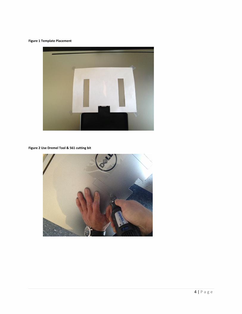
3. Using the supplied cutting template, align and tape to back cover as shown and cut out
both rectangles allowing Base Plate standoffs to fit through the back cover. The cutouts
should be larger than the standoffs to allow the cover to slide back and forth for
removal.
4. Install the Base Plate using the supplied six M4 screws adding a small drop of Loctite to the tip of the screw threads. See Figure 4
5. Replace XPS back cover following the Dell owner’s manual. Figure 6
6. Attach the VESA Plate to your Wall Mount (not supplied) using the VESA 100mm or
200mm pattern. If using the 100mm pattern you can use the supplied M6 screws,
washers and nuts. Use a washer on each side of the VESA Plate and apply Loctite to the tip of the screw threads.
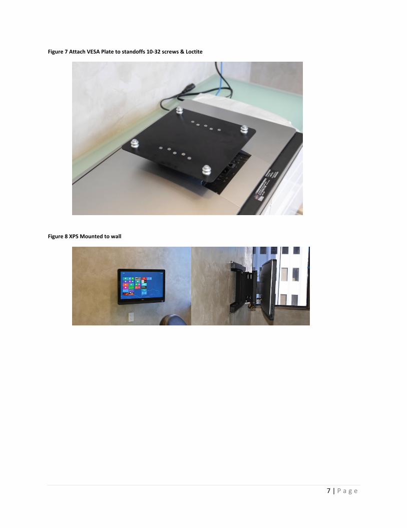
7. Attach the VESA Plate to the Base Plate standoffs using the supplied 10-32 screws and
again use a small drop of Loctite to the tip of each screw. Figure 7
8. Attach XPS to Wall Mount.
4 | P a g e
Figure 1 Template Placement
Figure 2 Use Dremel Tool & 561 cutting bit

5 | P a g e
Figure 3 Optional - File edges
Figure 4 One small drop of Loctite on the screw tip

6 | P a g e
Figure 5 Attach Base Plate to Computer M4 screws & Loctite
Figure 6 Replace back cover
7 | P a g e
Figure 7 Attach VESA Plate to standoffs 10-32 screws & Loctite
Figure 8 XPS Mounted to wall