xps-av · xps-av 13 y+ 23 y64 37 y74 47 y84 s31 a1 s32 s11 s13 s12 s14 03 14 04 24 57 58 38 48 a2 1...
TRANSCRIPT

l’instruction de service(Traduction de l’instruction de service originale)
Instruction sheet(Translation of the original instruction sheet)
Betriebsanleitung(Originalbetriebsanleitung)
03/2010
XPS-AV
13Y+
23Y64
37Y74
47Y84
S31A1
S32 S11S13
S12S14
03 14
0424
57 5838 48
A2 1 S22
Y39S33
Y40S34


03/2010 3
XPS-AV
DEUTSCH
ENGLISH
FRANÇAIS
FRANÇAIS 5
ENGLISH 31
DEUTSCH 57

4 03/2010
XPS-AV
DEUTSCH
ENGLISH
FRANÇAIS
XPS-AV
13Y+
23Y64
37Y74
47Y84
S31A1
S32 S11S13
S12S14
03 14
0424
57 5838 48
A2 1 S22
Y39S33
Y40S34
03/2010
Module de surveillance pourcircuits d’ARRET D’URGENCEselon EN / IEC 60204-1, EN ISO / ISO 13849-1,EN ISO / ISO 13850
l’instruction de service(Traduction de l’instruction de service originale)
6 03/2010
XPS-AV
FRANÇAIS
SommaireSommaire ............................................................................................... 6
Encombrement ............................................................................................... 7
Repérage des bornes ............................................................................................... 8
Vue de face (LED et Touches) ............................................................................................ 8
Démontage des bornes débrochables ................................................................................ 9
Module de surveillance pour circuits d'ARRET D'URGENCE ........................................... 11
Application ............................................................................................. 12
Fonction ............................................................................................. 12
Réglage de la temporisation ............................................................................................. 13
Affichage de la temporisation actuelle .............................................................................. 14
Sélection de la temporisation ........................................................................................... 14
Diagnostics de système ............................................................................................. 15
Indications complémentaires (Note) ................................................................................. 16
Radio perturbations (EN / IEC 60947-5-1) ....................................................................... 17
Risques résiduels (EN ISO / ISO 12100) .......................................................................... 17
Schéma de connexions et diagrammes fonctionnels,– Arrêt d’urgence, à un canal / démarrage automatique ......................................... 18 – 19– Arrêt d’urgence, à un canal / démarrage surveillé ................................................ 20 – 21– Arrêt d’urgence, à deux canaux / surveillance du démarrage .............................. 22 – 23– Verrouillage de protecteur / démarrage automatique ........................................... 24 – 25
Durée de vie électrique des contacts de sortieselon EN / IEC 60947-5-1 / Annexe C.3 ........................................................................... 26
Caractéristiques techniques ..................................................................................... 27 – 29
Déclaration CE de Conformité pour les Composants de Sécurité(Traduction française de la Déclaration CE de Conformité d'origine) ................................ 30

03/2000 7
XPS-AV
FRANÇAIS
Encombrement
XPS-AV...
XPS-AV...P
114 mm(4.48 in)
99 m
m(3
.89
in)
45 mm(1.77 in)
35 m
m
(1.3
8 in
)
99 m
m(3
.89
in)
114 mm(4.48 in)
45 mm(1.77 in)
35 m
m
(1.3
8 in
)

8 03/2010
XPS-AV
FRANÇAIS
Repérage de bornes
XPS-AV... XPS-AV...P
Y+13
Y6423
Y7437
Y8447
1403
2404
3857
4858
A1S31 S32
S13S11
S14S12
S21A2
S22 S33Y39
S34Y40
S31A1
S32 S11S13
S12S14
A2S21 S22
Y39S33 S34
Y40
13Y+
23Y64
37Y74
47Y84
0314
0424
5738
5848
Vue de face (LED)S12, S22, S32, S34 LED verteS14, Y40, K1/K2, K3/K4 LED vertePower A1/A2 LED verteError LED rougeConfig. Time Delay LED jaune
Vue de face (Touches)Time Delay Touches pour régler une valeur de tempsOK Touches pour confirmer la valeur et la mémoriser

03/2000 9
XPS-AV
FRANÇAIS
Démontage des bornes débrochables
XPS-AV...P
! DANGERTENSION DANGEREUSE
Le montage, la mise en service, les modifications et le rééquipement ne doiventêtre effectués que par un électrotechnicien ! Débranchez l’appareil / le systèmeavant de commencer les travaux !Dans le cas d’une défaillance de l’installation ou du système, les appareils ducircuit de commande sans isolation électrique peuvent être sous tension réseau !Lors de l’installation des appareils, respectez les réglementations de sécurité pourusage électrique et de la caisse de prévoyance contre les accidents.L’ouverture du boîtier ou toute autre manipulation entraîne l’expiration de lagarantie.
Le non-respect de cette directive entraînera la mort, des blessures graves oudes dommages matériels.

10 03/2010
XPS-AV
FRANÇAIS
ATTENTIONUTILISATION INAPPROPRIÉE
En cas d'usage non approprié ou d'utilisation non conforme, l'appareil ne peut plusêtre utilisé et nous refusons tout recours à la garantie.Des actions non autorisées peuvent être:forte charge mécanique de l'appareil, qui survient par ex. lorsqu'il tombe, ainsi quetensions, courants, températures et humidité en dehors des limites définies dans lesspécifications.Lors de la première mise en service de la machine/de l'installation, veuillez contrôlertoujours toutes les fonctions de sécurité conformément aux prescriptions en vigueuret respecter les cycles de contrôle prescrits pour les dispositifs de sécurité.
Le non-respect de cette directive peut entraîner des lésions corporelles et/oudes dommages matériels.
ATTENTIONDANGER À L´INSTALLATION
Respectez les mesures de sécurité suivantes avantl’installation / le montage ou le démontage :1. Débranchez l’appareil / le système avant de commencer les travaux !2. Protégez la machine / le système contre les redémarrages intempestifs !3. Assurez-vous que la machine est hors tension !4. Reliez les phases à la terre et court-circuitez les !5. Couvrez et isolez les pièces voisines sous tension !6. Le montage des appareils doit être effectué dans une armoire électrique avec
une classe de protection min. IP 54.
Le non-respect de cette directive peut entraîner des lésions corporelles et/oudes dommages matériels.
ATTENTIONPROTECTION PARTIELLE CONTRE LES CONTACTS ACCIDENTELS
• Classe de protection selon EN / IEC 60529.• Boîtier / bornes : IP 40 / IP 20.• Protection des doigts selon EN 50274.
Le non-respect de cette directive peut entraîner des lésions corporelles et/oudes dommages matériels.

03/2000 11
XPS-AV
FRANÇAIS
Module de surveillance pour circuits d'ARRET D'URGENCE• Module de surveillance conformément à EN / IEC 60204-1, EN ISO / ISO 13849-1 et
EN ISO / ISO 13850 pour le contrôle de l’arrêt d’urgence ou de portes de protection.
• PL e / catégorie 4 selon lanorme EN ISO / ISO 13849-1
• MTTFd = 75,8 Années
• DC > 99%
• PFHd = 7,95 x 10⁻⁹ 1/h
• SILCL 3 selon lanorme EN / IEC 62061
• Catégorie d’arrêt 0 et 1 selon lanorme EN / IEC 60204-1
• Démarrage manuel ou automatique
• 3 contacts de sortie - Catégorie d’arrêt 0,3 contacts de sortie - Catégorie d’arrêt 1et 3 contacts de signalisation
Note:• Le niveau de performance et la catégorie de sécurité selon la norme
EN ISO / ISO 13849-1 dépendent du câblage extérieur, du cas d’application, du choixde l’émetteur d’ordres et de l’agencement sur la machine sur place.
• L’utilisateur doit effectuer une évaluation du risque conformément à la normeEN ISO / ISO 14121-1.
• Il convient de réaliser sur cette base une validation de l’ensemble de l’installation / de lamachine selon les normes applicables.
• Le module contient des relais électromécaniques. Par conséquent le niveau deperformance déclaré et sa valeur MTTFd dépendent de la charge et de la fréquence demanœuvre dans le cas d’utilisation. Les valeurs niveau de performance et MTTFdmentionnées ci-dessus sont valables pour charge nominale et maximum 6 336manœuvres par an ou pour charge faible et maximum 316 800 manœuvres / an.
• Lorsque la charge électrique est connue, le diagramme de durée de vie électrique (voirpages 26) doit être utilisé pour calculer le nombre de manœuvres maximum. Le niveaude performance indiqué est uniquement garantit pour le nombre de manœuvres àdéterminer. Après atteinte de ce nombre de manœuvres, l'appareil doit êtreremplacé. La durée de vie de l’appareil ne doit cependant pas être dépassée.
• L’utilisation de l’appareil non conforme aux spécifications peut provoquer desdysfonctionnements ou la destruction de l’appareil.
• L’entrée d’alimentation A1 constitue l’entrée de commande. Ainsi, de brèvesinterruptions ou une baisse de la plage de tension de service UB peut entraîner lacommutation des contacts de sortie.
• Pour la duplication des contacts de sortie, il est possible d’utiliser des blocs d’extensionou des contacteurs-disjoncteurs externes avec des contacts à guidage forcé.
• Avant d’activer le poussoir de reset, la chaîne de l’arrêt d’urgence doit être fermée.
• Lors de la connexion de commutateurs magnétiques avec les contacts reed ou dedétecteurs avec les sorties de semi-conducteurs, faire attention au courant de pointe àl'entrée (voir Caractéristiques techniques).
• Respecter le schéma des installation notes.

12 03/2010
XPS-AV
FRANÇAIS
ApplicationLe module XPS-AV sert à interrompre en toute sécurité, un ou plusieurs circuits et estdestiné à être utilisé dans des circuits d’arrêt d’urgence ou de sécurité selon EN / IEC60204-1 . Il satisfait aux exigences des normes EN ISO / ISO 13850 pour les arrêtsd’urgence ainsi que EN / IEC 60204-1 pour les circuits de sécurité. Ces normes concernenten particulier les cas où une seule commande doit couper plusieurs circuits (arrêt d’urgenceà action indirecte). Le module répond également aux exigences de sécurité de lasurveillance électrique des interrupteurs de position actionnés par des dispositifs deprotection.
Le module est équipé de trois sorties de sécurité libres de potentiel de catégorie 0 (ENISO / ISO 13850, EN / IEC 60204-1), trois autres sorties retardée de catégorie 1. Celles-ci permettent une immobilisation assistée des éléments d’entraînement pour atteindrel’arrêt (par ex. freinage moteur au moyen d’un convertisseur de fréquences). Aprèsexpiration de la temporisation présélectionnée, l’interruption sûre de l’alimentation enénergie a lieu par l’ouverture des circuits de sortie retardés. La temporisation des troiscircuits de sortie entre les bornes 37-38, 47-48 et 57-58 est réglable de 0 à 300 secondes(XPSAV11113•) ou 0,1-2,0 secondes (XPSAV11113Z002) selon 16 positions (voirparagraphe: réglage de la temporisation).
Le module est conçu pour l’utilisation d’entrée à un ou deux canaux. Nous préconisonsl’utilisation d’entrée à deux canaux qui augmente ainsi le niveau de sécurité. Ce modeopératoire permet d’intégrer toute la connectique dans la surveillance. Tous les premiersdéfauts sont ainsi détectés.
FonctionLa tension d’alimentation est appliquée selon la valeur marquée sur la plaque signalétique,aux bornes A1/A2. Les unités de commande sont raccordés de la façon suivante:
Utilisation d’entrée à un canal:Les unités de commande doivent être connectées aux bornes S11-S12. Les bornesS21-S22 ainsi que S31-S32 doivent être shuntées.
Utilisation d’entrée à deux canaux:Les unités de commande doivent être connectées aux bornes S31-S32 etS21-S22. Les bornes S11-S12 doivent être shuntées.
Le module XPS-AV surveille toutes les entrées au niveau des courts-circuits entre lescircuits d’entrée et les courts-circuits avec la masse ou une dissipation de potentiel pouvantsurvenir. En cas de défaut, les sorties sont mises hors circuit et un message d’erreurapparait. (Le comportement de l’affichage LED, des sorties de signalisation et des sortiesde sécurité est représenté pour les différents cas d’erreur.)
Le bouton de démarrage ainsi que les contacts d’ouverture des relais ou contacteursconnectés en aval des sorties de sécurité doivent être connectés en série entre les bornesS33-S34 (ou bien, en cas de démarrage non surveillé ou démarrage automatique, entreles bornes S13-S14). Ainsi, une mise en circuit de l’appareil n’est possible que si les
Note:Observez également les informations de votre caisse de prévoyance contre lesaccidents !

03/2000 13
XPS-AV
FRANÇAIS
relais ou contacteurs connectés en aval, qui ont une fonction relatif à la sécurité, sontdevenus inactifs après avoir reçu l’ordre d’arrêt. La boucle de retour doit être fermé pourchaque nouvelle mise en marche.
Le bouton de démarrage est intégré dans la surveillance (utilisation recommandée) lorsqu’ilest branché entre les bornes S33-S34. Les sorties du module ne sont activées dans cetteconfiguration qu’au front descendant du signal de démarrage (donc lors du relâchementdu bouton de démarrage). Si le bouton de démarrage est branché entre les bornes S13-S14, les sorties sont activées directement dès l’actionnement du bouton de démarragedans la mesure où les circuits d’entrée sont fermés à ce moment.
Le module XPS-AV fonctionne dans toutes les versions de tension disponibles sans fusible.Un fusible électronique intégré protège l’appareil contre la destruction par des courts-circuits externes (par ex. en cas de courts-circuits dans le câblage entre les circuitsd’entrée). Après élimination du défaut et remise en circuit de la tension d’alimentation, lemodule est de nouveau opérationnel.
Après application de la tension d’alimentation sur les bornes A1-A2, le module XPS-AVexécute un auto-test interne. Toutes les 11 LED s’allument alors pendant 2 secondesdans le couvercle du boîtier. La LED verte «Power A1/A2» continue à s’allumer et lesautres LED s’éteignent dans la mesure où l’entrée ou la sortie correspondante est ouverte.
Réglage de la temporisationLe couvercle du boîtier du moduleXPS-AV comporte, outre les 11 LED,deux touches pour le réglage de latemporisation:
Time Delay pour régler unevaleur de temps
OK pour confirmer lavaleur et lamémoriser
Respectivement quatre LED vertesdans les deux colonnes de gaucheANZ.1 et ANZ.2 affichent enexploitation normale l ’état desentrées et sorties. La LED jaune«Config. Time Delay» est toujourséteinte.
Si la LED jaune «Config. TimeDelay» s’allume ou clignote, ANZ.1resp. ANZ.2 affichent alors le codebinaire pour la temporisation réglée.Les LED inférieures représentent leLSB (lowest significant bit) avec lavaleur (1).
TimeDelay
OK
PowerA1/A2
Error
Config.Time Delay
S12
S22
S14
Y40
S32
S34 K3/K4
K1/K2
(8)
(4)
(2)
(1)
AN
Z.1
(Val
eur b
inai
re)
AN
Z.2
Fig. 1: Eléments de commande

14 03/2010
XPS-AV
FRANÇAIS
Affichage de la temporisation actuellePour lire la valeur de la temporisation actuelle, on actionne la touche «Time Delay». LaLED jaune «Config. Time Delay» s’allume, et les quatre LED dans la colonne ANZ.2affichent le code binaire pour la temporisation jusqu’à ce que la touche soit relâchée.
La valeur de temps correspondant au code binaire mémorisé figure dans le tableau 1.1ou 1.2:
Sélection de la temporisationPour entrer dans le mode de configuration, les deux sorties de sécurité du module XPS-AV doivent être hors circuit. Puis, on actionne la touche «Time Delay « conjointementavec la touche «OK» pendant au moins 1 seconde. Puis, la LED jaune«Config. Time Delay» commence à clignoter et le mode de configuration est activé.
Tableau 1.2 – temporisation 0,1-2,0 secondes pour XPSAV11113Z002
S14
Y40
K1/K2
K3/K4
1
1
1
1
1
1
1
0
1
1
0
1
1
1
0
0
1
0
1
1
1
0
1
0
1
0
0
1
1
0
0
0
0
1
1
1
0
1
1
0
0
1
0
1
0
1
0
0
0
0
1
1
0
0
1
0
0
0
0
1
0
0
0
0
2,0s
1,5s
1,4s
1,3s
1,2s
1,1s
1,0s
0,9s
0,8s
0,7s
0,6s
0,5s
0,4s
0,3s
0,2s
0,1s
Tim
e
LED Code
Tableau 1.1 – temporisation 0-300 secondes pour XPSAV11113•
S14
Y40
K1/K2
K3/K4
1
1
1
1
1
1
1
0
1
1
0
1
1
1
0
0
1
0
1
1
1
0
1
0
1
0
0
1
1
0
0
0
0
1
1
1
0
1
1
0
0
1
0
1
0
1
0
0
0
0
1
1
0
0
1
0
0
0
0
1
0
0
0
0
300s
180s90
s
60s
30s
25s
20s
15s
10s8s6s4s2s1s
0,5s0s
Tim
e
LED Code

03/2000 15
XPS-AV
FRANÇAIS
Les colonnes ANZ.1 et ANZ.2 affichent maintenant le code binaire de la temporisationmémorisée. Après chaque nouvelle pression sur la touche «Time Delay», l’affichagebascule dans la colonne ANZ.2 sur le prochain code binaire possible, et ainsi sur laprochaine temporisation possible. ANZ.1 continue à afficher la temporisation mémorisée.
Si ANZ.2 affiche le code désiré, on mémorise la nouvelle valeur en appuyant sur la touche«OK». Ainsi, les colonnes ANZ.1 et ANZ.2 affichent la nouvelle temporisation et la LEDjaune pour la configuration est allumée en continu.
Les sorties du module XPS-AV restent cependant verrouillées jusqu’à ce que, par la misehors tension, puis sous tension du circuit d’alimentation, la nouvelle valeur de temporisationsoit confirmée et activée. Les huit LED des zones ANZ.1 et ANZ.2 signalisent alors l’étatd’exploitation des entrées et sorties en fonction des inscriptions imprimées sur le couvercle.
Diagnostics de systèmeLes états d’exploitation des fonctions XPS-AV sont représentés optiquement avec 11LED dans la zone de commande et signalés à une autre commande par trois sorties àsemi-conducteur.
1. Affichage LED en état d’exploitation et en cas d’erreur:En exploitation normale, la LED verte «Power A1/A2» s’allume dans la colonne de droitede l’affichage LED. La LED rouge «Error» et la LED jaune pour le mode configurationsont éteintes.
Si la LED rouge «Error» clignote, une erreur est survenue qui peut être éliminée.Alternativement avec la LED «Error», la LED de l’entrée concernée clignote et afficheainsi directement à l’utilisateur où il doit rechercher le défaut.
LED rouge„Error”
Eteinte
LED verte del'entrée/sortierespective
Lumièreclignotante
EteinteLumière continueLumièreclignotante
Entrée/sortie ouverteEntrée/sortie ferméeEntrée n'était pas ouverte lorsde la précédente mise hors circuit,nouveau démarrage impossible
Reconnaître étatd'exploitation
Vérifier l'élémentde contact
Contrôlerle cáblâge,éliminer erreur,remettre soustension
Tableau 2
Signification Action
Lumièrecontinue
Eteinte Eliminer lecourt-circuit,remettre soustension
Lumièreclignotante
Erreur de connexion, court-circuit, rupture de câble outapis à contact nonbranché
Eteinte Court-circuit à la massed'une entrée
Court-circuit d'uneentrée avec +24V
Démonter l'appareilErreur interne

16 03/2010
XPS-AV
FRANÇAIS
2. Affichage LED dans le mode configuration (la LED jaune s’allume):Si la LED jaune s’allume ou clignote, les LED vertes représentent les informations décritesdans le paragraphe «Sélection temporisation» dans le code binaire. (La LED rouge «Error»est toujours éteinte.)
3. Sorties de signalisation:Trois sorties à semi-conducteur indiquent les états d’exploitation respectifs des deuxfonctions du module XPS-AV à la commande environnante. Avec la borne Y +, les troissorties à semi-conducteur sont conjointement branchés sur la tension d’alimentation. Lasignification de ces signaux, pour l’exploitation normale et en cas d’erreur, est représentéedans le tableau 3.
Si la sortie Y64 est activée, une erreur est survenue. Si, en même temps, une autre sortieà semi-conducteur est activée, il y a une erreur externe dans les entrées, et le moduleXPS-AV est, après son élimination et la remise sous tension du circuit d’alimentation, denouveau opérationnel. Après une information, une mise hors circuit n’est pas nécessaire.
Indications complémentaires
Y64 Y74 Y84 Etat K1/K2000
1
1
1
*) après l'expiration de la temporisation
K3/K4001
0
0
1
011
0
1
1
001
0
0Erreur
Information
Exploitation
0
011
0
0 *)
0
Toutes sorties de sécurité hors circuitTemporisation tV en coursToutes les sorties de sécurité activéesErreur internetension externe détectée sur les entrées
Erreur externe,par exemple court-circuit entre 2 entrées
Temps de synchronisation tS dépassé1 1 0 0 0Bouton de démarrage appuyé trop longtemps
Tableau 3
Note:L’appareil ne contient pas de pièces à entretenir par l’utilisateur. Pour la coupure descircuits de courant de sécurité selon EN / IEC 60204-1 / EN ISO / ISO 13850, onn’utilisera que les sorties de sécurité libres de potentiel entre les bornes 03-04, 13-14, 23-24 (arrêt de catégorie 0) et les sorties 37-38, 47-48, 57-58 pour l’arrêt decatégorie 1. (Exception: si la temporisation est réglée à 0 seconde (code 0000), cessorties ouvrent également sans retard (arrêt de catégorie 0).L’utilisation des systèmes d’antiparasitage est recommandé pour les contacteursconnectés

03/2000 17
XPS-AV
FRANÇAIS
ATTENTIONRISQUES RÉSIDUELS (EN ISO / ISO 12100)
Le schéma de raccordement proposé ci-dessous a été vérifié et testé avec le plusgrand soin dans des conditions de mise en service. Des risques subsistent si :a) le schéma de câblage ci-dessous est modifié par changement des connexions ou
l’adjonction de composants lorsque ceux-ci ne sont pas ou insuffisammentintégrés dans le circuit de sécurité.
b) l’utilisateur ne respecte pas les exigences des normes de sécurité pour leservice, le réglage et la maintenance de la machine. Il est important de respecterstrictement les échéance de contrôle et de maintenance.
Le non-respect de cette directive peut entraîner des lésions corporelles et/oudes dommages matériels.
AVERTISSEMENTRADIO PERTURBATIONS (EN / IEC 60947-5-1)
Ceci est un produit de classe A. Cet appareil peut causer des perturbations radiodans un environnement domestique, c’est pourquoi l’utilisateur devra prendre, sinécessaire, des précautions appropriés.
Le non-respect de cette directive peut entraîner la mort, des lésionscorporelles graves ou des dommages matériels.

18 03/2010
XPS-AV
FRANÇAIS
Sch
éma
de
con
nex
ion
– A
rrêt
d’u
rgen
ce,
à un
can
al /
dém
arra
ge a
utom
atiq
ue
0V
Vers
aut
omat
epr
ogra
mm
able
K11
K12
Arrê
t cat
.0ES
C =
Con
ditio
ns d
e dé
mar
rage
ext
erne
sAr
rêt c
at.0
Arrê
t cat
.1Ar
rêt c
at.1
Lége
nde:
+24V
F1
0V
K02
K01
Sorti
es d
e sé
curit
éà
ouve
rture
dire
cte
(arr
êt c
atég
orie
0)
Sorti
es d
e sé
curit
éá
ouve
rture
reta
rdée
(arr
êt c
atég
orie
1)
+24V
Arrê
t de
late
mpo
risat
ion
DC
DC
DC
DC
K1 K3 K2 K4
Sorti
e1
Sorti
e2
Sorti
e1
Sorti
e2
LOG
IQU
E -
cana
l 1
LOG
IQU
E -
cana
l 2X
PS
-AV
Erreur
K1/K2
K3/K4
A1S1
3S1
1S3
1S3
2S1
2S1
403
1323
3747
57Y+
Y64
Y74
Y84
A2Y3
9S3
3S2
1S2
2S3
4Y4
004
1424
3848
58
S1
Arrê
t d'u
rgen
ce
11 12
S3
Dém
arra
ge
13 14
K12
K11
K02
K01
ESC

03/2000 19
XPS-AV
FRANÇAIS
Arrê
t d'u
rgen
ceno
n ac
tionn
éAr
rêt d
'urg
ence
non
actio
nné
Dém
arra
ge a
utom
atiq
ue(S
33-S
34 =
ouv
ert)
Mis
e so
us te
nsio
n(A
uto-
test
ach
evé)
Arrê
t d'u
rgen
ceac
tionn
éAr
rêt d
'urg
ence
actio
nné
Arrê
t d'u
rgen
ceS1
1-S1
2Dé
mar
rage
aut
omat
ique
(san
s ES
C)
S13-
S14
Entré
e sh
unté
eS2
1-S2
2
Entré
e sh
unté
eS3
1-S3
2In
terr
uptio
n de
tem
poris
atio
nY3
9-Y4
0So
rtie
"F"
03-0
4/13
-14/
23-2
4
Sorti
e "F
"37
-38/
47-4
8/57
-58
Sorti
e de
sig
nalis
atio
nY7
4
Sorti
e de
sig
nalis
atio
nY8
4
Arrê
t d'u
rgen
ceS1
1-S1
2
Bout
on d
e dé
mar
rage
S13-
S14
Entré
e sh
unté
eS2
1-S2
2
Entré
e sh
unté
eS3
1-S3
2In
terr
uptio
n de
tem
poris
atio
nY3
9-Y4
0So
rtie
"F"
03-0
4/13
-14/
23-2
4
Sorti
e "F
"37
-38/
47-4
8/57
-58
Sorti
e de
sig
nalis
atio
nY7
4
Sorti
e de
sig
nalis
atio
nY8
4
Arrê
t d'u
rgen
ceno
n ac
tionn
éAr
rêt d
'urg
ence
non
actio
nné
Dém
arra
ge n
on s
urve
illé
Mis
e so
us te
nsio
n(A
uto-
test
ach
evé)
Arrê
t d'u
rgen
ceac
tionn
éAr
rêt d
'urg
ence
actio
nné
Dém
arra
geD
émar
rage
Tem
poris
atio
nin
terro
mpu
eD
émar
rage
Dém
arra
geTe
mpo
risat
ion
inte
rrom
pue
t V
tV
=Te
mpo
risa
tion
t V
Dia
gra
mm
e fo
nct
ion
nel
– A
rrêt
d’u
rgen
ce,
à un
can
al /
dém
arra
ge a
utom
atiq
ue

20 03/2010
XPS-AV
FRANÇAIS
Sch
éma
de
con
nex
ion
– A
rrêt
d’u
rgen
ce,
à un
can
al /
dém
arra
ge s
urve
illé
0V
Vers
aut
omat
epr
ogra
mm
able
K11
K12
Arrê
t cat
.0ES
C =
Con
ditio
ns d
e dé
mar
rage
ext
erne
sAr
rêt c
at.0
Arrê
t cat
.1Ar
rêt c
at.1
Lége
nde:
+24V
F1
0V
K02
K01
Sorti
es d
e sé
curit
éà
ouve
rture
dire
cte
(arr
êt c
atég
orie
0)
Sorti
es d
e sé
curit
éá
ouve
rture
reta
rdée
(arr
êt c
atég
orie
1)
+24V
Arrê
tte
mpo
-ris
atio
n
DC
DC
DC
DC
K1 K3 K2 K4
Sorti
e1
Sorti
e2
Sorti
e1
Sorti
e2
LOG
IQU
E -
cana
l 1
LOG
IQU
E -
cana
l 2X
PS
-AV
A1S1
3S1
1S3
1S3
2S1
2S1
403
1323
3747
57Y+
Y64
Y74
Y84
A2Y3
9S3
3S2
1S2
2S3
4Y4
004
1424
3848
58
S1
Arrê
t d'u
rgen
ce
11 12
S3
Dém
arra
ge
13 14
K12
K11
K02
K01
ESC
Erreur
K1/K2
K3/K4

03/2000 21
XPS-AV
FRANÇAIS
Dia
gra
mm
e fo
nct
ion
nel
– A
rrêt
d’u
rgen
ce,
à un
can
al /
dém
arra
ge s
urve
illé
Dém
arra
ge
Arr
êt d
'urg
ence
, à u
n ca
nal /
dém
arra
ge s
urve
illé
(S13
-S14
= o
uver
t)
Mis
e so
us te
nsio
n(A
uto-
test
ach
evé)
Arrê
t d'u
rgen
ceac
tionn
éAr
rêt d
'urg
ence
non
actio
nné
Arrê
t d'u
rgen
ceno
n ac
tionn
éAr
rêt d
'urg
ence
actio
nné
Arrê
t d'u
rgen
ceS1
1-S1
2
Entré
e sh
unté
eS2
1-S2
2
Entré
e sh
unté
eS3
1-S3
2
Bout
on d
e dé
mar
rage
S33-
S34
Inte
rrup
tion
tem
poris
atio
nY3
9-Y4
0So
rtie
"F"
03-0
4/13
-14/
23-2
4
Sorti
e "F
"37
-38/
47-4
8/57
-58
Sorti
e de
sig
nalis
atio
nY7
4
Sorti
e de
sig
nalis
atio
nY8
4Te
mpo
risat
ion
inte
rrom
pue
Pas
dedé
mar
rage
1 )
t < 1
0sD
émar
rage
t < 1
0s
t V
tV
=Te
mpo
risa
tion
1)
=C
ontr
ôle
du b
outo
n de
dém
arra
ge:
Le b
outo
n de
dém
arra
ge n
'est
doit
pas
être
enc
lenc
hé a
um
omen
t de
la m
ise
sous
ten
sion
.

22 03/2010
XPS-AV
FRANÇAIS
Sch
éma
de
con
nex
ion
– A
rrêt
d’u
rgen
ce,
à de
ux c
anau
x /
surv
eilla
nce
du d
émar
rag
e
0V
+24V
S1Ar
rêt
d'ur
genc
e
11
+24V
F1
Erreur
K1/K2
K3/K4
XP
S-A
V
Vers
aut
omat
epr
ogra
mm
able
0V ESC
= C
ondi
tions
de
dém
arra
ge e
xter
nes
Lége
nde:
Arrê
t cat
.0Ar
rêt c
at.0
Arrê
t cat
.1Ar
rêt c
at.1
K11
K12
K02
K01
Sorti
es d
e sé
curit
éà
ouve
rture
dire
cte
(arr
êt c
atég
orie
0)
Sorti
es d
e sé
curit
éá
ouve
rture
reta
rdée
(arr
êt c
atég
orie
1)
Arrê
tte
mpo
-ris
atio
n
12
ESC
S3
Dém
arra
ge
13 14
S1
21 22
K12
K11
K02
K01
DC
DC
DC
DC
LOG
IQU
E -
cana
l 1
LOG
IQU
E -
cana
l 2
Sorti
e1
Sorti
e2
Sorti
e1
Sorti
e2
K1 K3 K2 K4
A1S1
3S1
1S3
1S3
2S1
2S1
403
1323
3747
57Y+
Y64
Y74
Y84
5848
3824
1404
Y40
S34
S22
S21
S33
Y39
A2
Arrê
td'
urge
nce

03/2000 23
XPS-AV
FRANÇAIS
Dia
gra
mm
e fo
nct
ion
nel
– A
rrêt
d’u
rgen
ce,
à de
ux c
anau
x /
surv
eilla
nce
du d
émar
rag
e
Arr
êt d
'urg
ence
, à d
eux
cana
ux /
dém
arra
ge s
urve
illé
(S13
-S14
= o
uver
t)
Mis
e so
us te
nsio
n(A
uto-
test
ach
evé) Ar
rêt d
'urg
ence
non
actio
nné
Arrê
t d'u
rgen
ceac
tionn
éAr
rêt d
'urg
ence
non
actio
nné
Arrê
t d'u
rgen
ceac
tionn
éEn
trée
shun
tée
S11-
S12
Arrê
t d'u
rgen
ce (c
anal
1)
S21-
S22
Arrê
t d'u
rgen
ce (c
anal
2)
S31-
S32
Bout
on d
e dé
mar
rage
S33-
S34
Inte
rrup
tion
tem
poris
atio
nY3
9-Y4
0So
rtie
"F"
03-0
4/13
-14/
23-2
4
Sorti
e "F
"37
-38/
47-4
8/57
-58
Sorti
e de
sig
nalis
atio
nY7
4
Sorti
e de
sig
nalis
atio
nY8
4Te
mpo
risat
ion
inte
rrom
pue
Pas
dedé
mar
rage
1 )D
émar
rage
t < 1
0sD
émar
rage
t < 1
0s
t V
tV
=Te
mpo
risa
tion
1)
=C
ontr
ôle
du b
outo
n de
dém
arra
ge:
Le b
outo
n de
dém
arra
ge n
'est
doit
pas
être
enc
lenc
hé a
um
omen
t de
la m
ise
sous
ten
sion
.

24 03/2010
XPS-AV
FRANÇAIS
Sch
éma
de
con
nex
ion
– V
erro
uilla
ge d
e pr
otec
teur
/ d
émar
rage
aut
omat
ique
K11
K12
+24V
F1
0V
K02
K01
+24V
0V
Arrê
t cat
.0ES
C =
Con
ditio
ns d
e dé
mar
rage
ext
erne
sAr
rêt c
at.0
Arrê
t cat
.1Ar
rêt c
at.1
Lége
nde:
Vers
aut
omat
epr
ogra
mm
able
XP
S-A
V
Erreur
K1/K2
K3/K4
Sorti
es d
e sé
curit
éá
ouve
rture
reta
rdée
(arr
êt c
atég
orie
1)
Sorti
es d
e sé
curit
éà
ouve
rture
dire
cte
(arr
êt c
atég
orie
0)
Arrê
t de
late
mpo
risat
ion
DC
DC
DC
DC
LOG
IQU
E -
cana
l 1
LOG
IQU
E -
cana
l 2
Sorti
e1
Sorti
e2
Sorti
e1
Sorti
e2
K1 K3 K2 K4ESC
K12
K11
K02
K01
S1
Prot
ecte
urfe
rmé
21 22
S2Pr
otec
teur
ferm
é13 14
13 14
S221 22
A2Y3
9S3
3S2
1S2
2S3
4Y4
004
1424
3848
58
Y84
Y74
Y64
Y+57
4737
2313
03S1
4S1
2S3
2S3
1S1
1S1
3A1

03/2000 25
XPS-AV
FRANÇAIS
Dém
arra
geTe
mpo
risat
ion
inte
rrom
pue
Entré
e sh
unté
eS1
1-S1
2
Prot
ecte
ur (c
anal
1)
S21-
S22
Prot
ecte
ur (c
anal
2)
S31-
S32
Prot
ecte
ur o
uver
tS1
3-S1
4In
terr
uptio
nte
mpo
risat
ion
Y39-
Y40
Sorti
e "F
"03
-04/
13-1
4/23
-24
Sorti
e "F
"37
-38/
47-4
8/57
-58
Sorti
e de
sig
nalis
atio
nY7
4
Sorti
e de
sig
nalis
atio
nY8
4
Pro
tect
eur
avec
dém
arra
ge a
utom
atiq
ue e
t syn
chro
nisa
tion
time
t S(S
33-S
34 =
ouv
ert)
Prot
ecte
urfe
rmé
Mis
e so
us te
nsio
n(A
uto-
test
ach
evé)
Prot
ecte
urou
vert
Prot
ecte
urfe
rmé
Prot
ecte
urfe
rmé
Prot
ecte
urou
vert
Prot
ecte
urou
vert
t S <
1,5
st V
tV
=Te
mpo
risa
tion
tS
=S
ynch
roni
satio
n tim
e
Dém
arra
ge
Dia
gra
mm
e fo
nct
ion
nel
– V
erro
uilla
ge d
e pr
otec
teur
/ d
émar
rage
aut
omat
ique

26 03/2010
XPS-AV
FRANÇAIS
0,1110
1010
010
0010
000
Courant d'exploitation nominal A
Cyc
les
de m
anoe
uvre
s x
10³
AC
1: 2
30 V
DC
1: 2
4 V
AC
15:
230
VDC
13:
24
V(<
0,1
Hz)
Du
rée
de
vie
élec
triq
ue
des
co
nta
cts
de
sort
ie s
elo
n E
N /
IEC
609
47-5
-1 /
An
nex
e C
.3

03/2000 27
XPS-AV
FRANÇAIS
Données sur les bornes et les connexions XPS-AV...
Connection un fil
Sans embout rigide 0,14-2,5 mm2
flexible 0,14-2,5 mm2
AWG 26-14
Longueur de dénudage 7 mm
Flexible avec embout (sans colleret plastique) 0,25-2,5 mm2
Flexible avec embout (avec colleret plastique) 0,25-1,5 mm2
Couple de rotation min. 0,5 Nm
Connection deux fils
Sans embout rigide 0,14-0,75 mm2
flexible 0,14-0,75 mm2
Longueur de dénudage 7 mm
Flexible avec embout (sans colleret plastique) 0,25-1 mm2
Flexible avec embout TWIN (avec colleret plastique) 0,5-1,5 mm2
Couple de rotation min. 0,5 Nm
Données sur les bornes et les connexions XPS-AV...P
Connection un fil
Sans embout rigide 0,2-2,5 mm2
flexible 0,2-2,5 mm2
AWG 24-14
Longueur de dénudage 7 mm
Flexible avec embout (sans colleret plastique) 0,25-2,5 mm2
Flexible avec embout (avec colleret plastique) 0,25-1,5 mm2
Couple de rotation min. 0,5 Nm
Connection deux fils
Sans embout rigide 0,2-1 mm2
flexible 0,2-1,5 mm2
Longueur de dénudage 7 mm
Flexible avec embout (sans colleret plastique) 0,25-1 mm2
Flexible avec embout TWIN (avec colleret plastique) 0,5-1,5 mm2
Couple de rotation min. 0,5 Nm
Caractéristiques techniques

28 03/2010
XPS-AV
FRANÇAIS
Fixation du boîtier Encliquetage sur profilechapeau 35 mmselon EN / IEC 60715
Degré de protection selon EN / IEC 60529, Bornes IP20Degré de protection selon EN / IEC 60529, Boîtier IP40
Poids 0,32 kg
Position de montage indifférente
Température de fonctionnement - 100 C / + 550 C
Catégorie de surtension III (4kV) Degré de pollution 2Tension assignée d’isolement 300V a selon EN / IEC 60664-1
Tension d’alimentation UE selon IEC 60038 24V c (±20%)(voir plaque signalétique)
Protection max. 4A gL ou 6A rapide
Puissance consommée, Version 24V c ≤ 5 W
Sorties de sécurité (libres de potentiel) 03..04, 13..14, 23..24Catégorie d’arrêt 0,EN / IEC 60204-1 /EN ISO / ISO 13850
37..38, 47..48, 57..58Catégorie d’arrêt 1,EN / IEC 60204-1 /EN ISO / ISO 13850
Sortie statique, fonction fermeture (sans contact) Y+..Y64, Y+..Y74, Y+..Y84(Typiquement: 24V c / 20mA)
Pouvoir de coupure maxi des sorties AC 15 - C300Ue = 230V a / Ie = 0,75 ADC 13Ue = 24V c / Ie = 1,5 A
Durée de vie mécanique (Commutations) 10 x 106
Limite des courants cumulés(charge simultanée de plusieurs circuits de sortie) Σ Ith ≤ 20 A
K1/K2 K3/K4
6A 2A 2A 6A 2A 2A
4A 4A 2A 4A 4A 2A
3,3A 3,3A 3,3A 3,3A 3,3A 3,3A
Protection des sorties max. 4A gL ou 6A rapide

03/2000 29
XPS-AV
FRANÇAIS
Schneider Electric Industries SAS
35, rue Joseph Monier92506 Rueil-MalmaisonFrance
Temps de réponse ≤ 30 ms
Temps de synchronisation tS, pour protecteur 1,5sTemps de synchronisation, pour arrêt d’urgence ∞Temporisation tV, XPSAV11113• 0-300 s
XPSAV11113Z002 0,1-2,0 s
PL e / catégorie selon la norme EN ISO / ISO 13849-1 4
Résistance de câblage maximaledans les circuits d’entrées 100 ΩLongueur de câblage maximaledans les circuits d’entrées 2000 m
L'appareil est aussi capable de commuter des charges faibles (17 V c / 10 mA minimum)à condition que le contact n'ait jamais commuté de forte charge auparavant, car la couched'or revêtant le contact pourrait être altérée.

30 03/2010
XPS-AV
FRANÇAIS
DÉCLARATION CE DE CONFORMITÉ POUR LES COMPOSANTS DE SÉCURITÉ(Traduction française de la Déclaration CE de Conformité d'origine Référence du document : S1A2880500.00)
Nous: Schneider Electric Industries SAS / 35, rue Joseph Monier / 92506 Rueil Malmaison, France
Déclarons que le composant de sécurité
MARQUE: SCHNEIDER ELECTRIC
NOM, TYPE: Module pour surveillance d'Arrêt d'urgence
MODELES: XPS-AV
NUMÉRO DE SÉRIE: voir de la Déclaration CE de Conformité d'origine
DATE DE FABRICATION: voir plaque signalétique
est conforme à l'ensemble des recommandations en matière de protection stipulées dans les consignes suivantes.Une description de la Déclaration avec les normes européennes harmonisées est fournie ci-après.:
L'organisme agréé suivant a établi une déclaration positive selon le Chapitre 7, phrase 2, 2004/108/EG:
Sous réserve d’installation, d’entretien et d’utilisation conformes à sa destination, à la réglementation, aux normes en vigueur, aux instructions du constructeur et aux règles de l’art.
Documentation autorité:Eric Léon Barry / Schneider Electric Automation GmbH / Steinheimer Straße 117 / 63500 Seligenstadt, Germany
France - Rueil Malmaison p. p. François Mondino17 - Février - 2010 OEM R&D Vice-President
La Déclaration CE de Conformité d'origine est disponible sur notre site Web: www.schneider-electric.com
DATE DE RÉFÉRENCE: DIRECTIVE:
EN 60204-01:2006 (DIN EN 60204-01:2007-06) DIRECTIVE 2006/95/CE DUPARLEMENT EUROPÉEN ET DU CONSEILdu 12 décembre 2006concernant le rapprochement des législations des États membres relatives au matériel électrique destiné à être employé dans certaines limites de tension
EN 60947-5-1:2004 (DIN EN 60947-5-1:2005-02)
EN 60947-01:2007 (DIN EN 60947-01:2008-04)
EN ISO 13850:2008 (DIN EN ISO 13850:2009-08)
EN 60947-01:2007 (DIN EN 60947-01:2008-04) DIRECTIVE 2004/108/CE DUPARLEMENT EUROPÉEN ET DU CONSEILdu 15 décembre 2004relative au rapprochement des législations des États membres concernant la compatibilité électromagnétique et abrogeant la directive 89/336/CEE
EN 61000-6-02:2005 (DIN EN 61000-6-2:2006-03)
EN 61000-6-4:2007 (DIN EN 61000-6-4:2007-09)
EN 60947-5-1:2004 (DIN EN 60947-5-1:2005-02)
EN 62061:2005 (DIN EN 62061:2005-10) DIRECTIVE 98/37/CE DU PARLEMENT EUROPÉEN ET DU CONSEILdu 22 juin 1998etDIRECTIVE 2006/42/CE DUPARLEMENT EUROPÉEN ET DU CONSEILdu 17 mai 2006relative aux machines et modifiant la directive 95/16/CE (refonte)
EN ISO 12100-2:2003 (DIN EN ISO 12100-2:2004-04)
EN ISO 13849-1:2008 (DIN EN ISO 13849-01:2008-12)
EN ISO 13849-2:2008 (DIN EN ISO 13849-2:2008-09)
RÉFÉRENCE DE L'ORGANISME AGRÉÉ: RÉFÉRENCE DE LA DÉCLARATION:
NOM, ADRESSE:
0044 4420509373024-001 TÜV NORD CERT GMBHLangemarckstr. 20D-45141 Essen

XPS-AV
Instruction sheet(Translation of the original instruction sheet)
03/2010
Safety relay for monitoring EMERGENCY STOPcircuits according to EN / IEC 60204-1,EN ISO / ISO 13849-1, EN ISO / ISO 13850
13Y+
23Y64
37Y74
47Y84
S31A1
S32 S11S13
S12S14
03 14
0424
57 5838 48
A2 1 S22
Y39S33
Y40S34

32 03/2010
XPS-AV
ENGLISH
Table of contentsTable of contents ............................................................................................. 32
Dimensions ............................................................................................. 33
Terminal marking ............................................................................................. 34
Front view (LED and Push buttons) ................................................................................ 34
Removing the plug-in terminals ...................................................................................... 35
Safety relay for monitoring EMERGENCY STOP circuits .............................................. 37
Application ............................................................................................. 38
Function ............................................................................................. 38
Setting the time delay ............................................................................................. 39
Displaying the current time delay ................................................................................... 40
Select time delay ............................................................................................. 40
System diagnosis ............................................................................................. 41
Supplementary note (Note) ............................................................................................ 42
Radio interference (EN / IEC 60947-5-1) ....................................................................... 43
Residual risks (EN ISO / ISO 12100) ............................................................................. 43
Wiring diagrams and Functional diagrams,– Emergency stop, one channel connection / Automatic start ............................. 44 – 45– Emergency stop, one channel connection / Start button monitored ................. 46 – 47– Emergency stop, two channel connection / Start button monitored ................. 48 – 49– Protective guard / Automatic start ..................................................................... 50 – 51
Electrical life of the output contactsdetermined by EN / IEC 60947-5-1 / Annex C.3 ............................................................ 52
Technical Data ..................................................................................... 53 – 55
EC Declaration of Conformity for Safety Components(English translation of the original EC declaration of conformity) ................................. 56

03/2010 33
XPS-AV
ENGLISH
Dimensions
114 mm(4.48 in)
99 m
m(3
.89
in)
45 mm(1.77 in)
35 m
m
(1.3
8 in
)
99 m
m(3
.89
in)
114 mm(4.48 in)
45 mm(1.77 in)
35 m
m
(1.3
8 in
)
XPS-AV...
XPS-AV...P

34 03/2010
XPS-AV
ENGLISH
Terminal marking
XPS-AV... XPS-AV...P
Y+13
Y6423
Y7437
Y8447
1403
2404
3857
4858
A1S31 S32
S13S11
S14S12
S21A2
S22 S33Y39
S34Y40
S31A1
S32 S11S13
S12S14
A2S21 S22
Y39S33 S34
Y40
13Y+
23Y64
37Y74
47Y84
0314
0424
5738
5848
Front view (LED)S12, S22, S32, S34 LED greenS14, Y40, K1/K2, K3/K4 LED greenPower A1/A2 LED greenError LED redConfig. Time Delay LED yellow
Front view (Push buttons)Time Delay Push button to set a time valueOK Push button to confirm the value and save

03/2010 35
XPS-AV
ENGLISH
Removing the plug-in terminals
! DANGERHAZARDOUS VOLTAGE
• Disconnect all power supplying ≥ 30V AC or 42VDC before working on equipment.
Electric shock will result in death or serious injury.
! DANGERHAZARDOUS VOLTAGE
Only trained professional electricians may install, startup, modify, and retrofit thisequipment!Disconnect the device / system from all power sources prior to starting any work!If installation or system errors occur, line voltage may be present at the controlcircuit in devices without DC isolation!Observe all electrical safety regulations issued by the appropriate technicalauthorities or the trade association. The safety function can be lost if the device isnot used for the intended purpose.Opening the housing or any other manipulation will void the warranty.
Failure to follow this instruction will result in death or serious injury.
XPS-AV...P

36 03/2010
XPS-AV
ENGLISH
CAUTIONUNINTENDEND USE
If the device has been subjected to improper or incorrect use it must no longer beused, and the guarantee loses its validity.Impermissible conditions include:strong mechanical stress, for example through a fall, or voltages, currents,temperatures or humidity outside of the specifications.Before starting up your machine/plant for the first time, please be sure to check allthe safety functions according to valid regulations, and observe the specified testcycles for safety equipment.
Failure to follow this instruction can result in injury or equipment damage.
CAUTIONRISKS ON INSTALLATION
Perform the following precautionary steps prior to installation, assembly, ordisassembly:1. Disconnect supply voltage to the equipment / system prior to starting any work!2. Lockout/tag the equipment / system to prevent accidental activation!3. Confirm that no voltage is present!4. Ground the phases and short to ground!5. Protect against adjacent live components using guards and barriers!6. The devices must be installed in a cabinet with a protection class of
at least IP 54.
Failure to follow this instruction can result in injury or equipment damage.
CAUTIONLIMITED CONTACT PROTECTION
• Protection type according to EN / IEC 60529.• Housing/terminals: IP 40 / IP 20.• Finger-proof acc. to EN 50274.
Failure to follow this instruction can result in injury or equipment damage.

03/2010 37
XPS-AV
ENGLISH
Safety relay for monitoring EMERGENCY STOP circuits• Safety Relay according to EN / IEC 60204-1, EN ISO / ISO 13849-1
and EN ISO / ISO 13850 for E-stop or protective guard monitoring
• PL e / category 4 in accordancewith EN ISO / ISO 13849-1
• MTTFd = 75,8 Years
• DC > 99%
• PFHd = 7,95 x 10⁻⁹ 1/h
• SILCL 3 in accordancewith EN / IEC 62061
• Stop category 0 and 1 in accordancewith EN / IEC 60204-1
• Manual or automatic start
• 3 Enabling paths - Stop category 0,3 Enabling paths - Stop category 1and 3 Signalling paths
Note:• The performance level and safety category in accordance with EN ISO / ISO
13849-1 depends on the external wiring, the application case, the choice ofcontrol station and how this is physically arranged on the machine.
• The user must carry out a risk assessment in accordance withEN ISO / ISO 14121-1.
• The entire system/machine must undergo validation in accordance with theapplicable standards on the basis of this.
• The module contains electro-mechanical relays. Therefore his indicatedperformance level and his MTTFd value depend on the load and on the operatingcycles in the application. The above mentioned performance level and MTTFdvalues are suitable for nominal load and maximum 6.336 switching cycles peryear or for low load and maximum 316.800 switching cycles per year.
• If the current load is known, use the diagram for the electrical service life(page 52) to calculate the maximum number of switching cycles. The specifiedperformance level can only be assured for the number of switching cyclescalculated using this method. The device must be replaced on reaching thismaximum figure. Thereby the lifetime of the device must not be exceeded.
• Operating the device not within the specifications may lead to malfunctions or thedestruction of the device.
• The supply input A1 serves as a control input. This may lead to short disruptionsor a lowering below the operating voltage UB in order to switch to the releasepath.
• Expansion devices or external contactors with positively driven contacts can beused to duplicate the enabling current paths.
• The emergency stop chain must be closed before the reset button is activated.
• If magnetic switches with reed contacts or sensors with semiconductor outputsare connected the switch ON peak current must be noticed (see Technical Data).
• Please consult the installation notes.

38 03/2010
XPS-AV
ENGLISH
ApplicationSafety systems are comprised of many components. No one safety component will ensurethe safety of the system. The design of the complete safety system should be consideredbefore you begin. It is very important to follow applicable safety standards when installingand wiring these components.
The XPS-AV module is used for interruption of one or more power circuit(s) and is intendedfor use in emergency stop and safety power circuits in accordance with EN / IEC 60204-1.It complies with the European standards EN ISO / ISO 13850 for emergency stop devicesand EN / IEC 60204-1 on safety power circuits in general, which also include instances inwhich one emergency stop command is used to switch off several power circuits (indirectemergency stop). The module also meets the safety requirements for the electricalmonitoring of position switches on disconnecting protective devices.
In addition to the three safety outputs in stop category 0 (EN ISO / ISO 13850, EN / IEC60204-1), the module also provides three additional stop category 1 outputs which switchoff after a time delay. These allow the moving elements to be brought to a stop in acontrolled way (e.g. braking via a variable frequency converter). After the preselectedtime delay has passed, the power supply is safely interrupted by opening the time-delayedoutput contacts. The time delay of the three output contacts between terminals 37-38, 47-48 and 57-58 can be set in sixteen stages from 0-300 seconds (XPSAV11113•) or 0,1-2,0seconds (XPSAV11113Z002) (see section on Setting the delay range).
The device is suitable for one-channel and two-channel input wiring. Based on theexpanded fault detection facilities and the resultant higher safety level, the two channelinput wiring system is recommended. In this operating mode, the connecting leads arealso incorporated in the monitoring and all initial faults are identified.
FunctionThe supply voltage is connected to terminals A1/A2 in accordance with the value markedon the device label. The input devices must be connected as follows:
One-channel input wiring:The input devices are to be connected to terminals S11-S12. The terminals S21-S22and S31-S32 are to be jumpered.
Two-channel input wiring:The input devices are to be connected to terminals S31-S32 and S21-S22. TerminalsS11-S12 are to be jumpered.
The XPS-AV monitors all inputs for any cross short-circuits arising between them or short-circuits to ground or accidental energisation. In the case of a fault, the outputs are switchedoff and a signal is generated. (Tables 2 and 3 show the behaviour of the LED display, thesignal outputs and the safety outputs for the various faults.)
The start button and the contacts for contactor monitoring are to be incorporated in thefeedback circuit between the terminals S33-S34 (or, with a non-monitored start or automatic
Note:Please observe instructions from safety authorities.

03/2010 39
XPS-AV
ENGLISH
start, between terminals S13-S14). This means that the device can only be switched on ifthe subsequent relays which have a safety function have dropped out after a previousstop command. The feedback circuit must be closed every time a start is carried out.
The start button is incorporated in the monitoring (recommended use) if it is connected tothe terminals S33-S34. The outputs of the module are only switched, in this configuration,when the slope of the start signal starts to fall (i.e. when the start button is released). Ifthe start button is connected to terminals S13-S14 and the input circuits are closed, thenthe outputs will switch after the start button is released.
The XPS-AV device operates without an internal fuse in all available voltage versions. Abuilt-in electronic circuit protects the device against being destroyed by external shortcircuits (e.g. short-circuits on the inputs). After repairing the cause of the fault and turningthe power supply back on, the module is ready for operation.
After connecting the power supply to terminals A1-A2, the XPS-AV carries out an internalself-test. During this, all 11 LEDs in the housing cover are illuminated for 2 seconds. Afterthis, the green LED “POWER A1/A2” continues to be illuminated and the other LEDs goout as soon as the relevant input/output is opened.
Setting the time delayIn addition to the 11 LEDs, thehousing cover of the XPS-AV alsoholds two push buttons for setting thetime delay:
Time delay to set a timevalue
OK to confirm thevalue and save.
During normal operation, four greenLEDs in each of the two left columnsDISP. 1 and DISP. 2 show the statusof the inputs and outputs for eachfunction separately. The yellow LED“Config. Time Delay” is alwaysswitched off.
TimeDelay
OK
PowerA1/A2
Error
Config.Time Delay
S12
S22
S14
Y40
S32
S34 K3/K4
K1/K2
(8)
(4)
(2)
(1)
DIS
P.1
(Bin
ary
valu
e)
DIS
P.2
Figure 1: Operating panel

40 03/2010
XPS-AV
ENGLISH
Displaying the current time delayIn order to read, the value of the current time delay, press the “Time Delay” button. Theyellow LED “Config. Time Delay” comes on, and the four LEDs in the “DISP. 2” show thesaved binary code for the time delay until the button is released.
The time value for the saved binary code can then be taken from the table 1.1 or 1.2:
Table 1.1 – time delay 0-300 seconds for XPSAV11113•
S14
Y40
K1/K2
K3/K4
1
1
1
1
1
1
1
0
1
1
0
1
1
1
0
0
1
0
1
1
1
0
1
0
1
0
0
1
1
0
0
0
0
1
1
1
0
1
1
0
0
1
0
1
0
1
0
0
0
0
1
1
0
0
1
0
0
0
0
1
0
0
0
0
300s
180s90
s
60s
30s
25s
20s
15s
10s8s6s4s2s1s
0,5s0s
Tim
e
LED Code
Table 1.2 – time delay 0,1-2,0 seconds for XPSAV11113Z002
S14
Y40
K1/K2
K3/K4
1
1
1
1
1
1
1
0
1
1
0
1
1
1
0
0
1
0
1
1
1
0
1
0
1
0
0
1
1
0
0
0
0
1
1
1
0
1
1
0
0
1
0
1
0
1
0
0
0
0
1
1
0
0
1
0
0
0
0
1
0
0
0
0
2,0s
1,5s
1,4s
1,3s
1,2s
1,1s
1,0s
0,9s
0,8s
0,7s
0,6s
0,5s
0,4s
0,3s
0,2s
0,1s
Tim
e
LED Code
Select time delayTo enter configuration mode, the safety outputs of the XPS-AV must be switched off. Thenpress the “Time Delay” button together with the “OK” button for at least 1 second. Theyellow LED “Config. Time Delay” will then start to flash, and configuration mode is activated.
The columns DISP. 1 and DISP. 2 now both show the binary code for the time delay that iscurrently saved. Each time the “Time Delay” key is pressed again, the display in columnDISP. 2 changes to the next possible binary code, and thus to the next possible timedelay. DISP. 1 continues to display the saved time delay.

03/2010 41
XPS-AV
ENGLISH
Once DISP. 2 shows the desired code, press “OK” to save the new configuration. Thecolumns DISP. 1 and DISP. 2 now both display the new time delay and the yellow LED forthe function is illuminated and will stay on.
The XPS-AV’s outputs, however, remain locked until the new time delay is confirmed andactivated by turning the power supply off and then back on again. The eight green LEDsin DISP. 1 and DISP. 2 then once again display the operating status of the inputs andoutputs in accordance with the information printed on the cover.
System diagnosisThe operating modes of the XPS-AV functions are displayed with 11 LEDs in the frontcover and can be sent to another control system via three semi-conductor outputs.
1. LED display in operating mode and with faults:In normal operation, the green LED “Power” is illuminated in the right-hand column of theLED display. The red LED “Error” and the yellow LED for configuration mode are off.
If the red LED “Error” is flashing, a fault has occurred which can be corrected. The LED ofthe affected input flashes alternately with the LED “Error”, showing the user where thefault is located.
2. LED display in configuration mode (the yellow LED is illuminated):If the yellow LED is illuminated or flashing, the green LEDs show the information describedin the section “Select Time Delay” in binary code. (The red LED “Error” is then off.)
red LED"Error"
off
green LEDof the relevantinput/output
flashinglight
offon continuouslyflashing light
input/output openinput/output closedInput was not open whenlast switched off, newstart not possible
Note operatingmode
Verify switchingelement
Check line,correct fault,power on
Table 2
Meaning Action
steadylight
off Correct shortcircuit, power on
flashing light Wrong connection, shortcircuit, cable break orsafety mat not connected
off Mass connection ofan input
Short circuit of aninput after +24V
Replace deviceInternal fault

42 03/2010
XPS-AV
ENGLISH
3. Signal outputs:Three semi-conductor outputs report the operating modes of the two functions of theXPS-AV to the surrounding control system. The three semi-conductor outputs are jointlyconnected to the power supply to terminal Y+. These signals indicate either normaloperation or faults, as shown in Table 3.
If the output Y64 is activated, a fault has occurred. If another semi-conductor output isactivated at the same time, there is an external fault in the inputs, and the XPS-AV will beready for operation after this has been corrected and the power supply has been switchedon. Switching off is not required after notification.
Supplementary note
Note:There are no user serviceable components in the module. To release the safety powercircuits in accordance with EN / IEC 60204-1 / EN ISO / ISO 13850, only the isolatedoutput circuits between terminals 03-04, 13-14, 23-24 (stop category 0) and outputs37-38, 47-48, 57-58 (stop category 1) should be used. (Exception: if the time delay isswitched off (code 0000), these outputs also open without delay (stop category 0).
The use of transient suppressors is recommended on the coils of the connected relays.
Y64 Y74 Y84 Status K1/K2000
1
1
1
*) after time delay has expired
K3/K4001
0
0
1
011
0
1
1
001
0
0Fault
Note
Operation
0
011
0
0 *)
0
all safety outputs offtime delay tV runningall safety outputs activatedinternal faultor external voltage on input
external fault,e.g. short circuit of two inputs
synchronous time tS exceeded1 1 0 0 0start button pressed too long
Table 3

03/2010 43
XPS-AV
ENGLISH
WARNINGRADIO INTERFERENCE (EN / IEC 60947-5-1)
This is a class A product, which can cause radio interference in domesticenvironments. Suitable measures must applied by the user if necessary.
Failure to follow this instruction can result in death, serious injury, orequipment damage.
CAUTIONRESIDUAL RISK (EN ISO / ISO 12100)
The following wiring diagrams have been tested under actual service conditions.This module must be used for safety-related functions in conjunction with theconnected safety equipment and devices that meet applicable standardrequirements. A residual risk will remain if:a) it is necessary to modify this recommended circuit and if the added/modified
components are not properly integrated in the control circuit.b) the user does not follow the required standards applicable to the operation of the
machine, or if the adjustments to and maintenance of the machine are notproperly made. It is essential to strictly follow the prescribed machinemaintenance schedule.
c) the devices connected to the safety outputs do not have mechanically -linkedcontacts.
Failure to follow this instruction can result in injury or equipment damage.
WARNINGFAILURE TO PROTECT
• Wire safety relay using wiring diagrams provided.• Wire to meet applicable standards requirements.• All devices connected to the safety outputs must have mechanically-linked
contacts.• It is imperative that properly sized external fuses be connected as shown in
wiring diagrams provided.• Strictly follow prescribed maintenance schedule when making adjustments to and
maintenance of machine.
Failure to follow these instructions can result in death or serious injury.

44 03/2010
XPS-AV
ENGLISH
Wir
ing
dia
gra
m –
Em
erge
ncy
stop
, on
e ch
anne
l con
nect
ion
/ A
utom
atic
sta
rt
0V
to P
LC
K11
K12
Stop
cat
.0ES
C =
Ext
erna
l sta
rt co
nditi
ons
Stop
cat
.0St
op c
at.1
Stop
cat
.1Le
gend
:
+24V
F1
0V
K02
K01
Und
elay
edsa
fety
out
puts
(Sto
p ca
t.0)
Del
ayed
ope
ning
safe
ty o
utpu
ts(S
top
cat.1
)
+24V
Inte
rrup
tion
ofde
lay
time
DC
DC
DC
DC
K1 K3 K2 K4
Out
put
1
Out
put
2
Out
put
1O
utpu
t2
LOG
IC -
Cha
nnel
1
LOG
IC -
Cha
nnel
2X
PS
-AV
Error
K1/K2
K3/K4
A1S1
3S1
1S3
1S3
2S1
2S1
403
1323
3747
57Y+
Y64
Y74
Y84
A2Y3
9S3
3S2
1S2
2S3
4Y4
004
1424
3848
58
S1
Emer
genc
y st
op
11 12
S3
Star
t
13 14
K12
K11
K02
K01
ESC

03/2010 45
XPS-AV
ENGLISH
Emer
genc
y st
opno
t act
uate
dEm
erge
ncy s
top
not a
ctuat
ed
Aut
omat
ic s
tart
(S33
-S34
= o
pen)
Pow
er O
n(S
elf-t
estin
g fin
ishe
d)Em
erge
ncy
stop
actu
ated
Emer
genc
y sto
pac
tuat
edEm
erge
ncy
stop
S11-
S12
Auto
mat
ic s
tart
(with
out E
SC)
S13-
S14
Jum
per a
t inp
utS2
1-S2
2
Jum
per a
t inp
utS3
1-S3
2In
terr
uptio
n of
dela
y tim
eY3
9-Y4
0O
utpu
t (N
O)
03-0
4/13
-14/
23-2
4
Out
put (
NO
)37
-38/
47-4
8/57
-58
Sign
allin
g ou
tput
Y74
Sign
allin
g ou
tput
Y84
Emer
genc
y st
opS1
1-S1
2
Star
t but
ton
S13-
S14
Jum
per a
t inp
utS2
1-S2
2
Jum
per a
t inp
utS3
1-S3
2In
terr
uptio
n of
dela
y tim
eY3
9-Y4
0O
utpu
t (N
O)
03-0
4/13
-14/
23-2
4
Out
put (
NO
)37
-38/
47-4
8/57
-58
Sign
allin
g ou
tput
Y74
Sign
allin
g ou
tput
Y84
Emer
genc
y st
opno
t act
uate
dEm
erge
ncy s
top
not a
ctuat
ed
Sta
rt b
utto
n no
t mon
itore
dPo
wer
On
(Sel
f-tes
ting
finis
hed)
Emer
genc
y st
opac
tuat
edEm
erge
ncy s
top
actu
ated
Star
tSt
art
Del
ay ti
me
inte
rrupt
edSt
art
Star
tD
elay
tim
ein
terru
pted
t V
tV
=D
elay
tim
e
t V
Fu
nct
ion
al d
iag
ram
– E
mer
genc
y st
op,
one
chan
nel c
onne
ctio
n /
Aut
omat
ic s
tart

46 03/2010
XPS-AV
ENGLISH
Wir
ing
dia
gra
m –
Em
erge
ncy
stop
, on
e ch
anne
l con
nect
ion
/ S
tart
but
ton
mon
itore
d
0V
to P
LC
K11
K12
Stop
cat
.0ES
C =
Ext
erna
l sta
rt co
nditi
ons
Stop
cat
.0St
op c
at.1
Stop
cat
.1Le
gend
:
+24V
F1
0V
K02
K01
Und
elay
edsa
fety
out
puts
(Sto
p ca
t.0)
Del
ayed
ope
ning
safe
ty o
utpu
ts(S
top
cat.1
)
+24V
Del
ay off
DC
DC
DC
DC
K1 K3 K2 K4
Out
put
1
Out
put
2
Out
put
1O
utpu
t2
LOG
IC -
Cha
nnel
1
LOG
IC -
Cha
nnel
2X
PS
-AV
A1S1
3S1
1S3
1S3
2S1
2S1
403
1323
3747
57Y+
Y64
Y74
Y84
A2Y3
9S3
3S2
1S2
2S3
4Y4
004
1424
3848
58
S1
Emer
genc
y st
op
11 12
S3
Star
t
13 14
K12
K11
K02
K01
ESC
Error
K1/K2
K3/K4

03/2010 47
XPS-AV
ENGLISH
Fu
nct
ion
al d
iag
ram
– E
mer
genc
y st
op,
one
chan
nel c
onne
ctio
n /
Sta
rt b
utto
n m
onito
red
No
star
t1 )
Em
erge
ncy
stop
, one
cha
nnel
con
nect
ion
/ Sta
rt b
utto
n m
onito
red
(S13
-S14
= o
pen)
Pow
er O
n(S
elf-t
estin
g fin
ishe
d)Em
erge
ncy
stop
actu
ated
Emer
genc
y st
opno
t act
uate
dEm
erge
ncy
stop
not a
ctua
ted
Emer
genc
y st
opac
tuat
edEm
erge
ncy
stop
S11-
S12
Jum
per a
t inp
utS2
1-S2
2
Jum
per a
t inp
utS3
1-S3
2
Star
t but
ton
S33-
S34
Inte
rrup
tion
ofde
lay
time
Y39-
Y40
Out
put (
NO
)03
-04/
13-1
4/23
-24
Out
put (
NO
)37
-38/
47-4
8/57
-58
Sign
allin
g ou
tput
Y74
Sign
allin
g ou
tput
Y84
Del
ay ti
me
inte
rrupt
ed
tV
=D
elay
tim
e
Star
tt <
10s
Star
tt <
10s
t V
1)
=S
tart
-but
ton
veri
ficat
ion:
The
sta
rt-b
utto
n m
ust
not
be p
ress
ed a
t "P
ower
On"
.

48 03/2010
XPS-AV
ENGLISH
Wir
ing
dia
gra
m –
Em
erge
ncy
stop
, tw
o ch
anne
l con
nect
ion
/ S
tart
but
ton
mon
itore
d
0V
+24V
S1Em
erge
ncy
stop
11
+24V
F1
Error
K1/K2
K3/K4
XP
S-A
V
to P
LC
0V ESC
= E
xter
nal s
tart
cond
ition
sLe
gend
:St
op c
at.0
Stop
cat
.0St
op c
at.1
Stop
cat
.1
K11
K12
K02
K01
Und
elay
edsa
fety
out
puts
(Sto
p ca
t.0)
Del
ayed
ope
ning
safe
ty o
utpu
ts(S
top
cat.1
)
Del
ay off
12
ESC
S3
Star
t
13 14
S1
Emer
genc
ysto
p
21 22
K12
K11
K02
K01
DC
DC
DC
DC
LOG
IC -
Cha
nnel
1
LOG
IC -
Cha
nnel
2
Out
put
1
Out
put
2
Out
put
1O
utpu
t2
K1 K3 K2 K4
A1S1
3S1
1S3
1S3
2S1
2S1
403
1323
3747
57Y+
Y64
Y74
Y84
5848
3824
1404
Y40
S34
S22
S21
S33
Y39
A2

03/2010 49
XPS-AV
ENGLISH
Fu
nct
ion
al d
iag
ram
– E
mer
genc
y st
op,
two
chan
nel c
onne
ctio
n /
Sta
rt b
utto
n m
onito
red
No
star
t1 )
Em
erge
ncy
stop
, tw
o ch
anne
l con
nect
ion
/ Sta
rt b
utto
n m
onito
red
(S13
-S14
= o
pen) Po
wer
On
(Sel
f-tes
ting
finis
hed)
Emer
genc
y st
opno
t act
uate
dEm
erge
ncy
stop
actu
ated
Emer
genc
y st
opno
t act
uate
dEm
erge
ncy
stop
actu
ated
Jum
per a
t inp
utS1
1-S1
2
Emer
genc
y st
op (C
h.1)
S21-
S22
Emer
genc
y st
op (C
h.2)
S31-
S32
Star
t but
ton
S33-
S34
Inte
rrup
tion
of d
elay
tim
eY3
9-Y4
0
Out
put (
NO
)03
-04/
13-1
4/23
-24
Out
put (
NO
)37
-38/
47-4
8/57
-58
Sign
allin
g ou
tput
Y74
Sign
allin
g ou
tput
Y84
Del
ay ti
me
inte
rrupt
edSt
art
t < 1
0sSt
art
t < 1
0s
t V
tV
=D
elay
tim
e
1)
=S
tart
-but
ton
veri
ficat
ion:
The
sta
rt-b
utto
n m
ust
not
be p
ress
ed a
t "P
ower
On"
.

50 03/2010
XPS-AV
ENGLISH
Wir
ing
dia
gra
m –
Pro
tect
ive
guar
d /
Aut
omat
ic s
tart
K11
K12
+24V
F1
0V
K02
K01
+24V
0V
Stop
cat
.0ES
C =
Ext
erna
l sta
rt co
nditi
ons
Stop
cat
.0St
op c
at.1
Stop
cat
.1Le
gend
:
to P
LC
XP
S-A
V
Error
K1/K2
K3/K4
Del
ayed
ope
ning
safe
ty o
utpu
ts(S
top
cat.1
)
Und
elay
edsa
fety
out
puts
(Sto
p ca
t.0)
Inte
rrup
tion
ofde
lay
time
DC
DC
DC
DC
LOG
IC -
Cha
nnel
1
LOG
IC -
Cha
nnel
2
Out
put
1
Out
put
2
Out
put
1O
utpu
t2
K1 K3 K2 K4ESC
K12
K11
K02
K01
S1
Prot
ectiv
egu
ard
(clo
sed)
21 22
S2
Prot
ectiv
egu
ard
(clo
sed)
13 14
13 14
S221 22
A2Y3
9S3
3S2
1S2
2S3
4Y4
004
1424
3848
58
Y84
Y74
Y64
Y+57
4737
2313
03S1
4S1
2S3
2S3
1S1
1S1
3A1

03/2010 51
XPS-AV
ENGLISH
Star
tD
elay
tim
ein
terru
pted
Jum
per a
t inp
utS1
1-S1
2
Prot
ectiv
e gu
ard
(Ch.
1)S2
1-S2
2
Prot
ectiv
e gu
ard
(Ch.
2)
S31-
S32
Prot
ectiv
e gu
ard
open
S13-
S14
Inte
rrup
tion
of d
elay
tim
eY3
9-Y4
0
Out
put (
NO
)03
-04/
13-1
4/23
-24
Out
put (
NO
)37
-38/
47-4
8/57
-58
Sign
allin
g ou
tput
Y74
Sign
allin
g ou
tput
Y84
Pro
tect
ive
guar
d w
ith a
utom
atic
sta
rt a
nd s
ynch
roni
satio
n tim
e t S
(S33
-S34
= o
pen)
Prot
ectiv
egu
ard
clos
ed
Pow
er O
n(S
elf-t
estin
g fin
ishe
d)Pr
otec
tive
guar
d op
enPr
otec
tive
guar
d cl
osed
Prot
ectiv
egu
ard
clos
edPr
otec
tive
guar
d op
enPr
otec
tive
guar
d op
en
Star
t t S <
1,5
st V
tV
=D
elay
tim
e t
S =
Syn
chro
nisa
tion
time
Fu
nct
ion
al d
iag
ram
– P
rote
ctiv
e gu
ard
/ A
utom
atic
sta
rt

52 03/2010
XPS-AV
ENGLISH
0,1110
1010
010
0010
000
Nominal operating current A
Ope
ratio
n cy
cles
x 1
0³
AC
1: 2
30 V
DC
1: 2
4 V
AC
15:
230
VDC
13:
24
V(<
0,1
Hz)
Ele
ctri
cal l
ife
of
the
ou
tpu
t co
nta
cts
det
erm
ined
by
EN
/ IE
C 6
0947
-5-1
/ A
nn
ex C
.3

03/2010 53
XPS-AV
ENGLISH
Terminals and connection XPS-AV...
Single wire connection
Without cable end solid 0.14-2.5 mm2
stranded 0.14-2.5 mm2
AWG 26-14
Stripping length: 7 mm (0.28 in.)
Stranded with cable end (without plastic sleeve) 0.25-2.5 mm2 (24-14 AWG1))
Stranded with cable end (with plastic sleeve) 0.25-1.5 mm2 (24-16 AWG1))
Tightening torque, min.: 0,5 Nm (4.4 lb-in)
Multiple-wire connection (2 wires max.)
Without cable end solid 0.14-0.75 mm2 (26-20 AWG1))stranded 0.14-0.75 mm2 (26-20 AWG1))
Stripping length: 7 mm (0.28 in.)
Stranded with cable end (without plastic sleeve) 0.25-1 mm2 (24-18 AWG1))
Stranded with TWIN-cable end (with plastic sleeve) 0.5-1.5 mm2 (22-14 AWG1))
Tightening torque, min.: 0,5 Nm (4.4 lb-in)
Terminals and connection XPS-AV...P
Single wire connection
Without cable end solid 0.2-2.5 mm2
stranded 0.2-2.5 mm2
AWG 24-12
Stripping length: 7 mm (0.28 in.)
Stranded with cable end (without plastic sleeve) 0.25-2.5 mm2 (22-14 AWG1))
Stranded with cable end (with plastic sleeve) 0.25-1.5 mm2 (22-16 AWG1))
Tightening torque, min.: 0,5 Nm (4.4 lb-in)
Multiple-wire connection (2 wires max.)
Without cable end solid 0.2-1 mm2 (24-18 AWG1))stranded 0.2-1.5 mm2 (24-16 AWG1))
Stripping length: 7 mm (0.28 in.)
Stranded with cable end (without plastic sleeve) 0.25-1 mm2 (22-18 AWG1))
Stranded with TWIN-cable end (with plastic sleeve) 0.5-1.5 mm2 (20-16 AWG1))
Tightening torque, min.: 0,5 Nm (4.4 lb-in)
TECHNICAL DATA
Note: 1)AWG indication according to EN/IEC 60947-1 / table 1
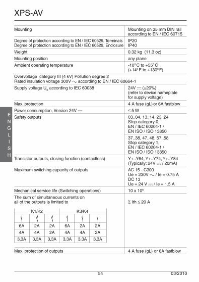
54 03/2010
XPS-AV
ENGLISH
Mounting Mounting on 35 mm DIN railaccording to EN / IEC 60715
Degree of protection according to EN / IEC 60529, Terminals IP20Degree of protection according to EN / IEC 60529, Enclosure IP40
Weight 0.32 kg (11.3 oz)
Mounting position any plane
Ambient operating temperature -100 C to +550 C(+140 F to +1300 F)
Overvoltage category III (4 kV) Pollution degree 2Rated insulation voltage 300V a according to EN / IEC 60664-1
Supply voltage UE according to IEC 60038 24V c (±20%)(refer to device nameplatefor supply voltage)
Max. protection 4 A fuse (gL) or 6A fastblow
Power consumption, Version 24V c ≤ 5 W
Safety outputs 03..04, 13..14, 23..24Stop category 0,EN / IEC 60204-1 /EN ISO / ISO 13850
37..38, 47..48, 57..58Stop category 1,EN / IEC 60204-1 /EN ISO / ISO 13850
Transistor outputs, closing function (contactless) Y+..Y64, Y+..Y74, Y+..Y84(Typically: 24V c / 20mA)
Maximum switching capacity of outputs AC 15 - C300Ue = 230V a / Ie = 0.75 ADC 13Ue = 24 V c / Ie = 1.5 A
Mechanical service life (Switching operations) 10 x 106
The sum of simultaneous currents onall of the outputs is limited to Σ Ith ≤ 20 A
K1/K2 K3/K4
6A 2A 2A 6A 2A 2A
4A 4A 2A 4A 4A 2A
3,3A 3,3A 3,3A 3,3A 3,3A 3,3A
Max. protection of outputs 4 A fuse (gL) or 6A fastblow

03/2010 55
XPS-AV
ENGLISH
Schneider Electric Industries SAS
35, rue Joseph Monier92506 Rueil-MalmaisonFrance
Response time ≤ 30 ms
Synchronisation time tS, by protective guard 1,5sSynchronisation time, by emergency stop ∞Time delay tV, XPSAV11113• 0-300 s
XPSAV11113Z002 0,1-2,0 s
PL e / category in accordance with EN ISO / ISO 13849-1 4
Maximum wiring resistance in the input circuits 100 ΩMaximum wire length in the input circuits 2000 m (6500 ft)
Minimum switching ratings of outputs:The device is capable of switching low voltage loads (min. 17 V c / 10 mA) provided thatthe contact has never been used with higher loads.

56 03/2010
XPS-AV
ENGLISH
EC DECLARATION OF CONFORMITY FOR SAFETY COMPONENTS(English translation of the original EC declaration of conformity, Document-no.: S1A2880500.00)
WE: Schneider Electric Industries SAS / 35, rue Joseph Monier / 92506 Rueil Malmaison, France
hereby declare that the safety component
TRADEMARK: SCHNEIDER ELECTRIC
PRODUCT, TYPE: Module for emergency stop monitoring
MODELS: XPS-AV
SERIAL NUMBER: refer to original EC declaration of conformity
DATE OF MANUFACTURING: refer to device nameplate
all the essential protection requirements that are described in the following directives are defined, corresponding.Furthermore, the conformity with the following harmonized European standards explained:
The following notified body has made a positive declaration in accordance to Chapter 7, Sentence 2, 2004/108/EG:
It is important that the safety component is subject to correct installation, maintenance and use conforming to its intended purpose, to the applicable regulations and standards, to the supplier’s instructions and to accepted rules of the art.
Documentation authority:Eric Léon Barry / Schneider Electric Automation GmbH / Steinheimer Straße 117 / 63500 Seligenstadt, Germany
France - Rueil Malmaison p. p. François Mondino17 - February - 2010 OEM R&D Vice-President
The original EC Declaration of Conformity is available on our website: www.schneider-electric.com
DATED REFERENCE: DIRECTIVE:
EN 60204-01:2006 (DIN EN 60204-01:2007-06) DIRECTIVE 2006/95/EC OF THEEUROPEAN PARLIAMENT AND OF THE COUNCILof 12 December 2006on the harmonisation of the laws of Member States relating to electrical equipment designed for use within certain voltage limits
EN 60947-5-1:2004 (DIN EN 60947-5-1:2005-02)
EN 60947-01:2007 (DIN EN 60947-01:2008-04)
EN ISO 13850:2008 (DIN EN ISO 13850:2009-08)
EN 60947-01:2007 (DIN EN 60947-01:2008-04) DIRECTIVE 2004/108/EC OF THEEUROPEAN PARLIAMENT AND OF THE COUNCILof 15 December 2004on the approximation of the laws of the Member States relating to electromagnetic compatibility and repealing Directive 89/336/EEC
EN 61000-6-02:2005 (DIN EN 61000-6-2:2006-03)
EN 61000-6-4:2007 (DIN EN 61000-6-4:2007-09)
EN 60947-5-1:2004 (DIN EN 60947-5-1:2005-02)
EN 62061:2005 (DIN EN 62061:2005-10) DIRECTIVE 98/37/EC OF THEEUROPEAN PARLIAMENT AND OF THE COUNCILof 22 June 1998andDIRECTIVE 2006/42/EC OF THEEUROPEAN PARLIAMENT AND OF THE COUNCILof 17 May 2006on machinery, and amending Directive 95/16/EC (recast)
EN ISO 12100-2:2003 (DIN EN ISO 12100-2:2004-04)
EN ISO 13849-1:2008 (DIN EN ISO 13849-01:2008-12)
EN ISO 13849-2:2008 (DIN EN ISO 13849-2:2008-09)
NUMBER OF THE NOTIFIED BODY: NUMBER OF DECLARATION: NAME, ADDRESS:
0044 4420509373024-001 TÜV NORD CERT GMBHLangemarckstr. 20D-45141 Essen

XPS-AV
13Y+
23Y64
37Y74
47Y84
S31A1
S32 S11S13
S12S14
03 14
0424
57 5838 48
A2 1 S22
Y39S33
Y40S34
Betriebsanleitung(Originalbetriebsanleitung)
03/2010
Überwachungsbaustein für Not-Halt Kreisegemäß EN / IEC 60204-1, EN ISO / ISO 13849-1,EN ISO / ISO 13850

58 03/2010
XPS-AV
DEUTSCH
InhaltsverzeichnisInhaltsverzeichnis ............................................................................................. 58
Maße ............................................................................................. 59
Klemmenanzeiger ............................................................................................. 60
Frontansicht (LED und Drucktaster) ............................................................................... 60
Demontage der Steck-Klemmen ..................................................................................... 61
Überwachungsbaustein für Not-Halt Kreise ................................................................... 63
Anwendungsbereich ............................................................................................. 64
Funktion ............................................................................................. 64
Einstellung der Verzögerungszeit ................................................................................... 65
Anzeigen der eingestellten Verzögerungszeit ................................................................ 66
Auswahl der Verzögerungszeit ....................................................................................... 67
Systemdiagnose ............................................................................................. 67
Ergänzende Hinweise (Hinweis) ..................................................................................... 68
Funkenstörungen (EN / IEC 60947-5-1) ........................................................................ 69
Restrisiken (EN ISO / ISO 12100) .................................................................................. 69
Anschlußschema und Funktionsdiagramme,– Not-Halt, einkanalig / Auto-Start ........................................................................ 70 – 71– Not-Halt, einkanalig / Startüberwachung ........................................................... 72 – 73– Not-Halt, zweikanalig / Startüberwachung ........................................................ 74 – 75– Schutzgitter / Auto-Start ..................................................................................... 76 – 77
Elektrische Lebensdauer der Ausgangskontaktegemäß EN / IEC 60947-5-1 / Anhang C.3 ...................................................................... 78
Technische Daten ..................................................................................... 79 – 81
EG-Konformitätserklärung für Sicherheitsbauteile(Kopie der original EG-Konformitätserklärung) .............................................................. 82
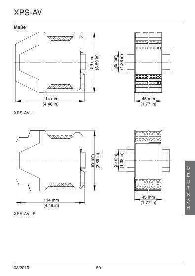
03/2010 59
XPS-AV
DEUTSCH
Maße
114 mm(4.48 in)
99 m
m(3
.89
in)
45 mm(1.77 in)
35 m
m
(1.3
8 in
)
99 m
m(3
.89
in)
114 mm(4.48 in)
45 mm(1.77 in)
35 m
m
(1.3
8 in
)
XPS-AV...
XPS-AV...P

60 03/2010
XPS-AV
DEUTSCH
Klemmenanzeiger
XPS-AV... XPS-AV...P
Y+13
Y6423
Y7437
Y8447
1403
2404
3857
4858
A1S31 S32
S13S11
S14S12
S21A2
S22 S33Y39
S34Y40
S31A1
S32 S11S13
S12S14
A2S21 S22
Y39S33 S34
Y40
13Y+
23Y64
37Y74
47Y84
0314
0424
5738
5848
Frontansicht (LED)S12, S22, S32, S34 LED grünS14, Y40, K1/K2, K3/K4 LED grünPower A1/A2 LED grünError LED rotConfig. Time Delay LED gelb
Frontansicht (Drucktaster)Time Delay Taste um einen Zeit-Wert einzustellenOK Taste um den Wert zu bestätigen und zu speichern

03/2010 61
XPS-AV
DEUTSCH
Demontage der Steck-Klemmen
XPS-AV...P
! GEFAHRGEFÄHRLICHE SPANNUNG
Die Montage, Inbetriebnahme, Änderung und Nachrüstung darf nur von einerElektrofachkraft ausgeführt werden!Schalten Sie das Gerät/ die Anlage vor Beginn der Arbeiten spannungsfrei!Bei Installations und Anlagenfehlern kann bei nicht galvanisch getrennten Gerätenauf dem Steuerkreis Netzpotential anliegen!Beachten Sie für die Installation der Geräte die Sicherheitsvorschriften derElektrotechnik und der Berufsgenossenschaft.Durch Öffnen des Gehäuses oder sonstige Manipulation erlischt jeglicheGewährleistung.
Die Nichtbeachtung dieser Anweisung wird Tod oder schwereKörperverletzung zur Folge haben.

62 03/2010
XPS-AV
DEUTSCH
VORSICHTUNSACHGEMÄSSER GEBRAUCH
Bei unsachgemäßen Gebrauch oder nicht bestimmungsgemäßer Verwendung darfdas Gerät nicht mehr verwendet werden und es erlischt jeglicherGewährleistungsanspruch.Nicht zulässige Einwirkungen können sein:starke mechanische Belastung des Gerätes, wie sie z.B. beim Herunterfallen auftritt,Spannungen, Ströme, Temperaturen, Feuchtigkeit außerhalb der Spezifikation.Bitte überprüfen Sie gemäß der geltenden Vorschriften bei Erstinbetriebnahme IhrerMaschine/ Anlage immer alle Sicherheitsfunktionen und beachten Sie dievorgegebenen Prüfzyklen für Sicherheitseinrichtungen.
Die Nichtbeachtung dieser Anweisung kann Körperverletzung oderMaterialschäden zur Folge haben.
VORSICHTGEFAHR BEI INSTALLATION
Führen Sie vor Beginn der Installation/ Montage oder Demontage folgendeSicherheitsmaßnahmen durch:1. Schalten Sie das Gerät/ die Anlage vor Beginn der Arbeiten spannungsfrei!2. Sichern Sie die Maschine/ Anlage gegen Wiedereinschalten!3. Stellen Sie die Spannungsfreiheit fest!4. Erden Sie die Phasen und schließen Sie diese kurz!5. Decken und schranken Sie benachbarte, unter Spannung stehende Teile ab!6. Der Einbau der Geräte muss in einem Schaltschrank mit einer Schutzart von
mindestens IP 54 erfolgen.
Die Nichtbeachtung dieser Anweisung kann Körperverletzung oderMaterialschäden zur Folge haben.
VORSICHTEINGESCHRÄNKTER BERÜHRUNGSSCHUTZ
• Schutzart nach EN / IEC 60529.• Gehäuse/Klemmen: IP 40 / IP 20.• Fingersicher nach EN 50274.
Die Nichtbeachtung dieser Anweisung kann Körperverletzung oderMaterialschäden zur Folge haben.

03/2010 63
XPS-AV
DEUTSCH
Überwachungsbaustein für Not-Halt Kreise• Überwachungsbaustein nach EN / IEC 60204-1, EN ISO / ISO 13849-1
und EN ISO / ISO 13850 für Not-Halt - oder Schutztür - Überwachung
Hinweis:• Der Performance-Level sowie die Sicherheits-Kategorie nach EN ISO / ISO
13849-1 hängt von der Außenbeschaltung,dem Einsatzfall, der Wahl derBefehlsgeber und deren örtlicher Anordnung an der Maschine ab.
• Der Anwender muss eine Risikobeurteilung nach EN ISO / ISO 14121-1durchführen.
• Auf dieser Basis muss eine Validierung der Gesamtanlage / -maschine nach deneinschlägigen Normen durchgeführt werden.
• Das Modul enthält elektromechanische Relais und somit ist sein angegebenerPerformance-Level und sein MTTFd Wert abhängig von der Last und derSchalthäufigkeit im Anwendungsfall. Bei Nennlast und maximal 6.336Schaltungen pro Jahr oder bei geringer Last und maximal 316.800 Schaltungenpro Jahr ergeben sich die obigen Werte für den Performance- Level und denMTTFd.
• Bei bekannter Strombelastung ist das Diagramm für die elektrische Lebensdauer(Seite 78) für die Berechnung der maximalen Schaltspiele heranzuziehen. Derangegebene Performance-Level ist nur für diese zu ermittelndenSchaltspiele gewährleistet. Nach Erreichen dieser Schaltspiele ist das Gerätauszutauschen. Die Lebensdauer des Gerätes darf dabei nicht überschrittenwerden.
• Das Betreiben des Gerätes außerhalb der Spezifikation kann zuFunktionsstörungen oder zur Zerstörung des Gerätes führen.
• Der Eingang A1 ist der Steuereingang, deshalb können kurze Unterbrechungenoder eine Absenkung unterhalb von UB zum Schalten der Freigabepfade führen.
• Zur Vervielfältigung der Freigabestrompfade können Erweiterungsgeräte oderexterne Schütze mit zwangsgeführten Kontakten eingesetzt werden.
• Bevor der Reset-Taster aktiviert wird, muss die Not-Halt-Kette geschlossen sein.
• Beim Anschluss von Magnetschaltern mit Reedkontakten oder Sensoren mitHalbleiter-Ausgängen muss der Einschaltspitzenstrom beachtet werden (sieheTechnische Daten).
• Beachten Sie die Installationshinweise.
• PL e / Kategorie 4nach EN ISO / ISO 13849-1
• MTTFd = 75,8 Jahre
• DC > 99%
• PFHd = 7,95 x 10⁻⁹ 1/h
• SILCL 3 nach EN / IEC 62061
• Stop-Kategorie 0 und 1gemäß EN / IEC 60204-1
• Manueller oder automatischer Start
• 3 Freigabekontakte - Stop-Kategorie 0,3 Freigabekontakte - Stop-Kategorie 1und 3 Meldekontakte

64 03/2010
XPS-AV
DEUTSCH
AnwendungsbereichDas Gerät XPS-AV dient dem sicherheitsgerichteten Unterbrechen eines oder mehrererStromkreise(s) und ist zur Anwendung in Not-Halt- und Sicherheitsstromkreisen gemäßEN / IEC 60204-1 bestimmt. Es erfüllt die Europanormen EN ISO / ISO 13850 für Not-Halt Einrichtungen sowie EN / IEC 60204-1 für Sicherheitsstromkreise allgemein, zu denenim besonderen auch die Fälle zählen, in denen mit einem Not-Halt Befehl mehrereStromkreise abgeschaltet werden sollen (indirekt wirkender Not-Halt). Der Baustein erfülltebenfalls die sicherheitstechnischen Anforderungen der elektrischen Überwachung vonPositionsschaltern an trennenden Schutzeinrichtungen.
Der Baustein stellt neben drei direkt abschaltenden Sicherheitsausgängen der Stop-Kategorie 0 (EN ISO / ISO 13850, EN / IEC 60204-1) noch drei weitere, zeitverzögertabschaltende Ausgänge der Stop-Kategorie 1 zur Verfügung. Diese ermöglichen eingesteuertes Stillsetzen der Antriebselemente, um den Halt zu erreichen (z.B.Motorbremsung mittels Frequenzumr ichter). Nach Ablauf der vorgewähltenVerzögerungszeit erfolgt das sichere Unterbrechen der Energiezufuhr durch Öffnen derzeitverzögerten Ausgangskreise. Die Verzögerungszeit der drei Ausgangskreise zwischenden Klemmen 37-38, 47-48 und 57-58 ist in sechzehn Stufen von 0-300 Sekunden(XPSAV11113•) bzw. 0,1-2,0 Sekunden (XPSAV11113Z002) einstellbar (siehe Abschnitt:Einstellung der Verzögerungszeit).
Das Gerät ist für einkanalige und zweikanalige Eingangsbeschaltung geeignet. Aufgrundder erweiterten Fehlerdetektionsmöglichkeiten und des daraus resultierenden höherenSicherheitsniveaus wird die zweikanalige Eingangsbeschaltung empfohlen. In dieserBetriebsart werden ebenfalls die Anschlußleitungen in die Überwachung einbezogenund alle Erstfehler werden entdeckt.
FunktionDie Versorgungsspannung wird gemäß markiertem Wert auf dem Typenschild an dieKlemmen A1/A2 angeschlossen. Der Anschluß der Befehlsgeräte ist wie folgtvorzunehmen:
Einkanalige Eingangsbeschaltung:Die Befehlsgeräte sind an die Klemmen S11-S12 anzuschließen. Die KlemmenS21-S22 sowie S31-S32 sind zu brücken.
Zweikanalige Eingangsbeschaltung:Die Befehlsgeräte sind an die Klemmen S31-S32 und S21-S22 anzuschließen.Die Klemmen S11-S12 sind zu brücken.
Das XPS-AV überwacht alle Eingänge auf eventuell auftretende Querschlüsseuntereinander bzw. auf Kurzschlüsse nach Masse oder Spannungsverschleppung. ImFehlerfall werden die Ausgänge abgeschaltet und es wird eine Meldung erzeugt. (In denTabellen 2 und 3 ist das Verhalten der LED-Anzeige, der Meldeausgänge und derSicherheitsausgänge für die verschiedenen Fehlerfälle dargestellt.)
Hinweis:Bitte beachten Sie auch die Informationen Ihrer Berufsgenossenschaft!

03/2010 65
XPS-AV
DEUTSCH
Die Starttaste sowie die Kontakte für die Schützkontrolle sind in den Rückführkreiszwischen den Klemmen S33-S34 (bzw. bei nicht überwachtem Start oder automatischenStart zwischen die Klemmen S13-S14) einzuschleifen. Dadurch gelingt eine Einschaltungdes Gerätes nur dann, wenn die nachgeschalteten Relais, welche sicherheitsrelevanteFunktion haben, nach einem vorausgegangenen Abschaltbefehl abgefallen waren. DerRückführkreis muß für jede neue Einschaltung geschlossen sein.
Der Starttaster wird in die Überwachung einbezogen (empfohlene Verwendung), wenn eran die Klemmen S33-S34 angeschlossen wird. Die Ausgänge des Bausteins werden indieser Konfiguration erst mit fallender Flanke des Startsignals (also beim Loslassen desStar ttasters) durchgeschaltet. Wird der Star t Taster an die Klemmen S13-S14angeschlossen, so schalten die Ausgänge unmittelbar nach Betätigung des Starttastersdurch, sofern die Eingangskreise zu diesem Zeitpunkt geschlossen sind.
Das Gerät XPS-AV arbeitet in allen verfügbaren Spannungsversionen sicherungslos. Eineeingebaute elektronische Sicherung schützt das Gerät vor Zerstörung durch äußereKurzschlüsse (z.B. bei Querschlüssen in der Eingangsbeschaltung). Nach Beseitigungder Fehlerursache und erneutem Einschalten der Versorgungsspannung ist der Bausteinwieder betriebsbereit.
Nach Anlegen der Versorgungsspannung an die Klemmen A1-A2 führt das XPS-AV eineninternen Selbsttest aus. Dabei leuchten für 2 Sekunden alle 11 LEDs im Gehäusedeckel.Danach leuchtet die grüne LED “POWER A1/A2” weiter und die übrigen LEDs verlöschenwieder, sofern der zugehörige Eingang bzw. Ausgang geöffnet ist.
Einstellung derVerzögerungszeitIm Gehäusedeckel des XPS-AV sindneben den 11 LEDs, zweiDrucktaster zur Einstellung derVerzögerungszeit untergebracht:
Time Delay um einen Zeit-Werteinzustellen
OK um den Wert zubestätigen undzu speichern.
Jeweils vier grüne LEDs in denbeiden linken Spalten ANZ.1 undANZ.2 zeigen im normalen Betriebden Zustand der Ein- und Ausgängean. Dabei ist die gelbe LED “Config.Time Delay” immer aus.
Leuchtet oder blinkt die gelbe LED“Config. Time Delay”, dann zeigenANZ.1 bzw. ANZ.2 den Binärcode fürdie eingestellte Verzögerung an. Dieunteren LEDs stellen jeweils dasLSB (lowest significant bit) mit derWertigkeit (1) dar.
TimeDelay
OK
PowerA1/A2
Error
Config.Time Delay
S12
S22
S14
Y40
S32
S34 K3/K4
K1/K2
(8)
(4)
(2)
(1)
AN
Z.1
(Bin
är-W
ert)
AN
Z.2
Abbildung 1: Bedienelemente
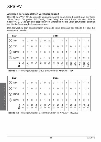
66 03/2010
XPS-AV
DEUTSCH
Anzeigen der eingestellten VerzögerungszeitUm z.B. den Wert für die aktuelle Verzögerungszeit auszulesen betätigt man die Taste“Time Delay”. Die gelbe LED “Config. Time Delay” leuchtet auf, und die vier LEDs inSpalte “ANZ. 2” zeigen den gespeicherten Binärcode für die Verzögerungszeit solangean, bis die Taste wieder losgelassen wird.
Der Zeitwert zu dem gespeicherten Binärcode kann dann aus der Tabelle 1.1 bzw. 1.2entnommen werden:
Tabelle 1.1 – Verzögerungszeit 0-300 Sekunden für XPSAV11113•
S14
Y40
K1/K2
K3/K4
1
1
1
1
1
1
1
0
1
1
0
1
1
1
0
0
1
0
1
1
1
0
1
0
1
0
0
1
1
0
0
0
0
1
1
1
0
1
1
0
0
1
0
1
0
1
0
0
0
0
1
1
0
0
1
0
0
0
0
1
0
0
0
0
300s
180s90
s
60s
30s
25s
20s
15s
10s8s6s4s2s1s
0,5s0s
Tim
e
LED Code
Tabelle 1.2 – Verzögerungszeit 0,1-2,0 Sekunden für XPSAV11113Z002
S14
Y40
K1/K2
K3/K4
1
1
1
1
1
1
1
0
1
1
0
1
1
1
0
0
1
0
1
1
1
0
1
0
1
0
0
1
1
0
0
0
0
1
1
1
0
1
1
0
0
1
0
1
0
1
0
0
0
0
1
1
0
0
1
0
0
0
0
1
0
0
0
0
2,0s
1,5s
1,4s
1,3s
1,2s
1,1s
1,0s
0,9s
0,8s
0,7s
0,6s
0,5s
0,4s
0,3s
0,2s
0,1s
Tim
e
LED Code
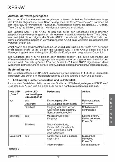
03/2010 67
XPS-AV
DEUTSCH
Auswahl der VerzögerungszeitUm in den Konfigurationsmodus zu gelangen müssen die beiden Sicherheitsausgängedes XPS-AV abgeschaltet sein. Dann betätigt man die Taste “Time Delay” zusammen mitder Taste “OK” für mindestens 1 Sekunde. Anschließend beginnt die gelbe LED “Config.Time Delay” zu blinken, und der Konfigurationsmodus ist aktiviert.
Die Spalten ANZ.1 und ANZ.2 zeigen nun beide den Binärcode der momentangespeicherten Verzögerungszeit an. Mit jedem erneuten Drücken der Taste “Time Delay”wechselt jetzt die Anzeige in der Spalte ANZ.2 zum nächst möglichen Binärcode, unddamit zur nächsten möglichen Verzögerungszeit. ANZ.1 zeigt weiterhin die gespeicherteVerzögerung an an.
Zeigt ANZ.2 den gewünschten Code an, so wird durch Drücken der Taste “OK” der neueWert gespeichert. Jetzt zeigen die Spalten ANZ.1 und ANZ.2 beide die neueVerzögerungszeit an und die gelbe LED für die Konfiguration zeigt wieder Dauerlicht.
Die Ausgänge des XPS-AV bleiben aber solange gesperrt, bis durch Abschalten undWiedereinschalten der Versorgungsspannung der neue Verzögerungwert bestätigt undaktiviert wird. Die acht grünen LEDs der Felder ANZ.1 und ANZ.2 signalisieren dannwieder den Betriebszustand der Ein- und Ausgänge entsprechend der Deckelbedruckung.
SystemdiagnoseDie Betriebszustände der XPS-AV Funktionen werden optisch mit 11 LEDs im Bedienfelddargestellt und durch drei Halbleiterausgänge an eine andere Steuerung gemeldet.
1. LED-Anzeige im Betriebszustand und im Fehlerfall:Im normalen Betrieb leuchtet in der rechten Spalte der LED-Anzeige die grüne LED “Power”. Die rote LED “Error” und die gelbe LED für den Konfigurationsmodus sind aus.
rote LED„Error”
aus
grüne LEDdes jeweiligen Ein-/Ausgangs
Blinklicht
ausDauerlichtBlinklicht
Ein-/Ausgang offenEin-/Ausgang geschlossenEingang war beim letztenAbschalten nicht geöffnet,Neustart nicht möglich
Betriebszustanderkennen
Schaltelementkontrollieren
Leitung prüfen,Fehler beheben,Power On
Tabelle 2
Bedeutung Aktion
Dauerlicht aus Kurzschlußbeheben,Power On
Blinklicht falsche Verbindung,Kurzschluß, Kabelbruch,bzw. Schaltmatte nichtangeschlossen
aus Masseschluß einesEingangs
Kurzschluß eines Eingangsnach +24V
Gerät ausbauenInterner Fehler
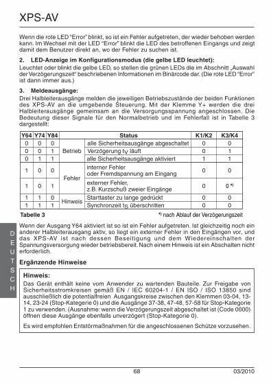
68 03/2010
XPS-AV
DEUTSCH
Wenn der Ausgang Y64 aktiviert ist so ist ein Fehler aufgetreten. Ist gleichzeitig noch einanderer Halbleiterausgang aktiv, so liegt ein externer Fehler in den Eingängen vor, unddas XPS-AV ist nach dessen Beseitigung und dem Wiedereinschalten derSpannungsversorgung wieder betriebsbereit. Nach einem Hinweis ist ein Abschalten nichterforderlich.
Ergänzende Hinweise
Hinweis:Das Gerät enthält keine vom Anwender zu wartenden Bauteile. Zur Freigabe vonSicherheitsstromkreisen gemäß EN / IEC 60204-1 / EN ISO / ISO 13850 sindausschließlich die potentialfreien Ausgangskreise zwischen den Klemmen 03-04, 13-14, 23-24 (Stop-Kategerie 0) und die Ausgänge 37-38, 47-48, 57-58 für Stop-Kategorie1 zu verwenden. (Ausnahme: wenn die Verzögerungszeit abgeschaltet ist (Code 0000)öffnen diese Ausgänge ebenfalls unverzögert (Stop-Kategorie 0).
Es wird empfohlen Entstörmaßnahmen für die angeschlossenen Schütze vorzusehen.
Wenn die rote LED “Error” blinkt, so ist ein Fehler aufgetreten, der wieder behoben werdenkann. Im Wechsel mit der LED “Error” blinkt die LED des betroffenen Eingangs und zeigtdamit dem Benutzer direkt an, wo der Fehler zu suchen ist.
2. LED-Anzeige im Konfigurationsmodus (die gelbe LED leuchtet):Leuchtet oder blinkt die gelbe LED, so stellen die grünen LEDs die im Abschnitt „Auswahlder Verzögerungszeit“ beschriebenen Informationen im Binärcode dar. (Die rote LED “Error”ist dann immer aus.)
3. Meldeausgänge:Drei Halbleiterausgänge melden die jeweiligen Betriebszustände der beiden Funktionendes XPS-AV an die umgebende Steuerung. Mit der Klemme Y+ werden die dreiHalbleiterausgänge gemeinsam an die Versorgungsspannung angeschlossen. DieBedeutung dieser Signale für den Normalbetrieb und im Fehlerfall ist in Tabelle 3dargestellt:
Y64 Y74 Y84 Status K1/K2000
1
1
1
*) nach Ablauf der Verzögerungszeit
K3/K4001
0
0
1
011
0
1
1
001
0
0Fehler
Hinweis
Betrieb
0
011
0
0 *)
0
alle Sicherheitsausgänge abgeschaltetVerzögerung tV läuftalle Sicherheitsausgänge aktiviertinterner Fehleroder Fremdspannung am Eingang
externer Fehler,z.B. Kurzschuß zweier Eingänge
Synchronzeit tS überschritten1 1 0 0 0Starttaster zu lange gedrückt
Tabelle 3

03/2010 69
XPS-AV
DEUTSCH
VORSICHTRESTRISIKEN (EN ISO / ISO 12100)
Die nachstehenden Schaltungsvorschläge wurden mit größter Sorgfalt unterBetriebsbedingungen geprüft und getestet. Sie erfüllen mit der angeschlossenenPeripherie sicherheitsgerichteter Einrichtungen und Schaltgeräte insgesamt dieeinschlägigen Normen. Restrisiken verbleiben wenn:a) vom vorgeschlagenen Schaltungskonzept abgewichen wird und dadurch die
angeschlossenen sicherheitsrelevanten Geräte oder Schutzeinrichtungenmöglicherweise nicht oder nur unzureichend in die Sicherheitsschaltungeinbezogen werden.
b) vom Betreiber die einschlägigen Sicherheitsvorschriften für Betrieb, Einstellungund Wartung der Maschine nicht eingehalten werden. Hier sollte auf strengeEinhaltung der Intervalle zur Prüfung und Wartung der Maschine geachtetwerden.
Die Nichtbeachtung dieser Anweisung kann Körperverletzung oderMaterialschäden zur Folge haben.
WARNUNGFUNKSTÖRUNGEN (EN / IEC 60947-5-1)
Dies ist ein Produkt der Klasse A. In Haushaltsumgebung kann dieses GerätFunkstörungen verursachen, weshalb der Anwender gegebenfalls geeigneteMaßnahmen ergreifen muß.
Die Nichtbeachtung dieser Anweisung kann den Tod, Körperverletzung oderMaterialschäden zur Folge haben!

70 03/2010
XPS-AV
DEUTSCH
An
sch
luß
sch
ema
– N
ot-H
alt,
ein
kana
lig /
Aut
o-S
tart
0V
zur S
PS
K11
K12
Stop
-Kat
.0ES
C =
Ext
erne
Sta
rt Be
ding
unge
nSt
op-K
at.0
Stop
-Kat
.1St
op-K
at.1
Lege
nde:
+24V
F1
0V
K02
K01
unve
rzög
erte
Sich
erhe
its-
ausg
änge
(Sto
p-Ka
t.0)
verz
öger
töf
fnen
deSi
cher
heits
-au
sgän
ge(S
top-
Kat.1
)
+24V
Unt
erbr
echu
ng d
erVe
rzög
erun
gsze
it
DC
DC
DC
DC
K1 K3 K2 K4
Ausg
ang
1
Ausg
ang
2
Ausg
ang
1Au
sgan
g2
LOG
IK -
Kana
l 1
LOG
IK -
Kana
l 2
XP
S-A
V
Error
K1/K2
K3/K4
A1S1
3S1
1S3
1S3
2S1
2S1
403
1323
3747
57Y+
Y64
Y74
Y84
A2Y3
9S3
3S2
1S2
2S3
4Y4
004
1424
3848
58
S1
Not
-Hal
t
11 12
S3
Star
t
13 14
K12
K11
K02
K01
ESC

03/2010 71
XPS-AV
DEUTSCH
Fu
nkt
ion
sdia
gra
mm
– N
ot-H
alt,
ein
kana
lig /
Aut
o-S
tart
Not
-Hal
tun
betä
tigt
Not
-Hal
tun
betä
tigt
Aut
omat
isch
er S
tart
(S33
-S34
= o
ffen)
Pow
er O
n(S
elbs
ttest
bee
ndet
)N
ot-H
alt
betä
tigt
Not
-Hal
tbe
tätig
tN
ot-H
alt
S11-
S12
Auto
-Sta
rt(o
hne
ESC
)S1
3-S1
4ge
brüc
kter
Ein
gang
S21-
S22
gebr
ückt
er E
inga
ngS3
1-S3
2U
nter
br.
Verz
öger
ungs
zeit
Y39-
Y40
Ausg
ang
(S)
03-0
4/13
-14/
23-2
4
Ausg
ang
(S)
37-3
8/47
-48/
57-5
8
Mel
deau
sgan
gY7
4
Mel
deau
sgan
gY8
4
Not
-Hal
tS1
1-S1
2
Star
ttast
erS1
3-S1
4
gebr
ückt
er E
inga
ngS2
1-S2
2
gebr
ückt
er E
inga
ngS3
1-S3
2U
nter
br.
Verz
öger
ungs
zeit
Y39-
Y40
Ausg
ang
(S)
03-0
4/13
-14/
23-2
4
Ausg
ang
(S)
37-3
8/47
-48/
57-5
8
Mel
deau
sgan
gY7
4
Mel
deau
sgan
gY8
4
Not
-Hal
tun
betä
tigt
Not
-Hal
tun
betä
tigt
Nic
ht ü
berw
acht
er S
tart
Pow
er O
n(S
elbs
ttest
bee
ndet
)N
ot-H
alt
betä
tigt
Not
-Hal
tbe
tätig
t
Star
tSt
art
t VVe
rzög
erun
gsze
itun
terb
roch
enSt
art
Star
tt V
Verz
öger
ungs
zeit
unte
rbro
chen
tV
=V
erzö
geru
ngsz
eit

72 03/2010
XPS-AV
DEUTSCH
An
sch
luß
sch
ema
– N
ot-H
alt,
ein
kana
lig /
Sta
rtüb
erw
achu
ng
0V
zur S
PS
K11
K12
Stop
-Kat
.0ES
C =
Ext
erne
Sta
rt Be
ding
unge
nSt
op-K
at.0
Stop
-Kat
.1St
op-K
at.1
Lege
nde:
+24V
F1
0V
K02
K01
unve
rzög
erte
Sich
erhe
its-
ausg
änge
(Sto
p-Ka
t.0)
verz
öger
töf
fnen
deSi
cher
heits
-au
sgän
ge(S
top-
Kat.1
)
+24V
Verz
ög.
Aus
DC
DC
DC
DC
K1 K3 K2 K4
Ausg
ang
1
Ausg
ang
2
Ausg
ang
1Au
sgan
g2
LOG
IK -
Kana
l 1
LOG
IK -
Kana
l 2
XP
S-A
V
A1S1
3S1
1S3
1S3
2S1
2S1
403
1323
3747
57Y+
Y64
Y74
Y84
A2Y3
9S3
3S2
1S2
2S3
4Y4
004
1424
3848
58
S1
Not
-Hal
t
11 12
S3
Star
t
13 14
K12
K11
K02
K01
ESC
Error
K1/K2
K3/K4

03/2010 73
XPS-AV
DEUTSCH
Fu
nkt
ion
sdia
gra
mm
– N
ot-H
alt,
ein
kana
lig /
Sta
rtüb
erw
achu
ng
Star
tke
inSt
art
1 )t V
Not
-Hal
t ein
kana
lig /
Sta
rtüb
erw
achu
ng(S
13-S
14 =
offe
n)
Pow
er O
n(S
elbs
ttest
bee
ndet
)N
ot-H
alt
betä
tigt
Not
-Hal
tun
betä
tigt
Not
-Hal
tun
betä
tigt
Not
-Hal
tbe
tätig
tN
ot-H
alt
S11-
S12
gebr
ückt
er E
inga
ngS2
1-S2
2
gebr
ückt
er E
inga
ngS3
1-S3
2
Star
t-Tas
ter
S33-
S34
Unt
erbr
.Ve
rzög
erun
gsze
itY3
9-Y4
0Au
sgan
g (S
)03
-04/
13-1
4/23
-24
Ausg
ang
(S)
37-3
8/47
-48/
57-5
8
Mel
deau
sgan
gY7
4
Mel
deau
sgan
gY8
4Ve
rzög
erun
gsze
itun
terb
roch
en
tV
=V
erzö
geru
ngsz
eit
1)
=Ü
berp
rüfu
ng d
es S
tart
sign
als:
Der
Sta
rtta
ster
dar
fbe
i "P
ower
On"
nic
htbe
tätig
t se
in.
t < 1
0sSt
art
t < 1
0s

74 03/2010
XPS-AV
DEUTSCH
An
sch
luß
sch
ema
– N
ot-H
alt,
zw
eika
nalig
/ S
tart
über
wac
hung
0V
+24V
S1
Not
-H
alt
11
+24V
F1
Error
K1/K2
K3/K4
XP
S-A
Vzur S
PS
0V ESC
= E
xter
ne S
tart
Bedi
ngun
gen
Lege
nde:
Stop
-Kat
.0St
op-K
at.0
Stop
-Kat
.1St
op-K
at.1
K11
K12
K02
K01
unve
rzög
erte
Sich
erhe
its-
ausg
änge
(Sto
p-Ka
t.0)
verz
öger
töf
fnen
deSi
cher
heits
-au
sgän
ge(S
top-
Kat.1
)Ve
rzög
.Au
s
12
ESC
S3
Star
t
13 14
S1
Not
-H
alt
21 22
K12
K11
K02
K01
DC
DC
DC
DC
LOG
IK -
Kana
l 1
LOG
IK -
Kana
l 2
Ausg
ang
1
Ausg
ang
2
Ausg
ang
1Au
sgan
g2
K1 K3 K2 K4
A1S1
3S1
1S3
1S3
2S1
2S1
403
1323
3747
57Y+
Y64
Y74
Y84
5848
3824
1404
Y40
S34
S22
S21
S33
Y39
A2

03/2010 75
XPS-AV
DEUTSCH
Fu
nkt
ion
sdia
gra
mm
– N
ot-H
alt,
zw
eika
nalig
/ S
tart
über
wac
hung
kein
Star
t1 )
Not
-Hal
t zw
eika
nalig
/ S
tart
über
wac
hung
(S13
-S14
= o
ffen)
Pow
er O
n(S
elbs
ttest
bee
ndet
) Not
-Hal
tun
betä
tigt
Not
-Hal
tbe
tätig
tN
ot-H
alt
unbe
tätig
tN
ot-H
alt
betä
tigt
gebr
ückt
er E
inga
ngS1
1-S1
2
Not
-Hal
t (Ka
nal 1
)S2
1-S2
2
Not
-Hal
t (Ka
nal 2
)S3
1-S3
2
Star
t-Tas
ter
S33-
S34
Unt
erbr
.Ve
rzög
erun
gsze
itY3
9-Y4
0Au
sgan
g (S
)03
-04/
13-1
4/23
-24
Ausg
ang
(S)
37-3
8/47
-48/
57-5
8
Mel
deau
sgan
gY7
4
Mel
deau
sgan
gY8
4Ve
rzög
erun
gsze
itun
terb
roch
enSt
art
t < 1
0sSt
art
t < 1
0s
t V
tV
=V
erzö
geru
ngsz
eit
1)
=Ü
berp
rüfu
ng d
es S
tart
sign
als:
Der
Sta
rtta
ster
dar
fbe
i "P
ower
On"
nic
htbe
tätig
t se
in.

76 03/2010
XPS-AV
DEUTSCH
An
sch
luß
sch
ema
– S
chut
zgitt
er /
Aut
o-S
tart
K11
K12
+24V
F1
0V
K02
K01
+24V
0V
Stop
-Kat
.0ES
C =
Ext
erne
Sta
rt Be
ding
unge
nSt
op-K
at.0
Stop
-Kat
.1St
op-K
at.1
Lege
nde:
zur S
PS
XP
S-A
V
Error
K1/K2
K3/K4
verz
öger
töf
fnen
deSi
cher
heits
-au
sgän
ge(S
top-
Kat.1
)
unve
rzög
erte
Sich
erhe
its-
ausg
änge
(Sto
p-Ka
t.0)
Unt
erbr
echu
ng d
erVe
rzög
erun
gsze
it
DC
DC
DC
DC
LOG
IK -
Kana
l 1
LOG
IK -
Kana
l 2
Ausg
ang
1
Ausg
ang
2
Ausg
ang
1Au
sgan
g2
K1 K3 K2 K4ESC
K12
K11
K02
K01
S1
Schu
tztü
re(g
esch
loss
en)
21 22
S2
Schu
tztü
re(g
esch
loss
en)13 14
13 14
S221 22
A2Y3
9S3
3S2
1S2
2S3
4Y4
004
1424
3848
58
Y84
Y74
Y64
Y+57
4737
2313
03S1
4S1
2S3
2S3
1S1
1S1
3A1

03/2010 77
XPS-AV
DEUTSCH
Fu
nkt
ion
sdia
gra
mm
– S
chut
zgitt
er /
Aut
o-S
tart
Star
tSt
art
Verz
öger
ungs
zeit
unte
rbro
chen
gebr
ückt
er E
inga
ngS1
1-S1
2
Schu
tzgi
tter (
Kana
l 1)
S21-
S22
Schu
tzgi
tter (
Kana
l 2)
S31-
S32
Schu
tzgi
tter o
ffen
S13-
S14
Unt
erbr
.Ve
rzög
erun
gsze
itY3
9-Y4
0Au
sgan
g (S
)03
-04/
13-1
4/23
-24
Ausg
ang
(S)
37-3
8/47
-48/
57-5
8
Mel
deau
sgan
gY7
4
Mel
deau
sgan
gY8
4
Sch
utzg
itter
mit
Aut
o-S
tart
und
Syn
chro
nzei
t tS
(S33
-S34
= o
ffen)
Schu
tzgi
tter
gesc
hlos
sen
Pow
er O
n(S
elbs
ttest
bee
ndet
)Sc
hutz
gitte
rof
fen
Schu
tzgi
tter
gesc
hlos
sen
Schu
tzgi
tter
gesc
hlos
sen
Schu
tzgi
tter
offe
nSc
hutz
gitte
rof
fen
t V
tV
=V
erzö
geru
ngsz
eit
tS
=S
ynch
ronz
eit
t S <
1,5
s

78 03/2010
XPS-AV
DEUTSCH
Ele
ktri
sch
e L
eben
sdau
er d
er A
usg
ang
sko
nta
kte
gem
äß E
N /
IEC
609
47-5
-1 /
An
han
g C
.3
0,1110
1010
010
0010
000
Nennbetriebsstrom A
Sch
alts
piel
e x
10³
AC
1: 2
30 V
DC
1: 2
4 V
AC
15:
230
VDC
13:
24
V(<
0,1
Hz)

03/2010 79
XPS-AV
DEUTSCH
Klemmen- und Anschlussdaten XPS-AV...
Einzelleiteranschluß
Ohne Aderendhülse starr 0,14-2,5 mm2
flexibel 0,14-2,5 mm2
AWG 26-14
Abisolierlänge 7 mm
Flexibel mit Aderendhülse (ohne Kunststoffhülse) 0,25-2,5 mm2
Flexibel mit Aderendhülse (mit Kunststoffhülse) 0,25-1,5 mm2
Anzugsdrehmoment min. 0,5 Nm
Mehrleiteranschluß (2 Leiter max.)
Ohne Aderendhülse starr 0,14-0,75 mm2
flexibel 0,14-0,75 mm2
Abisolierlänge 7 mm
Flexibel mit Aderendhülse (ohne Kunststoffhülse) 0,25-1 mm2
Flexibel mit TWIN-Aderendhülse (mit Kunststoffhülse) 0,5-1,5 mm2
Anzugsdrehmoment min. 0,5 Nm
Klemmen- und Anschlussdaten XPS-AV...P
Einzelleiteranschluß
Ohne Aderendhülse starr 0,2-2,5 mm2
flexibel 0,2-2,5 mm2
AWG 24-14
Abisolierlänge 7 mm
Flexibel mit Aderendhülse (ohne Kunststoffhülse) 0,25-2,5 mm2
Flexibel mit Aderendhülse (mit Kunststoffhülse) 0,25-1,5 mm2
Anzugsdrehmoment min. 0,5 Nm
Mehrleiteranschluß (2 Leiter max.)
Ohne Aderendhülse starr 0,2-1 mm2
flexibel 0,2-1,5 mm2
Abisolierlänge 7 mm
Flexibel mit Aderendhülse (ohne Kunststoffhülse) 0,25-1 mm2
Flexibel mit TWIN-Aderendhülse (mit Kunststoffhülse) 0,5-1,5 mm2
Anzugsdrehmoment min. 0,5 Nm
Technische Daten
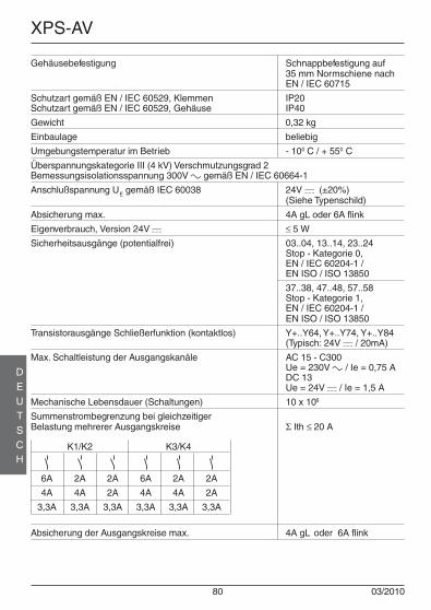
80 03/2010
XPS-AV
DEUTSCH
Gehäusebefestigung Schnappbefestigung auf35 mm Normschiene nachEN / IEC 60715
Schutzart gemäß EN / IEC 60529, Klemmen IP20Schutzart gemäß EN / IEC 60529, Gehäuse IP40
Gewicht 0,32 kg
Einbaulage beliebig
Umgebungstemperatur im Betrieb - 100 C / + 550 C
Überspannungskategorie III (4 kV) Verschmutzungsgrad 2Bemessungsisolationsspannung 300V a gemäß EN / IEC 60664-1
Anschlußspannung UE gemäß IEC 60038 24V c (±20%)(Siehe Typenschild)
Absicherung max. 4A gL oder 6A flink
Eigenverbrauch, Version 24V c ≤ 5 W
Sicherheitsausgänge (potentialfrei) 03..04, 13..14, 23..24Stop - Kategorie 0,EN / IEC 60204-1 /EN ISO / ISO 13850
37..38, 47..48, 57..58Stop - Kategorie 1,EN / IEC 60204-1 /EN ISO / ISO 13850
Transistorausgänge Schließerfunktion (kontaktlos) Y+..Y64, Y+..Y74, Y+..Y84(Typisch: 24V c / 20mA)
Max. Schaltleistung der Ausgangskanäle AC 15 - C300Ue = 230V a / Ie = 0,75 ADC 13Ue = 24V c / Ie = 1,5 A
Mechanische Lebensdauer (Schaltungen) 10 x 106
Summenstrombegrenzung bei gleichzeitigerBelastung mehrerer Ausgangskreise Σ Ith ≤ 20 A
K1/K2 K3/K4
6A 2A 2A 6A 2A 2A
4A 4A 2A 4A 4A 2A
3,3A 3,3A 3,3A 3,3A 3,3A 3,3A
Absicherung der Ausgangskreise max. 4A gL oder 6A flink

03/2010 81
XPS-AV
DEUTSCH
Ansprechzeit ≤ 30 ms
Synchronisationszeit tS, bei Schutzgitter 1,5 sSynchronisationszeit, bei Not-Halt ∞Verzögerungszeit tV, XPSAV11113• 0-300 s
XPSAV11113Z002 0,1-2,0 s
PL e / Kategorie nach EN ISO / ISO 13849-1 4
Maximaler Leitungswiderstand in den Eingangskreisen 100 ΩMaximale Leitungslänge in den Eingangskreisen 2000 m
Das Gerät ist ebenfalls zum Schalten von Kleinstlasten (min. 17 V c / 10 mA) geeignet.Dies ist jedoch nur dann möglich, wenn bisher über diesen Kontakt keine höheren Lastengeschaltet wurden, da hierdurch die Kontaktvergoldung abgebrannt sein könnte.
Schneider Electric Industries SAS
35, rue Joseph Monier92506 Rueil-MalmaisonFrance

82 03/2010
XPS-AV
DEUTSCH
EG-KONFORMITÄTSERKLÄRUNG FÜR SICHERHEITSBAUTEILE(Kopie der original EG-Konformitätserklärung, Dokument-Nr.: S1A2880500.00)
WIR: Schneider Electric Industries SAS / 35, rue Joseph Monier / 92506 Rueil Malmaison, France
erklären hiermit, daß das nachstehend aufgeführte Sicherheitsbauteil
MARKE: SCHNEIDER ELECTRIC
NAME, TYP: Not-Halt Überwachungsbaustein
MODELL: XPS-AV
SERIENNNUMMER: siehe original EG-Konformitätserklärung
FERTIGUNGSDATUM: siehe Typenschild
allen wesentlichen Schutzanforderungen, die in den nachfolgenden bezeichneten Richtlinien festgelegt sind, entspricht.Weiterhin wird die Konformität mit folgenden harmonisierten Europäischen Normen erklärt:
Folgende benannte Stelle hat eine positive Erklärung im Sinne des Artikels 7, Satz 2, 2004/108/EG ausgestellt:
Falls es gemäß seiner Bestimmung, den geltenden Vorschriften, Normen und Herstelleranweisungen entsprechend installiert, verwendet und gewartet wird.
Dokumentations Bevollmächtigter:Eric Léon Barry / Schneider Electric Automation GmbH / Steinheimer Straße 117 / 63500 Seligenstadt, Germany
Frankreich - Rueil Malmaison i. V. François Mondino17 - Februar - 2010 OEM R&D Vice-President
Die original EG-Konformitätserklärung ist auf unserer Webseite erhältlich: www.schneider-electric.com
DATIERTE FUNDSTELLE: RICHTLINIENBEZUG:
EN 60204-01:2006 (DIN EN 60204-01:2007-06) RICHTLINIE 2006/95/EG DESEUROPÄISCHEN PARLAMENTS UND DES RATESvom 12. Dezember 2006zur Angleichung der Rechtsvorschriften der Mitgliedstaaten betreffend elektrische Betriebsmittel zur Verwendung innerhalb bestimmter Spannungsgrenzen
EN 60947-5-1:2004 (DIN EN 60947-5-1:2005-02)
EN 60947-01:2007 (DIN EN 60947-01:2008-04)
EN ISO 13850:2008 (DIN EN ISO 13850:2009-08)
EN 60947-01:2007 (DIN EN 60947-01:2008-04) RICHTLINIE 2004/108/EG DESEUROPÄISCHEN PARLAMENTS UND DES RATESvom 15. Dezember 2004zur Angleichung der Rechtsvorschriften der Mitgliedstaaten über die elektromagnetische Verträglichkeit und zur Aufhebungder Richtlinie 89/336/EWG
EN 61000-6-02:2005 (DIN EN 61000-6-2:2006-03)
EN 61000-6-4:2007 (DIN EN 61000-6-4:2007-09)
EN 60947-5-1:2004 (DIN EN 60947-5-1:2005-02)
EN 62061:2005 (DIN EN 62061:2005-10) RICHTLINIE 98/37/EG DESEUROPÄISCHEN PARLAMENTS UND DES RATESvom 22. Juni 1998undRICHTLINIE 2006/42/EG DESEUROPÄISCHEN PARLAMENTS UND DES RATESvom 17. Mai 2006über Maschinen und zur Änderungder Richtlinie 95/16/EG (Neufassung)
EN ISO 12100-2:2003 (DIN EN ISO 12100-2:2004-04)
EN ISO 13849-1:2008 (DIN EN ISO 13849-01:2008-12)
EN ISO 13849-2:2008 (DIN EN ISO 13849-2:2008-09)
KENNNUMMER DER BENANNTEN STELLE: NUMMER DER ERKLÄRUNG: NAME, ANSCHRIFT:
0044 4420509373024-001 TÜV NORD CERT GMBHLangemarckstr. 20D-45141 Essen


S1A28768.0003/2010
Schneider Electric Industries SAS
35, rue Joseph Monier92506 Rueil-MalmaisonFrance