xt250 owner's manual xt250x/xt250xc - … · introduction eau10080 congratulations on your...
TRANSCRIPT

LIT-11626-21-52 3C5-28199-10
XT250XC
OWNER’S MANUAL
XT250X
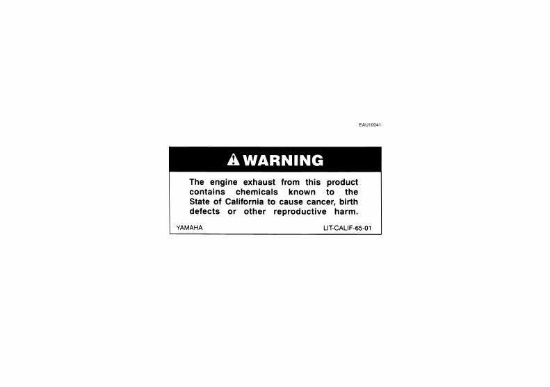
EAU10041

INTRODUCTION
EAU10080
Congratulations on your purchase of the Yamaha XT250X/XT250XC. This model is the result of Yamaha’s vast experiencein the production of fine sporting, touring, and pacesetting racing machines. It represents the high degree of craftsmanshipand reliability that have made Yamaha a leader in these fields.This manual will give you an understanding of the operation, inspection, and basic maintenance of this motorcycle. If youhave any questions concerning the operation or maintenance of your motorcycle, please consult a Yamaha dealer.The design and manufacture of this Yamaha motorcycle fully comply with the emissions standards for clean air applicableat the date of manufacture. Yamaha has met these standards without reducing the performance or economy of operation ofthe motorcycle. To maintain these high standards, it is important that you and your Yamaha dealer pay close attention to therecommended maintenance schedules and operating instructions contained within this manual.
IMPORTANT MANUAL INFORMATION
EAU10131
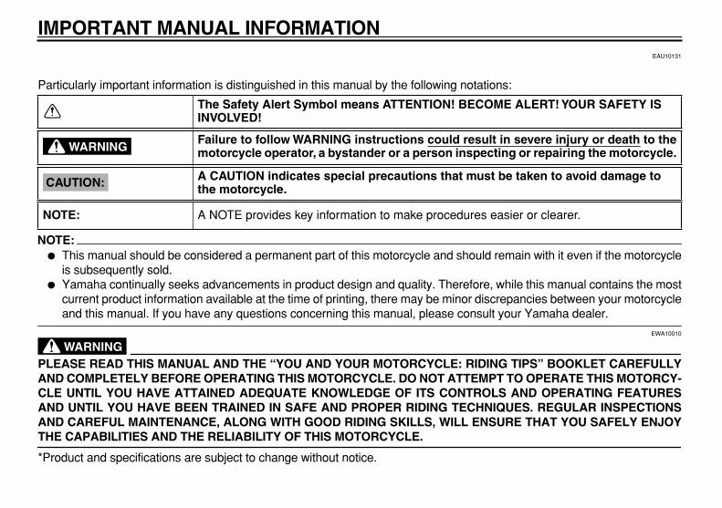
Particularly important information is distinguished in this manual by the following notations:
NOTE:
�
This manual should be considered a permanent part of this motorcycle and should remain with it even if the motorcycleis subsequently sold.
�
Yamaha continually seeks advancements in product design and quality. Therefore, while this manual contains the mostcurrent product information available at the time of printing, there may be minor discrepancies between your motorcycle
and this manual. If you have any questions concerning this manual, please consult your Yamaha dealer.
WARNING
EWA10010
PLEASE READ THIS MANUAL AND THE “YOU AND YOUR MOTORCYCLE: RIDING TIPS” BOOKLET CAREFULLYAND COMPLETELY BEFORE OPERATING THIS MOTORCYCLE. DO NOT ATTEMPT TO OPERATE THIS MOTORCY-CLE UNTIL YOU HAVE ATTAINED ADEQUATE KNOWLEDGE OF ITS CONTROLS AND OPERATING FEATURESAND UNTIL YOU HAVE BEEN TRAINED IN SAFE AND PROPER RIDING TECHNIQUES. REGULAR INSPECTIONSAND CAREFUL MAINTENANCE, ALONG WITH GOOD RIDING SKILLS, WILL ENSURE THAT YOU SAFELY ENJOY
THE CAPABILITIES AND THE RELIABILITY OF THIS MOTORCYCLE.
*Product and specifications are subject to change without notice.
The Safety Alert Symbol means ATTENTION! BECOME ALERT! YOUR SAFETY IS INVOLVED!
Failure to follow WARNING instructions could result in severe injury or death to themotorcycle operator, a bystander or a person inspecting or repairing the motorcycle.
A CAUTION indicates special precautions that must be taken to avoid damage to the motorcycle.
A NOTE provides key information to make procedures easier or clearer.
WARNING
CAUTION:
NOTE:

IMPORTANT MANUAL INFORMATION
EAU10192
XT250X/XT250XCOWNER’S MANUAL
©2007 by Yamaha Motor Corporation, U.S.A.1st edition, June 2007
All rights reserved.Any reprinting or unauthorized use without the written permission of Yamaha Motor Corporation, U.S.A.
is expressly prohibited.Printed in Japan.
P/N LIT-11626-21-52
AFFIX DEALER
LABEL HERE
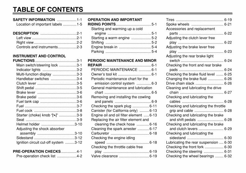
TABLE OF CONTENTS
SAFETY INFORMATION
...................1-1Location of important labels .............1-5
DESCRIPTION
...................................2-1Left view ...........................................2-1Right view .........................................2-2Controls and instruments..................2-3
INSTRUMENT AND CONTROL FUNCTIONS
........................................3-1Main switch/steering lock .................3-1Indicator lights .................................3-2Multi-function display .......................3-3Handlebar switches .........................3-4Clutch lever ......................................3-5Shift pedal ........................................3-5Brake lever ......................................3-6Brake pedal .....................................3-6Fuel tank cap ...................................3-6Fuel ..................................................3-7Fuel cock .........................................3-8Starter (choke) knob “
1
” .................3-9Seat .................................................3-9Helmet holder ................................3-10Adjusting the shock absorber
assembly ....................................3-10Sidestand .......................................3-12Ignition circuit cut-off system .........3-12
PRE-OPERATION CHECKS
...............4-1Pre-operation check list ...................4-2
OPERATION AND IMPORTANT RIDING POINTS
.................................. 5-1Starting and warming up a cold
engine .......................................... 5-1Starting a warm engine ................... 5-2Shifting ............................................ 5-2Engine break-in ............................... 5-4Parking ............................................ 5-4
PERIODIC MAINTENANCE AND MINOR REPAIR
............................................... 6-1PERIODIC MAINTENANCE ............ 6-1Owner’s tool kit ................................ 6-1Periodic maintenance chart for the
emission control system .............. 6-3General maintenance and lubrication
chart ............................................. 6-5Removing and installing the cowling
and panels ................................... 6-9Checking the spark plug ................ 6-11Canister (for California only) ......... 6-13Engine oil and oil filter element ..... 6-13Replacing the air filter element and
cleaning the check hose ............ 6-16Cleaning the spark arrester ........... 6-17Carburetor ..................................... 6-18Checking the engine idling
speed ......................................... 6-18Checking the throttle cable free
play ............................................ 6-19Valve clearance ............................. 6-19
Tires .............................................. 6-19Spoke wheels ............................... 6-21Accessories and replacement
parts ........................................... 6-22Adjusting the clutch lever free
play ............................................ 6-22Adjusting the brake lever free
play ............................................ 6-23Adjusting the rear brake light
switch ......................................... 6-24Checking the front and rear brake
pads ........................................... 6-24Checking the brake fluid level ....... 6-25Changing the brake fluid ............... 6-26Drive chain slack ........................... 6-26Cleaning and lubricating the drive
chain .......................................... 6-27Checking and lubricating the
cables ........................................ 6-28Checking and lubricating the throttle
grip and cable ............................ 6-28Checking and lubricating the brake
and shift pedals ......................... 6-28Checking and lubricating the brake
and clutch levers ........................ 6-29Checking and lubricating the
sidestand ................................... 6-30Lubricating the rear suspension .... 6-30Checking the front fork .................. 6-30Checking the steering ................... 6-31Checking the wheel bearings ........ 6-32
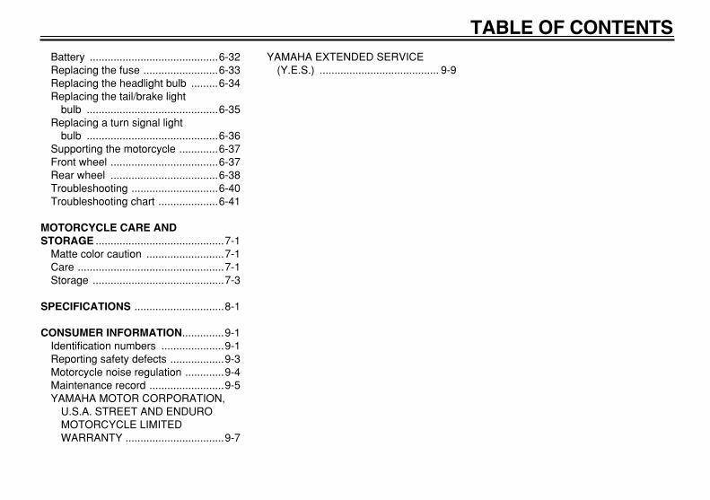
TABLE OF CONTENTS
Battery ...........................................6-32Replacing the fuse .........................6-33Replacing the headlight bulb .........6-34Replacing the tail/brake light
bulb ............................................6-35Replacing a turn signal light
bulb ............................................6-36Supporting the motorcycle .............6-37Front wheel ....................................6-37Rear wheel ....................................6-38Troubleshooting .............................6-40Troubleshooting chart ....................6-41
MOTORCYCLE CARE AND STORAGE
...........................................7-1Matte color caution ..........................7-1Care .................................................7-1Storage ............................................7-3
SPECIFICATIONS
..............................8-1
CONSUMER INFORMATION
..............9-1Identification numbers .....................9-1Reporting safety defects ..................9-3Motorcycle noise regulation .............9-4Maintenance record .........................9-5YAMAHA MOTOR CORPORATION,
U.S.A. STREET AND ENDURO MOTORCYCLE LIMITED WARRANTY .................................9-7
YAMAHA EXTENDED SERVICE (Y.E.S.) ........................................ 9-9

1-1
1
SAFETY INFORMATION
EAU10311
MOTORCYCLES ARE SINGLETRACK VEHICLES. THEIR SAFEUSE AND OPERATION ARE DEPEN-DENT UPON THE USE OF PROPERRIDING TECHNIQUES AS WELL ASTHE EXPERTISE OF THE OPERA-TOR. EVERY OPERATOR SHOULDKNOW THE FOLLOWING REQUIRE-MENTS BEFORE RIDING THIS MO-TORCYCLE.HE OR SHE SHOULD:
�
OBTAIN THOROUGH INSTRUC-TIONS FROM A COMPETENTSOURCE ON ALL ASPECTS OFMOTORCYCLE OPERATION.
�
OBSERVE THE WARNINGSAND MAINTENANCE REQUIRE-MENTS IN THE OWNER’S MAN-UAL.
�
OBTAIN QUALIFIED TRAININGIN SAFE AND PROPER RIDINGTECHNIQUES.
�
OBTAIN PROFESSIONAL TECH-NICAL SERVICE AS INDICATEDBY THE OWNER’S MANUALAND/OR WHEN MADE NECES-SARY BY MECHANICAL CONDI-
TIONS.
Safe riding
�
Always make pre-operationchecks. Careful checks may helpprevent an accident.
�
This motorcycle is designed to car-ry the operator and a passenger.
�
The failure of motorists to detectand recognize motorcycles in traf-fic is the predominating cause ofautomobile/motorcycle accidents.Many accidents have been causedby an automobile driver who didnot see the motorcycle. Makingyourself conspicuous appears tobe very effective in reducing thechance of this type of accident.
�
Therefore:
�
Wear a brightly colored jacket.
�
Use extra caution when ap-proaching and passing throughintersections, since intersec-tions are the most likely placesfor motorcycle accidents to oc-cur.
�
Ride where other motorists cansee you. Avoid riding in another
motorist’s blind spot.
�
Many accidents involve inexperi-enced operators. In fact, many op-erators who have been involved inaccidents do not even have a cur-rent motorcycle license.
�
Make sure that you are qualifiedand that you only lend your mo-torcycle to other qualified opera-tors.
�
Know your skills and limits.Staying within your limits mayhelp you to avoid an accident.
�
We recommend that you prac-tice riding your motorcyclewhere there is no traffic until youhave become thoroughly famil-iar with the motorcycle and all ofits controls.
�
Many accidents have been causedby error of the motorcycle opera-tor. A typical error made by the op-erator is veering wide on a turndue to EXCESSIVE SPEED or un-dercornering (insufficient lean an-gle for the speed).
�
Always obey the speed limit andnever travel faster than warrant-

SAFETY INFORMATION
1-2
1
ed by road and traffic conditions.
�
Always signal before turning orchanging lanes. Make sure thatother motorists can see you.
�
The posture of the operator andpassenger is important for propercontrol.
�
The operator should keep bothhands on the handlebar andboth feet on the operator foot-rests during operation to main-tain control of the motorcycle.
�
The passenger should alwayshold onto the operator, the seatstrap or grab bar, if equipped,with both hands and keep bothfeet on the passenger footrests.
�
Never carry a passenger unlesshe or she can firmly place bothfeet on the passenger footrests.
�
Never ride under the influence ofalcohol or other drugs.
Protective apparel
The majority of fatalities from motorcy-cle accidents are the result of head in-juries. The use of a safety helmet is thesingle most critical factor in the preven-
tion or reduction of head injuries.
�
Always wear an approved helmet.
�
Wear a face shield or goggles.Wind in your unprotected eyescould contribute to an impairmentof vision that could delay seeing ahazard.
�
The use of a jacket, heavy boots,trousers, gloves, etc., is effective inpreventing or reducing abrasionsor lacerations.
�
Never wear loose-fitting clothes,otherwise they could catch on thecontrol levers, footrests, or wheelsand cause injury or an accident.
�
Never touch the engine or exhaustsystem during or after operation.They become very hot and cancause burns. Always wear protec-tive clothing that covers your legs,ankles, and feet.
�
Passengers should also observethe precautions mentioned above.
Modifications
Modifications made to this motorcyclenot approved by Yamaha, or the re-moval of original equipment, may ren-
der the motorcycle unsafe for use andmay cause severe personal injury.Modifications may also make your mo-torcycle illegal to use.
Loading and accessories
Adding accessories or cargo to yourmotorcycle can adversely affect stabili-ty and handling if the weight distributionof the motorcycle is changed. To avoidthe possibility of an accident, use ex-treme caution when adding cargo oraccessories to your motorcycle. Useextra care when riding a motorcyclethat has added cargo or accessories.Here are some general guidelines tofollow if loading cargo or adding acces-sories to your motorcycle:
LoadingThe total weight of the operator, pas-senger, accessories and cargo mustnot exceed the maximum load limit.
When loading within this weight limit,keep the following in mind:
Maximum load:
160 kg (353 lb)

SAFETY INFORMATION
1-3
1
�
Cargo and accessory weightshould be kept as low and close tothe motorcycle as possible. Makesure to distribute the weight asevenly as possible on both sides ofthe motorcycle to minimize imbal-ance or instability.
�
Shifting weights can create a sud-den imbalance. Make sure that ac-cessories and cargo are securelyattached to the motorcycle beforeriding. Check accessory mountsand cargo restraints frequently.
�
Never attach any large or heavyitems to the handlebar, front fork,or front fender. These items, in-cluding such cargo as sleepingbags, duffel bags, or tents, cancreate unstable handling or a slowsteering response.
AccessoriesGenuine Yamaha accessories havebeen specifically designed for use onthis motorcycle. Since Yamaha cannottest all other accessories that may beavailable, you must personally be re-sponsible for the proper selection, in-
stallation and use of non-Yamahaaccessories. Use extreme cautionwhen selecting and installing any ac-cessories.Keep the following guidelines in mind,as well as those provided under “Load-ing” when mounting accessories.
�
Never install accessories or carrycargo that would impair the perfor-mance of your motorcycle. Care-fully inspect the accessory beforeusing it to make sure that it doesnot in any way reduce groundclearance or cornering clearance,limit suspension travel, steeringtravel or control operation, or ob-scure lights or reflectors.
�
Accessories fitted to the handle-bar or the front fork area cancreate instability due to improperweight distribution or aerody-namic changes. If accessoriesare added to the handlebar orfront fork area, they must be aslightweight as possible andshould be kept to a minimum.
�
Bulky or large accessories mayseriously affect the stability of
the motorcycle due to aerody-namic effects. Wind may at-tempt to lift the motorcycle, orthe motorcycle may become un-stable in cross winds. These ac-cessories may also causeinstability when passing or beingpassed by large vehicles.
�
Certain accessories can dis-place the operator from his orher normal riding position. Thisimproper position limits the free-dom of movement of the opera-tor and may limit control ability,therefore, such accessories arenot recommended.
�
Use caution when adding electri-cal accessories. If electrical acces-sories exceed the capacity of themotorcycle’s electrical system, anelectric failure could result, whichcould cause a dangerous loss oflights or engine power.
Gasoline and exhaust gas
�
GASOLINE IS HIGHLY FLAMMA-BLE:
�
Always turn the engine off when

SAFETY INFORMATION
1-4
1
refueling.
�
Take care not to spill any gaso-line on the engine or exhaustsystem when refueling.
�
Never refuel while smoking or inthe vicinity of an open flame.
�
Never start the engine or let it runfor any length of time in a closedarea. The exhaust fumes are poi-sonous and may cause loss ofconsciousness and death within ashort time. Always operate yourmotorcycle in an area that has ad-equate ventilation.
�
Always turn the engine off beforeleaving the motorcycle unattendedand remove the key from the mainswitch. When parking the motorcy-cle, note the following:
�
The engine and exhaust systemmay be hot, therefore, park themotorcycle in a place where pe-destrians or children are not like-ly to touch these hot areas.
�
Do not park the motorcycle on aslope or soft ground, otherwise itmay fall over.
�
Do not park the motorcycle near
a flammable source (e.g., a ker-osene heater, or near an openflame), otherwise it could catchfire.
�
When transporting the motorcyclein another vehicle, make sure thatit is kept upright and that the fuelcock(s) are turned to “ON” or“RES” (for vacuum type)/“OFF”(for manual type). If the motorcycleshould lean over, gasoline mayleak out of the carburetor or fueltank.
�
If you should swallow any gaso-line, inhale a lot of gasoline vapor,or allow gasoline to get into youreyes, see your doctor immediate-ly. If any gasoline spills on yourskin or clothing, immediately washthe affected area with soap andwater and change your clothes.
SAFETY INFORMATION
1-5
1
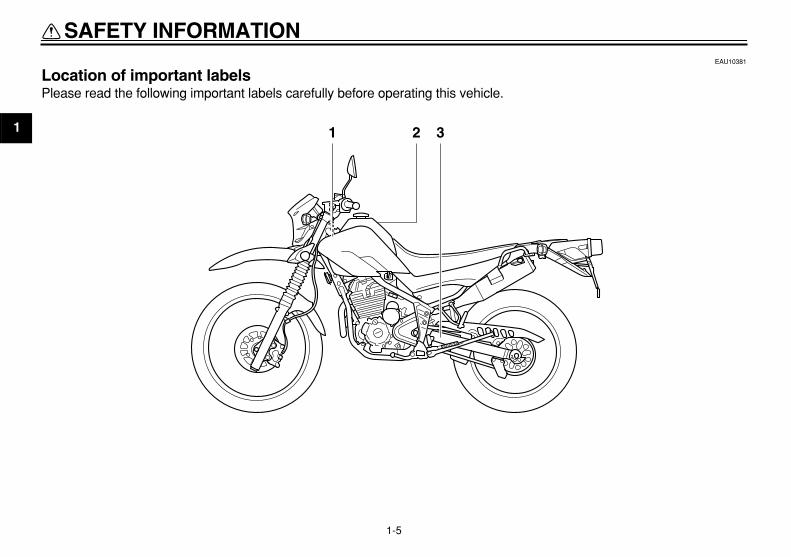
EAU10381
Location of important labels
Please read the following important labels carefully before operating this vehicle.
21 3

SAFETY INFORMATION
1-6
13
CARB.FROMFUEL TANK
CANISTERTO ATMOSPHERE
4YN-21686-00
1 California only
WARNINGBEFORE YOU OPERATE THIS VEHICLE, READTHE OWNER’S MANUAL AND ALL LABELS.ALWAYS WEAR AN APPROVED MOTORCYCLEHELMET, eye protection, and protective clothing.
5GK-2118K-00
2
3TT-21668-00

SAFETY INFORMATION
1-7
1
1 2

SAFETY INFORMATION
1-8
1
2
1
WARNING
8
8
This unit contains high pressure nitrogen gas.Mishandling can cause explosion.
Read owner's manual for instructions.Do not incinerate, puncture or open.
4AA-22259-80

2-1
1
2
3
4
5
6
7
8
9
DESCRIPTION
EAU10410
Left view
1 2 43
1. Fuel cock (page 3-8)2. Starter (choke) knob (page 3-9)3. Air filter element (page 6-16)4. Helmet holder (page 3-10)

DESCRIPTION
2-2
2
3
4
5
6
7
8
9
EAU10420
Right view
2 3 4
56
1
1. Spark arrester (page 6-17)2. Battery (page 6-32)3. Fuse (page 6-33)4. Owner’s tool kit (page 6-1)5. Engine oil level check window (page 6-13)6. Engine oil filler cap (page 6-13)
DESCRIPTION
2-3
1
2
3
4
5
6
7
8
9
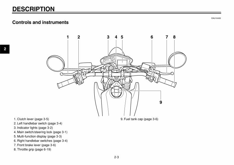
EAU10430
Controls and instruments
1 2 6 83 5 7
9
4
1. Clutch lever (page 3-5)2. Left handlebar switch (page 3-4)3. Indicator lights (page 3-2)4. Main switch/steering lock (page 3-1)5. Multi-function display (page 3-3)6. Right handlebar switches (page 3-4)7. Front brake lever (page 3-6)8. Throttle grip (page 6-19)
9. Fuel tank cap (page 3-6)

3-1
2
3
4
5
6
7
8
9
INSTRUMENT AND CONTROL FUNCTIONS
EAU10460
Main switch/steering lock
The main switch/steering lock controlsthe ignition and lighting systems, and isused to lock the steering. The variouspositions are described below.
EAU10580
ON
All electrical circuits are supplied withpower, and the meter lighting, taillightand position lights come on, and theengine can be started. The key cannotbe removed.
NOTE:
The headlight comes on automaticallywhen the engine is started and stays onuntil the key is turned to “OFF”, even if
the engine stalls.
EAU10660
OFF
All electrical systems are off. The keycan be removed.
EAU10690
LOCK
The steering is locked, and all electricalsystems are off. The key can be re-moved.
To lock the steering
1. Turn the handlebars all the way tothe left or right.
2. Push the key in from the “OFF” po-sition, and then turn it to “LOCK”while still pushing it.
3. Remove the key.
To unlock the steering
Push the key into the main switch, andthen turn it to “OFF” while still pushingit.
WARNING
EWA10060
Never turn the key to “OFF” or“LOCK” while the vehicle is moving,otherwise the electrical systems willbe switched off, which may result inloss of control or an accident. Make
1. Push.2. Turn.
1
2
1. Push.2. Turn.
1
2

INSTRUMENT AND CONTROL FUNCTIONS
3-2
1
2
3
4
5
6
7
8
9
sure that the vehicle is stopped be-fore turning the key to “OFF” or
“LOCK”.
EAU10980
Indicator lights
EAU11020
Turn signal indicator light “ ”
This indicator light flashes when theturn signal switch is pushed to the left orright.
EAU11060
Neutral indicator light “ ”
This indicator light comes on when thetransmission is in the neutral position.
EAU11080
High beam indicator light “ ”
This indicator light comes on when thehigh beam of the headlight is switchedon.
1. High beam indicator light “ ”
2. Turn signal indicator light “ ”
3. Neutral indicator light “ ”
1 2 3

INSTRUMENT AND CONTROL FUNCTIONS
3-3
2
3
4
5
6
7
8
9
EAU44861
Multi-function display
WARNING
EWA12311
Be sure to stop the vehicle beforemaking any setting changes to the
multi-function display.
The multi-function display is equippedwith the following:
�
a speedometer (which shows theriding speed)
�
an odometer (which shows the to-tal distance traveled)
�
two tripmeters (which show thedistance traveled since they werelast set to zero)
�
a clock
NOTE:
�
Be sure to turn the key to “ON” be-fore using the “SELECT” and “RE-SET” buttons.
�
When the key is turned to “ON”, allof the display segments of the
multi-function display will appearone after the other and then disap-pear, in order to test the electricalcircuit.
�
To switch the speedometer andodometer/tripmeter displays be-tween miles and kilometers, pressthe “SELECT” button for at least
two seconds.
Odometer, clock and tripmeter modes
Pushing the “SELECT” button switchesthe display between the odometermode “ODO” and the tripmeter modes“TRIP” in the following order:ODO
→
TRIP (top)
→
TRIP (bottom)
→
ODOTo reset a tripmeter, select it by push-ing the “SELECT” button until “TRIP”begins flashing (“TRIP” will only flashfor five seconds). While “TRIP” is flash-ing, push the “RESET” button for atleast one second.
Clock mode
To set the clock:1. Push the “SELECT” button and
1. “SELECT” button2. “RESET” button3. Clock4. Speedometer
1 2 3 4
1. Odometer/tripmeter (bottom)2. Tripmeter (top)
21

INSTRUMENT AND CONTROL FUNCTIONS
3-4
1
2
3
4
5
6
7
8
9
“RESET” button together for atleast two seconds.
2. When the hour digits start flashing,push the “RESET” button to set thehours.
3. Push the “SELECT” button, andthe minute digits will start flashing.
4. Push the “RESET” button to setthe minutes.
5. Push the “SELECT” button andthen release it to start the clock.
EAU12347
Handlebar switches
Left
Right
EAU12400
Dimmer switch “ / ”
Set this switch to “ ” for the highbeam and to “ ” for the low beam.
EAU12460
Turn signal switch “ / ”
To signal a right-hand turn, push thisswitch to “ ”. To signal a left-handturn, push this switch to “ ”. When re-leased, the switch returns to the centerposition. To cancel the turn signallights, push the switch in after it has re-turned to the center position.
1. Dimmer switch “ / ”
2. Turn signal switch “ / ”
3. Horn switch “ ”
1
23
1. Engine stop switch “ / ”
2. Start switch “ ”
1
2
INSTRUMENT AND CONTROL FUNCTIONS
3-5
2
3
4
5
6
7
8
9
EAU12500
Horn switch “ ”
Press this switch to sound the horn.
EAU12660
Engine stop switch “ / ”
Set this switch to “ ” before startingthe engine. Set this switch to “ ” tostop the engine in case of an emergen-cy, such as when the vehicle overturnsor when the throttle cable is stuck.
EAU12710
Start switch “ ”
Push this switch to crank the enginewith the starter.
CAUTION:
ECA10050
See page 5-1 for starting instruc-
tions prior to starting the engine.
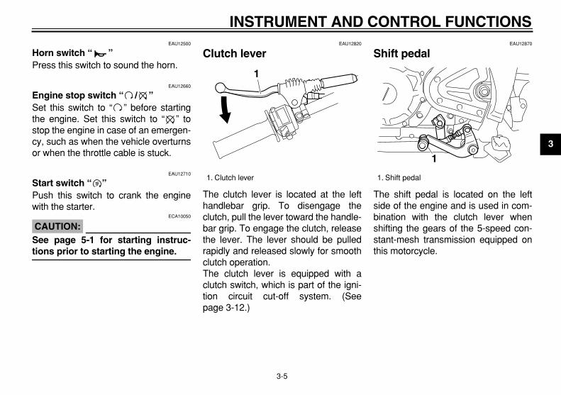
EAU12820
Clutch lever
The clutch lever is located at the lefthandlebar grip. To disengage theclutch, pull the lever toward the handle-bar grip. To engage the clutch, releasethe lever. The lever should be pulledrapidly and released slowly for smoothclutch operation.The clutch lever is equipped with aclutch switch, which is part of the igni-tion circuit cut-off system. (Seepage 3-12.)
EAU12870
Shift pedal
The shift pedal is located on the leftside of the engine and is used in com-bination with the clutch lever whenshifting the gears of the 5-speed con-stant-mesh transmission equipped onthis motorcycle.
1. Clutch lever
1
1. Shift pedal
1

INSTRUMENT AND CONTROL FUNCTIONS
3-6
1
2
3
4
5
6
7
8
9
EAU12890
Brake lever
The brake lever is located at the righthandlebar grip. To apply the frontbrake, pull the lever toward the handle-bar grip.
EAU12941
Brake pedal
The brake pedal is on the right side ofthe motorcycle. To apply the rearbrake, press down on the brake pedal.
EAUM1792
Fuel tank cap
To remove the fuel tank cap
1. Open the fuel tank cap lock cover.2. Insert the key into the lock and turn
it 1/4 turn clockwise. The lock willbe released and the fuel tank capcan be removed.
To install the fuel tank cap
1. Push and install the fuel tank capinto position with the key insertedin the lock.
2. Turn the key counterclockwise tothe original position, and then re-move it.
1. Brake lever
1
1. Brake pedal
1
1. Fuel tank cap lock cover2. Unlock.
12

INSTRUMENT AND CONTROL FUNCTIONS
3-7
2
3
4
5
6
7
8
9
NOTE:
The fuel tank cap cannot be installedunless the key is in the lock. In addition,the key cannot be removed if the cap is
not properly installed and locked.
3. Close the lock cover.
WARNING
EWA11140
Make sure that the fuel tank cap is
properly installed before riding.
EAU13211
Fuel
Make sure that there is sufficient fuel inthe tank. Fill the fuel tank to the bottomof the filler tube as shown.
WARNING
EWA10880
�
Do not overfill the fuel tank, oth-erwise it may overflow when thefuel warms up and expands.
�
Avoid spilling fuel on the hot en-
gine.
CAUTION:
ECA10070
Immediately wipe off spilled fuelwith a clean, dry, soft cloth, since
fuel may deteriorate painted surfac-
es or plastic parts.
EAU13300
CAUTION:
ECA11400
Use only unleaded gasoline. The useof leaded gasoline will cause severedamage to internal engine parts,such as the valves and piston rings,
as well as to the exhaust system.
Your Yamaha engine has been de-signed to use regular unleaded gaso-line with a pump octane number[(R+M)/2] of 86 or higher, or a researchoctane number of 91 or higher. Ifknocking (or pinging) occurs, use agasoline of a different brand or premi-
1. Fuel level2. Fuel tank filler tube
1
2
Recommended fuel:
UNLEADED GASOLINE ONLY
Fuel tank capacity:
9.1 L (2.40 US gal) (2.00 Imp.gal) (CAL)9.8 L (2.59 US gal) (2.16 Imp.gal) (U49)
Fuel reserve amount:
1.9 L (0.50 US gal) (0.42 Imp.gal)

INSTRUMENT AND CONTROL FUNCTIONS
3-8
1
2
3
4
5
6
7
8
9
um unleaded fuel. Use of unleaded fuelwill extend spark plug life and reducemaintenance costs.
Gasohol
There are two types of gasohol: gaso-hol containing ethanol and that contain-ing methanol. Gasohol containingethanol can be used if the ethanol con-tent does not exceed 10%. Gasoholcontaining methanol is not recom-mended by Yamaha because it cancause damage to the fuel system or ve-hicle performance problems.
EAU13561
Fuel cock
The fuel cock supplies fuel from thetank to the carburetor while filtering it al-so.The fuel cock has three positions:
OFF
With the lever in this position, fuel willnot flow. Always return the lever to thisposition when the engine is not running.
ON
With the lever in this position, fuel flowsto the carburetor. Normal riding is donewith the lever in this position.
RES
1. Pointed end positioned under “OFF”
1
1. Pointed end positioned over “ON”
1. Pointed end positioned over “RES”
1
1

INSTRUMENT AND CONTROL FUNCTIONS
3-9
2
3
4
5
6
7
8
9
This indicates reserve. If you run out offuel while riding, move the lever to thisposition. Fill the tank at the first oppor-tunity. Be sure to set the lever back to“ON” after refueling!
EAU13600
Starter (choke) knob “ ”
Starting a cold engine requires a richerair-fuel mixture, which is supplied bythe starter (choke).Move the knob in direction (a) to turn onthe starter (choke).Move the knob in direction (b) to turn offthe starter (choke).
EAU13970
Seat
To remove the seat
Remove the bolts, and then pull theseat off.
To install the seat
1. Insert the projection on the front ofthe seat into the seat holder asshown.
1. Starter (choke) knob “ ”
1
(a) (b)
1. Bolt
1

INSTRUMENT AND CONTROL FUNCTIONS
3-10
1
2
3
4
5
6
7
8
9
2. Place the seat in the original posi-tion, and then tighten the bolts.
NOTE:
Make sure that the seat is properly se-
cured before riding.
EAU14281
Helmet holder
To open the helmet holder, insert thekey into the lock, and then turn the keyas shown.To lock the helmet holder, place it in theoriginal position, and then remove thekey.
WARNING
EWA10160
Never ride with a helmet attached tothe helmet holder, since the helmetmay hit objects, causing loss of con-
trol and possibly an accident.
EAU44770
Adjusting the shock absorber assembly
This shock absorber assembly isequipped with a spring preload adjust-ing ring.It is recommended to have a Yamahadealer adjust the spring preload. How-ever, if you choose to make this adjust-ment yourself, obtain a special wrenchat a Yamaha dealer.
CAUTION:
ECA10100
Never attempt to turn an adjustingmechanism beyond the maximum or
minimum settings.
1. Loosen the locknut.2. To increase the spring preload and
thereby harden the suspension,turn the adjusting ring in direction(a). To decrease the spring pre-load and thereby soften the sus-pension, turn the adjusting ring indirection (b).
1. Projection2. Seat holder
1
2
1. Helmet holder2. Unlock.
1
2

INSTRUMENT AND CONTROL FUNCTIONS
3-11
2
3
4
5
6
7
8
9
NOTE:
The spring preload setting is deter-mined by measuring distance A, shownin the illustration. The shorter the dis-tance A is, the higher the spring pre-load; the longer distance A is, the lower
the spring preload. 3. Tighten the locknut to the specifiedtorque.
CAUTION:
ECA10130
Always tighten the locknut againstthe adjusting ring, and then tighten
the locknut to the specified torque.
WARNING
EWA10220
This shock absorber contains highlypressurized nitrogen gas. For prop-er handling, read and understandthe following information beforehandling the shock absorber. Themanufacturer cannot be held re-sponsible for property damage orpersonal injury that may result fromimproper handling.
�
Do not tamper with or attempt toopen the gas cylinder.
�
Do not subject the shock ab-sorber to an open flame or otherhigh heat sources, otherwise itmay explode due to excessivegas pressure.
�
Do not deform or damage thegas cylinder in any way, as thiswill result in poor damping per-formance.
�
Always have a Yamaha dealer
service the shock absorber.
1. Locknut2. Spring preload adjusting ring
1(b)
(a) 2
1. Distance A
Spring preload:
Minimum (soft):Distance A = 207 mm (8.15 in)
Standard:Distance A = 197 mm (7.76 in)
Maximum (hard):Distance A = 187 mm (7.36 in)
Tightening torque:
Locknut:30 Nm (3.0 m·kgf, 21.7 ft·lbf)
1

INSTRUMENT AND CONTROL FUNCTIONS
3-12
1
2
3
4
5
6
7
8
9
EAU15301
Sidestand
The sidestand is located on the left sideof the frame. Raise the sidestand orlower it with your foot while holding thevehicle upright.
NOTE:
The built-in sidestand switch is part ofthe ignition circuit cut-off system, whichcuts the ignition in certain situations.(See further down for an explanation of
the ignition circuit cut-off system.)
WARNING
EWA10240
The vehicle must not be ridden withthe sidestand down, or if the side-stand cannot be properly moved up(or does not stay up), otherwise thesidestand could contact the groundand distract the operator, resultingin a possible loss of control.Yamaha’s ignition circuit cut-offsystem has been designed to assistthe operator in fulfilling the respon-sibility of raising the sidestand be-fore starting off. Therefore, checkthis system regularly as describedbelow and have a Yamaha dealer re-
pair it if it does not function proper-
ly.
EAU15312
Ignition circuit cut-off system
The ignition circuit cut-off system (com-prising the sidestand switch, clutchswitch and neutral switch) has the fol-lowing functions.
�
It prevents starting when the trans-mission is in gear and the side-stand is up, but the clutch lever isnot pulled.
�
It prevents starting when the trans-mission is in gear and the clutch le-ver is pulled, but the sidestand isstill down.
�
It cuts the running engine when thetransmission is in gear and the sid-estand is moved down.
Periodically check the operation of theignition circuit cut-off system accordingto the following procedure.
WARNING
EWA10250
If a malfunction is noted, have aYamaha dealer check the system be-
fore riding.

INSTRUMENT AND CONTROL FUNCTIONS
3-13
2
3
4
5
6
7
8
9
With the engine turned off:1. Move the sidestand down.2. Make sure that the engine stop switch is turned on.3. Turn the key on. 4. Shift the transmission into the neutral position.5. Push the start switch.Does the engine start?
With the engine still running:6. Move the sidestand up.7. Keep the clutch lever pulled.8. Shift the transmission into gear.9. Move the sidestand down.Does the engine stall?
After the engine has stalled:10. Move the sidestand up.11. Keep the clutch lever pulled.12. Push the start switch.Does the engine start?
The system is OK. The motorcycle can be ridden.
This check is most reliable if performed witha warmed-up engine.
The neutral switch may be defective.The motorcycle should not be ridden untilchecked by a Yamaha dealer.
The sidestand switch may be defective.The motorcycle should not be ridden untilchecked by a Yamaha dealer.
The clutch switch may be defective.The motorcycle should not be ridden untilchecked by a Yamaha dealer.
YES NO
YES NO
YES NO
NOTE:

4-1
1
2
3
4
5
6
7
8
9
PRE-OPERATION CHECKS
EAU15593
The condition of a vehicle is the owner’s responsibility. Vital components can start to deteriorate quickly and unexpectedly,even if the vehicle remains unused (for example, as a result of exposure to the elements). Any damage, fluid leakage or lossof tire air pressure could have serious consequences. Therefore, it is very important, in addition to a thorough visual inspec-tion, to check the following points before each ride.
NOTE:
Pre-operation checks should be made each time the vehicle is used. Such an inspection can be accomplished in a very short
time; and the added safety it assures is more than worth the time involved.
WARNING
EWA11150
If any item in the Pre-operation check list is not working properly, have it inspected and repaired before operating
the vehicle.

PRE-OPERATION CHECKS
4-2
2
3
4
5
6
7
8
9
EAU15605
Pre-operation check list
ITEM CHECKS PAGE
Fuel
�
Check fuel level in fuel tank.
�
Refuel if necessary.
�
Check fuel line for leakage.3-7
Engine oil
�
Check oil level in engine.
�
If necessary, add recommended oil to specified level.
�
Check vehicle for oil leakage.6-13
Front brake
�
Check operation.
�
If soft or spongy, have Yamaha dealer bleed hydraulic system.
�
Check lever free play.
�
Adjust if necessary.
�
Check brake pads for wear.
�
Replace if necessary.
�
Check fluid level in reservoir.
�
If necessary, add recommended brake fluid to specified level.
�
Check hydraulic system for leakage.
6-23, 6-24, 6-25
Rear brake
�
Check operation.
�
If soft or spongy, have Yamaha dealer bleed hydraulic system.
�
Check brake pads for wear.
�
Replace if necessary.
�
Check fluid level in reservoir.
�
If necessary, add recommended brake fluid to specified level.
�
Check hydraulic system for leakage.
6-24, 6-25
Clutch
�
Check operation.
�
Lubricate cable if necessary.
�
Check lever free play.
�
Adjust if necessary.
6-22
Throttle grip
�
Make sure that operation is smooth.
�
Check cable free play.
�
If necessary, have Yamaha dealer adjust cable free play and lubricate cable and grip housing.
6-19, 6-28
PRE-OPERATION CHECKS
4-3
1
2
3
4
5
6
7
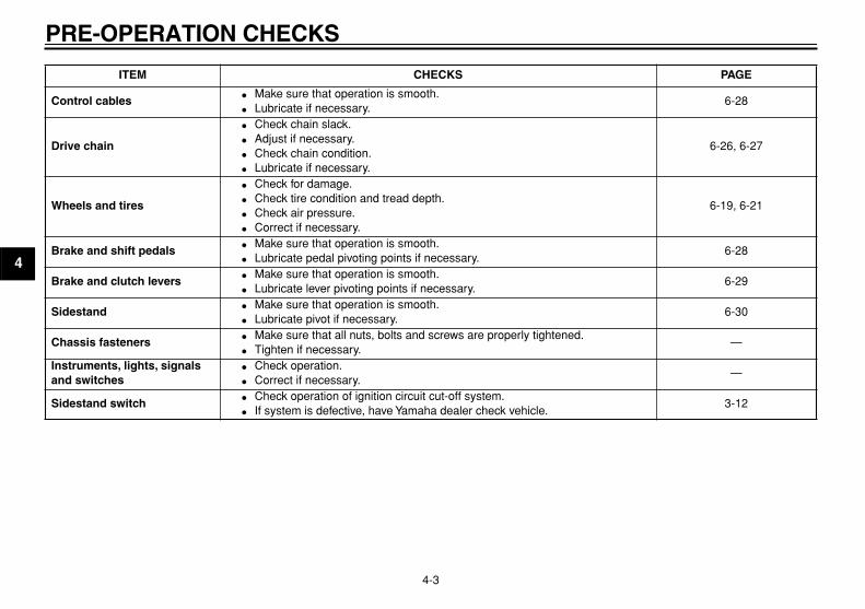
8
9
Control cables
�
Make sure that operation is smooth.
�
Lubricate if necessary.6-28
Drive chain
�
Check chain slack.
�
Adjust if necessary.
�
Check chain condition.
�
Lubricate if necessary.
6-26, 6-27
Wheels and tires
�
Check for damage.
�
Check tire condition and tread depth.
�
Check air pressure.
�
Correct if necessary.
6-19, 6-21
Brake and shift pedals
�
Make sure that operation is smooth.
�
Lubricate pedal pivoting points if necessary.6-28
Brake and clutch levers
�
Make sure that operation is smooth.
�
Lubricate lever pivoting points if necessary.6-29
Sidestand
�
Make sure that operation is smooth.
�
Lubricate pivot if necessary.6-30
Chassis fasteners
�
Make sure that all nuts, bolts and screws are properly tightened.
�
Tighten if necessary.—
Instruments, lights, signals and switches
�
Check operation.
�
Correct if necessary.—
Sidestand switch
�
Check operation of ignition circuit cut-off system.
�
If system is defective, have Yamaha dealer check vehicle.3-12
ITEM CHECKS PAGE

5-1
2
3
4
5
6
7
8
9
OPERATION AND IMPORTANT RIDING POINTS
EAU15950
WARNING
EWA10270
�
Become thoroughly familiarwith all operating controls andtheir functions before riding.Consult a Yamaha dealer re-garding any control or functionthat you do not thoroughly un-derstand.
�
Never start the engine or oper-ate it in a closed area for anylength of time. Exhaust fumesare poisonous, and inhalingthem can cause loss of con-sciousness and death within ashort time. Always make surethat there is adequate ventila-tion.
�
Before starting out, make surethat the sidestand is up. If thesidestand is not raised com-pletely, it could contact theground and distract the opera-tor, resulting in a possible loss
of control.
EAU32290
Starting and warming up a cold engine
In order for the ignition circuit cut-offsystem to enable starting, one of thefollowing conditions must be met:
�
The transmission is in the neutralposition.
�
The transmission is in gear withthe clutch lever pulled and the sid-estand up.
WARNING
EWA10290
�
Before starting the engine,check the function of the igni-tion circuit cut-off system ac-cording to the proceduredescribed on page 3-12.
�
Never ride with the sidestand
down.
1. Turn the fuel cock lever to “ON”.2. Turn the key to “ON” and make
sure that the engine stop switch isset to “ ”.
3. Shift transmission into the neutralposition.
NOTE:
When the transmission is in the neutral
position, the neutral indicator lightshould be on, otherwise have aYamaha dealer check the electrical cir-
cuit.
4. Turn the starter (choke) on andcompletely close the throttle. (Seepage 3-9.)
5. Start the engine by pushing thestart switch.
NOTE:
If the engine fails to start, release thestart switch, wait a few seconds, andthen try again. Each starting attemptshould be as short as possible to pre-serve the battery. Do not crank the en-gine more than 10 seconds on any one
attempt.
6. After starting the engine, move thestarter (choke) back halfway.
CAUTION:
ECA11130
For maximum engine life, alwayswarm the engine up before startingoff. Never accelerate hard when the
engine is cold!
7. When the engine is warm, turn the

OPERATION AND IMPORTANT RIDING POINTS
5-2
1
2
3
4
5
6
7
8
9
starter (choke) off.
NOTE:
The engine is warm when it respondsnormally to the throttle with the starter(choke) turned off. To avoid the possi-bility of excessive exhaust emissions,never leave the starter (choke) on long-er than necessary. The time necessaryfor starter (choke) use depends uponthe ambient temperature. Tempera-tures above 10 °C (50 °F) require about7 seconds of starter (choke) use andtemperatures below 10 °C (50 °F) re-quire about 35 seconds with the starter(choke) turned on, then about 2.5 min-utes with the starter (choke) in the half-
way position.
EAU16640
Starting a warm engine
Follow the same procedure as for start-ing a cold engine with the exceptionthat the starter (choke) is not requiredwhen the engine is warm.
EAU16671
Shifting
Shifting gears lets you control theamount of engine power available forstarting off, accelerating, climbing hills,etc.The gear positions are shown in the il-lustration.
NOTE:
To shift the transmission into the neu-tral position, press the shift pedal downrepeatedly until it reaches the end of its
travel, and then slightly raise it.
CAUTION:
ECA10260
�
Even with the transmission in
1. Shift pedal2. Neutral position
11
2345
N
2

OPERATION AND IMPORTANT RIDING POINTS
5-3
2
3
4
5
6
7
8
9
the neutral position, do notcoast for long periods of timewith the engine off, and do nottow the motorcycle for long dis-tances. The transmission isproperly lubricated only whenthe engine is running. Inade-quate lubrication may damagethe transmission.
�
Always use the clutch whilechanging gears to avoid damag-ing the engine, transmission,and drive train, which are notdesigned to withstand the
shock of forced shifting.
EAU16680
To start out and accelerate
1. Pull the clutch lever to disengagethe clutch.
2. Shift the transmission into firstgear. The neutral indicator lightshould go out.
3. Open the throttle gradually, and atthe same time, release the clutchlever slowly.
4. At the recommended shift pointsshown in the following table, close
the throttle, and at the same time,quickly pull the clutch lever in.
5. Shift the transmission into secondgear. (Make sure not to shift thetransmission into the neutral posi-tion.)
6. Open the throttle part way andgradually release the clutch lever.
7. Follow the same procedure whenshifting to the next higher gear.
NOTE:
Always shift gears at the recommended
shift points.
EAU16700
To decelerate
1. Apply both the front and the rearbrakes to slow the motorcycle.
2. Shift the transmission into firstgear when the motorcycle reaches20 km/h (12.5 mi/h). If the engine isabout to stall or runs very roughly,pull the clutch lever in and use thebrakes to stop the motorcycle.
3. Shift the transmission into the neu-tral position when the motorcycleis almost completely stopped. Theneutral indicator light should come
on.
EAU16720
Recommended shift points
The recommended shift points duringacceleration and deceleration areshown in the table below.
Shift up points:
1st
→
2nd: 16 km/h (10 mi/h)2nd
→
3rd: 24 km/h (15 mi/h)3rd
→
4th: 32 km/h (20 mi/h)4th
→
5th: 40 km/h (25 mi/h)
Shift down points:
5th
→
4th: 20 km/h (12.5 mi/h)4th
→
3rd: 20 km/h (12.5 mi/h)3rd
→
2nd: 20 km/h (12.5 mi/h)2nd
→
1st: 20 km/h (12.5 mi/h)

OPERATION AND IMPORTANT RIDING POINTS
5-4
1
2
3
4
5
6
7
8
9
EAU16841
Engine break-in
There is never a more important periodin the life of your engine than the periodbetween 0 and 1600 km (1000 mi). Forthis reason, you should read the follow-ing material carefully.Since the engine is brand new, do notput an excessive load on it for the first1600 km (1000 mi). The various parts inthe engine wear and polish themselvesto the correct operating clearances.During this period, prolonged full-throt-tle operation or any condition that mightresult in engine overheating must beavoided.
EAU17021
0–1000 km (0–600 mi)
Avoid prolonged operation above 1/3throttle.
1000–1600 km (600–1000 mi)
Avoid prolonged operation above 1/2throttle.
CAUTION:
ECA11281
After 1000 km (600 mi) of operation,
the engine oil must be changed, andthe oil filter cartridge or element re-
placed.
1600 km (1000 mi) and beyond
The vehicle can now be operated nor-mally.
CAUTION:
ECA10270
If any engine trouble should occurduring the engine break-in period,immediately have a Yamaha dealer
check the vehicle.
EAU17170
Parking
When parking, stop the engine, removethe key from the main switch, and thenturn the fuel cock lever to “OFF”.
WARNING
EWA10310
�
Since the engine and exhaustsystem can become very hot,park in a place where pedestri-ans or children are not likely totouch them.
�
Do not park on a slope or on softground, otherwise the vehicle
may overturn.

6-1
2
3
4
5
6
7
8
9
PERIODIC MAINTENANCE AND MINOR REPAIR
EAU17231
Safety is an obligation of the owner. Pe-riodic inspection, adjustment and lubri-cation will keep your vehicle in thesafest and most efficient condition pos-sible. The most important points of mo-torcycle inspection, adjustment, andlubrication are explained on the follow-ing pages.
Maintenance, replacement, or repairof the emission control devices andsystems may be performed by anyrepair establishment or individualthat is certified (if applicable).
WARNING
EWA10320
If you are not familiar with mainte-nance work, have a Yamaha dealer
do it for you.
EAU17301
PERIODIC MAINTENANCE
PROPER PERIODIC MAINTENANCEOF YOUR VEHICLE IS IMPORTANTIN ORDER TO ENJOY LONG, PLEA-SURABLE SERVICE. ESPECIALLYIMPORTANT ARE THE MAINTE-NANCE SERVICES RELATED TOEMISSIONS CONTROL. THESECONTROLS NOT ONLY FUNCTIONTO ENSURE CLEANER AIR, BUTARE ALSO VITAL TO PROPER EN-GINE OPERATION AND MAXIMUMPERFORMANCE. IN THE FOLLOW-ING PERIODIC MAINTENANCECHARTS, THE SERVICES RELATEDTO EMISSIONS CONTROL AREGROUPED SEPARATELY. THESESERVICES REQUIRE SPECIALIZEDDATA, KNOWLEDGE, AND EQUIP-MENT. YAMAHA DEALERS ARETRAINED AND EQUIPPED TO PER-FORM THESE PARTICULAR SER-VICES.
EAU17330
Owner’s tool kit
The owner’s tool kit is located behindpanel B. (See page 6-9.)The service information included in thismanual and the tools provided in theowner’s tool kit are intended to assistyou in the performance of preventivemaintenance and minor repairs. How-ever, additional tools such as a torquewrench may be necessary to performcertain maintenance work correctly.
NOTE:
If you do not have the tools or experi-ence required for a particular job, have
a Yamaha dealer perform it for you.
1. Owner’s tool kit
1

PERIODIC MAINTENANCE AND MINOR REPAIR
6-2
1
2
3
4
5
6
7
8
9
WARNING
EWA10340
Modifications not approved byYamaha may cause loss of perfor-mance, excessive emissions, andrender the vehicle unsafe for use.Consult a Yamaha dealer before at-
tempting any changes.

PERIODIC MAINTENANCE AND MINOR REPAIR
6-3
2
3
4
5
6
7
8
9
EAU17580
Periodic maintenance chart for the emission control system
No. ITEM ROUTINE
INITIAL ODOMETER READINGS
600 mi (1000 km)
or 1 month
4000 mi (6000 km)
or 6 months
7000 mi (11000 km)
or 12 months
10000 mi (16000 km)
or 18 months
13000 mi (21000 km)
or 24 months
16000 mi (26000 km)
or 30 months
1 *
Fuel line
�
Check fuel hoses for cracks or damage.
�
Replace if necessary.
√ √ √ √ √
2
Spark plug
�
Check condition.
�
Adjust gap and clean.
�
Replace at 7000 mi (11000 km) or 12 months and thereaf-ter every 6000 mi (10000 km) or 12 months.
√
Replace.
√
Replace.
√
3
Spark arrester
�
Clean.
√ √ √ √ √
4 *
Valve clearance
�
Check and adjust valve clear-ance when engine is cold.
√ √ √ √ √ √
5 *
Crankcase breather system
�
Check breather hose for cracks or damage.
�
Replace if necessary.
√ √ √ √ √
6 *
Idle speed
�
Check and adjust engine idle speed.
√ √ √ √ √
7 *
Exhaust system
�
Check for leakage.
�
Tighten if necessary.
�
Replace gasket(s) if neces-sary.
√ √ √ √ √
8 *
Evaporative emis-sion control system (For California only)
�
Check control system for dam-age.
�
Replace if necessary.
√ √

PERIODIC MAINTENANCE AND MINOR REPAIR
6-4
1
2
3
4
5
6
7
8
9
* Since these items require special tools, data and technical skills, have a Yamaha dealer perform the service.
9 *
Air induction system
�
Check the air cut-off valve, reed valve, and hose for dam-age.
�
Replace any damaged parts.
√ √
No. ITEM ROUTINE
INITIAL ODOMETER READINGS
600 mi (1000 km)
or 1 month
4000 mi (6000 km)
or 6 months
7000 mi (11000 km)
or 12 months
10000 mi (16000 km)
or 18 months
13000 mi (21000 km)
or 24 months
16000 mi (26000 km)
or 30 months

PERIODIC MAINTENANCE AND MINOR REPAIR
6-5
2
3
4
5
6
7
8
9
EAU32164
General maintenance and lubrication chart
No. ITEM ROUTINE
INITIAL ODOMETER READINGS
600 mi (1000 km)
or 1 month
4000 mi (6000 km)
or 6 months
7000 mi (11000 km)
or 12 months
10000 mi (16000 km)
or 18 months
13000 mi (21000 km)
or 24 months
16000 mi (26000 km)
or 30 months
1 *
Air filter element
�
Check condition and for dam-age.
�
Replace if necessary.
√ √ √
Replace.
√
�
Replace. Replace at 13000 mi (21000 km) and there after every 12000 mi (20000 km).
2 *
Clutch
�
Check operation.
�
Adjust or replace cable.
√ √ √ √ √ √
3 *
Front brake
�
Check operation, fluid level, and for fluid leakage.
�
Replace brake pads if neces-sary.
√ √ √ √ √ √
4 *
Rear brake
�
Check operation, fluid level, and for fluid leakage.
�
Replace brake pads if neces-sary.
√ √ √ √ √ √
5 *
Brake hose
�
Check for cracks or damage.
√ √ √ √ √
�
Replace. Every 4 years
6 *
Wheels
�
Check runout, spoke tightness and for damage.
�
Tighten spokes if necessary.
√ √ √ √ √
7 *
Tires
�
Check tread depth and for damage.
�
Replace if necessary.
�
Check air pressure.
�
Correct if necessary.
√ √ √ √ √

PERIODIC MAINTENANCE AND MINOR REPAIR
6-6
1
2
3
4
5
6
7
8
9
8 *
Wheel bearings
�
Check bearings for smooth operation.
�
Replace if necessary.
√ √ √ √ √
9 *
Swingarm pivot bushes
�
Check bush assemblies for looseness.
�
Lubricate with lith-ium-soap-based grease.
√ √ √ √ √
10
Drive chain
�
Check chain slack, alignment and condition.
�
Adjust and lubricate chain with a special O-ring chain lubricant thoroughly.
Every 300 mi (500 km) and after washing the motorcycle or riding in the rain
11
*
Steering bearings
�
Check bearing assemblies for looseness.
�
Moderately repack with lith-ium-soap-based grease.
√ √ √ √
Repack.
√
12
*
Chassis fasteners
�
Check all chassis fitting and fasteners.
�
Correct if necessary.
√ √ √ √ √
13
Brake lever pivot shaft
�
Apply silicone grease lightly.
√ √ √ √ √
14
Brake pedal pivot shaft
�
Apply lithium-soap-based grease lightly.
√ √ √ √ √
15
Clutch lever pivot shaft
�
Apply lithium-soap-based grease lightly.
√ √ √ √ √
16
Shift pedal pivot shaft
�
Apply lithium-soap-based grease lightly.
√ √ √ √ √
No. ITEM ROUTINE
INITIAL ODOMETER READINGS
600 mi (1000 km)
or 1 month
4000 mi (6000 km)
or 6 months
7000 mi (11000 km)
or 12 months
10000 mi (16000 km)
or 18 months
13000 mi (21000 km)
or 24 months
16000 mi (26000 km)
or 30 months

PERIODIC MAINTENANCE AND MINOR REPAIR
6-7
2
3
4
5
6
7
8
9
17
Sidestand pivot
�
Check operation.
�
Apply lithium-soap-based grease lightly.
√ √ √ √ √
18
*
Sidestand switch
�
Check operation and replace if necessary.
√ √ √ √ √ √
19
*
Front fork
�
Check operation and for oil leakage.
�
Replace if necessary.
√ √ √ √ √
20
*
Shock absorber assembly
�
Check operation and for oil leakage.
�
Replace if necessary.
√ √ √ √ √
21
*
Rear suspension link pivots
�
Check operation.
�
Correct if necessary.
√ √
22
Engine oil
�
Change (warm engine before draining).
√ √ √ √ √ √
23
Engine oil filter ele-ment
�
Replace.
√ √ √
24
*
Front and rear brake switches
�
Check operation.
√ √ √ √ √ √
25
*
Control cables
�
Apply Yamaha chain and cable lube or engine oil SAE 10W-30 thoroughly.
√ √ √ √ √ √
26
*
Throttle grip hous-ing and cable
�
Check operation and free play.
�
Adjust the throttle cable free play if necessary.
�
Lubricate the throttle grip housing and cable.
√ √ √ √ √
No. ITEM ROUTINE
INITIAL ODOMETER READINGS
600 mi (1000 km)
or 1 month
4000 mi (6000 km)
or 6 months
7000 mi (11000 km)
or 12 months
10000 mi (16000 km)
or 18 months
13000 mi (21000 km)
or 24 months
16000 mi (26000 km)
or 30 months

PERIODIC MAINTENANCE AND MINOR REPAIR
6-8
1
2
3
4
5
6
7
8
9
* Since these items require special tools, data and technical skills, have a Yamaha dealer perform the service.
NOTE:
From 19000 mi (31000 km) or 36 months, repeat the maintenance intervals starting from 7000 mi (11000 km) or 12 months.
EAU17650
NOTE:
�
Air filter
�
This model’s air filter is equipped with a disposable oil-coated paper element, which must not be cleaned with com-pressed air to avoid damaging it.
�
The air filter element needs to be replaced more frequently when riding in unusually wet or dusty areas.
�
Hydraulic brake service
�
After disassembling the brake master cylinders and calipers, always change the fluid. Regularly check the brake fluidlevels and fill the reservoirs as required.
�
Every two years replace the internal components of the brake master cylinders and calipers, and change the brakefluid.
�
Replace the brake hoses every four years and if cracked or damaged.
27
*
Lights, signals and switches
�
Check operation.
�
Adjust headlight beam.
√ √ √ √ √ √
No. ITEM ROUTINE
INITIAL ODOMETER READINGS
600 mi (1000 km)
or 1 month
4000 mi (6000 km)
or 6 months
7000 mi (11000 km)
or 12 months
10000 mi (16000 km)
or 18 months
13000 mi (21000 km)
or 24 months
16000 mi (26000 km)
or 30 months

PERIODIC MAINTENANCE AND MINOR REPAIR
6-9
2
3
4
5
6
7
8
9
EAU18721
Removing and installing the cowling and panels
The cowling and panels shown need tobe removed to perform some of themaintenance jobs described in thischapter. Refer to this section each timethe cowling or a panel needs to be re-moved and installed.
EAU44841
Cowling A
To remove the cowling1. Remove the bolts.
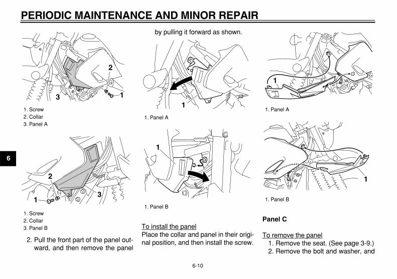
2. Unhook both projections at thebottom of the cowling by pulling itdownward, and then pull the cowl-ing forward as shown.
To install the cowling1. Place the cowling in the original
position.2. Install the bolts.
EAU44850
Panels A and B
To remove one of the panels1. Remove the screw and collar.
1. Cowling A2. Panel A
1 2
1. Panel B2. Panel C
1. Bolt
12
1
1. Projection
1 1
PERIODIC MAINTENANCE AND MINOR REPAIR
6-10
1
2
3
4
5
6
7
8
9
2. Pull the front part of the panel out-ward, and then remove the panel
by pulling it forward as shown.
To install the panelPlace the collar and panel in their origi-nal position, and then install the screw.
Panel C
To remove the panel1. Remove the seat. (See page 3-9.)2. Remove the bolt and washer, and
1. Screw2. Collar3. Panel A
1. Screw2. Collar3. Panel B
1
2
3
1
2
3
1. Panel A
1. Panel B
1
1
1. Panel A
1. Panel B
1
1

PERIODIC MAINTENANCE AND MINOR REPAIR
6-11
2
3
4
5
6
7
8
9
then remove the panel as shown.
To install the panel1. Place the panel in the original po-
sition, and then install the washerand bolt.
2. Install the seat.
EAU19603
Checking the spark plug
The spark plug is an important enginecomponent, which is easy to check.Since heat and deposits will cause anyspark plug to slowly erode, the sparkplug should be removed and checkedin accordance with the periodic mainte-nance and lubrication chart. In addition,the condition of the spark plug can re-veal the condition of the engine.
To remove the spark plug
1. Remove the spark plug cap.
2. Remove the spark plug as shown,with the spark plug wrench includ-ed in the owner’s tool kit.
1. Bolt2. Washer3. Panel C
1. Panel C
12
3
1
1. Spark plug cap
1

PERIODIC MAINTENANCE AND MINOR REPAIR
6-12
1
2
3
4
5
6
7
8
9
To check the spark plug
1. Check that the porcelain insulatoraround the center electrode of thespark plug is a medium-to-light tan(the ideal color when the vehicle isridden normally).
NOTE:
If the spark plug shows a distinctly dif-ferent color, the engine could be oper-ating improperly. Do not attempt todiagnose such problems yourself. In-stead, have a Yamaha dealer check
the vehicle.
2. Check the spark plug for electrodeerosion and excessive carbon orother deposits, and replace it if
necessary.
To install the spark plug
1. Measure the spark plug gap with awire thickness gauge and, if nec-essary, adjust the gap to specifica-tion.
2. Clean the surface of the spark pluggasket and its mating surface, andthen wipe off any grime from thespark plug threads.
3. Install the spark plug with thespark plug wrench, and then tight-en it to the specified torque.
NOTE:
If a torque wrench is not available wheninstalling a spark plug, a good estimateof the correct torque is 1/4–1/2 turnpast finger tight. However, the sparkplug should be tightened to the speci-
fied torque as soon as possible.
4. Install the spark plug cap.
1. Spark plug wrench
1
Specified spark plug:
NGK/DR7EA
1. Spark plug gap
Spark plug gap:
0.6–0.7 mm (0.024–0.028 in)
1
Tightening torque:
Spark plug:18 Nm (1.8 m·kgf, 13.0 ft·lbf)
PERIODIC MAINTENANCE AND MINOR REPAIR
6-13
2
3
4
5
6
7
8
9
EAU19681
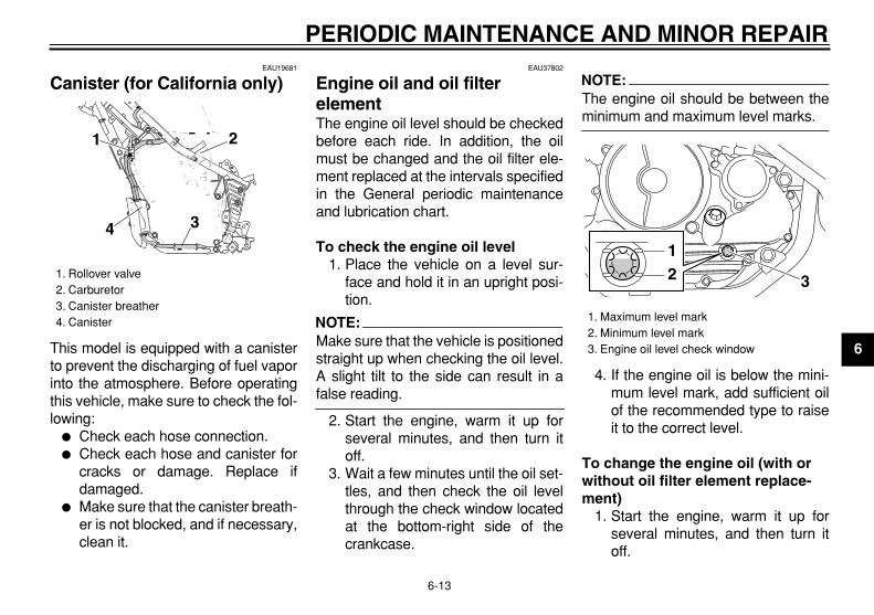
Canister (for California only)
This model is equipped with a canisterto prevent the discharging of fuel vaporinto the atmosphere. Before operatingthis vehicle, make sure to check the fol-lowing:
�
Check each hose connection.
�
Check each hose and canister forcracks or damage. Replace ifdamaged.
�
Make sure that the canister breath-er is not blocked, and if necessary,clean it.
EAU37802
Engine oil and oil filter element
The engine oil level should be checkedbefore each ride. In addition, the oilmust be changed and the oil filter ele-ment replaced at the intervals specifiedin the General periodic maintenanceand lubrication chart.
To check the engine oil level
1. Place the vehicle on a level sur-face and hold it in an upright posi-tion.
NOTE:
Make sure that the vehicle is positionedstraight up when checking the oil level.A slight tilt to the side can result in a
false reading.
2. Start the engine, warm it up forseveral minutes, and then turn itoff.
3. Wait a few minutes until the oil set-tles, and then check the oil levelthrough the check window locatedat the bottom-right side of thecrankcase.
NOTE:
The engine oil should be between the
minimum and maximum level marks.
4. If the engine oil is below the mini-mum level mark, add sufficient oilof the recommended type to raiseit to the correct level.
To change the engine oil (with or without oil filter element replace-ment)
1. Start the engine, warm it up forseveral minutes, and then turn itoff.
1. Rollover valve2. Carburetor3. Canister breather4. Canister
1 2
34
1. Maximum level mark2. Minimum level mark3. Engine oil level check window
12 3

PERIODIC MAINTENANCE AND MINOR REPAIR
6-14
1
2
3
4
5
6
7
8
9
2. Place an oil pan under the engineto collect the used oil.
3. Remove the engine oil filler boltand drain bolt to drain the oil fromthe crankcase.
NOTE:
Check the washer for damage and re-
place it if necessary.
4. Remove the oil filter element drain
bolt to drain the oil from the oil filterelement.
NOTE:
Skip steps 5–7 if the oil filter element is
not being replaced.
5. Remove the oil filter element coverby removing the bolts.
1. Engine oil filler bolt
1
1. Engine oil drain bolt
1. Engine oil drain bolt2. Washer
1
21
1. Oil filter element drain bolt
1
PERIODIC MAINTENANCE AND MINOR REPAIR
6-15
2
3
4
5
6
7
8
9
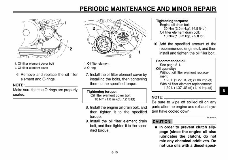
6. Remove and replace the oil filterelement and O-rings.
NOTE:
Make sure that the O-rings are properly
seated.
7. Install the oil filter element cover byinstalling the bolts, then tighteningthem to the specified torque.
8. Install the engine oil drain bolt, andthen tighten it to the specifiedtorque.
9. Install the oil filter element drainbolt, and then tighten it to the spec-ified torque.
10. Add the specified amount of therecommended engine oil, and theninstall and tighten the oil filler bolt.
NOTE:
Be sure to wipe off spilled oil on anyparts after the engine and exhaust sys-
tem have cooled down.
CAUTION:
ECA11620
�
In order to prevent clutch slip-page (since the engine oil alsolubricates the clutch), do notmix any chemical additives. Donot use oils with a diesel speci-
1. Oil filter element cover bolt2. Oil filter element cover
1
2
1. Oil filter element2. O-ring
Tightening torque:
Oil filter element cover bolt:10 Nm (1.0 m·kgf, 7.2 ft·lbf)
12
2
Tightening torques:
Engine oil drain bolt:20 Nm (2.0 m·kgf, 14.5 ft·lbf)
Oil filter element drain bolt:10 Nm (1.0 m·kgf, 7.2 ft·lbf)
Recommended oil:
See page 8-1.
Oil quantity:
Without oil filter element replace-ment:
1.20 L (1.27 US qt) (1.06 Imp.qt)With oil filter element replacement:
1.30 L (1.37 US qt) (1.14 Imp.qt)

PERIODIC MAINTENANCE AND MINOR REPAIR
6-16
1
2
3
4
5
6
7
8
9
fication of “CD” or oils of a high-er quality than specified. Inaddition, do not use oils labeled“ENERGY CONSERVING II” orhigher.
�
Make sure that no foreign mate-
rial enters the crankcase.
11. Start the engine, and then let it idlefor several minutes while checkingit for oil leakage. If oil is leaking, im-mediately turn the engine off andcheck for the cause.
12. Turn the engine off, and thencheck the oil level and correct it ifnecessary.
EAU44650
Replacing the air filter element and cleaning the check hose
The air filter element should be re-placed at the intervals specified in theperiodic maintenance and lubricationchart. Replace the air filter elementmore frequently if you are riding in un-usually wet or dusty areas. In addition,the air filter check hose must be fre-quently checked and cleaned if neces-sary.
To replace the air filter element
1. Remove the seat. (See page 3-9.)2. Remove the air filter case cover by
removing the screws.
3. Pull the air filter element out.4. Insert a new air filter element into
the air filter case as shown.
CAUTION:
ECA10480
�
Make sure that the air filter ele-ment is properly seated in theair filter case.
�
The engine should never be op-erated without the air filter ele-ment installed, otherwise thepiston(s) and/or cylinder(s) may
become excessively worn.
5. Install the air filter case cover by in-stalling the screws.
1. Screw2. Air filter case cover
2
1
1. Air filter element2. Air filter case3. Slot
1 2
3
PERIODIC MAINTENANCE AND MINOR REPAIR
6-17
2
3
4
5
6
7
8
9
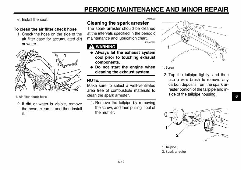
6. Install the seat.
To clean the air filter check hose
1. Check the hose on the side of theair filter case for accumulated dirtor water.
2. If dirt or water is visible, removethe hose, clean it, and then installit.
EAU41220
Cleaning the spark arrester
The spark arrester should be cleanedat the intervals specified in the periodicmaintenance and lubrication chart.
WARNING
EWA10980
�
Always let the exhaust systemcool prior to touching exhaustcomponents.
�
Do not start the engine when
cleaning the exhaust system.
NOTE:
Make sure to select a well-ventilatedarea free of combustible materials to
clean the spark arrester.
1. Remove the tailpipe by removingthe screw, and then pulling it out ofthe muffler.
2. Tap the tailpipe lightly, and thenuse a wire brush to remove anycarbon deposits from the spark ar-rester portion of the tailpipe and in-side of the tailpipe housing.
1. Air filter check hose
1
1. Screw
1. Tailpipe2. Spark arrester
1
1
2
PERIODIC MAINTENANCE AND MINOR REPAIR
6-18
1
2
3
4
5
6
7
8
9
3. Insert the tailpipe into the muffler,and then install and tighten thescrew.
NOTE:
Make sure to align the screw hole when
inserting the tailpipe.
EAU21251
Carburetor
The carburetor is an important part ofthe engine and its emission control sys-tem, which requires very sophisticatedadjustment. Therefore, carburetor ad-justments should be left to Yamahadealer, who has the necessary profes-sional knowledge and experience.
EAU21311
Checking the engine idling speed
The engine idling speed must bechecked as follows and, if necessary,adjusted by a Yamaha dealer at the in-tervals specified in the periodic mainte-nance and lubrication chart.Start the engine and warm it up for sev-eral minutes at 1000–2000 r/min whileoccasionally revving it to 4000–5000 r/min.
NOTE:
The engine is warm when it quickly re-
sponds to the throttle.
Engine idling speed:
1300–1500 r/min
PERIODIC MAINTENANCE AND MINOR REPAIR
6-19
2
3
4
5
6
7
8
9
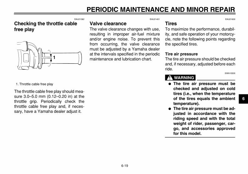
EAU21382
Checking the throttle cable free play
The throttle cable free play should mea-sure 3.0–5.0 mm (0.12–0.20 in) at thethrottle grip. Periodically check thethrottle cable free play and, if neces-sary, have a Yamaha dealer adjust it.
EAU21401
Valve clearance
The valve clearance changes with use,resulting in improper air-fuel mixtureand/or engine noise. To prevent thisfrom occurring, the valve clearancemust be adjusted by a Yamaha dealerat the intervals specified in the periodicmaintenance and lubrication chart.
EAU21600
Tires
To maximize the performance, durabil-ity, and safe operation of your motorcy-cle, note the following points regardingthe specified tires.
Tire air pressure
The tire air pressure should be checkedand, if necessary, adjusted before eachride.
WARNING
EWA10500
�
The tire air pressure must bechecked and adjusted on coldtires (i.e., when the temperatureof the tires equals the ambienttemperature).
�
The tire air pressure must be ad-justed in accordance with theriding speed and with the totalweight of rider, passenger, car-go, and accessories approved
for this model.
1. Throttle cable free play
1

PERIODIC MAINTENANCE AND MINOR REPAIR
6-20
1
2
3
4
5
6
7
8
9
WARNING
EWA11020
Because loading has an enormousimpact on the handling, braking,performance and safety characteris-tics of your motorcycle, you shouldkeep the following precautions inmind.
�
NEVER OVERLOAD THE MO-TORCYCLE! Operation of anoverloaded motorcycle may re-sult in tire damage, loss of con-trol, or severe injury. Make surethat the total weight of rider,
passenger, cargo, and accesso-ries does not exceed the speci-fied maximum load for thevehicle.
�
Do not carry along looselypacked items, which can shiftduring a ride.
�
Securely pack the heaviestitems close to the center of themotorcycle and distribute theweight evenly on both sides.
�
Adjust the suspension and tireair pressure with regard to theload.
�
Check the tire condition and air
pressure before each ride.
Tire inspection
The tires must be checked before eachride. If the tire shows crosswise lines(minimum tread depth), if the tire has anail or glass fragments in it, or if thesidewall is cracked, have a Yamahadealer replace the tire immediately.
NOTE:
The tire tread depth limits may differfrom country to country. Always comply
Tire air pressure (measured on cold tires):
0–90 kg (0–198 lb):
Front:125 kPa (18 psi) (1.25 kgf/cm
2
)Rear:
150 kPa (22 psi) (1.50 kgf/cm
2
)
90–160 kg (198–353 lb):
Front:150 kPa (22 psi) (1.50 kgf/cm
2
)Rear:
175 kPa (25 psi) (1.75 kgf/cm
2
)
Maximum load*:
160 kg (353 lb)* Total weight of rider, passenger, car-
go and accessories
1. Tire tread depth2. Tire sidewall3. Tire wear indicator
Minimum tire tread depth (front and rear):
1.0 mm (0.04 in)
32
1

PERIODIC MAINTENANCE AND MINOR REPAIR
6-21
2
3
4
5
6
7
8
9
with the local regulations.
Tire information
This motorcycle is equipped with tubetires.
WARNING
EWA10460
�
The front and rear tires shouldbe of the same make and de-sign, otherwise the handlingcharacteristics of the vehiclecannot be guaranteed.
�
After extensive tests, only thetires listed below have been ap-proved for this model by
Yamaha Motor Co., Ltd.
WARNING
EWA10560
�
It is dangerous to ride with aworn-out tire. When a tire treadbegins to show crosswise lines,have a Yamaha dealer replacethe tire immediately.
�
The replacement of all wheel-and brake-related parts, includ-ing the tires, should be left to aYamaha dealer, who has thenecessary professional knowl-edge and experience.
�
It is not recommended to patcha punctured tube. If unavoid-able, however, patch the tubevery carefully and replace it assoon as possible with a
high-quality product.
EAU21940
Spoke wheels
To maximize the performance, durabil-ity, and safe operation of your motorcy-cle, note the following points regardingthe specified wheels.
�
The wheel rims should be checkedfor cracks, bends or warpage, andthe spokes for looseness or dam-age before each ride. If any dam-age is found, have a Yamahadealer replace the wheel. Do notattempt even the smallest repair tothe wheel. A deformed or crackedwheel must be replaced.
�
The wheel should be balancedwhenever either the tire or wheelhas been changed or replaced. Anunbalanced wheel can result inpoor performance, adverse han-dling characteristics, and a short-ened tire life.
�
Ride at moderate speeds afterchanging a tire since the tire sur-face must first be “broken in” for itto develop its optimal characteris-tics.
Front tire:
Size:2.75-21 45P
Manufacturer/model:CHENG SHIN/C-6006DUNLOP/D605F
Rear tire:
Size:120/80-18M/C 62P
Manufacturer/model:CHENG SHIN/C-6006DUNLOP/D605

PERIODIC MAINTENANCE AND MINOR REPAIR
6-22
1
2
3
4
5
6
7
8
9
EAU22011
Accessories and replacement parts
WARNING
EWA10621
This vehicle is not designed to pull atrailer or to be attached to a sidecar.The accessories or replacementparts you choose for your vehicleshould be designed specifically forthis model, and they must be se-curely mounted to maintain the in-herent stability of the originaldesign. Genuine Yamaha Parts andAccessories are designed and test-ed to be compatible with your vehi-cle. Please consider GenuineYamaha Parts and Accessories be-fore making a purchase. Use ofnon-Yamaha-approved accessoriesor replacement parts may causeloss of handling stability and ridingsafety. Since Yamaha cannot con-trol the quality of accessories orparts manufactured by other compa-nies, Yamaha cannot be held liablefor any consequences caused bythe use of items which have not
been approved by Yamaha.
EAU22031
Adjusting the clutch lever free play
The clutch lever free play should mea-sure 10.0–15.0 mm (0.39–0.59 in) asshown. Periodically check the clutch le-ver free play and, if necessary, adjust itas follows.
1. Loosen the locknut at the clutch le-ver.
2. To increase the clutch lever freeplay, turn the adjusting bolt in di-rection (a). To decrease the clutch
1. Locknut (clutch lever)2. Adjusting bolt3. Adjusting nut4. Locknut (clutch cable)5. Clutch lever free play
1 2 (b)
(a)
(a)
(b)5
3
4
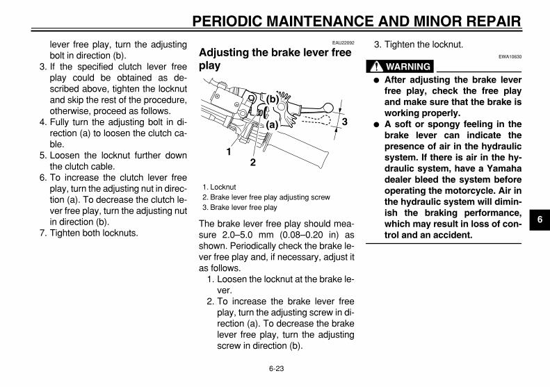
PERIODIC MAINTENANCE AND MINOR REPAIR
6-23
2
3
4
5
6
7
8
9
lever free play, turn the adjustingbolt in direction (b).
3. If the specified clutch lever freeplay could be obtained as de-scribed above, tighten the locknutand skip the rest of the procedure,otherwise, proceed as follows.
4. Fully turn the adjusting bolt in di-rection (a) to loosen the clutch ca-ble.
5. Loosen the locknut further downthe clutch cable.
6. To increase the clutch lever freeplay, turn the adjusting nut in direc-tion (a). To decrease the clutch le-ver free play, turn the adjusting nutin direction (b).
7. Tighten both locknuts.
EAU22092
Adjusting the brake lever free play
The brake lever free play should mea-sure 2.0–5.0 mm (0.08–0.20 in) asshown. Periodically check the brake le-ver free play and, if necessary, adjust itas follows.
1. Loosen the locknut at the brake le-ver.
2. To increase the brake lever freeplay, turn the adjusting screw in di-rection (a). To decrease the brakelever free play, turn the adjustingscrew in direction (b).
3. Tighten the locknut.
WARNING
EWA10630
�
After adjusting the brake leverfree play, check the free playand make sure that the brake isworking properly.
�
A soft or spongy feeling in thebrake lever can indicate thepresence of air in the hydraulicsystem. If there is air in the hy-draulic system, have a Yamahadealer bleed the system beforeoperating the motorcycle. Air inthe hydraulic system will dimin-ish the braking performance,which may result in loss of con-
trol and an accident.
1. Locknut2. Brake lever free play adjusting screw3. Brake lever free play
3
12
(b)
(a)
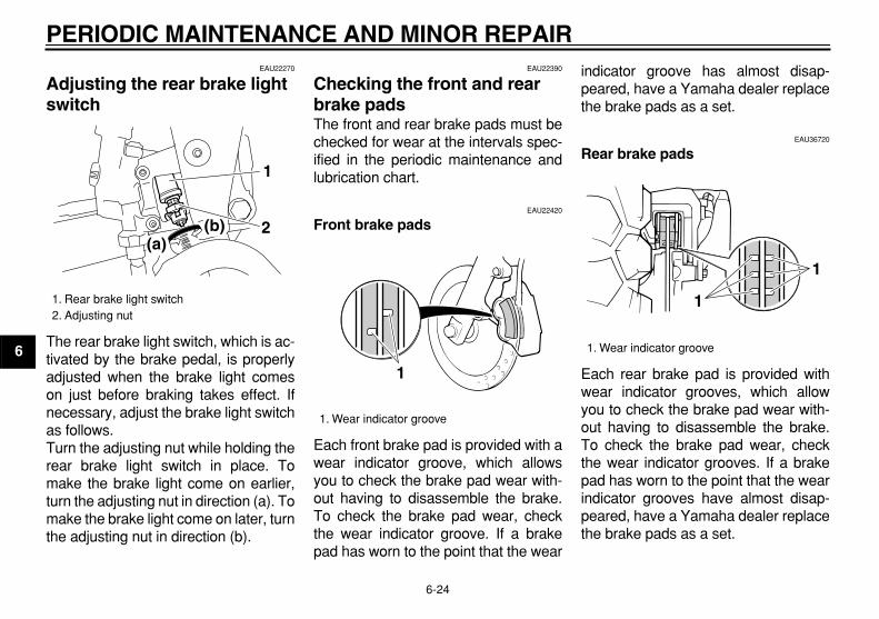
PERIODIC MAINTENANCE AND MINOR REPAIR
6-24
1
2
3
4
5
6
7
8
9
EAU22270
Adjusting the rear brake light switch
The rear brake light switch, which is ac-tivated by the brake pedal, is properlyadjusted when the brake light comeson just before braking takes effect. Ifnecessary, adjust the brake light switchas follows.Turn the adjusting nut while holding therear brake light switch in place. Tomake the brake light come on earlier,turn the adjusting nut in direction (a). Tomake the brake light come on later, turnthe adjusting nut in direction (b).
EAU22390
Checking the front and rear brake pads
The front and rear brake pads must bechecked for wear at the intervals spec-ified in the periodic maintenance andlubrication chart.
EAU22420
Front brake pads
Each front brake pad is provided with awear indicator groove, which allowsyou to check the brake pad wear with-out having to disassemble the brake.To check the brake pad wear, checkthe wear indicator groove. If a brakepad has worn to the point that the wear
indicator groove has almost disap-peared, have a Yamaha dealer replacethe brake pads as a set.
EAU36720
Rear brake pads
Each rear brake pad is provided withwear indicator grooves, which allowyou to check the brake pad wear with-out having to disassemble the brake.To check the brake pad wear, checkthe wear indicator grooves. If a brakepad has worn to the point that the wearindicator grooves have almost disap-peared, have a Yamaha dealer replacethe brake pads as a set.
1. Rear brake light switch2. Adjusting nut
2
1
(a)(b)
1. Wear indicator groove
1
1. Wear indicator groove
1
1

PERIODIC MAINTENANCE AND MINOR REPAIR
6-25
2
3
4
5
6
7
8
9
EAU22580
Checking the brake fluid level
Front brake
Rear brake
Insufficient brake fluid may allow air to
enter the brake system, possibly caus-ing it to become ineffective.Before riding, check that the brake fluidis above the minimum level mark andreplenish if necessary. A low brake fluidlevel may indicate worn brake padsand/or brake system leakage. If thebrake fluid level is low, be sure to checkthe brake pads for wear and the brakesystem for leakage.Observe these precautions:
�
When checking the fluid level,make sure that the top of the brakefluid reservoir is level.
�
Use only the recommended qualitybrake fluid, otherwise the rubberseals may deteriorate, causingleakage and poor braking perfor-mance.
�
Refill with the same type of brakefluid. Mixing fluids may result in aharmful chemical reaction andlead to poor braking performance.
�
Be careful that water does not en-ter the brake fluid reservoir when
refilling. Water will significantlylower the boiling point of the fluidand may result in vapor lock.
�
Brake fluid may deteriorate paint-ed surfaces or plastic parts. Al-ways clean up spilled fluidimmediately.
�
As the brake pads wear, it is nor-mal for the brake fluid level to grad-ually go down. However, if thebrake fluid level goes down sud-denly, have a Yamaha dealercheck the cause.
1. Minimum level mark
1. Minimum level mark
1
1
Recommended brake fluid:
DOT 4
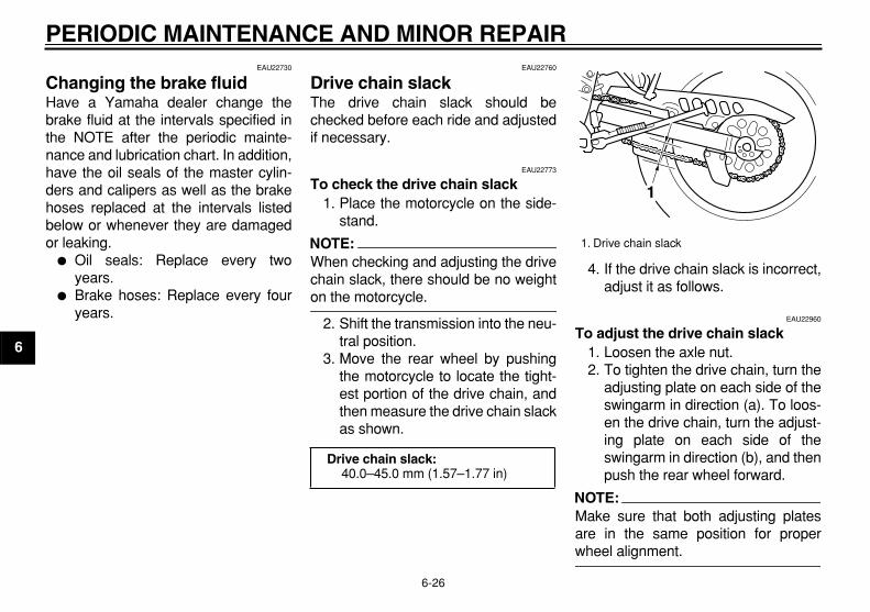
PERIODIC MAINTENANCE AND MINOR REPAIR
6-26
1
2
3
4
5
6
7
8
9
EAU22730
Changing the brake fluid
Have a Yamaha dealer change thebrake fluid at the intervals specified inthe NOTE after the periodic mainte-nance and lubrication chart. In addition,have the oil seals of the master cylin-ders and calipers as well as the brakehoses replaced at the intervals listedbelow or whenever they are damagedor leaking.
�
Oil seals: Replace every twoyears.
�
Brake hoses: Replace every fouryears.
EAU22760
Drive chain slack
The drive chain slack should bechecked before each ride and adjustedif necessary.
EAU22773
To check the drive chain slack
1. Place the motorcycle on the side-stand.
NOTE:
When checking and adjusting the drivechain slack, there should be no weight
on the motorcycle.
2. Shift the transmission into the neu-tral position.
3. Move the rear wheel by pushingthe motorcycle to locate the tight-est portion of the drive chain, andthen measure the drive chain slackas shown.
4. If the drive chain slack is incorrect,adjust it as follows.
EAU22960
To adjust the drive chain slack
1. Loosen the axle nut.2. To tighten the drive chain, turn the
adjusting plate on each side of theswingarm in direction (a). To loos-en the drive chain, turn the adjust-ing plate on each side of theswingarm in direction (b), and thenpush the rear wheel forward.
NOTE:
Make sure that both adjusting platesare in the same position for proper
wheel alignment.
Drive chain slack:
40.0–45.0 mm (1.57–1.77 in)
1. Drive chain slack
1

PERIODIC MAINTENANCE AND MINOR REPAIR
6-27
2
3
4
5
6
7
8
9
CAUTION:
ECA10570
Improper drive chain slack will over-load the engine as well as other vitalparts of the motorcycle and can leadto chain slippage or breakage. Toprevent this from occurring, keepthe drive chain slack within the
specified limits.
3. Tighten the axle nut to the speci-fied torque.
EAU23022
Cleaning and lubricating the drive chain
The drive chain must be cleaned andlubricated at the intervals specified inthe periodic maintenance and lubrica-tion chart, otherwise it will quickly wearout, especially when riding in dusty orwet areas. Service the drive chain asfollows.
CAUTION:
ECA10581
The drive chain must be lubricatedafter washing the motorcycle and
riding in the rain.
1. Clean the drive chain with kero-sene and a small soft brush.
CAUTION:
ECA11120
To prevent damaging the O-rings, donot clean the drive chain with steamcleaners, high-pressure washers or
inappropriate solvents.
2. Wipe the drive chain dry.3. Thoroughly lubricate the drive
chain with a special O-ring chainlubricant.
CAUTION:
ECA11110
Do not use engine oil or any other lu-bricants for the drive chain, as theymay contain substances that could
damage the O-rings.
1. Drive chain slack adjusting plate2. Stopper3. Axle nut
Tightening torque:
Axle nut:85 Nm (8.5 m·kgf, 61.5 ft·lbf)
1
3
2(a) (b)

PERIODIC MAINTENANCE AND MINOR REPAIR
6-28
1
2
3
4
5
6
7
8
9
EAU23091
Checking and lubricating the cables
The operation of all control cables andthe condition of the cables should bechecked before each ride, and the ca-bles and cable ends should be lubricat-ed if necessary. If a cable is damagedor does not move smoothly, have aYamaha dealer check or replace it.
WARNING
EWA10710
Damage to the outer housing of ca-bles may result in internal rustingand cause interference with cablemovement. Replace damaged ca-bles as soon as possible to prevent
unsafe conditions.
EAU23111
Checking and lubricating the throttle grip and cable
The operation of the throttle grip shouldbe checked before each ride. In addi-tion, the cable should be lubricated atthe intervals specified in the periodicmaintenance chart.
EAU23133
Checking and lubricating the brake and shift pedals
The operation of the brake and shiftpedals should be checked before eachride, and the pedal pivots should be lu-bricated if necessary.
Recommended lubricant:
Yamaha Chain and Cable Lube or engine oil SAE 10W-30
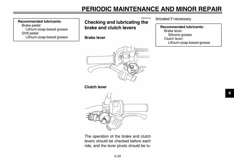
PERIODIC MAINTENANCE AND MINOR REPAIR
6-29
2
3
4
5
6
7
8
9
EAU23142
Checking and lubricating the brake and clutch levers
Brake lever
Clutch lever
The operation of the brake and clutchlevers should be checked before eachride, and the lever pivots should be lu-
bricated if necessary.
Recommended lubricants:
Brake pedal:Lithium-soap-based grease
Shift pedal:Lithium-soap-based grease
Recommended lubricants:
Brake lever:Silicone grease
Clutch lever:Lithium-soap-based grease

PERIODIC MAINTENANCE AND MINOR REPAIR
6-30
1
2
3
4
5
6
7
8
9
EAU23201
Checking and lubricating the sidestand
The operation of the sidestand shouldbe checked before each ride, and thesidestand pivot and metal-to-metalcontact surfaces should be lubricated ifnecessary.
WARNING
EWA10730
If the sidestand does not move upand down smoothly, have a Yamaha
dealer check or repair it.
EAU23250
Lubricating the rear suspension
The pivoting points of the rear suspen-sion must be lubricated at the intervalsspecified in the periodic maintenanceand lubrication chart.
EAU23271
Checking the front fork
The condition and operation of the frontfork must be checked as follows at theintervals specified in the periodic main-tenance and lubrication chart.
To check the condition
WARNING
EWA10750
Securely support the vehicle so that
there is no danger of it falling over.
Check the inner tubes for scratches,damage and excessive oil leakage.
To check the operation
1. Place the vehicle on a level sur-face and hold it in an upright posi-tion.
2. While applying the front brake,push down hard on the handlebarsseveral times to check if the frontfork compresses and reboundssmoothly.
Recommended lubricant:
Lithium-soap-based grease
Recommended lubricant:
Lithium-soap-based grease

PERIODIC MAINTENANCE AND MINOR REPAIR
6-31
2
3
4
5
6
7
8
9
CAUTION:
ECA10590
If any damage is found or the frontfork does not operate smoothly,have a Yamaha dealer check or re-
pair it.
EAU23280
Checking the steering
Worn or loose steering bearings maycause danger. Therefore, the operationof the steering must be checked as fol-lows at the intervals specified in the pe-riodic maintenance and lubricationchart.
1. Place a stand under the engine toraise the front wheel off theground.
WARNING
EWA10750
Securely support the vehicle so that
there is no danger of it falling over.
2. Hold the lower ends of the frontfork legs and try to move them for-ward and backward. If any freeplay can be felt, have a Yamahadealer check or repair the steering.

PERIODIC MAINTENANCE AND MINOR REPAIR
6-32
1
2
3
4
5
6
7
8
9
EAU23290
Checking the wheel bearings
The front and rear wheel bearings mustbe checked at the intervals specified inthe periodic maintenance and lubrica-tion chart. If there is play in the wheelhub or if the wheel does not turnsmoothly, have a Yamaha dealer checkthe wheel bearings.
EAU23390
Battery
The battery is located behind panel C.(See page 6-9.)This model is equipped with asealed-type (MF) battery, which doesnot require any maintenance. There isno need to check the electrolyte or toadd distilled water.
To charge the battery
Have a Yamaha dealer charge the bat-tery as soon as possible if it seems tohave discharged. Keep in mind that thebattery tends to discharge more quickly
if the vehicle is equipped with optionalelectrical accessories.
WARNING
EWA10760
�
Electrolyte is poisonous anddangerous since it contains sul-furic acid, which causes severeburns. Avoid any contact withskin, eyes or clothing and al-ways shield your eyes whenworking near batteries. In caseof contact, administer the fol-lowing FIRST AID.
�
EXTERNAL: Flush with plentyof water.
�
INTERNAL: Drink large quan-tities of water or milk and im-mediately call a physician.
�
EYES: Flush with water for 15minutes and seek promptmedical attention.
�
Batteries produce explosive hy-drogen gas. Therefore, keepsparks, flames, cigarettes, etc.,away from the battery and pro-vide sufficient ventilation whencharging it in an enclosedspace.
�
KEEP THIS AND ALL BATTER-
1. Negative battery lead (black)2. Positive battery lead (red)3. Battery
1 2
3
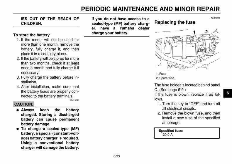
PERIODIC MAINTENANCE AND MINOR REPAIR
6-33
2
3
4
5
6
7
8
9
IES OUT OF THE REACH OF
CHILDREN.
To store the battery
1. If the model will not be used formore than one month, remove thebattery, fully charge it, and thenplace it in a cool, dry place.
2. If the battery will be stored for morethan two months, check it at leastonce a month and fully charge it ifnecessary.
3. Fully charge the battery before in-stallation.
4. After installation, make sure thatthe battery leads are properly con-nected to the battery terminals.
CAUTION:
ECA10630
�
Always keep the batterycharged. Storing a dischargedbattery can cause permanentbattery damage.
�
To charge a sealed-type (MF)battery, a special (constant-volt-age) battery charger is required.Using a conventional batterycharger will damage the battery.
If you do not have access to asealed-type (MF) battery charg-er, have a Yamaha dealer
charge your battery.
EAU23502
Replacing the fuse
The fuse holder is located behind panelC. (See page 6-9.)If the fuse is blown, replace it as fol-lows.
1. Turn the key to “OFF” and turn offall electrical circuits.
2. Remove the blown fuse, and theninstall a new fuse of the specifiedamperage.
1. Fuse2. Spare fuse
Specified fuse:
20.0 A
1 2

PERIODIC MAINTENANCE AND MINOR REPAIR
6-34
1
2
3
4
5
6
7
8
9
CAUTION:
ECA10640
Do not use a fuse of a higher amper-age rating than recommended toavoid causing extensive damage tothe electrical system and possibly a
fire.
3. Turn the key to “ON” and turn onthe electrical circuits to check if thedevices operate.
4. If the fuse immediately blowsagain, have a Yamaha dealercheck the electrical system.
EAU23812
Replacing the headlight bulb
This model is equipped with a quartzbulb headlight. If the headlight bulbburns out, replace it as follows.
1. Remove cowling A. (Seepage 6-9.)
2. Remove the headlight unit by re-moving the bolts.
3. Disconnect the headlight coupler,and then remove the headlightbulb cover.
4. Remove the headlight bulb holderby turning it counterclockwise, andthen remove the defective bulb.
1. Bolt
1
1. Headlight coupler2. Headlight bulb cover
1
2
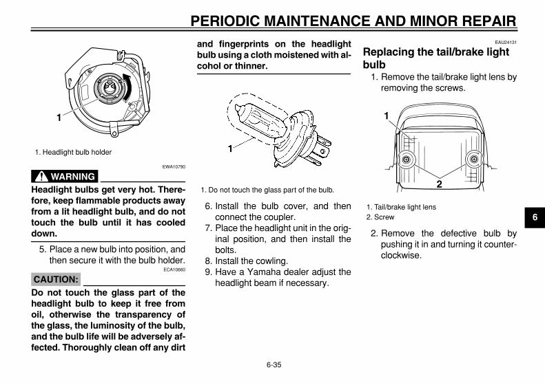
PERIODIC MAINTENANCE AND MINOR REPAIR
6-35
2
3
4
5
6
7
8
9
WARNING
EWA10790
Headlight bulbs get very hot. There-fore, keep flammable products awayfrom a lit headlight bulb, and do nottouch the bulb until it has cooled
down.
5. Place a new bulb into position, andthen secure it with the bulb holder.
CAUTION:
ECA10660
Do not touch the glass part of theheadlight bulb to keep it free fromoil, otherwise the transparency ofthe glass, the luminosity of the bulb,and the bulb life will be adversely af-fected. Thoroughly clean off any dirt
and fingerprints on the headlightbulb using a cloth moistened with al-
cohol or thinner.
6. Install the bulb cover, and thenconnect the coupler.
7. Place the headlight unit in the orig-inal position, and then install thebolts.
8. Install the cowling.9. Have a Yamaha dealer adjust the
headlight beam if necessary.
EAU24131
Replacing the tail/brake light bulb
1. Remove the tail/brake light lens byremoving the screws.
2. Remove the defective bulb bypushing it in and turning it counter-clockwise.
1. Headlight bulb holder
1
1. Do not touch the glass part of the bulb.
1. Tail/brake light lens2. Screw
1
2
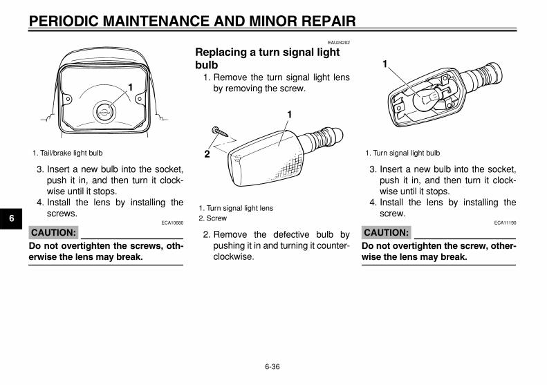
PERIODIC MAINTENANCE AND MINOR REPAIR
6-36
1
2
3
4
5
6
7
8
9
3. Insert a new bulb into the socket,push it in, and then turn it clock-wise until it stops.
4. Install the lens by installing thescrews.
CAUTION:
ECA10680
Do not overtighten the screws, oth-
erwise the lens may break.
EAU24202
Replacing a turn signal light bulb
1. Remove the turn signal light lensby removing the screw.
2. Remove the defective bulb bypushing it in and turning it counter-clockwise.
3. Insert a new bulb into the socket,push it in, and then turn it clock-wise until it stops.
4. Install the lens by installing thescrew.
CAUTION:
ECA11190
Do not overtighten the screw, other-
wise the lens may break.
1. Tail/brake light bulb
1
1. Turn signal light lens2. Screw
2
1
1. Turn signal light bulb
1

PERIODIC MAINTENANCE AND MINOR REPAIR
6-37
2
3
4
5
6
7
8
9
EAU24350
Supporting the motorcycle
Since this model is not equipped with acenterstand, follow these precautionswhen removing the front and rearwheel or performing other maintenancerequiring the motorcycle to stand up-right. Check that the motorcycle is in astable and level position before startingany maintenance. A strong woodenbox can be placed under the engine foradded stability.
To service the front wheel
1. Stabilize the rear of the motorcycleby using a motorcycle stand or, ifan additional motorcycle stand isnot available, by placing a jack un-der the frame in front of the rearwheel.
2. Raise the front wheel off theground by using a motorcyclestand.
To service the rear wheel
Raise the rear wheel off the ground byusing a motorcycle stand or, if a motor-cycle stand is not available, by placinga jack either under each side of the
frame in front of the rear wheel or undereach side of the swingarm.
EAU24360
Front wheel
EAUW0211
To remove the front wheel
WARNING
EWA10820
�
It is advisable to have a Yamahadealer service the wheel.
�
Securely support the motorcy-cle so that there is no danger of
it falling over.
1. Loosen the axle nut.
2. Lift the front wheel off the groundaccording to the procedure onpage 6-37.
3. Remove the axle nut, pull the
1. Axle nut
1

PERIODIC MAINTENANCE AND MINOR REPAIR
6-38
1
2
3
4
5
6
7
8
9
wheel axle out, and then removethe wheel.
CAUTION:
ECA11070
Do not apply the brake after thewheel has been removed togetherwith the brake disc, otherwise the
brake pads will be forced shut.
EAUW0230
To install the front wheel
1. Lift the wheel up between the forklegs.
NOTE:
Make sure that there is enough spacebetween the brake pads before insert-
ing the brake disc into the caliper.
2. Insert the wheel axle, and then in-stall the axle nut.
3. Lower the front wheel so that it ison the ground.
4. Tighten the axle nut to the speci-fied torque.
5. Push down hard on the handlebarseveral times to check for properfork operation.
EAU25080
Rear wheel
EAU37851
To remove the rear wheel
WARNING
EWA10820
�
It is advisable to have a Yamahadealer service the wheel.
�
Securely support the motorcy-cle so that there is no danger of
it falling over.
1. Loosen the axle nut.2. Lift the rear wheel off the ground
according to the procedure onpage 6-37.
3. Turn the drive chain adjustingplate on each side of the swingarmfully in direction (a).
4. Push the wheel forward, and thenremove the drive chain from therear sprocket.
Tightening torque:
Axle nut:85 Nm (8.5 m·kgf, 61.5 ft·lbf)
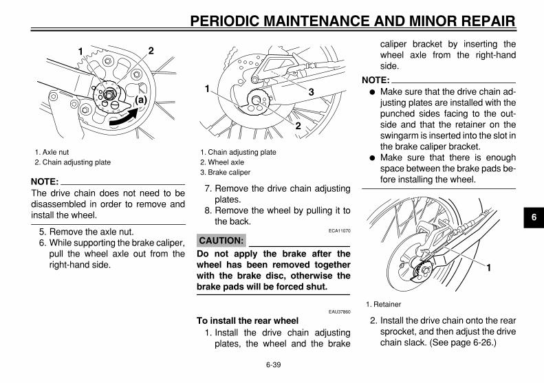
PERIODIC MAINTENANCE AND MINOR REPAIR
6-39
2
3
4
5
6
7
8
9
NOTE:
The drive chain does not need to bedisassembled in order to remove and
install the wheel.
5. Remove the axle nut.6. While supporting the brake caliper,
pull the wheel axle out from theright-hand side.
7. Remove the drive chain adjustingplates.
8. Remove the wheel by pulling it tothe back.
CAUTION:
ECA11070
Do not apply the brake after thewheel has been removed togetherwith the brake disc, otherwise the
brake pads will be forced shut.
EAU37860
To install the rear wheel
1. Install the drive chain adjustingplates, the wheel and the brake
caliper bracket by inserting thewheel axle from the right-handside.
NOTE:
�
Make sure that the drive chain ad-justing plates are installed with thepunched sides facing to the out-side and that the retainer on theswingarm is inserted into the slot inthe brake caliper bracket.
�
Make sure that there is enoughspace between the brake pads be-
fore installing the wheel.
2. Install the drive chain onto the rearsprocket, and then adjust the drivechain slack. (See page 6-26.)
1. Axle nut2. Chain adjusting plate
21
(a)
1. Chain adjusting plate2. Wheel axle3. Brake caliper
1 3
2
1. Retainer
1

PERIODIC MAINTENANCE AND MINOR REPAIR
6-40
1
2
3
4
5
6
7
8
9
3. Install the axle nut, and then lowerthe rear wheel so that it is on theground.
4. Tighten the axle nut to the speci-fied torque.
EAU25850
Troubleshooting
Although Yamaha motorcycles receivea thorough inspection before shipmentfrom the factory, trouble may occur dur-ing operation. Any problem in the fuel,compression, or ignition systems, forexample, can cause poor starting andloss of power.The following troubleshooting chartrepresents a quick and easy procedurefor checking these vital systems your-self. However, should your motorcyclerequire any repair, take it to a Yamahadealer, whose skilled technicians havethe necessary tools, experience, andknow-how to service the motorcycleproperly.Use only genuine Yamaha replace-ment parts. Imitation parts may look likeYamaha parts, but they are often inferi-or, have a shorter service life and canlead to expensive repair bills.
Tightening torque:
Axle nut:85 Nm (8.5 m·kgf, 61.5 ft·lbf)

PERIODIC MAINTENANCE AND MINOR REPAIR
6-41
2
3
4
5
6
7
8
9
EAU25901
Troubleshooting chart
WARNING
EWA10840
Keep away open flames and do not smoke while checking or working on the fuel system.
Check the fuel level inthe fuel tank.
1. FuelThere is enough fuel.
There is no fuel.
Check the compression.
Supply fuel. The engine does not start. Check the compression.
Operate the electric starter.
2. CompressionThere is compression.
There is no compression.
Check the ignition.
Have a Yamaha dealercheck the vehicle.
Remove the spark plugand check the electrodes.
3. Ignition Wipe off with a dry cloth and correct thespark plug gap, or replace the spark plug.
Have a Yamaha dealer check the vehicle.
The engine does not start.Have a Yamaha dealercheck the vehicle.
The engine does not start.Check the battery.
Operate the electric starter.
4. BatteryThe engine turns over quickly.
The engine turns over slowly.
The battery is good.
Check the battery lead connections,and charge the battery if necessary.
Dry
WetOpen the throttle halfway and operatethe electric starter.

7-1
1
2
3
4
5
6
7
8
9
MOTORCYCLE CARE AND STORAGE
EAU37833
Matte color caution
CAUTION:
ECA15192
Some models are equipped withmatte colored finished parts. Besure to consult a Yamaha dealer foradvice on what products to use be-fore cleaning the vehicle. Using abrush, harsh chemical products orcleaning compounds when cleaningthese parts will scratch or damagetheir surface. Wax also should notbe applied to any matte colored fin-
ished parts.
EAU26002
Care
While the open design of a motorcyclereveals the attractiveness of the tech-nology, it also makes it more vulnera-ble. Rust and corrosion can developeven if high-quality components areused. A rusty exhaust pipe may go un-noticed on a car, however, it detractsfrom the overall appearance of a motor-cycle. Frequent and proper care doesnot only comply with the terms of thewarranty, but it will also keep your mo-torcycle looking good, extend its lifeand optimize its performance.
Before cleaning
1. Cover the muffler outlet with aplastic bag after the engine hascooled down.
2. Make sure that all caps and coversas well as all electrical couplersand connectors, including thespark plug cap, are tightly in-stalled.
3. Remove extremely stubborn dirt,like oil burnt onto the crankcase,with a degreasing agent and abrush, but never apply such prod-
ucts onto seals, gaskets, sprock-ets, the drive chain and wheelaxles. Always rinse the dirt and de-greaser off with water.
Cleaning
CAUTION:
ECA10771
�
Avoid using strong acidic wheelcleaners, especially on spokedwheels. If such products areused on hard-to-remove dirt, donot leave the cleaner on the af-fected area any longer than in-structed. Also, thoroughly rinsethe area off with water, immedi-ately dry it, and then apply a cor-rosion protection spray.
�
Improper cleaning can damageplastic parts such as cowlings,panels, windshields, headlightlenses, meter lenses, etc. Useonly a soft, clean cloth orsponge with mild detergent andwater to clean plastic.
�
Do not use any harsh chemicalproducts on plastic parts. Besure to avoid using cloths orsponges which have been in
MOTORCYCLE CARE AND STORAGE
7-2
2
3
4
5
6
7
8
9
contact with strong or abrasivecleaning products, solvent orthinner, fuel (gasoline), rust re-movers or inhibitors, brake flu-id, antifreeze or electrolyte.
�
Do not use high-pressure wash-ers or steam-jet cleaners sincethey cause water seepage anddeterioration in the following ar-eas: seals (of wheel and swing-arm bearings, fork and brakes),electric components (couplers,connectors, instruments,switches and lights), breatherhoses and vents.
�
For motorcycles equipped witha windshield: Do not use strongcleaners or hard sponges asthey will cause dulling orscratching. Some cleaning com-pounds for plastic may leavescratches on the windshield.Test the product on a small hid-den part of the windshield tomake sure that it does not leaveany marks. If the windshield isscratched, use a quality plasticpolishing compound after
washing.
After normal useRemove dirt with warm water, a milddetergent, and a soft, clean sponge,and then rinse thoroughly with cleanwater. Use a toothbrush or bottlebrushfor hard-to-reach areas. Stubborn dirtand insects will come off more easily ifthe area is covered with a wet cloth fora few minutes before cleaning.
After riding in the rain, near the sea oron salt-sprayed roadsSince sea salt or salt sprayed on roadsduring winter are extremely corrosive incombination with water, carry out thefollowing steps after each ride in therain, near the sea or on salt-sprayedroads.
NOTE:
Salt sprayed on roads in the winter may
remain well into spring.
1. Clean the motorcycle with cold wa-ter and a mild detergent, after theengine has cooled down.
CAUTION:
ECA10790
Do not use warm water since it in-creases the corrosive action of the
salt.
2. Apply a corrosion protection sprayon all metal, including chrome- andnickel-plated, surfaces to preventcorrosion.
After cleaning
1. Dry the motorcycle with a chamoisor an absorbing cloth.
2. Immediately dry the drive chainand lubricate it to prevent it fromrusting.
3. Use a chrome polish to shinechrome, aluminum and stain-less-steel parts, including the ex-haust system. (Even the thermallyinduced discoloring of stain-less-steel exhaust systems can beremoved through polishing.)
4. To prevent corrosion, it is recom-mended to apply a corrosion pro-tection spray on all metal,including chrome- and nickel-plat-ed, surfaces.

MOTORCYCLE CARE AND STORAGE
7-3
1
2
3
4
5
6
7
8
9
5. Use spray oil as a universal clean-er to remove any remaining dirt.
6. Touch up minor paint damagecaused by stones, etc.
7. Wax all painted surfaces.8. Let the motorcycle dry completely
before storing or covering it.
WARNING
EWA11130
�
Make sure that there is no oil orwax on the brakes or tires.
�
If necessary, clean the brakediscs and brake linings with aregular brake disc cleaner or ac-etone, and wash the tires withwarm water and a mild deter-gent. Before riding at higherspeeds, test the motorcycle’sbraking performance and cor-
nering behavior.
CAUTION:
ECA10800
�
Apply spray oil and wax spar-ingly and make sure to wipe offany excess.
�
Never apply oil or wax to anyrubber and plastic parts, buttreat them with a suitable care
product.
�
Avoid using abrasive polishingcompounds as they will wear
away the paint.
NOTE:
Consult a Yamaha dealer for advice on
what products to use.
EAU26150
Storage
Short-term
Always store your motorcycle in a cool,dry place and, if necessary, protect itagainst dust with a porous cover.
CAUTION:
ECA10810
�
Storing the motorcycle in apoorly ventilated room or cover-ing it with a tarp, while it is stillwet, will allow water and humid-ity to seep in and cause rust.
�
To prevent corrosion, avoiddamp cellars, stables (becauseof the presence of ammonia)and areas where strong chemi-
cals are stored.
Long-term
Before storing your motorcycle for sev-eral months:
1. Follow all the instructions in the“Care” section of this chapter.
2. For motorcycles equipped with afuel cock that has an “OFF” posi-tion: Turn the fuel cock lever to

MOTORCYCLE CARE AND STORAGE
7-4
2
3
4
5
6
7
8
9
“OFF”.3. Drain the carburetor float chamber
by loosening the drain bolt; this willprevent fuel deposits from buildingup. Pour the drained fuel into thefuel tank.
4. Fill up the fuel tank and add fuelstabilizer (if available) to preventthe fuel tank from rusting and thefuel from deteriorating.
5. Perform the following steps to pro-tect the cylinder, piston rings, etc.from corrosion.a. Remove the spark plug cap
and spark plug.b. Pour a teaspoonful of engine oil
into the spark plug bore.c. Install the spark plug cap onto
the spark plug, and then placethe spark plug on the cylinderhead so that the electrodes aregrounded. (This will limit spark-ing during the next step.)
d. Turn the engine over severaltimes with the starter. (This willcoat the cylinder wall with oil.)
e. Remove the spark plug capfrom the spark plug, and then
install the spark plug and thespark plug cap.
WARNING
EWA10950
To prevent damage or injury fromsparking, make sure to ground thespark plug electrodes while turning
the engine over.
6. Lubricate all control cables and thepivoting points of all levers andpedals as well as of the sidestand/centerstand.
7. Check and, if necessary, correctthe tire air pressure, and then liftthe motorcycle so that both of itswheels are off the ground. Alterna-tively, turn the wheels a little everymonth in order to prevent the tiresfrom becoming degraded in onespot.
8. Cover the muffler outlet with aplastic bag to prevent moisturefrom entering it.
9. Remove the battery and fullycharge it. Store it in a cool, dryplace and charge it once a month.Do not store the battery in an ex-cessively cold or warm place
[less than 0 °C (30 °F) or morethan 30 °C (90 °F)]. For more in-formation on storing the battery,see page 6-32.
NOTE:
Make any necessary repairs before
storing the motorcycle.

8-1
1
2
3
4
5
6
7
8
9
SPECIFICATIONS
EAU2633K
Dimensions:
Overall length: 2150 mm (84.6 in)
Overall width: 805 mm (31.7 in)
Overall height: 1160 mm (45.7 in)
Seat height: 810 mm (31.9 in)
Wheelbase: 1360 mm (53.5 in)
Ground clearance: 285 mm (11.22 in)
Minimum turning radius: 1900 mm (74.8 in)
Weight:
With oil and fuel: 132.0 kg (291 lb)
Engine:
Engine type: Air cooled 4-stroke, SOHC
Cylinder arrangement: Forward-inclined single cylinder
Displacement: 249.0 cm
3
Bore
×
stroke: 74.0
×
58.0 mm (2.91
×
2.28 in)Compression ratio:
9.50 :1Starting system:
Electric starter
Lubrication system: Wet sump
Engine oil:
Type: YAMALUBE 4, SAE10W30 or SAE20W40
Recommended engine oil grade: API service SG type or higher, JASO stan-dard MA
Engine oil quantity:
Without oil filter element replacement: 1.20 L (1.27 US qt) (1.06 Imp.qt)
With oil filter element replacement: 1.30 L (1.37 US qt) (1.14 Imp.qt)
Air filter:
Air filter element: Oil-coated paper element
Fuel:
Recommended fuel: Unleaded gasoline only
Fuel tank capacity: 9.1 L (2.40 US gal) (2.00 Imp.gal) (CAL)9.8 L (2.59 US gal) (2.16 Imp.gal) (U49)
Fuel reserve amount: 1.9 L (0.50 US gal) (0.42 Imp.gal)
Carburetor:
Manufacturer: TEIKEI
Type
×
quantity: MV33 x 1
Spark plug (s):
Manufacturer/model: NGK/DR7EA
Spark plug gap: 0.6–0.7 mm (0.024–0.028 in)
Clutch:
Clutch type: Wet, multiple-disc
Transmission:
Primary reduction system: Spur gear
Primary reduction ratio: 74/24 (3.083)
Secondary reduction system: Chain drive
Secondary reduction ratio: 48/15 (3.200)
Transmission type: Constant mesh 5-speed
Operation: Left foot operation
Gear ratio:
1st: 37/13 (2.846)
2nd: 29/16 (1.812)
3rd: 29/22 (1.318)
10° 30° 50° 70° 90° 110°0° 130°F
YAMALUBE 4 (10W30)or SAE 10W30
YAMALUBE 4 (20W40)or SAE 20W40
–10° 0° 10° 20° 30° 40°–20° 50°C

SPECIFICATIONS
8-2
2
3
4
5
6
7
8
9
4th:
29/28 (1.035)5th:
23/28 (0.821)
Chassis:
Frame type: Semi double cradle
Caster angle: 26.42 °
Trail: 106.0 mm (4.17 in)
Front tire:
Type: With tube
Size: 2.75-21 45P
Manufacturer/model: CHENG SHIN/C-6006
Manufacturer/model: DUNLOP/D605F
Rear tire:
Type: With tube
Size: 120/80-18M/C 62P
Manufacturer/model: CHENG SHIN/C-6006
Manufacturer/model: DUNLOP/D605
Loading:
Maximum load: 160 kg (353 lb)
* (Total weight of rider, passenger, cargo and accessories)
Tire air pressure (measured on coldtires):
Loading condition: 0–90 kg (0–198 lb)
Front: 125 kPa (18 psi) (1.25 kgf/cm
2
)Rear:
150 kPa (22 psi) (1.50 kgf/cm
2
)Loading condition:
90–160 kg (198–353 lb)Front:
150 kPa (22 psi) (1.50 kgf/cm
2
)Rear:
175 kPa (25 psi) (1.75 kgf/cm
2
)
Front wheel:
Wheel type: Spoke wheel
Rim size: 21x1.60
Rear wheel:
Wheel type: Spoke wheel
Rim size: 18M/C x MT2.15
Front brake:
Type: Single disc brake
Operation: Right hand operation
Recommended fluid: DOT 4
Rear brake:
Type: Single disc brake
Operation: Right foot operation
Recommended fluid: DOT 4
Front suspension:
Type: Telescopic fork
Spring/shock absorber type: Coil spring/oil damper
Wheel travel: 225.0 mm (8.86 in)
Rear suspension:
Type: Swingarm (link suspension)
Spring/shock absorber type: Coil spring/gas-oil damper
Wheel travel: 180.0 mm (7.09 in)
Electrical system:
Ignition system: CDI
Charging system: AC magneto
Battery:
Model: YTZ7S

SPECIFICATIONS
8-3
1
2
3
4
5
6
7
8
9
Voltage, capacity: 12 V, 6.0 Ah
Headlight:
Bulb type: Halogen bulb
Bulb voltage, wattage
×
quantity:
Headlight: 12 V, 60 W/55.0 W
×
1Tail/brake light:
12 V, 8.0 W/27.0 W
×
1Front turn signal/position light:
12 V, 27 W/5.0 W
×
2Rear turn signal light:
12 V, 27.0 W
×
2License plate light:
12 V, 8.0 W
×
1Neutral indicator light:
LEDHigh beam indicator light:
LEDTurn signal indicator light:
LED
Fuse:
Main fuse: 20.0 A
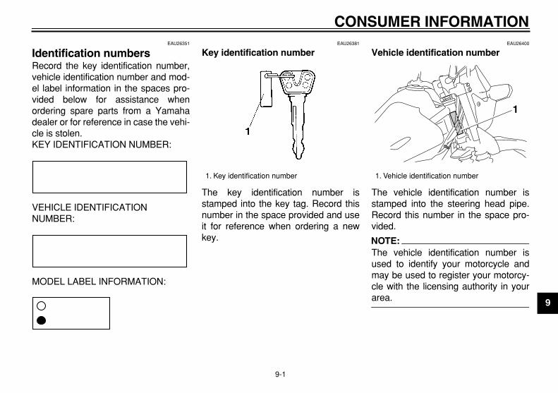
9-1
2
3
4
5
6
7
8
9
CONSUMER INFORMATION
EAU26351
Identification numbers
Record the key identification number,vehicle identification number and mod-el label information in the spaces pro-vided below for assistance whenordering spare parts from a Yamahadealer or for reference in case the vehi-cle is stolen.KEY IDENTIFICATION NUMBER:
VEHICLE IDENTIFICATION NUMBER:
MODEL LABEL INFORMATION:
EAU26381
Key identification number
The key identification number isstamped into the key tag. Record thisnumber in the space provided and useit for reference when ordering a newkey.
EAU26400
Vehicle identification number
The vehicle identification number isstamped into the steering head pipe.Record this number in the space pro-vided.
NOTE:
The vehicle identification number isused to identify your motorcycle andmay be used to register your motorcy-cle with the licensing authority in your
area.
1. Key identification number
1. Vehicle identification number
1

CONSUMER INFORMATION
9-2
1
2
3
4
5
6
7
8
9
EAU36980
Model label
The model label is affixed to the framebehind panel A. (See page 6-9.)Record the information on this label inthe space provided. This informationwill be needed when ordering spareparts from a Yamaha dealer.
1. Model label
1

CONSUMER INFORMATION
9-3
2
3
4
5
6
7
8
9
EAU26551
Reporting safety defects
If you believe that your vehicle has a defect which could cause a crash or could cause injury or death, you should immediatelyinform the National Highway Traffic Safety Administration (NHTSA) in addition to notifying Yamaha Motor Corporation,U.S.A. If NHTSA receives similar complaints, it may open an investigation, and if it finds that a safety defect exists in a groupof vehicles, it may order a recall and remedy campaign. However, NHTSA cannot become involved in individual problemsbetween you, your dealer, or Yamaha Motor Corporation, U.S.A.To contact NHTSA, you may call the Vehicle Safety Hotline toll-free at 1-888-327-4236 (TTY: 1-800-424-9153); go to http://www.safercar.gov; or write to: Administrator, NHTSA, 400 Seventh Street, SW., Washington, DC 20590. You can also obtainother information about motor vehicle safety from http://www.safercar.gov.
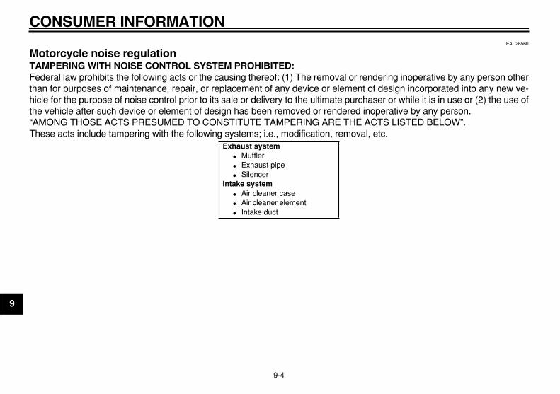
CONSUMER INFORMATION
9-4
1
2
3
4
5
6
7
8
9
EAU26560
Motorcycle noise regulation
TAMPERING WITH NOISE CONTROL SYSTEM PROHIBITED:
Federal law prohibits the following acts or the causing thereof: (1) The removal or rendering inoperative by any person otherthan for purposes of maintenance, repair, or replacement of any device or element of design incorporated into any new ve-hicle for the purpose of noise control prior to its sale or delivery to the ultimate purchaser or while it is in use or (2) the use ofthe vehicle after such device or element of design has been removed or rendered inoperative by any person.“AMONG THOSE ACTS PRESUMED TO CONSTITUTE TAMPERING ARE THE ACTS LISTED BELOW”.These acts include tampering with the following systems; i.e., modification, removal, etc.
Exhaust system
�
Muffler
�
Exhaust pipe
�
Silencer
Intake system
�
Air cleaner case
�
Air cleaner element
�
Intake duct

CONSUMER INFORMATION
9-5
2
3
4
5
6
7
8
9
EAU26611
Maintenance record
Copies of work orders and/or receipts for parts purchased and installed on your motorcycle will be required to document thatmaintenance has been completed in accordance with the emissions warranty. The chart below is printed only as a reminderthat maintenance work is required. It is not acceptable proof of maintenance work.
Maintenanceinterval
Date of service
MileageServicing dealer
name and addressRemarks
600 mi(1000 km) or
1 month4000 mi
(6000 km) or6 months7000 mi
(11000 km) or12 months10000 mi
(16000 km) or18 months13000 mi
(21000 km) or24 months16000 mi
(26000 km) or30 months19000 mi
(31000 km) or36 months22000 mi
(36000 km) or42 months

CONSUMER INFORMATION
9-6
1
2
3
4
5
6
7
8
9
25000 mi(41000 km) or
48 months28000 mi
(46000 km) or54 months31000 mi
(51000 km) or60 months
Maintenanceinterval
Date of service
MileageServicing dealer
name and addressRemarks
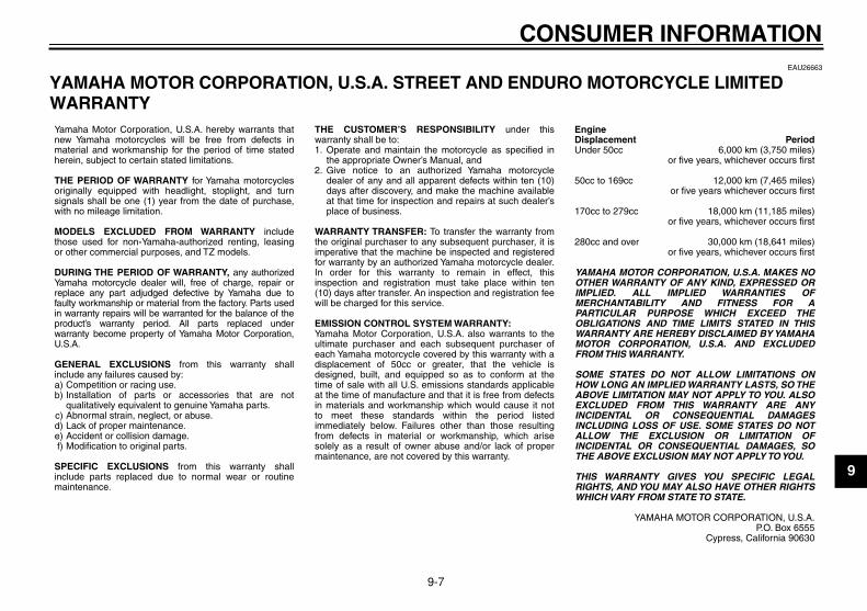
CONSUMER INFORMATION
9-7
2
3
4
5
6
7
8
9
EAU26663
YAMAHA MOTOR CORPORATION, U.S.A. STREET AND ENDURO MOTORCYCLE LIMITED WARRANTY
a)b)
c)d)e)f)
1.
2.
Yamaha Motor Corporation, U.S.A. hereby warrants that new Yamaha motorcycles will be free from defects in material and workmanship for the period of time stated herein, subject to certain stated limitations.
THE PERIOD OF WARRANTY for Yamaha motorcycles originally equipped with headlight, stoplight, and turn signals shall be one (1) year from the date of purchase, with no mileage limitation.
MODELS EXCLUDED FROM WARRANTY include those used for non-Yamaha-authorized renting, leasing or other commercial purposes, and TZ models.
DURING THE PERIOD OF WARRANTY, any authorized Yamaha motorcycle dealer will, free of charge, repair or replace any part adjudged defective by Yamaha due to faulty workmanship or material from the factory. Parts used in warranty repairs will be warranted for the balance of the product’s warranty period. All parts replaced under warranty become property of Yamaha Motor Corporation, U.S.A.
GENERAL EXCLUSIONS from this warranty shall include any failures caused by:
Competition or racing use.Installation of parts or accessories that are not qualitatively equivalent to genuine Yamaha parts.Abnormal strain, neglect, or abuse.Lack of proper maintenance.Accident or collision damage.Modification to original parts.
SPECIFIC EXCLUSIONS from this warranty shall include parts replaced due to normal wear or routine maintenance.
THE CUSTOMER’S RESPONSIBILITY under this warranty shall be to:
Operate and maintain the motorcycle as specified in the appropriate Owner’s Manual, andGive notice to an authorized Yamaha motorcycle dealer of any and all apparent defects within ten (10) days after discovery, and make the machine available at that time for inspection and repairs at such dealer’s place of business.
WARRANTY TRANSFER: To transfer the warranty from the original purchaser to any subsequent purchaser, it is imperative that the machine be inspected and registered for warranty by an authorized Yamaha motorcycle dealer. In order for this warranty to remain in effect, this inspection and registration must take place within ten (10) days after transfer. An inspection and registration fee will be charged for this service.
EMISSION CONTROL SYSTEM WARRANTY:Yamaha Motor Corporation, U.S.A. also warrants to the ultimate purchaser and each subsequent purchaser of each Yamaha motorcycle covered by this warranty with a displacement of 50cc or greater, that the vehicle is designed, built, and equipped so as to conform at the time of sale with all U.S. emissions standards applicable at the time of manufacture and that it is free from defects in materials and workmanship which would cause it not to meet these standards within the period listed immediately below. Failures other than those resulting from defects in material or workmanship, which arise solely as a result of owner abuse and/or lack of proper maintenance, are not covered by this warranty.
Period6,000 km (3,750 miles)
or five years, whichever occurs first
12,000 km (7,465 miles)or five years whichever occurs first
18,000 km (11,185 miles)or five years, whichever occurs first
30,000 km (18,641 miles)or five years, whichever occurs first
YAMAHA MOTOR CORPORATION, U.S.A. MAKES NO OTHER WARRANTY OF ANY KIND, EXPRESSED OR IMPLIED. ALL IMPLIED WARRANTIES OF MERCHANTABILITY AND FITNESS FOR A PARTICULAR PURPOSE WHICH EXCEED THE OBLIGATIONS AND TIME LIMITS STATED IN THIS WARRANTY ARE HEREBY DISCLAIMED BY YAMAHA MOTOR CORPORATION, U.S.A. AND EXCLUDED FROM THIS WARRANTY.
SOME STATES DO NOT ALLOW LIMITATIONS ON HOW LONG AN IMPLIED WARRANTY LASTS, SO THE ABOVE LIMITATION MAY NOT APPLY TO YOU. ALSO EXCLUDED FROM THIS WARRANTY ARE ANY INCIDENTAL OR CONSEQUENTIAL DAMAGES INCLUDING LOSS OF USE. SOME STATES DO NOT ALLOW THE EXCLUSION OR LIMITATION OF INCIDENTAL OR CONSEQUENTIAL DAMAGES, SO THE ABOVE EXCLUSION MAY NOT APPLY TO YOU.
THIS WARRANTY GIVES YOU SPECIFIC LEGAL RIGHTS, AND YOU MAY ALSO HAVE OTHER RIGHTS WHICH VARY FROM STATE TO STATE.
YAMAHA MOTOR CORPORATION, U.S.A.P.O. Box 6555
Cypress, California 90630
Engine Displacement Under 50cc
50cc to 169cc
170cc to 279cc
280cc and over
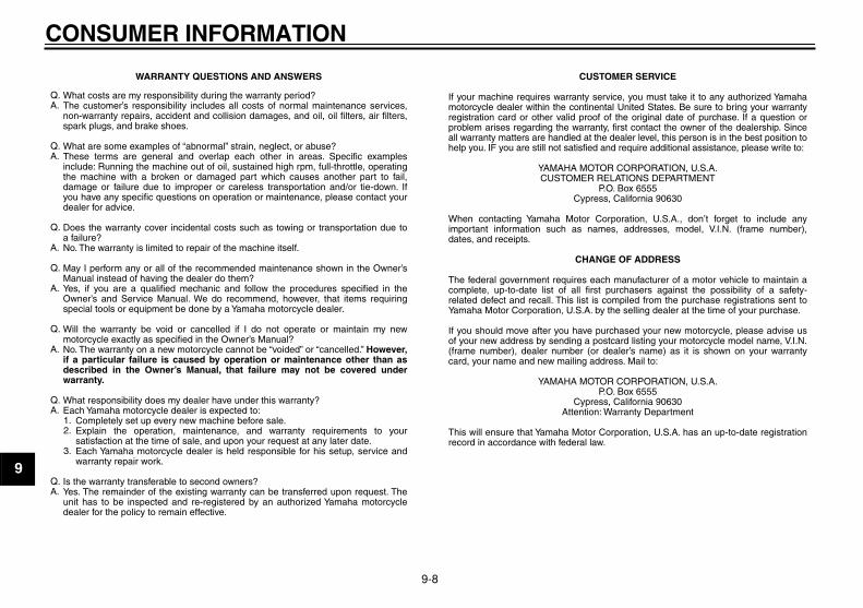
CONSUMER INFORMATION
9-8
1
2
3
4
5
6
7
8
9
WARRANTY QUESTIONS AND ANSWERS
What costs are my responsibility during the warranty period?The customer’s responsibility includes all costs of normal maintenance services, non-warranty repairs, accident and collision damages, and oil, oil filters, air filters, spark plugs, and brake shoes.
What are some examples of “abnormal” strain, neglect, or abuse?These terms are general and overlap each other in areas. Specific examples include: Running the machine out of oil, sustained high rpm, full-throttle, operating the machine with a broken or damaged part which causes another part to fail, damage or failure due to improper or careless transportation and/or tie-down. If you have any specific questions on operation or maintenance, please contact your dealer for advice.
Does the warranty cover incidental costs such as towing or transportation due toa failure?No. The warranty is limited to repair of the machine itself.
May I perform any or all of the recommended maintenance shown in the Owner’s Manual instead of having the dealer do them?Yes, if you are a qualified mechanic and follow the procedures specified in the Owner’s and Service Manual. We do recommend, however, that items requiring special tools or equipment be done by a Yamaha motorcycle dealer.
Will the warranty be void or cancelled if I do not operate or maintain my new motorcycle exactly as specified in the Owner’s Manual?No. The warranty on a new motorcycle cannot be “voided” or “cancelled.” However, if a particular failure is caused by operation or maintenance other than as described in the Owner’s Manual, that failure may not be covered under warranty.
What responsibility does my dealer have under this warranty?Each Yamaha motorcycle dealer is expected to:
Completely set up every new machine before sale.Explain the operation, maintenance, and warranty requirements to your satisfaction at the time of sale, and upon your request at any later date.Each Yamaha motorcycle dealer is held responsible for his setup, service and warranty repair work.
Is the warranty transferable to second owners?Yes. The remainder of the existing warranty can be transferred upon request. The unit has to be inspected and re-registered by an authorized Yamaha motorcycle dealer for the policy to remain effective.
CUSTOMER SERVICE
If your machine requires warranty service, you must take it to any authorized Yamaha motorcycle dealer within the continental United States. Be sure to bring your warranty registration card or other valid proof of the original date of purchase. If a question or problem arises regarding the warranty, first contact the owner of the dealership. Since all warranty matters are handled at the dealer level, this person is in the best position to help you. IF you are still not satisfied and require additional assistance, please write to:
YAMAHA MOTOR CORPORATION, U.S.A.CUSTOMER RELATIONS DEPARTMENT
P.O. Box 6555Cypress, California 90630
When contacting Yamaha Motor Corporation, U.S.A., don’t forget to include any important information such as names, addresses, model, V.I.N. (frame number), dates, and receipts.
CHANGE OF ADDRESS
The federal government requires each manufacturer of a motor vehicle to maintain a complete, up-to-date list of all first purchasers against the possibility of a safety-related defect and recall. This list is compiled from the purchase registrations sent to Yamaha Motor Corporation, U.S.A. by the selling dealer at the time of your purchase.
If you should move after you have purchased your new motorcycle, please advise us of your new address by sending a postcard listing your motorcycle model name, V.I.N. (frame number), dealer number (or dealer’s name) as it is shown on your warranty card, your name and new mailing address. Mail to:
YAMAHA MOTOR CORPORATION, U.S.A.P.O. Box 6555
Cypress, California 90630Attention: Warranty Department
This will ensure that Yamaha Motor Corporation, U.S.A. has an up-to-date registration record in accordance with federal law.
Q.A.
Q.A.
Q.
A.
Q.
A.
Q.
A.
Q.A.
1.2.
3.
Q.A.

CONSUMER INFORMATION
9-9
2
3
4
5
6
7
8
9
EAU26750
YAMAHA EXTENDED SERVICE (Y.E.S.) Keep your Yamaha protected even after your warranty expires with genuine Yamaha Extended Service (Y.E.S.).
Y.E.S. is designed and administered by Yamaha Motor Corporation to provide maximum owner satisfaction. You get uninterrupted factory-backed coverage for extra peace of mind.
Y.E.S. is flexible. You choose the plan that’s right foryou: 12 months, 24 months, 36 months or, on certain models, even 48 months beyond your warranty period.
Y.E.S. is designed and administered by the same Yamaha people who handle your warranty – and itshows in the comprehensive coverage benefits. There are no mileage limitations. Coverage isn’t limited to “moving parts” or the “drive train” like many other plans. And Y.E.S. covers manufacturing defects just like the warranty. See the sample contract at your Yamahadealer to see how comforting uninterrupted factory-backed protection can be.
You don’t have to pay anything for covered repairs. There’s no deductible to pay, and repairs aren’t“pro-rated.” You don’t have any “out-of-pocket” expenses for covered repairs.
In addition, Travel and Recreation Interruption Protection (TRIP) is included at no extra cost. TRIP gives you up to $150 reimbursement per occurrence for any reasonable expenses you incur because your Yamaha needs covered service: replacement vehicle rental, emergency towing, phone calls, even food and lodging when you are away from home. This superb coverage goes into effect when you purchase Y.E.S., so it applies to any warranty repairs as well as covered repairs during your entire Y.E.S. plan period.
Y.E.S. coverage is honored at any authorized Yamaha dealer nationwide.
Y.E.S. coverage is transferable to a new owner if yousell or trade-in. That can make your Yamaha much more valuable!
This excellent Y.E.S. plan coverage is only available to Yamaha owners like you, and only while your Yamaha is still within the Yamaha Limited Warranty period. So visit your authorized Yamaha dealer to get all the facts. He can show you how easy it is to protect your investment with Yamaha Extended Service.

CONSUMER INFORMATION
9-10
1
2
3
4
5
6
7
8
9
We urge you to act now. You’ll get the excellent benefits of TRIP coverage right away, and you’ll rest easy knowing you’ll have strong factory-backed protection even after your Yamaha Limited Warranty expires.
A special note:If visiting your dealer isn’t convenient, contact Yamaha with your Primary ID number (your frame number). We’ll be happy to help you get the Y.E.S. coverage you need.
Yamaha Service MarketingP.O. Box 6555Cypress, CA 906301-(866)-YES-EXTD (1-866-937-3983)

INDEX
A
Accessories and replacement parts ........6-22Air filter element and check hose,
replacing and cleaning ..........................6-16
B
Battery .....................................................6-32Brake and clutch levers, checking and
lubricating ..............................................6-29Brake and shift pedals, checking and
lubricating ..............................................6-28Brake fluid, changing ...............................6-26Brake fluid level, checking .......................6-25Brake lever ................................................3-6Brake lever free play, adjusting ...............6-23Brake pedal ...............................................3-6
C
Cables, checking and lubricating.............6-28Canister (for California only) ....................6-13Carburetor ...............................................6-18Care...........................................................7-1Clutch lever................................................3-5Clutch lever free play, adjusting ..............6-22Cowling and panels, removing and
installing ..................................................6-9
D
Dimmer switch ...........................................3-4Drive chain, cleaning and lubricating.......6-27Drive chain slack .....................................6-26
E
Engine break-in .........................................5-4Engine idling speed, checking .................6-18Engine oil and oil filter element................6-13Engine, starting a warm.............................5-2Engine stop switch.....................................3-5
F
Front and rear brake pads, checking.......6-24Front fork, checking.................................6-30Fuel ...........................................................3-7Fuel cock ...................................................3-8Fuel tank cap.............................................3-6Fuse, replacing........................................6-33
H
Handlebar switches ...................................3-4Headlight bulb, replacing.........................6-34Helmet holder ..........................................3-10High beam indicator light...........................3-2Horn switch................................................3-5
I
Identification numbers ...............................9-1Ignition circuit cut-off system ...................3-12Indicator lights ...........................................3-2
K
Key identification number ..........................9-1
L
Labels, location of .....................................1-5
M
Main switch/steering lock ..........................3-1Maintenance and lubrication, periodic.......6-5Maintenance, emission control system .....6-3Maintenance, periodic ...............................6-1Maintenance record...................................9-5Matte color, caution ...................................7-1Model label ................................................9-2Multi-function display.................................3-3
N
Neutral indicator light.................................3-2Noise regulation ........................................9-4
P
Parking ...................................................... 5-4Part locations ............................................ 2-1Pre-operation check list............................. 4-2
R
Rear brake light switch, adjusting ........... 6-24Rear suspension, lubricating................... 6-30
S
Safety defects, reporting ........................... 9-3Safety information ..................................... 1-1Seat........................................................... 3-9Shifting ...................................................... 5-2Shift pedal ................................................. 3-5Shock absorber assembly, adjusting ...... 3-10Sidestand ................................................ 3-12Sidestand, checking and lubricating........ 6-30Spark arrester, cleaning .......................... 6-17Spark plug, checking............................... 6-11Specifications ............................................ 8-1Starter (choke) knob.................................. 3-9Starting and warming up a cold engine..... 5-1Start switch................................................ 3-5Steering, checking................................... 6-31Storage...................................................... 7-3Supporting the motorcycle ...................... 6-37
T
Tail/brake light bulb, replacing ................ 6-35Throttle cable free play, checking ........... 6-19Throttle grip and cable, checking and
lubricating ............................................. 6-28Tires ........................................................ 6-19Tool kit....................................................... 6-1Troubleshooting ...................................... 6-40Troubleshooting chart ............................. 6-41

INDEX
Turn signal indicator light .......................... 3-2Turn signal light bulb, replacing .............. 6-36Turn signal switch ..................................... 3-4
V
Valve clearance ...................................... 6-19Vehicle identification number .................... 9-1
W
Warranty, extended................................... 9-9Warranty, limited ....................................... 9-7Wheel bearings, checking....................... 6-32Wheel (front) ........................................... 6-37Wheel (rear) ............................................ 6-38Wheels .................................................... 6-21


PRINTED ON RECYCLED PAPERYAMAHA MOTOR CO., LTD.
PRINTED IN JAPAN2007.8–1.3×1 !
(E)