xxx jsbo nbwbe dpn {yÂ»Ö |Àƻּ¸ mdl.iran-mavad.com/pdf95/corrosion under insulation...
TRANSCRIPT

www.iran-mavad.com مرجع علمى مهندسى مواد
www.iran-mavad.com مرجع علمى مهندسى مواد
European Federation of Corrosion PublicationsNUMBER 55
Corrosion-under-insulation (CUI)
guidelines
S. Winnik
Published for the European Federation of Corrosionby Woodhead Publishing and Maney Publishing
on behalf ofThe Institute of Materials, Minerals & Mining
CRC PressBoca Raton Boston New York Washington, DC
Cambridge England
WPNL2204
WPNL2204
www.iran-mavad.com مرجع علمى مهندسى مواد
Woodhead Publishing Limited and Maney Publishing Limited on behalf ofThe Institute of Materials, Minerals & Mining
Woodhead Publishing Limited, Abington Hall, Abington, Cambridge CB21 6AH, Englandwww.woodheadpublishing.com
Published in North America by CRC Press LLC, 6000 Broken Sound Parkway, NW, Suite 300, Boca Raton, FL 33487, USA
First published 2008 by Woodhead Publishing Limited and CRC Press LLC© 2008, Institute of Materials, Minerals & MiningThe author has asserted his moral rights.
This book contains information obtained from authentic and highly regarded sources. Reprinted material is quoted with permission, and sources are indicated. Reasonable efforts have been made to publish reliable data and information, but the author and the publishers cannot assume responsibility for the validity of all materials. Neither the author nor the publishers, nor anyone else associated with this publication, shall be liable for any loss, damage or liability directly or indirectly caused or alleged to be caused by this book.
Neither this book nor any part may be reproduced or transmitted in any form or by any means, electronic or mechanical, including photocopying, microfi lming and recording, or by any information storage or retrieval system, without permission in writing from Woodhead Publishing Limited.
The consent of Woodhead Publishing Limited does not extend to copying for general distribution, for promotion, for creating new works, or for resale. Specifi c permission must be obtained in writing from Woodhead Publishing Limited for such copying.
Trademark notice: Product or corporate names may be trademarks or registered trademarks, and are used only for identifi cation and explanation, without intent to infringe.
British Library Cataloguing in Publication DataA catalogue record for this book is available from the British Library.
Library of Congress Cataloging in Publication DataA catalog record for this book is available from the Library of Congress.
Woodhead Publishing ISBN-13 978-1-84569-423-4 (book)Woodhead Publishing ISBN-13 978-1-84569-427-2 (e-book)CRC Press ISBN 978-1-4200-7603-5CRC Press order number WP6035ISSN 1354-5116
The publishers’ policy is to use permanent paper from mills that operate a sustainable forestry policy, and which has been manufactured from pulp which is processed using acid-free and elementary chlorine-free practices. Furthermore, the publishers ensure that the text paper and cover board used have met acceptable environmental accreditation standards.
Typeset by SNP Best-set Typesetter Ltd., Hong KongPrinted by TJ International Limited, Padstow, Cornwall, England
WPNL2204www.iran-mavad.com مرجع علمى مهندسى مواد
Contents
Series introduction viii
Volumes in the EFC series x
List of abbreviations xvi
Dedication xvii
1 Introduction 11.1 Purpose of the document 51.2 References 9
2 Economic consideration 112.1 Statistical analysis 112.2 Size of the issue 122.3 Key performance indicators 14
3 Ownership and responsibility 153.1 Senior management 153.2 Engineering manager 153.3 Maintenance 153.4 Operations 163.5 Inspection 163.6 Members of a project team; corrosion-under-insulation
programme 16
4 The risk-based inspection methodology for corrosion-under-insulation 17
4.1 Introduction 174.2 Unit level prioritisation 184.3 Challenging the need for insulation 204.4 Data validation 244.5 Using risk-based inspection to design corrosion-under-
insulation inspection plans 284.6 Reference 38
iii
WPNL2204www.iran-mavad.com مرجع علمى مهندسى مواد
iv Contents
5 Inspection activities and strategy 395.1 General considerations 395.2 Typical locations on piping circuits susceptible to
corrosion-under-insulation 405.3 Typical locations on equipment susceptible to
corrosion-under-insulation 415.4 Examples of a risk-based inspection plan 44
6 Non-destructive examination and testing screening techniques for corrosion-under-insulation 46
6.1 Non-destructive examination and testing techniques 466.2 Reference 46
7 Recommended best practice to mitigate corrosion-under-insulation 53
7.1 Background 537.2 Current corrosion-under-insulation prevention methods 547.3 How to achieve a life expectancy of over 25 years 557.4 Benefi ts of thermally sprayed aluminium 587.5 Use of personnel protective guards 597.6 Use of aluminium foil to mitigate chloride external stress
corrosion cracking of austenitic stainless steel 607.7 References 62
8 Design for the prevention of corrosion-under-insulation 638.1 Introduction 638.2 Challenge the requirement for insulation 638.3 Plant layout 648.4 Mechanical considerations: equipment and tanks 648.5 Mechanical considerations: piping 658.6 Materials of construction 658.7 Coatings and wrappings 668.8 Insulation 678.9 Weatherproofi ng 688.10 References 69
9 Appendix overview 70
Appendix A Cost-economic evaluation 71
Appendix B Quality assurance 76
WPNL2204www.iran-mavad.com مرجع علمى مهندسى مواد
Contents v
Appendix C Additional guidelines on the implementation of corrosion-under-insulation best practice 78C.1 Maintenance and remediation issues 78C.2 Minimum standards 79C.3 Types of insulation service 79C.4 Surface preparation 81C.5 References 88
Appendix D Coatings 89D.1 General comments 89D.2 Protective coatings 89D.3 Thermally sprayed aluminium 89D.4 Surface and moisture tolerance 91D.5 Alternative coatings; tape coatings 91D.6 Reference 91
Appendix E Application of thermally sprayed aluminium 92E.1 Application of thermally sprayed coatings 92E.2 Use of organic topcoats 94E.3 Application strategies 95E.4 Thermally sprayed aluminium coating specifi cation 95E.5 Defi nitions 97E.6 Referenced codes, standards and specifi cations 97E.7 Coating philosophy 97E.8 Coating system 98E.9 Thermally sprayed aluminium material 99E.10 Seal coat 99E.11 Design 100E.12 Surface preparation 100E.13 Weather and surface conditions 101E.14 Application process 101E.15 Specifi c requirements for on-site thermally sprayed
aluminium application 102E.16 Piping fi eld welds 102E.17 Inspection and acceptance 103E.18 Documentation 105E.19 Surface and moisture tolerance 105E.20 Alternative coatings; tape coatings 105
Appendix F Types and forms of insulation material 106F.1 Mineral fi bre 106F.2 Low-density glass fi bre 109
WPNL2204www.iran-mavad.com مرجع علمى مهندسى مواد
vi Contents
F.3 Calcium silicate 109F.4 Cellular glass 110F.5 Ceramic fi bre paper 112F.6 Glass rope insulation 112F.7 Self-setting cement 112F.8 Flexible reusable insulation covers 112F.9 Preformed rigid polyurethane foam (polyurethane–
polyisocyanurate) 113F.10 Flexible elastomeric foam 115F.11 Flexible elastomeric foam (ethylene propylene diene
monomer) 116F.12 Polyethylene 116F.13 Perlite 117F.14 Vermiculite 118
Appendix G Cladding and jacketing materials 120G.1 Metallic cladding materials 120G.2 Non-metallic materials 122
Appendix H Use of protection guards 127H.1 Design considerations 127H.2 Method guidance notes 127
Appendix I Non-destructive examination and testing techniques 130I.1 Visual inspection 130I.2 Manual ultrasonic thickness measurement through
inspection openings 130I.3 Radiography 131I.4 Real-time radiography 132I.5 Guided-wave ultrasonic measurements 134I.6 Pulsed-eddy-current technique 134I.7 Digital radiography 135I.8 Infrared thermography 136I.9 Neutron backscattering 137I.10 Dye penetrant testing 138
Appendix J Case studies 139J.1 Case study 1 140J.2 Case study 2 142J.3 Case study 3 144J.4 Case study 4 145J.5 Case study 5 146
WPNL2204www.iran-mavad.com مرجع علمى مهندسى مواد
Contents vii
J.6 Case study 6 148J.7 Case study 7 150J.8 Case study 8 152
Index 154
WPNL2204www.iran-mavad.com مرجع علمى مهندسى مواد
European Federation of Corrosion (EFC) publications: Series introduction
The European Federation of Corrosion (EFC), incorporated in Belgium, was founded in 1955 with the purpose of promoting European cooperation in the fi elds of research into corrosion and corrosion prevention.
Membership of the EFC is based upon participation by corrosion societ-ies and committees in technical Working Parties. Member societies appoint delegates to Working Parties, whose membership is expanded by personal corresponding membership.
The activities of the Working Parties cover corrosion topics associated with inhibition, education, reinforcement in concrete, microbial effects, hot gases and combustion products, environment-sensitive fracture, marine environments, refi neries, surface science, physico-chemical methods of measurement, the nuclear industry, the automotive industry, computer-based information systems, coatings, tribo-corrosion and the oil and gas industry. Working Parties and Task Forces on other topics are established as required.
The Working Parties function in various ways, e.g. by preparing reports, organising symposia, conducting intensive courses and producing instruc-tional material, including fi lms. The activities of Working Parties are coor-dinated, through a Science and Technology Advisory Committee, by the Scientifi c Secretary. The administration of the EFC is handled by three Secretariats: DECHEMA e.V. in Germany, the Société de Chimie Indus-trielle in France, and The Institute of Materials, Minerals and Mining in the UK. These three Secretariats meet at the Board of Administrators of the EFC. There is an annual General Assembly at which delegates from all member societies meet to determine and approve EFC policy. News of EFC activities, forthcoming conferences, courses, etc., is published in a range of accredited corrosion and certain journals throughout Europe. More detailed descriptions of activities are given in a Newsletter prepared by the Scientifi c Secretary.
The output of the EFC takes various forms. Papers on particular topics, e.g. reviews or results of experimental work, may be published in scientifi c
viii
WPNL2204www.iran-mavad.com مرجع علمى مهندسى مواد
and technical journals in one or more countries in Europe. Conference proceedings are often published by the organisation responsible for the conference.
In 1987 the, then, Institute of Metals was appointed as the offi cial EFC publisher. Although the arrangement is non-exclusive and other routes for publication are still available, it is expected that the Working Parties of the EFC will use The Institute of Materials, Minerals and Mining for publica-tion of reports, proceedings, etc., wherever possible.
The name of The Institute of Metals was changed to The Institute of Materials (10 m) on 1 January 1992 and to The Institute of Materials, Miner-als and Mining with effect from 26 June 2002. The series is now published by Woodhead Publishing and Maney Publishing on behalf of The Institute of Materials, Minerals and Mining.
P. McIntyreEFC Series EditorThe Institute of Materials, Minerals and Mining, London, UK
EFC Secretariats are located at:
Dr B. A. RickinsonEuropean Federation of Corrosion, The Institute of Materials, Minerals and Mining, 1 Carlton House Terrace, London SW1Y 5DB, UK
Dr J. P. BergeFédération Européenne de la Corrosion, Société de Chimie Industrielle, 28 rue Saint-Dominique, F-75007 Paris, France
Professor Dr G. KreysaEuropäische Föderation Korrosion, DECHEMA e.V., Theodor-Heuss-Allee 25, D-60486 Frankfurt, Germany
Series introduction ix
WPNL2204www.iran-mavad.com مرجع علمى مهندسى مواد
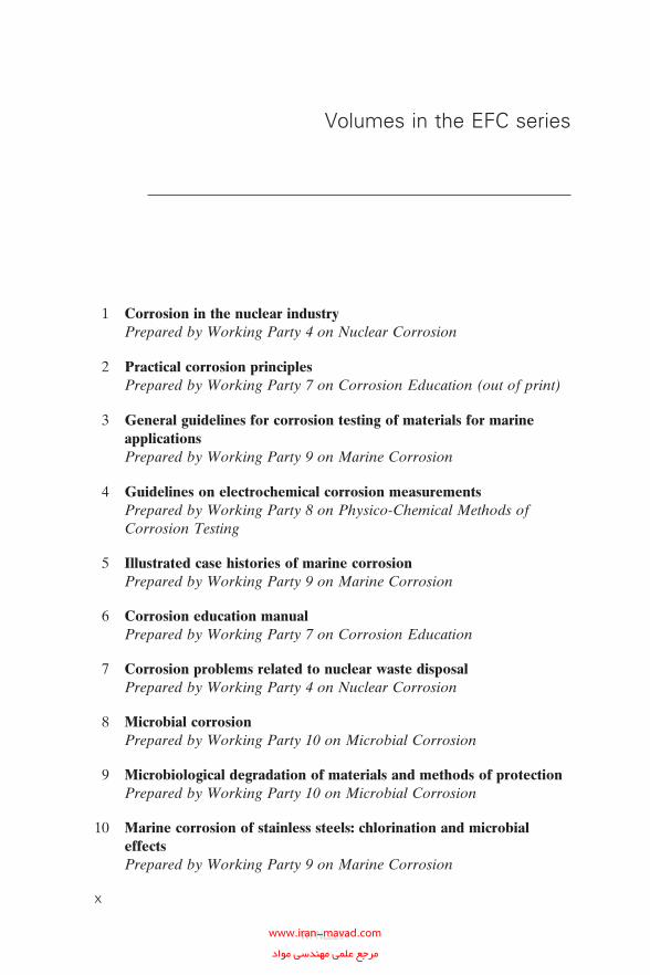
Volumes in the EFC series
1 Corrosion in the nuclear industry Prepared by Working Party 4 on Nuclear Corrosion
2 Practical corrosion principles Prepared by Working Party 7 on Corrosion Education (out of print)
3 General guidelines for corrosion testing of materials for marine applications
Prepared by Working Party 9 on Marine Corrosion
4 Guidelines on electrochemical corrosion measurements Prepared by Working Party 8 on Physico-Chemical Methods of
Corrosion Testing
5 Illustrated case histories of marine corrosion Prepared by Working Party 9 on Marine Corrosion
6 Corrosion education manual Prepared by Working Party 7 on Corrosion Education
7 Corrosion problems related to nuclear waste disposal Prepared by Working Party 4 on Nuclear Corrosion
8 Microbial corrosion Prepared by Working Party 10 on Microbial Corrosion
9 Microbiological degradation of materials and methods of protection Prepared by Working Party 10 on Microbial Corrosion
10 Marine corrosion of stainless steels: chlorination and microbial effects
Prepared by Working Party 9 on Marine Corrosion
x
WPNL2204www.iran-mavad.com مرجع علمى مهندسى مواد
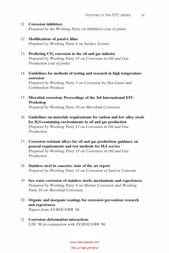
11 Corrosion inhibitors Prepared by the Working Party on Inhibitors (out of print)
12 Modifi cations of passive fi lms Prepared by Working Party 6 on Surface Science
13 Predicting CO2 corrosion in the oil and gas industry Prepared by Working Party 13 on Corrosion in Oil and Gas
Production (out of print)
14 Guidelines for methods of testing and research in high temperature corrosion
Prepared by Working Party 3 on Corrosion by Hot Gases and Combustion Products
15 Microbial corrosion: Proceedings of the 3rd International EFC Workshop
Prepared by Working Party 10 on Microbial Corrosion
16 Guidelines on materials requirements for carbon and low alloy steels for H2S-containing environments in oil and gas production
Prepared by Working Party 13 on Corrosion in Oil and Gas Production
17 Corrosion resistant alloys for oil and gas production: guidance on general requirements and test methods for H2S service
Prepared by Working Party 13 on Corrosion in Oil and Gas Production
18 Stainless steel in concrete: state of the art report Prepared by Working Party 11 on Corrosion of Steel in Concrete
19 Sea water corrosion of stainless steels: mechanisms and experiences Prepared by Working Party 9 on Marine Corrosion and Working
Party 10 on Microbial Corrosion
20 Organic and inorganic coatings for corrosion prevention: research and experiences
Papers from EUROCORR ’96
21 Corrosion–deformation interactions CDI ’96 in conjunction with EUROCORR ’96
Volumes in the EFC series xi
WPNL2204www.iran-mavad.com مرجع علمى مهندسى مواد
22 Aspects of microbially induced corrosion Papers from EUROCORR ’96 and EFC Working Party 10 on
Microbial Corrosion
23 CO2 corrosion control in oil and gas production: design considerations
Prepared by Working Party 13 on Corrosion in Oil and Gas Production
24 Electrochemical rehabilitation methods for reinforced concrete structures: a state of the art report
Prepared by Working Party 11 on Corrosion of Steel in Concrete
25 Corrosion of reinforcement in concrete: monitoring, prevention and rehabilitation
Papers from EUROCORR ’97
26 Advances in corrosion control and materials in oil and gas production
Papers from EUROCORR ’97 and EUROCORR ’98
27 Cyclic oxidation of high temperature materials Proceedings of an EFC Workshop, Frankfurt/Main, 1999
28 Electrochemical approach to selected corrosion and corrosion control
Papers from the 50th ISE Meeting, Pavia, 1999
29 Microbial corrosion: proceedings of the 4th International EFC Workshop
Prepared by the Working Party on Microbial Corrosion
30 Survey of literature on crevice corrosion (1979–1998): mechanisms, test methods and results, practical experience, protective measures and monitoring
Prepared by F. P. Ijsseling and Working Party 9 on Marine Corrosion
31 Corrosion of reinforcement in concrete: corrosion mechanisms and corrosion protection
Papers from EUROCORR ’99 and Working Party 11 on Corrosion of Steel in Concrete
xii Volumes in the EFC series
WPNL2204www.iran-mavad.com مرجع علمى مهندسى مواد
32 Guidelines for the compilation of corrosion cost data and for the calculation of the life cycle cost of corrosion: a working party report
Prepared by Working Party 13 on Corrosion in Oil and Gas Production
33 Marine corrosion of stainless steels: testing, selection, experience, protection and monitoring
Edited by D. Féron on behalf of Working Party 9 on Marine Corrosion
34 Lifetime modelling of high temperature corrosion processes Proceedings of an EFC Workshop 2001 Edited by M. Schütze, W. J. Quadakkers and J. R. Nicholls
35 Corrosion inhibitors for steel in concrete Prepared by B. Elsener with support from a Task Group of Working
Party 11 on Corrosion of Steel in Concrete
36 Prediction of long term corrosion behaviour in nuclear waste systems Edited by D. Féron on behalf of Working Party 4 on Nuclear
Corrosion
37 Test methods for assessing the susceptibility of prestressing steels to hydrogen induced stress corrosion cracking
By B. Isecke on behalf of Working Party 11 on Corrosion of Steel in Concrete
38 Corrosion of reinforcement in concrete: mechanisms, monitoring, inhibitors and rehabilitation techniques
Edited by M. Raupach, B. Elsener, R. Polder and J.Mietz on behalf of Working Party 11 on Corrosion of Steel in Concrete
39 The use of corrosion inhibitors in oil and gas production Edited by J. W. Palmer, W. Hedges and J. L. Dawson on behalf of
Working Party 13 on Corrosion in Oil and Gas Production
40 Control of corrosion in cooling waters Edited by J. D. Harston and F. Ropital on behalf of Working Party
15 on Corrosion in the Refi nery Industry
41 Metal dusting, carburisation and nitridation Edited by H. Grabke and M. Schütze on behalf of Working Party 3
on Corrosion by Hot Gases and Combustion Products
Volumes in the EFC series xiii
WPNL2204www.iran-mavad.com مرجع علمى مهندسى مواد
42 Corrosion in refi neries Edited by J. D. Harston and F. Ropital on behalf of Working Party
15 on Corrosion in the Refi nery Industry
43 The electrochemistry and characteristics of embeddable reference electrodes for concrete
Prepared by R. Myrdal on behalf of Working Party 11 on Corrosion of Steel in Concrete
44 The use of electrochemical scanning tunnelling microscopy (EC-STM) in corrosion analysis: reference material and procedural guidelines
Prepared by R. Lindström, V. Maurice, L. Klein and P. Marcus on behalf of Working Party 6 on Surface Science
45 Local probe techniques for corrosion research Edited by R. Oltra on behalf of Working Party 8 on Physico-
Chemical Methods of Corrosion Testing
46 Amine unit corrosion survey Edited by J. D. Harston and F. Ropital on behalf of Working Party
15 on Corrosion in the Refi nery Industry
47 Novel approaches to the improvement of high temperature corrosion resistance
Edited by M. Schütze and W. Quadakkers on behalf of Working Party 3 on Corrosion by Hot Gases and Combustion Products
48 Corrosion of metallic heritage artefacts: investigation, conservation and prediction of long term behaviour
Edited by P. Dillmann, G. Béranger, P. Piccardo and H. Matthiesen on behalf of Working Party 4 on Nuclear Corrosion
49 Electrochemistry in light water reactors: reference electrodes, measurement, corrosion and tribocorrosion
Edited by R.-W. Bosch, D. Féron and J.-P. Celis on behalf of Working Party 4 on Nuclear Corrosion
50 Corrosion behaviour and protection of copper and aluminium alloys in seawater
Edited by D. Féron on behalf of Working Party 9 on Marine Corrosion
xiv Volumes in the EFC series
WPNL2204www.iran-mavad.com مرجع علمى مهندسى مواد
51 Corrosion issues in light water reactors: stress corrosion cracking Edited by D. Féron and J-M. Olive on behalf of Working Party 4 on
Nuclear Corrosion
52 (not yet published)
53 Standardisation of thermal cycling exposure testing Edited by M. Schütze and M. Malessa on behalf of Working Party 3
on Corrosion by Hot Gases and Combustion Products
54 Innovative pre-treatment techniques to prevent corrosion of metallic surfaces
Edited by L. Fedrizzi, H. Terryn and A. Simões on behalf of Working Party 14 on Coatings
55 Corrosion-under-insulation (CUI) guidelines Prepared by S. Winnik on behalf of Working Party 13 on Corrosion
in Oil and Gas Production and Working Party 15 on Corrosion in the Refi nery Industry
Volumes in the EFC series xv
WPNL2204www.iran-mavad.com مرجع علمى مهندسى مواد
Abbreviations
ACFM alternating current fi eld measurementAISI American Iron and Steel InstituteASME American Society of Mechanical EngineersASTM American Society of Testing and MaterialsAWS American Welding SocietyBPSD barrels per stream dayBS British StandardCl-ESCC chloride external stress corrosion crackingCUI corrosion under insulationDCF discounted cash fl owEFC European Federation of CorrosionHOIS Harwell Offshore Inspection ServicesICI Imperial Chemical IndustriesIOM Institute of Materials (formerly Institute of Metals; now
Institute of Materials, Minerals and Mining)ISO International Organization for StandardizationKPI key performance indicatorLCC life cycle costLPO lost profi t opportunityMPY milli-inches/yearMTBF mean time between failuresMTI Materials Technology InstituteNACE National Association of Corrosion EngineersNDE non-destructive examinationNDT non-destructive testingPSV pressure safety valveRBI risk-based inspectionRTR real-time radiographySCC stress corrosion crackingSHE safety, health and environmentSSPC Steel Structures Painting CouncilTSA thermally sprayed aluminiumWP Working Party
xvi
WPNL2204www.iran-mavad.com مرجع علمى مهندسى مواد
Dedication
This book is dedicated to Terry Hallett who worked for Shell (UK) and died unexpectedly in 2005. He was one of the key early contributors to the development of this book. His enthusiasm inspired his friends and col-leagues, from within Shell and from other companies, into ensuring that the work he initiated would be completed. Corrosion under insulation (CUI) is not one of the work areas that typically inspires us, but, despite an excep-tionally heavy work load, Terry spared no effort to further the interests and activities of both the UK CUI Forum and the EFC and played a key role in both associations. Terry will be remembered by all who came into contact with him for his sincerity and his sense of humour. He will be sorely missed.
As the lead author, I know that the book would not have been completed without the many contributions from many others. We all know that writing a book by committee is never easy. Special thanks are extended to Hennie DeBruyn (Borealis), Andrew Kettle (ChevronTexaco), Rob Scanlan (Con-ocoPhillips), Staffan Olsen (Scanraff), Carmelo Aiello (Ente Nazionale Idrocarburi), Nicholas Dowling and Maarten Lorenz (Shell), François Ropital (Institut Français du Pétrole) and John Thirkettle (UK CUI Forum) for their efforts throughout the development of this book.
Dr Stefan WinnikEditor
ExxonMobil Chemical
xvii
WPNL2204www.iran-mavad.com مرجع علمى مهندسى مواد

WPNL2204www.iran-mavad.com مرجع علمى مهندسى مواد
1Introduction
Corrosion-under-insulation (CUI) refers to the external corrosion of piping and vessels fabricated from carbon–manganese, low-alloy and austenitic stainless steels that occurs underneath externally clad or jacketed insulation owing to the penetration of water. By its very nature, CUI tends to remain undetected until the insulation and cladding or jacketing are removed to allow inspection or when leaks to atmosphere occur. CUI is a major common problem on a worldwide basis that is shared by all the refi ning, petrochemi-cal, power, industrial, onshore and offshore industries. It is not a new problem, but it can be a serious problem. CUI has been responsible for many major leaks that lead to health and safety incidents, result in lost production and are responsible for the large maintenance budgets which are required to mitigate the problem.
Corrosion of austenitic stainless steels usually manifests itself as chloride external stress corrosion cracking (Cl-ESCC). Although Cl-ESCC [1] was fi rst reported in 1965, not many references are available on the CUI of carbon–manganese steels and low-alloy steels up to 1980 when a meeting was held in November 1980 [2]. A review of this very successful 2 day meeting was given by Richardson [3] during a symposium which was held in 1983 [4], and was sponsored by the Association for Testing and Materials (ASTM), the National Association of Corrosion Engineers (NACE) and the Materials Technology Institute (MTI). It would appear that, when reviewing the literature from that meeting today, the problems reported in 1980 mirror the experiences currently being reported today.
Although numerous instances of CUI are reported annually, this has not been refl ected in the production of many industry standards for insulation or measures to mitigate CUI. The fi rst ASTM standard on thermal insula-tion materials relevant to CUI was adopted in 1971 [5]. NACE Task Group T-6H-31 fi rst issued a report on CUI [6] in 1989 and later Task Group T-5A-30 was formed, which became an open forum for CUI problems and solutions. This led to the publication of a NACE recommended practice RP0198-98 [7] which was revised in 2004 [8]. A number of conferences and
1
WPNL2204www.iran-mavad.com مرجع علمى مهندسى مواد
2 Corrosion-under-insulation guidelines
initiatives covering CUI and insulation materials have taken place since 1983 but the problem remains unresolved. It would seem that the incidence of CUI examples is not diminishing and would appear to be increasing, given the number of instances being reported. An NACE conference in 2003 reviewed similar topics covered back in 1983 which were illustrated by Delahunt [9] who presented an excellent historical perspective of the occurrence of CUI. A conference held in the UK in 2004 [10] had a similar theme and again suggested that CUI had not been mitigated and that instances of CUI were actually increasing. These instances led to the for-mation of an informal group (UK CUI Forum) [11] by corrosion and materials engineers from a number of major oil and gas producers in the UK specifi cally to share CUI-related information. The Forum has since expanded and now includes representatives from other industries. Collabo-ration between the UK CUI Forum and the European Federation of Cor-rosion (EFC) led to the development of this document, which hopefully will be regularly updated to refl ect any major advances in the mitigation of CUI.
Why does CUI occur? CUI of carbon–manganese steels and low-alloy steels usually occurs when a number of conditions are fulfi lled.
• Water or moisture must be present on the substrate in order to allow oxygen corrosion to occur. Water ingress is due to breaks in the insula-tion, cladding or jacketing which may have resulted as a consequence of poor installation or damage during service or simply be a result of deterioration over time. The principal sources of water are as follows.
° External sources which include rainwater, deluge systems and process liquid spillage.
° Condensation.
This water may be retained depending on the absorption properties of the insulation material and the operating temperature. Depending upon process conditions, saturated insulation may never have the opportunity to dry out completely.
Contaminants that can cause problems on both carbon–manganese steels and low-alloy steels as well as on austenitic stainless steels need to be present. Chlorides and sulphides make up the bulk of the contamination and generally increase the corrosivity of the water. The source of the con-taminants can be external such as environmentally borne chloride sources include sites situated in a marine environment (e.g. offshore), or wind-borne salts from cooling tower drift, or from periodic testing of fi rewater deluge systems. Contaminants can also be produced by leaching from the insulation material itself. In the presence of an applied or residual stress and temperatures exceeding 60 °C (140 °F), high chloride contents of water contribute to Cl-ESCC.
WPNL2204www.iran-mavad.com مرجع علمى مهندسى مواد
Introduction 3
The operating temperature range of the piping or vessels should be between −4 °C (25 °F) and 175 °C (347 °F). This temperature range refl ects the experience from the contributors to this document and is meant as guide to enable mitigation procedures to be developed. CUI problems have been reported outside this range; the majority of CUI occurrences are, however, within the specifi ed range from −4 °C (25 °F) to 175 °C (347 °F). In general, the metal temperature will be approximately the same as the process operating temperature (for insulated equipment). However, if the insulation is damaged and/or highly humid conditions commonly exist, a process temperature signifi cantly above 121 °C (250 °F) can result in metal temperatures low enough to cause CUI; therefore the CUI range is extended to 175 °C (347 °F). In addition, equipment subject to cyclic temperatures even outside this range (e.g. regeneration equipment) or dead legs (includ-ing ‘cold’ dead legs nominally operating below −4 °C and warming up to ambient temperatures) should be considered to be subject to CUI. Systems which utilise heat tracing require careful consideration.
The insulation type may only be a contributing factor since CUI has been reported under all types of insulation. However, the individual insulation characteristics can infl uence the rate at which CUI occurs. These include the following.
• Water-leachable contaminants such as chlorides and sulphates are present.
• There is water retention, permeability and wettability of the insulation.
• Any residual compounds may react with water to form hydrochloric or other acids.
• It provides an annular space or crevice for the retention of water and other corrosive media.
• It may absorb water.• It may contribute contaminants that increase or accelerate the corrosion
rate.• Anodic reactions at the substrate surface may be caused by the presence
of anode/cathode corrosion cell activity in a low-resistance electrolyte which may be at an elevated temperature or subject to cyclic tempera-ture variations.
• CUI initiates owing to the presence of water, oxygen and other con-taminants. Once water and oxygen are present on the steel surface, corrosion occurs through metal dissolution.
It follows that the insulation system that holds the least amount of water and dries most quickly should result in the least amount of corrosion damage to equipment. The absence or the presence of a damaged barrier
WPNL2204www.iran-mavad.com مرجع علمى مهندسى مواد
4 Corrosion-under-insulation guidelines
coating will permit direct contact between the water and the piping or vessel surface which will permit corrosion to occur.
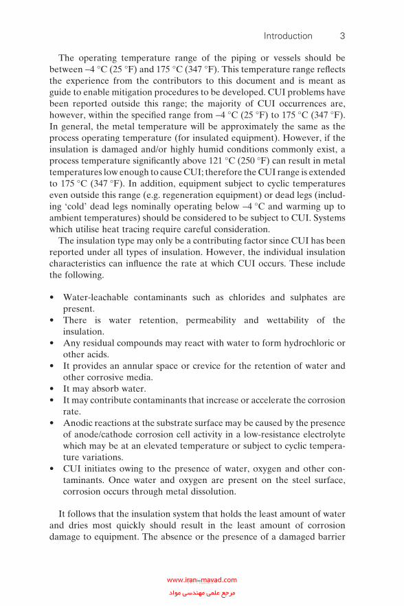
The rate of CUI is determined by the availability of oxygen, the contami-nants in water, the temperature, the heat transfer properties of the metal surface and the wet or dry condition of the surface. This in turn is infl uenced by the properties of the insulation materials. Damage can be general or localised. Service temperature is an important property as illustrated by Fig. 1.1 [12], which shows the effect of temperature of the corrosion rate of insulated carbon–manganese steels and introduces the concept of a closed system in which oxygenated water evaporation is limited, resulting in increased corrosion rates at higher temperature. This is the reason why CUI is such a problem as corrosion rates are often greater than anticipated.
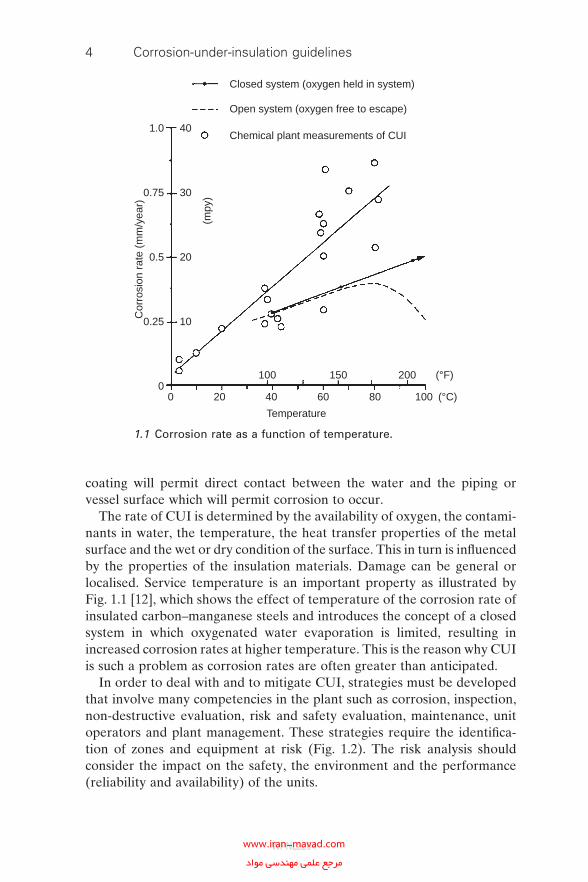
In order to deal with and to mitigate CUI, strategies must be developed that involve many competencies in the plant such as corrosion, inspection, non-destructive evaluation, risk and safety evaluation, maintenance, unit operators and plant management. These strategies require the identifi ca-tion of zones and equipment at risk (Fig. 1.2). The risk analysis should consider the impact on the safety, the environment and the performance (reliability and availability) of the units.
1.0
0.75
0.5
0.25
0
40
30
20
10
Cor
rosi
on r
ate
(mm
/yea
r)
0 20 40 60 80 100 (°C)
Temperature
100 150 200 (°F)
(mpy
)
Closed system (oxygen held in system)
Open system (oxygen free to escape)
Chemical plant measurements of CUI
1.1 Corrosion rate as a function of temperature.
WPNL2204www.iran-mavad.com مرجع علمى مهندسى مواد
Introduction 5
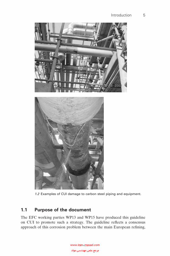
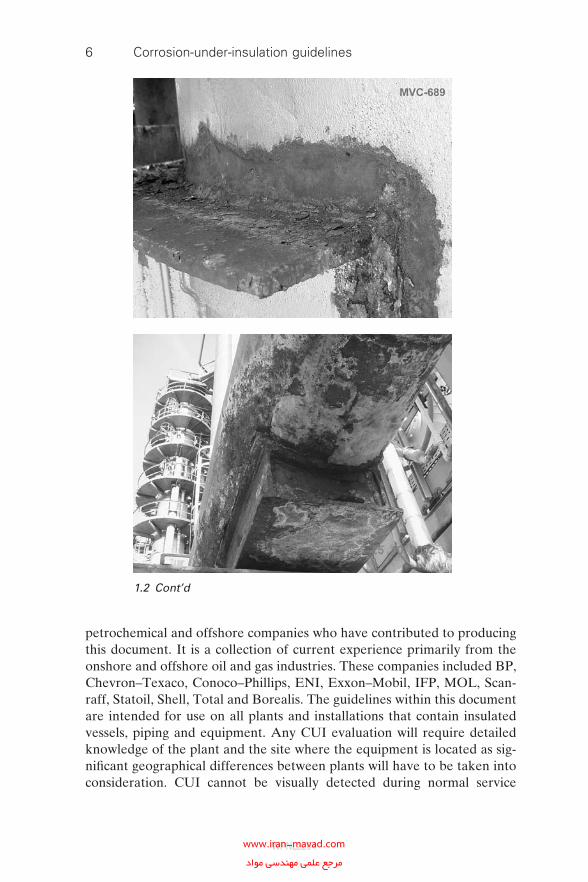
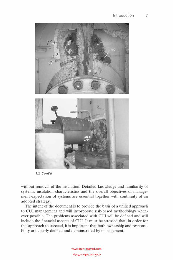
1.2 Examples of CUI damage to carbon steel piping and equipment.
1.1 Purpose of the document
The EFC working parties WP13 and WP15 have produced this guideline on CUI to promote such a strategy. The guideline refl ects a consensus approach of this corrosion problem between the main European refi ning,
WPNL2204www.iran-mavad.com مرجع علمى مهندسى مواد
6 Corrosion-under-insulation guidelines
petrochemical and offshore companies who have contributed to producing this document. It is a collection of current experience primarily from the onshore and offshore oil and gas industries. These companies included BP, Chevron–Texaco, Conoco–Phillips, ENI, Exxon–Mobil, IFP, MOL, Scan-raff, Statoil, Shell, Total and Borealis. The guidelines within this document are intended for use on all plants and installations that contain insulated vessels, piping and equipment. Any CUI evaluation will require detailed knowledge of the plant and the site where the equipment is located as sig-nifi cant geographical differences between plants will have to be taken into consideration. CUI cannot be visually detected during normal service
1.2 Cont’d
WPNL2204www.iran-mavad.com مرجع علمى مهندسى مواد
Introduction 7
without removal of the insulation. Detailed knowledge and familiarity of systems, insulation characteristics and the overall objectives of manage-ment expectation of systems are essential together with continuity of an adopted strategy.
The intent of the document is to provide the basis of a unifi ed approach to CUI management and will incorporate risk-based methodology when-ever possible. The problems associated with CUI will be defi ned and will include the fi nancial aspects of CUI. It must be stressed that, in order for this approach to succeed, it is important that both ownership and responsi-bility are clearly defi ned and demonstrated by management.
1.2 Cont’d
WPNL2204www.iran-mavad.com مرجع علمى مهندسى مواد
8 Corrosion-under-insulation guidelines
CUI guidelines
Chapter 2Economic
consideration
Chapter 3Ownership andresponsibility
Section 4.2Unit level
prioritisation
Section 4.3Challenging the need
for insulationSection 4.4
Data validationSection 4.5
Using risk-based inspection todesign CUI inspection plans
Chapter 5Inspection activities
and strategy
Chapter 6NDE/NDT screeningtechniques for CUI
Chapter 7Recommended bestpractice to mitigate
CUI
Chapter 8Design for the
prevention of CUI
AppendixCase studies
Review of the impact of CUI on process plant safety andfinancial performance; key performance indicators and casesupporting data are provided
For the early stages of a CUI programme proposal of a simplebusiness model to prioritise on a plant-by-plant basis
A methodical approach to challenging the continued use ofthermal insulation on process equipment most vulnerable to CUI
A proposal for a programme to verify the equipment insulationconditions and how to analyse future needs
A proposed risk-based inspection methodology for CUI
Proposals or specific CUI evaluation plans according to therisk level
Presentation of the main NDT techniques to evaluate CUI withtheir advantages and disadvantages
To ensure CUI mitigation field implementation should followrecommended best practice
A review of different maintenance and remediation issues:surface preparation, coatings and insulation materials,including a life cycle cost analysis
Feedback of findings into the main implementation to ensureoptimisation of the process
The implication and responsibility of different competenciesand a proposal for task organisation to manage CUI problems
Section Description
Costanalysis
Policy
Strategy
Inspectionand
maintenance
Implementation
Improvement
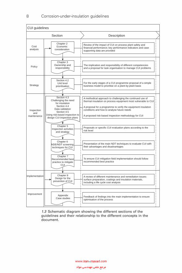
1.3 Schematic diagram showing the different sections of the guidelines and their relationship to the different concepts in the document.
WPNL2204www.iran-mavad.com مرجع علمى مهندسى مواد
Introduction 9
The primary objective of this document is to provide the background to manage CUI effectively using a high-level risk-based approach to develop adequate inspection and maintenance strategies, using current best practice developed in the fi eld. It is not intended that the document should provide a detailed prescription of when to inspect for CUI or to specify which of the many available non-destructive examination (NDE) and non-destructive testing (NDT) techniques to use or to specify a particular main-tenance strategy. Guidance will be given on the most appropriate approaches to use, but the fi nal decision will be left to the incumbent personnel who are responsible for the equipment that is susceptible to CUI.
The sections in the document will therefore include guidance on the following.
• Cost analysis.• Policy.• Strategy.• Inspection and maintenance.• Implementation.• Improvement.
The different chapters and sections of this document and their relation-ship to the above concepts are shown in Fig. 1.3.
1.2 References
1. W.G. Ashbaugh, ‘ESCC of stainless steel under thermal insulation’, Materials Protection, May 1965, 19–23.
2. European Meeting on Corrosion Under Lagging, Newcastle upon Tyne, UK, November 1980.
3. J. Richardson, ‘A review of the European Meeting on Corrosion under Lagging held in England, November 1980’, in Corrosion of Metals Under Thermal Insulation, ASTM Special Technical Publication 880, W.I. Pollock and J.M. Barnhart (Eds), Philadelphia, Pennsylvania, American Society for Testing and Materials, 1985, pp. 42–59.
4. W.I. Pollock and J.M. Barnhart (Eds), Corrosion of Metals Under Thermal Insulation, ASTM Special Technical Publication 880, Philadelphia, Pennsylva-nia, American Society for Testing and Materials, 1985.
5. ASTM C691-1971 Evaluating the Infl uence of Wicking Type Thermal Insulat-ions on the Stress Corrosion Cracking Tendency of Austenitic Stainless Steels, Philadelphia, Pennsylvania, American Society for Testing and Materials, 1971.
6. NACE Task Group T-6H-31, A State-of-the-Art Report on Protective Coatings for Carbon Steel and Austenitic Stainless Steel Surfaces Under Thermal Insula-tion and Cementitious Fireproofi ng, NACE Publication 6H189, Houston, Texas, National Association of Corrosion Engineers, 1983.
WPNL2204www.iran-mavad.com مرجع علمى مهندسى مواد
10 Corrosion-under-insulation guidelines
7. NACE RP0198-1998 The Control of Corrosion of Metals Under Thermal Insula-tion and Fireproofi ng Materials—A Systems Approach, Houston, Texas, NACE International, 1998.
8. NACE RP0198-2004 The Control of Corrosion of Metals Under Thermal Insula-tion and Fireproofi ng Materials—A Systems Approach, Houston, Texas, NACE International, 2004.
9. J.F. Delahunt, ‘Corrosion under insulation and fi reproofi ng—an overview’, in NACE Corrosion Conference 2003, Houston, Texas, NACE International, 2003, Paper 03022.
10. Corrosion under Insulation—Have you a Problem?, Corrosion Committee—CUI Conference, Sheffi eld, 14 January 2004, London, Institute of Materials, Minerals and Mining, 2004, http://www.iom3.org/divisions/surface/corrosion/cui_programme.htm.
11. J. Thirkettle, ‘UK CUI Forum activities’, in Corrosion under Insulation—Have you a Problem?, Corrosion Committee—CUI Conference, Sheffi eld, 14 January 2004, London, Institute of Materials, Minerals and Mining, 2004, http://www.iom3.org/divisions/surface/corrosion/paper15_thirkettle.ppt.
12. F.N. Speller, Corrosion—Causes and Prevention, 2nd edition, New York, McGraw-Hill, 1935, p. 153 and Fig. 25.
WPNL2204www.iran-mavad.com مرجع علمى مهندسى مواد
2Economic consideration
A fundamental step in the management process for any CUI or external corrosion control programme is a rigorous review of the current plant status. This review should include steps to identify the current incident rate and the potential incident rate, the impact of any failures on process plant safety, and the environmental and fi nancial performances. A clear demon-stration of the benefi t to be gained versus the potential cost of maintaining the status quo is a key driver in ensuring senior management support for what can be a signifi cant investment programme in any refi nery or petro-chemical, offshore or other process facility.
2.1 Statistical analysis
Analysis of inspection advice notes or recommendations, maintenance work orders and historical records should be carried out to determine a base case for failures and potential failure due to CUI or external corrosion. This information is best presented as an annualised fi gure, thus allowing year-on-year comparisons. Further partition of these data can prove useful in assessing the business risk ranking of process units used in high-level prioritisation (Chapter 4).
The number of CUI events that led to a loss of containment or leakage is the fi rst key statistical fi gure. Each one of these events is likely to have signifi cantly contributed to a lost profi t opportunity (LPO) for a process facility as sometimes they result in unplanned downtime.
The number of CUI and external corrosion events that led to an addi-tional engineering or maintenance work requirement is the second key statistical fi gure. Whilst each one is less likely to have a signifi cant contribu-tion to the LPO, as downtime can be better managed and planned, they are a clear indicator of the underlying trend of CUI on the facility.
11
WPNL2204www.iran-mavad.com مرجع علمى مهندسى مواد
12 Corrosion-under-insulation guidelines
2.2 Size of the issue
There are many ways of quantifying the cost associated with CUI and external corrosion. When collecting the data to make such an analysis, it is important to consider every detail, however small, as the cumulative effect will have a signifi cant impact over the life of a facility.
Key factors to be considered are discussed below.
2.2.1 Safety and integrity
It is diffi cult to assign a cost to the safety impact of CUI or external corro-sion in such an evaluation. However, it should always be the main priority and any event that has a personnel safety impact should be scored appropriately.
2.2.2 Environment
Environmental impact would include unscheduled fl aring, noise, losses to drains and water courses, air or soil pollution and non-compliance with environmental regulations.
2.2.3 Revenue or production loss
The costs associated with any CUI or external corrosion event which impacts upon production rate or product quality should be calculated. Most facilities run a linear model for production and this should be used in con-junction with the midcycle margin to calculate a production revenue loss. The evaluation should account for the volume of product lost, requiring reprocessing or being downgraded. By using the midcycle margin, one can remove the infl uence of fl uctuating margins on a year-by-year basis when fi xing lost profi t opportunities against operating and maintenance budgets.
2.2.4 Reputation
Reputation may be considered to be a soft and internal company issue. However, it is a major company issue as its impact may outweigh the sum total of all other costs. Also a potential loss of reputation may result in potential restrictions on a company’s licence to operate.
The total LPO for a facility is the sum of all the above. Typical examples are quoted in the case history section.
WPNL2204www.iran-mavad.com مرجع علمى مهندسى مواد
Economic consideration 13
2.2.5 Collateral damage cost
If a process line or piece of equipment failed by simple leakage and no other event occurred, then costing is simply the replacement cost of that item. If, however, another event occurred as a result of that leak, such as a fi re, and other equipment was damaged, then this must be accounted for in the evaluation. In some circumstances, environmental or clean-up costs should be considered and these may be signifi cant values.
2.2.6 Online leak sealing cost
In certain situations it may be acceptable to contain a leak or potential leakage area within an online leak-sealing device. Each device will have an associated manufacturing and installation cost. However, hidden behind this there may also be the cost of risk assessment to fi t such a device and this should not be forgotten.
2.2.7 Repair and/or replacement, fabrication and installation costs
Repair and/or replacement of corroded equipment and piping are mainte-nance or project costs depending upon the value of the item to be repaired or replaced. Emergency or replacements (reactive repairs) are often per-formed as part of an unplanned outage. If items can be deferred to a period of planned maintenance or project activity by using restricted fi tness for continued service criteria, then it is important to capture these costs also. These costs should be annualised from the time of the evaluation up to the next planned outage period.
2.2.8 Fitness for continued service
The cost of evaluating whether it is safe to leave an individual item of externally corroded equipment in service is not small. Based on the second key statistical fi gure referred to above, the value is likely to be large for a plant which has a high incidence of CUI or external corrosion.
2.2.9 On-stream inspection and non-destructive examination and testing
Care must be taken with this value as only costs associated with a loss of containment, associated collateral damage, or those inspections associated with a specifi c external corrosion or CUI event which warrants an inspec-tion advice note or recommendation should be captured.
WPNL2204www.iran-mavad.com مرجع علمى مهندسى مواد
14 Corrosion-under-insulation guidelines
2.3 Key performance indicators
With any programme where statistical evaluation of events and fi nancial performance is used as a method of enhancing justifi cation, it will benefi t the project cycle if key performance indicators (KPIs) can be identifi ed and used.
In CUI programmes, the statistical KPIs could include, but are not limited to, the following items.
• Number of leaks due to CUI or external corrosion.• Number of repairs for CUI or external corrosion.• Number of CUI saves (capturing equipment and piping before the wall
loss becomes signifi cant).• The risk reduction produced when an item is mitigated against CUI by
inspecting and maintaining (remove insulation, inspect, blast, paint, reinsulate and seal).
• Reprioritisation of inspection due dates.
In CUI programmes, the fi nancial KPIs could be items such as the following.
• LPO as a result of CUI or external corrosion.• Maintenance repair cost due to CUI or external corrosion.• Ranking of CUI or external corrosion in the facility revenue worst-
actors listing.
WPNL2204www.iran-mavad.com مرجع علمى مهندسى مواد
3Ownership and responsibility
Everyone who is working in a plant is responsible for ensuring that insu-lated systems are correctly installed, are inspected and are properly main-tained. In addition to this, all personnel that are working in the plant are responsible for reporting damage to insulation systems when observed.
3.1 Senior management
Management should be aware of the problem of CUI and act so that both fi nancial and human resources are available to manage the risk of CUI to an appropriate level. Management should also ensure that there is a culture within the organisation that reinforces the need to treat insulated systems in a way that avoids unnecessary damage that would promote CUI.
3.2 Engineering manager
It is the responsibility of an engineering manager to revise and improve specifi cations for vessel details, insulation, surface treatment, and supports and attachments to equipment in order to prolong the service life of equip-ment (see Appendix E).
3.3 Maintenance
It is the responsibility of maintenance departments to ensure that insulated systems are correctly installed and maintained (painting and insulation) using approved standards and that adequate quality checks are carried out. The responsibility of avoiding damage to insulation through plant engineer-ing work lies with maintenance departments. The inspection and corrosion engineering function should ensure correct maintenance procedures and check their execution.
15
WPNL2204www.iran-mavad.com مرجع علمى مهندسى مواد
16 Corrosion-under-insulation guidelines
3.4 Operations
The operations department should ensure that damage to insulation or steam tracing leaks under insulation are reported immediately to the main-tenance department for repair. The responsibility of avoiding damage to insulation through plant operational work lies with operations. This includes any changes required to equipment following process outside the operating window or when temporarily out of service (mothballing).
3.5 Inspection
Inspection departments should carry out inspection work to locate CUI on insulated systems, to assess the degree of corrosion damage and to deter-mine whether continued safe operation is affected. This function should also ensure that equipment or piping is repaired or replaced where required. Ensuring that proper standards of painting and insulation are applied should be achieved through inspection. Inspection should also be involved during construction of new projects and plant changes.
3.6 Members of a project team;
corrosion-under-insulation programme
Where a recognised ongoing CUI prevention programme is not in place and lack of maintenance has led to poor condition of the insulation of equipment, a number of major organisations have resorted to the setting up of dedicated CUI project teams to address the issues of CUI. This team may need considerable short-term funding to reinstate the refi nery and/or process plant to an acceptable condition.
WPNL2204www.iran-mavad.com مرجع علمى مهندسى مواد
4The risk-based inspection methodology for
corrosion-under-insulation
4.1 Introduction
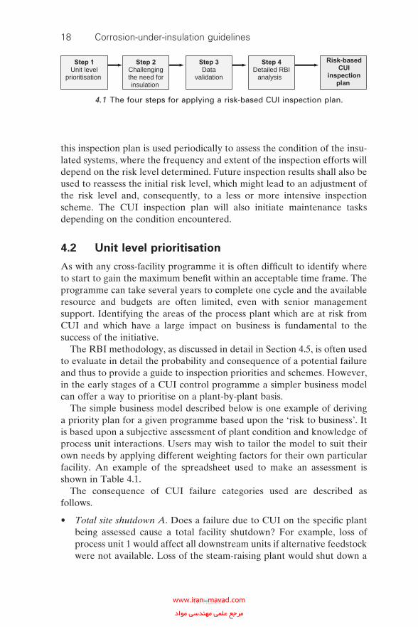
The risk-based inspection (RBI) methodology for setting up inspection plans (Fig. 4.1), which focus most effort on those items that possess the highest risk of failure, is generally accepted in the refi ning, petrochemical and offshore industries. For this reason a similar approach is recommended for CUI.
When introducing the RBI approach, risks will not be known. Insulated systems will have to be assessed in order to determine the appropriate risk levels and the associated inspection plans. In most practical situations it will be impossible to conduct such an effort on all insulated systems at once, because of limited resources and budget. For that reason, a unit level pri-oritisation step is introduced that may help to prioritise the RBI efforts for the different insulated systems. Using this approach, one will generally be able initially to direct RBI efforts to those insulated systems that feature the highest risks for operations. Section 4.2 will address this unit level pri-oritisation approach.
Once the units have been prioritised with respect to risk of CUI failure, it is recommended to challenge carefully the need for insulation. It is fairly obvious that the best way to eliminate CUI is to eliminate insulation. (Section 4.3 discusses the requirement for insulation.)
The RBI methodology makes use of actual operational and structural conditions of insulated systems, and not the design conditions. In order to obtain valid information from the RBI analysis it is important to be sure that all input data are correct. To this effect, data validation is described in Section 4.4, and the aim of this validation is to prevent errors in determining the risk of CUI failure.
Section 4.5 presents the RBI analysis for CUI, which consists of a condi-tion assessment of insulated systems, a risk level determination according to the probability of CUI failure and the consequence of CUI failure, and the resulting CUI inspection plan based on that risk level. Once established,
17
WPNL2204www.iran-mavad.com مرجع علمى مهندسى مواد
18 Corrosion-under-insulation guidelines
this inspection plan is used periodically to assess the condition of the insu-lated systems, where the frequency and extent of the inspection efforts will depend on the risk level determined. Future inspection results shall also be used to reassess the initial risk level, which might lead to an adjustment of the risk level and, consequently, to a less or more intensive inspection scheme. The CUI inspection plan will also initiate maintenance tasks depending on the condition encountered.
4.2 Unit level prioritisation
As with any cross-facility programme it is often diffi cult to identify where to start to gain the maximum benefi t within an acceptable time frame. The programme can take several years to complete one cycle and the available resource and budgets are often limited, even with senior management support. Identifying the areas of the process plant which are at risk from CUI and which have a large impact on business is fundamental to the success of the initiative.
The RBI methodology, as discussed in detail in Section 4.5, is often used to evaluate in detail the probability and consequence of a potential failure and thus to provide a guide to inspection priorities and schemes. However, in the early stages of a CUI control programme a simpler business model can offer a way to prioritise on a plant-by-plant basis.
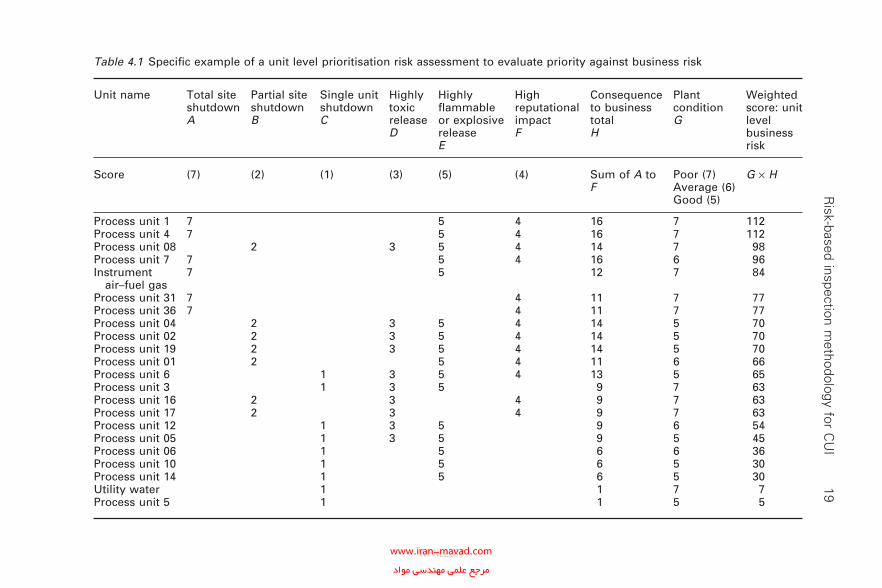
The simple business model described below is one example of deriving a priority plan for a given programme based upon the ‘risk to business’. It is based upon a subjective assessment of plant condition and knowledge of process unit interactions. Users may wish to tailor the model to suit their own needs by applying different weighting factors for their own particular facility. An example of the spreadsheet used to make an assessment is shown in Table 4.1.
The consequence of CUI failure categories used are described as follows.
• Total site shutdown A. Does a failure due to CUI on the specifi c plant being assessed cause a total facility shutdown? For example, loss of process unit 1 would affect all downstream units if alternative feedstock were not available. Loss of the steam-raising plant would shut down a
Step 1Unit level
prioritisation
Step 2Challengingthe need forinsulation
Step 3Data
validation
Step 4Detailed RBI
analysis
Risk-basedCUI
inspectionplan
4.1 The four steps for applying a risk-based CUI inspection plan.
WPNL2204www.iran-mavad.com مرجع علمى مهندسى مواد
R
isk-based inspection methodology for C
UI
19Table 4.1 Specifi c example of a unit level prioritisation risk assessment to evaluate priority against business risk
Unit name Total site shutdownA
Partial site shutdownB
Single unit shutdownC
Highly toxic releaseD
Highly fl ammable or explosive releaseE
High reputational impactF
Consequence to business totalH
Plant conditionG
Weighted score: unit level business risk
Score (7) (2) (1) (3) (5) (4) Sum of A to F
Poor (7) Average (6) Good (5)
G × H
Process unit 1 7 5 4 16 7 112Process unit 4 7 5 4 16 7 112Process unit 08 2 3 5 4 14 7 98Process unit 7 7 5 4 16 6 96Instrument air–fuel gas
7 5 12 7 84
Process unit 31 7 4 11 7 77Process unit 36 7 4 11 7 77Process unit 04 2 3 5 4 14 5 70Process unit 02 2 3 5 4 14 5 70Process unit 19 2 3 5 4 14 5 70Process unit 01 2 5 4 11 6 66Process unit 6 1 3 5 4 13 5 65Process unit 3 1 3 5 9 7 63Process unit 16 2 3 4 9 7 63Process unit 17 2 3 4 9 7 63Process unit 12 1 3 5 9 6 54Process unit 05 1 3 5 9 5 45Process unit 06 1 5 6 6 36Process unit 10 1 5 6 5 30Process unit 14 1 5 6 5 30Utility water 1 1 7 7Process unit 5 1 1 5 5
WPNL2204www.iran-mavad.com مرجع علمى مهندسى مواد
20 Corrosion-under-insulation guidelines
site that was heavily dependent on steam for heating and primary turbine drivers.
• Partial site shutdown B. Does a failure due to CUI on the specifi c plant being assessed cause a partial facility shutdown? For example, loss of the units that provide steam and fuel gas would affect the facility balance.
• Single unit shutdown C. Does a failure due to CUI on the specifi c plant being assessed have little or no effect outside that unit’s boundaries? For example, the unit does not affect the operation of other units but may impact fi nal product quality or available volume.
• High toxic release D. Does a failure due to CUI put plant personnel or the general public at risk from a toxic release? This should take account of process units that may have a signifi cant environmental impact if a release were to occur.
• Highly fl ammable or explosive release E. Does a failure due to CUI put the plant or plant personnel at risk from a fl ammable or explosive release? Process fl uids are such that a release would cause a signifi cant fi re or explosion.
• High reputational impact F. Does a failure due to CUI have an effect on the plant and/or company’s reputation? Some incidents will not involve high costs but could be regarded intolerable by the public and/or the authorities.
The probability of a CUI failure is assessed as follows.
• Plant condition G. What is the known or perceived general condition and preventative maintenance of a given process unit? This information is available from historical records or subjectively from interviews with plant personnel. The score is higher for poor condition and lower for good condition.
In the simple model described, the risk-to-business total is derived from the sum of the business consequence factors A to F. The fi nal weighted-risk ranking is the consequence to business (sum of A to F) multiplied by the probability of CUI failure, expressed by the plant condition G.
Once the weighted scores have been sorted from high down to low, a review of potential synergies between adjoining plants should be conducted to adjust the proposed schedule. Similarly, the scheduled shutdown or inspection and testing plans should be reviewed to assess whether there are any potential clashes or missed opportunities for progressing the CUI control programme.
4.3 Challenging the need for insulation
Dramatic increases in energy costs during the 1970s resulted in a tremen-dous drive in the refi ning and petrochemical industries to conserve process
WPNL2204www.iran-mavad.com مرجع علمى مهندسى مواد
Risk-based inspection methodology for CUI 21
energy, thus resulting in the increased and in many cases excessive use of thermal insulation. There is a need to challenge the very use of thermal insulation in the fi ght against CUI.
The purpose of this section of the guidelines is to provide the user with a methodical approach to challenging the continued use of thermal insula-tion on the process equipment most vulnerable to CUI.
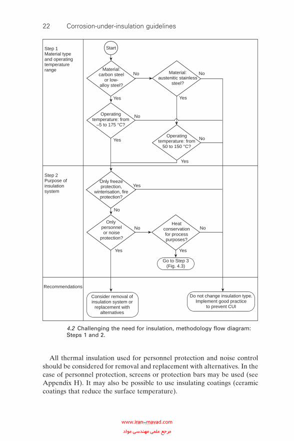
The methodology described below is also graphically presented as a deci-sion fl ow diagram in Fig. 4.2 and Fig. 4.3.
4.3.1 Step 1: determining the material type and operating temperature range
Carbon steel or low-alloy steel equipment that operates continuously above 175 °C or below −4 °C does not normally suffer serious problems due to CUI. For austenitic stainless steel the temperature limits above 175 °C or below 50 °C are used for guidance in these guidelines. Steady or cyclical operation between the temperatures given above present a signifi cant risk for CUI.
It is recommended that equipment that operates in the above tempera-ture range and that is insulated for heat conservation and process control should be selected for further assessment.
4.3.2 Step 2: determining the purpose of the insulation system
Plant equipment and piping are insulated for any or a combination of the following reasons.
• Heat conservation.• Process control.• Freeze protection and/or winterisation.• Personnel protection.• Noise control (acoustic purposes).• Fire protection.
This information is often contained in the equipment and piping specifi -cations for a particular facility, and it may be useful to gain an understand-ing of the various insulation codes used in the relevant specifi cations.
It is recommended that the use of thermal insulation for freeze protection or winterisation as well as fi re protection should not be challenged as these form a part of the safety design of a plant that should not be compromised. For such systems, all the recommendations for protection against CUI con-tained in these guidelines should be implemented.
WPNL2204www.iran-mavad.com مرجع علمى مهندسى مواد
22 Corrosion-under-insulation guidelines
All thermal insulation used for personnel protection and noise control should be considered for removal and replacement with alternatives. In the case of personnel protection, screens or protection bars may be used (see Appendix H). It may also be possible to use insulating coatings (ceramic coatings that reduce the surface temperature).
Material:carbon steel
or low-alloy steel?
Material:austenitic stainless
steel?
Operatingtemperature: from
–5 to 175 °C?
No
No
No
No
NoNo
No
Operatingtemperature: from
50 to 150 °C?
Only freezeprotection,
winterisation, fireprotection?
Only personnelor noise
protection?
Heatconservationfor processpurposes?
Step 1Material typeand operatingtemperaturerange
Step 2Purpose ofinsulationsystem
Recommendations
Start
Consider removal ofinsulation system or
replacement withalternatives
Do not change insulation type.Implement good practice
to prevent CUI
Go to Step 3(Fig. 4.3)
Yes
Yes
Yes
YesYes
Yes
Yes
4.2 Challenging the need for insulation, methodology fl ow diagram: Steps 1 and 2.
WPNL2204www.iran-mavad.com مرجع علمى مهندسى مواد
Risk-based inspection methodology for CUI 23
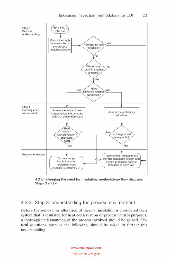
4.3.3 Step 3: understanding the process environment
Before the removal or alteration of thermal insulation is considered on a system that is insulated for heat conservation or process control purposes, a thorough understanding of the process involved should be gained. Cri-tical questions, such as the following, should be asked to further this understanding.
Normally no flow(dead leg)?
Will removalresult in process
changes?
Morecorrosive process
conditions?
Is change in riskacceptable?
Heatvalue >
CUI prevention?(life cycle
cost)
Assess the value of heatconservation and comparewith CUI prevention costs
Assess the probabilityof failure
Do not changeinsulation type.Implement good
practice to prevent CUI
Recommend removal of thethermal imsulation system and
ensure protection againstatmospheric corrosion.
Gain a thoroughunderstanding of
the process(multidisciplinary)
From Step 2(Fig. 4.2)
Step 3Processunderstanding
Step 4Consequenceassessment
Recommendations
Yes Yes
Yes
Yes
Yes
No
No
No
No
No
4.3 Challenging the need for insulation, methodology fl ow diagram: Steps 3 and 4.
WPNL2204www.iran-mavad.com مرجع علمى مهندسى مواد
24 Corrosion-under-insulation guidelines
• Will removal of the thermal insulation system result in any process changes (phase changes)?
• What are the consequences of the process changes associated with the total removal of the thermal insulation system?
• Will removal of the thermal insulation result in a higher consequence category in an RBI assessment, i.e. increased risk?
• Will removal of the thermal insulation system result in more corrosive process conditions (e.g. may lead to condensation)? Does this change the probability of failure above that previously determined in an RBI assessment?
4.3.4 Step 4: assessing the consequences and probability of removing the thermal insulation system
It is important to distinguish between economic consequences (e.g. increased energy costs and non-optimal process) and health and safety consequences. If health and safety consequences are the main drivers, then the use of the thermal insulation system should preferably be retained. If only economic consequences are involved, it is recommended that a thorough assessment of these costs be conducted and compared with the cost of preventing CUI (e.g. installing and maintaining a coating system under the thermal insulation).
Changes in the probability of failure due to internal corrosion should also be assessed. It is recommended that this be conducted using RBI principles. If no increase in the probability of failure is shown, it is recommended that the thermal insulation system be removed. Where permanent removal of insulation is carried out, the process should be captured by a management of change or plant change procedure so that the risks are evaluated and the relevant engineering records (e.g. drawings and engineering databases) are updated.
4.4 Data validation
4.4.1 The need for data validation
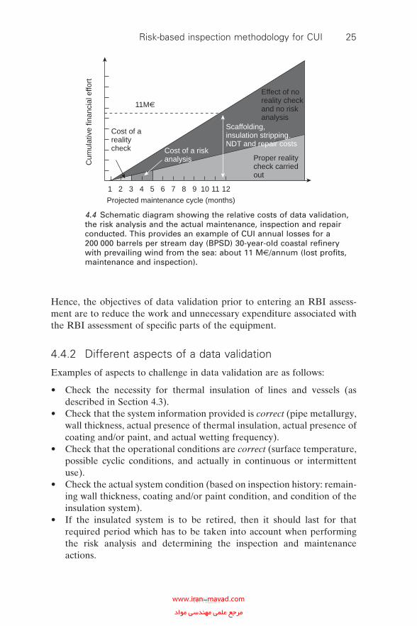
In Western Europe the costs of a CUI control programme can be very sig-nifi cant; however, those of inaction are even higher. The relative costs of action and inaction are the subject of Chapter 2 of these guidelines. The schematic diagram in Fig. 4.4 shows a rapid increase in costs associated with the logical actions taken to manage the risks associated with CUI. It also shows that, if a proper data validation has been carried out, the total costs of a CUI control programme may be signifi cantly lower than if all insulated systems as present on the original design drawings are being analysed.
WPNL2204www.iran-mavad.com مرجع علمى مهندسى مواد
Risk-based inspection methodology for CUI 25
Hence, the objectives of data validation prior to entering an RBI assess-ment are to reduce the work and unnecessary expenditure associated with the RBI assessment of specifi c parts of the equipment.
4.4.2 Different aspects of a data validation
Examples of aspects to challenge in data validation are as follows:
• Check the necessity for thermal insulation of lines and vessels (as described in Section 4.3).
• Check that the system information provided is correct (pipe metallurgy, wall thickness, actual presence of thermal insulation, actual presence of coating and/or paint, and actual wetting frequency).
• Check that the operational conditions are correct (surface temperature, possible cyclic conditions, and actually in continuous or intermittent use).
• Check the actual system condition (based on inspection history: remain-ing wall thickness, coating and/or paint condition, and condition of the insulation system).
• If the insulated system is to be retired, then it should last for that required period which has to be taken into account when performing the risk analysis and determining the inspection and maintenance actions.
1 2 3 4 5 6 7 8 9 10 11 12
Projected maintenance cycle (months)
11M€
Cost of arealitycheck Cost of a risk
analysis
Scaffolding,insulation stripping.NDT and repair costs
Proper realitycheck carriedout
Effect of noreality checkand no riskanalysis
Cum
ulat
ive
finan
cial
effo
rt
4.4 Schematic diagram showing the relative costs of data validation, the risk analysis and the actual maintenance, inspection and repair conducted. This provides an example of CUI annual losses for a 200 000 barrels per stream day (BPSD) 30-year-old coastal refi nery with prevailing wind from the sea: about 11 M@/annum (lost profi ts, maintenance and inspection).
WPNL2204www.iran-mavad.com مرجع علمى مهندسى مواد
26 Corrosion-under-insulation guidelines
• If the vessel and/or piping is mothballed or otherwise out of service, then it may be unreasonable to devote time and money to assessing or refurbishing it.
4.4.3 Implementation of data validation
The simple process described below is one example of carrying out data validation. Users may wish to tailor the process to suit their own needs by including or excluding certain aspects such as mentioned in Section 4.4.2.
It is important that the engineer involved in the data validation makes a prescreen list of insulated pipe sections and pressure vessels within the unit of concern. Each unit shall have battery limits established on paper and fl agged in the unit with plaques so that maintenance workers and subcon-tractors have clear indications of the limits of the unit.
Each insulated item appearing on the prescreen list shall be visually checked for the following, as an example.
• Insulation system presence.• Insulation system condition.• Item metallurgy.• Item surface temperature.• Item exposure to cyclic service.• Item service condition.
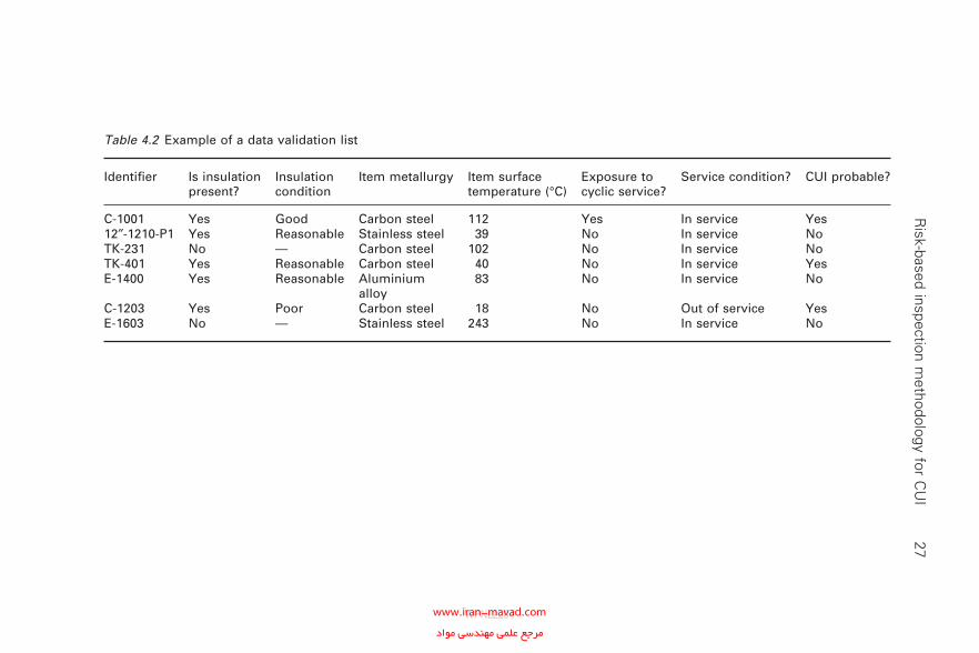
A sample data validation list with examples is presented in Table 4.2.
4.4.4 Corrosion under insulation and mothballing of equipment
Equipment is taken out of service with the intention of either permanent retirement (scrapping) or reuse after a period or time (possibly with refur-bishment) due to operational need in cyclic service. In both cases the equip-ment and piping must be rendered safe and hydrocarbon free. While permanent retirement can be considered a net loss, in the other case the equipment is important for the future of the plant and investment in a good mothballing procedure is critical. Specifi c mothballing procedures are required which preserve the equipment for future use and prevent any associated deterioration. In cyclic service a specifi c requirement for preven-tion against CUI is critical. Much equipment is not inspected for CUI because of the temperature range. Industry-wide the range for CUI is esti-mated as between −4 °C and 175 °C (carbon steels and low-alloy steels). However, out-of-service equipment will also deteriorate under ambient conditions owing to constantly saturated wet insulation which is not dried
WPNL2204www.iran-mavad.com مرجع علمى مهندسى مواد
R
isk-based inspection methodology for C
UI
27
Table 4.2 Example of a data validation list
Identifi er Is insulation present?
Insulation condition
Item metallurgy Item surface temperature (°C)
Exposure to cyclic service?
Service condition? CUI probable?
C-1001 Yes Good Carbon steel 112 Yes In service Yes12″-1210-P1 Yes Reasonable Stainless steel 39 No In service NoTK-231 No — Carbon steel 102 No In service NoTK-401 Yes Reasonable Carbon steel 40 No In service YesE-1400 Yes Reasonable Aluminium
alloy83 No In service No
C-1203 Yes Poor Carbon steel 18 No Out of service YesE-1603 No — Stainless steel 243 No In service No
WPNL2204www.iran-mavad.com مرجع علمى مهندسى مواد
28 Corrosion-under-insulation guidelines
during the process cycles. As a consequence, even good-quality low-salt insulation will produce an accelerated corrosion rate when continually in contact with carbon steels and low-alloy steels. This effect should be recog-nised during the data validation process, where equipment and vessels which are out of service have to be assessed for CUI risks. The fact that a unit is out of service for only a few months will not have a great effect on the long term (40+ years) viability of the average carbon steel or low-alloy steel unit. However, after the unit has lain idle for 12 months, the risk for the unit shall be assessed and scored accordingly.
4.5 Using risk-based inspection to design
corrosion-under-insulation inspection plans
The RBI methodology uses consequence of failure and probability of failure to determine the risk of failure. In the conventional RBI approach, the probability of failure is generally derived from corrosion rates, which can be used to estimate the remnant life of an item. However, the probabil-ity of a failure mode such as CUI is diffi cult to determine, because the cor-rosion rate is usually unknown. Since there are quite a number of factors that play a role in the process of CUI, the probability of CUI failure will be formed by a total score on a number of susceptibility factors, of which the operating temperature and the external environment (wetting extent and frequency) are the most important. Many companies will have general probability and consequence factors well established in their systems. The aim of this section is not to replace these, but to give an example of the methodology of RBI for CUI.
The following sections describe a possible process that can be used for an RBI assessment for CUI.
4.5.1 Preparation of a risk-based inspection analysis
An RBI analysis starts with compiling the detailed asset integrity data for the unit under study, which consist of the following.
• Process data, including actual operating windows.• Engineering and design data and information on actual structural condi-
tion (see Section 4.4).• Description and evaluation of degradation mechanisms.• A compilation of inspection history and degradation analysis.
For the purpose of effi ciency, the unit under study is divided into smaller corrosion loops or circuits, which are sections of the unit that are operating under similar conditions, are exposed to specifi c corrosion phenomena and consist of similar materials.
WPNL2204www.iran-mavad.com مرجع علمى مهندسى مواد
Risk-based inspection methodology for CUI 29
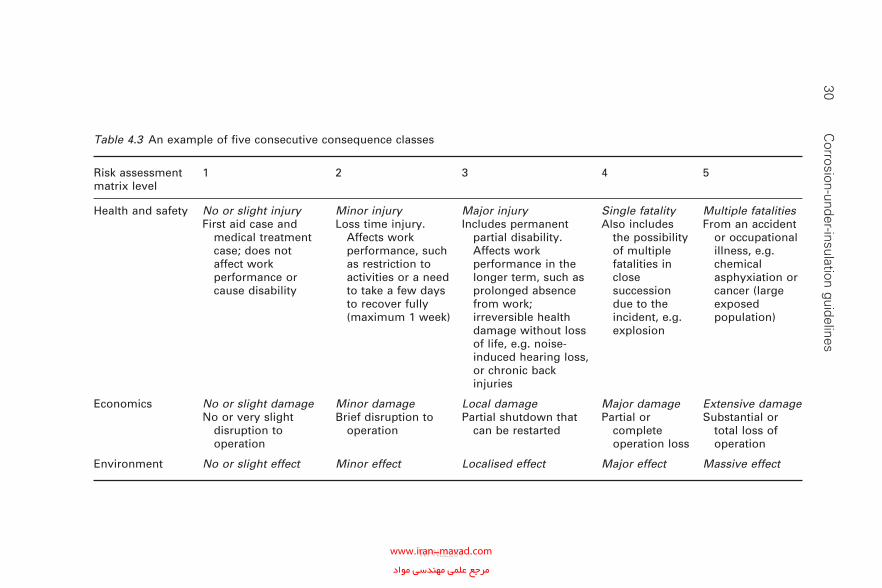
4.5.2 Consequence of corrosion-under-insulation failure
The next step in the RBI process for CUI is to determine the consequence of failure. A total of fi ve consequence classes for economics, for health and safety and for environment are considered in this example, but every company can use its own set of consequence classes. For the consequence assessment the consequence score table (Table 4.3) can be applied.
4.5.3 Probability of corrosion-under-insulation failure
When the consequence of failure has been established, the probability of failure is determined. This assessment distinguishes between carbon steel or low-alloy steel, and austenitic stainless steel. For austenitic stainless steel the term CUI refers to Cl-ESCC. Chlorides in the permeated water can, depending on the temperatures and concentration, cause external stress corrosion cracking (SCC) in AISI type 300 series austenitic stainless steel. Cl-ESCC typically is found in stressed areas (such as welds), where chloride ions dissolved in water are in contact with type 300 series stainless steel at temperatures above 50 °C (a temperature of 50 °C is used for guidance in these guidelines).
As explained at the start of this section, the susceptibility to CUI or Cl-ESCC failure is taken as the indicator for the probability level.
4.5.4 Susceptibility factors
Score tables are used to determine the level of CUI or Cl-ESCC susceptibil-ity. In the susceptibility tables, weighted scores can be awarded to a number of factors, which should include at least the key factors operating tempera-ture and external environment (wetting extent and frequency). In these guidelines these key factors have been supplemented by fi ve other factors contributing to the susceptibility to CUI (a total of four for Cl-ESCC). The user may decide to change or add to the susceptibility factors in order to fi t specifi c conditions. The seven susceptibility factors used in this example are explained below.
• Operating temperature is a very important aspect of the item’s suscepti-bility to CUI. In cyclic service (or temporary temperature changes), the temperature range corresponding to the most critical temperature reached should be taken. The occurrence of Cl-ESCC below 60 °C is very rare and, as a conservative approach, 50 °C is used for guidance in these guidelines. Above 175 °C, Cl-ESCC is seldom found; however, the item may still have a high susceptibility as it will be exposed to the most vulnerable temperature range of 50–175 °C during start-up or shutdown.
WPNL2204www.iran-mavad.com مرجع علمى مهندسى مواد
30 C
orrosion-under-insulation guidelines
Table 4.3 An example of fi ve consecutive consequence classes
Risk assessment matrix level
1 2 3 4 5
Health and safety No or slight injuryFirst aid case and
medical treatment case; does not affect work performance or cause disability
Minor injuryLoss time injury.
Affects work performance, such as restriction to activities or a need to take a few days to recover fully (maximum 1 week)
Major injuryIncludes permanent
partial disability. Affects work performance in the longer term, such as prolonged absence from work; irreversible health damage without loss of life, e.g. noise-induced hearing loss, or chronic back injuries
Single fatalityAlso includes
the possibility of multiple fatalities in close succession due to the incident, e.g. explosion
Multiple fatalities From an accident
or occupational illness, e.g. chemical asphyxiation or cancer (large exposed population)
Economics No or slight damageNo or very slight
disruption to operation
Minor damageBrief disruption to
operation
Local damagePartial shutdown that
can be restarted
Major damagePartial or
complete operation loss
Extensive damageSubstantial or
total loss of operation
Environment No or slight effect Minor effect Localised effect Major effect Massive effect
WPNL2204www.iran-mavad.com مرجع علمى مهندسى مواد
Risk-based inspection methodology for CUI 31
The frequency of such temperature cycles should be taken into consideration.
• Coating is the main barrier between the steel surface and its environ-ment. Therefore, the condition of the coating is crucial. As coatings degrade generally as a function of age, the older the coating, the greater is the probability of CUI. It should always be remembered that a poorly applied coating system can be worse than no coating at all, since it can accelerate corrosion by concentrating the corrosive effect on areas of coating breakdown. Equipment construction should be reviewed in detail to identify areas which, by design or poor fabrication, can act as a trap for water, resulting in coating breakdown. This will result in accelerated corrosion and an increased likelihood of both CUI and Cl-ESCC.
• Cladding and insulation condition. Although new cladding and insula-tion systems should be dry and virtually water tight, experience shows that, with age, water ingress is unavoidable. Mechanical damage, complex insulation geometries and/or inspection windows will increase the chances of water ingress. In Table 4.4 an example of an insulation defi ciency and defect checklist is given, which will assist maintenance and inspection staff with assessing insulation damage that might lead to CUI.
• Insulation type. Fibre-type insulation materials, e.g. mineral wool and fi breglass, easily absorb water, whilst expanded perlite and foam glass, with a closed-cell structure, have no capacity to absorb water and there-fore are less likely to contribute to CUI problems. Fibre-type insulation materials are commonly applied for hot insulation systems. The only way to reduce their contribution to CUI is by applying contact-free insulation techniques, whereby the insulation is held about 25 mm away from the steel surface.
• Available corrosion allowance. Thin-walled components will fail sooner owing to a certain CUI corrosion rate than will thick-walled compo-nents. However, the risk of CUI failure will not primarily be determined by the wall thickness, but by the available corrosion allowance. Although generally a conservative measure, the corrosion allowance indicates the tolerance of the component to wall loss before it will fail. By adding corrosion allowance, the susceptibility to CUI will not change, but the susceptibility to CUI failure will become lower. It is important to dis-criminate between the susceptibility to CUI, which is the chance that CUI will actually occur, and the susceptibility to CUI failure, which indicates the chance that CUI will lead to a failure; the latter is being considered here. For instance, in the case when a small bore connection in certain conditions will end up in a high-risk class, it may be considered that it should be replaced by a similar connection with a higher schedule
WPNL2204www.iran-mavad.com مرجع علمى مهندسى مواد
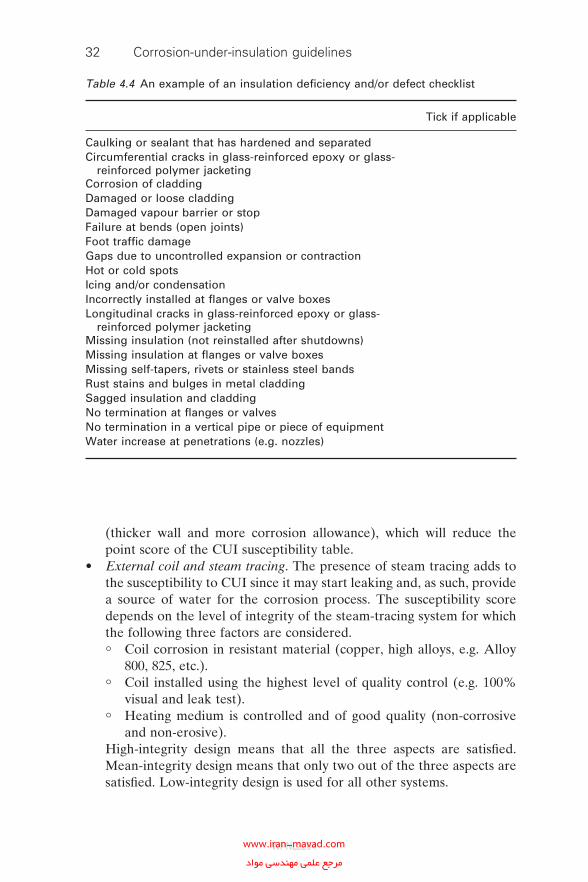
32 Corrosion-under-insulation guidelines
(thicker wall and more corrosion allowance), which will reduce the point score of the CUI susceptibility table.
• External coil and steam tracing. The presence of steam tracing adds to the susceptibility to CUI since it may start leaking and, as such, provide a source of water for the corrosion process. The susceptibility score depends on the level of integrity of the steam-tracing system for which the following three factors are considered.
° Coil corrosion in resistant material (copper, high alloys, e.g. Alloy 800, 825, etc.).
° Coil installed using the highest level of quality control (e.g. 100% visual and leak test).
° Heating medium is controlled and of good quality (non-corrosive and non-erosive).
High-integrity design means that all the three aspects are satisfi ed. Mean-integrity design means that only two out of the three aspects are satisfi ed. Low-integrity design is used for all other systems.
Table 4.4 An example of an insulation defi ciency and/or defect checklist
Tick if applicable
Caulking or sealant that has hardened and separatedCircumferential cracks in glass-reinforced epoxy or glass-
reinforced polymer jacketingCorrosion of claddingDamaged or loose claddingDamaged vapour barrier or stopFailure at bends (open joints)Foot traffi c damageGaps due to uncontrolled expansion or contractionHot or cold spotsIcing and/or condensationIncorrectly installed at fl anges or valve boxesLongitudinal cracks in glass-reinforced epoxy or glass-
reinforced polymer jacketingMissing insulation (not reinstalled after shutdowns)Missing insulation at fl anges or valve boxesMissing self-tapers, rivets or stainless steel bandsRust stains and bulges in metal claddingSagged insulation and claddingNo termination at fl anges or valvesNo termination in a vertical pipe or piece of equipmentWater increase at penetrations (e.g. nozzles)
WPNL2204www.iran-mavad.com مرجع علمى مهندسى مواد
Risk-based inspection methodology for CUI 33
• External environment. For CUI to occur, water needs to penetrate the insulation material and to contact the metal substrate surface. The degree of water ingress depends on the condition of the insulation mate-rial and the water sources and can be from rainfall, climatic environ-mental operating conditions, cooling water drifts, fi rewater, deluge systems, etc. Where no water can enter the system (inside buildings, no steam tracing, no sweating, etc.), the susceptibility to CUI will be insig-nifi cant and therefore the risk can be set to negligible by default.
4.5.4.1 Susceptibility score tables
Susceptibility score tables can be developed, both for carbon steel and low-alloy steel (less than 11% chromium) and for austenitic stainless steel, in order to establish the probability of failure class. An example of a suscep-tibility score table for carbon steel and low-alloy steel is shown in Table 4.5 and an example for austenitic stainless steel Cl-ESCC is shown in Table 4.6. Points should be awarded to each class, with more points for higher classes. The points awarded to any class can be determined by the user and can be dependent on their specifi c conditions. By adding the point score of the contributing factors, the total probability score can be determined.
Using the total score from the susceptibility score table, a probability class can be determined. For carbon steel and low-alloy steel, as well as for stainless steel, four probability classes are used in this example (but the user may decide to use more or fewer probability classes).
• Probability class negligible (total score 1-A).• Probability class low (total score A-B).• Probability class medium (total score B-C).• Probability class high (total score greater than C).
The limits A, B and C have to be determined by the user based on experi-ence and generally perceived corrosion rates in circumstances resembling the susceptibility conditions making up the total probability score.
It should be noted that the probability class, in combination with the consequence class, determines the risk level and hence there should be a sound relation with the inspection interval assigned to that corresponding CUI risk class. For instance, for a high-risk item with a predicted corrosion rate of 0.5 mm/year (although, generally, no corrosion rates are known for CUI, both literature and experience may provide rough indications of the worst-case values in certain conditions determined by the susceptibility factors) and a corrosion allowance of 2 mm, then the inspection interval should be signifi cantly less than 4 years. However, for a low-risk item in the same conditions an interval of 4 years may be acceptable.
WPNL2204www.iran-mavad.com مرجع علمى مهندسى مواد
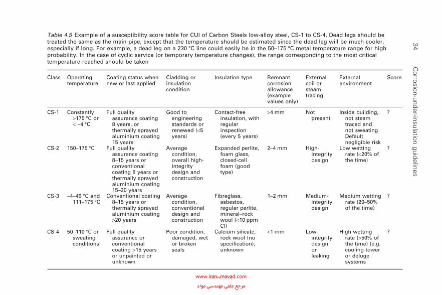
34 C
orrosion-under-insulation guidelinesTable 4.5 Example of a susceptibility score table for CUI of Carbon Steels low-alloy steel, CS-1 to CS-4. Dead legs should be treated the same as the main pipe, except that the temperature should be estimated since the dead leg will be much cooler, especially if long. For example, a dead leg on a 230 °C line could easily be in the 50–175 °C metal temperature range for high probability. In the case of cyclic service (or temporary temperature changes), the range corresponding to the most critical temperature reached should be taken
Class Operating temperature
Coating status when new or last applied
Cladding or insulation condition
Insulation type Remnant corrosion allowance (example values only)
External coil or steam tracing
External environment
Score
CS-1 Constantly >175 °C or < −4 °C
Full quality assurance coating 8 years, or thermally sprayed aluminium coating 15 years
Good to engineering standards or renewed (<5 years)
Contact-free insulation, with regular inspection (every 5 years)
>4 mm Not present
Inside building, not steam traced and not sweating Default negligible risk
?
CS-2 150–175 °C Full quality assurance coating 8–15 years or conventional coating 8 years or thermally sprayed aluminium coating 15–20 years
Average condition, overall high-integrity design and construction
Expanded perlite, foam glass, closed-cell foam (good type)
2–4 mm High-integrity design
Low wetting rate (<20% of the time)
?
CS-3 −4–49 °C and 111–175 °C
Conventional coating 8–15 years or thermally sprayed aluminium coating >20 years
Average condition, conventional design and construction
Fibreglass, asbestos, regular perlite, mineral–rock wool (<10 ppm Cl)
1–2 mm Medium-integrity design
Medium wetting rate (20–50% of the time)
?
CS-4 50–110 °C or sweating conditions
Full quality assurance or conventional coating >15 years or unpainted or unknown
Poor condition, damaged, wet or broken seals
Calcium silicate, rock wool (no specifi cation), unknown
<1 mm Low-integrity design or leaking
High wetting rate (>50% of the time) (e.g. cooling-tower or deluge systems
?
WPNL2204www.iran-mavad.com مرجع علمى مهندسى مواد
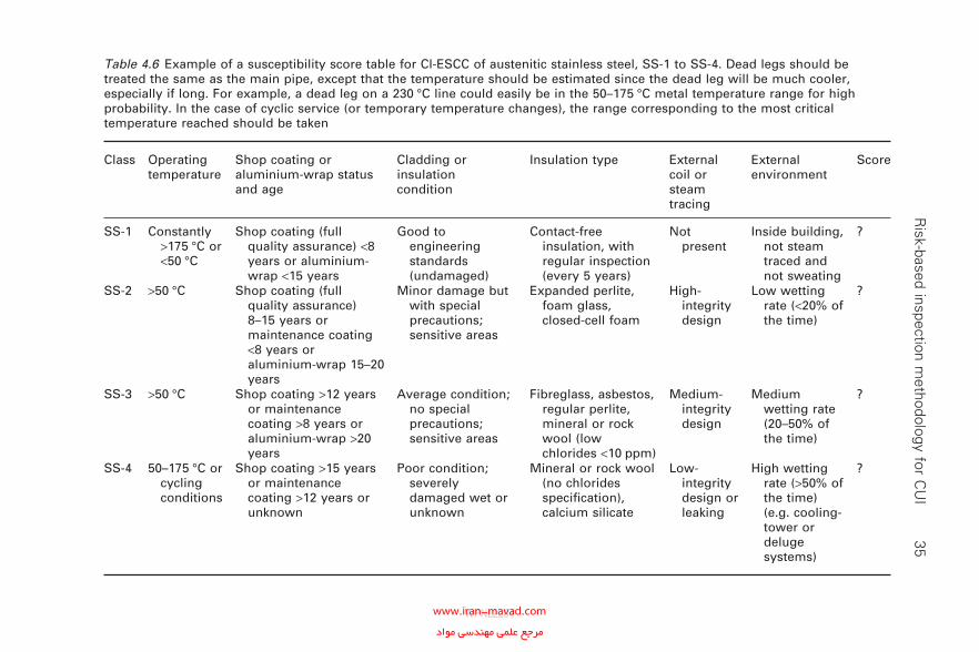
R
isk-based inspection methodology for C
UI
35Table 4.6 Example of a susceptibility score table for Cl-ESCC of austenitic stainless steel, SS-1 to SS-4. Dead legs should be treated the same as the main pipe, except that the temperature should be estimated since the dead leg will be much cooler, especially if long. For example, a dead leg on a 230 °C line could easily be in the 50–175 °C metal temperature range for high probability. In the case of cyclic service (or temporary temperature changes), the range corresponding to the most critical temperature reached should be taken
Class Operating temperature
Shop coating or aluminium-wrap status and age
Cladding or insulation condition
Insulation type External coil or steam tracing
External environment
Score
SS-1 Constantly >175 °C or <50 °C
Shop coating (full quality assurance) <8 years or aluminium-wrap <15 years
Good to engineering standards (undamaged)
Contact-free insulation, with regular inspection (every 5 years)
Not present
Inside building, not steam traced and not sweating
?
SS-2 >50 °C Shop coating (full quality assurance) 8–15 years or maintenance coating <8 years or aluminium-wrap 15–20 years
Minor damage but with special precautions; sensitive areas
Expanded perlite, foam glass, closed-cell foam
High-integrity design
Low wetting rate (<20% of the time)
?
SS-3 >50 °C Shop coating >12 years or maintenance coating >8 years or aluminium-wrap >20 years
Average condition; no special precautions; sensitive areas
Fibreglass, asbestos, regular perlite, mineral or rock wool (low chlorides <10 ppm)
Medium-integrity design
Medium wetting rate (20–50% of the time)
?
SS-4 50–175 °C or cycling conditions
Shop coating >15 years or maintenance coating >12 years or unknown
Poor condition; severely damaged wet or unknown
Mineral or rock wool (no chlorides specifi cation), calcium silicate
Low-integrity design or leaking
High wetting rate (>50% of the time) (e.g. cooling-tower or deluge systems)
?
WPNL2204www.iran-mavad.com مرجع علمى مهندسى مواد
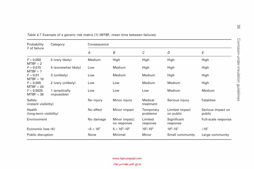
36 C
orrosion-under-insulation guidelines
Table 4.7 Example of a generic risk matrix [1] (MTBF, mean time between failures)
Probability F of failure
Category Consequence
A B C D E
F > 0.050MTBF < 2
5 (very likely) Medium High High High High
F = 0.015MTBF = 7
4 (somewhat likely) Low Medium High High High
F = 0.01MTBF = 10
3 (unlikely) Low Medium Medium High High
F = 0.005MTBF = 20
2 (very unlikely) Low Low Medium Medium High
F < 0.0025MTBF = 38
1 (practically impossible)
Low Low Low Medium Medium
Safety(instant visibility)
No injury Minor injury Medical treatment
Serious injury Fatalities
Health(long-term visibility)
No effect Minor impact Temporary problems
Limited impact on public
Serious impact on public
Environment No damage Minor impact; no response
Limited response
Signifi cant response
Full-scale response
Economic loss (2) <5 × 10³ 5 × 10³–105 105–106 106–107 >107
Public disruption None Minimal Minor Small community Large community
WPNL2204www.iran-mavad.com مرجع علمى مهندسى مواد
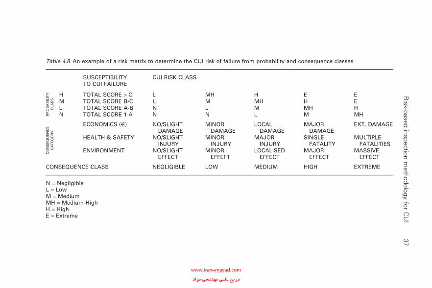
R
isk-based inspection methodology for C
UI
37
Table 4.8 An example of a risk matrix to determine the CUI risk of failure from probability and consequence classes
SUSCEPTIBILITY TO CUI FAILURE
CUI RISK CLASS
PR
OB
AB
ILIT
Y
CLA
SS
H TOTAL SCORE > C L MH H E EM TOTAL SCORE B-C L M MH H EL TOTAL SCORE A-B N L M MH HN TOTAL SCORE 1-A N N L M MH
CO
NS
EQ
UE
NC
E
CA
TE
GO
RY
ECONOMICS (2) NO/SLIGHT DAMAGE
MINOR DAMAGE
LOCAL DAMAGE
MAJOR DAMAGE
EXT. DAMAGE
HEALTH & SAFETY NO/SLIGHT INJURY
MINOR INJURY
MAJOR INJURY
SINGLE FATALITY
MULTIPLE FATALITIES
ENVIRONMENT NO/SLIGHT EFFECT
MINOR EFFEFT
LOCALISED EFFECT
MAJOR EFFECT
MASSIVE EFFECT
CONSEQUENCE CLASS NEGLIGIBLE LOW MEDIUM HIGH EXTREME
N = NegligibleL = LowM = MediumMH = Medium-HighH = HighE = Extreme
WPNL2204www.iran-mavad.com مرجع علمى مهندسى مواد
38 Corrosion-under-insulation guidelines
4.5.5 Risk of corrosion-under-insulation failure
Using the determined probability and the consequence classes, the CUI risk class can be established using a typical risk matrix such as given in Table 4.7 [1] or a risk matrix designed for CUI for carbon steel and low-alloy steel as well as stainless steel as given in Table 4.8. The risk assessment matrix or table can have any form depending on each individual company’s philosophy, but must be consistent with the risk assessment procedures for other hazards.
The fi nal step is to link the determined risk class to the appropriate inspection and maintenance strategy. Distinction shall be made between strategies for carbon steel and low-alloy steel and for stainless steel.
4.6 Reference
1. European Commission for the ‘GROWTH Programme, Research Project RIMAP Risk Based Inspection and Maintenance Procedures for European Industry’, GROWTH Project G1RD-CT2001-03008 ‘RIMAP’, D4.2 Petrochemical Work-book, Document 4-43-F-2004-01-1, 2004, p. 27.
WPNL2204www.iran-mavad.com مرجع علمى مهندسى مواد
5Inspection activities and strategy
The intent of this chapter is to provide an overview of a sample inspection strategy that can be applied to all equipment (including piping) in address-ing the problem of CUI. Individual companies may have their own strate-gies that they consider appropriate. The inspection plan strategy applied is dependent on and interacts with the principles and results of Section 4.3 and Section 4.5. Removal of insulation, external visual inspection and damage evaluation using NDE or NDT are the key issues proposed. Whilst non-intrusive techniques (NDE and NDT inspection can be performed without removal of insulation) may be used to assist the evaluation for corrosion, it is the general consensus of opinion in the refi ning and offshore industry that none of the NDE and NDT methods available alone can provide an adequate level of confi dence in their sensitivity to detect and quantify CUI at the time of writing.
5.1 General considerations
There are several ways of detecting CUI on piping systems. Detecting CUI on vessels is generally more diffi cult, but it is possible using some tech-niques. Before selecting NDE and NDT for the detection of CUI consid-eration should be given to the following.
• Utilised metallurgy (carbon steel, stainless steel, etc.).• Operating conditions.• Insulation type and thickness.
Selecting an NDT technique for detecting CUI also requires detailed knowledge of the piping system or equipment layout as well as the advan-tages and disadvantages with a cost-to-benefi t ratio for each technique.
Highly suspect areas that should be considered for CUI inspection include penetrations and damaged insulation. These are detailed below.
• Penetrations.
° All penetrations or breaches in the insulation jacketing systems such as dead legs, hangers and other supports, valves and fi ttings,
39
WPNL2204www.iran-mavad.com مرجع علمى مهندسى مواد
40 Corrosion-under-insulation guidelines
bolted-on pipe shoes, ladders and platforms, and vessel nameplates attached by welding.
° Steam-tracer tubing penetrations.
° Termination of insulation at fl anges and other components.• Damaged insulation areas.
° Damaged or missing insulation jacketing.
° Termination of insulation in a vertical pipe or piece of equipment.
° Caulking that has hardened or separated or is missing.
° Bulges, staining of the jacketing system or missing bands.
° Low points in systems that have a known breach in the insulation system, including low points in long unsupported piping runs.
° Carbon steel or low-alloy steel fl anges, bolting and other compo-nents under insulation in high-alloy piping.
• Other areas.
° Areas exposed to sources of water such as mist overspray from cooling towers, to steam vents, to deluge systems or to process spills, ingress of moisture or acid vapours.
° Carbon steel systems, including those insulated for personnel protec-tion, operating between −5 ºC and 175 ºC.
° Carbon steel systems that normally operate in service above 175 ºC but are in intermittent service or are subjected to frequent outages.
° Dead legs and attachments that protrude from the insulation and operate at a different temperature from that of the active line.
° Systems in which vibration has a tendency to infl ict damage on insu-lation jacketing, providing paths for water ingress.
° Steam-traced systems experiencing tracing leaks, especially at tubing fi ttings beneath the insulation.
° Systems with deteriorated coating and/or wrappings.
° Cold service equipment consistently operating below the atmo-spheric dew point.
5.2 Typical locations on piping circuits susceptible to
corrosion-under-insulation
Piping systems may have specifi c locations that are more susceptible to CUI (Fig. 5.1). These include the following areas.
• All penetrations or breaches in the insulation jacketing systems includ-ing the following.
° Dead legs (vents, drains, etc.).
° Pipe hangers and other supports.
° Valves and fi ttings (irregular insulation surfaces).
° Bolted-on pipe shoes.
° Steam and electric tracer tubing penetrations.
WPNL2204www.iran-mavad.com مرجع علمى مهندسى مواد
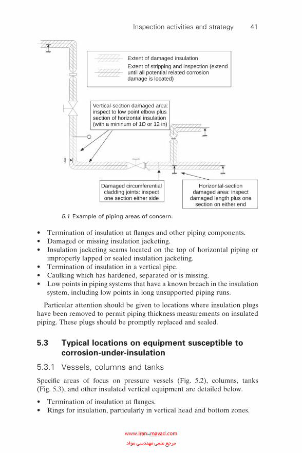
Inspection activities and strategy 41
• Termination of insulation at fl anges and other piping components.• Damaged or missing insulation jacketing.• Insulation jacketing seams located on the top of horizontal piping or
improperly lapped or sealed insulation jacketing.• Termination of insulation in a vertical pipe.• Caulking which has hardened, separated or is missing.• Low points in piping systems that have a known breach in the insulation
system, including low points in long unsupported piping runs.
Particular attention should be given to locations where insulation plugs have been removed to permit piping thickness measurements on insulated piping. These plugs should be promptly replaced and sealed.
5.3 Typical locations on equipment susceptible to
corrosion-under-insulation
5.3.1 Vessels, columns and tanks
Specifi c areas of focus on pressure vessels (Fig. 5.2), columns, tanks (Fig. 5.3), and other insulated vertical equipment are detailed below.
• Termination of insulation at fl anges.• Rings for insulation, particularly in vertical head and bottom zones.
Extent of damaged insulation
Extent of stripping and inspection (extenduntil all potential related corrosiondamage is located)
Vertical-section damaged area:inspect to low point elbow plussection of horizontal insulation(with a mininum of 1D or 12 in)
Damaged circumferentialcladding joints: inspectone section either side
Horizontal-sectiondamaged area: inspect
damaged length plus onesection on either end
5.1 Example of piping areas of concern.
WPNL2204www.iran-mavad.com مرجع علمى مهندسى مواد
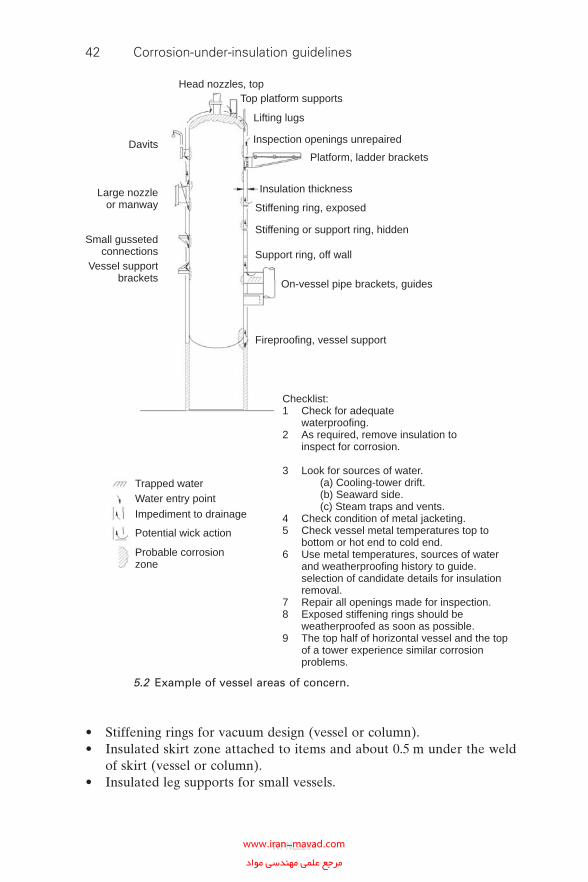
42 Corrosion-under-insulation guidelines
• Stiffening rings for vacuum design (vessel or column).• Insulated skirt zone attached to items and about 0.5 m under the weld
of skirt (vessel or column).• Insulated leg supports for small vessels.
Head nozzles, topTop platform supports
Lifting lugs
Inspection openings unrepaired
Platform, ladder brackets
Insulation thickness
Stiffening ring, exposed
Stiffening or support ring, hidden
Support ring, off wall
On-vessel pipe brackets, guides
Fireproofing, vessel support
Checklist:1 Check for adequate waterproofing.2 As required, remove insulation to inspect for corrosion.
3 Look for sources of water. (a) Cooling-tower drift. (b) Seaward side. (c) Steam traps and vents.4 Check condition of metal jacketing.5 Check vessel metal temperatures top to bottom or hot end to cold end.6 Use metal temperatures, sources of water and weatherproofing history to guide. selection of candidate details for insulation removal.7 Repair all openings made for inspection.8 Exposed stiffening rings should be weatherproofed as soon as possible.9 The top half of horizontal vessel and the top of a tower experience similar corrosion problems.
Trapped waterWater entry point
Impediment to drainage
Potential wick action
Probable corrosionzone
Davits
Large nozzleor manway
Small gussetedconnections
Vessel supportbrackets
5.2 Example of vessel areas of concern.
WPNL2204www.iran-mavad.com مرجع علمى مهندسى مواد
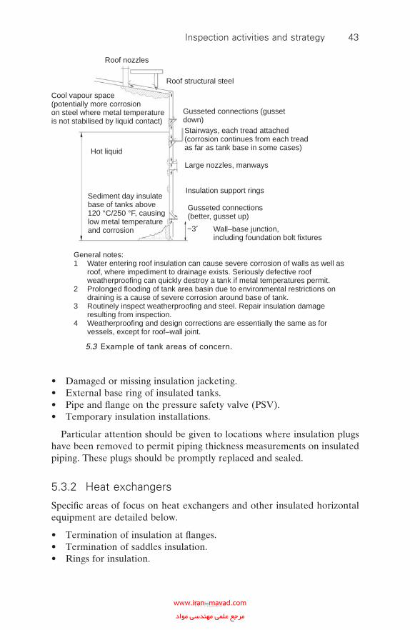
Inspection activities and strategy 43
• Damaged or missing insulation jacketing.• External base ring of insulated tanks.• Pipe and fl ange on the pressure safety valve (PSV).• Temporary insulation installations.
Particular attention should be given to locations where insulation plugs have been removed to permit piping thickness measurements on insulated piping. These plugs should be promptly replaced and sealed.
5.3.2 Heat exchangers
Specifi c areas of focus on heat exchangers and other insulated horizontal equipment are detailed below.
• Termination of insulation at fl anges.• Termination of saddles insulation.• Rings for insulation.
Roof nozzles
Roof structural steel
Gusseted connections (gussetdown)Stairways, each tread attached(corrosion continues from each treadas far as tank base in some cases)
Large nozzles, manways
Insulation support rings
Gusseted connections(better, gusset up)
Wall–base junction,including foundation bolt fixtures
Hot liquid
Sediment day insulatebase of tanks above120 °C/250 °F, causinglow metal temperatureand corrosion
Cool vapour space(potentially more corrosionon steel where metal temperatureis not stabilised by liquid contact)
~3′
General notes:1 Water entering roof insulation can cause severe corrosion of walls as well as roof, where impediment to drainage exists. Seriously defective roof weatherproofing can quickly destroy a tank if metal temperatures permit.2 Prolonged flooding of tank area basin due to environmental restrictions on draining is a cause of severe corrosion around base of tank.3 Routinely inspect weatherproofing and steel. Repair insulation damage resulting from inspection.4 Weatherproofing and design corrections are essentially the same as for vessels, except for roof–wall joint.
5.3 Example of tank areas of concern.
WPNL2204www.iran-mavad.com مرجع علمى مهندسى مواد
44 Corrosion-under-insulation guidelines
• Damaged or missing insulation jacketing.• Pipe and fl ange on PSV.
Attention should be given to locations where insulation plugs have been removed to permit piping thickness measurements on insulated piping. These plugs should be promptly replaced and sealed.
5.4 Examples of a risk-based inspection plan
The following examples provide an indication for the scope of inspection that is required when considering the likelihood of CUI. RBI should be used to minimise the economic impact prior to establishing ongoing CUI inspection and rehabilitation programmes. A number of different method-ologies can be employed in order to mitigate CUI. The section will depend on the scale of any CUI, resources employed and location or type of plant being considered.
• Individual targeted high safety, health and environment (SHE) risk equipment with known CUI issues.
• Individual targeted high-economic-risk equipment with known CUI issues.
• Individual high-risk equipment with potential CUI issues.• High-risk equipment within a particular area (zone approach).
5.4.1 Evaluated risk level: high–extreme
1 100% removal of thermal insulation.2 Complete visual inspection for corrosion and condition of coating as
applicable (including dye penetrant or alternating current fi eld mea-surement (ACFM) inspection to check for Cl-ESCC of austenitic stain-less steels) .
3 Evaluation of corroded areas by pit gauge, ultrasonic testing or radiography.
4 Analysis for root cause considering critical points.5 Reinstatement of use of practices recommended in this document.6 Re-evaluation of the risk.
5.4.2 Evaluated risk level: medium–high
1 Greater than 40% removal of thermal insulation including all critical points and damaged areas.
2 Complete visual inspection of exposed areas for corrosion and condition of coating as applicable (including dye penetrant or ACFM inspection to check for Cl-ESCC of austenitic stainless steels).
WPNL2204www.iran-mavad.com مرجع علمى مهندسى مواد
Inspection activities and strategy 45
3 Evaluation of corroded areas by pit gauge, ultrasonic testing or radiography.
4 Analysis for root cause considering critical points.5 Reinstatement of use of practices recommended in this document.6 Re-evaluation of the risk.
5.4.3 Evaluated risk level: medium
1 Greater than 20% removal of thermal insulation including all critical points and damaged areas.
2 Complete visual inspection of exposed areas for corrosion and condition of coating as applicable (including dye penetrant or ACFM inspection to check for Cl-ESCC of austenitic stainless steels).
3 Evaluation of corroded areas by pit gauge, ultrasonic testing or radiography.
4 Analysis for root cause considering critical points.5 Reinstatement of use of practices recommended in this document.6 Re-evaluation of the risk.
5.4.4 Evaluated risk level: low
1 Removal of thermal insulation at all critical points with evidence of damage.
2 Complete visual inspection of exposed areas for corrosion and condition of coating as applicable (including dye penetrant or ACFM inspection to check for Cl-ESCC of austenitic stainless steels).
3 Evaluation of corroded areas by pit gauge, ultrasonic testing or radiography.
4 Analysis for root cause considering critical points.5 Reinstatement of use of practices recommended in this document.6 Re-evaluation of the risk.
5.4.5 Evaluated risk level: negligible
No inspection is required when the evaluated risk level is negligible.
WPNL2204www.iran-mavad.com مرجع علمى مهندسى مواد
6Non-destructive examination and testing screening techniques for
corrosion-under-insulation
6.1 Non-destructive examination and testing
techniques
The NDE and NDT techniques listed below can be used to detect CUI. A more comprehensive description of each technique is given in Appendix I.
• External visual inspection (with and without removal of insulation).• Ultrasonic thickness measurement (with and without removal of insula-
tion, through inspection openings).• Profi le radiography.• Flash radiography.• Real-time radiography (RTR).• Guided-wave ultrasonic measurements.• Pulsed-eddy-current technique.• Digital radiography.• Infrared thermography.• Neutron backscattering.• Dye penetrant testing.
The limitations, advantages and disadvantages of each technique are detailed in Table 6.1. A comprehensive review of non-destructive evalua-tion techniques has been carried out by MTI [1] in 1998. This document provides a very thorough review of all the non-intrusive inspection methods available at that time; a summary is shown in Table 6.2.
6.2 Reference
1. Materials Technology Institute, MTI Project 118 Detection of Corrosion Through Insulation, September 1998.
46
WPNL2204www.iran-mavad.com مرجع علمى مهندسى مواد
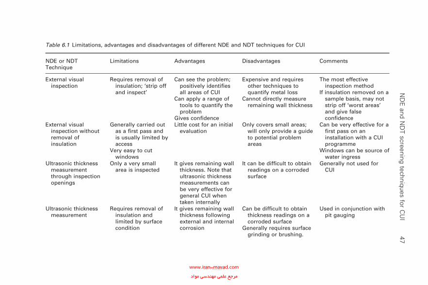
N
DE
and ND
T screening techniques for CU
I 47
Table 6.1 Limitations, advantages and disadvantages of different NDE and NDT techniques for CUI
NDE or NDT Technique
Limitations Advantages Disadvantages Comments
External visual inspection
Requires removal of insulation; ‘strip off and inspect’
Can see the problem; positively identifi es all areas of CUI
Can apply a range of tools to quantify the problem
Gives confi dence
Expensive and requires other techniques to quantify metal loss
Cannot directly measure remaining wall thickness
The most effective inspection method
If insulation removed on a sample basis, may not strip off ‘worst areas’ and give false confi dence
External visual inspection without removal of insulation
Generally carried out as a fi rst pass and is usually limited by access
Very easy to cut windows
Little cost for an initial evaluation
Only covers small areas; will only provide a guide to potential problem areas
Can be very effective for a fi rst pass on an installation with a CUI programme
Windows can be source of water ingress
Ultrasonic thickness measurement through inspection openings
Only a very small area is inspected
It gives remaining wall thickness. Note that ultrasonic thickness measurements can be very effective for general CUI when taken internally
It can be diffi cult to obtain readings on a corroded surface
Generally not used for CUI
Ultrasonic thickness measurement
Requires removal of insulation and limited by surface condition
It gives remaining wall thickness following external and internal corrosion
Can be diffi cult to obtain thickness readings on a corroded surface
Generally requires surface grinding or brushing.
Used in conjunction with pit gauging
WPNL2204www.iran-mavad.com مرجع علمى مهندسى مواد

48 C
orrosion-under-insulation guidelines
Table 6.1 Cont’d
NDE or NDT Technique
Limitations Advantages Disadvantages Comments
Profi le radiography Unlikely to detect Cl-ESCC in stainless steels
Typically only a single orientation is used, making it possible to miss localised thinning
Gives remaining wall thickness without removing insulation
Can be applied whilst equipment is running
Will reveal both internal and external corrosion thinning
Only for pipe wall in small sections
SHE issues, test areas require barriers to restrict access
The exposure source is usually iridium 192; cobalt 60 is used for pipes of heavier wall, but the mass is about 250 kg
Generally slow and suitable for pipe size <8 in
One of the most effective methods, with very good results achieved
Often used to evaluate the suitability of piping for insulation removal and grit blasting
Digital radiography Does not detect Cl-ESCC in stainless steels
Typically only a single orientation is used making it possible to miss localised thinning
As above Image management
easier
Scaffolding required when using cobalt 60 for thick sections (heavy enclosures (about 250 kg))
More expensive than profi le radiography
As aboveProvides greater fl exibility
when reviewing imagesOngoing developments
include small-controlled-area radiography, SafeRad, complementary metal–oxide–semiconductor, gamma-scan real-time radiography systems
WPNL2204www.iran-mavad.com مرجع علمى مهندسى مواد
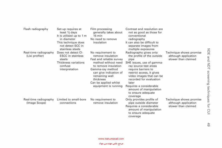
N
DE
and ND
T screening techniques for CU
I 49
Flash radiography Set-up requires at least 11–2 days
It is utilised up to 1 m in diameter
This technique does not detect SCC in stainless steels
Film processing generally takes about 15 min
No need to remove insulation
Contrast and resolution are not as good as those for conventional radiography
It can also be diffi cult to separate images from multiple exposures
Real-time radiography (Lixi profi ler)
Does not detect Cl-ESCC in stainless steels
Thickness variations confuse interpretation
No requirement to remove insulation
Fast and reliable survey method without need to remove insulation
Gamma-ray method can give indication of remaining wall thickness
Can be applied whilst equipment is running
Radiography gives only the profi le of the outside pipe
SHE issues, use of gamma-ray source test areas require barriers to restrict access, it gives video images that can be recorded for evaluation later
Requires a considerable amount of manipulation to ensure adequate coverage
Technique shows promise although application slower than claimed
Real-time radiography (Image Scope)
Limited to small-bore connections
No requirement to remove insulation
Only provides profi le of pipe outside diameter
Requires a considerable amount of manipulation to ensure adequate coverage
Technique shows promise although application slower than claimed
WPNL2204www.iran-mavad.com مرجع علمى مهندسى مواد
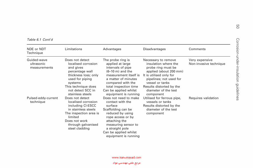
50 C
orrosion-under-insulation guidelines
Table 6.1 Cont’d
NDE or NDT Technique
Limitations Advantages Disadvantages Comments
Guided-wave ultrasonic measurements
Does not detect localised corrosion and gives percentage wall thickness loss; only used for piping systems
This technique does not detect SCC in stainless steels
The probe ring is applied at large intervals of pipe (6–10 m) and the measurement itself is a matter of minutes compared with the total inspection time
Can be applied whilst equipment is running
Necessary to remove insulation where the probe ring must be applied (about 200 mm)
It is utilised only for pipelines; not used for vessel or tanks
Results distorted by the diameter of the test component
Very expensive Non-invasive technique
Pulsed-eddy-current technique
Does not detect localised corrosion including Cl-ESCC in stainless steels
The inspection area is limited
Does not work through galvanised steel cladding
Does not need to make contact with the surface
Scaffolding can be reduced by using rope access or by attaching the measuring sensor to a straight pole
Can be applied whilst equipment is running
Utilised for ferrous pipe, vessels or tanks
Results distorted by the diameter of the test component
Requires validation
WPNL2204www.iran-mavad.com مرجع علمى مهندسى مواد
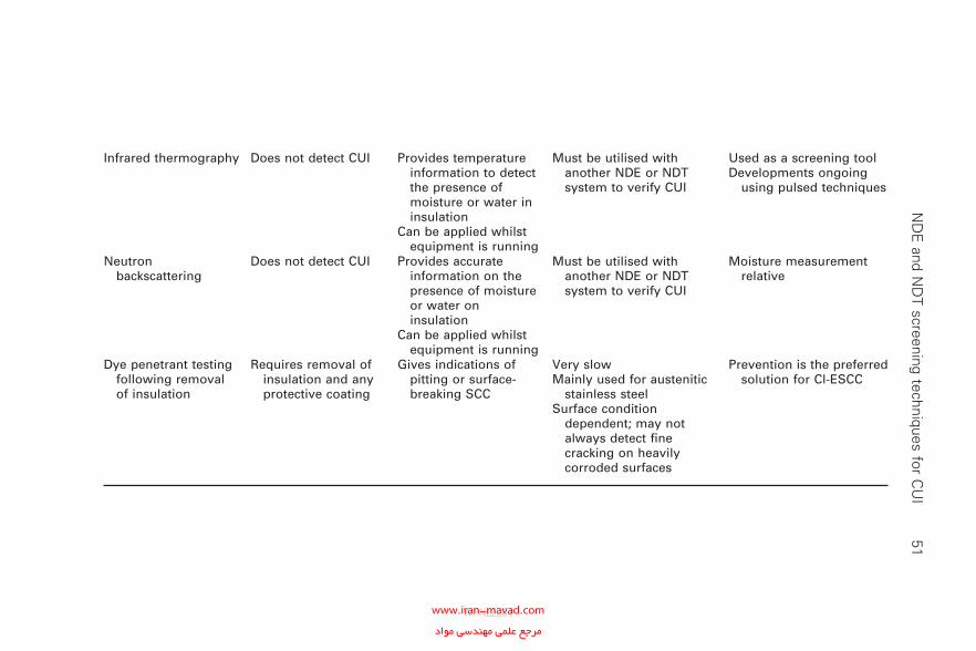
N
DE
and ND
T screening techniques for CU
I 51
Infrared thermography Does not detect CUI Provides temperature information to detect the presence of moisture or water in insulation
Can be applied whilst equipment is running
Must be utilised with another NDE or NDT system to verify CUI
Used as a screening toolDevelopments ongoing
using pulsed techniques
Neutron backscattering
Does not detect CUI Provides accurate information on the presence of moisture or water on insulation
Can be applied whilst equipment is running
Must be utilised with another NDE or NDT system to verify CUI
Moisture measurement relative
Dye penetrant testing following removal of insulation
Requires removal of insulation and any protective coating
Gives indications of pitting or surface-breaking SCC
Very slowMainly used for austenitic
stainless steelSurface condition
dependent; may not always detect fi ne cracking on heavily corroded surfaces
Prevention is the preferred solution for Cl-ESCC
WPNL2204www.iran-mavad.com مرجع علمى مهندسى مواد
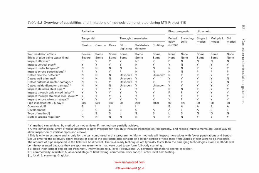
52 C
orrosion-under-insulation guidelines
Table 6.2 Overview of capabilities and limitations of methods demonstrated during MTI Project 118
Radiation Electromagnetic Ultrasonic
Tangential Through transmission Pulsed eddy current
Encircling coils
Single L modes
Multiple L modes
SH modes
Neutron Gamma X-ray Film digitising
Solid-state detector
Profi ling
Wet insulation effects Severe Some Some Some Some Some None None Some Some NoneEffect of pipe being water fi lled Severe Some Some Some Some Some None None Some Some NoneInspect elbows?* P Y Y Y N† Y P N N N NInspect vertical pipe?* Y Y Y Y N Y Y N Y Y YInspect under hangers?* N N N N N N N N Y Y YInspect across penetrations?* P Y Y P N N N N P P PDetect discrete defects?* N N N Unknown Y Unknown N Y Y Y YDetect wall thinning?* N N N Unknown Y Y Y Y Y Y NDetect outside-diameter damage?* N Y Y Unknown Y Y Y Y Y Y NDetect inside-diameter damage?* N N N Unknown Y Unknown Y Y Y Y YInspect stainless steel pipe?* Y Y Y Y Y Y N N Y Y YInspect through galvanised jacket?* Y Y Y Y Y Y P P Y Y YInspect through stainless steel jacket?* Y Y Y Y Y Y Y Y Y Y YInspect across wires or straps?* Y Y Y Y Y Y Y P Y Y YPipe inspected (ft/ 8 h day)‡ 500 500 500 20 250 1000 90 120 80 60 60Operator skill§ B I I I I I B A A A ADevelopment|| C C C C C A A E A E EType of method¶ L S S L S S L S G G GSurface access required* N N N N N N N N Y Y Y
* Y, method can achieve; N, method cannot achieve; P, method can partially achieve.† A two-dimensional array of these detectors is now available for fi lm-style through-transmission radiography, and robotic improvements are under way to allow inspection of vertical pipes and elbows.‡ This is only an estimate and is only for the test stand used in this programme. Many methods will inspect more pipes with fewer penetrations and bends. Set-up time for the relatively short amount of pipe in the test stand also consists of a larger portion of time than if thousands of feet were to be inspected. The amount of pipe inspected in the fi eld will be different. The fi eld-ready techniques are typically faster than the emerging technologies. Some methods will be misrepresented because they are spot measurements that were used to perform full-body scanning.§ B, basic (high-school and on-job training); I, intermediate (e.g. level II equivalent), A, advanced (Bachelor’s degree or higher).|| C, commercially available; A, advanced stage of fi eld testing, commercial very soon; E, entry level fi eld testing.¶ L, local; S, scanning; G, global.
WPNL2204www.iran-mavad.com مرجع علمى مهندسى مواد
7Recommended best practice to mitigate
corrosion-under-insulation
7.1 Background
In order to ensure that the fi eld implementation of a best-practice insula-tion specifi cation is successful, care must be taken in the development and design of all components of the specifi cation. Defi ciencies in any one of the components can and do lead to premature failure of the insulation system.
What are the primary parameters that control the effectiveness of an insulation system? What is the key parameter that controls life expectancy?
7.1.1 Key parameters
Field experience from a wide variety of oil, gas and petrochemical compa-nies has indicated that the following parameters are important.
• Insulation selection.• Protective coating selection.• Weather barrier selection and design.• Service temperatures (‘cold’ or ‘hot’ insulation).• Local environment.• Equipment and piping insulation design details.• Installation procedures.• Inspection and maintenance practices.• Life cycle costs (LCCs).
Historically, greater emphasis has been placed on the type of protective coating, type of insulation and type of weather barrier to be selected with less emphasis on the installation and maintenance of the insulation system. Failure of the insulation system is relative. Often the weather barrier is the fi rst to fail, followed by gradual degradation of the insulation and the pro-tective coating, leading to hidden localised corrosion of the steel equipment beneath the insulation.
53
WPNL2204www.iran-mavad.com مرجع علمى مهندسى مواد
54 Corrosion-under-insulation guidelines
7.1.2 Assumptions
How is failure defi ned?Failure is relative since it is associated with a number of components in
a multicomponent system. It is often assumed that the weather barrier is impermeable to water ingress. This is not always the case. The external weather protective claddings are not intrinsically waterproof and so it should be assumed that water can penetrate the external weather barrier immediately after installation.
A second assumption is that the insulation cannot and does not ‘hold’ water. This again is not necessarily true because the extent of water reten-tion is a function of the type of insulation being used; water can be retained by all insulation systems. CUI has been associated with all the different types of insulation materials that have been employed.
A third assumption is that the protective coating employed resists aque-ous corrosion; again this is not always true. The life expectancy of coatings ranges from 2 to 25 years (and even greater in some circumstances) with an average expectancy of less than 10 years.
For the majority of the oil, gas and petrochemical companies, failure is usually defi ned when leakage to the atmosphere occurs as a result of metal perforation.
The above assumptions are true for carbon steel installations. Cl-ESCC of austenitic stainless steels, although less typical, is another failure defi nition.
7.2 Current corrosion-under-insulation
prevention methods
It is the current oil, gas and petrochemical practice to include most of or all the following conventional CUI mitigation methods.
• Design and install the insulation system to exclude water ingress.• Application of a suitable organic protective coating to resist corrosion.• Perform periodic inspection and non-destructive inspection (NDE and
NDT) activities.• Periodically strip all insulation, prepare surfaces for coating and
reinsulate.
° Maintenance of a conventional coating system (paint) is the only mitigation for CUI on carbon steel equipment.
° Conventional paint systems have an average life expectancy (9–13 years) [1] that is heavily dependent on proper surface preparation and application.
° Cold service equipment prevents maintenance of conventional paint systems without unit shutdowns.
WPNL2204www.iran-mavad.com مرجع علمى مهندسى مواد
Recommended best practice to mitigate CUI 55
7.3 How to achieve a life expectancy of over 25 years
The rate of corrosion is infl uenced by the service conditions, the local envi-ronment and by the design details. The rate of corrosion is also infl uenced by the installation practices and by the local inspection and maintenance practices. These all affect the total cost of the installation (i.e. the LCCs).
So what is the key parameter that controls the life expectancy of an insulation system and what is required to ensure a life expectancy in excess of over 25 years?
It is now believed that the key parameter that controls the life expectancy of an insulated system is the protective coating. Failure of the weather barrier due to inadequate design or installation will lead to water ingress and retention. Subsequent degradation of the barrier coating leads to cor-rosion. The selection of a coating is therefore the key to the success of the insulation system as a whole. Many types of coating system are available but the selection criteria must include the following in order to be economi-cally viable and effective [1].
• The lifetime of the equipment. Include both the internal and the external corrosion mechanism and corrosion rates. Typically a plant life expec-tancy in excess of 25 years for equipment is generally used as the basis for all economic evaluations. Consideration of shorter periods can be adopted when the remnant plant life is limited. The majority of refi n-ing equipment in use today is considerably older than 25 years as essen-tial refi neries were initially installed during the 1950s and 1960s. Construction of petrochemical, gas and hydrocarbon processing plants and offshore production facilities continue, however, to the present day.
• The cost of application and reapplication of the protective coating and insulation system over the lifetime of the equipment.
• The expected lifetime of the protective coating system. This has consis-tently fallen short of all expectations.
Appendix C provides more information on the many types of protective coating that are available; however, the coating that is most likely to provide effective corrosion protection for over 25 years is thermally sprayed aluminium (TSA). It is therefore recommended that, where a minimum design life of 25 years is required, TSA should be considered for the pro-tective coating of all new equipment and should always be considered for the protective coating of equipment subject to maintenance and rehabilitation work. The following sections provide more detail on the benefi ts of TSA which will provide a low-cost leak-free system for well over 25 years. The application of conventional paint systems have a life expec-tancy heavily dependent on proper surface preparation and application (Table 7.1).
WPNL2204www.iran-mavad.com مرجع علمى مهندسى مواد
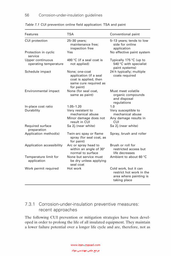
56 Corrosion-under-insulation guidelines
7.3.1 Corrosion-under-insulation preventive measures: recent approaches
The following CUI prevention or mitigation strategies have been devel-oped in order to prolong the life of all insulated equipment. They maintain a lower failure potential over a longer life cycle and are, therefore, not as
Table 7.1 CUI prevention online fi eld application: TSA and paint
Features TSA Conventional paint
CUI protection 25–30 years; maintenance free; inspection free
5–13 years; tends to low side for online application
Protection in cyclic service
Yes No effective paint system
Upper continuous operating temperature
480 °C (if a seal coat is not applied)
Typically 175 °C (up to 540 °C with specialist paint systems)
Schedule impact None; one-coat application (if a seal coat is applied, then same cure required as for paint)
24 h typically; multiple coats required
Environmental impact None (for seal coat, same as paint)
Must meet volatile organic compounds and disposal regulations
In-place cost ratio 1.05–1.20 1.0Durability Very resistant to
mechanical abuseMinor damage does not
result in CUI
Very susceptible to mechanical abuse
Any damage results in CUI
Required surface preparation
Sa 21–2 (near white) Sa 21–2 (near white)
Application method(s) Twin-arc spay or fl ame spray (for seal coat, as for paint)
Spray, brush and roller
Application accessibility Arc or spray head to within an angle of 30° normal to surface
Brush or roll for restricted access but life decreases
Temperature limit for application
None but service must be dry unless applying seal coat
Ambient to about 60 °C
Work permit required Hot work Cold work, but it can restrict hot work in the area where painting is taking place
WPNL2204www.iran-mavad.com مرجع علمى مهندسى مواد
Recommended best practice to mitigate CUI 57
dependent on the effective but expensive maintenance and inspection activ-ities that are required to manage CUI.
• Application of TSA coating system.• Upgrading to stainless steel when economically justifi ed.• Removing unnecessary insulation.• Removing insulation at pipe support vents, etc., with a seal either side
to remove the water ingress point.• Use of aluminium foil to prevent Cl-ESCC.• Use of waterproof and impervious non-metallic weather protection
barriers.
7.3.2 Material upgrade possibilities
The methodologies for CUI mitigation include the following.
• Painting or coating carbon and austenitic stainless steel for protection.• Application of TSA.• A metallurgy upgrade from carbon–manganese steel to an austenitic or
duplex stainless steel.
Whilst CUI of carbon steel is a relatively slow process, austenitic stainless steels are susceptible to accelerated corrosion (particularly Cl-ESCC) if exposed to wet aqueous conditions containing chlorides. Failures of insu-lated austenitic stainless steels by pitting and SCC due to chlorides have been extensively reported. Duplex stainless steels are less susceptible but are not totally immune. However, provided that suitable precautions are taken (especially when considering cold service insulation), stainless steels can prove to be more economical than carbon steels if LCCs are considered.
In order to minimise the risk of chloride SCC, the use of duplex stainless steels should be considered for operating temperatures greater than 50 ºC .The upper temperature limit at which duplex stainless steels can be used will depend on the actual grade selected. A temperature of 120 ºC is typically used for the generic 2205 duplex stainless steel. Each application must be carefully reviewed by the appropriate specialist engineers before proceeding. The greatest savings can be made for the following.
• Small-diameter piping systems.• Equipment requiring cold service insulation.• Equipment that will be operating under cyclic conditions.• Equipment that will be operating in high-humidity environments.
Since it will often be possible to reduce or eliminate corrosion allowances when moving from carbon steel to stainless steel, signifi cant savings can often be made in terms of total weight and cost by specifying thinner
WPNL2204www.iran-mavad.com مرجع علمى مهندسى مواد
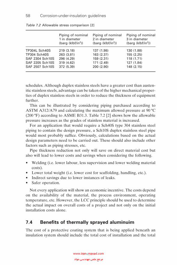
58 Corrosion-under-insulation guidelines
schedules. Although duplex stainless steels have a greater cost than austen-itic stainless steels, advantage can be taken of the higher mechanical proper-ties of duplex stainless steels in order to reduce the thickness of equipment further.
This can be illustrated by considering piping purchased according to ASTM A312/A79 and calculating the maximum allowed pressure at 90 ºC (200 ºF) according to ASME B31.3. Table 7.2 [2] shows how the allowable pressure increases as the grades of stainless material is increased.
For an application that would require a Sch40S type 304 stainless steel piping to contain the design pressure, a Sch10S duplex stainless steel pipe would most probably suffi ce. Obviously, calculations based on the actual design parameters need to be carried out. These should also include other factors such as piping stresses, etc.
Pipe thickness reduction not only will save on direct material cost but also will lead to lower costs and savings when considering the following.
• Welding (i.e. lower labour, less supervision and lower welding material costs).
• Lower total weight (i.e. lower cost for scaffolding, handling, etc.).• Indirect savings due to lower instances of leaks.• Safer operation.
Not every application will show an economic incentive. The costs depend on the availability of the material, the process environment, operating temperature, etc. However, the LCC principle should be used to determine the actual impact on overall costs of a project and not only on the initial installation costs alone.
7.4 Benefi ts of thermally sprayed aluminuim
The cost of a protective coating system that is being applied beneath an insulation system should include the total cost of installation and the total
Table 7.2 Allowable stress comparison [2]
Piping of nominal 1 in diameter (barg (klbf/in2))
Piping of nominal 2 in diameter (barg (klbf/in2))
Piping of nominal 3 in diameter (barg (klbf/in2))
TP304L Sch40S 219 (3.18) 137 (1.98) 130 (1.88)TP304 Sch40S 263 (3.81) 163 (2.37) 155 (2.25)SAF 2304 Sch10S 296 (4.29) 159 (2.31) 118 (1.71)SAF 2205 Sch10S 319 (4.62) 171 (2.49) 127 (1.84)SAF 2507 Sch10S 372 (5.39) 200 (2.90) 148 (2.15)
WPNL2204www.iran-mavad.com مرجع علمى مهندسى مواد
Recommended best practice to mitigate CUI 59
costs involved in the maintenance and inspection of the system over the entire life of the system.
The main advantages of TSA coatings over conventional organic coatings include the following.
• Longer life expectancy with minimal requirements for maintenance and inspection.
• Resistance to mechanical damage.• Greater range of temperature resistance than organic coatings (from
−100 ºC to 500 ºC).• Provides sacrifi cial protection to steels in aqueous environments.
The main disadvantages of TSA coatings over conventional organic coating include the following.
• Higher cost of application.• Increased diffi culty of fi eld application.• Resistance to change by operations and maintenance organisations.
On balance, providing that the total LCCs of operating a piece of insu-lated equipment are taken into consideration, the application of TSA, as a protective corrosion-resistant coating can be more effective and more eco-nomic than using an organic coating. The costs that should be included are as follows.
• Cost of surface preparation.• Cost of coating application.• Cost of fi eld erection (if new equipment) or extra costs if fi eld
applied.• Cost of inspection and quality assurance.• Cost of in-service inspection.• Cost of in-service maintenance.• Cost of repair and/or replacement in the event of CUI.
7.5 Use of personnel protective guards
Removal of insulation stops CUI and the associated inspection and main-tenance costs. With the use of personnel protective guards (see Appendix H) instead of insulation, savings of up to 100% of the costs associated with CUI incidents which can help to recover quickly the installation cost of the personal protection guards.
Traditionally personal protection consists of insulating the pipework to prevent human contact with hot surfaces. This is an easy option and is pre-dominately applied because other methods are seen as more expensive and requiring more resources. With business needs driving effi ciency
WPNL2204www.iran-mavad.com مرجع علمى مهندسى مواد
60 Corrosion-under-insulation guidelines
improvements in maintenance and capital spending, the initial cost of per-sonal protection is as important a factor as LCCs. Use of personal protection guidelines will reduce initial costs as well as improve life cycle savings.
Possible savings include the following.
• 100% of the cost of CUI (pipe replacement, painting and insulation).• 10–20% on initial costs compared with thermal insulation.• 90% or more on future pipe inspection costs.
A number of UK and European standards are available [3, 4], which give more detailed guidance for the design of guarding for personnel protection against heat exposure. They are utilised for equipment or pipelines whose surface temperature is above 60 ºC. Each guard should be individually designed to duty and local service conditions.
• Guards and their supports shall be manufactured from carbon steel, which may be galvanised or painted. (The mesh may be painted with yellow stripes, 50 mm wide, and shall include a hazard sign indicating ‘Hot surface’.)
• The guard mesh shall be 12 mm square when the distance from the heat source is less than 40 mm and can be a maximum of 40 mm square when the distance from the heat source is greater than 180 mm. The guards shall extend to a height of not more than 2 m above or 600 mm beyond areas at ground level or on platforms, access ways, stairways, ladders and other positions of personnel access for operational purposes.
• Guards may be supported by the pipeline or equipment that they are protecting. They shall have the support clamp(s) painted with same paint system as that specifi ed for the pipeline.
• Guards shall be securely anchored and not distort if lent against. They shall be free from sharp edges.
• All guarding shall be of a permanent type, designed to withstand mechanical abuse.
7.6 Use of aluminium foil to mitigate chloride
external stress corrosion cracking of austenitic
stainless steel
As discussed earlier, the fi rst reported instance of Cl-ESCC on austenitic stainless steel was published in 1965 [5]. Since then many articles have been published reporting similar instances but without guidance on how to miti-gate the problems. Many companies and contractors currently use alumin-ium foil to prevent Cl-ESCC of austenitic stainless steel piping and vessels. The use of aluminium foil to mitigate Cl-ESCC was fi rst published by ICI in 1985 [6]. When applied as recommended it has been shown to be 100%
WPNL2204www.iran-mavad.com مرجع علمى مهندسى مواد
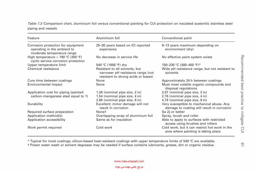
R
ecomm
ended best practice to mitigate C
UI
61
Table 7.3 Comparison chart, aluminium foil versus conventional painting for CUI protection on insulated austenitic stainless steel piping and vessels
Feature Aluminium foil Conventional paint
Corrosion protection for equipment operating in the ambient to moderate temperature range
25–30 years based on ICI reported experience
9–13 years maximum depending on environment (dry)
High temperature > 190 °C (350 °F) cyclic service corrosion protection
No decrease in service life No effective paint system exists
Upper temperature limit 540 °C (1000 °F) dry 150–230 °C (300–450 °F)*Chemical resistance Resistant to all solvents, but
narrower pH resistance range (not resistant to strong acids or bases)
Wide pH resistance range, but not resistant to solvents
Cure time between coatings None Approximately 24 h between coatingsEnvironmental impact None Must meet volatile organic compounds and
disposal regulationsApplication cost for piping (painted
carbon–manganese steel equal to 1)1.26 (nominal pipe size, 2 in)1.54 (nominal pipe size, 4 in)2.69 (nominal pipe size, 8 in)
2.07 (nominal pipe size, 2 in)2.76 (nominal pipe size, 4 in) 4.79 (nominal pipe size, 8 in)
Durability Excellent; minor damage will not result in corrosion
Very susceptible to mechanical abuse. Any damage to coating will result in corrosion
Required surface preparation None† Sa 21–2 or betterApplication method(s) Overlapping wrap of aluminium foil Spray, brush and rollerApplication accessibility Same as for insulation Able to apply to surfaces with restricted
access using brushes and rollersWork permit required Cold work Cold work, but it can restrict hot work in the
area where painting is taking place
* Typical for most coatings; silicon-based heat-resistant coatings with upper temperature limits of 540 °C are available.† Power water wash or solvent degrease may be needed if surface contains lubricants, grease, dirt or organic residue.
WPNL2204www.iran-mavad.com مرجع علمى مهندسى مواد
62 Corrosion-under-insulation guidelines
effective in preventing CUI due to Cl-ESCC. Concern over possible liquid-metal cracking of austenitic stainless steels has been expressed; however, a literature search did not highlight any instances in which aluminium causes the initiation of liquid-metal cracking. Cost comparisons in both North America [7] and Europe showed that the cost of aluminium-foil wrapping was 60–80% of the conventional coating cost. Discounted cash fl ows (DFCs) of 40% or greater will be typical.
The use of aluminium foil is recommended for all austenitic stainless steel piping requiring CUI Cl-ESCC protection on all maintenance and capital projects [8]. Typically, austenitic stainless steels can be used economically for small-bore piping replacing small-bore carbon steel piping failing from CUI. Aluminium foil can also be used on austenitic stainless steel vessels in lieu of conventional coating for Cl-ESCC cracking protection; costs should be economically based (Table 7.3).
Aluminium foil should not be used in sweating service because the service life of aluminium foil will be shortened. TSA is recommended in sweating service.
7.7 References
1. B.J. Fitzgerald, and S. Winnik , ‘A strategy for preventing CUI on pipeline in the petrochemical industry’, J. Prot. Coatings Linings, 2004, 21, 43–50.
2. M. Holmquist, ‘CUI—a materials based solution’, in Corrosion under Insulation, Corrosion Committee—CUI Conference, Have you a Problem?, Sheffi eld, 14 January 2004, London, Institute of Materials, Mineral and Mining, 2004 (http://www.iom3.org/divisions/surface/corrosion/paper5_holmquist.pdf)
3. BS EN 614–1:2006 Safety of Machinery. Ergonomic Design Principles. Terminol-ogy and General Principles, London, British Standards Institution, 2006.
4. BS EN ISO 12100:2003 Safety of Machinery. Basic Concepts, General Principles for Design. Technical Principles, London, British Standards Institution, 2003.
5. W.G. Ashbaugh, ‘ESCC of stainless steel under thermal insulation’, Mater. Protection, May 1965, 19–23.
6. J. Richardson and T. Fitzsimmons, ‘Use of aluminium foil for prevention of stress corrosion cracking of austenitic stainless steel under thermal insulation’, in Cor-rosion of Metals Under Thermal Insulation, ASTM Special Technical Publication 880, W.I. Pollock and J.M. Barnhart (Eds), Philadelphia, Pennsylvania, American Society for Testing and Materials, 1985, pp. 188–198.
7. B.J. Fitzgerald, P. Lazar III, R.M. Kay and S. Winnik, ‘Strategies to prevent CUI in petrochemical industry piping’, in NACE Corrosion Conference 2003, Houston, Texas, NACE International, 2003, Paper 03029.
8. J.P. Richert, ‘Issues surrounding insulated SS and cracking under thermal insula-tion—refi nery experiences in tropical environments’ piping’, in NACE Corrosion Conference 2003, Houston, Texas, NACE International, 2003, Paper 03026.
WPNL2204www.iran-mavad.com مرجع علمى مهندسى مواد
8Design for the prevention of
corrosion-under-insulation
8.1 Introduction
Equipment and piping design has an important infl uence on CUI. If proper consideration is given to CUI at the design stage it may be possible to eliminate corrosion altogether, or at least to limit signifi cantly the potential for CUI and Cl-ESCC. It is the intention of this chapter to give a brief overview of what designers should consider and some examples of good design practices that will reduce the potential for CUI and Cl-ESCC.
It is not the intention here to provide an in-depth detailed description of all design aspects relating to CUI prevention. Reference can be made to the CINI Manual, Insulation for Industries [1], for explicit details relating to insulation design.
There is some overlap with other sections of these guidelines, particularly regarding materials used for insulation, weatherproofi ng and coating, and using life cycle costing. The reader is therefore recommended to refer to these other sections for additional information.
8.2 Challenge the requirement for insulation
The best way of avoiding CUI is not to fi t insulation at all. Section 4.3 pro-vides detailed information on how the need for insulation can be chal-lenged. Ideally this decision should be correctly made at the design stage. Insulation is required for many reasons such as process requirements, heat conservation, fi re protection, noise, preventing freezing or condensation, and personal protection. However, experience has shown that sometimes the level of challenge has not been suffi cient when deciding whether insula-tion is required and this has resulted in insulation being fi tted when it need not have been. Where insulation is required only for personal protection it is better to fi t metal guards rather than insulation.
63
WPNL2204www.iran-mavad.com مرجع علمى مهندسى مواد
64 Corrosion-under-insulation guidelines
8.3 Plant layout
When designing where to situate equipment and piping, consideration should be given to providing suffi cient space to allow effective inspection and maintenance in the plant. For example, experience has shown that pipes placed too close together on the plant are practically impossible to inspect and maintain effectively.
8.4 Mechanical considerations: equipment and tanks
Equipment and tank design and mechanical details have important infl u-ences on the potential for CUI. There are many undesirable design features that infl uence CUI, some of which are as follows.
• Using shapes that are likely to retain water, such as fl at horizontal sur-faces, vacuum rings and insulation support rings.
• Using shapes that are impractical to insulate and weatherproof effec-tively, such as gussets and I-beams.
• Using shapes that funnel water into the insulation, such as angle-iron brackets.
• Other items that cause interruption in the weatherproofi ng, such as lifting lugs, ladder brackets, nozzle extensions, decking and platform supports.
The more breaks that there are in the weatherproofi ng, the more likely it will be that water will enter the insulation and potentially cause CUI. It is therefore essential to minimise the number of nozzles, supports and fi xings that will protrude through the weatherproofi ng. Because of the dif-fi culty in weatherproofi ng and sealing vessel lifting brackets, it has become good practice to cut these off once the equipment has been lifted on to the plant and securely fi xed in position.
Some further examples of good practice include the following.
• Hand railings on insulated tank roofs should be installed at the side of the roof edge instead of on top of it.
• Fixings on insulated tank walls and roofs should be cylindrical rather than angle steel, to avoid retention of water.
• Angle steel used for vacuum rings on columns should be installed with the outer vertical edge downwards to allow water to drain off.
• Nameplates on insulated equipment should not interfere with the insu-lation and weatherproofi ng; they should be fi tted on short brackets so that the nameplate does not extend beyond the weatherproofi ng. A duplicate nameplate can be mounted on the outside of the metal jacket-ing for in-service identifi cation.
WPNL2204www.iran-mavad.com مرجع علمى مهندسى مواد
Design for the prevention of CUI 65
8.5 Mechanical considerations: piping
As for equipment and tanks, the more breaks that there are in the weath-erproofi ng, the more likely it will be that water will enter the insulation and potentially cause CUI. It is therefore essential to minimise the number of vents, drains, supports, fl anges and fi xings that will protrude through the weatherproofi ng.
Pipe supports are a common area for CUI, owing to the diffi culty in insulating and sealing around them properly. Rod hanger or clamps used to support piping by ‘direct contact’ are impractical to insulate and seal effectively against water ingress. Another support that is similarly diffi cult to insulate is the fl at beam support, where the piping directly rests on a fl at metal beam.
All insulated piping should therefore be designed with suitable pipe sup-ports that mitigate, or at least minimise, water ingress. It is considered good practice to use high-density insulation at support locations and to fi t load-bearing supports that will contact the weatherproofi ng only, thus resulting in a continuous weather barrier.
Some examples of further good practice include the following.
• Locating valves and fl anges in the horizontal part of piping runs rather than the vertical to limit water retention.
• Providing enough space between piping and adjacent piping or plant structural supports to enable effective inspection and maintenance in situ.
• Not placing insulated piping in trenches or drains below grade because of the potential for immersion in water if the drains are not kept clear.
• Avoiding clamped pipe shoes in critical CUI areas and using only welded shoes to avoid points of entrapment.
• Not insulating vertical pipe supports, vents, etc., and seal of insulation either side.
8.6 Materials of construction
Carbon steels and low-alloy steels are the most common materials of con-struction for equipment, tanks and piping. When insulated, these materials often suffer from CUI in the form of localised or general corrosion. The potential for CUI is infl uenced by several factors including the operating temperature and the potential for water ingress into the insulation. If the risk of CUI is considered very high for, say, carbon steel, the designer may select another material of construction that will not suffer from CUI (e.g. austenitic and duplex stainless steels, accepting that there may still be a risk
WPNL2204www.iran-mavad.com مرجع علمى مهندسى مواد
66 Corrosion-under-insulation guidelines
of Cl-ESCC). The designer may even select high-nickel alloy materials that are almost immune to both CUI and Cl-ESCC.
Naturally, when selecting more costly materials of construction at the design stage it is important to consider life cycle costing over the design life of the project, to provide economic justifi cation for selecting these materials.
8.7 Coatings and wrappings
Coatings and wrappings applied to the external surface of equipment, tanks and piping are the last line of defence in preventing CUI. Generally speak-ing, organic coatings, TSA coatings and aluminium wrapping are most commonly used to reduce the potential for CUI.
8.7.1 Organic coatings
Organic coatings need to be of high-quality immersion grade to provide a barrier to CUI. Some provide good protection for many years. However, there is also poor experience where water ingress into the insulation has caused premature coating breakdown and signifi cant CUI. Organic coat-ings applied with good quality control procedures are normally considered to have a lifetime of 9–13 years before routine inspection and maintenance is required.
8.7.2 Thermally sprayed aluminium coatings
Historically, TSA coatings have been less commonly applied than organic coatings. TSA coatings have been applied to carbon steel equipment to provide a barrier to CUI. Experience has shown that they perform remark-ably well with lifetimes of 20–30 years [2] before fi rst inspection and main-tenance are required. It is important to consider life cycle costing at the design stage when considering TSA coatings instead of organic coatings.
8.7.3 Aluminium wrapping
Aluminium wrapping has most often been applied to insulated austenitic stainless steel equipment and piping to limit the potential for Cl-ESCC. Experience has shown that organic coatings do not necessarily provide an effective barrier to Cl-ESCC. There is good experience within industry that aluminium foil wrapping has provided a more effective solution than using organic coating by acting as both a physical barrier and a galvanic barrier to preventing Cl-ESCC. Care must be taken to ensure that the external insulation weather cladding is correctly applied under the control of appro-priate quality assurance levels.
WPNL2204www.iran-mavad.com مرجع علمى مهندسى مواد
Design for the prevention of CUI 67
8.8 Insulation
Poorly designed or applied insulation systems can result in water ingress into the insulation or condensation of water from atmospheric moisture, leading to CUI. The underlying metal also corrodes when insulation becomes wet following the breakdown of weatherproofi ng or vapour barrier after equipment and piping is put into service and is exposed to the weather without a corrective maintenance programme. Insulation system life can be prolonged, and substrate metal corrosion can be reduced, by better design of protrusions, attachments, supports, drainage points and expansion–contraction joints.
Generally, industrial insulations fall into two categories: low-temperature (below ambient) and high-temperature (above ambient) applications.
Low-temperature insulation typically includes polyurethane, polyisocy-anurate, fl exible elastomeric foams, cellular glass and phenolics. These insulation types normally require a vapour barrier under the outer weather-proofi ng to minimise the potential for condensation of atmospheric moisture.
High-temperature insulation typically includes perlite, calcium silicate, mineral wool, cellular glass and fi breglass. For SHE reasons the use of asbestos is no longer specifi ed for new construction.
System movement must be allowed for in insulation design. Rigid and semirigid insulation may require expansion joints and failure to install these can result in uncontrolled movement of the insulation in relation to the equipment or piping. This may result in vapour barrier or weatherproofi ng breakdown and condensation or ingress of water into the insulation.
Thermal movement caused by for example piping expansion or con-traction must also be addressed. The linear coeffi cients of thermal expansion of both the piping and the insulation must be considered. The difference between the amount of pipe and insulation movement, together with routing considerations, normally determines how many expansion–contraction joints are needed in the insulation. Expansion–contraction joints are typically constructed in staggered layers to avoid a path for water ingress.
Insulation that minimises water ingress and does not retain water can effectively act as a barrier to CUI. Therefore the ‘closed-cell’ insulation materials (e.g. fl exible elastomeric foams and cellular glass) can provide a more effective barrier to water ingress than ‘open-cell’ insulation materials (e.g. mineral wool and calcium silicate).
In addition to water absorbency, another factor to consider is the chemi-cal content of the insulation. It should be inert, containing no chemicals that would contribute to corrosion or Cl-SCC. Some industrial companies
WPNL2204www.iran-mavad.com مرجع علمى مهندسى مواد
68 Corrosion-under-insulation guidelines
specify a leachable chloride content of less than 10 mg/kg as a way of mini-mising the potential for Cl-SCC of insulated austenitic stainless steels.
A more recent insulation design which has proven successful is ‘non-contact insulation’. This design has an air gap between the equipment surface and the insulation. The insulation contacts a mesh screen that is raised above the equipment surface; hence any ingress of water into the insulation does not contact the equipment to cause corrosion damage. The air gap enables the equipment surface to stay relatively dry and also allows insertion of a boroscope inspection tool to check the external condition of the equipment, without removing the insulation and weatherproofi ng.
Where there are load-bearing supports (e.g. clamp type) it is good prac-tice to use high-density insulation so that supports can be fi tted to the outer weatherproofi ng and an area for water ingress is not created. Additionally, high-density insulation is recommended at areas of high foot traffi c so that, if the weatherproofi ng is walked on, it is not easily damaged.
8.9 Weatherproofi ng
Weatherproofi ng provides mechanical and weather protection for insula-tion systems. Although weatherproofi ng acts as a barrier to CUI, it is sus-ceptible to weather, chemical attack and foot traffi c damage once it is installed; therefore it should be adequately maintained.
Insulation weatherproofi ng materials basically come in two forms: metal-lic and non-metallic. The most common metallic weatherproofi ng materials are aluminised steel, galvanised steel, aluminium and stainless steel. Common non-metallic weatherproofi ng materials are ultraviolet-curable glass-reinforced plastics, polymeric compounds, coated tapes and cements.
Metal weatherproofi ng materials tend to become damaged easily if walked on and this increases the potential for water ingress into the insula-tion. The use of ultraviolet-curable glass-reinforced plastic weatherproofi ng provides a more robust barrier that can support foot traffi c without becom-ing damaged.
The choice of weatherproofi ng should consider several factors for example, an assessment of LCCs, the complexity of the equipment/piping, how much foot traffi c is expected and the temperature of the substrate.
The design of weatherproofi ng needs to take into consideration system movement and thermal expansion–contraction. Metal weatherproofi ng joints and protrusions are normally sealed with mastic or silicone materials to reduce the potential for water ingress. However, these sealants cannot be relied upon since they weather and break down. It has proven much better to overlap joints and to fi t weatherproof plates around protrusions to minimise the potential for water ingress.
WPNL2204www.iran-mavad.com مرجع علمى مهندسى مواد
Design for the prevention of CUI 69
Weatherproofi ng should be designed so that it is water repellent and it does not allow water retention. An example of this is metal weatherproofi ng that is sloped at column vacuum rings and insulation support rings. Signifi -cant experience shows that using fl at weatherproofi ng at these locations has resulted in water ingress and CUI of the column wall above the vacuum or insulation support ring.
Weatherproofi ng attachment methods should be compatible with the equipment and piping operating temperatures, particularly where the insu-lation terminates (e.g. at fl anges). Using screws in metal weatherproofi ng on cold insulation systems may result in puncturing of the protective vapour barrier.
8.10 References
1. CINI Manual, Insulation for Industries, Spijkernisse, Stichting Commissie Isolatie Nederlanse Industrie (CINI), 2006.
2. K.P. Fischer, W.H. Thomason, T. Rosbrook and J. Murali, ‘Performance of thermal-sprayed aluminum coatings in offshore service’, Mater. Performance, 1995, 34(4), 27–34.
WPNL2204www.iran-mavad.com مرجع علمى مهندسى مواد
9Appendix overview
In order to streamline these guidelines, additional information concerning the management and mitigation of CUI is attached in the form of appen-dixes. These contain additional information that is more detailed in nature and provides a basis for the preparation of individual company inspection and CUI management procedures or supplement existing procedures. The information is not proprietary in nature and can be used immediately. It is hoped that additional information will be added in future revisions of the guidelines that will continue to help with eliminating CUI.
70
WPNL2204www.iran-mavad.com مرجع علمى مهندسى مواد
Appendix ACost-economic evaluation
Although application of TSA is known to be an effective mitigation strategy for CUI, the initial capital or refurbishment costs tend to be higher than the costs for applying conventional organic coatings. In order to show that it is economically benefi cial to apply TSA as an alternative to organic coat-ings, plant management needs a positive economic evaluation to show that the long-term costs of TSA are actually lower than the costs of conventional organic coatings. The simplest method to show this is to determine the LCCs and to calculate a DCF.
The LCC determination includes the following.
• Lifetime cost of acquisition.• Total erected cost, namely the sum of all the direct and indirect costs
to install insulation on piping or equipment, including the cost of access (scaffolding), surface preparation, insulation and insulation cladding, coating costs and installation.
• Total erected cost of any piping that needs replacement.• Lifetime support cost.
° The total cost of resources and yearly costs for operation and maintenance.
• Lifetime unavailability cost.
° The sum of yearly costs due to unavailability of system and loss of earnings.
Life cycle savings are inherent in the use of TSA and can be very signifi -cant. Many large organisations have their own in-house methodologies to determine the LCC and DCF for project evaluations. However, the analysis can be easily performed using a simple spreadsheet. Three examples are given in Fig. A.1(a), Fig. A.1(b) and Fig. A.1(c).
Figure A.1(a) shows the analysis for a small project with incremental cost of @2 × 10⁴ for TSA (@1.2 × 10⁵ versus @105) and includes recoating costs (DCF of 21.2% over 30 years), Fig. A.1(b) show the analysis for a project with an incremental cost of @105 for TSA compared with a
71
WPNL2204www.iran-mavad.com مرجع علمى مهندسى مواد
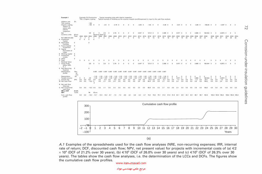
72 C
orrosion-under-insulation guidelinesExample CUI Economics Typical recoating cycle with interim inspectionTSA v Organic coating Typical example of building up the revenue impacts (profit/expenses) to input to the cash flow analysis
Inflation rate 2%TSA coating −120Organic coating,
repaint 12 yearly with interim inspection
−100 0 0 −2.5 0 −2.76 0 0 0 0 −3.05 0 −122 0 0 −3.36 0 0 −3.57 0 0 0 −3.86 0 −160.84 0 0 −4.267 0 0 0
Net −20 0 0 2.5 0 2.76 0 0 0 0 3.047 0 121.9 0 0 3.365 0 0 3.571 0 0 0 3.865 0 160.844 0 0 4.2672 0 0 0Currency units kEuro Revenue Start-up
Total 2002 2003 2004 2005 2006 2007 2008 2009 2010 2011 2012 2013 2014 2015 2016 2017 2018 2019 2020 2021 2022 2023 2024 2025 2026 2027 2028 2029 2030 2031 2032 2033 2034Ref CBM-070-004 −2 −1 0 1 2 3 4 5 6 7 8 9 10 11 12 13 14 15 16 17 18 19 20 21 22 23 24 25 26 27 28 29 30
A Investment Capital
0 0 0 0
B Associated Facilities
0 0
C Future Capital Investment
0
D Capital Equivalent of Lease
0
E Working capital 0F Investment
credits0
G Other 0H Total 0 0 0 0 0 0 0 0 0 0 0 0 0 0 0 0 0 0 0 0 0 0 0 0 0 0 0 0 0 0 0 0 0I Residual ValueJ Gross Profit
before NRE, D, T
−20 0 0 2.5 0 2.76 0 0 0 0 3.047 0 121.9 0 0 3.365 0 0 3.571 0 0 0 3.865 0 160.844 0 0 4.2672 0 0 0
K Non-Recurring Expense
0 0
Depreciation profile
15yr str line
0.067 0.067 0.067 0.067 0.067 0.067 0.067 0.067 0.067 0.067 0.067 0.067 0.067 0.067 0.067
Depreciation −20 −1.33 −1.33 −1.33 −1.33 −1.33 −1.33 −1.33 −1.33 −1.33 −1.33 −1.33 −1.33 −1.33 −1.33 −1.33 0 0 0 0 0 0 0 0 0 0 0 0 0 0 0Taxable income 0 0 −20 −1.33 −1.33 1.167 −1.33 1.427 −1.33 −1.33 −1.33 −1.33 1.714 −1.33 120.6 −1.33 −1.33 2.031 0 0 3.571 0 0 0 3.865 0 160.844 0 0 4.2672 0 0 0
L Income Tax 34% 0.0 0.0 6.8 0.5 0.5 −0.4 0.5 −0.5 0.5 0.5 0.5 0.5 −0.6 0.5 −41.0 0.5 0.5 −0.7 0.0 0.0 −1.2 0.0 0.0 0.0 −1.3 0.0 −54.7 0.0 0.0 −1.5 0.0 0.0 0.0M Net Cash Flow 0.0 0.0 −13.2 0
.50.5 2.1 0.5 2.3 0.5 0.5 0.5 0.5 2.5 0.5 80.9 0.5 0.5 2.7 0.0 0.0 2.4 0.0 0.0 0.0 2.6 0.0 106.2 0.0 0.0 2.8 0.0 0.0 0.0
N Net cash flow Alternate
O Net incremental cash Flow
0.0 0.0 −13.2 0.5 0.5 2.1 0.5 2.3 0.5 0.5 0.5 0.5 2.5 0.5 80.9 0.5 0.5 2.7 0.0 0.0 2.4 0.0 0.0 0.0 2.6 0.0 106.2 0.0 0.0 2.8 0.0 0.0 0.0
IRR or DCF 21.2%NPV 12.0% 14 kEuro
Cum. cash flow profile
0.0 0.0 −13.2 −12.7 −12.3 −10.2 −9.7 −7.5 −7.0 −6.6 −6.1 −5.6 −3.2 −2.7 78.2 78.6 79.1 81.8 81.8 81.8 84.1 84.1 84.1 84.1 86.7 86.7 192.8 192.8 192.8 195.6 195.6 195.6 195.6
–2 –1 0 1 2 3 4 5 6 7 8 9 10 11 12 13 14 15 16 17 18 19 20 21 22 23 24 25 26 27 28 29 30
300
200
100
0
–100 Years
Cumulative cash flow profile
(a)
Example 1
A.1 Examples of the spreadsheets used for the cash fl ow analyses (NRE, non-recurring expenses; IRR, internal rate of return; DCF, discounted cash fl ow; NPV, net present value) for projects with incremental costs of (a) @2 × 10⁴ (DCF of 21.2% over 30 years), (b) @105 (DCF of 26.0% over 30 years) and (c) @105 (DCF of 26.3% over 30 years). The tables show the cash fl ow analyses, i.e. the determination of the LCCs and DCFs. The fi gures show the cumulative cash fl ow profi les.
WPNL2204www.iran-mavad.com مرجع علمى مهندسى مواد
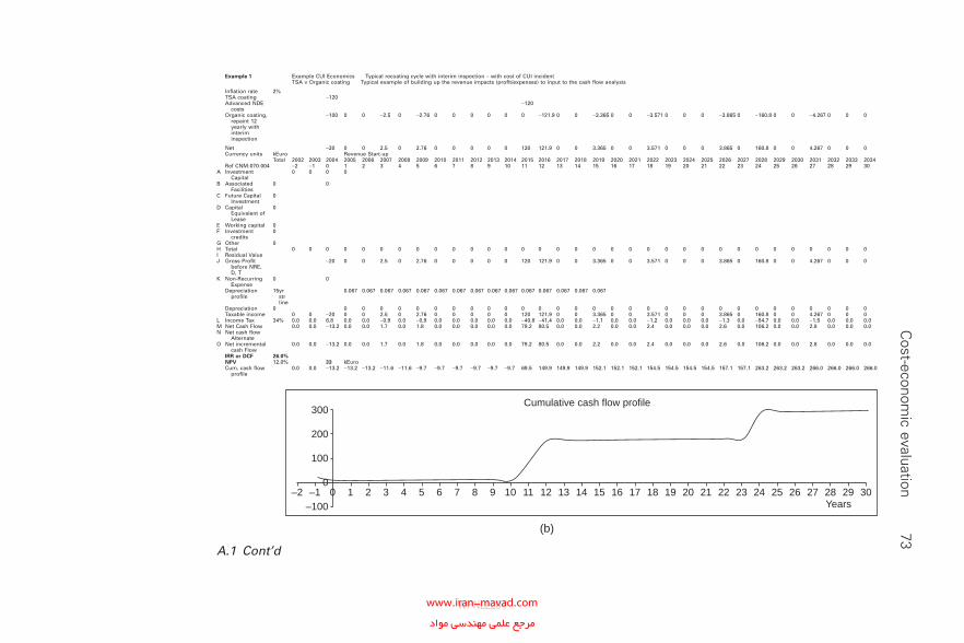
C
ost-economic evaluation
73Example CUI Economics Typical recoating cycle with interim inspection – with cost of CUI incidentTSA v Organic coating Typical example of building up the revenue impacts (profit/expenses) to input to the cash flow analysis
Inflation rate 2%TSA coating −120Advanced NDE
costs−120
Organic coating, repaint 12 yearly with interim inspection
−100 0 0 −2.5 0 −2.76 0 0 0 0 0 0 −121.9 0 0 −3.365 0 0 −3.571 0 0 0 −3.865 0 −160.8 0 0 −4.267 0 0 0
Net −20 0 0 2.5 0 2.76 0 0 0 0 0 120 121.9 0 0 3.365 0 0 3.571 0 0 0 3.865 0 160.8 0 0 4.267 0 0 0Currency units kEuro Revenue Start-up
Total 2002 2003 2004 2005 2006 2007 2008 2009 2010 2011 2012 2013 2014 2015 2016 2017 2018 2019 2020 2021 2022 2023 2024 2025 2026 2027 2028 2029 2030 2031 2032 2033 2034Ref CNM-070-004 −2 −1 0 1 2 3 4 5 6 7 8 9 10 11 12 13 14 15 16 17 18 19 20 21 22 23 24 25 26 27 28 29 30
A Investment Capital
0 0 0 0
B Associated Facilities
0 0
C Future Capital Investment
0
D Capital Equivalent of Lease
0
E Working capital 0F Investment
credits0
G Other 0H Total 0 0 0 0 0 0 0 0 0 0 0 0 0 0 0 0 0 0 0 0 0 0 0 0 0 0 0 0 0 0 0 0 0I Residual ValueJ Gross Profit
before NRE, D, T
−20 0 0 2.5 0 2.76 0 0 0 0 0 120 121.9 0 0 3.365 0 0 3.571 0 0 0 3.865 0 160.8 0 0 4.267 0 0 0
K Non-Recurring Expense
0 0
Depreciation profile
15yr str line
0.067 0.067 0.067 0.067 0.067 0.067 0.067 0.067 0.067 0.067 0.067 0.067 0.067 0.067 0.067
Depreciation 0 0 0 0 0 0 0 0 0 0 0 0 0 0 0 0 0 0 0 0 0 0 0 0 0 0 0 0 0 0 0Taxable income 0 0 −20 0 0 2.5 0 2.76 0 0 0 0 0 120 121.9 0 0 3.365 0 0 3.571 0 0 0 3.865 0 160.8 0 0 4.267 0 0 0
L Income Tax 34% 0.0 0.0 6.8 0.0 0.0 −0.9 0.0 −0.9 0.0 0.0 0.0 0.0 0.0 −40.8 −41.4 0.0 0.0 −1.1 0.0 0.0 −1.2 0.0 0.0 0.0 −1.3 0.0 −54.7 0.0 0.0 −1.5 0.0 0.0 0.0M Net Cash Flow 0.0 0.0 −13.2 0.0 0.0 1.7 0.0 1.8 0.0 0.0 0.0 0.0 0.0 79.2 80.5 0.0 0.0 2.2 0.0 0.0 2.4 0.0 0.0 0.0 2.6 0.0 106.2 0.0 0.0 2.8 0.0 0.0 0.0N Net cash flow
AlternateO Net incremental
cash Flow0.0 0.0 −13.2 0.0 0.0 1.7 0.0 1.8 0.0 0.0 0.0 0.0 0.0 79.2 80.5 0.0 0.0 2.2 0.0 0.0 2.4 0.0 0.0 0.0 2.6 0.0 106.2 0.0 0.0 2.8 0.0 0.0 0.0
IRR or DCF 26.0%NPV 12.0% 33 kEuroCum. cash flow
profile0.0 0.0 −13.2 −13.2 −13.2 −11.6 −11.6 −9.7 −9.7 −9.7 −9.7 −9.7 −9.7 69.5 149.9 149.9 149.9 152.1 152.1 152.1 154.5 154.5 154.5 154.5 157.1 157.1 263.2 263.2 263.2 266.0 266.0 266.0 266.0
–2 –1 0 1 2 3 4 5 6 7 8 9 10 11 12 13 14 15 16 17 18 19 20 21 22 23 24 25 26 27 28 29 30
300
200
100
0
–100 Years
Cumulative cash flow profile
(b)
Example 1
A.1 Cont’d
WPNL2204www.iran-mavad.com مرجع علمى مهندسى مواد
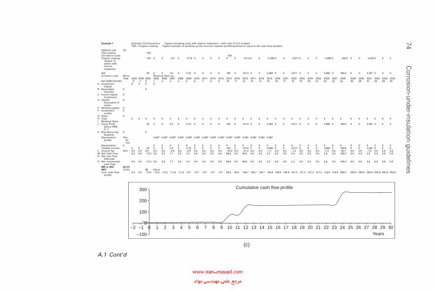
74 C
orrosion-under-insulation guidelines
Example CUI EconomicsExample 1 Typical recoating cycle with interim inspection – with cost of CUI incidentTSA v Organic coating Typical example of building up the revenue impacts (profit/expenses) to input to the cash flow analysis
Inflation rate 2%TSA coating −120CUI failure costs −100Organic coating,
repaint 12 yearly with interim inspection
−100 0 0 −2.5 0 −2.76 0 0 0 0 0 0 −121.9 0 0 −3.365 0 0 −3.571 0 0 0 −3.865 0 −160.8 0 0 −4.2670 0 0
Net −20 0 0 2.5 0 2.76 0 0 0 0 100 0 121.9 0 0 3.365 0 0 3.571 0 0 0 3.865 0 160.8 0 0 4.267 0 0 0Currency units kEuro Revenue Start-up
Total 2002 2003 2004 2005 2006 2007 2008 2009 2010 2011 2012 2013 2014 2015 2016 2017 2018 2019 2020 2021 2022 2023 2024 2025 2026 2027 2028 2029 2030 2031 2032 2033 2034Ref CNM-070-004 −2 −1 0 1 2 3 4 5 6 7 8 9 10 11 12 13 14 15 16 17 18 19 20 21 22 23 24 25 26 27 28 29 30
A Investment Capital
0 0 0 0
B Associated Facilities
0 0
C Future Capital Investment
0
D Capital Equivalent of Lease
0
E Working capital 0F Investment
credits0
G Other 0H Total 0 0 0 0 0 0 0 0 0 0 0 0 0 0 0 0 0 0 0 0 0 0 0 0 0 0 0 0 0 0 0 0 0I Residual ValueJ Gross Profit
before NRE, D, T
−20 0 0 2.5 0 2.76 0 0 0 0 100 0 121.9 0 0 3.365 0 0 3.571 0 0 0 3.865 0 160.8 0 0 4.267 0 0 0
K Non-Recurring Expense
0 0
Depreciation profile
15yr str line
0.067 0.067 0.067 0.067 0.067 0.067 0.067 0.067 0.067 0.067 0.067 0.067 0.067 0.067 0.067
Depreciation 0 0 0 0 0 0 0 0 0 0 0 0 0 0 0 0 0 0 0 0 0 0 0 0 0 0 0 0 0 0 0Taxable income 0 0 −20 0 0 2.5 0 2.76 0 0 0 0 100 0 121.9 0 0 3.365 0 0 3.571 0 0 0 3.865 0 160.8 0 0 4.267 0 0 0
L Income Tax 34% 0.0 0.0 6.8 0.0 0.0 −0.9 0.0 −0.9 0.0 0.0 0.0 0.0 −34.0 0.0 −41.4 0.0 0.0 −1.1 0.0 0.0 −1.2 0.0 0.0 0.0 −1.3 0.0 −54.7 0.0 0.0 −1.5 0.0 0.0 0.0M Net Cash Flow 0.0 0.0 −13.2 0.0 0.0 1.7 0.0 1.8 0.0 0.0 0.0 0.0 66.0 0.0 80.5 0.0 0.0 2.2 0.0 0.0 2.4 0.0 0.0 0.0 2.6 0.0 106.2 0.0 0.0 2.8 0.0 0.0 0.0N Net cash flow
AlternateO Net incremental
cash Flow0.0 0.0 −13.2 0.0 0.0 1.7 0.0 1.8 0.0 0.0 0.0 0.0 66.0 0.0 80.5 0.0 0.0 2.2 0.0 0.0 2.4 0.0 0.0 0.0 2.6 0.0 106.2 0.0 0.0 2.8 0.0 0.0 0.0
IRR or DCF 26.3%NPV 12.0% 32 kEuroCum. cash flow
profile0.0 0.0 −13.2 −13.2 −13.2 −11.6 −11.6 −9.7 −9.7 −9.7 −9.7 −9.7 56.3 56.3 136.7 136.7 136.7 138.9 138.9 138.9 141.3 141.3 141.3 141.3 143.9 143.9 250.0 250.0 250.0 252.8 252.8 252.8 252.8
–2 –1 0 1 2 3 4 5 6 7 8 9 10 11 12 13 14 15 16 17 18 19 20 21 22 23 24 25 26 27 28 29 30
300
200
100
0
–100 Years
Cumulative cash flow profile
(c)
A.1 Cont’d
WPNL2204www.iran-mavad.com مرجع علمى مهندسى مواد
conventional coating using advanced NDE and NDT after recoating after 12 years (DCF of 26.0% over 30 years) and Fig. A.1(c) shows the analysis for a project using an incremental cost of @105 for TSA compared with a conventional coating with a CUI incident and recoating costs (DCF of 26.3% over 30 years).
Where projected life expectancy or requirement is less than 25–30 years, the cost savings from the use of TSA may not be realised and other coating options may prove optimal from a maintenance budget viewpoint.
Cost-economic evaluation 75
WPNL2204www.iran-mavad.com مرجع علمى مهندسى مواد
Appendix BQuality assurance
• The insulation contractor should submit for approval a quality plan incorporating detailed quality control and testing procedures covering all aspects of the shop fabrication and fi eld installation of insulation systems. The quality plan and quality control procedures should comply with the requirements of ISO 9001, ISO 9002 or ISO 9003 as appropri-ate. The insulation contractor may propose incorporation of their own quality control procedures within the quality plan subject to review and ratifi cation by the equipment owner.
• The procedures should as a minimum be based on the quality control agreed by both the equipment owner and the insulation contractor and should incorporate inspection verifi cation sheets covering all work stages.
• Hot insulation. Specifi c checks that should be undertaken are as follows.
° Surfaces certifi ed clean and dry and any specifi ed paint system intact, when released for insulation.
° Application details for the following.� First insulation layer.� Second and subsequent layers of insulation (if required).� Weather protection sheeting.� Weather protection including fl ashings and seals.
° Additional requirements covering the following.� Irregular surfaces such as fl anges, valves, manways, etc.� Stainless steel surfaces.� Hot or acoustic insulation.� Preinsulation at a dressing yard or at a fabrication shop (where
applicable).• Cold insulation. Specifi c checks that should be be undertaken for are:
° Inspection of metal surfaces is completed prior to insulation, sup-ports, etc., fi tted, and hydrotest completed.
° Application details for the following.
76
WPNL2204www.iran-mavad.com مرجع علمى مهندسى مواد
� First insulation layer, no gaps in joints, cracked or damaged blocks, sealer is fi tted, layers are secured to specifi cation.
� Same as above for second layer if fi tted.� Same as above for third layer if fi tted.� Vapour barrier.� Vapour stops.� Flange insulation construction.� Valve box construction.
° Inspection of cladding for sealing, water shed and support; rejected if sealant not under overlap.
• Insulation installation should be subject to various checks at each stage of the insulation programme.
• A pro forma should be used to steward and record each stage of the inspection; the lack of the inspection signature should not allow the next stage of the insulation to proceed.
• Owing to various different plant conditions the insulation sections should be broken down into small manageable sections: isometrics and spool pieces or vessel, shell, head, nozzles, etc.
Quality assurance 77
WPNL2204www.iran-mavad.com مرجع علمى مهندسى مواد
Appendix CAdditional guidelines on the implementation
of corrosion-under-insulation best practice
C.1 Maintenance and remediation issues
C.1.1 Roles and responsibilities of maintenance and operations
C.1.1.1 Maintenance
The primary roles and responsibility of maintenance with respect to the prevention of CUI are as follows.
• Whilst repairing insulated equipment, maintenance should ensure that no damage to insulation, insulation seals or other devices aimed at pre-venting water ingress occurs.
• If damage does occur, maintenance should carry out repairs to restore the installation to its original condition as quickly as possible.
• When working on insulated equipment, the restoration of the insulation system must be considered an integral part of the job.
• Maintenance should ensure that all work is completed in a timely fashion.
• Whilst carrying out repairs, any other areas of insulation showing dis-tress should be included in the maintenance programme.
C.1.1.2 Operations
The primary roles and responsibility of operations with respect to the pre-vention of CUI are as follows.
• Whilst operating equipment, i.e. operating valves, clearing lines, steam-ing out systems, washing down spills, walking lines, etc., measures should be taken to avoid insulation system damage.
• If damage does occur, repairs should be initiated to restore the instal-lation to its original condition as quickly as possible.
78
WPNL2204www.iran-mavad.com مرجع علمى مهندسى مواد
Implementation of CUI best practice 79
• It should be ensured that work orders to repair insulation damage in CUI subject areas are addressed appropriately.
C.1.2 Safety considerations
Whilst carrying out maintenance repair work on live equipment, extra safety considerations should be considered. All activities on live equipment should be risk assessed prior to implementation. There are reported instances of failures occurring on the removal of loose scale during initial inspection and even of failures on removal of insulation. It may be necessary to utilise pre-screening NDE and NDT to establish that it is safe to remove insulation, scale, etc., and for the surface preparation required for coating. Although grit blasting on live equipment is a high-risk procedure, it can be carried out after appropriate task risk assessments have been carried out.
C.1.3 Safety, health and environment concerns with asbestos and lead paint removal
Regulations are in force to prevent exposure of employees to asbestos and lead. If this is not reasonably practicable, the law says that their exposure should be controlled to the lowest possible level. Before any work with asbestos or lead paint is carried out, the regulations require employers to make an assessment of the likely exposure of employees to asbestos and lead dust. The assessment should include a description of the precautions to be taken to control dust release and to protect workers and others who may be affected by that work. Companies employing a contractor to work on their premises should make sure that either the work will not lead to asbestos or lead exposures or that the contractor has carried out this assess-ment and identifi ed work practices to reduce exposures.
C.2 Minimum standards
There is a need to identify the criteria for a minimum standard.
• NACE RP0198-2004 The Control of Corrosion under Thermal Insula-tion and Fireproofi ng Materials—A Systems Approach
C.3 Types of insulation service
C.3.1 Equipment in cyclic service
Equipment normally operated outside the CUI temperature range but in cyclic service other than start-up and shutdown should also be included in the CUI programme. The corrosion rate during cyclic heat-up will be an
WPNL2204www.iran-mavad.com مرجع علمى مهندسى مواد
80 Corrosion-under-insulation guidelines
order of magnitude higher than under non-cyclic conditions. Therefore it is not recommended to take any credit for the period that the equipment is operating outside the CUI temperature range, unless the cyclic frequency is very low, e.g. once every 3–4 months or less.
C.3.2 Equipment in sweating service
Equipment in sweating conditions requires site-specifi c considerations. Vapour barriers cannot be guaranteed to prevent the air from entering the insulation. Therefore it should be assumed that insulation on equipment that operates regularly or permanently below ambient temperature is ‘wet’ unless proven differently. Sweating conditions may also exist locally, e.g. in piping downstream of let-down valves, where the expansion and evapora-tion of the product leads to a cool-down of the product. If the initial operat-ing temperature is suffi ciently close to ambient, this cool-down can result in cold spots below ambient, resulting in water condensation under ever perfect insulation.
C.3.3 Equipment adjacent to cooling towers
Equipment which is situated close to cooling towers, especially if austenitic stainless steels are being used as materials of construction, requires specifi c consideration. The cooling tower drift from the exhaust plume will typically be laden with a high concentration of chlorides which can be deposited on to the equipment under certain weather conditions. Vapour barriers cannot be guaranteed to prevent the air from entering the insulation, condensing and depositing chloride residues. Both carbon–manganese steel and low-alloy steel and austenitic stainless steel piping and equipment require the use of high-integrity coatings. TSA is recommended for carbon–manganese steels and low-alloy steels to prevent CUI and aluminium foil wrap for austenitic stainless steel to prevent Cl-ESCC.
C.3.4 Equipment close to freezing point
A special case is carbon steel and low-alloy steel equipment operating just below freezing point (i.e. liquid propane at atmospheric pressure). With the insulation in good condition, it can be assumed that any water in contact with the surface will be frozen and so CUI is unlikely. This assumption is not true for the vapour phase.
C.3.5 Deluge systems
Deluge systems are not typical for insulated equipment. Nevertheless it can happen that only some parts, an instrument or a small-bore piping
WPNL2204www.iran-mavad.com مرجع علمى مهندسى مواد
Implementation of CUI best practice 81
tie-in, are insulated. It is also possible that the deluge system was not properly designed and installed and can spray its water over adjacent insulated equipment. It is important to pay attention during visual inspec-tion to the presence of any deluge system on or near the insulated equipment.
C.3.6 Steam tracing
Steam tracing leaks will cause greatly accelerated CUI rates and therefore steam tracing is not recommended. It is important to keep the steam tracing in good condition and not leaking. A leaking steam-tracing system is clearly a location for increased CUI rates and should therefore be part of a routine inspection procedure. Use of copper tubing will reduce the probability of steam tracing leaking; however, in the case of wet insulation, copper or any other corrosion-resistant alloy may increase the CUI corrosion rate (gal-vanic effect) at the higher operating temperature.
C.4 Surface preparation
C.4.1 Overview
Coating systems suitable for long-term protection against CUI must be resistant to hot-water immersion. The environment beneath insulation can be very severe. As with new construction, surface preparation and steel cleanliness are crucial in maximising the performance life of any coating system. No suitable alternatives to abrasive blasting have been found to compare favourably as it relates to performance life and/or economics. In spite of this, there is a general reluctance to perform the necessary ‘grit’ blasting in in-situ maintenance situations such as CUI.
C.4.2 Scaffolding
Scaffolding is expensive, but access for inspection, surface preparation and coating application is required. The most effi cient way to minimise scaffold-ing is to eliminate its need through intelligent selection of inspection areas. When the inspection strategy calls for sampling of certain types of location or confi guration, select those that are close to grade, near platforms, ladders or walkways. When this cannot be done, inspectors should select those that are accessible by rolling ladder or other means. For the remaining points, rope access may prove to be the most cost effective, quickest and safest alternative to traditional scaffolding or mobile crane access.
WPNL2204www.iran-mavad.com مرجع علمى مهندسى مواد
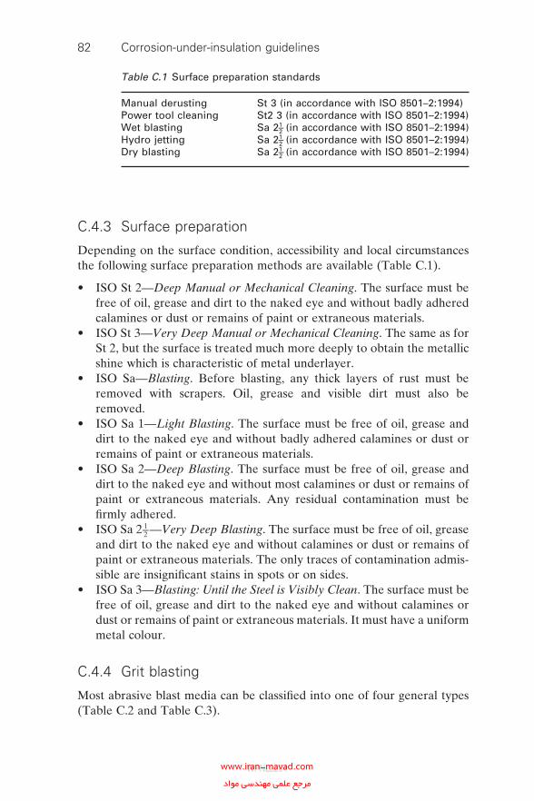
82 Corrosion-under-insulation guidelines
C.4.3 Surface preparation
Depending on the surface condition, accessibility and local circumstances the following surface preparation methods are available (Table C.1).
• ISO St 2—Deep Manual or Mechanical Cleaning. The surface must be free of oil, grease and dirt to the naked eye and without badly adhered calamines or dust or remains of paint or extraneous materials.
• ISO St 3—Very Deep Manual or Mechanical Cleaning. The same as for St 2, but the surface is treated much more deeply to obtain the metallic shine which is characteristic of metal underlayer.
• ISO Sa—Blasting. Before blasting, any thick layers of rust must be removed with scrapers. Oil, grease and visible dirt must also be removed.
• ISO Sa 1—Light Blasting. The surface must be free of oil, grease and dirt to the naked eye and without badly adhered calamines or dust or remains of paint or extraneous materials.
• ISO Sa 2—Deep Blasting. The surface must be free of oil, grease and dirt to the naked eye and without most calamines or dust or remains of paint or extraneous materials. Any residual contamination must be fi rmly adhered.
• ISO Sa 2 1–2 —Very Deep Blasting. The surface must be free of oil, grease and dirt to the naked eye and without calamines or dust or remains of paint or extraneous materials. The only traces of contamination admis-sible are insignifi cant stains in spots or on sides.
• ISO Sa 3—Blasting: Until the Steel is Visibly Clean. The surface must be free of oil, grease and dirt to the naked eye and without calamines or dust or remains of paint or extraneous materials. It must have a uniform metal colour.
C.4.4 Grit blasting
Most abrasive blast media can be classifi ed into one of four general types (Table C.2 and Table C.3).
Table C.1 Surface preparation standards
Manual derusting St 3 (in accordance with ISO 8501–2:1994)Power tool cleaning St2 3 (in accordance with ISO 8501–2:1994)Wet blasting Sa 21–2 (in accordance with ISO 8501–2:1994)Hydro jetting Sa 21–2 (in accordance with ISO 8501–2:1994)Dry blasting Sa 21–2 (in accordance with ISO 8501–2:1994)
WPNL2204www.iran-mavad.com مرجع علمى مهندسى مواد
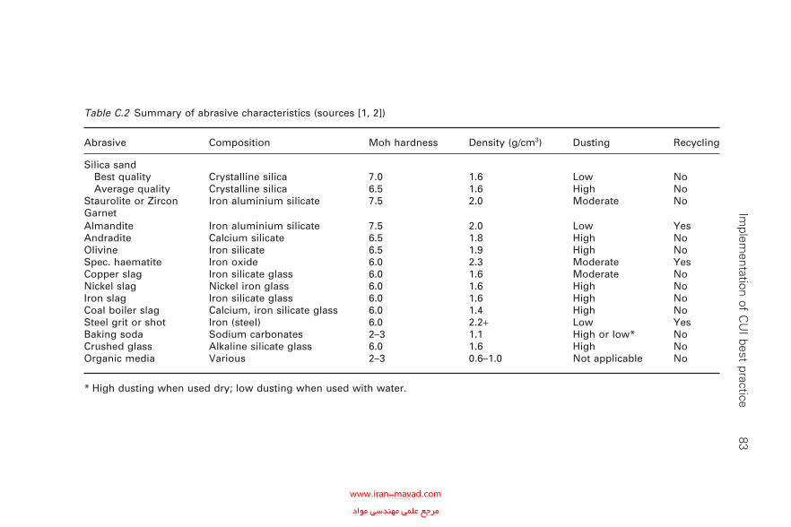
Im
plementation of C
UI best practice
83
Table C.2 Summary of abrasive characteristics (sources [1, 2])
Abrasive Composition Moh hardness Density (g/cm3) Dusting Recycling
Silica sand Best quality Crystalline silica 7.0 1.6 Low No Average quality Crystalline silica 6.5 1.6 High NoStaurolite or Zircon Iron aluminium silicate 7.5 2.0 Moderate NoGarnetAlmandite Iron aluminium silicate 7.5 2.0 Low YesAndradite Calcium silicate 6.5 1.8 High NoOlivine Iron silicate 6.5 1.9 High NoSpec. haematite Iron oxide 6.0 2.3 Moderate YesCopper slag Iron silicate glass 6.0 1.6 Moderate NoNickel slag Nickel iron glass 6.0 1.6 High NoIron slag Iron silicate glass 6.0 1.6 High NoCoal boiler slag Calcium, iron silicate glass 6.0 1.4 High NoSteel grit or shot Iron (steel) 6.0 2.2+ Low YesBaking soda Sodium carbonates 2–3 1.1 High or low* NoCrushed glass Alkaline silicate glass 6.0 1.6 High NoOrganic media Various 2–3 0.6–1.0 Not applicable No
* High dusting when used dry; low dusting when used with water.
WPNL2204www.iran-mavad.com مرجع علمى مهندسى مواد
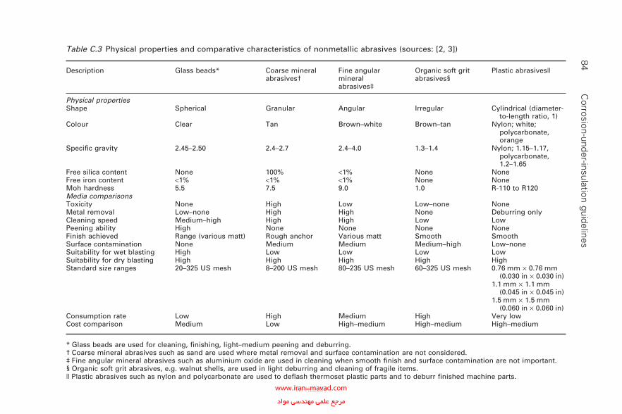
84 C
orrosion-under-insulation guidelinesTable C.3 Physical properties and comparative characteristics of nonmetallic abrasives (sources: [2, 3])
Description Glass beads* Coarse mineral abrasives†
Fine angular mineral abrasives‡
Organic soft grit abrasives§
Plastic abrasives||
Physical propertiesShape Spherical Granular Angular Irregular Cylindrical (diameter-
to-length ratio, 1)Colour Clear Tan Brown–white Brown–tan Nylon; white;
polycarbonate, orange
Specifi c gravity 2.45–2.50 2.4–2.7 2.4–4.0 1.3–1.4 Nylon; 1.15–1.17, polycarbonate, 1.2–1.65
Free silica content None 100% <1% None NoneFree iron content <1% <1% <1% None NoneMoh hardness 5.5 7.5 9.0 1.0 R-110 to R120Media comparisonsToxicity None High Low Low–none NoneMetal removal Low–none High High None Deburring onlyCleaning speed Medium–high High High Low LowPeening ability High None None None NoneFinish achieved Range (various matt) Rough anchor Various matt Smooth SmoothSurface contamination None Medium Medium Medium–high Low–noneSuitability for wet blasting High Low Low Low LowSuitability for dry blasting High High High High HighStandard size ranges 20–325 US mesh 8–200 US mesh 80–235 US mesh 60–325 US mesh 0.76 mm × 0.76 mm
(0.030 in × 0.030 in)1.1 mm × 1.1 mm
(0.045 in × 0.045 in)1.5 mm × 1.5 mm
(0.060 in × 0.060 in)Consumption rate Low High Medium High Very lowCost comparison Medium Low High–medium High–medium High–medium
* Glass beads are used for cleaning, fi nishing, light–medium peening and deburring.† Coarse mineral abrasives such as sand are used where metal removal and surface contamination are not considered.‡ Fine angular mineral abrasives such as aluminium oxide are used in cleaning when smooth fi nish and surface contamination are not important.§ Organic soft grit abrasives, e.g. walnut shells, are used in light deburring and cleaning of fragile items.|| Plastic abrasives such as nylon and polycarbonate are used to defl ash thermoset plastic parts and to deburr fi nished machine parts.
WPNL2204www.iran-mavad.com مرجع علمى مهندسى مواد
Implementation of CUI best practice 85
• Natural minerals (e.g. silica sand, garnet and olivine).• Manufactured media (e.g. steel shot, glass grit, alumina, plastic pellets
or beads, solid carbon dioxide and sodium bicarbonate).• Mineral slag (e.g. copper slag, nickel slag, iron slag and coal slag).• Organic media (e.g. corn cobs, nut shells and starch grains).
C.4.5 Wet abrasion (jet cleaning)
This consists of water washing at a very high pressure.
• Pressure, more than 2000 barg.• Cleaning speed, maximum 10–12 m/h, depending on the material to be
eliminated.• Use, complete elimination of coatings and rust. The result is comparable
with that of dry abrasive blasting but with premature oxidisation after drying.
C.4.6 Water washing at a pressure
• Pressure, up to 1300 barg.• Cleaning speed, maximum 5 m/h, depending on the material to be elimi-
nated. This method, at much lower pressure, is used to eliminate con-tamination from any layer underneath.
• Use, elimination of salts and other contaminants, coatings and rust.
C.4.7 Wet abrasive blasting at a low pressure
• Pressure, 6–8 bar.• Cleaning speed, maximum 10–16 m/h, depending on the material to be
eliminated.• Use, reduction in abrasion, dust, eliminates salts, avoids danger of
sparking. The result is comparable with that of dry abrasive blasting but with premature oxidation after drying.
C.4.8 Steam cleaning
• Pressure, 100–120 bar.• Use, elimination of soluble contamination is water or water emulsions;
the layer under dries more quickly than on scouring with water.
WPNL2204www.iran-mavad.com مرجع علمى مهندسى مواد
86 Corrosion-under-insulation guidelines
C.4.9 Vacuum blasting
Vacuum blasting quickly removes surface coatings, leaving an abraded sub-strate, while generating minimal waste and virtually no dust emissions.
The technology offers a safe, economical and effi cient means for cleaning up hazardous materials from many different types of surface. Benefi ts include the following.
• Increased productivity for clean-up of contaminated facilities by more than 50% over baseline.
• Minimal waste generation (1% of conventional open blasting) and vir-tually no dust emissions.
• Minimised worker exposure to hazardous contaminants.• Improved ergonomics from lightweight construction of the blast head.
Although the productivity of vacuum blasting is lower than for conven-tional blasting which increase the cost, the total cost of vacuum blasting may be similar because of lower scaffolding and sheeting requirements.
C.4.10 Mechanical surface preparation
The cost associated with dust containment and debris disposal may be sig-nifi cant but the improvement in coating integrity and therefore life means that blasting should always be applied wherever possible. When blasting cannot be successfully applied, it will be necessary to use power tools or manual preparation techniques. It should be recognised that in these cases the coating life will be substantially shortened and reinspection schedules should be set accordingly. These methods are not recommended but some-times are unavoidable.
C.4.10.1 Mechanical brushing
Mechanical brushing is usually performed with rotating wire brushes. The main disadvantage is that the surfaces treated are not usually corrosion free and are often polished and contaminated with oil. This makes the adhesion of any coating less effective and impairs the system’s performance.
C.4.10.2 Descaling
Mechanical descaling is usually carried out in combination with mechanical brushing. It is appropriate for small repairs and can be used to eliminate thick coats of rust and to make subsequent blasting operations cheaper.
WPNL2204www.iran-mavad.com مرجع علمى مهندسى مواد
Implementation of CUI best practice 87
C.4.10.3 Pin hammer
This is utilised to eliminate rust, paint, etc., from corners and angles and obtain a clean surface with a profi le.
C.4.10.4 Sanding with grinding discs
Sanding with a grinding disc requires the use of one or more rotating discs covered with an abrasive material. The system is used for small repairs or for eliminating particles and notches.
C.4.11 Non-dust (vacuum) grit blast technology
Alternative grit blast techniques such as the following should be considered in order to reduce dust contamination. Dust control is simplifi ed (no boxing in structures) and the risk of personal eye injuries is reduced.
C.4.11.1 Sponge jet
Sponge jet is a composite of urethane sponge and a cleaning (or abrasive) agent; this patented technology utilises the pliable open-celled characteris-tics of urethane sponge and the cleaning and cutting power of a cleaning agent or conventional abrasive. The pliant nature of sponge medium allows it to fl atten on impact, exposing the cleaning agent or abrasive. After leaving the surface, then it constricts (entrapping most of what would nor-mally have become air-borne contaminants). Blasted medium is collected and processed through either electric or pneumatic classifi ers, which sepa-rate the sponge medium abrasives into three categories: oversized debris, reusable medium and fi nes (consisting of spent media and dust). Up to 94% of sponge medium abrasives are reusable after each blast cycle.
C.4.11.2 Solid carbon dioxide
There are four cleaning methods using carbon dioxide.
• Macroscopic hard and dense dry ice pellets.• Softer microscopic ‘snow’ particles.• Liquid carbon dioxide washing systems.• Supercritical fl uid carbon dioxide.
Whichever process is used, cleaning depends on the liquid carbon dioxide solvent properties, the energy and momentum transfer by the impacting solid phase, or a combination of solvent properties and momentum or energy transfer. Pellet systems rely upon the thermomechanical impact
WPNL2204www.iran-mavad.com مرجع علمى مهندسى مواد
88 Corrosion-under-insulation guidelines
stresses related to the high impact velocity of macroscopic pellets for con-tamination removal—a momentum and energy transfer process. Snow sprays rely upon a combination of the solvent action of liquid carbon dioxide and the momentum transfer of high-velocity microscopic snow particles. The liquid-based carbon dioxide washing systems rely on the liquid-phase solvent properties. Finally, the supercritical fl uid carbon dioxide systems rely exclusively upon carbon dioxide’s unique supercritical fl uid properties.
C.5 References
1. J.D. Itansink, ‘An introduction to abrasives for protective coating removal opera-tions’, J. Prot. Coatings Linings, 2000, 17(4), 66–73.
2. PERA, Research Report, 2003.3. ‘Pickling of iron and steel’, in ASM Metals Handbook, Vol. 5, 9th edition, Metals
Park, Ohio, American Society for Metals, 1982, Table 4, p. 85.
WPNL2204www.iran-mavad.com مرجع علمى مهندسى مواد
Appendix DCoatings
D.1 General comments
Protective coatings include thermally sprayed or fl ame-sprayed metallic systems as well as the traditional organic coating systems. Each of these systems has its place in the prevention of CUI. Some are more effective then others but may cost more. An economic life cycle analysis can be very effective in determining which system to apply in a particular situation. This document will not include a detailed discussion of the various types of coating that are available, which can be used to protect piping and vessels that will be insulated. The reader is encouraged to consult NACE RP0198-2004 [1] for guidance as it contains a very detailed section on protective coatings.
D.2 Protective coatings
This section details information for the selection of protective coatings for carbon–manganese steels, low-alloy steels and austenitic stainless steels under thermal and/or noise reduction insulation systems and cem-entitious fi reproofi ng. Protective coatings have been recognised and accepted and are recommended as a highly effective method of protecting insulated metallic substrates such as these steels from corrosion. Attempts to prevent water from entering insulated systems have not been successful, and corrosion protection techniques such as inhibitors and cathodic pro-tection have been less effective than protective coatings in mitigating CUI.
D.3 Thermally sprayed aluminium
A comparison between TSA and conventional paint systems for the protec-tion of steel under insulation is provided in Table D.1.
89
WPNL2204www.iran-mavad.com مرجع علمى مهندسى مواد
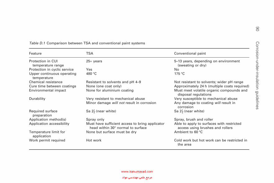
90 C
orrosion-under-insulation guidelines
Table D.1 Comparison between TSA and conventional paint systems
Feature TSA Conventional paint
Protection in CUI temperature range
25+ years 5–13 years, depending on environment (sweating or dry)
Protection in cyclic service Yes NoUpper continuous operating
temperature480 °C 175 °C
Chemical resistance Resistant to solvents and pH 4–9 Not resistant to solvents; wider pH rangeCure time between coatings None (one coat only) Approximately 24 h (multiple coats required)Environmental impact None for aluminium coating Must meet volatile organic compounds and
disposal regulationsDurability Very resistant to mechanical abuse
Minor damage will not result in corrosionVery susceptible to mechanical abuse Any damage to coating will result in
corrosionRequired surface
preparationSa 21–2 (near white) Sa 21–2 (near white)
Application method(s) Spray only Spray, brush and rollerApplication accessibility Must have suffi cient access to bring applicator
head within 30° normal to surfaceAble to apply to surfaces with restricted
access using brushes and rollersTemperature limit for
applicationNone but surface must be dry Ambient to 60 °C
Work permit required Hot work Cold work but hot work can be restricted in the area
WPNL2204www.iran-mavad.com مرجع علمى مهندسى مواد
D.4 Surface and moisture tolerance
When the above situations cannot be avoided, the use of a surface- and/or moisture-tolerant coating may be considered as a short-term measure. It is recommended that a specialist with expertise in coatings select these coatings.
D.5 Alternative coatings; tape coatings
In some situations where grit blasting is not acceptable, liquid applied coat-ings are not necessarily the best answer. Wax or petrolatum tape wrap systems are sometimes the best solution for corrosion prevention under insulation on piping where the operating temperature will not exceed 55 °C (130 °F). These coatings have a limited life.
Glass-fi bre-reinforced resin in tape or sheet form can be used in lieu of a conventional organic coating or TSA, but it is a costly process and would not normally be the fi rst choice. However, the application of tape at loca-tions where clamps, etc., are to be used not only acts as a buffer preventing coating damage but also prevents local moisture retention between the clamp and pipe from accelerating the degradation of the coating. Inserts such as rubber also prevent the damage but not the crevice water retention.
D.6 Reference
1. NACE RP0198-2004 The Control of Corrosion under Thermal Insulation and Fireproofi ng Materials—A Systems Approach, Houston, Texas, NACE Interna-tional, 2004.
Coatings 91
WPNL2204www.iran-mavad.com مرجع علمى مهندسى مواد
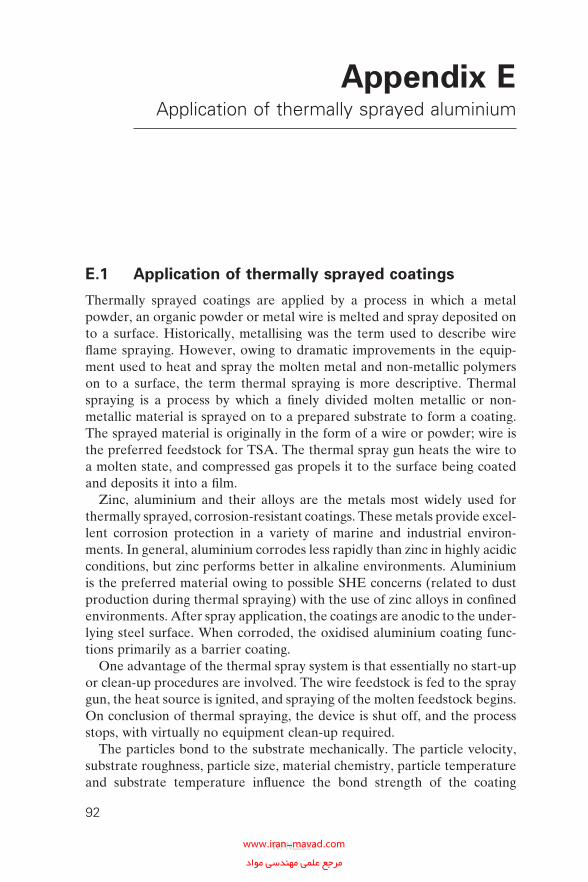
Appendix EApplication of thermally sprayed aluminium
E.1 Application of thermally sprayed coatings
Thermally sprayed coatings are applied by a process in which a metal powder, an organic powder or metal wire is melted and spray deposited on to a surface. Historically, metallising was the term used to describe wire fl ame spraying. However, owing to dramatic improvements in the equip-ment used to heat and spray the molten metal and non-metallic polymers on to a surface, the term thermal spraying is more descriptive. Thermal spraying is a process by which a fi nely divided molten metallic or non-metallic material is sprayed on to a prepared substrate to form a coating. The sprayed material is originally in the form of a wire or powder; wire is the preferred feedstock for TSA. The thermal spray gun heats the wire to a molten state, and compressed gas propels it to the surface being coated and deposits it into a fi lm.
Zinc, aluminium and their alloys are the metals most widely used for thermally sprayed, corrosion-resistant coatings. These metals provide excel-lent corrosion protection in a variety of marine and industrial environ-ments. In general, aluminium corrodes less rapidly than zinc in highly acidic conditions, but zinc performs better in alkaline environments. Aluminium is the preferred material owing to possible SHE concerns (related to dust production during thermal spraying) with the use of zinc alloys in confi ned environments. After spray application, the coatings are anodic to the under-lying steel surface. When corroded, the oxidised aluminium coating func-tions primarily as a barrier coating.
One advantage of the thermal spray system is that essentially no start-up or clean-up procedures are involved. The wire feedstock is fed to the spray gun, the heat source is ignited, and spraying of the molten feedstock begins. On conclusion of thermal spraying, the device is shut off, and the process stops, with virtually no equipment clean-up required.
The particles bond to the substrate mechanically. The particle velocity, substrate roughness, particle size, material chemistry, particle temperature and substrate temperature infl uence the bond strength of the coating
92
WPNL2204www.iran-mavad.com مرجع علمى مهندسى مواد
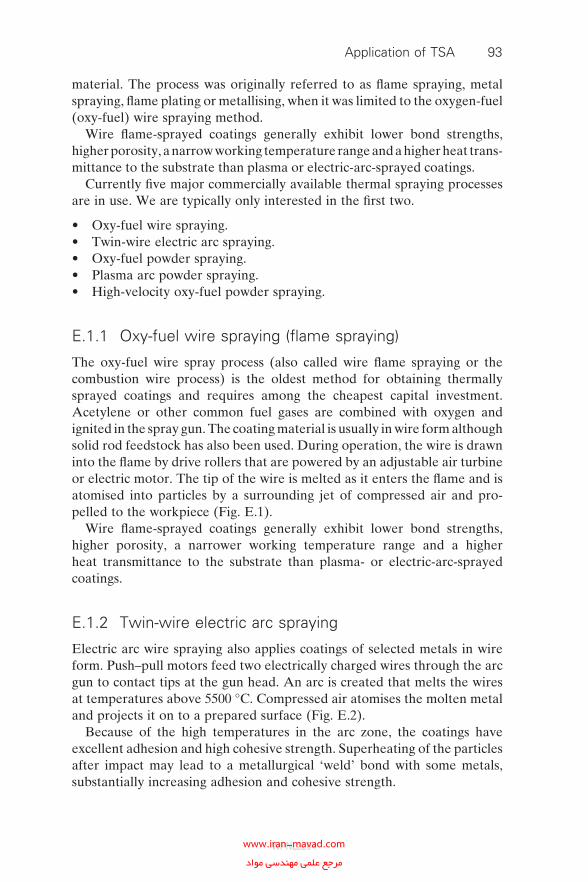
material. The process was originally referred to as fl ame spraying, metal spraying, fl ame plating or metallising, when it was limited to the oxygen-fuel (oxy-fuel) wire spraying method.
Wire fl ame-sprayed coatings generally exhibit lower bond strengths, higher porosity, a narrow working temperature range and a higher heat trans-mittance to the substrate than plasma or electric-arc-sprayed coatings.
Currently fi ve major commercially available thermal spraying processes are in use. We are typically only interested in the fi rst two.
• Oxy-fuel wire spraying.• Twin-wire electric arc spraying.• Oxy-fuel powder spraying.• Plasma arc powder spraying.• High-velocity oxy-fuel powder spraying.
E.1.1 Oxy-fuel wire spraying (fl ame spraying)
The oxy-fuel wire spray process (also called wire fl ame spraying or the combustion wire process) is the oldest method for obtaining thermally sprayed coatings and requires among the cheapest capital investment. Acety lene or other common fuel gases are combined with oxygen and ignited in the spray gun. The coating material is usually in wire form although solid rod feedstock has also been used. During operation, the wire is drawn into the fl ame by drive rollers that are powered by an adjustable air turbine or electric motor. The tip of the wire is melted as it enters the fl ame and is atomised into particles by a surrounding jet of compressed air and pro-pelled to the workpiece (Fig. E.1).
Wire fl ame-sprayed coatings generally exhibit lower bond strengths, higher porosity, a narrower working temperature range and a higher heat transmittance to the substrate than plasma- or electric-arc-sprayed coatings.
E.1.2 Twin-wire electric arc spraying
Electric arc wire spraying also applies coatings of selected metals in wire form. Push–pull motors feed two electrically charged wires through the arc gun to contact tips at the gun head. An arc is created that melts the wires at temperatures above 5500 °C. Compressed air atomises the molten metal and projects it on to a prepared surface (Fig. E.2).
Because of the high temperatures in the arc zone, the coatings have excellent adhesion and high cohesive strength. Superheating of the particles after impact may lead to a metallurgical ‘weld’ bond with some metals, substantially increasing adhesion and cohesive strength.
Application of TSA 93
WPNL2204www.iran-mavad.com مرجع علمى مهندسى مواد
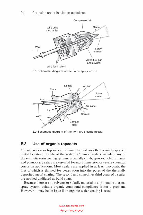
94 Corrosion-under-insulation guidelines
E.2 Use of organic topcoats
Organic sealers or topcoats are commonly used over the thermally sprayed metal to extend the life of the system. Common sealers include many of the synthetic resin coating systems, especially vinyls, epoxies, polyurethanes and phenolics. Sealers are essential for most immersion or severe chemical corrosion applications. Most sealers are applied in at least two coats, the fi rst of which is thinned for penetration into the pores of the thermally deposited metal coating. The second and sometimes third coats of a sealer are applied undiluted as build coats.
Because there are no solvents or volatile material in any metallic thermal spray system, volatile organic compound compliance is not a problem. However, it may be an issue if an organic sealer coating is used.
Wire drivemechanism
Compressed air
Flame
Spraystream
Mixed fuel gasand oxygen
Wire feed rollers
Wire
E.1 Schematic diagram of the fl ame spray nozzle.
Contacttube
Wire
Air
–ve
+ve
Shroud
Arc zone
Spraystream
Air capNozzleBlock
E.2 Schematic diagram of the twin-arc electric nozzle.
WPNL2204www.iran-mavad.com مرجع علمى مهندسى مواد
E.3 Application strategies
TSA can be applied to all equipment fabricated from carbon–manganese steels and low-alloy steels and if required to both austenitic and duplex stainless steels. The application is more economic when applied to new equipment in dedicated fabrication shops but TSA can also be applied in the fi eld in maintenance or project facilities and directly on to piping and equipment in situ. TSA is therefore applicable for similar applications as paint and conventional coatings.
• Off-site, on all new fabrications (vessels, tanks, piping, etc.).• Off-site, or in the fi eld on all new fabrications.• Off-site, in maintenance areas (equipment removed from service).• On-site, during maintenance turn-arounds (equipment taken out of
service).• On-site, on equipment taken out of service whilst other plant is
running.• On-site, on live equipment.
Procedures and application specifi cations need to be developed for TSA application in the fi eld, especially when application on live equipment con-taining fl ammable hydrocarbons is considered. Generally, coatings obtained by oxy-fuel wire spraying are preferred over these obtained by twin-wire electric arc spraying for site TSA application on piping and vessels with limited access. This is based on experience which shows that the former coatings are easier to apply and have fewer SHE-related issues. The bond strength of TSA obtained by oxy-fuel wire spraying is generally lower than the bond strength of TSA coatings obtained by twin-wire electric arc spray-ing but is nonetheless considered more than acceptable from a fi tness-for-purpose perspective. This is also true for live equipment applications because of the less stringent permit procedures that are required. Twin-wire electric arc spraying permits a higher application rate than oxy-fuel wire spraying in less congested areas such as large tanks and other large equip-ment which can be used to lower the overall cost of application. Selection of the TSA application process for shop-applied applications should be made following an economic assessment.
Table E.1 shows some of the advantages of using TSA over conventional organic coatings when considering application on live equipment.
E.4 Thermally sprayed aluminium specifi cation
This specifi cation outlines the requirements for the protection of externally insulated vessels and piping surfaces from CUI by the application of TSA.
Application of TSA 95
WPNL2204www.iran-mavad.com مرجع علمى مهندسى مواد
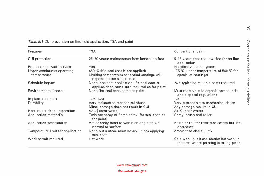
96 C
orrosion-under-insulation guidelines
Table E.1 CUI prevention on-line fi eld application: TSA and paint
Features TSA Conventional paint
CUI protection 25–30 years; maintenance free; inspection free 5–13 years; tends to low side for on-line application
Protection in cyclic service Yes No effective paint systemUpper continuous operating
temperature480 °C (If a seal coat is not applied)Limiting temperature for sealed coatings will
depend on the sealer used
175 °C (upper temperature of 540 °C for specialist coatings)
Schedule impact None; one-coat application (if a seal coat is applied, then same cure required as for paint)
24 h typically; multiple coats required
Environmental impact None (for seal coat, same as paint) Must meet volatile organic compounds and disposal regulations
In-place cost ratio 1.05–1.20 1.0Durability Very resistant to mechanical abuse
Minor damage does not result in CUIVery susceptible to mechanical abuseAny damage results in CUI
Required surface preparation SA 21–2 (near white) Sa 21–2 (near white)Application method(s) Twin-arc spray or fl ame spray (for seal coat, as
for paint)Spray, brush and roller
Application accessibility Arc or spray head to within an angle of 30° normal to surface
Brush or roll for restricted access but life decreases
Temperature limit for application None but surface must be dry unless applying seal coat
Ambient to about 60 °C
Work permit required Hot work Cold work, but it can restrict hot work in the area where painting is taking place
WPNL2204www.iran-mavad.com مرجع علمى مهندسى مواد
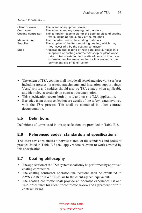
• The extent of TSA coating shall include all vessel and pipework surfaces including nozzles, brackets, attachments and insulation support rings. Vessel skirts and saddles should also be TSA coated when applicable and identifi ed accordingly in contract documentation.
• This specifi cation covers both on-site and off-site TSA application.• Excluded from this specifi cation are details of the safety issues involved
with the TSA process. This shall be contained in other contract documentation.
E.5 Defi nitions
Defi nitions of terms used in this specifi cation are provided in Table E.2.
E.6 Referenced codes, standards and specifi cations
The latest revisions, unless otherwise stated, of the standards and codes of practice listed in Table E.3 shall apply where relevant to work covered by this specifi cation.
E.7 Coating philosophy
• The application of the TSA systems shall only be performed by approved coating contractors.
• The coating contractor operator qualifi cations shall be evaluated to AWS C2.18 or AWS C2.23, or to the client-agreed equivalent.
• The coating contractor shall provide an operator experience list and TSA procedures for client or contractor review and agreement prior to contract award.
Table E.2 Defi nitions
Client or owner The eventual equipment ownerContractor The actual company carrying out the workCoating contractor The company responsible for the defi ned piece of coating
work, including the supply of the materialsManufacturer The manufacturer of the coating materialsSupplier The supplier of the item requiring coating, which may
not necessarily be the coating contractorShop Preparation and coating of new bare steel surfaces in a
supplier’s or coating contractor’s shop or plant works prior to transportation to the site of construction, or a controlled environment coating facility erected at the permanent site of construction
Application of TSA 97
WPNL2204www.iran-mavad.com مرجع علمى مهندسى مواد
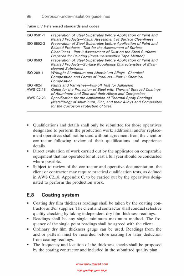
98 Corrosion-under-insulation guidelines
• Qualifi cations and details shall only be submitted for those operatives designated to perform the production work; additional and/or replace-ment operatives shall not be used without agreement from the client or contractor following review of their qualifi cations and experience details.
• Direct evaluation of work carried out by the applicator on comparable equipment that has operated for at least a full year should be conducted where possible.
• Subject to review of the contractor and operative documentation, the client or contractor may require practical qualifi cation tests, as defi ned in AWS C2.18, Appendix C, to be carried out by the operatives desig-nated to perform the production work.
E.8 Coating system
• Coating dry fi lm thickness readings shall be taken by the coating con-tractor and/or supplier. The client and contractor shall conduct selective quality checking by taking independent dry fi lm thickness readings.
• Readings shall be any single minimum–maximum method. The fre-quency of the single point readings shall be agreed with the client.
• Ordinary dry fi lm thickness gauge can be used. Readings from the anchor pattern must be recorded before coating for later deduction from coating readings.
• The frequency and location of the thickness checks shall be proposed by the coating contractor and included in the submitted quality plan.
Table E.3 Referenced standards and codes
ISO 8501-1 Preparation of Steel Substrates before Application of Paint and Related Products—Visual Assessment of Surface Cleanliness
ISO 8502-3 Preparation of Steel Substrates before Application of Paint and Related Products—Test for the Assessment of Surface Cleanliness—Part 3 Assessment of Dust on the Steel Surfaces Prepared for Painting (Pressure-sensitive Tape Method)
ISO 8503 Preparation of Steel Substrates before Application of Paint and Related Products—Surface Roughness Characteristics of Blast-cleaned Substrates
ISO 209-1 Wrought Aluminium and Aluminium Alloys—Chemical Composition and Forms of Products—Part 1: Chemical Composition
ISO 4624 Paints and Varnishes—Pull-off Test for AdhesionAWS C2.18 Guide for the Protection of Steel with Thermal Sprayed Coatings
of Aluminum and Zinc and their Alloys and CompositesAWS C2.23 Specifi cation for the Application of Thermal Spray Coatings
(Metallizing) of Aluminum, Zinc, and their Alloys and Composites for the Corrosion Protection of Steel
WPNL2204www.iran-mavad.com مرجع علمى مهندسى مواد
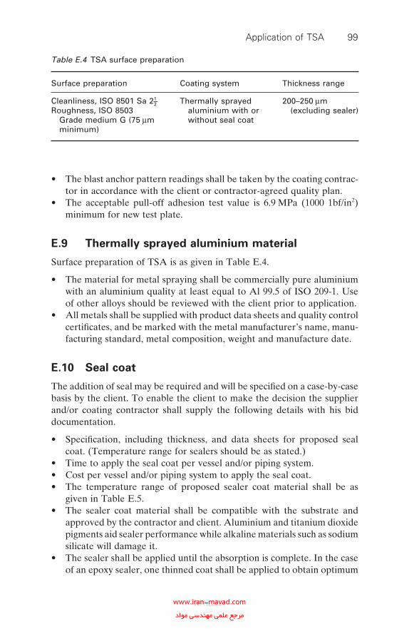
• The blast anchor pattern readings shall be taken by the coating contrac-tor in accordance with the client or contractor-agreed quality plan.
• The acceptable pull-off adhesion test value is 6.9 MPa (1000 1bf/in2) minimum for new test plate.
E.9 Thermally sprayed aluminium material
Surface preparation of TSA is as given in Table E.4.
• The material for metal spraying shall be commercially pure aluminium with an aluminium quality at least equal to Al 99.5 of ISO 209-1. Use of other alloys should be reviewed with the client prior to application.
• All metals shall be supplied with product data sheets and quality control certifi cates, and be marked with the metal manufacturer’s name, manu-facturing standard, metal composition, weight and manufacture date.
E.10 Seal coat
The addition of seal may be required and will be specifi ed on a case-by-case basis by the client. To enable the client to make the decision the supplier and/or coating contractor shall supply the following details with his bid documentation.
• Specifi cation, including thickness, and data sheets for proposed seal coat. (Temperature range for sealers should be as stated.)
• Time to apply the seal coat per vessel and/or piping system.• Cost per vessel and/or piping system to apply the seal coat.• The temperature range of proposed sealer coat material shall be as
given in Table E.5.• The sealer coat material shall be compatible with the substrate and
approved by the contractor and client. Aluminium and titanium dioxide pigments aid sealer performance while alkaline materials such as sodium silicate will damage it.
• The sealer shall be applied until the absorption is complete. In the case of an epoxy sealer, one thinned coat shall be applied to obtain optimum
Table E.4 TSA surface preparation
Surface preparation Coating system Thickness range
Cleanliness, ISO 8501 Sa 21–2Roughness, ISO 8503
Grade medium G (75 μm minimum)
Thermally sprayed aluminium with or without seal coat
200–250 μm (excluding sealer)
Application of TSA 99
WPNL2204www.iran-mavad.com مرجع علمى مهندسى مواد
100 Corrosion-under-insulation guidelines
penetration, followed by a second coat of the same material without thinning.
E.11 Design
• Welds shall not be coated until all approved heat treatment, non-destructive testing and pressure testing has been completed and approved.
• Certifi cates of release, confi rming that successful completion of all appropriate tests and safety checks have been carried out to the released working areas, shall be obtained before the commencement of coating work.
• The following items shall be shielded and protected to prevent damage during surface preparation and coating material application operations. All openings, including those that are fl anged or threaded shall be sealed to prevent entry of blast abrasive or coating material. After completion of coating operations, all material used for shielding and sealing shall be removed unless instructed otherwise.
° The sum of yearly costs due to unavailability of system and loss of earnings.
° Nameplates.
° Packing glands and seals.
° Vents.
° Valve stems.
° Instrument dials.
° Gauge and fl ow indicator glasses.
° Pressure gauges.
° Machined surfaces of gasket contact surfaces.
E.12 Surface preparation
Surface preparation for TSA is as given in Table E.4.
• The coating contractor shall grit blast the vessel and/or surface to ISO 8501 Grade Sa 21–2 (near-white blast fi nish).
Table E.5 Sealer temperature ranges
Surface temperature range
−20 °C minimum to 120 °C maximum120 °C and greater
WPNL2204www.iran-mavad.com مرجع علمى مهندسى مواد
• An anchor pattern of 75 μm minimum shall be achieved using an angular grit.
• The abrasive size shall be selected to achieve a surface roughness speci-fi ed to ensure the adhesion of the sprayed coating and shall be more coarse than normally used for painting.
• Abrasive blast cleaning employing sand or slag abrasive from mineral smelting is not permitted.
• The abrasive shall be clean and dry, and free from soluble salts.• The surface shall be dust free prior to application of the thermal spray
coating.• The coating contractor shall consider how large an area to blast prior
applying the TSA coating (i.e. how long the blast will hold) and shall include this in the overall coating plan.
E.13 Weather and surface conditions
Surface preparation and coating shall not be undertaken when any of the following conditions exist.
• In conditions which are favourable to surface condensation.• When the relative humidity is above 85%.• If there is the likelihood of a change in weather conditions within 4 h
of the application which would result in air temperatures below those specifi ed or the deposition of moisture upon the surface.
• On metal surfaces having temperatures less than 3 °C above the dew point.
E.14 Application process
• The application process may be oxy-fuel wire spraying or twin-wire electric arc spraying.
• The preferred material feed mechanism for in fi eld application is wire feed. Powder feed mechanisms are acceptable alternatives for shop-applied work but must be approved by the client for site application.
• The spray pattern should be in a block form layer and shall overlap on each pass of the gun. The coat shall be applied in multiple layers at right angles to the previous layers (box pattern).
• The success of TSA application is greatly dependent on the application technique, the head travel speed and the distance from the surface being coated. The application technique shall be detailed in the coating con-tractor’s application procedure and verifi ed and monitored by the area foreman during the application process.
Application of TSA 101
WPNL2204www.iran-mavad.com مرجع علمى مهندسى مواد
102 Corrosion-under-insulation guidelines
• The sprayed coating should be visibly free of lumps, blisters and loosely adhering particles.
• When applying TSA, production test plates shall be prepared for the purpose of adhesion testing during the TSA application process. The test plates shall provide similar geometrical complexity to the item to be coated, shall be prepared and coated concurrently with the item and shall be supplied one per shift. The plates shall be approximately 300 mm × 300 mm × 6 mm. The panel shall be blast cleaned and TSA coated in such a manner to show both processes equally split over one face of the panel. On completion of coating the panel, three adhesion tests shall be carried out to ISO 4624 and measured against the requirements of this specifi cation.
E.15 Specifi c requirements for on-site thermally
sprayed aluminium application
• The grit blasting and TSA coating application shall avoid damage to gaskets, cables, instruments, valves, etc., by using appropriate sheet-ing and/or shielding. The design of the sheeting and/or shielding shall be agreed between the coating contractor, the contractor and the client.
• The coating contractor, in general, is responsible for sheeting instru-ments, etc., using fi re retardant sheeting. However, a site visit prior to application will reveal any areas where the client will be required to assist with protection or removal for access. The protection of these items should be inspected and approved by the client before grit blasting and thermal spraying commences.
• The coating contractor shall grit blast surfaces using an vacuum-type process when requested by the client.
E.16 Piping fi eld welds
• The surface fi nish shall be as close to ISO 8501 Grade Sa 21–2 (near-white blast fi nish), as practical, using angular grit.
• The anchor pattern shall be as close to 75 μm as practical.• Slag abrasive from mineral smelting shall not be used.• Moisture shall not be present on the steel surface and spraying should
not take place when the steel temperature is less than 3 °C above the dew point.
• Existing TSA coating of pipe work shall be feathered back a minimum of 100 mm before a new coating is applied. Care should be taken not to apply new TSA coatings to seal coated surfaces.
WPNL2204www.iran-mavad.com مرجع علمى مهندسى مواد
• Full quality assurance documentation is not required for this process, but coating thickness readings shall be marked on the adjacent pipe for checking.
E.17 Inspection and acceptance
Before commencement of work the coating contractor shall determine witness or hold points for examination of the following areas during the work.
• Qualifi cation records before starting work.• Witnessing of test plates for individual operators. This will include a
surface profi le after grit blasting, pull-off tests, bend tests and thickness tests.
• Surface preparation and profi le before applying the metal coating.• Metal coating before applying the seal coat.• Seal coat after dried or cured to permit handling (if applied).• The coating contractor shall be responsible for inspection and tests
including all tools needed for quality control.• Any areas identifi ed as being below the requirements of this specifi ca-
tion shall be corrected immediately. Repair and correction methods shall be client or contractor agreed.
• The client or contractor reserves the right to inspect all phases of shop and fi eld cleaning, surface preparation and coating operations to ensure that the coating contractor is accurately following the recommendations and requirements of this project specifi cation and the manufacturer’s instructions. This inspection shall not be used as a substitute for adequate coating contractor supervision and inspection nor the coating contractor’s own quality assurance and quality control systems and procedures.
• The coating contractor shall keep an accurate daily record of air tem-peratures and humidity conditions and the times of commencement and cessation of all phases of the cleaning, surface preparation and painting operations. These records, which shall be certifi ed accurate by the coating contractor’s painting supervisor, shall be available for inspec-tion by the contractor at all times.
• Final acceptance will be by the client and will only be made a minimum of 24 h after the application to allow rust bloom of any low thickness areas to develop. The client may at their discretion request that the equipment is sprayed with fresh water to accelerate this process if thought necessary.
• Any areas found with rust bloom after this period and found to have a coating less than required in this specifi cation shall be grit blasted and recoated to the satisfaction of the client.
Application of TSA 103
WPNL2204www.iran-mavad.com مرجع علمى مهندسى مواد
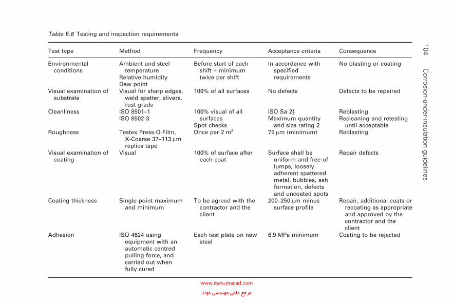
104 C
orrosion-under-insulation guidelinesTable E.6 Testing and inspection requirements
Test type Method Frequency Acceptance criteria Consequence
Environmental conditions
Ambient and steel temperature
Relative humidityDew point
Before start of each shift + minimum twice per shift
In accordance with specifi ed requirements
No blasting or coating
Visual examination of substrate
Visual for sharp edges, weld spatter, slivers, rust grade
100% of all surfaces No defects Defects to be repaired
Cleanliness ISO 8501–1ISO 8502-3
100% visual of all surfaces
Spot checks
ISO Sa 21–2Maximum quantity
and size rating 2
ReblastingRecleaning and retesting
until acceptableRoughness Testex Press-O-Film,
X-Coarse 37–113 μm replica tape
Once per 2 m2 75 μm (minimum) Reblasting
Visual examination of coating
Visual 100% of surface after each coat
Surface shall be uniform and free of lumps, loosely adherent spattered metal, bubbles, ash formation, defects and uncoated spots
Repair defects
Coating thickness Single-point maximum and minimum
To be agreed with the contractor and the client
200–250 μm minus surface profi le
Repair, additional coats or recoating as appropriate and approved by the contractor and the client
Adhesion ISO 4624 using equipment with an automatic centred pulling force, and carried out when fully cured
Each test plate on new steel
6.9 MPa minimum Coating to be rejected
WPNL2204www.iran-mavad.com مرجع علمى مهندسى مواد
• Failure by the client’s inspector to detect a defi ciency, or waiver of client inspection, does not relieve the coating contractor of responsibility for quality or performance of the coating as required by contract. The testing and inspection shall be in accordance with the requirements listed in Table E.6.
E.18 Documentation
• The coating contractor shall submit procedures with their tenders for application process, operator qualifi cation and training, and quality for client or contractor agreement. A control plan, preferably to AWS C218 or AWS/SSPC CS 2.23, is required for review and agreement prior to contract award.
• The fi nal coating documentation package shall include the operating parameters of equipment, application operative’s name, blast profi le, TSA dry fi lm thickness measurement data, pull-off test results and application environmental condition data.
E.19 Surface and moisture tolerance
When the above situations cannot be avoided, the use of a surface- and/or moisture-tolerant coating may be considered as a short-term measure. It is recommended that a specialist with expertise in coatings select these coatings.
E.20 Alternative coatings; tape coatings
In some situations where grit blasting is not acceptable, liquid applied coat-ings are not necessarily the best answer. Wax or petrolatum tape wrap systems are sometimes the best solution for corrosion prevention under insulation on piping where the operating temperature will not exceed 55 °C (130 °F). These coatings have a limited life.
Glass-fi bre-reinforced resin in tape or sheet form can be used in lieu of a conventional organic coating or TSA, but it is a costly process and would not normally be the fi rst choice. However, the application of tape at loca-tions where clamps, etc., are to be used not only acts as a buffer preventing coating damage but also prevents local moisture retention between the clamp and pipe from accelerating the degradation of the coating. Inserts such as rubber also prevent the damage but not the crevice water retention.
Application of TSA 105
WPNL2204www.iran-mavad.com مرجع علمى مهندسى مواد
Appendix FTypes and forms of insulation material
The most commonly used industrial insulation materials are described below. Generic references to the thermal insulation material as rock wool, mineral wool, mineral fi bre, etc., shall be interpreted in accordance with the defi nitions given in ASTM C547, ASTM C612, BS 3958: Part 4 and BS 3958: Part 5 (as man-made mineral fi bre made from rock, slag or glass, processed from a molten state into a fi brous form with a suitable binder). For the purposes of this document, materials of a rock composition (diabase, silica ore, basalt or similar types) shall be acceptable. Materials made from slag (in part or in whole) shall not be acceptable. Fibrous materials made of glass shall only be permitted where specifi ed as expansion joint fi ller.
F.1 Mineral fi bre
ASTM groups commercial glass and mineral fi bre materials into a single category, generally described as rocks, slag or glass processed from a molten state into a fi brous form with organic binders. Mineral fi bre is generally specifi ed for ambient to high temperatures, the upper temperature being dependent on the specifi c fi bre and binder used.
Both the water absorption characteristics and the ability to repel water are variable and are dependent on the specifi c fi bre and binder used. Some binders break down in the presence of heat and water, which leads to wicking.
Preformed mineral fi bre insulation shall be of a rock composition com-plying with physical characteristics listed in BS 3958: Part 4 and BS 3958: Part 5 and, where these do not confl ict, physical characteristics listed in ASTM C612 and C547. The material shall be a water-repellent grade com-plying with the following overriding requirements.
• Combustibility. Non-combustible when tested in accordance with BS 476: Part 4, ASTM E136 or ISO 1182.
• Chemical requirements. Less than 10 ppm chloride, and less than 10 ppm fl uoride, when tested in accordance with ASTM C871, with a combined
106
WPNL2204www.iran-mavad.com مرجع علمى مهندسى مواد
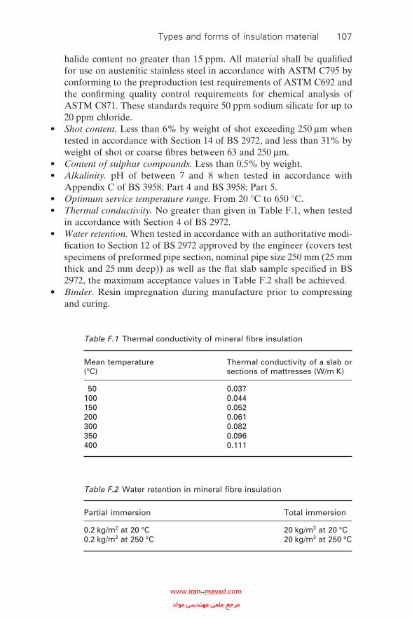
halide content no greater than 15 ppm. All material shall be qualifi ed for use on austenitic stainless steel in accordance with ASTM C795 by conforming to the preproduction test requirements of ASTM C692 and the confi rming quality control requirements for chemical analysis of ASTM C871. These standards require 50 ppm sodium silicate for up to 20 ppm chloride.
• Shot content. Less than 6% by weight of shot exceeding 250 μm when tested in accordance with Section 14 of BS 2972, and less than 31% by weight of shot or coarse fi bres between 63 and 250 μm.
• Content of sulphur compounds. Less than 0.5% by weight.• Alkalinity. pH of between 7 and 8 when tested in accordance with
Appendix C of BS 3958: Part 4 and BS 3958: Part 5.• Optimum service temperature range. From 20 °C to 650 °C.• Thermal conductivity. No greater than given in Table F.1, when tested
in accordance with Section 4 of BS 2972.• Water retention. When tested in accordance with an authoritative modi-
fi cation to Section 12 of BS 2972 approved by the engineer (covers test specimens of preformed pipe section, nominal pipe size 250 mm (25 mm thick and 25 mm deep)) as well as the fl at slab sample specifi ed in BS 2972, the maximum acceptance values in Table F.2 shall be achieved.
• Binder. Resin impregnation during manufacture prior to compressing and curing.
Table F.1 Thermal conductivity of mineral fi bre insulation
Mean temperature (°C)
Thermal conductivity of a slab or sections of mattresses (W/m K)
50 0.037100 0.044150 0.052200 0.061300 0.082350 0.096400 0.111
Table F.2 Water retention in mineral fi bre insulation
Partial immersion Total immersion
0.2 kg/m2 at 20 °C 20 kg/m3 at 20 °C0.2 kg/m2 at 250 °C 20 kg/m3 at 250 °C
Types and forms of insulation material 107
WPNL2204www.iran-mavad.com مرجع علمى مهندسى مواد
108 Corrosion-under-insulation guidelines
• Proportion of fi ne fi bres. 31% or less of fi bres of diameter less than 3 μm in the bulk fi brous material.
• Facings for fl exible mattresses. Facings shall consist of 0.9 mm × 25 mm mesh wire netting sewn with wire ties at close regular intervals in such a way as to ensure that these cannot be pulled through during storage, handling and fabrication. The wire mesh shall be stainless steel for application to stainless steel vessel heads and galvanised for other appli-cations. The facing shall be on both sides.
• Dimensional tolerances. Tolerance on thickness, length and inside diam-eter shall conform to requirements of BS 3958: Part 4 or ASTM C547.
• Densities and forms. The following minimum densities and forms of preformed mineral fi bre pipe sections and slabs shall be used as the fi rst and second layers up to 500 °C, and as the second and third (outer) layers only, for temperatures above 500 °C.
° Piping, with pipe sections of 125–155 kg/m3 density, either in two halves or in one piece hinged (snap-on) for all sizes up to maximum commercially available pipe size. For larger diameters, factory-cut bevelled lags of 140 kg/m3 density shall be employed.
° Heat-traced piping, with pipe sections as for piping but oversized generally up to the next commercially available size to accommodate parent line and its accompanying tracer.
° Equipment having a diameter up to maximum commercially avail-able pipe size, with pipe sections as for piping.
° Vertical equipment having a diameter exceeding maximum commercially available pipe size; bevelled lags and rigid slabs of 140 kg/m3 density for all single, inner and outer layers.
° Horizontal equipment having a diameter exceeding maximum commercially available pipe size: bevelled lags and rigid slabs of 120 kg/m3 density for all single, inner and outer layers.
° The following nominal densities of preformed mineral fi bre mat-tresses shall be used:� Flexible mattresses for equipment heads of 125–138 kg/m3 density
for all operating temperatures. Note that the nominal densities of mattresses shall exclude metallic facings and shall be within a tolerance of 15% as per Section 7.2 of BS 3958: Part 3.
° For hot face temperatures up to 650 °C, the concentration of organic bonding material for all specifi ed insulation densities shall not con-stitute a fi re risk through the incidence of welding sparks or through an internal self-heating phenomenon (punking) over the range of insulation thicknesses and individual layers proposed by the engi-neer. The manufacturer of the material shall demonstrate to the requirements of Section 18 of BS 2972 that the degree of self-heating does not exceed safe limits.
WPNL2204www.iran-mavad.com مرجع علمى مهندسى مواد
F.2 Low-density glass fi bre
Low-density glass-fi bre blanket (unfaced) for packing voids or for introduc-tion at expansion–contraction joints shall be manufactured from long con-tinuous textile-type glass fi bres chopped into 50–100 mm lengths and fi rmly bonded in random orientation with an inert thermosetting resin. The mate-rial shall have the following minimum properties.
• Density. 23.0–24.0 kg/m3.• Thermal conductivity. No greater than 0.034 W/m K at 25 °C mean tem-
perature when tested in accordance with ASTM C177.• Service temperature. Up to 230 °C.
The 100% glass fi bre matt for lining reusable insulation covers and for introduction at expansion joints above 230 °C shall be composed of E-glass fi bres in the form of a web which is needled together without chemical binders and having a low (less than 10 ppm) chloride level. The material shall have the following minimum properties.
• Density. 140–150 kg/m3.• Thermal conductivity. No greater than 0.058 W/m K at 150 °C mean
temperature when tested in accordance with BS 874.• Service temperature. Up to 500 °C.
F.3 Calcium silicate
Calcium silicate preformed insulation shall consist of reacted hydrous calcium silicate containing well-opened asbestos-free reinforcing fi bre. It is hygroscopic and readily absorbs water. The material shall comply with BS 3958: Part 2 or ASTM C533 and the following additional requirements.
• Combustibility. Non-combustible when tested in accordance with BS476: Part 4.
• Chemical requirements. All material shall be qualifi ed for use on aus-tenitic stainless steel in accordance with ASTM C795, by conforming to the preproduction test requirements of ASTM C692 and the confi rming quality control requirements for chemical analysis of ASTM C871. These standards require 50 ppm sodium silicate content for up to 20 ppm chloride.
• Optimum service temperature range. From 20 °C to 730 °C.• Thermal conductivity. No greater than given in Table F.3 when tested
in accordance with BS 874.• Bulk density. 190–240 kg/m3.• Flexural strength. Not less than 500 kN/m2.
Types and forms of insulation material 109
WPNL2204www.iran-mavad.com مرجع علمى مهندسى مواد
110 Corrosion-under-insulation guidelines
• Compressive strength (cold). Not less than 1300 kN/m2 load at onset of disruption in the dry state, with a reduction in thickness no greater than 2% under a compressive load of 700 kN/m2 in the dry state and no greater than 5% under a compressive load of 400 kN/m2 after 24 h immersion in water.
• Linear shrinkage. No greater than 1.6% after 24 h heat soak at 730 °C.
• Dimensional tolerances. Tolerances on thickness, length and inside diameter shall conform to requirements of BS 3958: Part 2 or ASTM C533.
F.4 Cellular glass
Cellular glass shall conform to the requirements of ASTM C552 and/or ASTM C240. It is a rigid block material that has been foamed under molten conditions to form a closed-cell structure having properties associated with the lighter-density lower-thermal-conductivity type T4 material, as follows.
• Rigid cellular glass. Factory shaped and cut into slabs, radiused and bevelled segments, and half-pipe sections.
• Density. Average 120 kg/m3 ± 10%, measured as per ASTM C303.• Thermal conductivity. No greater than 0.039 W/m K ± 10% at 10 °C,
measured as per ASTM C177.• Compressive strength. Average 700 kPa when capped with hot asphalt,
measured as per ASTM C165.• Chemical requirements. Less than 10 ppm chloride, when tested in
accordance with ASTM C871, and less than 10 ppm fl uoride, with a combined halide content no greater than 15 ppm. The material shall be qualifi ed for use on austenitic stainless steel in accordance with ASTM C795 by conforming to the preproduction test requirements of ASTM C692 and the confi rming quality control requirements for chemical
Table F.3 Thermal conductivity of calcium silicate
Mean temperature (°C) Thermal conductivity (W/m K)
50 0.055100 0.058150 0.063200 0.069250 0.075300 0.083350 0.092
WPNL2204www.iran-mavad.com مرجع علمى مهندسى مواد
analysis of ASTM C871. These standards require 50 ppm sodium silicate content for up to 20 ppm chloride.
• Water vapour permeability. Zero measured as per ASTM E96.• Linear coeffi cient of thermal expansion. 9.0 × 10⁻⁶ K−1 as per ASTM
E228.• Combustibility. Non-combustible as per ASTM E84.• Modulus of elasticity. 800 MPa, measured as per ASTM C623.• Alkalinity. pH of between 7 and 8 as per ASTM C871.• Dimensional tolerance on length. ±2.0 mm.• Dimensional tolerance on thickness. ±2.0 mm. For pipe sizes up to
450 mm diameter, the tolerances on thickness are in addition to permit-ted variations in thickness, where these are determined by the manu-facturer’s economic cutting programme, designed to ensure that the outside diameter of the cellular glass always corresponds to the outside diameter of a standard pipe. This results in thickness variations of +9 mm to −3 mm according to pipe size.
• Dimensional tolerance on inside diameter.
° +1.0 to +2.0 mm for half-shells with inside diameter less than 38 mm.
° +1.0 to +3.0 mm for half-shells with inside diameter greater than 38 mm.
° +2.0 to +5.0 mm for segments.• Concentricity. Maximum deviation 3.2 mm or 5% of wall thickness,
whichever is the greater.• Thickness range. Minimum thickness of 25 mm and maximum thickness
of 120 mm per layer. For thicknesses greater than 120 mm or where the temperature gradient through any individual layer is in excess of 120 °C, multilayer construction shall be used.
• Length. All pipe sizes, minimum length, 600 mm.• Availability in half-sections. Insulation shall be supplied as cylindrical
sections split into half-sections for all pipe sizes up to 450 mm diameter over insulation. For larger pipe sizes, insulation shall be supplied as radiused and bevelled segments.
• Fabrication standards. For all pipe sections fabricated for sizes exceed-ing 300 mm and not exceeding 450 mm diameter over insulation and for all radiused and bevelled segments, cellular glass may be cut from stacked blocks using a fabrication adhesive and with a minimum number of insulation blocks consistent with economic utilisation of the material. For this purpose each full section of insulation shall contain not more than four ‘through’ joints, excluding the half-section mating plane. No segment shall as a result of cutting be less than 25 mm thick at the highest point of the arc.
• Fabrication adhesive. For jointing of stacked blocks during fabrication of pipe sections, the grade of adhesive to be used for operating
Types and forms of insulation material 111
WPNL2204www.iran-mavad.com مرجع علمى مهندسى مواد
112 Corrosion-under-insulation guidelines
temperatures above ambient shall be a gypsum cement such as Hydrocal B-11.
• Adhesive coverage. Fabrication adhesive shall be applied such that there is 100% coverage of adhesive and mating surfaces. In addition, there shall be no visible voids in the adhered joint nor shall any adhered joint exceed 1.6 mm in width.
• Fabrication facilities. Shop fabrication of cellular glass pipe sections, segments and fi ttings shall be prequalifi ed and approved by the fabricator.
F.5 Ceramic fi bre paper
Ceramic fi bre paper is used for the initial wrapping of piping and equipment containing corrosive fl uids and also for similar wrapping of instruments and instrument leads where full contact with steam tracing is not required (clas-sifi ed as light tracing); it shall be a 1.0 mm material in rolls 10 m long and 1.0 m wide, containing a minimal quantity of organic binder.
F.6 Glass rope insulation
Glass rope insulation for wrapping small-bore piping and valves shall consist of unbonded glass fi bres enclosed in a braided cover of glass yarn, suffi -ciently robust to ensure stability during application and in service. The rope shall be resilient and suitable for operating temperatures up to 540 °C.
F.7 Self-setting cement
Self-setting cements are used to join insulation materials into useful shapes. Hydrated silicates are used in conjunction with calcium silicate, perlite and cellular glass to form an intimate mixture of non-asbestos inorganic mineral fi bres. These form a general-purpose protective coating suitable for trowel or hand application and with fast-setting properties without the application of heat. The material shall produce a robust surface layer having brea-ther-type weather-resistant properties and being resistant to impact and abrasion damage, with a temperature limit not less than 175 °C for continu-ous-service conditions. When dried out, the cement shall be free from cracking other than fi ne hairline cracks.
F.8 Flexible reusable insulation covers
Individually tailored fl exible reusable insulation covers for fl anged joints, valves and instruments should be shop fabricated in conformance with the following.
WPNL2204www.iran-mavad.com مرجع علمى مهندسى مواد
• Outer cover throughout. Heavy-duty satin-weave fi bre-glass fabric sili-cone rubber impregnated on both sides, completely waterproof, ultra-violet resistant and temperature resistant up to 260 °C (continuous) and having a mass of 560 g/m2, including 150 g/m2 silicone.
• Inner cover up to 260 °C. Heavy-duty satin-weave fi bre-glass fabric, sili-cone rubber impregnated on one side, water resistant, ultraviolet resis-tant and temperature resistant up to 260 °C (continuous) and having a mass of 500 g/m2, including 90 g/m2 silicone.
• Inner cover above 260 °C. High-purity silica fabric of mass 610 g/m2.• Insulation lining. Unbonded needled type-E glass-fi bre matt of 140 kg/m3
density at 25 mm thickness and having a low chloride level and no resin-ous or organic binders.
• Side extensions. Single-thickness outer cover extensions with heavy-duty drawstrings to effect end closure over adjacent pipe insulation. Draw-strings shall be solid braid Nomex of 4.8 mm diameter, with ends cauter-ised to prevent ravelling.
• Protection at hot protrusions. Double-thickness inner and outer cloth laps to obtain a weather- and heat-resistant seal. Above 260 °C, inner cover material carried over edges with box seams suffi cient to ensure integrity of outer cover material whilst remaining weather tight.
• Retention. Velcro incorporated at overlaps, and also fully effective easily releasable straps and stainless steel buckles.
• Sewing thread. Tefl on-coated glass for fabrication up to 400 °C and stain-less steel thread above this temperature.
F.9 Preformed rigid polyurethane foam
(polyurethane–polyisocyanurate)
• Polyurethane is made by the polymerisation of an isocyanate resin to create a plastic material with a wide range of properties. Reaction between the isocyanate (polymeric methyl diphenyl isocyanate) with certain types of polyol, such as a polyether, creates a tough but rigid plastic material.
• Polyisocyanurate is an improved type of rigid polyurethane. The pro-duction process creates strong isocyanurate linkages in the molecular structure. Chemical breakdown of the foam occurs at higher tempera-tures than polyurethane, and so it is much more diffi cult to ignite. True polyisocyanurate foam contains about 50% or more isocyanurate linkages.
• The material shall be supplied as slabs, as radiused and bevelled seg-ments and as pipe sections precision cut from fully cured bun stock. The material shall be factory coated with a Mylar or equivalent foil and shall have the following properties.
Types and forms of insulation material 113
WPNL2204www.iran-mavad.com مرجع علمى مهندسى مواد
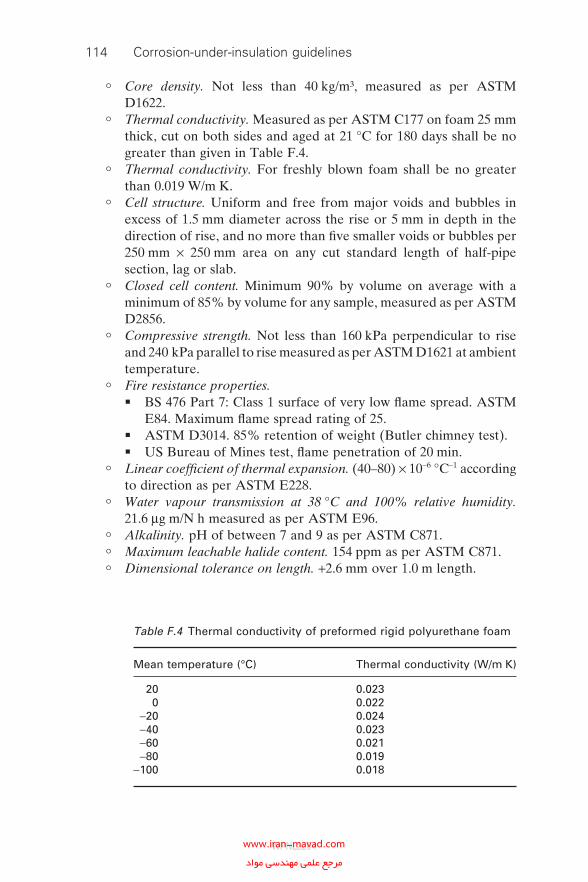
114 Corrosion-under-insulation guidelines
° Core density. Not less than 40 kg/m³, measured as per ASTM D1622.
° Thermal conductivity. Measured as per ASTM C177 on foam 25 mm thick, cut on both sides and aged at 21 °C for 180 days shall be no greater than given in Table F.4.
° Thermal conductivity. For freshly blown foam shall be no greater than 0.019 W/m K.
° Cell structure. Uniform and free from major voids and bubbles in excess of 1.5 mm diameter across the rise or 5 mm in depth in the direction of rise, and no more than fi ve smaller voids or bubbles per 250 mm × 250 mm area on any cut standard length of half-pipe section, lag or slab.
° Closed cell content. Minimum 90% by volume on average with a minimum of 85% by volume for any sample, measured as per ASTM D2856.
° Compressive strength. Not less than 160 kPa perpendicular to rise and 240 kPa parallel to rise measured as per ASTM D1621 at ambient temperature.
° Fire resistance properties.� BS 476 Part 7: Class 1 surface of very low fl ame spread. ASTM
E84. Maximum fl ame spread rating of 25.� ASTM D3014. 85% retention of weight (Butler chimney test).� US Bureau of Mines test, fl ame penetration of 20 min.
° Linear coeffi cient of thermal expansion. (40–80) × 10−6 °C−1 according to direction as per ASTM E228.
° Water vapour transmission at 38 °C and 100% relative humidity. 21.6 μg m/N h measured as per ASTM E96.
° Alkalinity. pH of between 7 and 9 as per ASTM C871.
° Maximum leachable halide content. 154 ppm as per ASTM C871.
° Dimensional tolerance on length. +2.6 mm over 1.0 m length.
Table F.4 Thermal conductivity of preformed rigid polyurethane foam
Mean temperature (°C) Thermal conductivity (W/m K)
20 0.0230 0.022
−20 0.024−40 0.023−60 0.021−80 0.019
−100 0.018
WPNL2204www.iran-mavad.com مرجع علمى مهندسى مواد
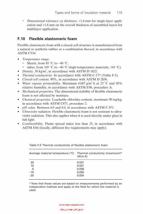
° Dimensional tolerance on thickness. +1.6 mm for single-layer appli-cation and +1.6 mm on the overall thickness of assembled layers for multilayer application.
F.10 Flexible elastomeric foam
Flexible elastomeric foam with a closed-cell structure is manufactured from a natural or synthetic rubber or a combination thereof, in accordance with ASTM C534.
• Temperature range.
° Sheets, from 85 °C to −40 °C.
° tubes, from 105 °C to −40 °C (high-temperature materials, 145 °C).• Density. 50 kg/m3, in accordance with ASTM D 1622.• Thermal conductivity. In accordance with ASTM C-177 (Table F.5).• Closed-cell content. 90%, in accordance with ASTM D 2856.• Water vapour permeability. Maximum 0.007 g/m2 h at 23 °C and 50%
relative humidity, in accordance with ASTM E96, procedure A.• Mechanical properties. The dimensional stability of fl exible elastomeric
foam is not affected by moisture.• Chemical properties. Leachable chlorides content, maximum 90 mg/kg,
in accordance with ASTM C871, procedure 2.• pH value. Between 6.0 and 8.0, in accordance with ASTM C 871.• Ultraviolet radiation. Flexible elastomeric foam is not resistant to ultra-
violet radiation. This also applies when it is used directly under glass in full light.
• Combustibility. Flame spread index less than 25, in accordance with ASTM E84 (locally, different fi re requirements may apply).
Table F.5 Thermal conductivity of fl exible elastomeric foam
Average material temperature (°C) Thermal conductivity (maximum)* (W/m K)
20 0.03710 0.0370 0.036
−10 0.035−20 0.034
* Note that these values are based on measurements performed by an independent institute and apply to the fi eld for which the material is used.
Types and forms of insulation material 115
WPNL2204www.iran-mavad.com مرجع علمى مهندسى مواد
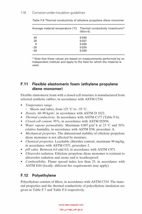
116 Corrosion-under-insulation guidelines
F.11 Flexible elastomeric foam (ethylene propylene
diene monomer)
Flexible elastomeric foam with a closed cell structure is manufactured from selected synthetic rubber, in accordance with ASTM C534.
• Temperature range.
° Sheets and tubes, from 125 °C to −55 °C.• Density. 60–90 kg/m3, in accordance with ASTM D 1622.• Thermal conductivity. In accordance with ASTM C177 (Table F.6).• Closed-cell content. 95%, in accordance with ASTM D2856.• Water vapour permeability. Maximum 0.007 g/m2 h at 23 °C and 50%
relative humidity, in accordance with ASTM E96, procedure A.• Mechanical properties. The dimensional stability of ethylene propylene
diene monomer is not affected by moisture.• Chemical properties. Leachable chlorides content, maximum 90 mg/kg,
in accordance with ASTM C871, procedure 2.• pH value. Between 6.0 and 8.0, in accordance with ASTM C871.• Ultraviolet radiation. Ethylene propylene diene monomer is resistant to
ultraviolet radiation and ozone and is weatherproof.• Combustibility. Flame spread index less than 25, in accordance with
ASTM E84 (locally, different fi re requirements may apply).
F.12 Polyethylene
Polyethylene consists of fi llers, in accordance with ASTM C534. The mate-rial properties and the thermal conductivity of polyethylene insulation are given in Table F.7 and Table F.8 respectively.
Table F.6 Thermal conductivity of ethylene propylene diene monomer
Average material temperature (°C) Thermal conductivity (maximum)* (W/m K)
40 0.04020 0.0370 0.035
−20 0.034−40 0.030
* Note that these values are based on measurements performed by an independent institute and apply to the fi eld for which the material is used.
WPNL2204www.iran-mavad.com مرجع علمى مهندسى مواد
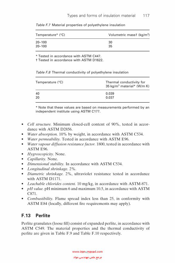
• Cell structure. Minimum closed-cell content of 90%, tested in accor-dance with ASTM D2856.
• Water absorption. 10% by weight, in accordance with ASTM C534.• Water permeability. Tested in accordance with ASTM E96.• Water vapour diffusion resistance factor. 1800, tested in accordance with
ASTM E96.• Hygroscopicity. None.• Capillarity. None.• Dimensional stability. In accordance with ASTM C534.• Longitudinal shrinkage. 2%.• Diametric shrinkage. 2%, ultraviolet resistance tested in accordance
with ASTM D1171.• Leachable chlorides content. 10 mg/kg, in accordance with ASTM-871.• pH value. pH minimum 6 and maximum 10.5, in accordance with ASTM
C871.• Combustibility. Flame spread index less than 25, in conformity with
ASTM E84 (locally, different fi re requirements may apply).
F.13 Perlite
Perlite granulates (loose fi ll) consist of expanded perlite, in accordance with ASTM C549. The material properties and the thermal conductivity of perlite are given in Table F.9 and Table F.10 respectively.
Table F.7 Material properties of polyethylene insulation
Temperature* (°C) Volumetric mass† (kg/m3)
20–10020–100
3035
* Tested in accordance with ASTM C447.† Tested in accordance with ASTM D1622.
Table F.8 Thermal conductivity of polyethylene insulation
Temperature (°C) Thermal conductivity for 35 kg/m3 material* (W/m K)
4020
0.0390.037
* Note that these values are based on measurements performed by an independent institute using ASTM C177.
Types and forms of insulation material 117
WPNL2204www.iran-mavad.com مرجع علمى مهندسى مواد
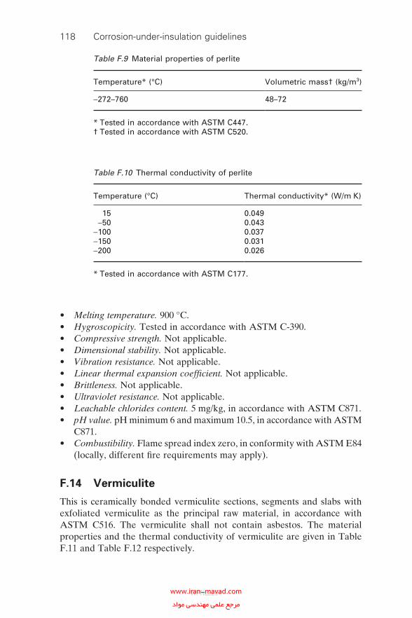
118 Corrosion-under-insulation guidelines
• Melting temperature. 900 °C.• Hygroscopicity. Tested in accordance with ASTM C-390.• Compressive strength. Not applicable.• Dimensional stability. Not applicable.• Vibration resistance. Not applicable.• Linear thermal expansion coeffi cient. Not applicable.• Brittleness. Not applicable.• Ultraviolet resistance. Not applicable.• Leachable chlorides content. 5 mg/kg, in accordance with ASTM C871.• pH value. pH minimum 6 and maximum 10.5, in accordance with ASTM
C871.• Combustibility. Flame spread index zero, in conformity with ASTM E84
(locally, different fi re requirements may apply).
F.14 Vermiculite
This is ceramically bonded vermiculite sections, segments and slabs with exfoliated vermiculite as the principal raw material, in accordance with ASTM C516. The vermiculite shall not contain asbestos. The material properties and the thermal conductivity of vermiculite are given in Table F.11 and Table F.12 respectively.
Table F.9 Material properties of perlite
Temperature* (°C) Volumetric mass† (kg/m3)
−272–760 48–72
* Tested in accordance with ASTM C447.† Tested in accordance with ASTM C520.
Table F.10 Thermal conductivity of perlite
Temperature (°C) Thermal conductivity* (W/m K)
15−50
−100−150−200
0.0490.0430.0370.0310.026
* Tested in accordance with ASTM C177.
WPNL2204www.iran-mavad.com مرجع علمى مهندسى مواد
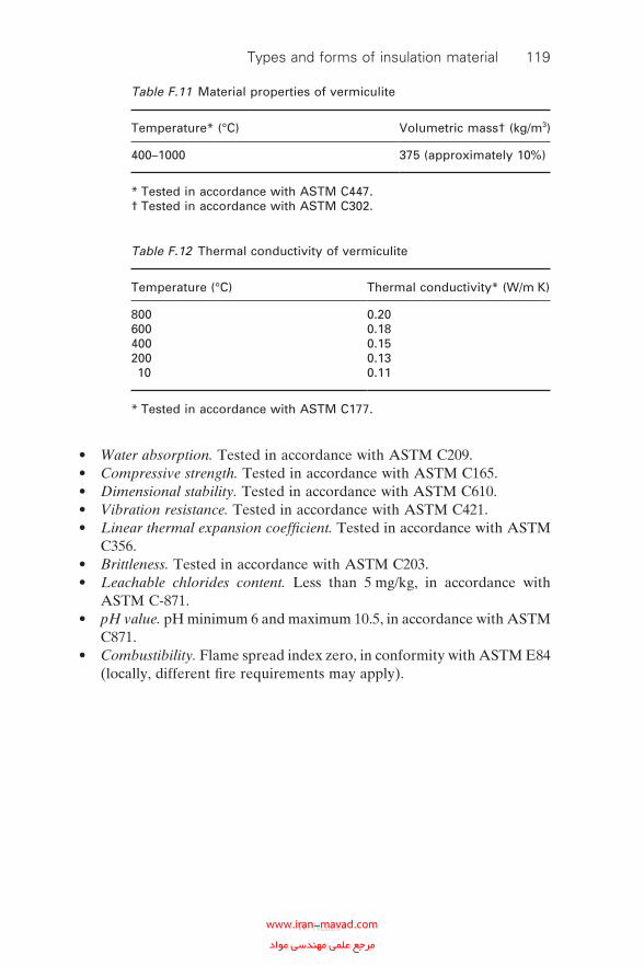
• Water absorption. Tested in accordance with ASTM C209.• Compressive strength. Tested in accordance with ASTM C165.• Dimensional stability. Tested in accordance with ASTM C610.• Vibration resistance. Tested in accordance with ASTM C421.• Linear thermal expansion coeffi cient. Tested in accordance with ASTM
C356.• Brittleness. Tested in accordance with ASTM C203.• Leachable chlorides content. Less than 5 mg/kg, in accordance with
ASTM C-871.• pH value. pH minimum 6 and maximum 10.5, in accordance with ASTM
C871.• Combustibility. Flame spread index zero, in conformity with ASTM E84
(locally, different fi re requirements may apply).
Table F.11 Material properties of vermiculite
Temperature* (°C) Volumetric mass† (kg/m3)
400–1000 375 (approximately 10%)
* Tested in accordance with ASTM C447.† Tested in accordance with ASTM C302.
Table F.12 Thermal conductivity of vermiculite
Temperature (°C) Thermal conductivity* (W/m K)
800600400200 10
0.200.180.150.130.11
* Tested in accordance with ASTM C177.
Types and forms of insulation material 119
WPNL2204www.iran-mavad.com مرجع علمى مهندسى مواد
Appendix GCladding and jacketing materials
A number of cladding and jacketing materials are available to provide mechanical and weather protection for insulation systems. These are nor-mally classifi ed as metallic or non-metallic materials. Choice is dependent on the availability, application and cost.
G.1 Metallic cladding materials
Commonly used materials include aluminium, aluminised steel, alumin-ium–zinc-coated steel and galvanised steel.
G.1.1 Aluminised steel sheeting
This consists of steel sheet T2M-300 with an aluminium coating in accor-dance with ASTM A463M.
• Aluminium layer thickness. 300 g/m2 in total for both sides, 50 mm per side, in accordance with ASTM A463M.
• Mechanical properties. 3.1, in accordance with ASTM A463M. The alu-minium coating shall not crack, fl ake or peel during mechanical process-ing with observance of the minimum deformation radius:
° Sheet thickness, 0.56 mm; minimum radius, 1 × sheet thickness.
° Sheet thickness, 0.80 mm; minimum radius, 2 × sheet thickness.• Chemical composition. Commercial quality, in accordance with ASTM
A463M, Table 2.• Corrosion resistance. 4.3, in accordance with ASTM A463M.• Maximum surface temperature. 450 °C.
G.1.2 Aluminium–zinc-coated sheeting
This consists of steel sheet provided with an aluminium–zinc alloy layer, in accordance with ASTM A792M.
120
WPNL2204www.iran-mavad.com مرجع علمى مهندسى مواد
• Tested in accordance with ASTM A370.• Aluminium–zinc layer. 185 g/m2 in total for both sides, tested in accor-
dance with ASTM A90 and ASTM A525M.• Mechanical properties. In accordance with ASTM A792M. The alumin-
ium–zinc layer applied shall not crack, fl ack or peel during mechanical processing with observance of the minimum deformation radius.
° Sheet thickness, les than 1.25 mm; minimum radius, 1 × sheet thickness.
• Chemical composition. In accordance with ASTM A792M.• Corrosion resistance. In accordance with ASTM A792M.• Maximum surface temperature. 315 °C (temperatures above 315 °C
cause a colour change; the protective action is retained at temperatures up to 700 °C).
G.1.3 Galvanised steel sheeting
This consists of steel sheet, in accordance with ASTM A527M, and tested in accordance with ASTM A370.
• Zinc layer. 275 g/m2 in total for both sides, tested in accordance with ASTM A525M.
• Mechanical properties. In accordance with ASTM A525M. The zinc layer applied shall not crack, fl ake or peel during mechanical processing with observance of the minimum deformation radius.
° Sheet thickness, less than 1.25 mm; minimum radius, 3 × sheet thickness.
• Chemical composition. In accordance with ASTM A525M.• Corrosion resistance. 4.3, in accordance with ASTM A525M.• Maximum surface temperature. 400 °C.
G.1.4 Stainless steel jacketing
This consists of type 304 stainless steel sheet, in accordance with ASTM A167.
• Mechanical properties. Tensile strength, yield strength and elongation, in accordance with ASTM A167.
• Chemical composition. In accordance with ASTM A167.• Corrosion resistance. In accordance with ASTM A167 and treated in
accordance with ASTM A480M.• Maximum surface temperature. 900 °C (a temperature of 500 °C causes
a colour change).
Cladding and jacketing materials 121
WPNL2204www.iran-mavad.com مرجع علمى مهندسى مواد
122 Corrosion-under-insulation guidelines
G.1.5 Aluminium sheeting
A number of alternative types of sheeting are available, these include the following:
• Flat sheeting unbacked.• Flat sheeting with a moisture barrier.• Profi led or corrugated sheeting.
Aluminium sheeting of the specifi ed thickness and profi le shall be 3103 or 5005 alloy to BS 1470, or 3003 or 5005 alloy to ASTM B209 (an accept-able alternative is commercial-grade Alloy 1050), of the hardness listed in Table G.1.
Resistance to mechanical damage is poor and so thicknesses must be increased in order to resist damage. However, the corrosion resistance is relatively high. Aluminium sheeting should not be used for fi reproofi ng because of its low melting point. The maximum surface temperature is 350 °C (a temperature above 150 °C causes structural deformation).
G.2 Non-metallic materials
Plastic materials such as fi bre-reinforced plastics and thermoplastic are not commonly used for jacketing because of their low melting temperatures and lack of resistance to mechanical abuse and ultraviolet radiation. However, recent developments have led to the introduction of ultraviolet-cured fi bre-reinforced materials which offer improved mechanical resis-tance and the ability of total containment.
G.2.1 Ultraviolet-cured fi bre-reinforced materials
Laminate based on glass-fi bre-reinforced polyester resins, which are cured by ultraviolet radiation offer a solution for long-term weatherproofi ng of insulation.
Table G.1 Hardnesses of aluminium sheeting
Type Temper
Profi le or corrugated sheets H16Flat rolled sheeting 0.4–0.6 mm thick H16Flat rolled sheeting 0.7–1.2 mm thick H14Flat sheets H14
WPNL2204www.iran-mavad.com مرجع علمى مهندسى مواد
• Joints. Watertight joints which resist heavy loads better than any clad-ding system.
• Adhesion and strength. Adhesion and strength at terminations to prevent water ingress and to resist mechanical load.
• Sealing. Can also be used to seal metallic cladding, helping to overcome the inadequacies of a metallic cladding system. Adhesion to all types of metal to seal joints in metallic cladding.
• Material properties. These are provided in Table G.2.• Ultraviolet resistance. Good.• Resistance to (most) chemicals. Good.• Combustibility. Flame spread index (dry) 20, in accordance with ASTM
E84 (locally, different fi re requirements may apply). Flame spread index (dry) class 1 in accordance with BS 476. Flash point (fl exible material) 32 °C, in accordance with ASTM D93.
G.2.2 Hypalon (chlorosulphonated polyethylene)
Polymeric material based on Hypalon (chlorosulphonated polyethylene) offers a solution for long-term weatherproofi ng of insulation.
• Joints. Watertight joints which resist heavy loads better than any clad-ding system.
• Adhesion and strength. Adhesion and strength at terminations to prevent water ingress and to resist mechanical load.
Table G.2 Mechanical properties of ultraviolet-cured fi bre-reinforced materials
Temperature range 0–90 °CMass 2 kg/m2
Bending strength 130 MPaTensile strength 50 MPaElongation at breaking point 1%Compression strength 125 MPaImpact resistance 57 kJ/m2
Temper 45 BarcolLayer thickness 1.5 mmWater vapour permeability* 0.001 g/m2 h mmHg
* In accordance with the ASTM E96 procedure. If exceeding the indicated value, for application as primary vapour barrier in cold insulation systems only in combination with vapour barrier multiplex foil.
Cladding and jacketing materials 123
WPNL2204www.iran-mavad.com مرجع علمى مهندسى مواد
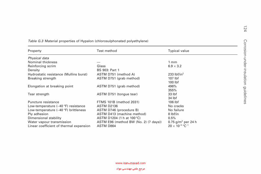
124 C
orrosion-under-insulation guidelines
Table G.3 Material properties of Hypalon (chlorosulphonated polyethylene)
Property Test method Typical value
Physical dataNominal thickness — 1 mmReinforcing scrim Glass 6.9 × 3.2Density BS 903: Part 1Hydrostatic resistance (Mullins burst) ASTM D751 (method A) 233 lbf/in2
Breaking strength ASTM D751 (grab method) 107 lbf100 lbf
Elongation at breaking point ASTM D751 (grab method) 496%355%
Tear strength ASTM D751 (tongue tear) 33 lbf34 lbf
Puncture resistance FTMS 101B (method 2031) 106 lbfLow-temperature (−40 °F) resistance ASTM D2136 No cracksLow-temperature (−40 °F) brittleness ASTM D746 (procedure B) No failurePly adhesion ASTM D413 (machine method) 8 lbf/inDimensional stability ASTM D1204 (1 h at 100 °C) 0.5%Water vapour transmission ASTM E96 (method BW (No. 2) (7 days)) 0.75 g/m2 per 24 hLinear coeffi cient of thermal expansion ASTM D864 20 × 10−5 °C−1
WPNL2204www.iran-mavad.com مرجع علمى مهندسى مواد
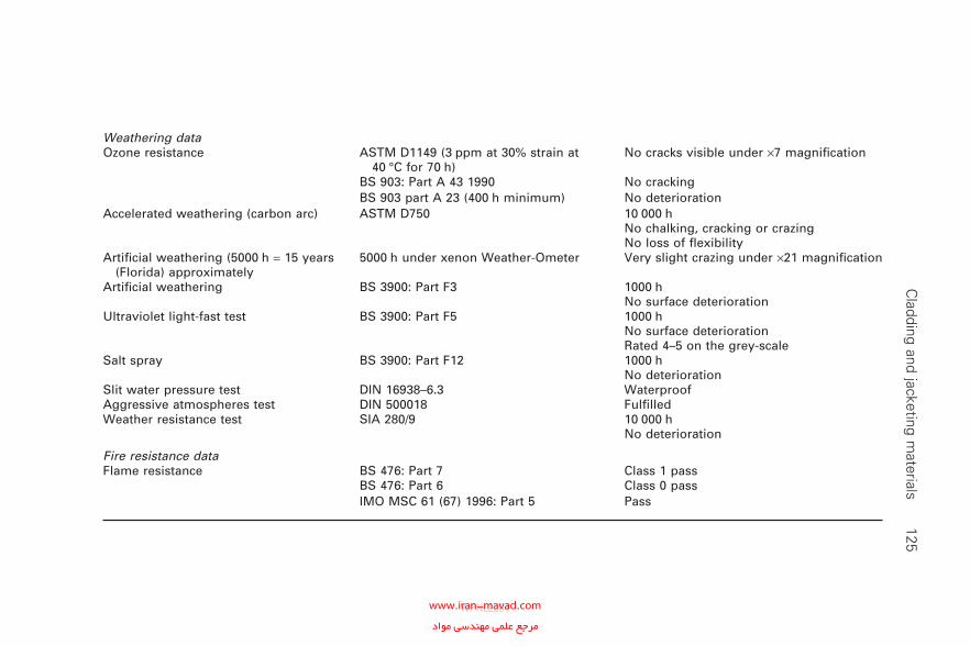
Weathering dataOzone resistance ASTM D1149 (3 ppm at 30% strain at
40 °C for 70 h)No cracks visible under ×7 magnifi cation
BS 903: Part A 43 1990 No crackingBS 903 part A 23 (400 h minimum) No deterioration
Accelerated weathering (carbon arc) ASTM D750 10 000 hNo chalking, cracking or crazingNo loss of fl exibility
Artifi cial weathering (5000 h = 15 years (Florida) approximately
5000 h under xenon Weather-Ometer Very slight crazing under ×21 magnifi cation
Artifi cial weathering BS 3900: Part F3 1000 hNo surface deterioration
Ultraviolet light-fast test BS 3900: Part F5 1000 hNo surface deteriorationRated 4–5 on the grey-scale
Salt spray BS 3900: Part F12 1000 hNo deterioration
Slit water pressure test DIN 16938–6.3 WaterproofAggressive atmospheres test DIN 500018 Fulfi lledWeather resistance test SIA 280/9 10 000 h
No deterioration
Fire resistance dataFlame resistance BS 476: Part 7 Class 1 pass
BS 476: Part 6 Class 0 passIMO MSC 61 (67) 1996: Part 5 Pass
C
ladding and jacketing materials
125
WPNL2204www.iran-mavad.com مرجع علمى مهندسى مواد
126 Corrosion-under-insulation guidelines
• Sealing. Can also be used to seal metallic cladding, helping to overcome the inadequacies of a metallic cladding system. Adhesion to all types of metal to seal joints in metallic cladding.
• Material properties. These are provided in Table G.3.
WPNL2204www.iran-mavad.com مرجع علمى مهندسى مواد
Appendix HUse of protection guards
H.1 Design considerations
It is not considered a requirement that all companies at all locations should use one design for personnel protection guards. Much will depend on indi-vidual site requirements and the experience and methods that the site’s insulation contractors have.
The aim with the personnel protective examples shown in Fig. H.1 is to eliminate the need for welding of supports and to make it a task that the insulation contractors can perform using their traditional tools and skills.
• The fl anges were not protected in this installation but could quite easily be if needed. When personal protection is needed on the fl anges or valves and easy access is needed for maintenance.
• On higher-temperature applications, or when the metal surface requires greater protection, a fi breglass insulation tape can be applied.
H.2 Method guidance notes
The principles and methods employed for this are very similar to fi tting standard insulation cladding. A few noteworthy points are detailed below.
• Spacing of end caps dependent upon the risk of personnel standing or falling on to it.
• Mesh rolled to shape as per normal cladding, 50 mm of overlap allowed.
• Mesh cut to shape using normal cladding patterns.• ‘Stand-off’ of mesh from 50 mm pipe.• Glass-fi bre insulating tape can be fi tted to the area where end caps make
contact to protect pipework and to reduce heat transfer.
127
WPNL2204www.iran-mavad.com مرجع علمى مهندسى مواد
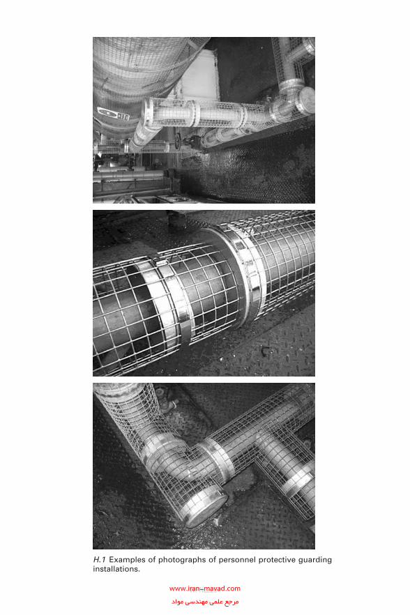
H.1 Examples of photographs of personnel protective guarding installations.
WPNL2204www.iran-mavad.com مرجع علمى مهندسى مواد
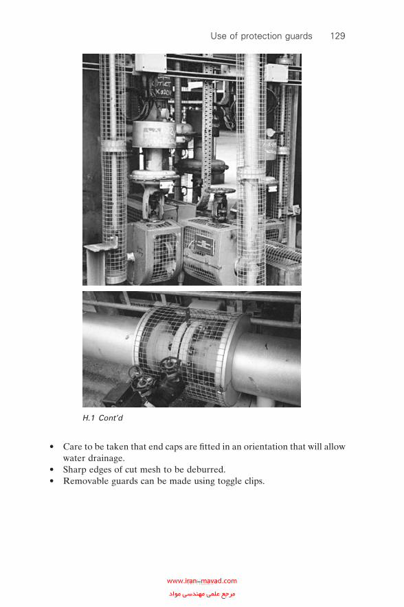
• Care to be taken that end caps are fi tted in an orientation that will allow water drainage.
• Sharp edges of cut mesh to be deburred.• Removable guards can be made using toggle clips.
H.1 Cont’d
Use of protection guards 129
WPNL2204www.iran-mavad.com مرجع علمى مهندسى مواد
Appendix INon-destructive examination and testing
techniques
I.1 Visual inspection
Visual inspection is acknowledged as the best method for determining the presence of CUI on carbon–manganese steels and low-alloy steels. However, it requires removal of the insulation system and is therefore considered to be costly. Normally, the corrosion scale on carbon–manganese steels and low-alloy steels involves an increase in volume and is normally fi ve to ten times greater than the original metal volume loss (Fig. I.1). Absolute quan-tifi cation of metal loss requires use of a more elaborate NDE or NDT technique. Although visual inspection can be used for determining the pres-ence of CUI on austenitic stainless steels it is not effective in determining the presence of Cl-ESCC.
I.2 Manual ultrasonic thickness measurement
through inspection openings
Typically a manual method is used to monitor the internal corrosion of carbon–manganese steel and low-alloy steel equipment using fi xed moni-toring points to enable periodic multiple-thickness measurements. It can also be used for determining the presence of CUI but is not as effective as measurements conducted from the inside of the vessel, because in part of the limited surface area that is being measured and location points (Fig. I.2). The installation procedures used to make the insulation holes and then to make them water tight with caps or covers is expensive and is often limited to accessible area not always prone to CUI. It is not practical to provide suffi cient inspection locations to obtain reliable results. The inspec-tion holes cut in the insulation may also compromise the integrity of the insulation and add to the CUI problem if they are not recovered carefully. This technique will not detect CI-ESCC in austenitic stainless steels with any degree of confi dence.
130
WPNL2204www.iran-mavad.com مرجع علمى مهندسى مواد
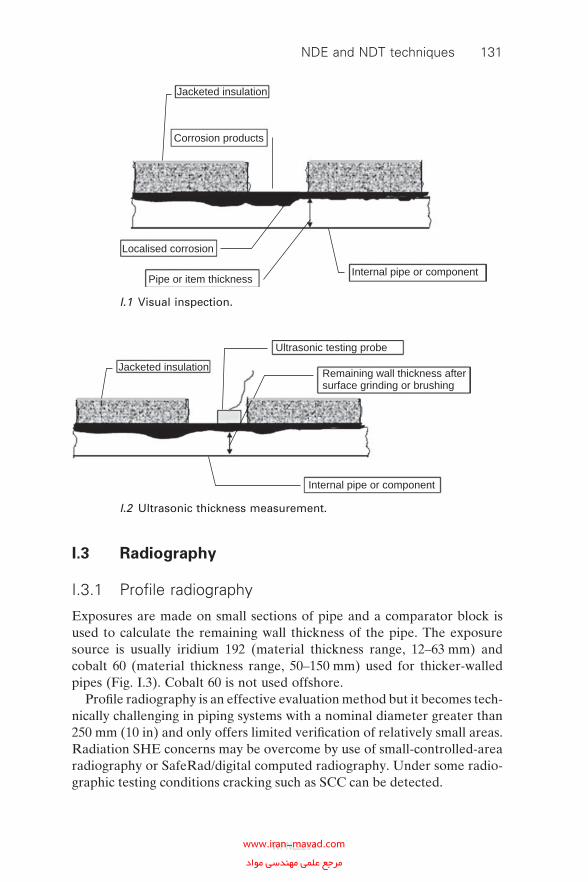
I.3 Radiography
I.3.1 Profi le radiography
Exposures are made on small sections of pipe and a comparator block is used to calculate the remaining wall thickness of the pipe. The exposure source is usually iridium 192 (material thickness range, 12–63 mm) and cobalt 60 (material thickness range, 50–150 mm) used for thicker-walled pipes (Fig. I.3). Cobalt 60 is not used offshore.
Profi le radiography is an effective evaluation method but it becomes tech-nically challenging in piping systems with a nominal diameter greater than 250 mm (10 in) and only offers limited verifi cation of relatively small areas. Radiation SHE concerns may be overcome by use of small-controlled-area radiography or SafeRad/digital computed radiography. Under some radio-graphic testing conditions cracking such as SCC can be detected.
Internal pipe or componentPipe or item thickness
Localised corrosion
Corrosion products
Jacketed insulation
I.1 Visual inspection.
Internal pipe or component
Jacketed insulation
Ultrasonic testing probe
Remaining wall thickness aftersurface grinding or brushing
I.2 Ultrasonic thickness measurement.
NDE and NDT techniques 131
WPNL2204www.iran-mavad.com مرجع علمى مهندسى مواد
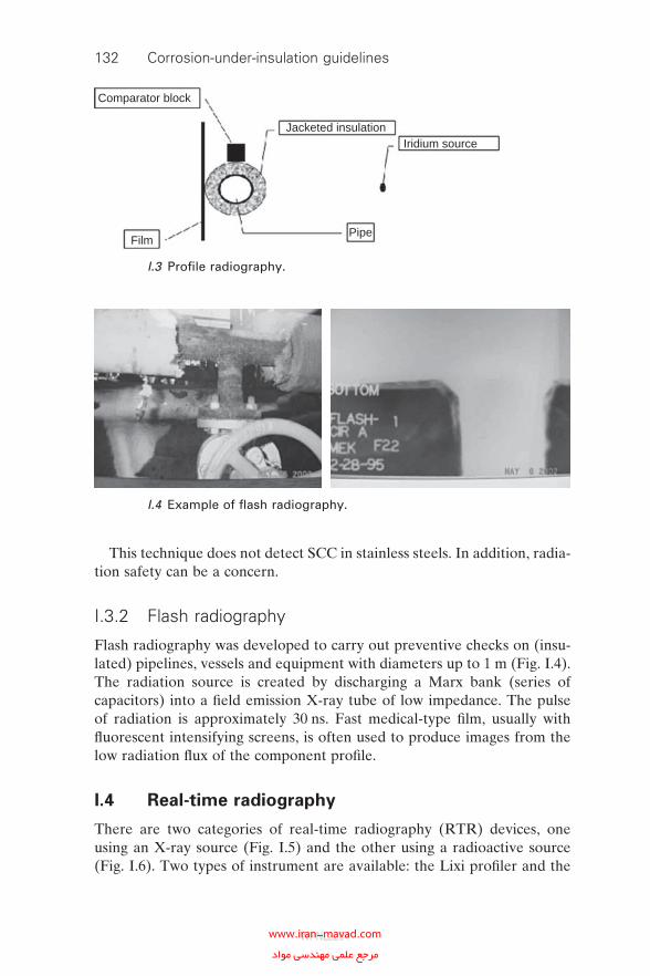
132 Corrosion-under-insulation guidelines
This technique does not detect SCC in stainless steels. In addition, radia-tion safety can be a concern.
I.3.2 Flash radiography
Flash radiography was developed to carry out preventive checks on (insu-lated) pipelines, vessels and equipment with diameters up to 1 m (Fig. I.4). The radiation source is created by discharging a Marx bank (series of capacitors) into a fi eld emission X-ray tube of low impedance. The pulse of radiation is approximately 30 ns. Fast medical-type fi lm, usually with fl uorescent intensifying screens, is often used to produce images from the low radiation fl ux of the component profi le.
I.4 Real-time radiography
There are two categories of real-time radiography (RTR) devices, one using an X-ray source (Fig. I.5) and the other using a radioactive source (Fig. I.6). Two types of instrument are available: the Lixi profi ler and the
Comparator block
Film
Jacketed insulationIridium source
Pipe
I.3 Profi le radiography.
I.4 Example of fl ash radiography.
WPNL2204www.iran-mavad.com مرجع علمى مهندسى مواد
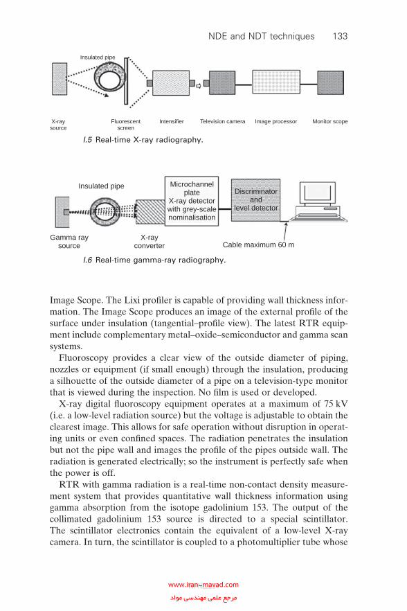
Image Scope. The Lixi profi ler is capable of providing wall thickness infor-mation. The Image Scope produces an image of the external profi le of the surface under insulation (tangential–profi le view). The latest RTR equip-ment include complementary metal–oxide–semiconductor and gamma scan systems.
Fluoroscopy provides a clear view of the outside diameter of piping, nozzles or equipment (if small enough) through the insulation, producing a silhouette of the outside diameter of a pipe on a television-type monitor that is viewed during the inspection. No fi lm is used or developed.
X-ray digital fl uoroscopy equipment operates at a maximum of 75 kV (i.e. a low-level radiation source) but the voltage is adjustable to obtain the clearest image. This allows for safe operation without disruption in operat-ing units or even confi ned spaces. The radiation penetrates the insulation but not the pipe wall and images the profi le of the pipes outside wall. The radiation is generated electrically; so the instrument is perfectly safe when the power is off.
RTR with gamma radiation is a real-time non-contact density measure-ment system that provides quantitative wall thickness information using gamma absorption from the isotope gadolinium 153. The output of the collimated gadolinium 153 source is directed to a special scintillator. The scintillator electronics contain the equivalent of a low-level X-ray camera. In turn, the scintillator is coupled to a photomultiplier tube whose
Insulated pipe
X-raysource
Fluorescentscreen
Intensifier Television camera Image processor Monitor scope
I.5 Real-time X-ray radiography.
X-rayconverter
Gamma raysource
Insulated pipe Microchannelplate
X-ray detectorwith grey-scalenominalisation
Discriminatorand
level detector
Cable maximum 60 m
I.6 Real-time gamma-ray radiography.
NDE and NDT techniques 133
WPNL2204www.iran-mavad.com مرجع علمى مهندسى مواد
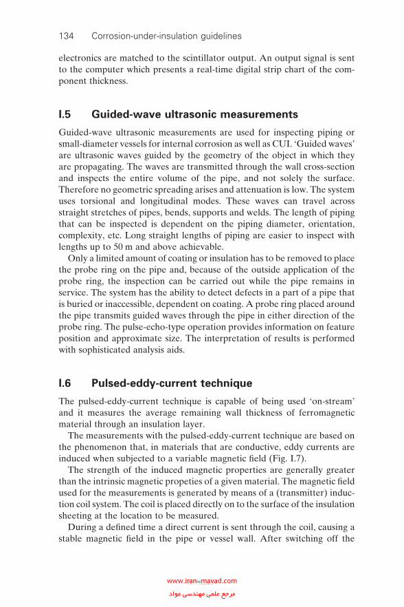
134 Corrosion-under-insulation guidelines
electronics are matched to the scintillator output. An output signal is sent to the computer which presents a real-time digital strip chart of the com-ponent thickness.
I.5 Guided-wave ultrasonic measurements
Guided-wave ultrasonic measurements are used for inspecting piping or small-diameter vessels for internal corrosion as well as CUI. ‘Guided waves’ are ultrasonic waves guided by the geometry of the object in which they are propagating. The waves are transmitted through the wall cross-section and inspects the entire volume of the pipe, and not solely the surface. Therefore no geometric spreading arises and attenuation is low. The system uses torsional and longitudinal modes. These waves can travel across straight stretches of pipes, bends, supports and welds. The length of piping that can be inspected is dependent on the piping diameter, orientation, complexity, etc. Long straight lengths of piping are easier to inspect with lengths up to 50 m and above achievable.
Only a limited amount of coating or insulation has to be removed to place the probe ring on the pipe and, because of the outside application of the probe ring, the inspection can be carried out while the pipe remains in service. The system has the ability to detect defects in a part of a pipe that is buried or inaccessible, dependent on coating. A probe ring placed around the pipe transmits guided waves through the pipe in either direction of the probe ring. The pulse-echo-type operation provides information on feature position and approximate size. The interpretation of results is performed with sophisticated analysis aids.
I.6 Pulsed-eddy-current technique
The pulsed-eddy-current technique is capable of being used ‘on-stream’ and it measures the average remaining wall thickness of ferromagnetic material through an insulation layer.
The measurements with the pulsed-eddy-current technique are based on the phenomenon that, in materials that are conductive, eddy currents are induced when subjected to a variable magnetic fi eld (Fig. I.7).
The strength of the induced magnetic properties are generally greater than the intrinsic magnetic propeties of a given material. The magnetic fi eld used for the measurements is generated by means of a (transmitter) induc-tion coil system. The coil is placed directly on to the surface of the insulation sheeting at the location to be measured.
During a defi ned time a direct current is sent through the coil, causing a stable magnetic fi eld in the pipe or vessel wall. After switching off the
WPNL2204www.iran-mavad.com مرجع علمى مهندسى مواد
current, the magnetic fi eld drops rapidly to zero. This generates eddy cur-rents within the material under examination. The duration of the eddy currents within the enclosed magnetic fi eld is directly related to the thick-ness of the material. The strength of the magnetic fi eld and the eddy cur-rents has no infl uence on the duration of the eddy currents.
The strength and the measurable duration of the eddy currents depend on the strength of the magnetic fi eld as well as on the conductivity and permeability of the material. If the strength and duration are measured, the average wall thickness can be calculated. A pulsed eddy current can be used on the fl at surfaces of a piping or equipment but corrosion is more likely to occur around nozzle welds, etc., where the eddy current technique cannot be used because of geometric restrictions.
I.7 Digital radiography
Digital radiography can highlight CUI and provide a measurement of mate-rial loss. The measurement sensitivity is dependent on a number of vari-ables. These include exposure conditions, image quality requirements and productivity. As with conventional radiographic fi lm techniques, digital radiography exhibits a wide range of resolutions, speeds and throughput capabilities (Fig. I.8).
The image quality of radiographic devices to achieve different levels of radiographic sensitivity, speed and throughput, targeted to different appli-cations includes the following.
• Film digitisation.• Storage phosphor computed radiography.• Digital radiography.
The performance characteristics of these systems can help to determine the right method for application.
Pipe wall
Probe coil
Insulation
Sheeting
Magnetic field
Eddy currents
I.7 Pulsed-eddy-current induction.
NDE and NDT techniques 135
WPNL2204www.iran-mavad.com مرجع علمى مهندسى مواد
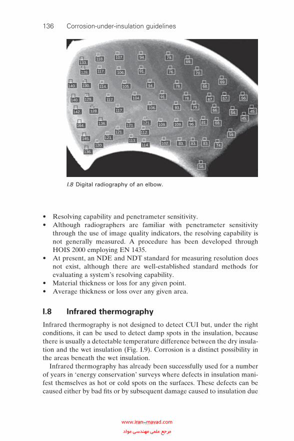
136 Corrosion-under-insulation guidelines
• Resolving capability and penetrameter sensitivity.• Although radiographers are familiar with penetrameter sensitivity
through the use of image quality indicators, the resolving capability is not generally measured. A procedure has been developed through HOIS 2000 employing EN 1435.
• At present, an NDE and NDT standard for measuring resolution does not exist, although there are well-established standard methods for evaluating a system’s resolving capability.
• Material thickness or loss for any given point.• Average thickness or loss over any given area.
I.8 Infrared thermography
Infrared thermography is not designed to detect CUI but, under the right conditions, it can be used to detect damp spots in the insulation, because there is usually a detectable temperature difference between the dry insula-tion and the wet insulation (Fig. I.9). Corrosion is a distinct possibility in the areas beneath the wet insulation.
Infrared thermography has already been successfully used for a number of years in ‘energy conservation’ surveys where defects in insulation mani-fest themselves as hot or cold spots on the surfaces. These defects can be caused either by bad fi ts or by subsequent damage caused to insulation due
133.
128.
140. 130. 114.
117.
117.
117.
129.140.
142. 128.
164.
145.
136.
136.
120.
121.121.
121.121.
113.114.
112.
109. 109.
102. 83. 83. 83. 74.
59.
45.
45.
56.57.
66.
67.
68.69.
70.
69.79.
76.
78.
78.
79.54.
68.
58.
118. 107. 94.
94.
91.
91.
93.
96. 81.
106.
106.
105.
104.
I.8 Digital radiography of an elbow.
WPNL2204www.iran-mavad.com مرجع علمى مهندسى مواد
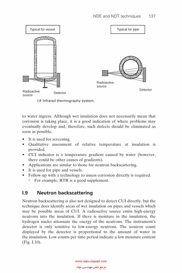
to water ingress. Although wet insulation does not necessarily mean that corrosion is taking place, it is a good indication of where problems may eventually develop and, therefore, such defects should be eliminated as soon as possible.
• It is used for screening.• Qualitative assessment of relative temperature at insulation is
provided.• CUI indicator is a temperature gradient caused by water (however,
there could be other causes of gradients).• Applications are similar to those for neutron backscattering.• It is used for pipe and vessels.• Follow-up with a technology to assess corrosion directly is required.
° For example, RTR is a good supplement.
I.9 Neutron backscattering
Neutron backscattering is also not designed to detect CUI directly, but the technique does identify areas of wet insulation on pipes and vessels which may be possible areas of CUI. A radioactive source emits high-energy neutrons into the insulation. If there is moisture in the insulation, the hydrogen nuclei attenuate the energy of the neutrons. The instrument’s detector is only sensitive to low-energy neutrons. The neutron count displayed by the detector is proportional to the amount of water in the insulation. Low counts per time period indicate a low moisture content (Fig. I.10).
Radioactivesource
Radioactivesource
Typical for vessel Typical for pipe
DetectorDetector
I.9 Infrared thermography system.
NDE and NDT techniques 137
WPNL2204www.iran-mavad.com مرجع علمى مهندسى مواد
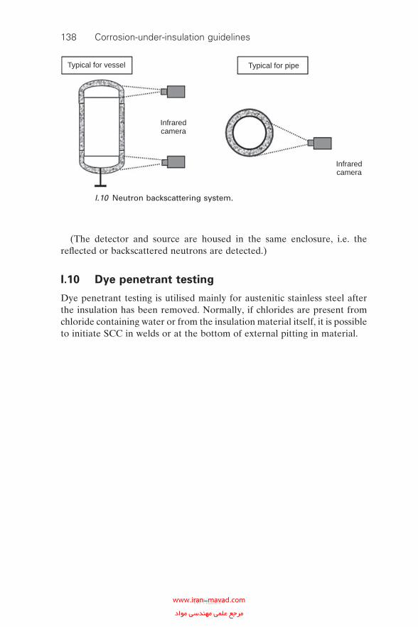
138 Corrosion-under-insulation guidelines
(The detector and source are housed in the same enclosure, i.e. the refl ected or backscattered neutrons are detected.)
I.10 Dye penetrant testing
Dye penetrant testing is utilised mainly for austenitic stainless steel after the insulation has been removed. Normally, if chlorides are present from chloride containing water or from the insulation material itself, it is possible to initiate SCC in welds or at the bottom of external pitting in material.
Infraredcamera
Typical for vessel Typical for pipe
Infraredcamera
I.10 Neutron backscattering system.
WPNL2204www.iran-mavad.com مرجع علمى مهندسى مواد
Appendix JCase studies
Appendix J is a compilation of a small selection of CUI case studies which represent the broad nature of the problem. A standard reporting template has been used in order to allow users of the document to easily complete and build their own portfolio of CUI failures. The case studies are taken from ‘hot’ environments and cover issues with both carbon steel and stain-less steel equipment, piping and vessels. The failures are primarily due to failings when originally commissioned due to poor design details and instal-lation procedures and exacerbated by poor maintenance programmes.
139
WPNL2204www.iran-mavad.com مرجع علمى مهندسى مواد
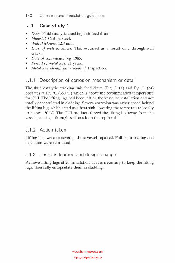
140 Corrosion-under-insulation guidelines
J.1 Case study 1
• Duty. Fluid catalytic cracking unit feed drum.• Material. Carbon steel.• Wall thickness. 12.7 mm.• Loss of wall thickness. This occurred as a result of a through-wall
crack.• Date of commissioning. 1985.• Period of metal loss. 21 years.• Metal loss identifi cation method. Inspection.
J.1.1 Description of corrosion mechanism or detail
The fl uid catalytic cracking unit feed drum (Fig. J.1(a) and Fig. J.1(b)) operates at 193 °C (380 °F) which is above the recommended temperature for CUI. The lifting lugs had been left on the vessel at installation and not totally encapsulated in cladding. Severe corrosion was experienced behind the lifting lug, which acted as a heat sink, lowering the temperature locally to below 150 °C. The CUI products forced the lifting lug away from the vessel, causing a through-wall crack on the top head.
J.1.2 Action taken
Lifting lugs were removed and the vessel repaired. Full paint coating and insulation were reinstated.
J.1.3 Lessons learned and design change
Remove lifting lugs after installation. If it is necessary to keep the lifting lugs, then fully encapsulate them in cladding.
WPNL2204www.iran-mavad.com مرجع علمى مهندسى مواد
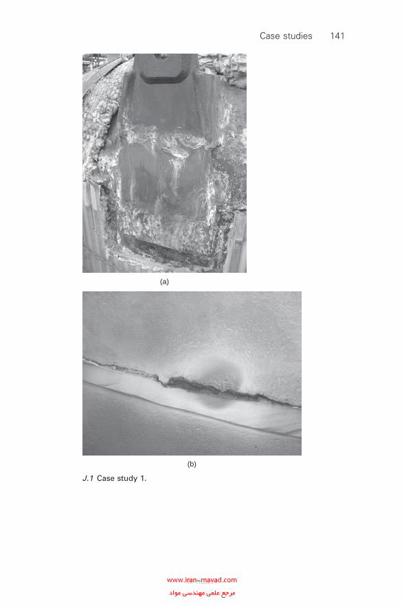
(a)
(b)
J.1 Case study 1.
Case studies 141
WPNL2204www.iran-mavad.com مرجع علمى مهندسى مواد
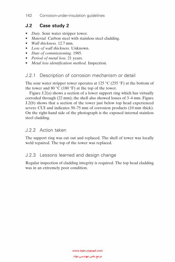
142 Corrosion-under-insulation guidelines
J.2 Case study 2
• Duty. Sour water stripper tower.• Material. Carbon steel with stainless steel cladding.• Wall thickness. 12.7 mm.• Loss of wall thickness. Unknown.• Date of commissioning. 1985.• Period of metal loss. 21 years.• Metal loss identifi cation method. Inspection.
J.2.1 Description of corrosion mechanism or detail
The sour water stripper tower operates at 125 °C (255 °F) at the bottom of the tower and 80 °C (180 °F) at the top of the tower.
Figure J.2(a) shows a section of a lower support ring which has virtually corroded through (22 mm); the shell also showed losses of 3–4 mm. Figure J.2(b) shows that a section of the tower just below top head experienced severe CUI and indicates 50–75 mm of corrosion products (10 mm thick). On the right-hand side of the photograph is the exposed internal stainless steel cladding.
J.2.2 Action taken
The support ring was cut out and replaced. The shell of tower was locally weld repaired. The top of the tower was replaced.
J.2.3 Lessons learned and design change
Regular inspection of cladding integrity is required. The top head cladding was in an extremely poor condition.
WPNL2204www.iran-mavad.com مرجع علمى مهندسى مواد
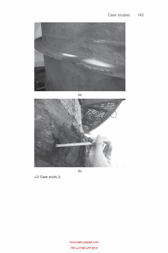
(a)
(b)
J.2 Case study 2.
Case studies 143
WPNL2204www.iran-mavad.com مرجع علمى مهندسى مواد
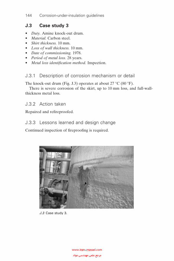
144 Corrosion-under-insulation guidelines
J.3 Case study 3
• Duty. Amine knock-out drum.• Material. Carbon steel.• Shirt thickness. 10 mm.• Loss of wall thickness. 10 mm.• Date of commissioning. 1978.• Period of metal loss. 28 years.• Metal loss identifi cation method. Inspection.
J.3.1 Description of corrosion mechanism or detail
The knock-out drum (Fig. J.3) operates at about 27 °C (80 °F).There is severe corrosion of the skirt, up to 10 mm loss, and full-wall-
thickness metal loss.
J.3.2 Action taken
Repaired and refi reproofed.
J.3.3 Lessons learned and design change
Continued inspection of fi reproofi ng is required.
J.3 Case study 3.
WPNL2204www.iran-mavad.com مرجع علمى مهندسى مواد
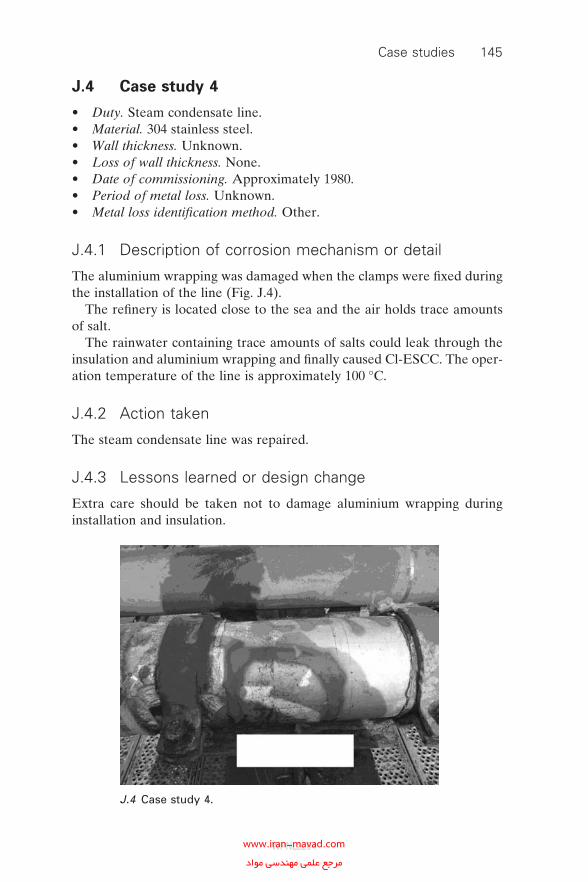
J.4 Case study 4
• Duty. Steam condensate line.• Material. 304 stainless steel.• Wall thickness. Unknown.• Loss of wall thickness. None.• Date of commissioning. Approximately 1980.• Period of metal loss. Unknown.• Metal loss identifi cation method. Other.
J.4.1 Description of corrosion mechanism or detail
The aluminium wrapping was damaged when the clamps were fi xed during the installation of the line (Fig. J.4).
The refi nery is located close to the sea and the air holds trace amounts of salt.
The rainwater containing trace amounts of salts could leak through the insulation and aluminium wrapping and fi nally caused Cl-ESCC. The oper-ation temperature of the line is approximately 100 °C.
J.4.2 Action taken
The steam condensate line was repaired.
J.4.3 Lessons learned or design change
Extra care should be taken not to damage aluminium wrapping during installation and insulation.
Case studies 145
J.4 Case study 4.
WPNL2204www.iran-mavad.com مرجع علمى مهندسى مواد
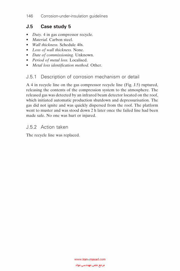
146 Corrosion-under-insulation guidelines
J.5 Case study 5
• Duty. 4 in gas compressor recycle.• Material. Carbon steel.• Wall thickness. Schedule 40s.• Loss of wall thickness. None.• Date of commissioning. Unknown.• Period of metal loss. Localised.• Metal loss identifi cation method. Other.
J.5.1 Description of corrosion mechanism or detail
A 4 in recycle line on the gas compressor recycle line (Fig. J.5) ruptured, releasing the contents of the compression system to the atmosphere. The released gas was detected by an infrared beam detector located on the roof, which initiated automatic production shutdown and depressurisation. The gas did not ignite and was quickly dispersed from the roof. The platform went to muster and was stood down 2 h later once the failed line had been made safe. No one was hurt or injured.
J.5.2 Action taken
The recycle line was replaced.
WPNL2204www.iran-mavad.com مرجع علمى مهندسى مواد
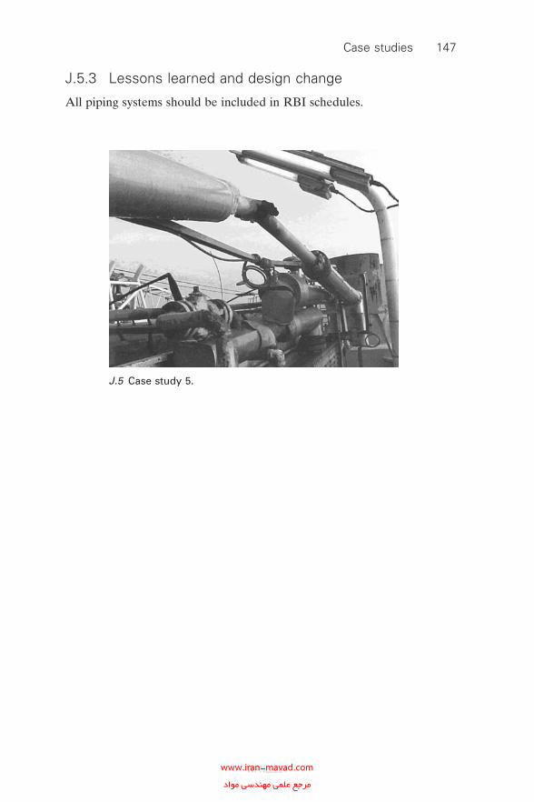
Case studies 147
J.5 Case study 5.
J.5.3 Lessons learned and design change
All piping systems should be included in RBI schedules.
WPNL2204www.iran-mavad.com مرجع علمى مهندسى مواد
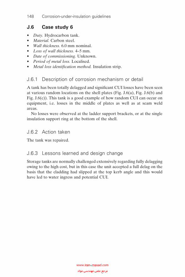
148 Corrosion-under-insulation guidelines
J.6 Case study 6
• Duty. Hydrocarbon tank.• Material. Carbon steel.• Wall thickness. 6.0 mm nominal.• Loss of wall thickness. 4–5 mm.• Date of commissioning. Unknown.• Period of metal loss. Localised.• Metal loss identifi cation method. Insulation strip.
J.6.1 Description of corrosion mechanism or detail
A tank has been totally delagged and signifi cant CUI losses have been seen at various random locations on the shell plates (Fig. J.6(a), Fig. J.6(b) and Fig. J.6(c)). This tank is a good example of how random CUI can occur on equipment, i.e. losses in the middle of plates as well as at seam weld areas.
No losses were observed at the ladder support brackets, or at the single insulation support ring at the bottom of the shell.
J.6.2 Action taken
The tank was repaired.
J.6.3 Lessons learned and design change
Storage tanks are normally challenged extensively regarding fully delagging owing to the high cost, but in this case the unit accepted a full delag on the basis that the cladding had slipped at the top kerb angle and this would have led to water ingress and potential CUI.
WPNL2204www.iran-mavad.com مرجع علمى مهندسى مواد
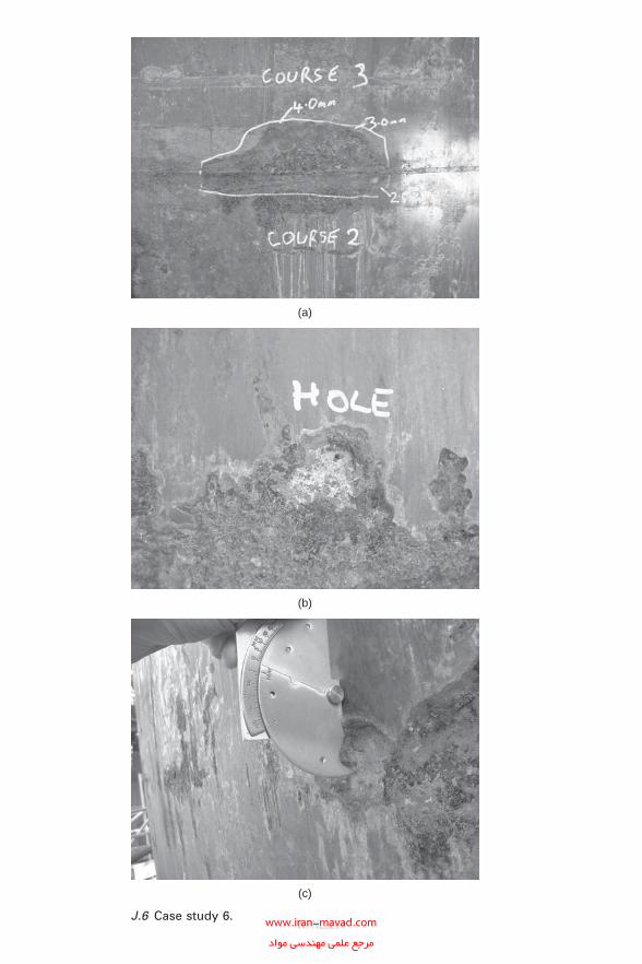
(a)
(b)
(c)
J.6 Case study 6.WPNL2204www.iran-mavad.com
مرجع علمى مهندسى مواد
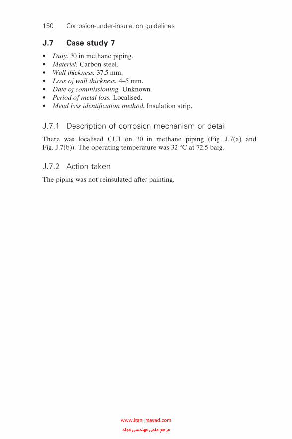
150 Corrosion-under-insulation guidelines
J.7 Case study 7
• Duty. 30 in methane piping.• Material. Carbon steel.• Wall thickness. 37.5 mm.• Loss of wall thickness. 4–5 mm.• Date of commissioning. Unknown.• Period of metal loss. Localised.• Metal loss identifi cation method. Insulation strip.
J.7.1 Description of corrosion mechanism or detail
There was localised CUI on 30 in methane piping (Fig. J.7(a) and Fig. J.7(b)). The operating temperature was 32 °C at 72.5 barg.
J.7.2 Action taken
The piping was not reinsulated after painting.
WPNL2204www.iran-mavad.com مرجع علمى مهندسى مواد
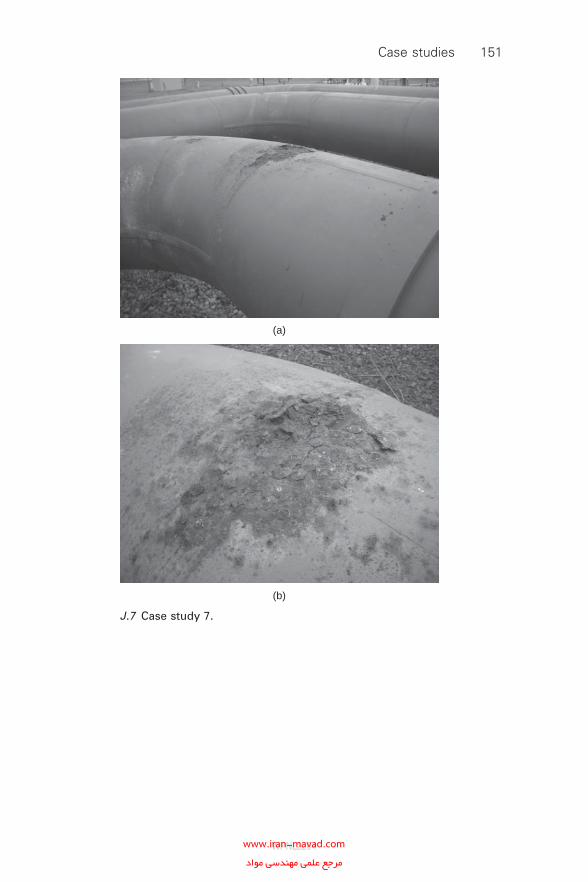
(a)
(b)
J.7 Case study 7.
Case studies 151
WPNL2204www.iran-mavad.com مرجع علمى مهندسى مواد
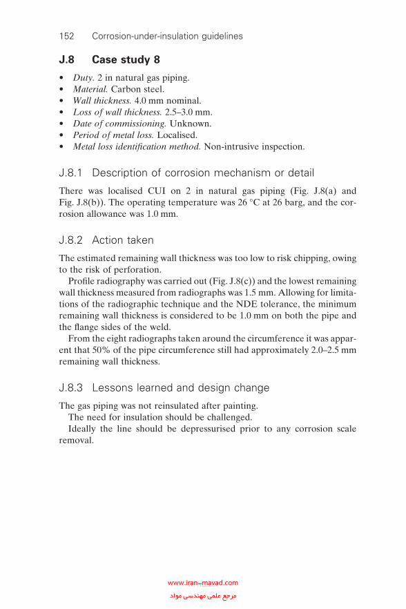
152 Corrosion-under-insulation guidelines
J.8 Case study 8
• Duty. 2 in natural gas piping.• Material. Carbon steel.• Wall thickness. 4.0 mm nominal.• Loss of wall thickness. 2.5–3.0 mm.• Date of commissioning. Unknown.• Period of metal loss. Localised.• Metal loss identifi cation method. Non-intrusive inspection.
J.8.1 Description of corrosion mechanism or detail
There was localised CUI on 2 in natural gas piping (Fig. J.8(a) and Fig. J.8(b)). The operating temperature was 26 °C at 26 barg, and the cor-rosion allowance was 1.0 mm.
J.8.2 Action taken
The estimated remaining wall thickness was too low to risk chipping, owing to the risk of perforation.
Profi le radiography was carried out (Fig. J.8(c)) and the lowest remaining wall thickness measured from radiographs was 1.5 mm. Allowing for limita-tions of the radiographic technique and the NDE tolerance, the minimum remaining wall thickness is considered to be 1.0 mm on both the pipe and the fl ange sides of the weld.
From the eight radiographs taken around the circumference it was appar-ent that 50% of the pipe circumference still had approximately 2.0–2.5 mm remaining wall thickness.
J.8.3 Lessons learned and design change
The gas piping was not reinsulated after painting.The need for insulation should be challenged.Ideally the line should be depressurised prior to any corrosion scale
removal.
WPNL2204www.iran-mavad.com مرجع علمى مهندسى مواد
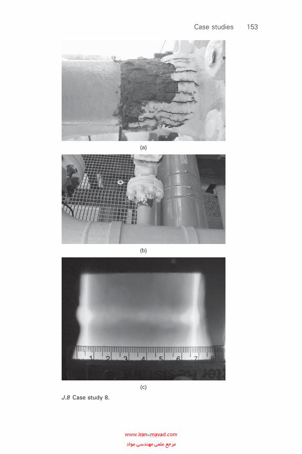
(a)
(b)
(c)
J.8 Case study 8.
Case studies 153
WPNL2204www.iran-mavad.com مرجع علمى مهندسى مواد
Index
acceptance of coatings 103–5adhesion tests on coatings 102aluminised steel sheeting 120aluminium coatings see thermally sprayed
coatingsaluminium foil 60–2, 66aluminium sheeting 122aluminium-zinc-coated sheeting 120–1anine knock-out drums 141–3anodic reactions 3application of coatings 92–4, 95, 101–2
coating contractors 97–8weather conditions 101
asbestos removal 79assessment of insulation systems 17austenitic steels 1, 57
corrosion cracking 1, 54, 60–2susceptibility score tables 33
best practice 53–62, 78–88for design 64NACE recommendations 1–2
blasting methods see surface preparationbrushing surfaces 86
calcium silicate insulation 109–10carbon dioxide cleaning 87–8carbon steels 1, 2, 40, 57
susceptibility score tables 33causes of CUI 2cellular glass insulation 110–12ceramic fi bre paper insulation 112certifi cates of release 100chemical content of insulation 67–8chlorides 2
external stress corrosion cracking (CI-ESCC) 1, 54, 60–2
chlorosulphonated polyethylene 123–6cladding and jacketing materials 120–6
aluminised steel sheeting 120aluminium sheeting 122aluminium-zinc-coated sheeting 120–1
154
condition 31galvanised steel sheeting 121Hypalon 123–6stainless steel jacketing 121ultraviolet-cured fi bre-reinforced
materials 122–3cleaning methods see surface preparationclosed-cell insulation 67coatings 31, 54, 55, 89–91
aluminium foil 60–2, 66design 66, 100organic 66surface and moisture
tolerance 91, 105surface preparation 81–8, 100–1, 102tape coatings 91, 105weatherproofi ng 53, 54, 55, 64, 68–9see also paint systems; thermally sprayed
coatingscoil corrosion 32cold insulation 76–7cold service equipment 40, 54
close to freezing point 80collateral damage costs 13columns 41–3condition of insulation 31consequences of failure 29, 30construction materials 65–6contaminant sources 2cooling towers 80corrosion allowance 31–2corrosion cracking 1, 54, 60–2corrosion under insulation (CUI)
causes 2defi nition 1evaluation 6prevention methods 16, 54, 56–8rate of CUI 4, 55
cost analysis 11–14, 24, 30, 71–5life cycle costs (LCCs) 55, 57–8, 59, 71material upgrades 57–8personnel protective guards 59–60
WPNL2204www.iran-mavad.com مرجع علمى مهندسى مواد
Index 155
statistical analysis 11thermally sprayed aluminium 59, 71, 75
cyclic service equipment 79–80
damaged insulation areas 40data validation 17, 24–8
aspects to challenge 25–6implementation 26need for 24–5
dead legs 40deluge systems 80–1descaling 86design considerations 63–9
best practice 64coatings 66, 100construction materials 65–6equipment and tanks 64insulation systems 67–8piping 65plant layout 64protective guards 127undesirable features 64weatherproofi ng 64, 68–9
detecting CUI 39–40digital radiography 48, 135–6documentation for coatings 105duplex stainless steels 57–8dye penetrant testing 51, 138
economic considerations see cost analysiselastomeric foam 115–16electric arc spraying 93elimination of insulation 17, 20–4, 63engineering managers responsibilities 15environmental impacts 12, 13, 30equipment
adjacent to cooling towers 80anine knock-out drum 141–3in cold service 40, 54
close to freezing point 80in cyclic service 79–80deluge systems 80–1design 64fl uid catalytic cracking unit feed
drum 139–40gas compressor recycle 144–5horizontal 43–4hydrocarbon tank 145–7methane piping 147mothballing 26, 28natural gas piping 147–50out-of-service 26, 28sour water stripping tower 140–1steam condensate line 143–4susceptible locations 41–4in sweating service 80vertical 41–3
ethylene propylene diene monomer 116evaluation of CUI 6
explosive releases 20external environment 23–4, 33
failure of insulation 54fi re protection insulation 21fi tness for continued service 13fl ame spraying 93fl ammable releases 20fl ash radiography 49, 132fl exible elastomeric foam 115–16fl exible reusable covers 112–13fl uid catalytic cracking unit feed
drum 139–40fl uoroscopy 133freeze protection insulation 21
galvanised steel sheeting 121gas compressor recycle 144–5glass rope insulation 112glass-fi bre-reinforced resin tape 91, 105grit blasting 79, 82, 85guards see personnel protective guardsguided-wave ultrasonic
measurements 50, 134
hand railings 64health and safety 12, 24, 30, 79heat exchangers 43–4high-density insulation 68high-extreme risk levels 44high-temperature insulation 67horizontal equipment 43–4hot insulation 76hydrocarbon tanks 145–7Hypalon 123–6
Image Scope 49, 133infrared thermography 51, 136–7inspections 39–45
advice notes 11of coatings 103–5departmental responsibilities 16detecting CUI 39–40non-destructive examination and
testing 13, 39, 46–52, 130–8on-stream 13scaffolding 81susceptible locations
on equipment 41–4on piping circuits 40–1
visual inspections 6–7, 47, 130see also risk-based inspection (RBI)
insulation materials 3, 31calcium silicate 109–10cellular glass 110–12ceramic fi bre paper 112fl exible elastomeric foam 115–16fl exible reusable covers 112–13glass rope 112
WPNL2204www.iran-mavad.com مرجع علمى مهندسى مواد
156 Index
low-density glass fi bre 109mineral fi bre 106–8perlite 117–18polyethylene 116–17polyurethane foam 113–15self-setting cement 112vermiculite 118–19
insulation systemsassessment 17chemical content 67–8cold insulation 76–7condition 31damaged areas 40design 67–8failure causes 54fi re protection 21freeze protection 21high-density 68high-temperature 67hot 76life expectancy 53, 55–8low-temperature 67noise control 22non-contact 68penetrations of 39–40personnel protection 22quality assurance 76–7removing 17, 20–4, 63servicing 79–81thermal movement 67water retention 54, 67
jacketing materials see cladding and jacketing materials
jet cleaning 85
key performance indicators (KPIs) 14
lead paint removal 79life cycle costs (LCCs) 55, 57–8, 59, 71life expectancy of insulation 53, 55–8liquid carbon dioxide cleaning 88Lixi profi ler 49, 132–3lost profi t opportunities (LPO) 11low risk levels 45low-alloy steels 1, 2
susceptibility score tables 33low-density glass fi bre insulation 109low-temperature insulation 67
maintenance departments 15, 78safety issues 79work orders 11
material upgrades 57–8mechanical surface cleaning 86–7medium risk levels 45medium-high risk levels 44–5metal weatherproofi ng 68–9metallic cladding materials 120–2
methane piping 147mineral fi bre insulation 106–8moisture tolerance of coatings 91, 105mothballing of equipment 26, 28
NACE recommended practice 1–2nameplates 64natural gas piping 147–50need for insulation 17, 20–4, 63
consequences of removal 24and operating temperature 21and probability of failure 24and the process environment 23–4purposes of insulation systems 21–3
negligible risk levels 45neutron backscattering 51, 137–8noise control insulation 22non-contact insulation 68non-destructive examination and testing 13,
39, 46–52, 130–8
on-stream inspections 13online leak sealing costs 13open-cell insulation 67operating temperatures 3, 4, 21, 29, 31, 34–5operations departments 16, 78–9organic coatings 66organic topcoats 94out-of-service equipment 26, 28ownership and responsibilities 15–16, 78–9oxy-fuel wire spraying 93oxygen availability 4
paint systems 54, 55compared to coatings 56, 61, 90, 96lead paint removal 79
partial site shutdown 20penetrations of insulation systems 39–40perlite 117–18personnel protection insulation 22personnel protective guards 59–60, 127–9pin hammers 87piping
design 65for methane 150for natural gas 147–50susceptible locations 40–1thickness reduction 58
plant layout 64plant life expectancy 55polyethylene 116–17polyisocyanurate 113polyurethane foam 113–15pressure vessels 41–3prevention programmes 16, 54, 56–8prioritisation 17, 18–20probability of failure 20, 24, 28, 29process environment 23–4, 33production loss 12
WPNL2204www.iran-mavad.com مرجع علمى مهندسى مواد
Index 157
profi le radiography 48, 131–2project teams 16protective coatings see coatingsprotective guards 59–60, 127–9pulsed-eddy-current technique 50, 134–5
qualifi cations of coating operators 97–8quality assurance 76–7
radiographydigital radiography 48, 135–6fl ash radiography 49, 132profi le radiography 48, 131–2real-time radiography (RTR) 132–4
rate of CUI 4, 55real-time radiography 49, 132–4records 11removing insulation systems 17, 20–4, 63repair costs 13replacement costs 13reputational impact 12, 20responsibility and ownership 15–16, 78–9revenue loss 12risk matrix 36–7, 38risk to business assessment 18–20risk-based inspection (RBI) 4, 17–38, 44–5
assessment of insulated systems 17consequences of failure 29, 30data validation 17, 24–8elimination of insulation 17, 20–4, 63high-extreme risk levels 44inspection plans 17–18, 28–38low risk levels 45medium risk levels 45medium-high risk levels 44–5negligible risk levels 45preparation 28probability of failure 20, 28, 29risk matrix 36–7, 38susceptibility factors 29–33susceptibility score tables 33unit level prioritisation 17, 18–20
roles and responsibilities 15–16, 78–9
safety issues 12, 24, 30, 79sanding with grinding discs 87scaffolding 81scrapping equipment 26, 28seal coats 99–100sealers for thermally sprayed
coatings 94self-setting cement 112senior management responsibilities 15servicing equipment 79–81site shutdown 18, 20solid carbon dioxide cleaning 87–8sour water stripping tower 140–1sponge jets 87spray pattern 101
stainless steels 57–8jacketing 121see also austenitic steels
standards 1, 79for coatings 95, 97, 98for surface preparation 82
steam cleaning 85steam condensate line 143–4steam tracing 32, 81sulphides 2supercritical fl uid carbon dioxide
cleaning 88supports for pipes 65surface and moisture tolerance of
coatings 91, 105surface preparation 81–8, 100–1, 102
brushing 86carbon dioxide cleaning 87–8descaling 86grit blasting 79, 82, 85jet cleaning 85mechanical techniques 86–7pin hammers 87sanding with grinding discs 87sponge jets 87standards 82steam cleaning 85vacuum blasting 86vacuum grit blasting 87–8water washing 85wet abrasion 85
susceptibility factors 29–33susceptibility score tables 33susceptible locations
on equipment 41–4on piping circuits 40–1
sweating conditions 80
tanks 41–3, 145–7tape coatings 91, 105temperature of operation 3, 4, 21, 29, 31,
34–5test plates 102thermal movement of insulation 67thermally sprayed coatings 92–105
adhesion tests 102aluminium 55, 56, 58–9, 66, 89–90, 99
specifi cations 95, 97application 92–4, 95, 101–2
coating contractors 97–8weather conditions 101
certifi cates of release 100compared to paint systems 56, 61, 90, 96costs 59, 71, 75design 100documentation 105fl ame spraying 93inspection and acceptance 103–5metals used 92
WPNL2204www.iran-mavad.com مرجع علمى مهندسى مواد
158 Index
organic topcoats 94oxy-fuel wire spraying 93protected items 100qualifi cations of operators 97–8seal coats 99–100spray pattern 101standards and specifi cations 95, 97, 98surface and moisture tolerance 105surface preparation 100–1, 102test plates 102thickness 98–9twin-wire electric arc spraying 93and welds 100wire feedstock 92, 101
thickness of coatings 98–9total site shutdown 18, 20toxic releases 20twin-wire electric arc spraying 93
ultrasonic thickness measurements 47, 130ultraviolet-cured fi bre-reinforced
materials 122–3
unit level prioritisation 17, 18–20unit shutdown 20
vacuum blasting 86vacuum grit blasting 87–8vermiculite 118–19vertical equipment 41–3vessels 41–3vibrations 40visual inspections 6–7, 47, 130
water retention of insulation 54, 67water sources 2, 40water washing 85weatherproofi ng 53, 54, 55, 64, 68–9welds 100wet abrasion 85wire feedstock 92, 101wire spraying 93wrappings see coatings
X-ray digital fl uoroscopy 133
WPNL2204
WPNL2204
www.iran-mavad.com مرجع علمى مهندسى مواد