xxxxxx - nasa. t i m tantalum thickness, a 0.060-inch stainless steel thickness and a length of 25...
TRANSCRIPT

NASA CR 72761
NM 9904. i0 ___
Final Report
COEXTRUDED TANTALUM - 3 16 STAINLESS STEEL
BIMETALLIC JOINTS AND TUBING
by
Gerald I. Friedman
WHITTAKER CORPORATION/Nuclear MetaIs Division
Concord, Massachusetts 01742
i
_AG_s_ i_ _'.;._'_ "_
(NASA CR OR i"MX OR An NU/_BER) (C,_IEOORY_--'-_
--._
#
prepared for
NATIONAL AERONAUTXCS AND SPACE ADMINISTRATION
CONTRACT I_$3-1184 7October 1970
NASA Lewis Research Center
Cleve land ,Ohio <
P. Stone, Project ManagerMaterials and Structures Division
XXXXXX
https://ntrs.nasa.gov/search.jsp?R=19710002944 2018-05-28T21:28:26+00:00Z

I
NASA CR 72761
NM 9904. i0
COEXTRIJDED TANTALUM - 316 STAINLESS STEEL
BIMETALLIC JOINTS AND TUBING
by
Gerald I. Friedman
WHITTAKER CORPORATION/Nuc lear Meta is Division
prepared for
NATIONAL AERONAUTICS AND SPACE ADMINISTRATION
NASA Lewis Research Center
CONTRACT NAS3-I1847
P. Stone, Project ManagerMaterials and Structures Division
XXXXXX-O02

PRECEDING PAGE _..".LANT(NOT FILMEr._
COEXTRUDED TANTALUM - 316 STAINLESS ST1 _L
BIMETALLIC JOINTS AND TUBING
by
Gerald I. Friedman
_BSTRACT
Techniques were established for the coextrusion of tandem and sleeve tantalum-
stainless steel bimetallic joints. Large sleeve joints, 1.76 inches inside
diamete_ with an unalloyed tantalum inner wall thickness of 0.i0 inch and an
AISI 316 stainless steel outer wall thickness of 0.22 inch, were produced.
Extrusion procedures were also developed for the production of small sleeve
joints, having the same wall thickness as the large sleeve joints but with aninside diameter of 0.76 inch. Conditions were established for the extrusion
of tandem tantalum-stainless steel joints of 1.76 inches inside diameter
and 0.12 inch wall thickness. An attempt was made to produce 25-foot long,
0.652-inch ID bimeballic tubing having a 0.020-inch tantalum thickness and a
0.060-inch stainless steel thickness.
The extrusion conditions for the production sleeve-type joints were an 8:1
reduction ratio at 1950°F, while the production tandem joints were made at
a 5:1 reduction ratio at 1825°F. All joints -- both those produced in the
developmental phase [with one exception] and those made for production --
were sound, with no evidence of non-bond or any metallurgical defects. Overall,
the bimetallic tubing fabrication experiment was not successful, but it is
believed that with further experimentation sound tubing could be produced.
iii
XXXXXX-O03

I
TABLE OF CONTENTS
Section PaRe Number
SUMMARY .............................. i
INTRODUCTION ............................ 3
FABRICATION PROCEDURE ....................... 4
Large Diameter Sleeve Joints ................. 4
Small Diameter Sleeve Joints ................. 22
Tandem Joints ......................... 26
Bimetallic Tubing ....................... 34
CONCLUSIONS ........................... 43
REFERENCES ............................. 44
E
V
XXXX -004
f
LIST OF FIGURES
Pane Number
i. Billet design for sleeve joint extrusions ......... 5
2. Stud test specimen for sleeve joints ............ ii
3. Notch-fracture test, sleeve joint ............. ii
4. Cross section of developmental large diameter
sleeve joints ...................... 13
5. Transverse sections of developmental large
diameter sleeve joints, bright light ............ 15
6. Transverse section of eight production large
diameter sleeve joints ................ 18
7. Cross sections of developmental small diameter
sleeve joints ....................... 24
8. Transverse sections of developmental small
diameter sleeve joints .................. 25
9. Transverse section of production small
diameter sleeve joint ................... 28
10. Billet design for tandem joint extrusions .......... 29
ii. Prototype tandem joints .................. 32
12. Tandem ioints -- tantalum-stalnless steel interface,
unetched, bright light .................... 33
13. Interface of 5:1/1825°F tandem joint containingbeveled interface ..................... 35
14. Production tandem joints .................. 36
15. Tantalum-llned 304 stainless steel tube from
sheet. Billet details for subscale Tube No. i ....... 37
16. Cross section of subscale tantalum-llned stainless
_ steel Tube I, made from 0.010 inch tantalum sheet, lO0X . . 38%
vi
XXXXXX-O05
LIST OF FIGURES - continued
Pa_e Number
17. Cross sections of subscale tantalum-lined
stainless steel Tube 2, made from 0.015 inch
tantalum sheet ................. 40
18. Tantalum-lined 316 stainless steel tube from
sheet. Billet details for full size tube ........ 41
19. Cross sections of full size tantalum-lined
stainless steel tube, made from 0.010-inch
tantalum sheet ................... 42
vii
m • ' i
XXXXXX-O06

LIST OF TABLES
Ta___bire Page Number
I. PREPARATION OF TANTALUM - STAINLESS STEEL
EXTRUSION BILLETS ................... 6
II. EXTRUSION CONDITIONS FOR DEVELOPMENTAL LARGE
DIAMETER SLEEVE JOINTS ................. 7
III. DIMENSIONS OF DEVELOPMENTAL LARGE DIAMETER SLEEVE
JOINTS AFTER REMOVAL OF CARBON STEEL JACKETS ...... 8
IV. OUTER AND INNER DIAMETERS OF DEVELOPMENTAL
LARGE DIAMETER SLEEVE JOINTS ............ 9
V. STRENGTH OF TANTALUM - STAINLESS STEEL !NTERFAC _.
DETERMINED BY STUD TENSILE TESTS ............ I0
VI. TANTALUM AND STAINLESS STEEL WALL THICKNESS
FOR DEVELOPMENTAL LARGE DIAMETER JOINTS ........ 14
VII. THICKNESS OF THE TANTALUM - STAINLESS STEEL _"
INTERMETALLIC LAYER FOR DEVELOPMENTAl LARGE iDIAMETER JOINTS .................... 14
VIII. DIMENSIONS OF PRODUCTION LARGE DIAMETER SLEEVE
JOINTS ......................... 16,
IX. BOND STRENGTH OF PRODUCTION LARGE DIAMETER I
SLEEVE JOINTS .................... 17
X. CROSS SECTIONAL DIMENSIONS OF PRODUCTION lARGE
DIAMETER SLEEVE JOINTS ................ 17
XI. EXTRUSION CONDITIONS FOR DEVELOPMENTAL SMALL
DIAMETER SLEEVE JOINTS ................. 22
XII. AS-EXTRUDED DIMENSIONS OF DEVELOPMENTAL SMALL
DIAMETER SLEEVE JOINTS .................. 23
XIII. EXTRUSION CONDITIONS FOR PRODUCTION SMALL
DIAMETER SLEEVE JOINTS ................. 23
XIV. DIMENSIONS OF FIRST PRODUCTION SMALL DIAMETER
. SLEEVE EXTRUSION .................... 26
viii
XXXXXX-O07

I.IST OF TABLES - continued
Tabl___.._e Page Number
XV. CROSS SECTIONAL DIMENSIONS OF FIRST PRODUCTION
SMALL DIAMETER SLEEVE JOINT ............. 27
XVI. EXTRUSION CONDITIONS FOR DEVELOPMENTAL TANDEM JOINTS . • 27
XVII. AS-EXTRUDED DIMENSIONS OF DEVELOPMENTAL
TANDEM JOINTS ..................... 3 1
XVIII. THICKNESS OF TANTALUM - STAINLESS STEEL ........ 31
XIX. CROSS SECTIONAL DIMENSIONS OF TANTALUM-LINED
304 STAINLESS STEEL TUBE NO. i MADE FROM
WRAPPED SHEET .................... 38
XX. CROSS SECTIONAL DIMENSIONS AT THE CENTER OF
FULL SIZE TANTALUM-LINED STAINLESS STEEL TUBE
FROM WRAPPED SHEET ................... 39
ix
I
XXXXXX-O08

COEXTRUDED TANTALUM - 316 STAINLESS STEEL
BIMETALLIC JOINTS AND TUBING
by
Gerald I. Friedman
Whittaker Corporation/Nuclear Metals Division
SUMMARY
An experimental program was performed, the prime objective of which was to
establish the optimum fabrication techniques for the production of extrudedtantalum - 316 stainless steel tandem and sleeve joints. [A sleeve joint
is a tantalum-lined stainless steel tube.] The design criteria were that
all joints be metallurgically bonded and that after extrusion they be machin-
able to the following dimensions:
i. Tandem joint: 1.76 inches ID, 0.12 incf_wal)
8 inches long
2. Large diameter sleeve joint: 1.76 inches ID, 0.I0 inch
tantalum, 0.22 inch stainless
steel, 12 inches long
3. Small diameter sleeve joint: 0.76 inch ID, 0.I0 inch
tantalum, 0.22 inch stainless
steel, 12 inches long. r
The starting materials were forged, arc-melted, hlgh-purlty tantalum with agrain size finer than ASTM 5, and 316 stainless steel, both in the annealed
condition. In the exploratory stage of the program, four tandem Joints were
extruded, at 5:1 and 7:1 extrusion ratios, at 1825°F and 1950°F. Following
the selection of 1825°F/5:1 conditions for this type joint, one additional
developmental tandem joint was made with a 0.4-inch beveled interface, toprovide a longer interface length in the extruded joint.
The developmental large diameter sleeve joints were extruded at 1825°F and
1950°F, at 5:1 and 8:1 extrusion ratios. Since these Joints could be satis-
factorily evaluated without destroying them [from sample rings cut fromthe ends and center of the _xtruded tubes], it _as possible to deliver to
XXXXXX-O09

DNASA eight 8-inch lengths [two from each extrusion]. The developmentalsmall diameter sleeve joints were extruded at an 8:1 reduction ratio at
1825°F and 1950°F. Four 8-inch lengths [two from each extrusion] of this
joint type were delivered to NASA.
Evaluation of the developmental joints showed them all to be sound from both
a metallurgical and mechanical point of view° All joints, with the exception
of the 7:1/1950°F tandem joint, displayed continuous metallurgical bond lines,with no evidence of voids or inclusions at the tantalum - stainless steel
interface. The 7:1/1950°F tandem joint showed a dark phase believed to be
an oxide along the bond line. Tensile tests performed on large diameter ;_
sleeve joint samples normal to the bond line showed average ultimate strengths
of 69,300 psi. and 52,900 psi for joints extruded at 18250F and 1950OF,
respectively. The higher strengths of the joints extru'ed at lower tempera-
ture reflect the additional wock-hardening imparted to the bimetal tube at
the lower extrusion temperature. Tandem joints were tested after machining
and revealed no defects when inspected by heli_,m r0_ss spectrometer and dyepenetrant. ._
The production tandem joints were extruded ac 1825°F at a 5:1 red:Jctlon
ratio, since the mlcrostructural eY_minations of the developmen_cl Joints
showed this condition to be opti_num. The developmental 7:1 ext_:gion_
produced interface lengths of ]_6 to 1.8 inches, while the corresponding
length for the _:i joints was o_ly 0.92 inch. All of these joint:: ,ere made
from square ended tantalum and st_less steel billet components, ",n order
to produce the desired longer in _ce in the 5:1 joints, mating i_ 'els
were machined on the stainless steel and tantalum components. _ t_ al
.. extrusion at a 5:1 reduction and !B25°F extrusion temperature _:_' ,,0.4-
inch bevel produced a joint with a _atlsfactory interface leng-ti_,of over
1.3 inches. Twelve production Joi_ were subsequently made u_'_:":_these
same conditions.
The production sleeve joints were extruded ac 1950°F at 8_. _-':[reduction
ratio. The choice of these conditiona was based on the feet that the
higher reduction ratio provides greater bonding assurance for a lined tube
joint. The increased forces associated with the 8:1 reduction dictated
the use of the 1950°F extrusion temperature. [The 8:i/Ib25=F large diameter
sleeve extrusion required over 1300 tons on the 1400-ton extrusion ptcss.]
Bond strengths for all extrusions exceeded 43,000 psi.
A brief fabrication process development effort was conducted, the objective
of which was co produce 0.652-inch ID bimetallic tubing having a 0.020-inch
XXXXXX-O 10

t
I
m
tantalum thickness, a 0.060-inch stainless steel thickness and a length of25 feet. Although this effort was not 3uccessful, the indications were that
with some further exoerimentatiou sound tubing coul_ be produced.
INTRODUCT ION
The primary objective of this program was to develop techniques for the
extrusion of tandem and sleeve tantalum - 316 stainless steel joints. Startirg
materials were arc melted and forged tantalum, 99.98 percent pure of grain
size ASTM 5 or finer, and 316 stainless steel purchased to QQ-S-/63-C.
A tandem joint contains one metal situated axially behind the other, while a
sleeve joint contains one component located =adially inside the other; i.e.,
a sleeve joint is a lined tube. In this program the tandem joints were
extruded with the _talnless steel _receding the tantalum, while the sleeve ijoints comprised a tantalum lining inside a stainless steel tube.
Dimensions of the bimetallic Joints were specified as follows_
Number ID (in.) Thickness (in._ Length (in.)
Required Ta SS
Large diameter sleeve 16 1.76 0.I0 0.22 8 and 12
Small diameter sleeve 6 0.76 0.I0 0.22 8 and 12
Tandem 12 I.76 0.12 0.12 8
In tilesecond portion of the program the feasibility of the filled billet
approach to long tantalum-llned stainless steel tubes of small diameter was
investigated. Target dimensions were 0.65k'inch ID, 0.020-inch tantalum,0.060-1nch stainless steel and a length of approximately 25 feet.
The manufacture of long tubes of small inside diameter requires different
techniques from th_se used for sleeve joints. All of the sleeve Joints were
produced by extruding hollow composite billets over t_ol steel mandrels. Themandrel diameters were 1.720 and 0.720 inches respectively for the 1.76 and
0.76 inch Insid_ diameter sleeve Joints. For a tube with an inner diameter
: of 0.652 inch the required mandrel size of approximately 0.61 inch diameter
3
|m mm
XXXXXX-O 11

3
is so small that there is a high probability it would overheat and fail in
tension during the course of the extrusion. An additional impediment to
a mandrel extrusion is the 25-foot length requirement, which dictates a longbillet [increased contact time between mandrel and billet] and a high
reduction _atio [increased unit extrusion pressures]. For these reasons
it was decided that a filled billet extrusion technique would be investigated
to manufacture a 25-foot length of 0.652-inch inner diameter tantalum-lined
tubing. This prototype tube was to be preceded by two 5-foot long subscaletubes, each 0.325 inch ID, 0.012 inch tantalum, 0.030 inch stainless steel.
The 28.5:1 reduction ratio required for the full size tube was also to be
employed for the two subscale tubes.
In the filled billet technique, all components -- steel can, stainless steel
outer tube, tantalum inner tube, and core -- are assembled into a billet
that is a geometrical enlargement of the desired extruded product; e.g.,
a 5-inch diameter stainless steel billet compo_t at a 25:1 reduction ratioproduces a l-inch diameter extruded tube [5_25]. Compared to a tube made
by conventional extrusion, a tube produced by the filled billet techniquelooses the benefit of having its inner surface "ironed" by the hardened steel
mandrel; it therefore becomes especially important to utilize fine-grain
starting material to produce a smooth inner surface in the extruded tube.
For material such as tantalum in which the cast ingot size is not teo much
larger than the required extrusion blank, it is difficult to obtain fine-grain material for the filled billet. One way to solve this problem is to
use tantalum sheet as starting stock, since the sheet manufacturing process
results in a high degree of grain refinement. The sheet is converted into
the desired cylindrical shape by wrapping it around a suitable billet com-ponent.
FABRICATION PROCEDURE
Large Diameter Slee'.eJoints
DeveloPment -- Based upon prior experience in the extrusion of tantalum- and
_olumbium-lined stainless steel tubing, four trial large diameter sleevem
extrusions were performed at reduction ratios of 5:1 and 8:1, at 1825°F and
1950°F. A typical billet design for these extrusions is shown in Figure I;the billet preparation procedure is included in Table I. Extrusion con-
4
XXXXXX-O 12
XXXXXX-O 13
TABLE I. PREPARATION OF TANTALUM - STAINLESS STEEL EXTRUSION BILLETS
A. CARBON STEEL
After inner and outer cans have been welded to nose plate, evacuation
tubes welded to tail plate, and all welds leak checked.
i. Clean in detergent solution.
2. Water rinse: tap water followed by distilled water.3, Rinse in acetone.
4, Rinse in ethanol; seal in polyethylene bag for shipment.
5. Outgas, 1950°F, I x 10-4 torr, 4 hours.
6. Store with dessicant zn sealed polyethylene bag.
B. STAINLESS STEEL
Clean as in A-I through A-4 above, and store in polyethylene bag.
C. TANTALUM
To be prepared immediately prior to billet assembly.
i. Degrease in trlchlorethylene vapor degreaser.2. Wash in acetone.
3. Bright etch, 2 mils/surface [ 4 mils from thickness]:
I part HF [49% Assay]
2 parts H^SO. [96% Assay]
2 parts H_O3_ [70% Assay]4. Rinse thoroughly in tap water.5. Rinse in distilled water.
6. Rinse _n acetone.7. Rinse in ethanol.
D. BILLET ASSEMBLY
i. Refer to billet drawings for location of tantalum and stainless
steel components. Wear nylon gloves.2.
a. Sleeve-type joints shall have a 5-railtantalum foil getterat both ends of the extrusion. These getters will bedonut-shaped, with OD and ID corresponding to the stainless
steel and tantalum_ respectively.
b. Tandem joints shall have a 5-mll tantalum sheet wrappedonce around the outside of the tantalum - stainless steel
combined leng=h.
3. Weld tall plate to billet immediately after assembly.%
4. Leak check each billet using helium mass spectrometer.5. Evacuate each billet for 2 hours at room temperature and then
heat slowly to 1200°F. Hold at temperature for at least 4 hours.
6. Cool billets to room temperature and seal off.-,u • '
rob., _ . n
6
I
XXXXXX-014
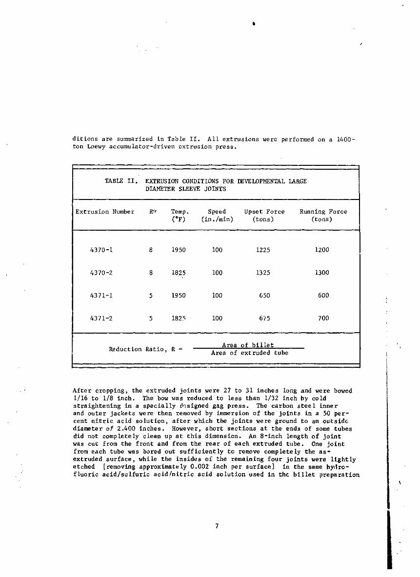
ditions are summarized in Table II. All extrusions were performed on a 1400-
ton Loewy accumulator-driven extrusion press.
TABLE II. EXTRUSION CONDITIONS FOR DEVELOPMENTAL lARGE
DIAMETER SLEEVE JOINTS
Extrusion Number R_ Temp. Speed Upset Force Running Force
(eF) (in./min) (tons) (tons)
4370-1 8 1950 i00 1225 1200
4370-2 8 1825 I00 1325 1300
4371-1 5 1950 I00 650 600
4371-2 5 1825 i00 675 700
Area of billet
Reduction Ratio, R = Area of extruded tube
After cropping, the extruded joints were 27 to 31 inches long and were bowed
1/16 to 1/8 inch. The bow was reduced to less than 1/32 inch by cold
straightening in a specially designed gag press. The carbon steel inner
and outer jackets were then removed by immersion of the joints in a 50 per-
cent nitric acid solution, after which the joints were ground to an outside
diameter of 2.400 inches. However, short sections at the ends of some tubes
did not completely clean up at this dimension. An 8-1nch length of joint
was cut from the front and from the rear of each extruded tube. One joint
from each tube was bored out sufficiently to remove completely the as-
extruded surface, while the insides of the remaining four joints were lightly
etched [removing approximately 0.002 inch per surface] in the same hydro-
fluoric acid/sulfuric acid/nitric acid solution used in the billet preparation%
7
XXXXXX- 15

procedure. Tables III and IV list the dimensions of these joints before and
after machining and etching. The eight j¢_:'_tswere shipped to the Westing-
house Astronuclear Laboratories for ultrasonic inspection.
The center and end sections of the extruded _leeves were used for evaluation
of the bond quality. Testing consisted of bend, stud-tensile, and notch-
fracture tests and metallographic examination of the tantalum - stainless
steel interface.
Bend Test -- Longitudinal strips of the entire tube wall were cut from
the joints. The edges were polished and inspected by fluorescent dye penetrant,
and no indications of voids or cracks were fcund. The specimens were then
bent cold a£ound a 1-inch pin and reinspected by fluorescent dye penetrant.
Again, no signs of separation were detected.
l
j-j
TABLE III. DIMENSIONS OF DEVELOPMENTAL LARGE DIAMETER
SLEEVE JOINTS AFTER REMOVAL OF CARBON STEEL !JACKETS
Joint Number Outside Diameter Length
Front Middle Rear
(in.) (in.) (in.) (in.)
S-8-1950 2.491 - 2.417 - 2.423 - 25 -1/22.422 2.422 2.424
S-8-1825 2.393 - 2.410 - 2.440 - 25 -3/42.395 2.414 2.441
S-5-1950 2.401 - 2.424 - 2.431 - 30 -1/22.401 2.428 2.432
S-5-1825 2.432 2.417 - 2.396 - 30-5/8
2.435 2.421 2.399J
, m,. ..., _J
XXXXXX-016

l
TABLE IV. OUTER AND INNER DIAMETERS OF DEVELOPMENTAL
LARGE DIAMETER SLEEVE JOINTS
Joint Number Condition Outside Diameter Inside Diameter
(in.) (in.)
S-8-1950 Machined 2.386- 2.386- 1.743- 1.745-
2.386 2.386 1.744 1.745
S-8-1825 Machined 2.376- 2.373- 1.756- 1.760-
2.376 2.373 1.757 1.761
S-5-1950 Machined 2.404- 2.404- 1.775- 1.771-
2.405 2.405 1.776 1.771
S-5-1825 Machined 2.400- 2.401- 1.750- 1.749-
2.402 2.401 1.751 1.751
m m m
t
S-8-1950 Etched 2.402- 2.403- 1.732- 1.732-
2.403 2.403 1.735 1.734
S-8-1825 Etched 2.400- 2.401- 1.733- 1.734-
2.401 2.401 1.736 1.736
S-5-1950 Etched 2.402- 2.404- 1.742- 1.742-
2.403 2.405 1.742 1.742
S-5-1825 Etched 2.401- 2.403- 1.736- 1.740-2.A02 2.403 1.739 1.743
• • ,,-,, i , , n __ ........
9
XXXXXX-O 17

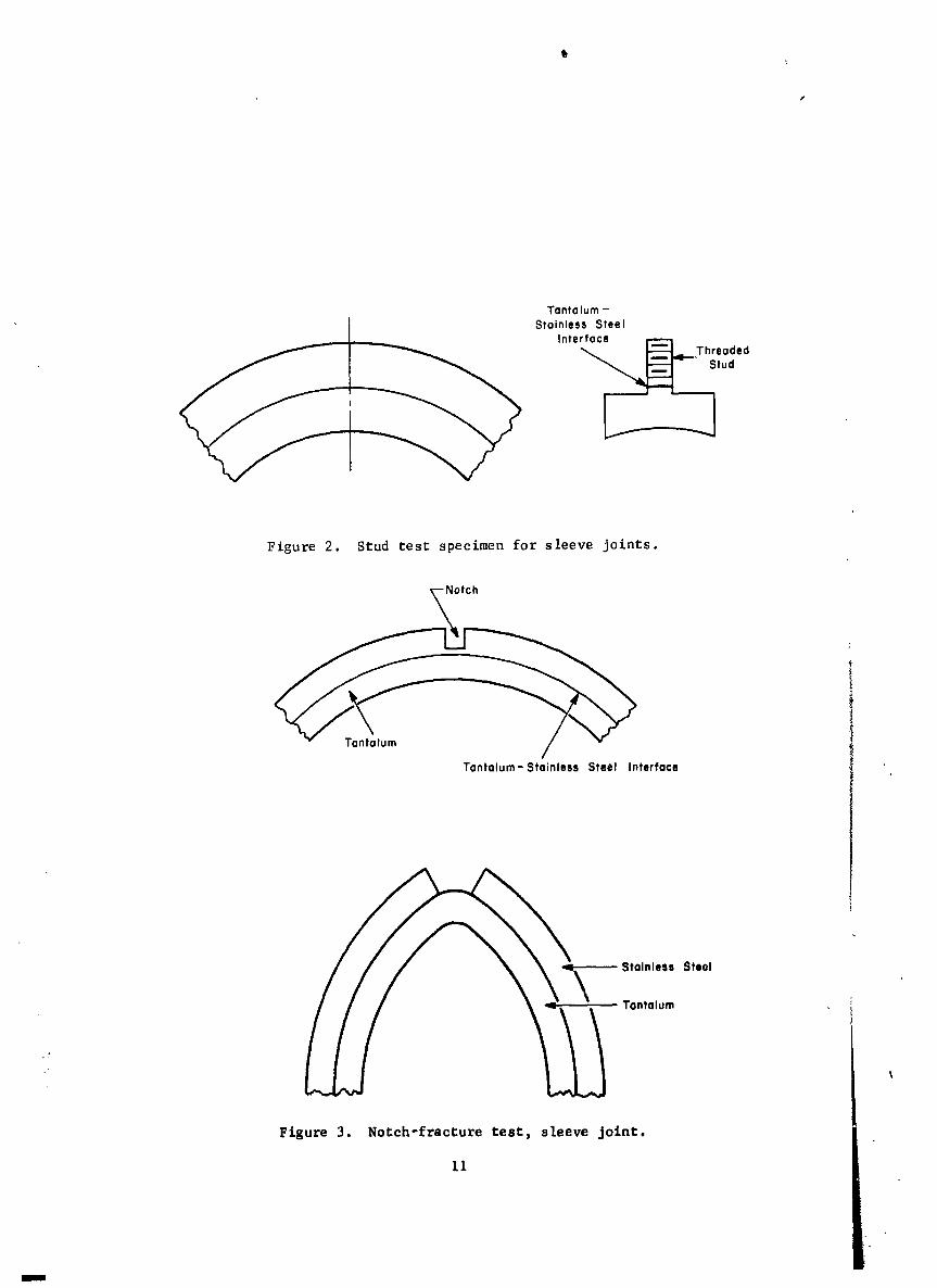
Stu___d Tests -- Stud test specimens as shown in Figure 2 were machined
from all sleeve joints. These were tested to failure, and the results of
these tests are shown in Table V. One specimen was destroyed accidentally.
All other specimens failed in the Joint area at ultimate strengths between
42,000 psi and 69,000 psi. One specimen failed in the threads at 74,000 psi.
In this specimen the bond was located very close to the base of the stud,
which may explain the higher strength on this test. The generally high values
for the strength of the bond is a further indication of the high quality of
the joints.
9 ,, , j
TABLE V. STRENGTH OF TANTALUM - STAINLESS STEEL INTERFACE
DETERMINED BY STUD TENSILE TESTS
Joint Number Front* Rear *
Stress at Failure Location Stress at Failure L0catlon
(psi) (psi)
S-8-1950 42,200 joint 61,400 joint
S-8-1825 broken before test 64,100 joint
S-5-1950 49,200 joint 58,600 joint
S-5 -1825 74,700** threads 69,000 joint
*specimen taken from front or rear of extruded sleeve joints
**Failed in the tantalum, at root of stud
Notch-Fracture Te.st --Notch-fracture tests, as shown schematically
in Figure 3, were carried out on strips cut from all extrusions. Because
of the thickness and the extreme degree of ductility of the tantalum, it
was possible to bend these specimens extensively without fracturing of the
material under the notch, which normally occurs in the testing of most other
materials. In each case, after considerable deformation, it was possible
to separate the stainless steel from the tantalum and to propagate the inter-
. face. This was neither alarming nor entirely unexpected, since this test _
• eventually forces a crack to propagate through the base material or the bond.
In the case of the stainless steel - tantalum bond at the thicknesses tested,
I
the bond line apparently offers the easiest path for this crack propagation.
I0
XXXXXX-O 18
Tantalum -Stainless Steel
Interface
"_ _Threaded
tud
Figure 2. Stud test specimen for sleeve joints.
OtCh
Tantalum-Stainless Steel Interface
\Stainless Steol
•"_ l , _ ' Tantalum%
Figure 3. Not:ch-fracture I:est, sleeve Joint.
li
m
XXXXXX-O 19
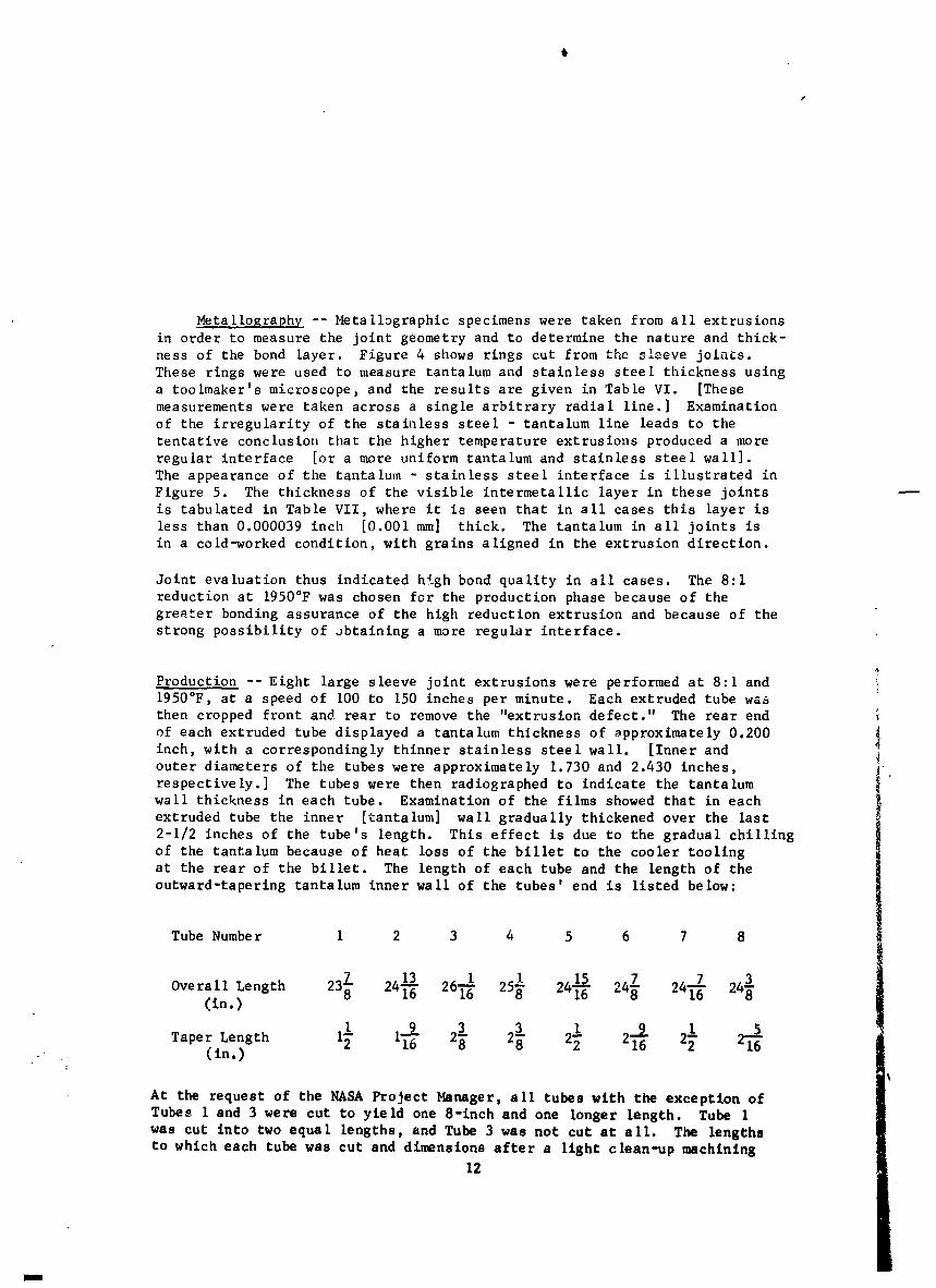
Metal lography -- Metallographic specimens were taken from all extrusions
in order to measure the joint geometry and to determine the nature and thick-
ness of the bond layer. Figure 4 shows rings cut from the _leeve joints.
These rings were used to measure tantalum and stainless steel thickness using
a toolmaker's microscope, and the results are given in Table VI. [These
measurements were taken across a single arbitrary radial line.] Examination
of the irregularity of the stainless steel - tantalum line leads to the
tentative conclusion that the higher temperature extrusions produced a more
regular interface [or a more uniform tantalum and stainless steel wall].
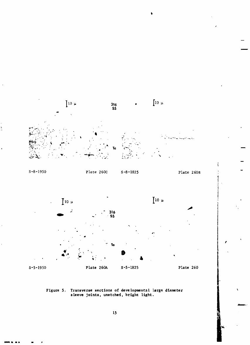
The appearance of the tantalum - stainless steel interface is illustrated in
Figure 5. The thickness of the visible intermetallic layer in these joints
is tabulated in Table VII, where it is seen that in all cases this layer is
less than 0.000039 inch [0.001 ram] thick. The tantalum in all joints is
in a cold-worked condition, with grains aligned in the extrusion direction.
Joint evaluation thus indicated high bond quality in all cases. The 8:1
reduction at 1950°F was chosen for the production phase because of the
greater bonding assurance of the high reduction extrusion and because of the
strong possibility of obtaining a more regular interface.
Production -- Eight large sleeve joint extrusions were performed at 8:1 and
1950°F, at a speed of I00 to 150 inches per minute. Each extruded tube wa_
then cropped front and rear to remove the "extrusion defect." The rear end
of each extruded tube displayed a tantalum thickness of approximately 0.200
inch, with a correspondingly thinner stainless steel wall. [Inner and
outer diameters of the tubes were approximately 1.730 and 2.430 inches,
respectively.] The tubes were then radiographed to indicate the tantalum
wall thickness in each tube. Examination of the films showed that in each
extruded tube the inner [tantalum] wall gradually thickened over the last
2-1/2 inches of the tube's length. This effect is due to the gradual chilling
of the tantalum because of heat loss of the billet to the cooler tooling
at the rear of the billet. The length of each tube and the length of the
outward-taperlng tantalum inner wall of the tubes' end is listed below:
Tube Number 1 2 3 4 5 6 7 8
Overall Length 237 24_6 26_ 251 24II-_6 247 24_ 243(in.)
.+ . (in.)
At the request of the NASA Project Manager, all tubes with the exception ofTubes 1 and 3 were cut to yield one 8-inch and one longer length. Tube 1
was cut into two equal lengths, and Tube 3 was not cut at all. The lengths
to which each tube was cut and dimensions after a light clean-up machining12
m
XXXXXX-020
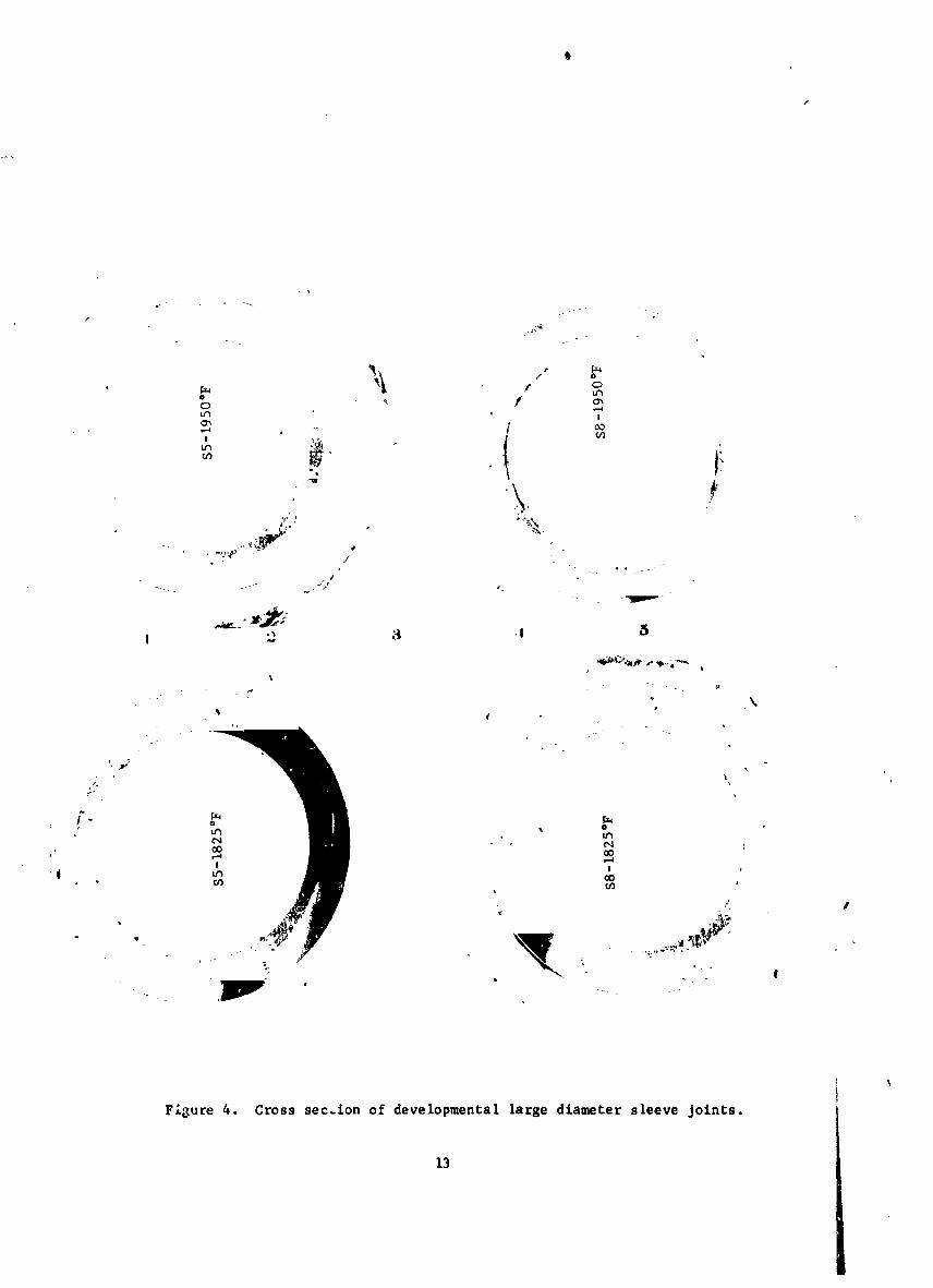
Fi_,ure 4. Cross sec,ton of developmental large diameter sleeve joints.
13
XXXXXX-021

TABLE VI. TANTALUM AND STAINLESS STEEL WALL THICKNESSFOR DEVELOPMENTAL lARGE DIAMEII_R JOINTS
Joint Number Wall Thickness Gin.)Tantalum Stainless Steel
S-8-1950 .1083 .2275
S-8-1825 .1002 .1982
S-5-1950 .1122 .2191
S-5-1825 .1130 .2202
i
TABLE Vll. THICKNESS OF THE TANTALUM - STAINLESS STEEL INTERMETALLIClAYER FOR DEVELOPMENTAL lARGE DIAMETER JOINTS
Joint Number Layer Thickness
(lO'SLn.)
S-8-1950 3.6 I
!S-8-1825 2.4
S-5-1950 3.6
S-5-1825 2.4 "
14
XXXXXX-022
lO _ 316 o [10SS
:-_ _.,_ og ,. • o . ; .. e" L " ,. . .'' • ''-
_- -' .... ' II ",_,. :.' ,g . . :-, : • , _ _: "....._
• r. .-'':. . " ..;.
i
5-8-1950 Plate 260C S-8-1825 Plate 260B
" [iolO _ '
-" " 316-" • SS
o
e
A
,i
_',e _ • •• &#
S-5-1950 Plate 260A S-5-1825 Plate 260
Figure 5. Transverse sections of developmental large diametersleeve Jolnts, unetched, brlghc light.
i
15
llIq ml am I r
XXXXXX-023

cut are given in Table VIII. The joints were then forwarded to Westinghouse
Astronuclear Laboratory for non-destructive evaluation.
Bend, ,lotch-fracture, an_ stud tests were performed as on the developmental
joints. All test results were equally positive in that no defects of any type
were indicated. No flaws were detected by fluorescent penetrant techL_iques on
the bend test samples, As in the case of the prototype joints, the notch-
fracture tests all produced eventual separation of the tantalum and stainless
steel components. The stud tensile tests [two samples from each tube] yielded
a minimum tensile strength of 44,400 psi and an average strength of over
49,000 psi, excluding the unexplained high strength [73,600 psi] of the
samples from T, be i. Test results are tabulated in Table IX,
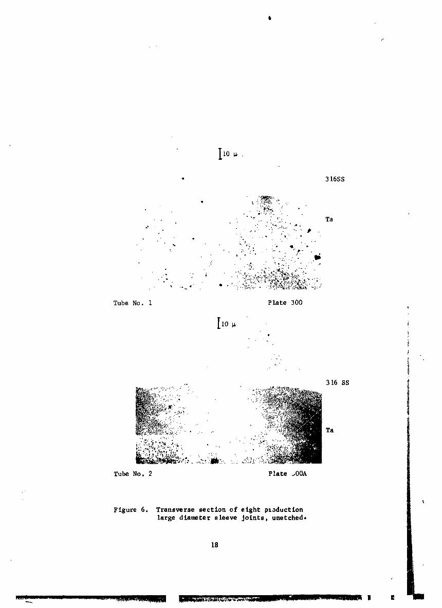
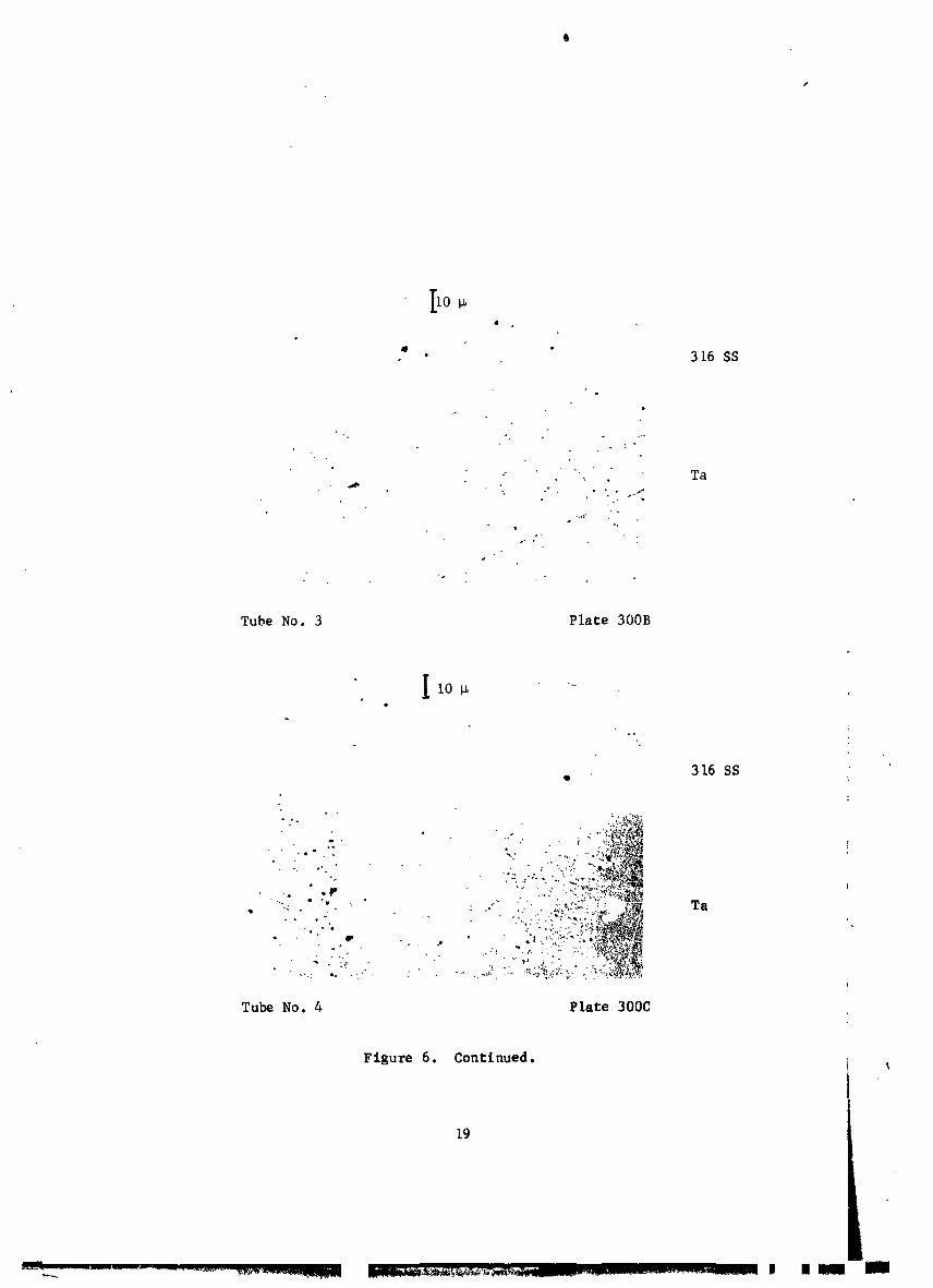
Photographs of the tantalum - Stainless steel interface for the eight joints
are shown in Figure 6. Table X lists the respective thicknesses of the stain-
less steel, tantalum, and intermetallic layers.
TABLE VIII. DIMENSIONS OF PRODUCTION LARGE DIAMETER SLEEVE JOINTS
Tube No. Length (in.) OD (in.)" ID (in.)
Front* Middle (at cJt) Rear
i -Front* iI- i/2 2.260 I.716 i.735 .....
Rear 11-I/2 2.370 ..... i.736 I. 767
2-Front 8 2.364 i.721 I.727 .....
Rear 15-3/8 2.307 ..... I.734 i. 763
3 24-1/4 2.414 i.721 ..... i.763
!
-Front 15-3/8 2.369 i.730 i.735 .....
Rear _ 2.361 ..... i.735 i.761
5-Front 8 2.297 1.724 1.732 .....
Rear 14-1/2 2.333 ..... I.731 i.764f
5-Front 14-3/4 2.253 I.725 i.737 .....
Rear 8 2.395 ..... i.733 I.752
7-Front 14-1/2 2.285 I.734 i.739 .....
Rear 8 2.308 ..... 1.730 1.761
3-Front 8 2.351 I.721 I.732 .....
Rear 14-1/4 2.371 ..... I.734 i.760
*Front, Middle, and Rear refer to positions along the extruded tube;
e.g., Middle is at the rear of the front section, or the front of arear section.
r _-. , ,, . , • . i J .........
16
XXXXXX-024

@
1
TABLE IX. BOND STRENGTH OF PRODUCTION LARGE DIAMETER SLEEVE JOINTS
_ube Number I 2 3 4 5 6 7 8
Jltimate Tensile 73.6 48.7 43.6 54.0 52.8 44.4 53.0 49.7
Strength* (psi x I000)
*Average of two test samples.
TABLE X. CROSS SECTIONAL DIMENSIONS OF PRODUCTION LARGE DIAMETER
SLEEVE JOINTS
Tube Number Ta Thickness SS Thickness Intermetallic Thickness
(in.) (in.) (10"5 in.)
1 .169" .174. 7.2
2 .099 .226 3.6
3 .118 .249 7.2
4 .113 .230 3.6
5 .137 .228 7.2
6 .108 .230 7.2
7 .Ii0 .230 7.2
8 .I01 .247 14.5
.... . |
*Sample taken in region of extrusion defect, t
!
i
××××××-025
" 3 16SS
Figure 6. Transverse section of eight ptoductlonlarge diameter sleeve Jolnts, unetched.
18
XXXXXX-026
i0
4 °• 3 16 SS
-. •.•
" Ta
• o...,
°-
Tube No. 3 Plate 300B
II0_ -
316 SS
+
.%
-- ,7 _-J*
• "_" " "" : Ta
Tube No. 4 Plate 300C
Figure 6. Continued.
19

IlO_
316 SS
• o f - ,
? ••4i" Ta
..
Tube No. 5 Plate 300D
q_
, Ii0 _
316 SSo
, , -' "".
: • _.,_r_.. , • ,,, , • . ., .
,. .... _.,_,..,,,,_,.,-,, ,_.Ta
. Tube No. 6 Plate 300E
Figure 6. Continued,
20

i0
3 16 SS
Ta
O
Tube No. 7 Plate 300F
?
[1o.
J3 16 SS
tTa
-_. . .
Tube No. 8 Plate 300G
Figure 6. Continued.
21
._ _ __ LL_ ' • - = " L'_ " lira I Ilillllllmll_
XXXXXX-029
The discrepancy between the component dimensions for Tube 1 aud the othertubes may explain the higher tensile values recorded in stud testing Tube i.
The thicker tantalum layer in this sample indicates that the ring from which
the sample was cut was still part of the non-unlform rear extrusion defect,and as such would not be expected to give typical results.
Small Diameter Sleeve Joints
Development -- A pair of small diameter sleeve joint billets were assembled
and extruded using the same procedures described for the large diameter sleeve
joints. A reduction ratio of 8:1 was used for both billets, one of whichwas extruded at 1825°F and one at 1950°F [Table XI].
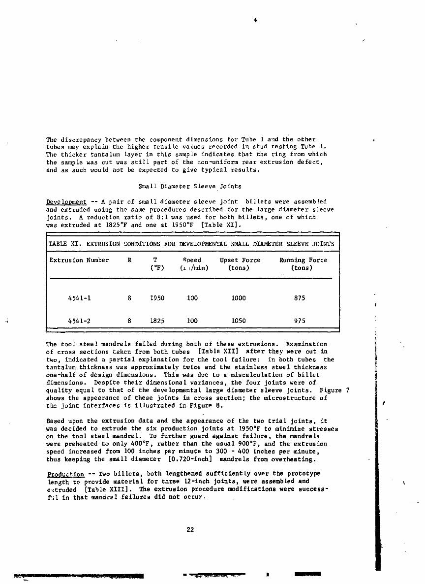
TABLE XI, EXTRUSION CONDITIONS FOR I_EVELOPMENTAL SMALL DIAMETER SLEEVE JOINTS
Extrusion Number R T _eed Upset Force Running Force
(°F) (11/min) (tons) (tons)
, J . . , . .. ,
4541-1 8 1950 i00 I000 875
-.i 454 i-2 8 1825 i00 1050 975
The tool steel mandrels failed during both of these extrusions. Examinationof cross sections taken from both tubes [Table XII] after they were cut in
two, indicated a partial explanation for the tool failure: in both tubes the
tantalum thickness was approximately twice and the stainless steel thickness
one-half of design dimensions. This was due to a miscalculation of billet
dimensions. Despite their dimensional variances, the four joints were of
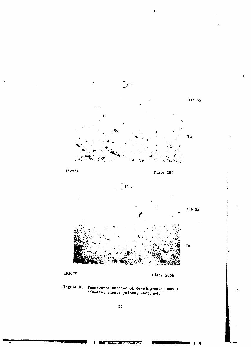
quality equal to that of the developmental large diameter sleeve joints. Figure 7shows the appearance of these joints in cross section; the microstructure of
the Joint interfaces is illustrated in Figure 8. t
Based upon the extrusion data and the appearance of the two trial joints, it
was decided to extrude the six production joints at 1950°F to minimize stresseson the tool steel mandrel. To further guard against failure, the mandrels
were preheated to only 400°F, rather than the usual 900°F, and the extrusion
speed increased from I00 inches per minute to 300 - 400 inches per minute,
thus keeping the small diameter [0.720-inch] mandrels from overheating.
p_gductlon -- Two billets, both lengthened sufficiently over the prototypelevgth to provide material for three 12-1nch Joints, were assembled ande'_truded [Table XIII]. The extrusion procedure modifications were success-ful in that mantis-elfailures did not occur,
22
m
_=_
××××××-030

TABLE XII. AS-EXTRUDED DIMENSIONS OF DEVELOPMENTAL SMALL
DIAMETER SLEEVE JOINTS
Front Midd le Rear
[8250F
ID (in.) 0.733 0.737 0.736
Ta thickness (in.) 0.215 0.220 0.202
SS thickness (in.) 0.131 0.124 0.133
OD (in.) 1.425 1.422 1.422-5
SS - Ta intermetallic (I0 in.) 3.6 3.6 3.6
1950OF
ID (in.) 0.720 0.758 0.767
Ta thickness (in.) 0.223 0.206 0.237
SS thickness (in.) 0.140 0.131 0.109
OD (in.) 1.425 1.436 1.440
SS - Ta intermetallic (10-5 in.) 2.4 2.4 2.4
TABLE Xlll. EXTRUSION CONDITIONS FOR PRODUCTION SMALL
DIAMETER SLEEVE JOINTS
_xtrusion Number R T Speed Upset Force Running Force
(°F) (in./min) (tons) (tons)
4599-1 8 1950 400 900 800
4634-1 8 1950 300 825 750
23
XXXXXX-031

24
XXXXXX-032
P
IIo
316 SS
,% ,
j
•• °
_. Ta
. _ -" .. - & s.i
• "- J :i
1825°F Plate 286
IIo _L
Figure 8. Transverse section of developmental smalldiameter sleeve Joints, unetched.
25

0
I
The first tube, after cropping and removal of the carbon steel extrusion
can, had the dimensions shown in Table XIV. This tube was cut into three
joints, each 10-1/2 inches long, plus two 4-inch evaluation lengths. Exam-
ination with a toolmaker's microscope of the samples cut from the front and
rear of the tube yielded the dimensional data [wall thickness and filar
or intermetallic layer measurements] shown in Table XV. The greater
apparent thickness of the tantalum [_nd correspondingly thinner stainless
steel] shcwn at the rear of the extrusion is again only an indication that
this sample is located within the extrusion defect region of the tube.The microstructure of the tantalum - stainless steel interface at the front
and rear of this extrusion is shown in Figure 9. Bend and notch-fracture
tests yielded result_ similar to all other sleeve joints, with separation
occuring in notch-fracture but not in bending.
The second small diameter sleeve joint extrusion was shipped to NASA in one
piece, after acid removal of the steel and a bright etch.
Tandem Joints
Development --Four tandem joints were extruded under the conditions listed
in Table XVI. Figure i0 illustrates a typical billet design for tandem joints.
Dimensions of these eight joints after acid removal of the carbon steel cans
i
TABLE XIV. DIMENSIONS OF FIRST PRODUCTION SMALL DIAMETER
SLEEVE EXTRUSION
Front Midd le Rear
Outside diameter (in.) 1.423 1.428 1.450
Total wall thickness (in.) 0,332 ..... 0.332
Tantalum thickness (in.) 0.I0 ..... 0.12
Stainless steel thickness (in.) 0._3 ..... 0.21
Length (in.) ............... 41-7/8 .............
i , = |i
.... - -- • -- ,m
i26
XXXXXX-034
E
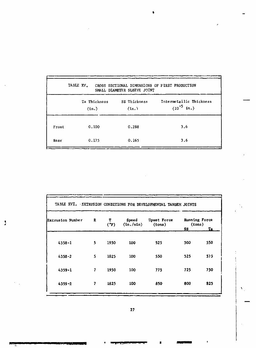
TABLE XV. CROSS SECTIONAL DIMENSIONS OF FIRST PRODUCTIONSMALL DIAMETER SLEEVE JOINT
Ta Thickness SS Thickness Intermetaillc Thickness
(in.) (in._ (10-5 in.)
Front 0.100 0.288 3.6
Rear 0. 175 0.165 3.6
TABLE XVI. EXTRUSION CONDITIONS FOR DEVELOPMENTAL TANDEM JOINTS
] Extrusion Number R T Speed Upset Force Running Force(°F) (In./mln) (tons) (tons)SS Ta
4358-I 5 1950 I00 525 500 550
4358-2 5 1825 100 550 525 5)5
4359-1 7 1950 100 775 725 750
4359-2 7 1825 100 850 800 825
i | i ii i i j i
27
XXXXXX-035

10D
316 SS
" Ta '
%
.
Front Plate 300G
I10 _ t
316 SS
o
Rear Plate 300H%
Figure 9. Transverse section of production small
diameter sleeve Joint, unetched.
28
XXXXXX-036

'i
29
XXXXXX-037
are listed in Table XVII. The joints were then machined to 2.000-inch out-
side diameter by 1.760-inch inside diameter by approximately 8 inches long.[Figure ii].
The four joints showed no defects when inspected for leaks by the helium mass
spectrometer and for bond separation by fluorescent dye penetrant. Longitudinal
test specimens were then cut from each joint. No sign of joint separationoccurred in any of the bend test samples. Notch fracture tests were performe_
by cutting through the stainless steel to the bond line and then bending the
joints, with the cut on the outside of the bend. As in the case of the
sleeve joints, the tantalum and stainless steel components separated at thenotch, in all cases.
Measurement of the tantalum - stainless steel intermetalllc [Table XVIII]
showed values similar to those obtained for the sleeve joints. The length
of each joint interface was measured under the microscope:
Joint : 5-1950 5-1825 7-1950 7-1825
Interface Length (in) 0.93 0.92 1.62 1.83
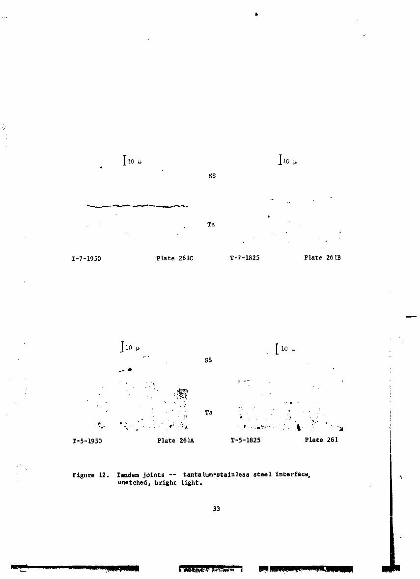
Figure 12 illustrates the microstructure of the interface region for the fourjoints. It can be seen that, with the exception of the 7:1/1950°F joint,all interfaces are clean and free of voids or inclusions. In the case of
the 7:1/1950°F joint, a thin layer [tentatively identified as an oxide]
separated the two components in an almost continuous layer. Considering thedata presented above for the sleeve joints and for the other three tandem
joints, it is fair to say t%at this black layer was not inherent to the
extrusion process, but rather represented foreign material initially presenton either the tantalum or stainless steel surface. Its thickness was no
greater than the i:,termetalllc layer present on the 5:1 tandem joint extrudedat the same temperature.
Since both of the joints extruded at 1825°F were completely free of defects
and contained intermetallic layers only half as thick as the 1950°F joints,it was decided to extrude the production joints at 1825°F and 5:1 reductionratio. The 5:1 reduction ratio was chosen because the interface over the
entire length appeared better than that extruded at 7:1.
It is considered desirable for the interface length in a tandem Joint to be
approximately 1-1/2 inches long. As indicated above, the 5:1 tandem Jointshad interfaces less than 1 inch long. Therefore, to lengthen the interface,it was necessary to preshape the mating tantalum and stainless steel inter-face surfaces in the billet. [This is frequently done, but in the oppositemanner, in the extrusion of nuclear fuel elements where it Is desired to attain
3O
r,
XXXXXX-038

TABLE XVII. AS-EXTRUDED DIMENSIONS OF DEVELOPMENTAL
TANDEM JOINTS
Joint Outside Diameter (in.)_ Inside Diameter (in.)
SS Joint Line Ta SS Ta
5-1825 2.198 2.215 2.225 1.555 1.580
5-1950 2.200 2.226 2.228 1.560 1.585
7-1825 2.278 2.184 2.204 ---Not measured---
7-1950 2.180 2.200 2.190 ---Not measured--- •
TABLE XVIII. THICKNESS OF TANTALUM - STAINLESS STEELINTERMETALLIC lAYER
Joint Number Intermetallic Thickness (10-5 in.)
T-5-1825 3.6
T-5-1950 7.2
T-7-1825 3.6
T-7-1950 7.2
31
I
XXXXXX-039

W
I: "I
"_...>.
5:1 / 1825°F 7:1 / 1825°F 5:1 / 1950°F 7:1 / 1950°F
Figure Ii. Prototype tandem jolnts.
32
XXXXXX-040
Ii0 _ Ii0Q
SS
°.
Ta
T-7-1950 Plate 261C T-7-1825 Plate 261B
+
llo+ 11o+SS
_w O
,, ..':-'- ., _,. •+ . + e
.. Ta " :
T-5-1950 Plate 261A T-5-1825 Plate 261
Figure 12. Tandem Joints -- tantalum-stainless steel interface,unetched, bright light.
33
XXXXXX-041

a short, sharply defined interface between the end of the fuel and the end
closures°] In the present situation, it was calculated that a simple bevel,
0.4 inch long, would satisfactorily lengthen the Joint interface. A single
tandem joint billet was therefore assembled in which the stainless steel wasmachined so that it was 0.4 inch shorter on the inside than on the outside.
A corresponding bevel was machined on the mating end of the tantalum com-
ponent. The billet was extruded at 1825°F at a 5:1 reduction ratio and
machined to 2.000 inches outside diameter by 1.760 inches inside diameter.
The joint passed mass spectrometer inspection and fluorescent pe_etrant in-
spection and was then sectioned. Figure 13 illust;'ates the bond line which
was clean and sound. The interface length had bee _, increased from 0.93 inch,
in the case of the 5:1 joints with plane ends, to ].22 _ inches in the present
case. This interface length was acceptable to NASA, _nd the decision was
made to produce the production joints by the same procedure.
Production -- Twelve tandem joints were extruded aL 1825°_ at a 5:1 reduction
ratio. Extrusion speed for all joints was I00 inches per m_n'_ -_" the upset
force was 675 tons; the running force was 750 tons. After a¢= :emoval of
the carbon steel jackets, the joints were machined to 2.000 inch_s outside
diameter by 1.760 inches inside diameter by 8 inches long [Figure 14].
All joints passed helium mass spectrometer and fluorescent penetrant inspection.
Bimeta llic Tubing
Development -- The first cf two subscale billets was machined and assembled
as shown in Figure 15. The manganese steel core piece served as the solid
central filler during extrusion and was to be removed after extrusion by
utilizing its exceptional strain hardening characteristics. The core was
separated from its containment can by a thin layer of parting agent. The
core/parting agent/contalnment can assembly was separate, inside the hermeti-
cally sealed stainless steel/tltanium package.
Tantalum loll 0.011 inch thick by 3 inches wide was wrapped seven and one-
half times around the outside of the inner steel can to form the cylindricaltantalum billet component. The stainless steel and tantalum were purchased
to the same specifications used for the sleeve and tandem joints. Since316 stainless steel of the proper size was not readily available, 304 stain-
less steel was used. Billet preparation procedure was the same as used for
the joints except that the tantalum was not etched.
The billet was evacuated, outgassed, sealed off, and heated following standard
procedures. The composite rod/tube was extruded satisfactorily at 1950°Fthrough a 0.565-inch die and after cropping was 69 inches long.
34
XXXXXX-042

3 16 SS
Ta
500X Plate 286B
I0 _ !t
t
. 316 SS
2000X Plate 268C
Figure 13. Interface of 5:1/1825°F tandem Jointcontaining beveled interface, unetched.
35
××××××-043
Figure 14. Production tandem Joints.
35
IIIII l I I ._ la
XXXXXX-044

XXXXXX-045
A tube cutter was used to remove the ends from the outer steel can, the stain-,
less steel/tantalum tube, the inner steel can, and the core containment can.
The core rod was then gripped in a drawbench and pulled, resulting in necking
and hardening of successive sections such that the core became small enough
to be pulled out. The remaining tube was then immersed in a 30 volume percent
aqueous nitric acid solution to dissolve the inner and outer carbon steelcans. Dimensions of this tube are given in Table XIX.
TABLE XIX, CROSS SECTIONAL DIMENSIONS OF TANTALUM-LINED 304 STAINLESS
STEEL TUBE NO. I MADE FROM WRAPPED TANTALUM SHEET
Pos'.tion OD (in.) ID (in.) Ta Thickness (in.) SS Thickness (in.)
Front .430 .310 .014 - .019 .042 - .045
Middle .407 .306 .011 - .017 .033 - .035
Rear .407 .304 .012 - .017 .035 - .037
Objective .416 .326 .0125 .032
The greater thickness of the tantalum and stainless steel components at the i
front end of the tube indicate that this sample is s_ill in the "extrusiondefect" region.
Figure 16 illustrates the microstructure of the tantalum lining where itcontacts the stainless steel. Interfaces can be seen between the stainless
steel and tantalum and between most of the tantalum layers. As the photo-
graph indicates, the inner tube surface is smooth.
5O
• 3 16 SS
........"...":..,,-r%.,-'."-,'&._.'..C,',.'*_-; ,e__ • .- _-........_4P
%
Figure 16. Cross section of subscale tantalum-llned stainless steel Tube t,made from 0.010 inch tantalum sheet, IOOX, Plate 314B.
38

i
A second billet was assembled, similar to the first in all respects except
that the tantalum sheet was 0.015 inch thick to allow for acid pickling prior
to the assembly process. The tantalum was degreased and etched in a solution
of hydrofluoric acid, sulfuric acid, and nitric acid to remove approximately
I railof metal from the sheet surfaces. The tube was processed in the samemanner as Tube 1 and resulted in similar dimensions. The photomicrographs of
the tube (Figure 17) show that an interface is stil] visible bet,.een the tan-talum and stainless steel and between the tantalum layers at the front andmiddle oi the tube but that no tantalum/tantalum interface_ can be seen at
the rear of the tube. The rough inner surface of the tube may have been
caused by the pre-extrusion etching of the tantalum.
Because the acid cleaning of the tantalum produced such variable bonding resultsand because the 0.015-inch tantalum was more difficult to work with, it was
decided to produce the full size tube from 0.Ol0-inch sheet, cleaned buc notetched.
Production -- The production billet was assembled as showltin Figure 18,
utilizing i0 feet of 12-inch wide 0.010-inch thick tantalum sheet. A_semblyand extrusion were performed as before, producing a composite rod 0.861 inch
in diameter by 20 feet long. Attempts to pull the manganese steel core frem --the tube were unsuccessful due to surface cracks in the core rod. It is believed
that the longer heating time [as compared to the subscale tubes] required
for this larger billet caused a surface reaction between the manganese steeland parting agent, transforming the tough austenite phase to the weaker and
more brittle ma_tensite structure. The -ore was removed by an acid drilling
technique. Dimensions at the center of this tube are given in Table XX.
, TABLE XK. CROSS SECTIONAL DIMENSIONS AT THE CENTER OF FULL SIZE
TANTALDM-LINED STAINLESS STEEL TUBE FROM WRAPPED SHEET
OD (in.) ID (in.) Ta Thickness (in.) SS Thickness (in.)
Actual* .805 .632 - .634 .025 - .026 .065
Obtect ire .0625 .020 .060
*Afte_ belt sanding
The oversize wall dimensions are a result of the cumulative clearances in the
billet [which were larger than for the 3-inch long subscale billets]. Thisalso resulted in the tube not achieving the target length of 25 feet.
Figure 19 illustrates the tube microstructure at the front, center, and rear. -It can be seen that the tantalum bonding is of variable quality: The inner-
most tantalum layer [relative to the tube ID] is unbonded at the front, _nd _ _the outer_o_et layer has separated from the tantalum and the stain=ess steelat the middle and rear of the tube.
39
t
XXXXXX-047

iii
"" XXXXXX-048
1
t,
2:oI-
:3:3
Ji LI.I i,I
/ ..11 ";ISON )IOIH.I. ,,_ X'VlQ 08_'_' (8) n."LJ.I
_ -- 0
) = A,,do_ \o z
"'g ,,111110\,,,- ,,. -',_l_", 9_% \
o,__ ; /1111111\ " "-•' """1 . . •
4 Illll m
IltlflV \ =
'X. iiiiiii/ \ _ "_
'X. IHIIII/ ...... _ M XX _0 ,u
........ _ X ,-,c;,,,,, ....... _ ...... d " "_ ,,J
-- -- z I lillll _ \ _ ro t
'X,. It11111/ ¢i.. -._ ¢1 u
"" ,wv _; :,:: \ _,j=
..... "= =
=___ _i (30
IHIV "== \
)',_ lib' '_ "_\ .._=-i, \
IM
'_ ZbJ:tl,. O- _._ . 0
_.,._ _ n, ZO--
k.
--- I
_ .... _ ......... _ _ _"_-_ _ _.,l_.'.ele_l .............
XXXXXX-049
3 16 SS
o
• +. ,.
.+
..+ -_'-" - _+''-_-+'''+"_'+_+'+ "_"_,+-_+" -+'_ -+.t.-i,_.__,'- ,+."_--_. +._
,.. + + • .., -+#.._-i .+_._....+ I-_.i ,t_ + ++f. _ ++-_.+ %'' *_. -% . ."_ • "...++" L"
+..,-.,,,,_. ,-.- ..,.- .-,....• - .+ __ • _-_lj__,,,. .+ ]
i
- .- 50 _ /k----4
a) Front, IOOX
Figure 19. Cross sections of full-size tantalum-linedstainless steel tube made from O.OlO-inch
tanta lure sheet.
4Z
CONCLUSIONS
Techniques were developed for the fabrication by hot extrusion of sleeve and
tandem tantalum - 316 stainless steel joints. The sleeve joints were 0.76 and
1.76 inches inside diameter. The tandem joints were 1.76 inches inside diameter.
The tested joints were all leak tight and showed no signs of non-bond. Tensile
strengths of over 40,000 psi transverse to the bond line were obtained for
the large sleeve joints.
It was demonstrated that high quality tandem joints can be made at 1825°F at
a reduction ratio of 5:1. High quality sleeve joints can be made at 1950°F
at a reduction ratio of 8:1. The sleeve joints offer the quality assurance
advantage that samples may be taken from regions adjacent to the joint without
affecting the joint itself.
The brief composite tubing investigation indicates that tubing can be made
by a wrapped sheet filled billet technique but that the procedure used
cannot produce uniformly satisfactory tantalum/tantalum or tantalum/stainless
steel bonds for a 0.652-inch, 25-foot long tube. It is possible that further
work could establish the precise nature of the bonding difficulties which
would result in a technique for producing tubes with the same bond quality as
the sleeve and tandem joints.
An alternate and more reliable route for introducing fine grain tantalum intc
the extrusion billet would be to use pressed-and-sintered tantalum powder as
starting material. The powder billet would produce even smoother inner surfaces
in the extruded tube, based on its very fine grain size and isotropic condition.
A second, though more costly, alternative would be to refine the grain size
of wrought tantalum by a redundant working scheme in which the cast bar is
reduced in size by forging or extrusion at a low temperature, upset back to
its original size, and then annealed at a low temperature. The cycle can be
repeated as often as is necessary to achieve the desired grain size. A 3ingle
cycle consisting of 75 percent cold work [total] plus a one-hour anneal at
2100°F has been used to refine the as-cast grain size of a 3-3/4 inch dimaeterbar to ASTM 5 - 6.
43
XXXXXX-051

REFERENCES
G. I. Friedman, Whittaker Corporation/Nuclear Metals Division, "Grain
Size Refinement in a Tantalum Ingot," Contract C-46194-B for
National Aeronautics and Space Administration/Lewis Research
Center, 28 March 1969.
Robert G. Jenkins, Whittaker Corporation/Nuclear M_taIs Division, "Process
Development and Pilot Production of Tantalum Lined 316 Stainless
Steel Tubing," Contract NAS 3-9435 for National Aeronautics and
Space Admlnistration/Lewis Research Center, 30 October 1967.
f
]
.L
i
44
XXXXXX-052