y axis backlash reduction.1 - rick's web site
TRANSCRIPT

R. G. Sparber May 4, 2015 Page 1 of 8
Reducing X and Y Axis Backlash on a
RF-30 Mill/Drill, version 1.1
By R. G. Sparber Copyleft protects this document.
1
Conclusion My X axis backlash went from 0.038 inches down to 0.006 inches. My Y axis
backlash went from 0.037 inches down to 0.013 inches.
In the Beginning�
"Wow! .038" backlash is terrible." That was the
opening comment from Dan Mauch of the
mach1mach2cnc Yahoo group. Of course, he was
absolutely right. Never bothered me when I was
manually machining but as I continue to get CNC
to work on my RF-30, it has become a problem.
Where does backlash come from? Most people
quickly point to the take up nut that engages with
the leadscrew. It has an adjustment that can take
out wear and keep backlash "reasonable".
However, there is a second source of backlash
that is not as obvious and turned out to be much
larger: play in the thrust bearings.
1 You are free to distribute this article but not to change it.
R. G. Sparber
Background Plenty of knowledgeable people in the Mach1/2
and Y lead screws with ballscrews.
leadscrews.
At least at this time, I would rather see how far I can push the existing leadscrews.
I know they can't be as tight as ballscrews but I do have plenty of room for
improvement.
Y Axis Backlash Reduction
When I tested the Y backlash, it had not improved very much. It was then that I
realized that the bearing might be a second source of backlash.
May 4, 2015
people in the Mach1/2 group urged me to replace my X
and Y lead screws with ballscrews. Ballscrews have far less backlash
At least at this time, I would rather see how far I can push the existing leadscrews.
I know they can't be as tight as ballscrews but I do have plenty of room for
Y Axis Backlash Reduction
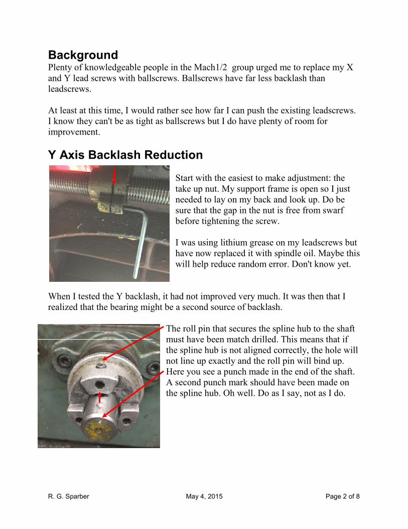
Start with the easiest to make adjustment: the
take up nut. My support frame is open so I just
needed to lay on my back and look up. Do be
sure that the gap in the nut is free from swarf
before tightening the screw.
I was using lithium grease on my leadscrews b
have now replaced it with spindle oil. Maybe this
will help reduce random error. Don't know yet.
When I tested the Y backlash, it had not improved very much. It was then that I
realized that the bearing might be a second source of backlash.
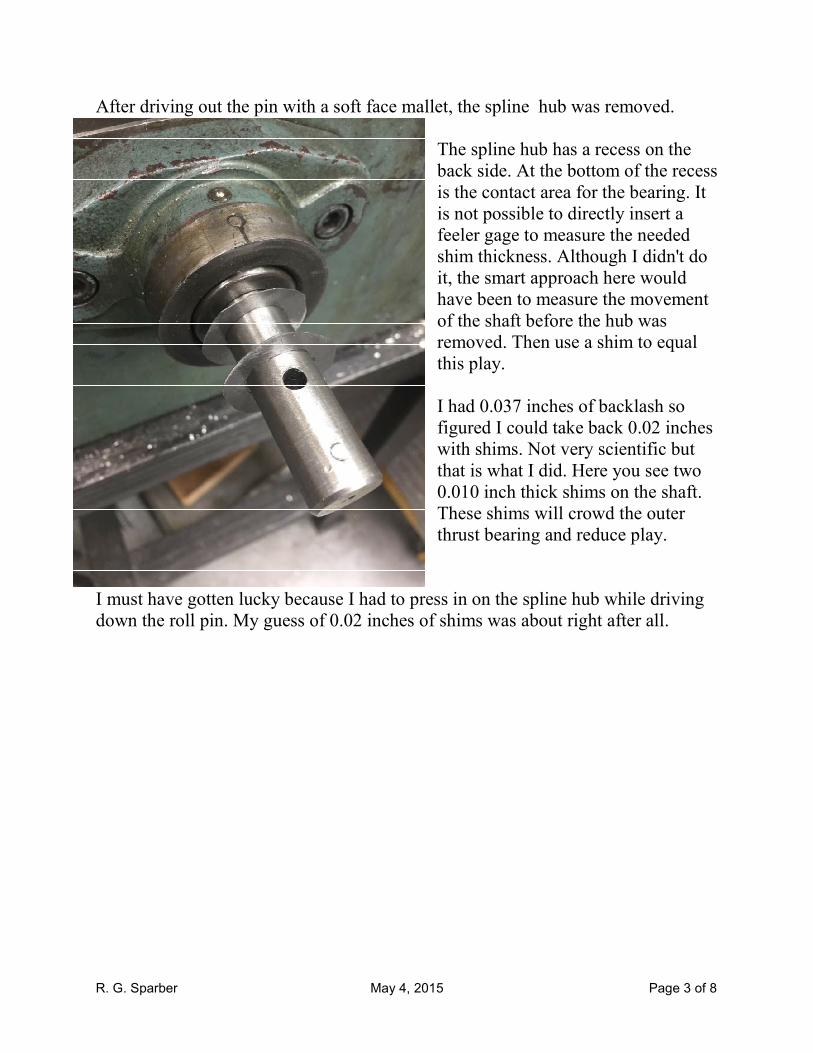
The roll pin that secures the spline hub
must have been match drilled. This means that if
the spline hub is not aligned correctly, the hole will
not line up exactly and the roll pin will bind up
Here you see a punch made in the end of the shaft.
A second punch mark should have been made on
the spline hub. Oh well. Do as I say, not as I do.
Page 2 of 8
group urged me to replace my X
have far less backlash than
At least at this time, I would rather see how far I can push the existing leadscrews.
I know they can't be as tight as ballscrews but I do have plenty of room for
with the easiest to make adjustment: the
take up nut. My support frame is open so I just
needed to lay on my back and look up. Do be
sure that the gap in the nut is free from swarf
I was using lithium grease on my leadscrews but
have now replaced it with spindle oil. Maybe this
will help reduce random error. Don't know yet.
When I tested the Y backlash, it had not improved very much. It was then that I
hub to the shaft
This means that if
is not aligned correctly, the hole will
exactly and the roll pin will bind up.
Here you see a punch made in the end of the shaft.
second punch mark should have been made on
. Oh well. Do as I say, not as I do.
R. G. Sparber May 4, 2015 Page 3 of 8
After driving out the pin with a soft face mallet, the spline hub was removed.
The spline hub has a recess on the
back side. At the bottom of the recess
is the contact area for the bearing. It
is not possible to directly insert a
feeler gage to measure the needed
shim thickness. Although I didn't do
it, the smart approach here would
have been to measure the movement
of the shaft before the hub was
removed. Then use a shim to equal
this play.
I had 0.037 inches of backlash so
figured I could take back 0.02 inches
with shims. Not very scientific but
that is what I did. Here you see two
0.010 inch thick shims on the shaft.
These shims will crowd the outer
thrust bearing and reduce play.
I must have gotten lucky because I had to press in on the spline hub while driving
down the roll pin. My guess of 0.02 inches of shims was about right after all.
R. G. Sparber May 4, 2015 Page 4 of 8
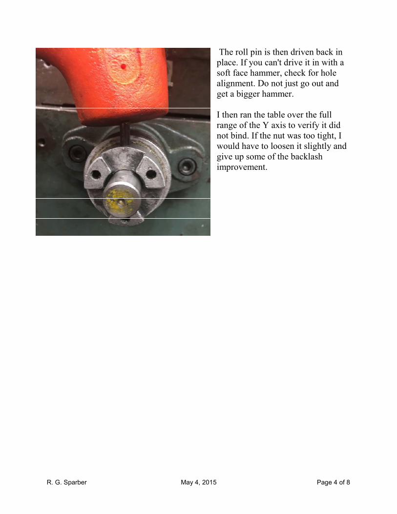
The roll pin is then driven back in
place. If you can't drive it in with a
soft face hammer, check for hole
alignment. Do not just go out and
get a bigger hammer.
I then ran the table over the full
range of the Y axis to verify it did
not bind. If the nut was too tight, I
would have to loosen it slightly and
give up some of the backlash
improvement.

R. G. Sparber May 4, 2015 Page 5 of 8
X Axis Backlash Reduction
In order to access the X axis take up nut, it is necessary
to remove the Y axis leadscrew. Start by removing the
flange screws.
Then turn the Y axis leadscrew clockwise until it
comes out of the mill's base. This is a left hand thread.
With the Y axis leadscrew removed, you
have easy access to the two bolts that secure
the X axis take up nut. This assumes you
have access to the underside of the mill.
Remove the two screws being careful not to
let the split washers fall off the screws. Set
aside.
Remove the spline hub from the left
end of the table by driving out the roll
pin. The same suggestion stands:
make marks in both the hub and shaft
before removing anything.
R. G. Sparber May 4, 2015 Page 6 of 8
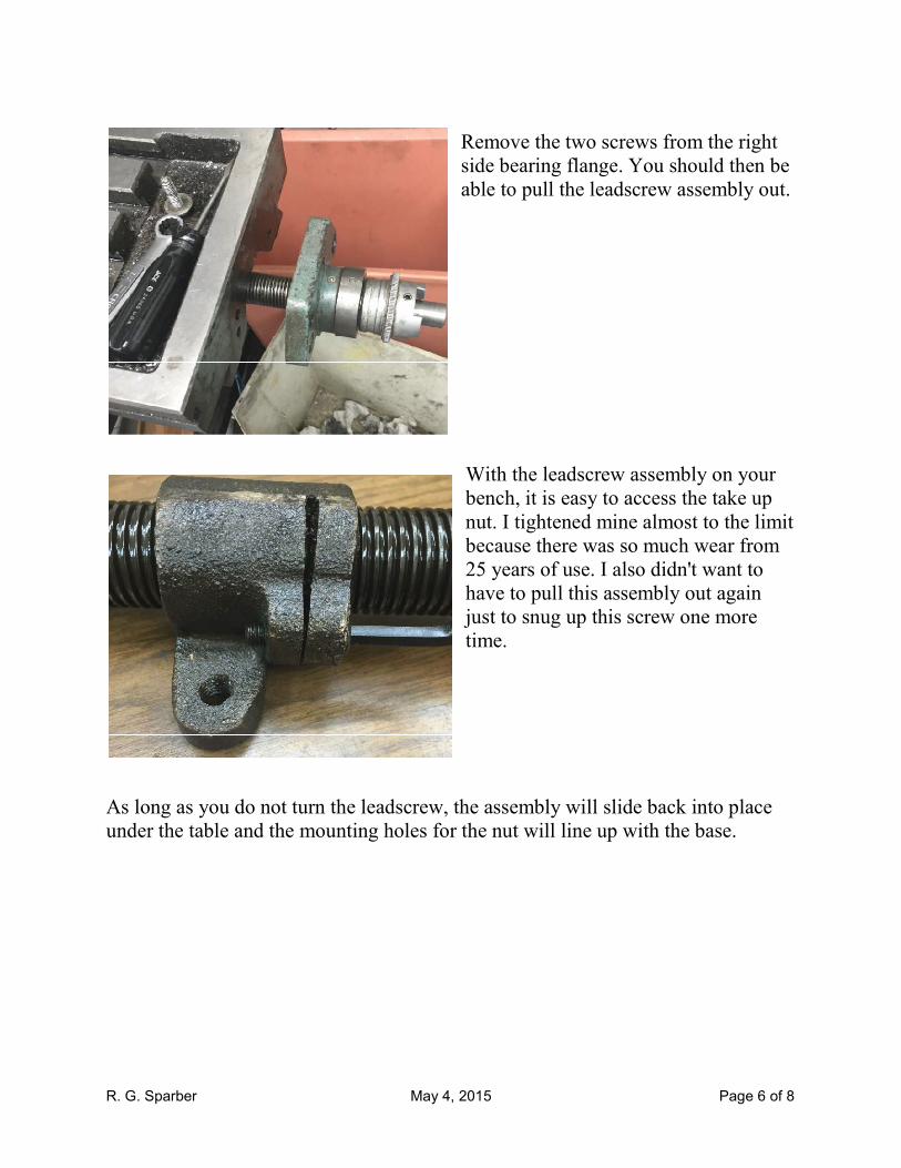
Remove the two screws from the right
side bearing flange. You should then be
able to pull the leadscrew assembly out.
With the leadscrew assembly on your
bench, it is easy to access the take up
nut. I tightened mine almost to the limit
because there was so much wear from
25 years of use. I also didn't want to
have to pull this assembly out again
just to snug up this screw one more
time.
As long as you do not turn the leadscrew, the assembly will slide back into place
under the table and the mounting holes for the nut will line up with the base.

R. G. Sparber
Slide the X axis leadscrew assembly back under the ta
the left side of the table, you can intercept the end of the leadscrew and guide it
into the left side bearing. Then run in the bolts that secure the take up nut. And
finally, put back the screws that secure the right bearing supp
The final check was to run the table over the full range of the X axis to verify it did
not bind. If a problem was discovered, the nut would be loosened slightly.
My X axis backlash went from 0.038 inches down to 0.006 inches. My Y axis
backlash went from 0.037 inches down to 0.013 inches.
May 4, 2015
I put two 0.01 inch shim washers on the X axis
the same as I had done on the Y.
Slide the X axis leadscrew assembly back under the table. With your hand under
the left side of the table, you can intercept the end of the leadscrew and guide it
into the left side bearing. Then run in the bolts that secure the take up nut. And
finally, put back the screws that secure the right bearing support.
The final check was to run the table over the full range of the X axis to verify it did
not bind. If a problem was discovered, the nut would be loosened slightly.
My X axis backlash went from 0.038 inches down to 0.006 inches. My Y axis
t from 0.037 inches down to 0.013 inches.
Page 7 of 8
I put two 0.01 inch shim washers on the X axis
ble. With your hand under
the left side of the table, you can intercept the end of the leadscrew and guide it
into the left side bearing. Then run in the bolts that secure the take up nut. And
The final check was to run the table over the full range of the X axis to verify it did
not bind. If a problem was discovered, the nut would be loosened slightly.
My X axis backlash went from 0.038 inches down to 0.006 inches. My Y axis

R. G. Sparber May 4, 2015 Page 8 of 8
Acknowledgments
Thanks to Dan Mauch for inspiring me to look closer at my backlash. Thanks to
Steve Blackmore for educating me on ballscrews. Thanks to Malcolm Parker for
pointing out that I did not discuss running the table over the full range to verify
there was no binding.
Thanks to Bob Sanders for pointing out the correct way to select the spacers.
I welcome your comments and questions.
If you wish to be contacted each time I publish an article, email me with just
"Article Alias" in the subject line.
Rick Sparber
Rick.Sparber.org