y et another hardware implementation o modular … et another hardware implementation o f ......
TRANSCRIPT

Y et Another Hardware Implementation o f Modular Multiplication
Nadia Nedjah· and Luiza de Macedo Mourelle Department o f Systems Engineering and Computation, Faculty o f Engineering,
State University o f Rio de Janeiro. E-mail : (nadia lldmm)@eng.uerj.br
Abstraci-Modular multiplication is fundamental to several public
key cryptography systems such as the RSA encryption system. lt is also the most dominant part of the computation performed in such systems. The operation is time consuming for large operands. This paper examines the characteristics of yet another architecture to implement modular multiplication. An experimental modular multiplier prototype is described and some simulation results are presented.
Key Words--Modular Multiplication, Cryptosystems
I. I NTRODUCTION
The modular exponentiation is a common operation for scrambling and is used by several public-key c ryptosystems, such as the RSA encryption scheme [RIV 78] . It consists of a repetition of modular multiplications: C = r mod M , where T is the plain text such that O $ T < M and C is the c ipher text or vice-versa, E is either the public or the private key depending on whether T is the plain or the cipher text, and M is called the modulus. The decryption and encryption operations are performed using lhe same procedure, i.e. using·the modular exponentiation.
The performance o f such cryptosystems is primarily dete rmined by lhe implementation effic iency of lhe modular multiplication and exponentiation. As the operands (the plain text of a message or the c ipher or possibly a partially ciphered) text are usually large (i. e. I 024 bits o r more), and in order to improve time requirements of the encryption/decryption operations, it is essential to attempt to minimise lhe number of modular multiplications performed and to reduce the time requirement of a single modular multiplication .
An RSA cry ptosystem consists of a set of three items: a modulus M o f around 1024 bits and two integers d and e called private and public keys that satisfy the property T' = T mod M. Plain text T obeying O $ T < M. Messages are encrypted using lhe public key as C = T mod M and decrypted as T = C mod M. So lhe same operation is used to perform both processes: encryptio n and decryption. Hardware implementation of the RSA cryptosystem are widely studied as in [BRI 89], [WAL 93]. [ELO 93] .
· 1llis author is a lccturer at Univcrsity Veiga de Almeida. Rio de Janeiro. Brazil.
70
In lhe rest of this paper, we start off by describing the a lgorithms used to implement the modular operation. Then we present lhe architecture of the hardware modular multiplier and explain in details how it executes a single multiplication . Then we commenl lhe simulation resulls obtained for such an architecture.
11. M ULTIPLICATION ALGORITHM
Algorithms that formalise the operation of multiplication generally consist of two steps: one generates a partia! product and lhe other accumulates it with the previous partia! products. The most basic a lgorithm for multiplication is based on the add-and-shift method: the shift operation generates the partia l products while the add step sums them up [RAB 95].
The straightforward way to implement a multiplication is based on an iterative adder-accumulator for lhe generated partial products as depicted in Figure I. However, this solution is quite slow as the final result is only available a fter n clock cycles, n is the size of the operands.
Parlial Ploduct Gere:tator
clock rllf\1 shift
Fig. I: lterative multiplier.

A faster version of the iterative multiplier should add severa! partia! product at once. This could be achieved by unfolding the iterative multiplier and yielding a combinatorial c ircuit that consists of severa! partia! product generators together with severa! adders that operate in parallel. In this paper, we use such a parallel multiplier as described in Figure 2. Now, we detail the algorithms used to compute the partia! products and to sum them up.
Fig. 2: Paralle l multiplier.
Now, we concentrate on the algorithm used to compute partia! products as well as reducing the corresponding number without deteriorating the space and time requirement o f the multiplier.
Let X and Y be the multiplicand and multiplicator respectively and let n and m be their respective sizes. So, we denote X and Y as follows:
n m
X= L,x1x21 and Y= _L, y1x21
i=O i=O 11
=>XxY= L,x1x Yx 21
i=O
Inspired by the above notation of X, Y and that of Xx Y, the add-and-shift method [RAB 95] generates n partia! products: x,xY, O s; i < 11. Each partia! product obtained is shifted left or right depending on whether the starting bit was the less or the most significant and added up. The number o f partia! products generated is bound above by the size (i.e. number of bits) of the multiplier operand. In cryptosystems, operands are quite large as they represent blocks o f text (i. e. ;;?: I 024 bits).
Another notation of X and Y allows to halve the number of partia! products without much increase in space requirements. Consider the following notation of X and Xx Y
71
f{t1+1)12l-1 X= _L,x1x2 2xi , where x1 =x2x;_1+x2xi-2xx2xi+l
i=O
f{ll+l)/21-1 X x Y = L,x1xYx22x1
i=O
The possible values of x1
with the respective values of
X2x,+p X2x,. and X2x,- 1 are -2 (I 00), -I ( I O I, li 0), O (000, 111), I (001 , 010) and 2(011). Using this recoding will generate f(n+l)/21-I partia! products.
Inspired by the above notation, the modified Booth algorithm [800 86], [MAC 6 1], [BEW 94] generates the
partia! products x1 xY. These partia! products can be
computed very efficiently due to the digits of the new
representation x1 • The hardware implementation will be
detailed in Section 3. In the algorithm of Figure 3, the terms 4x2 .. 1 and 3x2•••
are supplied to avoid working with negative numbers. The sum of these additional terms is congruent to zero modulo
2"+f<t~+ l>l-1 . So, once the sum of the partia! products is
obtained, the rest of this sum in the division by is finally
the result of the multiplication Xx Y.
Algorithm Multiplier(X2xl-l • X2xl • X 2xld • Y) ( int product =O; int pp [ Í!n+1)/2l-1 ];
pp[O]= (X0 xY + 4x2"' 1 )x22"
1
for i=O to
pp[i] = ( x1xY + 3x2"' 1 ) x22"
1
product = product + pp[i];
return product mod 2n+r<n+l l I 21-1 ;
Fig. 3: Multiplication algorithm.
III. REDUCTION ALGORITHM
A modular reduction is simply the computation of the remainder of an integer division. It can be denoted by:
X modM =X -l~ JxM
However, a division is very expensive even compared with a multiplication. Using Barrett's method [BAR 86], [SHI 97], we can estimate the remainder using two simple

multiplications. The approximation of the quotient is calculated as follows:
l.!_J= 2"-1
M :: 2"-1 M l l~Jxl 2"-1
X2"+1
J j ll~Jxl~Jj M 2"+1 2"+1
The equation above can be calculated very efficiently as division by a power of two 2x are simply a truncation of the
operand' x-least significant digits. The term L22x" / M J depends only on the modulus M and is constant for a given
modulus, hence, can be pre-computed and saved in an extra register. Hence the approximation of the remainder using Barrett' s method [BAR 86], [SHl 97] is a positive integer smaller than 2x(M- I). So, one or two subtractions of M might be required to yield the exact remainder.
IV. M ODULAR MULTIPLIER ARCHITECTURE
In this section, we outline the architecture of the multiplier, which is depicted in Figure 4 . Later on in this section and for each of the main parts of this architecture, we g ive the detailed circuitry, i.e. that of the partial product generator, adder and reducer.
lcail_kg_4
REDUCER
Fig. 4: The modular multiplier architecture.
The multiplier of Figure 4 performs the modular multipl ication Xx Y mod M in three main steps:
I. Computing the product P = XxY; 2. Computing the estimate quotient Q = PIM
=> Q = P/2"-1 x l22x"/M J; 3. Computing the final result P - QxM.
During the fi rst step, the modular multiplier first Ioads register, and register
2 with X and Y respecti vely; then waits
for PPG to yield the partia) products and finally waits for the ADDER to sum ali o f them. During the second step, the modular multiplier loads register" register2 and register3
with the obtained product P, the pre-computed constant
L22x"/M j and P respectively; then waits for PPG to yield
the partial products and finally waits for the ADDER to sum ali o f them. During the third step, the modular multiplier first loads register, and register2 with the obtained product Q and the modulus M respectively; then awaits for PPG to
72
generate the partia) products, then waits for the ADDER to provide the sum of these partia) products and fi nally waits for the REDUCER to calculate the final resu lt P-QxM, which is subsequently loaded in the accumulator acc.
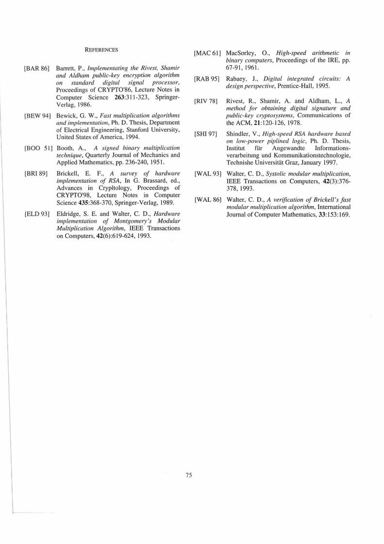
A The partia/ product generator
The partia) product generator is composed of k Booth recoders [BOO 86], [MAC 61 ], [BEW 94]. They communicate d irectly with k partia) product generators as shown in Figure 5.
The required parti ai products, i.e. 'i; x Y are easy
multiple. They can be obtained by a simple shift. The negative multiples in 2 's complement form, can be obtained form the positive corresponding number using a bit by bit complement with a I added at the least significant bit of the partia[ product. The additional te rms introduced in the previous section can be included into the partial product
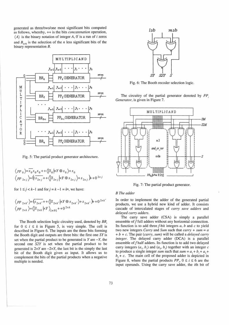
generated as three/two/one most significant bits computed as follows, whereby, ++ is the bits concatenation operation, (A) is the binary notation of integer A, O' is a run of i zeros
and 8 1"'01 is the selection of the n less significant bits of the binary representation B.
M u L T I p L I c A T o
·8~-· ~--------------~
Fig. 5: The partia) product generator architecture.
(PP o )=s os os o ++(lxo ~Y Ee s o )+so
( PP 2xj )=6 s 2xj ++(lx 2xj r r Ee s 2xj )+s 2xj fr+O 2xj
for I ~j < k-1 and for j = k -I = k•, we have:
( PP 2xk' )=(s 2xk' ++ (lx 2xk' ~y $ s 2xk' )+s 2xk' fr+O 2xk'
(PP 2xk )=(lx2xk ~y )(n:OJ++0 2xk
The Booth selection logic circuitry used, denoted by BR, for O ~ i $ k in Figure 5, is very simple. The cell is described in Figure 6. The inputs are the three bits forming the Booth digit and outputs are three bits: the first one SY is set when the partia! product to be generated is Y are - Y, the second one S2Y is set when the partia] product to be generated is 2xY are -2xY, the last bit is the simply the last bit of the Booth digit given as input. It allows us to complement lhe bits of the partia! products when a negative multiple is needed.
73
l.sb m.sb
SY S2Y .S
Fig. 6: The Booth recoder selection logic.
The circuitry of the partia! generator denoted by PP, Generator, is given in Figure 7.
MU LTI PLIC AN D
r-----1ffi~~--~-----+r---SM
r--r~+.--1ffi~~--~-+.--+~--~M
n-3
and_or_xor
cells
Fig. 7: The partia! product generator.
B The adder
In order to implement the adder of the generated partia! products, we use a hybrid new kind of adder. lt consists cascade of intercalated stages of carry save adders and delayed carry adders.
The carry save adder (CSA) is simply a parallel ensemble of Jfull adders without any horizontal connection. lts function is to add three f-bit integers a, b and c to yield two new integers Carry and Sum such that carry + sum = a +h + c. The pair (carry, sum) will be called a delayed carry integer. The delayed carry adder (DCA) is a parallel ensemble of fhalf adders. Its function is to add two delayed carry integers (a" h1) and (a2, h2) together with an integer c to produce a single integer sum such that sum = a
1 + h
1 + a2 +
h2 + c. The main cell of the proposed adder is depicted in Figure 8, where the partia! products PP,, O ~ i ~ 6 are the input operands. Using the carry save adder, the ith bit of

carry and sum are defined as sum, = a,$ b, $c, and carry,=a,Xb1+ a,xc,+ b,Xc1 respectively.
.sum 1
CDA
WM
Fig. 8: The ma in cell o f the proposed adder.
The architecture of the delayed carry adder uses 5xn half adders and n full adders as described in Figure 9. This architecture ignores the overtlows. However, these can be easily estimated from lhe three top bits o f the operands. The proof concerning lhe soundness of the result delivered by the adder can be found in [WAL 86).
c
carry1 b l
a:l
carry2
b2
carry4
carry5
11-bit HA
11-bit HA
11-bit HA
11-bit HA
11-bit FA
al
.sum1
.sum2
.sum3
.sum4
.sum
Fig. 9: The structure of lhe carry delayed adder.
74
C The reducer
The main task of the reducer consists of subtracting QxM, i.e. the product obtained in lhe third step of lhe modular multiplier from P, i.e. the product yielded in lhe first step of the modular multiplier. A subtraction of an p-bits integer K is equivalent to the addition of 2"- x. Hence the reducer simply performs the addition P + (2"+m - QxM). The latter value is simply the two's complement of QxM.
The addition is performed using a carry look-ahead adder. lt is based on computing lhe carry bits cl prior to the actual summation. The adder takes advantage of a relationship between the carry bits C1 and the input bits A1 and B,.
Ci=Gi-I+(G;_2+(G;_J+ A +(G,+(Go+Co-PakMA )><P;)
whereby G, =A, x 81 and P1 =A,+ B, The general structure o f lhe used carry look-ahead adder is given in Figure I O.
A, B.
l Carry look-ahead logic o
cn c"lt-~
c A
-1
Bn Bl - 1 o
; s; -I
Fig. I 0: The structure o f the carry look-ahead adder.
V CONCLUSJON
In this paper, an alternative architecture for computing modular multiplication based on Booth algorithm and on Barret's relaxed residiuum method is described. The Booth algorithm is used to compute the product while Barret's method is used to calculate the remainder. The architecture was validated through behavioral simulation results using the 0.6J..Lm CMOS-AMS standard cell library. The total execution time is 3570 nanoseconds for I 024-bit operands.
One of the advantage of this modular multiplication implementation resides in the fact that it is easily scalable with respect to the multiplier and modulus lengths.
I \
REFERENCES
[BAR 86] Barren, P., lmplementating the Rivest, Shamir and Aldham public-key encryption algorithm on standard digital signal processor, Proceedings of CRYPT0'86, Lecture Notes in Computer Science 263:311 -323, SpringerVerlag, 1986.
[BEW 94] Bewick, G. W., Fast multiplication algorithms and imp/ementation, Ph. D. Thesis, Department of Electrical Engineering, Stanford University, United States of America, 1994.
[BOO 51] Booth, A., A signed binary multiplication technique, Quarterly Journal of Mechanics and Applied Mathematics, pp. 236-240, 1951.
[BRI 89] Brickell, E. F., A survey of hardware implementation of RSA, In G. Brassard, ed., Advances in Crypltology, Proceedings of CRYPT0'98, Lecture Notes in Computer Science 435:368-370, Springer-Verlag, 1989.
[ELO 93] Eldridge, S. E. and Walter, C. D., Hardware implementation of Montgomery's Modular Multiplication Algorithm, IEEE Transactions on Computers, 42(6):619-624, 1993.
75
[MAC 61] MacSorley, 0., High-speed arithmetic in binary computers, Proceedings of the IRE, pp. 67-9 1, 1961.
[RAB 95] Rabaey, J., Digital integrated circuits: A design perspective, Prentice-Hall , 1995.
[RIV 78] Rivest, R., Shamir, A. and Aldham, L., A method f or obtaining digital signature and public-key cryptosystems, Communications of the ACM, 21: 120-126, 1978.
[SHI 97] Shindler, V., High-speed RSA hardware based on low-power piplined logic, Ph. D. Thesis, Institut für Angewandte Informationsverarbeitung und Kommunikationstechnologie, Technishe Universitat Graz, January 1997.
[WAL 93] Walter, C. D., Systolic modular multiplication, IEEE Transactions on Computers, 42(3):376-378, 1993.
[WAL 86] Walter, C. D., A verification of Brickell's fast modular multiplication algorithm, International Journal of Computer Mathematics, 33: !53: 169.