y-seriesrigging manual 1.4 en
TRANSCRIPT

Y Y-SeriesRigging manual 1.4 en

Symbolsontheproduct
Pleaserefertotheinformationinthemanual.
WARNING!
Dangerousvoltage!
General informationY-Series Rigging manualVersion: 1.4 en, 09/2017, D2718.EN .01Copyright © 2017 by d&b audiotechnik GmbH; all rightsreserved.Keep this manual with the product or in a safe placeso that it is available for future reference.When reselling this product, hand over this manual to the newowner.If you supply d&b products, please draw the attention of yourcustomers to this manual. Enclose the relevant manuals with thesystems. If you require additional manuals for this purpose, youcan order them from d&b.d&b audiotechnik GmbHEugen-Adolff-Strasse 134, D-71522 Backnang, GermanyT +49-7191-9669-0, F +49-7191-95 00 [email protected], www.dbaudio.com

1. Safety.................................................................................... 41.1. Intended use............................................................................ 41.2. General safety......................................................................... 41.3. Load capacity/System safety................................................. 41.4. Operational safety.................................................................. 51.5. d&b ArrayCalc simulation software / TI 385....................... 52. Y-Series rigging concept................................................ 62.1. Z5390 Y Flying frame - Scope of supply.............................. 62.2. Z5392 Y Safety chainset..................................................... 102.3. Z5391 Y Hoist connector chain option............................... 102.4. Ring cotters............................................................................ 112.5. Locking pins........................................................................... 122.6. Load adapter........................................................................ 132.7. Suspension of the Flying frame............................................ 132.8. Secondary safety.................................................................. 152.9. Splay link of the frame.......................................................... 162.10. Cable pick........................................................................... 172.11. Cabinet rigging mechanism............................................... 173. Y-Series arrays and assembly.................................. 203.1. Setup preparation................................................................. 213.2. Flown arrays.......................................................................... 213.3. Y Touring cart assembly....................................................... 283.4. Ground stacks....................................................................... 334. Safety and system checks.......................................... 374.1. Mechanical setup................................................................. 374.2. Wiring.................................................................................... 375. Hoisting and securing the array.............................. 385.1. Hoisting the array................................................................. 385.2. Securing the array................................................................ 386. Derigging.......................................................................... 396.1. General................................................................................. 396.2. Touring cart disassembly...................................................... 397. Care and maintenance / Disposal.......................... 417.1. Transport / Storing............................................................... 417.2. Visual and functional inspection.......................................... 417.3. Disposal................................................................................. 428. Manufacturer's declaration....................................... 43
Contents
d&b Y-Series Rigging manual 1.4 en 3

1.1. Intended useThe Y-Series rigging components (Flying frame, Load adapter,Locking pins) must only be used in conjunction with d&b Y-Seriesloudspeakers as described in this manual.
1.2. General safetyInstallation and setup should only be carried out by qualified andauthorized personnel observing the valid national Rules for thePrevention of Accidents (RPA).It is the responsibility of the person installing the assembly to ensurethat the suspension/fixing points are suitable for the intended use.Always carry out a visual and functional inspection of the itemsbefore use. In case there is any doubt as to the proper functioningand safety of the items, these must be withdrawn from useimmediately.
Please also refer to Þ Chapter 7. "Care and maintenance /Disposal" on page 41.
1.3. Load capacity/System safety
NOTICE!The Z5390 Y Flying frame is designed to suspend a total systemweight of 540 kg (1191 lb) – SWL.This allows the suspension of a maximum of 24 x Y-TOP cabinetsor a SUB column consisting of a maximum of 10 x Y-SUB cabinets.The rigging components allow arrays of up to 10 x Y-TOP cabinetswith a total system weight of 220 kg (485 lb) to be flown in anyvertical splay angle configuration between the cabinets.For any other array configuration the load conditions within thearray have to be checked using the Þ d&b ArrayCalc simulationsoftware.
1.3.1. Wind loads
WARNING!Potential risk of personal injury and materialdamage!
Flying loudspeakers overhead at wind forces higher than 6 bft(22-27 knots, 39-49 km/h, 25-31 mph) is not recommended.If the wind force exceeds 8 bft (34-40 knots,62-74 km/h, 39-46 mph):– Make sure that no person remains in the vicinity of the array.– Lower and secure the array.
1. Safety
d&b Y-Series Rigging manual 1.4 en4

1.4. Operational safetyThe assembly should always be carried out by two persons.During assembly pay attention to the possible risk of crushing.Wear suitable protective clothing.Observe all instructions given on the respective instruction labels ofthe rigging components (Flying frame, Load adapters), Touringcarts and loudspeaker cabinets.When chain hoists are in operation ensure that there is nobodydirectly underneath or in the vicinity of the load.Do not under any circumstances climb on the array.
1.5. d&b ArrayCalc simulation software / TI 385For both safety and acoustic reasons, d&b line arrays must bedesigned using the d&b ArrayCalc simulation software. Thesoftware is available as a native stand-alone application for bothMicrosoft Windows and Mac OS X operating systems and can bedownloaded at www.dbaudio.com.Detailed information on how to use and operate ArrayCalc isprovided by the Help system of the software. To access the Helpsystem, press F1 or select the Help button ( ) fromthe ArrayCalc toolbar. This will launch the HelpViewer whichprovides an overview of the program as well as a search functionand direct access to the related topics.In addition, ArrayCalc will provide you with typical arrayconfigurations within the permitted load limits and will help you getfamiliar with the mechanical load conditions and limitations.Further information on line array design can be found in "TI 385d&b Line array design, ArrayCalc". The TI is supplied with thesoftware or can be downloaded from the d&b website atwww.dbaudio.com.We also recommend you to attend the regularly hosted d&b Linearray training seminars. Further information regarding the d&bseminars and a seminar schedule can also be found on the d&bwebsite at www.dbaudio.com.
d&b ArrayCalc
d&b Y-Series Rigging manual 1.4 en 5

2.1. Z5390 Y Flying frame - Scope of supplyPlease verify the shipment for completeness and proper conditionof the items.
The Z5390 Y Flying frame is equipped and supplied with thefollowing rigging components:
Z5390 Y Flying frame top and bottom views
2. Y-Series rigging concept
d&b Y-Series Rigging manual 1.4 en6

Pos. Component Description[1][2]
Z5390 Y Flying frameFlying frame center bar
The Z5390 Y Flying frame is designed to support arrays consisting of:– Z0707/Z0708, Y8/Y12. Weight: 20 kg (44 lb).– Z0709 Y-SUB. Weight: 52 kg (115 lb).
The weight of the Y Flying frame including all rigging components is 19 kg (42 lb).[3][4]
Z5392 Y Safety chainsetSafety point(s)
The Z5392 Y Safety chainset is supplied with the Flying frame.The Flying frame is fitted with two safety points each equipped with a 1.5 t shackle to attach asecondary safety device using the enclosed Y Safety chainset (refer to Þ Chapter 2.8."Secondary safety" on page 15).
[5] Y Load adapter The Flying frame is supplied with two Load adapter to allow single or dual pickpointoperation. Each Load adapter is supplied with a pair of Locking pins 10 mm and a 2 t shackle(refer to Þ Chapter 2.6. "Load adapter" on page 13).
[6] Y Load adapter Rota Clamp In addition, the enclosed Y Load adapter Rota Clamp allows single pickpoint operation incombination with the d&b Z5147 Rota clamp for a maximum system weight of up to 500 kg/1100 lb (also refer to Þ Chapter 2.6. "Load adapter" on page 13).
[P] Park position During transport the Load adapters should be stored at their park positions (refer toÞ Chapter 2.6. " Load adapter" Þ " Fixing the Load adapter at Park position" on page 13).
[7] Front link (Frame) Two additional Front links together with a pair of Locking pins 8 mm each are supplied withthe Flying frame. They are used to mount Y-Series cabinets on top of the Flying frame for thefollowing setups:– Mixed Y-Series array with Y-SUB cabinets at the top of the column (refer to
Þ Chapter 3.2.3. "Mixed array" on page 26).– Y-Series ground stack with the Flying frame as ground support (refer to Þ Chapter 3.4.
"Ground stacks" on page 33).[8] Mounting plate An additional mounting plate is provided to accept industry standard inclinometers such as the
Teqsas LAP-TEQ line array positioning tool.[9] Splay link (Frame) In connection with the Front links of the Y-Series loudspeaker cabinets, the Splay link of the
frame is used to attach the first cabinet to the frame. By default, the Splay link of the frame isfixed at «POSITION Y8/Y12». To accept Y-SUB cabinets, the Splay link can be moved to«POSITION Y-SUB» (refer to Þ Chapter 2.9. "Splay link of the frame" on page 16).During transport the Splay link should be folded back into its park position and secured by therespective Locking pin.
[10] Cable pick An O-ring at the rear bottom of the frame slides out when releasing the respective Locking pinto attach a cable pick (refer to Þ Chapter 2.10. "Cable pick" on page 17).
d&b Y-Series Rigging manual 1.4 en 7

2.1.1. Flying frame instruction label
Pos. Description[2] Center bar of the Flying frame with user instruction label.
[2.1] Main hole grid at the top of the center bar with a total of 45 holes numbered with an increment of five. Using the Y Loadadapters the Flying frame can be suspended from one or two pickpoints (refer to Þ Chapter 2.6. "Load adapter" on page 13and Þ Chapter 2.7. "Suspension of the Flying frame" on page 13).
[2.2a][2.2b]
Fixing point for the frame's Splay link in «POSITION Y8/Y12».The additional hole is used to fix the Splay link at park position ( ) using the respective Locking pin (refer to Þ Chapter 2.9."Splay link of the frame" on page 16).
[2.3a][2.3b]
Fixing point for the frame's Splay link in «POSITION Y-SUB».The additional hole is used to fix the Splay link at park position ( ) using the respective Locking pin (refer to Þ Chapter 2.9."Splay link of the frame" on page 16).
[2.4] Hole grid ground stack: when Y8/Y12 cabinets are attached to the top of the frame, this hole grid indicates the possible settingsof –7°, –3.5°, 0°, +3.5° or +7° for the Splay link of the first (bottom) cabinet (refer to Þ Chapter 3.4. "Ground stacks"on page 33).
[2.5] If the Flying frame is fitted below a Y-SUB cabinet (Mixed Y-Series array with Y-SUB cabinets at the top of the column), these twoholes are used to fix the Rear link of the "last" Y-SUB cabinet to the frame using the Locking pin of the respective cabinet and theLocking pin of the Cable pick (refer to Þ Chapter 3.2.3. " Mixed array", Þ step " 2. Attach the assembly to the frame" onpage 26).
d&b Y-Series Rigging manual 1.4 en8

2.1.2. Dimensional drawing
Z5390 Y Flying frame laser/inclinometer mounting plate [8]dimensions in mm [inch]
Z5390 Y Flying frame dimensions in mm [inch]
d&b Y-Series Rigging manual 1.4 en 9

2.2. Z5392 Y Safety chainsetThe Z5392 Y Safety chainset is supplied with the Y Flying frameand is used as a secondary safety device. Please also refer toÞ Chapter 2.8. "Secondary safety" on page 15.SpecificationLifting chain (DIN EN 818) 2-leg, 8 mmGrade 8Nominal length incl. hooks 416 mm (16.4")Maximum sling angle bMax 60°Load rating 3.35 t (b: 0° - 45°)
2.5 t (b: 46° - 60°)
2.3. Z5391 Y Hoist connector chain optionThe Z5391 Y Hoist connector chain is used to connect the liftingmotor(s) to the Y Flying frame using the 1.5 t shackle which isattached to the Y Load adapter. Its length of 53 cm (21") allowsenough space for the hang of most 2 t motor chain containers andavoids any impact on the vertical balance of the array whensuspended from a single pickpoint.
SpecificationLifting chain (DIN EN 818) 1-leg, 8 mmGrade 8Nominal length incl. hook 535 mm (21")Load rating 2 t
d&b Y-Series Rigging manual 1.4 en10

2.4. Ring cottersIn connection with the Y-Series rigging system, ring cotters are usedfor the following items to prevent the respective item fromslackening and/or loosening:– Fixing bolt of the SUB cabinet's Rear link.– Fixing bolt of the frame's Splay link and cable pick.– Fixing bolt of the 1.5 t shackles attached to the Load adapters
and safety points of the Flying frame.– Fixing bolt of the Z5147 Rota clamp.
Function of the ring cotterBy default, the ring cotters are "locked" to prevent them fromloosening.For modification reasons such as altering the position of the frame'sSplay link or exchanging a shackle, it may be necessary totemporarily remove the cotter and reattach it afterwards.For this purpose proceed as follows:1. Unlock
Unlock the ring cotter by pushing up the front wire loop overthe straight wire shaft.
2. Release and removePush down the rear wire loop until the ring cotter snaps overthe edge of the bolt and remove the ring cotter.
3. Refit and lockRefit the ring cotter by pushing the straight wire shaft throughthe hole and pressing the front wire loop underneath thestraight wire shaft.
Ring cotter
Ring cotter locked
d&b Y-Series Rigging manual 1.4 en 11

2.5. Locking pins
WARNING!Potential risk of personal injury and/ordamage to material!
The steel wires between the Locking pins of the cabinets andrigging components are not intended to carry any load. Thecabinet's weight must only be carried by the Front and Splay/Rearlinks in conjunction with the front and rear rigging strands of theloudspeaker cabinets and the Flying frame.Ensure all Locking pins are fully inserted and securely lockedbefore lifting any load.
The Y-Series loudspeaker cabinets and flying frame are equippedwith three types of Locking pins:
Type [A] Locking pin 10 x 32 mm.Used for the Load adapters.
Type [B] Locking pin 8 x 40 mm.Used for the cabinets' Splay/Rear links and for theframe's Splay link and Cable pick.
Type [C] Locking pin 7 x 18 mm.Used for the Front links of the loudspeaker cabinetsand the frame.
Note: The Locking pins are undetachably attached to thedifferent rigging components on the cabinet and the frameusing steel wires.Throughout this manual these steel wires are not shown in thecorresponding illustrations.
Functionality (Quick lock mechanism)The quick lock mechanism applies to all types of Locking pins listedabove. Proceed as follows:1. Press the button to release the locking mechanism ( [r]).2. Remove the Locking pin through the respective link or socket.3. Insert the Locking pin through the respective link or socket until
it is fixed in place.4. Release the button to lock the pin ( [l]).5. Recheck the Locking pin is securely locked by briefly pulling
the Locking pin towards you.Locking pin assemblyShown with pin type [C]
d&b Y-Series Rigging manual 1.4 en12

2.6. Load adapterThe Flying frame is supplied with two different types of loadadapters:Type 1: 2 x Y Load adapter, allowing either single or dual
pickpoint operation.Type 2: 1 x Y Load adapter Rota Clamp, allowing single
pickpoint operation in combination with the d&bZ5147 Rota clamp for a maximum system weight ofup to 500 kg /1100 lb.
Both types allow for a full grid (1/1 PICKPOINT DETENT) or a halfgrid (½ PICKPOINT DETENT) setting depending on the direction ofattachment to the frame's center bar.The frame's hole index marked on one side of the center bar is thereference for the direction of the Load adapter.
Note: The same applies to the Y Load adapter Rota Clamp.
Attaching the Load adapter to the Flying frame
WARNING!Potential risk of personal injury and/ordamage to material!
Before attaching the Load adapter, check the 1.5 t. shackle isproperly fitted to the Load adapter and secured with a locked ringcotter.Ensure the Load adapter is properly attached to the center bar ofthe frame and both Locking pins are inserted and locked securelybefore lifting the array.
The Load adapter is attached to the center bar of the Flying frameand fixed using its two Locking pins 10 mm.
Note: It is advisable to insert the Locking pins opposite eachother as shown in the graphic opposite.
Fixing the Load adapter at Park positionDuring transport the Load adapters should be stored at their parkpositions [P].For this purpose, insert both Locking pins of each Load adapter inthe same direction from the top, as shown in the graphic opposite.
2.7. Suspension of the Flying frameThe suspension of the Y Flying frame is carried out using one ortwo Y Load adapter(s), depending on the chosen type ofsuspension (Single or Dual pickpoint operation).The Load adapters are attached to the center bar of the Flyingframe and fixed using the two Locking pins of each adapter asdescribed in the previous section Þ 2.6. Load adapterÞ Attaching the Load adapter to the Flying frame on page 13.
Direction of the Load adapter for:Left: Full grid (1/1 PICKPOINT DETENT), shown: Hole 17Right: Half grid (½ PICKPOINT DETENT), shown: Hole 17.5
d&b Y-Series Rigging manual 1.4 en 13

2.7.1. Single pickpoint operationWith "Single pickpoint operation" the position of the Y Loadadapter defines the vertical aiming of the entire array.The corresponding hole position is calculated using ArrayCalc.
Note: The target angle of the entire array is achieved whenthe array is fully set up and hoisted as intended.
Attachment1. Choose the appropriate hole position on the center bar
according to the ArrayCalc calculation and attach the Loadadapter correspondingly.Þ If ArrayCalc displays a half numbered hole setting (half
grid) turn the Load adapter correspondingly.2. Attach the Hoist connector chain or motor hook to the shackle
of the Load adapter.
2.7.2. Z5147 Rota clamp optionAlternatively, a Y-Series array with a total system weight of up to500 kg (1100 lb) can be suspended and horizontally alignedfrom a single flying point using the d&b Z5147 Rota clamp. Theclamp allows the load to be attached to overhead bars or trusswith a tube diameter of up to 51 mm (2”).The corresponding hole position is calculated using ArrayCalc.
Attachment1. Choose the appropriate hole position on the center bar
according to the ArrayCalc calculation and attach the Loadadapter Rota clamp correspondingly.Þ If ArrayCalc displays a half numbered hole setting (half
grid) turn the Load adapter correspondingly.2. Attach the Rota clamp to the Load adapter.
Note: Please observe the relevant mounting instructionswhich are enclosed with the Rota clamp.
ArrayCalc Single pickpoint
ArrayCalc Single pickpoint
d&b Y-Series Rigging manual 1.4 en14

2.7.3. Dual pickpoint operationWith "Dual pickpoint operation" the vertical aiming of the array isset by trimming the hoist motors after the array has been fullyassembled and lifted to its operating position.The corresponding hole positions are calculated using ArrayCalc.
Attachment1. Choose the appropriate hole positions for the Front and
Rearpick on the Flying frame center bar according to theArrayCalc calculation and attach the Load adapterscorrespondingly (Direction: Full grid 1/1 pickpoint Detent).
2. Connect the Hoist connector chains or motor hooks to theshackles of the Load adapters.
2.8. Secondary safety
WARNING!Potential risk of personal injury and/ordamage to material!
The secondary safety suspension must be independent of theprimary suspension points and capable of carrying the total systemweight.The additional safety device must be mounted in a way that thearray is caught by the safety device without any drop and swing inthe event that the primary suspension fails.
The Z5390 Y Flying frame is equipped with two safety points [4]fitted with two1.5 t shackles to accept a secondary safety device.We recommend the use of the d&b Z5392 Y Safety chainsetwhich is supplied with the Flying frame.
AssemblyThe two legs of the Y Safety chainset and the distance [d] betweenthe two safety points [4] of the frame's tie bar form an equilateraltriangle maintaining the maximum sling angle (bMax) of 60°.1. Before attaching the safety device ensure the two 2 t shackles
[S] are properly fitted to the frame's safety points [4] andsecured against loosening using a locked ring cotter [C] asshown in the graphic opposite.
2. Attach the Safety chain and ensure the chains are not twistedand the hooks [H] are in the right direction as shown in thegraphic opposite.
ArrayCalc Dual pickpoint
d&b Y-Series Rigging manual 1.4 en 15

2.9. Splay link of the frameSplay link positionBy factory default the Splay link is attached and parked to«POSITION Y8/Y12».Depending on the type of cabinet (Y8/Y12 or Y-SUB) to beattached to the Flying frame the position of the frame's Splay linkneeds to be changed as described in the following sectionÞ Changing the Splay link position.
Splay link of the frame – «POSITION Y8/Y12»
Splay link of the frame – «POSITION Y-SUB»
Splay link park positionDuring transport the Splay link can be folded into its park positionand fixed using its Locking pin.
Splay link at park position – «POSITION Y8/Y12»
Splay link at park position – «POSITION Y-SUB»
Changing the Splay link position
WARNING!Potential risk of personal injury and/ordamage to material!
The fixing bolt [B] of the frame's Splay link bears the full load ofthe array.It is essential that the bolt is fitted correctly and secured by alocked ring cotter [C].
To change the Splay link position, proceed as follows:
d&b Y-Series Rigging manual 1.4 en16

1. Release and remove the Locking pin of the Splay link at parkposition and fold out the Splay link.
2. Unlock and remove the ring cotter of the fixing bolt.3. Pull out the fixing bolt and remove the Splay link.
4. Attach the Splay link to its new position and insert the fixingbolt.
5. Secure the fixing bolt using the ring cotter and ensure the ringcotter is properly locked.
2.10. Cable pickThe Flying frame is equipped with an O-ring to allow theattachment of a cable pick. To prepare the attachment of the cablepick, proceed as follows:1. Release the Locking pin holding the O-ring at park position.2. Pull out the O-ring and reinsert the Locking pin.
2.11. Cabinet rigging mechanismY-Series cabinets are mechanically connected to the Y Flying frameand subsequent loudspeakers using the Front links attached to bothsides of the cabinet front and the central Splay/Rear link at therear of the cabinet.All necessary rigging components are mounted to the cabinet andslide out when needed.
Cable pick
d&b Y-Series Rigging manual 1.4 en 17

2.11.1. Front link mechanismY8/Y12Þ Simply release the Locking pin.
Þ Due to the integrated spring mechanism, the Front linkslides out automatically.
Y-SUBÞ Simply release the upper Locking pin.
Þ Due to the integrated spring mechanism, the Front linkslides out automatically.
The Front link mechanism of the SUB cabinets provides fourdifferent settings:a. SUB to Frame (Þ Fig. 1)b. SUB to SUB with 0° splay between the cabinets (Þ Fig. 2).c. SUB to SUB with 2.5° splay (free Þ Fig. 3) between the
cabinets.d. SUB to SUB with 2.5° splay (blocked Þ Fig. 4) between the
cabinets.This setting is used to prevent the cabinets from folding up.
Fig. 1: SUB to Frame Fig. 2: SUB to SUB, 0° splay Fig. 3: SUB to SUB, 2.5° splay,free
Fig. 4: SUB to SUB, 2.5° splay,blocked
2.11.2. Splay/Rear link mechanismRelease the respective Locking pin(s) and fold out the Splay/Rearlink.
Y8/Y12 Front link mechanism
Y-SUB Front link mechanism
Splay/Rear link mechanism
d&b Y-Series Rigging manual 1.4 en18

2.11.3. Preset splay angles on Y8/Y12 cabinetsThe splay angles between adjacent cabinets can be set in therange from 0° to 14° in 1° steps. The splay angles are set at thecentral rear rigging strands of the cabinets.– Insert and lock the Locking pin to the respective hole.
2.11.4. Park position Y8/Y12 Splay linkThe Splay link of the last cabinet of an array may be kept in itspark position.
Note: In this case, the lowest cabinet can be set to thefollowing splay angles: 3°, 5° and 7° to 14°.
Preset splay angle (e.g. 7°)
Park position Y8/Y12 Splay link
d&b Y-Series Rigging manual 1.4 en 19

Y8 Line array 8-deep,dual pickpoint operation,shown with:Z5391 Y Hoist connector chainZ5392 Y Safety chainsetRefer to Þ Chapter 3.2.1. "Y8/Y12Array" on page 22
Y-SUB column shown with 2.5°splay between the cabinetsRefer to Þ Chapter 3.2.2. "Y-SUBColumn" on page 24
Mixed array withY-SUB at the top of the arrayRefer to Þ Chapter 3.2.3. "Mixedarray" on page 26
Y Touring cart assemblyRefer to Þ Chapter 3.3. "Y Touring cartassembly" on page 28
Y8/Y12 Ground stackRefer to Þ Chapter 3.4.1. "Y8/Y12ground stack" on page 33
Y-SUB Ground stackRefer to Þ Chapter 3.4.2. "Y-SUBstack" on page 35
Mixed ground stackRefer to Þ Chapter 3.4.3. "Mixedground stack" on page 36
3. Y-Series arrays and assembly
d&b Y-Series Rigging manual 1.4 en20

3.1. Setup preparationCheck the acoustical and mechanical setup using ArrayCalc andprepare enough printouts for each array.The plan enables the riggers to set up the suspension points, thesecuring points and the chain hoists.When on site first:– Clear the working areas and ensure there is enough space to
set up and lift the array.– Check that the hoists are exactly in the specified position.– Ensure the chains are not twisted.
Inspections before setupBefore setting up the array, carry out a visual inspection of allsystem components for faults. This also includes the loudspeakersand in particular the rigging parts of the cabinets (Front andSplay/Rear links).Damaged components must be withdrawn from use immediately.
Please follow the instructions given in Þ Chapter 7. "Care andmaintenance / Disposal" on page 41.
3.2. Flown arraysFlown arrays are suspended using the Z5390 Y Flying frame.1. Suspend the Flying frame according to the chosen type of
suspension as described in Þ Chapter 2.7. "Suspension of theFlying frame" on page 13.
2. At this point we recommend you to attach the secondarysafety device using the Z5392 Y Safety chainset as describedin Þ Chapter 2.8. "Secondary safety" on page 15.
3. Prepare the cables and link cables according to the number ofamplifier channels and cabinets used.
d&b Y-Series Rigging manual 1.4 en 21

3.2.1. Y8/Y12 ArrayPreparationsFor this type of setup the Splay link of the frame must be attachedto «POSITION Y8/Y12». Check the position and alter it ifnecessary as described in Þ Chapter 2.9. " Splay link of theframe" Þ " Changing the Splay link position" on page 16.
1. Prepare the first cabinetPrepare the Front and Splay links of the first cabinet as describedin Þ Chapter 2.11. " Cabinet rigging mechanism" on page 17.
2. Attach the Flying frame to the first cabinet1. Lower the frame onto the cabinet until the Front links fit into the
slots at the front of the frame.2. Insert and lock the Locking pins of the cabinet's Front links on
both sides.
3. Release the Locking pin that keeps the frame's Splay link in itspark position.
4. Fold out the Splay link and reinsert the Locking pin.
5. On the rear rigging strand of the cabinet, insert and lock thefirst Locking pin of the cabinet in the [0°] hole.
6. Slightly lower the frame and fold in the Splay link.7. Lift the frame until the hook of the Splay link hooks into the
preset Locking pin.8. Insert the second Locking pin (Safety pin) to secure the frame's
Splay link in place.
Splay link of the frame – «POSITION Y8/Y12»
d&b Y-Series Rigging manual 1.4 en22

3. Add further cabinets1. Prepare the Front and Splay links of the next cabinet as
described in Þ Chapter 2.11. " Cabinet rigging mechanism"on page 17.
2. Preselect the splay angle according to your ArrayCalcsimulation.
3. Lift the frame to a suitable working height.4. Attach the prepared cabinet to the corresponding slots on the
front of the upper cabinet.5. Insert and lock the second Locking pins of the cabinet's Front
links on both sides.
6. Raise the bottom cabinet until the Splay link of the uppercabinet has hooked into the preset Locking pin.
7. Release the cabinet and insert the second Locking pin (Safetypin) to secure the Splay link.
To add further cabinets proceed in the same manner until theassembly is completed.
4. Rig the cabling1. Connect the flying cables and link cables according to the
number of amplifier channels and cabinets used.2. Attach the cable pick.
5. Check the assemblyBefore hoisting the array to its operating position recheck theactual status of the entire assembly according to the checklist givenin Þ Chapter 4. "Safety and system checks" on page 37.
d&b Y-Series Rigging manual 1.4 en 23

3.2.2. Y-SUB ColumnPreparationsFor this type of setup the Splay link of the frame must be attachedto «POSITION Y-SUB». Check the position and alter it if necessaryas described in Þ Chapter 2.9. " Splay link of the frame"Þ " Changing the Splay link position" on page 16.
1. Prepare the first cabinetPrepare the Front links of the first cabinet as described in sectionÞ Chapter 2.11. " Cabinet rigging mechanism" on page 17.
2. Attach the Flying frame to the first cabinet1. Lower the frame onto the cabinet until the Front links fit into the
slots at the front of the frame.2. Insert the Locking pins of the cabinet's Front links on both sides.
3. On the rear rigging strand of the cabinet, release the Lockingpin.
4. Fold the Splay link into the rigging strand and reinsert theLocking pin.
5. Reinsert the second Locking pin (Safety pin).Þ For this purpose, use the Locking pin of the frame which isnormally used to hold the frame's Splay link in its parkposition.
3. Add further cabinets1. Prepare the Front links of the next cabinet as described in
section Þ Chapter 2.11. " Cabinet rigging mechanism" onpage 17.
2. Lift the current assembly to a suitable working height.3. Position the next cabinet below the assembly.4. Lower the assembly onto the cabinet until the Front links of the
bottom cabinet fit into the slots of the upper cabinet.5. Insert the second Locking pins of the cabinet's Front links on
both sides.
Splay link of the frame – «POSITION Y-SUB»
d&b Y-Series Rigging manual 1.4 en24

6. On the rear rigging strand, release the Locking pins of bothcabinets.
7. Fold out the Rear link of the upper cabinet.8. Fold the Rear link into the rigging strand of the bottom cabinet.9. Reinsert the Locking pin on the bottom cabinet.10. Reinsert the second Locking pin using the Locking pin of the
upper cabinet.
To add further cabinets, proceed in the same manner until theassembly is completed.
Splay optionThe Front links of the SUB cabinets allow for a splay angle of 2.5°between adjacent SUB cabinets. Before hoisting the array, theangle can be set in two ways:free The second Locking pin of the cabinet's Front link is
inserted in the top hole of the front rigging strand asshown in the graphic opposite. This can be done forall cabinets in one step.The angle opens itself as soon as the array ishoisted.
blocked The second Locking pin of each cabinet's Front linkis inserted in the second hole cabinet by cabinetduring hoisting as shown in the graphic opposite.Due to the design of the Front link mechanism, theLocking pin can be inserted free of load.
4. Rig the cabling1. Connect the flying cables and link cables according to the
number of amplifier channels and cabinets used.2. Attach the cable pick.
5. Check the assemblyBefore hoisting the array to its operating position recheck theactual status of the entire assembly according to the checklist givenin Þ Chapter 4. "Safety and system checks" on page 37.
SUB to SUB, 2.5° splay, free
SUB to SUB, 2.5° splay, blocked
d&b Y-Series Rigging manual 1.4 en 25

3.2.3. Mixed array
NOTICE!If SUB cabinets are included in the array, these must always bepositioned at the top of the column.
RemarksFor a mixed setup two Flying frames are required. One frame isused for suspension and the second frame acts as an adapter toadd Y8/Y12 cabinets below the SUB cabinets.Since the first part of the setup is similar to the setup of a flownSUB column as described in Þ Chapter 3.2.2. "Y-SUB Column"on page 24, this section only describes the assembly of the secondFlying frame below the SUB cabinets.
PreparationsFor this type of setup the Splay link of the second frame must beattached to «POSITION Y8/Y12». Check the position and alter it ifnecessary as described in Þ Chapter 2.9. " Splay link of theframe" Þ " Changing the Splay link position" on page 16.
1. Prepare the second Flying frameTo attach the second frame below the SUB cabinets, the twoadditional Front links of the frame are needed.1. Remove the additional Front links together with their Locking
pins from their park positions on the frame.2. Attach the additional Front links at the top of the front tracks of
the frame and fix them with one Locking pin each.
Note: Observe the direction of attachment as shown in thegraphic opposite.
2. Attach the assembly to the frame1. Lift the assembly to allow the second frame to be positioned
below the assembly.2. Position the frame below the assembly.3. Fold out the Rear link of the SUB cabinet.
Splay link of the frame – «POSITION Y8/Y12»
d&b Y-Series Rigging manual 1.4 en26

4. Lower the assembly onto the frame untilthe Front links fit into the slots at the front of the frameand the Rear link fits into the track of the frame's center bar.
5. Insert the second Locking pins of the Front links on both sides.
6. On the rear rigging strand of the cabinet, insert the (first)Locking pin of the cabinet's Rear link to the fixing hole of theframe's center bar.
7. Release the Locking pin of the cable pick and insert it to thesecond fixing hole of the frame's center bar.
3. Add Y8/Y12 cabinets below the SUBsAdding Y8/Y12 cabinets below the SUBs is similar to the setup ofa flown Y8/Y12 array as described in Þ Chapter 3.2.1. "Y8/Y12Array" on page 22.
4. Rig the cabling1. Connect the flying cables and link cables according to the
number of amplifier channels and cabinets used.2. Attach the cable pick.
5. Check the assemblyBefore hoisting the array to its operating position recheck theactual status of the entire assembly according to the checklist givenin Þ Chapter 4. "Safety and system checks" on page 37.
d&b Y-Series Rigging manual 1.4 en 27

3.3. Y Touring cart assemblyThe Y Touring cart allows for a quick and easy setup of arrays asthe entire cabinet assembly stored in the cart can be directlyconnected to the Y Flying frame or mounted below alreadysuspended Y8/Y12 or Y-SUB cabinets.This type of setup is also very efficient when working space isrestricted.
3.3.1. AssemblyRemarksFor the assembly the same general preparations are made asdescribed in .The setup should always be carried out by two persons.The rigging procedure described below applies to both touringcart options.
Splay link of the frameFor this type of setup, the Splay link of the frame must be attachedto «POSITION Y8/Y12». Check the position and alter it ifnecessary as described in Þ Chapter 2.9. " Splay link of theframe" Þ " Changing the Splay link position" on page 16.
3.3.1.1. Cabinet assembly to Flying frame1. Prepare the touring cart1. Move the cart to its assembly position.2. Unlock the four fasteners (CamLocks) on the top lid and take
off the lid.3. Unlock the four fasteners (CamLocks) on the bottom tray and
remove the connecting poles.
2. Prepare the cabinets1. On the rear first remove all Locking pins.2. Preset the splay angles of all cabinets based on your
ArrayCalc simulation.
Note: If the cabinet assembly is connected directly to theFlying frame, the splay angle of the first (top) cabinet must beset to [0°].
Splay link of the frame – «POSITION Y8/Y12»
d&b Y-Series Rigging manual 1.4 en28

3. On the top cabinet, release both Locking pins and slide out theFront link.
3. Attach the Flying frame1. Lower the frame onto the first cabinet of the assembly until the
Front links fit into the slots at the front of the frame.2. Insert and lock the Locking pins of the cabinet's Front links on
both sides.
3. Release the Locking pin that keeps the frame's Splay link in itspark position.
4. Fold out the Splay link and reinsert the Locking pin.
5. On the rear rigging strand of the first cabinet, check the splayangle is set to [0°].
6. Slightly lower the frame and fold in the Splay link into thestrand.
7. Lift the frame until the Splay link hooks into the preset Lockingpin.
8. Insert and lock the second Locking pin (Safety pin) to securethe Splay link in place.
4. Apply and fix the preset splay anglesThe Splay links will be engaged automatically while lifting theassembly.
d&b Y-Series Rigging manual 1.4 en 29

1. Slowly lift the cabinet assembly out of the cart until all Splaylinks have hooked into the preset Locking pins.
2. Stop lifting and insert and lock the second Locking pins (Safetypins) to secure the Splay links in place.
Note: In certain cases, the Splay links may not be engagedautomatically. In this case, the Splay angles of the cabinetsshould be applied and fixed in the cart before the assembly isconnected to the array. For this purpose, proceed as follows:
4a. Apply and fix the preset splay angles manually1. Raise the back of the cabinet until the Splay link has hooked
into the preset Locking pin of the bottom cabinet.2. Hold the cabinet in place and insert the second Locking pin
(Safety pin) to fix the Splay link.
To apply and fix the splay angles of further cabinets, proceed inthe same manner.
3.3.1.2. Cabinet assembly below Y8/Y12 cabinetsPreparationsTo mount the cabinet assembly below already suspended Y8/Y12cabinets, prepare the respective cabinet assembly in the samemanner as described in the previous section Þ 3.3.1.1. " Cabinetassembly to Flying frame", Þ "2. Prepare the cabinets" on page 28.1. Attach the assembly to the array1. Lower the array until the Front links of the top cabinet in the
cart fit into the slots at the front of the bottom cabinet in thearray while a second person secures the cart against movingand tipping over.
2. Insert and lock the second Locking pins of the cabinet's Frontlinks on both sides.
2. Apply and fix the preset splay angles1. Slowly lift the cabinet assembly out of the cart until all Splay
links have hooked into the preset Locking pins.2. Stop lifting and insert and lock the second Locking pins (Safety
pins) to secure the Splay links in place.
Note: If the Splay links are not engaged automatically,proceed in the same manner as described in the pervioussection Þ 3.3.1.1. " Cabinet assembly to Flying frame"Þ " 4a. Apply and fix the preset splay angles manually" onpage 30.
d&b Y-Series Rigging manual 1.4 en30

3. Connect the bottom assembly to the Splay link ofthe upper assembly1. With two persons raise the entire assembly until the Splay link
of the array's bottom cabinet hooks into the preset Locking pin.2. Slightly lower the assembly to allow the second Locking pin
(Safety pin) to be inserted.3. Insert and lock the second Locking pin (Safety pin) to secure
the Splay link in place.
4. Rig the cablingConnect the flying cables and link cables according to the numberof amplifier channels and cabinets used.5. Check the assemblyBefore hoisting the array to its operating position recheck theactual status of the entire assembly according to the checklist givenin Þ Chapter 4. "Safety and system checks" on page 37.
3.3.1.3. Cabinet assembly below Y-SUB cabinetsMounting the cabinet assembly below already suspended Y-SUBcabinets is similar to the procedure described in the previoussection Þ Chapter 3.3.1.2. "Cabinet assembly below Y8/Y12cabinets" on page 30.However, due to the possible size and weight of the suspendedSUB assembly, carry out the assembly very carefully andconsiderably.We recommend you to apply and fix the splay angles of the TOPcabinets in the cart manually, before attaching the SUB assembly.For this purpose proceed as follwos:
Apply and fix the preset splay angles manually1. Raise the back of the cabinet until the Splay link has hooked
into the preset Locking pin of the bottom cabinet.2. Hold the cabinet in place and insert the second Locking pin
(Safety pin) to fix the Splay link.
To apply and fix the splay angles of further cabinets, proceed inthe same manner.
d&b Y-Series Rigging manual 1.4 en 31

3.3.1.4. Cart storageThe most space-saving way to store the carts during an event is toplace the connecting poles into the bottom tray and attach the toplid to the bottom tray.The conical connectors of the bottom tray will keep the top lid fixedin place.
d&b Y-Series Rigging manual 1.4 en32

3.4. Ground stacks
WARNING!Potential risk of personal injury and/ordamage to material!
Always secure ground stacked setups against movement andpossible tipping over.Observe the maximum number of cabinets permitted. This isparticularly important when setting up mixed ground stacks.
3.4.1. Y8/Y12 ground stackLimitationsA maximum of 8 x TOP cabinets with the Y Flying frame serving asground support are allowed to be set up as ground stack.
PreparationsIn this type of setup the Y Flying frame is used as ground support.For this purpose, the Splay link of the frame should be parked inY-SUB position.The Locking pin of the Cable pick will be used to fix the verticalaiming of the first TOP cabinet on the Flying frame at a later stage.For this reason, the Cable pick assembly (O-ring) must be attachedto hole 30 of the Frame's hole grid.Proceed as follows:
1. Prepare the Flying frameTo attach the TOP cabinets to the Flying frame, the two additionalFront links of the frame are required.1. Remove the additional Front links together with their Locking
pins from the park position on the frame.2. Attach the additional Front links at the top of the front tracks of
the frame and fix them using one Locking pin.
2. Change the position of the Cable pick1. Release and remove the Locking pin of the Cable pick.2. Unlock and remove the ring cotter of the fixing bolt.3. Pull out the fixing bolt and take off the O-ring.4. Attach the O-ring to its new position (hole 30) and insert the
fixing bolt.5. Reinsert the ring cotter to secure the fixing bolt and ensure the
ring cotter is properly locked.
Splay link of the frame parked in «POSITION Y-SUB» and Cable pickattached to hole 30.
d&b Y-Series Rigging manual 1.4 en 33

3. Attach the first cabinet to the frame1. Place the cabinet onto the frame until the additional Front links
fit into the slots at the front of the cabinet.2. Insert the second Locking pins of the additional Front links on
both sides.
4. Set the vertical aiming of the first cabinetThe hole grid on the Flying frame allows the first cabinet to be setto a fixed vertical angle of –7°, –3.5°, 0°, +3.5° or +7°. Thehole (drill) of the cabinet's Splay link is used for this purpose. Itsupports the cabinet and defines the angle setting.1. Release the Locking pins of the cabinet's Splay link.2. Fold out and insert the Splay link into the track of the center
bar of the frame and align the hole of the link with the desiredhole of the frame.
3. Fix the angle of the cabinet using the Locking pin of the Cablepick.
5. Add further cabinets1. Release the Locking pins of the Front links of the first cabinet.2. Attach the next cabinet to the Front links and insert the Locking
pins on both sides.
4. At the rear, release both Locking pins of the upper cabinet'sSplay link.
5. Preset the desired splay angle on the rear rigging strand of thebottom cabinet using one Locking pin.
6. Fold the Splay link of the upper cabinet into the rigging strandof the bottom cabinet.
7. Raise the upper cabinet until the hook of the Splay link hooksinto the preset Locking pin.
8. Hold the cabinet in place and insert the second Locking pin(Safety pin) to fix the Splay link in place.
To add further cabinets, proceed in the same manner until theassembly is completed.
6. Rig the cablingConnect the flying cables and link cables according to the numberof amplifier channels and cabinets used.
d&b Y-Series Rigging manual 1.4 en34

7. Check the assemblyRecheck the actual status of the entire assembly according to thechecklist given in Þ Chapter 4. "Safety and system checks"on page 37.
3.4.2. Y-SUB stackLimitationsA maximum of 8 x SUB cabinets are allowed to be set up as SUBstack.1. AssemblyStack the SUB cabinets and interconnect them with their Front andRear links.
2. Rig the cablingConnect the flying cables and link cables according to the numberof amplifier channels and cabinets used.
3. Check the assemblyRecheck the actual status of the entire assembly according to thechecklist given in Þ Chapter 4. "Safety and system checks"on page 37.
d&b Y-Series Rigging manual 1.4 en 35

3.4.3. Mixed ground stackLimitationsA combination of 8 x TOP/SUB cabinets at maximum are allowedto be set up as mixed ground stack.PreparationsFor this type of setup the Splay link of the frame must be attachedto «POSITION Y-SUB». Check the position and alter it if necessaryas described in Þ Chapter 2.9. " Splay link of the frame"Þ " Changing the Splay link position" on page 16.
1. Assembly1. Stack the SUB cabinets and interconnect them using their Front
and Rear links.2. Prepare the Front links of the upper SUB cabinet as described
in Þ Chapter 2.11.1. "Front link mechanism" on page 18.3. Place the frame onto the cabinet until the Front links fit into the
slots at the front of the frame.4. Insert the second Locking pins of the cabinet's Front links on
both sides.5. On the rear rigging strand of the cabinet, release the Locking
pin.6. Fold the frame's Splay link into the rigging strand and reinsert
the Locking pin.7. Reinsert the second Locking pin (Safety pin).
Þ For this purpose, use the Locking pin of the frame which isnormally used to hold the frame's Splay link in its parkposition.
The assembly of the Y8/Y12 cabinets on top of the frame iscarried out in the same manner as described in the previoussection Þ Chapter 3.4.1. "Y8/Y12 ground stack" on page 33.
2. Rig the cablingConnect the flying cables and link cables according to the numberof amplifier channels and cabinets used.
3. Check the assemblyRecheck the actual status of the entire assembly according to thechecklist given in Þ Chapter 4. "Safety and system checks"on page 37.
Splay link of the frame – «POSITION Y-SUB»
d&b Y-Series Rigging manual 1.4 en36

Before hoisting the array to its operating position recheck theactual status of the assembly as follows:
Note: When applicable, the same system and safety checksalso apply to ground stack assemblies.
4.1. Mechanical setup– Check the attachment of the Load adapter(s) to the Flying
frame and ensure all Locking pins are properly inserted andlocked.
– Check the attachment of the secondary safety device at theFlying frame (refer to section Þ Chapter 2.8. "Secondarysafety" on page 15).
– Check the attachment of the Flying frame(s) to the cabinetsand ensure all Locking pins are properly inserted and locked.
– Check the attachment of all Front links on both sides of thecabinets and ensure all Locking pins are properly inserted andlocked.
– Check the splay angles and the attachment of the Splay/Rearlinks on the rear of the cabinets and ensure all Locking pinsare properly inserted and locked.
– In "Single pickpoint operation" check the desired total verticalaiming of the entire array using an inclinometer.
4.2. Wiring– Check the wiring.
If the amplifiers are already wired and powered on, use theirSystem check functions or Channel mute switches and a testsignal to check the correct operation and routing of allchannels and cabinets.
4. Safety and system checks
d&b Y-Series Rigging manual 1.4 en 37

5.1. Hoisting the array
WARNING!Potential risk of personal injury and/ordamage to material!
Always ensure that each of the hoists is able to carry the totalweight of the array.When hoisting the array, unpredictable dynamic forces as well asswinging of the array must be taken into account. This may lead topersonal injury and/or damage to the rigging components andloudspeaker cabinets.Ensure that there is nobody directly underneath or in the vicinity ofthe load who is not involved in the setup.
When all the mechanical adjustments, system checks and safetychecks have been made, the array can be hoisted up to itsoperating position.When hoisting the array, ensure that the loudspeaker cables donot get caught anywhere. The cables can be strapped togetherwith the motor cable to form a loom while the system is hoisted.The chain hoist motors must raise the system slowly and evenly sothat it does not swing or move from side to side during hoisting.
5.2. Securing the arrayWhen the array is in its final operating position the secondarysafety must be applied. A detailed description is given inÞ Chapter 2.8. "Secondary safety" on page 15.
5. Hoisting and securing the array
d&b Y-Series Rigging manual 1.4 en38
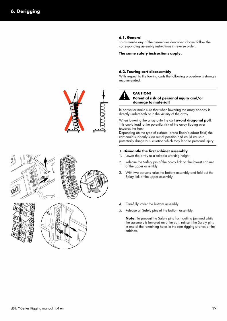
6.1. GeneralTo dismantle any of the assemblies described above, follow thecorresponding assembly instructions in reverse order.The same safety instructions apply.
6.2. Touring cart disassemblyWith respect to the touring carts the following procedure is stronglyrecommended.
CAUTION!Potential risk of personal injury and/ordamage to material!
In particular make sure that when lowering the array nobody isdirectly underneath or in the vicinity of the array.When lowering the array onto the cart avoid diagonal pull.This could lead to the potential risk of the array tipping overtowards the front.Depending on the type of surface (arena floor/outdoor field) thecart could suddenly slide out of position and could cause apotentially dangerous situation which may lead to personal injury.
1. Dismantle the first cabinet assembly1. Lower the array to a suitable working height.2. Release the Safety pin of the Splay link on the lowest cabinet
of the upper assembly.3. With two persons raise the bottom assembly and fold out the
Splay link of the upper assembly.
4. Carefully lower the bottom assembly.5. Release all Safety pins of the bottom assembly.
Note: To prevent the Safety pins from getting jammed whilethe assembly is lowered onto the cart, reinsert the Safety pinsin one of the remaining holes in the rear rigging strands of thecabinets.
6. Derigging
d&b Y-Series Rigging manual 1.4 en 39

6. Lower the array slowly and evenly onto the cart until the Frontlinks are load-free.
7. Release the Locking pins of the Front links on the top cabinet ofthe assembly while a second person renders support toprevent the upper suspended assembly from unpredictableswing.
8. Slowly lift the remaining assembly to allow the cart to beturned or moved aside.
Proceed in the same manner until the array is completelydismantled.
2. Reassembling the cart1. Slide in the Front links of the top cabinet and reinsert the
Locking pins.
2. Attach the connecting poles to the bottom tray and lock allfasteners (CamLocks).
3. Attach the top lid and lock all fasteners (CamLocks).
Note: The top lids of the touring carts are equipped withadditional guiding tracks to fix the cabinet assemblies in place.In conjunction with the E7470 Touring cart 4 x Y8/Y12observe the direction of attachment as shown in the graphicbelow.
d&b Y-Series Rigging manual 1.4 en40

7.1. Transport / StoringDuring transport ensure the rigging components are not stressed ordamaged by mechanical forces. Use suitable transport cases.We recommend the use of the d&b E7470 or E7471 Y Touringcart for this purpose.Due to their surface treatment the rigging components aretemporarily protected against moisture. However, ensure thecomponents are in a dry state while stored or during transport anduse.
7.2. Visual and functional inspection
WARNING!Potential risk of personal injury and/ordamage to material
To eliminate the potential risk of accident due to malfunctioning ofa component, regularly inspect all system components.
Cabinet enclosure– Visual inspection of all fitting plates for obvious damage (e.g.
cracks or corrosion).– Visual inspection of the rear rigging strand for obvious
damage (e.g. cracks, deformation or corrosion) including alldrilled holes of the component.
– Inspection of all fitting plates including front grills to ensurethey are securely attached.
– Regularly lubricate the sockets using WD-40® or a similarproduct.
Front and Splay (Rear) linksVisual inspection regarding deformation and damage (e.g. cracksand corrosion) including all drilled holes of the component.
Locking pins– Visual inspection for deformation, cracks and corrosion of the
component.– Inspection for missing ball bearings and damage.– Functional inspection of the release mechanism to ensure it
operates properly.– Regularly lubricate the Locking pins using WD-40® or a similar
product.
7. Care and maintenance / Disposal
d&b Y-Series Rigging manual 1.4 en 41

Ring cotters– Visual inspection for obvious damage and deformation.– Functional test of the locking mechanism as described in
Þ Chapter 2.4. "Ring cotters" on page 11.If a ring cotter can no longer be properly fitted to the fixingbolt and locked, it must be exchanged.
Z5390 Y Flying frame– Visual inspection regarding deformation and damage (e.g.
cracks and corrosion) including all drilled holes of thecomponent.
– Regularly check the flatness of the Flying frame. For thispurpose position the Flying frame on a flat surface and visuallycheck the frame for deformation and/or torsion. For obviousdeformation and/or torsion contact d&b audiotechnik forfurther advice on how to proceed.
Z5391 Y Hoist connector chain / Z5392 Y SafetychainsetInspection according to the appropriate regulations for liftingdevices (EN 818-6:2000). Regularly inspect within a 12 monthsperiod. Regularly inspect for cracks within a 36 months period.
7.3. DisposalWhen out of use the rigging components must be disposed of inaccordance with the national environmental regulations.Ensure that damaged rigging components are disposed of in away that they cannot be used again.
Condition of the ring cotter[a]: Ring cotter OK[b]: Exchange the ring cotter
d&b Y-Series Rigging manual 1.4 en42

We hereby declare that the equipment designated below isdesigned and built in the version sold by us in such a way as tocomply with the relevant fundamental safety and health criteria ofthe applicable EC Directive(s). This declaration shall cease to bevalid if alterations are made to the equipment without our prioragreement.This declaration covers:
d&b Y-Series loudspeaker cabinets(With integrated rigging components.)– Z0707 Y8– Z0708 Y12– Z0709 Y-SUB
d&b Y-Series rigging components(Including all additional components such as Load adapter, Frontlinks frame, shackles.)– Z5390 Y Flying frame– Z5391 Y Hoist connector chain– Z5392 Y Safety chainset
National standards and technical specificationsapplied:DIN EN ISO 12 100, DIN EN 1050, BGV C1.
Backnang, 2014-07-8
Frank Bothe,Head of R&Dd&b audiotechnik GmbH
8. Manufacturer's declaration
d&b Y-Series Rigging manual 1.4 en 43

D271
8.EN
.01, 0
9/20
17 ©
d&b a
udiot
echn
ik Gm
bH
www.dbaudio.com