yamaha - vintage snoprimary sheave cap and sliding sheave. d. remove the sheave subassembly tool....
TRANSCRIPT
_YAMAHA
supp
[Frame serial number: 8J5-038101 ~ 8J5-049999 ] Engine serial number: S246-038101 ~ S246-049999
LIT -12618-00-22 8J5-28197-10
1980 ET 250D
CONTENTS
( 1. NEW SERVICE PROCEDURE .. .................. .... ...... .... ......... ........... ............. 1
2 . MAINTENANCE INTERVALS ..... ...... .. ........... .... ............... ... ........ ........... .. 6
3 . SPECiFiCATIONS ..... ................ .................. ... .... ... ........ .... ........ .. .. ............. . 8
4. SPECIAL TOOLS .. ......... .. .. ... ... .... ...... ....... .. ...... ..... .... ...... .... .......... ..... ......... 13
5. WIRING DIAGRAM ... .... .... ..... ... ... ......... ............. .............. .. ....... ... .... .... ... ... 14
( 6 . WIRE ROUTING DIAGRAM/PIPING AND CONTROL
CABLE DIAGRAM ... .... .... .................. ... .. .. ............... ........ .... ............. ........ .. 15
1. NEW SERVICE PROCEDURE
(N ew service procedure applied to the 1980 ET250D)
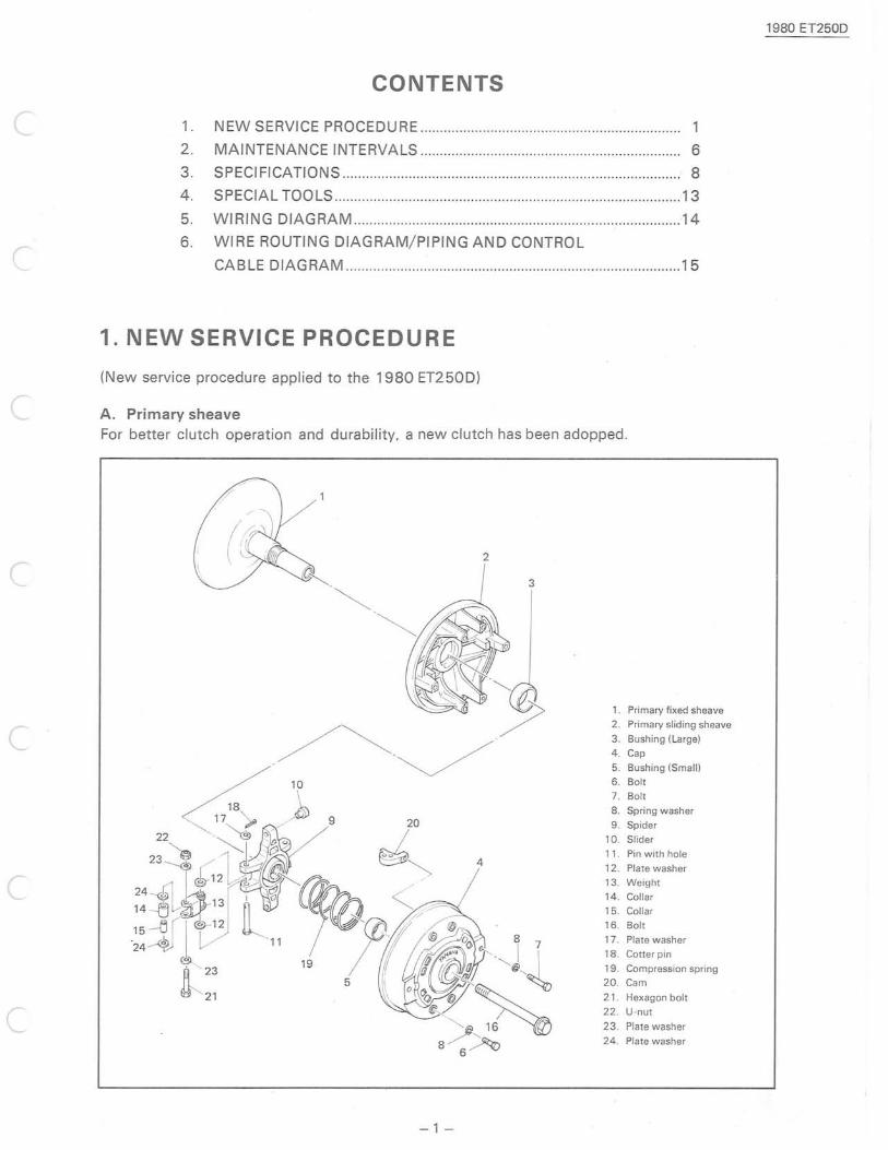
c A. Primary sheave For better clutch operation and durability, a new clutch has been adopped .
2
1. Primary fixed sheave
C 2_ Primary sliding sheave 3 _ Bushing (Large) 4 _ Cap 5_ Bushing (Small) 6_ Bolt 7_ Bolt 8_ Spring washer
20 9 _ Spider 10_ Sl ider
11. Pin with hole 4 12 _ Plate washer
C 13 _ Weight 14_ Collar 15_ Collar 16_ Bolt 17_ Plate washer 18_ Cotter pin 19_ Compression spring
5 20_ Cam
21. Hexagon bolt
C 22_ U-nut
23_ Plate washer 24_ Plate washer
- 1-
1980 ET250D
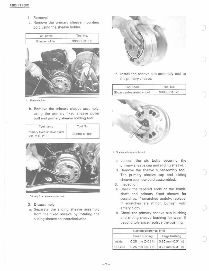
1. Removal a. Remove the primary sheave mounting
bolt using the sheave holder.
Tool name Tool No.
Sheave holder 90890-01880
1. Sheave holder
b. Remove the primary sheave assembly, using the primary fixed sheave puller bolt and primary sheave holding tool.
Tool name
Primary fixed sheave puller bolt (M 18 Pl.5)
1. Primary fixed sheave puller bolt
2. Disassembly
Tool No.
90890-01881
a. Separate the sliding sheave assembly from the fixed sheave by rotating the sliding sheave counterclockwise.
- 2-
b. Install the sheave sub-assembly tool to
the primary sheave.
Tool name Tool No.
Sheave sub-assembly tool 90890-01879
1 Sheave sub-assembly tool
c. Loosen the six bolts securing the primary sheave cap and sliding sheave.
d. Remove the sheave subassembly tool. The primary sheave cap and sliding sheave cap now be disassembled.
3 . Inspection a. Check the tapered ends of the crank
shaft and primary fixed sheave for scratches. If scratched unduly, replace. If scratches are minor, burnish with emery cloth.
b. Check the primary sheave cap bushing
and sliding sheave bushing for w ear. If beyond tolerance, replace the bushing .
bushing clearance, limit
Small bushing Large bushing
Inside 0 .25 mm (0.01 in) 0 .25 mm (0.01 in)
Outside 0.25 mm (0.01 in) 0 .25 mm (0.01 in)
)
)
r
c
(
c
c
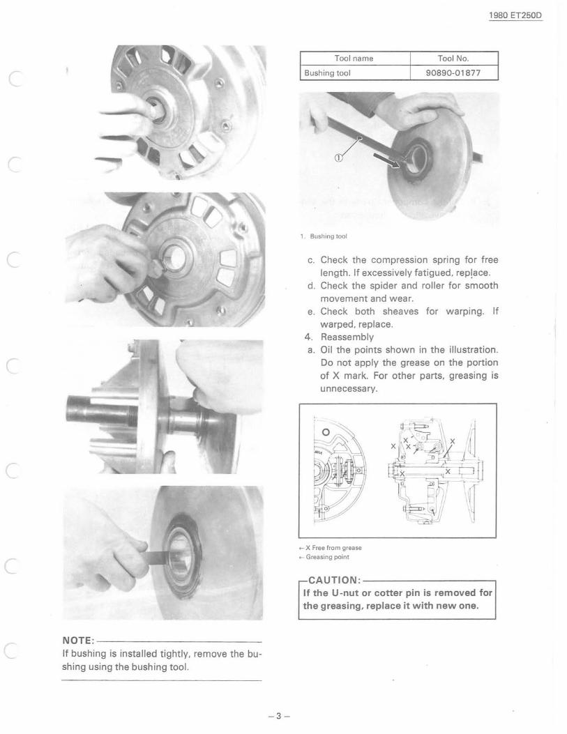
c NOTE:-------------------------If bushing is installed tightly, remove the bushing using the bushing tool.
-3-
1980 ET250D
Tool name Tool No.
Bushing tool 90890-01877
1. Bushing tool
c. Check the compression spring for free length. If excessively fatigued, rep!ace.
d. Check the spider and roller for smooth movement and wear.
e. Check both sheaves for warping. If warped, replace.
4. Reassembly a. Oil the points shown in the illustration .
Do not apply the grease on the portion of X mark. For other parts, greasing is unnecessary.
+- X Free from grease
+- Greasing point
CAUTION:-------------------, If the U -nut or cotter pin is removed for the greasing, replace it with new one.
1980 ET25lJD
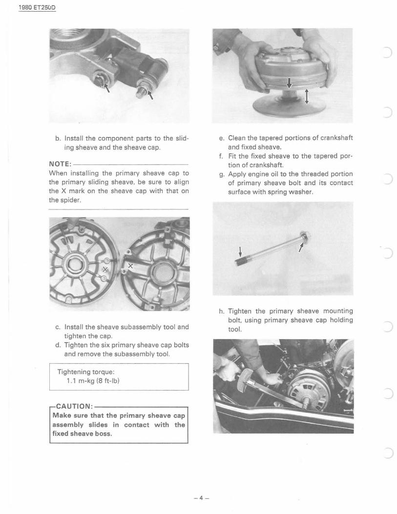
b. Install the component parts to the sliding sheave and the sheave cap.
NOTE:-------------------------When installing the primary sheave cap to the primary sliding sheave, be sure to align the X mark on the sheave cap with that on the spider.
c. Install the sheave subassembly tool and tighten the cap.
d. Tighten the six primary sheave cap bolts and remove the subassembly tool.
Tightening torque: 1.1 m-kg (8 ft-Ib)
CAUTION: --------------, Make sure that the primary sheave cap assembly slides in contact with the fixed sheave boss.
-4-
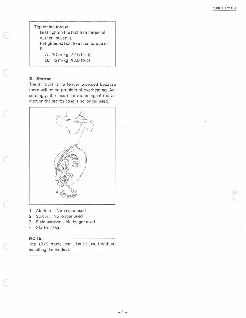
e. Clean the tapered portions of crankshaft
and fixed sheave. f. Fit the fixed sheave to the tapered por
tion of crankshaft. g. Apply engine oil to the threaded portion
of primary sheave bolt and its contact surface with spring washer.
,
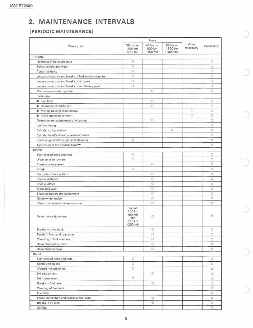
h. Tighten the primary sheave mounting bolt using primary sheave cap holding tool.
Tightening torque : First tighten the bolt to a torque of A then loosen it. Ret ightened bolt to a final torque of B.
A.: 10m-kg (72 .5 ft-Ibl B. : 6 m-kg (43.5 ft-Ibl
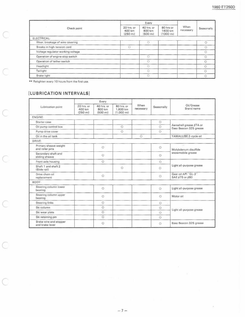
B. Starter
The air duct is no longer provided because there will be no problem of overheating. According ly, the insert for mounting of the air duct on the starter case is no longer used.
1. Air duct .. . No longer used 2 . Screw ... No longer used 3. Plain washer ... No longer used
4. Starter case
NOTE:-------------------------. The 1979 model can also be used without
installing the air duct.
1980 ET250D
- 5 -
1980 ET250D
2. MAINTENANCE INTERVALS [PERIODIC MAINTENANCE]
Every
Check point 20 hrs. or 40 hrs. or 80 hrs or When Seasonally
400 km 800 km 1600 km necessary
(2 50 mil (500 mil (1000 m il
ENGINE
Tightness of bolts and nuts 0 0
Bends. cracks and wear 0 0
Abnormal noise 0 0
Loose connection and breaks of fuel and pulse pipes 0 0
Loose connection and breaks of oil pipes 0 0
Loose connection and breaks of oil delivery pipe 0 0
Manual rope starter system 0 0
Carburetor
• Fuel level 0 0
• Operation of starter jet 0 0
• Mixing adjuster (pilot screw) 0 0
• Idling speed adjustment 0 0
Operation and adjustment of oil pump 0 0
Ignition timing 0
Cylinder compressions 0 0
Cylinder head/exhaust pipe decarbonize 0
Spark plug condition. gap and cleaning 0 0
Tightening of the cylinder head" 0
DRIVE :
Tightness of bolts and nuts 0 0
Wear on slide runners 0 0
Primary drive system 0 0
V-belt 0 0
Secondary drive system 0 0
Sheave distance 0 0
Sheave offset 0 0
Brake pad wear 0 0
Brake operation and adjustment 0 0
Guide wheel rubber 0 0
Wear of drive track wheel sprocket 0 0
Initial 100 km
Drive track adjustment (60 mil
0 0 and
300 km (200 mil
Breaks in drive track 0 0
Bends in front and rear axles 0 0
Checking of lock washers 0 0 "- Drive chain adjustment 0 0
Drive chain oil level 0 0
BODY
Tightness of bolts and nuts 0 0
Bends and cracks 0 0
Welded riveted. joints 0 0
Ski adjustment 0 0
Ski runner wear 0 0
Breaks in fuel tank 0 0
Cleaning of fuel tank 0
F,uel filter 0
Loose connection and breaks in fuel pipe 0 0
Breaks in oil tank 0 0
Oil filter 0
- 6 -
1980 ET250D
Every
Check point 20 hrs. or 40 hrs. or 80 hrs or When Seasonally
400 km 800 km 1600 km necessary
(250 mil (500 mil (1000 mil
ELECTRICAL:
Wear, breakage of wire covering 0 0
Breaks in high -tension cord 0 0
Voltage regu lator working voltage 0
Operation of engine stop switch 0 0
Operat ion of tether switch 0 0
Headlight 0 0
Taillight 0 0
Brake light 0 0
•• Retighten every 10 hours from the first use.
[LUBRICATION INTERVALS]
Every
Lubrication point 20 hrs, or 40 hrs. or 80 hrs, or When Seasonally
Oil/Grease
400 km 800 km 1,600 km necessary 8rand name
(2 50 mil (500 mil (1.000 mil
ENGINE :
Starter case 0
Oil pump contro l box 0 0 Aeroshell grease #7 A or Esso Beacon 325 grease
Pump drive cover 0 0
Oil in the oil tank 0 YAMALUB E 2-cycle oil
DR IVE :
Primary sheave weight 0 0 and roller pins Molybdenum disulfide
Secondary shaft and 0 snowmobile grease
sliding sheave 0
Front axle housing 0 0
Shaft 1 and shaft 2 0 Light all-purpose grease
(Slide raill 0
Drive chain oil 0 Gear oil API " GL-3"
replacement 0 SAE#750r #80
BODY :
Steering column lower 0 0 Light all-purpose grease bearing
Steering colu mn upper 0 0 Motor oil bearing
Steering links 0 0
Ski column 0 0
Ski wear plate 0 Light all -purpose grease
0
Ski retaining pi n 0 0
Brake wire end stopper 0 0 Esso 8eacon 325 grease and brake lever
-7 -
1980 ET250D
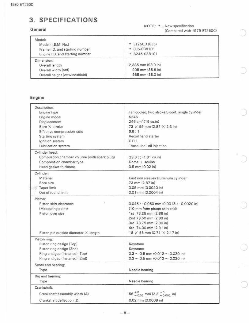
3. SPECIFICATIONS General
NOTE: * ... New specification (Compa red with 1979 ET250C)
Model:
Model (I.B.M. No) * ET250D (8J5)
Frame 1.0. and starting number * 8J5-038101
Engine 1.0. and starting number * S246-0381 01
Dimension:
Overall length 2 .385 mm (93.9 in)
Overall width (std) 905 mm (35.6 in)
Overall height (w/ windshield) 965 mm (38.0 in)
Engine
Description:
Engine type Fan cooled. two stroke 5-port. single cylinder
Engine model S246
Displacement 246 cm 3 (15 cu .in)
Bore X stroke 73 X 59 mm (2.87 X 2 .3 in)
Effective compression ratio 6.6: 1
Starting system Recoi l hand starter
Ignition system C.D.1.
Lubrication system "Autolube" oil injection
Cylinder head Combustion chamber volume (with spark plug) 29.6cc(1.81 cu.in)
Compression chamber type Dome + squish
Head gasket thickness 0.5 mm (0.02 in)
Cylinder:
Material Cast iron sleeves aluminum cylinder
Bore size 73 mm (2.87 in)
Taper limit 0.05 mm (0.0020 in)
Out of round limit 0.01 mm (0.0004 in)
Piston:
Piston skirt clearance 0.045 ~ 0.050 mm (0.00 18 ~ 0 .0020 in)
(Measuring point) (10 mm from piston skirt end)
Piston over size 1 st 73 .25 mm (2.88 in)
2nd 73.50 mm (2.89 in)
3rd 73.75 mm (2 .90 in)
4th 74.00 mm (2 .91 in)
Piston pin outside diameter X length 18 X 55 mm (0.71 X 2.17 in)
Piston ring:
Piston ring design (Top) Keystone
Piston ring design (2nd) Keystone Ring end gap (Installed) (Top) 0.3 ~ 0 .5 mm (0.012 ~ 0.020 in)
Ring end gap (Installed) (2nd) 0.3 ~ 0.5 mm (0.012 ~ 0.020 in)
Small end bearing:
Type Needle bearing
Big end bearing:
Type Needle bearing
Crankshaft:
Crankshaft assembly width (A) +0 +0. 56 _ 0.05 mm (2.2 _ 0.002 In)
Crankshaft deflection (D) 0.02 mm (0.0008 in)
- 8-
1980 ET250D
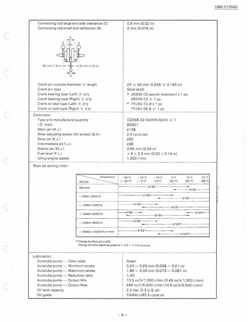
Connecting rod large end side clearance (C) 0 .5 mm (0.02 in)
Connecting rod small end deflection (S) 2 mm (0.079 in)
A r-----
D -
rrD~ cj~ 40 mm 116 in) 40 mm 11.6 in)
I -S
Crank pin outside diameter X length 24 X 55 mm (0.945 X 2.165 in) Crank pin type Solid shaft Crank bearing type (Left) X q'ty * #6306 C3 special treatment x 1 pc. Crank bearing type (Right) X q'ty #6206 C3 X 1 pc Crank oil seal type (Left) X q'ty * FPJ 30-72-8 x 1 pc. Cra nk oil sea l type (Right) X q'ty FPJ30-48-8 X 1 pc.
Carburetor:
Type and manufacture/ quantity CDX38-32 KEIHIN SEIKI X 1 I.D. mark 8G501 Main jet (M.J) #138 Slow adjusting screw (Air screw) (SA) 2.0 turns out Slow jet (SJ.) #50 Intermediate jet (I.J.) #38 St arter jet (St.J.) 0.95 mm (004 in) Fuel level (F. L.) + 5 ± 3 .5 mm (0.20 ± 0.14 in) Idling engine speed 1,300 r/ min
Main jet setting chart:
~ -30°C - 20 °C - 10 °C O°C 10°C 20° C
Altitud~ . 1- 22 °F) 1- 4 ° F) 114° F) 132 ° F) 150 ° F) 168 ° F)
#138 Sea level . #130 !
- 600m 12000 It) #138 . #1 30 ;
- 1200m (4000 It) #138 . #130
- 1800m 16000 It) - #138- -#125--
#130
#1 30 - 2400m 18000 It)
#12 5 -
# 125 -- 3000m 110000 It) or more . # 120 -
- Change the Slow jet to #45 Change the slow adjusting screw to 1-1/4 - 1-1 / 2 turns out.
Lubrication:
Autolube pump - Color code Green
Autolube pump - Minimum stroke 0 .20 ~ 0.25 mm (0.008 ~ 0.01 in)
Autolube pump - Maximum stroke 1.85 ~ 205 mm (0.073 ~ 0.081 in)
Autolube pump - Reduction ratio 1/ 40
Autolube pump - Output Min. 13.5 cc/h/l,300 r/min (0.46 oz/h/l,300 r/min) Autolube pump - Output Max. 440 cc/h/6,500 r/min (14.9 oz/h/6,500 r/min)
Oil tank capacity 2.2 liter (2 .3 U .S. qt)
Oil grade YAMALUBE 2-cycle oil
- 9 -
1980 ET250D
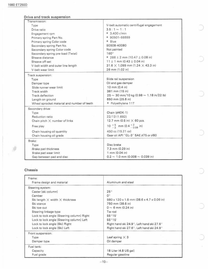
Drive and track suspension Transmission:
Type
Drive ratio
Engagement rpm
Primary spring Part No.
Primary spring Color code
Secondary spring Part No. Secondary spring Color code
Secondary spring pre-load (Twist)
Sheave distance
Sheave off-set
V-belt width and outer line length
V-belt wear limit
Track suspension:
Type
Damper type
Slide runner wear limit
Track width
Track deflection Length on ground
Wheel sprocket material and number of teeth
Secondary drive:
Type Reduction ratio
Chain pitch X number of links
Free play
Chain housing oil quantity
Chain housing oil grade
Brake:
Type
:Brake pad thickness Brake pad wear limit
Gap between pad and disc
Chassis
Frame:
Frame design and material
Steering system:
Caster (ski column)
Camber
Ski length X width X thickness
Ski stance Ski toe-out
Steering linkage type
Lock to lock angle (Steering column) Right
Lock to lock angle (Steering column) Left
Lock to lock angle (Ski) Right
Lock to lock angle (Ski) Left
Front suspension: Type
Damper type
Fuel tank:
Capacity Fuel grade
V-belt automatic centrifugal engagement
3.5: 1 ~ 1 : 1
* 3.400 r/ min * 90501-55559
* Blue 90508-40080
Not painted
160° * 266 ± 2 mm (10.47 ± 0.08 in)
11 ± 1 mm (0.43 ± 0.04 in)
31.6 X 1.099 mm (1.24 X 43.3 in)
26 mm (1 .02 in)
Slide rail suspension
Oil and gas damper
10 mm (0.4 in)
381 mm (15 in)
25 ~ 30 mm/l 0 kg (098 ~ 1.18 in/22 Ib)
650 mm (25 .6 in)
* Polyethylene 11 T
Chain (#40K-1)
22/ 13 (1692) 12 .7 mm (0.5 in) X 60 pcs.
1 0 ~ ~ mm (0.4 ~ ~08 in)
450 cc (15.21 oz)
Gear oil API "GL-3" SAE #75 or #80
Disc brake 7.3 mm (029 in)
1 mm (0.04 in) 0.2 ~ 1.0 mm (0008 ~ 0.039 in)
Aluminum and steel
25 °
0 ° 980 x 120 x 1.6 mm (38.6 x 4 .7 x 0.06 in)
750 mm (38.6 in) o ~ 6 mm (024 in)
Tie-rod
55 ° 15'
55 ° 15'
Right hand ski 24.9 ° , Left hand ski 27 .6 °
Right hand ski 27 .6 ° , Left hand ski 24.9 °
Leaf spring X 3
Oil damper
18 Liter (4.8 US gal) Regular gasoline
- 10-
19S0 ET250D
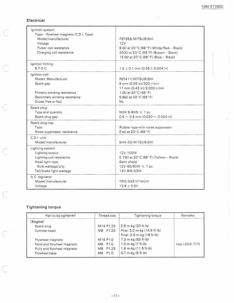
Electrical
Ignition system: Type-flywheel magneto (C.D.I. Type)
MOdel/manufacturer F3T355/MITSUBISHI Voltage lZV
Pulser coil resistance 9.0n at 20° C (68 ° F) (White/Red-Black) Charging coil resistance 350n at 20° C (6S 0F) (Brown- Black)
15.0n at 20° C (68 ° F) (Blue- Black)
Ignition timing: B.T.D.C. 1.2 ± 0.1 mm (0.05 ± 0.004 in)
Ignition coil: Model : Manufacturer F6T411/MITSUBISHI Spark gap 9 mm (0.35 in)/300 r/ min
11 mm (0.43 in)/3,000 r/min Primary winding resistance 1.0n at 20° C (68 ° F) Secondary winding resistance 5.9kn at 20° C (6S 0F) Diode (Yes or No) No
Spark plug: Type and quantity NGK B-SHS X 1 pc. Spark plug gap 0.5 ~ 0.6 mm (0.020 ~ 0.024 in)
Spark plug cap: Type Rubber type with noise suppressor Noise suppressor resistance 5 kn at 20° C (68 ° F)
C.D.I. unit:
Model/manufacturer 8H4-20/MITSUBISHI
Lighting system: Lighting output 12V-l00W
Lighting coil resistance 0.19n at 20° C (68 ° F) (Yellow-Black) Head light type Semi shield
Bulb wattage/q'ty 12V-60/60W X 1 pc. Tail/brake light wattage 12V-8W/23W
A.C. regulator: Model/manufactu rer TRIZ-24B HITACHI
Voltage 13.S ± 0.5V
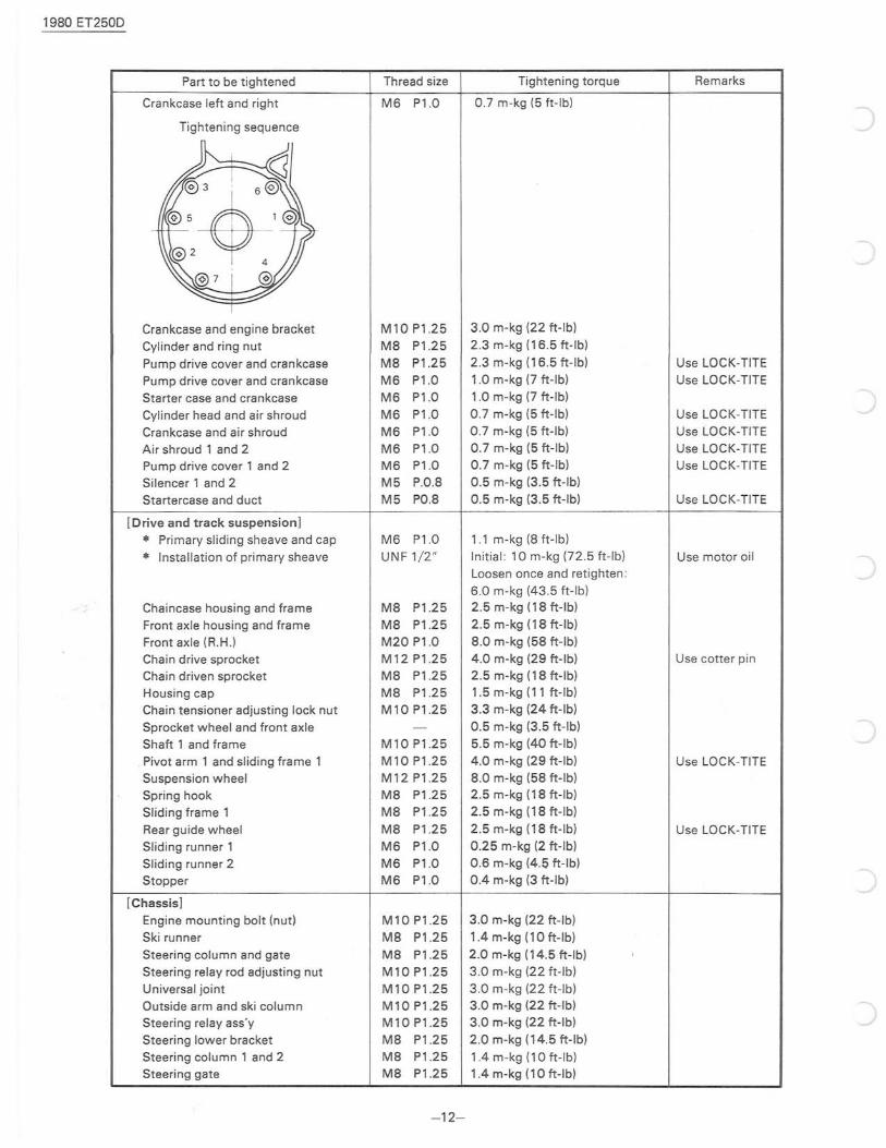
Tightening torque
Part to be tightened Thread size Tightening torque Remarks
[Engine]
Spark plug M14Pl.25 2.S m-kg (20 ft-Ib)
Cyl inder head MS Pl.25 First: 2.0 m-kg (14.5 ft -Ib) Final : 2.5 m-kg (18 ft-Ib)
Flywheel magneto M16 Pl.0 7.3 m-kg (53 ft -Ib)
Fand and flywheel magneto M6 Pl .0 1.0 m-kg (7 ft-Ib) Use LOCK-TITE
Pully and flywheel magneto M8 Pl.25 1.6 m-kg (11.5 ft-Ib)
Flywheel base M6 Pl .0 0 .7 m-kg (5 ft-Ib)
-11-
1980 ET250D
Part to be tightened
Crankcase left and right
Tightening sequence
1
Crankcase and engine bracket Cylinder and ring nut
Pump drive cover and crankcase Pump drive cover and crankcase Starter case and crankcase Cylinder head and air shroud
Crankcase and air shroud Air shroud 1 and 2 Pump drive cover 1 and 2 Silencer 1 and 2
Startercase and duct
[Drive and track suspension)
* Primary sliding sheave and cap
* Installation of primary sheave
Chaincase housing and frame Front axle housing and frame Front axle (R .H.) Chain drive sprocket Chain driven sprocket Housing cap Chain tensioner adjusting lock nut Sprocket whee l and front axle Shaft 1 and frame
. Pivot arm 1 and sliding frame 1 Suspension wheel Spring hook
Sliding frame 1 Rear guide wheel Sliding runner 1 Sliding runner 2 Stopper
[Chassis]
Engine mounting bolt (nut) Ski runner
Steering column and gate Steering relay rod adjusting nut
Universal joint Outside arm and ski column Steering relay ass'y
Steering lower bracket Steering column 1 and 2 Steering gate
Thread size
M6 P1.0
M10P1.25 M8 P1.25 M8 P1.25 M6 P1 .0 M6 P1.0
M6 P1.0 M6 P1 .0 M6 P1.0 M6 P1.0 M5 P.0.8 M5 PO.8
M6 P1.0 UNF 1/ 2"
M8 P1.25 M8 P1.25 M20 P1.0 M12P1.25 M8 P1.25 M8 P1.25 M10P1.25
M10P1.25 M10P1.25 M12 P1.25 M8 P1.25 M8 P1.25
M8 P1.25 M6 P1.0 M6 P1.0 M6 P1.0
M10P1 .25
M8 P1.25 M8 P1 .25
M10P1.25 M10P1.25 M10P1.25 M10P1.25 M8 P1.25 M8 P1.25 M8 P1.25
- 12-
Tightening torque
0.7 m-kg (5 ft -Ib)
3 .0 m-kg (22 ft-Ib) 2 .3 m-kg (16.5 ft-Ib)
2 .3 m-kg (16.5 ft-Ib) 1.0 m-kg (7 ft-Ib)
1.0 m-kg (7 ft -Ib) 0.7 m-kg (5 ft-Ib) 0.7 m-kg (5 ft-Ib) 0 .7 m-kg (5 ft-Ib) 0.7 m-kg (5 ft-Ib) 0.5 m-kg (3.5 ft-Ib) 0.5 m-kg (3.5 ft-Ib)
1.1 m-kg (8 ft-Ib)
Initial: 10m-kg (72.5 ft -Ib) Loosen once and retighten: 6.0 m-kg (43 .5 ft-Ib) 2.5 m-kg (18 ft-Ib)
2 .5 m-kg (18 ft-Ib) 8.0 m-kg (58 ft-Ib)
4.0 m-kg (29 ft-Ib) 2.5 m-kg (18 ft-Ib) 1.5 m-kg (11 ft- Ib) 3.3 m-kg (24 ft-Ib)
0.5 m-kg (3.5 ft-Ib) 5.5 m-kg (40 ft-Ib) 4.0 m-kg (29 ft-Ib) 8.0 m-kg (58 ft-Ib) 2.5 m-kg (18 ft-Ib) 2.5 m-kg (18 ft-Ib)
2.5 m-kg (18 ft-Ib) 0.25 m-kg (2 ft-Ib) 0.6 m-kg (4.5 ft-Ib) 0.4 m-kg (3 ft-Ib)
3 .0 m-kg (22 ft-Ib)
1.4 m-kg (10 ft-Ib)
2.0 m-kg (14.5 ft-Ib) 3 .0 m-kg (22 ft-Ib)
3.0 m-kg (22 ft-Ib) 3.0 m-kg (22 ft-Ib) 3 .0 m-kg (22 ft-Ib)
2.0 m-kg (14.5 ft-Ib)
1.4 m-kg (10 ft-Ib) 1.4 m-kg (10 ft-Ib)
Remarks
Use LOCK-TITE Use LOCK-TITE
Use LOCK-TITE Use LOCK-TITE Use LOCK-TITE Use LOCK-TITE
Use LOCK-TITE
Use motor oil
Use cotter pin
Use LOCK-TITE
Use LOCK-TITE
4.
( l-a_
l -b_
l-c. r
2-a.
(
( 2-c.
r No.
1-a
1-b
1-c
2-a
2 -b
2 -c
2 -d
2 -e
3
4
5-a
5-b
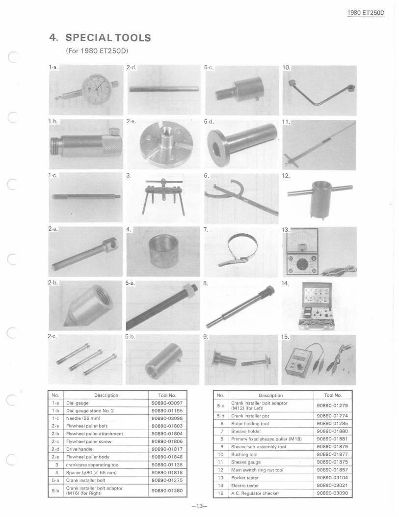
SPECIAL TOOLS (For 1980 ET250D)
2-d_
2-e.
3.
4.
5-b.
Description
Dial gauge
Dial gauge stand No.2
Needle (56 mm)
Flywheel puller bolt
Flywheel puller attachment
Flywheel puller screw
Drive handle
Flywheel puller body
crankcase separating tool
Spacer (<1>80 X 55 mm)
Crank installer bolt
Crank installer bolt adaptor (M16) (for Right)
1980 ET250D
5-c.
6. 12.
7. 13. - --'"
14.
9.
Tool No. No. Description Tool No.
90890-03097
90890-01195 5-c
Crank installer bolt adaptor 90890-01279
(M 12) (for Left)
90890-03098 5-d Crank installer pot 90890-01274
90890-01803 6 Rotor holding tool 90890-01235
90890-01804 7 Sheave holder 90890-01880
90890-01806 8 Primary fixed sheave puller (M18) 90890-01881
90890-01817 9 Sheave sub-assembly tool 90890-01879
90890-01848 10 Bushing tool 90890-01877
90890-01135 11 Sheave gauge 90890-01875
90890-01818 12 Main switch ring nut tool 90890-01857
90890-01275 13 Pocket tester 90890-03104
14 Electro tester 90890-03021 90890-01280
15 A.C. Regulator checker 90890-03090
-13-
-" ~ I
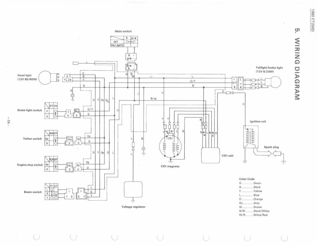
Main switch
Tai llight/brake light (12V 8!23W)
Head light (h (12V60!60W) ~
L ~
~ G I 11111 l III ,I G~' I I) ~~ Brake light switch
: G I y I Gyi ~ I L Y
G" I I I I I 01 il I
1
To"" .wi"h L
B/W
I " , B
w
o
Ignition coil
Eo,i" "'"' .wi"h D=rn :G y Gy o L L
~ Gy
0 :
--l r COl magneto
CO l unit
Color Code
G ................ Green
B ................ Black
q
,
_J Beam switch Y ..... ........... Yeliow
L . . ......... Blue
o ................ Orange ~
Gy .............. Gray Voltage regu lator Br .............. Brown
B! W .......... Black/White
W! R .......... White/ Red
U1
~ :l'J -2 G)
C -» G) :l'J » S
<.0 co o m --l N (J1 o o
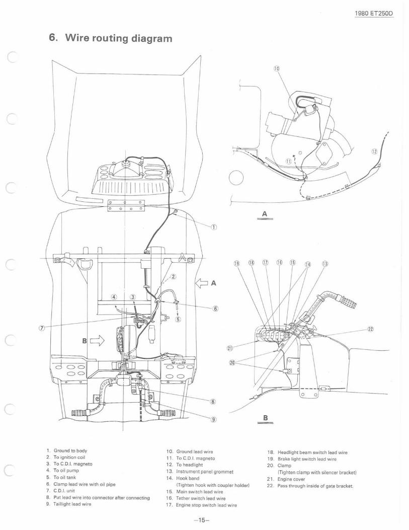
6. Wire routing diagram
r
r
c
1. G rou nd to body 10. 2. To ignition coil 11. 3 . To C.D.I. magneto 12. 4. To oil pump 13. 5. To oil tank 14. 6. Clamp lead wire with oil pipe
7. C.D.I. unit 15. 8. Put lead wire into connector after connecting 16. 9. Taillight lead wire 17 .
o A
B
Ground lead wire 18. To C.D.I. magneto 19. To headlight 20. Instrument panel grommet
Hook band 21 (Tighten hook with coupler holder) 22. Main switch lead wire
Tether switch lead wire
Engine stop switch lead wire
- 15-
/ I
I \ ....
Headlight beam switch lead wire
Brake light switch lead wire
Clamp
1980 ET250D
, , I
(Tighten clamp with silencer bracket)
Engine cover
Pass through inside of gate bracket.
1980 ET250D
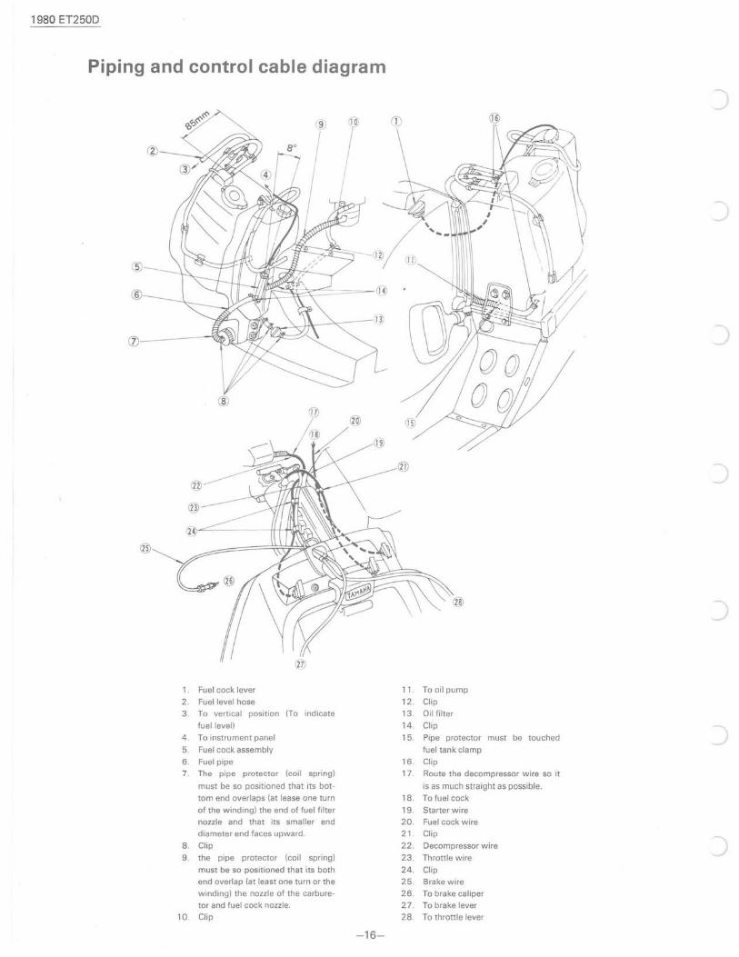
Piping and control cable diagram
®
(j)----~
@
®
@
®~------tH~;.\.l
Fuel cock lever
2. Fuel level hose
3. To vertical position (To indicate
fuellevell
4. To instrument panel
5. Fuel cock assembly
6. Fuel pipe 7. The pipe protector (coil spring)
must be so positioned that its bot
tom end overlaps (at lease one turn
of the winding) the end of fuel filter
nozzle and that its smaller end
diameter end faces upward.
8. Clip
9. the pipe protector (coil spring)
must be so positioned that its both
end overlap (at least one turn or the
winding) the nozzle of the carbure
tor and fuel cock nozzle.
10. Clip
-16-
11. To oil pump
12. Clip
13. Oil filter
14. Clip
15. Pipe protector must be touched
fuel tank clamp
16. Clip
17. Route the decompressor wire so it
is as much straight as possible.
18. To fuel cock
19. Starter wire
20. Fuel cock wire
21. Clip
22. Decompressor wire
23. Throttle wire
24. Clip
25. Brake wire
26. To brake caliper
27. To brake lever
28. To throttle lever