yankee nuclear plant siterelevant to the yankee nuclear power station (ynps) site. the hsa focuses...
TRANSCRIPT

Yankee Nuclear Plant Station Historical Site Assessment
Volume I
Yankee Atomic Electric Company
YNPS Historical Site Assessment Revision 1
Table of Contents Page 1 ABBREVIATIONS ______________________________________________ 1-1
2 EXECUTIVE SUMMARY ______________________________________________ 2-1
3 PURPOSE OF THE HISTORICAL SITE ASSESSMENT__________________________ 3-1
4 PROPERTY IDENTIFICATION ______________________________________________ 4-1
4.1 PHYSICAL CHARACTERISTICS _____________________________________________ 4-1 4.1.1 License Holder ______________________________________________ 4-1 4.1.2 Location ______________________________________________ 4-1 4.1.3 Topography ______________________________________________ 4-1 4.1.4 Stratigraphy ______________________________________________ 4-1
4.2 ENVIRONMENTAL SETTING ______________________________________________ 4-2
5 HISTORICAL SITE ASSESSMENT AND SURVEY AREA DELINEATION _________ 5-1
5.1 APPROACH AND RATIONALE _____________________________________________ 5-1 5.2 BOUNDARIES OF THE SITE ______________________________________________ 5-4 5.3 DOCUMENTS REVIEWED ______________________________________________ 5-5 5.4 PROPERTY INSPECTIONS ______________________________________________ 5-6 5.5 PERSONNEL INTERVIEWS ______________________________________________ 5-7
6 HISTORY ______________________________________________ 6-1
6.1 LICENSING HISTORY ______________________________________________ 6-1 6.2 REGULATORY INVOLVEMENT_____________________________________________ 6-2 6.3 FACILITY DESCRIPTION ______________________________________________ 6-3
6.3.1 Description of Operations Impacting Site Radiological Status ___________ 6-4 6.3.2 Unplanned Events______________________________________________ 6-5
6.3.2.1 Unplanned Gaseous Releases______________________________ 6-6 6.3.2.2 Unplanned Liquid Releases _______________________________ 6-6
6.3.3 Waste Handling Procedures ______________________________________ 6-6 6.4 ADJACENT LAND USE ______________________________________________ 6-7
7 FINDINGS ______________________________________________ 7-1
7.1 OVERVIEW ______________________________________________ 7-1 7.2 NON-IMPACTED AREA ASSESSMENT ________________________________________ 7-2
7.2.1 Non-Impacted Area Description___________________________________ 7-2 7.2.2 Decommissioning Activities______________________________________ 7-2 7.2.3 Basis of Area Classification ______________________________________ 7-3 7.2.4 Occurrence of Anthropologic Radionuclides in the Environmental
Background ______________________________________________ 7-3 7.2.5 Evaluation of the Impact of Elevated Releases in Particulate Radioactive
Material ______________________________________________ 7-3 7.2.6 Approach and Methodology for Evaluation of the Non-Impacted Area_____ 7-4 7.2.7 Non-Impacted Area Justification Summary __________________________ 7-4
7.3 POTENTIALLY CONTAMINATED AREAS ______________________________________ 7-5 7.3.1 Radionuclides of Concern________________________________________ 7-5 7.3.2 Impacted Areas ______________________________________________ 7-6
7.3.2.1 Buildings, Structures and Open Land Areas Inside the RCA______ 7-6 7.3.2.1.1 Buildings _____________________________________ 7-6 7.3.2.1.2 Yard Structures _______________________________ 7-14 7.3.2.1.3 Open Land Areas______________________________ 7-27 7.3.2.2 Buildings, Structures and Open Land Areas Outside the RCA ___ 7-33
i

YNPS Historical Site Assessment Revision 1
7.3.2.2.1 Buildings and Structures ________________________ 7-34 7.3.2.2.2 Open Land Areas Outside of the RCA______________ 7-43
7.4 CONTAMINATED MEDIA _____________________________________________ 7-57 7.5 RELATED ENVIRONMENTAL CONCERNS ____________________________________ 7-57
8 REFERENCES ______________________________________________ 8-1
APPENDIX A1 HISTORY OF PLANT GASEOUS RELEASES __________________________ A1-1
APPENDIX A2 SUMMARIES OF THE SIGNIFICANT EVENTS AT THE YNPS SITE _____ A2-1
VOLUME II HISTORICAL SITE ASSESSMENT AND CLASSIFICATION SUMMARIES
List of Tables TABLE 6-1 AOR/PIR LIST OF UNPLANNED LIQUID RELEASES ___________________ 6-9
TABLE 7-1 FLOOR AND TOTAL AREA OF BUILDINGS AND FEATURES __________ 7-59
TABLE 7-2 AREA OF OPEN LAND SURVEY AREAS _____________________________ 7-60
TABLE 7-3 CURRENT RADIOLOGICAL CONDITIONS OF BUILDINGS IN THE INDUSTRIAL AREA _____________________________________________ 7-61
TABLE 7-4 SUMMARY OF RADIOLOGICAL CONDITIONS OF OPEN LAND AREAS (SOF = SUM OF FRACTIONS OF SOIL DCGLS) _______________________ 7-63
TABLE 7-5 RADIONUCLIDES OF CONCERN AT YNPS ___________________________ 7-65
List of Figures FIGURE 7-1A PRELIMINARY LAND SURFACE IMPACTED AREA BOUNDARIES
FIGURE 7-1B PRELIMINARY LAND SURFACE IMPACTED AREA BOUNDARIES (CON’T)
FIGURE 7-2 PRELIMINARY STRUCTURE SURVEY AREA BOUNDARIES
FIGURE 7-3 PRELIMINARY LAND SURFACE IMPACTED AREA CLASSIFICATIONS
FIGURE 7-4 PRELIMINARY STRUCTURE CLASSIFICATIONS
FIGURE 7-5 LOCATIONS OF SAMPLES TO DETERMINE BACKGROUND CS-137 IN SOIL
FIGURE 7-6 HISTORIC EXPANSION OF RCA BOUNDARIES
ii

YNPS Historical Site Assessment Revision 1
1 Abbreviations AEC Atomic Energy Commission
ALARA As Low As Reasonably Achievable
AOR Abnormal Occurrence Report
ASWS Auxiliary Service Water System
BRT Buried Ring Tonnage - Subsurface Reactor Support Structure (RSS) consisting of poured reinforced concrete
CFR Code of Federal Regulations
cpm Counts Per Minute
DCGL Derived Concentration Guideline Level
DCGLEMC DCGL for small areas of elevated activity, used with the EMC
DCGLW DCGL for average concentrations over a wide area, used
with statistical tests DOT Department of Transportation
dpm Disintegrations Per Minute
DQO Data Quality Objectives
DWP Decommissioning Work Plan
ECN Engineering Change Notice
EMC Elevated Measurement Comparison
EPA Environmental Protection Agency
FCN Field Change Notice
FERC Federal Energy Regulatory Commission
GM Geiger-Mueller
1-1

YNPS Historical Site Assessment Revision 1
GPS Global Positioning System
GWSI Ground Water Site Inventory
HP Health Physics
HSA Historical Site Assessment
IX Pit Ion Exchange Pit
LLD Lower Limit of Detection
LLRWPA Low Level Radioactive Waste Policy Act as Amended
MARSSIM Multi-Agency Radiation Survey and Site Investigation Manual
MCA Multi-Channel Analyzer
MDA Minimum Detectable Activity
MDC Minimum Detectable Concentration
MDCR Minimum Detectable Count Rate
MPC Maximum Permissible Concentrations
NPDES National Pollutant Discharge Elimination System
NRC Nuclear Regulatory Commission
ORISE Oak Ridge Institute for Science and Education
ORNL Oak Ridge National Laboratory
PAB Primary Auxiliary Building
PCA Potentially Contaminated Area
PIC Pressurized Ionization Chamber
PIR Plant Information Report
QA Quality Assurance
QAPP Quality Assurance Project Plan
1-2

YNPS Historical Site Assessment Revision 1
QC Quality Control
QMP Quality Management Plan
RC Release Criterion
RCA Radiation Control Area
RI/FS Remedial Investigation/Feasibility Study
RP Radiation Protection
RSS Reactor Support Structure
RSSI Radiation Survey and Site Investigation
SARA Superfund Amendments and Reauthorization Act
SFP Spent Fuel Pit or Spent Fuel Pool
SIDG Safety Injection and Diesel Building
SOP Step Off Pad
SSWP Secondary Side Work Plan
Tech Spec Technical Specification (part of plant license)
TRU Transuranics
USGEN USGEN New England Inc.
USGS United States Geological Survey
VCC Vertical Concrete Cask
YAEC Yankee Atomic Electric Company
YNPS Yankee Nuclear Power Station
1-3

YNPS Historical Site Assessment Revision 1
This page intentionally left blank.
1-4

YNPS Historical Site Assessment Revision 1
2 Executive Summary This Historical Site Assessment (HSA) describes the Yankee Nuclear Power Station (YNPS) site, surrounding environs, and adjacent property. The HSA documents the construction, operational and decommissioning histories and the current use of the YNPS site. The HSA identifies radioactive contaminants potentially present at the YNPS site due to plant operations and describes the media likely to contain these contaminants. The HSA documents the historical information used to justify survey area classifications (Class 1, Class 2 or Class 3) as described in NUREG-1575 guidance. The HSA describes impacted areas and the known distribution of contaminants within these areas. It also provides justification for designating other areas as non-impacted. The HSA contains two volumes. Volume I is a summary report that:
Outlines the methodology used to perform the HSA. • • •
Describes the history and current status of the site. Provides findings from review of the site documents.
Volume II provides the following for each survey area: • Survey area description. • Survey area history.
− Translocation pathways. − Scoping/characterization activities performed in the area. − Decommissioning activities performed in the area.
• Findings. − Current status summary. − Classification statement.
• Tables identifying samples collected to date and comparison of the results with the site criteria.
The enclosed CD (Master Reference List) includes reference lists for each of the Volume II survey area sections, and many are hyperlinked to the actual referenced document. See the electronic file folder entitled “Reference List” for those documents.
2-1

YNPS Historical Site Assessment Revision 1
This page intentionally left blank.
2-2

YNPS Historical Site Assessment Revision 1
3 Purpose of the Historical Site Assessment The purpose of this Historical Site Assessment (HSA) is to document a comprehensive investigation that identifies, collects, organizes, and evaluates historical information relevant to the Yankee Nuclear Power Station (YNPS) site. The HSA focuses on open land areas and those structures that will remain at the time of final status survey. The HSA does not address portions of structures or structural systems that are being removed from the site or that will be verified, using existing procedures, to contain no measurable amounts of radioactive contamination (such as plumbing, buried piping, and storm and floor drains). The HSA describes the site's physical configuration, identifies the radioactive constituents of site contamination, assesses the migration of contaminants, identifies contaminated media, identifies non-impacted and impacted areas, and classifies impacted areas. Guidance contained in NUREG-1575 (MARSSIM), “Multi-Agency Radiation Survey and Site Investigation Manual” (Reference 1) was used to classify site areas as Class 1, Class 2 or Class 3 Survey Areas. The HSA supplements the information provided in the License Termination Plan (LTP) for the YNPS site.
3-1

YNPS Historical Site Assessment Revision 1
This page intentionally left blank.
3-2

YNPS Historical Site Assessment Revision 1
4 Property Identification
4.1 Physical Characteristics
4.1.1 License Holder Yankee Atomic Electric Company (YAEC) is the holder of Possession Only License (POL) No. DPR-3 (Reference 2). Yankee Atomic Electric Company 19 Midstate Drive, Suite 200 Auburn, Massachusetts 01501
4.1.2 Location Yankee Nuclear Power Station 49 Yankee Road Rowe, Massachusetts 01367 The Yankee Nuclear Power Station is located in the town of Rowe, in Franklin County of the Commonwealth of Massachusetts. This site is three-quarters of a mile south of the Vermont-Massachusetts border. The geographical coordinates of the centerline of the reactor containment structure (Vapor Container) are as follows: Latitude: North 42 degrees, 43 minutes, 42 seconds Longitude: West 72 degrees, 55 minutes, 42 seconds
4.1.3 Topography The location of YNPS is identified on the USGS 7.5 minute quadrangle map Rowe Massachusetts – Vermont (42072-F8-TF-024, 1973, DMA III NW-SERIES V814) (Reference 3).
4.1.4 Stratigraphy Information on site stratigraphy was taken from the Environmental Characterization Summary, Yankee Nuclear Power Plant Site, June 2000 (Reference 4). This detailed information may be viewed in Section 4 of the Master Reference List on the CD included with this document.
4-1
YNPS Historical Site Assessment Revision 1
4.2 Environmental Setting The information pertaining to Geology, Hydrogeology/Hydrology, and Meteorology has been obtained from the Decommissioning Environmental Report - pages 3.16 through 3.24 (Reference 5). This detailed information may be viewed in Section 4 of the Master Reference List on the CD included with this document.
4-2

YNPS Historical Site Assessment Revision 1
5 Historical Site Assessment and Survey Area Delineation
5.1 Approach and Rationale This Historical Site Assessment (HSA) documents those events and circumstances occurring during the history of the facility that contributed to the contamination of portions of the site environs above background levels. Information relevant to changes in the radiological status of the site following publication of the HSA will be considered a part of the ongoing characterization evaluations and decommissioning activities. These ongoing activities include the expansion of the site groundwater investigation and evaluations of subsurface contamination. The results of the ongoing investigations into the extent of subsurface contamination will drive continuing remediation and/or mitigation efforts as appropriate. The HSA involved collecting, organizing, and evaluating information that described the YNPS site in terms of physical configuration and the extent to which the site was radioactively contaminated as a result of plant operations and decommissioning activities. The HSA information was used to bound and classify survey areas. The boundaries of the identified survey areas, as depicted in Figures 7-1a, 7-1b, 7-2, 7-3, and 7-4, were based on operational history, including recorded significant events, common radiological profiles, and, where appropriate, parcel ownership boundaries. The preliminary survey area classifications and sizes are shown in Tables 7-1 for structures and 7-2 for open land areas. Survey areas for structures will be broken into multiple survey units where appropriate in order to meet the survey unit size limitations recommended by NUREG-1575 (Reference 1). All open land survey area boundaries have been sized to meet the NUREG-1575 size limitation constraints. The general criteria used to classify the survey areas were drawn from the regulatory guidance of NUREG-1575 (MARSSIM) as follows: Non-impacted Area: Areas where there is no reasonable possibility (extremely low
probability) of residual contamination. Non-impacted areas are typically off-site and may be used as background reference areas.
Impacted Area: Areas that are not classified as non-impacted. These are areas that
could possibly contain residual radioactivity in excess of natural background or fallout levels. All impacted areas must be classified as Class 1, 2 or 3 as described in NUREG-1575.
Class 1 Area: Impacted areas that have, or had prior to remediation, a potential for
radioactive contamination (based on site operating history) or known contamination (based on previous radiological surveys) above the DCGL. Size limitations are ≤ 100 sq. m for structures and ≤ 2000 sq. m. for open land areas.
5-1

YNPS Historical Site Assessment Revision 1
Class 2 Area: Impacted areas that have a potential for radioactive contamination or known contamination, but are not expected to exceed the DCGL. Size limitations are > 100 sq. m and ≤ 1000 sq. m for structures and > 2000 sq. m and ≤ 10,000 sq. m for open land areas.
Class 3 Area: Impacted areas that are not expected to contain any residual radioactivity,
or are expected to contain levels of residual radioactivity at a small fraction of the DCGL, based on site operating history and previous radiological surveys. There are no size limitations for Class 3 areas.
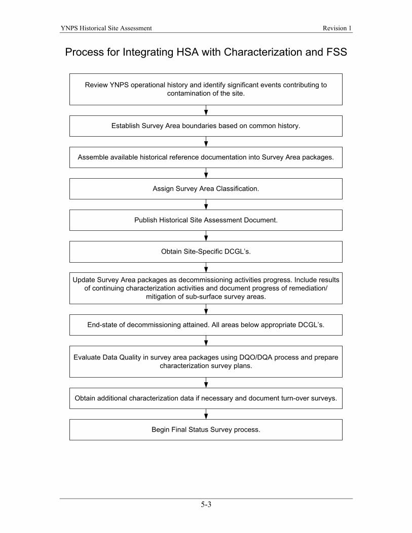
The collection and evaluation of site radiological information are conducted under approved site procedures. The output of this process is the information generated for each survey area that is used in the preparation of survey plans. Information collected for each survey area includes a detailed description of the survey area, an operational history, an evaluation of past and current translocation pathways, and a description of the status of decommissioning work. The findings section for each survey area includes an assessment of radiological contaminants, contaminated media, current radiological status, results of any subsurface mitigation or remediation efforts, and remaining decommissioning activities. The general process for integrating the HSA with continuing characterization and the Final Status Survey (performed after remediation to confirm that the site release criteria have been met) is shown in the following flowchart.
5-2
YNPS Historical Site Assessment Revision 1
Process for Integrating HSA with Characterization and FSS
Review YNPS operational history and identify significant events contributing tocontamination of the site.
Establish Survey Area boundaries based on common history.
Assemble available historical reference documentation into Survey Area packages.
Assign Survey Area Classification.
Publish Historical Site Assessment Document.
Obtain Site-Specific DCGL’s.
Update Survey Area packages as decommissioning activities progress. Include resultsof continuing characterization activities and document progress of remediation/
mitigation of sub-surface survey areas.
End-state of decommissioning attained. All areas below appropriate DCGL’s.
Evaluate Data Quality in survey area packages using DQO/DQA process and preparecharacterization survey plans.
Obtain additional characterization data if necessary and document turn-over surveys.
Begin Final Status Survey process.
5-3

YNPS Historical Site Assessment Revision 1
Over the operational history of the YNPS site, the term "remediation" was often used to refer to any process involving the removal of radioactive media. For the purpose of license termination activities, "remediation" is narrowly defined as efforts specifically conducted to reduce the quantity or concentration of radioactivity to a level below the appropriate Derived Concentration Guideline Level (DCGL). Other processes may be referred to as “mitigation” or routine decommissioning activities.
5.2 Boundaries of the Site The YNPS site consists of about 2,200 acres on both sides of the Deerfield River in the towns of Rowe and Monroe, in Franklin County, Commonwealth of Massachusetts. Figure 1, “Soil Sample Locations – Site Overview,” located in the beginning of Volume II of this document, shows the boundaries of the site and plant exclusion area. The “YAEC Deed Study Project Rowe and Monroe, Massachusetts,” dated December 18, 1998, (Reference 6) provides information concerning properties that make up the YAEC site and current abutments. YAEC or USGen New England, Inc. (USGen) own all of the land located within the licensed site property boundary, and all of the property within the exclusion boundary is under the control of YAEC. The USGen property is generally located along the riverbank and Sherman Reservoir. The portions of the YAEC industrial area located on USGen property are the circulating water discharge seal pit, the Screenwell Pump House, and the meteorological tower located on the peninsula at the northeast corner of the site. USGen also owns that portion of the northeast yard area that fronts Sherman Reservoir and the property outside of the industrial area fence located between Yankee Road and the Deerfield River. A portion of the USGen property is considered impacted by licensed activities and is included in license termination activities. Two public secondary roads traverse the exclusion area. The first, Tunnel Road, is across the river from the plant, approximately 1,500 feet away at its closest point, and runs north and south along the river connecting the towns of Monroe, Massachusetts and Readsboro, Vermont. The second, Monroe Hill Road, is approximately 2500 feet away from the plant at its nearest point and is located southwest of the plant and runs between the towns of Rowe and Monroe, Massachusetts. During the early site history, a public rail line ran through the industrial area. This rail line and the associated spur facilitated construction of YNPS and spent fuel shipments. Currently, there are no rail lines that traverse or are adjacent to the YNPS site. Most of the site area is wooded with very steep grades on both sides of the Deerfield River. Features of the site include the Yankee Nuclear Power Station, the YNPS Independent Spent Fuel Storage Installation (ISFSI), the USGen Sherman Station hydroelectric plant, Sherman Reservoir and Dam, the transmission lines running through the site, the Yankee Administration Building and the Yankee Visitor Center (Furlon House).
5-4

YNPS Historical Site Assessment Revision 1
5.3 Documents Reviewed In performing the YNPS Historical Site Assessment (HSA), the following documents were reviewed:
• License and Technical Specifications. − Technical Specification Changes. − License Amendments.
• Original Plant Design. − Function and purpose of systems and structures. − Plant operating parameters. − Plant operating procedures.
• Original Plant Construction Drawings and Photographs. − Specifications for systems and structures. − Field Changes/as built drawings. − Site Conditions.
• Plant Operating History. − Abnormal Operating Reports (AOR). − Licensee Event Reports (LER). − Plant Information Reports (PIR). − Radiological Occurrence Reports (ROR). − Radiological Incident Reports (RIR). − Condition Reports (CR). − Plant Operating Procedures Regarding Spills and Unplanned Releases. − Plant Operations Logbooks. − Radiological Environmental Monitoring Program and Radiological
Environmental Technical Specification Reports (REMP & RETS). − Monthly Plant Operations Reports. − Semi-Annual Plant Operations Reports.
• Work Control Documents and Site Modifications. − Job Orders. − Plant Alterations. − Engineering Design Change Requests (EDCR). − Plant Modifications. − Maintenance Requests.
• Radiological Surveys and Assessments. − Radiological surveys performed in support of normal plant operations and
maintenance. − Radiological surveys performed in support of special plant operations and
maintenance. − Radiological assessments performed in response to radioactive spills or
events. − Scoping and characterization surveys performed as part of
Decommissioning Plan development.
5-5
YNPS Historical Site Assessment Revision 1
− Remediation support surveys conducted during decommissioning activities.
− Surveys conducted under the guidance of NUREG/CR-5849. • The historical evaluations performed for the previously submitted LTP. • The YAEC Decommissioning Plan.
− Decommissioning Work Plans. − Secondary Side Work Plans. − Engineering Change Notifications. − Field Change Notifications. − Temporary Change Requests.
• The documented radiological end point of decommissioning activities. • Documentation of remediation area stabilization and restoration activities.
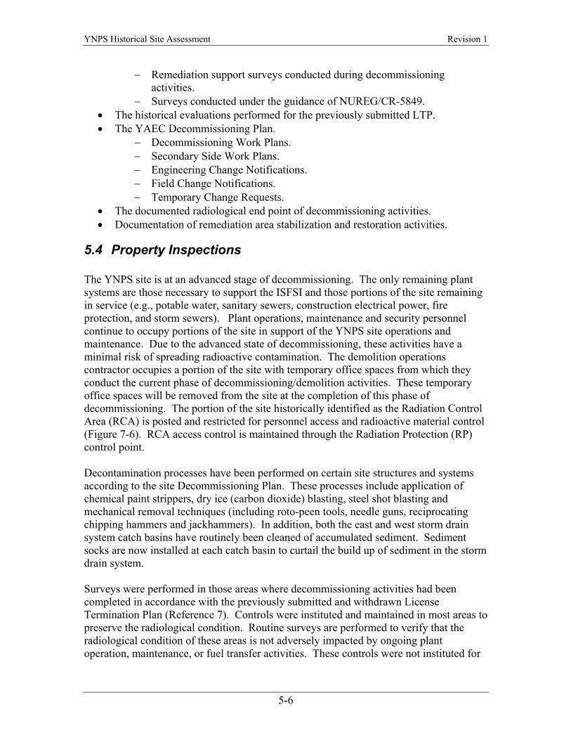
5.4 Property Inspections The YNPS site is at an advanced stage of decommissioning. The only remaining plant systems are those necessary to support the ISFSI and those portions of the site remaining in service (e.g., potable water, sanitary sewers, construction electrical power, fire protection, and storm sewers). Plant operations, maintenance and security personnel continue to occupy portions of the site in support of the YNPS site operations and maintenance. Due to the advanced state of decommissioning, these activities have a minimal risk of spreading radioactive contamination. The demolition operations contractor occupies a portion of the site with temporary office spaces from which they conduct the current phase of decommissioning/demolition activities. These temporary office spaces will be removed from the site at the completion of this phase of decommissioning. The portion of the site historically identified as the Radiation Control Area (RCA) is posted and restricted for personnel access and radioactive material control (Figure 7-6). RCA access control is maintained through the Radiation Protection (RP) control point. Decontamination processes have been performed on certain site structures and systems according to the site Decommissioning Plan. These processes include application of chemical paint strippers, dry ice (carbon dioxide) blasting, steel shot blasting and mechanical removal techniques (including roto-peen tools, needle guns, reciprocating chipping hammers and jackhammers). In addition, both the east and west storm drain system catch basins have routinely been cleaned of accumulated sediment. Sediment socks are now installed at each catch basin to curtail the build up of sediment in the storm drain system. Surveys were performed in those areas where decommissioning activities had been completed in accordance with the previously submitted and withdrawn License Termination Plan (Reference 7). Controls were instituted and maintained in most areas to preserve the radiological condition. Routine surveys are performed to verify that the radiological condition of these areas is not adversely impacted by ongoing plant operation, maintenance, or fuel transfer activities. These controls were not instituted for
5-6
YNPS Historical Site Assessment Revision 1
areas in which FSS activities were placed on hold or where it was not practical to maintain the controls because of decommissioning work in adjacent areas. Decommissioning activities have disturbed and/or excavated soils in certain survey areas. Extensive soil evaluations have been performed during removal of sub-grade components/systems. They have also been performed in conjunction with site modifications necessary for the construction of the ISFSI and for the upgrade of security measures around the spent fuel pool. Piles of excavated soil are located in several areas of the site. Controls are in place to track the location of these soils from the point of origin (excavation) through temporary onsite storage to final disposition. Disturbed/excavated soils that were evaluated and verified to have radiological constituents at non-detectable levels (below the environmental Lower Limit of Detection (LLD) for soils) were used as backfill in some excavated areas. Excavated soils contaminated above a very preliminary DCGL protocol were packaged and disposed of as radioactive waste. This DCGL protocol allowed some soils contaminated above background to be used as backfill in some locations. Retrospectively, the criterion used for the approval of the use of slightly contaminated soils as backfill is lower than the currently proposed DCGL. As these areas are evaluated for survey planning, the backfilled soil results will be evaluated against the soil DCGL for mitigation action. During the evaluation of survey areas, walk-downs of each area were performed to document the types of survey media remaining, or expected to remain, at project end-state. The walk-downs also documented the current decommissioning status of the area and identified any potential radionuclide translocation pathways that may have impacted the area or any contiguous survey areas. Such translocation pathways include ongoing decommissioning activities and environmental transport pathways, including sub-surface migration of radioactivity by surface water infiltration, wind, surface water run-off, or wildlife.
5.5 Personnel Interviews At the time of plant shutdown in 1992, personnel interviews were conducted as a part of an exit interview process in order to capture information of historical value. Since that time additional personnel interviews have been conducted in order to obtain additional information on plant operations and practices.
5-7
YNPS Historical Site Assessment Revision 1
This page intentionally left blank.
5-8
YNPS Historical Site Assessment Revision 1
6 History
6.1 Licensing History Yankee Atomic Electric Company is the holder of Yankee Nuclear Power Station Facility Operating License DPR-3 issued under the authority of the Atomic Energy Commission (AEC). Yankee Nuclear Power Station achieved initial criticality in 1960 and began commercial operations in 1961. The original thermal power design limit of 485 MWt was upgraded to 600 MWt in 1963. On February 26, 1992, the YAEC Board of Directors decided to cease power operations permanently at YNPS. On August 5, 1992, the NRC amended the YNPS Facility Operating License to a possession only status. The YNPS Decommissioning Plan (Reference 8) was submitted in March 1994 and received NRC approval in October 1996. In 2000, in response to updated regulations for decommissioning, Yankee created a Post-Shutdown Decommissioning Activities Report (PSDAR) within the Final Safety Analysis Report (FSAR). NRC Draft Regulatory Guide DG-1071 recommends that licensees with approved Decommissioning Plans (D Plans) “extract pertinent detail from the decommissioning plan and submit a PSDAR update in the format and content specified by [DG-1071].” Based on the NRC draft guidance, Yankee segregated, updated and condensed certain information concerning post-shutdown decommissioning activities in a manner that conforms to the standard format and content of a PSDAR. In May 1997, Yankee submitted to the NRC for approval a License Termination Plan (LTP) for YNPS, pursuant to 10CFR50.82(a)(9) and in accordance with Draft NUREG/CR-5849 (Reference 9). Subsequent changes in NRC regulations regarding license termination and the adoption of NUREG-1575 (Reference 1) as the final status survey standard led to withdrawal of the original LTP in May 1999 by Yankee Atomic Electric Company. A new LTP was submitted in November 2003 incorporating the NUREG-1575 (MARSSIM) final status survey methodology and also reflecting the regulations and regulatory guidance issued since the original LTP submittal. Decommissioning activities completed as of January 2000 already removed the majority of systems and components not required to support the storage of spent fuel in the spent fuel pit. Detailed planning for the transfer of spent fuel from the spent fuel pit began in February 2000. In June 2003, the transfer of all fuel and Greater Than Class “C” (GTCC) waste from the Spent Fuel Pit to the ISFSI was completed. A total of fifteen dry casks containing spent fuel and one cask containing GTCC were transferred for storage on the ISFSI pad. Decommissioning activities resumed during the summer of 2003 with the draining of the SFP and the commencement of building demolition.
6-1

YNPS Historical Site Assessment Revision 1
6.2 Regulatory Involvement NRC inspectors from Region I offices perform quarterly onsite inspections of YNPS site activities. Periodic calls are also held with NRC headquarters and Region I staff to monitor plant status and decommissioning progress. The NRC is notified of any incidents on site per the existing protocol established with NRC Region I and NRC reporting regulations. The decommissioning of the YNPS site is being performed under various Federal, State and local requirements in addition to NRC regulations. For example, YNPS is subject to OSHA regulations in 29 CFR 1910 and 1926 for worker health and safety protection. Asbestos and lead-based paint handling and removal are also subject to the OSHA regulations and the EPA regulations in 40 CFR Part 61. State and EPA requirements will be met for PCB paint removal activities. YNPS will also be required to meet the state standards for surface water and groundwater. The Commonwealth of Massachusetts Department of Public Health also has state radiological remediation standards. Compliance with the state standards is not addressed in this document. This issue will be addressed in separate correspondence with the Commonwealth. Permits and approvals from, or notifications to, several State (Commonwealth) and local agencies are required for safety and environmental protection purposes. Some of these permits are for specific decommissioning activities and others are for existing site facilities and ongoing activities that are necessary to support decommissioning. The following is a partial listing of permits and approvals, anticipated or already obtained, for decommissioning activities.
• Air emissions from the burning of diesel fuel are regulated by the Commonwealth of Massachusetts, Department of Environmental Protection, Division of Air Quality Control.
• Non-radioactive liquid effluents are regulated by the Commonwealth of
Massachusetts, Department of Environmental Protection, Division of Water Pollution Control.
• Liquid effluents are controlled under the National Pollutant Discharge
Elimination System (NPDES permit) under the EPA and State (Commonwealth) approvals.
• Building permits may be required by the Town of Rowe, Massachusetts, for
temporary field office facilities constructed on the plant site to support decommissioning activities. The Town of Rowe uses the Uniform Building Code for evaluating building permit applications.
6-2

YNPS Historical Site Assessment Revision 1
• The site potable water wells are operated under permits from the Commonwealth of Massachusetts, Department of Environmental Protection, Division of Water Supply.
• Hazardous waste generation is regulated by the Commonwealth of Massachusetts,
Department of Environmental Protection, Division of Hazardous Waste. Notification of the generator status and annual reporting are conducted in accordance with Massachusetts regulations.
• The Commonwealth of Massachusetts, Department of Labor and Industries,
Division of Industrial Safety, regulates the installation, removal and encapsulation of friable asbestos-containing materials and lead-based paint. All non-radiological solid waste will be handled and disposed of in accordance with State and local rules and regulations.
• The Commonwealth of Massachusetts, Department of Public Health, Radiological
Control Program, and the Vermont State Health Department, Division of Occupational and Radiological Health, are notified in advance of all placarded shipments of radioactive waste. In addition, the Governors of all affected States receive advance notifications in accordance with 10 CFR 71.97, “Advance notification of shipment of nuclear waste.”
• Licenses are required for radio communications by the Federal Communications
Commission. • PCB paints will be removed from all exposed concrete surfaces prior to
demolition of the structures, in accordance with the Alternate Method of Disposal Authorization (AMDA) requirements imposed by the EPA on October 8, 2002 and subsequent changes thereto.
6.3 Facility Description The Yankee Nuclear Power Station operated a Westinghouse Electric Corporation design, four loop, pressurized water reactor, with an original thermal power design limit of 485 MWt. The thermal power design limit was upgraded to 600 MWt in 1963. The turbine generator, also designed by Westinghouse Electric Corporation, was originally rated to produce 167 MWe. Following the thermal power upgrade, the turbine generator design allowed an increase in production capacity to 185 MWe (Reference 10).
6-3
YNPS Historical Site Assessment Revision 1
6.3.1 Description of Circumstances Impacting Site Radiological Status
Normal plant operations were expected to result in contamination of certain areas of the site and these areas were designed to contain such material; however, below is a list of events and conditions that occurred throughout the plant history (through 1994) that resulted in radioactive material being deposited in other locations. As a result, the plant design and operational procedures evolved to accommodate or eliminate these circumstances. Review of the early operational history of the site drew heavily on the Plant Superintendent's "Monthly Operating Reports" (Reference 11). The following events and circumstances, listed in chronological order, contributed to the residual contamination now found on the site.
• Mechanical wear and corrosion in the initial set of control rods caused the release of elemental silver and nickel into the reactor coolant that resulted in the distribution of radioactive silver and nickel in plant systems and on equipment during the first refueling. [circa 1960's]
• Storage of the refueling equipment and radioactive waste outdoors distributed
contaminants, including radioactive silver, within the RCA yard area.
• Snow removal activities performed in the RCA caused a redistribution of accumulated surface contamination to areas outside the RCA where snow was plowed or dumped.
• Rain falling on yard areas in the RCA caused redistribution of low level
contamination into low lying areas of the RCA and into the storm drain system.
• Leaks in the radioactive systems in the Ion Exchange (IX) Pit resulted in contamination of the water in the IX Pit. A defect in the construction of the IX Pit concrete allowed the contaminated water to leak, resulting in contamination of the subsurface soils, asphalt, and concrete surrounding the IX Pit and adjoining structures (1963 through 1965).
• Wear on internal valve components made of stellite resulted in the introduction of
wear particles into the reactor primary system. These particles were activated to gamma emitting Co-60 during plant power operations. Some particles associated with fuel fragments were also generated during plant operations. Maintenance on primary system components resulted in the contamination of tools and equipment. Although not a frequent occurrence, Co-60 particles have been identified and removed during surveys of the yard area. The particles associated with fuel fragments have not been identified in open yard areas. They were generally confined to controlled contamination areas.
6-4

YNPS Historical Site Assessment Revision 1
• A failure of a check valve allowed shutdown cooling water to backflow into the
seal water system, contaminating the normally clean seal water system up to and including the vent port on the PAB roof.
• The outdoor North and South decontamination facilities/pads resulted in
contamination of the soils around the pads.
• The repair of a damaged reactor cooling pump motor on the turbine deck resulted in general contamination of the turbine building. Areas specifically affected were the turbine deck and control room.
• In the mid-1970s, YNPS converted from stainless steel to zirconium clad fuel
pins. Some of the zirconium fuel pins failed in the reactor due to water jetting. This resulted in a release of fuel pellets directly into the reactor coolant system. This event changed the isotopic mix within the Reactor Coolant System. In particular, detectable quantities of fission products such as Cs-137 and Cs-134 were dispersed throughout the primary side plant systems and the fuel handling facility for the first time in the plant operating history.
• During a refueling outage in 1981, while relocating the reactor head to its outside
storage location, the reactor head made contact with the wall above the equipment hatch in the Vapor Container. The impact dislodged particulate radioactivity that had been adhered to the under side of the reactor head. This incident resulted in contamination of the RCA yard area under and around the equipment hatch.
• Construction of the original PCA storage facility included a PVC drainpipe that
connected the PCA storage building to the Waste Disposal Building. The PVC pipe joints failed, allowing liquid to flow from the drainpipe into the surrounding soil.
• The use of an underwater plasma torch to section the reactor internals resulted in
the release of highly radioactive cutting debris into the shield tank cavity shield water. This changed the radionuclide mix of the residual contamination in the shield tank cavity and, to a certain extent, in the Spent Fuel Pit.
6.3.2 Unplanned Events A comprehensive review of all recorded events outside normal operational conditions was performed to identify those events that contributed to contamination of the site. These events were typically documented in reports to regulatory authorities and included Abnormal Occurrence Reports (AORs), Plant Incident Reports (PIRs), Licensee Event Reports (LERs), and Condition Reports (CRs). Where available, the information in these reports was supplemented by supporting documents such as plant memoranda and radiological survey data.
6-5
YNPS Historical Site Assessment Revision 1
6.3.2.1 Unplanned Gaseous Releases Over the lifetime of the plant, a number of unplanned gaseous release events occurred. Short descriptions of these gaseous events, as described in AOR/PIR/LERs, are documented in Appendix A-1. These gaseous release events did not contribute significantly to residual contamination at YNPS. A detailed study of the particulate releases during the entire operating history of YNPS is used to justify the non-impacted status for a majority of the YAEC property (Reference 15). This study considered the impact of particulate emissions from the Primary Vent Stack (PVS) as well as those from the radioactive waste incinerator. The batch incinerator emissions were considered to be of negligible impact when compared to the particulate releases from the PVS over the life of the plant. A careful review of the PVS discharges did not reveal any unmonitored particulate component that could have significantly contributed to the long-term contamination of the site or its environs.
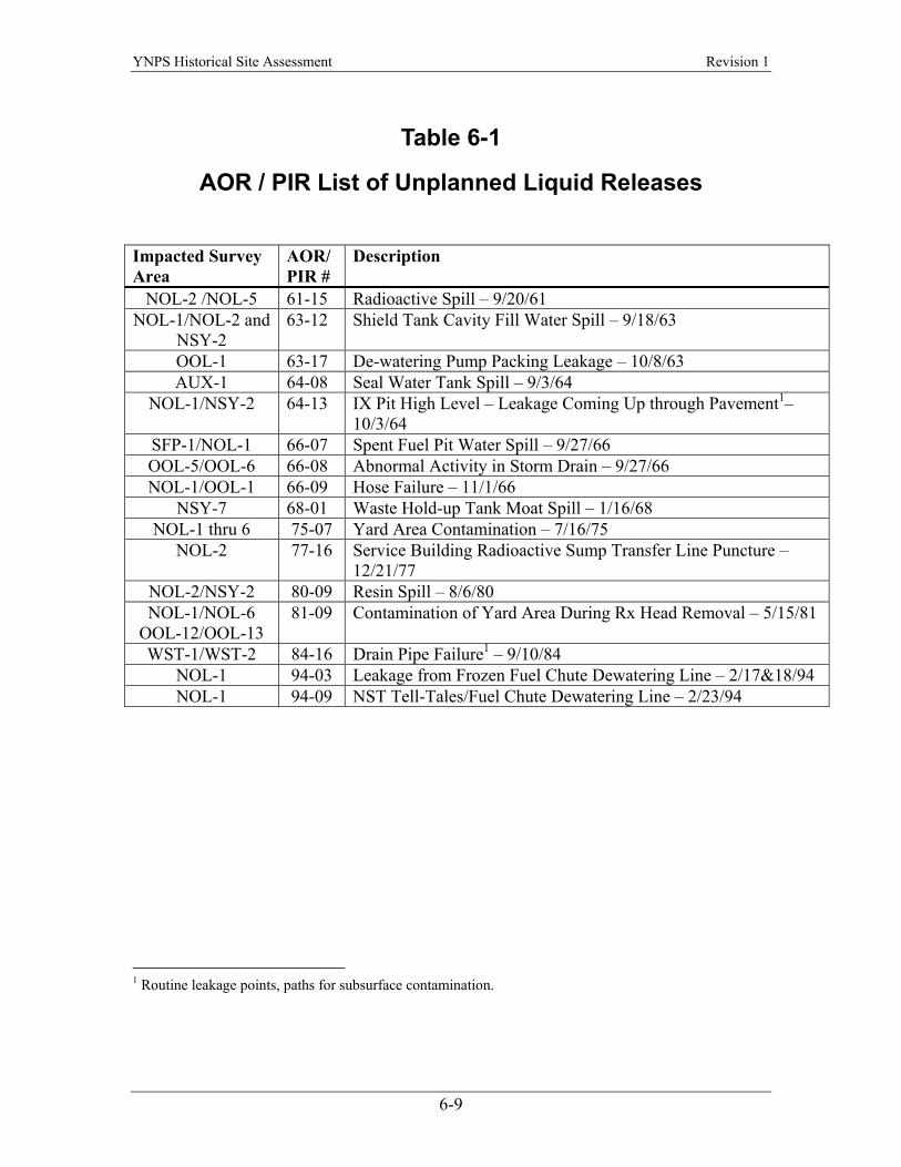
6.3.2.2 Unplanned Liquid Releases Several AORs and PIRs documented unplanned liquid releases that contaminated site grounds, buildings and subsurface locations. When subsurface contamination investigations were not performed due to inaccessibility or were not completed to a level suitable for license termination, these locations were targeted for continuing characterization investigation. Table 6-1 lists the events that resulted in contamination of the site. Appendix A-2 provides a brief summary of each event and an assessment of survey areas that were impacted.
6.3.3 Waste Handling Procedures The Technical Specifications of the YAEC license described the processes for handling radioactive waste generated as a byproduct of plant operation. The waste handling procedures were intended to contain, adequately treat, and dispose of these radioactive byproducts. The waste disposal system used several basic methods to treat and dispose of radioactive material (Reference 10):
• Retention in storage to allow natural decay of short lived radioactive isotopes. • Filtration and ion exchange to remove radioactive constituents from liquids. • Evaporation to concentrate radioactive constituents. • Filtration by charcoal and high efficiency particulate air filters for gaseous
discharge. • Dilution of low-activity liquid and gaseous discharges.
6-6

YNPS Historical Site Assessment Revision 1
Spent fuel was removed from the site and shipped to a reprocessing facility in the early years of plant operation. The last spent fuel shipments from YNPS occurred in 1971. After that date, spent fuel remained on site in the SFP. This spent fuel now has been transferred to the YNPS Independent Spent Fuel Storage Installation (ISFSI).
6.4 Adjacent Land Use The following paragraphs describe the features and uses of land within 5 miles of the plant. Included is a summary of the population centers within 10 miles of the YNPS site. Major Bodies of Water: In addition to Sherman Pond and the Deerfield River (including branches and brooks feeding it), other major bodies of water are located within 5 miles of the YNPS site. These include: Sadawga Pond (184 acres), Shippee Pond (25 acres), North Pond (17 acres), and Clara Lake (12 acres) in Whitingham, Vermont; Howe Pond (42 acres) in Readsboro, Vermont; and Bear Swamp Upper Reservoir (128 acres) and Pelham Lake (89 acres) in Rowe, Massachusetts. Industry: There are no exclusively commercial areas within 5 miles of the plant. The only industries within the area are the YNPS and USGen New England’s hydroelectric stations. USGen has five powerhouses within 5 miles of YNPS. There are three stations that are part of the Deerfield River Project and they are the Harriman, Sherman, and No. 5 Stations. In addition, the Bear Swamp and Fife Brook stations are a part of the Bear Swamp Pumped Storage Facility. Public Lands and Conservation Areas: There are several public lands/conservation areas within 5 miles of the YNPS site. These areas offer a variety of recreational opportunities including fishing, hunting, boating, swimming, picnicking, and hiking. Schools: There are two schools within 5 miles of the plant. Rowe Elementary is located about 2.5 miles southeast of the site on Pond Road in Rowe, Massachusetts. Readsboro Central School is located off Route 100 near the center of Readsboro, Vermont. Farms: Information was collected by YAEC to document the nearest garden and milk animal locations. These locations include farms, private gardens, and dairying locations. Water Supplies: Water supplies within the Deerfield River Drainage Basin, including the entire area within 5 miles of the plant, generally consist of private wells. The only communal source of water within 5 miles of the plant site is Phelps Brook, which services some of the residents of Monroe, Massachusetts. Beyond 5 miles, downstream there are two small water supply wells servicing local private developments: the Deerfield River Club and the Heath Stage Apartments in Charlemont, Massachusetts. Still further downstream, the closest public water supply wells, Stillwater Springs, are in the town of Deerfield, 20 to 25 miles south of the YNPS. Stillwater Springs has a safe yield of about 120,000 gallons per day. This well field is immediately adjacent to the Deerfield River. Another supply well, the Deerfield Well Field, off Route 116, has been
6-7

YNPS Historical Site Assessment Revision 1
closed due to contamination from nearby agricultural uses. The Quabbin Reservoir, serving the greater Boston area, is 35 to 40 miles southeast of the YNPS. Population: The population within 10 miles of the site is estimated to be 39,300 people and includes 17 municipalities in two states. North Adams, MA is the most populous municipality. In general, the area is rural.
6-8
YNPS Historical Site Assessment Revision 1
Table 6-1
AOR / PIR List of Unplanned Liquid Releases
Impacted Survey Area
AOR/PIR #
Description
NOL-2 /NOL-5 61-15 Radioactive Spill – 9/20/61 NOL-1/NOL-2 and
NSY-2 63-12 Shield Tank Cavity Fill Water Spill – 9/18/63
OOL-1 63-17 De-watering Pump Packing Leakage – 10/8/63 AUX-1 64-08 Seal Water Tank Spill – 9/3/64
NOL-1/NSY-2 64-13 IX Pit High Level – Leakage Coming Up through Pavement1– 10/3/64
SFP-1/NOL-1 66-07 Spent Fuel Pit Water Spill – 9/27/66 OOL-5/OOL-6 66-08 Abnormal Activity in Storm Drain – 9/27/66 NOL-1/OOL-1 66-09 Hose Failure – 11/1/66
NSY-7 68-01 Waste Hold-up Tank Moat Spill – 1/16/68 NOL-1 thru 6 75-07 Yard Area Contamination – 7/16/75
NOL-2 77-16 Service Building Radioactive Sump Transfer Line Puncture – 12/21/77
NOL-2/NSY-2 80-09 Resin Spill – 8/6/80 NOL-1/NOL-6
OOL-12/OOL-13 81-09 Contamination of Yard Area During Rx Head Removal – 5/15/81
WST-1/WST-2 84-16 Drain Pipe Failure1 – 9/10/84 NOL-1 94-03 Leakage from Frozen Fuel Chute Dewatering Line – 2/17&18/94 NOL-1 94-09 NST Tell-Tales/Fuel Chute Dewatering Line – 2/23/94
1 Routine leakage points, paths for subsurface contamination.
6-9

YNPS Historical Site Assessment Revision 1
This page intentionally left blank.
6-10

YNPS Historical Site Assessment Revision 1
7 Findings
7.1 Overview An in-depth assessment of the operational history was used to bound and classify survey areas in accordance with NUREG-1575. Generally, of the approximately 2200 acres of land that comprise the YNPS site, less than 30 acres were impacted by plant operations. The preliminary boundaries of the impacted areas are depicted in Figures 7-1a, 7-1b and 7-2. Tables 7-1 and 7-2 list the survey area dimensions and their classifications in a tabular format. Impacted area classifications are shown in Figures 7-3 and 7-4 on a color-coded site map. The majority of the site property is considered to be non-impacted by YNPS operations (approximately 2170 acres). The site property lines defining the outer boundaries of the non-impacted area (NIA) are shown relative to the size of the site industrial area in Figure 7-5. A detailed assessment of the condition of the NIA and the justification for the assignment of a non-impacted status is provided in Section 7.2. Of the approximately 30 acres that are impacted, most are only minimally impacted and, as such, are classified as a group of Class 3 open land survey areas arranged around the perimeter of the impacted area. These Class 3 open land survey areas completely surround the site industrial area and embrace the farthest extent to which potential pathways could have introduced site-related radioactivity into the surrounding environment. Some other Class 3 open land survey areas, identified in Figure 7-1b, are isolated from the impacted areas; however, these areas received material, primarily soil, from plant locations that were impacted. The Class 2 open land survey areas that abut the Class 1 open land survey areas may have locations containing detectable activity; however, these areas are not expected to yield measurements of radioactivity in excess of the DCGL. This creates a buffer zone that will be subjected to a higher level of assessment based upon its likelihood of containing radioactivity at some fraction of the DCGL. Class 1 open land survey areas are identified based upon historical information that suggests the potential for radioactivity exits at levels greater than the DCGL. These areas are mostly located within the boundaries of the historical RCA. Boundaries of the RCA are shown on Figure 7-6. Table 7-4 summarizes the radiological conditions of open land areas, the associated MARSSIM classifications, and the total land area by survey area. All of the different media from each survey area were systematically sampled and analyzed for radioactivity. The radiological condition of each area and its media were expressed as the minimum, maximum, and mean of the sum of fractions of the interim DCGL for soils. The samples were all collected in 1997/1998 as part of the land area survey performed under the guidance of NUREG/CR5849. The interim DCGLs were calculated in support of the LTP development process and those calculations are used here for comparison. Prior to
7-1
YNPS Historical Site Assessment Revision 1
the completion of this HSA, the final proposed DCGLs were calculated. A discussion of this comparison is presented later in Section 7.3 of this HSA. Subsurface soils and subsurface structures/systems that are located within or that traverse an open land survey area will be evaluated separately as described in Section 2.6 of the Yankee Nuclear Plant Site License Termination Plan (LTP), Revision 0 (Reference 20). If subsurface areas or structures are found to be impacted they will be removed, remediated or mitigated, as appropriate, until the clean-up criteria have been met. All YNPS structures associated with the site are considered impacted to some extent by plant operations and are located within an impacted open land survey area. Few of the structures on site will remain after the current phase of decommissioning. The majority of structures will be demolished to grade leaving reinforced concrete floor slabs, foundations, and sub-grade structures. The floor slabs and adjoining interior walls may be included within a given survey unit dependent on surface area size limitations. Table 7-1 summarizes the structure survey area classifications and the total interior area to be surveyed. A summary of the current radiological conditions of structures and buildings has been tabulated by survey area and this is presented in Table 7-3.
7.2 Non-Impacted Area Justification
7.2.1 Non-Impacted Area Description The majority of the land surrounding the industrial area is classified as non-impacted by MARSSIM criteria. This portion of the site is open land consisting of approximately 2170 acres. This non-impacted land completely surrounds the industrial area. The non-impacted area is bounded on the east and south by Monroe State Forest, on the southeast by USGen property, on the west by Readsboro Road (with the exception of an 89 acre plot on Kingsley Hill Road), and on the north by the Massachusetts/Vermont state line. The non-impacted area was not involved in plant operations and consists mostly of rugged terrain which is forested and undisturbed. Power lines traverse the area in a northeast by east direction (see Figure 7-5). The general site is shown on USGS map Rowe, Massachusetts-Vermont (Reference 3).
7.2.2 Decommissioning Activities There were no decommissioning or remediation activities performed in the non-impacted area. Most of the area is forested. The power line right-of-way is cleared of trees.
7-2

YNPS Historical Site Assessment Revision 1
7.2.3 Basis of Area Classification The basis for the non-impacted classification of this survey unit is that there is no reasonable possibility of residual contamination (References 13, 14 and 15): • Samples collected as part of the Radiological Environmental Monitoring Program
(REMP) throughout the plant’s operational and post-operational history show no evidence of any significant radiological impact due to plant operations;
• Aerial photographs from 1966, 1970, 1974, 1980, 1981, 1982, 1989, and 1990 show
no evidence of soil disturbance; • Using a Gaussian dispersion/deposition model, a conservative evaluation of the
potential impact of particulate effluents to soils outside of the industrial area supports the conclusion that this source of plant-derived radioactive material would be expected to contribute (at a maximum) only a very small fraction of the DCGL. Beyond the impacted area boundary, concentrations of plant-derived radioactive material would be non-detectable and indistinguishable from background.
• A statistical comparison of soil sample analytical data from the non-impacted areas
and an environmentally equivalent reference area (unaffected by plant releases) was performed (Reference 13).
7.2.4 Occurrence of Anthropogenic Radionuclides in the Environmental Background
According to the National Council on Radiation Protection and Measurements (References 16, 17 and 18), radionuclides present in the environmental background are both naturally occurring and man-made. Carbon-14 is introduced cosmogenically and by the atmospheric detonation of nuclear weapons. Tritium is also introduced cosmogenically and through atmospheric detonation of nuclear weapons. Cesium-137 and Strontium-90 are fission products that occur in the environment as a result of atmospheric nuclear weapon detonations.
7.2.5 Evaluation of the Impact of Elevated Releases of Particulate Radioactive Material
YRC-1178 (Reference 15) provides a conservative evaluation of the deposition of particulate activity in gaseous effluents over the operating history of YNPS. The study examined Semi-Annual Effluent Reports and Monthly Operating Reports that contain the total activity, by radionuclide, released from the plant in airborne particulate form. This study substantiates the fact that the non-impacted area was not impacted by particulate releases from the Primary Vent Stack.
7-3

YNPS Historical Site Assessment Revision 1
Investigation during HSA preparations in 2003 revealed that the radioactive waste incinerator was actually operated until 1975 rather than the February 1964 date cited in YRC-1178. The discharge from the incinerator was passed through a water bath type scrubber and a particulate filter. The effluent was sampled in batch mode for particulate radioactivity. A follow-up study (YA-REPT-00-002-004, Evaluation of Effluent Releases from Onsite Incineration of Waste”, Reference 21) was conducted to re-examine ground level discharges of gaseous effluent in particulate form originating from the on-site radioactive waste incinerator for the time period not included in YRC-1178. This study supports the conclusion that the operation of the incinerator had a negligible impact on the long term contamination of the site environs.
7.2.6 Approach and Methodology for Evaluation of the Non-Impacted Area
Thirty (30) surface soil samples were collected from the non-impacted area in August of 1998. The location of each sample point and the general location of the plant site relative to the survey area are presented in Figure 7-5. In 1996, sixty (60) surface soil samples also were obtained from a reference area that was beyond the boundaries of the YNPS-owned property. Two types of statistical tests were performed to evaluate whether the soils from the non-impacted area contain excess Cs-137 relative to the soil samples from the reference area. These analyses are presented in Reference 13. The Student t-test was used to compare the mean values of the two data sets. The second test was a single-tailed Fisher's "F-Test" of the variances of the Cs-137 concentrations in the reference area and the non-impacted area. This comparison is also known as the Analysis of Variance or the Variance Ratio. The test compares the variances of both data sets. Additional statistical analyses were performed on the shapes of the sample distribution to provide additional evidence that these two distributions may have the same source. These were tests for skewness and normality. These tests indicated that the parameters for the data sets are alike.
7.2.7 Non-impacted Area Justification Summary The classification of the area described above as non-impacted is based upon historical photographs, results of Radiological Environmental Monitoring Program surveys, particulate gaseous effluent deposition modeling and a statistical analysis of Cs-137 soil concentrations relative to a set of background reference areas (Reference 13).
7-4
YNPS Historical Site Assessment Revision 1
7.3 Potentially Contaminated Areas The summary assessments provided in section 7.2.2 include a description, key elements of the history, contaminated media, and an evaluation of the principal radionuclides expected to be present in the area. Detailed information for each survey area is provided in Volume II of the HSA and titled with survey area designators (e.g., AUX-01). These detailed survey area descriptions and operational histories also include the current decommissioning status and a description of the work remaining to be performed to attain the anticipated end-state. A survey area classification statement is provided at the end of each detailed assessment. The classifications are based on historical information about activities performed in these survey areas. These classifications are substantiated by a large quantity of historical data from soil sample analyses and surveys. In the context of MARSSIM surveys, these sample data are considered scoping data. The soil sampling data taken in each survey area during 1997/1998 represent the “as left” post remediation condition. Summaries of the survey and soil sampling data shown in Tables 7-3 and 7-4 were compiled from information in the detailed survey area reports that are included in Volume II of the HSA. The data provided in Table 7-4 for the open land areas provide comparisons to soil DCGLs (as presented in YA-CALC-01-002-03) in the last three columns as sums of the fractions (SOFs) using the unity rule relationship as:
∑=i
i
DCGLC
SOF
As seen in Table 7-4, three values of SOFs are provided for each survey area and these are the minimum value (min), the maximum value (max), and the mean value (mean) for all sample data available for this comparison. The resulting SOFs are biased high since only positively measured values were included and no correction is made for radiological decay to a common date.
7.3.1 Radionuclides of Concern An analysis has been performed to determine which radionuclides have potential dose significance at license termination (Reference 19). This analysis has used three sources of radionuclide data to assure that all significant nuclides associated with plant operations are identified. The sources are selected Part 61 analyses that represent several media types and span a time period from pre-shutdown to the present, radionuclide distributions identified in the YNPS Decommissioning Plan (Reference 9), and source term information from NRC published reports. The significant radionuclides identified by the Part 61 analyses encompassed all those identified by the latter two sources. The final listing of potentially significant radionuclides is shown on Table 7-5.
7-5
YNPS Historical Site Assessment Revision 1
7.3.2 Impacted Areas
7.3.2.1 Buildings, Structures and Open Land Areas Inside the RCA The following designations are used in identifying survey areas inside of the RCA (Figures 7-3 and 7-4): AUX Primary Auxiliary Building BRT Vapor Container Support Structure (sub-surface) NOL Open Land Areas Inside the RCA NSY Yard Structures Inside the RCA WST Waste Disposal Building Summary individual survey area assessments are described in Volume II. In general all survey areas within the confines of the historical RCA (Figure 7-6) have been assigned a Class 1 status. The exceptions are the ISFSI Pad and the open land area immediately surrounding this structure (NSY-10, NOL-07). This area was excavated to prepare a suitable surface for the new concrete pad structure. The soils removed from this excavation were evaluated by composite sampling and found to contain only naturally occurring radionuclides. The pad and surrounding land have been assigned a Class 3 status pending evaluations that will be performed once there has been final disposition of the spent fuel containers.
7.3.2.1.1 Buildings Old PCA Warehouse (WST-01) Description: WST-01 is a concrete block structure constructed on a reinforced concrete foundation. It contains a reinforced concrete tank/tub fitted with a drain that connects to the floor drain and then to the Waste Disposal Building ash de-watering sump. WST-01 also had a locally-controlled ventilation system located in the northeast corner of the structure. History: WST-01 was originally constructed for use as an equipment decontamination and storage facility. It was subsequently converted to a contaminated area that was used for radioactive material storage only. It was later decontaminated and is now used as a hazardous and mixed waste storage location. The decontamination tub was generally used for items that were considered heavily contaminated. These included control rod dash-pots and other components of moderate size from the primary systems. The glue in the joints of the drain line from this tub failed to hold over time and the use of the tub was discontinued. This drain line was partially remediated in 1984 during construction of the Radwaste Warehouse (WST-02). The area directly under the tub remains to be investigated.
7-6
YNPS Historical Site Assessment Revision 1
Contamination: 1. Radionuclides Potentially Present: The primary radionuclides of concern for
Survey Area WST-01 are Co-60, Cs-137, Ag-108m, Ni-63, Sr-90, and H-3. 2. Media: Reinforced concrete structure (slab), sub-floor soil, and subsurface
structures. 3. Continued Investigation: Continued investigation will evaluate below grade
reinforced concrete and adjacent sub-floor soils. Decommissioning/Decontamination Activities:
1. Performed: Decommissioning activities performed in WST-01 include: • Closing of the tank/tub and floor drain system to inputs. • Removal of the local ventilation system. • Decontamination activities. • Painting of the structure interior.
2. Planned: Planned decommissioning activities for the WST-01 include: • Demolition of walls to elevation 1035’-6”.
3. Anticipated End-State Configuration: The end-state configuration of WST-01 is anticipated to include: • Reinforced concrete structures (slab). • Subsurface concrete structures (foundations). • Sub-floor soil.
Classification Statement: Based upon the radiological condition of this survey area as identified in the operating history and as a result of the decommissioning activities performed to date, Survey Area WST-01 is designated as a Class 1 Area. Radwaste Warehouse (WST-02) Description: WST-02 is a steel frame and concrete block structure constructed on a reinforced concrete foundation. WST-02 is bounded by WST-04 and WST-03 on the north; NOL-03, NOL-02, and WST-01 on the east; NOL-04 on the south; and NOL-05 on the west. History: WST-02 was constructed for use as a radioactive waste storage facility. However, it is normally maintained as a non-contaminated area. Contaminating events occurred in WST-02. Contamination:
1. Radionuclides Potentially Present: The primary radionuclides of concern for Survey Area WST-02 are Co-60, Cs-137, Ag-108m, Sr-90 and H-3.
2. Media: Reinforced concrete, surface soil, and subsurface soil. 3. Continued Investigation: Continued investigation will evaluate reinforced
concrete surface structures, subsurface structures, systems, and subsurface soil.
7-7
YNPS Historical Site Assessment Revision 1
Decommissioning/Decontamination Activities: 1. Performed: No decommissioning activities have been performed in WST-02. 2. Planned: Planned decommissioning activities for the WST-02 include:
• Demolition of walls to elevation 1035’-6.” 3. Anticipated End-State Configuration: The end-state configuration of WST-02 is
anticipated to include: • Reinforced concrete structures. • Subsurface concrete structures. • Subsurface soil.
Classification Statement: Based upon the radiological condition of this survey area as identified in the operating history, Survey Area WST-02 is designated as a Class 1 Area. Waste Disposal Building (WST-03) Description: WST-03 is a steel frame and concrete block structure constructed on a reinforced concrete foundation. WST-03 is bounded by NOL-05 on the north, NOL-02 on the east, WST-02 on the south, and WST-04 on the west. History: WST-03 was constructed for use as a radioactive waste processing and storage facility. It was normally maintained as a contaminated area. Contaminating events occurred in WST-03. Contamination:
1. Radionuclides Potentially Present: The primary radionuclides of concern for Survey Area WST-03 are Co-60, Cs-137, Ag-108m, Sr-90, and H-3.
2. Media: Reinforced concrete, surface soil, subsurface soil, and subsurface structures.
3. Continued Investigation: Continued investigation will evaluate reinforced concrete surface structures, subsurface structures, systems, and subsurface soil.
Decommissioning/Decontamination Activities:
1. Performed: Decommissioning activities performed in WST-03 include: • Removal of all waste processing systems. • Removal of floor drains. • Removal of floors. • Removal of sub-floor soils. • Backfill of soil removal areas.
2. Planned: Planned decommissioning activities for the WST-03 include: • Demolition of walls to elevation 1035’-6”.
3. Anticipated End-State Configuration: The end-state configuration of WST-03 is anticipated to include: • Surface concrete structures (slabs).
7-8
YNPS Historical Site Assessment Revision 1
• Subsurface concrete structures. • Subsurface soil.
Classification Statement: Based upon the radiological condition of this survey area as identified in the operating history and as a result of the decommissioning activities performed to date, Survey Area WST-03 is designated as a Class 1 Area. Waste Compactor Building (WST-04) Description: WST-04 is a steel frame and concrete block structure constructed on a reinforced concrete foundation. WST-04 is bounded by NOL-05 on the north, WST-03 on the east, WST-02 on the south, and NOL-05 on the west. History: WST-04 was constructed for use as a radioactive waste processing and storage facility. It was normally maintained as a non-contaminated area. Contaminating events occurred in WST-04. Contamination:
1. Radionuclides Potentially Present: The primary radionuclides of concern for Survey Area WST-04 are Co-60, Cs-137, Ag-108m, Sr-90, and H-3.
2. Media: Reinforced concrete, surface soil, subsurface soil, and subsurface structures.
3. Continued Investigation: Continued investigation will evaluate reinforced concrete surface structures, subsurface structures, systems, and subsurface soil.
Decommissioning/Decontamination Activities:
1. Performed: Decommissioning activities performed in WST-04 include: • Removal of all waste processing systems.
2. Planned: Planned decommissioning activities for WST-04 include: • Demolition of walls to elevation 1035’-6”.
3. Anticipated End-State Configuration: The end-state configuration of WST-04 is anticipated to include: • Surface concrete structures. • Subsurface concrete structures. • Subsurface soil.
Classification Statement: Based upon the radiological condition of this survey area as identified in the operating history and as a result of the decommissioning activities performed to date, Survey Area WST-04 is designated a Class 1 Area.
7-9

YNPS Historical Site Assessment Revision 1
Service Building RCA (SVC-02) Description: SVC-02 is bounded by SVC-01 and SVC-03 on the north, SVC-03 and OMB-04 on the east, OOL-12, OOL-01, and NSY-01on the south, and NSY-01 and TBN-01 on the west. SVC-02 consists of a steel frame and concrete block structure. The sink and floor drains located in SVC-02 are contaminated and connect to the Liquid Waste Disposal System in NSY-11. History: The systems present and the processes performed in SVC-02 did involve radioactive materials. Contaminating events did occur in SVC-02. SVC-02 has served as the primary point of entrance and egress from the RCA during most of the plant history. Contamination:
1. Radionuclides Potentially Present: The primary radionuclides of concern for Survey Area SVC-02 are Co-60, Cs-137, Ag-108m, Sr-90, and H-3.
2. Media: Reinforced concrete, surface soil, and subsurface soil. 3. Continued Investigation: Continued investigation will evaluate below grade
reinforced concrete and adjacent subsurface soils. Decommissioning/Decontamination Activities:
1. Performed: Decommissioning activities performed in SVC-02 include: • Removal of equipment.
2. Planned: Planned decommissioning activities for the SVC-02 include: • Demolition of walls to elevation 1022’-8”.
3. Anticipated End-State Configuration: The end-state configuration of WST-04 is anticipated to include: • Surface concrete structures. • Subsurface concrete structures. • Subsurface soil.
Classification Statement: Based upon the current/best information concerning the radiological conditions, the conditions and events identified in the operating history, and the result of the decommissioning activities performed to date, Survey Area SVC-02 is designated as a Class 1 Area. East Primary Auxiliary Building (AUX-01) Description: AUX-01 consists of that portion of the PAB designed to contain the radioactivity associated with operation of the plant's primary (radioactive) systems. The design of the AUX-01 portion of the PAB provided for collection and control of radioactive liquid and gaseous spills or releases that occurred within this portion of the PAB. All areas within AUX-01 have floor drains that channel liquids to the radwaste system and have
7-10

YNPS Historical Site Assessment Revision 1
ventilation through the Primary Ventilation Stack. AUX-01 is bounded by NOL-01 on the north, NSY-02 on the east, NOL-02 and NOL-05 on the south, and AUX-02 on the west. The structure is constructed of reinforced concrete. History: Shortly after the initial criticality of the YNPS reactor, the PAB was identified as a contaminated area due to a pipe leak. Over the operating history of the YNPS this portion of the plant was maintained as a contaminated area. Contamination:
1. Radionuclides Potentially Present: The primary radionuclides of concern for Survey Area AUX-01 are Co-60, Cs-137, Ag-108m, Sr-90, Fe-55, Ni-63, Am-241, and H-3.
2. Media: Reinforced concrete, surface soil, and subsurface soil. 3. Continued Investigation: Continued investigation will evaluate below grade
reinforced concrete and adjacent subsurface soils. Decommissioning/Decontamination Activities:
1. Performed: Decommissioning activities performed in AUX-01 include: • Removal of all radiologically contaminated piping, pumps, tanks, and other
system components. • De-contamination of concrete surfaces by surface removal techniques.
2. Planned: Planned decommissioning activities for the AUX-01 structure include: • Demolition of the west, north and east walls to grade elevation on the north
side of the building. • Demolition of the south wall to grade elevation on the south side of the
building. 3. Anticipated End-State Configuration: The end-state configuration of AUX-01 is
anticipated to include: • Reinforced concrete floor slabs, foundations, and surface structures below the
north grade elevation and the south wall up to the south grade elevation (a difference of about 13 feet) and adjacent subsurface soils.
Classification Statement: Based upon the radiological condition of this survey area as identified in the operating history and as a result of the decommissioning activities performed to date, Survey Area AUX-01 is designated as a Class 1 Area. West Primary Auxiliary Building (AUX-02) Description: AUX-02 consists of that portion of the PAB that was not designed to contain the radioactivity associated with the plant's primary (radioactive) operating systems. The design of the AUX-02 portion of the PAB did not provide for collection and control of
7-11
YNPS Historical Site Assessment Revision 1
radioactive liquid and gaseous spills or releases. All areas within AUX-02 had floor drains that channeled liquids to the storm drain system. These spaces were not ventilated through the Primary Ventilation System. AUX-02 is bounded by NOL-06, and NSY-03 on the north, AUX-01 on the east, NOL-05 on the south, and NOL-06 and NSY-03 on the west. The structure consists of a steel frame and block wall construction. History: The AUX-02 area of the PAB was contaminated during a cross-contaminating event where water spilled from the seal water system vent. Contamination of AUX-02 also occurred when the Safety Injection Tank heating system pump leaked. This event resulted in contamination of the floor and floor drains in the lower level of the PAB. Over the operating history of the YNPS, AUX-02 has been decontaminated in order to maintain it as a non-contaminated area. Contamination:
1. Radionuclides Potentially Present: The primary radionuclides of concern for Survey Area AUX-02 are Co-60, Cs-137, Ag-108m, Sr-90, and H-3.
2. Media: Reinforced concrete, surface soil, and subsurface soil. 3. Continued Investigation: Continued investigation will evaluate below grade
reinforced concrete and adjacent subsurface soils. Decommissioning/Decontamination Activities:
1. Performed: Decommissioning activities performed in AUX-02 include: • Removal of all piping, pumps, tanks, and other system components except for
the Roof Drain System. • Decontamination of concrete surfaces by surface removal techniques.
2. Planned: Planned decommissioning activities for the AUX-02 structure include: • Demolition of the west, north and east walls to the north grade elevation. • Demolition of the south wall to the south grade elevation (similar to AUX-
01). 3. Anticipated End-State Configuration: The end-state configuration of AUX-02 is
anticipated to include: • Reinforced concrete floor slabs, foundations, and surface structures below the
north grade elevation and the south wall below the south grade elevation including adjacent subsurface soils.
Classification Statement: Based upon the radiological condition of this survey area as identified in the operating history and as a result of the decommissioning activities performed to date, Survey Area AUX-02 is designated as a Class 1 Area.
7-12
YNPS Historical Site Assessment Revision 1
Spent Fuel Pit (SFP-01) Description: SFP-01 is a steel frame and metal panel structure built atop the reinforced concrete spent fuel pool. SFP-01 is bounded by NOL-01 on the north, SFP-02 on the east, NSY-02 on the south, and NSY-09 and NOL-01 on the west. History: SFP-01 was constructed for use as a wet spent fuel storage facility. It was normally maintained as a contaminated area. Contaminating events occurred in SFP-01 that resulted in contamination of the outside of the structure. This survey area also includes appurtenances such as the fuel chute lower lock valve assembly ("Woodchuck Hole") and the fuel chute de-watering pump pad. Contamination:
1. Radionuclides Potentially Present: The primary radionuclides of concern for Survey Area SFP-01 are Co-60, Cs-137, Ag-108m, Sr-90, C-14, Fe-55, Am-241, Pu-238, 239/240, 241, and H-3.
2. Media: Reinforced concrete, surface soil, sub-surface soil, and subsurface structures.
3. Continued Investigation: Continued investigation will evaluate reinforced concrete surface structures, subsurface structures, systems, and subsurface soil.
Decommissioning/Decontamination Activities:
1. Performed: Decommissioning activities performed in SFP-01 include: • Isolation of the fuel transfer chute from the VC. • Draining and preliminary decontamination of the pit to allow removal of the
stainless steel pit liner. 2. Planned: Planned decommissioning activities for the SFP-01 include:
• Demolition of walls to elevation grade. • Continued investigation of the extent of the residual concrete contamination
may result in complete removal of this structure. 3. Anticipated End-State Configuration: The end-state configuration of SFP-01 is
currently anticipated to include: • Surface concrete structures. • Subsurface concrete structures. • Subsurface soil.
Classification Statement: Based upon the radiological condition of this survey area as identified in the operating history, Survey Area SFP-01 is designated as a Class 1 Area.
7-13

YNPS Historical Site Assessment Revision 1
New Fuel Vault (SFP-02) Description: SFP-02 is a concrete block structure built on a reinforced concrete foundation. SFP-02 is bounded by NOL-01 on the north and the east, NOL-02 on the south, and SFP-01 on the west. History: SFP-02 was constructed for use as a new fuel storage facility. It was normally maintained as a contaminated area. Contamination:
1. Radionuclides Potentially Present: The primary radionuclides of concern for Survey Area SFP-02 are Co-60, Cs-137, Ag-108m, Sr-90, and H-3.
2. Media: Reinforced concrete, surface soil, subsurface soil, and subsurface structures.
3. Continued Investigation: Continued investigation will evaluate reinforced concrete surface structures, subsurface structures, systems, and subsurface soil.
Decommissioning/Decontamination Activities:
1. Performed: No decommissioning activities have been performed in SFP-02. 2. Planned: Planned decommissioning activities for the SFP-02 include:
• Demolition of walls to elevation 1022’-8”. 3. Anticipated End-State Configuration: The end-state configuration of SFP-02 is
anticipated to include: • Surface concrete structures. • Subsurface concrete structures. • Subsurface soil.
Classification Statement: Based upon the radiological condition of this survey area as identified in the operating history, Survey Area SFP-02 is designated as a Class 1 Area.
7.3.2.1.2 Yard Structures VC/Reactor Support Structure (BRT-01) Description: BRT-01 is enclosed by NOL-01 on the east and NOL-06 on the west. BRT-01 consists of reinforced concrete structures remaining after demolition of the Lower Pipe Chase, the Fuel Transfer Chute Support, Vapor Container (VC), and the Reactor Support Structure (RSS). These remnant structures include the following:
• The two, reinforced concrete RSS leg bases that protrude out of the RSS mat foundation.
7-14
YNPS Historical Site Assessment Revision 1
• The six, reinforced concrete RSS leg bases that protrude out of the RSS ring beam foundation.
• The sixteen, reinforced concrete bases that support the VC legs. • The Lower Pipe Chase Support and foundation. • The Fuel Transfer Chute Support and foundation.
The VC formerly contained the primary reactor systems such as the reactor vessel and steam generators. All of these primary system components have been removed leaving, as of September, 2003, the concrete shield tank cavity structure surrounded by the steel sphere of the VC. The VC and support legs will be removed from the site as radioactive waste, leaving only the items listed above as an end-state condition, subject to these residual structures meeting the license termination criteria. History: All the structures within BRT-01 are equally likely to be contaminated as a result of work activities performed in the area. With the exception of the six leg RSS bases on the ring beam, the structures that comprise BRT-01 are of original plant construction. The six leg RSS bases on the ring beam received a seismic upgrade modification in 1979. Contamination:
1. Radionuclides Potentially Present: The primary radionuclides of concern for Survey Area BRT-01 are Co-60, Cs-137, Ag-108m, Sr-90, and H-3.
2. Media: Reinforced concrete. 3. Continued Investigation: Continued investigation will evaluate below grade
reinforced concrete. Decommissioning/Decontamination Activities:
1. Performed: No decommissioning activities have been performed on BRT-01. Primary systems have been removed from the VC.
2. Planned: Planned decommissioning activities for the BRT-01 include: • Demolition of the BRT-01 related structures down to grade (elevation 1022’-
8”). • Removal of the VC and supporting legs.
3. Anticipated End-State Configuration: The end-state configuration of BRT-01 is anticipated to include: • Reinforced concrete support structures below 1022’-8”.
Classification Statement: Based upon the radiological condition of this survey area as identified in the operating history and as a result of the decommissioning activities currently planned, Survey Area BRT-01 is designated a Class 1 Area.
7-15
YNPS Historical Site Assessment Revision 1
North and South Decon Pads and Fuel Transfer Enclosure (NSY-01) Description: NSY-01 is bounded on the north byTBN-01 and SVC-02. The eastern and southern boundaries abut NOL-01. The western boundary abuts NOL-01 and NOL-06. NSY-01 consists of portions of the Service Building and these are the former north and south decontamination rooms and the recent addition to the structure south of the Hot Machine Shop (all of which are now referred to as the Fuel Transfer Enclosure, or FTE). The former north decontamination room consists of a reinforced concrete floor and concrete block walls. The former south decontamination room consists of a reinforced concrete floor surrounding a steel clad decontamination pad that has a drain trench around the perimeter. The walls of the former south decontamination room were removed and replaced with insulated metal panel and steel frame construction. The addition that is south of the former hot machine shop consists of a reinforced concrete floor and insulated walls made of metal panel and steel frame. History: The FTE was used for closure of the NAC Nuclear Fuel Transportable Storage Canisters in preparation for placement into the Vertical Concrete Casks (VCCs). Portions of the FTE were maintained as contaminated areas. Prior to construction of the FTE, the north and south decontamination rooms were used to decontaminate and perform maintenance on plant components, tools, and equipment. This area also was used for preparation of waste shipping containers/casks. The north and south decontamination rooms were generally maintained as contaminated areas. Contamination:
1. Radionuclides Potentially Present: The primary radionuclides of concern for Survey Area NSY-01 are Co-60, Cs-137, Ag-108m, Sr-90, and H-3.
2. Media: Reinforced concrete, surface soil, and subsurface soil. 3. Continued Investigation: Reinforced concrete, surface soil, and subsurface soil.
Decommissioning/Decontamination Activities:
1. Performed: No decommissioning activities have been performed in NSY-01. 2. Planned: Planned decommissioning activities for the FTE include:
• Demolition of the structure down to elevation 1022’-8” • Decontamination or removal of the decon pads.
3. Anticipated End-State Configuration: The end-state configuration of the FTE is anticipated to include: • Reinforced concrete structures. • Subsurface concrete structures. • Subsurface soil.
Classification Statement: Based upon the radiological condition of this survey area as identified in the operating history, Survey Area NSY-01 is designated as a Class 1 Area.
7-16

YNPS Historical Site Assessment Revision 1
Ion Exchange Pit (NSY-02) Description: NSY-02 consists of the concrete structure that contained the purification system ion exchange vessels and filter capsules in a water-filled shield tank and an adjoining valve gallery and pipe chase that connected the Ion Exchange Pit (IX Pit) to the PAB. In addition, Survey Area NSY-02 includes the stairway leading to the foyer of the east PAB cubicle corridor access. The north wall of the IX Pit and the south wall of the spent fuel pool (SFP-01) are a common wall. The east wall of the IX Pit abuts NOL-02. The south boundary of the IX Pit also abuts NOL-02. The west boundary of the IX Pit abuts AUX-01, NSY-09, and NOL-01. History: Survey Area NSY-02 (IX Pit) became contaminated as a result of purification system leakage into the shield water and as a result of inadvertent misalignment of valves. The IX Pit itself leaked as a result of a flawed concrete joint in the northwest corner where it attaches to the SFP and the VC elevator foundation. This leak was repaired in 1965. The IX Pit was also contaminated by spills during ion exchange resin transfers. Contamination:
1. Radionuclides Potentially Present: The primary radionuclides of concern for Survey Area NSY-02 are Co-60, Cs-137, Ag-108m, Sr-90, C-14, Fe-55, Am-241, Pu-238, 239/240, 241, and H-3.
2. Media: Reinforced concrete, surface soil, and subsurface soil. 3. Continued Investigation: Reinforced concrete surface, subsurface structures, and
subsurface soil. Decommissioning/Decontamination Activities:
1. Performed: Decommissioning activities performed in NSY-02 include: • Removal of the purification system valves, piping and pipe supports. • Concrete shield blocks. • Ion exchange vessels and filter capsules. • Decontamination via surface removal of the interior surfaces of the IX Pit and
the valve gallery. 2. Planned: Planned decommissioning activities for the IX Pit include:
• Demolition of the structure down to elevation 1022’-8” along the north and west walls, and to 1035’-6” on the east and south walls.
• Investigation of the impact of the IX Pit leakage during early plant operations on the adjacent open land survey areas (NOL-01 and NOL-02) with regard to the path of leakage into subsurface soils and into the groundwater will be conducted in accordance with Section 2-5 (Continuing Investigation of Subsurface Contamination) and Section 2-6 (Continuing Investigation of Groundwater Contamination) concurrent with the subsurface investigation of the Spent Fuel Pit (SFP-01).
7-17

YNPS Historical Site Assessment Revision 1
3. Anticipated End-State Configuration: The end-state configuration of the IX Pit is anticipated to include: • Reinforced concrete structures. • Subsurface concrete structures. • Subsurface soil.
Classification Statement: Based upon the radiological condition of this survey area as identified in the operating history and as a result of the decommissioning activities performed to date, Survey Area NSY-02 is designated as a Class 1 Area. Safety Injection and Diesel Generator Building (NSY-03) Description: NSY-03 consists of the remainder of the Safety Injection/Diesel Generator Building (SI/DG) and includes the #3 Battery and MCC rooms. NSY-03 is bounded by NOL-06 on the north, south, and west and by AUX-02 on the east. The original storm drain system and an electrical duct bank ran under the SI/Diesel building. History: The SI/Diesel Building was constructed in 1970, adjacent to the northeast corner of the PAB. This location is suspected of having been contaminated prior to construction of the SI/Diesel Building. The SI/Diesel building contained radioactive systems that caused minor contamination of the floor area. The safety injection pumps leaked to a pump pedestal drain that was connected to a sump that was pumped to the gravity drain tank in the PAB. This drain system leaked radioactive liquids into the surrounding soils under the SI/Diesel building floor. Contamination:
1. Radionuclides Potentially Present: The primary radionuclides of concern for Survey Area NSY-03 are Co-60, Cs-137, Ag-108m, Sr-90, and H-3.
2. Media: Reinforced concrete, surface soil, and subsurface soil. 3. Continued Investigation: Reinforced concrete structures and subsurface structures,
systems, and soil. Decommissioning/Decontamination Activities:
1. Performed: Decommissioning activities performed in NSY-03 include: • Removal of the Safety Injection System piping, valves, pumps, and controls. • Removal of the floor drain and surrounding soils. • Removal of the Diesel Generators and support systems. • Removal of the #3 Battery and MCC. • Removal of the electrical distribution systems in manhole #3. • Removal of the walls and roof of the SI/Diesel building and the #3 Battery
Room and MCC. 2. Planned: Planned decommissioning activities for NSY-03 include:
• Demolition of the structure down to grade.
7-18

YNPS Historical Site Assessment Revision 1
3. Anticipated End-State Configuration: The end-state configuration of NSY-03 is anticipated to include: • Reinforced concrete structures (floor slabs). • Subsurface concrete structures (foundations, electrical duct banks). • Subsurface soil.
Classification Statement: Based upon the radiological condition of this survey area as identified in the operating history and as a result of the decommissioning activities performed to date, Survey Area NSY-03 is designated as a Class 1 Area. Safe Shutdown System Building (NSY-04) Description: NSY-04 consists of the Safe Shutdown System (SSS) Building. The SSS Building was constructed in 1985 in a portion of the RCA that had been temporarily cleared to facilitate its construction in a clean area. NSY-04 is bounded entirely by NOL-05. History: Prior to 1985, the location of the SSS building was part of the RCA that was down grade from the radwaste storage area. This configuration subjected the soils on which the SSS building was constructed to percolation of surface run-off possibly containing long lived contaminants such as Ag-108m. The Safe Shutdown System Building was contaminated as a result of a radioactive liquid spill in 1985. The spill was cleaned-up and the building was subsequently maintained as a non-contaminated area. Contamination:
1. Radionuclides Potentially Present: The primary radionuclides of concern for Survey Area NSY-04 are Co-60, Cs-137, Ag-108m, Sr-90, and H-3.
2. Media: Reinforced concrete, surface soil, and subsurface soil. 3. Continued Investigation: Reinforced concrete, surface soil, and subsurface soil.
Decommissioning/Decontamination Activities:
1. Performed: Decommissioning activities performed in NSY-04 include: • Removal of the SSS diesel generator and support systems. • Removal of the SSS control panel and electrical distribution system. • Removal of the SSS pumps, piping, and tanks. • Removal of a portion of the floor and contaminated soil under the floor.
2. Planned: Planned decommissioning activities for NSY-04 include: • Demolition of the structure.
3. Anticipated End-State Configuration: The end-state configuration of NSY-04 is anticipated to include: • Reinforced concrete structures. • Subsurface concrete structures. • Subsurface soil.
7-19

YNPS Historical Site Assessment Revision 1
Classification Statement: Based upon the radiological condition of this survey area as identified in the operating history and as a result of the decommissioning activities performed to date, Survey Area NSY-04 is designated as a Class 1 Area. Firewater Storage Tank and Diesel Fire Pump House (NSY-05) Description: NSY-05 consists of the Firewater Storage Tank and Diesel Fire Pump House, constructed in 1979 in a portion of the RCA. NSY-05 is bounded entirely by NOL-04. History: Prior to 1979, the location of the Firewater Storage Tank and Diesel Fire Pump House were on the edge of the RCA, down slope from the Radwaste Storage Area. The Firewater Storage Tank and Diesel Fire Pump House have not been surveyed on a routine basis. The Firewater Storage Tank and Diesel Fire Pump House, although located in the RCA, are not considered radioactively contaminated structures. Contamination:
1. Radionuclides Potentially Present: The primary radionuclides of concern for Survey Area NSY-05 are Co-60, Cs-137, Ag-108m, Sr-90, and H-3.
2. Media: Reinforced concrete, surface soil, and subsurface soil. 3. Continued Investigation: Reinforced concrete, surface soil, subsurface soil, and
subsurface systems. Decommissioning/Decontamination Activities:
1. Performed: No decommissioning activities have been performed in NSY-05. 2. Planned: Planned decommissioning activities for NSY-05 include:
• Removal of the firewater storage tank, diesel driven pump, and pump house. 2. Anticipated End-State Configuration: The end-state configuration of NSY-05 is
anticipated to include: • Reinforced concrete structures. • Subsurface concrete structures. • Subsurface soil.
Classification Statement: Based upon the radiological condition of this survey area as identified in the operating history and as a result of the decommissioning activities performed to date, Survey Area NSY-05 is designated as a Class 1 Area. New PCA Storage Building (NSY-06) Description: NSY-06 consists of a pre-fabricated metal building that was constructed in 1975 in a portion of the RCA. NSY-06 is bounded by NOL-03 on the north, south, and east and bounded by NOL-04 on the west.
7-20
YNPS Historical Site Assessment Revision 1
History: Prior to 1975, the location of the New PCA Storage Building was on the edge of the RCA and down slope from the radwaste storage area. This configuration subjected the soils on which the NSY-06 was constructed to percolation of surface run-off possibly containing long lived contaminants such as Ag-108m. NSY-06 was used as a radioactive material storage area and, occasionally, as a contaminated work area Contamination:
1. Radionuclides Potentially Present: The primary radionuclides of concern for Survey Area NSY-06 are Co-60, Cs-137, Ag-108m, Sr-90, and H-3.
2. Media: Reinforced concrete, surface soil, and subsurface soil. 3. Continued Investigation: Reinforced concrete, surface soil, subsurface soil, and
subsurface systems. Decommissioning/Decontamination Activities:
1. Performed: No decommissioning activities have been performed in NSY-06. 2. Planned: Planned decommissioning activities for NSY-06 include:
• Removal of the metal structure. 3. Anticipated End-State Configuration: The end-state configuration of NSY-06 is
anticipated to include: • Reinforced concrete structures. • Subsurface concrete structures. • Subsurface soil.
Classification Statement: Based upon the radiological condition of this survey area as identified in the operating history and as a result of the decommissioning activities performed to date, Survey Area NSY-06 is designated as a Class 1 Area. Radioactive Waste Storage Tank Moat Area (NSY-07) Description: NSY-07 consists of a concrete structure that served as a secondary containment for radioactive liquids and provided shielding from radioactive liquids that were stored in the tanks. A drain valve isolated the moat area from the east storm drain system. NSY-07 is bounded by NOL-02 on the north, NOL-03 on the east and south, and WST-03 on the west. History: NSY-07 is part of the original plant structure. NSY-07 was contaminated by a pipe leak during early plant operations.
7-21
YNPS Historical Site Assessment Revision 1
Contamination: 1. Radionuclides Potentially Present: The primary radionuclides of concern for
Survey Area NSY-07 are Co-60, Cs-137, Ag-108m, Sr-90, and H-3. 2. Media: Reinforced concrete, surface soil, and subsurface soil. 3. Continued Investigation: Reinforced concrete, surface soil, and subsurface soil.
Decommissioning/Decontamination Activities:
1. Performed: Decommissioning work activities performed under Decommissioning Work Packages (DWPs) include: • Removal of Tank-31 (Waste Hold-up Tank). • Removal of Tank-32 (Activity Dilution and Decay Tank).
2. Planned: Planned decommissioning activities for the NSY-07 include: • Demolition of the structure down to grade.
3. Anticipated End-State Configuration: The end-state configuration of the NSY-07 is anticipated to include: • Reinforced concrete structures. • Subsurface concrete structures. • Subsurface soil.
Classification Statement: Based upon the radiological condition of this survey area as identified in the operating history and as a result of the decommissioning activities performed to date, Survey Area NSY-07 is designated as a Class 1 Area. New Safety Injection Tank Pad (NSY-08) Description: NSY-08 consists of the New Safety Injection (SI) Tank Pad that was constructed in 1991 in a portion of the RCA. NSY-08 is bounded entirely by NOL-05. History: Prior to 1991, the location of the New SI Tank Pad was on the edge of the RCA and down slope from the Radwaste Storage Area. This configuration subjected the soils on which the new SI Tank was constructed to percolation of surface run-off possibly containing long lived contaminants such as Ag-108m. The new SI tank developed a leak from a temperature monitoring well that was located on the eastside of the tank. This leak resulted in minor contamination of the side of the tank and a portion of the tank pad. Contamination:
1. Radionuclides Potentially Present: The primary radionuclides of concern for Survey Area NSY-08 are Co-60, Cs-137, Ag-108m, Sr-90, and H-3.
2. Media: Reinforced concrete, surface soil, and subsurface soil. 3. Continued Investigation: Reinforced concrete, surface soil, subsurface soil, and
subsurface systems.
7-22
YNPS Historical Site Assessment Revision 1
Decommissioning/Decontamination Activities: 1. Performed: Decommissioning activities performed in NSY-08 include:
Removal of the New SI Tank. • • Removal of the SI Tank piping.
2. Planned: Planned decommissioning activities will depend on the results of the continuing investigation.
3. Anticipated End-State Configuration: The end-state configuration of NSY-08 is anticipated to include: • Reinforced concrete structures. • Subsurface concrete structures. • Subsurface soil.
Classification Statement: Based upon the radiological condition of this survey area as identified in the operating history and as a result of the decommissioning activities performed to date, Survey Area NSY-08 is designated as a Class 1 Area. VC Elevator Foundation (NSY-09) Description: NSY-09 is the foundation of the VC elevator structure. NSY-09 abuts NOL-01 on the north, west, and south. The eastern boundary of NSY-09 is contiguous with the walls of SFP-01 and NSY-02. History: NSY-09 is part of the original plant structure. The interior surface of NSY-09 was contaminated by loose contamination within the elevator shaft. The exterior of NSY-09 was likely contaminated by a leak from the Ion Exchange Pit (NSY-02). Contamination:
1. Radionuclides Potentially Present: The primary radionuclides of concern for Survey Area NSY-09 are Co-60, Cs-137, Ag-108m, Sr-90, and H-3.
2. Media: Reinforced concrete, surface soil, and subsurface soil. 3. Continued Investigation: Reinforced concrete, surface soil, and subsurface soil.
Decommissioning/Decontamination Activities:
1. Performed: No decommissioning activities have been performed in NSY-09. 2. Planned: Planned decommissioning activities for the NSY-09 include:
• Demolition of the structure down to elevation 1022’-8”. 3. Anticipated End-State Configuration: The end-state configuration of the NSY-09
is anticipated to include: • Reinforced concrete structures. • Subsurface concrete structures. • Subsurface soil.
7-23
YNPS Historical Site Assessment Revision 1
Classification Statement: Based upon the radiological condition of this survey area as identified in the operating history, Survey Area NSY-09 is designated as a Class 1 Area. ISFSI Pad (NSY-10) Description: NSY-10 is the ISFSI Pad. The pad was constructed in 1999 on the former location of the Pole Barn. NSY-10 is bounded entirely by NOL-07. The design and function of the VCCs are such that no contamination of the ISFSI is expected to occur. History: Prior to 1999, this location was used for storage of materials and equipment, some of which were radioactive. During construction of the ISFSI Pad, a radiological assessment of some areas north of the pad (notably the NOL-03 and NOL-04 yard areas and the above grade exterior walls of structures within them) was performed using a technologically advanced method. The assessment was performed because it was anticipated that the area background would be impacted by transfer of fuel to the ISFSI Pad. The ISFSI Pad is now occupied by loaded VCCs. The transportation of the loaded VCCs was performed under strict controls to ensure that the transport process would not contaminate the ISFSI. The ISFSI is surveyed on a routine basis and is expected to remain uncontaminated despite the presence of the VCCs. Should future surveys identify the presence of contamination on the ISFSI Pad, it may be re-classified. Contamination:
1. Radionuclides Potentially Present: The primary radionuclides of concern for Survey Area NSY-10 are Co-60, Cs-137, and Sr-90.
2. Media: Reinforced concrete, surface soil, and subsurface soil. 3. Continued Investigation: Reinforced concrete, surface soil, subsurface soil, and
subsurface systems. Decommissioning/Decontamination Activities:
1. Performed: Decommissioning work performed under DWPs included removal of the Pole Barn and re-grading of the surface to facilitate ISFSI pad and road construction. Soils removed from the area were deposited primarily in Survey Areas OOL-07 and OOL-09. Soils from the roadway approach area were deposited in Survey Areas OOL-02 and OOL-10.
2. Planned: Planned decommissioning activities will depend on the results of the investigation conducted when the ISFSI is taken out of service.
3. Anticipated End-State Configuration: The end-state configuration of NSY-10 is anticipated to include: • Reinforced concrete structures. • Subsurface concrete structures. • Subsurface soil.
7-24

YNPS Historical Site Assessment Revision 1
Classification Statement: Based upon the radiological condition of this survey area as identified in the operating history and as a result of the decommissioning activities performed to date, Survey Area NSY-10 is designated as a Class 3 Area. Chem-waste Transfer Pump Pit (NSY-11) Description: NSY-11 consists of a concrete vault, which houses the liquid waste transfer pumps supporting the decon room drains, the RP control point drains, and the chemistry laboratory drains. NSY-11 is bounded entirely by NOL-01. History: NSY-11 is part of the original plant structure. NSY-11 was contaminated by leaks and/or spills that occurred during early plant operations. Contamination:
1. Radionuclides Potentially Present: The primary radionuclides of concern for Survey Area NSY-11 are Co-60, Cs-137, Ag-108m, Sr-90, and H-3.
2. Media: Reinforced concrete, surface soil, and subsurface soil. 3. Continued Investigation: Reinforced concrete, surface soil, and subsurface soil.
Decommissioning/Decontamination Activities:
1. Performed: No decommissioning activities have been performed in NSY-11. 2. Planned: Decommissioning activities for the NSY-11 will depend upon the results
of the continuing investigation. 3. Anticipated End-State Configuration: The end-state configuration of the NSY-11
is anticipated to include: • Reinforced concrete structures. • Subsurface concrete structures. • Subsurface soil.
Classification Statement: Based upon the radiological condition of this survey area as identified in the operating history, Survey Area NSY-11 is designated as a Class 1 Area. Tank-1 Base and Pipe Chase (NSY-12) Description: NSY-12 consists of the base for Tank-1 (TK-1) and a subsurface pipe chase that connects the TK-1 base to the Auxiliary Boiler Room in the Turbine Building. NSY-12 is bounded entirely by NOL-06.
7-25
YNPS Historical Site Assessment Revision 1
History: NSY-12 is part of the original plant structure. There is no written documentation showing that NSY-12 is contaminated; however, there is information that indicates that the area around NSY-12 is potentially contaminated. Contamination:
1. Radionuclides Potentially Present: The primary radionuclides of concern for Survey Area NSY-12 are Co-60, Cs-137, Ag-108m, Sr-90, and H-3.
2. Media: Reinforced concrete, surface soil, and subsurface soil. 3. Continued Investigation: Reinforced concrete, surface soil, and subsurface soil.
Decommissioning/Decontamination Activities:
1. Performed: Decommissioning activities performed in NSY-12 include: • Removal of TK-1 and related systems.
2. Planned: Decommissioning activities for NSY-12 will depend upon the results of the continuing investigation.
3. Anticipated End-State Configuration: The end-state configuration of the NSY-12 is anticipated to include: • Reinforced concrete structures. • Subsurface concrete structures. • Subsurface soil.
Classification Statement: Based upon the radiological condition of this survey area as identified in the operating history and as a result of the decommissioning activities performed to date, Survey Area NSY-12 is designated as a Class 1 Area. Tank-39 Base Demineralized Water Storage Tank (NSY-13) Description: NSY-13 consists of the base for Tank-39 (TK-39). NSY-13 is bounded entirely by NOL-02. History: NSY-13 is part of the original plant structure. There is a history of tritium being detected in the tank water but no other radionuclides. The tank was recently drained. There is information indicating that the area around NSY-13 (tank base) is potentially contaminated. Contamination:
1. Radionuclides Potentially Present: The primary radionuclides of concern for Survey Area NSY-12 are Co-60, Cs-137, Ag-108m, Sr-90, and H-3.
2. Media: Reinforced concrete, surface soil, and subsurface soil. 3. Continued Investigation: Reinforced concrete, surface soil, and subsurface soil.
7-26
YNPS Historical Site Assessment Revision 1
Decommissioning/Decontamination Activities: 1. Performed: No Decommissioning activities have been performed in NSY-13. 2. Planned: Decommissioning activities planned for NSY-13 include:
• Removal of Tank-39. (Disposition of the concrete tank base will depend upon the results of the continuing investigation.)
3. Anticipated End-State Configuration: The end-state configuration of the NSY-13 is anticipated to include: • Reinforced concrete structures. • Subsurface concrete structures. • Subsurface soil.
Classification Statement: Based upon the radiological condition of this survey area as identified in the operating history and as a result of the decommissioning activities performed to date, Survey Area NSY-13 is designated as a Class 1 Area.
7.3.2.1.3 Open Land Areas Eastern Lower RCA Yard (NOL-01) Description: NOL-01 is the land area within the RCA that is bounded by NOL-06, FTE, and the Service Building on the north; the east boundary of the RCA (OOL-12) on the east; NOL-02, the New Fuel Vault/Spent Fuel Pit and PAB on the south; and NOL-06 on the west. The bounds of NOL-01 were established of appropriate MARSSIM size for a Class 1 survey unit. Subsurface structures within NOL-01 will be surveyed as a survey unit. History: In addition to the normal, minor migration of contaminants within the RCA, NOL-01 was contaminated by the following events:
• Overfilling of the Spent Fuel Pool. • Leaks associated with the fuel transfer chute pump. • A Reactor Head removal contamination event. • Leakage from the IX Pit during early plant operations.
Contamination:
1. Radionuclides Potentially Present: The primary radionuclides of concern for Survey Area NOL-01 are Co-60, Cs-137, Ag-108m, Sr-90, and H-3.
2. Media: Surface and subsurface soil and subsurface concrete. 3. Continued Investigation: Continued investigation will evaluate below grade
reinforced concrete structures and systems. The continuing investigation will also evaluate the extent of soil contamination by known spills as described in sections 6.3.1 and 6.3.2.2.
7-27
YNPS Historical Site Assessment Revision 1
Decommissioning/Decontamination Activities: 1. Performed: Decommissioning activities performed in NOL-01 include:
• Construction of the landing pads for reactor vessel removal and fuel transfer casks.
• Construction of the Spent Fuel Pit Security Blast Shield Wall (this entailed some remediation of contaminated soils disposed of as radioactive waste).
• Installation of the Auxiliary Service Water System. 2. Planned: Future decommissioning activities are dependent upon the results of
continued investigations. 3. Anticipated End-State Configuration: A soil surface configuration suitable for
survey. Subsurface structures requiring survey will be sufficiently exposed to allow survey.
Classification Statement: Based upon the current/best information concerning the radiological conditions, the conditions and events identified in the operating history, and the results of the decommissioning activities performed to date, Survey Area NOL-01 is designated as a Class 1 Area. Northeast Upper RCA Yard (NOL-02) Description: NOL-02 is the land area within the RCA that is bounded by the Exchange Pit/New Fuel Vault and NOL-01 on the north, the east boundary of the RCA (OOL-11) on the east, NOL-03 and the Liquid Waste Storage Tanks (NSY-07) on the south, and NOL-05 and Waste Disposal on the west. The bounds of NOL-02 were established of appropriate MARSSIM size for a Class 1 survey unit. Subsurface structures identified within NOL-02 will be surveyed as a survey unit within the survey area. History: In addition to the normal, minor migration of contaminants within the RCA, NOL-02 was contaminated or affected by the following events:
• A resin spill during resin transfer operation. • The inadvertent severing of a buried radwaste transfer pipe. • Leak from piping associated with the Test Tanks. • Release of Test Tank liquids during sample collection. • A subsurface break in the fire protection piping. • Leakage from the IX Pit during early plant operations.
Contamination:
1. Radionuclides Potentially Present: The primary radionuclides of concern for Survey Area NOL-02 are Co-60, Cs-137, Ag-108m, Sr-90, and H-3.
2. Media: Surface soil, subsurface soil, and subsurface concrete.
7-28

YNPS Historical Site Assessment Revision 1
3. Continued Investigation: Continued investigation will evaluate below grade reinforced concrete structures and systems. The continuing investigation will also evaluate the extent of soil contamination by known spills as described in sections 6.3.1 and 6.3.2.2.
Decommissioning/Decontamination Activities:
1. Performed: Decommissioning activities performed in NOL-02 include: • Removal of the Test Tanks. • Removal of the Monitor Tanks. • Removal of waste transfer piping. • Removal of contaminated soils identified in the area of the test tanks. • Backfill of excavations with surveyed clean soil.
2. Planned: Future decommissioning activities are dependent upon the results of continued investigations.
3. Anticipated End-State Configuration: A soil surface configuration suitable for survey. Subsurface structures requiring survey will be sufficiently exposed to allow survey.
Classification Statement: Based upon the current/best information concerning the radiological conditions, and the conditions and events identified in the operating history, Survey Area NOL-02 is designated as a Class 1 Area. Southeast Upper RCA Yard (NOL-03) Description: NOL-03 is the land area within the RCA that is bounded by NOL-02 and the Liquid Waste Storage Tanks (NSY-07) on the north, the east boundary of the RCA (OOL-11) on the east, OOL-10 on the south, and NOL-04 and the radwaste warehouse complex on the west. The bounds of NOL-03 were established of appropriate MARSSIM size for a Class 1 survey unit. Subsurface structures and systems identified within NOL-03 will be surveyed as a survey unit within the survey area. History: In addition to the normal, minor migration of contaminants within the RCA, NOL-03 was contaminated by the following event:
• Radioactive Material storage. Contamination:
1. Radionuclides Potentially Present: The primary radionuclides of concern for Survey Area NOL-03 are Co-60, Cs-137, Ag-108m, Sr-90, and H-3.
2. Media: Surface soil, subsurface soil, and subsurface concrete. 3. Continued Investigation: Continued investigation will evaluate below grade
reinforced concrete structures, systems and the extent of contamination in soil.
7-29
YNPS Historical Site Assessment Revision 1
Decommissioning/Decontamination Activities: 1. Performed: Decommissioning activities performed in NOL-03 have removed
contaminated soils where there was radioactive material storage. Excavations were backfilled with surveyed, clean soil.
2. Planned: Future decommissioning activities are dependent upon the results of continued investigations.
3. Anticipated End-State Configuration: A soil surface configuration suitable for survey. Subsurface structures requiring survey will be sufficiently exposed to allow survey.
Classification Statement: Based upon the current/best information concerning the radiological conditions, and the conditions and events identified in the operating history, Survey Area NOL-03 is designated as a Class 1 Area. Southwest Upper RCA Yard (NOL-04) Description: NOL-04 is the land area within the RCA that is bounded by NOL-05 and the radwaste warehouse on the north, NOL-03 and NSY-06 on the east, and OOL-10 on the south and west. NOL-04 is appropriately sized for a Class 1 survey unit (MARSSIM). Subsurface structures and systems identified within NOL-04 will be surveyed as a survey unit within the survey area. History: In addition to the normal, minor migration of contaminants within the RCA, NOL-04 was contaminated by temporary storage of packaged radioactive material awaiting shipment. Contamination:
1. Radionuclides Potentially Present: The primary radionuclides of concern for Survey Area NOL-04 are Co-60, Cs-137, Ag-108m, Sr-90, and H-3.
2. Media: Surface soil, subsurface soil, and subsurface concrete. 3. Continued Investigation: Continued investigation will evaluate below grade
reinforced concrete structures, systems, and the extent of contamination in soil. Decommissioning/Decontamination Activities:
1. Performed: No decommissioning activities have been performed in NOL-04. 2. Planned: Future decommissioning activities are dependent upon the results of
continued investigations. 3. Anticipated End-State Configuration: A soil surface configuration suitable for
survey. Subsurface structures requiring survey will be sufficiently exposed to allow survey.
Classification Statement:
7-30

YNPS Historical Site Assessment Revision 1
Based upon the current/best information concerning the radiological conditions and the conditions and events identified in the operating history, Survey Area NOL-04 is designated as a Class 1 Area. Northwest Upper RCA Yard (NOL-05) Description: NOL-05 is the land area within the RCA that is bounded by NOL-06 and the PAB on the north, NOL-02 and the waste disposal and radwaste warehouse on the east, NOL-04 on the south, and OOL-10 on the west. NOL-05 is appropriately sized for a Class 1 survey unit (MARSSIM). Subsurface structures and systems identified within NOL-05 will be surveyed as a separate survey unit within the survey area. History: In addition to the normal, minor migration of contaminants within the RCA, NOL-05 was contaminated by radioactive liquid leakage from the original plant Safety Injection Tank. Contamination:
1. Radionuclides Potentially Present: The primary radionuclides of concern for Survey Area NOL-05 are Co-60, Cs-137, Ag-108m, Sr-90, and H-3.
2. Media: Surface soil, subsurface soil, and subsurface concrete. 3. Continued Investigation: Continued investigation will evaluate below grade
reinforced concrete structures, systems, and the extent of contamination in soil. Decommissioning/Decontamination Activities:
1. Performed: Decommissioning activities performed in NOL-05 include: • Removal of buried piping connecting the Safe Shutdown System Building to
the PAB. • Removal of both the original and new Safety Injection Tanks. • Removal of the piping connecting the Safety Injection Tanks to the PAB.
2. Planned: Future decommissioning activities are dependent upon the results of continued investigations.
3. Anticipated End-State Configuration: A soil surface configuration suitable for survey. Subsurface structures requiring survey will be sufficiently exposed to allow survey.
Classification Statement: Based upon the current/best information concerning the radiological conditions and the conditions and events identified in the operating history, Survey Area NOL-05 is designated as a Class 1 Area.
Western Lower RCA Yard (NOL-06) Description: NOL-06 is the land area within the RCA that is bounded by OOL-10 and the Turbine Building on the north; the FTE, NOL-01 and the PAB on the east; NOL-05 on the south;
7-31

YNPS Historical Site Assessment Revision 1
and OOL-10 on the west. The bounds of NOL-06 were established of appropriate size for a Class 1 survey unit (MARSSIM). Subsurface structures and systems identified within NOL-06 will be surveyed as a survey unit within the survey area. History: NOL-06 was contaminated by the normal, minor migration of contaminants within the RCA. Contamination:
1. Radionuclides Potentially Present: The primary radionuclides of concern for Survey Area NOL-06 are Co-60, Cs-137, Ag-108m, Sr-90, and H-3.
2. Media: Surface soil, subsurface soil, and subsurface concrete. 3. Continued Investigation: Continued investigation will evaluate below grade
reinforced concrete structures, systems, and the extent of contamination in soil. Decommissioning/Decontamination Activities:
1. Performed: Decommissioning activities performed in NOL-06 include: • Remediation of mixed waste along the south wall of the SI/Diesel Building. • Construction of the Fuel Transfer Haul road under the VC.
2. Planned: Future decommissioning activities are dependent upon the results of continued investigations.
3. Anticipated End-State Configuration: A soil surface configuration suitable for survey. Subsurface structures requiring survey will be sufficiently exposed to allow survey.
Classification Statement: Based upon the current/best information concerning the radiological conditions and the conditions and events identified in the operating history, Survey Area NOL-06 is designated as a Class 1 Area. ISFSI RCA Yard (NOL-07) Description: NOL-07 is the land area that bounds the ISFSI pad. NOL-07 is bounded entirely by OOL-10. History: NOL-07 was constructed at the same time as the ISFSI. A comprehensive radiological assessment of this area was performed prior to construction of the ISFSI. Previously this area was used as a material storage area. Some of this material was later identified as radioactive material. A survey of this area under the guidelines of NUREG/CR-5849 was conducted prior to grading. Samples were taken from each load of soil removed from the area. These samples showed no detectable activity. All soils removed from the area were deposited in Survey Areas OOL-07 (Class 2) and OOL-09 (Class 3).
7-32
YNPS Historical Site Assessment Revision 1
Contamination: 1. Radionuclides Potentially Present: The primary radionuclides of concern for
Survey Area NOL-07 are Co-60, Cs-137, and Sr-90. 2. Media: Surface soil and subsurface soil. 3. Continued Investigation: Continued investigation will not be performed until the
spent fuel and waste stored on the ISFSI have been removed. Decommissioning/Decontamination Activities:
1. Performed: The pole barn structure and non-rad material storage area were dismantled. The area was then graded for construction of the ISFSI pad. New concrete was used in the structure. VCCs have been placed on the pad and are in their final configuration.
2. Planned: Future decommissioning activities are dependent upon the results of continued investigations.
3. Anticipated End-State Configuration: A soil surface configuration suitable for survey. Subsurface structures requiring survey will be sufficiently exposed to allow survey.
Classification Statement: Based upon the current/best information concerning the radiological conditions and the conditions and events identified in the operating history, Survey Area NOL-07 is designated as a Class 3 Area. It is not expected that any radioactive material will leave the confines of the VCCs, and any residual contamination after removal of the VCCs is anticipated to be less than a small fraction of the DCGL.
7.3.2.2 Buildings, Structures and Open Land Areas Outside the RCA The following designations are used to identify survey areas outside the RCA (Figures 7-3 and 7-4): OMB Support Buildings Outside the RCA OOL Open Land Areas Outside the RCA SVC Service Building TBN Turbine Building Summary assessments for individual survey areas are described in Volume II. In general, the impacted areas immediately outside the confines of the historical RCA have been designated as Class 2 areas. Most of these buffer zones are areas where radionuclides may have migrated beyond the RCA boundary due to environmental or other translocation vectors. However, there are two exceptions. In Survey Areas OOL-12 and OOL-13 radionuclides are known to have migrated beyond the RCA boundary due to the combination of a recorded contaminating event (PIR 81-09) and a significant rain event. Surface run-off from the RCA yard not channeled into the storm drain system migrated down grade along the rail spur in these areas toward Sherman Reservoir. Although the surfaces of these
7-33

YNPS Historical Site Assessment Revision 1
areas were quickly decontaminated and cleared for general access, some of the contamination carried by the run-off did filter into the crevices of the rails and rail bed and these contaminants remain embedded there. These areas have been assigned a Class 1 status. Survey Area OOL-07 has been assigned a Class 2 status because it contains soils removed from other Class 2 areas and soils that have been evaluated by composite sampling techniques. The remaining impacted areas are assigned a Class 3 status. These areas were designated as impacted areas for a wide variety of reasons. None of these areas are expected to contain radioactivity in excess of a small fraction of the appropriate DCGL.
7.3.2.2.1 Buildings and Structures Screenwell Pump House (OMB-01) Description: OMB-01 is a YNPS structure located on USGen owned property. OMB-01 is located within the bounds of Survey Area OOL-03, a Class 3 land Survey Area. OMB-01 consists of reinforced concrete that forms the intake and Screenwell structure below grade and a steel frame and block structure that housed the pump motors and controls above grade. The intake structure connects to Sherman Reservoir through a corrugated metal pipe. The pump discharge connects to the Turbine Building through an 84-inch diameter concrete pipe. History: The systems present and the processes performed in OMB-01 did not involve radioactive materials. There is no information showing the presence of radioactive materials in OMB-01. Access to OMB-01 is through OOL-03, a Class 3 land Survey Area. There is a possibility that contamination may have been translocated to OMB-01 from OOL-03. Surveys based on draft NUREG/CR-5849 were performed on 9/2/98 and these surveys did not identify any licensed radioactivity. Contamination:
1. Radionuclides Potentially Present: The primary radionuclides of concern for Survey Area OMB-01 are Co-60, Cs-137, Sr-90, and H-3, resulting from the intake of waters and sediments at Sherman Reservoir. The circulating water system discharges into Sherman Reservoir and this discharge includes liquid radioactive effluents as allowed by permit. The East Storm Drain System also discharges into Sherman Reservoir, and this discharge contains radioactivity from surface run-off from within the RCA.
2. Media: Reinforced concrete, and subsurface soil. 3. Continued Investigation: Continued investigation will evaluate below grade
reinforced concrete and adjacent subsurface soils. There is potential for migration
7-34
YNPS Historical Site Assessment Revision 1
of radioactivity due to groundwater movement along the backfill around the circulating water system piping under the Turbine Building. This will be investigated by core bore sampling of soils adjacent to and under the circulating water system piping.
Decommissioning/Decontamination Activities:
1. Performed: Decommissioning activities performed in OMB-01 include: • Removal of the circulating water pump motors and impellers. • Removal of the circulating water pipes within the structure. • Removal of the traveling screen equipment in the Intake Structure. • Removal of the service water pumps and pipes within the structure. • Installation of the Auxiliary Service Water System (ASWS).
2. Planned: No further decommissioning activities are planned at this time. 3. Anticipated End-State Configuration: OMB-01, if present, will be surveyed as it
exits at the time of FSS: reinforced concrete, concrete blocks, and structural steel. This structure may be removed in its entirety, subject to FERC approval.
Classification Statement: Based upon the current/best information concerning the radiological conditions and the conditions and events identified in the HSA, Survey Area OMB-01 is designated as a Class 3 Area. Security Gatehouse and Diesel Generator Building (OMB-02) Description: OMB-02 is located on YAEC owned property. OMB-02 is bounded by OOL-02 on the north, east, and south, and by OOL-06 on the west. OMB-02 consists of reinforced concrete and block structures. OMB-02 functions as the access control point for the YNPS site, houses the YNPS control room and includes the Security Diesel Generator Building that supplies emergency power to the Gatehouse and the ISFSI. A portion of the West Storm Drain System runs under OMB-02. The potable water and sanitary sewer systems connect to OMB-02. History: The use of radioactive materials in OMB-02 involved electro-plated or sealed check sources for instrument response verification. There is information that identifies events involving the presence of other radioactive materials in OMB-02 resulting from infrequent and unintentional translocation of plant related radioactivity into OMB-02 from within the RCA. Contamination monitors at the gatehouse were the final check for radioactivity on personnel leaving the industrial area. When contamination was identified by these monitors, it was cleaned up and a post decontamination survey was performed to verify the absence of detectable residual contamination. It is anticipated that any residual contamination in OMB-02 would not exceed a small fraction of the appropriate DCGLs.
7-35
YNPS Historical Site Assessment Revision 1
Contamination: 1. Radionuclides Potentially Present: The primary radionuclides of concern for
Survey Area OMB-02 are Co-60, Cs-137, Ag-108m, Sr-90, and H-3. 2. Media: Reinforced concrete, concrete block, and subsurface soil. 3. Continued Investigation: Continued investigation will evaluate below grade
reinforced concrete and adjacent subsurface soils. Decommissioning/Decontamination Activities:
1. Performed: Decommissioning activities performed in OMB-02 include: • Relocation of the Control Room into the gatehouse.
2. Planned: No further decommissioning activities are needed at this time. 3. Anticipated End-State Configuration: OMB-02 will be surveyed as it exists at the
time of FSS: a reinforced concrete and concrete block structure. Classification Statement: Based upon the current/best information concerning the radiological conditions and the conditions and events identified in the HSA, Survey Area OMB-02 is designated as a Class 3 Area. Administration Building (OMB-03) Description: OMB-03 is located on YAEC owned property and it is bounded entirely by OOL-06. OMB-03 consists of a metal frame and panel structure set on a reinforced concrete pad and it functions as the Administration Office Building. History: The systems present and the processes performed in OMB-03 did not involve use of radioactive materials. Over its history as a visitor and training center, various radioactive materials were present in the building, including electro-plated and sealed check sources and examples of naturally occurring radioactive materials and consumer products. Contamination:
1. Radionuclides Potentially Present: The primary radionuclides of concern for Survey Area OMB-03 are Co-60 and Cs-137.
2. Media: Reinforced concrete, and surface soil. Continued Investigation: Continued investigation will evaluate the structure as it exists at the time of FSS.
Decommissioning/Decontamination Activities: 1. Performed: No decommissioning activities have been performed in OMB-03. 2. Planned: No further decommissioning activities are needed at this time. 3. Anticipated End-State Configuration: OMB-03 will be surveyed as it exists at the
time of FSS.
7-36
YNPS Historical Site Assessment Revision 1
Classification Statement: Based upon the current/best information concerning the radiological conditions and the conditions and events identified in the operating history, Survey Area OMB-03 is designated as a Class 3 Area. Warehouse and Loading Dock (OMB-04) Description: OMB-04 is located on YAEC-owned property and is bounded by OOL-02 on the north and east, OOL-12 on the south, and SVC-03 on the west. OMB-04 consists of a metal frame and panel structure set on a concrete pad. History: Although a single structure now, OMB-04 previously consisted of two separate structures: the original warehouse and a two bay garage. The warehouse and garage were connected by construction of an addition that spanned the gap between the east end of the warehouse and the west end of the garage. The construction of the Service Building Annex connected the warehouse to the Service Building. A two-inch thick layer of concrete was poured over the existing floor of the warehouse as part of a loading dock modification. OMB-04 was used as a storage location for plant equipment and materials and was not intended for storage of radioactive materials. There were incidents where radioactively contaminated equipment was inadvertently stored in OMB-04. The contamination consisted of loose radioactive material, resulting from the unintentional translocation of contaminated equipment into OMB-04 from the RCA. When these events were identified, the radioactive contamination was cleaned and effective decontamination verified by survey. It is anticipated that any residual contamination, if present, would not exceed a small fraction of the appropriate DCGL. Survey Area OMB-04 is adjacent to a Class 1 open land area (OOL-12). The mode of contamination of OOL-12 was via surface water run-off from inside the RCA. The entire surface of Survey Area OMB-04 is elevated above the prevailing grade of the surface water run-off pathway in Survey Area OOL-12. Consequently, Survey Area OMB-04 was not impacted by this mode of contamination spread. Residual contamination in Survey Area OOL-12 is embedded in crevices of the rail bed and cannot be translocated by foot traffic. Contamination:
1. Radionuclides Potentially Present: The primary radionuclides of concern for Survey Area OMB-04 are Co-60, Cs-137, Ag-108m, Sr-90, and H-3.
2. Media: Concrete. 3. Continued Investigation: Continued investigation will evaluate the radiological
status of the original floor surface, and will also evaluate the backfill surrounding the recently installed ASWS.
7-37

YNPS Historical Site Assessment Revision 1
Decommissioning/Decontamination Activities: 1. Performed: Decommissioning activities performed in OMB-04 included:
• Installation of the Auxiliary Service Water System. • The steel frame and panel structure has been demolished and removed from
site. 2. Planned: None. 3. Anticipated End-State Configuration: The end-state configuration of the OMB-04
is anticipated to include: • Concrete floor slab. • Reinforced concrete loading dock structure.
Classification Statement: Based upon the current/best information concerning the radiological conditions and the conditions and events identified in the operating history, Survey Area OMB-04 is designated as a Class 3 Area. Furlon House (OMB-05) Description: OMB-05 is located on YAEC owned property and is bounded entirely by OOL-16. OMB-05 is a wood frame structure set on a stone and concrete foundation and was constructed prior to construction and operation of YNPS. History: OMB-05 was used for storage of emergency response equipment, some of which may have had trace amounts of radioactive contamination (respirators, protective clothing, etc.), and other radioactive material in the form of electro-plated and sealed check sources used to verify instrument operability. The emergency response equipment was packaged as radioactive material, and the package was radiologically surveyed prior to placement into storage in OMB-05. After 9/11/01, OMB-05 was designated to be the shipping and receiving location for the YNPS site. Radioactive material packages being shipped are brought to OMB-05 in a condition ready for shipment. No preparation of packaged radioactive material is performed in OMB-05 itself. No radioactive material packages are opened in OMB-05. Radioactive material packages received at the YNPS site are surveyed in accordance with transportation regulations to verify package integrity prior to opening. Packages are opened inside the RCA. Surveys based on draft NUREG/CR-5849 were performed in 1998 and they did not detect any licensed radioactivity. Only naturally occurring radionuclides were identified during the scans of the lower walls and floors and in the total surface contamination measurements. No exposure rate or loose surface contamination measurements were obtained. In August, 2003, the foundation was repaired on the south wall. Soils excavated from the work area were deposited in OOL-07.
7-38
YNPS Historical Site Assessment Revision 1
Contamination: 1. Radionuclides Potentially Present: The primary radionuclides of concern for
Survey Area OMB-05 are Co-60 and Cs-137. This radioactivity would have been reintroduced to the area after 1998 and, if present, would be a small fraction of the DCGL.
2. Media: Generic Building Materials. 3. Continued Investigation: Continued investigation will evaluate the structure as it
currently exists. Decommissioning/Decontamination Activities:
1. Performed: No decommissioning activities have been performed in OMB-05. 2. Planned: No further decommissioning activities are planned. 3. Anticipated End-State Configuration: The structure will remain as it currently
exists. Classification Statement: Based upon the current/best information concerning the radiological conditions and the conditions and events identified in the operating history, Survey Area OMB-05 is designated as a Class 3 Area. Seal Pit (OMB-06) Description: OMB-06 is a YNPS structure located on USGen owned property and is bounded by Survey Area OOL-03 on the east, south, and west, and by Survey Area OOL-01 on the north. OMB-01 consists of reinforced concrete that forms the discharge structure of the circulating water system. The discharge structure is located at the edge of Sherman Reservoir and is the terminus of the 84-inch diameter concrete pipe returning water to Sherman Reservoir. History: The circulating water system is the ultimate discharge point for release of liquid radioactive effluents as permitted by 10 CFR 20. Access to OMB-06 is through OOL-03, a Class 3 land Survey Area. There is a potential that contamination may have been translocated to OMB-06 from OOL-03. Surveys based on draft NUREG/CR-5849 were performed in 1998 and these detected licensed radioactivity in scale that had built up on the circulating water pipes upstream of OMB-06. The surveys also detected radioactivity in pond sediment samples collected in the bay of Sherman Reservoir (OOL-01) in front of OMB-06. The radioactive material detected in the pond sediment, and the sediments taken from inside the structure after the circulating water system was deactivated, are below the proposed DCGLs for soil. The circulating water piping will be surveyed as part of the continuing characterization investigations and will either be free released or will be removed and disposed of as low-level radioactive waste. The accumulated sediments within the structure will be
7-39
YNPS Historical Site Assessment Revision 1
removed. It is expected that any residual contamination, if present, would not exceed a small fraction of the appropriate DCGL. Contamination:
1. Radionuclides Potentially Present: Because of the permitted release of liquid radioactive effluents into the circulating water system and discharge to Sherman Reservoir, the primary radionuclides of concern for Survey Area OMB-06 are Co-60, Cs-137, Sr-90, and H-3.
2. Media: Reinforced concrete and accumulated sediment within the structure. 3. Continued Investigation: Continued investigation will evaluate reinforced
concrete and sediments. There is potential for migration of radioactivity because of groundwater movement through the backfill around the outside of the circulating water system piping under the Turbine Building. This will be investigated by core bore sampling of soils adjacent to and under the circulating water system piping.
Decommissioning/Decontamination Activities:
1. Performed: None. 2. Planned: No decommissioning activities are planned at this time. 3. Anticipated End-State Configuration: OMB-06 will be surveyed as it currently
exists. The media includes: • Reinforced concrete.
Classification Statement: Based upon the current/best information concerning the radiological conditions and the conditions and events identified in the HSA, Survey Area OMB-06 is designated as a Class 3 Area. Turbine Building and Portions of Service Building Outside of the RCA Turbine Building and Offices (TBN-01) Description: TBN-01 is bounded by OOL-02 on the north, SVC-01 on the east, NOL-06 on the south, and OOL-10 and OOL-02 on the west. The TBN-01 consists of a steel frame and concrete block lower structure with a steel frame and metal panel upper structure. History: The systems present and the processes performed in TBN-01 were not intended to involve radioactive materials. However, there is information that identifies conditions and events where radioactive material was present in TBN-01. A portion of the Turbine Building became contaminated in 1967 when a main coolant pump was being refurbished on the turbine deck. The area was decontaminated at that time. The event was incorporated into plans for decommissioning activities and survey plans were developed for this area.
7-40
YNPS Historical Site Assessment Revision 1
The condensate system was contaminated as a result of primary to secondary system leakage that occurred in the steam generators. Contamination was identified in the condensate piping and components, in the floor drain system, and in the soil around and under the floor drains. Additional contaminated concrete surfaces and soil below the concrete floor were identified near turbine support pedestal #4. All of these identified subsurface locations have undergone a successful mitigation process and have been backfilled to grade. The interior of the structure and slab were surveyed according to NUREG/CR-5849 criteria after phase 1 decommissioning activities. The general subsurface conditions are the subject of continuing investigation. Contamination:
1. Radionuclides Potentially Present: The primary radionuclides of concern for Survey Area TBN-01 are Co-60, Cs-137, Sr-90, and H-3.
2. Media: Reinforced concrete, and subsurface soil. 3. Continued Investigation: Continued investigation will evaluate below-grade
reinforced concrete and adjacent subsurface soils. Decommissioning/Decontamination Activities:
1. Performed: Decommissioning activities performed in TBN-01 include: • Removal of secondary systems. • Removal of equipment. • Removal of sub-floor systems (floor and equipment drains, service water
piping). • Removal of soil from around the sub-floor systems. • Soil excavations backfilled.
2. Planned: Planned decommissioning activities for the TBN-01 include demolition of the entire structure to grade.
3. Anticipated End-State Configuration: Reinforced concrete structure (floor slab), sub-floor soils, and sub-grade structures.
Classification Statement: Based upon the current/best information concerning the radiological conditions and the conditions and events identified in the operating history, Survey Area TBN-01 is designated as a Class 3 Area. Non-Rad Service Building (SVC-01) Description: SVC-01 is bounded by OOL-02 on the north, by SVC-03 on the east, by SVC-02 on the south, and by TBN-01 on the west. SVC-01 consists of a steel frame and concrete block structure built on a floor slab and foundation made of reinforced concrete. History: The systems present and the processes performed in SVC-01 did not involve radioactive materials other than radioactive electro-plated and sealed check sources that are used to
7-41
YNPS Historical Site Assessment Revision 1
test instrumentation operability. SVC-01 is adjacent to the radiation protection (RP) control point and was maintained as a clean area. There is information indicating the presence of radioactive contamination in SVC-01. The contamination was loose and was due to inadvertent translocation of radioactivity from the RCA at the control point into SVC-01. When these events were identified, the radioactive contamination was cleaned and the area surveyed. It is anticipated that any residual contamination, if present, would not exceed a small fraction of the appropriate DCGL. Contamination:
1. Radionuclides Potentially Present: The primary radionuclides of concern for Survey Area SVC-01 are Co-60, Cs-137, Ag-108m, Sr-90, and H-3.
2. Media: Reinforced concrete, and subsurface soil. 3. Continued Investigation: Continued investigation will evaluate below grade
reinforced concrete structures and adjacent subsurface soils. Decommissioning/Decontamination Activities:
1. Performed: Decommissioning activities performed in SVC-01 include: • Removal of secondary systems. • Removal of equipment.
2. Planned: Planned decommissioning activities for the SVC-01 include: • Demolition of entire structure to elevation 1022’-8”.
3. Anticipated End-State Configuration: Reinforced concrete structure (floor slab). Classification Statement: Based upon the current/best information concerning the radiological conditions and the conditions and events identified in the operating history, Survey Area SVC-01 is designated as a Class 3 Area. Service Building Addition (SVC-03) Description: SVC-03 is bounded by OOL-02 on the north, OOL-02 and OMB-04 on the east, SVC-02 on the south, and SVC-02 and SVC-01 on the west. SVC-03 is a steel frame and concrete block structure. Neither the ground floor corridor that runs north to south in the southwest corner of the Service Building Addition nor the south most room adjacent to it are included in SVC-03. Instead, they are included in SVC-02. History: The systems present and the processes performed in SVC-03 did not involve radioactive materials. However, there is information that identifies inadvertent transmigration of plant related radioactivity into SVC-03. The contamination was loose and was due to inadvertent translocation of radioactivity from the RCA into SVC-03. When these events were identified, the radioactive contamination was cleaned and effective decontamination verified by survey. It is anticipated that any residual contamination, if present, would not exceed a small fraction of the appropriate DCGL.
7-42

YNPS Historical Site Assessment Revision 1
A portion of SVC-03 was built on top of what used to be part of the RCA. This circumstance will be investigated as part of the continuing investigation of subsurface locations; however, it is anticipated that any residual contamination beneath the poured slab, if present, would not exceed a small fraction of the appropriate DCGL. Contamination:
1. Radionuclides Potentially Present: The primary radionuclides of concern for Survey Area SVC-03 are Co-60, Cs-137, Ag-108m, Sr-90, and H-3.
2. Media: Reinforced concrete, surface soil, and subsurface soil. 3. Continued Investigation: Continued investigation will evaluate below grade
reinforced concrete and adjacent subsurface soils. Decommissioning/Decontamination Activities:
1. Performed: Decommissioning activities performed in SVC-03 include: • Removal of secondary systems. • Removal of equipment. • Demolition and removal of the non-RCA portion of the structure.
2. Planned: Planned decommissioning activities for the SVC-03 include: • Demolition of walls to grade.
3. Anticipated End-State Configuration: The end-state configuration of SVC-03 is anticipated to include: • Surface concrete structures (floor slab), • Subsurface concrete structures (foundations), and • Subsurface soil.
Classification Statement: Based upon the current/best information on radiological conditions, on conditions and events identified in the operating history, and on activities performed during decommissioning, Survey Area SVC-03 is designated as a Class 3 Area.
7.3.2.2.2 Open Land Areas Outside of the RCA Sherman Pond Sediment (OOL-01) Description: OOL-01 consists of the sediment layers in Sherman Pond and is bounded by the continuation of Sherman Pond on the north, OOL-15 on the east, OOL-13 and OOL-03 on the south, and OOL-03 on the west. Sherman Pond is owned by USGen. History: OOL-01 has received surface run-off from the east end of the RCA via OOL-12 and OOL-13 and discharge from the east storm drain system. It also received the permitted liquid waste discharge effluent that was released from the site via the circulating water system. A significant amount of sediment sampling was performed over the life of the plant under the Radiological Environmental Monitoring Program (REMP) with no impact
7-43

YNPS Historical Site Assessment Revision 1
being noted. Additional sediment sampling has been performed in OOL-01 following the cessation of power operations. Scoping samples of pond sediment indicate mean levels of radioactivity are a small fraction of the soil DCGLs (see Table 7-4). Contamination:
1. Radionuclides Potentially Present: The primary radionuclides of concern for Survey Area OOL-01 are Cs-137, Sr-90, and H-3. PCBs also have been identified in the sediments of Sherman Pond.
2. Media: Sediment. 3. Continued Investigation: Continued investigation will be necessary to support
possible PCB sediment removal. Decommissioning/Decontamination Activities:
1. Performed: No decommissioning activities have been performed in OOL-01. 2. Planned: Future decommissioning activities may include sediment removal for
non-radioactive concerns. 3. Anticipated End-State Configuration: A soil surface configuration suitable for
survey. Classification Statement: Based upon the current/best information concerning the radiological conditions and the conditions and events identified in the operating history, Survey Area OOL-01 is designated as a Class 3 Area. Yankee Non-Rad Yard Area (OOL-02) Description: OOL-02 consists of the land area (owned by YAEC) that is in the yard within the current industrial area of the YNPS site. Survey Area OOL-02 is bounded by the YAEC/USGen property line on the north, OOL-12 and OOL-13 on the east, the Warehouse/Service Building/Turbine Building complex, plus OOL-10 and OOL-08 on the south, and OOL-06 on the west. Subsurface systems present in OOL-02 include the east storm drain system, security lighting and video conduit runs, the sanitary sewer system, the fire protection water system, and the circulating water system. History: The west end of Survey Area OOL-02 received surface run-off from OOL-10, a Class 2 Survey Area. On the east end, OOL-02 is located upslope from Survey Areas OOL-12 and OOL-13 and, therefore, was not subject to run-off from the RCA. OOL-02 has been the main travel path for all material, including radioactive material that was received or shipped from the YNPS site. Scoping samples of various survey media in OOL-02 indicate that mean levels of radioactivity are a small fraction of the soil DCGLs (see Table 7-4).
7-44

YNPS Historical Site Assessment Revision 1
Contamination: 1. Radionuclides Potentially Present: The primary radionuclides of concern for
Survey Area OOL-02 are Co-60, Cs-137, Sr-90, and H-3. 2. Media: Surface and subsurface soil. 3. Continued Investigation: Continued investigation will be necessary to assess
subsurface structures and systems. Decommissioning/Decontamination Activities:
1. Performed: Decommissioning activities performed in OOL-02 include: • Removal of subsurface system components that traverse OOL-02. • Installation of the Auxiliary Service Water system.
2. Planned: Future decommissioning activities may include removal of certain subsurface structures and systems.
3. Anticipated End-State Configuration: A soil surface configuration suitable for survey. Subsurface structures requiring survey are sufficiently exposed to allow survey.
Classification Statement: Based upon the current/best information concerning the radiological conditions, the conditions and events identified in the operating history, and the decommissioning activities performed to date, Survey Area OOL-02 is designated as a Class 3 Area. Sherman Reservoir Dam and South Shoreline (OOL-03) Description: OOL-03 consists of land owned by USGen. Survey Area OOL-03 is bounded by the Deerfield River and Sherman Reservoir on the north, OOL-13 on the east, the YAEC/USGen property line (OOL-02) on the south, and OOL-04 on the west. Subsurface systems present in OOL-02 include the east storm drain system, security lighting and video conduit runs, the sanitary sewer system, the fire protection water system, and the circulating water system. History: Survey Area OOL-03 has received surface run-off from OOL-02, a Class 3 Survey Area. OOL-03 has been used as a path of travel for radioactive material received at or shipped from the YNPS site. The HSA has identified that there are no contaminating events associated with OOL-03. Scoping samples of various survey media in OOL-03 indicate that mean levels of radioactivity are a small fraction of the soil DCGLs (see Table 7-4). Contamination:
1. Radionuclides Potentially Present: The primary radionuclides of concern for Survey Area OOL-03 are Co-60, Cs-137, Sr-90, and H-3.
2. Media: Surface and subsurface soil. 3. Continued Investigation: Continued investigation will be necessary to assess
subsurface structures and systems.
7-45
YNPS Historical Site Assessment Revision 1
Decommissioning/Decontamination Activities: 1. Performed: No decommissioning activities have been performed in Survey Area
OOL-03. 2. Planned: Future decommissioning activities may include removal of certain
subsurface structures and systems. 3. Anticipated End-State Configuration: A soil surface configuration suitable for
survey. Subsurface structures requiring survey are sufficiently exposed to allow survey.
Classification Statement: Based upon the current/best information concerning the radiological conditions and the conditions and events identified in the operating history, Survey Area OOL-03 is designated as a Class 3 Area. USGen Sherman Station (OOL-04) Description: OOL-04 consists of land owned by USGen. Survey Area OOL-04 is bounded by the Deerfield River on the north, OOL-03 on the east, the YAEC/USGen property line (OOL-02) on the south, and OOL-05 on the west. History: Survey Area OOL-04 has received surface run-off from the OOL-02, a Class 3 Survey Area. The groundwater within OOL-04 is suspected of containing radioactivity due to the operations at YNPS. Sherman Spring, located in OOL-04, has been determined to contain plant related radioactivity (tritium). Scoping samples of various survey media in OOL-04 indicate that mean levels of radioactivity are a small fraction of the soil DCGLs (see Table 7-4). Contamination:
1. Radionuclides Potentially Present: The primary radionuclides of concern for Survey Area OOL-04 are Co-60, Cs-137, Ag-108m, Sr-90, and H-3.
2. Media: Surface and subsurface soil, surface water, and groundwater. 3. Continued Investigation: Continued investigation will be necessary to assess
subsurface soil, surface water, and groundwater. Decommissioning/Decontamination Activities:
1. Performed: No decommissioning activities have been performed in Survey Area OOL-04.
2. Planned: Depending upon the results of the continuing investigation, future decommissioning activities may include the removal of certain soils.
3. Anticipated End-State Configuration: A soil surface configuration suitable for survey and access to surface water and groundwater.
7-46
YNPS Historical Site Assessment Revision 1
Classification Statement: Based upon the current/best information concerning the radiological conditions and the conditions and events identified in the operating history, Survey Area OOL-04 is designated as a Class 3 Area. USGen Deerfield River Frontage Property (OOL-05) Description: OOL-05 consists of land owned by USGen. Survey Area OOL-05 is bounded by the Deerfield River on the north, OOL-04 on the east, the YAEC/USGen property line (OOL-06) on the south, and by non-impacted USGen owned property on the west. History: Survey Area OOL-05 has received surface run-off from OOL-06 and the west storm drain system of YNPS. The septic waste disposal systems associated with YNPS are located within the bounds of OOL-05. The original septic system leach field was abandoned in place after it became clogged with solids. A radiological assessment of the leach field identified the presence of low levels of Co-60. Scoping samples of various media in OOL-06 indicate that mean levels of radioactivity are a small fraction of the soil DCGLs (see Table 7-4). Contamination:
1. Radionuclides Potentially Present: The primary radionuclides of concern for Survey Area OOL-05 are Co-60, Cs-137, Sr-90, and H-3.
2. Media: Surface and subsurface soil, surface water, and groundwater. 3. Continued Investigation: Continued investigation will be necessary to assess
surface and subsurface soils, surface water, and groundwater. Decommissioning/Decontamination Activities:
1. Performed: No decommissioning activities have been performed in Survey Area OOL-05.
2. Planned: Depending upon the results of the continuing investigation and any actions required to close the leach fields, future decommissioning activities may include removal of certain soils.
3. Anticipated End-State Configuration: A soil surface configuration suitable for survey and access to surface water and groundwater.
Classification Statement: Based upon the current/best information concerning the radiological conditions and the conditions and events identified in the operating history, Survey Area OOL-05 is designated as a Class 3 Area. YNPS Western Access (OOL-06) Description:
7-47
YNPS Historical Site Assessment Revision 1
OOL-06 consists of land owned by YAEC and is bounded by the YAEC/USGen property line (OOL-05) on the north, OOL-02 and OOL-08 on the east, OOL-08 on the south, and non-impacted YAEC property on the west. OOL-06 contains, within its bounds, Survey Areas OOL-07 and OMB-03. Subsurface systems present in OOL-06 include the west storm drain system, electrical supply conduits, and the sanitary sewer system associated with OMB-03. Adjacent to OOL-07 is the location of the YNPS trash compactor and salt/sand shed, both of which are temporary structures. The surface area of OOL-06 is indigenous soils and asphalt parking lot areas and roadways. There are numerous temporary structures present in OOL-06. History: Survey Area OOL-06 has received surface run-off from OOL-02 and is the outfall of the west storm drain system. OOL-06 contains the primary access point for the YNPS site and is a travel path for material, including radioactive material, which was received at or shipped from the YNPS site. There is an abandoned leach field and an active leach field associated with the administration building that are located within the bounds of OOL-06. Scoping samples of various survey media in OOL-06 indicate that mean levels of radioactivity are a small fraction of the soil DCGLs (see Table 7-4). Contamination:
1. Radionuclides Potentially Present: The primary radionuclides of concern for Survey Area OOL-06 are Co-60, Cs-137, Sr-90, and H-3.
2. Media: Surface and subsurface soil, surface water, and groundwater. 3. Continued Investigation: Continued investigation will be necessary to assess
surface and subsurface soils, surface water, and groundwater. Decommissioning/Decontamination Activities:
1. Performed: No decommissioning activities have been performed in Survey Area OOL-06.
2. Planned: Depending upon the results of the continuing investigation, future decommissioning activities may include removal of certain soils.
3. Anticipated End-State Configuration: A soil surface configuration suitable for survey and access to surface water and groundwater.
Classification Statement: Based upon the current/best information concerning the radiological conditions and the conditions and events identified in the operating history, Survey Area OOL-06 is designated as a Class 3 Area.
7-48

YNPS Historical Site Assessment Revision 1
Spoils Deposit Area (OOL-07) Description: OOL-07 consists of land owned by YAEC. OOL-07 is bounded entirely by the Survey Area OOL-06. Survey Area OOL-07 consists of a deposit of soils excavated from the area of the ISFSI and ISFSI haul road. The soil deposited in OOL-07 partially covers the footprint of a septic system leach field that serves the Administration Building/Training Center. History: Survey Area OOL-07 has received excavation spoils from certain site modifications performed over the history of the YNPS site. Although a majority of the spoils were assessed for radioactivity prior to deposition in OOL-07 and although “no detectable activity” was found, no location specific data have been collected in this survey area. Contamination:
1. Radionuclides Potentially Present: The primary radionuclides of concern for Survey Area OOL-07 are Co-60, Cs-137, Sr-90, and Ag-108m.
2. Media: Surface and subsurface soil 3. Continued Investigation: Continued investigation may be necessary to assess
surface and subsurface soils. Decommissioning/Decontamination Activities:
1. Performed: Decommissioning activities performed in OOL-07 include: • The addition of soil excavated during construction of the ISFSI and the ISFSI
haul road. 2. Planned: Depending upon the results of the continuing investigation, future
decommissioning activities may include removal of certain soils. 3. Anticipated End-State Configuration: A soil surface configuration suitable for
survey. Classification Statement: Based upon the current/best information concerning the radiological conditions, the conditions and events identified in the operating history, and the decommissioning activities performed to date, Survey Area OOL-07 is designated as a Class 2 Area. YNPS Site Impacted Perimeter Zone (OOL-08) Description: OOL-08 consists of land owned by YAEC. OOL-08 is bounded by OOL-06, OOL-02, OOL-10, OOL-09, OOL-11, OOL-12, OOL-14, and OOL-15 on the north, and by the non-impacted area on the east, west, and south. The surface of OOL-08 is indigenous soils.
7-49

YNPS Historical Site Assessment Revision 1
History: Survey Area OOL-08 represents that portion of the YNPS site that may have been impacted by wind born transmigration of radioactivity. OOL-08 forms a wide buffer zone between the plant industrial area and that portion of the site designated as non-impacted. Scoping samples of various survey media in OOL-08 indicate that mean levels of radioactivity are a small fraction of the soil DCGLs (see Table 7-4). Contamination:
1. Radionuclides Potentially Present: The primary radionuclides of concern for Survey Area OOL-08 are Co-60, Cs-137, Sr-90, Ag-108m, and H-3.
2. Media: Surface soil. 3. Continued Investigation: Continued investigation may be necessary to assess
surface soil. Decommissioning/Decontamination Activities:
1. Performed: No decommissioning activities have been performed in Survey Area OOL-08.
2. Planned: Depending upon the results of the continuing investigation, future decommissioning activities may include removal of certain soils.
3. Anticipated End-State Configuration: A soil surface configuration suitable for survey.
Classification Statement: Based upon the current/best information concerning the radiological conditions and the conditions and events identified in the operating history, Survey Area OOL-08 is designated as a Class 3 Area. Southeast Construction Fill Area (OOL-09) Description: OOL-09 consists of land owned by YAEC. OOL-09 is bounded on the north, east, and south by Survey Area OOL-08, and on the west by Survey Area OOL-10. History: Survey Area OOL-09 has received construction spoils and certain discarded material previously used at YNPS. A comprehensive radiological assessment of this survey area has been performed with subsurface objects being located by ground penetrating radar. These objects were exhumed and surveyed for radioactivity. In addition, numerous test pits were excavated and assessed. No radioactive material was discovered in the objects, soils, or groundwater. The area is currently operated as a landfill and ground water is being monitored. Scoping samples of various survey media in OOL-09 indicate that mean levels of radioactivity are a small fraction of the soil DCGLs (see Table 7-4). Contamination:
1. Radionuclides Potentially Present: The primary radionuclides of concern for Survey Area OOL-09 are Co-60, Cs-137, Sr-90, Ag-108m, and H-3.
7-50

YNPS Historical Site Assessment Revision 1
2. Media: Surface and subsurface soil, surface water, and groundwater. 3. Continued Investigation: Continued investigation will be necessary to assess
surface and subsurface soils, surface water, and groundwater. Decommissioning/Decontamination Activities:
1. Performed: Decommissioning activities performed in OOL-09 include: • The addition of soil excavated during construction of the ISFSI and the ISFSI
haul road. 2. Planned: Depending upon the results of the continuing investigation and any
further clean-up related to non-radioactive materials, future decommissioning activities may include removal of certain soils and materials.
3. Anticipated End-State Configuration: A soil surface configuration suitable for survey and access to surface water and groundwater.
Classification Statement: Based upon the current/best information concerning the radiological conditions and the conditions and events identified in the operating history, Survey Area OOL-09 is designated as a Class 3 Area. ISFSI Pad Access Zone (OOL-10) Description: OOL-10 consists of land owned by YAEC. OOL-10 is bounded by OOL-02, NOL-06, NOL-05, NOL-04, NOL-03 and OOL-11 on the north, OOL-08 and OOL-09 on the east, OOL-08 on the south and also on the west. History: Survey Area OOL-10 is the buffer zone around the RCA and, as such, has the potential to be contaminated. Contamination:
1. Radionuclides Potentially Present: The primary radionuclides of concern for Survey Area OOL-10 are Co-60, Cs-137, Sr-90, Ag-108m, and H-3.
2. Media: Surface and subsurface soil, surface water, and groundwater. 3. Continued Investigation: Continued investigation will be necessary to assess
surface and subsurface soils, surface water, and groundwater.
Decommissioning/Decontamination Activities: 1. Performed: Decommissioning activities performed in OOL-10 include:
• Soil removal to adjust the grade of the ISFSI fuel transfer haul road. 2. Planned: Depending upon the results of the continuing investigation, future
decommissioning activities may include removal of certain soils and materials. 3. Anticipated End-State Configuration: A soil surface configuration suitable for
survey and access to surface water and groundwater.
7-51

YNPS Historical Site Assessment Revision 1
Classification Statement: Based upon the current/best information concerning the radiological conditions and the conditions and events identified in the operating history, Survey Area OOL-10 is designated as a Class 2 Area. East RCA Buffer Zone (OOL-11) Description: OOL-11 consists of the land area owned by YAEC. OOL-11 is bounded by OOL-12 on the north, OOL-08 on the east, OOL-10 on the south, and NOL-02 and NOL-03 on the west. History: Survey Area OOL-11 is the buffer zone around the RCA and, as such, has the potential to be contaminated. Contamination:
1. Radionuclides Potentially Present: The primary radionuclides of concern for Survey Area OOL-11 are Co-60, Cs-137, Sr-90, Ag-108m, and H-3.
2. Media: Surface and subsurface soil. 3. Continued Investigation: Continued investigation will be necessary to assess
surface soil.
Decommissioning/Decontamination Activities: 1. Performed: No decommissioning activities have been performed in OOL-11. 2. Planned: Depending upon the results of the continuing investigation, future
decommissioning activities may include removal of certain soils and materials. 3. Anticipated End-State Configuration: A soil surface configuration suitable for
survey.
Classification Statement: Based upon the current/best information concerning the radiological conditions and the conditions and events identified in the operating history, Survey Area OOL-11 is designated as a Class 2 Area.
Warehouse Rail Spur (OOL-12) Description: OOL-12 consists of land owned by YAEC that is located in the yard of the current industrial area of the YNPS site. It extends from the east line of the RCA to the YAEC/USGen property line. Survey Area OOL-12 is bounded by the Service Building and warehouse, OOL-02, and the YAEC/USGen property line on the north, OOL-13 and OOL-14 on the east, OOL-08 and OOL-11 on the south, and NOL-01 on the west. History:
7-52

YNPS Historical Site Assessment Revision 1
Survey Area OOL-12 has received surface run-off from the east end of the RCA and has been a travel path for radioactive material received at or shipped from the YNPS site. Contaminated surface soil has been removed from OOL-12 during plant operations. Contamination:
1. Radionuclides Potentially Present: The primary radionuclides of concern for Survey Area OOL-12 are Co-60, Cs-137, Sr-90, and H-3.
2. Media: Surface and subsurface soil. 3. Continued Investigation: Continued investigation will be necessary to assess
subsurface structures and systems. Decommissioning/Decontamination Activities:
1. Performed: Decommissioning activities performed in OOL-02 include: • The installation of the Auxiliary Service Water system.
2. Planned: Future decommissioning activities may include removal of certain surface and subsurface structures and systems.
3. Anticipated End-State Configuration: A soil surface configuration suitable for survey.
Classification Statement: Based upon the current/best information concerning the radiological conditions and the conditions and events identified in the operating history, Survey Area OOL-12 is designated as a Class 1 Area. USGen Rail Spur Terminus (OOL-13) Description: OOL-13 consists of land owned by USGen. Survey Area OOL-13 is bounded by Sherman Reservoir on the north, OOL-15 on the east, OOL-14 on the south, and OOL-12 on the west. History: Survey Area OOL-13 has received surface run-off from the OOL-12 and has been used as a travel path for radioactive material received at and shipped from the YNPS site. Contamination:
1. Radionuclides Potentially Present: The primary radionuclides of concern for Survey Area OOL-13 are Co-60, Cs-137, Sr-90, and H-3.
2. Media: Surface and subsurface soil. 3. Continued Investigation: Continued investigation will be necessary to assess
surface and subsurface soils. Decommissioning/Decontamination Activities:
1. Performed: No decommissioning activities have been performed in Survey Area OOL-13.
2. Planned: Future decommissioning activities may include removal of certain soils.
7-53
YNPS Historical Site Assessment Revision 1
3. Anticipated End-State Configuration: A soil surface configuration suitable for survey.
Classification Statement: Based upon the current/best information concerning the radiological conditions and the conditions and events identified in the operating history, Survey Area OOL-13 is designated as a Class 1 Area. USGen Wheeler Brook Frontage (OOL-14) Description: OOL-14 consists of land owned by USGen. Survey Area OOL-14 is bounded by OOL-13 on the north, OOL-15 and OOL-08 on the east, and OOL-08 on the south and west. History: Survey Area OOL-14 was formally included within the security fence of the YNPS site. OOL-14 serves as a buffer zone between Survey Areas OOL-12 and OOL-13. Scoping samples of various survey media in OOL-14 indicate that mean levels of radioactivity are a small fraction of the soil DCGLs (see Table 7-4). Although OOL-14 abuts Class 1 Area OOL-13, the mode of contamination of OOL-13 was by surface water run-off from the RCA. OOL-14 is above the grade level of OOL-13 and was not impacted by surface water run-off. Contamination:
1. Radionuclides Potentially Present: The primary radionuclides of concern for Survey Area OOL-14 are Co-60, Cs-137, Sr-90, and H-3.
2. Media: Surface soil. 3. Continued Investigation: Continued investigation will be necessary to assess
surface soils. Decommissioning/Decontamination Activities:
1. Performed: Decommissioning activities performed in OOL-02 include: • Placement of LP Gas storage tanks.
2. Planned: Future decommissioning activities include removal of the LP Gas tanks. 3. Anticipated End-State Configuration: A soil surface configuration suitable for
survey. Classification Statement: Based upon the current/best information concerning the radiological conditions and the conditions and events identified in the operating history, Survey Area OOL-14 is designated a Class 3 Area.
7-54

YNPS Historical Site Assessment Revision 1
USGen Sherman Reservoir East Shoreline (OOL-15) Description: OOL-15 consists of land owned by USGen. Survey Area OOL-15 is bounded by Sherman Reservoir (OOL-01) on the north, USGen owned non-impacted area on the east, OOL-08 on the south, and OOL-14 and OOL-13 on the west. History: Survey Area OOL-15 serves as a buffer zone to Survey Area OOL-13. Although OOL-15 abuts Class 1 Area OOL-13, the mode of contamination of OOL-13 was by surface water run-off from the RCA. OOL-15 is above the grade level of OOL-13 and beyond the Wheeler Brook surface water run-off terminus. OOL-15 was not impacted by the surface water run-off that impacted OOL-13. Contamination:
1. Radionuclides Potentially Present: The primary radionuclides of concern for Survey Area OOL-15 are Co-60, Cs-137, Sr-90, and H-3.
2. Media: Surface soil. 3. Continued Investigation: Continued investigation will be necessary to assess
surface soils. Decommissioning/Decontamination Activities:
1. Performed: No decommissioning activities have been performed in Survey Area OOL-15.
2. Planned: No decommissioning activities are anticipated for Survey Area OOL-15. 3. Anticipated End-State Configuration: A soil surface configuration suitable for
survey. Classification Statement: Based upon the current/best information concerning the radiological conditions and the conditions and events identified in the operating history, Survey Area OOL-15 is designated as a Class 3 Area. Yankee (Furlon) House Parking (OOL-16) Description: OOL-16 consists of land owned by YAEC that is entirely bounded by non-impacted areas. History: Survey Area OOL-16 received soil from the YNPS site when the parking lot was leveled. Although the soil originated in areas that are impacted (Class 3 Areas), soils from these Class 3 Areas typically show levels of radioactivity that are a small fraction of the soil DCGLs.
7-55

YNPS Historical Site Assessment Revision 1
Contamination: 1. Radionuclides Potentially Present: The primary radionuclides of concern for
Survey Area OOL-16 are Co-60, Cs-137, Sr-90, and H-3. 2. Media: Surface soil. 3. Continued Investigation: Continued investigation will be necessary to assess
surface soils. Decommissioning/Decontamination Activities:
1. Performed: No decommissioning activities have been performed in Survey Area OOL-16.
2. Planned: No decommissioning activities are anticipated for Survey Area OOL-16. 3. Anticipated End-State Configuration: A soil surface configuration suitable for
survey. Classification Statement: Based upon the current/best information concerning the radiological conditions and the conditions and events identified in the operating history, Survey Area OOL-16 is designated as a Class 3 Area. Asphalt, Brick and Concrete Storage Area (OOL-17) Description: OOL-17 consists of land owned by YAEC. Survey Area OOL-17 is bounded entirely by non-impacted areas. History: Survey Area OOL-17 received asphalt and concrete from the YNPS site. Materials deposited in this area were subjected to radiological survey for free release prior to being transported to OOL-17. Based on the origin of this material, the area must be classified as impacted. It is anticipated that any residual radioactivity, if present, would not exceed even a small fraction of the soil DCGLs. Contamination:
1. Radionuclides Potentially Present: The primary radionuclides of concern for Survey Area OOL-17 are Co-60, Cs-137, Sr-90, and H-3.
2. Media: Surface soil. 3. Continued Investigation: Continued investigation will be necessary to assess
surface soils. Decommissioning/Decontamination Activities:
1. Performed: No decommissioning activities have been performed in Survey Area OOL-17.
2. Planned: No decommissioning activities are anticipated for Survey Area OOL-17. 3. Anticipated End-State Configuration: A soil surface configuration suitable for
survey.
7-56
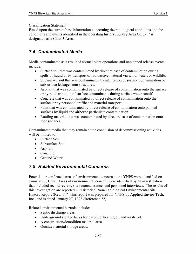
YNPS Historical Site Assessment Revision 1
Classification Statement: Based upon the current/best information concerning the radiological conditions and the conditions and events identified in the operating history, Survey Area OOL-17 is designated as a Class 3 Area.
7.4
7.5
Contaminated Media Media contaminated as a result of normal plant operations and unplanned release events include:
• Surface soil that was contaminated by direct release of contamination during spills of liquid or by transport of radioactive material via wind, water, or wildlife.
• Subsurface soil that was contaminated by infiltration of surface contamination or subsurface leakage from structures.
• Asphalt that was contaminated by direct release of contamination onto the surface or by re-distribution of surface contaminants during surface water runoff.
• Concrete that was contaminated by direct release of contamination onto the surface or by personnel traffic and material transport.
• Paint that was contaminated by direct release of contamination onto painted surfaces by liquid and airborne particulate contamination.
• Roofing material that was contaminated by direct release of contamination onto roof surfaces.
Contaminated media that may remain at the conclusion of decommissioning activities will be limited to:
• Surface Soil. • Subsurface Soil. • Asphalt. • Concrete. • Ground Water.
Related Environmental Concerns Potential or confirmed areas of environmental concern at the YNPS were identified on January 27, 1998. Areas of environmental concern were identified by an investigation that included record review, site reconnaissance, and personnel interviews. The results of this investigation are reported in "Historical Non-Radiological Environmental Site History Report (Rev. 1)." This report was prepared for YNPS by Applied Enviro-Tech, Inc., and is dated January 27, 1998 (Reference 22). Related environmental hazards include:
• Septic discharge areas. • Underground storage tanks for gasoline, heating oil and waste oil. • A construction/demolition material area. • Outside material storage areas.
7-57
YNPS Historical Site Assessment Revision 1
• Parking areas. • Fire extinguisher training area. • Location of electrical transformers. • Loading areas. • Subsurface piping. • Above ground storage tanks. • Herbicide and pesticide areas.
Environmental concerns associated with plant structures include:
• Lead paint. • PCB paint. • Asbestos paint. • Asbestos pipe insulation, roofing paper, window caulking and floor tiles. • Gal-bestos building siding. • Bituminous roofing materials. • Lead shielding.
Environmental concerns associated with plant operations include:
Chromate (hexavalent chromium). • • • • • • • • • • •
Boric acid. Water treatment chemicals. Caustic decontamination solutions. Acid decontamination solutions. Diesel fuel. Fuel oil. Gasoline. Greases. Paints. Solvents.
7-58
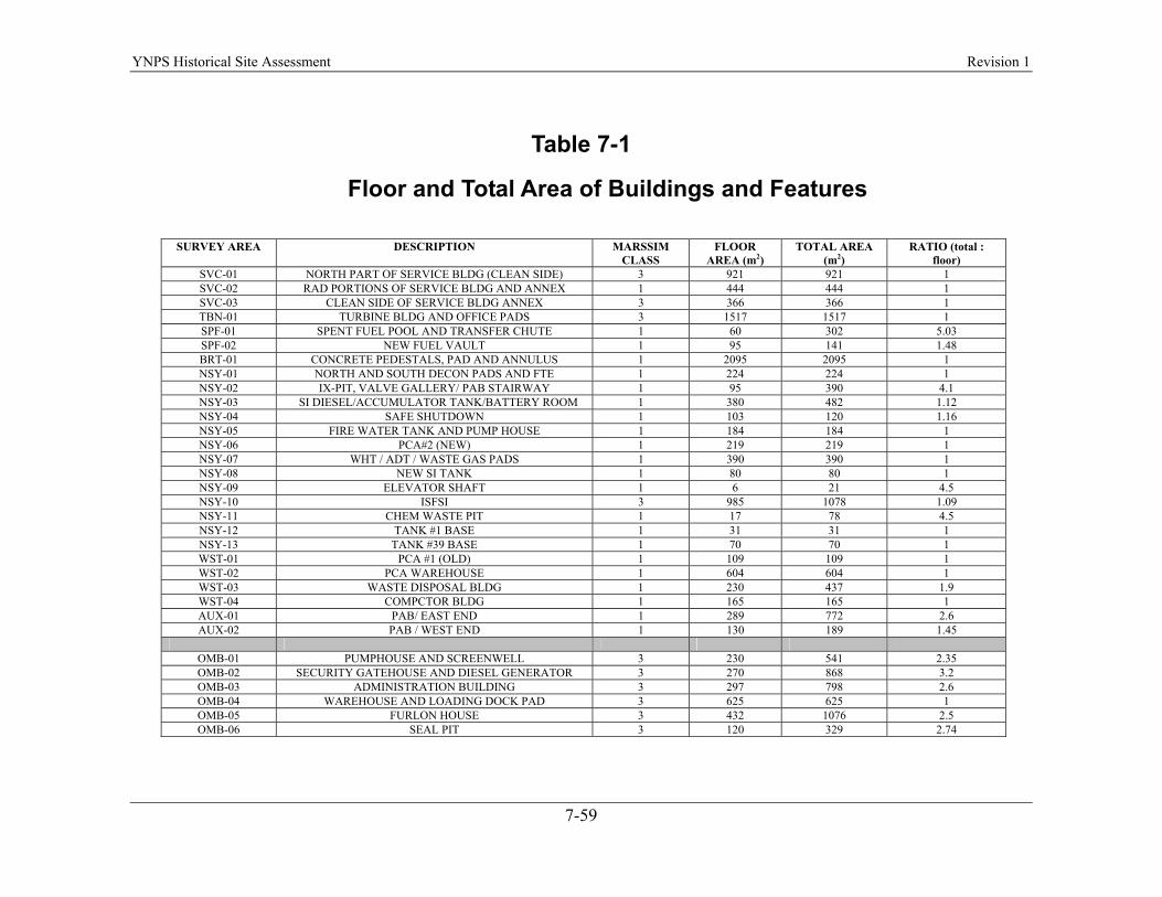
YNPS Historical Site Assessment Revision 1
Table 7-1
Floor and Total Area of Buildings and Features
SURVEY AREA DESCRIPTION MARSSIM CLASS
FLOOR AREA (m2)
TOTAL AREA (m2)
RATIO (total : floor)
SVC-01 NORTH PART OF SERVICE BLDG (CLEAN SIDE) 3 921 921 1 SVC-02 RAD PORTIONS OF SERVICE BLDG AND ANNEX 1 444 444 1 SVC-03 CLEAN SIDE OF SERVICE BLDG ANNEX 3 366 366 1 TBN-01 TURBINE BLDG AND OFFICE PADS 3 1517 1517 1 SPF-01 SPENT FUEL POOL AND TRANSFER CHUTE 1 60 302 5.03 SPF-02 NEW FUEL VAULT 1 95 141 1.48 BRT-01 CONCRETE PEDESTALS, PAD AND ANNULUS 1 2095 2095 1 NSY-01 NORTH AND SOUTH DECON PADS AND FTE 1 224 224 1 NSY-02 IX-PIT, VALVE GALLERY/ PAB STAIRWAY 1 95 390 4.1 NSY-03 SI DIESEL/ACCUMULATOR TANK/BATTERY ROOM 1 380 482 1.12 NSY-04 SAFE SHUTDOWN 1 103 120 1.16NSY-05 FIRE WATER TANK AND PUMP HOUSE 1 184 184 1 NSY-06 PCA#2 (NEW) 1 219 219 1NSY-07 WHT / ADT / WASTE GAS PADS 1 390 390 1 NSY-08 NEW SI TANK 1 80 80 1 NSY-09 ELEVATOR SHAFT 1 6 21 4.5NSY-10 ISFSI 3 985 1078 1.09NSY-11 CHEM WASTE PIT 1 17 78 4.5 NSY-12 TANK #1 BASE 1 31 31 1 NSY-13 TANK #39 BASE 1 70 70 1 WST-01 PCA #1 (OLD) 1 109 109 1 WST-02 PCA WAREHOUSE 1 604 604 1WST-03 WASTE DISPOSAL BLDG 1 230 437 1.9WST-04 COMPCTOR BLDG 1 165 165 1AUX-01 PAB/ EAST END 1 289 772 2.6AUX-02 PAB / WEST END 1 130 189 1.45
OMB-01 PUMPHOUSE AND SCREENWELL 3 230 541 2.35 OMB-02 SECURITY GATEHOUSE AND DIESEL GENERATOR 3 270 868 3.2 OMB-03 ADMINISTRATION BUILDING 3 297 798 2.6OMB-04 WAREHOUSE AND LOADING DOCK PAD 3 625 625 1 OMB-05 FURLON HOUSE 3 432 1076 2.5OMB-06 SEAL PIT 3 120 329 2.74
7-59

YNPS License Termination Plan Revision 1
TABLE 7-2
Area of Open Land Survey Areas
SURVEY AREA
DESCRIPTION MARSSIM CLASS
AREA (m2)
OOL-01 SHERMAN POND SEDIMENT 3 73971 OOL-02 YANKEE NON-RAD YARD AREA 3 7134 OOL-03 SHERMAN RESERVOIR DAM AND SOUTH
SHORELINE 3 16177
OOL-04 USGEN SHERMAN STATION OVERLYING GROUNDWATER PLUME
3 17870
OOL-05 USGEN DEERFIELD RIVER FRONTAGE PROPERTY
3 28574
OOL-06 YNPS WESTERN ACCESS 3 37281 OOL-07 SOILS DEPOSIT AREA 2 2108 OOL-08 YNPS SITE IMPACT PERIMETER ZONE 3 133368 OOL-09 SOUTHEAST CONSTRUCTION FILL AREA 3 2387 OOL-10 ISFSI PAD ACCESS, EXCLUSION ZONE,
BUFFER ZONE 2 8408
OOL-11 EAST RCA BUFFER ZONE 2 1220 OOL-12 WAREHOUSE RAIL SPUR 1 876 OOL-13 USGEN RAIL SPUR TERMINUS 1 1148 OOL-14 USGEN WHEELER BROOK FRONTAGE 3 2354 OOL-15 USGEN SHERMAN RESERVOIR EAST
SHORELINE 3 4662
OOL-16 YANKEE (FURLON) HOUSE PARKING LOT 3 2481 OOL-17 ASPHALT, BRICK AND CONCRETE
STORAGE AREA 3 3247
NOL-01 EASTERN LOWER RCA YARD 1 1364 NOL-02 NORTHEAST UPPER RCA YARD 1 1990 NOL-03 SOUTHEAST UPPER RCA YARD 1 1575 NOL-04 SOUTHWEST UPPER RCA YARD 1 1753 NOL-05 NORTHWEST UPPER RCA YARD 1 1586 NOL-06 WESTERN LOWER RCA YARD 1 1329 NOL-07 ISFSI RCA YARD 3 1717
7-60
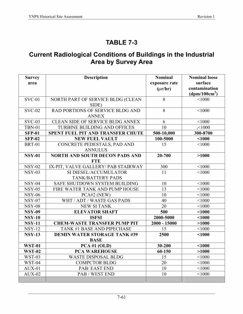
YNPS Historical Site Assessment Revision 1
TABLE 7-3
Current Radiological Conditions of Buildings in the Industrial Area by Survey Area
Survey area
Description Nominal exposure rate
(µr/hr)
Nominal loose surface
contamination (dpm/100cm2)
SVC-01 NORTH PART OF SERVICE BLDG (CLEAN SIDE)
8 <1000
SVC-02 RAD PORTIONS OF SERVICE BLDG AND ANNEX
8 <1000
SVC-03 CLEAN SIDE OF SERVICE BLDG ANNEX 6 <1000 TBN-01 TURBINE BUILDING AND OFFICES 10 ,<1000 SFP-01 SPENT FUEL PIT AND TRANSFER CHUTE 500-10,000 300-8700 SFP-02 NEW FUEL VAULT 100-5000 <1000 BRT-01 CONCRETE PEDESTALS, PAD AND
ANNULUS 15 <1000
NSY-01 NORTH AND SOUTH DECON PADS AND FTE
20-700 >1000
NSY-02 IX-PIT, VALVE GALLERY/ PAB STAIRWAY 300 <1000 NSY-03 SI DIESEL/ACCUMULATOR
TANK/BATTERY PADS 11 <1000
NSY-04 SAFE SHUTDOWN SYSTEM BUILDING 10 <1000 NSY-05 FIRE WATER TANK AND PUMP HOUSE 13 <1000 NSY-06 PCA#2 (NEW) 10 <1000 NSY-07 WHT / ADT / WASTE GAS PADS 40 <1000 NSY-08 NEW SI TANK 20 <1000 NSY-09 ELEVATOR SHAFT 500 <1000 NSY-10 ISFSI 2000-5000 <1000 NSY-11 CHEM-WASTE TRANSFER PUMP PIT 2000 - 15000 >1000 NSY-12 TANK #1 BASE AND PIPECHASE 15 <1000 NSY-13 DEMIN WATER STORAGE TANK #39
BASE 2500 <1000
WST-01 PCA #1 (OLD) 30-200 <1000 WST-02 PCA WAREHOUSE 60-150 >1000 WST-03 WASTE DISPOSAL BLDG 15 <1000 WST-04 COMPCTOR BLDG 20 <1000 AUX-01 PAB/ EAST END 10 <1000 AUX-02 PAB / WEST END 10 <1000
7-61
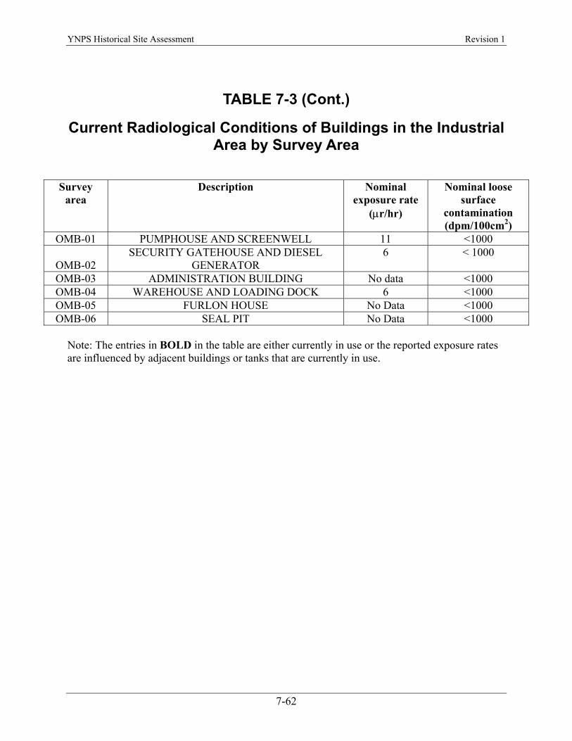
YNPS Historical Site Assessment Revision 1
TABLE 7-3 (Cont.)
Current Radiological Conditions of Buildings in the Industrial Area by Survey Area
Survey area
Description Nominal exposure rate
(µr/hr)
Nominal loose surface
contamination (dpm/100cm2)
OMB-01 PUMPHOUSE AND SCREENWELL 11 <1000
OMB-02 SECURITY GATEHOUSE AND DIESEL
GENERATOR 6 < 1000
OMB-03 ADMINISTRATION BUILDING No data <1000 OMB-04 WAREHOUSE AND LOADING DOCK 6 <1000 OMB-05 FURLON HOUSE No Data <1000 OMB-06 SEAL PIT No Data <1000
Note: The entries in BOLD in the table are either currently in use or the reported exposure rates are influenced by adjacent buildings or tanks that are currently in use.
7-62
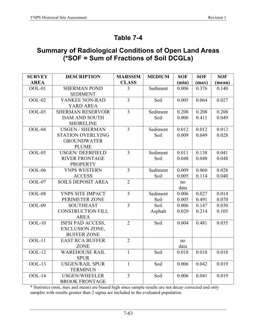
YNPS Historical Site Assessment Revision 1
Table 7-4
Summary of Radiological Conditions of Open Land Areas (*SOF = Sum of Fractions of Soil DCGLs)
SURVEY
AREA DESCRIPTION MARSSIM
CLASS MEDIUM SOF
(min) SOF
(max) SOF
(mean) OOL-01 SHERMAN POND
SEDIMENT 3 Sediment 0.006 0.376 0.140
OOL-02 YANKEE NON-RAD YARD AREA
3 Soil 0.005 0.064 0.027
OOL-03 SHERMAN RESERVOIR DAM AND SOUTH
SHORELINE
3 Sediment Soil
0.208 0.006
0.208 0.411
0.208 0.049
OOL-04 USGEN / SHERMAN STATION OVERLYING
GROUNDWATER PLUME
3 Sediment Soil
0.012 0.009
0.012 0.049
0.012 0.028
OOL-05 USGEN/ DEERFIELD RIVER FRONTAGE
PROPERTY
3 Sediment Soil
0.011 0.048
0.138 0.048
0.041 0.048
OOL-06 YNPS WESTERN ACCESS
3 Sediment Soil
0.009 0.005
0.060 0.114
0.028 0.040
OOL-07 SOILS DEPOSIT AREA 2 no data
OOL-08 YNPS SITE IMPACT PERIMETER ZONE
3 Sediment Soil
0.006 0.005
0.027 0.491
0.014 0.070
OOL-09 SOUTHEAST CONSTRUCTION FILL
AREA
3 Soil Asphalt
0.006 0.020
0.147 0.214
0.030 0.105
OOL-10 ISFSI PAD ACCESS, EXCLUSION ZONE,
BUFFER ZONE
2 Soil 0.004 0.481 0.035
OOL-11 EAST RCA BUFFER ZONE
2 no data
OOL-12 WAREHOUSE RAIL SPUR
1 Soil 0.018 0.018 0.018
OOL-13 USGEN/RAIL SPUR TERMINUS
1 Soil 0.006 0.042 0.019
OOL-14 USGEN/WHEELER BROOK FRONTAGE
3 Soil 0.006 0.041 0.019
* Statistics (min, max and mean) are biased high since sample results are not decay corrected and only samples with results greater than 2 sigma are included in the evaluated population.
7-63

YNPS Historical Site Assessment Revision 1
Table 7-4 (Cont.) Summary of Radiological Conditions of Open Land Areas
(*SOF = Sum of Fractions of Soil DCGLs)
SURVEY AREA
DESCRIPTION MARSSIM CLASS
MEDIUM SOF (min)
SOF (max)
SOF (mean)
OOL-15 USGEN/SHERMAN RESERVOIR EAST
SHORELINE
3 Soil 0.017 0.017 0.017
OOL-16 FURLON HOUSE PARKING LOT
3 no data
OOL-17 ASPHALT, BRICK AND CONCRETE STORAGE
YARD AREA
3 no data
NOL-01 EASTERN LOWER RCA YARD
1 Soil 0.006 0.651 0.207
NOL-02 NORTHEAST UPPER RCA YARD
1 Soil 0.005 0.523 0.103
NOL-03 SOUTHEAST UPPER RCA YARD
1 Soil 0.005 272.0 5.232
NOL-04 SOUTHWEST UPPER RCA YARD
1 Soil 0.007 0.838 0.125
NOL-05 NORTHWEST UPPER RCA YARD
1 Soil 0.005 0.171 0.028
NOL-06 WESTERN LOWER RCA YARD
1 Soil 0.004 0.491 0.092
NOL-07 ISFSI RCA YARD 3 Soil 0.005 0.021 0.009 * Statistics (min, max and mean) are biased high since sample results are not decay corrected and only samples with results greater than 2 sigma are included in the evaluated population.
7-64
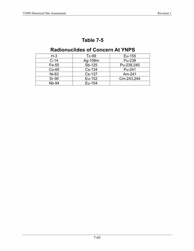
YNPS Historical Site Assessment Revision 1
Table 7-5
Radionuclides of Concern At YNPS H-3 Tc-99 Eu-155
C-14 Ag-108m Pu-238 Fe-55 Sb-125 Pu-239,240 Co-60 Cs-134 Pu-241 Ni-63 Cs-137 Am-241 Sr-90 Eu-152 Cm-243,244 Nb-94 Eu-154
7-65
YNPS Historical Site Assessment Revision 1
This page intentionally left blank.
7-66
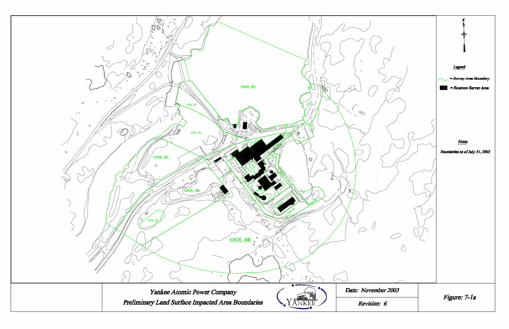
NOL-01
OOL-02
NOL-06
OOL-12
OOL-06
OOL-05
OOL-04
OOL-01
OOL-11
OOL-10
OOL-09
NOL-04
OOL-14
OOL-13
OOL-15OOL-03
OOL-08
NOL-03
OOL-07
TBN-01NOL-02
NOL-05
NOL-07
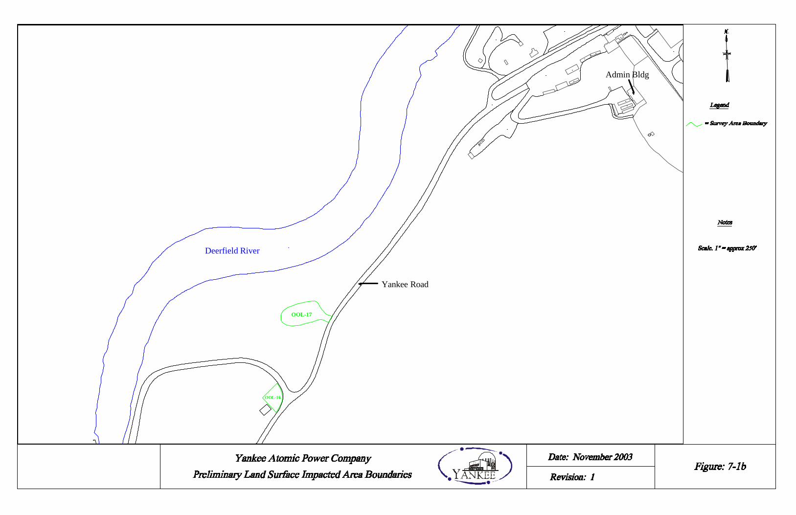
OOL-16
OOL-17
Deerfield River
Yankee Road
Admin Bldg

OMB-04
US GEN PROPERTY LINE
SVC-03
SVC-02
SVC-01
WST-01
WST-02
WST-03
NSY-06
NSY-01
WST-04
TBN-01
NSY-03
NSY-07AUX-02
AUX-01
NSY-02
SFP-01
SFP-02
NSY-04
NSY-05
NSY-10
OMB-02
OMB-01
OMB-03NSY-08
OMB-06
NSY-12
NSY-13
NSY-09

OOL-09NOL-04
NOL-05
NOL-03
NOL-06NOL-01
NOL-02
OOL-11
OOL-03
OOL-04
OOL-05
OOL-06
OOL-07
OOL-08
NOL-07
OOL-12
OOL-13
OOL-14
OOL-15
OOL-01
OOL-02
OOL-10

NSY-12
NSY-13
OMB-06 OMB-01
OMB-02
TBN-01
SVC-01
SVC-03OMB-04
SVC-02
NSY-01
NSY-03AUX-02
AUX-01
NSY-02
SFP-01
SFP-02
OMB-03
WST-04
WST-03
NSY-07
WST-01
WST-02
NSY-08
NSY-04
NSY-05
NSY-06
NSY-10
USGen Property Line

12 1 29 27
26
6
21
22
23
20
28
24
25
19
5
18
17
30
2/3211/31
10
9
8
14
15
16
4
7
13
3
Prevailing Wind Direction

SVC-03
SVC-02
WST-01
WST-02
WST-03
NSY-06
NSY-01
WST-04
TBN-01
NSY-03
NSY-07
NSY-02
NSY-04
NSY-05
NSY-10
NSY-08
WBr
NSY-12
NSY-13
NSY-11
NSY-09

YNPS Historical Site Assessment Revision 1
8 References
1. NUREG-1575: Multi-Agency Radiation Survey and Site Investigation Manual, Revision 1, dated August 2000.
2. Possession Only License (POL) No. DPR-3.
3. USGS 7.5 minute quadrangle map Rowe Massachusetts – Vermont (42072-F8-TF-024,
1973, DMA III NW-SERIES V814).
4. Environmental Characterization Summary, Yankee Nuclear Power Plant Site, June 2000.
5. Decommissioning Environmental Report.
6. YAEC Deed Study Project Rowe and Monroe, Massachusetts, dated December 18, 1998.
7. YNPS License Termination Plan, dated December 1997 (withdrawn in May 1999).
8. YNPS Decommissioning Plan, dated March 29, 1994.
9. DRAFT NUREG/CR-5849 (ORAU 92/C57): "Manual for Conducting Radiological Surveys in Support of License Termination," by J.D. Berger, dated June 1992.
10. Yankee Nuclear Power Station, Systems Training Manual.
11. Plant Superintendent's "Monthly Operating Reports" Number 1, February 1961 through
Number 120, December 1970.
12. Condition Report 03-259, “While down ending a fuel rack in the rad waste warehouse, several gallons of potentially contaminated water were released onto the floor,” dated June 19, 2003.
13. Technical Basis Document YA-REPT-00-006-03, “Statistical Evaluation of Non-
Impacted Area, Evaluation of 137Cs Concentration in Soils of Non-impacted and Reference Areas in the Vicinity of YNPS.”
14. EG&G 10617-1233, UC-702, “An Aerial Radiological Survey of the Yankee Rowe
Nuclear Power Station and Surrounding Area,” EG&G Energy Measurements, dated September 1993.
15. YRC-1178, Radionuclide Soil Concentrations Surrounding YNPS Resulting from
Gaseous Release During Plant Operation, dated March 1998.
16. NCRP Report 47 "Tritium Measurement Techniques," dated May 28, 1976.
8-1
YNPS Historical Site Assessment Revision 1
17. NCRP Report 50 "Environmental Radiation Measurements," dated December 27, 1976.
18. NCRP Report 81 "Carbon-14 in the Environment," dated May 15, 1985.
19. Technical Basis Document YA-REPT-00-001-03, Radionuclide Selection for DCGL Determination, dated November 5, 2003.
20. Yankee Nuclear Plant Site License Termination Plan (LTP), Revision 0, dated November
2003.
21. Technical Basis DocumentYA-REPT-00-002-004, Evaluation of Effluent Releases from Onsite Incineration of Waste, dated May 24, 2004
22. Historical Non-Radiological Environmental Site History Report (Rev. 1), Applied
Enviro-Tech, Inc., dated January 27, 1998
8-2
YNPS Historical Site Assessment Revision 1
Appendix A1
History of Plant Gaseous Releases
A1 - 1
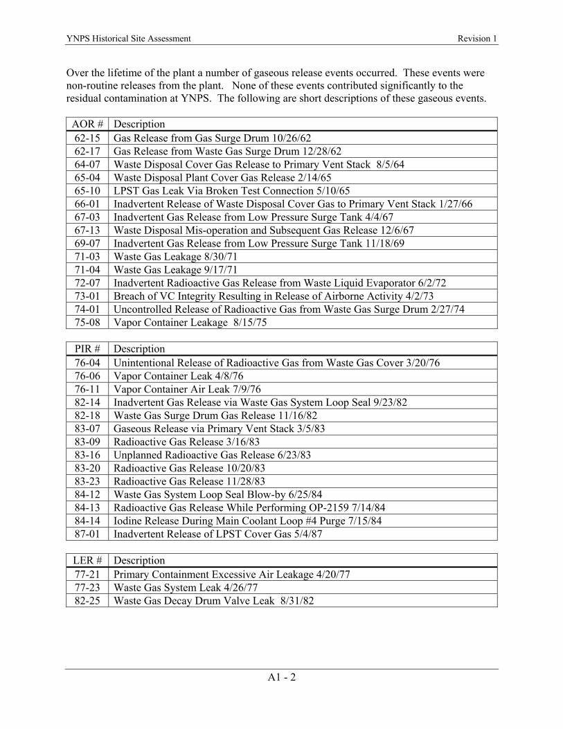
YNPS Historical Site Assessment Revision 1
Over the lifetime of the plant a number of gaseous release events occurred. These events were non-routine releases from the plant. None of these events contributed significantly to the residual contamination at YNPS. The following are short descriptions of these gaseous events. AOR # Description 62-15 Gas Release from Gas Surge Drum 10/26/62 62-17 Gas Release from Waste Gas Surge Drum 12/28/62 64-07 Waste Disposal Cover Gas Release to Primary Vent Stack 8/5/64 65-04 Waste Disposal Plant Cover Gas Release 2/14/65 65-10 LPST Gas Leak Via Broken Test Connection 5/10/65 66-01 Inadvertent Release of Waste Disposal Cover Gas to Primary Vent Stack 1/27/66 67-03 Inadvertent Gas Release from Low Pressure Surge Tank 4/4/67 67-13 Waste Disposal Mis-operation and Subsequent Gas Release 12/6/67 69-07 Inadvertent Gas Release from Low Pressure Surge Tank 11/18/69 71-03 Waste Gas Leakage 8/30/71 71-04 Waste Gas Leakage 9/17/71 72-07 Inadvertent Radioactive Gas Release from Waste Liquid Evaporator 6/2/72 73-01 Breach of VC Integrity Resulting in Release of Airborne Activity 4/2/73 74-01 Uncontrolled Release of Radioactive Gas from Waste Gas Surge Drum 2/27/74 75-08 Vapor Container Leakage 8/15/75
PIR # Description 76-04 Unintentional Release of Radioactive Gas from Waste Gas Cover 3/20/76 76-06 Vapor Container Leak 4/8/76 76-11 Vapor Container Air Leak 7/9/76 82-14 Inadvertent Gas Release via Waste Gas System Loop Seal 9/23/82 82-18 Waste Gas Surge Drum Gas Release 11/16/82 83-07 Gaseous Release via Primary Vent Stack 3/5/83 83-09 Radioactive Gas Release 3/16/83 83-16 Unplanned Radioactive Gas Release 6/23/83 83-20 Radioactive Gas Release 10/20/83 83-23 Radioactive Gas Release 11/28/83 84-12 Waste Gas System Loop Seal Blow-by 6/25/84 84-13 Radioactive Gas Release While Performing OP-2159 7/14/84 84-14 Iodine Release During Main Coolant Loop #4 Purge 7/15/84 87-01 Inadvertent Release of LPST Cover Gas 5/4/87
LER # Description 77-21 Primary Containment Excessive Air Leakage 4/20/77 77-23 Waste Gas System Leak 4/26/77 82-25 Waste Gas Decay Drum Valve Leak 8/31/82
A1 - 2

YNPS Historical Site Assessment Revision 1
Gas Release from Gas Surge Drum – On October 26, 1962, approximately one volume at STP of the Gas Surge Drum was released due to a low water level in the loop seal. The line to the low water alarm was partially blocked and this prevented the alarm from functioning. Radiation monitoring records showed that the radioactivity level of the released gas was insignificant. AOR 62-15.
Gas Release from Waste Gas Surge Drum – On December 28, 1962, the drain valve on the
waste gas surge drum loop seal, after being opened for a weekly check, was closed again but did not seat properly. This allowed the loop seal to drain, causing a release calculated to be 800 ft3 of gas containing 3 x 10⁻² µCi/cc of noble gas. The original gas volume was further diluted by make-up air as the gas entered the release pathway and this resulted in a final, maximum concentration of 1 x 10⁻⁴ µCi/cc to be released. AOR 62-17.
Waste Disposal Cover Gas Release to Primary Vent Stack – On August 5, 1964, Waste
Disposal Cover Gas was bled to the vent stack over a period of time due to an incorrect valve lineup. Due to the low activity level, the stack monitor did not alarm. Over a 17-½ hour period, 3140 ft3 of gas containing 13.2 x 10⁴ µCi of Xe133 was released. The released gas had a specific activity of 1.5 x 10⁻³ µCi/cc Xe133 which, when diluted with 15,000 cfm from the stack fan, made the release to the environs 3.0 x 10⁻¹⁰ µCi/cc Xe133. AOR 64-07.
Waste Disposal Plant Cover Gas Release – On February 14-15, 1965, radioactive gas was
released from the waste disposal plant evaporator through open valves and an open window in the evaporator cubicle. Approximately 1450 ft3 of gas was released to the outside environs. A sample of the remaining cover gas showed 2.3 x 10⁻⁵ µCi/cc of Xe133. Total activity released was ~943 µCi. AOR 65-04.
LPST Gas Leak via Broken Test Connection in Vent Discharge Line During Normal Gas
Pressure Reduction – On May 4, 1965, a broken test connection on the vent line to the LPST allowed 16 ft3 of gas to escape to the vent stack. The gross gaseous concentration was 2.83 x 10⁻⁵ µCi/cc. A calculated 43 mCi of Ar41, Xe133 and Xe135 plus an estimated 4.5 mCi of H3 were released. Later, sample results showed 0.427 x 10⁻⁸ µCi/cc Xe133, 0.507 x 10⁻⁸ µCi/cc Xe135, 0.267 x 10⁻⁸ µCi/cc H3, and 1.629 x 10⁻⁸ µCi/cc Ar41 were vented out of the stack. AOR 65-10.
Inadvertent Release of Waste Disposal Cover Gas to the Primary Vent Stack – On January
27, 1966, while removing the waste disposal gas blanket from the Primary Drain Collecting Tank for maintenance, it was noticed that the cover gas system pressure maintenance valve was partially open. Upon ceasing the operation and closing the PDCT vent to the stack, the makeup valve closed and this indicated that there had been a release. It was discovered that the fission gas drain line was the origin of the leak, terminating inside the PDCT near the top above the water line. With the fission gas drain valve closed, the leak stopped. A sample of the waste disposal cover gas showed principle isotopes of 1.0 x 10⁻⁵ µCi/cc Xe133 and 1.0 x 10⁻² µCi/cc H3. Inventory of the system indicated a possible release of 500 ft3. The total release was 142 µCi of Xe133 and 142
A1 - 3
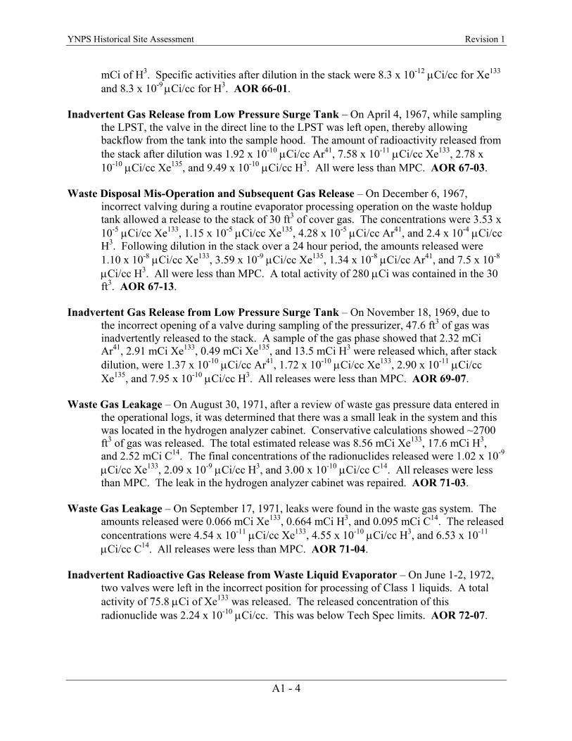
YNPS Historical Site Assessment Revision 1
mCi of H3. Specific activities after dilution in the stack were 8.3 x 10⁻¹² µCi/cc for Xe133 and 8.3 x 10⁻⁹ µCi/cc for H3. AOR 66-01.
Inadvertent Gas Release from Low Pressure Surge Tank – On April 4, 1967, while sampling
the LPST, the valve in the direct line to the LPST was left open, thereby allowing backflow from the tank into the sample hood. The amount of radioactivity released from the stack after dilution was 1.92 x 10⁻¹⁰ µCi/cc Ar41, 7.58 x 10⁻¹¹ µCi/cc Xe133, 2.78 x 10⁻¹⁰ µCi/cc Xe135, and 9.49 x 10⁻¹⁰ µCi/cc H3. All were less than MPC. AOR 67-03.
Waste Disposal Mis-Operation and Subsequent Gas Release – On December 6, 1967,
incorrect valving during a routine evaporator processing operation on the waste holdup tank allowed a release to the stack of 30 ft3 of cover gas. The concentrations were 3.53 x 10⁻⁵ µCi/cc Xe133, 1.15 x 10⁻⁵ µCi/cc Xe135, 4.28 x 10⁻⁵ µCi/cc Ar41, and 2.4 x 10⁻⁴ µCi/cc H3. Following dilution in the stack over a 24 hour period, the amounts released were 1.10 x 10⁻⁸ µCi/cc Xe133, 3.59 x 10⁻⁹ µCi/cc Xe135, 1.34 x 10⁻⁸ µCi/cc Ar41, and 7.5 x 10⁻⁸ µCi/cc H3. All were less than MPC. A total activity of 280 µCi was contained in the 30 ft3. AOR 67-13.
Inadvertent Gas Release from Low Pressure Surge Tank – On November 18, 1969, due to
the incorrect opening of a valve during sampling of the pressurizer, 47.6 ft3 of gas was inadvertently released to the stack. A sample of the gas phase showed that 2.32 mCi Ar41, 2.91 mCi Xe133, 0.49 mCi Xe135, and 13.5 mCi H3 were released which, after stack dilution, were 1.37 x 10⁻¹⁰ µCi/cc Ar41, 1.72 x 10⁻¹⁰ µCi/cc Xe133, 2.90 x 10⁻¹¹ µCi/cc Xe135, and 7.95 x 10⁻¹⁰ µCi/cc H3. All releases were less than MPC. AOR 69-07.
Waste Gas Leakage – On August 30, 1971, after a review of waste gas pressure data entered in
the operational logs, it was determined that there was a small leak in the system and this was located in the hydrogen analyzer cabinet. Conservative calculations showed ~2700 ft3 of gas was released. The total estimated release was 8.56 mCi Xe133, 17.6 mCi H3, and 2.52 mCi C14. The final concentrations of the radionuclides released were 1.02 x 10⁻⁹ µCi/cc Xe133, 2.09 x 10⁻⁹ µCi/cc H3, and 3.00 x 10⁻¹⁰ µCi/cc C14. All releases were less than MPC. The leak in the hydrogen analyzer cabinet was repaired. AOR 71-03.
Waste Gas Leakage – On September 17, 1971, leaks were found in the waste gas system. The
amounts released were 0.066 mCi Xe133, 0.664 mCi H3, and 0.095 mCi C14. The released concentrations were 4.54 x 10⁻¹¹ µCi/cc Xe133, 4.55 x 10⁻¹⁰ µCi/cc H3, and 6.53 x 10⁻¹¹ µCi/cc C14. All releases were less than MPC. AOR 71-04.
Inadvertent Radioactive Gas Release from Waste Liquid Evaporator – On June 1-2, 1972,
two valves were left in the incorrect position for processing of Class 1 liquids. A total activity of 75.8 µCi of Xe133 was released. The released concentration of this radionuclide was 2.24 x 10⁻¹⁰ µCi/cc. This was below Tech Spec limits. AOR 72-07.
A1 - 4
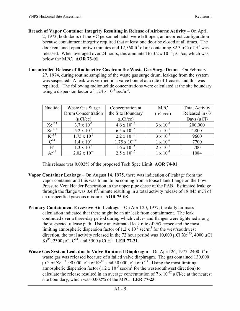
YNPS Historical Site Assessment Revision 1
Breach of Vapor Container Integrity Resulting in Release of Airborne Activity – On April 2, 1973, both doors of the VC personnel hatch were left open, an incorrect configuration because containment integrity required that at least one door be closed at all times. The door remained open for two minutes and 12,560 ft3 of air containing 82.3 µCi of H3 was released. When averaged over 24 hours, this amounted to 3.2 x 10⁻¹⁰ µCi/cc, which was below the MPC. AOR 73-01.
Uncontrolled Release of Radioactive Gas from the Waste Gas Surge Drum – On February
27, 1974, during routine sampling of the waste gas surge drum, leakage from the system was suspected. A leak was verified in a valve bonnet at a rate of 1 cc/sec and this was repaired. The following radionuclide concentrations were calculated at the site boundary using a dispersion factor of 1.24 x 10⁻⁵ sec/m3:
Nuclide Waste Gas Surge Drum Concentration
(µCi/cc)
Concentration at the Site Boundary
(µCi/cc)
MPC (µCi/cc)
Total Activity Released in 63
Days (µCi) Xe133 3.7 x 10⁻² 4.6 x 10⁻¹³ 3 x 10⁻⁷ 200,000 Xe135 5.2 x 10⁻⁴ 6.5 x 10⁻¹⁵ 1 x 10⁻⁷ 2800 Kr85 1.75 x 10⁻³ 2.2 x 10⁻¹⁴ 3 x 10⁻⁷ 9600 C14 1.4 x 10⁻³ 1.75 x 10⁻¹⁴ 1 x 10⁻⁷ 7700 H3 1.3 x 10⁻⁴ 1.6 x 10⁻¹⁵ 2 x 10⁻⁷ 700
Ar41 2.02 x 10⁻⁴ 2.5 x 10⁻¹⁵ 1 x 10⁻⁴ 1084
This release was 0.002% of the proposed Tech Spec Limit. AOR 74-01. Vapor Container Leakage – On August 14, 1975, there was indication of leakage from the
vapor container and this was found to be coming from a loose blank flange on the Low Pressure Vent Header Penetration in the upper pipe chase of the PAB. Estimated leakage through the flange was 0.4 ft3/minute resulting in a total activity release of 18.845 mCi of an unspecified gaseous mixture. AOR 75-08.
Primary Containment Excessive Air Leakage – On April 20, 1977, the daily air mass
calculation indicated that there might be an air leak from containment. The leak continued over a three-day period during which valves and flanges were tightened along the suspected release path. Using an estimated leak rate of 967 cc/sec and the most limiting atmospheric dispersion factor of 1.2 x 10⁻⁵ sec/m3 for the west/southwest direction, the total activity released in the 72 hour period was 10,000 µCi Xe133, 4000 µCi Kr85, 2300 µCi C14, and 3500 µCi H3. LER 77-21.
Waste Gas System Leak due to Valve Ruptured Diaphragm – On April 26, 1977, 2400 ft3 of
waste gas was released because of a failed valve diaphragm. The gas contained 130,000 µCi of Xe133, 90,000 µCi of Kr85, and 30,000 µCi of C14. Using the most limiting atmospheric dispersion factor (1.2 x 10⁻⁵ sec/m3 for the west/southwest direction) to calculate the release resulted in an average concentration of 7 x 10-12 µCi/cc at the nearest site boundary, which was 0.002% of the MPC. LER 77-23.
A1 - 5
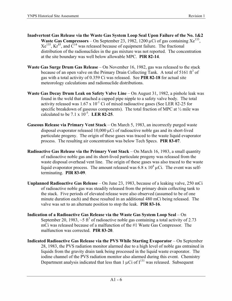
YNPS Historical Site Assessment Revision 1
Inadvertent Gas Release via the Waste Gas System Loop Seal Upon Failure of the No. 1&2
Waste Gas Compressors – On September 23, 1982, 1200 µCi of gas containing Xe133, Xe135, Kr85, and C14 was released because of equipment failure. The fractional distribution of the radionuclides in the gas mixture was not reported. The concentration at the site boundary was well below allowable MPC. PIR 82-14.
Waste Gas Surge Drum Gas Release – On November 16, 1982, gas was released to the stack
because of an open valve on the Primary Drain Collecting Tank. A total of 5161 ft3 of gas with a total activity of 0.359 Ci was released. See PIR 82-18 for actual site meteorology calculations and radionuclide distributions.
Waste Gas Decay Drum Leak on Safety Valve Line – On August 31, 1982, a pinhole leak was
found in the weld that attached a capped pipe nipple to a safety valve body. The total activity released was 1.67 x 10⁻¹ Ci of mixed radioactive gases (See LER 82-25 for specific breakdown of gaseous components). The total fraction of MPC at ½ mile was calculated to be 7.1 x 10⁻⁵. LER 82-25.
Gaseous Release via Primary Vent Stack – On March 5, 1983, an incorrectly purged waste
disposal evaporator released 10,000 µCi of radioactive noble gas and its short-lived particulate progeny. The origin of these gases was traced to the waste liquid evaporator process. The resulting air concentration was below Tech Specs. PIR 83-07.
Radioactive Gas Release via the Primary Vent Stack – On March 16, 1983, a small quantity
of radioactive noble gas and its short-lived particulate progeny was released from the waste disposal overhead vent line. The origin of these gases was also traced to the waste liquid evaporator process. The amount released was 6.8 x 10⁴ µCi. The event was self-terminating. PIR 83-09.
Unplanned Radioactive Gas Release – On June 23, 1983, because of a leaking valve, 250 mCi
of radioactive noble gas was steadily released from the primary drain collecting tank to the stack. Five periods of elevated release were also observed (assumed to be of one minute duration each) and these resulted in an additional 480 mCi being released. The valve was set to an alternate position to stop the leak. PIR 83-16.
Indication of a Radioactive Gas Release via the Waste Gas System Loop Seal – On
September 20, 1983, ~5 ft3 of radioactive noble gas containing a total activity of 2.73 mCi was released because of a malfunction of the #1 Waste Gas Compressor. The malfunction was corrected. PIR 83-20.
Indicated Radioactive Gas Release via the PVS While Starting Evaporator – On September
28, 1983, the PVS radiation monitor alarmed due to a high level of noble gas entrained in liquids from the gravity drain tank being processed in the liquid waste evaporator. The iodine channel of the PVS radiation monitor also alarmed during this event. Chemistry Department analysis indicated that less than 1 µCi of I131 was released. Subsequent
A1 - 6

YNPS Historical Site Assessment Revision 1
investigation indicated that the iodine channel window was not properly adjusted and was receiving signal due to noble gas. PIR 83-23.
Waste Gas Loop Seal Unplanned Releases – On June 25, 1984, oscillations in the loop seal
allowed a small release of gas containing 3.61 x 10⁻¹⁰ µCi/cc of Xe133. The total activity was 34.8 mCi. On June 26, 1984, while bleeding gas from the high to low pressure side of the waste gas system, a valve was mis-positioned allowing another small gas release. The maximum offsite concentration was 1.77 x 10⁻⁹ µCi/cc. PIR 84-12.
Radioactive Gas Release While Performing OP-2159, “Removal of the Hydrogen Blanket
from the Low Pressure Surge Tank” – On July 14, 1984, while performing OP-2159, higher than normal activity gas, coupled with system operation and configuration, allowed the release of 3.38 x 10⁻⁶ µCi/cc of Xe133. PIR 84-13.
Iodine Release during Main Coolant Loop #4 Purge – On July 15, 1984, while purging loop
4, the stack charcoal filter did not retain iodine gas as expected. The maximum iodine level offsite for one hour was 29% of MPC. PIR 84-14.
Inadvertent Release of LPST Cover Gas via VC Purge System – On May 4, 1987, after
degassing the pressurizer, stack monitors detected a gaseous release. A total of 3.5 Ci of radioactive noble gas was released. The cause was attributed to a malfunctioning valve and the valve was repaired. PIR 87-01.
A1 - 7
YNPS Historical Site Assessment Revision 1
This page intentionally left blank.
A1 - 8
YNPS Historical Site Assessment Revision 1
Appendix A2
Summaries of the Significant Events at the YNPS Site (Presented in HSA Table 6-1)
A2 - 1
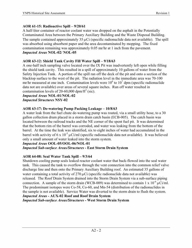
YNPS Historical Site Assessment Revision 1 AOR 61-15: Radioactive Spill – 9/20/61 A half-liter container of reactor coolant water was dropped on the asphalt in the Potentially Contaminated Area between the Primary Auxiliary Building and the Waste Disposal Building. The sample contained approximately 35 µCi (specific radionuclide data not available). The spill was absorbed using absorbent paper and the area decontaminated by mopping. The fixed contamination remaining was approximately 0.05 mr/hr at 1 inch from the pavement. Impacted Areas NOL-02/ NOL-05 AOR 63-12: Shield Tank Cavity Fill Water Spill – 9/18/63 A one-half inch sampling valve located over the IX Pit was inadvertently left open while filling the shield tank cavity. This resulted in a spill of approximately 10 gallons of water from the Safety Injection Tank. A portion of the spill ran off the deck of the pit and onto a section of the blacktop surface to the west of the pit. The radiation level in the immediate area was 70-100 mr/hr measured at one inch. Contamination levels were 106 to 107 dpm (specific radionuclide data not are available) over areas of several square inches. Run off water resulted in contamination levels of 20-60,000 dpm/ft2 (sic). Impacted Areas NOL-01/NOL-02 Impacted Structures NSY-02 AOR 63-17: De-watering Pump Packing Leakage – 10/8/63 A water leak from the fuel chute de-watering pump was routed, via a small utility hose, to a 30 gallon collection drum placed in a storm drain catch basin (ECB-005). The catch basin was located between the railroad tracks and the NE corner of the spent fuel pit. It was determined that the bottom rim of the barrel was corroded, and water was leaking from the bottom of the barrel. At the time the leak was identified, six to eight inches of water had accumulated in the barrel with activity of 6 x 10⁻⁵ µCi/ml (specific radionuclide data not available). It was believed only a small amount of water leaked into the storm system. Impacted Areas OOL-05/OOL-06/NOL-01 Impacted Sub-surface Areas/Structures - East Storm Drain System AOR 64-08: Seal Water Tank Spill – 9/3/64 Shutdown cooling pump seals leaked reactor coolant water that back-flowed into the seal water tank. This caused the tank to overflow through the vent connection into the common relief valve discharge line and then onto the Primary Auxiliary Building roof. An estimated 35 gallons of water containing a total activity of 270 µCi (specific radionuclide data not available) was released. The Roof Drain System drained into the Storm Drain System via a sub-surface piping connection. A sample of the storm drain (WCB-009) was determined to contain 1 x 10⁻⁶ µCi/ml. The predominant isotopes were Co-58, Co-60, and Mn-54 (distribution of the radionuclides in the sample is not available). Service Water was diverted to the storm drain to flush the system. Impacted Areas - AUX-02 Roof and Roof Drain System Impacted Sub-surface Areas/Structures - West Storm Drain System
A2 - 2

YNPS Historical Site Assessment Revision 1 AOR 64-13: Leakage from Ion Exchange Pit - 10/3/64 After filling the IX Pit to its normal operating level, the operator failed to close the fill valve. Water continued to flow into the pit from the Primary Water Storage Tank by gravity feed. Later, the operator noticed water seeping through the blacktop on the west side of the pit, diagnosed the cause, and closed the valve. The water on the blacktop was sampled and was found to contain radioactivity. The radionuclides and concentrations identified were: Ag-110m at 5 x 10⁻⁷ µCi/ml and Co-60 at 1 x 10⁻⁶ µCi/ml. The blacktop was rinsed down with Service Water and this flowed to the storm drain (ECB-005). Impacted Areas NSY-02/NOL-01/OOL-05/OOL-06 Impacted Sub-surface Areas/Structures - East Storm Drain System internal and external to piping (backfill) / SFP-02 sub-floor / NSY-09 / AUX-01 North external perimeter (backfill) / SFP-01 West external perimeter (backfill) / BRT-01 Eastern external perimeter AOR 66-7: Spent Fuel Pit Water Spill – 9/27/66 A two-inch priming valve for the Spent Fuel Pit (SFP) cooling and purification pump was left open; however, an upstream valve isolating make-up water to the Low Pressure Surge Tank (LPST) was correctly closed. The LPST make up pump was started to provide make up water to a hose connection located between the two valves to wash down a shipping cask as it was removed from the pit. Water flowed through the open priming valve to the SFP in sufficient quantity to result in actuation of the high level alarm. The reason for the high level alarm was not immediately determined and, by the time the reason was identified, water had overflowed from the SFP. Approximately 33 gallons of water flowed down the SFP exterior wall, over a small section of asphalt paving, and into an immediately adjacent storm drain, ECB-005. A continuous service water flush of the east side culvert system (ECB-005) was initiated and continued for a 24-hour period. This occurrence resulted in a total release of 4 µCi gross β-γ and 670 µCi of H3 (more specific radionuclide data are not available). Impacted Areas SFP-01 North external wall /NOL-01/OOL-01 Impacted Sub-surface Areas/Structures East Storm Drain System internal and external to piping (backfill between SFP-01 and ECB-005) AOR 66-8: Abnormal Activity in Storm Drain – 9/27/66 Water from the west storm drain culvert was sampled (the SFP water release discussed above, in AOR66-7, discharged to the east side only). An average of two samples from the west side showed gross activity of 6.7 x 10⁻⁷ µCi/ml (specific radionuclide data is not available). Investigation found a relief valve on the safety injection tank heating system to be slowly leaking into a floor drain in the PAB. The floor drains in that section of the building were traced and found to discharge into a storm drain located on the outside of the building (WCB-009). Further investigation indicated that the relief valve leak could not have existed for more than one day and that the maximum volume did not exceed eight gallons during that period. A sample of culvert water collected 24 hours after the occurrence indicated a gross activity of 1.2 x 10⁻⁸ µCi/ml and H3 activity of 5.1 x 10⁻⁵ µCi/ml. This occurrence resulted in a total release of 0.8 µCi gross β-γ and 3.32 mCi of H3. Impacted Area - OOL-05/OOL-06 Impacted Sub-surface Areas/Structures - West Storm Drain system
A2 - 3
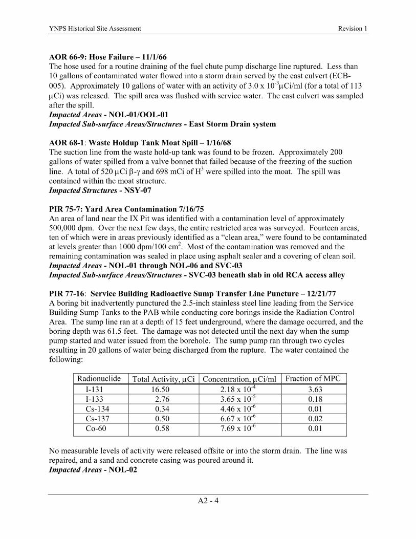
YNPS Historical Site Assessment Revision 1 AOR 66-9: Hose Failure – 11/1/66 The hose used for a routine draining of the fuel chute pump discharge line ruptured. Less than 10 gallons of contaminated water flowed into a storm drain served by the east culvert (ECB-005). Approximately 10 gallons of water with an activity of 3.0 x 10⁻³µCi/ml (for a total of 113 µCi) was released. The spill area was flushed with service water. The east culvert was sampled after the spill. Impacted Areas - NOL-01/OOL-01 Impacted Sub-surface Areas/Structures - East Storm Drain system AOR 68-1: Waste Holdup Tank Moat Spill – 1/16/68 The suction line from the waste hold-up tank was found to be frozen. Approximately 200 gallons of water spilled from a valve bonnet that failed because of the freezing of the suction line. A total of 520 µCi β-γ and 698 mCi of H3 were spilled into the moat. The spill was contained within the moat structure. Impacted Structures - NSY-07 PIR 75-7: Yard Area Contamination 7/16/75 An area of land near the IX Pit was identified with a contamination level of approximately 500,000 dpm. Over the next few days, the entire restricted area was surveyed. Fourteen areas, ten of which were in areas previously identified as a “clean area,” were found to be contaminated at levels greater than 1000 dpm/100 cm2. Most of the contamination was removed and the remaining contamination was sealed in place using asphalt sealer and a covering of clean soil. Impacted Areas - NOL-01 through NOL-06 and SVC-03 Impacted Sub-surface Areas/Structures - SVC-03 beneath slab in old RCA access alley PIR 77-16: Service Building Radioactive Sump Transfer Line Puncture – 12/21/77 A boring bit inadvertently punctured the 2.5-inch stainless steel line leading from the Service Building Sump Tanks to the PAB while conducting core borings inside the Radiation Control Area. The sump line ran at a depth of 15 feet underground, where the damage occurred, and the boring depth was 61.5 feet. The damage was not detected until the next day when the sump pump started and water issued from the borehole. The sump pump ran through two cycles resulting in 20 gallons of water being discharged from the rupture. The water contained the following:
Radionuclide Total Activity, µCi Concentration, µCi/ml Fraction of MPC I-131 16.50 2.18 x 10⁻⁴ 3.63 I-133 2.76 3.65 x 10⁻⁵ 0.18 Cs-134 0.34 4.46 x 10⁻⁶ 0.01 Cs-137 0.50 6.67 x 10⁻⁶ 0.02 Co-60 0.58 7.69 x 10⁻⁶ 0.01
No measurable levels of activity were released offsite or into the storm drain. The line was repaired, and a sand and concrete casing was poured around it. Impacted Areas - NOL-02
A2 - 4

YNPS Historical Site Assessment Revision 1 Impacted Sub-surface Areas/Structures - Soils surrounding perforation and transfer line backfill/Soils to a depth of 61.5 feet and below along the bore hole. PIR 80-9: Resin Spill - 8/6/80 A hose developed a pinhole leak while pumping resin to a cask. The failure of the hose allowed the release of several gallons of water and one quart of resin. A 15-foot by 20-foot area of the RCA yard was contaminated. Radiation readings on contact with the resin were 1 mrad/hr and the spilled liquid readings were up to several hundred thousand dpm/100 cm2 (sic) (specific radionuclide data are not available). Decontamination included removal and disposal of some of the blacktop. Impacted Areas - NOL-02/NSY-02 Impacted Sub-surface Areas/Structures - South and East exterior walls of NSY-02. The sub-slab area of NSY-02 (IX-pit) was also impacted due to transfer of contamination by surface water (i.e., water used in decontamination and rainwater) into cracks between asphalt and IX Pit walls. PIR 81-9: Contamination of Yard Area During Reactor Head Removal – 5/15/81 While positioning the reactor vessel head over the equipment hatch in preparation for lowering the head through the hatch, the reactor head made contact with the shield wall. This resulted in the spread of removable radioactivity outside of the Vapor Container (VC). Removable radioactivity immediately below the equipment hatch was 200 mrad/hr beta. The total activity released to the ground was approximately 250 µCi, with approximately 10 µCi (specific radionuclide data are not available) discharged to Sherman Pond. The area was cleaned, but due to rainfall, trace radioactive material levels were detected in the east storm drains. Impacted Areas - NOL-01/NOL-06/OOL-12/OOL-13 Impacted Sub-surface Areas/Structures - BRT-01/in cracks and crevices under VC Equipment Hatch and along rails/ties in OOL-12 and OOL-13 and the East Storm Drain System due to surface water run-off. PIR 84-16: Drain Pipe Failure – 9/10/84 An excavated drainpipe from the Potentially Contaminated Area (PCA) storage building to the Waste Disposal building was found to be leaking. Soil samples from around the pipe identified the presence of Co-60 and Cs-137 and the excavation of the pipe continued. The area of maximum contamination was measured at 25-35 mR/hr (specific radionuclide data are not available), with a hot spot of 29,300 pCi/gm Co-60 in this same area. The pipe from the edge of the old PCA building to the edge of the Waste Disposal building and approximately 420 ft3 of dirt and rock were removed as radioactive waste. The soil remaining at the bottom of the excavation contained Co-60 at an average concentration of 30 pCi/gm. Impacted Areas – WST-01/WST-02/WST-03 Impacted Sub-surface Areas/Structures – WST-02 at a depth in excess of 9 feet below grade, potentially contains activity in excess of the soil DCGL. WST-03 at ash dewatering sump in drumming pit potentially contains activity in excess of the soil DCGL. Decommissioning standards had not yet been developed at the time this partial remediation was performed. Radiological decay since 1984 may have reduced the radionuclide concentration below the soil DCGL. Further scoping data will be collected below the 9-foot clean backfill to confirm this evaluated condition.
A2 - 5
YNPS Historical Site Assessment Revision 1
A2 - 6
PIR 94-03 & 94-09. Leakage from Frozen Fuel Chute Dewatering Line and NST Tell-tales On February 17 and 18, 1994, a fuel chute dewatering line and a neutron shield tank tell-tale drain line ruptured due to freezing. A 3.5-liter sample from the fuel chute line indicated 1000 net cpm, and a sample from the NST tell-tale line indicated the presence of Co-60 and Cs-137. The ground below the rupture, as well as the area adjacent to the railroad tracks and pumpback house, showed no contamination. However, the snow pile along the south side of the rails by the new fuel vault indicated the presence of Co-60, Cs-137, and Mn-54. All snow piles with positive radiation measurements were sent to the rad drains and the areas were de-posted. Impacted Area – NOL-01