yd25ddti and zd30ddt engines in nissan repair manuals
TRANSCRIPT

ENGINE MECHANICAL
SECTIONEMMODIFICATION NOTICE:I YD25DDTi and ZD30DDT engine information have been added.
For information not included here, refer to information for YD25DDTi and ZD30DDT engines in NISSANmodel D22 series SERVICE MANUAL Supplement-VI 1st Revision (Publication No. SM1E-1D22FG1).
CONTENTSYD
CYLINDER HEAD ............................................................2Inspection.....................................................................2
CYLINDER BLOCK .........................................................3Inspection.....................................................................3
ZD
CAMSHAFT .....................................................................5Removal and Installation .............................................5Inspection.....................................................................5
VALVE CLEARANCE INSPECTIONS ANDADJUSTMENTS ...............................................................7
Adjustments .................................................................7TIMING GEAR .................................................................8
Removal and Installation .............................................8Inspection.....................................................................9
CYLINDER HEAD ..........................................................10Inspection...................................................................10
Disassembly and Assembly.......................................10Inspection...................................................................10
CYLINDER BLOCK .......................................................12Inspection...................................................................12
YD
SERVICE DATA AND SPECIFICATIONS (SDS) ..........14Cylinder Head ............................................................14Cylinder Block............................................................15Piston, Piston Ring and Piston Pin ...........................15
ZD
SERVICE DATA AND SPECIFICATIONS (SDS) ..........16Valve ..........................................................................16Camshaft and Camshaft Bearing ..............................19Crankshaft..................................................................19Available Connecting Rod Bearing............................19
GI
MA
LC
EC
FE
CL
MT
AT
TF
PD
FA
RA
BR
ST
RS
BT
HA
EL
IDX
EM-1

InspectionCYLINDER HEAD DISTORTIONClean surface of cylinder head. Use a reliable straightedge andfeeler gauge to check the flatness of cylinder head surface. Checkalong six positions shown in the figure.
Head surface flatness: Limit 0.1 mm (0.004 in)If beyond the specified limit, resurface or replace it.The limit for cylinder head resurfacing is determined by thecylinder block resurfacing.
Resurfacing limit:Amount of cylinder head resurfacing is “A”.Amount of cylinder block resurfacing is “B”.
The maximum limit: A + B = 0.07 mm (0.0028 in)After resurfacing cylinder head, check that camshaft rotates freelyby hand. If resistance is felt, cylinder head must be replaced.
Nominal cylinder head height:153.9 - 154.1 mm (6.059 - 6.067 in)
SEM496G
CYLINDER HEAD YD
EM-2

InspectionPISTON-TO-BORE CLEARANCE1. Using a bore gauge, measure cylinder bore in X and Y direc-
tions at A, B and C for wear, out-of-round and taper.Cylinder bore inner diameter:
Standard89.000 - 89.030 mm (3.5039 - 3.5051 in)
Wear limit0.07 mm (0.0028 in)
If it exceeds the limit, rebore all cylinders. Replace cylinderblock if necessary.
Out-of-round (Difference between X and Y):Limit 0.015 mm (0.0006 in)
Taper (Difference between A and C):Limit 0.010 mm (0.0004 in)
2. Check for scratches and seizure. If seizure is found, hone it.
3. Measure piston skirt diameter.Piston diameter “A”:
Standard88.925 - 88.955 mm (3.5010 - 3.5022 in)
Measuring point “a” (Distance from the top):59.0 mm (2.323 in)
4. Check that piston-to-bore clearance is within specification.I Calculate the clearance by using outer diameter at piston skirt
and inner diameter of cylinder (direction of X, point B):Piston-to-bore clearance = Cylinder bore − Pistondiameter “A”Standard [at room temperature 20°C (68°F)]:
0.065 - 0.085 mm (0.0026 - 0.0033 in)I If the value is out of the specified range, replace piston and
piston pin assembly.
I If cylinder block or pistons are replaced with new ones, selectpiston as follows:
When using a new cylinder block:I Identify the cylinder bore grade (No. 1, 2, or 3) on LH surface
at the rear of cylinder block and select a piston of the samegrade.
I The part No. of piston is specified together with the piston pinas an assembly.
JEM206G
SEM899G
SEM258C
JEM208G
CYLINDER BLOCK YD
EM-3
GI
MA
LC
EC
FE
CL
MT
AT
TF
PD
FA
RA
BR
ST
RS
BT
HA
EL
IDX

When re-using a removed cylinder block:I Measure the inner diameter of the cylinder block bore.I Determine the bore grade by comparing the measurement with
the values under “Cylinder bore ID” of the table below. Choosea piston of the same grade.
Selective fitting for piston:Unit: mm (in)
Grade (punched) 1 2 3
Cylinder bore ID89.000 - 89.010
(3.5039 - 3.5043)89.010 - 89.020
(3.5043 - 3.5047)89.020 - 89.030
(3.5047 - 3.5051)
Piston OD88.925 - 88.935
(3.5010 - 3.5014)88.935 - 88.945
(3.5014 - 3.5018)88.945 - 88.955
(3.5018 - 3.5022)
5. Determine piston oversize according to amount of cylinderwear.
I For oversize pistons, 0.25 and 0.5 OS [0.25 mm (0.0098 in),0.5 mm (0.0197 in) oversize] are available as service parts.Refer to SDS, EM-15. When using an oversize piston, honecylinder so that the clearance between piston and cylinderbecomes the specified value. Be sure to use appropriateoversize piston ring for the oversize piston.
6. Cylinder bore size is determined by adding piston-to-bore clear-ance to piston diameter “A”.
Rebored size calculation: D = A + B − Cwhere,D: Bored diameterA: Piston diameter as measuredB: Piston-to-bore clearanceC: Honing allowance 0.02 mm (0.0008 in)
7. Cut cylinder bores.I When any cylinder needs boring, all other cylinders must
also be bored.I Do not cut too much out of cylinder bore at a time. Cut only
0.05 mm (0.0020 in) or so in diameter at a time.8. Hone cylinders to obtain specified piston-to-bore clearance.9. Measure finished cylinder bore for out-of-round and taper.I Measurement should be done after cylinder bore cools
down.
SEM508GB
CYLINDER BLOCK YD
Inspection (Cont’d)
EM-4

Removal and Installation
InspectionCAMSHAFT END PLAYI Set the dial gauge to the front end of the camshaft. Measure
the end play by moving the camshaft in the direction of the axle.Standard: 0.065 - 0.169 mm (0.0026 - 0.0067 in)Limit: 0.2 mm (0.0079 in)
I Replace the following parts if outside the limit.a. Dimension A for camshaft (No. 2 journal)
Standard: 19.455 - 19.507 mm (0.7659 - 0.7680 in)b. Dimension B for No. 2 camshaft bracket
Standard: 19.338 - 19.390 mm (0.7613 - 0.7634 in)I Replace camshaft and/or cylinder head referring to the stan-
dards above.NOTE:It is impossible to replace only the camshaft bracket as the cam-shaft bracket is manufactured with the cylinder head.
SEM186H
PBIC0366E
KBIA2318E
CAMSHAFT ZD
EM-5
GI
MA
LC
EC
FE
CL
MT
AT
TF
PD
FA
RA
BR
ST
RS
BT
HA
EL
IDX

VISUAL INSPECTION OF VALVE LIFTERI Check if surface of valve lifter has any wear or cracks.I Replace valve lifter if necessary.I Select the thickness of the head so that valve clearance is the
standard when replacing. Refer to EM-117, “Inspection” inNISSAN model D22 series SERVICE MANUAL SUPPLE-MENT-VI 1st Revision (Publication No. SM1E-1D22FG1).
VALVE LIFTER OUTER DIAMETERMeasure the outer diameter of the valve lifter with a micrometer.
Standard: 34.455 - 34.465 mm (1.3565 - 1.3569 in)
LIFTER GUIDE INNER DIAMETERMeasure the lifter guide inner diameter of the cylinder head with aninside micrometer.
Standard: 34.495 - 34.515 mm (1.3581 - 1.3589 in)
VALVE LIFTER CLEARANCE CALCULATIONSClearance = Lifter guide inner diameter − Valve lifter outer diameter
Standard: 0.030 - 0.060 mm (0.0012 - 0.0024 in)If it exceeds the standard value, refer to the outer diameter andbore diameter standard values and replace valve lifter and/or cyl-inder head.
KBIA2285E
KBIA2286E
PBIC0367E
CAMSHAFT ZD
Inspection (Cont’d)
EM-6

AdjustmentsI Perform adjustment depending on selected head thickness of
valve lifter.1. Remove camshaft. Refer to EM-111, “Removal” in NISSAN
model D22 series SERVICE MANUAL SUPPLEMENT-VI 1stRevision (Publication No. SM1E-1D22FG1).
2. Remove valve lifters at the locations that are outside the stan-dard.
3. Measure the center thickness of the removed valve lifters witha micrometer.
4. Use the equation below to calculate valve lifter thickness forreplacement.
I Valve lifter thickness calculation:Thickness of replacement valve lifter = t1 + (C1 - C2)t1 = Thickness of removed valve lifterC1 = Measured valve clearanceC2 = Standard valve clearance:
When engine is cool [Approximately 20°C (68°F)]Intake and exhaust: 0.35 mm (0.014 in)
I Thickness of a new valve lifter can be identified by stamp markson the reverse side (inside the cylinder).Stamp mark 535 indicates 5.35 mm (0.2106 in) in thickness.
Available thickness of valve lifter: 15 sizes with range 5.35 to 6.05mm (0.2106 to 0.2382 in) in steps of 0.05 mm (0.0020 in) (whenmanufactured at factory). Refer to EM-17, “AVAILABLE VALVELIFTER”.5. Install the selected valve lifter.6. Install camshaft. Refer to EM-114, “Installation” in NISSAN
model D22 series SERVICE MANUAL SUPPLEMENT-VI 1stRevision (Publication No. SM1E-1D22FG1).
7. Manually turn crankshaft pulley a few turns.8. Make sure that valve clearances for cold engine are within
specifications by referring to the specified values.Valve clearance:
When engine is cool [Approximately 20°C (68°F)]Intake and exhaust
0.30 - 0.40 mm (0.012 - 0.016 in)
KBIA0057E
KBIA2292E
VALVE CLEARANCE INSPECTIONS AND ADJUSTMENTS ZD
EM-7
GI
MA
LC
EC
FE
CL
MT
AT
TF
PD
FA
RA
BR
ST
RS
BT
HA
EL
IDX

Removal and Installation2 idler gears are shown in this chapter. Idler gear (A) has scissors gear, and idler gear (B) does not.
SEM187H
TIMING GEAR ZD
EM-8

InspectionBALANCER SHAFT OIL CLEARANCE
Outer diameter of balancer shaft journalMeasure the outer diameter of the balancer shaft journal with amicrometer.
Standard:Front side
50.875 - 50.895 mm (2.0029 - 2.0037 in) dia.Rear side
50.675 - 50.695 mm (1.9951 - 1.9959 in) dia.
Inner diameter of balancer shaft bearingMeasure the inner diameter of the balancer shaft bearing using abore gauge.
Standard:Front side
50.955 - 50.980 mm (2.0061 - 2.0071 in) dia.Rear side
50.755 - 50.780 mm (1.9982 - 1.9992 in) dia.
Oil clearance calculationsOil clearance = Bearing inner diameter − Journal outer diameter
Standard: 0.060 - 0.105 mm (0.0024 - 0.0041 in)Limit: 0.180 mm (0.0071 in)
Replace the balancer shaft and/or cylinder block if it exceeds thelimit.NOTE:It is impossible to replace only balancer shaft bearing becausebalancer shaft bearing is manufactured with cylinder block.
FEM039
FEM040A
TIMING GEAR ZD
EM-9
GI
MA
LC
EC
FE
CL
MT
AT
TF
PD
FA
RA
BR
ST
RS
BT
HA
EL
IDX

InspectionIDLER GEAR OIL CLEARANCEI Measure the inner diameter (d1) of idler gear shaft hole.
Standard: 26.000 - 26.020 mm (1.0236 - 1.0244 in)I Measure the outer diameter (d2) of idler shaft.
Standard: 25.967 - 25.980 mm (1.0223 - 1.0228 in)I Calculate gear clearance.
Clearance = d1 − d2Standard: 0.020 - 0.053 mm (0.0008 - 0.0021 in)
I Replace idler gear and/or idler shaft if it is outside the limit.
Disassembly and Assembly
InspectionVALVE DIMENSIONUsing micrometer, measure the dimensions of each part.Standard
Unit: mm (in)
Intake valve Exhaust valvea 113.5 (4.468) 113.5 (4.468)
b3.8 - 4.2
(0.150 - 0.165)3.8 - 4.2
(0.150 - 0.165)c 1.5 (0.059) 1.5 (0.059)
d6.962 - 6.977
(0.2741 - 0.2747)6.945 - 6.960
(0.2734 - 0.2740)
D31.9 - 32.1
(1.256 - 1.264)29.9 - 30.1
(1.177 - 1.185)α 45°00′ - 45°30′ 45°00′ - 45°30′
FEM057
PBIC1749E
PBIC0413E
CYLINDER HEAD ZD
EM-10

VALVE GUIDE CLEARANCEI Calculate the clearance by measuring valve stem outer diam-
eter and valve guide inner diameter.Unit: mm (in)
Standard Limit
Intake0.023 - 0.056
(0.0009 - 0.0022)0.18 (0.0071)
Exhaust0.040 - 0.073
(0.0016 - 0.0029)0.10 (0.0039)
I If the measured value exceeds the limit, replace valve guideand/or valve.
SEM938C
CYLINDER HEAD ZD
Inspection (Cont’d)
EM-11
GI
MA
LC
EC
FE
CL
MT
AT
TF
PD
FA
RA
BR
ST
RS
BT
HA
EL
IDX

InspectionSELECTIVE PISTON COMBINATIONSelective combination chartI New pistons are classified into 4 weight classes at factory. The
same class pistons are used on a engine.
Weight grade symbol Weight class g (oz)
E 615 - 620 (21.7 - 21.9)
F 620 - 625 (21.9 - 22.0)
G 625 - 630 (22.0 - 22.2)
H 630 - 635 (22.2 - 22.4)
CRANKSHAFT RUNOUTI Place V-block onto surface plate to support No. 2 and No. 4
journals.I Position dial indicator vertically onto No. 1, No. 3 and No. 5
journals.I Rotate crankshaft to read needle movement on dial indicator.
(Total indicator reading)Standard: Less than 0.01 mm (0.0004 in)Limit: 0.03 mm (0.0012 in)
I Replace crankshaft if it exceeds the limit.
CONNECTING ROD BEARING CRUSH HEIGHTI Tighten connecting rod caps to the specified torque with con-
necting rod bearings installed.: 79 - 83 N⋅m (8.0 - 8.5 kg-m, 58 - 61 ft-lb)
I Remove connecting rod caps. The connecting rod bearing endmust then be higher than the flat surface.
Standard: Crush height must exist.I If out of specification, replace connecting rod bearings.
OIL JETI Check nozzle for deformation and damage.I Blow compressed air from nozzle, and check for clogs.
Standard: No deformation and no damage.I Replace oil jet if it is out of the standard.
PBIC1756E
PBIC1646E
PBIC0392E
CYLINDER BLOCK ZD
EM-12

OIL JET RELIEF VALVEI Press check valve in oil jet relief valve using a clean plastic
stick. Make sure that valve moves smoothly with proper reac-tion force.
Standard:Valve moves smoothly with proper reaction force.
I Replace oil jet relief valve if it is out of the standard.
EMT0186D
CYLINDER BLOCK ZD
Inspection (Cont’d)
EM-13
GI
MA
LC
EC
FE
CL
MT
AT
TF
PD
FA
RA
BR
ST
RS
BT
HA
EL
IDX

Cylinder HeadUnit: mm (in)
Standard Limit
Head surface distortion Less than 0.03 (0.0012) 0.1 (0.004)
JEM204G
SERVICE DATA AND SPECIFICATIONS (SDS) YD
EM-14

Cylinder BlockUnit: mm (in)
SEM899G
Surface flatnessStandard Less than 0.03 (0.0012)
Limit 0.1 (0.004)
Cylinder bore Inner diameterStandard
Grade No. 1 89.000 - 89.010 (3.5039 - 3.5043)
Grade No. 2 89.010 - 89.020 (3.5043 - 3.5047)
Grade No. 3 89.020 - 89.030 (3.5047 - 3.5051)
Wear limit 0.07 (0.0028)
Out-of-round (Difference between X and Y) Less than 0.015 (0.0006)
Taper (Difference between A and C) Less than 0.010 (0.0004)
Piston, Piston Ring and Piston PinAVAILABLE PISTON
Unit: mm (in)
SEM882E
Piston skirt diameter “A” Standard
Grade No. 1 88.925 - 88.935 (3.5010 - 3.5014)
Grade No. 2 88.935 - 88.945 (3.5014 - 3.5018)
Grade No. 3 88.945 - 88.955 (3.5018 - 3.5022)
0.25 (0.0098) oversize (Service) 89.175 - 89.205 (3.5108 - 3.5120)
0.50 (0.0197) oversize (Service) 89.425 - 89.455 (3.5207 - 3.5218)
“a” dimension 59.0 (2.323)
Piston clearance to cylinder block 0.065 - 0.085 (0.0026 - 0.0033)
SERVICE DATA AND SPECIFICATIONS (SDS) YD
EM-15
GI
MA
LC
EC
FE
CL
MT
AT
TF
PD
FA
RA
BR
ST
RS
BT
HA
EL
IDX

ValveVALVE
Unit: mm (in)
PBIC0413E
Valve length “a”Intake
113.5 (4.468)Exhaust
“b”Intake
3.8 - 4.2 (0.150 - 0.165)Exhaust
Valve margin “c”Intake
1.5 (0.059)Exhaust
Valve stem diameter “d”Intake 6.962 - 6.977 (0.2741 - 0.2747)
Exhaust 6.945 - 6.960 (0.2734 - 0.2740)
Valve head diameter “D”Intake 31.9 - 32.1 (1.256 - 1.264)
Exhaust 29.9 - 30.1 (1.177 - 1.185)
Valve seat angle “α”Intake
45°00′ - 45°30′Exhaust
VALVE CLEARANCEUnit: mm (in)
Items Cold*
Intake and exhaust 0.30 - 0.40 (0.012 - 0.016)
*: Approximately 20°C (68°F)
SERVICE DATA AND SPECIFICATIONS (SDS) ZD
EM-16
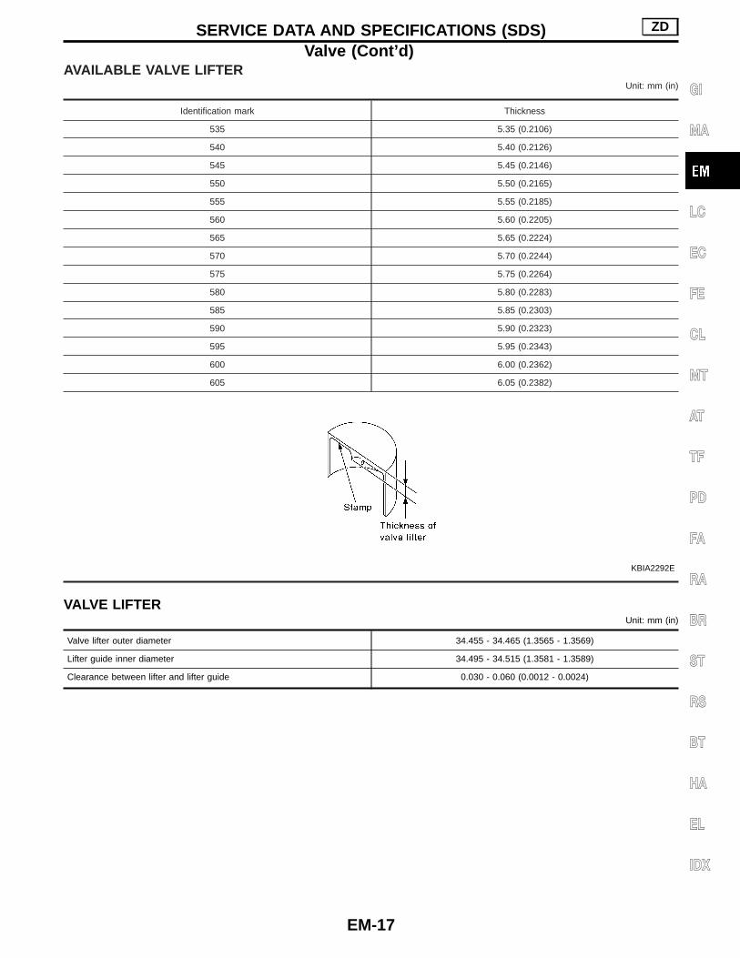
AVAILABLE VALVE LIFTERUnit: mm (in)
Identification mark Thickness
535 5.35 (0.2106)
540 5.40 (0.2126)
545 5.45 (0.2146)
550 5.50 (0.2165)
555 5.55 (0.2185)
560 5.60 (0.2205)
565 5.65 (0.2224)
570 5.70 (0.2244)
575 5.75 (0.2264)
580 5.80 (0.2283)
585 5.85 (0.2303)
590 5.90 (0.2323)
595 5.95 (0.2343)
600 6.00 (0.2362)
605 6.05 (0.2382)
KBIA2292E
VALVE LIFTERUnit: mm (in)
Valve lifter outer diameter 34.455 - 34.465 (1.3565 - 1.3569)
Lifter guide inner diameter 34.495 - 34.515 (1.3581 - 1.3589)
Clearance between lifter and lifter guide 0.030 - 0.060 (0.0012 - 0.0024)
SERVICE DATA AND SPECIFICATIONS (SDS) ZD
Valve (Cont’d)
EM-17
GI
MA
LC
EC
FE
CL
MT
AT
TF
PD
FA
RA
BR
ST
RS
BT
HA
EL
IDX

VALVE GUIDEUnit: mm (in)
FEM071
Standard Limit
Valve guideOuter diameter 11.023 - 11.034 (0.4340 - 0.4344) —
Inner diameter (Finished size) 7.000 - 7.018 (0.2756 - 0.2763) —
Cylinder head valve guide hole diameter 10.996 - 10.975 (0.4329 - 0.4321) —
Interference fit of valve guide 0.027 - 0.059 (0.0011 - 0.0023) —
Stem to guide clearanceIntake 0.023 - 0.056 (0.0009 - 0.0022) 0.18 (0.0071)
Exhaust 0.040 - 0.073 (0.0016 - 0.0029) 0.10 (0.0039)
Projection length 12.8 - 13.2 (0.5309 - 0.5197) —
SERVICE DATA AND SPECIFICATIONS (SDS) ZD
Valve (Cont’d)
EM-18

Camshaft and Camshaft BearingUnit: mm (in)
Standard Limit
Camshaft end play 0.065 - 0.169 (0.0026 - 0.0067) 0.2 (0.008)
KBIA2318E
Camshaft (No. 2 journal) “A” dimension 19.455 - 19.507 (0.7659 - 0.7680)
No. 2 camshaft bracket “B” dimension 19.338 - 19.390 (0.7613 - 0.7634)
Valve timing
PBIC0517E
Unit: degree
a b c d e
232 220 6 34 50
CrankshaftUnit: mm (in)
Runout [TIR*]Standard Less than 0.01 (0.0004)
Limit 0.03 (0.0012)
*: Total indicator reading
Available Connecting Rod BearingBALANCER SHAFT BEARING
Unit: mm (in)
Balancer shaft journal outer diameterFront 50.875 - 50.895 (2.0029 - 2.0037)
Rear 50.675 - 50.695 (1.9951 - 1.9959)
Balancer shaft bearing inner diameterFront 50.955 - 50.980 (2.0061 - 2.0071)
Rear 50.755 - 50.780 (1.9982 - 1.9992)
Balancer shaft journal oil clearanceStandard 0.060 - 0.105 (0.0024 - 0.0041)
Limit 0.180 (0.0071)
SERVICE DATA AND SPECIFICATIONS (SDS) ZD
EM-19
GI
MA
LC
EC
FE
CL
MT
AT
TF
PD
FA
RA
BR
ST
RS
BT
HA
EL
IDX