year 10 physics electricity
TRANSCRIPT

Name………………………………..
Year 10 Physics – Electricity
Current Electricity
An electrical circuit consists of a power supply (e.g. A battery) and a pathway so that an
electric current can flow back to the power supply. The pathway normally includes a load of
some sort (e.g. a light or a speaker) and connecting wires. The circuit must be complete (both
ends of the battery connected), in order for the current to flow.
There may also be means to control the circuit. This may be a simple switch or a device
which will cause the circuit to turn on when there is a change to the environment (e.g a photo
resistor) .
The most common power supply used to create an electric current is a battery (or cell). A
battery stores chemical energy which can be converted into electrical energy. The electrical
energy can in turn be used to give an output such as light. If a simple circuit is made up of a
battery and a lamp connected together, the energy transformations which occur when the
circuit is turned on are shown in the energy flow diagram below:
Chemical energy Electrical energy Light energy in the battery in the wires from the lamp
The electrical energy in the wires occurs due to the flow of electrons. The electrons are not
used up as they flow around the circuit. The electrons are given energy by the battery and
they lose energy as they pass through the load. In this way energy is passed from the battery
to the load by using electricity to connect the two.

Drawing Circuits
Rather than drawing complex circuits with life-like pictures, it is easier to draw them with
symbols:
Circuit Symbols
Cell
Battery
Lamp
Buzzer
OR
Motor OR
Push Switch
Open Switch
Closed Switch
Resistor
Variable Resistor
Wires
Where wires join
Diode

Series and parallel circuits
In a circuit where two components are placed one after another on the same wire the components are said to be in series with each other.
In a circuit where two components are placed on separate wires or ‘branches’, the components are said to be in parallel with each other.
If light globes are put in series with each other, they have more resistance, so the globes are
dimmer. When they are placed in parallel, it is easier for more current to flow through the
globes, so they are brighter. If one of the globes in the series circuit breaks, the current can no
longer get through, so both globes will go off. In parallel, if one of the globes breaks the other
globe will still remain on.
Charge, current and voltage and resistance
Charge There are two types of charge, called
positive and negative. Like charges
always repel each other and unlike
charges attract each other. Q or q is used
to represent a quantity of charge. Charge
is measured in coulombs (symbol C).
The charge on a single electron is
knowns as the elementary charge
(smallest possible charge) and is equal
to -1.6 x 10⁻¹⁹ C.

Current (I)
The amount of electricity (number of electrons) flowing around a circuit in a particular time
is called the Current . Current can be determined from the following equation:
I = Q
t
where I is current in amperes (A)
Q is charge in coulombs (C)
t is time in seconds (s)
Potential difference (Voltage) (V)
Resistance (R)
The resistance of a component (or material) is defined as the ratio of the voltage across the
component compared to the current passing through the component.
R = V
I
where I is current in amperes (A)
V is the potential difference across the component in Volts (V)
R is the resistance in ohms (Ω)
If too much current flows a circuit can overheat and become damaged. This is why resistors
are included in a circuit to prevent too much current from flowing.
Review 1: Check your understanding
1. What is the current in a conductor if 10 coulombs of charge pass a point in 20 seconds?
2. What resistance is needed to create a 0.1 A current from a 9 volt supply.
3. What voltage is needed to produce 0.05 A through a 120Ω resistor.
4. A 240 V light globe draws 0.25 A. What is its resistance?

Circuits
The current through all components in a series circuit is the same.
The voltage across each branch of a parallel circuit is the same.
The way voltage and current is distributed in series and parallel circuits is known as Kirchoff’s laws

Review 2: Check your understanding
1. Work out the voltages of each of the light globes in the circuits below. Write the voltages
next to each globe.
2. An ammeter is included in each circuit in question 1. From each ammeter reading, predict
the current that is flowing through points labelled A, B, C, D, etc in the above circuits.

3. What is the resistance of the following resistance when placed in series: a. 3Ω, 6Ω, 9Ω
b. 4Ω, 6Ω, 12Ω
4. What is resistance of the resistors below in parallel? a. 3Ω, 6Ω, 9Ω
b. 4Ω, 6Ω, 12Ω
5. Find the total current flowing through the power supply in the circuit below.
6. Find the current in a circuit with a 9 Volt power supply and three resistors set up as follows A
50 ohm resistor is placed in series with two other resistors of 100 and 500 ohm which are set
up in parallel with each other.

7. Complete each of the following questions by using the information in the circuit diagrams
a. What is the reading on the voltmeter?
___________V
b. What is the current running through the resistor?
_____________A
c. How much charge goes through the resistor in ten
seconds?
____________C
d. What is the reading on the voltmeter?
___________V
e. What is the current flowing through the 10 Ω resistor?
__________A
f. What is the current through the 15 ohm resistor?
__________A
g. What is the current through the 20 ohm resistor?
__________A
h. What is the potential difference across the
resistors?
___________V

i. What is the reading on the voltmeter?
___________V
j. What is the current through the point A?
_________ A
k. What is the current through the point B?
_________ A
h. If point A was to become disconnected what would be
the reading on the voltmeter?
___________V
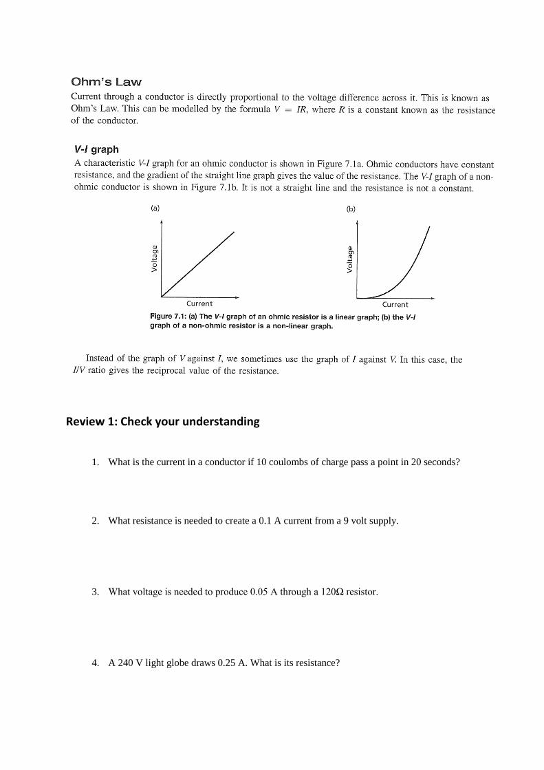
Non-ohmic resistors
Some components do not obey ohm’s law and there resistance changes depending on a number of
factors.


Voltage Dividers
Voltage dividers can be used to measure a wide range of variables, such as light, sound,
heat, etc, or can be used as part of a circuit control.
For example:
When the light level is low, R1 will be high so the voltage across R1 will be high and the
voltage across R2 is low.
Therefore, V out is small.
When the light increases R1 is lower, so voltage across R1 is also lower. This means the
voltage across R2 is higher and therefore V out is larger.
To work out the value of Vout compared to Vin, the following formula can be used:
Vout = R2 × V in
RTotal
Vout = Output voltage
V in = Input voltage
R2 = The resistance across which Vout is measured
RTotal = Total resistance in the circuit
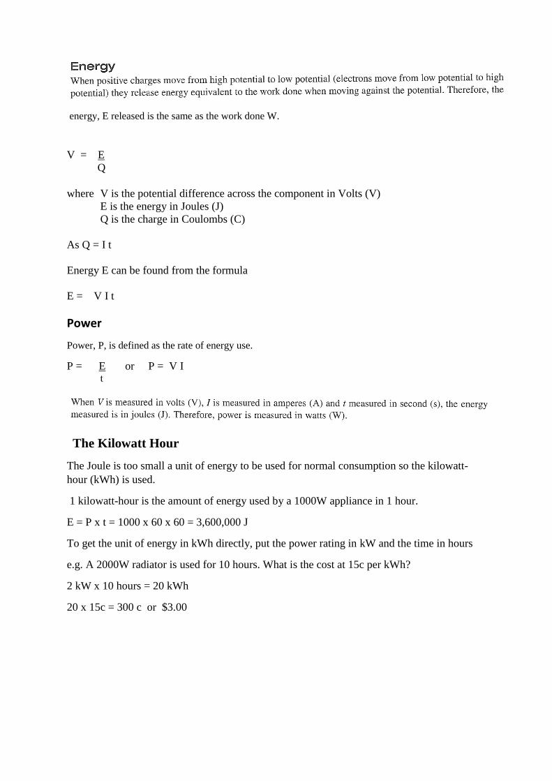
energy, E released is the same as the work done W.
V = E
Q
where V is the potential difference across the component in Volts (V)
E is the energy in Joules (J)
Q is the charge in Coulombs (C)
As Q = I t
Energy E can be found from the formula
E = V I t
Power
Power, P, is defined as the rate of energy use.
P = E or P = V I t
The Kilowatt Hour
The Joule is too small a unit of energy to be used for normal consumption so the kilowatt-
hour (kWh) is used.
1 kilowatt-hour is the amount of energy used by a 1000W appliance in 1 hour.
E = P x t = 1000 x 60 x 60 = 3,600,000 J
To get the unit of energy in kWh directly, put the power rating in kW and the time in hours
e.g. A 2000W radiator is used for 10 hours. What is the cost at 15c per kWh?
2 kW x 10 hours = 20 kWh
20 x 15c = 300 c or $3.00