yellow highlight is to further study - kingtech · pdf file1 what’s new the kingtech...
TRANSCRIPT

2016
KingTech Turbines - Engine Manual
KingTech Turbines
11/1/2016


Table of Contents What’s New ................................................................................................... 1 PURCHASE AGREEMENT, FULL ASSUMPTION OF LIABILITY AND INDEMNITY AGREEMENT .................................................................................................. 3
KingTech * Limited Lifetime Warranty * ............................................................ 7 Introduction ................................................................................................ 10
Safety Precautions ....................................................................................... 11 The Checklist ............................................................................................... 13 Fuel and Oil/ Fuel Care ................................................................................. 14
Fuel System ................................................................................................ 15 UAT (Ultimate Air Trap) ................................................................................ 16
Mounting the Turbine ................................................................................... 18 Installing the Fuel Pump ............................................................................... 19 Connections at the Turbine & ECU (G Models) .................................................. 20
ECU Battery ................................................................................................ 22 Description of the ECU .................................................................................. 23
Setting up the ECU ....................................................................................... 25 Learn R/C - Teach the ECU Your Radio System ................................................ 27 Setting the Restart Function .......................................................................... 31
Throttle Curves ............................................................................................ 34 Test/Info Functions ...................................................................................... 35
Turbine Starting and Running ........................................................................ 40 Turbine Stopping and Cooling ........................................................................ 42
Run Menu ................................................................................................... 43 Start Menu .................................................................................................. 48 Summary .................................................................................................... 55
Turbine Log ................................................................................................. 58 List of ECU Status Message Codes .................................................................. 62
List of ECU Warning Message Codes: .............................................................. 63 Diagnostic Messages .................................................................................... 64 K-45G Specifications: ................................................................................... 65
K-45TP Specifications: .................................................................................. 66 K-60G Specifications: ................................................................................... 67
K-60TP Specifications: .................................................................................. 68 K-80G Specifications: ................................................................................... 69 K-100G Specifications: ................................................................................. 70
K-120G Specifications: ................................................................................. 71 K-140G Specifications: ................................................................................. 72
K-140G2 Specifications: ................................................................................ 73 K-160G2 Specifications: ................................................................................ 74 K-180G Specifications: ................................................................................. 75
K-210G Specifications: ................................................................................. 76 Maintenance cycle includes: .......................................................................... 77
G Model Series 2 Components List ................................................................. 78 KingTech Turbines Fuel Start Operating Guide: ................................................ 79 K-60TP Turboprop Operating Guide: ............................................................... 81
TROUBLESHOOTING ..................................................................................... 84 CONTACT INFORMATION ............................................................................... 86
Glossary ..................................................................................................... 87 Service Request Form ................................................................................... 89


1
What’s New
The KingTech Series 2 turbines have three
new components.
New KingTech Series 2 self-priming fuel
pumps with black anodized case having machined
aluminum mounting brackets and priming valve.
o Pump features integrated multiplex connector and led operating
indicator light.
o 3 different size pumps. KP-500V – K-60, K-80, K-100, K-120.
o KP-600V – K-140, K-160.
o KP-800V – K-180, K-210.
o The “V” designation indicates the pump models having a priming
valve. Models without the “V” (Valve) are replacement pumps for
turbine models with Xicoy ECUs. Pumps with priming valves may
also be used with Xicoy ECUs but priming values will not be
connected to the ECU and will not function.
o (Note: K-45 uses MTH pump without self-priming function. KP-500,
KP-600 and KP-800 pumps wthout self-priming valves are available
for turbines with Xicoy ECUs.)
New KingTech Series 2 ECU with Anodized case
with new mounting bracket, and new simplified
temp/rpm cable with indexed connector on ECU end
and the following operating features:
o P-Valve, pump priming - in a start sequence,
during burner on, the ECU will command fuel pump to conduct self
priming, by closing the integrated solenoid valve on our new fuel pump
to engage a self- looping pump run

2
o Temperature probe failsafe will allow the turbine to continue to run even
when the temperature probe is no longer working
o Auto-restart modes including automatic restart and glider modes.
o Fuel and Gas valve error detection.
o Turbine Cool down and auto-shut off with RX power turned off. This
innovative new features saves transmitter batteries from being depleted
while turbine cool down is achieved. Receiver batteries are also saved
from unnecessary discharge. The problem of forgetting to turn off the
receiver and transmitter after cool down is totally eliminated. Power to
the ECU is turned off when the cool down sequence is completed.
o ECU Summary data viewable on the GSU detailing last four turbine
engine runs with Minimum, Mean, and Maximum values for critical
values necessary for troubleshooting.
o ECU Turbine Log data displayed in graphical format with horizontal
scrolling through the time of the last four turbine runs. Critical data
points displayed in separate colors superimposed on each other to
highlight relationships.
New KingTech Series 2 GSU with bright LCD
Touchscreen that is thin and can be mounted
inside the RC Aircraft.
It is recommended if mounting in the
aircraft to mount with a single small strip of
Velcro for easy removal when trouble shooting
and be sure to leave a service loop of connection cable as well for this purpose.

3
PURCHASE AGREEMENT, FULL ASSUMPTION OF
LIABILITY AND INDEMNITY AGREEMENT
User acquires from KingTech, or from one of KingTech’s authorized dealers, a MINIATURE
TURBOJET ENGINE for model aircraft, agrees to all of the following terms and conditions:
1. User's Representations. User represents that he/she is very experienced in model
airplane operation, and that all of the information set forth is true and
correct. KingTech relies on such representations, and would not enter into this
transaction but for these representations.
2. User acknowledges the Risks and Dangers involved. User recognizes that operation
of the Model Engine may be dangerous, and that under certain circumstances, its
handling will be dangerous. As set forth in Paragraph 3 below, User accepts full
responsibility for all of these risks and waives all liability against KingTech.
a. User's Acknowledgment of Danger. User expressly acknowledges that use of
the Model Engine is dangerous if improperly handled, and could inflict injury
if attempts are made to handle it properly, if the user does not fully acquaint
himself/herself with the Model Engine's operation procedures. The Model
Engine may cause burns to the user, or the user's assistant, particularly in
the start-up procedure, and user agrees to use extreme caution. The Model
Engine exhaust is extremely hot, and will burn someone or something placed
directly behind the exhaust tube. Highly flammable liquid is used to operate
the Model Engine, and it or its fumes will ignite easily and flare up
rapidly. The Model Engine itself remains extremely hot, after it is shut off,
and requires a cooling down period. Improper use of the Model Engine, or
failure to follow Academy of Model Aeronautics ("AMA") guidelines and rules
will result in injury to the user, the user's assistant, or
bystanders. Operation of the Model Engine in any location other than an
approved location, and under safe circumstances could lead to injury to

4
bystanders. A risk exists from explosion, in the event of tampering,
modifications leading to over-speed or extreme metal fatigue.
b. User's Obligation to Become Fully Acquainted With Operation
Procedure. User acknowledges receipt of operating instructions for the Model
Engine which depicts its handling and operation. User agrees to thoroughly
acquaint himself/herself with these materials, and to require his/her
assistant to become equally familiar with them. User expressly agrees not to
allow any person to assist in the start-up procedure of the Model Engine,
who has not become thoroughly familiar with these materials.
c. Agreement to Use Qualified Assistant in Start-Up Procedure. User
acknowledges that the start-up procedure for the Model Engine cannot be
safely done without an assistant. User expressly agrees to use an assistant,
who is thoroughly familiar with the Model Engine and its operation as set
forth above, on each occasion when the Model Engine is starting up.
d. Warning to Bystanders. User acknowledges that injury or burns to
bystanders could occur, during the start-up procedure or when operating the
Model Engine. User expressly agrees to take all steps necessary to assure
that no bystander will be in a position to receive injuries during the start-up
procedure, or while the Model Engine is running.
3. Full Assumption of Liability; Waiver and Release of KingTech. User assumes all risks
of injury, harm and damages, of every nature whatsoever, to himself/herself and
his/her property. User fully and completely waives and releases any and all claims which
he/she might have at any time arising out of the purchase, handling, or operation of the
Model Engine. This assumption, waiver and release is complete, full, and
comprehensive.
a. Release Even If KingTech Is Negligent. The waiver and release contained
herein releases KingTech from all conduct, no matter how it could be
characterized or alleged. KingTech shall not be liable based on any theory in
strict liability in tort. KingTech shall not be liable for any alleged breach of

5
warranty, whether express or implied, of any nature whatsoever, whether a
warranty of fitness for a particular use, merchantability, or otherwise.
b. Waiver Effective for All Time. The waiver and release contained herein is
effective, without regard to the passage of time. It is effective indefinitely. It
will not be changed by any modification to the Model Engine, to any later
resold, or other changes in any circumstances.
c. Release Extends to KingTech and All Its Associates. The waiver and release
contained herein protects KingTech, and all of its employees, officers,
principals, owners, importers, distributors, dealers, designers, and agents
("Associates").
4. No Modifications to Model Engine. User agrees to make no modifications of any
kind to the Model Engine. This Agreement pertains to the entire life of the Model
Engine.
5. Sale By User to Other Party. User agrees to fully inform any person to whom
he/she sells or transfers the Model Engine, concerning the handling, use, and
operation of the Model Engine, and agrees to give all operating instructions to
such person, at or before the time of sale or transfer. The indemnity and hold
harmless agreement contained in Paragraph 3 continues in effect, following such
sale or transfer.
6. Severability. In the event any clause, provision, or term of this Agreement is held
to be ineffective, void or otherwise unenforceable for any reason, that clause,
provision, or term shall be severed from this Agreement, and the Agreement
shall otherwise remain binding and effective. If any portion of Paragraph 3 is
found to be unenforceable, then the parties agree that the fullest and most
complete waiver and release, which is permitted by law, shall be effective.
7. No Interpretation of Agreement Against Either Party. User understands and
expressly acknowledges that he/she has the right to have an attorney read and
review this Agreement, before execution. This Agreement shall not be

6
interpreted against either party, but shall be interpreted as if it was drafted
mutually by the parties.
8. KingTech reserves the right to void warranty to an individual if one chooses to
make a negative public announcement before contacting us and allowing us
opportunity to assist or correct.
9. Make certain to comply all local rules, and obtain local licensing, permit, or
waiver to operate a turbine engine.
10. KingTech Turbines reserves the right to terminate support to those who are
defiant and incompliant to our ways of operations.
11. If the Buyer is not prepared to fully accept the PURCHASE AGREEMENT, FULL
ASSUMPTION OF LIABILITY AND INDEMNITY AGREEMENT, the Buyer is advised
to return this Model Engine immediately in new and unused condition to the place
of purchase.
12. Engine sent in for crash repair or misuse is subject to a $50 inspection fee
(inspection fee waived if work is authorized) and return shipping charge.
13. We reserve the right to ensure all repairs are up to factory spec including
cosmetics, quality or level of repair is not to be negotiated nor compromised.
14. Any engine sent in not reclaimed within 90 days will be considered abandoned
and will be dismantled, disposed or recycled.
15. Terms and conditions may change without notice. Buyers are to accept the latest
terms and conditions with no exceptions, which is to be found at:
www.kingtechturbines.com.

7
KingTech * Limited Lifetime Warranty *
KingTech warrants that this MINIATURE TURBOJET ENGINE for model aircraft, cars or boats
(“Model Engine”) enclosed with this warranty statement is free from defects in materials and
workmanship during normal usage, according to the following terms and conditions.
1. The limited warranty extends to the original purchaser ("Buyer") of the Model Engine
and is transferable with no fees during the first year of the original purchase, after
the first year, a warranty transfer fee of $150 is required to any subsequent
purchaser / end-user. Though it may still not have the warranty in place, all engines
must be registered with us at www.kingtechturbines.com to receive any type of
support.
2. Warranty coverage begins the day you bought the turbine to the day you sold or loss
the turbine, all electrical components such as batteries, electric starter motor, glow
plug, valves, ECU, GSU, pump and all frictional materials and components will have a
one year warranty coverage including but not limited to that of the bearings. All
parts, including repaired and replaced parts are covered for the original warranty
period. When the warranty on the turbine expires, the warranty on all replaced and
repaired parts also expires. The engine core, including but not limited to that of
combustion chamber, shaft, shaft tunnel, diffuser, injectors, NGV, turbine wheel, will
enjoy lifetime warranty and may or may not be replaced or upgraded during interval
services.
3. Buyer must fully accept all conditions of the PURCHASE AGREEMENT, FULL
ASSUMPTION OF LIABILITY AND INDEMNITY AGREEMENT
4. During the warranty period KingTech will repair or replace, at KingTech’s option, any
defective parts with new or factory rebuilt replacement items if such repair or
replacement is needed because of Model Engine malfunction or failure during normal
usage. No charge will be made to the Buyer for any such parts. KingTech will also
pay for the labor charges incurred by KingTech in repairing or replacing the

8
warranted parts and or components. The limited warranty does not cover defects in
appearance. KingTech will not be liable for any other losses or damages.
5. Upon request from KingTech, the Buyer must prove the date of the original purchase
of the Model Engine by a dated bill of sale or dated itemized receipt.
6. Buyer must bear the cost of shipping the turbine to KingTech, Taiwan or KingTech
Turbines International in Pasadena, California.
7. Buyer shall have no coverage or benefits under this lifetime warranty if any of the
following conditions are applicable
a. The Model Engine has been subject to abnormal use, abnormal conditions,
improper storage, unauthorized modifications, unauthorized repair, misuse,
neglect, abuse, accident, alteration, improper installation, fail to engage into
proper cool down, or other acts which are not the fault of KingTech, including
damage caused by shipping.
b. The Model Engine has been damaged from external causes such as crash
damage, foreign object damage, weather, Act of God, improper electrical
connections, or connections to other products not recommend for
interconnection by KingTech.
c. The Model Engine is operated for commercial or institutional use.
d. The Model Engine serial number has been removed, defaced or altered.
8. If a problem develops during the warranty period, the Buyer shall take the following
step-by-step procedure:
a. The Buyer shall ship the Model Engine prepaid and insured to KingTech,
Taiwan or KingTech Turbines International in United States.
b. The Buyer shall include a return address, daytime phone number, complete
description of the problem and proof of purchase.
c. The Buyer will be charged for any parts and/or labor charges not covered by
this warranty.
d. If the Model Engine is returned to KingTech during the warranty period, but
the problem with the Model Engine is not covered under the terms and

9
conditions of this warranty, the Buyer will be notified and given an estimate
of the charges the Buyer must pay to have the Model Engine repaired, with
all shipping charges billed to the Buyer. If the estimate is refused, the Model
Engine will be returned freight collect plus cost of estimate generally $50. If
the Model Engine is returned to KingTech after the expiration of the warranty
period, KingTech’s normal service policies shall apply and the Buyer will be
responsible for all charges.
9. KingTech shall not be liable for delay in rendering service under the limited warranty,
or loss of use during the period that the Model Engine is being repaired.
10. KingTech neither assumes nor authorizes any other person or entity to assume for it
any other obligation or liability beyond that is expressly provided for in this limited
warranty.
11. This is the entire warranty between KingTech and the Buyer, and supersedes all prior
and contemporaneous agreements or understandings, oral or written, and all
communications relating to the Model Engine, and no representation, promise or
condition not contained herein shall modify these terms.
12. This lifetime warranty allocates the risk of failure of the Model Engine between the
Buyer and KingTech. The allocation is recognized by the Buyer and is reflected in the
purchase price of the Model Engine.
13. If and when the bearings require replacement and ECU timer set back to zero during
a warranty repair, customer is to be responsible for the charges of interval service at
a prorated amount for the hours used.
14. Terms and conditions of warranty and liability may change without notice; users are
to accept the latest terms and conditions with no exceptions.

10
Introduction
Congratulations, you have just purchased a turbo-jet engine from KingTech Turbines, with
the highest standards and technologies in turbine design and manufacturing. We will
provide you with the best after-sales customer support and service to ensure you with many
years of enjoyment with this new turbine engine. *Please take a moment to properly
register your engine at www.kingtechturbines.com.
Obviously, model turbine aviation - despite all the apparent fun involved - has its potential
dangers. All KingTech turbine engines have been through an extensive period of R&D and
testing.
To begin, read this manual thoroughly. Develop an overall impression of the engine and its
operating procedures, measuring equipment and accessories.
Study the material step-by-step and ascertain how to install, operate and maintain your
turbine engine. If you are unsure about anything, re-read it again or contact us directly.
DO NOT OPERATE THE TURBINE BEFORE YOU HAVE READ THE MANUAL AND
FULLY UNDERSTAND EVERY PROCEDURAL DETAIL
Once you are accustomed to handling the Kingtech turbine, you will observe that it is a very
reliable engine. Some experienced operators have expressed their belief that it handles
better than many piston engines. However, always remember, this is a REAL JET ENGINE,
requiring knowledge, discipline and maintenance.
In order to learn more about the development of the model turbine engine and understand
its function, we highly recommend reading Gas Turbine Engines for Model Aircraft by Kurt
Schreckling and Model Jet Engines by Thomas Kamps. These books are available through:
Traplet Publications
Traplet House
Severn Drive
Upton upon Severn, Worcestershire ISBN 0 9510589 1 6
United Kingdom WR8 0JL ISBN 0 9510589 9 1

11
Safety Precautions
ALWAYS ENFORCE THE PROPER MINIMUM SAFE DISTANCES FROM THE TURBINE!
In front of ~ 15 feet, On the side (perpendicular to the engine thrust) ~ 25 feet, Behind ~
15 feet
Fire extinguishers should be on hand at all times. We recommend the CO2 variety.
To avoid hearing damage, always use ear protection when you are near a running turbine
engine.
When the turbine is running, never place your hands into the area of the intake. An
extreme suction - which can grasp a hand, fingers or other objects in a flash – prevails in
this area. Be aware of this source of danger, always!
Prevent foreign materials from entering the intake or exhaust when working with the
turbine. Before operation, make sure there are no loose parts or debris near the turbine or
within the fuselage. Objects being sucked in will cause severe damage to the engine, which
will not be covered by any warranty; furthermore, such damage may also injuries.
Always exercise caution around the hot parts of the turbine, to avoid burns. The outer case
at the turbine stage and nozzle reaches 450-500° (Celsius), while the exhaust gas may
exceed 750 °C.
Ensure that the fuel is mixed with approximately 5% approved oil. Use only turbine oils by
KingTech Special Blend with Synthetics, which is a non-carcinogenic blend and available at
www.kingtechturbines.com or turbine oil with MIL-PRF-23699 available at local airport fuel
suppliers.
Never run the turbine in a closed room, or an area near any kind of flammable matter.
Do not fly turbine-powered aircraft near flammable materials, nor in forested tracts or areas
experiencing drought or dryness. Obey all forest fire regulations and warnings by refraining
from operating turbine in restricted fire zones. Never operate model turbine jet aircraft in or
around residential or heavily populated areas.
Installation of unauthorized parts from another manufacturing source may also result in
engine failure.

12
Warning:
A flying model with a turbine can reach higher flight speeds than ducted fan-powered
models, because the turbine’s thrust degrades less with higher flight speeds. With attainable
flight speeds of up to 200 MPH or over, you can quickly run out if flying space. There is also
a danger of developing control surface flutter or mechanical overload, causing the model to
fail in flight. When piloting a turbine powered aircraft, one must properly control the throttle.
Full power should be used for takeoff or vertical maneuvers and a reduced setting for level
or descending flight. Please abide AMA flight rules of maintaining less than 200 MPH at all
times.

13
The Checklist
Before Running the Turbine
Charge ECU Battery
Observe all safety precautions on Safety Precautions
Prepare fire extinguisher
Check fuel lines and filter. Make sure they are clean with no restrictions
Check that the fuel tank vent is unobstructed
Fill fuel tank(s). Make sure the main and header tanks are full
Purge Fuel Line, by Test Pump. Take good care not flooding turbine, (Purging
fuel line is only necessary after initial set up, and do not get confused with Prime
Pump.
Turn on receiver switch
Place the model with nose into the wind
Activate brakes and now you ready to start.
After Stopping the Turbine
Turn model into the wind. Activate brakes and stop turbine
After the cooling process (approximately two minutes), turn off receiver switch.
The new ECU will allow you to shut down the engine and receiver as soon as you
are back at the pit and it will continue cooling until desired temperature has
reached without the RX being powered on.
In the event that the turbine does not go into the cooling mode, please refer to
Turbine Stopping and Cooling 28 for manual activation.

14
Fuel and Oil/ Fuel Care
KingTech engines use Diesel, 1-K kerosene or Jet-A1 for fuel. Fuel must be mixed with 5%
KingTech Special Blend or synthetic turbine oil (Aeroshell 500 and all 2-stroke oil are
prohibited), or 1 quart of oil in every 5 gallons of fuel. Among the above 3 types of fuel
KingTech highly recommends using regular pump Diesel as they are readily available,
inexpensive and having a higher energy density and up to 10 to 12% better fuel efficiency.
For best result and full core warranty, use KingTech Oil only, it is proven to be the cleanest
and has the best lubrication properties for our engines, please refer to the below comparison
chart:

15
Fuel System
When installing the fuel lines on components with barbed connectors, if necessary slightly
heat the tubing and lubricate the barbs before connecting. This will soften the tube slightly,
making it much easier to install. Double looping safety wire on all barbed connection is also
required. To remove tubing from barbed connectors, you must cut the tubing off. Be careful
not to damage the barbs when cutting off tubing. This could be done by snipping away the
tubing material parallel at the fitting. To insert tubing into a Pisco or Festo quick release
fittings, put a drop of oil on the outside of the tubing and use firm pressure until you feel the
tube snaps in then lightly pull on the front ring and tubing to ensure a good seal. To
release, press in on the front ring, while slightly pushing the turning the tubing then pull the
tubing out for a clean release.
ALWAYS use a gasoline-compatible stopper. Silicon stoppers swell and leak.
Check your fuel filters every ten or so flights. The filter is installed with the O-ring located
toward the fuel pump.
Use caution not to pinch o-ring when assembling filters. We recommend to smear a little oil
on the O ring mounting the fuel filter vertically. This will provide a better seal from the O
ring and limit the possibility of air being trapped inside and then coming out at an
inopportune time. It is also better not to affix it but to leave it free to slightly move.
When running the engine at full power, check the fuel line from the pump to the engine. If
there is a large quantity of air bubbles flowing with the fuel, there is probably a restriction in
the fuel system or an air leak in at least one of the many fittings.
Be careful not to over-pressurize the fuel tanks and the shut off valve during
refueling operations.
You want to make sure the vent is not plugged up. We are now requiring a manual shutoff
valve, as an additional prevention of pumping raw fuel into the engine and to avoid a
subsequent wet start.

16
UAT (Ultimate Air Trap)
A UAT is recommended, between the main fuel tank and the engine. KingTech highly
recommends the BVM UAT or its equivalent. Always use a filter between the fuel pump and
the turbine as shown in the diagram. The pump may emit small particles that can block the
solenoid valve in the turbine from completely closing!
Prime the Pump and System
To prime fuel pump and fuel lines (or for fuel pump test purposes), it is necessary to open
the manual fuel shutoff valve and run fuel pump manually. For this operation, use the GSU
and go to TEST icon, and scroll to 6 of 9 or 6/9 to Test Pump. This test opens the fuel valve
and acts as a speed control for running the pump.
Tap on the #1 ON button to begin (at this time the pump will run at very low voltage) then you might
want to increase pump power by tapping on the same button until desired pump speed reached
(more tap more power) pump will continue running at the last tapped power, then tap #2 button to
turn it off.
Extremely Important:
Pump Test allows the fuel pump to operate without the turbine running. However, if the fuel
feed line is not removed from the turbine during this procedure; it will become flooded with
fuel. When this occurs, the next turbine start can become highly combustible!
Before activating the pump test mode, ALWAYS remove the fuel feed line
connected to the turbine and dip the line back to your fuel can or overflow tank.

17
Fuel System Connection Diagram G Model

18
Mounting the Turbine
A two-piece, aluminum mounting bracket is included with the turbine. Place the bracket
around the turbine, with the glow plug situated within the slot of the smaller bracket
piece. This will help stabilize the engine along the thrust axis. The glow plug must be in the
vertical position, when mounted in your model (+/- 75° of engine rotation, from the glow
plug at top dead center, is the allowable deviation). Secure the engine, using four metric
mounting screws and lock washers that are provided with the bracket.
Other Notes on Turbine Installation
When the turbine is mounted in models with the air intake at the bottom, for example an F-
16, care should be taken to prevent foreign object damage of the compressor blades.
This can be accomplished by using a strainer screen at the inlet. The screen mesh should be
about 0.06 inches in width.
KingTech also offers an FOD screen as an optional accessory and it is highly recommended
to protect your investment.

19
Installing the Fuel Pump
Connect pump MPX power cable from ECU to pump and from ECU to ECU battery.
Note: THE MPX CONNECTOR THAT ATTACHES TO THE PUMP HAS ONLY 2 WIRES. THE MPX
CONNECTOR WITH 4 WIRES ATTACHES TO THE ECU.
Black Wire Red Wire
Arrow on the pump indicates direction of fuel
flow
Connect output of UAT to input of pump with hard
line tubing
Connect turbine with fuel filter in line using
4mm hard line
tubing.
Blue indicator
light shows pump
operation
Pump power
cable from ECU
2 wires
Pump P-Valve (Priming Valve)

20
Connections at the Turbine & ECU (G Models)
Starter and Glow plug
GSU
9V to 10.5V power

21
New Data Connector at Turbine
The data connector at the turbine end has a new safety latch and removal
assisting mechanism. This assist device pictured above on the left if placed
under the plastic tab when attached to the turbine acts as a locking mechanism.
The center picture above shows the latch in the retracted position. The picture
on the right shows the device above the tab on the data connector in a position
to assist with removal of the data cable from the turbine.
ECU Connections
The picture above shows the new single data cable with a keyed connector which prevents
it from being inserted into the ECU incorrectly. The picture on the right shows connection of
all cables on the ECU from the turbine, receiver, pump and GSU.

22
ECU Battery (not included)
Electrical power for all electrical components for our F/G series turbine (starter / glow plug /
ECU / fuel pump / fuel and gas valves) will require a 3S LiFe pack or 7C NiMh from 2000mah
to 5000mah ECU battery. The amount of battery capacity used per flight is approximately
300-350 mah. This includes starting and cool down. The ECU battery must not be used
over 80% of its capacity, or it must be recharged.
Charging the Battery - Do not charge the battery with a charger using negative discharge
pulses when connected to the ECU. This will destroy the electronics of the ECU. You must
disconnect the battery from the ECU and charge it directly.
Also, we recommend you reset the battery used value to zero using the GSU. Go to the
menu item “Info”, “Battery” then press the “+” button after each completed charge. This
will clear the cumulatively monitor mAh used. Again, make sure you stop flying and starting
charging if it the value is near 20% of the capacity.
Note: If your turbine does not start on the first flight of the day after fully charging
your ECU battery, check the GSU for an error message. 3S LiFe packs peak at
10.8V when fully charged. This will cause an error message on the GSU "Voltage
Overload". To resolve this issue, with Trim Down, stick up to actuate starter motor
for 5 seconds. This will bleed the voltage down just enough to get it closer to
nominal for normal operation.

23
Description of the ECU
The ECU is a system for the control of a model gas turbine engine. Its main function is to
control and regulate the fuel pump, providing to the turbine engine the necessary amount of
fuel for safe and controlled operation, and to operate the ancillary devices for starting. The
ECU measures the exhaust gas temperature, the relative position of the throttle stick and
the rotor speed. It monitors all of the controls necessary to make sure that the engine stays
between the user defined parameters of operations, also providing failsafe shutdown of the
engine when it has detected any important anomaly. In order to make this assessment, the
ECU has a rpm sensor, a thermocouple input, a throttle servo input, power connections for
the fuel pump, fuel pump primer valve, starter, glow plug, fuel and gas valves and the
battery and a data port to program and read the data in real-time from the GSU or a
PC. The measurements made by the ECU are:
• Temperature of the exhaust gas
• Battery voltage
• Battery current
• Width of the throttle pulses from the radio transmitter
• Engine rotor RPM
• Engine run time.
• External analog signal (airspeed sensor)
Features:
• RPM input: Magnetic sensor up to 250.000 R.P.M.
• Temperature range up to 1000ºC using a "K" type thermocouple
• PWM control of 8192 levels for pump, glow plug and starter motor.
• Adjustable power for the starter motor
• Build-in electronic brake for the starter motor to help the clutch to disengage.
• Blown glow-plug detector
• Adjustable glow-plug power
• Glow-plug temperature independent of the battery voltage

24
• Elapsed engine run timers
• RS232 or USB interface to PC, cable must be purchased separately.
• Black box function. Record the engine measures each 0.5sec up to 52 minutes.
• Radio link error counter
• Battery usage counter in mA/h, (reset this value on a freshly charged pack)
• Test functions for all connected devices.
P-Valve, pump priming - in a start sequence, during burner on, the ECU will
command fuel pump to conduct self priming, by closing the integrated solenoid
valve on our new fuel pump to engage a self- looping pump run
Temperature probe failsafe with allow the turbine to continue to run even when
the temperature probe is no longer working
Auto-restart modes including automatic restart and glider modes.
Fuel and Gas valve error detection.
Turbine Cooldown and auto-shut off with RX power turned off.

25
Setting up the ECU
All the programming and measurements are done through the GSU, Ground Support Unit.
The GSU is a Handheld Data Terminal featuring a bright touch screen display. When you
first connect the GSU to the ECU via the connection labeled GSU on the ECU or turn on
power to your aircraft the logo screen appears briefly.
Next a Dashboard screen appears displaying a host of information..
Next touch anywhere on this screen to select the Home Screen of functions available on the
ECU.
Engine Model
ECU State
Throttle Command
Turbine Speed Graph Temperature
and Pump
PW Graphs
ECU Battery Voltage
Digital Turbine Speed
Receiver Battery Voltage
Turbine Temperature
Pump Pulse
Width
Select Home Screen

26
The Home Screen for the ECU is displayed. All the functions available can be displayed by
using the scroll bar on the right side of this screen
For now, touch the Radio button, the icon looks like a transmitter.
The following screen appears.
Pressing the “Next” button enters the RC Learn menu.
Menu Title Page 1 of 6
Exit Menu to previous
screen
Throttle
pulse width Relative
stick position

27
Learn R/C - Teach the ECU Your Radio System
Learn RC, follow below procedures to ensure learning RC for proper failsafe.
1) For JR and Spektrum Compatible and Jeti, Power on the transmitter and make sure the
throttle reversing is set to normal, travel 100% and put Stick Down, Trim Down, then turn
off transmitter.
1a) For Futaba and compatible, do the above except activate the reversing on the throttle
channel
2) Bind the transmitter to the receiver with stick down trim down
3) Touch anywhere on the Dashboard for the GSU Home Screen.
Touch anywhere
for the
Home
Screen

28
5) Touch "Radio" on the Home Screen
6) To Start the RC-Learn process press <4> Next.
Note: The correct reading of throttle % by the ECU can be verified on this screen,
percentage of the throttle position is shown on, 0% in the position of engine stop (trim and
stick down), 100% with stick/trim full up and between 10% and 30% at idle, (stick up trim
down).
7) Press <2> to enter the RC-Learn function.
Touch Radio to perform RC-Learn
Press <4> to
enter the RC-Learn function
Press <2> to start
RC-Learn

29
8) Place the Stick Up and the Trim Up on the transmitter and press <2> on the GSU
9) Place the Stick Down and the Trim Down on transmitter and Press <2> on the GSU
10) Place the Stick Down and the Trim Up on the transmitter Tx and Press <2> on the GSU
Press <2> to Save and continue
Press <2> to
Save and continue
Press <2> to Save and continue

30
11) Use <4> on the GSU to scroll to "HALF EXPO", default and recommended curve see
Throttle Curves for additional information.
This now completes your radio setup. Re-learning RC is also useful if you are
experiencing high idle due to a broken-in pump motor, typically about 1 to 2 hours
from brand new.
On your first start after RC learned: Be patient until ECU stabilizes idling RPM, this may
take up to 1 minute or so, subsequently hold on tight to your airplane and apply full throttle,
and again let the ECU to stabilize its peak RPM, then back down to idle to verify, do this a
couple more times and you are ready to go.
Note: Error “Cooling Down” message - Anytime you have a cool down message after you
completed the above steps for Learn RC, you have a connection error, most likely your
throttle cable is plugged in incorrectly, please check polarity and/or correct slot.
Press <4> to
save and exit.

31
Setting the Restart Function
By default the Restart function for the Turbine is set to OFF. Before you enable the
Restart function it is important to understand the drawbacks, and limitations and
the limited advantages of it’s use. The advantage of automatic restart is that it
will restart the turbine whenever a momentary interruption in fuel supply occurs.
Logically, if the fuel supply is unreliable, the likelihood that it will continue to be
unreliable is great. Therefore, restarting the turbine in all likelihood will result in
another flameout. The liability that exists in this situation is that if the failure
results in a crash, a fire is much more likely to occur when the restart function is
turned on. It takes approximately 15 seconds for the Restart function to restore
turbine power. In many aircraft where heavy wing loading exists, this is not
enough time for the aircraft to glide without impacting the ground before the
restart would be effective in restoring power.
Disclaimer
By turning on the Restart function, the user agrees the he/she fully understands
the workings of this function and the user assumes all responsibility for any
negative outcomes resulting from the Restart function being enabled.
To set the restart function touch anywhere on the Dashboard.
The restart function has three settings, Off, Restart and Glider. If the setting is set to Off
then no restart is attempted. If the Restart Mode is set to Restart, the ECU will attempt an
automatic restart in event of a temporary interruption of the fuel supply. In Glider mode the
user may shut down the turbine in the air and then later restart it providing the turbine
temperature drops below 150C.
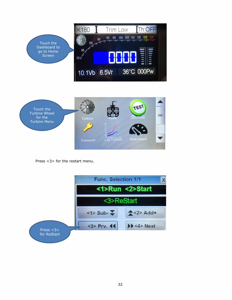
32
Press <3> for the restart menu.
Touch the Turbine Wheel
for the Turbine Menu
Press <3>
for ReStart
Touch the Dashboard to go to Home
Screen

33
To turn the restart mode on Press <2>. Press <3> to go to previous menu. To exit and
return to previous menu press <4>
To turn Glider mode on press <2> again. To exit and return to previous menu Press <4>
Press <2>
to turn
Restart
Mode On.
Press <1>
to turn
Restart
Mode Off
Press <4> to
return to previous menu
Press <1>
to turn
Glider
Mode Off
Press <2>
to turn
Restart Mode On.
Press <4> to
return to previous menu

34
Throttle Curves
Jet engines develop the thrust exponentially, thus half of the RPM is only approximately 1/4
of the thrust. On small engines with a high idle to full power rpm ratio, or in a high drag/low
power plane, often only the last 1/3 of the throttle stick produces significant thrust. The low
half of the stick travel is not used. Although current digital Transmitters can modify the
throttle curve to suit the requirement of the model, the Kingtech ECU can simplify the
installation by adjusting to three different throttle curves as follows:
FULL EXPO: Mean linear RPM, it is the default setting and the mode used for all
previous software versions. Thrust develops exponentially, and it is the recommended curve
for big engines or/and high thrust/weight ratio planes, as it ease the control in low power
used during taxi.
LINEAR: Mean that the thrust develop linearly with the throttle setting, has more resolution
at lower half of the throttle stick.
HALF EXPO: An intermediate setting between the previous two modes. This is the KingTech
factory setting and we are sure you will find this setting to be the most suitable.

35
Test/Info Functions
The ECU provides testing functions to the starter motor, glow or burner plug, pump and both
solenoid valves. These test screens are only available when the ECU is on the “Trim Low”
status, that is to say, recently powered up and receiving a STOP signal from the TX. Pressing
the <1> button will energize the selected device and pressing <2> will shut it down. Special
care should be taken when testing the pump, as it is possible that fuel can be pumped into
the engine, flooding it, and causing a hot start on next startup. Testing the pump works
differently than Xicoy ECUs in that the <1> on function must be pressed repeatedly to
increase pump flow. Prior models increased pump flow during test with only a single press
of the button.
*Some LiFe chargers is capable to peak a 3S pack over 10.7V, the ECU might
display “Over Voltage” and will not engage engine start mode. Please go back to
Description of the ECU to bleed off the peaked voltage.
To initiate the test functions press the turbine wheel from the Dashboard.
Touch the Dashboard to go to Home
Screen

36
Home Screen: Press “Test” to initiate the test functions.
Test/Info page 1 displays Turbine Total Time in minutes, last Cycle time in seconds and
number of cycles. Note: These numbers are reset to 0 upon overhaul. (Interval 25 hours)
Test/Info page 2 displays condition of last shutdown with Temperature, RPM and Pw.
Press Test to initiate test functions
Press X to exit to Home Screen
Press <4> to
proceed to next
screen
Press X to exit to Home Screen
Press <4> for next screen
Press <3> for previous
screen
Displays page
number and total pages

37
Test/Info page 3 displays ECU Burn date and version information.
Test/Info page 4 is for testing Starter
Test/Info page 5 is for testing the Glow Plug.
Press <3> for
previous
screen
Press X to exit to Home
Screen
Press <4> for next screen
Press <3> for previous
screen
Press X to exit to Home Screen
Press <4> for next screen
Press <1> to begin
Starter test Press <2> to end Starter
test

38
Test/Info page 6 is for testing Fuel Pump.
Test/Info page 7 is for testing the Gas Valve.
Test/Info page 8 is for testing the Fuel Valve

39
Test/Info page 9 is used for priming the turbine.

40
Turbine Starting and Running
Always set-up and confirm the operation of your Auto-start installation on the test-stand,
before installing into your model. This will help you to familiarize all components associated
and the characteristics of different stages of turbine engine starting.
The present version of auto start uses only one channel for the entire engine functions: To
trigger the auto start cycle, the process is as follows:
• The user raises the trim. "Ready" will appear on the GSU screen. The trim and stick
should be where the engine is supposedly to be to idle once running. If the trim is on "stop"
position, "Trim low" will be read on the GSU.
If throttle value is higher than idle, "StickLo!" will be read.
• When "Ready" is displayed, the user should cycle the stick to beyond ½ throttle and back
to idle in order to initiate the start sequence. * For F & G models, do not be alarmed by
the starter motor engaging the rotor if you place the throttle on full, this briefly
actuates manual cool down*
Stage 1
• The burner plug is powered and checked. Once hot, the starter is engaged at reduced
power (soft start). If the glow test fail, a "Glow Bad" message is displayed, and if the
starter fails to arrive a minimum RPM in 2 seconds, a “start bad” message is issued, and the
auto start function aborted.
• Ignition – (Ambient to plus 4C) When the rotor arrives at more than the "ignition max
rpm" programmed parameter the starter is disconnected, the ignition fuel is being
introduced; you could recognize this by the clicking sound of burner fuel solenoid and the
pulsating of fuel pump. Once this fuel delivery is engaged, you would want to hear a very
positive “pffffff” ignition.
• Preheat – (up to 72 C) Once the temperature climes for 2 to 4 degrees from ambient,
Preheat stage commences, flame is something you do not want at this stage. If flame is
present, abort (trim down) you could either reduce Preheat fuel or increase preheat RPM.
41
What you want to see is a steady climb of temperature up to 72C.
Stage 2
• Switch Over – (up to 200 to 300 C) This is the stage that the main fuel also opens and a
slight yellow to bluish flame is expected, while starter motor drives the rotor even faster in
preparation for fuel ramp.
Stage 3
• Fuel Ramp - Some popping and some flashes of yellowing blue flame is expected. At this
stage, the burner valve is closing while the pump and start motor drive the engine up to idle
temperature and RPM, once Running, your transmitter takes over the engine.
Watch out for temperature hanging at a certain stage, primarily Ignition and/or
Preheat. This will potentially accumulate fuel and an undesirable wet-start may
occur.
It’d be a good practice to extend your GSU to be viewed in-line with the tail cone to
have a sighting of possible fuel dripping or flame.
NOTE: Do not confuse the auto-start function described above with the auto-restart function
previously discussed under Setting the Restart Function.
Before you call tech support on start-up related issues, please have enough above
information to facilitate an effective support.

42
Turbine Stopping and Cooling
The user can finish the sequence at any moment, simply setting the trim to "off" position. If
the engine was on "running" phase (above idle rpm), a cooling sequence will be triggered,
cycling the starter motor until the EGT is below the minimum programmed
temperature. This cooling sequence will be aborted if the trim is raised again.
• If the engine is hot (EGT higher than the minimum temperature) at the moment that the
user triggers the auto start cycle, then the ECU will begin a cooling cycle until the
temperature is below 100C.
You may turn off power to the receiver at any time after engine shutdown and the ECU will
continue to cool the turbine. When the cooling is below 100C the ECU will shut down. This
is a new feature of the KingTech Series 2 ECU.
Manual cool down:
In the event if engine does not go into the cool down mode after the turbine shuts down or
flames-out, the user can lower the trim, and advance throttle stick to trigger cooling from
the starter. Make sure you simulate the auto cooling sequence and monitor the real time
temperature and do not leave motor running for longer than a couple of seconds.
Another option is to unplug reconnect power to ECU. This power cycle will enable ECU to
recognize that the engine temperature is still higher than normal, and should engage auto
cool down.

43
Run Menu
To access the Run menu touch anywhere on the Dashboard.
Touch the Turbine on the Home Screen to select the Function Menu.
On the function selection screen press <1> Run
Touch the
Dashboard
to access
the Home Screen
Touch the
Turbine to
go to the next menu
Press <1>
for the
Run function

44
Under this submenu, the parameters used for the engine during normal run can be
modified. Note: Some of these menus parameters cannot be changed by user. It was
factory set for best operation and to protect turbine. Please do not change these values
set by factory. This may void your warranty!
Full power speed: On this screen you can set the RPM that the engine will run at 100%
throttle. If the engine manufacturer has set a maximum limit, you will only be able to
reduce the max RPM.
Press
<1> to decrease Press <2>
to increase
Press
<3> for
previous
screen
Press
<4> for
next
screen
Press X to exit

45
Idle speed: Set the RPM that the engine will run when the ECU receive IDLE
Command. While the engine is running, the ECU will adjust the rotor speed accordingly the
throttle position in a closed loop system. (For rough idle, please refer to TROUBLESHOOT
towards the end of this manual)
Maximum temperature: Set the maximum temperature that the engine is allowed to
run. The ECU will reduce the acceleration rate if the EGT approaches to maximum and will
reduce the pump power if necessary to keep the temperature below the maximum, but it
don’t will cut the engine if the temperature is too high, it will try always to keep the engine
running by reducing the fuel flow. 850 DEG C
Press <2> to increase
Press
<3> for
previous
screen
Press
<4> for
next
screen
Press X to exit
Press
<1> to
decrease

46
Acceleration delay: Set the acceleration time on the engine. Higher the values, slower the
acceleration. The real acceleration is calculated using a complex algorithm that take in to
account this value, temperature, current RPM, commanded RPM, and the tendency of EGT
and RPM.
Deceleration delay: Similar to the acceleration, but used during throttle down. Higher
values mean slower deceleration.

47
Stability delay: When the engine is running at constant throttle setting, the ECU is
adjusting continuously the pump power so that the rotor RPM mach exactly with the throttle
signal. The speed of which the ECU adjusts the pump power as set by this parameter. A
value of 100 usually is the best for all engines. A too low of a value can cause instability on
the RPM.
Pump Limit: The ECU can give to the pump the full battery voltage, but in most cases the
voltage needed for the pump is only a fraction of the full battery voltage. Limiting the pump
give a much smoother control of the engine and prevents that the pump could receive
excessive voltage in the case of a problem in the fuel circuit, a clogged filter for
example. This excessive power will cause a high pressure on the circuit that can cause leaks
or blown tubes. Modifying this parameter is similar to reducing the battery voltage, so the
accel and decal times will be modified. The most ideal is to have the limit set at the lowest
and still be able to reach full max RPM, run the engine, check and annotate the Pw of the
pump displayed on the first screen when the engine is running at full power and then use
this value as pump limit, increasing it in a 15%-20% to give a bit of margin for weak
batteries and pump wear. Once the new value set, adjust the accel and decel delays for
best engine handling.

48
Start Menu
Startup parameters are set at the factory and are fine tuned during run testing. No
two motors are exactly the same, so comparison with another motor of the same
type may not yield the same result or value. Do NOT attempt to change
parameters unless specifically instructed to do so by KingTech technicians. Doing
so on your own may void the turbine warranty.
To access the Start menu touch anywhere on the Dashboard.
Touch the Turbine on the Home Screen to select the Function Menu.
Touch the
Dashboard
to access
the Home Screen
Touch the
Turbine to
go to the next menu

49
On the function selection screen press <2> start
Press <2>
for the
Run
function
Press
<1> to decrease
Press
<3> for
previous
screen
Press X
to exit
Press <2>
to increase
Press
<4> for
next
screen

50
Pump start Value: Sets the power of the pump when it is started at the beginning of the fuel
ramp.
Pump Pw Ignition (in thousands): Sets the power of the pump. This adjust the amount of
fuel sent to the burner during the ignition phase of startup.
Ignition RPM: Sets the rpm where the starter will be switch off during ignition
Press
<1> to
decrease
Press
<3> for
previous
screen
Press X to exit
Press <2> to increase
Press
<4> for
next
screen

51
Stage 1 RPM:The RPM that triggers stage 1 of startup.
Stage 3 RPM: The RPM that triggers stage 3 of startup.
Starter power at Ignition: The power sent to the starter motor controlling the amount of air
injected into the burner can at the Ignition phase.

52
Stage 1 Starter Power: The power sent to the starter motor controlling the amount of air
injected into the burner can during the Stage 1.
RPM 100% starter power: The resulting RPM value that is considered 100% maximum
starter power.
Engine Minimum Flow in %: The percentage of time the main fuel valve is open (pulsed)
during the switchover phase of startup.

53
Stage 1 fuel duty: The percentage of total fuel applied during Stage 1 of startup.
Stage 1 EGT: Temperature in Celsius.
RPM OFF Starter: The RPM at which the electric starter motor is disengaged.

54
RPM to reconnect: The RPM at which to re-power the starter motor if the turbine RPM falls
below this value during startup.

55
Summary
The Summary is a listing of operating data collected on the last four turbine runs stored in
the KingTech ECU and displayed on the GSU screen.
To access the Summary touch anywhere on the Dashboard.
On the Home Screen, touch the Turbine Log to display one of the last four turbine runs or
“Rounds”.
If Summary is not displayed, use the scroll bar on the right side of Home Screen to
display Summary.
Touch the
Dashboard
to access
the Home
Screen
Touch
Summary

56
Next the GSU will read the logs from the ECU. Depending on the amount of data this
may take a minute or two. To cancel this function and return to the Home Screen touch
the “Cancel” button.
To change which of the
last four rounds is
displayed, use the drop down list.
Scroll bar
up or down
to show all data

57
To display all of the information you will need to use the scroll bar on the right side of the
screen
This information displayed is the Maximum, Mean, and Minimum values for each of the
following data items:
Turbine RPM
EGT – Exhaust Gas Temperature
PW Pump Pulse Width
Tp_Rpm (Turbo prop Shaft Rpm)
Speed (Air Speed from accessory device)
Battery V. : ECU battery voltage
RX. V : Receiver battery voltage
AMP: ECU current. Engine running only
AbNor: Diagnostic Codes
This function is a subset of data stored by the ECU. A more complete data log will be
available using the PCT (PC Terminal interface) at a future date.
Exit Turbine
Log and return
to Home Screen

58
Turbine Log
The Turbine Log is a graphical display of Turbine Log data which scrolls across the screen in
reference to lapsed time for a turbine run.
To access the Turbine Log screen, touch anywhere on the Dashboard.
On the Home Screen, use the scroll bar to display the Turbine Log Icon.
Touch the
Dashboard
to access
the Home
Screen
Touch the Turbine Log

59
Make sure Throttle Trim is in off position to retrieve log data.
Select one of the four most recent turbine runs *(Rounds)” and touch the Download button
Select one of
the four most
recent rounds to display.
Touch Download
button to start data download.

60
Select data to be displayed from one of four most recent turbine runs.
Wait for data to be displayed.
Touch the Info button for buttons to be displayed for control of displayed log data or press
Exit to return to Home Screen.

61
Touch the “Full Screen” button to return to display without control buttons. . The data will
scroll on the screen from right to left representing a time line for the data. Press Back,
Pause or Forward to control the graphic display of data. This is helpful in comparing the
relationships between the various data points. Colored lines on the graph represent.
Green – RPM in thousands
Orange – Pump PW (Pulse Width)
Red – Temperature Celsius
Violet – Throttle %
Press Exit to return to previous screen.Home Screen.
Press Exit to return to Home Screen.

62
List of ECU Status Message Codes
Here is a list of possible messages shown on the data terminal screen and their meaning.
TrimLow: Indicates that the signal received from the transmitter corresponds to the
lowered trim, that is to say, engine OFF.
Ready: Indicates that the engine is ready for starting, and that the transmitter signal
corresponds to IDLE, (green LED lit)
StickLo!: This indicates that the throttle stick is in the IDLE position, the engine will not
start with the stick in this position.
Glow Test: Verifying of glow plug
StartOn: Test of the starter
Ignition: Gas ignition phase.
Preheat: Phase of heating of the combustion chamber after detecting gas ignition.
FuelRamp: Phase of fuel acceleration until IDLE IS reached.
Running: Engine working correctly, pilot have full control of engine power.
Stop: Engine off.
Cooling: Starter operating to cool the engine. (This message would also display if ECU is
connected incorrectly, most likely the throttle cable, please check all connections to and
from the engine and ECU)
GlowBad: Defective or disconnected glow plug, or a short of glow system wiring.
StartBad: Defective starter, insufficient RPM reached during start.
Low RPM: Engine speed below the minimum.
HighTemp: Excessive temperature
FlameOut: Exhaust GAS Temperature below the minimum.

63
List of ECU Warning Message Codes:
RC SIGNAL LOST/INCORRECT: The signal received from the RX is wrong (outside
calibration margin) or absent.
PUMP LIMIT REACHED: The ECU has increased the pump power up to the value set on the
“Pump Limit” parameter, but the engine has not arrived to the full power. Causes could be
flat battery, fuel restriction or anything that can cause a reduction in the fuel flow.
xxxx OVERLOAD: An excessive current is detected from the specified output.

64
Diagnostic Messages
During engine operation the ECU measures and stores all the engine operating parameters
recorded during the last the 51 minutes of operation. These measures can be downloaded
later to a PC to study the behavior of the engine in flight and to diagnose any possible
problems. Also, after each cycle of operation, the ECU stores the last cause of shut down
and the values of RPM, temperature and pump power at the moment of shutdown. In order
to access these measures, it is necessary to reinitialize the ECU (shut down and powerup).
Set the trim down (TrimLow) and push the left button on the display. The ECU will show the
cause of shutdown and the measured values at the moment of shut down.
These are as follows:
Diagnosis messages:
UserOff: The engine has been shut down because it has received the shut down
command from the transmitter.
FailSafe: The engine has been shut down because of loss of signal from the
transmitter. Once the ECU detects a loss or invalid RC signal for over 0.5 second, it sets
engine power to idle, and if after another 1.5 seconds a valid signal is still not received the
engine is shut down.
LowRPM: The engine has been shut down because the RPM has dropped below a
minimum. Cause could be lack of fuel, air bubbles, problem with the batteries, or defective
RPM sensor.
FlameOut: The engine has been shut down because the temperature has dropped below
the minimum of (100ºC). (If not shut down manually, usually a thermocouple failure).
RCPwFail: Lack of power from the radio receiver

65
K-45G Specifications:
Diameter: 76mm (2.99")
Length: 195mm (7.68")
Weight: 700g (1 lb. 8.6 oz. )
Max. RPM: 170000
Thrust: 4.5 kg @ 15° C ( 9.9 lb @ 15° c )
EGT: 700°C max
Fuel consumption: 155 g / min ( 5.46 oz / min )
Fuel: Diesel, Jet A1, Kerosene
Lubrication: 5%
Maintenance cycle: 25 hr USD300
Recommended pump: MCT pump (no priming valve)

66
K-45TP Specifications:
Length: 335mm ( 13.19" )
Weight: 1800g ( 3 lb. 15.5 oz. )
Maximum RPM: 170000
Power:7.3KW ( 8000RPM )
EGT: 700°c max ( 1292°f max )
Fuel consumption: 180 g / min ( 8.46 oz. ) Fuel: Diesel, Jet A1, Kerosene
Lubrication: 5%

67
K-60G Specifications:
Diameter: 82mm ( 3.22" )
Length: 228mm ( 8.97") - including starter
Weight: 850g (1 lb 14oz) - including starter
Maximum RPM: 162000 MAX (up to)
Thrust: 6 kg @ 15° C. ( 13.22 lb @ 15° C )
Idle: 50000rpm
Exhaust temperature: 700°C
Fuel consumption: 195 g / min ( 6.88 oz / min )
Oil: 5% (refer to Fuel and Oil/ Fuel CareFuel and Oil/ Fuel Care for restrictions and
recommendations)
Fuel: Diesel, Jet-A, Kero
Maintenance cycle: 25 hr USD300
Recommended pump: KP-500V with Priming Valve (Kingtech ECU) KP-500 (Xicoy ECU)

68
K-60TP Specifications:
Length: 385mm ( 15.15" )
Weight: 2400g ( 5 lb. 4 oz. )
Maximum RPM: 160000
Power:7.3KW ( 7000RPM )
EGT: 700°c max ( 1292°f max )
Fuel consumption: 240 g / min ( 8.46 oz. ) Fuel: Diesel, Jet A1, Kerosene
Lubrication: 5%
Recommended pump: KP-500V with Priming Valve (Kingtech ECU) KP-500 (Xicoy ECU)

69
K-80G Specifications:
Diameter: 95.25mm ( 3-3/4" )
Length: 254mm ( 10" ) - including starter
Weight: 1304 g ( 2 lb. 14oz. ) - including starter
Maximum RPM: 145000 (up to)
Thrust: 8618 g @ 21.1° C. ( 19 lb. @ 70° F. )
Idle: 45000rpm
Exhaust temperature: 650°C
Fuel consumption: 239 g / min ( 8.46 oz / min )
Oil: 5% (refer to Fuel and Oil/ Fuel Care for restrictions and recommendations)
Fuel: Diesel, Jet-A, Kero
Maintenance cycle: 25 hrs or 30hrs with KT oil, USD300
Recommended pump: KP-500V with Priming Valve (Kingtech ECU) KP-500 (Xicoy ECU)

70
K-100G Specifications:
Diameter: 95.25mm ( 3-3/4" )
Length: 254mm ( 10” ) - including starter
Weight: 1300 g ( 2 lb. 14oz. ) - including starter
Maximum RPM: 142000 (up to)
Thrust: 10 KG @ 15° C. ( 22 lb. @59° F. )
Idle: 43000rpm, 0.85 pound
Temperature at NGV: 650° C
Fuel consumption: 350 g / min ( 11.84 oz / min )
Oil: 5% (refer to Fuel and Oil/ Fuel Care for restrictions and recommendations)
Fuel: Diesel, Jet-A, Kero
Maintenance cycle: 25 hr USD300
Recommended pump: KP-500V with Priming Valve (Kingtech ECU) KP-500 (Xicoy ECU)

71
K-120G Specifications:
Diameter: 95.25mm (3.75")
Length: 254 mm (10")
Weight: 1280 g (2 lb. 14oz. )
Maximum RPM: 140000
Thrust: 12 KG @ 15° C. ( 27 lb. @59° F.)
EGT: 700°C max
Fuel consumption: 385 g / min ( 11.84 oz / min )
Fuel: Diesel, Jet A1, Kerosene
Lubrication: 5%
Maintenance cycle: 25 hr USD300
Recommended pump: KP-500V with Priming Valve (Kingtech ECU) KP-500 (Xicoy ECU)

72
K-140G Specifications:
Diameter: 113mm ( 4-1/2" )XJ0
Length: 270mm ( 10-1/2” ) - including starter
Weight: 1650 g ( 3lb. 10oz. )
RPM Range: 33,000 - 123,000 RPM (up to)
Thrust: 14 kg - 15° C ( 31 lbs @ 59° F )
Exhaust gas temp: 700°C
Fuel consumption: 400g / min—average ( 14.1 oz / min )
Oil: 5% (refer to Fuel and Oil/ Fuel Care for restrictions and recommendations)
Fuel: Diesel, Jet-A, Kero
Maintenance cycle: 25 hr USD300
Recommended pump: KP-600V with Priming Valve (Kingtech ECU) KP-600 (Xicoy ECU)

73
K-140G2 Specifications:
Diameter: 103mm ( 4.055" )
Length: 260mm ( 10.23” ) - including starter
Weight: 1460 g ( 3lb. 5oz. )
RPM Range: 33,000 - 130,000 RPM (up to)
Thrust: 14.5 kg - 15° C ( 31.97 lbs @ 59° F )
Exhaust gas temp: 700°C
Fuel consumption: 400g / min—average ( 14.1 oz / min )
Oil: 5% (refer to Fuel and Oil/ Fuel Care for restrictions and recommendations)
Fuel: Diesel, Jet-A, Kero
Maintenance cycle: 25 hr USD300
Recommended pump: KP-600V with Priming Valve (Kingtech ECU) KP-600 (Xicoy ECU)

74
K-160G2 Specifications:
Diameter: 103mm ( 4.055" )
Length: 260mm ( 10.23” ) - including starter
Weight: 1460 g ( 3.5lb.3.5 oz )
RPM Range: 33,000 - 130,000 RPM (up to)
Thrust: 16 kg - 15° C ( 35 lbs @ 59° F )
Exhaust gas temp: 700°C
Fuel consumption: 490g / min—average ( 17.28 oz / min )
Oil: 5% (refer to Fuel and Oil/ Fuel Care for restrictions and recommendations)
Fuel: Diesel, Jet-A, Kero
Maintenance cycle: 25 hr USD300
Recommended pump: KP-600V with Priming Valve (Kingtech ECU) KP-600 (Xicoy ECU)

75
K-180G Specifications:
Diameter: 114mm ( 4-1/2" )
Weight: 1644g ( 3 lb. 10oz. )
RPM Range: 35,000 - 123,000 RPM (up to)
Thrust: 18 kg or 40 lbs
NGV Temperature: 520°C to 700°C
Fuel consumption: 550g / min ( 19.4 oz / min )
Lubrication: 5% (refer to Fuel and Oil/ Fuel Care for restrictions and recommendations)
Fuel: Diesel, Jet-A, Kero
Maintenance cycle: 25 hr USD300
Recommended pump: KP-800V with Priming Valve (Kingtech ECU) KP-800 (Xicoy ECU)

76
K-210G Specifications:
Diameter: 112.6 mm (4.43")
Length: 286 mm (11.26")
Weight: 1650 g (3 lb. 10oz. )
RPM Range: 33,000-120,000RPM (up to)
Thrust: 21 kg at max RPM (46.3 lbs at max RPM)
EGT: 650°C
Fuel consumption: 590 g / min ( 20.8 oz / min )
Fuel: Diesel, Jet-A, Kero
Lubrication: 5% (refer to Fuel and Oil/ Fuel Care for restrictions and recommendations)
Maintenance cycle: 25 hr USD300
Recommended pump: KP-800V with Priming (Kingtech ECU) KP-800 (Xicoy ECU)

77
Maintenance cycle includes:
• Turbine dismantle
Replace of bearings and other components determined by technical staff
• Balance correction
Cleaning of injectors and chamber
• Turbine assembly
• Test and adjust if necessary

78
G Model Series 2 Components List
Engine
Engine Control Unit (ECU)
Ground Support Unit (GSU)
Wiring harness and Tubing set
JR TYPE male to male, throttle
Fuel Pump, Filter and Shutoff Valve
Fuel Inlet Attachments
Manual

79
KingTech Turbines Fuel Start Operating Guide:
1. Please install engine on a simple stand to familiarize components and starting
sequence.
2. For ECU battery pack, use 3S LiFe pack at 9.9V or 7S NiMh at 8.4V, anytime your
residual voltage falls under 7.9V the engine may not start.
3. When Learning RC, disconnect ECU battery to avoid initiating a starting sequence
4. If the combustion chamber of the engine is not properly cooled after a fail start, a
wet start may or may not occur on the subsequent attempt, please refer to below to
avoid a wet start.
5. If and when your engine fails to start, there may still be residual flame and fuel
remain in the combustion chamber, please do the following to avoid a wet start:
a. Stick Low, Trim Low
b. Move Stick forward to activate rotor to further cooling the chamber.
c. Wait at least 3 to 5 minutes before resuming
6. Two of the most important parameters for fuel start engines in reference of reducing
flame during start up, please consider leaning by decrease value on following
parameters, say 10 to 90% from existing:
a. Ignition Pump PW
b. Preheat Fuel
7. In some cases, if the above #6 does not help enough, one could also do the
following:
a. Decrease given stage starter power and RPM to facilitate temperature raise.
b. Increase given stage starter power and/or RPM to decrease flame.
8. Try to monitor GSU during start up and sight it towards tail cone to take a close look
at given stage, whether or not EGT is climbing or flame or fuel dripping is present.

80
9. During startup, occasional poppy yellow to bluish flame with good velocity is
expected and is absolutely normal and healthy; it is the slow orange reddish flame
that would be of concern.
10. Before you call-in for tech support on startup, make sure you know which of the
three stages that it is or isn’t doing what, ie. What temperature it is hanging, any
flame or dripping of fuel... Four primary stages of startup: Ignition, Stage 1, Stage
2, Stage 3. It would be a good practice to extend your GSU to be able to view in-line
towards the tail cone to watch out for the presence of flame or fuel.

81
K-60TP Turboprop Operating Guide:
Make sure propeller is well balanced, unbalanced props will cause failure to the Gearbox and
airframe, particularly the engine mount and bracket and may cause serious injuries or
worse.
Lubrication tube brackets.

82

83
KingTech K-60TP is designed to be running at a high load but low RPM. The ideal prop would
be turning at 5000 static and unload only up to 7000RPM. This would ensure max output
and longevity of engine. Please use no smaller than 24x16x3b, as it would provide
5500/7500RPM, while a 24x20x3b would achieve the sweet spot of 5000/7000RPM.

84
TROUBLESHOOTING
High and Rough Idle –
1. Please relearn RC
2. If relearn RC didn’t help, run engine at full RPM, take a look at the value of PW,
multiply 1.2, reestablish new pump limit under RUN menu and relearn RC.
3. If above didn’t help either, you may have a fuel pump problem, please send it in
for evaluation.
ECU Fails to Learn RC
Go to the radio screen, Page 1 of 6 on the GSU and make sure you have a reading on
"RX: xxx μs " when the TX is set in the 3 relevant positions (stop, idle, full power).
If Zero, then it is most likely a hardware problem. The throttle lead may be damaged or
in the wrong port or the ECU or Receiver is defective.
If same reading is in all 3 positions, the throttle lead is connected in the wrong channel
on the Receiver.
If not zero then you should check the value of the readings.
STOP should be between 900μs and 1000μs, Idle should be between 1200μs
and 1400μs and full power should be between 1900μs and 2100μs
Idle should be in between STOP and Full, at least 100μs higher than STOP position and
500uS lower than full power position, and be stable, same readings should be obtained
after resetting the TX and in all flight modes. For example, an AUTOTRIM function will
center the trim each power up, changing the IDLE position.
Readings outside these limits mean an improper setup on the transmitter, and should
be corrected on transmitter. Your ATV settings on the throttle channel need to be set
to 100% and -100%.

85
If all of these items are correct, the Learn RC process may have been done incorrectly.
The usual failures done during procedure are not using the "+" key to confirm the
position, or skipping one step, or raising the stick before the trim, some model set ups
have a security function for electric flight where the stick is disabled if the trim is not
raised first, to prevent sudden startup of electric motors that can injury the operator.

86
CONTACT INFORMATION
KingTech Turbines International 289 S SANTA ANITA AVE
PASADENA CA 91107
United States
Email Sales and Support: [email protected]
Email Administrative Only: [email protected] Website: www.kingtechturbines.com
Emergency Support: Barry‘s Cell: 626-399-7588 talk/text
Skype: barrymhou
Line: barryhou1
Emergency Support: Dirk’s Cell: 626-712-8751 talk/text
Engine Model: _________________
Serial Number: ________________
* Before you call for tech support, make sure your engine is properly registered at
www.kingtechturbines.com and with above information ready.
* When sending in an engine for service, please make sure you have included at least the
ECU and a Service Request Form (following page or www.kingtechturbines.com) filled out, or
you will compromise your service priority. Completed service request forms ensure that
your turbine is serviced and diagnosed correctly. Information passed verbally in person or
over the phone does not become part of the permanent record.
* When checking up on status of an engine sent in for service, do not call, please email with
history and serial number of engine. Do not call to see if we have received the engine, you
have that information through tracking.
KingTech Turbines Co., Ltd. No.198, Ln. 818, Gongxing Rd.
Pingtung City, Pingtung County 90086
TAIWAN
886-8-751-0065 (This is an International call. Check with your provider for additional
charges)
For additional information on the ECU, please go to:
http://www.espiell.com/FAD10.pdf
Revision Date: Aug. 2015, 15th Edition
Engine sent in without this form will not be serviced until supplied

87
Glossary
ECU – Engine Control Unit (Detail description on Description of the ECU)
EGT – Exhaust Gas Temperature
FADEC – Full Authority Digital Engine Control. This is another term for ECU.
GSU – Ground Support Unit. The KingTech Series 2 GSU is an LCD touch screen display
that allows for viewing of turbine operation values and allows for access to other
maintenance, setup and troubleshooting functions. Note: the Series 2 GSU is only
compatible with a KingTech Series 2 ECU.
RX – Radio receiver. The device in your RC Aircraft that receives radio signals from your
transmitter and acts a connection and control point for servos and other devices such as
your turbine.
TX – Radio transmitter that has control inputs such as levers, dials and switches which
send control inputs via radio wave transmission to the Radio Receiver in the RC Aircraft.
UAT – Universal Air Trap. This device eliminates air bubbles from entering the fuel line
leaving the fuel supply tanks before they enter the fuel pump and turbine causing a
likely flameout.
μs – This is the symbol for microseconds. A microsecond is equal to one millionth of
a second.

88

89
Service Request Form