ympg 100 - young powertech inc
TRANSCRIPT


DESCRIPTION IntroductIon 2ProductIon Program 2technIcal data 3reducers selectIon 5outPut selectIon 5calculatIon of the actual torque requIrements and unIt selectIon 6outPut shaft radIal load calculatIon 11oIl quantIty and WeIght 12InPut sIde assembly confIguratIon 14outPut sIde assembly confIguratIon 15sPeed reducers aPPlIcatIon data sheet 16hydraulIc motor connector on unIversal InPut 18hydraulIc motor connector (Integral) 27electrIc motor connectIons 33Warranty 34ymPg100 - ymPga 100 sectIon 100ymPg102 - ymPga 102 sectIon 102ymPg104 - ymPga 104 sectIon 104ymPg106 - ymPga 106 sectIon 106ymPg106s - ymPga 106s sectIon 106symPg108 - ymPga 108 sectIon 108ymPg110 - ymPga 110 sectIon 110ymPg110s - ymPga 110s sectIon 110symPg112 - ymPga 112 sectIon 112ymPg114 - ymPga 114 sectIon 114ymPg116 - ymPga 116 sectIon 116ymPg118 - ymPga 118 sectIon 118ymPg120 - ymPga 120 sectIon 120
INDEx

3www.yptius.com
The YMPG Series Planetary reducers have been designed to cover a wide variety of ap-plications in many fields. After many successful applications for many years in the Heavy In-dustrial Field, they are now available in a complete range from 1500 Nm to 500,000 Nm and in a variety of version to fit almost every possible application in the Mobile, Farming, Marine and mining field.
This series has been designed by some of the most Experienced European engineers in the Planetary field with in mind the most efficient and smallest size for any given torque outputs. Most of our planetary have four (4) planets and the gear designed to withstand the most rigorous applications, The “Modular System” permits the combination of all sub-assem-blies to meet the exact requirements by any application.
Manufactured in one of the most modern facilities under the constant supervision of quality minded expert and tested to meet the strictest controls, we are confident to meet or exceed any standard required by today ever demanding customers.
YMPGYMPG-A
YMPG-FYMPG-FA
YMPG-SDYMPG-SDA
YMPG-SCI
YMPG-FMYMPG-FMA
YMPG-FMSDYMPG-FMSDA
IN-LINE MALE SPLINE OUTPUTANGLE DRIVE MALE SPLINE OUTPUT
IN-LINE FEMALE SPLINE OUTPUTANGLE DRIVE FEMALE SPLINE OUTPUT
IN-LINE SHRINK DISC OUTPUTANGLE DRIVE SHRINK DISC OUTPUT
SPECIAL INTERCHANGEABLE
IN-LINE FOOT MOUNTED SPLINE OUTPUTANGLE DRIVE FOOT MOUNTED SPLINE OUTPUT
IN-LINE SHRINK DISC SHAFT MOUNTEDANGLE DRIVE SHRINK DISC SHAFT MOUNTED
INTRODuCTION
PRODuCTION PROgRam

4 www.yptius.com
For the correct selection of a Young Powertech Inc Planetary reducer is necessary to take into consideration a number of factors. The correct use of the information in this catalogue will help the customer to choose the best possible unit.
MOTOR-InPuT POweR
The motor or device that will transmit the rotating motion to the speed reducer and the torque is a determinant factor in the life of the reducer especially if this cannot be closely controlled. Please consult our technical department
ReDuCTIOn
To achieve the correct output speed or torque, a proper reduction related to the motor speed and torque and the application speed is necessary.
MAXIMuM InPuT SPeeD RPM
This is the maximum INTERMITTENT speed the unit can be run at without damaging ge-ars and other components. For continuous duty or speed higher than those permitted, please contact Young Powertech Inc
eFFICIenCY
The efficiency of a planetary reducer is very high. The average efficiency if 98% per sta-ge. Only when in very high speed or with the use of bevel gear the efficiency drops a little.
COnTInuOuS TORQue MC
This is the highest torque according to ISO standard 6336. This value corresponds to and “Unlimited” gear life taking into consideration the bending and surface stresses of the teeth. When selecting the reducer, this value is found in each reducer pages and rated depending on the input speed. For different life at different condition, please refer to diagram on page page 9 Table 3
MAXIMuM TORQue MMAX
This is the maximum torque the reducer can transmit for a limited period of time without causing damages to internal components. This value MUST be considered as the MAXIMUM output torque during starting, reversing or working time. It cannot be considered as CONTI-NUOUS working torque. This value must also be carefully evaluated in application with starts, stops and reversing actions
TEChNICal DaTa

5www.yptius.com
THeRMAL RATInG HP/Kw
This is the maximum power the reducer can transmit continuously without damages to the components in normal operating condition and ambient temperature without external co-oling system. In this condition oil temperature should not exceed 90 degrees without external cooling. These conditions are: Input speed 1500 RPM; Ambient temperature 20C; Oil ISO VG 150; mounting position Horizontal; free air flow around unit. If the application required po-wer is higher than the reducer Thermal Rating an external cooling system must be installed.
If ambient temperature, input speed and torque output varies from the standard, a “CORRECTION” factor must be used to calculate the proper cooling requirements. Please see table 4 page 10.
OPeRATInG TeMPeRATuRe
Normal operating temperature should be between -20 to +90. Other working temperatu-re is possible with special lubricants and seals. Please refer to Young Powertech Inc Engine-ering deptm. for approval.
PLEASE NOTE: The Thermal capacity of the reducer must be related to the actual require-ment of the application and not the power of the motor installed which could be greater than the power required by the application.
SeRVICe FACTOR
The “SF” is a coefficient used with the formula for the selection of the correct unit. The formula takes into account load conditions.
LIFe CALCuLATIOn
Life calculation is based on cycles and on the working conditions of the reducer. With the diagram Table 3, Page 9 an almost exact life calculation is possible.
VARIABLe TORQue AnD SeRVICe FACTOR “FS”
To calculate the gear life of the reducer, the “FS” factor is important. This relate to the number of starts, stops and reversal within a period of time. The following data will apply to the reducer torque output reducing it to bring the life rating in line with requirements

6 www.yptius.com
To insure proper reducer selection for a given application a number of factors need to be taken into consideration.
The Torque rating T ISO has been calculated using the ISO DP 6336. This “torque” is ba-sed on an “unlimited” life (cycles) of the weakest part of the reducer.
T. cont. is the “transmitted torque” on a continuous basis that guaranty a life of “hours” at a given output speed RPM n2, This is given in each individual reducer and ratio based on 5000 hours at different input speed. Other life calculation can be achieved by using the “Life Calculation Diagram Table 3 Page 9”.
FACTORS TO Be COnSIDeReD1 - Input Speed2 - Input Torque3 - Type of input4 - Input HP5 - Ratio6 - Service factor7 - Safety factor based on F.E.M. requirement8 - Thermal capacity9 - Ambient temperature10 - Number of start - stop - reversal
With the above data, it will be easy to choose the best possible reducer configuration. Young Powertech Inc engineers would be happy to select the proper unit. Please fill in the “Application data sheet” in the catalogue or on-line for a quick response.
To choose the proper output selection to meet application requirement, please use the following factors.1 - Output torque2 - Radial load3 - Distance from mounting flange to center of load4 - Diameter of Pinion, sprocket,5 - Output speed RPM6 - Life required Number of cycles expected
REDuCERS SElECTION
OuTPuT SElECTION

7www.yptius.com
In any mechanical transmission, the selection of the correct planetary reducer is of the outmost importance. Every component is subjected to variable stresses, load, speed and wor-king cycles and the following information is necessary for such selection.
InPuT MOVeRTipe of the prime mover. Hydraulics, electric, mechanical etc.1. Power of prime mover2. Speed of the input mover3. Torque input4.
DRIVen eQuIPMenTPower required by the equipment1. Speed required2. Type of operation3. Working cicle4.
White the above information, the following data will become availableReduction ratio required1. Actual working torque and speed2. Actual loads on input and output shafts3.
Now we have to check if the reducerr chosen can accept the required loads and speed Input and output speed1. Actual working torque2. Loads on input and output shafts3. Horsepower to be transmitted4. Ambient temperature5.
VeRIFICATIOn OF THe GeAR ReDuCTIOn ACCORDInG TO TORQue ReQuIReD
APPLICATIOn LOAD CLASSIFICATIOn
The following page is an “industry standard” load classification for the calculation of tor-que requirements.
CalCulaTION Of ThE aCTual TORquE REquIREmENTS aND uNIT SElECTION

8 www.yptius.com
TABLe 1
Oil industryPipeline pumps ★
Totary drilling equipment •Paper machinesCalenders •Couches •Drying cylinders •Glazing cylinders •Pulpers •Pulp grinders •Suction rolls •Suction presses •Wet presses •Willows •Plastic industry machineryCalenders ★
Crushers ★
Extruders ★
Mixers ★
PumpsCentrifugal pumps (light liquids) ❏
Centrifugal pumps (viscous liquids) •Piston pumps •Plunger pumps •Pressure pumps •Rubber machineryCalenders ★
Extruders •Mixers ★
Pug mills •Rolling mills •Stone and clay working machinesHammer mills •Beater mills •Breakers •Brick presses •Rotary ovens •Tube mills •Textile machinesBatchers ★
Looms ★
Printing and dyeing machines ★
Tanning vats ★
Willows ★
water treatmentAerators ★
Screw pumps ★
wood working machinesBarkers •Planing machines ★
Saw frames •Wood working machines ❏
Blowers, ventilatorsBlowers (axial and radial) ❏
Cooling tower fans ★
Induced draught fans ★
Rotary piston blowers ★
Turbo blowers ❏
Chemical industryAgitators (liquid material) ❏
Agitators (semi-liquid material) ★
Centrifuges (heavy) ★
Centrifuges (light) ❏
Cooling drums ★
Drying drums ★
Mixers ★
CompressorsPiston compressors •Turbo compressors ★
ConveyorsApron conveyors ★
Ballast elevators ★
Band pocket conveyors ★
Belt conveyors (bulk material) ★
Belt conveyors (piece goods) •Bucket conveyors for flour ❏
Chain conveyors ★
Circular conveyors ★
Hoists •Inclined hoists •Steel belt conveyors ★
Passenger lifts ★
Screw conveyors ★
Trough chain conveyors ★
Winches hauling ★
CranesDerricking jib gear ★
Hoist gear ❏
Slewing gear ★
Travelling gear •DredgersBucket conveyors •Bucket wheels •Cutter heads •Manoeuvring winches ★
Pumps ★
Slewing gear ★
Travelling gear (caterpillar) •Travelling gear (rails) ★
Food industry machineryBottling and container filling machinesCane crushers ★
Cane knives •Cane mills ★
Kneading machines ★
Mash tubs (crystallizers) •Packaging machines ❏
Sugar beet cutters ★
Sugar beet washing machines ★
Building machineryConcrete mixers ★
Hoists ★
Road construction machinery ★
Generators, transformersFrequency transformers •Generators •Welding generators •LaundriesTumblers ★
Washing machines ★
Pressing machines ★
Metal rolling millsBillet shears •Chain transfers ★
Cold rolling mills •Continuous casting plant •Cooling beds ★
Cropping shears •Heavy and medium plate mills •Descaling machines •Manipulators •Ingot pushers •Plate tilters ★
Roller tables (heavy) •Roller tables (light) •Tube welding machines ★
Winding machines (strip and wire) ★
Wire drawing banches ★
Metal working machinesContershafts, line shafts ❏
Forging presses ❏ •Hammers •Machine tools, auxiliary drivesMachine tools, main drives ★
Metal planing machines •Plate straightening machines •Presses •Punch presses •Shears ★
Sheet metal bending machines ★
LOAD CLASSIFICATIOn Listed load classification symbols may be modified after giving exact details of operating conditions.Legend:❏ = Uniform load★ = Moderate shock load• = Heavy shock load

9www.yptius.com
“SF” VARIABLe TORQue AnD SeRVICe FACTOR
The working conditions of the application like starts. stops and reversing, shock loads. intermittent motions and overloads must be calculated by using the “SF” factor
The “SF” is coefficient used with the following table (table2) for the selection of the cor-rect unit. The formula takes into account load condition from previous pge (table 1)
Depending on the application rating (U-M-H) from (table 1) and the relative conditions, the following multiplying factors must be used.
Note: above value refers to Hydraulic and electric motors. If the input is an engine or other type of mover, please contact our engineering depth.
M16,6 . Y1% + M26,6 . Y2% + …... Mn6,6 . Yn%
160006,6 • 10% + 145006,6 • 25% + 110006,6 • 65% = 12.811 Nm
6,6
6,6
Meq
Meq
Meq =• M1=• Y1=• M2=• Y2=•
M3=• Y3=• Mn=• Yn=•
When torque is variable and working condition change, the value of the total working torque must be calculated. To achieve this, we have designed a table with three (3) different values and the resulting average will be used calculate the actual requirements
Example: 16.000 Nm for 10% of time output speed RPM 40 10% of time
14.500 Nm for 25% of time output speed RPM 25 25% of time
11.000 Nm for 65% of time output speed RPM 15 65% of time
Example:
Load classificationHours-day U uniform M moderate H hearyStart time >1.0 1-4 4-8 8-24 >1.0 1-4 4-8 8-24 >1.0 1-4 4-8 8-24
> 5 0.8 0.9 1.0 1.5 0.9 1.0 1.3 1.9 1.0 1.5 1.9 2.45-50 1.0 1.0 1.4 1.7 1.0 1.3 1.6 1.9 1.4 1.8 2.1 2.5< 50 1.3 1.5 1.7 1.9 1.4 1.7 1.9 2.2 1.7 2.1 2.5 2.9
TABLe 2

10 www.yptius.com
Same system to find out average speed by using the following formula
nuaq = nu1 • 10% + nu2 • 25% + nu3 • 65%
nuaq = 40 • 10% + 25 • 25% + 15 • 65% = 20 rpm
LIFe CALCuLATIOn
The “TORQUE” of each reducer “ratio” has been rated at three (3) different speed input for a life of 5000 hous
If a different life (cycles or hours) is expected, the following diagram must be used
EX: YMPG 500Torque required 12.811 NmRatio 21.02:1Input speed 1500 RPMOutput speed 71.36Rated life 5000 hours - cycles 356.800Under these conditions, the life-line (middle line) is about 1.1
Life required 10.000 Hours - cycles 356.800Under these conditions, the same line is at 1.05
So, now we take the rated torque (page 1/110) of 6220 Nm and we Divide it by 1.1 and mul-tiply by 1.05 and we find that the rated torque for the same reducer under this new condition is only 5937 Nm. If the application require a higher torque, then we need to look for another reducer or you can accept a shorter life.
TABLe 3

11www.yptius.com
n1( rpm )
Hours of workper day
Ambient temperature ( °C )
10° 20° 30° 40° 50°
500
>10 1,27 1,1 0,94 0,77 0,668 1,38 1,21 1,1 0,94 0,776 1,54 1,38 1,21 1,1 0,944 1,76 1,54 1,38 1,21 1,12 1,98 1,76 1,54 1,38 1,21
1000
>10 1,21 1,05 0,9 0,74 0,638 1,32 1,16 1,05 0,9 0,746 1,47 1,32 1,16 1,05 0,94 1,68 1,47 1,32 1,16 1,052 1,89 1,68 1,47 1,32 1,16
1500
>10 1,15 1,00 0,85 0,70 0,608 1,25 1,10 1,00 0,85 0,706 1,40 1,25 1,10 1,00 0,85
1,8 1,60 1,40 1,25 1,10 1,002 1,80 1,60 1,40 1,25 1,10
1750
>10 1,09 0,94 0,8 0,66 0,578 1,18 1,04 0,94 0,8 0,666 1,32 1,18 1,04 0,94 0,84 1,51 1,32 1,18 1,04 0,942 1,7 1,51 1,32 1,18 1,04
THeRMAL RATInG HP/Kw
This is the maximum power the reducer can transmit continuously without damages to the components in normal operating condition and ambient temperature without external co-oling system. In this condition oil temperature should not exceed 90 degrees without external cooling. These conditions are: Input speed 1500 RPM; Ambient temperature 20C; Oil ISO VG 150; mounting position Horizontal; free air flow around unit. If the input power is higher than the reducer Thermal Rating and external cooling system must be installed.
If ambient temperature, input speed and torque output varies from the standard, a “CORRECTION” factor must be used to calculate the proper cooling requirements. Please see table below.
OPeRATInG TeMPeRATuRe
Normal operating temperature should be between -20 to +90. Other working temperatu-re is possible with special lubricants and seals. Please refer to Young Powertech Inc Engine-ering deptm. for approval.
PLEASE NOTE: The Thermal capacity of the reducer must be related to the actual re-quirement of the application and not the power of the motor installed which could be greater than the power required by the application.TABLe 4

12 www.yptius.com
THIS IS THe B 10 LIFe OF THe OuTPuT SHAFT BeARInGS
This chapter will help you in the calculation of the bearing life related to the radial load at different distance from the mounting flange, different speed and different number of cycles from the diagram in each reducer section
EX: YMPG 110 has a rated load of 4000 daN at the middle of the output shaft with a pre-calculate axial load of 2000 daN.
To find out the life, please use diagram below.
At the bottom of the diagram you will find number of cycles ( 105 = 100,000 cycle or 10.000 hours life at 10RPM output.
If you need to reach 10.000 hours at 20 RPM or a total of 200,000 cycles, please multiply the load ( 3000 daN) x the factor on the left side of the diagram by .8 which will have a result of 2,400 daN. If your load is higher, you need a different reducer with a higher radial load rating or have shorter life.
OuTPuT ShafT RaDIal lOaD CalCulaTION
TABLe 5

13www.yptius.com
lubRICaNT
Based on ISO 3448 and SAE J-306-81
MAKE VG 100 VG 150 VG 220 VG 320VG150-200 SINTETIC
Temper.
AGIP Blasia 100 Blasia 150 Blasia 220 Blasia 320 Blasia S 220
ARAL Degol BG 100 Degol BG 150 Degol BG 320 Degol GS 220
BP MACH GR XP 100 GR XP 150 GR XP 320 Enersyn HTX 220
CASTROL Alpha SP 100 Alpha SP 150 Alpha 320 Alpha sin 220
CHEVRON NL Gear 100 NL Gear 150 Ultra gear 220 Tegra Syn 320 HiPerSYN 220
EXXON Spartan EP 100 Spartan EP 150 Spartan EP 320 Glycolube 220
DEA Falcon CLP
ELF Reduct. SP 100 Reduct. SP 150 Reduct. SP 320 ELF Synth P
FINA Giran 100 Giran 150 Giran 320 Giran 220
IP Mellana 100 Mellana 150 Mellana 320 Telesia oil 150
KLUEBER Gem 1-100 Gem 1-150 Gem 1-320 Synteso D 220 EP
MOBIL Mob. XMP 150 Mob. XMP 220 Mob. XMP 320 Glygoyle 22
SHELL Omala 150 Omala 220 Omala 320 Tivela S 220
Texaco Meropa 150 Meropa 220 Meropa 320 Synlube CLP 220
Total Carter EP 150 Carter EP 220 Carter EP 320 Carter SY 220

14 www.yptius.com
Male output shaft Female output shaft
Horizontal Verticaloutput down
Verticaloutput up
Mass
Horizontal Verticaloutput down
Verticaloutput up
Mass
daN daN100.1 0,50 1,00 1,00 11,0 0,4 0,8 0,8 10,0100.2 0,70 1,50 1,50 14,0 0,6 1,3 1,3 13,0102.1 0,60 1,20 1,20 11,5 0,5 1,0 1,0 10,5102.2 0,80 1,70 1,70 14,5 0,7 1,5 1,5 13,5102.3 1,00 2,20 2,20 17,0 0,9 2,0 2,0 16,0104.1 0,60 1,20 1,20 12,0 0,5 1,0 1,0 11,0104.2 0,80 1,70 1,70 15,0 0,7 1,5 1,5 14,0104.3 1,00 2,20 2,20 17,5 0,9 2,0 2,0 16,5106.1 0,55 1,10 1,10 13,0 0,5 1,0 1,0 12,0106.2 0,65 1,40 1,40 16,0 0,7 1,5 1,5 15,0106.3 0,90 2,00 2,00 18,5 0,9 2,0 2,0 17,5106S.1 0,70 1,40 1,40 14,0 - - - -106S.2 0,90 1,80 1,80 17,0 - - - -106S.3 1,10 2,40 2,40 19,5 - - - -108.1 1,40 2,30 2,30 30,0 1,2 1,9 1,9 24,0108.2 1,60 2,90 2,90 34,0 1,4 2,5 2,5 28,0108.3 2,00 3,70 3,70 37,0 1,8 3,2 3,2 30,0110.1 1,30 1,90 1,90 38,0 1,2 1,7 1,7 26,0110.2 1,80 3,20 3,20 42,0 1,6 2,8 2,8 30,0110.3 2,20 4,00 4,00 45,0 2,0 3,6 3,6 32,0110S.1 1,50 2,10 2,10 48,0 - - - -110S.2 2,20 3,70 3,70 52,0 - - - -110S.3 2,60 4,60 4,60 55,0 - - - -112.1 1,80 3,20 3,20 66,0 1,5 2,7 2,7 36,0112.2 2,70 5,00 5,00 77,0 2,4 4,2 4,2 47,0112.3 3,10 5,60 5,60 83,0 2,8 5,0 5,0 52,0114.1 2,50 4,50 4,50 87,0 2,2 4,0 4,0 52,0114.2 3,20 5,80 5,80 106,0 2,8 5,0 5,0 71,0114.3 4,00 7,50 7,50 115,0 3,5 6,5 6,5 79,0116.1 2,50 4,50 4,50 87,0 2,2 4,0 4,0 52,0116.2 3,20 5,80 5,80 106,0 2,8 5,0 5,0 71,0116.3 4,00 7,50 7,50 115,0 3,5 6,5 6,5 79,0118.1 4,00 7,50 7,50 132,0 3,5 6,5 6,5 117,0118.2 4,80 9,20 9,20 157,0 4,0 7,3 7,3 142,0118.3 5,60 11,00 11,00 177,0 5,0 9,0 9,0 152,0120.1 4,50 8,50 8,50 160,0 4,0 7,5 7,5 140,0120.2 5,50 11,00 11,00 198,0 5,0 9,0 9,0 179,0120.3 6,30 12,00 12,00 218,0 5,8 10,5 10,5 198,0
OIl quaNTITy aND WEIghT

15www.yptius.com
Male output shaft Female output shaft
Horizontal Verticaloutput down
Verticaloutput up
Mass(daN)
Horizontal Verticaloutput down
Verticaloutput up
Mass(daN)
daN daN100.1 1,0 2,1 2,1 34,0 0,9 2 2 32,0100.2 1,2 2,5 2,5 37,0 1,1 2,3 2,3 35,0102.1 1,1 2,3 2,3 35,0 1,0 2,1 2,1 32,5102.2 1,3 2,7 2,7 37,5 1,2 2,4 2,4 35,0102.3 1,5 3,1 3,1 40,0 1,3 2,7 2,7 38,0104.1 1,1 2,3 2,3 35,0 1,0 2,3 2,3 33,0104.2 1,3 2,7 2,7 38,0 1,3 2,7 2,7 35,5104.3 1,5 3,1 3,1 41,0 1,5 3,1 3,1 38,5106.1 1,1 2,3 2,3 36,0 1,0 2,3 2,3 33,5106.2 1,3 2,7 2,7 38,0 1,3 2,7 2,7 36,0106.3 1,5 3,1 3,1 41,0 1,5 3,1 3,1 39,0106S.1 1,3 2,7 2,7 38,0 - - - -106S.2 1,5 3,2 3,2 40,0 - - - -106S.3 1,7 3,5 3,5 43,0 - - - -108.1 1,8 3,7 3,7 46,0 1,6 3,3 3,3 40,0108.2 2,0 4,2 4,2 49,0 1,8 3,7 3,7 43,0108.3 2,4 4,8 4,8 52,0 2,2 4,4 4,4 46,0110.1 2,1 4,3 4,3 82,0 1,9 3,8 3,8 74,0110.2 2,3 4,8 4,8 64,0 2,1 4,2 4,2 56,0110.3 2,8 5,7 5,7 69,0 2,6 5,3 5,3 61,0110S.1 2,4 5,0 5,0 92,0 - - - -110S.2 2,6 5,3 5,3 74,0 - - - -110S.3 3,0 6,0 6,0 79,0 - - - -112.1 2,8 5,8 5,8 113,0 2,5 5 5 83,0112.2 3,2 6,5 6,5 96,0 2,8 5,7 5,7 66,0112.3 3,6 7,3 7,3 102,0 3,2 6,5 6,5 71,0114.1 3,8 7,8 7,8 123,0 3,5 7 7 93,0114.2 4,5 9,0 9,0 142,0 4,2 8,4 8,4 112,0114.3 4,7 9,5 9,5 127,0 4,4 8,8 8,8 97,0116.1 4,8 9,8 9,8 123,0 4,4 8,8 8,8 93,0116.2 5,2 10,5 10,5 142,0 4,8 9,5 9,5 112,0116.3 6,2 13,0 13,0 127,0 5,8 11,5 11,5 97,0118.1 6,0 12,5 12,5 235,0 5,5 11 11 220,0118.2 6,8 13,5 13,5 187,0 6,3 12,5 12,5 172,0118.3 7,0 14,5 14,5 176,0 6,8 13,5 13,5 161,0120.1 7,0 14,5 14,5 255,0 6,5 13 13 235,0120.2 8,0 16,5 16,5 213,0 7,5 15 15 193,0120.3 8,8 17,5 17,5 200,0 8,2 16,5 16,5 180,0

16 www.yptius.com
Heavy duty male input shaft
INPuT SIDE aSSEmbly CONfIguRaTION
Orbital Motor
Universal input
Light duty male input shaft
Parking brake
Worm gear drive
High speed motor
Integral motor connection
Medium duty male input shaft
Radial Piston Motor
Electric motor connection
Electric motors
Engines and PTO.S
A-1
B-1
C-1
D-1
D-2
A-2
B-2
A-3
B-3
A-4
B-4
A-5 B-5
B-6
Angle drive

17www.yptius.com
OuTPuT SIDE aSSEmbly CONfIguRaTION
SYSTeM ORDeR
Motorspecification Motor Motor
Manufacturer size and type
Flange size and type
Shaft type and size
Input Option
Input Option
Reducer type and size
Ratiorequired
Outputtype
Output accessory
Output option
Spline- F Billet J-1 Lock FlangeKeyed - G Pinion J - 2Shrink - HFemale I-1
eXAMPLe ORDeRAA 2 FM 28 "C" 4 B 24-12-2014 B - xxx None YMPG 110 26.89 F - 1 J - 1 J - 3
Single stage
Two stages
Three stages
Four stages
OPTIONAL
Five stages
Medium duty Shrink Disc output
Heavy duty Shrink disc output
Light duty keyed output
Medium duty keyed output
Heavy duty keyed output
Splined female output
Light duty spline output
Medium duty spline output
Heavy duty spline output
Locking flange
Integral pinion
Shrink Disc
E-1
F-1 G-1
H-1
I-1
E-2
F-2 G-2
H-2
E-3 J-3
F-3 G-3E-4 J-4
E-5 J-5
Splined billet
Splined pinion
J-1
J-2

18 www.yptius.com
SPEED REDuCERS aPPlICaTION DaTa ShEETCompany ______________________________ Street _____________________________City __________________________________ Zip Code ___________________________Phone n° ______________________________ Fax n° _____________________________E-mail ________________________________ Contact ____________________________
ReDuCeR DATAExisting ____________________________ Mfg ______________ Code _______________________________Model # ____________________________ Others ________________________________________________
APPLICATIOn DATA
Torque nm Speed required RPM Reducer mounting
1) _________ % of time __________ 1) _________ % of time _____________ Horizontal _______________
2) _________ % of time __________ 2) _________ % of time _____________ Shaft Up _________________
3) _________ % of time __________ 3) _________ % of time _____________ Shaft down ______________
4) _________ % of time __________ 4) _________ % of time _____________ Other ___________________
wORKInG CYCLe
Cycles per Minute ____________Hours ____________ Day __________ Expected life _________________HRS
Stop-Starts-reversal conditions ___________________ S.F. _________________________________________
COOLInG
Enclosed location _____________Open air, outside _________________ Ambient temperature _____________
MOTOR DATA
Hydraulic ___________________Displacement CC/Rev. _____________ Max Oil Flow _________________ L/m
Pressure MPa Continuous ________________________ % Intermittent ______________________________ %
Peak pressure valve setting _____________________ % Others ____________________________________
Electric _____________________KW /HP Air _______ Driveshaft driven ______________________________
Installed Power ______________HP ______________ KW
PReFeRReD ReDuCeR TYPe
In-Line ____________________Right angle ______________________ Ratio __________________________
InPuT OPTIOnS. MOTOR COnneCTIOn
Metric ______________________SAE _____________ Input shaft ______________________________Other
Brakes required __________ Yes __________No Dynamic _______________Parking ___________________

19www.yptius.com
OuTPuT OPTIOnS
Male spline __________________Male keyed shaft _________________ Female spline ___________________
Shrink Disc __________________
FOR YOunG POweRTeCH InC AnSweR OnLY. PLeASe DO nOT wRITe BeLOw
SuGGeSTeD unIT
Reducer type _________________________________ Size _________________________________________
Ratio_______________________:1 Model ________________________ Life Hrs ________________________
Complete part No. __________________________________________________________________________
Complete description ________________________________________________________________________
Price ________________________________________ Delivery _____________________________________
PLeASe nOTe
The unit Suggested by Young Powertech Inc Engineering department is the result of the application data supplied.
Should premature failure or other problem arise, Young Powertech Inc engineering will have the option to inspect the
application and verify application data actually required.
For all other reason, please refer to “ warranty” on page 34
Young Powertech Inc will not be responsible for premature failure or total failure unless actual data is supplied.

20 www.yptius.com
hyDRaulIC mOTOR CONNECTOR ON uNIvERSal INPuT
A2
ødød
1
A1
A
X
AXIAL PuMPMotorType Shaft Type Length to face Coupling on
universal Flange Type Part. no
M1 15-21 Dia. 19 "B" 2B Oval 5.999.33.005.00M2-AMVCS 34-40-50-55 16/32-13 X,875 1.250" 5.999.32.004.00 "B" 2B Oval 5.999.33.005.00M2-AMVCS 34-40-50-55 16/32 DP 15 T 1,625" 5.999.32.005.00 "B" 2B Oval 5.999.33.005.00
AMF 24-34AMF 55
M3 40-65 16/32 DP 13 T 1.250" 5.999.32.004.00 "B" 2B Oval 5.999.33.005.00M3 40-65 16/32 DP 15 T 1.625" 5.999.32.005.00 "B" 2B Oval 5.999.33.005.00
BOSCH-HYDROMATIK-ReXROTHMotorType Shaft Type Length
to faceSplined coupling
on UniversalSplined coupling
on ring gear Flange Type Flangeon Universal
Flange on ring gear
MeTRICA2FM 10-12-16 W 25x1.25.30x18x9g 48 5.997.32.002.00 5.997.32.502.00 4B80mm PD 5.996.33.001.00A2FM 10-12-16 W 20x1.25x30x14x9g 54 5.997.32.001.00 5.997.503.00 4B80mmPD 5.996.33.001.00A2FM 23-28-32 W 25x1.25x30x18x9g 68 5.997.32.016.00 5.997.32.516.00 4B100mmPD 5.996.33.002.00A2FM 23-28-32 W 30x2x30x14x95 60 5.997.32.003.00 5.997.32.503.00 4B100mmPD 5.996.33.002.00A2FM 45-56-63 W 30x2x30x14x9g 67 5.997.32.017.00 5.997.32.517.00 4B125mmPD 5.996.33.003.00
A2FM56-63-80-90 W 35x2x30x16x9g 72 5.997.32.005.00 5.997.32.505.00 4B125mmPD 5.996.33.003.00A2FM 80-90 W 40x2x30c18x9g 77 5.997.32.007.00 5.997.32.507.00 4B140mmPD 5.996.33.009.00
A2FM107-125-160-180 W 45x2x30x21x9g 90 5.997.32.008.00 5.997.32.508.00 4B160mmPD 5.996.33.012.00A2FM 160-180 W 50x2x30x24x9g 95 5.997.32.009.00 5.997.32.509.00 4B180mmPD 5.996.33.018.00

21www.yptius.com
MotorType Shaft Type Length
to faceSplined coupling
on UniversalSplined coupling
on ring gear Flange Type Flangeon Universal
Flange on ring gear
A2FM 200 W 50x2x30x24x9g 95 5.997.32.009.00 5.997.32.509.00 4B200mmPD 5.996.33.022.00 5.996.33.504.00A2FM 250 W 50xx30x24x9g 108 5.997.32.023.00 5.997.32.523.00 4B224mmPD 5.996.33.024.00 5.996.33.506.00A2FM 355 W 60x2x30x28x9g 132 5.997.32.010.00 5.997.32.510.00 8B280mmPD 5.996.33.515.00A2FM 500 W 70x3x30x22x9g 130 5.997.32.011.00 5.997.32.511.00 8B315mmPD 5.996.33.522.00A2FM 710 W 90x3x30x28x9g 155 5.997.32.013.00 5.997.32.513.00 8B400mmPD 5.996.33.538.00
A2FM 1000 W 90x2x30x28x9g 155 5.997.32.013.00 5.997.32.513.00 8B400mmPD 5.996.33.538.00A4FM 22-28 16/32 DP 13T 1,63 5.999.32.027.00 5.997.32.527.00 "B" 2B Oval 5.999.33.005.00
A4FM 22 - 28 16/32 DP 15T 1,75 5.999.32.028.00 5.997.32.528.00 "B" 2B Oval 5.999.33.005.00A4FM 40 W 30x2x30x14x9g 45 5.997.32.003.00 5.997.32.503.00 "B" 2B Oval 5.999.33.005.00A4FM 56 W 30x2x30x14x9g 45 5.997.32.003.00 5.997.32.503.00 "C" 2B Oval 5.999.33.007.00A4FM 71 W40x2x30x18x9g 55 5.997.32.007.00 5.997.32.507.00 4B140mmPD 5.996.33.009.00A4FM125 W50x2x30x24x9g 64 5.997.32.009.00 5.997.32.509.00 4B160mmPD 5.996.33.012.00A4FM 250 W60x2x30x28x9g 80 5.997.32.010.00 5.997.32.510.00 4B224mmPD 5.996.33.024.00A6VM 28 W 30x2x30x14x9g 60 5.997.32.003.00 5.997.32.503.00 4B100mmPD 5.996.33.002.00A6VM 28 W 25x1.25x30x18.9g 68 5.997.32.016.00 5.997.32.516.00A6VM55 W 30x2x30x14x9g 5.997.32.005.00 5.997.32.505.00 U/RA6VM 55 W 30x2x30x149g 5.997.32.003.00 5.997.32.503.00 U/RA6VM 80 W 35x2x30x169g 5.997.32.005.00 5.997.32 505.00 U/RA6VM 80 W 40x2x30x18x9g 5.997.32.007.00 5.997.32.507.00 U/R
A6VM 107 W 40x2x30x18x9g 5.997.32.007.00 5.997.32.507.00 U/RA6VM 107 W 40x2x30x18x9g 5.997.32.007.00 5.997.32.507.00 U.RA6VM 107 W 45x2x30x21x9g 5.997.32.008.00 5.997.32.508.00 U/RA6VM 140 W 45x2x30x21x9g 90 5.997.32.008.00 5.997.32.508.00 4B180mmPD 5.996.33.018.00A6VM 160 W 45x2x30x21x9g 5.997.32.008.00 5.997.32.508.00 U/RA6VM 355 W 60x2x30x28x9g 132 5.997.32.010.00 5.997.32.510.00 8B280mmPD 5.996.33.515.00A6VM 500 W 70x3x30x22x9g 130 5.997.32.011.00 5.997.32.511.00 8B315mmPD 5.996.33.522.00
A6VM 1000 W 90x3x30x28x9g 155 5.997.32.013.00 5.997.32.513.00 8B400mmPD 5.996.33.538.00
SAe DeSIGnAA2FM 10-12-16 7/8-13t 16/32 DP 1,7 5.999.32.027.00 5.999.32.504.00 SAE "B" 2B 5.999.33.005.00 5.999.33.505.00AA2FM 23-28-32 1-1/4-14T 12/24 DP 2,2 5.999.32.009.00 5.999.32.509.00 SAE "C" 4B 5.999.33.009.00 5.999.33.509.00
AA2FM 45 1-1/4-14 T 12/24DP 2,2 5.999.32.009.00 5.999.32.509.00 SAE "C" 4B 5.999.33.009.00 5.999.33.509.00AA2FM 56-63 1-1/4-14 T 12/24DP 2,2 5.999.32.009.00 5.999.32.509.00 SAE "C" 4B 5.999.33.009.00 5.999.33.509.00AA2FM 80-90 1-3/8-21 T 16/32DP 2,20 5.999.32.006.00 5.999.32.506.00 SAE "C" 4B 5.999.33.009.00 5.999.33.509.00
AA2FM 107-125 1-3/4-13 T 8/16 DP 2,95 5.999.32.015.00 5.999.32.515.00 SAE "D" 4B 5.999.33.011.00 5.999.33.511.00AA2FM 160-180 1-3/4- 13 T 8/16 DP 2,95 5.999.32.015.00 5.999.32.515.00 SAE "D" 4B 5.999.33.011.00 5.999.33.511.00
AA2FM 250 2 in 15T 8/16DP 2,95 5.999.32.017.00 5,999,32.517.00 SAE "E" 4B 5.999.33.013.00 5.999.33.513.00AA6VM 55 1-1/4 14T 12/24 DP 2,2 5.999.32.009.00 5.999.32.509.00 SAE "C" 4B 5.999.33.009.00 5.999.33.509.00AA6VM 80 1-1/4 14T 12/24 DP 2,2 5.999.32.009.00 5.999.32.509.00 SAE "C" 2B 5.999.33.007.00 5.999.33.507.00
AA6VM 107 1-3/4 13 T 8/16DP 2,95 5.999.32.015.00 5.999.32.515.00 SAE "D" 4B 5.999.33.011.00 5.999.33.511.00AA6VM 160 1-3/4 13T 8/16 DP 2,95 5.999.32.015.00 5.999.32.515.00 SAE "D" 4B 5.998.33.011.00 5.999.33.511.00AA6VM 200 2.0 15T 8/16DP 3,125 5.999.32.017.00 5.999.32.517.00 SAE "E" 4B 5.999.33.013.00 5.999.33.513.00AA6VM 250 2.0 15T 8/16DP 3,125 5.999.33.017.00 5.999.32.517.00 SAE "E" 4B 5.999.33.013.00 5.999.33.513.00
AA10FM 23-28 16/32 DP 13T 5.999.32.004.00 5.999.32.504.00 SAE "B" 2B 5.999.33.005.00 5.999.33.505.00AA10FM 37-45 16/32 DP 15T 5.999.32.005.00 5.999.32.505.00 SAE "B" 2B 5.999.33.005.00 5.999.33.505.00
ALL “FE” series connection available upon request

22 www.yptius.com
eATOn
MotorType Shaft Type Shaft length Coupling on
UniversalFlange onUniversal
CHAR-LYnn "SAe"A-H-S 1" Dia. 5.998.32.005.00A-H-S 1" 6B 5.999.32.001.00
Series 2000
1.00 " Dia 5.998.32.005.001.250 " Dia. 5.998.32.006.001" 6 B Spline 5.999.32.001.0012/24 DP 14T 5.999.32.009.00
Bearingless Standard Standard
Series 400012/24 DP 17T 5.999.32.011.00 "C" 2 B Oval1.250 " Dia. 5.998.32.006.00 "C" 4B Square
Bearingless Standard Standard
Series 600012/24 DP 17T 5.999.32.011.00 "C" 2 B Oval
"C" 4B squareSeries 10000 “C” 4B square
MeTRICA-H-S 25 mm Dia 5.996.32.029.00 "A" 2B Oval
Series 2000 32 mm Dia. 5.996.32.030.00 "A" 4B MagnetoSeries 4000 40 mm Dia. 5.996.32.002.00 "C" 4 B SquareSeries 6000 40 mm Dia. 5.996.32.002.00 "C" 4 B SquareSeries 6000 40 mm Dia. 5.996.32.002.00
eATOn PISTOnMF-MV 25 16/32 DP 13T 5.999.32.004.00MF-MV 25 16/32 DP 15T 5.999.32.005.00
MF-MV 33/39/46 16/32 DP 21T 5.999.32.006.00MF-MV 54 16/32 DP 23T 5.999.32.007.00
MF-MV 33-39-46-54 12/24 DP 14T 5.999.32.009.00MF-MV 25 .875 " Dia 5.999.32.004.00
LInDe MOTOR COnneCTIOnS
MotorType Shaft Type Length to
face inchCoupling on
universalFlangetype
Flange onUniversal
SAe
BMF 35 24-12-2014 2.200" 5.999.32.035.00 "C" 4B 5.999.33.009.00BMF - BMV 50 24-12-2014 2.200" 5.999.32.035.00 "C" 4B 5.999.33.009.00BMF - BMV 75 24-12-2014 2.200" 5.999.32.035.00 "C" 4B 5.999.33.009.00
BMF - BMV 105 16-08-2013 2.200" 5.999.32.035.00 "D" 4B 5.999.33.011.00 5.999.33.511.00BMF - BMV 140 16-08-2013 2.900" 5.999.32.016.00 "D" 4B 5.999.33.011.00 5.999.33.511.00BMF - BMV 186 16-08-2013 2.900" 5.999.32.016.00 "D" 4B 5.999.33.011.00 5.999.33.511.00BMF - BMV 260 16/32-30 3.000" 5.999.32.016.00 "E" 4B 5.999.33.013.00 5.999.33.513.00

23www.yptius.com
M + S
MotorType Shaft Type Coupling on
Universal Flange Type Flange on universal
SAe
MLHM .625 " Dia 5.998.32.002.00 3 Bolts Round
2 Bolts Oval
MLHP
.875 " Dia. 5.998.32.004.00 "A" 2 B 5.999.33.002.001.00 " Dia 5.998.32.005.00 "A" 4 B Oval 5.999.33.003.00
7/8-13 T Spline 5.999.32.004.00 Square 1.75 PD1" 6B Spline 5.999.32.001.00
1.25 12/24 DP 14T
MLHPL
32 mm Dia 5.996.32.030.00 "A" 2B 5.999.33.002.001.00 " Dia. 5.998.32.005.00 "A" 4 B Oval 5.999.33.003.001.25 " Dia 5.998.32.006.00 "A" Magneto 5.999.33.003.00
1.0 SAE 6B Spline 5.999.32.001.00 Square 1.75 PD1.25 " 12/24 DP 14T 5.999.32.009.00
HP - HR
1.00 " Dia 5.998.32.005.00 "A" 2 B 5.999.33.002.00Square 4B 1.75 PD
7/8-13 T Spline 5.999.32.004.001.0 " SAE 6B Spline 5.999.32.001.00
MLHRMLHRL
.875 " Dia. 5.998.32.004.00 "A" 2 B 5.999.33.002.001.00 " Dia. 5.998.32.005.00 "A" 4 Bolt Oval 5.999.33.003.001.250 " Dia 5.998.32,006.00 "A" Magneto 5.999.33.003.00
7/8-13 Spline 5.999.32.004.00 Square 4B 1.75 PD1.0 " 6 B Spline 5.999.32.001.00
1.25 12/24 DP 14 T
MLHH
32 mm Dia 5.996.32.030.00 "A" 4 B Oval 5.999.33.003.0035 mm Dia 5.996.32.032.001.250 " Dia 5.998.32.006.00
1.250" 12/24 DP 14T 5.999.32.009.00
MLHS
32 mm Dia 5.996.32.030.00 "A" 2 B Oval 5.999.33.002.001.00 " Dia 5.996.32.005.00 "A" 4 B Square 5.999.33.004.001.25 " Dia 5.998.32.006.00 "A" Magneto 5.999.33.003.00
1" SAE 6B Spline 5.999.32.001.00 "B" 2 B Oval 5.999.33.005.001.25 12/24 DP 14T 5.999.32.009.00
MLHSSMLHSY Standard Standard
MLHT40 mm Dia 5.996.32.002.00 Square 4B 5.0" PD1.50 " Dia 5.998.32.007.00 Square 4B 160 mm
1.50 12/24 DP 17T 5.999.32.011.00MLHTSMLHTV Standard U/R Standard U/R
MLHV50 mm Dia 5.996.32.003.00 Square 4B 160 mm2.25 " Dia 5.998.32.011.00 "C" 4 B Square 5.999.33.009.00
2.125 " 8/16 DP 16T 5.999.32.026.00MLHVSMLHVV Standard U/R Standard

24 www.yptius.com
M + S
MotorType Shaft Type Coupling on
Universal Flange Type Flange on universal
MeTRIC
ePMM8 - 50
14 mm Dia. 5.996.32.009.00 3 B Mount U/R16 mm Dia. 5.996.32.031.00 2 B Oval U/R
B 17x14 DIN 5482 U/R
ePM40-630
25 mm Dia. 5.996.32.029.00 "A" 2 B 5.999.33.001.0032 mm Dia. 5.996.32.030.00 "A" Oval 4 B 5.999.33.003.00
B25x22h9 DIN 5482 U/R "A" Square 4B 5.999.33.004.00
ePRM50 - 400
25 mm Dia. 5.996.32.029.00 "A" 2 B 5.999.33.001.0032 mm Dia. 5.996.32.030.00 "A" Oval 4 B 5.999.33.003.00
B 25x22 DIN 5482 ?? "A" Square 4B 5.999.33.004.00
ePML50 - 400
25 mm Dia. 5.996.32.029.00 "A" Oval 4 B 5.999.33.003.0032 mm Dia. 5.996.32.030.00 "A" Square 4B 5.999.33.004.00
B 25x22 DIN 5482 U/R
ePRML50 - 400
25 mm Dia. 5.996.32.029.00 "A" Oval 4 B 5.999.33.003.0032 mm Dia. 5.996.32.030.00 "A" Square 4B 5.999.33.004.00
ePMH 200-500 32 mm Dia. 5.996.32.030.00 "A" Oval 4 B 5.999.33.003.00
ePMS-ePMSY32 mm Dia. 5.996.32.030.00 "A" Oval 4 B 5.999.33.003.00
34.85 PTO DIN 9611 U/R "A" Square 4B 5.999.33.004.00ePMSS Standard U/R Standard U/R
ePMT40 mm Dia. 5.996.32.002.00 "C" Square 4B 5.999.33.009.00
34.85 PTO DIN 9611 U/RePMTS Standard U/R Standard U/R
ePMV50 mm Dia. 5.996.32.003.00 Square 160 mm PD
Square 180 mm PDePMVS Standard U/R Standard
VOLVO - PARKeR
MotorType Shaft Type Coupling on
universalCoupling onring gear
Flange onUniversal
MeTRICF 11 - 10 20 mm Dia.F 11 - 10 W20x1.25-14T DIN 5480 5.997.32.001.00F 11 - 19 W25x1.25-18T DIN 5480 5.997.32.002.00
F 11 - 39/58 W30x2 - 14T DIN 5480 5.997.32.003.00F 11 - 78 W40x2 - 18T DIN 5480 5.997.32.008.00
F 11 - 110 W40x2 - 18T DIN 5480 5.997.32.008.00
F 12 - 30 W25x1.25-18-DIN 5480 5.997.32.002.00F 12 - 40 W 32x2 - 14T DIN 5480 5.997.32.004.00F 12 - 80 W40x2 - 18T DIN 5480 5.997.32.008.00V 12 - 60 W30x2 -14T DIN 5480 5.997.32.004.00V 12 - 60 W35x2 -16T DIN 5480 5.997.32.005.00
V 12 - 110 W45x2 -21T DIN 5480 5.997.32.010.00

25www.yptius.com
SAeF 12 - 30 1" Dia 5.998.32.005.00 "A" 2 B 5.999.33.002.00F 12 - 40 16/32 DP 13T 5.999.32.004.00 "C" 4 B 5.999.33.009.00F 12 - 40 1.25" Dia 5.998.32.006.00 "C" 4 B 5.999.33.009.00F 12 - 60 12/24 DP 14T 5.999.32.009.00 "C" 4 B 5.999.32.009.00F 12 - 60 1.25 " Dia 5.998.32.006.00 "C" 4 B 5.999.32.009.00F 12 - 80 12/24 DP 14T 5.999.32.009.00 "C" 4 B 5.999.32.009.00V 12 - 60 12/24 DP 17T 5.999.32.011.00 "C" 4 B 5.999.32.009.00V 12 - 80 12/24 DP 14T 5.999.32.009.00 "C" 4 B 5.999.32.009.00
SAueR - DAnFOSSMotorType Shaft Type Length to face Coupling on
sungearCoupling onring gear
Flange onUniversal
Flange onring gear
ORBITAL "SAe"OMM .625 " Dia. 5.998.32.002.00
OMP - OMR .875 " Dia 5.998.32.004.00OMP - OMR 1" Dia. 5.998.32.005.00OMP - OMR 1.250 " Dia 5.998.32.006.00OMP - OMR 7/8-13 T 5.999.32.004.00OMP - OMR 12/24 DP 14T 5.999.32.009.00OMP - OMR 1" 6B Spline 5.999.32.001.00
OMS 12/24 DP 14T 5.999.32.009.00OMT N/AOMV N/A
MeTRICOMM 16 mm Dia. 5.996.32.031.00OMM B 17x14
OMP - OMR 25 mm Dia. 5.996.32.029.00OMP-OMR-OMH 32 mm Dia. 5.996.32.030.00
OMS 32 mm Dia. 5.996.32.030.00OMSS Standard U/ROMT 40 mm Dia. 5.996.32.002.00 5.996.32.502.00
OMTS Standard U/ROMV 50 mm Dia. 5.996.32.003.00 5.996.32.503.00
OMVS Standard U/R
SeRIeS 40MMF 025 16/32 DP 13T 5.999.32.004.00
MMF035-MMV035 16/32 DP 13T 5.999.32.004.00MMF046-MMV046 16/32 DP 13T 5.999.32.004.00MMF046-MMV046 16/32 DP 15T 5.999.32.005.00
SeRIeS 5151V060 (C6) 13/32 DP 21T 5.999.32.006.0051V060 (S1) 12/24 DP 14T 5.999.32.009.0051V080 (C7) 16/32 DP 23T 5.999.32.007.0051V080 (S1) 12/24 DP 14T 5.999.32.009.00 5.999.32.509.0051V110 (C8) 16/32 DP 27T 5.999.32.008.00 5.999.32.508.0051V110 (F1) 8/16 DP 27T 5.999.32.019.00 5.999.32.519.00

26 www.yptius.com
MotorType Shaft Type Length to face Coupling on
sungearCoupling onring gear
Flange onUniversal
Flange onring gear
SeRIeS 9090M032/042 16/32 DP 13T 5.999.32.004.0090M032/042 16/32 DP 15T 5.999.32.005.00
90M055 16/32 DP 21T 5.999.32.006.0090M075/100 16/32 DP 23T 5.999.32.007.00 5.999.32.507.00
90M130 16/32 DP 27T 5.999.32.008.00 5.999.32.508.00
wHITeMotorType Shaft Type Length to face Coupling on
UniversalFlange onUniversal
FlangeNumber
Flange onUniversal
Re 120-7501" Straight (10) 1.97" 5.998.32.017.00 "A" 4 B Oval A 31 5.999.33.003.00
1.25 Straight (20) 2.41" 5.998.32.019.00 "A" Magneto A 51 5.999.33.003.00
500-501series shaft
25 mm ( 12) 56 mm 5.996.32.029.00 "A" 4B Sq W 31 5.999.33.004.0032 mm (21) 61 mm 5.996.32.054.00
6 B (02) 1.97" 5.999.32.001.0012/24-14 (23) 2.41" 5.999.32.040.00
520-521series shaft
1" Keyes (15) 2.41" 5.998.32.021.00 "A" Magneto 5.999.33.003.001.250" ( 07) 2.41" 5.998.32.019.0032 mm (08) 63 mm 5.996.32.054.00SAE 6B (03) 2.63" 5.999.32.001.00
12/24-14 ( 09) 2.47"
530 - 5311.500" ( 30) 3.42" 5.998.32.016.00 "A" Magneto 5.999.33.003.0035mm (27) 101 mm 5.996.32.061.00
DT Series 7000
1.500 " (30) 3.02" 5.998.32.016.00 4B 5" Pilot 5.999.33.009.002.250" (40) 4.46" 5.998.32.020.00 4B 125 mm 5.996.33.003.0040 mm (36) 113 mm 5.996.32.040.0050 mm (41) 122 mm 5.996.32.062.00
12/24-14T (23) 2.19" 5.999.32.035.0012/24-17T (33) 2.69" 5.999.32.041.008/16-16 T (42) 3.57" 5.999.32.039.00

27www.yptius.com
YOunG POweRTeCHMotorType Shaft Type Shaft
LetterShaft
LengthCoupling onUniversal
Coupling onring gear
Flange onuniversal
FlangeLetter
Flange onuniversal
Flange on ring gear
ORBITAL MOTORS
YMP Series
25 mm Dia. A 43,2 5.996.32.029.00 “A” 2 B Oval 2 5.999.33.002.0032 mm Dia. B 56,2 5.996.32.030.00 4 B Magneto 4 5.999.33.003.00
1” Dia. C 1,7 5.998.32.005.00 4B Square H4 U/R1” SAE 6B E 1,7 5.999.32.001.00 4B Square H5 U/R
1” Dia. R 1,57 5.998.32.005.0012/24 DP 14T F 1,82 5.999.32.009.0012/24 DP 14T FD 2,21
1.25” Dia G 5.998.32.006.00
YMPH Series
25 mm Dia. P 40 5.996.32.029.00 “A” 2 B Oval H2 5.999.33.002.0025 mm Dia. J 40 5.996.32.029.00 4 B Magneto H6 5.999.33.003.0025 mm Dia. A 43,2 5.996.32.029.00 4B Square H4 U/R
1” Dia. K 1,57 5.998.32.005.00 4B Square H5 U/RSAE 6B Spline S 1,57 5.999.32.001.007/8-13T Spline I 1,3 5.999.32.004.00
1” Dia. R 1,57 5.998.32.005.00.875 “ Dia. D 1,81 5.998.32.004.00
YMR Series
25 mm Dia. A 43,2 5.996.32.029.00 “A” 2 B Oval 2 5.999.33.002.0032 mm Dia. B 56,2 5.996.32.030.00 4 B Magneto 4 5.999.33.003.00
1” Dia. C 1,57 5.998.32.005.00 4B Square H4 U/RSAE 6B Spline E 1,70 5.999.32.001.00 4B Square H5 U/R
1” Dia. R 1,57 5.998.32.005.0012/24 DP 14T F 46,15 5.999.32.009.0012/24 DP 14T FD 2,21
1.25 Dia. G 1,82 5.998.32.006.00
YMRS Series
25 mm Dia. P 40 5.996.32.029.00 “A” 2B Oval H2 5.999.33.002.0025 mm Dia. J 40 5.996.32.029.00 4 B Magneto H6 5.999.33.003.0025 mm Dia. A 43,2 5.996.32.029.00 4B Square H4 U/R
1” Dia. K 1,57 5.998.32.005.00 4B Square H5 U/RSAE 6B Spline S 1,57 5.999.32.001.007/8-13T Spline I 1,3 5.999.32.004.00
1” Dia. R 1,57 5.998.32.005.007/8” Dia. D 1,32 5.998.32.004.00
YMH Series
32 mm Dia. B 58 5.996.32.030.00 4B Magneto 4 5.999.33.003.0035 mm Dia. M 58 5.996.32.032.00
12/24 DP 14T F 1,89 5.999.32.009.0012/24 DP 14T FD 2,28 5.999.32.028.00
1.25 Dia. G 1,89 5.998.32.006.00SAE 6B Spline S 1,57 5.999.32.001.00
YMS Series
25 mm Dia. A 41,8 5.996.32.052.00 "A" 2B Oval E2 5.999.33.002.0032 mm Dia. B 56,5 5.996.32.030.00 "A" 4B Square E4 5.999.33.004.001.00" Dia. D 1,65 5.998.32.005.00 4/6 B Magneto F 6 5.999.33.003.001.250" Dia. G 1,89 5.998.32.013.00 "B" 2B Oval E2B 5.999.33.005.0024-12-2014 FD 2,21 5.999.32.028.00 "A" 4B Square SP 5.999.33.004.00

28 www.yptius.com
MotorType Shaft Type Shaft
LetterShaft
LengthCoupling onUniversal
Coupling onring gear
Flange onuniversal
FlangeLetter
Flange onuniversal
Flange on ring gear
YMSY Series
25 mm Dia. A 41,8 5.996.32.051.00 "A" 2B Oval E2 5.999.33.002.0032 mm Dia. B 56,5 5.996.32.030.00 "A" 4B Square E 4 5.999.33.004.00
1” Dia. D 1,65 5.999.32.005.00 2/4 B Magneto F6 5.999.33.003.001.25” Dia. G 1,89 5.999.32.006.00 "B" 2B Oval E2B 5.999.33.005.00
12/24 DP 14T F 2,21 5.999.32.009.00 "A" 4B square SP 5.999.33.004.0012/24 DP 14T FD 2,21 5.999.32.035.00 4B-125 PD W U/R1.375” Dia. SL 4,25 5.998.32.015.00
SAE 6B Spline S1 1,65 5.999.32.001.007/8-13T Spline I 1,3 5.999.32.004.00
YMSe Series
25 mm Dia. A 41,8 5.996.32.051.00 "A" 2 B Oval E2 5.999.33.002.0032 mm Dia. B 56,5 5.996.32.030.00 "A" 4 B Square E4 5.999.33.004.00
1” Dia. K 1,65 5.998.32.005.00 4 B Magneto E6 5.999.33.003.001.25” Dia G 1,89 5.998.32.006.00 "B" 2 B Oval E2B 5.999.33.005.00
12/24 DP 14T F 1,3 5.999.32.009.00SAE 6B Spline S1 1,65 5.999.32.001.007/8-13T Spline I 1,3 5.999.32.004.00
YMSS Series Standard Standard
YMSJ Series Standard Standard
YMT Series
40 mm Dia. M 82 5.996.32.053.00 4 B Square 4 U/R1.50 " Dia. G 3,23 5.998.32.016.00 "C"4BSquare K6 5.999.33.009.00
12/24 DP 17T F 3,23 5.998.32.036.00 Wheel W U/R4 B Square B2E U/R
1.25" Dia. G1 2,28 5.998.32.006.0012/24 DP 14T F1 2,28 5.999.32.009.0012/24 DP 17T FD 3,23 5.999.32.036.00
YMTe Series
40 mm Dia. Y1 76 5.996.32.053.0040 mm Dia. Y2 76 5.996.32.053.00
12/24 DP 17T FE 2,24 5.999.32.035.008-42x36x7 Sp H 2,56 5.997.32.090.00
YMTS Series
Standard 4B Round D U/R4B Square E U/R
YMTJ Series Standard 4B Square J U/R
YMV-YMVeSeries
50 mm Dia. A 82 5.996.32.003.00 4 B Square 4 U/R2.250 " Dia. C 3,23 5.999.32.011.00 4 B Square W U/R8/16 DP 16T BD 3,23 5.999.32.026.00 "C"4B Square K6 5.999.33.009.008/16 DP 16T B 3,23 5.999.32.026.00
YMe2 Series
25 mm Dia. A 5.996.32.029.00 "A" 2 B Oval HS 5.999.33.002.001" Dia. K 5.998.32.005.00 4B 1.75 PD H4S U/R
SAE 6B Spline S 5.999.32.001.00 4B 80mm PD U/R
29www.yptius.com
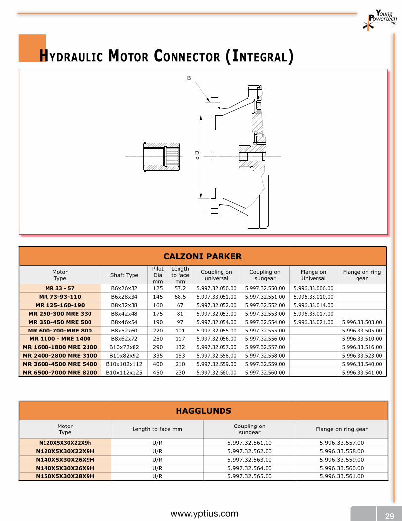
hyDRaulIC mOTOR CONNECTOR (INTEgRal)B
ø D
HAGGLunDS
MotorType Length to face mm Coupling on
sungear Flange on ring gear
n120X5X30X22X9h U/R 5.997.32.561.00 5.996.33.557.00n120X5X30X22X9H U/R 5.997.32.562.00 5.996.33.558.00n140X5X30X26X9H U/R 5.997.32.563.00 5.996.33.559.00n140X5X30X26X9H U/R 5.997.32.564.00 5.996.33.560.00n150X5X30X28X9H U/R 5.997.32.565.00 5.996.33.561.00
CALZOnI PARKeR
MotorType Shaft Type
PilotDiamm
Length to face
mm
Coupling onuniversal
Coupling onsungear
Flange onUniversal
Flange on ring gear
MR 33 - 57 B6x26x32 125 57.2 5.997.32.050.00 5.997.32.550.00 5.996.33.006.00MR 73-93-110 B6x28x34 145 68.5 5.997.33.051.00 5.997.32.551.00 5.996.33.010.00
MR 125-160-190 B8x32x38 160 67 5.997.32.052.00 5.997.32.552.00 5.996.33.014.00MR 250-300 MRe 330 B8x42x48 175 81 5.997.32.053.00 5.997.32.553.00 5.996.33.017.00MR 350-450 MRe 500 B8x46x54 190 97 5.997.32.054.00 5.997.32.554.00 5.996.33.021.00 5.996.33.503.00MR 600-700-MRe 800 B8x52x60 220 101 5.997.32.055.00 5.997.32.555.00 5.996.33.505.00MR 1100 - MRe 1400 B8x62x72 250 117 5.997.32.056.00 5.997.32.556.00 5.996.33.510.00
MR 1600-1800 MRe 2100 B10x72x82 290 132 5.997.32.057.00 5.997.32.557.00 5.996.33.516.00MR 2400-2800 MRe 3100 B10x82x92 335 153 5.997.32.558.00 5.997.32.558.00 5.996.33.523.00MR 3600-4500 MRe 5400 B10x102x112 400 210 5.997.32.559.00 5.997.32.559.00 5.996.33.540.00MR 6500-7000 MRe 8200 B10x112x125 450 230 5.997.32.560.00 5.997.32.560.00 5.996.33.541.00

30 www.yptius.com
SAI
MotorType Shaft Type Coupling on
Universal InputCoupling onring gear Flange on universal Flange on
ring gear
GM 0528 UNI 221 5.997.32.085.00 5.996.33.005.00
35x2x16x9H DIN 5480 5.997.32.006.00
GM 05Female spline
28 UNI 221 5.997.32.085.00 5.996.33.005.0035x2x16x9H DIN 5480 5.997.32.006.00
GM 1 - GS 128 UNI 221 5.997.32.085.00 5.996.33.016.00
35x2x16x9H DIN 5480 5.997.32.006.00
Female spline28 UNI 221 5.996.33.016.00
35x2x16x9H DIN 5480 5.997.32.006.00
GM 2 - GS 236 UNI 220 5.997.32.086.00 5.996.33.011.00
40x3x12x9H DIN 5480 5.997.32.009.00
Female spline36 UNI 220 5.996.33.011.00
40x3x12x9H DIN 5480 5.997.32.009.00
GM 3 - GS 346 UNI 221 5.997.32.087.00 5.996.33.512.00
40x3x12 DIN 5480 5.997.32.009.00
Female spline36 UNI 220 5.996.33.512.00
40x3x12x9H DIN 5480 5.997.32.009.00
GM 4 - GS 456 UNI 221 5.997.32.088.00 5.997.32.588.00 5.996.33.513.00
65x3x20 DIN 5480 5.997.32.014.00 5.997.32.514.00
Female spline55x50 DIN 5482 5.996.33.513.00
55x3x17 DIN 5480 5.997.32.012.00 5.997.32.512.00
GM 5 - GS 556 UNI 221 5.997.32.088.00 5.997.32.588.00 5.996.33.514.00
65x3x20 DIN 5480 5.997.32.014.00 5.997.32.514.00
Female spline55x50 DIN 5482 5.996.33.514.00
55x3x17 DIN 5480 5.997.32.012.00 5.997.32.512.00
GM 6 - GS 66/12-20T BS 3550 5.999.32.021.00 5.997.32.521.00 5.996.33.526.0080x3x25 DIN 5480 5.997.32.016.00 5.997.32.516.00
Female spline 80x3x25 DIN 5480 5.996.33.526.00
GM 7 - S 76/12-20T BS 3550 5.999.32.021.00 5.997.32.521.0080x3x25 DIN 5480 5.997.32.016.00 5.997.32.516.00 5.996.33.527.00
Female spline 80x3x25 DIN 5480 5.996.33.527.00L 7 6/12-20T BS 3550 5.999.32.021.00 5.997.32.521.00 5.996.33.528.00
GM 9 - S 9 120x3x38 DIN 5480 5.997.32.021.00 5.997.32.521.00Female spline 100x3x32 DIN 5480
InTeRMOT
MotorType Shaft Type
Leng-th to face
Coupling onuniversal
Coupling onring gear
Flange type
Pilot DIA
Flange B.C.
Flange onUniversal
IAM SeRIeS
80-100-150-175-195-H1 UNI 221 6X32X26 59 5.996.32.089.00 172 5B - 190 5.996.33.025.00 5.996.33.551.00200-250-300-350-H2 UNI 221 8x38x32 79 5.996.32.090.00 190 5B - 210 5.996.33.026.00 5.996.33.552.00
350-400-450-500-600-700 H3 UNI 221 8x42x36 90 5.996.32.091.00 5.996.32.591.00 230 5B - 254 5.996.33.027.00 5.996.33.553.00From 700 to 1400 H4 UNI 220 8x50x46 104 5.996.32.092.00 5.996.32.592.00 256 5B - 300 5.996.33.511.00
From 1100 to 1800 H 45 UNI 221 8x72x62x12 148 5.996.32.093.00 5.996.32.593.00 230 5B - 327 5.996.33.553.00From 1000 to 2200 H5 UNI 221 8x72x62x12 148 5.996.32.093.00 5.996.32.593.00 301,6 5B - 327 5.996.33.518.00
From 2200 to 2800 H 55 BS 3550 6/12-20 133 5.996.32.096.00 5.996.32.596.00 381 5B - 419.1 5.996.33.554.00From 2200 to 3500 H6 UNI 221 10x92x82x12 156 5.996.32.095.00 5.996.32.595.00 381 5B - 419.1 5.996.33.526.00From 3900 to 5400 h7 BS 3550 6/12-20 138 5.996.32.097.00 5.996.32.597.00 457,1 7B - 520.7 5.996.33.555.00From 6000 to 8000 h8 BS 3550 6/12-20 184 5.996.32.098.00 5.996.32.598.00 381 5B - 419.1 5.996.33.530.00

31www.yptius.com
KAwASAKI MOTOR COnneCTIOnSMotorType Shaft Type Coupling on Universal Coupling on
ring gearFlange onUniversal
Flange onring gear
HMB 010 8/16-13 x 3,68 5.999.32.015.00 5.999.32.515.00 5.996.33.023.00HMB-HMC 030 8/16-17 x 5.09" 5.999.32.018.00 5.999.32.518.00 5.996.33.019.00 5.996.33.501.00
HMC 30 W55x3x17x7hx129.3 5.997.32.012.00 5.997.32.512.00
HMB-HMC 0458/16-17 x 5,59" 5.999.32.030.00 5.999.32.530.00 5.996.33.507.00
W55x3x17x7hx142 5.997.32.033.00 5.997.32.533.00Female shaft 12/24DP 21T 5.999.32.512.00
HMB 60 6/12-14 x 5.19 5.999.32.520.00 5.996.33.520.00Female shaft 12/24 DP 24T 5.999.32.513.00
HMB-HMC 806/12-14 x 5.19 5.999.32.520.00 5.996.33.518.00
W70x3x22x7hx132 5.997.32.536.00 5.996.33.519.00Female spline 12/24 DP 24T 5.999.32.513.00
HMB 1006/12-14 x 5.19 5.999.32.520.00 5.996.33.521.00
W70x3x22x7hx132 5.997.32.536.00Female spline 12/24 DP 24T 5.999.32.513.00
HM(HD)B-HMC 125
6/12-20 x 5.67 5.999.32.531.00 5.996.33.534.00W85x3x27x7h-144 5.997.32.547.00W100x4x24x7h-144 5.997.32.540.00
5/10-16 x 5.76 5.999.32.524.00Female spline 12/24 DP 34 T 5.999.32.514.00
HM(HD)B 150
6/12-20 x 5.16" 5.999.32.521.00 5.996.33.535.005/10-16 x 5.16 5.999.32.529.00
W85x3x27x7hx131 5.999.32.517.00W100x4x24x7hx131 5.997.32.539.00
Female spline 12/24 DP 34T 5.999.32.514.00
HM(HD)B-HMC 200
6/12-20 x 5.16 5.999.32.521.00 5.996.33.536.005/10-16 x 5.16" 5.999.32.532.00
W85x3x27x7h x131 5.997.32.517.00W100x4x24x7hx131 5.997.32.539.00
Female spline 12/24 DP 34T 5.999.32.514.00
HMB 2706/12-20 x 5.538 5.999.32.531.00 5.996.33.546.00
W100x4x24x7hx141 5.997.32.541.00Female spline 12/24 DP 34T 5.999.32.514.00
HMC 270 6/12-20 x 5.538 5.999.32.531.00Female W 75x3x24x9H 5.997.32.601.00
HMC 3256/12-20 x 5.50 5.999.32.531.00 5.996.33.548.00
W90x4x21x7hx5.5 5.997.32.548.00 5.996.33.549.00Female spline W 75x3x24x9H 5.999.32.514.00
HMB 3256/12-20 x 5.53" 5.999.32.531.00 5.996.33.548.00
W100x4x24x7hx140 5.997.32.541.00Female 12/24 DP 34T
HMHDB 4006/12-23 x 7.25 5.999.32.522.00 5.996.33.537.00
W100x4x24x7hx184 5.999.32.543.00Female spline 10/20 DP 31T 5.999.32.525.00
HMB 700 W120x4x28x7hx239 5.997.32.546.00 U/R

32 www.yptius.com
YOunG POweRTeCHMotorType Shaft Type Shaft
LetterShaft
LengthCoupling onUniversal
Coupling onring gear
Flange onuniversal
FlangeLetter
Flange onuniversal
Flange on ring gear
ORBITAL MOTORS
YSTFC80
60 mmx170 mm P 72 6,69 5.996.32.522.00 5.996.33.518.006/12-14x5.20 S 71 5,2 5.999.32.520.00
W70x3x30x22x7h S 72 132 5.997.32.536.00Female Spline12/24 DP 24T Q 71 80 5.999.32.513.00
YSTFC-YSTFD
100
60 mm x 170 mm P 72 6,69 5.996.32.522.00 5.996.33.518.006/12-14 x 5.20 S 71 5,2 5.999.32.520.00 5.996.33.519.00
W70x3x30x22x7hx132 S 72 132/5.20 5.997.32.536.00Female Spline12/24 DP 24T 80
YSTFC 125
85 mm x 190 mm P 72 190 5.996.32.525.00 5.996.33.526.0085 mm x 178 mm P 73 178 5.996.32.529.00 5.996.33.527.00
100 mm x 195 P 74 195 5.996.32.530.006/12-20T S 71 5.999.32.521.006/12-23T S 73 5.999.32.522.00
W85x3x27x7h S 72 5.997.32.517.00W100x4x27x7h S 74 5.997.32.519.00Female Spline12/24 DP 34T Q 71 5.999.32.514.00
YSTFD2 speed
125
85 mm x 145 P 71 5.996.32.531.006/12-20T S 71 5.999.32.521.00 5.996.33.526.00
W85x3x27x7h S 72 5.997.32.517.00 5.996.33.527.00Female Spline12/24 DP 34T Q 71 5.997.32.514.00
YSTFC 200
85 mm x 165 mm P 71 5.996.32.511.00 5.996.33.528.00100 mm x 182 mm P 73 5.996.32.527.00 5.996.33.529.00
6/12-20T S 71 5.999.32.521.006/12-23T S 73 5.999.32.522.00
W85x3x27x7h S 72 5.997.32.517.00W100x4x24x7h S 74 5.997.32.519.00Female Spline12/24 DP 34T Q 71 5.999.32.514.00
YSTFD2 speed
200
85 mm x 132 mm P 71 5.996.32.532.00 5.996.33.528.006/12-20T S 71 5.999.32.521.00 5.996.33.529.00
W85x3x27x7h S 72 5.997.32.517.00Female Spline12/24 DP 34T Q 71 5.999.32.514.00
YSTFC 270
85 mm x 188 mm P 73 5.996.32.525.00 5.996.33.543.00100 mm x 203 mm P 74 5.996.32.526.00
6/12-20T S 71 5.999.32.521.00W100x4x24x7h S 72 5.997.32.519.00Female Spline12/24 DP 34T Q 72 5.999.32.514.00
YSTFD2 speed
270
90 mm x 140 mm P 71 5.996.32.533.00 5.996.33.543.006/12-20T S 71 5.999.32.521.00
W85x3x27x7h S 72 5.997.32.517.00Female Spline W75x3x24x9h Q 71
YSTFC 325
85 mm x 188 mm P 73 5.996.32.525.00100 mm x 203 mm P 74 5.996.32.526.00
6/12-20T S 71 5.999.32.521.00W100x4x24x7h S 72 5.997.32.519.00Female Spline12/24 DP 34 T Q 72 5.999.32.514.00

33www.yptius.com
MotorType Shaft Type Shaft
LetterCoupling onUniversal
Coupling onring gear Flange Type Flange
Letter Part No.
YSTFD2 speed
325
90 mm x 140 mm P 71 5.996.32.533.006/12-20T S 71 5.999.32.521.00
W90x4x21x7h S 72 5.997.32.548.00Female Spline W 75x3x24x9h Q 71
YSTFC 400
100 mm x 183 mm P 71 5.996.32.527.00 5.996.33.530.006/12-23T S 71 5.999.32.522.00
W100x4x24x7h S 72 5.997.32.519.00Female Spline10/20 DP 31T Q 71 5.999.32.525.00
YITM 01
1.00" x 2.13" P101 5.998.32.005.00 5.996.33.004.00 5.996.33.504.0035 mm x 62 mm P102 5.996.32.032.0025 mm x 55 mm P103 5.996.32.029.0035 mm x 55 mm P104 5.996.32.034.00
6-30b12x25bx12x6f8 S105
YITM 02
1.00" x 2.0 " P201 5.998.32.005.00 5.996.33.007.001.25" x 0.80" P202 5.998.32.006.00
25 mm x 54 mm P203 5.996.32.029.0040 mm x 72 mm P 204 5.996.32.038.0040 mm x 66 mm P 205 5.996.32.039.00
6-30b12x25bx12x6f8 S2066-34d11x28d11x7f8 S207
Female Spline6-48h11x42h11x12d9 FS208
Female Spline6-48h11x42h11x12d9 FS209
YITM 03
38 mm x 79 mm P301 5.996.32.014.00 5.996.33.002.00 5.996.33.502.0040 mm x 65 mm P302 5.996.32.039.0040 mm x 113 mm P303 5.996.32.040.0050 mm x 85 mm P304 5.996.32.004.00
8-40d11x36d11x7f8 S3058-38bx32b12x6f8 S306
6-34d11x28d11x7f8 S307Female Spline
6-48h11x42h11x12d9 FS308
Female Spline6-48h11x42h11x12d9 FS309
YITM 06
42 mm x 90 mm P601 5.996.32.041.00 5.996.33.508.0050 mm x 85 mm P602 5.996.32.004.0050 mm x 86 mm P603 5.996.32.004.0050 mm x 91 mm P604 5.996.32.042.00
8-42b12x36b12x7f8 S6058-40d11x36d11x7f8 S6068-54d11x46g7x9f9 S607
YITM 06
8-54d11x46g7x9f8 S6088-60b12x52b12x9f8 S609
Female Spline6-55h11x50h11x14d9 FS610
Female Spline6-7h11x62h16d9 FS611
YITM 08
42 mm x 90 mm P801 5.996.32.041.00 5.996.33.509.0054 mm 123 mm P802 5.996.32.043.00
8-42b12x36b12x7f8 S8038-50b12x46b12x9f8 S804

34 www.yptius.com
MotorType Shaft Type Shaft
LetterShaft
LengthCoupling onUniversal
Coupling onring gear
Flange onuniversal
FlangeLetter
Flange onuniversal
Flange on ring gear
YITM 11
50 mm x 96 mm P1101 5.996.32.044.00 5.996.33,511.0054 mm x 123 mm P1102 5.996.32.043.0060 mm x 123 mm P1103 5.996.32.045.00
8-40d11x36d11x7f8 S11048-42b12x36bx7f8 S1105
8-60b12x52b12x12f8 S11068-65d11x56d11x10f8 S11078-65d11x56d11x10f8 S11088-65d11x56d11x10f8 S1109
Female Spline 6-90h11x80h11x20d9 FS1110
Female Spline 6-90h11x80h11x20d9 FS1111
YITM 16
60 mm x 131 mm P1601 5.996.32.046.00 5.996.33.517.0060 mm x 170 mm P1602 5.996.32.522.0072 mm x 170 mm P1603 5.996.32.047.0075 mm x 148 mm P1604 5.996.32.048.0075 mm x 170 mm P1605 5.996.32.049.0080 mm x 115 mm P1606 5.996.32.050.00
8-65d11x56d11x10f8 S16078-65d11x56d11x10f8 S16088-72b12x62b12x12f8 S1609
10-82b12x72b12x12f8 S1610
10-98h11x92h11x14d9 FS1611
10-98h11x92h11x14d9 FS1612
12-98h11x92h11x14d9 FS1613
YITM 31
85 mm x 130 mm P3101 5.996.32.536.00 5.996.33.524.0085 mm x 167 mm P3102 5.996.32.511.0085 mm x 190 mm P3103 5.996.32.525.00
4.00" Dia. P3104 5.998.32.512.004.00" Dia. P3105 5.998.32.512.00
10-88b12x8b12x12f8 S310610-92b12x82b12x12f8 S3107
Female Spline 10-98h11x92h11x14d9 FS3108
Female Spline 10-98h11x92h11x14d9 FS3109
10-120h11x112h11x14d9 FS3110
YITM
70
85 mm x 166 mm P7001 5.996.32.511.00 5.996.33.544.0085 mm x 188 mm P7002 5.996.32.525.00120 mm x 240 mm P7003 5.996.32.528.00
10-120b12x112b12x16f8 S700410-92b12x82b12x12f8 S7005
YITM 100
120 mm x 240 mm P10001 5.996.32.528.00
10-102b12x112b12x18f8 S10002

35www.yptius.com
ElECTRIC mOTOR CONNECTIONS
L B X
ø D
eLeCTRIC MOTOR
MotorType Shaft Type Length to face
mmCoupling on
universalCoupling onring gear
Flange onUniversal Flange on ring gear
MeTRIC63 11 23 5.994.32.001.00 5.994.32.501.00 5.994.33.001.00 5.994.33.501.0071 14 30 5.994.32.002.00 5.994,32,502.00 5.994.33.002.00 5.994.33.502.0080 19 40 5.994.32.003.00 5.994.32.503.00 5.994.33.003.00 5.994.33.503.00
90S 24 50 5.994.32.004.00 5.994.32.504.00 5.994.33.004.00 5.994.33.504.0090L 24 50 5.994.32.005.00 5.994.32.505.00 5.994.33.005,.00 5.994.33.505.00
100L 28 60 5.994.32.506.00 5.994.33.506.00132S 38 80 5.994.32.507.00 5.994.33.507.00160L 42 110 5.994.32.508.00 5.994.33.508.00180L 48 110 5.994.32.509.00 5.994.33.509.00200L 55 110 5.994.32.510.00 5.994.33.510.00
neMA56 .625" 1.125" 5.993.32.001.00 5.993.32.501.00 5.993.33.001.00 5.993.33.501.00
143T .875" 2.250" 5.993.32.002.00 5.993.32.502.00 5.993.33.002.00 5.993.33.502.00145T .875" 2,25 5.993.32.003.00 5.993.32.503.00 5.993.33.003.00 5.993.33.503.00182T 1.125" 2.750" 5.993.004,00 5.993.32.504.00 5.993.33.004.00 5.993.33.504.00184T 1.125" 2.750" 5.993.32.005.00 5.993.32.505.00 5.993.33.005.00 5.993.33.505.00213T 1.375" 3.375" 5.993.32.006.00 5.993.32.506.00 5.993.33.006.00 5.993.33.506.00215T 1,375 3.375" 5.993.32.007.00 5.993.32.507.00 5.993.33.007.00 5.993.33.507.00254T 1.625" 4.00" 5.993.32.508.00 5.993.33.008.00 5.993.33.508.00256T 1.625" 4.00" 5.993.32.509.00 5.993.33.009.00 5.993.33.509.00284T 1.875" 4.625" 5.993.32.510.00 5.993.33.010.00 5.993.33.510.00286T 1.875" 4.625" 5.993.32.511.00 5.993.33.011.00 5.993.33.511.00324T 2.125" 5.250" 5.993.32.512.00 5.993.33.012.00 5.993.33.512.00326T 2.125" 5.250" 5.993.32.513.00 5.993.33.013.00 5.993.33.513.00

36 www.yptius.com
WaRRaNTy
Limited one year warranty for SPeed redUCerS
If the speed reducer (product) fails to function within one (1) year after the date of its original shipment, or
invoice date whichever come first, due to a defect in the materials or workmanship, Young Powertech will
remedy the defect without charge to the consumer purchaser. The foregoing limited warranty does not co-
ver failure to function caused by damage to the product while in your possession, improper installation, un-
reasonable use or abuse of the product, failure to provide or use of improper maintenance, failure to follow
written installation and instructions, or any use other than for personal, family or household purposes. THE
REMEDIES PROVIDED IN THE ABOVE EXPRESS LIMITED WARRANTY ARE THE SOLE AND EXCLUSIVE
REMEDIES AVAILABLE TO YOU. NO OTHER EXPRESS WARRANTIES ARE MADE. ALL IMPLIED WAR-
RANTIES, INCLUDING BUT NOT LIMITED TO ANY IMPLIED WARRANTY OF MERCHANTABILITY OR FIT-
NESS FOR A PARTICULAR PURPOSE OR USE, ARE LIMITED IN DURATION AS SET FORTH ABOVE. IN
NO EVENT SHALL YPT BE LIABLE FOR ANY INCIDENTAL OR CONSEQUENTIAL DAMAGES. Some states
do not allow limitations on how long an implied warranty lasts or do not allow the exclusion or limi-
tation of incidental or consequential damages, so the above limitations or exclusions may not ap-
ply to you. This warranty gives you specific legal rights and you may also have other rights which vary
from state to state. The consumer-purchaser must maintain proof of purchase and shipment date
of the product to prove the date of purchase and shipment in the unlikely event of a warranty claim.
In order to obtain a return authorization number you must contact Young Powertech at
(610) 558-0760 prior to shipping. The customer will be required to ship only the defective
parts, freight pre-paid to :
Young Powertech Inc
3060 Plaza Drive # 107 • Garnet Valley PA 19060 • Tel: (610) 558-0760 • Fax: (610) 558-0762
e-mail: [email protected]
Young Powertech, will repair or replace any part found defective and return the unit prepaid by ground
shipment to the customer.
In the event that the unit is not found to have a defect the customer will be charged an inspection fee and
the unit will be returned freight collect to the customer.

1/100series100www.yptius.com
NOTE: Higher or different ratios available upon request. Please contact Young Powertech Inc Engineering Dept.
YMPG 100 - 5000 HOuRS
i eff
n1 (rpm)
1500 Toutp 1000 Toutp 500 Toutp Toutp max PT
Nm lb/ft Nm lb/ft Nm lb/ft Nm lb/ft Kw HP
100.1
4.03 1160 855.57 1230 907.20 1275 940.39 2050 1512.00 11 14.754.43 1140 840.82 1190 877.70 1230 907.20 2000 1475.12 11 14.855.65 880 649.05 905 667.49 925 682.24 1560 1150.60 11 14.856.64 690 508.92 710 523.67 745 549.48 1220 899.82 11 14.85
100.2
16.24 1320 973.58 1370 1010.46 1425 1051.02 2050 1512.00 5.5 7.4317.85 1310 966.20 1380 1017.83 1435 1058.40 2050 1512.00 5.5 7.4319.62 1260 929.33 1300 958.83 1370 1010.46 2000 1475.12 5.5 7.4322.77 1360 1003.08 1390 1025.21 1475 1087.90 2050 1512.00 5.5 7.4325.03 1300 958.83 1325 977.27 1460 1076.84 2000 1475.12 5.5 7.4326.76 1380 1017.83 1405 1036.27 1480 1091.59 2050 1512.00 5.5 7.4329.42 1300 958.83 1345 992.02 1415 1043.65 2000 1475.12 5.5 7.4331.91 1000 737.56 1040 767.06 1090 803.94 1560 1150.60 5.5 7.4337.50 1020 752.31 1060 781.81 1100 811.32 1560 1150.60 5.5 0.4144.09 780 575.30 820 604.80 860 634.30 1220 899.82 5.5 0.41
YMPGA 100 - 5000 HOuRS
i eff
n1 (rpm)
1500 Toutp 1000 Toutp 500 Toutp Toutp max PT
Nm lb/ft Nm lb/ft Nm lb/ft Nm lb/ft Kw HP
1001
1310 870 64168 923 68077 956 70511 1540 1135.84 8 10.72
14,40 855 630.61 893 658.64 923 680.77 1500 1106.34 8 10.80
18,36 660 486.79 679 500.80 694 511.87 1170 862.95 8 10.80
21,58 518 382.06 533 393.12 559 412.30 920 678.56 8 10.80
100.2
52,78 990 730.19 1028 758.21 1069 788.45 1540 1135.84 4 5.40
58,01 983 725.02 1035 763.38 1076 793.62 1540 1135.84 4 5.40
63,77 945 697.00 975 719.12 1028 758.21 1500 1106.34 4 5.40
74,00 1020 752.31 1043 769.28 1106 815.74 1540 1135.84 4 5.40
81,35 975 719.12 994 733.14 1095 807.63 1500 1106.34 4 5.40
86,97 1035 763.38 1054 777.39 1110 818.69 1540 1135.84 4 5.40
95,62 975 719.12 1009 744.20 1061 782.55 1500 1106.34 4 5.40
103,71 750 553.17 780 575.30 818 603.32 1170 862.95 4 5.40
121,88 765 564.23 795 586.36 825 608.49 1170 862.95 4 0.30
143,29 585 43147 615 45360 645 47573 920 67856 4 030
ymPg 100 - ymPga 100 RaTIOS aND RaTINgS

2/100series100 www.yptius.com
ymPg100
ymPgf100
ø D
3
ø D
2
ø D
1
L2L3 L1 KI
H
ø A
ø C
ø G
ø E
ø F
d1
U
Z
M N
O
PP1
ø R
Qd2
T
S
ødV
øB
L1 K
ø A
ø C
ø EZ
M N
ø D
1
HI
L2
ø D
2
ø D
3
L3
ø B
ø d
V
ø d1
V1
Type A B C D1 D2 D3 E F G H I K L1 L2 L3 M
100mm 185 165 110 h8 212 212 212 35 f7 24 42 f7 5 12 62 176.5 239 301 35inch 7.28 6.49 4.33 h8 8.35 8.35 8.35 1.37 f7 0.94 1.65 f7 0.19 0.47 2.44 6.95 9.40 11.85 1.37
Type A B C D1 D2 D3 E H I K
100mm 212 188 168 h8 212 212 212 42 f7 9 81 51inch 8.35 7.40 6.61 h8 8.35 8.35 8.35 1.65 f7 0.35 3.19 2.01
Type N O P P1 Q R S T U V Z d d1 d2
100mm 5 55 70 6 82 42 h6 12 45 16
45°B 40 x 36 DIN 5482 11 n°8
M 6 M 16inch 0.19 2.16 2.75 0.23 3.22 1.65 h6 0.47 1.77 0.62 0.43 n°8
Type L1 L2 L3 M N V V1 Z d d1
100mm 99 161 223 48 6
45° 22°30’A 40 x 36 DIN 5482 10.5 n° 8 10 h8
inch 3.90 6.34 8.78 1.89 0.24 0.41 n° 8 0.39 h8

3/100series100www.yptius.com
ymPga100
PP1
ø R
Qd2
T
S
ø A
ø C
ø G
ø E
ø F
d1
Z
M N
O
KI
H
U
L1L2
ø D
1
ø W
1
Y1
ø X
ø Xø
W2
ø D
2
Y2
ø B
ø dV
ø A
ø C
ø E
KI
H
Z
L1
N
M
ø X
ø W
1
ø D
1
Y1
L2
ø X
ø W
2
ø D
2
Y2
ø d
V
ø d1
V1
øB
Type A B C D1 D2 E F G H I K L1 L2 M N O P P1
100mm 185 165 110 h8 212 212 35 f7 24 42 f7 5 12 62 201 263 35 5 55 70 6inch 7.28 6.49 4.33 h8 8.35 8.35 1.37 f7 0.94 1.65 f7 0.19 0.47 2.44 6.95 9.40 1.37 0.19 2.16 2.75 0.23
Type Q R S T U V W1 W2 W3 X Y1 Y2 Z d d1 d2
10082 42 h6 12 45 16
45°180 180 180 212 195 195 B 40 x 36 DIN 5482 11 n°8
M 6 M 163.22 1.65 h6 0.47 1.77 0.62 7.09 7.09 7.09 8.35 7.68 7.68 0.43 n°8
Type A B C D1 D2 E H I K L1 L2 M N
100mm 212 188 168 h8 212 212 42 f7 9 81 51 124 185 51 6inch 8.35 7.40 6.61 h8 8.35 8.35 1.65 f7 0.35 3.19 2.01 4.88 7.28 2.01 0.24
Type V V1 W1 W2 W3 X Y1 Y2 Z d d1
100mm
45° 22°30’180 180 180 212 195 195 A 40 x 36 DIN 5482 10.5 n° 8 10 h8
inch 7.09 7.09 7.09 8.35 7.68 7.68 0.41 n° 8 0.39 h8
ymPgfa100

4/100series100 www.yptius.com
Type K L1 L2 L3 M N O V d L min.
100mm 73 176.5 239 301 42 18 65
45°11 n° 8 300
inch 2.87 6.95 9.41 11.85 1.65 0.71 2.56 0.43 n° 8 11.81
ymPg100ShRINKDISCK
ymPga100ShRINKDISCK
ø D
1
Vød
ø A
ø C
ø F
ø G
L m
in øE h
6
øF f6
L2 KI
H
L1
øB
ø E
O
MN
Ra ≤16 mm 0.63 inch
ø D
2
L3
ø D
3
ø D
1
Vød
ø A
ø C
ø F
ø G
L m
in
øE h
6
øF f6
L2K
IH
L1
øB
ø E
O
MN
ø W
1
Y1
øX
Ra ≤16mm 0.63 inch
ø D
2
ø W
2
Y2
øX
Type A B C D1 D2 D3 E F G H I
100mm 185 165 110 h8 212 212 212 35 h7 42 f7 50 f7 5 12inch 7.28 6.50 4.33 h8 8.35 8.35 8.35 1.38 h7 1.65 f7 1.97 f7 0.20 0.47
Type A B C D1 D2 E F G H I K L1 L2
100mm 185 165 110 h8 212 212 35 h7 42 f7 50 f7 5 12 73 201 263inch 7.28 6.50 4.33 h8 8.35 8.35 1.38 h7 1.65 f7 1.97 f7 0.20 0.47 2.87 7.91 10.35
Type M N O V W1 W2 W3 X Y1 Y2 d L min.
100mm 42 18 65
45°180 180 180 212 195 195 11 n° 8 300
inch 1.65 0.71 2.56 7.09 7.09 7.09 8.35 7.68 7.68 0.43 n° 8 11.81

5/100series100www.yptius.com
Fr
Fa
daN
[lb/
ft]
-30
[-1.1
8] -10
[-0.3
9]
mm [inch]
30[1
.18]10
[0.3
9] 50[1
.97]
1.843,90
1.475,12
1.106,34
737,56
368,78
2500
2000
1500
1000
500
0
ymPg 100 - ymPga 100INPuT CONfIguRaTION
OuTPuT ShafT lOaD DIagRam
TypeType and number of stages
1 2
100 100.1 100.2
Fa=500dan
22.50°
42,7[1.68]
17,8[0.70]
3 [0.12]
ø 21
2 [8
.35]
ø 20
6 [8
.11]
H7
ø 18
8 [7
.40]
ø 16
3 [6
.42]
20 [0.79]
DIN 548240x36
M10
ø8 [0.31] H7
45°
For different load or life, please refer to “output shaft radial load calculation” on page 11

6/100series100 www.yptius.com
Type 1 or 2 mod Z X A B C D L L1 L2 L3 Lu S
100
mm1
4 15 0.5 74 42 h7 52 h7 60 56 5 6 15 48
A 40 x 36DIN 5482
inch 0.16 0.59 0.02 2.91 1.65 h7 2.05 h7 2.36 2.20 0.20 0.24 0.59 1.89mm
14.5 14 0.5 75.5 42 h7 52 h7 63 56 5 6 15 50
inch 0.18 0.55 0.02 2.97 1.65 h7 2.05 h7 2.48 2.20 0.20 0.24 0.59 1.97mm
15 14 0.5 84 42 h7 52 h7 70 56 5 6 15 50
inch 0.20 0.55 0.02 3.30 1.65 h7 2.05 h7 2.75 2.20 0.20 0.24 0.59 1.97
ymPg 100 - ymPga 100 aCCESSORIES
integral pinions or different pinions available upon request
ø B
L2L1
ø A
L
ø A
ø B
L2
L3
L1
L
ø C
S
ø A
ø R
L1
ø B
L
øE
øF
ø D
ø B
L1
L3
L2
ø A
ø B
Lu
L
S
ø A
Type L L2 L3 A B
100mm 200 95 10 A 40 x 36 DIN 5482 A 40 x 36 DIN 5482inch 7.87 3.74 0.39
Type A B C L L1 L2 L3 S
100mm 70 h7 42 h7 52 h7 56 5 6 15 A 40 x 36 DIN 5482inch 2.76 h7 1.65 h7 2.05 h7 2.20 0.20 0.24 0.59
Type A B C D F L L1
100mm 60 52 f7 35 h7 24 n° 3 7 10 5inch 2.36 2.05 1.38 0.94 0.28 0.39 0.20
SPlINED bIllET
REmOvablE PINION
lOCKINg flaNgE
SPlINED ShafT fOR fEmalE OuTPuT

1/102series102www.yptius.com
NOTE: Higher or different ratios available upon request. Please contact Young Powertech Inc Engineering Dept.
YMPG 102 - 5000 HOuRS
i eff
n1 (rpm)1500 Toutp 1000 Toutp 500 Toutp Toutp max PT
Nm lb/ft Nm lb/ft Nm lb/ft Nm lb/ft Kw HP
102.14.16 1560 1150.60 1630 1202.22 1690 1246.48 2750 2028.29 12.0 16.094.76 1380 1017.83 1435 1058.40 1500 1106.34 2460 1814.40 12.0 16.095.65 1140 840.82 1180 870.32 1230 907.20 1980 1460.37 12.0 16.09
102.2
16.76 1720 1268.60 1750 1290.73 1850 1364.49 2750 2028.29 7.5 10.0518.43 1730 1275.98 1780 1312.86 1870 1379.24 2750 2028.29 7.5 10.0519.18 1520 1121.09 1580 1165.35 1660 1224.35 2460 1814.40 7.5 10.0521.09 1550 1143.22 1600 1180.10 1650 1216.98 2460 1814.40 7.5 10.0523.50 1780 1312.86 1840 1357.11 1970 1453.00 2750 2028.29 7.5 10.0526.89 1570 1157.97 1615 1191.16 1680 1239.10 2460 1814.40 7.5 10.0527.62 1825 1346.05 1870 1379.24 1985 1464.06 2750 2028.29 7.5 10.0531.61 1590 1172.72 1630 1202.22 1720 1268.60 2460 1814.40 7.5 10.0537.52 1300 958.83 1340 988.33 1395 1028.90 1980 1460.37 7.5 10.05
102.3
67.56 1900 1401.37 1950 1438.24 2090 1541.50 2750 2028.29 6.0 8.0474.27 1910 1408.74 1970 1453.00 2160 1593.13 2750 2028.29 6.0 8.0481.64 1920 1416.12 1985 1464.06 2200 1622.63 2750 2028.29 6.0 8.0494.72 1950 1438.24 2000 1475.12 2280 1681.64 2750 2028.29 6.0 8.04104.12 1960 1445.62 2010 1482.50 2300 1696.39 2750 2028.29 6.0 8.04132.80 2000 1475.12 2150 1585.76 2360 1740.64 2750 2028.29 6.0 8.04156.07 2010 1482.50 2170 1600.51 2380 1755.40 2750 2028.29 6.0 8.04178.58 1850 1364.49 1960 1445.62 2230 1644.76 2460 1814.40 6.0 8.04209.87 1890 1393.99 2040 1504.62 2270 1674.26 2460 1814.40 6.0 8.04249.11 1590 1172.72 1690 1246.48 1910 1408.74 1980 1460.37 6.0 8.04
YMPGA 102 - 5000 HOuRS
i eff
n1 (rpm)1500 Toutp 1000 Toutp 500 Toutp Toutp max PT
Nm lb/ft Nm lb/ft Nm lb/ft Nm lb/ft Kw HP
102.113.5 1170 862.95 1223 902.04 1268 935.23 2060 1519.38 9.0 12.0615,5 1035 763.38 1076 793.62 1125 829.76 1840 1357.11 9,0 12.0618,4 855 630.61 885 652.74 923 680.77 1480 1091.59 9,0 12.06
102.2
54,5 1290 951.45 1313 968.42 1388 1023.73 2060 1519.38 6,0 8.0459,9 1298 957.35 1335 984.64 1403 1034.80 2060 1519.38 6,0 8.0462,3 1140 840.82 1185 874.01 1245 918.26 1840 1357.11 6,0 8.0468,5 1163 857.78 1200 885.07 1238 913.10 1840 1357.11 6,0 8.0476,4 1335 984.64 1380 1017.83 1478 1090.12 2060 1519.38 6,0 8.0487,4 1178 868.85 1211 893.19 1260 929.33 1840 1357.11 6,0 8.0489,8 1369 1009.72 1403 1034.80 1489 1098.23 2060 1519.38 6,0 8.04102,7 1193 879.91 1223 902.04 1290 951.45 1840 1357.11 6,0 8.04121,9 975 719.12 1005 741.25 1046 771.49 1480 1091.59 6,0 8.04
102.3
219,6 1425 1051.02 1463 1079.05 1568 1156.50 2060 1519.38 5,0 6.70241,4 1433 1056.92 1478 1090.12 1620 1194.85 2060 1519.38 5,0 6.70265,3 1440 1062.09 1489 1098.23 1650 1216.98 2060 1519.38 5,0 6.70307,8 1463 1079.05 1500 1106.34 1710 1261.23 2060 1519.38 5,0 6.70338,4 1470 1084.21 1508 1112.24 1725 1272.29 2060 1519.38 5,0 6.70431,6 1500 1106.34 1613 1189.69 1770 1305.48 2060 1519.38 5,0 6.70507,2 1508 1112.24 1628 1200.75 1785 1316.55 2060 1519.38 5,0 6.70580,4 1388 1023.73 1470 1084.21 1673 1233.94 1840 1357.11 5,0 6.70682,1 1418 1045.86 1530 1128.47 1703 1256.07 1840 1357.11 5.0 6.70809.6 1193 879.91 1268 935.23 1433 1056.92 1480 1091.59 5.0 6.70
ymPg 102 - ymPga 102 RaTIOS aND RaTINgS

2/102series102 www.yptius.com
ymPg102
ymPgf102
ø D
4
ø D
3
ø D
2
ø D
1
L2L3L4 L1 KI
H
ø A
ø C
ø G
ø E
ø F
d1
U
Z
M N
O
PP1
ø R
Qd2
T
S
ødV
øB
L1 K
ø A
ø C
ø EZ
M N
ø D
1H
I
L2
ø D
2
ø D
3
L3
ø D
4
L4
ø B
ø d
V
ø d1
V1
Type A B C D1 D2 D3 D4 E F G H I K L1 L2 L3 L4 M
102mm 185 165 110 h8 212 212 212 212 35 f7 24 52 f7 14 14 70 198 260.5 322.5 386 35inch 7.28 6.49 4.33 h8 8.35 8.35 8.35 8.35 1.37 f7 0.94 2.05 f7 0.55 0.55 2.76 7.80 10.26 12.70 15.20 1.38
Type A B C D1 D2 D3 D4 E H I K
102mm 212 188 168 h8 212 212 212 212 52 f7 9 98 51inch 8.35 7.40 6.61 h8 8.35 8.35 8.35 8.35 2.05 f7 0.35 3.86 2.01
Type N O P P1 Q R S T U V Z d d1 d2
102mm 5 55 70 6 82 42 h6 12 45 16
45°B 50 x 45 DIN 5482 11 n°8
M 6 M 16inch 0.19 2.16 2.75 0.23 3.22 1.65 h6 0.47 1.77 0.62 0.43 n°8
Type L1 L2 L3 L4 M N V V1 Z d d1
102mm 99 161 223 286 51 6
45° 22°30’A 50 x 45 DIN 5482 10.5 n° 8 10 h8
inch 3.90 6.34 8.78 11.26 2.01 0.24 0.41 n° 8 0.39 h8

3/102series102www.yptius.com
ymPga102
PP1
ø R
Qd2
T
S
ø A
ø C
ø G
ø E
ø F
d1
Z
M N
O
KI
H
U
L1L2L3
ø D
1ø
W1
Y1
ø Xø X
ø X
ø W
2
ø D
2Y
2
ø W
3ø
D3
Y3
ø B
ø dV
ø A
ø C
ø E
KI
H
Z
L1
N
M
ø X
ø W
1
ø D
1Y
1
L2
ø X
ø W
2
ø D
2Y
2
L3
ø X
ø W
3ø
D3
Y3
ø d
V
ø d1
V1
øB
Type A B C D1 D2 D3 E F G H I K L1 L2 L3 M N O P
102mm 185 165 110 h8 212 212 212 35 f7 24 52 f7 14 14 70 222 284 347 35 5 55 70inch 7.28 6.49 4.33 h8 8.35 8.35 8.35 1.37 f7 0.94 2.05 f7 0.55 0.55 2.76 8.74 11.1813.66 1.38 0.20 2.17 2.76
Type P1 Q R S T U V W1 W2 W3 X Y1 Y2 Y3 Z d d1 d2
102mm 6 82 42 h6 12 45 16
45°180 180 180 212 195 195 195 A 50 x 45 DIN 5482 11 n°8
M 6 M 16inch 0.24 3.23 1.65 0.47 1.77 0.63 7.09 7.09 7.09 8.35 7.68 7.68 7.68 0.43 n°8
Type A B C D1 D2 D3 E H I K L1 L2 L3 M N
102mm 212 188 168 h8 212 212 212 52 f7 9 98 51 124 185 248 51 6inch 8.35 7.40 6.61 h8 8.35 8.35 8.35 2.05 f7 0.35 3.86 2.01 4.88 7.28 9.76 2.01 0.24
Type V V1 W1 W2 W3 X Y1 Y2 Y3 Z d d1
102mm
45° 22°30’180 180 180 212 195 195 195 A 50 x 45 DIN 5482 10.5 n° 8 10 h8
inch 7.09 7.09 7.09 8.35 7.68 7.68 7.68 0.41 n° 8 0.39 h8
ymPgfa102

4/102series102 www.yptius.com
ymPg102ShRINKDISCK
ymPga102ShRINKDISCK
ø D
1
Vød
ø A
ø C
ø F
ø G
L m
in øE h
6
øF f6
L2 KI
H
L1
øB
ø E
O
MN
Ra ≤16mm 0.63 inch
ø D
2
L3
ø D
4
L4
ø D
4
ø D
1
Vød
ø A
ø C
ø F
ø G
L m
in
øE h
6
øF f6
L2L3 KI
H
L1
øB
ø E
O
MN
ø W
1
Y1
øX
Ra ≤16mm 0.63 inch
øX
ø D
2
ø W
2
Y2
ø D
3
ø W
3
Y3
øX
Type K L1 L2 L3 L4 M N O V d L min.
102mm 73 176,5 239 301 386 42 18 65
45°11 n° 8 300
inch 2.87 6.95 9.41 11.85 15.20 1.65 0.71 2.56 0.43 n° 8 11.81
Type A B C D1 D2 D3 E F G H I
102mm 185 165 110 h8 212 212 212 35 h7 42 f7 50 f7 5 12inch 7.28 6.50 4.33 h8 8.35 8.35 8.35 1.38 h7 1.65 f7 1.97 f7 0.20 0.47
Type A B C D1 D2 D3 E F G H I K L1 L2
102mm 185 165 110 h8 212 212 212 35 h7 42 f7 50 f7 14 14 73 222 284inch 7.28 6.50 4.33 h8 8.35 8.35 8.35 1.38 h7 1.65 f7 1.97 f7 0,55 0,55 2,87 8,74 11,18
Type L3 M N O V W1 W2 W3 X Y1 Y2 Y2 d L min.
102mm 347 42 18 65
45°180 180 180 212 195 195 195 11 n° 8 300
inch 13,66 1.65 0.71 2.56 7.09 7.09 7.09 8.35 7.68 7.68 7.68 0.43 n° 8 11.81

5/102series102www.yptius.com
ymPg 102 - ymPga 102
OuTPuT ShafT lOaD DIagRam
0
-40
[-1.5
7] -20
[-0.7
9] 20[0
.79] 40
[1.5
7] 60[2
.36]
Fr
Fa
daN
[inc
h/lb
]
-30
[-1.1
8] -10
[-0.3
9]
mm [inch]
30[1
.18]10
[0.3
9] 50[1
.97]
5500
5000
4500
4000
3500
3000
2500
2000
1500
1000
4.056,59
3.687,81
3.319,02
2.950,24
2.581,46
2.212,68
1.843,90
1.475,12
1.106,34
737,56
22.50°
42,7[1.68]
17,8[0.70]
3 [0.12]
ø 21
2 [8
.35]
ø 20
6 [8
.11]
H7
ø 18
8 [7
.40]
ø 16
3 [6
.42]
20 [0.79]
DIN 548240x36
M10
ø8 [0.31] H7
45°
INPuT CONfIguRaTION
TypeType and number of stages
1 2 3102 102.1 102.2 102.3
Fa=2000dan
For different load or life, please refer to “output shaft radial load calculation” on page 11

6/102series102 www.yptius.com
ymPg 102 - ymPga 102 aCCESSORIES
ø B
L2L1
ø A
L
ø A
ø B
L2
L3
L1
L
ø C
S
ø A
ø R
L1
ø B
L
øE
øF
ø D
ø B
L1
L3
L2
ø A
ø B
Lu
L
S
ø A
SPlINED bIllET
REmOvablE PINION
lOCKINg flaNgE
SPlINED ShafT fOR fEmalE OuTPuT
integral pinions or different pinions available upon request
Type 1 or 2 mod Z X A B C D L L1 L2 L3 Lu S
102
mm1
4 15 0,5 74 42 h7 52 h7 60 56 5 6 15 48
A 40 x 36DIN 5482
inch 0.16 0.59 0.02 2.91 1.65 h7 2.05 h7 2.36 2.20 0.20 0.24 0.59 1.89mm
14,5 14 0,5 75,5 42 h7 52 h7 63 56 5 6 15 50
inch 0.18 0.55 0.02 2.97 1.65 h7 2.05 h7 2.48 2.20 0.20 0.24 0.59 1.97mm
15 14 0,5 84 42 h7 52 h7 70 56 5 6 15 50
inch 0.20 0.55 0.02 3.30 1.65 h7 2.05 h7 2.75 2.20 0.20 0.24 0.59 1.97mm
16 12 0,5 88 42 h7 52 h7 72 56 5 6 15 55
inch 3.43 6.86 0.02 50.29 1.65 h7 2.05 h7 41.14 2.20 0.20 0.24 0.59 31.43
Type L L2 L3 A B
102mm 200 95 10 A 50 x 45 DIN 5482 A 50 x 45 DIN 5482inch 7,87 3,74 0,39
Type A B C L L1 L2 L3 S
102mm 70 h7 52 h7 52 h7 56 5 6 15 A 50 x 45 DIN 5482inch 2.76 h7 2.05 h7 2.05 h7 2.20 0.20 0.24 0.59
Type A B C D F L L1
102mm 60 52 f7 35 h7 24 n° 3 7 10 5inch 2,36 2,05 1,38 0,94 0,28 0,39 0.20

1/104series104www.yptius.com
NOTE: Higher or different ratios available upon request. Please contact Young Powertech Inc Engineering Dept.
YMPGA 104 - 5000 HOuRS
i eff
n1 (rpm)
1500 Toutp 1000 Toutp 500 Toutp Toutp max PT
Nm lb/ft Nm lb/ft Nm lb/ft Nm lb/ft Kw HP
1041 13.1 1388 1023.73 1455 1073.15 1523 1123.31 2320 1711.14 9.0 12.06
104.2
54.5 1553 1145.43 1635 1205.91 1695 1250.17 2320 1711.14 6.0 8.04
58.1 1575 1161.66 1643 1211.81 1710 1261.23 2320 1711.14 6.0 8.04
74.1 1635 1205.91 1665 1228.04 1763 1300.32 2320 1711.14 6.0 8.04
87.1 1643 1211.81 1673 1233.94 1774 1308.43 2320 1711.14 6.0 8.04
104.3
213.1 1748 1289.26 1785 1316.55 2018 1488.40 2320 1711.14 5.0 6.70
234.3 1763 1300.32 1800 1327.61 2063 1521.59 2320 1711.14 5.0 6.70
298.8 1785 1316.55 1883 1388.83 2153 1587.97 2320 1711.14 5.0 6.70
328.5 1804 1330.56 1928 1422.02 2198 1621.16 2320 1711.14 5.0 6.70
418.9 1838 1355.64 1995 1471.43 2265 1670.58 2320 1711.14 5.0 6.70
492.3 1928 1422.02 2078 1532.65 2310 1703.77 2320 1711.14 5.0 6.70
578.6 1980 1460.37 2108 1554.78 2340 1725.89 2320 1711.14 5.0 6.70
YMPG 104 - 5000 HOuRS
i eff
n1 (rpm)
1500 Toutp 1000 Toutp 500 Toutp Toutp max PT
Nm lb/ft Nm lb/ft Nm lb/ft Nm lb/ft Kw HP
1041 4.04 1850 1364.49 1940 1430.87 2030 1497.25 3100 2286.44 12.0 16.09
104.2
16,76 2070 1526.75 2180 1607.88 2260 1666.89 3100 2286.44 7,5 10.05
17,89 2100 1548.88 2190 1615.26 2280 1681.64 3100 2286.44 7,5 10.05
22,81 2180 1607.88 2220 1637.39 2350 1733.27 3100 2286.44 7,5 10.05
26,81 2190 1615.26 2230 1644.76 2365 1744.33 3100 2286.44 7,5 10.05
104.3
65,58 2330 1718.52 2380 1755.40 2690 1984.04 3100 2286.44 6,0 8.04
72,09 2350 1733.27 2400 1770.15 2750 2028.29 3100 2286.44 6,0 8.04
91,94 2380 1755.40 2510 1851.28 2870 2116.80 3100 2286.44 6,0 8.04
101,07 2405 1773.83 2570 1895.53 2930 2161.05 3100 2286.44 6,0 8.04
128,90 2450 1807.02 2660 1961.91 3020 2227.43 3100 2286.44 6,0 8.04
151,49 2570 1895.53 2770 2043.04 3080 2271.69 3100 2286.44 6,0 8.04
178,03 2640 1947.16 2810 2072.55 3120 2301.19 3100 2286.44 6.0 8.04
ymPg 104 - ymPga 104 RaTIOS aND RaTINgS

2/104series104 www.yptius.com
ymPg104
ymPgf104
ø D
4
ø D
3
ø D
2
ø D
1
L2L3L4 L1 KI
H
ø A
ø C
ø G
ø E
ø F
d1
U
Z
M N
O
PP1
ø R
Qd2
T
S
ødV
øB
L1 K
ø A
ø C
ø EZ
M N
ø D
1H
I
L2
ø D
2
ø D
3
L3
ø D
4
L4
ø B
ø d
V
ø d1
V1
Type A B C D1 D2 D3 D4 E F G H I K L1 L2 L3 L4 M
104mm 185 165 110 h8 212 212 212 212 35 f7 24 52 f7 14 14 70 198 260,5 322,5 386 35inch 7.28 6.49 4.33 h8 8.35 8.35 8.35 8.35 1.37 f7 0.94 2.05 f7 0,55 0,55 2,76 7,80 10,26 12,70 15,20 1,38
Type A B C D1 D2 D3 D4 E H I K
104mm 212 188 168 h8 212 212 212 212 52 f7 9 98 51inch 8.35 7,40 6,61 h8 8.35 8.35 8.35 8.35 2.05 f7 0,35 3,86 2,01
Type N O P P1 Q R S T U V Z d d1 d2
104mm 5 55 70 6 82 42 h6 12 45 16
45°B 50 x 45 DIN 5482 11 n°8
M6 M16inch 0.19 2.16 2.75 0.23 3.22 1.65 h6 0.47 1.77 0.62 0.43 n°8
Type L1 L2 L3 L4 M N V V1 Z d d1
104mm 99 161 223 286 51 6
45° 22°30’A 50 x 45 DIN 5482 10,5 n° 8 10 h8
inch 3,90 6,34 8,78 11,26 2,01 0,24 0.41 n° 8 0.39 h8

3/104series104www.yptius.com
PP1
ø R
Qd2
T
S
ø A
ø C
ø G
ø E
ø F
d1
Z
M N
O
KI
H
U
L1L2L3
ø D
1ø
W1
Y1
ø Xø X
ø X
ø W
2
ø D
2Y
2
ø W
3ø
D3
Y3
ø B
ø dV
ø A
ø C
ø E
KI
H
Z
L1
N
M
ø X
ø W
1
ø D
1Y
1
L2
ø X
ø W
2
ø D
2Y
2
L3
ø X
ø W
3ø
D3
Y3
ø d
V
ø d1
V1
øB
Type A B C D1 D2 D3 E F G H I K L1 L2 L3 M N O P
104mm 185 165 110 h8 212 212 212 35 f7 24 52 f7 14 14 70 222 284 347 35 5 55 70inch 7.28 6.49 4.33 h8 8.35 8.35 8.35 1.37 f7 0.94 2.05 f7 0,55 0,55 2,76 8,74 11,1813,66 1,38 0,20 2,17 2.76
Type P1 Q R S T U V W1 W2 W3 X Y1 Y2 Y3 Z d d1 d2
104mm 6 82 42 h6 12 45 16
45°180 180 180 212 195 195 195 A 50 x 45 DIN 5482 11 n°8
M6 M16inch 0,24 3,23 1,65 0,47 1,77 0,63 7,09 7,09 7,09 8,35 7,68 7,68 7,68 0.43 n°8
Type A B C D1 D2 D3 E H I K L1 L2 L3 M N
104mm 212 188 168 h8 212 212 212 52 f7 9 98 51 124 185 248 51 6inch 8.35 7,40 6,61 h8 8.35 8.35 8.35 2.05 f7 0,35 3,86 2.01 4,88 7,28 9,76 2,01 0,24
Type V V1 W1 W2 W3 X Y1 Y2 Y3 Z d d1
104mm
45° 22°30’180 180 180 212 195 195 195 A 50 x 45 DIN 5482 10,5 n° 8 10 h8
inch 7,09 7,09 7,09 8,35 7,68 7,68 7,68 0.41 n° 8 0.39 h8
ymPga104
ymPgfa104

4/104series104 www.yptius.com
ymPg104ShRINKDISCK
ymPga104ShRINKDISCK
ø D
1
Vød
ø A
ø C
ø F
ø G
L m
in øE h
6
øF f6
L2 KI
H
L1
øB
ø E
O
MN
Ra ≤16mm 0.63 inch
ø D
2
L3
ø D
4
L4
ø D
4
ø D
1
Vød
ø A
ø C
ø F
ø G
L m
in
øE h
6
øF f6
L2L3 KI
H
L1
øB
ø E
O
MN
ø W
1
Y1
øX
Ra ≤16mm 0.63 inch
øX
ø D
2
ø W
2
Y2
ø D
3
ø W
3
Y3
øX
Type K L1 L2 L3 L4 M N O V d L min.
104mm 73 176,5 239 301 386 42 18 65
45°11 n° 8 300
inch 2.87 7,80 10,26 12,70 15.20 1.65 0.71 2.56 0.43 n° 8 13,78
Type A B C D1 D2 D3 E F G H I
104mm 185 165 110 h8 212 212 212 35 h7 42 f7 50 f7 14 14inch 7.28 6.50 4.33 h8 8.35 8.35 8.35 1.38 h7 1.65 f7 1.97 f7 0,55 0,55
Type A B C D1 D2 D3 E F G H I K L1 L2
104mm 185 165 110 h8 212 212 212 35 h7 42 f7 50 f7 14 14 73 222 284inch 7.28 6.50 4.33 h8 8.35 8.35 8.35 1.38 h7 1.65 f7 1.97 f7 0,55 0,55 2,87 8,74 11,18
Type L3 M N O V W1 W2 W3 X Y1 Y2 Y2 d L min.
104mm 347 42 18 65
45°180 180 180 212 195 195 195 11 n° 8 350
inch 13,66 1.65 0.71 2.56 7.09 7.09 7.09 8.35 7.68 7.68 7.68 0.43 n° 8 13.78

5/104series104www.yptius.com
0
-40
[-1.5
7] -20
[-0.7
9] 20[0
.79] 40
[1.5
7] 60[2
.36]
Fr
Fa
daN
[inc
h/lb
]
-30
[-1.1
8] -10
[-0.3
9]
mm [inch]
30[1
.18]10
[0.3
9] 50[1
.97]
5500
5000
4500
4000
3500
3000
2500
2000
1500
1000
4.056,59
3.687,81
3.319,02
2.950,24
2.581,46
2.212,68
1.843,90
1.475,12
1.106,34
737,56
Fa=2000dan
ymPg 104 - ymPga 104
OuTPuT ShafT lOaD DIagRam
INPuT CONfIguRaTION
22.50°
42,7[1.68]
17,8[0.70]
3 [0.12]
ø 21
2 [8
.35]
ø 20
6 [8
.11]
H7
ø 18
8 [7
.40]
ø 16
3 [6
.42]
20 [0.79]
DIN 548240x36
M10
ø8 [0.31] H7
45°
TypeType and number of stages
1 2 3104 104.1 104.2 104.3
For different load or life, please refer to “output shaft radial load calculation” on page 11

6/104series104 www.yptius.com
ymPg 104 - ymPga 104 aCCESSORIES
ø B
L2L1
ø A
L
ø A
ø B
L2
L3
L1
L
ø C
S
ø A
ø R
L1
ø B
L
øE
øF
ø D
ø B
L1
L3
L2
ø A
ø B
Lu
L
S
ø A
SPlINED bIllET
REmOvablE PINION
lOCKINg flaNgE
SPlINED ShafT fOR fEmalE OuTPuT
integral pinions or different pinions available upon request
Type 1 or 2 mod Z X A B C D L L1 L2 L3 Lu S
104
mm1
4 15 0,5 74 42 h7 52 h7 60 56 5 6 15 48
A 40 x 44DIN 5482
inch 0.16 0.59 0.02 2.91 1.65 h7 2.05 h7 2.36 2.20 0.20 0.24 0.59 1.89mm
14,5 14 0,5 75,5 42 h7 52 h7 63 56 5 6 15 50
inch 0.18 0.55 0.02 2.97 1.65 h7 2.05 h7 2.48 2.20 0.20 0.24 0.59 1.97mm
15 14 0,5 84 42 h7 52 h7 70 56 5 6 15 50
inch 0.20 0.55 0.02 3.30 1.65 h7 2.05 h7 2.75 2.20 0.20 0.24 0.59 1.97mm
16 12 0,5 88 42 h7 52 h7 72 56 5 6 15 55
inch 3.43 6.86 0.02 50.29 1.65 h7 2.05 h7 41.14 2.20 0.20 0.24 0.59 31.43
Type L L2 L3 A B
104mm 200 95 10 A 50 x 45 DIN 5482 A 50 x 45 DIN 5482inch 7,87 3,74 0,39
Type A B C L L1 L2 L3 S
104mm 70 h7 52 h7 52 h7 56 5 6 15 A 50 x 45 DIN 5482inch 2.76 h7 2.05 h7 2.05 h7 2.20 0.20 0.24 0.59
Type A B C D F L L1
104mm 60 52 f7 35 h7 24 n° 3 7 10 5inch 2,36 2,05 1,38 0,94 0,28 0,39 0.20

1/106series106www.yptius.com
YMPGA 106 - 5000 HOuRS
i eff
n1 (rpm)1500 Toutp 1000 Toutp 500 Toutp Toutp max PT
Nm lb/ft Nm lb/ft Nm lb/ft Nm lb/ft Kw HP
106113.5 2025 1493.56 2115 1559.94 2190 1615.26 3300 2433.95 10.0 13.4015.5 1763 1300.32 1830 1349.74 1913 1410.95 2900 2138.93 10.0 13.4018.4 1463 1079.05 1515 1117.40 1575 1161.66 2450 1807.02 10.0 13.40
106.2
54.5 2265 1670.58 2329 1717.78 2468 1820.30 3300 2433.95 7.0 9.3859.9 2288 1687.54 2348 1731.79 2475 1825.46 3300 2433.95 7.0 9.3862.3 1913 1410.95 1980 1460.37 2048 1510.52 2900 2138.93 7.0 9.3868.5 1950 1438.24 2025 1493.56 2093 1543.72 2900 2138.93 7.0 9.3876.4 2310 1703.77 2385 1759.08 2490 1836.53 3300 2433.95 7.0 9.3887.4 1973 1455.21 2048 1510.52 2130 1571.01 2900 2138.93 7.0 9.3889.8 2333 1720.73 2393 1764.98 2520 1858.65 3300 2433.95 7.0 9.38102.7 2025 1493.56 2070 1526.75 2160 1593.13 2900 2138.93 7.0 9.38121.9 1628 1200.75 1673 1233.94 1755 1294.42 2450 1807.02 7.0 9.38
106.3
219.6 2490 1836.53 2550 1880.78 2663 1964.13 3300 2433.95 6.0 8.04241.4 2505 1847.59 2573 1897.74 2745 2024.61 3300 2433.95 6.0 8.04265.3 2513 1853.49 2588 1908.81 2835 2090.99 3300 2433.95 6.0 8.04307.8 2535 1869.72 2625 1936.10 2895 2135.24 3300 2433.95 6.0 8.04338.4 2550 1880.78 2640 1947.16 2910 2146.30 3300 2433.95 6.0 8.04431.6 2588 1908.81 2745 2024.61 2940 2168.43 3300 2433.95 6.0 8.04507.2 2610 1925.03 2775 2046.73 2963 2185.39 3300 2433.95 6.0 8.04580.4 2250 1659.51 2460 1814.40 2550 1880.78 2900 2138.93 6.0 8.04682.1 2340 1725.89 2520 1858.65 2588 1908.81 2900 2138.93 6.0 8.04809.6 1883 1388.83 1995 1471.43 2040 1504.62 2450 1807.02 6.0 8.04
YMPG 106 - 5000 HOuRS
i eff
n1 (rpm)1500 Toutp 1000 Toutp 500 Toutp Toutp max PT
Nm lb/ft Nm lb/ft Nm lb/ft Nm lb/ft Kw HP
10614.16 2700 1991.41 2820 2079.92 2920 2153.68 4300 3171.51 14.0 18.774.76 2350 1733.27 2440 1799.65 2550 1880.78 3800 2802.73 14.0 18.775.65 1950 1438.24 2020 1489.87 2100 1548.88 3100 2286.44 14.0 18.77
106.2
16.76 3020 2227.43 3105 2290.13 3290 2426.58 4300 3171.51 8.0 10.7218.43 3050 2249.56 3130 2308.57 3300 2433.95 4300 3171.51 8.0 10.7219.18 2550 1880.78 2640 1947.16 2730 2013.54 3800 2802.73 8.0 10.7221.09 2600 1917.66 2700 1991.41 2790 2057.80 3800 2802.73 8.0 10.7223.50 3080 2271.69 3180 2345.44 3320 2448.70 4300 3171.51 8.0 10.7226.89 2630 1939.79 2730 2013.54 2840 2094.67 3800 2802.73 8.0 10.7227.62 3110 2293.81 3190 2352.82 3360 2478.21 4300 3171.51 8.0 10.7231.61 2700 1991.41 2760 2035.67 2880 2124.18 3800 2802.73 8.0 10.7237.52 2170 1600.51 2230 1644.76 2340 1725.89 3100 2286.44 8.0 10.72
106.3
67.56 3320 2448.70 3400 2507.71 3550 2618.34 4300 3171.51 7.0 9.3874.27 3340 2463.45 3430 2529.83 3660 2699.47 4300 3171.51 7.0 9.3881.64 3350 2470.83 3450 2544.59 3780 2787.98 4300 3171.51 7.0 9.3894.72 3380 2492.96 3500 2581.46 3860 2846.99 4300 3171.51 7.0 9.38104.12 3400 2507.71 3520 2596.21 3880 2861.74 4300 3171.51 7.0 9.38132.80 3450 2544.59 3660 2699.47 3920 2891.24 4300 3171.51 7.0 9.38156.07 3480 2566.71 3700 2728.98 3950 2913.37 4300 3171.51 7.0 9.38178.58 3000 2212.68 3280 2419.20 3400 2507.71 3800 2802.73 7.0 9.38209.87 3120 2301.19 3360 2478.21 3450 2544.59 3800 2802.73 7.0 9.38249.11 2510 1851.28 2660 1961.91 2720 2006.17 3100 2286.44 7.0 9.38
ymPg 106 - ymPga 106 RaTIOS aND RaTINgS
NOTE: Higher or different ratios available upon request. Please contact Young Powertech Inc Engineering Dept.

2/106series106 www.yptius.com
ymPg106
ymPgf106
ø D
4
ø D
3
ø D
2
ø D
1
L2L3L4 L1 KI
H
ø A
ø C
ø G
ø E
ø F
d1
U
Z
M N
O
PP1
ø R
Qd2
T
S
ødV
øB
L1 K
ø A
ø C
ø EZ
M N
ø D
1H
I
L2
ø D
2
ø D
3
L3
ø D
4
L4
ø B
ø d
V
ø d1
V1
Type A B C D1 D2 D3 D4 E F G H I K L1 L2 L3 L4 M
106mm 185 165 110 h8 212 212 212 212 35 f7 24 52 f7 14 14 70 213 275 337 386 35inch 7.28 6.49 4.33 h8 8.35 8.35 8.35 8.35 1.37 f7 0.94 2.05 f7 0,55 0,55 2,76 8,39 10,83 13,27 15,20 1,38
Type A B C D1 D2 D3 D4 E H I K
106mm 212 188 168 h8 212 212 212 212 52 f7 9 113 51inch 8.35 7,40 6,61 h8 8.35 8.35 8.35 8.35 2.05 f7 0,35 4,45 2,01
Type N O P P1 Q R S T U V Z d d1 d2
106mm 5 55 70 6 82 42 h6 12 45 16
45°B 50 x 45 DIN 5482 11 n°8
M6 M16inch 0.19 2.16 2.75 0.23 3.22 1.65 h6 0.47 1.77 0.62 0.43 n°8
Type L1 L2 L3 L4 M N V V1 Z d d1
106mm 114 176 238 286 51 6
45° 22°30’A 50 x 45 DIN 5482 10,5 n° 8 10 h8
inch 4,49 6,93 9,37 11,26 2,01 0,24 0.41 n° 8 0.39 h8

3/106series106www.yptius.com
ymPga106
PP1
ø R
Qd2
T
S
ø A
ø C
ø G
ø E
ø F
d1
Z
M N
O
KI
H
U
L1L2L3
ø D
1ø
W1
Y1
ø Xø X
ø X
ø W
2
ø D
2Y
2
ø W
3ø
D3
Y3
ø B
ø dV
ø A
ø C
ø E
KI
H
Z
L1
N
M
ø X
ø W
1
ø D
1Y
1
L2
ø X
ø W
2
ø D
2Y
2
L3
ø X
ø W
3ø
D3
Y3
ø d
V
ø d1
V1
øB
Type A B C D1 D2 D3 E F G H I K L1 L2 L3 M N O P
106mm 185 165 110 h8 212 212 212 35 f7 24 52 f7 14 14 70 244 296 347 35 5 55 70inch 7.28 6.49 4.33 h8 8.35 8.35 8.35 1.37 f7 0.94 2.05 f7 0,55 0,55 2,76 9,61 11,6513,66 1,38 0,20 2,17 2.76
Type P1 Q R S T U V W1 W2 W3 X Y1 Y2 Y3 Z d d1 d2
106mm 6 82 42 h6 12 45 16
45°180 180 180 212 195 195 195 A 50 x 45 DIN 5482 11 n°8
M6 M16inch 0,24 3,23 1,65 0,47 1,77 0,63 7,09 7,09 7,09 8,35 7,68 7,68 7,68 0.43 n°8
Type A B C D1 D2 D3 E H I K L1 L2 L3 M N
106mm 212 188 168 h8 212 212 212 52 f7 9 113 51 131 183 248 51 6inch 8.35 7,40 6,61 h8 8.35 8.35 8.35 2.05 f7 0,35 4,45 2.01 5,16 7,20 9,76 2,01 0,24
Type V V1 W1 W2 W3 X Y1 Y2 Y3 Z d d1
106mm
45° 22°30’180 180 180 212 195 195 195 A 50 x 45 DIN 5482 10,5 n° 8 10 h8
inch 7,09 7,09 7,09 8,35 7,68 7,68 7,68 0.41 n° 8 0.39 h8
ymPgfa106

4/106series106 www.yptius.com
ymPg106ShRINKDISCK
ymPga106ShRINKDISCK
ø D
1
Vød
ø A
ø C
ø F
ø G
L m
in øE h
6
øF f6
L2 KI
H
L1
øB
ø E
O
MN
Ra ≤16mm 0.63 inch
ø D
2
L3
ø D
4
L4
ø D
4
ø D
1
Vød
ø A
ø C
ø F
ø G
L m
in
øE h
6
øF f6
L2L3 KI
H
L1
øB
ø E
O
MN
ø W
1
Y1
øX
Ra ≤16mm 0.63 inch
øX
ø D
2
ø W
2
Y2
ø D
3
ø W
3
Y3
øX
Type K L1 L2 L3 L4 M N O V d L min.
106mm 73 213 275 337 386 42 18 65
45°11 n° 8 350
inch 2.87 8,39 10,83 13,27 15.20 1.65 0.71 2.56 0.43 n° 8 13,78
Type A B C D1 D2 D3 E F G H I
106mm 222 195 150 h8 212 212 212 35 h7 42 f7 50 f7 14 14inch 7.28 6.50 4.33 h8 8.35 8.35 8.35 1.38 h7 1.65 f7 1.97 f7 0,55 0,55
Type A B C D1 D2 D3 E F G H I K L1 L2
106mm 222 195 150 h8 212 212 212 35 h7 42 f7 50 f7 14 14 73 244 296inch 7.28 6.50 4.33 h8 8.35 8.35 8.35 1.38 h7 1.65 f7 1.97 f7 0,55 0,55 2,87 9,61 11,65
Type L3 M N O V W1 W2 W3 X Y1 Y2 Y2 d L min.
106mm 347 42 18 65
45°180 180 180 212 195 195 195 11 n° 8 350
inch 13,66 1.65 0.71 2.56 7.09 7.09 7.09 8.35 7.68 7.68 7.68 0.43 n° 8 13.78

5/106series106www.yptius.com
ymPg 106 - ymPga 106
OuTPuT ShafT lOaD DIagRam
0
-40
[-1.5
7] -20
[-0.7
9] 20[0
.79] 40
[1.5
7] 60[2
.36]
Fr
Fa
daN
[inc
h/lb
]
-30
[-1.1
8] -10
[-0.3
9]
mm [inch]
30[1
.18]10
[0.3
9] 50[1
.97]
5500
5000
4500
4000
3500
3000
2500
2000
1500
1000
4.056,59
3.687,81
3.319,02
2.950,24
2.581,46
2.212,68
1.843,90
1.475,12
1.106,34
737,56
INPuT CONfIguRaTION
22.50°
42,7[1.68]
17,8[0.70]
3 [0.12]
ø 21
2 [8
.35]
ø 20
6 [8
.11]
H7
ø 18
8 [7
.40]
ø 16
3 [6
.42]
20 [0.79]
DIN 548240x36
M10
ø8 [0.31] H7
45°
TypeType and number of stages
1 2 3106 106.1 106.2 106.3
Fa=2000dan
For different load or life, please refer to “output shaft radial load calculation” on page 11

6/106series106 www.yptius.com
ymPg 106 - ymPga 106 aCCESSORIES
ø B
L2L1
ø A
L
ø A
ø B
L2
L3
L1
L
ø C
S
ø A
ø R
L1
ø B
L
øE
øF
ø D
ø B
L1
L3
L2
ø A
ø B
Lu
L
S
ø A
SPlINED bIllET
REmOvablE PINION
lOCKINg flaNgE
SPlINED ShafT fOR fEmalE OuTPuT
integral pinions or different pinions available upon request
Type 1 or 2 mod Z X A B C D L L1 L2 L3 Lu S
106
mm1
4 15 0,5 74 52 h7 52 h7 60 56 5 6 15 48
A 48 x 44DIN 5482
inch 0.16 0.59 0.02 2.91 2.05 h7 2.05 h7 2.36 2.20 0.20 0.24 0.59 1.89mm
14,5 14 0,5 75,5 52 h7 52 h7 63 56 5 6 15 50
inch 0.18 0.55 0.02 2.97 2.05 h7 2.05 h7 2.48 2.20 0.20 0.24 0.59 1.97mm
15 14 0,5 84 52 h7 52 h7 70 56 5 6 15 50
inch 0.20 0.55 0.02 3.30 2.05 h7 2.05 h7 2.75 2.20 0.20 0.24 0.59 1.97mm
16 12 0,5 88 52 h7 52 h7 72 56 5 6 15 55
inch 3.43 6.86 0.02 50.29 2.05 h7 2.05 h7 41.14 2.20 0.20 0.24 0.59 31.43
Type L L2 L3 A B
106mm 200 95 10 A 50 x 45 DIN 5482 A 50 x 45 DIN 5482inch 7,87 3,74 0,39
Type A B C L L1 L2 L3 S
106mm 70 h7 52 h7 52 h7 56 5 6 15 A 50 x 45 DIN 5482inch 2.76 h7 2.05 h7 2.05 h7 2.20 0.20 0.24 0.59
Type A B C D F L L1
106mm 60 52 f7 35 h7 24 n° 3 7 10 5inch 2,36 2,05 1,38 0,94 0,28 0,39 0.20
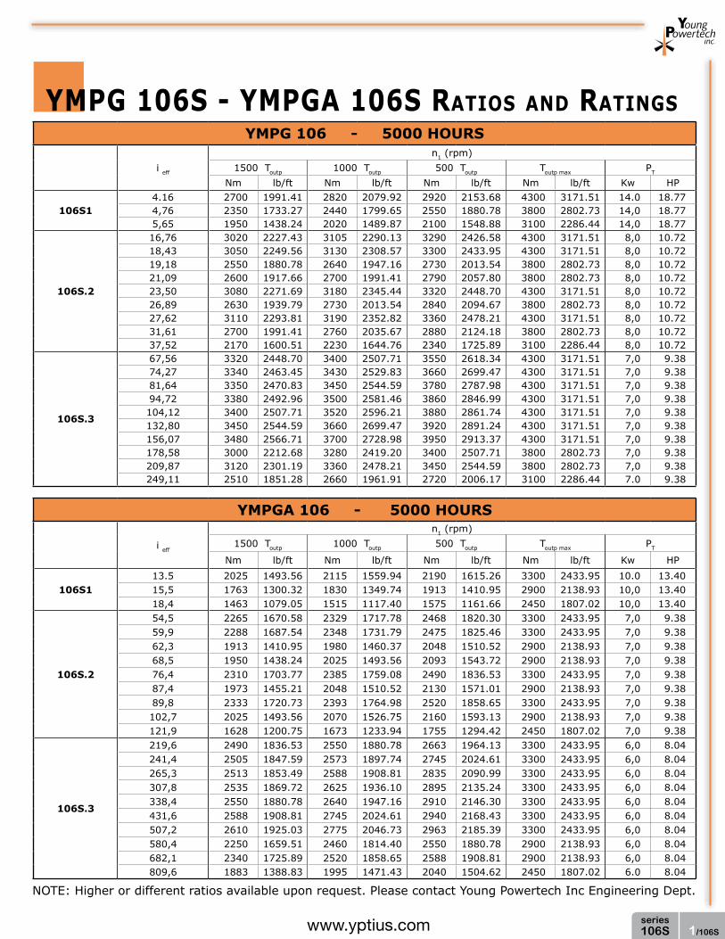
1/106Sseries106Swww.yptius.com
ymPg 106S - ymPga 106S RaTIOS aND RaTINgS
NOTE: Higher or different ratios available upon request. Please contact Young Powertech Inc Engineering Dept.
YMPGA 106 - 5000 HOuRS
i eff
n1 (rpm)1500 Toutp 1000 Toutp 500 Toutp Toutp max PT
Nm lb/ft Nm lb/ft Nm lb/ft Nm lb/ft Kw HP
106S113.5 2025 1493.56 2115 1559.94 2190 1615.26 3300 2433.95 10.0 13.4015,5 1763 1300.32 1830 1349.74 1913 1410.95 2900 2138.93 10,0 13.4018,4 1463 1079.05 1515 1117.40 1575 1161.66 2450 1807.02 10,0 13.40
106S.2
54,5 2265 1670.58 2329 1717.78 2468 1820.30 3300 2433.95 7,0 9.3859,9 2288 1687.54 2348 1731.79 2475 1825.46 3300 2433.95 7,0 9.3862,3 1913 1410.95 1980 1460.37 2048 1510.52 2900 2138.93 7,0 9.3868,5 1950 1438.24 2025 1493.56 2093 1543.72 2900 2138.93 7,0 9.3876,4 2310 1703.77 2385 1759.08 2490 1836.53 3300 2433.95 7,0 9.3887,4 1973 1455.21 2048 1510.52 2130 1571.01 2900 2138.93 7,0 9.3889,8 2333 1720.73 2393 1764.98 2520 1858.65 3300 2433.95 7,0 9.38102,7 2025 1493.56 2070 1526.75 2160 1593.13 2900 2138.93 7,0 9.38121,9 1628 1200.75 1673 1233.94 1755 1294.42 2450 1807.02 7,0 9.38
106S.3
219,6 2490 1836.53 2550 1880.78 2663 1964.13 3300 2433.95 6,0 8.04241,4 2505 1847.59 2573 1897.74 2745 2024.61 3300 2433.95 6,0 8.04265,3 2513 1853.49 2588 1908.81 2835 2090.99 3300 2433.95 6,0 8.04307,8 2535 1869.72 2625 1936.10 2895 2135.24 3300 2433.95 6,0 8.04338,4 2550 1880.78 2640 1947.16 2910 2146.30 3300 2433.95 6,0 8.04431,6 2588 1908.81 2745 2024.61 2940 2168.43 3300 2433.95 6,0 8.04507,2 2610 1925.03 2775 2046.73 2963 2185.39 3300 2433.95 6,0 8.04580,4 2250 1659.51 2460 1814.40 2550 1880.78 2900 2138.93 6,0 8.04682,1 2340 1725.89 2520 1858.65 2588 1908.81 2900 2138.93 6,0 8.04809,6 1883 1388.83 1995 1471.43 2040 1504.62 2450 1807.02 6.0 8.04
YMPG 106 - 5000 HOuRS
i eff
n1 (rpm)1500 Toutp 1000 Toutp 500 Toutp Toutp max PT
Nm lb/ft Nm lb/ft Nm lb/ft Nm lb/ft Kw HP
106S14.16 2700 1991.41 2820 2079.92 2920 2153.68 4300 3171.51 14.0 18.774,76 2350 1733.27 2440 1799.65 2550 1880.78 3800 2802.73 14,0 18.775,65 1950 1438.24 2020 1489.87 2100 1548.88 3100 2286.44 14,0 18.77
106S.2
16,76 3020 2227.43 3105 2290.13 3290 2426.58 4300 3171.51 8,0 10.7218,43 3050 2249.56 3130 2308.57 3300 2433.95 4300 3171.51 8,0 10.7219,18 2550 1880.78 2640 1947.16 2730 2013.54 3800 2802.73 8,0 10.7221,09 2600 1917.66 2700 1991.41 2790 2057.80 3800 2802.73 8,0 10.7223,50 3080 2271.69 3180 2345.44 3320 2448.70 4300 3171.51 8,0 10.7226,89 2630 1939.79 2730 2013.54 2840 2094.67 3800 2802.73 8,0 10.7227,62 3110 2293.81 3190 2352.82 3360 2478.21 4300 3171.51 8,0 10.7231,61 2700 1991.41 2760 2035.67 2880 2124.18 3800 2802.73 8,0 10.7237,52 2170 1600.51 2230 1644.76 2340 1725.89 3100 2286.44 8,0 10.72
106S.3
67,56 3320 2448.70 3400 2507.71 3550 2618.34 4300 3171.51 7,0 9.3874,27 3340 2463.45 3430 2529.83 3660 2699.47 4300 3171.51 7,0 9.3881,64 3350 2470.83 3450 2544.59 3780 2787.98 4300 3171.51 7,0 9.3894,72 3380 2492.96 3500 2581.46 3860 2846.99 4300 3171.51 7,0 9.38104,12 3400 2507.71 3520 2596.21 3880 2861.74 4300 3171.51 7,0 9.38132,80 3450 2544.59 3660 2699.47 3920 2891.24 4300 3171.51 7,0 9.38156,07 3480 2566.71 3700 2728.98 3950 2913.37 4300 3171.51 7,0 9.38178,58 3000 2212.68 3280 2419.20 3400 2507.71 3800 2802.73 7,0 9.38209,87 3120 2301.19 3360 2478.21 3450 2544.59 3800 2802.73 7,0 9.38249,11 2510 1851.28 2660 1961.91 2720 2006.17 3100 2286.44 7.0 9.38

2/106Sseries106S www.yptius.com
ymPg106S
ø D
4
ø D
3
ø D
2
ø D
1
L2L3L4 L1 KI
H
ø A
ø C
ø G
ø E
ø F
d1
U
Z
M N
O
PP1
ø R
Qd2
T
S
ødV
øB
Type A B C D1 D2 D3 D4 E F G H I K L1 L2 L3 L4 M
106Smm 222 195 150 h8 212 212 212 212 50 f7 32 60 f7 13 18 84 217 280 341 404 35inch 8.74 7.68 5.91 h8 8.35 8.35 8.35 8.35 1.97 f7 1.26 2.36 f7 0.51 0.71 3.29 8.54 11.00 13.43 15.91 1.38
Type N O P P1 Q R S T U V Z d d1 d2
106Smm 8 68 90 8 105 42 h6 18 69 20
36°B 50 x 53 DIN 5482 13 n°8
M10 M20inch 0.31 2.68 3.54 0.30 4.13 2.56 h6 0.71 2.72 0.79 0.51 n°8

3/106Sseries106Swww.yptius.com
PP1
ø R
Qd2
T
S
ø A
ø C
ø G
ø E
ø F
d1
Z
M N
O
KI
H
U
L1L2L3
ø D
1ø
W1
Y1
ø Xø X
ø X
ø W
2
ø D
2Y
2
ø W
3ø
D3
Y3
ø B
ø dV
Type A B C D1 D2 D3 E F G H I K L1 L2 L3 M N O P
106Smm 222 195 150 h8 212 212 212 50 f7 32 60 f7 13 18 84 241 293 365 35 8 68 90inch 8.74 7.68 2.91 h8 8.35 8.35 8.35 1.97 f7 1.26 2.36 f7 0.51 0.71 3.29 9.49 11.5414.37 1.38 0.31 2.68 3.54
Type P1 Q R S T U V W1 W2 W3 X Y1 Y2 Y3 Z d d1 d2
106Smm 8 105 65 h6 18 69 20
36°180 180 180 212 195 195 195 B 58 x 53 DIN 5482 13 n°10
M10 M20inch 0.30 4.13 2.56 H6 0.71 2.72 0.79 7.09 7.09 7.09 8.35 7.68 7.68 7.68 0.51 n°10
ymPga106S

4/106Sseries106S www.yptius.com
ymPg106SShRINKDISCK
ymPga106SShRINKDISCK
ø D
1
Vød
ø A
ø C
ø F
ø G
L m
in øE h
6
øF f6
L2 KI
H
L1
øB
ø E
O
MN
Ra ≤16mm 0.63 inch
ø D
2
L3
ø D
4
L4
ø D
4
ø D
1
Vød
ø A
ø C
ø F
ø G
L m
in
øE h
6
øF f6
L2L3 KI
H
L1
øB
ø E
O
MN
ø W
1
Y1
øX
Ra ≤16mm 0.63 inch
øX
ø D
2
ø W
2
Y2
ø D
3
ø W
3
Y3
øX
Type K L1 L2 L3 L4 M N O V d L min.
106Smm 73 213 293 355 404 42 18 65
45°11 n° 8 350
inch 2.87 8.39 11.54 13.98 15.91 1.65 0.71 2.56 0.43 n° 8 13.78
Type A B C D1 D2 D3 E F G H I
106Smm 222 195 150 h8 212 212 212 35 h7 42 f7 50 f7 14 14inch 8.74 7.68 5.91 h8 8.35 8.35 8.35 1.38 h7 1.65 f7 1.97 f7 0.55 0.55
Type A B C D1 D2 D3 E F G H I K L1 L2
106Smm 222 195 150 h8 212 212 212 35 h7 42 f7 50 f7 14 14 73 262 314inch 8.74 7.68 5.91 h8 8.35 8.35 8.35 1.38 h7 1.65 f7 1.97 f7 0.55 0.55 2.87 10.31 12.36
Type L3 M N O V W1 W2 W3 X Y1 Y2 Y2 d L min.
106Smm 365 42 18 65
45°180 180 180 212 195 195 195 11 n° 8 350
inch 14.37 1.65 0.71 2.56 7.09 7.09 7.09 8.35 7.68 7.68 7.68 0.43 n° 8 13.78

5/106Sseries106Swww.yptius.com
ymPg 106S - ymPga 106S
OuTPuT ShafT lOaD DIagRam
6.000
5.000
4.000
3.000
2.000
1.000
0
mm [inch]
Fr
Fa
4.425,37
3.687,81
2.950,24
2.212,68
1.475,12
737,56
daN
[inc
h/lb
]
20[0
.79] 40
[1.5
7] 60[2
.36]-40
[-1.5
7] -20
[-0.7
9]-30
[-1.1
8] -10
[-0.3
9] 30[1
.18]10
[0.3
9] 50[1
.97]-50
[-1.9
7]
INPuT CONfIguRaTION
22.50°
42,7[1.68]
17,8[0.70]
3 [0.12]
ø 21
2 [8
.35]
ø 20
6 [8
.11]
H7
ø 18
8 [7
.40]
ø 16
3 [6
.42]
20 [0.79]
DIN 548240x36
M10
ø8 [0.31] H7
45°
TypeType and number of stages
1 2 3106S 106S.1 106S.2 106S.3
Fa=2000dan
For different load or life, please refer to “output shaft radial load calculation” on page 11

6/106Sseries106S www.yptius.com
ymPg 106S - ymPga 106S aCCESSORIES
ø B
L2L1
ø A
L
ø A
ø B
L2
L3
L1
L
ø C
S
ø A
ø R
L1
ø B
L
øE
øF
ø D
ø B
L1
L3
L2
ø A
ø B
Lu
L
S
ø A
SPlINED bIllET
REmOvablE PINION
lOCKINg flaNgE
SPlINED ShafT fOR fEmalE OuTPuT
integral pinions or different pinions available upon request
Type 1 or 2 mod Z X A B C D L L1 L2 L3 Lu S
106S
mm1
5 19 0,2 116,0 60 h7 62 h7 95 69 8 8 25 69A 58 x 53 DIN 5482
inch 0.20 0.75 0.01 4.57 2.36 h7 2.44 h7 3.74 2.72 0.31 0.31 0.98 2.72mm
16 14 0,5 100,0 60 h7 62 h7 84 69 8 8 25 69
inch 3.43 0.55 0.02 3.94 2.36 h7 2.44 h7 3.31 2.72 0.31 0.31 0.98 2.72
Type L L2 L3 A B
106mm 250 120 10 A 50 x 53 DIN 5482 A 50 x 53 DIN 5482inch 9.84 4.72 0.39
Type A B C L L1 L2 L3 S
106Smm 93 h7 60 h7 62 h7 69 8 8 25 A 58 x 53 DIN 5482inch 3.66 h7 2.36 h7 2.44 h7 2.72 0.31 0.31 0.98
Type A B C D F L L1
106Smm 78 62 f7 50 h7 32 n° 3 11 16 8inch 3.07 2.44 f7 1.97 h7 1.26 n° 11 0.43 0.63 0.31

1/108series108www.yptius.com
YMPG 108 - 5000 HOuRS
i eff
n1 (rpm)1500 Toutp 1000 Toutp 500 Toutp Toutp max PT
Nm lb/ft Nm lb/ft Nm lb/ft Nm lb/ft Kw HP
10814,16 2670 1969,29 2780 2050,42 2940 2168,43 4600 3392,78 18,0 24.134,76 2450 1807.02 2550 1880.78 2650 1954.54 4250 3134.63 18,0 24.135,65 2000 1475.12 2060 1519.38 2155 1589.44 3500 2581.46 18,0 24.13
108.2
16,76 3020 2227.43 3150 2323.32 3260 2404.45 4600 3392.78 10,0 13.4018,43 3070 2264.31 3170 2338.07 3280 2419.20 4600 3392.78 10,0 13.4021,09 2720 2006.17 2770 2043.04 2960 2183.18 4250 3134.63 10,0 13.4023,50 3150 2323.32 3200 2360.20 3400 2507.71 4600 3392.78 10,0 13.4026,89 2750 2028.29 2840 2094.67 3010 2220.06 4250 3134.63 10,0 13.4031,61 2770 2043.04 2910 2146.30 3060 2256.94 4250 3134.63 10,0 13.4037,52 2260 1666.89 2360 1740.64 2450 1807.02 3500 2581.46 10,0 13.40
108.3
67,56 3400 2507.71 3470 2559.34 3920 2891.24 4600 3392.78 8,0 10.7274,27 3420 2522.46 3500 2581.46 3940 2905.99 4600 3392.78 8,0 10.7281,64 3430 2529.83 3580 2640.47 4040 2979.75 4600 3392.78 8,0 10.7294,72 3450 2544.59 3680 2714.22 4160 3068.25 4600 3392.78 8,0 10.72104,12 3470 2559.34 3700 2728.98 4200 3097.76 4600 3392.78 8,0 10.72119,14 3080 2271.69 3300 2433.95 3720 2743.73 4600 3392.78 8,0 10.72132,80 3630 2677.35 3940 2905.99 4320 3186.26 4600 3392.78 8,0 10.72156,07 3660 2699.47 4030 2972.37 4580 3378.03 4600 3392.78 8,0 10.72178,58 3230 2382.32 3460 2551.96 3940 2905.99 4250 3134.63 8,0 10.72209,87 3410 2515.08 3620 2669.97 4040 2979.75 4250 3134.63 8,0 10.72249,11 2720 2006,17 3010 2220,06 3320 2448,70 3500 2581,46 8,0 10,72
YMPGA 108 - 5000 HOuRS
i eff
n1 (rpm)1500 Toutp 1000 Toutp 500 Toutp Toutp max PT
Nm lb/ft Nm lb/ft Nm lb/ft Nm lb/ft Kw HP
108113,5 2003 1477,33 2085 1537,81 2205 1626,32 3450 2544,59 14,0 18.7715,5 1838 1355.64 1913 1410.95 1988 1466.27 3180 2345.44 14,0 18.7718,4 1500 1106.34 1545 1139.53 1616 1191.90 2620 1932.41 14,0 18.77
108.2
54,5 2265 1670.58 2363 1742.86 2445 1803.34 3450 2544.59 8,0 10.7259,9 2303 1698.60 2378 1753.92 2460 1814.40 3450 2544.59 8,0 10.7268,5 2040 1504.62 2078 1532.65 2220 1637.39 3180 2345.44 8,0 10.7276,4 2363 1742.86 2400 1770.15 2550 1880.78 3450 2544.59 8,0 10.7287,4 2063 1521.59 2130 1571.01 2258 1665.41 3180 2345.44 8,0 10.72102,7 2078 1532.65 2183 1610.10 2295 1692.70 3180 2345.44 8,0 10.72121,9 1695 1250.17 1770 1305.48 1838 1355.64 2620 1932.41 8,0 10.72
108.3
219,6 2550 1880.78 2603 1919.87 2940 2168.43 3450 2544.59 6,0 8.04241,4 2565 1891.84 2625 1936.10 2955 2179.49 3450 2544.59 6,0 8.04265,3 2573 1897.74 2685 1980.35 3030 2234.81 3450 2544.59 6,0 8.04307,8 2588 1908.81 2760 2035.67 3120 2301.19 3450 2544.59 6,0 8.04338,4 2603 1919.87 2775 2046.73 3150 2323.32 3450 2544.59 6,0 8.04387,2 2310 1703.77 2475 1825.46 2790 2057.80 3450 2544.59 6,0 8.04431,6 2723 2008.38 2955 2179.49 3240 2389.70 3450 2544.59 6,0 8.04507,2 2745 2024.61 3023 2229.65 3435 2533.52 3450 2544.59 6,0 8.04580,4 2423 1787.11 2595 1913.97 2955 2179.49 3180 2345.44 6,0 8.04682,1 2558 1886.68 2715 2002.48 3030 2234.81 3180 2345.44 6,0 8.04809,6 2040 1504,62 2258 1665,41 2490 1836,53 2620 1932,41 6,0 8,04
ymPg 108 - ymPga 108 RaTIOS aND RaTINgS
NOTE: Higher or different ratios available upon request. Please contact Young Powertech Inc Engineering Dept.

2/108series108 www.yptius.com
ymPg108
ymPgf108
ø D
4
ø D
3
ø D
2
ø D
1
L2L3L4 L1 KI
H
ø A
ø C
ø G
ø E
ø F
d1
U
Z
M N
O
PP1
ø R
Qd2
T
S
ødV
øB
L1 K
ø A
ø C
ø EZ
M N
ø D
1H
I
L2
ø D
2
ø D
3
L3
ø D
4
L4
ø B
ø d
V
ø d1
V1
Type A B C D1 D2 D3 D4 E F G H I K L1 L2 L3 L4 M
108mm 222 195 150 h8 255 212 212 212 50 f7 32 60 f7 13 20 84 220 283 344 407 35inch 8.74 7.68 5.91 h8 10.04 8.35 8.35 8.35 1.97 f7 1.26 2.36 f7 0.51 0.79 3.29 8.66 11.12 13.54 16.02 1.38
Type N O P P1 Q R S T U V Z d d1 d2
108mm 8 68 90 8 105 65 h6 18 69 20
36°B 50 x 45 DIN 5482 13 n°10
M 10 M 20inch 0.31 2.68 3.54 0.30 4.13 2.56 h6 0.71 2.72 0.79 0.51 n°8
Type A B C D1 D2 D3 D4 E H I K
108mm 255 230 210 h8 255 212 212 212 60 f7 10 63 58inch 10.04 9.06 8.27 h8 10.04 8.35 8.35 8.35 2.36 f7 0.39 2.48 2.28
Type L1 L2 L3 L4 M N V V1 Z d d1
108mm 110 173 234 297 55 5
30° 15°A 58 x 44 DIN 5482 10,5 n° 12 10 h8
inch 4.33 6.81 9.21 11.7 2.17 0.20 0.41 n° 12 0.39 h8

3/108series108www.yptius.com
ymPga108
PP1
ø R
Qd2
T
S
ø A
ø C
ø G
ø E
ø F
d1
Z
M N
O
KI
H
U
L1L2L3
ø D
1ø
W1
Y1
ø Xø X
ø X
ø W
2
ø D
2Y
2
ø W
3ø
D3
Y3
ø B
ø dV
ø A
ø C
ø E
KI
H
Z
L1
N
M
ø X
ø W
1
ø D
1Y
1
L2
ø X
ø W
2
ø D
2Y
2
L3
ø X
ø W
3ø
D3
Y3
ø d
V
ø d1
V1
øB
Type A B C D1 D2 D3 E F G H I K L1 L2 L3 M N O P
108mm 222 195 150 h8 212 212 212 50 f7 32 60 f7 13 20 84 245 307 375 35 8 68 90inch 8.74 7.68 5.91 h8 8.35 8.35 8.35 1.97 f7 1.26 2.36 f7 0.51 0.79 3.29 9.65 12.0914.76 1.38 0.31 2.68 3.54
Type P1 Q R S T U V W1 W2 W3 X Y1 Y2 Y3 Z d d1 d2
108mm 7,5 105 65 h6 18 69 20
36°180 180 180 212 195 195 195 B 58 x 53 DIN 5482 13 n°10
M10 M20inch 0.30 4.13 2.56 h6 0.71 2.72 0.79 7.09 7.09 7.09 8.35 7.68 7.68 7.68 0.51 n°10
Type A B C D1 D2 D3 E H I K L1 L2 L3 M N
108mm 255 230 210 h8 255 212 212 60 f7 10 63 58 135 198 265 59 5inch 10.04 9.06 8.27 h8 10.04 8.35 8.35 2.36 f7 0.39 2.48 2.28 5.31 7.80 10.43 2.32 0.20
Type V V1 W1 W2 W3 X Y1 Y2 Y3 Z d d1
108mm
30 15°180 180 180 212 195 195 195 A 58 x 53 DIN 5482 10.5 n° 12 10 h8
inch 7.09 7.09 7.09 8.35 7.68 7.68 7.68 0.41 n° 12 0.39 h8
ymPgaf108

4/108series108 www.yptius.com
ymPg108SShRINKDISCK
ymPga108SShRINKDISCK
ø D
1
Vød
ø A
ø C
ø F
ø G
L m
in øE h
6
øF f6
L2 KI
H
L1
øB
ø E
O
MN
Ra ≤16mm 0.63 inch
ø D
2
L3
ø D
4
L4
ø D
4
ø D
1
Vød
ø A
ø C
ø F
ø G
L m
in
øE h
6
øF f6
L2L3 KI
H
L1
øB
ø E
O
MN
ø W
1
Y1
øX
Ra ≤16mm 0.63 inch
øX
ø D
2
ø W
2
Y2
ø D
3
ø W
3
Y3
øX
Type K L1 L2 L3 L4 M N O V d L min.
108mm 110 220 283 344 407 70 30 95
36°13 n° 10 350
inch 4.33 8.66 11.12 13.54 16.02 2.76 1.18 3.74 0.51 n° 8 13.78
Type A B C D1 D2 D3 E F G H I
108mm 222 195 150 h8 255 212 212 65 h7 75 f7 100 f7 13 20inch 8.74 7.68 5.91 h8 10.04 8.35 8.35 2.56 h7 2.95 f7 3.94 f7 0.51 0.79
Type A B C D1 D2 D3 E F G H I K L1 L2
108mm 222 195 150 h8 255 212 212 65 h7 75 f7 100 f7 13 20 110 245 307inch 8.74 7.68 5.91 h8 10.04 8.35 8.35 2.56 h7 2.95 f7 2.94 f7 0.51 0.79 4.33 9.65 12.09
Type L3 M N O V W1 W2 W3 X Y1 Y2 Y2 d L min.
108mm 375 70 30 95
36°180 180 180 212 195 195 195 13 n° 10 350
inch 14.76 2.76 1.18 3.74 7.09 7.09 7.09 8.35 7.68 7.68 7.68 0.51 n° 10 13.78

5/108series108www.yptius.com
ymPg 108 - ymPga 108
OuTPuT ShafT lOaD DIagRam
0
Fr
Fa
7.000
6.000
5.000
4.000
3.000
2.000
1.000
mm [inch]
5.162,93
4.425,37
3.687,81
2.950,24
2.212,68
1.475,12
737,56
daN
[inc
h/lb
]
20[0
.79] 40
[1.5
7] 60[2
.36]-40
[-1.5
7] -20
[-0.7
9]-60
[-2.3
6]INPuT CONfIguRaTION
22.50°
42,7[1.68]
17,8[0.70]
3 [0.12]
ø 21
2 [8
.35]
ø 20
6 [8
.11]
H7
ø 18
8 [7
.40]
ø 16
3 [6
.42]
20 [0.79]
DIN 548240x36
M10
ø8 [0.31] H7
45°
TypeType and number of stages
1 2 3108 108.1 108.2 108.3
Fa=2000dan
For different load or life, please refer to “output shaft radial load calculation” on page 11

6/108series108 www.yptius.com
ymPg 108 - ymPga 108 aCCESSORIES
ø B
L2L1
ø A
L
ø A
ø B
L2
L3
L1
L
ø C
S
ø A
ø R
L1
ø B
L
øE
øF
ø D
ø B
L1
L3
L2
ø A
ø B
Lu
L
S
ø A
SPlINED bIllET
REmOvablE PINION
lOCKINg flaNgE
SPlINED ShafT fOR fEmalE OuTPuT
integral pinions or different pinions available upon request
Type 1 or 2 mod Z X A B C D L L1 L2 L3 Lu S
106S
mm1
5 19 0,2 116,0 60 h7 62 h7 95 69 8 8 25 69A 58 x 53 DIN 5482
inch 0.20 0.75 0.01 4.57 2.36 h7 2.44 h7 3.74 2.72 0.31 0.31 0.98 2.72mm
16 14 0,5 100 60 h7 62 h7 84 69 8 8 25 69
inch 3.43 0.55 0.02 3.94 2.36 h7 2.44 h7 3.31 2.72 0.31 0.31 0.98 2.72
Type L L2 L3 A B
106mm 250 120 10 A 50 x 53 DIN 5482 A 50 x 53 DIN 5482inch 9.84 4.72 0.39
Type A B C L L1 L2 L3 S
108mm 93 h7 60 h7 62 h7 69 8 8 25 A 58 x 53 DIN 5482inch 3.66 h7 2.36 h7 2.44 h7 2.72 0.31 0.31 0.98
Type A B C D F L L1
106Smm 78 62 f7 50 h7 32 n° 3 11 16 8inch 3.07 2.44 f7 1.97 h7 1.26 n° 11 0.43 0.63 0.31

1/110series110www.yptius.com
ymPg 110 - ymPga 110 RaTIOS aND RaTINgS
YMPGA 110 - 5000 HOuRS
i eff
n1 (rpm)1500 Toutp 1000 Toutp 500 Toutp Toutp max PT
Nm lb/ft Nm lb/ft Nm lb/ft Nm lb/ft Kw HP
110,1
14,9 3990 2942,87 4185 3086,69 4388 3236,42 6450 4757,27 14,0 18.7716,6 3713 2738.56 3863 2849.20 4080 3009.25 6075 4480.68 14,0 18.7719,0 3315 2445.01 3825 2821.17 4005 2953.93 5550 4093.46 14,0 18.7722,6 2700 1991.41 2760 2035.67 2918 2152.20 4500 3319.02 14,0 18.77
110.2
48,7 4470 3296.90 4665 3440.72 4823 3557.26 6450 4757.27 8,0 10.7254,5 4155 3064.57 4313 3181.10 4455 3285.83 6075 4480.68 8,0 10.7262,3 4080 3009.25 4230 3119.88 4395 3241.58 5550 4093.46 8,0 10.7268,3 4665 3440.72 4748 3501.94 4905 3617.74 6450 4757.27 8,0 10.7276,3 4268 3147.91 4380 3230.52 4568 3369.18 6075 4480.68 8,0 10.7289,8 4283 3158.97 4395 3241.58 4620 3407.53 6075 4480.68 8,0 10.72102,7 4230 3119.88 4380 3230.52 4605 3396.47 5550 4093.46 8,0 10.72121,9 3053 2251.77 3158 2329.22 3300 2433.95 4500 3319.02 8,0 10.72
110.3
196,4 4950 3650.93 5145 3794.75 5715 4215.16 6450 4757.27 6,0 8.04215,8 4988 3678.95 5175 3816.88 5745 4237.29 6450 4757.27 6,0 8.04241,4 4635 3418.60 4815 3551.36 5453 4021.92 6075 4480.68 6,0 8.04275,3 5063 3734.27 5306 3913.50 6060 4469.62 6450 4757.27 6,0 8.04307,8 4680 3451.79 5010 3695.18 5565 4104.53 6075 4480.68 6,0 8.04338,2 4710 3473.91 5025 3706.24 5670 4181.97 6075 4480.68 6,0 8.04431,4 4898 3612.57 5190 3827.94 5910 4358.99 6075 4480.68 6,0 8.04507,2 4973 3667.89 5415 3993.89 6105 4502.81 6075 4480.68 6,0 8.04596,1 5123 3778.53 5445 4016.02 6150 4536.00 6075 4480.68 6,0 8.04682,1 5100 3761.56 5490 4049.21 6128 4519.77 5550 4093.46 6,0 8.04809,6 3720 2743,73 4050 2987,12 4538 3347,05 4500 3319,02 6,0 8,04
YMPG 110 - 5000 HOuRS
i eff
n1 (rpm)1500 Toutp 1000 Toutp 500 Toutp Toutp max PT
Nm lb/ft Nm lb/ft Nm lb/ft Nm lb/ft Kw HP
1101
3,72 5320 3923,82 5580 4115,59 5850 4314,73 8600 6343,02 18,5 24.804,16 4950 3650.93 5150 3798.44 5440 4012.33 8100 5974.24 18,5 24.804,76 4420 3260.02 5100 3761.56 5340 3938.58 7400 5457.95 18,5 24.805,65 3600 2655.22 3680 2714.22 3890 2869.11 6000 4425.37 18,5 24.80
110.2
15,48 5960 4395.86 6220 4587.63 6430 4742.52 8600 6343.02 10,5 14.0817,31 5540 4086.09 5750 4240.98 5940 4381.11 8100 5974.24 10,5 14.0819,80 5690 4196.72 5840 4307.36 6090 4491.75 8100 5974.24 10,5 14.0823,50 5710 4211.47 5860 4322.11 6160 4543.38 8100 5974.24 10,5 14.0826,89 5640 4159.84 5840 4307.36 6140 4528.62 7400 5457.95 10,5 14.0831,92 4070 3001.87 4210 3105.13 4400 3245.27 6000 4425.37 10,5 14.08
110.3
62,37 6600 4867.90 6860 5059.67 7620 5620.22 8600 6343.02 8,0 10.7269,74 6650 4904.78 6900 5089.17 7660 5649.72 8600 6343.02 8,0 10.7276,66 6180 4558.13 6420 4735.14 7270 5362.07 8100 5974.24 8,0 10.7287,72 6750 4978.54 7075 5218.24 8080 5959.49 8600 6343.02 8,0 10.7297,78 6240 4602.38 6680 4926.91 7420 5472.70 8100 5974.24 8,0 10.72111,88 6280 4631.88 6700 4941.66 7560 5575.96 8100 5974.24 8,0 10.72132,80 6530 4816.27 6920 5103.92 7880 5811.98 8100 5974.24 8,0 10.72156,07 6630 4890.03 7220 5325.19 8140 6003.75 8100 5974.24 8,0 10.72178,58 6830 5037.54 7260 5354.69 8200 6048.00 8100 5974.24 8,0 10.72211,97 6800 5015.42 7320 5398.95 8170 6025.87 7400 5457.95 8,0 10.72261,13 4960 3658,30 5400 3982,83 6050 4462,24 6000 4425,37 8,0 10,72
NOTE: Higher or different ratios available upon request. Please contact Young Powertech Inc Engineering Dept.

2/110series110 www.yptius.com
ymPg110
ymPgf110
ø D
4
ø D
3
ø D
2
ø D
1
L2L3L4 L1 KI
H
ø A
ø C
ø G
ø E
ø F
d1
U
Z
M N
O
PP1
ø R
Qd2
T
S
ødV
øB
L1 K
ø A
ø C
ø EZ
M N
ø D
1H
I
L2
ø D
2
ø D
3
L3
ø D
4
L4
ø B
ø d
V
ø d1
V1
Type A B C D1 D2 D3 D4 E F G H I K L1 L2 L3 L4 M
110mm 222 195 150 h8 255 212 212 212 50 f7 32 60 f7 13 20 84 237 309 371 434 35inch 8.74 7.68 5.91 h8 10.04 8.35 8.35 8.35 1.97 f7 1.26 2.36 f7 0.51 0.79 3.29 9.33 12.17 14,61 17,09 1,38
Type N O P P1 Q R S T U V Z d d1 d2
110mm 8 68 90 7,5 105 65 h6 18 69 20
36°B 58 x 53 DIN 5482 13 n°10
M 10 M 20inch 0.31 2.68 3.54 0.30 4.13 2.56 h6 0.71 2.72 0.79 0.51 n°8
Type A B C D1 D2 D3 D4 E H I K
110mm 255 230 210 h8 255 212 212 212 72 f7 10 80 58inch 10.04 9.06 8.27 h8 10.04 8.35 8.35 8.35 2.36 f7 0.39 3.15 2.28
Type L1 L2 L3 L4 M N V V1 Z d d1
110mm 127 199 261 324 54 5
30° 15°A 70 x 64 DIN 5482 10,5 n° 12 10 h8
inch 5.00 7.83 10.28 12.76 2.13 0.20 0.41 n° 12 0.39 h8
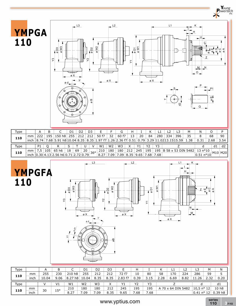
3/110series110www.yptius.com
ymPga110
PP1
ø R
Qd2
T
S
ø A
ø C
ø G
ø E
ø F
d1
Z
M N
O
KI
H
U
L1L2L3
ø D
1ø
W1
Y1
ø Xø X
ø X
ø W
2
ø D
2Y
2
ø W
3ø
D3
Y3
ø B
ø dV
ø A
ø C
ø E
KI
H
Z
L1
N
M
ø X
ø W
1
ø D
1Y
1
L2
ø X
ø W
2
ø D
2Y
2
L3
ø X
ø W
3ø
D3
Y3
ø d
V
ø d1
V1
øB
Type A B C D1 D2 D3 E F G H I K L1 L2 L3 M N O P
110mm 222 195 150 h8 255 212 212 50 f7 32 60 f7 13 20 84 280 334 396 35 8 68 90inch 8.74 7.68 5.91 h8 10.04 8.35 8.35 1.97 f7 1.26 2.36 f7 0.51 0.79 3.29 11.0213.1515.59 1.38 0.31 2.68 3.54
Type P1 Q R S T U V W1 W2 W3 X Y1 Y2 Y3 Z d d1 d2
110mm 7,5 105 65 h6 18 69 20
36°210 180 180 212 245 195 195 B 58 x 53 DIN 5482 13 n°10
M10 M20inch 0.30 4.13 2.56 h6 0.71 2.72 0.79 8.27 7.09 7.09 8.35 9.65 7.68 7.68 0.51 n°10
Type A B C D1 D2 D3 E H I K L1 L2 L3 M N
110mm 255 230 210 h8 255 212 212 72 f7 10 80 58 170 224 286 59 5inch 10.04 9.06 8.27 h8 10.04 8.35 8.35 2.83 f7 0.39 3.15 2.28 6.69 8.82 11.26 2.32 0.20
Type V V1 W1 W2 W3 X Y1 Y2 Y3 Z d d1
110mm
30 15°210 180 180 212 245 195 195 A 70 x 64 DIN 5482 10,5 n° 12 10 h8
inch 8.27 7.09 7.09 8.35 9.65 7.68 7.68 0.41 n° 12 0.39 h8
ymPgfa110

4/110series110 www.yptius.com
ymPg110ShRINKDISCK
ymPga110ShRINKDISCK
ø D
1
Vød
ø A
ø C
ø F
ø G
L m
in øE h
6
øF f6
L2 KI
H
L1
øB
ø E
O
MN
Ra ≤16mm 0.63 inch
ø D
2
L3
ø D
4
L4
ø D
4
ø D
1
Vød
ø A
ø C
ø F
ø G
L m
in
øE h
6
øF f6
L2L3 KI
H
L1
øB
ø E
O
MN
ø W
1
Y1
øX
Ra ≤16mm 0.63 inch
øX
ø D
2
ø W
2
Y2
ø D
3
ø W
3
Y3
øX
Type K L1 L2 L3 L4 M N O V d L min.
110mm 110 237 309 371 434 70 30 95
36°13 n° 10 350
inch 4.33 9.33 12.17 14.61 17.09 2.76 1.18 3.74 0.51 n° 8 13.78
Type A B C D1 D2 D3 E F G H I
110mm 222 195 150 h8 255 212 212 65 h7 75 f7 100 f7 13 20inch 8.74 7.68 5.91 h8 10.04 8.35 8.35 2.56 h7 2.95 f7 3.94 f7 0.51 0.79
Type A B C D1 D2 D3 E F G H I K L1 L2
110mm 222 195 150 h8 255 212 212 65 h7 75 f7 100 f7 13 20 110 280 334inch 8.74 7.68 5.91 h8 10.04 8.35 8.35 2.56 h7 2.95 f7 2.94 f7 0.51 0.79 4.33 11.02 13.15
Type L3 M N O V W1 W2 W3 X Y1 Y2 Y2 d L min.
110mm 396 70 30 95
36°210 180 180 212 245 195 195 13 n° 10 350
inch 15.59 2.76 1.18 3.74 8.27 7.09 7.09 8.35 9.65 7.68 7.68 0.51 n° 10 13.78

5/110series110www.yptius.com
ymPg 110 - ymPga 110
OuTPuT ShafT lOaD DIagRam
0
Fr
Fa
7.000
6.000
5.000
4.000
3.000
2.000
1.000
mm [inch]
5.162,93
4.425,37
3.687,81
2.950,24
2.212,68
1.475,12
737,56
daN
[inc
h/lb
]
20[0
.79] 40
[1.5
7] 60[2
.36]-40
[-1.5
7] -20
[-0.7
9]-60
[-2.3
6]
INPuT CONfIguRaTION
22.50°
42,7[1.68]
17,8[0.70]
3 [0.12]
ø 21
2 [8
.35]
ø 20
6 [8
.11]
H7
ø 18
8 [7
.40]
ø 16
3 [6
.42]
20 [0.79]
DIN 548240x36
M10
ø8 [0.31] H7
45°
TypeType and number of stages
1 2 3110 110.1 110.2 110.3
Fa=2000dan
For different load or life, please refer to “output shaft radial load calculation” on page 11

6/110series110 www.yptius.com
Type 1 or 2 mod Z X A B C D L L1 L2 L3 Lu S
100
mm1
6 14 0,5 100 72 h7 75 h7 84 91 10 8 28 80
A 70 x 64 DIN 5482
inch 3.43 0.55 0.02 3.94 2.83 h7 2.95 h7 3.31 3.58 0.39 0.31 1.10 3.15mm
16 18 0,5 124 72 h7 75 h7 108 91 10 8 28 80
inch 3.43 0.71 0.02 4.88 2.83 h7 2.95 h7 4.25 3.58 0.39 0.31 1.10 3.15mm
18 14 0 126 72 h7 75 h7 112 91 10 8 28 85
inch 0.31 0.55 0 4.96 2.83 h7 2.95 h7 4.41 3.58 0.39 0.31 1.10 3.35mm
18 15 0,25 138 72 h7 75 h7 120 91 10 8 28 85
inch 0.31 0.59 0.01 5.43 2.83 h7 2.95 h7 4.72 3.58 0.39 0.31 1.10 3.35mm
110 12 0,5 148 72 h7 75 h7 120 91 10 8 28 91
inch 0.39 0.47 0.02 5.83 2.83 h7 2.95 h7 4.72 3.58 0.39 0.31 1.10 3.58mm
110 15 0,5 168 72 h7 75 h7 150 91 10 8 28 91
inch 0.39 0.59 0.02 6.61 2.83 h7 2.95 h7 5.91 3.58 0.39 0.31 1.10 3.58
ymPg 110 - ymPga 110 aCCESSORIES
ø B
L2L1
ø A
L
ø A
ø B
L2
L3
L1
L
ø C
S
ø A
ø R
L1
ø B
L
øE
øF
ø D
ø B
L1
L3
L2
ø A
ø B
Lu
L
S
ø A
SPlINED bIllET
REmOvablE PINION
lOCKINg flaNgE
SPlINED ShafT fOR fEmalE OuTPuT
integral pinions or different pinions available upon request
Type L L2 L3 A B
110mm 300 140 20 A 70 x 64 DIN 5482 A 70 x 64 DIN 5482inch 11.81 5.51 0.79
Type A B C L L1 L2 L3 S
108mm 104 h7 72 h7 75 h7 69 8 8 28 A 70 x 64 DIN 5482inch 3.66 h7 2.83 h7 2.95 h7 2.72 0.31 0.31 1.10
Type A B C D F L L1
110mm 88 75 h7 62 f7 40 n° 3 11 16 8inch 3.46 2.95 h7 2.44 f7 1.57 n° 11 0.43 0.63 0.31

1/110Sseries110Swww.yptius.com
ymPg 110S - ymPga 110S RaTIOS aND RaTINgSYMPG 110S - 5000 HOuRS
i eff
n1 (rpm)1500 Toutp 1000 Toutp 500 Toutp Toutp max PT
Nm lb/ft Nm lb/ft Nm lb/ft Nm lb/ft Kw HP
110S1
3,72 5320 3923,82 5580 4115,59 5850 4314,73 8600 6343,02 23,0 30.834,16 4950 3650.93 5150 3798.44 5440 4012.33 8100 5974.24 23,0 30.834,76 4420 3260.02 5100 3761.56 5340 3938.58 7400 5457.95 23,0 30.835,65 3600 2655.22 3680 2714.22 3890 2869.11 6000 4425.37 23,0 30.83
110S.2
15,48 5960 4395.86 6220 4587.63 6430 4742.52 8600 6343.02 12,5 16.7617,31 5540 4086.09 5750 4240.98 5940 4381.11 8100 5974.24 12,5 16.7619,80 5690 4196.72 5840 4307.36 6090 4491.75 8100 5974.24 12,5 16.7623,50 5710 4211.47 5860 4322.11 6160 4543.38 8100 5974.24 12,5 16.7626,89 5640 4159.84 5840 4307.36 6140 4528.62 7400 5457.95 12,5 16.7631,92 4070 3001.87 4210 3105.13 4400 3245.27 6000 4425.37 12,5 16.76
110S.3
62,37 6600 4867.90 6860 5059.67 7620 5620.22 8600 6343.02 9,0 12.0669,74 6180 4558.13 6420 4735.14 7270 5362.07 8100 5974.24 9,0 12.0676,66 6750 4978.54 7075 5218.24 8080 5959.49 8600 6343.02 9,0 12.0687,72 6240 4602.38 6680 4926.91 7420 5472.70 8100 5974.24 9,0 12.0697,78 6280 4631.88 6700 4941.66 7560 5575.96 8100 5974.24 9,0 12.06111,88 6530 4816.27 6920 5103.92 7880 5811.98 8100 5974.24 9,0 12.06132,80 6630 4890.03 7220 5325.19 8140 6003.75 8100 5974.24 9,0 12.06156,07 6830 5037.54 7260 5354.69 8200 6048.00 8100 5974.24 9,0 12.06178,58 6800 5015.42 7320 5398.95 8170 6025.87 7400 5457.95 9,0 12.06211,97 4960 3658.30 5400 3982.83 6050 4462.24 6000 4425.37 9,0 12.06261,13 5000 3687,81 5450 4019,71 6090 4491,75 6000 4425,37 9,0 12,06
YMPGA 110S - 5000 HOuRS
i eff
n1 (rpm)1500 Toutp 1000 Toutp 500 Toutp Toutp max PT
Nm lb/ft Nm lb/ft Nm lb/ft Nm lb/ft Kw HP
110S1
14,9 3990 2942,87 4185 3086,69 4388 3236,42 6450 4757,27 14,0 18.7716,6 3713 2738.56 3863 2849.20 4080 3009.25 6075 4480.68 14,0 18.7719,0 3315 2445.01 3825 2821.17 4005 2953.93 5550 4093.46 14,0 18.7722,6 2700 1991.41 2760 2035.67 2918 2152.20 4500 3319.02 14,0 18.77
110S.2
50,3 4470 3296.90 4665 3440.72 4823 3557.26 6450 4757.27 8,0 10.7256,2 4155 3064.57 4313 3181.10 4455 3285.83 6075 4480.68 8,0 10.7264,3 4268 3147.91 4380 3230.52 4568 3369.18 6075 4480.68 8,0 10.7276,3 4283 3158.97 4395 3241.58 4620 3407.53 6075 4480.68 8,0 10.7287,4 4230 3119.88 4380 3230.52 4605 3396.47 5550 4093.46 8,0 10.72103,7 3053 2251.77 3158 2329.22 3300 2433.95 4500 3319.02 8,0 10.72
110S.3
202,7 4950 3650.93 5145 3794.75 5715 4215.16 6450 4757.27 6,0 8.04226,6 4635 3418.60 4815 3551.36 5453 4021.92 6075 4480.68 6,0 8.04249,1 5063 3734.27 5306 3913.50 6060 4469.62 6450 4757.27 6,0 8.04285,1 4680 3451.79 5010 3695.18 5565 4104.53 6075 4480.68 6,0 8.04317,8 4710 3473.91 5025 3706.24 5670 4181.97 6075 4480.68 6,0 8.04363,6 4898 3612.57 5190 3827.94 5710 4211.47 6075 4480.68 6,0 8.04431,6 4973 3667.89 5415 3993.89 5730 4226.22 6075 4480.68 6,0 8.04507,2 5123 3778.53 5445 4016.02 5750 4240.98 6075 4480.68 6,0 8.04580,3 5100 3761.56 5490 4049.21 5270 3886.95 5550 4093.46 6,0 8.04688,9 3720 2743.73 4050 2987.12 4200 3097.76 4500 3319.02 6,0 8.04848,6 3750 2765,85 4080 3009,25 4230 3119,88 4500 3319,02 6,0 8,04
NOTE: Higher or different ratios available upon request. Please contact Young Powertech Inc Engineering Dept.

2/110Sseries110S www.yptius.com
ymPg110S
ø D
4
ø D
3
ø D
2
ø D
1
L2L3L4 L1 KI
H
ø A
ø C
ø G
ø E
ø F
d1
U
Z
M N
O
PP1
ø R
Qd2
T
S
ødV
øB
Type A B C D1 D2 D3 D4 E F G H I K L1 L2 L3 L4 M
110Smm 272 245 175 h8 255 212 212 212 62 f7 40 72 f7 15 20 129 277 349 413 457 52inch 10.71 9.65 6.89 h8 10.04 8.35 8.35 8.35 2.44 f7 1.57 2.83 f7 0.59 0.79 5.08 10.91 13.74 16.26 17.99 2.05
Type N O P P1 Q R S T U V Z d d1 d2
110Smm 10 90 90 7,5 105 65 h6 18 69 20
36°B 70 x 64 DIN 5482 13 n°10
M 10 M 20inch 0.39 3.54 3.54 0.30 4.13 2.56 h6 0.71 2.72 0.79 0.51 n°8

3/110Sseries110Swww.yptius.com
ymPga110S
PP1
ø R
Qd2
T
S
ø A
ø C
ø G
ø E
ø F
d1
Z
M N
O
KI
H
U
L1L2L3
ø D
1ø
W1
Y1
ø Xø X
ø X
ø W
2
ø D
2Y
2
ø W
3ø
D3
Y3
ø B
ø dV
Type A B C D1 D2 D3 E F G H I K L1 L2 L3 M N O P
110Smm 272 245 175 h8 255 212 212 62 f7 40 72 f7 15 20 129 303 357 419 52 10 90 90inch 10.71 9.65 6.89 h8 10.04 8.35 8.35 2.44 f7 1.57 2.83 f7 0.59 0.79 5.08 11.9314.0616.50 2.05 0.39 3.54 3.54
Type P1 Q R S T U V W1 W2 W3 X Y1 Y2 Y3 Z d d1 d2
110Smm 7,5 105 65 h6 18 69 20
36°210 180 180 212 245 195 195 B 70 x 64 DIN 5482 13 n°10
M10 M20inch 0.30 4.13 2.56 h6 0.71 2.72 0.79 8.27 7.09 7.09 8.35 9.65 7.68 7.68 0.51 n°10

4/110Sseries110S www.yptius.com
ymPg110SShRINKDISCK
ymPga110SShRINKDISCK
ø D
1
Vød
ø A
ø C
ø F
ø G
L m
in øE h
6
øF f6
L2 KI
H
L1
øB
ø E
O
MN
Ra ≤16mm 0.63 inch
ø D
2
L3
ø D
4
L4
ø D
4
ø D
1
Vød
ø A
ø C
ø F
ø G
L m
in
øE h
6
øF f6
L2L3 KI
H
L1
øB
ø E
O
MN
ø W
1
Y1
øX
Ra ≤16mm 0.63 inch
øX
ø D
2
ø W
2
Y2
ø D
3
ø W
3
Y3
øX
Type K L1 L2 L3 L4 M N O V d L min.
110Smm 120 277 349 413 457 70 30 105
36°13 n° 10 350
inch 4.72 10.91 13.74 16.26 17.99 2.76 1.18 4.13 0.51 n° 8 13.78
Type A B C D1 D2 D3 E F G H I
110Smm 272 245 175 h8 255 212 212 65 h7 75 f7 100 f7 15 20inch 10.71 9.65 6.89 h8 10.04 8.35 8.35 2.56 h7 2.95 f7 3.94 f7 0.59 0.79
Type A B C D1 D2 D3 E F G H I K L1 L2
110Smm 272 245 175 h8 255 212 212 65 h7 75 f7 100 f7 15 20 120 303 357inch 10.71 9.65 6.89 h8 10.04 8.35 8.35 2.56 h7 2.95 f7 2.94 f7 0.59 0.79 4.72 11.93 14.06
Type L3 M N O V W1 W2 W3 X Y1 Y2 Y2 d L min.
110Smm 419 70 30 105
36°210 180 180 212 245 195 195 13 n° 10 350
inch 16.50 2.76 1.18 4.13 8.27 7.09 7.09 8.35 9.65 7.68 7.68 0.51 n° 10 13.78

5/110Sseries110Swww.yptius.com
0
Fr
Fa
10.000
9.000
8.000
7.000
6.000
5.000
4.000
3.000
2.000
mm [inch]
7.375,61
6.638,05
5.900,49
5.162,93
4.425,37
3.687,81
2.950,24
2.212,68
1.475,12
daN
[inc
h/lb
]
20[0
.79] 40
[1.5
7] 60[2
.36]-40
[-1.5
7] -20
[-0.7
9]-60
[-2.3
6]
ymPg 110S - ymPga 110S
OuTPuT ShafT lOaD DIagRam
INPuT CONfIguRaTION
22.50°
42,7[1.68]
17,8[0.70]
3 [0.12]
ø 21
2 [8
.35]
ø 20
6 [8
.11]
H7
ø 18
8 [7
.40]
ø 16
3 [6
.42]
20 [0.79]
DIN 548240x36
M10
ø8 [0.31] H7
45°
TypeType and number of stages
1 2 3110S 110S.1 110S.2 110S.3
Fa=4000dan
For different load or life, please refer to “output shaft radial load calculation” on page 11

6/110Sseries110S www.yptius.com
Type 1 or 2 mod Z X A B C D L L1 L2 L3 Lu S
110S
mm1
6 14 0,5 100 72 h7 75 h7 84 91 10 8 28 80
A 70 x 64 DIN 5482
inch 3.43 0.55 0.02 3.94 2.83 h7 2.95 h7 3.31 3.58 0.39 0.31 1.10 3.15mm
16 18 0,5 124 72 h7 75 h7 108 91 10 8 28 80
inch 3.43 0.71 0,02 4.88 2.83 h7 2.95 h7 4.25 3.58 0.39 0.31 1.10 3.15mm
18 14 0 126 72 h7 75 h7 112 91 10 8 28 85
inch 0.31 0.55 0 4.96 2.83 h7 2.95 h7 4.41 3.58 0.39 0.31 1.10 3.35mm
18 15 0,25 138 72 h7 75 h7 120 91 10 8 28 85
inch 0.31 0.59 0.01 5.43 2.83 h7 2.95 h7 4.72 3.58 0.39 0.31 1.10 3.35mm
110 12 0,5 148 72 h7 75 h7 120 91 10 8 28 91
inch 0.39 0.47 0.02 5.83 2.83 h7 2.95 h7 4.72 3.58 0.39 0.31 1.10 3.58mm
110 15 0,5 168 72 h7 75 h7 150 91 10 8 28 91
inch 0.39 0.59 0.02 6.61 2.83 h7 2.95 h7 5.91 3.58 0.39 0.31 1.10 3.58
ymPg 110S - ymPga 110S aCCESSORIES
ø A
ø B
L2
L3
L1
L
ø C
S
ø A
ø R
L1
ø B
L
øE
øF
ø D
ø B
L1
L3
L2
ø A
ø B
Lu
L
S
ø A
SPlINED bIllET
REmOvablE PINION
lOCKINg flaNgE
integral pinions or different pinions available upon request
Type A B C L L1 L2 L3 S
110Smm 104 h7 72 h7 75 h7 91 10 8 28 A 70 x 64 DIN 5482inch 3.66 h7 2.83 h7 2.95 h7 3.58 0.39 0.31 1.10
Type A B C D F L L1
110Smm 88 75 h7 62 f7 40 n° 3 11 20 10inch 3.46 2.95 h7 2.44 f7 1.57 n° 11 0.43 0.79 0.39

1/112series112www.yptius.com
YMPG 112 - 5000 HOuRS
i eff
n1 (rpm)1500 Toutp 1000 Toutp 500 Toutp Toutp max PT
Nm lb/ft Nm lb/ft Nm lb/ft Nm lb/ft Kw HP
1121
3,72 8910 6571.67 9440 6962.58 9800 7228.10 14100 10399.61 26 34.854,16 8100 5974.24 8510 6276.64 8900 6564.29 13700 10104.59 26 34.854,76 7200 5310.44 7480 5516.96 7790 5745.60 12200 8998.24 26 34.855,65 6000 4425.37 6200 4572.88 6480 4779.40 11500 8481.95 26 34.85
112.2
13,84 9980 7360.86 10330 7619.01 10780 7950.91 14100 10399.61 17 22.7917,71 10150 7486.24 10510 7751.77 10870 8017.29 14100 10399.61 17 22.7919,80 9070 6689.68 9400 6933.07 9800 7228.10 13700 10104.59 17 22.7923,49 9230 6807.69 9480 6992.08 10040 7405.11 13700 10104.59 17 22.7926,88 8140 6003.75 8420 6210.26 8780 6475.79 12200 8998.24 17 22.7931,89 6780 5000.66 6960 5133.42 7320 5398.95 11500 8481.95 17 22.7937,50 6800 5015.42 7080 5221.93 7380 5443.20 11500 8481.95 17 22.7951,48 10870 8017.29 11310 8341.82 12380 9131.01 14100 10399.61 12 16.09
112.3
61,30 11130 8209.05 11410 8415.57 12900 9514.54 14100 10399.61 12 16.0978,15 11220 8275.43 11760 8673.72 13360 9853.82 14100 10399.61 12 16.0987,72 8580 6328.27 8750 6453.66 9340 6888.82 13700 10104.59 12 16.0999,99 11490 8474.58 12380 9131.01 14160 10443.86 14100 10399.61 12 16.09111,82 10370 7648.51 10930 8061.54 12560 9263.77 13700 10104.59 12 16.09117,58 11670 8607.34 12650 9330.15 14700 10842.15 14100 10399.61 12 16.09132,66 10610 7825.52 11340 8363.94 12850 9477.66 13700 10104.59 12 16.09155,98 11010 8120.55 11980 8835.98 13480 9942.32 13700 10104.59 12 16.09178,48 9800 7228.10 10300 7596.88 11660 8599.96 12200 8998.24 12 16.09211,74 8100 5974.24 8640 6372.53 9880 7287.10 11500 8481.95 12 16.09248,97 8280 6107,01 8950 6601,17 10200 7523,12 11500 8481,95 12 16,09
YMPGA 112 - 5000 HOuRS
i eff
n1 (rpm)1500 Toutp 1000 Toutp 500 Toutp Toutp max PT
Nm lb/ft Nm lb/ft Nm lb/ft Nm lb/ft Kw HP
1121
14,9 6683 4929,12 7080 5221,93 7350 5421,07 10550 7781,27 20,0 26.8116,6 6075 4480.68 6383 4707.85 6675 4923.22 10250 7560.00 20,0 26.8119,0 5400 3982.83 5610 4137.72 5843 4309.57 9150 6748.68 20,0 26.8122,6 4500 3319.02 4650 3429.66 4860 3584.55 8600 6343.02 20,0 26.81
112.2
45,0 7485 5520.64 7748 5714.62 8085 5963.18 10550 7781.27 13,0 17.4357,6 7613 5615.05 7883 5814.19 8153 6013.34 10550 7781.27 13,0 17.4364,4 6803 5017.63 7050 5199.81 7350 5421.07 10250 7560.00 13,0 17.4376,3 6923 5106.14 7110 5244.06 7530 5553.83 10250 7560.00 13,0 17.4387,4 6105 4502.81 6315 4657.70 6585 4856.84 9150 6748.68 13,0 17.43103,6 5085 3750.50 5220 3850.07 5490 4049.21 8600 6343.02 13,0 17.43121,9 5100 3761.56 5310 3916.45 5535 4082.40 8600 6343.02 13,0 17.43167,3 8153 6013.34 8483 6256.73 9285 6848.25 10550 7781.27 9,0 12.06
112.3
199,2 8348 6157.16 8558 6312.05 9675 7135.90 10550 7781.27 9,0 12.06254,0 8415 6206.58 8820 6505.29 10020 7390.36 10550 7781.27 9,0 12.06285,1 6435 4746.21 6563 4840.61 7005 5166.62 10250 7560.00 9,0 12.06325,0 8618 6356.30 9285 6848.25 10620 7832.90 10550 7781.27 9,0 12.06363,4 7778 5736.75 8198 6046.53 9420 6947.82 10250 7560.00 9,0 12.06382,1 8753 6455.87 9488 6997.98 11025 8131.61 10550 7781.27 9,0 12.06431,1 7958 5869.51 8505 6272.96 9638 7108.61 10250 7560.00 9,0 12.06506,9 8258 6090.78 8985 6626.99 10110 7456.74 10250 7560.00 9,0 12.06580,1 7350 5421.07 7725 5697.66 8745 6449.97 9150 6748.68 9,0 12.06688,2 6075 4480.68 6480 4779.40 7410 5465.33 8600 6343.02 9,0 12.06809,2 6210 4580,25 6713 4951,25 7650 5642,34 8600 6343,02 9,0 12,06
ymPg 112 - ymPga 112 RaTIOS aND RaTINgS
NOTE: Higher or different ratios available upon request. Please contact Young Powertech Inc Engineering Dept.

2/112series112 www.yptius.com
ymPg112
ymPgf112
ø D
4
ø D
3
ø D
2
ø D
1
L2L3L4 L1 KI
H
ø A
ø C
ø G
ø E
ø F
d1
U
Z
M N
O
PP1
ø R
Qd2
T
S
ødV
øB
L1 K
ø A
ø C
ø EZ
M N
ø D
1H
I
L2
ø D
2
ø D
3
L3
ø D
4
L4
ø B
ø d
V
ø d1
V1
Type A B C D1 D2 D3 D4 E F G H I K L1 L2 L3 L4 M
112mm 280 250 200 h8 300 255 212 212 62 f7 40 72 f7 17 21 130 253 341 403 465 52inch 11.02 9.84 7.87 h8 11.81 10.04 8.35 8.35 2.44 f7 1.57 2.83 f7 0.67 0.83 5.12 9.96 13.43 15.87 18.31 2.05
Type N O P P1 Q R S T U V Z d d1 d2
112mm 10 90 160 5 170 90 h6 25 95 20
30°B 70 x 64 DIN 5482 16 n°12
M 10 M 24inch 0.39 3.54 6.30 0.20 6.69 3.54 h6 0.98 3.74 0.79 0.63 n°12
Type A B C D1 D2 D3 D4 E H I K
112mm 300 275 261 h8 300 255 255 212 72 f7 7 85 60inch 11.81 10.83 10.28 h8 11.81 10.04 10.04 8.35 2.36 f7 0.28 3.35 2.36
Type L1 L2 L3 L4 M N V V1 Z d d1
112mm 117 211 267 329 56 7
30° 15°A 70 x 64 DIN 5482 12,5 n° 12 12 h8
inch 4.61 8.31 10.51 12.95 2.20 0.28 0.49 n° 12 0.47 h8

3/112series112www.yptius.com
ymPga112
PP1
ø R
Qd2
T
S
ø A
ø C
ø G
ø E
ø F
d1
Z
M N
O
KI
H
U
L1L2L3
ø D
1ø
W1
Y1
ø Xø X
ø X
ø W
2
ø D
2Y
2
ø W
3ø
D3
Y3
ø B
ø dV
ø A
ø C
ø E
KI
H
Z
L1
N
M
ø X
ø W
1
ø D
1Y
1
L2
ø X
ø W
2
ø D
2Y
2
L3
ø X
ø W
3ø
D3
Y3
ø d
V
ø d1
V1
øB
Type A B C D1 D2 D3 E F G H I K L1 L2 L3 M N O P
112mm 280 250 200 h8 300 255 212 212 62 f7 40 72 f7 17 21 315 365 428 52 10 90 160inch 11.02 9.84 7.87 h8 11.8110.04 8.35 8.35 2.44 f7 1.57 2.83 f7 0.67 0.83 12.40 14.37 16.85 2.05 0.39 3.54 6.30
Type P1 Q R S T U V W1 W2 W3 X Y1 Y2 Y3 Z d d1 d2
112mm 5 170 90 h6 25 95 20
30°210 180 180 212 245 195 195 B 70 x 64 DIN 5482 16 n°12
M10 M24inch 0.20 6.69 3.54 h6 0.98 3.74 0.79 8.27 7.09 7.09 8.35 9.65 7.68 7.68 0.63 n°12
Type A B C D1 D2 D3 E H I K L1 L2 L3 M N
112mm 255 230 210 h8 255 212 212 72 f7 10 80 58 170 224 286 59 5inch 10.04 9.06 8.27 h8 10.04 8.35 8.35 2.83 f7 0.39 3.15 2.28 6.69 8.82 11.26 2.32 0.20
Type V V1 W1 W2 W3 X Y1 Y2 Y3 Z d d1
112mm
30 15°210 180 180 212 245 195 195 A 70 x 64 DIN 5482 12,5 n° 12 12 h8
inch 8.27 7.09 7.09 8.35 9.65 7.68 7.68 0.49 n° 12 0.47 h8
ymPgfa112

4/112series112 www.yptius.com
ymPg112ShRINKDISCK
ymPga112ShRINKDISCK
ø D
1
Vød
ø A
ø C
ø F
ø G
L m
in øE h
6
øF f6
L2 KI
H
L1
øB
ø E
O
MN
Ra ≤16mm 0.63 inch
ø D
2
L3
ø D
4
L4
ø D
4
ø D
1
Vød
ø A
ø C
ø F
ø G
L m
in
øE h
6
øF f6
L2L3 KI
H
L1
øB
ø E
O
MN
ø W
1
Y1
øX
Ra ≤16mm 0.63 inch
øX
ø D
2
ø W
2
Y2
ø D
3
ø W
3
Y3
øX
Type K L1 L2 L3 L4 M N O V d L min.
112mm 145 253 341 403 465 90 50 110
30°16 n° 12 400
inch 5.71 9.96 13.43 15.87 18.31 3.54 1.97 4.33 0.63 n° 12 15.75
Type A B C D1 D2 D3 D4 E F G H I
112mm 280 250 200 h8 300 255 212 212 75 f7 90 f7 115 f7 17 21inch 11.02 9.84 7.87 h8 11.81 10.04 8.35 8.35 2.95 f7 3.54 f7 4.53 f7 0.67 0.83
Type A B C D1 D2 D3 E F G H I K L1 L2
112mm 280 250 200 h8 300 255 212 75 f7 90 f7 115 f7 17 21 145 315 365inch 11.02 9.84 7.87 h8 11.81 10.04 8.35 2.95 f7 3.54 f7 4.53 f7 0.67 0.83 5.71 12.40 14.37
Type L3 M N O V W1 W2 W3 X Y1 Y2 Y2 d L min.
112mm 428 90 50 110
30°210 180 180 212 245 195 195 16 n° 10 400
inch 16.85 3.54 1.97 4.33 8.27 7.09 7.09 8.35 9.65 7.68 7.68 0.63 n° 10 15.75

5/112series112www.yptius.com
ymPg 112 - ymPga 112
OuTPuT ShafT lOaD DIagRam
0
Fr
Fa
12.000
11.000
10.000
9.000
8.000
7.000
6.000
5.000
4.000
3.000
mm [inch]
8.850,73
8.113,17
7.375,61
6.638,05
5.900,49
5.162,93
4.425,37
3.687,81
2.950,24
2.212,68
daN
[inc
h/lb
]
20[0
.79] 40
[1.5
7] 60[2
.36]-40
[-1.5
7] -20
[-0.7
9]-60
[-2.3
6]
INPuT CONfIguRaTION INPuT CONfIguRaTION
22.50°
42,7[1.68]
17,8[0.70]
3 [0.12]
ø 21
2 [8
.35]
ø 20
6 [8
.11]
H7
ø 18
8 [7
.40]
ø 16
3 [6
.42]
20 [0.79]
DIN 548240x36
M10
ø8 [0.31] H7
45°
42,7 [1.68]
3 [0.12]
ø 25
5 [1
0.04
]
ø 24
7 [9
.72]
H7
ø 23
0 [9
.06]
ø 20
6 [8
.11]
30°
M10DIN 548240x36[1.57x1.42]
20 [0.79] ø10 [0.39] H7
15°14,5 [0.57]
TypeType and number of stages
1 2 3112 - 112.2 112.3
TypeType and number of stages
1 2 3112 112.1 - -
Fa=4000dan
For different load or life, please refer to “output shaft radial load calculation” on page 11

6/112series112 www.yptius.com
ymPg 112 - ymPga 112 aCCESSORIES
ø B
L2L1
ø A
L
ø A
ø B
L2
L3
L1
L
ø C
S
ø A
ø R
L1
ø B
L
øE
øF
ø D
ø B
L1
L3
L2
ø A
ø B
Lu
L
S
ø A
SPlINED bIllET
REmOvablE PINION
lOCKINg flaNgE
SPlINED ShafT fOR fEmalE OuTPuT
integral pinions or different pinions available upon request
Type 1 or 2 mod Z X A B C D L L1 L2 L3 Lu S
112
mm1
6 14 0.5 100 72 h7 75 h7 84 91 10 8 28 80
A 70 x 64 DIN 5482
inch 3.43 0.55 0.02 3.94 2.83 h7 2.95 h7 3.31 3.58 0.39 0.31 1.10 3.15mm
16 18 0.5 124 72 h7 75 h7 108 91 10 8 28 80
inch 3.43 0.71 0.02 4.88 2.83 h7 2.95 h7 4.25 3.58 0.39 0.31 1.10 3.15mm
18 14 0 126 72 h7 75 h7 112 91 10 8 28 85
inch 0.31 0.55 0 4.96 2.83 h7 2.95 h7 4.41 3.58 0.39 0.31 1.10 3.35mm
18 15 0.25 138 72 h7 75 h7 120 91 10 8 28 85
inch 0.31 0.59 0.01 5.43 2.83 h7 2.95 h7 4.72 3.58 0.39 0.31 1.10 3.35mm
110 12 0.5 148 72 h7 75 h7 120 91 10 8 28 91
inch 0.39 0.47 0.02 5.83 2.83 h7 2.95 h7 4.72 3.58 0.39 0.31 1.10 3.58mm
110 15 0.5 168 72 h7 75 h7 150 91 10 8 28 91
inch 0.39 0.59 0.02 6.61 2.83 h7 2.95 h7 5.91 3.58 0.39 0.31 1.10 3.58
Type L L2 L3 A B
112mm 300 140 20 A 70 x 64 DIN 5482 A 70 x 64 DIN 5482inch 11.81 5.51 0.79
Type A B C L L1 L2 L3 S
112mm 104 h7 72 h7 75 h7 91 10 8 28 A 70 x 64 DIN 5482inch 3.66 h7 2.83 h7 2.95 h7 3.58 0.39 0.31 1.10
Type A B C D F L L1
112mm 88 75 h7 62 f7 40 n° 3 11 20 10inch 3.46 2.95 h7 2.44 f7 1.57 n° 11 0.43 0.79 0.39

1/114series114www.yptius.com
YMPG 114 - 5000 HOuRS
i eff
n1 (rpm)1500 Toutp 1000 Toutp 500 Toutp Toutp max PT
Nm lb/ft Nm lb/ft Nm lb/ft Nm lb/ft Kw HP
114,1
3,72 13800 10178,34 14600 10768,39 21600 15931,32 30,0 40.214,16 12700 9367.03 13700 10104.59 20500 15120.00 30,0 40.214,76 11100 8186.93 11430 8430.32 18300 13497.37 30,0 40.215,65 9100 6711.81 9730 7176.47 17250 12722.93 30,0 40.21
114.2
13,84 15450 11395.32 15900 11727.22 16560 12214.01 21600 15931.32 19,0 25.4715,48 13970 10303.73 14350 10584.00 15240 11240.43 20500 15120.00 19,0 25.4717,31 14220 10488.12 14605 10772.08 15370 11336.31 20500 15120.00 19,0 25.4719,52 14265 10521.31 14730 10864.27 15480 11417.44 20500 15120.00 19,0 25.4723,17 14350 10584.00 14980 11048.66 15760 11623.96 20500 15120.00 19,0 25.4726,89 12430 9167.88 12540 9249.02 13540 9986.58 18300 13497.37 19,0 25.4731,92 10100 7449.37 10560 7788.64 11010 8120.55 17250 12722.93 19,0 25.47
114.3
55,77 16830 12413.15 17660 13025.33 19300 14234.93 21600 15931.32 13,5 18.1061,47 15490 11424.82 16250 11985.37 17780 13113.84 20500 15120.00 13,5 18.1068,74 15870 11705.09 16290 12014.87 18160 13394.11 20500 15120.00 13,5 18.1078,15 17520 12922.07 17940 13231.84 20400 15046.25 21600 15931.32 13,5 18.1086,13 16000 11800.98 16510 12177.13 18780 13851.40 20500 15120.00 13,5 18.1096,32 16040 11830.48 17100 12612.29 19540 14411.94 20500 15120.00 13,5 18.10110,21 16320 12037.00 17160 12656.55 19620 14470.95 20500 15120.00 13,5 18.10130,81 17100 12612.29 17880 13187.59 19870 14655.34 20500 15120.00 13,5 18.10153,82 17160 12656.55 18160 13394.11 20560 15164.25 20500 15120.00 13,5 18.10178,58 14870 10967.53 15870 11705.09 17900 13202.34 18300 13497.37 13,5 18.10211,97 12000 8850,73 12920 9529,29 14740 10871,65 17250 12722,93 13,5 18,10
YMPGA 114 - 5000 HOuRS
i eff
n1 (rpm)1500 Toutp 1000 Toutp 500 Toutp Toutp max PT
Nm lb/ft Nm lb/ft Nm lb/ft Nm lb/ft Kw HP
114,1
12,6 10350 7633,76 10950 8076,29 16200 11948,49 23,0 30.8314,1 9525 7025.27 10275 7578.44 15350 11321.56 23,0 30.8316,2 8325 6140.20 8573 6323.11 13700 10104.59 23,0 30.8319,2 6825 5033.85 7298 5382.72 12900 9514.54 23,0 30.83
114.2
55,4 11588 8546.86 11925 8795.42 12420 9160.51 16200 11948.49 14,0 18.7761,9 10478 7728.16 10763 7938.37 11430 8430.32 15350 11321.56 14,0 18.7769,2 10665 7866.09 10954 8079.24 11528 8502.60 15350 11321.56 14,0 18.7778,1 10699 7891.17 11048 8148.57 11610 8563.08 15350 11321.56 14,0 18.7792,7 10763 7938.37 11235 8286.50 11820 8717.97 15350 11321.56 14,0 18.77107,6 9323 6876.28 9405 6936.76 10155 7489.93 13700 10104.59 14,0 18.77127,7 7575 5587.02 7920 5841.48 8258 6090.78 12900 9514.54 14,0 18.77
114.3
181,3 12623 9310.23 13245 9769.00 14475 10676.20 16200 11948.49 10,0 13.40199,8 11618 8568.98 12188 8989.39 13335 9835.38 15350 11321.56 10,0 13.40223,4 11903 8779.19 12218 9011.52 13620 10045.58 15350 11321.56 10,0 13.40254,0 13140 9691.55 13455 9923.88 15300 11284.68 16200 11948.49 10,0 13.40279,9 12000 8850.73 12383 9133.22 14085 10388.55 15350 11321.56 10,0 13.40313,0 12030 8872.86 12825 9459.22 14655 10808.96 15350 11321.56 10,0 13.40358,2 12240 9027.75 12870 9492.41 14715 10853.21 15350 11321.56 10,0 13.40425,1 12825 9459.22 13410 9890.69 14903 10991.87 15350 11321.56 10,0 13.40499,9 12870 9492.41 13620 10045.58 15420 11373.19 15350 11321.56 10,0 13.40580,4 11153 8226.02 11903 8779.19 13425 9901.76 13700 10104.59 10,0 13.40688,9 9000 6638,05 9690 7146,97 11055 8153,74 12900 9514,54 10,0 13,40
ymPg 114 - ymPga 114 RaTIOS aND RaTINgS
NOTE: Higher or different ratios available upon request. Please contact Young Powertech Inc Engineering Dept.

2/114series114 www.yptius.com
ymPg114
ymPgf114
ø D
4
ø D
3
ø D
2
ø D
1
L2L3L4 L1 KI
H
ø A
ø C
ø G
ø E
ø F
d1
U
Z
M N
O
PP1
ø R
Qd2
T
S
ødV
øB
L1 K
ø A
ø C
ø EZ
M N
ø D
1H
I
L2
ø D
2
ø D
3
L3
ø D
4
L4
ø B
ø d
V
ø d1
V1
Type A B C D1 D2 D3 D4 E F G H I K L1 L2 L3 L4 M
114mm 325 295 230 h8 350 255 212 212 70 f7 25 85 f7 13 25 126 277 382 454 516 52inch 12.80 11.61 9.06 h8 13.78 10.04 8.35 8.35 2.76 f7 0.98 2.83 f7 0.51 0.98 4.96 10.91 15.04 17.87 20.31 2.05
Type N O P P1 Q R S T U V Z d d1 d2
114mm 10 90 200 5 210 100 h6 28 106 20
36°B 80 x 74 DIN 5482 17 n°10
M 10 M 24inch 0.39 3.54 7.87 0.20 8.27 3.94 h6 1.10 4.17 0.79 0.67 n°12
Type A B C D1 D2 D3 D4 E H I K
114mm 325 295 290 h8 350 255 212 212 82 f7 12 91 63inch 12.80 11.61 11.42 h8 13.78 10.04 8.35 8.35 3.23 f7 0.47 3.58 2.48
Type L1 L2 L3 L4 M N V V1 Z d d1
114mm 128 233 305 367 57 7
30° 15°A 80 x 74 DIN 5482 15 n° 12 12 h8
inch 5.04 9.17 12.01 14.45 2.24 0.28 0.59 n° 12 0.47 h8

3/114series114www.yptius.com
ymPga114
PP1
ø R
Qd2
T
S
ø A
ø C
ø G
ø E
ø F
d1
Z
M N
O
KI
H
U
L1L2L3
ø D
1ø
W1
Y1
ø X1ø X
ø X
ø W
2
ø D
2Y
2
ø W
3ø
D3
Y3
ø B
ø dV
ø A
ø C
ø E
KI
H
Z
L1
N
M
ø X1
ø W
1
ø D
1Y
1
L2
ø X
ø W
2
ø D
2Y
2
L3
ø X
ø W
3ø
D3
Y3
ø d
V
ø d1
V1
øB
Type A B C D1 D2 D3 E F G H I K L1 L2 L3 M N O P P1
114mm 325 295 230 h8 350 255 212 70 f7 45 85 f7 13 25 126 404 424 478 52 10 90 200 5inch 12.8011.61 9.06 h8 13.7810.04 8.35 2.76 f7 1.77 2.83 f7 0.51 0.98 4.96 15.91 16.69 18.82 2.05 0.39 3.54 7.87 0.20
Type Q R S T U V W1 W2 W3 X X1 Y1 Y2 Y3 Z d d1 d2
114mm 210 100 h6 28 106 20
36°270 210 180 212 255 295 245 195 B 70 x 64 DIN 5482 16 n°12
M10 M24inch 8.27 3.94 h6 1.10 4.17 0.79 10.63 8.27 7.09 8.35 10.04 11.61 9.65 7.68 0.63 n°12
Type A B C D1 D2 D3 E H I K L1 L2 L3 M N
114mm 350 320 290 h8 255 212 212 82 f7 12 91 63 255 275 329 64 7inch 13.78 12.60 11.42 h8 10.04 8.35 8.35 3.23 f7 0.47 3.58 2.48 10.04 10.83 12.95 2.52 0.28
Type V V1 W1 W2 W3 X X1 Y1 Y2 Y3 Z d d1
114mm
30° 15°270 210 180 212 255 295 245 195 A 80 x 74 DIN 5482 15 n° 12 12 h8
inch 10.63 8.27 7.09 8.35 10.04 11.61 9.65 7.68 0.59 n° 12 0.47 h8
ymPgfa114

4/114series114 www.yptius.com
ymPg114ShRINKDISCK
ymPga114ShRINKDISCK
ø D
1
Vød
ø A
ø C
ø F
ø G
L m
in øE h
6
øF f6
L2 KI
H
L1
øB
ø E
O
MN
Ra ≤16mm 0.63 inch
ø D
2
L3
ø D
4
L4
ø D
4
ø D
1
Vød
ø A
ø C
ø F
ø G
L m
in
øE h
6
øF f6
L2L3K
IH
L1
øB
ø E
O
MN
ø W
1
Y1
øX
Ra ≤16mm
øX
ø D
2
ø W
2
Y2
ø D
3
ø W
3
Y3
øX1
Type K L1 L2 L3 L4 M N O V d L min.
114mm 155 277 382 454 516 100 40 120
36°17 n° 10 450
inch 9.06 10.91 15.04 17.87 20.31 3.94 1.57 4.72 9.06 n° 10 17.72
Type A B C D1 D2 D3 D4 E F G H I
114mm 325 295 230 h8 350 255 212 212 85 f7 100 f7 130 f7 13 25inch 12.80 11.61 9.06 h8 13.78 10.04 8.35 8.35 3.35 f7 4.33 f7 5.12 f7 0.51 0.98
Type A B C D1 D2 D3 E F G H I K L1 L2
114mm 325 295 230 h8 350 255 212 85 f7 100 f7 130 f7 13 25 155 404 424inch 12.80 11.61 9.06 h8 13.78 10.04 8.35 9.06 f7 4.33 f7 5.12 f7 0.51 0.98 6.10 15.91 16.69
Type L3 M N O V W1 W2 W3 X X1 Y1 Y2 Y2 d L min.
114mm 478 100 40 120
36°270 210 180 212 255 295 245 195 17 n° 10 450
inch 18.82 3.94 1.57 4.72 10.63 8.27 7.09 8.35 10.04 11.61 9.65 7.68 0.67 n° 10 17.72

5/114series114www.yptius.com
ymPg 114 - ymPga 114
OuTPuT ShafT lOaD DIagRam
0
Fr
Fa
12.000
11.000
10.000
9.000
8.000
7.000
6.000
5.000
4.000
3.000
mm [inch]
8.850,73
8.113,17
7.375,61
6.638,05
5.900,49
5.162,93
4.425,37
3.687,81
2.950,24
2.212,68
daN
[inc
h/lb
]
20[0
.79] 40
[1.5
7] 60[2
.36]-40
[-1.5
7] -20
[-0.7
9]-60
[-2.3
6]INPuT CONfIguRaTION INPuT CONfIguRaTION
INPuT CONfIguRaTION
22.50°
42,7[1.68]
17,8[0.70]
3 [0.12]
ø 21
2 [8
.35]
ø 20
6 [8
.11]
H7
ø 18
8 [7
.40]
ø 16
3 [6
.42]
20 [0.79]
DIN 548240x36
M10
ø8 [0.31] H7
45°
42,7 [1.68]
3 [0.12]
ø 25
5 [1
0.04
]
ø 24
7 [9
.72]
H7
ø 23
0 [9
.06]
ø 20
6 [8
.11]
30°
M10DIN 548240x36[1.57x1.42]
20 [0.79] ø10 [0.39] H7
15°14,5 [0.57]
49,6 [1.95]12,6 [0.50]
3 [0.12]
45°
M10
DIN 548270x64[2.76x2.52]
30°
ø 25
5 [1
0.04
]
ø 24
7 [9
.72]
H7
ø 23
0 [9
.06]
ø 20
6 [8
.11]
20 [0.79]ø10 [0.39] H7
TypeType and number of stages
1 2 3114 - 114.2 114.3
TypeType and number of stages
1 2 3114 114.1 114.2 -
TypeType and number of stages
1 2 3114 114.1 - -
Fa=4000dan
For different load or life, please refer to “output shaft radial load calculation” on page 11

6/114series114 www.yptius.com
ymPg 114 - ymPga 114 aCCESSORIES
ø B
L2L1
ø A
L
ø A
ø B
L2
L3
L1
L
ø C
S
ø A
ø R
L1
ø B
L
øE
øF
ø D
ø B
L1
L3
L2
ø A
ø B
Lu
L
S
ø A
SPlINED bIllET
REmOvablE PINION
lOCKINg flaNgE
SPlINED ShafT fOR fEmalE OuTPuT
integral pinions or different pinions available upon request
Type 1 or 2 mod Z X A B C D L L1 L2 L3 Lu S
114
mm1
10 12 0.5 148 85 h7 85 h7 120 91 10 8 28 91
A 80 x 74 DIN 5482
inch 0.39 0.47 0.02 5.83 3.35 h7 3.35 h7 4.72 3.58 0.39 0.31 1.10 3.58mm
110 15 0.5 168 85 h7 85 h7 150 91 10 8 28 91
inch 0.39 0.59 0.02 6.61 3.35 h7 3.35 h7 5.91 3.58 0.39 0.31 1.10 3.58mm
112 14 0.5 200 85 h7 85 h7 168 91 10 8 28 91
inch 0.47 0.55 0.02 7.87 3.35 h7 3.35 h7 6.61 3.58 0.39 0.31 1.10 3.58
Type L L2 L3 A B
114mm 300 140 20 A 80 x 74 DIN 5482 A 80 x 74 DIN 5482inch 11.81 5.51 0.79
Type A B C L L1 L2 L3 S
114mm 122 h7 85 h7 85 h7 91 10 8 28 A 80 x 74 DIN 5482inch 4.80 h7 3.35 h7 3.35 h7 3.58 0.39 0.31 1.10
Type A B C D F L L1
114mm 98 85 h7 70 f7 40 n° 3 11 20 10inch 3.86 3.35 h7 2.76 f7 1.77 n° 11 0.43 0.79 0.39

1/116series116www.yptius.com
YMPG 116 - 5000 HOuRS
i eff
n1 (rpm)1500 Toutp 1000 Toutp 500 Toutp Toutp max PT
Nm lb/ft Nm lb/ft Nm lb/ft Nm lb/ft Kw HP
116,1
3,68 17600 12981,07 19360 14279,18 31400 23159,42 36,0 48.26
4,19 15700 11579.71 16930 12486.91 29200 21536.78 36,0 48.26
4,94 13150 9698.93 14300 10547.12 24500 18070.25 36,0 48.26
116.2
13,69 19700 14529.95 20400 15046.25 21100 15562.54 31400 23159.42 22,0 29.49
15,31 19730 14552.08 20460 15090.50 21650 15968.20 31400 23159.42 22,0 29.49
17,43 17400 12833.56 17900 13202.34 19000 14013.66 29200 21536.78 22,0 29.49
19,94 17600 12981.07 18360 13541.62 19080 14072.66 29200 21536.78 22,0 29.49
23,67 17060 12582.79 17800 13128.59 18400 13571.12 27800 20504.20 22,0 29.49
27,91 14850 10952.78 15250 11247.81 16040 11830.48 24500 18070.25 22,0 29.49
116.3
55,17 21470 15835.44 22300 16447.61 24800 18291.51 31400 23159.42 15,0 20.11
61,69 22000 16226.34 22700 16742.64 25500 18807.81 31400 23159.42 15,0 20.11
77,31 22500 16595.12 22900 16890.15 26400 19471.61 31400 23159.42 15,0 20.11
86,45 22540 16624.63 23400 17258.93 26750 19729.76 31400 23159.42 15,0 20.11
101,65 22700 16742.64 24460 18040.74 27800 20504.20 31400 23159.42 15,0 20.11
115,74 20250 14935.61 21500 15857.56 24650 18180.88 29200 21536.78 15,0 20.11
132,43 20600 15193.76 22100 16300.10 25100 18512.78 29200 21536.78 15,0 20.11
157,19 19630 14478.32 21580 15916.57 24460 18040.74 27800 20504.20 15,0 20.11
185,33 17480 12892.57 18600 13718.64 20900 15415.03 24500 18070.25 15,0 20,11
YMPGA 116 - 5000 HOuRS
i eff
n1 (rpm)1500 Toutp 1000 Toutp 500 Toutp Toutp max PT
Nm lb/ft Nm lb/ft Nm lb/ft Nm lb/ft Kw HP
116,1
12,5 13200 9735,81 14520 10709,39 23550 17369,56 27,0 36.19
14,2 11775 8684.78 12698 9365.55 21900 16152.59 27,0 36.19
16,8 9863 7274.56 10725 7910.34 18350 13534.24 27,0 36.19
116.2
46,5 14775 10897.46 15300 11284.68 15825 11671.90 23550 17369.56 17,0 22.79
52,1 14798 10914.43 15345 11317.87 16238 11976.52 23550 17369.56 17,0 22.79
59,3 13050 9625.17 13425 9901.76 14250 10510.24 21900 16152.59 17,0 22.79
67,8 13200 9735.81 13770 10156.22 14310 10554.50 21900 16152.59 17,0 22.79
80,5 12795 9437.09 13350 9846.44 13800 10178.34 20850 15378.15 17,0 22.79
94,9 11138 8214.95 11438 8436.22 12030 8872.86 18350 13534.24 17,0 22.79
116.3
187,6 16103 11876.95 16725 12335.71 18600 13718.64 23550 17369.56 11,0 14.75
209,7 16500 12169.76 17025 12556.98 19125 14105.85 23550 17369.56 11,0 14.75
262,9 16875 12446.34 17175 12667.61 19800 14603.71 23550 17369.56 11,0 14.75
293,9 16905 12468.47 17550 12944.20 20063 14797.69 23550 17369.56 11,0 14.75
345,6 17025 12556.98 18345 13530.56 20850 15378.15 23550 17369.56 11,0 14.75
393,5 15188 11202.08 16125 11893.17 18488 13636.03 21900 16152.59 11,0 14.75
450,3 15450 11395.32 16575 12225.07 18825 13884.59 21900 16152.59 11,0 14.75
534,4 14723 10859.11 16185 11937.43 18345 13530.56 20850 15378.15 11,0 14.75
630,1 13110 9669.43 13950 10288.98 15675 11561.27 18350 13534.24 11,0 14,75
ymPg 116 - ymPga 116 RaTIOS aND RaTINgS
NOTE: Higher or different ratios available upon request. Please contact Young Powertech Inc Engineering Dept.

2/116series116 www.yptius.com
ymPg116
ymPgf116
ø D
4
ø D
3
ø D
2
ø D
1
L2L3L4 L1 KI
H
ø A
ø C
ø G
ø E
ø F
d1
U
Z
M N
O
PP1
ø R
Qd2
T
S
ødV
øB
L1 K
ø A
ø C
ø EZ
M N
ø D
1H
I
L2
ø D
2
ø D
3
L3
ø D
4
L4
ø B
ø d
V
ø d1
V1
Type A B C D1 D2 D3 D4 E F G H I K L1 L2 L3 L4 M
116mm 330 295 230 h8 345 255 212 212 85 f7 52 105 f7 11,5 27 146 334 439 511 573 65inch 12.99 11.61 9.06 h8 13.58 10.04 8.35 8.35 3.35 f7 2.05 4.13 f7 0.45 1.06 5.75 13.15 17.28 20.12 22.56 2.56
Type N O P P1 Q R S T U V Z d d1 d2
116mm 12 110 200 5 210 100 h6 28 106 30
36°B 100 x 94 DIN 5482 17 n°12
M 14 M 24inch 0.47 4.33 7.87 0.20 8.27 3.94 h6 1.10 4.17 1.18 0.67 n°12
Type A B C D1 D2 D3 D4 E H I K
116mm 325 295 278 h8 345 255 212 212 102 f7 17 107 69inch 12.80 11.61 10.94 h8 13.58 10.04 8.35 8.35 4.02 f7 0.67 4.21 2.72
Type L1 L2 L3 L4 M N V V1 Z d d1
116mm 142 247 319 381 64 10
30° 15°A 100 x 94 DIN 5482 17 n°12 14 h8
inch 5.59 9.72 12.56 15.00 2.52 0.39 0.67 n°12 0.55 h8

3/116series116www.yptius.com
ymPga116
PP1
ø R
Qd2
T
S
ø A
ø C
ø G
ø E
ø F
d1
Z
M N
O
KI
H
U
L1L2L3
ø D
1ø
W1
Y1
ø X1ø X
ø X
ø W
2
ø D
2Y
2
ø W
3ø
D3
Y3
ø B
ø dV
ø A
ø C
ø E
KI
H
Z
L1
N
M
ø X1
ø W
1
ø D
1Y
1
L2
ø X
ø W
2
ø D
2Y
2
L3
ø X
ø W
3ø
D3
Y3
ø d
V
ø d1
V1
øB
Type A B C D1 D2 D3 E F G H I K L1 L2 L3 M N O P P1
116mm 330 295 230 h8 345 255 212 85 f7 52 105 f7 11,5 27 146 474 542 536 65 12 110 200 5inch 12.9911.61 9.06 h8 13.5810.04 8.35 2.83 f7 2.05 4.13 f7 0.45 1.06 5.75 18.66 21.34 21.10 2.56 0.47 4.33 7.87 0.20
Type Q R S T U V W1 W2 W3 X X1 Y1 Y2 Y3 Z d d1 d2
116mm 210 100 h6 28 106 30
36°270 210 180 212 255 295 245 195 B100 x 94 DIN 5482 17 n°10
M10 M24inch 8.27 3.94 h6 1.10 4.17 1.18 10.63 8.27 7.09 8.35 10.04 11.61 9.65 7.68 0.67 n°10
Type A B C D1 D2 D3 E H I K L1 L2 L3 M N
116mm 345 314 278 h8 345 255 212 102 f7 17 107 69 282 350 344 74 10inch 13.58 12.36 10.94 h8 13.58 10.04 8.35 4.02 f7 0.67 4.21 2.72 11.10 13.78 13.54 2.91 0.39
Type V V1 W1 W2 W3 X X1 Y1 Y2 Y3 Z d d1
116mm
30° 15°270 210 180 212 255 295 245 195 A 100 x 94 DIN 5482 17 n°12 14 h8
inch 10.63 8.27 7.09 8.35 10.04 11.61 9.65 7.68 0.67 n°12 0.55 h8
ymPgfa116

4/116series116 www.yptius.com
ymPg116ShRINKDISCK
ymPga116ShRINKDISCK
ø D
1
Vød
ø A
ø C
ø F
ø G
L m
in øE h
6
øF f6
L2 KI
H
L1
øB
ø E
O
MN
Ra ≤16mm 0.63 inch
ø D
2
L3
ø D
4
L4
ø D
4
ø D
1
Vød
ø A
ø C
ø F
ø G
L m
in
øE h
6
øF f6
L2L3K
IH
L1
øB
ø E
O
MN
ø W
1
Y1
øX
Ra ≤16mm
øX
ø D
2
ø W
2
Y2
ø D
3
ø W
3
Y3
øX1
Type K L1 L2 L3 L4 M N O V d L min.
116mm 165 334 439 511 573 120 45 125
36°17 n° 10 600
inch 6.50 13.15 17.28 20.12 22.56 4.72 1.77 4.92 9.06 n° 10 23.62
Type A B C D1 D2 D3 D4 E F G H I
116mm 330 295 230 h8 345 255 212 212 90 f7 120 f7 165 f7 11,5 27inch 12.99 11.61 9.06 h8 13.58 10.04 8.35 8.35 3.54 f7 4.33 f7 6.50 f7 0.45 1.06
Type A B C D1 D2 D3 E F G H I K L1 L2
116mm 330 295 230 h8 345 255 212 90 f7 120 f7 165 f7 11,5 27 165 474 542inch 12.99 11.61 9.06 h8 13.58 10.04 8.35 3.54 f7 4.33 f7 6.50 f7 0.45 1.06 6.50 18.66 21.34
Type L3 M N O V W1 W2 W3 X X1 Y1 Y2 Y2 d L min.
116mm 536 120 45 125
36°270 210 180 212 255 295 245 195 17 n° 10 600
inch 21.10 4.72 1.77 4.92 10.63 8.27 7.09 8.35 10.04 11.61 9.65 7.68 0.67 n° 10 23.62

5/116series116www.yptius.com
ymPg 116 - ymPga 116
OuTPuT ShafT lOaD DIagRam
Fr
Fa
18000
16000
14000
12.000
10.000
8.000
6.000
13.276,10
11.800,98
10.325,85
8.850,73
7.375,61
5.900,49
4.425,37
daN
[inc
h/lb
]
0
mm [inch]
20[0
.79] 40
[1.5
7] 60[2
.36]-40
[-1.5
7] -20
[-0.7
9]-60
[-2.3
6] 80[3
.15]
Fa=4000dan
INPuT CONfIguRaTION INPuT CONfIguRaTION
INPuT CONfIguRaTION
22.50°
42,7[1.68]
17,8[0.70]
3 [0.12]
ø 21
2 [8
.35]
ø 20
6 [8
.11]
H7
ø 18
8 [7
.40]
ø 16
3 [6
.42]
20 [0.79]
DIN 548240x36
M10
ø8 [0.31] H7
45°
42,7 [1.68]
3 [0.12]
ø 25
5 [1
0.04
]
ø 24
7 [9
.72]
H7
ø 23
0 [9
.06]
ø 20
6 [8
.11]
30°
M10DIN 548240x36[1.57x1.42]
20 [0.79] ø10 [0.39] H7
15°14,5 [0.57]
49,6 [1.95]12,6 [0.50]
3 [0.12]
45°
M10
DIN 548270x64[2.76x2.52]
30°
ø 25
5 [1
0.04
]
ø 24
7 [9
.72]
H7
ø 23
0 [9
.06]
ø 20
6 [8
.11]
20 [0.79]ø10 [0.39] H7
TypeType and number of stages
1 2 3116 - 116.2 116.3
TypeType and number of stages
1 2 3116 116.1 116.2 -
TypeType and number of stages
1 2 3116 116.1 - -
For different load or life, please refer to “output shaft radial load calculation” on page 11

6/116series116 www.yptius.com
ymPg 116 - ymPga 116 aCCESSORIES
ø B
L2L1
ø A
L
ø A
ø B
L2
L3
L1
L
ø C
S
ø A
ø R
L1
ø B
L
øE
øF
ø D
ø B
L1
L3
L2
ø A
ø B
Lu
L
S
ø A
SPlINED bIllET
REmOvablE PINION
lOCKINg flaNgE
SPlINED ShafT fOR fEmalE OuTPuT
integral pinions or different pinions available upon request
Type 1 or 2 mod Z X A B C D L L1 L2 L3 Lu S
116
mm1
12 14 0.5 200 105 h7 105 h7 168 112 12 10 33 100A 100x94DIN 5482
inch 0.47 0.55 0.02 7.87 4.13 h7 4.13 h7 6.61 4.41 0.47 0.39 1.30 3.94mm
112 18 0.5 249 105 h7 105 h7 216 112 12 10 33 100
inch 0.47 0.71 0.02 9.80 4.13 h7 4.13 h7 8.50 4.41 0.47 0.39 1.30 3.94
Type L L2 L3 A B
116mm 300 140 20 A 100 x 94 DIN 5482 A 100 x 94 DIN 5482inch 11.81 5.51 0.79
Type A B C L L1 L2 L3 S
116mm 138 105 h7 105 h7 112 12 10 33 A 100 x 94 DIN 5482inch 5.43 4.13 h7 4.13 h7 4.41 0.47 0.39 1.30
Type A B C D F L L1
116mm 122 105 h7 85 f7 52 n° 3 15 22 12inch 4.80 4.13 h7 3.35 f7 2.05 n° 11 0.59 0.87 0.47
integral pinions or different pinions available upon request

1/118series118www.yptius.com
YMPG 118 - 5000 HOuRS
i eff
n1 (rpm)1500 Toutp 1000 Toutp 500 Toutp Toutp max PT
Nm lb/ft Nm lb/ft Nm lb/ft Nm lb/ft Kw HP
118,1
3,69 25900 19102,83 27700 20430,44 46800 34517,86 32,0 42.904,18 24600 18144.00 26550 19582.25 44400 32747.71 32,0 42.904,89 20200 14898.73 21800 16078.83 36000 26552.20 32,0 42.906,00 16300 12022.24 17600 12981.07 29000 21389.27 32,0 42.90
118.2
13,73 28800 21241.76 29900 22053.07 31300 23085.66 46800 34517.86 21,0 28.1515,35 28950 21352.39 30400 22421.86 31550 23270.05 46800 34517.86 21,0 28.1517,39 27300 20135.42 27800 20504.20 29500 21758.05 44400 32747.71 21,0 28.1519,90 27550 20319.81 28400 20946.73 28750 21204.88 44400 32747.71 21,0 28.1523,62 28300 20872.98 29050 21426.15 30900 22790.64 44400 32747.71 21,0 28.1527,63 23050 17000.78 23450 17295.81 24850 18328.39 36000 26552.20 21,0 28.1533,90 18400 13571.12 18400 13571.12 19720 14544.70 29000 21389.27 21,0 28.15
118.3
57,10 31750 23417.56 33100 24413.27 36250 26736.59 46800 34517.86 16,0 21.4563,86 32340 23852.72 33450 24671.42 37400 27584.78 46800 34517.86 16,0 21.4572,34 30900 22790.64 31950 23565.08 36450 26884.10 44400 32747.71 16,0 21.4582,77 31200 23011.90 32900 24265.76 37350 27547.90 44400 32747.71 16,0 21.4586,73 33100 24413.27 34200 25224.59 39050 28801.76 46800 34517.86 16,0 21.4598,25 31900 23528.20 34150 25187.71 38850 28654.25 44400 32747.71 16,0 21.45112,42 31980 23587.20 34450 25408.98 39260 28956.65 44400 32747.71 16,0 21.45133,44 32050 23638.83 35560 26227.67 39350 29023.03 44400 32747.71 16,0 21.45156,10 25850 19065.95 28620 21109.00 32320 23837.97 36000 26552.20 16,0 21.45191,54 21350 15746.93 23150 17074.54 25250 18623.42 29000 21389.27 16,0 21,45
YMPGA 118 - 5000 HOuRS
i eff
n1 (rpm)1500 Toutp 1000 Toutp 500 Toutp Toutp max PT
Nm lb/ft Nm lb/ft Nm lb/ft Nm lb/ft Kw HP
118,116,6 15150 11174,05 16350 12059,12 27000 19914,15 24,0 32.1720,4 12225 9016.68 13200 9735.81 21750 16041.95 24,0 32.17
118.2
46,7 21600 15931.32 22425 16539.81 23475 17314.25 35100 25888.39 16,0 21.4552,2 21713 16014.66 22800 16816.39 23663 17452.91 35100 25888.39 16,0 21.4559,1 20475 15101.56 20850 15378.15 22125 16318.54 33300 24560.78 16,0 21.4567,7 20663 15240.22 21300 15710.05 21563 15904.03 33300 24560.78 16,0 21.4580,3 21225 15654.73 21788 16069.98 23175 17092.98 33300 24560.78 16,0 21.4593,9 17288 12750.96 17588 12972.22 18638 13746.66 27000 19914.15 16,0 21.45115,3 13800 10178.34 13800 10178.34 14790 10908.53 21750 16041.95 16,0 21.45
118.3
194,1 23813 17563.54 24825 18309.95 27188 20052.81 35100 25888.39 12,0 16.09217,1 24255 17889.54 25088 18503.93 28050 20688.59 35100 25888.39 12,0 16.09246,0 23175 17092.98 23963 17674.18 27338 20163.44 33300 24560.78 12,0 16.09281,4 23400 17258.93 24675 18199.32 28013 20661.30 33300 24560.78 12,0 16.09294,9 24825 18309.95 25650 18918.44 29288 21601.69 35100 25888.39 12,0 16.09334,1 23925 17646.15 25613 18891.15 29138 21491.05 33300 24560.78 12,0 16.09382,2 23985 17690.40 25838 19057.10 29445 21717.48 33300 24560.78 12,0 16.09453,7 24038 17729.49 26670 19670.75 29513 21767.64 33300 24560.78 12,0 16.09530,7 19388 14299.83 21465 15831.75 24240 17878.48 27000 19914.15 12,0 16.09651,2 16013 11810.56 17363 12806.27 18938 13967.93 21750 16041.95 12,0 16,09
ymPg 118 - ymPga 118 RaTIOS aND RaTINgS
NOTE: Higher or different ratios available upon request. Please contact Young Powertech Inc Engineering Dept.

2/118series118 www.yptius.com
ymPg118
ymPgf118
KI H
L1
ø A
ø Cø E
ø G
ø F
d1
U
ø D
1
ZNM
PP1
øR
Q
S
d2
T
øB
ødV
ø D
2
L2L3
ø D
3
L4
ø D
4
O
KI
H
L1
ø A
ø C
ø EZ
N
M
ø D
1
L2
ø D
2
L3
ø D
3
L4
ø D
4
Vød
øB
Type A B C D2 D3 D4 E F G H I K L1 L2 L3 L4 M
118mm 399 370 340 h8 300 255 212 85 f7 65 120 f7 15 114 210 210 303 391 453 65inch 15.71 14.57 13.39 h8 11.81 10.04 8.35 3.35 f7 2.56 4.72 f7 0.59 4.49 8.27 8.27 11.93 15.39 17.83 2.56
Type N O P P1 Q R S T U V Z d d1 d2
118mm 12 110 200 5 210 120 h6 32 127 24
20°W 120 x 3x8F DIN 5480 15 n°18
M 14 M 24inch 0.47 4.33 7.87 0.20 8.27 4.72 h6 1.26 5.00 0.94 0.59 n°18
Type A B C D1 D2 D3 D4 E H I K
118mm 399 370 340 h8 300 255 212 212 121 f7 114 117 117inch 15.71 14.57 13.39 h8 11.81 10.04 8.35 8.35 4.76 f7 4.49 4.61 4.61
Type L1 L2 L3 L4 M N V Z d
118mm 210 303 391 453 114 20
20N 120x 3X9h DIN 5480 15 n°18
inch 8.27 11.93 15.39 17.83 4.49 0.79 0.59 n°18

3/118series118www.yptius.com
ymPga118
KI H
L1
ø A
ø Cø E
ø G
ø F
d1
U
ø D
1
ZNM
O
PP1
øR
Q
S
d2
T
ø W
1
Y1
L2
ø D
2ø
W2
Y2
øX1øXøX
L3
ø D
3ø
W3
Y3
øB
ødV
KI
H
L1
ø A
ø C
ø EZ
N
L2
ø X1
ø W
1ø
D1
Y1
ø X
ø W
2ø
D2
Y2
ø X
ø W
3ø
D3
Y3
L3
M
ø B
Vø d
Type A B C D1 D2 D3 E F G H I K L1 L2 L3 M N O P P1
118mm 399 370 340 h8 300 255 212 85 f7 65 120 f7 15 114 210 365 415 478 65 12 110 200 5inch 15.71 14.57 13.39 h8 11.81 10.04 8.35 3.35 f7 2.56 4.72 f7 0.59 4.49 8.27 14.37 16.34 18.82 2.56 0.47 4.33 7.87 0.20
Type Q R S T U V W1 W2 W3 X X1 Y1 Y2 Y3 Z d d1 d2
118mm 210 120 h6 32 127 24
20°270 210 180 212 255 245 195 195 W 120x3x8f DIN 5480 15 n°18
M14 M24inch 8.27 4.72 h6 1.26 5.00 0.94 10.63 8.27 7.09 8.35 10.04 9.65 7.68 7.68 0.59 n°18
Type A B C D1 D2 D3 E H I K L1 L2 L3 M N
118mm 399 370 340 h8 300 255 212 121 f7 15 114 117 365 415 478 114 20inch 15.71 14.57 13.39 h8 11.81 10.04 8.35 4.76 f7 0.59 4.49 4.61 14.37 16.34 18.82 4.49 0.79
Type V W1 W2 W3 X X1 Y1 Y2 Y3 Z d
118mm
20°270 210 180 212 255 245 195 195 N 120x 3X8f DIN 5480 15 n°18
inch 10.63 8.27 7.09 8.35 10.04 9.65 7.68 7.68 0.59 n°18
ymPgaf118

4/118series118 www.yptius.com
KI
H
L1
ø A
ø C
ø F
O
ø D
1
L2L3
ø D
3
L4
ø D
4
Vød
øB
ø G
ø E
M
ø D
2
L m
in
øE h
6
øF f6
Ra ≤16�m
KI
H
L1
ø A
ø C
ø F
L
ø D
1
L2L3
ø D
3
Vød
øB
ø G
ø E
M
ø D
2
L m
in
øE h
6
øF f6
Ra ≤16�m
ø W
1
Y1
ø W
2
ø W
3
Y2
Y3
ø X1
ø Xø X
ymPg118ShRINKDISCK
ymPga118ShRINKDISCK
Type K L1 L2 L3 L4 M O V d L min.
118mm 175 210 303 391 453 80 170
20°15 n° 18 700
inch 6.89 8.27 11.93 15.39 17.83 3.15 6.69 0.59 n° 10 27.56
Type A B C D2 D3 D4 E F G H I
118mm 399 370 340 h8 300 255 212 90 f7 120 f7 165 f7 15 114inch 15.71 14.57 13.39 h8 11.81 10.04 8.35 3.54 f7 4.33 f7 6.50 f7 0.59 4.49
Type A B C D1 D2 D3 E F G H I K L1
118mm 399 370 340 h8 300 255 212 115 f7 125 f7 165 f7 15 114 175 365inch 15.71 14.57 13.39 h8 11.81 10.04 8.35 4.53 f7 4.92 f7 6.50 f7 0.59 4.49 6.89 14.37
Type L2 L3 M O V W1 W2 W3 X X1 Y1 Y2 Y3 d L min.
118mm 415 478 80 170
20°270 210 180 212 255 295 245 195 15 n° 18 700
inch 16.34 18.82 3.15 6.69 10.63 8.27 7.09 8.35 10.04 11.61 9.65 7.68 0.59 n° 10 27.56

5/118series118www.yptius.com
ymPg 118 - ymPga 118
28000
26000
24000
22000
20000
18000
16000
14000
12000
20.651,71
19.176,59
17.701,46
16.226,34
14.751,22
13.276,10
11.800,98
10.325,85
8.850,73
daN
[inc
h/lb
]
0
mm [inch]
20[0
.79] 40
[1.5
7] 60[2
.36]-40
[-1.5
7] -20
[-0.7
9]-60
[-2.3
6] 80[3
.15]
Fa=1900dan
OuTPuT ShafT lOaD DIagRam
INPuT CONfIguRaTION INPuT CONfIguRaTION
22.50°
42,7[1.68]
17,8[0.70]
3 [0.12]
ø 21
2 [8
.35]
ø 20
6 [8
.11]
H7
ø 18
8 [7
.40]
ø 16
3 [6
.42]
20 [0.79]
DIN 548240x36
M10
ø8 [0.31] H7
45°
42,7 [1.68]
3 [0.12]
ø 25
5 [1
0.04
]
ø 24
7 [9
.72]
H7
ø 23
0 [9
.06]
ø 20
6 [8
.11]
30°
M10DIN 548240x36[1.57x1.42]
20 [0.79] ø10 [0.39] H7
15°14,5 [0.57]
TypeType and number of stages
1 2 3118 - - 118.3
TypeType and number of stages
1 2 3118 - 118.2 118.3
For different load or life, please refer to “output shaft radial load calculation” on page 11

6/118series118 www.yptius.com
ymPg 118 - ymPga 118 aCCESSORIES
ø B
L2L1
ø A
L
ø A
ø B
L2
L3
L1
L
ø C
S
ø A
ø R
L1
ø B
L
øE
øF
ø D
ø B
L1
L3
L2
ø A
ø B
Lu
L
S
ø A
SPlINED bIllET
REmOvablE PINION
lOCKINg flaNgE
SPlINED ShafT fOR fEmalE OuTPuT
Pinions available upon request
Type L L2 L3 A B
118mm 350 165 20 N 120x3x8f DIN 5480 N 120x3x8f DIN 5480inch 13.78 6.50 0.79
Type A B C L L1 L2 L3 S
118mm 165 120 h7 125 h7 112 12 10 33 N120 x 3 x 8f DIN 5480inch 6.50 4.72 h7 4.92 h7 4.41 0.47 0.39 1.30
Type A B C D F L L1
118mm 138 125 h7 85 f7 65 n° 3 15 22 12inch 5.43 4.92 h7 3.35 f7 2.56 n° 11 0.59 0.87 0.47
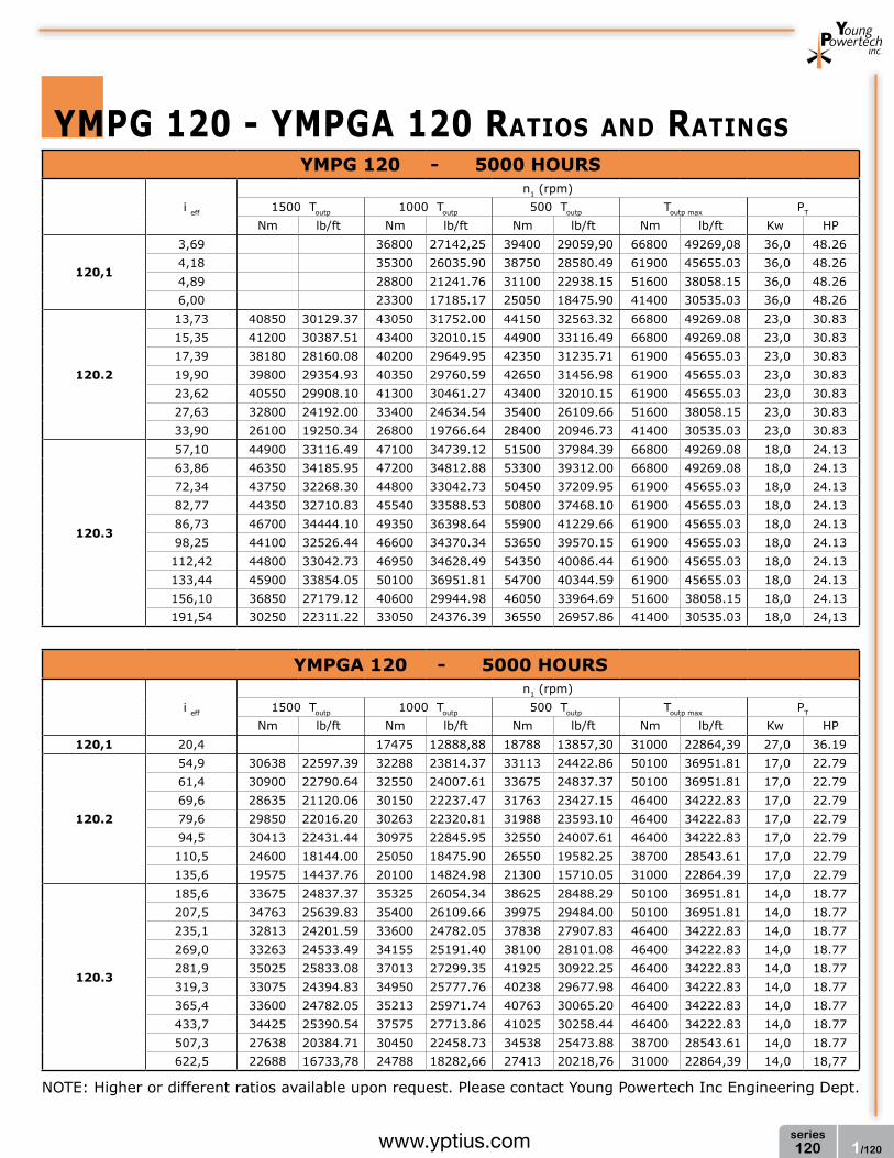
1/120series120www.yptius.com
YMPG 120 - 5000 HOuRS
i eff
n1 (rpm)1500 Toutp 1000 Toutp 500 Toutp Toutp max PT
Nm lb/ft Nm lb/ft Nm lb/ft Nm lb/ft Kw HP
120,1
3,69 36800 27142,25 39400 29059,90 66800 49269,08 36,0 48.264,18 35300 26035.90 38750 28580.49 61900 45655.03 36,0 48.264,89 28800 21241.76 31100 22938.15 51600 38058.15 36,0 48.266,00 23300 17185.17 25050 18475.90 41400 30535.03 36,0 48.26
120.2
13,73 40850 30129.37 43050 31752.00 44150 32563.32 66800 49269.08 23,0 30.8315,35 41200 30387.51 43400 32010.15 44900 33116.49 66800 49269.08 23,0 30.8317,39 38180 28160.08 40200 29649.95 42350 31235.71 61900 45655.03 23,0 30.8319,90 39800 29354.93 40350 29760.59 42650 31456.98 61900 45655.03 23,0 30.8323,62 40550 29908.10 41300 30461.27 43400 32010.15 61900 45655.03 23,0 30.8327,63 32800 24192.00 33400 24634.54 35400 26109.66 51600 38058.15 23,0 30.8333,90 26100 19250.34 26800 19766.64 28400 20946.73 41400 30535.03 23,0 30.83
120.3
57,10 44900 33116.49 47100 34739.12 51500 37984.39 66800 49269.08 18,0 24.1363,86 46350 34185.95 47200 34812.88 53300 39312.00 66800 49269.08 18,0 24.1372,34 43750 32268.30 44800 33042.73 50450 37209.95 61900 45655.03 18,0 24.1382,77 44350 32710.83 45540 33588.53 50800 37468.10 61900 45655.03 18,0 24.1386,73 46700 34444.10 49350 36398.64 55900 41229.66 61900 45655.03 18,0 24.1398,25 44100 32526.44 46600 34370.34 53650 39570.15 61900 45655.03 18,0 24.13112,42 44800 33042.73 46950 34628.49 54350 40086.44 61900 45655.03 18,0 24.13133,44 45900 33854.05 50100 36951.81 54700 40344.59 61900 45655.03 18,0 24.13156,10 36850 27179.12 40600 29944.98 46050 33964.69 51600 38058.15 18,0 24.13191,54 30250 22311.22 33050 24376.39 36550 26957.86 41400 30535.03 18,0 24,13
YMPGA 120 - 5000 HOuRS
i eff
n1 (rpm)1500 Toutp 1000 Toutp 500 Toutp Toutp max PT
Nm lb/ft Nm lb/ft Nm lb/ft Nm lb/ft Kw HP120,1 20,4 17475 12888,88 18788 13857,30 31000 22864,39 27,0 36.19
120.2
54,9 30638 22597.39 32288 23814.37 33113 24422.86 50100 36951.81 17,0 22.7961,4 30900 22790.64 32550 24007.61 33675 24837.37 50100 36951.81 17,0 22.7969,6 28635 21120.06 30150 22237.47 31763 23427.15 46400 34222.83 17,0 22.7979,6 29850 22016.20 30263 22320.81 31988 23593.10 46400 34222.83 17,0 22.7994,5 30413 22431.44 30975 22845.95 32550 24007.61 46400 34222.83 17,0 22.79110,5 24600 18144.00 25050 18475.90 26550 19582.25 38700 28543.61 17,0 22.79135,6 19575 14437.76 20100 14824.98 21300 15710.05 31000 22864.39 17,0 22.79
120.3
185,6 33675 24837.37 35325 26054.34 38625 28488.29 50100 36951.81 14,0 18.77207,5 34763 25639.83 35400 26109.66 39975 29484.00 50100 36951.81 14,0 18.77235,1 32813 24201.59 33600 24782.05 37838 27907.83 46400 34222.83 14,0 18.77269,0 33263 24533.49 34155 25191.40 38100 28101.08 46400 34222.83 14,0 18.77281,9 35025 25833.08 37013 27299.35 41925 30922.25 46400 34222.83 14,0 18.77319,3 33075 24394.83 34950 25777.76 40238 29677.98 46400 34222.83 14,0 18.77365,4 33600 24782.05 35213 25971.74 40763 30065.20 46400 34222.83 14,0 18.77433,7 34425 25390.54 37575 27713.86 41025 30258.44 46400 34222.83 14,0 18.77507,3 27638 20384.71 30450 22458.73 34538 25473.88 38700 28543.61 14,0 18.77622,5 22688 16733,78 24788 18282,66 27413 20218,76 31000 22864,39 14,0 18,77
ymPg 120 - ymPga 120 RaTIOS aND RaTINgS
NOTE: Higher or different ratios available upon request. Please contact Young Powertech Inc Engineering Dept.
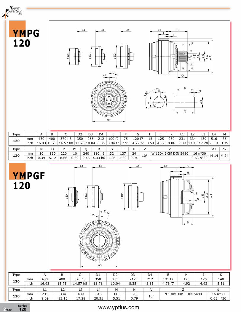
2/120series120 www.yptius.com
ymPg120
ymPgf120
KI H
L1
ø A
ø Cø E
ø G
ø F
d1
U
ZNM
PP1
øR
Q
S
d2
T
øB
ødV
ø D
2
L2L3
ø D
3
L4
ø D
4
120°
O
KI
H
L1
ø A
ø C
ø EZ
N
M
L2
ø D
2
L3
ø D
3
L4
ø D
4
Vød
øB
Type A B C D2 D3 D4 E F G H I K L1 L2 L3 L4 M
120mm 430 400 370 h8 350 255 212 100 f7 75 120 f7 15 125 230 231 334 439 516 85inch 16.93 15.75 14.57 h8 13.78 10.04 8.35 3.94 f7 2.95 4.72 f7 0.59 4.92 9.06 9.09 13.15 17.28 20.31 3.35
Type N O P P1 Q R S T U V Z d d1 d2
120mm 10 130 220 10 240 110 h6 32 137 24
10°W 130x 3X8f DIN 5480 16 n°30
M 14 M 24inch 0.39 5.12 8.66 0.39 9.45 4.33 h6 1.26 5.39 0.94 0.63 n°30
Type A B C D1 D2 D3 D4 E H I K
120mm 430 400 370 h8 350 255 212 212 131 f7 125 125 140inch 16.93 15.75 14.57 h8 13.78 10.04 8.35 8.35 4.76 f7 4.92 4.92 5.51
Type L1 L2 L3 L4 M N V Z d
120mm 231 334 439 516 140 20
10°N 130x 3Xh DIN 5480 16 n°30
inch 9.09 13.15 17.28 20.31 5.51 0.79 0.63 n°30

3/120series120www.yptius.com
ymPga120
KI H
L1
ø A
ø Cø E
ø G
ø F
d1
U
ø D
1
ZNM
O
PP1
øR
Q
S
d2
T
ø W
1
Y1
L2
ø D
2ø
W2
Y2
øX1øX1øX
L3
ø D
3ø
W3
Y3
øB
ødV
120°
KI
H
L1
ø A
ø C
ø EZ
N
L2
ø X1
ø W
1ø
D1
Y1
ø X1
ø W
2ø
D2
Y2
ø X
ø W
3ø
D3
Y3
L3
M
ø B
Vø d
Type A B C D1 D2 D3 E F G H I K L1 L2 L3 M N O P P1
120mm 430 400 370 h8 350 255 212 100 f7 75 120 f7 15 125 230 461 481 535 85 10 130 220 10inch 16.93 15.75 14.57 h8 13.78 10.04 8.35 3.94 f7 2.95 4.72 f7 0.59 4.92 9.06 18.15 18.94 21.06 3.35 0.39 5.12 8.66 0.39
Type Q R S T U V W1 W2 W3 X Y1 Y2 Y3 Z d d1 d2
120mm 240 120 h6 32 137 24
10°270 210 180 212 295 245 195 W 130x 3X8f DIN 5480 16 n°30
M 14 M 24inch 9.45 4.72 h6 1.26 5.39 0.94 10.63 8.27 7.09 8.35 11.61 9.65 7.68 0.63 n°30
Type A B C D1 D2 D3 E H I K L1 L2 L3 M N
120mm 430 400 370 h8 350 255 212 131 f7 15 125 140 461 481 535 140 20inch 16.93 15.75 14.57 h8 13.78 10.04 8.35 5.16 f7 0.59 4.92 5.51 18.15 18.94 21.06 5.51 0.79
Type V W1 W2 W3 X X1 Y1 Y2 Y3 Z d
120mm
10°270 210 180 212 255 245 195 195 N 130x 3X8f DIN 5480 16 n°30
inch 10.63 8.27 7.09 8.35 10.04 9.65 7.68 7.68 0.63 n°30
ymPgfa120

4/120series120 www.yptius.com
KI
H
L1
ø A
ø C
ø F
O
ø D
1
L2L3
ø D
3
L4
ø D
4
Vød
øB
ø G
ø E
M
ø D
2
L m
in
øE h
6
øF f6
Ra ≤16�m
KI H
L1
ø A
ø C
ø F
L
ø D
1
L2L3
ø D
3
Vød
øB
ø G
ø E
M
ø D
2
L m
in
øE h
6øF
f6
Ra ≤16mm
ø W
1
Y1
ø W
2
ø W
3
Y2
Y3
ø X1ø X1ø X
ymPg120ShRINKDISCK
ymPga120ShRINKDISCK
Type K L1 L2 L3 L4 M O V d L min.
120mm 185 231 334 439 516 90 180
10°16 n° 30 800
inch 7.28 9.09 13.15 17.28 20.31 3.54 7.09 0.63 n° 10 31.50
Type A B C D2 D3 D4 E F G H I
120mm 430 400 370 h8 255 212 212 130 f7 140 f7 185 f7 15 125inch 16.93 15.75 14.57 h8 10.04 8.35 8.35 5.12 f7 5.51 f7 7.28 f7 0.59 4.92
Type A B C D1 D2 D3 E F G H I K L1
120mm 430 400 370 h8 350 255 212 130 f7 125 f7 140 f7 15 125 185 461inch 16.93 15.75 14.57 h8 13.78 10.04 8.35 5.12 f7 4.92 f7 5.51 f7 0.59 4.92 7.28 18.15
Type L2 L3 M O V W1 W2 W3 X X1 Y1 Y2 Y3 d L min.
120mm 481 535 90 180
10°270 210 180 212 255 295 245 195 16 n° 30 800
inch 18.94 21.06 3.54 7.09 10.63 8.27 7.09 8.35 10.04 11.61 9.65 7.68 0.63 n° 10 31.50
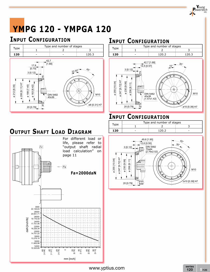
5/120series120www.yptius.com
ymPg 120 - ymPga 120
3000
28000
26000
24000
22000
20000
18000
16000
14000
22.126,83
20.651,71
19.176,59
17.701,46
16.226,34
14.751,22
13.276,10
11.800,98
10.325,85
daN
[inc
h/lb
]
0
mm [inch]
20[0
.79] 40
[1.5
7] 60[2
.36]-40
[-1.5
7] -20
[-0.7
9]-60
[-2.3
6] 80[3
.15]
Fa=2000dan
OuTPuT ShafT lOaD DIagRam
INPuT CONfIguRaTION INPuT CONfIguRaTION
INPuT CONfIguRaTION
22.50°
42,7[1.68]
17,8[0.70]
3 [0.12]
ø 21
2 [8
.35]
ø 20
6 [8
.11]
H7
ø 18
8 [7
.40]
ø 16
3 [6
.42]
20 [0.79]
DIN 548240x36
M10
ø8 [0.31] H7
45°
42,7 [1.68]
3 [0.12]
ø 25
5 [1
0.04
]
ø 24
7 [9
.72]
H7
ø 23
0 [9
.06]
ø 20
6 [8
.11]
30°
M10DIN 548240x36[1.57x1.42]
20 [0.79] ø10 [0.39] H7
15°14,5 [0.57]
49,6 [1.95]12,6 [0.50]
3 [0.12]
45°
M10
DIN 548270x64[2.76x2.52]
30°
ø 25
5 [1
0.04
]
ø 24
7 [9
.72]
H7
ø 23
0 [9
.06]
ø 20
6 [8
.11]
20 [0.79]ø10 [0.39] H7
TypeType and number of stages
1 2 3120 - - 120.3
TypeType and number of stages
1 2 3120 - 120.2 120.3
TypeType and number of stages
1 2 3120 - 120.2 -
For different load or life, please refer to “output shaft radial load calculation” on page 11

6/120series120 www.yptius.com
ymPg 120 - ymPga 120 aCCESSORIES
ø B
L2L1
ø A
L
ø A
ø B
L2
L3
L1
L
ø C
S
ø A
ø R
L1
ø B
L
øE
øF
ø D
ø B
L1
L3
L2
ø A
ø B
Lu
L
S
ø A
SPlINED bIllET
REmOvablE PINION
lOCKINg flaNgE
SPlINED ShafT fOR fEmalE OuTPuT
Pinions available upon request
Type L L2 L3 A B
118mm 350 165 20 N 130x3x8f DIN 5480 N 130x3x8f DIN 5480inch 13.78 6.50 0.79
Type A B C L L1 L2 L3 S
120mm 175 130 h7 135 h7 132 10 10 35 N 130x3x8f DIN 5480inch 6.89 5.12 h7 5.31 h7 5.20 0.39 0.39 1.38
Type A B C D F L L1
120mm 148 135 h7 100 f7 75 n° 3 15 20 10inch 5.83 5.31 h7 3.94 f7 2.95 n° 11 0.59 0.79 0.39

