yorkshire tube systems · yorkshire tube systems technical guide kme group yorkshire ... glance to...
TRANSCRIPT

YORKSHIRE TUBE SYSTEMS
TECHNICAL GUIDE
KME Group
YORKSHIRE COPPER TUBE

Contents
1 Introduction 1.1 Technical Expertise … … … … … … … … … … … … … … 1-1 1.2 Technical Department Contact Details … … … … … … … … … 1-1 1.3 Copper Tube Development … … … … … … … … … … … … 1-2
2 Policy Statements 2.1 Quality Policy … … … … … … … … … … … … … … … 2-1 2.2 Environmental and Energy Conservation Policy … … … … … … … 2-2 2.3 Health & Safety Policy … … … … … … … … … … … … … 2-3
3 Installation Guide 3.1 Installation of Plastic Covered Tube … … … … … … … … … … 3-1 3.2 Flushing and Avoidance of Stagnation … … … … … … … … … 3-4 3.3 Disinfection … … … … … … … … … … … … … … … … 3-5 3.4 Cold Bending … … … … … … … … … … … … … … … 3-6 3.5 Use with Fittings … … … … … … … … … … … … … … … 3-8 3.6 Use of Fluxes … … … … … … … … … … … … … … … 3-10 3.7 Burying Tubes in Contaminated Ground … … … … … … … … … 3-11 3.8 Lagging of Pipework … … … … … … … … … … … … … … 3-12 3.9 Medical Gas Tubes … … … … … … … … … … … … … … 3-13
4 Technical Data 4.1 Pipe Sizing, Flow Rates and Pressure Drops … … … … … … … … 4-1 4.2 Tube Support Distances … … … … … … … … … … … … … 4-3 4.3 Thermal Expansion and Contraction … … … … … … … … … … 4-4 4.4 Pressure Ratings and the Effect of Annealing … … … … … … … … 4-5 4.5 Suitability of Copper with Various Materials … … … … … … … … 4-6
5 Product Specifications 5.1 Copper Tubes … … … … … … … … … … … … … … … 5-1 5.2 Plastic Covered Tubes … … … … … … … … … … … … … 5-2 5.3 Chrome Plated Tubes … … … … … … … … … … … … … 5-3 5.4 Medical Gas Tubes … … … … … … … … … … … … … … 5-4
6 Approvals 6.1 Quality System … … … … … … … … … … … … … … … 6-1 6.2 Kitemark – BS EN 1057 copper tubes … … … … … … … … … 6-2 6.3 Kitemark – BS EN13348 medical tubes … … … … … … … … … 6-5
7 Guarantee 7.1 YCT 25 Year Guarantee … … … … … … … … … … … … … 7-1 7.2 YCT 30 Year Guarantee … … … … … … … … … … … … … 7-2
8 COSHH 8.1 Material Safety Data Sheet … … … … … … … … … … … … 8-1
9 References 9.1 References … … … … … … … … … … … … … … … … 9-1

YCT TECHNICAL GUIDE 1-1 Section 1 – INTRODUCTION Issue 01/08
Section 1 - Introduction 1.1 Technical Expertise
The roots of Yorkshire stretch back to the time of the industrial revolution. During this period we have accumulated an unrivalled wealth of knowledge concerning the use of copper tubing for a diverse range of applications ranging from the conveyance of liquid nitrogen, at temperatures of -196ºC, to steam, at temperatures up to +205 ºC.
A lot of this knowledge is included in this Technical Data Guide, however it is impossible to cover all eventualities in such a publication. If you cannot find the information you require please feel free to contact our Technical Services Department by simply picking up a telephone or via our website. Throughout this guide superscript references are included to refer to data sources. A full list of these references is included in Section 9.
1.2 Technical Department Contact Details
Service Telephone Application Enquiries After Sales Service COSHH Environmental Matters +44(0)151-545-5107
Quality Systems Product Approvals Product Certification +44(0)151-545-5098
Facsimile +44 (0)151-545-5018
E-mail [email protected]
Web-site www.yct.com

YCT TECHNICAL GUIDE 1-2 Section 1 – INTRODUCTION Issue 01/08
1.3 Copper Tube Development
The first recorded use of copper for conveying water goes back to a conduit that has been dated to 2,750 B.C. discovered at Abusir in Egypt. Copper water pipes and cisterns were also widely used by the Romans and good examples of copper plumbing can still be seen at the archaeological site of Herculaneum, which was uniquely preserved by the eruption of Vesuvius in 79 A.D. Historically copper tubing was expensive and only installed in prestige buildings. It was not until the development of modern types of fittings in the 1930’s, which lead to the introduction of light gauge copper tubes, that copper plumbing systems became highly competitive with other materials.
In 1996 the latest specification for copper tubes, EN 1057, was adopted across Europe. In the UK it was published as BS EN 1057:1996, “Copper and copper alloys - Seamless, round copper tubes for water and gas in sanitary and heating applications”. It replaced the previously familiar standard BS 2871 Part 1: 1971, “Copper and Copper Alloys - Tubes - Copper tubes for water, gas and sanitation”. In 2006, EN 1057 was further revised to support the essential requirements of the EU Construction Products Directive (CPD) 89/106/EEC and the EU Pressure Equipment Directive (PED) 97/23/EC.
In drawing up this standard, the opportunity was taken to rationalise tube sizes across Europe. At first glance to UK users, familiar with BS 2871 Part 1, the changes to the standard may have seemed quite large and the available options quite confusing. Yorkshire simplified this process by branding their products as Yorkex, Kuterlon and Minibore in line with Tables X, Y and W in BS 2871 Part 1.
Under BS EN 1057, temper condition (material strength) is designated with an ‘R’ number, the higher the number indicating a stronger material. Soft condition is denoted R220, half hard R250 and hard R290. Because of the variety of sizes both diameter and thickness should be specified when ordering to BS EN 1057. For example when ordering half hard copper tube with an outside diameter of 15mm and a thickness of 0.7mm (formerly 15mm BS 2871 Part 1 Table X tubing) the official designation is EN 1057 – R250 – 15 x 0.7mm. More simply it can be ordered as 15mm Yorkex.
The following tables show the relationship of the current Yorkshire range with BS EN 1057 and BS 2871 Part 1.
Yorkex - Half Hard Range Yorkex – Hard Range Size mm
(od x wall) EN 1057
Designation BS 2871 Part 1
Designation Size mm
(od x wall) EN 1057
Designation BS 2871 Part 1
Designation
6 x 0.6 6 x 0.6mm – R250 6mm Table X 35 x 1.0 35 x 1.0mm – R290 New size 8 x 0.6 8 x 0.6mm – R250 8mm Table X 35 x 1.2 35 x 1.2mm – R290 35mm Table X ►► 10 x 0.6 10 x 0.6mm – R250 10mm Table X 42 x 1.0 42 x 1.0mm – R290 New size 12 x 0.6 12 x 0.6mm – R250 12mm Table X 42 x 1.2 42 x 1.2mm – R290 42mm Table X ►►
15 x 0.7 15 x 0.7mm – R250 15mm Table X 54 x 1.0 54 x 1.0mm – R290 New size
22 x 0.9 22 x 0.9mm – R250 22mm Table X 54 x 1.2 54 x 1.2mm – R290 54mm Table X ►►
28 x 0.9 28 x 0.9mm – R250 28mm Table X 66.7 x 1.2 66.7 x 1.2mm – R290 66.7mm Table X ►► 35 x 1.2 35 x 1.2mm – R250 35mm Table X 76.1 x 1.5 76.1 x 1.2mm – R290 76.1mm Table X ►► 42 x 1.2 42 x 1.2mm – R250 42mm Table X 108 x 1.5 108 x 1.5mm – R290 108mm Table X ►► 54 x 1.2 54 x 1.2mm – R250 54mm Table X 133 x 1.5 133 x 1.5mm – R290 133mm Table X ►►
159 x 2.0 159 x 2.0mm – R290 159mm Table X ►►
Kuterlon - Straight Tube Range Minibore – Coil Range Size mm
(od x wall) EN 1057
Designation BS 2871 Part 1
Designation Size mm
(od x wall) EN 1057
Designation BS 2871 Part 1
Designation
6 x 0.8 6 x 0.8mm – R250 6mm Table Y 6 x 0.6 6 x 0.6mm – R220 6mm Table W 8 x 0.8 8 x 0.8mm – R250 8mm Table Y 8 x 0.6 8 x 0.6mm – R220 8mm Table W 10 x 0.8 10 x 0.8mm – R250 10mm Table Y 10 x 0.7 10 x 0.7mm – R220 10mm Table W
12 x 0.8 12 x 0.8mm – R250 12mm Table Y 15 x 1.0 15 x 1.0mm – R250 15mm Table Y 22 x 1.2 22 x 1.2mm – R250 22mm Table Y
28 x 1.2 28 x 1.2mm – R250 28mm Table Y Kuterlon – Coil Range 35 x 1.5 35 x 1.5mm – R290 35mm Table Y ►► Size mm EN 1057 BS 2871 Part 1 42 x 1.5 42 x 1.5mm – R290 42mm Table Y ►► (od x wall) Designation Designation
54 x 2.0 54 x 2.0mm – R290 54mm Table Y ►► 12 x 0.8 12 x 0.8mm – R220 12mm Table Y coil 66.7 x 2.0 66.7 x 2.0mm – R290 66.7mm Table Y ►► 15 x 1.0 15 x 1.0mm – R220 15mm Table Y coil 76.1 x 2.0 76.1 x 2.0mm – R290 76.1mm Table Y ►► 22 x 1.2 22 x 1.2mm – R220 22mm Table Y coil
108 x 2.5 108 x 2.5mm – R290 108mm Table Y ►► 28 x 1.2 28 x 1.2mm – R220 28mm Table Y coil ►► Hard temper equivalent size.

YCT TECHNICAL GUIDE 2-1 Section 2 – POLICY STATEMENTS Issue 01/08
Section 2 – Policy Statements This section details copies of commonly requested policies covering areas of quality, the environment and heath and safety. The Company also operates to numerous other policies covering various business activities (e.g. employment policy, disaster recovery policy, etc.).
2.1 QUALITY POLICY STATEMENT Yorkshire Copper Tube is dedicated to the manufacture of copper tubes to national and international standards used extensively in many fields of building construction and throughout the general and civil engineering industries. The quality objectives of the company are:
♦ continually to improve upon levels of customer satisfaction,
♦ to manufacture products to meet the requirements of internal and external specifications,
♦ to operate and develop an effective Quality Management System
To this end a fully documented Management System has been established which covers all activities and functions concerned with the attainment and continual improvement of quality. The system is based on and meets the requirements of ISO 9001:2000. The Company Quality Manual describes the organisation and operation of the quality assurance programme and is issued with the full support and commitment of the Directors of the Company who undertake to ensure that the Company Quality Policy is understood, implemented and maintained at all levels in the organisation. Documented procedures supporting the Management System detail responsibilities for carrying out the work and it is a mandatory requirement that Yorkshire Copper Tube personnel at all levels comply with the policies, systems and procedures described. It is every employee's responsibility to adhere to these requirements; failure to do so will be treated as seriously as failure to meet any other Company requirements. The policies and procedures will be reviewed at regular intervals.
Ref. - ISO 9001: 2000, Clause 5.3

YCT TECHNICAL GUIDE 2-2 Section 2 – POLICY STATEMENTS Issue 01/08
2.2 ENVIRONMENTAL AND ENERGY CONSERVATION POLICY STATEMENT It is the Policy of Yorkshire Copper Tube to conduct its activities in a responsible manner, having due regard to their impact on the environment, energy resources and the community within which the company operates. The Plant Manager of Yorkshire Copper Tube is responsible for the implementation of this policy. The Policy includes the following commitments:
♦ to design, construct, install and maintain all plant and equipment, so far as to ensure that it will operate in conformity with agreed quality standards for air, water, waste disposal and noise, in line also with good energy efficiency practice;
♦ to use materials and manufacture products which are, so far as is reasonably practicable, harmless;
♦ to ensure full compliance with the monitoring requirements as laid down in the relevant discharge consent(s);
♦ to contribute to the economical use of materials and energy through improved design, increased plant efficiency, better process control, use of recyclable materials and good housekeeping;
♦ to ensure that, wherever possible, all products and packaging are recyclable and or energy efficient in use, so as to assist in the conservation of resources;
♦ to instruct and inform all employees with respect to their responsibilities for the energy conservation, waste minimisation and environmental aspects of their work;
♦ to pursue a policy of continual improvement in the use of energy with the aim of meeting negotiated agreement targets for Energy Reduction;
♦ to keep records of:- -the quantity, type and disposal methods for wastes produced, -noise attenuation, -energy usage relative to production, -results of all monitoring.
The Policy requires the full co-operation of all employees, who should operate plant and equipment in such a way as to:-
♦ minimise environmental impact and
♦ maximise the conservation of energy and materials.

YCT TECHNICAL GUIDE 2-3 Section 2 – POLICY STATEMENTS Issue 01/08
2.3 HEALTH AND SAFETY POLICY STATEMENT Yorkshire Copper Tube recognises and accepts its obligations and responsibilities under the Health and Safety at Work Act (1974) and all associated legislation. The Company’s policy objective is to manufacture copper tube without causing injury or ill-health to it’s employees, visitors or members of the public and to promote a continued improvement to the Occupational Health, Safety and Welfare of everyone associated with it’s operations. The Plant Manager is primarily responsible for meeting the requirements of the Act and shall ensure all reasonable steps are taken to do so. Directors, Managers and Co-ordinators are directly responsible for ensuring Health and Safety is an integral part of production, maintenance and quality on a daily basis. They are also responsible for preventing injury and illnesses by ensuring full adherence with Company Rules and Safe Systems of Work, each level being accountable to the one above and responsible for the level below. The Company recognises Safety as a condition of employment and expects each employee to assume individual responsibility for working safely at all times. This will include following all Company Rules, Procedures and co-operating with all reasonable requests to enable the Company to fulfil its legal duties. Resources will be made available to meet this objective in the form of instruction and training, increasing employee’s knowledge to eliminate injuries. The Company recognises people as the most critical element to the success of its Health and Safety performance and will ensure consultation with all levels through works and departmental safety committees on a regular basis. The Company employs a qualified Health and Safety Manager and Occupational Health Nurse to ensure full compliance with legislation and as a support to all employees. They will devise safe systems of work, monitor Occupational Health and Safety performance, audit for compliance and communicate results to all levels, recommending actions for further improvements. This Policy and associated Procedures will be reviewed / revised periodically to reflect legislative changes and brought to the attention of all employees and Contractors.

YCT TECHNICAL GUIDE 2-4 Section 2 – POLICY STATEMENTS Issue 01/08
This page has been intentionally left blank
YCT TECHNICAL GUIDE 3-1 Section 3 – INSTALLATION GUIDE Issue 01/08
Section 3 – Installation Guide
3.1 Installation of plastic covered tube
Experienced, time-served, plumbers are familiar with the installation of copper tube systems since they have been used for very many years and are considered the standard material against which all others are measured. The Kuterlex and Kuterlex Plus products are increasing in use and some comments on their installation follow.
Kuterlex and Kuterlex Plus tubes are Yorkshire copper tubes sheathed in a continuous plastics cover. The covering on Kuterlex Plus has air channels on its internal surface. Although Kuterlex and Kuterlex Plus are primarily designed for protection against external aggressive materials, the Kuterlex Plus cover creates a thermal barrier that reduces heat loss from buried hot service tube and condensation along surface fixed cold service pipework. Kuterlex Plus tubes are particularly recommended for domestic hot water and heating services, especially if the pipes are to be buried in plaster or screed, or for cold water services exposed to conditions of high humidity where condensation may be a problem.
Kuterlex and Kuterlex Plus are primarily intended for internal / underground applications and outdoor surface fixing of these products is therefore not recommended.
3.1.1 Maintaining the Protection
To maintain protection any breach made in the plastic cover must be made good to ensure the protective properties are maintained. To maintain a continuous protective coating where the plastics cover has been cut back exposing the copper, for making joints for instance, the bare copper tube (and fitting) should be carefully and completely wrapped with an adhesive polythene or PVC waterproof tape: see Installation Instructions 3.1.5. Moisture should be prevented from entering the channels in the plastics coating of Kuterlex Plus where it has been terminated, breached or damaged. The best way to do this is by the spiral, overlapping application of a suitable waterproof adhesive plastics tape over at least the last 25mm of intact Kuterlex Plus plastics covering and at least a similar length of immediately adjacent bare copper pipe.
3.1.2 Taking Care of Expansion and Contraction
For the relatively short tube runs encountered in domestic installations, thermal expansion and contraction is normally accommodated by bends, elbows, off-sets, etc. and no special precautions are generally required. However, on longer straight tube runs (usually in excess of 10 metres) consideration should be given to the use of expansion devices such as expansion bellows or loops. Where burying in concrete is allowed, Kuterlex Plus helps to take care of thermal expansion and contraction.
Where pipework carrying hot water is buried in concrete, precautions need to be taken to protect the tubing from both external corrosion and the effects of thermal movement. In such circumstances Kuterlex Plus, by virtue of the air channels formed on the inside surface of the plastics coating, not only provides external protection and a degree of thermal insulation but also, when laid in the manner recommended, has a greater ability to absorb the stresses imposed by thermal movement.
The coefficient of linear expansion of copper is 16.8 x 10⁻⁶
per ºC. This means, for example, that a 10m length of copper tube, irrespective of diameter, thickness or temper, will increase in length by 10.2mm when its temperature is increased by 60ºC (a typical value for a central heating system). On cooling down, the tube will contract to its original length. If this thermal movement is not allowed for in design and installation, considerable cyclic stress will be imposed on the tubing and/or associated fittings. These stresses can lead to either premature failure of the joint (i.e. a so-called “pulled joint”) or fatigue failure of the tube itself. To avoid this, ideally fittings should not be buried in concrete. Clearly, if firmly buried in screed the branch of a tee will become a fixed point and this situation should be avoided wherever possible. If burying the system in concrete is unavoidable, however, any joints such as tees, elbows, etc., should be installed so that they are free to move when the pipework system expands and contracts. For example, a tee joint and approximately one metre of its branch
YCT TECHNICAL GUIDE 3-2 Section 3 – INSTALLATION GUIDE Issue 01/08
should be laid in a duct filled with a material that will “give” (e.g. vermiculite) and covered with a duct cover. This will normally be sufficient to absorb the stresses imposed on the branch.
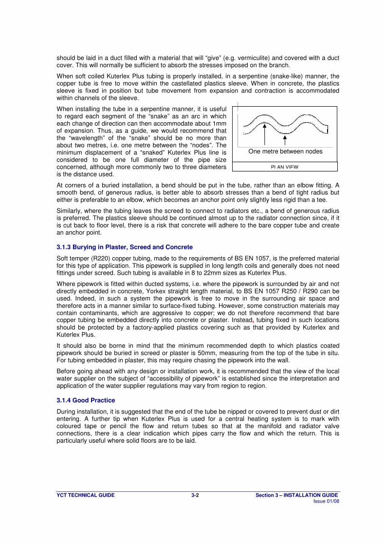
When soft coiled Kuterlex Plus tubing is properly installed, in a serpentine (snake-like) manner, the copper tube is free to move within the castellated plastics sleeve. When in concrete, the plastics sleeve is fixed in position but tube movement from expansion and contraction is accommodated within channels of the sleeve.
When installing the tube in a serpentine manner, it is useful to regard each segment of the “snake” as an arc in which each change of direction can then accommodate about 1mm of expansion. Thus, as a guide, we would recommend that the “wavelength” of the “snake” should be no more than about two metres, i.e. one metre between the “nodes”. The minimum displacement of a “snaked” Kuterlex Plus line is considered to be one full diameter of the pipe size concerned, although more commonly two to three diameters is the distance used.
At corners of a buried installation, a bend should be put in the tube, rather than an elbow fitting. A smooth bend, of generous radius, is better able to absorb stresses than a bend of tight radius but either is preferable to an elbow, which becomes an anchor point only slightly less rigid than a tee.
Similarly, where the tubing leaves the screed to connect to radiators etc., a bend of generous radius is preferred. The plastics sleeve should be continued almost up to the radiator connection since, if it is cut back to floor level, there is a risk that concrete will adhere to the bare copper tube and create an anchor point.
3.1.3 Burying in Plaster, Screed and Concrete
Soft temper (R220) copper tubing, made to the requirements of BS EN 1057, is the preferred material for this type of application. This pipework is supplied in long length coils and generally does not need fittings under screed. Such tubing is available in 8 to 22mm sizes as Kuterlex Plus.
Where pipework is fitted within ducted systems, i.e. where the pipework is surrounded by air and not directly embedded in concrete, Yorkex straight length material, to BS EN 1057 R250 / R290 can be used. Indeed, in such a system the pipework is free to move in the surrounding air space and therefore acts in a manner similar to surface-fixed tubing. However, some construction materials may contain contaminants, which are aggressive to copper; we do not therefore recommend that bare copper tubing be embedded directly into concrete or plaster. Instead, tubing fixed in such locations should be protected by a factory-applied plastics covering such as that provided by Kuterlex and Kuterlex Plus.
It should also be borne in mind that the minimum recommended depth to which plastics coated pipework should be buried in screed or plaster is 50mm, measuring from the top of the tube in situ. For tubing embedded in plaster, this may require chasing the pipework into the wall.
Before going ahead with any design or installation work, it is recommended that the view of the local water supplier on the subject of “accessibility of pipework” is established since the interpretation and application of the water supplier regulations may vary from region to region.
3.1.4 Good Practice
During installation, it is suggested that the end of the tube be nipped or covered to prevent dust or dirt entering. A further tip when Kuterlex Plus is used for a central heating system is to mark with coloured tape or pencil the flow and return tubes so that at the manifold and radiator valve connections, there is a clear indication which pipes carry the flow and which the return. This is particularly useful where solid floors are to be laid.
One metre between nodes
PLAN VIEW
YCT TECHNICAL GUIDE 3-3 Section 3 – INSTALLATION GUIDE Issue 01/08
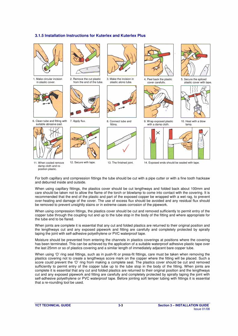
3.1.5 Installation Instructions for Kuterlex and Kuterlex Plus
For both capillary and compression fittings the tube should be cut with a pipe cutter or with a fine tooth hacksaw and deburred inside and outside.
When using capillary fittings, the plastics cover should be cut lengthways and folded back about 100mm and care should be taken not to allow the flame of the torch or blowlamp to come into contact with the covering. It is recommended that the end of the plastic and part of the exposed copper be wrapped with a wet rag, to prevent over-heating and damage of the cover. The use of excess flux should be avoided and any residual flux should be removed to prevent unsightly stains or in extreme cases corrosion of the pipework.
When using compression fittings, the plastics cover should be cut and removed sufficiently to permit entry of the copper tube through the coupling nut and up to the tube stop in the body of the fitting and where appropriate for the tube end to be flared.
When joints are complete it is essential that any cut and folded plastics are returned to their original position and the lengthways cut and any exposed pipework and fitting are carefully and completely protected by spirally taping the joint with self-adhesive polyethylene or PVC waterproof tape.
Moisture should be prevented from entering the channels in plastics coverings at positions where the covering has been terminated. This can be achieved by the application of a suitable waterproof adhesive plastic tape over the last 25mm or so of plastics covering and a similar length of immediately adjacent bare copper tube.
When using ‘O’ ring seal fittings, such as in push-fit or press-fit fittings, care must be taken when removing the plastics covering not to create a lengthways score mark on the copper where the fitting will be placed. Such a score could prevent the ‘O’ ring from making a complete seal. The plastics cover should be cut and removed sufficiently to permit entry of the copper tube up to the tube stop in the body of the fitting. When joints are complete it is essential that any cut and folded plastics are returned to their original position and the lengthways cut and any exposed pipework and fitting are carefully and completely protected by spirally taping the joint with self-adhesive polyethylene or PVC waterproof tape. Before jointing soft temper tubing with fittings it is essential that a re-rounding tool be used.
1. Make circular incision in plastic cover.
2. Remove the cut plastic from the end of the tube.
3. Make the incision in plastic along tube.
4. Peel back the plastic cover carefully.
5. Secure the spliced plastic cover with tape.
6. Clean tube and fitting with suitable abrasive pad.
7. Apply flux. 8. Connect tube and fitting.
9. Wrap exposed plastic with a damp cloth.
10. Heat with a blow lamp.
11. When cooled remove damp cloth and re-position plastic.
12. Secure with tape. 13. The finished joint. 14. Exposed ends should be sealed with tape.
YCT TECHNICAL GUIDE 3-4 Section 3 – INSTALLATION GUIDE Issue 01/08
3.2 Flushing and Avoidance of Stagnation
BS 6700(2)
, Section 3.1.10.1 states that; “every new water service, cistern, distributing pipe, hot water cylinder, or other appliance and any extension or modification to such a service shall be thoroughly flushed with drinking water before being taken into use” All water services/heating systems should be thoroughly flushed with clean water as soon as possible after completion to remove foreign matter including filings, flux residues etc. Flushing should continue until the discharge water is completely clear. It should be borne in mind that simply filling a system and then draining down does not constitute a flush and, in most cases, will serve merely to move extraneous matter from one point in the pipework installation to another. Ideally, new/modified systems should be brought into use immediately after flushing and not left charged with stagnant water. If it is not possible to bring the system into immediate use then it should be completely drained down. If this is for an extended period then disinfection may be required (see Section 3.3.) It is, in practice, notoriously difficult to effect a 100% drain down of an installation particularly where long, horizontal tube runs are involved. Instead, it is recommended, for the purpose on minimizing the risk of pipework deterioration and/or water quality problems, that the systems be left fully charged and flushed through at regular intervals. The system should be flushed, at a frequency of no less than twice per week, by opening all outlets for a period that is long enough to completely recharge the system with fresh water. This practice should continue until such time as the system is brought into regular use. Under certain circumstances, consideration should also be given to frost protection. Reference to the need to avoid stagnation in pipework is made in various publications including a HSE publication
(1) which provides information on how to prevent the development of legionella
bacteria. Certain systems will require to be disinfected, prior to bringing into use, to comply with the requirements of BS 6700
(2). For further information on disinfection, see Section 3.3 of this manual.
YCT TECHNICAL GUIDE 3-5 Section 3 – INSTALLATION GUIDE Issue 01/08
3.3 Disinfection
After flushing, disinfection may also be required. This is not a task for the inexperienced and should always be carried out by someone with the appropriate skill and training. It is important to gain an understanding of when and how disinfection should be carried out. The correct procedure is laid down in BS6700
(2) which states in section 3.1.10.2 that systems shall be disinfected in the following
situations:
“a) in new installations (except private dwellings occupied by a single family);
b) where major extensions or alterations have been carried out;
c) where underground pipework has been installed (except where localised repairs only have been carried out or junctions have been inserted);
d) where it is suspected that contamination may have occurred, e.g. fouling by sewage, drainage, animals or physical entry by site personnel for interior inspection, painting or repairs;
e) where a system has not been in regular use and not regularly flushed.”
BS6700 further indicates, in section 3.1.10.4.1, that for an effective disinfection procedure the free residual chlorine concentration shall be 50 p.p.m. (50 mg/l) for a contact period of one hour. Also, the free residual chlorine must be measured at the end of the contact period and if the value obtained is less than 30 p.p.m., the disinfection process must be repeated. This section of the standard also states that “after successful chlorination, the system shall be immediately drained and thoroughly flushed with cleaned water. Flushing shall continue until the free residual chlorine is at the level present in the drinking water supplied.”
In order to avoid problems developing, both in terms of preservation of water quality and prevention of corrosion, care needs to be exercised to ensure that the above mentioned strengths of sodium hypochlorite solutions and related dwell times are not exceeded during disinfection. It is equally important to ensure that, after disinfection, systems are thoroughly flushed with fresh water, i.e. disinfection should be carried out strictly in accordance with the requirements of BS6700.
YCT TECHNICAL GUIDE 3-6 Section 3 – INSTALLATION GUIDE Issue 01/08
3.4 Cold Bending
Half-hard copper tubing to BS EN 1057(5)
R250 in straight lengths is in an ideal condition for cold bending, using either a bending spring or a machine as appropriate. Nevertheless, to achieve consistently satisfactory bends some basic precautions must be observed:
3.4.1 Spring Bending
During internal spring bending, the use of a little lubricating oil or grease greatly assists the bending operation and prolongs the life of the spring by preventing rusting.
As with any equipment, bending springs must be kept in good condition and when worn they should be replaced. Internal bending springs are normally used for half-hard, 12, 15 and 22mm tubing, although clearly the choice of spring depends on the wall thickness of the tube being manipulated. For example, the nominal internal diameter of 15mm Yorkex tubing is 13.6mm, whereas that of 15mm Kuterlon material is only 13mm. Bends can usually be made by hand, bending gradually but firmly around the knee, to a minimum radius of around 5 times the diameter of the tubing in question.
Although some plumbers occasionally use an internal spring for larger sizes, it should be noted that this practice is not recommended or indeed allowed for in BS 5431
(4) (the British Standard for
bending springs). Hence consistently satisfactory spring bending of tubes in sizes above 22mm cannot be guaranteed.
External bending springs are also available for half-hard tube in sizes up to and including 10mm.
3.4.2 Machine Bending
Bending machines form significantly tighter bends (minimum root/inside radius approximately 3 x o.d. of tube) than are possible using a spring. This method is by far the most widely used for bending copper tubes in the U.K. Machines are supplied by various manufacturers in many forms but essentially fall into one of two categories, i.e. "non-adjustable" or "adjustable".
3.4.2.1 Non-adjustable Machine Bending
In recent years the "non-adjustable" type of bender has become increasingly popular, particularly for use with smaller size tubes (i.e. up to and including 22mm o.d.). These benders offer two main advantages over "adjustable" machines in that they are relatively cheap and usually light in weight, hence more portable.
When choosing a "non-adjustable" bender care should be taken to ensure that the machine is suitable for bending the specification of the tube being used.
As with any tooling, care should always be taken with maintenance, with particular regard to the replacement of worn guides or formers (preferably with a matched pair).
3.4.2.2 Adjustable Machine Bending
Adjustable bending machines are readily available in sizes up to and including 28mm. Occasionally, they may be employed to manipulate half-hard tubing in sizes up to and including 54mm. They have the advantage of allowing the operator to adjust the pressure applied to the tube, via the former, thereby compensating for any slight tooling wear or even marginal differences in physical and mechanical properties between different batches of tube, albeit within the confines of the specification.
The point at which bending pressure is exerted on the tube is crucial and must be maintained at a fixed distance in front of the point of support of the former. If this distance is too small, excessive “necking” (or throating) at either end of the bend will occur; too great and corrugations or “wrinkles” may result along the inside radius.
Clearly, manipulation of medical quality tubing must be undertaken using equipment applied to the outside of the tube only, since internal springs will compromise the cleanliness of the bore.
N.B. It should be noted that bending has no detrimental effect on maximum safe working pressures of half-hard tubes, since any slight reduction in wall thickness along the outer radii of bends is off-set by the increase in hardness of the tube in the manipulated region.
YCT TECHNICAL GUIDE 3-7 Section 3 – INSTALLATION GUIDE Issue 01/08
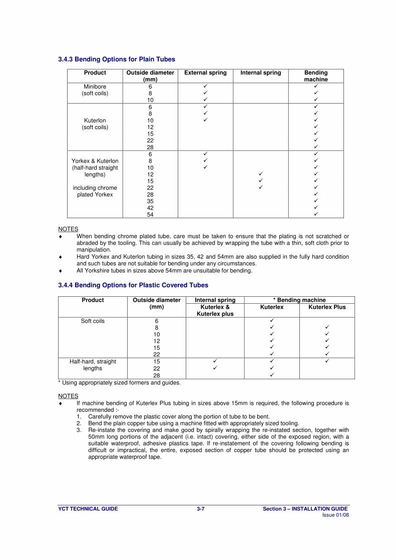
3.4.3 Bending Options for Plain Tubes
Product Outside diameter (mm)
External spring Internal spring Bending machine
6 � � 8 � �
Minibore (soft coils)
10 � �
6 � � 8 � � 10 � � 12 � 15 � 22 �
Kuterlon (soft coils)
28 �
6 � � 8 � � 10 � � 12 � � 15 � � 22 � � 28 � 35 � 42 �
Yorkex & Kuterlon (half-hard straight
lengths)
including chrome plated Yorkex
54 �
NOTES
♦ When bending chrome plated tube, care must be taken to ensure that the plating is not scratched or abraded by the tooling. This can usually be achieved by wrapping the tube with a thin, soft cloth prior to manipulation.
♦ Hard Yorkex and Kuterlon tubing in sizes 35, 42 and 54mm are also supplied in the fully hard condition and such tubes are not suitable for bending under any circumstances.
♦ All Yorkshire tubes in sizes above 54mm are unsuitable for bending.
3.4.4 Bending Options for Plastic Covered Tubes
Internal spring * Bending machine Product Outside diameter (mm) Kuterlex &
Kuterlex plus Kuterlex Kuterlex Plus
6 � 8 � �
Soft coils
10 � � 12 15
�
� �
�
22 � �
15 � � �
22 � �
Half-hard, straight lengths
28 �
* Using appropriately sized formers and guides. NOTES
♦ If machine bending of Kuterlex Plus tubing in sizes above 15mm is required, the following procedure is recommended :- 1. Carefully remove the plastic cover along the portion of tube to be bent. 2. Bend the plain copper tube using a machine fitted with appropriately sized tooling. 3. Re-instate the covering and make good by spirally wrapping the re-instated section, together with
50mm long portions of the adjacent (i.e. intact) covering, either side of the exposed region, with a suitable waterproof, adhesive plastics tape. If re-instatement of the covering following bending is difficult or impractical, the entire, exposed section of copper tube should be protected using an appropriate waterproof tape.
YCT TECHNICAL GUIDE 3-8 Section 3 – INSTALLATION GUIDE Issue 01/08
3.5 Use with Fittings
Tube joints can be made by a variety of fittings such as:
♦ integral solder ring (ISR) capillary
♦ end-feed capillary
♦ braze end-feed
♦ non- manipulative compression (Type A)
♦ manipulative compression (Type B)
♦ push fit
♦ press fit Fittings that meet the requirements of BS EN 1254: 1998
(6-11) are compatible with copper tube to BS
EN 1057: 1996 (5)
.
NOT ALL FITTINGS ARE SUITABLE FOR ALL APPLICATIONS, ADVICE SHOULD BE SOUGHT FROM THE FITTINGS MANUFACTURER
FITTINGS MUST BE USED IN ACCORDANCE WITH THE MANUFACTURERS INSTRUCTIONS
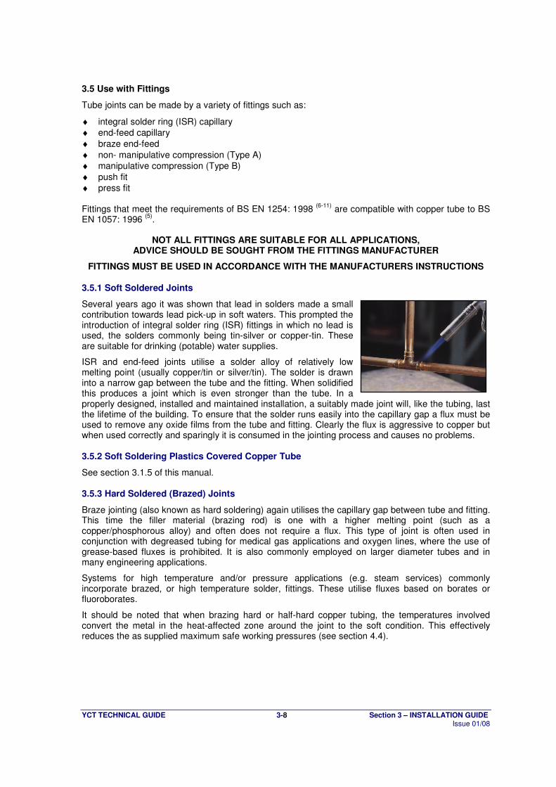
3.5.1 Soft Soldered Joints
Several years ago it was shown that lead in solders made a small contribution towards lead pick-up in soft waters. This prompted the introduction of integral solder ring (ISR) fittings in which no lead is used, the solders commonly being tin-silver or copper-tin. These are suitable for drinking (potable) water supplies.
ISR and end-feed joints utilise a solder alloy of relatively low melting point (usually copper/tin or silver/tin). The solder is drawn into a narrow gap between the tube and the fitting. When solidified this produces a joint which is even stronger than the tube. In a properly designed, installed and maintained installation, a suitably made joint will, like the tubing, last the lifetime of the building. To ensure that the solder runs easily into the capillary gap a flux must be used to remove any oxide films from the tube and fitting. Clearly the flux is aggressive to copper but when used correctly and sparingly it is consumed in the jointing process and causes no problems.
3.5.2 Soft Soldering Plastics Covered Copper Tube
See section 3.1.5 of this manual.
3.5.3 Hard Soldered (Brazed) Joints
Braze jointing (also known as hard soldering) again utilises the capillary gap between tube and fitting. This time the filler material (brazing rod) is one with a higher melting point (such as a copper/phosphorous alloy) and often does not require a flux. This type of joint is often used in conjunction with degreased tubing for medical gas applications and oxygen lines, where the use of grease-based fluxes is prohibited. It is also commonly employed on larger diameter tubes and in many engineering applications.
Systems for high temperature and/or pressure applications (e.g. steam services) commonly incorporate brazed, or high temperature solder, fittings. These utilise fluxes based on borates or fluoroborates.
It should be noted that when brazing hard or half-hard copper tubing, the temperatures involved convert the metal in the heat-affected zone around the joint to the soft condition. This effectively reduces the as supplied maximum safe working pressures (see section 4.4).
YCT TECHNICAL GUIDE 3-9 Section 3 – INSTALLATION GUIDE Issue 01/08
3.5.4 Compression Joints
These joints use the tightening action of nuts on threads in the fittings to produce a watertight joint on the tube, either by tightening up on an olive (non-manipulative or “Type A” fittings) or by tightening up on a pre-shaped end of the tube (manipulative or “Type B” fittings).
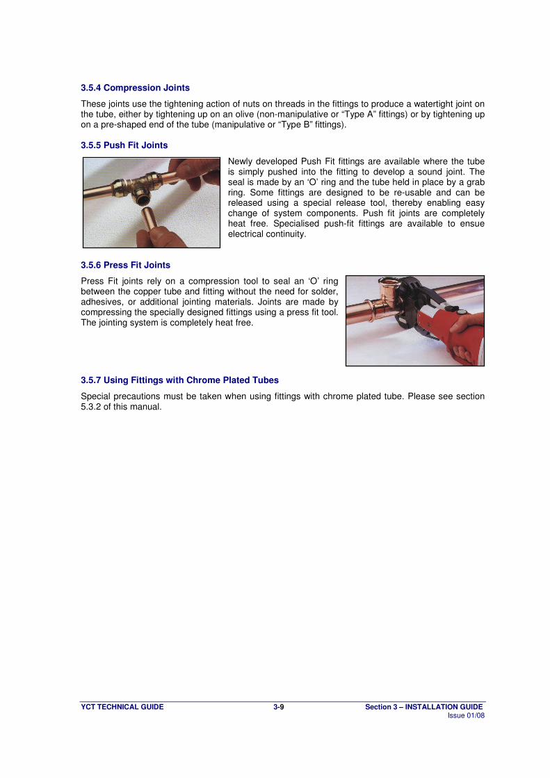
3.5.5 Push Fit Joints
Newly developed Push Fit fittings are available where the tube is simply pushed into the fitting to develop a sound joint. The seal is made by an ‘O’ ring and the tube held in place by a grab ring. Some fittings are designed to be re-usable and can be released using a special release tool, thereby enabling easy change of system components. Push fit joints are completely heat free. Specialised push-fit fittings are available to ensue electrical continuity.
3.5.6 Press Fit Joints
Press Fit joints rely on a compression tool to seal an ‘O’ ring between the copper tube and fitting without the need for solder, adhesives, or additional jointing materials. Joints are made by compressing the specially designed fittings using a press fit tool. The jointing system is completely heat free.
3.5.7 Using Fittings with Chrome Plated Tubes
Special precautions must be taken when using fittings with chrome plated tube. Please see section 5.3.2 of this manual.

YCT TECHNICAL GUIDE 3-10 Section 3 – INSTALLATION GUIDE Issue 01/08
3.6 Use of Fluxes
Capillary joints have become a traditional and reliable part of installation practice to such an extent that normally they are expected to last the entire lifetime of the systems on which they are installed.
In order to achieve such longevity, skilled installers have learnt that certain basic precautions need to be taken during assembly operations, including careful and sparing use of flux. Indeed when making capillary joints, care should be taken to prevent excess quantities of flux from running into the tube since fluxes are, of necessity, aggressive to the metals for which they are used, their purpose being to chemically clean the mating surfaces in order to effect sound bonding. Any small excess is normally destroyed by heat during the soldering operation or swept away by the initial ingress of water. However, excessive amounts may cause continued corrosion until the active ingredients are used up or until perforation of the tube occurs.
Whilst fluxes are to some extent soluble in water, the solubility factor is dependent upon the amount of flux present. Thus, if a relatively small amount of flux remains following installation, the flux will be dissolved fairly quickly. However, if excessive amounts remain it may take months for the flux to dissolve. Indeed in some cases the flux may form a hard, water repellent skin or become coated with deposits which protect it from dissolution. It should also be borne in mind that problems due to the inappropriate use of flux can occur on both hot or cold water systems, though they generally tend to happen less frequently on hot circuits where elevated temperatures increase their solubility.
The use of excessive flux is warned against in British Standards such as BS6700(2)
and BS5449(3)
which states in section 30.3 that "some fluxes are more aggressive than others but all fluxes should be considered to be corrosive to some extent. Any excess flux should be wiped off the assembly before applying heat to melt the solder and any residue removed immediately the joint has cooled. The system should be cleared of any internal residues."
Thus all fluxes should be used sparingly and strictly in accordance with manufacturers instructions.
YCT TECHNICAL GUIDE 3-11 Section 3 – INSTALLATION GUIDE Issue 01/08
3.7 Burying Tubes in Contaminated Ground
When copper pipework is to be laid directly in contaminated ground, it should be borne in mind that such environments can contain various substances, which are potentially aggressive to copper. Such substances include sulphides, ammonia or ammoniacal derivatives, mercury or mercurous compounds, nitrates, sulphates, chlorides, particles of carbonaceous matter, acidic compounds, decomposing vegetation etc. BS 6700
(2) states, in Section 2.6.2.2., that; “No pipe that is permeable to any contaminant shall be
laid or installed in any position where permeation is likely to occur.”. “Kuterlon” tubing to BS EN1057
(5) in R250 or R290 (straight lengths) or R220 (coiled) format, is
recommended when pipework is to be laid directly in the ground, since it has a greater wall thickness than “Yorkex” tubing of a similar diameter. It is therefore more able to withstand external loads, vibrations, traffic movement etc. In consideration of the above, we would recommend the use of our “Kuterlex” plastics covered copper tube, to the dimensional specification of our ”Kuterlon” range, for use in situations where the surrounding environment may be contaminated or potentially aggressive to the bare metal. The copper element of the product is eminently suitable for below ground applications and provides a barrier to any permeation of contaminants whilst the plastics coating protects the tube from material that is aggressive to the copper. Any joints along such tube runs should also be protected by spirally wrapping with a suitable waterproof, adhesive plastics tape in such a manner that moisture cannot gain ingress between the laps in the tape. Taping should cover any bare sections of copper pipework together with a 50mm (approx) long portion of the adjacent plastic covering either side of the exposed section.

YCT TECHNICAL GUIDE 3-12 Section 3 – INSTALLATION GUIDE Issue 01/08
3.8 Lagging of Pipework
A number of different insulation materials exist which are eminently suitable for use in conjunction
with copper tube. Each material possesses a thermal conductivity (λ) value which determines how well this particular material will perform in terms of reducing heat losses. The lower the value the better the insulator. Below are some common types of lagging together with their respective thermal conductivities:
MATERIAL λ λ λ λ (W/mK)
Nitrile/Elastomeric Rubber 0.035
Polyethylene Foam 0.034/0.035
Mineral Wool 0.032
Polyurethane (PUR) 0.025
Polyisocyanurate (PIR) 0.023
Phenolic Foam 0.018
Choosing which particular type of lagging to use and how thick that lagging has to be depends on how much thermal insulation is required. BS5422:2001
(13) gives reference to the thicknesses required
for materials with different thermal conductivities in order to achieve particular heat losses on both hot water and central heating systems (see table below) : Environmental insulation thickness for domestic central heating installations and hot water systems in potentially unheated areas to control heat loss
Insulation Thickness (mm) Heat Loss (W/m) OD of Cu
Tube (mm)
λλλλ=0.025 λλλλ=0.030 λλλλ=0.035 λλλλ=0.040 λλλλ=0.045
Hot Water (60ºC)
Central Heating (75ºC)
10 10 16 22 31 44 6.8 8.6
12 12 18 26 36 49 7.3 9.2
15 15 22 31 42 58 7.8 9.7
22 19 26 35 47 62 8.2 10.2
28 21 28 38 49 64 9.0 11.3
35 22 30 39 51 64 10.0 12.6
42 23 31 41 52 65 11.0 13.8
54 25 33 42 53 65 12.8 16.0
From Table 14 of BS 5422:2001
For example, a nitrile rubber lagging with a wall thickness of 31mm, when used in conjunction with a 15mm OD copper tube, will give a heat loss of 7.8W/m on a hot water system and 9.7W/m on a central heating system. When using rigid phenolic foam insulation materials it is recommend that a moisture barrier be installed at the tube / lagging interface. Moisture between the tube and lagging may lead to external corrosion of the copper tube. When using rigid phenolic foam insulation reference should always be made to the manufacturer’s installation instructions.

YCT TECHNICAL GUIDE 3-13 Section 3 – INSTALLATION GUIDE Issue 01/08
3.9 Medical Gas Tube
YCT supplies specially cleaned tubes meeting the requirements of HTM 02-01 (20)
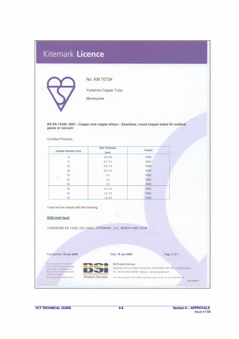
for medical pipeline systems (see section 5.4 of this guide). These tubes are supplied with ends individually plugged to prevent the ingress of grease or dirt. Plugs should be retained in the tubes during storage. It is also important that the ends of these tubes are kept closed and ends re-sealed if part lengths are used. Tubes should always be cut with a pipe-cutter (not a hacksaw) to prevent ingress of any particulate matter (e.g. copper swarf). Additionally tubes in the 12-54mm diameter range are manufactured in full accordance with BS EN 13448
(21). Tubes in this size range are also 'Kitemarked' as independent confirmation by BSI that
tubes conform to the specification. BS EN 13448 only specifies tubes in the 12-54mm diameter range, so Medical Gas Tube outside this range is manufactured and 'Kitemarked' to BS EN 1057
(5) and cleaned to the requirements of BS EN
13348. Jointing and installation practices for this type of tube differ from standard plumbing tubes and are defined in HTM 02-01. These practices should be followed for all medical installations to prevent contamination of the gas line and on oxygen lines to prevent the risk of explosion.

YCT TECHNICAL GUIDE 3-14 Section 3 – INSTALLATION GUIDE Issue 01/08
This page has been intentionally left blank
YCT TECHNICAL GUIDE 4-1 Section 4 – TECHNICAL DATA Issue 01/08
Section 4 – Technical Data
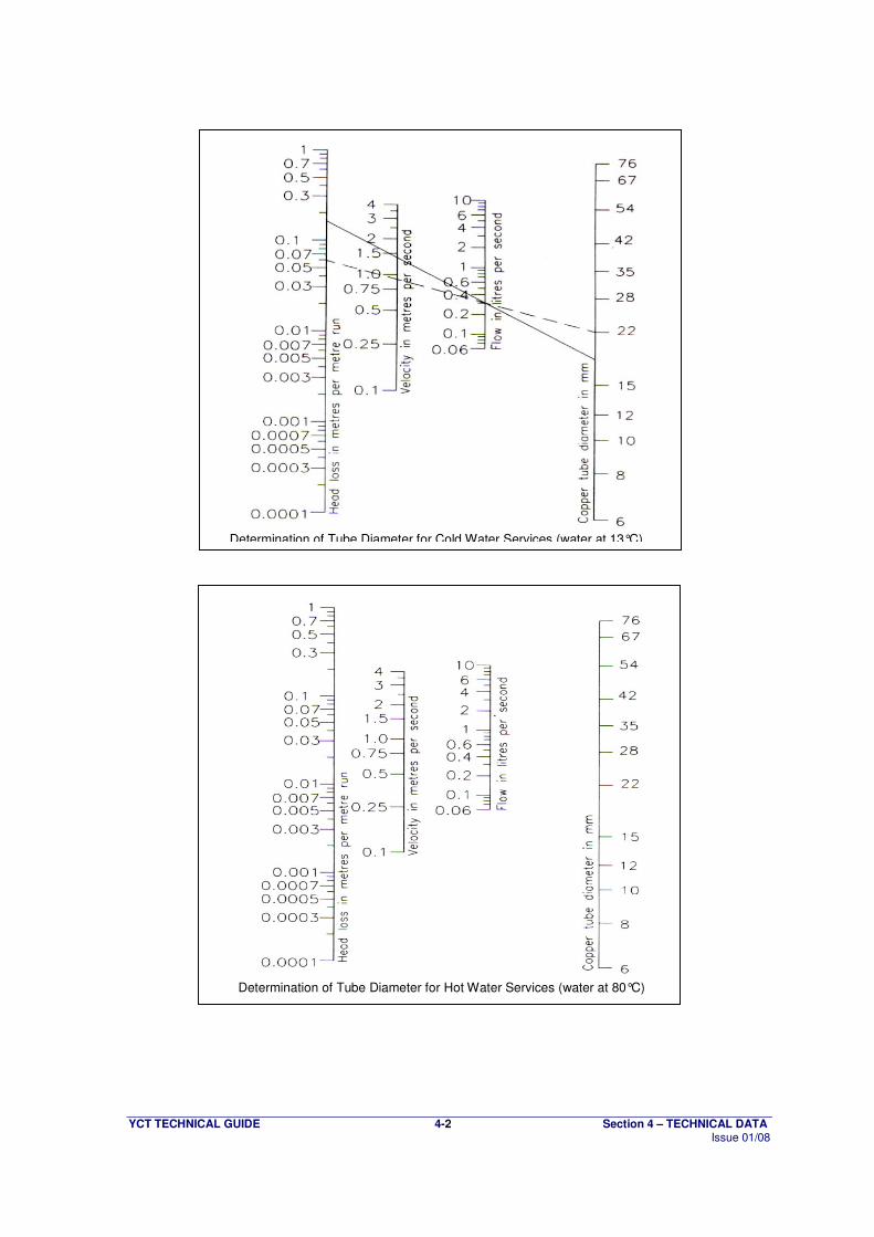
4.1 Pipe Sizing, Flow Rates and Pressure Drops
Nomograms for determining pipe size from flow rate, velocity and pressure loss are shown on the next page.
Water velocities in a system should be between 0.5 m/s, below which any suspended matter may settle out, and 2 m/s above which erosion corrosion damage may occur. If the tube size originally chosen gives rise to velocities outside these parameters, a smaller or larger tube size respectively should be adopted.
The resistance to flow of fittings and taps should also be taken into account. The simplest way to do this is to regard each fitting as an equivalent length of the appropriate size of tubing as indicated in the tables below.
For further detailed information regarding equivalent lengths refer to CDA Publication 33(12)
.
Equivalent copper tube lengths for fittings / valves
Nominal equivalent tube length (m) Tube Diameter (mm) Elbow Tee Stopvalve Checkvalve
15 0.5 0.6 4.0 2.5 22 0.8 1.0 7.0 4.3 28 1.0 1.5 10.0 5.6 35 1.4 2.0 13.0 6.0 42 1.7 2.5 16.0 7.9 54 2.3 3.5 22.0 11.5
66.7 3.0 4.5 - - 76.1 3.4 5.8 34.0 -
Note: Losses through tees can be taken to occur on a change of direction only.
Losses through fully open gatevalves can be ignored. Where systems have special fittings with significant head losses, reference should be made to the manufacturer.
Typical Loss of Head Through Taps (and equivalent tube lengths)
Tap Flow rate (l/s)
Loss of head (m)
Equivalent tube length (m)
Nominal 1/2” 0.20 0.8 3.7 Nominal 3/4” 0.30 0.8 11.8 Nominal 1” 0.60 1.5 22.0
Note: Losses for stated flow rates are typical only and may vary with taps of
different manufacturers. Example Calculation
For a run of 10m of 15mm tubing with 4 capillary elbows, in a cold water service feeding a 3/4” bath tap, with an available head of 4m requiring a flow rate of 0.3 l/s the calculation is as follows:
Equivalent tube length 10 + (4 x 0.5) + 11.8 m = 23.8m (say 24m)
Permissible head loss = available head/equivalent tube length = 4 / 24 = 0.15 m/m.
By reference to the appropriate nomogram (see page 4-2 or BS6700(2)
), draw a line from 0.15 m/m head loss extending through 0.3 l/s flow rate, as indicated by the solid line on the cold water service nomogram. The intercept on the right hand copper tube diameter axis indicates that 22mm tube (the next size up) would be satisfactory. The broken line drawn from the chosen 22mm diameter through the required 0.3 l/s flow rate shows the actual head loss consumed when using this size of tube.
YCT TECHNICAL GUIDE 4-2 Section 4 – TECHNICAL DATA Issue 01/08
Determination of Tube Diameter for Cold Water Services (water at 13°C)
Determination of Tube Diameter for Hot Water Services (water at 80°C)
YCT TECHNICAL GUIDE 4-3 Section 4 – TECHNICAL DATA Issue 01/08
4.2 Tube Support Distances
To hold tubes securely and to prevent sagging and distortion, tubes should be supported at the following maximum distances.
Tube Diameter
(mm)
Intervals for Vertical Run
(m)
Intervals for Horizontal Run
(m)
6 0.6 0.4 8 0.9 0.6 10 1.2 0.8 12 1.5 1.0 15 1.8 1.2
22 2.4 1.8 28 2.4 1.8 35 3.0 2.4 42 3.0 2.4 54 3.0 2.7
66.7 3.6 3.0 76.1 3.6 3.0 108 3.6 3.0 133 3.6 3.0 159 4.2 3.6
YCT TECHNICAL GUIDE 4-4 Section 4 – TECHNICAL DATA Issue 01/08
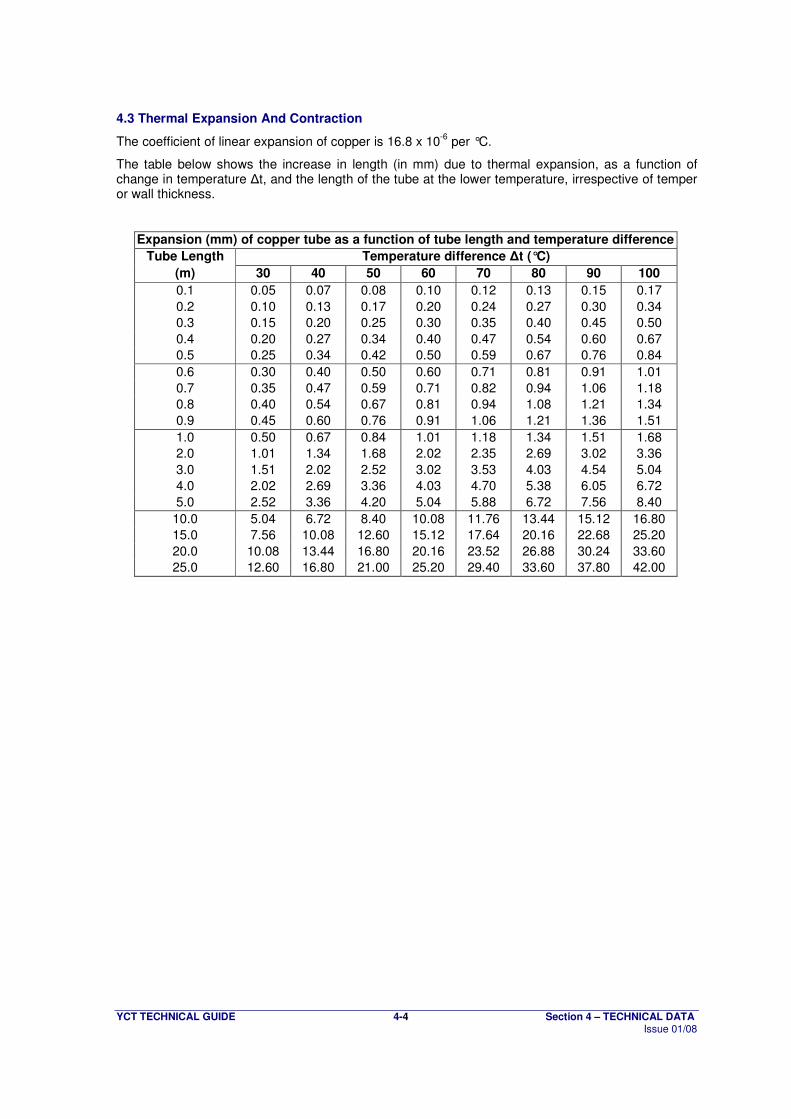
4.3 Thermal Expansion And Contraction
The coefficient of linear expansion of copper is 16.8 x 10⁻⁶
per °C.
The table below shows the increase in length (in mm) due to thermal expansion, as a function of change in temperature ∆t, and the length of the tube at the lower temperature, irrespective of temper or wall thickness.
Expansion (mm) of copper tube as a function of tube length and temperature difference
Tube Length Temperature difference ∆t (°C)
(m) 30 40 50 60 70 80 90 100
0.1 0.05 0.07 0.08 0.10 0.12 0.13 0.15 0.17
0.2 0.10 0.13 0.17 0.20 0.24 0.27 0.30 0.34
0.3 0.15 0.20 0.25 0.30 0.35 0.40 0.45 0.50
0.4 0.20 0.27 0.34 0.40 0.47 0.54 0.60 0.67
0.5 0.25 0.34 0.42 0.50 0.59 0.67 0.76 0.84
0.6 0.30 0.40 0.50 0.60 0.71 0.81 0.91 1.01
0.7 0.35 0.47 0.59 0.71 0.82 0.94 1.06 1.18
0.8 0.40 0.54 0.67 0.81 0.94 1.08 1.21 1.34
0.9 0.45 0.60 0.76 0.91 1.06 1.21 1.36 1.51
1.0 0.50 0.67 0.84 1.01 1.18 1.34 1.51 1.68
2.0 1.01 1.34 1.68 2.02 2.35 2.69 3.02 3.36
3.0 1.51 2.02 2.52 3.02 3.53 4.03 4.54 5.04
4.0 2.02 2.69 3.36 4.03 4.70 5.38 6.05 6.72
5.0 2.52 3.36 4.20 5.04 5.88 6.72 7.56 8.40
10.0 5.04 6.72 8.40 10.08 11.76 13.44 15.12 16.80
15.0 7.56 10.08 12.60 15.12 17.64 20.16 22.68 25.20
20.0 10.08 13.44 16.80 20.16 23.52 26.88 30.24 33.60
25.0 12.60 16.80 21.00 25.20 29.40 33.60 37.80 42.00
YCT TECHNICAL GUIDE 4-5 Section 4 – TECHNICAL DATA Issue 01/08
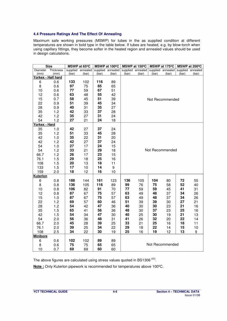
4.4 Pressure Ratings And The Effect Of Annealing
Maximum safe working pressures (MSWP) for tubes in the as supplied condition at different temperatures are shown in bold type in the table below. If tubes are heated, e.g. by blow-torch when using capillary fittings, they become softer in the heated region and annealed values should be used in design calculations.
Size MSWP at 65ºC MSWP at 100ºC MSWP at 150ºC MSWP at 175ºC MSWP at 200ºC Diameter Thickness supplied annealed supplied annealed supplied annealed supplied annealed supplied annealed
(mm) (mm) (bar) (bar) (bar) (bar) (bar) (bar) (bar) (bar) (bar) (bar)
Yorkex - Half hard 6 0.6 133 102 116 89 8 0.6 97 75 85 65
10 0.6 77 59 67 51 12 0.6 63 48 55 42 15 0.7 58 45 51 39 22 0.9 51 39 45 34 28 0.9 40 31 35 27 35 1.2 42 33 37 28 42 1.2 35 27 31 24 54 1.2 27 21 24 18
Yorkex - Hard 35 1.0 42 27 37 24 35 1.2 51 33 45 28 42 1.0 35 22 31 20 42 1.2 42 27 37 24 54 1.0 27 17 24 15 54 1.2 33 21 29 18
66.7 1.2 26 17 23 15 76.1 1.5 29 18 25 16 108 1.5 20 13 18 11 133 1.5 17 10 14 9 159 2.0 18 12 16 10
Kuterlon 6 0.8 188 144 161 123 136 105 104 80 72 55 8 0.8 136 105 116 89 99 76 75 58 52 40
10 0.8 106 82 91 70 77 59 59 45 41 31 12 0.8 87 67 75 57 63 49 48 37 34 26 15 1.0 87 67 75 57 63 49 48 37 34 26 22 1.2 69 57 60 46 51 39 39 30 27 21 28 1.2 54 42 47 36 40 30 30 23 21 16 35 1.5 65 41 56 36 48 30 37 23 25 16 42 1.5 54 34 47 30 40 25 30 19 21 13 54 2.0 56 36 48 31 41 26 32 20 22 14
66.7 2.0 45 28 39 25 33 21 25 16 18 11 76.1 2.0 39 25 34 22 29 18 22 14 15 10 108 2.5 34 22 30 19 25 16 19 12 13 9
Minibore 6 0.6 102 102 89 89 8 0.6 75 75 65 65
10 0.7 69 69 60 60
The above figures are calculated using stress values quoted in BS1306 (22)
.
Note : Only Kuterlon pipework is recommended for temperatures above 100ºC.
Not Recommended
Not Recommended
Not Recommended
YCT TECHNICAL GUIDE 4-6 Section 4 – TECHNICAL DATA Issue 01/08
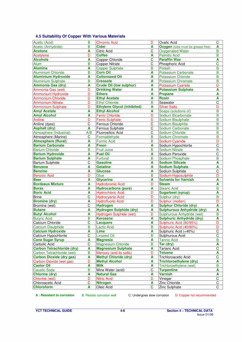
4.5 Suitability Of Copper With Various Materials
Acetic (Acid) B Chromic Acid D Oxalic Acid C
Acetic (Anhydride) B Cider A Oxygen (tube must be grease free) A
Acetone A Citric Acid C Oxygenated Water B Acetylene D Coffee A Palmitic Acid B Alcohols A Copper Chloride C Paraffin Wax A
Alum B Copper Nitrate C Phosphoric Acid C Alumina A Copper Sulphate B Potash B
Aluminium Chloride B Corn Oil A Potassium Carbonate B Aluminium Hydroxide A Cottonseed Oil A Potassium Chloride B
Aluminium Sulphate B Creosote A Potassium Chromate B Ammonia Gas (dry) A Crude Oil (low sulphur) A Potassium Cyanide D
Ammonia Gas (wet) D Drinking Water A Potassium Sulphate A
Ammonium Hydroxide D Ethers A Propane A
Ammonium Chloride D Ethyl Acetate A Rosin A
Ammonium Nitrate D Ethyl Chloride B Seawater C Ammonium Sulphate D Ethylene Glycol (inhibited) A Silver Salts D Amyl Acetate A Ethyl Alcohol A Soaps (solutions of) B Amyl Alcohol A Ferric Chloride D Sodium Bicarbonate B
Aniline D Ferric Sulphate D Sodium Bisulphate B
Aniline (dyes) C Ferrous Chloride C Sodium Bisulphite B Asphalt (dry) A Ferrous Sulphate C Sodium Carbonate B
Atmosphere (Industrial) A/B Fluorosilicic Acid C Sodium Chloride B
Atmosphere (Marine) C Formaldehyde B Sodium Chromate B Atmosphere (Rural) A Formic Acid B Sodium Cyanide D Barium Carbonate A Freon A Sodium Hypochlorite C Barium Chloride B Fruit Juice B Sodium Nitrate B Barium Hydroxide A Fuel Oil A Sodium Peroxide C Barium Sulphate A Furfural B Sodium Phosphate B
Barium Sulphide C Gasoline A Sodium Silicate A
Benzene A Gelatine A Sodium Sulphate A Benzine A Glucose A Sodium Sulphide C
Benzoic Acid D Glue B Sodium Hyposulphite D Beer A Glycerine A Solvents for Varnish A
Bordeaux Mixture A Hydrobromic Acid D Steam A
Borax A Hydrocarbons (pure) A Stearic Acid B Boric Acid A Hydrochloric Acid D Sugarbeet (syrup) A
Brine C Hydrocyanic Acid D Sulphur (dry) B Bromine (dry) A Hydrofluoric Acid D Sulphur (molten) D
Bromine (wet) C Hydrogen A Sulphur Chloride (dry) A
Butane A Hydrogen Sulphide (dry) A Sulphurous Anhydride (dry) A
Butyl Alcohol A Hydrogen Sulphide (wet) D Sulphurous Anhydride (wet) B
Butyric Acid B Kerosene A Sulphuric Anhydride (dry) A
Calcium Chloride C Lacquers A Sulphuric Acid (80/95%) D
Calcium Disulphide B Lactic Acid B Sulphuric Acid (40/80%) D Calcium Hydroxide A Lime A Sulphuric Acid (<40%) C
Calcium Hypochlorite C Linseed Oil B Sulphurous Acid C Cane Sugar Syrup A Magnesia A Tannic Acid B Carbolic Acid C Magnesium Chloride B Tar (dry) A
Carbon Tetrachloride (dry) A Magnesium Sulphate A Tartaric Acid C Carbon Tetrachloride (wet) B Mercury (and its salts) D Toluene A
Carbon Dioxide (dry gas) A Methyl Chloride (dry) A Trichloroacetic Acid C
Carbon Dioxide (wet gas) D Methyl Alcohol A Trichloroethylene (dry) A Castor Oil A Milk A Trichloroethylene (wet) B
Caustic Soda B Mine Water (acid) C Turpentine A Chlorine (dry) A Natural Gas A Varnish A
Chlorine (wet) D Nitric Acid D Vinegar C
Chloroacetic Acid C Nitrogen A Zinc Chloride C Chloroform A Oleic Acid C Zinc Sulphate C
A : Resistant to corrosion B: Resists corrosion well C: Undergoes slow corrosion D: Copper not recommended
YCT TECHNICAL GUIDE 5-1 Section 5 – PRODUCT SPECIFICATIONS Issue 01/08
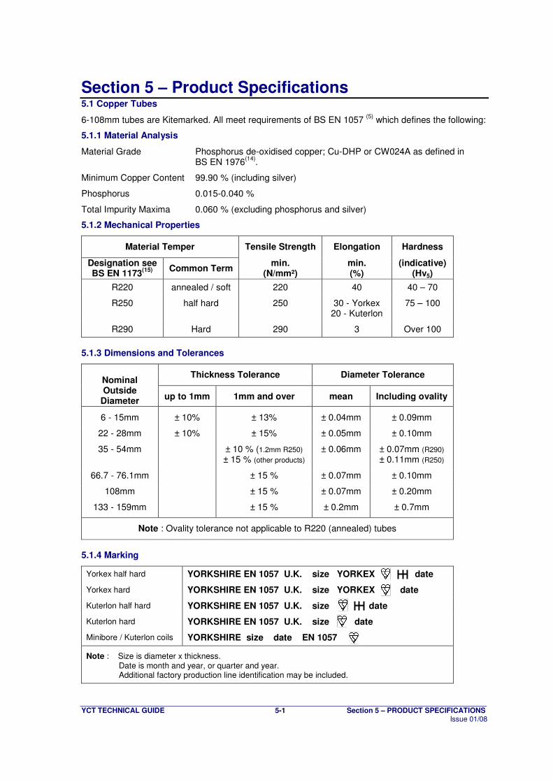
Section 5 – Product Specifications 5.1 Copper Tubes
6-108mm tubes are Kitemarked. All meet requirements of BS EN 1057 (5)
which defines the following:
5.1.1 Material Analysis
Material Grade Phosphorus de-oxidised copper; Cu-DHP or CW024A as defined in BS EN 1976
(14).
Minimum Copper Content 99.90 % (including silver)
Phosphorus 0.015-0.040 %
Total Impurity Maxima 0.060 % (excluding phosphorus and silver)
5.1.2 Mechanical Properties
Material Temper Tensile Strength Elongation Hardness
Designation see BS EN 1173
(15) Common Term min.
(N/mm²) min. (%)
(indicative) (Hv5)
R220 annealed / soft 220 40 40 – 70
R250 half hard 250 30 - Yorkex 20 - Kuterlon
75 – 100
R290 Hard 290 3 Over 100
5.1.3 Dimensions and Tolerances
Thickness Tolerance Diameter Tolerance Nominal Outside
Diameter up to 1mm 1mm and over mean Including ovality
6 - 15mm ± 10% ± 13% ± 0.04mm ± 0.09mm
22 - 28mm ± 10% ± 15% ± 0.05mm ± 0.10mm
35 - 54mm ± 10 % (1.2mm R250)
± 15 % (other products) ± 0.06mm ± 0.07mm (R290)
± 0.11mm (R250)
66.7 - 76.1mm ± 15 % ± 0.07mm ± 0.10mm
108mm ± 15 % ± 0.07mm ± 0.20mm
133 - 159mm ± 15 % ± 0.2mm ± 0.7mm
Note : Ovality tolerance not applicable to R220 (annealed) tubes
5.1.4 Marking
Yorkex half hard YORKSHIRE EN 1057 U.K. size YORKEX date
Yorkex hard YORKSHIRE EN 1057 U.K. size YORKEX date
Kuterlon half hard YORKSHIRE EN 1057 U.K. size date
Kuterlon hard YORKSHIRE EN 1057 U.K. size date
Minibore / Kuterlon coils YORKSHIRE size date EN 1057
Note : Size is diameter x thickness. Date is month and year, or quarter and year. Additional factory production line identification may be included.
YCT TECHNICAL GUIDE 5-2 Section 5 – PRODUCT SPECIFICATIONS Issue 01/08
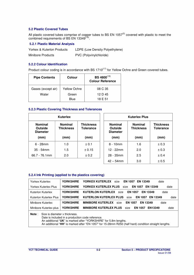
5.2 Plastic Covered Tubes
All plastic covered tubes comprise of copper tubes to BS EN 1057(5)
covered with plastic to meet the combined requirements of BS EN 13349
(16).
5.2.1 Plastic Material Analysis
Yorkex & Kuterlon Products LDPE (Low Density Polyethylene)
Minibore Products PVC (Polyvinylchloride)
5.2.2 Colour Identification
Product colour coding is in accordance with BS 1710(17)
for Yellow Ochre and Green covered tubes.
Pipe Contents Colour BS 4800(18)
Colour Reference
Gases (except air) Yellow Ochre 08 C 35
Water Green 12 D 45
Blue 18 E 51
5.2.3 Plastic Covering Thickness and Tolerances
Kuterlex Kuterlex Plus
Nominal Outside
Diameter
Nominal Thickness
Thickness Tolerance
Nominal Outside
Diameter
Nominal Thickness
Thickness Tolerance
(mm) (mm) (mm) (mm) (mm) (mm)
6 - 28mm 1.0 ± 0.1 8 - 10mm 1.6 ± 0.3
35 - 54mm 1.5 ± 0.15 12 - 22mm 2.0 ± 0.3
66.7 - 76.1mm 2.0 ± 0.2 28 - 35mm 2.5 ± 0.4
42 – 54mm 3.0 ± 0.5
5.2.4 Ink Printing (applied to the plastics covering)
Yorkex Kuterlex YORKSHIRE YORKEX KUTERLEX size EN 1057 EN 13349 date
Yorkex Kuterlex Plus YORKSHIRE YORKEX KUTERLEX PLUS size EN 1057 EN 13349 date
Kuterlon Kuterlex YORKSHIRE KUTERLON KUTERLEX size EN 1057 EN 13349 date
Kuterlon Kuterlex Plus YORKSHIRE KUTERLON KUTERLEX PLUS size EN 1057 EN 13349 date
Minibore Kuterlex YORKSHIRE MINIBORE KUTERLEX size EN 1057 EN 13349 date
Minibore Kuterlex plus YORKSHIRE MINIBORE KUTERLEX PLUS size EN 1057 EN13349 date
Note : Size is diameter x thickness. Date is included in a production code reference. An additional “UK” is marked after “YORKSHIRE” for 5.8m lengths. An additional “HH” is marked after “EN 1057” for 15-28mm R250 (half hard) condition straight lengths.
YCT TECHNICAL GUIDE 5-3 Section 5 – PRODUCT SPECIFICATIONS Issue 01/08
5.3 Chrome Plated Tubes
Yorkex Chrome Plated tubes are half hard copper tubes, to BS EN 1057(5)
- R250, chrome plated in accordance with BS EN 12540
(19), generally to Service Condition 2.
Chromium cannot be directly electrodeposited onto copper with satisfactory adhesion, therefore a layer of nickel is deposited before the finishing layer of chromium is applied.
Nominal thickness’ of the respective layers are as follows:
Nickel : 10 µm
Chromium : 0.3 µm
5.3.1 Bending Chrome Plated Tubes
Chrome plated tubes are suitable for cold bending in the ‘as supplied’ condition using appropriately sized bending machines or springs. When using a bending machine, care should be taken not to damage the chromium plated surface by ensuring that the equipment used is in good condition and a lubricant is used to ease forming.
5.3.2 Jointing Chrome Plated Tubes
5.3.2.1 Capillary Jointing
It is essential to remove the chrome plating in order to solder capillary fittings. This is best done by using a fine-toothed flat file, carefully removing the chrome until bare copper is visible all the way round the tube for the full insertion depth of the fitting. Care must be taken not to remove too much metal; otherwise the capillary gap may become too big for a leak tight joint to be made. Once the plating has been removed, the remainder of the jointing process is the same as normal, except that a damp rag should be wrapped around the tubes close to the fitting to prevent damage from the blowtorch flame.
5.3.2.2 Compression Jointing
When making compression joints with chrome plated tubes, the harder nature of the chrome plating makes it necessary to increase the pressure used to ensure a sound joint.
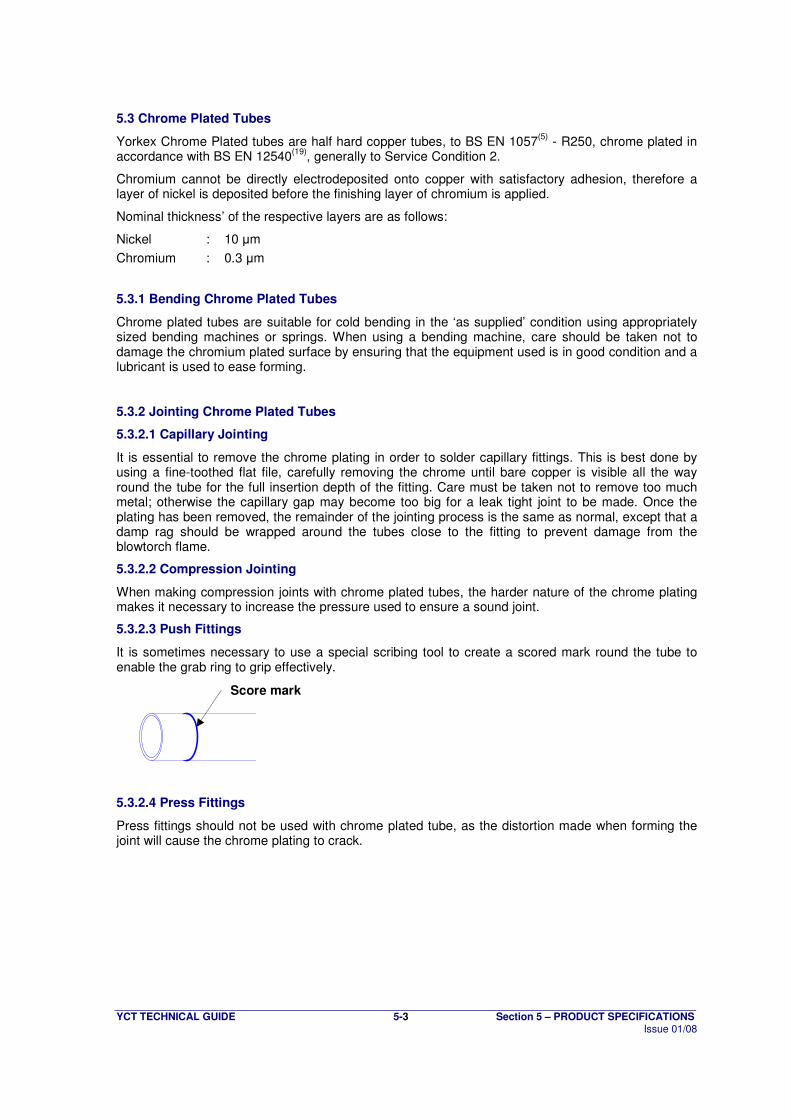
5.3.2.3 Push Fittings
It is sometimes necessary to use a special scribing tool to create a scored mark round the tube to enable the grab ring to grip effectively.
5.3.2.4 Press Fittings
Press fittings should not be used with chrome plated tube, as the distortion made when forming the joint will cause the chrome plating to crack.
Score mark

YCT TECHNICAL GUIDE 5-4 Section 5 – PRODUCT SPECIFICATIONS Issue 01/08
5.4 Medical Gas Tubes
Yorkshire Medical Gas tubes, available in both the Yorkex and Kuterlon ranges, are specially cleaned tubes suitable for use with Medical Gases. Tubes are supplied with ends individually plugged to prevent bore contamination.
The special cleaning is important to eliminate explosion risk in oxygen pipelines and contamination of respirable gases.
Tubes are cleaned to meet the cleanliness requirements for pipeline materials as specified in HTM 02-01
(20) and BS EN 13348
(21).
Tubes in the 12-54mm diameter range are manufactured in full accordance with BS EN 13348(21)
. Engravings on these sizes are as follows
Yorkex Medical half hard YORKSHIRE EN 13348 U.K. size DEG date
Yorkex Medical hard YORKSHIRE EN 13348 U.K. size DEG date
Kuterlon Medical half hard YORKSHIRE EN 13348 U.K. size DEG date
Kuterlon Medical hard YORKSHIRE EN 13348 U.K. size DEG date
Note : Size is diameter x thickness. Date is month and year, or quarter and year. Additional factory production line identification may be included.
Engravings may also include the brand name 'Yorkex Medical' or 'Kuterlon Medical'
Other sizes are marked with an additional “DEG” on standard engravings (see section 5.1.4), to denote compliance.
YCT TECHNICAL GUIDE 6-1 Section 6 – APPROVALS Issue 01/08
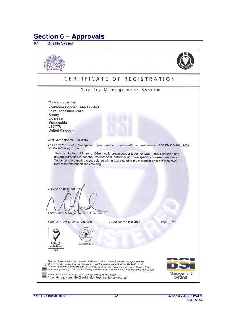
Section 6 – Approvals 6.1 Quality System
YCT TECHNICAL GUIDE 6-2 Section 6 – APPROVALS Issue 01/08
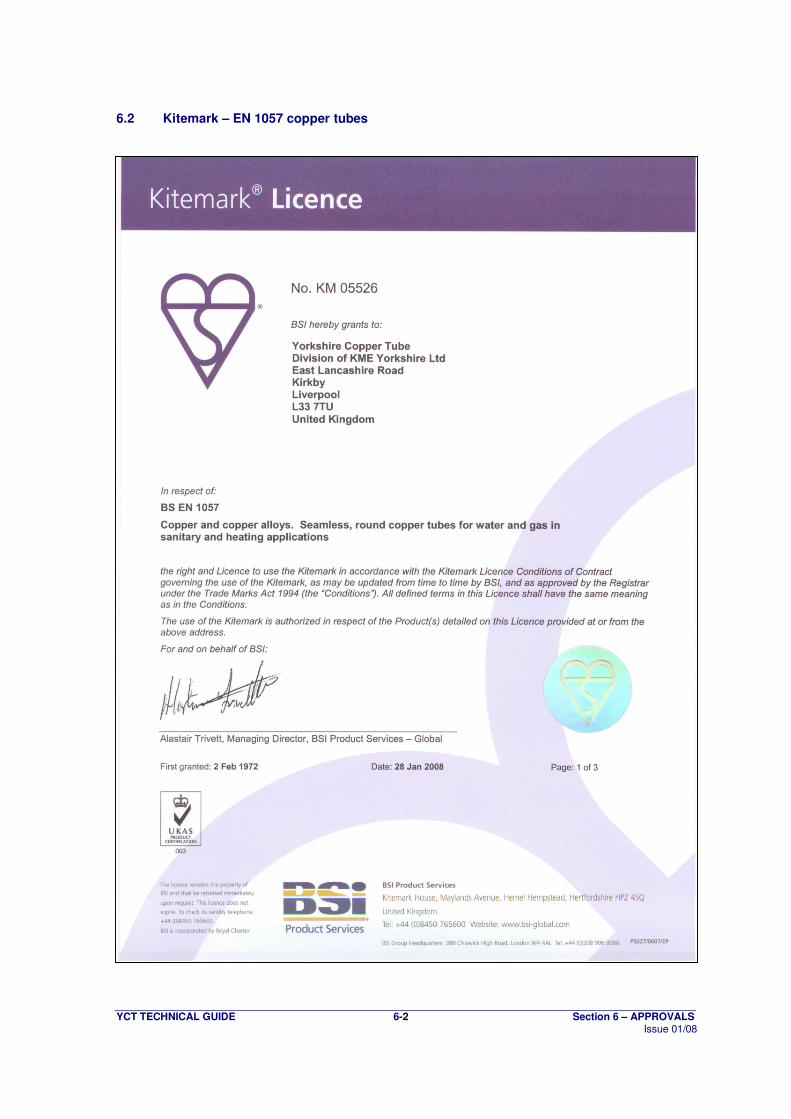
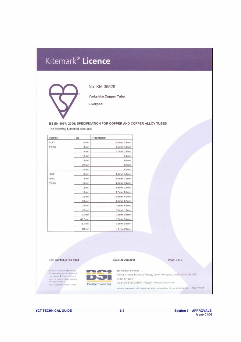
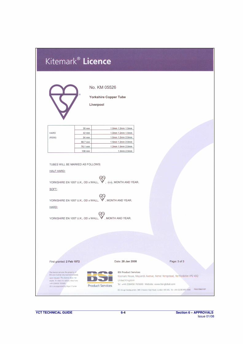
6.2 Kitemark – EN 1057 copper tubes
YCT TECHNICAL GUIDE 6-3 Section 6 – APPROVALS Issue 01/08
YCT TECHNICAL GUIDE 6-4 Section 6 – APPROVALS Issue 01/08
YCT TECHNICAL GUIDE 6-5 Section 6 – APPROVALS Issue 01/08
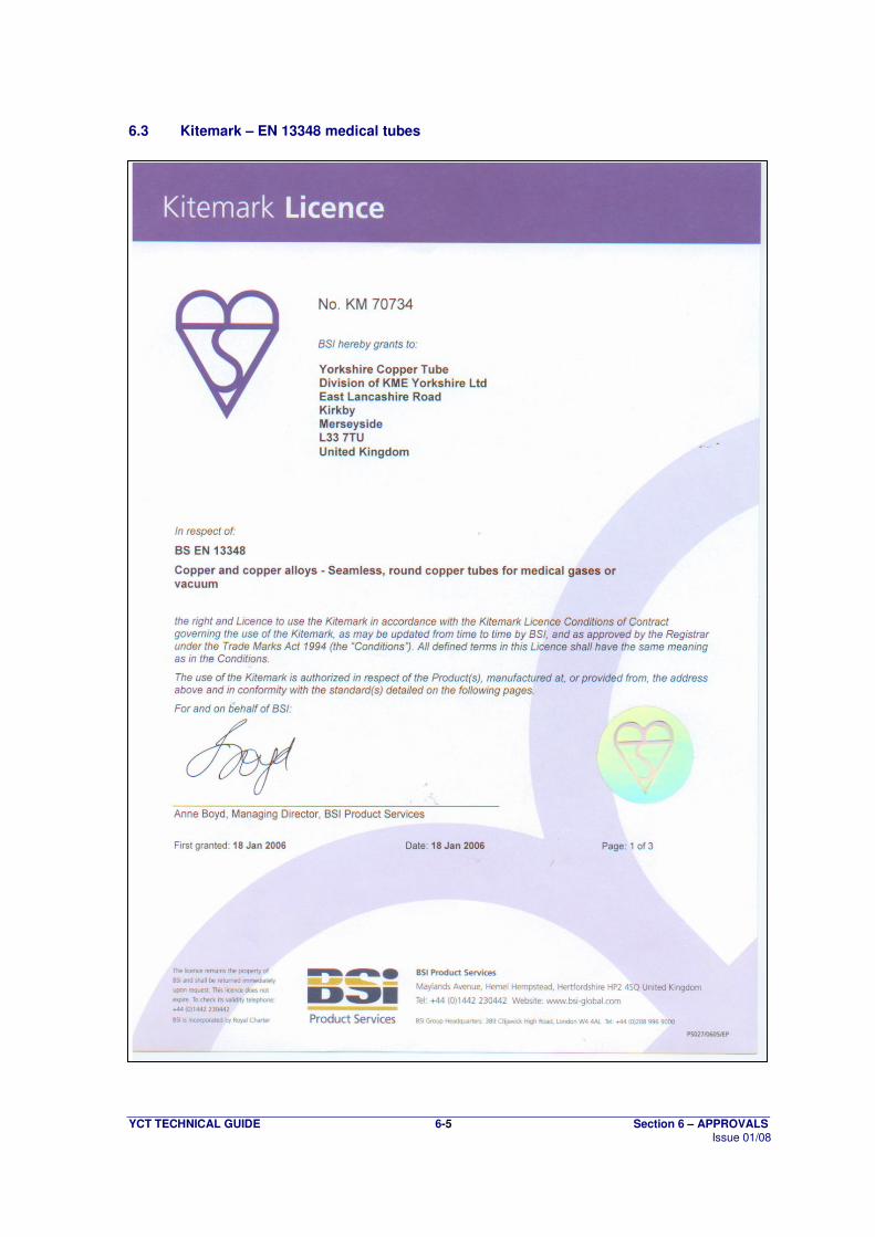
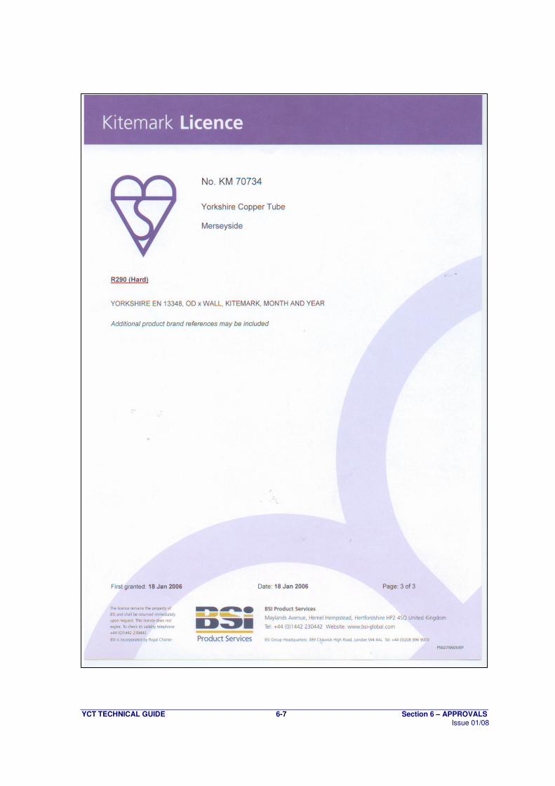
6.3 Kitemark – EN 13348 medical tubes
YCT TECHNICAL GUIDE 6-6 Section 6 – APPROVALS Issue 01/08
YCT TECHNICAL GUIDE 6-7 Section 6 – APPROVALS Issue 01/08
YCT TECHNICAL GUIDE 7-1 Section 7 – GUARANTEE Issue 01/08
Section 7 – Guarantee 7.1 25 Year Guarantee
YORKSHIRE COPPER TUBE
25 YEAR GUARANTEE
Yorkshire Copper Tube is a subsidiary of KM Europa Metal AG (KME). KME is Europe’s largest manufacturer of copper and copper alloy products. Yorkshire’s factory situated on Merseyside is today one of the most modern tube-producing plants in the world. We employ advanced manufacture methods and sophisticated quality control techniques to ensure that consistently high standards are maintained. A comprehensive Technical Service is freely available with advice on installation and design. GUARANTEE YORKSHIRE COPPER TUBE (hereafter called “YCT”) HEREBY GUARANTEES the goods purchased by the Installer and fitted by him on the undermentioned terms:- 1. “The Goods” shall mean:
(a) Plain copper tubes for water, heating, gas and sanitation purposes, supplied by YCT.
(b) “Kuterlex” composite plastic covered copper tube, supplied by YCT.
(c) Chromium plated copper tubes supplied by YCT.
2. Liability
In the event that, during a period of 25 years from the date of purchase by the installer, tube failure or other damage occurs when the Installer’s customer uses the goods, as a direct consequence of:
(a) Manufacturing defects in the goods; or
(b) Material faults in the goods; or
(c) Failure to comply with the prime requirements of the national/international standard engraved on the goods
YCT TECHNICAL GUIDE 7-2 Section 7 – GUARANTEE Issue 01/08
YCT undertakes:
(i) To replace such faulty or defective goods free of charge;
(ii) To pay the installer his reasonable charge for removing or replacing such faulty or defective goods up to a maximum of £75,000 per incident;
(iii) To accept responsibility for the costs of remedying the said damage, to a maximum of £250,000 for each incidence of damage to persons and property for which YCT is legally liable.
When the extent of such damage has been established, YCT reserves the right either to repair the damage itself or to have it repaired at its expense by firms appointed by YCT.
3. Obligations of the Installer
It is a condition precedent to the coming into effect of this guarantee that the Installer shall:
(a) ensure correct installation and assembly of the relevant pipe system in accordance with such technical rules and local codes of Practice as are valid at the time of installation;
(b) immediately implement all necessary measures to reduce damage;
(c) notify the fault, defect or damage to YCT as soon as practicable after the fault, defect
or damage has become apparent;
(d) on request, make the goods available to YCT for inspection, and YCT shall have the opportunity to assess the damage itself or through experts and form its opinion thereon. Those parts of the good which are responsible for the damage are always to be kept available for inspection until the final settlement of the relevant claim.
4. Assignability
The guarantee is personal to the Installer and is not assignable. Save as aforesaid, transactions between YCT and the merchants concerned continue to be subject to our Standard Conditions of Sale.
7.2 30 Year Guarantee The above guarantee is extended to 30 years where pipeline systems are constructed exclusively from Yorkshire copper tube and XPress Copper, Xpress Gas, Tectite and Tectite Pro fittings from Yorkshire Fittings Ltd.
YCT TECHNICAL GUIDE 8-1 Section 8 – COSHH Issue 01/08
Section 8 – COSHH
8.1 MATERIAL SAFETY DATA SHEET
1. IDENTIFICATION OF THE SUBSTANCE AND COMPANY. Identification of the substance.
Extruded, seamless copper tube. Identification of the Company.
Yorkshire Copper Tube, East Lancashire Road, Kirkby, Liverpool, Merseyside, United Kingdom. Post Code : L33 7TU.
2. COMPOSITION/INFORMATION. Composition.
COMPONENT % EINECS NO. SYMBOL R-PHRASES S-PHRASES
Copper 99.90 min. 231 - 159 - 6 N/A N/A N/A
Description. This product is extruded as a seamless tube from solid copper.
3. HAZARDS IDENTIFICATION. There are no hazards to health of humans in solid form.
In high concentrations copper oxide dust is a mechanical irritant to eyes and upper respiratory tract, causing symptoms similar to "metal fume fever", which may last up to 24 hours. There are no known permanent effects. However, when used in accordance with manufacturer's instructions no particulates should be generated.
4. FIRST AID MEASURES.
Inhalation : Extreme amounts of copper dust may be irritant to the upper respiratory tract. Remove to fresh air. Seek medical attention.
Skin Contact : Non-irritant. Rinse affected area with water as a precaution. Eye Contact : Flush eyes with copious amounts of water. Seek medical attention. Ingestion : Drink plenty of water.
5. FIRE FIGHTING MEASURES.
Copper is non-flammable and indeed does not melt below 1083°C.
6. ACCIDENTAL RELEASE MEASURES. Environmental Precautions.
Do not flush copper filings or copper oxide dust to drain. Prevent filings or dust from entering natural water courses.

YCT TECHNICAL GUIDE 8-2 Section 8 – COSHH Issue 01/08
7. HANDLING AND STORAGE. Handling.
Under normal circumstances, may be handled without personal protective equipment, however, it is advisable to wear suitable cut-resistant gloves when cutting with a hacksaw.
Storage.
No special precautions are necessary. Store in a horizontal position, preferably indoors, to prevent ingress of dust, dirt etc.
8. EXPOSURE CONTROLS/PERSONAL PROTECTION.
COMPONENT CAS NO. EINECS NO. LTEL (8 hours)
R-PHRASE STEL (15 mins.)
Copper fume 7440 - 50 - 8 231 - 159 - 6 0.2 mg/m3
N/A ----
Copper dust/mist 7440 - 50 - 8 1 mg/m3 2 mg/m
3
LTEL = Long term exposure limit. STEL = Short term exposure limit
Engineering Measures. Not applicable. Respiratory Protection. Not necessary when used in accordance with manufacturer's instructions. Eye Protection.
During cutting and soldering operations, eye protection to British Standard 2092/EN166 should be worn.
Skin Protection.
During cutting and soldering operations, it is recommended that suitable hand protection is worn.
9. PHYSICAL AND CHEMICAL PROPERTIES. COLOUR Red/brown MATERIAL STATE Solid ODOUR None MELTING POINT 1083ºC DENSITY 8.93g/cm
3 FLAMMABILITY None
10. STABILITY AND REACTIVITY. Stability. Fully stable. Conditions To Avoid.
Excessive exposure to the elements will result in formation of a protective oxide layer which nevertheless gives the material a surface tarnish. In potentially corrosive environments protection of the pipework may be afforded by the use of a factory-applied, plastics covering (refer to manufacturer for further details).
Hazardous Decomposition Products.
None.
YCT TECHNICAL GUIDE 8-3 Section 8 – COSHH Issue 01/08
11. TOXICOLOGICAL INFORMATION. EEC Substance/Preparation Toxicity Classification. Oral LD50 (Rat) Dermal LD50 (Rabbit) Inhalation LC50 (4 Hr. Rat) Skin Irritation (Rabbit) Eye Irritation (Rabbit) Dermal Sensitisation Inhalation Sensitation AMES Test Not classified under any of the above. Potential Health Effects.
The product is entirely suitable for use in conjunction with potable (i.e. drinking) waters. Hazardous Ingredients Toxicity Data.
None.
12. ECOLOGICAL INFORMATION.
Copper in large quantities may cause pollution of the water course with subsequent deterioration of water quality which may cause harm to aquatic life forms. However, the human body requires 2.5 to 5.0 mg of copper per day to maintain health. Copper is an essential trace element in maintaining the general well-being of humans.
13. DISPOSAL CONSIDERATIONS.
Copper is a fully recyclable metal and therefore no waste should ensue from its use. Where scrap is generated, local non-ferrous scrap handlers should be contacted.
14. TRANSPORT INFORMATION. Copper is a non-regulated material by land, sea or air.
15. REGULATORY INFORMATION. EEC Marking And Labelling. Not applicable.
16. OTHER INFORMATION. None. Ref.y:\archive\lab\coshh\chipsht Issue No: 6 Date of issue : January 2005

YCT TECHNICAL GUIDE 8-4 Section 8 – COSHH Issue 01/08
This page has been intentionally left blank
YCT TECHNICAL GUIDE 9-1 Section 9 – REFERENCES Issue 01/08
Section 9 – References
(1) Paragraph No.165 of the HSE Approved Code of Practice, L8, “The Control of Legionella Bacteria in Water Systems”.
(2) BS 6700:2006, British Standard Specification for Design, installation, testing and maintenance of services supplying water for domestic use within buildings and their curtilages.
(3) BS 5449:1990, "British Standard Specification for forced circulation hot water central heating systems for domestic premises".
(4) BS 5431:1976, “Specification for Bending Springs for use with Copper Tubes for Water, Gas and Sanitation”.
(5) BS EN 1057:2006, “Copper and copper alloys - Seamless, round copper tubes for water and gas in sanitary and heating applications”.
(6) BS EN 1254-1:1998, “Copper and copper alloys - Plumbing fittings - Part 1: Fittings with ends for capillary soldering or capillary brazing to copper tubes”.
(7) BS EN 1254-2:1998, “Copper and copper alloys - Plumbing fittings - Part 2: Fittings with compression ends for use with copper tubes”.
(8) BS EN 1254-4:1998, “Copper and copper alloys - Plumbing fittings - Part 4: Fittings combining other end connections with capillary or compression ends”.
(9) BS EN 1254-5:1998, “Copper and copper alloys - Plumbing fittings - Part 5: Fittings with short ends for capillary brazing to copper tubes”.
(10) PrEN 1254-6: (currently in draft), “Copper and copper alloys - Plumbing fittings - Part 6: Fittings with push-fit ends”.
(11) PrEN 1254-7: (currently in draft), “Copper and copper alloys - Plumbing fittings - Part 7: Fittings with press ends for metallic tubes”.
(12) Copper Development Association Publication 33, “Copper Tube in Domestic Water Services, Design and Installation”.
(13) BS 5422:2001 “Methods for specifying thermal insulation materials on pipes, ductwork and equipment in the temperature range -40 to +700ºC”
(14) BS EN 1976:1998, “Copper and copper alloys - Cast unwrought copper products”.
(15) BS EN 1173:1996, “Copper and copper alloys - Material condition or temper designation”.
(16) BS EN 13349:2002, “Copper and copper alloys - Pre-insulated copper tubes with solid covering”.
(17) BS 1710:1984, “Identification of pipelines and services”.
(18) BS 4800:1989 “Schedule of paint colours for building purposes”.
(19) BS EN 12540:2000, “Corrosion protection of metals – Electrodeposited coatings of nickel, nickel plus chromium, copper plus nickel and copper plus nickel plus chromium”.
(20) HTM 02-01:2006, “Medical gas pipeline systems Part A Design, Installation, Validation and Verification”.
(21) BS EN 13348:2001, “Copper and copper alloys – Seamless round copper tubes for medical gases or vacuum”.
(22) BS 1306:1975, “Copper and copper alloy pressure piping systems”.