you can help improve this manual by calling attention to
TRANSCRIPT

You can help improve this manual by calling attention to errors and by recommending improvements.Please convey your comments to the nearest Ishida Company regional representative. Thank you!
Copyright 2002 by Ishida Co., Ltd. All Rights Reserved.No part of this manual may be reproduced in any form, by mimeograph or any other means, withoutwritten permission of the publisher.
Precautions
i AC-4000 Service Manual No.0181A
SAFETY CONSIDERATIONSFor safe operation, the following safety considerations must be observed.GroundingThis machine requires protective grounding for safe operation. To avoid potential shock hazards, aprotective grounding conductor for the machine must be securely connected to the main groundingprovision by qualified service personnel.
Do not remove covers or enclosuresTo avoid personal injury and shock, do not open or remove any covers or enclosures of the machineunless specified in the manual.
Do not perform unspecified maintenanceFor your personal safety, do not perform any maintenance procedures which are not specified in themanual.
Disconnect power supply before servicingTo ensure your personal safety, disconnect the power supply before servicing.
SERVICE SAFETYFor correct maintenance, and to prevent accidents, please adhere to the following items dur-ing service.• Ensure that the power switch is OFF before any maintenance work and remove the power cable
from the main power outlet.• Keep the machine surroundings clean and tidy. Take additional care, especially during disassembly,
not to leave screws etc. inside the machine as this may lead to serious injury.• Do not pull internal wiring cables as cable breaks, poor contact, etc. may take place. Always hold
the connector end before removing. Take special care with thermal head cable, where poor contactmay lead to damage.
• Take care when cleaning thermal heads and print heads, as these are easily damaged.• There are precautions relating to assembly and adjustment parts. Read and understand the manual
thoroughly before attempting maintenance.
Precautions
AC-4000 Service Manual No. 0181A ii
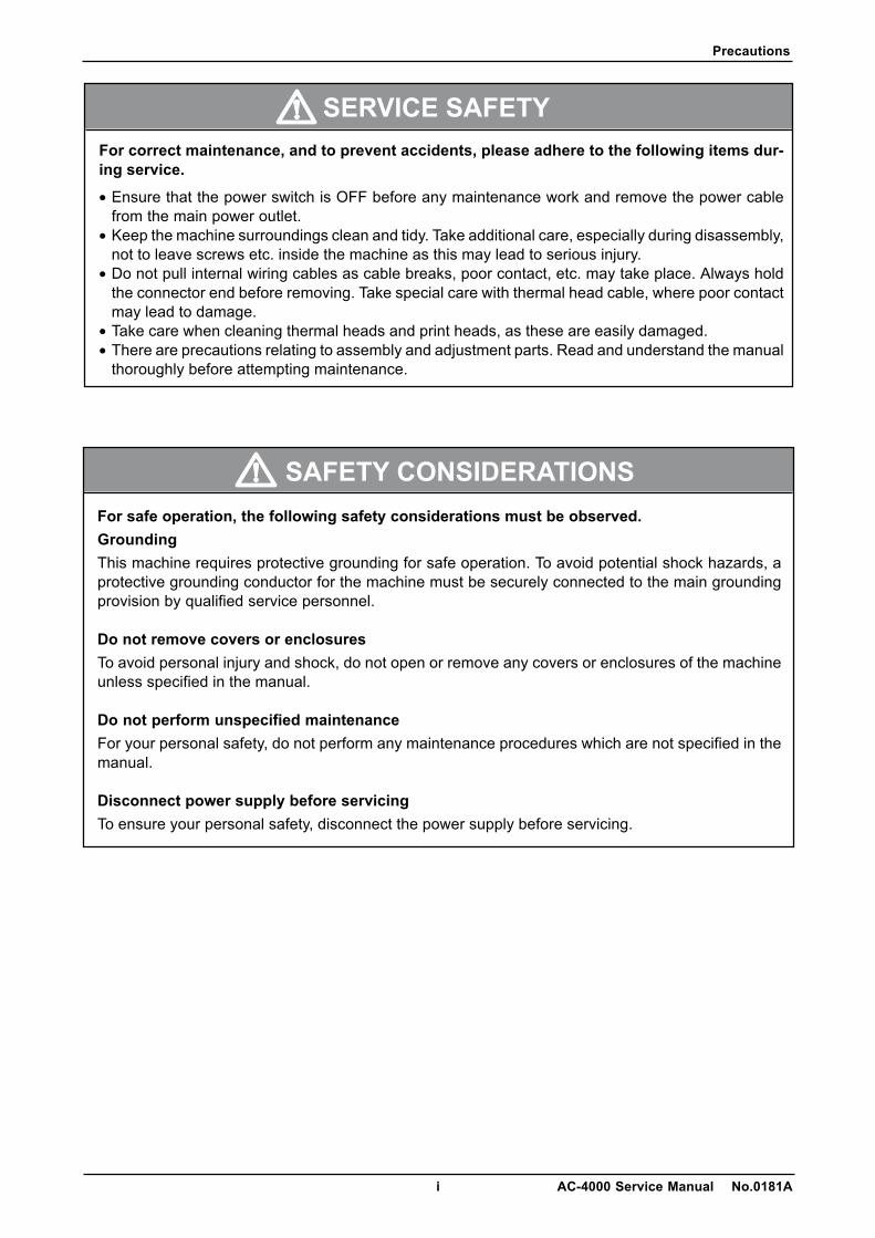
When cleaning the machine, only use asoft dry cloth or a cloth wetted with aneutral cleanser.Never use thinner or other volatileliquids.
Do not drop or apply a strong shock to the scale.
Do not allow any liquids to come into con-tact with the machine.
Do not disassemble the machine.
Power Supply• Use the appropirate voltage after referring to the specification
plate located on the machine.• Use a dedicated power source.
(Voltage fluctuation may cause the machine to malfunction)
Precautions
iii AC-4000 Service Manual No.0181A
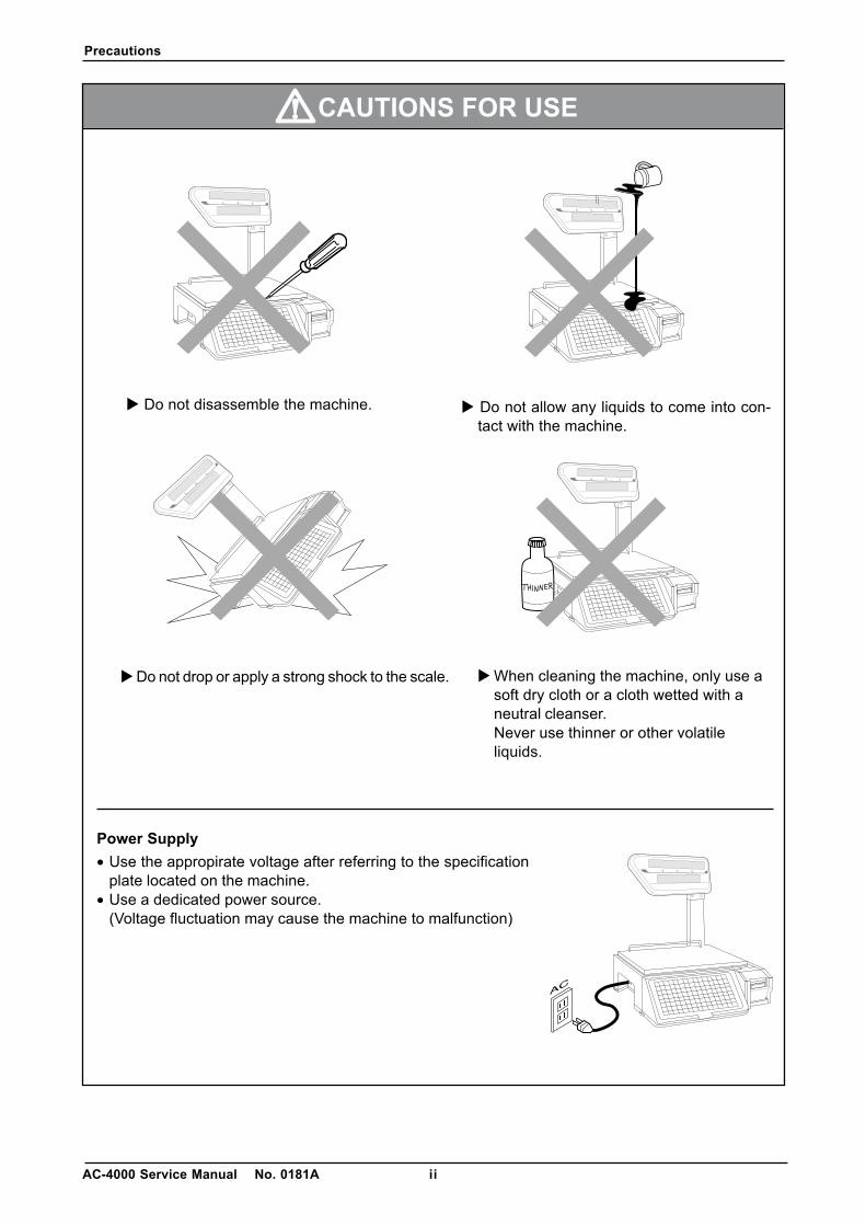
Avoid the following areas when installing the machine
Level adjustment● Always ensure that the machine is level. If the machine is not level, weighing may not be accurate.● Adjust the machine to a level position using the four level adjustment feet located on the buttom of
the machine, until the bubble is completely centered in the round level indicator.
● Areas subject to high temperatures or highhumidity
● Areas exposed to direct sunlight● Areas where water or other liquids are
easily spilled on the machine
● Areas subject to a lot of dust or dirt● Areas with large voltage fluctuations
● Areas subject to excissive vibration orunstable surfaces
● Areas exposed to direct cold air● Areas subject to low temperatures
● Areas where the scale is not level
Contents
AC-4000 Service Manual No. 0181A iv
Contents
CHAPTER 1 OVERVIEW .............................................................................................. 1-11.1 Appearance and Name of Each Part.................................................................................. 1-11.2 Display ................................................................................................................................ 1-11.3 Key Sheet ........................................................................................................................... 1-21.4 Printer ................................................................................................................................. 1-21.5 Main Specifications ............................................................................................................ 1-31.6 Exploded Drawing .............................................................................................................. 1-4
CHAPTER 2 INSTALLATION ........................................................................................ 2-12.1 Packed Goods .................................................................................................................... 2-12.2 Installation Environment ..................................................................................................... 2-22.3 Assembly ............................................................................................................................ 2-22.4 Weigh Platter Installation.................................................................................................... 2-32.5 Label Loading ..................................................................................................................... 2-32.6 Power Cable Connection.................................................................................................... 2-42.7 Turning Power Switch “ON” ............................................................................................... 2-42.8 Customer’s Specification Setup ......................................................................................... 2-5
(Initialization, Setup, and Registration) .............................................................................. 2-52.9 Normal Mode Display ......................................................................................................... 2-62.10 Label Batch Print Mode ...................................................................................................... 2-7
2.10.1 Basic operation ...................................................................................................... 2-72.10.2 Additional functions ................................................................................................ 2-72.10.3 Label batch printing on continuous paper ............................................................. 2-8
2.11 Scroll Message Display ...................................................................................................... 2-92.12 Campaign Function ............................................................................................................ 2-9
CHAPTER 3 TEST MODE............................................................................................. 3-13.1 Test Mode Menu List .......................................................................................................... 3-13.2 Test Mode Start .................................................................................................................. 3-23.3 Hardware Test .................................................................................................................... 3-23.4 RAM Clear .......................................................................................................................... 3-73.5 Printer Head ..................................................................................................................... 3-113.6 Label Sensor Check ......................................................................................................... 3-133.7 Total Memory .................................................................................................................... 3-143.8 ROM Switch ..................................................................................................................... 3-153.9 Peel Sensor Check ........................................................................................................... 3-17
CHAPTER 4 SETUP MODE .......................................................................................... 4-14.1 Setup Mode Menu .............................................................................................................. 4-14.2 Starting Procedure for Each Mode ..................................................................................... 4-24.3 Starting Procedure for Setup Mode .................................................................................... 4-24.4 Label Format [Print conditions] .......................................................................................... 4-34.5 POS Code .......................................................................................................................... 4-84.6 Barcode [Item code] ......................................................................................................... 4-11
Contents
v AC-4000 Service Manual No. 0181A
4.7 Default Data ..................................................................................................................... 4-124.8 Total Mode Select ............................................................................................................. 4-134.9 Forced Tare [USA specification only] ............................................................................... 4-134.10 Open Price [Prohibition of Unit Price Change] ................................................................. 4-144.11 PLU Select [Editing PLU File] ........................................................................................... 4-154.12 System [Availabilty of Registration Mode Menu] .............................................................. 4-224.13 Ethernet Setup [Ethernet Data Setting] ............................................................................ 4-264.14 System Timer ................................................................................................................... 4-324.15 Password Setup ............................................................................................................... 4-33
CHAPTER 5 ELECTRICITY COMPOSITION................................................................ 5-1
CHAPTER 6 TROUBLESHOOTING ............................................................................. 6-16.1 Error List ............................................................................................................................. 6-1
CHAPTER 7 PARTS REPLACEMENT ......................................................................... 7-17.1 Detaching Each Part (Unit) ................................................................................................. 7-17.2 Detaching Internal Parts ..................................................................................................... 7-47.3 Periodical Replacement Parts .......................................................................................... 7-147.4 How to Pass Labels.......................................................................................................... 7-14
Chapter 1 Overview
1-1 AC-4000 Service Manual No. 0181A
CHAPTER 1 OVERVIEW
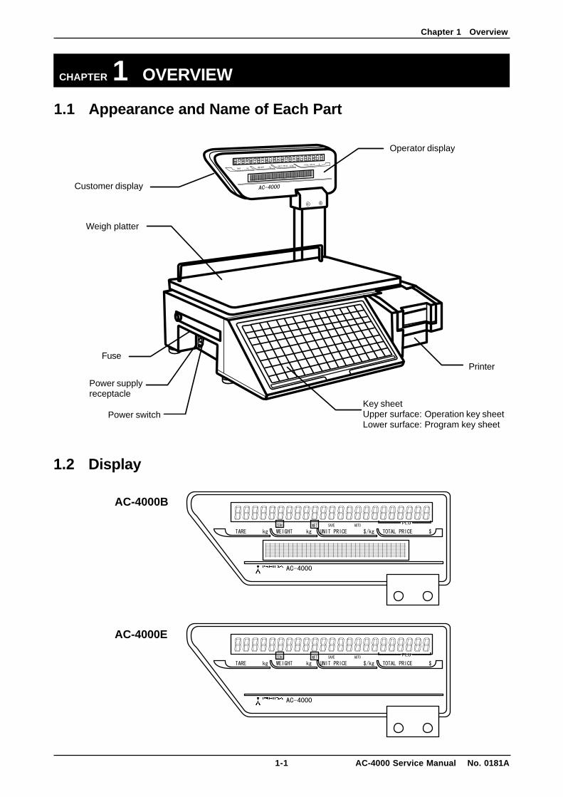
1.1 Appearance and Name of Each Part
1.2 Display
AC-4000B
AC-4000E
Customer display
Operator display
Weigh platter
Power switch
Power supplyreceptacle
FusePrinter
Key sheetUpper surface: Operation key sheetLower surface: Program key sheet
Chapter 1 Overview
AC-4000 Service Manual No. 0181A 1-2
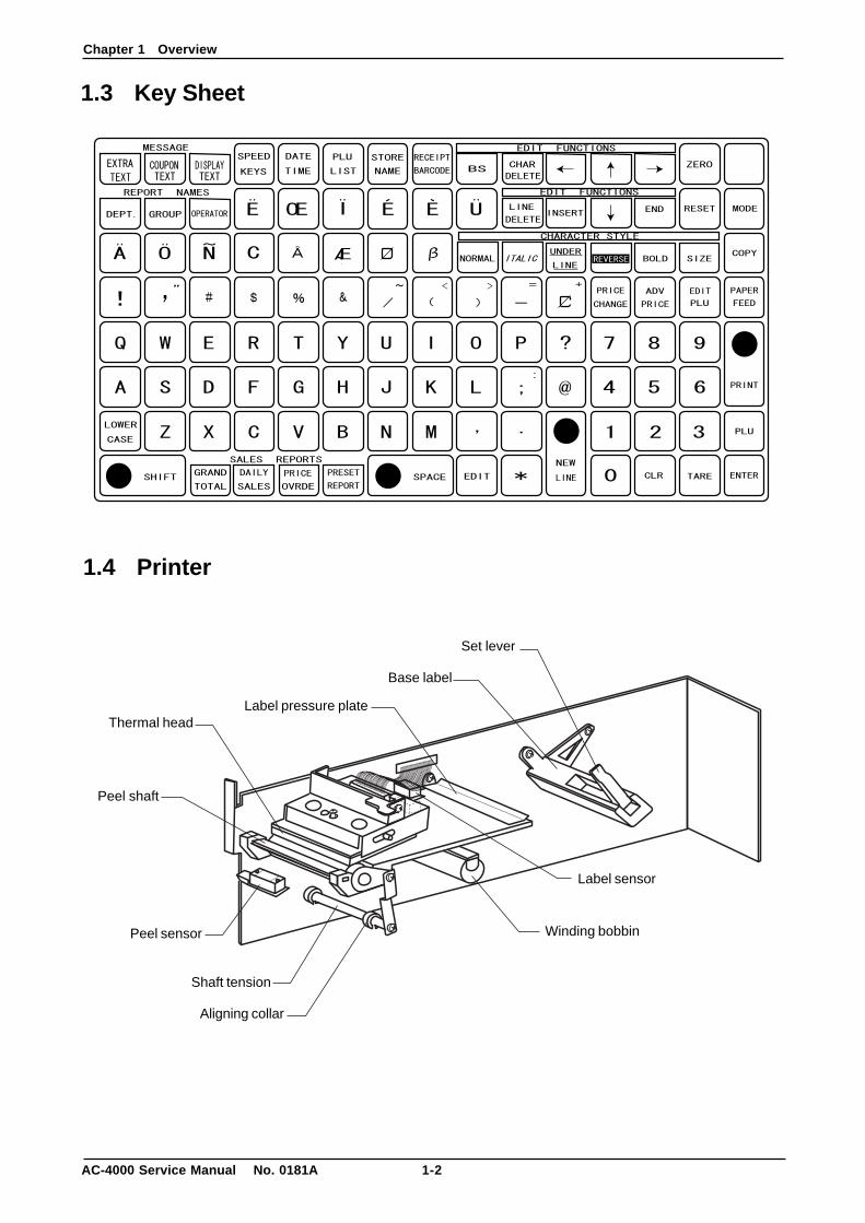
1.3 Key Sheet
1.4 Printer
Winding bobbin
Shaft tension
Aligning collar
Base label
Peel shaft
Set lever
Label pressure plateThermal head
Peel sensor
Label sensor
Chapter 1 Overview
1-3 AC-4000 Service Manual No. 0181A
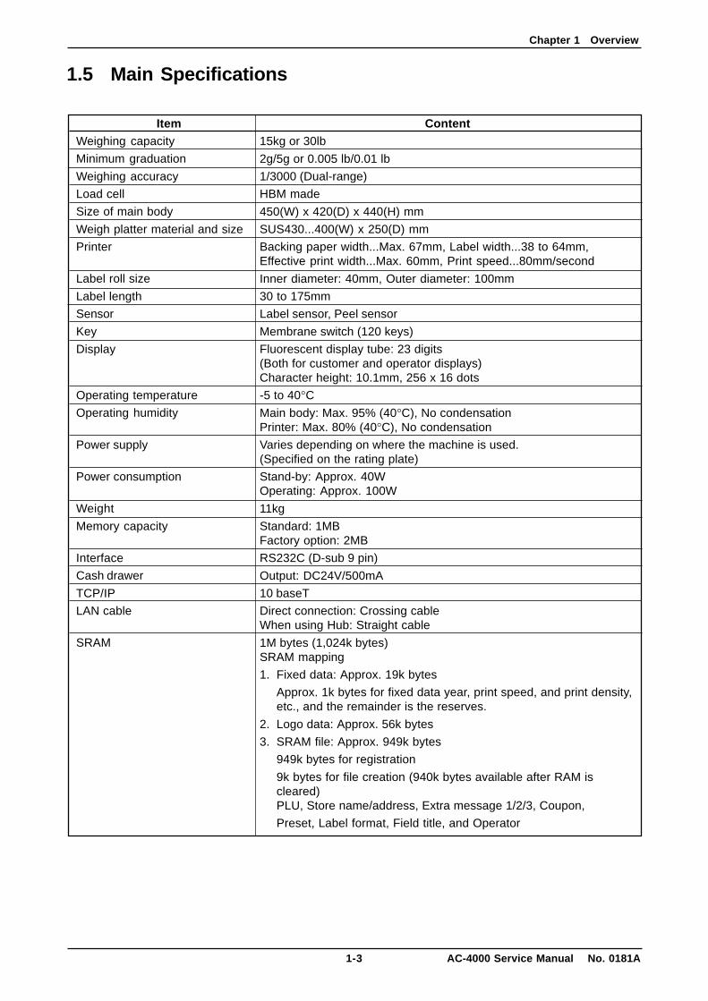
1.5 Main Specifications
ItemWeighing capacity
Minimum graduation
Weighing accuracy
Load cell
Size of main body
Weigh platter material and size
Printer
Label roll size
Label length
Sensor
Key
Display
Operating temperature
Operating humidity
Power supply
Power consumption
Weight
Memory capacity
Interface
Cash drawer
TCP/IP
LAN cable
SRAM
Content15kg or 30lb
2g/5g or 0.005 lb/0.01 lb
1/3000 (Dual-range)
HBM made
450(W) x 420(D) x 440(H) mm
SUS430...400(W) x 250(D) mm
Backing paper width...Max. 67mm, Label width...38 to 64mm,Effective print width...Max. 60mm, Print speed...80mm/second
Inner diameter: 40mm, Outer diameter: 100mm
30 to 175mm
Label sensor, Peel sensor
Membrane switch (120 keys)
Fluorescent display tube: 23 digits(Both for customer and operator displays)Character height: 10.1mm, 256 x 16 dots
-5 to 40°CMain body: Max. 95% (40°C), No condensationPrinter: Max. 80% (40°C), No condensation
Varies depending on where the machine is used.(Specified on the rating plate)
Stand-by: Approx. 40WOperating: Approx. 100W
11kg
Standard: 1MBFactory option: 2MB
RS232C (D-sub 9 pin)
Output: DC24V/500mA
10 baseT
Direct connection: Crossing cableWhen using Hub: Straight cable
1M bytes (1,024k bytes)SRAM mapping
1. Fixed data: Approx. 19k bytes
Approx. 1k bytes for fixed data year, print speed, and print density,etc., and the remainder is the reserves.
2. Logo data: Approx. 56k bytes
3. SRAM file: Approx. 949k bytes
949k bytes for registration
9k bytes for file creation (940k bytes available after RAM iscleared)PLU, Store name/address, Extra message 1/2/3, Coupon,
Preset, Label format, Field title, and Operator
Chapter 1 Overview
AC-4000 Service Manual No. 0181A 1-4
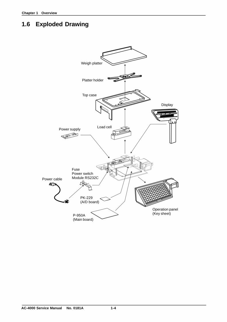
1.6 Exploded Drawing
AC-4000
TARE kg WEIGHT kg UNIT PRICE $/kg TOTAL PRICE $
+ +
Weigh platter
Platter holder
Display
Load cellPower supply
FusePower switchModule RS232CPower cable
PK-229(A/D board)
P-950A(Main board)
Operation panel(Key sheet)
Top case

Chapter 2 Installation
2-1 AC-4000 Service Manual No. 0181A
CHAPTER 2 INSTALLATION
2.1 Packed GoodsOpen the packing case and check whether there are all the packed goods (machine and accessories) andif there are any damaged parts.
Note: AC-4000 “B type” or “E type” can be identified by a description of the sticker on the case.
[Packed goods]
1. Stand2. Power cable3. Thermal head cleaner4. Main body5. Display6. Weigh platter7. Operation manual
Chapter 2 Installation
AC-4000 Service Manual No. 0181A 2-2
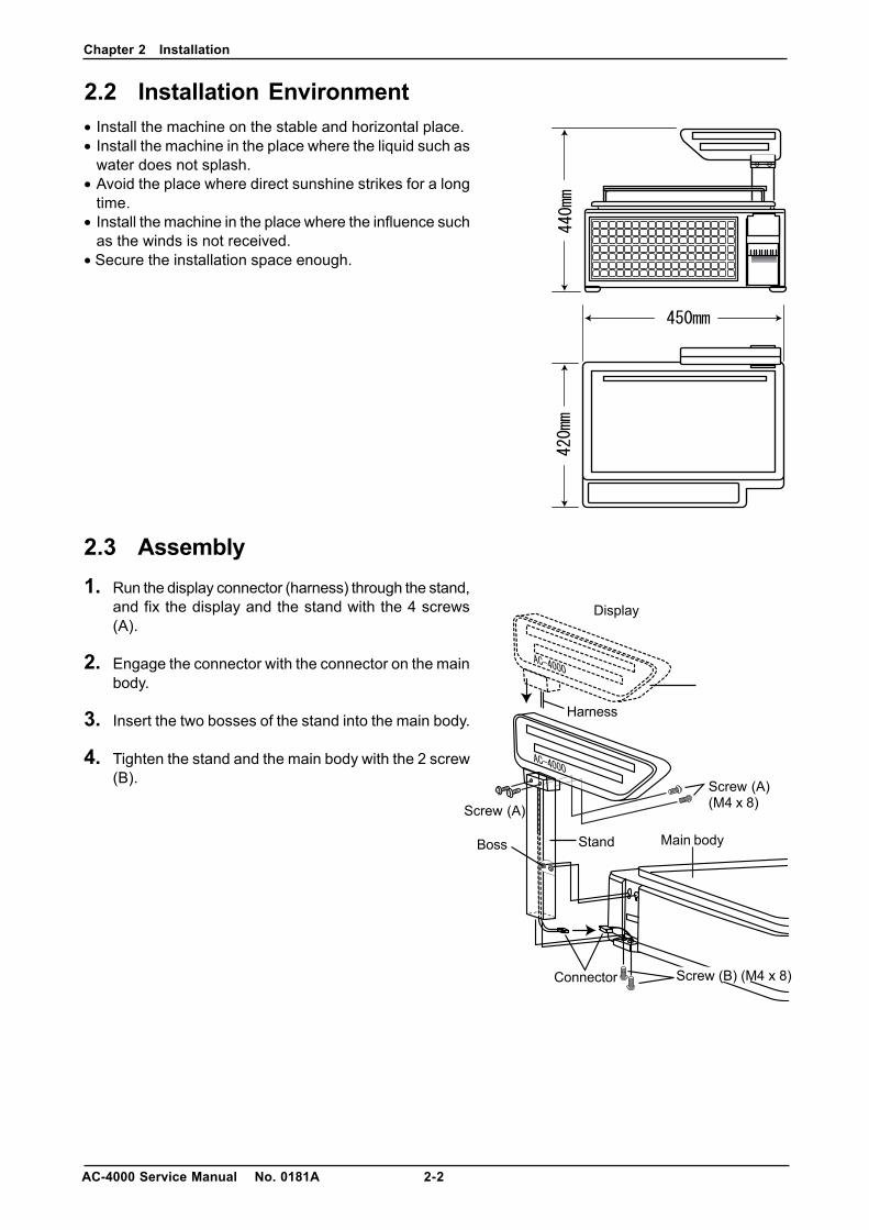
2.2 Installation Environment• Install the machine on the stable and horizontal place.• Install the machine in the place where the liquid such as
water does not splash.• Avoid the place where direct sunshine strikes for a long
time.• Install the machine in the place where the influence such
as the winds is not received.• Secure the installation space enough.
2.3 Assembly1. Run the display connector (harness) through the stand,
and fix the display and the stand with the 4 screws(A).
2. Engage the connector with the connector on the mainbody.
3. Insert the two bosses of the stand into the main body.
4. Tighten the stand and the main body with the 2 screw(B). Screw (A)
(M4 x 8)Screw (A)
Screw (B) (M4 x 8)
Stand
Harness
Connector
Boss Main body
Display
Chapter 2 Installation
2-3 AC-4000 Service Manual No. 0181A
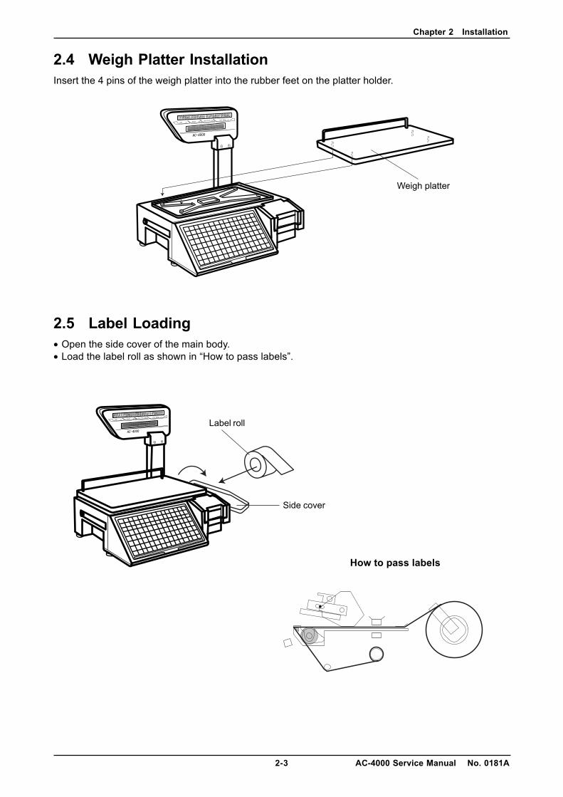
2.4 Weigh Platter InstallationInsert the 4 pins of the weigh platter into the rubber feet on the platter holder.
2.5 Label Loading• Open the side cover of the main body.• Load the label roll as shown in “How to pass labels”.
Label roll
How to pass labels
Side cover
Weigh platter
Chapter 2 Installation
AC-4000 Service Manual No. 0181A 2-4
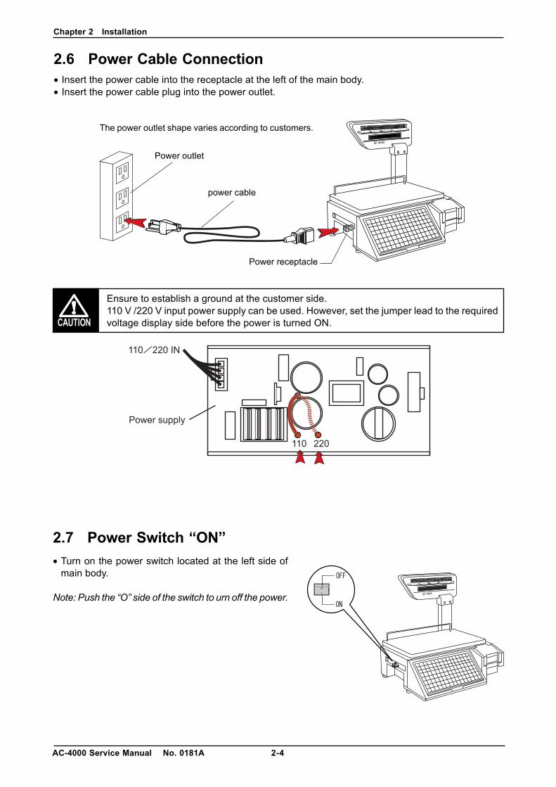
2.6 Power Cable Connection• Insert the power cable into the receptacle at the left of the main body.• Insert the power cable plug into the power outlet.
Ensure to establish a ground at the customer side.110 V /220 V input power supply can be used. However, set the jumper lead to the requiredvoltage display side before the power is turned ON.
Power outlet
power cable
Power receptacle
The power outlet shape varies according to customers.
2.7 Power Switch “ON”• Turn on the power switch located at the left side of
main body.
Note: Push the “O” side of the switch to urn off the power.
Chapter 2 Installation
2-5 AC-4000 Service Manual No. 0181A
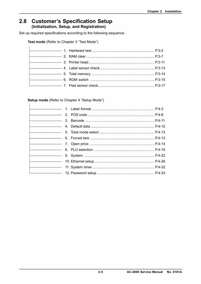
2.8 Customer’s Specification Setup(Initialization, Setup, and Registration)
Set up required specifications according to the following sequence.
Test mode (Refer to Chapter 3 “Test Mode”)
1. Hardware test ................................................................ P.3-2 2. RAM clear ..................................................................... P.3-7 3. Printer head................................................................... P.3-11 4. Label sensor check ....................................................... P.3-13 5. Total memory ................................................................ P.3-14 6. ROM switch .................................................................. P.3-15 7. Peel sensor check ......................................................... P.3-17
Setup mode (Refer to Chapter 4 “Setup Mode”)
1. Label format ................................................................ P.4-3 2. POS code .................................................................... P.4-8 3. Barcode ....................................................................... P.4-11 4. Default data ................................................................. P.4-12 5. Total mode select ........................................................ P.4-13 6. Forced tare .................................................................. P.4-13 7. Open price .................................................................. P.4-14 8. PLU selection .............................................................. P.4-15 9. System ........................................................................ P.4-22 10. Ethernet setup ............................................................. P.4-26 11. System timer ............................................................... P.4-32 12. Password setup .......................................................... P.4-33
Chapter 2 Installation
AC-4000 Service Manual No. 0181A 2-6
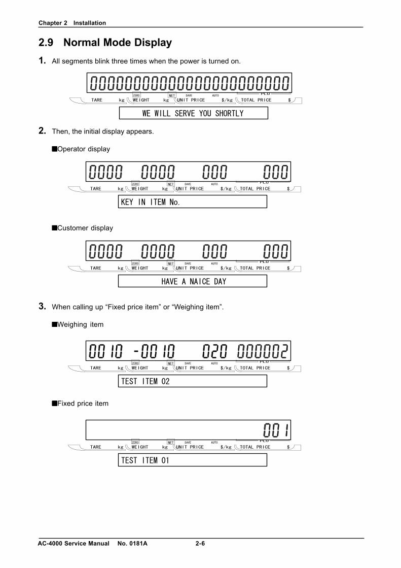
2.9 Normal Mode Display1. All segments blink three times when the power is turned on.
2. Then, the initial display appears.
■■■■■Operator display
■■■■■Customer display
3. When calling up “Fixed price item” or “Weighing item”.
■■■■■Weighing item
■■■■■Fixed price item
Chapter 2 Installation
2-7 AC-4000 Service Manual No. 0181A
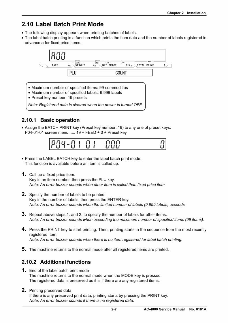
2.10 Label Batch Print Mode• The following display appears when printing batches of labels.• The label batch printing is a function which prints the item data and the number of labels registered in
advance a for fixed price items.
• Maximum number of specified items: 99 commodities• Maximum number of specified labels: 9,999 labels• Preset key number: 19 presets
Note: Registered data is cleared when the power is turned OFF.
2.10.1 Basic operation• Assign the BATCH PRINT key (Preset key number: 19) to any one of preset keys.
P04-01-01 screen menu ..... 19 + FEED + 0 + Preset key
• Press the LABEL BATCH key to enter the label batch print mode.This function is available before an item is called up.
1. Call up a fixed price item.Key in an item number, then press the PLU key.Note: An error buzzer sounds when other item is called than fixed price item.
2. Specify the number of labels to be printed.Key in the number of labels, then press the ENTER key.Note: An error buzzer sounds when the limited number of labels (9,999 labels) exceeds.
3. Repeat above steps 1. and 2. to specify the number of labels for other items.Note: An error buzzer sounds when exceeding the maximum number of specified items (99 items).
4. Press the PRINT key to start printing. Then, printing starts in the sequence from the most recentlyregistered item.Note: An error buzzer sounds when there is no item registered for label batch printing.
5. The machine returns to the normal mode after all registered items are printed.
2.10.2 Additional functions1. End of the label batch print mode
The machine returns to the normal mode when the MODE key is pressed.The registered data is preserved as it is if there are any registered items.
2. Printing preserved dataIf there is any preserved print data, printing starts by pressing the PRINT key.Note: An error buzzer sounds if there is no registered data.
Chapter 2 Installation
AC-4000 Service Manual No. 0181A 2-8
3. Deleting label batch print dataThe label batch print data is deleted while sounding an OK buzzer by pressing the ZERO key twice.
4. Stop of label batch print operationLabel batch print stops by pressing the PRINT key while printing a print reservation data.However, the remaining label batch print items are not deleted.(If printing stops when five labels have been issued for an item specified to issue 10 labels, theremaining 5 labels are preserved.)
5. Addition of label batch print data to the preserved dataThe label batch print data is added to the preserved data.(When there are “40 preserved items”, “59 items” can be added.)
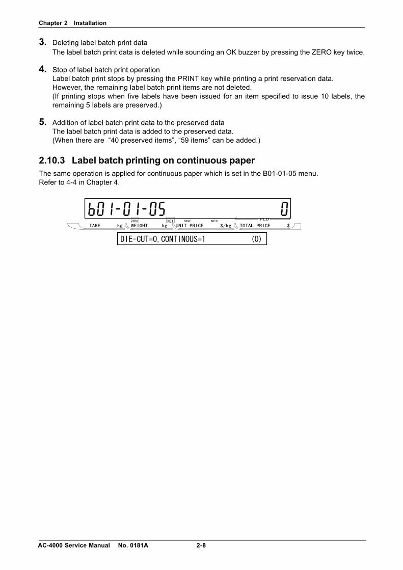
2.10.3 Label batch printing on continuous paperThe same operation is applied for continuous paper which is set in the B01-01-05 menu.Refer to 4-4 in Chapter 4.

Chapter 2 Installation
2-9 AC-4000 Service Manual No. 0181A
2.11 Scroll Message Display• A function to display the registered scroll message. When an item has not been called up, it starts after
five seconds have passed.
• Display method registration function(0: No display 1: High-speed scroll 2: Normal scroll 3: Low-speed scroll 4: High-speed blinking5: Normal blinking 6: Low-speed blinking)
• Day of the week registration function(0: Every day 1: Sunday 2: Monday 3: Tuesday 4: Wednesday 5: Thursday 6: Friday 7: Saturday)
• Display time registration function (Start/stop)[Example] 09:00 to 13:00
Enter “0913” and press the ENTER key.
• Maximum number of scroll messages: 9 messages (1 to 9)• Maximum number of characters: 96 characters (one byte English code)
2.12 Campaign Function• Registered campaign items start to be sold at the registered campaign price when the time reaches
registered campaign time.
• Maximum number of campaign: 20• Maximum number of items for each campaign: 100• Discount method (0: Unit price 1: Special price 2: Amount discount 3: Percent discount 4: Special unit price)
• Campaign 1 becomes top priority for items registered during the overlapping time.• Priority is given from Campaign 1, 2, and 3 to the last 20 if the same item is registered.
That is, priority is given to the campaign 1 even if the same item is registered in campaign 1 and 2during the overlapping time.
• Registration of the same item is not supported in one campaign.• An error message appears when a label is issued with a registered price in the campaign greater than
the weighing price.
Chapter 3 Test Mode
3-1 AC-4000 Service Manual No. 0181A
CHAPTER 3 TEST MODE
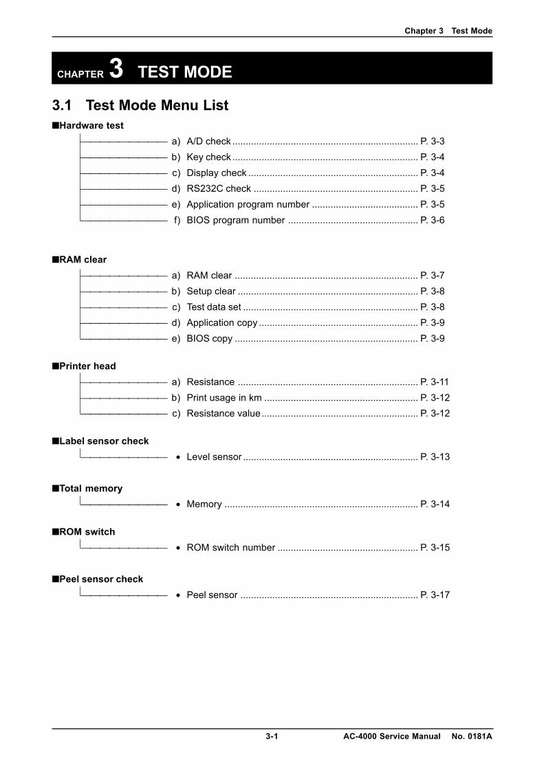
3.1 Test Mode Menu List■Hardware test
a) A/D check ...................................................................... P. 3-3 b) Key check ...................................................................... P. 3-4 c) Display check ................................................................ P. 3-4 d) RS232C check .............................................................. P. 3-5 e) Application program number ........................................ P. 3-5 f) BIOS program number ................................................. P. 3-6
■RAM clear a) RAM clear ..................................................................... P. 3-7 b) Setup clear .................................................................... P. 3-8 c) Test data set .................................................................. P. 3-8 d) Application copy ............................................................ P. 3-9 e) BIOS copy ..................................................................... P. 3-9
■Printer head a) Resistance .................................................................... P. 3-11 b) Print usage in km .......................................................... P. 3-12 c) Resistance value........................................................... P. 3-12
■Label sensor check • Level sensor .................................................................. P. 3-13
■Total memory • Memory ......................................................................... P. 3-14
■ROM switch • ROM switch number ..................................................... P. 3-15
■Peel sensor check • Peel sensor ................................................................... P. 3-17
Chapter 3 Test Mode
AC-4000 Service Manual No. 0181A 3-2
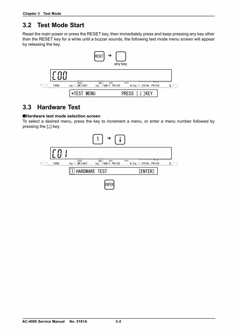
3.2 Test Mode StartReset the main power or press the RESET key, then immediately press and keep pressing any key otherthan the RESET key for a while until a buzzer sounds, the following test mode menu screen will appearby releasing the key.
3.3 Hardware Test■Hardware test mode selection screenTo select a desired menu, press the key to increment a menu, or enter a menu number followed bypressing the [↓] key.
➔
➔
any key
Chapter 3 Test Mode
3-3 AC-4000 Service Manual No. 0181A
Zero point adjustment screen
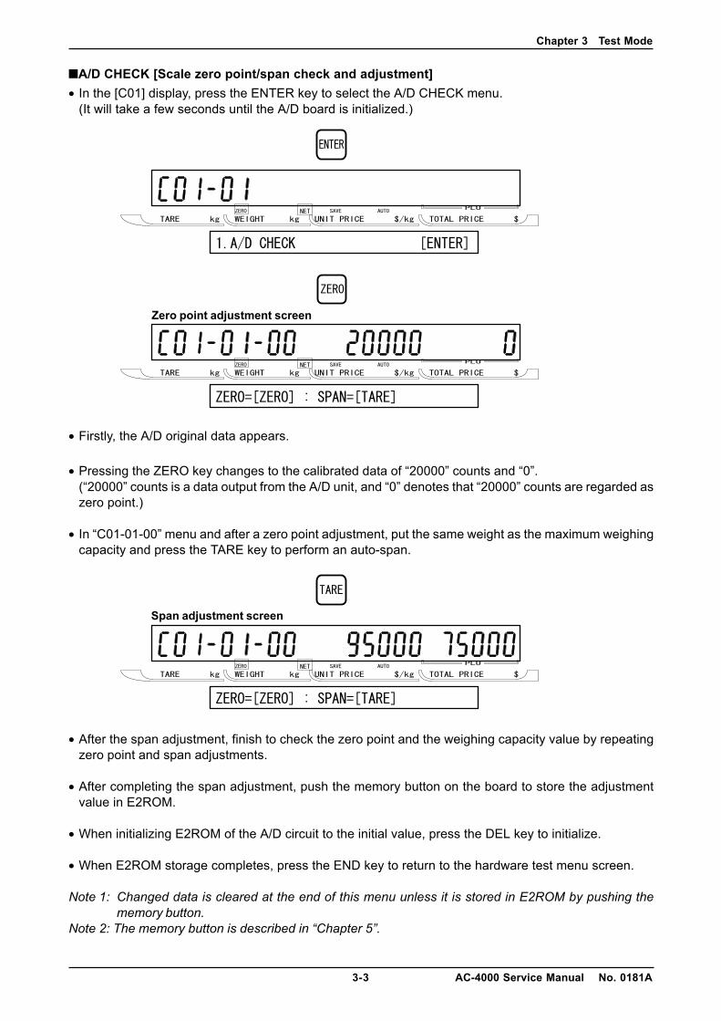
■A/D CHECK [Scale zero point/span check and adjustment]• In the [C01] display, press the ENTER key to select the A/D CHECK menu.
(It will take a few seconds until the A/D board is initialized.)
• Firstly, the A/D original data appears.
• Pressing the ZERO key changes to the calibrated data of “20000” counts and “0”.(“20000” counts is a data output from the A/D unit, and “0” denotes that “20000” counts are regarded aszero point.)
• In “C01-01-00” menu and after a zero point adjustment, put the same weight as the maximum weighingcapacity and press the TARE key to perform an auto-span.
• After the span adjustment, finish to check the zero point and the weighing capacity value by repeatingzero point and span adjustments.
• After completing the span adjustment, push the memory button on the board to store the adjustmentvalue in E2ROM.
• When initializing E2ROM of the A/D circuit to the initial value, press the DEL key to initialize.
• When E2ROM storage completes, press the END key to return to the hardware test menu screen.
Note 1: Changed data is cleared at the end of this menu unless it is stored in E2ROM by pushing thememory button.
Note 2: The memory button is described in “Chapter 5”.
Span adjustment screen
Chapter 3 Test Mode
AC-4000 Service Manual No. 0181A 3-4
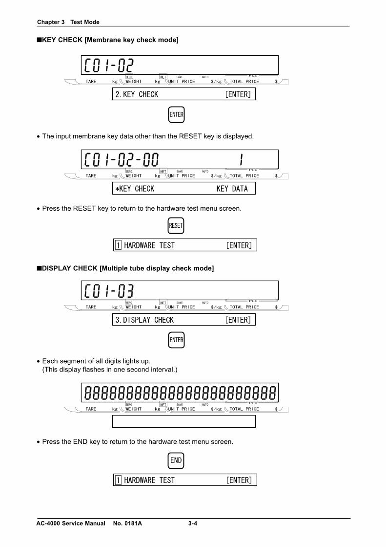
■KEY CHECK [Membrane key check mode]
• The input membrane key data other than the RESET key is displayed.
• Press the RESET key to return to the hardware test menu screen.
■DISPLAY CHECK [Multiple tube display check mode]
• Each segment of all digits lights up.(This display flashes in one second interval.)
• Press the END key to return to the hardware test menu screen.

Chapter 3 Test Mode
3-5 AC-4000 Service Manual No. 0181A
■RS232C CHECK [Driver/receiver test]
• Serial output port (RS232C) driver/receiver test menu screen
• Perform a loop back test to carry out the RS232C input test. Engage the TXD and RXD short-circuitedconnector with D-SUB 9, press the PRINT key to output test data, and judge by verifying received testdata and sent data.If the data matches, “PASS” is displayed and “OK” buzzer sounds.“ERR” is displayed and “NG” (No Good) buzzer sounds.
• Press the RESET key to return to the hardware test menu screen.
■APPLICATION PROGRAM No. [Program no. and version display check]
• The program number and version of the main program are displayed.Note: The program number for the prototype is the development code “APPLY”.
• Press the END key to return to the hardware test menu screen.
Chapter 3 Test Mode
AC-4000 Service Manual No. 0181A 3-6
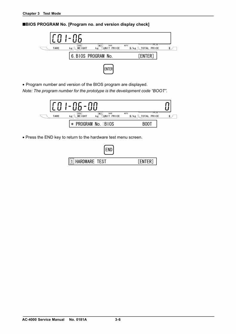
■BIOS PROGRAM No. [Program no. and version display check]
• Program number and version of the BIOS program are displayed.Note: The program number for the prototype is the development code “BOOT”.
• Press the END key to return to the hardware test menu screen.
Chapter 3 Test Mode
3-7 AC-4000 Service Manual No. 0181A
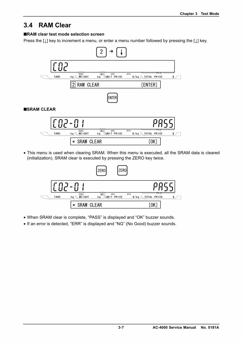
3.4 RAM Clear■RAM clear test mode selection screenPress the [↓] key to increment a menu, or enter a menu number followed by pressing the [↓] key.
■SRAM CLEAR
• This menu is used when clearing SRAM. When this menu is executed, all the SRAM data is cleared(initialization). SRAM clear is executed by pressing the ZERO key twice.
• When SRAM clear is complete, “PASS” is displayed and “OK” buzzer sounds.• If an error is detected, “ERR” is displayed and “NG” (No Good) buzzer sounds.
➔
Chapter 3 Test Mode
AC-4000 Service Manual No. 0181A 3-8
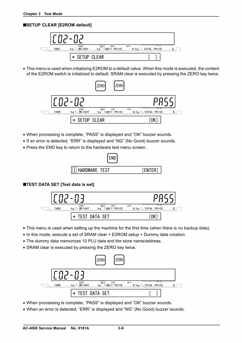
■SETUP CLEAR [E2ROM default]
• This menu is used when initializing E2ROM to a default value. When this mode is executed, the contentof the E2ROM switch is initialized to default. SRAM clear is executed by pressing the ZERO key twice.
• When processing is complete, “PASS” is displayed and “OK” buzzer sounds.• If an error is detected, “ERR” is displayed and “NG” (No Good) buzzer sounds.• Press the END key to return to the hardware test menu screen.
■TEST DATA SET [Test data is set]
• This menu is used when setting up the machine for the first time (when there is no backup data).• In this mode, execute a set of SRAM clear + E2ROM setup + Dummy data creation.• The dummy data memorizes 10 PLU data and the store name/address.• SRAM clear is executed by pressing the ZERO key twice.
• When processing is complete, “PASS” is displayed and “OK” buzzer sounds.• When an error is detected, “ERR” is displayed and “NG” (No Good) buzzer sounds.

Chapter 3 Test Mode
3-9 AC-4000 Service Manual No. 0181A
• Press the END key to return to the hardware test menu screen.
■APPLICATION COPY [Writing application]
• Write the application part of flash ROM. [1M byte]
• When processing is complete, “PASS” is displayed and “OK” buzzer sounds.• When an error is detected, “ERR” is displayed and “NG” (No Good) buzzer sounds.
■BIOS COPY [Writing boot program]
• Write the boot program part of flash ROM. [512k byte]
• When processing is complete, “PASS” is displayed and “OK” buzzer sounds.• When an error is detected, “ERR” is displayed and “NG” (No Good) buzzer sounds.
Chapter 3 Test Mode
AC-4000 Service Manual No. 0181A 3-10
AC-4000
TARE kg WEIGHT kg UNIT PRICE $/kg TOTAL PRICE $
+ +
Memory button
PK-236
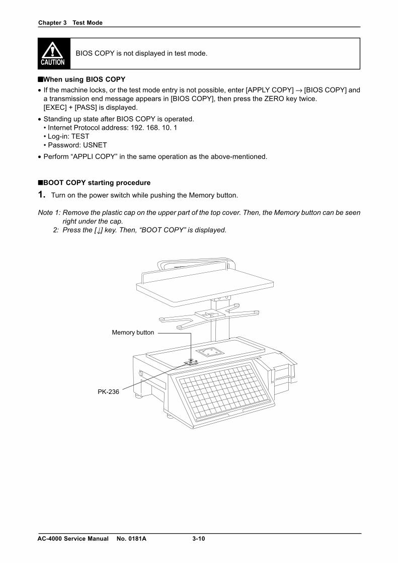
BIOS COPY is not displayed in test mode.
■■■■■When using BIOS COPY• If the machine locks, or the test mode entry is not possible, enter [APPLY COPY] → [BIOS COPY] and
a transmission end message appears in [BIOS COPY], then press the ZERO key twice.[EXEC] + [PASS] is displayed.
• Standing up state after BIOS COPY is operated.• Internet Protocol address: 192. 168. 10. 1• Log-in: TEST• Password: USNET
• Perform “APPLI COPY” in the same operation as the above-mentioned.
■BOOT COPY starting procedure
1. Turn on the power switch while pushing the Memory button.
Note 1: Remove the plastic cap on the upper part of the top cover. Then, the Memory button can be seenright under the cap.
2: Press the [↓] key. Then, “BOOT COPY” is displayed.
Chapter 3 Test Mode
3-11 AC-4000 Service Manual No. 0181A
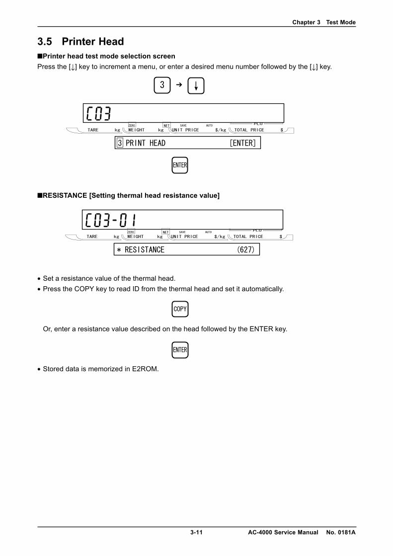
3.5 Printer Head■Printer head test mode selection screenPress the [↓] key to increment a menu, or enter a desired menu number followed by the [↓] key.
■RESISTANCE [Setting thermal head resistance value]
• Set a resistance value of the thermal head.• Press the COPY key to read ID from the thermal head and set it automatically.
Or, enter a resistance value described on the head followed by the ENTER key.
• Stored data is memorized in E2ROM.
➔
Chapter 3 Test Mode
AC-4000 Service Manual No. 0181A 3-12
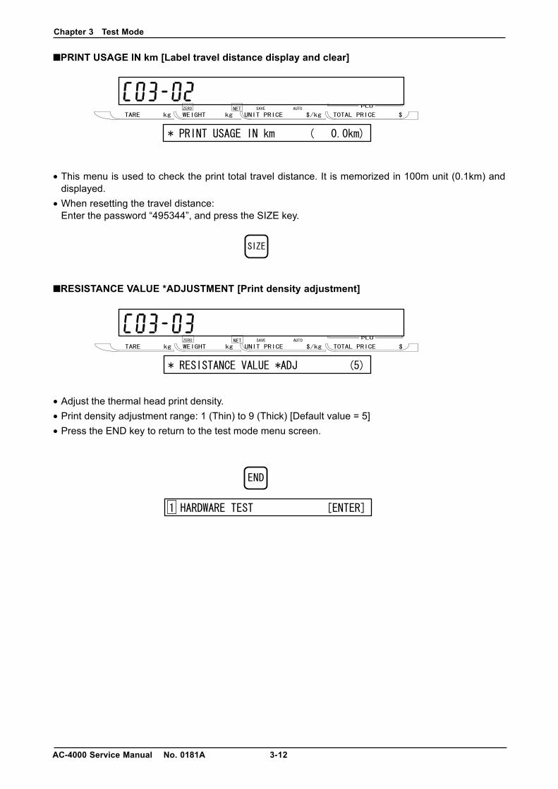
■PRINT USAGE IN km [Label travel distance display and clear]
• This menu is used to check the print total travel distance. It is memorized in 100m unit (0.1km) anddisplayed.
• When resetting the travel distance:Enter the password “495344”, and press the SIZE key.
■RESISTANCE VALUE *ADJUSTMENT [Print density adjustment]
• Adjust the thermal head print density.• Print density adjustment range: 1 (Thin) to 9 (Thick) [Default value = 5]• Press the END key to return to the test mode menu screen.
Chapter 3 Test Mode
3-13 AC-4000 Service Manual No. 0181A
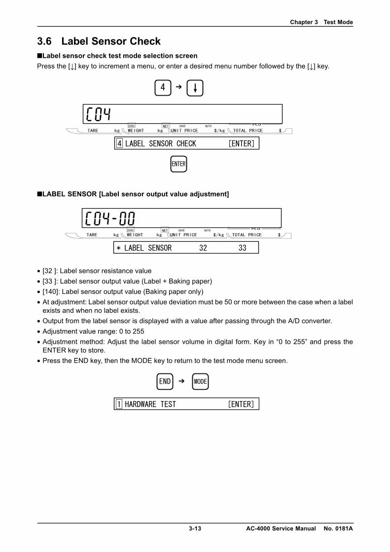
3.6 Label Sensor Check■Label sensor check test mode selection screenPress the [↓] key to increment a menu, or enter a desired menu number followed by the [↓] key.
■LABEL SENSOR [Label sensor output value adjustment]
• [32 ]: Label sensor resistance value• [33 ]: Label sensor output value (Label + Baking paper)• [140]: Label sensor output value (Baking paper only)• At adjustment: Label sensor output value deviation must be 50 or more between the case when a label
exists and when no label exists.• Output from the label sensor is displayed with a value after passing through the A/D converter.• Adjustment value range: 0 to 255• Adjustment method: Adjust the label sensor volume in digital form. Key in “0 to 255” and press the
ENTER key to store.• Press the END key, then the MODE key to return to the test mode menu screen.
➔
➔
Chapter 3 Test Mode
AC-4000 Service Manual No. 0181A 3-14
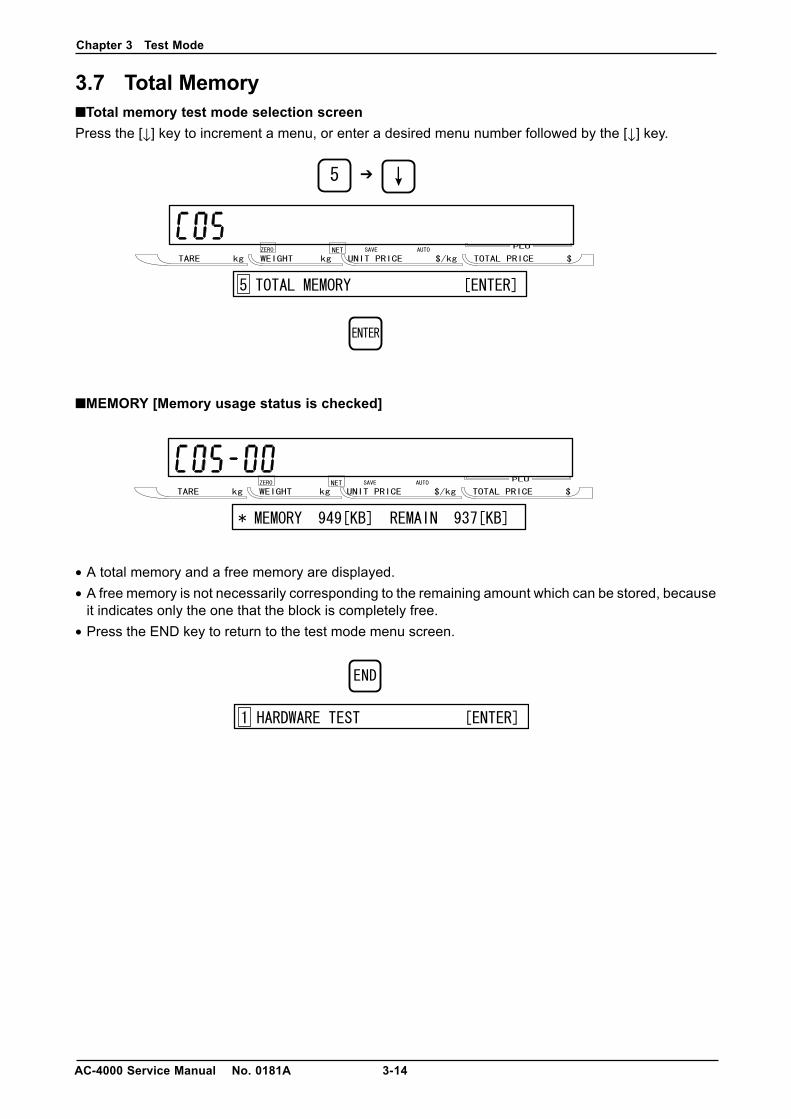
3.7 Total Memory■Total memory test mode selection screenPress the [↓] key to increment a menu, or enter a desired menu number followed by the [↓] key.
■MEMORY [Memory usage status is checked]
• A total memory and a free memory are displayed.• A free memory is not necessarily corresponding to the remaining amount which can be stored, because
it indicates only the one that the block is completely free.• Press the END key to return to the test mode menu screen.
➔
Chapter 3 Test Mode
3-15 AC-4000 Service Manual No. 0181A
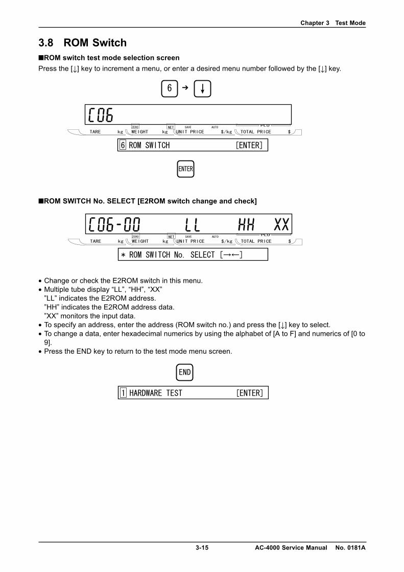
3.8 ROM Switch■ROM switch test mode selection screenPress the [↓] key to increment a menu, or enter a desired menu number followed by the [↓] key.
■ROM SWITCH No. SELECT [E2ROM switch change and check]
• Change or check the E2ROM switch in this menu.• Multiple tube display “LL”, “HH”, “XX”
”LL” indicates the E2ROM address.”HH” indicates the E2ROM address data.”XX” monitors the input data.
• To specify an address, enter the address (ROM switch no.) and press the [↓] key to select.• To change a data, enter hexadecimal numerics by using the alphabet of [A to F] and numerics of [0 to
9].• Press the END key to return to the test mode menu screen.
➔
Chapter 3 Test Mode
AC-4000 Service Manual No. 0181A 3-16
■ROM SWITCH No.
Note: “ROM SWITCH” items and default value vary depending on a country where the machine is used.• Value in ( ) indicates the default value.
[0]: Weight data zero suppression (4)[1]: Price data zero suppression (3)[2]: Unit price data zero suppression (3)[3]: DC motor (41)[4]: Fixed price item quantity addition “0”: Real number “1”: Fixed price item quantity[5]: Price calculation rate “0”: kg “1”: 100g[7]: Effective day calculation
When ROM SWITCH No.7 is “0”, packed date is included. When ROM SWITCH No.7 is othernumeric than “0”, packed date is not included, therefore, add one day to the current effective day.
[8]: Time rounding calculation 0, 1 to 30 (0)Function to increase the price based on the set minute at time now is set by standard.(Minute/No. 8) * No. 8
[Example]◊ Example: No. 8 = 1 min.
1 → 1 min., 2 → 2 min., ..... 59 → 59 min.◊ Example: No. 8 = 2 min.
1 → 0 min., 2 → 2 min., 3 → 2 min., 4 → 4 min., 5 → 4 min., ..... 58 → 58 min., 59 → 58 min.◊ Example: No. 8 = 3 min.
1 → 0 min., 2 → 0 min., 3 → 3 min., 4 → 3 min., 5 → 3 min., 6 → 6 min., ..... 57 → 57 min.58 → 57 min., 59 → 57 min.
..◊ Example: No. 8 = 30 min.
1 → 0 min., 2 → 0 min., 3 → 0 min., 4 → 0 min., 5 → 0 min., 6 → 0 min.29 → 0 min., ..... 30 → 30 min., 31 → 30 min., ..... 59 → 30 min.
[9]: Subtotal label item name mode0 : “sub total“ is printed.1: Item name is printed when an item is called.
[10]: Reset key 0: Enable 1: Disable (0)[11]: Automatic clear after totals are sent out
0: Not cleared (default) 1: Clear[15]: Price calculation fraction processing (0)
0: 3rd decimal digit round-down 1: 3rd decimal digit round off2: 2nd decimal digit round-down 3: 2nd decimal digit round off
[16] ITF BARCODE check digit calculation processing (0)0: 3131. . . . . from the right 1: 1313. . . . . from the right
[17]: Head fault check (0)0: Not available 1: Available (Set “0” for ASTRA XT)
[18]: Head fault check timing (0)0: When calling 1: When issuing (no provision) ff: Only when changing to normal mode
[19]: Head check type (0)0: Always at the head fault 1: When the number of head fault increases.
Chapter 3 Test Mode
3-17 AC-4000 Service Manual No. 0181A
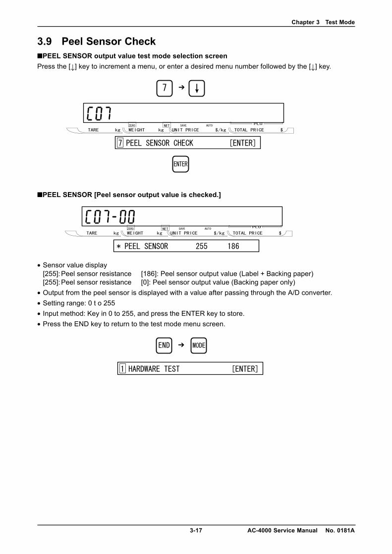
3.9 Peel Sensor Check■PEEL SENSOR output value test mode selection screenPress the [↓] key to increment a menu, or enter a desired menu number followed by the [↓] key.
■PEEL SENSOR [Peel sensor output value is checked.]
• Sensor value display[255]:Peel sensor resistance [186]: Peel sensor output value (Label + Backing paper)[255]:Peel sensor resistance [0]: Peel sensor output value (Backing paper only)
• Output from the peel sensor is displayed with a value after passing through the A/D converter.• Setting range: 0 t o 255• Input method: Key in 0 to 255, and press the ENTER key to store.• Press the END key to return to the test mode menu screen.
➔
➔
Chapter 4 Setup Mode
4-1 AC-4000 Service Manual No. 0181A
CHAPTER 4 SETUP MODE
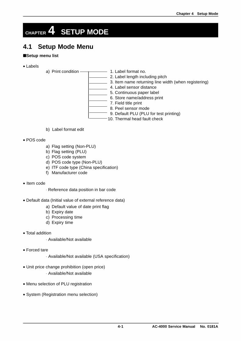
4.1 Setup Mode Menu■Setup menu list
• Labelsa) Print condition 1. Label format no.
2. Label length including pitch3. Item name returning line width (when registering)4. Label sensor distance5. Continuous paper label6. Store name/address print7. Field title print8. Peel sensor mode9. Default PLU (PLU for test printing)
10. Thermal head fault check
b) Label format edit
• POS code
a) Flag setting (Non-PLU)b) Flag setting (PLU)c) POS code systemd) POS code type (Non-PLU)e) ITF code type (China specification)f) Manufacturer code
• Item code
⋅ Reference data position in bar code
• Default data (Initial value of external reference data)
a) Default value of date print flagb) Expiry datec) Processing timed) Expiry time
• Total addition
⋅ Available/Not available
• Forced tare
⋅ Available/Not available (USA specification)
• Unit price change prohibition (open price)
⋅ Available/Not available
• Menu selection of PLU registration
• System (Registration menu selection)
Chapter 4 Setup Mode
AC-4000 Service Manual No. 0181A 4-2
• Ethernet setting
a) IP addressb) Gateway address setupc) Subnet mask setupd) Server address setupe) Log-in name setupf) Password setupg) Mac address setup
• System timer
• Password setting
a) Passwordb) Registrationc) Totald) Subtractione) Setupf) Tare
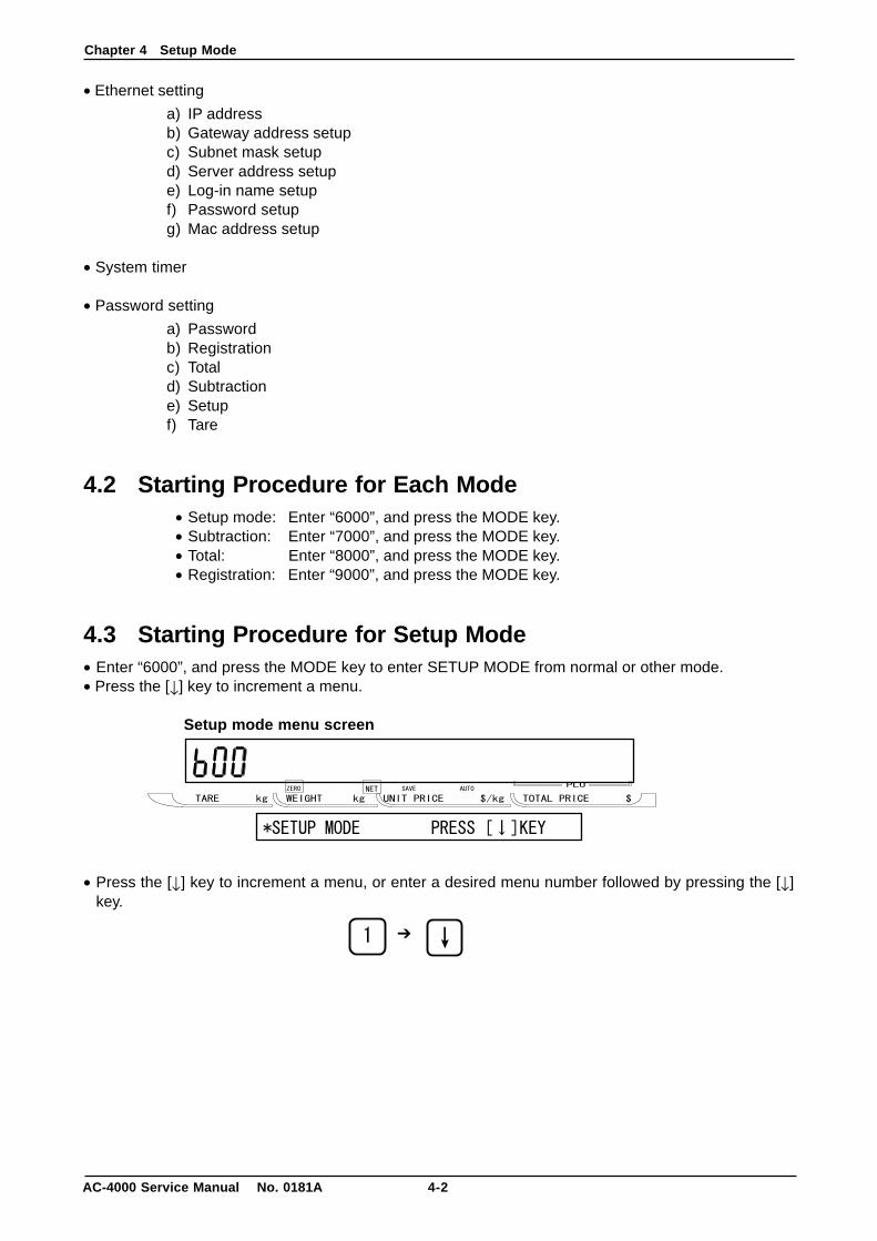
4.2 Starting Procedure for Each Mode• Setup mode: Enter “6000”, and press the MODE key.• Subtraction: Enter “7000”, and press the MODE key.• Total: Enter “8000”, and press the MODE key.• Registration: Enter “9000”, and press the MODE key.
4.3 Starting Procedure for Setup Mode• Enter “6000”, and press the MODE key to enter SETUP MODE from normal or other mode.• Press the [↓] key to increment a menu.
Setup mode menu screen
• Press the [↓] key to increment a menu, or enter a desired menu number followed by pressing the [↓]key.
➔
Chapter 4 Setup Mode
4-3 AC-4000 Service Manual No. 0181A
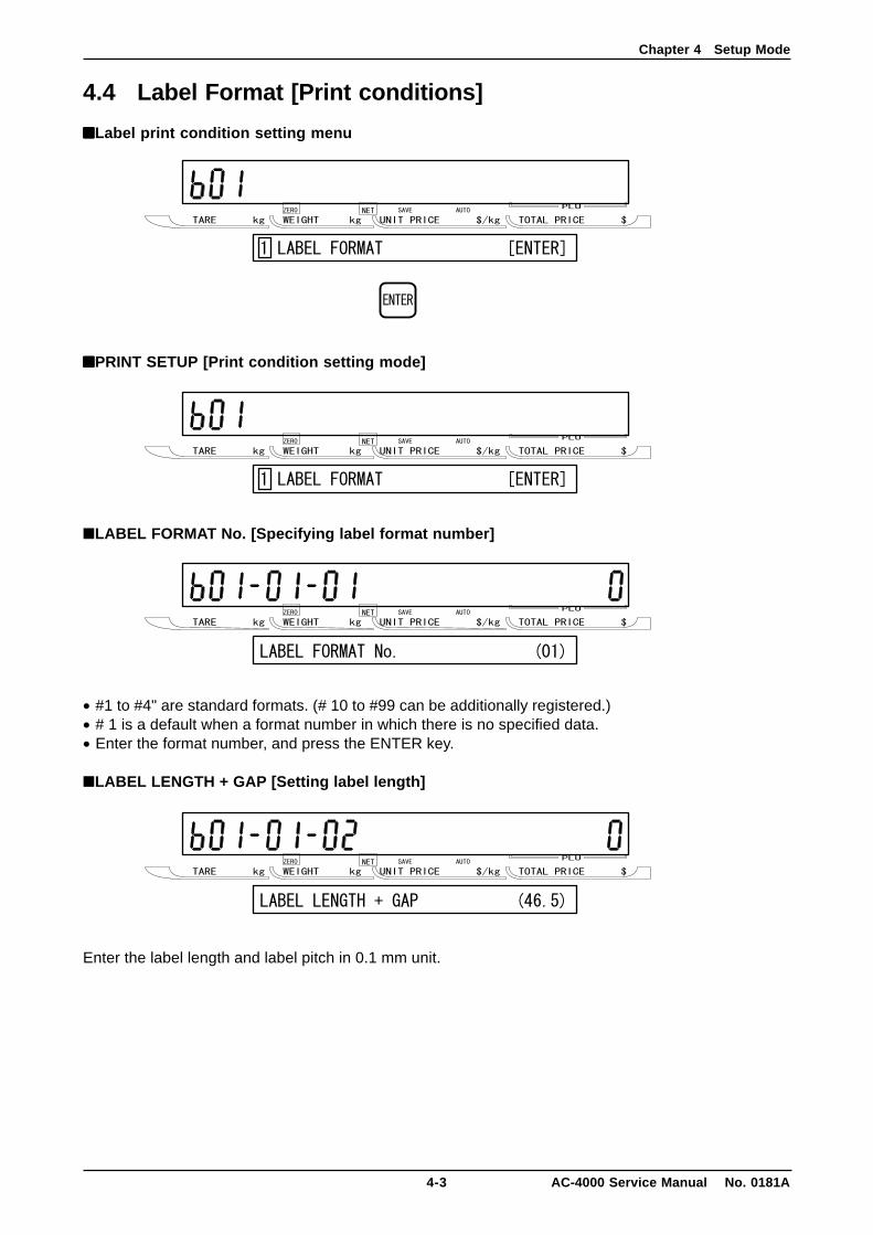
4.4 Label Format [Print conditions]
■■■■■Label print condition setting menu
■■■■■PRINT SETUP [Print condition setting mode]
■LABEL FORMAT No. [Specifying label format number]
• #1 to #4" are standard formats. (# 10 to #99 can be additionally registered.)• # 1 is a default when a format number in which there is no specified data.• Enter the format number, and press the ENTER key.
■LABEL LENGTH + GAP [Setting label length]
Enter the label length and label pitch in 0.1 mm unit.
Chapter 4 Setup Mode
AC-4000 Service Manual No. 0181A 4-4
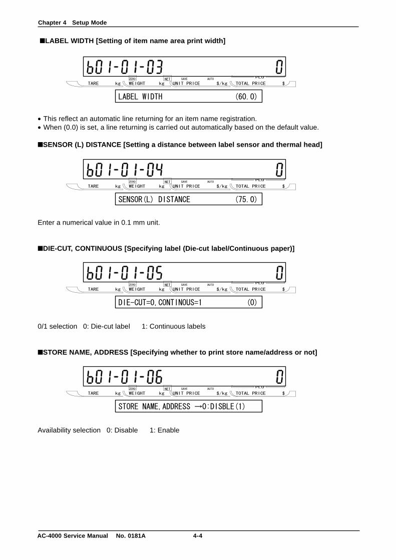
■LABEL WIDTH [Setting of item name area print width]
• This reflect an automatic line returning for an item name registration.• When (0.0) is set, a line returning is carried out automatically based on the default value.
■SENSOR (L) DISTANCE [Setting a distance between label sensor and thermal head]
Enter a numerical value in 0.1 mm unit.
■DIE-CUT, CONTINUOUS [Specifying label (Die-cut label/Continuous paper)]
0/1 selection 0: Die-cut label 1: Continuous labels
■STORE NAME, ADDRESS [Specifying whether to print store name/address or not]
Availability selection 0: Disable 1: Enable
Chapter 4 Setup Mode
4-5 AC-4000 Service Manual No. 0181A
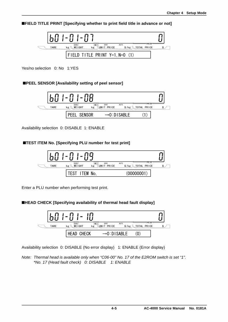
■FIELD TITLE PRINT [Specifying whether to print field title in advance or not]
Yes/no selection 0: No 1:YES
■PEEL SENSOR [Availability setting of peel sensor]
Availability selection 0: DISABLE 1: ENABLE
■TEST ITEM No. [Specifying PLU number for test print]
Enter a PLU number when performing test print.
■HEAD CHECK [Specifying availability of thermal head fault display]
Availability selection 0: DISABLE (No error display) 1: ENABLE (Error display)
Note: Thermal head is available only when “C06-00” No. 17 of the E2ROM switch is set “1”.*No. 17 (Head fault check) 0: DISABLE 1: ENABLE
Chapter 4 Setup Mode
AC-4000 Service Manual No. 0181A 4-6
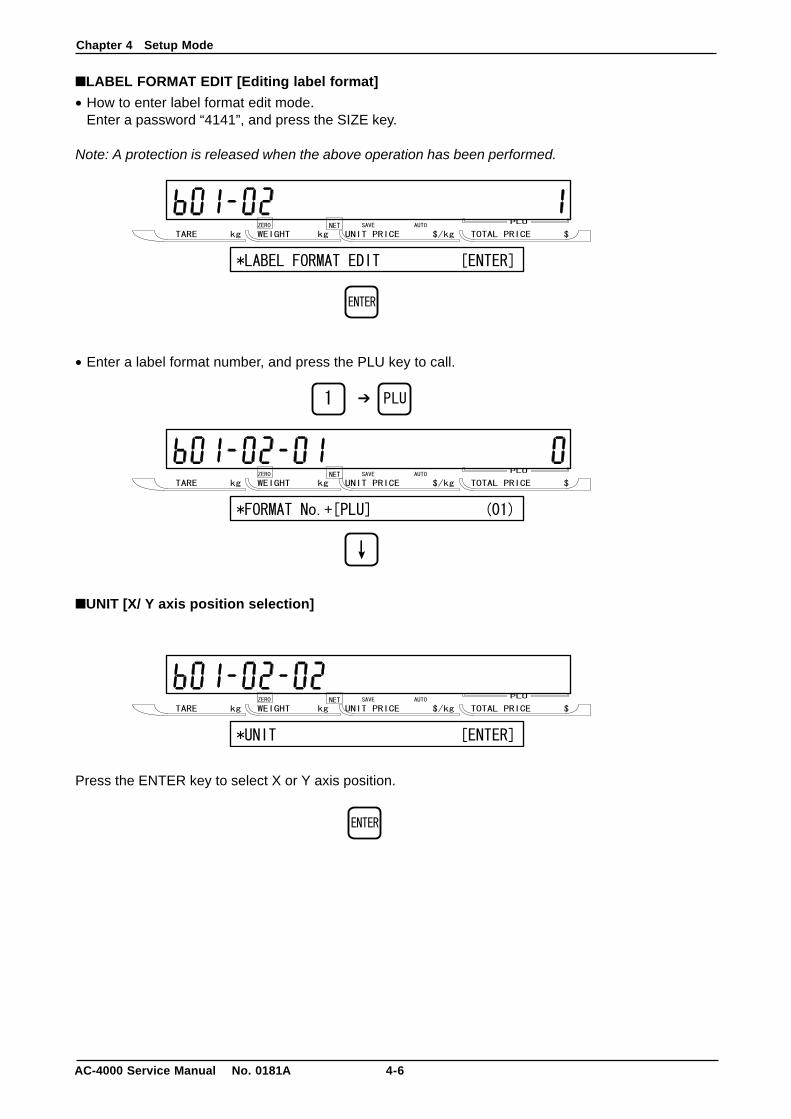
■LABEL FORMAT EDIT [Editing label format]
• How to enter label format edit mode.Enter a password “4141”, and press the SIZE key.
Note: A protection is released when the above operation has been performed.
• Enter a label format number, and press the PLU key to call.
■UNIT [X/ Y axis position selection]
Press the ENTER key to select X or Y axis position.
➔
Chapter 4 Setup Mode
4-7 AC-4000 Service Manual No. 0181A
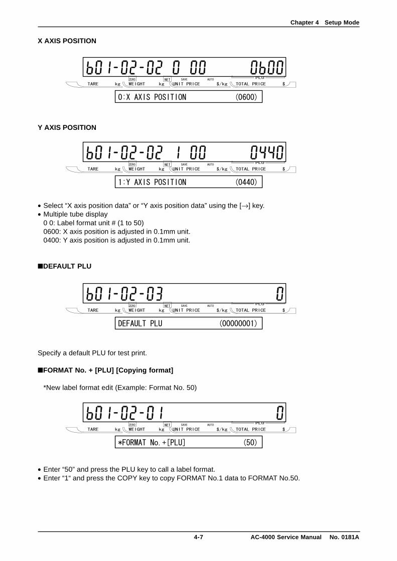
X AXIS POSITION
Y AXIS POSITION
• Select “X axis position data” or “Y axis position data” using the [→] key.• Multiple tube display
0 0: Label format unit # (1 to 50)0600: X axis position is adjusted in 0.1mm unit.0400: Y axis position is adjusted in 0.1mm unit.
■DEFAULT PLU
Specify a default PLU for test print.
■FORMAT No. + [PLU] [Copying format]
*New label format edit (Example: Format No. 50)
• Enter “50” and press the PLU key to call a label format.• Enter “1“ and press the COPY key to copy FORMAT No.1 data to FORMAT No.50.
Chapter 4 Setup Mode
AC-4000 Service Manual No. 0181A 4-8
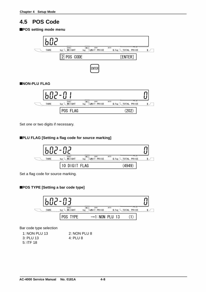
4.5 POS Code■■■■■POS setting mode menu
■NON-PLU FLAG
Set one or two digits if necessary.
■PLU FLAG [Setting a flag code for source marking]
Set a flag code for source marking.
■POS TYPE [Setting a bar code type]
Bar code type selection
1: NON PLU 13 2: NON PLU 83: PLU 13 4: PLU 85: ITF 18
Chapter 4 Setup Mode
4-9 AC-4000 Service Manual No. 0181A
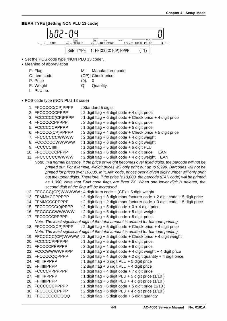
■BAR TYPE [Setting NON PLU 13 code]
• Set the POS code type “NON PLU 13 code”.• Meaning of abbreviation
F: Flag M: Manufacturer codeC: Item code (CP): Check priceP: Price (0): 0E: Weight Q: QuantityI: PLU no.
• POS code type (NON PLU 13 code)
1. FFCCCCC(CP)PPPP : Standard 5 digits2. FFCCCCCCPPPP : 2 digit flag + 6 digit code + 4 digit price3. FCCCCCC(CP)PPPP : 1 digit flag + 6 digit code + Check price + 4 digit price4. FFCCCCCPPPPP : 2 digit flag + 5 digit code + 5 digit price5. FCCCCCCPPPPP : 1 digit flag + 6 digit code + 5 digit price6. FFCCCC(CP)PPPPP : 2 digit flag + 4 digit code + Check price + 5 digit price7. FFCCCCCCWWWW : 2 digit flag + 6 digit code + 4 digit weight8. FCCCCCCWWWWW : 1 digit flag + 6 digit code + 5 digit weight9. FCCCCCIIIIII : 1 digit flag + 5 digit code + 6 digit PLU
10. FFCCCCCCPPPP : 2 digit flag + 6 digit code + 4 digit price EAN11. FFCCCCCCWWWW : 2 digit flag + 6 digit code + 4 digit weight EAN
Note: In a normal barcode, if the price or weight becomes over fixed digits, the barcode will not beprinted out. For example, 4-digit prices will only print out up to 9,999. Barcodes will not beprinted for prices over 10,000. In “EAN” code, prices over a given digit number will only printout the upper digits. Therefore, if the price is 10,000, the barcode (EAN code) will be printedas 1,000. Note that EAN code flags are fixed 2X. When one lower digit is deleted, thesecond digit of the flag will be increased.
12. FFCCCC(CP)WWWWW : 4 digit item code + (CP) + 5 digit weight13. FFMMMCCPPPPP : 2 digit flag + 3 digit manufacturer code + 2 digit code + 5 digit price14. FFMMCCCPPPPP : 2 digit flag + 2 digit manufacturer code + 3 digit code + 5 digit price15. FFCCCCCC(0)PPPP : 2 digit flag + 5 digit code + 0 + 4 digit price16. FFCCCCCWWWWW : 2 digit flag + 5 digit code + 5 digit weight17. FFCCCCCPPPPP : 2 digit flag + 5 digit code + 5 digit price
Note: The least significant digit of the total amount is omitted for barcode printing.18. FFCCCCC(CP)PPPP : 2 digit flag + 5 digit code + Check price + 4 digit price
Note: The least significant digit of the total amount is omitted for barcode printing.19. FFCCCCC(CP)WWWW : 2 digit flag + 5 digit code + Check price + 4 digit weight20. FCCCCCPPPPPP : 1 digit flag + 5 digit code + 6 digit price21. FFCCCCPPPPPP : 2 digit flag + 4 digit code + 6 digit price22. FCCCWWWWPPPP : 1 digit flag + 3 digit code + 4 digit weight + 4 digit price23. FFCCCCQQPPPP : 2 digit flag + 4 digit code + 2 digit quantity + 4 digit price24. FIIIIIIPPPPP : 1 digit flag + 6 digit PLU + 5 digit price25. FFIIIIIIPPPP : 2 digit flag + 6 digit PLU + 4 digit price26. FCCCCPPPPPPP : 1 digit flag + 4 digit code + 7 digit price27. FIIIIIIPPPPP : 1 digit flag + 6 digit PLU + 5 digit price (1/10 )28. FFIIIIIIPPPP : 2 digit flag + 6 digit PLU + 4 digit price (1/10 )29. FCCCCCCPPPPP : 1 digit flag + 6 digit code + 5 digit price (1/10 )30. FFCCCCCCPPPP : 2 digit flag + 6 digit PLU + 4 digit price (1/10 )31. FFCCCCCQQQQQ : 2 digit flag + 5 digit code + 5 digit quantity
Chapter 4 Setup Mode
AC-4000 Service Manual No. 0181A 4-10
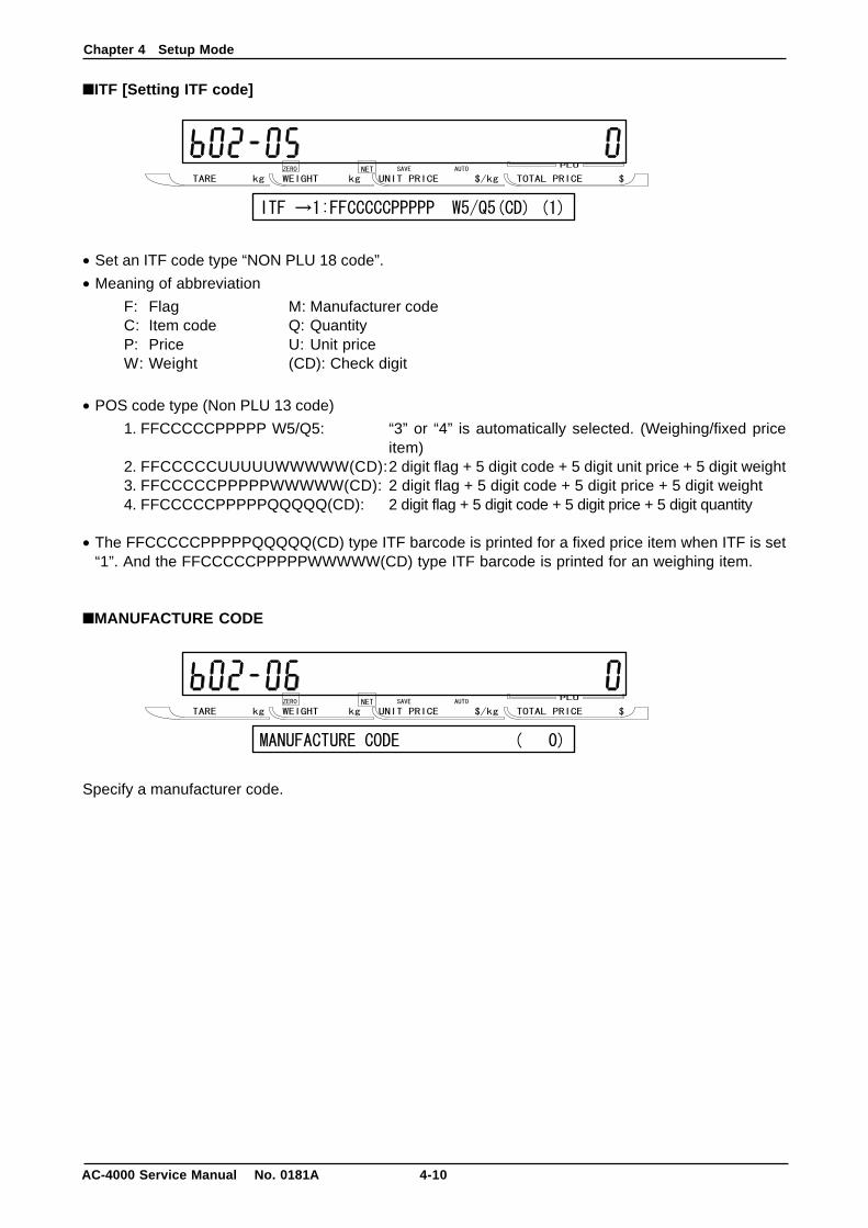
■ITF [Setting ITF code]
• Set an ITF code type “NON PLU 18 code”.
• Meaning of abbreviation
F: Flag M: Manufacturer codeC: Item code Q: QuantityP: Price U: Unit priceW: Weight (CD): Check digit
• POS code type (Non PLU 13 code)
1. FFCCCCCPPPPP W5/Q5: “3” or “4” is automatically selected. (Weighing/fixed priceitem)
2. FFCCCCCUUUUUWWWWW(CD):2 digit flag + 5 digit code + 5 digit unit price + 5 digit weight3. FFCCCCCPPPPPWWWWW(CD): 2 digit flag + 5 digit code + 5 digit price + 5 digit weight4. FFCCCCCPPPPPQQQQQ(CD): 2 digit flag + 5 digit code + 5 digit price + 5 digit quantity
• The FFCCCCCPPPPPQQQQQ(CD) type ITF barcode is printed for a fixed price item when ITF is set“1”. And the FFCCCCCPPPPPWWWWW(CD) type ITF barcode is printed for an weighing item.
■MANUFACTURE CODE
Specify a manufacturer code.
Chapter 4 Setup Mode
4-11 AC-4000 Service Manual No. 0181A
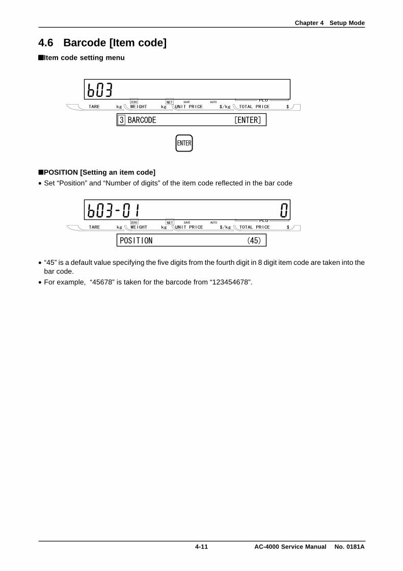
4.6 Barcode [Item code]■■■■■Item code setting menu
■POSITION [Setting an item code]
• Set “Position” and “Number of digits” of the item code reflected in the bar code
• “45” is a default value specifying the five digits from the fourth digit in 8 digit item code are taken into thebar code.
• For example, “45678” is taken for the barcode from “123454678”.
Chapter 4 Setup Mode
AC-4000 Service Manual No. 0181A 4-12
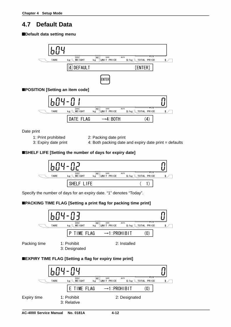
4.7 Default Data■■■■■Default data setting menu
■POSITION [Setting an item code]
Date print
1: Print prohibited 2: Packing date print3: Expiry date print 4: Both packing date and expiry date print = defaults
■SHELF LIFE [Setting the number of days for expiry date]
Specify the number of days for an expiry date. “1” denotes “Today”.
■PACKING TIME FLAG [Setting a print flag for packing time print]
Packing time 1: Prohibit 2: Installed3: Designated
■EXPIRY TIME FLAG [Setting a flag for expiry time print]
Expiry time 1: Prohibit 2: Designated3: Relative
Chapter 4 Setup Mode
4-13 AC-4000 Service Manual No. 0181A
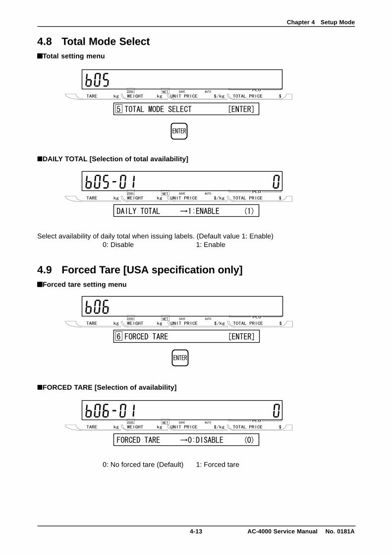
4.8 Total Mode Select■■■■■Total setting menu
■DAILY TOTAL [Selection of total availability]
Select availability of daily total when issuing labels. (Default value 1: Enable)0: Disable 1: Enable
4.9 Forced Tare [USA specification only]■■■■■Forced tare setting menu
■FORCED TARE [Selection of availability]
0: No forced tare (Default) 1: Forced tare
Chapter 4 Setup Mode
AC-4000 Service Manual No. 0181A 4-14
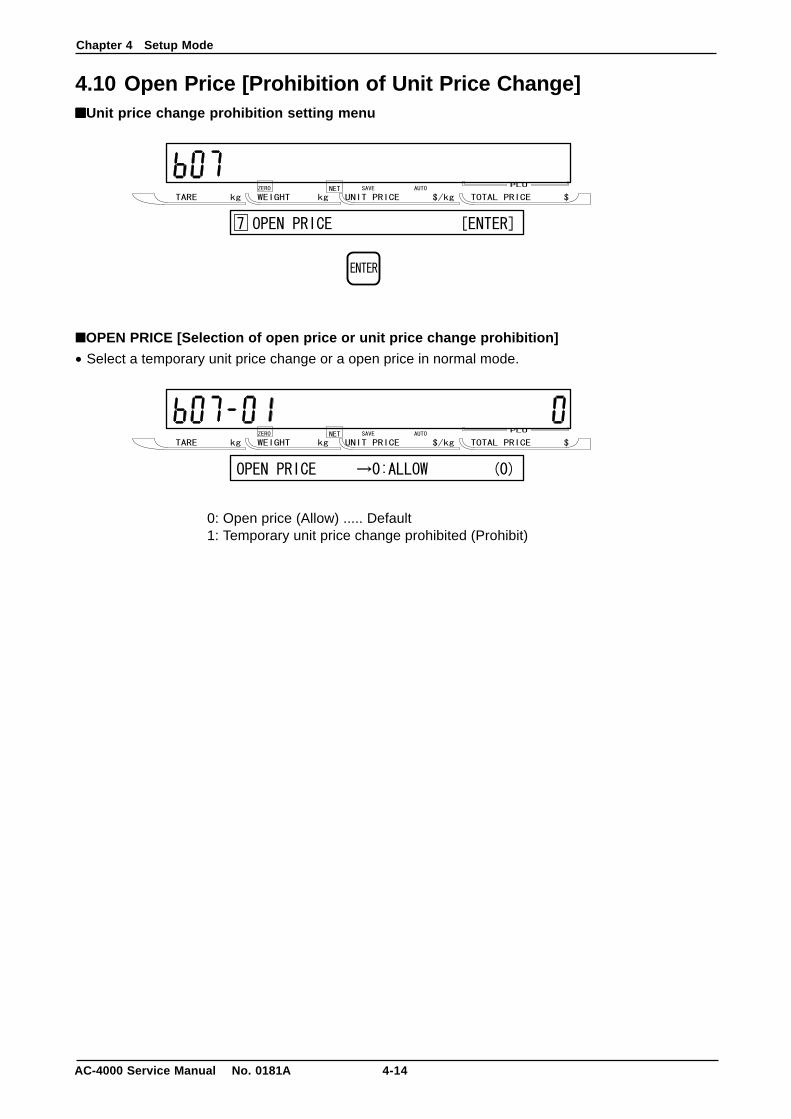
4.10 Open Price [Prohibition of Unit Price Change]■■■■■Unit price change prohibition setting menu
■OPEN PRICE [Selection of open price or unit price change prohibition]
• Select a temporary unit price change or a open price in normal mode.
0: Open price (Allow) ..... Default1: Temporary unit price change prohibited (Prohibit)
Chapter 4 Setup Mode
4-15 AC-4000 Service Manual No. 0181A
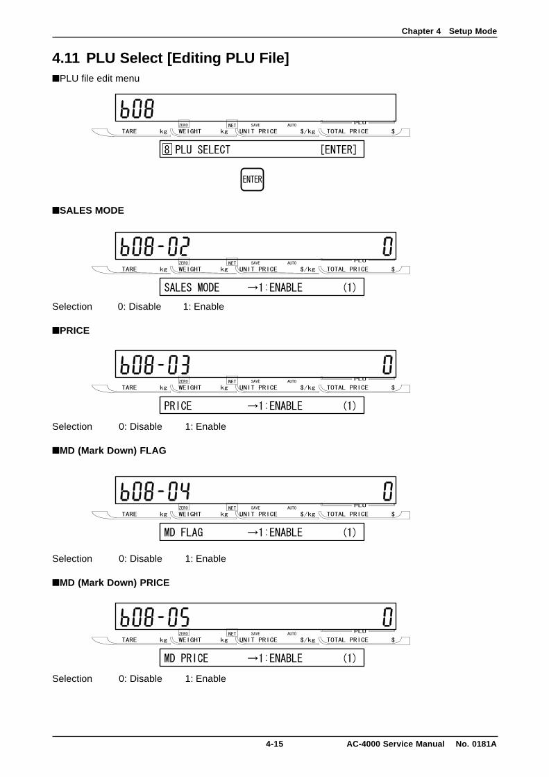
4.11 PLU Select [Editing PLU File]■PLU file edit menu
■SALES MODE
Selection 0: Disable 1: Enable
■PRICE
Selection 0: Disable 1: Enable
■MD (Mark Down) FLAG
Selection 0: Disable 1: Enable
■MD (Mark Down) PRICE
Selection 0: Disable 1: Enable
Chapter 4 Setup Mode
AC-4000 Service Manual No. 0181A 4-16
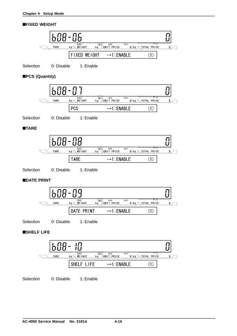
■FIXED WEIGHT
Selection 0: Disable 1: Enable
■PCS (Quantity)
Selection 0: Disable 1: Enable
■TARE
Selection 0: Disable 1: Enable
■DATE PRINT
Selection 0: Disable 1: Enable
■SHELF LIFE
Selection 0: Disable 1: Enable

Chapter 4 Setup Mode
4-17 AC-4000 Service Manual No. 0181A
■BEST BEFORE DATE FLAG
Selection 0: Disable 1: Enable
■BEST BEFORE DATE
Selection 0: Disable 1: Enable
■PACKING TIME FLAG
Selection 0: Disable 1: Enable
■PACKING TIME DATE
Selection 0: Disable 1: Enable
■EXPIRY TIME FLAG
Selection 0: Disable 1: Enable
Chapter 4 Setup Mode
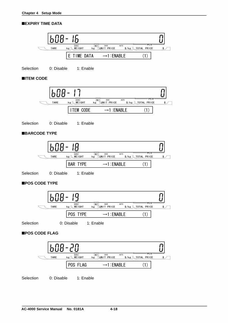
AC-4000 Service Manual No. 0181A 4-18
■EXPIRY TIME DATA
Selection 0: Disable 1: Enable
■ITEM CODE
Selection 0: Disable 1: Enable
■BARCODE TYPE
Selection 0: Disable 1: Enable
■POS CODE TYPE
Selection 0: Disable 1: Enable
■POS CODE FLAG
Selection 0: Disable 1: Enable

Chapter 4 Setup Mode
4-19 AC-4000 Service Manual No. 0181A
■POS CODE
Selection 0: Disable 1: Enable
■OPEN PRICE
Selection 0: Disable 1: Enable
■EXTRA MESSAGE 1
Selection 0: Disable 1: Enable
■EXTRA MESSAGE 2
Selection 0: Disable 1: Enable
■EXTRA MESSAGE 3
Selection 0: Disable 1: Enable

Chapter 4 Setup Mode
AC-4000 Service Manual No. 0181A 4-20
■COUPON MESSAGE
Selection 0: Disable 1: Enable
■LOGO IMAGE 1
Selection 0: Disable 1: Enable
■LOGO IMAGE 2
Selection 0: Disable 1: Enable
■LABEL FORMAT No.
Selection 0: Disable 1: Enable
■UPPER LIMIT
Selection 0: Disable 1: Enable
Chapter 4 Setup Mode
4-21 AC-4000 Service Manual No. 0181A
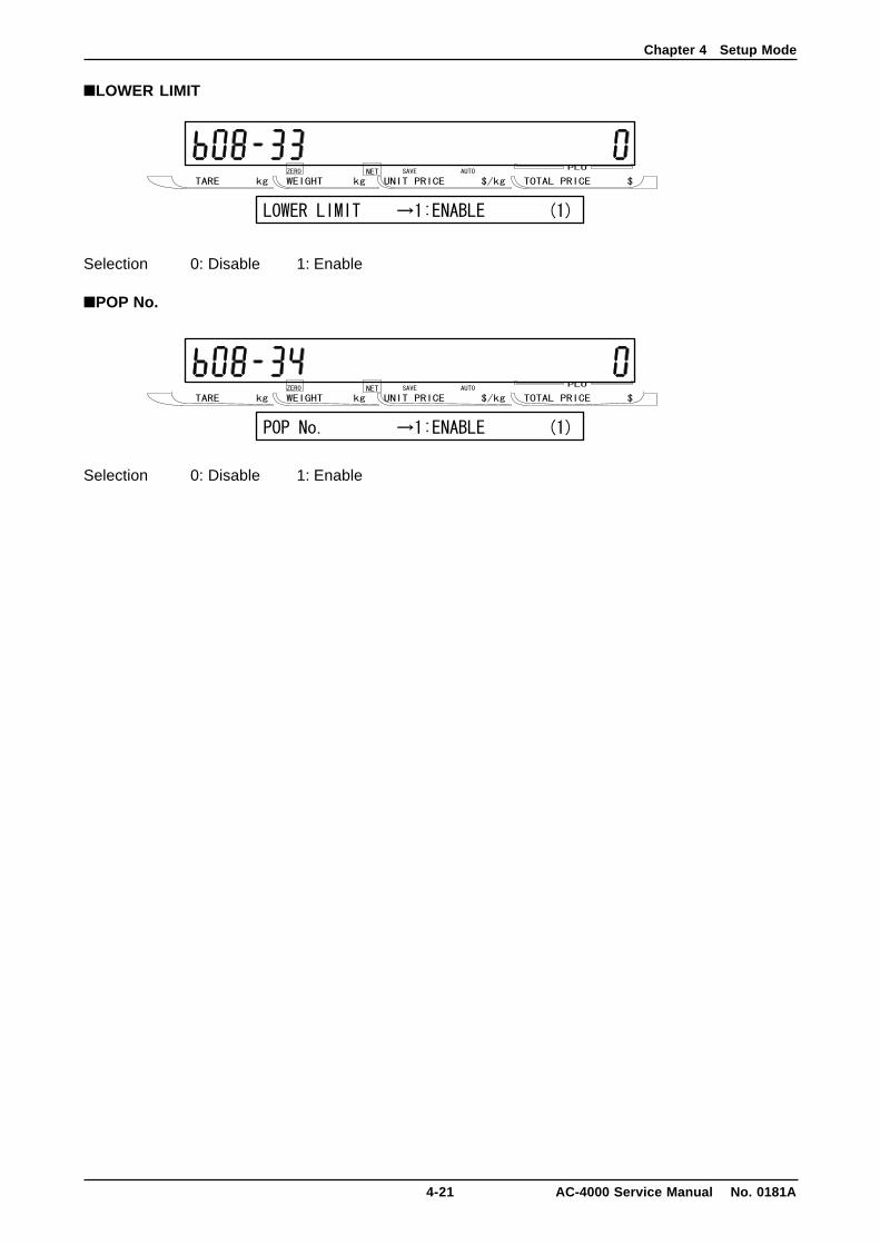
■LOWER LIMIT
Selection 0: Disable 1: Enable
■POP No.
Selection 0: Disable 1: Enable
Chapter 4 Setup Mode
AC-4000 Service Manual No. 0181A 4-22
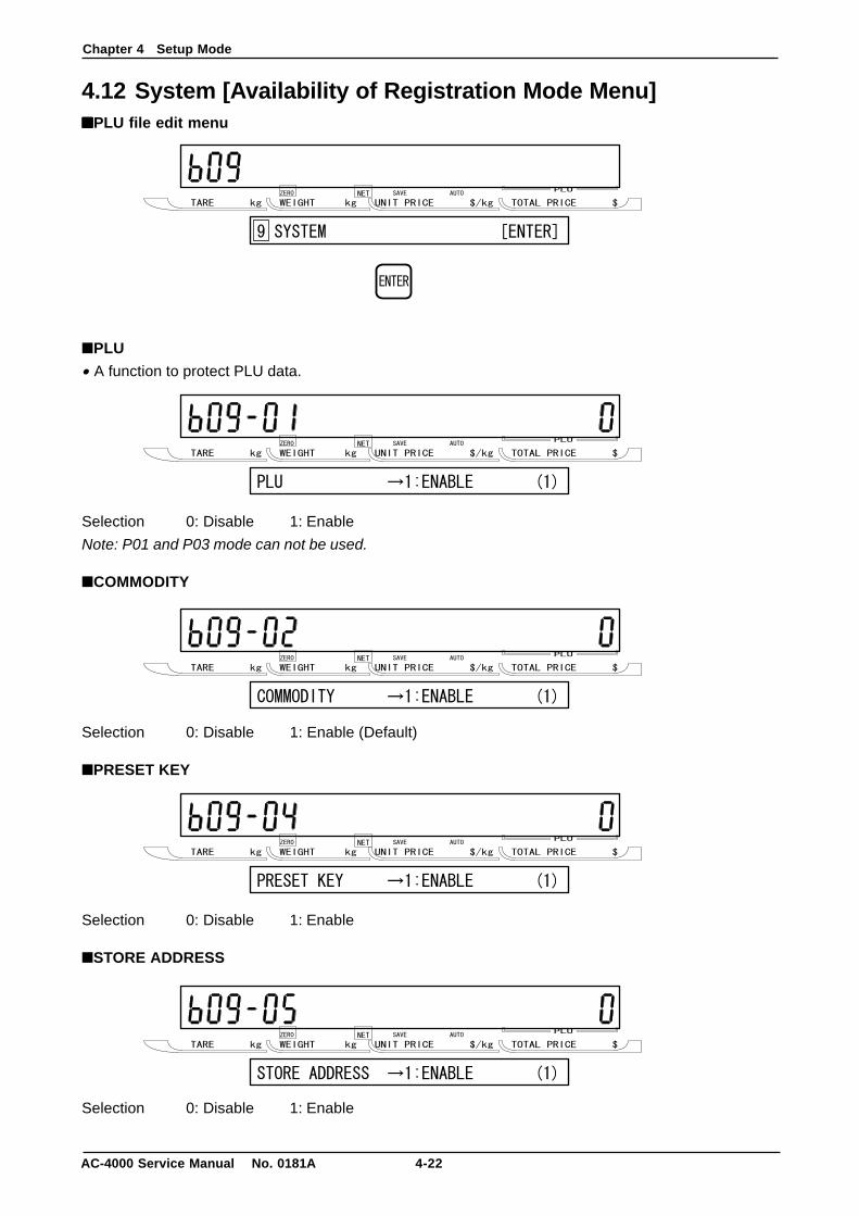
4.12 System [Availability of Registration Mode Menu]■■■■■PLU file edit menu
■PLU
• A function to protect PLU data.
Selection 0: Disable 1: Enable
Note: P01 and P03 mode can not be used.
■COMMODITY
Selection 0: Disable 1: Enable (Default)
■PRESET KEY
Selection 0: Disable 1: Enable
■STORE ADDRESS
Selection 0: Disable 1: Enable
Chapter 4 Setup Mode
4-23 AC-4000 Service Manual No. 0181A
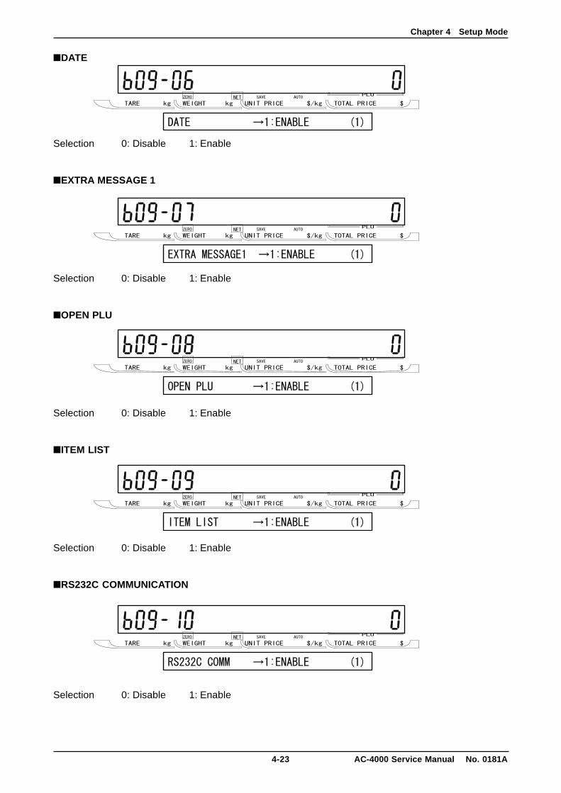
■DATE
Selection 0: Disable 1: Enable
■EXTRA MESSAGE 1
Selection 0: Disable 1: Enable
■OPEN PLU
Selection 0: Disable 1: Enable
■ITEM LIST
Selection 0: Disable 1: Enable
■RS232C COMMUNICATION
Selection 0: Disable 1: Enable
Chapter 4 Setup Mode
AC-4000 Service Manual No. 0181A 4-24
■COUPON MESSAGE
Selection 0: Disable 1: Enable
■EXTRA MESSAGE 2
Selection 0: Disable 1: Enable
■EXTRA MESSAGE 3
Selection 0: Disable 1: Enable
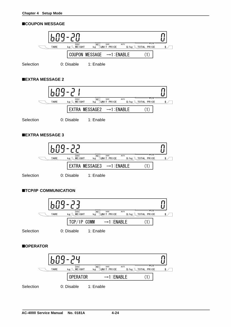
■TCP/IP COMMUNICATION
Selection 0: Disable 1: Enable
■OPERATOR
Selection 0: Disable 1: Enable
Chapter 4 Setup Mode
4-25 AC-4000 Service Manual No. 0181A
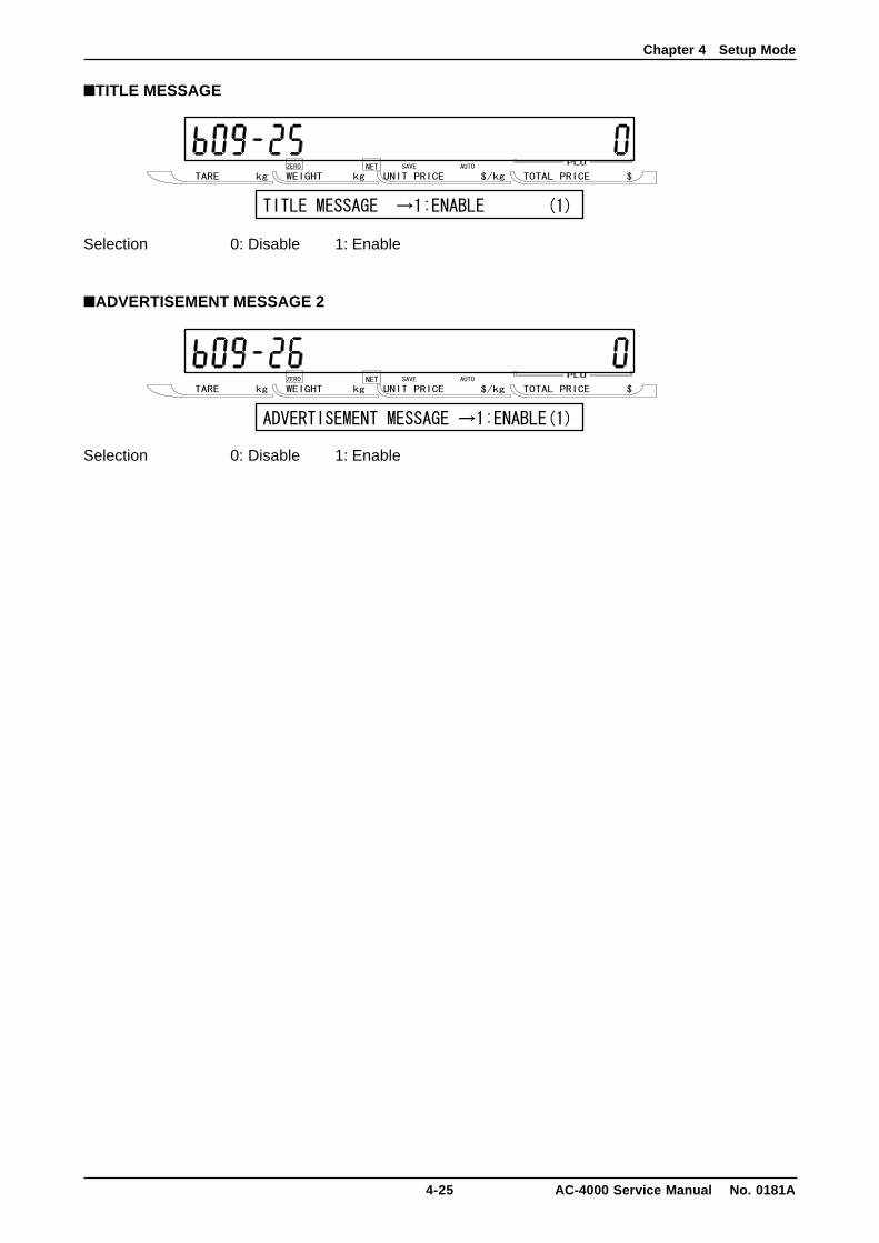
■TITLE MESSAGE
Selection 0: Disable 1: Enable
■ADVERTISEMENT MESSAGE 2
Selection 0: Disable 1: Enable
Chapter 4 Setup Mode
AC-4000 Service Manual No. 0181A 4-26
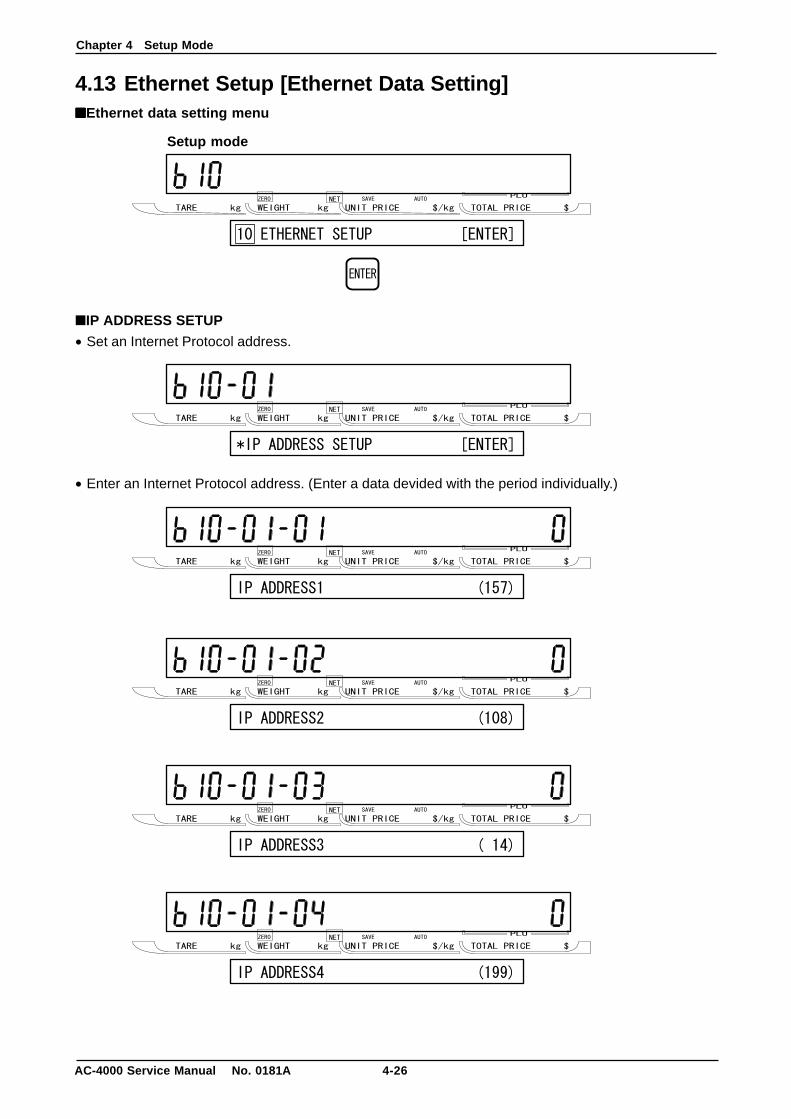
4.13 Ethernet Setup [Ethernet Data Setting]■■■■■Ethernet data setting menu
■IP ADDRESS SETUP
• Set an Internet Protocol address.
• Enter an Internet Protocol address. (Enter a data devided with the period individually.)
Setup mode

Chapter 4 Setup Mode
4-27 AC-4000 Service Manual No. 0181A
• Set a gateway address.
• Enter a gateway address. (Enter a data divided with the period individually.)
Chapter 4 Setup Mode
AC-4000 Service Manual No. 0181A 4-28
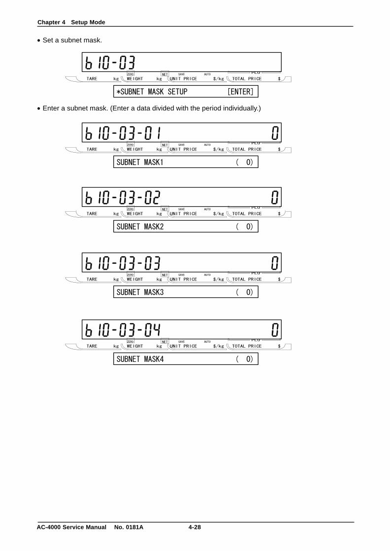
• Set a subnet mask.
• Enter a subnet mask. (Enter a data divided with the period individually.)
Chapter 4 Setup Mode
4-29 AC-4000 Service Manual No. 0181A
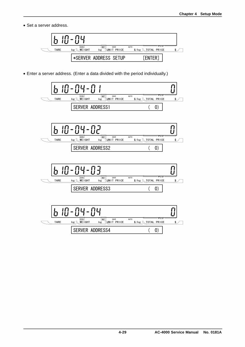
• Set a server address.
• Enter a server address. (Enter a data divided with the period individually.)
Chapter 4 Setup Mode
AC-4000 Service Manual No. 0181A 4-30
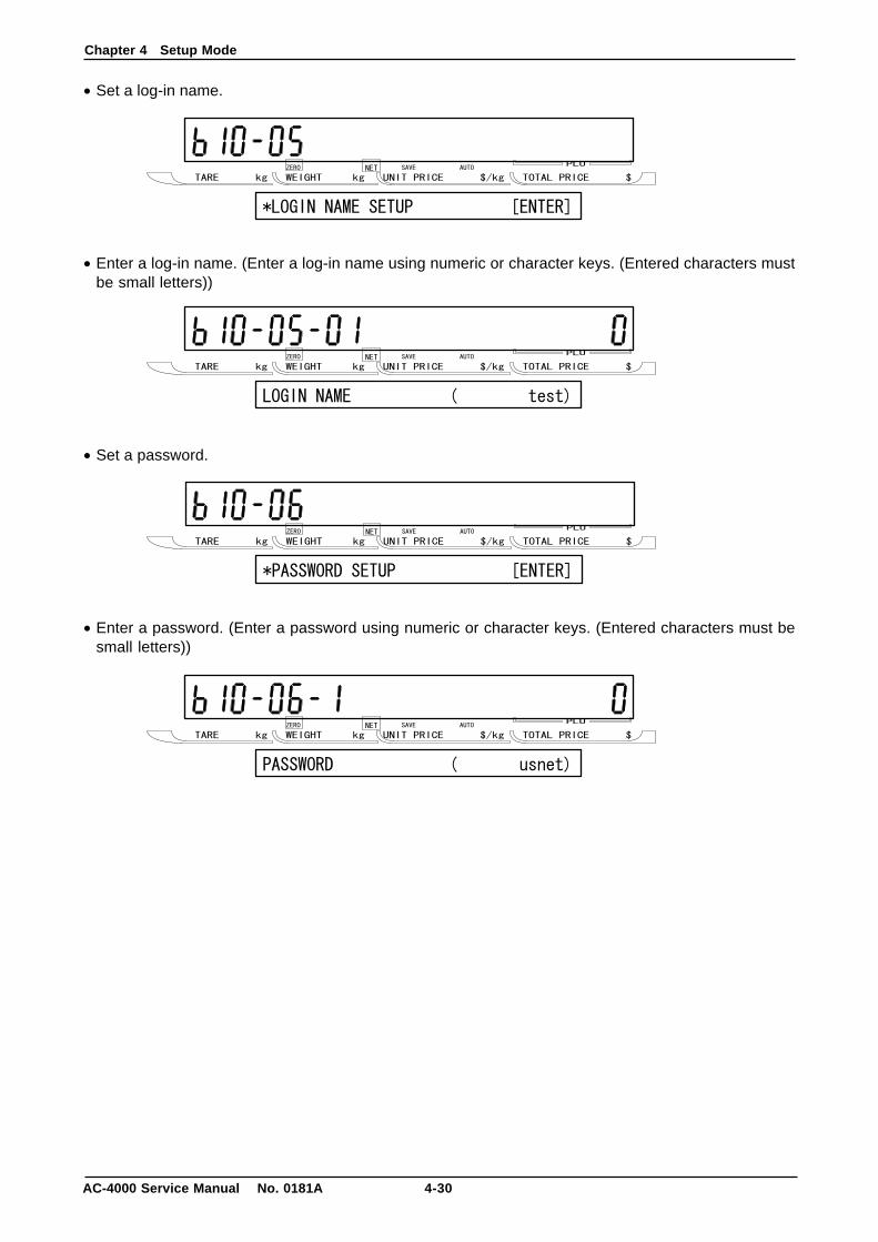
• Set a log-in name.
• Enter a log-in name. (Enter a log-in name using numeric or character keys. (Entered characters mustbe small letters))
• Set a password.
• Enter a password. (Enter a password using numeric or character keys. (Entered characters must besmall letters))
Chapter 4 Setup Mode
4-31 AC-4000 Service Manual No. 0181A
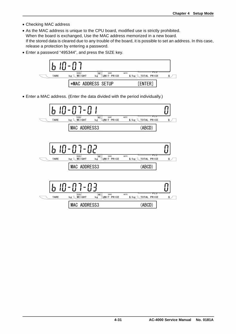
• Checking MAC address
• As the MAC address is unique to the CPU board, modified use is strictly prohibited.When the board is exchanged, Use the MAC address memorized in a new board.If the stored data is cleared due to any trouble of the board, it is possible to set an address. In this case,release a protection by entering a password.
• Enter a password “495344”, and press the SIZE key.
• Enter a MAC address. (Enter the data divided with the period individually.)
Chapter 4 Setup Mode
AC-4000 Service Manual No. 0181A 4-32
4.14 System Timer■■■■■System timer setting menu
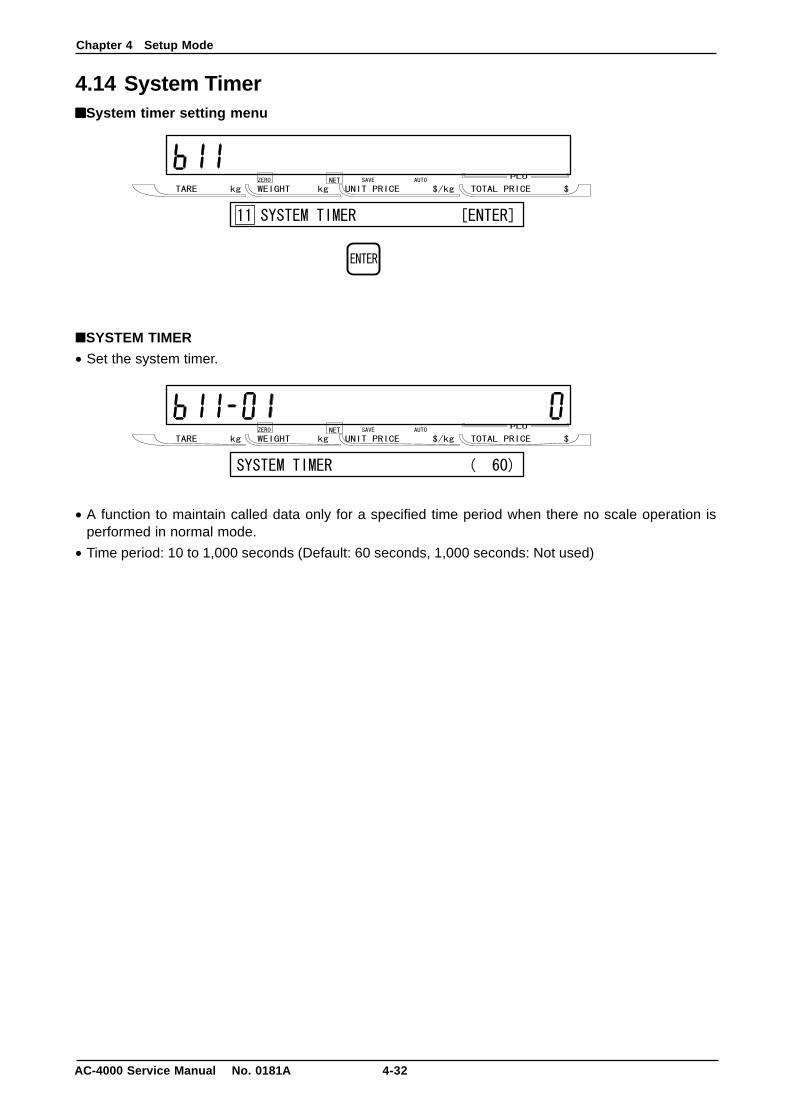
■SYSTEM TIMER
• Set the system timer.
• A function to maintain called data only for a specified time period when there no scale operation isperformed in normal mode.
• Time period: 10 to 1,000 seconds (Default: 60 seconds, 1,000 seconds: Not used)
Chapter 4 Setup Mode
4-33 AC-4000 Service Manual No. 0181A
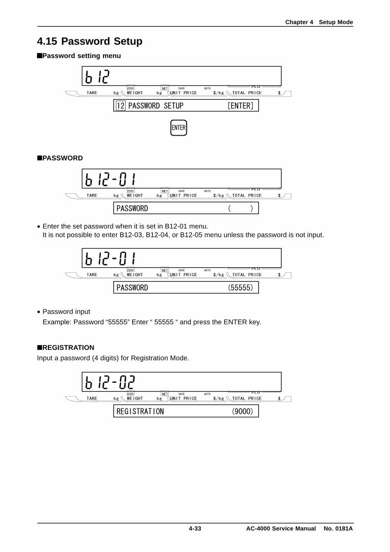
4.15 Password Setup■■■■■Password setting menu
■PASSWORD
• Enter the set password when it is set in B12-01 menu.It is not possible to enter B12-03, B12-04, or B12-05 menu unless the password is not input.
• Password input
Example: Password “55555” Enter “ 55555 “ and press the ENTER key.
■REGISTRATION
Input a password (4 digits) for Registration Mode.
Chapter 4 Setup Mode
AC-4000 Service Manual No. 0181A 4-34
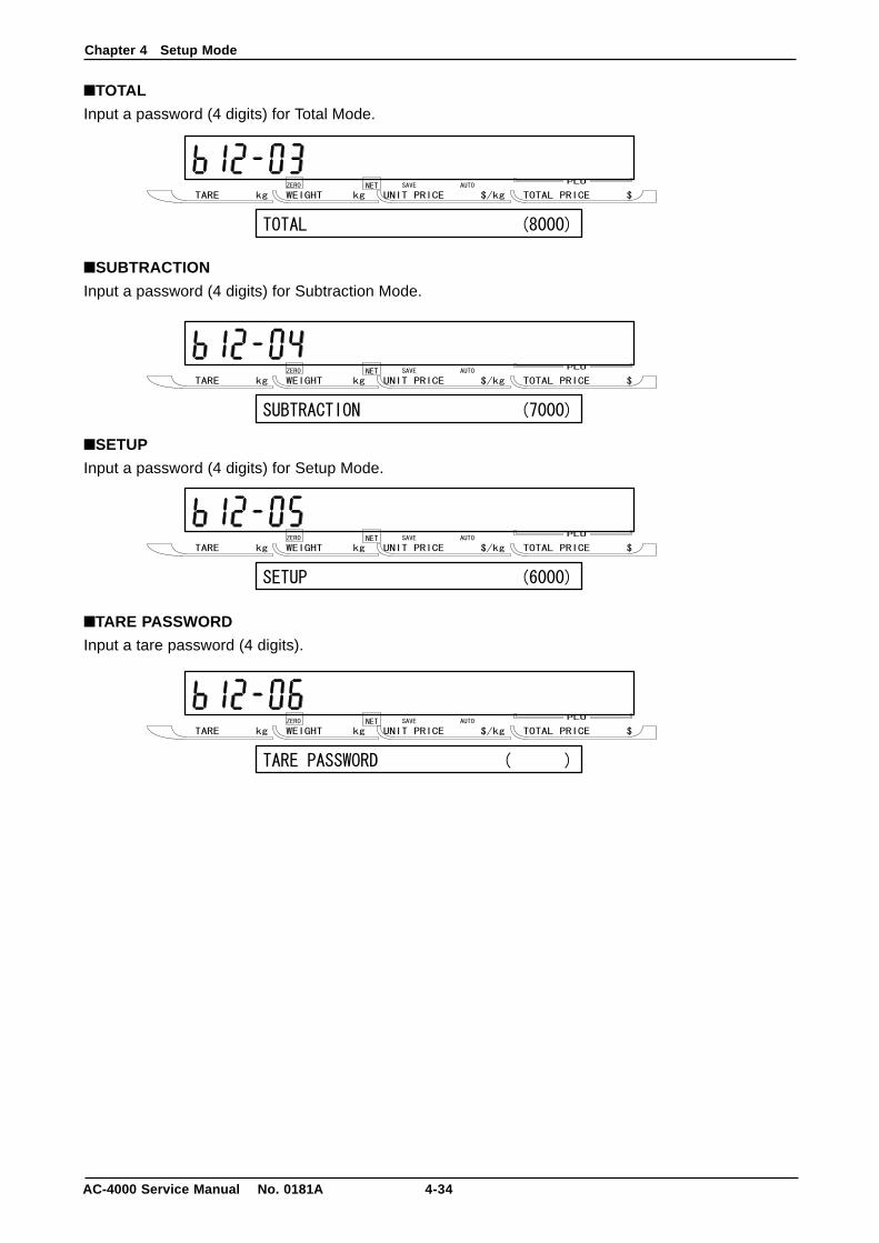
■TOTAL
Input a password (4 digits) for Total Mode.
■SUBTRACTION
Input a password (4 digits) for Subtraction Mode.
■SETUP
Input a password (4 digits) for Setup Mode.
■TARE PASSWORD
Input a tare password (4 digits).
Chapter 5 Electricity Composition
5-1 AC-4000 Service Manual No. 0181A
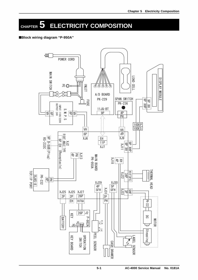
CHAPTER 5 ELECTRICITY COMPOSITION
■Block wiring diagram “P-950A”
Chapter 5 Electricity Composition
AC-4000 Service Manual No. 0181A 5-2
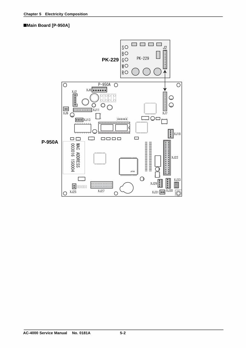
■Main Board [P-950A]
P-950A
PK-229

Chapter 5 Electricity Composition
5-3 AC-4000 Service Manual No. 0181A
■AC-4000 (B/E) Main Unit (PK-950A) Connector Signal Name
XJ2: 9P D-SUB (Receptacle Plug), RS232C
XJ6: B6P-VH, DC Power Supply
XJ7: B11B-XH -A, A/D Board
XJ9: B2B-XH, -A Span Switch (PK-236)
XJ11: B9B-XH-A VFD I/F, (Display Module)
XJ13: B4B-PH K-S, TCP/IP Port
No Signal Name1 RXD2 TXD3 DTR
No Signal Name4 SG5 RTS6 CTS
No Signal Name1 24V2 24V3 24V
No Signal Name4 GND5 GND6 GND
No Signal Name1 SW
No Signal Name2 GND
No Signal Name1 TX+2 TX–
No Signal Name3 RX+4 RX–
No Signal Name1 DF XIN2 XIN3 SDATA4 SCLK5 CS6 CONV
No Signal Name7 CAL8 DRDY9 GND10 VH(+12V)11 RES
No Signal Name1 +5V2 GND3 +24V4 VH GND5 DATA
No Signal Name6 DATA #7 FG8 SG9 RES
Chapter 5 Electricity Composition
AC-4000 Service Manual No. 0181A 5-4
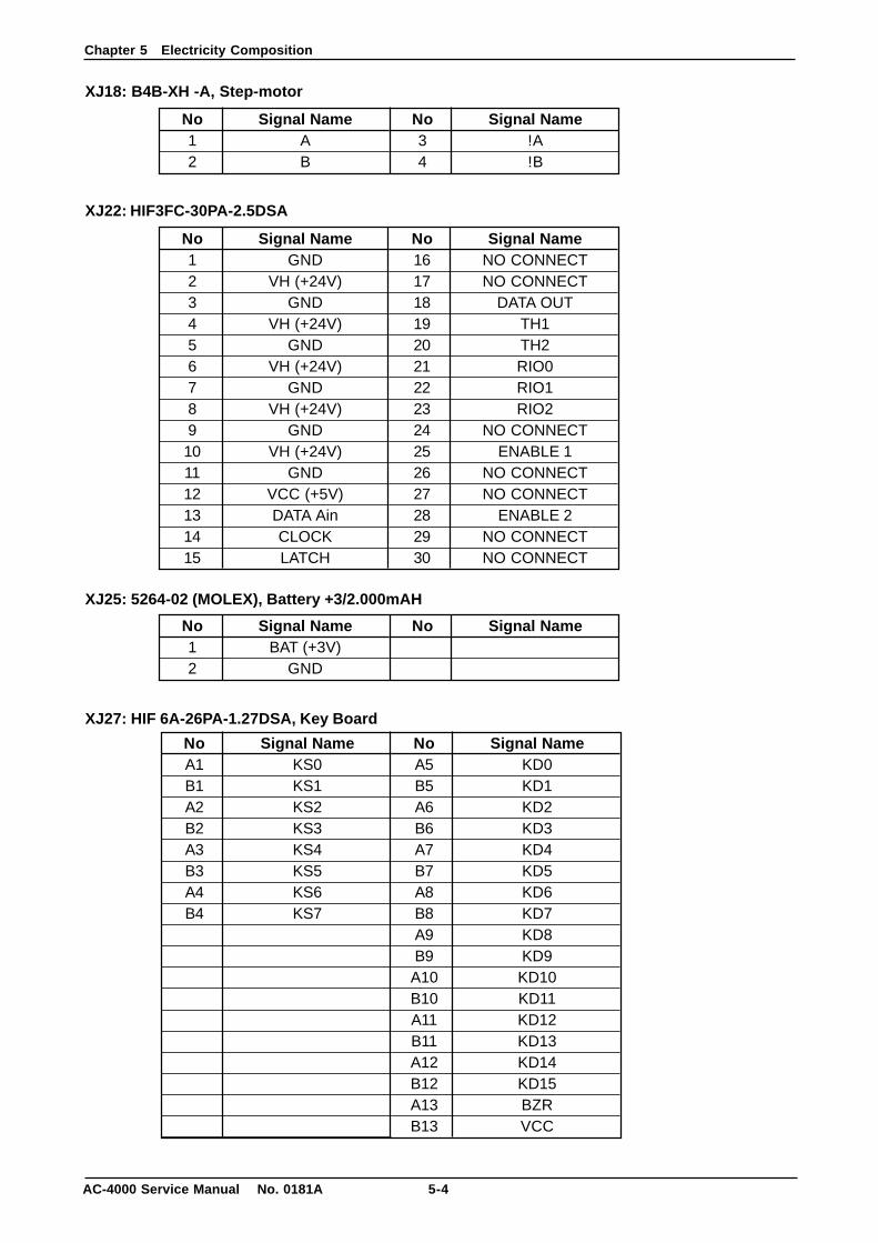
XJ18: B4B-XH -A, Step-motor
XJ22: HIF3FC-30PA-2.5DSA
XJ25: 5264-02 (MOLEX), Battery +3/2.000mAH
XJ27: HIF 6A-26PA-1.27DSA, Key Board
No Signal Name1 A2 B
No Signal Name3 !A4 !B
No Signal Name1 BAT (+3V)2 GND
No Signal Name
No Signal Name1 GND2 VH (+24V)3 GND4 VH (+24V)5 GND6 VH (+24V)7 GND8 VH (+24V)9 GND10 VH (+24V)11 GND12 VCC (+5V)13 DATA Ain14 CLOCK15 LATCH
No Signal Name16 NO CONNECT17 NO CONNECT18 DATA OUT19 TH120 TH221 RIO022 RIO123 RIO224 NO CONNECT25 ENABLE 126 NO CONNECT27 NO CONNECT28 ENABLE 229 NO CONNECT30 NO CONNECT
No Signal NameA1 KS0B1 KS1A2 KS2B2 KS3A3 KS4B3 KS5A4 KS6B4 KS7
No Signal NameA5 KD0B5 KD1A6 KD2B6 KD3A7 KD4B7 KD5A8 KD6B8 KD7A9 KD8B9 KD9A10 KD10B10 KD11A11 KD12B11 KD13A12 KD14B12 KD15A13 BZRB13 VCC
Chapter 5 Electricity Composition
5-5 AC-4000 Service Manual No. 0181A
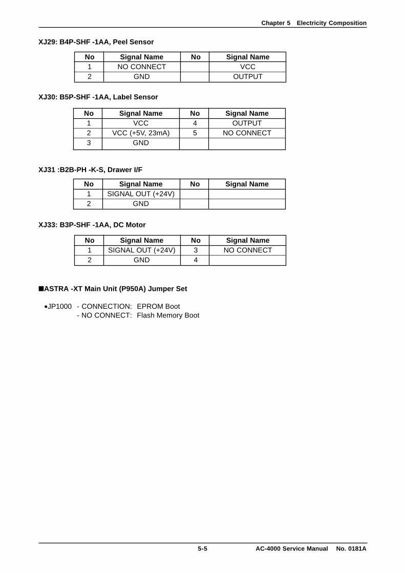
XJ29: B4P-SHF -1AA, Peel Sensor
XJ30: B5P-SHF -1AA, Label Sensor
XJ31 :B2B-PH -K-S, Drawer I/F
XJ33: B3P-SHF -1AA, DC Motor
■ASTRA -XT Main Unit (P950A) Jumper Set
•JP1000 - CONNECTION: EPROM Boot- NO CONNECT: Flash Memory Boot
No Signal Name1 NO CONNECT2 GND
No Signal NameVCC
OUTPUT
No Signal Name1 SIGNAL OUT (+24V)2 GND
No Signal Name
No Signal Name1 SIGNAL OUT (+24V)2 GND
No Signal Name3 NO CONNECT4
No Signal Name1 VCC2 VCC (+5V, 23mA)3 GND
No Signal Name4 OUTPUT5 NO CONNECT
Chapter 5 Electricity Composition
AC-4000 Service Manual No. 0181A 5-6
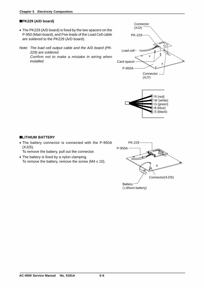
■PK229 (A/D board)
• The PK229 (A/D board) is fixed by the two spacers on theP-950 (Main board), and Five leads of the Load Cell cableare soldered to the PK229 (A/D board).
Note: The load cell output cable and the A/D board (PK-229) are soldered.Confirm not to make a mistake in wiring wheninstalled.
■LITHIUM BATTERY
• The battery connector is connected with the P-950A(XJ25).To remove the battery, pull out the connector.
• The battery is fixed by a nylon clamping.To remove the battery, remove the screw (M4 x 10).
R (red)W (white)G (green)B (blue)S (black)
Battery( Lithium battery)
Connector(XJ25)
P-950A
PK-229
Card spacer
Connector(XJ2)
Connector(XJ7)
Load cell
PK-229
P-950A
Chapter 5 Electricity Composition
5-7 AC-4000 Service Manual No. 0181A
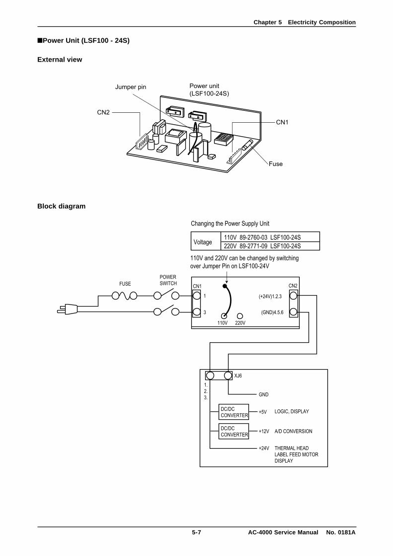
■Power Unit (LSF100 - 24S)
External view
Block diagram
Chapter 5 Electricity Composition
AC-4000 Service Manual No. 0181A 5-8
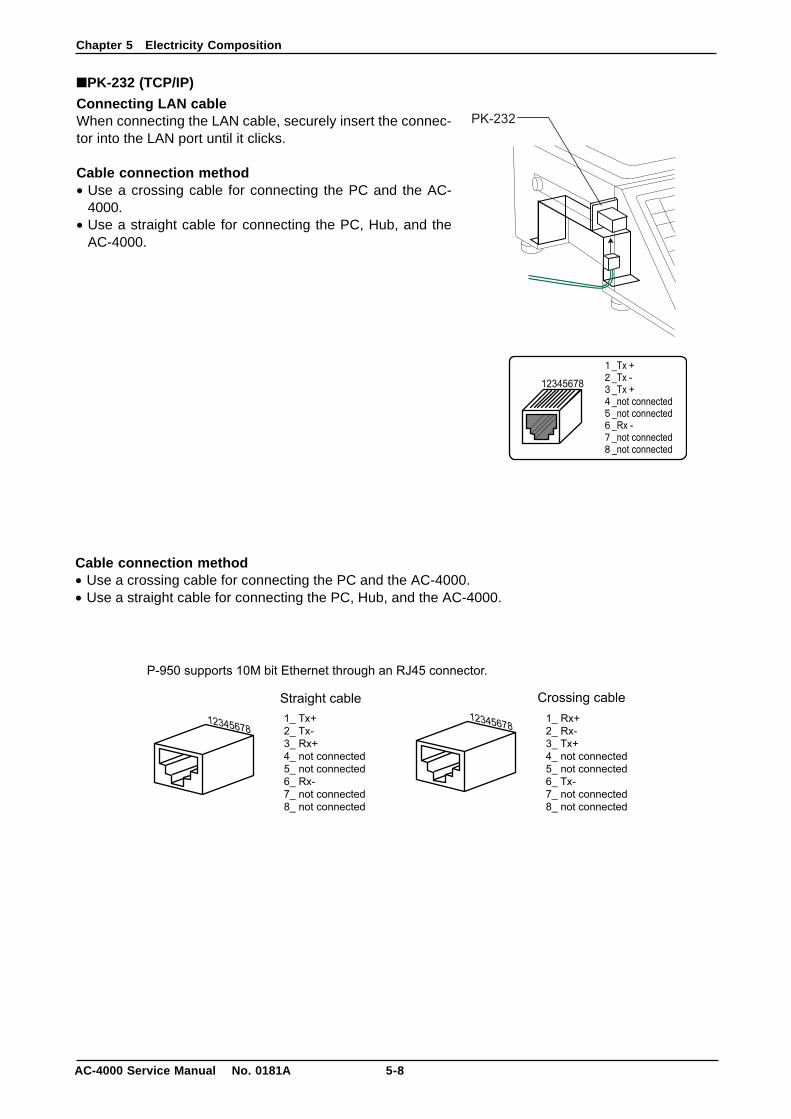
■PK-232 (TCP/IP)
Connecting LAN cableWhen connecting the LAN cable, securely insert the connec-tor into the LAN port until it clicks.
Cable connection method• Use a crossing cable for connecting the PC and the AC-
4000.• Use a straight cable for connecting the PC, Hub, and the
AC-4000.
Cable connection method• Use a crossing cable for connecting the PC and the AC-4000.• Use a straight cable for connecting the PC, Hub, and the AC-4000.
Chapter 5 Electricity Composition
5-9 AC-4000 Service Manual No. 0181A
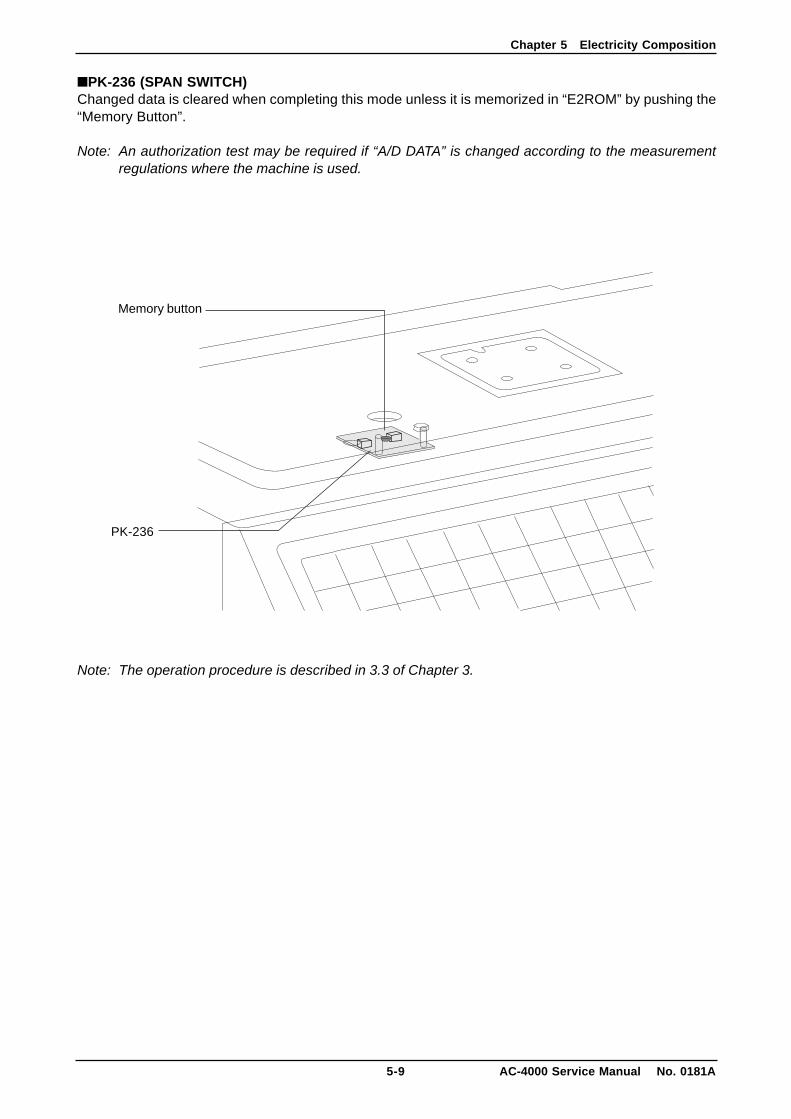
■PK-236 (SPAN SWITCH)Changed data is cleared when completing this mode unless it is memorized in “E2ROM” by pushing the“Memory Button”.
Note: An authorization test may be required if “A/D DATA” is changed according to the measurementregulations where the machine is used.
Note: The operation procedure is described in 3.3 of Chapter 3.
PK-236
Memory button
Chapter 5 Electricity Composition
AC-4000 Service Manual No. 0181A 5-10
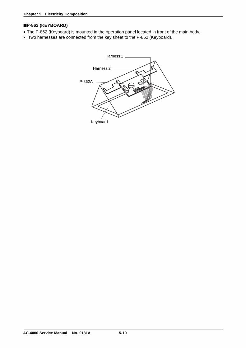
■P-862 (KEYBOARD)
• The P-862 (Keyboard) is mounted in the operation panel located in front of the main body.• Two harnesses are connected from the key sheet to the P-862 (Keyboard).
Harness 1
Harness 2
P-862A
Keyboard
Chapter 6 Troubleshooting
6-1 AC-4000 Service Manual No. 0181A
CHAPTER 6 TROUBLESHOOTING
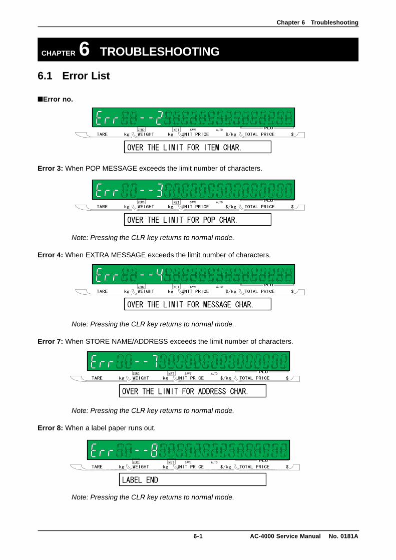
6.1 Error List
■Error no.
Error 3: When POP MESSAGE exceeds the limit number of characters.
Note: Pressing the CLR key returns to normal mode.
Error 4: When EXTRA MESSAGE exceeds the limit number of characters.
Note: Pressing the CLR key returns to normal mode.
Error 7: When STORE NAME/ADDRESS exceeds the limit number of characters.
Note: Pressing the CLR key returns to normal mode.
Error 8: When a label paper runs out.
Note: Pressing the CLR key returns to normal mode.
Chapter 6 Troubleshooting
AC-4000 Service Manual No. 0181A 6-2
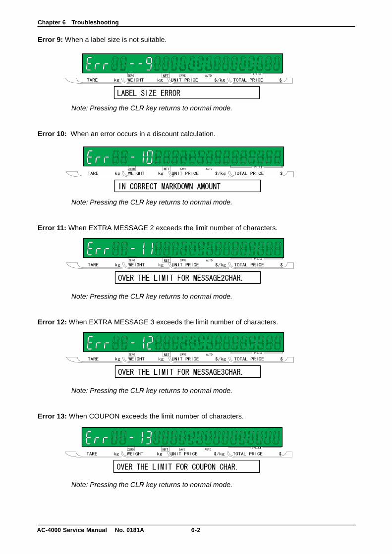
Error 9: When a label size is not suitable.
Note: Pressing the CLR key returns to normal mode.
Error 10: When an error occurs in a discount calculation.
Note: Pressing the CLR key returns to normal mode.
Error 11: When EXTRA MESSAGE 2 exceeds the limit number of characters.
Note: Pressing the CLR key returns to normal mode.
Error 12: When EXTRA MESSAGE 3 exceeds the limit number of characters.
Note: Pressing the CLR key returns to normal mode.
Error 13: When COUPON exceeds the limit number of characters.
Note: Pressing the CLR key returns to normal mode.
Chapter 6 Troubleshooting
6-3 AC-4000 Service Manual No. 0181A
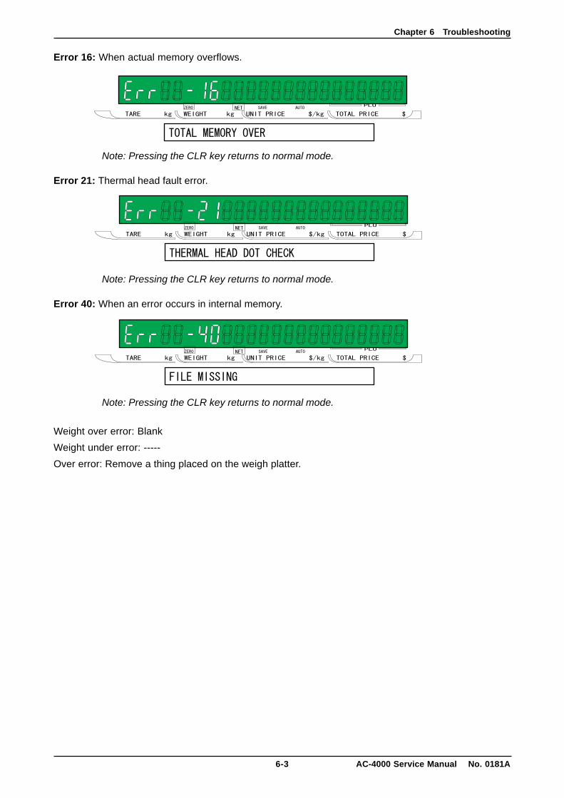
Error 16: When actual memory overflows.
Note: Pressing the CLR key returns to normal mode.
Error 21: Thermal head fault error.
Note: Pressing the CLR key returns to normal mode.
Error 40: When an error occurs in internal memory.
Note: Pressing the CLR key returns to normal mode.
Weight over error: Blank
Weight under error: -----
Over error: Remove a thing placed on the weigh platter.

Chapter 6 Troubleshooting
AC-4000 Service Manual No. 0181A 6-4
Symptom
Power is not applied.
Turning on powerenters test mode.
No further processafter display check
Weighing marginoccurs. (Flickering)
Specific segment doesnot light.
A key is not entered.
Registered datachanges.
All the display goesoff.
Print is not carried out.
Measures
1. Insert the power plug.2. Replace with a new fuse.3. Replace with a new PK-950.4. Replace with a new LSF100-24S.
5. Replace with a new power switch.
1. Replace with a new PK-950.2. Replace with a new keyboard switch.
1. Loading cell adjustment and exchange2. Confirmation and transfer of installa-
tion location3. Replace with a new PK-229.4. Replace with a new PK-950.5. Replace with a new LSF100-24S.
1. The four corners limit screw is ad-justed
2. Removal of foreign body3. Replace with a new PK-229.4. Adjustment and exchange of load cell5. Replace with a new PK-950.
1. The connector connection is con-firmed.
2. Replace with a new PK-950.3. Replace with a new display board.
1. Replace with a new key sheet.2. The connector connection is con-
firmed.
1. Replace with a new battery.2. Replace with a new PK-950.3. The installation location is confirmed
and transferred.
1. The power-supply voltage is confirmed.2. Replace with a new LSF100-24S.
3. Replace with a new display board.4. Replace with a new PK-950.
1. Confirmation of cable2. Head sign acceptable voltage confir-
mation LSF100-24S exchange3. Thermal head adjustment and ex-
change4. Replace with a new PK-950.
Cause
1. Power plug has come off.2. Fuse burns.3. Defect of main board (PK-950)4. Defect of power supply unit
(LSF100-24S)5. Defect of power switch
1. Defect of PK-9502. Defect of keyboard switch
1. Defect of load cell2. Vibration from the outside.
3. Defect of A/D board (PK-229)4. Defect of main board (PK-950)5. Defect of power supply unit
(LSF100-24S)
1. Four corners limit screw comes incontact.
2. Foreign obstacle under the load cell.3. Defect of A/D board (PK-229)4. Defect of load cell5. Defect of main board (PK-950)
1. The connection is abnormal of theconnector.
2. Defect of main board (PK-950)3. Defect of display board
1. Defect of key sheet2. Improper connection of connector
1. Defect of battery2. Defect of main board (PK-950)3. Noise from the outside or influence
of static electricity
1. Voltage fluctuation2. Defect of power supply unit
(LSF100-24S)3. Defect of display board4. Defect of main board (PK-950)
1. Abnormality of thermal head cable2. Defect of power supply unit
(LSF100-24S)3. Defect of thermal head
4. Defect of main board (PK-950)
■Symptom, cause, and measures
Chapter 7 Parts Replacement
7-1 AC-4000 Service Manual No. 0181A
CHAPTER 7 PARTS REPLACEMENT
7.1 Detaching Each Part (Unit)
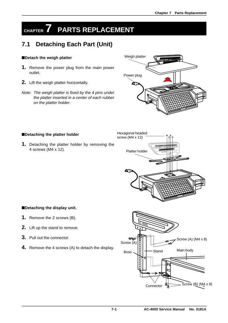
■Detach the weigh platter
1. Remove the power plug from the main poweroutlet.
2. Lift the weigh platter horizontally.
Note: The weigh platter is fixed by the 4 pins underthe platter inserted in a center of each rubberon the platter holder.
■Detaching the platter holder
1. Detaching the platter holder by removing the4 screws (M4 x 12).
■Detaching the display unit.
1. Remove the 2 screws (B).
2. Lift up the stand to remove.
3. Pull out the connector.
4. Remove the 4 screws (A) to detach the display.
Screw (A) (M4 x 8)
Stand
Screw (A)
Connector
Boss Main body
Screw (B) (M4 x 8)
Weigh platter
Power plug
Hexagonal headedscrew (M4 x 12)
Platter holder

Chapter 7 Parts Replacement
AC-4000 Service Manual No. 0181A 7-2
■Detaching the front cover (key sheet)
1. Cut the seal wire.
2. Remove the 2 seal screws.
3. Remove the 2 screws (M4 x 12) of the operationpanel (front cover).
4. Remove the harness connected with P-950Afrom P-862A on the back of the front cover(operation panel).
5. Pull out the connector of the P-862A.
6. Remove the front cover.
Note 1: The base seal wire is used only for a countryrequiring a base seal. For other countries,remove the 4 screws (M4 x 12) only.
2: If the base seal wire is cut, it is necessary toseal the base again for an authorization test.Do not cut the base seal wire except a casewhen necessary.
Seal screw
Seal wire
Screw (M4 x 12)Seal screw (M4)
Front cover(Key sheet)
Chapter 7 Parts Replacement
7-3 AC-4000 Service Manual No. 0181A
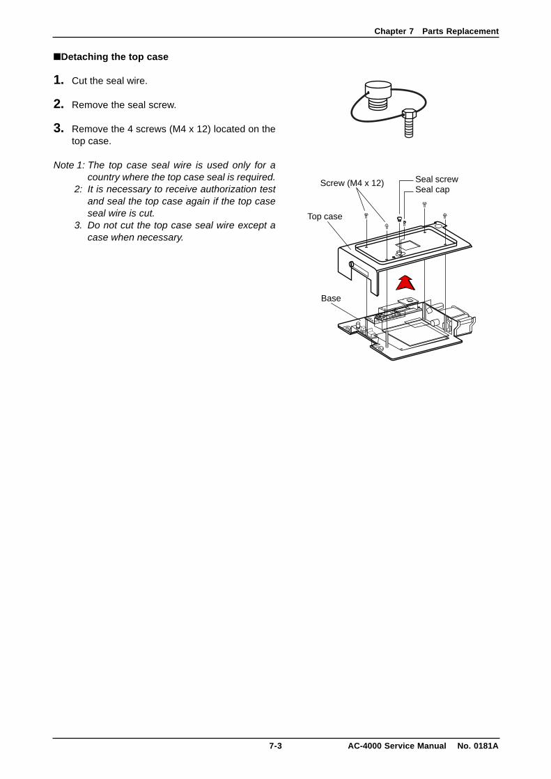
■Detaching the top case
1. Cut the seal wire.
2. Remove the seal screw.
3. Remove the 4 screws (M4 x 12) located on thetop case.
Note 1: The top case seal wire is used only for acountry where the top case seal is required.
2: It is necessary to receive authorization testand seal the top case again if the top caseseal wire is cut.
3. Do not cut the top case seal wire except acase when necessary.
Screw (M4 x 12) Seal screwSeal cap
Base
Top case
Chapter 7 Parts Replacement
AC-4000 Service Manual No. 0181A 7-4
7.2 Detaching Internal PartsThis work must be carried out after finishing preceding section 7.1.
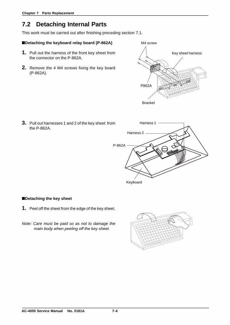
■Detaching the keyboard relay board (P-862A)
1. Pull out the harness of the front key sheet fromthe connector on the P-862A.
2. Remove the 4 M4 screws fixing the key board(P-862A).
3. Pull out harnesses 1 and 2 of the key sheet fromthe P-862A.
■Detaching the key sheet
1. Peel off the sheet from the edge of the key sheet.
Note: Care must be paid so as not to damage themain body when peeling off the key sheet.
Harness 1
Harness 2
P-862A
Keyboard
Key sheet harness
Bracket
P862A
M4 screw
Chapter 7 Parts Replacement
7-5 AC-4000 Service Manual No. 0181A
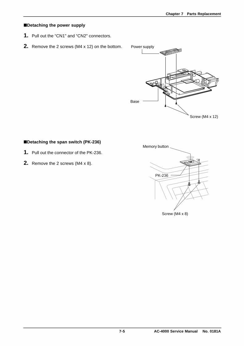
■Detaching the power supply
1. Pull out the “CN1" and “CN2" connectors.
2. Remove the 2 screws (M4 x 12) on the bottom.
■Detaching the span switch (PK-236)
1. Pull out the connector of the PK-236.
2. Remove the 2 screws (M4 x 8).
Memory button
Screw (M4 x 8)
Base
Screw (M4 x 12)
Power supply
Chapter 7 Parts Replacement
AC-4000 Service Manual No. 0181A 7-6
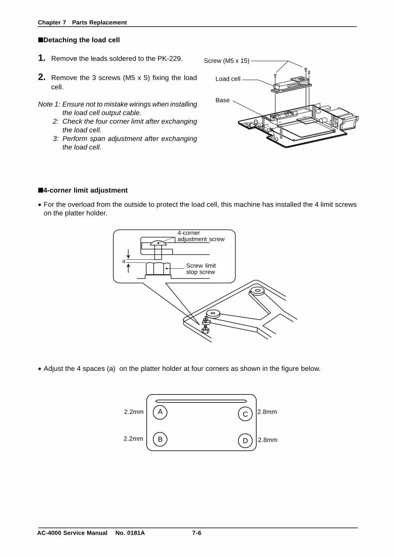
■Detaching the load cell
1. Remove the leads soldered to the PK-229.
2. Remove the 3 screws (M5 x 5) fixing the loadcell.
Note 1: Ensure not to mistake wirings when installingthe load cell output cable.
2: Check the four corner limit after exchangingthe load cell.
3: Perform span adjustment after exchangingthe load cell.
■4-corner limit adjustment
• For the overload from the outside to protect the load cell, this machine has installed the 4 limit screwson the platter holder.
• Adjust the 4 spaces (a) on the platter holder at four corners as shown in the figure below.
A
B
C
D
2.2mm 2.8mm
2.2mm 2.8mm
Base
Load cell
Screw (M5 x 15)
Screw limitstop screw
4-corneradjustment screw
Chapter 7 Parts Replacement
7-7 AC-4000 Service Manual No. 0181A
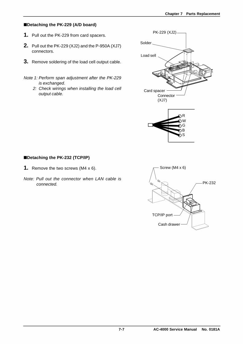
■Detaching the PK-229 (A/D board)
1. Pull out the PK-229 from card spacers.
2. Pull out the PK-229 (XJ2) and the P-950A (XJ7)connectors.
3. Remove soldering of the load cell output cable.
Note 1: Perform span adjustment after the PK-229is exchanged.
2: Check wirings when installing the load celloutput cable.
■Detaching the PK-232 (TCP/IP)
1. Remove the two screws (M4 x 6).
Note: Pull out the connector when LAN cable isconnected.
RWGBS
Solder
Card spacer
PK-229 (XJ2)
Load sell
Connector(XJ7)
Screw (M4 x 6)
PK-232
TCP/IP port
Cash drawer
Chapter 7 Parts Replacement
AC-4000 Service Manual No. 0181A 7-8
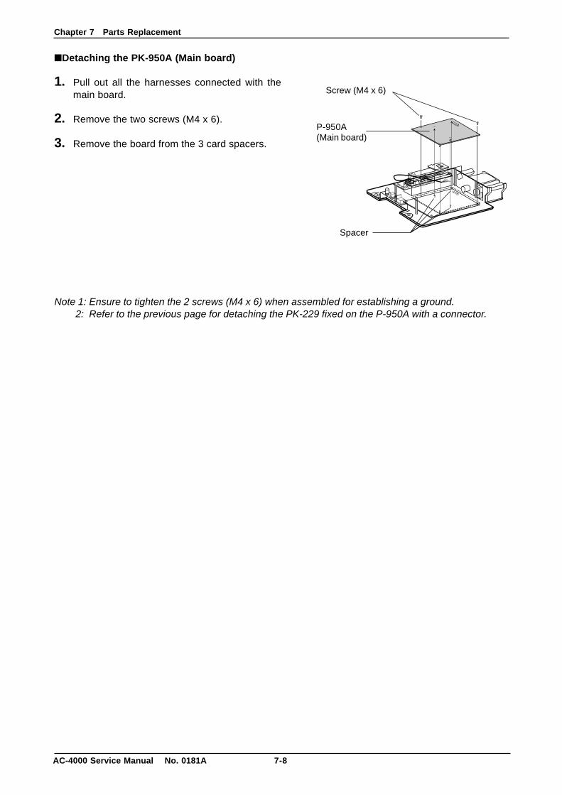
■Detaching the PK-950A (Main board)
1. Pull out all the harnesses connected with themain board.
2. Remove the two screws (M4 x 6).
3. Remove the board from the 3 card spacers.
Note 1: Ensure to tighten the 2 screws (M4 x 6) when assembled for establishing a ground.2: Refer to the previous page for detaching the PK-229 fixed on the P-950A with a connector.
Screw (M4 x 6)
P-950A(Main board)
Spacer
Chapter 7 Parts Replacement
7-9 AC-4000 Service Manual No. 0181A
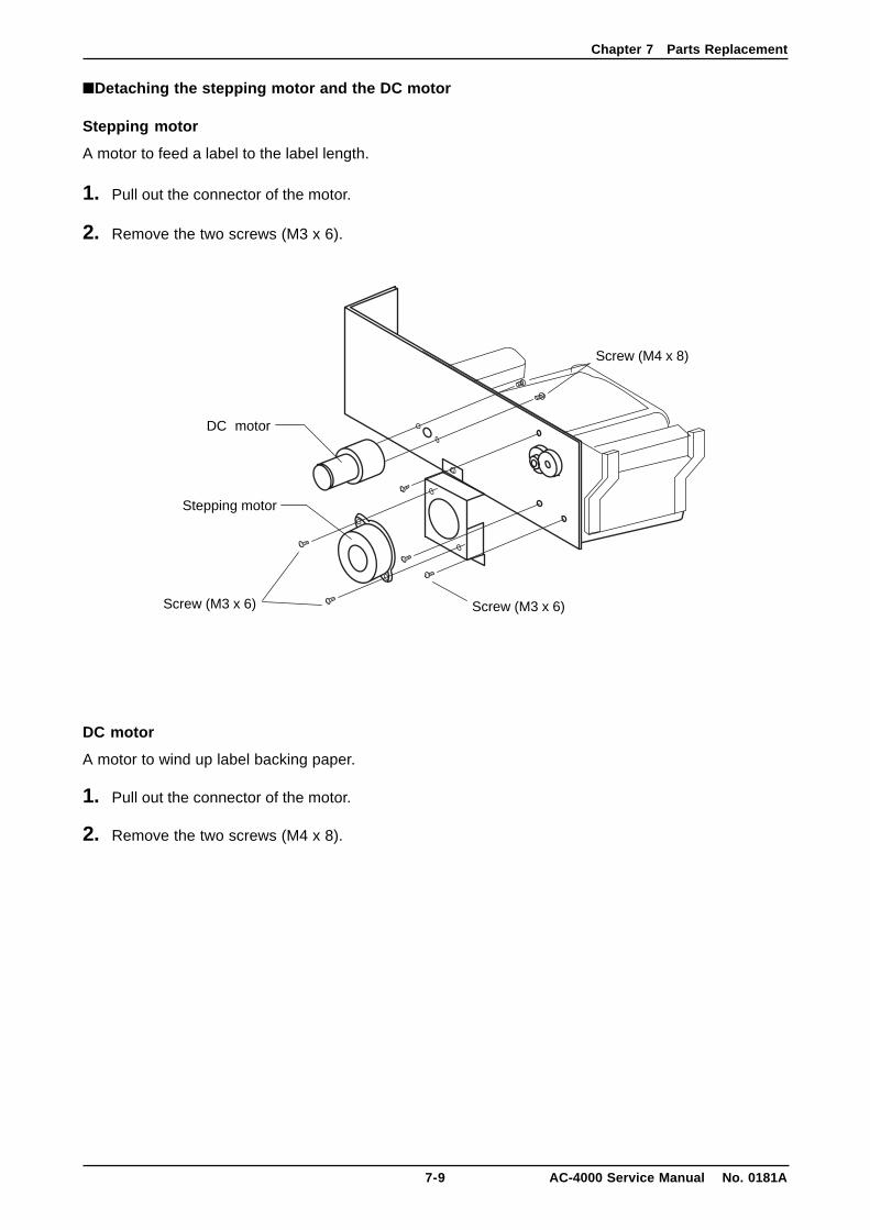
■Detaching the stepping motor and the DC motor
Stepping motor
A motor to feed a label to the label length.
1. Pull out the connector of the motor.
2. Remove the two screws (M3 x 6).
DC motor
A motor to wind up label backing paper.
1. Pull out the connector of the motor.
2. Remove the two screws (M4 x 8).
Screw (M4 x 8)
Screw (M3 x 6)Screw (M3 x 6)
Stepping motor
DC motor
Chapter 7 Parts Replacement
AC-4000 Service Manual No. 0181A 7-10
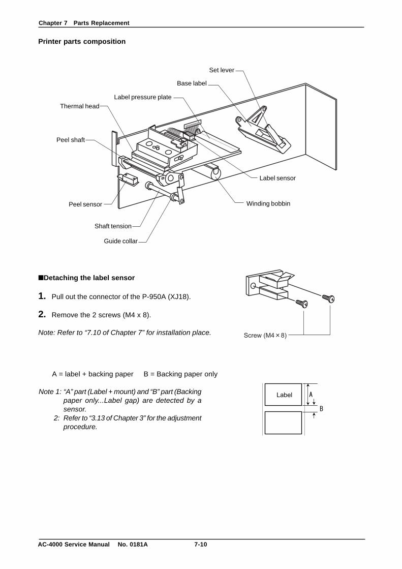
Printer parts composition
■Detaching the label sensor
1. Pull out the connector of the P-950A (XJ18).
2. Remove the 2 screws (M4 x 8).
Note: Refer to “7.10 of Chapter 7” for installation place.
A = label + backing paper B = Backing paper only
Note 1: “A” part (Label + mount) and “B” part (Backingpaper only...Label gap) are detected by asensor.
2: Refer to “3.13 of Chapter 3” for the adjustmentprocedure.
Winding bobbin
Shaft tension
Guide collar
Base label
Peel shaft
Set lever
Label pressure plateThermal head
Peel sensor
Label sensor
Chapter 7 Parts Replacement
7-11 AC-4000 Service Manual No. 0181A
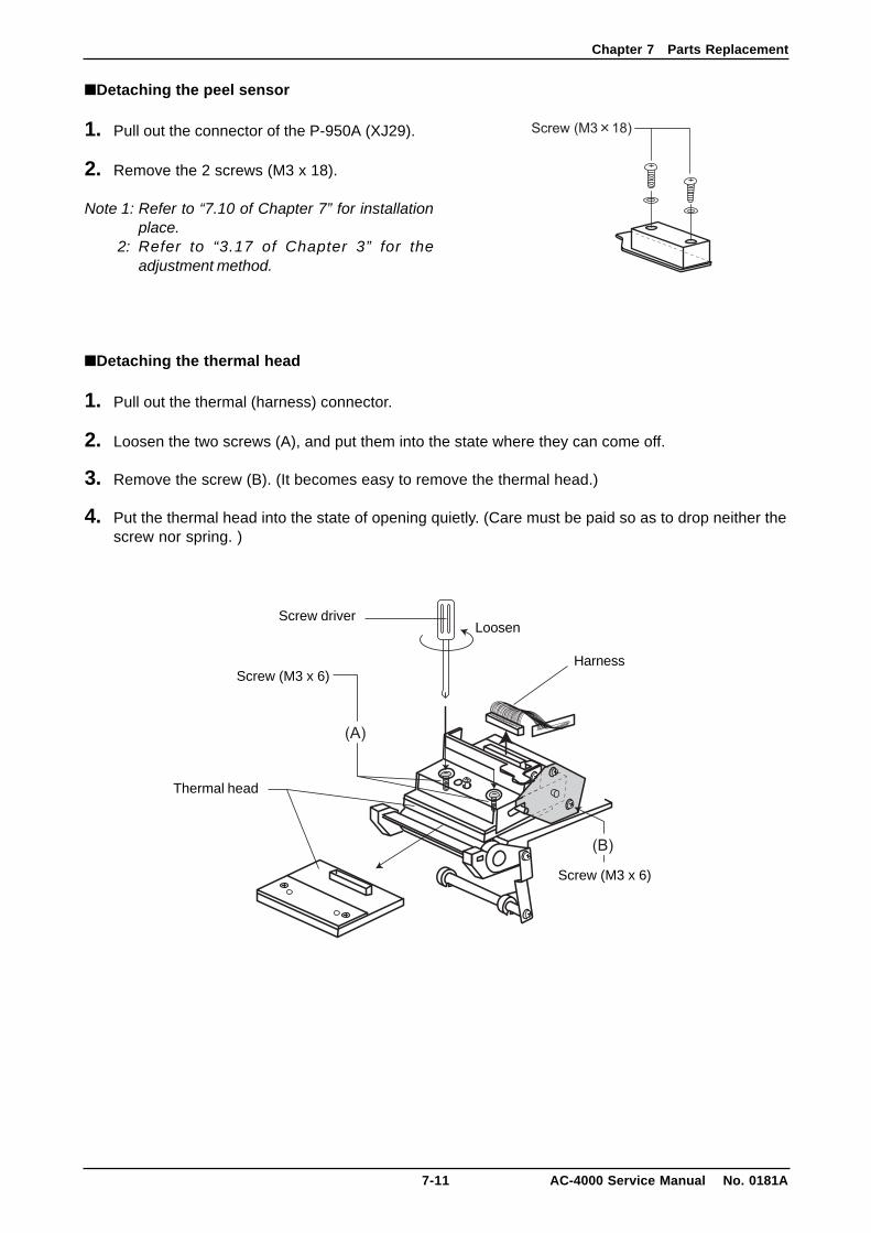
■Detaching the peel sensor
1. Pull out the connector of the P-950A (XJ29).
2. Remove the 2 screws (M3 x 18).
Note 1: Refer to “7.10 of Chapter 7” for installationplace.
2: Refer to “3.17 of Chapter 3” for theadjustment method.
■Detaching the thermal head
1. Pull out the thermal (harness) connector.
2. Loosen the two screws (A), and put them into the state where they can come off.
3. Remove the screw (B). (It becomes easy to remove the thermal head.)
4. Put the thermal head into the state of opening quietly. (Care must be paid so as to drop neither thescrew nor spring. )
Thermal head
Screw driverLoosen
HarnessScrew (M3 x 6)
Screw (M3 x 6)
Chapter 7 Parts Replacement
AC-4000 Service Manual No. 0181A 7-12
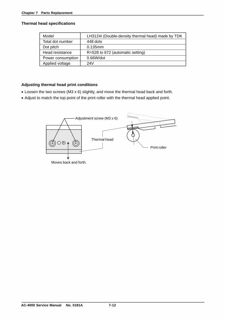
Thermal head specifications
Adjusting thermal head print conditions
• Loosen the two screws (M3 x 6) slightly, and move the thermal head back and forth.
• Adjust to match the top point of the print roller with the thermal head applied point.
Model LH3124I (Double-density thermal head) made by TDKTotal dot number 448 dotsDot pitch 0.135mmHead resistance R=528 to 672 (automatic setting)Power consumption 0.66W/dotApplied voltage 24V
Adjustment screw (M3 x 6)
Moves back and forth.
Thermal head
Print roller
Chapter 7 Parts Replacement
7-13 AC-4000 Service Manual No. 0181A
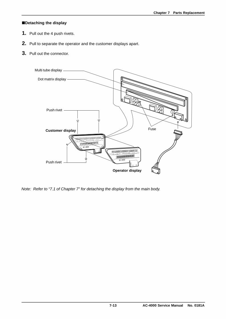
■Detaching the display
1. Pull out the 4 push rivets.
2. Pull to separate the operator and the customer displays apart.
3. Pull out the connector.
Note: Refer to “7.1 of Chapter 7” for detaching the display from the main body.
Customer display
Operator display
Fuse
Multi tube display
Dot matrix display
Push rivet
Push rivet

Chapter 7 Parts Replacement
AC-4000 Service Manual No. 0181A 7-14
7.3 Periodical Replacement Parts■Thermal head (LH3124I)
Replacement period: Label travel distance 40 to 60km (standard)
Note: The label travel distance varies depending on the label material or thermal head cleaning conditions.
■Display tube (Display board)
Life: Brightness must be 80% or more of the standard lower bound after lighting for 1,000 hours underthe condition of all segments lighting by the standard ratings drive.
Life expectancy: 30,000 hours or more when using it by standard ratings drive.(Life here is assumed to be a value that the average brightness becomes half of thestandard lower bounds.)
■Print roller
Replacement period: 300km in the travel distance. (standard)
7.4 How to Pass LabelsA sticker “How to pass labels” is pasted to inner side of the side cover.

44 SANNO-CHO SHOGOIN SAKYO-KUKYOTO, 606 JAPANPHONE: (075) 771-4141FACSIMILE: (075) 751-1634TELEX: 05422065 SCALES JCABLE ADD: “SCALES”KYOTO