you're not alone: dealing with isolation
TRANSCRIPT
������������������ �� ���� ������ �����������������������1
hen I think ofisolation, I think
of Robinson Crusoeand Friday or in more
recent times, Tom Hanks as ChuckNoland. When I think isolation in theelectronics context, I think of thetransformer. For years, transformershave been used to isolate signals.Magnetic properties transfer informa-tion without an electrical connectionbetween primary and secondary wind-ings. On most transformers, it’s theplastic bobbin that holds the primaryand secondary windings separated thatcreates the isolation barrier. Morerecently, opto devices have become apopular method of obtaining isolation.
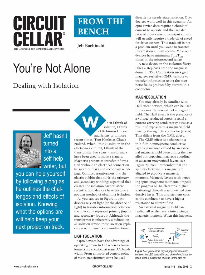
As you can see in Figure 1, optodevices rely on light (or the absence oflight) to transfer information betweenthe physically separated primary (input)and secondary (output). Although thetransformer is inherently a bidirection-al isolation device, most isolation appli-cation requirements are unidirectional.
����� !����!"Opto devices have the advantage of
operating down to DC whereas trans-formers are specified at some AC band-width. From an isolated control pointof view, transformers can’t be used
directly for steady-state isolation. Optodevices work well in this scenario. Anopto device does require a chunk ofcurrent to operate and the transferratio of input current to output currentwill usually require a trade-off of speedfor drive current. This trade-off is nota problem until you want to transferinformation at high speeds. Most optodevices have minimum TON/TOFF
times in the microsecond range. A new device in the isolation flurry
takes a step back into the magneticdomain. NVE Corporation uses giantmagneto resistive (GMR) sensors totransfer information using the mag-netic fields produced by current in aconductor.
���"� !����!"You may already be familiar with
Hall effect devices, which can be usedto measure the strength of a magneticfield. The Hall effect is the presence ofa voltage produced across (x-axis) acurrent-carrying conductor (y-axis) as aresult of exposure to a magnetic fieldpassing through the conductor (z-axis).This differs from the GMR effect.
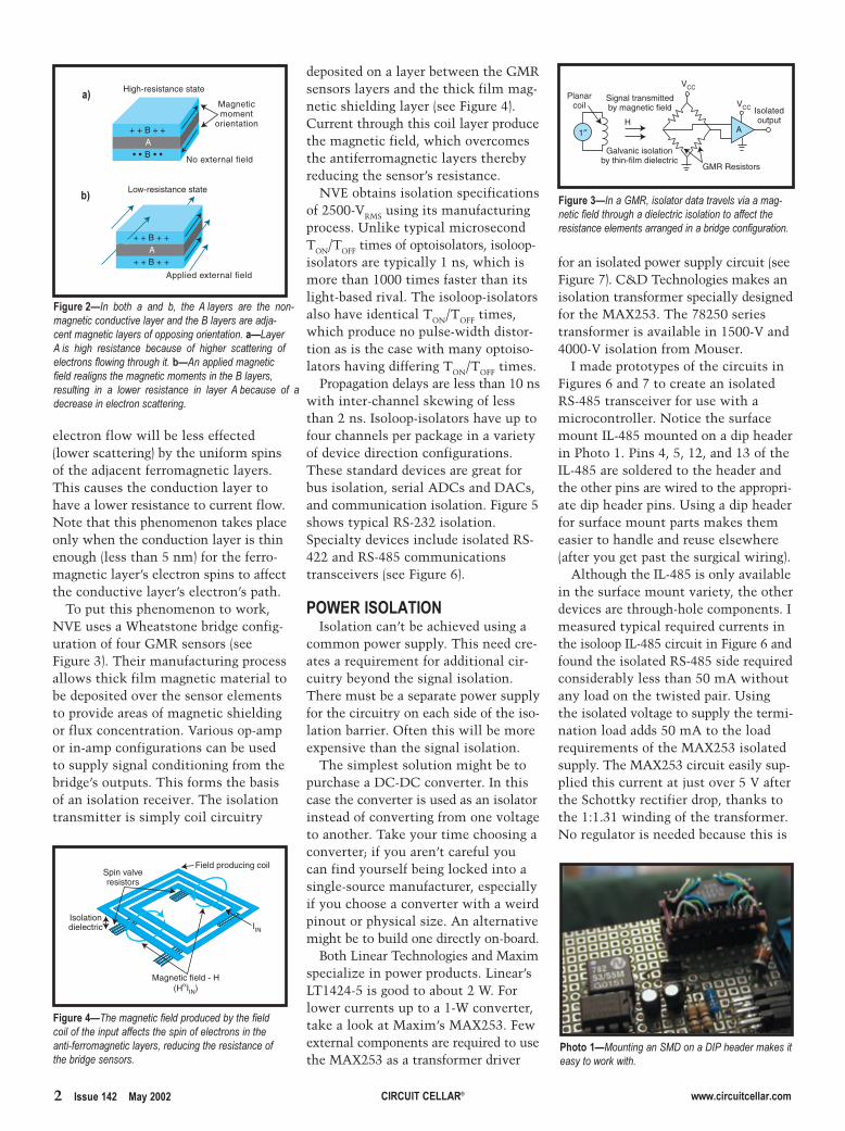
The GMR effect is a change in athin film nonmagnetic conductivelayer’s resistance caused by an exter-nal magnetic field overcoming the par-allel but opposing magnetic couplingof adjacent magnetized layers (seeFigure 2). You’ll remember that thespin of electrons in a magnet arealigned to produce a magneticmoment. Magnetic layers with oppos-ing spins (magnetic moments) impedethe progress of the electrons (higherscattering) through a sandwiched con-ductive layer. This arrangement caus-es the conductor to have a higherresistance to current flow.
An external magnetic field canrealign all of the layers into a singlemagnetic moment. When this happens,
���������������
� �������������������������������������
��������������������������������������������������������������������������������������������������������������������������������������������� �����������
LED
1″
Signal transmittedby photo stream
Galvanic isolationby bulk dielectric
A
Isolatedoutput
VCC
Photo detector
#�$�����%���������������� ���������������� ������ �������� ������� ������������������������ ��������������������� ��������������
Jeff Bachiochi
FROM THE BENCH
Dealing with Isolation
2 �������������������� �� ���� ������ ������������������
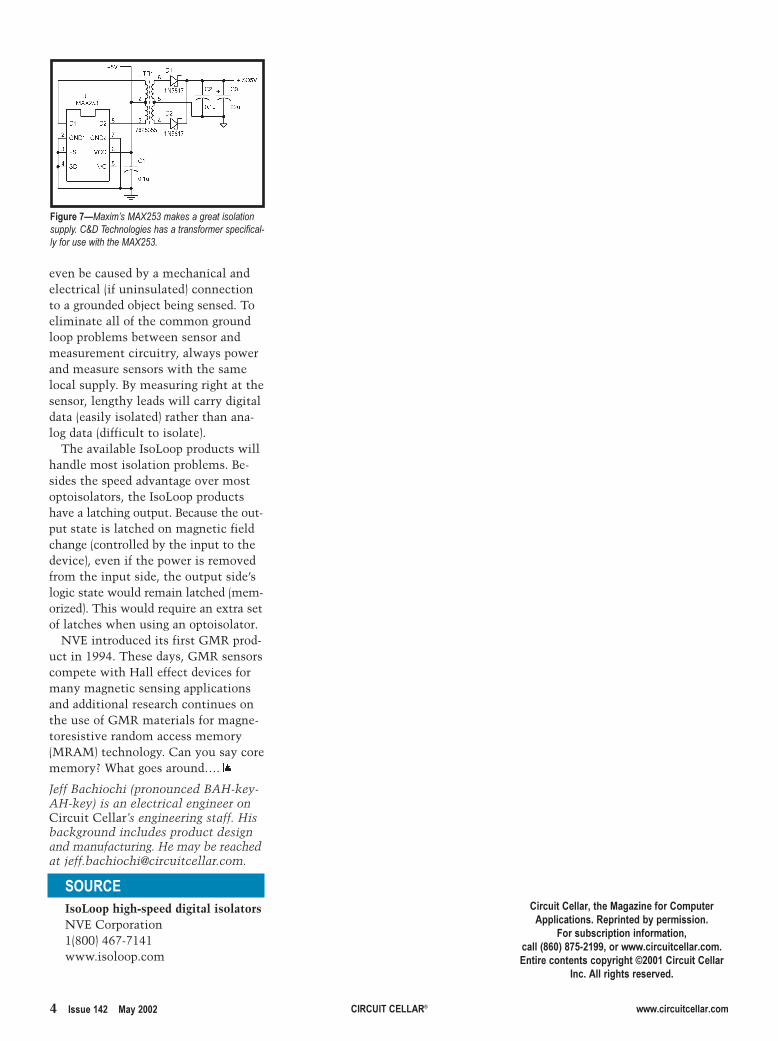
for an isolated power supply circuit (seeFigure 7). C&D Technologies makes anisolation transformer specially designedfor the MAX253. The 78250 seriestransformer is available in 1500-V and4000-V isolation from Mouser.
I made prototypes of the circuits inFigures 6 and 7 to create an isolatedRS-485 transceiver for use with amicrocontroller. Notice the surfacemount IL-485 mounted on a dip headerin Photo 1. Pins 4, 5, 12, and 13 of theIL-485 are soldered to the header andthe other pins are wired to the appropri-ate dip header pins. Using a dip headerfor surface mount parts makes themeasier to handle and reuse elsewhere(after you get past the surgical wiring).
Although the IL-485 is only availablein the surface mount variety, the otherdevices are through-hole components. Imeasured typical required currents inthe isoloop IL-485 circuit in Figure 6 andfound the isolated RS-485 side requiredconsiderably less than 50 mA withoutany load on the twisted pair. Usingthe isolated voltage to supply the termi-nation load adds 50 mA to the loadrequirements of the MAX253 isolatedsupply. The MAX253 circuit easily sup-plied this current at just over 5 V afterthe Schottky rectifier drop, thanks tothe 1:1.31 winding of the transformer.No regulator is needed because this is
electron flow will be less effected(lower scattering) by the uniform spinsof the adjacent ferromagnetic layers.This causes the conduction layer tohave a lower resistance to current flow.Note that this phenomenon takes placeonly when the conduction layer is thinenough (less than 5 nm) for the ferro-magnetic layer’s electron spins to affectthe conductive layer’s electron’s path.
To put this phenomenon to work,NVE uses a Wheatstone bridge config-uration of four GMR sensors (seeFigure 3). Their manufacturing processallows thick film magnetic material tobe deposited over the sensor elementsto provide areas of magnetic shieldingor flux concentration. Various op-ampor in-amp configurations can be usedto supply signal conditioning from thebridge’s outputs. This forms the basisof an isolation receiver. The isolationtransmitter is simply coil circuitry
deposited on a layer between the GMRsensors layers and the thick film mag-netic shielding layer (see Figure 4).Current through this coil layer producethe magnetic field, which overcomesthe antiferromagnetic layers therebyreducing the sensor’s resistance.
NVE obtains isolation specificationsof 2500-VRMS using its manufacturingprocess. Unlike typical microsecondTON/TOFF times of optoisolators, isoloop-isolators are typically 1 ns, which ismore than 1000 times faster than itslight-based rival. The isoloop-isolatorsalso have identical TON/TOFF times,which produce no pulse-width distor-tion as is the case with many optoiso-lators having differing TON/TOFF times.
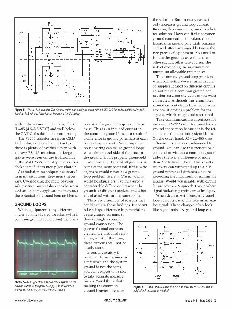
Propagation delays are less than 10 nswith inter-channel skewing of lessthan 2 ns. Isoloop-isolators have up tofour channels per package in a varietyof device direction configurations.These standard devices are great forbus isolation, serial ADCs and DACs,and communication isolation. Figure 5shows typical RS-232 isolation.Specialty devices include isolated RS-422 and RS-485 communicationstransceivers (see Figure 6).
&!'���� !����!"Isolation can’t be achieved using a
common power supply. This need cre-ates a requirement for additional cir-cuitry beyond the signal isolation.There must be a separate power supplyfor the circuitry on each side of the iso-lation barrier. Often this will be moreexpensive than the signal isolation.
The simplest solution might be topurchase a DC-DC converter. In thiscase the converter is used as an isolatorinstead of converting from one voltageto another. Take your time choosing aconverter; if you aren’t careful youcan find yourself being locked into asingle-source manufacturer, especiallyif you choose a converter with a weirdpinout or physical size. An alternativemight be to build one directly on-board.
Both Linear Technologies and Maximspecialize in power products. Linear’sLT1424-5 is good to about 2 W. Forlower currents up to a 1-W converter,take a look at Maxim’s MAX253. Fewexternal components are required to usethe MAX253 as a transformer driver
High-resistance state
+ + B + +
• • B • •A
Magneticmoment
orientation
No external field
Low-resistance state
+ + B + +
+ + B + +A
Applied external field
#�$�����%� ������ ������ ���������� � ���! ������ �"���������� ����#���������$���� ���! ����������������� !��� ����� �%���� ����!������� ������"������!��������� !�������� ������ !���"!����(% ���������! �������������! ������! �������� ��� ���#��������"��� !� ����������� ��� ���� ����"������������� ������ ������� !�
Planarcoil
1″H
Signal transmittedby magnetic field
Galvanic isolationby thin-film dielectric
A
Isolatedoutput
VCC
VCC
GMR Resistors
#�$����)%� �%&'������������������������!� ������������"!������������������� ����������������� ������� ���� !��� ����!��� ��!"���� �
Spin valveresistors
Isolationdielectric
Magnetic field - H(HαIIN)
IIN
Field producing coil
#�$�����%(����! ������������"����������������������� �"�������������� �������� �� ���� ��������! ������������"�� !��������� ����������!��� ����
&*�����%&�" �� !� )&�� ���* ��������������������������
+
(+
������������������ �� ���� ������ �����������������������3
the solution. But, in many cases, thisonly increases ground loop current.Breaking this common ground is a bet-ter solution. However, if the commonground connection is broken, the dif-ferential in ground potentials remainsand will affect any signal between thetwo pieces of equipment. You need toisolate the grounds as well as theother signals, otherwise you run therisk of exceeding the maximum orminimum allowable input specs.
To eliminate ground loop problemswhen connecting devices using ground-ed supplies located on different circuits,do not make a common ground con-nection between the devices you wantconnected. Although this eliminatesground currents from flowing betweendevices, it creates a problem for thesignals, which are ground referenced.
Take communications interfaces forinstance. RS-232 circuitry must have aground connection because it is the ref-erence for the remaining signal lines.On the other hand, RS-422/485 usesdifferential signals not referenced toground. You can use this twisted pairconnection without a common groundunless there is a difference of morethan 7 V between them. The RS-485receivers can withstand up to a 7-Vground-referenced difference beforeexceeding the maximum or minimumratings. Would you gamble with circuitfailure over a 7-V spread? This is wheresignal isolation payoff comes into play.
When dealing with sensors, groundloop currents cause changes in an ana-log signal. These changes often looklike signal noise. A ground loop can
within the recommended range for theIL-485 (4.5–5.5 VDC) and well belowthe 7-VDC absolute maximum rating.
The 78253 transformer from C&DTechnologies is rated at 200 mA, sothere is plenty of overhead even witha heavy RS-485 termination. Largespikes were seen on the isolated sideof the MAX253’s circuitry, but a serieschoke tamed them nicely (see Photo 2).
Are isolation techniques necessary?In many situations, they aren’t neces-sary. Overlooking the more obvioussafety issues (such as distances betweendevices) in some applications increasesthe potential for ground loop problems.
��!�",��!!& When equipment using different
power supplies is tied together (with acommon ground connection) there is a
potential for ground loop currents toexist. This is an induced current inthe common ground line as a result ofa difference in ground potentials at eachpiece of equipment. (Note: improperhouse wiring can cause ground loopswhen the neutral side of the line, orthe ground, is not properly grounded.)
We normally think of all grounds asbeing of the same potential. If this wereso, there would never be a groundloop problem. Here at Circuit Cellarworld headquarters, I’ve measured aconsiderable difference between thegrounds of different outlets (and differ-ent phases) within the same room.
There are a number of reasons thatcould explain these findings. It doesn’ttake a large difference in potential tocause ground currents toflow through a commonground connection. Thepotentials (and currentscreated) are also load relat-ed, so, most of the time,these currents will not besteady state.
If sensor circuitry isbased on its own ground asa reference and the systemground is not the same,you can’t expect to be ableto take accurate measure-ments. You’d think thatmaking the commonground heavier might be
&*�����%(��"������������+�,�-������� ������������"��"�����������"�����(�����������������������"��"�����������������
#�$����-%(�����./0�� ��� �1���������������� ��������"��������& 2�030��������������� � �������� �����./0��������������� ���������� ������ !�
#�$����.%(�����45,����������')�45,���������� � ������������������ ������� ������
4 �������������������� �� ���� ������ ������������������
even be caused by a mechanical andelectrical (if uninsulated) connectionto a grounded object being sensed. Toeliminate all of the common groundloop problems between sensor andmeasurement circuitry, always powerand measure sensors with the samelocal supply. By measuring right at thesensor, lengthy leads will carry digitaldata (easily isolated) rather than ana-log data (difficult to isolate).
The available IsoLoop products willhandle most isolation problems. Be-sides the speed advantage over mostoptoisolators, the IsoLoop productshave a latching output. Because the out-put state is latched on magnetic fieldchange (controlled by the input to thedevice), even if the power is removedfrom the input side, the output side’slogic state would remain latched (mem-orized). This would require an extra setof latches when using an optoisolator.
NVE introduced its first GMR prod-uct in 1994. These days, GMR sensorscompete with Hall effect devices formany magnetic sensing applicationsand additional research continues onthe use of GMR materials for magne-toresistive random access memory(MRAM) technology. Can you say corememory? What goes around…. I
#�$����/%&�6��7�& 20,3������!����������� �"�����89�(��� ���!��������� ��������������������"���������& 20,3�
!�� �IsoLoop high-speed digital isolatorsNVE Corporation1(800) 467-7141www.isoloop.com
Jeff Bachiochi (pronounced BAH-key-AH-key) is an electrical engineer onCircuit Cellar’s engineering staff. Hisbackground includes product designand manufacturing. He may be reachedat [email protected].
������� ��0��*���$1�2��3��� ��4�����44�����2�����4��2��5�(��4��������2��
#�����(����4���2��23������20���67.�+�7/-8��990������������������������2�������2��2�����4���$*��:����� ������� ��
�2�������$*��������;�5�