yrc1000 options instructions - motoman€¦ · yrc1000 options instructions standard i/o signal...
TRANSCRIPT

MANUAL NO.
HW1484105 1
YRC1000 OPTIONSINSTRUCTIONSSTANDARD I/O SIGNAL ASSIGNMENT TABLE (PNP SPECIFICATION)FOR GENERAL-PURPOSE I/O BOARD TYPE: JANCD-AIO02-E
Upon receipt of the product and prior to initial operation, read these instructions thoroughly, and retain for future reference.
MOTOMAN INSTRUCTIONS
MOTOMAN- INSTRUCTIONSYRC1000 INSTRUCTIONSYRC1000 OPERATOR’S MANUAL (GENERAL) (SUBJECT SPECIFIC) YRC1000 MAINTENANCE MANUAL YRC1000 ALARM CODES
1/35
178669-1CD1
HW1484105
DANGER
• This manual describes the standard I/O signal assignments for the PNP specification of the YRC1000 system. Read this manual carefully and be sure to understand its contents before handling the YRC1000. Any matter, including operation, usage, measures, and an item to use, not described in this manual must be regarded as “prohibited” or “improper”.
• General information related to safety are described in “Chapter 1. Safety” of “YRC1000 INSTRUCTIONS”. To ensure correct and safe operation, carefully read “Chapter 1. Safety” of “YRC1000 INSTRUCTIONS”.
CAUTION
• In some drawings in this manual, protective covers or shields are removed to show details. Make sure that all the covers or shields are installed in place before operating this product.
• YASKAWA is not responsible for incidents arising from unauthorized modification of its products. Unauthorized modification voids the product warranty.
NOTICE
• Replace ”Robot General-Purpose I/O Signal Assignment” part of “YRC1000 INSTRUCTIONS” with this instruction manual and refer to it.
• The drawings and photos in this manual are representative examples and differences may exist between them and the delivered product.
• YASKAWA may modify this model without notice when necessary due to product improvements, modifications, or changes in specifications. If such modification is made, the manual number will also be revised.
• If your copy of the manual is damaged or lost, contact a YASKAWA representative to order a new copy. The representatives are listed on the back cover. Be sure to tell the representative the manual number listed on the front cover.
ii HW1484105 2/35
HW1484105
Notes for Safe OperationRead this manual carefully before installation, operation, maintenance, or inspection of the YRC1000.
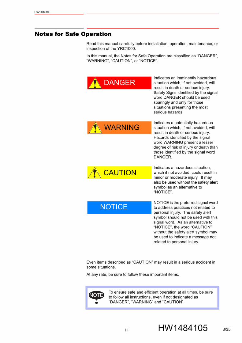
In this manual, the Notes for Safe Operation are classified as “DANGER”, “WARNING”, “CAUTION”, or “NOTICE”.
Even items described as “CAUTION” may result in a serious accident in some situations.
At any rate, be sure to follow these important items.
DANGERIndicates an imminently hazardous situation which, if not avoided, will result in death or serious injury. Safety Signs identified by the signal word DANGER should be used sparingly and only for those situations presenting the most serious hazards.
WARNINGIndicates a potentially hazardous situation which, if not avoided, will result in death or serious injury. Hazards identified by the signal word WARNING present a lesser degree of risk of injury or death than those identified by the signal word DANGER.
CAUTIONIndicates a hazardous situation, which if not avoided, could result in minor or moderate injury. It may also be used without the safety alert symbol as an alternative to “NOTICE”.
NOTICENOTICE is the preferred signal word to address practices not related to personal injury. The safety alert symbol should not be used with this signal word. As an alternative to “NOTICE”, the word “CAUTION” without the safety alert symbol may be used to indicate a message not related to personal injury.
NOTETo ensure safe and efficient operation at all times, be sure to follow all instructions, even if not designated as“DANGER”, “WARNING” and “CAUTION”.
iii HW1484105 3/35

HW1484105
DANGER
• Before operating the manipulator, make sure the servo power is turned OFF by performing the following operations. When the servo power is turned OFF, the SERVO ON LED on the programming pendant is turned OFF.– Press the emergency stop buttons on the front door of the
YRC1000, on the programming pendant, on the external control device, etc.
– Disconnect the safety plug of the safety fence. (when in the play mode or in the remote mode)
If operation of the manipulator cannot be stopped in an emergency, personal injury and/or equipment damage may result.
Fig. : Emergency Stop Button
• Before releasing the emergency stop, make sure to remove the obstacle or error caused the emergency stop, if any, and then turn the servo power ON.
Failure to observe this instruction may cause unintended movement of the manipulator, which may result in personal injury.
Fig. : Release of Emergency StopTURN
• Observe the following precautions when performing a teaching operation within the manipulator's operating range:– Be sure to perform lockout by putting a lockout device on the
safety fence when going into the area enclosed by the safety fence. In addition, the operator of the teaching operation must display the sign that the operation is being performed so that no other person closes the safety fence.
– View the manipulator from the front whenever possible.– Always follow the predetermined operating procedure.– Always keep in mind emergency response measures against the
manipulator’s unexpected movement toward a person.– Ensure a safe place to retreat in case of emergency.
Failure to observe this instruction may cause improper or unintended movement of the manipulator, which may result in personal injury. • Confirm that no person is present in the manipulator's operating
range and that the operator is in a safe location before: – Turning ON the YRC1000 power – Moving the manipulator by using the programming pendant – Running the system in the check mode– Performing automatic operations
Personal injury may result if a person enters the manipulator's operating range during operation. Immediately press an emergency stop button whenever there is a problem. The emergency stop buttons are located on the front panel of the YRC1000 and on the right of the programming pendant.• Read and understand the Explanation of the Warning Labels before
operating the manipulator.
iv HW1484105 4/35
HW1484105
Definition of Terms Used Often in This ManualThe MOTOMAN manipulator is the YASKAWA industrial robot product.
The MOTOMAN usually consists of the controller, the programming pendant, and supply cables.
In this manual, the equipment is designated as follows.
WARNING
• Perform the following inspection procedures prior to conducting manipulator teaching. If there is any problem, immediately take necessary steps to solve it, such as maintenance and repair.
– Check for a problem in manipulator movement.
– Check for damage to insulation and sheathing of external wires.
• Always return the programming pendant to the hook on the YRC1000 cabinet after use.
If the programming pendant is left unattended on the manipulator, on a fixture, or on the floor, etc., the Enable Switch may be activated due to surface irregularities of where it is left, and the servo power may be turned ON. In addition, in case the operation of the manipulator starts, the manipulator or the tool may hit the programming pendant left unattended, which may result in personal injury and/or equipment damage.
Equipment Manual DesignationYRC1000 Controller YRC1000
YRC1000 Programming Pendant Programming Pendant
Cable between the manipulator and the controller
Manipulator cable
v HW1484105 5/35
HW1484105
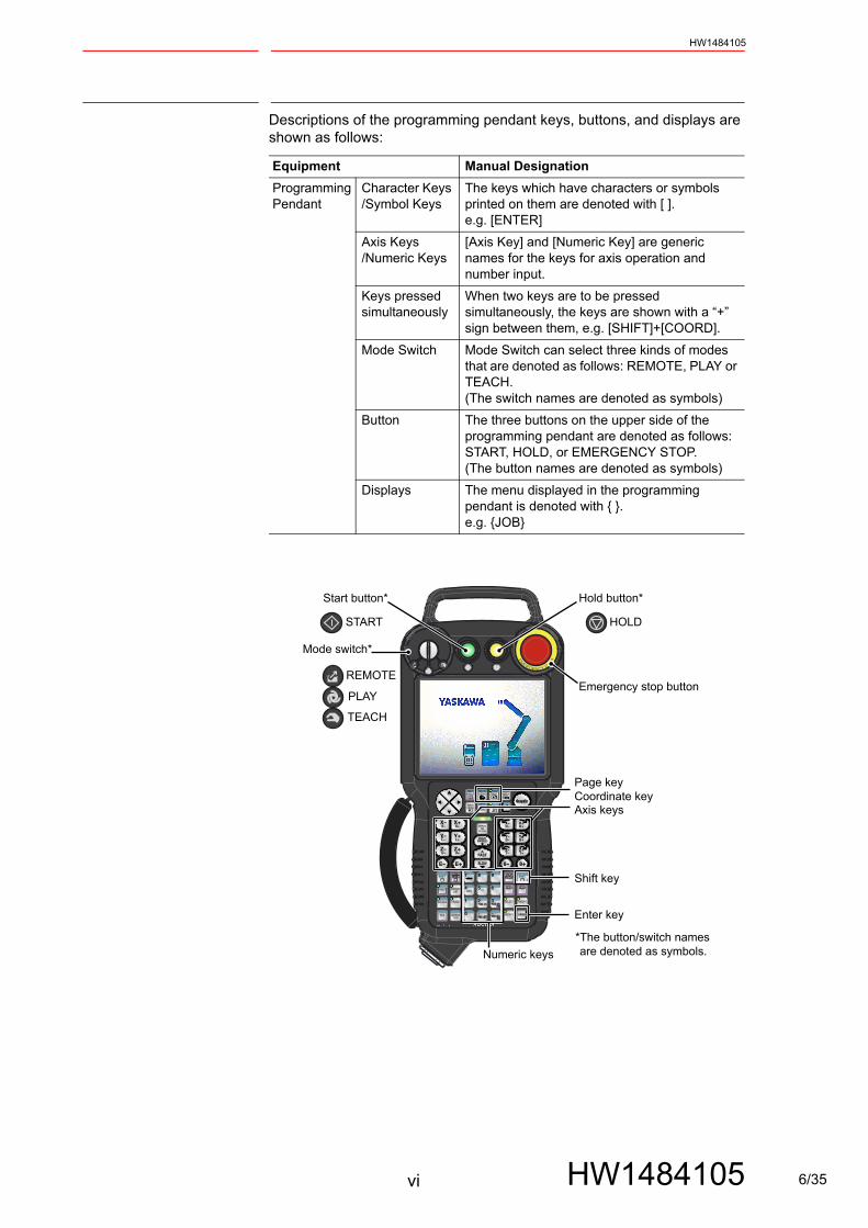
Descriptions of the programming pendant keys, buttons, and displays are shown as follows:
Equipment Manual DesignationProgrammingPendant
Character Keys /Symbol Keys
The keys which have characters or symbols printed on them are denoted with [ ].e.g. [ENTER]
Axis Keys/Numeric Keys
[Axis Key] and [Numeric Key] are generic names for the keys for axis operation and number input.
Keys pressed simultaneously
When two keys are to be pressed simultaneously, the keys are shown with a “+” sign between them, e.g. [SHIFT]+[COORD].
Mode Switch Mode Switch can select three kinds of modes that are denoted as follows: REMOTE, PLAY or TEACH. (The switch names are denoted as symbols)
Button The three buttons on the upper side of the programming pendant are denoted as follows: START, HOLD, or EMERGENCY STOP. (The button names are denoted as symbols)
Displays The menu displayed in the programming pendant is denoted with { }.e.g. {JOB}
EM
ERGENCY STOP
Numeric keys
Axis keys
Enter key
Mode switch*
Start button* Hold button*
Emergency stop button
Shift key
Page keyCoordinate key
PLAY
REMOTE
TEACH
START
*The button/switch names are denoted as symbols.
HOLD
vi HW1484105 6/35

HW1484105
Description of the Operation ProcedureIn the explanation of the operation procedure, the expression “Select • • •” means that the cursor is moved to the object item and the [SELECT] is pressed, or that the item is directly selected by touching the screen.
Registered TrademarkIn this manual, names of companies, corporations, or products are trademarks, registered trademarks, or brand names for each company or corporation. The indications of (R) and TM are omitted.
vii HW1484105 7/35

Contents
viii
HW1484105
HW1484105
1 Arc Welding.....................................................................................................................................1-1
2 Handling.......................................................................................................................................... 2-1
3 General Application.........................................................................................................................3-1
4 Spot Welding................................................................................................................................... 4-1
8/35
1 Arc WeldingHW1484105
1 Arc Welding
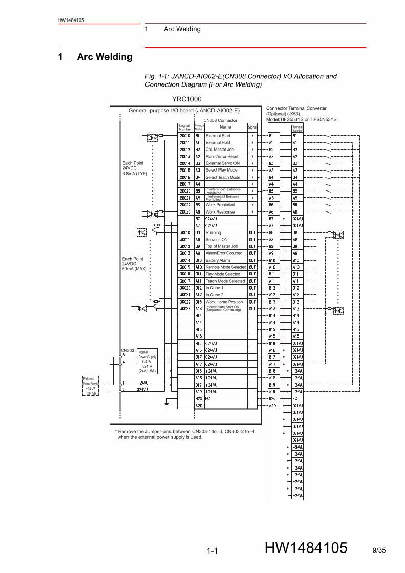
Fig. 1-1: JANCD-AIO02-E(CN308 Connector) I/O Allocation and Connection Diagram (For Arc Welding)
ExternalPower Supply +24 VE 024 VE
Internal Power Supply +24 V 024 V(24V,1.5A)
CN303
Name Signal Terminal Number
LogicalNumber
ConnectorNumber
Connector Terminal Converter(Optional) (-X53)Model:TIFS553YS or TIFS5N53YS
* Remove the Jumper-pins between CN303-1 to -3, CN303-2 to -4 when the external power supply is used.
CN308 Connector
External Start
External Hold
External Servo ON
Call Master Job
Alarm/Error Reset
Interference1 Entrance Prohibited
Work Prohibited
Work Response
Running
Servo is ON
Top of Master Job
Alarm/Error Occurred
Battery Alarm
Remote Mode Selected
Play Mode Selected
Teach Mode Selected
In Cube 1
In Cube 2
Work Home PositionIntermediate Start OK(Sequence Continuing)
Interference2 Entrance Prohibited
Select Play Mode
Select Teach Mode
General-purpose I/O board (JANCD-AIO02-E)
Each Point24VDC50mA (MAX)
YRC1000
Each Point24VDC6.8mA (TYP)
1-1 HW1484105 9/35

1 Arc Welding
HW1484105
Fig. 1-2: JANCD-AIO02-E (CN309 Connector) I/O Allocation and Connection Diagram (For Arc Welding)
Internal Power Supply +24 V 024 V(24V,1.5A)
ExternalPower Supply +24 VE 024 VE
CN303
CN309 Connector
YRC1000
LogicalNumber SignalName
Connector Terminal Converter(Optional) (-X54)Model:TIFS553YS or TIFS5N53YS
Terminal Number
ConnectorNumber
* Remove the Jumper-pins between CN303-1 to -3, CN303-2 to -4 when the external power supply is used.
Weaving Prohibited
Sensing Prohibited
IN01 GP Input
IN02 GP Input
IN03 GP Input
IN04 GP Input
IN05 GP Input
IN06 GP Input
IN07 GP Input
IN08 GP Input
Wire Sticking (Monitor)
Gas Shortage (Monitor)
Wire Shortage (Monitor)
Arc Shortage (Monitor)
OUT01 GP Output
OUT02 GP Output
OUT03 GP Output
OUT04 GP Output
OUT05 GP Output
OUT06 GP Output
OUT07 GP Output
OUT08 GP Output
General-purpose I/O board (JANCD-AIO02-E)
Each Point24VDC50mA (MAX)
Each Point24VDC6.8mA (TYP)
1-2 HW1484105 10/35

1 Arc WeldingHW1484105
Fig. 1-3: JANCD-AIO02-E (CN306 Connector) I/O Allocation and Connection Diagram (For Arc Welding)
Internal Power Supply +24 V 024 V(24V,1.5A)
ExternalPower Supply +24 VE 024 VE
CN303
CN306 ConnectorLogicalNumber
Name SignalConnectorNumber
Terminal Number
Connector Terminal Converter(Optional) (-X51)Model:TIFS553YS or TIFS5N53YS
* Remove the Jumper-pins between CN303-1 to -3, CN303-2 to -4 when the external power supply is used.
GP Input
GP Input
GP Input
GP Input
GP Input
GP Input
GP Input
GP Input
GP Output
GP Output
GP Output
GP Output
GP Output
GP Output
GP Output
GP Output
General-purpose I/O board (JANCD-AIO02-E)
Each Point24VDC50mA (MAX)
YRC1000
Each Point24VDC6.8mA (TYP)
1-3 HW1484105 11/35
1 Arc Welding
HW1484105
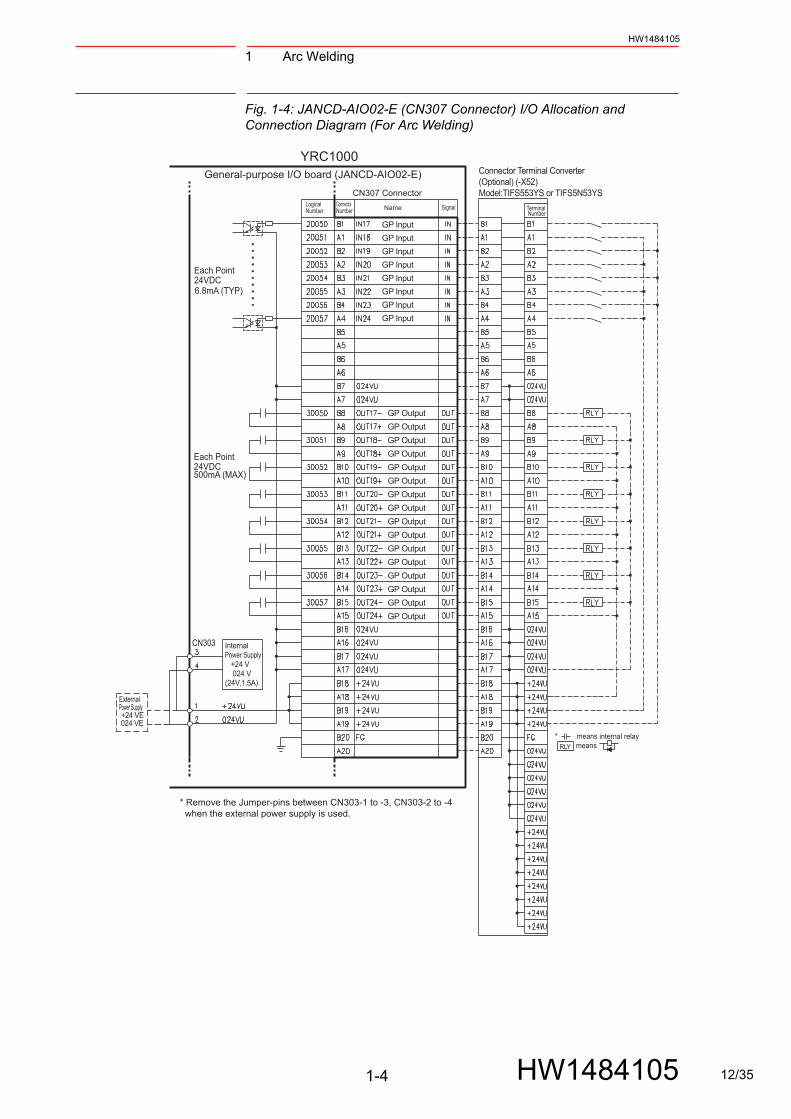
Fig. 1-4: JANCD-AIO02-E (CN307 Connector) I/O Allocation and Connection Diagram (For Arc Welding)
Internal Power Supply +24 V 024 V(24V,1.5A)
ExternalPower Supply +24 VE 024 VE
CN303
CN307 Connector
Terminal Number
LogicalNumber
ConnectorNumber SignalName
Connector Terminal Converter(Optional) (-X52)Model:TIFS553YS or TIFS5N53YS
* Remove the Jumper-pins between CN303-1 to -3, CN303-2 to -4 when the external power supply is used.
* means internal relay means RLY
GP Input
GP Input
GP Input
GP Input
GP Input
GP Input
GP Input
GP Input
GP Output
GP Output
GP Output
GP Output
GP Output
GP Output
GP Output
GP Output
GP Output
GP Output
GP Output
GP Output
GP Output
GP Output
GP Output
GP Output
YRC1000General-purpose I/O board (JANCD-AIO02-E)
Each Point24VDC500mA (MAX)
Each Point24VDC6.8mA (TYP)
1-4 HW1484105 12/35

1 Arc WeldingHW1484105
Table 1-1: Specific Input (Arc Welding)
Logical
Number
Input Name / Function
20010 EXTERNAL STARTFunctions the same as the [START] button in the programming pendant. Only the rising edge of the signal is valid. It starts robot operation (playback). This signal is invalid if external start is prohibited from the playback condition display.
20011 EXTERNAL HOLDThe hold lamp turns on and the signal “HOLDING (50071)” turns ON while this signal is ON. Depending on the setting, the status of manipulator can be “HOLDING” while this signal is OFF.
20012 CALL MASTER JOBOnly the rising edge of the signal is valid. It calls up the top of the robot program, that is the top of the master job1). This signal is invalid during playback, during teach lock and when play master or call is prohibited (set from the playback operation condition display).
20013 ALARM/ERROR RESETAfter an alarm or error has occurred and the cause been corrected, this signal resets the alarm or error.
20014 EXTERNAL SERVO ONOnly the rising edge of this signal is valid. This signal turns ON the servo power. Use this signal to turn ON the servo power from an external device.
20015 SELECT PLAY MODEThe play mode is selected when the mode key on the programming pendant is set at “REMOTE”. Only the rising edge of the signal is valid. When this selection signal assigned concurrently with other mode selection signal, the teach mode is selected on a priority basis. The signal is invalid while EXTERNAL MODE SWITCH is prohibited.
20016 SELECT TEACH MODEThe teach mode is selected when the mode key of the programming pendant is set at “REMOTE”. The other mode selection is unavailable when this signal is ON; the signal is selected by priority even when the other selection signal is ON, enabling the teach mode selection.
20020 INTERFERENCE 1 ENTRANCE PROHIBITEDIf the manipulator attempts to enter the cube 12) area while this signal is ON, the manipulator goes to wait status (with servo power ON). During wait status, the manipulator operation restarts if this signal turns OFF.
20021 INTERFERENCE 2 ENTRANCE PROHIBITEDIf the manipulator attempts to enter the cube 22) area while this signal is ON, the manipulator goes to wait status (with servo power ON). During wait status, the manipulator operation restarts if this signal turns OFF.
20022 WORK PROHIBITED (Arc Generation Prohibited)Arc generation is prohibited while this signal is ON. Arc generation starts when this signal turns OFF inside the arc-generation area. Use this signal to confirm teaching.
20023 WORK RESPONSE (Pseudo Arc ON Response)This signal is used as a pseudo signal in cases that “Arc Generation Confirmation” signal is not equipped on a welding power supply. Wire this signal ON normally (short to OV).
20026 WEAVING PROHIBITEDWeaving is prohibited while this signal is ON. Use this signal to check taught steps and movements without performing the weaving operation.
20027 SENSlNG PROHIBITEDArc sensing is prohibited while this signal is ON. Use this signal to check taught steps and movements if an arc sensor is mounted.
1 A master job is a job (program) which can be called by CALL MASTER JOB.Other functions are the same as fornormal jobs. Normally, the parent job, which manages the child jobs called up immediately after the power isturned ON, is set as the master job.
2 See “Chap.8.6 Interference Area” in “ YRC1000 INSTRUCTIONS (RE-CTO-A221) “.
1-5 HW1484105 13/35
1 Arc Welding
HW1484105
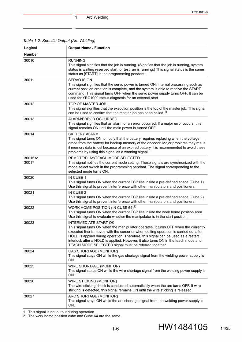
Table 1-2: Specific Output (Arc Welding)
Logical
Number
Output Name / Function
30010 RUNNINGThis signal signifies that the job is running. (Signifies that the job is running, system status is waiting reserved start, or test run is running.) This signal status is the same status as [START] in the programming pendant.
30011 SERVO IS ONThis signal signifies that the servo power is turned ON, internal processing such as current position creation is complete, and the system is able to receive the START command. This signal turns OFF when the servo power supply turns OFF. It can be used for YRC1000 status diagnosis for an external start.
30012 TOP OF MASTER JOBThis signal signifies that the execution position is the top of the master job. This signal can be used to confirm that the master job has been called.1)
30013 ALARM/ERROR OCCURREDThis signal signifies that an alarm or an error occurred. If a major error occurs, this signal remains ON until the main power is turned OFF.
30014 BATTERY ALARMThis signal turns ON to notify that the battery requires replacing when the voltage drops from the battery for backup memory of the encoder. Major problems may result if memory data is lost because of an expired battery. It is recommended to avoid these problems by using this signal as a warning signal.
30015 to30017
REMOTE/PLAY/TEACH MODE SELECTEDThis signal notifies the current mode setting. These signals are synchronized with the mode select switch in the programming pendant. The signal corresponding to the selected mode turns ON.
30020 IN CUBE 1This signal turns ON when the current TCP lies inside a pre-defined space (Cube 1). Use this signal to prevent interference with other manipulators and positioners.
30021 IN CUBE 2This signal turns ON when the current TCP lies inside a pre-defined space (Cube 2). Use this signal to prevent interference with other manipulators and positioners.
30022 WORK HOME POSITION (IN CUBE 64)2)
This signal turns ON when the current TCP lies inside the work home position area. Use this signal to evaluate whether the manipulator is in the start position.
30023 INTERMEDIATE START OKThis signal turns ON when the manipulator operates. It turns OFF when the currently executed line is moved with the cursor or when editing operation is carried out after HOLD is applied during operation. Therefore, this signal can be used as a restart interlock after a HOLD is applied. However, it also turns ON in the teach mode and TEACH MODE SELECTED signal must be referred together.
30024 GAS SHORTAGE (MONITOR)This signal stays ON while the gas shortage signal from the welding power supply is ON.
30025 WIRE SHORTAGE (MONITOR)This signal status ON while the wire shortage signal from the welding power supply is ON.
30026 WIRE STICKING (MONITOR)The wire sticking check is conducted automatically when the arc turns OFF. If wire sticking is detected, this signal remains ON until the wire sticking is released.
30027 ARC SHORTAGE (MONITOR)This signal stays ON while the arc shortage signal from the welding power supply is ON.
1 This signal is not output during operation. 2 The work home position cube and Cube 64 are the same.
1-6 HW1484105 14/35
2 HandlingHW1484105
2 Handling
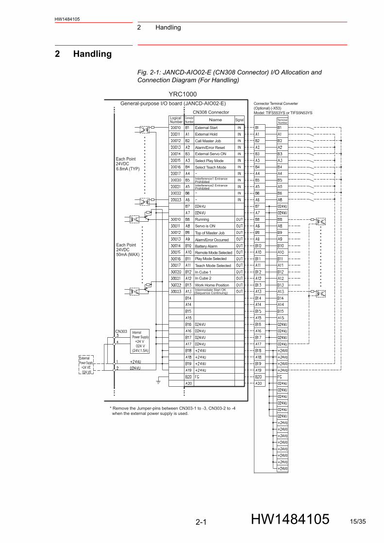
Fig. 2-1: JANCD-AIO02-E (CN308 Connector) I/O Allocation and Connection Diagram (For Handling)
ExternalPower Supply +24 VE 024 VE
Internal Power Supply +24 V 024 V(24V,1.5A)
CN303
CN308 Connector
Name Signal
Connector Terminal Converter(Optional) (-X53)Model: TIFS553YS or TIFS5N53YS
Terminal Number
LogicalNumber
ConnectorNumber
* Remove the Jumper-pins between CN303-1 to -3, CN303-2 to -4 when the external power supply is used.
External Start
External Hold
Call Master Job
Alarm/Error Reset
External Servo ON
Interference1 Entrance Prohibited
Running
Servo is ON
Top of Master Job
Alarm/Error Occurred
Battery Alarm
Remote Mode Selected
Play Mode Selected
Teach Mode Selected
In Cube 1
In Cube 2
Work Home PositionIntermediate Start OK
Interference2 Entrance Prohibited
Select Play Mode
Select Teach Mode
(Sequence Continuing)
YRC1000General-purpose I/O board (JANCD-AIO02-E)
Each Point24VDC50mA (MAX)
Each Point24VDC6.8mA (TYP)
2-1 HW1484105 15/35

2 Handling
HW1484105
Fig. 2-2: JANCD-AIO02-E (CN309 Connector) I/O Allocation and Connection Diagram (For Handling)
Internal Power Supply +24 V 024 V(24V,1.5A)
ExternalPower Supply +24 VE 024 VE
CN303
CN309 ConnectorLogicalNumber
SignalName
Connector Terminal Converter(Optional) (-X54)Model: TIFS553YS or TIFS5N53YS
Terminal Number
ConnectorNumber
* Remove the Jumper-pins between CN303-1 to -3, CN303-2 to -4 when the external power supply is used.
Shock Sensor (NC)- Hold
Low Air Pressure
GP Output
GP Input
GP Input
GP Input
GP Input
GP Input
GP Input
GP Input
GP Input
GP Output
GP Output
GP Output
GP Output
GP Output
GP Output
GP Output
YRC1000General-purpose I/O board (JANCD-AIO02-E)
Each Point24VDC50mA (MAX)
Each Point24VDC6.8mA (TYP)
2-2 HW1484105 16/35
2 HandlingHW1484105
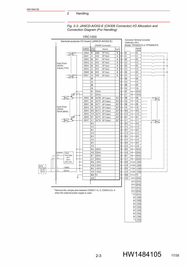
Fig. 2-3: JANCD-AIO02-E (CN306 Connector) I/O Allocation and Connection Diagram (For Handling)
Internal Power Supply +24 V 024 V(24V,1.5A)
ExternalPower Supply +24 VE 024 VE
CN303
CN306 ConnectorLogicalNumber Name Signal
Connector Terminal Converter(Optional) (-X51)Model: TIFS553YS or TIFS5N53YS
ConnectorNumber
Terminal Number
* Remove the Jumper-pins between CN303-1 to -3, CN303-2 to -4 when the external power supply is used.
GP Output
GP Output
GP Output
GP Output
GP Output
GP Output
GP Output
GP Output
GP Input
GP Input
GP Input
GP Input
GP Input
GP Input
GP Input
GP Input
YRC1000General-purpose I/O board (JANCD-AIO02-E)
Each Point24VDC50mA (MAX)
Each Point24VDC6.8mA (TYP)
2-3 HW1484105 17/35
2 Handling
HW1484105
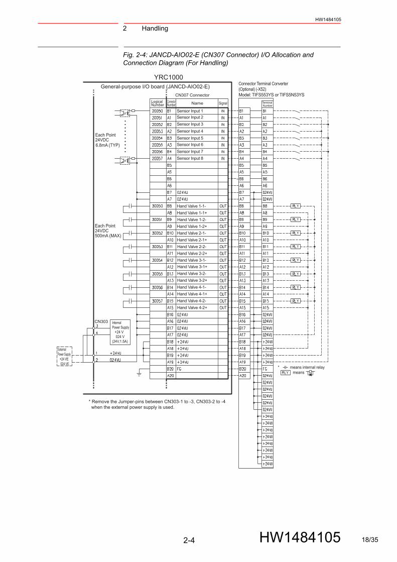
Fig. 2-4: JANCD-AIO02-E (CN307 Connector) I/O Allocation and Connection Diagram (For Handling)
Internal Power Supply +24 V 024 V(24V,1.5A)
ExternalPower Supply +24 VE 024 VE
CN303
CN307 Connector
Connector Terminal Converter(Optional) (-X52)Model: TIFS553YS or TIFS5N53YS
Terminal Number
LogicalNumber
ConnectorNumber SignalName
* Remove the Jumper-pins between CN303-1 to -3, CN303-2 to -4 when the external power supply is used.
Sensor Input 8
Sensor Input 1
Sensor Input 2
Sensor Input 3
Sensor Input 4
Sensor Input 5
Sensor Input 6
Sensor Input 7
Hand Valve 1-1-
Hand Valve 1-1+
Hand Valve 1-2-
Hand Valve 1-2+
Hand Valve 2-1-
Hand Valve 2-1+
Hand Valve 2-2-
Hand Valve 2-2+
Hand Valve 3-1-
Hand Valve 3-1+
Hand Valve 3-2-
Hand Valve 3-2+
Hand Valve 4-1-
Hand Valve 4-1+
Hand Valve 4-2-
Hand Valve 4-2+
* means internal relay means
YRC1000General-purpose I/O board (JANCD-AIO02-E)
Each Point24VDC
Each Point24VDC
500mA (MAX)
6.8mA (TYP)
2-4 HW1484105 18/35
2 HandlingHW1484105
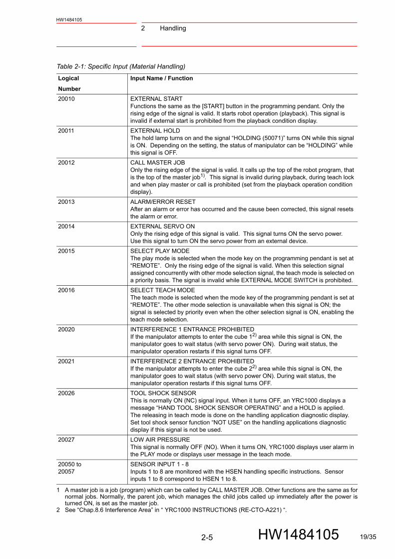
Table 2-1: Specific Input (Material Handling)
Logical
Number
Input Name / Function
20010 EXTERNAL STARTFunctions the same as the [START] button in the programming pendant. Only the rising edge of the signal is valid. It starts robot operation (playback). This signal is invalid if external start is prohibited from the playback condition display.
20011 EXTERNAL HOLDThe hold lamp turns on and the signal “HOLDING (50071)” turns ON while this signal is ON. Depending on the setting, the status of manipulator can be “HOLDING” while this signal is OFF.
20012 CALL MASTER JOBOnly the rising edge of the signal is valid. It calls up the top of the robot program, that is the top of the master job1). This signal is invalid during playback, during teach lock and when play master or call is prohibited (set from the playback operation condition display).
20013 ALARM/ERROR RESETAfter an alarm or error has occurred and the cause been corrected, this signal resets the alarm or error.
20014 EXTERNAL SERVO ONOnly the rising edge of this signal is valid. This signal turns ON the servo power. Use this signal to turn ON the servo power from an external device.
20015 SELECT PLAY MODEThe play mode is selected when the mode key on the programming pendant is set at “REMOTE”. Only the rising edge of the signal is valid. When this selection signal assigned concurrently with other mode selection signal, the teach mode is selected on a priority basis. The signal is invalid while EXTERNAL MODE SWITCH is prohibited.
20016 SELECT TEACH MODEThe teach mode is selected when the mode key of the programming pendant is set at “REMOTE”. The other mode selection is unavailable when this signal is ON; the signal is selected by priority even when the other selection signal is ON, enabling the teach mode selection.
20020 INTERFERENCE 1 ENTRANCE PROHIBITEDIf the manipulator attempts to enter the cube 12) area while this signal is ON, the manipulator goes to wait status (with servo power ON). During wait status, the manipulator operation restarts if this signal turns OFF.
20021 INTERFERENCE 2 ENTRANCE PROHIBITEDIf the manipulator attempts to enter the cube 22) area while this signal is ON, the manipulator goes to wait status (with servo power ON). During wait status, the manipulator operation restarts if this signal turns OFF.
20026 TOOL SHOCK SENSORThis is normally ON (NC) signal input. When it turns OFF, an YRC1000 displays a message “HAND TOOL SHOCK SENSOR OPERATING” and a HOLD is applied. The releasing in teach mode is done on the handling application diagnostic display. Set tool shock sensor function “NOT USE” on the handling applications diagnostic display if this signal is not be used.
20027 LOW AIR PRESSUREThis signal is normally OFF (NO). When it turns ON, YRC1000 displays user alarm in the PLAY mode or displays user message in the teach mode.
20050 to20057
SENSOR INPUT 1 - 8Inputs 1 to 8 are monitored with the HSEN handling specific instructions. Sensor inputs 1 to 8 correspond to HSEN 1 to 8.
1 A master job is a job (program) which can be called by CALL MASTER JOB. Other functions are the same as fornormal jobs. Normally, the parent job, which manages the child jobs called up immediately after the power isturned ON, is set as the master job.
2 See “Chap.8.6 Interference Area” in “ YRC1000 INSTRUCTIONS (RE-CTO-A221) “.
2-5 HW1484105 19/35
2 Handling
HW1484105
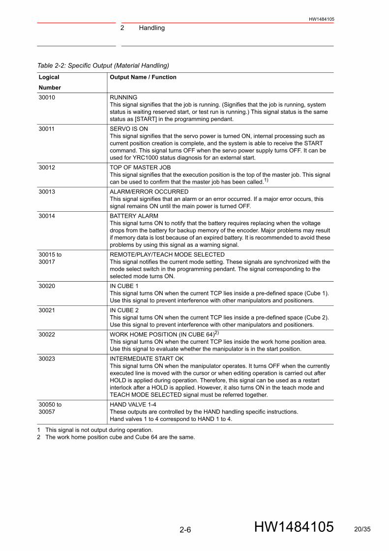
Table 2-2: Specific Output (Material Handling)
Logical
Number
Output Name / Function
30010 RUNNINGThis signal signifies that the job is running. (Signifies that the job is running, system status is waiting reserved start, or test run is running.) This signal status is the same status as [START] in the programming pendant.
30011 SERVO IS ONThis signal signifies that the servo power is turned ON, internal processing such as current position creation is complete, and the system is able to receive the START command. This signal turns OFF when the servo power supply turns OFF. It can be used for YRC1000 status diagnosis for an external start.
30012 TOP OF MASTER JOBThis signal signifies that the execution position is the top of the master job. This signal can be used to confirm that the master job has been called.1)
30013 ALARM/ERROR OCCURREDThis signal signifies that an alarm or an error occurred. If a major error occurs, this signal remains ON until the main power is turned OFF.
30014 BATTERY ALARMThis signal turns ON to notify that the battery requires replacing when the voltage drops from the battery for backup memory of the encoder. Major problems may result if memory data is lost because of an expired battery. It is recommended to avoid these problems by using this signal as a warning signal.
30015 to30017
REMOTE/PLAY/TEACH MODE SELECTEDThis signal notifies the current mode setting. These signals are synchronized with the mode select switch in the programming pendant. The signal corresponding to the selected mode turns ON.
30020 IN CUBE 1This signal turns ON when the current TCP lies inside a pre-defined space (Cube 1). Use this signal to prevent interference with other manipulators and positioners.
30021 IN CUBE 2This signal turns ON when the current TCP lies inside a pre-defined space (Cube 2). Use this signal to prevent interference with other manipulators and positioners.
30022 WORK HOME POSITION (IN CUBE 64)2)
This signal turns ON when the current TCP lies inside the work home position area. Use this signal to evaluate whether the manipulator is in the start position.
30023 INTERMEDIATE START OKThis signal turns ON when the manipulator operates. It turns OFF when the currently executed line is moved with the cursor or when editing operation is carried out after HOLD is applied during operation. Therefore, this signal can be used as a restart interlock after a HOLD is applied. However, it also turns ON in the teach mode and TEACH MODE SELECTED signal must be referred together.
30050 to30057
HAND VALVE 1-4These outputs are controlled by the HAND handling specific instructions. Hand valves 1 to 4 correspond to HAND 1 to 4.
1 This signal is not output during operation. 2 The work home position cube and Cube 64 are the same.
2-6 HW1484105 20/35

3 General ApplicationHW1484105
3 General Application
Fig. 3-1: JANCD-AIO02-E (CN308 Connector) I/O Allocation and Connection Diagram (For General Application)
ExternalPower Supply +24 VE 024 VE
Internal Power Supply +24 V 024 V(24V,1.5A)
CN303
CN308 Connector
Name Signal
Connector Terminal Converter(Optional) (-X53)Model:TIFS553YS or TIFS5N53YS
Terminal Number
LogicalNumber
ConnectorNumber
* Remove the Jumper-pins between CN303-1 to -3, CN303-2 to -4 when the external power supply is used.
External Start
External Hold
Call Master Job
Alarm/Error Reset
External Servo ON
Interference1 Entrance Prohibited
Work Prohibited
Running
Servo is ON
Top of Master Job
Alarm/Error Occurred
Battery Alarm
Remote Mode Selected
Play Mode Selected
Teach Mode Selected
In Cube 1
In Cube 2
Work Home PositionIntermediate Start OK
Interference2 Entrance Prohibited
Select Play Mode
Select Teach Mode
(Sequence Continuing)
YRC1000General-purpose I/O board (JANCD-AIO02-E)
Each Point24VDC50mA (MAX)
Each Point24VDC6.8mA (TYP)
3-1 HW1484105 21/35

3 General Application
HW1484105
Fig. 3-2: JANCD-AIO02-E (CN309 Connector) I/O Allocation and Connection Diagram (For General Application)
ExternalPower Supply +24 VE 024 VE
Internal Power Supply +24 V 024 V(24V,1.5A)
CN303
CN309 Connector
GP Input
GP Input
GP Input
GP Input
GP Input
GP Input
GP Input
GP Input
GP Output
GP Output
GP Output
GP Output
GP Output
GP Output
GP Output
GP Output
Logical
NumberSignalName
Connector Terminal Converter(Optional) (-X54)Model: TIFS553YS or TIFS5N53YS
Terminal Number
Connector
Number
* Remove the Jumper-pins between CN303-1 to -3, CN303-2 to -4 when the external power supply is used.
Interference3 Entrance ProhibitedInterference4 Entrance Prohibited
In Cube 3
In Cube 4
Work Instruction
YRC1000
General-purpose I/O board (JANCD-AIO02-E)
Each Point24VDC50mA (MAX)
Each Point24VDC6.8mA (TYP)
3-2 HW1484105 22/35

3 General ApplicationHW1484105
Fig. 3-3: JANCD-AIO02-E (CN306 Connector) I/O Allocation and Connection Diagram (General Application)
ExternalPower Supply +24 VE 024 VE
Internal Power Supply +24 V 024 V(24V,1.5A)
CN303
CN306 Connector
GP Input
GP Input
GP Input
GP Input
GP Input
GP Input
GP Input
GP Input
GP Output
GP Output
GP Output
GP Output
GP Output
GP Output
GP Output
GP Output
LogicalNumber Name Signal
Connector Terminal Converter(Optional) (-X51)Model: TIFS553YS or TIFS5N53YS
ConnectorNumber
Terminal Number
* Remove the Jumper-pins between CN303-1 to -3, CN303-2 to -4 when the external power supply is used.
YRC1000General-purpose I/O board (JANCD-AIO02-E)
Each Point24VDC50mA (MAX)
Each Point24VDC6.8mA (TYP)
3-3 HW1484105 23/35

3 General Application
HW1484105
Fig. 3-4: JANCD-AIO02-E (CN307 Connector) I/O Allocation and Connection Diagram (For General Application)
CN307 Connector
Connector Terminal Converter(Optional) (-X52)Model: TIFS553YS or TIFS5N53YS
Terminal Number
LogicalNumber
ConnectorNumber SignalName
* Remove the Jumper-pins between CN303-1 to -3, CN303-2 to -4 when the external power supply is used.
* means internal relay means
Internal Power Supply +24 V 024 V(24V,1.5A)
ExternalPower Supply +24 VE 024 VE
RLY
CN303
GP Input
GP Output
GP Input
GP Output
GP Input
GP Output
GP Input
GP Output
GP Input
GP Output
GP Input
GP Output
GP Input
GP Output
GP Input
GP Output
GP Output
GP Output
GP Output
GP Output
GP Output
GP Output
GP Output
GP Output
YRC1000General-purpose I/O board (JANCD-AIO02-E)
Each Point24VDC500mA (MAX)
Each Point24VDC6.8mA (TYP)
3-4 HW1484105 24/35
3 General ApplicationHW1484105
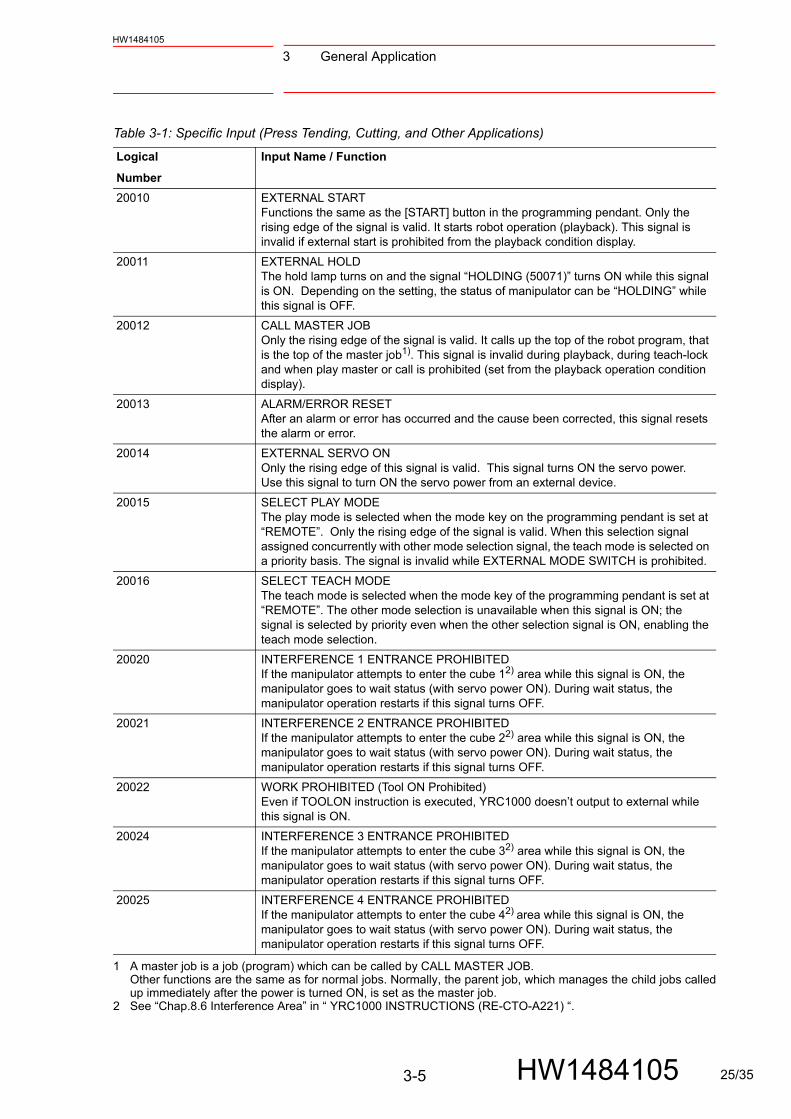
Table 3-1: Specific Input (Press Tending, Cutting, and Other Applications)
Logical
Number
Input Name / Function
20010 EXTERNAL STARTFunctions the same as the [START] button in the programming pendant. Only the rising edge of the signal is valid. It starts robot operation (playback). This signal is invalid if external start is prohibited from the playback condition display.
20011 EXTERNAL HOLDThe hold lamp turns on and the signal “HOLDING (50071)” turns ON while this signal is ON. Depending on the setting, the status of manipulator can be “HOLDING” while this signal is OFF.
20012 CALL MASTER JOBOnly the rising edge of the signal is valid. It calls up the top of the robot program, that is the top of the master job1). This signal is invalid during playback, during teach-lock and when play master or call is prohibited (set from the playback operation condition display).
20013 ALARM/ERROR RESETAfter an alarm or error has occurred and the cause been corrected, this signal resets the alarm or error.
20014 EXTERNAL SERVO ONOnly the rising edge of this signal is valid. This signal turns ON the servo power. Use this signal to turn ON the servo power from an external device.
20015 SELECT PLAY MODEThe play mode is selected when the mode key on the programming pendant is set at “REMOTE”. Only the rising edge of the signal is valid. When this selection signal assigned concurrently with other mode selection signal, the teach mode is selected on a priority basis. The signal is invalid while EXTERNAL MODE SWITCH is prohibited.
20016 SELECT TEACH MODEThe teach mode is selected when the mode key of the programming pendant is set at “REMOTE”. The other mode selection is unavailable when this signal is ON; the signal is selected by priority even when the other selection signal is ON, enabling the teach mode selection.
20020 INTERFERENCE 1 ENTRANCE PROHIBITEDIf the manipulator attempts to enter the cube 12) area while this signal is ON, the manipulator goes to wait status (with servo power ON). During wait status, the manipulator operation restarts if this signal turns OFF.
20021 INTERFERENCE 2 ENTRANCE PROHIBITEDIf the manipulator attempts to enter the cube 22) area while this signal is ON, the manipulator goes to wait status (with servo power ON). During wait status, the manipulator operation restarts if this signal turns OFF.
20022 WORK PROHIBITED (Tool ON Prohibited)Even if TOOLON instruction is executed, YRC1000 doesn’t output to external while this signal is ON.
20024 INTERFERENCE 3 ENTRANCE PROHIBITEDIf the manipulator attempts to enter the cube 32) area while this signal is ON, the manipulator goes to wait status (with servo power ON). During wait status, the manipulator operation restarts if this signal turns OFF.
20025 INTERFERENCE 4 ENTRANCE PROHIBITEDIf the manipulator attempts to enter the cube 42) area while this signal is ON, the manipulator goes to wait status (with servo power ON). During wait status, the manipulator operation restarts if this signal turns OFF.
1 A master job is a job (program) which can be called by CALL MASTER JOB. Other functions are the same as for normal jobs. Normally, the parent job, which manages the child jobs calledup immediately after the power is turned ON, is set as the master job.
2 See “Chap.8.6 Interference Area” in “ YRC1000 INSTRUCTIONS (RE-CTO-A221) “.
3-5 HW1484105 25/35
3 General Application
HW1484105
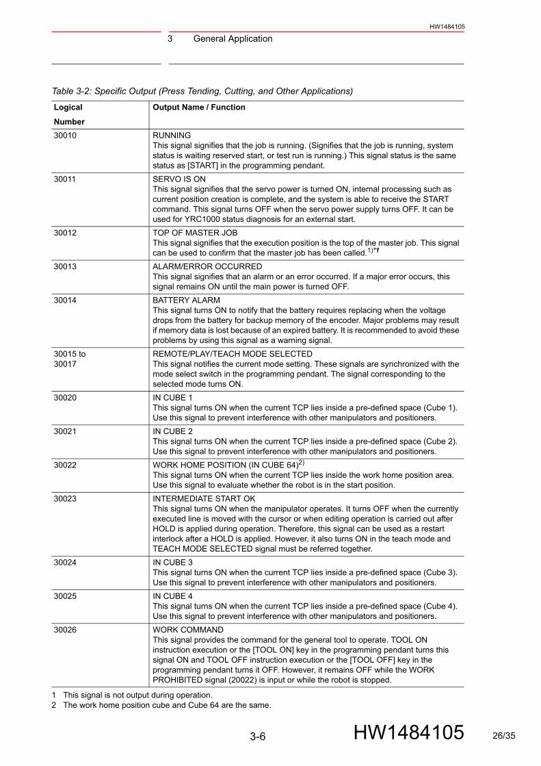
Table 3-2: Specific Output (Press Tending, Cutting, and Other Applications)
Logical
Number
Output Name / Function
30010 RUNNINGThis signal signifies that the job is running. (Signifies that the job is running, system status is waiting reserved start, or test run is running.) This signal status is the same status as [START] in the programming pendant.
30011 SERVO IS ONThis signal signifies that the servo power is turned ON, internal processing such as current position creation is complete, and the system is able to receive the START command. This signal turns OFF when the servo power supply turns OFF. It can be used for YRC1000 status diagnosis for an external start.
30012 TOP OF MASTER JOBThis signal signifies that the execution position is the top of the master job. This signal can be used to confirm that the master job has been called.1)*1
30013 ALARM/ERROR OCCURREDThis signal signifies that an alarm or an error occurred. If a major error occurs, this signal remains ON until the main power is turned OFF.
30014 BATTERY ALARMThis signal turns ON to notify that the battery requires replacing when the voltage drops from the battery for backup memory of the encoder. Major problems may result if memory data is lost because of an expired battery. It is recommended to avoid these problems by using this signal as a warning signal.
30015 to30017
REMOTE/PLAY/TEACH MODE SELECTEDThis signal notifies the current mode setting. These signals are synchronized with the mode select switch in the programming pendant. The signal corresponding to the selected mode turns ON.
30020 IN CUBE 1This signal turns ON when the current TCP lies inside a pre-defined space (Cube 1). Use this signal to prevent interference with other manipulators and positioners.
30021 IN CUBE 2This signal turns ON when the current TCP lies inside a pre-defined space (Cube 2). Use this signal to prevent interference with other manipulators and positioners.
30022 WORK HOME POSITION (IN CUBE 64)2)
This signal turns ON when the current TCP lies inside the work home position area. Use this signal to evaluate whether the robot is in the start position.
30023 INTERMEDIATE START OKThis signal turns ON when the manipulator operates. It turns OFF when the currently executed line is moved with the cursor or when editing operation is carried out after HOLD is applied during operation. Therefore, this signal can be used as a restart interlock after a HOLD is applied. However, it also turns ON in the teach mode and TEACH MODE SELECTED signal must be referred together.
30024 IN CUBE 3This signal turns ON when the current TCP lies inside a pre-defined space (Cube 3). Use this signal to prevent interference with other manipulators and positioners.
30025 IN CUBE 4This signal turns ON when the current TCP lies inside a pre-defined space (Cube 4). Use this signal to prevent interference with other manipulators and positioners.
30026 WORK COMMANDThis signal provides the command for the general tool to operate. TOOL ON instruction execution or the [TOOL ON] key in the programming pendant turns this signal ON and TOOL OFF instruction execution or the [TOOL OFF] key in the programming pendant turns it OFF. However, it remains OFF while the WORK PROHIBITED signal (20022) is input or while the robot is stopped.
1 This signal is not output during operation. 2 The work home position cube and Cube 64 are the same.
3-6 HW1484105 26/35
4 Spot WeldingHW1484105
4 Spot Welding
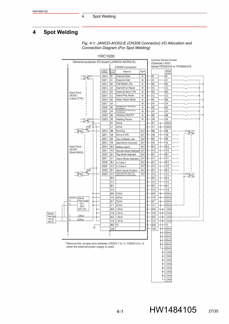
Fig. 4-1: JANCD-AIO02-E (CN308 Connector) I/O Allocation and Connection Diagram (For Spot Welding)
ExternalPower Supply +24 VE 024 VE
Internal Power Supply +24 V 024 V(24V,1.5A)
CN303
CN308 Connector
Name Signal
Connector Terminal Converter(Optional) (-X53)Model:TIFS553YS or TIFS5N53YS
Terminal Number
LogicalNumber
ConnectorNumber
* Remove the Jumper-pins between CN303-1 to -3, CN303-2 to -4 when the external power supply is used.
External Start
External Hold
Call Master Job
Alarm/Error Reset
External Servo ON
Interference1 Entrance Prohibited
Welding ON/OFF
Welding Pause
Running
Servo is ON
Top of Master Job
Alarm/Error Occurred
Battery Alarm
Remote Mode Selected
Play Mode Selected
Teach Mode Selected
In Cube 1
In Cube 2
Work Home PositionIntermediate Start OK
Interference2 Entrance Prohibited
Select Play Mode
Select Teach Mode
(Sequence Continuing)
YRC1000General-purpose I/O board (JANCD-AIO02-E)
Each Point24VDC50mA (MAX)
Each Point24VDC6.8mA (TYP)
4-1 HW1484105 27/35

4 Spot Welding
HW1484105
Fig. 4-2: JANCD-AIO02-E (CN309 Connector) I/O Allocation and Connection Diagram (For Spot Welding)
ExternalPower Supply +24 VE 024 VE
Internal Power Supply +24 V 024 V(24V,1.5A)
CN303
CN309 Connector
GP Input
GP Input
GP Input
GP Input
GP Input
GP Input
GP Input
GP Input
GP Output
GP Output
GP Output
GP Output
GP Output
GP Output
GP Output
GP Output
Logical
NumberSignalName
Connector Terminal Converter(Optional) (-X54)Model: TIFS553YS or TIFS5N53YS
Terminal Number
Connector
Number
* Remove the Jumper-pins between CN303-1 to -3, CN303-2 to -4 when the external power supply is used.
Interference3 Entrance ProhibitedInterference4 Entrance Prohibited
In Cube 3
In Cube 4
YRC1000
General-purpose I/O board (JANCD-AIO02-E)
Each Point24VDC50mA (MAX)
Each Point24VDC6.8mA (TYP)
4-2 HW1484105 28/35
4 Spot WeldingHW1484105
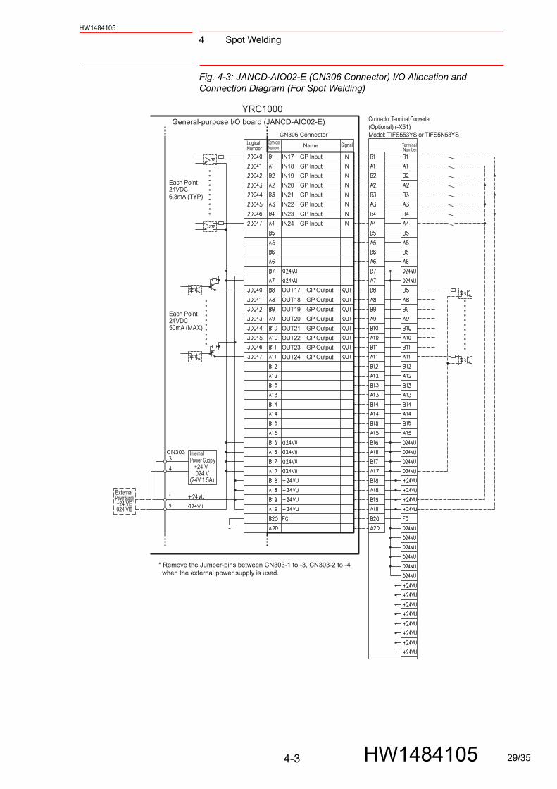
Fig. 4-3: JANCD-AIO02-E (CN306 Connector) I/O Allocation and Connection Diagram (For Spot Welding)
ExternalPower Supply +24 VE 024 VE
Internal Power Supply +24 V 024 V(24V,1.5A)
CN303
CN306 Connector
IN17 GP Input
IN18 GP Input
IN19 GP Input
IN20 GP Input
IN21 GP Input
IN22 GP Input
IN23 GP Input
IN24 GP Input
OUT17 GP Output
OUT18 GP Output
OUT19 GP Output
OUT20 GP Output
OUT21 GP Output
OUT22 GP Output
OUT23 GP Output
OUT24 GP Output
LogicalNumber Name Signal
Connector Terminal Converter(Optional) (-X51)Model: TIFS553YS or TIFS5N53YS
ConnectorNumber
Terminal Number
* Remove the Jumper-pins between CN303-1 to -3, CN303-2 to -4 when the external power supply is used.
YRC1000General-purpose I/O board (JANCD-AIO02-E)
Each Point24VDC50mA (MAX)
Each Point24VDC6.8mA (TYP)
4-3 HW1484105 29/35

4 Spot Welding
HW1484105
Fig. 4-4: JANCD-AIO02-E (CN307 Connector) I/O Allocation and Connection Diagram (For Spot Welding)
CN307 Connector
Connector Terminal Converter(Optional) (-X52)Model: TIFS553YS or TIFS5N53YS
Terminal Number
LogicalNumber
ConnectorNumber SignalName
* means internal relay means
Internal Power Supply +24 V 024 V(24V,1.5A)
ExternalPower Supply +24 VE 024 VE
RLY
CN303
Timer Cooling Water Error (IN09) ***
Gun Cooling Water Error (IN10) ***
Weld ON/OFF (OUT09) ***
Transthermo Error (IN11) ***
Low Air Pressure (IN12) ***
Weld Error Reset (OUT10) **
Weld Completion (IN13) **
Weld Error (IN14) **
Weld Condition 1 (OUT11) **
Gun Short Open Detection (IN15) **
Tip Replacement Completion (IN16) **
Weld Condition 2 (OUT12) **
Weld Condition 3 (OUT13) **
Weld Condition 4 (OUT14) **
Gun Press Command (OUT15) **
Tip Change Request (OUT16) **
YRC1000General-purpose I/O board (JANCD-AIO02-E)
Each Point24VDC500mA (MAX)
Each Point24VDC6.8mA (TYP)
*
**
***
Remove the Jumper-pins between CN303-1 to -3, CN303-2 to -4 when the external power supply is used.This assignment can be changed at the I/O assignment display.Refer to and for detail.This assignment can be changed at the PSEDU input display.Refer to and for detail.
table 4-1 “Specific Input (Spot Welding)”table 4-2 “Specific Output (Spot Welding)”
table 4-1 “Specific Input (Spot Welding)”table 4-2 “Specific Output (Spot Welding)”
4-4 HW1484105 30/35

4 Spot WeldingHW1484105
Table 4-1: Specific Input (Spot Welding)
Logical
Number
Input Name / Function
20010 EXTERNAL STARTFunctions the same as the [START] button in the programming pendant. Only the rising edge of the signal is valid. It starts robot operation (playback). This signal is invalid if external start is prohibited from the playback condition display.
20011 EXTERNAL HOLDThe hold lamp turns on and the signal “HOLDING (50071)” turns ON while this signal is ON. Depending on the setting, the status of manipulator can be “HOLDING” while this signal is OFF.
20012 CALL MASTER JOBOnly the rising edge of the signal is valid. It calls up the top of the robot program, that is the top of the master job1). This signal is invalid during playback, during teach lock and when play master or call is prohibited (set from the playback operation condition display).
20013 ALARM/ERROR RESETAfter an alarm or error has occurred and the cause been corrected, this signal resets the alarm or error.
20014 EXTERNAL SERVO ONOnly the rising edge of this signal is valid. This signal turns ON the servo power. Use this signal to turn ON the servo power from an external device.
20015 SELECT PLAY MODEThe play mode is selected when the mode key on the programming pendant is set at “REMOTE”. Only the rising edge of the signal is valid. When this selection signal assigned concurrently with other mode selection signal, the teach mode is selected on a priority basis. The signal is invalid while EXTERNAL MODE SWITCH is prohibited.
20016 SELECT TEACH MODEThe teach mode is selected when the mode key of the programming pendant is set at “REMOTE”. The other mode selection is unavailable when this signal is ON; the signal is selected by priority even when the other selection signal is ON, enabling the teach mode selection.
20020 INTERFERENCE 1 ENTRANCE PROHIBITEDIf the manipulator attempts to enter the cube 12) area while this signal is ON, the manipulator goes to wait status (with servo power ON). During wait status, the manipulator operation restarts if this signal turns OFF.
20021 INTERFERENCE 2 ENTRANCE PROHIBITEDIf the manipulator attempts to enter the cube 22) area while this signal is ON, the manipulator goes to wait status (with servo power ON). During wait status, the manipulator operation restarts if this signal turns OFF.
20022 WELDING ON/OFF (From sequencer)This signal inputs the welding ON/OFF selector switch status from the sequencer in the interlock unit. The WELD ON/OFF signal is output to the Power Source according to this signal and the manipulator status.
20023 WELDING PAUSE (From sequencer)This signal is used to move the manipulator to the home position when an error occurs in the Power Source or the gun. The robot ignores the spot welding instruction and operates playback motion.
20024 INTERFERENCE 3 ENTRANCE PROHIBITEDIf the manipulator attempts to enter the cube 32) area while this signal is ON, the manipulator goes to wait status (with servo power ON). During wait status, the manipulator operation restarts if this signal turns OFF.
20025 INTERFERENCE 4 ENTRANCE PROHIBITEDIf the manipulator attempts to enter the cube 42) area while this signal is ON, the manipulator goes to wait status (with servo power ON). During wait status, the manipulator operation restarts if this signal turns OFF.
4-5 HW1484105 31/35

4 Spot Welding
HW1484105
200503)
TIMER COOLING WATER ERRORThis signal monitors the status of timer cooling water. The manipulator displays alarm and stops when this signal is input. The servo power remains ON.
200513)
GUN COOLING WATER ERRORThis signal monitors the status of gun cooling water. The manipulator displays alarm and stops when this signal is input. The servo power supply remains ON.
200523)
TRANSTHERMO ERRORError signal is sent from the transformer in the gun to the robot. This signal is ON normally (NC) and an alarm occurs when the signal is OFF. The servo power supply remains ON.
200533)
LOW AIR PRESSUREWhen air pressure is reduced and this input is turned ON, an alarm occurs. The servo power supply remains ON.
200544)
WELD COMPLETIONThis signal indicates that the Power Source completed welding without error. This signal is used as a confirmation signal for welding instruction execution and manual spot welding.After this signal is input, the welding sequence is completed and the next step is executed when confirmation limit switch is not provided.
200554)
WELDING ERRORThis signal indicates an abnormal welding result or Power Source’s error. Alarm occurs and the manipulator stops if this signal is input during welding.
4) STICK DETECTIONThis signal indicates an abnormal welding result or Power Source’s error. Alarm occurs and the manipulator stops if this signal is input during welding.
4) GUN FULL OPEN DETECTIONThis signal indicates that the stroke of the double stroke gun is full open.
200564)
GUN SHORT OPEN DETECTIONThis signal is connected with a single gun open verification limit switch or a double stroke gun short open verification limit switch to verify the gun open.
4) GUN PRESSURE DETECTIONThis signal indicates that a gun is in pressing status.
200574)
TIP REPLACE COMPLETIONWhen this signal is input after tip replacement, the TIP REPLACE REQUEST signal turns OFF, and the stored number of welding is cleared.
1 A master job is a job (program) which can be called by CALL MASTER JOB.Other functions are the same as fornormal jobs. Normally, the parent job, which manages the child jobs called up immediately after the power isturned ON, is set as the master job.
2 See YRC1000 INSTRUCTIONS (RE-CTO-A221) chapter 8.6 “Interference Area”. 3 This signal can be set as “USE” or “NOT USE” by pseudo input signal ”8202x”. If “NOT USE” is selected, this
signal can be used as the universal I/O signal described in parentheses. 4 This signal can be allocated to any universal I/O signal at the I/O allocation display in operation condition.
Table 4-1: Specific Input (Spot Welding)
Logical
Number
Input Name / Function
Timer Cooling Water Error Validating (or IN09)
Gun Cooling Water Error Validating (or IN10)
Transthermo Error Validating (or IN11)
Low Air Pressure Validating (or IN12)
Weld ON/OFF Validating (or OUT09)
7 6 5 4 3 2 1 0 0 0 0 1 1 1 1 1
Pseudo InputSignal 8202x
4-6 HW1484105 32/35
4 Spot WeldingHW1484105
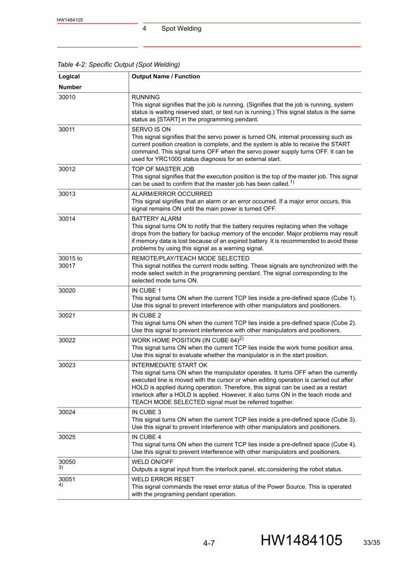
Table 4-2: Specific Output (Spot Welding)
Logical
Number
Output Name / Function
30010 RUNNINGThis signal signifies that the job is running. (Signifies that the job is running, system status is waiting reserved start, or test run is running.) This signal status is the same status as [START] in the programming pendant.
30011 SERVO IS ONThis signal signifies that the servo power is turned ON, internal processing such as current position creation is complete, and the system is able to receive the START command. This signal turns OFF when the servo power supply turns OFF. It can be used for YRC1000 status diagnosis for an external start.
30012 TOP OF MASTER JOBThis signal signifies that the execution position is the top of the master job. This signal can be used to confirm that the master job has been called.1)
30013 ALARM/ERROR OCCURREDThis signal signifies that an alarm or an error occurred. If a major error occurs, this signal remains ON until the main power is turned OFF.
30014 BATTERY ALARMThis signal turns ON to notify that the battery requires replacing when the voltage drops from the battery for backup memory of the encoder. Major problems may result if memory data is lost because of an expired battery. It is recommended to avoid these problems by using this signal as a warning signal.
30015 to30017
REMOTE/PLAY/TEACH MODE SELECTEDThis signal notifies the current mode setting. These signals are synchronized with the mode select switch in the programming pendant. The signal corresponding to the selected mode turns ON.
30020 IN CUBE 1This signal turns ON when the current TCP lies inside a pre-defined space (Cube 1). Use this signal to prevent interference with other manipulators and positioners.
30021 IN CUBE 2This signal turns ON when the current TCP lies inside a pre-defined space (Cube 2). Use this signal to prevent interference with other manipulators and positioners.
30022 WORK HOME POSITION (IN CUBE 64)2)
This signal turns ON when the current TCP lies inside the work home position area. Use this signal to evaluate whether the manipulator is in the start position.
30023 INTERMEDIATE START OKThis signal turns ON when the manipulator operates. It turns OFF when the currently executed line is moved with the cursor or when editing operation is carried out after HOLD is applied during operation. Therefore, this signal can be used as a restart interlock after a HOLD is applied. However, it also turns ON in the teach mode and TEACH MODE SELECTED signal must be referred together.
30024 IN CUBE 3This signal turns ON when the current TCP lies inside a pre-defined space (Cube 3). Use this signal to prevent interference with other manipulators and positioners.
30025 IN CUBE 4This signal turns ON when the current TCP lies inside a pre-defined space (Cube 4). Use this signal to prevent interference with other manipulators and positioners.
300503)
WELD ON/OFFOutputs a signal input from the interlock panel, etc.considering the robot status.
300514)
WELD ERROR RESETThis signal commands the reset error status of the Power Source. This is operated with the programing pendant operation.
4-7 HW1484105 33/35

4 Spot Welding
HW1484105
30052 to300554)
WELD CONDITION (Level signals) 1(1), 2(2), 4(3), 8(4), 16(5), 32(6), 64(7), 128(8) Sets the welding conditions for the Power Source. The output format can be selected as binary or discrete (bit number). It can handle up to 255 conditions. Most-significant bit is the parity bit (when specified).
4) WELDING COMMANDThis signal outputs execution command signal to the Power Source. This signal is not necessary for a Power Source which is executed using the WELDING CONDITION signal.
4) STROKE CHANGE1SINGLE SOLENOIDDOUBLE SOLENOIDThis is a signal, when a double stroke gun is used, to change the open stroke of the welding gun.
300564)
GUN PRESS COMMAND This outputs gun press command.
300574)
TIP REPLACE REQUESTThis signal is output when the stored number of welding reaches the number of welding set for the tip replacement.
1 This signal is not output during operation. 2 The work home position cube and Cube 64 are the same. 3 This signal can be select “USE” or “NOT USE” by pseudo input signal ”8202x”. If “NOT USE” is selected, this
signal can be used as the universal I/O signal described in parentheses. 4 This signal can be allocated to any universal I/O signal at the I/O allocation display in operation condition.
Table 4-2: Specific Output (Spot Welding)
Logical
Number
Output Name / Function
Timer Cooling Water Error Validating (or IN09)
Gun Cooling Water Error Validating (or IN10)
Transthermo Error Validating (or IN11)
Low Air Pressure Validating (or IN12)
Weld ON/OFF Validating (or OUT09)
7 6 5 4 3 2 1 00 0 0 1 1 1 1 1
Pseudo InputSignal 8202x
4-8 HW1484105 34/35
YRC1000 OPTIONSINSTRUCTIONSSTANDARD I/O SIGNAL ASSIGNMENT TABLE (PNP SPECIFICATION)FOR GENERAL-PURPOSE I/O BOARD TYPE: JANCD-AIO02-E
HEAD OFFICE2-1 Kurosakishiroishi, Yahatanishi-ku, Kitakyushu 806-0004, JapanPhone +81-93-645-7703 Fax +81-93-645-7802
100 Automation Way, Miamisburg, OH 45342, U.S.A. Phone +1-937-847-6200 Fax +1-937-847-6277
YASKAWA America Inc. (Motoman Robotics Division)
Yaskawastrasse 1, 85391 Allershausen, GermanyPhone +49-8166-90-100 Fax +49-8166-90-103
YASKAWA Europe GmbH (Robotics Divsion )
Phone +82-2-784-7844 Fax +82-2-784-8495
151 Lorong Chuan, #04-02A, New Tech Park, Singapore 556741Phone +65-6282-3003 Fax +65-6289-3003
YASKAWA Electric (Singapore) PTE Ltd.
No7 Yongchang North Road, Beijing E&T Development Area,China 100176Phone +86-10-6788-2858 Fax +86-10-6788-2878
YASKAWA SHOUGANG ROBOT Co. Ltd.
#426, Udyog Vihar, Phase- IV, Gurgaon, Haryana, IndiaFax +91-124-475-8542Phone +91-124-475-8500
YASKAWA India Private Ltd. (Robotics Division)
YASKAWA Electric (China) Co., Ltd.22F, One Corporate Avenue, No.222, Hubin Road, Huangpu District, Shanghai 200021, ChinaPhone +86-21-5385-2200 Fax +86-21-5385-3299
YASKAWA Electric (Thailand) Co., Ltd.59,1st-5th Floor, Flourish Building, Soi Ratchadapisek 18,Ratchadapisek Road, Huaykwang, Bangkok 10310, THAILANDPhone +66-2-017-0099 Fax +66-2-017-0199
12F, No.207, Sec. 3, Beishin Rd., Shindian District, New Taipei City 23143, TaiwanFax +886-2-8913-1513Phone +886-2-8913-1333
YASKAWA Electric Taiwan Corporation
Secure Building-Gedung B Lantai Dasar & Lantai 1 JI. Raya Protokol Halim Perdanakusuma, Jakarta 13610, Indonesia
Fax +62-21-2982-6741Phone +62-21-2982-6470
PT. YASKAWA Electric Indonesia
Phone +46-480-417-800 Fax +46-486-414-10
YASKAWA Nordic ABVerkstadsgatan 2, Box 504 ,SE-385 25 Torsas, Sweden
35F, Three IFC, 10 Gukjegeumyung-ro, Yeongdeungpo-gu, Seoul, Korea 07326YASKAWA Electric Korea Corporation
HW1484105
C 2016 YASKAWA ELECTRIC CORPORATION
March 2019 16-09
Published by YASKAWA
MANUAL NO.
1 35/35