yta510 temperature transmitter · field wireless system: refer to gs 01w01a01-01en field wireless...
TRANSCRIPT

GeneralSpecifications
<<Contents>> <<Index>>
YTA510Temperature Transmitter
Yokogawa Electric Corporation2-9-32, Nakacho, Musashino-shi, Tokyo, 180-8750 JapanTel.: 81-422-52-5690 Fax.: 81-422-52-2018
GS 01C50E01-01EN
GS 01C50E01-01EN©Copyright July 2010
11th Edition June 2017
The YTA510 is the high performance temperature transmitter that accepts Thermocouple, RTD, ohms or DC millivolt inputs. The dual input type independently measures and calculates process values for Sensor 1 and Sensor 2. YTA510 transmit not only process variables but also the setting parameters using wireless signal. The transmitters run on internal batteries, and the installation cost can be decreased since hard-wiring is not required. The communication is compliant with ISA100.11a protocol specifications.
Battery CharacteristicBattery pack with long life lithium-thionyl chloride batteries. With the intrinsically safe type, the battery pack is replaceable in hazardous area. Typical battery life is 10 years at 30 seconds update time or 6 years at 10 seconds update time in the following conditions.*
• Ambient temperature: 23±2°C• Device role: IO mode• LCD display: off* For amplifier housing code 8 and 9, typical
battery life is 8 years at 5 seconds update time with power saving mode. Environmental condition such as vibration may affect the battery life.
■ FUNCTIONAL SPECIFICATIONSInput
Single input: Amplifier housing code 7Dual input: Amplifier housing code 8 and 9Input type is selectable: Thermocouples, 2-, 3-, and 4-wire RTDs, ohms and DC millivolts. See Table 1.4-wire is available for Sensor 1 input.
Input Signal Source Resistance (for T/C, mV)1 kΩ or lower
Input Lead Wire Resistance (for RTD, Ohm)10 Ω per wire or lower
OutputWireless (ISA100.11a protocol) 2.4 GHz signal.
RangeSee Table 1.
Update Period1 to 3600 s selectable.*
* Minimum update time is 2 s at dual input sensor use.
FEATURES● Long Life Battery Design
Ultra low current consumption design using two high capacity lithium-thionyl chloride batteries provide wireless operation for years.
● Security Assured Wireless Network JoiningInfrared communication between the devices for wireless network configuration and parameter setting.
● Quick Update TimeSelectable from 1 second to 60 minutes for measured process value to publish wirelessly.
STANDARD SPECIFICATIONS■ WIRELESS SPECIFICATIONS
Communication protocol: ISA100.11a protocolData rate: 250 kbpsFrequency: 2400 - 2483.5 MHz license free ISM bandRadio security: AES 128 bit codifiedRF Transmitter power: Max. 11.6 dBm (fixed)Antenna: +2 dBi Omni directional monopole typeSeparately sold remote antenna and antenna cables can be used.
■ POWER SUPPLY SPECIFICATIONSBattery:
Use the dedicated battery pack.Rated voltage: 7.2 VRated capacity: 19 Ah
■ PERFORMANCE SPECIFICATIONSAccuracy
See Table 1.Cold Junction Compensation Accuracy
For T/C only± 0.5°C (± 0.9°F)
Ambient Temperature Effect (per 1.0°C change)See Table 2.

2
All Rights Reserved. Copyright © 2010, Yokogawa Electric Corporation
<<Contents>> <<Index>>
GS 01C50E01-01EN
Zero-gain AdjustmentSet the amount of zero-gain point adjustment.
Integral Indicator (LCD display)5-digit numerical display, unit display and bar graph. The indicator is configurable to display the following variables periodically. °C, K, °F, °R, mV and ohm, 0 to 100 % bar graph, and alternate display of Sensor 1 and Sensor 2 process valueSee also “Factory Setting.”
Sensor BurnoutSelect either HIGH or LOW as the configuration.
Self DiagnosticsAmplifier failure, sensor failure, configuration error, battery alarm, wireless communication alarm and over-range error for process variables.
Software Download FunctionSoftware download function permits to update wireless field device software via ISA100.11a wireless communication.
Battery Pack2x primary lithium-thionyl chloride batteriesWith battery case (batteries sold separately)
■ NORMAL OPERATING CONDITION(Optional features or approval codes may affect limits.)
Ambient Temperature Limits-40 to 85°C (-40 to 185°F)-30 to 80°C (-22 to 176°F) LCD visible range
Ambient Humidity Limits0 to 100% RH
■ REGULATORY COMPLIANCE STATEMENTSThis device contains the wireless module which satisfies the following standards.
* The specific radio equipment (Approval Number:007WWCUL0480) which received the technicalstandard satisfied certification based on the Radio Law is used for this product.
* Please confirm that an installation region fulfills an applicable standard. If additional regulatory information and approvals are required, contact a Yokogawa representative.
EMC Conformity Standards EN61326-1 Class A, Table 2 (For use in industrial locations), EN61326-2-3
June 13, 2017-00
Radio Equipment Directive (RE)ETSI EN 300 328, ETSI EN 301 489-1, ETSI EN 301 489-17, EN61010-1, EN61010-2-030, EN62311
• Indoor/Outdoor useEU RoHS Directive
EN50581Safety Requirement Standards
EN61010-1, EN61010-2-030• Installation category: I
(Anticipated transient overvoltage 330 V)• Pollution degree: 2• Indoor/Outdoor use
Regulation Conformity of the Wireless Module • FCC Approval• IC Approval
■ PHYSICAL SPECIFICATIONSEnclosure
HousingLow copper cast aluminum alloy
Coating of housing[for aluminum housing]Urethane curing type polyester resin powder coatingMint-green paint (Munsell 5.6BG 3.3/2.9 or its equivalent)[for option code /P or /X2]Epoxy and polyurethane resin solvent coating
Degrees of ProtectionIP66/IP67, NEMA4X
Name plate and tag316 SST tag plate wired onto transmitter.
Weight2.8 kg (6.2 lb)Without battery pack and mounting bracket.
ConnectionsRefer to “MODEL AND SUFFIX CODE.”
< Related Instruments >Field Wireless System: Refer to GS 01W01A01-01ENField Wireless Management Station YFGW410: GS 01W02D01-01ENField Wireless Access Point YFGW510: GS 01W02E01-01ENField Wireless Media Converter YFGW610: GS 01W02D02-01EN

3<<Contents>> <<Index>>
All Rights Reserved. Copyright © 2010, Yokogawa Electric Corporation GS 01C50E01-01EN
Table 1. Sensor type, measurement range, and accuracy
Sensor Type Standard Measurement Range Accuracy
T/C
B
IEC584
100 to 300°C ( 212 to 572°F ) ± 5.0°C ( ± 9.0°F )300 to 400°C ( 572 to 752°F ) ± 2.0°C ( ± 3.6°F )400 to 1820°C ( 752 to 3308°F ) ± 1.5°C ( ± 2.7°F )
E -200 to 1000°C ( -328 to 1832°F ) ± 0.4°C ( ± 0.8°F )J -200 to 1200°C ( -328 to 2192°F ) ± 0.5°C ( ± 0.9°F )K -200 to 1372°C ( -328 to 2502°F ) ± 0.6°C ( ± 1.1°F )N -200 to 1300°C ( -328 to 2372°F ) ± 0.6°C ( ± 1.1°F )
R-50 to 100°C ( -58 to 212°F ) ± 1.7°C ( ± 3.1°F )100 to 1768°C ( 212 to 3214°F ) ± 0.8°C ( ± 1.5°F )
S-50 to 100°C ( -58 to 212°F ) ± 1.7°C ( ± 3.1°F )100 to 1768°C ( 212 to 3214°F ) ± 0.8°C ( ± 1.5°F )
T -200 to 400°C ( -328 to 752°F ) ± 0.5°C ( ± 0.9°F )
RTDPt100
IEC751-200 to 850°C ( -328 to 1562°F ) ± 0.3°C ( ± 0.6°F )
Pt200 -200 to 850°C ( -328 to 1562°F ) ± 0.6°C ( ± 1.1°F )Pt500 -200 to 850°C ( -328 to 1562°F ) ± 0.5°C ( ± 0.9°F )
mV - -10 to 220 [mV] ± 0.03 [mV]Ohm - 0 to 2000 [Ω] ± 1 [Ω]
Note: For T/C input, add Cold Junction Compensation Accuracy (± 0.5°C) to the total accuracy. For RTD input of the 2-wire connection, add a corrected value (± 0.1°C) to the total accuracy.
Table 2. Effects of ambient temperature
Sensor Type Temperature Effects per 1.0°C Change in Ambient Temperature Measurement Range
T/C
B0.2°C - ( 0.066% of ( t - 100 ) ) 100°C ≤ t < 300°C0.07°C - ( 0.0057% of ( t - 300 ) ) 300°C ≤ t < 1000°C0.037°C t ≥ 1000°C
E0.0035°C - ( 0.00492% of t ) t < 0°C
0.0035°C + ( 0.00146% of t ) t ≥ 0°C
J0.0039°C - ( 0.00529% of t ) t < 0°C0.0039°C + ( 0.00149% of t ) t ≥ 0°C
K0.00521°C - ( 0.00707% of t ) t < 0°C0.00521°C + ( 0.00182% of t ) t ≥ 0°C
N0.0077°C - ( 0.00918% of t ) t < 0°C0.0077°C + ( 0.00136% of t ) t ≥ 0°C
R, S
0.04°C - ( 0.057% of t ) t < 0°C0.04°C + ( 0.0102% of t ) 0°C ≤ t < 100°C0.0316°C - ( 0.001% of t ) 100°C ≤ t < 600°C0.0175°C + ( 0.00173% of t ) t ≥ 600°C
T0.00513°C - ( 0.00631% of t ) t < 0°C0.00513°C + ( 0.0008% of t ) t ≥ 0°C
RTD
Pt100 0.0048°C + ( 0.0016% of absolute value t ) Entire Sensor Input Range
Pt2000.0038°C + ( 0.0015% of absolute value t ) t < 650°C0.0028°C + ( 0.0016% of t ) t ≥ 650°C
Pt5000.003°C + ( 0.0014% of absolute value t ) t < 650°C0.002°C + ( 0.0016% of t ) t ≥ 650°C
mV 0.2μV + ( 0.0015% of reading ) Entire Sensor Input RangeOhm 0.001Ω + ( 0.0011% of reading ) Entire Sensor Input Range
Note1: The “t” on Table 2 means the value of the reading in °C.Note2: The “absolute value t” on Table 2 means the absolute value of the reading in °C. [ Example of absolute value t ] When the temperature value is 250 Kelvin, abs reading is 23.15, absolute (250 - 273.15).
Feb. 1, 2017-00
4
All Rights Reserved. Copyright © 2010, Yokogawa Electric Corporation
<<Contents>> <<Index>>
GS 01C50E01-01EN
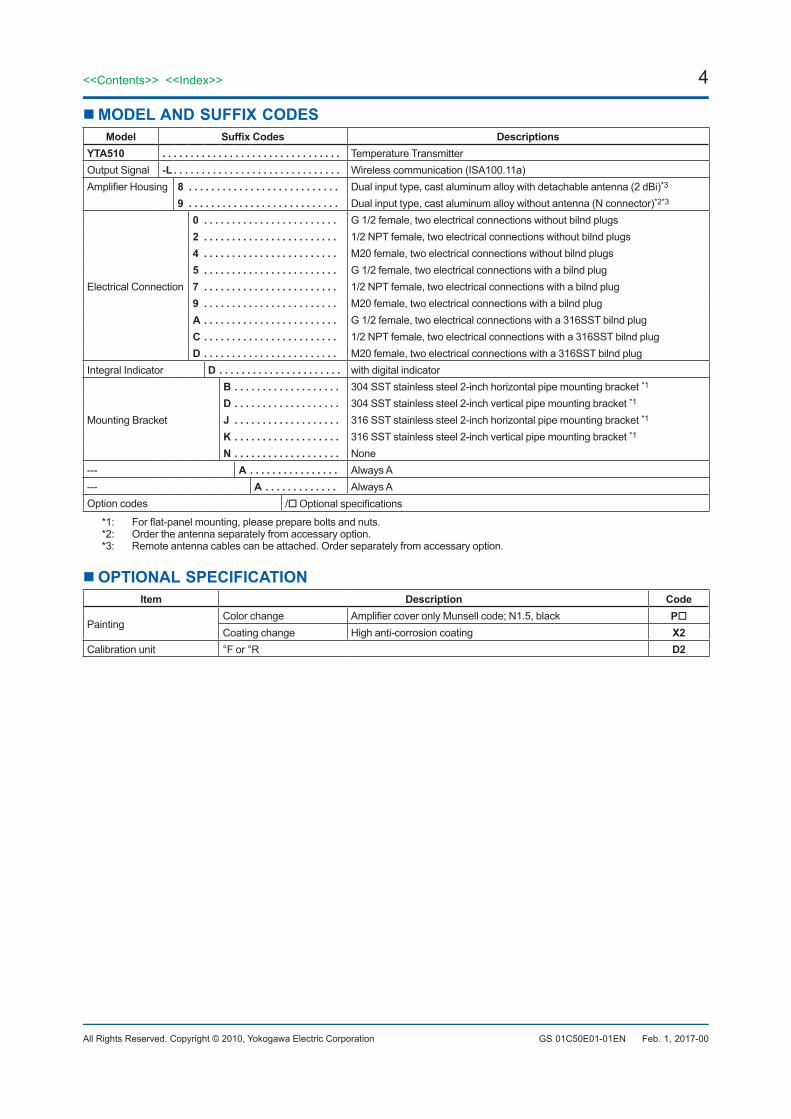
MODEL AND SUFFIX CODESModel Suffix Codes Descriptions
YTA510 . . . . . . . . . . . . . . . . . . . . . . . . . . . . . . . . Temperature TransmitterOutput Signal -L . . . . . . . . . . . . . . . . . . . . . . . . . . . . . . Wireless communication (ISA100.11a)Amplifier Housing 8 . . . . . . . . . . . . . . . . . . . . . . . . . . . Dual input type, cast aluminum alloy with detachable antenna (2 dBi)*3
9 . . . . . . . . . . . . . . . . . . . . . . . . . . . Dual input type, cast aluminum alloy without antenna (N connector)*2*3
Electrical Connection
0 . . . . . . . . . . . . . . . . . . . . . . . . G 1/2 female, two electrical connections without bilnd plugs2 . . . . . . . . . . . . . . . . . . . . . . . . 1/2 NPT female, two electrical connections without bilnd plugs4 . . . . . . . . . . . . . . . . . . . . . . . . M20 female, two electrical connections without bilnd plugs5 . . . . . . . . . . . . . . . . . . . . . . . . G 1/2 female, two electrical connections with a bilnd plug7 . . . . . . . . . . . . . . . . . . . . . . . . 1/2 NPT female, two electrical connections with a bilnd plug9 . . . . . . . . . . . . . . . . . . . . . . . . M20 female, two electrical connections with a bilnd plugA . . . . . . . . . . . . . . . . . . . . . . . . G 1/2 female, two electrical connections with a 316SST bilnd plugC . . . . . . . . . . . . . . . . . . . . . . . . 1/2 NPT female, two electrical connections with a 316SST bilnd plugD . . . . . . . . . . . . . . . . . . . . . . . . M20 female, two electrical connections with a 316SST bilnd plug
Integral Indicator D . . . . . . . . . . . . . . . . . . . . . . with digital indicator
Mounting Bracket
B . . . . . . . . . . . . . . . . . . . 304 SST stainless steel 2-inch horizontal pipe mounting bracket *1
D . . . . . . . . . . . . . . . . . . . 304 SST stainless steel 2-inch vertical pipe mounting bracket *1
J . . . . . . . . . . . . . . . . . . . 316 SST stainless steel 2-inch horizontal pipe mounting bracket *1
K . . . . . . . . . . . . . . . . . . . 316 SST stainless steel 2-inch vertical pipe mounting bracket *1
N . . . . . . . . . . . . . . . . . . . None--- A . . . . . . . . . . . . . . . . Always A--- A . . . . . . . . . . . . . Always AOption codes / Optional specifications
*1: For flat-panel mounting, please prepare bolts and nuts.*2: Order the antenna separately from accessary option.*3: Remote antenna cables can be attached. Order separately from accessary option.
OPTIONAL SPECIFICATIONItem Description Code
PaintingColor change Amplifier cover only Munsell code; N1.5, black PCoating change High anti-corrosion coating X2
Calibration unit °F or °R D2
Feb. 1, 2017-00

5<<Contents>> <<Index>>
All Rights Reserved. Copyright © 2010, Yokogawa Electric Corporation GS 01C50E01-01EN
OPTIONAL SPECIFICATION (For Explosion Protected type)Item Description Code
Factory Mutual (FM) FM Intrinsically safe ApprovalApplicable Standard: Class 3600, Class 3610, Class 3611, Class 3810, NEMA 250, ANSI/ISA-60079-0, ANSI/ISA-60079-11Intrinsically Safe for Class I, Division 1, Groups A, B, C & D, Class II, Division 1, Groups E, F & G and Class III, Division 1, Class I, Zone 0, in Hazardous Locations, AEx ia IICNonincendive for Class I, Division 2, Groups A, B, C & D, Class II, Division 2, Groups F & G and Class III, Division 1, Class I, Zone 2, Group IIC, in Hazardous LocationsEnclosure: "NEMA 4X", Temp. Class: T4, Amb. Temp.: –50 to 70°C (–58 to 158°F)Sensor Circuit Parameter : Voc=6.6 V, Isc=66 mA, Po=109 mW, Ca=22 uF, La=8.1 mH
FS17
ATEX ATEX Intrinsically safe ApprovalApplicable Standard: EN60079-0, EN60079-11, EN60079-26Certificate: KEMA 10ATEX0163 XII 1 G Ex ia IIC T4 Ga Degree of protection: IP66/IP67Amb. Temp(Tamb).: –50 to 70°C (–58 to 158°F)Sensor Circuit Parameter : Uo=6.6 V, Io=66 mA, Po=109 mW, Co=22 uF, Lo=8.1 mH
KS27
Canadian Standards Association (CSA)
CSA Intrinsically safe ApprovalCertificate: 2328785Applicable standard: CAN/CSA-C22.2 No.0, CAN/CSA-C22.2 No.0.4, C22.2 No.25, CAN/CSA-C22.2 No.94,CAN/CSA-C22.2 No.157, C22.2 No.213, CAN/CSA-C22.2 No.61010-1, CAN/CSA-C22.2 No.60079-0, CAN/CSA-E60079-11, IEC60529Ex ia IIC T4Intrinsically Safe for Class I, Division 1, Groups A, B, C & D, Class II, Division 1, Groups E, F & G, Class III, Division 1, Nonincendive for Class I, Division 2, Groups A, B, C & D, Class II, Division 2, Groups F & G, Class III, Division 1 Enclosure: IP66/IP67 and Type 4X , Temperature Code: T4Amb. Temp(Tamb).: –50 to 70°C (–58 to 158°F)Sensor Circuit Parameter : Uo=6.6 V, Io=66 mA, Po=109 mW, Co=22 uF, Lo=8.1 mH
CS17
IECEx IECEx Intrinsically safe ApprovalApplicable Standard: IEC60079-0:2011, IEC60079-11:2011, IEC60079-26:2006Certificate: IECEx KEM 10.0073 XEx ia IIC T4 Ga Enclosure: IP66/IP67Amb. Temp(Tamb).: –50 to 70°C (–58 to 158°F)Sensor Circuit Parameter : Uo=6.6 V, Io=66 mA, Po=109 mW, Co=22 uF, Lo=8.1 mH
SS27
Jan. 14, 2014-00
6
All Rights Reserved. Copyright © 2010, Yokogawa Electric Corporation
<<Contents>> <<Index>>
GS 01C50E01-01EN
OPTIONAL ACCESSORIESProduct Part number Specification
Battery pack assembly F9915NQ*1 Battery case, Lithium-thionyl chloride batteries 2 piecesBatteries*2 F9915NR Lithium-thionyl chloride batteries, 2 piecesBattery case F9915NK*3 Battery case onlyRemote antenna cable F9915KU 3 m with mounting bracket
F9915KV 13 m (3 m+10 m), with arrester and mounting bracketAntenna F9915KW 2 dBi standard antenna
F9915KY 6 dBi high gain antenna*4
*1: If you need F9915MA, please purchase F9915NQ. F9915NQ is a set of F9915MA and instruction manual.*2: Alternatively, Tadiran SL-2780/S or TL-5930/S batteries can be purchased from your local distributor.*3: If you need F9915NS, please purchase F9915NK. F9915NK is a set of F9915NS and instruction manual.*4: Use of high gain antenna is limited by local regulation of radio and telecommunication law. Consult Yokogawa for details.
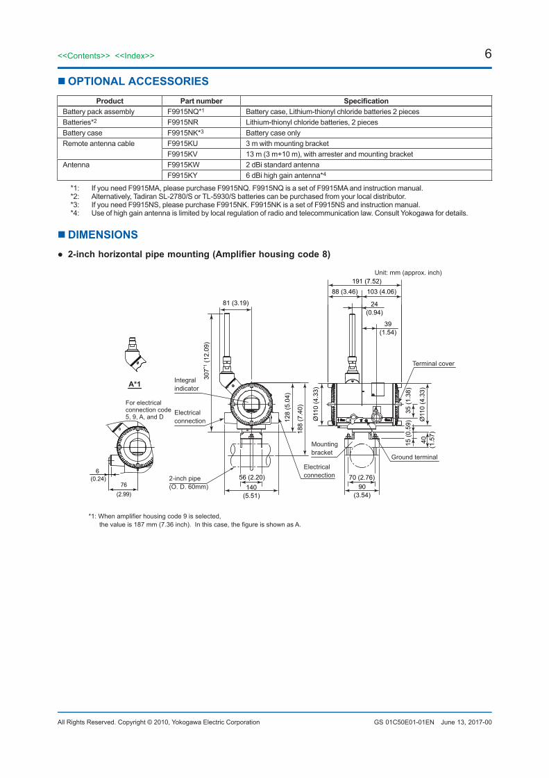
DIMENSIONS● 2-inch horizontal pipe mounting (Amplifier housing code 8)
81 (3.19)
191 (7.52)88 (3.46) 103 (4.06)
24 (0.94)
39 (1.54)
70 (2.76)90
(3.54)
56 (2.20)140
(5.51)
Terminal cover
Ground terminal
Mounting bracket
Electrical connection2-inch pipe
(O. D. 60mm)
Electrical connection
Integral indicator
Ø11
0 (4
.33)
Ø11
0 (4
.33)
188
(7.4
0)
128
(5.0
4)
307*
1 (1
2.09
)
40
(1.5
7)
15 (0
.59)
35 (1
.38)
Unit: mm (approx. inch)
*1: When amplifier housing code 9 is selected, the value is 187 mm (7.36 inch). In this case, the figure is shown as A.
A*1
F01.ai
For electricalconnection code5, 9, A, and D
76(2.99)
6(0.24)
June 13, 2017-00

7<<Contents>> <<Index>>
All Rights Reserved. Copyright © 2010, Yokogawa Electric Corporation GS 01C50E01-01EN
● Infrared Configuration
F03.ai
Infrared port
● Terminal Configuration
Ground terminal F04.ai
● 2-inch vertical pipe mounting (Amplifier housing code 8)
Unit: mm (approx. inch)
*1: When amplifier housing code 9 is selected, the value is 187 mm (7.36 inch). In this case, the figure is shown as A.
A*1
191 (7.52)88 (3.46) 103 (4.06)
24 (0.94)
39 (1.54)
81 (3.19)
140 (5.51)
98 (3.86)
204 (8.03)
110 (4.33)
Electrical connection
Mounting bracket
Electrical connection
Integral indicator
2-inch pipe(O. D. 60mm)
Ground terminal
Terminal cover
307*
1 (1
2.09
)
128
(5.0
4)
Ø11
0 (4
.33)
Ø11
0 (4
.33)
35 (1
.38)
104
(4.0
9)
107
(4.2
1) 61
(2.4
0)
F02.ai
For electricalconnection code5, 9, A, and D
76(2.99)
6(0.24)
Feb. 1, 2017-00

8
All Rights Reserved. Copyright © 2010, Yokogawa Electric Corporation
<<Contents>> <<Index>>
GS 01C50E01-01EN
2-inch pipe (O.D. 60.5 mm)
72 (2.83)17(0.67)
F05.ai
Unit: mm (approx. inch)
Antenna mounting bracket
Antenna/Cable
Non-directional antenna• Gain: 2 dBi
Part number: F9915KW
Antenna cable• Sheath diameter: 11.2 mm• Gain: 6 dBi
Part number: F9915KY< Without arrester >
Part number: F9915KU
< With arrester >
Part number: F9915KV
130
(5.1
2)
Ø14(Ø0.55)
Ø21(Ø0.83)
500
(19.
69)
Ø26(Ø1.02)
Ø22(Ø0.87)
68(2.68)
2 dBi antenna
*1: When 6 dBi antenna is selected, the value is 642 mm (25.28 inch).
Transmitter body Transmitter body
19(0
.75)
25(0
.98)
18(0.69)
88 (3
.46)
135
(5.3
1)272
(10.
71)*1
98 (3.86)
Cable 1Length: 3 m
Cable 2Length: 10 m
Cable 1Length: 3 m
Arrester
Antenna
Antenna
Feb. 1, 2017-00

9
All Rights Reserved. Copyright © 2010, Yokogawa Electric Corporation
<<Contents>> <<Index>>
GS 01C50E01-01EN
9<<Contents>> <<Index>>
Subject to change without notice.
< Ordering Information >Specify the following when ordering1. Model, suffix codes, and option codes2. Sensor type
- For RTD and resistance input, specify the number of wire as well. (Example; RTD Pt100 3-wire system)
- When Sensor 2 is not used, select "NON-CONNECTION" for Sensor 2.
- When “4-WIRE” is selected for Sensor 1, select “NON-CONNECTION” for Sensor 2.
3. Calibration range and unit:- Calibration range can be specified within the
measurement range shown in Table 1. Also, set the upper limit is larger than the lower limit.
- When both Sensor 1 and Sensor 2 are used, specify Range 1 and Range 2, respectively.
- Specify °C or K for Calibration unit except for the following cases:• When “mV” or “Ohm” is specified for Sensor
type, select “mV” or “Ohm” for Calibration unit respectively.
• When option code D2 is specified, °F and °R are available.
4. Tag Number (if required)Specify Tag number (up to 16 letters) to be engraved on the tag plate. The specified letters are written on TAG_Name (16 letters) in the amplifier memory.
5. Software tag (if required)Specify this software tag when tag number which is different from the tag number specified in the “TAG NUMBER” is required. The tag number specified in “SOFTWARE TAG” will be entered on “TAG” (up to 16 letters) in the amplifier memory.
6. Network ID (if required)Specify the number from 2 to 65535.When not specified, it will use 1 as the default.
< Factory Setting >Table A. Settings upon shipment
Calibration range lower limit
As specified or lower range value for the specified sensor type otherwise specified in order. See Table 1.
Calibration range upper limit
As specified or lower range value for the specified sensor type otherwise specified in order. See Table 1.
Calibration unit Unit used for specified sensor type
Tag No. Blank unless otherwise specified in order
Software tag Blank unless otherwise specified in order
Network ID ‘1‘ unless otherwise specified in order.
● Input Wiring
T/C or DC milivolts three-wireRTD or ohm
T/C and three-wire RTD or ohm
two-wireRTD or ohm
T/C or DC milivolts two-wire RTD or ohm
three-wireRTD or ohm
four-wireRTD
Single input
Dual input
F06.ai
(–)
(+)1
2
3
4
5
(B1)
(A1)1
2
3
4
5
(–)
(+)1
2
3
4
5
(B1)
(B1)1
2
3
4
5
(–)
(+)1
2
3
4
5
(B)
(B)
1
2
3
4
5
(B)
(B)1
2
3
4
5
(B)
(A)1
2
3
4
5
(A)
(A)
(A)
(+)
(A1)
(B2)
(B2)
(A2)
(A)
(B)
(B)
(B2)
(A2)
Feb. 1, 2017-00