z p1 p2 p1 p2 b t - tranzilla.ru · in addition to the chemical and thermal resistance, the wear...
TRANSCRIPT
TECHNICAL DATA
O-Rings
General technical information
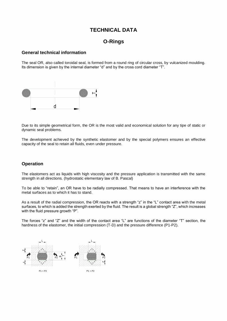
The seal OR, also called toroidal seal, is formed from a round ring of circular cross, by vulcanized moulding. Its dimension is given by the internal diameter “d” and by the cross cord diameter “T”.
d
T
Due to its simple geometrical form, the OR is the most valid and economical solution for any tipe of static or dynamic seal problems.
The development achieved by the synthetic elastomer and by the special polymers ensures an effective capacity of the seal to retain all fluids, even under pressure.
Operation
The elastomers act as liquids with high viscosity and the pressure application is transmitted with the same strength in all directions. (hydrostatic elementary law of B. Pascal)
To be able to “retain”, an OR have to be radially compressed. That means to have an interference with the metal surfaces as to which it has to stand.
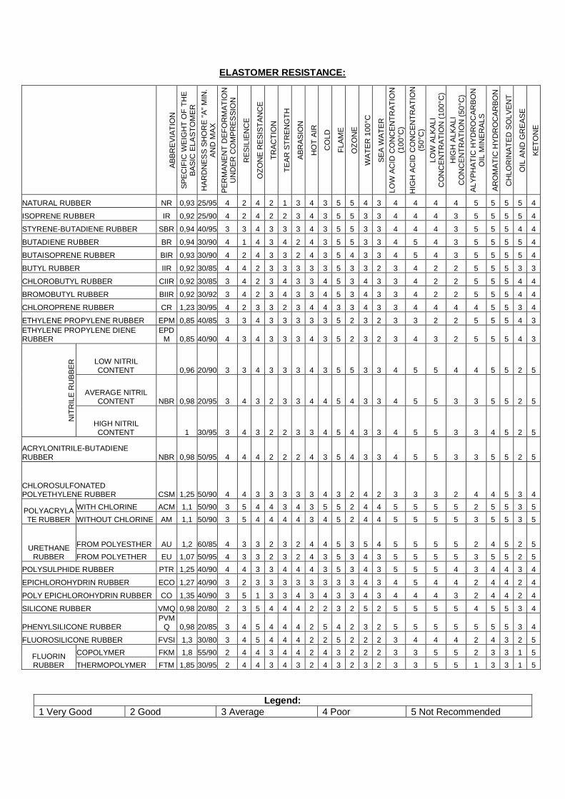
As a result of the radial compression, the OR reacts with a strength “z” in the “L” contact area with the metal surfaces, to which is added the strength exerted by the fluid. The result is a global strength “Z”, which increases with the fluid pressure growth “P”.
The forces “z” and “Z” and the width of the contact area “L” are functions of the diameter “T” section, the hardness of the elastomer, the initial compression (T-D) and the pressure difference (P1-P2).
L
Zz
B T
P1 = P2
Z
L
P1 > P2
P1 P2 P1 P2

In addition to the chemical and thermal resistance, the wear resistance and the hardness, another important element to determine the seal’s fitness is the elastomer residual deformation (or permanent) after compression.
The definition “residual deformation” means the deformation that persists after having removed the load acting on an elastomer.
T
DCompressiondeformation
Compressionset deformation
Residual
t
I II III
Compression % T – D
deformation = • 100
T
Residual T – t
deformation % = • 100
T – D
Material selection.
For the most appropriate choice of materials for the OR production the following factors have to be considered:
fluid chemical resistance
maximum operating temperature, considering also the increase due to the friction in the dynamic
applications
minimum operating temperature
operating pressure
resistance to wear and tear
supply availability.

The elastomer O-Rings subjects to contact with food, have to meet certain basic requirements:
1) without toxicity (human or animal) and carcinogenicity - have to be basic characteristics for all elastomer components;
2) without unpleasant taste and smell; 3) minimal decomposition in short and long term.
The standards of other countries follow almost the same principals as the up mentioned.
The well-known standards are the following:
82/711/CEE to 90/128/CEE
ACS For drinking water
BGA Recommendations KTW 1.3.13
CLP (DGS/VS4 N° 2000/232) For drinking water
DM 21/3/73, DL 25/192, DM 26/4/93
DVGW DIN EN 549 B1 (0/+80 °C) H3 For gas
DVGW DIN EN 549 B2 (-20/+80 °c) H2 For gas membranes
DVGW DIN EN 549 B2 (-20/+80 °c) H3 For gas
DVGW EN682 For gas
DVGW VP 406-A 7 consistent with FDA (177.2600-21) For food
DVGW W534 For hot drinking water type WB n° DW-5253VT0074
DVGW W534 For hot drinking water type WA-WB n° NW-5253BT0306
DVGW-W270 E For drinking water
FDA (Food and Drug Adm.) USA Title 21 C.F.R. 177 2600
KIWA (BRL 2013) For hot drinking water
KTW (1.3.13 D1/D2) For cold and hot (up to 85 ° C) drinking water
KTW (1.3.13 D2) For cold and hot (up to 85 ° C) drinking water
NSF International Standard 61 For cold and hot (up to 82 ° C) drinking water
USDA (Un. States Dept. Agriculture) 3° Sanitary Standard
WRAS (BS 6920) For cold drinking water
As regards the drinking water, the respective piping and containers, there are specific standards as follows:
USA ANSI/NSF 61-92 Drinking water system components
G.B. BS 6920:2000

OUR RUBBER COMPOUNDS HOMOLOGATIONS
Code Rubber Compounds Homologations
M009 M023 M203 M212 M219
VMQ 70 various colours
FDA n. 0131/B of 1/0497 FDA n. 0131/D of 31/07/97
M012 VMQ 70 Transparent FDA n. 0457 of 28/10/97
M042 NBR 80 BALCK FDA n. 0583/B of 03/12/98
M060 NBR 50 BLACK
FDA n. 0213/A of 05/07/96 FDA n. 0213/C of 31/07/97
M061 NBR 60 BLACK
DVGW B2/H2 (-20/+80°C) n. NG-5112bq0350 of 09/09/05
M062 NBR 70 BLACK
DVGW B2/H3 (-20/+80°C) n. NG-5112BM0546 of 19/12/06
M066
NBR 70 BLACK
FDA n. 305/A of 29/09/99 FDA n. 279/B of 9/10/00 KTW D2 n. 279/A of 09/10/00 KTW D2 n. 648/99 of 28/01/00 DVGW B1/H3 (0/+80°C) n. DG-5112BM0264 of 12/06/06 ACS n. 02 MAT NY 110 of 26/05/03
M067 HNBR 70 GREEN FDA n. 0332 of 21/07/98
M069 NBR 90 BLACK FDA n. 0369 of 08/07/99
M079 FKM 70 GREEN FDA n. 0331 of 21/07/98
M080 FKM 70 BLACK VW 2.8.1 C75 of 11/02/05 (Labor Richter)
M097 EPDM 80 PEROXIDE BLACK
FDA n. 0131/A of 01/04/97 FDA n. 0131/C of 31/07/97
M129 ACM 70 BLACK DBL 6038.20 n. 88036 of 22/11/03 (Daimler Chrysler)
M320 NBR 70 BLACK WRC (cold water) n. MAT/LAB 014F of 18/05/01
M332 NBR 70 BLACK
FDA n. 0224 of 29/04/02 WRC (cold and hot water) n. 0203516 of 15/07/03 UL778 n. MH28238 of 16/07/02
M377 NBR 70 BLACK EN 682 Type GBL n. NG-5113BS0256 of 12/06/07
M461 NBR 70 BLACK
UNI EN 681 – 1/06 WB of 15/05/07 UNI EN 549 D2.H3 of 15/05/07 FDA n. 276/B of 16/05/06
M518 EPDM 60 BLACK WRC (cold and hot water) of 15/05/07
M534
EPDM 70 PEROXIDE BLACK
DVGW-W270 of 12/06/03 TZW (it’s OK for KTW D1 D2) FDA n. 468 of 10/09/04 WRC (cold and hot water) N. 0106514 of 06/06/05 EN681.1 WB WD n. 05/053/5114/1 of 05/07/05 by DVGW ACS n. 06 CLP NY 026 of 04/10/06 UL778 n. MH28238 of 18/12/06 DIN EN 681 – 1 (01.05.2003) DVGW W 534-10.3 (01.05.2004) BGA KTW (07.01.1977)
M572 EPDM 70 BLACK FDA n. 448/A of 20/07/04
M715 NBR 70 Black
DVGW B2/H3 (-20/+80°C) n. NG-5112BR0211 of 31/05/06
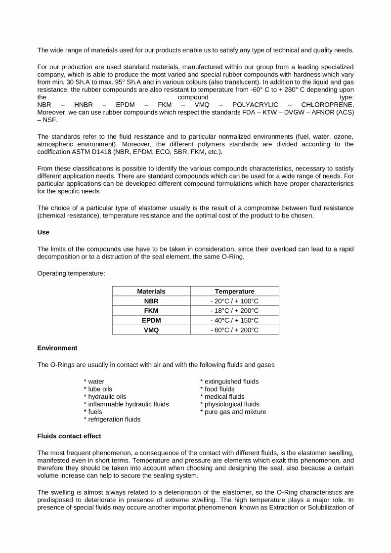
ELASTOMER RESISTANCE:
Legend:
1 Very Good 2 Good 3 Average 4 Poor 5 Not Recommended
AB
BR
EV
IAT
ION
SP
EC
IFIC
WE
IGH
T O
F T
HE
B
AS
IC E
LA
ST
OM
ER
HA
RD
NE
SS
SH
OR
E "
A"
MIN
. A
ND
MA
X
PE
RM
AN
EN
T D
EF
OR
MA
TIO
N
UN
DE
R C
OM
PR
ES
SIO
N
RE
SIL
IEN
CE
OZ
ON
E R
ES
IST
AN
CE
TR
AC
TIO
N
TE
AR
ST
RE
NG
TH
AB
RA
SIO
N
HO
T A
IR
CO
LD
FL
AM
E
OZ
ON
E
WA
TE
R 1
00
°C
SE
A W
AT
ER
LO
W A
CID
CO
NC
EN
TR
AT
ION
(1
00
°C)
HIG
H A
CID
CO
NC
EN
TR
AT
ION
(5
0°C
)
LO
W A
LK
AL
I C
ON
CE
NT
RA
TIO
N (
10
0°C
)
HIG
H A
LK
AL
I C
ON
CE
NT
RA
TIO
N (
50
°C)
AL
YP
HA
TIC
HY
DR
OC
AR
BO
N
OIL
MIN
ER
AL
S
AR
OM
AT
IC H
YD
RO
CA
RB
ON
CH
LO
RIN
AT
ED
SO
LV
EN
T
OIL
AN
D G
RE
AS
E
KE
TO
NE
NATURAL RUBBER NR 0,93 25/95 4 2 4 2 1 3 4 3 5 5 4 3 4 4 4 4 5 5 5 5 4
ISOPRENE RUBBER IR 0,92 25/90 4 2 4 2 2 3 4 3 5 5 3 3 4 4 4 3 5 5 5 5 4
STYRENE-BUTADIENE RUBBER SBR 0,94 40/95 3 3 4 3 3 3 4 3 5 5 3 3 4 4 4 3 5 5 5 4 4
BUTADIENE RUBBER BR 0,94 30/90 4 1 4 3 4 2 4 3 5 5 3 3 4 5 4 3 5 5 5 5 4
BUTAISOPRENE RUBBER BIR 0,93 30/90 4 2 4 3 3 2 4 3 5 4 3 3 4 5 4 3 5 5 5 5 4
BUTYL RUBBER IIR 0,92 30/85 4 4 2 3 3 3 3 3 5 3 3 2 3 4 2 2 5 5 5 3 3
CHLOROBUTYL RUBBER CIIR 0,92 30/85 3 4 2 3 4 3 3 4 5 3 4 3 3 4 2 2 5 5 5 4 4
BROMOBUTYL RUBBER BIIR 0,92 30/92 3 4 2 3 4 3 3 4 5 3 4 3 3 4 2 2 5 5 5 4 4
CHLOROPRENE RUBBER CR 1,23 30/95 4 2 3 3 2 3 4 4 3 3 4 3 3 4 4 4 4 5 5 3 4
ETHYLENE PROPYLENE RUBBER EPM 0,85 40/85 3 3 4 3 3 3 3 3 5 2 3 2 3 3 2 2 5 5 5 4 3
ETHYLENE PROPYLENE DIENE RUBBER
EPDM 0,85 40/90 4 3 4 3 3 3 4 3 5 2 3 2 3 4 3 2 5 5 5 4 3
NIT
RIL
E R
UB
BE
R
LOW NITRIL CONTENT 0,96 20/90 3 3 4 3 3 3 4 3 5 5 3 3 4 5 5 4 4 5 5 2 5
AVERAGE NITRIL CONTENT NBR 0,98 20/95 3 4 3 2 3 3 4 4 5 4 3 3 4 5 5 3 3 5 5 2 5
HIGH NITRIL CONTENT 1 30/95 3 4 3 2 2 3 3 4 5 4 3 3 4 5 5 3 3 4 5 2 5
ACRYLONITRILE-BUTADIENE RUBBER NBR 0,98 50/95 4 4 4 2 2 2 4 3 5 4 3 3 4 5 5 3 3 5 5 2 5
CHLOROSULFONATED POLYETHYLENE RUBBER CSM 1,25 50/90 4 4 3 3 3 3 3 4 3 2 4 2 3 3 3 2 4 4 5 3 4
POLYACRYLATE RUBBER
WITH CHLORINE ACM 1,1 50/90 3 5 4 4 3 4 3 5 5 2 4 4 5 5 5 5 2 5 5 3 5
WITHOUT CHLORINE AM 1,1 50/90 3 5 4 4 4 4 3 4 5 2 4 4 5 5 5 5 3 5 5 3 5
URETHANE RUBBER
FROM POLYESTHER AU 1,2 60/85 4 3 3 2 3 2 4 4 5 3 5 4 5 5 5 5 2 4 5 2 5
FROM POLYETHER EU 1,07 50/95 4 3 3 2 3 2 4 3 5 3 4 3 5 5 5 5 3 5 5 2 5
POLYSULPHIDE RUBBER PTR 1,25 40/90 4 4 3 3 4 4 4 3 5 3 4 3 5 5 5 4 3 4 4 3 4
EPICHLOROHYDRIN RUBBER ECO 1,27 40/90 3 2 3 3 3 3 3 3 3 3 4 3 4 5 4 4 2 4 4 2 4
POLY EPICHLOROHYDRIN RUBBER CO 1,35 40/90 3 5 1 3 3 4 3 4 3 3 4 3 4 4 4 3 2 4 4 2 4
SILICONE RUBBER VMQ 0,98 20/80 2 3 5 4 4 4 2 2 3 2 5 2 5 5 5 5 4 5 5 3 4
PHENYLSILICONE RUBBER PVM
Q 0,98 20/85 3 4 5 4 4 4 2 5 4 2 3 2 5 5 5 5 5 5 5 3 4
FLUOROSILICONE RUBBER FVSI 1,3 30/80 3 4 5 4 4 4 2 2 5 2 2 2 3 4 4 4 2 4 3 2 5
FLUORIN RUBBER
COPOLYMER FKM 1,8 55/90 2 4 4 3 4 4 2 4 3 2 2 2 3 3 5 5 2 3 3 1 5
THERMOPOLYMER FTM 1,85 30/95 2 4 4 3 4 3 2 4 3 2 3 2 3 3 5 5 1 3 3 1 5
The wide range of materials used for our products enable us to satisfy any type of technical and quality needs.
For our production are used standard materials, manufactured within our group from a leading specialized company, which is able to produce the most varied and special rubber compounds with hardness which vary from min. 30 Sh.A to max. 95° Sh.A and in various colours (also translucent). In addition to the liquid and gas resistance, the rubber compounds are also resistant to temperature from -60° C to + 280° C depending upon the compound type: NBR – HNBR – EPDM – FKM – VMQ – POLYACRYLIC – CHLOROPRENE. Moreover, we can use rubber compounds which respect the standards FDA – KTW – DVGW – AFNOR (ACS) – NSF.
The standards refer to the fluid resistance and to particular normalized environments (fuel, water, ozone, atmospheric environment). Moreover, the different polymers standards are divided according to the codification ASTM D1418 (NBR, EPDM, ECO, SBR, FKM, etc.).
From these classifications is possible to identify the various compounds characteristics, necessary to satisfy different application needs. There are standard compounds which can be used for a wide range of needs. For particular applications can be developed different compound formulations which have proper characterisrics for the specific needs.
The choice of a particular type of elastomer usually is the result of a compromise between fluid resistance (chemical resistance), temperature resistance and the optimal cost of the product to be chosen.
Use
The limits of the compounds use have to be taken in consideration, since their overload can lead to a rapid decomposition or to a distruction of the seal element, the same O-Ring.
Operating temperature:
Materials Temperature
NBR - 20°C / + 100°C
FKM - 18°C / + 200°C
EPDM - 40°C / + 150°C
VMQ - 60°C / + 200°C
Environment
The O-Rings are usually in contact with air and with the following fluids and gases
* water * extinguished fluids * lube oils * food fluids * hydraulic oils * medical fluids * inflammable hydraulic fluids * physiological fluids * fuels * pure gas and mixture * refrigeration fluids
Fluids contact effect
The most frequent phenomenon, a consequence of the contact with different fluids, is the elastomer swelling, manifested even in short terms. Temperature and pressure are elements which exalt this phenomenon, and therefore they should be taken into account when choosing and designing the seal, also because a certain volume increase can help to secure the sealing system.
The swelling is almost always related to a deterioration of the elastomer, so the O-Ring characteristics are predisposed to deteriorate in presence of extreme swelling. The high temperature plays a major role. In presence of special fluids may occure another importat phenomenon, known as Extraction or Solubilization of

the compounds components. In this case there is a decrease in the O-Ring volume because of the prestress effect failing, which is essential for a correct sealing. Even for this phenomenon the temperature has a strong influence. If not properly protected, some components of the atmospheric environment can have negative effects on the elastomers. These are ozone, ultraviolet rays, moisture (we’ll deal with the environment influence in the section O-Rings storing)
Extreme temperature conditions
The low temperature results in the loss of elasticity and the hardening of the elastomers.The temperature limit beyond which there is the O-Ring breaking corresponds to the rubber embrittlement, brittle point (ATSM D746). There are other characteristic low-temperature levels, for example TR10 TR50 (ATSM D1329). They represent the temperatures at which the elastomer recovers its elasticity (ex. TR10=-15°C indicates that the elastomer, subject to a certain extension, blocked in this condition and cooled to a state of inelasticity, afterwards taken again to the temperature of 15°C, recovers 10% of its original length). There is a certain correlation between the temperature TR10 and the brittle point.
The continuous operation at high temperature leads in most cases to phenomenons and basic characteristics decay with exponential trend correlated with the temperature. Irreversible surface phenomenons occure with almost deep cracks and consequent mechanical strength loss. These phenomenons may be contained inserting in the rubber compund special ingredients with anti-aging function. To set the duration of the rubber product is necessary to determine the characteristic temperatures to which the surface aging phenomenons appeared. (cfr. Standard GME 60 258 ‘Accelerated aging proof on the elastomer).
Wear and tear
The elastomer’s wear and tear resistance (ASTM D624-B) is an important element for all applications in which is a subject of traction, especially in cases where there is a risk of surface cuts, which can trigger the product deterioration.
The wear and tear resistance determination is very important for a correct project valuation in all dynamic seal applications made with O-Rings. The essential factors to be considered are: polymer type, hardness, surface finishing, lubrication, relative speed, operating environment.
Electric characteristics
For their dielectric characteristics and versatility, the elastomers are widely used in the electric and electronic field. For a constructor the electric isolation with rubber is usually the principal element to be considered. Upon request the elastomer can be made conductive and antistatic, using special components in the compund fromulation. The most known standards concerning the electric characteristics are: ASTM D257 and ASTN D991 (volume and surface resistance), ASTM D149 (dielectric strength) and IEC Standards (International Electrotechnical Commission)
Structural instructions
Our O-Rings are manufactured dimensionally and on a quality level according to the standard UNI ISO 3601 series G, class N, and the controls are carried out according to the standard UNI ISO 2859, LQA = 1.0. Moreover, we are able to produce PTFE O-Rings.
Application types:
We distinguish the following OR seal types:
- static with axial compression (ex. flange, caps, etc.) with radial compression (shaft couplings / holes)
- dynamic alternative movement (hydraulic and pneumatic controls) rotating movement (continuous or intermittent; ex. faucet stems).
To be able to “hold”, an OR must be compressed between two surfaces towards which it must carry the seal. In other words the OR must have an interference with the surfaces.
The OR elastomer undergo a permanent deformation due to the fatigue of the material subject of compression. The OR with small diameter section undergo a relatively high permanent deformation
Moreover, they have a wide range of production tolerances in proportion to their sizes. For this reason it is recommanded to use OR with bigger cord diameter.
Before choosing an OR the following parameters have to be defined: components type on which seal must be exercised liquid, state and concentration max. and min. temperature at the contact point, temperature variations and respective intervals max. and min. pressure of use or pulsation in the seal area seal type (static or dynamic) values of the movement (stroke, frequency, number of rotations)

Coupling / Tolerances
In static use the pressure can reach very high values, on condition that coupling parts have a sufficient rigidity. It is essential that the components, between which carry the seal (flange, caps), can not move away from each other under the pressure. Otherwise the OR is extruded and is plucked at the end of the pressure. After several cycles it will be damaged. In the dynamic use (only alternative movement) the fluid pressure do not have to exceed the 350 bar. Only very slow relative movements permit exceptions.
RA
DIA
L P
LA
Y "
S"
PRESSURE
The acceptable radial play “S” between the sealing surfaces dipends on the pressure of the system, the cord section and the O-Ring hardness.
The following table contains the instructions for measure the seat and the sealing system.
The values refer only to O-Rings made of elastomers, the following materials are excluded: PTFE, polyurethanes, and encapsulated FEP O-ring.
In the following cases is recommended the anti-extrusion ring (Back-up ring):
• Pressure greater than 5 MPa (50 bar) and internal diameter greater than 50 mm
• Pressure greater than 10 MPa (100 bar) and internal diameter less than 50 mm.
Ø cord O-ring Up to 2 mm From 2 to 3
mm From 3 to 5
mm From 5 to 7 Over 7 mm
O-Rings hardness 70° Shore A
Pressure Maximum Radial Play “S” (mm)
≤ 3,50 MPa (35 bar) 0,08 0,09 0,10 0,13 0,15
≤ 7,00 MPa (70 bar) 0,05 0,07 0,08 0,09 0,10
≤ 10,50 MPa (105 bar) 0,03 0,04 0,05 0,07 0,08
O-Rings hardness 90° Shore A
Pressure Maximum Radial Play“S” (mm)
≤ 3,50 MPa (70 bar) 0,13 0,15 0,20 0,23 0,25
≤ 7,00 MPa (70 bar) 0,10 0,13 0,15 0,18 0,20
≤ 10,50 MPa (105 bar) 0,07 0,09 0,10 0,13 0,15
≤ 14,00 MPa (140 bar) 0,05 0,07 0,08 0,09 0,10

≤ 17,50 MPa (175 bar) 0,04 0,05 0,07 0,08 0,09
≤ 21,00 MPa (210 bar) 0,03 0,04 0,05 0,07 0,08
≤ 35,00 MPa (350 bar) 0,02 0,03 0,03 0,04 0,04
For the choice of coupling, both in static and dynamic use, it is recommended to follow the values given in the table above.
ØA ØF
Surfaces finishing
Static use:
The surface finishing represented here bellow is valid for OR with hardness 70 + 90 °Shore A. If for reasons of economy, renouncing a very accurate surface seal finishing have to be used OR of less hardness and the compression has to be increased.
Dynamic use, alternative movements:
to respect rigidly the here below indicated surfaces finishing is a determining factor for the OR hardness.
A further finishing improvement reduces the wear and extends the OR duration.
r 1
r = max. 0,2
Sealsurface(sliding)
(bottom housing)SurfaceSeal
0°- 5°
Sides of the seat
r = max. 0,2
r 1
surfaceSeal
0°- 5°
Sides of the seat

Dynamic use, rotating movements:
0°- 5°
Sealsurface(bottom housing)
(sliding)surfaceSeal
r = max. 0,2
r 1
Sides of the seat
Seat surface roughness
Static seals:
SURFACE PRESSURE SURFACE ROUGHNESS
Ra ųm Rt ųm Rz ųm
Seal surface Pulsating 1.6 16 6.3
Not pulsating 0.8 6.3 3.15
Sides of the seat Pulsating 3.2 22 12.5
Not pulsating 1.6 16 6.3
Dynamic Seals:
SURFACE PRESSURE SURFACE ROUGHNESS
Seal surface Sliding surface Ra ųm Rt ųm Rz ųm
0.4 3 1.6
Bottom of the seat 0.8 6.3 3.15
Sides of the seat 0.8 6.3 3.15
Contact surfaces materials
For the selection of materials for the contact surfaces the following has to be taken in consideration:
• The materials should not undergo any alteration by chemical, thermal and mechanical stress of the fluid to
hold
• The aluminium and the synthetic materials are not the right one for high pressures
• The copper alloys, for example the brass, can be used only with OR which do not contain free sulphur,
such as the OR silicone elastomer (VMQ) or ethylene propylene (EPDM).
• The plasticisers present in the OR can attack the synthetic materials. The OR silicone elastomer do not
contain plasticisers
In the dynamic applications, we recommend to use the following materials for the surfaces contact area. They are in order of decreasing fitness:
• carbon steel
• tempered steel
• hard chromium-plated steel

• stainless steel
• grey cast iron
• aluminium alloy
• synthetic materials
• brass ottone
This clasification is based on the tendency of the OR adhesion to the surface contact area. This characteristic is decisive for the correct formation of a lubricating film in the contact sliding area. If it is not permitted any OR adhesion phenomenon on the dynamic element, this one can undergo a hard chrome plating (with this processing the coat surface do not present flakes or bows, which striping can provoke a quick wear of the OR), nickel-plating, sulphonation. The OR silicone elastomers are not a subject of the adhesion phenomenon, but on the other hand they have less wear resistance.
Compression
We have already had occasions to say that to be able to hold a OR has to be compressed between the two surfaces towards which it must carry the seal. The minimum required compression depends on the type of application; the maximum compression is limited by the need to increase the OR long-term resistance. A high compression increase the permanent deformation. Regardless of the permanent deformation increase in dynamic use an excessive compression exercised on the OR cause a higher friction and consequently to a greater abrasion and temperature increase.
Ø F
T D
T – D
Compression (%) = • 100
T
Seat width D according to the cord diameter T and the % compression

Static axial seal (external pressure)
Ø cord (mm) L (mm) K (mm) d” = d + 1 0,7 1,4 0,5
1,5 1,1 2,1 0,5
1,6 1,2 2,2 0,5
1,78 1,4 2,5 0,5
1,9 1,4 2,7 0,5
2 1,6 2,8 0,5
2,2 1,8 2,9 0,5
2,4 1,8 3,1 0,5
2,5 1,9 3,3 0,5
2,62 2,2 3,5 0,5
2,7 2,2 3,5 0,5
2,9 2,4 3,8 0,5
3 2,4 4 0,5
3,5 2,9 4,5 0,5
3,53 2,9 4,5 0,5
3,6 3 4,5 0,5
4 3,3 5,2 0,5
4,5 3,8 5,9 0,5
5 4 6,5 0,5
5,34 4,5 7 0,5
5,5 4,5 7,3 0,5
5,7 4,6 7,4 0,5
6 4,9 7,6 0,5
6,99 6 9,5 0,5
8,4 7,1 10,3 0,5
P P
d"K +0,20
L0+
0,05
T
d
A

Static axial seal (internal pressure)
Ø cord (mm) L (mm) K (mm) d’ = A - 1 0,7 1,4 0,5
1,5 1,1 2,1 0,5
1,6 1,2 2,2 0,5
1,78 1,4 2,5 0,5
1,9 1,4 2,7 0,5
2 1,6 2,8 0,5
2,2 1,8 2,9 0,5
2,4 1,8 3,1 0,5
2,5 1,9 3,3 0,5
2,62 2,2 3,5 0,5
2,7 2,2 3,5 0,5
2,9 2,4 3,8 0,5
3 2,4 4 0,5
3,5 2,9 4,5 0,5
3,53 2,9 4,5 0,5
3,6 3 4,5 0,5
4 3,3 5,2 0,5
4,5 3,8 5,9 0,5
5 4 6,5 0,5
5,34 4,5 7 0,5
5,5 4,5 7,3 0,5
5,7 4,6 7,4 0,5
6 4,9 7,6 0,5
6,99 6 9,5 0,5
8,4 7,1 10,3 0,5
P
A
d
T
d'
K +0,20
L0+
0,05

Static radial seal seats implementation
Ø cord T L K 1 0,7 1,6
1,5 1,1 2,2
1,6 1,2 2,3
1,78 1,3 2,5
1,9 1,5 2,6
2 1,6 2,7
2,2 1,75 3
2,4 1,8 3,2
2,5 1,9 3,3
2,62 2,05 3,5
2,7 2,1 3,5
2,9 2,2 3,7
3 2,4 4
3,5 2,9 4,5
3,53 2,9 4,5
3,6 2,95 4,8
4 3,3 5,2
4,5 3,75 6
5 4,1 6,5
5,34 4,5 7
5,5 4,6 7,2
5,7 4,85 7,4
6 5 8,1
6,99 6 9,5
8,4 7,25 10
T
d A
0+0,
05L
K K+0,20
+0,20
L+
0,05
0

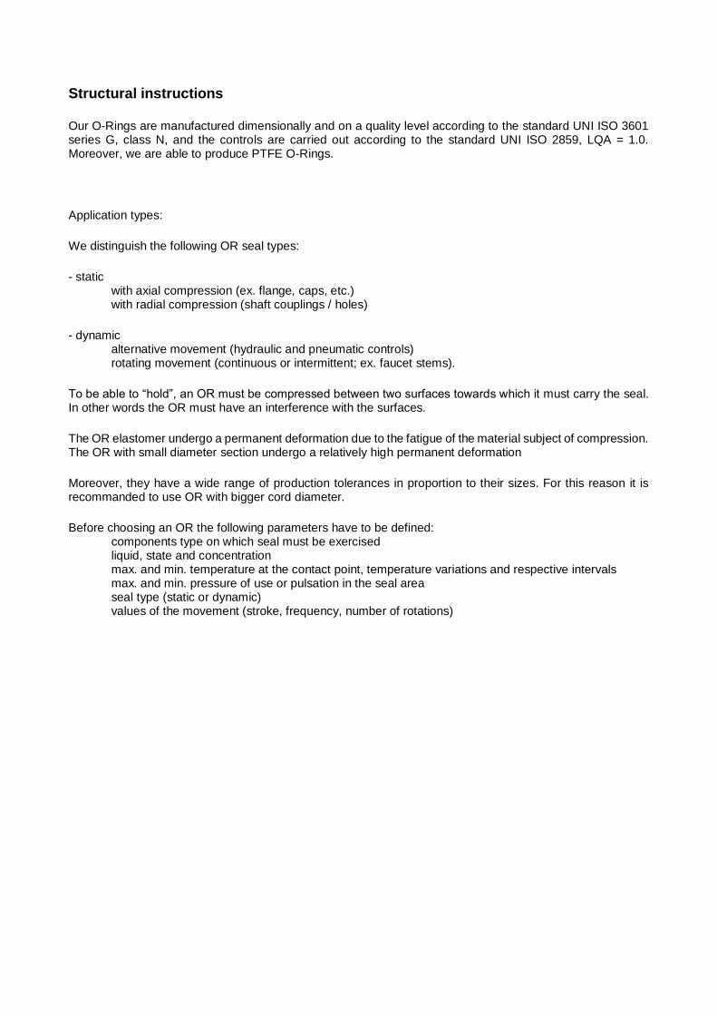
Dynamic radial seal rectilinear movement
Ø cord (mm) H = D + M (mm) 1 1,4 1,6
1,5 2,2 2,2
1,6 2,4 2,3
1,78 2,9 2,5
1,9 3,2 2,6
2 3,2 2,7
2,2 3,7 3
2,4 3,7 3,2
2,5 4 3,3
2,62 4,4 3,5
2,7 4,6 3,5
2,9 4,9 3,7
3 5,2 4
3,5 6 4,5
3,53 6,1 4,5
3,6 6,2 4,8
4 7 5,2
4,5 7,9 6
5 8,8 6,5
5,34 9,4 7
5,5 9,7 7,2
5,7 10 7,4
6 10,6 8,1
6,99 12,4 9,5
8,4 15 10
D
H (
H 9
)
+0,20M
d
T
Dynamic radial seal rectilinear movement
Ø cord (mm) H = D - M (mm) 1 1,4 1,6
1,5 2,2 2,2
1,6 2,4 2,3
1,78 2,9 2,5
1,9 3,2 2,6
2 3,2 2,7
2,2 3,7 3
2,4 3,7 3,2
2,5 4 3,3
2,62 4,4 3,5
2,7 4,6 3,5
2,9 4,9 3,7
3 5,2 4
3,5 6 4,5
3,53 6,1 4,5
3,6 6,2 4,8
4 7 5,2
4,5 7,9 6
5 8,8 6,5
5,5 9,7 7,2
5,34 9,4 7
5,7 10 7,4
6 10,6 8,1
6,99 12,4 9,5
8,4 15 10
H (
h 9)
D
+0,20M
T
d

Triangular seat implementation
T
Ø f 7 H8
45°
d
T
T cord diameter mm T seat length mm 1,00 1,40 ± 0,04
1,50 2,10 ± 0,06
1,60 2,30 ± 0,06
1,78 2,50 ± 0,07
1,80 2,60 ± 0,07
2,00 2,90 ± 0,08
2,40 3,50 ± 0,10
2,50 3,60 ± 0,10
2,62 3,80 ± 0,10
2,65 3,80 ± 0,11
3,00 4,30 ± 0,12
3,50 5,10 ± 0,14
3,53 5,10 ± 0,14
4,00 5,80 ± 0,16
4,50 6,50 ± 0,18
5,00 7,30 ± 0,20
5,30 7,70 ± 0,21
5,34 7,70 ± 0,21
5,50 8,00 ± 0,22
5,70 8,30 ± 0,23
6,00 8,70 ± 0,24
6,50 9,50 ± 0,26
6,99 10,20 ± 0,28
7,00 10,20 ± 0,28
7,50 11,00 ± 0,30
8,00 11,70 ± 0,32
8,40 11,51 ± 0,40
8,50 12,40 ± 0,34
9,00 13,20 ± 0,36
9,50 13,90 ± 0,38
10,00 14,70 ± 0,40
10,50 15,40 ± 0,42
11,00 15,07 ± 0,40
11,50 15,76 ± 0,40
12,00 17,60 ± 0,48
12,50 17,13 ± 0,50
13,00 18,50 ± 0,50
13,50 19,10 ±0,52
14,00 19,18 ± 0,50
14,50 19,87 ± 0,50
15,00 22,10 ± 0,60

Trapezoidal seat implementation
r 2
r 3
h
b 2
b 1
25°±1°
T cord dimensions mm
Seat dimensions mm
Length b1 ± 0,05
Length b2 ± 0,05
Width h
Radius (max.)
r3 r2
3,53 2,90 3,20 2,90 0,25 0,80
4,00 3,40 3,70 3,20 0,25 0,80
5,00 4,30 4,60 4,20 0,25 0,80
5,34 4,60 4,90 4,60 0,25 0,80
5,70 4,75 5,25 4,80 0,40 0,80
6,00 5,05 5,55 5,10 0,40 0,80
7,00 6,00 6,50 6,00 0,40 1,60
8,00 6,85 7,45 6,90 0,50 1,60
8,40 7,25 7,85 7,30 0,50 1,60
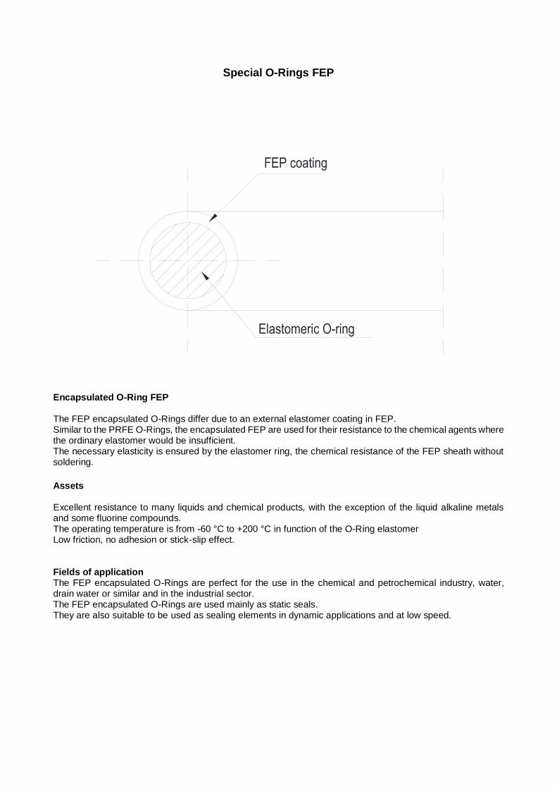
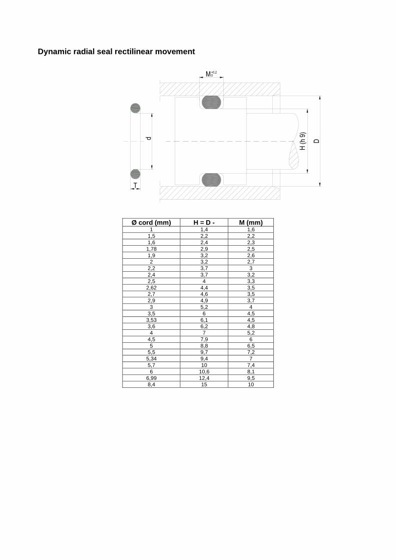
Special O-Rings FEP
FEP coating
Elastomeric O-ring
Encapsulated O-Ring FEP The FEP encapsulated O-Rings differ due to an external elastomer coating in FEP. Similar to the PRFE O-Rings, the encapsulated FEP are used for their resistance to the chemical agents where the ordinary elastomer would be insufficient. The necessary elasticity is ensured by the elastomer ring, the chemical resistance of the FEP sheath without soldering.
Assets Excellent resistance to many liquids and chemical products, with the exception of the liquid alkaline metals and some fluorine compounds. The operating temperature is from -60 °C to +200 °C in function of the O-Ring elastomer Low friction, no adhesion or stick-slip effect. Fields of application The FEP encapsulated O-Rings are perfect for the use in the chemical and petrochemical industry, water, drain water or similar and in the industrial sector. The FEP encapsulated O-Rings are used mainly as static seals. They are also suitable to be used as sealing elements in dynamic applications and at low speed.

New production technology for O-Rings with large diameter
In 2002 we have launched a project for a new production technology for large O-Rings. In these years we have developed a new technology for the production of large O-Rings without limits in the diameter, at competitive prices, fast delivery and with mechanical performances comparable to the O-Rings produced using traditional technology. All this at no additional costs for moulding and with no minimal purchase quantities. The name of this innovative technology is OringOne.
The production is based on the principle of a “conventional” compression moulding. This moulding technology ensures the best mechanical characteristics for our O-Rings. The moulds are designed, engineered and manufactured in our factories. The system is controlled by an apposite software. This permits to produce very high quality items on maximum performance levels and at competitive prices. Some of the methods mainly used for the production of large O-Rings are the hot and cold vulcanization and the gluing. The OringOne system is another thing. DELIVERABLE CORDS:
2,62 3,00 3,53 4,00 4,50 5,00 5,33 5,50 5,70 6,00 6,35 6,50 7,00 7,50 8,00 8,40 8,50 9,00 9,50 10,00 10,82 11,00 12,00 12,70 13,00 14,00 14,40 15,00 16,00 18,00 20,00 22.00 24.00 26.00
Service Innovation also in the services The O-Rings can be customized by printing directly on the cord the text you want. There are 40 characters available (including spaces). The letters are white and the ink is non-food.
Test To highlight the quality of our product, we have tested the tensile strength of an O-Ring in black FKM 70 produced with the OringOne technology comparing it to the tensile strength of a standard sample produced from the same compound, of an O-Ring produced by compression moulding and comparing to the tensile strength of an O-Ring produced by injection moulding. To give you further information, we “break down” the tensile strength value of the O-RingOne. We have tested the O-Ring “portion” (approx. 40 mm) where the unvulcanized drawn product is joined inside the mould during the vulcanization and the registered value in another section of the O-Ring.
ULTIMATE TENSILE STRENGTH TEST VALUES (MPa)
Relative value on the standard sample (ISO 37 Type 1) 14,0
Relative value on the entire O-Ring (O-ring 200,00x7,00 FKM 70 black produced by the system OringOne)
11,5
Relative value on the “junction” section of the O-ring (O-ring 200,00x7,00 FKM 70 black produced by the system OringOne)
10,4
Relative value on another section of the O-ring (O-ring 200,00x7,00 FKM 70 black produced by the system OringOne)
11,8
Relative value on an injection-moulded O-ring (O-ring 200,00x7,00 FKM 70 black)
10,8
Relative value on O-ring compression moulded (O-ring 200,00x7,00 FKM 70 black)
12,6
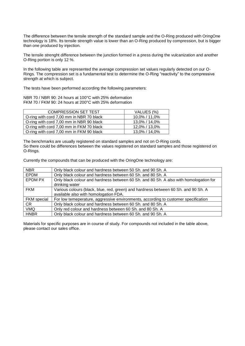
The difference between the tensile strength of the standard sample and the O-Ring produced with OringOne technology is 18%. Its tensile strength value is lower than an O-Ring produced by compression, but is bigger than one produced by injection. The tensile strenght difference between the junction formed in a press during the vulcanization and another O-Ring portion is only 12 %. In the following table are represented the average compression set values regularly detected on our O-Rings. The compression set is a fundamental test to determine the O-Ring “reactivity” to the compressive strength at which is subject. The tests have been performed according the following parameters: NBR 70 / NBR 90: 24 hours at 100°C with 25% deformation FKM 70 / FKM 90: 24 hours at 200°C with 25% deformation
COMPRESSION SET TEST VALUES (%)
O-ring with cord 7,00 mm in NBR 70 black 10,0% / 11,0%
O-ring with cord 7,00 mm in NBR 90 black 13,0% / 14,0%
O-ring with cord 7,00 mm in FKM 70 black 12,0% / 13,0%
O-ring with cord 7,00 mm in FKM 90 black 13,0% / 14,0%
The benchmarks are usually registered on standard samples and not on O-Ring cords. So there could be differences between the values registered on standard samples and those registered on O-Rings. Currently the compounds that can be produced with the OringOne technology are:
NBR Only black colour and hardness between 50 Sh. and 90 Sh. A
EPDM Only black colour and hardness between 60 Sh. and 80 Sh. A
EPDM PX Only black colour and hardness between 60 Sh. and 80 Sh. A also with homologation for drinking water
FKM Various colours (black, blue, red, green) and hardness between 60 Sh. and 90 Sh. A available also with homologation FDA.
FKM special For low temeperature, aggressive environments, according to customer specification
CR Only black colour and hardness between 60 Sh. and 80 Sh. A
VMQ Only red colour and hardness between 60 Sh. and 80 Sh. A
HNBR Only black colour and hardness between 60 Sh. and 90 Sh. A
Materials for specific purposes are in course of study. For compounds not included in the table above, please contact our sales office.
MOUNTING
Accidental damages to the O-Rings
If the assembling instructions are not respected or the limits of use are exceeded, the O-Ring can go out of use in short terms. The most frequent damages are the following:
- very high operating temperature - poor fluid compatibility - very high pressure, too large seal interstice - very strong abrasion - very big permanent deformation - rapid seal gas decompression - very strong extension - mounting location measured incorrectly
Very high operating temperature
As a consequence of an overload above the recommended operating temperature there is the O-Ring vulcanization, which harden the material. This can lead to the O-Ring fragility. The higher temperature can also be caused by dynamic friction.
Poor fluid compatibility
Incorrectly selected materials have a tendancy to swell or to shrink agressively. With the swelling the material loses its compression strength due to the softening. With the contraction the compression decreases. The pressure resistance becomes lower.
Very high pressure
If the O-Ring is not supported by a ring bearing at the pressure side, in the presence of very high pressure and too large seal interstice, the seal element is pushed out through the interstice. The consequence is a mechanical damage, such as flaking, cutting and cracking of the material. With pulsating pressure and structural parts that “breathe”, the O-Ring can get stuck at the pressure disappearance.
Very strong abrasion
Very strong mechanical load, poor lubrication, rough surfaces or very high compression lead to an undesired abrasion. Under pulsating pressure the O-Ring moves in its seat, which can lead to abrasion. Dirt can cause an abrasion.
Very big permanent deformation (Compression-Set)
Very big permanent deformation means the loss of seal strength. It occures because of very high operating temperature, inferior quality of materials or incorrectly measured seat. The permanent deformation can be explained in the following way: under compression the elastomer vulcanization is extended due to the heating effect. Hence there is a new formation. The temperature and the load time duration have a great influence on the coupling. Poor material quality predispose to the deformation. A small permanent deformation can still be detected in all materials used for O-Rings, that means that after being removed the O-Ring can not turn back in the original circular section.
Rapid decompression
An extremely rapid gas seal decompression leads to the formation of bubbles or to the surface cracking. The gas internally diffused with high pressure extends as a result of rapid decompression and slips out from the O-Ring surface.This explosive decompression leads to the surface’s damage. The rarefied or light gas, for example CO2 or helium, spread more rapidly in the elastomer material. It is possible to prevent such damages

reducing the surface contact with the gas to hold (smaller cord diameter) or increasing the time pressure reduction.
Very strong extension
A very strong extension (above the 6-10% of the internal diameter according to the material) leads to the O-Ring surface cracking. Under extension these ozone cracks are produced more rapidly and can occur mainly with materials not resistant to the ozone and the weather-beaten (for example NBR). With the twist mounted O-Ring, due to the larger adjustment in the torsion area, can occur a crack formation. The crack formation occurs more rapidly at high temperature or very high oxygen or ozone concentrations.