z02215 single-chip modem evaluation board
TRANSCRIPT
ZiLOG Worldwide Headquarters • 532 Race Street • San Jose, CA 95126-3432Telephone: 408.558.8500 • Fax: 408.558.8300 • www.ZiLOG.com
Z02215
Single-Chip ModemEvaluation Board
User Manual
UM002304-0802
Preliminary
Z02215 Single-Chip ModemEvaluation Board User Manual
This publication is subject to replacement by a later edition. To determine whether a later edition exists, or to request copies of publications, contact:
ZiLOG Worldwide Headquarters532 Race Streete San Jose, CA 95126-3432Telephone: 408.558.8500Fax: 408.558.8300www.ZiLOG.com
Document Disclaimer
ZiLOG is a registered trademark of ZiLOG Inc. in the United States and in other countries. All other products and/or service names mentioned herein may be trademarks of the companies with which they are associated.
©2002 by ZiLOG, Inc. All rights reserved. Information in this publication concerning the devices, applications, or technology described is intended to suggest possible uses and may be superseded. ZiLOG, INC. DOES NOT ASSUME LIABILITY FOR OR PROVIDE A REPRESENTATION OF ACCURACY OF THE INFORMATION, DEVICES, OR TECHNOLOGY DESCRIBED IN THIS DOCUMENT. ZiLOG ALSO DOES NOT ASSUME LIABILITY FOR INTELLECTUAL PROPERTY INFRINGEMENT RELATED IN ANY MANNER TO USE OF INFORMATION, DEVICES, OR TECHNOLOGY DESCRIBED HEREIN OR OTHERWISE. Devices sold by ZiLOG, Inc. are covered by warranty and limitation of liability provisions appearing in the ZiLOG, Inc. Terms and Conditions of Sale. ZiLOG, Inc. makes no warranty of merchantability or fitness for any purpose Except with the express written approval of ZiLOG, use of information, devices, or technology as critical components of life support systems is not authorized. No licenses are conveyed, implicitly or otherwise, by this document under any intellectual property rights.
UM002304-0802 PRELIMINARY
Z02215 Single-Chip ModemEvaluation Board User Manual
iii
Table of ContentsIntroduction . . . . . . . . . . . . . . . . . . . . . . . . . . . . . . . . . . . . . . . . . . . . . . . . . . .1
Overview . . . . . . . . . . . . . . . . . . . . . . . . . . . . . . . . . . . . . . . . . . . . . . . . . .1Key Features . . . . . . . . . . . . . . . . . . . . . . . . . . . . . . . . . . . . . . . . . . . . . . .1Related ZiLOG Products . . . . . . . . . . . . . . . . . . . . . . . . . . . . . . . . . . . . .2Hardware Specifications . . . . . . . . . . . . . . . . . . . . . . . . . . . . . . . . . . . . . .2Kit Contents . . . . . . . . . . . . . . . . . . . . . . . . . . . . . . . . . . . . . . . . . . . . . . .3
Hardware . . . . . . . . . . . . . . . . . . . . . . . . . . . . . . . . . . . . . . . . . . . . . .3Software . . . . . . . . . . . . . . . . . . . . . . . . . . . . . . . . . . . . . . . . . . . . . . .3Documentation . . . . . . . . . . . . . . . . . . . . . . . . . . . . . . . . . . . . . . . . . .3
Additional Required and Optional Items . . . . . . . . . . . . . . . . . . . . . . . . .3Required Items Not Supplied With Kit . . . . . . . . . . . . . . . . . . . . . . .3
Setup and Installation . . . . . . . . . . . . . . . . . . . . . . . . . . . . . . . . . . . . . . . . . . . .1Introduction . . . . . . . . . . . . . . . . . . . . . . . . . . . . . . . . . . . . . . . . . . . . . . . .1Setting Up the Hardware . . . . . . . . . . . . . . . . . . . . . . . . . . . . . . . . . . . . .1
Serial Port Interface . . . . . . . . . . . . . . . . . . . . . . . . . . . . . . . . . . . . . .1RJ-11 Interface . . . . . . . . . . . . . . . . . . . . . . . . . . . . . . . . . . . . . . . . . .2Connecting to a Power Supply . . . . . . . . . . . . . . . . . . . . . . . . . . . . . .2Troubleshooting . . . . . . . . . . . . . . . . . . . . . . . . . . . . . . . . . . . . . . . . .4
Country Configuration . . . . . . . . . . . . . . . . . . . . . . . . . . . . . . . . . . . . . . .4The Diplomat Program . . . . . . . . . . . . . . . . . . . . . . . . . . . . . . . . . . . .4Install Diplomat . . . . . . . . . . . . . . . . . . . . . . . . . . . . . . . . . . . . . . . . .5Run Diplomat . . . . . . . . . . . . . . . . . . . . . . . . . . . . . . . . . . . . . . . . . . .5TB1 Parameter File Format . . . . . . . . . . . . . . . . . . . . . . . . . . . . . . . .7
Initial Checkout/Sample Session . . . . . . . . . . . . . . . . . . . . . . . . . . . . . .17Starting A Session . . . . . . . . . . . . . . . . . . . . . . . . . . . . . . . . . . . . . .17Ending A Session . . . . . . . . . . . . . . . . . . . . . . . . . . . . . . . . . . . . . . .18
Using The AT Command Set . . . . . . . . . . . . . . . . . . . . . . . . . . . . . . . . . . . . . .1Introduction . . . . . . . . . . . . . . . . . . . . . . . . . . . . . . . . . . . . . . . . . . . . . . . .1Conventions . . . . . . . . . . . . . . . . . . . . . . . . . . . . . . . . . . . . . . . . . . . . . . .1
Table of Contents PRELIMINARY UM002304-0802
Z02215 Single-Chip ModemEvaluation Board User Manual
iv
RS-232 Signal Values . . . . . . . . . . . . . . . . . . . . . . . . . . . . . . . . . . . .1Command Line Format . . . . . . . . . . . . . . . . . . . . . . . . . . . . . . . . . . .2Entering Command Lines . . . . . . . . . . . . . . . . . . . . . . . . . . . . . . . . .2Command Line Execution . . . . . . . . . . . . . . . . . . . . . . . . . . . . . . . . .3Numeric Arguments . . . . . . . . . . . . . . . . . . . . . . . . . . . . . . . . . . . . . .3AT Command Prefix . . . . . . . . . . . . . . . . . . . . . . . . . . . . . . . . . . . . .3
Dial Modifiers . . . . . . . . . . . . . . . . . . . . . . . . . . . . . . . . . . . . . . . . . . . . .25Setting the Highest Line Rate . . . . . . . . . . . . . . . . . . . . . . . . . . . . . . . . .27S-Registers . . . . . . . . . . . . . . . . . . . . . . . . . . . . . . . . . . . . . . . . . . . . . . .29
Schematics . . . . . . . . . . . . . . . . . . . . . . . . . . . . . . . . . . . . . . . . . . . . . . . . . . .62Problem/Suggestion Report Form . . . . . . . . . . . . . . . . . . . . . . . . . . . . . . . . .67
Table of Contents PRELIMINARY DRAFT UM002304-0802
Z02215 Single-Chip ModemEvaluation Board User Manual
List of Figures PRELIMINARY DRAFT UM002304-0802
v
List of FiguresFigure 1. Z02215 Modem Evaluation Kit Functional Block Diagram . . .4
Figure 2. Z02215 Modem Evaluation Board . . . . . . . . . . . . . . . . . . . . . .9
Figure 3. Z02215 Modem Evaluation Board Schematic . . . . . . . . . . . .63
Figure 4. RS-232 Interface, Power Supply and Indicators Schematic . .64
Figure 5. Z02215 Data Access Arangement Schematic . . . . . . . . . . . . .65
Figure 6. Z02215 Modem Evaluation Board SpeakerCircuit Schematic . . . . . . . . . . . . . . . . . . . . . . . . . . . . . . . .66
Z02215 Single-Chip ModemEvaluation Board User Manual
List of Tables PRELIMINARY DRAFT UM002304-0802
vi
List of TablesTable 1. RS-232 Signal Voltages . . . . . . . . . . . . . . . . . . . . . . . . . . . . . .28
Table 2. Dial Modifiers . . . . . . . . . . . . . . . . . . . . . . . . . . . . . . . . . . . . . .52
Table 3. Connect Rates . . . . . . . . . . . . . . . . . . . . . . . . . . . . . . . . . . . . . .53
Table 4. Result Codes . . . . . . . . . . . . . . . . . . . . . . . . . . . . . . . . . . . . . . .54
Table 5. Modem S-Registers . . . . . . . . . . . . . . . . . . . . . . . . . . . . . . . . .56
Z02215 Single-Chip ModemEvaluation Board User Manual
1
Preface
ABOUT THIS MANUAL
We recommend that the user read and understand everything in this man-ual before setting up and using the product. However, we recognize that users have different styles of learning. Some want to set up and use their development board while they read about it; others open these pages only as a last resort to check on a particular specification. Therefore, we have designed this manual to be used either as a how-to procedural manual or a reference guide to important data.
The complete development board schematic diagram is included in Chap-ter 4 at the back of this user’s manual.
For technical support, send an email to: [email protected], or call 877-ZILOGCS (877-945-6424)
DOCUMENT CONVENTIONS
The following conventions have been adopted throughout this book for consistency and clarity:
• Italics For Emphasis
Words which require special emphasis are distinguished by the use of ital-ics. For an example, the third and subsequent actions are preceded by the word and..
• Courier Font For Executables
Commands, variables, icon names, entry field names, selection buttons, code examples, and other executable items are distinguished by the use of the Courier font. Where the use of the font is not possible, like in the Index, the name of the entity is capitalized. For example, a procedure may contain an instruction which appears as: Click on File.
UM002304-0802 PRELIMINARY Preface
Z02215 Single-Chip ModemEvaluation Board User Manual
2
• Grouping of Actions Within A Procedure Step
Actions in a procedure step are all performed on the same window or dia-log box. Actions performed on different windows or dialog boxes appear in separate steps.
• Sequencing Words Within A Procedure Step
When an item in a procedure contains a series of actions, the second action is preceded by the word then, and the third and subsequent actions are preceded by the word and. For example: Click on File, then Import, and File.
TRADEMARKS
ZiLOG and Z8 are registered trademarks of ZiLOG, Inc. Windows is a registered trademark of Microsoft Corp. Notepad is a trademark of Microsoft Corp. HyperTerminal is a trademark of Hilgraeve, Inc. Pro-Comm is a trademark of DATASTORM Technologies, Inc. Diplomat and Biquad are trademarks of Softart Microsystems Inc. Intel is a trademark of Intel Corporation.
Preface PRELIMINARY UM002304-0802
Z02215 Single-Chip ModemEvaluation Board User Manual
3
Introduction
OVERVIEW
The Z02215™ Modem Evaluation Kit (Z0221500ZCO) provides a plat-form that allows evaluation of the ZiLOG Z02215 single-chip modem. The evaluation board (including the Z02215 Single-Chip Modem) is a fully-functional modem that supports AT commands.
Modem code contained in Z02215’s on-chip ROM includes V.22bis, V.22, V.21, V.23, Bell 103, Bell 212A, Bell 202, and Bell 202T as well as basic data pump driver routines, AT commands, plus other controller code.
The evaluation board provides one serial port interface with a DB25 con-nector and a phone line interface through the RJ-11 connector. A power supply is provided that converts 110V AC power to +12V AC.
KEY FEATURES
• Z02215 Single-Chip modem DSP, Analog Front End, controller, and on-chip ROM to hold all modem firmware.
• RS-232 DB25 port interface
• Telephone line interface with RJ-11 jack
• LED indicators
• Speaker
• Operates from single 12V AC, 1 Amp wall adapter power supply
UM002304-0802 PRELIMINARY Introduction
Z02215 Single-Chip ModemEvaluation Board User Manual
4
RELATED ZILOG PRODUCTS
HARDWARE SPECIFICATIONS
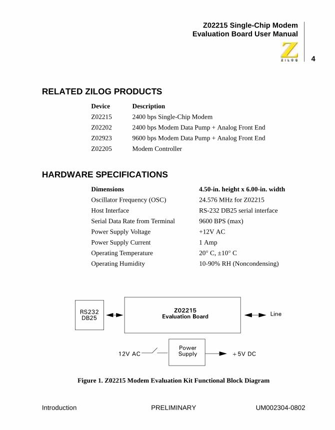
Figure 1. Z02215 Modem Evaluation Kit Functional Block Diagram
Device Description
Z02215 2400 bps Single-Chip Modem
Z02202 2400 bps Modem Data Pump + Analog Front End
Z02923 9600 bps Modem Data Pump + Analog Front End
Z02205 Modem Controller
Dimensions 4.50-in. height x 6.00-in. width
Oscillator Frequency (OSC) 24.576 MHz for Z02215
Host Interface RS-232 DB25 serial interface
Serial Data Rate from Terminal 9600 BPS (max)
Power Supply Voltage +12V AC
Power Supply Current 1 Amp
Operating Temperature 20° C, ±10° C
Operating Humidity 10-90% RH (Noncondensing)
����
������ �������������
��������
������������ ��� ���
Introduction PRELIMINARY UM002304-0802
Z02215 Single-Chip ModemEvaluation Board User Manual
5
KIT CONTENTS
Hardware
• Z02215 V.22bis modem evaluation board
• 12VAC power converter (110V wall supply)
• Connector - female, 2.1 MM (inner diameter) by 5.5 MM (outer diameter)
• RJ11 phone cord (6-ft. length)
Software
• Diplomat™ Utility, including partial table files and hexadecimal files for the following countries: U.K., Germany, Japan, Korea, North America, Portugal, Spain, Australia, China, and France
• Biquad™ Filter Design Utility
Documentation
• Z02215 Modem Evaluation Kit User’s Manual
• Z02215 Single-Chip Modem with Integrated Controller, Data Pump, and Analog Front End Product Specification
• Board schematic print files
• Evaluation board OrCAD and Gerber files
ADDITIONAL REQUIRED AND OPTIONAL ITEMS
Required Items Not Supplied With Kit
IBM PC (or compatible) with the following minimum recommended con-figuration:
Introduction PRELIMINARY UM002304-0802
Z02215 Single-Chip ModemEvaluation Board User Manual
6
• 486 CPU, 66 MHz
• 4-MB RAM
• Hard disk drive (1-MB free space)
• VGA video adapter
• 3.5-inch high-density floppy disk drive
• RS-232C communications port
• Windows 95
For increased performance, ZiLOG recommends a 486- or Pentium-based machine operating at 66 MHz or faster with 8 MB of RAM.
Note:
Introduction PRELIMINARY UM002304-0802
Z02215 Single-Chip ModemEvaluation Board User Manual
7
Setup and Installation
INTRODUCTION
This chapter provides the various steps necessary to test the functionality of the Z02215 single-chip modem, as demonstrated on the Z02215 modem evaluation board. A sample session to evaluate the Modem Eval-uation board along with some troubleshooting tips are also provided.
The following sections are covered in this chapter:
• Setting Up the Hardware
– Serial Port Interface
– RJ11 Interface
– Connecting to a Power Supply
• Software Configuration
• Diplomat™ Application
• Initial Checkout/Sample Session
• Troubleshooting
SETTING UP THE HARDWARE
Serial Port Interface
The Z0221500ZCO modem evaluation board includes one DB25 serial port interface. To interface with the PC Host, use the DB25-male to DB25-female cable. Connect the male end to the female connector on the side of the modem evaluation board, and the female end to either the COM1, COM2, COM3, or COM4 connector of your PC.
UM002304-0802 PRELIMINARY Setup and Installation
Z02215 Single-Chip ModemEvaluation Board User Manual
8
Record the number of the serial port you selected. This information is necessary when configuring the terminal software on the Host PC.
If your PC has a DB9 serial port interface, get a DB25-male to DB9-female cable or an equivalent adapter to make the connection between the modem evaluation board and the host PC.
RJ-11 Interface
Connect the incoming phone line to the RJ11 jack.
An ANALOG phone line must be used. Digital phone lines can damage the modem. Most of the office phone lines are digital, so make sure the correct phone line is used.
Connecting to a Power Supply
A 12V AC wall adapter power supply is provided in the Modem Evalua-tion Kit. Connect the power adapter to the 12V AC jack on the Z02215 Modem Evaluation Board and plug in to a 110V AC supply.
The Power LED (red-PWR) along with the red DCD LED must glow when the power switch is turned ON. If not, check the 110V AC supply and the power supply connections.
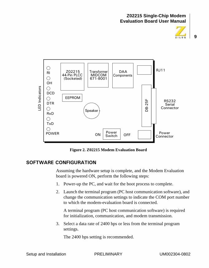
Figure 2 shows the layout of Z02215 Modem Evaluation Board.
Notes:
Note:
Note:
Setup and Installation PRELIMINARY UM002304-0802
Z02215 Single-Chip ModemEvaluation Board User Manual
9
Figure 2. Z02215 Modem Evaluation Board
����������������������
Assuming the hardware setup is complete, and the Modem Evaluation board is powered ON, perform the following steps:
1. Power-up the PC, and wait for the boot process to complete.
2. Launch the terminal program (PC host communication software), and change the communication settings to indicate the COM port number to which the modem-evaluation board is connected.
A terminal program (PC host communication software) is required for initialization, communication, and modem transmission.
3. Select a data rate of 2400 bps or less from the terminal program settings.
The 2400 bps setting is recommended.
�����
����
���
�!"��
#$
�$
#�
%&����''(������)���*����+
#��� ,��-��.�!./0�(1&&�
���-������
!22!3 �� ��� ���4
�(��2
�� ����������
�5��
�����������
������������*��
��
!6
����!.
Setup and Installation PRELIMINARY UM002304-0802
Z02215 Single-Chip ModemEvaluation Board User Manual
10
ZiLOG’s modem is capable of understanding commands at data rates of 300, 600, 1200, 2400, 4800 and 9600 bps. Any one of the data rates can be picked to initialize the modem. The characters may have a word length of 7 bits with parity or 8 bits with no parity.
The Z02215 Modem Evaluation Board is now ready to be configured by means of initialization commands sent asynchronously through the termi-nal program.
4. Initialize the modem by typing AT&F<CR> to the command line. This command returns a result:
OK.
5. Go to the Initial Checkout/Sample Session if the OK notice is echoed to the terminal.
Troubleshooting
If result codes do not appear after typing AT commands, the modem is not properly installed. Repeat the setup procedure to ensure all the hardware and software settings are correct.
If the modem is still not responding despite all the correct settings, check to make sure there are no conflicts between the COM port and IRQ set-tings through the Windows Control Panel.
COUNTRY CONFIGURATION
The default firmware on the evaluation board is configured for operation in North America only. Using the Diplomat™ utility program, the modem firmware can be modified for use in other countries.
The Diplomat Program
The Diplomat program modifies the modem firmware according to the parameters in a country profile. Partial country files end with a .tb1 extension and are also called TB1 files..
Setup and Installation PRELIMINARY UM002304-0802
Z02215 Single-Chip ModemEvaluation Board User Manual
11
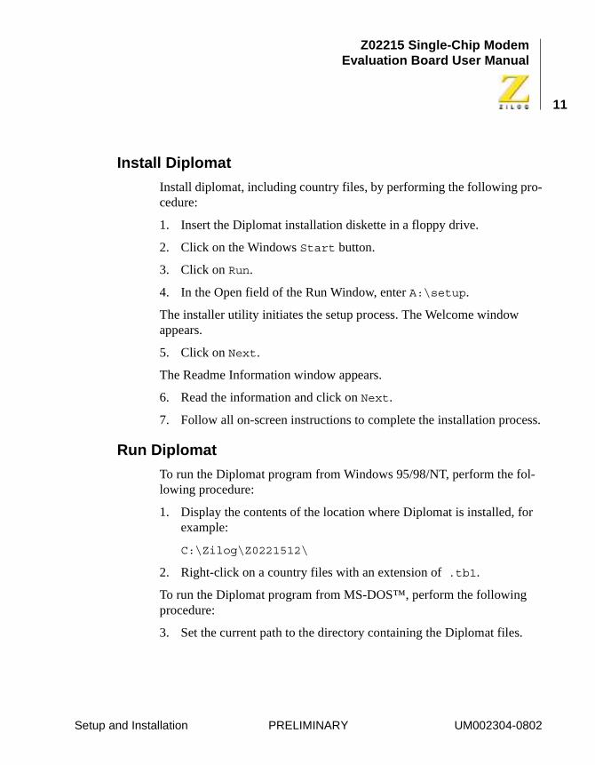
Install Diplomat
Install diplomat, including country files, by performing the following pro-cedure:
1. Insert the Diplomat installation diskette in a floppy drive.
2. Click on the Windows Start button.
3. Click on Run.
4. In the Open field of the Run Window, enter A:\setup.
The installer utility initiates the setup process. The Welcome window appears.
5. Click on Next.
The Readme Information window appears.
6. Read the information and click on Next.
7. Follow all on-screen instructions to complete the installation process.
Run Diplomat
To run the Diplomat program from Windows 95/98/NT, perform the fol-lowing procedure:
1. Display the contents of the location where Diplomat is installed, for example:
C:\Zilog\Z0221512\
2. Right-click on a country files with an extension of .tb1.
To run the Diplomat program from MS-DOS™, perform the following procedure:
3. Set the current path to the directory containing the Diplomat files.
Setup and Installation PRELIMINARY UM002304-0802
Z02215 Single-Chip ModemEvaluation Board User Manual
12
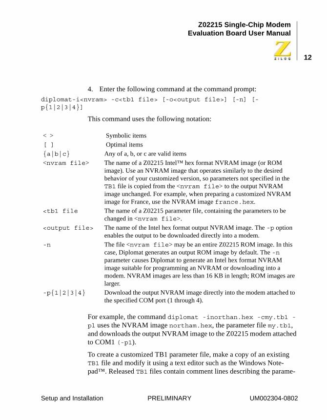
4. Enter the following command at the command prompt:
diplomat-i<nvram> -c<tb1 file> [-o<output file>] [-n] [-p{1|2|3|4}]
This command uses the following notation:
For example, the command diplomat -inorthan.hex -cmy.tb1 -pl uses the NVRAM image northam.hex, the parameter file my.tb1, and downloads the output NVRAM image to the Z02215 modem attached to COM1 (-p1).
To create a customized TB1 parameter file, make a copy of an existing TB1 file and modify it using a text editor such as the Windows Note-pad™. Released TB1 files contain comment lines describing the parame-
< > Symbolic items
[ ] Optimal items
{a|b|c} Any of a, b, or c are valid items
<nvram file> The name of a Z02215 Intel™ hex format NVRAM image (or ROM image). Use an NVRAM image that operates similarly to the desired behavior of your customized version, so parameters not specified in the TB1 file is copied from the <nvram file> to the output NVRAM image unchanged. For example, when preparing a customized NVRAM image for France, use the NVRAM image france.hex.
<tb1 file The name of a Z02215 parameter file, containing the parameters to be changed in <nvram file>.
<output file> The name of the Intel hex format output NVRAM image. The -p option enables the output to be downloaded directly into a modem.
-n The file <nvram file> may be an entire Z02215 ROM image. In this case, Diplomat generates an output ROM image by default. The -n parameter causes Diplomat to generate an Intel hex format NVRAM image suitable for programming an NVRAM or downloading into a modem. NVRAM images are less than 16 KB in length; ROM images are larger.
-p{1|2|3|4} Download the output NVRAM image directly into the modem attached to the specified COM port (1 through 4).
Setup and Installation PRELIMINARY UM002304-0802
Z02215 Single-Chip ModemEvaluation Board User Manual
13
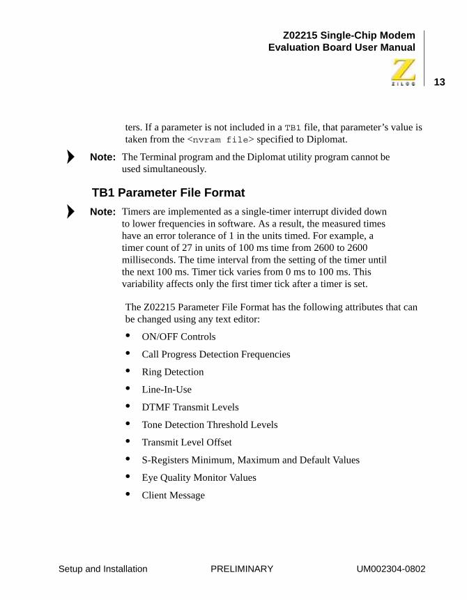
ters. If a parameter is not included in a TB1 file, that parameter’s value is taken from the <nvram file> specified to Diplomat.
The Terminal program and the Diplomat utility program cannot be used simultaneously.
TB1 Parameter File Format
Timers are implemented as a single-timer interrupt divided down to lower frequencies in software. As a result, the measured times have an error tolerance of 1 in the units timed. For example, a timer count of 27 in units of 100 ms time from 2600 to 2600 milliseconds. The time interval from the setting of the timer until the next 100 ms. Timer tick varies from 0 ms to 100 ms. This variability affects only the first timer tick after a timer is set.
The Z02215 Parameter File Format has the following attributes that can be changed using any text editor:
• ON/OFF Controls
• Call Progress Detection Frequencies
• Ring Detection
• Line-In-Use
• DTMF Transmit Levels
• Tone Detection Threshold Levels
• Transmit Level Offset
• S-Registers Minimum, Maximum and Default Values
• Eye Quality Monitor Values
• Client Message
Note:
Note:
Setup and Installation PRELIMINARY UM002304-0802
Z02215 Single-Chip ModemEvaluation Board User Manual
14
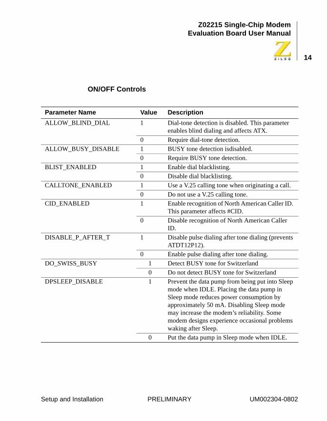
ON/OFF Controls
Parameter Name Value Description
ALLOW_BLIND_DIAL 1 Dial-tone detection is disabled. This parameter enables blind dialing and affects ATX.
0 Require dial-tone detection.
ALLOW_BUSY_DISABLE 1 BUSY tone detection isdisabled.
0 Require BUSY tone detection.
BLIST_ENABLED 1 Enable dial blacklisting.
0 Disable dial blacklisting.
CALLTONE_ENABLED 1 Use a V.25 calling tone when originating a call.
0 Do not use a V.25 calling tone.
CID_ENABLED 1 Enable recognition of North American Caller ID. This parameter affects #CID.
0 Disable recognition of North American Caller ID.
DISABLE_P_AFTER_T 1 Disable pulse dialing after tone dialing (prevents ATDT12P12).
0 Enable pulse dialing after tone dialing.
DO_SWISS_BUSY 1 Detect BUSY tone for Switzerland
0 Do not detect BUSY tone for Switzerland
DPSLEEP_DISABLE 1 Prevent the data pump from being put into Sleep mode when IDLE. Placing the data pump in Sleep mode reduces power consumption by approximately 50 mA. Disabling Sleep mode may increase the modem’s reliability. Some modem designs experience occasional problems waking after Sleep.
0 Put the data pump in Sleep mode when IDLE.
Setup and Installation PRELIMINARY UM002304-0802
Z02215 Single-Chip ModemEvaluation Board User Manual
15
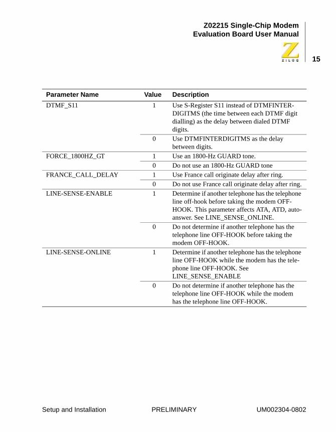
DTMF_S11 1 Use S-Register S11 instead of DTMFINTER-DIGITMS (the time between each DTMF digit dialling) as the delay between dialed DTMF digits.
0 Use DTMFINTERDIGITMS as the delay between digits.
FORCE_1800HZ_GT 1 Use an 1800-Hz GUARD tone.
0 Do not use an 1800-Hz GUARD tone
FRANCE_CALL_DELAY 1 Use France call originate delay after ring.
0 Do not use France call originate delay after ring.
LINE-SENSE-ENABLE 1 Determine if another telephone has the telephone line off-hook before taking the modem OFF-HOOK. This parameter affects ATA, ATD, auto-answer. See LINE_SENSE_ONLINE.
0 Do not determine if another telephone has the telephone line OFF-HOOK before taking the modem OFF-HOOK.
LINE-SENSE-ONLINE 1 Determine if another telephone has the telephone line OFF-HOOK while the modem has the tele-phone line OFF-HOOK. See LINE_SENSE_ENABLE
0 Do not determine if another telephone has the telephone line OFF-HOOK while the modem has the telephone line OFF-HOOK.
Parameter Name Value Description
Setup and Installation PRELIMINARY UM002304-0802
Z02215 Single-Chip ModemEvaluation Board User Manual
16
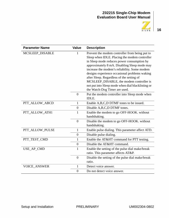
MCSLEEP_DISABLE 1 Prevent the modem controller from being put to Sleep when IDLE. Placing the modem controller in Sleep mode reduces power consumption by approximately 8 mA. Disabling Sleep mode may increase the modem’s reliability. Some modem designs experience occasional problems waking after Sleep. Regardless of the setting of MCSLEEP_DISABLE, the modem controller is not put into Sleep mode when dial blacklisting or the Watch-Dog Timer are used.
0 Put the modem controller into Sleep mode when IDLE.
PTT_ALLOW_ABCD 1 Enable A,B,C,D DTMF tones to be issued.
0 Disable A,B,C,D DTMF tones.
PTT_ALLOW_ATH1 1 Enable the modem to go OFF-HOOK. without handshaking.
0 Disable the modem to go OFF-HOOK. without handshaking.
PTT_ALLOW_PULSE 1 Enable pulse dialing. This parameter affect ATD.
0 Disable pulse dialing.
PTT_TEST_CMD 1 Enable the AT&HT command for PTT testing.
0 Disable the AT&HT command.
USE_AP_CMD 1 Enable the setting of the pulse dial make/break ratio. This parameter affects AT&P.
0 Disable the setting of the pulse dial make/break ratio.
VOICE_ANSWER 1 Detect voice answer.
0 Do not detect voice answer.
Parameter Name Value Description
Setup and Installation PRELIMINARY UM002304-0802
Z02215 Single-Chip ModemEvaluation Board User Manual
17
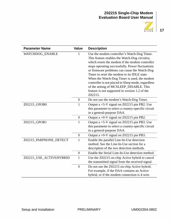
WATCHDOG_ENABLE 1 Use the modem controller’s Watch-Dog Timer. This feature enables the Watch-Dog circuitry, which resets the modem if the modem controller stops operating successfully. Power fluctuations or firmware problems can cause the Watch-Dog Timer to reset the modem to its IDLE state. When the Watch-Dog Timer is used, the modem controller is not placed in Sleep mode, regardless of the setting of MCSLEEP_DISABLE. This feature is not supported in version 1.2 of the Z02215.
0 Do not use the modem’s Watch-Dog Timer.
Z02215_GPOB0 1 Output a +5-V signal on Z02215 pin PB2. Use this parameter to select a country-specific circuit in a general-purpose DAA.
0 Output a +0-V signal on Z02215 pin PB2.
Z02215_GPOB1 1 Output a +5-V signal on Z02215 pin PB3. Use this parameter to select a country-specific circuit in a general-purpose DAA.
0 Output a +0-V signal on Z02215 pin PB3.
Z02215_PARPHONE_DETECT 1 Enable the parallel Line-In-Use detection method. See the Line-In-Use section for a description of the two detection methods.
0 Enable the Serial Line-In-Use detection method.
Z02215_USE_ACTIVEHYBRID 1 Use the Z02215 on-chip Active hybrid to cancel the transmitted signal from the received signal.
0 Do not use the Z02215 on-chip Active hybrid. For example, if the DAA contains an Active hybrid, or if the modem connection is 4 wire.
Parameter Name Value Description
Setup and Installation PRELIMINARY UM002304-0802
Z02215 Single-Chip ModemEvaluation Board User Manual
18
Call-Progress Detection Frequencies
The modem detects telephone network conditions during call establish-ment using a biquad tone detector. This detector is configured by a set of coefficients to detect tones within a frequency band.
Different frequency ranges may be specified to Dial tone and the other call-progress tones (Busy, Congestion [fast busy], and Ring Back).
The coefficients are determined and written by the filter design program Biquad. Do not change these coefficients manually.
The parameter CP_BQ* contains the call-progress tone-detector coeffi-cients. The call-progress detector follows the progress of the call after dialing. Tones such as Busy, Congestion [fast busy], and Ring-Back are detected by this detector.
The parameter DIAL_HQ* contains the dial tone detector coefficients. The Dial tone detector detects the Dial tone before the call is dialed.
Ring Detection
The modem controller detects ring cycles by monitoring the RDET sig-nal. If a ring frequency is within the RING_MAX_HZ and RING_MIN_HZ, then a ring is detected; if not, a ring is not detected.
The parameter RING_MAX_HZ contains the upper bound of the ring sig-nal in Hertz (cycles per second). The parameter RING_MIN_HZ contains the lower bound of the ring signal in Hertz (cycles per second).
Line-In-Use
Line-In-Use sensing may be performed both before the modem takes the telephone line OFF-HOOK to dial a number and during a connection.
Before Dialing
The LINE_SENSE_ENABLE parameter determines if the modem checks that another telephone has the telephone line OFF-HOOK
Note:
Setup and Installation PRELIMINARY UM002304-0802
Z02215 Single-Chip ModemEvaluation Board User Manual
19
before the modem takes the telephone line OFF-HOOK to dial a number.
The Data Access Arrangement (DAA) provides a Line-In-Use circuit for the modem, connected to the combined Ring Detection and Line-In-Use input signal (RDET/LCS). There are two methods of implementing the Line-In-Use circuit in a DAA. For serial phone detect, the circuit only detects if a telephone in series with the modem is OFF-HOOK. For parallel phone detect, the circuit detects if any telephone on the line is OFF-HOOK, including telephones wired in parallel to the modem. Serial and parallel phone detection schemes require different hardware and firmware support.
To perform parallel phone detection, the modem activates the line check circuit by driving the Line-Check output signal (LCS_CHK) Active for a period of time (X). During this time, the modem examines the Line- In-Use input signal (RDET/LCS). If the Line-In-Use input remains active (0V) for a period of time (Y) while the Line-Check output signal is active, the line is deemed to be in use and the call is aborted.
To perform serial phone detection, the modem examines the Line-In-Use input signal (RDET/LCS) for a period of time (X) without activating the Line-Check output signal (LCS_CHK).If the Line-In-Use signal stays active (0V) for a period of time (Y), within the check period (X), the dial attempt is permitted. Otherwise, the line is deemed to be in use, and the call is aborted.
Bit 7 of the Z02215_PARPHONE_DETECT parameter selects whether parallel or serial phone detection is required. The Line-In-Use function can be disabled by setting Bit 9 in PttBitmap0 (LINE_SENSE_ENABLE) to 0.
Setup and Installation PRELIMINARY UM002304-0802
Z02215 Single-Chip ModemEvaluation Board User Manual
20
During a Connection
The LINE_SENSE_ONLINE parameter determines if the modem checks that another telephone takes the telephone line OFF-HOOK while the modem has a connection and is transferring data.
The DAA provides a Line-In-Use circuit for the modem connected to the combined Ring-Detection and Line-In-Use input signal (RDET/LCS). During a connection, the modem examines the Line-In-Use input. If it is Inactive for the amount of time specified in Z02215_PARPHONE_DETECT (Bits 0..6) another telephone is deemed to have picked up the telephone line, causing the modem to abort the connection and hang up the telephone line so it may be used by the other telephone.
Line_in_Use Parameters
The parameter Z02212_LIU_ACTIVETIME contains the length of time (Y) in 40 υs units that the Line-In-Use input must be Active before dialing. This parameter is only used if the LINE_SENSE_ENABLE parameter is 1.
The parameter Z02215_CHK_LIU_TIME contains the length of time (X) in 40 υs units the Line-In-Use input signal is monitored before dialing. The LCS_CHK output signal is held Active during the entire period (X). For successful operation, period (X) must be greater than period (Y). This parameter is only used if the LINE_SENSE_ENABLE parameter is 1.
The parameter Z02215_LIU_HANGUPTIME_MS contains the Line-In-Use debounce value during a Connection. The length of time in 1 ms units that Line-In-Use must be Inactive before a connection is aborted.
DTMF Transmit Levels
The parameter DTMFLOLEV_dBm contains the low-band transmit level in dBm and can be fractional. Adjust this value for loss or gain in the
Setup and Installation PRELIMINARY UM002304-0802
Z02215 Single-Chip ModemEvaluation Board User Manual
21
modem’s DAA hardware. DTMFLOLEV_dBm and DTMFLILEV_dBm must not exceed the maximum transmit level of the data pump.
The parameter DTMFLILEV_dBm contains the high-end transmit level; see DTMFLOLEV.
Tone Detection Threshold Levels
All values are in dBm and can be fractional. Adjust these values for expected loss or gain in the modem’s DAA. On and Off thresholds pro-vide hysteresis in the tone detectors. On and Off thresholds must differ by at least 3dBm. Tone levels above the On threshold are detected; tone lev-els below the Off threshold ar not detected.
The parameter TONELEV_DON_dBm contains the On threshold for the detection of discrete answer tones such as V.21, Bell 103/212, V.22bis, and V.25.
The parameter CPON_dBm contains the On threshold for CALL-PROGRESS tone detection.
The parameter CPOFF_dBm contains the Off threshold for CALL-PROGRESS tone detection.
The parameter DTON_dBm contains the On threshold for DIAL tone detection.
The parameter DTOFF_dBm contains the Off threshold for DIAL tone detection.
The parameter DRLSTON_dBm contains the On threshold for Receive Line Signal Detect (carrier).
The parameter DRLSTOFF_dBm contains the Off threshold for Receive Line Signal Detect (carrier).
Transmit Level Offset
The parameter XMIT_ OFFSET contains the units of dBm and the value may be fractional. It is used to offset the transmit level in all data modes
Setup and Installation PRELIMINARY UM002304-0802
Z02215 Single-Chip ModemEvaluation Board User Manual
22
to compensate for loss or gain in the modem’s DAA. Tone-detection threshold levels and STMF transmit levels are not adjusted by this value.
S-Registers Minimum, Maximum, and Default Values
Any modem s-Register may be specified. The format for each line is:
The following example sets the parameters for S-Register 11 to 50 as the minimum, 255 as the maximum, and 95 as the default.
When setting bit mapped registers, set the minimum to 0 and maximum to 255 to allow AT commands to change their value.
EQM Values
The parameter EQMRETRAIN contains the upper limit for the Eye Qual-ity Monitor (EQM). If the EQM exceeds this value during a V.22bis con-nection and AT%E1 is set (1), the modem initiates a retrain.
The parameter EQMHANGUP contains the upper limit for the Eye Qual-ity Monitor (EQM). If the EQM exceeds this value during a V.22, Bell 212 or V.22bis connection for sufficient time, the modem hans up the tele-phone line. Set to 0x7000 to disable hang up caused by high EQM.
Client Message
The parameter CLIENTMSG contains the message to be displayed in response to the AT14 command. Start and end the message with double-quote (“) characters. The message may be up to 127 characters long. The message may contain \r or \n sequences that are translated to carriage-
REGISTER Sreg, Min, Max, Default
REGISTER 11, 50, 255, 95
Setup and Installation PRELIMINARY UM002304-0802
Z02215 Single-Chip ModemEvaluation Board User Manual
23
return (S-Register S3) and line-feed (S-Register S4) characters when the message is displayed.
INITIAL CHECKOUT/SAMPLE SESSION
This section provides a sample session and introduces the user to some of the features of the Z02215 Modem Evaluation Board.
The AT command set enables the user to control and test all the features of the ZILOG modem. Refer to Chapter 3, “Using the AT Command Set”, for more details on individual AT commands that are needed for special configurations.
The sample session is an example of the common application of dialing into a remote computer. In this session the user dials into a remote Bulle-tin Board Service (BBS) using the Z02215 Modem Evaluation board. Please obtain a local BBS phone number or contact [email protected] to obtain an active phone number. For example, the Bytecraft Limited, Canada BBS number is: 519-888-7626.
The Z02215 Modem Evaluation Board has been factory preset (AT&F) to originate a call in the 2400-bps data mode.
Starting A Session
1. Type ATI3<CR> to the modem command line to check the version of the board being used. This command returns this result:
Z02215 Ver: V2.0Z02202 Ver: 50
26-Apr-1999
OK
This procedure is not required to start a session, but it ensures that the setup is correct before the user continues.
Setup and Installation PRELIMINARY UM002304-0802
Z02215 Single-Chip ModemEvaluation Board User Manual
24
2. Type ATI4<CR> to the modem command line to check the country configuration of the firmware being used. This command returns this result:
ZiLOG/Softart V.22bis Modem Control for North America
OK
This step displays the country profile being used. This step is not required to start a session.
3. Type the following to the modem command line to start dialing into the BBS (1-408-292-0522).
ATDT9,14082920522<CR>
The Z02215 Modem Evaluation Board can be used to dial any other remote modem with ATDT<number>. If a 9 must be dialed before making any outgoing calls, the command is ATDT9,<number>, as shown in the example above.
4. Wait for 5-10 seconds for the remote modem to answer. When the connection is established, the modem answers:
CONNECT 2400
If the remote modem is BUSY, it echoes a BUSY. Try again until a con-nection is achieved. Refer to Chapter 3 for interpreting any other result codes.
5. The modem is now in the ON-LINE mode, connected to the remote modem at a data rate of 2400 bps. At this point, the modem can communicate with the remote modem and exchange data.
Ending A Session
The modem may be instructed from the terminal program to disconnect. To disconnect the data connection, the modem must be brought from DATA mode to COMMAND mode by typing the Escape Sequence.
Setup and Installation PRELIMINARY UM002304-0802
Z02215 Single-Chip ModemEvaluation Board User Manual
25
1. Enter COMMAND mode by typing:
+++
A slight delay is needed for the modem to recognize the Escape Sequence.
Do not press the <CR> key!
The modem answers:
OK
2. Return to ONLINE mode by entering ATO.
3. Disconnect by entering:
ATH<CR>
The modem then returns
NO CARRIER
The connection is ended, and the modem is ready for other use.
Note:
Setup and Installation PRELIMINARY UM002304-0802
Z02215 Single-Chip ModemEvaluation Board User Manual
26
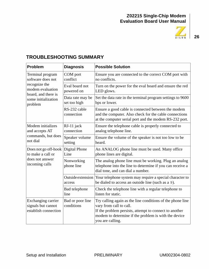
TROUBLESHOOTING SUMMARY
Problem Diagnosis Possible Solution
Terminal program software does not recognize the modem evaluation board, and there is some initialization problem
COM port conflict
Ensure you are connected to the correct COM port with no conflicts.
Eval board not powered on
Turn on the power for the eval board and ensure the red LED glows.
Data rate may be set too high
Set the data rate in the terminal program settings to 9600 bps or lower.
RS-232 cable connection
Ensure a good cable is connected between the modem and the computer. Also check for the cable connections at the computer serial port and the modem RS-232 port.
Modem initializes and accepts AT commands, but does not dial
RJ-11 jack connection
Ensure the telephone cable is properly connected to analog telephone line.
Speaker volume setting
Ensure the volume of the speaker is not too low to be heard.
Does not go off-hook to make a call or does not answer incoming calls
Digital Phone Line
An ANALOG phone line must be used. Many office phone lines are digital.
Nonworking phone line
The analog phone line must be working. Plug an analog telephone into the line to determine if you can receive a dial tone, and can dial a number.
Outside extension access
Your telephone system may require a special character to be dialed to access an outside line (such as a 9).
Bad telephone line
Check the telephone line with a regular telephone to listen for static.
Exchanging carrier signals but cannot establish connection
Bad or poor line conditions
Try calling again as the line conditions of the phone line vary from call to call.If the problem persists, attempt to connect to another modem to determine if the problem is with the device you are calling.
Setup and Installation PRELIMINARY UM002304-0802
Z02215 Single-Chip ModemEvaluation Board User Manual
27
Using The AT Command Set
INTRODUCTION
The following topics are covered in this chapter:
• Conventions
• AT Commands
• Data Commands
• S-Registers
At hardware RESET, the firmware performs diagnostic tests of the board’s components. At completion of the diagnostics, the firmware waits for an AT command from the terminal connected to the board. The firm-ware automatically determines the data rate and parity of the A and T characters that precede the board command.
CONVENTIONS
RS-232 Signal Values
In this user’s manual, RS-232 control signals such as RTS, CTS, DTR, DSR, and DCD are referred to as being OFF or ON.
These signals are active Low on the Z0221500ZCO evaluation board.
Note:
UM002304-0802 PRELIMINARY Using The AT Command Set
Z02215 Single-Chip ModemEvaluation Board User Manual
28
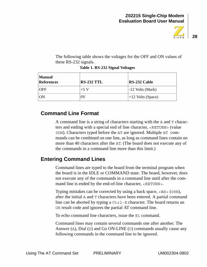
The following table shows the voltages for the OFF and ON values of these RS-232 signals.
Command Line Format
A command line is a string of characters starting with the A and T charac-ters and ending with a special end of line character, <RETURN> (value 0DH). Characters typed before the AT are ignored. Multiple AT com-mands can be combined on one line, as long as command lines contain no more than 40 characters after the AT. (The board does not execute any of the commands in a command line more than this limit.)
Entering Command Lines
Command lines are typed to the board from the terminal program when the board is in the IDLE or COMMAND state. The board, however, does not execute any of the commands in a command line until after the com-mand line is ended by the end-of-line character, <RETURN>.
Typing mistakes can be corrected by using a back space, <BS> (08H), after the initial A and T characters have been entered. A partial command line can be aborted by typing a Ctrl-X character. The board returns an OK result code and ignores the partial AT command line.
To echo command line characters, issue the E1 command.
Command lines may contain several commands one after another. The Answer (A), Dial (D) and Go ON-LINE (O) commands usually cause any following commands in the command line to be ignored.
Table 1. RS-232 Signal Voltages
ManualReferences RS-232 TTL RS-232 Cable
OFF +5 V -12 Volts (Mark)
ON 0V +12 Volts (Space)
Using The AT Command Set PRELIMINARY UM002304-0802
Z02215 Single-Chip ModemEvaluation Board User Manual
29
Command Line Execution
The characters in a command line are executed one at a time. Any unex-pected characters, except control characters, terminate command line exe-cution and return an ERROR result code. Unexpected characters include numbers outside the range of values accepted by the command. All con-trol characters in a command line except Ctrl-X and the special charac-ters such as <RETURN> and <BS> are ignored.
Numeric Arguments
The numerical argument of a command is assumed to be 0 if it is not pro-vided.
Example: Commands ATH<RETURN> and ATH0<RETURN> both hang up the telephone line.
Leading 0s in numeric arguments, including S-register numbers, are ignored.
Example: ATS1=2 and ATS01=2 both set S-register S1 to 2.
All numeric arguments, including S-register numbers, are decimal (base 10).
When the board has executed a command line, the result code of the last command executed is returned to the terminal. If the AT command typed to the board is not supported by the modem firmware, the ERROR result code is returned.
AT Command Prefix
Each board command line begins with the letters A and T. The board uses these characters to determine the data rate and parity of data from the ter-minal.
Using The AT Command Set PRELIMINARY UM002304-0802
Z02215 Single-Chip ModemEvaluation Board User Manual
30
Repeat Last Command
To repeat the commands in the last command line type the letters / and A instead of A and T.
End-Of-Line Character
This character is typed to end a command line. The value of the <RETURN> character is stored in S-register S3. The default is ASCII 13, the return character.
When the <RETURN> character is entered, the board executes the com-mands in the command line.
Back Space Character
This character is typed to erase the last character in a command line. The value of the <BS> character is stored in S-register S5. The default is ASCII 8, the back space character.
Using The AT Command Set PRELIMINARY UM002304-0802
Z02215 Single-Chip ModemEvaluation Board User Manual
31
AT COMMANDS
North American default values are designated by bold type. The operation of these commands, and the default values of option commands, is configurable for operation in different countries.
��� ��!�"����� ##����� �
Mnemonic Name Function and Description
A Answer The A command makes the modem go OFF-HOOK and respond to an incoming call. This command is issued after the modem has returned the RING result code.
If the modems successfully complete the answering process, each returns a CONNECT result code and enters the ON-LINE state.
If no transmit carrier signal is received from the calling modem within the time specified in S-register S7, the modem hangs up, returns the NO CARRIER result code, and enters the IDLE state.
If the modem is in the Command state or &Q2 or &Q3 is selected then the ERROR result code is returned. Any commands following the answer command on the command line are ignored.
This command is aborted if a key is pressed before the answer process is completed, when DTR is OFF, or if some options in the &Q or &D commands have been used.
Note:
Using The AT Command Set PRELIMINARY UM002304-0802
Z02215 Single-Chip ModemEvaluation Board User Manual
32
B Communication Standard Option
The B command specifies a special telephone line modulation standard:1. Bell 212A instead of ITU-T V.22 at 1200 bps
2. Bell 103 instead of ITU-T V.21 at 300 bps
3. In data modes where the receive and transmit speeds are different (ITU-TV.23 or Bell 202), whether the caller or answerer transmits data at the higher data rate.
4. In ITU-T V.23 data mode, Minitel line reversals.
5. In data modes where the receive and transmit speeds differ (ITU-T V.23or Bell 202), a 4-wire telephone interface instead of a 2-wire telephone interface.
When ON-LINE in data modes where the receive and transmit speeds differ (V.23 and Bell 202), the modem only recognizes the Escape Sequence (+++), and modem commands, at the higher of the transmit and receive speeds.
S-register S37 also affects the selection of modulation standards. S37 controls the telephone line data rate, and the split-rate data mode (Bell 202 or V.23).
Configure both modems identically to prevent communication failures caused by incompatible telephone line modulation stan-dards.
��� ��!�"����� ##����� � �$� ���� �%
Mnemonic Name Function and Description
Using The AT Command Set PRELIMINARY UM002304-0802
Z02215 Single-Chip ModemEvaluation Board User Manual
33
B(Continued)
Communication Standard Option
B0 This option uses the ITU-T modulation standards for all telephone line data rates, unless S-register S37 is 2. These rates include V.22 for the 1200 bps telephone line data rate, and V.21 for the 300-bps telephone line data rate.
When S-register S37 is 1, V.23 is adopted when the originating modem is transmitting at 75 bps and receiving at 1200 bps. The answering modem trans-mits data at 1200 bps and receives data at 75 bps.
When S-register S37 is 2, Bell 202 is adopted when the originating modem is transmitting at 150 bps and receiving at 1200 bps. The answering modem trans-mits data at 1200 bps and receives data at 150 bps.
B1 This option uses the Bell modulation standards for 1200-bps and 300-bps telephone line data rates, unless S-register S37 is 1. Bell 212A at 1200 bps is adopted instead of V.22. This value is the default value for North America.
Bell 102 is used when a 300-bps telephone line data rate is required.
If neither the 1200-bps nor 300-bps telephone line data rate are required, a setting of B1 is ignored and the modem functions as if B0 is set.
��� ��!�"����� ##����� � �$� ���� �%
Mnemonic Name Function and Description
Using The AT Command Set PRELIMINARY UM002304-0802
Z02215 Single-Chip ModemEvaluation Board User Manual
34
B(Continued
Communication Standard Option
B2 When S-register S37 is set to 1, V.23 is adopted. The originating modem transmits at 1200 bps and receives at 75 bps. The answering modem transmits data at 75 bps and receives data at 1200 bps.
When S-register S37 is 2, Bell 202 is adopted. The originating modem transmits at 1200 bps and receives at 150 bps. The answering modem transmits data at 150 bps and receives data at 1200 bps.
If S-register S37 is set to any value other than 1 or 2, a setting of B2 operates as if B0 is set.
B3 This option is the same as B0.
��� ��!�"����� ##����� � �$� ���� �%
Mnemonic Name Function and Description
Using The AT Command Set PRELIMINARY UM002304-0802
Z02215 Single-Chip ModemEvaluation Board User Manual
35
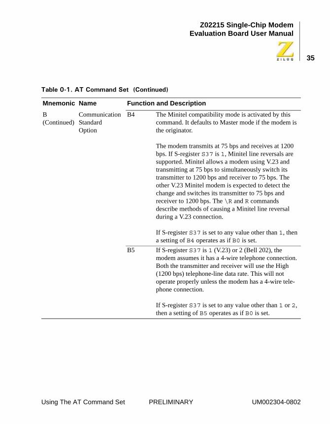
B (Continued)
Communication Standard Option
B4 The Minitel compatibility mode is activated by this command. It defaults to Master mode if the modem is the originator.
The modem transmits at 75 bps and receives at 1200 bps. If S-register S37 is 1, Minitel line reversals are supported. Minitel allows a modem using V.23 and transmitting at 75 bps to simultaneously switch its transmitter to 1200 bps and receiver to 75 bps. The other V.23 Minitel modem is expected to detect the change and switches its transmitter to 75 bps and receiver to 1200 bps. The \R and R commands describe methods of causing a Minitel line reversal during a V.23 connection.
If S-register S37 is set to any value other than 1, then a setting of B4 operates as if B0 is set.
B5 If S-register S37 is 1 (V.23) or 2 (Bell 202), the modem assumes it has a 4-wire telephone connection. Both the transmitter and receiver will use the High (1200 bps) telephone-line data rate. This will not operate properly unless the modem has a 4-wire tele-phone connection.
If S-register S37 is set to any value other than 1 or 2, then a setting of B5 operates as if B0 is set.
��� ��!�"����� ##����� � �$� ���� �%
Mnemonic Name Function and Description
Using The AT Command Set PRELIMINARY UM002304-0802
Z02215 Single-Chip ModemEvaluation Board User Manual
36
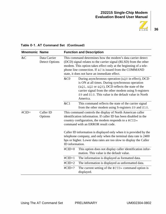
&C Data Carrier Detect Options
This command determines how the modem’s data carrier detect (DCD) signal relates to the carrier signal (RLSD) from the other modem. This option takes effect only at the beginning of a tele-phone line connection. If &C is issued from the COMMAND state, it does not have an immediate effect.
&C0 During asynchronous operation (&Q0 in effect), DCD is ON at all times. During synchronous operation (&Q1, &Q2 or &Q3), DCD reflects the state of the carrier signal from the other modem using S-registers S9 and S10. This value is the default value in North America.
&C1 This command reflects the state of the carrier signal from the other modem using S-registers S9 and S10.
#CID= Caller ID Options
This command controls the display of North American caller identification information. If caller ID has been disabled in the country configuration, the modem responds to a #CID= command with an ERROR result code.
Caller ID information is displayed only when it is provided by the telephone company, and only when the terminal data rate is 2400 bps or higher. Lower data rates are too slow to display the Caller ID information.
#CID=0 This option does not display caller identification infor-mation. This value is the default value.
#CID=1 The information is displayed as formatted data.
#CID=2 The information is displayed as unformatted data.
#CID=? The current setting of the #CID= command option is displayed.
��� ��!�"����� ##����� � �$� ���� �%
Mnemonic Name Function and Description
Using The AT Command Set PRELIMINARY UM002304-0802
Z02215 Single-Chip ModemEvaluation Board User Manual
37
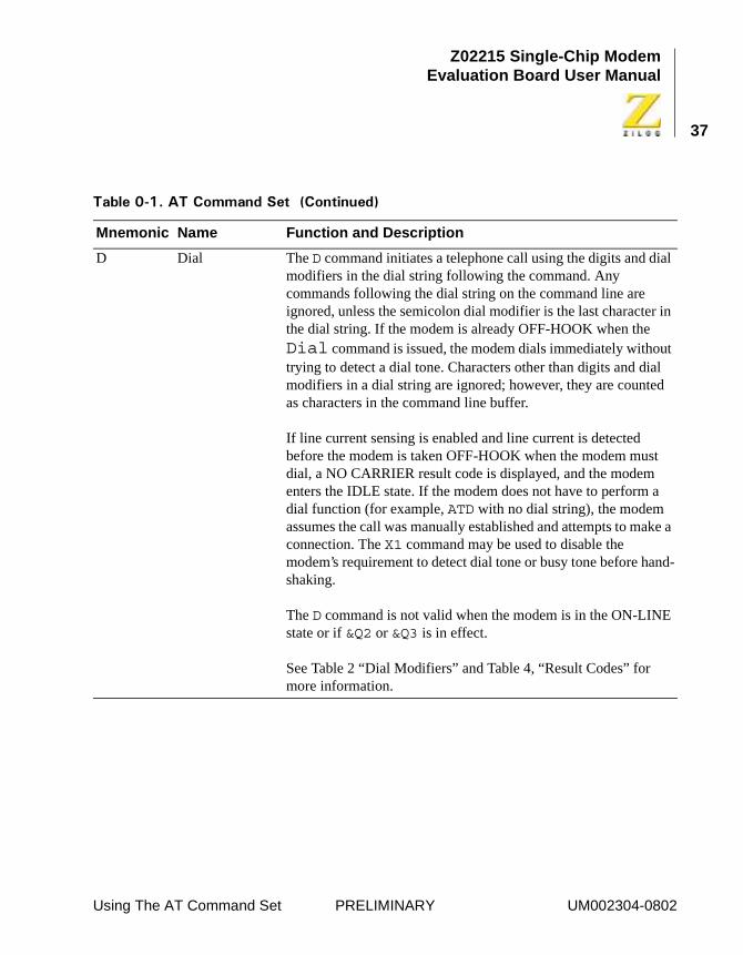
D Dial The D command initiates a telephone call using the digits and dial modifiers in the dial string following the command. Any commands following the dial string on the command line are ignored, unless the semicolon dial modifier is the last character in the dial string. If the modem is already OFF-HOOK when the Dial command is issued, the modem dials immediately without trying to detect a dial tone. Characters other than digits and dial modifiers in a dial string are ignored; however, they are counted as characters in the command line buffer.
If line current sensing is enabled and line current is detected before the modem is taken OFF-HOOK when the modem must dial, a NO CARRIER result code is displayed, and the modem enters the IDLE state. If the modem does not have to perform a dial function (for example, ATD with no dial string), the modem assumes the call was manually established and attempts to make a connection. The X1 command may be used to disable the modem’s requirement to detect dial tone or busy tone before hand-shaking.
The D command is not valid when the modem is in the ON-LINE state or if &Q2 or &Q3 is in effect.
See Table 2 “Dial Modifiers” and Table 4, “Result Codes” for more information.
��� ��!�"����� ##����� � �$� ���� �%
Mnemonic Name Function and Description
Using The AT Command Set PRELIMINARY UM002304-0802
Z02215 Single-Chip ModemEvaluation Board User Manual
38
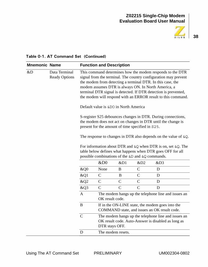
&D Data Terminal Ready Options
This command determines how the modem responds to the DTR signal from the terminal. The country configuration may prevent the modem from detecting a terminal DTR. In this case, the modem assumes DTR is always ON. In North America, a terminal DTR signal is detected. If DTR detection is prevented, the modem will respond with an ERROR result to this command.
Default value is &DO in North America
S-register S25 debounces changes in DTR. During connections, the modem does not act on changes in DTR until the change is present for the amount of time specified in S25.
The response to changes in DTR also depends on the value of &Q.
For information about DTR and &Q when DTR is on, set &Q. The table below defines what happens when DTR goes OFF for all possible combinations of the &D and &Q commands.
&D0 &D1 &D2 &D3
&Q0 None B C D
&Q1 C B C D
&Q2 C C C D
&Q3 C C C D
A The modem hangs up the telephone line and issues an OK result code.
B If in the ON-LINE state, the modem goes into the COMMAND state, and issues an OK result code.
C The modem hangs up the telephone line and issues an OK result code. Auto-Answer is disabled as long as DTR stays OFF.
D The modem resets.
��� ��!�"����� ##����� � �$� ���� �%
Mnemonic Name Function and Description
Using The AT Command Set PRELIMINARY UM002304-0802
Z02215 Single-Chip ModemEvaluation Board User Manual
39
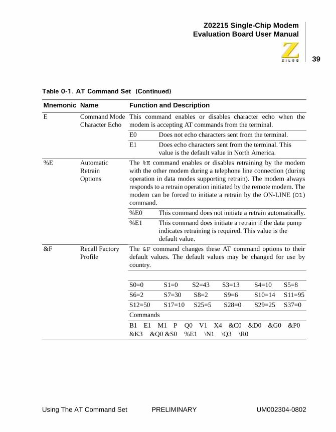
E Command Mode Character Echo
This command enables or disables character echo when themodem is accepting AT commands from the terminal.
E0 Does not echo characters sent from the terminal.
E1 Does echo characters sent from the terminal. This value is the default value in North America.
%E Automatic Retrain Options
The %E command enables or disables retraining by the modemwith the other modem during a telephone line connection (duringoperation in data modes supporting retrain). The modem alwaysresponds to a retrain operation initiated by the remote modem. Themodem can be forced to initiate a retrain by the ON-LINE (O1)command.
%E0 This command does not initiate a retrain automatically.
%E1 This command does initiate a retrain if the data pump indicates retraining is required. This value is the default value.
&F Recall Factory Profile
The &F command changes these AT command options to theirdefault values. The default values may be changed for use bycountry.
S0=0 S1=0 S2=43 S3=13 S4=10 S5=8
S6=2 S7=30 S8=2 S9=6 S10=14 S11=95
S12=50 S17=10 S25=5 S28=0 S29=25 S37=0
Commands
B1 E1 M1 P Q0 V1 X4 &C0 &D0 &G0 &P0 &K3 &Q0 &S0 %E1 \N1 \Q3 \R0
��� ��!�"����� ##����� � �$� ���� �%
Mnemonic Name Function and Description
Using The AT Command Set PRELIMINARY UM002304-0802
Z02215 Single-Chip ModemEvaluation Board User Manual
40
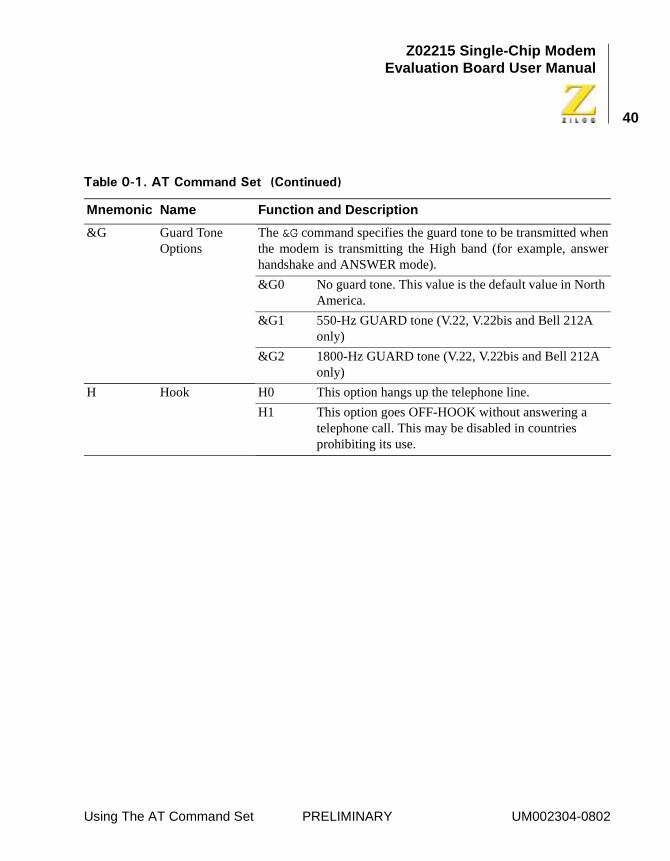
&G Guard Tone Options
The &G command specifies the guard tone to be transmitted whenthe modem is transmitting the High band (for example, answerhandshake and ANSWER mode).
&G0 No guard tone. This value is the default value in North America.
&G1 550-Hz GUARD tone (V.22, V.22bis and Bell 212A only)
&G2 1800-Hz GUARD tone (V.22, V.22bis and Bell 212A only)
H Hook H0 This option hangs up the telephone line.
H1 This option goes OFF-HOOK without answering a telephone call. This may be disabled in countries prohibiting its use.
��� ��!�"����� ##����� � �$� ���� �%
Mnemonic Name Function and Description
Using The AT Command Set PRELIMINARY UM002304-0802
Z02215 Single-Chip ModemEvaluation Board User Manual
41
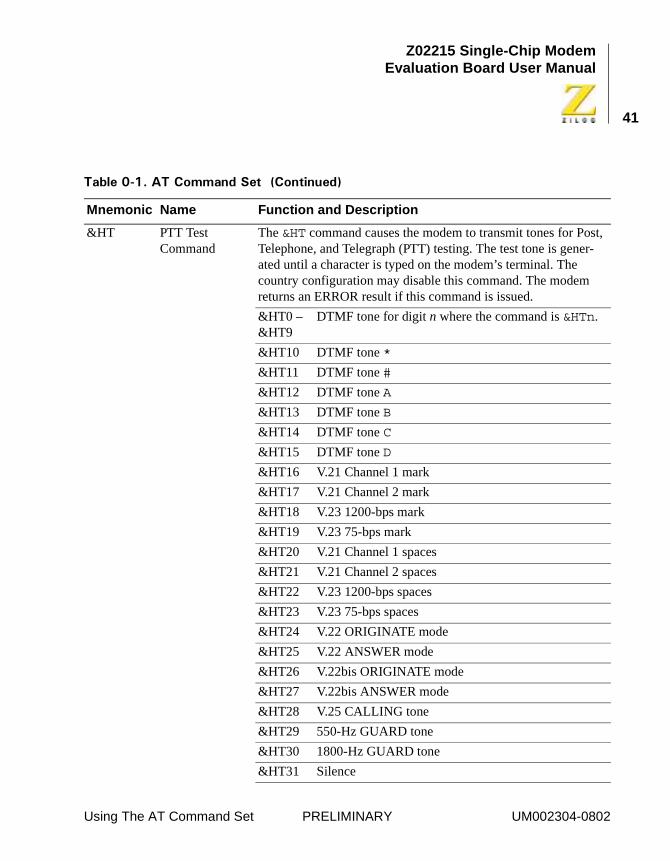
&HT PTT Test Command
The &HT command causes the modem to transmit tones for Post, Telephone, and Telegraph (PTT) testing. The test tone is gener-ated until a character is typed on the modem’s terminal. The country configuration may disable this command. The modem returns an ERROR result if this command is issued.
&HT0 – &HT9
DTMF tone for digit n where the command is &HTn.
&HT10 DTMF tone *
&HT11 DTMF tone #
&HT12 DTMF tone A
&HT13 DTMF tone B
&HT14 DTMF tone C
&HT15 DTMF tone D
&HT16 V.21 Channel 1 mark
&HT17 V.21 Channel 2 mark
&HT18 V.23 1200-bps mark
&HT19 V.23 75-bps mark
&HT20 V.21 Channel 1 spaces
&HT21 V.21 Channel 2 spaces
&HT22 V.23 1200-bps spaces
&HT23 V.23 75-bps spaces
&HT24 V.22 ORIGINATE mode
&HT25 V.22 ANSWER mode
&HT26 V.22bis ORIGINATE mode
&HT27 V.22bis ANSWER mode
&HT28 V.25 CALLING tone
&HT29 550-Hz GUARD tone
&HT30 1800-Hz GUARD tone
&HT31 Silence
��� ��!�"����� ##����� � �$� ���� �%
Mnemonic Name Function and Description
Using The AT Command Set PRELIMINARY UM002304-0802
Z02215 Single-Chip ModemEvaluation Board User Manual
42
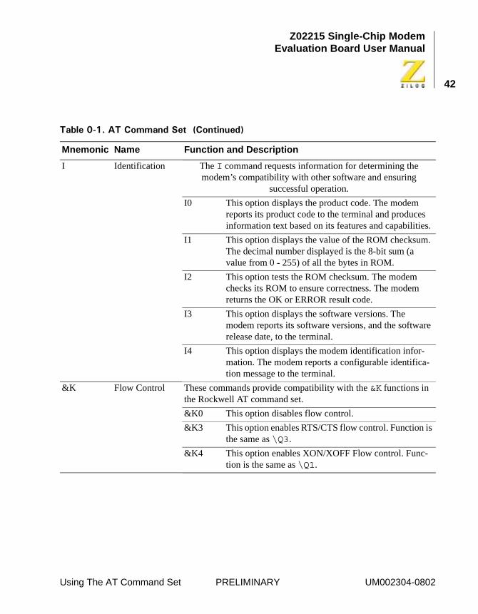
I Identification The I command requests information for determining the modem’s compatibility with other software and ensuring
successful operation.
I0 This option displays the product code. The modem reports its product code to the terminal and produces information text based on its features and capabilities.
I1 This option displays the value of the ROM checksum. The decimal number displayed is the 8-bit sum (a value from 0 - 255) of all the bytes in ROM.
I2 This option tests the ROM checksum. The modem checks its ROM to ensure correctness. The modem returns the OK or ERROR result code.
I3 This option displays the software versions. The modem reports its software versions, and the software release date, to the terminal.
I4 This option displays the modem identification infor-mation. The modem reports a configurable identifica-tion message to the terminal.
&K Flow Control These commands provide compatibility with the &K functions in the Rockwell AT command set.
&K0 This option disables flow control.
&K3 This option enables RTS/CTS flow control. Function is the same as \Q3.
&K4 This option enables XON/XOFF Flow control. Func-tion is the same as \Q1.
��� ��!�"����� ##����� � �$� ���� �%
Mnemonic Name Function and Description
Using The AT Command Set PRELIMINARY UM002304-0802
Z02215 Single-Chip ModemEvaluation Board User Manual
43
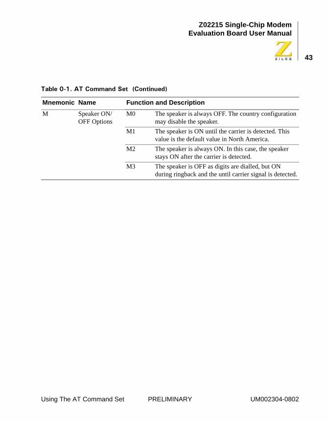
M Speaker ON/OFF Options
M0 The speaker is always OFF. The country configuration may disable the speaker.
M1 The speaker is ON until the carrier is detected. This value is the default value in North America.
M2 The speaker is always ON. In this case, the speaker stays ON after the carrier is detected.
M3 The speaker is OFF as digits are dialled, but ON during ringback and the until carrier signal is detected.
��� ��!�"����� ##����� � �$� ���� �%
Mnemonic Name Function and Description
Using The AT Command Set PRELIMINARY UM002304-0802
Z02215 Single-Chip ModemEvaluation Board User Manual
44
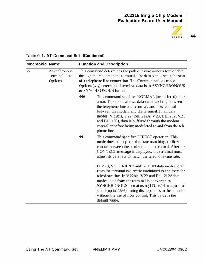
\N Asynchronous Terminal Data Options
This command determines the path of asynchronous format data through the modem to the terminal. The data path is set at the start of a telephone line connection. The Communications mode Options (&Q) determine if terminal data is in ASYNCHRONOUS or SYNCHRONOUS format.
\N0 This command specifies NORMAL (or buffered) oper-ation. This mode allows data-rate matching between the telephone line and terminal, and flow control between the modem and the terminal. In all data modes (V.22bis, V.22, Bell 212A, V.23, Bell 202, V.21 and Bell 103), data is buffered through the modem controller before being modulated to and from the tele-phone line.
\N1 This command specifies DIRECT operation. This mode does not support data-rate matching, or flow control between the modem and the terminal. After the CONNECT message is displayed, the terminal must adjust its data rate to match the telephone-line rate.
In V.23, V.21, Bell 202 and Bell 103 data modes, data from the terminal is directly modulated to and from the telephone line. In V.22bis, V.22 and Bell 212Adata modes, data from the terminal is converted to SYNCHRONOUS format using ITU V.14 to adjust for small (up to 2.5%) timing discrepancies in the data rate without the use of flow control. This value is the default value.
��� ��!�"����� ##����� � �$� ���� �%
Mnemonic Name Function and Description
Using The AT Command Set PRELIMINARY UM002304-0802
Z02215 Single-Chip ModemEvaluation Board User Manual
45
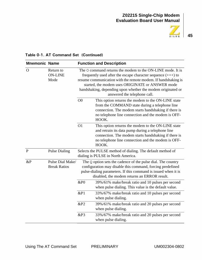
O Return to ON-LINE Mode
The O command returns the modem to the ON-LINE mode. It is frequently used after the escape character sequence (+++) to
resume communication with the remote modem. If handshaking is started, the modem uses ORIGINATE or ANSWER mode
handshaking, depending upon whether the modem originated or answered the telephone call.
O0 This option returns the modem to the ON-LINE state from the COMMAND state during a telephone line connection. The modem starts handshaking if there is no telephone line connection and the modem is OFF-HOOK.
O1 This option returns the modem to the ON-LINE state and retrain its data pump during a telephone line connection. The modem starts handshaking if there is no telephone line connection and the modem is OFF-HOOK.
P Pulse Dialing Selects the PULSE method of dialing. The default method of dialing is PULSE in North America.
&P Pulse Dial Make/Break Ratios
The Q option sets the cadence of the pulse dial. The country configuration may disable this command, forcing predefined pulse-dialing parameters. If this command is issued when it is
disabled, the modem returns an ERROR result.
&P0 39%/61% make/break ratio and 10 pulses per second when pulse dialing. This value is the default value.
&P1 33%/67% make/break ratio and 10 pulses per second when pulse dialing.
&P2 39%/61% make/break ratio and 20 pulses per second when pulse dialing.
&P3 33%/67% make/break ratio and 20 pulses per second when pulse dialing.
��� ��!�"����� ##����� � �$� ���� �%
Mnemonic Name Function and Description
Using The AT Command Set PRELIMINARY UM002304-0802
Z02215 Single-Chip ModemEvaluation Board User Manual
46
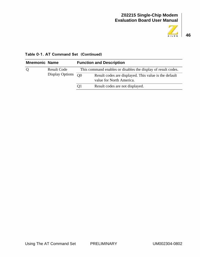
Q Result Code Display Options
This command enables or disables the display of result codes.
Q0 Result codes are displayed. This value is the default value for North America.
Q1 Result codes are not displayed.
��� ��!�"����� ##����� � �$� ���� �%
Mnemonic Name Function and Description
Using The AT Command Set PRELIMINARY UM002304-0802
Z02215 Single-Chip ModemEvaluation Board User Manual
47
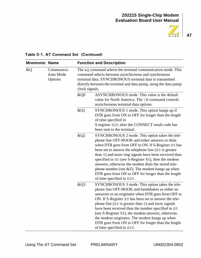
&Q Communica-tions Mode Options
The &Q command selects the terminal communication mode. This command selects between asynchronous and synchronous terminal data. SYNCHRONOUS terminal data is transmitted directly between the terminal and data pump, using the data pump clock signals.
&Q0 ASYNCHRONOUS mode. This value is the default value for North America. The \N command controls asynchronous terminal data options.
&Q1 SYNCHRONOUS 1 mode. This option hangs up if DTR goes from ON to OFF for longer than the length of time specified in S-register S25 after the CONNECT result code has been sent to the terminal.
&Q2 SYNCHRONOUS 2 mode. This option takes the tele-phone line OFF-HOOK and either answers or dials when DTR goes from OFF to ON. If S-Register S0 has been set to answer the telephone line (S0 is greater than 0) and more ring signals have been received than specified in S0 (see S-Register S1), then the modem answers, otherwise the modem dials the stored tele-phone number (see &Z). The modem hangs up when DTR goes from ON to OFF for longer than the length of time specified in S25.
&Q3 SYNCHRONOUS 3 mode. This option takes the tele-phone line OFF-HOOK and handshakes as either an answerer or an originator when DTR goes from OFF to ON. If S-Register S0 has been set to answer the tele-phone line (S0 is greater than 0) and more signals have been received than the number specified in S0 (see S-Register S1), the modem answers, otherwise, the modem originates. The modem hangs up when DTR goes from ON to OFF for longer than the length of time specified in S25.
��� ��!�"����� ##����� � �$� ���� �%
Mnemonic Name Function and Description
Using The AT Command Set PRELIMINARY UM002304-0802
Z02215 Single-Chip ModemEvaluation Board User Manual
48
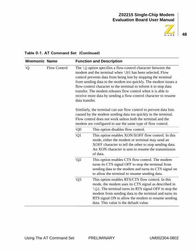
\Q Flow Control The \Q option specifies a flow-control character between the modem and the terminal when \N0 has been selected. Flow control prevents data from being lost by stopping the terminal from sending data to the modem too quickly. The modem issues a flow-control character to the terminal to inform it to stop data transfer. The modem releases flow control when it is able to receive more data by sending a flow-control character to resume data transfer.
Similarly, the terminal can use flow control to prevent data loss caused by the modem sending data too quickly to the terminal. Flow control does not work unless both the terminal and the modem are configured to use the same type of flow control.
\Q0 This option disables flow control.
\Q1 This option enables XON/XOFF flow control. In this mode, either the modem or terminal may send an XOFF character to tell the other to stop sending data. An XON character is sent to resume the transmission of data.
\Q2 This option enables CTS flow control. The modem turns its CTS signal OFF to stop the terminal from sending data to the modem and turns its CTS signal on to allow the terminal to resume sending data.
\Q3 This option enables RTS/CTS flow control. In this mode, the modem uses its CTS signal as described in \Q2. The terminal turns its RTS signal OFF to stop the modem from sending data to the terminal and turns its RTS signal ON to allow the modem to resume sending data. This value is the default value.
��� ��!�"����� ##����� � �$� ���� �%
Mnemonic Name Function and Description
Using The AT Command Set PRELIMINARY UM002304-0802
Z02215 Single-Chip ModemEvaluation Board User Manual
49
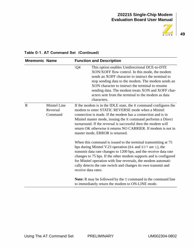
\Q4 This option enables Unidirectional DCE-to-DTE XON/XOFF flow control. In this mode, the modem sends an XOFF character to instruct the terminal to stop sending data to the modem. The modem sends an XON character to instruct the terminal to resume sending data. The modem treats XON and XOFF char-acters sent from the terminal to the modem as data characters.
R Minitel Line Reversal Command
If the modem is in the IDLE state, the R command configures the modem to enter STATIC REVERSE mode when a Minitel connection is made. If the modem has a connection and is in Minitel master mode, issuing the R command performs a Direct turnaround. If the reversal is successful then the modem will return OK otherwise it returns NO CARRIER. If modem is not in master mode, ERROR is returned.
When this command is issued to the terminal transmitting at 75 bps during Minitel V.23 operation (B4 and S37 are 1), the transmit data rate changes to 1200 bps, and the receive data rate changes to 75 bps. If the other modem supports and is configured for Minitel operation with line reversals, the modem automati-cally detects the rate switch and changes its own transmit and receive data rates.
Note: R may be followed by the O command in the command line to immediately return the modem to ON-LINE mode.
��� ��!�"����� ##����� � �$� ���� �%
Mnemonic Name Function and Description
Using The AT Command Set PRELIMINARY UM002304-0802
Z02215 Single-Chip ModemEvaluation Board User Manual
50
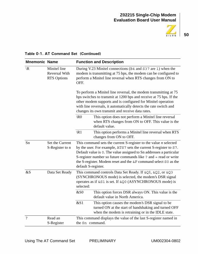
\R Minitel line Reversal With RTS Options
During V.23 Minitel connections (B4 and S37 are 1) when the modem is transmitting at 75 bps, the modem can be configured to perform a Minitel line reversal when RTS changes from ON to OFF.
To perform a Minitel line reversal, the modem transmitting at 75 bps switches to transmit at 1200 bps and receive at 75 bps. If the other modem supports and is configured for Minitel operation with line reversals, it automatically detects the rate switch and changes its own transmit and receive data rates.
\R0 This option does not perform a Minitel line reversal when RTS changes from ON to OFF. This value is the default value.
\R1 This option performs a Minitel line reversal when RTS changes from ON to OFF.
Sn Set the Current S-Register to n
This command sets the current S-register to the value n selected by the user. For example, ATS7 sets the current S-register to S7. Default value is 0. The value assigned to Sn addresses a particular S-register number so future commands like ? and = read or write the S-register. Modem reset and the &F command select S0 as the default S-register.
&S Data Set Ready This command controls Data Set Ready. If &Q1, &Q2, or &Q3 (SYNCHRONOUS mode) is selected, the modem’s DSR signal operates as if &S1 is set. If &Q0 (ASYNCHRONOUS mode) is selected:
&S0 This option forces DSR always ON. This value is the default value in North America.
&S1 This option causes the modem’s DSR signal to be turned ON at the start of handshaking and turned OFF when the modem is retraining or in the IDLE state.
? Read an S-Register
This command displays the value of the last S-register named in the Sn command.
��� ��!�"����� ##����� � �$� ���� �%
Mnemonic Name Function and Description
Using The AT Command Set PRELIMINARY UM002304-0802
Z02215 Single-Chip ModemEvaluation Board User Manual
51
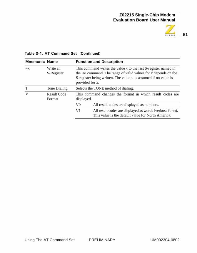
=x Write an S-Register
This command writes the value x to the last S-register named in the Sn command. The range of valid values for x depends on the S-register being written. The value 0 is assumed if no value is provided for x.
T Tone Dialing Selects the TONE method of dialing.
V Result Code Format
This command changes the format in which result codes aredisplayed.
V0 All result codes are displayed as numbers.
V1 All result codes are displayed as words (verbose form). This value is the default value for North America.
��� ��!�"����� ##����� � �$� ���� �%
Mnemonic Name Function and Description
Using The AT Command Set PRELIMINARY UM002304-0802
Z02215 Single-Chip ModemEvaluation Board User Manual
52
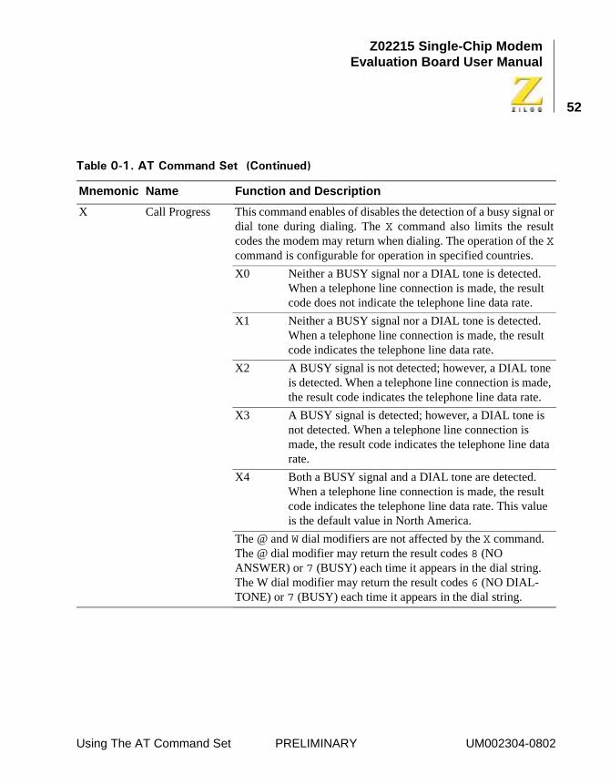
X Call Progress This command enables of disables the detection of a busy signal ordial tone during dialing. The X command also limits the resultcodes the modem may return when dialing. The operation of the Xcommand is configurable for operation in specified countries.
X0 Neither a BUSY signal nor a DIAL tone is detected. When a telephone line connection is made, the result code does not indicate the telephone line data rate.
X1 Neither a BUSY signal nor a DIAL tone is detected. When a telephone line connection is made, the result code indicates the telephone line data rate.
X2 A BUSY signal is not detected; however, a DIAL tone is detected. When a telephone line connection is made, the result code indicates the telephone line data rate.
X3 A BUSY signal is detected; however, a DIAL tone is not detected. When a telephone line connection is made, the result code indicates the telephone line data rate.
X4 Both a BUSY signal and a DIAL tone are detected. When a telephone line connection is made, the result code indicates the telephone line data rate. This value is the default value in North America.
The @ and W dial modifiers are not affected by the X command. The @ dial modifier may return the result codes 8 (NO ANSWER) or 7 (BUSY) each time it appears in the dial string. The W dial modifier may return the result codes 6 (NO DIAL-TONE) or 7 (BUSY) each time it appears in the dial string.
��� ��!�"����� ##����� � �$� ���� �%
Mnemonic Name Function and Description
Using The AT Command Set PRELIMINARY UM002304-0802
Z02215 Single-Chip ModemEvaluation Board User Manual
53
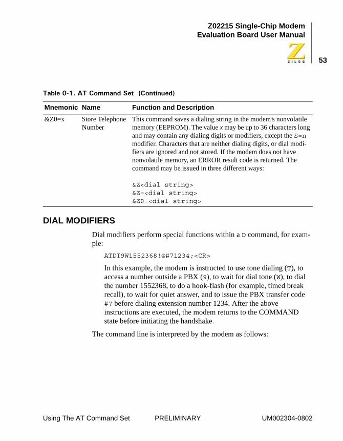
DIAL MODIFIERS
Dial modifiers perform special functions within a D command, for exam-ple:
ATDT9W1552368!@#71234;<CR>
In this example, the modem is instructed to use tone dialing (T), to access a number outside a PBX (9), to wait for dial tone (W), to dial the number 1552368, to do a hook-flash (for example, timed break recall), to wait for quiet answer, and to issue the PBX transfer code #7 before dialing extension number 1234. After the above instructions are executed, the modem returns to the COMMAND state before initiating the handshake.
The command line is interpreted by the modem as follows:
&Z0=x Store Telephone Number
This command saves a dialing string in the modem’s nonvolatile memory (EEPROM). The value x may be up to 36 characters long and may contain any dialing digits or modifiers, except the S=n modifier. Characters that are neither dialing digits, or dial modi-fiers are ignored and not stored. If the modem does not have nonvolatile memory, an ERROR result code is returned. The command may be issued in three different ways:
&Z<dial string>&Z=<dial string>&Z0=<dial string>
��� ��!�"����� ##����� � �$� ���� �%
Mnemonic Name Function and Description
Using The AT Command Set PRELIMINARY UM002304-0802
Z02215 Single-Chip ModemEvaluation Board User Manual
54
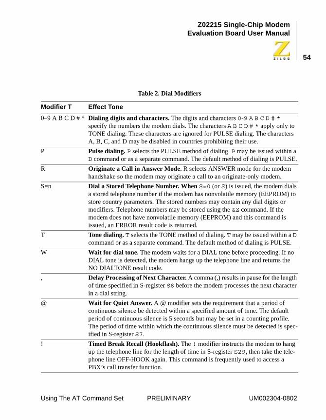
Table 2. Dial Modifiers
Modifier T Effect Tone
0–9 A B C D # * Dialing digits and characters. The digits and characters 0-9 A B C D # * specify the numbers the modem dials. The characters A B C D # * apply only to TONE dialing. These characters are ignored for PULSE dialing. The characters A, B, C, and D may be disabled in countries prohibiting their use.
P Pulse dialing. P selects the PULSE method of dialing. P may be issued within a D command or as a separate command. The default method of dialing is PULSE.
R Originate a Call in Answer Mode. R selects ANSWER mode for the modem handshake so the modem may originate a call to an originate-only modem.
S=n Dial a Stored Telephone Number. When S=0 (or S) is issued, the modem dials a stored telephone number if the modem has nonvolatile memory (EEPROM) to store country parameters. The stored numbers may contain any dial digits or modifiers. Telephone numbers may be stored using the &Z command. If the modem does not have nonvolatile memory (EEPROM) and this command is issued, an ERROR result code is returned.
T Tone dialing. T selects the TONE method of dialing. T may be issued within a D command or as a separate command. The default method of dialing is PULSE.
W Wait for dial tone. The modem waits for a DIAL tone before proceeding. If no DIAL tone is detected, the modem hangs up the telephone line and returns the NO DIALTONE result code.
, Delay Processing of Next Character. A comma (,) results in pause for the length of time specified in S-register S8 before the modem processes the next character in a dial string.
@ Wait for Quiet Answer. A @ modifier sets the requirement that a period of continuous silence be detected within a specified amount of time. The default period of continuous silence is 5 seconds but may be set in a counting profile. The period of time within which the continuous silence must be detected is spec-ified in S-register S7.
! Timed Break Recall (Hookflash). The ! modifier instructs the modem to hang up the telephone line for the length of time in S-register S29, then take the tele-phone line OFF-HOOK again. This command is frequently used to access a PBX’s call transfer function.
Using The AT Command Set PRELIMINARY UM002304-0802
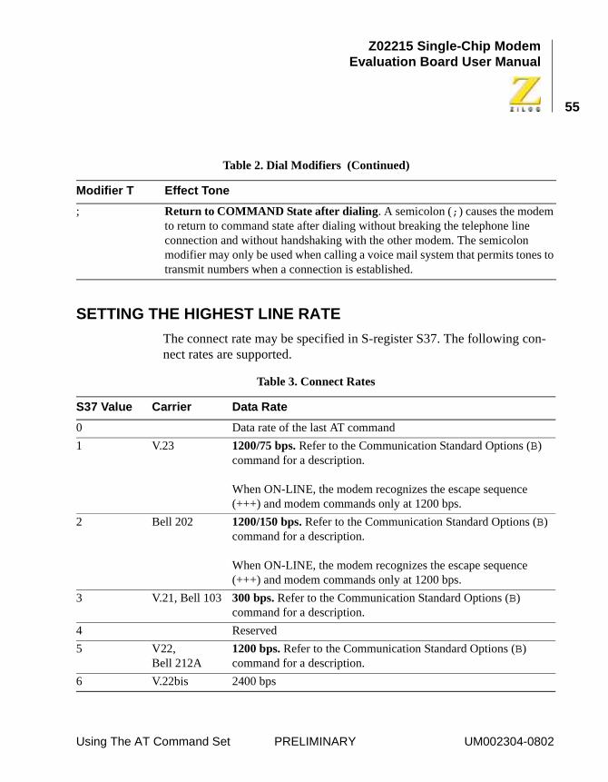
Z02215 Single-Chip ModemEvaluation Board User Manual
55
SETTING THE HIGHEST LINE RATE
The connect rate may be specified in S-register S37. The following con-nect rates are supported.
; Return to COMMAND State after dialing. A semicolon (;) causes the modem to return to command state after dialing without breaking the telephone line connection and without handshaking with the other modem. The semicolon modifier may only be used when calling a voice mail system that permits tones to transmit numbers when a connection is established.
Table 3. Connect Rates
S37 Value Carrier Data Rate
0 Data rate of the last AT command
1 V.23 1200/75 bps. Refer to the Communication Standard Options (B) command for a description.
When ON-LINE, the modem recognizes the escape sequence (+++) and modem commands only at 1200 bps.
2 Bell 202 1200/150 bps. Refer to the Communication Standard Options (B) command for a description.
When ON-LINE, the modem recognizes the escape sequence (+++) and modem commands only at 1200 bps.
3 V.21, Bell 103 300 bps. Refer to the Communication Standard Options (B) command for a description.
4 Reserved
5 V22, Bell 212A
1200 bps. Refer to the Communication Standard Options (B) command for a description.
6 V.22bis 2400 bps
Table 2. Dial Modifiers (Continued)
Modifier T Effect Tone
Using The AT Command Set PRELIMINARY UM002304-0802
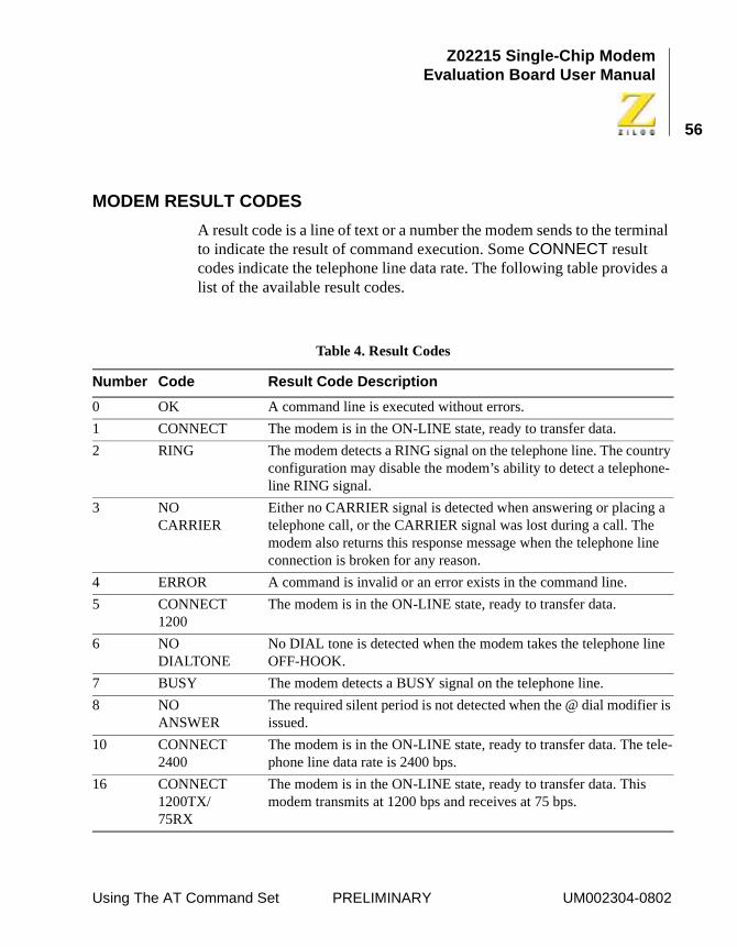
Z02215 Single-Chip ModemEvaluation Board User Manual
56
MODEM RESULT CODES
A result code is a line of text or a number the modem sends to the terminal to indicate the result of command execution. Some CONNECT result codes indicate the telephone line data rate. The following table provides a list of the available result codes.
Table 4. Result Codes
Number Code Result Code Description
0 OK A command line is executed without errors.
1 CONNECT The modem is in the ON-LINE state, ready to transfer data.
2 RING The modem detects a RING signal on the telephone line. The country configuration may disable the modem’s ability to detect a telephone-line RING signal.
3 NO CARRIER
Either no CARRIER signal is detected when answering or placing a telephone call, or the CARRIER signal was lost during a call. The modem also returns this response message when the telephone line connection is broken for any reason.
4 ERROR A command is invalid or an error exists in the command line.
5 CONNECT 1200
The modem is in the ON-LINE state, ready to transfer data.
6 NO DIALTONE
No DIAL tone is detected when the modem takes the telephone line OFF-HOOK.
7 BUSY The modem detects a BUSY signal on the telephone line.
8 NO ANSWER
The required silent period is not detected when the @ dial modifier is issued.
10 CONNECT 2400
The modem is in the ON-LINE state, ready to transfer data. The tele-phone line data rate is 2400 bps.
16 CONNECT 1200TX/75RX
The modem is in the ON-LINE state, ready to transfer data. This modem transmits at 1200 bps and receives at 75 bps.
Using The AT Command Set PRELIMINARY UM002304-0802
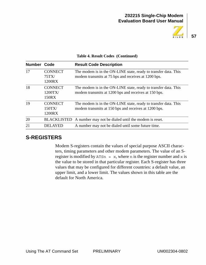
Z02215 Single-Chip ModemEvaluation Board User Manual
57
S-REGISTERS
Modem S-registers contain the values of special purpose ASCII charac-ters, timing parameters and other modem parameters. The value of an S-register is modified by ATSn = x, where n is the register number and x is the value to be stored in that particular register. Each S-register has three values that may be configured for different countries: a default value, an upper limit, and a lower limit. The values shown in this table are the default for North America.
17 CONNECT 75TX/1200RX
The modem is in the ON-LINE state, ready to transfer data. This modem transmits at 75 bps and receives at 1200 bps.
18 CONNECT 1200TX/150RX
The modem is in the ON-LINE state, ready to transfer data. This modem transmits at 1200 bps and receives at 150 bps.
19 CONNECT 150TX/1200RX
The modem is in the ON-LINE state, ready to transfer data. This modem transmits at 150 bps and receives at 1200 bps.
20 BLACKLISTED A number may not be dialed until the modem is reset.
21 DELAYED A number may not be dialed until some future time.
Table 4. Result Codes (Continued)
Number Code Result Code Description
Using The AT Command Set PRELIMINARY UM002304-0802
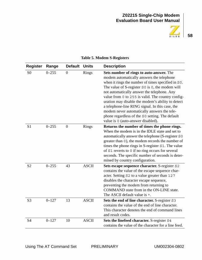
Z02215 Single-Chip ModemEvaluation Board User Manual
58
Table 5. Modem S-Registers
Register Range Default Units Description
S0 0–255 0 Rings Sets number of rings to auto-answer. The modem automatically answers the telephone when it rings the number of times specified in S0. The value of S-register S0 is 0, the modem will not automatically answer the telephone. Any value from 0 to 255 is valid. The country config-uration may disable the modem’s ability to detect a telephone-line RING signal. In this case, the modem never automatically answers the tele-phone regardless of the S0 setting. The default value is 0 (auto-answer disabled).
S1 0–255 0 Rings Returns the number of times the phone rings. When the modem is in the IDLE state and set to automatically answer the telephone (S-register S0 greater than 0), the modem records the number of times the phone rings in S-register S1. The value of S1 reverts to 0 if no ring occurs for several seconds. The specific number of seconds is deter-mined by country configuration.
S2 0–255 43 ASCII Sets escape sequence character. S-register S2 contains the value of the escape sequence char-acter. Setting S2 to a value greater than 127 disables the character escape sequence, preventing the modem from returning to COMMAND state from in the ON-LINE state. The ASCII default value is +.
S3 0–127 13 ASCII Sets the end of line character. S-register S3 contains the value of the end of line character. This character denotes the end of command lines and result codes.
S4 0–127 10 ASCII Sets the linefeed character. S-register S4 contains the value of the character for a line feed.
Using The AT Command Set PRELIMINARY UM002304-0802
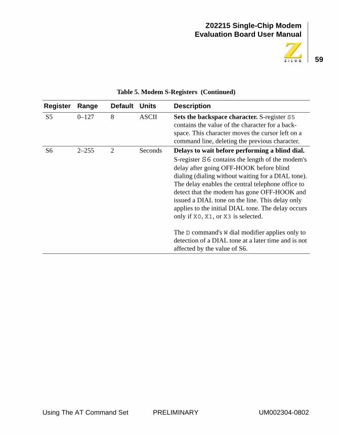
Z02215 Single-Chip ModemEvaluation Board User Manual
59
S5 0–127 8 ASCII Sets the backspace character. S-register S5 contains the value of the character for a back-space. This character moves the cursor left on a command line, deleting the previous character.
S6 2–255 2 Seconds Delays to wait before performing a blind dial. S-register S6 contains the length of the modem's delay after going OFF-HOOK before blind dialing (dialing without waiting for a DIAL tone). The delay enables the central telephone office to detect that the modem has gone OFF-HOOK and issued a DIAL tone on the line. This delay only applies to the initial DIAL tone. The delay occurs only if X0, X1, or X3 is selected.
The D command's W dial modifier applies only to detection of a DIAL tone at a later time and is not affected by the value of S6.
Table 5. Modem S-Registers (Continued)
Register Range Default Units Description
Using The AT Command Set PRELIMINARY UM002304-0802
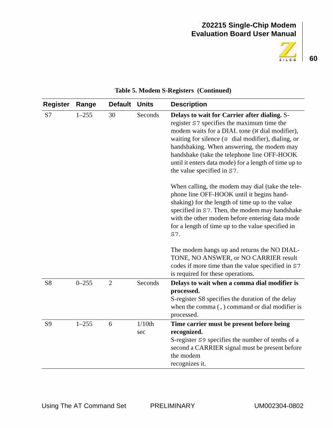
Z02215 Single-Chip ModemEvaluation Board User Manual
60
S7 1–255 30 Seconds Delays to wait for Carrier after dialing. S-register S7 specifies the maximum time the modem waits for a DIAL tone (W dial modifier), waiting for silence (@ dial modifier), dialing, or handshaking. When answering, the modem may handshake (take the telephone line OFF-HOOK until it enters data mode) for a length of time up to the value specified in S7.
When calling, the modem may dial (take the tele-phone line OFF-HOOK until it begins hand-shaking) for the length of time up to the value specified in S7. Then, the modem may handshake with the other modem before entering data mode for a length of time up to the value specified in S7.
The modem hangs up and returns the NO DIAL-TONE, NO ANSWER, or NO CARRIER result codes if more time than the value specified in S7 is required for these operations.
S8 0–255 2 Seconds Delays to wait when a comma dial modifier is processed. S-register S8 specifies the duration of the delay when the comma (,) command or dial modifier is processed.
S9 1–255 6 1/10th sec
Time carrier must be present before being recognized. S-register S9 specifies the number of tenths of a second a CARRIER signal must be present before the modem recognizes it.
Table 5. Modem S-Registers (Continued)
Register Range Default Units Description
Using The AT Command Set PRELIMINARY UM002304-0802
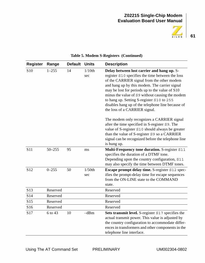
Z02215 Single-Chip ModemEvaluation Board User Manual
61
S10 1–255 14 1/10th sec
Delay between lost carrier and hang up. S-register S10 specifies the time between the loss of the CARRIER signal from the other modem and hang up by this modem. The carrier signal may be lost for periods up to the value of S10 minus the value of S9 without causing the modem to hang up. Setting S-register S10 to 255 disables hang up of the telephone line because of the loss of a CARRIER signal.
The modem only recognizes a CARRIER signal after the time specified in S-register S9. The value of S-register S10 should always be greater than the value of S-register S9 so a CARRIER signal can be recognized before the telephone line is hung up.
S11 50–255 95 ms Multi-Frequency tone duration. S-register S11 specifies the duration of a DTMF tone. Depending upon the country configuration, S11 may also specify the time between DTMF tones.
S12 0–255 50 1/50th sec
Escape prompt delay time. S-register S12 spec-ifies the prompt-delay time for escape sequences from the ON-LINE state to the COMMAND state.
S13 Reserved Reserved
S14 Reserved Reserved
S15 Reserved Reserved
S16 Reserved Reserved
S17 6 to 43 10 –dBm Sets transmit level. S-register S17 specifies the actual transmit power. This value is adjusted by the country configuration to accommodate differ-ences in transformers and other components in the telephone line interface.
Table 5. Modem S-Registers (Continued)
Register Range Default Units Description
Using The AT Command Set PRELIMINARY UM002304-0802
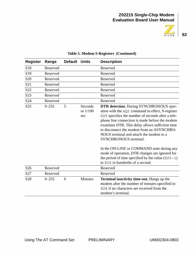
Z02215 Single-Chip ModemEvaluation Board User Manual
62
S18 Reserved Reserved
S19 Reserved Reserved
S20 Reserved Reserved
S21 Reserved Reserved
S22 Reserved Reserved
S23 Reserved Reserved
S24 Reserved Reserved
S25 0–255 5 Secondsor 1/100 sec
DTR detection. During SYNCHRONOUS oper-ation with the &Q1 command in effect, S-register S25 specifies the number of seconds after a tele-phone line connection is made before the modem examines DTR. This delay allows sufficient time to disconnect the modem from an ASYNCHRO-NOUS terminal and attach the modem to a SYNCHRONOUS terminal.
In the ON-LINE or COMMAND state during any mode of operation, DTR changes are ignored for the period of time specified by the value (S25–1) to S25 in hundreths of a second.
S26 Reserved Reserved
S27 Reserved Reserved
S28 0–255 0 Minutes Terminal inactivity time-out. Hangs up the modem after the number of minutes specified in S28 if no characters are received from the modem’s terminal.
Table 5. Modem S-Registers (Continued)
Register Range Default Units Description
Using The AT Command Set PRELIMINARY UM002304-0802
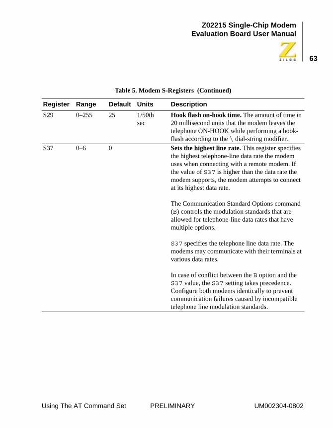
Z02215 Single-Chip ModemEvaluation Board User Manual
63
S29 0–255 25 1/50th sec
Hook flash on-hook time. The amount of time in 20 millisecond units that the modem leaves the telephone ON-HOOK while performing a hook-flash according to the \ dial-string modifier.
S37 0–6 0 Sets the highest line rate. This register specifies the highest telephone-line data rate the modem uses when connecting with a remote modem. If the value of S37 is higher than the data rate the modem supports, the modem attempts to connect at its highest data rate.
The Communication Standard Options command (B) controls the modulation standards that are allowed for telephone-line data rates that have multiple options.
S37 specifies the telephone line data rate. The modems may communicate with their terminals at various data rates.
In case of conflict between the B option and the S37 value, the S37 setting takes precedence. Configure both modems identically to prevent communication failures caused by incompatible telephone line modulation standards.
Table 5. Modem S-Registers (Continued)
Register Range Default Units Description
Using The AT Command Set PRELIMINARY UM002304-0802
Z02215 Single-Chip ModemEvaluation Board User Manual
62
Schematics
SCHEMATICS
The following pages contains the complete evaluation board schematic, which includes the Speaker Circuit, RS-232 Interface, Power Supply and Indicators, Data Access Arrangement.
UM002304-0802 PRELIMINARY Schematics
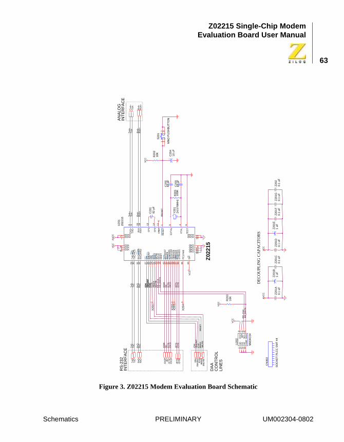
Z02215 Single-Chip ModemEvaluation Board User Manual
63
Figure 3. Z02215 Modem Evaluation Board Schematic
AV
CC
AV
CC
VC
C
VC
C
VC
C
VC
C
VC
C
VC
C
TxA
-T
xA-
RxA
-R
xA-
RxA
+R
xA+
TxA
+T
xA+
/RE
SE
T
TxD
TxD
TxC
TxC
RxD
RxD
/DC
D/D
CD
/DS
R/D
SR
/RI
/RI
/CT
S/C
TS
/RT
S/R
TS
/DT
R/D
TR
EE
_CLK
EE
_CLK
EE
_DA
TA
EE
_DA
TA
RxC
RxC
/MU
TE
/MU
TE
/OH
/OH
/OH
/SH
UN
T
/SH
UN
T
/SH
UN
T/C
ID
/CID
/CID
/RD
ET
/RIN
G
/RD
ET
/LC
S
Y20
124
.576
MH
zR
201
100K
+Z
201B
1 uF
+Z
201E
1 uF
CN
302
SO
CK
ET
PLC
C S
MT
44
C20
182
pF
C20
268
pF
C20
368
pF
Z20
1A0.
1 uF
Z20
1C0.
1 uF
Z20
1D0.
1 uF
Z20
1F0.
1 uF
R20
210
K
+C
204
10 u
F
U20
2
NM
24C
04
1 2 37 6 5
4
8A
0A
1A
2W
PS
CL
SD
AG
ND
VC
C
Z20
1G0.
1 uF
Z20
20.
1 uF
R20
310
K
X20
11
X20
21
X20
31
X20
41
S20
1
MN
O P
US
HB
UT
TO
N
1 342
U20
1Z
0221
5
1
23
45 6
7
8 9
1012
13 1415 16
17
18
19
20
21
2223
24
25
26
27
28
29
30
31
32
35
33
34
36
37
38
39
40
41
42
43
44
11
RE
SE
T
VDDGND
XT
AL
EX
TA
L
TE
ST
AVDD
TX
O+
TX
O-
AGNDAGND
CF
1
CF
2
RX
I-R
XI+
AVDD
EE
DT
EE
CK
MU
TE
RD
ET
VDDGND
LCS
CID
SH
UN
TO
H
GND
TX
D/IR
QT
XC
/HC
S
RX
D/H
WR
RX
C/H
RD
PC
1/H
A0
VDD
GND
DT
R/H
D0
RT
S/H
D1
PB
2/H
D2
PB
3/H
D3
DC
D/H
D4
CT
S/H
D5
RI/H
D6
DS
R/H
D7
S/P
VR
EF
/DC
D
TxD
/SH
UN
T/O
H
/RIN
G
RxD
TxC
/CID
TxA
+T
xA-
RxA
-R
xA+
/RT
S
/CT
S/R
I/D
SR
RxC
/DT
R
/MU
TE
DE
CO
UPL
ING
CA
PA
CIT
OR
S
DA
AC
ON
TR
OL
LIN
ES
AN
ALO
GIN
TE
RF
AC
ER
S-2
32IN
TE
RF
AC
E
Z02
215
Schematics PRELIMINARY UM002304-0802
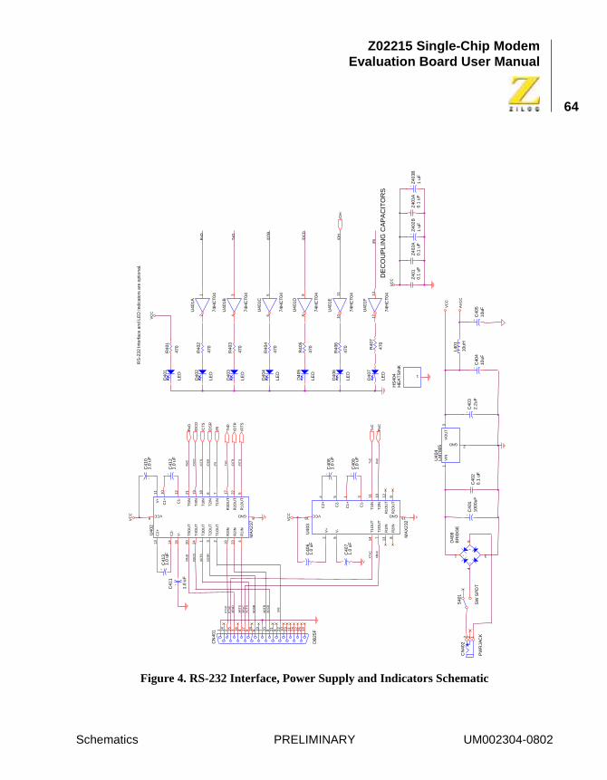
Z02215 Single-Chip ModemEvaluation Board User Manual
64
Figure 4. RS-232 Interface, Power Supply and Indicators Schematic
VC
C
VC
C
VC
C
AV
CC
VC
C
VC
C
TxD
/DT
R
/DC
D
/OH
RxD
TxD
/DT
R
/DC
D
XD
TR
RxD
/DS
R
/RT
S
XR
xD
XR
xD
/RI
XR
I
XD
SR
XD
CD
XD
CD
XD
SR
XT
xD
XR
TS
XT
xC
XR
xC
XR
xC
TxC
RxC
XT
xC
/CT
S
XC
TS
XC
TS
/RI
CN
402
PW
RJA
CK3 2 1
S40
1
SW
SP
DT
-+
~
~
D40
8B
RID
GE
6
1
4
3
+C
401
100
0uF
U4
04L
M7
805
13
2
VIN
VO
UT
GND
U40
1A
74H
CT
041
2
+Z
402
B1
uF
U40
1B
74H
CT
043
4
U4
01C
74H
CT
045
6
U4
01D
74H
CT
049
8
U40
1E
74H
CT
0411
10
Z4
010.
1 u
FZ
402
A0.
1 u
F
C40
20
.1 u
F+
C40
51
0uF
L40
1
10u
H
+Z
403B
1 u
FZ
403
A0.
1 uF
+C
403
2.2
uF
+C
404
10uF
HS
404
HE
AT
SIN
K1
U4
03
MA
X2
32
54 1
2
3
6 7 891011 12
1314
1516
C2-
C2+
C1+
V+
C1-
V-
T2O
UT
R2
INR
2O
UT
T2I
N
T1I
N
R1
OU
TR
1IN
T1O
UT
GNDVCC
CN
401
DB
25F1
32
51
22
41
12
31
02
292
182
071
961
851
741
631
521
41
R4
06
470
D4
06
LED
R4
05
470
D4
05
LED
D4
04
LED
R4
04
470
R4
03
470
D4
03
LED
R4
02
470
D4
02
LED
R4
01
470
D4
01
LED
D4
07
LED
R4
07
470
U4
01F
74H
CT
0413
12
+C
408
1.0
uF
+
C40
61
.0 u
F
+
C40
71
.0 u
F+
C40
91
.0 u
F
+C
412
1.0
uF
U4
02
MA
X2
37
24 1 23 23226 7 5
4
89
1819
2021 17
16
1011 12
13 14 15
T4O
UT
T3O
UT
T1O
UT
T2O
UT
R2I
NR
2OU
T
T2I
N
T1I
N
R1O
UT
R1I
N
GNDVCC
T3I
N
T4I
N
T5O
UT
T5I
N
R3O
UT
R3I
N
C1
+
V+
C1-
C2+
C2-
V-
+C
413
1.0
uF
+
C41
01
.0 u
F
+
C4
11
1.0
uF
/OH
TxD
/DT
R
TxC
RxD
RxC
/DC
D
/RT
S
/CT
S
/DS
R
/RI
DE
CO
UP
LIN
G C
AP
AC
ITO
RS
RS
-23
2 In
terf
ace
an
d L
ED
Indi
cato
rs a
re o
ptio
nal.
Schematics PRELIMINARY UM002304-0802
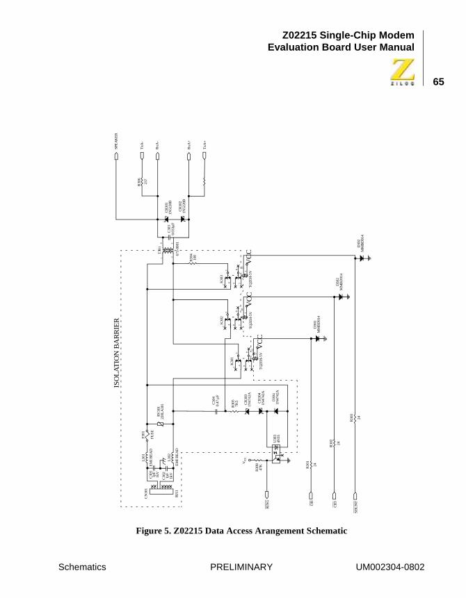
Z02215 Single-Chip ModemEvaluation Board User Manual
65
Figure 5. Z02215 Data Access Arangement Schematic
VC
CV
CC
VC
C
ISO
LA
TIO
N B
AR
RIE
R
CN
301
RJ1
1
C30
11p
F1k
V
C30
21p
F1k
V
L30
1
EM
I B
EA
D
L30
2
EM
I B
EA
D
F30
1
FUS
E
RV
301
220L
A30
1 C30
40.
47 µ
F
R30
5
CR
303
1N47
42A
7K5 CR
304
1N47
42A
D30
41N
4742
AU
303
4N35
VC
C
R30
847
K
RIN
G
OH
CID
SH
UN
T
R30
1
24
R30
2
24
R30
3
24
K30
1
TQ
2EH
-5V
D30
1M
MB
D91
4
D30
2M
MB
D91
4
D30
2M
MB
D91
4
K30
2
TQ
2EH
-5V
K30
3
TQ
2EH
-5V
23
4 98
710
1
23
4 98
710
1
23
4 98
710
1
T30
1
SPE
AK
ER
R30
6T
xA-
RxA
-
237
CR
301
1N52
28B
C30
30.
033µ
F67
1-80
01
R30
410
0
CR
302
1N52
28B
RxA
+
TxA
+
1 234
Schematics PRELIMINARY UM002304-0802
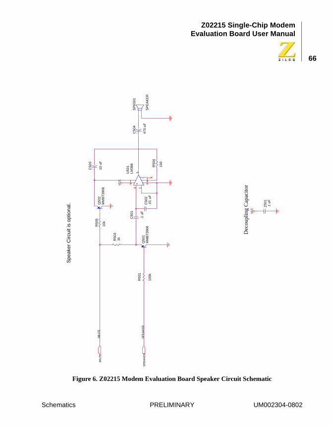
Z02215 Single-Chip ModemEvaluation Board User Manual
66
Figure 6. Z02215 Modem Evaluation Board Speaker Circuit Schematic
VC
C
VC
C
SP
EA
KE
R
/MU
TE
+C50
3
10 u
F
SP
K50
1
SP
EA
KE
R
+C50
4
470
uFC
502
.01
uF
+ -
U50
1LM
386
3 25
61
487
C50
1
.1 u
FQ
501
MM
BT
3906
Z50
1.1
uF
R50
1
100k
R50
31k
R50
5
10k
Q50
2M
MB
T39
06
R50
4
100
/MU
TE
SP
EA
KE
R
Spe
aker
Circ
uit i
s op
tiona
l.
Dec
oupl
ing
Cap
acito
r
Schematics PRELIMINARY UM002304-0802
Z02215 Single-Chip ModemEvaluation Board User Manual
67
Problem/Suggestion Report FormIf you experience any problems while operating this product, or if you note any inaccuracies while reading the User’s Manual, please copy this form, fill it out, then mail or fax it to ����� (see “Return Information”). We also welcome your suggestions!
Customer Information
Product InformationReturn Information
Name Country
Company Telephone
Address Fax Number
City/State/ZIP E-Mail Address
Serial # or Board Fab #/Rev. # �����, Inc.
Software Version Support Products Director
Manual Number 532 Race Street
Host Computer Description/Type San Jose, CA 95126-3432
Fax Number: (408) 558-8300
Email: [email protected]
UM002304-0802 PRELIMINARY Problem/Suggestion Report Form
Z02215 Single-Chip ModemEvaluation Board User Manual
68
Problem Description or Suggestion
Provide a complete description of the problem or your suggestion. If you are reporting a specific problem, include all steps leading up to the occur-rence of the problem. Attach additional pages as necessary.
Information Integrity
The information contained within this document has been verified accord-ing to the general principles of electrical and mechanical engineering. Any applicable source code illustrated in the document was either written by an authorized ZiLOG employee or licensed consultant. Permission to use these codes in any form, besides the intended application, must be approved through a license agreement between both parties. ZiLOG will not be responsible for any code(s) used beyond the intended application. Contact the local ZiLOG Sales Office to obtain necessary license agree-ments.
Problem/Suggestion Report Form PRELIMINARY UM002304-0802
Z02215 Single-Chip ModemEvaluation Board User Manual
69
Document Disclaimer
© 2002 by ZiLOG, Inc. All rights reserved. Information in this publica-tion concerning the devices, applications, or technology described is intended to suggest possible uses and may be superseded. ZiLOG, INC. DOES NOT ASSUME LIABILITY FOR OR PROVIDE A REPRESEN-TATION OF ACCURACY OF THE INFORMATION, DEVICES, OR TECHNOLOGY DESCRIBED IN THIS DOCUMENT. ZiLOG ALSO DOES NOT ASSUME LIABILITY FOR INTELLECTUAL PROPERTY INFRINGEMENT RELATED IN ANY MANNER TO USE OF INFOR-MATION, DEVICES, OR TECHNOLOGY DESCRIBED HEREIN OR OTHERWISE. Except with the express written approval ZiLOG, use of information, devices, or technology as critical components of life support systems is not authorized. No licenses or other rights are conveyed, implicitly or otherwise, by this document under any intellectual property rights.
Problem/Suggestion Report Form PRELIMINARY UM002304-0802