z10.1 hull surveys of oil tankers - turkloydu.org iacs req. 1992/rev.21 2014 z10.1 (1992) (rev.1 ......
TRANSCRIPT

Z10.1 (cont’d)
Z10.1
1 IACS Req. 1992/Rev.21 2014
Z10.1 (1992) (Rev.1 1994) (Rev. 2 1994) (Rev. 3 1995) (Rev. 4 1996) Rev 5 1997) (Rev. 6 July 1999) (Rev.6.1 Dec. 1999) (Rev.7 Sept.2000) (Rev.8 Nov. 2000) (Rev.8.1 June 2001) (Rev.9 Mar. 2002) (Rev.10 Oct.2002) (Rev.11 August 2003) (Rev.12 June 2005) (Rev.13 Jan. 2006) (Corr.1 Sept 2006) (Rev.14 Feb 2007) (Rev.15 Nov 2007) (Rev.16 Mar 2009) (Rev.17 Feb 2010) (Rev.18 Mar 2011) (Rev.19 July 2011) (Rev.20 May 2013) (Rev.21 Jan 2014)
Hull Surveys of Oil Tankers CONTENTS 1. General 1.1 Application 1.2 Definitions 1.3 Repairs 1.4 Thickness measurements and close-up surveys 2. Special Survey 2.1 Schedule 2.2 Scope 2.2.1 General 2.2.2 Dry Dock Survey 2.2.3 Tank Protection 2.3 Extent of Overall and Close-up Survey 2.4 Extent of Thickness Measurement 2.5 Extent of Tank Testing 3. Annual Survey 3.1 Schedule 3.2 Scope 3.2.1 General 3.2.2 Examination of the Hull 3.2.3 Examination of Weather decks 3.2.4 Examination of Cargo pump rooms 3.2.5 Examination of Ballast Tanks 4. Intermediate Survey 4.1 Schedule 4.2 Scope 4.2.1 General 4.2.2 Oil Tankers 5 - 10 years of Age 4.2.3 Oil Tankers 10 - 15 years of Age 4.2.4 Oil Tankers Exceeding 15 years of Age 5. Preparation for Survey 5.1 Survey Programme 5.2 Conditions for Survey 5.3 Access to Structures 5.4 Equipment for Survey 5.5 Rescue and emergency response equipment 5.6 Survey at Sea or at Anchorage 5.7 Survey Planning Meeting 6. Documentation On Board 6.1 General 6.2 Survey Report File 6.3 Supporting Documents 6.4 Review of Documentation On Board

Z10.1 (cont’d)
Z10.1
2 IACS Req. 1992/Rev.21 2014
7. Procedures for Thickness Measurements 7.1 General 7.2 Certification of Thickness Measurement Company 7.3 Reporting 8. Reporting and Evaluation of Survey 8.1 Evaluation of Survey Report 8.2 Reporting

Z10.1 (cont’d)
Z10.1
3 IACS Req. 1992/Rev.21 2014
ENCLOSURES Table I: Minimum requirements to Close-up Surveys at Special Survey of Oil Tankers,
Ore/Oil Ships and etc.
Table II: Minimum requirements to thickness measurements at Special Survey of Oil Tankers, Ore/Oil Ships and etc.
Table III: Minimum requirements to tank testing at Special Survey of Oil Tankers, Ore/Oil Ships etc.
Table IV: Requirements for extent of thickness measurements at those areas of substantial corrosion.
Table V: Owners Inspection Report Table VI: Superseded by Annex 1 Table VII: Procedures for Certification of Firms Engaged in Thickness Gauging of Hull
Structures Table VIII: Survey Reporting Principles Table IX: Executive Hull Summary Annex I: Guidelines for Technical Assessment in conjunction with planning for
Enhanced Surveys of Oil Tankers Special Survey - Hull
Annex II: Recommended Procedures for Thickness Measurements of Oil Tankers Ore/Oil Ships and etc.
Annex III: Criteria for Longitudinal Strength of Hull Girder for Oil Tankers Appendix 1: Calculation criteria of section modulus of midship section of hull girder Appendix II: Diminution limit of minimum longitudinal strength of ships in service Appendix III: Sampling method of thickness measurements for longitudinal strength evaluation and repair methods Annex IVA: Survey Programme Appendix 1 List of Plans Appendix 2 Survey Planning Questionnaire Appendix 3 Other Documentation Annex IVB: Survey Planning Questionnaire

Z10.1 (cont’d)
Z10.1
4 IACS Req. 1992/Rev.21 2014
Notes: 1. Revision 4, 1996 of Unified Requirements Z10.1 have been approved by Council for
uniform application from 1 January 1997. 2. Changes introduced in Rev.6 to UR Z10.1 are to be applied by all Member Societies
and Associates from 1 September 1999. 3. Changes introduced in Rev.6.1 to UR Z10.1, i.e. 2.2.1.3 are to be applied by all
Member Societies and Associates from 1 July 2000. 4. Changes introduced in Rev.7 to UR Z10.1 are to be applied by all Member Societies
and Associates from 1 July 2001. 5. Changes introduced in Rev.8 and Rev.8.1 to UR Z10.1 are to be applied by all
Member Societies and Associates from 1 July 2001. 6. Changes introduced in Rev.9 to UR Z10.1, which come from Res MSC.105(73) and
MSC.108(73), i.e. 4.2.4.3(dry-dock in intermediate survey for ships over 15 years), 8(evaluation of longitudinal strength), Table VIII, Table IX(ii), Table (IX(v) and Annex III, are to be applied by all Member Societies and Associates from 1 July 2002.
Changes introduced in Rev.9 to UR Z10.1, other than the above, are to be
implemented by all Member Societies and Associates within one year of the adoption by Council.
7. Changes introduced in Rev.12 are to be uniformly implemented from 1 July 2006. The
amendments to paragraphs 2.2.3.1 and 4.2.2.2 related to the protective coating condition are to apply to the ballast tanks of which the coating condition will be assessed at the forthcoming Special Survey and Intermediate Survey on
or after 1 July 2006. 8. Changes introduced in Rev.13 (para. 1.4, 5.5.4, 5.5.6 and 7.1.3) are to be uniformly
applied by IACS Societies on surveys commenced on or after 1 January 2007. 9. Changes introduced in Rev.14 are to be uniformly implemented for surveys
commenced on or after 1 January 2008, whereas statutory requirements of IMO Res. MSC 197(80) apply on 1 January 2007.
10. Changes introduced in Rev.15 are to be uniformly applied by IACS Societies for
surveys commenced on or after the 1 January 2009. 11. Changes introduced in Rev.16 are to be uniformly applied by IACS Societies for
surveys commenced on or after 1 July 2010. As for the requirements regarding semi-hard coatings, these coatings, if already
applied, will not be accepted from the next special or intermediate survey commenced on or after 1 July 2010, whichever comes first, with respect to waiving the annual internal examination of the ballast tanks.
12. Changes introduced in Rev.18 are to be uniformly applied by IACS Societies for
surveys commenced on or after 1 July 2012. 13. Changes introduced in Rev.19 are to be uniformly applied by IACS Societies for
surveys commenced on or after 1 July 2012.

Z10.1 (cont’d)
Z10.1
5 IACS Req. 1992/Rev.21 2014
14. Changes introduced in Rev.20 are to be uniformly applied by IACS Societies for surveys commenced on or after 1 July 2014.
15. Changes introduced in Rev.21 are to be uniformly applied by IACS Societies for
surveys commenced on or after 1 January 2015.

Z10.1 (cont’d)
Z10.1
6 IACS Req. 1992/Rev.21 2014
1. GENERAL 1.1 Application 1.1.1 The requirements apply to all self-propelled Oil Tankers other than Double Hull Oil Tankers, as defined in 1.1.1 of UR Z 10.4. 1.1.2 The requirements apply to surveys of hull structure and piping systems in way of cargo tanks, pump rooms, cofferdams, pipe tunnels, void spaces within the cargo area and all ballast tanks. The requirements are additional to the classification requirements applicable to the remainder of the ship. Refer to Z7. 1.1.3 The requirements contain the minimum extent of examination, thickness measurements and tank testing. The survey is to be extended when Substantial Corrosion and/or structural defects are found and include additional Close-up Survey when necessary. 1.2 Definitions 1.2.1 Oil Tanker: An Oil Tanker is a ship which is constructed primarily to carry oil in bulk and includes ship types such as combination carriers (Ore/Oil ships etc.). 1.2.2 Ballast Tank: A Ballast Tank is a tank which is used solely for the carriage of salt water ballast. 1.2.2 bis A Combined Cargo/Ballast Tank is a tank which is used for the carriage of cargo or ballast water as a routine part of the vessel’s operation and will be treated as a Ballast Tank. Cargo tanks in which water ballast might be carried only in exceptional cases per MARPOL I/18(3) are to be treated as cargo tanks. 1.2.3 Overall Survey: An Overall Survey is a survey intended to report on the overall condition of the hull structure and determine the extent of additional Close-up Surveys. 1.2.4 Close-up Survey: A Close-up Survey is a survey where the details of structural components are within the close visual inspection range of the surveyor, i.e. normally within reach of hand. 1.2.5 Transverse Section: A Transverse Section includes all longitudinal members such as plating, longitudinals and girders at the deck, side, bottom, inner bottom and longitudinal bulkheads. For transversely framed vessels, a transverse section includes adjacent frames and their end connections in way of transverse sections. 1.2.6 Representative Tank: Representative Tanks are those which are expected to reflect the condition of other tanks of similar type and service and with similar corrosion prevention systems. When selecting Representative Tanks account is to be taken of the service and repair history onboard and identifiable Critical Structural Areas and/or Suspect Areas. 1.2.7 Suspect Area: Suspect Areas are locations showing Substantial Corrosion and/or are considered by the Surveyor to be prone to rapid wastage. 1.2.8 Critical Structural Area: Critical Structural Areas are locations which have been identified from calculations to require monitoring or from the service history of the subject ship or from similar or sister ships (if available) to be sensitive to cracking, buckling or corrosion which would impair the structural integrity of the ship.

Z10.1 (cont’d)
Z10.1
7 IACS Req. 1992/Rev.21 2014
1.2.9 Substantial Corrosion: Substantial Corrosion is an extent of corrosion such that assessment of corrosion pattern indicate a wastage in excess of 75% of allowable margins, but within acceptable limits. 1.2.10 Corrosion Prevention System: A Corrosion Prevention System is normally considered a full hard protective coating. Hard Protective Coating is usually to be epoxy coating or equivalent. Other coating systems, which are neither soft nor semi-hard coatings, may be considered acceptable as alternatives provided that they are applied and maintained in compliance with the manufacturer’s specifications. 1.2.11 Coating Condition: Coating condition is defined as follows: GOOD condition with only minor spot rusting. FAIR condition with local breakdown at edges of stiffeners and weld
connections and/or light rusting over 20% or more of areas under consideration, but less than as defined for POOR condition
POOR condition with general breakdown of coating over 20% or more, or hard scale at 10% or more, of areas under consideration.
Reference is made to IACS Recommendation No.87 “Guidelines for Coating Maintenance & Repairs for Ballast Tanks and Combined Cargo / Ballast Tanks on Oil Tankers”.
1.2.12 Cargo Area: Cargo Area is that part of the ship which contains cargo tanks, slop tanks and cargo/ballast pump-rooms, cofferdams, ballast tanks and void spaces adjacent to cargo tanks and also deck areas throughout the entire length and breadth of the part of the ship over the above mentioned spaces. 1.2.13 Special consideration: Special consideration or specially considered (in connection with close-up surveys and thickness measurements) means sufficient close-up inspection and thickness measurements are to be taken to confirm the actual average condition of the structure under the coating. 1.2.14 Prompt and Thorough Repair: A Prompt and Thorough Repair is a permanent repair completed at the time of survey to the satisfaction of the Surveyor, therein removing the need for the imposition of any associated condition of classification, or recommendation. 1.3 Repairs 1.3.1 Any damage in association with wastage over the allowable limits (including buckling, grooving, detachment or fracture), or extensive areas of wastage over the allowable limits, which affects or, in the opinion of the Surveyor, will affect the vessel’s structural, watertight or weathertight integrity, is to be promptly and thoroughly (see 1.2.14) repaired. Areas to be considered include: -bottom structure and bottom plating; -side structure and side plating; -deck structure and deck plating; -watertight or oiltight bulkheads; -hatch covers or hatch coamings, where fitted (combination carriers).

Z10.1 (cont’d)
Z10.1
8 IACS Req. 1992/Rev.21 2014
For locations where adequate repair facilities are not available, consideration may be given to allow the vessel to proceed directly to a repair facility. This may require discharging the cargo and/or temporary repairs for the intended voyage. 1.3.2 Additionally, when a survey results in the identification of structural defects or corrosion, either of which, in the opinion of the Surveyor, will impair the vessel’s fitness for continued service, remedial measures are to be implemented before the ship continues in service. 1.3.3 Where the damage found on structure mentioned in Para. 1.3.1 is isolated and of a localised nature which does not affect the ship's structural integrity, consideration may be given by the surveyor to allow an appropriate temporary repair to restore watertight or weather tight integrity and impose a Recommendation/Condition of Class in accordance with IACS PR 35, with a specific time limit. 1.4 Thickness measurements and close-up surveys In any kind of survey, i.e. special, intermediate, annual or other surveys having the scope of the foregoing ones, thickness measurements of structures in areas where close-up surveys are required shall be carried out simultaneously with close-up surveys.

Z10.1 (cont’d)
Z10.1
9 IACS Req. 1992/Rev.21 2014
2. SPECIAL SURVEY1 2.1 Schedule 2.1.1 Special Surveys are to be carried out at 5 years intervals to renew the Classification Certificate. 2.1.2 The first Special Survey is to be completed within 5 years from the date of the initial classification survey and thereafter within 5 years from the credited date of the previous Special Survey. However, an extension of class of 3 months maximum beyond the 5th year can be granted in exceptional circumstances. In this case, the next period of class will start from the expiry date of the Special Survey before the extension was granted. 2.1.3 For surveys completed within 3 months before the expiry date of the Special Survey, the next period of class will start from the expiry date of the Special Survey. For surveys completed more than 3 months before the expiry date of the Special Survey, the period of class will start from the survey completion date. In cases where the vessel has been laid up or has been out of service for a considerable period because of a major repair or modification and the owner elects to only carry out the overdue surveys, the next period of class will start from the expiry date of the special survey. If the owner elects to carry out the next due special survey, the period of class will start from the survey completion date. 2.1.4 The Special Survey may be commenced at the 4th Annual Survey and be progressed with a view to completion by the 5th anniversary date. When the Special Survey is commenced prior to the 4th Annual Survey, the entire survey is to be completed within 15 months if such work is to be credited to the Special Survey. 2.1.5 Concurrent crediting to both Intermediate Survey (IS) and Special Survey (SS) for surveys and thickness measurements of spaces are not acceptable. 2.2 Scope 2.2.1 General 2.2.1.1 The Special Survey is to include, in addition to the requirements of the Annual Survey, examination, tests and checks of sufficient extent to ensure that the hull and related piping, as required in 2.2.1.3, is in a satisfactory condition and is fit for its intended purpose for the new period of class of 5 years to be assigned, subject to proper maintenance and operation and to periodical surveys being carried out at the due dates. 2.2.1.2 All cargo tanks, Ballast Tanks, including double bottom tanks, pumprooms, pipe tunnels, cofferdams and void spaces bounding cargo tanks, decks and outer hull are to be examined, and this examination is to be supplemented by thickness measurement and testing required in 2.4 and 2.5, to ensure that the structural integrity remains effective. The aim of the examination is to discover Substantial Corrosion, significant deformation, fractures, damages or other structural deterioration, that may be present. _______________________ 1 Some member Societies use the term “Special Periodical Survey” others use the term “Class Renewal Survey” instead of the term “Special Survey”.

Z10.1 (cont’d)
Z10.1
10 IACS Req. 1992/Rev.21 2014
2.2.1.3 Cargo piping on deck, including Crude Oil Washing (COW) piping, Cargo and Ballast piping within the above tanks and spaces are to be examined and operationally tested to working pressure to attending Surveyor’s satisfaction to ensure that tightness and condition remain satisfactory. Special attention is to be given to any ballast piping in cargo tanks and cargo piping in ballast tanks and void spaces, and Surveyors are to be advised on all occasions when this piping, including valves and fittings are open during repair periods and can be examined internally. 2.2.2 Dry Dock Survey 2.2.2.1 A survey in dry dock is to be a part of the Special Survey. The overall and close-up surveys and thickness measurements, as applicable, of the lower portions of the cargo tanks and ballast tanks are to be carried out in accordance with the applicable requirements for special surveys, if not already performed. Note: Lower portions of the cargo and ballast tanks are considered to be the parts below
light ballast water line. 2.2.3 Tank Protection 2.2.3.1 Where provided, the condition of the corrosion prevention system of cargo tanks is to be examined. A Ballast Tank is to be examined at subsequent annual intervals where: a. a hard protective coating has not been applied from the time of construction, or b. a soft or semi-hard coating has been applied, or c. substantial corrosion is found within the tank, or d. the hard protective coating is found to be in less than GOOD condition and the hard
protective coating is not repaired to the satisfaction of the Surveyor. Thickness measurements are to be carried out as deemed necessary by the surveyor. 2.3 Extent of Overall and Close-up Survey 2.3.1 An Overall Survey of all tanks and spaces is to be carried out at each Special Survey. 2.3.2 The minimum requirements for Close-up Surveys at Special Survey are given in Table I. 2.3.3 The Surveyor may extend the Close-up Survey as deemed necessary taking into account the maintenance of the tanks under survey, the condition of the corrosion prevention system and also in the following cases: a) In particular, tanks having structural arrangements or details which have suffered
defects in similar tanks or on similar ships according to available information. b) In tanks which have structures approved with reduced scantlings due to an approved
corrosion control system.

Z10.1 (cont’d)
Z10.1
11 IACS Req. 1992/Rev.21 2014
2.3.4 For areas in tanks where hard protective coatings are found to be in a GOOD condition as defined in 1.2.11, the extent of Close-up Surveys according to Table I may be specially considered. 2.4 Extent of Thickness Measurement 2.4.1 The minimum requirements for thickness measurements at Special Survey are given in Table II. 2.4.2 Provisions for extended measurements for areas with Substantial Corrosion are given in Table IV, and as may be additionally specified in the Survey Programme as required by 5.1. These extended thickness measurements are to be carried out before the survey is credited as completed. Suspect Areas identified at previous surveys are to be examined. Areas of substantial corrosion identified at previous surveys are to have thickness measurements taken. 2.4.3 The Surveyor may further extend the thickness measurements as deemed necessary. 2.4.4 For areas in tanks where hard protective coating are found to be in a GOOD condition as defined in 1.2.11, the extent of thickness measurements according to Table II may be specially considered. 2.4.5 Transverse sections are to be chosen where the largest reductions are suspected to occur or are revealed from deck plating measurements. 2.4.6 In cases where two or three sections are to be measured, at least one is to include a Ballast Tank within 0.5L amidships. In case of oil tankers of 130m in length and upwards (as defined in the International Convention on Load Lines in force) and more than 10 years of age, for the evaluation of the ship’s longitudinal strength as required in 8.1.1.1, the sampling method of thickness measurements is given in Annex III Appendix 3. 2.5 Extent of Tank Testing 2.5.1 The minimum requirements for ballast tank testing at Special Survey are given in 2.5.3 and Table III. The minimum requirements for cargo tank testing at Special Survey are given in 2.5.4 and Table III. Cargo tank testing carried out by the vessel’s crew under the direction of the Master may be accepted by the surveyor provided the following conditions are complied with: a) a tank testing procedure has been submitted by the owner and reviewed by the
Society prior to the testing being carried out; b) there is no record of leakage, distortion or substantial corrosion that would affect the
structural integrity of the tank; c) the tank testing has been satisfactorily carried out within special survey window not
more than 3 months prior to the date of the survey on which the overall or close up survey is completed;
d) the satisfactory results of the testing is recorded in the vessel’s logbook;

Z10.1 (cont’d)
Z10.1
12 IACS Req. 1992/Rev.21 2014
e) the internal and external condition of the tanks and associated structure are found satisfactory by the surveyor at the time of the overall and close up survey.
2.5.2 The Surveyor may extend the tank testing as deemed necessary. 2.5.3 Boundaries of ballast tanks are to be tested with a head of liquid to the top of air pipes. 2.5.4 Boundaries of cargo tanks are to be tested to the highest point that liquid will rise under service conditions.

Z10.1 (cont’d)
Z10.1
13 IACS Req. 1992/Rev.21 2014
3. ANNUAL SURVEY 3.1 Schedule 3.1.1 Annual Surveys are to be held within 3 months before or after anniversary date from the date of the initial classification survey or of the date credited for the last Special Survey. 3.2 Scope 3.2.1 General 3.2.1.1 The survey is to consist of an examination for the purpose of ensuring, as far as practicable, that the hull and piping are maintained in a satisfactory condition. 3.2.2 Examination of the Hull 3.2.2.1 Examination of the hull plating and its closing appliances as far as can be seen. 3.2.2.2 Examination of watertight penetrations as far as practicable. 3.2.3 Examination of weather decks 3.2.3.1 Examination of cargo tank openings including gaskets, covers, coamings and flame screens. 3.2.3.2 Examination of cargo tanks pressure/vacuum valves and flame screens. 3.2.3.3 Examination of flame screens on vents to all bunker tanks. 3.2.3.4 Examination of cargo, crude oil washing, bunker and vent piping systems, including vent masts and headers. 3.2.4 Examination of Cargo pump rooms and pipe tunnels if fitted. 3.2.4.1 Examination of all pumproom bulkheads for signs of oil leakage or fractures and, in particular, the sealing arrangements of all penetrations of pumproom bulkheads. 3.2.4.2 Examination of the condition of all piping systems. 3.2.5 Examination of Ballast Tanks 3.2.5.1 Examination of Ballast Tanks where required as a consequence of the results of the Special Survey (see 2.2.3) and Intermediate Survey (see 4.2.2.1 and 4.2.2.2) is to be carried out. When considered necessary by the surveyor, or when extensive corrosion exists, thickness measurements are to be carried out and if the results of these thickness measurements indicate that Substantial Corrosion is found, the extent of thickness measurements is to be increased in accordance with Table IV. These extended thickness measurements are to be carried out before the survey is credited as completed. Suspect Areas identified at previous surveys are to be examined. Areas of substantial corrosion identified at previous surveys are to have thickness measurements taken.

Z10.1 (cont’d)
Z10.1
14 IACS Req. 1992/Rev.21 2014
4. INTERMEDIATE SURVEY 4.1 Schedule 4.1.1 The Intermediate Survey is to be held at or between either the 2nd or 3rd Annual Survey. 4.1.2 Those items which are additional to the requirements of the Annual Surveys may be surveyed either at or between the 2nd and 3rd Annual Survey. 4.1.3 Concurrent crediting to both Intermediate Survey (IS) and Special Survey (SS) for surveys and thickness measurements of spaces are not acceptable. 4.2 Scope 4.2.1 General 4.2.1.1 The survey extent is dependent on the age of the vessel as specified in 4.2.2 to 4.2.4. 4.2.1.2 For weather decks, an examination as far as applicable of cargo, crude oil washing, bunker, ballast, steam and vent piping systems as well as vent masts and headers is to be carried out. If upon examination there is any doubt as to the condition of the piping, the piping may be required to be pressure tested, thickness measured or both. 4.2.2 Oil Tankers 5 – 10 Years of Age, the following is to apply: 4.2.2.1 All Ballast Tanks are to be examined. When considered necessary by the surveyor, thickness measurement and testing are to be carried out to ensure that the structural integrity remains effective. 4.2.2.2 A Ballast Tank is to be examined at subsequent annual intervals where: a. a hard protective coating has not been applied from the time of construction, or b. a soft or semi-hard coating has been applied, or c. substantial corrosion is found within the tank, or d. the hard protective coating is found to be in less than GOOD condition and the hard
protective coating is not repaired to the satisfaction of the Surveyor. 4.2.2.3 In addition to the requirements above, suspect areas identified at previous surveys are to be examined. 4.2.3 Oil Tankers 10 - 15 years of Age, the following is to apply: 4.2.3.1 The requirements of the Intermediate Survey are to be to the same extent as the previous Special Survey as required in 2 and 5.1. However, pressure testing of cargo and ballast tanks and the requirements for longitudinal strength evaluation of Hull Girder as required in 8.1.1.1 are not required unless deemed necessary by the attending Surveyor. 4.2.3.2 In application of 4.2.3.1, the intermediate survey may be commenced at the second annual survey and be progressed during the succeeding year with a view to completion at the third annual survey in lieu of the application of 2.1.4.

Z10.1 (cont’d)
Z10.1
15 IACS Req. 1992/Rev.21 2014
4.2.3.3 In application of 4.2.3.1, an under water survey may be considered in lieu of the requirements of 2.2.2. 4.2.4 Oil Tankers over 15 years of Age, the following is to apply: 4.2.4.1 The requirements of the Intermediate Survey are to be to the same extent as the previous Special Survey as required in 2 and 5.1. However, pressure testing of cargo and ballast tanks and the requirements for longitudinal strength evaluation of Hull Girder as required in 8.1.1.1 are not required unless deemed necessary by the attending Surveyor. 4.2.4.2 In application of 4.2.4.1, the intermediate survey may be commenced at the second annual survey and be progressed during the succeeding year with a view to completion at the third annual survey in lieu of the application of 2.1.4. 4.2.4.3 In application of 4.2.4.1, a survey in dry dock is to be part of the intermediate survey. The overall and close-up surveys and thickness measurements, as applicable, of the lower portions of the cargo tanks and water ballast tanks are to be carried out in accordance with the applicable requirements for intermediate surveys, if not already performed. Note: Lower portions of the cargo and ballast tanks are considered to be the parts below light ballast water line.

Z10.1 (cont’d)
Z10.1
16 IACS Req. 1992/Rev.21 2014
5. PREPARATIONS FOR SURVEY 5.1 Survey Programme 5.1.1 The Owner in co-operation with the Classification Society is to work out a specific Survey Programme prior to the commencement of any part of: - the Special Survey - the Intermediate Survey for oil tanker over 10 years of age The Survey Programme is to be in a written format, based on the information in Annex IVA. The survey is not to commence until the survey programme has been agreed. The Survey Programme at Intermediate Survey may consist of the Survey Programme at the previous Special Survey supplemented by the Executive Hull Summary of that Special Survey and later relevant survey reports. 5.1.1.1 Prior to the development of the survey programme, the survey planning questionnaire is to be completed by the owner based on the information set out in Annex IVB, and forwarded to the Classification Society. The Survey Programme is to be worked out taking into account any amendments to the survey requirements implemented after the last Special Survey carried out.
5.1.2 In developing the survey programme, the following documentation is to be collected and consulted with a view to selecting tanks, areas, and structural elements to be examined:
.1 survey status and basic ship information;
.2 documentation on board, as described in 6.2 and 6.3;
.3 main structural plans of cargo and ballast tanks (scantlings drawings), including information regarding use of high-tensile steels (HTS);
.4 Executive Hull Summary;
.5 relevant previous damage and repair history;
.6 relevant previous survey and inspection reports from both the recognized organization and the owner;
.7 cargo and ballast history for the last 3 years, including carriage of cargo under heated conditions;
.8 details of the inert gas plant and tank cleaning procedures;
.9 information and other relevant data regarding conversion or modification of the ship’s cargo and ballast tanks since the time of construction;
.10 description and history of the coating and corrosion protection system (including previous class notations), if any;
.11 inspections by the Owner’s personnel during the last 3 years with reference to structural deterioration in general, leakages in tank boundaries and piping and condition of the coating and corrosion protection system if any;
.12 information regarding the relevant maintenance level during operation including port state control reports of inspection containing hull related deficiencies, Safety Management System non-conformities relating to hull maintenance, including the associated corrective action(s); and

Z10.1 (cont’d)
Z10.1
17 IACS Req. 1992/Rev.21 2014
.13 any other information that will help identify suspect areas and critical structural areas
5.1.3 The submitted survey programme is to account for and comply, as a minimum, with the requirements of Tables I, II and III for close-up survey, thickness measurement and tank testing, respectively, and is to include relevant information including at least:
.1 basic ship information and particulars;
.2 main structural plans of cargo and ballast tanks (scantling drawings), including information regarding use of high tensile steels (HTS);
.3 arrangement of tanks;
.4 list of tanks with information on their use, extent of coatings and corrosion protection systems;
.5 conditions for survey (e.g., information regarding tank cleaning, gas freeing, ventilation, lighting, etc.);
.6 provisions and methods for access to structures;
.7 equipment for surveys;
.8 identification of tanks and areas for close-up survey (see 2.3);
.9 identification of areas and sections for thickness measurement (see 2.4);
.10 identification of tanks for tank testing (see 2.5);
.11 identification of the thickness measurement company;
.12 damage experience related to the ship in question; and
.13 critical structural areas and suspect areas, where relevant. 5.1.4 The Classification Society will advise the Owner of the maximum acceptable structural corrosion diminution levels applicable to the vessel. 5.1.5 Use may also be made of the Guidelines for Technical Assessment in Conjunction with Planning for Enhanced Surveys of Oil Tankers Special Survey - Hull, contained in Annex I. These guidelines are a recommended tool which may be invoked at the discretion of the Classification Society, when considered necessary and appropriate, in conjunction with the preparation of the required Survey Programme. 5.2 Conditions For Survey 5.2.1 The Owner is to provide the necessary facilities for a safe execution of the survey.
5.2.1.1 In order to enable the attending surveyors to carry out the survey, provisions for proper and safe access are to be agreed between the owner and the Classification Society and are to be in accordance with IACS PR 37.
5.2.1.2 Details of the means of access are to be provided in the survey planning questionnaire.

Z10.1 (cont’d)
Z10.1
18 IACS Req. 1992/Rev.21 2014
5.2.1.3 In cases where the provisions of safety and required access are judged by the attending surveyors not to be adequate, the survey of the spaces involved is not to proceed. 5.2.2 Tanks and spaces are to be safe for access. Tanks and spaces are to be gas free and properly ventilated. Prior to entering a tank, void or enclosed space, it is to be verified that the atmosphere in that space is free from hazardous gas and contains sufficient oxygen. 5.2.3 In preparation for survey and thickness measurements and to allow for a thorough examination, all spaces are to be cleaned including removal from surfaces of all loose accumulated corrosion scale. Spaces are to be sufficiently clean and free from water, scale, dirt, oil residues etc. to reveal corrosion, deformation, fractures, damages, or other structural deterioration as well as the condition of the coating. However, those areas of structure whose renewal has already been decided by the owner need only be cleaned and descaled to the extent necessary to determine the limits of the areas to be renewed. 5.2.4 Sufficient illumination is to be provided to reveal corrosion, deformation, fractures, damages or other structural deterioration. 5.2.5 Where Soft or Semi-hard Coatings have been applied, safe access is to be provided for the surveyor to verify the effectiveness of the coating and to carry out an assessment of the conditions of internal structures which may include spot removal of the coating. When safe access cannot be provided, the soft or semi-hard coating is to be removed.
5.2.6 The surveyor(s) are to always be accompanied by at least one responsible person, assigned by the owner, experienced in tank and enclosed spaces inspection. In addition a backup team of at least two experienced persons is to be stationed at the hatch opening of the tank or space that is being surveyed. The back-up team is to continuously observe the work in the tank or space and is to keep lifesaving and evacuation equipment ready for use.
5.2.7 A communication system is to be arranged between the survey party in the tank or space being examined, the responsible officer on deck and, as the case may be, the navigation bridge. The communication arrangements are to be maintained throughout the survey. 5.3 Access to Structures 5.3.1 For overall survey, means are to be provided to enable the surveyor to examine the hull structure in a safe and practical way. 5.3.2 For close-up survey, one or more of the following means for access, acceptable to the Surveyor, is to be provided: - permanent staging and passages through structures - temporary staging and passages through structures
- hydraulic arm vehicles such as conventional cherry pickers, lifts and
movable platforms - boats or rafts
- portable ladders
- other equivalent means

Z10.1 (cont’d)
Z10.1
19 IACS Req. 1992/Rev.21 2014
5.4 Equipment for Survey 5.4.1 Thickness measurement is normally to be carried out by means of ultrasonic test equipment. The accuracy of the equipment is to be proven to the Surveyor as required. 5.4.2 One or more of the following fracture detection procedures may be required if deemed necessary by the Surveyor: - radiographic equipment - ultrasonic equipment - magnetic particle equipment - dye penetrant.
5.4.3 Explosimeter, oxygen-meter, breathing apparatus, lifelines, riding belts with rope and hook and whistles together with instructions and guidance on their use are to be made available during the survey. A safety check-list is to be provided.
5.4.4 Adequate and safe lighting is to be provided for the safe and efficient conduct of the survey.
5.4.5 Adequate protective clothing is to be made available and used (e.g. safety helmet, gloves, safety shoes, etc) during the survey.
5.5 Rescue and emergency response equipment If breathing apparatus and/or other equipment is used as ‘Rescue and emergency response equipment’ then it is recommended that the equipment should be suitable for the configuration of the space being surveyed. 5.6 Survey at Sea or at Anchorage 5.6.1 Survey at sea or at anchorage may be accepted provided the Surveyor is given the necessary assistance from the personnel onboard. Necessary precautions and procedures for carrying out the survey are to be in accordance with 5.1, 5.2, 5.3 and 5.4. 5.6.2 A communication system is to be arranged between the survey party in the tank and the responsible officer on deck. This system is also to include the personnel in charge of Ballast pump handling if boats or rafts are used. 5.6.3 Surveys of tanks by means of boats or rafts may only be undertaken with the agreement of the Surveyor, who is to take into account the safety arrangements provided, including weather forecasting and ship response under foreseeable conditions and provided the expected rise of water within the tank does not exceed 0.25m.
5.6.4 When rafts or boats will be used for close-up survey the following conditions are to be observed:
.1 only rough duty, inflatable rafts or boats, having satisfactory residual buoyancy and stability even if one chamber is ruptured, are to be used;
.2 the boat or raft is to be tethered to the access ladder and an additional person is to be stationed down the access ladder with a clear view of the boat or raft;

Z10.1 (cont’d)
Z10.1
20 IACS Req. 1992/Rev.21 2014
.3 appropriate lifejackets are to be available for all participants;
.4 the surface of water in the tank is to be calm (under all foreseeable conditions the expected rise of water within the tank is to not exceed 0.25 m) and the water level stationary. On no account is the level of the water to be rising while the boat or raft is in use;
.5 the tank or space must contain clean ballast water only. Even a thin sheen of oil on the water is not acceptable;
.6 at no time is the water level to be allowed to be within 1 m of the deepest under deck web face flat so that the survey team is not isolated from a direct escape route to the tank hatch. Filling to levels above the deck transverses is only to be contemplated if a deck access manhole is fitted and open in the bay being examined, so that an escape route for the survey party is available at all times. Other effective means of escape to the deck may be considered;
.7 if the tanks (or spaces) are connected by a common venting system, or Inert Gas system, the tank in which the boat or raft is to be used is to be isolated to prevent a transfer of gas from other tanks (or spaces).
5.6.5 Rafts or boats alone may be allowed for inspection of the under deck areas for tanks or spaces, if the depth of the webs is 1.5 m or less. 5.6.6 If the depth of the webs is more than 1.5 m, rafts or boats alone may be allowed only: .1 when the coating of the under deck structure is in GOOD condition and there is
no evidence of wastage; or .2 if a permanent means of access is provided in each bay to allow safe entry and
exit. This means: i. access direct from the deck via a vertical ladder and a small platform fitted approximately 2 m below the deck in each bay; or ii. access to deck from a longitudinal permanent platform having ladders to deck in each end of the tank. The platform shall, for the full length of the tank, be arranged in level with, or above, the maximum water level needed for rafting of under deck structure. For this purpose, the ullage corresponding to the maximum water level is to be assumed not more than 3m from the deck plate measured at the midspan of deck transverses and in the middle length of the tank (See Figure 1).
If neither of the above conditions are met, then staging or an “other equivalent means” is to be provided for the survey of the under deck areas.

Z10.1 (cont’d)
Z10.1
21 IACS Req. 1992/Rev.21 2014
3.0m3.0m
Figure 1
5.6.7 The use of rafts or boats alone in paragraphs 5.6.5 and 5.6.6 does not preclude the use of boats or rafts to move about within a tank during a survey.
Reference is made to IACS Recommendation 39 - Guidelines for the use of Boats or Rafts for Close-up surveys.
5.7 Survey Planning Meeting 5.7.1 Proper preparation and close co-operation between the attending surveyor(s) and the owner’s representatives onboard prior to and during the survey are an essential part in the safe and efficient conduct of the survey. During the survey on board safety meetings are to be held regularly.
5.7.2 Prior to commencement of any part of the renewal and intermediate survey, a survey planning meeting is to be held between the attending surveyor(s), the owner’s representative in attendance, the thickness measurement company operator (as applicable) and the master of the ship or an appropriately qualified representative appointed by the master or Company for the purpose to ascertain that all the arrangements envisaged in the survey programme are in place, so as to ensure the safe and efficient conduct of the survey work to be carried out. See also 7.1.2.
5.7.3 The following is an indicative list of items that are to be addressed in the meeting:
.1 schedule of the vessel (i.e. the voyage, docking and undocking manoeuvres, periods alongside, cargo and ballast operations, etc.);
.2 provisions and arrangements for thickness measurements (i.e. access, cleaning/de-scaling, illumination, ventilation, personal safety);
.3 extent of the thickness measurements;
.4 acceptance criteria (refer to the list of minimum thicknesses);
.5 extent of close-up survey and thickness measurement considering the coating condition and suspect areas/areas of substantial corrosion;
.6 execution of thickness measurements;
.7 taking representative readings in general and where uneven corrosion/pitting is found;
.8 mapping of areas of substantial corrosion; .9 communication between attending surveyor(s) the thickness measurement
company operator(s) and owner representative(s) concerning findings.

Z10.1 (cont’d)
Z10.1
22 IACS Req. 1992/Rev.21 2014
6. DOCUMENTATION ON BOARD 6.1 General 6.1.1 The owner is to obtain, supply and maintain on board documentation as specified in 6.2 and 6.3, which is to be readily available for the Surveyor. 6.1.2 The documentation is to be kept on board for the life time of the ship. 6.2 Survey Report File 6.2.1 A Survey Report File is to be a part of the documentation on board consisting of – Reports of structural surveys – Executive Hull Summary – Thickness measurement reports 6.2.2 The Survey Report File is to be available also in the Owner's and the Classification Society's management offices. 6.3 Supporting Documents 6.3.1 The following additional documentation is to be available onboard: _ Survey Programme as required by 5.1 until such time as the Special
Survey or Intermediate Survey, as applicable, has been completed. – Main structural plans of cargo and ballast tanks – Previous repair history – Cargo and ballast history – Extent of use of inert gas plant and tank cleaning procedures – Inspections by ship's personnel with reference to
structural deterioration in general leakages in bulkheads and piping condition of corrosion prevention system, if any
– A guidance for reporting is shown in Table V. – Any other information that will help identify Critical Structural Areas and/or
Suspect Areas requiring inspection. 6.4 Review of Documentation On Board 6.4.1 Prior to survey, the Surveyor is to examine the completeness of the documentation onboard, and its contents as a basis for the survey.

Z10.1 (cont’d)
Z10.1
23 IACS Req. 1992/Rev.21 2014
7. PROCEDURES FOR THICKNESS MEASUREMENTS 7.1 General 7.1.1 The required thickness measurements, if not carried out by the Society itself, are to be witnessed by a Surveyor of the Society. The Surveyor is to be on board to the extent necessary to control the process. 7.1.2 The thickness measurement company is to be part of the survey planning meeting to be held prior to commencing the survey. 7.1.3 Thickness measurements of structures in areas where close-up surveys are required shall be carried out simultaneously with close-up surveys. 7.1.4 In all cases the extent of the thickness measurements is to be sufficient as to represent the actual average condition. 7.2 Certification of Thickness Measurement Company 7.2.1 The thickness measurements are to be carried out by a qualified company certified by the Classification Society according to principles stated in Table VII. 7.3 Reporting 7.3.1 A thickness measurement report is to be prepared. The report is to give the location of measurements, the thickness measured as well as corresponding original thickness. Furthermore, the report is to give the date when the measurements were carried out, type of measurement equipment, names of personnel and their qualifications and has to be signed by the operator. The thickness measurement report is to follow the principles as specified in the Recommended Procedures for Thickness Measurements for Oil Tankers, Ore/Oil Ships and etc., contained in Annex II. 7.3.2 The Surveyor is to review the final thickness measurement report and countersign the cover page.

Z10.1 (cont’d)
Z10.1
24 IACS Req. 1992/Rev.21 2014
8. REPORTING AND EVALUATION OF SURVEY 8.1 Evaluation of Survey Report 8.1.1 The data and information on the structural condition of the vessel collected during the survey is to be evaluated for acceptability and continued structural integrity of the vessel. 8.1.1.1 In case of oil tankers of 130 m in length and upwards (as defined in the International Convention on Load Lines in force), the ship’s longitudinal strength is to be evaluated by using the thickness of structural members measured, renewed and reinforced, as appropriate, during the special survey carried out after the ship reached 10 years of age in accordance with the criteria for longitudinal strength of the ship’s hull girder for oil tankers specified in Annex III. 8.1.1.2 The final result of evaluation of the ship’s longitudinal strength required in 8.1.1.1, after renewal or reinforcement work of structural members, if carried out as a result of initial evaluation, is to be reported as a part of the Executive Hull Summary. 8.2 Reporting 8.2.1 Principles for survey reporting are shown in Table VIII. 8.2.2 When a survey is split between different survey stations, a report is to be made for each portion of the survey. A list of items examined and / or tested (pressure testing, thickness measurements etc.) and an indication of whether the item has been credited, are to be made available to the next attending Surveyor(s), prior to continuing or completing the survey. 8.2.3 An Executive Hull Summary of the survey and results is to be issued to the Owner as shown in Table IX and placed on board the vessel for reference at future surveys. The Executive Hull Summary is to be endorsed by the Classification Society's head office or regional managerial office.

Z10.1 (cont’d)
Z10.1
25 IACS Req. 1992/Rev.21 2014
TABLE I
Table of Minimum Requirements to Close-up Surveys at Special Survey of Oil Tankers, Ore/Oil Ships and etc.
Special Survey No.1
age ≤ 5 Special Survey No.2
5 < age ≤ 10 Special Survey No.3
10 < age ≤ 15 Special Survey No.4 and
Subsequent age > 15
A) ONE WEB FRAME
RING - in a ballast wing tank, if any, or a cargo wing tank used primarily for water ballast
A) ALL WEB FRAME RINGS - in a ballast wing tank, if any, or a cargo wing tank, used primarily for water ballast
A) ALL WEB FRAME RINGS - in all ballast tanks
As special survey No.3
B) ONE DECK TRANSVERSE - in a cargo oil tank
B) ONE DECK TRANSVERSE - in each of the remaining ballast tanks, if any
A) ALL WEB FRAME RINGS - in a cargo wing tank
Additional transverses included as deemed necessary by the Classification Society
D) ONE TRANVERSE BULKHEAD - in a ballast tank
B) ONE DECK TRANSVERSE - in a cargo wing tank
A) A minimum of 30% of all web frame rings in each remaining cargo wing tank (see Note 1)
D) ONE TRANSVERSE BULKHEAD - in a cargo oil wing tank
B) ONE DECK TRANSVERSE - in two cargo centre tanks
C) ALL TRANSVERSE BULKHEADS - in all cargo and ballast tanks
D) ONE TRANSVERSE BULKHEAD - in a cargo oil centre tank
C) BOTH TRANSVERSE BULKHEADS - in a wing ballast tank, if any, or a cargo wing tank used primarily for water ballast
E) A minimum of 30% of deck and bottom transverses including adjacent structural members in each cargo centre tank
D) ONE TRANSVERSE BULKHEAD - in each remaining ballast tank
F) As considered necessary by the surveyor
D) ONE TRANSVERSE BULKHEAD - in a cargo oil wing tank
D) ONE TRANSVERSE BULKHEAD - in two cargo centre tanks
A) Complete transverse web frame ring including adjacent structural members B) Deck transverse including adjacent deck structural members C) Transverse bulkhead complete – including girder system and adjacent structural members D) Transverse bulkhead lower part – including girder system and adjacent structural members E) Deck and bottom transverse including adjacent structural members F) Additional complete transverse web frame ring See sketches in Sheet 15. Note 1: The 30% is to be rounded up to the next whole integer.

Z10.1 (cont’d)
Z10.1
26 IACS Req. 1992/Rev.21 2014
TABLE II
Minimum Requirements to Thickness Measurements at Special Survey of Oil Tankers, Ore/Oil Ships and etc.
Special Survey No.1
age ≤ 5 Special Survey No.2
5 < age ≤ 10 Special Survey No.3
10 < age ≤ 15 Special Survey No.4
and Subsequent age > 15
1. Suspect areas 1. Suspect areas 1. Suspect areas 1. Suspect areas
2. One section of deck
plating for the full beam of the ship within the cargo area (in way of a ballast tank, if any, or a cargo tank used primarily for water ballast)
2. Within the cargo area: 2. Within the cargo area: 2. Within the cargo area:
.1 .2
Each deck plate One transverse section
.1 .2 .3
Each deck plate Two transverse sections (1) All wind and water strakes
.1 .2 .3
Each deck plate Three transverse sections (1) Each bottom plate
3. Selected wind and water strakes outside the cargo area
3. Selected wind and water strakes outside the cargo area
3. All wind and water strakes, full length
4. Measurements, for general assessment and recording of corrosion pattern, of those structural members subject to close-up survey according to Table I.
4. Measurements, for general assessment and recording of corrosion pattern, of those structural members subject to close-up survey according to Table I.
4. Measurements, for general assessment and recording of corrosion pattern, of those structural members subject to close-up survey according to Table I.
4. Measurements, for general assessment and recording of corrosion pattern, of those structural members subject to close-up survey according to Table I.
(1): at least one section is to include a ballast tank within 0.5L amidships.

Z10.1 (cont’d)
Z10.1
27 IACS Req. 1992/Rev.21 2014
TABLE III Minimum Requirements to Tank Testing at Special Survey of Oil Tankers, Ore/Oil Ships and etc.
Special Survey No.1 age ≤ 5
Special Survey No.2 and Subsequent age > 5
All ballast tank boundaries
All ballast tank boundaries
Cargo tank boundaries facing ballast tanks, void spaces, pipe tunnels, pump-rooms or cofferdams
All cargo tank bulkheads

Z10.1 (cont’d)
Z10.1
28 IACS Req. 1992/Rev.21 2014
TABLE IV / Sheet 1 Requirements for extent of thickness measurement at those areas of substantial corrosion. Special Survey of Oil Tankers, Ore/Oil Ships and etc. within the cargo tank length. BOTTOM STRUCTURE
STRUCTURAL MEMBER EXTENT OF MEASUREMENT
PATTERN OF MEASUREMENT
1. Bottom plating Minimum of 3 bays across tank aft bay Measurements around and under all bell mouths
5 point pattern for each panel between longitudinals and webs
2. Bottom Longitudinals Minimum of 3 longitudinals in each bay where bottom plating measured
3 measurements in line across flange and 3 measurements on vertically web
3. Bottom girders and brackets
At fore and aft transverse bulkhead bracket toes and in centre of tanks
Vertical line of single measurements on web plating with one measurement between each panel stiffener, or a minimum of three measurements. Two measurements across face flat. 5 point pattern on girder/bhd brackets.
4. Bottom transverse webs 3 webs in bays where bottom plating measured, with measurements at both ends and middle
5 point pattern over 2 square metre area. Single measurements on face flat.
5. Panel stiffening Where provided Single measurements

Z10.1 (cont’d)
Z10.1
29 IACS Req. 1992/Rev.21 2014
TABLE IV / Sheet 2 Requirements for extent of thickness measurement at those areas of substantial corrosion. Special Survey of Oil Tankers, Ore/Oil Ships and etc. within the cargo tank length. DECK STRUCTURE
STRUCTURAL MEMBER EXTENT OF MEASUREMENT
PATTERN OF MEASUREMENT
1. Deck plating Two bands across tank
Minimum of three measurements per plate per band
2. Deck Longitudinals Minimum of 3 longitudinals in each of two bays
3 measurements in line vertically on webs, and 2 measurements on flange (if fitted)
3. Deck girders and brackets
At fore and aft transverse bulkhead, bracket toes and in centre of tanks
Vertical line of single measurements on web plating with one measurement between each panel stiffener, or a minimum of three measurements. Two measurements across face flat. 5 point pattern on girder/bhd brackets.
4. Deck transverse webs Minimum of two webs with measurements at middle and both ends of span
5 point pattern over about 2 square metre areas. Single measurements on face flat.
5. Panel stiffening Where provided Single measurements

Z10.1 (cont’d)
Z10.1
30 IACS Req. 1992/Rev.21 2014
TABLE IV / Sheet 3 Requirements for extent of thickness measurement at those areas of substantial corrosion. Special Survey of Oil Tankers, Ore/Oil Ships etc. within the cargo tank length. SIDE SHELL AND LONGITUDINAL BULKHEADS STRUCTURAL MEMBER EXTENT OF
MEASUREMENT PATTERN OF
MEASUREMENT 1. Deckhead and bottom
strakes, and strakes in way of stringer platforms
Plating between each pair of longitudinals in a minimum of 3 bays
Single measurement
2. All other strakes Plating between every 3rd pair of longitudinals in same 3 bays
Single measurement
3. Longitudinals - deckhead and bottom strakes
Each longitudinal in same 3 bays
3 measurements across web and 1 measurement on flange
4. Longitudinals - all others
Every third longitudinal in same 3 bays
3 measurements across web and 1 measurement on flange
5. Longitudinals - bracket
Minimum of three at top, middle and bottom of tank in same 3 bays
5 point pattern over area of bracket
6. Web frames and cross ties
3 webs with minimum of three locations on each web, including in way of cross tie connections
5 point pattern over about 2 square metre area, plus single measurements on web frame and cross tie face flats

Z10.1 (cont’d)
Z10.1
31 IACS Req. 1992/Rev.21 2014
TABLE IV / Sheet 4 Requirements for extent of thickness measurement at those areas of substantial corrosion. Special Survey of Oil Tankers, Ore/Oil Ships and etc. within the cargo tank length. TRANSVERSE BULKHEADS AND SWASH BULKHEADS STRUCTURAL MEMBER EXTENT OF
MEASUREMENT PATTERN OF
MEASUREMENT 1. Deckhead and bottom
strakes, and strakes in way of stringer platforms
Plating between pair of stiffeners at three locations - approx. 1/4, 1/2 and 3/4 width of tank
5 points pattern between stiffeners over 1 metre length
2. All other strakes
Plating between pair of stiffeners at middle location
Single measurement
3. Strakes in corrugated bulkheads
Plating for each change of scantling at centre of panel and at flange or fabricated connection
5 point pattern over about 1 square metre of plating
4. Stiffeners Minimum of three typical stiffeners
For web, 5 point pattern over span between bracket connections (2 measurements across web at each bracket connection, and one at centre of span). For flange, single measurements at each bracket toe and at centre of span
5. Brackets Minimum of three at top, middle and bottom of tank
5 point pattern over areas of bracket
6. Deep webs and girders
Measurements at toe of bracket and at centre of span
For web, 5 point pattern over about 1 square metre. 3 measurements across face flat.
7. Stringer platforms All stringers with measurements at both ends and middle
5 point pattern over 1 square metre of area plus single measurements near bracket toes and on face flats

Z10.1 (cont’d)
Z10.1
32 IACS Req. 1992/Rev.21 2014
TABLE V Ship Name: ................................
OWNERS INSPECTION REPORT - Structural Condition For Tank No: .......................
Grade of Steel: Deck
Bottom : ................. : .................
Side Long. Bhd
: ................. : .................
Elements Other
Cracks Buckles Corrosion Coating cond.
Pitting Mod. /Rep.
Deck: Bottom: Side: Long. Bulkheads: Transv. Bulkheads: Repairs carried out due to: Thickness measurements carried out, dates: Results in General: Overdue Surveys: Outstanding Conditions of class: Comments: Date of Inspection: Inspected by: Signature:

Z10.1 (cont’d)
Z10.1
33 IACS Req. 1992/Rev.21 2014
TABLE VI Note: Table VI is superseded by Annex I: Guidelines for Technical Assessment in conjunction with planning for Enhanced Surveys of Oil Tankers Special Survey - Hull.

Z10.1 (cont’d)
Z10.1
34 IACS Req. 1992/Rev.21 2014
TABLE VII PROCEDURES FOR THE CERTIFICATION OF FIRMS ENGAGED IN THICKNESS MEASUREMENT OF HULL STRUCTURE 1. Application
This guidance applies for certification of the firms which intend to engage in the thickness measurement of hull structures of the vessels.
2. Procedures for Certification (1) Submission of Documents: Following documents are to be submitted to the society for approval: a) Outline of firms, e.g. organization and management structure. b) Experience of the firms on thickness measurement inter alia of hull structures of
the vessels. c) Technicians’ careers, i.e. experience of technicians as thickness measurement
operators, technical knowledge of hull structure etc. Operators, are to be qualified according to a recognized industrial NDT Standard.
d) Equipment used for thickness measurement such as ultra-sonic testing machines and its maintenance/calibration procedures.
e) A guide for thickness measurement operators. f) Training programmes of technicians for thickness measurement. g) Measurement record format in accordance with the Recommended Procedures
for Thickness Measurements of Oil Tankers, Ore/Oil Ships and etc., contained in Annex II.
(2) Auditing of the firms:
Upon reviewing the documents submitted with satisfactory results, the firm is audited in order to ascertain that the firm is duly organised and managed in accordance with the documents submitted, and eventually is capable of conducting thickness measurement of the hull construction of the ships.
(3) Certification is conditional on an onboard demonstration at thickness measurements
as well as satisfactory reporting. 3. Certification (1) Upon satisfactory results of both the audit of the firm in 2(2) and the demonstration
tests in 2(3) above, the Society will issue a Certificate of Approval as well as a notice to the effect that the thickness measurement operation system of the firm has been certified by the Society.
(2) Renewal/endorsement of the Certificate is to be made at intervals not exceeding 3
years by verification that original conditions are maintained. 4. Information of any alteration to the Certified Thickness Measurement Operation
System
In case where any alteration to the certified thickness measurement operation system of the firm is made, such an alteration is to be immediately informed to the Society. Re-audit is made where deemed necessary by the Society.

Z10.1 (cont’d)
Z10.1
35 IACS Req. 1992/Rev.21 2014
5. Cancellation of Approval Approval may be cancelled in the following cases: (1) Where the measurements were improperly carried out or the results were improperly
reported. (2) Where the Society's surveyor found any deficiencies in the approved thickness
measurement operation systems of the firm. (3) Where the firm failed to inform of any alteration in 4 above to the Society.

Z10.1 (cont’d)
Z10.1
36 IACS Req. 1992/Rev.21 2014
TABLE VIII SURVEY REPORTING PRINCIPLES As a principle, for oil tankers subject to ESP, the surveyor is to include the following content in his report for survey of hull structure and piping systems, as relevant for the survey. The structure of the reporting content may be different, depending on the report system for the respective Societies. 1. General 1.1 A survey report is to be generated in the following cases: - In connection with commencement, continuation and / or completion of periodical hull surveys, i.e. annual, intermediate and special surveys, as relevant - When structural damages / defects have been found - When repairs, renewals or modifications have been carried out - When condition of class (recommendation) has been imposed or deleted 1.2 The purpose of reporting is to provide: - Evidence that prescribed surveys have been carried out in accordance with applicable classification rules - Documentation of surveys carried out with findings, repairs carried out and condition
of class (recommendation) imposed or deleted - Survey records, including actions taken, which shall form an auditable documentary trail. Survey reports are to be kept in the survey report file required to be on board - Information for planning of future surveys - Information which may be used as input for maintenance of classification rules and
instructions 1.3 When a survey is split between different survey stations, a report is to be made for each portion of the survey. A list of items surveyed, relevant findings and an indication of whether the item has been credited, is to be made available to the next attending surveyor, prior to continuing or completing the survey. Thickness measurement and tank testing carried out is also to be listed for the next surveyor. 2. Extent of the survey 2.1 Identification of compartments where an overall survey has been carried out. 2.2 Identification of locations, in each tank, where a close-up survey has been carried out, together with information of the means of access used. 2.3 Identification of locations, in each tank, where thickness measurement has been carried out. Note: As a minimum, the identification of location of close-up survey and thickness measurement is to include a confirmation with description of individual structural members corresponding to the extent of requirements stipulated in Z10.1 based on type of periodical survey and the ship's age. Where only partial survey is required, i.e. one web frame ring / one deck transverse, the identification is to include location within each tank by reference to frame numbers.
Z10.1 (cont’d)
Z10.1
37 IACS Req. 1992/Rev.21 2014
2.4 For areas in tanks where protective coating is found to be in GOOD condition and the extent of close-up survey and / or thickness measurement has been specially considered, structures subject to special consideration are to be identified. 2.5 Identification of tanks subject to tank testing. 2.6 Identification of cargo piping on deck, including crude oil washing (COW) piping, and cargo and ballast piping within cargo and ballast tanks, pump rooms, pipe tunnels and void spaces, where: - Examination including internal examination of piping with valves and fittings and
thickness measurement, as relevant, has been carried out - Operational test to working pressure has been carried out 3. Result of the survey 3.1 Type, extent and condition of protective coating in each tank, as relevant (rated GOOD, FAIR or POOR). 3.2 Structural condition of each compartment with information on the following, as relevant: - Identification of findings, such as: • Corrosion with description of location, type and extent • Areas with substantial corrosion • Cracks / fractures with description of location and extent • Buckling with description of location and extent • Indents with description of location and extent - Identification of compartments where no structural damages / defects are found The report may be supplemented by sketches / photos. 3.3 Thickness measurement report is to be verified and signed by the surveyor controlling the measurements on board. 3.4 Evaluation result of longitudinal strength of the hull girder of oil tankers of 130 m in length and upwards and over 10 years of age. The following data is to be included, as relevant: - Measured and as-built transverse sectional areas of deck and bottom flanges - Diminution of transverse sectional areas of deck and bottom flanges - Details of renewals or reinforcements carried out, as relevant (as per 4.2) 4. Actions taken with respect to findings 4.1 Whenever the attending surveyor is of the opinion that repairs are required, each item to be repaired is to be identified in the survey report. Whenever repairs are carried out, details of the repairs effected are to be reported by making specific reference to relevant items in the survey report. 4.2 Repairs carried out are to be reported with identification of: - Compartment - Structural member - Repair method (i.e. renewal or modification) including: • Steel grades and scantlings (if different from the original) • Sketches/photos, as appropriate

Z10.1 (cont’d)
Z10.1
38 IACS Req. 1992/Rev.21 2014
- Repair extent - NDT / Tests 4.3 For repairs not completed at the time of survey, condition of class (recommendation) is to be imposed with a specific time limit for the repairs. In order to provide correct and proper information to the surveyor attending for survey of the repairs, condition of class (recommendation) is to be sufficiently detailed with identification of each item to be repaired. For identification of extensive repairs, reference may be given to the survey report.
Z10.1 (cont’d)
Z10.1
39 IACS Req. 1992/Rev.21 2014
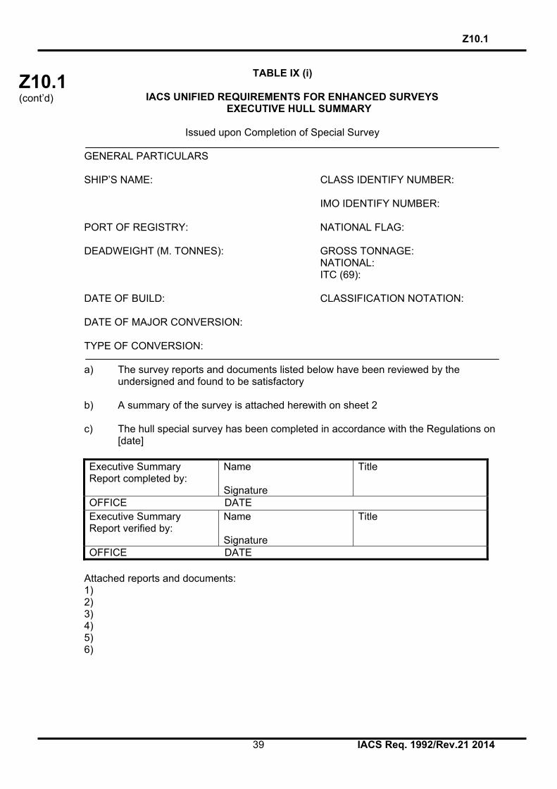
TABLE IX (i)
IACS UNIFIED REQUIREMENTS FOR ENHANCED SURVEYS EXECUTIVE HULL SUMMARY
Issued upon Completion of Special Survey
GENERAL PARTICULARS SHIP’S NAME: CLASS IDENTIFY NUMBER:
IMO IDENTIFY NUMBER: PORT OF REGISTRY: NATIONAL FLAG: DEADWEIGHT (M. TONNES): GROSS TONNAGE: NATIONAL: ITC (69): DATE OF BUILD: CLASSIFICATION NOTATION: DATE OF MAJOR CONVERSION: TYPE OF CONVERSION: a) The survey reports and documents listed below have been reviewed by the
undersigned and found to be satisfactory b) A summary of the survey is attached herewith on sheet 2 c) The hull special survey has been completed in accordance with the Regulations on
[date] Executive Summary Report completed by:
Name Signature
Title
OFFICE DATE Executive Summary Report verified by:
Name Signature
Title
OFFICE DATE Attached reports and documents: 1) 2) 3) 4) 5) 6)

Z10.1 (cont’d)
Z10.1
40 IACS Req. 1992/Rev.21 2014
TABLE IX (ii)
EXECUTIVE HULL SUMMARY A) General Particulars: - Ref. Table IX (i) B) Report Review: - Where and how survey was done C) Close-up Survey: - Extent (Which tanks) D) Cargo & Ballast Piping System: - Examined - Operationally tested E) Thickness measurements: - Reference to Thickness Measurement report
- Summary of where measured - Separate form indicating the tanks/areas with
Substantial Corrosion, and corresponding
* Thickness diminution * Corrosion pattern
F) Tank Protection: Separate form indicating: - Location of coating - Condition of coating (if applicable) G) Repairs: - Identification of tanks/areas H) Condition of Class/Recommendations: I) Memoranda: - Acceptable defects
- Any points of attention for future surveys, e.g. for Suspect Areas
- Extended Annual/Intermediate survey due to coating
breakdown
J) Evaluation results of the ship’s longitudinal strength (for oil tankers of 130 m in length and upwards and of over 10 years of age)
K) Conclusion: - Statement on evaluation/verification of survey report

Z10.1 (cont’d)
Z10.1
41 IACS Req. 1992/Rev.21 2014
TABLE IX (iii)
EXTRACT OF THICKNESS MEASUREMENTS
Reference is made to the thickness measurements report:
1)
Positions of substantially corroded Tanks/Areas or Areas with deep pitting
Thickness diminution [%]
2)
Corrosion pattern
Remarks: e.g. Ref. attached sketches
Remarks 1) Substantial corrosion, i.e. 75 – 100% of acceptable margins wasted 2) P = Pitting
C = Corrosion in General Any bottom plating with a pitting intensity of 20% or more, with wastage in the substantial corrosion range or having an average depth of pitting of 1/3 or more of actual plate thickness is to be noted.

Z10.1 (cont’d)
Z10.1
42 IACS Req. 1992/Rev.21 2014
TABLE IX (iv)
TANK PROTECTION
1)
Tank Nos.
2)
Tank protection
3)
Coating condition
Remarks
Remarks: 1) All segregated ballast tanks and combined cargo/ballast tanks to be listed. 2) C = Coating NP = No Protection 3) Coating condition according to the following standard GOOD condition with only minor spot rusting.
FAIR condition with local breakdown at edges of stiffeners and weld connections and/or light rusting over 20% or more of areas under consideration, but less than as defined for POOR condition.
POOR condition with general breakdown of coating over 20% or more of areas
or hard scale at 10% or more of areas under consideration. If coating condition less than “GOOD" is given, extended annual surveys are to be introduced. This is to be noted in part I) of the Executive Hull Summary.

Z10.1 (cont’d)
Z10.1
43 IACS Req. 1992/Rev.21 2014
TABLE IX (v) Evaluation result of longitudinal strength of the hull girder of oil tankers of 130 m in length and upwards and of over 10 years of age (Of sections 1, 2 and 3 below, only one applicable section is to be completed) 1 This section applies to ships regardless of the date of construction: Transverse sectional areas of deck flange (deck plating and deck longitudinals) and bottom flange (bottom shell plating and bottom longitudinals) of the ship’s hull girder have been calculated by using the thickness measured, renewed or reinforced, as appropriate, during the special survey most recently conducted after the ship reached 10 years of age, and found that the diminution of the transverse sectional area does not exceed 10% of the as-built area, as shown in the following table: Table 1 Transverse sectional area of hull girder flange
Measured As-built Diminution Transverse Section 1
Deck flange cm2 cm2 cm2 (%) Bottom flange cm2 cm2 cm2 (%)
Transverse Section 2
Deck flange cm2 cm2 cm2 (%) Bottom flange cm2 cm2 cm2 (%)
Transverse Section 3
Deck flange cm2 cm2 cm2 (%) Bottom flange cm2 cm2 cm2 (%)
2 This section applies to ships constructed on or after 1 July 2002: Section moduli of transverse section of the ship’s hull girder have been calculated by using the thickness of structural members measured, renewed or reinforced, as appropriate, during the special survey most recently conducted after the ship reached 10 years of age in accordance with the provisions of paragraph 2.2.1.1 of Annex III, and are found to be within their diminution limits determined by the Classification Society*, as shown in the following table: Table 2 Transverse section modulus of hull girder
Zact (cm3) *1 Zreq (cm3) *2 Remarks Transverse Section 1
Upper deck Bottom
Transverse Section 2
Upper deck Bottom
Transverse Section 3
Upper deck Bottom
* The actual transverse section modulus of the hull girder of oil tankers calculated under
paragraph 2.2.1.1 of Annex III to UR Z10.1 is not to be less than 90% of the required section modulus for new buildings specified in IACS Unified Requirements S7* or S11, whichever is the greater.
* C = 1.0 cn is to be used for the purpose of this calculation.

Z10.1 (cont’d)
Z10.1
44 IACS Req. 1992/Rev.21 2014
Notes *1 Zact means the actual section moduli of the transverse section of the ship's hull
girder calculated by using the thickness of structural members measured, renewed or reinforced, as appropriate, during the special survey, in accordance with the provisions of paragraph 2.2.1.1 of Annex III.
*2 Zreq means diminution limit of the longitudinal bending strength of ships, as
calculated in accordance with the provisions of paragraph 2.2.1.1 of Annex III. The calculation sheets for Zact are to be attached to this report. 3 This section applies to ships constructed before 1 July 2002: Section moduli of transverse section of the ship’s hull girder have been calculated by using the thickness of structural members measured, renewed or reinforced, as appropriate, during the special survey most recently conducted after the ship reached 10 years of age in accordance with the provisions of paragraph 2.2.1.2 of Annex III, and found to meet the criteria required by the Classification Society and that Zact is not less than Zmc (defined in *2 below) as specified in appendix 2 to Annex III, as shown in the following table: Describe the criteria for acceptance of the minimum section moduli of the ship's hull girder for ships in service required by the Classification Society. Table 3 Transverse section modulus of hull girder
Zact (cm3) *1 Zmc (cm3) *2 Remarks Transverse Section 1
Upper deck Bottom
Transverse Section 2
Upper deck Bottom
Transverse Section 3
Upper deck Bottom
Notes: *1 As defined in note *1 of Table 2. *2 Zmc means the diminution limit of minimum section modulus calculated in accordance
with provisions of paragraph 2.2.1.2 of Annex III.
End of Main Section

Z10.1 (cont’d)
Z10.1 Annex I
45 IACS Req. 1992/Rev.21 2014
ANNEX I
GUIDELINES FOR TECHNICAL ASSESSMENT IN CONJUNCTION WITH PLANNING FOR ENHANCED SURVEYS OF OIL TANKERS
SPECIAL SURVEY - HULL Contents: 1. INTRODUCTION 2. PURPOSE AND PRINCIPLES 2.1 Purpose 2.2 Minimum Requirements 2.3 Timing 2.4 Aspects to be Considered 3. TECHNICAL ASSESSMENT 3.1 General 3.2 Methods 3.2.1 Design Details 3.2.2 Corrosion 3.2.3 Locations for Close-up Survey and Thickness Measurement REFERENCES 1. IACS Unified Requirement Z10.1, "Hull Surveys of Oil Tankers." 2.TSCF, "Guidance Manual for the Inspection and Condition Assessment of Tanker Structures, 1986." 3.TSCF, "Condition Evaluation and Maintenance of Tanker Structures, 1992." 1. INTRODUCTION These guidelines contain information and suggestions concerning technical assessments which may be of use in conjunction with the planning of enhanced special surveys of oil tankers. As indicated in section 5.1.5 of IACS Unified Requirement Z10.1, "Hull Surveys of Oil Tankers," (Ref. 1), the guidelines are a recommended tool which may be invoked at the discretion of an IACS Member Society, when considered necessary and appropriate, in conjunction with the preparation of the required Survey Programme. 2. PURPOSE AND PRINCIPLES 2.1 Purpose The purpose of the technical assessments described in these guidelines is to assist in identifying critical structural areas, nominating suspect areas and in focusing attention on structural elements or areas of structural elements which may be particularly susceptible to, or evidence a history of, wastage or damage. This information may be useful in nominating locations, areas and tanks for thickness measurement, close-up survey and tank testing. Critical Structural Areas are locations which have been identified from calculations to require monitoring or from the service history of the subject ship or from similar or sister ships (if available) to be sensitive to cracking, buckling or corrosion which would impair the structural integrity of the ship.

Z10.1 (cont’d)
Z10.1 Annex I
46 IACS Req. 1992/Rev.21 2014
2.2 Minimum Requirements However, these guidelines may not be used to reduce the requirements pertaining to thickness measurement, close-up survey and tank testing contained in Tables I, II and III, respectively, of Z10.1; which are, in all cases, to be complied with as a minimum. 2.3 Timing As with other aspects of survey planning, the technical assessments described in these guidelines are to be worked out by the Owner or operator in cooperation with the Classification Society well in advance of the commencement of the Special Survey, i.e., prior to commencing the survey and normally at least 12 to 15 months before the survey's completion due date. 2.4 Aspects to be Considered Technical assessments, which may include quantitative or qualitative evaluation of relative risks of possible deterioration, of the following aspects of a particular ship may be used as a basis for the nomination of tanks and areas for survey: * Design features such as stress levels on various structural elements, design details and
extent of use of high tensile steel. * Former history with respect to corrosion, cracking, buckling, indents and repairs for the particular ship as well as similar vessels, where available. * Information with respect to types of cargo carried, use of different tanks for cargo/ballast, protection of tanks and condition of coating, if any. Technical assessments of the relative risks of susceptability to damage or deterioration of various structural elements and areas are to be judged and decided on the basis of recognised principles and practices, such as may be found in publications of the Tanker Structure Cooperative Forum (TSCF), (Refs. 2 and 3). 3. TECHNICAL ASSESSMENT 3.1 General There are three basic types of possible failure which may be the subject of technical assessment in connection with planning of surveys; corrosion, cracks and buckling. Contact damages are not normally covered by the survey plan since indents are usually noted in memoranda and assumed to be dealt with as a normal routine by Surveyors. Technical assessments performed in conjunction with the survey planning process are, in principle to be as shown schematically in Figure 1 depicts, schematically, how technical assessments can be carried out in conjunction with the survey planning process. The approach is basically an evaluation of the risk based on the knowledge and experience related to design and corrosion. The design is to be considered with respect to structural details which may be susceptible to buckling or cracking as a result of vibration, high stress levels or fatigue. Corrosion is related to the ageing process, and is closely connected with the quality of corrosion protection at newbuilding, and subsequent maintenance during the service life. Corrosion may also lead to cracking and/or buckling. 3.2 Methods 3.2.1 Design Details Damage experience related to the ship in question and similar ships, where available, is the main source of information to be used in the process of planning. In addition, a selection of structural details from the design drawings is to be included.

Z10.1 (cont’d)
Z10.1 Annex I
47 IACS Req. 1992/Rev.21 2014
Typical damage experience to be considered will consist of: - Number, extent, location and frequency of cracks; - Location of buckles. This information may be found in the survey reports and/or the Owner's files, including the results of the Owner's own inspections. The defects should be analyzed, noted and marked on sketches. In addition, general experience is to be utilized. For example, reference should be made to TSCF's "Guidance Manual for the Inspection and Condition Assessment of Tanker Structures," (Ref. 2), which contains a catalogue of typical damages and proposed repair methods for various tanker structural details. Such figures are to be used together with a review of the main drawings, in order to compare with the actual structure and search for similar details which may be susceptible to damage. An example is shown in Figure 2. The review of the main structural drawings, in addition to using the above mentioned figures, should include checking for typical design details where cracking has been experienced. The factors contributing to damage are to be carefully considered. The use of high tensile steel (HTS) is an important factor. Details showing good service experience where ordinary, mild steel has been used may be more susceptible to damage when HTS, and its higher associated stresses, are utilized. There is extensive and, in general, good experience, with the use of HTS for longitudinal material in deck and bottom structures. Experience in other locations, where the dynamic stresses may be higher, is less favourable, e.g. side structures. In this respect, stress calculations of typical and important components and details, in accordance with the latest Rules or other relevant methods, may prove useful and are to be considered. The selected areas of the structure identified during this process are to be recorded and marked on the structural drawings to be included in the Survey Programme. 3.2.2 Corrosion In order to evaluate relative corrosion risks, the following information is generally to be considered: - Usage of Tanks and Spaces - Condition of Coatings - Cleaning Procedures - Previous Corrosion Damage - Ballast use and time for Cargo Tanks - Corrosion Risk Scheme (See Ref. 3, Table 3.1) - Location of Heated Tanks Ref. 3 gives definitive examples which can be used for judging and describing coating condition, using typical pictures of conditions. The evaluation of corrosion risks is to be based on information in Ref. 3, together with relevant information on the anticipated condition of the ship as derived from the information collected in order to prepare the Survey Programme and the age of the ship. The various tanks and spaces are to be listed with the corrosion risks nominated accordingly.

Z10.1 (cont’d)
Z10.1 Annex I
48 IACS Req. 1992/Rev.21 2014
3.2.3 Locations for Close-up Survey and Thickness Measurement On the basis of the table of corrosion risks and the evaluation of design experience, the locations for initial close-up survey and thickness measurement (sections) may be nominated. The sections subject to thickness measurement are to normally be nominated in tanks and spaces where corrosion risk is judged to be the highest. The nomination of tanks and spaces for close-up survey should, initially, be based on highest corrosion risk, and should always include ballast tanks. The principle for the selection is to be that the extent is increased by age or where information is insufficient or unreliable.

Z10.1 (cont’d)
Z10.1 Annex I
49 IACS Req. 1992/Rev.21 2014
Design Related Risk Corrosion Risk
Survey
Figure 1: Technical Assessment and the Survey Planning Process
Input: Drawings, Reports, Acceptable Corrosion Allowance
Collection of InformationCoating Condition Usage of Tanks
Analyse: Hull Damage This Ship
Analyse: Hull Damage for Similar Ships Where Available
Hull Damage: General Experience
Coating condition Usage of Tanks
Corrosion Damage This Ship
Corrosion Damage Similar Ship where Available
Location for Thickness Measurement and Close-Up Survey
Survey Programme
Present Areas where Damage has been found and Risks considered high. Mark Sketches or Drawings
Acceptance by Class & Owner

Z10.1 (cont’d)
Z10.1 Annex I
50 IACS Req. 1992/Rev.21 2014
A
LUG
BACKING BRACKET
X
X
VIEW A - A
WEB AND FLAT BAR CROPPED AND PART RENEWED OR ALTERNATIVELY WELDED
A
FULL COLLAR IF FRACTURES IN WEB PLATE ARE SMALL AND ARE REPAIRED BY WELDING
LUG
FACTORS CONTRIBUTING TO DAMAGE
1. Asymmetrical connection of flat bar stiffener resulting in high peak stresses at the heel of the stiffener under fatigue loading.
2. Insufficient area of connection of longitudinal to web plate.
3. Defective weld at return around the plate thickness.
4. High localised corrosion at areas of stress concentration such as flat bar stiffener connections, corners of cut-out for the longitudinal and connection of web to shell at cut-outs.
5 High stress in the web of the transverse.
6. Dynamic sea way load/ship motions.
TYPICAL DAMAGE PROPOSED REPAIR
FIGURE 1
FIGURE 1
TANKER STRUCTURE CO-OPERATIVE FORUM
SUBJECT: CATALOGUE OF STRUCTURAL DETAILS
SHELL PLATING OR LONGITUDINAL BULKHEAD
�FRACTURE
FLAT BAR STIFFENER
FRACTURED WELD/WEB �
FRACTURE
SIDE SHELL OR BULKHEAD LONGITUDINAL
�FRACTURE
WEB PLATING
VIEW A - A
NOTE �ONE OR MORE FRACTURES MAY OCCUR
A A
WEB FLAT BAR STIFFENER
LOCATION: Connection of longitudinals to transverse webs
EXAMPLE No. 1 : Web and flat bar fractures at cut-outs for longitudinal stiffener connections
>
Figure 2: Typical Damage and Repair Example (Reproduced from Ref. 2)
End of Annex I

Z10.1 (cont’d)
Z10.1 Annex II
51 IACS Req. 1992/Rev.21 2014
ANNEX II
Recommended Procedures for Thickness Measurements of Oil Tankers, Ore/Oil Ships and etc.*
* Note: Annex II is recommendatory.

Z10.1 (cont’d)
Z10.1 Annex II
52 IACS Req. 1992/Rev.21 2014
CONTENTS Sheet 1 - Contents Sheet 2 - Instructions Sheet 3 - General Particulars REPORTS Sheet 4 - Report TM1-T for recording the thickness measurements of all deck
plating, all bottom shell plating and side shell plating Sheet 5 - Report TM2-T (i) for recording the thickness measurement of shell and
deck plating at transverse sections - strength deck and sheerstrake plating
Sheet 6 - Report TM2-T (ii) for recording the thickness measurement of shell and
deck plating at transverse sections - shell plating Sheet 7 - Report TM3-T for recording the thickness measurement of longitudinal
members at transverse sections Sheet 8 - Report TM4-T recording the thickness measurement of transverse
structural members Sheet 9 - Report TM5-T for recording the thickness measurement of W.T./O.T.
transverse bulkheads Sheet 10 - Report TM6-T for recording the thickness measurement of
miscellaneous structural members GUIDANCE Sheet 11 - Oil tanker typical transverse sections. The diagram includes details of
the items to be measured and the report forms to be used. Sheet 12 - Ore/Oil ship typical transverse section. The diagram includes details of
the items to be measured and the report forms to be used. Sheet 13 - Transverse section outline. The diagram may be used for those ships
where the diagrams on sheet 11 and sheet 12 are not suitable Sheet 14 - Oil tank and Ore/Oil Ship, diagrams showing the typical longitudinal
members in a transverse section Sheet 15 - Transverse sections of oil tankers and ore/oil ships showing typical
areas for thickness measurement in association with close-up survey requirements
Sheet 1

Z10.1 (cont’d)
Z10.1 Annex II
53 IACS Req. 1992/Rev.21 2014
INSTRUCTIONS
Recommended Procedures for Thickness Measurements of Oil Tankers, Ore/Oil Ships, etc.
1. This document is to be used for recording thickness measurements as required by
IACS Unified Requirement Z10.1. 2. Reporting forms TM1-T, TM2-T, TM3-T, TM4-T, TM5-T and TM6-T
(sheets 4-10) are to be used for recording thickness measurements and the maximum allowable diminution is to be stated.
The maximum allowable diminution could be stated in an attached document. 3. The remaining sheets 11-15 are guidance diagrams and notes relating to the reporting forms and the procedure for the thickness measurements.
Sheet 2

Z10.1 (cont’d)
Z10.1 Annex II
54 IACS Req. 1992/Rev.21 2014
Sheet 3 GENERAL PARTICULARS Ship’s name:- IMO Number:- Class Identification number:- Port of registry:- Gross tons:- Deadweight:- Date of build:- Classification society:- Name of Company performing thickness measurement:- Thickness measurement company certified by:- Certificate No.:- Certificate valid from..................to................ Place of measurement:- First date of measurement:- Last date of measurement:- Special survey/intermediate survey due:-* Details of measurement equipment:- Qualification of operator:- Report Number:- consisting of.....Sheets Names of operator:- ........................ Name of surveyor:- ....................... Signature of operator:- ........................ Signature of surveyor:- ........................ Company official stamp:- ........................ Classification Society Official Stamp:- ........................ * Delete as appropriate

Z10.1 (cont’d)
Z10.1 Annex II
55 IACS Req. 1992/Rev.21 2014
Sheet 4
TM1-T Report on THICKNESS MEASUREMENT of ALL DECK PLATING, ALL BOTTOM SHELL PLATING or SIDE SHELL PLATING* (* - delete as appropriate) Ship’s name......................... Class Identity No. ......................... Report No. .........................
STRAKE POSITION
PLATE
POSITION
No. or
Letter
Org. Thk. mm
Forward Reading Aft Reading Mean Diminution %
Maximum Allowable Diminution
Gauged Diminution P Diminution S Gauged Diminution P Diminution S
P S mm % mm % P S mm % mm % P S mm 12th forward 11th 10th 9th 8th 7th 6th 5th 4th 3rd 2nd 1st Amidships 1st aft 2nd 3rd 4th 5th 6th 7th 8th 9th 10th 11th 12th
Operators Signature............................................. NOTES – See Reverse

Z10.1 (cont’d)
Z10.1 Annex II
56 IACS Req. 1992/Rev.21 2014
NOTES 1. This report is to be used for recording the thickness measurement of:- A - All strength deck plating within the cargo area. B - All keel, bottom shell plating and bilge plating within the cargo area.
C - Side shell plating including selected wind and water strakes outside cargo area.
D - All wind and water strakes within cargo area. 2. The strake position is to be clearly indicated as follows:- 2.1 For strength deck indicate the number of the strake of plating inboard from the
stringer plate. 2.2 For bottom plating indicate the number of the strake of plating outboard from the
keel plate. 2.3 For side shell plating give number of the strake of plating below sheerstrake and
letter as shown on shell expansion. 3. For oil tankers all deck plating strakes are to be recorded, for ore/oil ships only the deck
plating strakes outside line of openings are to be recorded. 4. Measurements are to be taken at the forward and aft areas of all and where plates
cross ballast/cargo tank boundaries separate measurements for the area of plating in way of each type of tank are to be recorded.
5. The single measurements recorded are to represent the average of multiple
measurements. 6. The maximum allowable diminution could be stated in an attached document.

Z10.1 (cont’d)
Z10.1 Annex II
57 IACS Req. 1992/Rev.21 2014
Sheet 5
TM2-T (i) Report on THICKNESS MEASUREMENT OF SHELL AND DECK PLATING (one, two or three transverse sections) Ship’s name......................... Class Identity No. ......................... Report No. .........................
STRENGTH DECK AND SHEERSTRAKE PLATING
FIRST TRANSVERSE SECTION AT FRAME NUMBER
SECOND TRANSVERSE SECTION AT FRAME NUMBER
THIRD TRANSVERSE SECTION AT FRAME NUMBER
STRAKE
POSITION
No. or
Letter
Org. Thk.
Max. Alwb. Dim.
Gauged Diminution P
Diminution S
No. or
Letter
Org. Thk.
Max. Alwb. Dim.
Gauged Diminution P
Diminution S
No. or
Letter
Org. Thk.
Max. Alwb. Dim.
Gauged Diminution P
Diminution S
mm mm P S mm % mm % mm mm P S mm % mm % mm mm P S mm % mm % Stringer Plate
1st strake inboard
2nd 3rd 4th 5th 6th 7th 8th 9th 10th 11th 12th 13th 14th centre strake
sheer strake
TOPSIDE TOTAL
Operators Signature............................................. NOTES – See Reverse

Z10.1 (cont’d)
Z10.1 Annex II
58 IACS Req. 1992/Rev.21 2014
NOTES
1. This report form is to be used for recording the thickness measurements of: Strength deck plating and sheerstrake plating transverse sections:
One, two or three sections within the cargo area comprising of the structural items (1), (2) and (3) as shown on the diagrams of typical transverse sections.
2. For oil tankers all deck plating strakes are to be recorded and for ore/oil ships only the
deck plating strakes outside the line of openings are to be recorded. 3. The topside area comprises deck plating, stringer plate and sheerstrake (including
rounded gunwales). 4. The exact frame station of measurement is to be stated. 5. The single measurements recorded are to represent the average of multiple
measurements. 6. The maximum allowable diminution could be stated in an attached document.

Z10.1 (cont’d)
Z10.1 Annex II
59 IACS Req. 1992/Rev.21 2014
Sheet 6
TM2-T (ii) Report on THICKNESS MEASUREMENT OF SHELL AND DECK PLATING (one, two or three transverse sections) Ship’s name......................... Class Identity No. ......................... Report No. .........................
SHELL PLATING
FIRST TRANSVERSE SECTION AT FRAME NUMBER
SECOND TRANSVERSE SECTION AT FRAME NUMBER
THIRD TRANSVERSE SECTION AT FRAME NUMBER
STRAKE
POSITION
No. or
Letter
Org. Thk.
Max. Alwb. Dim.
Gauged Diminution P
Diminution S
No. or
Letter
Org. Thk.
Max. Alwb. Dim.
Gauged Diminution P
Diminution S
No. or
Letter
Org. Thk.
Max. Alwb. Dim.
Gauged Diminution P
Diminution S
mm mm P S mm % mm % mm mm P S mm % mm % mm mm P S mm % mm % 1st below sheer strake
2nd 3rd 4th 5th 6th 7th 8th 9th 10th 11th 12th 13th 14th 15th 16th 17th 18th 19th 20th keel strake BOTTOM TOTAL
Operators Signature............................................. NOTES – See Reverse

Z10.1 (cont’d)
Z10.1 Annex II
60 IACS Req. 1992/Rev.21 2014
NOTES 1. This report form is to be used for recording the thickness measurements of: Shell plating transverse sections:
One, two or three sections within the cargo area comprising of the structural items (4), (5) and (6) and (7) as shown on the diagrams of typical transverse sections.
2. The bottom area comprises keel, bottom and bilge plating. 3. The exact frame station of measurement is to be stated. 4. The single measurements recorded are to represent the average of multiple measurements. 5. The maximum allowable diminution could be stated in an attached document.

Z10.1 (cont’d)
Z10.1 Annex II
61 IACS Req. 1992/Rev.21 2014
Sheet 7
TM3-T Report on THICKNESS MEASUREMENT OF LONGITUDINAL MEMBERS (one, two or three transverse sections) Ship’s name......................... Class Identity No. ......................... Report No. ........................
FIRST TRANSVERSE SECTION AT FRAME NUMBER
SECOND TRANSVERSE SECTION AT FRAME NUMBER
THIRD TRANSVERSE SECTION AT FRAME NUMBER
STRUCTURAL
MEMBER
Item No.
Org. Thk.
Max. Alwb. Dim.
Gauged Diminution P
Diminution S
Item No.
Org. Thk.
Max. Alwb. Dim.
Gauged Diminution P
Diminution S
Item No.
Org. Thk.
Max. Alwb. Dim.
Gauged Diminution P
Diminution S
mm mm P S mm % mm % mm mm P S mm % mm % mm mm P S mm % mm %
Operators Signature............................................. NOTES – See Reverse

Z10.1 (cont’d)
Z10.1 Annex II
62 IACS Req. 1992/Rev.21 2014
NOTES 1. This report is to be used for recording the thickness measurements of: Longitudinal Members at transverse sections:
One, two or three sections within the cargo area comprising of the appropriate structural items (8) to (20) as shown on the diagrams of typical transverse sections.
2. The exact frame station of measurement is to be stated. 3. The single measurements recorded are to represent the average of multiple measurements. 4. The maximum allowable diminution could be stated in an attached document.

Z10.1 (cont’d)
Z10.1 Annex II
63 IACS Req. 1992/Rev.21 2014
Sheet 8
TM4-T Report on THICKNESS MEASUREMENT OF TRANSVERSE STRUCTURAL MEMBERS In the cargo oil and water ballast tanks within the cargo tank length Ship’s name......................... Class Identity No. ......................... Report No. ........................
TANK DESCRIPTION: LOCATION OF STRUCTURE:
STRUCTURAL MEMBER
ITEM
Original
Thickness mm
Max. Alwb. Dim. mm
Gauged
Diminution
P
Diminution
S
P
S
mm
%
mm
%
Operators Signature............................................. NOTES – See Reverse

Z10.1 (cont’d)
Z10.1 Annex II
64 IACS Req. 1992/Rev.21 2014
NOTES 1. This report is to be used for recording the thickness measurements of transverse structural members, comprising of the appropriate structural items (25) to (33) as shown on diagrams of typical transverse section. 2. Guidance for areas of measurement is indicated on sheet 15 of this document. 3. The single measurements recorded are to represent the average of multiple measurements. 4. The maximum allowable diminution could be stated in an attached document.

Z10.1 (cont’d)
Z10.1 Annex II
65 IACS Req. 1992/Rev.21 2014
Sheet 9
TM5-T Report on THICKNESS OF W.T./O.T. TRANSVERSE BULKHEADS within the cargo tank or cargo hold spaces Ship’s name......................... Class Identity No. ......................... Report No. ........................
TANK/HOLD DESCRIPTION: LOCATION OF STRUCTURE: FRAME NO.:
STRUCTURAL COMPONENT
(PLATING/STIFFENER)
Original
Thickness mm
Max. Alwb. Dim. mm
Gauged
Diminution
P
Diminution
S
Port
Starboard
mm
%
mm
%
Operators Signature............................................. NOTES – See Reverse

Z10.1 (cont’d)
Z10.1 Annex II
66 IACS Req. 1992/Rev.21 2014
NOTES 1. This report is to be used for recording the thickness measurement of W.T./O.T. transverse bulkheads. 2. Guidance for areas of measurement is indicated on sheet 15 of this document. 3. The single measurements recorded are to represent the average of multiple measurements. 4. The maximum allowable diminution could be stated in an attached document.

Z10.1 (cont’d)
Z10.1 Annex II
67 IACS Req. 1992/Rev.21 2014
Sheet 10
TM6-T Report on THICKNESS MEASUREMENT OF MISCELLANEOUS STRUCTURAL MEMBERS Ship’s name......................... Class Identity No. ......................... Report No. ........................ STRUCTURAL MEMBER:
SKETCH
LOCATION OF STRUCTURE:
Description
Org. Thk. mm
Max. Alwb.Dim. mm
Gauged Diminution P
Diminution S
P S mm % mm %
Operators Signature............................................. NOTES – See Reverse

Z10.1 (cont’d)
Z10.1 Annex II
68 IACS Req. 1992/Rev.21 2014
NOTES 1. This report is to be used for recording the thickness measurement of miscellaneous
structural members including the structural items (36), (37) and (38). 2. The single measurements recorded are to represent the average of multiple
measurements. 3. The maximum allowable diminution could be stated in an attached document.

Z10.1 (cont’d)
Z10.1 Annex II
69 IACS Req. 1992/Rev.21 2014
Sheet 11
12 7512
32
32
32
13
6
18
1326
15
30
1314
32
17
2929
29 29
31
253
11
9
89
1
98
4
16 17
Oil tanker - Typical transverse section indication longitudinal and transverse members
10
2
27
Thickness Measurement - Oil Tankers, Ore/Oil ships and etc.
Report on TM2-T (i) & (ii)
1. Strength deck plating 2. Stringer plate 3. Sheerstrake 4. Side shell plating 5. Bilge plating 6. Bottom shell plating 7. Keel plate
Report on TM3-T 8. Deck longitudinals 9. Deck girders 10. Sheerstrake longitudinals 11. Longitudinal bulkhead top strake 12. Bottom longitudinals 13. Bottom girders 14. Bilge longitudinals 15. Longitudinal bulkhead lower strake 16. Side shell longitudinals 17. Longitudinal bulkhead plating (remainder) 18. Longitudinal bulkhead longitudinals 19. Inner bottom plating 20. Inner bottom longitudinals 21. 22. 23. 24.
Report on TM4-T 25. Deck transverse centre tank 26. Bottom transverse centre tank 27. Deck transverse wing tank 28. Side shell vertical web 29. Longitudinal bulkhead vertical web 30. Bottom transverse wing tank 31. Struts 32. Transverse web face plate 33. D.B. Floors 34. 35.
Report on TM6-T 36. Hatch coamings 37. Deck plating between hatches 38. Hatch covers 39. 40.

Z10.1 (cont’d)
Z10.1 Annex II
70 IACS Req. 1992/Rev.21 2014
Sheet 12
712
17
28
31
30 29
32
32
8
1
9
2
3
10
36
9
2511
4
2729
28
3232
16
13
20
19
15
6
14
5
12
33
18
Oil/Ore Ship - Typical transverse section indication longitudinal and transverse
members
Thickness Measurement - Oil Tankers, Ore/Oil ships and etc.
Report on TM2-T (i) & (ii)
1. Strength deck plating 2. Stringer plate 3. Sheerstrake 4. Side shell plating 5. Bilge plating 6. Bottom shell plating 7. Keel plate
Report on TM3-T 8. Deck longitudinals 9. Deck girders 10. Sheerstrake longitudinals 11. Longitudinal bulkhead top strake 12. Bottom longitudinals 13. Bottom girders 14. Bilge longitudinals 15. Longitudinal bulkhead lower strake 16. Side shell longitudinals 17. Longitudinal bulkhead plating (remainder) 18. Longitudinal bulkhead longitudinals 19. Inner bottom plating 20. Inner bottom longitudinals 21. 22. 23. 24.
Report on TM4-T 25. Deck transverse centre tank 26. Bottom transverse centre tank 27. Deck transverse wing tank 28. Side shell vertical web 29. Longitudinal bulkhead vertical web 30. Bottom transverse wing tank 31. Struts 32. Transverse web face plate 33. D.B. Floors 34. 35.
Report on TM6-T 36. Hatch coamings 37. Deck plating between hatches 38. Hatch covers 39. 40.

Z10.1 (cont’d)
Z10.1 Annex II
71 IACS Req. 1992/Rev.21 2014
Sheet 13
Transverse section outline.
To be used for longitudinal and transverse members where typical Oil Tanker
or Oil/Ore ship sections are not applicable
Thickness Measurement - Oil Tankers, Ore/Oil ships and etc.
Report on TM2-T (i) & (ii)
1. Strength deck plating 2. Stringer plate 3. Sheerstrake 4. Side shell plating 5. Bilge plating 6. Bottom shell plating 7. Keel plate
Report on TM3-T 8. Deck longitudinals 9. Deck girders 10. Sheerstrake longitudinals 11. Longitudinal bulkhead top strake 12. Bottom longitudinals 13. Bottom girders 14. Bilge longitudinals 15. Longitudinal bulkhead lower strake 16. Side shell longitudinals 17. Longitudinal bulkhead plating (remainder) 18. Longitudinal bulkhead longitudinals 19. Inner bottom plating 20. Inner bottom longitudinals 21. 22. 23. 24.
Report on TM4-T 25. Deck transverse centre tank 26. Bottom transverse centre tank 27. Deck transverse wing tank 28. Side shell vertical web 29. Longitudinal bulkhead vertical web 30. Bottom transverse wing tank 31. Struts 32. Transverse web face plate 33. D.B. Floors 34. 35.
Report on TM6-T 36. Hatch coamings 37. Deck plating between hatches 38. Hatch covers 39. 40.

Z10.1 (cont’d)
Z10.1 Annex II
72 IACS Req. 1992/Rev.21 2014
Sheet 14
Oil Tanker
Ore/oil Ship
Typical transverse section showing all longitudinal members to be reported on TM2-T and TM3-T
Thickness Measurement - Oil Tankers, Ore/Oil ships and etc.

Z10.1 (cont’d)
Z10.1 Annex II
73 IACS Req. 1992/Rev.21 2014
Sheet 15
and
B
B E
A
Upper Stool
Lower stool
Double bottom tank
C
D
D
B
E
A
B
D
C C
D
Girder
Girder
Close-up survey requirements
Oil TankerTypical transverse section close-up survey
Oil TankerTypical transverse bulkhead
Thickness to be reported on TM3-T and TM4-T as appropriate
Thickness to be reported on TM5-T
Thickness to be reported on TM3-T and TM4-T as appropriate
Thickness to be reported on TM5-T
Oil/Ore shipTypical transverse bulkhead
Oil/Ore shipTypical transverse section close-up survey
Close-up survey area
Recommendations for the extent and pattern of gaugings are indicated in Table IV of the IACS Unified Requirements
Girder
Thickness Measurement - Oil Tankers, Ore/Oil ships and etc.
End of Annex II

Z10.1 (cont’d)
Z10.1 Annex III
74 IACS Req. 1992/Rev.21 2014
ANNEX III
Criteria for Longitudinal Strength of Hull Girder for Oil Tankers

Z10.1 (cont’d)
Z10.1 Annex III
75 IACS Req. 1992/Rev.21 2014
Annex III
Criteria for Longitudinal Strength of Hull Girder for Oil Tankers 1 General 1.1 These criteria are to be used for the evaluation of longitudinal strength of the ship's hull girder as required by section 8.1.1.1. 1.2 In order that ship’s longitudinal strength to be evaluated can be recognized as valid, fillet welding between longitudinal internal members and hull envelopes are to be in sound condition so as to keep integrity of longitudinal internal members with hull envelopes. 2 Evaluation of longitudinal strength On oil tankers of 130 m in length and upwards and of over 10 years of age, the longitudinal strength of the ship's hull girder is to be evaluated in compliance with the requirements of this annex on the basis of the thickness measured, renewed or reinforced, as appropriate, during the special survey. The condition of the hull girder for longitudinal strength evaluation is to be determined in accordance with the methods specified in appendix 3. 2.1 Calculation of transverse sectional areas of deck and bottom flanges of hull
girder 2.1.1 The transverse sectional areas of deck flange (deck plating and deck longitudinals) and bottom flange (bottom shell plating and bottom longitudinals) of the ship’s hull girder are to be calculated by using the thickness measured, renewed or reinforced, as appropriate, during the special survey. 2.1.2 If the diminution of sectional areas of either deck or bottom flange exceeds 10% of their respective as-built area (i.e. original sectional area when the ship was built), either one of the following measures is to be taken: .1 to renew or reinforce the deck or bottom flanges so that the actual sectional
area is not less than 90% of the as-built area; or
.2 to calculate the actual section moduli (Zact) of transverse section of the ship’s hull girder by applying the calculation method specified in appendix 1, by using the thickness measured, renewed or reinforced, as appropriate, during the special survey.
2.2 Requirements for transverse section modulus of hull girder 2.2.1 The actual section moduli of transverse section of the ship’s hull girder calculated in accordance with the foregoing paragraph 2.1.2.2 is to satisfy either of the following provisions, as applicable:
.1 for ships constructed on or after 1 July 2002, the actual section moduli (Zact) of the transverse section of the ship's hull girder calculated in accordance with the requirements of the foregoing paragraph 2.1.2.2 is not to be less than the diminution limits determined by the Classification Society*; or
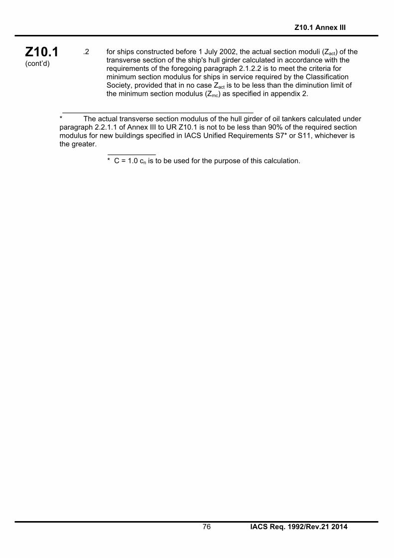
Z10.1 (cont’d)
Z10.1 Annex III
76 IACS Req. 1992/Rev.21 2014
.2 for ships constructed before 1 July 2002, the actual section moduli (Zact) of the transverse section of the ship's hull girder calculated in accordance with the requirements of the foregoing paragraph 2.1.2.2 is to meet the criteria for minimum section modulus for ships in service required by the Classification Society, provided that in no case Zact is to be less than the diminution limit of the minimum section modulus (Zmc) as specified in appendix 2.
* The actual transverse section modulus of the hull girder of oil tankers calculated under paragraph 2.2.1.1 of Annex III to UR Z10.1 is not to be less than 90% of the required section modulus for new buildings specified in IACS Unified Requirements S7* or S11, whichever is the greater. * C = 1.0 cn is to be used for the purpose of this calculation.

Z10.1 (cont’d)
Z10.1 Annex III
77 IACS Req. 1992/Rev.21 2014
APPENDIX 1
CALCULATION CRITERIA OF SECTION MODULI OF MIDSHIP SECTION OF HULL GIRDER
1 When calculating the transverse section modulus of the ship's hull girder, the sectional area of all continuous longitudinal strength members is to be taken into account. 2 Large openings, i.e. openings exceeding 2.5m in length or 1.2m in breadth and scallops, where scallop welding is applied, are always to be deducted from the sectional areas used in the section modulus calculation. 3 Smaller openings (manholes, lightening holes, single scallops in way of seams, etc.) need not be deducted provided that the sum of their breadths or shadow area breadths in one transverse section does not reduce the section modulus at deck or bottom by more than 3% and provided that the height of lightening holes, draining holes and single scallops in longitudinals or longitudinal girders does not exceed 25% of the web depth, for scallops maximum 75mm. 4 A deduction-free sum of smaller opening breadths in one transverse section in the bottom or deck area of 0.06(B - ∑b) (where B = breadth of ship, ∑b = total breadth of large openings) may be considered equivalent to the above reduction in sectional modulus. 5 The shadow area will be obtained by drawing two tangent lines with an opening angle of 30˚. 6 The deck modulus is related to the moulded deck line at side. 7 The bottom modulus is related to the base line. 8 Continuous trunks and longitudinal hatch coamings are to be included in the longitudinal sectional area provided they are effectively supported by longitudinal bulkheads or deep girders. The deck modulus is then to be calculated by dividing the moment of inertia by the following distance, provided this is greater than the distance to the deck line at side:
Bx
yyt 2.09.0
where: y = distance from neutral axis to top of continuous strength member, x = distance from top of continuous strength member to centreline of the ship. x and y to be measured to the point giving the largest value of yt. 9 Longitudinal girders between multi-hatchways will be considered by special calculations.

Z10.1 (cont’d)
Z10.1 Annex III
78 IACS Req. 1992/Rev.21 2014
APPENDIX 2
DIMINUTION LIMIT OF MINIMUM LONGITUDINAL STRENGTH OF SHIPS IN SERVICE
1 The diminution limit of the minimum section modulus (Zmc) of oil tankers in service is given by the following formula: Zmc = cL2B (Cb + 0.7)k (cm3) where
L = Length of ships. L is the distance, in metres, on the summer load waterline from the fore side of stem to the after side of the rudder post, or the centre of the rudder stock if there is no rudder post. L is not to be less than 96%, and need not be greater than 97%, of the extreme length on the summer load waterline. In ships with unusual stern and bow arrangement the length L may be specially considered.
B = Greatest moulded breadth in metres.
Cb = Moulded block coefficient at draught d corresponding to summer load waterline, based on L and B. Cb is not to be taken less than 0.60.
dBLd
Cb
draught at )(m ntdisplaceme moulded 3
c = 0.9 cn
5.1
100300
75.10
L
cn for 130 m ≤ L ≤ 300 m
75.10nc for 300 m < L < 350 m
5.1
150350
75.10
L
cn for 350 m ≤ L ≤ 500 m
k = material factor, e.g. k = 1.0 for mild steel with yield stress of 235N/mm2 and over; k = 0.78 for high tensile steel with yield stress of 315N/mm2 and over; k = 0.72 for high tensile steel with yield stress of 355N/mm2 and over. 2 Scantlings of all continuous longitudinal members of the ship's hull girder based on the section modulus requirement in 1 above are to be maintained within 0.4L amidships. However, in special cases, based on consideration of type of ship, hull form and loading conditions, the scantlings may be gradually reduced towards the end of 0.4L part, bearing in mind the desire not to inhibit the ship’s loading flexibility. 3 However, the above standard may not be applicable to ships of unusual type or design, e.g. for ships of unusual main proportions and/or weight distributions.

Z10.1 (cont’d)
Z10.1 Annex III
79 IACS Req. 1992/Rev.21 2014
APPENDIX 3
Sampling method of thickness measurements for longitudinal strength evaluation and repair methods
1 Extent of longitudinal strength evaluation Longitudinal strength should be evaluated within 0.4L amidships for the extent of the hull girder length that contains tanks therein and within 0.5L amidships for adjacent tanks which may extend beyond 0.4L amidships, where tanks means ballast tanks and cargo tanks. 2 Sampling method of thickness measurement 2.1 Pursuant to the requirements of section 2.4 of Z10.1, transverse sections should be chosen such that thickness measurements can be taken for as many different tanks in corrosive environments as possible, e.g. ballast tanks sharing a common plane boundary with cargo tanks fitted with heating coils, other ballast tanks, cargo tanks permitted to be filled with sea water and other cargo tanks. Ballast tanks sharing a common plane boundary with cargo tanks fitted with heating coils and cargo tanks permitted to be filled with sea water should be selected where present. 2.2 The minimum number of transverse sections to be sampled should be in accordance with Table II of Z10.1. The transverse sections should be located where the largest thickness reductions are suspected to occur or are revealed from deck and bottom plating measurements prescribed in 2.3 and should be clear of areas which have been locally renewed or reinforced. 2.3 At least two points should be measured on each deck plate and/or bottom shell plate required to be measured within the cargo area in accordance with the requirements of Table II of Z10.1. 2.4 Within 0.1D (where D is the ship’s moulded depth) of the deck and bottom at each transverse section to be measured in accordance with the requirements of Table II of Z10.1, every longitudinal and girder should be measured on the web and face plate, and every plate should be measured at one point between longitudinals. 2.5 For longitudinal members other than those specified in 2.4 to be measured at each transverse section in accordance with the requirements of Table II of Z10.1, every longitudinal and girder should be measured on the web and face plate, and every plate should be measured at least in one point per strake. 2.6 The thickness of each component should be determined by averaging all of the measurements taken in way of the transverse section on each component. 3 Additional measurements where the longitudinal strength is deficient 3.1 Where one or more of the transverse sections are found to be deficient in respect of the longitudinal strength requirements given in this annex, the number of transverse sections for thickness measurement should be increased such that each tank within the 0.5L amidships region has been sampled. Tank spaces that are partially within, but extend beyond, the 0.5L region, should be sampled. 3.2 Additional thickness measurements should also be performed on one transverse section forward and one aft of each repaired area to the extent necessary to ensure that the areas bordering the repaired section also comply with the requirements of Z10.1.

Z10.1 (cont’d)
Z10.1 Annex III
80 IACS Req. 1992/Rev.21 2014
4 Effective repair methods 4.1 The extent of renewal or reinforcement carried out to comply with this annex should be in accordance with 4.2. 4.2 The minimum continuous length of a renewed or reinforced structural member should be not less than twice the spacing of the primary members in way. In addition, the thickness diminution in way of the butt joint of each joining member forward and aft of the replaced member (plates, stiffeners, girder webs and flanges, etc.) should not be within the substantial corrosion range (75% of the allowable diminution associated with each particular member). Where differences in thickness at the butt joint exceed 15% of the lower thickness, a transition taper should be provided. 4.3 Alternative repair methods involving the fitting of straps or structural member modification should be subject to special consideration. In considering the fitting of straps, it should be limited to the following conditions: .1 to restore and/or increase longitudinal strength; .2 the thickness diminution of the deck or bottom plating to be reinforced should not be within the substantial corrosion range (75% of the allowable diminution associated with the deck plating); .3 the alignment and arrangement, including the termination of the straps, is in accordance with a standard recognized by the Classification Society; .4 the straps are continuous over the entire 0.5L amidships length; and .5 continuous fillet welding and full penetration welds are used at butt welding and,
depending on the width of the strap, slot welds. The welding procedures applied should be acceptable to the Classification Society.
4.4 The existing structure adjacent to replacement areas and in conjunction with the fitted straps, etc. should be capable of withstanding the applied loads, taking into account the buckling resistance and the condition of welds between the longitudinal members and hull envelope plating.
End of Annex III

Z10.1 (cont’d)
Z10.1 Annex IV
81 IACS Req. 1992/Rev.21 2014
ANNEX IV

Z10.1 (cont’d)
Z10.1 Annex IVA
82 IACS Req. 1992/Rev.21 2014
ANNEX IVA
SURVEY PROGRAMME
Basic information and particulars Name of ship:
IMO number:
Flag State:
Port of registry:
Gross tonnage:
Deadweight (metric tonnes):
Length between perpendiculars (m):
Shipbuilder:
Hull number:
Classification Society:
Class ID:
Date of build of the ship:
Owner:
Thickness measurement company:
1 Preamble 1.1 Scope 1.1.1 The present survey programme covers the minimum extent of overall surveys, close-up surveys, thickness measurements and pressure testing within the cargo area, cargo tanks, ballast tanks, including fore and aft peak tanks, required by UR Z10.1. 1.1.2 The arrangements and safety aspects of the survey are to be acceptable to the attending surveyor(s). 1.2 Documentation All documents used in the development of the survey programme are to be available onboard during the survey as required by section 6. 2 Arrangement of tanks and spaces This section of the survey programme is to provide information (either in the form of plans or text) on the arrangement of tanks and spaces that fall within the scope of the survey.

Z10.1 (cont’d)
Z10.1 Annex IVA
83 IACS Req. 1992/Rev.21 2014
3 List of tanks and spaces with information on their use, extent of coatings and corrosion protection system
This section of the survey programme is to indicate any changes relating to (and is to update) the information on the use of the tanks of the ship, the extent of coatings and the corrosion protective system provided in the Survey Planning Questionnaire. 4 Conditions for survey This section of the survey programme is to provide information on the conditions for survey, e.g. information regarding cargo hold and tank cleaning, gas freeing, ventilation, lighting, etc. 5 Provisions and method of access to structures This section of the survey programme is to indicate any changes relating to (and is to update) the information on the provisions and methods of access to structures provided in the Survey Planning Questionnaire. 6 List of equipment for survey This section of the survey programme is to identify and list the equipment that will be made available for carrying out the survey and the required thickness measurements. 7 Survey requirements 7.1 Overall survey This section of the survey programme is to identify and list the spaces that are to undergo an overall survey for the ship in accordance with 2.3.1. 7.2 Close-up survey This section of the survey programme is to identify and list the hull structures that are to undergo a close-up survey for the ship in accordance with 2.3.2. 8 Identification of tanks for tank testing This section of the survey programme is to identify and list the tanks that are to undergo tank testing for the ship in accordance with 2.5. 9 Identification of areas and sections for thickness measurements This section of the survey programme is to identify and list the areas and sections where thickness measurements are to be taken in accordance with 2.4.1.

Z10.1 (cont’d)
Z10.1 Annex IVA
84 IACS Req. 1992/Rev.21 2014
10 Minimum thickness of hull structures This section of the survey programme is to specify the minimum thickness for hull structures of the ship that are subject to UR Z10.1 (indicate either (a) or preferably (b), if such information is available): (a) Determined from the attached wastage allowance table and the original
thickness to the hull structure plans of the ship; (b) Given in the following table(s):
Area or location Original as-
built thickness(mm)
Minimum thickness
(mm)
Substantial corrosion thickness
(mm) Deck Plating Longitudinals Longitudinal girders Bottom Plating Longitudinals Longitudinal girders Ship side Plating Longitudinals Longitudinal girders Longitudinal bulkhead Plating Longitudinals Longitudinal girders Inner bottom Plating Longitudinals Longitudinal girders Transverse bulkheads Plating Stiffeners Transverse web frames, floors and stringers
Plating Flanges Stiffeners Cross ties Flanges Webs
Note: The wastage allowance tables are to be attached to the survey programme.

Z10.1 (cont’d)
Z10.1 Annex IVA
85 IACS Req. 1992/Rev.21 2014
11 Thickness measurement company This section of the survey programme is to identify changes, if any, relating to the information on the thickness measurement company provided in the Survey Planning Questionnaire. 12 Damage experience related to the ship This section of the survey programme is to, using the tables provided below, provide details of the hull damages for at least the last three years in way of the cargo and ballast tanks and void spaces within the cargo area. These damages are subject to survey.
Hull damages sorted by location for the ship
Tank or space
number or area
Possible cause, if known
Description of the
damages
Location Repair Date of repair
Hull damages for sister or similar ships (if available) in the case of design related damage
Tank or space
number or area
Possible cause, if known
Description of the
damages
Location Repair Date of repair

Z10.1 (cont’d)
Z10.1 Annex IVA
86 IACS Req. 1992/Rev.21 2014
13 Areas identified with substantial corrosion from previous surveys
This section of the survey programme is to identify and list the areas of substantial corrosion from previous surveys. 14 Critical structural areas and suspect areas This section of the survey programme is to identify and list the critical structural areas and the suspect areas, if such information is available. 15 Other relevant comments and information This section of the survey programme is to provide any other comments and information relevant to the survey.

Z10.1 (cont’d)
Z10.1 Annex IVA
87 IACS Req. 1992/Rev.21 2014
Appendices Appendix 1 - List of plans Paragraph 5.1.3.2 requires that main structural plans of cargo and ballast tanks (scantling drawings), including information regarding use of high tensile steel (HTS), to be available. This appendix of the survey programme is to identify and list the main structural plans which form part of the survey programme. Appendix 2 - Survey Planning Questionnaire The Survey Planning Questionnaire (annex IVB), which has been submitted by the owner, is to be appended to the survey programme. Appendix 3 - Other documentation This part of the survey programme is to identify and list any other documentation that forms part of the Plan. Prepared by the owner in co-operation with the Classification Society for compliance with 5.1.3. Date:…………………………………. (name and signature of authorized owner’s
representative) Date:…………………………………. (name and signature of authorized representative of the
Classification Society)

Z10.1 (cont’d)
Z10.1 Annex IVB
88 IACS Req. 1992/Rev.21 2014
ANNEX IVB
SURVEY PLANNING QUESTIONNAIRE
The following information will enable the owner in co-operation with the Classification Society to develop a survey programme complying with the requirements of UR Z10.1. It is essential that the owner provides, when completing the present questionnaire, up-to-date information. The present questionnaire, when completed, is to provide all information and material required by UR Z10.1. Particulars
Ship's name: IMO number: Flag State: Port of registry: Owner: Classification Society: Class ID: Gross tonnage: Deadweight (metric tonnes): Date of build: Information on access provision for close-up surveys and thickness measurement: The owner is to indicate, in the table below, the means of access to the structures subject to close-up survey and thickness measurement. A close-up survey is an examination where the details of structural components are within the close visual inspection range of the attending surveyor, i.e. normally within reach of hand.
Tank No.
Structure C(Cargo)/ B(Ballast)
Temporary staging
Rafts Ladders Direct access
Other means (please specify)
F.P. Fore peak A.P. Aft peak Wing Tanks
Under deck Side shell Bottom transverse
Longitudinal Transverse
Centre Tanks
Under deck Bottom transverse
Transverse

Z10.1 (cont’d)
Z10.1 Annex IVB
89 IACS Req. 1992/Rev.21 2014
History of cargo with H2S content or heated cargo for the last 3 years together with indication as to whether cargo was heated and, where available, Marine Safety Data Sheets (MSDS)*
* Refer to resolution MSC. 150(77) on Recommendation for material safety data sheets for MARPOL Annex I cargoes and marine fuel oils.

Z10.1 (cont’d)
Z10.1 Annex IVB
90 IACS Req. 1992/Rev.21 2014
Owner’s inspections Using a format similar to that of the table below (which is given as an example), the owner is to provide details of the results of their inspections for the last 3 years on all cargo and ballast tanks and void spaces within the cargo area, including peak tanks.
Tank No. Corrosion protection
(1)
Coating extent
(2)
Coating condition
(3)
Structural deterioration
(4)
Tank damage history
(5) Cargo centre tanks
Cargo wing tanks
Slop

Z10.1 (cont’d)
Z10.1 Annex IVB
91 IACS Req. 1992/Rev.21 2014
Tank No. Corrosion
protection (1)
Coating extent
(2)
Coating condition
(3)
Structural deterioration
(4)
Tank damage history
(5) Ballast tanks
Aft peak
Fore peak
Miscellaneous spaces
Note: Indicate tanks which are used for oil/ballast. 1) HC=hard coating; SC=soft coating; SH=semi-hard coating; NP=no protection. 2) U=upper part; M=middle part; L=lower part; C=complete 3) G=good; F=fair; P=poor; RC=recoated (during the last 3 years) 4) N=no findings recorded; Y=findings recorded, description of findings is to be attached to the questionnaire 5) DR=damage & repair; L=leakages; CV=conversion (description is to be attached to this questionnaire) Name of owner’s representative: Signature: Date:

Z10.1 (cont’d)
Z10.1 Annex IVB
92 IACS Req. 1992/Rev.21 2014
Reports of Port State Control inspections List the reports of Port State Control inspections containing hull structural related deficiencies and relevant information on rectification of the deficiencies:
Safety Management System
List non-conformities related to hull maintenance, including the associated corrective actions:
Name and address of the approved thickness measurement company:
Annex IV end Document end
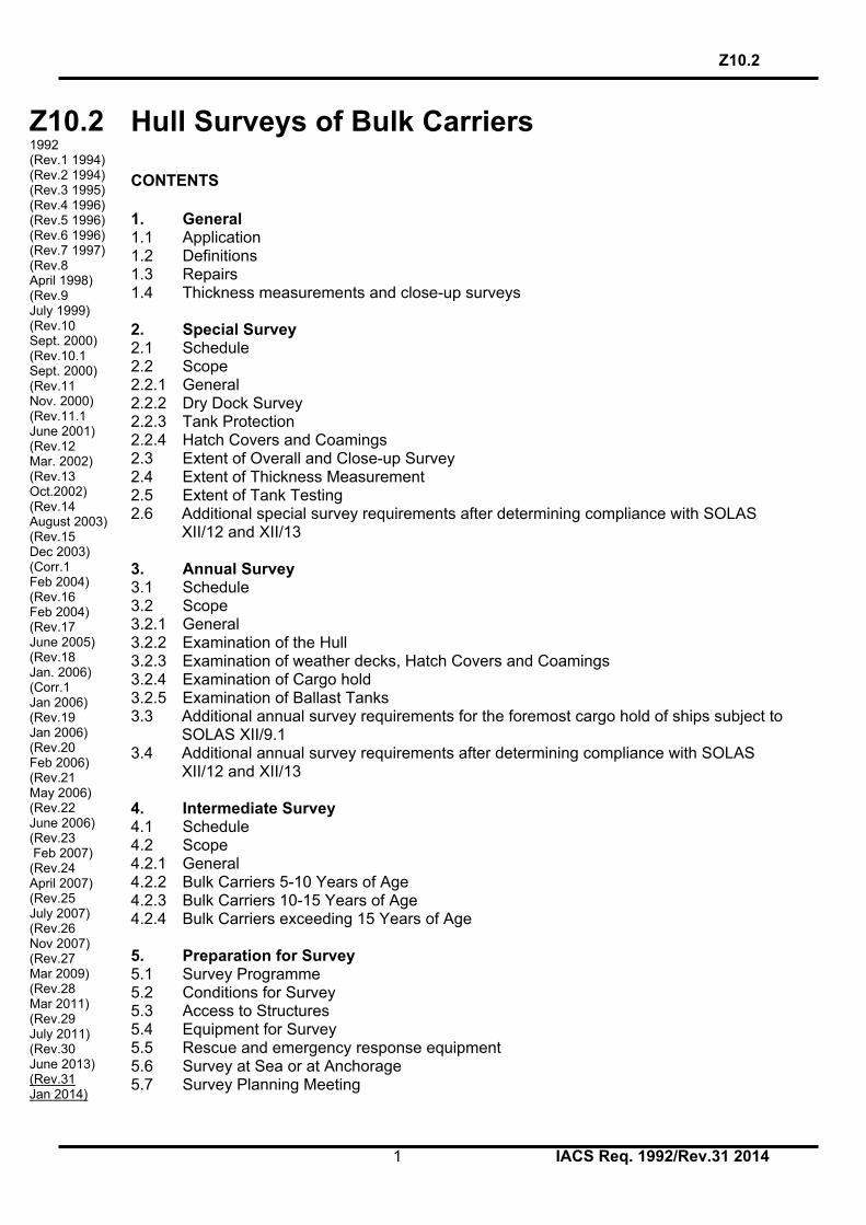
Z10.2 (cont’d)
Z10.2
1 IACS Req. 1992/Rev.31 2014
Z10.2 1992 (Rev.1 1994) (Rev.2 1994) (Rev.3 1995) (Rev.4 1996) (Rev.5 1996) (Rev.6 1996) (Rev.7 1997) (Rev.8 April 1998) (Rev.9 July 1999) (Rev.10 Sept. 2000) (Rev.10.1 Sept. 2000) (Rev.11 Nov. 2000) (Rev.11.1 June 2001) (Rev.12 Mar. 2002) (Rev.13 Oct.2002) (Rev.14 August 2003) (Rev.15 Dec 2003) (Corr.1 Feb 2004) (Rev.16 Feb 2004) (Rev.17 June 2005) (Rev.18 Jan. 2006) (Corr.1 Jan 2006) (Rev.19 Jan 2006) (Rev.20 Feb 2006) (Rev.21 May 2006) (Rev.22 June 2006) (Rev.23 Feb 2007) (Rev.24 April 2007) (Rev.25 July 2007) (Rev.26 Nov 2007) (Rev.27 Mar 2009) (Rev.28 Mar 2011) (Rev.29 July 2011) (Rev.30 June 2013) (Rev.31 Jan 2014)
Hull Surveys of Bulk Carriers CONTENTS 1. General 1.1 Application 1.2 Definitions 1.3 Repairs 1.4 Thickness measurements and close-up surveys 2. Special Survey 2.1 Schedule 2.2 Scope 2.2.1 General 2.2.2 Dry Dock Survey 2.2.3 Tank Protection 2.2.4 Hatch Covers and Coamings 2.3 Extent of Overall and Close-up Survey 2.4 Extent of Thickness Measurement 2.5 Extent of Tank Testing 2.6 Additional special survey requirements after determining compliance with SOLAS
XII/12 and XII/13 3. Annual Survey 3.1 Schedule 3.2 Scope 3.2.1 General 3.2.2 Examination of the Hull 3.2.3 Examination of weather decks, Hatch Covers and Coamings 3.2.4 Examination of Cargo hold 3.2.5 Examination of Ballast Tanks 3.3 Additional annual survey requirements for the foremost cargo hold of ships subject to
SOLAS XII/9.1 3.4 Additional annual survey requirements after determining compliance with SOLAS
XII/12 and XII/13 4. Intermediate Survey 4.1 Schedule 4.2 Scope 4.2.1 General 4.2.2 Bulk Carriers 5-10 Years of Age 4.2.3 Bulk Carriers 10-15 Years of Age 4.2.4 Bulk Carriers exceeding 15 Years of Age 5. Preparation for Survey 5.1 Survey Programme 5.2 Conditions for Survey 5.3 Access to Structures 5.4 Equipment for Survey 5.5 Rescue and emergency response equipment 5.6 Survey at Sea or at Anchorage 5.7 Survey Planning Meeting

Z10.2 (cont’d)
Z10.2
2 IACS Req. 1992/Rev.31 2014
6. Documentation On Board 6.1 General 6.2 Survey Report File 6.3 Supporting Documents 6.4 Review of Documentation on board 7. Procedures for Thickness Measurement 7.1 General 7.2 Certification of Thickness Measurement Company 7.3 Number and Locations of Measurements 7.4 Reporting 8. Acceptance Criteria 8.1 General 8.2 Acceptance criteria for pitting corrosion of CSR ships 8.3 Acceptance criteria for edge corrosion of CSR ships 8.4 Acceptance criteria for grooving corrosion of CSR ships 9. Reporting and Evaluation of Survey 9.1 Evaluation of Survey Report 9.2 Reporting

Z10.2 (cont’d)
Z10.2
3 IACS Req. 1992/Rev.31 2014
ENCLOSURES: Table I: Minimum Requirement for Close-up Survey at Special Hull Surveys of Bulk Carriers Table II: Minimum Requirements of Thickness Measurement at Special Hull Surveys of Bulk Carriers Table III: Owners Inspection Report Table IV: (Superseded by Annex 1) Table V: Procedures for certification of Firms Engaged in Thickness Measurement of Hull
Structures Table VI: Survey Reporting Principles
Table VII: Executive Hull Summary Table VIII: Requirements of extent of thickness measurements at those areas of substantial
corrosion Annex I: IACS Guidelines for Technical Assessment in conjunction with
planning for Enhanced Survey for Bulk Carriers Annex II: IACS Recommended Procedures for Thickness Measurements of
Bulk Carriers IACS Recommended Procedures for Thickness Measurements of
Bulk Carriers Built Under IACS Common Structural Rules Annex III: Guidelines for the Gauging of the Vertically Corrugated Transverse
Watertight Bulkhead between Holds Nos. 1 and 2 Annex IV: Additional annual survey requirements for the foremost cargo hold of
ships subject to SOLAS XII/9.1
Annex V: Guidelines for the Gauging of the Side Shell Frames and Brackets in Single Side Skin Bulk Carriers
Annex VIA: Survey Programme Appendix 1 List of Plans Appendix 2 Survey Planning Questionnaire Appendix 3 Other Documentation Annex VIB: Survey Planning Questionnaire

Z10.2 (cont’d)
Z10.2
4 IACS Req. 1992/Rev.31 2014
Notes: 1. Revisions 4, 5 & 6 1996 of Unified Requirements Z10.2 have been approved by
Council for application as soon as possible but not later than 1 January 1997. 2. Changes introduced in Revision 8, 1998 of UR Z10.2, i.e. 1.1.4 and 2.4.1 and columns
for Special Surveys Nos. 3 and 4 of Table II as well as Annex III should be applied by all Member societies and Associates not later than 1 July 1998.
3. Changes introduced in Rev.9 to UR Z10.2 are to be applied by all Member Societies
and Associates from 1 September 1999.
4. Changes introduced in Rev.10 to UR Z10.2 are to be applied by all Member Societies and Associates from 1 July 2001.
5. The introduction of Annex IV in Rev.10.2 is to maintain the intermediate survey
requirements invoked in SOLAS XII/9.1 to those of A.744(18) as amended as they existed in September 2000 and to preclude the inadvertent extension of changes to intermediate survey introduced in Chapter 4 of Rev.10 of this UR from being applied to ships subject to SOLAS XII/9.1.
6. Changes introduced in Rev.11 & Rev.11.1 to UR Z10.2 are to be applied by all
Member Societies and Associates from 1 July 2001. 7. The amendments to Table I and 4.2.3 introduced in Rev.12 are to further increase the
requirements for close-up survey at Special Survey No.2 and to require the scope of the Intermediate Survey therafter to have the scope of Special Survey No.2.
These requirements are to be implemented for any Special Survey No.2 or the Intermediate Survey subsequent to Special Survey No.2 commenced after 1 January 2003.
Paragraph 4.2.4.3 is newly introduced in Rev.12 in accordance with Res.MSC 105(73) and is to be implemented from 1 July 2002.
The other changes introduced in Rev.12 are to be implemented within one year of the adoption by Council.
8. Changes introduced in Rev.15 Corr.1 to UR Z10.2 are to be applied by all Member
Societies and Associates from 1 January 2004 in conjunction with UR S31. 9. Changes introduced in Rev.16 are in para 1.1.4 and SS3 in Table 1 and are to be
applied by all Member Societies and Associates from 1 January 2005. 10. Changes introduced in Rev.17 are to be uniformly implemented from 1 July 2006. 11. Changes introduced in Rev.18 (para. 1.4, 5.5.4, 5.5.6 and 7.1.3) are to be uniformly
applied by IACS Societies on surveys commenced on or after 1 January 2007. 12. Changes introduced in Rev.19 (para. 2.6 and 3.4) are to be uniformly applied by IACS
Societies on surveys commenced on or after 1 January 2007. 13. Changes introduced in Rev. 20 (i.e. in para. 5.3.2 through 5.3.4) are to be uniformly
applied by IACS Societies on surveys commenced on or after 1 January 2007. 14. Changes introduced in Rev.21 (Table 1) are to be uniformly applied by IACS Societies
on surveys commenced on or after 1 July 2007.

Z10.2 (cont’d)
Z10.2
5 IACS Req. 1992/Rev.31 2014
15. Changes introduced in Rev.22 are to be uniformly applied by IACS Societies on surveys commenced on or after 1 July 2007. 16. Changes introduced in Rev. 23 are to be uniformly implemented for surveys
commenced on or after 1 January 2008, whereas statutory requirements of IMO Res. MSC197(80) apply on 1 January 2007.
17. Changes introduced in Rev.24 are to be uniformly implemented by IACS Societies for
surveys commenced on or after 1 July 2008. 18. Changes introduced in Rev.25 are to be uniformly implemented by IACS Societies for
surveys commenced on or after 1 July 2008. 19. Changes introduced in Rev.26 are to be uniformly applied by IACS Societies for
surveys commenced on or after the 1 January 2009. 20. Changes introduced in Rev.27 are to be uniformly applied by IACS Societies for
surveys commenced on or after 1 July 2010.
As for the requirements regarding semi-hard coatings, these coatings, if already applied, will not be accepted from the next special or intermediate survey commenced on or after 1 July 2010, whichever comes first, with respect to waiving the annual internal examination of the ballast tanks.
21. Changes introduced in Rev.28 are to be uniformly applied by IACS Societies for
surveys commenced on or after 1 July 2012. 22. Changes introduced in Rev.29 are to be uniformly applied by IACS Societies for
surveys commenced on or after 1 July 2012. 23. The changes to section 6 introduced in Rev.30 are to be uniformly applied by IACS
Societies for surveys commenced on or after 1 July 2016. The other changes introduced in Rev.30 are to be uniformly applied by IACS Societies for surveys commenced on or after 1 July 2014.
24. Changes introduced in Rev.31 are to be uniformly applied by IACS Societies for
surveys commenced on or after 1 January 2015.

Z10.2 (cont’d)
Z10.2
6 IACS Req. 1992/Rev.31 2014
1. GENERAL 1.1 Application 1.1.1 The requirements apply to all self-propelled Bulk Carriers other than Double Skin Bulk Carriers as defined in 1.1.1 of UR Z10.5. 1.1.2 The Requirements apply to surveys of hull structure and piping systems in way of the cargo holds, cofferdams, pipe tunnels, void spaces, fuel oil tanks within the cargo length area and all ballast tanks. The requirements are additional to the classification requirements applicable to the remainder of the ship. Refer to Z7. 1.1.3 The requirements contain the minimum extent of examination, thickness measurement and tank testing. The survey is to be extended when Substantial Corrosion and/or structural defects are found and include additional Close-Up Survey when necessary. 1.1.4 Ships which are required to comply with UR S19 are subject to the additional thickness measurement guidance contained in Annex III with respect to the vertically corrugated transverse watertight bulkhead between cargo holds Nos. 1 and 2 for purposes of determining compliance with UR S19 prior to the relevant compliance deadline stipulated in UR S23 and at subsequent intermediate surveys (for ships over 10 years of age) and special surveys for purposes of verifying continuing compliance with UR S19. 1.1.5 Ships which are required to comply with UR S31 are subject to the additional thickness measurement guidance contained in Annex V with respect to the side shell frames and brackets for the purposes of determining compliance with UR S31 prior to the relevant compliance deadline stipulated in UR S31 and at subsequent intermediate and special surveys for purposes of verifying continuing compliance with UR S31. 1.1.6 For bulk carriers with hybrid cargo hold arrangements, e.g. with some cargo holds of single side skin and others of double side skin, the requirements of UR Z10.5 are to apply to cargo holds of double side skin and associated wing spaces. 1.2 Definitions 1.2.1 Bulk Carrier A Bulk Carrier is a ship which is constructed generally with single deck, double bottom, topside tanks and hopper side tanks in cargo spaces, and is intended primarily to carry dry cargo in bulk. Combination carriers are included.1 Ore and combination carriers are not covered by the IACS Common Structural Rules.
1. For single skin combination carriers additional requirements are specified in UR Z10.1.

Z10.2 (cont’d)
Z10.2
7 IACS Req. 1992/Rev.31 2014
1.2.2 Ballast Tank A Ballast Tank is a tank which is used solely for salt water ballast, or, where applicable, a space which is used for both cargo and salt water ballast will be treated as a Ballast tank when substantial corrosion has been found in that space. 1.2.3 Spaces Spaces are separate compartments including holds, tanks, cofferdams and void spaces bounding cargo holds, decks and the outer hull. 1.2.4 Overall Survey An Overall Survey is a survey intended to report on the overall conditions of the hull structure and determine the extent of additional Close-Up Surveys. 1.2.5 Close-Up Survey A Close-Up Survey is a survey where the details of structural components are within the close visual inspection range of the surveyor i.e. normally within reach of hand. 1.2.6 Transverse Section A Transverse Section includes all longitudinal members such as plating, longitudinals and girders at the deck, sides, bottom; inner bottom hopper sides, longitudinal bulkheads and bottom in top wing tanks. For transversely framed vessels, a transverse section includes adjacent frames and their end connections in way of transverse sections. 1.2.7 Representative Spaces Representative Spaces are those which are expected to reflect the condition of other Spaces of similar type and service and with similar corrosion prevention systems. When selecting Representative Spaces account is to be taken of the service and repair history on board and identifiable Critical Structural Areas and/or Suspect Areas. 1.2.8 Suspect Areas Suspect Areas are locations showing Substantial Corrosion and/or are considered by the Surveyor to be prone to rapid wastage. 1.2.9 Critical Structural Area Critical Structural Areas are locations which have been identified from calculations to require monitoring or from the service history of the subject ship or from similar or sister ships (if available) to be sensitive to cracking, buckling or corrosion which would impair the structural integrity of the ship. 1.2.10 Renewal Thickness Renewal thickness (tren) is the minimum allowable thickness, in mm, below which renewal of structural members is to be carried out. 1.2.11 Substantial Corrosion Substantial Corrosion is an extent of corrosion such that assessment of corrosion pattern indicates a wastage in excess of 75% of allowable margins, but within acceptable limits. For vessels built under the IACS Common Structural Rules, substantial corrosion is an extent of corrosion such that the assessment of the corrosion pattern indicates a measured thickness between tren + 0.5mm and tren. 1.2.12 Corrosion Prevention System A Corrosion Prevention System is normally considered a full hard protective coating. Hard Protective Coating is usually to be epoxy coating or equivalent. Other coating systems, which are neither soft nor semi-hard coatings, may be considered acceptable as alternatives

Z10.2 (cont’d)
Z10.2
8 IACS Req. 1992/Rev.31 2014
provided that they are applied and maintained in compliance with the manufacturer’s specifications. 1.2.13 Coating Condition Coating Condition is defined as follows: GOOD condition with only minor spot rusting. FAIR condition with local breakdown at edges of stiffeners and weld
connection and/or light rusting over 20% or more of areas under consideration, but less than as defined for POOR condition.
POOR condition with general breakdown of coating over 20% or more, or
hard scale at 10% or more, of areas under consideration. 1.2.14 Cargo Length Area Cargo Length Area is that part of the ship which includes cargo holds and adjacent areas including fuel tanks, cofferdams, ballast tanks and void spaces. 1.2.15 Special consideration Special consideration or specially considered (in connection with close-up surveys and thickness measurements) means sufficient close-up inspection and thickness measurements are to be taken to confirm the actual average condition of the structure under the coating. 1.2.16 Prompt and Thorough Repair A Prompt and Thorough Repair is a permanent repair completed at the time of survey to the satisfaction of the Surveyor, therein removing the need for the imposition of any associated condition of classification, or recommendation. 1.2.17 Pitting Corrosion Pitting corrosion is defined as scattered corrosion spots/areas with local material reductions which are greater than the general corrosion in the surrounding area. Pitting intensity is defined in Figure 1. 1.2.18 Edge Corrosion Edge corrosion is defined as local corrosion at the free edges of plates, stiffeners, primary support members and around openings. An example of edge corrosion is shown in Figure 2. 1.2.19 Grooving Corrosion Grooving corrosion is typically local material loss adjacent to weld joints along abutting stiffeners and at stiffener or plate butts or seams. An example of groove corrosion is shown in Figure 3.

Z10.2 (cont’d)
Z10.2
9 IACS Req. 1992/Rev.31 2014
Figure 1 - Pitting intensity diagrams
Figure 2 - Edge corrosion

Z10.2 (cont’d)
Z10.2
10 IACS Req. 1992/Rev.31 2014
Figure 3 - Grooving corrosion
1.3 Repairs 1.3.1 Any damage in association with wastage over the allowable limits (including buckling, grooving, detachment or fracture), or extensive areas of wastage over the allowable limits, which affects or, in the opinion of the Surveyor, will affect the vessel’s structural, watertight or weathertight integrity, is to be promptly and thoroughly (see 1.2.16) repaired. Areas to be considered include: - bottom structure and bottom plating - side structure and side plating - deck structure and deck plating - inner bottom structure and inner bottom plating - inner side structure and inner side plating - watertight or oiltight bulkheads - hatch covers or hatch coamings - items in 3.2.3.10.

Z10.2 (cont’d)
Z10.2
11 IACS Req. 1992/Rev.31 2014
For locations where adequate repair facilities are not available, consideration may be given to allow the vessel to proceed directly to a repair facility. This may require discharging the cargo and/or temporary repairs for the intended voyage. 1.3.2 Additionally, when a survey results in the identification of structural defects or corrosion, either of which, in the opinion of the Surveyor, will impair the vessel’s fitness for continued service, remedial measures are to be implemented before the ship continues in service. 1.3.3 Where the damage found on structure mentioned in Para. 1.3.1 is isolated and of a localised nature which does not affect the ship's structural integrity, consideration may be given by the surveyor to allow an appropriate temporary repair to restore watertight or weather tight integrity and impose a Recommendation/Condition of Class in accordance with IACS PR 35, with a specific time limit. 1.4 Thickness measurements and close-up surveys In any kind of survey, i.e. special, intermediate, annual or other surveys having the scope of the foregoing ones, thickness measurements of structures in areas where close-up surveys are required shall be carried out simultaneously with close-up surveys.

Z10.2 (cont’d)
Z10.2
12 IACS Req. 1992/Rev.31 2014
2. SPECIAL SURVEY1 2.1 Schedule 2.1.1 Special Surveys are to be carried out at a 5 year intervals to renew the Classification certificate. 2.1.2 The first Special Survey is to be completed within 5 years from the date of the initial classification survey and thereafter within 5 years from the credited date of the previous Special Survey. However, an extension of class of 3 months maximum beyond the 5th year can be granted in exceptional circumstances. In this case, the next period of class will start from the expiry date of the Special Survey before the extension was granted. 2.1.3 For surveys completed within 3 months before the expiry date of the Special Survey, the next period of class will start from the expiry date of the Special Survey. For surveys completed more than 3 months before the expiry date of the Special Survey, the period of class will start from the survey completion date. In cases where the vessel has been laid up or has been out of service for a considerable period because of a major repair or modification and the owner elects to only carry out the overdue surveys, the next period of class will start from the expiry date of the special survey. If the owner elects to carry out the next due special survey, the period of class will start from the survey completion date. 2.1.4 The Special Survey may be commenced at the 4th Annual Survey and be progressed with a view to completion by the 5th anniversary date. When the Special Survey is commenced prior to the 4th Annual Survey, the entire survey is to be completed within 15 months if such work is to be credited to the Special Survey. 2.1.5 Concurrent crediting to both Intermediate Survey (IS) and Special Survey (SS) for surveys and thickness measurements of spaces are not acceptable. 2.2 Scope 2.2.1 General 2.2.1.1 The Special Survey is to include, in addition to the requirements of the Annual Survey, examination, tests, and checks of sufficient extent to ensure that the hull and related piping as required in 2.2.1.3, is in a satisfactory condition and is fit for its intended purpose for the new period of class of 5 years to be assigned subject to proper maintenance and operation and to periodical surveys being carried out at the due dates. 2.2.1.2 All cargo holds, Ballast Tanks, including double bottom tanks, pipe tunnels, cofferdams and void spaces bounding cargo holds, decks and outer hull are to be examined, and this examination is to be supplemented by thickness measurement and testing as required in 2.4 and 2.5, to ensure that the structural integrity remains effective. The aim of the examination is to discover Substantial Corrosion, significant deformation, fractures, damages or other structural deterioration, that may be present. 2.2.1.3 All piping systems within the above Spaces are to be examined and operationally tested to working pressure to attending Surveyor’s satisfaction to ensure that tightness and condition remain satisfactory.
1 Some member Societies use the term "Special Periodical Survey" others use the term "Class Renewal
Survey" instead of the term "Special Survey".

Z10.2 (cont’d)
Z10.2
13 IACS Req. 1992/Rev.31 2014
2.2.1.4 The survey extent of ballast tanks converted to void spaces is to be specially considered in relation to the requirements for ballast tanks. 2.2.2 Dry dock Survey 2.2.2.1 A survey in dry dock is to be a part of the Special Survey. The overall and close-up surveys and thickness measurements, as applicable, of the lower portions of the cargo holds and ballast tanks are to be carried out in accordance with the applicable requirements for special surveys, if not already performed. Note: Lower portions of the cargo holds and ballast tanks are considered to be the parts below light ballast water line. 2.2.3 Tank Protection 2.2.3.1 Where provided, the condition of the corrosion prevention system of Ballast Tanks is to be examined. For ballast tanks, excluding double bottom tanks, where a hard protective coating is found in POOR condition and it is not renewed where soft or semi-hard coating has been applied, or where a hard protective coating has not been applied from the time of construction, the tanks in question are to be examined at annual intervals. Thickness measurements are to be carried out as deemed necessary by the surveyor. When such breakdown of hard protective coating is found in water ballast double bottom tanks and it is not renewed, where a soft or semi-hard coating has been applied, or where a hard protective coating has not been applied from the time of construction, the tanks in question may be examined at annual intervals. When considered necessary by the surveyor, or where extensive corrosion exists, thickness measurements are to be carried out. 2.2.3.2 Where a hard protective coating is provided in cargo holds, as defined by Z9 and is found in GOOD condition, the extent of close-up surveys and thickness measurements may be specially considered. 2.2.4 Hatch Covers and Coamings The hatch covers and coamings are to be surveyed as follows: 2.2.4.1 A thorough inspection of the items listed in 3.2.3 is to be carried out, in addition to all hatch covers and coamings. 2.2.4.2 Checking of the satisfactory operation of all mechanically operated hatch covers is to be made, including: - stowage and securing in open condition; - proper fit and efficiency of sealing in closed condition; - operational testing of hydraulic and power components, wires, chains, and link drives. 2.2.4.3 Checking the effectiveness of sealing arrangements of all hatch covers by hose testing or equivalent. 2.2.4.4 Thickness measurement of the hatch cover and coaming plating and stiffeners is to be carried out as given in Table II.

Z10.2 (cont’d)
Z10.2
14 IACS Req. 1992/Rev.31 2014
2.3 Extent of Overall and Close-up Survey 2.3.1 An Overall Survey of all tanks and spaces is to be carried out at each Special Survey. Fuel oil tanks in the cargo length area are to be surveyed as follows:
Special Survey
No.1 Age 5
Special Survey No.2
5 < Age 10
Special Survey No.3
10 < Age 15
Special Survey No.4
and Subsequent 15 < Age
None One Two Half, minimum two
Notes 1. These requirements apply to tanks of integral (structural) type. 2. If a selection of tanks is accepted to be examined, then different tanks are to be examined at each special survey, on a rotational basis. 3. Peak tanks (all uses) are subject to internal examination at each special survey. 4. At special survey No.3 and subsequent special surveys, one deep tank for fuel oil in the cargo area is to be included, if fitted.
2.3.2 The minimum requirements for close-up surveys at special survey are given in Table I. 2.3.3 The Surveyor may extend the close-up survey as deemed necessary taking into account the maintenance of the spaces under survey, the condition of the corrosion prevention system and where spaces have structural arrangements or details which have suffered defects in similar spaces or on similar ships according to available information. 2.3.4 For areas in spaces where hard protective coatings are found to be in a GOOD condition, the extent of close-up surveys according to Table I may be specially considered. Refer also to 2.2.3.2. 2.4 Extent of Thickness Measurement 2.4.1 The minimum requirements for thickness measurement at Special Survey are given in Table II. For additional thickness measurement guidelines applicable to the vertically corrugated transverse watertight bulkhead between cargo hold Nos. 1 and 2 on ships subject to compliance with URs S19 and S23, reference is to be made to 1.1.4 and Annex III. For additional thickness measurement guidelines applicable to the side shell frames and brackets on ships subject to compliance with UR S31, reference is to be made to 1.1.5 and Annex V. 2.4.2 Provisions for extended measurements for areas with Substantial Corrosion are given in Table VIII and as may be additionally specified in the Survey Programme as required by 5.1. These extended thickness measurements are to be carried out before the survey is credited as completed. Suspect Areas identified at previous surveys are to be examined. Areas of substantial corrosion identified at previous surveys are to have thickness measurements taken. For vessels built under IACS Common Structural Rules, the identified substantial corrosion areas may be:

Z10.2 (cont’d)
Z10.2
15 IACS Req. 1992/Rev.31 2014
a) protected by coating applied in accordance with the coating manufacturer’s requirements and examined at annual intervals to confirm the coating in way is still in good condition, or alternatively b) required to be measured at annual intervals. 2.4.3 The Surveyor may further extend the thickness measurements as deemed necessary. 2.4.4 For areas in tanks where hard protective coatings are found to be in a GOOD condition, the extent of thickness measurement according to Table II may be specially considered. Refer also to 2.2.3.2 2.4.5 Transverse sections are to be chosen where largest reductions are suspected to occur or are revealed from deck plating measurements, one of which is to be in the amidships area. 2.4.6 Representative thickness measurement to determine both general and local levels of corrosion in the shell frames and their end attachments in all cargo holds and water ballast tanks is to be carried out. Thickness measurement is also to be carried out to determine the corrosion levels on the transverse bulkhead plating. The extent of thickness measurements may be specially considered provided the Surveyor is satisfied by the close-up survey, that there is no structural diminution, and the hard protective coating where applied remains efficient. 2.5 Extent of Tank Testing 2.5.1 All boundaries of water ballast tanks, deep tanks and cargo holds used for water ballast within the cargo length area are to be pressure tested. For Fuel Oil Tanks, only representative tanks are to be pressure tested. 2.5.2 The Surveyor may extend the tank testing as deemed necessary 2.5.3 Boundaries of ballast tanks are to be tested with a head of liquid to the top of air pipes. 2.5.4 Boundaries of ballast holds are to be tested with a head of liquid to near to the top of hatches. 2.5.5 Boundaries of fuel oil tanks are to be tested with a head of liquid to the highest point that liquid will rise under service conditions. Tank testing of fuel oil tanks may be specially considered based on a satisfactory external examination of the tank boundaries, and a confirmation from the Master stating that the pressure testing has been carried out according to the requirements with satisfactory results. 2.5.6 The testing of double bottom tanks and other spaces not designed for the carriage of liquid may be omitted, provided a satisfactory internal examination together with an examination of the tanktop is carried out. 2.6 Additional special survey requirements after determining compliance with
SOLAS XII/12 and XII/13 2.6.1 For ships complying with the requirements of SOLAS XII/12 for hold, ballast and dry space water level detectors, the special survey is to include an examination and a test of the water ingress detection systems and of their alarms.

Z10.2 (cont’d)
Z10.2
16 IACS Req. 1992/Rev.31 2014
2.6.2 For ships complying with the requirements of SOLAS XII/13 for the availability of pumping systems, the special survey is to include an examination and a test of the means for draining and pumping ballast tanks forward of the collision bulkhead and bilges of dry spaces any part of which extends forward of the foremost cargo hold, and of their controls.

Z10.2 (cont’d)
Z10.2
17 IACS Req. 1992/Rev.31 2014
3. ANNUAL SURVEY 3.1 Schedule 3.1.1 Annual Surveys are to be held within 3 months before or after anniversary date from the date of the initial classification survey or of the date credited for the last Special Survey. 3.2 Scope 3.2.1 General 3.2.1.1 The survey is to consist of an examination for the purpose of ensuring, as far as practicable, that the hull, weather decks, hatch covers, coamings and piping are maintained in a satisfactory condition. 3.2.2 Examination of the Hull 3.2.2.1 Examination of the hull plating and its closing appliances as far as can be seen. 3.2.2.2 Examination of watertight penetrations as far as practicable. 3.2.3 Examination of weather decks, Hatch covers and coamings 3.2.3.1 Confirmation is to be obtained that no unapproved changes have been made to the hatch covers, hatch coamings and their securing and sealing devices since the last survey. 3.2.3.2 A thorough survey of cargo hatch covers and coamings is only possible by examination in the open as well as closed positions and should include verification of proper opening and closing operation. As a result, the hatch cover sets within the forward 25% of the ship’s length and at least one additional set, such that all sets on the ship are assessed at least once in every 5-year period, are to be surveyed open, closed and in operation to the full extent on each direction at each annual survey, including: .1 stowage and securing in open condition; .2 proper fit and efficiency of sealing in closed condition; and
.3 operational testing of hydraulic and power components, wires, chains, and link drives.
The closing of the covers is to include the fastening of all peripheral, and cross joint cleats or other securing devices. Particular attention is to be paid to the condition of the hatch covers in the forward 25% of the ship’s length, where sea loads are normally greatest. 3.2.3.3 If there are indications of difficulty in operating and securing hatch covers, additional sets above those required by 3.2.3.2, at the discretion of the surveyor, are to be tested in operation. 3.2.3.4 Where the cargo hatch securing system does not function properly, repairs are to be carried out under the supervision of the Classification Society.

Z10.2 (cont’d)
Z10.2
18 IACS Req. 1992/Rev.31 2014
3.2.3.5 For each cargo hatch cover set, at each annual survey, the following items are to be surveyed:
1. Cover panels, including side plates, and stiffener attachments that may be accessible in the open position by close-up survey (for corrosion, cracks, deformation);
2. sealing arrangements of perimeter and cross joints (gaskets for condition and permanent deformation, flexible seals on combination carriers, gasket lips, compression bars, drainage channels and non return valves);
3. clamping devices, retaining bars, cleating (for wastage, adjustment, and condition of rubber components);
4. closed cover locating devices (for distortion and attachment);
5. chain or rope pulleys;
6. guides;
7. guide rails and track wheels;
8. stoppers;
9. wires, chains, tensioners, and gypsies;
10. hydraulic system, electrical safety devices and interlocks; and
11. end and interpanel hinges, pins and stools where fitted. 3.2.3.6 At each hatchway, at each annual survey, the coamings, with panel stiffeners and brackets are to be checked for corrosion, cracks and deformation, especially of the coaming tops, including close-up survey. 3.2.3.7 Where considered necessary, the effectiveness of sealing arrangements may be proved by hose or chalk testing supplemented by dimensional measurements of seal compressing components. 3.2.3.8 Where portable covers, wooden or steel pontoons are fitted, checking the satisfactory condition, where applicable, of: - wooden covers and portable beams, carriers or sockets for the portable beam, and
their securing devices; - steel pontoons, including close-up survey of hatchcover plating. - tarpaulins; - cleats, battens and wedges; - hatch securing bars and their securing devices; - loading pads/bars and the side plate edge; - guide plates and chocks; - compression bars, drainage channels and drain pipes (if any). 3.2.3.9 Examination of flame screens on vents to all bunker tanks.

Z10.2 (cont’d)
Z10.2
19 IACS Req. 1992/Rev.31 2014
3.2.3.10 Examination of bunker and vent piping systems, including ventilators. 3.2.4 Examination of Cargo Holds 3.2.4.1 Bulk Carriers 10-15 years of age, the following is to apply: a) Overall Survey of all cargo holds. b) Close-up survey of sufficient extent, minimum 25% of frames, to establish the condition of the lower region of the shell frames including approx. lower one third length of side frame at side shell and side frame end attachment and the adjacent shell plating in the forward cargo hold. Where this level of survey reveals the need for remedial measures, the survey is to be extended to include a Close-up Survey of all of the shell frames and adjacent shell plating of that cargo hold as well as a Close-up survey of sufficient extent of all remaining cargo holds. c) When considered necessary by the surveyor, or where extensive corrosion exists, thickness measurement is to be carried out. If the results of these thickness measurements indicate that Substantial Corrosion is found, the extent of thickness measurements is to be increased in accordance with Table VIII. These thickness measurements are to be carried out before the annual survey is credited as completed. Suspect Areas identified at previous surveys are to be examined. Areas of substantial corrosion identified at previous surveys are to have thickness measurements taken. For vessels built under the IACS Common Structural Rules, the annual thickness gauging may be omitted where a protective coating has been applied in accordance with the coating manufacturer’s requirements and is maintained in good condition. d) Where the protective coating in cargo holds, as defined by Z9 is found to be in GOOD condition, the extent of close-up surveys and thickness measurements may be specially considered. e) All piping and penetrations in cargo holds, including overboard piping, are to be examined. 3.2.4.2 Bulk Carriers over 15 years of age, the following is to apply: a) Overall Survey of all cargo holds. b) Close-up survey of sufficient extent, minimum 25% of frames, to establish the condition of the lower region of the shell frames including approx. lower one third length of side frame at side shell and side frame end attachment and the adjacent shell plating in the forward cargo hold and one other selected cargo hold. Where this level of survey reveals the need for remedial measures, the survey is to be extended to include a Close-up Survey of all of the shell frames and adjacent shell plating of that cargo hold as well as a Close-up Survey of sufficient extent of all remaining cargo holds. c) When considered necessary by the surveyor, or where extensive corrosion exists, thickness measurement is to be carried out. If the results of these thickness measurements indicate that Substantial Corrosion is found, the extent of thickness measurements is to be increased in accordance with Table VIII. These extended thickness measurements are to be carried out before the annual survey is credited as completed. Suspect Areas identified at previous surveys are to be examined. Areas of substantial corrosion identified at previous surveys are to have thickness measurements taken.

Z10.2 (cont’d)
Z10.2
20 IACS Req. 1992/Rev.31 2014
For vessels built under the IACS Common Structural Rules, the annual thickness gauging may be omitted where a protective coating has been applied in accordance with the coating manufacturer’s requirements and is maintained in good condition. d) Where a hard protective coating is fitted in cargo holds, as defined by Z.9 and is found in GOOD condition, the extent of close-up surveys and thickness measurements may be specially considered. e) All piping and penetrations in cargo holds, including overboard piping, are to be examined. 3.2.5 Examination of Ballast Tanks 3.2.5.1 Examination of Ballast Tanks when required as a consequence of the results of the Special Survey and Intermediate Survey is to be carried out. When considered necessary by the surveyor, or where extensive corrosion exists, thickness measurements are to be carried out. If the results of these thickness measurements indicate that Substantial Corrosion is found, the extent of thickness measurements is to be increased in accordance with Table VIII. These extended thickness measurements are to be carried out before the survey is credited as completed. Suspect Areas identified at previous surveys are to be examined. Areas of substantial corrosion identified at previous survey are to have thickness measurements taken. For vessels built under the IACS Common Structural Rules, the annual thickness gauging may be omitted where a protective coating has been applied in accordance with the coating manufacturer’s requirements and is maintained in good condition. 3.3 Additional annual survey requirements for the foremost cargo hold of ships subject to SOLAS XII/9.1 3.3.1 Ships subject to SOLAS XII/9.1 are those meeting all the following conditions: - Bulk Carriers of 150m in length and upwards of single side skin construction, - carrying solid bulk cargoes having a density of 1780 kg/m3 and above, - contracted for construction (see Note 1) before 1 July 1999, and - constructed with an insufficient number of transverse watertight bulkheads to enable them to withstand flooding of the foremost cargo hold in all loading conditions and
remain afloat in a satisfactory condition of equilibrium as specified in SOLAS XII/4.3. 3.3.2 In accordance with SOLAS XII/9.1, for the foremost cargo hold of such ships, the additional survey requirements listed in Annex IV shall apply. 3.4 Additional annual survey requirements after determining compliance with
SOLAS XII/12 and XII/13 3.4.1 For ships complying with the requirements of SOLAS XII/12 for hold, ballast and dry space water level detectors, the annual survey is to include an examination and a test, at random, of the water ingress detection systems and of their alarms. 3.4.2 For ships complying with the requirements of SOLAS XII/13 for the availability of pumping systems, the annual survey is to include an examination and a test, of the means for

Z10.2 (cont’d)
Z10.2
21 IACS Req. 1992/Rev.31 2014
draining and pumping ballast tanks forward of the collision bulkhead and bilges of dry spaces any part of which extends forward of the foremost cargo hold, and of their controls.
Note 1: “The “contracted for construction” date means the date on which the contract to build the vessel is
signed between the prospective owner and the shipbuilder. For further details regarding the date of “contract for construction”, refer to IACS Procedural Requirement (PR) No.29.”

Z10.2 (cont’d)
Z10.2
22 IACS Req. 1992/Rev.31 2014
4. INTERMEDIATE SURVEY 4.1 Schedule 4.1.1 The intermediate Survey is to be held at or between either the 2nd or 3rd Annual Survey. 4.1.2 Those items which are additional to the requirements of the Annual Survey may be surveyed either at or between the 2nd and 3rd Annual Survey. 4.1.3 Concurrent crediting to both Intermediate Survey (IS) and Special Survey (SS) for surveys and thickness measurements of spaces are not acceptable. 4.2 Scope 4.2.1 General 4.2.1.1 The survey extent is dependent on the age of the vessel as specified in 4.2.2 to 4.2.4. 4.2.2 Bulk Carriers 5 -10 years of age. The following is to apply: 4.2.2.1 Ballast Tanks a) For tanks used for water ballast, an overall survey of representative spaces selected by the Surveyor is to be carried out. The selection is to include fore and aft peak tanks and a number of other tanks, taking into account the total number and type of ballast tanks. If such overrall survey reveals no visible structural defects, the examination may be limited to verification that the corrosion prevention system remains efficient. b) Where POOR coating condition, corrosion or other defects are found in water Ballast tanks or where a hard Protective Coating was not applied from the time of construction, the examination is to be extended to other Ballast tanks of the same type. c) In ballast tanks other than double bottom tanks, where a hard Protective Coating is found in POOR condition, and it is not renewed, or where soft or semi-hard coating has been applied, or where a hard protective coating was not applied from the time of construction, the tanks in question are to be examined and thickness measurements carried out as considered necessary at annual intervals. When such breakdown of hard protective coating is found in ballast double bottom tanks, or where a soft or semi-hard coating has been applied, or where a hard protective coating has not been applied, the tanks in question may be examined at annual intervals. When considered necessary by the Surveyor, or where extensive corrosion exists, thickness measurements are to be carried out. d) In addition to the requirements above, suspect areas identified at previous surveys are to be overall and close-up surveyed. 4.2.2.2 Cargo Holds a) An overall survey of all cargo holds, including close-up survey of sufficient extent, minimum 25 % of frames, is to be carried out to establish the condition of:

Z10.2 (cont’d)
Z10.2
23 IACS Req. 1992/Rev.31 2014
- Shell frames including their upper and lower end attachments, adjacent shell plating, and transverse bulkheads in the forward cargo hold and one other
selected cargo hold; - Areas found suspect at previous surveys. b) Where considered necessary by the surveyor as a result of the overall and close-up survey as described in 4.2.2.2a, the survey is to be extended to include a close-up survey of all of the shell frames and adjacent shell plating of that cargo hold as well as a close-up survey of sufficient extent of all remaining cargo holds. 4.2.2.3 Extent of Thickness Measurements a) Thickness measurements are to be carried out to an extent sufficient to determine both general and local corrosion levels at areas subject to close-up survey as described in 4.2.2.2a. The minimum requirement for thickness measurements at the Intermediate Survey are areas found to be Suspect Areas at previous surveys. b) The extent of thickness measurement may be specially considered provided the Surveyor is satisfied by the close-up survey, that there is no structural diminution and the hard protective coatings are found to be in a GOOD condition. c) Where Substantial Corrosion is found, the extent of thickness measurements is to increased in accordance with the requirements of Table VIII. These extended thickness measurements are to be carried out before the survey is credited as completed. Suspect Areas identified at previous surveys are to be examined. Areas of substantial corrosion identified at previous surveys are to have thickness measurements taken.
For vessels built under IACS Common Structural Rules, the identified substantial corrosion areas may be: a) protected by coating applied in accordance with the coating manufacturer’s requirements and examined at annual intervals to confirm the coating in way is still in good condition, or alternatively b) required to be measured at annual intervals.
d) Where the hard protective coating in cargo holds, as defined by Z9 is found to be in GOOD condition, the extent of close-up surveys and thickness measurements may be specially considered.
Explanatory note: For existing bulk carriers, where owners may elect to coat or recoat cargo holds as noted above, consideration may be given to the extent of the close-up and thickness measurement surveys. Prior to the coating of cargo holds of existing ships, scantlings should be ascertained in the presence of a surveyor.
4.2.3 Bulk Carriers 10 - 15 years of age. The following is to apply: 4.2.3.1 The requirements of the Intermediate Survey are to be to the same extent to the
previous Special Survey as required in 2 and 5.1. However, internal examination of fuel tanks and pressure testing of all tanks are not required unless deemed necessary by the attending surveyor.

Z10.2 (cont’d)
Z10.2
24 IACS Req. 1992/Rev.31 2014
4.2.3.2 In application of 4.2.3.1, the intermediate survey may be commenced at the second annual survey and be progressed during the succeeding year with a view to completion at the third annual survey in lieu of the application of 2.1.4.
4.2.3.3 In application of 4.2.3.1, an under water survey may be considered in lieu of the requirements of 2.2.2. 4.2.4. Bulk Carriers over 15 years of age. The following is to apply: 4.2.4.1 The requirements of the Intermediate Survey are to be to the same extent to the
previous Special Survey as required in 2 and 5.1. However, internal examination of fuel tanks and pressure testing of all tanks are not required unless deemed necessary by the attending surveyor.
4.2.4.2 In application of 4.2.4.1, the intermediate survey may be commenced at the second
annual survey and be progressed during the succeeding year with a view to completion at the third annual survey in lieu of the application of 2.1.4.
4.2.4.3 In application of 4.2.4.1, a survey in dry dock is to be part of the intermediate survey.
The overall and close-up surveys and thickness measurements, as applicable, of the lower portions of the cargo holds and water ballast tanks are to be carried out in accordance with the applicable requirements for intermediate surveys, if not already performed.
Note: Lower portions of the cargo holds and ballast tanks are considered to be the parts below light ballast water line.

Z10.2 (cont’d)
Z10.2
25 IACS Req. 1992/Rev.31 2014
5 PREPARATION FOR SURVEY 5.1 Survey Programme 5.1.1 The Owner in cooperation with the Classification Society is to work out a specific Survey Programme prior to the commencement of any part of:
- the Special Survey - the Intermediate Survey for bulk carriers over 10 years of age.
The Survey Programme is to be in a written format based on the information in Annex VIA. The survey is not to commence until the Survey programme has been agreed. 5.1.1.1 Prior to the development of the survey programme, the survey planning questionnaire
is to be completed by the owner based on the information set out in Annex VIB, and forwarded to the Classification Society.
5.1.1.2 The Survey Programme at Intermediate Survey may consist of the Survey Programme
at the previous Special Survey supplemented by the Executive Hull Summary of that Special Survey and later relevant survey reports.
The Survey Programme is to be worked out taking into account any amendments to the survey requirements after the last Special Survey carried out. 5.1.2 In developing the Survey Programme, the following documentation is to be collected and consulted with a view to selecting tanks, holds, areas, and structural elements to be examined: - Survey status and basic ship information, - Documentation on-board, as described in 6.2 and 6.3,
- Main structural plans (scantlings drawings), including information regarding use of high tensile steels (HTS), - Relevant previous survey and inspection reports from both Classification Society and the Owner, - Information regarding the use of the ship’s holds and tanks, typical cargoes and other
relevant data,
- Information regarding corrosion prevention level on the newbuilding, - Information regarding the relevant maintenance level during operation. 5.1.3 The submitted Survey Programme is to account for and comply, as a minimum, with the requirements of Tables I, II and paragraph 2.5 for close-up survey, thickness measurement and tank testing, respectively, and is to include relevant information including at least : - Basic ship information and particulars, - Main structural plans (scantling drawings), including information regarding use of high
tensile steels (HTS)

Z10.2 (cont’d)
Z10.2
26 IACS Req. 1992/Rev.31 2014
- Plan of holds and tanks, - List of holds and tanks with information on use, protection and condition of coating,
- Conditions for survey (e.g., information regarding hold and tank cleaning, gas freeing,
ventilation, lighting, etc.), - Provisions and methods for access to structures, - Equipment for surveys, - Nomination of holds and tanks and areas for close-up survey (per 2.3), - Nominations of sections for thickness measurement (per 2.4), - Nomination of tanks for tank testing (per 2.5), - Damage experience related to the ship in question. 5.1.4 The Classification Society will advise the Owner of the maximum acceptable structural corrosion diminution levels applicable to the vessel. 5.1.5 Use may also be made of the Guidelines for Technical Assessment in Conjunction with Planning for Enhanced Surveys of Bulk Carriers Special Survey - Hull, contained in Annex I. These guidelines are a recommended tool which may be invoked at the discretion of the Classification Society, when considered necessary and appropriate, in conjunction with the preparation of the required Survey Programme. 5.2 Conditions for Survey 5.2.1 The owner is to provide the necessary facilities for a safe execution of the survey. 5.2.1.1 In order to enable the attending surveyors to carry out the survey, provisions for proper and safe access, are to be agreed between the owner and the Classification society are to be in accordance with IACS PR 37. 5.2.1.2 Details of the means of access are to be provided in the survey planning questionnaire. 5.2.1.3 In cases where the provisions of safety and required access are judged by the attending surveyor(s) not to be adequate, the survey of the spaces involved is not to proceed. 5.2.2 Cargo holds, tanks and spaces are to be safe for access. Cargo holds, tanks and spaces are to be gas free and properly ventilated. Prior to entering a tank, void or enclosed space, it is to be verified that the atmosphere in the tank is free from hazardous gas and contains sufficient oxygen. 5.2.3 In preparation for survey and thickness measurements and to allow for a thorough examination, all spaces are to be cleaned including removal from surfaces of all loose accumulated corrosion scale. Spaces are to be sufficiently clean and free from water, scale, dirt, oil residues etc. to reveal corrosion, deformation, fractures, damages, or other structural deterioration as well as the condition of the coating. However, those areas of structure whose renewal has already been decided by the owner need only be cleaned and descaled to the extent necessary to determine the limits of the areas to be renewed.

Z10.2 (cont’d)
Z10.2
27 IACS Req. 1992/Rev.31 2014
5.2.4 Sufficient illumination is to be provided to reveal corrosion, deformation, fractures, damages or other structural deterioration as well as the condition of the coating. 5.2.5 Where soft or semi-hard coatings have been applied, safe access is to be provided for the surveyor to verify the effectiveness of the coating and to carry out an assessment of the conditions of internal structures which may include spot removal of the coating. When safe access cannot be provided, the soft or semi-hard coating is to be removed. 5.2.6 The surveyor(s) are to always be accompanied by at least one responsible person, assigned by the owner, experienced in tank and enclosed spaces inspection. In addition a backup team of at least two experienced persons is to be stationed at the hatch opening of the tank or space that is being surveyed. The back-up team is to continuously observe the work in the tank or space and is to keep lifesaving and evacuation equipment ready for use.
5.2.7 A communication system is to be arranged between the survey party in the cargo hold, tank or space being examined, the responsible officer on deck and, as the case may be, the navigation bridge. The communication arrangements are to be maintained throughout the survey. 5.3 Access to Structures 5.3.1 For overall surveys, means are to be provided to enable the surveyor to examine the hull structure in a safe and practical way. 5.3.2 For close-up surveys of the hull structure, other than cargo hold shell frames, one or more of the following means for access, acceptable to the Surveyor, is to be provided: - permanent staging and passages through structures; - temporary staging and passages through structures; - hydraulic arm vehicles such as conventional cherry pickers, lifts and movable
platforms; - portable ladders; - boats or rafts; - other equivalent means. 5.3.3 For close-up surveys of the cargo hold shell frames of bulk carriers less than 100,000 dwt, one or more of the following means for access, acceptable to the Surveyor, is to be provided: - permanent staging and passages through structures; - temporary staging and passages through structures; - portable ladder restricted to not more than 5 m in length may be accepted for surveys
of lower section of a shell frame including bracket; - hydraulic arm vehicles such as conventional cherry pickers, lifts and movable
platforms;

Z10.2 (cont’d)
Z10.2
28 IACS Req. 1992/Rev.31 2014
- boats or rafts provided the structural capacity of the hold is sufficient to withstand static loads at all levels of water;
- other equivalent means. 5.3.4 For close-up surveys of the cargo hold shell frames of bulk carriers 100,000 dwt and above, the use of portable ladders is not accepted, and one or more of the following means for access, acceptable to the surveyor, is to be provided: Annual Surveys, Intermediate Survey under 10 years of age and Special Survey No. 1 - permanent staging and passages through structures; - temporary staging and passages through structures; - hydraulic arm vehicles such as conventional cherry pickers, lifts and movable
platforms; - boats or rafts provided the structural capacity of the hold is sufficient to withstand
static loads at all levels of water; - other equivalent means. Subsequent Intermediate Surveys and Special Surveys: - Either permanent or temporary staging and passage through structures for close-up
survey of at least the upper part of hold frames; - Hydraulic arm vehicles such as conventional cherry pickers for surveys of lower and
middle part of shell frames as alternative to staging; - lifts and movable platforms; - boats or rafts provided the structural capacity of the hold is sufficient to withstand
static loads at all levels of water; - other equivalent means. Notwithstanding the above requirements, the use of a portable ladder fitted with a mechanical device to secure the upper end of the ladder is acceptable for the "close-up examination of sufficient extent, minimum 25% of frames, to establish the condition of the lower region of the shell frames including approx. lower one third length of side frame at side shell and side frame end attachment and the adjacent shell plating of the forward cargo hold" at Annual Survey, required in 3.2.4.1.b, and the “one other selected cargo hold" required in 3.2.4.2.b. 5.4 Equipment for Survey 5.4.1 Thickness measurement is normally to be carried out by means of ultrasonic test equipment. The accuracy of the equipment is to be proven to the Surveyor as required. 5.4.2 One or more of the following fracture detection procedures may be required if deemed necessary by the Surveyor: - radiographic equipment

Z10.2 (cont’d)
Z10.2
29 IACS Req. 1992/Rev.31 2014
- ultrasonic equipment - magnetic particle equipment - dye penetrant
5.4.3 Explosimeter, oxygen-meter, breathing apparatus, lifelines, riding belts with rope and hook and whistles together with instructions and guidance on their use are to be made available during the survey. A safety check-list should be provided.
5.4.4 Adequate and safe lighting is to be provided for the safe and efficient conduct of the survey.
5.4.5 Adequate protective clothing is to be made available and used (e.g. safety helmet, gloves, safety shoes, etc.) during the survey. 5.5 Rescue and emergency response equipment If breathing apparatus and/or other equipment is used as ‘Rescue and emergency response equipment’ then it is recommended that the equipment should be suitable for the configuration of the space being surveyed. 5.6 Survey at Sea or at Anchorage 5.6.1 Surveys at sea or at anchorage may be accepted provided the Surveyor is given the necessary assistance from the personnel on board. Necessary precautions and procedures for carrying out the survey are to be in accordance with 5.1, 5.2, 5.3, and 5.4. 5.6.2 A communication system is to be arranged between the survey party in the spaces under examination and the responsible officer on deck. This system is to also include the personnel in charge of ballast pump handling if boats or rafts are used. 5.6.3 Surveys of tanks or applicable holds by means of boats or rafts may only be undertaken with the agreement of the Surveyor, who is to take into account the safety arrangements provided, including weather forecasting and ship response under foreseeable conditions and provided the expected rise of water within the tank does not exceed 0.25m. 5.6.4 When rafts or boats will be used for close-up survey the following conditions are to be observed:
.1 only rough duty, inflatable rafts or boats, having satisfactory residual buoyancy and stability even if one chamber is ruptured, are to be used;
.2 the boat or raft is to be tethered to the access ladder and an additional person is to be stationed down the access ladder with a clear view of the boat or raft;
.3 appropriate lifejackets are to be available for all participants;
.4 the surface of water in the tank or hold is to be calm (under all foreseeable conditions the expected rise of water within the tank is to not exceed 0.25 m) and the water level stationary. On no account is the level of the water to be rising while the boat or raft is in use;
.5 the tank, hold or space must contain clean ballast water only. Even a thin sheen of oil on the water is not acceptable; and

Z10.2 (cont’d)
Z10.2
30 IACS Req. 1992/Rev.31 2014
.6 at no time is the water level to be allowed to be within 1 m of the deepest under deck web face flat so that the survey team is not isolated from a direct escape route to the tank hatch. Filling to levels above the deck transverses is only to be contemplated if a deck access manhole is fitted and open in the bay being examined, so that an escape route for the survey party is available at all times. Other effective means of escape to the deck may be considered.
5.6.5 Rafts or boats alone may be allowed for inspection of the under deck areas for tanks or spaces, if the depth of the webs is 1.5 m or less. 5.6.6 If the depth of the webs is more than 1.5 m, rafts or boats alone may be allowed only: .1 when the coating of the under deck structure is in GOOD condition and there is
no evidence of wastage; or .2 if a permanent means of access is provided in each bay to allow safe entry and
exit. This means: i. access direct from the deck via a vertical ladder and a small platform fitted approximately 2 m below the deck in each bay; or ii. access to deck from a longitudinal permanent platform having ladders to deck
in each end of the tank. The platform shall, for the full length of the tank, be arranged in level with, or above, the maximum water level needed for rafting of under deck structure. For this purpose, the ullage corresponding to the maximum water level is to be assumed not more than 3m from the deck plate measured at the midspan of deck transverses and in the middle length of the tank.
If neither of the above conditions are met, then staging or an “other equivalent means” is to be provided for the survey of the under deck areas.
5.6.7 The use of rafts or boats alone in paragraphs 5.6.5 and 5.6.6 does not preclude the use of boats or rafts to move about within a tank during a survey. Reference is made to IACS Recommendation 39 - Guidelines for the use of Boats or Rafts for Close-up surveys. 5.7 Survey Planning Meeting 5.7.1 The establishment of proper preparation and the close co-operation between the attending surveyor(s) and the owner’s representatives onboard prior to and during the survey are an essential part in the safe and efficient conduct of the survey. During the survey on board safety meetings are to be held regularly.
5.7.2 Prior to commencement of any part of the renewal and intermediate survey, a survey planning meeting is to be held between the attending surveyor(s), the owner’s representative in attendance, the TM company representative, where involved, and the master of the ship or an appropriately qualified representative appointed by the master or Company for the purpose to ascertain that all the arrangements envisaged in the survey programme are in place, so as to ensure the safe and efficient conduct of the survey work to be carried out. See also 7.1.2.

Z10.2 (cont’d)
Z10.2
31 IACS Req. 1992/Rev.31 2014
5.7.3 The following is an indicative list of items that are to be addressed in the meeting:
.1 schedule of the vessel (i.e. the voyage, docking and undocking manoeuvres, periods alongside, cargo and ballast operations, etc.)
.2 provisions and arrangements for thickness measurements (i.e. access, cleaning/de-scaling, illumination, ventilation, personal safety);
.3 extent of the thickness measurements;
.4 acceptance criteria (refer to the list of minimum thicknesses);
.5 extent of close-up survey and thickness measurement considering the coating condition and suspect areas/areas of substantial corrosion;
.6 execution of thickness measurements;
.7 taking representative readings in general and where uneven corrosion/pitting is found;
.8 mapping of areas of substantial corrosion; and
.9 communication between attending surveyor(s) the thickness measurement company operator(s) and owner representative(s) concerning findings.

Z10.2 (cont’d)
Z10.2
32 IACS Req. 1992/Rev.31 2014
6. DOCUMENTATION ON BOARD 6.1 General 6.1.1 The Owner is to obtain, supply and maintain on board documentation as specified in 6.2 and 6.3, which is to be readily available for the surveyor. 6.1.2 The documentation is to be kept on board for the life time of the ship. 6.1.3 For tankers and bulk carriers subject to SOLAS Chapter II-1 Part A-1 Regulation 3-10, the Owner is to arrange the updating of the Ship Construction File (SCF) throughout the ship’s life whenever a modification of the documentation included in the SCF has taken place. Documented procedures for updating the SCF are to be included within the Safety Management System. 6.2 Survey Report File 6.2.1 A Survey Report File is to be a part of the documentation on board consisting of - Reports of structural surveys - Executive Hull Summary - Thickness measurement reports 6.2.2 The Survey Report File is to be available also in the Owner’s and the Classification Society's management offices. 6.3 Supporting Documents 6.3.1 The following additional documentation is to be available on board: - Survey Programme as required by 5.1 until such time as the Special Survey or
Intermediate Survey, as applicable, has been completed
- Main structural plans of cargo holds and Ballast Tanks (for CSR ships these plans are to include for each structural element both the as-built and renewal thickness. Any thickness for voluntary addition is also to be clearly indicated on the plans. The midship section plan to be supplied on board the ship is to include the minimum allowable hull girder sectional properties for hold transverse section in all cargo holds)
- Previous repair history - Cargo and ballast history - Inspection by ship's personnel with reference to
structural deterioration in general leakages in bulkheads and piping condition of corrosion prevention system, if any
- A guidance for reporting is shown in Table III.

Z10.2 (cont’d)
Z10.2
33 IACS Req. 1992/Rev.31 2014
- Any other information that will help identify critical structural areas and/or Suspect Areas requiring inspection.
6.3.2 For tankers and bulk carriers subject to SOLAS Chapter II-1 Part A-1 Regulation 3-10, the Ship Construction File (SCF), limited to the items to be retained on board, is to be available on board. 6.4 Review of Documentation On Board 6.4.1 Prior to survey, the Surveyor is to examine the completeness of the documentation on board, and its contents as a basis for the survey. 6.4.2 For tankers and bulk carriers subject to SOLAS Chapter II-1 Part A-1 Regulation 3-10, on completion of the survey, the surveyor is to verify that the update of the Ship Construction File (SCF) has been done whenever a modification of the documentation included in the SCF has taken place. 6.4.3 For tankers and bulk carriers subject to SOLAS Chapter II-1 Part A-1 Regulation 3-10, on completion of the survey, the surveyor is to verify any addition and/or renewal of materials used for the construction of the hull structure are documented within the Ship Construction File list of materials.

Z10.2 (cont’d)
Z10.2
34 IACS Req. 1992/Rev.31 2014
7. PROCEDURES FOR THICKNESS MEASUREMENT 7.1 General 7.1.1 The required thickness measurements, if not carried out by the Society itself, are to be witnessed by a surveyor of the Society. The surveyor is to be on board to the extent necessary to control the process. 7.1.2 The thickness measurement company is to be part of the survey planning meeting to be held prior to commencing the survey. 7.1.3 Thickness measurements of structures in areas where close-up surveys are required shall be carried out simultaneously with close-up surveys. 7.1.4 In all cases the extent of thickness measurements is to be sufficient as to represent the actual average condition. 7.2 Certification of Thickness Measurement Company 7.2.1 The thickness measurement is to be carried out by a qualified company certified by the Classification Society according to principles stated in Table V. 7.3 Number and Locations of Measurements 7.3.1 Application The item 7.3 only applies to vessels built under the IACS Common Structural Rules of Bulk Carriers. For vessels not built under IACS Common Structural Rules, the requirements for number and locations of measurements are according to the Rules of the individual Classification Society and/or specific IACS URs depending on ship’s age and structural elements concerned. 7.3.2 Number of measurements Considering the extent of thickness measurements according to the different structural elements of the ship and surveys (special, intermediate and annual), the locations of the points to be measured are given for the most important items of the structure. 7.3.3 Locations of measurements Table 1 provides explanations and/or interpretations for the application of those requirements indicated in the Rules, which refer to both systematic thickness measurements related to the calculation of global hull girder strength and specific measurements connected to close-up surveys. Fig 4 to Fig 9 are provided to facilitate the explanations and/or interpretations given in Table 1, to show typical arrangements of single side skin bulk carriers.

Z10.2 (cont’d)
Z10.2
35 IACS Req. 1992/Rev.31 2014
Table 1: Interpretations of rule requirements for the locations and number of points to be measured for CSR bulk carriers (single skin)
Item Interpretation Figure reference Selected plates on deck, tank top, bottom, double bottom and wind-and- water area
«Selected» means at least a single point on one out of three plates, to be chosen on representative areas of average corrosion
All deck, tank top and bottom plates and wind-and-water strakes
At least two points on each plate to be taken either at each 1/4 extremity of plate or at representative areas of average corrosion
Transverse section A transverse section includes all longitudinal members such as plating, longitudinals and girders at the deck, side, bottom; inner bottom and hopper side plating, longitudinal bulkhead and bottom plating in top wing tanks.
Fig 4
All cargo hold hatch covers and coamings
Including plates and stiffeners
Locations of points are given in Fig 5
Transverse section of deck plating outside line of cargo hatch openings
Two single points on each deck plate (to be taken either at each 1/4 extremity of plate or at representative areas of average corrosion) between the ship sides and hatch coamings in the transverse section concerned
All deck plating and underdeck structure inside line of hatch openings between cargo hold hatches
«All deck plating» means at least two points on each plate to be taken either at each 1/4 extremity of plate or at representative areas of average corrosion. “Under deck structure”: at each short longitudinal girder: three points for web plating (fwd/middle/aft), single point for face plate, one point for web plating and one point for face plating of transverse beam in way. At each ends of transverse beams, one point for web plating and one point for face plating
Extent of areas is shown in Annex II Sheet 14 Location of points are given in Fig 9

Z10.2 (cont’d)
Z10.2
36 IACS Req. 1992/Rev.31 2014
Item Interpretation Figure reference Selected side shell frames in cargo holds
Includes side shell frame, upper and lower end attachments and adjacent shell plating. 25% of frames: one out of four frames should preferably be chosen throughout the cargo hold length on each side. 50% of frames: one out of two frames should preferably be chosen throughout the cargo hold length on each side. «Selected frames» means at least 3 frames on each side of cargo holds
Extent of areas is shown in Annex II Sheet 14 Locations of points are given in Fig 6
Transverse bulkheads in cargo holds
Includes bulkhead plating, stiffeners and girders, including internal structure of upper and lower stools, where fitted. Two selected bulkheads: one is to be the bulkhead between the two foremost cargo holds and the second may be chosen in other positions
Areas of measurements are shown in Annex II Sheet 14 Locations of points are given in Fig 7
One transverse bulkhead in each cargo hold
This means that the close-up survey and related thickness measurements are to be performed on one side of the bulkhead; the side is to be chosen based on the outcome of the overall survey of both sides. In the event of doubt, the Surveyor may also require (possibly partial) close-up survey on the other side
Areas of measurements are shown in Annex II Sheet 14 Locations of points are given in Fig 7
Transverse bulkheads in one topside, hopper and double bottom ballast tank
Includes bulkhead and stiffening systems. The ballast tank is to be chosen based on the history of ballasting among those prone to have the most severe conditions
Locations of points are given in Fig 8

Z10.2 (cont’d)
Z10.2
37 IACS Req. 1992/Rev.31 2014
Item Interpretation Figure reference Transverse webs in ballast tanks
Includes web plating, face plates, stiffeners and associated plating and longitudinals. One of the representative tanks of each type (i.e. topside or hopper or side tank) is to be chosen in the forward part
Areas of measurements are shown in Annex II Sheet 14 Locations of points are given in Fig 6
Note: Measurements are to be taken on both port and starboard sides of the selected transverse section.
Figure 4 - Transverse section of a single skin bulk carrier

Z10.2 (cont’d)
Z10.2
38 IACS Req. 1992/Rev.31 2014
Notes: 1. Three sections at L/4, L/2, 3L/4 of hatch cover length, including:
• one measurement of each hatch cover plate and skirt plate • measurements of adjacent beams and stiffeners • one measurement of coaming plates and coaming flange, each side
2. Measurements of both ends of hatch cover skirt plate, coaming plate and coaming flange
3. One measurement (two points for web plate and one point for face plate) of one out of three hatch coaming brackets and bars, on both sides and both ends
Figure 5 - Locations of measurements on hatch covers and coamings

Z10.2 (cont’d)
Z10.2
39 IACS Req. 1992/Rev.31 2014
Note: The gauging pattern for web plating is to be a three point pattern for zones A, C and D,
and a two point pattern for zone B (see figure). The gauging report is to reflect the average reading. The average reading is to be compared with the allowable thickness. If the web plating has general corrosion then this pattern is to be expanded to a five-point pattern.
Figure 6 - Locations of measurements on structural members in cargo holds and
ballast tanks of single side skin bulk carriers

Z10.2 (cont’d)
Z10.2
40 IACS Req. 1992/Rev.31 2014
Note: Measurements to be taken in each shaded area as per views A - A and B - B
Figure 7 - Locations of measurements on cargo hold transverse bulkheads (additional measurements to internal structure of upper and lower stools to be added,
e. g. two points in the upper and two points in the lower stools to be indicated in section A - A)

Z10.2 (cont’d)
Z10.2
41 IACS Req. 1992/Rev.31 2014
Note: Measurements to be taken in each vertical section as per view A - A Figure 8 - Locations of measurements on transverse bulkheads of topside, hopper and
double bottom tanks (two additional measurements to internal structure of double bottom tank to be added at midspan)

Z10.2 (cont’d)
Z10.2
42 IACS Req. 1992/Rev.31 2014
Figure 9 - Locations of measurements on underdeck structure 7.4 Reporting 7.4.1 A thickness measurement report is to be prepared. The report is to give the location of measurement, the thickness measured as well as corresponding original thickness. Furthermore, the report is to give the date when the measurement was carried out, type of measuring equipment, names of personnel and their qualifications and has to be signed by the operator. The thickness measurement report is to follow the principles as specified in the Recommended Procedures for Thickness Measurement of Bulk Carriers, contained in Annex II. 7.4.2 The Surveyor is to review the final thickness measurement report and countersign the cover page.

Z10.2 (cont’d)
Z10.2
43 IACS Req. 1992/Rev.31 2014
8. ACCEPTANCE CRITERIA 8.1 General 8.1.1 For vessels built under IACS Common Structural Rules, the Acceptance Criteria is according to Ch.13 of IACS Common Structural Rules for Bulk Carriers and as specified in 8.2, 8.3 and 8.4. 8.1.2 For vessels not built under IACS Common Structural Rules, the Acceptance Criteria are according to the Rules of the individual Classification Society and/or specific IACS URs depending on ship’s age and structural elements concerned, e.g UR S31 for side shell frames. 8.2 Acceptance criteria for pitting corrosion of CSR ships 8.2.1 Side structures If pitting intensity in an area where coating is required, according to Ch 3, Sec 5 of CSRs for Bulk Carriers, is higher than 15% (see Figure 1), thickness measurements are to be performed to check the extent of pitting corrosion. The 15% is based on pitting or grooving on only one side of a plate. In cases where pitting is exceeding 15%, as defined above, an area of 300 mm or more, at the most pitted part of the plate, is to be cleaned to bare metal and the thickness is to be measured in way of the five deepest pits within the cleaned area. The least thickness measured in way of any of these pits is to be taken as the thickness to be recorded. The minimum remaining thickness in pits, grooves or other local areas is to be greater than the following without being greater than the renewal thickness (tren): • 75% of the as-built thickness, in the frame and end brackets webs and flanges • 70% of the as-built thickness, in the side shell, hopper tank and topside tank plating
attached to the each side frame, over a width up to 30 mm from each side of it. 8.2.2 Other structures For plates with pitting intensity less than 20%, see Figure 1, the measured thickness, tm of any individual measurement is to meet the lesser of the following criteria:
tm ≥ 0.7 (tas-built - tvol add) mm tm ≥ tren - 1 mm
Where: tas-built As-built thickness of the member, in mm tvol add Voluntary thickness addition; thickness, in mm, voluntarily added as the Owner’s
extra margin for corrosion wastage in addition to tC tren Renewal thickness; minimum allowable thickness, in mm, below which renewal of
structural members is to be carried out tC Total corrosion addition, in mm, defined in Ch 3, Sec 3 of CSR for Bulk Carriers

Z10.2 (cont’d)
Z10.2
44 IACS Req. 1992/Rev.31 2014
tm Measured thickness, in mm, on one item, i.e. average thickness on one item using the various measurements taken on this same item during periodical ship’s in service surveys.
The average thickness across any cross section in the plating is not to be less than the renewal criteria for general corrosion given in Chapter 13 of CSR. 8.3 Acceptance criteria for edge corrosion of CSR ships 8.3.1 Provided that the overall corroded height of the edge corrosion of the flange, or web in the case of flat bar stiffeners, is less than 25%, see Figure 2, of the stiffener flange breadth or web height, as applicable, the measured thickness, tm, is to meet the lesser of the following criteria: tm ≥ 0.7 (tas-built - tvol add) mm
tm ≥ tren - 1 mm 8.3.2 The average measured thickness across the breadth or height of the stiffener is not to be less than that defined in Chapter 13 of CSR. 8.3.3 Plate edges at openings for manholes, lightening holes etc. may be below the minimum thickness given in Chapter 13 of CSR provided that: (a) the maximum extent of the reduced plate thickness, below the minimum given in
Chapter 13 of CSR, from the opening edge is not more than 20% of the smallest dimension of the opening and does not exceed 100mm.
(b) rough or uneven edges may be cropped-back provided that the maximum dimension
of the opening is not increased by more than 10% and the remaining thickness of the new edge is not less than tren - 1 mm.
8.4 Acceptance criteria for grooving corrosion of CSR ships 8.4.1 Where the groove breadth is a maximum of 15% of the web height, but not more than 30mm, see Figure 3, the measured thickness, tm, in the grooved area is to meet the lesser of the following criteria: tm ≥ 0.75 (tas-built - tvol add) mm
tm ≥ tren - 0.5 mm
but is not to be less than
tm = 6 mm
8.4.2 Structural members with areas of grooving greater than those in 8.4.1 above are to be assessed based on the criteria for general corrosion as defined in Chapter 13 of CSR using the average measured thickness across the plating/stiffener.

Z10.2 (cont’d)
Z10.2
45 IACS Req. 1992/Rev.31 2014
9. REPORTING AND EVALUATION OF SURVEY 9.1 Evaluation of Survey Report 9.1.1 The data and information on the structural condition of the vessel collected during the survey is to be evaluated for acceptability and continued structural integrity of the vessel. 9.1.1.1 For CSR bulk carriers, the ship’s longitudinal strength is to be evaluated by using the thickness of structural members measured, renewed and reinforced, as appropriate, during the special surveys carried out after the ship reached 15 years of age (or during the special survey no. 3, if this is carried out before the ship reaches 15 years) in accordance with the criteria for longitudinal strength of the ship’s hull girder for CSR bulk carriers specified in Ch 13 of CSR. 9.1.1.2 The final result of evaluation of the ship’s longitudinal strength required in 9.1.1.1, after renewal or reinforcement work of structural members, if carried out as a result of initial evaluation, is to be reported as a part of the Executive Hull Summary. 9.2 Reporting 9.2.1 Principles for survey reporting are shown in table VI. 9.2.2 When a survey is split between different survey stations, a report is to be made for each portion of the survey. A list of items examined and / or tested (pressure testing, thickness measurements etc.) and an indication of whether the item has been credited, are to be made available to the next attending surveyor(s), prior to continuing or completing the survey. 9.2.3 An Executive Hull Summary of the survey and results is to be issued to the Owner as shown in table VII and placed on board the vessel for reference at future surveys. The Executive Hull Summary is to be endorsed by the Classification Society's head office or regional managerial office.

Z10.2 (cont’d)
Z10.2
46 IACS Req. 1992/Rev.31 2014
TABLE I
TABLE OF MINIMUM REQUIREMENT FOR CLOSE-UP SURVEY AT SPECIAL HULL SURVEYS OF BULK CARRIERS
Special Survey No. 1
Age ≤ 5 Special Survey No. 2
5 < Age ≤ 10 Special Survey No. 3
10 < Age ≤ 15 Special Survey No. 4 and
Subsequent Age > 15
(A) (A) (B) (C) (D)
- 25% of shell frames in the forward cargo hold at representative positions. - Selected frames in remaining cargo holds. - One transverse web with associated plating and longitudinals in two representative water ballast tanks of each type (i.e. topside, or hopper side tank). - Two selected cargo hold transverse bulkheads, including internal structure of upper and lower stools, where fitted. - All cargo hold hatch covers and coamings (plating and stiffeners).
(A) (B) (B) (C) (D) (E)
- All shell frames in the forward cargo hold and 25% of shell frames in each of the remaining cargo holds, including upper and lower end attachments and adjacent shell plating. For Bulk Carriers 100,000 DWT and above, all shell frames in the forward cargo hold and 50% of shell frames in each of the remaining cargo holds, including upper and lower end attachments and adjacent shell plating. - One transverse web with associated plating and longitudinals in each water ballast tank. - Forward and aft transverse bulkhead in one ballast tank, including stiffening system. - All cargo hold transverse bulkheads, including internal structure of upper and lower stools, where fitted. - All cargo hold hatch covers and coamings (plating and stiffeners). - All deck plating and under deck structure inside line of hatch openings between all cargo hold hatches.
(A) (B) (B)
- All shell frames in the forward and one other selected cargo hold and 50% of frames in each of the remaining cargo holds, including upper and lower end attachments and adjacent shell plating. - All transverse webs with associated plating and longitudinals in each water ballast tank. - All transverse bulkheads in ballast tanks, including stiffening system.
(A)
- All shell frames in all cargo holds including upper and lower end attachments and adjacent shell plating.
Areas (B) - (E) as for Special Survey No. 3
Areas (C), (D) and (E) as for Special Survey No. 2
(A) - Cargo hold transverse frames (B) - Transverse web frame or watertight transverse bulkhead in water ballast tanks (C) - Cargo hold transverse bulkheads plating, stiffeners and girders (D) - Cargo hold hatch covers and coamings (E) - Deck plating and under deck structure inside line of hatch openings between cargo hold hatches See sketches of sheet 14 for the areas corresponding to (A), (B), (C), (D) and (E) See also sketch in Annex V for zones of side shell frames for ships subject to compliance with UR S31
Note: Close-up Survey of transverse bulkheads to be carried out at four levels: Level (a) Immediately above the inner bottom and immediately above the line of gussets (if fitted) and shedders for ships without
lower stool. Level (b) Immediately above and below the lower stool shelf plate (for those ships fitted with lower stools), and immediately above
the line of the shedder plates. Level (c) About mid-height of the bulkhead. Level (d) Immediately below the upper deck plating and immediately adjacent to the upper wing tank, and immediately below the
upper stool shelf plate for those ships fitted with upper stools, or immediately below the topside tanks.

Z10.2 (cont’d)
Z10.2
47 IACS Req. 1992/Rev.31 2014
TABLE II
MINIMUM REQUIREMENTS FOR THICKNESS MEASUREMENTS AT SPECIAL HULL SURVEY OF BULK CARRIERS
Special Survey
No. 1 Age ≤ 5
Special Survey No. 2 5 < Age ≤ 10
Special Survey No. 3 10 < Age ≤ 15
Special Survey No. 4 and Subsequent
Age > 15 Suspect areas Suspect areas Suspect areas Suspect areas Within the cargo length: Within the cargo length: Within the cargo length: Two transverse
sections of deck plating outside line of cargo hatch openings
- - -
each deck plate outside line of cargo hatch openings two transverse sections, one in the amidship area, outside line of cargo hatch openings all wind and water strakes
- - -
each deck plate outside line of cargo hatch openings three transverse sections, one in the amidship area, outside line of cargo hatch openings each bottom plate
Wind and water strakes in way of the two transverse sections considered above Selected wind and water strakes outside the cargo length area
Selected wind and water strakes outside the cargo length area
All wind and water strakes, full length
Measurements, for general assessment and recording of corrosion pattern, of those structural members subject to close-up survey according to Table I
Measurements, for general assessment and recording of corrosion pattern, of those structural members subject to close-up survey according to Table I
Measurements, for general assessment and recording of corrosion pattern, of those structural members subject to close-up survey according to Table I
See 1.1.4 and Annex III for additional thickness measurement guidelines applicable to the vertically corrugated transverse watertight bulkhead between cargo hold Nos. 1 and 2 on ships subject to compliance with URs S19 and S23.
See 1.1.4 and Annex III for additional thickness measurement guidelines applicable to the vertically corrugated transverse watertight bulkhead between cargo hold Nos. 1 and 2 on ships subject to compliance with URs S19 and S23.
See 1.1.5 and Annex V for additional thickness measurement guidelines applicable to the side shell frames and brackets on ships subject to compliance with UR S31.
See 1.1.5 and Annex V for additional thickness measurement guidelines applicable to the side shell frames and brackets on ships subject to compliance with UR S31.
See 1.1.5 and Annex V for additional thickness measurement guidelines applicable to the side shell frames and brackets on ships subject to compliance with UR S31.

Z10.2 (cont’d)
Z10.2
48 IACS Req. 1992/Rev.31 2014
TABLE III Ship Name: ................................
OWNERS INSPECTION REPORT - Structural Condition For Tank/Hold No: .......................
Grade of Steel: Deck
Bottom : ................. : .................
Side Long. Bhd
: ................. : .................
Elements Other
Cracks Buckles Corrosion Coating cond.
Pitting Mod. /Rep.
Deck: Bottom: Side: Long. Bulkheads: Transv. Bulkheads: Repairs carried out due to: Thickness measurements carried out, dates: Results in General: Overdue Surveys: Outstanding Conditions of class: Comments: *Repairs are to be surveyed by the classification society
Date of Inspection: Inspected by: Signature:

Z10.2 (cont’d)
Z10.2
49 IACS Req. 1992/Rev.31 2014
TABLE IV
PRINCIPLES FOR PLANNING DOCUMENT Note: Table IV is superseded by Annex I: Guidelines for Technical Assessment in conjunction with planning for Enhanced Surveys of Bulk Carriers Special Survey - Hull.

Z10.2 (cont’d)
Z10.2
50 IACS Req. 1992/Rev.31 2014
TABLE V
PROCEDURES FOR CERTIFICATION OF FIRMS ENGAGED IN THICKNESS MEASUREMENT OF HULL STRUCTURES
1. Application
This guidance applies for certification of the firms which intend to engage in the thickness measurement of hull structures of the vessels.
2. Procedures for Certification (1) Submission of Documents: Following documents are to be submitted to the society for approval: a) Outline of firms, e.g. organisation and management structure.
b) Experiences of the firms on thickness measurement inter alia of hull structures of the vessels.
c) Technicians careers, i.e. experiences of technicians as thickness measurement operators, technical knowledge of hull structure etc. Operators, are to be qualified according to a recognized industrial NDT Standard.
d) Equipment used for thickness measurement such as ultra-sonic testing machines and its maintenance/calibration procedures.
e) A guide for thickness measurement operators. f) Training programmes of technicians for thickness measurement. g) Measurement record format in accordance with the Recommended
Procedures for Thickness Measurements of Bulk Carriers, contained in Annex II.
(2) Auditing of the firms:
Upon reviewing the documents submitted with satisfactory results, the firm is audited in order to ascertain that the firm is duly orgainized and managed in accordance with the documents submitted, and eventually is capable of conducting thickness measurement of the hull construction of the ships.
(3) Certification is conditional on an onboard demonstration at thickness measurements
as well as satisfactory reporting. 3. Certification (1) Upon satisfactory results of both the audit of the firm in 2(2) and the demonstration
tests in 2(3) above, the Society will issue a Certificate of Approval as well as a notice to the effect that the thickness measurement operation system of the firm has been certified by the Society.
(2) Renewal/endorsement of the Certificate is to be made at intervals not exceeding 3
years by verification that original conditions are maintained.

Z10.2 (cont’d)
Z10.2
51 IACS Req. 1992/Rev.31 2014
4. Information of any alteration to the Certified Thickness Measurement Operation System
In case where any alteration to the certified thickness measurement operation system of the firm is made, such an alteration is to be immediately informed to the Society. Re-audit is made where deemed necessary by the Society.
5. Cancellation of Approval Approval may be cancelled in the following cases: (1) Where the measurements were improperly carried out or the results were improperly
reported. (2) Where the Society's surveyor found any deficiencies in the approved thickness
measurement operation systems of the firm. (3) Where the firm failed to inform of any alteration in 4 above to the Society.

Z10.2 (cont’d)
Z10.2
52 IACS Req. 1992/Rev.31 2014
TABLE VI
SURVEY REPORTING PRINCIPLES As a principle, for bulk carriers subject to ESP, the surveyor is to include the following content in his report for survey of hull structure and piping systems, as relevant for the survey. The structure of the reporting content may be different, depending on the report system for the respective Societies. 1. General 1.1 A survey report is to be generated in the following cases: - In connection with commencement, continuation and / or completion of periodical hull surveys, i.e. annual, intermediate and special surveys, as relevant - When structural damages / defects have been found - When repairs, renewals or modifications have been carried out - When condition of class (recommendation) has been imposed or deleted 1.2 The purpose of reporting is to provide: - Evidence that prescribed surveys have been carried out in accordance with applicable classification rules - Documentation of surveys carried out with findings, repairs carried out and condition
of class (recommendation) imposed or deleted - Survey records, including actions taken, which shall form an auditable documentary trail. Survey reports are to be kept in the survey report file required to be on board - Information for planning of future surveys - Information which may be used as input for maintenance of classification rules and instructions 1.3 When a survey is split between different survey stations, a report is to be made for each portion of the survey. A list of items surveyed, relevant findings and an indication of whether the item has been credited, are to be made available to the next attending surveyor, prior to continuing or completing the survey. Thickness measurement and tank testing carried out is also to be listed for the next surveyor. 2. Extent of the survey 2.1 Identification of compartments where an overall survey has been carried out. 2.2 Identification of locations, in each ballast tank and cargo hold including hatch covers and coamings, where a close-up survey has been carried out, together with information of the means of access used. 2.3 Identification of locations, in each ballast tank and cargo hold including hatch covers and coamings, where thickness measurement has been carried out. Note: As a minimum, the identification of location of close-up survey and thickness
measurement is to include a confirmation with description of individual structural members corresponding to the extent of requirements stipulated in UR Z10.2 based on type of periodical survey and the ship's age.

Z10.2 (cont’d)
Z10.2
53 IACS Req. 1992/Rev.31 2014
Where only partial survey is required, i.e. 25% of shell frames, one transverse web, two selected cargo hold transverse bulkheads, the identification is to include location within each ballast tank and cargo hold by reference to frame numbers. 2.4 For areas in ballast tanks and cargo holds where protective coating is found to be in GOOD condition and the extent of close-up survey and / or thickness measurement has been specially considered, structures subject to special consideration are to be identified. 2.5 Identification of tanks subject to tank testing. 2.6 Identification of piping systems on deck and within cargo holds, ballast tanks, pipe tunnels, cofferdams and void spaces where:
- Examination including internal examination of piping with valves and fittings and thickness measurement, as relevant, has been carried out
- Operational test to working pressure has been carried out
3. Result of the survey 3.1 Type, extent and condition of protective coating in each tank, as relevant (rated GOOD, FAIR or POOR). 3.2 Structural condition of each compartment with information on the following, as relevant: - Identification of findings, such as:
• Corrosion with description of location, type and extent • Areas with substantial corrosion • Cracks / fractures with description of location and extent • Buckling with description of location and extent • Indents with description of location and extent
- Identification of compartments where no structural damages / defects are found The report may be supplemented by sketches / photos. 3.3 Thickness measurement report is to be verified and signed by the surveyor controlling the measurements on board. 4. Actions taken with respect to findings 4.1 Whenever the attending surveyor is of the opinion that repairs are required, each item to be repaired is to be identified in the survey report. Whenever repairs are carried out, details of the repairs effected are to be reported by making specific reference to relevant items in the survey report. 4.2 Repairs carried out are to be reported with identification of: - Compartment - Structural member - Repair method (i.e. renewal or modification) including: - steel grades and scantlings (if different from the original); - sketches/photos, as appropriate; - Repair extent

Z10.2 (cont’d)
Z10.2
54 IACS Req. 1992/Rev.31 2014
- NDT / Tests 4.3 For repairs not completed at the time of survey, condition of class (recommendation) is to be imposed with a specific time limit for the repairs. In order to provide correct and proper information to the surveyor attending for survey of the repairs, condition of class (recommendation) is to be sufficiently detailed with identification of each item to be repaired. For identification of extensive repairs, reference may be given to the survey report.

Z10.2 (cont’d)
Z10.2
55 IACS Req. 1992/Rev.31 2014
TABLE VII (i)
IACS UNIFIED REQUIREMENTS FOR ENHANCED SURVEYS EXECUTIVE HULL SUMMARY
Issued upon Completion of Special Survey
GENERAL PARTICULARS SHIP’S NAME: CLASS IDENTIFY NUMBER:
IMO IDENTIFY NUMBER: PORT OF REGISTRY: NATIONAL FLAG: DEADWEIGHT (M. TONNES): GROSS TONNAGE: NATIONAL: ITC (69): DATE OF BUILD: CLASSIFICATION NOTATION: DATE OF MAJOR CONVERSION: TYPE OF CONVERSION: a) The survey reports and documents listed below have been reviewed by the
undersigned and found to be satisfactory b) A summary of the survey is attached herewith on sheet 2 c) The hull special survey has been completed in accordance with the Regulations on
[date] Executive Summary Report completed by:
Name Signature
Title
OFFICE DATE Executive Summary Report verified by:
Name Signature
Title
OFFICE DATE Attached reports and documents: 1) 2) 3) 4) 5) 6)

Z10.2 (cont’d)
Z10.2
56 IACS Req. 1992/Rev.31 2014
TABLE VII (ii)
EXECUTIVE HULL SUMMARY A) General Particulars: - Ref.Table VII (i) B) Report Review: - Where and how survey was done C) Close-up Survey: - Extent (Which tanks) D) Thickness measurements: - Reference to Thickness Measurement report
- Summary of where measured - Separate form indicating the tanks/areas with
Substantial Corrosion, and corresponding - Thickness diminution
- Corrosion pattern E) Tank Protection: Separate form indicating: - Location of coating - Condition of coating (if applicable) F) Repairs: - Identification of tanks/areas G) Condition of Class/Recommendations: H) Memoranda: - Acceptable defects
- Any points of attention for future surveys, e.g. for Suspect Areas.
- Extended Annual/Intermediate survey due to coating
breakdown I) Conclusion: - Statement on evaluation/verification of survey report

Z10.2 (cont’d)
Z10.2
57 IACS Req. 1992/Rev.31 2014
TABLE VII (iii) A – non CSR vessels
EXTRACT OF THICKNESS MEASUREMENT
Reference is made to the thickness measurements report: 1)
Position of substantially corroded Tanks/Areas or Areas with deep pitting
Thickness diminution[%]
2)
Corrosion pattern Remarks: e.g. Ref. attached sketches
Remarks 1) Substantial corrosion, i.e. 75 – 100% of acceptable margins wasted. 2) P = Pitting C = Corrosion in General
Any bottom plating with a pitting intensity of 20% or more, with wastage in the substantial corrosion range or having an average depth of pitting of 1/3 or more of actual plate thickness is to be noted.

Z10.2 (cont’d)
Z10.2
58 IACS Req. 1992/Rev.31 2014
TABLE VII (iii) B – CSR vessels
EXTRACT OF THICKNESS MEASUREMENTS
Reference is made to the thickness measurements report:
1)
Position of substantially corroded Tanks/Areas or Areas with deep pitting
tm – tren (mm)
2)
Corrosion pattern Remarks: e.g. Ref. Attached sketches
Remarks 1) Substantial corrosion, an extent of corrosion such that the assessment of the corrosion
pattern indicates a measured thickness between tren + 0.5mm and tren. 2) P = Pitting C = Corrosion in General Areas with deep pitting assessed according to 8.2 are to be recorded in this column.

Z10.2 (cont’d)
Z10.2
59 IACS Req. 1992/Rev.31 2014
TABLE VII (iv)
TANK PROTECTION
1)
Tank/hold Nos.
2)
Tank/hold protection
3)
Coating condition Remarks
Remarks: 1) All ballast tanks and cargo holds to be listed. 2) C = Coating NP = No Protection 3) Coating condition according to the following standard GOOD condition with only minor spot rusting.
FAIR condition with local breakdown at edges of stiffeners and weld connections and/or light rusting over 20% or more of areas under consideration, but less than as defined for POOR condition.
POOR condition with general breakdown of coating over 20% or more of areas
or hard scale at 10% or more of areas under consideration. If coating condition "POOR" is given, extended annual surveys are to be introduced. This is to be noted in part H) of the Executive Hull Summary.

Z10.2 (cont’d)
Z10.2
60 IACS Req. 1992/Rev.31 2014
TABLE VIII Sheet 1
REQUIREMENTS FOR EXTENT OF THICKNESS MEASUREMENT AT THOSE
AREAS OF SUBSTANTIAL CORROSION SPECIAL SURVEY OF BULK CARRIERS WITHIN THE CARGO AREA
SHELL STRUCTURES
STRUCTURAL MEMBER EXTENT OF MEASUREMENT
PATTERN OF MEASUREMENT
1. Bottom and Side Shell plating
a. Suspect plate, plus four adjacent plates
a. 5 point pattern for each panel between longitudinals
b. See other tables for particulars on gauging in way of tanks and cargo holds
2. Bottom/Side Shell longitudinals
Minimum of three longitudinals in way of suspect areas
3 measurements in line across web 3 measurements on flange

Z10.2 (cont’d)
Z10.2
61 IACS Req. 1992/Rev.31 2014
TABLE VIII Sheet 2
REQUIREMENTS FOR EXTENT OF THICKNESS MEASUREMENT AT THOSE
AREAS OF SUBSTANTIAL CORROSION SPECIAL SURVEY OF BULK CARRIERS WITHIN THE CARGO AREA
TRANSVERSE BULKHEADS IN CARGO HOLDS
STRUCTURAL MEMBER EXTENT OF MEASUREMENT
PATTERN OF MEASUREMENT
1. Lower Stool a. Transverse band within 25mm of welded connection to inner bottom
a. 5 point between stiffeners over 1 metre length
b. Transverse band within 25 mm of welded connection to shelf plate
b. Ditto
2. Transverse Bulkhead a. Transverse band at approximately mid height
a. 5 point pattern over 1 sq. metre of plating
b. Transverse band at part of bulkhead adjacent to upper deck or below upper stool shelf plate (for those ships fitted with upper stools)
b. 5 point pattern over 1 sq. metre of plating

Z10.2 (cont’d)
Z10.2
62 IACS Req. 1992/Rev.31 2014
TABLE VIII Sheet 3
REQUIREMENTS FOR EXTENT OF THICKNESS MEASUREMENT AT THOSE
AREAS OF SUBSTANTIAL CORROSION SPECIAL SURVEY OF BULK CARRIERS WITHIN THE CARGO AREA
DECK STRUCTURE INCLUDING CROSS STRIPS, MAIN CARGO HATCHWAYS, HATCH COVERS, COAMINGS AND TOPSIDE TANKS
STRUCTURAL MEMBER
EXTENT OF
MEASUREMENT PATTERN OF
MEASUREMENT 1. Cross Deck Strip plating Suspect cross deck strip plating a. 5 point pattern between underdeck
stiffeners over 1 metre length
2. Underdeck Stiffeners a. Transverse members a. 5 point pattern at each end and mid span
b. Longitudinal member b. 5 point pattern on both web and flange
3. Hatch Covers a. Side and end skirts, each 3 locations
a. 5 point pattern at each location
b. 3 longitudinal bands outboard strakes (2) and centreline strake (1)
b. 5 point measurement each band
4. Hatch Coamings Each side and end coaming, one band lower 1/3, one band upper 2/3 of coaming
5 point measurement each band i.e. end of side coaming
5. Topside Water Ballast Tanks a. Watertight transverse bulkheads
i. lower 1/3 of bulkhead i. 5 point pattern over 1 sq. metre of plating
ii. upper 2/3 of bulkhead ii. 5 point pattern over 1 sq. metre of plating
iii. stiffeners
iii 5 point pattern over 1 metre length
b. 2 representative swash transverse bulkheads
i. lower 1/3 of bulkhead i. 5 point pattern over 1 sq. metre of plating
ii. upper 2/3 of bulkhead ii. 5 point pattern over 1 sq. metre of plating
iii. stiffeners
iii. 5 point pattern over 1 metre length
c. 3 representative bays of slope plating
i. lower 1/3 of tank i. 5 point pattern over 1 sq. metre of plating
ii. upper 2/3 of tank ii. 5 point pattern over 1 sq. metre of plating
d. Longitudinals, suspect and adjacent
d. 5 point pattern both web and flange over 1 metre length
6. Main Deck Plating Suspect plates and adjacent (4) 5 point pattern over 1 sq. metre of plating
7. Main Deck Longitudinals Minimum of 3 longitudinals where plating measured
5 point pattern on both web and flange over 1 metre length
8. Web frames/Transverses Suspect plates 5 point pattern over 1 sq. metre

Z10.2 (cont’d)
Z10.2
63 IACS Req. 1992/Rev.31 2014
TABLE VIII Sheet 4
REQUIREMENTS FOR EXTENT OF THICKNESS MEASUREMENT AT THOSE AREAS OF SUBSTANTIAL CORROSION
SPECIAL SURVEY OF BULK CARRIERS WITHIN THE CARGO AREA
DOUBLE BOTTOM AND HOPPER STRUCTURE
STRUCTURAL MEMBER EXTENT OF MEASUREMENT
PATTERN OF MEASUREMENT
1. Inner/Double Bottom Plating
Suspect plate plus all adjacent plates
5 point pattern for each panel between longitudinals over 1 metre length
2. Inner/Double Bottom Longitudinals
Three longitudinals where plates measured
+3 measurements in line across web and 3 measurements on flange
3. Longitudinal Girders or Transverse floors
b. Suspect plates b. 5 point pattern over about 1 sq. metre
4. Watertight Bulkheads (WT Floors)
a. lower 1/3 of tank a. 5 point pattern over 1 sq. metre of plating
b. upper 2/3 of tank b. 5 point pattern alternate plates over 1 sq. metre of plating
5. Web Frames Suspect plate 5 point pattern over 1 sq. metre of plating
6. Bottom/side shell longitudinals
Minimum of three longitudinals in way of suspect areas
3 measurements in line across web 3 measurements on flange

Z10.2 (cont’d)
Z10.2
64 IACS Req. 1992/Rev.31 2014
TABLE VIII Sheet 5
REQUIREMENTS FOR EXTENT OF THICKNESS MEASUREMENT AT THOSE
AREAS OF SUBSTANTIAL CORROSION SPECIAL SURVEY OF BULK CARRIERS WITHIN THE CARGO AREA
CARGO HOLDS
STRUCTURAL MEMBER EXTENT OF MEASUREMENT
PATTERN OF MEASUREMENT
1. Side Shell frames Suspect frame and each adjacent
a. At each end and mid span: 5 point pattern of both web and flange
b. 5 point pattern within 25 mm of welded attachment to both shell and lower slope plate
End of Main Section

Z10.2 (cont’d)
Z10.2 Annex I
65 IACS Req. 1992/Rev.31 2014
ANNEX I
GUIDELINES FOR TECHNICAL ASSESSMENT IN CONJUNCTION WITH PLANNING FOR ENHANCED SURVEYS OF BULK CARRIERS
SPECIAL SURVEY - HULL
Contents: 1. INTRODUCTION 2. PURPOSE AND PRINCIPLES 2.1 Purpose 2.2 Minimum Requirements 2.3 Timing 2.4 Aspects to be Considered 3. TECHNICAL ASSESSMENT 3.1 General 3.2 Methods 3.2.1 Design Details 3.2.2 Corrosion 3.2.3 Locations for Close-up Survey and Thickness Measurement REFERENCES 1. IACS Unified Requirement Z10.2, "Hull Surveys of Bulk Carriers." 2.TSCF, "Guidance Manual for the Inspection and Condition Assessment of Tanker Structures, 1986." 3.TSCF, "Condition Evaluation and Maintenance of Tanker Structures, 1992." 4. IACS, "Bulk Carriers: Guidelines for Surveys, Assessment and Repair of Hull Structures, 1994." 1. INTRODUCTION These guidelines contain information and suggestions concerning technical assessments which may be of use in conjunction with the planning of enhanced special surveys of bulk carriers. As indicated in section 5.1.5 of IACS Unified Requirement Z10.2, "Hull Surveys of Bulk Carriers," (Ref. 1), the guidelines are a recommended tool which may be invoked at the discretion of an IACS Member Society, when considered necessary and appropriate, in conjunction with the preparation of the required Survey Programme.

Z10.2 (cont’d)
Z10.2 Annex I
66 IACS Req. 1992/Rev.31 2014
2. PURPOSE AND PRINCIPLES 2.1 Purpose The purpose of the technical assessments described in these guidelines is to assist in identifying critical structural areas, nominating suspect areas and in focusing attention on structural elements or areas of structural elements which may be particularly susceptible to, or evidence a history of, wastage or damage. This information may be useful in nominating locations, areas, holds and tanks for thickness measurement, close-up survey and tank testing. Critical Structural Areas are locations which have been identified from calculations to require monitoring or from the service of the subject ship or from similar or sister ships (if available) to be sensitive to cracking, buckling or corrosion which would impair the structural integrity of the ship. 2.2 Minimum Requirements However, these guidelines may not be used to reduce the requirements pertaining to thickness measurement, close-up survey and tank testing contained in Tables I, II and paragraph 2.5, respectively, of Z10.2; which are, in all cases, to be complied with as a minimum. 2.3 Timing As with other aspects of survey planning, the technical assessments described in these guidelines should be worked out by the Owner or operator in cooperation with the Classification Society well in advance of the commencement of the Special Survey, i.e., prior to commencing the survey and normally at least 12 to 15 months before the survey's completion due date. 2.4 Aspects to be Considered Technical assessments, which may include quantitative or qualitative evaluation of relative risks of possible deterioration, of the following aspects of a particular ship may be used as a basis for the nomination of holds, tanks and areas for survey:
*Design features such as stress levels on various structural elements, design details and extent of use of high tensile steel. *Former history with respect to corrosion, cracking, buckling, indents and repairs for the particular ship as well as similar vessels, where available. *Information with respect to types of cargo carried, protection of tanks, and condition of coating, if any, of holds and tanks.
Technical assessments of the relative risks of susceptibility to damage or deterioration of various structural elements and areas are to be judged and decided on the basis of recognized principles and practices, such as may be found in the IACS publication "Bulk Carriers: Guidelines for Surveys, Assessment and Repair of Hull Structure," (Ref. 4). 3. TECHNICAL ASSESSMENT 3.1 General There are three basic types of possible failure which may be the subject of technical assessment in connection with planning of surveys; corrosion, cracks and buckling. Contact damages are not normally covered by the survey plan since indents are usually noted in memoranda and assumed to be dealt with as a normal routine by Surveyors.

Z10.2 (cont’d)
Z10.2 Annex I
67 IACS Req. 1992/Rev.31 2014
Technical assessments performed in conjunction with the survey planning process are, in principle, to be as shown schematically in Figure 1 depicts, schematically, how technical assessments can be carried out in conjunction with the survey planning process. The approach is basically an evaluation of the risk based on the knowledge and experience related to design and corrosion. The design is to be considered with respect to structural details which may be susceptible to buckling or cracking as a result of vibration, high stress levels or fatigue. Corrosion is related to the ageing process, and is closely connected with the quality of corrosion protection at newbuilding, and subsequent maintenance during the service life. Corrosion may also lead to cracking and/or buckling. 3.2 Methods 3.2.1 Design Details Damage experience related to the ship in question and similar ships, where available, is the main source of information to be used in the process of planning. In addition, a selection of structural details from the design drawings is to be included. Typical damage experience to be considered will consist of: - Number, extent, location and frequency of cracks. - Location of buckles. This information may be found in the survey reports and/or the Owner's files, including the results of the Owner's own inspections. The defects are to be analyzed, noted and marked on sketches. In addition, general experience is to be utilized. For example, Figure 2 shows typical locations in bulk carriers which experience has shown may be susceptible to structrual damage. Also, reference is to be made to IACS's "Bulk Carriers: Guidelines for Survey, Assessment and Repair," (Ref. 4) which contains a catalogue of typical damages and proposed repair methods for various bulk carrier structural details. Such figures are to be used together with a review of the main drawings, in order to compare with the actual structure and search for similar details which may be susceptible to damage. An example is shown in Figure 3. The review of the main structural drawings, in addition to using the above mentioned figures, is to include checking for typical design details where cracking has been experienced. The factors contributing to damage are to be carefully considered. The use of high tensile steel (HTS) is an important factor. Details showing good service experience where ordinary, mild steel has been used may be more susceptible to damage when HTS, and its higher associated stresses are utilized. There is extensive and, in general, good experience, with the use of HTS for longitudinal material in deck and bottom structures. Experience in other locations, where the dynamic stresses may be higher, is less favorable, e.g. side structures. In this respect, stress calculations of typical and important components and details, in accordance with the latest Rules or other relevant methods, may prove useful and are to be considered.

Z10.2 (cont’d)
Z10.2 Annex I
68 IACS Req. 1992/Rev.31 2014
The selected areas of the structure identified during this process are to be recorded and marked on the structural drawings to be included in the Survey Programme. 3.2.2 Corrosion In order to evaluate relative corrosion risks, the following information is generally to be considered: - Usage of Tanks, Holds and Spaces - Condition of Coatings - Cleaning Procedures - Previous Corrosion Damage - Ballast use and time for Cargo Holds - Risk of Corrosion in Cargo Holds and Ballast Tanks - Location of Ballast Tanks Adjacent to Heated Fuel Oil Tanks Ref. 3 gives definitive examples which can be used for judging and describing coating condition, using typical pictures of conditions. For bulk carriers, Ref. 4 is to be used as the basis for the evaluation, together with relevant information on the anticipated condition of the ship as derived from the information collected in order to prepare the Survey Programme and the age of the ship. The various tanks, holds and spaces are to be listed with the corrosion risks nominated accordingly. 3.2.3 Locations for Close-up Survey and Thickness Measurement On the basis of the table of corrosion risks and the evaluation of design experience, the locations for initial close-up survey and thickness measurement (sections) may be nominated. The sections subject to thickness measurement are to normally be nominated in tanks, holds and spaces where corrosion risk is judged to be the highest. The nomination of tanks, holds and spaces for close-up survey is to, initially, be based on highest corrosion risk, and is to always include ballast tanks. The principle for the selection should be that the extent is increased by age or where information is insufficient or unreliable.

Z10.2 (cont’d)
Z10.2 Annex I
69 IACS Req. 1992/Rev.31 2014
Design Related Risk Corrosion Risk
Survey
Figure 1: Technical Assessment & the Survey Planning Process
Input: Drawings, Reports, Acceptable Corrosion Allowance
Collection of InformationCoating Condition Usage of Tanks
Analyse: Hull Damage This Ship
Analyse: Hull Damage for Similar Ships Where Available
Hull Damage: General Experience
Coating condition Usage of Tanks
Corrosion Damage This Ship
Corrosion Damage Similar Ship where Available
Location for Thickness Measurement and Close-Up Survey
Survey Programme
Acceptance by Class & Owner
Present Areas where Damage has been found and Risks considered high. Mark Sketches or Drawings

Z10.2 (cont’d)
Z10.2 Annex I
70 IACS Req. 1992/Rev.31 2014
Figure 2: Typical Locations Susceptible to Structural Damage or Corrosion

Z10.2 (cont’d)
Z10.2 Annex I
71 IACS Req. 1992/Rev.31 2014
3276/23
AREA 1
Detail of damage
Sketch of damage Sketch of repair
3276/04
Side shell frames and end brackets (separate bracket configuration)
Fractures in brackets at termination of frame
Separate Bracket Configuration
Side shell
Hoppertank
x
0,3Y
Y
S
S
S
S
Modifiedbrackets
Notes on possible cause of damage
0,3x
Y
TopsidetankTopside tank
FracturesSide shell
Hoppertank
Structural item
X
S = Sniped end
Snipeframe
Snipeframe
EXAMPLE 1
Notes on repairs
1. This type of damage is due to stress concentration. 1. For small fractures e.g. hairline fractures, the fracture can be 'veed' out, welded up, ground and examined by NDT for fractures.
2. For larger/significant fractures consideration is to be given to cropping and partly renewing/renewing the frame brackets. If renewing the brackets, ends of frames can be sniped to soften them.
3. If felt prudent, soft toes are to be incorporated at the boundaries of the bracket to the wing tanks.
4. Attention to be given to the structure in wing tanks in way of the extended bracket arm i.e. reinforcement provided in line with the bracket arm.
Figure 3: Typical Damage and Repair Example (Reproduced from Ref: 4)
End of Annex I

Z10.2 (cont’d)
Z10.2 Annex II
72 IACS Req. 1992/Rev.31 2014
Sheet 1ANNEX II
IACS RECOMMENDED PROCEDURES FOR THICKNESS MEASUREMENTS
OF BULK CARRIERS* * Note: Annex II is recomendatory.

Z10.2 (cont’d)
Z10.2 Annex II
73 IACS Req. 1992/Rev.31 2014
1. This document is to be used for recording thickness measurements as required by the IACS Unified Requirement Z10.2. 2. Reporting forms TM1-BC, TM2-BC, TM3-BC, TM4-BC, TM5-BC, TM6-BC and TM7-
BC (sheets 4-11) are to be used for recording thickness measurements and the maximum allowable diminution is to be stated.
The maximum allowable diminution could be stated in an attached document. 3. The remaining sheets 12-14 are guidance diagrams and notes relating to the reporting
forms and the IACS Unified Requirements for thickness measurement.

Z10.2 (cont’d)
Z10.2 Annex II
74 IACS Req. 1992/Rev.31 2014
Sheet 2CONTENTS Sheet 1 - Front cover Sheet 2 - Contents Sheet 3 - General particulars REPORTS Sheet 4 - Report TM1-BC for recording the thickness measurement of all deck
plating, all bottom shell plating and side shell plating.
Sheet 5 - Report TM2-BC (i) for recording the thickness measurement of shell and deck plating at transverse sections - strength deck and sheerstrake plating.
Sheet 6 - Report TM2-BC (ii) for recording the thickness measurement of shell
and deck plating at transverse sections - shell plating. Sheet 7 - Report TM3-BC for recording the thickness measurement of
longitudinal members at transverse sections. Sheet 8 - Report TM4-BC for recording the thickness measurement of transverse
structural members. Sheet 9 - Report TM5-BC for recording the thickness measurement of cargo hold
transverse bulkheads. Sheet 10 - Report TM6-BC for recording the thickness measurement of
miscellaneous structural members. Sheet 11 - Report TM7-BC for recording the thickness measurement of cargo hold
transverse frames. Sheet 11 bis - Report TM7-BC S31 for recording thickness measurement of cargo
hold side shell frames under UR S31. GUIDANCE Sheet 12 - Bulk Carrier typical transverse section. The diagram includes details of
the items to be measured and the report forms to be used. Sheet 13 - Transverse section outline. This diagram may be used for those ships
where the diagram on sheet 12 is not suitable. Sheet 14 - Sketches of bulk carrier showing typical areas for thickness
measurement of cargo hold frames, structural members and transverse bulkheads in association with close-up survey requirements.

Z10.2 (cont’d)
Z10.2 Annex II
75 IACS Req. 1992/Rev.31 2014
Sheet 3 GENERAL PARTICULARS
Ship’s name:- IMO number:- Class identity number:- Port of registry:- Gross tons:- Deadweight:- Date of build:- Classification Society:- Name of Company performing thickness measurement:- Thickness measurement company certified by:- Certificate No:- Certificate valid from..................to................ Place of measurement:- First date of measurement:- Last date of measurement:- Special survey/intermediate survey due:-* Details of measurement equipment:- Qualification of operators:- Report Number:- consisting of Sheets Names of operator:-........................ Name of surveyor:-........................ Signature of operator:-........................ Signature of surveyor:-........................ Company official stamp:- Classification Society Official Stamp:- * Delete as appropriate

Z10.2 (cont’d)
Z10.2 Annex II
76 IACS Req. 1992/Rev.31 2014
Sheet 4
TM1-BC Report on THICKNESS MEASUREMENT of ALL DECK PLATING, ALL BOTTOM SHELL PLATING or SIDE SHELL PLATING* (* - delete as appropriate) Ship’s name......................... Class Identity No. ......................... Report No. .........................
STRAKE POSITION
PLATE
POSITION
No. or
Letter
Org. Thk. mm
Forward Reading Aft Reading Mean Diminution %
Maximum Allowable Diminution
Gauged Diminution P Diminution S Gauged Diminution P Diminution S
P S mm % mm % P S mm % mm % P S mm 12th forward 11th 10th 9th 8th 7th 6th 5th 4th 3rd 2nd 1st Amidships 1st aft 2nd 3rd 4th 5th 6th 7th 8th 9th 10th 11th 12th
Operators Signature............................................. NOTES – See Reverse

Z10.2 (cont’d)
Z10.2 Annex II
77 IACS Req. 1992/Rev.31 2014
NOTES 1. This report is to be used for recording the thickness measurement of:- A - All strength deck plating within cargo length area. B - Keel, bottom shell plating and bilge plating within the cargo length area.
C - Side shell plating that is all wind and water strakes within the cargo length area.
D - Side shell plating that is selected wind and water strakes outside the cargo
length area. 2. The strake position is to be cleared indicates as follows:-
2.1 For strength deck indicate the number of the strake of plating inboard from the stringer plate.
2.2 For bottom plating indicate the number of the strake of plating outboard from
the keel plate.
2.3 For side shell plating give number of the strake of plating sheerstrake and letter as shown on shell expansion.
3. Only the deck plating strakes outside line of openings are to be recorded. 4. Measurements are to be taken at the forward and aft areas of all plates and the single measurements recorded are to represent the average of multiple measurements. 5. The maximum allowable diminution could be stated in an attached document.

Z10.2 (cont’d)
Z10.2 Annex II
78 IACS Req. 1992/Rev.31 2014
Sheet 5
TM2-BC (I) Report on THICKNESS MEASUREMENT OF SHELL AND DECK PLATING (one, two or three transverse sections) Ship’s name......................... Class Identity No. ......................... Report No. .........................
STRENGTH DECK AND SHEERSTRAKE PLATING
FIRST TRANSVERSE SECTION AT FRAME NUMBER
SECOND TRANSVERSE SECTION AT FRAME NUMBER
THIRD TRANSVERSE SECTION AT FRAME NUMBER
STRAKE
POSITION
No. or
Letter
Org. Thk.
Max. Alwb. Dim.
Gauged Diminution P
Diminution S
No. or
Letter
Org. Thk.
Max. Alwb. Dim.
Gauged Diminution P
Diminution S
No. or
Letter
Org. Thk.
Max. Alwb. Dim.
Gauged Diminution P
Diminution S
mm mm P S mm % mm % mm mm P S mm % mm % mm mm P S mm % mm % Stringer Plate
1st strake inboard
2nd 3rd 4th 5th 6th 7th 8th 9th 10th 11th 12th 13th 14th centre strake
sheer strake
TOPSIDE TOTAL
Operators Signature............................................. NOTES – See Reverse

Z10.2 (cont’d)
Z10.2 Annex II
79 IACS Req. 1992/Rev.31 2014
NOTES 1. This report is to be used for recording the thickness measurement of:- Strength deck plating and sheerstrake plating transverse sections:-
Two or three section within the cargo length area, comprising of the structural items (1), (2) and (3) as shown on the diagram of typical transverse section.
2. Only the deck plating strakes outside the line of openings are to be recorded. 3. The topside area comprises deck plating, stringer plate and sheerstrake (including
rounded gunwales). 4. The exact frame station of measurement is to be stated. 5. The single measurements recorded are to represent the average of multiple
measurements. 6. The maximum allowable diminution could be stated in an attached document.

Z10.2 (cont’d)
Z10.2 Annex II
80 IACS Req. 1992/Rev.31 2014
Sheet 6
TM2-BC (II) Report on THICKNESS MEASUREMENT OF SHELL AND DECK PLATING (one, two or three transverse sections) Ship’s name......................... Class Identity No. ......................... Report No. .........................
SHELL PLATING
FIRST TRANSVERSE SECTION AT FRAME NUMBER
SECOND TRANSVERSE SECTION AT FRAME NUMBER
THIRD TRANSVERSE SECTION AT FRAME NUMBER
STRAKE
POSITION
No. or
Letter
Org. Thk.
Max. Alwb. Dim.
Gauged Diminution P
Diminution S
No. or
Letter
Org. Thk.
Max. Alwb. Dim.
Gauged Diminution P
Diminution S
No. or
Letter
Org. Thk.
Max. Alwb. Dim.
Gauged Diminution P
Diminution S
mm mm P S mm % mm % mm mm P S mm % mm % mm mm P S mm % mm % 1st below sheer strake
2nd 3rd 4th 5th 6th 7th 8th 9th 10th 11th 12th 13th 14th 15th 16th 17th 18th 19th 20th keel strake BOTTOM TOTAL
Operators Signature............................................. NOTES – See Reverse

Z10.2 (cont’d)
Z10.2 Annex II
81 IACS Req. 1992/Rev.31 2014
NOTES 1. This report is to be used for recording the thickness measurement of:- Shell plating transverse sections:-
Two or three sections within cargo length area comprising of the structural items (4), (5), (6) and (7) as shown on the diagram of typical transverse section.
2. The bottom area comprises keel, bottom and bilge plating. 3. The exact frame station of measurement is to be stated. 4. The single measurements recorded are to represent the average of multiple
measurements. 5. The maximum allowable diminution could be stated in an attached document.

Z10.2 (cont’d)
Z10.2 Annex II
82 IACS Req. 1992/Rev.31 2014
Sheet 7
TM3-BC Report on THICKNESS MEASUREMENT OF LONGITUDINAL MEMBERS (one, two or three transverse sections) Ship’s name......................... Class Identity No. ......................... Report No. ........................
FIRST TRANSVERSE SECTION AT FRAME NUMBER
SECOND TRANSVERSE SECTION AT FRAME NUMBER
THIRD TRANSVERSE SECTION AT FRAME NUMBER
STRUCTURAL
MEMBER
Item No.
Org. Thk.
Max. Alwb. Dim.
Gauged Diminution P
Diminution S
Item No.
Org. Thk.
Max. Alwb. Dim.
Gauged Diminution P
Diminution S
Item No.
Org. Thk.
Max. Alwb. Dim.
Gauged Diminution P
Diminution S
mm mm P S mm % mm % mm mm P S mm % mm % mm mm P S mm % mm %
Operators Signature............................................. NOTES – See Reverse

Z10.2 (cont’d)
Z10.2 Annex II
83 IACS Req. 1992/Rev.31 2014
NOTES 1. This report is to be used for recording the thickness measurement of:- Longitudinal Members at transverse sections:-
Two, or three sections within the cargo length area, comprising of the appropriate structural items (8) to (20) as shown on diagram of typical transverse section.
2. The exact frame station of measurement is to be stated. 3. The single measurements recorded are to represent the average of multiple
measurements. 4. The maximum allowable diminution could be stated in an attached document.

Z10.2 (cont’d)
Z10.2 Annex II
84 IACS Req. 1992/Rev.31 2014
Sheet 8
TM4-BC Report on THICKNESS MEASUREMENT OF TRANSVERSE STRUCTURAL MEMBERS In the double bottom, hopper side and topside water ballast tanks Ship’s name......................... Class Identity No. ......................... Report No. ........................
TANK DESCRIPTION: LOCATION OF STRUCTURE:
STRUCTURAL MEMBER
ITEM
Original
Thickness mm
Max. Alwb. Dim. mm
Gauged
Diminution
P
Diminution
S
P
S
mm
%
mm
%
Operators Signature............................................. NOTES – See Reverse

Z10.2 (cont’d)
Z10.2 Annex II
85 IACS Req. 1992/Rev.31 2014
NOTES 1. This report is to be used for recording the thickness measurement of transverse
structural members, comprising of the appropriate structural items (23) to (25) as shown on diagram of typical transverse section, sheet 12 of this document.
2. Guidance for areas if measurement is indicated on the diagrams shown on sheet 14
of this document. 3. The single measurements recorded are to represent the average of multiple
measurements. 4. The maximum allowable diminution could be stated in an attached document.

Z10.2 (cont’d)
Z10.2 Annex II
86 IACS Req. 1992/Rev.31 2014
Sheet 9
TM5-BC Report on THICKNESS OF CARGO HOLD TRANSVERSE BULKHEADS Ship’s name......................... Class Identity No. ......................... Report No. ........................
LOCATION OF STRUCTURE: FRAME NO.: STRUCTURAL COMPONENT (PLATING/STIFFENER)
Original
Thickness mm
Max. Alwb. Dim. mm
Gauged
Diminution
P
Diminution
S
Port
Starboard
mm
%
mm
%
Operators Signature............................................. NOTES – See Reverse

Z10.2 (cont’d)
Z10.2 Annex II
87 IACS Req. 1992/Rev.31 2014
NOTES 1. This report form is to be used for recording the thickness measurement of cargo hold
transverse bulkheads. 2. Guidance for areas of measurement is indicated on the diagrams shown on sheet 14
of this document. 3. The single measurements recorded are to represent the average of multiple
measurements. 4. The maximum allowable diminution could be stated in an attached document.

Z10.2 (cont’d)
Z10.2 Annex II
88 IACS Req. 1992/Rev.31 2014
Sheet 10
TM6-BC Report on THICKNESS MEASUREMENT OF MISCELLANEOUS STRUCTURAL MEMBERS Ship’s name......................... Class Identity No. ......................... Report No. ........................ STRUCTURAL MEMBER:
SKETCH
LOCATION OF STRUCTURE:
Description
Org. Thk. mm
Max. Alwb.Dim. mm
Gauged Diminution P
Diminution S
P S mm % mm %
Operators Signature............................................. NOTES – See Reverse

Z10.2 (cont’d)
Z10.2 Annex II
89 IACS Req. 1992/Rev.31 2014
NOTES 1. This report is to be used for recording the thickness measurement of miscellaneous
structural members including the structural items (28), (29), (30) and (31) as shown on diagram of typical transverse section, sheet 12 of this document.
2. Guidance for areas of measurement is indicated on sheet 14 of this document. 3. The single measurements recorded are to represent the average of multiple
measurements. 4. The maximum allowable diminution could be stated in an attached document.

Z10.2 (cont’d)
Z10.2 Annex II
90 IACS Req. 1992/Rev.31 2014
Sheet 11
TM7-BC Report on THICKNESS MEASUREMENT OF CARGO HOLD TRANSVERSE FRAMES Ship’s name......................... Class Identity No. ......................... Report No. ........................
CARGO HOLD NO.
UPPER PART
MID PART
LOWER PART
FRAME
NUMBER
Org. Thk.
Max. Alwb. Dim.
Gauged Diminution P
Diminution S
Org. Thk.
Max. Alwb. Dim.
Gauged Diminution P
Diminution S
Org. Thk.
Max. Alwb. Dim.
Gauged Diminution P
Diminution S
mm mm P S mm % mm % mm mm P S mm % mm % mm mm P S mm % mm %
Operators Signature............................................. NOTES – See Reverse

Z10.2 (cont’d)
Z10.2 Annex II
91 IACS Req. 1992/Rev.31 2014
NOTES 1. This report is to be used for recording the thickness measurement of:- Cargo Hold Transverse Frames
Structural item number 34 as shown on the diagram of typical transverse section, sheet 12 of this document.
2. Guidance for areas of measurement is indicated on the diagrams shown on sheet 14
of this document. The single measurements recorded are to represent the average of multiple measurements.
3. The location and pattern of measurements is to be indicated on the sketches of hold
frames shown below.
Upper part
Mid part
Lower part
Typical transverse frames in cargo hold Thickness gauging area A
Non - typical transverseframe in cargo holdThickness gauging area A
4. The maximum allowable diminution could be stated in an attached document.

Z10.2 (cont’d)
Z10.2 Annex II
92 IACS Req. 1992/Rev.31 2014
Sheet 11 bis
TM7-BC S31 Report on THICKNESS MEASUREMENT OF CARGO HOLD SIDE SHELL FRAMES Ship’s name......................... Class Identity No. ......................... Report No. ........................
CARGO HOLD NO.: Side: (Port / stb.)
ZONE A
ZONE B
ZONE C
ZONE D
FRAME NO
Org. Thk.
tREN tCOAT tM Diminution Org. Thk.
tREN tCOAT tM Diminution Org. Thk.
tREN tCOAT tM Diminution Org. Thk.
tREN tCOAT tM Diminution
mm mm mm mm mm % mm mm mm mm mm % mm mm mm mm mm % mm mm mm mm mm %
Operators Signature............................................. NOTES – See Reverse

Z10.2 (cont’d)
Z10.2 Annex II
93 IACS Req. 1992/Rev.31 2014
NOTES 1. This report is to be used for recording the thickness measurement of:- Cargo Hold Transverse Frames for application of UR S31 2. Guidance for areas of measurement is provided in Annex V. 3. The maximum allowable diminution could be stated in an attached document.

Z10.2 (cont’d)
Z10.2 Annex II
94 IACS Req. 1992/Rev.31 2014
THICKNESS MEASUREMENT - BULK CARRIERS
Typical transverse section indicating longitudinal and transverse members1
4
67
8
910
12
13
1418
16
19
20
9
Deck longitudinals
Deck girders
Sheerstrake longitudinals
Topside tank sloping plating
Topside tank sloping plating longitudinals
Bottom longitudinals
Bilge girders
Bilge Longitudinals
8
9
10
11
12
13
14
15
1
2
3
4
5
6
7
Report on TM2
Strength deck plating
Stringer plate
Sheerstrake
Side shell plating
Bilge plating
Bottom shell plating
Keel plate
28
29
30
31
Report on TM6-BC
Hatch coamings
Deck plating between hatches
Hatch covers
Inner bulkhead plating
32
33
23
16
24
1514
11
28
31
34
34
Report on TM7-BC
Hold frames or diaphragms
Single or double skin
23 25
5
17
Report on TM4
Double bottom tank floors
Topside tank transverses
Hopper side tank transverses
23
24
25
26
27
Side shell longitudinals
Inner bottom plating
Inner botom longitudinals
Hopper side plating
Hopper side longitudinals
16
17
18
19
20
21
22
Report on TM3-BC
14
Sheet 12

Z10.2 (cont’d)
Z10.2 Annex II
95 IACS Req. 1992/Rev.31 2014
THICKNESS MEASUREMENT - BULK CARRIERS
Bulk Carriers : Typical transverse section outline
To be used for longitudinal and transverse members where the typical Bulk Carrier section is not applicable
Deck longitudinals
Deck girders
Sheerstrake longitudinals
Topside tank sloping plating
Topside tank sloping plating longitudinals
Bottom longitudinals
Bottom girders
Bilge Longitudinals
8
9
10
11
12
13
14
15
1
2
3
4
5
6
7
Report on TM2
Strength deck plating
Stringer plate
Sheerstrake
Side shell plating
Bilge plating
Bottom shell plating
Keel plate
28
29
30
31
Report on TM6-BC
Hatch coamings
Deck plating between hatches
Hatch covers
Inner bulkhead plating
32
33
34
Report on TM7-BC
Hold frames or diaphragms
Report on TM4
Double bottom tank floors
Topside tank transverses
Hopper side tank transverses
23
24
25
26
27
21
22
Side shell longitudinals
Inner bottom plating
Inner botom longitudinals
Hopper side plating
Hopper side longitudinals
16
17
18
19
20
Report on TM3-BC
Sheet 13

Z10.2 (cont’d)
Z10.2 Annex II
96 IACS Req. 1992/Rev.31 2014
Upper stoolTopside tank
HoppersidetankDouble bottom tank
Lower stool
E
B
A
B
D
Hatchopening
Hatchopening
Hatchopening
E
CArea
EArea
A cargo hold, transverse bulkhead
Typical areas of deck plating inside lineof hatch openings between cargo hold hatches
Typical transverse section
AAreas , andB D
Thickness to be reported on TM5-BC
Thickness to be reportedd on TM3-BC, TM4-BC,TM6-BC and TM7-BC as appropriate
Close-up Survey and Thickness Measurement Areas
C
Thickness to be reported on TM6-BC
Sheet 14

Z10.2 (cont’d)
Z10.2 Annex II (CSR)
97 IACS Req. 1992/Rev.31 2014
Sheet 1ANNEX II (CSR)
IACS RECOMMENDED PROCEDURES FOR THICKNESS MEASUREMENTS OF BULK CARRIERS BUILT UNDER IACS COMMON STRUCTURAL RULES*
* Note: Annex II (CSR) is recomendatory.

Z10.2 (cont’d)
Z10.2 Annex II (CSR)
98 IACS Req. 1992/Rev.31 2014
1. This document is to be used for recording thickness measurements of bulk carriers built under IACS Common Structural Rules as required by the IACS Unified Requirement Z10.2.
2. Reporting forms TM1-BC(CSR), TM2-BC(CSR) (i) and (ii), TM3-BC(CSR), TM4-
BC(CSR), TM5-BC(CSR), TM6-BC(CSR) and TM7-BC(CSR) (sheets 4-11) are to be used for recording thickness measurements. The as-built thickness and the voluntary thickness addition and renewal thickness (minimum allowable thickness) are to be stated in the said forms.
3. The remaining sheets 12-14 are guidance diagrams and notes relating to the reporting
forms and the IACS Unified Requirements for thickness measurement.

Z10.2 (cont’d)
Z10.2 Annex II (CSR)
99 IACS Req. 1992/Rev.31 2014
Sheet 2CONTENTS Sheet 1 - Front cover Sheet 2 - Contents Sheet 3 - General particulars REPORTS Sheet 4 - Report TM1-BC(CSR) for recording the thickness measurement of all
deck plating, all bottom plating and side shell plating.
Sheet 5 - Report TM2-BC(CSR) (i) for recording the thickness measurement of shell and deck plating at transverse sections - strength deck and sheerstrake plating.
Sheet 6 - Report TM2-BC(CSR) (ii) for recording the thickness measurement of
shell plating at transverse sections. Sheet 7 - Report TM3-BC(CSR) for recording the thickness measurement of
longitudinal members at transverse sections. Sheet 8 - Report TM4-BC(CSR) for recording the thickness measurement of
transverse structural members. Sheet 9 - Report TM5-BC(CSR) for recording the thickness measurement of
cargo hold transverse bulkheads. Sheet 10 - Report TM6-BC(CSR) for recording the thickness measurement of
miscellaneous structural members. Sheet 11 - Report TM7-BC(CSR) for recording the thickness measurement of
cargo hold transverse frames. GUIDANCE Sheet 12 - Bulk Carrier typical transverse section. The diagram includes details of
the items to be measured and the report forms to be used. Sheet 13 - Transverse section outline. This diagram may be used for those ships
where the diagram on sheet 12 is not suitable. Sheet 14 - Sketches of bulk carrier showing typical areas for thickness
measurement of cargo hold frames, structural members and transverse bulkheads in association with close-up survey requirements.

Z10.2 (cont’d)
Z10.2 Annex II (CSR)
100 IACS Req. 1992/Rev.31 2014
Sheet 3 GENERAL PARTICULARS
Ships name:- IMO number:- Class identity number:- Port of registry:- Gross tons:- Deadweight:- Date of build:- Classification Society:- Name of Company performing thickness measurement:- Thickness measurement company certified by:- Certificate No:- Certificate valid from..................to................ Place of measurement:- First date of measurement:- Last date of measurement:- Special survey/intermediate survey due:-* Details of measurement equipment:- Qualification of operators:- Report Number:- consisting of Sheets Names of operator:-........................ Name of surveyor:-........................ Signature of operator:-........................ Signature of surveyor:-........................ Company official stamp:- Classification Society Official Stamp:- * Delete as appropriate

Z10.2 (cont’d)
Z10.2 Annex II (CSR)
101 IACS Req. 1992/Rev.31 2014
Sheet 4
TM1-BC(CSR) Report on THICKNESS MEASUREMENT of ALL DECK PLATING, ALL BOTTOM PLATING or SIDE SHELL PLATING* (* - delete as appropriate) Ship’s name......................... Class Identity No......................... Report No.........................
STRAKE POSITION
PLATE
POSITION
No. or
Letter
As Built Thk. mm
Voluntary Thickness Addition
mm
Renewal Thickness
mm (a)
Forward Reading Aft Reading Mean Remaining Corr. Addition, mm
[(c1)+(c2)]/2
Gauged Thk. mm (b1)
Remaining Corr. Addition, mm (c1)=(b1)-(a)
Gauged Thk. mm (b2)
Remaining Corr. Addition, mm (c2)=(b2)-(a)
P S P S P S P S P S 12th forward 11th 10th 9th 8th 7th 6th 5th 4th 3rd 2nd 1st Amidships 1st aft 2nd 3rd 4th 5th 6th 7th 8th 9th 10th 11th 12th
Operators Signature............................................. NOTES – See Reverse

Z10.2 (cont’d)
Z10.2 Annex II (CSR)
102 IACS Req. 1992/Rev.31 2014
NOTES TO REPORT TM1-BC(CSR) 1. This report is to be used for recording the thickness measurement of:- A - All strength deck plating within cargo length area. B - Keel, bottom shell plating and bilge plating within the cargo length area.
C - Side shell plating that is all wind and water strakes within the cargo length area.
D - Side shell plating that is selected wind and water strakes outside the cargo
length area. 2. The strake position is to be clearly indicated as follows:-
2.1 For strength deck indicate the number of the strake of plating inboard from the stringer plate.
2.2 For bottom plating indicate the number of the strake of plating outboard from
the keel plate.
2.3 For side shell plating give number of the strake of plating sheerstrake and letter as shown on shell expansion.
3. Only the deck plating strakes outside line of openings are to be recorded. 4. Measurements are to be taken at the forward and aft areas of all plates and the single measurements recorded are to represent the average of multiple measurements. 5. The remaining corrosion addition is to be recorded with result of gauged thickness
minus renewal thickness. If the result is negative, the structure in way shall be renewed, and the mark “R” is to be indicated in the right-hand column. If the result is between 0 and 0.5 mm (0 included), the structure in way shall be additional gauged, and the mark “S” is to be indicated in the right-hand column.

Z10.2 (cont’d)
Z10.2 Annex II (CSR)
103 IACS Req. 1992/Rev.31 2014
Sheet 5
TM2-BC(CSR) (i) Report on THICKNESS MEASUREMENT OF SHELL AND DECK PLATING (one, two or three transverse sections) Ship’s name......................... Class Identity No. ......................... Report No. .........................
STRENGTH DECK AND SHEERSTRAKE PLATING
FIRST TRANSVERSE SECTION AT FRAME NUMBER
SECOND TRANSVERSE SECTION AT FRAME NUMBER
THIRD TRANSVERSE SECTION AT FRAME NUMBER
STRAKE
POSITION
No. or
Letter
As Built Thk. mm
Vol. Thk.Add.mm
Ren.Thk. mm
(a)
Gauged Thk. mm (b)
Remaining Corr. Addition, mm
(b)-(a)
No. or
Letter
As Built Thk. mm
Vol. Thk. Add. mm
Ren.Thk. mm
(a)
Gauged Thk. mm (b)
Remaining Corr. Addition, mm
(b)-(a)
No. or
Letter
As Built Thk. mm
Vol. Thk. Add. mm
Ren. Thk. mm
(a)
Gauged Thk. mm (b)
Remaining Corr. Addition, mm
(b)-(a)
P S P S P S P S P S P S Stringer Plate
1st strake inboard
2nd 3rd 4th 5th 6th 7th 8th 9th 10th 11th 12th 13th 14th centre strake
sheer strake
TOPSIDE TOTAL
Operators Signature............................................. NOTES – See Reverse

Z10.2 (cont’d)
Z10.2 Annex II (CSR)
104 IACS Req. 1992/Rev.31 2014
NOTES TO REPORT TM2-BC(CSR) (i) 1. This report is to be used for recording the thickness measurement of:- Strength deck plating and sheerstrake plating transverse sections:-
One, two or three sections within the cargo length area, comprising of the structural items (1), (2) and (3) as shown on the diagram of typical transverse section.
2. Only the deck plating strakes outside the line of openings are to be recorded. 3. The topside area comprises deck plating, stringer plate and sheerstrake (including
rounded gunwales). 4. The exact frame station of measurement is to be stated. 5. The single measurements recorded are to represent the average of multiple
measurements. 6. The remaining corrosion addition is to be recorded with result of gauged thickness
minus renewal thickness. If the result is negative, the structure in way shall be renewed, and the mark “R” is to be indicated in the right-hand column. If the result is between 0 and 0.5 mm (0 included), the structure in way shall be additional gauged, and the mark “S” is to be indicated in the right-hand column.

Z10.2 (cont’d)
Z10.2 Annex II (CSR)
105 IACS Req. 1992/Rev.31 2014
Sheet 6
TM2-BC(CSR) (ii) Report on THICKNESS MEASUREMENT OF SHELL PLATING (one, two or three transverse sections) Ship’s name......................... Class Identity No. ......................... Report No. .........................
SHELL PLATING
FIRST TRANSVERSE SECTION AT FRAME NUMBER
SECOND TRANSVERSE SECTION AT FRAME NUMBER
THIRD TRANSVERSE SECTION AT FRAME NUMBER
STRAKE
POSITION
No. or
Letter
As Built Thk. mm
Vol. Thk. Add. mm
Ren.Thk. mm
(a)
Gauged Thk. mm (b)
Remaining Corr. Addition, mm
(b)-(a)
No. or
Letter
As Built Thk. mm
Vol. Thk. Add. mm
Ren.Thk. mm
(a)
Gauged Thk. mm (b)
Remaining Corr. Addition, mm
(b)-(a)
No. or
Letter
As Built Thk. mm
Vol. Thk. Add. mm
Ren.Thk. mm
(a)
Gauged Thk. mm (b)
Remaining Corr. Addition, mm
(b)-(a)
P S P S P S P S P S P S 1st below sheer strake
2nd 3rd 4th 5th 6th 7th 8th 9th 10th 11th 12th 13th 14th 15th 16th 17th 18th 19th 20th Keel strake BOTTOM TOTAL
Operators Signature............................................. NOTES – See Reverse
Z10.2 (cont’d)
Z10.2 Annex II (CSR)
106 IACS Req. 1992/Rev.31 2014
NOTES TO REPORT TM2-BC(CSR) (ii) 1. This report is to be used for recording the thickness measurement of:- Shell plating transverse sections:-
One, two or three sections within cargo length area comprising of the structural items (4), (5), (6) and (7) as shown on the diagram of typical transverse section.
2. The bottom area comprises keel, bottom and bilge plating. 3. The exact frame station of measurement is to be stated. 4. The single measurements recorded are to represent the average of multiple
measurements. 5. The remaining corrosion addition is to be recorded with result of gauged thickness
minus renewal thickness. If the result is negative, the structure in way shall be renewed, and the mark “R” is to be indicated in the right-hand column. If the result is between 0 and 0.5 mm (0 included), the structure in way shall be additional gauged, and the mark “S” is to be indicated in the right-hand column.

Z10.2 (cont’d)
Z10.2 Annex II (CSR)
107 IACS Req. 1992/Rev.31 2014
Sheet 7
TM3-BC(CSR) Report on THICKNESS MEASUREMENT OF LONGITUDINAL MEMBERS (one, two or three transverse sections) Ship’s name......................... Class Identity No. ......................... Report No. ........................
FIRST TRANSVERSE SECTION AT FRAME NUMBER
SECOND TRANSVERSE SECTION AT FRAME NUMBER
THIRD TRANSVERSE SECTION AT FRAME NUMBER
STRUCTURAL MEMBER
Item No.
As Built Thk. mm
Vol. Thk. Add.mm
Ren.Thk. mm
(a)
Gauged Thk. mm (b)
Remaining Corr. Addition, mm
(b)-(a)
Item No.
As Built Thk. mm
Vol. Thk. Add. mm
Ren.Thk. mm
(a)
Gauged Thk. mm (b)
Remaining Corr. Addition, mm
(b)-(a)
Item No.
As Built Thk. mm
Vol. Thk. Add. mm
Ren.Thk. mm
(a)
Gauged Thk. mm (b)
Remaining Corr. Addition, mm
(b)-(a)
P S P S P S P S P S P S
Operators Signature............................................. NOTES – See Reverse

Z10.2 (cont’d)
Z10.2 Annex II (CSR)
108 IACS Req. 1992/Rev.31 2014
NOTES TO REPORT TM3-BC(CSR) 1. This report is to be used for recording the thickness measurement of:- Longitudinal Members at transverse sections:-
One, two, or three sections within the cargo length area, comprising of the appropriate structural items (8) to (20) as shown on diagram of typical transverse section.
2. The exact frame station of measurement is to be stated. 3. The single measurements recorded are to represent the average of multiple
measurements. 4. The remaining corrosion addition is to be recorded with result of gauged thickness
minus renewal thickness. If the result is negative, the structure in way shall be renewed, and the mark “R” is to be indicated in the right-hand column. If the result is between 0 and 0.5 mm (0 included), the structure in way shall be additional gauged, and the mark “S” is to be indicated in the right-hand column.

Z10.2 (cont’d)
Z10.2 Annex II (CSR)
109 IACS Req. 1992/Rev.31 2014
Sheet 8
TM4-BC(CSR) Report on THICKNESS MEASUREMENT OF TRANSVERSE STRUCTURAL MEMBERS In the double bottom, hopper side and topside water ballast tanks Ship’s name......................... Class Identity No. ......................... Report No. ........................
TANK DESCRIPTION: LOCATION OF STRUCTURE
STRUCTURAL MEMBER
ITEM
As Built Thickness
mm
Voluntary Thickness Addition
mm
Renewal Thickness
mm (a)
Gauged Thickness mm (b)
Remaining Corr. Addition mm
(b)-(a)P S P S
Operators Signature............................................. NOTES – See Reverse

Z10.2 (cont’d)
Z10.2 Annex II (CSR)
110 IACS Req. 1992/Rev.31 2014
NOTES TO REPORT TM4-BC(CSR) 1. This report is to be used for recording the thickness measurement of transverse
structural members, comprising of the appropriate structural items (23) to (25) as shown on diagram of typical transverse section.
2. Guidance for areas if measurement is indicated on the diagrams shown on sheet 14
of this document. 3. The single measurements recorded are to represent the average of multiple
measurements. 4. The remaining corrosion addition is to be recorded with result of gauged thickness
minus renewal thickness. If the result is negative, the structure in way shall be renewed, and the mark “R” is to be indicated in the right-hand column. If the result is between 0 and 0.5 mm (0 included), the structure in way shall be additional gauged, and the mark “S” is to be indicated in the right-hand column.

Z10.2 (cont’d)
Z10.2 Annex II (CSR)
111 IACS Req. 1992/Rev.31 2014
Sheet 9
TM5-BC(CSR) Report on THICKNESS OF CARGO HOLD TRANSVERSE BULKHEADS Ship’s name......................... Class Identity No. ......................... Report No. ........................
HOLD DESCRIPTION: LOCATION OF STRUCTURE: FRAME NO.:
STRUCTURAL COMPONENT (PLATING/STIFFENER)
As Built Thickness
mm
Voluntary Thickness Addition
mm
Renewal Thickness
mm (a)
Gauged Thickness mm (b)
Remaining Corr. Addition mm
(b)-(a)P S P S
Operators Signature............................................. NOTES – See Reverse

Z10.2 (cont’d)
Z10.2 Annex II (CSR)
112 IACS Req. 1992/Rev.31 2014
NOTES TO REPORT TM5-BC(CSR) 1. This report form is to be used for recording the thickness measurement of cargo hold
transverse bulkheads. 2. Guidance for areas of measurement is indicated on the diagrams shown on sheet 14
of this document. 3. The single measurements recorded are to represent the average of multiple
measurements. 4. The remaining corrosion addition is to be recorded with result of gauged thickness
minus renewal thickness. If the result is negative, the structure in way shall be renewed, and the mark “R” is to be indicated in the right-hand column. If the result is between 0 and 0.5 mm (0 included), the structure in way shall be additional gauged, and the mark “S” is to be indicated in the right-hand column.

Z10.2 (cont’d)
Z10.2 Annex II (CSR)
113 IACS Req. 1992/Rev.31 2014
Sheet 10
TM6-BC(CSR) Report on THICKNESS MEASUREMENT OF MISCELLANEOUS STRUCTURAL MEMBERS Ship’s name......................... Class Identity No. ......................... Report No. ........................ STRUCTURAL MEMBER:
SKETCH
LOCATION OF STRUCTURE:
Description
As Built Thk. mm
Voluntary Thickness Addition
mm
Renewal Thickness
mm (a)
Gauged Thickness mm (b)
Remaining Corr. Addition mm
(b)-(a)
P S P S
Operators Signature............................................. NOTES – See Reverse

Z10.2 (cont’d)
Z10.2 Annex II (CSR)
114 IACS Req. 1992/Rev.31 2014
NOTES TO REPORT TM6-BC(CSR) 1. This report is to be used for recording the thickness measurement of miscellaneous
structural members including the structural items (28), etc. as shown on diagram of typical transverse section.
2. Guidance for areas of measurement is indicated on sheet 14 of this document. 3. The single measurements recorded are to represent the average of multiple
measurements. 4. The remaining corrosion addition is to be recorded with result of gauged thickness
minus renewal thickness. If the result is negative, the structure in way shall be renewed, and the mark “R” is to be indicated in the right-hand column. If the result is between 0 and 0.5 mm (0 included), the structure in way shall be additional gauged, and the mark “S” is to be indicated in the right-hand column.

Z10.2 (cont’d)
Z10.2 Annex II (CSR)
115 IACS Req. 1992/Rev.31 2014
Sheet 11
TM7-BC(CSR) Report on THICKNESS MEASUREMENT OF CARGO HOLD TRANSVERSE FRAMES Ship’s name......................... Class Identity No. ......................... Report No. ........................
CARGO HOLD NO.
UPPER PART
MID PART
LOWER PART
FRAME
NUMBER
As Built Thk mm
Volun. Thk. Add. mm
Renewal Thickness
mm (a)
Gauged Thickness
mm (b)
Remaining Corr. Addition
mm (b)-(a)
As Built Thk mm
Volun. Thk. Add. mm
Renewal Thickness
mm (a)
Gauged Thickness
mm (b)
Remaining Corr. Addition
mm (b)-(a)
As Built Thk mm
Volun. Thk. Add. mm
Renewal Thickness
mm (a)
Gauged Thickness
mm (b)
Remaining Corr. Addition
mm (b)-(a)
P S P S P S P S P S P S
Operators Signature............................................. NOTES – See Reverse

Z10.2 (cont’d)
Z10.2 Annex II (CSR)
116 IACS Req. 1992/Rev.31 2014
NOTES TO REPORT TM7-BC(CSR) 1. This report is to be used for recording the thickness measurement of:- Cargo Hold Transverse Frames
Structural item number 34 as shown on the diagram of typical transverse section. 2. Guidance for areas of measurement is indicated on the diagrams shown on sheet 14
of this document. The single measurement recorded are to represent the average of multiple measurements.
3. The location and pattern of measurements is to be indicated on the sketches of hold
frames shown below.
Upper part
Mid part
Lower part
Typical transverse frames in cargo hold Thickness gauging area A
Non - typical transverseframe in cargo holdThickness gauging area A
4. The remaining corrosion addition is to be recorded with result of gauged thickness
minus renewal thickness. If the result is negative, the structure in way shall be renewed, and the mark “R” is to be indicated in the right-hand column. If the result is between 0 and 0.5 mm (0 included), the structure in way shall be additional gauged, and the mark “S” is to be indicated in the right-hand column.

Z10.2 (cont’d)
Z10.2 Annex II (CSR)
117 IACS Req. 1992/Rev.31 2014
Thickness Measurement - Bulk Carriers
Typical transverse section including longitudinal and transverse members
Report on TM2-BC(CSR) (i) & (ii) Report on TM3-BC(CSR) Report on TM6-BC(CSR)
1. Strength deck plating 8. Deck longitudinals 17. Inner bottom plating 28. Hatch coamings
2. Stringer plate 9. Deck girders 18. Inner bottom longitudinals -. Deck plating between hatches
3. Sheerstrake 10. Sheerstrake longitudinals 19. Hopper plating -. Hatch covers
4. Side shell plating 11. Topside tank sloping plating 20. Hopper longitudinals 29.
5. Bilge plating 12. Topside tank sloping plating longitudinals
21. 30.
6. Bottom plating 13. Bottom longitudinals 22. 31.
7. Keel plate 14. Bottom girders Report on TM4-BC(CSR) 32.
15. Bilge longitudinals 23. Double bottom tank floors 33.
16. Side shell longitudinals, if any
24. Top side tank transverses
25. Hopper side tank transverses Report on TM7-BC(CSR)
26. 34.Cargo hold frames
27.
Sheet 12

Z10.2 (cont’d)
Z10.2 Annex II (CSR)
118 IACS Req. 1992/Rev.31 2014
Thickness Measurement - Bulk Carriers
Transverse section outline: The diagram may be used for those ships where the
diagrams on sheet 12 are not suitable.
Report on TM2-BC(CSR) (i) & (ii) Report on TM3-BC(CSR) Report on TM6-BC(CSR)
1. Strength deck plating 8. Deck longitudinals 17. Inner bottom plating 28. Hatch coamings
2. Stringer plate 9. Deck girders 18. Inner bottom longitudinals -. Deck plating between hatches
3. Sheerstrake 10. Sheerstrake longitudinals 19. Hopper plating -. Hatch covers
4. Side shell plating 11. Topside tank sloping plating 20. Hopper longitudinals 29.
5. Bilge plating 12. Topside tank sloping plating longitudinals
21. 30.
6. Bottom plating 13. Bottom longitudinals 22. 31.
7. Keel plate 14. Bottom girders Report on TM4-BC(CSR) 32.
15. Bilge longitudinals 23. Double bottom tank floors 33.
16. Side shell longitudinals, if any
24. Top side tank transverses
25. Hopper side tank transverses Report on TM7-BC(CSR)
26. 34.Cargo hold frames
27.
Sheet 13
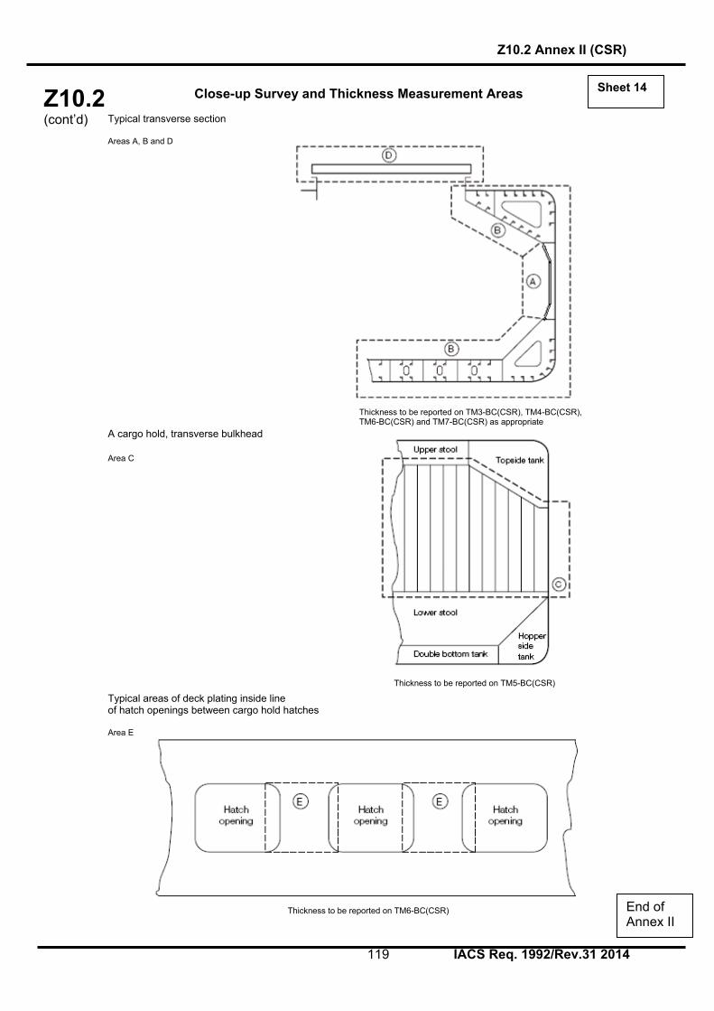
Z10.2 (cont’d)
Z10.2 Annex II (CSR)
119 IACS Req. 1992/Rev.31 2014
Close-up Survey and Thickness Measurement Areas Typical transverse section Areas A, B and D A cargo hold, transverse bulkhead Area C Typical areas of deck plating inside line of hatch openings between cargo hold hatches Area E
Thickness to be reported on TM3-BC(CSR), TM4-BC(CSR), TM6-BC(CSR) and TM7-BC(CSR) as appropriate
Sheet 14
End of Annex II
Thickness to be reported on TM3-BC(CSR), TM4-BC(CSR), TM6-BC(CSR) and TM7-BC(CSR) as appropriate
Thickness to be reported on TM5-BC(CSR)
Thickness to be reported on TM6-BC(CSR)

Z10.2 (cont’d)
Z10.2 Annex III
120 IACS Req. 1992/Rev.31 2014
ANNEX III
GUIDELINES FOR THE GAUGING OF THE VERTICALLY CORRUGATED TRANSVERSE WATERTIGHT BULKHEAD BETWEEN HOLDS NOS. 1 AND 2
1. Gauging is necessary to determine the general condition of the structure and to define
the extent of possible repairs and/or reinforcements of the vertically corrugated transverse watertight bulkhead for verification of the compliance with UR S19.
2. Taking into account the buckling model applied in UR S19 in the evaluation of
strength of the bulkhead, it is essential to determine the thickness diminution at the critical levels shown in Figures 1 and 2.
3. The gauging is to be carried out at the levels as described below. To adequately
assess the scantlings of each individual vertical corrugation, each corrugation flange, web, shedder plate and gusset plate within each of the levels given below are to be gauged.
Level (a) Ships without lower stool (see Figure 1): Locations:
• The mid-breadth of the corrugation flanges at approximately 200 mm above the line of shedder plates;
• The middle of gusset plates between corrugation flanges, where fitted; • The middle of the shedder plates;
• The mid-breadth of the corrugation webs at approximately 200 mm above the line of shedder plates.
Level (b) Ships with lower stool (see Figure 2): Locations:
• The mid-breadth of the corrugation flanges at approximately 200 mm above the line of shedder plates;
• The middle of gusset plates between corrugation flanges, where fitted; • The middle of the shedder plates;
• The mid-breadth of the corrugation webs at approximately 200 mm above the line of shedder plates.
Level (c) Ships with or without lower stool (see Figures 1 and 2): Locations:
• The mid-breadth of the corrugation flanges and webs at about the mid-height of the corrugation.
4. Where the thickness changes within the horizontal levels, the thinner plate is to be
gauged. 5. Steel renewal and/or reinforcement is to comply with S19.

Z10.2 (cont’d)
Z10.2 Annex III
121 IACS Req. 1992/Rev.31 2014
l e v e l cl e v e l c
levelb
F i g u r e 1
l e v e l c
l e v e l a
F i g u r e 2
End of Annex III

Z10.2 (cont’d)
Z10.2 Annex IV
122 IACS Req. 1992/Rev.31 2014
ANNEX IV
ADDITIONAL ANNUAL SURVEY REQUIREMENTS FOR THE FOREMOST CARGO HOLD OF SHIPS SUBJECT TO SOLAS XII/9.1
1 General 1.1 In the case of Bulk Carrier over 5 years of age, the Annual Survey is to include, in addition to the requirements of the Annual Surveys prescribed in chapter 3, an examination of the following items: 1.2 Extent of Survey 1.2.1 For bulk carriers of 5 - 15 years of age: a) An Overall Survey of the foremost cargo hold, including Close-up Survey of sufficient extent, minimum 25% of frames, is to be carried out to establish the condition of: - Shell frames including their upper and lower end attachments, adjacent shell plating,
and transverse bulkheads. - Suspect areas identified at previous surveys (see 1.2.9 of UR Z10.2). b) Where considered necessary by the surveyor as a result of the Overall and Close-up Survey as described in a) above, the survey is to be extended to include a Close-up Survey of all of the shell frames and adjacent shell plating of the cargo hold. 1.2.2 For bulk carriers exceeding 15 years of age: a) An Overall Survey of the foremost cargo hold, including Close-up Survey is to be carried out to establish the condition of: - All shell frames including their upper and lower end attachments, adjacent shell
plating, and transverse bulkheads. - Suspect areas identified at previous surveys (see 1.2.9 of UR Z10.2). 1.3 Extent of Thickness Measurement 1.3.1 Thickness measurement is to be carried out to an extent sufficient to determine both general and local corrosion levels at areas subject to Close-up Survey, as described in 1.2.1 a) and 1.2.2. a) above. The minimum requirement for thickness measurements are suspect areas identified at previous surveys (see 1.2.9 of UR Z10.2). Where Substantial Corrosion as defined in chapter 1.2.9 is found, the extent of thickness measurements should be increased with the requirements of Table VIII. 1.3.2 The thickness measurement may be dispensed with provided the surveyor is satisfied by the Close-up Survey, that there is no structural diminution and the Protective Coating where fitted remains effective.

Z10.2 (cont’d)
Z10.2 Annex IV
123 IACS Req. 1992/Rev.31 2014
1.4 Special Consideration 1.4.1 Where the protective coating in the foremost cargo hold, as defined by Z.9 is found to be in GOOD condition, the extent of close-up surveys and thickness measurements may be specially considered. Explanatory note: For existing bulk carriers, where owners may elect to coat or recoat cargo holds as noted above, consideration may be given to the extent of the close-up and thickness measurement surveys. Prior to the coating of cargo holds of existing ships, scantlings should be ascertained in the presence of a surveyor.
End of Annex IV

Z10.2 (cont’d)
Z10.2 Annex V
124 IACS Req. 1992/Rev.31 2014
ANNEX V
GUIDELINES FOR THE GAUGING OF SIDE SHELL FRAMES AND BRACKETS IN SINGLE SIDE SKIN BULK CARRIERS REQUIRED TO COMPLY WITH UR S31
1. General Gauging is necessary to determine the general condition of the structure and to define the extent of possible steel renewals or other measures for the webs and flanges of side shell frames and brackets for verification of the compliance with UR S31. 2. Zones of Side Shell Frames and Brackets For the purpose of steel renewal, sand blasting and coating, four zones A, B, C and D are defined, as shown in Figure 1. Zones A & B are considered to be the most critical zones.
Lower part of side frame
Figure 1 Zones of Side Shell Frames and Brackets
3. Pitting and grooving Pits can grow in a variety of shapes, some of which would need to be ground before assessment. Pitting corrosion may be found under coating blisters, which must be removed before inspection. To measure the remaining thickness of pits or grooving the normal ultrasonic transducer (generally 10mm diameter) will not suffice. A miniature transducer (3 to 5 mm diameter) must be used. Alternatively the gauging firm must use a pit gauge to measure the depth of the pits and grooving and calculate the remaining thickness.

Z10.2 (cont’d)
Z10.2 Annex V
125 IACS Req. 1992/Rev.31 2014
3.1 Assessment based upon Area This is the method specified in S31.2.5 and is based upon the intensity determined from Figure 2 below.
Figure 2 Pitting intensity diagrams (from 5% to 25% intensity)
If pitting intensity is higher than 15% in an area (see Figure 2), then thickness measurements are to be taken to check the extent of the pitting corrosion. The 15% is based upon pitting or grooving on only one side of the plate. In cases where pitting is evident as defined above (exceeding 15 %) then an area of 300mm diameter or more (or, where this is impracticable on the frame flange or the side shell, hopper tank plating or topside tank plating attached to the side frame, an equivalent rectangular area), at the most pitted part, is to be cleaned to bare metal, and the thickness measured in way of the five deepest pits within the cleaned area. The least thickness measured in way of any of these pits is to be taken as the thickness to be recorded. The minimum acceptable remaining thickness in any pit or groove is equal to: - 75% of the as built thickness, for pitting or grooving in the cargo hold side frame webs
and flanges. - 70% of the as built thickness, for pitting or grooving in the side shell, hopper tank and
topside tank plating attached to the cargo hold side frame, over a width up to 30mm from each side of it.

Z10.2 (cont’d)
Z10.2 Annex V
126 IACS Req. 1992/Rev.31 2014
4. Gauging methodology Numbers of side frames to be measured are equivalent to those of Special Survey or Intermediate Survey corresponding to the ship’s age. Representative thickness measurements are to be taken for each zone as specified below. Special consideration to the extent of the thickness measurements may be given by the Classification Society, if the structural members show no thickness diminution with respect to the as built thicknesses and the coating is found in "as-new" condition (i.e., without breakdown or rusting). Where gauging readings close to the criteria are found, the number of hold frames to be measured is to be increased. If renewal or other measures according to S31 are to be applied on individual frames in a hold, then all frames in that hold are to be gauged. There is a variety of construction methods used for side shell frames in bulk carriers. Some have faceplates (T sections) on the side shell frames, some have flanged plates and some have bulb plates. The use of faceplates and flanged sections is considered similar for gauging purposes in that both the web and faceplate or web and flange plate are to be gauged. If bulb plate has been used, then web of the bulb plate is to be gauged in the normal manner and the sectional modulus has to be specially considered if required. 4.1 Gaugings for Zones A, B & D Web plating The gauging pattern for Zones A, B & D are to be a five point pattern. See Figure 3. The 5 point pattern is to be over the depth of the web and the same area vertically. The gauging report is to reflect the average reading.
Face Plate
Side shell X X
X W mm
WebX X
W mm
Figure 3 Typical 5 point pattern on the web plate

Z10.2 (cont’d)
Z10.2 Annex V
127 IACS Req. 1992/Rev.31 2014
4.2 Gaugings for Zone C Web plating Depending upon the condition of the web in way of Zone C, the web may be measured by taking 3 readings over the length of Zone C and averaging them. The average reading is to be compared with the allowable thickness. If the web plating has general corrosion then this pattern should be expanded to a five point pattern as noted above. 4.3 Gaugings for section a) and b) (flanges and side shell plating) Where the lower bracket length or depth does not meet the requirements in UR S12(Rev.3), gaugings are to be taken at sections a) and b) to calculate the actual section modulus required in UR S31.3.4. See Figure 4. At least 2 readings on the flange/faceplate are to be taken in way of each section. At least one reading of the attached shell plating is to be taken on each side of the frame (i.e. fore and aft) in way of section a) and section b).
hBhB = frame web depth
da = lower bracket web depth for determining t
db
hB = lower bracket length
REN,SSection b)
Section a)
db
da
Figure 4 Sections a) and b) 5 Report on Thickness Measurement of Cargo Hold Frames See form TM7-BC S31 (sheet 11 bis).
End of Annex V

Z10.2 (cont’d)
Z10.2 Annex VI
128 IACS Req. 1992/Rev.31 2014
ANNEX VI

Z10.2 (cont’d)
Z10.2 Annex VIA
129 IACS Req. 1992/Rev.31 2014
ANNEX VIA
SURVEY PROGRAMME Basic information and particulars
Name of ship:
IMO number:
Flag State:
Port of registry:
Gross tonnage:
Deadweight (metric tonnes):
Length between perpendiculars (m):
Shipbuilder:
Hull number:
Classification Society:
Class ID:
Date of build of the ship:
Owner:
Thickness measurement company:
1 Preamble
1.1 Scope
1.1.1 The present survey programme covers the minimum extent of overall surveys, close-up surveys, thickness measurements and pressure testing within the cargo length area, cargo holds, ballast tanks, including fore and aft peak tanks, required by UR Z10.2.
1.1.2 The arrangements and safety aspects of the survey are to be acceptable to the attending surveyor(s).
1.2 Documentation
All documents used in the development of the survey programme are to be available onboard during the survey as required by section 6.
2 Arrangement of cargo holds, tanks and spaces This section of the survey programme is to provide information (either in the form of plans or text) on the arrangement of cargo holds, tanks and spaces that fall within the scope of the survey.
3 List of cargo holds, tanks and spaces with information on their use, extent of coatings and corrosion prevention system

Z10.2 (cont’d)
Z10.2 Annex VIA
130 IACS Req. 1992/Rev.31 2014
This section of the survey programme is to indicate any changes relating to (and is to update) the information on the use of the holds and tanks of the ship, the extent of coatings and the corrosion prevention system provided in the Survey Planning Questionnaire.
4 Conditions for survey
This section of the survey programme is to provide information on the conditions for survey, e.g. information regarding cargo hold and tank cleaning, gas freeing, ventilation, lighting, etc.
5 Provisions and method of access to structures
This section of the survey programme is to indicate any changes relating to (and is to update) the information on the provisions and methods of access to structures provided in the Survey Planning Questionnaire.
6 List of equipment for survey
This section of the survey programme is to identify and list the equipment that will be made available for carrying out the survey and the required thickness measurements.
7 Survey requirements
7.1 Overall survey
This section of the survey programme is to identify and list the spaces that should undergo an overall survey for this ship in accordance with 2.3.1.
7.2 Close-up survey
This section of the survey programme is to identify and list the hull structures that are to undergo a close-up survey for this ship in accordance with 2.3.2.
8 Identification of tanks for tank testing
This section of the survey programme is to identify and list the cargo holds and tanks that are to undergo tank testing for this ship in accordance with 2.5.
9 Identification of areas and sections for thickness measurements This section of the survey programme is to identify and list the areas and sections where thickness measurements are to be taken in accordance with 2.2.4.4 and 2.4.1. 10 Minimum thickness of hull structures
This section of the survey programme is to specify the minimum thickness for hull structures of this ship that are subject to survey, according to (a) or (b): (a) Determined from the attached wastage allowance table and the original
thickness to the hull structure plans of the ship; (b) Given in the following table(s):

Z10.2 (cont’d)
Z10.2 Annex VIA
131 IACS Req. 1992/Rev.31 2014
Area or location Original as-
built thickness
(mm)
Minimum thickness
(mm)
Substantial corrosion thickness
(mm) Deck Plating Longitudinals Longitudinal girders Cross deck plating Cross deck stiffeners Bottom Plating Longitudinals Longitudinal girders Inner bottom Plating Longitudinals Longitudinal girders Floors Ship side in way of topside tanks Plating Longitudinals Ship side in way of hopper side tanks Plating Longitudinals Ship side in way of tanks (if applicable) Plating Longitudinals Longitudinal stringers Ship side in way of cargo holds Plating Side frames webs Side frames flanges Upper brackets webs Upper brackets flanges Lower brackets webs Lower brackets flanges Longitudinal bulkhead (if applicable) Plating Longitudinals (if applicable) Longitudinal girders (if applicable) Transverse bulkheads Plating Stiffeners (if applicable) Upper stool plating Upper stool stiffeners Lower stool plating Lower stool stiffeners Transverse web frames in topside tanks Plating Flanges Stiffeners

Z10.2 (cont’d)
Z10.2 Annex VIA
132 IACS Req. 1992/Rev.31 2014
Transverse web frames in hopper tanks Plating Flanges Stiffeners
Hatch Covers Plating Stiffeners
Hatch Coamings Plating Stiffeners Note: The wastage allowance tables are to be attached to the survey programme. For vessels built under IACS Common Structural Rules, the renewal thickness of the hull structure elements is indicated in the appropriate drawings. 11 Thickness measurement company
This section of the survey programme is to identify changes, if any, relating to the information on the thickness measurement company provided in the Survey Planning Questionnaire.
12 Damage experience related to the ship This section of the survey programme is to, using the tables provided below, provide details of the hull damages for at least the last three years in way of the cargo holds, ballast tanks and void spaces within the cargo length area. These damages are subject to survey.
Hull damages sorted by location for this ship
Cargo hold,
tank or space
number or area
Possible cause, if known
Description of the
damages
Location Repair Date of repair

Z10.2 (cont’d)
Z10.2 Annex VIA
133 IACS Req. 1992/Rev.31 2014
Hull damages for sister or similar ships (if available) in the case of design related damage
Cargo hold, tank or space
number or area
Possible cause, if known
Description of the
damages
Location Repair Date of repair
13 Areas identified with substantial corrosion from previous surveys
This section of the survey programme is to identify and list the areas of substantial corrosion from previous surveys.
14 Critical structural areas and suspect areas
This section of the survey programme is to identify and list the critical structural areas and the suspect areas, when such information is available.
15 Other relevant comments and information This section of the survey programme is to provide any other comments and information relevant to the survey.

Z10.2 (cont’d)
Z10.2 Annex VIA
134 IACS Req. 1992/Rev.31 2014
Appendices
Appendix 1 - List of plans
Paragraph 5.1.3 requires that main structural plans of cargo holds and ballast tanks (scantling drawings), including information regarding use of high tensile steel (HTS) are to be available. This Appendix of the survey programme is to identify and list the main structural plans which form part of the survey programme.
Appendix 2 - Survey Planning Questionnaire
The Survey Planning Questionnaire (annex VIB), which has been submitted by the owner, is to be appended to the survey programme.
Appendix 3 - Other documentation
This part of the survey programme is to identify and list any other documentation that forms part of the plan.
Prepared by the owner in co-operation with the Classification Society for compliance with 5.1.3:
Date:…………………………………(name and signature of authorized owner’s representative) Date:…………………………………(name and signature of authorized representative of the
Classification Society)

Z10.2 (cont’d)
Z10.2 Annex VIB
135 IACS Req. 1992/Rev.31 2014
ANNEX VIB
SURVEY PLANNING QUESTIONNAIRE
1 The following information will enable the owner in co-operation with the Classification Society to develop a Survey Programme complying with the requirements of UR Z10.2. It is essential that the owner provides, when completing the present questionnaire, up-to-date information. The present questionnaire, when completed, shall provide all information and material required by UR Z10.2.
Particulars
Ship’s name: IMO number: Flag State: Port of registry: Owner: Classification Society: Class ID: Gross tonnage: Deadweight (metric tonnes): Date of build:

Z10.2 (cont’d)
Z10.2 Annex VIB
136 IACS Req. 1992/Rev.31 2014
Information on access provision for close-up surveys and thickness measurement 2 The owner is to indicate, in the table below, the means of access to the structures subject to close-up survey and thickness measurement. A close-up survey is an examination where the details of structural components are within the close visual inspection range of the attending surveyor, i.e. preferably within reach of hand.
Hold/ Tank No.
Structure PermanentMeans of Access
Temporary staging
Rafts Ladders Direct access
Other means (please specify)
F.P. Fore Peak A.P. Aft Peak CARGO HOLDS
Hatch side coamings Topside sloping plate Upper stool plating Cross deck Side shell, frames & brackets
Transverse bulkhead Hopper tank plating Lower stool plating Tank top
TOPSIDE TANKS
Underdeck structure Side shell & structure Sloping plate & structure
Webs & bulkheads HOPPER TANKS
Hopper sloping plate & structure
Side shell & structure Bottom structure Webs & bulkheads
Double bottom structure
Upper stool internal structure
Lower stool internal structure

Z10.2 (cont’d)
Z10.2 Annex VIB
137 IACS Req. 1992/Rev.31 2014
History of bulk cargoes of a corrosive nature (e.g. high sulphur content)
Owner’s inspections 3 Using a format similar to that of the table below (which is given as an example), the owner is to provide details of the results of their inspections, for the last 3 years - in accordance with the Guidelines - on all CARGO holds and BALLAST tanks and VOID spaces within the cargo area.
Tank/Hold No.
Corrosion protection
(1)
Coating extent
(2)
Coating condition
(3)
Structural deterioration
(4)
Hold and tank history
(5)
Cargo holds Topside tanks Hopper tanks Double bottom tanks
Upper stools Lower stools Fore peak Aft peak Miscellaneous other spaces:
Note: Indicate tanks which are used for oil/ballast 1) HC=hard coating; SC=soft coating; SH=semi-hard coating; NP=no protection 2) U=upper part; M=middle part; L=lower part; C=complete 3) G=good; F=fair; P=poor; RC=recoated (during the last 3 years) 4) N=no findings recorded; Y=findings recorded, description of findings is to be attached to this questionnaire 5) DR=Damage & Repair; L=Leakages; CV= Conversion (Description to be attached to this questionnaire)

Z10.2 (cont’d)
Z10.2 Annex VIB
138 IACS Req. 1992/Rev.31 2014
Name of owner’s representative: Signature: Date: Reports of Port State Control inspections List the reports of Port State Control inspections containing hull structural related deficiencies, relevant information on rectification of the deficiencies:

Z10.2 (cont’d)
Z10.2 Annex VIB
139 IACS Req. 1992/Rev.31 2014
Safety Management System List non-conformities related to hull maintenance, including the associated corrective actions:
Name and address of the approved thickness measurement company:
Annex VI end Document end

Z10.3 (cont)
Z10.3
Page 1 of 62 IACS Req. 1996/Rev.16 2014
Hull Surveys of Chemical Tankers CONTENTS 1. General 1.1 Application 1.2 Definitions 1.3 Repairs 1.4 Thickness measurements and close-up surveys 2. Special Survey 2.1 Schedule 2.2 Scope 2.2.1 General 2.2.2 Dry Dock Survey 2.2.3 Tank Protection 2.3 Extent of Overall and Close-up Survey 2.4 Extent of Thickness Measurement 2.5 Extent of Tank Testing 2.6 Chemical Tankers over 10 years of Age 3. Annual Survey 3.1 Schedule 3.2 Scope 3.2.1 General 3.2.2 Examination of the Hull 3.2.3 Examination of Weather decks 3.2.4 Examination of Cargo pump rooms and pipe tunnels, if fitted 3.2.5 Examination of Ballast Tanks 4. Intermediate Survey 4.1 Schedule 4.2 Scope 4.2.1 General 4.2.2 Chemical Tankers 5 - 10 years of Age 4.2.3 Chemical Tankers 10 - 15 years of Age 4.2.4 Chemical Tankers over 15 years of Age 5. Preparation for Survey 5.1 Survey Programme 5.2 Conditions for Survey 5.3 Access to Structures 5.4 Equipment for Survey 5.5 Rescue and emergency response equipment 5.6 Survey at Sea or at Anchorage 5.7 Survey Planning Meeting 6. Documentation On Board 6.1 General 6.2 Survey Report File 6.3 Supporting Documents 6.4 Review of Documentation On Board
Z10.3 (1996) (Rev.1 1997) (Rev.2 July 1999) (Rev.3 Sept 2000) (Rev.4 Nov 2000) (Rev.4.1 June 2001) (Rev.5 Mar 2002) (Rev.6 Oct 2002) (Rev.7 June 2005) (Rev.8 Jan 2006) (Corr.1 Sept 2006) (Rev.9 Nov 2007) (Rev.10 Dec 2008) (Rev.11 Mar 2009) (Rev.12 Mar 2011) (Rev.13 July 2011) (Rev.14 Aug 2012) (Rev.15 May 2013) (Rev.16 Jan 2014)

Z10.3 (cont)
Z10.3
Page 2 of 62 IACS Req. 1996/Rev.16 2014
7. Procedures for Thickness Measurements 7.1 General 7.2 Certification of Thickness Measurement Company 7.3 Reporting 8. Reporting and Evaluation of Survey 8.1 Evaluation of Survey Report 8.2 Reporting

Z10.3 (cont)
Z10.3
Page 3 of 62 IACS Req. 1996/Rev.16 2014
ENCLOSURES Table I.1: Minimum requirements for Close-up Survey at Special Survey of Single Skin
Chemical Tankers I.2: Minimum requirements for Close-up Survey at Special Survey of Double Skin
Chemical Tankers Table II: Minimum requirements for thickness measurements at Special Survey of
Chemical Tankers Table III: Minimum requirements for tank testing at Special Survey of Chemical Tankers Table IV: Requirements for extent of thickness measurements at those areas of substantial
corrosion Table V: (deleted, as included in Annex IIIC) Table VII: Procedures for certification of Firms Engaged in Thickness Gauging of Hull
Structures Table VIII: Survey Reporting Principles Table IX: Executive Hull Summary Annex I: Guidelines for Technical Assessment in conjunction with planning for
Enhanced Surveys of Chemical Tankers Special Survey - Hull Annex II: Recommended Procedures for Thickness Measurements of Chemical
Tankers Annex IIIA: Survey Programme
Appendix 1 List of Plans Appendix 2 Survey Planning Questionnaire Appendix 3 Other Documentation
Annex IIIB: Survey Planning Questionnaire Annex IIIC: Owner’s Inspection Report

Z10.3 (cont)
Z10.3
Page 4 of 62 IACS Req. 1996/Rev.16 2014
Notes: 1. This UR Z10.3 is applicable from the first Annual, Intermediate or Special Survey
commencing on or after 1 July 1997. 2. Changes introduced in Rev.2 to UR Z10.3 are to be applied by all Member Societies
and Associates from 1 September 1999. 3. Changes introduced in Rev.3 to UR Z10.3 are to be applied by all Member Societies
and Associates from 1 July 2001. 4. Changes introduced in Rev.4 and Rev.4.1 to UR Z10.3 are to be applied by all
Member Societies and Associates from 1 July 2001. 5. Paragraph 4.2.4.3 is newly introduced in Rev.5 in accordance with Res MSC.105(73)
and is to be implemented from 1 July 2002. The other changes introduced in Rev.5 are to be implemented within one year of the
adoption by Council. 6. Changes introduced in Rev.7 are to be uniformly implemented from 1 July 2006. The
amendments to paragraphs 2.2.3.1 and 4.2.2.2 related to the protective coating condition are to apply to the ballast tanks of which the condition will be assessed at the forthcoming Special Survey and Intermediate Survey on or after 1 July 2006.
7. Changes introduced in Rev.8 (para. 1.4, 5.5.4, 5.5.6 and 7.1.3) are to be uniformly
applied by IACS Societies on surveys commenced on or after 1 January 2007. 8. Changes introduced in Rev.9 are to be uniformly applied by IACS Societies for
surveys commenced on or after the 1 January 2009. 9. Changes introduced in Rev.10 are to be uniformly applied by IACS Societies for
surveys commenced on or after 1 January 2010. 10. Changes introduced in Rev.11 are to be uniformly applied by IACS Societies for
surveys commenced on or after 1 July 2010.
As for the requirements regarding semi-hard coatings, these coatings, if already applied, will not be accepted from the next special or intermediate survey commenced on or after 1 July 2010, whichever comes first, with respect to waiving the annual internal examination of the ballast tanks.
11. Changes introduced in Rev.12 are to be uniformly applied by IACS Societies for
surveys commenced on or after 1 July 2012. 12. Changes introduced in Rev.13 are to be uniformly applied by IACS Societies for
surveys commenced on or after 1 July 2012.
13. Changes introduced in Rev.14 are to be uniformly applied by IACS Societies for surveys commenced on or after 1 July 2013.
14. Changes introduced in Rev.15 are to be uniformly applied by IACS Societies for
surveys commenced on or after 1 July 2014. 15. Changes introduced in Rev.16 are to be uniformly applied by IACS Societies for
surveys commenced on or after 1 January 2015.

Z10.3 (cont)
Z10.3
Page 5 of 62 IACS Req. 1996/Rev.16 2014
1. GENERAL 1.1 Application 1.1.1 The requirements apply to all self-propelled Chemical Tankers with integral tanks i.e. vessels with IMO certificate of fitness for the carriage of dangerous chemicals in bulk. If a chemical tanker is constructed with both integral and independent tanks, these requirements are applicable only to that portion of the cargo length containing integral tanks. Combined gas carriers/chemical tankers with independent tanks within the hull, are to be surveyed as gas carriers. 1.1.2 The requirements apply to surveys of hull structure and piping systems in way of cargo tanks, pump rooms, cofferdams, pipe tunnels, void spaces within the cargo area and all Ballast Tanks. The requirements are additional to the classification requirements applicable to the remainder of the ship. The requirements are not applicable for independent tanks on deck. Refer to Z7. 1.1.3 The requirements contain the minimum extent of examination, thickness measurements and tank testing. The survey is to be extended when Substantial Corrosion and/or structural defects are found and include additional Close-up Survey when necessary. 1.2 Definitions 1.2.1 Chemical Tanker A Chemical Tanker is a ship constructed or adapted and used for the carriage in bulk of any liquid product listed in Chapter 17 of the International Code For The Construction And Equipment Of Ships Carrying Dangerous Chemicals In Bulk, IBC Code. 1.2.2 Ballast Tank A Ballast Tank is a tank which is used solely for the carriage of salt water ballast. 1.2.2 bis A Combined Cargo/Ballast Tank is a tank which is used for the carriage of cargo or ballast water as a routine part of the vessel’s operation and will be treated as a Ballast Tank. Cargo tanks in which water ballast might be carried only in exceptional cases per MARPOL I/18.3 are to be treated as cargo tanks. 1.2.3 Overall Survey An Overall Survey is a survey intended to report on the overall condition of the hull structure and determine the extent of additional Close-up Surveys. 1.2.4 Close-up Survey A Close-up Survey is a survey where the details of structural components are within the close visual inspection range of the surveyor, i.e. normally within reach of hand. 1.2.5 Transverse Section A Transverse Section includes all longitudinal members such as plating, longitudinals and girders at the deck, sides, bottom, inner bottom and longitudinal bulkheads. For transversely framed vessels, a transverse section includes adjacent frames and their end connections in way of transverse sections. 1.2.6 Representative Tank Representative Tanks are those which are expected to reflect the condition of other tanks of similar type and service and with similar corrosion prevention systems. When selecting Representative Tanks account is to be taken of the service and repair history onboard and identifiable Critical Structural Areas and/or Suspect Areas.

Z10.3 (cont)
Z10.3
Page 6 of 62 IACS Req. 1996/Rev.16 2014
1.2.7 Suspect Area Suspect Areas are locations showing Substantial Corrosion and/or are considered by the Surveyor to be prone to rapid wastage. 1.2.8 Critical Structural Area Critical Structural Areas are locations which have been identified from calculations to require monitoring or from the service history of the subject ship or from similar or sister ships (if available) to be sensitive to cracking, buckling or corrosion which would impair the structural integrity of the ship. 1.2.9 Substantial Corrosion Substantial Corrosion is an extent of corrosion such that assessment of corrosion pattern indicate a wastage in excess of 75% of allowable margins, but within acceptable limits. 1.2.10 Corrosion Prevention System A Corrosion Prevention System is normally considered a full hard protective coating. Hard Protective Coating is usually to be epoxy coating or equivalent. Other coating systems, which are neither soft nor semi-hard coatings, may be considered acceptable as alternatives provided that they are applied and maintained in compliance with the manufacturer’s specifications. 1.2.11 Coating condition Coating condition is defined as follows: GOOD condition with only minor spot rusting.
FAIR condition with local breakdown at edges of stiffeners and weld connections and/or light rusting over 20% or more of areas under consideration, but less than as defined for POOR condition.
POOR condition with general breakdown of coating over 20% or more, or hard
scale at 10% or more, of areas under consideration. Reference is made to IACS Recommendation No.87 “Guidelines for Coating Maintenance & Repairs for Ballast Tanks and Combined Tanks on Oil Tankers”. 1.2.12 Cargo Area Cargo Area is that part of the ship which contains cargo tanks, slop tanks and cargo/ballast pump-rooms, cofferdams, ballast tanks and void spaces adjacent to cargo tanks and also deck areas throughout the entire length and breadth of the part of the ship over the above mentioned spaces. 1.2.13 Special consideration Special consideration or specially considered (in connection with close-up surveys and thickness measurements) means sufficient close-up inspection and thickness measurements are to be taken to confirm the actual average condition of the structure under the coating. 1.2.14 Prompt and Thorough Repair A Prompt and Thorough repair is a permanent repair completed at the time of survey to the satisfaction of the Surveyor, therein removing the need for the imposition of any associated condition of classification, or recommendation.

Z10.3 (cont)
Z10.3
Page 7 of 62 IACS Req. 1996/Rev.16 2014
1.3 Repairs 1.3.1 Any damage in association with wastage over the allowable limits (including buckling, grooving, detachment or fracture), or extensive areas of wastage over the allowable limits, which affects or, in the opinion of the Surveyor, will affect the vessel’s structural, watertight or weathertight integrity, is to be promptly and thoroughly (see 1.2.14) repaired. Areas to be considered include: - bottom structure and bottom plating; - side structure and side plating; - deck structure and deck plating; - watertight or oiltight bulkheads; - hatch covers or hatch coamings, where fitted. For locations where adequate repair facilities are not available, consideration may be given to allow the vessel to proceed directly to a repair facility. This may require discharging the cargo and/or temporary repairs for the intended voyage. 1.3.2 Additionally, when a survey results in the identification of structural defects or corrosion, either of which, in the opinion of the Surveyor, will impair the vessel’s fitness for continued service, remedial measures are to be implemented before the ship continues in service. 1.3.3 Where the damage found on structure mentioned in Para. 1.3.1 is isolated and of a localised nature which does not affect the ship's structural integrity, consideration may be given by the surveyor to allow an appropriate temporary repair to restore watertight or weather tight integrity and impose a Recommendation/Condition of Class in accordance with IACS PR 35, with a specific time limit. 1.4 Thickness measurements and close-up surveys In any kind of survey, i.e. special, intermediate, annual or other surveys having the scope of the foregoing ones, thickness measurements of structures in areas where close-up surveys are required shall be carried out simultaneously with close-up surveys.

Z10.3 (cont)
Z10.3
Page 8 of 62 IACS Req. 1996/Rev.16 2014
2. SPECIAL SURVEY1 2.1 Schedule 2.1.1 Special Surveys are to be carried out at 5 years intervals to renew the Classification Certificate. 2.1.2 The first Special Survey is to be completed within 5 years from the date of the initial classification survey and thereafter within 5 years from the credited date of the previous Special Survey. However, an extension of class of 3 months maximum beyond the 5th year can be granted in exceptional circumstances. In this case, the next period of class will start from the expiry date of the Special Survey before the extension was granted. 2.1.3 For surveys completed within 3 months before the expiry date of the Special Survey, the next period of class will start from the expiry date of the Special Survey. For surveys completed more than 3 months before the expiry date of the Special Survey, the period of class will start from the survey completion date. In cases where the vessel has been laid up or has been out of service for a considerable period because of a major repair or modification and the owner elects to only carry out the overdue surveys, the next period of class will start from the expiry date of the special survey. If the owner elects to carry out the next due special survey, the period of class will start from the survey completion date. 2.1.4 The Special Survey may be commenced at the 4th Annual Survey and be progressed with a view to completion by the 5th anniversary date. When the Special Survey is commenced prior to the 4th Annual Survey, the entire survey is to be completed within 15 months if such work is to be credited to the Special Survey. 2.1.5 Concurrent crediting to both Intermediate Survey (IS) and Special Survey (SS) for surveys and thickness measurements of spaces are not acceptable. 2.2 Scope 2.2.1 General 2.2.1.1 The Special Survey is to include, in addition to the requirements of the Annual Survey, examination, tests and checks of sufficient extent to ensure that the hull and related piping, as required in 2.2.1.3, is in a satisfactory condition and is fit for its intended purpose for the new period of class of 5 years to be assigned, subject to proper maintenance and operation and to periodical surveys being carried out at the due dates. 2.2.1.2 All cargo tanks, Ballast Tanks, including double bottom tanks, pump rooms, pipe tunnels, cofferdams and void spaces bounding cargo tanks, decks and outer hull are to be examined, and this examination is to be supplemented by thickness measurement and testing as required in 2.4 and 2.5, to ensure that the structural integrity remains effective. The aim of the examination is to discover Substantial Corrosion, significant deformation, fractures, damages or other structural deterioration, that may be present. 2.2.1.3 Cargo piping on deck and cargo and ballast piping within the above tanks and spaces are to be examined and operationally tested to working pressure to attending Surveyor’s satisfaction to ensure that tightness and condition remain satisfactory. Special attention is to be given to any ballast piping in cargo tanks and cargo piping in ballast tanks and void
1 Some member Societies use the term “Special Periodical Survey” others use the term “Class Renewal Survey” instead of the term “Special Survey”.

Z10.3 (cont)
Z10.3
Page 9 of 62 IACS Req. 1996/Rev.16 2014
spaces, and Surveyors are to be advised on all occasions when this piping, including valves and fittings are open during repair periods and can be examined internally. 2.2.2 Dry Dock Survey 2.2.2.1 A survey in dry dock is to be a part of the Special Survey. The overall and close-up surveys and thickness measurements, as applicable, of the lower portions of the cargo tanks and ballast tanks are to be carried out in accordance with the applicable requirements for special surveys, if not already performed. Note: lower portions of the cargo and ballast tanks are considered to be the parts below light
ballast water line. 2.2.3 Tank Protection 2.2.3.1 Where provided, the condition of the corrosion prevention system of cargo tanks is to be examined. A Ballast Tank is to be examined at subsequent annual intervals where: a. a hard protective coating has not been applied from the time of construction, or b. a soft or semi-hard coating has been applied, or c. substantial corrosion is found within the tank, or d. the hard protective coating is found to be in less than GOOD condition and the hard
protective coating is not repaired to the satisfaction of the Surveyor. Thickness measurements are to be carried out as deemed necessary by the surveyor. 2.3 Extent of Overall and Close-up Survey 2.3.1 An Overall Survey of all tanks and spaces is to be carried out at each Special Survey. 2.3.2 The minimum requirements for Close-up Surveys at Special Survey are given in Table I. The survey of stainless steel tanks may be carried out as an overall survey supplemented by Close-up Survey as deemed necessary by the surveyor. 2.3.3 The Surveyor may extend the Close-up Survey as deemed necessary taking into account the maintenance of the tanks under survey, the condition of the corrosion prevention system and also in the following cases: a) In particular, tanks having structural arrangements or details which have suffered
defects in similar tanks or on similar ships according to available information. b) In tanks which have structures approved with reduced scantlings due to an approved
corrosion control system. 2.3.4 For areas in tanks where hard protective coatings are found to be in a GOOD condition as defined in 1.2.11, the extent of Close-up Surveys according to Table I may be specially considered.

Z10.3 (cont)
Z10.3
Page 10 of 62 IACS Req. 1996/Rev.16 2014
2.4 Extent of Thickness Measurement 2.4.1 The minimum requirements for thickness measurements at Special Survey are given in Table II. Thickness measurement of stainless steel hull structure and piping may be waived, except for clad steel plating. 2.4.2 Provisions for extended measurements for areas with Substantial Corrosion are given in Table IV, and as may be additionally specified in the Survey Programme as required in 5.1. These extended thickness measurements are to be carried out before the survey is credited as completed. Suspect Areas identified at previous Special Surveys are to be examined. Areas of substantial corrosion identified at previous surveys are to have thickness measurements taken. 2.4.3 The Surveyor may further extend the thickness measurements as deemed necessary. 2.4.4 For areas in tanks where hard protective coatings are found to be in a GOOD condition as defined in 1.2.11, the extent of thickness measurements according to Table II may be specially considered. 2.4.5 Transverse sections are to be chosen where the largest reductions are suspected to occur or are revealed from deck plating measurements. 2.4.6 In cases where two or three sections are to be measured, at least one is to include a Ballast Tank within 0.5L amidships. 2.5 Extent of Tank Testing 2.5.1 The minimum requirements for ballast tank testing at Special Survey are given in 2.5.3 and Table III. The minimum requirements for cargo tank testing at Special Survey are given in 2.5.4 and Table III. Cargo tank testing carried out by the vessel’s crew under the direction of the Master may be accepted by the surveyor provided the following conditions are complied with: a) a tank testing procedure has been submitted by the owner and reviewed by the
Society prior to the testing being carried out; b) there is no record of leakage, distortion or substantial corrosion that would affect the
structural integrity of the tank; c) the tank testing has been satisfactorily carried out within special survey window not
more than 3 months prior to the date of the survey on which the overall or close up survey is completed;
d) the satisfactory results of the testing is recorded in the vessel’s logbook; e) the internal and external condition of the tanks and associated structure are found
satisfactory by the surveyor at the time of the overall and close up survey. 2.5.2 The Surveyor may extend the tank testing as deemed necessary. 2.5.3 Boundaries of ballast tanks are to be tested with a head of liquid to the top of air pipes. 2.5.4 Boundaries of cargo tanks are to be tested to the highest point that liquid will rise under service conditions.

Z10.3 (cont)
Z10.3
Page 11 of 62 IACS Req. 1996/Rev.16 2014
2.5.5 The testing of double bottom tanks and other spaces not designed for the carriage of liquid may be omitted, provided a satisfactory internal examination together with an examination of the tanktop is carried out. 2.6 Chemical Tankers over 10 Years of Age 2.6.1 Selected steel cargo pipes outside cargo tanks and ballast pipes passing through cargo tanks are to be: - Thickness measured at random or selected pipe lengths to be opened for internal
inspection; - Pressure tested to the maximum working pressure. Special attention is to be given to cargo/slop discharge piping through Ballast Tanks and void spaces.

Z10.3 (cont)
Z10.3
Page 12 of 62 IACS Req. 1996/Rev.16 2014
3. ANNUAL SURVEY 3.1 Schedule 3.1.1 Annual Surveys are to be held within 3 months before or after anniversary date from the date of the initial classification survey or of the date credited for the last Special Survey. 3.2 Scope 3.2.1 General 3.2.1.1 The survey is to consist of an examination for the purpose of ensuring, as far as practicable, that the hull and piping are maintained in a satisfactory condition. 3.2.2 Examination of the Hull 3.2.2.1 Examination of the hull plating and its closing appliances as far as can be seen. 3.2.2.2 Examination of watertight penetrations as far as practicable. 3.2.3 Examination of weather decks 3.2.3.1 Examination of cargo tank openings including gaskets, covers, coamings and flame screens. 3.2.3.2 Examination of cargo tanks pressure/vacuum valves and flame screens. 3.2.3.3 Examination of flame screens on vents to all bunker tanks. 3.2.3.4 Examination of cargo, bunker and vent piping systems, including vent masts and headers. 3.2.4 Examination of Cargo pump rooms and pipe tunnels if fitted 3.2.4.1 Examination of all pump room bulkheads for signs of chemical leakage or fractures and, in particular, the sealing arrangements of all penetrations of pump room bulkheads. 3.2.4.2 Examination of the condition of all piping systems. 3.2.5 Examination of Ballast Tanks 3.2.5.1 Examination of Ballast Tanks where required as a consequence of the results of the Special Survey (see 2.2.3) and Intermediate Survey (see 4.2.2.1 and 4.2.2.2) is to be carried out. When considered necessary by the surveyor, or when extensive corrosion exists, thickness measurements are to be carried out and if the results of these thickness measurements indicate that Substantial Corrosion is found, the extent of thickness measurements is to be increased in accordance with Table IV. These extended thickness measurements are to be carried out before the survey is credited as completed. Suspect Areas identified at previous Surveys are to be examined. Areas of substantial corrosion identified at previous surveys are to have thickness measurements taken.

Z10.3 (cont)
Z10.3
Page 13 of 62 IACS Req. 1996/Rev.16 2014
4. INTERMEDIATE SURVEY 4.1 Schedule 4.1.1 The Intermediate Survey is to be held at or between either the 2nd or 3rd Annual Survey. 4.1.2 Those items which are additional to the requirements of the Annual Survey may be surveyed either at or between the 2nd and 3rd Annual Survey. 4.1.3 Concurrent crediting to both Intermediate Survey (IS) and Special Survey (SS) for surveys and thickness measurements of spaces are not acceptable. 4.2 Scope 4.2.1 General 4.2.1.1 The survey extent is dependent on the age of the vessel as specified in 4.2.2 to 4.2.4. 4.2.1.2 For weather decks, an examination as far as applicable of cargo, bunker, ballast, steam and vent piping systems as well as vent masts and headers is to be carried out. If upon examination there is any doubt as to the condition of the piping, the piping may be required to be pressure tested, thickness measured or both. 4.2.2 Chemical Tankers between 5 and 10 Years of Age The following is to apply: 4.2.2.1 For ballast tanks, an Overall Survey of Representative Tanks selected by the Surveyor is to be carried out. If such inspections reveal no visible structural defects, the examination may be limited to a verification that the hard protective coating remains in GOOD condition. 4.2.2.2 A Ballast Tank is to be examined at subsequent annual intervals where: a. a hard protective coating has not been applied from the time of construction, or b. a soft or semi-hard coating has been applied, or c. substantial corrosion is found within the tank, or d. the hard protective coating is found to be in less than GOOD condition and the hard
protective coating is not repaired to the satisfaction of the Surveyor. 4.2.2.3 In addition to the requirements above, suspect areas identified at previous surveys are to be examined. 4.2.3 Chemical Tankers between 10 and 15 years of Age The following is to apply: 4.2.3.1 The requirements of the Intermediate Survey are to be to the same extent as the previous Special Survey as required in 2 and 5.1. However, pressure testing of cargo and ballast tanks is not required unless deemed necessary by the attending Surveyor.
Z10.3 (cont)
Z10.3
Page 14 of 62 IACS Req. 1996/Rev.16 2014
4.2.3.2 In application of 4.2.3.1, the intermediate survey may be commenced at the second annual survey and be progressed during the succeeding year with a view to completion at the third annual survey in lieu of the application of 2.1.4. 4.2.3.3 In application of 4.2.3.1, an under water survey may be considered in lieu of the requirements of 2.2.2. 4.2.4 Chemical Tankers over 15 years of Age The following is to apply: 4.2.4.1 The requirements of the Intermediate Survey are to be to the same extent as the previous Special Survey as required in 2 and 5.1. However, pressure testing of cargo and ballast tanks is not required unless deemed necessary by the attending Surveyor. 4.2.4.2 In application of 4.2.4.1, the intermediate survey may be commenced at the second annual survey and be progressed during the succeeding year with a view to completion at the third annual survey in lieu of the application of 2.1.4. 4.2.4.3 In application of 4.2.4.1, a survey in dry dock is to be part of the intermediate survey. The overall and close-up surveys and thickness measurements, as applicable, of the lower portions of the cargo tanks and water ballast tanks are to be carried out in accordance with the applicable requirements for intermediate surveys, if not already performed. Note: lower portions of the cargo and ballast tanks are considered to be the parts below light
ballast water line.

Z10.3 (cont)
Z10.3
Page 15 of 62 IACS Req. 1996/Rev.16 2014
5. PREPARATION FOR SURVEY 5.1 Survey Programme 5.1.1 The Owner in co-operation with the Classification Society is to work out a specific Survey Programme prior to the commencement of any part of: - the Special Survey; - the Intermediate Survey for chemical tankers over 10 years of age. The Survey Programme at Intermediate Survey may consist of the Survey Programme at the previous Special Survey supplemented by the Executive Hull Summary of that Special Survey and later relevant survey reports. The Survey Programme is to be worked out taking into account any amendments to the survey requirements implemented after the last Special Survey carried out. The Survey Programme is to be in a written format based on the information in annex IIIA. 5.1.1.1 Prior to the development of the survey programme, the survey planning questionnaire is to be completed by the owner based on the information set out in annex IIIB, and forwarded to the Classification Society. 5.1.2 In developing the Survey Programme, the following documentation is to be collected and consulted with a view to selecting tanks, areas, and structural elements to be examined: .1 Survey status and basic ship information; .2 Documentation on-board, as described in 6.2 and 6.3; .3 Main structural plans of cargo and ballast tanks (scantling drawings), including
information regarding use of high tensile steels (HTS), clad steel and stainless steel; .4 Executive Hull Summary; .5 Relevant previous damage and repair history; .6 Relevant previous survey and inspection reports from both Classification Society and
the owner; .7 Information regarding the use of the ship's tanks, typical cargoes and other relevant
data; .8 details of the inert gas plant and tank cleaning procedures; .9 information and other relevant data regarding conversion or modification of the ship’s
cargo and ballast tanks since the time of construction; .10 description and history of the coating and corrosion protection system (previous class
notations), if any; .11 inspections by the Owner’s personnel during the last 3 years with reference to
structural deterioration in general, leakages in tank boundaries and piping and condition of the coating and corrosion protection system, if any;

Z10.3 (cont)
Z10.3
Page 16 of 62 IACS Req. 1996/Rev.16 2014
.12 information regarding the relevant maintenance level during operation including port state control reports of inspection containing hull related deficiencies, Safety Management System non-conformities relating to hull maintenance, including the associated corrective action(s); and
.13 any other information that will help identify suspect areas and critical structural areas. 5.1.3 The submitted Survey Programme is to account for and comply, as a minimum, with the requirements of Tables I, II, 2.5 and 2.6 for close-up survey, thickness measurement, tank testing and pipe testing, respectively, and is to include relevant information including at least: .1 Basic ship information and particulars; .2 Main structural plans (scantling drawings), including information regarding use of high
tensile steels (HTS), clad steel and stainless steel; .3 Plan of tanks; .4 List of tanks with information on use, corrosion prevention and condition of coating; .5 Conditions for survey (e.g., information regarding tank cleaning, gas freeing,
ventilation, lighting, etc.); .6 Provisions and methods for access to structures; .7 Equipment for surveys; .8 Nomination of tanks and areas for close-up survey (per 2.3); .9 Nomination of sections for thickness measurement (per 2.4); .10 Nomination of tanks for tank testing (per 2.5); and the pipes that are to undergo pipe
testing as per 2.6; .11 Identification of the thickness measurement company; .12 Damage experience related to the ship in question; .13 Critical structural areas and suspect areas, where relevant. 5.1.4 The Classification Society will advise the Owner of the maximum acceptable structural corrosion diminution levels applicable to the vessel. 5.1.5 Use may also be made of the Guidelines for Technical Assessment in Conjunction with Planning for Enhanced Surveys of Chemical Tankers Special Survey - Hull, contained in Annex I. These guidelines are a recommended tool which may be invoked at the discretion of the Classification Society, when considered necessary and appropriate, in conjunction with the preparation of the required Survey Programme. 5.2 Conditions For Survey 5.2.1 The Owner is to provide the necessary facilities for a safe execution of the survey.

Z10.3 (cont)
Z10.3
Page 17 of 62 IACS Req. 1996/Rev.16 2014
5.2.1.1 In order to enable the attending surveyors to carry out the survey, provisions for proper and safe access are to be agreed between the owner and the Classification society are to be in accordance with IACS PR 37. 5.2.1.2 Details of the means of access are to be provided in the survey planning questionnaire. 5.2.1.3 In cases where the provisions of safety and required access are judged by the attending surveyors not to be adequate, the survey of the spaces involved is to not proceed. 5.2.2 Tanks and spaces are to be safe for access. Tanks and spaces are to be gas free and properly ventilated. Prior to entering a tank, void or enclosed space, it is to be verified that the atmosphere in that space is free from hazardous gas and contains sufficient oxygen. 5.2.3 In preparation for survey and thickness measurements and to allow for a thorough examination, all spaces are to be cleaned including removal from surfaces of all loose accumulated corrosion scale. Spaces are to be sufficiently clean and free from water, scale, dirt, oil residues etc. to reveal corrosion, deformation, fractures, damages, or other structural deterioration as well as the condition of the coating. However, those areas of structure whose renewal has already been decided by the owner need only be cleaned and descaled to the extent necessary to determine the limits of the areas to be renewed. 5.2.4 Sufficient illumination is to be provided to reveal significant corrosion, deformation, fractures, damages or other structural deterioration. 5.2.5 Where soft or semi-hard coatings have been applied, safe access is to be provided for the Surveyor to verify the effectiveness of the coating and to carry out an assessment of the conditions of internal structures which may include spot removal of the coating. When safe access cannot be provided, the soft or semi-hard coating is to be removed. 5.2.6 The surveyor(s) are to always be accompanied by at least one responsible person, assigned by the owner, experienced in tank and enclosed spaces inspection. In addition a back-up team of at least two experienced persons is to be stationed at the hatch opening of the tank or space that is being surveyed. The back-up team is to continuously observe the work in the tank or space and is to keep lifesaving and evacuation equipment ready for use. 5.2.7 A communication system is to be arranged between the survey party in the tank or space being examined, the responsible officer on deck and, as the case may be, the navigation bridge. The communication arrangements are to be maintained throughout the survey. 5.3 Access to Structures 5.3.1 For overall survey, means are to be provided to enable the surveyor to examine the hull structure in a safe and practical way. 5.3.2 For close-up survey, one or more of the following means for access, acceptable to the Surveyor, is to be provided: - permanent staging and passages through structures; - temporary staging and passages through structures; - hydraulic arm vehicles such as conventional cherry pickers, lifts and movable
platforms; - boats or rafts; - portable ladders;

Z10.3 (cont)
Z10.3
Page 18 of 62 IACS Req. 1996/Rev.16 2014
- other equivalent means. 5.4 Equipment for Survey 5.4.1 Thickness measurement is normally to be carried out by means of ultrasonic test equipment. The accuracy of the equipment is to be proven to the Surveyor as required. 5.4.2 One or more of the following fracture detection procedures may be required if deemed necessary by the Surveyor: - radiographic equipment; - ultrasonic equipment; - magnetic particle equipment; - dye penetrant. 5.4.3 Explosimeter, oxygen-meter, breathing apparatus, lifelines, riding belts with rope and hook and whistles together with instructions and guidance on their use are to be made available during the survey. A safety check-list is to be provided. 5.4.4 Adequate and safe lighting is to be provided for the safe and efficient conduct of the survey. 5.4.5 Adequate protective clothing is to be made available and used during the survey (e.g. safety helmet, gloves, safety shoes, etc.). 5.5 Rescue and emergency response equipment If breathing apparatus and/or other equipment is used as ‘Rescue and emergency response equipment’ then it is recommended that the equipment should be suitable for the configuration of the space being surveyed. 5.6 Survey at Sea or at Anchorage 5.6.1 Survey at sea or at anchorage may be accepted provided the Surveyor is given the necessary assistance from the personnel onboard. Necessary precautions and procedures for carrying out the survey are to be in accordance with 5.1, 5.2, 5.3 and 5.4. 5.6.2 A communication system is to be arranged between the survey party in the tank and the responsible officer on deck. This system is to include the personnel in charge of Ballast pump handling if boats or rafts are used. 5.6.3 Surveys of tanks by means of boats or rafts may only be undertaken with the agreement of the Surveyor, who is to take into account the safety arrangements provided, including weather forecasting and ship response under foreseeable conditions and provided the expected rise of water within the tank does not exceed 0.25m. 5.6.4 When rafts or boats are used for close-up surveys, the following conditions are to be observed: .1 only rough duty, inflatable rafts or boats, having satisfactory residual buoyancy and
stability even if one chamber is ruptured, should be used; .2 the boat or raft should be tethered to the access ladder and an additional person
should be stationed down the access ladder with a clear view of the boat or raft;

Z10.3 (cont)
Z10.3
Page 19 of 62 IACS Req. 1996/Rev.16 2014
.3 appropriate lifejackets should be available for all participants; .4 the surface of water in the tank should be calm (under all foreseeable conditions the
expected rise of water within the tank should not exceed 0.25 m) and the water level stationary. On no account should the level of the water be rising while the boat or raft is in use;
.5 the tank or space must contain clean ballast water only. Even a thin sheen of cargo on
the water is not acceptable; .6 at no time should the water level be allowed to be within 1 m of the deepest under
deck web face flat so that the survey team is not isolated from a direct escape route to the tank hatch. Filling to levels above the deck transverses should only be contemplated if a deck access manhole is fitted and open in the bay being examined, so that an escape route for the survey party is available at all times. Other effective means of escape to the deck may be considered;
.7 if the tanks (or spaces) are connected by a common venting system, or inert gas
system, the tank in which the boat or raft should be used should be isolated to prevent a transfer of gas from other tanks (or spaces).
5.6.5 Rafts or boats alone may be allowed for inspection of the under deck areas for tanks or spaces, if the depth of the webs is 1.5 m or less. 5.6.6 If the depth of the webs is more than 1.5 m, rafts or boats alone may be allowed only: .1 when the coating of the under deck structure is in GOOD condition and there is no
evidence of wastage; or .2 if a permanent means of access is provided in each bay to allow safe entry and exit. This means:
i. access direct from the deck via a vertical ladder and a small platform fitted approximately 2 m below the deck in each bay; or
ii. access to deck from a longitudinal permanent platform having ladders
to deck in each end of the tank. The platform shall, for the full length of the tank, be arranged in level with, or above, the maximum water level needed for rafting of under deck structure. For this purpose, the ullage corresponding to the maximum water level is to be assumed not more than 3 m from the deck plate measured at the midspan of deck transverses and in the middle length of the tank (See Figure 1).
If neither of the above conditions are met, then staging or an “other equivalent means” is to be provided for the survey of the under deck areas.
3.0m3.0m
Figure 1

Z10.3 (cont)
Z10.3
Page 20 of 62 IACS Req. 1996/Rev.16 2014
5.6.7 The use of rafts or boats alone in paragraphs 5.6.5 and 5.6.6 does not preclude the use of boats or rafts to move about within a tank during a survey. Reference is made to IACS Recommendation 39 - Guidelines for the use of Boats or Rafts for Close-up surveys. 5.7 Survey Planning Meeting 5.7.1 Proper preparation and close co-operation between the attending surveyor(s) and the owner’s representatives onboard prior to and during the survey are an essential part in the safe and efficient conduct of the survey. During the survey on board safety meetings are to be held regularly. 5.7.2 Prior to the commencement of any part of the Special and Intermediate Survey a survey planning meeting is to be held between the attending Surveyor(s), the Owner’s Representative in attendance and the TM company representative, where involved, and the master of the ship or an appropriately qualified representative appointed by the master or Company for the purpose of ascertaining that all the arrangements envisaged in the survey programme are in place, so as to ensure the safe and efficient conduct of the survey work to be carried out. See also 7.1.2. 5.7.3 The following is an indicative list of items that are to be addressed in the meeting: .1 schedule of the vessel (i.e. the voyage, docking and undocking manoeuvres, periods
alongside, cargo and ballast operations etc.); .2 provisions and arrangements for thickness measurements (i.e. access, cleaning/de-
scaling, illumination, ventilation, personal safety); .3 extent of the thickness measurements; .4 acceptance criteria (refer to the list of minimum thicknesses); .5 extent of close-up survey and thickness measurement considering the coating
condition and suspect areas/areas of substantial corrosion; .6 execution of thickness measurements; .7 taking representative readings in general and where uneven corrosion/pitting is found; .8 mapping of areas of substantial corrosion; and .9 communication between attending surveyor(s) the thickness measurement company
operator(s) and owner representative(s) concerning findings.

Z10.3 (cont)
Z10.3
Page 21 of 62 IACS Req. 1996/Rev.16 2014
6. DOCUMENTATION ON BOARD 6.1 General 6.1.1 The owner is to obtain, supply and maintain on board documentation as specified in 6.2 and 6.3, which is to be readily available for the Surveyor. 6.1.2 The documentation is to be kept on board for the lifetime of the ship. 6.2 Survey Report File 6.2.1 A Survey Report File is to be a part of the documentation on board consisting of - Reports of structural surveys; - Executive Hull Summary; - Thickness measurement reports. 6.2.2 The Survey Report File is to be available also in the Owner's and the Classification Society's management offices. 6.3 Supporting Documents 6.3.1 The following additional documentation is to be available onboard: - Survey Programme as required by 5.1 until such time as the Special Survey or
Intermediate Survey, as applicable, has been completed; - Main structural plans of cargo and ballast tanks; - Previous repair history; - Cargo and ballast history; - Extent of use of inert gas plant and tank cleaning procedures; - Inspections by ship's personnel with reference to - structural deterioration in general - leakage in bulkheads and piping - condition of corrosion prevention system, if any; - Any other information that will help identify Critical Structural Areas and/or Suspect
Areas requiring inspection. 6.4 Review of Documentation On Board 6.4.1 Prior to survey, the Surveyor is to examine the completeness of the documentation onboard, and its contents as a basis for the survey.

Z10.3 (cont)
Z10.3
Page 22 of 62 IACS Req. 1996/Rev.16 2014
7. PROCEDURES FOR THICKNESS MEASUREMENTS 7.1 General 7.1.1 The required thickness measurements, if not carried out by the Society itself, are to be witnessed by a Surveyor of the Society. The Surveyor is to be on board to the extent necessary to control the process. 7.1.2 The thickness measurement company is to be part of the survey planning meeting to be held prior to commencing the survey. 7.1.3 Thickness measurements of structures in areas where close-up surveys are required shall be carried out simultaneously with close-up surveys. 7.1.4 In all cases the extent of the thickness measurements are to be sufficient as to represent the actual average condition. 7.2 Certification of Thickness Measurement Company 7.2.1 The thickness measurements are to be carried out by a qualified company certified by the Classification Society according to principles stated in Table VII. 7.3 Reporting 7.3.1 A thickness measurement report is to be prepared. The report is to give the location of measurements, the thickness measured as well as corresponding original thickness. Furthermore, the report is to give the date when the measurements were carried out, type of measurement equipment, names of personnel and their qualifications and has to be signed by the operator. The thickness measurement report is to follow the principles as specified in the Recommended Procedures for Thickness Measurements of Chemical Tankers, contained in Annex II. 7.3.2 The Surveyor is to review the final thickness measurement report and countersign the cover page.

Z10.3 (cont)
Z10.3
Page 23 of 62 IACS Req. 1996/Rev.16 2014
8. REPORTING AND EVALUATION OF SURVEY 8.1 Evaluation of Survey Report 8.1.1 The data and information on the structural condition of the vessel collected during the survey is to be evaluated for acceptability and continued structural integrity of the vessel. 8.2 Reporting 8.2.1 Principles for survey reporting are shown in Table VIII. 8.2.2 When a survey is split between different survey stations, a report is to be made for each portion of the survey. A list of items examined and / or tested (pressure testing, thickness measurements etc.) and an indication of whether the item has been credited, are to be made available to the next attending Surveyor(s), prior to continuing or completing the survey. 8.2.3 An Executive Hull Summary of the survey and results is to be issued to the Owner as shown in Table IX and placed on board the vessel for reference at future surveys. The Executive Hull Summary is to be endorsed by the Classification Society's head office or regional managerial office.

Z10.3 (cont)
Z10.3
Page 24 of 62 IACS Req. 1996/Rev.16 2014
TABLE I.1
MINIMUM REQUIREMENTS FOR CLOSE-UP SURVEY AT SPECIAL SURVEY OF SINGLE SKIN CHEMICAL TANKERS
Special Survey No.1
age < 5 Special Survey No.2
5 < age < 10 Special Survey No.3
10 < age < 15 Special Survey No.4
and Subsequent: age > 15
A ONE WEB FRAME RING - in a ballast wing tank
A
ALL WEB FRAME RINGS - in a ballast wing tank or double bottom ballast tank
(see Note I)
A ALL WEB FRAME RINGS - in all ballast tanks
As special survey No.3
B
ONE DECK TRANSVERSE - in a cargo tank or on deck
B B
ONE DECK TRANSVERSE - in each remaining ballast tank or on deck ONE DECK TRANSVERSE - in a cargo wing tank or on deck
A ALL WEB FRAME RINGS - in a cargo wing tank
Additional transverse areas as deemed necessary by the Society
D ONE TRANSVERSE BULKHEAD - lower part in a ballast tank
B ONE DECK TRANSVERSE - in two cargo centre tanks or on deck
A ONE WEB FRAME RING - in each remaining cargo tank
D ONE TRANSVERSE BULKHEAD - lower part in a cargo wing tank
C
BOTH TRANSVERSE BULKHEADS - in a ballast wing tank
C ALL TRANSVERSE BULKHEADS - in all cargo tanks
D ONE TRANSVERSE BULKHEAD - lower part in a cargo centre tank (see Note II)
D ONE TRANSVERSE BULKHEAD - lower part in each remaining ballast tank
C ALL TRANSVERSE BULKHEADS - in all ballast tanks
D ONE TRANSVERSE BULKHEAD - lower part in two cargo centre tanks (see Note II)
D ONE TRANSVERSE BULKHEAD - lower part in a cargo wing tank

Z10.3 (cont)
Z10.3
Page 25 of 62 IACS Req. 1996/Rev.16 2014
Note I: Ballast double hull tank: means double bottom tank plus double side tank plus double deck tank, as applicable, even if these tanks are separate. Note II: Where no centre cargo tanks are fitted (as in case of centre longitudinal bulkhead), transverse bulkheads in wing tanks are to be surveyed. A-D: are areas to be subjected to close-up surveys and thickness measurements (see Fig. 2.1 and 2.2). A) Complete transverse web frame ring including adjacent structural members. B) Deck transverse including adjacent deck structural members. C) Transverse bulkhead complete - including girder system and adjacent structural members. D) Transverse bulkhead lower part - including girder system and adjacent structural members.

Z10.3 (cont)
Z10.3
Page 26 of 62 IACS Req. 1996/Rev.16 2014
TABLE I.2
MINIMUM REQUIREMENTS FOR CLOSE-UP SURVEY
AT SPECIAL SURVEY OF DOUBLE SKIN CHEMICAL TANKERS
Special Survey No.1 age < 5
Special Survey No.25 < age < 10
Special Survey No.3 10 < age < 15
Special Survey No.4 and Subsequent:
age > 15
(1) ONE WEB FRAME RING - in a ballast double hull tank (see Note I)
(1)
ALL WEB FRAME RINGS - in a ballast wing tank or ballast double hull tank (see Note I)
(1) ALL WEB FRAME RINGS - in all ballast tanks
As special survey No.3
(2)
ONE DECK TRANSVERSE - in a cargo tank or on deck
(6) THE KNUCKLE AREA AND THE UPPER PART (3 metres approx) of one web frame in each remaining ballast tank
(7) ALL WEB FRAME RINGS - in a cargo wing tank
Additional transverse areas as deemed necessary by the Society
(4) ONE TRANSVERSE BULKHEAD - in a ballast tank (see Note I)
(7) ONE WEB FRAME RING - in each remaining cargo tank
(5) ONE TRANSVERSE BULKHEAD - in a cargo wing tank
(2) ONE DECK TRANSVERSE - in two cargo tanks
(3) ALL TRANSVERSE BULKHEADS - in all cargo tanks
(5) ONE TRANSVERSE BULKHEAD - in a cargo centre tank (see Note II)
(4)
ONE TRANSVERSE BULKHEAD - in each ballast tank (see Note I)
(4) ALL TRANSVERSE BULKHEADS - in all ballast tanks
(5) ONE TRANSVERSE BULKHEAD - in two cargo centre tanks (see Note II)
(5) ONE TRANSVERSE BULKHEAD - in a cargo wing tank

Z10.3 (cont)
Z10.3
Page 27 of 62 IACS Req. 1996/Rev.16 2014
(1), (2), (3), (4), (5), (6) and (7) are areas to be subjected to close-up surveys and thickness measurements (see Figures 2.1 - 2.3). (1): Web frame in a ballast tank means vertical web in side tank, hopper web in hopper tank, floor in double bottom tank and deck transverse in double deck tank (where fitted), including adjacent structural members. In fore and aft peak tanks web frame means a complete transverse web frame ring including adjacent structural members. (2): Deck transverse, including adjacent deck structural members (or external structure on deck in way of the tank, where applicable). (3): Transverse bulkhead complete in cargo tanks, including girder system, adjacent structural members (such as longitudinal bulkheads) and internal structure of lower and upper stools, where fitted. (4): Transverse bulkhead complete in ballast tanks, including girder system and adjacent structural members, such as longitudinal bulkheads, girders in double bottom tanks, inner bottom plating, hopper side, connecting brackets. (5): Transverse bulkhead lower part in cargo tank, including girder system, adjacent structural members (such as longitudinal bulkheads) and internal structure of lower stool, where fitted. (6): The knuckle area and the upper part (3 metres approximately), including adjacent structural members. Knuckle area is the area of the web frame around the connections of the slope hopper plating to the inner hull bulkhead and the inner bottom plating, up to 2 metres from the corners both on the bulkhead and the double bottom. (7): Web frame in a cargo tank means deck transverse, longitudinal bulkhead vertical girder and cross ties, where fitted, including adjacent structural members. Note I: Ballast double hull tank: means double bottom tank plus double side tank plus double deck tank, as applicable, even if these tanks are separate. Note II: Where no centre cargo tanks are fitted (as in the case of centre longitudinal bulkhead), transverse bulkheads in wing tanks are to be surveyed.
Fig. 2.1 Representative transverse section of chemical tanker. Areas A & B and 1 and 2
A, (1)
B, (2)

Z10.3 (cont)
Z10.3
Page 28 of 62 IACS Req. 1996/Rev.16 2014
Fig. 2.2 Representative transverse section of chemical tanker. Areas C & D and 3, 4 and 5
Fig. 2.3 Representative transverse section of chemical tanker. Areas 6 and 7
(7)
(7)
(6)
(6)
C, (3)
D, (5)
(4)

Z10.3 (cont)
Z10.3
Page 29 of 62 IACS Req. 1996/Rev.16 2014
TABLE II
MINIMUM REQUIREMENTS FOR THICKNESS MEASUREMENTS AT SPECIAL SURVEY OF CHEMICAL TANKERS
Special Survey No.1
age < 5 Special Survey No.2
5 < age ≤ 10 Special Survey No.3
10 < age ≤ 15 Special Survey No.4
and Subsequent age > 15
1. Suspect areas 1. Suspect areas 1. Suspect areas 1. Suspect areas
2. One section of deck plating for the full beam of the ship within the cargo area (in way of a ballast tank, if any, or a cargo tank used primarily for water ballast)
2. Within the cargo area: 2. Within the cargo area: 2. Within the cargo area:
.1 .2
Each deck plate One transverse section
.1 .2 .3
Each deck plate Two transverse sections (1) All wind and water strakes
.1 .2 .3
Each deck plate Three transverse sections (1) Each bottom plate
3. Selected wind and water strakes outside the cargo area
3. Selected wind and water strakes outside the cargo area
3. All wind and water strakes, full length
4. Measurements, for general assessment and recording of corrosion pattern, of those structural members subject to close-up survey according to Table I.
4. Measurements, for general assessment and recording of corrosion pattern, of those structural members subject to close-up survey according to Table I.
4. Measurements, for general assessment and recording of corrosion pattern, of those structural members subject to close-up survey according to Table I.
4. Measurements, for general assessment and recording of corrosion pattern, of those structural members subject to close-up survey according to Table I.
(1): at least one section is to include a ballast tank within 0.5L amidships.

Z10.3 (cont)
Z10.3
Page 30 of 62 IACS Req. 1996/Rev.16 2014
TABLE III MINIMUM REQUIREMENTS FOR TANK TESTING AT SPECIAL SURVEY OF CHEMICAL TANKERS
Special Survey No.1 age ≤ 5
Special Survey No.2 and Subsequent age > 5
All ballast tank boundaries
All ballast tank boundaries
Cargo tank boundaries facing ballast tanks, void spaces, pipe tunnels, pump rooms or cofferdams
All cargo tank bulkheads

Z10.3 (cont)
Z10.3
Page 31 of 62 IACS Req. 1996/Rev.16 2014
TABLE IV/Sheet 1
REQUIREMENTS FOR EXTENT OF THICKNESS MEASUREMENTS AT THOSE AREAS OF SUBSTANTIAL CORROSION. SPECIAL SURVEY OF CHEMICAL TANKERS WITHIN THE CARGO AREA LENGTH.
BOTTOM, INNER BOTTOM AND HOPPER STRUCTURE
Structural member
Extent of measurement Pattern of measurement
Bottom, inner bottom and hopper structure plating
Minimum of three bays across tank, including aft bay Measurements around and under all suction bell mouths
5-point pattern for each panel between longitudinals and floors
Bottom, inner bottom and hopper structure longitudinals
Minimum of three longitudinals in each bay where bottom plating measured
Three meaurements in line across the flange and three measurements on vertical web
Bottom girders, including the watertight ones
At fore and aft watertight floors and in centre of tanks
Vertical line of single measurements on girder plating with one measurement between each panel stiffener, or a minimum of three measurements. Two measurements across face flat where fitted.
Bottom floors, including the watertight ones
Three floors in bays where bottom plating measured, with measurements at both ends and middle
5-point pattern over two square metre area
Hopper structure web frame ring
Three floors in bays where bottom plating measured
5-point pattern over one square metre of plating. Single measurements on flange
Hopper structure transverse watertight bulkhead or swash bulkhead
- lower 1/3 of bulkhead
- 5-point pattern over one square metre of plating
- upper 2/3 of bulkhead
- 5-point pattern over two square metre of plating
- stiffeners (minimum of three)
- For web, 5-point pattern over span (two measurements across web at each end and one at centre of span). For flange, single measurements at each end and centre of span
Panel stiffening Where applicable
Single measurements

Z10.3 (cont)
Z10.3
Page 32 of 62 IACS Req. 1996/Rev.16 2014
TABLE IV/Sheet 2
REQUIREMENTS FOR EXTENT OF THICKNESS MEASUREMENTS AT THOSE AREAS OF SUBSTANTIAL CORROSION. SPECIAL SURVEY OF CHEMICAL TANKERS WITHIN THE CARGO AREA LENGTH.
DECK STRUCTURE
Structural member Extent of measurement Pattern of measurement
Deck plating Two transverse bands across tank
Minimum of three measurements per plate per band
Deck longitudinals Every third longitudinal in each of two bands with a minimum of one longitudinal
Three measurements in line vertically on webs and two measurements on flange (if fitted)
Deck girders and brackets At fore and aft transverse bulkhead, bracket toes and in centre of tanks
Vertical line of single measurements on web plating with one measurement between each panel stiffener, or a minimum of three measurements. Two measurements across flange. 5-point pattern on girder/bulkhead brackets
Deck transverse webs Minimum of two webs, with measurements at both ends and middle of span
5-point pattern over one square metre area. Single measurements on flange
Vertical web and transverse bulkhead in wing ballast tank for double hull design (two metres from deck)
Minimum of two webs, and both transverse bulkheads
5-point pattern over one square metre area
Panel stiffening Where applicable Single measurements

Z10.3 (cont)
Z10.3
Page 33 of 62 IACS Req. 1996/Rev.16 2014
TABLE IV/Sheet 3
REQUIREMENTS FOR EXTENT OF THICKNESS MEASUREMENTS AT THOSE AREAS OF SUBSTANTIAL CORROSION. SPECIAL SURVEY OF CHEMICAL TANKERS WITHIN THE CARGO AREA LENGTH.
SIDE SHELL AND LONGITUDINAL BULKHEADS
Structural member Extent of measurement Pattern of measurement Side shell and longitudinal bulkhead plating:
- Deckhead and bottom strakes, and strakes in way of horizontal girders
- Plating between each pair of longitidinals in a minimum of three bays (along the tank)
Single measurement
- All other strakes - Plating between every third pair of longitudinals in same three bays
Side shell and longitudinal bulkhead longitudinals on:
- Deckhead and bottom strakes
- Each longitudinal in same three bays
3 measurements across web and 1 measurement on flange
- All other strakes - Every third longitudinal in same three bays
Longitudinals - brackets Minimum of three at top, middle and bottom of tank in same three bays
5-point pattern over area of bracket
Vertical web and transverse bulkheads of double side tanks (excluding deck area):
- Strakes in way of horizontal girders
- Minimum of two webs and both transverse bulkheads
- 5-point pattern over approx. two square metre area
- Other strakes - Minimum of two webs and both transverse bulkheads
- Two measurements between each pair of vertical stiffeners
Web frames and cross ties for other tanks than double side tanks
Three webs with minimum of three locations on each web, including in way of cross tie connections and lower end bracket
5-point pattern over approximately two square metre area of webs, plus single measurements on flanges of web frame and cross ties
Horizontal girders Plating on each girder in a minimum of three bays
Two measurements between each pair of longitudinal girder stiffeners
Panel stiffening Where applicable Single measurements

Z10.3 (cont)
Z10.3
Page 34 of 62 IACS Req. 1996/Rev.16 2014
TABLE IV/Sheet 4
REQUIREMENTS FOR EXTENT OF THICKNESS MEASUREMENTS AT THOSE AREAS OF SUBSTANTIAL CORROSION. SPECIAL SURVEY OF CHEMICAL TANKERS WITHIN THE CARGO AREA LENGTH.
TRANSVERSE WATERTIGHT AND SWASH BULKHEADS
Structural member Extent of measurement Pattern of measurement Upper and lower stool, where fitted
- -
Transverse band within 25mm of welded connection to inner bottom/deck plating Transverse band within 25mm of welded connection to shelf plate
5-point pattern between stiffeners over one metre length
Deckhead and bottom strakes, and strakes in way of horizontal stringers
Plating between pair of stiffeners at three locations: approximately 1/4, 1/2 and 3/4 width of tank
5-point pattern between stiffeners over one metre length
All other strakes Plating between pair of stiffeners at middle location
Single measurement
Strakes in corrugated bulkheads
Plating for each change of scantling at centre of panel and at flange of fabricated connection
5-point pattern over about one square metre of plating
Stiffeners Minimum of three typical stiffeners
For web, 5-point pattern over span between bracket connections (two measurements across web at each bracket connection and one at centre of span). For flange, single measurements at each bracket toe and at centre of span
Brackets Minimum of three at top, middle and bottom of tank
5-point pattern over area of bracket
Horizontal stringers All stringers with measurements at both ends and middle.
5-point pattern over one square metre area, plus single measurements near bracket toes and on flanges
Deep webs and girders Measurements at toe of bracket and at centre of span
For web, 5 point pattern over about 1 square metre. 3 measurements across face flat.

Z10.3 (cont)
Z10.3
Page 35 of 62 IACS Req. 1996/Rev.16 2014
TABLE V Deleted, data now contained in Annex IIIC.

Z10.3 (cont)
Z10.3
Page 36 of 62 IACS Req. 1996/Rev.16 2014
TABLE VII
PROCEDURES FOR CERTIFICATION OF FIRMS ENGAGED IN THICKNESS MEASUREMENT OF HULL STRUCTURES
1. Application
This guidance applies for certification of the firms which intend to engage in the thickness measurement of hull structures of the vessels.
2. Procedures for Certification (1) Submission of Documents: Following documents are to be submitted to the society for approval: a) Outline of firms, e.g. organisation and management structure.
b) Experience of the firms on thickness measurement inter alia of hull structures of the vessels.
c) Technicians’ careers, i.e. experience of technicians as thickness measurement operators, technical knowledge of hull structure etc. Operators, are to be qualified according to a recognized industrial NDT Standard.
d) Equipment used for thickness measurement such as ultra-sonic testing machines and its maintenance/calibration procedures.
e) A guide for thickness measurement operators. f) Training programmes of technicians for thickness measurement. g) Measurement record format in accordance with the Recommended
Procedures for Thickness Measurements of Chemical Tankers, contained in Annex II.
(2) Auditing of the firms:
Upon reviewing the documents submitted with satisfactory results, the firm is audited in order to ascertain that the firm is duly organised and managed in accordance with the documents submitted, and eventually is capable of conducting thickness measurement of the hull construction of the ships.
(3) Certification is conditional on an onboard demonstration at thickness measurements
as well as satisfactory reporting. 3. Certification (1) Upon satisfactory results of both the audit of the firm in 2(2) and the demonstration
tests in 2(3) above, the Society will issue a Certificate of Approval as well as a notice to the effect that the thickness measurement operation system of the firm has been certified by the Society.
(2) Renewal/endorsement of the Certificate is to be made at intervals not exceeding 3
years by verification that original conditions are maintained.

Z10.3 (cont)
Z10.3
Page 37 of 62 IACS Req. 1996/Rev.16 2014
4. Information of any alteration to the Certified Thickness Measurement Operation System
In case where any alteration to the certified thickness measurement operation system of the firm is made, such an alteration is to be immediately informed to the Society. Re-audit is made where deemed necessary by the Society.
5. Cancellation of Approval Approval may be cancelled in the following cases: (1) Where the measurements were improperly carried out or the results were improperly
reported. (2) Where the Society's surveyor found any deficiencies in the approved thickness
measurement operation systems of the firm. (3) Where the firm failed to inform of any alteration in 4 above to the Society.

Z10.3 (cont)
Z10.3
Page 38 of 62 IACS Req. 1996/Rev.16 2014
TABLE VIII
SURVEY REPORTING PRINCIPLES As a principle, for chemical tankers subject to ESP, the surveyor is to include the following content in his report for survey of hull structure and piping systems, as relevant for the survey. The structure of the reporting content may be different, depending on the report system for the respective Societies. 1. General 1.1 A survey report is to be generated in the following cases: - In connection with commencement, continuation and / or completion of periodical hull surveys, i.e. annual, intermediate and special surveys, as relevant - When structural damages / defects have been found - When repairs, renewals or modifications have been carried out - When condition of class (recommendation) has been imposed or deleted 1.2 The purpose of reporting is to provide: - Evidence that prescribed surveys have been carried out in accordance with applicable classification rules - Documentation of surveys carried out with findings, repairs carried out and condition of
class (recommendation) imposed or deleted - Survey records, including actions taken, which shall form an auditable documentary trail. Survey reports are to be kept in the survey report file required to be on board - Information for planning of future surveys - Information which may be used as input for maintenance of classification rules and
instructions 1.3 When a survey is split between different survey stations, a report is to be made for each portion of the survey. A list of items surveyed, relevant findings and an indication of whether the item has been credited, is to be made available to the next attending surveyor, prior to continuing or completing the survey. Thickness measurement and tank testing carried out is also to be listed for the next surveyor. 2. Extent of the survey 2.1 Identification of compartments where an overall survey has been carried out. 2.2 Identification of locations, in each tank, where a close-up survey has been carried out, together with information of the means of access used. 2.3 Identification of locations, in each tank, where thickness measurement has been carried out. Note: As a minimum, the identification of location of close-up survey and thickness measurement is to include a confirmation with description of individual structural
members corresponding to the extent of requirements stipulated in Z10.3 based on type of periodical survey and the ship's age. Where only partial survey is required, i.e. one web frame ring / one deck transverse, the identification is to include location within each tank by reference to frame numbers.

Z10.3 (cont)
Z10.3
Page 39 of 62 IACS Req. 1996/Rev.16 2014
2.4 For areas in tanks where protective coating is found to be in GOOD condition and the extent of close-up survey and / or thickness measurement has been specially considered, structures subject to special consideration are to be identified. 2.5 Identification of tanks subject to tank testing. 2.6 Identification of cargo piping on deck and cargo and ballast piping within cargo and ballast tanks, pump rooms, pipe tunnels and void spaces, where: - Examination including internal examination of piping with valves and fittings and
thickness measurement, as relevant, has been carried out - Operational test to working pressure has been carried out 3. Result of the survey 3.1 Type, extent and condition of protective coating in each tank, as relevant (rated GOOD, FAIR or POOR). 3.2 Structural condition of each compartment with information on the following, as relevant: - Identification of findings, such as: • Corrosion with description of location, type and extent • Areas with substantial corrosion • Cracks / fractures with description of location and extent • Buckling with description of location and extent • Indents with description of location and extent - Identification of compartments where no structural damages / defects are found The report may be supplemented by sketches / photos. 3.3 Thickness measurement report is to be verified and signed by the surveyor controlling the measurements on board. 4. Actions taken with respect to findings 4.1 Whenever the attending surveyor is of the opinion that repairs are required, each item to be repaired is to be identified in the survey report. Whenever repairs are carried out, details of the repairs effected are to be reported by making specific reference to relevant items in the survey report. 4.2 Repairs carried out are to be reported with identification of: - Compartment - Structural member - Repair method (i.e. renewal or modification) including:
• Steel grades and scantlings (if different from the original), • Sketches/photos, as appropriate
- Repair extent - NDT / Tests
4.3 For repairs not completed at the time of survey, condition of class (recommendation) is to be imposed with a specific time limit for the repairs. In order to provide correct and proper information to the surveyor attending for survey of the repairs, condition of class (recommendation) is to be sufficiently detailed with identification of each item to be repaired. For identification of extensive repairs, reference may be given to the survey report.

Z10.3 (cont)
Z10.3
Page 40 of 62 IACS Req. 1996/Rev.16 2014
TABLE IX (i)
IACS UNIFIED REQUIREMENTS FOR ENHANCED SURVEYS
EXECUTIVE HULL SUMMARY
Issued upon Completion of Special Survey GENERAL PARTICULARS SHIP’S NAME: CLASS IDENTIFY NUMBER:
IMO IDENTIFY NUMBER: PORT OF REGISTRY: NATIONAL FLAG: DEADWEIGHT (M. TONNES): GROSS TONNAGE: NATIONAL: ITC (69): DATE OF BUILD: CLASSIFICATION NOTATION: DATE OF MAJOR CONVERSION: TYPE OF CONVERSION: a) The survey reports and documents listed below have been reviewed by the
undersigned and found to be satisfactory b) A summary of the survey is attached herewith on sheet 2 c) The hull special survey has been completed in accordance with the Regulations on
[date] Executive Summary Report completed by:
Name Signature
Title
OFFICE DATE Executive Summary Report verified by:
Name Signature
Title
OFFICE DATE Attached reports and documents: 1) 2) 3) 4) 5) 6)

Z10.3 (cont)
Z10.3
Page 41 of 62 IACS Req. 1996/Rev.16 2014
TABLE IX (ii)
EXECUTIVE HULL SUMMARY A) General Particulars: - Ref. Table IX (i) B) Report Review: - Where and how survey was done C) Close-up Survey: - Extent (Which tanks) D) Cargo & Ballast Piping System: - Examined - Operationally tested E) Thickness measurements: - Reference to Thickness Measurement report
- Summary of where measured - Separate form indicating the tanks/areas with
Substantial Corrosion, and corresponding
* Thickness diminution * Corrosion pattern
F) Tank Protection: Separate form indicating: - Location of coating - Condition of coating (if applicable) G) Repairs: - Identification of tanks/areas H) Condition of Class/Recommendations: I) Memoranda: - Acceptable defects
- Any points of attention for future surveys, e.g. for Suspect Areas.
- Extended Annual/Intermediate survey due to coating
breakdown J) Conclusion: - Statement on evaluation/verification of survey report
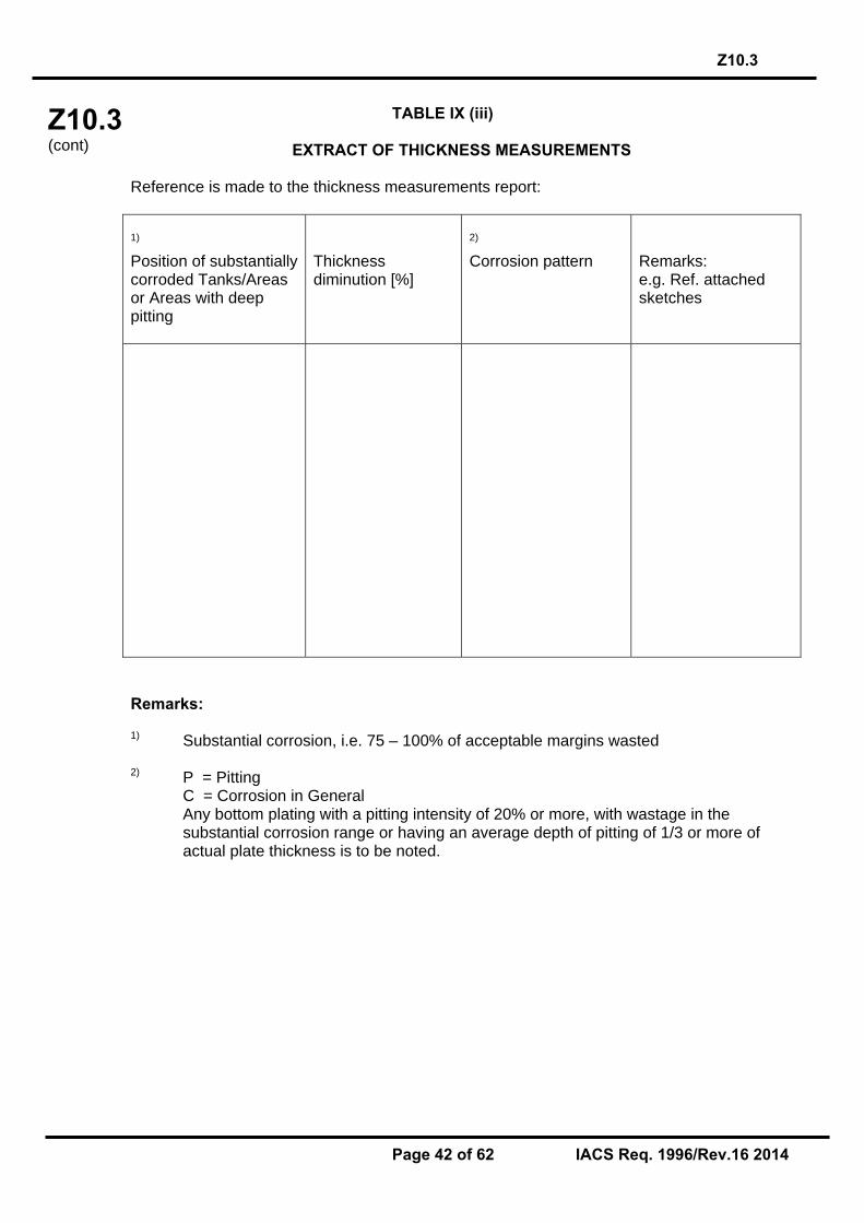
Z10.3 (cont)
Z10.3
Page 42 of 62 IACS Req. 1996/Rev.16 2014
TABLE IX (iii)
EXTRACT OF THICKNESS MEASUREMENTS
Reference is made to the thickness measurements report:
1)
Position of substantially corroded Tanks/Areas or Areas with deep pitting
Thickness diminution [%]
2)
Corrosion pattern
Remarks: e.g. Ref. attached sketches
Remarks: 1) Substantial corrosion, i.e. 75 – 100% of acceptable margins wasted 2) P = Pitting
C = Corrosion in General Any bottom plating with a pitting intensity of 20% or more, with wastage in the substantial corrosion range or having an average depth of pitting of 1/3 or more of actual plate thickness is to be noted.

Z10.3 (cont)
Z10.3
Page 43 of 62 IACS Req. 1996/Rev.16 2014
TABLE IX (iv)
TANK PROTECTION
1)
Tank Nos.
2)
Tank protection
3)
Coating condition
Remarks
Remarks: 1) All segregated ballast tanks and combined cargo/ballast tanks to be listed. 2) C = Coating NP = No Protection 3) Coating condition according to the following standard GOOD condition with only minor spot rusting.
FAIR condition with local breakdown at edges of stiffeners and weld connections and/or light rusting over 20% or more of areas under consideration, but less than as defined for POOR condition.
POOR condition with general breakdown of coating over 20% or more of areas
or hard scale at 10% or more of areas under consideration. If coating condition less than “GOOD" is given, extended annual surveys are to be introduced. This is to be noted in part I) of the Executive Hull Summary.
End of First Section

Z10.3 (cont)
Z10.3 Annex I
Page 44 of 62 IACS Req. 1996/Rev.16 2014
ANNEX I
GUIDELINES FOR TECHNICAL ASSESSMENT IN CONJUNCTION WITH
PLANNING FOR ENHANCED SURVEYS OF CHEMICAL TANKERS SPECIAL SURVEY - HULL
Contents: 1. INTRODUCTION 2. PURPOSE AND PRINCIPLES 2.1 Purpose 2.2 Minimum Requirements 2.3 Timing 2.4 Aspects to be Considered 3. TECHNICAL ASSESSMENT 3.1 General 3.2 Methods 3.2.1 Design Details 3.2.2 Corrosion 3.2.3 Locations for Close-up Survey and Thickness Measurement REFERENCES 1. IACS Unified Requirement Z10.3, "Hull Surveys of Chemical Tankers." 2. TSCF, "Guidelines for the Inspection and Maintenance of Double Hull Tanker Structures, 1995." 3. TSCF, "Guidance Manual for Tanker Structures, 1997."
1 INTRODUCTION These guidelines contain information and suggestions concerning technical assessments which may be of use in conjunction with the planning of enhanced special surveys of chemical tankers. As indicated in section 5.1.5 of IACS Unified Requirement Z10.3, "Hull Surveys of Chemical Tankers," (Ref. 1), the guidelines are a recommended tool which may be invoked at the discretion of an IACS Member Society, when considered necessary and appropriate, in conjunction with the preparation of the required Survey Programme. 2 PURPOSE AND PRINCIPLES 2.1 Purpose The purpose of the technical assessments described in these guidelines is to assist in identifying critical structural areas, nominating suspect areas and in focusing attention on structural elements or areas of structural elements which may be particularly susceptible to, or evidence a history of, wastage or damage. This information may be useful in nominating locations, areas and tanks for thickness measurement, close-up survey and tank testing. Critical Structural Areas are locations which have been identified from calculations to require monitoring or from the service history of the subject ship or from similar or sister ships (if

Z10.3 (cont)
Z10.3 Annex I
Page 45 of 62 IACS Req. 1996/Rev.16 2014
available) to be sensitive to cracking, buckling or corrosion which would impair the structural integrity of the ship. 2.2 Minimum Requirements However, these guidelines may not be used to reduce the requirements pertaining to thickness measurement, close-up survey and tank testing contained in Tables I, II and III, respectively, of Z10.3; which are, in all cases, to be complied with as a minimum. 2.3 Timing As with other aspects of survey planning, the technical assessments described in these guidelines should be worked out by the Owner or operator in cooperation with the Classification Society well in advance of the commencement of the Special Survey, i.e., prior to commencing the survey and normally at least 12 to 15 months before the survey's completion due date. 2.4 Aspects to be Considered Technical assessments, which may include quantitative or qualitative evaluation of relative risks of possible deterioration, of the following aspects of a particular ship may be used as a basis for the nomination of tanks and areas for survey: - Design features such as stress levels on various structural elements, design details and
extent of use of high tensile steel. - Former history with respect to corrosion, cracking, buckling, indents and repairs for the particular ship as well as similar vessels, where available. - Information with respect to types of cargo carried, use of different tanks for cargo/ballast, protection of tanks and condition of coating, if any. Technical assessments of the relative risks of susceptibility to damage or deterioration of various structural elements and areas are to be judged and decided on the basis of recognised principles and practices, such as may be found in publications of the Tanker Structure Cooperative Forum (TSCF), (Refs. 2 and 3). 3 TECHNICAL ASSESSMENT 3.1 General There are three basic types of possible failure which may be the subject of technical assessment in connection with planning of surveys; corrosion, cracks and buckling. Contact damages are not normally covered by the survey plan since indents are usually noted in memoranda and assumed to be dealt with as a normal routine by Surveyors. Technical assessments performed in conjunction with the survey planning process are, in principle, to be as shown schematically in Figure 1 depicts, schematically, how technical assessments can be carried out in conjunction with the survey planning process. The approach is basically an evaluation of the risk based on the knowledge and experience related to design and corrosion. The design is to be considered with respect to structural details which may be susceptible to buckling or cracking as a result of vibration, high stress levels or fatigue. Corrosion is related to the ageing process, and is closely connected with the quality of corrosion protection at newbuilding, and subsequent maintenance during the service life. Corrosion may also lead to cracking and/or buckling.

Z10.3 (cont)
Z10.3 Annex I
Page 46 of 62 IACS Req. 1996/Rev.16 2014
3.2 Methods 3.2.1 Design Details Damage experience related to the ship in question and similar ships, where available, is the main source of information to be used in the process of planning. In addition, a selection of structural details from the design drawings are to be included. Typical damage experience to be considered will consist of: - Number, extent, location and frequency of cracks; - Location of buckles. This information may be found in the survey reports and/or the Owner's files, including the results of the Owner's own inspections. The defects are to be analyzed, noted and marked on sketches. In addition, general experience is to be utilized. For example, reference is to be made to the two TSCF’s publications mentioned in Ref.2 and Ref.3, which contain a catalogue of typical damages and proposed repair methods for various tanker structural details. Such figures are to be used together with a review of the main drawings, in order to compare with the actual structure and search for similar details which may be susceptible to damage. An example is shown in Figure 2. In particular, Chapter 3 of Ref.2 deals with various aspects specific to double hull tankers, such as stress concentration locations, misalignment during construction, corrosion trends, fatigue considerations and areas requiring special attention, which are to be considered in working out the survey planning. The review of the main structural drawings, in addition to using the above mentioned figures, is to include checking for typical design details where cracking has been experienced. The factors contributing to damage are to be carefully considered. The use of high tensile steel (HTS) is an important factor. Details showing good service experience where ordinary, mild steel has been used may be more susceptible to damage when HTS, and its higher associated stresses, are utilized. There is extensive and, in general, good experience, with the use of HTS for longitudinal material in deck and bottom structures. Experience in other locations, where the dynamic stresses may be higher, is less favourable, e.g. side structures. In this respect, stress calculations of typical and important components and details, in accordance with the latest Rules or other relevant methods, may prove useful and are to be considered. The selected areas of the structure identified during this process are to be recorded and marked on the structural drawings to be included in the Survey Programme. 3.2.2 Corrosion In order to evaluate relative corrosion risks, the following information is generally to be considered: - Usage of Tanks and Spaces - Condition of Coatings - Cleaning Procedures - Previous Corrosion Damage - Ballast use and time for Cargo Tanks - Corrosion Risk Scheme (See Ref. 3, Table 2.1) - Location of Heated Tanks

Z10.3 (cont)
Z10.3 Annex I
Page 47 of 62 IACS Req. 1996/Rev.16 2014
Ref. 3 gives definitive examples which can be used for judging and describing coating condition, using typical pictures of conditions. The evaluation of corrosion risks is to be based on information in Ref. 3, together with relevant information on the anticipated condition of the ship as derived from the information collected in order to prepare the Survey Programme and the age of the ship. The various tanks and spaces are to be listed with the corrosion risks nominated accordingly. Special attention is to be given to the areas where the double hull tanker is particularly exposed to corrosion. To do this end, the specific aspects addressing corrosion in double hull tankers indicated in 3.4 (Corrosion trends) of Ref.2 are to be taken into account. 3.2.3 Locations for Close-up Survey and Thickness Measurement On the basis of the table of corrosion risks and the evaluation of design experience, the locations for initial close-up survey and thickness measurement (areas and sections) may be nominated. The sections subject to thickness measurement are to normally be nominated in tanks and spaces where corrosion risk is judged to be the highest. The nomination of tanks and spaces for close-up survey is to, initially, be based on highest corrosion risk, and is to always include ballast tanks. The principle for the selection is to be that the extent is increased by age or where information is insufficient or unreliable.

Z10.3 (cont)
Z10.3 Annex I
Page 48 of 62 IACS Req. 1996/Rev.16 2014
Design Related Risk Corrosion Risk
Survey
Figure 1: Technical Assessment and the Survey Planning Process
Input: Drawings, Reports, Acceptable Corrosion Allowance
Collection of InformationCoating Condition Usage of Tanks
Analyse: Hull Damage This Ship
Analyse: Hull Damage for Similar Ships Where Available
Hull Damage: General Experience
Coating condition Usage of Tanks
Corrosion Damage This Ship
Corrosion Damage Similar Ship where Available
Location for Thickness Measurement and Close-Up Survey
Survey Programme
Present Areas where Damage has been found and Risks considered high. Mark Sketches or Drawings
Acceptance by Class & Owner

Z10.3 (cont)
Z10.3 Annex I
Page 49 of 62 IACS Req. 1996/Rev.16 2014
A
LUG
BACKING BRACKET
X
X
VIEW A - A
WEB AND FLAT BAR CROPPED AND PART RENEWED OR ALTERNATIVELY WELDED
A
FULL COLLAR IF FRACTURES IN WEB PLATE ARE SMALL AND ARE REPAIRED BY WELDING
LUG
FACTORS CONTRIBUTING TO DAMAGE
1. Asymmetrical connection of flat bar stiffener resulting in high peak stresses at the heel of the stiffener under fatigue loading.
2. Insufficient area of connection of longitudinal to web plate.
3. Defective weld at return around the plate thickness.
4. High localised corrosion at areas of stress concentration such as flat bar stiffener connections, corners of cut-out for the longitudinal and connection of web to shell at cut-outs.
5 High stress in the web of the transverse.
6. Dynamic sea way load/ship motions.
TYPICAL DAMAGE PROPOSED REPAIR
FIGURE 1
FIGURE 1
TANKER STRUCTURE CO-OPERATIVE FORUM
SUBJECT: CATALOGUE OF STRUCTURAL DETAILS
SHELL PLATING OR LONGITUDINAL BULKHEAD
�FRACTURE
FLAT BAR STIFFENER
FRACTURED WELD/WEB �
FRACTURE
SIDE SHELL OR BULKHEAD LONGITUDINAL
�FRACTURE
WEB PLATING
VIEW A - A
NOTE �ONE OR MORE FRACTURES MAY OCCUR
A A
WEB FLAT BAR STIFFENER
LOCATION: Connection of longitudinals to transverse webs
EXAMPLE No. 1 : Web and flat bar fractures at cut-outs for longitudinal stiffener connections
>
Figure 2: Typical Damage and Repair Example (Reproduced from Ref. 2)
End of Annex I

Z10.3 (cont)
Z10.3 Annex II
Page 50 of 62 IACS Req. 1996/Rev.16 2014
ANNEX II
RECOMMENDED PROCEDURES FOR THICKNESS MEASUREMENTS OF CHEMICAL TANKERS*
* Note 1: Annex II is recommendatory Note 2: For Single Hull Chemical Tankers, please refer to Annex II of URZ10.1 Note 3: For Double Hull Chemical Tankers, please refer to Annex II of URZ10.4 End of
Annex II

Z10.3 (cont)
Z10.3 Annex III
Page 51 of 62 IACS Req. 1996/Rev.16 2014
ANNEX III

Z10.3 (cont’d)
Z10.3 Annex IIIA
Page 52 of 62 IACS Req. 1996/Rev.16 2014
ANNEX IIIA
SURVEY PROGRAMME Basic information and particulars
Name of ship:
IMO number:
Flag State:
Port of registry:
Gross tonnage:
Deadweight (metric tonnes):
Length between perpendiculars (m):
Shipbuilder:
Hull number:
Classification Society:
Class ID:
Date of build of the ship:
Owner:
Thickness measurement company:

Z10.3 (cont’d)
Z10.3 Annex IIIA
Page 53 of 62 IACS Req. 1996/Rev.16 2014
Preamble 1.1 Scope 1.1.1 The present survey programme covers the minimum extent of overall surveys, close-up surveys, thickness measurements and pressure testing within the cargo area, cargo tanks, ballast tanks, including fore and aft peak tanks, required by UR Z10.3. 1.1.2 The arrangements and safety aspects of the survey are to be acceptable to the attending surveyor(s). 1.2 Documentation All documents used in the development of the survey programme are to be available onboard during the survey as required by section 6. 2 Arrangement of tanks and spaces This section of the survey programme is to provide information (either in the form of plans or text) on the arrangement of tanks and spaces that fall within the scope of the survey. 3 List of tanks and spaces with information on their use, extent of coatings and
corrosion protection system This section of the survey programme is to indicate any changes relating to (and is to update) the information on the use of the tanks of the ship, the extent of coatings and the corrosion protective system provided in the Survey Planning Questionnaire. 4 Conditions for survey This section of the survey programme is to provide information on the conditions for survey, e.g. information regarding cargo hold and tank cleaning, gas freeing, ventilation, lighting, etc. 5 Provisions and method of access to structures This section of the survey programme is to indicate any changes relating to (and is to update) the information on the provisions and methods of access to structures provided in the Survey Planning Questionnaire. 6 List of equipment for survey This section of the survey programme is to identify and list the equipment that will be made available for carrying out the survey and the required thickness measurements. 7 Survey requirements 7.1 Overall survey This section of the survey programme is to identify and list the spaces that are to undergo an overall survey for the ship in accordance with 2.3.1.

Z10.3 (cont’d)
Z10.3 Annex IIIA
Page 54 of 62 IACS Req. 1996/Rev.16 2014
7.2 Close-up survey This section of the survey programme is to identify and list the hull structures that are to undergo a close-up survey for the ship in accordance with 2.3.2. 8 Identification of tanks for tank testing and pipes for pipe testing This section of the survey programme is to identify and list the tanks that are to undergo tank testing for the ship in accordance with 2.5 and the pipes that are to undergo pipe testing in accordance with 2.6. 9 Identification of areas and sections for thickness measurements This section of the survey programme is to identify and list the areas and sections where thickness measurements are to be taken in accordance with 2.4.1. 10 Minimum thickness of hull structures This section of the survey programme is to specify the minimum thickness for hull structures of the ship that are subject to UR Z10.3 (indicate either (a) or preferably (b), if such information is available): (a) Determined from the attached wastage allowance table and the original thickness to
the hull structure plans of the ship; (b) Given in the following table(s):
Area or location Original as-
built thickness(mm)
Minimum thickness
(mm)
Substantial corrosion thickness
(mm) Deck Plating Longitudinals Longitudinal girders Bottom Plating Longitudinals Longitudinal girders Ship side Plating Longitudinals Longitudinal girders Longitudinal bulkhead Plating Longitudinals
Longitudinal girders Inner bottom Plating Longitudinals Longitudinal girders Transverse bulkheads Plating Stiffeners

Z10.3 (cont’d)
Z10.3 Annex IIIA
Page 55 of 62 IACS Req. 1996/Rev.16 2014
Transverse web frames, floors and stringers and diaphragms
Plating Flanges Stiffeners
Note: The wastage allowance tables are to be attached to the survey programme. 11 Thickness measurement company This section of the survey programme is to identify changes, if any, relating to the information on the thickness measurement company provided in the Survey Planning Questionnaire. 12 Damage experience related to the ship This section of the survey programme is to, using the tables provided below, provide details of the hull damages for at least the last three years in way of the cargo and ballast tanks and void spaces within the cargo area. These damages are subject to survey.
Hull damages sorted by location for the ship
Tank or space
number or area
Possible cause, if known
Description of the
damages
Location Repair Date of repair

Z10.3 (cont’d)
Z10.3 Annex IIIA
Page 56 of 62 IACS Req. 1996/Rev.16 2014
Hull damages for sister or similar ships (if available) in the case of design related damage
Tank or space
number or area
Possible cause, if known
Description of the
damages
Location Repair Date of repair
13 Areas identified with substantial corrosion from previous surveys This section of the survey programme is to identify and list the areas of substantial corrosion from previous surveys. 14 Critical structural areas and suspect areas This section of the survey programme is to identify and list the critical structural areas and the suspect areas, if such information is available. 15 Other relevant comments and information This section of the survey programme is to provide any other comments and information relevant to the survey.

Z10.3 (cont’d)
Z10.3 Annex IIIA
Page 57 of 62 IACS Req. 1996/Rev.16 2014
Appendices Appendix 1 - List of plans Paragraph 5.1.3.2 requires that main structural plans of cargo and ballast tanks (scantling drawings), including information regarding use of high tensile steel (HTS), clad steel and stainless steel to be available. This appendix of the survey programme is to identify and list the main structural plans which form part of the survey programme. Appendix 2 - Survey Planning Questionnaire The Survey Planning Questionnaire (annex IIIB), which has been submitted by the owner, is to be appended to the survey programme. Appendix 3 - Other documentation This part of the survey programme is to identify and list any other documentation that forms part of the Plan. Prepared by the owner in co-operation with the Classification Society for compliance with 5.1.3. Date:…………………………………. (name and signature of authorized owner’s
representative) Date:…………………………………. (name and signature of authorized representative of the
Classification Society)

Z10.3 (cont’d)
Z10.3 Annex IIIB
Page 58 of 62 IACS Req. 1996/Rev.16 2014
ANNEX IIIB
SURVEY PLANNING QUESTIONNAIRE
The following information will enable the owner in co-operation with the Classification Society to develop a survey programme complying with the requirements of UR Z10.3. It is essential that the owner provides, when completing the present questionnaire, up-to-date information. The present questionnaire, when completed, is to provide all information and material required by UR Z10.3. Particulars Ship's name: IMO number: Flag State: Port of registry: Owner: Classification Society: Class ID: Gross tonnage: Deadweight (metric tonnes): Date of build: Information on access provision for close-up surveys and thickness measurement: The owner is to indicate, in the table below, the means of access to the structures subject to close-up survey and thickness measurement. A close-up survey is an examination where the details of structural components are within the close visual inspection range of the attending surveyor, i.e. normally within reach of hand.
Tank No.
Structure C(Cargo)/ B(Ballast)
Temporary staging
Rafts Ladders Direct access
Other means (please specify)
F.P. Fore peak A.P. Aft peak Wing Tanks
Under deck Side shell Bottom transverse
Longitudinal Transverse
Centre Tanks
Under deck Bottom transverse
Transverse

Z10.3 (cont’d)
Z10.3 Annex IIIB
Page 59 of 62 IACS Req. 1996/Rev.16 2014
History of heated cargo for the last 3 years together with indication as to whether cargo was heated
Owner’s inspections Using a format similar to that of the table below (which is given as an example), the owner is to provide details of the results of their inspections for the last 3 years on all cargo and ballast tanks and void spaces within the cargo area, including peak tanks.
Tank No. Corrosion protection
(1)
Coating extent
(2)
Coating condition
(3)
Structural deterioration
(4)
Tank damage history
(5) Cargo centre tanks
Cargo wing tanks

Z10.3 (cont’d)
Z10.3 Annex IIIB
Page 60 of 62 IACS Req. 1996/Rev.16 2014
Tank No. Corrosion
protection (1)
Coating extent
(2)
Coating condition
(3)
Structural deterioration
(4)
Tank damage history
(5) Ballast tanks
Fore peak Aft peak Miscellaneous spaces
Note: Indicate tanks which are used for cargo/ballast. 1) HC=hard coating; SC=soft coating; SH=semi-hard coating; NP=no protection 2) U=upper part; M=middle part; L=lower part; C=complete 3) G=good; F=fair; P=poor; RC=recoated (during the last 3 years) 4) N=no findings recorded; Y=findings recorded, (Description of findings is to be attached to the questionnaire) 5) DR=damage & repair; L=leakages; CV=conversion (Description is to be attached to this questionnaire) Name of owner’s representative: Signature: Date:

Z10.3 (cont’d)
Z10.3 Annex IIIB
Page 61 of 62 IACS Req. 1996/Rev.16 2014
Reports of Port State Control inspections
List the reports of Port State Control inspections containing hull structural related deficiencies and relevant information on rectification of the deficiencies:
Safety Management System List non-conformities related to hull maintenance, including the associated corrective actions:
Name and address of the approved thickness measurement company:

Z10.3 (cont)
Z10.3 Annex IIIC
Page 62 of 62 IACS Req. 1996/Rev.16 2014
ANNEX IIIC
OWNER’S INSPECTION REPORT
Structural condition
Ship’s name: For tank No: Grade of steel: deck: side: bottom: longitudinal bulkhead: Elements Cracks Buckles Corrosion Coating
condition Pitting Modification/
repair Other
Deck
Bottom
Side
Longitudinal bulkhead
Transverse bulkhead
Repairs carried out due to: Thickness measurements carried out (dates): Results in general: Overdue surveys: Outstanding conditions of class: Comments: Date of inspection: Inspected by: Signature:
End of Annex III End of Document

Z10.4 (cont’d)
Z10.4
1 IACS Req. 2001/Rev.12 2014
Z10.4 (Dec. 2001) (Rev. 1 Oct. 2002) (Rev.2 June 2005) (Rev.3 Jan 2006) (Rev.4 June 2006) (Corr.1 Sept 2006) (Rev.5 Feb 2007) (Rev.6 Nov 2007) (Rev.7 Mar 2009) (Rev.8 Feb 2010) (Rev.9 Mar 2011) (Rev.10 July 2011) (Rev.11 June 2013) (Rev.12 Jan 2014)
Hull Surveys of Double Hull Oil Tankers CONTENTS 1. General 1.1 Application 1.2 Definitions 1.3 Repairs 1.4 Thickness Measurements And Close-Up Surveys 2. Special Survey 2.1 Schedule 2.2 Scope 2.3 Extent of Overall and Close-up Surveys 2.4 Extent of Thickness Measurements 2.5 Extent of Tank Testing 3. Annual Survey 3.1 Schedule 3.2 Scope 4. Intermediate Survey 4.1 Schedule 4.2 Scope 5. Preparation For Survey 5.1 Survey Programme 5.2 Conditions For Survey 5.3 Access To Structures 5.4 Equipment For Survey 5.5 Rescue and emergency response equipment 5.6 Survey At Sea Or At Anchorage 5.7 Survey Planning Meeting 6. Documentation On Board 6.1 General 6.2 Survey Report File 6.3 Supporting Documents 6.4 Review Of Documentation On Board 7. Procedures For Thickness Measurement 7.1 General 7.2 Certification Of Thickness Measurement Company 7.3 Number and Locations of Measurements 7.4 Reporting 8. Acceptance Criteria 8.1 General 8.2 Acceptance criteria for pitting corrosion of CSR ships 8.3 Acceptance criteria for edge corrosion of CSR ships 8.4 Acceptance criteria for grooving corrosion of CSR ships

Z10.4 (cont’d)
Z10.4
2 IACS Req. 2001/Rev.12 2014
9. Reporting and Evaluation of Survey 9.1 Evaluation of Survey Report 9.2 Reporting

Z10.4 (cont’d)
Z10.4
3 IACS Req. 2001/Rev.12 2014
ENCLOSURES Table I: Minimum requirements for Close-up Surveys at Special Survey of Double Hull Oil
Tankers
Table II: Minimum requirements for thickness measurements at Special Survey of Double Hull Oil Tankers Table III: Minimum requirements for tank testing at Special Survey of Double Hull Oil Tankers Table IV: Requirements for extent of thickness measurements at those areas of substantial
corrosion Table V: Minimum requirements for overall and close-up survey and thickness
measurements at intermediate survey of double hull oil tankers Table VI: Owners Inspection Report Table VII: Procedures for Certification of Firms Engaged in Thickness Gauging of Hull
Structures Table VIII: Survey Reporting Principles Table IX: Executive Hull Summary Annex I: Guidelines for Technical Assessment in conjunction with planning for Enhanced Surveys of Double Hull Oil Tankers Special Survey - Hull
Annex II: Recommended Procedures for Thickness Measurements of Double Hull Oil Tankers IACS Recommended Procedures for Thickness Measurements of Double Hull Oil Tankers Built Under IACS Common Structural Rules
Annex III: Criteria for Longitudinal Strength of Hull Girder for Oil Tankers Appendix 1: Calculation criteria of section modulus of midship section
of hull girder Appendix II: Diminution limit of minimum longitudinal strength of ships
in service Appendix III: Sampling method of thickness measurements for longitudinal strength evaluation and repair methods Annex IVA: Survey Programme Appendix 1 List of Plans Appendix 2 Survey Planning Questionnaire Appendix 3 Other Documentation Annex IVB: Survey Planning Questionnaire Annex IVC: Owner’s Inspection Report

Z10.4 (cont’d)
Z10.4
4 IACS Req. 2001/Rev.12 2014
Note: 1. Changes introduced in Rev. 2 are to be uniformly implemented from 1 July 2006.
The amendments to paragraphs 2.2.3.1 and 4.2.2.2 related to the protective coating condition are to apply to the ballast tanks of which the coating condition will be assessed at the forthcoming Special Survey and Intermediate Survey on or after 1 July 2006.
2. Changes introduced in Rev.3 (para. 1.4, 5.5.4, 5.5.6 and 7.1.3) are to be uniformly
applied by IACS Societies on surveys commenced on or after 1 January 2007. 3. Changes introduced in Rev.4 are to be uniformly applied by IACS Societies on
surveys commenced on or after 1 July 2007. 4. Changes introduced in Rev.5 are to be uniformly implemented for surveys
commenced on or after 1 January 2008, whereas statutory requirements of IMO Res. MSC 197(80) apply on 1 January 2007.
5. Changes introduced in Rev.6 are to be uniformly applied by IACS Societies for
surveys commenced on or after the 1 January 2009. 6. Changes introduced in Rev.7 are to be uniformly applied by IACS Societies for
surveys commenced on or after 1 July 2010.
As for the requirements regarding semi-hard coatings, these coatings, if already applied, will not be accepted from the next special or intermediate survey commenced on or after 1 July 2010, whichever comes first, with respect to waiving the annual internal examination of the ballast tanks.
7. Changes introduced in Rev.9 are to be uniformly applied by IACS Societies for surveys commenced on or after 1 July 2012.
8. Changes introduced in Rev.10 are to be uniformly applied by IACS Societies for surveys commenced on or after 1 July 2012.
9. The changes to section 6 introduced in Rev.11 are to be uniformly applied by IACS Societies for surveys commenced on or after 1 July 2016. The other changes introduced in Rev.11 are to be uniformly applied by IACS Societies for surveys commenced on or after 1 July 2014.
10. Changes introduced in Rev.12 are to be uniformly applied by IACS Societies for
surveys commenced on or after 1 January 2015.

Z10.4 (cont’d)
Z10.4
5 IACS Req. 2001/Rev.12 2014
1. GENERAL 1.1 Application 1.1.1 The requirements apply to all self-propelled Double Hull Oil Tankers. 1.1.2 The requirements apply to surveys of hull structure and piping systems in way of cargo tanks, pump rooms, cofferdams, pipe tunnels, void spaces within the cargo area and all ballast tanks. The requirements are additional to the classification requirements applicable to the remainder of the ship. Refer to Z7. 1.1.3 The requirements contain the minimum extent of examination, thickness measurements and tank testing. The survey is to be extended when Substantial Corrosion and/or structural defects are found and include additional Close-up Survey when necessary. 1.2 Definitions 1.2.1 Double Hull Oil Tanker A Double Hull Oil Tanker is a ship which is constructed primarily for the carriage of oil1) in bulk, which have the cargo tanks protected by a double hull which extends for the entire length of the cargo area, consisting of double sides and double bottom spaces for the carriage of water ballast or void spaces. 1.2.2 Ballast Tank A Ballast Tank is a tank which is used solely for the carriage of salt water ballast. 1.2.2 bis A Combined Cargo/Ballast Tank is a tank which is used for the carriage of cargo or ballast water as a routine part of the vessel’s operation and will be treated as a Ballast Tank. Cargo tanks in which water ballast might be carried only in exceptional cases per MARPOL I/18(3) are to be treated as cargo tanks. 1.2.3 Overall Survey An Overall Survey is a survey intended to report on the overall condition of the hull structure and determine the extent of additional Close-up Surveys. 1.2.4 Close-up Survey A Close-up Survey is a survey where the details of structural components are within the close visual inspection range of the surveyor, i.e. normally within reach of hand.
Note: 1) MARPOL Annex I cargoes
The requirements in this UR are also applicable to existing double hull tankers not complying with MARPOL Regulation 13F, but having a U-shaped midship section.

Z10.4 (cont’d)
Z10.4
6 IACS Req. 2001/Rev.12 2014
1.2.5 Transverse Section A Transverse Section includes all longitudinal members such as plating, longitudinals and girders at the deck, sides, bottom, inner bottom and longitudinal bulkheads. For transversely framed vessels, a transverse section includes adjacent frames and their end connections in way of transverse sections. 1.2.6 Representative Tank Representative Tanks are those which are expected to reflect the condition of other tanks of similar type and service and with similar corrosion prevention systems. When selecting Representative Tanks account is to be taken of the service and repair history onboard and identifiable Critical Structural Areas and/or Suspect Areas. 1.2.7 Suspect Area Suspect Areas are locations showing Substantial Corrosion and/or are considered by the Surveyor to be prone to rapid wastage. 1.2.8 Critical Structural Area Critical Structural Areas are locations which have been identified from calculations to require monitoring or from the service history of the subject ship or from similar or sister ships (if available) to be sensitive to cracking, buckling or corrosion which would impair the structural integrity of the ship. 1.2.9 Renewal Thickness Renewal thickness (tren) is the minimum allowable thickness, in mm, below which renewal of structural members is to be carried out. 1.2.10 Substantial Corrosion Substantial Corrosion is an extent of corrosion such that assessment of corrosion pattern indicates a wastage in excess of 75% of allowable margins, but within acceptable limits. For vessels built under the IACS Common Structural Rules, substantial corrosion is an extent of corrosion such that the assessment of the corrosion pattern indicates a measured thickness between tren + 0.5mm and tren. 1.2.11 Corrosion Prevention System A Corrosion Prevention System is normally considered a full hard protective coating. Hard Protective Coating is usually to be epoxy coating or equivalent. Other coating systems, which are neither soft nor semi-hard coatings, may be considered acceptable as alternatives provided that they are applied and maintained in compliance with the manufacturer’s specifications. 1.2.12 Coating Condition Coating condition is defined as follows: • GOOD condition with only minor spot rusting, • FAIR condition with local breakdown at edges of stiffeners and weld connections and/or light rusting over 20% or more of areas under
Z10.4 (cont’d)
Z10.4
7 IACS Req. 2001/Rev.12 2014
consideration, but less than as defined for POOR condition, • POOR condition with general breakdown of coating over 20% or more, or hard scale at 10% or more, of areas under consideration. Reference is made to IACS Recommendation No.87 “Guidelines for Coating Maintenance & Repairs for Ballast Tanks and Combined Cargo / Ballast Tanks on Oil Tankers” 1.2.13 Cargo Area Cargo Area is that part of the ship which contains cargo tanks, slop tanks and cargo/ballast pump-rooms, cofferdams, ballast tanks and void spaces adjacent to cargo tanks and also deck areas throughout the entire length and breadth of the part of the ship over the above mentioned spaces. 1.2.14 Special consideration Special consideration or specially considered (in connection with close-up surveys and thickness measurements) means sufficient close-up inspection and thickness measurements are to be taken to confirm the actual average condition of the structure under the coating. 1.2.15 Prompt and Thorough Repair A Prompt and Thorough Repair is a permanent repair completed at the time of survey to the satisfaction of the Surveyor, therein removing the need for the imposition of any associated condition of classification, or recommendation. 1.2.16 Pitting Corrosion Pitting corrosion is defined as scattered corrosion spots/areas with local material reductions which are greater than the general corrosion in the surrounding area. Pitting intensity is defined in Figure 1. 1.2.17 Edge Corrosion Edge corrosion is defined as local corrosion at the free edges of plates, stiffeners, primary support members and around openings. An example of edge corrosion is shown in Figure 2. 1.2.18 Grooving Corrosion Grooving corrosion is typically local material loss adjacent to weld joints along abutting stiffeners and at stiffener or plate butts or seams. An example of groove corrosion is shown in Figure 3.

Z10.4 (cont’d)
Z10.4
8 IACS Req. 2001/Rev.12 2014
Figure 1 - Pitting intensity diagrams
Figure 2 - Edge corrosion

Z10.4 (cont’d)
Z10.4
9 IACS Req. 2001/Rev.12 2014
Figure 3 - Grooving corrosion
1.3 Repairs 1.3.1 Any damage in association with wastage over the allowable limits (including buckling, grooving, detachment or fracture), or extensive areas of wastage over the allowable limits, which affects or, in the opinion of the Surveyor, will affect the vessel’s structural, watertight or weathertight integrity, is to be promptly and thoroughly (see 1.2.14) repaired. Areas to be considered include: - bottom structure and bottom plating; - side structure and side plating; - deck structure and deck plating; - watertight or oiltight bulkheads, - hatch covers or hatch coamings, where fitted (combination carriers). For locations where adequate repair facilities are not available, consideration may be given to allow the vessel to proceed directly to a repair facility. This may require discharging the cargo and/or temporary repairs for the intended voyage.

Z10.4 (cont’d)
Z10.4
10 IACS Req. 2001/Rev.12 2014
1.3.2 Additionally, when a survey results in the identification of structural defects or corrosion, either of which, in the opinion of the Surveyor, will impair the vessel’s fitness for continued service, remedial measures are to be implemented before the ship continues in service. 1.3.3 Where the damage found on structure mentioned in Para. 1.3.1 is isolated and of a localised nature which does not affect the ship's structural integrity, consideration may be given by the surveyor to allow an appropriate temporary repair to restore watertight or weather tight integrity and impose a Recommendation/Condition of Class in accordance with IACS PR 35, with a specific time limit. 1.4 Thickness measurements and close-up surveys In any kind of survey, i.e. special, intermediate, annual or other surveys having the scope of the foregoing ones, thickness measurements of structures in areas where close-up surveys are required shall be carried out simultaneously with close-up surveys.

Z10.4 (cont’d)
Z10.4
11 IACS Req. 2001/Rev.12 2014
2. SPECIAL SURVEY(2) 2.1 Schedule 2.1.1 Special Surveys are to be carried out at 5 years intervals to renew the Classification Certificate. 2.1.2 The first Special Survey is to be completed within 5 years from the date of the initial classification survey and thereafter within 5 years from the credited date of the previous Special Survey. However, an extension of class of 3 months maximum beyond the 5th year can be granted in exceptional circumstances. In this case, the next period of class will start from the expiry date of the Special Survey before the extension was granted. 2.1.3 For surveys completed within 3 months before the expiry date of the Special Survey, the next period of class will start from the expiry date of the Special Survey. For surveys completed more than 3 months before the expiry date of the Special Survey, the period of class will start from the survey completion date. In cases where the vessel has been laid up or has been out of service for a considerable period because of a major repair or modification and the owner elects to only carry out the overdue surveys, the next period of class will start from the expiry date of the special survey. If the owner elects to carry out the next due special survey, the period of class will start from the survey completion date. 2.1.4 The Special Survey may be commenced at the 4th Annual Survey and be progressed with a view to completion by the 5th anniversary date. When the Special Survey is commenced prior to the 4th Annual Survey, the entire survey is to be completed within 15 months if such work is to be credited to the Special Survey. 2.1.5 Concurrent crediting to both Intermediate Survey (IS) and Special Survey (SS) for surveys and thickness measurements of spaces are not acceptable.
Note: 2) Some member Societies use the term "Special Periodical Survey" others use the term "Class Renewal Survey" instead of the term "Special Survey".

Z10.4 (cont’d)
Z10.4
12 IACS Req. 2001/Rev.12 2014
2.2 Scope 2.2.1 General 2.2.1.1 The Special Survey is to include, in addition to the requirements of the Annual Survey, examination, tests and checks of sufficient extent to ensure that the hull and related piping, as required in 2.2.1.3, is in a satisfactory condition and is fit for its intended purpose for the new period of class of 5 years to be assigned, subject to proper maintenance and operation and to periodical surveys being carried out at the due dates. 2.2.1.2 All cargo tanks, Ballast Tanks, including double bottom tanks, pump rooms, pipe tunnels, cofferdams and void spaces bounding cargo tanks, decks and outer hull are to be examined, and this examination is to be supplemented by thickness measurement and testing as required in 2.4 and 2.5, to ensure that the structural integrity remains effective. The aim of the examination is to discover Substantial Corrosion, significant deformation, fractures, damages or other structural deterioration that may be present. 2.2.1.3 Cargo piping on deck, including Crude Oil Washing (COW) piping, Cargo and Ballast piping within the above tanks and spaces are to be examined and operationally tested to working pressure to attending Surveyor’s satisfaction to ensure that tightness and condition remain satisfactory. Special attention is to be given to any ballast piping in cargo tanks and any cargo piping in ballast tanks and void spaces, and Surveyors are to be advised on all occasions when this piping, including valves and fittings are open during repair periods and can be examined internally. 2.2.2 Dry Dock Survey 2.2.2.1 A survey in dry dock is to be a part of the Special Survey. The overall and close-up surveys and thickness measurements, as applicable, of the lower portions of the cargo tanks and ballast tanks are to be carried out in accordance with the applicable requirements for special surveys, if not already performed. Note: Lower portions of the cargo and ballast tanks are considered to be the parts below light ballast water line. 2.2.3 Tank Protection 2.2.3.1 Where provided, the condition of the corrosion prevention system of cargo tanks is to be examined. A Ballast Tank is to be examined at subsequent annual intervals where: a. a hard protective coating has not been applied from the time of construction, or b. a soft or semi-hard coating has been applied, or c. substantial corrosion is found within the tank, or d. the hard protective coating is found to be in less than GOOD condition and the hard protective coating is not repaired to the satisfaction of the Surveyor.

Z10.4 (cont’d)
Z10.4
13 IACS Req. 2001/Rev.12 2014
Thickness measurements are to be carried out as deemed necessary by the surveyor. 2.3 Extent of Overall and Close-up Surveys 2.3.1 An Overall Survey of all tanks and spaces is to be carried out at each Special Survey. 2.3.2 The minimum requirements for Close-up Surveys at Special Survey are given in Table I. 2.3.3 The Surveyor may extend the Close-up Survey as deemed necessary taking into account the maintenance of the tanks under survey, the condition of the corrosion prevention system and also in the following cases: a) in particular, tanks having structural arrangements or details which have suffered defects in similar tanks or on similar ships according to available information, b) In tanks which have structures approved with reduced scantlings due to an approved corrosion control system. 2.3.4 For areas in tanks where hard protective coatings are found to be in a GOOD condition as defined in 1.2.11, the extent of Close-up Surveys according to Table I may be specially considered. 2.4 Extent of Thickness Measurements 2.4.1 The minimum requirements for thickness measurements at Special Survey are given in Table II. 2.4.2 Provisions for extended measurements for areas with Substantial Corrosion are given in Table IV, and as may be additionally specified in the Survey Programme as required in 5.1. These extended thickness measurments are to be carried out before the survey is credited as completed. Suspect Areas identified at previous surveys are to be examined. Areas of substantial corrosion identified at previous surveys are to have thickness measurements taken. For vessels built under IACS Common Structural Rules, the identified substantial corrosion areas are required to be examined and additional thickness measurements are to be carried out at annual and intermediate surveys. 2.4.3 The Surveyor may further extend the thickness measurements as deemed necessary. 2.4.4 For areas in tanks where hard protective coating are found to be in a GOOD condition as defined in 1.2.11, the extent of thickness measurements according to Table II may be specially considered. 2.4.5 Transverse sections are to be chosen where the largest reductions are suspected to occur or are revealed from deck plating measurements.

Z10.4 (cont’d)
Z10.4
14 IACS Req. 2001/Rev.12 2014
2.4.6 In cases where two or three sections are to be measured, at least one is to include a Ballast Tank within 0.5L amidships. In case of oil tankers of 130m in length and upwards (as defined in the International Convention on Load Lines in force) and more than 10 years of age, for the evaluation of the ship’s longitudinal strength as required in 8.1.1.1, the sampling method of thickness measurements is given in Annex III Appendix 3. 2.5 Extent of Tank Testing 2.5.1 The minimum requirements for ballast tank testing at Special Survey are given in 2.5.3 and Table III. The minimum requirements for cargo tank testing at Special Survey are given in 2.5.4 and Table III. Cargo tank testing carried out by the vessel’s crew under the direction of the Master may be accepted by the surveyor provided the following conditions are complied with: a) a tank testing procedure has been submitted by the owner and reviewed by the Society
prior to the testing being carried out; b) there is no record of leakage, distortion or substantial corrosion that would affect the
structural integrity of the tank; c) the tank testing has been satisfactorily carried out within special survey window not
more than 3 months prior to the date of the survey on which the overall or close up survey is completed;
d) the satisfactory results of the testing is recorded in the vessel’s logbook; e) the internal and external condition of the tanks and associated structure are found
satisfactory by the surveyor at the time of the overall and close up survey. 2.5.2 The Surveyor may extend the tank testing as deemed necessary. 2.5.3 Boundaries of ballast tanks are to be tested with a head of liquid to the top of air pipes. 2.5.4 Boundaries of cargo tanks are to be tested to the highest point that liquid will rise under service conditions. 2.5.5 The testing of double bottom tanks and other spaces not designed for the carriage of liquid may be omitted, provided a satisfactory internal examination together with an examination of the tanktop is carried out.

Z10.4 (cont’d)
Z10.4
15 IACS Req. 2001/Rev.12 2014
3. ANNUAL SURVEY 3.1 Schedule 3.1.1 Annual Surveys are to be held within 3 months before or after anniversary date from the date of the initial classification survey or of the date credited for the last Special Survey. 3.2 Scope 3.2.1 General 3.2.1.1 The survey is to consist of an examination for the purpose of ensuring, as far as practicable, that the hull and piping are maintained in a satisfactory condition. 3.2.2 Examination of the hull 3.2.2.1 Examination of the hull plating and its closing appliances as far as can be seen. 3.2.2.2 Examination of watertight penetrations as far as practicable. 3.2.3 Examination of the weather deck 3.2.3.1 Examination of cargo tank openings including gaskets, covers, coamings and flame screens. 3.2.3.2 Examination of cargo tanks pressure/vacuum valves and flame screens. 3.2.3.3 Examination of flame screens on vents to all bunker tanks. 3.2.3.4 Examination of cargo, crude oil washing, bunker and vent piping systems, including vent masts and headers. 3.2.4 Examination of cargo pump rooms and pipe tunnels if fitted. 3.2.4.1 Examination of all pump room bulkheads for signs of oil leakage or fractures and, in particular, the sealing arrangements of all penetrations of pump room bulkheads. 3.2.4.2 Examination of the condition of all piping systems. 3.2.5 Examination of Ballast Tanks 3.2.5.1 Examination of Ballast Tanks where required as a consequence of the results of the Special Survey (see 2.2.3) and Intermediate Survey (see 4.2.2.1 and 4.2.2.2) is to be carried out. When considered necessary by the Surveyor, or when extensive corrosion exists, thickness

Z10.4 (cont’d)
Z10.4
16 IACS Req. 2001/Rev.12 2014
measurements are to be carried out and if the results of these thickness measurements indicate that Substantial Corrosion is found, the extent of thickness measurements is to be increased in accordance with Table IV. These extended thickness measurements are to be carried out before the survey is credited as completed. Suspect Areas identified at previous surveys are to be examined. Areas of substantial corrosion identified at previous surveys are to have thickness measurements taken. For vessels built under IACS Common Structural Rules, the identified substantial corrosion areas are required to be examined and additional thickness measurements are to be carried out.

Z10.4 (cont’d)
Z10.4
17 IACS Req. 2001/Rev.12 2014
4. INTERMEDIATE SURVEY 4.1 Schedule 4.1.1 The Intermediate Survey is to be held at or between either the 2nd or 3rd Annual Survey. 4.1.2 Those items, which are additional to the requirements of the Annual Surveys, may be surveyed either at or between the 2nd and 3rd Annual Survey. 4.1.3 Concurrent crediting to both Intermediate Survey (IS) and Special Survey (SS) for surveys and thickness measurements of spaces are not acceptable. 4.2 Scope 4.2.1 General 4.2.1.1 The survey extent is dependent on the age of the vessel as specified in 4.2.2 to 4.2.4 and shown in Table V. 4.2.1.2 For weather decks, an examination as far as applicable of cargo, crude oil washing, bunker, ballast, steam and vent piping systems as well as vent masts and headers is to be carried out. If upon examination there is any doubt as to the condition of the piping, the piping may be required to be pressure-tested, thickness measured or both. 4.2.1.3 For vessels built under IACS Common Structural Rules, the identified substantial corrosion areas are required to be examined and additional thickness measurements are to be carried out. 4.2.2 Double Hull Oil Tankers between 5 and 10 years of age. The following is to apply: 4.2.2.1 For tanks used for salt-water ballast, an Overall Survey of Representative Tanks selected by the Surveyor is to be carried out. If such inspections reveal no visible structural defects, the examination may be limited to a verification that the hard protective coating remains in GOOD condition. 4.2.2.2 A Ballast Tank is to be examined at subsequent annual intervals where: a. a hard protective coating has not been applied from the time of construction, or b. a soft or semi-hard coating has been applied, or c. substantial corrosion is found within the tank, or d. the hard protective coating is found to be in less than GOOD condition and the hard protective coating is not repaired to the satisfaction of the Surveyor.

Z10.4 (cont’d)
Z10.4
18 IACS Req. 2001/Rev.12 2014
4.2.2.3 In addition to the requirements above, suspect areas identified at previous surveys are to be examined. 4.2.3 Double Hull Oil Tankers between 10 and 15 years of age. The following is to apply: 4.2.3.1 The requirements of the Intermediate Survey are to be to the same extent as the previous Special Survey as required in 2 and 5.1. However, pressure testing of cargo and ballast tanks and the requirements for longitudinal strength evaluation of Hull Girder as required in 8.1.1.1.are not required unless deemed necessary by the attending Surveyor. 4.2.3.2 In application of 4.2.3.1, the intermediate survey may be commenced at the second annual survey and be progressed during the succeeding year with a view to completion at the third annual survey in lieu of the application of 2.1.4. 4.2.3.3 In application of 4.2.3.1, an under water survey may be considered in lieu of the requirements of 2.2.2. 4.2.4 Double Hull Oil Tankers over 15 years of age. The following is to apply: 4.2.4.1 The requirements of the Intermediate Survey are to be to the same extent as the previous Special Survey as required in 2 and 5.1. However, pressure testing of cargo and ballast tanks and the requirements for longitudinal strength evaluation of Hull Girder as required in 8.1.1.1 are not required unless deemed necessary by the attending Surveyor. 4.2.4.2 In application of 4.2.4.1, the intermediate survey may be commenced at the second annual survey and be progressed during the succeeding year with a view to completion at the third annual survey in lieu of the application of 2.1.4. 4.2.4.3 In application of 4.2.4.1, a survey in dry dock is to be part of the intermediate survey. The overall and close-up surveys and thickness measurements, as applicable, of the lower portions of the cargo tanks and water ballast tanks are to be carried out in accordance with the applicable requirements for intermediate surveys, if not already carried out. Note: Lower portions of the cargo and ballast tanks are considered to be the parts below light ballast water line.

Z10.4 (cont’d)
Z10.4
19 IACS Req. 2001/Rev.12 2014
5. PREPARATION FOR SURVEY 5.1 Survey Programme 5.1.1 The Owner in co-operation with the Classification Society is to work out a specific Survey Programme prior to the commencement of any part of: - the Special Survey - the Intermediate Survey for oil tanker over 10 years of age
The Survey Programme at Intermediate Survey may consist of the Survey Programme at the previous Special Survey supplemented by the Executive Hull Summary of that Special Survey and later relevant survey reports. The Survey Programme is to be worked out taking into account any amendments to the survey requirements implemented after the last Special Survey carried out.
The Survey Programme is to be in a written format based on the information in annex IVA. The survey is not to commence until the survey programme has been agreed.
5.1.1.1 Prior to the development of the survey programme, the survey planning questionnaire is to be completed by the owner based on the information set out in annex IVB, and forwarded to the Classification Society.
5.1.2
In developing the survey programme, the following documentation is to be collected and consulted with a view to selecting tanks, areas, and structural elements to be examined:
.1 survey status and basic ship information;
.2 documentation on board, as described in 6.2 and 6.3;
.3 main structural plans of cargo and ballast tanks (scantlings drawings), including information regarding use of high-tensile steels (HTS);
.4 Executive Hull Summary;
.5 relevant previous damage and repair history;
.6 relevant previous survey and inspection reports from both the recognized organization and the owner;
.7 cargo and ballast history for the last 3 years, including carriage of cargo under heated conditions;
.8 details of the inert gas plant and tank cleaning procedures;
.9 information and other relevant data regarding conversion or modification of the ship’s cargo and ballast tanks since the time of construction;

Z10.4 (cont’d)
Z10.4
20 IACS Req. 2001/Rev.12 2014
.10 description and history of the coating and corrosion protection system (previous class notations), if any;
.11 inspections by the Owner’s personnel during the last 3 years with reference to structural deterioration in general, leakages in tank boundaries and piping and condition of the coating and corrosion protection system if any.
.12 information regarding the relevant maintenance level during operation including port state control reports of inspection containing hull related deficiencies, Safety Management System non-conformities relating to hull maintenance, including the associated corrective action(s); and
.13 any other information that will help identify suspect areas and critical structural areas
5.1.3 The submitted Survey Programme is to account for and comply, as a minimum, with the requirements of Tables I, II and 2.5 for close-up survey, thickness measurement and tank testing, respectively, and is to include relevant information including at least: .1 basic ship information and particulars; .2 main structural plans (scantling drawings), including information regarding use of high tensile steels (HTS); .3 plan of tanks; .4 list of tanks with information on use, corrosion prevention and condition of coating; .5 conditions for survey (e.g., information regarding tank cleaning, gas freeing, ventilation, lighting, etc.); .6 provisions and methods for access to structures; .7 equipment for surveys; .8 nomination of tanks and areas for close-up survey (per 2.3); .9 nominations of sections for thickness measurement (per 2.4); .10 nomination of tanks for tank testing (per 2.5); .11 identification of the thickness measurement company; .12 damage experience related to the ship in question; .13 critical structural areas and suspect areas, where relevant.

Z10.4 (cont’d)
Z10.4
21 IACS Req. 2001/Rev.12 2014
5.1.4 The Classification Society will advise the Owner of the maximum acceptable structural corrosion diminution levels applicable to the vessel. 5.1.5 Use may also be made of the Guidelines for Technical Assessment in Conjunction with Planning for Enhanced Surveys of Double Hull Oil Tankers Special Survey - Hull, contained in Annex I. These guidelines are a recommended tool which may be invoked at the discretion of the Classification Society, when considered necessary and appropriate, in conjunction with the preparation of the required Survey Programme. 5.2 Conditions for survey 5.2.1 The Owner is to provide the necessary facilities for a safe execution of the survey.
5.2.1.1 In order to enable the attending surveyors to carry out the survey, provisions for proper and safe access are to be agreed between the owner and the Classification society are to be in accordance with IACS PR 37. 5.2.1.2 Details of the means of access are to be provided in the survey planning questionnaire. 5.2.1.3 In cases where the provisions of safety and required access are judged by the attending surveyors not to be adequate, the survey of the spaces involved is to not proceed. 5.2.2 Tanks and spaces are to be safe for access. Tanks and spaces are to be gas free and properly ventilated. Prior to entering a tank, void or enclosed space, it is to be verified that the atmosphere in that space is free from hazardous gas and contains sufficient oxygen. 5.2.3 In preparation for survey and thickness measurements and to allow for a thorough examination, all spaces are to be cleaned including removal from surfaces of all loose accumulated corrosion scale. Spaces are to be sufficiently clean and free from water, scale, dirt, oil residues etc. to reveal corrosion, deformation, fractures, damages, or other structural deterioration as well as the condition of the coating. However, those areas of structure whose renewal has already been decided by the owner need only be cleaned and descaled to the extent necessary to determine the limits of the areas to be renewed. 5.2.4 Sufficient illumination is to be provided to reveal corrosion, deformation, fractures, damages or other structural deterioration. 5.2.5 Where Soft or Semi-hard Coatings have been applied, safe access is to be provided for the surveyor to verify the effectiveness of the coating and to carry out an assessment of the

Z10.4 (cont’d)
Z10.4
22 IACS Req. 2001/Rev.12 2014
conditions of internal structures which may include spot removal of the coating. When safe access cannot be provided, the soft or semi-hard coating is to be removed.
5.2.6
The surveyor(s) are to always be accompanied by at least one responsible person, assigned by the owner, experienced in tank and enclosed spaces inspection. In addition a back-up team of at least two experienced persons is to be stationed at the hatch opening of the tank or space that is being surveyed. The back-up team is to continuously observe the work in the tank or space and is to keep lifesaving and evacuation equipment ready for use.
5.2.7 A communication system is to be arranged between the survey party in the tank or space being examined, the responsible officer on deck and, as the case may be, the navigation bridge. The communication arrangements are to be maintained throughout the survey. 5.3 Access to structures 5.3.1 For overall survey, means are to be provided to enable the surveyor to examine the hull structure in a safe and practical way. 5.3.2 For close-up survey, one or more of the following means for access, acceptable to the Surveyor, is to be provided: • permanent staging and passages through structures; • temporary staging and passages through structures; • hydraulic arm vehicles such as conventional cherry pickers, lifts and movable
platforms; • boats or rafts; portable ladders; other equivalent means. 5.4 Equipment for survey 5.4.1 Thickness measurement is normally to be carried out by means of ultrasonic test equipment. The accuracy of the equipment is to be proven to the Surveyor as required. 5.4.2 One or more of the following fracture detection procedures may be required if deemed necessary by the Surveyor: • radiographic equipment; • ultrasonic equipment; • magnetic particle equipment; • dye penetrant.

Z10.4 (cont’d)
Z10.4
23 IACS Req. 2001/Rev.12 2014
5.4.3 Explosimeter, oxygen-meter, breathing apparatus, lifelines, riding belts with rope and hook and whistles together with instructions and guidance on their use are to be made available during the survey. A safety check-list is to be provided.
5.4.4
Adequate and safe lighting is to be provided for the safe and efficient conduct of the survey.
5.4.5
Adequate protective clothing is to be made available and used during the survey (e.g. safety helmet, gloves, safety shoes, etc.). 5.5 Rescue and emergency response equipment If breathing apparatus and/or other equipment is used as ‘Rescue and emergency response equipment’ then it is recommended that the equipment should be suitable for the configuration of the space being surveyed. 5.6 Survey at sea or at anchorage 5.6.1 Survey at sea or at anchorage may be accepted provided the Surveyor is given the necessary assistance from the personnel onboard. Necessary precautions and procedures for carrying out the survey are to be in accordance with 5.1, 5.2, 5.3 and 5.4. 5.6.2 A communication system is to be arranged between the survey party in the tank and the responsible officer on deck. This system is to include the personnel in charge of ballast pump handling if boats or rafts are used. 5.6.3 Surveys of tanks by means of boats or rafts may only be undertaken with the agreement of the Surveyor, who is to take into account the safety arrangements provided, including weather forecasting and ship response under foreseeable conditions and provided the expected rise of water within the tank does not exceed 0.25m.
5.6.4 When rafts or boats are used for close-up surveys, the following conditions are to be observed:
.1 only rough duty, inflatable rafts or boats, having satisfactory residual buoyancy and stability even if one chamber is ruptured, are to be used;
.2 the boat or raft is to be tethered to the access ladder and an additional person is to be stationed down the access ladder with a clear view of the boat or raft;
.3 appropriate lifejackets are to be available for all participants;
.4 the surface of water in the tank is to be calm (under all foreseeable conditions the expected rise of water within the tank is to not exceed 0.25 m) and the

Z10.4 (cont’d)
Z10.4
24 IACS Req. 2001/Rev.12 2014
water level stationary. On no account is the level of the water to be rising while the boat or raft is in use;
.5 the tank or space must contain clean ballast water only. Even a thin sheen of oil on the water is not acceptable;
.6 at no time should the water level be allowed to be within 1 m of the deepest under deck web face flat so that the survey team is not isolated from a direct escape route to the tank hatch. Filling to levels above the deck transverses should only be contemplated if a deck access manhole is fitted and open in the bay being examined, so that an escape route for the survey party is available at all times. Other effective means of escape to the deck may be considered;
.7 if the tanks (or spaces) are connected by a common venting system, or inert gas system, the tank in which the boat or raft should be used should be isolated to prevent a transfer of gas from other tanks (or spaces).
5.6.5 Rafts or boats alone may be allowed for inspection of the under deck areas for tanks or spaces, if the depth of the webs is 1.5 m or less. 5.6.6 If the depth of the webs is more than 1.5 m, rafts or boats alone may be allowed only: .1 when the coating of the under deck structure is in GOOD condition and there is
no evidence of wastage; or .2 if a permanent means of access is provided in each bay to allow safe entry and
exit. This means: i. access direct from the deck via a vertical ladder and a small platform fitted approximately 2 m below the deck in each bay; or ii. access to deck from a longitudinal permanent platform having ladders to deck in
each end of the tank. The platform shall, for the full length of the tank, be arranged in level with, or above, the maximum water level needed for rafting of under deck structure. For this purpose, the ullage corresponding to the maximum water level is to be assumed not more than 3m from the deck plate measured at the midspan of deck transverses and in the middle length of the tank (See Figure 4).
If neither of the above conditions are met, then staging or an “other equivalent means” is to be provided for the survey of the under deck areas.

Z10.4 (cont’d)
Z10.4
25 IACS Req. 2001/Rev.12 2014
3.0m3.0m
Figure 4
5.6.7 The use of rafts or boats alone in paragraphs 5.6.5 and 5.6.6 does not preclude the use of boats or rafts to move about within a tank during a survey. Reference is made to IACS Recommendation 39 - Guidelines for the use of Boats or Rafts for Close-up surveys. 5.7 Survey Planning Meeting 5.7.1 Proper preparation and close co-operation between the attending surveyor(s) and the owner’s representatives onboard prior to and during the survey are an essential part in the safe and efficient conduct of the survey. During the survey on board safety meetings are to be held regularly. 5.7.2 Prior to the commencement of any part of the Special and Intermediate Survey a survey planning meeting is to be held between the attending Surveyor(s), the Owner’s Representative in attendance, the TM company representative, where involved, and the master of the ship or an appropriately qualified representative appointed by the master or Company for the purpose of ascertaining that all the arrangements envisaged in the survey programme are in place, so as to ensure the safe and efficient conduct of the survey work to be carried out. See also 7.1.2.
5.7.3 The following is an indicative list of items that are to be addressed in the meeting:
.1 schedule of the vessel (i.e. the voyage, docking and undocking manoeuvres, periods alongside, cargo and ballast operations etc.);
.2 provisions and arrangements for thickness measurements (i.e. access, cleaning/de-scaling, illumination, ventilation, personal safety);
.3 extent of the thickness measurements;
.4 acceptance criteria (refer to the list of minimum thicknesses);
.5 extent of close-up survey and thickness measurement considering the coating condition and suspect areas/areas of substantial corrosion;
.6 execution of thickness measurements;
.7 taking representative readings in general and where uneven corrosion/pitting is found;

Z10.4 (cont’d)
Z10.4
26 IACS Req. 2001/Rev.12 2014
.8 mapping of areas of substantial corrosion; and
.9 communication between attending surveyor(s) the thickness measurement company operator(s) and owner representative(s) concerning findings.

Z10.4 (cont’d)
Z10.4
27 IACS Req. 2001/Rev.12 2014
6. DOCUMENTATION ON BOARD 6.1 General 6.1.1 The owner is to obtain, supply and maintain on board documentation as specified in 6.2 and 6.3, which is to be readily available for the Surveyor. 6.1.2 The documentation is to be kept on board for the lifetime of the ship. 6.1.3 For tankers and bulk carriers subject to SOLAS Chapter II-1 Part A-1 Regulation 3-10, the Owner is to arrange the updating of the Ship Construction File (SCF) throughout the ship’s life whenever a modification of the documentation included in the SCF has taken place. Documented procedures for updating the SCF are to be included within the Safety Management System. 6.2 Survey report file 6.2.1 A Survey Report File is to be a part of the documentation on board consisting of: • reports of structural surveys; • Executive Hull Summary; • thickness measurement reports. 6.2.2 The Survey Report File is to be available also in the Owner's and the Classification Society's management offices. 6.3 Supporting documents 6.3.1 The following additional documentation is to be available onboard: • Survey Programme as required by 5.1 until such time as the Special Survey or Intermediate Survey, as applicable, has been completed; • main structural plans of cargo and ballast tanks (for CSR ships these plans are to
include for each structural element both the as-built and renewal thickness. Any thickness for voluntary addition is also to be clearly indicated on the plans. The Midship Section plan to be supplied on board the ship is to include the minimum allowable hull girder sectional properties for the tank transverse section in all cargo tanks);
• previous repair history; • cargo and ballast history; • extent of use of inert gas plant and tank cleaning procedures;

Z10.4 (cont’d)
Z10.4
28 IACS Req. 2001/Rev.12 2014
• inspections by ship's personnel with reference to • structural deterioration in general; • leakage in bulkheads and piping; • condition of coating or corrosion prevention system, if any. • any other information that will help identify Critical Structural Areas and/or Suspect Areas requiring inspection; 6.3.2 For tankers and bulk carriers subject to SOLAS Chapter II-1 Part A-1 Regulation 3-10, the Ship Construction File (SCF), limited to the items to be retained on board, is to be available on board. 6.4 Review of documentation on board 6.4.1 Prior to survey, the Surveyor is to examine the completeness of the documentation onboard, and its contents as a basis for the survey. 6.4.2 For tankers and bulk carriers subject to SOLAS Chapter II-1 Part A-1 Regulation 3-10, on completion of the survey, the surveyor is to verify that the update of the Ship Construction File (SCF) has been done whenever a modification of the documentation included in the SCF has taken place. 6.4.3 For tankers and bulk carriers subject to SOLAS Chapter II-1 Part A-1 Regulation 3-10, on completion of the survey, the surveyor is to verify any addition and/or renewal of materials used for the construction of the hull structure are documented within the Ship Construction File inventory list.

Z10.4 (cont’d)
Z10.4
29 IACS Req. 2001/Rev.12 2014
7. PROCEDURES FOR THICKNESS MEASUREMENT 7.1 General 7.1.1 The required thickness measurements, if not carried out by the Society itself, are to be witnessed by a Surveyor of the Society. The Surveyor is to be on board to the extent necessary to control the process. 7.1.2 The thickness measurement company is to be part of the survey planning meeting to be held prior to commencing the survey. 7.1.3 Thickness measurements of structures in areas where close-up surveys are required shall be carried out simultaneously with close-up surveys. 7.1.4 In all cases the extent of the thickness measurements are to be sufficient as to represent the actual average condition. 7.2 Certification of thickness measurement company 7.2.1 The thickness measurement is to be carried out by a qualified company certified by the Classification Society according to principles stated in Table VII. 7.3 Number and locations of measurements 7.3.1 Application The item 7.3 only applies to vessels built under the IACS Common Structural Rules of Double Hull Oil Tankers. For vessels not built under IACS Common Structural Rules, the requirements for number and locations of measurements are according to the Rules of the individual Classification Society and/or specific IACS URs depending on ship’s age and structural elements concerned. 7.3.2 Number of measurements Considering the extent of thickness measurements according to the different structural elements of the ship and surveys (special, intermediate and annual), the locations of the points to be measured are given for the most important items of the structure. 7.3.3 Locations of measurements Table 1 provides explanations and/or interpretations for the application of those requirements indicated in the Rules, which refer to both systematic thickness measurements related to the calculation of global hull girder strength and specific measurements connected to close-up surveys. Fig 5 to Fig 8 are provided to facilitate the explanations and/or interpretations given in Table 1, to show typical arrangements of double hull oil tankers.

Z10.4 (cont’d)
Z10.4
30 IACS Req. 2001/Rev.12 2014
Table 1: Interpretations of rule requirements for the locations and number of points to be measured
Item Interpretation Figure reference Selected plates «Selected» means at least
a single point on one out of three plates, to be chosen on representative areas of average corrosion.
Deck, bottom plates and wind-and-water strakes
At least two points on each plate to be taken either at each 1/4 extremity of plate or at representative areas of average corrosion.
Transverse section Measurements to be taken on all longitudinal members such as plating, longitudinals and girders at the deck, side, bottom, longitudinal bulkheads, inner bottom and hopper. One point to be taken on each plate. Both web and flange to be measured on longitudinals, if applicable. For tankers older than 10 years of age: within 0.1D (where D is the ship’s moulded depth) of the deck and bottom at each transverse section to be measured, every longitudinal and girder is to be measured on the web and face plate, and every plate is to be measured at one point between longitudinals.
Fig 5
Transverse rings (#) in cargo and ballast tanks
At least two points on each plate in a staggered pattern and two points on the corresponding flange where applicable. Minimum 4 points on the first plate below deck. Additional points in way of curved parts. At least one point on each of two stiffeners between stringers / longitudinal
Fig 6

Z10.4 (cont’d)
Z10.4
31 IACS Req. 2001/Rev.12 2014
Item Interpretation Figure reference girders.
Transverse bulkheads in cargo tanks
At least two points on each plate. Minimum 4 points on the first plate below main deck. At least one point on every third stiffener to be taken between each stringer. At least two points on each plate of stringers and girders, and two points on the corresponding flange. Additional points in way of curved part. Two points of each diaphragm plate of stools if fitted.
Fig 7
Transverse bulkheads in ballast tanks
At least 4 points on plates between stringers / longitudinal girders, or per plate if stringers / girders not fitted. At least two points on each plate of stringers and girders, and two points on the corresponding flange. Additional points in way of curved part. At least one point on two stiffeners between each stringer / longitudinal girder.
Fig 8
Adjacent structural members
On adjacent structural members one point per plate and one point on every third stiffener / longitudinal.
(#°) Transverse rings means all transverse material appearing in a cross-section of the ship's hull, in way of a double bottom floor, vertical web and deck transverse (definition from CSR)

Z10.4 (cont’d)
Z10.4
32 IACS Req. 2001/Rev.12 2014
Figure 5 - Transverse section
Figure 6 - Transverse rings in cargo and ballast tanks

Z10.4 (cont’d)
Z10.4
33 IACS Req. 2001/Rev.12 2014
Figure 7 - Transverse bulkheads in cargo tanks
Figure 8 - Transverse bulkheads in ballast tanks

Z10.4 (cont’d)
Z10.4
34 IACS Req. 2001/Rev.12 2014
7.4 Reporting
7.4.1 A thickness measurement report is to be prepared. The report is to give the location of measurement, the thickness measured as well as corresponding original thickness. Furthermore, the report is to give the date when the measurement was carried out, type of measuring equipment, names of personnel and their qualifications and has to be signed by the operator. The thickness measurement report is to follow the principles as specified in the Recommended Procedures for Thickness Measurement of Double Hull Oil Tankers, contained in Annex II. 7.4.2 The Surveyor is to review the final thickness measurement report and countersign the cover page.

Z10.4 (cont’d)
Z10.4
35 IACS Req. 2001/Rev.12 2014
8. ACCEPTANCE CRITERIA 8.1 General 8.1.1 For vessels built under IACS Common Structural Rules, the Acceptance Criteria is according to Section 12 - Ship in Operation Renewal Criteria of IACS Common Structural Rules for Double Hull Oil Tankers and as specified in 8.2, 8.3 and 8.4. 8.1.2 For vessels not built under IACS Common Structural Rules, the Acceptance Criteria are according to the Rules of the individual Classification Society and/or specific IACS URs depending on ship’s age and structural elements concerned. 8.2 Acceptance criteria for pitting corrosion of CSR ships 8.2.1 For plates with pitting intensity less than 20%, see Figure 1, the measured thickness, tm, of any individual measurement is to meet the lesser of the following criteria:
tm ≥ 0.7 (tas-built - tvol add) mm tm ≥ tren - 1 mm
Where: tas-built as-built thickness of the member, in mm tvol add voluntary thickness addition; thickness, in mm, voluntarily added as the Owner’s
extra margin for corrosion wastage in addition to tC tren renewal criteria for general corrosion as defined in 2.1.2.1 of Section 12 of CSRs
for Oil Tankers 8.2.2 The average thickness across any cross section in the plating is not to be less than the renewal criteria for general corrosion given in 2.1.2.1 of Section 12 of CSRs for Oil Tankers. 8.3 Acceptance criteria for edge corrosion of CSR ships 8.3.1 Provided that the overall corroded height of the edge corrosion of the flange, or web in the case of flat bar stiffeners, is less than 25%, see Figure 2, of the stiffener flange breadth or web height, as applicable, the measured thickness, tm, is to meet the lesser of the following criteria:
tm ≥ 0.7 (tas-built - tvol add) mm
tm ≥ tren - 1 mm
Where: tas-built as-built thickness of the member, in mm tvol add voluntary thickness addition; thickness, in mm, voluntarily added as the Owner’s
extra margin for corrosion wastage in addition to tC

Z10.4 (cont’d)
Z10.4
36 IACS Req. 2001/Rev.12 2014
tren renewal criteria for general corrosion as defined in 2.1.2.1 of Section 12 of CSRs for Oil Tankers
8.3.2 The average measured thickness across the breadth or height of the stiffener is not to be less than that defined in 2.1.2 of Section 12 of CSRs for Oil Tankers. 8.3.3 Plate edges at openings for manholes, lightening holes etc. may be below the minimum thickness given in 2.1.2 of Section 12 of CSRs for Oil Tankers provided that: a) the maximum extent of the reduced plate thickness, below the minimum given in 2.1.2
of Section 12 of CSRs for Oil Tankers, from the opening edge is not more than 20% of the smallest dimension of the opening and does not exceed 100mm.
b) rough or uneven edges may be cropped-back provided that the maximum dimension
of the opening is not increased by more than 10% and the remaining thickness of the new edge is not less than tren - 1 mm.
8.4 Acceptance criteria for grooving corrosion of CSR ships 8.4.1 Where the groove breadth is a maximum of 15% of the web height, but not more than 30mm, see Figure 3, the measured thickness, tm, in the grooved area is to meet the lesser of the following criteria:
tm ≥ 0.75 (tas-built - tvol add) mm tm ≥ tren - 0.5 mm but is not to be less than tm = 6 mm
Where: tas-built as-built thickness of the member, in mm tvol add voluntary thickness addition; thickness, in mm, voluntarily added as the Owner’s
extra margin for corrosion wastage in addition to tC
tren renewal criteria for general corrosion as defined in 2.1.2.1 of Section 12 of CSRs for Oil Tankers
8.4.2 Structural members with areas of grooving greater than those in 8.4.1 are to be assessed based on the criteria for general corrosion as defined in 2.1.2 of Section 12 of CSRs for Oil Tankers using the average measured thickness across the plating/stiffener.

Z10.4 (cont’d)
Z10.4
37 IACS Req. 2001/Rev.12 2014
9 REPORTING AND EVALUATION OF SURVEY 9.1 Evaluation of survey report 9.1.1 The data and information on the structural condition of the vessel collected during the survey is to be evaluated for acceptability and continued structural integrity of the vessel. 9.1.1.1 In case of oil tankers of 130 m in length and upwards (as defined in the International Convention on Load Lines in force), the ship’s longitudinal strength is to be evaluated by using the thickness of structural members measured, renewed and reinforced, as appropriate, during the special survey carried out after the ship reached 10 years of age in accordance with the criteria for longitudinal strength of the ship’s hull girder for oil tankers specified in Annex III. 9.1.1.2 The final result of evaluation of the ship’s longitudinal strength required in 9.1.1.1, after renewal or reinforcement work of structural members, if carried out as a result of initial evaluation, is to be reported as a part of the Executive Hull Summary. 9.2 Reporting 9.2.1 Principles for survey reporting are shown in Table VIII. 9.2.2 When a survey is split between different survey stations, a report is to be made for each portion of the survey. A list of items examined and / or tested (pressure testing, thickness measurements etc.) and an indication of whether the item has been credited, are to be made available to the next attending Surveyor(s), prior to continuing or completing the survey. 9.2.3 An Executive Hull Summary of the survey and results is to be issued to the Owner as shown in Table IX and placed on board the vessel for reference at future surveys. The Executive Hull Summary is to be endorsed by the Classification Society's head office or regional managerial office.

Z10.4 (cont’d)
Z10.4
38 IACS Req. 2001/Rev.12 2014
TABLE I
Minimum Requirements for Close-Up Survey at Special Survey of Double Hull Oil Tankers Special Survey No.1
age ≤ 5 Special Survey No.2
5 < age ≤ 10 Special Survey No.3
10 < age ≤ 15 Special Survey No.4
and Subsequent age > 15
One web frame (1), in a ballast tank (see Note 1)
All web frames (1), in a ballast tank (see Note 1) The knuckle area and the upper part (5 metres approximately) of one web frame in each remaining ballast tank (6)
All web frames (1), in all ballast tanks
As for Special Survey for age from 10 to 15 years Additional transverse areas as deemed necessary by the Society
One deck transverse, in a cargo oil tank (2)
One deck transverse, in two cargo oil tanks (2)
All web frames (7), including deck transverse and cross ties, if fitted, in a cargo oil tank One web frame (7), including deck transverse and cross ties, if fitted, in each remaining cargo oil tank
One transverse bulkhead (4), in a ballast tank (see Note 1)
One transverse bulkhead (4), in each ballast tank (see Note 1)
All transverse bulkheads, in all cargo oil (3) and ballast (4) tanks One transverse bulkhead (5), in a
cargo oil centre tank One transverse bulkhead (5), in a cargo oil wing tank (see Note 2)
One transverse bulkhead (5), in two cargo oil centre tanks One transverse bulkhead (5), in a cargo oil wing tank (see Note 2)
(1), (2), (3), (4), (5), (6) and (7) are areas to be subjected to close-up surveys and thickness measurements (see Figure 9 and Figure 10) (1): (2): (3): (4): (5): (6): (7):
Web frame in a ballast tank means vertical web in side tank, hopper web in hooper tank, floor in double bottom tank and deck transverse in double deck tank (where fitted), including adjacent structural members. In fore and aft peak tanks web frame means a complete transverse web frame ring including adjacent structural members Deck transverse, including adjacent deck structural members (or external structure on deck in way of the tank, where applicable) Transverse bulkhead complete in cargo tanks, including girder system, adjacent structural members (such as longitudinal bulkheads) and internal structure of lower and upper stools, where fitted Transverse bulkhead complete in ballast tanks, including girder system and adjacent structural members, such as longitudinal bulkheads, girders in double bottom tanks, inner bottom plating, hopper side, connecting brackets Transverse bulkhead lower part in cargo tank, including girder system, adjacent structural members (such as longitudinal bulkheads) and internal structure of lower stool, where fitted The knuckle area and the upper part (5 metres approximately), including adjacent structural members. Knuckle area is the area of the web frame around the connections of the slope hopper plating to the inner hull bulkhead and the inner bottom plating, up to 2 metres from the corners both on the bulkhead and the double bottom Web frame in a cargo oil tank means deck transverse, longitudinal bulkhead vertical girder and cross ties, where fitted, including adjacent structural members
Note 1: Ballast tank: means double bottom tank plus double side tank plus double deck tank, as applicable, even if these tanks are separate
Note 2: Where no centre cargo tanks are fitted (as in case of centre longitudinal bulkhead), transverse bulkheads in wing tanks are to be surveyed

Z10.4 (cont’d)
Z10.4
39 IACS Req. 2001/Rev.12 2014
TABLE II Minimum Requirements for Thickness Measurements at Special Survey of Double Hull Oil Tankers
Special Survey No.1 age ≤ 5
Special Survey No.25 < age ≤ 10
Special Survey No.310 < age ≤ 15
Special Survey No.4and Subsequent
age > 15
1. Suspect areas 1. Suspect areas 1. Suspect areas 1. Suspect areas
2. One section of deck plating for the full beam of the ship within the cargo area
2. Within the cargo area: 2. Within the cargo area: 2. Within the cargo area:
.1 .2
Each deck plate One transverse section
.1 .2 .3
Each deck plate Two transverse sections (1) All wind and water strakes
.1 .2 .3
Each deck plate Three transverse sections (1) Each bottom plate
3. Selected wind and water strakes outside the cargo area
3. Selected wind and water strakes outside the cargo area
3. All wind and water strakes, full length
4. Measurements, for general assessment and recording of corrosion pattern, of those structural members subject to close-up survey according to Table I.
4. Measurements, for general assessment and recording of corrosion pattern, of those structural members subject to close-up survey according to Table I.
4. Measurements, for general assessment and recording of corrosion pattern, of those structural members subject to close-up survey according to Table I.
4. Measurements, for general assessment and recording of corrosion pattern, of those structural members subject to close-up survey according to Table I.
(1): at least one section is to include a ballast tank within 0.5L amidships.

Z10.4 (cont’d)
Z10.4
40 IACS Req. 2001/Rev.12 2014
TABLE III Minimum Requirements for Tank Testing at Special Survey of Double Hull Oil Tankers
Age of ship (in years at time of special survey due date)
Special Survey No.1 age ≤ 5
Special Survey No.2 and Subsequent age > 5
All ballast tank boundaries
All ballast tank boundaries
Cargo tank boundaries facing ballast tanks, void spaces, pipe tunnels, pump rooms or cofferdams
All cargo tank bulkheads

Z10.4 (cont’d)
Z10.4
41 IACS Req. 2001/Rev.12 2014
TABLE IV / Sheet 1 Requirements for extent of Thickness Measurements at those areas of
substantial corrosion - Special Survey of Double Hull Oil Tankers within the Cargo Area Length
BOTTOM, INNER BOTTOM AND HOPPER STRUCTURE
Structural member
Extent of measurement Pattern of measurement
Bottom, inner bottom and hopper structure plating
Minimum of three bays across double bottom tank, including aft bay Measurements around and under all suction bell mouths
5-point pattern for each panel between longitudinals and floors
Bottom, inner bottom and hopper structure longitudinals
Minimum of three longitudinals in each bay where bottom plating measured
Three meaurements in line across the flange and three measurements on vertical web
Bottom girders, including the watertight ones
At fore and aft watertight floors and in centre of tanks
Vertical line of single measurements on girder plating with one measurement between each panel stiffener, or a minimum of three measurements
Bottom floors, including the watertight ones
Three floors in the bays where bottom plating measured, with measurements at both ends and middle
5-point pattern over two square metre area
Hopper structure web frame ring
Three floors in bays where bottom plating measured
5-point pattern over one square metre of plating. Single measurements on flange
Hopper structure transverse watertight bulkhead or swash bulkhead
- lower 1/3 of bulkhead
- 5-point pattern over one square metre of plating
- upper 2/3 of bulkhead
- 5-point pattern over two square metre of plating
- stiffeners (minimum of three)
- For web, 5-point pattern over span (two measurements across web at each end and one at centre of span). For flange, single measurements at each end and centre of span
Panel stiffening Where applicable
Single measurements

Z10.4 (cont’d)
Z10.4
42 IACS Req. 2001/Rev.12 2014
TABLE IV / Sheet 2 Requirements for extent of Thickness Measurements at those areas of
substantial corrosion - Special Survey of Double Hull Oil Tankers within the Cargo Area Length
DECK STRUCTURE
Structural member Extent of measurement Pattern of measurement
Deck plating Two transverse bands across tank
Minimum of three measurements per plate per band
Deck longitudinals Every third longitudinal in each of two bands with a minimum of one longitudinal
Three measurements in line vertically on webs and two measurements on flange (if fitted)
Deck girders and brackets (usually in cargo tanks only)
At fore and aft transverse bulkhead, bracket toes and in centre of tanks
Vertical line of single measurements on web plating with one measurement between each panel stiffener, or a minimum of three measurements. Two measurements across flange. 5-point pattern on girder/bulkhead brackets
Deck transverse webs Minimum of two webs, with measurements at both ends and middle of span
5-point pattern over one square metre area. Single measurements on flange
Vertical web and transverse bulkhead in wing ballast tank (two metres from deck)
Minimum of two webs, and both transverse bulkheads
5-point pattern over one square metre area
Panel stiffening Where applicable Single measurements

Z10.4 (cont’d)
Z10.4
43 IACS Req. 2001/Rev.12 2014
TABLE IV / Sheet 3 Requirements for extent of Thickness Measurements at those areas of substantial corrosion - Special Survey of Double Hull Oil Tankers within the Cargo Area Length
STRUCTURE IN WING BALLAST TANKS
Structural member Extent of measurement Pattern of measurement Side shell and longitudinal bulkhead plating:
- Upper strake and strakes in way of horizontal girders
- Plating between each pair of longitidinals in a minimum of three bays (along the tank)
- Single measurement
- All other strakes - Plating between every third pair of longitudinals in same three bays
- Single measurement
Side shell and longitudinal bulkhead longitudinals on:
- Upper strake - Each longitudinal in same three bays
- 3 measurements across web and 1 measurement on flange
- All other strakes - Every third longitudinal in same three bays
- 3 measurements across web and 1 measurement on flange
Longitudinals - brackets Minimum of three at top, middle and bottom of tank in same three bays
5-point pattern over area of bracket
Vertical web and transverse bulkheads (excluding deckhead area):
- Strakes in way of horizontal girders
- Minimum of two webs and both transverse bulkheads
- 5-point pattern over approx. two square metre area
- Other strakes - Minimum of two webs and both transverse bulkheads
- Two measurements between each pair of vertical stiffeners
Horizontal girders Plating on each girder in a minimum of three bays
Two measurements between each pair of longitudinal girder stiffeners
Panel stiffening Where applicable Single measurements

Z10.4 (cont’d)
Z10.4
44 IACS Req. 2001/Rev.12 2014
TABLE IV / Sheet 4 Requirements for extent of Thickness Measurements at those areas of substantial corrosion - Special Survey of Double Hull Oil Tankers within the Cargo Area Length
LONGITUDINAL BULKHEADS IN CARGO TANKS
Structural Member Extent of Measurement Pattern of Measurement Deckhead and bottom strakes, and strakes in way of the horizontal stringers of transverse bulkheads
Plating between each pair of longitudinals in a minimum of three bays
Single measurement
All other strakes Plating between every third pair of longitudinals in same three bays
Single measurement
Longitudinals on deckhead and bottom strakes
Each longitudinal in same three bays
Three measurements across web and one measurement on flange
All other longitudinals Every third longitudinal in same three bays
Three measurements across web and one measurement on flange
Longitudinals - brackets Minimum of three at top, middle and bottom of tank in same three bays
5-point pattern over area of bracket
Web frames and cross ties Three webs with minimum of three locations on each web, including in way of cross tie connections
5-point pattern over approximately two square metre area of webs, plus single measurements on flanges of web frame and cross ties
Lower end brackets (opposite side of web frame)
Minimum of three brackets 5-point pattern over approximately two square metre area of brackets, plus single measurements on bracket flanges

Z10.4 (cont’d)
Z10.4
45 IACS Req. 2001/Rev.12 2014
TABLE IV / Sheet 5 Requirements for extent of Thickness Measurements at those areas of substantial corrosion - Special Survey of Double Hull Oil Tankers within the Cargo Area Length
TRANSVERSE WATERTIGHT AND SWASH BULKHEADS IN CARGO TANKS
Stuctural member Extent of measurement Pattern of measurement Upper and lower stool, where fitted
- -
Transverse band within 25mm of welded connection to inner bottom/deck plating Transverse band within 25mm of welded connection to shelf plate
5-point pattern between stiffeners over one metre length
Deckhead and bottom strakes, and strakes in way of horizontal stringers
Plating between pair of stiffeners at three locations: approximately 1/4, 1/2 and 3/4 width of tank
5-point pattern between stiffeners over one metre length
All other strakes Plating between pair of stiffeners at middle location
Single measurement
Strakes in corrugated bulkheads
Plating of each change of scantling at centre of panel and at flange of fabricated connection
5-point pattern over about one square metre of plating
Stiffeners Minimum of three typical stiffeners
For web, 5-point pattern over span between bracket connections (two measurements across web at each bracket connection and one at centre of span). For flange, single measurements at each bracket toe and at centre of span
Brackets Minimum of three at top, middle and bottom of tank
5-point pattern over area of bracket
Horizontal stringers All stringers with measurements at both ends and middle
5-point pattern over one square metre area, plus single measurements near bracket toes and on flanges

Z10.4 (cont’d)
Z10.4
46 IACS Req. 2001/Rev.12 2014
TABLE V
Minimum Requirements for Overall and Close-Up Survey and Thickness Measurements at Intermediate Survey of Double Hull Oil Tankers
Age of ship at time of intermediate survey due date
5 < age ≤ 10
10 < age ≤ 15 age > 15
See 4.2.2
See 4.2.3
See 4.2.4

Z10.4 (cont’d)
Z10.4
47 IACS Req. 2001/Rev.12 2014
Close-up Survey Area
Figure 9 - Close-up Survey Requirements for Double Hull Oil Tankers Areas (1) to (5)

Z10.4 (cont’d)
Z10.4
48 IACS Req. 2001/Rev.12 2014
Close-up Survey Area
Figure 10 - Close-up Survey Requirements for Double Hull Oil Tankers Areas (6) and (7)

Z10.4 (cont’d)
Z10.4
49 IACS Req. 2001/Rev.12 2014
TABLE VI Note: Table VI is superseded by Annex I: Guidelines for Technical Assessment in
conjunction with planning for Enhanced Surveys of Double Hull Oil Tankers Special Survey – Hull.

Z10.4 (cont’d)
Z10.4
50 IACS Req. 2001/Rev.12 2014
TABLE VII PROCEDURES FOR CERTIFICATION OF FIRMS ENGAGED IN THICKNESS MEASUREMENT OF HULL STRUCTURES 1. Application
This guidance applies for certification of the firms which intend to engage in the thickness measurement of hull structures of the vessels.
2. Procedures for Certification (1) Submission of Documents: Following documents are to be submitted to the society for approval; a) Outline of firms, e.g. organization and management structure.
b) Experience of the firms on thickness measurement inter alia of hull structures of the vessels.
c) Technicians’ careers, i.e. experience of technicians as thickness measurement operators, technical knowledge of hull structure etc. Operators, are to be qualified according to a recognized industrial NDT Standard.
d) Equipment used for thickness measurement such as ultra-sonic testing machines and its maintenance/calibration procedures.
e) A guide for thickness measurement operators. f) Training programmes of technicians for thickness measurement.
g) Measurement record format in accordance with the Recommended Procedures for Thickness Measurements of Double Hull Oil Tankers contained in Annex II.
(2) Auditing of the firms:
Upon reviewing the documents submitted with satisfactory results, the firm is audited in order to ascertain that the firm is duly orgainized and managed in accordance with the documents submitted, and eventually is capable of conducting thickness measurement of the hull construction of the ships.
(3) Certification is conditional on an onboard demonstration at thickness measurements
as well as satisfactory reporting. 3. Certification (1) Upon satisfactory results of both the audit of the firm in 2(2) and the demonstration
tests in 2(3) above, the Society will issue a Certificate of Approval as well as a notice to the effect that the thickness measurement operation system of the firm has been certified by the Society.
(2) Renewal/endorsement of the Certificate is to be made at intervals not exceeding 3
years by verification that original conditions are maintained. 4. Information of any alteration to the Certified Thickness Measurement Operation
System
In case where any alteration to the certified thickness measurement operation system of the firm is made, such an alteration is to be immediately informed to the Society. Re-audit is made where deemed necessary by the Society.

Z10.4 (cont’d)
Z10.4
51 IACS Req. 2001/Rev.12 2014
5. Cancellation of Approval Approval may be cancelled in the following cases: (1) Where the measurements were improperly carried out or the results were improperly
reported. (2) Where the Society's surveyor found any deficiencies in the approved thickness
measurement operation systems of the firm. (3) Where the firm failed to inform of any alteration in 4 above to the Society.

Z10.4 (cont’d)
Z10.4
52 IACS Req. 2001/Rev.12 2014
TABLE VIII SURVEY REPORTING PRINCIPLES As a principle, for oil tankers subject to ESP, the surveyor is to include the following content in his report for survey of hull structure and piping systems, as relevant for the survey. The structure of the reporting content may be different, depending on the report system for the respective Societies. 1. General 1.1 A survey report is to be generated in the following cases: - In connection with commencement, continuation and / or completion of periodical hull surveys, i.e. annual, intermediate and special surveys, as relevant - When structural damages / defects have been found - When repairs, renewals or modifications have been carried out - When condition of class (recommendation) has been imposed or deleted 1.2 The purpose of reporting is to provide: - Evidence that prescribed surveys have been carried out in accordance with applicable classification rules - Documentation of surveys carried out with findings, repairs carried out and condition
of class (recommendation) imposed or deleted - Survey records, including actions taken, which shall form an auditable documentary trail. Survey reports are to be kept in the survey report file required to be on board - Information for planning of future surveys - Information which may be used as input for maintenance of classification rules and instructions 1.3 When a survey is split between different survey stations, a report is to be made for each portion of the survey. A list of items surveyed, relevant findings and an indication of whether the item has been credited, is to be made available to the next attending surveyor, prior to continuing or completing the survey. Thickness measurement and tank testing carried out is also to be listed for the next surveyor. 2. Extent of the survey 2.1 Identification of compartments where an overall survey has been carried out. 2.2 Identification of locations, in each tank, where a close-up survey has been carried out, together with information of the means of access used. 2.3 Identification of locations, in each tank, where thickness measurement has been carried out. Note: As a minimum, the identification of location of close-up survey and thickness measurement is to include a confirmation with description of individual structural members corresponding to the extent of requirements stipulated in Z10.4 based on type of periodical survey and the ship's age. Where only partial survey is required, i.e. one web frame ring / one deck transverse, the identification is to include location within each tank by reference to frame numbers.

Z10.4 (cont’d)
Z10.4
53 IACS Req. 2001/Rev.12 2014
2.4 For areas in tanks where protective coating is found to be in GOOD condition and the extent of close-up survey and / or thickness measurement has been specially considered, structures subject to special consideration are to be identified. 2.5 Identification of tanks subject to tank testing. 2.6 Identification of cargo piping on deck, including crude oil washing (COW) piping, and cargo and ballast piping within cargo and ballast tanks, pump rooms, pipe tunnels and void spaces, where: - Examination including internal examination of piping with valves and fittings and thickness measurement, as relevant, has been carried out - Operational test to working pressure has been carried out 3. Result of the survey 3.1 Type, extent and condition of protective coating in each tank, as relevant (rated GOOD, FAIR or POOR). 3.2 Structural condition of each compartment with information on the following, as relevant: - Identification of findings, such as: • Corrosion with description of location, type and extent • Areas with substantial corrosion • Cracks / fractures with description of location and extent • Buckling with description of location and extent • Indents with description of location and extent - Identification of compartments where no structural damages / defects are found The report may be supplemented by sketches / photos. 3.3 Thickness measurement report is to be verified and signed by the surveyor controlling the measurements on board. 3.4 Evaluation result of longitudinal strength of the hull girder of oil tankers of 130 m in length and upwards and over 10 years of age. The following data is to be included, as relevant: - Measured and as-built transverse sectional areas of deck and bottom flanges - Diminution of transverse sectional areas of deck and bottom flanges - Details of renewals or reinforcements carried out, as relevant (as per 4.2) 4. Actions taken with respect to findings 4.1 Whenever the attending surveyor is of the opinion that repairs are required, each item to be repaired is to be identified in the survey report. Whenever repairs are carried out, details of the repairs effected are to be reported by making specific reference to relevant items in the survey report.

Z10.4 (cont’d)
Z10.4
54 IACS Req. 2001/Rev.12 2014
4.2 Repairs carried out are to be reported with identification of: - Compartment - Structural member - Repair method (i.e. renewal or modification) including:
• Steel grades and scantlings (if different from the original) • Sketches/photos, as appropriate
- Repair extent - NDT / Tests 4.3 For repairs not completed at the time of survey, condition of class (recommendation) is to be imposed with a specific time limit for the repairs. In order to provide correct and proper information to the surveyor attending for survey of the repairs, condition of class (recommendation) is to be sufficiently detailed with identification of each item to be repaired. For identification of extensive repairs, reference may be given to the survey report.

Z10.4 (cont’d)
Z10.4
55 IACS Req. 2001/Rev.12 2014
TABLE IX (i)
IACS UNIFIED REQUIREMENTS FOR ENHANCED SURVEYS EXECUTIVE HULL SUMMARY
Issued upon Completion of Special Survey
GENERAL PARTICULARS SHIP’S NAME: CLASS IDENTIFY NUMBER:
IMO IDENTIFY NUMBER: PORT OF REGISTRY: NATIONAL FLAG: DEADWEIGHT (M. TONNES): GROSS TONNAGE: NATIONAL: ITC (69): DATE OF BUILD: CLASSIFICATION NOTATION: DATE OF MAJOR CONVERSION: TYPE OF CONVERSION: a) The survey reports and documents listed below have been reviewed by the
undersigned and found to be satisfactory b) A summary of the survey is attached herewith on sheet 2 c) The hull special survey has been completed in accordance with the Regulations on
[date] Executive Summary Report completed by:
Name Signature
Title
OFFICE DATE Executive Summary Report verified by:
Name Signature
Title
OFFICE DATE Attached reports and documents: 1) 2) 3) 4) 5) 6)

Z10.4 (cont’d)
Z10.4
56 IACS Req. 2001/Rev.12 2014
TABLE IX (ii)
EXECUTIVE HULL SUMMARY A) General Particulars: - Ref. Table IX (i) B) Report Review: - Where and how survey was done C) Close-up Survey: - Extent (Which tanks) D) Cargo & Ballast
Piping System: - Examined - Operationally tested
E) Thickness measurements: - Reference to Thickness Measurement report
- Summary of where measured - Separate form indicating the tanks/areas with
Substantial Corrosion, and corresponding
* Thickness diminution
* Corrosion pattern F) Tank Protection: Separate form indicating: - Location of coating - Condition of coating (if applicable) G) Repairs: - Identification of tanks/areas H) Condition of Class/Recommendations: I) Memoranda: - Acceptable defects
- Any points of attention for future surveys, e.g. for Suspect Areas.
- Extended Annual/Intermediate survey due to coating
breakdown J) Evaluation results of the ship’s longitudinal strength (for oil tankers of 130 m in length
and upwards and of over 10 years of age) K) Conclusion: - Statement on evaluation/verification of survey report

Z10.4 (cont’d)
Z10.4
57 IACS Req. 2001/Rev.12 2014
TABLE IX (iii) A – non CSR vessels
EXTRACT OF THICKNESS MEASUREMENT
Reference is made to the thickness measurements report:
1)
Position of substantially corroded Tanks/Areas or Areas with deep pitting
Thickness diminution[%]
2)
Corrosion pattern
Remarks: e.g. Ref. attached sketches
Remarks 1) Substantial corrosion, i.e. 75 – 100% of acceptable margins wasted. 2) P = Pitting
C = Corrosion in General Any bottom plating with a pitting intensity of 20% or more, with wastage in the substantial corrosion range or having an average depth of pitting of 1/3 or more of actual plate thickness is to be noted.

Z10.4 (cont’d)
Z10.4
58 IACS Req. 2001/Rev.12 2014
TABLE IX (iii) B – CSR vessels
EXTRACT OF THICKNESS MEASUREMENTS Reference is made to the thickness measurements report: 1)
Position of substantially corroded Tanks/Areas or Areas with deep pitting
tm – tren (mm)
2)
Corrosion pattern Remarks: e.g. Ref. Attached sketches
Remarks 1) Substantial corrosion, an extent of corrosion such that the assessment of the corrosion
pattern indicates a measured thickness between tren + 0.5mm and tren. 2) P = Pitting C = Corrosion in General
Areas with deep pitting assessed according to 8.2 are to be recorded in this column.

Z10.4 (cont’d)
Z10.4
59 IACS Req. 2001/Rev.12 2014
TABLE IX (iv)
TANK PROTECTION
1)
Tank Nos.
2)
Tank protection
3)
Coating condition
Remarks
Remarks: 1) All segregated ballast tanks and combined cargo/ballast tanks to be listed. 2)
C = Coating NP = No Protection 3)
Coating condition according to the following standard GOOD condition with only minor spot rusting.
FAIR condition with local breakdown at edges of stiffeners and weld connections and/or light rusting over 20% or more of areas under consideration, but less than as defined for POOR condition.
POOR condition with general breakdown of coating over 20% or more of areas
or hard scale at 10% or more of areas under consideration. If coating condition less than "GOOD" is given, extended annual surveys are to be introduced. This is to be noted in part I) of the Executive Hull Summary.

Z10.4 (cont’d)
Z10.4
60 IACS Req. 2001/Rev.12 2014
TABLE IX (v)
Evaluation result of longitudinal strength of the hull girder of oil tankers of 130 m in length and upwards and of over 10 years of age
(Of sections 1, 2 and 3 below, only one applicable section is to be completed) 1 This section applies to ships regardless of the date of construction: Transverse sectional areas of deck flange (deck plating and deck longitudinals) and bottom flange (bottom shell plating and bottom longitudinals) of the ship’s hull girder have been calculated by using the thickness measured, renewed or reinforced, as appropriate, during the special survey most recently conducted after the ship reached 10 years of age, and found that the diminution of the transverse sectional area does not exceed 10% of the as-built area, as shown in the following table: Table 1 Transverse sectional area of hull girder flange
Measured As-built Diminution Transverse Section 1
Deck flange cm2 cm2 cm2 (%) Bottom flange cm2 cm2 cm2 (%)
Transverse Section 2
Deck flange cm2 cm2 cm2 (%) Bottom flange cm2 cm2 cm2 (%)
Transverse Section 3
Deck flange cm2 cm2 cm2 (%) Bottom flange cm2 cm2 cm2 (%)
2 This section applies to ships constructed on or after 1 July 2002: Section moduli of transverse section of the ship’s hull girder have been calculated by using the thickness of structural members measured, renewed or reinforced, as appropriate, during the special survey most recently conducted after the ship reached 10 years of age in accordance with the provisions of paragraph 2.2.1.1 of Annex III, and are found to be within their diminution limits determined by the Classification Society*, as shown in the following table: Table 2 Transverse section modulus of hull girder
Zact (cm3) *1 Zreq (cm3) *2 Remarks Transverse Section 1
Upper deck Bottom
Transverse Section 2
Upper deck Bottom
Transverse Section 3
Upper deck Bottom
* The actual transverse section modulus of the hull girder of oil tankers calculated under paragraph 2.2.1.1 of Annex III to UR Z10.4 is not to be less than 90% of the required section modulus for new buildings specified in IACS Unified Requirements S7* or S11, whichever is the greater.
* C = 1.0 cn is to be used for the purpose of this calculation.

Z10.4 (cont’d)
Z10.4
61 IACS Req. 2001/Rev.12 2014
Notes
*1 Zact means the actual section moduli of the transverse section of the ship's hull girder calculated by using the thickness of structural members measured, renewed or reinforced, as appropriate, during the special survey, in accordance with the provisions of paragraph 2.2.1.1 of Annex III.
*2 Zreq means diminution limit of the longitudinal bending strength of ships, as
calculated in accordance with the provisions of paragraph 2.2.1.1 of Annex III. The calculation sheets for Zact are to be attached to this report. 3 This section applies to ships constructed before 1 July 2002: Section moduli of transverse section of the ship’s hull girder have been calculated by using the thickness of structural members measured, renewed or reinforced, as appropriate, during the special survey most recently conducted after the ship reached 10 years of age in accordance with the provisions of paragraph 2.2.1.2 of Annex III, and found to meet the criteria required by the Classification Society and that Zact is not less than Zmc (defined in *2 below) as specified in appendix 2 to Annex III, as shown in the following table:
Describe the criteria for acceptance of the minimum section moduli of the ship's hull girder for ships in service required by the Classification Society.
Table 3 Transverse section modulus of hull girder
Zact (cm3) *1 Zreq (cm3) *2 Remarks Transverse Section 1
Upper deck Bottom
Transverse Section 2
Upper deck Bottom
Transverse Section 3
Upper deck Bottom
Notes: *1 As defined in note *1 of Table 2. *2 Zmc means the diminution limit of minimum section modulus calculated in accordance
with provisions of paragraph 2.2.1.2 of Annex III.
End of Main Section

Z10.4 (cont’d)
Z10.4 Annex I
62 IACS Req. 2001/Rev.12 2014
ANNEX I
GUIDELINES FOR TECHNICAL ASSESSMENT IN CONJUNCTION WITH PLANNING FOR ENHANCED SURVEYS OF DOUBLE HULL OIL TANKERS
SPECIAL SURVEY - HULL Contents: 1. INTRODUCTION 2. PURPOSE AND PRINCIPLES 2.1 Purpose 2.2 Minimum Requirements 2.3 Timing 2.4 Aspects to be Considered 3. TECHNICAL ASSESSMENT 3.1 General 3.2 Methods 3.2.1 Design Details 3.2.2 Corrosion 3.2.3 Locations for Close-up Survey and Thickness Measurement REFERENCES 1. IACS Unified Requirement Z10.4, "Hull Surveys of Double Hull Oil Tankers." 2.TSCF, "Guidelines for the Inspection and Maintenance of Double Hull Tanker Structures, 1995." 3.TSCF, "Guidance Manual for Tanker Structures, 1997." 1. INTRODUCTION These guidelines contain information and suggestions concerning technical assessments which may be of use in conjunction with the planning of enhanced special surveys of double hull oil tankers. As indicated in 5.1.5 of IACS Unified Requirement Z10.4, "Hull Surveys of Double Hull Oil Tankers," (Ref. 1), the guidelines are a recommended tool which may be invoked at the discretion of an IACS Member Society, when considered necessary and appropriate, in conjunction with the preparation of the required Survey Programme. 2. PURPOSE AND PRINCIPLES 2.1 Purpose The purpose of the technical assessments described in these guidelines is to assist in identifying critical structural areas, nominating suspect areas and in focusing attention on structural elements or areas of structural elements which may be particularly susceptible to, or evidence a history of, wastage or damage. This information may be useful in nominating locations, areas and tanks for thickness measurement, close-up survey and tank testing. Critical Structural Areas are locations which have been identified from calculations to require monitoring or from the service history of the subject ship or from similar or sister ships (if available) to be sensitive to cracking, buckling or corrosion which would impair the structural integrity of the ship.

Z10.4 (cont’d)
Z10.4 Annex I
63 IACS Req. 2001/Rev.12 2014
2.2 Minimum Requirements However, these guidelines may not be used to reduce the requirements pertaining to thickness measurement, close-up survey and tank testing contained in Tables I, II and III, respectively, of Z10.4; which are, in all cases, to be complied with as a minimum. 2.3 Timing As with other aspects of survey planning, the technical assessments described in these guidelines are to be worked out by the Owner or operator in cooperation with the Classification Society well in advance of the commencement of the Special Survey, i.e., prior to commencing the survey and normally at least 12 to 15 months before the survey's completion due date. 2.4 Aspects to be Considered Technical assessments, which may include quantitative or qualitative evaluation of relative risks of possible deterioration, of the following aspects of a particular ship may be used as a basis for the nomination of tanks and areas for survey:
* Design features such as stress levels on various structural elements, design details and extent of use of high tensile steel.
* Former history with respect to corrosion, cracking, buckling, indents and repairs for the particular ship as well as similar vessels, where available.
* Information with respect to types of cargo carried, use of different tanks for cargo/ballast, protection of tanks and condition of coating, if any.
Technical assessments of the relative risks of susceptibility to damage or deterioration of various structural elements and areas are to be judged and decided on the basis of recognised principles and practices, such as may be found in publications of the Tanker Structure Cooperative Forum (TSCF), (Refs. 2 and 3). 3. TECHNICAL ASSESSMENT 3.1 General There are three basic types of possible failure which may be the subject of technical assessment in connection with planning of surveys; corrosion, cracks and buckling. Contact damages are not normally covered by the survey plan since indents are usually noted in memoranda and assumed to be dealt with as a normal routine by Surveyors. Technical assessments performed in conjunction with the survey planning process are, in principle to be as shown schematically in Figure 1, which depicts how technical assessments can be carried out in conjunction with the survey planning process. The approach is basically an evaluation of the risk based on the knowledge and experience related to design and corrosion. The design is to be considered with respect to structural details which may be susceptible to buckling or cracking as a result of vibration, high stress levels or fatigue. Corrosion is related to the ageing process, and is closely connected with the quality of corrosion protection at newbuilding, and subsequent maintenance during the service life. Corrosion may also lead to cracking and/or buckling. 3.2 Methods 3.2.1 Design Details Damage experience related to the ship in question and similar ships, where available, is the main source of information to be used in the process of planning. In addition, a selection of structural details from the design drawings is to be included.

Z10.4 (cont’d)
Z10.4 Annex I
64 IACS Req. 2001/Rev.12 2014
Typical damage experience to be considered will consist of: - Number, extent, location and frequency of cracks. - Location of buckles. This information may be found in the survey reports and/or the Owner's files, including the results of the Owner's own inspections. The defects should be analyzed, noted and marked on sketches. In addition, general experience is to be utilized. For example, reference is to be be made to the two TSCF’s publications mentioned in Ref.2 and Ref.3, which contain a catalogue of typical damages and proposed repair methods for various tanker structural details. Such figures are to be used together with a review of the main drawings, in order to compare with the actual structure and search for similar details which may be susceptible to damage. An example is shown in Figure 2. In particular, Chapter 3 of Ref.2 deals with various aspects specific to double hull tankers, such as stress concentration locations, misalignment during construction, corrosion trends, fatigue considerations and areas requiring special attention, which are to be considered in working out the survey planning. The review of the main structural drawings, in addition to using the above mentioned figures, should include checking for typical design details where cracking has been experienced. The factors contributing to damage are to be carefully considered. The use of high tensile steel (HTS) is an important factor. Details showing good service experience where ordinary, mild steel has been used may be more susceptible to damage when HTS, and its higher associated stresses, are utilized. There is extensive and, in general, good experience, with the use of HTS for longitudinal material in deck and bottom structures. Experience in other locations, where the dynamic stresses may be higher, is less favourable, e.g. side structures. In this respect, stress calculations of typical and important components and details, in accordance with the latest Rules or other relevant methods, may prove useful and are to be considered. The selected areas of the structure identified during this process are to be recorded and marked on the structural drawings to be included in the Survey Programme. 3.2.2 Corrosion In order to evaluate relative corrosion risks, the following information is generally to be considered: - Usage of Tanks and Spaces - Condition of Coatings - Cleaning Procedures - Previous Corrosion Damage - Ballast use and time for Cargo Tanks - Corrosion Risk Scheme (See Ref. 3, Table 2.1) - Location of Heated Tanks Ref. 3 gives definitive examples which can be used for judging and describing coating condition, using typical pictures of conditions. The evaluation of corrosion risks is to be based on information in Ref. 3, together with relevant information on the anticipated condition of the ship as derived from the information collected in order to prepare the Survey Programme and the age of the ship. The various tanks and spaces are to be listed with the corrosion risks nominated accordingly.

Z10.4 (cont’d)
Z10.4 Annex I
65 IACS Req. 2001/Rev.12 2014
Special attention is to be given to the areas where the double hull tanker is particularly exposed to corrosion. To do this end, the specific aspects addressing corrosion in double hull tankers indicated in 3.4 (Corrosion trends) of Ref.2 are to be taken into account. 3.2.3 Locations for Close-up Survey and Thickness Measurement On the basis of the table of corrosion risks and the evaluation of design experience, the locations for initial close-up survey and thickness measurement (areas and sections) may be nominated. The sections subject to thickness measurement are to normally be nominated in tanks and spaces where corrosion risk is judged to be the highest. The nomination of tanks and spaces for close-up survey should, initially, be based on highest corrosion risk, and should always include ballast tanks. The principle for the selection is to be that the extent is increased by age or where information is insufficient or unreliable.

Z10.4 (cont’d)
Z10.4 Annex I
66 IACS Req. 2001/Rev.12 2014
Design Related Risk Corrosion Risk
Survey
Figure 1: Technical Assessment and the Survey Planning Process
Input: Drawings, Reports, Acceptable Corrosion Allowance
Collection of InformationCoating Condition Usage of Tanks
Analyse: Hull Damage This Ship
Analyse: Hull Damage for Similar Ships Where Available
Hull Damage: General Experience
Coating condition Usage of Tanks
Corrosion Damage This Ship
Corrosion Damage Similar Ship where Available
Location for Thickness Measurement and Close-Up Survey
Survey Programme
Acceptance by Class & Owner
Present Areas where Damage has been found and Risks considered high. Mark Sketches or Drawings

Z10.4 (cont’d)
Z10.4 Annex I
67 IACS Req. 2001/Rev.12 2014
A
LUG
BACKING BRACKET
X
X
VIEW A - A
WEB AND FLAT BAR CROPPED AND PART RENEWED OR ALTERNATIVELY WELDED
A
FULL COLLAR IF FRACTURES IN WEB PLATE ARE SMALL AND ARE REPAIRED BY WELDING
LUG
FACTORS CONTRIBUTING TO DAMAGE
1. Asymmetrical connection of flat bar stiffener resulting in high peak stresses at the heel of the stiffener under fatigue loading.
2. Insufficient area of connection of longitudinal to web plate.
3. Defective weld at return around the plate thickness.
4. High localised corrosion at areas of stress concentration such as flat bar stiffener connections, corners of cut-out for the longitudinal and connection of web to shell at cut-outs.
5 High stress in the web of the transverse.
6. Dynamic sea way load/ship motions.
TYPICAL DAMAGE PROPOSED REPAIR
FIGURE 1
FIGURE 1
TANKER STRUCTURE CO-OPERATIVE FORUM
SUBJECT: CATALOGUE OF STRUCTURAL DETAILS
SHELL PLATING OR LONGITUDINAL BULKHEAD
�FRACTURE
FLAT BAR STIFFENER
FRACTURED WELD/WEB �
FRACTURE
SIDE SHELL OR BULKHEAD LONGITUDINAL
�FRACTURE
WEB PLATING
VIEW A - A
NOTE �ONE OR MORE FRACTURES MAY OCCUR
A A
WEB FLAT BAR STIFFENER
LOCATION: Connection of longitudinals to transverse webs
EXAMPLE No. 1 : Web and flat bar fractures at cut-outs for longitudinal stiffener connections
>
Figure 2: Typical Damage and Repair Example (Reproduced from Ref. 2)
End of Annex I

Z10.4 (cont’d)
Z10.4 Annex II
68 IACS Req. 2001/Rev.12 2014
ANNEX II
RECOMMENDED PROCEDURES FOR THICKNESS MEASUREMENTS OF DOUBLE HULL OIL TANKERS*
* Note: Annex II is recommendatory.

Z10.4 (cont’d)
Z10.4 Annex II
69 IACS Req. 2001/Rev.12 2014
CONTENTS Sheet 1 - Contents Sheet 2 - Instructions Sheet 3 - General Particulars REPORTS Sheet 4 - Report TM1-DHT for recording the thickness measurements of all deck
plating, all bottom shell plating and side shell plating Sheet 5 - Report TM2-DHT (i) for recording the thickness measurement of shell
and deck plating at transverse sections - strength deck and sheerstrake plating
Sheet 6 - Report TM2-DHT (ii) for recording the thickness measurement of shell
and deck plating at transverse sections - shell plating Sheet 7 - Report TM3-DHT for recording the thickness measurement of
longitudinal members at transverse sections (including double hull plating)
Sheet 8 - Report TM4-DHT for recording the thickness measurement of
transverse structural members Sheet 9 - Report TM5-DHT for recording the thickness measurement of
W.T./O.T. transverse bulkheads Sheet 10 - Report TM6-DHT for recording the thickness measurement of
miscellaneous structural members GUIDANCE Sheet 11 - Typical transverse section of a double hull oil tanker (up to 150,000
dwt). The diagram includes details of the items to be measured and the report forms to be used.
Sheet 12 - Typical transverse section of a double hull oil tanker (above 150,000
dwt). The diagram included details of the items to be measured and the report forms to be used.
Sheet 13 - Transverse section outline. The diagram may be used for those ships
where the diagrams on sheet 11 and sheet 12 are not suitable Sheet 14 - Transverse section and transverse bulkheads of a double hull
oil tanker showing typical areas for thickness measurement in association with close-up survey requirements, areas (1) to (5) as defined in Table I of the UR Z10.4.
Sheet 15 - Transverse section of a double hull oil tanker showing typical
areas for thickness measurement in association with close-up survey requirements, areas (6) to (7) as defined in Table I of the UR Z10.4.
Sheet 1

Z10.4 (cont’d)
Z10.4 Annex II
70 IACS Req. 2001/Rev.12 2014
INSTRUCTIONS
Recommended Procedures for Thickness Measurements of Double Hull Oil Tankers
1. This document is to be used for recording thickness measurements as required by
IACS Unified Requirement Z10.4. 2. Reporting forms TM1-DHT, TM2-DHT, TM3-DHT, TM4-DHT, TM5-DHT and TM6-DHT
(sheets 4-10) are to be used for recording thickness measurements and the maximum allowable diminution is to be stated.
The maximum allowable diminution could be stated in an attached document.
3. The remaining sheets 11-15 are guidance diagrams and notes relating to the reporting
forms and the procedure for the thickness measurements.
Sheet 2Sheet 2

Z10.4 (cont’d)
Z10.4 Annex II
71 IACS Req. 2001/Rev.12 2014
GENERAL PARTICULARS Ship’s name:- IMO Number:- Class Identification number:- Port of registry:- Gross tons:- Deadweight:- Date of build:- Classification society:- Name of Company performing the thickness measurement:- Thickness measurement company certified by:- Certificate No.:- Certificate valid from..................to................ Place of measurement:- First date of measurement:- Last date of measurement:- Special survey/intermediate survey due:-* Details of measurement equipment:- Qualification of operator:- Report Number:- Consisting of......Sheets Name of operator:- ........................ Name of surveyor:- ........................ Signature of operator:-. ....................... Signature of surveyor:- ........................ Company official stamp:- ........................ Classification Society Official Stamp:- ........................ * Delete as appropriate
Sheet 3

Z10.4 (cont’d)
Z10.4 Annex II
72 IACS Req. 2001/Rev.12 2014
Sheet 4
TM1-DHT Report on THICKNESS MEASUREMENT of ALL DECK PLATING, ALL BOTTOM SHELL PLATING or SIDE SHELL PLATING* (* - delete as appropriate) Ship’s name......................... Class Identity No. ......................... Report No. .........................
STRAKE POSITION
PLATE
POSITION
No. or
Letter
Org. Thk. mm
Forward Reading Aft Reading Mean Diminution %
Maximum Allowable Diminution
Gauged Diminution P Diminution S Gauged Diminution P Diminution S
P S mm % mm % P S mm % mm % P S mm 12th forward 11th 10th 9th 8th 7th 6th 5th 4th 3rd 2nd 1st Amidships 1st aft 2nd 3rd 4th 5th 6th 7th 8th 9th 10th 11th 12th
Operators Signature............................................. NOTES – See Reverse

Z10.4 (cont’d)
Z10.4 Annex II
73 IACS Req. 2001/Rev.12 2014
NOTES TO THE REPORT TM1-DHT 1. This report is to be used for recording the thickness measurement of:- 1.1 All strength deck plating within the cargo area. 1.2 All keel, bottom shell plating and bilge plating within the cargo area.
1.3 Side shell plating including selected wind and water strakes outside cargo area.
1.4 All wind and water strakes within cargo area. 2. The strake position is to be clearly indicated as follows:-
2.1 For strength deck indicate the number of the strake of plating inboard from the stringer plate.
2.2 For bottom plating indicate the number of the strake of plating outboard from
the keel plate.
2.3 For side shell plating give number of the strake of plating below sheerstrake and letter as shown on shell expansion.
3. Measurements are to be taken at the forward and aft areas of all and where plates
cross ballast/cargo tank boundaries separate measurements for the area of plating in way of each type of tank are to be recorded.
4. The single measurements recorded are to represent the average of multiple
measurements. 5. The maximum allowable diminution could be stated in an attached document.

Z10.4 (cont’d)
Z10.4 Annex II
74 IACS Req. 2001/Rev.12 2014
Sheet 5 TM2-DHT (i) Report on THICKNESS MEASUREMENT OF SHELL AND DECK PLATING (one, two or three transverse sections) Ship’s name......................... Class Identity No. ......................... Report No. .........................
STRENGTH DECK AND SHEERSTRAKE PLATING
FIRST TRANSVERSE SECTION AT FRAME NUMBER
SECOND TRANSVERSE SECTION AT FRAME NUMBER
THIRD TRANSVERSE SECTION AT FRAME NUMBER
STRAKE
POSITION
No. or
Letter
Org. Thk.
Max. Alwb. Dim.
Gauged Diminution P
Diminution S
No. or
Letter
Org. Thk.
Max. Alwb. Dim.
Gauged Diminution P
Diminution S
No. or
Letter
Org. Thk.
Max. Alwb. Dim.
Gauged Diminution P
Diminution S
mm mm P S mm % mm % mm mm P S mm % mm % mm mm P S mm % mm % Stringer Plate
1st strake inboard
2nd 3rd 4th 5th 6th 7th 8th 9th 10th 11th 12th 13th 14th centre strake
sheer strake
TOPSIDE TOTAL
Operators Signature............................................. NOTES – See Reverse

Z10.4 (cont’d)
Z10.4 Annex II
75 IACS Req. 2001/Rev.12 2014
NOTES TO THE REPORT TM2-DHT (i) 1. This report form is to be used for recording the thickness measurements of: Strength deck plating and sheerstrake plating transverse sections:
One, two or three sections within the cargo area comprising of the structural items (0), (1) and (2) as shown on the diagrams of typical transverse sections illustrated on sheets 11 and 12 of this document.
2. The topside area comprises deck plating, stringer plate and sheerstrake (including rounded gunwales). 3. The exact frame station of measurement is to be stated. 4. The single measurements recorded are to represent the average of multiple measurements. 5. The maximum allowable diminution could be stated in an attached document.

Z10.4 (cont’d)
Z10.4 Annex II
76 IACS Req. 2001/Rev.12 2014
Sheet 6 TM2-DHT (ii) Report on THICKNESS MEASUREMENT OF SHELL AND DECK PLATING (one, two or three transverse sections) Ship’s name......................... Class Identity No. ......................... Report No. .........................
SHELL PLATING
FIRST TRANSVERSE SECTION AT FRAME NUMBER
SECOND TRANSVERSE SECTION AT FRAME NUMBER
THIRD TRANSVERSE SECTION AT FRAME NUMBER
STRAKE
POSITION
No. or
Letter
Org. Thk.
Max. Alwb. Dim.
Gauged Diminution P
Diminution S
No. or
Letter
Org. Thk.
Max. Alwb. Dim.
Gauged Diminution P
Diminution S
No. or
Letter
Org. Thk.
Max. Alwb. Dim.
Gauged Diminution P
Diminution S
mm mm P S mm % mm % mm mm P S mm % mm % mm mm P S mm % mm % 1st below sheer strake
2nd 3rd 4th 5th 6th 7th 8th 9th 10th 11th 12th 13th 14th 15th 16th 17th 18th 19th 20th keel strake BOTTOM TOTAL
Operators Signature............................................. NOTES – See Reverse

Z10.4 (cont’d)
Z10.4 Annex II
77 IACS Req. 2001/Rev.12 2014
NOTES TO THE REPORT TM2-DHT (ii) 1. This report form is to be used for recording the thickness measurements of: Shell plating transverse sections:
One, two or three sections within the cargo area comprising of the structural items (3), (4) and (5) and (6) as shown on the diagrams of typical transverse sections illustrated on sheets 11 and 12 of this document.
2. The bottom area comprises keel, bottom and bilge plating. 3. The exact frame station of measurement is to be stated. 4. The single measurements recorded are to represent the average of multiple
measurements. 5. The maximum allowable diminution could be stated in an attached document.

Z10.4 (cont’d)
Z10.4 Annex II
78 IACS Req. 2001/Rev.12 2014
TM3-DHT Report on THICKNESS MEASUREMENT OF LONGITUDINAL MEMBERS (one, two or three transverse sections) Ship’s name......................... Class Identity No. ......................... Report No. ........................
FIRST TRANSVERSE SECTION AT FRAME NUMBER
SECOND TRANSVERSE SECTION AT FRAME NUMBER
THIRD TRANSVERSE SECTION AT FRAME NUMBER
STRUCTURAL
MEMBER
Item No.
Org. Thk.
Max. Alwb. Dim.
Gauged Diminution P
Diminution S
Item No.
Org. Thk.
Max. Alwb. Dim.
Gauged Diminution P
Diminution S
Item No.
Org. Thk.
Max. Alwb. Dim.
Gauged Diminution P
Diminution S
mm mm P S mm % mm % mm mm P S mm % mm % mm mm P S mm % mm %
Operators Signature............................................. NOTES – See Reverse
Sheet 7

Z10.4 (cont’d)
Z10.4 Annex II
79 IACS Req. 2001/Rev.12 2014
NOTES TO THE REPORT TM3-DHT 1. This report is to be used for recording the thickness measurements of: Longitudinal Members at transverse sections:
One, two or three sections within the cargo area comprising of the appropriate structural items (10) to (29) as shown on the diagrams of typical transverse sections illustrated on sheets 11 and 12 of this document.
2. The exact frame station of measurement is to be stated. 3. The single measurements recorded are to represent the average of multiple
measurements. 4. The maximum allowable diminution could be stated in an attached document.

Z10.4 (cont’d)
Z10.4 Annex II
80 IACS Req. 2001/Rev.12 2014
Sheet 8 TM4-DHT Report on THICKNESS MEASUREMENT OF TRANSVERSE STRUCTURAL MEMBERS In the cargo oil and water ballast tanks within the cargo tank length Ship’s name......................... Class Identity No. ......................... Report No. ........................
TANK DESCRIPTION: LOCATION OF STRUCTURE:
STRUCTURAL MEMBER
ITEM
Original
Thickness mm
Max. Alwb. Dim. mm
Gauged
Diminution
P
Diminution
S
P
S
mm
%
mm
%
Operators Signature............................................. NOTES – See Reverse

Z10.4 (cont’d)
Z10.4 Annex II
81 IACS Req. 2001/Rev.12 2014
NOTES TO THE REPORT TM4-DHT 1. This report is to be used for recording the thickness measurements of:
Transverse structural members, comprising of the appropriate structural items (30) to (36) as shown on diagrams of typical transverse sections illustrated on sheets 11 and 12 of this document.
2. Guidance for areas of measurement is indicated on sheet 14 and 15 of this document.
The single measurements recorded are to represent the average of multiple measurements.
3. The maximum allowable diminution could be stated in an attached document.

Z10.4 (cont’d)
Z10.4 Annex II
82 IACS Req. 2001/Rev.12 2014
Sheet 9 TM5-DHT Report on THICKNESS OF W.T./O.T. TRANSVERSE BULKHEADS within the cargo tank or cargo hold spaces Ship’s name......................... Class Identity No. ......................... Report No. ........................
TANK/HOLD DESCRIPTION: LOCATION OF STRUCTURE: FRAME NO.:
STRUCTURAL COMPONENT
(PLATING/STIFFENER)
Original
Thickness mm
Max. Alwb. Dim. mm
Gauged
Diminution
P
Diminution
S
Port
Starboard
mm
%
mm
%
Operators Signature............................................. NOTES – See Reverse

Z10.4 (cont’d)
Z10.4 Annex II
83 IACS Req. 2001/Rev.12 2014
NOTES TO THE REPORT TM5-DHT 1. This report is to be used for recording the thickness measurement of: W.T./O.T. transverse bulkheads. 2. Guidance for areas of measurement is indicated on sheet 14 of this document. 3. The single measurements recorded are to represent the average of multiple
measurements. 4. The maximum allowable diminution could be stated in an attached document.

Z10.4 (cont’d)
Z10.4 Annex II
84 IACS Req. 2001/Rev.12 2014
Sheet 10 TM6-DHT Report on THICKNESS MEASUREMENT OF MISCELLANEOUS STRUCTURAL MEMBERS Ship’s name......................... Class Identity No. ......................... Report No. ........................ STRUCTURAL MEMBER:
SKETCH
LOCATION OF STRUCTURE:
Description
Org. Thk. mm
Max. Alwb.Dim. mm
Gauged Diminution P
Diminution S
P S mm % mm %
Operators Signature............................................. NOTES – See Reverse

Z10.4 (cont’d)
Z10.4 Annex II
85 IACS Req. 2001/Rev.12 2014
NOTES TO THE REPORT TM6-DHT 1. This report is to be used for recording the thickness measurement of: Miscellaneous structural members. 2. The single measurements recorded are to represent the average of multiple
measurements. 3. The maximum allowable diminution could be stated in an attached document.

Z10.4 (cont’d)
Z10.4 Annex II
86 IACS Req. 2001/Rev.12 2014
Thickness Measurement - Double Hull Oil Tankers
Typical transverse section of a double hull tanker up to 150,000 dwt with indication of longitudinal and transverse members
Report on TM2-DHT (i) & (ii)
0. Strength deck plating 1. Stringer plate 2. Sheerstrake 3. Side shell plating 4. Bilge plating 5. Bottom shell plating 6. Keel plate
Report on TM3-DHT
10. Deck longitudinals 20. Longitudinal bulkhead plating (remainder) 11. Sheerstrake longitudinals 21. Longitudinal bulkhead longitudinals 12. Side shell longitudinals 22. Inner side plating 13. Bilge longitudinals 23. Inner side longitudinals 14. Bottom longitudinals 24. Hopper plating 15. Deck girders 25. Hopper longitudinals 16. Horizontal girders in wing ballast tanks 26. Inner bottom plating 17. Bottom girders 27. Inner bottom longitudinals 18. Longitudinal bulkhead top strake 28. Topside tank plating 19. Longitudinal bulkhead bottom strake 29. Topside tank longitudinals
Report on TM4-DHT
30. Deck transverse - centre tank 31. Deck transverse - wing tank 32. Vertical web in wing ballast tank 33. Double bottom floor - wing tank 34. Double bottom floor - centre tank 35. Longitudinal bulkhead vertical web 36. Cross ties
Sheet 11

Z10.4 (cont’d)
Z10.4 Annex II
87 IACS Req. 2001/Rev.12 2014
Thickness Measurement - Double Hull Oil Tankers
Typical transverse section of a double hull tanker above 150,000 dwt with indication of longitudinal and transverse members
Report on TM2-DHT (i) & (ii)
0. Strength deck plating 1. Stringer plate 2. Sheerstrake 3. Side shell plating 4. Bilge plating 5. Bottom shell plating 6. Keel plate
Report on TM3-DHT
10. Deck longitudinals 20. Longitudinal bulkhead plating (remainder) 11. Sheerstrake longitudinals 21. Longitudinal bulkhead longitudinals 12. Side shell longitudinals 22. Inner side plating 13. Bilge longitudinals 23. Inner side longitudinals 14. Bottom longitudinals 24. Hopper plating 15. Deck girders 25. Hopper longitudinals 16. Horizontal girders in wing ballast tanks 26. Inner bottom plating 17. Bottom girders 27. Inner bottom longitudinals 18. Longitudinal bulkhead top strake 28. Topside tank plating 19. Longitudinal bulkhead bottom strake 29. Topside tank longitudinals
Report on TM4-DHT
30. Deck transverse - centre tank 31. Deck transverse - wing tank 32. Vertical web in wing ballast tank 33. Double bottom floor - wing tank 34. Double bottom floor - centre tank 35. Longitudinal bulkhead vertical web 36. Cross ties
Sheet 12

Z10.4 (cont’d)
Z10.4 Annex II
88 IACS Req. 2001/Rev.12 2014
The diagram may be used for those ships where the diagrams on sheet 11and sheet 12 are not suitable
Thickness Measurement - Double Hull Oil Tankers Transverse section outline
Report on TM2-DHT (i) & (ii)
0. Strength deck plating 1. Stringer plate 2. Sheerstrake 3. Side shell plating 4. Bilge plating 5. Bottom shell plating 6. Keel plate
Report on TM3-DHT
10. Deck longitudinals 20. Longitudinal bulkhead plating (remainder) 11. Sheerstrake longitudinals 21. Longitudinal bulkhead longitudinals 12. Side shell longitudinals 22. Inner side plating 13. Bilge longitudinals 23. Inner side longitudinals 14. Bottom longitudinals 24. Hopper plating 15. Deck girders 25. Hopper longitudinals 16. Horizontal girders in wing ballast tanks 26. Inner bottom plating 17. Bottom girders 27. Inner bottom longitudinals 18. Longitudinal bulkhead top strake 28. Topside tank plating 19. Longitudinal bulkhead bottom strake 29. Topside tank longitudinals
Report on TM4-DHT
30. Deck transverse - centre tank 31. Deck transverse - wing tank 32. Vertical web in wing ballast tank 33. Double bottom floor - wing tank 34. Double bottom floor - centre tank 35. Longitudinal bulkhead vertical web 36. Cross ties
Sheet 13

Z10.4 (cont’d)
Z10.4 Annex II
89 IACS Req. 2001/Rev.12 2014
Close-up Survey Area
Thickness Measurements - Double Hull Oil Tankers
Areas subject to close-up survey and thickness measurements - areas (1) to (5)as defined in Table I of UR Z10.4 - Thickness to be reported on TM3-DHT, TM4-DHT and TM5-DHT as appropriate
Sheet 14
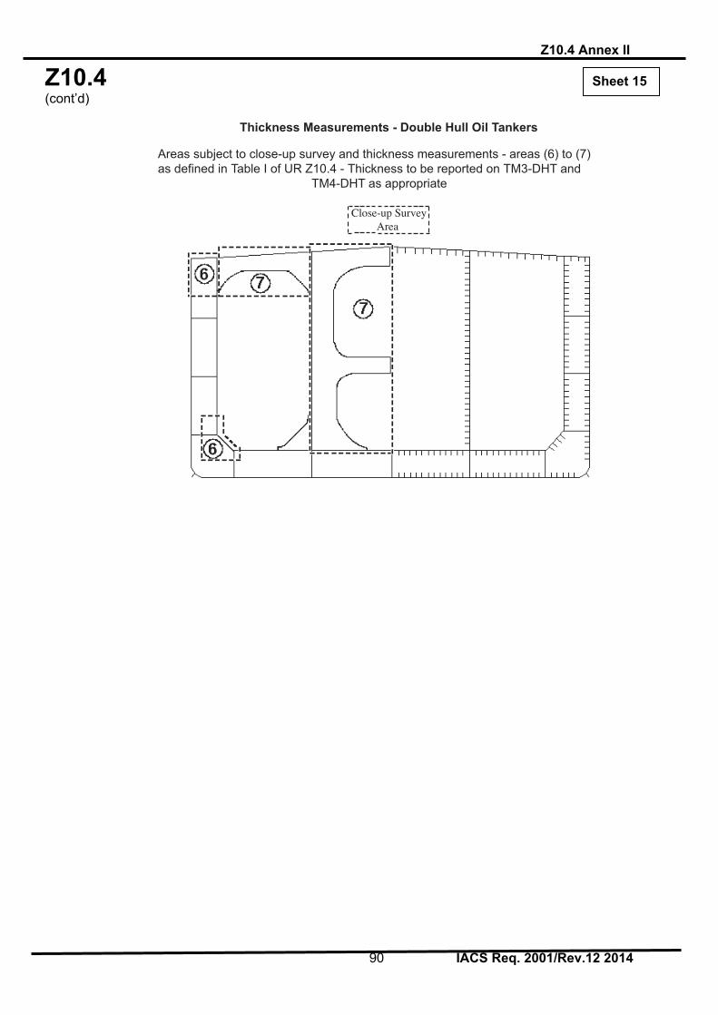
Z10.4 (cont’d)
Z10.4 Annex II
90 IACS Req. 2001/Rev.12 2014
Close-up Survey Area
Thickness Measurements - Double Hull Oil Tankers
Areas subject to close-up survey and thickness measurements - areas (6) to (7)as defined in Table I of UR Z10.4 - Thickness to be reported on TM3-DHT and TM4-DHT as appropriate
Sheet 15

Z10.4 (cont’d)
Z10.4 Annex II (CSR)
91 IACS Req. 2001/Rev.12 2014
ANNEX II (CSR)
IACS RECOMMENDED PROCEDURES FOR THICKNESS MEASUREMENTS OF DOUBLE HULL OIL TANKERS BUILT UNDER
IACS COMMON STRUCTURAL RULES*
* Note: Annex II (CSR) is recommendatory.

Z10.4 (cont’d)
Z10.4 Annex II (CSR)
92 IACS Req. 2001/Rev.12 2014
CONTENTS Sheet 1 - Contents Sheet 2 - Instructions Sheet 3 - General particulars REPORTS Sheet 4 - Report TM1-DHT(CSR) for recording the thickness measurement of
all deck plating, all bottom plating and side shell plating Sheet 5 - Report TM2-DHT(CSR) (i) for recording the thickness measurement of
shell and deck plating at transverse sections - strength deck and sheerstrake plating
Sheet 6 - Report TM2-DHT(CSR) (ii) for recording the thickness measurement of
shell plating at transverse sections Sheet 7 - Report TM3-DHT(CSR) for recording the thickness measurement of
longitudinal members at transverse sections (including double hull plating)
Sheet 8 - Report TM4-DHT(CSR) for recording the thickness measurement of
transverse structural members Sheet 9 - Report TM5-DHT(CSR) for recording the thickness measurement of
W.T./O.T. transverse bulkheads Sheet 10 - Report TM6-DHT(CSR) for recording the thickness measurement of
miscellaneous structural members GUIDANCE Sheet 11 - Typical transverse section of a double hull oil tanker (up to 150,000
dwt). The diagram includes details of the items to be measured and the report forms to be used.
Sheet 12 - Typical transverse section of a double hull oil tanker (above 150,000
dwt). The diagram includes details of the items to be measured and the report forms to be used.
Sheet 13 - Transverse section outline. This diagram may be used for those ships
where the diagram on sheet 11 and sheet 12 is not suitable. Sheet 14 - Transverse section and transverse bulkheads of a double hull
oil tanker showing typical areas for thickness measurement in association with close-up survey requirements, areas (1) to (5) as defined in Table I of the UR Z10.4.
Sheet 15 - Transverse section of a double hull oil tanker showing typical
areas for thickness measurement in association with close-up survey requirements, areas (6) to (7) as defined in Table I of the UR Z10.4.
Sheet 1

Z10.4 (cont’d)
Z10.4 Annex II (CSR)
93 IACS Req. 2001/Rev.12 2014
INSTRUCTIONS
IACS Recommended Procedures for Thickness Measurements of Double Hull Oil Tankers Built under IACS Common Structural Rules
1. This document is to be used for recording thickness measurements of double hull oil
tankers built under IACS Common Structural Rules as required by the IACS Unified Requirement Z10.4.
2. Reporting forms TM1-DHT(CSR), TM2-DHT(CSR) (i) and (ii), TM3-DHT(CSR), TM4-
DHT(CSR), TM5-DHT(CSR) and TM6-DHT(CSR) (sheets 4-10) are to be used for recording thickness measurements. The as-built thickness and the voluntary thickness addition and renewal thickness (minimum allowable thickness) are to be stated in the said forms.
3. The remaining sheets 11-15 are guidance diagrams and notes relating to the reporting
forms and the procedure for the thickness measurement.
Sheet 2Sheet 2

Z10.4 (cont’d)
Z10.4 Annex II (CSR)
94 IACS Req. 2001/Rev.12 2014
GENERAL PARTICULARS Ships name:- IMO number:- Class identity number:- Port of registry:- Gross tons:- Deadweight:- Date of build:- Classification Society:- Name of Company performing thickness measurement:- Thickness measurement company certified by:- Certificate No:- Certificate valid from..................to................ Place of measurement:- First date of measurement:- Last date of measurement:- Special survey/intermediate survey due:-* Details of measurement equipment:- Qualification of operators:- Report Number:- consisting of......Sheets Name of operator:- ........................ Name of surveyor:- ........................ Signature of operator:- ....................... Signature of surveyor:- ........................ Company Classification Society Official Stamp:- Official Stamp:- * Delete as appropriate
Sheet 3

Z10.4 (cont’d)
Z10.4 Annex II (CSR)
95 IACS Req. 2001/Rev.12 2014
Sheet 4
TM1-DHT(CSR) Report on THICKNESS MEASUREMENT of ALL DECK PLATING, ALL BOTTOM PLATING or SIDE SHELL PLATING* (* - delete as appropriate) Ship’s name......................... Class Identity No......................... Report No.........................
STRAKE POSITION
PLATE
POSITION
No. or
Letter
As Built Thk. mm
Voluntary Thickness Addition
mm
Renewal Thickness
mm (a)
Forward Reading Aft Reading Mean Remaining Corr. Addition, mm
[(c1)+(c2)]/2
Gauged Thk. mm (b1)
Remaining Corr. Addition, mm (c1)=(b1)-(a)
Gauged Thk. mm (b2)
Remaining Corr. Addition, mm (c2)=(b2)-(a)
P S P S P S P S P S 12th forward 11th 10th 9th 8th 7th 6th 5th 4th 3rd 2nd 1st Amidships 1st aft 2nd 3rd 4th 5th 6th 7th 8th 9th 10th 11th 12th
Operators Signature............................................. NOTES – See Reverse

Z10.4 (cont’d)
Z10.4 Annex II (CSR)
96 IACS Req. 2001/Rev.12 2014
NOTES TO REPORT TM1-DHT(CSR) 1. This report is to be used for recording the thickness measurement of:- 1.1 All strength deck plating within the cargo length area. 1.2 All keel, bottom shell plating and bilge plating within the cargo length area.
1.3 Side shell plating including selected wind and water strakes outside the cargo length area.
1.4 All wind and water strakes within the cargo length area. 2. The strake position is to be clearly indicated as follows:-
2.1 For strength deck indicate the number of the strake of plating inboard from the stringer plate.
2.2 For bottom plating indicate the number of the strake of plating outboard from
the keel plate.
2.3 For side shell plating give number of the strake of plating sheerstrake and letter as shown on shell expansion.
3. Measurements are to be taken at the forward and aft areas of all plates cross
ballast/cargo tank boundaries separate measurements for the area of plating in way of each type of tank are to be recorded.
4. The single measurements recorded are to represent the average of multiple
measurements. 5. The remaining corrosion addition is to be recorded with result of gauged thickness
minus renewal thickness. If the result is negative, the structure in way shall be renewed, and the mark “R” is to be indicated in the right-hand column. If the result is between 0 and 0.5 mm (0 included), the structure in way shall be additional gauged, and the mark “S” is to be indicated in the right-hand column.

Z10.4 (cont’d)
Z10.4 Annex II (CSR)
97 IACS Req. 2001/Rev.12 2014
Sheet 5
TM2-DHT(CSR) (i) Report on THICKNESS MEASUREMENT OF SHELL AND DECK PLATING (one, two or three transverse sections) Ship’s name......................... Class Identity No......................... Report No.........................
STRENGTH DECK AND SHEERSTRAKE PLATING
FIRST TRANSVERSE SECTION AT FRAME NUMBER
SECOND TRANSVERSE SECTION AT FRAME NUMBER
THIRD TRANSVERSE SECTION AT FRAME NUMBER
STRAKE
POSITION
No. or
Letter
As Built Thk. mm
Vol. Thk. Add.mm
Ren.Thk. mm
(a)
Gauged Thk. mm (b)
Remaining Corr. Addition, mm
(b)-(a)
No. or
Letter
As Built Thk. mm
Vol. Thk. Add. mm
Ren.Thk. mm
(a)
Gauged Thk. mm (b)
Remaining Corr. Addition, mm
(b)-(a)
No. or
Letter
As Built Thk. mm
Vol. Thk. Add. mm
Ren.Thk. mm
(a)
Gauged Thk. mm (b)
Remaining Corr. Addition, mm
(b)-(a)
P S P S P S P S P S P S Stringer Plate
1st strake inboard
2nd 3rd 4th 5th 6th 7th 8th 9th 10th 11th 12th 13th 14th centre strake
sheer strake
TOPSIDE TOTAL
Operators Signature............................................. NOTES – See Reverse

Z10.4 (cont’d)
Z10.4 Annex II (CSR)
98 IACS Req. 2001/Rev.12 2014
NOTES TO REPORT TM2-DHT(CSR) (i) 1. This report is to be used for recording the thickness measurement of:- Strength deck plating and sheerstrake plating transverse sections:-
One, two or three sections within the cargo length area, comprising of the structural items (0), (1) and (2) as shown on the diagram of typical transverse sections illustrated on sheets 11 and 12 of this document.
2. The topside area comprises deck plating, stringer plate and sheerstrake (including
rounded gunwales). 3. The exact frame station of measurement is to be stated. 4. The single measurements recorded are to represent the average of multiple
measurements. 5. The remaining corrosion addition is to be recorded with result of gauged thickness
minus renewal thickness. If the result is negative, the structure in way shall be renewed, and the mark “R” is to be indicated in the right-hand column. If the result is between 0 and 0.5 mm (0 included), the structure in way shall be additional gauged, and the mark “S” is to be indicated in the right-hand column.

Z10.4 (cont’d)
Z10.4 Annex II (CSR)
99 IACS Req. 2001/Rev.12 2014
Sheet 6
TM2-DHT(CSR) (ii) Report on THICKNESS MEASUREMENT OF SHELL PLATING (one, two or three transverse sections) Ship’s name......................... Class Identity No......................... Report No.........................
SHELL PLATING
FIRST TRANSVERSE SECTION AT FRAME NUMBER
SECOND TRANSVERSE SECTION AT FRAME NUMBER
THIRD TRANSVERSE SECTION AT FRAME NUMBER
STRAKE
POSITION
No. or
Letter
As Built Thk. mm
Vol. Thk. Add.mm
Ren.Thk. mm
(a)
Gauged Thk. mm (b)
Remaining Corr. Addition, mm
(b)-(a)
No. or
Letter
As Built Thk. mm
Vol. Thk. Add. mm
Ren.Thk. mm
(a)
Gauged Thk. mm (b)
Remaining Corr. Addition, mm
(b)-(a)
No. or
Letter
As Built Thk. mm
Vol. Thk. Add. mm
Ren.Thk. mm
(a)
Gauged Thk. mm (b)
Remaining Corr. Addition, mm
(b)-(a)
P S P S P S P S P S P S 1st below sheer strake
2nd 3rd 4th 5th 6th 7th 8th 9th 10th 11th 12th 13th 14th 15th 16th 17th 18th 19th 20th Keel strake BOTTOM TOTAL
Operators Signature............................................. NOTES – See Reverse

Z10.4 (cont’d)
Z10.4 Annex II (CSR)
100 IACS Req. 2001/Rev.12 2014
NOTES TO REPORT TM2-DHT(CSR) (ii) 1. This report is to be used for recording the thickness measurement of:- Shell plating transverse sections:-
One, two or three sections within the cargo length area comprising of the structural items (3), (4) and (5) and (6) as shown on the diagram of typical transverse sections illustrated on sheets 11 and 12 of this document.
2. The bottom area comprises keel, bottom and bilge plating. 3. The exact frame station of measurement is to be stated. 4. The single measurements recorded are to represent the average of multiple
measurements. 5. The remaining corrosion addition is to be recorded with result of gauged thickness
minus renewal thickness. If the result is negative, the structure in way shall be renewed, and the mark “R” is to be indicated in the right-hand column. If the result is between 0 and 0.5 mm (0 included), the structure in way shall be additional gauged, and the mark “S” is to be indicated in the right-hand column.

Z10.4 (cont’d)
Z10.4 Annex II (CSR)
101 IACS Req. 2001/Rev.12 2014
Sheet 7
TM3-DHT(CSR) Report on THICKNESS MEASUREMENT OF LONGITUDINAL MEMBERS (one, two or three transverse sections) Ship’s name......................... Class Identity No......................... Report No........................
FIRST TRANSVERSE SECTION AT FRAME NUMBER
SECOND TRANSVERSE SECTION AT FRAME NUMBER
THIRD TRANSVERSE SECTION AT FRAME NUMBER
STRUCTURAL MEMBER
Item No.
As Built Thk. mm
Vol. Thk. Add.mm
Ren.Thk. mm
(a)
Gauged Thk. mm (b)
Remaining Corr. Addition, mm
(b)-(a)
Item No.
As Built Thk. mm
Vol. Thk. Add. mm
Ren.Thk. mm
(a)
Gauged Thk. mm (b)
Remaining Corr. Addition, mm
(b)-(a)
Item No.
As Built Thk. mm
Vol. Thk. Add. mm
Ren.Thk. mm
(a)
Gauged Thk. mm (b)
Remaining Corr. Addition, mm
(b)-(a)
P S P S P S P S P S P S
Operators Signature............................................. NOTES – See Reverse

Z10.4 (cont’d)
Z10.4 Annex II (CSR)
102 IACS Req. 2001/Rev.12 2014
NOTES TO REPORT TM3-DHT(CSR) 1. This report is to be used for recording the thickness measurement of:- Longitudinal Members at transverse sections:-
One, two or three sections within the cargo length area, comprising of the appropriate structural items (10) to (29) as shown on the diagram of typical transverse sections illustrated on sheets 11 and 12 of this document.
2. The exact frame station of measurement is to be stated. 3. The single measurements recorded are to represent the average of multiple
measurements. 4. The remaining corrosion addition is to be recorded with result of gauged thickness
minus renewal thickness. If the result is negative, the structure in way shall be renewed, and the mark “R” is to be indicated in the right-hand column. If the result is between 0 and 0.5 mm (0 included), the structure in way shall be additional gauged, and the mark “S” is to be indicated in the right-hand column.

Z10.4 (cont’d)
Z10.4 Annex II (CSR)
103 IACS Req. 2001/Rev.12 2014
Sheet 8
TM4-DHT(CSR) Report on THICKNESS MEASUREMENT OF TRANSVERSE STRUCTURAL MEMBERS In the cargo oil and water ballast tanks within the cargo tank length Ship’s name......................... Class Identity No......................... Report No........................
TANK DESCRIPTION: LOCATION OF STRUCTURE
STRUCTURAL MEMBER
ITEM
As Built Thickness
mm
Voluntary Thickness Addition
mm
Renewal Thickness
mm (a)
Gauged Thickness mm (b)
Remaining Corr. Addition mm
(b)-(a)P S P S
Operators Signature............................................. NOTES – See Reverse

Z10.4 (cont’d)
Z10.4 Annex II (CSR)
104 IACS Req. 2001/Rev.12 2014
NOTES TO REPORT TM4-DHT(CSR) 1. This report is to be used for recording the thickness measurement of:-
Transverse structural members, comprising of the appropriate structural items (30) to (36) as shown on diagram of typical transverse section, illustrated on sheets 11 and 12 of this document.
2. Guidance for areas if measurement is indicated on the diagrams shown on sheet 14
and 15 of this document. 3. The single measurements recorded are to represent the average of multiple
measurements. 4. The remaining corrosion addition is to be recorded with result of gauged
thickness minus renewal thickness. If the result is negative, the structure in way shall be renewed, and the mark “R” is to be indicated in the right-hand column. If the result is between 0 and 0.5 mm (0 included), the structure in way shall be additional gauged, and the mark “S” is to be indicated in the right-hand column.
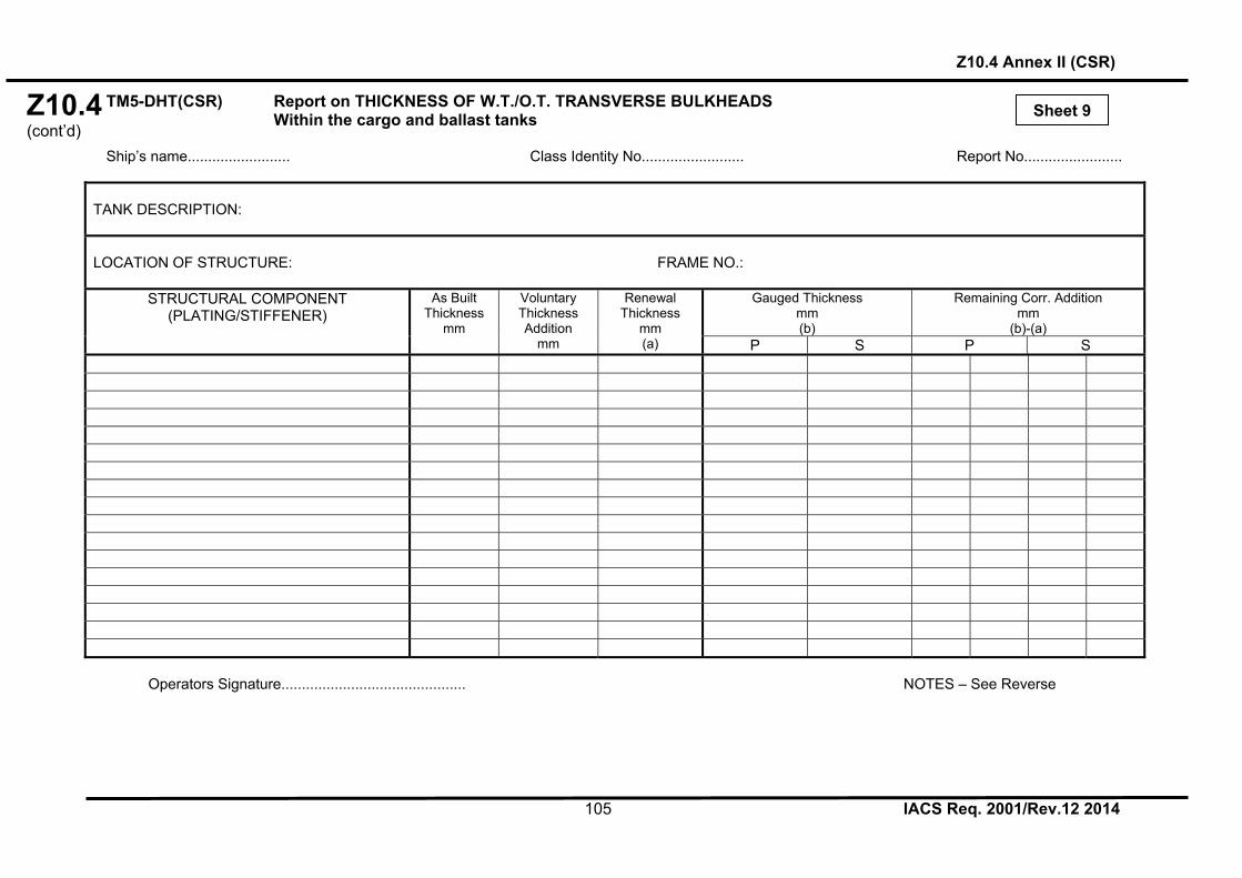
Z10.4 (cont’d)
Z10.4 Annex II (CSR)
105 IACS Req. 2001/Rev.12 2014
Sheet 9
TM5-DHT(CSR) Report on THICKNESS OF W.T./O.T. TRANSVERSE BULKHEADS Within the cargo and ballast tanks Ship’s name......................... Class Identity No......................... Report No........................
TANK DESCRIPTION: LOCATION OF STRUCTURE: FRAME NO.:
STRUCTURAL COMPONENT (PLATING/STIFFENER)
As Built Thickness
mm
Voluntary Thickness Addition
mm
Renewal Thickness
mm (a)
Gauged Thickness mm (b)
Remaining Corr. Addition mm
(b)-(a)P S P S
Operators Signature............................................. NOTES – See Reverse

Z10.4 (cont’d)
Z10.4 Annex II (CSR)
106 IACS Req. 2001/Rev.12 2014
NOTES TO REPORT TM5-DHT(CSR) 1. This report is to be used for recording the thickness measurement of:- W.T./O.T. transverse bulkheads. 2. Guidance for areas of measurement is indicated on the diagrams shown on sheet 14
of this document. 3. The single measurements recorded are to represent the average of multiple
measurements. 4. The remaining corrosion addition is to be recorded with result of gauged thickness
minus renewal thickness. If the result is negative, the structure in way shall be renewed, and the mark “R” is to be indicated in the right-hand column. If the result is between 0 and 0.5 mm (0 included), the structure in way shall be additional gauged, and the mark “S” is to be indicated in the right-hand column.

Z10.4 (cont’d)
Z10.4 Annex II (CSR)
107 IACS Req. 2001/Rev.12 2014
Sheet 10
TM6-DHT(CSR) Report on THICKNESS MEASUREMENT OF MISCELLANEOUS STRUCTURAL MEMBERS Ship’s name......................... Class Identity No......................... Report No........................ STRUCTURAL MEMBER:
SKETCH
LOCATION OF STRUCTURE:
Description
As Built Thk. mm
Voluntary Thickness Addition
mm
Renewal Thickness
mm (a)
Gauged Thickness mm (b)
Remaining Corr. Addition mm
(b)-(a)
P S P S
Operators Signature............................................. NOTES – See Reverse

Z10.4 (cont’d)
Z10.4 Annex II (CSR)
108 IACS Req. 2001/Rev.12 2014
NOTES TO REPORT TM6-DHT(CSR) 1. This report is to be used for recording the thickness measurement of:- Miscellaneous structural members. 2. The single measurements recorded are to represent the average of multiple
measurements. 3. The remaining corrosion addition is to be recorded with result of gauged thickness
minus renewal thickness. If the result is negative, the structure in way shall be renewed, and the mark “R” is to be indicated in the right-hand column. If the result is between 0 and 0.5 mm (0 included), the structure in way shall be additional gauged, and the mark “S” is to be indicated in the right-hand column.

Z10.4 (cont’d)
Z10.4 Annex II (CSR)
109 IACS Req. 2001/Rev.12 2014
Sheet 11 Thickness Measurement - Double Hull Oil Tankers
Typical transverse section of a double hull oil tanker up to 150,000 dwt with indication of
longitudinal and transverse members
Report on TM2-DHT(CSR) (i) & (ii)
0. Strength deck plating 1. Stringer plate 2. Sheerstrake 3. Side shell plating 4. Bilge plating 5. Bottom shell plating 6. Keel plate
Report on TM3-DHT(CSR)
10. Deck longitudinals 20. Longitudinal bulkhead plating (remainder) 11. Sheerstrake longitudinals 21. Longitudinal bulkhead longitudinals 12. Side shell longitudinals 22. Inner side plating 13. Bilge longitudinals 23. Inner side longitudinal 14. Bottom longitudinals 24. Hopper plating 15. Deck girders 25. Hopper longitudinal 16. Horizontal girders in wing ballast tanks 26. Inner bottom plating 17. Bottom girders 27. Inner bottom longitudinals 18. Longitudinal bulkhead top strake 28. Topside tank plating 19. Longitudinal bulkhead bottom strake 29. Topside tank longitudinals
Report on TM4-DHT(CSR)
30. Deck transverse - centre tank 31. Deck transverse - wing tank 32. Vertical web in wing ballast tank 33. Double bottom floor - wing tank 34. Double bottom floor - centre tank 35. Longitudinal bulkhead vertical web 36. Cross ties

Z10.4 (cont’d)
Z10.4 Annex II (CSR)
110 IACS Req. 2001/Rev.12 2014
Sheet 12
Thickness Measurement - Double Hull Oil Tankers
Typical transverse section of a double hull oil tanker above 150,000 dwt with indication of longitudinal and transverse members
Report on TM2-DHT(CSR) (i) & (ii)
0. Strength deck plating 1. Stringer plate 2. Sheerstrake 3. Side shell plating 4. Bilge plating 5. Bottom shell plating 6. Keel plate
Report on TM3-DHT(CSR)
10. Deck longitudinals 20. Longitudinal bulkhead plating (remainder) 11. Sheerstrake longitudinals 21. Longitudinal bulkhead longitudinals 12. Side shell longitudinals 22. Inner side plating 13. Bilge longitudinals 23. Inner side longitudinal 14. Bottom longitudinals 24. Hopper plating 15. Deck girders 25. Hopper longitudinal 16. Horizontal girders in wing ballast tanks 26. Inner bottom plating 17. Bottom girders 27. Inner bottom longitudinals 18. Longitudinal bulkhead top strake 28. Topside tank plating 19. Longitudinal bulkhead bottom strake 29. Topside tank longitudinals
Report on TM4-DHT(CSR)
30. Deck transverse - centre tank 31. Deck transverse - wing tank 32. Vertical web in wing ballast tank 33. Double bottom floor - wing tank 34. Double bottom floor - centre tank 35. Longitudinal bulkhead vertical web 36. Cross ties

Z10.4 (cont’d)
Z10.4 Annex II (CSR)
111 IACS Req. 2001/Rev.12 2014
Sheet 13 Thickness Measurement - Double Hull Oil Tankers
Transverse section outline
The diagram may be used for those ships where the diagrams on sheet 11 and 12 are not suitable
Report on TM2-DHT(CSR) (i) & (ii)
0. Strength deck plating 1. Stringer plate 2. Sheerstrake 3. Side shell plating 4. Bilge plating 5. Bottom shell plating 6. Keel plate
Report on TM3-DHT(CSR)
10. Deck longitudinals 20. Longitudinal bulkhead plating (remainder) 11. Sheerstrake longitudinals 21. Longitudinal bulkhead longitudinals 12. Side shell longitudinals 22. Inner side plating 13. Bilge longitudinals 23. Inner side longitudinal 14. Bottom longitudinals 24. Hopper plating 15. Deck girders 25. Hopper longitudinal 16. Horizontal girders in wing ballast tanks 26. Inner bottom plating 17. Bottom girders 27. Inner bottom longitudinals 18. Longitudinal bulkhead top strake 28. Topside tank plating 19. Longitudinal bulkhead bottom strake 29. Topside tank longitudinals
Report on TM4-DHT(CSR)
30. Deck transverse - centre tank 31. Deck transverse - wing tank 32. Vertical web in wing ballast tank 33. Double bottom floor - wing tank 34. Double bottom floor - centre tank 35. Longitudinal bulkhead vertical web 36. Cross ties

Z10.4 (cont’d)
Z10.4 Annex II (CSR)
112 IACS Req. 2001/Rev.12 2014
Close-up Survey and Thickness Measurement Areas Areas subject to close-up survey and thickness measurements - areas (1) to (5) as defined in
Table I of UR Z10.4 - Thickness to be reported on TM3-DHT(CSR), TM4-DHT(CSR) and TM5-DHT(CSR) as appropriate.
Sheet 14

Z10.4 (cont’d)
Z10.4 Annex II (CSR)
113 IACS Req. 2001/Rev.12 2014
Close-up Survey and Thickness Measurement Areas Areas subject to close-up survey and thickness measurements - areas (6) to (7) as defined in
Table I of UR Z10.4 - Thickness to be reported on TM3-DHT(CSR), TM4-DHT(CSR) as appropriate.
End of Annex II
Sheet 15

Z10.4 (cont’d)
Z10.4 Annex III
114 IACS Req. 2001/Rev.12 2014
ANNEX III
CRITERIA FOR LONGITUDINAL STRENGTH OF HULL GIRDER FOR OIL TANKERS

Z10.4 (cont’d)
Z10.4 Annex III
115 IACS Req. 2001/Rev.12 2014
ANNEX III
CRITERIA FOR LONGITUDINAL STRENGTH OF HULL GIRDER FOR OIL TANKERS
1 General 1.1 These criteria is to be used for the evaluation of longitudinal strength of the ship's hull girder as required by section 8.1.1.1. 1.2 In order that ship’s longitudinal strength to be evaluated can be recognized as valid, fillet welding between longitudinal internal members and hull envelopes is to be in sound condition so as to keep integrity of longitudinal internal members with hull envelopes. 2 Evaluation of longitudinal strength On oil tankers of 130 m in length and upwards and of over 10 years of age, the longitudinal strength of the ship's hull girder is to be evaluated in compliance with the requirements of this annex on the basis of the thickness measured, renewed or reinforced, as appropriate, during the special survey. The condition of the hull girder for longitudinal strength evaluation should be determined in accordance with the methods specified in appendix 3. 2.1 Calculation of transverse sectional areas of deck and bottom flanges of hull
girder 2.1.1 The transverse sectional areas of deck flange (deck plating and deck longitudinals) and bottom flange (bottom shell plating and bottom longitudinals) of the ship’s hull girder is to be calculated by using the thickness measured, renewed or reinforced, as appropriate, during the special survey. 2.1.2 If the diminution of sectional areas of either deck or bottom flange exceeds 10% of their respective as-built area (i.e. original sectional area when the ship was built), either one of the following measures is to be taken:
.1 to renew or reinforce the deck or bottom flanges so that the actual sectional area is not less than 90% of the as-built area; or
.2 to calculate the actual section moduli (Zact) of transverse section of the ship’s
hull girder by applying the calculation method specified in appendix 1, by using the thickness measured, renewed or reinforced, as appropriate, during the special survey.
2.2 Requirements for transverse section modulus of hull girder 2.2.1 The actual section moduli of transverse section of the ship’s hull girder calculated in accordance with the foregoing paragraph 2.1.2.2 is to satisfy either of the following provisions, as applicable:
.1 for ships constructed on or after 1 July 2002, the actual section moduli (Zact) of the transverse section of the ship's hull girder calculated in accordance with the requirements of the foregoing paragraph 2.1.2.2 should is not to be less than the diminution limits determined by the Classification Society*; or

Z10.4 (cont’d)
Z10.4 Annex III
116 IACS Req. 2001/Rev.12 2014
.2 for ships constructed before 1 July 2002, the actual section moduli (Zact) of the transverse section of the ship's hull girder calculated in accordance with the requirements of the foregoing paragraph 2.1.2.2 is to meet the criteria for minimum section modulus for ships in service required by the Classification Society, provided that in no case Zact is to be less than the diminution limit of the minimum section modulus (Zmc) as specified in appendix 2.
* The actual transverse section modulus of the hull girder of oil tankers calculated under
paragraph 2.2.1.1 of Annex III to UR Z10.4 is not to be less than 90% of the required section modulus for new buildings specified in IACS Unified Requirements S7* or S11, whichever is the greater.
* C = 1.0 cn is to be used for the purpose of this calculation.

Z10.4 (cont’d)
Z10.4 Annex III
117 IACS Req. 2001/Rev.12 2014
APPENDIX 1
CALCULATION CRITERIA OF SECTION MODULI OF MIDSHIP SECTION OF HULL GIRDER
1 When calculating the transverse section modulus of the ship's hull girder, the sectional area of all continuous longitudinal strength members is to be taken into account. 2 Large openings, i.e. openings exceeding 2.5m in length or 1.2m in breadth and scallops, where scallop welding is applied, are always to be deducted from the sectional areas used in the section modulus calculation. 3 Smaller openings (manholes, lightening holes, single scallops in way of seams, etc.) need not be deducted provided that the sum of their breadths or shadow area breadths in one transverse section does not reduce the section modulus at deck or bottom by more than 3% and provided that the height of lightening holes, draining holes and single scallops in longitudinals or longitudinal girders does not exceed 25% of the web depth, for scallops maximum 75mm. 4 A deduction-free sum of smaller opening breadths in one transverse section in the bottom or deck area of 0.06(∑B - b) (where B = breadth of ship, ∑b = total breadth of large openings) may be considered equivalent to the above reduction in sectional modulus. 5 The shadow area will be obtained by drawing two tangent lines with an opening angle of 30˚. 6 The deck modulus is related to the moulded deck line at side. 7 The bottom modulus is related to the base line. 8 Continuous trunks and longitudinal hatch coamings are to be included in the longitudinal sectional area provided they are effectively supported by longitudinal bulkheads or deep girders. The deck modulus is then to be calculated by dividing the moment of inertia by the following distance, provided this is greater than the distance to the deck line at side:
Bx
yyt 2.09.0
where:
y = distance from neutral axis to top of continuous strength member, x = distance from top of continuous strength member to centreline of the ship. x and y to be measured to the point giving the largest value of yt. 9 Longitudinal girders between multi-hatchways will be considered by special calculations.

Z10.4 (cont’d)
Z10.4 Annex III
118 IACS Req. 2001/Rev.12 2014
APPENDIX 2
DIMINUTION LIMIT OF MINIMUM LONGITUDINAL STRENGTH OF SHIPS IN SERVICE
1 The diminution limit of the minimum section modulus (Zmc) of oil tankers in service is given by the following formula: Zmc = cL2B (Cb + 0.7)k (cm3) where
L = Length of ships. L is the distance, in metres, on the summer load waterline from the fore side of stem to the after side of the rudder post, or the centre of the rudder stock if there is no rudder post. L is not to be less than 96%, and need not be greater than 97%, of the extreme length on the summer load waterline. In ships with unusual stern and bow arrangement the length L may be specially considered.
B = Greatest moulded breadth in metres.
Cb = Moulded block coefficient at draught d corresponding to summer load waterline, based on L and B. Cb is not to be taken less than 0.60.
dBL
dCb
draught at )(m ntdisplaceme moulded 3
c = 0.9 cn
5.1
100300
75.10
L
cn for 130 m ≤ L ≤ 300 m
75.10nc for 300 m < L < 350 m
5.1
150350
75.10
L
cn for 350 m ≤ L ≤ 500 m
k = material factor, e.g. k = 1.0 for mild steel with yield stress of 235N/mm2 and over; k = 0.78 for high tensile steel with yield stress of 315N/mm2 and over; k = 0.72 for high tensile steel with yield stress of 355N/mm2 and over.

Z10.4 (cont’d)
Z10.4 Annex III
119 IACS Req. 2001/Rev.12 2014
2 Scantlings of all continuous longitudinal members of the ship's hull girder based on the section modulus requirement in 1 are to be maintained within 0.4L amidships. However, in special cases, based on consideration of type of ship, hull form and loading conditions, the scantlings may be gradually reduced towards the end of 0.4L part, bearing in mind the desire not to inhibit the ship’s loading flexibility. 3 However, the above standard may not be applicable to ships of unusual type or design, e.g. for ships of unusual main proportions and/or weight distributions.

Z10.4 (cont’d)
Z10.4 Annex III
120 IACS Req. 2001/Rev.12 2014
APPENDIX 3
SAMPLING METHOD OF THICKNESS MEASUREMENTS FOR LONGITUDINAL STRENGTH EVALUATION
AND REPAIR METHODS 1 Extent of longitudinal strength evaluation Longitudinal strength should be evaluated within 0.4L amidships for the extent of the hull girder length that contains tanks therein and within 0.5L amidships for adjacent tanks which may extend beyond 0.4L amidships, where tanks means ballast tanks and cargo tanks. 2 Sampling method of thickness measurement 2.1 Pursuant to the requirements of section 2.4 of Z10.4, transverse sections should be chosen such that thickness measurements can be taken for as many different tanks in corrosive environments as possible, e.g. ballast tanks sharing a common plane boundary with cargo tanks fitted with heating coils, other ballast tanks, cargo tanks permitted to be filled with sea water and other cargo tanks. Ballast tanks sharing a common plane boundary with cargo tanks fitted with heating coils and cargo tanks permitted to be filled with sea water should be selected where present. 2.2 The minimum number of transverse sections to be sampled should be in accordance with Table II of Z10.4. The transverse sections should be located where the largest thickness reductions are suspected to occur or are revealed from deck and bottom plating measurements prescribed in 2.3 and should be clear of areas which have been locally renewed or reinforced. 2.3 At least two points should be measured on each deck plate and/or bottom shell plate required to be measured within the cargo area in accordance with the requirements of Table II of Z10.4. 2.4 Within 0.1D (where D is the ship’s moulded depth) of the deck and bottom at each transverse section to be measured in accordance with the requirements of Table II of Z10.4, every longitudinal and girder should be measured on the web and face plate, and every plate should be measured at one point between longitudinals. 2.5 For longitudinal members other than those specified in 2.4 to be measured at each transverse section in accordance with the requirements of Table II of Z10.4, every longitudinal and girder should be measured on the web and face plate, and every plate should be measured at least in one point per strake. 2.6 The thickness of each component should be determined by averaging all of the measurements taken in way of the transverse section on each component. 3 Additional measurements where the longitudinal strength is deficient 3.1 Where one or more of the transverse sections are found to be deficient in respect of the longitudinal strength requirements given in this annex, the number of transverse sections for thickness measurement should be increased such that each tank within the 0.5L amidships region has been sampled. Tank spaces that are partially within, but extend beyond, the 0.5L region, should be sampled.

Z10.4 (cont’d)
Z10.4 Annex III
121 IACS Req. 2001/Rev.12 2014
3.2 Additional thickness measurements should also be performed on one transverse section forward and one aft of each repaired area to the extent necessary to ensure that the areas bordering the repaired section also comply with the requirements of Z10.4. 4 Effective repair methods 4.1 The extent of renewal or reinforcement carried out to comply with this annex should be in accordance with 4.2. 4.2 The minimum continuous length of a renewed or reinforced structural member should be not less than twice the spacing of the primary members in way. In addition, the thickness diminution in way of the butt joint of each joining member forward and aft of the replaced member (plates, stiffeners, girder webs and flanges, etc.) should not be within the substantial corrosion range (75% of the allowable diminution associated with each particular member). Where differences in thickness at the butt joint exceed 15% of the lower thickness, a transition taper should be provided. 4.3 Alternative repair methods involving the fitting of straps or structural member modification should be subject to special consideration. In considering the fitting of straps, it should be limited to the following conditions: .1 to restore and/or increase longitudinal strength; .2 the thickness diminution of the deck or bottom plating to be reinforced should not be within the substantial corrosion range (75% of the allowable diminution associated with the deck plating); .3 the alignment and arrangement, including the termination of the straps, is in accordance with a standard recognized by the Classification Society;
.4 the straps are continuous over the entire 0.5L amidships length; and .5 continuous fillet welding and full penetration welds are used at butt welding and, depending on the width of the strap, slot welds. The welding procedures applied should be acceptable to the Classification Society. 4.4 The existing structure adjacent to replacement areas and in conjunction with the fitted straps, etc. should be capable of withstanding the applied loads, taking into account the buckling resistance and the condition of welds between the longitudinal members and hull envelope plating.
End of Annex III

Z10.4 (cont’d)
Z10.4 Annex IV
122 IACS Req. 2001/Rev.12 2014
ANNEX IV

Z10.4 (cont’d)
Z10.4 Annex IVA
123 IACS Req. 2001/Rev.12 2014
ANNEX IVA
SURVEY PROGRAMME Basic information and particulars
Name of ship:
IMO number:
Flag State:
Port of registry:
Gross tonnage:
Deadweight (metric tonnes):
Length between perpendiculars (m):
Shipbuilder:
Hull number:
Classification Society:
Class ID:
Date of build of the ship:
Owner:
Thickness measurement company:

Z10.4 (cont’d)
Z10.4 Annex IVA
124 IACS Req. 2001/Rev.12 2014
Preamble 1.1 Scope 1.1.1 The present survey programme covers the minimum extent of overall surveys, close-up surveys, thickness measurements and pressure testing within the cargo area, cargo tanks, ballast tanks, including fore and aft peak tanks, required by UR Z10.4. 1.1.2 The arrangements and safety aspects of the survey are to be acceptable to the attending surveyor(s). 1.2 Documentation All documents used in the development of the survey programme are to be available onboard during the survey as required by section 6. 2 Arrangement of tanks and spaces This section of the survey programme is to provide information (either in the form of plans or text) on the arrangement of tanks and spaces that fall within the scope of the survey. 3 List of tanks and spaces with information on their use, extent of coatings and
corrosion protection system This section of the survey programme is to indicate any changes relating to (and is to update) the information on the use of the tanks of the ship, the extent of coatings and the corrosion protective system provided in the Survey Planning Questionnaire. 4 Conditions for survey This section of the survey programme is to provide information on the conditions for survey, e.g. information regarding cargo hold and tank cleaning, gas freeing, ventilation, lighting, etc. 5 Provisions and method of access to structures This section of the survey programme is to indicate any changes relating to (and is to update) the information on the provisions and methods of access to structures provided in the Survey Planning Questionnaire. 6 List of equipment for survey This section of the survey programme is to identify and list the equipment that will be made available for carrying out the survey and the required thickness measurements. 7 Survey requirements 7.1 Overall survey This section of the survey programme is to identify and list the spaces that are to undergo an overall survey for the ship in accordance with 2.3.1.

Z10.4 (cont’d)
Z10.4 Annex IVA
125 IACS Req. 2001/Rev.12 2014
7.2 Close-up survey This section of the survey programme is to identify and list the hull structures that are to undergo a close-up survey for the ship in accordance with 2.3.2. 8 Identification of tanks for tank testing This section of the survey programme is to identify and list the tanks that are to undergo tank testing for the ship in accordance with 2.5. 9 Identification of areas and sections for thickness measurements This section of the survey programme is to identify and list the areas and sections where thickness measurements are to be taken in accordance with 2.4.1. 10 Minimum thickness of hull structures This section of the survey programme is to specify the minimum thickness for hull structures of this ship that are subject to UR Z10.4 (indicate either (a) or preferably (b), if such information is available): (a) Determined from the attached wastage allowance table and the original thickness to
the hull structure plans of the ship; (b) Given in the following table(s):
Area or location Original as-
built thickness(mm)
Minimum thickness
(mm)
Substantial corrosion thickness
(mm) Deck Plating Longitudinals Longitudinal girders Bottom Plating Longitudinals Longitudinal girders Ship side Plating Longitudinals Longitudinal girders Longitudinal bulkhead Plating Longitudinals
Longitudinal girders Inner bottom Plating Longitudinals Longitudinal girders Transverse bulkheads Plating Stiffeners

Z10.4 (cont’d)
Z10.4 Annex IVA
126 IACS Req. 2001/Rev.12 2014
Transverse web frames, floors and stringers
Plating Flanges Stiffeners Cross ties Flanges Webs
Note: The wastage allowance tables are to be attached to the survey programme. For vessels built under IACS Common Structural Rules, the renewal thickness of the hull structure elements is indicated in the appropriate drawings. 11 Thickness measurement company
This section of the survey programme is to identify changes, if any, relating to the information on the thickness measurement company provided in the Survey Planning Questionnaire. 12 Damage experience related to the ship This section of the survey programme is to, using the tables provided below, provide details of the hull damages for at least the last three years in way of the cargo and ballast tanks and void spaces within the cargo area. These damages are subject to survey.
Hull damages sorted by location for the ship
Tank or space
number or area
Possible cause, if known
Description of the
damages
Location Repair Date of repair

Z10.4 (cont’d)
Z10.4 Annex IVA
127 IACS Req. 2001/Rev.12 2014
Hull damages for sister or similar ships (if available) in the case of design related damage
Tank or space
number or area
Possible cause, if known
Description of the
damages
Location Repair Date of repair
13 Areas identified with substantial corrosion from previous surveys This section of the survey programme is to identify and list the areas of substantial corrosion from previous surveys. 14 Critical structural areas and suspect areas This section of the survey programme is to identify and list the critical structural areas and the suspect areas, if such information is available. 15 Other relevant comments and information This section of the survey programme is to provide any other comments and information relevant to the survey.

Z10.4 (cont’d)
Z10.4 Annex IVA
128 IACS Req. 2001/Rev.12 2014
Appendices Appendix 1 - List of plans Paragraph 5.1.3.2 requires that main structural plans of cargo and ballast tanks (scantling drawings), including information regarding use of high tensile steel (HTS), to be available. This appendix of the survey programme is to identify and list the main structural plans which form part of the survey programme. Appendix 2 - Survey Planning Questionnaire The Survey Planning Questionnaire (annex IVB), which has been submitted by the owner, is to be appended to the survey programme. Appendix 3 - Other documentation This part of the survey programme is to identify and list any other documentation that forms part of the Plan. Prepared by the owner in co-operation with the Classification Society for compliance with 5.1.3. Date:…………………………………. (name and signature of authorized owner’s
representative) Date:…………………………………. (name and signature of authorized representative of the
Classification Society)

Z10.4 (cont’d)
Z10.4 Annex IVB
129 IACS Req. 2001/Rev.12 2014
ANNEX IVB
SURVEY PLANNING QUESTIONNAIRE
The following information will enable the owner in co-operation with the Classification Society to develop a survey programme complying with the requirements of UR Z10.4. It is essential that the owner provides, when completing the present questionnaire, up-to-date information. The present questionnaire, when completed, is to provide all information and material required by UR Z10.4. Particulars Ship's name: IMO number: Flag State: Port of registry: Owner: Classification Society: Class ID: Gross tonnage: Deadweight (metric tonnes): Date of build: Information on access provision for close-up surveys and thickness measurement: The owner is to indicate, in the table below, the means of access to the structures subject to close-up survey and thickness measurement. A close-up survey is an examination where the details of structural components are within the close visual inspection range of the attending surveyor, i.e. normally within reach of hand.
Tank No.
Structure C(Cargo)/ B(Ballast)
Permanent Means of Access
Temporary staging
Rafts Ladders Direct access
Other means (please specify)
F.P. Fore Peak A.P. Aft Peak Wing Tanks
Under deck Side shell Bottom transverse
Longitudinal Transverse
Centre Tanks
Underdeck Bottom transverse
Transverse

Z10.4 (cont’d)
Z10.4 Annex IVB
130 IACS Req. 2001/Rev.12 2014
History of cargo with H2S content or heated cargo for the last 3 years together with indication as to whether cargo was heated and, where available, Marine Safety Data Sheets (MSDS)*
* Refer to resolution MSC. 150(77) on Recommendation for material safety data sheets for MARPOL Annex I cargoes and marine fuel oils. Owner’s inspections Using a format similar to that of the table below (which is given as an example), the owner is to provide details of the results of their inspections for the last 3 years on all cargo and ballast tanks and void spaces within the cargo area, including peak tanks.
Tank No. Corrosion protection
(1)
Coating extent
(2)
Coating condition
(3)
Structural deterioration
(4)
Tank damage history
(5) Cargo centre tanks
Cargo wing tanks
Slop

Z10.4 (cont’d)
Z10.4 Annex IVB
131 IACS Req. 2001/Rev.12 2014
Tank No. Corrosion protection
(1)
Coating extent
(2)
Coating condition
(3)
Structural deterioration
(4)
Tank damage history
(5) Ballast tanks
Aft peak
Fore peak
Miscellaneous spaces
Note: Indicate tanks which are used for oil/ballast. 1) HC=hard coating; SC=soft coating; SH=semi-hard coating; NP=no protection 2) U=upper part; M=middle part; L=lower part; C=complete 3) G=good; F=fair; P=poor; RC=recoated (during the last 3 years) 4) N=no findings recorded; Y=findings recorded, description of findings is to be attached to the questionnaire 5) DR=damage & repair; L=leakages; CV=conversion (description is to be attached to this questionnaire) Name of owner’s representative: Signature: Date:

Z10.4 (cont’d)
Z10.4 Annex IVB
132 IACS Req. 2001/Rev.12 2014
Reports of Port State Control inspections
List the reports of Port State Control inspections containing hull structural related deficiencies and relevant information on rectification of the deficiencies:
Safety Management System List non-conformities related to hull maintenance, including the associated corrective actions:
Name and address of the approved thickness measurement company:

Z10.4 (cont’d)
Z10.4 Annex IVC
133 IACS Req. 2001/Rev.12 2014
ANNEX IVC
OWNER’S INSPECTION REPORT
Structural condition
Ship’s name: For tank No: Grade of steel: deck: side: bottom: longitudinal bulkhead: Elements Cracks Buckles Corrosion Coating
condition Pitting Modification/
repair Other
Deck
Bottom
Side
Longitudinal bulkhead
Transverse bulkhead
Repairs carried out due to: Thickness measurements carried out (dates): Results in general: Overdue surveys: Outstanding conditions of class: Comments: Date of inspection: Inspected by: Signature: Annex IV end
Document end

Z10.5
1 IACS Req. 2003/Rev.14 2014
Z10.5 (cont)
HULL SURVEYS OF DOUBLE SKIN BULK CARRIERS 1. General 1.1 Application 1.2 Definitions 1.3 Repairs 1.4 Thickness Measurements And Close-Up Surveys 2. Special Survey 2.1 Schedule 2.2 Scope 2.3 Extent Of Overall And Close-Up Surveys 2.4 Extent Of Thickness Measurements 2.5 Extent Of Tank Testing 2.6 Additional Special Survey Requirements After Determining Compliance With SOLAS
XII/12 And XII/13 3. Annual Survey 3.1 Schedule 3.2 Scope 3.3 Additional Annual Survey Requirements After Determining Compliance With SOLAS
XII/12 And XII/13 4. Intermediate Survey 4.1 Schedule 4.2 Scope 5. Preparation For Survey 5.1 Survey Programme 5.2 Conditions For Survey 5.3 Access To Structures 5.4 Equipment For Survey 5.5 Rescue and emergency response equipment 5.6 Survey At Sea Or At Anchorage 5.7 Survey Planning Meeting 6. Documentation On Board 6.1 General 6.2 Survey Report File 6.3 Supporting Documents 6.4 Review Of Documentation On Board 7. Procedures For Thickness Measurement 7.1 General 7.2 Certification Of Thickness Measurement Company 7.3 Number and Locations of Measurements 7.4 Reporting
Z10.5 (Dec. 2003) (Corr.1 Jan 2004) (Rev.1 June 2005) (Rev.2 Jan. 2006) (Rev.3 Jan 2006) (Rev.4 June 2006) (Rev.5 Feb 2007) (Rev.6 Apr 2007) (Rev.7 July 2007) (Rev.8 Nov 2007) (Rev.9 Mar 2009) (Rev.10 Mar 2011) (Rev.11 July 2011) (Rev.12 May 2012) (Rev.13 June 2013) (Rev.14 Jan 2014)

Z10.5
2 IACS Req. 2003/Rev.14 2014
Z10.5 (cont)
8. Acceptance Criteria 8.1 General 8.2 Acceptance criteria for pitting corrosion of CSR ships 8.3 Acceptance criteria for edge corrosion of CSR ships 8.4 Acceptance criteria for grooving corrosion of CSR ships 9. Reporting and Evaluation of Survey 9.1 Evaluation of Survey Report 9.2 Reporting

Z10.5
3 IACS Req. 2003/Rev.14 2014
Z10.5 (cont)
ENCLOSURES Table I: Minimum Requirements For Close-Up Survey At Special Hull Survey
Table II: Minimum Requirements For Thickness Measurements At Special Hull Survey Of Double Skin Bulk Carriers
Table III: Requirements For Extent Of Thickness Measurements At Those Areas Of Substantial Corrosion Of Double Skin Bulk Carriers Within The Cargo Length Area
Table IV: Minimum Requirements Of Overall And Close-Up Survey And Thickness Measurements At Intermediate Survey Of Double Skin Bulk Carriers
Table V: Procedures For Certification Of Firms Engaged In Thickness Measurement Of Hull Structures Table VI: Survey Reporting Principles Table VII: Executive Hull Summary Annex I: Guidelines For Technical Assessment In Conjunction With Planning
For Enhanced Surveys Of Double Skin Bulk Carriers - Special Survey - Hull
Annex II: Recommended Procedures For Thickness Measurements Of Double
Skin Bulk Carriers
IACS Recommended Procedures For Thickness Measurements Of Double Skin Bulk Carriers Built Under IACS Common Structural Rules
Annex IIIA: Survey Programme Appendix 1 List of Plans Appendix 2 Survey Planning Questionnaire Appendix 3 Other documentation Annex IIIB: Survey Planning Questionnaire

Z10.5
4 IACS Req. 2003/Rev.14 2014
Z10.5 (cont)
Note: 1. This Unified Requirement is to be implemented by IACS Members and Associates
from 1 January 2005. 2. Changes introduced in Rev.1 are to be uniformly implemented from 1 July 2006. 3. Changes introduced in Rev. 2 (para. 1.4, 5.5.4, 5.5.6 and 7.1.3) are to be uniformly applied by IACS Societies on surveys commenced on or after 1 January 2007. 4. Changes introduced in Rev. 3 (para. 2.6 and 3.3) are to be uniformly applied by IACS
Societies on surveys commenced on or after 1 January 2007. 5. Changes introduced in Rev.4 are to be uniformly applied by IACS Societies on
surveys commenced on or after 1 July 2007. 6. Changes introduced in Rev.5 are to be uniformly implemented for surveys
commenced on or after 1 January 2008, whereas statutory requirements of IMO Res. MSC 197(80) apply on 1 January 2007.
7. Changes introduced in Rev.6 are to be uniformly implemented by IACS Societies for
surveys commenced on or after 1 July 2008. 8. Changes introduced in Rev.7 are to be uniformly applied by IACS Societies on
surveys commenced on or after 1 July 2008. 9. Changes introduced in Rev.8 are to be uniformly applied by IACS Societies for
surveys commenced on or after the 1 January 2009. 10. Changes introduced in Rev.9 are to be uniformly applied by IACS Societies for
surveys commenced on or after 1 July 2010.
As for the requirements regarding semi-hard coatings, these coatings, if already applied, will not be accepted from the next special or intermediate survey commenced on or after 1 July 2010, whichever comes first, with respect to waiving the annual internal examination of the ballast tanks.
11. Changes introduced in Rev.10 are to be uniformly applied by IACS Societies for
surveys commenced on or after 1 July 2012. 12. Changes introduced in Rev.11 are to be uniformly applied by IACS Societies for
surveys commenced on or after 1 July 2012. 13. Changes introduced in Rev.12 are to be uniformly applied by IACS Societies for
surveys commenced on or after 1 January 2013. 14. The changes to section 6 introduced in Rev.13 are to be uniformly applied by IACS
Societies for surveys commenced on or after 1 July 2016. The other changes introduced in Rev.13 are to be uniformly applied by IACS Societies for surveys commenced on or after 1 July 2014.
15. Changes introduced in Rev.14 are to be uniformly applied by IACS Societies for
surveys commenced on or after 1 January 2015.

Z10.5
5 IACS Req. 2003/Rev.14 2014
Z10.5 (cont)
1. GENERAL 1.1 Application 1.1.1 The requirements apply to all self-propelled Double Skin Bulk Carriers. 1.1.2 For bulk carriers with hybrid cargo hold arrangements, e.g. with some cargo holds of single side skin and others of double side skin, the requirements of UR Z10.2 are to apply to cargo holds of single side skin. 1.1.3 The requirements apply to surveys of hull structure and piping systems in way of cargo holds, cofferdams, pipe tunnels, void spaces, fuel oil tanks within the cargo length area and all ballast tanks. The requirements are additional to the classification requirements applicable to the remainder of the ship. Refer to Z7. 1.1.4 The requirements contain the minimum extent of examination, thickness measurements and tank testing. The survey is to be extended when Substantial Corrosion and/or structural defects are found and include additional close-up survey when necessary. 1.2 Definitions 1.2.1 Double Skin Bulk Carrier A Double Skin Bulk Carrier is a ship which is constructed generally with single deck, double bottom, top-side tanks and hopper side tanks in cargo spaces, and is intended primarily to carry dry cargo in bulk, including such types as ore carriers and combination carriers1), in which all cargo holds are bounded by a double-side skin (regardless of the width of the wing space). Ore and combination carriers are not covered by the IACS Common Structural Rules. 1.2.2 Ballast Tank A Ballast Tank is a tank which is used solely for salt water ballast, or, where applicable, a space which is used for both cargo and salt water ballast will be treated as a Ballast tank when substantial corrosion has been found in that space. A Double Side Tank is to be considered as a separate tank even if it is in connection to either the topside tank or the hopper side tank. 1.2.3 Spaces Spaces are separate compartments including holds, tanks, cofferdams and void spaces bounding cargo holds, decks and the outer hull. 1.2.4 Overall Survey An Overall Survey is a survey intended to report on the overall condition of the hull structure and determine the extent of additional close-up surveys. 1.2.5 Close-up Survey A Close-up Survey is a survey where the details of structural components are within the close visual inspection range of the Surveyor, i.e. normally within reach of hand.
1) For combination carriers with longitudinal bulkheads additional requirements are specified in UR Z10.1 or UR Z10.4, as applicable.

Z10.5
6 IACS Req. 2003/Rev.14 2014
Z10.5 (cont)
1.2.6 Transverse Section A Transverse Section includes all longitudinal members such as plating, longitudinals and girders at the deck, sides, bottom, inner bottom, hopper sides, inner sides top wing inner sides and longitudinal bulkheads. For transversely framed vessels, a transverse section includes adjacent frames and their end connections in way of transverse sections. 1.2.7 Representative Space Representative Spaces are those which are expected to reflect the condition of other spaces of similar type and service and with similar corrosion prevention systems. When selecting Representative Spaces account is to be taken of the service and repair history onboard and identifiable Critical Structural Areas and/or Suspect Areas. NOTE: Critical Structural Areas are defined in Annex I. 1.2.8 Suspect Area Suspect Areas are locations showing Substantial Corrosion and/or are considered by the surveyor to be prone to rapid wastage. 1.2.9 Critical Structural Area Critical Structural Areas are locations which have been identified from calculations to require monitoring or from the service history of the subject ship or from similar or sister ships (if available) to be sensitive to cracking, buckling or corrosion which would impair the structural integrity of the ship. 1.2.10 Renewal Thickness Renewal thickness (tren) is the minimum allowable thickness, in mm, below which renewal of structural members is to be carried out. 1.2.11 Substantial Corrosion Substantial Corrosion is an extent of corrosion such that assessment of corrosion pattern indicates a wastage in excess of 75% of allowable margins, but within acceptable limits. For vessels built under the IACS Common Structural Rules, substantial corrosion is an extent of corrosion such that the assessment of the corrosion pattern indicates a measured thickness between tren + 0.5mm and tren. 1.2.12 Corrosion Prevention System A Corrosion Prevention System is normally considered a full hard protective coating. Hard Protective Coating is usually to be epoxy coating or equivalent. Other coating systems, which are neither soft nor semi-hard coatings, may be considered acceptable as alternatives provided that they are applied and maintained in compliance with the manufacturer’s specifications.

Z10.5
7 IACS Req. 2003/Rev.14 2014
Z10.5 (cont)
1.2.13 Coating Condition Coating condition is defined as follows: • GOOD condition with only minor spot rusting, • FAIR condition with local breakdown at edges of stiffeners and weld connections
and/or light rusting over 20% or more of areas under consideration, but less than as defined for POOR condition,
• POOR condition with general breakdown of coating over 20% or more, or hard
scale at 10% or more, of areas under consideration 1.2.14 Cargo Length Area Cargo Length Area is that part of the ship which contains cargo holds and adjacent areas including fuel tanks, cofferdams, ballast tanks and void spaces. 1.2.15 Special Consideration Special consideration or specially considered (in connection with close-up surveys and thickness measurements) means sufficient close-up inspection and thickness measurements are to be taken to confirm the actual average condition of the structure under the coating. 1.2.16 Prompt and Thorough Repair A Prompt and Thorough Repair is a permanent repair completed at the time of survey to the satisfaction of the Surveyor, therein removing the need for the imposition of any associated condition of classification, or recommendation. 1.2.17 Pitting Corrosion Pitting corrosion is defined as scattered corrosion spots/areas with local material reductions which are greater than the general corrosion in the surrounding area. Pitting intensity is defined in Figure 1. 1.2.18 Edge Corrosion Edge corrosion is defined as local corrosion at the free edges of plates, stiffeners, primary support members and around openings. An example of edge corrosion is shown in Figure 2. 1.2.19 Grooving Corrosion Grooving corrosion is typically local material loss adjacent to weld joints along abutting stiffeners and at stiffener or plate butts or seams. An example of groove corrosion is shown in Figure 3.

Z10.5
8 IACS Req. 2003/Rev.14 2014
Z10.5 (cont)
Figure 1 - Pitting intensity diagrams
Figure 2 - Edge corrosion

Z10.5
9 IACS Req. 2003/Rev.14 2014
Z10.5 (cont)
Figure 3 - Grooving corrosion
1.3 Repairs 1.3.1 Any damage in association with wastage over the allowable limits (including buckling, grooving, detachment or fracture), or extensive areas of wastage over the allowable limits, which affects or, in the opinion of the Surveyor, will affect the vessel’s structural, watertight or weathertight integrity, is to be promptly and thoroughly (see 1.2.15) repaired. Areas to be considered include: - bottom structure and bottom plating - side structure and side plating - deck structure and deck plating - inner bottom structure and inner bottom plating - inner side structure and inner side plating - watertight or oiltight bulkheads - hatch covers and hatch coamings - items in 3.2.3.10.

Z10.5
10 IACS Req. 2003/Rev.14 2014
Z10.5 (cont)
For locations where adequate repair facilities are not available, consideration may be given to allow the vessel to proceed directly to a repair facility. This may require discharging the cargo and/or temporary repairs for the intended voyage. 1.3.2 Additionally, when a survey results in the identification of structural defects or corrosion, either of which, in the opinion of the Surveyor, will impair the vessel’s fitness for continued service, remedial measures are to be implemented before the ship continues in service. 1.3.3 Where the damage found on structure mentioned in Para. 1.3.1 is isolated and of a localised nature which does not affect the ship's structural integrity, consideration may be given by the surveyor to allow an appropriate temporary repair to restore watertight or weather tight integrity and impose a Recommendation/Condition of Class in accordance with IACS PR 35, with a specific time limit. 1.4 Thickness measurements and close-up surveys In any kind of survey, i.e. special, intermediate, annual or other surveys having the scope of the foregoing ones, thickness measurements of structures in areas where close-up surveys are required shall be carried out simultaneously with close-up surveys.

Z10.5
11 IACS Req. 2003/Rev.14 2014
Z10.5 (cont)
2. SPECIAL SURVEY 2.1 Schedule 2.1.1 Special Surveys are to be carried out at 5 years intervals to renew the Classification Certificate. 2.1.2 The first Special Survey is to be completed within 5 years from the date of the initial classification survey and thereafter within 5 years from the credited date of the previous Special Survey. However, an extension of class of 3 months maximum beyond the 5th year can be granted in exceptional circumstances. In this case, the next period of class will start from the expiry date of the Special Survey before the extension was granted. 2.1.3 For surveys completed within 3 months before the expiry date of the Special Survey, the next period of class will start from the expiry date of the Special Survey. For surveys completed more than 3 months before the expiry date of the Special Survey, the period of class will start from the survey completion date. In cases where the vessel has been laid up or has been out of service for a considerable period because of a major repair or modification and the owner elects to only carry out the overdue surveys, the next period of class will start from the expiry date of the special survey. If the owner elects to carry out the next due special survey, the period of class will start from the survey completion date. 2.1.4 The Special Survey may be commenced at the 4th Annual Survey and be progressed with a view to completion by the 5th anniversary date. When the Special Survey is commenced prior to the 4th Annual Survey, the entire survey is to be completed within 15 months if such work is to be credited to the Special Survey. 2.1.5 Concurrent crediting to both Intermediate Survey (IS) and Special Survey (SS) for surveys and thickness measurements of spaces are not acceptable. 2.2 Scope 2.2.1 General 2.2.1.1 The Special Survey is to include, in addition to the requirements of the annual survey, examination, tests and checks of sufficient extent to ensure that the hull and related piping, as required in 2.2.1.3, is in a satisfactory condition and is fit for its intended purpose for the new period of class of 5 years to be assigned, subject to proper maintenance and operation and to periodical surveys being carried out at the due dates. 2.2.1.2 All cargo holds, ballast tanks, including double bottom and double side tanks, pipe tunnels, cofferdams and void spaces bounding cargo holds, decks and outer hull are to be examined, and this examination is to be supplemented by thickness measurement and testing as required in 2.4 and 2.5, to ensure that the structural integrity remains effective. The aim of the examination is to discover Substantial Corrosion, significant deformation, fractures, damages or other structural deterioration, that may be present. 2.2.1.3 All piping systems within the above spaces are to be examined and operationally tested to working pressure to attending Surveyor’s satisfaction to ensure that tightness and condition remain satisfactory.
Some member Societies use the term "Special Periodical Survey" others use the term "Class Renewal Survey" instead of the term "Special Survey".

Z10.5
12 IACS Req. 2003/Rev.14 2014
Z10.5 (cont)
2.2.1.4 The survey extent of ballast tanks converted to void spaces is to be specially considered in relation to the requirements for ballast tanks. 2.2.2 Dry Dock Survey 2.2.2.1 A survey in dry dock is to be a part of the Special Survey. The overall and close-up surveys and thickness measurements, as applicable, of the lower portions of the cargo holds and ballast tanks are to be carried out in accordance with the applicable requirements for Special Surveys, if not already performed. Note: Lower portions of the cargo holds and ballast tanks are considered to be the parts below light ballast water line. 2.2.3 Tank Protection 2.2.3.1 Where provided, the condition of the corrosion prevention system of ballast tanks is to be examined. For ballast tanks, excluding double bottom tanks, where a hard protective coating is found in POOR condition, and it is not renewed, where soft or semi-hard coating has been applied, or where a hard protective coating has not been applied from the time of construction, the tanks in question are to be examined at annual intervals. Thickness measurements are to be carried out as deemed necessary by the Surveyor. When such a breakdown of hard protective coating is found in water ballast double bottom tanks and it is not renewed, where a soft or semi-hard coating is applied, or where a hard Protective Coating has not been applied from the time of construction, the tanks in question may be examined at annual intervals. When considered necessary by the Surveyor, or where extensive corrosion exists, thickness measurements are to be carried out. 2.2.3.2 Where a hard protective coating is provided in cargo holds, as defined by Z9 and is found in GOOD condition, the extent of close-up surveys and thickness measurements may be specially considered. 2.2.4 Hatch Covers and Coamings The hatch covers and coamings are to be surveyed as follows: 2.2.4.1 A thorough inspection of the items listed in 3.2.3 is to be carried out, in addition to all hatch covers and coamings. 2.2.4.2 Checking of the satisfactory operation of all mechanically operated hatch covers is to be made, including: • stowage and securing in open condition; • proper fit and efficiency of sealing in closed condition; • operational testing of hydraulic and power components, wires, chains, and link drives. 2.2.4.3 Checking the effectiveness of sealing arrangements of all hatch covers by hose testing or equivalent. 2.2.4.4 Thickness measurement of the hatch cover and coaming plating and stiffeners is to be carried out as given in Table II.

Z10.5
13 IACS Req. 2003/Rev.14 2014
Z10.5 (cont)
2.3 Extent of Overall and Close-up Surveys 2.3.1 An overall survey of all tanks and spaces is to be carried out at each Special Survey. Fuel oil tanks in the cargo length area are to be surveyed as follows:
Special Survey No.1
Age 5
Special Survey No.2
5 < Age 10
Special Survey No.3
10 < Age 15
Special Survey No.4
and Subsequent 15 < Age
None One Two Half, minimum two
Notes 1. These requirements apply to tanks of integral (structural) type. 2. If a selection of tanks is accepted to be examined, then different tanks are to be examined at each special survey, on a rotational basis. 3. Peak tanks (all uses) are subject to internal examination at each special survey. 4. At special survey No.3 and subsequent special surveys, one deep tank for fuel oil in the cargo area is to be included, if fitted. 2.3.2 The minimum requirements for close-up surveys at Special Surveys are given in Table I/Sheet 1 for double skin bulk carriers, excluding ore carriers and in Table I/Sheet 2 for ore carriers, respectively. 2.3.3 The Surveyor may extend the close-up survey as deemed necessary taking into account the maintenance of the spaces under survey, the condition of the corrosion prevention system and where spaces have structural arrangements or details which have suffered defects in similar spaces or on similar ships according to available information. 2.3.4 For areas in spaces where hard protective coatings are found to be in a GOOD condition, the extent of close-up surveys according to Table I may be specially considered, refer also to 2.2.3.2. 2.4 Extent of Thickness Measurements 2.4.1 The minimum requirements for thickness measurements at Special Surveys are given in Table II. 2.4.2 Provisions for extended measurements for areas with Substantial Corrosion are given in Table III and as may be additionally specified in the Survey Programme as required by 5.1. These extended thickness measurements are to be carried out before the survey is credited as completed. Suspect Areas identified at previous surveys are to be examined. Areas of substantial corrosion identified at previous surveys are to have thickness measurements taken. For vessels built under IACS Common Structural Rules, the identified substantial corrosion areas may be: a) protected by coating applied in accordance with the coating manufacturer’s requirements and examined at annual intervals to confirm the coating in way is still in good condition, or alternatively b) required to be measured at annual intervals.

Z10.5
14 IACS Req. 2003/Rev.14 2014
Z10.5 (cont)
2.4.3 The Surveyor may further extend the thickness measurements as deemed necessary. 2.4.4 For areas in tanks where hard protective coatings are found to be in a GOOD condition, the extent of thickness measurements according to Table II may be specially considered. Refer also to 2.2.3.2. 2.4.5 Transverse sections are to be chosen where the largest reductions are suspected to occur or are revealed from deck plating measurements, one of which is to be in the amidships area. 2.4.6 Representative thickness measurement to determine both general and local levels of corrosion in the transverse web frames in all water ballast tanks is to be carried out. Thickness measurement is also to be carried out to determine the corrosion levels on the transverse bulkhead plating. The extent of thickness measurements may be specially considered provided the surveyor is satisfied by the close-up survey, that there is no structural diminution, and the hard protective coating where applied remains efficient. 2.5 Extent of Tank Testing 2.5.1 All boundaries of water ballast tanks, deep tanks and cargo holds used for water ballast within the cargo length area are to be pressure tested. For Fuel Oil Tanks, only representative tanks are to be pressure tested. 2.5.2 The Surveyor may extend the tank testing as deemed necessary. 2.5.3 Boundaries of ballast tanks are to be tested with a head of liquid to the top of air pipes. 2.5.4 Boundaries of ballast holds are to be tested with a head of liquid to near to the top of hatches. 2.5.5 Boundaries of fuel oil tanks are to be tested with a head of liquid to the highest point that liquid will rise under service conditions. Tank testing of fuel oil tanks may be specially considered based on a satisfactory external examination of the tank boundaries, and a confirmation from the Master stating that the pressure testing has been carried out according to the requirements with satisfactory results. 2.5.6 The testing of double bottom tanks and other spaces not designed for the carriage of liquid may be omitted, provided a satisfactory internal examination together with an examination of the tanktop is carried out. 2.6 Additional special survey requirements after determining compliance with SOLAS XII/12 and XII/13 2.6.1 For ships complying with the requirements of SOLAS XII/12 for hold, ballast and dry space water level detectors, the special survey is to include an examination and a test of the water ingress detection systems and of their alarms. 2.6.2 For ships complying with the requirements of SOLAS XII/13 for the availability of pumping systems, the special survey is to include an examination and a test of the means for draining and pumping ballast tanks forward of the collision bulkhead and bilges of dry spaces any part of which extends forward of the foremost cargo hold, and of their controls.

Z10.5
15 IACS Req. 2003/Rev.14 2014
Z10.5 (cont)
3. ANNUAL SURVEY 3.1 Schedule 3.1.1 Annual Surveys are to be held within 3 months before or after the anniversary date from the date of the initial classification survey or of the date credited for the last Special Survey. 3.2 Scope 3.2.1 General 3.2.1.1 The survey is to consist of an examination for the purpose of ensuring, as far as practicable, that the hull, weather decks, hatch covers, coamings and piping are maintained in a satisfactory condition. 3.2.2 Examination of the hull 3.2.2.1 Examination of the hull plating and its closing appliances as far as can be seen. 3.2.2.2 Examination of watertight penetrations as far as practicable. 3.2.3 Examination of weather decks, hatch covers and coamings 3.2.3.1 Confirmation is to be obtained that no unapproved changes have been made to the hatch covers, hatch coamings and their securing and sealing devices since the last survey. 3.2.3.2 A thorough survey of cargo hatch covers and coamings is only possible by examination in the open as well as closed positions and is to include verification of proper opening and closing operation. As a result, the hatch cover sets within the forward 25% of the ship’s length and at least one additional set, such that all sets on the ship are assessed at least once in every 5-year period, are to be surveyed open, closed and in operation to the full extent on each direction at each annual survey, including: .1 stowage and securing in open condition; .2 proper fit and efficiency of sealing in closed condition; and
.3 operational testing of hydraulic and power components, wires, chains, and link drives.
The closing of the covers is to include the fastening of all peripheral, and cross joint cleats or other securing devices. Particular attention is to be paid to the condition of the hatch covers in the forward 25% of the ship’s length, where sea loads are normally greatest. 3.2.3.3 If there are indications of difficulty in operating and securing hatch covers, additional sets above those required by 3.2.3.2, at the discretion of the surveyor, are to be tested in operation. 3.2.3.4 Where the cargo hatch securing system does not function properly, repairs are to be carried out under the supervision of the Classification Society.

Z10.5
16 IACS Req. 2003/Rev.14 2014
Z10.5 (cont)
3.2.3.5 For each cargo hatch cover set, at each annual survey, the following items are to be surveyed:
1. Cover panels, including side plates, and stiffener attachments that may be accessible in the open position by close-up survey (for corrosion, cracks, deformation);
2. sealing arrangements of perimeter and cross joints (gaskets for condition and permanent deformation, flexible seals on combination carriers, gasket lips, compression bars, drainage channels and non return valves);
3. clamping devices, retaining bars, cleating (for wastage, adjustment, and condition of rubber components);
4. closed cover locating devices (for distortion and attachment); 5. chain or rope pulleys; 6. guides; 7. guide rails and track wheels; 8. stoppers;
9. wires, chains, tensioners, and gypsies; 10. hydraulic system, electrical safety devices and interlocks; and 11. end and interpanel hinges, pins and stools where fitted. 3.2.3.6 At each hatchway, at each annual survey, the coamings, with panel stiffeners and brackets are to be checked for corrosion, cracks and deformation, especially of the coaming tops, including close-up survey. 3.2.3.7 Where considered necessary, the effectiveness of sealing arrangements may be proved by hose or chalk testing supplemented by dimensional measurements of seal compressing components. 3.2.3.8 Where portable covers, wooden or steel pontoons are fitted, checking the satisfactory condition, where applicable, of: - wooden covers and portable beams, carriers or sockets for the portable beam, and
their securing devices; - steel pontoons, including close-up survey of hatchcover plating; - tarpaulins; - cleats, battens and wedges; - hatch securing bars and their securing devices; - loading pads/bars and the side plate edge; - guide plates and chocks; - compression bars, drainage channels and drain pipes (if any). 3.2.3.9 Examination of flame screens on vents to all bunker tanks. 3.2.3.10 Examination of bunker and vent piping systems, including ventilators.

Z10.5
17 IACS Req. 2003/Rev.14 2014
Z10.5 (cont)
3.2.4 Examination of Cargo Holds. 3.2.4.1 Double Skin Bulk Carriers 10-15 years of age. The following is to apply: a) Overall survey of two selected cargo holds. b) When considered necessary by the Surveyor, or where extensive corrosion exists, thickness measurement is to be carried out. If the results of these thickness measurements indicate that Substantial Corrosion is found, the extent of thickness measurements is to be increased in accordance with Table III. These extended thickness measurements are to be carried out before the annual survey is credited as complete. Suspect Areas identified at previous surveys are to be examined. Areas of substantial corrosion identified at previous surveys are to have thickness measurements taken.
For vessels built under the IACS Common Structural Rules, the annual thickness gauging may be omitted where a protective coating has been applied in accordance with the coating manufacturer’s requirements and is maintained in good condition.
c) All piping and penetrations in cargo holds, including overboard piping, are to be
examined. 3.2.4.2 Double Skin Bulk Carriers over 15 years of age. The following is to apply: a) Overall survey of all cargo holds. b) When considered necessary by the Surveyor, or where extensive corrosion exists, thickness measurement is to be carried out. If the results of these thickness measurements indicate that Substantial Corrosion is found, the extent of thickness measurements is to be increased in accordance with Table III. These extended thickness measurements are to be carried out before the annual survey is credited as com plete. Suspect Areas identified at previous surveys are to be examined. Areas of substantial corrosion identified at previous surveys are to have thickness measurements taken.
For vessels built under the IACS Common Structural Rules, the annual thickness gauging may be omitted where a protective coating has been applied in accordance with the coating manufacturer’s requirements and is maintained in good condition.
c) All piping and penetrations in cargo holds, including overboard piping, are to be examined. 3.2.5 Examination of Ballast Tanks 3.2.5.1 Examination of Ballast Tanks when required as a consequence of the results of the Special Survey and Intermediate Survey is to be carried out. When considered necessary by the surveyor, or where extensive corrosion exists, thickness measurements are to be carried out. If the results of these thickness measurements indicate that Substantial Corrosion is found, the extent of thickness measurements is to be increased in accordance with Table III. These extended thickness measurements are to be carried out before the survey is credited as complete. Suspect Areas identified at previous surveys are to be examined. Areas of substantial corrosion identified at previous surveys are to have thickness measurements taken.

Z10.5
18 IACS Req. 2003/Rev.14 2014
Z10.5 (cont)
For vessels built under the IACS Common Structural Rules, the annual thickness gauging may be omitted where a protective coating has been applied in accordance with the coating manufacturer’s requirements and is maintained in good condition. 3.3 Additional annual survey requirements after determining compliance with SOLAS XII/12 and XII/13 3.3.1 For ships complying with the requirements of SOLAS XII/12 for hold, ballast and dry space water level detectors, the annual survey is to include an examination and a test, at random, of the water ingress detection systems and of their alarms. 3.3.2 For ships complying with the requirements of SOLAS XII/13 for the availability of pumping systems, the annual survey is to include an examination and a test, of the means for draining and pumping ballast tanks forward of the collision bulkhead and bilges of dry spaces any part of which extends forward of the foremost cargo hold, and of their controls.

Z10.5
19 IACS Req. 2003/Rev.14 2014
Z10.5 (cont)
4. INTERMEDIATE SURVEY 4.1 Schedule 4.1.1 The Intermediate Survey is to be held at or between either the 2nd or 3rd Annual Survey. 4.1.2 Those items, which are additional to the requirements of the Annual Survey, may be surveyed either at or between the 2nd and 3rd Annual Survey. 4.1.3 Concurrent crediting to both Intermediate Survey (IS) and Special Survey (SS) for surveys and thickness measurements of spaces are not acceptable. 4.2 Scope 4.2.1 General 4.2.1.1 The survey extent is dependent on the age of the vessel as specified in 4.2.2 to 4.2.4 and shown in Table IV. 4.2.2 Double Skin Bulk Carriers 5 - 10 years of age. The following is to apply: 4.2.2.1 Ballast Tanks a) For tanks used for water ballast, an overall survey of representative tanks selected by the Surveyor is to be carried out. The selection is to include fore and aft peak tanks and a number of other tanks, taking into account the total number and type of ballast tanks. If such overall survey reveals no visible structural defects, the examination may be limited to verification that the corrosion prevention system remains efficient. b) Where POOR coating condition, corrosion or other defects are found in water ballast tanks or where a hard protective coating was not applied from the time of construction, the examination is to be extended to other ballast tanks of the same type. c) In ballast tanks other than double bottom tanks, where a hard protective coating
is found in POOR condition, and it is not renewed, or where soft or semi-hard coating has been applied, or where a hard protective coating was not applied from the time of construction, the tanks in question are to be examined and thickness measurements carried out as considered necessary at annual intervals. When such breakdown of hard protective coating is found in ballast double bottom tanks, or where a soft or semi-hard coating has been applied, or where a hard protective coating has not been applied, the tanks in question may be examined at annual intervals. When considered
necessary by the Surveyor, or where extensive corrosion exists, thickness measurements are to be carried out. d) In addition to the requirements above, suspect areas identified at previous surveys are to be overall and close-up surveyed.

Z10.5
20 IACS Req. 2003/Rev.14 2014
Z10.5 (cont)
4.2.2.2 Cargo Holds a) An overall survey of all cargo holds is to be carried out. b) Where considered necessary by the Surveyor as a result of the overall survey as described in 4.2.2.2a, the survey is to be extended to include a close-up survey of those areas of structure in the cargo holds selected by the Surveyor. 4.2.2.3 Extent of Thickness Measurements a) Thickness measurements are to be carried out to an extent sufficient to determine both general and local corrosion levels at areas subject to close-up survey, where required as per 4.2.2.2b), and as provided in 4.2.2.1c). b) The extent of thickness measurement may be specially considered provided the Surveyor is satisfied by the close-up survey that there is no structural diminution and the hard protective coatings are found to be in a GOOD condition. c) Where Substantial Corrosion is found, the extent of thickness measurements is to be increased in accordance with the requirements of Table III. These extended thickness measurements are to be carried out before the survey is credited as completed. Suspect Areas identified at previous surveys are to be examined. Areas of substantial corrosion identified at previous surveys are to have thickness measurements taken.
For vessels built under IACS Common Structural Rules, the identified substantial corrosion areas may be: a) protected by coating applied in accordance with the coating manufacturer’s requirements and examined at annual intervals to confirm the coating in way is still in good condition, or alternatively b) required to be measured at annual intervals.
d) Where the hard protective coating in cargo holds, as defined by Z9 is found to be in
GOOD condition, the extent of close-up surveys and thickness measurements may be specially considered.
Explanatory note: For existing bulk carriers, where owners may elect to coat or recoat cargo holds as noted above, consideration may be given to the extent of the close-up and thickness measurement surveys. Prior to the coating of cargo holds of existing ships, scantlings are to be ascertained in the presence of a surveyor. 4.2.3 Double Skin Bulk Carriers 10 – 15 years of age. The following is to apply: 4.2.3.1 The requirements of the Intermediate Survey are to the same extent as the previous Special Survey as required in 2 and 5.1. However, internal examination of fuel oil tanks and pressure testing of all tanks are not required unless deemed necessary by the attending Surveyor. 4.2.3.2 In application of 4.2.3.1, the intermediate survey may be commenced at the second annual survey and be progressed during the succeeding year with a view to completion at the third annual survey in lieu of the application of 2.1.4.

Z10.5
21 IACS Req. 2003/Rev.14 2014
Z10.5 (cont)
4.2.3.3 In application of 4.2.3.1, an under water survey may be considered in lieu of the requirement of 2.2.2. 4.2.4 Double Skin Bulk Carriers over 15 years of age. The following is to apply: 4.2.4.1 The requirements of the Intermediate Survey are to be to the same extent as the previous Special Survey as required in 2 and 5.1. However, internal examination of fuel oil tanks and pressure testing of all tanks are not required unless deemed necessary by the attending Surveyor. 4.2.4.2 In application of 4.2.4.1, the intermediate survey may be commenced at the second Annual Survey and be progressed during the succeeding year with a view to completion at the third Annual Survey in lieu of the application of 2.1.4. 4.2.4.3 In application of 4.2.4.1, a survey in dry dock is to be part of the Intermediate Survey. The overall and close-up surveys and thickness measurements, as applicable, of the lower portions of the cargo holds and ballast tanks are to be carried out in accordance with the applicable requirements for Intermediate Surveys, if not already performed. Note: Lower portions of the cargo holds and ballast tanks are considered to be the parts below light ballast water line.

Z10.5
22 IACS Req. 2003/Rev.14 2014
Z10.5 (cont)
5. PREPARATION FOR SURVEY 5.1 Survey Programme 5.1.1 The Owner in co-operation with the Classification Society is to work out a specific Survey Programme prior to the commencement of any part of: • the Special Survey • the Intermediate Survey for double skin bulk carriers over 10 years of age. The Survey Programme is to be in a written format based on the information in Annex IIIA. The survey is not to commence until the Survey programme has been agreed. 5.1.1.1 Prior to the development of the survey programme, the survey planning questionnaire is to be completed by the owner based on the information set out in Annex IIIB, and forwarded to the Classification Society. 5.1.1.2 The Survey Programme at Intermediate Survey may consist of the Survey Programme at the previous Special Survey supplemented by the Executive Hull Summary of that Special Survey and later relevant survey reports. The Survey Programme is to be worked out taking into account any amendments to the survey requirements implemented after the last Special Survey carried out. 5.1.2 In developing the Survey Programme, the following documentation is to be collected and consulted with a view to selecting holds, tanks, areas, and structural elements to be examined: • survey status and basic ship information, • documentation on-board, as described in 6.2 and 6.3, • main structural plans (scantlings drawings), including information regarding use of high tensile steels (HTS), • relevant previous survey and inspection reports from both Classification Society and the Owner, • information regarding the use of the ship’s holds and tanks, typical cargoes and other relevant data, • information regarding corrosion prevention level on the new-building, • information regarding the relevant maintenance level during operation. 5.1.3 The submitted Survey Programme is to account for and comply, as a minimum, with the requirements of Tables I and II and paragraph 2.5 for close-up survey, thickness measurement and tank testing, respectively, and is to include relevant information including at least: • basic ship information and particulars, • main structural plans (scantling drawings), including information regarding use of high tensile steels (HTS),

Z10.5
23 IACS Req. 2003/Rev.14 2014
Z10.5 (cont)
• plan of holds and tanks, • list of holds and tanks with information on use, protection and condition of coating, • conditions for survey (e.g., information regarding hold and tank cleaning, gas freeing, ventilation, lighting, etc.), • provisions and methods for access to structures, • equipment for surveys, • nomination of holds and tanks and areas for close-up survey (per 2.3), • nominations of sections and areas for thickness measurement (per 2.4), • nomination of tanks for tank testing (per 2.5), • damage experience related to the ship in question. 5.1.4 The Classification Society will advise the Owner of the maximum acceptable structural corrosion diminution levels applicable to the vessel. 5.1.5 Use may also be made of the Guidelines for Technical Assessment in Conjunction with Planning for Enhanced Surveys of Double Skin Bulk Carriers - Special Survey - Hull, contained in Annex I. These guidelines are a recommended tool which may be invoked at the discretion of the Classification Society, when considered necessary and appropriate, in conjunction with the preparation of the required Survey Programme. 5.2 Conditions for survey 5.2.1 The Owner is to provide the necessary facilities for a safe execution of the survey. 5.2.1.1 In order to enable the attending surveyors to carry out the survey, provisions for proper and safe access, are to be agreed between the owner and the Classification society are to be in accordance with IACS PR 37. 5.2.1.2 Details of the means of access are to be provided in the survey planning questionnaire. 5.2.1.3 In cases where the provisions of safety and required access are judged by the attending surveyor(s) not to be adequate, the survey of the spaces involved is not to proceed. 5.2.2 Cargo holds, tanks and spaces are to be safe for access. Cargo holds, tanks and spaces are to be gas free and properly ventilated. Prior to entering a tank, void or enclosed space, it is to be verified that the atmosphere in the tank is free from hazardous gas and contains sufficient oxygen. 5.2.3 In preparation for survey and thickness measurements and to allow for a thorough examination, all spaces are to be cleaned including removal from surfaces of all loose accumulated corrosion scale. Spaces are to be sufficiently clean and free from water, scale, dirt, oil residues etc. to reveal corrosion, deformation, fractures, damages, or other structural deterioration as well as the condition of the coating. However, those areas of structure whose renewal has already been decided by the owner need only be cleaned and descaled to the extent necessary to determine the limits of the areas to be renewed.

Z10.5
24 IACS Req. 2003/Rev.14 2014
Z10.5 (cont)
5.2.4 Sufficient illumination is to be provided to reveal corrosion, deformation, fractures, damages or other structural deterioration as well as the condition of the coating. 5.2.5 Where Soft or Semi-hard Coatings have been applied, safe access is to be provided for the Surveyor to verify the effectiveness of the coating and to carry out an assessment of the conditions of internal structures which may include spot removal of the coating. When safe access cannot be provided, the soft or semi-hard coating is to be removed. 5.2.6 The surveyor(s) are to always be accompanied by at least one responsible person, assigned by the owner, experienced in tank and enclosed spaces inspection. In addition a back-up team of at least two experienced persons is to be stationed at the hatch opening of the tank or space that is being surveyed. The back-up team is to continuously observe the work in the tank or space and is to keep lifesaving and evacuation equipment ready for use. 5.2.7 A communication system is to be arranged between the survey party in the cargo hold, tank or space being examined, the responsible officer on deck and, as the case may be, the navigation bridge. The communication arrangements are to be maintained throughout the survey. 5.3 Access to structures 5.3.1 For overall surveys, means are to be provided to enable the Surveyor to examine the hull structure in a safe and practical way. 5.3.2 For close-up surveys, one or more of the following means for access, acceptable to the Surveyor, is to be provided:
permanent staging and passages through structures,
temporary staging, e.g. ladders and passages through structures,
hydraulic arm vehicles such as conventional cherry pickers, lifts and movable platforms,
portable ladders,
boats or rafts,
other equivalent means.
5.4 Equipment for survey 5.4.1 Thickness measurement is normally to be carried out by means of ultrasonic test equipment. The accuracy of the equipment is to be proven to the Surveyor as required. 5.4.2 One or more of the following fracture detection procedures may be required if deemed necessary by the Surveyor: • radiographic equipment, • ultrasonic equipment, • magnetic particle equipment,

Z10.5
25 IACS Req. 2003/Rev.14 2014
Z10.5 (cont)
• dye penetrant. 5.4.3 Explosimeter, oxygen-meter, breathing apparatus, lifelines, riding belts with rope and hook and whistles together with instructions and guidance on their use are to be made available during the survey. A safety check-list is to be provided. 5.4.4 Adequate and safe lighting is to be provided for the safe and efficient conduct of the survey. 5.4.5 Adequate protective clothing is to be made available and used (e.g. safety helmet, gloves, safety shoes, etc.) during the survey. 5.5 Rescue and emergency response equipment If breathing apparatus and/or other equipment is used as ‘Rescue and emergency response equipment’ then it is recommended that the equipment should be suitable for the configuration of the space being surveyed. 5.6 Survey at sea or at anchorage 5.6.1 Survey at sea or at anchorage may be accepted provided the Surveyor is given the necessary assistance from the personnel onboard. Necessary precautions and procedures for carrying out the survey are to be in accordance with 5.1, 5.2, 5.3 and 5.4. 5.6.2 A communication system is to be arranged between the survey party in the spaces under examination and the responsible officer on deck. This system is to also include the personnel in charge of ballast pump handling if boats or rafts are used. 5.6.3 Surveys of tanks or applicable holds by means of boats or rafts may only be undertaken with the agreement of the Surveyor, who is to take into account the safety arrangements provided, including weather forecasting and ship response under foreseeable conditions and provided the expected rise of water within the tank does not exceed 0.25m. 5.6.4 When rafts or boats will be used for close-up survey the following conditions are to be observed:
.1 only rough duty, inflatable rafts or boats, having satisfactory residual buoyancy and stability even if one chamber is ruptured, are to be used;
.2 the boat or raft is to be tethered to the access ladder and an additional person
is to be stationed down the access ladder with a clear view of the boat or raft;
.3 appropriate lifejackets are to be available for all participants;
.4 the surface of water in the tank or hold is to be calm (under all foreseeable conditions the expected rise of water within the tank is not to exceed 0.25 m) and the water level stationary. On no account is the level of the water to be rising while the boat or raft is in use;
.5 the tank, hold or space must contain clean ballast water only. Even a thin
sheen of oil on the water is not acceptable; and
.6 at no time is the water level to be allowed to be within 1 m of the deepest under deck web face flat so that the survey team is not isolated from a direct escape route to the tank hatch. Filling to levels above the deck transverses is only to be contemplated if a deck access manhole is fitted and open in the bay

Z10.5
26 IACS Req. 2003/Rev.14 2014
Z10.5 (cont)
being examined, so that an escape route for the survey party is available at all times. Other effective means of escape to the deck may be considered.
5.6.5 Rafts or boats alone may be allowed for inspection of the under deck areas for tanks or spaces, if the depth of the webs is 1.5 m or less. 5.6.6 If the depth of the webs is more than 1.5 m, rafts or boats alone may be allowed only: .1 when the coating of the under deck structure is in GOOD condition and there is
no evidence of wastage; or .2 if a permanent means of access is provided in each bay to allow safe entry and exit. This means: i. access direct from the deck via a vertical ladder and a small platform fitted approximately 2 m below the deck in each bay; or ii. access to deck from a longitudinal permanent platform having ladders to
deck in each end of the tank. The platform shall, for the full length of the tank, be arranged in level with, or above, the maximum water level needed for rafting of under deck structure. For this purpose, the ullage corresponding to the maximum water level is to be assumed not more than 3m from the deck plate measured at the midspan of deck transverses and in the middle length of the tank.
If neither of the above conditions are met, then staging or an “other equivalent means” is to be provided for the survey of the under deck areas. 5.6.7 The use of rafts or boats alone in paragraphs 5.6.5 and 5.6.6 does not preclude the use of boats or rafts to move about within a tank during a survey. Reference is made to IACS Recommendation 39 - Guidelines for the use of Boats or Rafts for Close-up surveys. 5.7 Survey Planning Meeting 5.7.1 The establishment of proper preparation and the close co-operation between the attending surveyor(s) and the owner’s representatives onboard prior to and during the survey are an essential part in the safe and efficient conduct of the survey. During the survey on board safety meetings are to be held regularly.
5.7.2 Prior to commencement of any part of the renewal and intermediate survey, a survey planning meeting is to be held between the attending surveyor(s), the owner’s representative in attendance, the TM company representative, where involved, and the master of the ship or an appropriately qualified representative appointed by the master or Company for the purpose to ascertain that all the arrangements envisaged in the survey programme are in place, so as to ensure the safe and efficient conduct of the survey work to be carried out. See also 7.1.2.
5.7.3 The following is an indicative list of items that are to be addressed in the meeting:
.1 schedule of the vessel (i.e. the voyage, docking and undocking manoeuvres, periods alongside, cargo and ballast operations, etc.);
.2 provisions and arrangements for thickness measurements (i.e. access, cleaning/de-scaling, illumination, ventilation, personal safety);

Z10.5
27 IACS Req. 2003/Rev.14 2014
Z10.5 (cont)
.3 extent of the thickness measurements;
.4 acceptance criteria (refer to the list of minimum thicknesses);
.5 extent of close-up survey and thickness measurement considering the coating condition and suspect areas/areas of substantial corrosion;
.6 execution of thickness measurements;
.7 taking representative readings in general and where uneven corrosion/pitting is found;
.8 mapping of areas of substantial corrosion; and
.9 communication between attending surveyor(s) the thickness measurement company operator(s) and owner representative(s) concerning findings.

Z10.5
28 IACS Req. 2003/Rev.14 2014
Z10.5 (cont)
6. DOCUMENTATION ON BOARD 6.1 General 6.1.1 The Owner is to obtain, supply and maintain on board documentation as specified in 6.2 and 6.3, which is to be readily available for the Surveyor. 6.1.2 The documentation is to be kept on board for the life time of the ship. 6.1.3 For tankers and bulk carriers subject to SOLAS Chapter II-1 Part A-1 Regulation 3-10, the Owner is to arrange the updating of the Ship Construction File (SCF) throughout the ship’s life whenever a modification of the documentation included in the SCF has taken place. Documented procedures for updating the SCF are to be included within the Safety Management System. 6.2 Survey report file 6.2.1 A Survey Report File is to be a part of the documentation on board consisting of • reports of structural surveys, • Executive Hull Summary, • thickness measurement reports. 6.2.2 The Survey Report File is to be available also in the Owner's and the Classification Society's management offices. 6.3 Supporting documents 6.3.1 The following additional documentation is to be available onboard: • Survey Programme as required by 5.1 until such time as the Special Survey or Intermediate Survey, as applicable, has been completed,
• Main structural plans of cargo holds and ballast tanks (for CSR ships these plans are to include for each structural element both the as-built and renewal thickness. Any thickness for voluntary addition is also to be clearly indicated on the plans. The midship section plan to be supplied on board the ship is to include the minimum allowable hull girder sectional properties for hold transverse section in all cargo holds),
• Previous repair history, • Cargo and ballast history, • Inspection by ship's personnel with reference to - structural deterioration in general, - leakage in bulkheads and piping, - condition of corrosion prevention system, if any.
• Any other information that will help identify critical structural areas and/or Suspect Areas requiring inspection.

Z10.5
29 IACS Req. 2003/Rev.14 2014
Z10.5 (cont)
6.3.2 For tankers and bulk carriers subject to SOLAS Chapter II-1 Part A-1 Regulation 3-10, the Ship Construction File (SCF), limited to the items to be retained on board, is to be available on board. 6.4 Review of documentation on board 6.4.1 Prior to survey, the Surveyor is to examine the completeness of the documentation onboard, and its contents as a basis for the survey. 6.4.2 For tankers and bulk carriers subject to SOLAS Chapter II-1 Part A-1 Regulation 3-10, on completion of the survey, the surveyor is to verify that the update of the Ship Construction File (SCF) has been done whenever a modification of the documentation included in the SCF has taken place. 6.4.3 For tankers and bulk carriers subject to SOLAS Chapter II-1 Part A-1 Regulation 3-10, on completion of the survey, the surveyor is to verify any addition and/or renewal of materials used for the construction of the hull structure are documented within the Ship Construction File inventory list.

Z10.5
30 IACS Req. 2003/Rev.14 2014
Z10.5 (cont)
7. PROCEDURES FOR THICKNESS MEASUREMENT 7.1 General 7.1.1 The required thickness measurements, if not carried out by the Classification Society itself, are to be witnessed by a Surveyor of the Society. The Surveyor is to be on board to the extent necessary to control the process. 7.1.2 The thickness measurement company is to be part of the survey planning meeting to be held prior to commencing the survey. 7.1.3 Thickness measurements of structures in areas where close-up surveys are required shall be carried out simultaneously with close-up surveys. 7.1.4 In all cases the extent of thickness measurements is to be sufficient as to represent the actual average condition. 7.2 Certification of thickness measurement company 7.2.1 The thickness measurement is to be carried out by a qualified company certified by the Classification Society according to principles stated in Table V. 7.3 Number and locations of measurements 7.3.1 Application The item 7.3 only applies to vessels built under the IACS Common Structural Rules of Bulk Carriers. For vessels not built under IACS Common Structural Rules, the requirements for number and locations of measurements are according to the Rules of the individual Classification Society and/or specific IACS URs depending on ship’s age and structural elements concerned. 7.3.2 Number of measurements Considering the extent of thickness measurements according to the different structural elements of the ship and surveys (special, intermediate and annual), the locations of the points to be measured are given for the most important items of the structure. 7.3.3 Locations of measurements Table 1 provides explanations and/or interpretations for the application of those requirements indicated in the Rules, which refer to both systematic thickness measurements related to the calculation of global hull girder strength and specific measurements connected to close-up surveys. Fig 4 to Fig 9 are provided to facilitate the explanations and/or interpretations given in Table 1, to show typical arrangements of double side skin bulk carriers.

Z10.5
31 IACS Req. 2003/Rev.14 2014
Z10.5 (cont)
Table 1: Interpretations of rule requirements for the locations and number of points to be measured for CSR bulk carriers (double skin)
Item Interpretation Figure reference
Selected plates on deck, tank top, bottom, double bottom and wind-and-water area
«Selected» means at least a single point on one out of three plates, to be chosen on representative areas of average corrosion
All deck, tank top and bottom plates and wind-and-water strakes
At least two points on each plate to be taken either at each 1/4 extremity of plate or at representative areas of average corrosion
Transverse section A transverse section includes all longitudinal members such as plating, longitudinals and girders at the deck, sides, bottom, inner bottom, hopper sides, inner sides and top wing inner sides.
Fig 4
All cargo hold hatch covers and coamings
Including plates and stiffeners
Locations of points are given in Fig 5
Transverse section of deck plating outside line of cargo hatch openings
Two single points on each deck plate (to be taken either at each 1/4 extremity of plate or at representative areas of average corrosion) between the ship sides and hatch coamings in the transverse section concerned
All deck plating and underdeck structure inside line of hatch openings between cargo hold hatches
«All deck plating» means at least two points on each plate to be taken either at each 1/4 extremity of plate or at representative areas of average corrosion. “Under deck structure”: at each short longitudinal girder: three points for web plating (fwd/middle/aft), single point for face plate, one point for web plating and one point for face plating of transverse beam in way. At each ends of transverse beams, one point for web plating and one point for face plating
Extent of areas is shown in Fig 10 Locations of points are given in Fig 9

Z10.5
32 IACS Req. 2003/Rev.14 2014
Z10.5 (cont)
Item Interpretation Figure reference Transverse frame in double skin tank
Fig 4
Transverse bulkheads in cargo holds
Includes bulkhead plating, stiffeners and girders, including internal structure of upper and lower stools, where fitted. Two selected bulkheads: one is to be the bulkhead between the two foremost cargo holds and the second may be chosen in other positions
Areas of measurements are shown in Fig 10 Locations of points are given in Fig 7
One transverse bulkhead in each cargo hold
This means that the close-up survey and related thickness measurements are to be performed on one side of the bulkhead; the side is to be chosen based on the outcome of the overall survey of both sides. In the event of doubt, the Surveyor may also require (possibly partial) close-up survey on the other side
Areas of measurements are shown in Fig 10 Locations of points are given in Fig 7
Transverse bulkheads in one topside, hopper and double bottom ballast tank
Includes bulkhead and stiffening systems. The ballast tank is to be chosen based on the history of ballasting among those prone to have the most severe conditions
Locations of points are given in Fig 8
Transverse webs in ballast tanks
Includes web plating, face plates, stiffeners and associated plating and longitudinals. One of the representative tanks of each type (i.e. topside or hopper or side tank) is to be chosen in the forward part
Areas of measurements are shown in Fig 10 Locations of points are given in Fig 6

Z10.5
33 IACS Req. 2003/Rev.14 2014
Z10.5 (cont)
Note: Measurements are to be taken on both port and starboard sides of the selected
transverse section.
Figure 4 - Transverse section of a double skin bulk carrier

Z10.5
34 IACS Req. 2003/Rev.14 2014
Z10.5 (cont)
Notes: 1. Three sections at L/4, L/2, 3L/4 of hatch cover length, including:
• one measurement of each hatch cover plate and skirt plate • measurements of adjacent beams and stiffeners • one measurement of coaming plates and coaming flange, each side
2. Measurements of both ends of hatch cover skirt plate, coaming plate and coaming
flange 3. One measurement (two points for web plate and one point for face plate) of one out of
three hatch coaming brackets and bars, on both sides and both ends
Figure 5 - Locations of measurements on hatch covers and coamings

Z10.5
35 IACS Req. 2003/Rev.14 2014
Z10.5 (cont)
Figure 6 - Locations of measurements on structural members in ballast tanks of
double skin bulk carriers (topside or hopper or side tank)

Z10.5
36 IACS Req. 2003/Rev.14 2014
Z10.5 (cont)
Note: Measurements to be taken in each shaded area as per views A - A and B - B
Figure 7 - Locations of measurements on cargo hold transverse bulkheads (additional measurements to internal structure of upper and lower stools to be added,
e.g. two points in the upper and two points in the lower stools to be indicated in section A - A)

Z10.5
37 IACS Req. 2003/Rev.14 2014
Z10.5 (cont)
Note: Measurements to be taken in each vertical section as per view A - A Figure 8 - Locations of measurements on transverse bulkheads of topside, hopper and
double bottom tanks (two additional measurements to internal structure of double bottom tank to be added at midspan)

Z10.5
38 IACS Req. 2003/Rev.14 2014
Z10.5 (cont)
Figure 9 - Locations of measurements on underdeck structure 7.4 Reporting 7.4.1 A thickness measurement report is to be prepared. The report is to give the location of measurement, the thickness measured as well as corresponding original thickness. Furthermore, the report is to give the date when the measurements were carried out, type of measuring equipment, names of personnel and their qualifications and has to be signed by the operator. The thickness measurement report is to follow the principles as specified in the Recommended Procedures for Thickness Measurement of Double Skin Bulk Carriers, contained in Annex II. 7.4.2 The Surveyor is to review the final thickness measurement report and countersign the cover page.

Z10.5
39 IACS Req. 2003/Rev.14 2014
Z10.5 (cont)
8. ACCEPTANCE CRITERIA 8.1 General 8.1.1 For vessels built under IACS Common Structural Rules, the Acceptance Criteria is according to Ch.13 of IACS Common Structural Rules for Bulk Carriers and as specified in 8.2, 8.3 and 8.4. 8.1.2 For vessels not built under IACS Common Structural Rules, the Acceptance Criteria are according to the Rules of the individual Classification Society and/or specific IACS URs depending on ship’s age and structural elements concerned. 8.2 Acceptance criteria for pitting corrosion of CSR ships 8.2.1 Side structures If pitting intensity in an area where coating is required, according to Ch 3, Sec 5 of CSRs for Bulk Carriers, is higher than 15% (see Figure 1), thickness measurements are to be performed to check the extent of pitting corrosion. The 15% is based on pitting or grooving on only one side of a plate. In cases where pitting is exceeding 15%, as defined above, an area of 300 mm or more, at the most pitted part of the plate, is to be cleaned to bare metal and the thickness is to be measured in way of the five deepest pits within the cleaned area. The least thickness measured in way of any of these pits is to be taken as the thickness to be recorded. The minimum remaining thickness in pits, grooves or other local areas is to be greater than 70% of the as-built thickness, in the side shell, hopper tank and topside tank plating attached to the each side frame, over a width up to 30 mm from each side of it, without being greater than tren. 8.2.2 Other structures For plates with pitting intensity less than 20%, see Figure 1, the measured thickness, tm of any individual measurement is to meet the lesser of the following criteria: tm ≥ 0.7 (tas-built - tvol add) mm tm ≥ tren - 1 mm Where: tas-built As-built thickness of the member, in mm tvol add Voluntary thickness addition; thickness, in mm, voluntarily added as the
Owner’s extra margin for corrosion wastage in addition to tC
tren Renewal thickness; minimum allowable thickness, in mm, below which
renewal of structural members is to be carried out tC Total corrosion addition, in mm, defined in Ch 3, Sec 3 of CSR for Bulk
Carriers tm Measured thickness, in mm, on one item, i.e. average thickness on one item

Z10.5
40 IACS Req. 2003/Rev.14 2014
Z10.5 (cont)
using the various measurements taken on this same item during periodical ship’s in service surveys.
The average thickness across any cross section in the plating is not to be less than the renewal criteria for general corrosion given in Chapter 13 of CSR. 8.3 Acceptance criteria for edge corrosion of CSR ships 8.3.1 Provided that the overall corroded height of the edge corrosion of the flange, or web in the case of flat bar stiffeners, is less than 25%, see Figure 2, of the stiffener flange breadth or web height, as applicable, the measured thickness, tm, is to meet the lesser of the following criteria: tm ≥ 0.7 (tas-built - tvol add) mm tm ≥ tren - 1 mm 8.3.2 The average measured thickness across the breadth or height of the stiffener is not to be less than that defined in Chapter 13 of CSR. 8.3.3 Plate edges at openings for manholes, lightening holes etc. may be below the minimum thickness given in Chapter 13 of CSR provided that: (a) the maximum extent of the reduced plate thickness, below the minimum given in Chapter 13 of CSR, from the opening edge is not more than 20% of the smallest dimension of the opening and does not exceed 100mm. (b) rough or uneven edges may be cropped-back provided that the maximum dimension
of the opening is not increased by more than 10% and the remaining thickness of the new edge is not less than tren - 1 mm.
8.4 Acceptance criteria for grooving corrosion of CSR ships 8.4.1 Where the groove breadth is a maximum of 15% of the web height, but not more than 30mm, see Figure 3, the measured thickness, tm, in the grooved area is to meet the lesser of the following criteria: tm ≥ 0.75 (tas-built - tvol add) mm
tm ≥ tren - 0.5 mm but is not to be less than
tm = 6 mm 8.4.2 Structural members with areas of grooving greater than those in 8.4.1 above are to be assessed based on the criteria for general corrosion as defined in Chapter 13 of CSR using the average measured thickness across the plating/stiffener.

Z10.5
41 IACS Req. 2003/Rev.14 2014
Z10.5 (cont)
9 REPORTING AND EVALUATION OF SURVEY 9.1 Evaluation of survey report 9.1.1 The data and information on the structural condition of the vessel collected during the survey is to be evaluated for acceptability and continued structural integrity of the vessel. 9.1.1.1 For CSR bulk carriers, the ship’s longitudinal strength is to be evaluated by using the thickness of structural members measured, renewed and reinforced, as appropriate, during the special surveys carried out after the ship reached 15 years of age (or during the special survey no. 3, if this is carried out before the ship reaches 15 years) in accordance with the criteria for longitudinal strength of the ship’s hull girder for CSR bulk carriers specified in Ch 13 of CSR. 9.1.1.2 The final result of evaluation of the ship’s longitudinal strength required in 9.1.1.1, after renewal or reinforcement work of structural members, if carried out as a result of initial evaluation, is to be reported as a part of the Executive Hull Summary. 9.2 Reporting 9.2.1 Principles for survey reporting are shown in Table VI. 9.2.2 When a survey is split between different survey stations, a report is to be made for each portion of the survey. A list of items examined and / or tested (pressure testing, thickness measurements etc.) and an indication of whether the item has been credited, are to be made available to the next attending Surveyor(s), prior to continuing or completing the survey. 9.2.3 An Executive Hull Summary of the survey and results is to be issued to the Owner as shown in Table VII and placed on board the vessel for reference at future surveys. The Executive Hull Summary is to be endorsed by the Classification Society's head office or regional managerial office.

Z10.5
42 IACS Req. 2003/Rev.14 2014
Z10.5 (cont)
TABLE I / Sheet I
MINIMUM REQUIREMENTS FOR CLOSE-UP SURVEY AT SPECIAL HULL SURVEY OF DOUBLE SKIN BULK CARRIERS, EXCLUDING ORE CARRIERS
Special Survey
No.1 age 5
Special Survey No.2
5 age 10
Special Survey No.3
10 age 15
Special Survey No.4 and subsequent
age 15 One transverse web with associated plating and longitudinals in two representative water ballast tanks of each type. (This is to include the foremost topside and double side water ballast tanks on either side) (A)
One tranverse web with associated plating and longitudinals as applicable in each water ballast tank. (A) Forward and aft transverse bulkheads including stiffening system in a transverse section including topside, hopper side and double side ballast tanks on one side of the ship (i.e. port or starboard). (A) 25% of ordinary transverse web frames in the foremost double side tanks. (B)
All tranverse webs with associated plating and longitudinals as applicable in each water ballast tank. (A) All transverse bulkheads including stiffening system in each water ballast tank. (A) 25% of ordinary transverse web frames in all double side tanks. (B)
All tranverse webs with associated plating and longitudinals as applicable in each water ballast tank. (A) All transverse bulkheads including stiffening system in each water ballast tank. (A) All ordinary transverse web frames in all double side tanks. (B) Areas (C) – (E) as for age interval 10 to 15 years.
Two selected cargo hold transverse bulkheads, including internal structure of upper and lower stools, where fitted. (C)
One transverse bulkhead in each cargo hold, including internal structure of upper and lower stools, where fitted. (C)
All cargo hold transverse bulkheads, including internal structure of upper and lower stools, where fitted. (C)
All cargo hold hatch covers and coamings (platings and stiffeners). (D)
All cargo hold hatch covers and coamings (platings and stiffeners). (D)
All cargo hold hatch covers and coamings (platings and stiffeners). (D)
All deck plating and under deck structure inside line of hatch openings between all cargo hold hatches. (E)
All deck plating and under deck structure inside line of hatch openings between all cargo hold hatches. (E)

Z10.5
43 IACS Req. 2003/Rev.14 2014
Z10.5 (cont)
(A), (B), (C), (D) and (E) are areas to be subjected to close-up surveys and thickness measurements (see Figure 10 and 11). (A): Transverse web frame or watertight transverse bulkhead in topside, hopper side and double
side ballast tanks. In fore and aft peak tanks transverse web frame means a complete transverse web frame ring including adjacent structural members
(B): Ordinary transverse frame in double side tanks (C): Cargo hold transverse bulkheads plating, siffeners and girders (D): Cargo hold hatch covers and coamings (E): Deck plating and under deck structure inside line of hatch openings between cargo hold
hatches Note: Close-up survey of transverse bulkheads to be carried out at four levels: Level (a): Immediately above the inner bottom and immediately above the line of gussets (if
fitted) and shedders for ships without lower stool. Level (b): Immediately above and below the lower stool shelf plate (for those ships fitted with
lower stools), and immediately above the line of the shedder plates. Level (c): Above mid-height of the bulkhead. Level (d): Immediately below the upper deck plating and immediately adjacent to the upper wing
tank, and immediately below the upper stool shelf plate for those ships fitted with upper stools, or immediately below the topside tanks.

Z10.5
44 IACS Req. 2003/Rev.14 2014
Z10.5 (cont)
TABLE I / Sheet 2
MINIMUM REQUIREMENTS FOR CLOSE-UP SURVEY AT SPECIAL HULL SURVEY OF ORE CARRIERS
Special Survey
No.1 age 5
Special Survey No.2
5 age 10
Special Survey No.3
10 age 15
Special Survey No.4
and subsequent age 15
One web frame ring complete including adjacent structural members in a ballast wing tank. (A) One transverse bulkhead lower part - including girder system and adjacent structural members - in a ballast tank. (A)
All web frame rings complete including adjacent structural members in a ballast wing tank. (A) One deck transverse including adjacent deck structural members in each remaining ballast tank. (A) Forward and aft transverse bulkheads complete - including girder system and adjacent structural members - in a ballast wing tank. (A) One transverse bulkhead lower part - including girder system and adjacent structural members - in each remaining ballast tank. (A)
All web frame rings complete including adjacent structural members in each ballast tank. (A) All transverse bulkheads complete - including girder system and adjacent structural members - in each ballast tank. (A) One web frame ring complete including adjacent structural members in each wing void space. (A) Additional web frame rings in void spaces as deemed necessary by the Classification Society. (A)
As for Special Survey for age from 10 to 15 years.
Two selected cargo hold transverse bulkheads, including internal structure of upper and lower stools, where fitted. (C)
One transverse bulkhead in each cargo hold, including internal structure of upper and lower stools, where fitted. (C)
All cargo hold transverse bulkheads, including internal structure of upper and lower stools, where fitted. (C)
Areas (C) - (E) as for age interval 10 to 15 years.
All cargo hold hatch covers and coamings (plating and stiffeners). (D)
All cargo hold hatch covers and coamings (plating and stiffeners).(D)
All cargo hold hatch covers and coamings (plating and stiffeners). (D)
All deck plating and under deck structure inside line of hatch openings between all cargo hold hatches. (E)
All deck plating and under deck structure inside line of hatch openings between all cargo hold hatches. (E)

Z10.5
45 IACS Req. 2003/Rev.14 2014
Z10.5 (cont)
(A), (C), (D) and (E) are areas to be subjected to close-up surveys and thickness measurements (see Figure 10 and Figure 11). (A): Transverse web frame or watertight transverse bulkhead in ballast wing tanks and void spaces. In fore and aft peak tanks transverse web frame means a complete transverse web frame ring including adjacent structural members (C): Cargo hold transverse bulkheads plating, stiffeners and girders (D): Cargo hold hatch covers and coamings (E): Deck plating and under deck structure inside line of hatch openings between cargo hold hatches Note: Close-up Survey of transverse bulkheads to be carried out at four levels: Level (a): Immediately above the inner bottom and immediately above the line of gussets (if fitted) and shedders for ships without lower stool. Level (b): Immediately above and below the lower stool shelf plate (for those ships fitted with lower stools), and immediately above the line of the shedder plates. Level (c): About mid-height of the bulkhead. Level (d): Immediately below the upper deck plating and immediately adjacent to the upper wing tank, and immediately below the upper stool shelf plate for those ships fitted with upper stools, or immediately below the topside tanks.

Z10.5
46 IACS Req. 2003/Rev.14 2014
Z10.5 (cont)
TABLE II
MINIMUM REQUIREMENTS FOR THICKNESS MEASUREMENTS AT SPECIAL HULL SURVEY OF DOUBLE SKIN BULK CARRIERS
Special Survey
No.1 age 5
Special Survey No.2
5 age 10
Special Survey No.3
10 age 15
Special Survey No.4 and subsequent
age 15 Suspect areas
Suspect areas
Suspect areas
Suspect areas
Within the cargo length: - Two transverse sections of deck plating outside line of cargo hatch openings
Within the cargo length: - each deck plate outside line of cargo hatch openings - two transverse sections, one in the amidship area, outside line of cargo hatch openings - all wind and water strakes
Within the cargo length: - each deck plate outside line of cargo hatch openings - three transverse sections, one in the amidship area, outside line of cargo hatch openings - each bottom plate
Wind and water strakes in way of the two transverse sections considered above Selected wind and water strakes outside the cargo length area
Selected wind and water strakes outside the cargo length area
All wind and water strakes, full length
Measurements, for general assessment and recording of corrosion pattern, of those structural members subject to close-up survey according to Table I
Measurements, for general assessment and recording of corrosion pattern, of those structural members subject to close-up survey according to Table I
Measurements, for general assessment and recording of corrosion pattern, of those structural members subject to close-up survey according to Table I

Z10.5
47 IACS Req. 2003/Rev.14 2014
Z10.5 (cont)
TABLE III / Sheet 1
REQUIREMENTS FOR EXTENT OF THICKNESS MEASUREMENTS AT THOSE AREAS OF SUBSTANTIAL CORROSION OF DOUBLE SKIN BULK CARRIERS WITHIN THE
CARGO LENGTH AREA
BOTTOM, INNER BOTTOM AND HOPPER STRUCTURE
Structural member
Extent of measurement Pattern of measurement
Bottom, inner bottom and hopper structure plating
Minimum of three bays across double bottom tank, including aft bay Measurements around and under all suction bell mouths
Five-point pattern for each panel between longitudinals and floors
Bottom, inner bottom and hopper structure longitudinals
Minimum of three longitudinals in each bay where bottom plating measured
Three meaurements in line across the flange and three measurements on the vertical web
Bottom girders, including the watertight ones
At fore and aft watertight floors and in centre of tanks
Vertical line of single measurements on girder plating with one measurement between each panel stiffener, or a minimum of three measurements
Bottom floors, including the watertight ones
Three floors in the bays where bottom plating measured, with measurements at both ends and middle
Five-point pattern over two square metre area
Hopper structure web frame ring
Three floors in bays where bottom plating measured
Five-point pattern over one square metre of plating Single measurements on flange
Hopper structure transverse watertight bulkhead or swash bulkhead
- lower 1/3 of bulkhead
- five-point pattern over one square metre of plating
- upper 2/3 of bulkhead
- five-point pattern over two square metre of plating
- stiffeners (minimum of three)
- For web, five-point pattern over span (two measurements across web at each end and one at centre of span). For flange, single measurements at each end and centre of span
Panel stiffening Where applicable
Single measurements

Z10.5
48 IACS Req. 2003/Rev.14 2014
Z10.5 (cont)
TABLE III / Sheet 2
REQUIREMENTS FOR EXTENT OF THICKNESS MEASUREMENTS AT THOSE AREAS OF SUBSTANTIAL CORROSION OF DOUBLE SKIN BULK CARRIERS WITHIN THE
CARGO LENGTH AREA
DECK STRUCTURE INCLUDING CROSS STRIPS, MAIN CARGO HATCHWAYS, HATCH COVERS, COAMINGS AND TOPSIDE TANKS
Structural member
Extent of measurement Pattern of measurement
Cross Deck Strip plating Suspect Cross Deck Strip plating Five-point pattern between underdeck siffeners over 1 metre length
Underdeck Stiffeners Transverse members Longitudinal member
Five-point pattern at each end and mid span Five-point pattern on both web and flange
Hatch Covers Side and end skirts, each three locations Three longitudinal bands, outboard strakes (2) and centreline strake (1)
Five-point pattern at each location Five-point measurement each band
Hatch Coamings Each side and end of coaming, one band lower 1/3, one band upper 2/3 of coaming
Five-point measurement each band i.e. end or side coaming
Topside Ballast Tanks a) watertight transverse bulkheads: - Lower 1/3 of bulkhead - Upper 2/3 of bulkhead - Stiffeners
Five-point pattern over 1 sq. metre of plating Five-point pattern over 1 sq. metre of plating Five-point pattern over 1 metre length
Topside Ballast Tanks b) two representative swash transverse bulkheads: - Lower 1/3 of bulkhead - Upper 2/3 of bulkhead - Stiffeners
Five-point pattern over 1 sq. metre of plating Five-point pattern over 1 sq. metre of plating Five-point pattern over 1 metre length
Topside Ballast Tanks c) three representative bays of slope plating - Lower 1/3 of tank - Upper 2/3 of tank
Five-point pattern over 1 sq. metre of plating Five-point pattern over 1 sq. metre of plating
Topside Ballast Tanks d) Longitudinals, suspect and adjacent
Five-point pattern on both web and flange over 1 metre length
Main Deck Plating Suspect plates and adjacent (4) Five-point pattern over 1 sq. metre of plating
Main Deck Longitudinals Suspect Plates Five-point pattern on both web and flange over 1 metre length
Web Frames/Transverses Suspect Plates Five-point pattern over 1 sq. metre
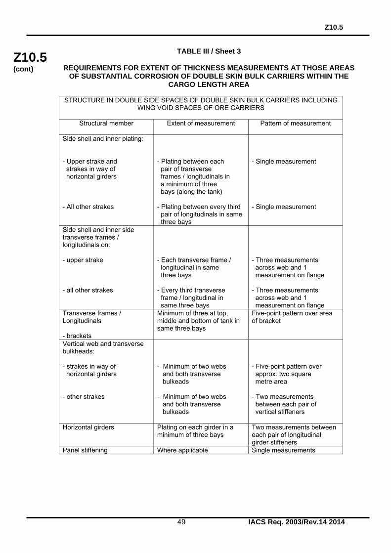
Z10.5
49 IACS Req. 2003/Rev.14 2014
Z10.5 (cont)
TABLE III / Sheet 3
REQUIREMENTS FOR EXTENT OF THICKNESS MEASUREMENTS AT THOSE AREAS OF SUBSTANTIAL CORROSION OF DOUBLE SKIN BULK CARRIERS WITHIN THE
CARGO LENGTH AREA
STRUCTURE IN DOUBLE SIDE SPACES OF DOUBLE SKIN BULK CARRIERS INCLUDING WING VOID SPACES OF ORE CARRIERS
Structural member
Extent of measurement Pattern of measurement
Side shell and inner plating: - Upper strake and strakes in way of horizontal girders - All other strakes
- Plating between each pair of transverse frames / longitudinals in a minimum of three bays (along the tank) - Plating between every third pair of longitudinals in same three bays
- Single measurement - Single measurement
Side shell and inner side transverse frames / longitudinals on: - upper strake - all other strakes
- Each transverse frame / longitudinal in same three bays - Every third transverse frame / longitudinal in same three bays
- Three measurements across web and 1 measurement on flange - Three measurements across web and 1 measurement on flange
Transverse frames / Longitudinals - brackets
Minimum of three at top, middle and bottom of tank in same three bays
Five-point pattern over area of bracket
Vertical web and transverse bulkheads: - strakes in way of horizontal girders - other strakes
- Minimum of two webs and both transverse bulkeads - Minimum of two webs and both transverse bulkeads
- Five-point pattern over approx. two square metre area - Two measurements between each pair of vertical stiffeners
Horizontal girders Plating on each girder in a minimum of three bays
Two measurements between each pair of longitudinal girder stiffeners
Panel stiffening Where applicable Single measurements

Z10.5
50 IACS Req. 2003/Rev.14 2014
Z10.5 (cont)
TABLE III / Sheet 4
REQUIREMENTS FOR EXTENT OF THICKNESS MEASUREMENTS AT THOSE AREAS OF SUBSTANTIAL CORROSION OF DOUBLE SKIN BULK CARRIERS WITHIN THE
CARGO LENGTH AREA
TRANSVERSE BULKHEADS IN CARGO HOLDS
Structural member
Extent of measurement Pattern of measurement
Lower stool, where fitted
- Transverse band within 25mm of welded connection to inner bottom - Transverse bands within 25mm of welded connection to shelf plate
- Five-point pattern between stiffeners over one metre length - Five-point pattern between stiffeners over one metre length
Transverse bulkheads - Transverse band at approximately mid height - Transverse band at part of bulkhead adjacent to upper deck or below upper stool shelf plate (for those ships fitted with upper stools)
- Five-point pattern over one square metre of plating - Five-point pattern over one square metre of plating

Z10.5
51 IACS Req. 2003/Rev.14 2014
Z10.5 (cont)
TABLE IV
MINIMUM REQUIREMENTS OF OVERALL AND CLOSE-UP SURVEY AND THICKNESS MEASUREMENTS AT INTERMEDIATE SURVEY OF DOUBLE SKIN BULK CARRIERS
Age of ship at time of intermediate survey due date
5 age 10 10 age 15 age 15
Overall survey of Representative ballast tanks selected by the attending surveyor (the selection is to include fore and aft peak tanks and a number of other tanks, taking into account the total number and type of ballast tanks)
The requirements of the previous special survey
The requirements of the previous special survey
Overall and close-up survey of Suspect Areas identified at previous surveys
Overall survey of all cargo holds
Thickness measurements to an extent sufficient to determine both general and local corrosion levels at areas subject to close-up survey at ‘suspect areas’ identified at previous surveys

Z10.5
52 IACS Req. 2003/Rev.14 2014
Z10.5 (cont)
TABLE V
PROCEDURES FOR CERTIFICATION OF FIRMS ENGAGED IN THICKNESS MEASUREMENT OF HULL STRUCTURES
1. Application
This guidance applies for certification of the firms which intend to engage in the thickness measurement of hull structures of the vessels.
2. Procedures for Certification (1) Submission of Documents: Following documents are to be submitted to the Society for approval: a) Outline of firm, e.g. organization and management structure.
b) Experience of the firm on thickness measurement inter alia of hull structures of the vessels.
c) Technicians’ careers, i.e. experience of technicians as thickness measurement
operators, technical knowledge of hull structure, etc. Operators, are to be qualified according to a recognized industrial NDT Standard.
d) Equipment used for thickness measurement such as ultra-sonic testing
machines and its maintenance/calibration procedures. e) A guide for thickness measurement operators. f) Training programmes of technicians for thickness measurement.
g) Measurement record format in accordance with the Recommended Procedures for Thickness Measurements of Bulk Carriers, contained in Annex II.
(2) Auditing of the firm:
Upon reviewing the documents submitted with satisfactory results, the firm is audited in order to ascertain that the firm is duly organised and managed in accordance with the documents submitted, and eventually is capable of conducting thickness measurement of the hull construction of the ships.
(3) Certification is conditional on an onboard demonstration at thickness measurements
as well as satisfactory reporting. 3. Certification (1) Upon satisfactory results of both the audit of the firm in 2(2) and the demonstration
tests in 2(3) above, the Society will issue a Certificate of Approval as well as a notice to the effect that the thickness measurement operation system of the firm has been certified by the Society.
(2) Renewal/endorsement of the Certificate is to be made at intervals not exceeding 3
years by verification that original conditions are maintained.

Z10.5
53 IACS Req. 2003/Rev.14 2014
Z10.5 (cont)
4. Information of any alteration to the Certified Thickness Measurement Operation System
In case where any alteration to the certified thickness measurement operation system of the firm is made, such an alteration is to be immediately informed to the Society. Re-audit is made where deemed necessary by the Society.
5. Cancellation of Approval Approval may be cancelled in the following cases:
(1) Where the measurements were improperly carried out or the results were improperly reported.
(2) Where the Society's surveyor found any deficiencies in the approved thickness measurement operation systems of the firm. (3) Where the firm failed to inform of any alteration in 4 above to the Society.

Z10.5
54 IACS Req. 2003/Rev.14 2014
Z10.5 (cont)
TABLE VI
SURVEY REPORTING PRINCIPLES As a principle, for bulk carriers subject to ESP, the surveyor is to include the following content in his report for survey of hull structure and piping systems, as relevant for the survey. The structure of the reporting content may be different, depending on the report system for the respective Societies. 1. General 1.1 A survey report is to be generated in the following cases: - In connection with commencement, continuation and / or completion of periodical hull surveys, i.e. annual, intermediate and special surveys, as relevant - When structural damages / defects have been found - When repairs, renewals or modifications have been carried out - When condition of class (recommendation) has been imposed or deleted 1.2 The purpose of reporting is to provide: - Evidence that prescribed surveys have been carried out in accordance with applicable classification rules - Documentation of surveys carried out with findings, repairs carried out and condition
of class (recommendation) imposed or deleted - Survey records, including actions taken, which shall form an auditable documentary trail. Survey reports are to be kept in the survey report file required to be on board - Information for planning of future surveys - Information which may be used as input for maintenance of classification rules and instructions 1.3 When a survey is split between different survey stations, a report is to be made for each portion of the survey. A list of items surveyed, relevant findings and an indication of whether the item has been credited, are to be made available to the next attending surveyor, prior to continuing or completing the survey. Thickness measurement and tank testing carried out is also to be listed for the next surveyor. 2. Extent of the survey 2.1 Identification of compartments where an overall survey has been carried out. 2.2 Identification of locations, in each ballast tank and cargo hold including hatch covers and coamings, where a close-up survey has been carried out, together with information of the means of access used. 2.3 Identification of locations, in each ballast tank and cargo hold including hatch covers and coamings, where thickness measurement has been carried out. Note: As a minimum, the identification of location of close-up survey and thickness
measurement is to include a confirmation with description of individual structural members corresponding to the extent of requirements stipulated in UR Z10.2 based on type of periodical survey and the ship's age.

Z10.5
55 IACS Req. 2003/Rev.14 2014
Z10.5 (cont)
Where only partial survey is required, i.e. 25% of shell frames, one transverse web, two selected cargo hold transverse bulkheads, the identification is to include location within each ballast tank and cargo hold by reference to frame numbers. 2.4 For areas in ballast tanks and cargo holds where protective coating is found to be in GOOD condition and the extent of close-up survey and / or thickness measurement has been specially considered, structures subject to special consideration are to be identified. 2.5 Identification of tanks subject to tank testing. 2.6 Identification of piping systems on deck and within cargo holds, ballast tanks, pipe tunnels, cofferdams and void spaces where:
- Examination including internal examination of piping with valves and fittings and thickness measurement, as relevant, has been carried out
- Operational test to working pressure has been carried out
3. Result of the survey 3.1 Type, extent and condition of protective coating in each tank, as relevant (rated GOOD, FAIR or POOR). 3.2 Structural condition of each compartment with information on the following, as relevant: - Identification of findings, such as: • Corrosion with description of location, type and extent • Areas with substantial corrosion • Cracks / fractures with description of location and extent • Buckling with description of location and extent • Indents with description of location and extent - Identification of compartments where no structural damages / defects are found The report may be supplemented by sketches / photos. 3.3 Thickness measurement report is to be verified and signed by the surveyor controlling the measurements on board. 4. Actions taken with respect to findings 4.1 Whenever the attending surveyor is of the opinion that repairs are required, each item to be repaired is to be identified in the survey report. Whenever repairs are carried out, details of the repairs effected are to be reported by making specific reference to relevant items in the survey report. 4.2 Repairs carried out are to be reported with identification of: - Compartment - Structural member - Repair method (i.e. renewal or modification) including: - steel grades and scantlings (if different from the original); - sketches/photos, as appropriate. - Repair extent - NDT / Tests

Z10.5
56 IACS Req. 2003/Rev.14 2014
Z10.5 (cont)
4.3 For repairs not completed at the time of survey, condition of class (recommendation) is to be imposed with a specific time limit for the repairs. In order to provide correct and proper information to the surveyor attending for survey of the repairs, condition of class (recommendation) is to be sufficiently detailed with identification of each item to be repaired. For identification of extensive repairs, reference may be given to the survey report.

Z10.5
57 IACS Req. 2003/Rev.14 2014
Z10.5 (cont)
TABLE VII (i)
IACS UNIFIED REQUIREMENTS FOR ENHANCED SURVEYS EXECUTIVE HULL SUMMARY
Issued upon Completion of Special Survey
GENERAL PARTICULARS SHIP’S NAME: CLASS IDENTIFY NUMBER:
IMO IDENTIFY NUMBER: PORT OF REGISTRY: NATIONAL FLAG: DEADWEIGHT (M. TONNES): GROSS TONNAGE: NATIONAL: ITC (69): DATE OF BUILD: CLASSIFICATION NOTATION: DATE OF MAJOR CONVERSION: TYPE OF CONVERSION: a) The survey reports and documents listed below have been reviewed by the
undersigned and found to be satisfactory b) A summary of the survey is attached herewith on sheet 2 c) The hull special survey has been completed in accordance with the Regulations on
[date] Executive Summary Report completed by:
Name Signature
Title
OFFICE DATE Executive Summary Report verified by:
Name Signature
Title
OFFICE DATE
Attached reports and documents: 1) 2) 3) 4) 5) 6)

Z10.5
58 IACS Req. 2003/Rev.14 2014
Z10.5 (cont)
TABLE VII (ii)
EXECUTIVE HULL SUMMARY A) General Particulars: - Ref.Table VII (i) B) Report Review: - Where and how survey was done C) Close-up Survey: - Extent (Which tanks) D) Thickness measurements: - Reference to Thickness Measurement report
- Summary of where measured - Separate form indicating the tanks/areas with
Substantial Corrosion, and corresponding - Thickness diminution
- Corrosion pattern E) Tank Protection: Separate form indicating: - Location of coating - Condition of coating (if applicable) F) Repairs: - Identification of tanks/areas G) Condition of Class/Recommendations: H) Memoranda: - Acceptable defects
- Any points of attention for future surveys, e.g. for Suspect Areas.
- Extended Annual/Intermediate survey due to coating
breakdown I) Conclusion: - Statement on evaluation/verification of survey report

Z10.5
59 IACS Req. 2003/Rev.14 2014
Z10.5 (cont)
TABLE VII (iii) A – non CSR vessels
EXTRACT OF THICKNESS MEASUREMENT
Reference is made to the thickness measurements report:
Position of substantially corroded Tanks/Areas or Areas with deep pitting1)
Thickness diminution[%]
Corrosion pattern2)
Remarks: e.g. Ref. attached sketches
Remarks: 1) Substantial corrosion, i.e. 75 – 100% of acceptable margins wasted. 2) P = Pitting; C = Corrosion in General
Any bottom plating with a pitting intensity of 20% or more, with wastage in the substantial corrosion range or having an average depth of pitting of 1/3 or more of actual plate thickness is to be noted.

Z10.5
60 IACS Req. 2003/Rev.14 2014
Z10.5 (cont)
TABLE VII (iii) B – CSR vessels
EXTRACT OF THICKNESS MEASUREMENTS
Reference is made to the thickness measurements report: 1)
Position of substantially corroded Tanks/Areas or Areas with deep pitting
tm - tren (mm)
2)
Corrosion pattern Remarks: e.g. Ref. Attached sketches
Remarks 1) Substantial corrosion, an extent of corrosion such that the assessment of the corrosion
pattern indicates a measured thickness between tren + 0.5mm and tren. 2) P = Pitting
C = Corrosion in General Areas with deep pitting assessed according to 8.2 are to be recorded in this column.

Z10.5
61 IACS Req. 2003/Rev.14 2014
Z10.5 (cont)
TABLE VII (iv)
TANK PROTECTION
Tank/hold nos.1)
Tank/hold protection2)
Coating condition3)
Remarks
Remarks: 1) All ballast tanks and cargo holds to be listed. 2) C = Coating; NP = No Protection 3) Coating condition according to the following standard: GOOD condition with only minor spot rusting.
FAIR condition with local breakdown at edges of stiffeners and weld connections and/or light rusting over 20% or more of areas under consideration, but less than as defined for POOR condition.
POOR condition with general breakdown of coating over 20% or more of areas
or hard scale at 10% or more of areas under consideration. If coating condition "POOR" is given, extended annual surveys are to be introduced. This is to be noted in part H) of the Executive Hull Summary.

Z10.5
62 IACS Req. 2003/Rev.14 2014
Z10.5 (cont)
Upper stoolTopside tank
HoppersidetankDouble bottom tank
Lower stool
E
A
A
D
Hatchopening
Hatchopening
Hatchopening
E
CArea
EArea
A cargo hold, transverse bulkhead
Typical areas of deck plating and underdeck structure inside lineof hatch openings between cargo hold hatches
Typical transverse section
AAreas and D
Thickness to be reported on TM5-BC
Thickness to be reported on TM3-BC, TM4-BC,TM6-BC and TM7-BC as appropriate
Thickness to be reported on TM6-BC
C
Figure 10 - Close-up survey and thickness measurement areas

Z10.5
63 IACS Req. 2003/Rev.14 2014
Z10.5 (cont)
Area (B)
Figure 11 - Close-up survey and thickness measurement areas ordinary transverse frame in double skin tank
End of Section

Z10.5 Annex I
64 IACS Req. 2003/Rev.14 2014
Z10.5 (cont)
ANNEX I
GUIDELINES FOR TECHNICAL ASSESSMENT IN CONJUNCTION WITH PLANNING FOR ENHANCED SURVEYS OF DOUBLE SKIN BULK CARRIERS SPECIAL
SURVEY– HULL Contents: 1. INTRODUCTION 2. PURPOSE AND PRINCIPLES 2.1 Purpose 2.2 Minimum Requirements 2.3 Timing 2.4 Aspects to be considered 3. TECHNICAL ASSESSMENT 3.1 General 3.2 Methods 3.2.1 Design Details 3.2.2 Corrosion 3.2.3 Locations for Close-up Survey and Thickness Measurement REFERENCES 1. IACS, Unified Requirement Z10.5, "Hull Surveys of Double Skin Bulk Carriers" 2. IACS, "Bulk Carriers: Guidelines for Surveys, Assessment and Repair of Hull Structures, January 2002" 3. TSCF, "Guidelines for the Inspection and Maintenance of Double Hull Tanker Structures, 1995" 4. TSCF, "Guidance Manual for Tanker Structures, 1997" 1. INTRODUCTION These guidelines contain information and suggestions concerning technical assessments, which may be of use in conjunction with the planning of enhanced Special Surveys of double skin bulk carriers. As indicated in 5.1.5 of IACS Unified Requirement Z10.5, "Hull Surveys of Double Skin Bulk Carriers" (Ref. 1), the guidelines are a recommended tool which may be invoked at the discretion of an IACS Member Society, when considered necessary and appropriate, in conjunction with the preparation of the required Survey Programme. 2. PURPOSE AND PRINCIPLES 2.1 Purpose The purpose of the technical assessments described in these guidelines is to assist in identifying critical structural areas, nominating suspect areas and in focusing attention on structural elements or areas of structural elements which may be particularly susceptible to, or evidence a history of, wastage or damage. This information may be useful in nominating locations, areas holds and tanks for thickness measurement, close-up survey and tank testing.
Z10.5 Annex I
65 IACS Req. 2003/Rev.14 2014
Z10.5 (cont)
Critical Structural Areas are locations which have been identified from calculations to require monitoring or from the service history of the subject ship or from similar or sister ships (if available) to be sensitive to cracking, buckling or corrosion which would impair the structural integrity of the ship. 2.2 Minimum Requirements However, these guidelines may not be used to reduce the requirements pertaining to thickness measurement, close-up survey and tank testing contained in Tables I and II and in paragraph 2.5, respectively, of Z10.5, which are, in all cases, to be complied with as a minimum. 2.3 Timing As with other aspects of survey planning, the technical assessments described in these guidelines should be worked out by the Owner or operator in cooperation with the Classification Society well in advance of the commencement of the Special Survey, i.e. prior to commencing the survey and normally at least 12 to 15 months before the survey's completion due date. 2.4 Aspects to be considered Technical assessments, which may include quantitative or qualitative evaluation of relative risks of possible deterioration, of the following aspects of a particular ship may be used as a basis for the nomination of holds, tanks and areas for survey: • Design features such as stress levels on various structural elements, design details
and extent of use of high tensile steel. • Former history with respect to corrosion, cracking, buckling, indents and repairs for
the particular ship as well as similar vessels, where available. • Information with respect to types of cargo carried, use of different holds/tanks for
cargo/ballast, protection of holds and tanks and condition of coating, if any. Technical assessments of the relative risks of susceptibility to damage or deterioration of various structural elements and areas are to be judged and decided on the basis of recognized principles and practices, such as may be found in publications of IACS (Ref 2) and Tanker Structure Cooperative Forum (TSCF), (Refs. 3 and 4). 3. TECHNICAL ASSESSMENT 3.1 General There are three basic types of possible failure, which may be the subject of technical assessment in connection with planning of surveys; corrosion, cracks and buckling. Contact damages are not normally covered by the survey planning since indents are usually noted in memoranda and assumed to be dealt with as a normal routine by Surveyors. Technical assessments performed in conjunction with the survey planning process are, in principle, to be as shown schematically in Figure 1. The approach is basically an evaluation of the risk in the following aspects based on the knowledge and experience related to: - Design - Corrosion.

Z10.5 Annex I
66 IACS Req. 2003/Rev.14 2014
Z10.5 (cont)
The design is to be considered with respect to structural details, which may be susceptible to buckling or cracking as a result of vibration, high stress levels or fatigue. Corrosion is related to the ageing process, and is closely connected with the quality of corrosion prevention systems fitted at new building, and subsequent maintenance during the service life. Corrosion may also lead to cracking and/or buckling. 3.2 Methods 3.2.1 Design Details Damage experience related to the ship in question and sister and/or similar ships, where available, is the main source of information to be used in the process of planning. In addition, a selection of structural details from the design drawings is to be included. Typical damage experience to be considered will consist of: - Number, extent, location and frequency of cracks - Location of buckles. This information may be found in the survey reports and/or the Owner's files, including the results of the Owner's own inspections. The defects are to be analyzed, noted and marked on sketches. In addition, general experience is to be utilized. Also, reference is to be made to IACS's "Bulk Carriers: Guidelines for Survey, Assessment and Repair," (Ref. 2) which contains a catalogue of typical damages and proposed repair methods for various structural details on single skin bulk carriers. Reference should also be made to the TSCF's publication mentioned in Ref. 3, which contains catalogues of typical damages and proposed repair methods for double hull oil tanker structural details which may to some extent be similar to structural details in double skin bulk carriers. Such figures are to be used together with a review of the main drawings, in order to compare with the actual structure and search for similar details that may be susceptible to damage. In particular, Chapter 3 of Ref. 3 deals with various aspects specific to double hull tankers, such as stress concentration locations, misalignment during construction, corrosion trends, fatigue considerations and areas requiring special attention, while Chapter 4 of Ref. 3 addresses experience gained on structural defects in double hulls (chemical tankers, OBO carriers, ore/oil carriers, gas carriers), which are also to be considered in working out the survey planning. The review of the main structural drawings, in addition to using the above-mentioned figures, is to include checking for typical design details where cracking has been experienced. The factors contributing to damage are to be carefully considered. The use of high tensile steel (HTS) is an important factor. Details showing good service experience where ordinary, mild steel has been used may be more susceptible to damage when HTS, and its higher associated stresses, are utilized. There is extensive and, in general, good experience, with the use of HTS for longitudinal material in deck and bottom structures. Experience in other locations, where the dynamic stresses may be higher, is less favourable, e.g. side structures. In this respect, stress calculations of typical and important components and details, in accordance with the latest Rules or other relevant methods may prove useful and are to be considered. The selected areas of the structure identified during this process should be recorded and marked on the structural drawings to be included in the Survey Programme.

Z10.5 Annex I
67 IACS Req. 2003/Rev.14 2014
Z10.5 (cont)
3.2.2 Corrosion In order to evaluate relative corrosion risks, the following information is generally to be considered: - Usage of Tanks, Holds and Spaces - Condition of Coatings - Cleaning Procedures - Previous Corrosion Damage - Ballast use and time for Cargo Holds - Risk of Corrosion in Cargo Holds and Ballast Tanks - Location of Ballast Tanks Adjacent to Heated Fuel Oil Tanks Ref. 4 gives definitive examples which can be used for judging and describing coating condition, using typical pictures of conditions. The evaluation of corrosion risks is to be based on information in both Ref. 2 and Ref. 4, as far as applicable to double skin bulk carriers, together with relevant information on the anticipated condition of the ship as derived from the information collected in order to prepare the Survey Programme and the age of the ship. The various holds, tanks and spaces are to be listed with the corrosion risks nominated accordingly. 3.2.3 Locations for Close-up Survey and Thickness Measurement On the basis of the table of corrosion risks and the evaluation of design experience, the locations for initial close-up survey and thickness measurement (areas and sections) may be nominated. The sections subject to thickness measurement are to normally be nominated in tanks, holds and spaces where corrosion risk is judged to be the highest. The nomination of tanks, holds and spaces for close-up survey is to, initially, be based on highest corrosion risk, and is to always include ballast tanks. The principle for the selection should that the extent is increased by age or where information is insufficient or unreliable.

Z10.5 Annex I
68 IACS Req. 2003/Rev.14 2014
Z10.5 (cont)
Design Related Risk Corrosion Risk
Survey
Figure 1: Technical Assessment & the Survey Planning Process
Input: Drawings, Reports, Acceptable Corrosion Allowance
Collection of InformationCoating Condition Usage of Tanks
Analyse: Hull Damage This Ship
Analyse: Hull Damage for Similar Ships Where Available
Hull Damage: General Experience
Coating condition Usage of Tanks
Corrosion Damage This Ship
Corrosion Damage Similar Ship where Available
Location for Thickness Measurement and Close-Up Survey
Survey Programme
Acceptance by Class & Owner
Present Areas where Damage has been found and Risks considered high. Mark Sketches or Drawings
End of Annex I

Z10.5 Annex II
69 IACS Req. 2003/Rev.14 2014
Z10.5 (cont)
ANNEX II
RECOMMENDED PROCEDURES FOR THICKNESS MEASUREMENTS OF DOUBLE SKIN BULK CARRIERS *
* Note: Annex II is recommendatory.

Z10.5 Annex II
70 IACS Req. 2003/Rev.14 2014
Z10.5 (cont)
CONTENTS Sheet 1 - Contents Sheet 2 - Instructions Sheet 3 - General Particulars REPORTS Sheet 4 - Report TM1-DSBC for recording the thickness measurements of all deck plating, all bottom shell plating and side shell plating Sheet 5 - Report TM2-DSBC (i) for recording the thickness measurement of shell and deck plating at transverse sections - strength deck and sheerstrake plating Sheet 6 - Report TM2-DSBC (ii) for recording the thickness measurement of shell and deck plating at transverse sections - shell plating Sheet 7 - Report TM3-DSBC for recording the thickness measurement of
longitudinal members at transverse sections (including double hull structure)
Sheet 8 - Report TM4-DSBC for recording the thickness measurement of
transverse structural members (including common frames, web frames and transverse bulkheads in double hull tanks)
Sheet 9 - Report TM5-DSBC for recording the thickness measurement of W.T.
transverse bulkheads in cargo holds Sheet 10 - Report TM6-DSBC for recording the thickness measurement of miscellaneous structural members GUIDANCE Sheet 11 - Typical transverse section of a double skin bulk carrier.
The diagram includes details of the items to be measured and the report forms to be used.
Sheet 12 - Typical transverse section of an ore carrier. The diagram includes details of the items to be measured and the
report forms to be used. Sheet 13 - Thickness Measurement - Double Skin Bulk Carriers
Transverse section outline. The diagram may be used for those ships where the diagrams on sheet 11 and 12 are not suitable.
Sheet 14 - Thickness Measurement - Ore Carriers
Areas subject to close-up surveys and thickness measurements - areas (A) to (E) as defined in Table I of the UR Z10.5.
Sheet 1

Z10.5 Annex II
71 IACS Req. 2003/Rev.14 2014
Z10.5 (cont)
INSTRUCTION
Recommended Procedures for Thickness Measurements of Double Skin Bulk Carriers
1. This document is to be used for recording thickness measurements as required by IACS Unified Requirement Z10.5.
2. Reporting forms TM1-DSBC, TM2-DSBC, TM3-DSBC, TM4-DSBC, TM5-DSBC and
TM6-DSBC (sheets 4-10) are to be used for recording thickness measurements and the maximum allowable diminution should be stated. The maximum allowable diminution could be stated in an attached document.
3. The remaining sheets 11-14 are guidance diagrams and notes relating to the reporting
forms and the procedure for the thickness measurements.
Sheet 2

Z10.5 Annex II
72 IACS Req. 2003/Rev.14 2014
Z10.5 (cont)
GENERAL PARTICULARS Ship’s name:- IMO Number:- Class Identification number:- Port of registry:- Gross tons:- Deadweight:- Date of build:- Classification Society:- Name of Company performing the thickness measurement:- Thickness measurement company certified by:- Certificate No. :- Certificate valid from..................to................ Place of measurement:- First date of measurement:- Last date of measurement:- Special survey/intermediate survey due:-* Details of measurement equipment:- Qualification of operator:- Report Number:- Consisting of......Sheets Name of operator:- ........................ Name of surveyor:- ........................ Signature of operator:-. ....................... Signature of surveyor:- ........................ Company official stamp:- ........................ Classification Society Official Stamp:- ........................ * Delete as appropriate
Sheet 3

Z10.5 Annex II
73 IACS Req. 2003/Rev.14 2014
Z10.5 (cont)
Sheet 4
TM1-DSBC Report on THICKNESS MEASUREMENT of ALL DECK PLATING, ALL BOTTOM SHELL PLATING and SIDE SHELL PLATING* (* - delete as appropriate) Ship’s name......................... Class Identity No. ......................... Report No. .........................
STRAKE POSITION
PLATE
POSITION
No. or
Letter
Org. Thk. mm
Forward Reading Aft Reading Mean Diminution %
Maximum Allowable Diminution
Gauged Diminution P Diminution S Gauged Diminution P Diminution S
P S mm % mm % P S mm % mm % P S mm 12th forward 11th 10th 9th 8th 7th 6th 5th 4th 3rd 2nd 1st Amidships 1st aft 2nd 3rd 4th 5th 6th 7th 8th 9th 10th 11th 12th
Operators Signature............................................. NOTES – See Reverse

Z10.5 Annex II
74 IACS Req. 2003/Rev.14 2014
Z10.5 (cont)
NOTES TO REPORT TM1-DSBC 1. This report is to be used for recording the thickness measurement of:- 1.1 All strength deck plating within cargo length area. 1.2 All keel, bottom shell plating and bilge plating within the cargo length area.
1.3 Side shell plating including selected wind and water strakes outside cargo length area.
1.4 All wind and water strakes within cargo length area. 2. The strake position is to be cleared indicates as follows:-
2.1 For strength deck indicate the number of the strake of plating inboard from the stringer plate.
2.2 For bottom plating indicate the number of the strake of plating outboard from
the keel plate.
2.3 For side shell plating give number of the strake of plating sheerstrake and letter as shown on shell expansion.
3. Only the deck plating strakes outside line of openings are to be recorded. 4. Measurements are to be taken at the forward and aft areas of all plates and where
plates cross ballast/cargo tank boundaries separate measurements for the area of plating in way of each type of tank are to be recorded.
5. The single measurements recorded are to represent the average of multiple
measurements. 6. The maximum allowable diminution could be stated in an attached document.

Z10.5 Annex II
75 IACS Req. 2003/Rev.14 2014
Z10.5 (cont)
Sheet 5
TM2-DSBC (i) Report on THICKNESS MEASUREMENT OF SHELL AND DECK PLATING at transverse sections (one, two or three transverse sections) Ship’s name......................... Class Identity No. ......................... Report No. .........................
STRENGTH DECK AND SHEERSTRAKE PLATING
FIRST TRANSVERSE SECTION AT FRAME NUMBER
SECOND TRANSVERSE SECTION AT FRAME NUMBER
THIRD TRANSVERSE SECTION AT FRAME NUMBER
STRAKE
POSITION
No. or
Letter
Org. Thk.
Max. Alwb. Dim.
Gauged Diminution P
Diminution S
No. or
Letter
Org. Thk.
Max. Alwb. Dim.
Gauged Diminution P
Diminution S
No. or
Letter
Org. Thk.
Max. Alwb. Dim.
Gauged Diminution P
Diminution S
mm mm P S mm % mm % mm mm P S mm % mm % mm mm P S mm % mm % Stringer Plate
1st strake inboard
2nd 3rd 4th 5th 6th 7th 8th 9th 10th 11th 12th 13th 14th centre strake
sheer strake
TOPSIDE TOTAL
Operators Signature............................................. NOTES – See Reverse

Z10.5 Annex II
76 IACS Req. 2003/Rev.14 2014
Z10.5 (cont)
NOTES TO REPORT TM2-DSBC (i) 1. This report is to be used for recording the thickness measurement of:- Strength deck plating and sheerstrake plating transverse sections:-
One, two or three sections within the cargo length area, comprising the structural items (0), (1) and (2) as shown on the diagrams of typical transverse sections illustrated on sheets 11, 12 and 13 of this document.
2. Only the deck plating strakes outside line of hatch openings are to be recorded. 3. The top side area comprises deck plating, stringer plate and sheerstrake (including
rounded gunwales). 4. The exact frame station of measurement is to be stated. 5. The single measurements recorded are to represent the average of multiple
measurements. 6. The maximum allowable diminution could be stated in an attached document.

Z10.5 Annex II
77 IACS Req. 2003/Rev.14 2014
Z10.5 (cont)
Sheet 6
TM2-DSBC (ii) Report on THICKNESS MEASUREMENT OF SHELL AND DECK PLATING at transverse sections (one, two or three transverse sections) Ship’s name......................... Class Identity No. ......................... Report No. .........................
SHELL PLATING
FIRST TRANSVERSE SECTION AT FRAME NUMBER
SECOND TRANSVERSE SECTION AT FRAME NUMBER
THIRD TRANSVERSE SECTION AT FRAME NUMBER
STRAKE
POSITION
No. or
Letter
Org. Thk.
Max. Alwb. Dim.
Gauged Diminution P
Diminution S
No. or
Letter
Org. Thk.
Max. Alwb. Dim.
Gauged Diminution P
Diminution S
No. or
Letter
Org. Thk.
Max. Alwb. Dim.
Gauged Diminution P
Diminution S
mm mm P S mm % mm % mm mm P S mm % mm % mm mm P S mm % mm % 1st below sheer strake
2nd 3rd 4th 5th 6th 7th 8th 9th 10th 11th 12th 13th 14th 15th 16th 17th 18th 19th 20th keel strake BOTTOM TOTAL
Operators Signature............................................. NOTES – See Reverse

Z10.5 Annex II
78 IACS Req. 2003/Rev.14 2014
Z10.5 (cont)
NOTES TO REPORT TM2-DSBC (ii) 1. This report is to be used for recording the thickness measurement of:- Shell plating at transverse sections:
One, two or three sections within the cargo length area, comprising the structural items (3), (4), (5) and (6) as shown on the diagrams of typical transverse sections illustrated on sheets 11, 12 and 13 of this document.
2. The bottom area comprises keel, bottom and bilge plating. 3. The exact frame station of measurement is to be stated. 4. The single measurements recorded are to represent the average of multiple measurements. 5. The maximum allowable diminution could be stated in an attached document.

Z10.5 Annex II
79 IACS Req. 2003/Rev.14 2014
Z10.5 (cont)
Sheet 7
TM3-DSBC Report on THICKNESS MEASUREMENT OF LONGITUDINAL MEMBERS at transverse sections (one, two or three transverse sections) Ship’s name......................... Class Identity No. ......................... Report No. ........................
FIRST TRANSVERSE SECTION AT FRAME NUMBER
SECOND TRANSVERSE SECTION AT FRAME NUMBER
THIRD TRANSVERSE SECTION AT FRAME NUMBER
STRUCTURAL
MEMBER
Item No.
Org. Thk.
Max. Alwb. Dim.
Gauged Diminution P
Diminution S
Item No.
Org. Thk.
Max. Alwb. Dim.
Gauged Diminution P
Diminution S
Item No.
Org. Thk.
Max. Alwb. Dim.
Gauged Diminution P
Diminution S
mm mm P S mm % mm % mm mm P S mm % mm % mm mm P S mm % mm %
Operators Signature............................................. NOTES – See Reverse

Z10.5 Annex II
80 IACS Req. 2003/Rev.14 2014
Z10.5 (cont)
NOTES TO REPORT TM3-DSBC 1. This report is to be used for recording the thickness measurement of:- Longitudinal Members at transverse sections:- Two, or three sections within the cargo length area comprising the appropriate
structural items (10) to (25) as shown on diagrams of typical transverse sections illustrated on sheets 11, 12 and 13 of this document.
2. The exact frame station of measurement is to be stated. 3. The single measurements recorded are to represent the average of multiple
measurements. 4. The maximum allowable diminution could be stated in an attached document.

Z10.5 Annex II
81 IACS Req. 2003/Rev.14 2014
Z10.5 (cont)
Sheet 8
TM4-DSBC Report on THICKNESS MEASUREMENT OF TRANSVERSE STRUCTURAL MEMBERS In the double bottom, hopper side and topside water ballast tanks Ship’s name......................... Class Identity No. ......................... Report No. ........................
TANK DESCRIPTION: LOCATION OF STRUCTURE:
STRUCTURAL MEMBER
ITEM
Original
Thickness mm
Max. Alwb. Dim. mm
Gauged
Diminution
P
Diminution
S
P
S
mm
%
mm
%
Operators Signature............................................. NOTES – See Reverse

Z10.5 Annex II
82 IACS Req. 2003/Rev.14 2014
Z10.5 (cont)
NOTES TO REPORT TM4-DSBC 1. This report is to be used for recording the thickness measurement of:
Transverse structural members, comprising the appropriate structural items (30) to (34) as shown on diagrams of typical transverse sections illustrated on sheets 11, 12 and 13 of this document.
2. Guidance for areas of measurements is indicated on sheet 14 of this document. 3. The single measurements recorded are to represent the average of multiple
measurements. 4. The maximum allowable diminution could be stated in an attached document.

Z10.5 Annex II
83 IACS Req. 2003/Rev.14 2014
Z10.5 (cont)
Sheet 9
TM5-DSBC Report on THICKNESS OF WATERTIGHT TRANSVERSE BULKHEADS IN CARGO HOLDS Ship’s name......................... Class Identity No. ......................... Report No. ........................
LOCATION OF STRUCTURE: FRAME NO.: STRUCTURAL COMPONENT (PLATING/STIFFENER)
Original
Thickness mm
Max. Alwb. Dim. mm
Gauged
Diminution
P
Diminution
S
Port
Starboard
mm
%
mm
%
Operators Signature............................................. NOTES – See Reverse

Z10.5 Annex II
84 IACS Req. 2003/Rev.14 2014
Z10.5 (cont)
NOTES TO REPORT TM5-DSBC 1. This report form is to be used for recording the thickness measurement of: W.T. transverse bulkheads in cargo holds 2. Guidance for areas of measurements is indicated on sheet 14 of this document. 3. The single measurements recorded are to represent the average of multiple
measurements. 4. The maximum allowable diminution could be stated in an attached document.

Z10.5 Annex II
85 IACS Req. 2003/Rev.14 2014
Z10.5 (cont)
Sheet 10
TM6-DSBC Report on THICKNESS MEASUREMENT OF MISCELLANEOUS STRUCTURAL MEMBERS Ship’s name......................... Class Identity No. ......................... Report No. ........................ STRUCTURAL MEMBER:
SKETCH
LOCATION OF STRUCTURE:
Description
Org. Thk. mm
Max. Alwb.Dim. mm
Gauged Diminution P
Diminution S
P S mm % mm %
Operators Signature............................................. NOTES – See Reverse

Z10.5 Annex II
86 IACS Req. 2003/Rev.14 2014
Z10.5 (cont)
NOTES TO REPORT TM6-DSBC 1. This report is to be used for recording the thickness measurement of:
Miscellaneous structural members including the structural items (40), (41) and (42) as shown on diagrams of typical transverse sections illustrated on sheets 11, 12 and 13 of this document.
2. Guidance for areas of measurement is indicated on sheet 14 of this document. 3. The single measurements recorded are to represent the average of multiple
measurements. 4. The maximum allowable diminution could be stated in an attached document.

Z10.5 Annex II
87 IACS Req. 2003/Rev.14 2014
Z10.5 (cont)
Thickness Measurement - Double Skin Bulk Carriers
Typical transverse section of a double skin bulk carrier with indication of longitudinal and transverse members
1
4
67
8
910
12
13
1418
16
19
20
9
23
16
24
1514
11
28
31
34
Double Skin
23 25
5
17
14
Report on TM2-DSBC (i) & (ii)
Report on TM3-DSBC
1. Strength deck plating 8. Deck longitudinals 17. Inner bottom plating 2. Stringer plate 9. Deck girders 18. Inner bottom longitudinals 3. Sheerstrake 10. Sheerstrake longitudinals 19. Hopper plating 4. Side shell plating 11. Topside tank sloping plate 20. Hopper longitudinals 5. Bilge plating 12. Topside tank sloping plate longitudinals 31. Inner side plating 6. Bottom shell plating 13. Bottom longitudinals - Inner side longitudinals, if any 7. Keel plate 14. Bottom girders - Horizontal girders in wing ballast tanks 15. Bilge longitudinals 16. Side shell longitudinals, if any
Report on TM4-DSBC Report on TM6-DSBC
23. Double bottom tank floors 28. Hatch coamings 25. Hopper side tank transverses - Deck plating between hatches 34. Transverse web frame - Hatch covers - Topside tank transverses
Sheet 11

Z10.5 Annex II
88 IACS Req. 2003/Rev.14 2014
Z10.5 (cont)
712
17
28
31
30 29
32
32
8
1
9
2
3
10
36
9
2511
4
2729
28
3232
16
13
20
19
15
6
14
5
12
33
18
Typical transverse section of an ore carrier with indication of longitudinal and transverse members
Thickness Measurement - Ore Carriers
Report on TM2-DSBC (i) & (ii)
1. Strength deck plating 2. Stringer plate 3. Sheerstrake 4. Side shell plating 5. Bilge plating 6. Bottom shell plating 7. Keel plate
Report on TM3-DSBC 8. Deck longitudinals 9. Deck girders 10. Sheerstrake longitudinals 11. Longitudinal bulkhead top strake 12. Bottom longitudinals 13. Bottom girders 14. Bilge longitudinals 15. Longitudinal bulkhead lower strake 16. Side shell longitudinals 17. Longitudinal bulkhead plating (remainder) 18. Longitudinal bulkhead longitudinals 19. Inner bottom plating 20. Inner bottom longitudinals 21. 22. 23. 24.
Report on TM4-DSBC 25. Deck transverse centre tank 26. Bottom transverse centre tank 27. Deck transverse wing tank 28. Side shell vertical web 29. Longitudinal bulkhead vertical web 30. Bottom transverse wing tank 31. Struts 32. Transverse web face plate 33. D.B. Floors 34. 35.
Report on TM6-DSBC 36. Hatch coamings 37. Deck plating between hatches 38. Hatch covers 39. 40.
Sheet 12

Z10.5 Annex II
89 IACS Req. 2003/Rev.14 2014
Z10.5 (cont)
Thickness Measurement - Double Skin Bulk Carriers
Transverse section outline: The diagram may be used for thoseships where the diagrams on sheet 11 and 12 are not suitable
Report on TM2-DSBC
(i) & (ii) Report on TM3-DSBC
1. Strength deck plating 8. Deck longitudinals 17. Inner bottom plating 2. Stringer plate 9. Deck girders 18. Inner bottom longitudinals 3. Sheerstrake 10. Sheerstrake longitudinals 19. Hopper plating 4. Side shell plating 11. Topside tank sloping plate 20. Hopper longitudinals 5. Bilge plating 12. Topside tank sloping plate longitudinals 31. Inner side plating 6. Bottom shell plating 13. Bottom longitudinals - Inner side longitudinals, if any 7. Keel plate 14. Bottom girders - Horizontal girders in wing ballast tanks 15. Bilge longitudinals 16. Side shell longitudinals, if any
Report on TM4-DSBC Report on TM6-DSBC
23. Double bottom tank floors 28. Hatch coamings 25. Hopper side tank transverses - Deck plating between hatches 34. Transverse web frame - Hatch covers - Topside tank transverses
Sheet 13

Z10.5 Annex II
90 IACS Req. 2003/Rev.14 2014
Z10.5 (cont)
and
B
B E
A
Upper Stool
Lower stool
Double bottom tank
C
D
D
Thickness to be reported on TM3-DSBC and TM4-DSBC as appropriate
Thickness to be reported on TM5-DSBC
Typical transverse bulkheadTypical transverse section close-up survey
Close-up survey area
Thickness Measurement - Ore Carriers
Areas subject to close up survey and thickness measurements - areas(A) to (E) as defined in Table I of UR Z10.5 - Thickness to be reported onTM3-DSBC, TM4-DSBC, TM5-DSBC and TM6-DSBC as appropriate
Sheet 14

Z10.5 Annex II (CSR)
91 IACS Req. 2003/Rev.14 2014
Z10.5 (cont) ANNEX II (CSR)
IACS RECOMMENDED PROCEDURES FOR THICKNESS MEASUREMENTS OF DOUBLE SKIN BULK CARRIERS BUILT UNDER IACS COMMON STRUCTURAL RULES* * Note: Annex II (CSR) is recommendatory.

Z10.5 Annex II (CSR)
92 IACS Req. 2003/Rev.14 2014
Z10.5 (cont)
CONTENTS Sheet 1 - Contents Sheet 2 - Instructions Sheet 3 - General particulars REPORTS Sheet 4 - Report TM1-DSBC(CSR) for recording the thickness measurement of all deck plating, all bottom plating and side shell plating Sheet 5 - Report TM2-DSBC(CSR) (i) for recording the thickness measurement of shell and deck plating at transverse sections - strength deck and sheerstrake plating
Sheet 6 - Report TM2-DSBC(CSR) (ii) for recording the thickness measurement of shell plating at transverse sections Sheet 7 - Report TM3-DSBC(CSR) for recording the thickness measurement of
longitudinal members at transverse sections (including double hull structure)
Sheet 8 - Report TM4-DSBC(CSR) for recording the thickness measurement of
transverse structural members (including common frames, web frames and transverse bulkheads in double hull tanks)
Sheet 9 - Report TM5-DSBC(CSR) for recording the thickness measurement of
W.T. transverse bulkheads in cargo holds Sheet 10 - Report TM6-DSBC(CSR) for recording the thickness measurement of miscellaneous structural members GUIDANCE Sheet 11 - Typical transverse section of a double skin bulk carrier.
The diagram includes details of the items to be measured and the report forms to be used.
Sheet 12 - Thickness Measurement - Double Skin Bulk Carriers
Transverse section outline. This diagram may be used for those ships where the diagram on sheet 11 is not suitable.
Sheet 13 - Sketches of double skin bulk carrier showing typical areas for thickness measurement of structural members and transverse bulkheads in association with close-up survey requirements. – areas (A) to (E) as defined in Table I of the UR Z10.5.
Sheet 1

Z10.5 Annex II (CSR)
93 IACS Req. 2003/Rev.14 2014
Z10.5 (cont)
INSTRUCTIONS
IACS Recommended Procedures for Thickness Measurements of Double Skin Bulk Carriers Built under IACS Common Structural Rules
1. This document is to be used for recording thickness measurements of double skin bulk carriers built under IACS Common Structural Rules as required by the IACS Unified Requirement Z10.5.
2. Reporting forms TM1-DSBC(CSR), TM2-DSBC(CSR) (i) and (ii), TM3-DSBC(CSR),
TM4-DSBC(CSR), TM5-DSBC(CSR) and TM6-DSBC(CSR) (sheets 4-10) are to be used for recording thickness measurements. The as-built thickness and the voluntary thickness addition and renewal thickness (minimum allowable thickness) are to be stated in the said forms.
3. The remaining sheets 11-13 are guidance diagrams and notes relating to the reporting
forms and the procedure for the thickness measurement.
Sheet 2

Z10.5 Annex II (CSR)
94 IACS Req. 2003/Rev.14 2014
Z10.5 (cont)
GENERAL PARTICULARS Ships name:- IMO number:- Class identity number:- Port of registry:- Gross tons:- Deadweight:- Date of build:- Classification Society:- Name of Company performing thickness measurement:- Thickness measurement company certified by:- Certificate No:- Certificate valid from..................to................ Place of measurement:- First date of measurement:- Last date of measurement:- Special survey/intermediate survey due:-* Details of measurement equipment:- Qualification of operators:- Report Number:- consisting of......Sheets Name of operator:- ........................ Name of surveyor:- ........................ Signature of operator:-. ....................... Signature of surveyor:- ........................ Company official stamp:- Classification Society Official Stamp:- * Delete as appropriate
Sheet 3
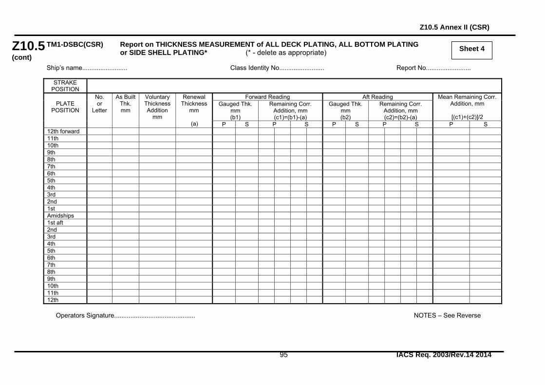
Z10.5 (cont)
Z10.5 Annex II (CSR)
95 IACS Req. 2003/Rev.14 2014
Sheet 4
TM1-DSBC(CSR) Report on THICKNESS MEASUREMENT of ALL DECK PLATING, ALL BOTTOM PLATING or SIDE SHELL PLATING* (* - delete as appropriate) Ship’s name......................... Class Identity No......................... Report No.........................
STRAKE POSITION
PLATE
POSITION
No. or
Letter
As Built Thk. mm
Voluntary Thickness Addition
mm
Renewal Thickness
mm (a)
Forward Reading Aft Reading Mean Remaining Corr. Addition, mm
[(c1)+(c2)]/2
Gauged Thk. mm (b1)
Remaining Corr. Addition, mm (c1)=(b1)-(a)
Gauged Thk. mm (b2)
Remaining Corr. Addition, mm (c2)=(b2)-(a)
P S P S P S P S P S 12th forward 11th 10th 9th 8th 7th 6th 5th 4th 3rd 2nd 1st Amidships 1st aft 2nd 3rd 4th 5th 6th 7th 8th 9th 10th 11th 12th
Operators Signature............................................. NOTES – See Reverse

Z10.5 Annex II (CSR)
96 IACS Req. 2003/Rev.14 2014
Z10.5 (cont)
NOTES TO REPORT TM1-DSBC(CSR) 1. This report is to be used for recording the thickness measurement of:- 1.1 All strength deck plating within cargo length area. 1.2 All keel, bottom shell plating and bilge plating within the cargo length area.
1.3 Side shell plating including selected wind and water strakes outside the cargo length area.
1.4 All wind and water strakes within the cargo length area. 2. The strake position is to be cleared indicated as follows:-
2.1 For strength deck indicate the number of the strake of plating inboard from the stringer plate.
2.2 For bottom plating indicate the number of the strake of plating outboard from
the keel plate.
2.3 For side shell plating give number of the strake of plating sheerstrake and letter as shown on shell expansion.
3. Only the deck plating strakes outside line of openings are to be recorded. 4. Measurements are to be taken at the forward and aft areas of all plates and the single
measurements recorded are to represent the average of multiple measurements. 5. The remaining corrosion addition is to be recorded with result of gauged
thickness minus renewal thickness. If the result is negative, the structure in way shall be renewed, and the mark “R” is to be indicated in the right-hand column. If the result is between 0 and 0.5 mm (0 included), the structure in way shall be additional gauged, and the mark “S” is to be indicated in the right-hand column.

Z10.5 (cont)
Z10.5 Annex II (CSR)
97 IACS Req. 2003/Rev.14 2014
Sheet 5
TM2-DSBC(CSR) (i) Report on THICKNESS MEASUREMENT OF SHELL AND DECK PLATING (one, two or three transverse sections) Ship’s name......................... Class Identity No......................... Report No.........................
STRENGTH DECK AND SHEERSTRAKE PLATING
FIRST TRANSVERSE SECTION AT FRAME NUMBER
SECOND TRANSVERSE SECTION AT FRAME NUMBER
THIRD TRANSVERSE SECTION AT FRAME NUMBER
STRAKE
POSITION
No. or
Letter
As Built Thk. mm
Vol. Thk. Add.mm
Ren.Thk. mm
(a)
Gauged Thk. mm (b)
Remaining Corr. Addition, mm
(b)-(a)
No. or
Letter
As Built Thk. mm
Vol. Thk. Add. mm
Ren.Thk. mm
(a)
Gauged Thk. mm (b)
Remaining Corr. Addition, mm
(b)-(a)
No. or
Letter
As Built Thk. mm
Vol. Thk. Add. mm
Ren.Thk. mm
(a)
Gauged Thk. mm (b)
Remaining Corr. Addition, mm
(b)-(a)
P S P S P S P S P S P S Stringer Plate
1st strake inboard
2nd 3rd 4th 5th 6th 7th 8th 9th 10th 11th 12th 13th 14th centre strake
sheer strake
TOPSIDE TOTAL
Operators Signature............................................. NOTES – See Reverse

Z10.5 Annex II (CSR)
98 IACS Req. 2003/Rev.14 2014
Z10.5 (cont)
NOTES TO REPORT TM2-DSBC(CSR) (i) 1. This report is to be used for recording the thickness measurement of:- Strength deck plating and sheerstrake plating transverse sections:-
One, two or three sections within the cargo length area, comprising of the structural items (1), (2) and (3) as shown on the diagram of typical transverse sections illustrated on sheets 11 and 12 of this document.
2. Only the deck plating strakes outside the line of openings are to be recorded. 3. The topside area comprises deck plating, stringer plate and sheerstrake (including
rounded gunwales). 4. The exact frame station of measurement is to be stated. 5. The single measurements recorded are to represent the average of multiple
measurements. 6. The remaining corrosion addition is to be recorded with result of gauged thickness
minus renewal thickness. If the result is negative, the structure in way shall be renewed, and the mark “R” is to be indicated in the right-hand column. If the result is between 0 and 0.5 mm (0 included), the structure in way shall be additional gauged, and the mark “S” is to be indicated in the right-hand column.

Z10.5 (cont)
Z10.5 Annex II (CSR)
99 IACS Req. 2003/Rev.14 2014
Sheet 6
TM2-DSBC(CSR) (ii) Report on THICKNESS MEASUREMENT OF SHELL PLATING (one, two or three transverse sections) Ship’s name......................... Class Identity No......................... Report No.........................
SHELL PLATING
FIRST TRANSVERSE SECTION AT FRAME NUMBER
SECOND TRANSVERSE SECTION AT FRAME NUMBER
THIRD TRANSVERSE SECTION AT FRAME NUMBER
STRAKE
POSITION
No. or
Letter
As Built Thk. mm
Vol. Thk. Add.mm
Ren.Thk. mm
(a)
Gauged Thk. mm (b)
Remaining Corr. Addition, mm
(b)-(a)
No. or
Letter
As Built Thk. mm
Vol. Thk. Add. mm
Ren.Thk. mm
(a)
Gauged Thk. mm (b)
Remaining Corr. Addition, mm
(b)-(a)
No. or
Letter
As Built Thk. mm
Vol. Thk. Add. mm
Ren.Thk. mm
(a)
Gauged Thk. mm (b)
Remaining Corr. Addition, mm
(b)-(a)
P S P S P S P S P S P S 1st below sheer strake
2nd 3rd 4th 5th 6th 7th 8th 9th 10th 11th 12th 13th 14th 15th 16th 17th 18th 19th 20th Keel strake BOTTOM TOTAL
Operators Signature............................................. NOTES – See Reverse

Z10.5 Annex II (CSR)
100 IACS Req. 2003/Rev.14 2014
Z10.5 (cont)
NOTES TO REPORT TM2-DSBC(CSR) (ii) 1. This report is to be used for recording the thickness measurement of:- Shell plating at transverse sections:-
One, two or three sections within the cargo length area, comprising of the structural items (4), (5), (6) and (7) as shown on the diagram of typical transverse sections illustrated on sheets 11 and 12 of this document.
2. The bottom area comprises keel, bottom and bilge plating. 3. The exact frame station of measurement is to be stated. 4. The single measurements recorded are to represent the average of multiple measurements. 5. The remaining corrosion addition is to be recorded with result of gauged thickness
minus renewal thickness. If the result is negative, the structure in way shall be renewed, and the mark “R” is to be indicated in the right-hand column. If the result is between 0 and 0.5 mm (0 included), the structure in way shall be additional gauged, and the mark “S” is to be indicated in the right-hand column.

Z10.5 (cont)
Z10.5 Annex II (CSR)
101 IACS Req. 2003/Rev.14 2014
Sheet 7
TM3-DSBC(CSR) Report on THICKNESS MEASUREMENT OF LONGITUDINAL MEMBERS (one, two or three transverse sections) Ship’s name......................... Class Identity No......................... Report No........................
FIRST TRANSVERSE SECTION AT FRAME NUMBER
SECOND TRANSVERSE SECTION AT FRAME NUMBER
THIRD TRANSVERSE SECTION AT FRAME NUMBER
STRUCTURAL MEMBER
Item No.
As Built Thk. mm
Vol. Thk. Add.mm
Ren.Thk. mm
(a)
Gauged Thk. mm (b)
Remaining Corr. Addition, mm
(b)-(a)
Item No.
As Built Thk. mm
Vol. Thk. Add. mm
Ren.Thk. mm
(a)
Gauged Thk. mm (b)
Remaining Corr. Addition, mm
(b)-(a)
Item No.
As Built Thk. mm
Vol. Thk. Add. mm
Ren.Thk. mm
(a)
Gauged Thk. mm (b)
Remaining Corr. Addition, mm
(b)-(a)
P S P S P S P S P S P S
Operators Signature............................................. NOTES – See Reverse

Z10.5 Annex II (CSR)
102 IACS Req. 2003/Rev.14 2014
Z10.5 (cont)
NOTES TO REPORT TM3-DSBC(CSR)
1. This report is to be used for recording the thickness measurement of:- Longitudinal Members at transverse sections:-
One, two or three sections within the cargo length area, comprising of the appropriate structural items (8) to (20) and (31) as shown on diagram of typical transverse sections illustrated on sheets 11 and 12 of this document.
2. The exact frame station of measurement is to be stated. 3. The single measurements recorded are to represent the average of multiple
measurements. 4. The remaining corrosion addition is to be recorded with result of gauged thickness
minus renewal thickness. If the result is negative, the structure in way shall be renewed, and the mark “R” is to be indicated in the right-hand column. If the result is between 0 and 0.5 mm (0 included), the structure in way shall be additional gauged, and the mark “S” is to be indicated in the right-hand column.

Z10.5 (cont)
Z10.5 Annex II (CSR)
103 IACS Req. 2003/Rev.14 2014
Sheet 8
TM4-DSBC(CSR) Report on THICKNESS MEASUREMENT OF TRANSVERSE STRUCTURAL MEMBERS In the double bottom, hopper side and topside water ballast tanks Ship’s name......................... Class Identity No......................... Report No........................
TANK DESCRIPTION: LOCATION OF STRUCTURE
STRUCTURAL MEMBER
ITEM
As Built Thickness
mm
Voluntary Thickness Addition
mm
Renewal Thickness
mm (a)
Gauged Thickness mm (b)
Remaining Corr. Addition mm
(b)-(a)P S P S
Operators Signature............................................. NOTES – See Reverse

Z10.5 Annex II (CSR)
104 IACS Req. 2003/Rev.14 2014
Z10.5 (cont)
NOTES TO REPORT TM4-DSBC(CSR) 1. This report is to be used for recording the thickness measurement of:-
Transverse structural members, comprising of the appropriate structural items (23) to (25) and (34) as shown on diagram of typical transverse section, illustrated on sheets 11 and 12 of this document.
2. Guidance for areas if measurement is indicated on the diagrams shown on sheet 13
of this document. 3. The single measurements recorded are to represent the average of multiple
measurements. 4. The remaining corrosion addition is to be recorded with result of gauged thickness
minus renewal thickness. If the result is negative, the structure in way shall be renewed, and the mark “R” is to be indicated in the right-hand column. If the result is between 0 and 0.5 mm (0 included), the structure in way shall be additional gauged, and the mark “S” is to be indicated in the right-hand column.

Z10.5 (cont)
Z10.5 Annex II (CSR)
105 IACS Req. 2003/Rev.14 2014
Sheet 9
TM5-DSBC(CSR) Report on THICKNESS OF CARGO HOLD TRANSVERSE BULKHEADS Ship’s name......................... Class Identity No......................... Report No........................
HOLD DESCRIPTION: LOCATION OF STRUCTURE: FRAME NO.:
STRUCTURAL COMPONENT (PLATING/STIFFENER)
As Built Thickness
mm
Voluntary Thickness Addition
mm
Renewal Thickness
mm (a)
Gauged Thickness mm (b)
Remaining Corr. Addition mm
(b)-(a)P S P S
Operators Signature............................................. NOTES – See Reverse

Z10.5 Annex II (CSR)
106 IACS Req. 2003/Rev.14 2014
Z10.5 (cont)
NOTES TO REPORT TM5-DSBC(CSR) 1. This report form is to be used for recording the thickness measurement of:- W.T. transverse bulkheads in cargo holds 2. Guidance for areas of measurement is indicated on the diagrams shown on sheet 13
of this document. 3. The single measurements recorded are to represent the average of multiple
measurements. 4. The remaining corrosion addition is to be recorded with result of gauged thickness
minus renewal thickness. If the result is negative, the structure in way shall be renewed, and the mark “R” is to be indicated in the right-hand column. If the result is between 0 and 0.5 mm (0 included), the structure in way shall be additional gauged, and the mark “S” is to be indicated in the right-hand column.

Z10.5 (cont)
Z10.5 Annex II (CSR)
107 IACS Req. 2003/Rev.14 2014
Sheet 10
TM6-DSBC(CSR) Report on THICKNESS MEASUREMENT OF MISCELLANEOUS STRUCTURAL MEMBERS Ship’s name......................... Class Identity No......................... Report No........................ STRUCTURAL MEMBER:
SKETCH
LOCATION OF STRUCTURE:
Description
As Built Thk. mm
Voluntary Thickness Addition
mm
Renewal Thickness
mm (a)
Gauged Thickness mm (b)
Remaining Corr. Addition mm
(b)-(a)
P S P S
Operators Signature............................................. NOTES – See Reverse

Z10.5 Annex II (CSR)
108 IACS Req. 2003/Rev.14 2014
Z10.5 (cont)
NOTES TO REPORT TM6-DSBC(CSR) 1. This report is to be used for recording the thickness measurement of:-
Miscellaneous structural members including the structural items (28) as shown on diagram of typical transverse section illustrated on sheets 11 and 12 of this document.
2. Guidance for areas of measurement is indicated on sheet 13 of this document. 3. The single measurements recorded are to represent the average of multiple
measurements. 4. The remaining corrosion addition is to be recorded with result of gauged thickness
minus renewal thickness. If the result is negative, the structure in way shall be renewed, and the mark “R” is to be indicated in the right-hand column. If the result is between 0 and 0.5 mm (0 included), the structure in way shall be additional gauged, and the mark “S” is to be indicated in the right-hand column.

Z10.5 Annex II (CSR)
109 IACS Req. 2003/Rev.14 2014
Z10.5 (cont)
Thickness Measurement - Double Skin Bulk Carriers
Typical transverse section of a double skin bulk carrier with indication of longitudinal and transverse members
Report on TM2-DSBC(CSR) (i) & (ii)
Report on TM3-DSBC(CSR)
1. Strength deck plating 8. Deck longitudinals 17. Inner bottom plating 2. Stringer plate 9. Deck girders 18. Inner bottom longitudinals 3. Sheerstrake 10. Sheerstrake longitudinals 19. Hopper plating 4. Side shell plating 11. Topside tank sloping plate 20. Hopper longitudinals 5. Bilge plating 12. Topside tank sloping plate longitudinals 31. Inner side plating 6. Bottom plating 13. Bottom longitudinals - Inner side longitudinals, if any 7. Keel plate 14. Bottom girders - Horizontal girders in wing ballast tanks 15. Bilge longitudinals 16. Side shell longitudinals, if any
Report on TM4-DSBC(CSR) Report on TM6-DSBC(CSR)
23. Double bottom tank floors 28. Hatch coamings 24. Topside tank transverses - Deck plating between hatches 25. Hopper side tank transverses - Hatch covers 34. Transverse web frame - Ordinary transverse frame in
double skin tank
Sheet 11

Z10.5 Annex II (CSR)
110 IACS Req. 2003/Rev.14 2014
Z10.5 (cont)
Sheet 12 Thickness Measurement - Double Skin Bulk Carriers
Transverse section outline: This diagram may be used for those ships where the diagram on sheet 11 is not suitable
Report on TM2-DSBC(CSR)
(i) & (ii) Report on TM3-DSBC(CSR)
1. Strength deck plating 8. Deck longitudinal 17. Inner bottom plating 2. Stringer plate 9. Deck girders 18. Inner bottom longitudinals 3. Sheerstrake 10. Sheerstrake longitudinals 19. Hopper plating 4. Side shell plating 11. Topside tank sloping plating 20. Hopper longitudinals 5. Bilge plating 12. Topside tank sloping plating longitudinal 31. Inner side plating 6. Bottom plating 13. Bottom longitudinals - Inner side longitudinals, if any 7. Keel plate 14. Bottom girders - Horizontal girders in wing ballast tanks 15. Bilge longitudinals 16. Side shell longitudinals, if any
Report on TM4-DSBC(CSR) Report on TM6-DSBC(CSR)
23. Double bottom tank floors 28. Hatch coamings 24. Topside tank transverses - Deck plating between hatches 25. Hopper side tank transverses - Hatch covers 34. Transverse web frame - Ordinary transverse frame in
double skin tank

Z10.5 Annex II (CSR)
111 IACS Req. 2003/Rev.14 2014
Z10.5 (cont)
Sheet 13 Close-up Survey and Thickness Measurement Areas
Typical transverse section Areas A and D
Ordinary transverse frame in double skin tank A cargo hold, transverse bulkhead Area B Area C Typical areas of deck plating inside line of hatch openings between cargo hold hatches Area E
End of Annex II
Thickness to be reported on TM3-DSBC(CSR), TM4-DSBC(CSR),TM6-DSBC(CSR) as appropriate
Thickness to be reported on TM5-DSBC(CSR)
Thickness to be reported on TM6-DSBC(CSR)
Thickness to be reported on TM4-DSBC(CSR)

Z10.5 Annex III
112 IACS Req. 2003/Rev.14 2014
Z10.5 (cont) ANNEX III

Z10.5 Annex IIIA
113 IACS Req. 2003/Rev.14 2014
Z10.5 (cont)
ANNEX IIIA
SURVEY PROGRAMME Basic information and particulars
Name of ship:
IMO number:
Flag State:
Port of registry:
Gross tonnage:
Deadweight (metric tonnes):
Length between perpendiculars (m):
Shipbuilder:
Hull number:
Classification Society:
Class ID:
Date of build of the ship:
Owner:
Thickness measurement company:

Z10.5 Annex IIIA
114 IACS Req. 2003/Rev.14 2014
Z10.5 (cont)
1 Preamble 1.1 Scope 1.1.1 The present survey programme covers the minimum extent of overall surveys, close-up surveys, thickness measurements and pressure testing within the cargo length area, cargo holds, ballast tanks, including fore and aft peak tanks, required by UR Z10.5. 1.1.2 The arrangements and safety aspects of the survey are to be acceptable to the attending surveyor(s). 1.2 Documentation All documents used in the development of the survey programme are to be available onboard during the survey as required by section 6. 2 Arrangement of cargo holds, tanks and spaces This section of the survey programme is to provide information (either in the form of plans or text) on the arrangement of cargo holds, tanks and spaces that fall within the scope of the survey. 3 List of cargo holds, tanks and spaces with information on their use, extent of
coatings and corrosion prevention system This section of the survey programme is to indicate any changes relating to (and is to update) the information on the use of the holds and tanks of the ship, the extent of coatings and the corrosion prevention system provided in the Survey Planning Questionnaire. 4 Conditions for survey This section of the survey programme is to provide information on the conditions for survey, e.g. information regarding cargo hold and tank cleaning, gas freeing, ventilation, lighting, etc. 5 Provisions and method of access to structures This section of the survey programme is to indicate any changes relating to (and is to update) the information on the provisions and methods of access to structures provided in the Survey Planning Questionnaire. 6 List of equipment for survey This section of the survey programme is to identify and list the equipment that will be made available for carrying out the survey and the required thickness measurements. 7 Survey requirements 7.1 Overall survey This section of the survey programme is to identify and list the spaces that should undergo an overall survey for this ship in accordance with 2.3.1. 7.2 Close-up survey

Z10.5 Annex IIIA
115 IACS Req. 2003/Rev.14 2014
Z10.5 (cont)
This section of the survey programme is to identify and list the hull structures that are to undergo a close-up survey for this ship in accordance with 2.3.2. 8 Identification of tanks for tank testing This section of the survey programme is to identify and list the cargo holds and tanks that are to undergo tank testing for this ship in accordance with 2.5. 9 Identification of areas and sections for thickness measurements This section of the survey programme is to identify and list the areas and sections where thickness measurements are to be taken in accordance with 2.4.1. 10 Minimum thickness of hull structures This section of the survey programme is to specify the minimum thickness for hull structures of this ship that are subject to UR Z10.5 (indicate either (a) or preferably (b), if such information is available): (a) Determined from the attached wastage allowance table and the original thickness to
the hull structure plans of the ship; (b) Given in the following table(s):
Area or location Original as-built
thickness (mm)
Minimum thickness
(mm)
Substantial corrosion thickness
(mm) Deck Plating Longitudinals Longitudinal girders Cross deck plating Cross deck stiffeners Bottom Plating Longitudinals Longitudinal girders Inner bottom Plating Longitudinals Longitudinal girders Floors Ship side in way of topside tanks Plating Longitudinals Ship side in way of hopper side tanks Plating Longitudinals Ship side in way of double hull tanks Plating Longitudinals or ordinary transverse frames Longitudinal stringers Longitudinal bulkhead (inner side)

Z10.5 Annex IIIA
116 IACS Req. 2003/Rev.14 2014
Z10.5 (cont)
Plating Longitudinals or ordinary transverse frames Longitudinal girders (if applicable) Transverse bulkheads Plating Stiffeners (if applicable) Upper stool plating Upper stool stiffeners Lower stool plating Lower stool stiffeners Transverse web frames in topside tanks Plating Flanges Stiffeners Transverse web frames in double hull tanks
Plating Flanges Stiffeners Transverse web frames in hopper tanks Plating Flanges Stiffeners
Hatch Covers Plating Stiffeners
Hatch Coamings Plating Stiffeners Note: The wastage allowance tables are to be attached to the survey programme.
For vessels built under IACS Common Structural Rules, the renewal thickness of the hull structure elements is indicated in the appropriate drawings. 11 Thickness measurement company This section of the survey programme is to identify changes, if any, relating to the information on the thickness measurement company provided in the Survey Planning Questionnaire. 12 Damage experience related to the ship This section of the survey programme is to, using the tables provided below, provide details of the hull damages for at least the last three years in way of the cargo holds, ballast tanks and void spaces within the cargo length area. These damages are subject to survey.

Z10.5 Annex IIIA
117 IACS Req. 2003/Rev.14 2014
Z10.5 (cont)
Hull damages sorted by location for this ship Cargo hold,
tank or space
number or area
Possible cause, if known
Description of the
damages
Location Repair Date of repair
Hull damages for sister or similar ships (if available) in the case of design related damage
Cargo hold, tank or space
number or area
Possible cause, if known
Description of the
damages
Location Repair Date of repair
13 Areas identified with substantial corrosion from previous surveys
This section of the survey programme is to identify and list the areas of substantial corrosion from previous surveys.
14 Critical structural areas and suspect areas
This section of the survey programme is to identify and list the critical structural areas and the suspect areas, when such information is available.
15 Other relevant comments and information This section of the survey programme is to provide any other comments and information relevant to the survey.

Z10.5 Annex IIIA
118 IACS Req. 2003/Rev.14 2014
Z10.5 (cont)
Appendices
Appendix 1 - List of plans
Paragraph 5.1.3 requires that main structural plans of cargo holds and ballast tanks (scantling drawings), including information regarding use of high tensile steel (HTS) are to be available. This Appendix of the survey programme is to identify and list the main structural plans which form part of the survey programme.
Appendix 2 - Survey Planning Questionnaire
The Survey Planning Questionnaire (annex IIIB), which has been submitted by the owner, is to be appended to the survey programme.
Appendix 3 - Other documentation
This part of the survey programme is to identify and list any other documentation that forms part of the plan.
Prepared by the owner in co-operation with the Classification Society for compliance with 5.1.3:
Date:…………………………(name and signature of authorized owner’s representative) Date:…………………………(name and signature of authorized representative of the
Classification Society)

Z10.5 Annex IIIB
119 IACS Req. 2003/Rev.14 2014
Z10.5 (cont)
ANNEX IIIB
SURVEY PLANNING QUESTIONNAIRE
1 The following information will enable the owner in co-operation with the Classification Society to develop a Survey Programme complying with the requirements of UR Z10.5. It is essential that the owner provides, when completing the present questionnaire, up-to-date information. The present questionnaire, when completed, shall provide all information and material required by UR Z10.5.
Particulars
Ship’s name: IMO number: Flag State: Port of registry: Owner: Classification Society: Class ID: Gross tonnage: Deadweight (metric tonnes): Date of build: Information on access provision for close-up surveys and thickness measurement 2 The owner is to indicate, in the table below, the means of access to the structures subject to close-up survey and thickness measurement. A close-up survey is an examination where the details of structural components are within the close visual inspection range of the attending surveyor, i.e. normally within reach of hand.

Z10.5 Annex IIIB
120 IACS Req. 2003/Rev.14 2014
Z10.5 (cont)
Hold/ Tank No.
Structure Permanent Means of Access
Temporary staging
Rafts Ladders Direct access
Other means (please specify)
F.P. Fore Peak A.P. Aft Peak CARGO HOLDS
Hatch side coamings Topside sloping plate Upper stool plating Cross deck Double side tank plating
Transverse bulkhead Hopper tank platting Lower stool plating Tank top
TOPSIDE TANKS
Underdeck structure Side shell & structure Sloping plate & structure
Webs & bulkheads HOPPER TANKS
Hopper sloping plate & structure
Side shell & structure Bottom structure Webs & bulkheads
DOUBLE SIDE SKIN TANKS
Side shell & structure Inner skin & structure Webs & bulkheads
Double bottom structure
Upper stool internal structure
Lower stool internal structure
WING TANKS OF ORE CARRIERS
Underdeck & structure
Side shell & structure Side shell vertical web & structure
Longitudinal bulkhead & structure
Longitudinal bulkhead web & structure
Bottom plating & structure
Cross ties/stringers

Z10.5 Annex IIIB
121 IACS Req. 2003/Rev.14 2014
Z10.5 (cont)
History of bulk cargoes of a corrosive nature (e.g. high sulphur content)
Owner’s inspections 3 Using a format similar to that of the table below (which is given as an example), the owner is to provide details of the results of their inspections, for the last 3 years - in accordance with UR Z10.5 - on all CARGO holds and BALLAST tanks and VOID spaces within the cargo area.
Tank/Hold No.
Corrosion protection
(1)
Coating extent
(2)
Coating condition
(3)
Structural deterioration
(4)
Hold and tank history
(5)
Cargo holds Topside tanks Hopper tanks Double side skin tanks
Double bottom tanks
Upper stools Lower stools Wing tanks (ore carriers)
Fore peak Aft peak Miscellaneous other spaces:
Note: Indicate tanks which are used for oil/ballast 1) HC=hard coating; SC=soft coating; SH=semihard coating; NP=no protection 2) U=upper part; M=middle part; L=lower part; C=complete

Z10.5 Annex IIIB
122 IACS Req. 2003/Rev.14 2014
Z10.5 (cont)
3) G=good; F=fair; P=poor; RC=recoated (during the last 3 years) 4) N=no findings recorded; Y=findings recorded, description of findings is to be attached to this questionnaire 5) DR=Damage & Repair; L=Leakages; CV= Conversion (Description to be attached to this questionnaire) Name of owner’s representative: Signature: Date:

Z10.5 Annex IIIB
123 IACS Req. 2003/Rev.14 2014
Z10.5 (cont)
Reports of Port State Control inspections List the reports of Port State Control inspections containing hull structural related deficiencies, relevant information on rectification of the deficiencies:
Safety Management System List non-conformities related to hull maintenance, including the associated corrective actions:
Name and address of the approved thickness measurement company:
Annex III end Document end