z11 user m
TRANSCRIPT

JVA TECHNOLOGIESwww.jva-fence.com
Z11 User ManUal

Page 2 © JVA Technologies www.jva-fence.com
1 CONTENTS1 Quick Start Guide . . . . . . . . . . . . . . . . 61.1 Changing The Programming Options . . . . . . 6
1.1.1 Relay Functions . . . . . . . . . . . . . . . 10
1.1.2 Input Functions . . . . . . . . . . . . . . . 12
1.2 Quick Test Of Configured Unit . . . . . . . . 14
1.3 Connecting your Z11 to the fence . . . . . . 15
1.4 Most Frequently Used LCD Keypad Commands 16
2 Introduction . . . . . . . . . . . . . . . . . . . 17
3 Features And Benefits . . . . . . . . . . . 193.1 More Features . . . . . . . . . . . . . . . 20
4 Description . . . . . . . . . . . . . . . . . . . . 214.1 JVA Z11 - Exterior . . . . . . . . . . . . . 21
4.2 Front Panel Status Lights . . . . . . . . . . 22
4.3 Inputs and Outputs . . . . . . . . . . . . . 22
4.4 Z-Series Models. . . . . . . . . . . . . . . 22
4.5 Internal Beeper/Keypad Beeper . . . . . . . 23
4.6 Programmable Options . . . . . . . . . . . 23
4.7 Arm input and Key Switch . . . . . . . . . . 23
4.8 Gate Input . . . . . . . . . . . . . . . . . 23
4.9 Low Power Mode . . . . . . . . . . . . . . 23
4.10 Agricultural mode . . . . . . . . . . . . . 24
4.11 Group Simultaneous Pulse Feature . . . . . 24
4.12 Remote Control Unit (Optional) . . . . . . . 24
4.13 Cabling . . . . . . . . . . . . . . . . . . 24
4.14 Lightning Protection . . . . . . . . . . . . 25
4.15 Earth Loop Monitoring . . . . . . . . . . . 25
4.16 Noise and Interference . . . . . . . . . . . 25
4.17 PC Control . . . . . . . . . . . . . . . . 25
5 Installation . . . . . . . . . . . . . . . . . . . 275.1 Installation Steps . . . . . . . . . . . . . 27
5.2 Interior Configuration . . . . . . . . . . . 28
Page 3
© JVA Technologies www.jva-fence.com JVA Z11 Manual
6 Control . . . . . . . . . . . . . . . . . . . . . . 316.1 Arming the Fence Using the Keypad. . . . . . 31
6.2 ACTIVATING Low Power Mode . . . . . . . . 31
6.3 When an Alarm Occurs . . . . . . . . . . . 32
6.4 To Silence the Alarm . . . . . . . . . . . . 32
6.5 Changing the USER PIN . . . . . . . . . . . 32
7 Technical Information . . . . . . . . . . . . 337.1 Low Voltage connections . . . . . . . . . . 33
7.2 Power Options . . . . . . . . . . . . . . . 34
7.3 Standby Battery . . . . . . . . . . . . . . 34
7.4 Status Codes . . . . . . . . . . . . . . . . 35
8 Installation Programming Options . . . . . . . . . . . . . . . . . . . . . . . 37
8.1 Programming Mode . . . . . . . . . . . . . 37
8.2 To Exit Programming Mode . . . . . . . . . . 37
8.3 Changing the Installer PIN . . . . . . . . . 37
8.4 Changing an Option . . . . . . . . . . . . . 37
8.5 Programming Options in Detail . . . . . . . . 38
8.5.1 Output Power Level (Option 1) . . . . . . . . 38
8.5.2 Low Power Mode Output Voltage (Option 2) . 38
8.5.3 Fence Return Alarm Voltage (Option 3) . . . 39
8.5.4 Fence Return Alarm Voltage for Low Power Mode (Option 5) . . . . . . . . . . . . . . . . 39
8.5.5 Missed Pulse Count (Option 6) . . . . . . . 39
8.5.6 Battery Alarm Voltage (Option 7) . . . . . . 40
8.5.7 Siren On Time (Option 8) . . . . . . . . . . . 40
8.5.8 Siren Off time (Option 9) . . . . . . . . . . 41
8.5.9 Siren Cycles (Option 10) . . . . . . . . . . 41
8.5.10 Gate Entry/Exit Delay (Option 13) . . . . . . 42
8.5.11 Chime Mode (Option 14) . . . . . . . . . . . 43
8.5.12 Fence Mode . . . . . . . . . . . . . . . . . 43
8.5.13 Combined Options (Option 16) . . . . . . . . 43
8.5.14 Anti-Bridging threshold (Option 17) . . . . . 44
8.5.15 Combined Options 2 (Option 18) . . . . . . . 45
8.5.16 Auto Re-arm Time (Option 20) . . . . . . . . 46

Page 4 © JVA Technologies www.jva-fence.com
8.5.17 Relay Programming . . . . . . . . . . . . . 47
8.5.18 Relay Functions . . . . . . . . . . . . . . . 48
8.5.19 Group Mode (Option 26) . . . . . . . . . . . 49
8.5.20 Input Function and Trigger . . . . . . . . . 50
9 Specifications . . . . . . . . . . . . . . . . . . 519.1 Z11 Specification . . . . . . . . . . . . . . 51
10 Z-Series Keypads . . . . . . . . . . . . . . . . 5310.1 PTE0210 LCD Keypad . . . . . . . . . . . . 53
10.2 PTE0230 Touch Keypad . . . . . . . . . . . 54
10.3 PTE0240 4-line Keypad . . . . . . . . . . . 55
10.4 Connecting Multiple Keypads . . . . . . . . 55
10.5 Notes Regarding Keypad Configuration . . . 56
10.6 Summary Of Keypad Functions . . . . . . . . 57
11 Remote Control Unit . . . . . . . . . . . . 6111.1 Features . . . . . . . . . . . . . . . . . . 61
11.2 Installation . . . . . . . . . . . . . . . . . 62
11.3 Operation and configuration . . . . . . . . 62
12 Standard Requirements for Security Electric Fences . . . . . . . . . 63
12.1 Definitions . . . . . . . . . . . . . . . . . 63
12.2 General requirements for electric fences . . 63
12.3 Particular requirements for electric animal fences in Australia . . . . . . . . . . . . 65
12.4 Installation of electric security fences . . . 66
12.4.1 General . . . . . . . . . . . . . . . . . . 66
12.4.2 Location of electric security fence . . . . . 66
12.4.3 Prohibited zone for pulsed conductors . . . 67
12.4.4 Separation between electric fence and physical barrier . . . . . . . . . . . . . . . . . . 69
12.4.5 Prohibited mounting . . . . . . . . . . . . . 70
12.4.6 Operation of electric security fence . . . . . 70
13 Appendix A: Group Simultaneous Pulse Feature . . . . . . . . . . . . . . . . . . . . . . . 71

Page 5
© JVA Technologies www.jva-fence.com JVA Z11 Manual
13.1 Group Simultaneous Pulse Feature . . . . . 71
13.2 Group Mode Programming (Option 26) . . . . 71
13.3 Group linking via the Keypad “bus” . . . . . 72

Page 6©
JVA Technologies.
Quick Start Guide
JVA Z11 M
anual
2 QUICK START GUIDE2.1 CHANGING THE PROGRAMMING OPTIONS
Default Installer PIN 012345Default User PIN 1234
First you have to enter Programming mode.
Command Key1 Key2 Key3 Key4 Key5 Key6 Key7 Key8 Key9Enter Programming Mode Installer Pin * 0 #
When you have entered Programming mode you can begin to enter the following options to configure your Z11 Se-curity Energizer. Default Values are highlighted in grey.
Command Key1 Key2 Keys 3 and 4 Key5Change The Installer PIN 6 Digits
0 0 Enter the new 6 digit Installer PIN #
High Power Mode Power Level
0 1 Enter the value in Hundreds of Volts #Example: to set 8.2kV, use 82 for keys 3 and 4. Default is 99 (9.9kV)
Low Power Mode Power Level
0 2 Enter the value in Hundreds of Volts #Example: to set 1.3kV, use 13 for keys 3 and 4. Default is 20 (2.0kV)
Quick Start Guide
JVA Z11 M
anualPage 7
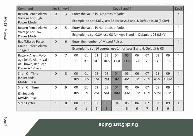
Command Key1 Key2 Keys 3 and 4 Key5Return Fence Alarm Voltage For High Power Mode
0 3 Enter the value in Hundreds of Volts #
Example: to set 3.8kV, use 38 for keys 3 and 4. Default is 30 (3.0kV)
Return Fence Alarm Voltage For Low Power Mode
0 5 Enter the value in Hundreds of Volts #
Example: to set 0.8V, use 08 for keys 3 and 4. Default is 05 0.5kV)
Bad/Missed Pulse Count Before Alarm Triggers
0 6 Enter the number of Missed Pulses #
Example: to set 14 counts, use 14 for keys 3 and 4. Default is 03
Battery Alarm Volt-age (olts). Alarm Val-ue Shown, Reduced Power is 1V less
0 7 00 01 02 03 04 05 06 07 08 09 #9.0 9.5 10.0 10.5 11.0 11.5 12.0 12.5 13.0 13.5
Siren On Time (S=Seconds, M=Minutes)
0 8 00 01 02 03 04 05 06 07 08 09 #10S 30S 1M 2M 3M 4M 5M 20M 45M 130M
Siren Off Time
(S=Seconds, M=Minutes)
0 9 00 01 02 03 04 05 06 07 08 09 #10S 1M 2M 5M 10M 20M 30M 40M 50M 60M
Siren Cycles 1 0 00 01 02 03 04 05 06 07 08 09 #0 1 2 3 4 5 6 7 8 9
Page 8©
JVA Technologies.
Quick Start Guide
JVA Z11 M
anual
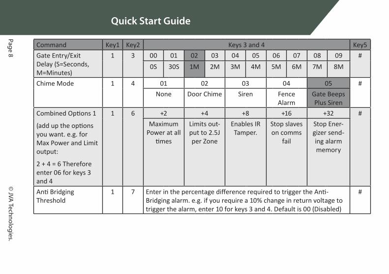
Command Key1 Key2 Keys 3 and 4 Key5Gate Entry/Exit Delay (S=Seconds, M=Minutes)
1 3 00 01 02 03 04 05 06 07 08 09 #0S 30S 1M 2M 3M 4M 5M 6M 7M 8M
Chime Mode 1 4 01 02 03 04 05 #None Door Chime Siren Fence
AlarmGate Beeps Plus Siren
Combined Options 1
(add up the options you want. e.g. for Max Power and Limit output:
2 + 4 = 6 Therefore enter 06 for keys 3 and 4
1 6 +2 +4 +8 +16 +32 #Maximum
Power at all times
Limits out-put to 2.5J per Zone
Enables IR Tamper.
Stop slaves on comms
fail
Stop Ener-gizer send-ing alarm memory
Anti Bridging Threshold
1 7 Enter in the percentage difference required to trigger the Anti-Bridging alarm. e.g. if you require a 10% change in return voltage to trigger the alarm, enter 10 for keys 3 and 4. Default is 00 (Disabled)
#

Quick Start Guide
JVA Z11 M
anualPage 9
Command Key1 Key2 Keys 3 and 4 Key5Combined Options 2 (like Combined Options 1)
1 8 +1 +2 +4 +8 +16 +32 +64 +128 #
Siren Chirp
on Arm
Enable Entry Exit Gate
4800 Baud
9600 Baud
Low Power to Bite
Bite to Low
Power
Auto Re-arm Time
S=Seconds, M = Min-utes, D=Disabled
2 0 00 01 02 03 04 05 06 07 08 09 #0S 30S 1M 2M 3M 4M 5M 6M 7M D
Relay 1 2 1 Options Explained under “2.1.1 Relay Functions”. Default is 08 #Relay 2 2 2 Options Explained under “2.1.1 Relay Functions”. Default is 09 #Group Mode 2 6 00 01 02 etc 15 #
No Group Master Slave 1 Slave 14Input 1 2 7 Options Explained under “2.1.2 Input Functions”. Default is (N/C Arm) #Input 2 2 8 Options Explained under “2.1.2 Input Functions”. Default is 06 (N/O
Gate 1)#
Exit Programming Mode
* #

Page 10©
JVA Technologies.
Quick Start Guide
JVA Z11 M
anual
2.1.1 Relay FunctionsThe table below is for use for the relay programming options mentioned in the table on the previous page.
Keys 3 and 4
Function Description
00 Fence Triggers when Zone 1 is Armed and Return Voltage is below the Threshold Voltage
01 Fence or Off Triggers when Zone 1 is Disarmed or Return Voltage is below the Threshold Voltage02 Armed Zone 1 is Armed07 General Triggers on AC Fail, Tamper, Low Battery/Bad Battery, Gate Alarm or Internal error.
Latched (internal errors only)08 Siren Triggers on Fence Alarm, Gate or Tamper. Will time out after the Siren Time Out time.
Latched09 Strobe Triggers on Fence alarm, Gate or Tamper. Only turns off on Energizer Disarm. Latched10 AC Fail Triggers on AC Fail
11 Low/Bad Battery Triggers on Low or Bad Battery
12 Tamper Triggers when the Tamper input activates
14 Gate Triggers on Gate Alarm
15 Siren Caused by Gate
behaves like siren, only for Gate Alarms
16 Armed - Low Power Mode
Triggers when Armed in Low Power mode
17 Group Armed Triggers when group is Armed. Only configurable on group master.
18 Group general Triggers on group general Alarm. Only configurable on group master.

Quick Start Guide
JVA Z11 M
anualPage 11
Keys 3 and 4
Function Description
20 Host Control This Relay is completely controlled from a Host system such as Perimeter Patrol or a Keypad. If the Host system is disconnected from the Energizer for more than 30 sec-onds, the Relay will automatically change to the Alarm State
21 Host Control - Not Fail Safe
This Relay is completely controlled from a Host system such as Perimeter Patrol or a Keypad. If the Host system is disconnected then the Relay will maintain its current state until the Host re-connects and requests the relay to change state.
Page 12©
JVA Technologies.
Quick Start Guide
JVA Z11 M
anual
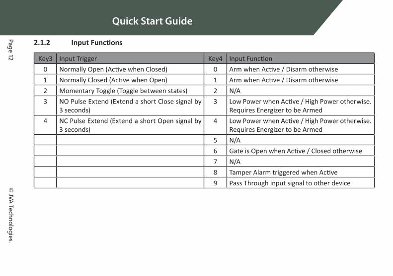
2.1.2 Input Functions
Key3 Input Trigger Key4 Input Function0 Normally Open (Active when Closed) 0 Arm when Active / Disarm otherwise1 Normally Closed (Active when Open) 1 Arm when Active / Disarm otherwise2 Momentary Toggle (Toggle between states) 2 N/A3 NO Pulse Extend (Extend a short Close signal by
3 seconds)3 Low Power when Active / High Power otherwise.
Requires Energizer to be Armed4 NC Pulse Extend (Extend a short Open signal by
3 seconds)4 Low Power when Active / High Power otherwise.
Requires Energizer to be Armed5 N/A6 Gate is Open when Active / Closed otherwise7 N/A8 Tamper Alarm triggered when Active9 Pass Through input signal to other device

Quick Start G
uide
JVA Z11 Manual Page 13

Qui
ck S
tart
Gui
de
Page 14 © JVA Technologies www.jva-fence.com
2.2 QUICK TEST OF CONFIGURED UNITNow that the Z11 is configured to your fences requirements, it is a good idea to test the configuration before connecting the Z-Series energizer to a fence. The reason for this is that you could get spurious results if you test on the final fence and you will never be certain whether the issue lies with the fence, the Z-Series energizer, or the configuration of the unit itself.
To test your unit it is best to connect your Z11 with a test fence, this is done by connecting cables as shown in the picture below.
Power the Z11 and then Arm it. The unit should begin pulsing and not show any alarms. Disarm the Z11 and remove the fence cable as shown in the picture below.
Arm the Z11 once again, after 3 pulses (unless you configured it otherwise) the unit should go into alarm as the fence will appear to be cut. Check that any sirens, strobes or relays correctly activate as you expect.
If your site consists of multiple Z-series test each energizer one at a time as shown in the above photographs. Following that each energizer should be assigned a unique group ID with only one Z-Series device as the master unit (For more information see “14 Appendix A: Group Simultaneous Pulse

Page 15
Quick Start G
uide
© JVA Technologies www.jva-fence.com JVA Z11 Manual
Feature” on page 71). After that each Z-Series device can be connected together via the keypad bus and tested using group Arm and Disarm com-mands, they should all pulse in unison when armed.
By disconnecting each Z-Series Energizer in turn from the keypad bus (shown in the above diagaram) you can check to see how each Z-Series device behaves under comms fail conditions. This way, you can test to see that the relays have been configured correctly for comms fail. Once you are satisfied that each Z-Series device is configured correctly you can begin to wire them to the real fence.
2.3 CONNECTING YOUR Z11 TO THE FENCEThis is covered under “6.3 Example of Fence (High Voltage) Wiring Dia-grams” on page 29. In depth installation instructions begin on page 27. After the Z11 has been wired up you can begin to protect your pe-rimeter.

Quick Start Guide
JVA Z11 M
anualPage 16
2.4 MOST FREQUENTLY USED LCD KEYPAD COMMANDSFor a full list of all keypad commands please see “11.6 Summary Of Keypad Functions” on page 57.
Default Installer PIN 012345Default User PIN 1234
First you need to connect the Z-Series LCD keypad to the Z-Series device. Once you have a keypad connected you can refer to the table below to control the Z-Series device.
Command Key1 Key2 Key3 Key4 Key5 Key6 Key7 Key8 Key9Arm/Disarm User PIN #Silence alarm 1 4 7 0 #Enter Programming Mode Installer PIN * 0 #Exit Programming Mode * #Arm All Zones User PIN * 1 0 #Arm Specific Zone (up to Zone 15) User PIN * 1 Zone
Number#
Disarm all Zones User PIN * 2 0 #Disarm Specific Zone (up to Zone 15) User PIN * 2 Zone
Number#
Clear alarm memory * 1 #

Intr
oduc
tion
Page 17 © JVA Technologies www.jva-fence.com
3 INTRODUCTIONThank you for purchasing a JVA security electric fence energizer. The grow-ing use of non-lethal electric security fences around the world is indicative of the confidence security professionals are placing in this form of perim-eter security. The reason for this popularity is simple – monitored electric security fences are effective and they reduce false alarms when compared to other technologies.
DEMARCATION The JVA electric fence around your property shows you mean business.
DEFLECTION Intruders are deflected to softer targets.
DETERRENCE The safe, powerful JVA shock is a strong deterrent to intruders.
DELAY The barrier will help delay an intruder, giving you more time to react.
DETECTION The JVA’s voltage monitor warns you of any tampering with the fence.
DEPENDABLE 60 seconds a minute, 60 minutes an hour, 24 hours a day, 365 days a year, your JVA electric security fence is monitored by an alert, sober, electronic watchman.
Once every second the JVA Z11 energizer produces a very short-duration, safe, high-voltage pulse and sends it down the fence live wires. The JVA Z11 then monitors the voltage at the end of this live wire, checking that the voltage is being maintained along the entire fence line. In the event of a voltage drop caused by shorting, cutting or poor fence maintenance, the monitor will trigger an alarm, alerting you to the problem.
Designed and manufactured to meet the most stringent international safe-ty standards, the JVA Z11 is in a class of its own when it comes to features and benefits at an affordable price.
Page 18
Introduction
© JVA Technologies www.jva-fence.com JVA Z11 Manual

Feat
ures
And
Ben
efits
Page 19 © JVA Technologies www.jva-fence.com
4 FEATURES AND BENEFITS
Feature BenefitsAustralian designed and manufactured
High reliability and great service
Programmable Options Customise the energizer to unique fence conditions
Wall-mountable, robust enclosure with easily detach-able PCB chassis
Ease of installation and repair
Internal 7aH 12V recharge-able battery
Ensure continued operation of your security electric fence in the event of a mains power failure
Optional LCD Keypad Ease of control and display of fence voltages
Optional PC and internet connections
Integration with security information management systems
Low Power mode Detection together with reduced volt-age for during the day
Switched +12V outputs for Siren and Strobe
Local audible and visual indication alert-ing user to breach of security
Earth monitor input Ensures that all the wires on the fence are monitored continually
Enclosed fence terminals Tamper resistant and prevents acciden-tal contact with high voltage

Page 20
Features And Benefits
© JVA Technologies www.jva-fence.com JVA Z11 Manual
4.1 MORE FEATURES• Meets Safety and EMC standards (reports available on request)
• Economical 1.5 joules peak output energy
• High and low Power mode
• Built in charger and space for a 12V 7.2aH backup battery
• Alarms on fence short or open circuit
• Control and programming via a Z-Series keypad
• Monitor via PC (using Perimeter Patrol software)
• Internal beeper
• AC fail, low battery and bad battery detection
• Large number of keypad programmable options
• Adjustable fence voltage level
• Two 12V dc switch outputs (also referred to as relays)
• Two control Inputs configured as NO or NC contacts

Des
crip
tion
Page 21 © JVA Technologies www.jva-fence.com
5 DESCRIPTION5.1 JVA Z11 - EXTERIOR

Page 22
Description
© JVA Technologies www.jva-fence.com JVA Z11 Manual
5.2 FRONT PANEL STATUS LIGHTS
Status Light DescriptionPOWER On whenever the unit has powerARMED On when the unit is armed (pulsing), will flash when
in Low Power modeFENCE Green when voltage on and OK, Red when there is a
fence alarmGATE On when there is a gate alarmSTATUS/FAULT The number of times the status/fault light flashes
indicates any faults on the energizer. See the table in section “8.4 Status Codes” on page 35
5.3 INPUTS AND OUTPUTSSee “8 Technical Information” on page 33.
5.4 Z-SERIES MODELSZ11 Single zone, conventional 1.5 Joule.
Z13 Single zone, conventional 2.8 Joule.
Z14 Single zone, conventional or Bi-Polar 5 Joule.
Z14R Z14 with relays and IR Tamper circuit, 4 Joule.
Z14E Z14 for high value animals. When the Z11E detects a ground short it switches to low power mode until the short is removed. If an animal is caught in the fence, causing the short, it will be in less distress than with a conventional security energizer.
Z18 Single zone, conventional or Bi-Polar 8 Joule, contains relays and IR Tamper circuit.
Z28 Dual zone, conventional 8 Joule (4 Joules per zone).
ZM1 Single zone start of fence monitor with Distant Fault Detection ™
ZM20 Twenty sector loop monitor.
ZLM4 Four zone low voltage electric fence monitor.

Des
crip
tion
Page 23 © JVA Technologies www.jva-fence.com
Z-SERIES KEYPAD (OPTIONAL) A Z-Series keypad allows for easy remote control of your JVA energizer. Arming and disarming, responding to alarms or just checking the fence voltage, the keypad makes this easy through a simple menu system or key sequences (shortcuts). Your security is protected by a user PIN.
A keypad is required to change the program-mable options, see “9 Installation Programming Options” on page 37.
5.5 INTERNAL BEEPER/KEYPAD BEEPERDepending on the chime setting, the internal beeper and keypad beeper will sound when there is a fence alarm, a gate alarm, a door chime or a gen-eral alarm. Should the battery voltage run low, the keypad will beep 4 times before the energizer automatically enters Low Power mode to preserve the battery.
5.6 PROGRAMMABLE OPTIONSThe Z11 has many programmable options. To alter these options, a Z-Series keypad must be used. The options are explained in “9.5 Programming Op-tions in Detail” on page 38. Each parameter has a factory set default.
5.7 ARM INPUT AND KEY SWITCHThe JVA Z-Series energizer can be armed (to energise the fence) by closing a contact wired into the arm input. On some models a key switch is fitted to the right-hand side of the case for this purpose.
An external switch device, for example a remote receiver or access control keypad, can also be wired into the energizer to arm and disarm the unit.
5.8 GATE INPUTAn input can be configured for a Gate Function and wired to a gate switch to trigger an alarm when a gate is opened. Alternatively, it may be pro-grammed to many other functions. For more information see “9.5.20 Input Function and Trigger” on page 50.
5.9 LOW POWER MODE Z11 energizers can be switched into Low Power mode. Low Power mode may be used in situations where the fence is not required to be a deterrent but is still required to actively detect intrusion. In Low Power mode the fence live wires operate at a much lower voltage, typically 500V peak.

Page 24
Description
© JVA Technologies www.jva-fence.com JVA Z11 Manual
5.10 AGRICULTURAL MODEThe Z-Series Energizer can be armed in Agricultural Mode to provide a way test the fence without triggering any of the alarms. This mode should only be used to confirm that a new installation is operating correctly. The Energizer will remain in this mode until the Energizer is Disarmed.
The Fence Alarm LED will flash to indicate the return voltage is below the threshold, however it will not trigger the alarm.
5.11 GROUP SIMULTANEOUS PULSE FEATUREIn some installations it may be preferable to provide the ability to link mul-tiple units into a group. When linked, the individual Z-Series devices be-come a group. As many as fifteen energizers can be grouped. Individual units in a group have simultaneous high voltage output pulses and act as if they are one energizer with multiple outputs. This is designed so that no possible combination of individual outputs can be dangerous. For more information see “14 Appendix A: Group Simultaneous Pulse Feature” on page 71
5.12 REMOTE CONTROL UNIT (OPTIONAL)The Remote Control Unit provides the Z11 with the ability to arm or dis-arm the energizer via a compact key chain fob remote control. If using the remote control the siren can be used to acknowledge arming with 1 beep and disarm with 2 beeps, see programming option “9.5.11 Chime Mode (Option 14)” on page 43.
The remote controls have a range of up to 100 metres. They come fitted with a LR27A 12V battery that will provide up to 2 years service.
5.13 CABLING High voltage cabling (fence feed and returns) should be run using suitably rated cable. Double insulated electric fence “underground” cable is suit-able. High voltage cables must never be run within the same conduit as low voltage cables. A minimum distance of 30mm should be kept between high voltage and low voltages cables.
To maintain the IPx4 rating of the enclosure and to ensure moisture does not enter the enclosure via the cable entry area a silicon sealant (neutral cure) must be used to seal all the cable passages.

Des
crip
tion
Page 25 © JVA Technologies www.jva-fence.com
5.14 LIGHTNING PROTECTIONAlthough the Z11 contains internal lightning protection elements, external lightning protection elements such as additional external lightning protec-tion kits are recommended to further reduce lightning damage and thus reduce repair costs. They are available from your local dealer.
5.15 EARTH LOOP MONITORINGThe Z11 has two fence earth terminals. If the earth monitoring facility is not required, the Earth Out and Earth Return terminals must be joined with a wire bridge. Directions on how to wire for earth loop monitoring are in Section “6.3 Example of Fence (High Voltage) Wiring Diagrams” on page 29.
5.16 NOISE AND INTERFERENCEThe Z11 contains a microprocessor. Extreme electrical noise can upset mi-croprocessors. The most likely cause of such noise is the high voltage out-put from the unit itself. In the event of erratic behaviour, check that the high voltage wiring is firmly connected to the terminals and that no spark-ing is seen. The Z11 is designed to self-recover from interference. Powering off (both AC and battery) should not be necessary.
5.17 PC CONTROL A standard Windows PC may be used to control and monitor a group of Z-Series devices. Ask your JVA distributor for a demonstration of Perimeter Patrol™ software. Z-Series devices can be connected to a PC using either a serial data adaptor, such as the PAE223 or TCP/IP using a PAE212.

Page 26
Description
© JVA Technologies www.jva-fence.com JVA Z11 Manual

Inst
alla
tion
Page 27 © JVA Technologies www.jva-fence.com
6 INSTALLATIONJVA recommends installation by qualified technicians.
6.1 INSTALLATION STEPS1. Read the entire manual first!
2. Design and build the fence. (Beyond the scope of this manual.) Ask your distributor for help if required.
3. Decide where the JVA Z11 is to be mounted. If on an external wall it should be housed within a waterproof equipment box and definitely not in direct sunlight.
4. Remove the JVA Z11 PCB chassis from the housing.
5. Mount the housing using 4 screws through the rear of the box.
6. Replace the PCB chassis.
7. If using a keypad, remove the rear housing of the keypad and fix it to the wall.
8. Wire the low voltage cables to the PCB terminals*.
9. Wire the high voltage cable to the PCB terminals*.
10. If earth monitoring is not going to be used on the fence, connect a bridge wire from earth out to earth return.
11. Ensure that the key switch is off.
12. Fit the battery leads to the battery.
13. Mount the 230 – 16V transformer and connect the 16V side to the Z11 16V input terminals. Do not connect a live or neutral to the earth terminal on the PCB.
14. Replace the front cover.
15. Turn AC power on.
16. Arm the unit.
17. Check to ensure that a short anywhere on the fence triggers the alarm.
Ensure that the user understands how to change the User PIN and is in possession of this Installer/User Manual and the installer’s contact details.
* NOTE: Keep high voltage and low voltage cables at least 30mm apart. Do not run high and low voltage cables in the same conduit.

Page 28
Installation
© JVA Technologies www.jva-fence.com JVA Z11 Manual
6.2 INTERIOR CONFIGURATION
High Voltage Terminals Low Voltage Terminals

Installation
Page 29©
JVA Technologies w
ww
.jva-fence.com
6.3 Exam
ple of Fence (High Voltage) W
iring Dia-
grams
Z11 energizer configured for conventional fence operation

Page 30
Installation
© JVA Technologies www.jva-fence.com JVA Z11 Manual

Cont
rol
Page 31 © JVA Technologies www.jva-fence.com
7 CONTROLYour JVA Z11 security energizer has been designed for ease of operation. It may be armed and disarmed using any of the following:
• Key switch or remote switch connected to the control input (IN1)
• Remote control radio receiver connected to IN1
• Z-Series Keypad (LCD or Touch)
• JVA GSM module
• Windows PC running JVA Perimeter Patrol
• Low level interface (wired to control inputs and relay outputs) from a third party security alarm panel or Physical Security Information Sys-tem (PSIM)
NOTE: More than one method may be used in the one installation.
7.1 ARMING THE FENCE USING THE KEYPAD.Enter your User PIN # (Default User PIN is 1234).
Make sure the red ARM light comes on.
• The keypad will beep twice to confirm that the system is armed.
• The fence will power up and if all is well (no faults) the system will be ready to deter and detect.
• If there is a fault on the fence and it cannot achieve full voltage, the keypad will indicate that there is a fault.
• To disarm the system, enter your User PIN and press #.
7.2 ACTIVATING LOW POWER MODETo switch to Low Power mode, enter your User PIN *41#. In Low Power mode the fence will still be powered and any breach will be detected, but the voltage will be much lower than normal operation. The ARM light will flash in Low Power mode.
Enter your User PIN and press *42# to switch back to Full Power mode.
Alternatively, the unit can be switched to Low Power mode using a switch connected to a control input, if it has been programmed accordingly. See “9.5.20 Input Function and Trigger” on page 50

Page 32
Control
© JVA Technologies www.jva-fence.com JVA Z11 Manual
NOTE: Switching Power Mode will not automatically Arm the Energizer
7.3 WHEN AN ALARM OCCURSIf the system is armed and the fence is tampered with, the fence light will flash and then remain on. A siren or strobe connected to the unit will turn on. If the energizer is connected to an alarm system for monitoring, an alarm signal will be sent to the alarm company monitoring the alarm sys-tem.
An alarm will also sound if the gate input is opened and the entry/exit delay time has elapsed.
7.4 TO SILENCE THE ALARM
Enter 1470# on the Keypad. This will silence the Siren but not disarm the system; the armed light will remain on and the Strobe will still indicate the Zone that was in Alarm.
Entering this command will force the Siren into its “Siren Off Time”. If the fault remains on the Fence, then the Siren will sound again after the “Siren Off Time“ has elapsed. If however, the fault is cleared, then the Siren will be ready to sound again for the next Alarm.
Alternatively, disarming the energizer will silence the alarm.
7.5 CHANGING THE USER PIN• Enter the current User PIN (default is 1234) and press *0#. This enters
User Programming mode.
• Enter your new User PIN (must be 4 digits) and then #.
• Press *# to exit User Programming mode.
• Make sure your new User PIN works by using it to arm the energizer.

Tech
nica
l Inf
orm
atio
n
Page 33 © JVA Technologies www.jva-fence.com
8 TECHNICAL INFORMATION
8.1 LOW VOLTAGE CONNECTIONS
Label Type DescriptionIN1 2 Way Energizer control input 1 (dry contact momentary)
internally wired in parallel with the key switch. Can be used for a remote switch or a radio receiver. The receiver may be powered from the keypad +12V termi-nal.
GATE 2 Way Energizer control input 2 (dry contact). Default func-tion is gate input, normally closed. When the unit is armed and the gate is opened, it will trigger the gate alarm. Alternatively, this input can be programmed to make the energizer alternate between Low Power and High Power mode.
KEYPAD 3 Way Supplies power and data line for an external keypad. The +12 source on these terminals is protected with 1A self resetting fuse.
SIREN 2 Way Switched 12V output. 30W max, shared between Siren and Strobe. A buffer relay should be used when connecting these outputs to an alarm panel. Low side switched
STROBE 2 Way Switched 12V output. 30W max, shared between Siren and Strobe. A buffer relay should be used when connecting these outputs to an alarm panel. Low side switched

Page 34
Technical Information
© JVA Technologies www.jva-fence.com JVA Z11 Manual
Label Type Description16Vac 3 Way 16Vac 1.5A power input plus earth. Connection of
the earth is only required where local safety or wiring codes demand it. This should be connected to the cabinet or mains earth NOT the fence earth.
Batt Batter y leads
12V dc or battery connection via F1
(4 Amp slow blow fuse).
8.2 POWER OPTIONSThe Z11 has 2 sources of power, 16VAC and 12VDC (battery). If using solar power and an external battery, connect the battery to the battery leads, not the 16Vac input.
A 24Vdc 1.5A supply can be used in place of the 16Vac supply. The correct connection is +24V to the left AC pin, GND to the middle AC pin. Due to the stored energy in a 24Vdc plug-pack, an AC fail may take up to 5 minutes to be reported.
NOTE: Use only rechargeable batteries.
8.3 STANDBY BATTERYShould there be a loss of mains power, the power light on the keypad will go off. If the loss of power is prolonged, the battery may discharge power and become ineffective. The power light will start to flash indicating a bat-tery low power problem. If the battery is fully depleted, the unit will not pulse.
If the standby battery requires replacement, the power light will flash and the status light will flash three times.

Tech
nica
l Inf
orm
atio
n
Page 35 © JVA Technologies www.jva-fence.com
8.4 STATUS CODES
Status LED
Number of Flashes
Interpretation Corrective Action
1 Tamper detected Fix tamper input
2 Mains supply fail Restore mains power3 Low battery,
bad batteryCharge or replace battery
4 PCB service fault Seek advice from your in-staller or distributor
If a minor error occurs, it will self-clear if the error condition is removed. If the mains fail or the battery runs low, it will not disarm the energizer. However, without mains power, the battery will eventually be depleted and the energizer will attempt to maintain operation by entering Low Power mode after 4 warning beeps. If the battery charge continues to fall, the energizer will eventually stop. Once mains power has been restored and the battery has recovered, the energizer will rearm itself automatical-ly after 4 warning beeps. A PCB fault will disarm the energizer. If an error disarms the energizer, the fence alarm will be activated.
If an error has momentarily caused the energizer to stop pulsing, this can be corrected by disarming and rearming the unit. Should the error recur return the unit for service.

Page 36
Technical Information
© JVA Technologies www.jva-fence.com JVA Z11 Manual

Inst
alla
tion
Prog
ram
min
g O
ptio
ns
Page 37 © JVA Technologies www.jva-fence.com
9 INSTALLATION PROGRAMMING OPTIONS
The Z11 has permanent memory in which the programming options are stored. These are factory pre-set but can be field programmed using a Z-Series keypad. To see the programming options in brief see “2.1 Changing The Programming Options” on page 6
9.1 PROGRAMMING MODETo enter Programming mode, enter the 6-digit Installer PIN (default is 012345) followed by *, 0, # keys. The keypad will beep twice to indicate that the command was accepted. If the Installer PIN was incorrect, the key-pad will beep 3 times.
NOTE: Not all option numbers are used.
9.2 TO EXIT PROGRAMMING MODEAfter programming, press *, # to exit. If left unattended, the unit will time out and auto exit Programming mode after approximately 5 minutes.
9.3 CHANGING THE INSTALLER PINThe installer PIN may only be changed while in Programming mode.
To enter a new installer pin, press 00 followed by the new 6-digit Installer PIN, then the # key.
If you cannot remember your Installer or User PIN, return the unit’s memo-ry to default. To do this, remove power (AC off and disconnect the battery), open the energizer, remove jumper J4 and reconnect the battery for about 10 seconds. Re-fit J4.
This will return all options to the factory set defaults.
9.4 CHANGING AN OPTIONMost of the options have possible values in the range of 0 to 9.
To change any options, the unit must be in Programming mode. Check the option number (see table below) and then the table of values for that op-tion. Then press the option number followed by the required value. When the programming is completed, exit from Programming mode. (See above)
For example, to change the power level to maximum, enter programming mode and press 0199#, and the keypad will beep twice to indicate that the

Page 38
Installation Programm
ing Options
© JVA Technologies www.jva-fence.com JVA Z11 Manual
command was successful.
9.5 PROGRAMMING OPTIONS IN DETAILNOTE: The bold panel in each table indicates the default value.
9.5.1 Output Power Level (Option 1)The power level option allows the shocking power of the fence to be ad-justed. The value entered is the Voltage level in 100’s of volts.
The Default setting is 99 (9.9kV), the Maximum is 99.
For example: To change the power level to 6.8kV, enter 0168#.
The keypad will beep twice to indicate that the new option has been ac-cepted. The actual fence voltage depends on the amount of fence wire and fence conditions.
This option may affect the average power drain and therefore backup bat-tery time.
Energizer Function Key1 Key2 Key3 Key4 Key5High Power Level 0 1 100’s volts #
9.5.2 Low Power Mode Output Voltage (Option 2)Same as above, but for Low Power mode.
The Default setting is 20 (2.0kV), the Maximum is 20.
Energizer Function Key1 Key2 Key3 Key4 Key5Low Power Level 0 2 100’s volts #

Inst
alla
tion
Prog
ram
min
g O
ptio
ns
Page 39 © JVA Technologies www.jva-fence.com
9.5.3 Fence Return Alarm Voltage (Option 3)This option sets the voltage threshold below which the fence alarm will oc-cur. The value entered is the Voltage level in 100’s of volts.
The Default setting is 30 (3.0kV) in conventional mode, the Maximum is 60.
Energizer Function Key1 Key2 Key3 Key4 Key5Fence Return Alarm Voltage 0 3 100’s volts #
9.5.4 Fence Return Alarm Voltage for Low Power Mode (Op-tion 5)
This option sets the voltage threshold below which the fence alarm will occur.
The Default setting is 05 (0.5kV), the Maximum is 15 (1.5kV).
Energizer Function Key1 Key2 Key3 Key4 Key5Fence Return Alarm Voltage for Low Power mode
0 5 100’s volts #
9.5.5 Missed Pulse Count (Option 6)This option sets the number of bad or missing pulses that are counted be-fore the alarm occurs.
The Default setting is 03, the Maximum is 99.
NOTE: The lower this option is set, the more likely you are to get false alarms.
Energizer Function Key1 Key2 Key3 Key4 Key5Missed Pulse Count 0 6 New Value #

Page 40
Installation Programm
ing Options
© JVA Technologies www.jva-fence.com JVA Z11 Manual
9.5.6 Battery Alarm Voltage (Option 7)This option sets the battery voltage threshold below which the alarm will activate. The default Battery Alarm Voltage is 10.0 Volts and the unit will drop to low power at 9.0 Volts (after beeping 4 times).
If the unit enters Low Power mode due to a flat battery, the unit will auto-matically return to high voltage, without warning, when the mains voltage comes back on and the battery voltage rises.
Key3 Alarm Reduce Power0 9.0V 8.0V1 9.5V 8.5V2 10.0V 9.0V3 10.5V 9.5V4 11.0V 10.0V5 11.5V 10.5V6 12.0V 11.0V7 12.5V 11.5V8 13.0V 12.0V9 13.5V 12.5V
9.5.7 Siren On Time (Option 8)This option sets the duration of time that the siren will remain on after a fence alarm occurs. After this time the siren will turn off for the Siren Off Time. The siren will sound again if the alarm is still present after this Siren Off Time has passed.
The default is 2 minutes. This may be the subject of local regulations to stop an alarm causing undue disturbance to neighbours, etc.
NOTE: The Siren On Time will be cut short if the battery falls below the low battery level.
Key3 Time0 10 Seconds1 30 Seconds

Inst
alla
tion
Prog
ram
min
g O
ptio
ns
Page 41 © JVA Technologies www.jva-fence.com
Key3 Time2 1 Minute3 2 Minutes4 3 Minutes5 4 Minutes6 5 Minutes7 20 Minutes8 45 Minutes9 130 Minutes
9.5.8 Siren Off time (Option 9)This option sets the amount of time the siren will be off for after the “Siren On Time” above has expired. If an alarm is still present after this off time, the siren will sound again.
Key3 Time0 10 Seconds1 1 Minute2 2 Minute3 5 Minutes4 10 Minutes5 20 Minutes6 30 Minutes7 40 Minutes8 50 Minutes9 60 Minutes
9.5.9 Siren Cycles (Option 10)This option sets the maximum number of times the siren will sound for the “on time” if the alarm continues. This may be limited by local regulations to stop an alarm causing undue disturbance to neighbours, etc.
NOTE: This is the maximum number of cycles for 1 continuous alarm.

Page 42
Installation Programm
ing Options
© JVA Technologies www.jva-fence.com JVA Z11 Manual
Key3 Cycles
0 11 12 23 34 45 56 67 78 89 9
9.5.10 Gate Entry/Exit Delay (Option 13)The gate switch must remain open for longer than the Gate Entry/Exit De-lay before the gate alarm is triggered.
Key3 Time0 0 Seconds
(immediate)1 30 Seconds2 1 Minute3 2 Minutes4 3 Minutes5 4 Minutes6 5 Minutes7 6 Minutes8 7 Minutes9 8 Minutes
10 15 minutes11 30 minutes12 45 minutes13 60 minutes

Inst
alla
tion
Prog
ram
min
g O
ptio
ns
Page 43 © JVA Technologies www.jva-fence.com
9.5.11 Chime Mode (Option 14)This option allows the energizer internal and keypad beeper to be used as a door chime for the gate switch. When set to None, the keypad beeper is used to indicate correct keypad operation only. When set to Door Chime mode, both beepers will sound when the gate switch opens, even if the energizer is disarmed.
NOTE: “Gate Function” must be selected for an input. If set to siren, both beepers mimic the siren function.
Gate Beeps plus Siren will give 2 beeps on gate open and 4 on close, plus continuous for an alarm. This option is different as beeps are on the keypad only, not the internal beeper.
Key3 Function0 None1 Door Chime2 Siren3 Fence Alarm4 Gate beeps plus Siren
9.5.12 Fence ModeThis option sets the fence mode from conventional mode to Bi-Polar mode. Bi-Polar mode is not available on the Z11. Setting this option to Zero will have cause detection problems
Key3 Function0 Bi-Polar1 Conventional
9.5.13 Combined Options (Option 16) Each option in this table can be turned on by adding the corresponding value. E.g., if you require maximum power at all times and you would like to enable the IR tamper circuit you would require option +2 and option +8 from the list below.
This equates to setting option 16 to 10 because 2 + 8 = 10.

Page 44
Installation Programm
ing Options
© JVA Technologies www.jva-fence.com JVA Z11 Manual
+2: Maximum power at all times. NOTE: Turning this option on may remove IEC standards compliance.
+4: Limits a Z11 to 2.5J per zone in group mode.
+8: Enables the IR tamper detection under the lid. J3 changes function to inhibit tamper.
+16: Stop slaves on E-16 (Coms Fail) if the communications from the group master is lost.
+32: Stops the energizer sending alarm memory to a PC, relay PCB or key-pad. Set this to restore “unlatched” mode on a PAE201 relay PCB.
+64: Allow the energizer to operate at full power without a battery. The AC supply must be sufficient to power all hardware connected.
Key3 and 4 Function0 None+2 Max Power+4 2.5 Joules Limit+8 IR Tamper enabled+16 Stop slave on coms fail+32 Do not send Alarm memory+64 No Battery
9.5.14 Anti-Bridging threshold (Option 17)Anti-bridging has been designed to detect a section of fence being by-passed, and removed from circuit, by an intruder bridging the feed to re-turns together and then cutting the live wires in between.
Setting this option to a value greater than 0 (default is 0 = off) will enable Anti-bridging, however this feature will not operate in low power mode. While Armed, a fence alarm will trigger if the fence voltage rises OR falls quickly by more than the threshold. A slow change to the voltage will not trigger a fence alarm until the voltage is less than the Fence Alarm Voltage (Option 03).
The Anti-bridging Threshold is a percentage value of the current fence voltage. For Example, setting option 17 to 10 (1710#) will set a 10% Anti-

Inst
alla
tion
Prog
ram
min
g O
ptio
ns
Page 45 © JVA Technologies www.jva-fence.com
bridging Threshold. At this level a fence (return) voltage normally reading 7.5kV will trigger a fence alarm if the voltage quickly rises to over 8.3kV or falls to less than 6.7kV.
NOTE: Power Level (option 1) must be set higher than the normal fence running voltage, otherwise if the load is released (fence bridged) voltage control will limit the voltage rise and the anti-bridging alarm will not acti-vate. For the above example, option 1 must be set to 7 or greater to allow the un-loaded fence to rise to 8.3kV or higher, thus triggering the Alarm.
9.5.15 Combined Options 2 (Option 18)Each option in this table can be turned on by adding the corresponding value.
For option +1 set 18 to 01, for +1 and +2 set option 18 to 03.
+1: Enables Siren Acknowledge. The siren will chirp once for armed and twice for disarmed.
+2: Enables a home alarm style entry/exit delay for the gate input.
+4: Sets the keypad bus baud rate to 4800 (default is 2400), all units in a group, PC and keypad must be set to the same baud rate. The change will not take effect until after a reset.
+8: Sets the keypad bus baud rate to 9600 (default is 2400)
+16: Enable Low Power Bite mode. If the Energizer (running in Low Power Mode) detects a “Fence Touch”, it will immediately start pulsing in High Power for 5 pulses before reverting back to Low Power Mode.
+32: Enables Bite to Low Power mode. If the Energizer (running in High Power Mode) detects a “Fence Touch” , it will immediately start pulsing in Low Power Mode for 5 pulses before reverting to High Power Mode.
A “Fence Touch“ is detected when the fence voltage drops below the threshold for one pulse
NOTE: Only enable one Bite modes at a time.

Page 46
Installation Programm
ing Options
© JVA Technologies www.jva-fence.com JVA Z11 Manual
Key3 Function0 None+1 Siren codes+2 Gate delay type+4 4800 baud+8 9600 baud+16 Low Power Bite+32 Bite to Low Power
9.5.16 Auto Re-arm Time (Option 20)This option sets the time which must elapse before another alarm will sound after the first alarm has timed out (gone completely through its cycles without being turned off).If an event occurs (such as a low fence voltage) which triggers the siren, any other events which would otherwise trigger the siren (such as a gate alarm) will be ignored while the siren is sounding and until after the Auto Re-arm time has passed. A setting of 0 will disable Auto Re-arm.
If this time is set to less than the Siren Off Time, the Energizer may re-arm in the “Off” time and the number of Siren Cycles will be reduced.
Key3 Time0 0 Seconds
(Immediate)1 30 Seconds2 1 Minute3 2 Minutes4 3 Minutes5 4 Minutes6 5 Minutes7 6 Minutes8 7 Minutes9 Disabled – Do not auto rearm

Page 47©
JVA Technologies.
Installation Programming Options
JVA Z11 M
anual
9.5.17 Relay ProgrammingAll relays can be set to any of the available functions (user assignable).
Command Key1 Key2 Keys 3 and 4 Key 5Relay 1 2 1 Options Explained under “9.5.18 Relay Functions” Default is 08 #Relay 2 2 2 Options Explained under “9.5.18 Relay Functions” Default is 09 #

Installation Programming Options
JVA Z11 M
anualPage 48
9.5.18 Relay FunctionsThe table below is for use for the relay programming options mentioned in the above table.
Key3 4 Function Description00 Fence Triggers when Zone 1 is armed and return voltage is below set threshold voltage01 Fence or Off Triggers when Zone 1 is off or return voltage is below the threshold voltage02 Armed Zone 1 is armed07 General Triggers on AC Fail, Tamper, Low Battery/Bad Battery, Gate Alarm or Internal error.
Latched (internal errors only)08 Siren Triggers on Fence alarm , Gate or tamper. Will time out after the Siren Time Out time.
Latched09 Strobe Triggers on Fence alarm, Gate or Tamper. Only turns off on Energizer disarm. Latched10 AC Fail Triggers on AC Fail11 Low/Bad Battery Triggers on low or bad battery12 Tamper Triggers when the Tamper input detects a fault14 Gate Triggers on Gate15 Gate Siren behaves like siren, only for Gate alarms16 Armed Low Power Triggers when armed in Low Power mode17 Group Armed Triggers when group is armed. Only configurable on group master.18 Group general Triggers on group general alarm. Only configurable on group master.

Page 49©
JVA Technologies.
Installation Programming Options
JVA Z11 M
anual
Key3 4 Function Description20 Host Control This Relay is completely controlled from a Host system such as Perimeter Patrol or
a Keypad. If the Host system is disconnected from the Energizer for more than 30 seconds, the Relay will automatically change to the Alarm State
21 Host Control - Not Fail Safe
This Relay Host Controlled however if the Host system is disconnected then the Relay will maintain its current state
NOTE: The siren and strobe switched 12V outputs can be used to drive external buffer relays.
9.5.19 Group Mode (Option 26)A group of Energizers must have only one master. The other Z-Series devices in the group are slaves. Each energizer in the group must have a different value programmed into Option 26. Since the keypad bus is common among the group, one keypad can be used to program all units for all options except this Group Mode.
The procedure is:
1. Connect the keypad directly each Energizer in turn
2. Program the Group Mode value for that Energizer
3. Link all Z-Series devices (via the Keypad Bus) into a group
Installation Programming Options
JVA Z11 M
anualPage 50
Key3 and 4 00 01 02 ... 15Group Mode No Group Group Master Slave 1 etc Slave 14
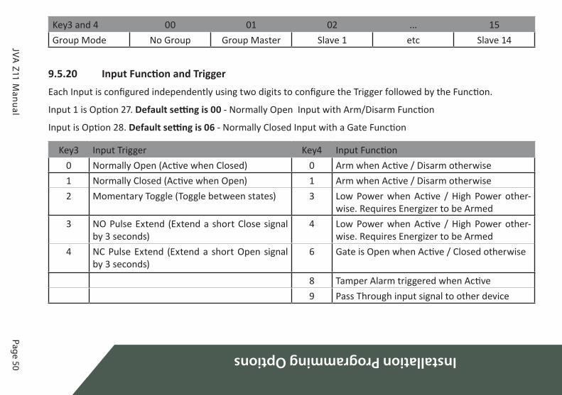
9.5.20 Input Function and TriggerEach Input is configured independently using two digits to configure the Trigger followed by the Function.
Input 1 is Option 27. Default setting is 00 - Normally Open Input with Arm/Disarm Function
Input is Option 28. Default setting is 06 - Normally Closed Input with a Gate Function
Key3 Input Trigger Key4 Input Function0 Normally Open (Active when Closed) 0 Arm when Active / Disarm otherwise1 Normally Closed (Active when Open) 1 Arm when Active / Disarm otherwise2 Momentary Toggle (Toggle between states) 3 Low Power when Active / High Power other-
wise. Requires Energizer to be Armed3 NO Pulse Extend (Extend a short Close signal
by 3 seconds)4 Low Power when Active / High Power other-
wise. Requires Energizer to be Armed4 NC Pulse Extend (Extend a short Open signal
by 3 seconds)6 Gate is Open when Active / Closed otherwise
8 Tamper Alarm triggered when Active9 Pass Through input signal to other device

Spec
ifica
tions
Page 51 © JVA Technologies www.jva-fence.com
10 SPECIFICATIONS10.1 Z11 SPECIFICATION
Specification Name SpecificationEnergizer Output Voltage 9.5kV peak no loadPeak Output Energy 1.5 Joules at 500 OhmsPulse Rate Locked at 0.8 Hz12v Dc Power Consumption Energizer on – 160mA average, 220mA
peak
Energizer off – 28mA (40mA with key-pad)
Ac Power Input 16-18Vac or 24VdcBattery Charger Output Float voltage 14V, 300mA, short circuit
and reverse polarity protection utilising 4A slow SMD fuses.
Siren and Strobe Outputs Self-resetting fuse protection, switched 12V, rated at 30W (combined)
Enclosure IP4x ABS plasticSize 300mm high, 190mm wide, 115mm
deepWeight – packed, no battery 1.9kg

Page 52
Specifications
© JVA Technologies www.jva-fence.com JVA Z11 Manual
• There are no user-serviceable parts in this unit.
• The installer is reminded that high voltages are retained for a while after switching off, and to wait for at least 10 minutes before opening the case.
• Before working on the high voltage wiring of an electric fence, it is rec-ommended that the energizer be turned off and an intentional short circuit be placed from the fence live wires to earth.
• Electric fences are not toys; do not let children play with them.
This appliance is not intended for use by persons (including children) with reduced physical, sensory or mental
capabilities, or lack of experience and knowledge, unless they have been given supervision or instruction con-
cerning use of the appliance by a person responsible for their safety. Children should be supervised to ensure
that they do not play with the appliance.

Z-Se
ries
Key
pads
Page 53 © JVA Technologies www.jva-fence.com
11 Z-SERIES KEYPADSThere are 3 different keypads that can connect to the keypad bus of a Z-Series device:
• PTE0210 LCD keypad
• PTE0230 Touch Keypad
• PTE0240 4-line keypad
A keypad can be used to control, program and monitor the devices on your fence.
11.1 PTE0210 LCD KEYPAD
The PTE0210 is an easy to use, durable and economical LCD keypad that can be used to control and program all Z-Series devices. It displays fence information such as fence voltages, battery voltages and any alarms if and when they occur. The onboard beeper alerts the user to any issues and instantly shows the relevant information that the user needs to see.

Page 54
Z-Series Keypads
© JVA Technologies www.jva-fence.com JVA Z11 Manual
11.2 PTE0230 TOUCH KEYPAD
JVA’s most advanced keypad features include:
• Touch screen with clean user interface designed for ease of use
• Quickly arm or disarm the entire site or granularly via the Zones screen
• Emails on alarm
• View all active and latched alarms in the alarms screen
• Program all Z-Series devices through an intuitive system, without hav-ing to remember or refer to a manual for key sequences. With the new MK2 protocol, these devices can be all programmed together without having to isolate each device individually
• The ability to monitor and log all user actions
• Large detailed event log

Z-Se
ries
Key
pads
Page 55 © JVA Technologies www.jva-fence.com
11.3 PTE0240 4-LINE KEYPAD
JVA’s mid-range keypad features include:
• Quick Arm/Disarm keys
• 4-line Backlit LCD Display
• Menu driven interface
• 500 entry event log with date and time stamps
11.4 CONNECTING MULTIPLE KEYPADS
Function Code Default CodeRe-analyse the Keypad group [User Pin]*68# 1234*68#
Up to three keypads may be used to remotely monitor and control Z-Series devices.
To operate correctly, each keypad must be configured to use a unique key-pad address. This is best achieved by connecting one keypad (at a time) to the master Z-Series device and updating the keypad address. Once all keypads have a different address, all can be connected to the system. Enter the above command using the keypad (at address 1).

Page 56
Z-Series Keypads
© JVA Technologies www.jva-fence.com JVA Z11 Manual
11.5 NOTES REGARDING KEYPAD CONFIGURA-TION
Zone 1 (the master) must be connected to the group. If it is not connected to the other Z-Series devices in the group, the keypad will report a com-munications failure with all the zones.
After connecting an LCD keypad to a group of devices, enter *68# on the keypad to ‘discover’ the connected energizers. Ensure that all Z-Series de-vices are disarmed first.
NOTE:
1. If the group ID has recently been changed you may need to reset, [User Pin] * 6 8 # before the new ID’s will be properly reported to the keypad.

Page 57©
JVA Technologies.
Z-Series Keypads
JVA Z11 M
anual
11.6 SUMMARY OF KEYPAD FUNCTIONS Default Installer PIN 012345Default User PIN 1234
Command Key1 Key2 Key3 Key4 Key5 Key6 Key7 Key8 Key9 Key10
Arm/Disarm USER PIN #Silence the Energizer Siren 1 4 7 0 #Enter Programming Mode INSTALLER PIN * 0 #Enter Keypad Programming Mode INSTALLER PIN * 0 1 #Exit Programming (Any Mode) * #Change a User PIN, 4 Digits USER PIN * 0 # [New
PIN]#
Arm All Zones (Multi-Zone Groups) USER PIN * 1 0 #Arm Specific Zone (up to Zone 15) USER PIN * 1 Zone
Number#
Disarm All Zones USER PIN * 2 0 #Disarm Specific Zone (up to Zone 15) USER PIN * 2 Zone
Number#
Switch to Low Power Mode (All Zones) USER PIN * 4 1 #Switch Specific Zone to Low Power USER PIN * 4 1 Zone No. #

Z-Series Keypads
JVA Z11 M
anualPage 58
Command Key1 Key2 Key3 Key4 Key5 Key6 Key7 Key8 Key9 Key10
Switch to High Power Mode (All Zones) USER PIN * 4 2 #Switch Specific Zone to High Power USER PIN * 4 2 Zone No. #Arm Gate Zone only USER PIN * 4 #Bypass Siren (All Zones) USER PIN * 5 2 #Bypass Specific Zone Siren USER PIN * 5 2 Zone No. #Re-enable Siren USER PIN * 5 1 #Re-enable Specific Zone Siren USER PIN * 5 1 Zone No. #Bypass Gate Alarm (All Zones) USER PIN * 5 4 #Bypass Specific Gate Alarm USER PIN * 5 4 Zone No. #Re-enable Gate Alarm (All Zones) USER PIN * 5 3 #Re-enable Specific Gate Alarm USER PIN * 5 3 Zone No. #Arm in Agricultural Mode (No Alarms) USER PIN * 9 Zone No.Reset and Display Firmware Version USER PIN * 6 8 #Reset and Return to Factory Defaults INSTALLER PIN * 6 8 #

Z-Se
ries
Key
pads
Page 59 © JVA Technologies www.jva-fence.com
Energizer Function Key1 Key2 Key3 Key4Clear Alarm Memory * 1 #Display the Group ID of the Energizer * 2 6 #Siren Test * 6 3 #Battery Test * 6 4 #
Keypad Specific Function Key1 Key2 Key3 Key4Re-Analyse the Energizer Group * 6 8 #Keypress Beep On/Off * 5 1 #Chimes On/Off * 5 3 #Error Tones On/Off * 5 4 #Keypad Alarm Tones On/Off * 5 5 #Change Backlight Mode * 8 #Display Keypad Model * 9 #

Page 60
Z-Series Keypads
© JVA Technologies www.jva-fence.com JVA Z11 Manual

Rem
ote
Cont
rol U
nit
Page 61 © JVA Technologies www.jva-fence.com
12 REMOTE CONTROL UNITThe Remote Control Unit provides the Z11 with the ability to arm or disarm the energizer via a compact key chain fob remote control.
12.1 FEATURES• Enables arm / disarm of the energizer, or a single zone, by key chain fob
remote control
• 2 remote controls included
• Uses digital rolling-code algorithm to uniquely and securely couple to remote controls
• Operates between 315 – 433.92MHz
• 100 metres range
• Easily connected and configured
• Wire to keypad bus (for power) and input (usually IN1)
Remote Control Unit Receiver

Page 62
Remote Control U
nit
© JVA Technologies www.jva-fence.com JVA Z11 Manual
12.2 INSTALLATIONThe Remote control receiver unit requires 12V and 0V (GND) from the key-pad bus, and its output wired to IN1.
Mount the receiver on the right hand side of the Z11 energizer. Connect +12V and 0V (GND) from the KEYPAD terminals on the energizer to the right-most terminals of the receiver, as per the diagram above.
Connect the IN1 terminals to the left-most terminals of the receiver.
Keep all connections away from any high voltage wiring, specifically the Fence Feed connections coming from the left side of the energizer.
Remote Control Receiver Wiring Diagram
12.3 OPERATION AND CONFIGURATIONSimply press the LOCK key to arm the energizer. Press the UNLOCK key to disarm.
Should a remote control become lost or stolen, it is possible to disassoci-ate the receiver with all remote controls. To do this, press the button on the bottom right corner of the receiver unit and hold for approximately 10 seconds. When the red light goes off the receiver has wiped all associated remote controls from its memory.
To associate a remote control, press the same button on the receiver once. The light will come on momentarily. Next, press a button on the remote control. The receiver light will begin flashing. Press the same button on the receiver again and the light will stop flashing. Test the remote control by pressing a button.

Stan
dard
Req
uire
men
ts fo
r Se
curi
ty E
lect
ric
Fenc
es
Page 63 © JVA Technologies www.jva-fence.com
13 STANDARD REQUIREMENTS FOR SECURITY ELECTRIC FENCES
13.1 DEFINITIONSConnecting lead
An electric conductor, used to connect the energizer to the electric fence or the earth electrode
Electric animal fence
An electric fence used to contain animals within or exclude animals from a particular area
Electric fence
A barrier which includes one or more electric conductors, insulated from earth, to which electric pulses are applied by an energizer
Electric security fence
A fence used for security purposes which comprises an electric fence and a physical barrier electrically isolated from the electric fence
13.2 GENERAL REQUIREMENTS FOR ELECTRIC FENCES
1. Electric fences shall be installed and operated so that they cause no electrical hazard to persons, animals or their surroundings.
2. Electric fence constructions which are likely to lead to the entangle-ment of animals or persons shall be avoided.
3. INSTALLERS/USERS SHOULD NOTE: WARNING: Avoid contacting elec-tric fence wires especially with the head, neck or torso. Do not climb over, through or under a multi-wire electric fence. Use a gate or a spe-cially designed crossing point.
4. An electric fence shall not be supplied from two different energizers or from independent fence circuits of the same energizer. For any two different electric fences, each supplied from a different energizer inde-pendently timed, the distance between the wires of the two electric fences shall be at least 2.5 m. If this gap is to be closed, this shall be af-fected by means of electrically non-conductive material or an isolated metal barrier.

Page 64
Standard Requirements for Security Electric Fences
© JVA Technologies www.jva-fence.com JVA Z11 Manual
5. Barbed wire or razor wire shall not be electrified by an energizer.
6. Any part of an electric fence which is installed along a public road or pathway shall be identified at frequent intervals by warning plates se-curely fastened to the fence posts or firmly clamped to the fence wires.
• The size of the warning plates shall be at least 100 mm x 200 mm.
• The background colour of both sides of the warning plate shall be yel-low. The colour on the plate shall be black and shall be either:
• The symbol of figure 7, or
• The substance of “Caution - ELECTRIC FENCE”.
• The inscription shall be indelible, inscribed on both sides of the warn-ing plate and have a height of at least 25 mm.
Warning plate symbol
7. The energizer earth electrode shall penetrate the ground to a depth of at least 1 m.
8. Connecting leads that are run inside buildings shall be effectively in-sulated from the earthed structural parts of the building. This may be achieved by using insulated high voltage cable.
9. Connecting leads that are run underground shall be run in a conduit of insulating material or else insulated high voltage cable shall be used. Care shall be taken to avoid damage to the connecting leads due to the effects of animal hooves or tractor wheels sinking into the ground.
10. Connecting leads shall not be installed in the same conduit as the mains supply wiring, communicating cables or data cables.
11. Connecting leads and electric fence wires shall not cross above over-head power or communication lines.

Stan
dard
Req
uire
men
ts fo
r Sec
urit
y El
ectr
ic F
ence
s
Page 65 © JVA Technologies www.jva-fence.com
12. Crossings with overhead power lines shall be avoided wherever pos-sible. If such a crossing cannot be avoided, it shall be made underneath the power line and as nearly as possible at right angles to it.
13. If connecting leads and electric fence wires are installed near an over-head power line, the clearances shall be not less than those shown in table.
Power line voltage V Clearance m<=1 000 3
>1 000 <=33 000 4
>33 000 8
Minimum Clearances from Power Lines
14. If connecting leads and electric fence wires are installed near an over-head power line, their height above the ground shall not exceed 2 m. This height applies either side of the orthogonal projection of the out-ermost conductors of the power line on the ground surface, for a dis-tance of
• 2 m for power lines operating at a nominal voltage not exceeding 1,000 V.
• 15 m for power lines operating at a nominal voltage exceeding 1,000V.
13.3 PARTICULAR REQUIREMENTS FOR ELECTRIC ANIMAL FENCES IN AUSTRALIA
1. A distance of at least 10 m shall be maintained between the energizer earth electrode and any other earthing system such as the power sup-ply system protective earth or the telecommunication system earth.
2. Electric fences intended for deterring birds, household pet contain-ment or training animals such as cows need only be supplied from low output energizers to obtain satisfactory and safe performance.
3. In electric fences intended for deterring birds from roosting on build-ings, no electric fence wire shall be connected to the energizer earth electrode. A warning plate, as described above, shall be fitted to every point where persons may gain ready access to the conductors.
4. A non-electrified fence incorporating barbed wire or razor wire may be used to support one or more off-set electrified wires of an electric

Page 66
Standard Requirements for Security Electric Fences
© JVA Technologies www.jva-fence.com JVA Z11 Manual
animal fence. The supporting devices for the electrified wires shall be constructed so as to ensure that these wires are positioned at a mini-mum distance of 150 mm from the vertical plane of the non-electrified wires. The barbed wire and razor wire shall be earthed at regular in-tervals.
5. Where an electric animal fence crosses a public pathway, a non-elec-trified gate shall be incorporated in the electric fence at the point or a crossing by means of stiles shall be provided. At any such crossing, the adjacent electrified wires shall carry warning plates as described above.
13.4 INSTALLATION OF ELECTRIC SECURITY FENC-ES
13.4.1 GeneralAn electric security fence should be installed so that, under normal condi-tions of operation, persons are protected against inadvertent contact with pulsed conductors.
NOTE:
1. This requirement is primarily intended to establish that a desirable level of safety is present or is being maintained in the physical barrier.
2. When selecting the type of physical barrier, the likely presence of young children should be a factor in considering the size of openings.
13.4.2 Location of electric security fenceThe electric fence should be separated from the public access area by means of a physical barrier.
Where an electric fence is installed in an elevated position, such as on the inner side of a window or skylight, the physical barrier may be less than 1.5 m high where it covers the whole of the electric fence. If the bottom of the window or skylight is within a distance of 1.5 m from the floor or access level then the physical barrier need only extend up to a height of 1.5 m above the floor or access level.

Stan
dard
Req
uire
men
ts fo
r Sec
urit
y El
ectr
ic F
ence
s
Page 67 © JVA Technologies www.jva-fence.com
13.4.3 Prohibited zone for pulsed conductorsPulsed conductors shall not be installed within the shaded zone shown in Figure 8.
Prohibited Area for Pulse Conductors
NOTE: Where an electric security fence is planned to run close to a site boundary, the relevant government authority should be consulted before installation begins.

Page 68
Standard Requirements for Security Electric Fences
© JVA Technologies www.jva-fence.com JVA Z11 Manual
Typical Constructions where an Electric Security Fence is
Exposed to the Public
NOTE: Typical electric security fence installations are shown in Figure 9 and Figure 10.

Stan
dard
Req
uire
men
ts fo
r Sec
urit
y El
ectr
ic F
ence
s
Page 69 © JVA Technologies www.jva-fence.com
Typical fence constructions where the electric security fence is
installed in windows and skylights
13.4.4 Separation between electric fence and physical barrierWhere a physical barrier is installed in compliance with 3 at least one di-mension in any opening should be not greater than 130 mm and the sepa-ration between the electric fence and the physical barrier should be
• within the range of 100 mm to 200 mm or greater than 1 000 mm where at least one dimension in each opening in the physical barrier is not greater than 130 mm;
• greater than 1 000 mm where any opening in the physical barrier has all dimensions greater than 50 mm;
• less than 200 mm or greater than 1 000 mm where the physical barrier does not have any openings.
NOTE:
1. These restrictions are intended to reduce the possibility of persons making inadvertent contact with the pulsed conductors and to pre-vent them from becoming wedged between the electric fence and the physical barrier, thereby being exposed to multiple shocks from the energizer.

Page 70
Standard Requirements for Security Electric Fences
© JVA Technologies www.jva-fence.com JVA Z11 Manual
2. The separation is the perpendicular distance between the electric fence and the physical barrier.
13.4.5 Prohibited mountingElectric fence conductors should not be mounted on a support used for any overhead power line.
13.4.6 Operation of electric security fenceThe conductors of an electric fence should not be energized unless all au-thorized persons, within or entering the secure area, have been informed of its location.
Where there is a risk of persons being injured by a secondary cause, ap-propriate additional safety precautions should be taken.
NOTE: An example of a secondary cause is where a person may be expect-ed to fall from a surface if contact is made with pulsed conductors.

App
endi
x A
: Gro
up S
imul
tane
ous
Puls
e Fe
atur
e
Page 71 © JVA Technologies www.jva-fence.com
14 APPENDIX A: GROUP SIMULTANEOUS PULSE FEATURE
14.1 GROUP SIMULTANEOUS PULSE FEATUREIn some Industrial Installations it may be preferable to provide the ability to link multiple Energizers into a group. When linked the individual Z-Series devices become a “Group”. Members of a group have simultaneous high voltage output pulses and act as is they are one energizer with multiple outputs. This is designed so that no possible combination of individual out-puts can be dangerous.
14.2 GROUP MODE PROGRAMMING (OPTION 26)A group MUST have only 1 master. The other Energizers in the group are slaves.
For the Z11 Energizers, if there is no Master, a Slave will display Error 4 on the Status LED when Armed and it will not electrify the fence. This is a re-quirement for Australian Standards.
For every other Z-series device, if there is no Master, each Slave will elec-trify the fence (pulses) when Armed. However, the simultaneous pulse fea-ture will NOT be operating.NOTE:
1. Do not interconnect the energizers via the keypad bus until after they are programmed.
2. If more than one keypad is used, they will need different addresses.
3. If Perimeter Patrol is used any keypad in the system should not have address 2.
For all Energizers that will be part of a group, the procedure is as follows:
1. Make sure the key switch is turned off and IN1 isn’t shorted.
2. Connect the battery.
3. On the keypad, enter [Installer’s code] *, 0, #.
4. Enter 2, 6 followed by the required value (e.g. 1 for master) then #.
5. Enter *, # to exit programming.
6. Connect the group using the keypad bus as the Group Mode Linking diagram.

Page 72
Appendix A
: Group Sim
ultaneous Pulse Feature
© JVA Technologies www.jva-fence.com JVA Z11 Manual
NOTE: At this time groups are limited to a master and 14 slaves (15 zones total)
Key3 Mode
0 No Group1 Master2 Slave 13 Slave 24 Slave 35 Slave 46 Slave 57 Slave 68 Slave 79 Slave 8
10 Slave 911 Slave 1012 Slave 1113 Slave 1214 Slave 1315 Slave 14
14.3 GROUP LINKING VIA THE KEYPAD “BUS”The keypad terminals on all Energizers in the group are linked. Since only one Energizer needs to power the keypad, 3 wires are linked from one En-ergizer (preferably the Master) to the keypad (optional) and 2 wires to ev-ery other Energizer in the group. Do not connect the + lines between Ener-gizers as this could result in some strange behaviour and possibly damage.
NOTE the connections can be a star or daisy chain or any mixture. It is possible for a PC to be added to the group using a keypad to USB adaptor (PAE223).

App
endi
x A
: Gro
up S
imul
tane
ous
Puls
e Fe
atur
e
Page 73 © JVA Technologies www.jva-fence.com
We recommend following these steps in the right order:
1. Disarm all energizers in the group. If energizers are not disarmed Step10 may not work correctly.
2. Program the keypad address using one of the energizers.
3. Program each energizer with its required address (Master address=1, Slave 1 address=2...).
4. Connect any control/monitoring unit 12V, GND and Data to the Group Master
5. Connect all the slaves Data and GND to the Group Master.
6. Connect the battery and AC power of the Group Master but do not arm.
7. Connect the battery and AC power of each slave. Note: Do not arm them until all the Energizers in the group are connected.
8. Wait 5 minutes for all the Energizers to synchronise with the Master
9. If there are more than one Z-Series keypad or control unit, make sure they have a different ID, then reset the group using keypad code: [User PIN] *, 6, 8, # or Perimeter Patrol’s “Reset All” this will allow both key-pads to be recognised by all energizers in the group.
10. If using a PTE0210 keypad, enter the key sequence *, 6, 8, # to re-scan the group and check what energizers are connected.
11. Arm the group using keypad 1, 2, 3, 4, *, 1, 0, #, or by using Perimeter Patrol. Make sure all Energizers are activated.
Note:
1. Members of a group can be individually switched on and off; even the master can be turned off via input or key switch.
2. A slave will generate a General alarm if the keypad bus is broken be-tween it and the group master.
3. After programming the Keypad may be disconnected, it is not required for group operation.
4. When connected to Perimeter Patrol, the arm/disarm function of a keypad is disabled. Control of these functions is through the Perimeter Patrol interface.
5. A Keypad that is connected to a Slave Energizer that is disconnected

Page
74Appendix A: Group Simultaneous Pulse Feature
© JV
A T
echn
olog
ies
ww
w.jv
a-fe
nce
.com
JVA
Z11
Man
ual
from
the
Grou
p, m
ust h
ave
a KE
YPAD
ADD
RESS
set t
o 1.

DEALER
www.jvA-fEncE.com